US12185996B2 - Implant positioning devices and methods - Google Patents
Implant positioning devices and methodsDownload PDFInfo
- Publication number
- US12185996B2 US12185996B2US17/569,259US202217569259AUS12185996B2US 12185996 B2US12185996 B2US 12185996B2US 202217569259 AUS202217569259 AUS 202217569259AUS 12185996 B2US12185996 B2US 12185996B2
- Authority
- US
- United States
- Prior art keywords
- fastener
- attachment mechanism
- plate
- compression attachment
- compression
- Prior art date
- Legal status (The legal status is an assumption and is not a legal conclusion. Google has not performed a legal analysis and makes no representation as to the accuracy of the status listed.)
- Active, expires
Links
Images


Classifications
- A—HUMAN NECESSITIES
- A61—MEDICAL OR VETERINARY SCIENCE; HYGIENE
- A61B—DIAGNOSIS; SURGERY; IDENTIFICATION
- A61B17/00—Surgical instruments, devices or methods
- A61B17/56—Surgical instruments or methods for treatment of bones or joints; Devices specially adapted therefor
- A61B17/58—Surgical instruments or methods for treatment of bones or joints; Devices specially adapted therefor for osteosynthesis, e.g. bone plates, screws or setting implements
- A61B17/68—Internal fixation devices, including fasteners and spinal fixators, even if a part thereof projects from the skin
- A61B17/80—Cortical plates, i.e. bone plates; Instruments for holding or positioning cortical plates, or for compressing bones attached to cortical plates
- A61B17/808—Instruments for holding or positioning bone plates, or for adjusting screw-to-plate locking mechanisms
- A—HUMAN NECESSITIES
- A61—MEDICAL OR VETERINARY SCIENCE; HYGIENE
- A61B—DIAGNOSIS; SURGERY; IDENTIFICATION
- A61B17/00—Surgical instruments, devices or methods
- A61B17/16—Instruments for performing osteoclasis; Drills or chisels for bones; Trepans
- A61B17/17—Guides or aligning means for drills, mills, pins or wires
- A61B17/1728—Guides or aligning means for drills, mills, pins or wires for holes for bone plates or plate screws
- A—HUMAN NECESSITIES
- A61—MEDICAL OR VETERINARY SCIENCE; HYGIENE
- A61B—DIAGNOSIS; SURGERY; IDENTIFICATION
- A61B17/00—Surgical instruments, devices or methods
- A61B17/16—Instruments for performing osteoclasis; Drills or chisels for bones; Trepans
- A61B17/17—Guides or aligning means for drills, mills, pins or wires
- A61B17/1739—Guides or aligning means for drills, mills, pins or wires specially adapted for particular parts of the body
- A61B17/1789—Guides or aligning means for drills, mills, pins or wires specially adapted for particular parts of the body for the sternum
- A—HUMAN NECESSITIES
- A61—MEDICAL OR VETERINARY SCIENCE; HYGIENE
- A61B—DIAGNOSIS; SURGERY; IDENTIFICATION
- A61B17/00—Surgical instruments, devices or methods
- A61B17/56—Surgical instruments or methods for treatment of bones or joints; Devices specially adapted therefor
- A61B17/58—Surgical instruments or methods for treatment of bones or joints; Devices specially adapted therefor for osteosynthesis, e.g. bone plates, screws or setting implements
- A61B17/68—Internal fixation devices, including fasteners and spinal fixators, even if a part thereof projects from the skin
- A61B17/84—Fasteners therefor or fasteners being internal fixation devices
- A61B17/86—Pins or screws or threaded wires; nuts therefor
- A61B17/865—Packages or dispensers for bone screws or threaded wires
- A—HUMAN NECESSITIES
- A61—MEDICAL OR VETERINARY SCIENCE; HYGIENE
- A61B—DIAGNOSIS; SURGERY; IDENTIFICATION
- A61B17/00—Surgical instruments, devices or methods
- A61B17/56—Surgical instruments or methods for treatment of bones or joints; Devices specially adapted therefor
- A61B17/58—Surgical instruments or methods for treatment of bones or joints; Devices specially adapted therefor for osteosynthesis, e.g. bone plates, screws or setting implements
- A61B17/68—Internal fixation devices, including fasteners and spinal fixators, even if a part thereof projects from the skin
- A61B17/80—Cortical plates, i.e. bone plates; Instruments for holding or positioning cortical plates, or for compressing bones attached to cortical plates
- A61B17/8023—Variable length plates adjustable in both directions
- A—HUMAN NECESSITIES
- A61—MEDICAL OR VETERINARY SCIENCE; HYGIENE
- A61B—DIAGNOSIS; SURGERY; IDENTIFICATION
- A61B17/00—Surgical instruments, devices or methods
- A61B17/56—Surgical instruments or methods for treatment of bones or joints; Devices specially adapted therefor
- A61B17/58—Surgical instruments or methods for treatment of bones or joints; Devices specially adapted therefor for osteosynthesis, e.g. bone plates, screws or setting implements
- A61B17/68—Internal fixation devices, including fasteners and spinal fixators, even if a part thereof projects from the skin
- A61B17/80—Cortical plates, i.e. bone plates; Instruments for holding or positioning cortical plates, or for compressing bones attached to cortical plates
- A61B17/8061—Cortical plates, i.e. bone plates; Instruments for holding or positioning cortical plates, or for compressing bones attached to cortical plates specially adapted for particular bones
- A61B17/8076—Cortical plates, i.e. bone plates; Instruments for holding or positioning cortical plates, or for compressing bones attached to cortical plates specially adapted for particular bones for the ribs or the sternum
- A—HUMAN NECESSITIES
- A61—MEDICAL OR VETERINARY SCIENCE; HYGIENE
- A61B—DIAGNOSIS; SURGERY; IDENTIFICATION
- A61B17/00—Surgical instruments, devices or methods
- A61B17/56—Surgical instruments or methods for treatment of bones or joints; Devices specially adapted therefor
- A61B17/58—Surgical instruments or methods for treatment of bones or joints; Devices specially adapted therefor for osteosynthesis, e.g. bone plates, screws or setting implements
- A61B17/88—Osteosynthesis instruments; Methods or means for implanting or extracting internal or external fixation devices
- A61B17/90—Guides therefor
Definitions
- the disclosurerelates generally to implant positioning apparatuses and devices. More particularly, the disclosure relates to implant positioning apparatuses and devices for use in bone fixation, sternum fixation, and other orthopaedic fixation procedures.
- the proceduremay involve separating a bone into portions, which are thereafter reunited. This happens, for example, in entries into the chest cavity, as for heart surgery, where the sternum is required to be separated along its length. There may be other instances where a bone has undergone fracturing through some trauma, and is thereafter to have portions rejoined for proper healing. Additionally, in applications involving the spine, there may be independent bones that benefit from holding a particular position relative to each other to allow for healing of the disc and other surrounding tissues.
- fixation devicescan be held secure to one another in adjacency using a fixation device, or system.
- fixation devicesinclude wires or cables that are organized to pull the bone portions together, laterally across a divide or fracture.
- fixation devicescan be relatively complex to emplace. For instance, if a plate-type structure is to be attached to a bone, it is important to locate the fixation points (e.g., for screws) very accurately, as for drilling pilot holes for the screws. Plainly, speed and ease in then attaching the structure are significant considerations.
- Implant positioning devicesare disclosed for assisting in positioning orthopaedic fixation devices (such as bone plates, etc.) for use in bone fixation, sternum fixation, and other orthopaedic fixation procedures.
- the implant positioning deviceincludes a compression attachment mechanism configured to removably couple to a plate.
- a fastener guideis coupled to the compression attachment mechanism and configured to receive a fastener, and a spring member is disposed in the fastener guide and configured to hold the fastener in the fastener guide.
- a combined guide and holder for fasteners used in orthopaedic fixationwherein a plate is to be affixed to a bone.
- the deviceincludes a base or frame adapted to align with the plate in a manner to orient fasteners with the plate for fixation.
- a plurality of fastener holdersare on the base, with each fastener holder adapted to releasably hold a fastener in a manner where the fastener is exposed at a proximal end for access by a fastener driver and aligned at a distal end with an aperture in the plate through which the fastener is to be driven.
- a device for positioning an orthopaedic fixation devicehas a base, including: a mounting structure, a first fastener guide coupled to the mounting structure, and a second fastener guide coupled to the mounting structure, wherein the mounting structure is between the first and second fastener guides.
- a compression attachment mechanismis also coupled to the base and configured to releasably hold a plate and align the plate with at least one of the first and second fastener guides.
- the implant positioning devicemay also be used to affix fasteners to a bone or other body part in a designed pattern without a plate or the like being fixed therein.
- FIG. 1illustrates a first perspective view of an implant positioning device in accordance with an embodiment of the disclosure
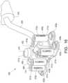
- FIG. 2illustrates a second perspective view of the implant positioning device of FIG. 1 in accordance with an embodiment of the disclosure
- FIG. 3illustrates a first perspective view of a body portion of the implant positioning device of FIG. 1 aligned with a pair of plates in accordance with an embodiment of the disclosure
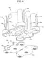
- FIG. 4illustrates a second perspective view of the body portion of the implant positioning device of FIG. 1 aligned with the pair of plates in accordance with an embodiment of the disclosure
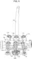
- FIG. 5illustrates a first cut-away view of the implant positioning device of FIG. 1 in accordance with an embodiment of the disclosure
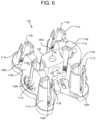
- FIG. 6illustrates a third perspective view of the body portion of the implant positioning device of FIG. 1 in accordance with an embodiment of the disclosure
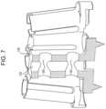
- FIG. 7illustrates a first cut-away view of the body portion of the implant positioning device of FIG. 1 in accordance with an embodiment of the disclosure
- FIG. 8illustrates a first cut-away view of the body portion of the implant positioning device of FIG. 1 showing a compression attachment mechanism in accordance with an embodiment of the disclosure
- FIG. 9illustrates a side cut-away view of the body portion of the implant positioning device of FIG. 1 showing the compression attachment mechanism in accordance with an embodiment of the disclosure
- FIG. 10illustrates a perspective view of the implant positioning device of FIG. 1 coupled with a plate in accordance with an embodiment of the disclosure
- FIG. 11illustrates a perspective view of another implant positioning device in accordance with an embodiment of the disclosure.
- FIG. 12illustrates a perspective view of the implant positioning device of FIG. 11 coupled with a plate in accordance with an embodiment of the disclosure
- FIG. 13illustrates a first cut-away view of the body portion of the implant positioning device of FIG. 11 showing fasteners in accordance with an embodiment of the disclosure
- FIG. 14illustrates a perspective view of the compression attachment mechanism of the implant positioning device of FIG. 11 in accordance with an embodiment of the disclosure
- FIG. 15illustrates a perspective view in phantom of a housing of the compression attachment mechanism of the implant positioning device of FIG. 11 in accordance with an embodiment of the disclosure
- FIG. 16illustrates a perspective view of another implant positioning device of in accordance with an embodiment of the disclosure.
- FIG. 17illustrates a first cut-away view of the body portion of the implant positioning device of FIG. 16 showing fasteners in accordance with an embodiment of the disclosure.
- FIGS. 1 - 5illustrate an implant positioning device 100 in the form of a combined drill guide and fixation element holder according to an embodiment of the disclosure.
- the implant positioning device 100includes a frame or body portion 102 , a handle portion 104 coupled to the body portion 102 , and a compression attachment mechanism 106 including attachment feet 108 a and 108 b.
- the body 102includes one or more sets of fastener guides (for example, a first set of fastener guides 110 a and a second set of fastener guides 110 b ) on opposite sides of the body 102 .
- the first set of fastener guides 110 aincludes one or more first fastener holders or fastener housing members 111 a capable of holding fastener captive elements 112 a respectively disposed in each of the fastener housing members 111 a .
- the second set of fastener guides 110 bincludes one or more second fastener housing members 111 b capable of holding fastener captive elements 112 b respectively disposed in each of the fastener housing members 111 b .
- the fastener captive elements 112 a and 112 bmay be a spring element, o-ring, etc.
- the first and second sets of fastener guides 110 a and 110 bprovide fastener housings 111 a and 111 b to hold, position, and guide fasteners 114 for insertion into and through fastener apertures in one or more plates 200 (which may include a first plate 202 a and a second plate 202 b illustrated in FIG. 3 ) to install the plate(s) 200 on a bone, calcaneus body part, or other area of a patient.
- the plates 200may be the plates disclosed in U.S. Patent Application Publication No. 2015/0119887, entitled Orthopedic Fixation Device, System and Method, filed Oct. 27, 2014, the disclosure of which is incorporated by reference herein in its entirety.
- the first and second sets of fastener guides 110 a and 110 bare two sets of fastener guides, the first and second sets of fastener guides 110 a and 110 b , (one disposed on each side of the body 102 ), with each set respectively including three fastener housings 111 a and 111 b , and the fasteners 114 are screws.
- the fasteners 114may be pins, rivets, and other types of fasteners, etc.
- the first and second sets of fastener guides 110 a and 110 bprovide the fastener housings 111 a and 111 b in the form of substantially cylindrical, hollow, tube like guide barrels that are positioned to align with the fastener apertures in the plate(s) 200 .
- the first and second fastener housings 111 a and 111 bcommunicate with respective first and second recesses 116 a and 116 b in a bottom of the body 102 .
- the respective first and second recesses 116 a and 116 bare respectively sized and shaped to receive the corresponding first and second plates 202 a and 202 b .
- the first recess 116 ais sized and shaped to receive the first plate 202 a
- the second recess 116 bis sized and shaped to receive the second plate 202 b
- the first plate 202 aincludes shear bars or pins 204
- the first sets of fastener guides 110 aincludes grooves 118 that communicate with the first recess 116 a .
- the grooves 118are sized and shaped to receive the corresponding pins 204 when the first plate 202 a is received in the first recess 116 a and the pins 204 are in an undeployed position (as illustrated in FIG. 4 ).
- the first and second plates 202 a and 202 bare respectively disposed in the corresponding first and second recesses 116 a and 116 b and a bottom portion of the fastener housings 111 a and 111 b are in close proximity to the plate(s) 202 a and 202 b to minimize the opportunity for any unintentional angulation of the fasteners 114 as the fasteners 114 pass through the respective guides of the first and second sets of fastener guides 110 a and 110 b .
- first and second sets of fastener guides 110 a and 110 bare illustrated as positioned to align with the fastener apertures of the plate(s) 200 , the first and second sets of fastener guides 110 a and 110 b may be positioned to align with apertures of any plate(s) or other device, and/or the location of the guides in each of the first and second sets of fastener guides 110 a and 110 b may be adapted or modified to align with apertures of any plate(s) or other device.
- the implant positioning device 100may also be used to locate and attach fasteners to a bone or other body part without any plate or the like being involved.
- the first and second sets of fastener guides 110 a and 110 bmay also be used to guide a driver and/or drill depending on the application.
- the first and second sets of fastener guides 110 a and 110 bmay also be used to guide other instruments, for example, to place markings, pegs, headless pins, etc. in a bone, which then serve as locating features to place plates or any other device before or after a resection is made.
- first and second sets of fastener guides 110 a and 110 bmay be disposable, and pre-loaded with fasteners.
- the first and second sets of fastener guides 110 a and 110 bmay be removable from the compression attachment mechanism 106 . This allows the first and second sets of fastener guides 110 a and 110 b to be easily replaced during a surgical procedure.
- each of the fastener housings 111 a and 111 b of the first and second sets of fastener guides 110 a and 110 bmay include one or more side apertures or slits.
- each of the fastener housings 111 aincludes first side slits or apertures 120 a
- each of the fastener housings 111 bincludes second side slits or apertures 120 b .
- the first and second side apertures 120 a and 120 bfor one or more finger-like structures that make up the fastener housings 111 a and 111 b . These finger-like structures allow for ease of cleaning and sterilization of the implant positioning device 100 .
- the first and second side apertures 120 a and 120 bmay also receive and serve as expansion zones for the fastener captive elements 112 a and 112 b , respectively.
- the fastener captive elements 112 a and 112 bretain a fastener 114 in the respective fastener housings 111 a and 111 b of the first and second sets of fastener guides 110 a and 110 b .
- the fastener housings 111 a and 111 bmay have no such side apertures 120 a / 120 b and the fastener captive elements 112 a and 112 b may be contained within the respective fastener housings 111 a and 111 b of the first and second sets of fastener guides 110 a and 110 b .
- one or more internal recessesmay be formed in the respective fastener housings 111 a and 111 b of the first and second sets of fastener guides 110 a and 110 b to receive and serve as expansion zones for the fastener captive elements 112 a / 112 b.
- the fastener captive elements 112 a and 112 bmay be spring elements that create tension against the fastener 114 (for example, the threads of the fastener 114 ) and center the fastener 114 in the respective fastener housings 111 a and 111 b of the first and second sets of fastener guides 110 a and 110 b .
- each fastener captive element 112 a , 112 bincludes three spring elements or prongs 122 extending downwardly from an upper collar 124 .
- the prongs 122extends along a side of fastener housing 111 a , 111 b and includes teeth that contact and grip a side of the fastener 114 (such as the threads of the fastener 114 ), and the collar 124 surrounds a head of the fastener 114 to hold the fastener 114 in the fastener captive element 112 a , 112 b .
- the fastener captive elements 112 a and 112 bmay be cages, or other structure.
- the prongs 122may be located at various positions around each respective collar 124 , for example, about 120 degrees apart, when there are three prongs 122 .
- the fastener captive elements 112 a , 112 bcenter the fasteners 114 in the respective fastener housings 111 a and 111 b of the first and second sets of fastener guides 110 a and 110 b to ensure the fasteners 114 are deployed in a center of the corresponding apertures in the corresponding plate(s) 202 a , 202 b.
- the fastener captive elements 112 a , 112 bserve as a capture mechanism.
- fastener captive elements 112 a , 112 bare biased to compress against and apply a force to the fastener 114 and hold the fasteners 114 within each fastener housing 111 a and 111 b , respectively.
- Each fastener captive element 112 a and 112 bmay be disposed in and removed from the respective fastener housings 111 a and 111 b of the first and second sets of fastener guides 110 a and 110 b for ease of loading fasteners into the respective fastener housings 111 a and 111 b .
- a fastenersuch as fastener 114
- fastener 114may be disposed in a fastener captive element 112 b and then the fastener captive element 112 b along with the fastener 114 may be loaded into a corresponding fastener housing 111 b of the second set of fastener guides 110 b .
- each of the fastener housings 111 a and 111 brespectively include shoulders 113 a and 113 b that receive and abut the collar 124 of the respective fastener captive elements 112 a , 112 b and prevent the fastener captive elements 112 a , 112 b from sliding or being forced into the fastener housings 111 a and 111 b when the fastener 114 is driven into a bone.
- the fastener captive elements 112 a / 112 bmay expand elastically as a head of the fastener having a larger diameter than a shank or threaded portion of the fastener passes through the respective fastener housings 111 a and 111 b .
- Each of the fasteners 114may have a head portion having a feature that mates with a driver (for example, a flat head, cross head, hex head etc. of a driver and/or drill) for use in insertion and receiving torque to drive the fasteners 114 into a bone or other body part.
- the fastener captive elements 112 a / 112 bthen return to their normal resting state for repeated use.
- the fastener captive elements 112 a / 112 balso hold the fasteners 114 within each fastener housings 111 a and 111 b and prevent the fasteners 114 from accidentally falling out of the fastener housings 111 a and 111 b onto an operating room floor or into a patient's open body cavity.
- the body 102includes a central mounting structure 126 adapted to receive the compression attachment mechanism 106 .
- the central mounting structure 126couples the first and second sets of fastener guides 110 a and 110 b together and includes a first aperture 128 extending horizontally through the central mounting structure 126 and a second aperture 130 extending horizontally through the central mounting structure 126 .
- the first aperture 128is proximal to a top of the central mounting structure 126 and the second aperture 130 is proximal to a bottom of the central mounting structure 126 .
- the central mounting structure 126may also include a third aperture 132 extending vertically through the central mounting structure 126 . This third aperture 132 may provide for easy cleaning and sterilization of the implant positioning device 100 .
- the compression attachment mechanism 106may be a spring loaded mechanism, that when compressed causes a distance between the attachment feet 108 a and 108 b to increase and when released causes the distance between the attachment feet 108 a and 108 b to decrease and mate with corresponding structure on the plate(s) 200 (as illustrated in FIG. 10 ).
- the attachment feet 108 a and 108 bserve to hold two plate halves (such as plates 202 a and 202 b ) in the implant positioning device 100 at a predetermined distance from each other.
- the attachment feet 108 a and 108 bhold the two plate halves (such as plates 202 and 202 b ) in a coplanar arrangement, with the fastener apertures in the plate(s) aligned with the respective fastener housings 111 a and 111 b of the first and second sets of fastener guides 110 a and 110 b .
- the implant positioning device 100may have clamping or connectable features in a plane opposite the attachment feet 108 a and/or 108 b , such as another set of feet oriented about 90 degrees from the attachment feet 108 a and/or 108 b . These feet may also thread into holes or attach in a number of different ways to plates and other devices.
- the compression attachment mechanism 106allows for the implant positioning device 100 to be coupled to and uncoupled from the plates 200 quickly and easily, simply by compressing the spring loaded mechanism.
- the compression attachment mechanism 106may include one or more rails, such as a first rail 134 and a second rail 136 having corresponding gripping portions 138 and 140 and first and second springs 142 and 144 disposed on a corresponding rails 134 and 136 .
- the first rail 134is disposed through a first support 146 of the compression attachment mechanism 106 , through the first aperture 128 in the central mounting structure 126 , and coupled to a second support 148 of the compression attachment mechanism 106 .
- the first spring 142is disposed on the first rail 134 between the first support 146 and the central mounting structure 126 .
- a first stop 150may also be disposed on the first rail 134 between the first spring 142 and the first support 146 .
- the second rail 136is disposed through the second support 148 of the compression attachment mechanism 106 , through the second aperture 130 in the central mounting structure 126 , and coupled to the first support 146 of the compression attachment mechanism 106 .
- the second spring 144is disposed on the second rail 136 between the second support 148 and the central mounting structure 126 .
- a second stop 152may also be disposed on the second rail 136 between the second spring 144 and the second support 148 .
- the distance between the feet 108 a and 108 bis increased.
- Thisallows the plates 200 to be placed in the implant positioning device 100 , and when the compression force applied to the gripping portions 138 and 140 is released, the distance between the feet 108 a and 108 b decreases and the feet 108 a and 108 b mate with corresponding recesses on the plate(s) 200 to couple the plate(s) 200 to the implant positioning device 100 (for example as illustrated in FIG. 10 ).
- Other means and ways to hold a plate in placewill also be readily adoptable.
- the implant positioning device 100may also include one or more spikes 154 extending from a bottom of the body 102 of the implant positioning device 100 to assist in placing and holding the implant positioning device 100 and the plate(s) 200 in a proper orientation as the fasteners 114 are driven to couple the plate(s) 200 to a bone or other portion of a patient's body.
- a gripmay also be removably coupled to the handle 104 to provide for ease of use of the implant positioning device 100 .
- the handle 104may be used to retain the implant positioning device 100 in a particular position for ease of assembly of elements (such as the plates 200 ) that may be connected to it.
- the implant positioning device 100may be coupled to the plates 200 having fastener holes and various other features.
- the handle 104 and gripmay have an ergonomic design for comfort and control of the implant positioning device 100 .
- the handle 104may also be angled to accommodate soft tissues and various surgical approaches. Further, the handle 104 may be removable from the body 102 .
- an implant positioning device 300is described with reference to FIGS. 11 - 15 .
- the implant positioning device 300is similar to the implant positioning device 100 described above, but includes the modifications as described below.
- the implant positioning device 300includes a body 302 and a compression attachment mechanism 306 including attachment feet 308 a and 308 b.
- the body 302includes one or more sets of fastener guides (for example, a first set of fastener guides 310 a and a second set of fastener guides 310 b ) disposed on opposite sides of the body 302 and having respective fastener captive elements 312 a and 312 b disposed in respective first and second fastener housings 311 a and 311 b .
- fastener guidesfor example, a first set of fastener guides 310 a and a second set of fastener guides 310 b .
- the first and second sets of fastener guides 310 a and 310 bprovide fastener housings 311 a and 311 b to guide fasteners (such as fasteners 114 described above) for insertion into fastener apertures in one or more plates (such as plates 200 , including the first plate 202 a and the second plate 202 b ) to install the plate(s) on bone or other area of a patient.
- fastenerssuch as fasteners 114 described above
- platessuch as plates 200 , including the first plate 202 a and the second plate 202 b
- the fastenersmay be pins, rivets, and other types of fasteners, etc.
- the first and second fastener housings 311 a , 311 bcommunicate with respective first and second recesses 316 a and 316 b in a bottom of the body 302 .
- the respective first and second recesses 316 a and 316 bare respectively sized and shaped to receive the corresponding first and second plates 202 a and 202 b .
- the first plate 202 aincludes shear bars or pins 204 .
- the first sets of fastener guides 310 aincludes grooves 318 (as illustrated in FIG. 11 ) that communicate with the first recess 316 a and receive the corresponding pins 204 when the first plate 202 a is received in the first recess 116 a and the pins 204 are in an undeployed position.
- each of the first and second fastener housings 311 a , 311 bmay be cylindrical hollow tube like guide barrels that are positioned and oriented to align with the fastener apertures in the plate(s). While the first and second fastener housings 311 a and 311 b are illustrated as positioned and oriented to align with the fastener apertures of the plate(s) 200 , the first and second sets of fastener guides 310 a and 310 b and/or the individual guide barrels may be positioned and oriented to align with apertures of any plate or other device.
- the first and second sets of fastener guides 310 a and 310 b of the implant positioning device 300may also be used to guide a driver and/or drill depending on the application, and/or to guide other instruments, for example, to place markings, pegs, headless pins, etc. in a bone, which then serve as locating features to place plates or any other device after a resection is made.
- the implant positioning devicesmay also be used simply to apply fasteners or other fixation elements alone, or in a desired pattern, as for use in a wired closure arrangement.
- the first and second sets of fastener guides 310 a and 310 bmay be disposable, and pre-loaded with fasteners.
- the first and second sets of fastener guides 310 a and 310 bmay be removable from the compression attachment mechanism 306 . This allows the first and second sets of fastener guides 310 a and 310 b to be easily replaced during a surgical procedure.
- first and second sets of fastener guides 306 a and 306 bmay be coupled around at least a portion of the compression attachment mechanism 306 (such as a housing 356 ) due to the shape of the first and second sets of fastener guides 310 a and 310 b and the first and second sets of fastener guides 310 a and 310 b may be coupled together by pins, for example.
- each of the first and second fastener housings 311 a and 311 b of the first and second sets of fastener guides 310 a and 310 binclude one or more side apertures or slits 320 a and 320 b , respectively, that receive and serve as expansion zones for the respective fastener captive elements 312 a and 312 b for retaining a fastener in a corresponding first and second fastener housing 311 a , 311 b of the first and second sets of fastener guides 310 a and 310 b .
- first and second fastener housings 311 a , 311 b of the first and second sets of fastener guides 310 a and 310 bmay have no such side apertures 320 a / 320 b and the fastener captive elements 312 a / 312 b may be contained within the respective first and second fastener housings 311 a , 311 b .
- one or more internal recessesmay be in the first and second fastener housings 311 a , 311 b to receive and serve as expansion zones for the respective fastener captive elements 312 a / 312 b.
- the fastener captive elements 312 a and 312 bmay be spring elements that create tension against the fastener 114 (for example, the threads of the fastener) and center the fastener 114 in the respective first and second fastener housings 311 a , 311 b .
- each fastener captive element 312 a and 312 bincludes three spring elements coupled to an upper collar.
- each fastener captive element 312 a and 312 bincludes three spring elements 322 coupled to an upper collar 324 .
- more or less than three spring elementsmay be used.
- Each fastener captive element 312 a and 312 bmay be disposed in and removed from the respective first and second fastener housing 311 a , 311 b for ease of loading fasteners into the respective first and second fastener housing 311 a , 311 b .
- a fastenersuch as fastener 114
- the fastener captive element 312 b along with the fastener 114may be loaded into a corresponding fastener housing 311 b of the second set of fastener guides 310 b.
- the fastener captive elements 312 a and 312 bserve to center the fasters in the respective first and second fastener housings 311 a , 311 b of the first and second sets of fastener guides 310 a and 310 b and serve also as a capture mechanism.
- the spring elements 322compress against and apply a force to the fastener 114 and hold the fasteners 114 within each first and second fastener housings 311 a , 311 b .
- the spring elements 322may expand elastically as a head of the fastener having a larger diameter than a shank or threaded portion of the fastener passes through the first and second fastener housing 311 a , 311 b .
- the spring elements 322then return to their normal resting state for repeated use.
- the fastener captive elements 312 a , 312 balso hold the fasteners 114 within the respective first and second fastener housings 311 a , 311 b of the first and second sets of fastener guides 310 a and 310 b and prevent the fasteners 114 from accidentally falling out of the first and second fastener housings 311 a , 311 b onto an operating room floor or into a patient's open body cavity.
- the compression attachment mechanism 306may include a spring loaded mechanism that when compressed causes a distance between the attachment feet 308 a and 308 b to increase and when released causes the distance between the attachment feet 308 a and 308 b to decrease and mate with corresponding structure (such a mating recesses) in the plate(s) 200 .
- the attachment feet 308 a and 308 bserve to hold the two plate halves 202 a and 202 b in the implant positioning device 300 at a predetermined distance from each other.
- the attachment feet 308 a and 308 bhold the plate halve(s) 202 a and 202 b in a coplanar arrangement, with the fastener apertures in the plate(s) 202 a and 202 b aligned with the respective guide barrels of the first and second sets of fastener guides 310 a and 310 b.
- the compression attachment mechanism 306allows for the implant positioning device 300 to be coupled to and uncoupled from the plate(s) quickly and easily, simply by compressing the spring loaded mechanism.
- the compression attachment mechanism 306may include a housing 356 , one or more rails 334 and 336 having corresponding gripping portions 338 and 340 and springs 342 (not shown) and 344 disposed on a corresponding rail 334 or 336 .
- the housing 356is illustrated in FIGS. 14 - 15 as transparent to allow an internal structure of the compression attachment mechanism 306 to be visible.
- the compression attachment mechanism 306includes two rails, a top or first rail 334 and a bottom or second rail 336 below the first rail 334 .
- the first rail 334is disposed through a first support 346 and coupled to a second support 348
- the second rail 336is disposed through the second support 348 and coupled to the first support 346 .
- the housing 356is disposed around the rails between the first support 346 and the second support 348 .
- the housing 356includes a first longitudinal channel 358 adapted to receive the first rail 334 and a second longitudinal channel 360 adapted to receive the second rail 336 .
- the first longitudinal channel 358extends from a first opening 362 having a first diameter to a stop 364 internal to the housing 356 , at which the first longitudinal channel 358 transitions to a second diameter smaller than the first diameter and continues to extend from the stop 364 to a second opening 366 .
- the second longitudinal channel 360extends from a first opening 368 having a first diameter to a stop 370 internal to the housing 356 , at which the second longitudinal channel 360 transitions to a second diameter smaller than the first diameter and continues to extend from the stop 370 to a second opening 372 .
- the first opening 362 with the first diameter of the first longitudinal channel 358is proximal to a first end of the housing 356
- the first opening 368 with the first diameter of the second longitudinal channel 360is proximal to a second end of the housing 356 opposite the first end.
- a springis disposed around each of the rails 334 and 336 , and positioned in the respective areas of the housing having the first diameter. As illustrated, only the spring 344 is illustrated as disposed around the second rail 336 and disposed in the first diameter of the second longitudinal channel 360 . It should be appreciated that a similar spring is also disposed around the first rail 334 and disposed in the first diameter of the first longitudinal channel 358 .
- the spring 344applies a spring bias force against the stop 370 where the transition of the first and second diameters is located in a direction of the gripping portion 140 of the second rail 336 .
- the spring of the first rail 334applies a spring bias force against the stop 364 where the transition of the first and second diameters is located in a direction of the gripping portion 338 of the first rail 334 .
- the implant positioning device 300to be placed over the plate(s) 200 , and when the compression force applied to the gripping portions 330 a and 340 is released, the distance between the feet 308 a and 308 b decreases and the feet 308 a and 308 b mate with the recesses on the plate(s) 200 to couple the plate(s) 200 to the implant positioning device.
- the implant positioning device 300may also include one or more spikes 354 extending from a bottom of the implant positioning device 300 to assist in placing and holding the implant positioning device 300 and the plate(s) 200 in a proper orientation as the fasteners 114 are driven to couple the plate(s) 200 to a bone or other portion of a patient's body.
- an implant positioning device 400is described with reference to FIGS. 16 and 17 .
- the implant positioning device 400is similar to the implant positioning devices 100 and 300 described above, but includes the modifications as described below.
- the implant positioning device 400includes a body 402 , a handle 404 coupled to the body 402 , and a compression attachment mechanism 406 including attachment feet 408 a and 408 b.
- the body 402includes one or more sets of fastener guides (for example, a first set of fastener guides 410 a and a second set of fastener guides 410 b ) disposed on opposite sides of the body 402 and having respective first and second fastener housings 411 a and 411 b that receive corresponding fastener captive elements 412 a and 412 b.
- fastener guidesfor example, a first set of fastener guides 410 a and a second set of fastener guides 410 b disposed on opposite sides of the body 402 and having respective first and second fastener housings 411 a and 411 b that receive corresponding fastener captive elements 412 a and 412 b.
- the first and second sets of fastener guides 410 a and 410 bprovide fastener housings 411 a and 411 b to hold and guide fasteners 114 for insertion into and through fastener apertures in one or more plates 500 (including first and second plates 502 a and 502 b ) to install the plate(s) on a bone or other area of a patient.
- the first and second sets of fastener guides 410 a and 410 b(one disposed on each side of the body 402 ), with each set including four fastener housings 411 a , 411 b .
- first and second sets of fastener guides 410 a and 410 bprovide fastener housings 411 a and 411 b in the form of substantially cylindrical, hollow, tube like guide barrels that are positioned to align with the fastener apertures in the plate(s).
- first and second sets of fastener guides 410 a and 410 bare illustrated as positioned to align with the fastener apertures of the plate(s) 502 a and 502 b
- the first and second sets of fastener guides 410 a and 410 bmay be positioned to align with apertures of any plate(s) or other device, and/or the location of the guides in each of the first and second sets of fastener guides 410 a and 410 b may be adapted or modified to align with apertures of any plate(s) or other device.
- first and second sets of fastener guides 410 a and 410 bmay also be used to guide a driver, drill, or instrument depending on the application, for example, to place markings, pegs, headless pins, etc. in a bone, which then serve as locating features to place plates or any other device before or after a resection is made.
- the individual fastener housings 411 a and 411 b of the first and second sets of fastener guides 410 a and 410 bmay be adapted to swivel to allow for varying degrees of angular positions for guiding the fasteners 114 .
- the individual fastener housings 411 a and 411 b of the first and second sets of fastener guides 410 a and 410 bmay individually be slidable along a shaft or bar to allow the position of each respective fastener housings 411 a , 411 b to be adjusted.
- a length and diameter of the individual fastener housings 411 a and 411 b of the first and second sets of fastener guides 410 a and 410 bmay also be varied to accommodate different lengths of fasteners and fasteners of different diameters.
- the first and second sets of fastener guides 410 a and 410 bmay be disposable, and pre-loaded with fasteners. This allows the first and second sets of fastener guides 410 a and 410 b to be easily replaced during a surgical procedure.
- the first and second sets of fastener guides 410 a and 410 bmay be coupled to the compression attachment mechanism 406 by a compression locking mechanism 474 (which is illustrated as a turn knob). Removal of the compression locking mechanism 474 allows the first and second sets of fastener guides 410 a and 410 b to be removed from the compression attachment mechanism 406 .
- each of the fastener housings 411 a and 411 b of the first and second sets of fastener guides 410 a and 410 binclude one or more side apertures, such as first side apertures 420 a and second side apertures 420 b .
- the first and second side apertures 420 a and 420 breceive and serve as expansion zones for the fastener captive elements 412 a and 412 b , respectively.
- the fastener captive elements 412 a and 412 bretain a fastener 114 in the respective fastener housing 411 a , 411 b of the first and second sets of fastener guides 410 a and 410 b .
- the fastener housings 411 a and 411 bmay have no such side apertures 420 a / 420 b and the fastener captive elements 412 a and 412 b may be contained within the respective fastener housing 411 a and 411 b .
- one or more internal recessesmay be formed in the respective fastener housings 411 a and 411 b to receive and serve as expansion zones for the fastener captive elements 412 a / 412 b.
- the fastener captive elements 412 a and 412 bmay be spring elements that create tension against the fastener 114 (for example, the threads of the fastener) and center the fastener 114 in the respective fastener housings 411 a and 411 b .
- more or less than threemay be used.
- the fastener captive elements 412 a , 412 bmay be located at various positions around each respective fastener housings 411 a and 411 b , for example, about 120 degrees apart, when there are three fastener captive elements 412 a , 412 b per fastener housing 411 a , 411 b . As illustrated, the fastener captive elements 412 a , 412 b center the fasteners 114 to ensure the fasteners 114 are deployed in a center of the corresponding apertures in the plate(s) 502 a , 502 b.
- the fastener captive elements 412 a , 412 balso serve as a capture mechanism. For example, as a fastener 114 is driven into a bone or other material, the fastener captive elements 412 a , 412 b may expand elastically as a head of the fastener having a larger diameter than a shank or threaded portion of the fastener passes through the respective fastener housing 411 a , 411 b . The fastener captive elements 412 a , 412 b then return to their normal resting state for repeated use.
- the fastener captive elements 412 a , 412 balso hold the fasteners 114 within each fastener housing 411 a , 411 b and prevent the fasteners 114 from accidentally falling out of the fastener housings 411 a , 411 b onto an operating room floor or into a patient's open body cavity.
- the compression attachment mechanism 406(which is similar in construction to the compression attachment mechanism 106 and/or 306 described above) may include a spring loaded mechanism, disposed in the housing 456 , that when compressed causes a distance between the attachment feet 408 a and 408 b to increase and when released causes the distance between the attachment feet 408 a and 408 b to decrease and mate with corresponding structure on the plate(s). As illustrated, the attachment feet 408 a and 408 b hold the two plate halves 502 a and 502 b in a coplanar arrangement, with the fastener apertures in the plates aligned with the respective sets of fastener guides 410 a / 410 b .
- the compression attachment mechanism 406allows for the implant positioning device 400 to be coupled to and uncoupled from the plates 502 a and 502 b quickly and easily, simply by compressing the spring loaded mechanism.
- the implant positioning device 400may also be adapted to accommodate different plate geometries. Additionally, the implant positioning device 400 may also have clamping or connectable features in a plane opposite the attachment feet 408 a and 408 b , such as another set of feet oriented about 90 degrees from the attachment feet 408 a and 408 b . These feet may also thread into holes or attach in a number of different ways to plates and other devices.
- the compression locking mechanism 474is a threaded turn knob disposed on a top of the implant positioning device 400 .
- the compression locking mechanism 474may be tightened, for example, by turning the compression locking mechanism 474 , to place a compression force against an inner rail of the compression attachment mechanism 406 to lock the compression attachment mechanism 406 in a desired position.
- the compression locking mechanism 474is illustrated as a threaded turn knob, the compression locking mechanism 474 may be any number of locking mechanisms, for example, one or more levers, cams, etc. that are configured to lock the compression attachment mechanism 406 in a desired position.
- These mechanismsmay also be designed such that a user can only place fasteners 114 into the guide barrels of the first and second sets of fastener guides 410 a and 410 b when the implant positioning device 400 is in a locked position.
- the locking mechanismmay cover the guide barrels of the first and second sets of fastener guides 410 a and 410 b in an unlocked position.
- the handle 404may be removably coupled to the implant positioning device 400 and is used to retain the implant positioning device 400 in a particular position for ease of assembly of elements (such as the plates 502 and 502 b ) that may be connected to it.
- the handle 404may also include a grip 476 with an ergonomic design for comfort and control of the implant positioning device 400 .
- the implant positioning devices 100 , 300 and/or 400may be adapted or modified to accommodate different plate geometries. Additionally, one or more features of the implant positioning devices 100 , 300 and/or 400 may be incorporated into the other implant positioning devices 100 , 300 and/or 400 .
- the implant positioning device 300may include the locking mechanism and the handle described in connection with the implant positioning device 400 .
- the fastener housings of the first and second sets of fastener guides 110 a and 110 b / 310 a and 310 bmay be adapted to swivel to allow for varying degrees of angular positions for guiding the fasteners 114 .
- the fastener housings of the first and second sets of fastener guides 110 a and 110 b / 310 a and 310 bmay individually be slidable along a shaft or bar to allow the position of each respective fastener housing of the first and second sets of fastener guides 110 a and 110 b / 310 a and 310 b to be adjusted. Further, a length and diameter of the fastener housings of the first and second sets of fastener guides 110 a and 110 b / 310 a and 310 b may also be varied to accommodate different lengths of fasteners and fasteners of different diameters.
- the locking mechanism incorporated into the implant positioning devices 400may be the turn knob described above, or may be another type of locking mechanism.
- the locking mechanismmay be a rack and pinion, ratchet, lever, a switch, or other type of locking mechanism known in the art.
- the implant positioning devices 100 , 300 and/or 400may be used in conjunction with any device that utilizes screws, drills, pins, and/or other types of fasteners or drilling device that involve directional alignment, positioning, etc. prior to final fixation.
- the implant positioning devices 100 , 300 and/or 400may be used to guide a drill bit and then also be used to place a screw or other fastener.
- the implant positioning devices 100 , 300 and/or 400may be used in conjunction with any type of bone plate or other type of plate.
- the implant positioning devices 100 , 300 and/or 400may be for used for fixation of boney elements to prevent motion in a particular direction as well as providing dynamic stabilization.
- the sets of fastener guidesmay have a base profile proximal to the plate(s) 200 that is extended as compared to the implant positioning device 400 , to conform to a shape of the plate(s) 500 . This serves as a loading tool for the plate(s) 200 and/or 500 .
- the base profile of the first and second sets of fastener guidesmay be keyed so left and right are not commingled.
- the base profile of the first and second sets of fastener guidesmay also provide stabilization when the fasteners are driven into the bone or other part of a patient's body to prevent torqueing of the plate/device. Thus, it preserves the orientation of each plate respectively to the other.
- the implant positioning devices 100 , 300 and/or 400may be used to fix plates or other implant devices, as well as remove such devices.
- the implant positioning devices 100 , 300 and/or 400may be used for screw or fastener removal.
- the fastener(s)may be pulled into the guide barrels of the first and second sets of fastener guides and held by the fastener captive elements to prevent the fasteners from falling into the patient.
- the sets of fastener guidemay also be wholly or partially transparent to allow the user to view the progress of the fastener being inserted/driven.
- the sets of fastener guidesmay also each include one or more fastener housings to accommodate or be agnostic to varying plate(s) and other devices with a single or more than one fastener aperture.
- the sets of fastener guidesmay also be adjustable, to accommodate shorter, wider, longer, etc. plate(s) and other devices of the type.
Landscapes
- Health & Medical Sciences (AREA)
- Orthopedic Medicine & Surgery (AREA)
- Life Sciences & Earth Sciences (AREA)
- Surgery (AREA)
- Medical Informatics (AREA)
- General Health & Medical Sciences (AREA)
- Biomedical Technology (AREA)
- Heart & Thoracic Surgery (AREA)
- Nuclear Medicine, Radiotherapy & Molecular Imaging (AREA)
- Molecular Biology (AREA)
- Animal Behavior & Ethology (AREA)
- Engineering & Computer Science (AREA)
- Public Health (AREA)
- Veterinary Medicine (AREA)
- Neurology (AREA)
- Dentistry (AREA)
- Oral & Maxillofacial Surgery (AREA)
- Surgical Instruments (AREA)
- Prostheses (AREA)
Abstract
Description
Claims (20)
Priority Applications (1)
| Application Number | Priority Date | Filing Date | Title |
|---|---|---|---|
| US17/569,259US12185996B2 (en) | 2014-08-20 | 2022-01-05 | Implant positioning devices and methods |
Applications Claiming Priority (4)
| Application Number | Priority Date | Filing Date | Title |
|---|---|---|---|
| US201462039672P | 2014-08-20 | 2014-08-20 | |
| US14/831,422US10226290B2 (en) | 2014-08-20 | 2015-08-20 | Implant positioning devices and methods |
| US16/263,100US11234744B2 (en) | 2014-08-20 | 2019-01-31 | Implant positioning devices and methods |
| US17/569,259US12185996B2 (en) | 2014-08-20 | 2022-01-05 | Implant positioning devices and methods |
Related Parent Applications (1)
| Application Number | Title | Priority Date | Filing Date |
|---|---|---|---|
| US16/263,100ContinuationUS11234744B2 (en) | 2014-08-20 | 2019-01-31 | Implant positioning devices and methods |
Publications (2)
| Publication Number | Publication Date |
|---|---|
| US20220125492A1 US20220125492A1 (en) | 2022-04-28 |
| US12185996B2true US12185996B2 (en) | 2025-01-07 |
Family
ID=55347258
Family Applications (3)
| Application Number | Title | Priority Date | Filing Date |
|---|---|---|---|
| US14/831,422Active2036-10-27US10226290B2 (en) | 2014-08-20 | 2015-08-20 | Implant positioning devices and methods |
| US16/263,100Active2036-03-24US11234744B2 (en) | 2014-08-20 | 2019-01-31 | Implant positioning devices and methods |
| US17/569,259Active2035-10-10US12185996B2 (en) | 2014-08-20 | 2022-01-05 | Implant positioning devices and methods |
Family Applications Before (2)
| Application Number | Title | Priority Date | Filing Date |
|---|---|---|---|
| US14/831,422Active2036-10-27US10226290B2 (en) | 2014-08-20 | 2015-08-20 | Implant positioning devices and methods |
| US16/263,100Active2036-03-24US11234744B2 (en) | 2014-08-20 | 2019-01-31 | Implant positioning devices and methods |
Country Status (3)
| Country | Link |
|---|---|
| US (3) | US10226290B2 (en) |
| EP (1) | EP3182905A4 (en) |
| WO (1) | WO2016029008A1 (en) |
Families Citing this family (17)
| Publication number | Priority date | Publication date | Assignee | Title |
|---|---|---|---|---|
| US9820755B2 (en)* | 2013-03-15 | 2017-11-21 | Zimmer Biomet CMF and Thoracic, LLC | Sternal closure cerclage, plate implant and instrumentation |
| US11253299B2 (en) | 2013-10-28 | 2022-02-22 | Jace Medical, Llc | Orthopaedic fixation devices, systems and methods |
| WO2016029008A1 (en) | 2014-08-20 | 2016-02-25 | Jace Medical, Llc | Implant positioning devices and methods |
| WO2017156221A1 (en) | 2016-03-11 | 2017-09-14 | Jace Medical, Llc | Orthopaedic fixation devices, systems and methods |
| EP3562414A2 (en)* | 2016-12-27 | 2019-11-06 | Depuy Synthes Products, Inc. | Bone plate fastening system |
| US10582955B2 (en)* | 2017-03-22 | 2020-03-10 | Zavation, Llc | Methods of implanting bone plate assemblies |
| US11364061B2 (en)* | 2017-09-27 | 2022-06-21 | Jace Medical, Llc | Implant positioning devices and methods |
| TWD192265S (en) | 2017-10-06 | 2018-08-11 | 愛派司生技股份有限公司 | Specific external component osteotomy surgical instrument |
| ES2971443T3 (en) | 2017-12-08 | 2024-06-05 | Paragon 28 Inc | Bone fixation and implant set |
| CA3088923A1 (en) | 2018-01-19 | 2019-07-25 | Jace Medical, Llc | Implant positioner and sternal plating system |
| FR3081096B1 (en)* | 2018-05-18 | 2024-03-08 | Selenium Medical | DEVICE FOR MAINTAINING AND RELEASE AN OBJECT, SUCH AS A MEDICAL IMPLANT, ASSEMBLY AND CORRESPONDING RELEASE METHOD |
| US11033284B2 (en)* | 2018-06-18 | 2021-06-15 | Revelation Plating, Llc | Flexible guide for application of bone plates |
| CN110897699B (en)* | 2019-12-04 | 2020-09-22 | 深圳爱司科技有限公司 | Fixing device of rib bone fracture plate |
| US11439450B2 (en)* | 2019-12-13 | 2022-09-13 | Jace Medical, Llc | Screw guides for bone plates |
| US11957394B2 (en)* | 2020-02-27 | 2024-04-16 | J.M. Longyear Manufacturing, Llc | Screw caddy |
| US20230346438A1 (en)* | 2022-04-30 | 2023-11-02 | Kls Martin, Lp | Bone Plate Implantation Assembly |
| US12171477B1 (en) | 2024-02-10 | 2024-12-24 | Peter Eric Pierman | Surgical screw caddy |
Citations (91)
| Publication number | Priority date | Publication date | Assignee | Title |
|---|---|---|---|---|
| US3812961A (en)* | 1972-04-24 | 1974-05-28 | Triad Fastener Corp | Screw package |
| US4072278A (en) | 1976-11-19 | 1978-02-07 | Petersen Leo D | Drop cord reel |
| EP0512262A1 (en) | 1991-05-10 | 1992-11-11 | Synthes AG, Chur | Screw loader |
| US5423826A (en)* | 1993-02-05 | 1995-06-13 | Danek Medical, Inc. | Anterior cervical plate holder/drill guide and method of use |
| US5484439A (en) | 1992-09-16 | 1996-01-16 | Alphatec Manufacturing, Inc. | Modular femur fixation device |
| US5507801A (en)* | 1990-06-06 | 1996-04-16 | Synthes (U.S.A.) | Compression drill guide |
| US5746743A (en)* | 1990-07-13 | 1998-05-05 | Greenberg Surgical Technologies, Llc | Single-handed surgical drill depth guide with mandibular retractor |
| US5827286A (en) | 1997-02-14 | 1998-10-27 | Incavo; Stephen J. | Incrementally adjustable tibial osteotomy fixation device and method |
| US5849012A (en) | 1996-03-11 | 1998-12-15 | Abboudi; Shalom Y. | Surgical clamping assemblies and methods of use |
| US5894843A (en) | 1996-02-20 | 1999-04-20 | Cardiothoracic Systems, Inc. | Surgical method for stabilizing the beating heart during coronary artery bypass graft surgery |
| US5925049A (en) | 1996-02-23 | 1999-07-20 | Midwest Orthopedic Research Foundation | Device and method for distal femur cutting and prosthesis measuring |
| US6007538A (en) | 1997-07-25 | 1999-12-28 | Duke University | Sternal closure device |
| US6051007A (en) | 1998-03-02 | 2000-04-18 | Corvascular, Inc. | Sternal closure device and instruments therefor |
| US6224602B1 (en) | 1999-10-11 | 2001-05-01 | Interpore Cross International | Bone stabilization plate with a secured-locking mechanism for cervical fixation |
| US6355036B1 (en) | 1999-08-02 | 2002-03-12 | Kyowa Precision Instruments Corp. | Bone adjuster |
| US6471706B1 (en) | 2000-04-18 | 2002-10-29 | Walter Lorenz Surgical, Inc. | Resorbable bone distractor and method |
| US6666867B2 (en) | 2001-02-15 | 2003-12-23 | Fast Enetix, Llc | Longitudinal plate assembly having an adjustable length |
| US20040015174A1 (en)* | 2002-07-22 | 2004-01-22 | Null William B. | Guide assembly for engaging a bone plate to a bony segment |
| US20040097938A1 (en) | 2002-07-24 | 2004-05-20 | Neville Alleyne | Compressible fixation apparatus for spinal surgery |
| US20040204710A1 (en) | 2003-04-09 | 2004-10-14 | Tushar Patel | Drill guide and plate inserter |
| US6821279B2 (en) | 2001-06-15 | 2004-11-23 | Piergiacomi Sud-S.R.L. | Anti-trauma surgical plate used to fix mandibular stumps |
| US20050043732A1 (en) | 2003-08-18 | 2005-02-24 | Dalton Brian E. | Cervical compression plate assembly |
| US6872210B2 (en) | 2001-02-23 | 2005-03-29 | James P. Hearn | Sternum fixation device |
| US20050124990A1 (en)* | 2003-12-09 | 2005-06-09 | Michael Teague | Bone plate holder and screw guide |
| US20050177163A1 (en) | 2003-12-29 | 2005-08-11 | Abdou M. S. | Plating system for bone fixation and method of implantation |
| US7033377B2 (en) | 2004-05-27 | 2006-04-25 | Mavrek Medical, L.L.C. | Surgical device for capturing, positioning and aligning portions of a severed human sternum |
| US7044952B2 (en) | 2001-06-06 | 2006-05-16 | Sdgi Holdings, Inc. | Dynamic multilock anterior cervical plate system having non-detachably fastened and moveable segments |
| US7048739B2 (en) | 2002-12-31 | 2006-05-23 | Depuy Spine, Inc. | Bone plate and resilient screw system allowing bi-directional assembly |
| US20060122606A1 (en) | 2002-07-01 | 2006-06-08 | Philippe Wolgen | Radial osteogenic distractor device |
| US20060189997A1 (en)* | 2005-02-10 | 2006-08-24 | Zimmer Spine, Inc. | All through one drill guide for cervical plating |
| US20060235398A1 (en) | 2005-04-05 | 2006-10-19 | Sdgi Holdings, Inc. | Ratcheting fixation plate |
| US7156847B2 (en) | 2002-11-06 | 2007-01-02 | Horacio Abramson | Apparatus for the correction of chest wall deformities such as Pectus Carinatum and method of using the same |
| US7166109B2 (en) | 2001-10-23 | 2007-01-23 | Biedermann Motech Gmbh | Bone fixation device and screw therefor |
| US7291152B2 (en) | 2003-04-18 | 2007-11-06 | Abdou M Samy | Bone fixation system and method of implantation |
| US7479143B2 (en) | 2005-03-11 | 2009-01-20 | Synthes (U.S.A.) | Unidirectional fixation device |
| US20090131987A1 (en) | 2007-09-18 | 2009-05-21 | Anthem Orthopaedics Llc | Bone reduction device and method utilizing same |
| US7540874B2 (en) | 2004-05-27 | 2009-06-02 | Trimed Inc. | Method and device for use in osteotomy |
| US7604638B2 (en) | 2004-06-21 | 2009-10-20 | Depuy Spine, Inc. | Instruments and methods for holding a bone plate |
| US7621914B2 (en) | 2004-10-28 | 2009-11-24 | Biodynamics, Llc | Adjustable bone plate |
| US7635364B2 (en) | 2004-12-01 | 2009-12-22 | Synthes Usa, Llc | Unidirectional translation system for bone fixation |
| US7641675B2 (en) | 2006-03-08 | 2010-01-05 | Warsaw Orthopedic, Inc. | Flexible bone plates and methods for dynamic spinal stabilization |
| US7670361B2 (en) | 2001-06-15 | 2010-03-02 | Aesculap Ag | Implant for fixing bone plates |
| US20100057127A1 (en) | 2008-08-26 | 2010-03-04 | Mcguire Brian | Expandable Laminoplasty Fixation System |
| US20100076444A1 (en) | 2008-09-24 | 2010-03-25 | Hienz Staehler | Bone distraction device having a quick release disengagement mechanism |
| US7695473B2 (en) | 2006-01-18 | 2010-04-13 | Biodynamics Llc | Adjustable bone plate |
| US20100121328A1 (en) | 2007-01-30 | 2010-05-13 | Cliff-Georg Reitzig | Plate implant, in particular for use on a spinal column |
| US20100198221A1 (en) | 2007-08-20 | 2010-08-05 | Synthes USA , LLC | Ratcheting Epiphysiodesis Plate |
| US7776047B2 (en) | 2003-04-09 | 2010-08-17 | Depuy Spine, Inc. | Guide for spinal tools, implants, and devices |
| US7780672B2 (en) | 2006-02-27 | 2010-08-24 | Biomet Manufacturing Corp. | Femoral adjustment device and associated method |
| US20100268242A1 (en) | 2003-11-26 | 2010-10-21 | Paul Ciccone | Cannulated fastener system |
| US20100324566A1 (en)* | 2004-04-12 | 2010-12-23 | Rathbun David S | Drill-tap-screw drill guide |
| US20110004254A1 (en) | 2008-02-21 | 2011-01-06 | Aesculap Ag | Magazine for receiving at least one bone screw and bone plate having such a magazine |
| US20110034958A1 (en) | 2009-08-05 | 2011-02-10 | Anderson Charles A | Adjustable sternal clamp array |
| US20110082459A1 (en) | 2008-05-07 | 2011-04-07 | Dan Aravot | Structured sternal incision |
| US7993375B2 (en) | 2006-12-05 | 2011-08-09 | Spine Wave, Inc. | Dynamic stabilization devices and methods |
| US20110230885A1 (en) | 2010-03-19 | 2011-09-22 | Nextremity Solutions, Llc | Dynamic bone plate |
| US20110238068A1 (en) | 2008-11-27 | 2011-09-29 | I.T.S Gmbh | Device for shortening an elongated bone |
| US8029543B2 (en) | 2002-10-28 | 2011-10-04 | Warsaw Othopedic, Inc. | Multi-axial, cross-link connector system for spinal implants |
| US8128628B2 (en) | 2002-02-01 | 2012-03-06 | Zimmer Spine, Inc. | Spinal plate system for stabilizing a portion of a spine |
| US8133227B2 (en) | 2006-09-22 | 2012-03-13 | Aesculap Ag | Sternum closure device |
| US20120109135A1 (en) | 2010-11-02 | 2012-05-03 | Zimmer, Inc. | Composite surgical instrument |
| US20120136392A1 (en) | 2009-03-16 | 2012-05-31 | Synthes Usa, Llc | System and Method for Stabilizing Vertebrae in Spine Surgery Through a Lateral Access Channel |
| US8206390B2 (en) | 2006-11-02 | 2012-06-26 | Warsaw Orthopedic, Inc. | Uni-directional ratcheting bone plate assembly |
| US8257355B2 (en) | 2006-06-07 | 2012-09-04 | Spinefrontier Inc. | Methods and devices for static or dynamic spine stabilization |
| US8282644B2 (en) | 2007-01-17 | 2012-10-09 | Edwards Scott G | System and method for bone shortening |
| US20120265203A1 (en) | 2011-04-13 | 2012-10-18 | Christopher Angelucci | Spine Stabilization |
| US20120316562A1 (en) | 2010-01-15 | 2012-12-13 | Piero Costa | Variable-angle modular synthesis plate and tool for the application of the plate |
| US8348949B2 (en) | 2008-08-29 | 2013-01-08 | Life Spine, Inc. | Single-sided dynamic spine plates |
| US8366754B2 (en) | 2007-11-02 | 2013-02-05 | Kls-Martin, L.P. | Bi-directionally expandable sternal clamp device |
| US8388663B2 (en) | 2007-09-13 | 2013-03-05 | Stryker Spine | Dynamic cervical plate |
| US20130090695A1 (en) | 2011-09-30 | 2013-04-11 | Acute Innovations, Llc | Bone fixation system with opposed mounting portions |
| US8435265B2 (en) | 2009-03-18 | 2013-05-07 | Depuy Spine, Inc. | Laminoplasty methods using hinge device |
| US8486079B2 (en) | 2007-09-11 | 2013-07-16 | Zimmer, Inc. | Method and apparatus for remote alignment of a cut guide |
| US20130204310A1 (en) | 2005-05-13 | 2013-08-08 | Biomet Microfixation, Llc | Pectus bar stabilizer |
| US8518089B2 (en) | 2005-01-25 | 2013-08-27 | Karl-Leibinger Medizintechnik | Lock and release mechanism for a sternal clamp |
| US8523861B2 (en) | 2010-08-30 | 2013-09-03 | Biomet Manufacturing, Llc | Method and apparatus for osteosynthesis |
| US20130253592A1 (en) | 2010-12-01 | 2013-09-26 | D.L.P. | Device for compressing two bone parts |
| US20130282064A1 (en) | 2010-09-27 | 2013-10-24 | Uri Arnin | Ratcheted spinal device |
| US20130304067A1 (en) | 2012-05-10 | 2013-11-14 | Spinal Simplicity Llc | Dynamic bone fracture plates |
| US8585742B2 (en) | 2008-08-15 | 2013-11-19 | Ao Technology Ag | Bone fixation device |
| US20140018810A1 (en)* | 2012-07-10 | 2014-01-16 | Stryker Trauma Sa | Drill guide |
| US8636738B2 (en) | 2007-10-23 | 2014-01-28 | K2M, Inc. | Dynamic cervical plate |
| US20140039561A1 (en) | 2012-08-03 | 2014-02-06 | Nextremity Solutions, Llc | Bone fixation device and method |
| US8652142B2 (en) | 2006-04-28 | 2014-02-18 | Acumed Llc | Osteotomy systems |
| US20150018830A1 (en) | 2013-07-11 | 2015-01-15 | Stryker Leibinger Gmbh & Co. Kg | Fixation assembly with multiple sections for securing parts of a sternum |
| US20150045794A1 (en)* | 2013-03-15 | 2015-02-12 | Biomet Microfixation, Llc | Sternal Closure Cerclage, Plate Implant And Instrumentation |
| US20150119887A1 (en) | 2013-10-28 | 2015-04-30 | Jace Medical, Llc | Orthopedic Fixation Device, System and Method |
| US20150201975A1 (en)* | 2014-01-23 | 2015-07-23 | Warsaw Orthopedic, Inc. | Surgical instrument system and method |
| US20160051297A1 (en) | 2014-08-20 | 2016-02-25 | Jace Medical, Llc | Implant positioning devices and methods |
| US20180177510A1 (en)* | 2016-12-27 | 2018-06-28 | DePuy Synthes Products, Inc. | Bone Plate Fastening System |
| US12053219B2 (en)* | 2019-12-13 | 2024-08-06 | Biomet Microfixation, Llc | Screw guides for bone plates |
- 2015
- 2015-08-20WOPCT/US2015/046098patent/WO2016029008A1/enactiveApplication Filing
- 2015-08-20EPEP15834517.3Apatent/EP3182905A4/ennot_activeWithdrawn
- 2015-08-20USUS14/831,422patent/US10226290B2/enactiveActive
- 2019
- 2019-01-31USUS16/263,100patent/US11234744B2/enactiveActive
- 2022
- 2022-01-05USUS17/569,259patent/US12185996B2/enactiveActive
Patent Citations (110)
| Publication number | Priority date | Publication date | Assignee | Title |
|---|---|---|---|---|
| US3812961A (en)* | 1972-04-24 | 1974-05-28 | Triad Fastener Corp | Screw package |
| US4072278A (en) | 1976-11-19 | 1978-02-07 | Petersen Leo D | Drop cord reel |
| US5507801A (en)* | 1990-06-06 | 1996-04-16 | Synthes (U.S.A.) | Compression drill guide |
| US5746743A (en)* | 1990-07-13 | 1998-05-05 | Greenberg Surgical Technologies, Llc | Single-handed surgical drill depth guide with mandibular retractor |
| EP0512262A1 (en) | 1991-05-10 | 1992-11-11 | Synthes AG, Chur | Screw loader |
| US5484439A (en) | 1992-09-16 | 1996-01-16 | Alphatec Manufacturing, Inc. | Modular femur fixation device |
| US5423826A (en)* | 1993-02-05 | 1995-06-13 | Danek Medical, Inc. | Anterior cervical plate holder/drill guide and method of use |
| US5894843A (en) | 1996-02-20 | 1999-04-20 | Cardiothoracic Systems, Inc. | Surgical method for stabilizing the beating heart during coronary artery bypass graft surgery |
| US5925049A (en) | 1996-02-23 | 1999-07-20 | Midwest Orthopedic Research Foundation | Device and method for distal femur cutting and prosthesis measuring |
| US5849012A (en) | 1996-03-11 | 1998-12-15 | Abboudi; Shalom Y. | Surgical clamping assemblies and methods of use |
| US5827286A (en) | 1997-02-14 | 1998-10-27 | Incavo; Stephen J. | Incrementally adjustable tibial osteotomy fixation device and method |
| US6007538A (en) | 1997-07-25 | 1999-12-28 | Duke University | Sternal closure device |
| US6051007A (en) | 1998-03-02 | 2000-04-18 | Corvascular, Inc. | Sternal closure device and instruments therefor |
| US6355036B1 (en) | 1999-08-02 | 2002-03-12 | Kyowa Precision Instruments Corp. | Bone adjuster |
| US6224602B1 (en) | 1999-10-11 | 2001-05-01 | Interpore Cross International | Bone stabilization plate with a secured-locking mechanism for cervical fixation |
| US6471706B1 (en) | 2000-04-18 | 2002-10-29 | Walter Lorenz Surgical, Inc. | Resorbable bone distractor and method |
| US6666867B2 (en) | 2001-02-15 | 2003-12-23 | Fast Enetix, Llc | Longitudinal plate assembly having an adjustable length |
| US6872210B2 (en) | 2001-02-23 | 2005-03-29 | James P. Hearn | Sternum fixation device |
| US7044952B2 (en) | 2001-06-06 | 2006-05-16 | Sdgi Holdings, Inc. | Dynamic multilock anterior cervical plate system having non-detachably fastened and moveable segments |
| US6821279B2 (en) | 2001-06-15 | 2004-11-23 | Piergiacomi Sud-S.R.L. | Anti-trauma surgical plate used to fix mandibular stumps |
| US7670361B2 (en) | 2001-06-15 | 2010-03-02 | Aesculap Ag | Implant for fixing bone plates |
| US7166109B2 (en) | 2001-10-23 | 2007-01-23 | Biedermann Motech Gmbh | Bone fixation device and screw therefor |
| US8128628B2 (en) | 2002-02-01 | 2012-03-06 | Zimmer Spine, Inc. | Spinal plate system for stabilizing a portion of a spine |
| US20060122606A1 (en) | 2002-07-01 | 2006-06-08 | Philippe Wolgen | Radial osteogenic distractor device |
| US20040015174A1 (en)* | 2002-07-22 | 2004-01-22 | Null William B. | Guide assembly for engaging a bone plate to a bony segment |
| US7011665B2 (en) | 2002-07-22 | 2006-03-14 | Sdgi Holdings, Inc. | Guide assembly for engaging a bone plate to a bony segment |
| US7214226B2 (en) | 2002-07-24 | 2007-05-08 | Nas Spine, Inc. | Compressible fixation apparatus for spinal surgery |
| US20040097938A1 (en) | 2002-07-24 | 2004-05-20 | Neville Alleyne | Compressible fixation apparatus for spinal surgery |
| US20070288010A1 (en) | 2002-07-24 | 2007-12-13 | Nas Spine, Inc. | Compressible fixation apparatus for spinal surgery |
| US8029543B2 (en) | 2002-10-28 | 2011-10-04 | Warsaw Othopedic, Inc. | Multi-axial, cross-link connector system for spinal implants |
| US7156847B2 (en) | 2002-11-06 | 2007-01-02 | Horacio Abramson | Apparatus for the correction of chest wall deformities such as Pectus Carinatum and method of using the same |
| US7048739B2 (en) | 2002-12-31 | 2006-05-23 | Depuy Spine, Inc. | Bone plate and resilient screw system allowing bi-directional assembly |
| US20040204710A1 (en) | 2003-04-09 | 2004-10-14 | Tushar Patel | Drill guide and plate inserter |
| US7776047B2 (en) | 2003-04-09 | 2010-08-17 | Depuy Spine, Inc. | Guide for spinal tools, implants, and devices |
| US7291152B2 (en) | 2003-04-18 | 2007-11-06 | Abdou M Samy | Bone fixation system and method of implantation |
| US20050043732A1 (en) | 2003-08-18 | 2005-02-24 | Dalton Brian E. | Cervical compression plate assembly |
| US20100268242A1 (en) | 2003-11-26 | 2010-10-21 | Paul Ciccone | Cannulated fastener system |
| US20050124990A1 (en)* | 2003-12-09 | 2005-06-09 | Michael Teague | Bone plate holder and screw guide |
| US20050177163A1 (en) | 2003-12-29 | 2005-08-11 | Abdou M. S. | Plating system for bone fixation and method of implantation |
| US20100324566A1 (en)* | 2004-04-12 | 2010-12-23 | Rathbun David S | Drill-tap-screw drill guide |
| US7540874B2 (en) | 2004-05-27 | 2009-06-02 | Trimed Inc. | Method and device for use in osteotomy |
| US7033377B2 (en) | 2004-05-27 | 2006-04-25 | Mavrek Medical, L.L.C. | Surgical device for capturing, positioning and aligning portions of a severed human sternum |
| US7604638B2 (en) | 2004-06-21 | 2009-10-20 | Depuy Spine, Inc. | Instruments and methods for holding a bone plate |
| US7621914B2 (en) | 2004-10-28 | 2009-11-24 | Biodynamics, Llc | Adjustable bone plate |
| US7635364B2 (en) | 2004-12-01 | 2009-12-22 | Synthes Usa, Llc | Unidirectional translation system for bone fixation |
| US8518089B2 (en) | 2005-01-25 | 2013-08-27 | Karl-Leibinger Medizintechnik | Lock and release mechanism for a sternal clamp |
| US20060189997A1 (en)* | 2005-02-10 | 2006-08-24 | Zimmer Spine, Inc. | All through one drill guide for cervical plating |
| US7479143B2 (en) | 2005-03-11 | 2009-01-20 | Synthes (U.S.A.) | Unidirectional fixation device |
| US7749256B2 (en) | 2005-04-05 | 2010-07-06 | Warsaw Orthopedic, Inc. | Ratcheting fixation plate |
| US20060235398A1 (en) | 2005-04-05 | 2006-10-19 | Sdgi Holdings, Inc. | Ratcheting fixation plate |
| US20130204310A1 (en) | 2005-05-13 | 2013-08-08 | Biomet Microfixation, Llc | Pectus bar stabilizer |
| US7695473B2 (en) | 2006-01-18 | 2010-04-13 | Biodynamics Llc | Adjustable bone plate |
| US7780672B2 (en) | 2006-02-27 | 2010-08-24 | Biomet Manufacturing Corp. | Femoral adjustment device and associated method |
| US7641675B2 (en) | 2006-03-08 | 2010-01-05 | Warsaw Orthopedic, Inc. | Flexible bone plates and methods for dynamic spinal stabilization |
| US8652142B2 (en) | 2006-04-28 | 2014-02-18 | Acumed Llc | Osteotomy systems |
| US8257355B2 (en) | 2006-06-07 | 2012-09-04 | Spinefrontier Inc. | Methods and devices for static or dynamic spine stabilization |
| US8133227B2 (en) | 2006-09-22 | 2012-03-13 | Aesculap Ag | Sternum closure device |
| US8206390B2 (en) | 2006-11-02 | 2012-06-26 | Warsaw Orthopedic, Inc. | Uni-directional ratcheting bone plate assembly |
| US7993375B2 (en) | 2006-12-05 | 2011-08-09 | Spine Wave, Inc. | Dynamic stabilization devices and methods |
| US8282644B2 (en) | 2007-01-17 | 2012-10-09 | Edwards Scott G | System and method for bone shortening |
| US20100121328A1 (en) | 2007-01-30 | 2010-05-13 | Cliff-Georg Reitzig | Plate implant, in particular for use on a spinal column |
| US20100198221A1 (en) | 2007-08-20 | 2010-08-05 | Synthes USA , LLC | Ratcheting Epiphysiodesis Plate |
| US8486079B2 (en) | 2007-09-11 | 2013-07-16 | Zimmer, Inc. | Method and apparatus for remote alignment of a cut guide |
| US8388663B2 (en) | 2007-09-13 | 2013-03-05 | Stryker Spine | Dynamic cervical plate |
| US20090131987A1 (en) | 2007-09-18 | 2009-05-21 | Anthem Orthopaedics Llc | Bone reduction device and method utilizing same |
| US8636738B2 (en) | 2007-10-23 | 2014-01-28 | K2M, Inc. | Dynamic cervical plate |
| US8366754B2 (en) | 2007-11-02 | 2013-02-05 | Kls-Martin, L.P. | Bi-directionally expandable sternal clamp device |
| US20110004254A1 (en) | 2008-02-21 | 2011-01-06 | Aesculap Ag | Magazine for receiving at least one bone screw and bone plate having such a magazine |
| US20110082459A1 (en) | 2008-05-07 | 2011-04-07 | Dan Aravot | Structured sternal incision |
| US8585742B2 (en) | 2008-08-15 | 2013-11-19 | Ao Technology Ag | Bone fixation device |
| US20100057127A1 (en) | 2008-08-26 | 2010-03-04 | Mcguire Brian | Expandable Laminoplasty Fixation System |
| US8348949B2 (en) | 2008-08-29 | 2013-01-08 | Life Spine, Inc. | Single-sided dynamic spine plates |
| US20100076444A1 (en) | 2008-09-24 | 2010-03-25 | Hienz Staehler | Bone distraction device having a quick release disengagement mechanism |
| US20110238068A1 (en) | 2008-11-27 | 2011-09-29 | I.T.S Gmbh | Device for shortening an elongated bone |
| US20120136392A1 (en) | 2009-03-16 | 2012-05-31 | Synthes Usa, Llc | System and Method for Stabilizing Vertebrae in Spine Surgery Through a Lateral Access Channel |
| US8435265B2 (en) | 2009-03-18 | 2013-05-07 | Depuy Spine, Inc. | Laminoplasty methods using hinge device |
| US20110034958A1 (en) | 2009-08-05 | 2011-02-10 | Anderson Charles A | Adjustable sternal clamp array |
| US20120316562A1 (en) | 2010-01-15 | 2012-12-13 | Piero Costa | Variable-angle modular synthesis plate and tool for the application of the plate |
| US20110230885A1 (en) | 2010-03-19 | 2011-09-22 | Nextremity Solutions, Llc | Dynamic bone plate |
| US8523861B2 (en) | 2010-08-30 | 2013-09-03 | Biomet Manufacturing, Llc | Method and apparatus for osteosynthesis |
| US20130282064A1 (en) | 2010-09-27 | 2013-10-24 | Uri Arnin | Ratcheted spinal device |
| US20120109135A1 (en) | 2010-11-02 | 2012-05-03 | Zimmer, Inc. | Composite surgical instrument |
| US20130253592A1 (en) | 2010-12-01 | 2013-09-26 | D.L.P. | Device for compressing two bone parts |
| US20120265203A1 (en) | 2011-04-13 | 2012-10-18 | Christopher Angelucci | Spine Stabilization |
| US20130090695A1 (en) | 2011-09-30 | 2013-04-11 | Acute Innovations, Llc | Bone fixation system with opposed mounting portions |
| US20130304067A1 (en) | 2012-05-10 | 2013-11-14 | Spinal Simplicity Llc | Dynamic bone fracture plates |
| US20140018810A1 (en)* | 2012-07-10 | 2014-01-16 | Stryker Trauma Sa | Drill guide |
| US20140039561A1 (en) | 2012-08-03 | 2014-02-06 | Nextremity Solutions, Llc | Bone fixation device and method |
| US20150045794A1 (en)* | 2013-03-15 | 2015-02-12 | Biomet Microfixation, Llc | Sternal Closure Cerclage, Plate Implant And Instrumentation |
| US20150018830A1 (en) | 2013-07-11 | 2015-01-15 | Stryker Leibinger Gmbh & Co. Kg | Fixation assembly with multiple sections for securing parts of a sternum |
| WO2015065915A4 (en) | 2013-10-28 | 2015-06-18 | Jace Medical, Llc | Orthopaedic fixation devices, systems and methods |
| US10441329B2 (en) | 2013-10-28 | 2019-10-15 | Jace Medical, Llc | Orthopedic fixation device, system and method |
| US20150119887A1 (en) | 2013-10-28 | 2015-04-30 | Jace Medical, Llc | Orthopedic Fixation Device, System and Method |
| US20220257293A1 (en) | 2013-10-28 | 2022-08-18 | Jace Medical, Llc | Orthopaedic fixation device, system and method |
| WO2015065915A1 (en) | 2013-10-28 | 2015-05-07 | Jace Medical, Llc | Orthopaedic fixation devices, systems and methods |
| EP3062747A1 (en) | 2013-10-28 | 2016-09-07 | Jace Medical, LLC | Orthopaedic fixation devices, systems and methods |
| US20160262812A1 (en) | 2013-10-28 | 2016-09-15 | Jace Medical, Llc | Orthopaedic fixation devices, systems and methods |
| US11344345B2 (en) | 2013-10-28 | 2022-05-31 | Jace Medical, Llc | Orthopaedic fixation device, system and method |
| US11253299B2 (en) | 2013-10-28 | 2022-02-22 | Jace Medical, Llc | Orthopaedic fixation devices, systems and methods |
| US20220047309A1 (en) | 2013-10-28 | 2022-02-17 | Jace Medical, Llc | Orthopaedic fixation devices, systems and methods |
| US20200015869A1 (en) | 2013-10-28 | 2020-01-16 | Jace Medical, Llc | Orthopaedic fixation device, system and method |
| US20150201975A1 (en)* | 2014-01-23 | 2015-07-23 | Warsaw Orthopedic, Inc. | Surgical instrument system and method |
| WO2016029008A1 (en) | 2014-08-20 | 2016-02-25 | Jace Medical, Llc | Implant positioning devices and methods |
| US20190167320A1 (en) | 2014-08-20 | 2019-06-06 | Jace Medical, Llc | Implant positioning devices and methods |
| US11234744B2 (en) | 2014-08-20 | 2022-02-01 | Jace Medical, Llc | Implant positioning devices and methods |
| US10226290B2 (en) | 2014-08-20 | 2019-03-12 | Jace Medical, Llc | Implant positioning devices and methods |
| EP3182905A1 (en) | 2014-08-20 | 2017-06-28 | Jace Medical, LLC | Implant positioning devices and methods |
| US20160051297A1 (en) | 2014-08-20 | 2016-02-25 | Jace Medical, Llc | Implant positioning devices and methods |
| US20180177510A1 (en)* | 2016-12-27 | 2018-06-28 | DePuy Synthes Products, Inc. | Bone Plate Fastening System |
| US12053219B2 (en)* | 2019-12-13 | 2024-08-06 | Biomet Microfixation, Llc | Screw guides for bone plates |
Non-Patent Citations (67)
Also Published As
| Publication number | Publication date |
|---|---|
| WO2016029008A1 (en) | 2016-02-25 |
| US20190167320A1 (en) | 2019-06-06 |
| US11234744B2 (en) | 2022-02-01 |
| EP3182905A1 (en) | 2017-06-28 |
| US10226290B2 (en) | 2019-03-12 |
| EP3182905A4 (en) | 2018-05-16 |
| US20220125492A1 (en) | 2022-04-28 |
| US20160051297A1 (en) | 2016-02-25 |
Similar Documents
| Publication | Publication Date | Title |
|---|---|---|
| US12185996B2 (en) | Implant positioning devices and methods | |
| US12023016B2 (en) | Spine access retractor | |
| ES2521619T3 (en) | Help for the selection of a bone plate | |
| US7416553B2 (en) | Drill guide and plate inserter | |
| JP5108060B2 (en) | Apparatus and method for stabilizing bone structures | |
| US7618424B2 (en) | Orthopedic instrument | |
| US7909829B2 (en) | Tissue retractor and drill guide | |
| KR101987004B1 (en) | Bone repair system, kit and method | |
| US12178487B2 (en) | Implant positioning devices and methods | |
| US20140243828A1 (en) | Orthopaedic Device | |
| KR20070109977A (en) | Less Invasive Surgical Systems and Methods | |
| CN105246421A (en) | Circular fixator system and method | |
| US20040210232A1 (en) | Guide device and plate inserter | |
| AU759901B2 (en) | Repositioning device for bone fragments | |
| US20200261129A1 (en) | Positioning device for fixing a polyaxial plate to a tubular bone using a hole section | |
| US10076370B2 (en) | Clip for dynamic spinal plate | |
| WO2017096730A1 (en) | Bone plate assembly for minimally invasive surgery in orthopedics | |
| KR20180134861A (en) | Tools to dynamically stabilize and locate intervertebral implants | |
| EP1635721A2 (en) | Orthopedic clamps |
Legal Events
| Date | Code | Title | Description |
|---|---|---|---|
| FEPP | Fee payment procedure | Free format text:ENTITY STATUS SET TO UNDISCOUNTED (ORIGINAL EVENT CODE: BIG.); ENTITY STATUS OF PATENT OWNER: LARGE ENTITY | |
| FEPP | Fee payment procedure | Free format text:ENTITY STATUS SET TO SMALL (ORIGINAL EVENT CODE: SMAL); ENTITY STATUS OF PATENT OWNER: LARGE ENTITY | |
| STPP | Information on status: patent application and granting procedure in general | Free format text:DOCKETED NEW CASE - READY FOR EXAMINATION | |
| STPP | Information on status: patent application and granting procedure in general | Free format text:RESPONSE TO NON-FINAL OFFICE ACTION ENTERED AND FORWARDED TO EXAMINER | |
| STPP | Information on status: patent application and granting procedure in general | Free format text:FINAL REJECTION MAILED | |
| STPP | Information on status: patent application and granting procedure in general | Free format text:DOCKETED NEW CASE - READY FOR EXAMINATION | |
| AS | Assignment | Owner name:BIOMET MICROFIXATION, LLC, FLORIDA Free format text:ASSIGNMENT OF ASSIGNORS INTEREST;ASSIGNOR:JACE MEDICAL, LLC;REEL/FRAME:066398/0969 Effective date:20240205 | |
| STPP | Information on status: patent application and granting procedure in general | Free format text:NON FINAL ACTION MAILED | |
| STPP | Information on status: patent application and granting procedure in general | Free format text:FINAL REJECTION MAILED | |
| STPP | Information on status: patent application and granting procedure in general | Free format text:RESPONSE AFTER FINAL ACTION FORWARDED TO EXAMINER | |
| STPP | Information on status: patent application and granting procedure in general | Free format text:NOTICE OF ALLOWANCE MAILED -- APPLICATION RECEIVED IN OFFICE OF PUBLICATIONS | |
| FEPP | Fee payment procedure | Free format text:ENTITY STATUS SET TO UNDISCOUNTED (ORIGINAL EVENT CODE: BIG.); ENTITY STATUS OF PATENT OWNER: LARGE ENTITY | |
| STPP | Information on status: patent application and granting procedure in general | Free format text:PUBLICATIONS -- ISSUE FEE PAYMENT VERIFIED | |
| STCF | Information on status: patent grant | Free format text:PATENTED CASE |