US12185006B2 - Image reader comprising CMOS based image sensor array - Google Patents
Image reader comprising CMOS based image sensor arrayDownload PDFInfo
- Publication number
- US12185006B2 US12185006B2US18/303,834US202318303834AUS12185006B2US 12185006 B2US12185006 B2US 12185006B2US 202318303834 AUS202318303834 AUS 202318303834AUS 12185006 B2US12185006 B2US 12185006B2
- Authority
- US
- United States
- Prior art keywords
- image
- module
- package
- reader
- image reader
- Prior art date
- Legal status (The legal status is an assumption and is not a legal conclusion. Google has not performed a legal analysis and makes no representation as to the accuracy of the status listed.)
- Expired - Lifetime
Links
Images


Classifications
- G—PHYSICS
- G06—COMPUTING OR CALCULATING; COUNTING
- G06K—GRAPHICAL DATA READING; PRESENTATION OF DATA; RECORD CARRIERS; HANDLING RECORD CARRIERS
- G06K7/00—Methods or arrangements for sensing record carriers, e.g. for reading patterns
- G06K7/10—Methods or arrangements for sensing record carriers, e.g. for reading patterns by electromagnetic radiation, e.g. optical sensing; by corpuscular radiation
- G06K7/10544—Methods or arrangements for sensing record carriers, e.g. for reading patterns by electromagnetic radiation, e.g. optical sensing; by corpuscular radiation by scanning of the records by radiation in the optical part of the electromagnetic spectrum
- G06K7/10712—Fixed beam scanning
- G06K7/10722—Photodetector array or CCD scanning
- G—PHYSICS
- G06—COMPUTING OR CALCULATING; COUNTING
- G06K—GRAPHICAL DATA READING; PRESENTATION OF DATA; RECORD CARRIERS; HANDLING RECORD CARRIERS
- G06K7/00—Methods or arrangements for sensing record carriers, e.g. for reading patterns
- G06K7/10—Methods or arrangements for sensing record carriers, e.g. for reading patterns by electromagnetic radiation, e.g. optical sensing; by corpuscular radiation
- G06K7/14—Methods or arrangements for sensing record carriers, e.g. for reading patterns by electromagnetic radiation, e.g. optical sensing; by corpuscular radiation using light without selection of wavelength, e.g. sensing reflected white light
- G06K7/1404—Methods for optical code recognition
- G06K7/1439—Methods for optical code recognition including a method step for retrieval of the optical code
- H—ELECTRICITY
- H04—ELECTRIC COMMUNICATION TECHNIQUE
- H04N—PICTORIAL COMMUNICATION, e.g. TELEVISION
- H04N23/00—Cameras or camera modules comprising electronic image sensors; Control thereof
- H04N23/50—Constructional details
- H04N23/54—Mounting of pick-up tubes, electronic image sensors, deviation or focusing coils
- H—ELECTRICITY
- H04—ELECTRIC COMMUNICATION TECHNIQUE
- H04N—PICTORIAL COMMUNICATION, e.g. TELEVISION
- H04N23/00—Cameras or camera modules comprising electronic image sensors; Control thereof
- H04N23/56—Cameras or camera modules comprising electronic image sensors; Control thereof provided with illuminating means
- H—ELECTRICITY
- H04—ELECTRIC COMMUNICATION TECHNIQUE
- H04N—PICTORIAL COMMUNICATION, e.g. TELEVISION
- H04N23/00—Cameras or camera modules comprising electronic image sensors; Control thereof
- H04N23/60—Control of cameras or camera modules
- H04N23/63—Control of cameras or camera modules by using electronic viewfinders
- H04N23/631—Graphical user interfaces [GUI] specially adapted for controlling image capture or setting capture parameters
- H—ELECTRICITY
- H04—ELECTRIC COMMUNICATION TECHNIQUE
- H04N—PICTORIAL COMMUNICATION, e.g. TELEVISION
- H04N23/00—Cameras or camera modules comprising electronic image sensors; Control thereof
- H04N23/60—Control of cameras or camera modules
- H04N23/667—Camera operation mode switching, e.g. between still and video, sport and normal or high- and low-resolution modes
- H—ELECTRICITY
- H04—ELECTRIC COMMUNICATION TECHNIQUE
- H04N—PICTORIAL COMMUNICATION, e.g. TELEVISION
- H04N23/00—Cameras or camera modules comprising electronic image sensors; Control thereof
- H04N23/70—Circuitry for compensating brightness variation in the scene
- H04N23/73—Circuitry for compensating brightness variation in the scene by influencing the exposure time
- H—ELECTRICITY
- H04—ELECTRIC COMMUNICATION TECHNIQUE
- H04N—PICTORIAL COMMUNICATION, e.g. TELEVISION
- H04N25/00—Circuitry of solid-state image sensors [SSIS]; Control thereof
- H04N25/70—SSIS architectures; Circuits associated therewith
- H—ELECTRICITY
- H04—ELECTRIC COMMUNICATION TECHNIQUE
- H04N—PICTORIAL COMMUNICATION, e.g. TELEVISION
- H04N25/00—Circuitry of solid-state image sensors [SSIS]; Control thereof
- H04N25/70—SSIS architectures; Circuits associated therewith
- H04N25/71—Charge-coupled device [CCD] sensors; Charge-transfer registers specially adapted for CCD sensors
- H04N25/745—Circuitry for generating timing or clock signals
- H—ELECTRICITY
- H04—ELECTRIC COMMUNICATION TECHNIQUE
- H04N—PICTORIAL COMMUNICATION, e.g. TELEVISION
- H04N25/00—Circuitry of solid-state image sensors [SSIS]; Control thereof
- H04N25/70—SSIS architectures; Circuits associated therewith
- H04N25/71—Charge-coupled device [CCD] sensors; Charge-transfer registers specially adapted for CCD sensors
- H04N25/75—Circuitry for providing, modifying or processing image signals from the pixel array
- H—ELECTRICITY
- H04—ELECTRIC COMMUNICATION TECHNIQUE
- H04N—PICTORIAL COMMUNICATION, e.g. TELEVISION
- H04N25/00—Circuitry of solid-state image sensors [SSIS]; Control thereof
- H04N25/70—SSIS architectures; Circuits associated therewith
- H04N25/76—Addressed sensors, e.g. MOS or CMOS sensors
- H—ELECTRICITY
- H04—ELECTRIC COMMUNICATION TECHNIQUE
- H04N—PICTORIAL COMMUNICATION, e.g. TELEVISION
- H04N25/00—Circuitry of solid-state image sensors [SSIS]; Control thereof
- H04N25/70—SSIS architectures; Circuits associated therewith
- H04N25/76—Addressed sensors, e.g. MOS or CMOS sensors
- H04N25/7795—Circuitry for generating timing or clock signals
- H—ELECTRICITY
- H04—ELECTRIC COMMUNICATION TECHNIQUE
- H04N—PICTORIAL COMMUNICATION, e.g. TELEVISION
- H04N25/00—Circuitry of solid-state image sensors [SSIS]; Control thereof
- H04N25/70—SSIS architectures; Circuits associated therewith
- H04N25/76—Addressed sensors, e.g. MOS or CMOS sensors
- H04N25/78—Readout circuits for addressed sensors, e.g. output amplifiers or A/D converters
Definitions
- the inventionrelates to image data collection in general and particularly to an image data collector with coordinated illumination and global shutter control.
- CCDscharge-coupled device
- a CCD based image sensorcontains an array of electrically coupled light sensitive photodiodes that convert incident light energy into packets of electric charge. In operation, the charge packets are shifted out of the CCD imager sensor for subsequent processing.
- CMOS based image sensorsAs with CCDs, CMOS based image sensors contain arrays of light sensitive photodiodes that convert incident light energy into electric charge. Unlike CCDs, however, CMOS based image sensors allow each pixel in a two-dimensional array to be directly addressed. One advantage of this is that sub-regions of a full frame of image data can be independently accessed. Another advantage of CMOS based image sensors is that in general they have lower costs per pixel. This is primarily due to the fact that CMOS image sensors are made with standard CMOS processes in high volume wafer fabrication facilities that produce common integrated circuits such as microprocessors and the like.
- CMOS pixel arraycan be integrated on a single circuit with other standard electronic devices such as clock drivers, digital logic, analog/digital converters and the like. This in turn has the further advantage of reducing space requirements and lowering power usage.
- CMOS based image readershave traditionally employed rolling shutters to expose pixels in the sensor array.
- rows of pixelsare activated and read out in sequence.
- the exposure or integration time for a pixelis the time between a pixel being reset and its value being read out.
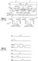
- FIG. 2 Athe exposure for each of the rows “a” though “n” is diagrammatically represented by the bars 4 a . . . 4 n (generally 4 ).
- the horizontal extent 8 of each baris intended to correspond to the exposure period for a particular row.
- the horizontal displacement of each bar 4is suggestive of the shifting time period during which each row of pixels is exposed.
- the exposure period for sequential rowsoverlap.
- the second 12 and third 16 lines of the timing diagramrepresent the reset timing signal and the read out timing signal, respectively, for row “a.”
- the fourth 20 and fifth 24 linesrepresent the reset and the read out timing signals, respectively for row “b.”
- the exposure for row “b”is initiated before the values for row “a” are read out.
- the exposure periods for adjacent rows of pixelstypically overlap substantially as several hundred rows of pixels must be exposed and read during the capture of a frame of data.
- the rolling shutter architecture with its overlapping exposure periodsrequires that the illumination source remain on during substantially all of the time required to capture a frame of data so that illumination is provided for all of the rows.
- the rolling shutter architecturesuffers from at least two disadvantages: image distortion and image blur.
- Image distortionis an artifact of the different times at which each row of pixels is exposed.
- the effect of image distortionis most pronounced when fast moving objects are visually recorded.
- FIG. 3shows a representation of an image taken with a rolling shutter of a bus image pixels 50 passing through the field of view from right to left.
- the top row of bus image pixels 54 of the buswas taken earlier than the bottom row of pixels 58 , and as the bus was traveling to the left, the bottom row of bus image pixels 58 is displaced to the left relative to the top row of bus image pixels 54 .
- Image bluris an artifact of the long exposure periods typically required in a rolling shutter architecture in an image reader.
- the illumination sourcemust remain on during substantially all of the time required to capture a frame of data. Due to battery and/or illumination source limitations, the light provided during the capture of an entire frame of data is usually not adequate for short exposure times. Without a short exposure time, blur inducing effects become pronounced. Common examples of blur inducing effects include the displacement of an image sensor due to, for example, hand shake with a hand held image reader.
- the inventionfeatures a complementary metal oxide semiconductor (CMOS) based image reader for collecting image data from a target.
- CMOS based imager readercomprises a CMOS based image sensor array; a timing module in electrical communication with the CMOS based image sensor array.
- the timing moduleis capable of simultaneously exposing an entire frame of pixels of the CMOS based image sensor array during an exposure period.
- the CMOS based image readeralso comprises an illumination module capable of illuminating the target during an illumination period.
- the illumination moduleis in electrical communication with the timing module.
- the CMOS based image readerfurther comprises a control module in electrical communication with the timing module and the illumination module. The control module is capable of causing at least a portion of the exposure period to occur during the illumination period.
- illuminating the targetcomprises overdriving light sources in the illumination module.
- the light sourcescomprise light emitting diodes.
- the exposure periodstarts after the start of the illumination period and the exposure period ends before the end of the illumination period.
- the illumination periodstarts after the start of the exposure period and the illumination period ends before the end of the exposure period.
- the illumination periodstarts before the start of the exposure period and the illumination period ends before the end of the exposure period.
- the exposure periodhas a duration of less than 3.7 milliseconds.
- the targetincludes a symbology such as a one-dimensional bar code such as a Code 39 or a UPC code or a two-dimensional bar code such as a PDF417 bar code, an Aztec symbol or Datamatrix symbol.
- the inventionfeatures a complementary metal oxide semiconductor (CMOS) based image reader for collecting image data from a target.
- CMOS based imager readercomprises an integrated circuit including at least a CMOS based image sensor array and global electronic shutter control circuitry.
- the global electronic shutter control circuitryis capable of generating an exposure control timing pulse that is capable of causing the simultaneous exposure of substantially all of an entire frame of pixels of the CMOS based image sensor array.
- the CMOS based image readeralso comprises light sources in electrical communication with the integrated circuit. The light sources are capable of illuminating the target including the symbology in response to an illumination control timing pulse. At least a portion of the illumination control timing pulse occurs during the exposure control timing pulse.
- illuminating the targetcomprises overdriving light sources.
- the light sourcescomprise light emitting diodes.
- the exposure periodstarts after the start of the illumination period and the exposure period ends before the end of the illumination period.
- the illumination periodstarts after the start of the exposure period and the illumination period ends before the end of the exposure period.
- the illumination periodstarts before the start of the exposure period and the illumination period ends before the end of the exposure period.
- the exposure periodhas a duration of less than 3.7 milliseconds.
- the targetincludes a symbology such as a one-dimensional bar code such as a Code 39 or a UPC code or a two-dimensional bar code such as a PDF417 bar code, an Aztec symbol or Datamatrix symbol.
- the inventionfeatures an image reader for collecting image data from a target.
- the imager readercomprises an integrated circuit including at least an image sensor array and exposure timing control circuitry.
- the exposure timing control circuitryis capable of generating an exposure control timing pulse that is capable of simultaneously exposing substantially all of the pixels in the image sensor array.
- the image readeralso comprises an illumination module in electrical communication with the integrated circuit.
- the illumination modulecomprises light sources that are capable of illuminating the target in response to an illumination control timing pulse. At least a portion of the illumination control timing pulse occurs during the exposure control timing pulse.
- the illumination control timing pulseis generated by an illumination module.
- the overlap between the illumination control timing pulse and the exposure control timing pulseis coordinated by a control module that is in electrical communication with the integrated circuit and the illumination module.
- the control modulecomprises a microprocessor.
- illuminating the targetcomprises overdriving light sources.
- the light sourcescomprise light emitting diodes.
- the exposure periodstarts after the start of the illumination period and the exposure period ends before the end of the illumination period.
- the illumination periodstarts after the start of the exposure period and the illumination period ends before the end of the exposure period.
- the illumination periodstarts before the start of the exposure period and the illumination period ends before the end of the exposure period.
- the exposure periodhas a duration of less than 3.7 milliseconds.
- the targetincludes a symbology such as a one-dimensional bar code such as a Code 39 or a UPC code or a two-dimensional bar code such as a PDF417 bar code, an Aztec symbol or Datamatrix symbol.
- the inventionfeatures a method for collecting image data from a target.
- the methodcomprises activating light sources to illuminate the target in response to an illumination control timing pulse.
- the activation of the light sourcesoccurs for the duration of the illumination control timing pulse.
- the methodalso comprises simultaneously activating a plurality of pixels to photoconvert incident radiation.
- the activation of the plurality of pixelsoccurs in response to an exposure control timing pulse.
- the methodadditionally comprises storing image data collected by each of the plurality of pixels in a shielded portion of each of the plurality of pixels.
- the storing of the image dataoccurs in response to the exposure control timing pulse.
- the methodfurther comprises reading out image data from the plurality of pixels wherein at least a portion of the exposure control timing pulse occurs during the illumination control timing pulse.
- the methodfurther comprises coordinating the overlap between the illumination control timing pulse and the exposure control timing pulse.
- the coordinationis directed by a control module.
- the control modulecomprises a microprocessor.
- illuminating the targetcomprises overdriving light sources in an illumination module.
- the light sourcescomprise light emitting diodes.
- the storing of image dataoccurs in response to a stop portion of the exposure control timing pulse.
- the exposure periodstarts after the start of the illumination period and the exposure period ends before the end of the illumination period.
- the illumination periodstarts after the start of the exposure period and the illumination period ends before the end of the exposure period.
- the illumination periodstarts before the start of the exposure period and the illumination period ends before the end of the exposure period.
- the exposure periodhas a duration of less than 3.7 milliseconds.
- the targetincludes a symbology such as a one-dimensional bar code such as a Code 39 or a UPC code or a two-dimensional bar code such as a PDF417 bar code, an Aztec symbol or Datamatrix symbol.
- the inventionfeatures a bar code image reader for collecting and processing bar code data from a bar code symbol.
- the image readercomprises a two-dimensional array of pixels for receiving light radiation reflected from the bar code symbol, the two-dimensional array of pixels comprising a first plurality of pixels and a second plurality of pixels, the two-dimensional array capable of reading out the first plurality of pixels independently of reading out the second plurality, each of the pixels comprising a photosensitive region and an opaque shielded data storage region.
- the image readeralso comprising an optics assembly for directing light radiation reflected from the bar code symbol onto the two-dimensional array of pixels.
- the image readerfurther comprising a global electronic shutter associated with the two-dimensional array of pixels, the global electronic shutter capable of simultaneously exposing substantially all of the pixels in the two-dimensional array.
- the image readeradditionally comprising a processor module, the processor module in electronic communication with the two-dimensional array of pixels, the processor module capable of processing image data from the two-dimensional array of pixels to generate decoded bar code data.
- the two-dimensional image sensor arrayis a complementary metal oxide (CMOS) image sensor.
- CMOScomplementary metal oxide
- processing the image data to generate output datacomprises automatically discriminating between a plurality of bar code types.
- the inventionfeatures a complementary metal oxide semiconductor (CMOS) based image reader for collecting image data from a target.
- CMOS based imager readercomprises a CMOS based image sensor array, the CMOS based image sensor array comprising a first plurality of pixels and a second plurality of pixels, the CMOS based image sensor array capable of reading out the first plurality of pixels independently of reading out the second plurality, each of the pixels of the CMOS based image sensor array comprising a photosensitive region and an opaque shielded data storage region.
- CMOScomplementary metal oxide semiconductor
- the CMOS based image readeralso comprising a timing module in electrical communication with the CMOS based image sensor array, the timing module configured to simultaneously expose an entire frame of pixels of the CMOS based image sensor array during an exposure period.
- the CMOS based image sensor arrayfurther comprising an illumination module configured to illuminate the target during an illumination period, the illumination module in electrical communication with the timing module.
- the CMOS based image sensor arrayadditionally comprising a control module in electrical communication with the timing module and the illumination module, the control module configured to cause at least a portion of the exposure period to occur during the illumination period.
- the inventionfeatures a complementary metal oxide semiconductor (CMOS) based image reader for collecting image data from a target.
- CMOScomplementary metal oxide semiconductor
- the CMOS based imager readercomprising an integrated circuit including at least a CMOS based image sensor array, the CMOS based image sensor array comprising a first plurality of pixels and a second plurality of pixels, the CMOS based image sensor array capable of reading out the first plurality of pixels independently of reading out the second plurality, each of the pixels of the CMOS based image sensor array comprising a photosensitive region and an opaque shielded data storage region.
- the CMOS based image sensor arrayalso comprising a global electronic shutter control circuitry, the global electronic shutter control circuitry configured to generate an exposure control timing pulse that is capable of causing the simultaneous exposure of substantially all of an entire frame of pixels of the CMOS based image sensor array.
- the CMOS based image sensor arrayfurther comprising light sources configured to illuminate the target in response to an illumination control timing pulse, the light sources in electrical communication with the integrated circuit.
- at least a portion of the illumination control timing pulseoverlaps with at least a portion of the exposure control timing pulse.
- illuminating the targetcomprises overdriving light sources in the illumination module.
- the light sourcescomprise light emitting diodes.
- the exposure control timing pulsehas a shorter duration than the illumination control timing pulse.
- the illumination control timing pulsehas a shorter duration than the exposure control timing pulse.
- the illumination control timing pulsestarts before the start of the exposure control timing pulse and the illumination control timing pulse ends before the end of the exposure control timing pulse.
- the exposure control timing pulsehas a duration of less than 3.7 milliseconds.
- the targetincludes a symbology.
- the symbologyis a one-dimensional bar code.
- the symbologyis a two-dimensional bar code.
- the two-dimensional bar codeis a PDF417 bar code.
- the inventionfeatures a bar code image reader for collecting image data from a bar code.
- the imager readercomprises an integrated circuit including at least a two-dimensional image sensor array, the two-dimensional image sensor array including a plurality of active pixels, each active pixel including at least a shielded data storage area, the two-dimensional image sensor array capable of employing a transfer function to convert an incident light intensity into an output voltage, the transfer function having a first region with a first slope and a second region with a second slope, the two-dimensional image sensor array capable of employing the second region of the transfer function when the incident light intensity is above a specified level and the two-dimensional image sensor array capable of employing the first region of the transfer function when the incident intensity is below a specified level.
- the bar code image readeralso comprises an exposure timing control circuitry, the exposure timing control circuitry configured to generate an exposure control timing pulse that is capable of simultaneously exposing all or substantially all of the pixels in the image sensor array to photoconvert incident radiation.
- the exposure control timing pulsehas a duration of less than 3.7 milliseconds.
- a dynamic range of the two-dimensional image array sensoris greater than 65 decibels.
- the inventionfeatures a method for automatically focusing an image reader.
- the methodcomprises directing with an optical system light energy reflected from a target onto an image sensor.
- the methodalso comprises exposing sequentially a plurality of rows of pixels in the image sensor during a frame exposure period, the frame exposure period being defined as a time duration extending from the beginning of the exposure of the first of the plurality of rows to the end of the exposure of the last of the plurality of rows.
- the methodfurther comprising varying in incremental steps an optical system from a first setting where a distinct image of objects located at a first distance from the image reader is formed on the image sensor to a second setting where a distinct image of objects located at a second distance from the image reader is formed on the image sensor.
- the methodadditionally comprising reading out a plurality of rows of image data from the plurality of rows of pixels in the image sensor, wherein the varying in incremental steps the optical system occurs during at least a portion of the frame exposure period.
- the methodfurther comprises analyzing the plurality of rows of image data to determine a proper setting for the optical system corresponding to a distinct image of the target being formed on the image sensor.
- the methodalso comprises simultaneously exposing the plurality of rows in the image sensor to generate an image of the target.
- the exposure period for adjacent lines of pixels in image readeroverlap.
- the targetincludes a symbology.
- the symbologyis a one-dimensional bar code.
- the symbologyis a two-dimensional bar code.
- the inventionfeatures an image reader with an automatic focusing capability.
- the imager readercomprising an integrated circuit including at least an image sensor array.
- the image readeralso comprising an optical system capable of directing light reflected from a target onto the image sensor array, the optical system having a plurality of focus settings, a first focus setting corresponding to distinct images of objects located at a first distance from the image reader being formed on the image sensor array and a second focus setting corresponding to distinct images of objects located at a second distance from the image reader being formed on the image sensor array.
- the image readerfurther comprising a rolling shutter control module configured to sequentially expose a plurality of rows of pixels in the image sensor array to collect focusing image data.
- the imager readeradditionally comprising an automatic focusing module configured to analyze the focusing image data to determine a focus setting for the target corresponding to a distinct image of the target being formed on the image sensor, wherein the optical system is capable of being varied in incremental steps from the first focus setting to the second focus setting during at least a portion of a time period during which the rolling shutter control module is sequentially exposing the plurality of rows of pixels.
- the imager readerfurther comprises a global electronic shutter control module configured to simultaneously expose the plurality of lines of pixels in the image sensor array to collect a frame of image data once the focus setting for the target has been determined.
- the rolling shutter control module and the global electronic shutter control moduleare integrated on the same integrated circuit containing the image sensor array.
- the rolling shutter control module and the global electronic shutter control moduleare combined in a single image array control module.
- the rolling shutter control moduleis capable of causing exposure periods for adjacent rows of pixels to overlap.
- the inventionfeatures an image reader for minimizing ambient light image degradation.
- the image readercomprises an integrated circuit including at least an image sensor array, the image sensor array providing a signal suitable for light intensity determination.
- the image readeralso comprises a rolling shutter control module configured to sequentially expose a plurality line of pixels in the image sensor array.
- the image readerfurther comprises a global electronic shutter control module configured to simultaneously expose the plurality of lines of pixels in the image sensor array, wherein one of the rolling shutter control module and the global electronic shutter control module is capable of being selected to control the image sensor array in response to the signal suitable for light intensity determination.
- the signal suitable for light intensity determinationincludes information related to an intensity of a light source of the image reader.
- the signal suitable for light intensity determinationis useful for determining whether a minimum integration time is satisfied. In a further embodiment of the image reader, the signal suitable for light intensity determination is useful for determining whether the exposure time (also known as the integration time) for the current environmental condition is less than a calculated minimum integration time. In yet another embodiment of the image reader, the rolling shutter control module and the global electronic shutter control module are integrated on the same integrated circuit containing the image sensor array.
- the inventionfeatures a method for minimizing image data degradation collected by an image reader.
- the methodcomprises determining at least one parameter related to an ambient light intensity and analyzing the at least one parameter.
- the methodalso comprises switching control of an image sensor array in the image reader from a global electronic shutter control module to a rolling shutter control module in response to the analysis of the at least one parameter.
- the at least one parameterincludes an exposure time for current environmental conditions.
- the analyzing the at least one parameterincludes calculating a ratio of the exposure time for current environmental conditions to a predetermined exposure time.
- the predetermined exposure timeis based on illumination supplied by light sources of the image reader.
- analyzing the at least one parameterincludes determining whether a ratio of the ambient light intensity to an intensity of a light source of the image reader exceeds a specified threshold.
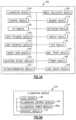
- FIG. 1 Ais a block diagram of one embodiment of an image reader constructed in accordance with the principles of the invention
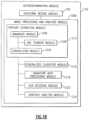
- FIG. 1 Bis a schematic block diagram of an autodiscrimination module which may be utilized with the invention.
- FIG. 1 Cis a process for practicing principles of the invention including automatically discriminating between different dataform types
- FIG. 2 Aillustrates the operation of an image sensor employing a rolling shutter architecture according to the prior art
- FIG. 2 Bis a timing diagram used in the prior art rolling shutter architecture presented with respect to FIG. 2 A ;
- FIG. 3is a representation of an image taken by a prior art image sensor
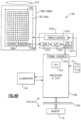
- FIG. 4 Ais a block electrical diagram corresponding to a specific embodiment of the invention.
- FIG. 4 Bis a block electrical diagram corresponding to another specific embodiment of the invention.
- FIG. 5 Ais a block diagram of one embodiment of an illumination module in an image reader constructed in accordance with the principles of the invention
- FIG. 5 Bis a block diagram of one embodiment of an image collection module in an image reader constructed in accordance with the principles of the invention.
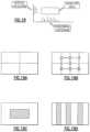
- FIG. 6is a perspective drawing of one embodiment of a hand held image reader constructed in accordance with the principles of the invention.
- FIG. 7is a schematic block diagram of one embodiment of an image reader constructed in accordance with the principles of the invention.
- FIG. 8 Ais a schematic diagram of a portion of one embodiment of an image sensor array from the prior art that can be employed in one embodiment of the image reader of FIG. 7 ;
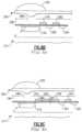
- FIGS. 8 B and 8 Care cross-sectional details of pixel architectures from the prior art that can be employed in one embodiment of the image reader of FIG. 7 ;
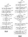
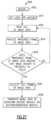
- FIG. 9is a flow chart illustrating one embodiment of a process for collecting image data according to the principles of the invention.
- FIGS. 10 A, 10 B, 10 C, and 10 Dare timing diagrams for various embodiments of the process of FIG. 9 ;
- FIG. 10 Eillustrates an illumination control timing pulse including a plurality of individual pulses
- FIG. 11is a schematic diagram of a portion of an image sensor according to the prior art.
- FIG. 12is a timing diagram for the prior art image sensor of FIG. 11 ;
- FIG. 13is a flow chart illustrating one embodiment of a process for automatic focusing according to the principles of the invention.
- FIG. 14is a flow chart illustrating one embodiment of a process for changing operational modes according to the principles of the invention.
- FIGS. 15 A, 15 B, and 15 Care various views of one embodiment of portable data terminal image reader constructed in accordance with the principles of the invention.
- FIG. 16is an electrical block diagram of one embodiment of the portable data terminal image reader of FIGS. 15 A, 15 B, and 15 C ;
- FIG. 17 Ashows one embodiment of a plurality of curvelent detector maps which may be utilized with the invention
- FIG. 17 Bshows another embodiment of a plurality of curvelent detector maps which may be utilized with the invention.
- FIG. 18is a diagrammatic representation of a histogram analysis which may be performed in one embodiment of the invention.
- FIGS. 19 A- 19 Dare diagrammatic representations of an image data segmentation process according to embodiments of the invention.
- FIG. 20is a schematic block diagram of one embodiment of a lens driver constructed in accordance with the principles of the invention.
- FIGS. 21 , 22 A and 22 Bare diagram illustrations of a focus level detection process according to an embodiment of the invention.
- FIGS. 23 , 24 , 25 , 26 and 27are flow diagrams illustrating various focusing processes which may be practiced according to the invention.
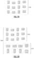
- FIGS. 28 A, 28 B and 28 Care representations of image sensor pixel array, wherein shaded regions indicate groups of positionally contiguous pixels that may be selectively addressed and read out when the image sensor array is operated in a windowed frame operating mode;
- FIGS. 29 , 30 A and 30 Bare diagrams illustrating a focus level detection process which may be utilized in an embodiment of the invention.
- FIGS. 31 and 32are flow diagrams illustrating additional processes which may be practiced in accordance with the invention.
- FIG. 33is an exploded assembly view of an imaging module according to the invention.
- FIG. 34is a front view of the imaging module shown in FIG. 33 ;
- FIG. 35is a side view of an assembled imaging module as shown in FIG. 33 ;
- FIG. 36is a view of a substrate bearing a bar code symbol and having projected thereon an illumination pattern and an aiming pattern and having delineated thereon a full frame field of view of an image reader according to the invention that projects the illumination pattern and the aiming pattern;
- FIG. 37is a chart describing various embodiments of the invention having LEDs which emit light in different wavelength bands.
- the inventionfeatures an image reader and a corresponding method for capturing a sharp non-distorted image of a target.
- the image readercomprises a two-dimensional CMOS based image sensor array, a timing module, an illumination module, and a control module all in electrical communication with each other.
- the illumination moduleshines light on the target, such as a symbology such as one or two-dimensional bar code, so that reflected light that can be collected and processed by the image sensor array.
- the time during which the target is illuminatedis referred to as the illumination period.
- the capture of the image by the image sensor arrayis driven by the timing module that, in one embodiment, is able to simultaneously expose all or substantially all of the pixels in the array.
- the simultaneous exposure of the pixels in the sensor arrayenables the image reader to capture a distortion free image.
- the time during which the pixels are collectively activated to photo-convert incident light into chargedefines the exposure period for the sensor array.
- the collected chargeis transferred to a shielded storage area until the data is read out.
- the exposure period and the illumination periodare under the control of the control module.
- the control modulecauses at least a portion of the exposure period to occur during the illumination period.
- the general image readerincludes one or more of: an illumination module 104 , an image collection module 108 , a control module 112 , a memory module 116 , an I/O module 120 , an actuation module 124 , a user feedback module 128 , a display module 132 , a user interface module 134 , a radio frequency identification (RFID) module 136 , a smart card module 140 , magnetic stripe card module 144 , a decoder module 150 , an autodiscriminating module 152 , and/or one or more power modules 168 and a lens driver module 165 .
- RFIDradio frequency identification
- each of the modulesis in combination with one or more of the other modules.
- the image reader 100comprises a bar code image reader with a full frame electronic global shutter based image sensor that is capable of simultaneously exposing substantially all of the pixels in the image sensor.
- the image sensoris a CMOS based image sensor.
- the image sensoris a CCD based image sensor.
- Dataform decode module 150(which may be a bar code symbol dataform decode module) when receiving image data transferred by control module 112 may search the image data for markers, such as a quiet zone, indicative of the presence of a dataform, such as a one or two-dimensional bar code. If a potential dataform is located, the dataform decode module 150 applies one or more dataform decoding algorithms to the image data. If the decode attempt is successful, the image reader outputs decoded dataform data through I/O module 120 and signals a successful read with an alert, such as a beep tone through user interface module 134 .
- markerssuch as a quiet zone
- a dataform decode module 150applies one or more dataform decoding algorithms to the image data. If the decode attempt is successful, the image reader outputs decoded dataform data through I/O module 120 and signals a successful read with an alert, such as a beep tone through user interface module 134 .
- Image reader 100may also include an autodiscriminating module 152 .
- autodiscriminating module 152may incorporate a dataform decode module 150 and an image processing and analysis module 1208 , that are in communication with one another.
- the image processing and analysis module 1208comprises a feature extraction module 1212 , a generalized classifier module 1216 , a signature data processing module 1218 , an OCR decode module 1222 , and a graphics analysis module 1224 that are in communication with each other.
- the feature extraction module 1212comprises a binarizer module 1226 , a line thinning module 1228 , and a convolution module 1230 that are in communication with each other.
- FIG. 1 Cshows a process 1300 for employing one embodiment of the invention utilizing the autodiscrimination module shown in FIG. 1 B .
- the process 1300comprises an image reader recording an actuation event (step 1302 ), such as a trigger pull as sensed by actuation module 124 , and in response collecting (step 1304 ) image data from a target with the image reader 100 .
- the collecting of image data stepmay be in accordance with e.g., process 300 , process 400 , (this process is used twice, see FIG. 13 and FIGS. 23 and 24 ), process 600 or process 800 .
- the image datais transferred (step 1308 ) to the dataform decode module 150 .
- the dataform decode modulesearches (step 1310 ) the image data for markers, such as a quiet zone, indicative of the presence of a dataform, such as a one or two-dimensional bar code. If a potential dataform is located, the dataform decode module 150 applies (step 1314 ) one or more dataform decoding algorithms to the ensuing image data. If the decode attempt is successful, the image reader 100 outputs (step 1318 ) decoded dataform data and signals (step 1322 ) a successful read with an alert, such as a beep tone.
- markerssuch as a quiet zone
- a dataform decode module 150applies (step 1314 ) one or more dataform decoding algorithms to the ensuing image data. If the decode attempt is successful, the image reader 100 outputs (step 1318 ) decoded dataform data and signals (step 1322 ) a successful read with an alert, such as a beep tone.
- the image datais transferred (step 1326 ) to the image processing and analysis module 1208 .
- the image datais processed in parallel with the attempt to decode the dataform data.
- the process that completes firsti.e., dataform decode attempt or the image processing
- outputs its datae.g., a decoded bar code or a captured signature
- the image datais processed in response to the decoding of the dataform.
- a bar codeencodes item information such as shipping label number and information indicating that a signature should be captured.
- the image datais processed by the feature extraction module 1212 .
- the feature extraction modulegenerates numeric outputs that are indicative of the texture of the image data.
- the texture of the image datarefers to the characteristics of the type of data contained in the image data.
- Common types of textureinclude one or two-dimensional bar code texture, signature texture, graphics texture, typed text texture, hand-written text texture, drawing or image texture, photograph texture, and the like.
- sub-categories of textureare sometime capable of being identified.
- the image datais processed (step 1328 ) by the binarizer module 1226 .
- the binarizer module 1226binarizes the grey level image into a binary image according to the local thresholding and target image size normalization.
- the image datais processed (step 1332 ) by the line thinning module 1228 to reduce multi-pixel thick line segments into single pixel thick lines.
- the image datais processed (step 1336 ) by the convolution module 1230 .
- the convolution module 1230convolves the processed image data with one or more detector maps designed according to the invention to identify various textural features in the image data.
- the convolution module 1230generates a pair of numbers, the mean and variance (or standard deviation), for each convolved detector map.
- FIG. 17 Ashows a set of 12 2 ⁇ 3 binary curvelet detector maps 1250 used to detect curved elements present in image data.
- the mean value and the variance generatedprovide an indication of the presence or density of elements in the binarized line thinned image data having similar shapes to the curvelet detector maps 1250 .
- the 12 curvelet detector maps 1250generate a total of 24 numbers. According to one embodiment, these 24 numbers are representative of the curved or signature texture of the processed image data.
- Further processing of the image dataincludes the outputs from the feature extraction module 1212 being fed (step 1340 ) into the generalized classified module 1216 .
- the generalized classifier module 1216uses the numbers generated by the feature extraction module as inputs to a neural network, a mean square error classifier or the like. These tools are used to classify the image data into general categories.
- different neural network configurationsare contemplated in accordance with the invention to achieve different operational optimizations and characteristics.
- the input layerhas 24 nodes for the 12 pairs of mean and variance outputs generated by a convolution module 1230 employing the 12 curvelet detector maps 1250 .
- a convolution module 1230employing the 12 curvelet detector maps 1250 .
- the 20 curvelet detector maps 1260 shown in FIG. 17 Bare used by the convolution module 1230 .
- the 20 curvelet detector maps 1260include the original 12 curvelet detector maps 1250 of FIG. 17 A .
- the additional 8 pixel maps 1260are used to provide orientation information regarding the signature.
- the input layerhas 40 nodes for the 20 pairs of mean and variance outputs generated by a convolution module 1230 employing the 20 curvelet detector maps 1260 .
- the neural network of this embodimentthere are two hidden layers of 40 nodes and 20 nodes respectively, one output node to report the positive or negative existence of a signature, and 8 output nodes to report the degree of orientation of the signature.
- the generalized classifier module 1216is capable of classifying data into an expanded collection of categories. For example in some embodiments, the generalized classifier module 1216 specifies whether the image data contains various data types such as a signature; a dataform; handwritten text; typed text; machine readable text; OCR data; graphics; pictures; images; forms such as shipping manifest, bill of lading, ID cards, and the like; fingerprints, biometrics such as fingerprints, facial images, retinal scans and the like, and/or other types of identifiers. In further additional embodiments, the generalized classifier module 1216 specifies whether the image data includes various combinations of these data types.
- the general classifier module 1216specifies whether the image data contains a specified type of data or not.
- the image processing and analysis module 1208is contained within an identification module that outputs an affirmative or negative response depending on the presence or absence of the specified data type, such as a signature or a biometric, in the image data.
- image datais transferred (step 1344 ) to the signature data processing module 1218 .
- the signature data processing module 1218is used to detect the boundaries of the signature in the image data.
- the signature boundaryis detected using a histogram analysis. As shown in FIG. 18 , a histogram analysis consists of a series of one-dimensional slices along horizontal and vertical directions defined relative to the orientation of the signature. In one embodiment, the value for each one-dimensional slice corresponds to the number of black (i.e., zero valued) pixels along that pixel slice.
- some specified region of the full frame of image datasuch as a central region is captured for signature analysis.
- the histogram analysisprovides a two-dimensional plot of the density of data element pixels in the image data. The boundary of the signature is determined with respect to a minimum density that must be achieved for a certain number of sequential slices.
- the histogram analysissearches inwardly along both horizontal and vertical directions until the pixel density rises above a predefined cutoff threshold. So that the signature data is not inadvertently cropped, it is common to use low cutoff threshold values.
- the signature data processing module 1218crops the image data and extracts the signature image data.
- the croppingis performed by an image modification module that generates modified image data in which a portion of the image data not including the signature has been deleted.
- various compression techniquesare employed to reduce the memory requirements for the signature image data.
- One such techniqueincludes the encoding of the signature image data by run length encoding. According to this technique, the length of each run of similar binarized values (i.e., the length of each run of 1 or 0) for each scan line is recorded as a means of reconstructing a bit map.
- Another encoding techniquetreats the signature image data as a data structure where the elements of the data structure consist of vectors.
- the signatureis broken down into a collection of vectors.
- the position of each vector in combination with the length and orientation of each vectoris used to reconstruct the original signature.
- the encoding processgenerates a new vector whenever the curvature for a continuous pixel run exceeds a specified value.
- a further compression techniqueemploys B-Spline curve fitting. This technique has the capacity to robustly accommodate curvature and scaling issues.
- the signature image data or a compressed or encoded version of the signature image datais stored locally on a dedicated memory device.
- the local memory devicecan be a detachable memory device such as a CompactFlash memory card or the like described in more detail below.
- the signature image datais stored in a volatile or non-volatile portion of general purpose memory and downloaded at a future time.
- the signature image datacan be transmitted via wired or wireless means either at the time of capture or at a later point, such as when a data collection session has been completed.
- the signature data processing module 218does not perform a histogram analysis but simply stores in memory the entire image or a compressed version once the presence of a signature has been determined.
- the initial image analysisis performed on a lower resolution image. Once the presence of a signature is determined in this embodiment, a higher resolution image is taken. In one embodiment, a signature extraction histogram analysis is performed on this image.
- the imageis stored in memory in either compressed or original format. In some embodiments, the image data is combined with other data to form a record for a particular item such as a package or shipping envelope.
- some of the additional data that can be collected by the image reader 100 and stored with or separate from the signature dataincludes but is not limited to dataform data, handwritten text data, typed text data, graphics data, image or picture data, and the like.
- the image processing and analysis module 1208can be designed to perform specialized tasks for different data types. For example, if the generalized classifier module 1216 determines that the image data contains typed or machine readable text, the image data can be collected, possibly histogram analyzed, and stored or alternatively the image data can be transferred to the OCR decoding module 1222 . Similarly, if the generalized classifier module 1216 determines that the image data includes a graphic element, the image data can be transferred to the graphics analysis module 1224 for processing.
- the graphics analysis module 1224is configured to recognize and decode predefined graphics. In one such embodiment, the graphics analysis can include determining which, if any, boxes have been selected in the billing and shipping instructions on a shipping label.
- the graphics analysiscan include locating and decoding the typed or handwritten text contained in the zip code box on a shipping label.
- the image reader 100can be configured to automatically attempt decode operations in addition to the dataform decode, such as OCR decoding or graphics decoding, prior to the activation of the feature extraction module 1212 .
- the image processing and analysis module 1208segments the image data into regions and performs a feature extraction and general classification analysis on each region.
- the standard rectangular image data windowis divided into four equal sized sub-rectangles.
- the segmentationconsists of overlapping regions so that the total area of the segmented regions is larger than that of the complete field of the image data.
- FIG. 8 Bthere are seven shown overlapping regions where each identifying numeral is shown in the center of its region.
- the segmentationconsists of sample regions (shown as cross-hatched) within the complete field of the image data.
- the sampled regionscan be based on a preloaded user template that, for example, identifies regions of interest such as a signature region and/or a bar code region, in for example, a shipping label.
- the segmentation processis used to identify the location of a signature in image data the might include additional elements such as dataforms including bar code dataforms, text, graphics, images and the like.
- the generalized classifier module 1216classifies the contents of each region of the segmented image data. The region containing the signature is then extracted by the signature data processing module 1218 .
- the signature data processing module 1218analyzes the arrangement of these regions to identify the region most likely to contain the image data.
- the image processing and analysis moduleestablishes a feedback loop where additional segmented regions are generated and analyzed until a single segmented region containing signature data is located.
- illumination module 104can include light sources 160 , an illumination control module 164 , an illumination power module 168 a , and an interface module 172 .
- the light sources 160can include white or colored LEDs, such as 660 nm illumination LEDs, infrared LED, ultra-violet LED, lasers, halogen lights, arc lamps, or incandescent lights, capable of producing adequate intensity light given image reader power constraints and image sensor exposure/sensitivity requirements.
- LEDsare chosen for the light source as their efficient operation enables relatively low power consumption.
- the illumination control module 164controls the operation of illumination module 104 and can include timing and light source activation and deactivation circuitry.
- the illumination power module 168 asupplies the energy necessary to drive the light sources 160 and can include batteries, capacitors, inductors, transformers, semiconductors, integrated circuits and the like. In an alternative embodiment, some or all of the elements of the illumination power module 168 a are located external to the illumination module.
- An image reader 100 with a single common power sourceis one such embodiment.
- the interface module 172is used for communication with the other modules of the image reader 100 such as those required to synchronize operations. This can include, for example, the coordination of the illumination and exposure periods discussed above.
- An image reader 100 of the inventionmay include an imaging module such as imaging module 1802 .
- Imaging module 1802 as shown in FIGS. 33 - 35incorporates certain features of an IT4000 imaging module as referenced herein and additional features.
- Imaging module 1802includes first circuit board 1804 carrying light sources 160 a , 160 b , while second circuit board 1806 carries light sources 160 c , 160 d , 160 e , 160 f , 160 g , 160 h , 160 i , 160 j , 160 k , 160 l , 160 m , 160 n , 1600 , 160 p , 160 q , 160 r , 160 s , and 160 t (hereinafter 160 c through 160 t ).
- First circuit board 1804also carries image sensor array 182 .
- Imaging module 1802also includes support assembly 1810 including lens holder 1812 , which holds lens barrel 1814 that carries imaging lens 212 .
- Light sources 160 a , 160 bare aiming illumination light sources whereas light sources 160 c through 160 t are illumination light sources.
- illumination light sources 160 c through 160 tproject a two-dimensional illumination pattern 1830 over a substrate, s, that carries a decodable indicia such as a bar code symbol 1835 whereas aiming illumination light sources 160 a , 160 b project an aiming pattern 1838 .
- a decodable indiciasuch as a bar code symbol 1835
- aiming illumination light sources 160 a , 160 bproject an aiming pattern 1838 .
- Illumination pattern 1830substantially corresponds to a full frame field of view of image reader 100 designated by box 1850 .
- Aiming pattern 1838is in the form of a line that extends horizontally across a center of field of view of image reader 100 .
- Illumination pattern 1830may be projected when all of illumination light sources 160 c through 160 t are operated simultaneously.
- Illumination pattern 1830may also be projected when a subset of light sources 160 c through 160 t are simultaneously energized. Illumination pattern 1830 may also be projected when only one of light sources 160 c through 160 t is energized such as LED 160 s or LED 160 t . LEDs 160 s and 160 t of imaging module 1802 have a wider projection angle than LEDs 160 c through 160 t.
- the image collection module 108in one embodiment includes an optics module 178 , a sensor array module 182 , and a sensor array control module 186 all in electrical communication with each other.
- the optics module 178includes an imaging lens or other optical elements used to direct and focus reflected radiation.
- the optics module 178includes associated circuitry and processing capacity that can be used, for example, as part of automatically determining the proper focus for an object, being imaged.
- the sensor array control module 186includes a global electronic shutter control module 190 , a row and column address and decode module 194 , and a read out module 198 , each of which modules is in electrical communication with one or more of the other modules in the sensor array control module 186 .
- the sensor array module 182includes components of an integrated circuit chip 1082 as shown in FIG. 4 A with a two-dimensional CMOS based image sensor array 182 .
- associated circuitrysuch as analog-to-digital converters and the like can be discrete from the image sensor array or integrated on the same chip as the image sensor array.
- the sensor array module 182can include a CCD sensor array capable of simultaneous exposure and storage of a full frame of image data.
- the global electronic shutter control module 190is capable of globally and simultaneously exposing all or substantially all of the pixels in the image sensor array.
- the global electronic shutter control module 190includes a timing module.
- the row and column address and decode module 194is used to select particular pixels for various operations such as collection activation, electronic shutter data storage and data read out.
- the read out module 198organizes and processes the reading out of data from the sensor array.
- the sensor array control module 186further includes a rolling shutter control module 202 that is capable of sequentially exposing and reading out the lines of pixels in the image sensor array.
- image reader 100A specific embodiment of image reader 100 is described with reference to FIG. 4 A .
- image sensor array 182 , 182 a having a two-dimensional array of pixels 250is incorporated onto CMOS integrated circuit (IC) chip 1082 , 1082 a .
- image sensor array 182 ais a CMOS image sensor array adapted to operate in a global shutter operating mode.
- Each pixel 250 of CMOS image sensor array 182 ahas an on-chip pixel amplifier 254 (shown in FIG. 8 A ) and an on-chip optically shielded storage area 286 (shown in FIG. 8 B and FIG. 8 C ).
- Image sensor array 182 amay also have a two-dimensional grid of electrical interconnects 262 as shown in FIG. 8 A that are in electrical communication with pixels 250 .
- Image sensor array 182 amay also have an on-chip row circuitry 296 and column circuitry 270 .
- Row circuitry 296 and the column circuitry 270may enable one or more various processing and operational tasks such as addressing pixels, decoding signals, amplification of signals, analog-to-digital signal conversion, applying timing, read out and reset signals and the like.
- CMOS image sensor IC chip 182 aincludes, on the same chip as pixels 250 row circuitry 296 , column circuitry 270 , processing and control circuitry 254 including pixel amplifiers 255 , optically shields storage area 258 , interconnects 262 , a gain circuit 1084 , an analog-to-digital conversion circuit 1086 and line driver circuit 1090 , which generates a multi-bit (e.g., 8 bit 10 bit) signal indicative of light incident on each pixel 250 of array, the output being presented on a set of output pins of chip 1082 a .
- a multi-bite.g. 8 bit 10 bit
- CMOS image sensor IC chip 1082 aincludes timing/control circuit 1092 which may include such components as a bias circuit, a clock/timing generation circuit, and an oscillator. Timing/control circuit 1092 may form part of sensor array control module 108 as described in connection with FIG. 5 B .
- image reader 100includes a main processor IC chip 548 , memory module 116 , illumination module 104 , and actuation module 124 .
- Main processor IC chip 548may be a multifunctional IC chip having an integrated frame grabber circuit 549 and central processing unit (CPU) 552 .
- Processor IC chip 548 with an integrated frame grabbermay be an e.g., an XSCALE PXA27X processor IC chip with “Quick Capture Camera Interface” available from INTEL.
- Image reader 100further includes actuation module 124 which generates a trigger signal that initiates a bar code decode process. Actuation module 124 may include a manually actuated trigger 216 .
- Image reader 100further includes imaging lens 212 and memory module 116 including such memory devices as a RAM, EPROM, flash memory.
- Memory module 116is in communication with processor IC chip 548 via a system bus 584 .
- Processor IC chip 548may be programmed or otherwise configured to carry out various functions required of modules 104 , 108 , 112 , 120 , 124 , 128 , 132 , 134 , 136 , 140 , 144 , 150 , 152 , 168 , 165 described with reference to FIG. 1 A .
- the functions of dataform decode module 150 and autodiscrimination module 152are carried by processor IC chip 548 operating in accordance with specific software stored in memory module 116 .
- the combination of processor IC chip 548 and memory module 116is, therefore, labeled 150 , 152 in the embodiment of FIG. 4 A .
- CCD image sensor IC chip 1082 bhas an area array of pixels 250 , a register 1094 and an output amplifier 1096 incorporated onto chip 1082 b .
- Output register 1094 and associated circuitrysequentially converts the charge associated with each pixel into a voltage and sends pixel image signals to a component external to chip 1082 b .
- charges on a first row of pixels 250are sequentially transferred to output register 1094 .
- Output register 1094sequentially feeds charges to amplifier 1096 which converts pixel charges into voltages and supplies signals to image processing circuitry 1070 .
- amplifier 1096which converts pixel charges into voltages and supplies signals to image processing circuitry 1070 .
- output register 1094receives charges from a second row of pixels. The process continues until image data corresponding to pixels from all of the rows of image sensor array 182 b are read out.
- Image reader 100further includes image signal processing circuit 1070 external to chip 1082 b .
- Image signal processing circuit 1070includes such elements as a gain circuit 1072 an analog-to-digital converter 1074 and a line driver 1076 .
- Timing and control circuit 1078 of circuit 1070may include such elements as a bias generator, an oscillator, a clock and timing generator.
- the gain circuit 1072may also implement additional functionality such as correlated double sampling to reduce to effects of pixel offsets and noise. Additional components of image reader 100 are as shown in FIG. 4 A .
- Image signal processing circuit 1070may be included in an integrated circuit chip (IC chip) external to image sensor IC chip 1082 b.
- components of image collection module 108 and illumination module 104are provided by any one of the IMAGETEAMTM area (2D) imaging engines, such as the 4000 OEM 2D Image Engine available from Hand Held Products, Inc. of 700 Visions Drive, P.O. Box 208, Skaneateles Falls, NY, constructed in accordance with the principles of the invention.
- 2DIMAGETEAMTM area
- the hand held image reader 100 aincludes a housing 208 , a plurality of light sources 160 , a lens 212 , a trigger 216 , and an interface cable 200 .
- the functionality of the image reader 100 acan be provided by any one of the area (2D) IMAGETEAMTM image readers such as the models 4410, 4600, or 4800 available from Hand Held Products, Inc. and constructed in accordance with the invention.
- All of the modules 104 , 108 , 112 , 116 , 120 , 124 , 128 , 132 , 134 , 136 , 140 , 144 , 150 , 152 , 165 , and 168 described in connection with FIG. 1 Amay be incorporated into, and may be supported by hand held housing 208 or alternative housing 506 shown in FIG. 15 A such that housing 208 or housing 506 encapsulate and support the various modules.
- all of the components shown in FIGS. 4 A and 4 B and FIG. 16may be incorporated into and may be supported by housing 208 or housing 506 such that housing 208 or housing 506 encapsulate and support the various components.
- Lens 212may comprise glass and/or polycarbonate.
- Lens 212may be a lens singlet or else comprise a plurality of lens components; that is, lens 212 may be a lens doublet or lens triplet, etc.
- the image reader 100includes the light sources 160 , an illumination control module 164 , a power module 168 b , and an interface module 172 all in electrical communication with each other.
- the light sources 160direct light energy 162 towards a target 166 including a symbology 170 .
- Reflected radiation 174 from the target 166is focused by a lens 212 onto an image sensor array 182 in electrical communication with a sensor array control module 186 and the power module 168 b .
- the image sensor array 182is a CMOS based image sensor array. In another embodiment, the image sensor array 182 is a CCD based image sensor array.
- the sensor array control module 186is further in electrical communication with a memory module 116 and a control module 112 also in electrical communication with the power module 168 b and the interface module 172 .
- an optical window(not shown) is placed on the front of the scanner to reduce the likelihood of damage to the unit.
- the image sensor array 182 aincludes a two-dimensional array of pixels 250 .
- Each pixelincludes a photosensitive sensitive region 252 , processing and control circuitry 254 including amplifier 255 and a shielded storage area 258 (for clarity of presentation, the reference numerals 252 , 254 , 255 , and 258 are provided only with respect to a single pixel).
- the presence of amplifier 255means that the CMOS image array 182 a is considered an active pixel array; that is, each pixel of the CMOS image array 182 a is able to amplify the signal generated from the photo-conversion of incident light energy.
- the charge-to-voltage conversion circuitryallows the CMOS image array 182 a to convert the collected charge into an output signal.
- the shielded storage area 258stores collected pixel values until read out so that additional incident radiation impinging on the CMOS image array 182 a does not corrupt the value read during the defined exposure period.
- the processing and control circuitry 254 for each pixel 250may include, among other elements, a reset and select transistor.
- the dynamic range of the CMOS based image sensor array 182 ais extended by providing additional intelligence in the processing and control circuitry 254 .
- the processing circuitryis augmented to include the capacity to dynamically change the conversion factor between the incident radiation input intensity and the output voltage. That is, the processing circuitry employs a transfer curve with multiple slopes.
- the particular form of the transfer curve with its multiple slopescan take various forms including a series of linear relations joined at knee points, a linear section at low intensity connected to a logarithmic transfer curve at higher intensity, or a completely continuous curve of arbitrary shape with steeper slopes for low intensity and higher slopes at greater intensities.
- the dynamic range of the CMOS based image sensor 182 ais significantly extended as each individual pixel is capable of independently employing a different section of the transfer curve depending on the intensity of radiation incident upon it.
- regions of the CMOS based image sensor 182 a that are receiving less incident radiationemploy a steeper conversion slope corresponding to greater sensitivity and regions that are receiving more incident radiation employ a shallower conversion slope corresponding to less sensitivity.
- the CMOS based image sensor 182 acan achieve a dynamic range of 65 to 120 dB.
- CMOS based image sensor array 182 amay be operated to selectively address and read out data from individual pixels in an X-Y coordinate system.
- CMOS based image sensor array 182 amay also be operated by way of appropriate programming of image reader 100 , to selectively address and read out a portion of the full frame of pixels.
- the portion of pixels read outcan exclude undesired pixels external to a desired pixel region.
- the portion of pixels readcan also represent a sampling of pixels in a region so that individual pixels, rows of pixels, or columns of pixels in the region of interest are not read out. Further details of image reader 100 operating in a windowed frame operating mode in which image reader 100 selectively addresses and reads out image data from less than all pixels of image sensor array 182 is described in connection with FIGS. 28 A, 28 B, and 28 C .
- image reader 100can be programmed or otherwise configured to selectively address and read out from CMOS based image sensor array 182 a image data from a first plurality of pixels in the array independently of selectively addressing and reading out a second plurality of pixels in the array.
- the pixel architecturecan be as described in U.S. Pat. No. 5,986,297 assigned to Eastman Kodak Company and entitled “Color Active Pixel Sensor with Electronic Shuttering, Anti-blooming and Low Cross-talk.”
- the patentdescribes the cross sections of the relevant regions of the pixel architectures shown in the patent's FIGS. 1A and 2A (herein reproduced as FIGS. 8 B and 8 C ).
- the disclosurestates that the pixel in FIG. 8 B comprises a photodiode 270 with a vertical overflow drain 274 , transfer gate 276 , floating diffusion 280 , reset gate 282 , reset drain 284 , and a light shield 286 .
- FIG. 8 Cshows a second pixel architecture that is similar in many respects to the embodiment shown in FIG. 8 B except that there are two transfer gates 294 , 296 , and a storage region 298 .
- the light shieldis constructed by effectively covering all regions except the photodetectors (photodiode 270 in this case), with an opaque layer or overlapping layers, so that incident light falls only on the photodiode area. Creation of an aperture in a light shield that limits the creation of photoelectrons to the photodetector region suppresses cross-talk between pixels.
- the floating diffusionis labeled 281
- the reset gateis labeled 283
- the reset drainis labeled 285 .
- the color filter 290may be omitted, and in other embodiments the microlens 292 may be omitted.
- a process 300 for collecting image data from a target with the image reader 100is presented with respect to FIGS. 9 , 10 A, 10 B, 10 C and 10 D .
- the targetcan contain a symbology such as a one or two-dimensional bar code.
- actuation module 124initiates process 300 in response e.g., to trigger 216 being depressed or to a sensing of a presence of an object in a field of view of image reader 100 .
- control module 112may receive a trigger signal in response to a depressing of trigger 216 or the sensing of an object and responsively present a series of control signals to various modules, e.g., illumination module 104 and image collection module 108 in accordance with process 300 .
- the process 300includes activating (step 304 ) an illumination source to illuminate the target with illumination light 162 .
- the activation of the illumination sourceoccurs in response to an illumination control timing pulse 350 .
- the illumination of the target by the activated illumination sourceoccurs for the duration of the illumination control timing pulse 350 .
- the illumination sourceis the light source 160 and the illumination control timing pulse 350 is generated by the illumination control module 164 in the illumination module 104 .
- the process 300also includes activating the global electronic shutter to simultaneously expose (step 312 ) a plurality of pixels in a plurality of rows in an image sensor array to photoconvert incident radiation into electric charge.
- the simultaneous activation of the plurality of pixelsoccurs in response to an exposure control timing pulse 354 .
- the simultaneous activation of the plurality of pixelsoccurs in response to a start portion 360 of the exposure control timing pulse 354 .
- the exposure control timing pulse 354is generated by the global electronic shutter control module 190 ( FIG. 5 B ) of the sensor array control module 186 .
- the targetis illuminated by overdriving the illumination sources, such as LEDs, to generate illumination several times brighter than standard operation.
- illumination sourcessuch as LEDs
- LEDs 160 c through 160 teach may have a standard recommend maximum DC operation current draw rating of 40 mA (100% LED current) but may be overdriven to draw more than e.g., 60 mA (150% current), or 80 mA (200% current) throughout the duration of illumination timing pulse 350 , or any one of pulses 350 ′, 350 ′′, 350 ′′ described herein.
- LEDs 160 c through 160 tmay also be overdriven to draw more than e.g., 120 mA (300% current), 160 mA (400% current), 200 mA (500% current), or 500 mA (1,250% current) throughout the duration of timing pulse 350 or any one of pulses 350 ′, 350 ′′, 350 ′′ described herein.
- Illumination timing pulse 350 , 350 ′, 350 ′′, 350 ′are shown as DC drive current pulses. However, according to the invention as indicated by FIG.
- pulses 350 , 350 ′, 350 ′′, 350 ′′′can also be pulse modulated or “strobed” pulses such that each pulse 350 , 350 ′, 350 ′′, 350 ′′′ comprise a series of short duration individual pulses for driving LEDs 160 .
- Substituting a pulsed driving signal for a DC driving signalreduces the duty cycle of LEDs, and thus the power dissipated in the LEDs. Since in many cases the LED operating life is determined by the maximum junction temperature of the LED die, reduced power dissipation reduces the junction temperature. The net effect is that a higher peak current can be tolerated while not exceeding the maximum operating junction temperature limit for the LED die.
- the strobing rate of a “strobed” or “pulsed” illumination control pulses as described hereinmay be, e.g., 1,000 Hz to 10,000 Hz.
- the overdriven illumination sources in combination with the electronic global shutterallows for short exposure periods. That is, the bright illumination allows for a short integration time for each pixel and the global electronic shutter allows for all of the pixels in the image sensor to be simultaneously sensitive. With a short exposure period for a brightly illuminated target, an image reader of the present invention is able to collect a sharp non-distorted image even when the target is moving relative to the image reader. In one embodiment, the exposure period is less than 3.7 milliseconds.
- the light sourcesare overdriven
- light sources with different colorsare employed.
- the image readerincludes white and red LEDs, red and green LEDs, white, red, and green LEDs, or some other combination chosen in response to, for example, the color of the symbols most commonly imaged by the image reader.
- the different colored LEDsare each alternatively pulsed at a level in accordance with the overall power budget.
- both colored LEDsare pulsed each time but each at a relatively lower power level so that the overall power budget is again maintained.
- red, green, and blue LED'scan be interleaved to simulate white light.
- imaging module 1802 of image reader 100Various embodiments of imaging module 1802 of image reader 100 are described with reference to FIG. 37 .
- LEDs 160 of imaging module 1802may be divided into banks as indicated in the chart of FIG. 37 .
- Image reader 100can be configured so that LEDs of each bank emits light in a certain emission wavelength band.
- image reader 100is configured so that aiming LEDs 160 a , 160 b emit green light and all illumination LEDs 160 c through 160 t emit red light. Additional embodiments are described in the chart of FIG. 37 .
- Image reader 100can be configured so that the light sources for the various banks may be energized simultaneously (e.g., bank 1, bank 2, bank 3, bank 4 simultaneously energized) or sequentially (e.g., bank 1, then bank 2, then bank 3, then bank 4) by the illumination timing control pulse 350 , 350 ′, 350 ′′, 350 ′′.
- the light sources for the various banksmay be energized simultaneously (e.g., bank 1, bank 2, bank 3, bank 4 simultaneously energized) or sequentially (e.g., bank 1, then bank 2, then bank 3, then bank 4) by the illumination timing control pulse 350 , 350 ′, 350 ′′, 350 ′′.
- the process 300also includes processing (step 316 ) the photoconversion generated electric charge to produce image data.
- the processingcan include, for example, amplifying the data generated from the incident radiation.
- the processingfurther includes storing the generated image data values in a shielded portion of each of the plurality of pixels.
- the process 300additionally includes reading out and processing (step 320 ) the stored image data values from the plurality of pixels.
- the processingcan include amplifying the data generated from the incident radiation and converting the generated data into a digital signal.
- the processing (step 320 )can also include storing a set of digital signal values corresponding to incident light on the plurality of pixels of image sensor array module 182 as a frame of image data.
- Image reader 100 at step 320may store into memory module 116 a frame of image data including a plurality of N-bit (grey scale) pixel values, each pixel value representing light incident at one of the plurality of pixels.
- the reading out of the plurality of pixelsis controlled by a read out timing control pulse 368 generated by the read out module 198 of the sensor array control module 186 .
- the read out timing control pulse 368includes a plurality of pulses transmitted to each of the plurality of pixels.
- At least a portion of the illumination control timing pulse 350occurs during the exposure control timing pulse 354 .
- the operation of the image collection module 104 including the sensor array control module 186 with the global electronic shutter control module 190is coordinated with the operation of the illumination module 104 including the illumination control module 164 by the control module 112 to achieve the overlap in the illumination 350 and exposure 354 control timing signals.
- the exposure control timing pulse 354begins after and finishes before the illumination control timing pulse 350 .
- the read out control timing pulse 368begins at the conclusion of the illumination control timing pulse 350 .
- the illumination control timing pulse 350 ′begins after and finishes before the exposure control timing pulse 354 ′.
- the read out control timing pulse 368 ′begins at the conclusion of the exposure control timing pulse 354 ′.
- the exposure control timing pulse and the illumination control timing pulseoverlap each other while occurring sequentially. In one such embodiment as shown in FIG.
- this sequential operationcan include the illumination control timing pulse 350 ′′ starting, the exposure control timing pulse 354 ′′ starting, the illumination control timing signal pulse 350 ′′ ending, and then the exposure control timing pulse 354 ′′ ending.
- the read out control timing pulse 368 ′′begins at the conclusion of the exposure control timing pulse 354 ′′.
- the sequential operationcan include the exposure control timing pulse 354 ′′ starting, the illumination control timing pulse 350 ′′′ starting, the exposure control timing pulse 354 ′′ ending, and then the illumination control timing signal pulse 350 ′′ ending.
- the read out control timing pulse 368 ′′′begins at the conclusion of the illumination control timing signal pulse 350 ′′.
- each illumination control timing pulse 350 , 350 ′, 350 ′′, 350 ′′′ described hereinmay comprise a plurality of short duration individual pulses.
- an image reader 100 having imaging module 1802may have an operating mode in which aiming LEDs 160 a , 160 b are controlled to be off or de-energized during exposure control timing pulse 354 , 354 ′, 354 ′′, or 354 ′′′ so that light from LEDs 160 a , 160 b does not influence an image that is collected and transferred to decode module 150 or autodiscrimination module 152 .
- aiming illumination LEDs 160 a , 160 bin addition to illumination LEDs 160 c through 160 t , are controlled to be energized during exposure control timing pulse 354 , 354 ′, 354 ′′, or 354 ′′.
- image reader 100may be configured so that illumination control pulse 350 , 350 ′, 350 ′′, or 350 ′′′ at step 304 simultaneously energizes at least one of aiming LED 160 a or 160 b and at least one of illumination LEDs 160 c through 160 t so as to increase the intensity of illumination on substrate, s, and specifically the regions of substrate, s, onto which illumination pattern 1830 and aiming pattern 1838 are simultaneously projected.
- a decoding process carried out by decode module 150 or autodiscrimination module 152 where an image is collected pursuant to an exposure period wherein aiming LEDs 160 a , 160 b and illumination LEDs 160 c through 160 t are simultaneously energizedmay include a process wherein image data corresponding pattern 1838 (that is, image data corresponding to pixels of array onto which pattern 1838 is imaged) is selectively subjected to a decoding process such as a finder pattern locating process, a linear bar code symbol decode attempt or a quiet zone locating process.
- decode module 150 processing a collected full frame imagemay selectively analyze image data corresponding to center rows of image sensor 182 (i.e., image data corresponding to rows 2802 shown in FIG. 28 a ) for purposes of locating a finder pattern, decoding a linear bar code symbol, or locating a quiet zone where an image is collected pursuant to a frame exposure period wherein at least one aiming LED 160 a , 160 b and at least one illumination LED 160 c through 160 t are simultaneously energized.
- the aiming LEDs 160 a , 160 b and illumination LEDs 160 c through 160 tmay be overdriven throughout the duration of pulse 350 , 350 ′, 350 ′′, or 350 ′′′′ as has been described herein.
- the CMOS image array 182 acan be implemented with a KAC-0331 640 ⁇ 480 VGA CMOS image sensor available from the Eastman Kodak Company.
- the KAC-0311is more fully described in a technical description entitled, “KAC-0311 640 ⁇ 480 VGA CMOS IMAGE SENSOR Fully Integrated Timing, Analog Signal Processing & 10 bit ADC.” Revision 1 dated Aug. 5, 2002 and available at http://www.kodak.com/global/plugins/acrobat/en/digital/ccd/products/cmos/KAC-0311LongSpec.pdf, hereby incorporated by reference in its entirety.
- the KAC-0311is a solid state active CMOS imager that integrates analog image acquisition, digitization, and digital signal processing on a single chip.
- the image sensorcomprises a VGA format pixel array with 640 ⁇ 480 active elements.
- the image sizeis programmable by a user to define a window of interest.
- a usercan define a window of interest down to a resolution of 1 ⁇ 1 pixel.
- the windowcan be used to enable a digital zoom operation of a viewport that can be panned.
- a constant field of viewis maintained while subsampling is used to reduce the resolution the collected image.
- the analog video output of the pixel arrayis processed by an on-chip analog signal pipeline.
- correlated double samplingis used to eliminate pixel reset temporal and fixed pattern noise.
- a frame rate clampis used to enable contemporaneous optical black level calibration and offset correction.
- the programmable analog gain of the KAC-0311 image sensorincludes a global exposure gain to map the signal swing to the analog-to-digital converter input range. The programmable analog gain further includes white balance gain to perform color balance in the analog domain.
- the analog signal processing chain of the KAC-0311 image sensorconsists of column op-amp processing, column digital offset voltage adjustment, white balancing, programmable gain amplification, global programmable gain amplification, and global digital offset voltage adjustment.
- the digitally programmable amplifiersare used to provide contemporaneous color gain correction for auto white balance as well as exposure gain adjustment.
- the offset calibrationin various embodiments is done on a per column basis and globally.
- the per column offset correctioncan be applied by using stored values in the on-chip registers, and a ten-bit redundant signed digit analog-to-digital converter converts the analog data to a ten-bit digital word stream.
- the differential analog signal processing pipelineis used to improve noise immunity, the signal to noise ratio, and the system's dynamic range.
- the serial interface of the KAC-0311is an industry standard two line I′C compatible serial interface.
- power for the KAC-0311 image sensoris provided by a single 3.3V power supply.
- the KAC-0311 image sensorhas a single master clock and operates at speeds up to 20 MHz.
- Pixels in the same row of the disclosed image sensorshare a pixel output node and an output signal line. Further, the disclosure indicates that image signal separation within a row is achieved by having two separate row select signal lines per row, one for every other pixel within a row, and a 1:2 column output signal line de-multiplexing scheme for each pair of columns.
- a schematic diagram, here reproduced as FIG. 11shows two adjacent pixels 5 . Identifiers used in the schematic include the following: reset transistor with a reset gate (RG), transfer gate (TG), signal transistor (SIG), row select transistor with a row select gate (RSEL), photodetector (PD), and floating diffusion (FD). The operation of the global shutter is described at column 3 lines 25-45 of U.S. Pat. No.
- readoutcommences by transfer of the integrated signal charge from the photodetectors 30 a , 30 b to the floating diffusions 10 a , 10 b in each pixel of the sensor simultaneously.
- row select 1 ( 15 )is turned on and the signal level of floating diffusion 1 ( 10 a ) is sampled and held by the column circuit 20 a by pulsing SS 1 .
- Row select 1 ( 15 )is then turned off and row select 2 ( 25 ) is turned on and the signal level of floating diffusion 2 ( 10 b ) is sampled and held by the column circuit 20 b by pulsing SS 2 .
- the KAC-9630 image sensoras a low power CMOS active pixel image sensor capable of capturing monochrome images at 580 frames per second.
- the KAC-9630 image sensoris described as including an on-chip eight-bit analog-to-digital converter, fixed pattern noise elimination circuits and a video gain amplifier.
- the KAC-9630is further described as having integrated programmable timing and control circuitry that allows for the adjustment of integration time and frame rate.
- the read out circuit in the KAC-9630 image sensoris described as capable of supporting a full frame read out on a single eight-bit digital data bus in less than 2 milliseconds.
- the KAC-9630 image sensoris described as including an integrated electronic shutter.
- the CMOS image array 182 acan be implemented with a Micron image sensor such as the Wide VGA MT9V022 image sensor from Micron Technology, Inc., 8000 South Federal Way, Post Office Box 6, Boise, ID 83707-0006.
- the MT9V022 image sensoris describe in more detail in the product MT9V099 product flyer available from Micron Technology (www.micron.com), for example at http://download.micron.com/pdf/flyers/mt9v022_(mi-0350)_flyer.pdf. This document is hereby herein incorporated by reference in its entirety.
- the near point of the optical systemis the closest distance an object can be brought with respect to the optical system where the optical system is still able to create a distinct image of the object.
- the variation of in the focus of the optical systemdoes not cover the entire range of the optical system.
- a focus setting of image reader 100is varied between focus settings that are millimeters apart.
- a focus setting of image reader 100is varied between focus settings that are centimeters apart. Configuring reader 100 to include lens driver module 165 allows a scanner to operate over an extended depth of field.
- lens driver module 165With further reference to lens driver module 165 , various lens driving technologies and methods can be implemented.
- U.S. Pat. No. 4,350,4108incorporated by reference herein in its entirety, discloses a lens focus adjustment system including a distance adjusting ring, wherein position adjustment of a lens is achieved by rotation of the adjustment ring.
- 4,793,689also incorporated herein by reference in its entirety, discloses a lens barrel having a hollow rotary ring rotatable about an optical axis that is disposed within a hollow of a hollow fixed cylinder with a bearing interposed there between, a moving cylinder moveable in response to rotation of the rotary ring, and a vibration wave motor disposed between the diametrical directions of the fixed cylinder and the rotary ring.
- 5,541,777also incorporated herein by reference in its entirety, discloses an electromagnetic lens driver having a fixed member including an inside yoke and an outside yoke, an operationally disposed magnet, a moveable member for holding a body to be driven, a coil wound in an axial direction between the outside yoke and the inside yoke and position detector which detects the magnetic field of the operationally disposed magnet to generate a position indicating signal.
- the process 400also includes reading out (step 420 ) image data from the plurality of exposed rows.
- This image datais analyzed (step 424 ) by an automatic focusing algorithm, such as the contrast detection method or the phase detection method.
- the image reader 100uses the row focus image information to establishes (step 428 ) a proper focus setting of lens 212 e.g., by determining a proper focus setting based on collected data and then moving the lens 212 to that setting or by assessing the present row image data to determine whether at the present focus setting, the image reader is acceptably focused.
- the analysis of the image datacan be performed by the image collection module 108 , the optics module, the control module 112 , or a dedicated auto-focusing module (e.g., an ASIC or FPGA dedicated for purposes of performing focus calculations).
- the image reader 100enters (step 432 ) a global electronic shutter operational mode. It will be seen that in certain instances according to process 400 , image reader 100 may cease operation in a rolling shutter and commence operation in a global electronic shutter operational mode prior to reading out image data from each pixel of image sensor array module 182 .
- the image reader 100collects (step 436 ) a full frame of image data that is stored in memory module 116 and subsequently transferred to decode module 150 or autodiscriminating module 152 by control module 112 .
- control module 112In the global electronic shutter operational mode, the image reader 100 collects (step 436 ) a full frame of image data that is stored in memory module 116 and subsequently transferred to decode module 150 or autodiscriminating module 152 by control module 112 .
- automatically focusing the image reader to image the targetmay be achieved within one frame of data.
- the automatic focusing operationscan be handled by a dedicated automatic focusing module or the focusing module can be incorporated into other modules such as the image collection module 108 and/or the control module 112 .
- step 424 of analyzing row image data to determine focus characteristicsis further described with reference to the flow diagram of FIG. 21 , and the histogram plots of FIG. 22 a and FIG. 22 b .
- image reader 100may construct a histogram plot of pixel values of the present row of image data read out at step 420 .
- FIG. 22 Ais a histogram plot of pixel values of a row of data corresponding to a bi-tonal image (such as in a bar code symbol on a monochrome substrate) that is acceptably focused.
- Histogram plot 2108represents a high contrast image and includes numerous pixel values at the high end of the grey scale, numerous pixel values at the low end of the grey scale, and few pixel values at the center grey scale range.
- FIG. 22 Bis a histogram plot of pixel values of a row of data corresponding to a poorly focused bi-tonal image.
- the image data summarized by histogram 2110is “flatter” lower contrast image data, meaning that it has fewer pixel values at extremes of the grey scale and a larger number of pixel values at a center of the grey scale. Accordingly, it can be seen that a focus level of an image can readily be determined utilizing image contrast information.
- image reader 100assesses the collected histogram data.
- image reader 100may either determine an appropriate in-focus setting for lens 212 or else determine whether the histogram data extracted from the present row of image data indicates that the image reader is acceptably focused at the present lens setting or position.
- the histogram datamay be from the present row or based on a combination of present row data and preceding row data.
- position or setting values of lens 212are recorded so that the histogram information of each row of image data that is read out has associated lens position data indicating a position of lens 212 at the time at which the row information was collected.
- a transfer function for determining an in-focus lens settingmay utilize row contrast information as summarized in histogram plots, as well as lens position data indicating a position of lens 212 associated with each set of row data.
- image reader 100 at step 414may control lens 212 to be in either continuous motion or in stepwise continuous motion.
- lens 212moves continuously throughout a time that sequentive rows of pixels of image sensor array module 182 are exposed and read out.
- lens 212When controlled to be in stepwise continuous motion, lens 212 repeatedly moves and stops throughout the time that rows of pixels of sensor module 182 are exposed and read out.
- image reader 100continuously moves lens between two extreme points, a first, further field position and second, a nearer field position.
- image reader 100In another embodiment of an image reader 100 , controlling lens 212 to be in stepwise continuous motion, image reader 100 continuously moves lens 212 between two extreme positions and intermittently stops lens 212 at one or more positions between the extreme positions.
- a lens 212 controlled to be in stepwise continuous motioncan be considered to have motion periods, i.e., the times during which the lens moves, and stop periods, i.e., the times during which the lens is temporarily idle.
- the motion of the lens 212 and a reading out of image data from rows of pixelsare coordinated.
- image sensor array module 182can be coordinated such that an exposure period for one or more rows of image sensor array module 182 occurs during a stop period of lens 212 so that lens 212 is idle during an entire row exposure period.
- image reader 100can be configured so that image data corresponding to pixels exposed during motion periods of lens 212 are discarded, e.g., during row analysis step 424 .
- image reader 100 at step 424attempts to determine an in-focus lens setting based on collected row image data collected to that point. If at step 428 a , image reader 100 determines that enough information has been collected to determine an in-focus position of lens 212 , image reader 100 determines an in-focus setting for lens 212 and proceeds to step 428 b to move lens 212 to the determined in-focus position. If sufficient information has not been collected, image reader 100 returns to step 432 to collect additional row information.
- Image reader 100may continue to read and process row image data while moving lens 212 at step 428 b , e.g., for purposes of confirming that the determined in-focus position is correct.
- image reader 100proceeds to step 432 to enter a global electronic shutter operational mode of operation.
- image reader 100may halt the motion of lens 212 .
- the image readerthen proceeds to step 436 to collect a full frame of image data, and then to step 438 to transfer image data to one of the dataform decode module 150 or autodiscriminating module 152 .
- image reader 100establishes an in-focus setting of lens 212 by assessing at step 424 present row data (the most recent collected row data) to determine whether the present row data indicates that image reader 100 is presently in-focus. If image reader 100 at step 428 d determines that image reader 100 is presently not in focus, image reader 100 returns to step 420 to collect additional row information. If at step 420 image reader 100 determines that the reader is presently in an in-focus position, image reader 100 proceeds to step 432 to enter a global electronic shutter mode of operation. At the time that image reader 100 enters the global shutter operating mode, (step 432 ) image reader 100 may halt the motion of lens 212 . The image reader 100 then proceeds to step 436 to collect a full frame of image data, and then to step 438 to transfer image data to one of the dataform decode module 150 or autodiscriminating module 152 .
- image reader 100 in establishing an “in focus” positionmay designate a prospective or present position of lens 212 to be “in focus” on the basis of the prospective or present lens position rendering indicia in better focus that other available lens focus positions.
- reader 100may, nevertheless, designate the position as being “in focus” if it renders indicia more in focus than other available lens position.
- lens 100may be “toggled” between a limited number of discrete positions (e.g., two positions) when it is controlled to be in stepwise continuous motion.
- image reader 100may designate one of the limited number of possible discrete positions to be the “in focus” positions if the lens position renders indicia more in focus than the remaining possible positions.
- the focus determining stepsmay be omitted and the image data transferred directly to the decode module 150 or autodiscrimination module 152 .
- the in-focus positioncan readily be discriminated based on which position the results in a successful decode. Discriminating an in-focus position by way of decode attempts may reduce average decode time.
- image reader 100 at step 420reads out a predetermined number of rows of image data and analyzes the predetermined number of rows at step 424 .
- the predetermined number of rowsmay be e.g., 2 rows, 3 rows, 10 rows or all of the rows (100+) rows of image sensor array 182 .
- Image reader 100 at step 424may select the best focused (e.g., highest contrast) row out of the plurality of rows and determine that the recorded focus setting associated with the best focused row is the “in-focus” setting of image reader 100 .
- image reader 100may calculate-in-focus setting data utilizing data image collected over several rows.
- image reader 100may first enter global electronic shutter operational mode at step 432 , and then move lens 212 into the determined focus position setting or else image reader 100 may alternatively move lens 212 to the determined lens setting prior to entering the global electronic shutter operational mode at step 432 or these two operations may occur at the same time.
- the global electronic shutter operational modemay be used during both the focusing period and the data collection period.
- a limited, “windowed” frame of image datamay be collected for each variation in the focus setting or position. For example, only the central region, or a central group of scan lines-such as the middle ten scan lines, of the image sensor is read out and analyzed by the focus determination algorithm.
- the limited frame of dataprovides adequate information for the focus determination algorithm while significantly decreasing the time required to collect the series of frames required to focus the image reader.
- the specific order of the steps in the process 400 or process 800can be altered without departing from the inventive concepts contained therein.
- the circuitry implementing the rolling shutter operation and the circuitry implementing the global electronic shutter operationcan be implemented on the same CMOS chip or one or both of the circuitry components can be implemented on separate dedicated chips.
- the rolling shutter functionality and the global electronic shutter operationcan be combined in a single module that includes hardware, software, and/or firmware.
- the image reader 100is able to dynamically shift between the global electronic shutter operational mode and the rolling shutter operational mode.
- the image reader 100shifts from the default global electronic shutter operational mode to the rolling shutter operational mode when the integration time is shorter than a given threshold.
- Many commercially available imagersare implemented with light shields that allow some amount of light leakage into the storage element or with electronic switches that do not completely isolate the storage element from the photosensitive element. As a result of this, the contents of the storage element can be adversely influenced by the ambient illumination incident upon the imager after the charge has been transferred to the storage element. The following provides a numeric example of such operation.
- the shutter efficiency of a CMOS image sensor with global electronic shutter capabilitiesspecifies the extent to which the storage area on the image sensor is able to shield stored image data. For example, if a shutter has an efficiency of 99.9%, then it takes an integration time (also known as exposure time) that is 1,000 times longer to generate the same amount of charge in the shielded portion as in the unshielded portion of the image sensor.
- the following equationprovides an indication of the light irradiance on the imager from the ambient light that can be tolerated during the time period after the image is shifted into the storage region relative to the light irradiance on the imager from the object illuminated with the ambient illumination and the light sources 160 during the time period before the image is shifted into the storage region while not exceeding a desired degradation percentage.
- the equationcan also address the case where the light incident upon the imager is the same during the entire imaging cycle. In both instances, one needs to know the minimum integration that can be used without the introduction of a maximum degradation.
- the light on the imageris unchanged during the exposure period and during the remainder of the frame.
- the light irradiance on the imageris constant, and it is possible to solve for the minimum integration time that can be used without the light leakage excessively perturbing the desired image. Solving the equation in this case, allows the calculation of the minimum integration period for a specific degradation.
- the image reader 100shifts to rolling shutter operation when the integration time becomes shorter than a level determined with respect to the frame rate, maximum allowable degradation and shutter efficiency of the image reader.
- a process 600 for shifting operational modes in response to short integration timesis shown in FIG. 14 .
- Actuation module 124may generate a trigger signal to initiate process 600 in response to e.g., a depressing of a trigger 216 by operator or in response to an object being provided into a field of view of image reader 100 .
- the process 600includes storing (step 604 ) a calculated minimum integration time. In one embodiment, this threshold is determined in accordance with the equations presented above.
- the process 600also includes collecting (step 608 ) image data. As part of the collection of image data, an exposure time for the current environmental conditions is established (step 612 ) by the sensor array control module 186 . In various embodiments, this exposure time is established by the global electronic shutter control module 190 , the optics module 178 , or another appropriate module in the image reader 100 . To determine whether the operational mode of the image reader 100 should shift from global shutter to rolling shutter, the established exposure time is compared (step 616 ) with the minimum integration time threshold.
- the operational mode of the image reader 100is shifted (step 620 ) from global electronic shutter to rolling shutter. If the established integration time is greater than or equal to the calculated minimum integration time threshold, then the global electronic shutter operational mode (step 628 ) is maintained.
- image reader 100can be configured to have user selectable configuration settings.
- image reader 100may present on display 504 a graphical user interface (GUI) menu option display screen 3170 which presents to an operator the user selectable configuration options of a rolling shutter operational mode and a global shutter operational mode.
- GUI display screensmay be configured with tool kits associated with certain available operating systems such as WINDOWS CE, which may be installed on image reader 100 .
- GUI 3170can be created using various open standard languages (e.g., HTML/JAVA, XML/JAVA).
- GUI icon 3152is a rolling shutter selection button and GUI icon 3154 is a global electronic shutter menu option.
- image reader 100is configured so that when image reader 100 receives a next trigger signal as described herein to initiate a decode attempt, image reader 100 collects image data utilizing a rolling shutter operating mode without utilizing the global electronic operational mode.
- image reader 100When icon 3154 is selected, image reader 100 is configured so that when image reader 100 receives a next trigger signal to initiate a decode attempt, image reader 100 collects image data utilizing the global electronic shutter operational mode without utilizing the rolling shutter operational mode.
- GUI 3170can be created to permit additional user selectable configuration options.
- selection of button 3156(which may be in text or icon form) configures image reader 100 so that process 300 is executed the next time a trigger signal is received.
- Selection of button 3158configures image reader 100 so that process 400 is executed a next time a trigger signal is received.
- Selection of button 3160configures image reader 100 so that process 600 is executed a next time a trigger signal is received.
- Selection of button 3162configures image reader 100 so that process 800 is executed a next time a trigger signal is received.
- Selection of button 3164configures image reader 100 so that image reader 100 is in “image capture” mode of operation such that a next time a trigger signal is received, image reader collects image data such as a 2D full frame of image data and outputs an image (e.g., to display 504 or a spaced apart device) without transferring the collected image data to module 150 or module 152 .
- image readercollects image data such as a 2D full frame of image data and outputs an image (e.g., to display 504 or a spaced apart device) without transferring the collected image data to module 150 or module 152 .
- it may be beneficial to capture images in an “image capture” mode corresponding to moving objectse.g., a moving delivery vehicle, a package on an assembly line).
- a systemcan be created so that SDK-created commands (e.g., a “ROLLING SHUTTER” and a “GLOBAL SHUTTER” command) causing image reader 100 to be in one of a rolling shutter configuration and a global electronic shutter configuration can be selected at a host terminal spaced apart from image reader 100 and transmitted to image reader 100 to reconfigure reader 100 .
- SDK-created commandse.g., a “ROLLING SHUTTER” and a “GLOBAL SHUTTER” command
- an operatorselects between a rolling shutter configuration and a global electronic shutter configuration at step 3102 . If an operator selects the rolling shutter configuration, image reader 100 proceeds to step 3104 .
- image reader 100is driven from an idle state to an active reading state by the generation of a trigger signal (e.g., by manual actuation of trigger 216 or another method) and then automatically executes steps 3106 and 3108 .
- image reader 100collects image data utilizing a rolling shutter operational mode and at step 3108 the image data collected at step 3106 is transferred to dataform decode module 150 or autodiscrimination module 152 to decode or otherwise process the image data.
- image reader 100transfers the image data collected at step 3206 to dataform decode module 150 and/or autodiscrimination module 152 .
- Dataform decode module 150 or autodiscrimination module 152may decode or otherwise process the image data collected and output a result (e.g., output a decoded bar code message to display 504 and or a spaced apart device).
- image reader 100enters a global electronic shutter operational mode.
- image reader 100collects image data utilizing the global electronic shutter operational mode.
- the image data collected at step 3212may be full frame or a windowed frame image data.
- image reader 100transfers the image data collected at step 3212 to dataform decode module 150 or autodiscrimination module 152 .
- Dataform decode module 150 or autodiscrimination module 152may decode or otherwise process the image data collected and output a result (e.g., output a decoded bar code message to display 540 and/or a spaced apart device). As indicated by control loop arrow 3216 , image reader 100 may automatically repeat steps 3204 , 3206 , 3208 , 3210 , 3212 , and 3214 until a stop condition is satisfied.
- a stop conditionmay be e.g., the generation of a trigger stop signal (as may be generated by the release of trigger 216 ) or the successful decoding a predetermined number of bar code symbols.
- Process 800is similar to process 400 in that it involves the processing of a limited amount of image data collected during a time that lens 212 is controlled to be in motion. With process 400 and with process 800 an in-focus position of lens 212 is quickly established. Whereas process 400 involves utilization of an image sensor array module 182 operated, at different times during the course of the process, in a first rolling shutter operational mode and a second, subsequently executed global electronic operational mode, process 800 may be implemented with use of one of the selectively addressable image sensor array modules described herein operated throughout the process in either one of a rolling shutter mode of operation or in a global electronic mode of operation.
- actuation module 124 at step 802initiates process 800 by generating a trigger signal, e.g., in response to a depression of a trigger 216 , a sensing of an object in a field of view of image reader or receipt of a command from a spaced apart device.
- image reader 100sets lens 212 into motion.
- image reader 100may control lens 212 to be in one of continuous motion or stepwise continuous motion.
- a windowed frame operating modeis illustrated wherein windowed image data is read out of image sensor array 182 by selectively addressing and reading out only centerline pattern of pixels consisting of a set of rows of pixels at a center of image sensor array module 182 .
- image reader 100may selectively address and selectively read out image data from a single row of pixels of image sensor array module 182 .
- image reader 100may selectively address, and selectively read out image data from rows 2802 a and 2802 b .
- a windowed frame operating modeis illustrated wherein windowed image data is read out of image sensor array module 182 by selectively addressing and reading out only a collection of positionally contiguous pixels (i.e., a collection of pixels that are adjacent to one another) at a center of image sensor array module 182 .
- a windowed frame operating modeis illustrated wherein windowed image data is read out of image sensor array module 182 by selectively reading out spaced apart clusters of 10 ⁇ 10 blocks of positionally contiguous pixels.
- image data corresponding to less than half of the pixels of the image sensoris selectively addressed and read out.
- image reader 100may collect image data corresponding to light incident on pixels in one or more of the patterns illustrated in FIG. 28 A, 28 B or 28 C or another pattern. Such collections of image data may include a collection of gray scale values and may be termed windowed frames of image data.
- a windowed frame operating mode described hereinis contrasted with an alternative operating mode in which a full frame of image data is stored into memory module 116 , and then a portion of that full frame of image data is designated as a region of interest (i.e., a “sample” region) which is subject to further processing.
- a region of interesti.e., a “sample” region
- a frame of image datamay collected in a fraction of the time required to collect a full frame of image data.
- image reader 100 at step 824analyzes a windowed frame of image data to determine focus characteristics of image reader 100 .
- the step of analyzing windowed frame image data to determine focus characteristicsis further described with reference to the flow diagram of FIG. 29 , and the histogram plots of FIG. 30 A and FIG. 30 B .
- image reader 100may construct a histogram plot of pixel values of the present windowed frame of image data read out at step 820 .
- FIG. 30 Ais a histogram plot of pixel values of a row of data corresponding to a bi-tonal image (such as in a bar code symbol on a monochrome substrate) that is acceptably focused.
- Histogram plot 4108represents a high contrast image and includes numerous pixel values at the high end of the grey scale, numerous pixel values at the low end of the grey scale, and few pixel values at the center grey scale range.
- FIG. 30 Bis a histogram plot of pixel values of a windowed frame of image data corresponding to a poorly focused bi-tonal image.
- the image data summarized by histogram 4110is “flatter,” lower contrast image meaning that it has fewer pixel values at extremes of the grey scale and a larger number of pixel values at a center of the grey scale. Accordingly, it can be seen that a focus level of an image can readily be determined utilizing image contrast information.
- image reader 100assesses the collected histogram data.
- image reader 100may either determine an appropriate in-focus setting for lens 212 or else determine whether the histogram data extracted from the present row of image data indicates that the image reader 100 is acceptably focused at the present lens position.
- the histogram datamay be from the present windowed frame of image data or based on a combination of present windowed frame of image data and preceding data of previously collected one or more frames of windowed image data.
- position or setting values of lens 212are recorded so that the histogram information of each row of image data that is read out and analyzed has associated lens position data indicating a position of lens 212 at the time at which the windowed frame of image data information was collected.
- a transfer function for determining an in-focus lens settingmay utilize windowed frame contrast information as summarized in histogram plots, as well as lens position data indicating a position of lens 212 associated with each collected windowed frame of image data.
- image reader 100 at step 814may control lens 212 to be in either continuous motion or in stepwise continuous motion.
- lens 212moves continuously throughout a time that pixels corresponding to a windowed frame of image data are exposed and read out.
- lens 212When controlled to be in stepwise continuous motion, lens 212 repeatedly moves and stops throughout the time that pixels corresponding to a windowed frame of image data are exposed and read out.
- image reader 100In one embodiment of an image reader 100 controlling lens 212 to be in stepwise continuous motion, image reader 100 continuously moves lens between two extreme points, a first further-field position and second, a nearer-field position.
- image reader 100In another embodiment of an image reader 100 controlling lens 212 to be in stepwise continuous motion, image reader 100 continuously moves lens 212 between two extreme positions and intermittently stops lens 212 at one or more positions between the extreme positions.
- a lens 212 controlled to be stepwise continuous motioncan be considered to have motion periods, i.e., the times during which the lens moves, and stop periods corresponding the time the lens is temporarily idle.
- the motion of the lens 212 and a reading out of image data from rows of pixelsare coordinated.
- the stepwise movement of lens 212 and control of image sensor array module 182can be coordinated such that a stop period of a lens in stepwise continuous motion occurs during an exposure period for exposing pixels corresponding to a windowed frame of image data and motion periods occur before and after such an exposure period.
- image reader 100can be configured so that image data corresponding to pixels exposed during motion periods of lens 212 are discarded, e.g., during analysis step 824 .
- image reader 100 at step 824attempts to determine an in-focus setting based on collected windowed frame image data collected to that point. If at block 828 a image reader 100 determines that enough information has been collected to determine an in-focus position of image reader 100 , image reader 100 proceeds to step 828 b to move the lens to the determined in-focus position. If sufficient information has not been collected, image reader returns to step 820 to collect additional windowed frame information.
- Image reader 100may continue to read and process windowed frame image data while moving lens 212 at step 828 b , e.g., for purposes of confirming that the determined in-focus position is correct.
- image reader 100proceeds to step 836 to collect a full frame of image data (e.g., in accordance with process 300 ), and then proceeds to step 838 to transfer the collected image data to one of dataform decode module 150 or autodiscriminating module 152 .
- image reader 100establishes an in-focus setting of lens 212 by assessing at step 824 present windowed frame image data (the most recent collected windowed frame data) to determine whether the present windowed frame image data indicates that image reader 100 is presently in-focus. If image reader 100 at step 828 c determines that image reader 100 is presently not in focus, image reader 100 returns to step 820 to collect additional windowed frame information.
- image reader 100determines that the reader is presently in an in-focus position, image reader 100 proceeds to step 836 to collect a full frame of image data, (e.g., in accordance with process 300 ), and then proceeds to step 838 to transfer the collected image data to one of dataform decode module 150 or autodiscriminating module 152 .
- image reader 100 at step 820may read out a predetermined number of windowed frames of image data, and at step 824 may analyze a predetermined number of windowed frames of image data.
- the windowed frames of image datamay have the same pattern (e.g., always the pattern of FIG. 28 A ) or may have alternating patterns (e.g., first the pattern of FIG. 28 A , next the pattern of FIG. 28 B , and next the pattern of FIG. 28 C ).
- image reader 100may transfer each collected windowed frame of image data, subsequent to collection, to dataform decode module 150 and/or autodiscrimination module 152 .
- image reader 100analyzes the predetermined number of frames of image data in order to determine an in-focus setting of image reader 100 .
- image reader 100may select the in-focus setting associated with the best focused (highest contrast) windowed frame of image data out of the plurality of windowed frames of image data or else image reader 100 may calculate a focus setting utilizing image data from the plurality of windowed frames collected.
- image reader 100may collect a full frame of image data at step 836 after determining an in-focus setting of image reader 100 before or after moving lens 212 to the determined setting position to establish an in-focus setting.
- image reader 828 in establishing an “in focus” positionmay designate a prospective or present position of lens 212 to be “in focus” on the basis of the prospective or present lens position rendering target indicia in better focus than other available lens focus positions.
- a lens focus positionis not highly focused in a general sense reader 100 may, nevertheless, designate the position as being “in focus” if it renders target indicia more in focus than other available lens position.
- lens 212may be “toggled” between a limited number of discrete positions (e.g., two positions) when it is controlled to be in stepwise continuous motion.
- image reader 100may designate one of the limited number of possible discrete positions to be the “in-focus” position if the lens position renders target indicia more in focus than the remaining possible positions.
- the focus determining stepsmay be omitted and the image data transferred directly to the decode module 150 or autodiscrimination module 152 .
- the in-focus positioncan readily be discriminated based on which position the results in a successful decode. Discriminating an in-focus position by way of decode attempts may reduce average decode time.
- image sensor arrayshave configurations or operation modes in which a limited number of edge columns/and or rows are not read out because of packaging concerns (e.g., edge pixels are covered by packaging material of the chip) or because of a configuration to a particular aspect ratio.
- image data from an image sensoris read out from all of the pixels of the image sensor or substantially all the pixels excluding a limited number of row and/or column edge pixels, such image data collecting is regarded herein as a collecting of a full frame of image data.
- control module 112can include a central processing unit including on-chip fast accessible memory, application specific integrated circuits (ASICs) for performing specialized operations, as well as software, firmware and digitally encoded logic.
- the memory module 116can comprise any one or more of read-only (ROM), random access (RAM) and non-volatile programmable memory for data storage.
- ROMread-only
- RAMrandom access
- non-volatile programmable memoryfor data storage.
- the ROM-based memorycan be used to accommodate security data and image reader operating system instructions and code for other modules.
- the RAM-based memorycan be used to facilitate temporary data storage during image reader operation.
- Non-volatile programmable memorymay take various forms, erasable programmable ROM (EPROM) and electrically erasable programmable ROM (EEPROM) being typical. In some embodiments, non-volatile memory is used to ensure that the data is retained when the image reader 100 is in its quiescent or power-saving “sleep” state.
- EPROMerasable programmable ROM
- EEPROMelectrically erasable programmable ROM
- the I/O module 120is used to establish potentially bi-directional communications between the image reader 100 and other electronic devices.
- elements that can comprise a portion of the I/O module 120include a wireless or wired Ethernet interface, a dial-up or cable modem interface, a USB interface, a PCMCIA interface, a RS232 interface, an IBM Tailgate Interface RS485 interface, a PS/2 keyboard/mouse port, a specialized audio and/or video interface, a CompactFlash interface, a PC Card Standard interface, a Secure Digital standard for memory, a Secure Digital Input Output for input/output devices and/or any other standard or proprietary device interface.
- a CompactFlash interfaceis an interface designed in accordance with the CompactFlash standard as described in the CompactFlash Specification version 2.0 maintained at the website http://www.compactflash.org.
- the CompactFlash Specification version 2.0 documentis herein incorporated by reference in its entirety.
- a PC Card Standard interfaceis an interface designed in accordance with the PC Card Standard as described by, for example, the PC Card Standard 8.0 Release-April 2001 maintained by the Personal Computer Memory Card International Association (PCMCIA) and available through the website at http://www.pcmcia.org.
- PCMCIAPersonal Computer Memory Card International Association
- the PC Card Standard 8.0 Release-April 2001 Specification version 2.0 documentis hereby herein incorporated by reference in its entirety.
- the actuation module 124is used to initiate the operation of various aspects of the image reader 100 such as data collection and processing in accordance with process 300 , process 400 , process 600 or process 800 as described herein. All of the steps of process 300 , process 400 , process 600 and process 800 may be automatically executed in response to an initiation of the respective process by actuation module 124 .
- Image reader 100may be configured so that the steps of process 300 , process 400 , process 600 , and process 800 continue automatically when initiated until a stop condition is satisfied.
- a stop conditionmay be e.g., the generation of a trigger stop signal (as may be generated by the release of trigger 216 ) or the successful decoding a predetermined number of bar code symbols.
- the actuation modulecomprises the trigger 216 which, when depressed, generates a trigger signal received by control module 112 which, in turn, sends control signals to appropriate other modules of image reader 100 .
- the actuation module 124comprises an object sensing module that generates a trigger signal to initiate the operation of the image reader 100 when the presence of an object to be imaged is detected.
- a trigger signalis generated, image reader 100 is driven from an idle state to an active reading state.
- Actuation module 124may also generate a trigger signal in response to receipt of a command from a local or remote spaced apart device.
- the user feedback module 128is used to provide sensory feedback to an operator.
- the feedbackcan include an auditory signal such as a beep alert, a visual display such as an LED flashing indicator, a mechanical sensation such as vibration in the image reader 100 , or any other sensory feedback capable of indicating to an operator the status of operation of the image reader 100 such as a successful image capture.
- the user interface module 134is used to provide an interface mechanism for communication between an operator and the image reader 100 .
- the user interface module 134comprises a keypad, function specific or programmable buttons, a joystick or toggle switch and the like. If the display module 132 includes a touch-pad screen overlay as mentioned above, the display module can incorporate some of the input functionality alternatively provided by elements in the user interface module 134 .
- the RFID module 136is an ISO/IEC 14443 compliant RFID interrogator and reader that can interrogate a RFID contactless device and that can recover the response that a RFID tag emits.
- the International Organization for Standardization (ISO) and the International Electrotechnical Commission (IEC)are bodies that define the specialized system for worldwide standardization.
- the RFID module 136operates in accordance with ISO/IEC 10536 or ISO/IEC 15963.
- Contactless Card Standards promulgated by ISO/IECcover a variety of types as embodied in ISO/IEC 10536 (Close coupled cards), ISO/IEC 14443 (Proximity cards), and ISO/IEC 15693 (Vicinity cards).
- the RFID module 136is configured to read tags that comprise information recorded in accordance with the Electronic Product Code (EPC), a code format proposed by the Auto-ID Center at MIT. In some embodiments, the RFID module 136 operates according to a proprietary protocol. In some embodiments, the RFID module 136 communicates at least a portion of the information received from an interrogated RFID tag to a computer processor that uses the information to access or retrieve data stored on a server accessible via the Internet. In some embodiments, the information is a serial number of the RFID tag or of the object associated with the RFID tag.
- EPCElectronic Product Code
- the RFID module 136operates according to a proprietary protocol.
- the RFID module 136communicates at least a portion of the information received from an interrogated RFID tag to a computer processor that uses the information to access or retrieve data stored on a server accessible via the Internet.
- the informationis a serial number of the RFID tag or of the object associated with the RFID tag.
- the magnetic stripe card module 144is a magnetic stripe reader capable of reading objects such as cards carrying information encoded in magnetic format on one or more tracks, for example, the tracks used on credit cards.
- the magnetic stripe card module 144is a magnetic character reading device, for reading characters printed using magnetic ink, such as is found on bank checks to indicate an American Bankers Association routing number, an account number, a check sequence number, and a draft amount. In some embodiments, both types of magnetic reading devices are provided.
- the decoder module 150is used to decode target data such as one and two-dimensional bar codes such as UPC/EAN, Code 11, Code 39, Code 128, Codabar, Interleaved 2 of 5, MSI, PDF417, MicroPDF417, Code 16K, Code 49, MaxiCode, Aztec, Aztec Mesa, Data Matrix, Qcode, QR Code, UCC Composite, Snowflake, Vericode, Dataglyphs, RSS, BC 412, Code 93, Codablock, Postnet (US), BPO4 State, Canadian 4 State, Japanese Post, KIX (Dutch Post), Planet Code, OCR A, OCR B, and the like.
- target datasuch as one and two-dimensional bar codes such as UPC/EAN, Code 11, Code 39, Code 128, Codabar, Interleaved 2 of 5, MSI, PDF417, MicroPDF417, Code 16K, Code 49, MaxiCode, Aztec, Aztec Mesa, Data Matrix, Qcode, QR Code, UCC Composite, Snowflake, Vericode,
- the decoder modulealso includes autodiscrimination functionality that allows it to automatically discriminate between a plurality of bar code such as those listed above.
- autodiscrimination functionalitythat allows it to automatically discriminate between a plurality of bar code such as those listed above.
- Certain functionality of the decoder 150such as the measurement of characteristics of decodable indicia, is described in the related U.S. application Ser. No. 10/982,393, filed Nov. 5, 2004, entitled “Device and System for Verifying Quality of Bar Codes.” This application is hereby herein incorporated by reference in its entirety.
- FIG. 15 Ashows a top perspective
- FIG. 15 Bshows a front perspective view
- FIG. 15 Cshows a back perspective view.
- the portable data terminal 100 bin one embodiment includes interface elements including a display 504 , a keyboard 508 , interface buttons 512 for example for positioning a cursor, a trigger 216 , and a stylus 520 with a stylus holder 524 (not shown).
- the portable data terminal 100 bfurther includes a lens 212 b and light sources 160 b .
- the portable data terminalcan have its functionality enhanced with the addition of multiple detachable computer peripherals.
- the computer peripheralscan include one or more of a magnetic stripe reader, a biometric reader such as a finger print scanner, a printer such as a receipt printer, a RFID tag or RF payment reader, a smart card reader, and the like.
- the portable data terminal 100 bcan be a Dolphin 7200, 7300, 7400, 7900, or 9500 Series Mobile Computer available from Hand Held Products, Inc., of 700 Visions Drive, P.O. Box 208, Skaneateles Falls, NY and constructed in accordance with the invention.
- the portable data terminal 100 bfurther includes an electro-mechanical interface 532 such as a dial-up or cable modem interface, a USB interface, a PCMCIA interface, an Ethernet interface, a RS232 interface, an IBM Tailgate Interface RS485 interface, a CompactFlash interface, a PC Card Standard interface, a Secure Digital standard for memory interface, a Secure Digital Input Output for input/output devices interface and/or any other appropriate standard or proprietary device interface.
- the electro-mechanical interface 532can be used as part of attaching computer peripherals.
- an image collection module 108 bincludes an image engine including two-dimensional image sensor 536 provided on image sensor chip 546 and associated imaging optics 544 .
- the associated imaging optics 544includes the lens 212 b (not shown).
- Image sensor chip 546may be provided in an IT4000 or IT4200 image engine of the type available from Hand Held Products, Inc. of Skaneateles Falls, NY constructed in accordance with the invention and may be a suitable commercially available chip such as the Kodak KAC-0311 or the Micron MT9V022 image sensor array described above.
- the portable data terminal 100 balso includes an illumination module 104 b including the light sources 160 b and an illumination control module 164 b . These illumination modules are also an integral part of the IT4000 and IT4200 image engines referenced above.
- the portable data terminal 100 bfurther includes a processor integrated circuit (IC) chip 548 such as may be provided by, for example, an INTEL Strong ARM RISC processor or an INTEL PXA255 Processor.
- Processor IC chip 548includes a central processing unit (CPU) 552 . For capturing images, the processor IC chip 548 sends appropriate control and timing signals to image sensor chip 546 , as described above.
- the processor IC chip 548further manages the transfer of image data generated by the chip 546 into RAM 576 .
- Processor IC chip 548may be configured to partially or entirely carry out the functions of one or more of the modules, e.g., modules 104 , 108 , 112 , 116 , 120 , 124 , 128 , 132 , 134 , 136 , 140 , 144 , 150 , 152 , 165 , 168 as described in connection with FIG. 1 A .
- the portable data terminal 100 bmay include a display 504 , such as a liquid crystal display, a keyboard 508 , a plurality of communication or radio transceivers such as a 802.11 radio communication link 556 , a Global System for Mobile Communications/General Packet Radio Service (GSM/GPRS) radio communication link 560 , and/or a Bluetooth radio communication link 564 .
- the portable data terminal 100 bmay also have the capacity to transmit information such as voice or data communications via Code Division Multiple Access (CDMA), Cellular Digital Packet Data (CDPD), Mobitex cellular phone and data networks and network components.
- CDMACode Division Multiple Access
- CDPDCellular Digital Packet Data
- MobitexMobitex cellular phone and data networks and network components.
- the portable data terminal 100 bcan transmit information using a DataTACTM network or a wireless dial-up connection.
- the portable data terminal 100 bmay further include an infrared (IR) communication link 568 .
- the keyboard 508may communicate with IC chip 548 via microcontroller chip 572 .
- the portable data terminal 110 bmay further include RFID circuitry 578 as described above for reading or writing data to a RFID tag or token and smart card circuitry 586 including electrical contacts 590 for establishing electrical communication with a smart card such as a circuitry enabled credit card.
- the portable data terminal 100 bfurther includes a memory 574 including a volatile memory and a non-volatile memory.
- the volatile memoryin one embodiment is provided in part by the RAM 576 .
- the non-volatile memorymay be provided in part by flash ROM 580 .
- Processor IC chip 548is in communication with the RAM 576 and ROM 580 via a system bus 584 .
- Processor IC chip 548 and microcontroller chip 572also include areas of volatile and non-volatile memory.
- the software componentscan be stored in the non-volatile memories such as the ROM 580 .
- the processor IC chip 548includes a control circuit that itself employs the CPU 552 and memory 574 . Non-volatile areas of the memory 574 can be used, for example, to store program operating instructions.
- the processor IC chip 548processes frames of image data to, for example, decode a one or two-dimensional bar code or a set of OCR characters.
- Various bar code and/or OCR decoding algorithmsare commercially available, such as by the incorporation of an IT4250 image engine with decoder board, available from Hand Held Products, Inc.
- the decoder boarddecodes symbologies such as UPC/EAN, Code 11, Code 39, Code 128, Codabar, Interleaved 2 of 5, MSI, PDF417, MicroPDF417, Code 16K, Code 49, MaxiCode, Aztec, Aztec Mesa, Data Matrix, Qcode, QR Code, UCC Composite, Snowflake, Vericode, Dataglyphs, RSS, BC 412, Code 93, Codablock, Postnet (US), BPO4 State, Canadian 4 State, Japanese Post, KIX (Dutch Post), Planet Code, OCR A, OCR B, and the like.
- symbologiessuch as UPC/EAN, Code 11, Code 39, Code 128, Codabar, Interleaved 2 of 5, MSI, PDF417, MicroPDF417, Code 16K, Code 49, MaxiCode, Aztec, Aztec Mesa, Data Matrix, Qcode, QR Code, UCC Composite, Snowflake, Vericode, Dataglyphs, RSS, BC 412, Code 93, Codablock
- the infrared transceiver 568facilitates infrared copying of data from a portable data terminal 100 b in a broadcasting mode to a portable data terminal 100 b in a receiving mode. Utilization of infrared transceiver 568 during a data copying session allows data broadcast from a single broadcast device to be simultaneously received by several receiving devices without any of the receiving devices being physically connected to the broadcasting device.
- the image reader 100can be contained in a transaction terminal such as the Transaction Terminal Image Kiosk 8870 available from Hand Held Products, Inc., of 700 Visions Drive, P.O. Box 208, Skaneateles Falls, NY and constructed in accordance with the invention.
- the image reader 100can be contained in a fixed mount system such as the IMAGETEAM 3800E linear image engine or the IMAGETEAM 4710 two-dimensional reader available from Hand Held Products, Inc. of 700 Visions Drive, P.O. Box 208, Skaneateles Falls, NY.
- the modules discussed aboveincluding the illumination module 104 , the image collection module 108 , the control module 112 , the memory module 116 , the I/O module 120 , the actuation module 124 , the user feedback module 128 , the display module 132 , the user interface module 134 , the RFID module 136 , the smart card module 140 , the magnetic stripe card module 144 , the decoder module 150 , the illumination control module 164 , the power module 168 , the interface module 172 , the optics module 178 , the sensor array module 182 , the sensor array control module 186 , the global electronic shutter control module 190 , the row and column address and decode module 194 , and the read out module 198 , the rolling shutter control module 202 , and the auto-focusing module can be implemented in different combinations of software, firmware, and/or hardware.
- Machine readable storage mediathat can be used in the invention include electronic, magnetic and/or optical storage media, such as magnetic floppy disks and hard disks, a DVD drive, a CD drive that in some embodiments can employ DVD disks, any of CD-ROM disks (i.e., read-only optical storage disks), CD-R disks (i.e., write-once, read-many optical storage disks), and CD-RW disks (i.e., rewriteable optical storage disks); and electronic storage media, such as RAM, ROM, EPROM, Compact Flash cards, PCMCIA cards, or alternatively SD or SDIO memory; and the electronic components (e.g., floppy disk drive, DVD drive, CD/CD-R/CD-RW drive, or Compact Flash/PCMCIA/SD adapter) that accommodate and read from and/or write to the storage media.
- CD-ROM disksi.e., read-only optical storage disks
- CD-R disksi.e., write-once, read-many
- any implementation of the transfer functionincluding any combination of hardware, firmware and software implementations of portions or segments of the transfer function, is contemplated herein.
Landscapes
- Engineering & Computer Science (AREA)
- Signal Processing (AREA)
- Multimedia (AREA)
- Physics & Mathematics (AREA)
- Electromagnetism (AREA)
- Toxicology (AREA)
- Artificial Intelligence (AREA)
- Computer Vision & Pattern Recognition (AREA)
- General Physics & Mathematics (AREA)
- Theoretical Computer Science (AREA)
- General Health & Medical Sciences (AREA)
- Health & Medical Sciences (AREA)
- Human Computer Interaction (AREA)
- Image Input (AREA)
- Studio Devices (AREA)
- Transforming Light Signals Into Electric Signals (AREA)
- Color Television Image Signal Generators (AREA)
- Solid State Image Pick-Up Elements (AREA)
Abstract
Description
(Amb.Irrad)*Tframe*(100%−% eff)=(Amb.Irrad+Light Source Irrad)*Texposure*(% deg)
20 ms*(100%−99.9%)=(Texposure*5%)
or solving for the minimum exposure time that can be used without incurring a degration of more than 5%:
Texposure=0.4 ms.
Thus if the integration time during image capture is shorter than 0.4 ms, then the degradation leakage (both optical or electrical) will cause an error to be introduced of 5% or greater.
Claims (21)
Priority Applications (1)
| Application Number | Priority Date | Filing Date | Title |
|---|---|---|---|
| US18/303,834US12185006B2 (en) | 2005-03-11 | 2023-04-20 | Image reader comprising CMOS based image sensor array |
Applications Claiming Priority (14)
| Application Number | Priority Date | Filing Date | Title |
|---|---|---|---|
| US11/077,975US7568628B2 (en) | 2005-03-11 | 2005-03-11 | Bar code reading device with global electronic shutter control |
| US12/534,664US7909257B2 (en) | 2005-03-11 | 2009-08-03 | Apparatus having coordinated exposure period and illumination period |
| US13/052,768US8733660B2 (en) | 2005-03-11 | 2011-03-21 | Image reader comprising CMOS based image sensor array |
| US14/221,903US9465970B2 (en) | 2005-03-11 | 2014-03-21 | Image reader comprising CMOS based image sensor array |
| US15/016,927US9578269B2 (en) | 2005-03-11 | 2016-02-05 | Image reader comprising CMOS based image sensor array |
| US15/401,779US10171767B2 (en) | 2005-03-11 | 2017-01-09 | Image reader comprising CMOS based image sensor array |
| US16/204,077US10958863B2 (en) | 2005-03-11 | 2018-11-29 | Image reader comprising CMOS based image sensor array |
| US16/728,797US10721429B2 (en) | 2005-03-11 | 2019-12-27 | Image reader comprising CMOS based image sensor array |
| US16/728,810US10735684B2 (en) | 2005-03-11 | 2019-12-27 | Image reader comprising CMOS based image sensor array |
| US16/893,973US11317050B2 (en) | 2005-03-11 | 2020-06-05 | Image reader comprising CMOS based image sensor array |
| US17/167,452US11323649B2 (en) | 2005-03-11 | 2021-02-04 | Image reader comprising CMOS based image sensor array |
| US17/198,587US11323650B2 (en) | 2005-03-11 | 2021-03-11 | Image reader comprising CMOS based image sensor array |
| US17/657,215US12075176B2 (en) | 2005-03-11 | 2022-03-30 | Image reader comprising CMOS based image sensor array |
| US18/303,834US12185006B2 (en) | 2005-03-11 | 2023-04-20 | Image reader comprising CMOS based image sensor array |
Related Parent Applications (1)
| Application Number | Title | Priority Date | Filing Date |
|---|---|---|---|
| US17/657,215ContinuationUS12075176B2 (en) | 2005-03-11 | 2022-03-30 | Image reader comprising CMOS based image sensor array |
Publications (2)
| Publication Number | Publication Date |
|---|---|
| US20230319438A1 US20230319438A1 (en) | 2023-10-05 |
| US12185006B2true US12185006B2 (en) | 2024-12-31 |
Family
ID=36969801
Family Applications (18)
| Application Number | Title | Priority Date | Filing Date |
|---|---|---|---|
| US11/077,975Active2026-06-15US7568628B2 (en) | 2005-03-11 | 2005-03-11 | Bar code reading device with global electronic shutter control |
| US12/534,664Expired - LifetimeUS7909257B2 (en) | 2005-03-11 | 2009-08-03 | Apparatus having coordinated exposure period and illumination period |
| US13/052,768Expired - LifetimeUS8733660B2 (en) | 2005-03-11 | 2011-03-21 | Image reader comprising CMOS based image sensor array |
| US14/221,903Expired - LifetimeUS9465970B2 (en) | 2005-03-11 | 2014-03-21 | Image reader comprising CMOS based image sensor array |
| US14/273,631Expired - LifetimeUS8978985B2 (en) | 2005-03-11 | 2014-05-09 | Image reader comprising CMOS based image sensor array |
| US15/016,927Expired - LifetimeUS9578269B2 (en) | 2005-03-11 | 2016-02-05 | Image reader comprising CMOS based image sensor array |
| US15/401,779Expired - LifetimeUS10171767B2 (en) | 2005-03-11 | 2017-01-09 | Image reader comprising CMOS based image sensor array |
| US16/204,077Expired - LifetimeUS10958863B2 (en) | 2005-03-11 | 2018-11-29 | Image reader comprising CMOS based image sensor array |
| US16/728,797Expired - LifetimeUS10721429B2 (en) | 2005-03-11 | 2019-12-27 | Image reader comprising CMOS based image sensor array |
| US16/728,810Expired - LifetimeUS10735684B2 (en) | 2005-03-11 | 2019-12-27 | Image reader comprising CMOS based image sensor array |
| US16/893,973Expired - LifetimeUS11317050B2 (en) | 2005-03-11 | 2020-06-05 | Image reader comprising CMOS based image sensor array |
| US17/167,452Expired - LifetimeUS11323649B2 (en) | 2005-03-11 | 2021-02-04 | Image reader comprising CMOS based image sensor array |
| US17/198,587Expired - LifetimeUS11323650B2 (en) | 2005-03-11 | 2021-03-11 | Image reader comprising CMOS based image sensor array |
| US17/657,215Expired - LifetimeUS12075176B2 (en) | 2005-03-11 | 2022-03-30 | Image reader comprising CMOS based image sensor array |
| US17/733,328Expired - LifetimeUS11968464B2 (en) | 2005-03-11 | 2022-04-29 | Image reader comprising CMOS based image sensor array |
| US17/733,315Expired - LifetimeUS11863897B2 (en) | 2005-03-11 | 2022-04-29 | Image reader comprising CMOS based image sensor array |
| US18/157,525PendingUS20230156366A1 (en) | 2005-03-11 | 2023-01-20 | Image reader comprising cmos based image sensor array |
| US18/303,834Expired - LifetimeUS12185006B2 (en) | 2005-03-11 | 2023-04-20 | Image reader comprising CMOS based image sensor array |
Family Applications Before (17)
| Application Number | Title | Priority Date | Filing Date |
|---|---|---|---|
| US11/077,975Active2026-06-15US7568628B2 (en) | 2005-03-11 | 2005-03-11 | Bar code reading device with global electronic shutter control |
| US12/534,664Expired - LifetimeUS7909257B2 (en) | 2005-03-11 | 2009-08-03 | Apparatus having coordinated exposure period and illumination period |
| US13/052,768Expired - LifetimeUS8733660B2 (en) | 2005-03-11 | 2011-03-21 | Image reader comprising CMOS based image sensor array |
| US14/221,903Expired - LifetimeUS9465970B2 (en) | 2005-03-11 | 2014-03-21 | Image reader comprising CMOS based image sensor array |
| US14/273,631Expired - LifetimeUS8978985B2 (en) | 2005-03-11 | 2014-05-09 | Image reader comprising CMOS based image sensor array |
| US15/016,927Expired - LifetimeUS9578269B2 (en) | 2005-03-11 | 2016-02-05 | Image reader comprising CMOS based image sensor array |
| US15/401,779Expired - LifetimeUS10171767B2 (en) | 2005-03-11 | 2017-01-09 | Image reader comprising CMOS based image sensor array |
| US16/204,077Expired - LifetimeUS10958863B2 (en) | 2005-03-11 | 2018-11-29 | Image reader comprising CMOS based image sensor array |
| US16/728,797Expired - LifetimeUS10721429B2 (en) | 2005-03-11 | 2019-12-27 | Image reader comprising CMOS based image sensor array |
| US16/728,810Expired - LifetimeUS10735684B2 (en) | 2005-03-11 | 2019-12-27 | Image reader comprising CMOS based image sensor array |
| US16/893,973Expired - LifetimeUS11317050B2 (en) | 2005-03-11 | 2020-06-05 | Image reader comprising CMOS based image sensor array |
| US17/167,452Expired - LifetimeUS11323649B2 (en) | 2005-03-11 | 2021-02-04 | Image reader comprising CMOS based image sensor array |
| US17/198,587Expired - LifetimeUS11323650B2 (en) | 2005-03-11 | 2021-03-11 | Image reader comprising CMOS based image sensor array |
| US17/657,215Expired - LifetimeUS12075176B2 (en) | 2005-03-11 | 2022-03-30 | Image reader comprising CMOS based image sensor array |
| US17/733,328Expired - LifetimeUS11968464B2 (en) | 2005-03-11 | 2022-04-29 | Image reader comprising CMOS based image sensor array |
| US17/733,315Expired - LifetimeUS11863897B2 (en) | 2005-03-11 | 2022-04-29 | Image reader comprising CMOS based image sensor array |
| US18/157,525PendingUS20230156366A1 (en) | 2005-03-11 | 2023-01-20 | Image reader comprising cmos based image sensor array |
Country Status (2)
| Country | Link |
|---|---|
| US (18) | US7568628B2 (en) |
| CN (2) | CN101171597B (en) |
Families Citing this family (232)
| Publication number | Priority date | Publication date | Assignee | Title |
|---|---|---|---|---|
| US20070267501A1 (en)* | 2006-05-18 | 2007-11-22 | Hand Held Products, Inc. | Multipurpose optical reader |
| US6879340B1 (en) | 1998-08-19 | 2005-04-12 | Micron Technology Inc. | CMOS imager with integrated non-volatile memory |
| US8596542B2 (en) | 2002-06-04 | 2013-12-03 | Hand Held Products, Inc. | Apparatus operative for capture of image data |
| US7604174B2 (en) | 2003-10-24 | 2009-10-20 | Cognex Technology And Investment Corporation | Method and apparatus for providing omnidirectional lighting in a scanning device |
| US9536124B1 (en) | 2003-10-24 | 2017-01-03 | Cognex Corporation | Integrated illumination assembly for symbology reader |
| US7823783B2 (en) | 2003-10-24 | 2010-11-02 | Cognex Technology And Investment Corporation | Light pipe illumination system and method |
| US7874487B2 (en) | 2005-10-24 | 2011-01-25 | Cognex Technology And Investment Corporation | Integrated illumination assembly for symbology reader |
| US7823789B2 (en) | 2004-12-21 | 2010-11-02 | Cognex Technology And Investment Corporation | Low profile illumination for direct part mark readers |
| US9070031B2 (en) | 2003-10-24 | 2015-06-30 | Cognex Technology And Investment Llc | Integrated illumination assembly for symbology reader |
| US7841533B2 (en) | 2003-11-13 | 2010-11-30 | Metrologic Instruments, Inc. | Method of capturing and processing digital images of an object within the field of view (FOV) of a hand-supportable digitial image capture and processing system |
| JP2006040046A (en)* | 2004-07-28 | 2006-02-09 | Sony Corp | Information processing system and information processing method |
| US7617984B2 (en) | 2004-12-16 | 2009-11-17 | Cognex Technology And Investment Corporation | Hand held symbology reader illumination diffuser |
| US9292724B1 (en) | 2004-12-16 | 2016-03-22 | Cognex Corporation | Hand held symbology reader illumination diffuser with aimer optics |
| US7611060B2 (en) | 2005-03-11 | 2009-11-03 | Hand Held Products, Inc. | System and method to automatically focus an image reader |
| US7568628B2 (en) | 2005-03-11 | 2009-08-04 | Hand Held Products, Inc. | Bar code reading device with global electronic shutter control |
| US7780089B2 (en) | 2005-06-03 | 2010-08-24 | Hand Held Products, Inc. | Digital picture taking optical reader having hybrid monochrome and color image sensor array |
| US7770799B2 (en) | 2005-06-03 | 2010-08-10 | Hand Held Products, Inc. | Optical reader having reduced specular reflection read failures |
| KR101182557B1 (en)* | 2005-06-24 | 2012-10-02 | 엘지디스플레이 주식회사 | Liquid crystal display device and method for manufacturing thereof |
| US20070063048A1 (en)* | 2005-09-14 | 2007-03-22 | Havens William H | Data reader apparatus having an adaptive lens |
| JP4827524B2 (en)* | 2005-12-26 | 2011-11-30 | キヤノン株式会社 | Imaging device |
| US7934660B2 (en) | 2006-01-05 | 2011-05-03 | Hand Held Products, Inc. | Data collection system having reconfigurable data collection terminal |
| JP4677367B2 (en)* | 2006-06-05 | 2011-04-27 | オリンパス株式会社 | Illumination device and microscope system |
| US7740176B2 (en)* | 2006-06-09 | 2010-06-22 | Hand Held Products, Inc. | Indicia reading apparatus having reduced trigger-to-read time |
| US7784696B2 (en)* | 2006-06-09 | 2010-08-31 | Hand Held Products, Inc. | Indicia reading apparatus having image sensing and processing circuit |
| KR100745982B1 (en)* | 2006-06-19 | 2007-08-06 | 삼성전자주식회사 | Image processing apparatus and method for reducing power of self-luminous display |
| JP2008011298A (en)* | 2006-06-30 | 2008-01-17 | Fujitsu Ltd | Solid-state imaging device and control method thereof |
| US20080037080A1 (en)* | 2006-08-09 | 2008-02-14 | Robert Spano | Illumination arrangement for an imager |
| US20080142598A1 (en)* | 2006-12-14 | 2008-06-19 | Sik Piu Kwan | Method, system, and apparatus for an electronic freeze frame shutter for a high pass-by image scanner |
| US8027096B2 (en) | 2006-12-15 | 2011-09-27 | Hand Held Products, Inc. | Focus module and components with actuator polymer control |
| US7813047B2 (en) | 2006-12-15 | 2010-10-12 | Hand Held Products, Inc. | Apparatus and method comprising deformable lens element |
| US7918398B2 (en)* | 2007-06-04 | 2011-04-05 | Hand Held Products, Inc. | Indicia reading terminal having multiple setting imaging lens |
| US20090024621A1 (en)* | 2007-07-16 | 2009-01-22 | Yahoo! Inc. | Method to set up online book collections and facilitate social interactions on books |
| US8162218B2 (en)* | 2007-09-17 | 2012-04-24 | Hand Held Products, Inc. | Using a 2D imager for rastering scanning |
| US7866557B2 (en)* | 2007-09-27 | 2011-01-11 | Symbol Technologies, Inc. | Imaging-based bar code reader utilizing modified rolling shutter operation |
| JP4887275B2 (en)* | 2007-12-27 | 2012-02-29 | 富士フイルム株式会社 | Imaging apparatus and shutter drive mode selection method thereof |
| EP2248069B1 (en) | 2008-02-12 | 2013-08-28 | Datalogic ADC, Inc. | Systems and methods for forming a composite image of multiple portions of an object from multiple perspectives |
| US8608076B2 (en)* | 2008-02-12 | 2013-12-17 | Datalogic ADC, Inc. | Monolithic mirror structure for use in a multi-perspective optical code reader |
| US8353457B2 (en)* | 2008-02-12 | 2013-01-15 | Datalogic ADC, Inc. | Systems and methods for forming a composite image of multiple portions of an object from multiple perspectives |
| US8678287B2 (en)* | 2008-02-12 | 2014-03-25 | Datalogic ADC, Inc. | Two-plane optical code reader for acquisition of multiple views of an object |
| US8474723B2 (en)* | 2008-03-26 | 2013-07-02 | Symbol Technologies, Inc. | Method for optimizing auto-exposure performance of an imaging device |
| US7926721B2 (en) | 2008-03-26 | 2011-04-19 | Hand Held Products, Inc. | Processing scheme for an indicia reader |
| US8077240B2 (en)* | 2008-04-23 | 2011-12-13 | Inernational Business Machines Corporation | Methods for enhancing quality of pixel sensor image frames for global shutter imaging |
| US8336778B2 (en)* | 2008-08-19 | 2012-12-25 | The Code Corporation | Graphical code readers that provide sequenced illumination for glare reduction |
| US8899484B2 (en)* | 2008-09-26 | 2014-12-02 | Symbol Technologies, Inc. | Imaging reader and method with enhanced aiming pattern detection |
| US20100141263A1 (en)* | 2008-12-10 | 2010-06-10 | Fumiki Nakamura | System and method for testing an image sensor using gradation image capture |
| US8011584B2 (en)* | 2008-12-12 | 2011-09-06 | The Code Corporation | Graphical code readers that are configured for glare reduction |
| US7815120B2 (en)* | 2008-12-12 | 2010-10-19 | Symbol Technologies, Inc. | Electronic shutter for a dual-mode imager |
| US9639727B2 (en)* | 2008-12-12 | 2017-05-02 | The Code Corporation | Graphical barcode readers that are configured for glare reduction |
| US8322621B2 (en)* | 2008-12-26 | 2012-12-04 | Datalogic ADC, Inc. | Image-based code reader for acquisition of multiple views of an object and methods for employing same |
| US8261990B2 (en)* | 2008-12-26 | 2012-09-11 | Datalogic ADC, Inc. | Data reader having compact arrangement for acquisition of multiple views of an object |
| EP2382583B1 (en)* | 2008-12-26 | 2016-09-21 | Datalogic ADC, Inc. | Systems and methods for imaging |
| US8800874B2 (en) | 2009-02-20 | 2014-08-12 | Datalogic ADC, Inc. | Systems and methods of optical code reading using a color imager |
| US9183425B2 (en) | 2009-04-09 | 2015-11-10 | Hand Held Products, Inc. | Image sensor pixel array having output response curve including logarithmic pattern for image sensor based terminal |
| US8218027B2 (en)* | 2009-04-09 | 2012-07-10 | Hand Held Products, Inc. | Imaging terminal having color correction |
| US8305691B2 (en)* | 2009-04-29 | 2012-11-06 | Hand Held Products, Inc. | Fluid lens element for use in changing thermal operating environment |
| US20100316291A1 (en)* | 2009-06-11 | 2010-12-16 | Shulan Deng | Imaging terminal having data compression |
| US20110135144A1 (en)* | 2009-07-01 | 2011-06-09 | Hand Held Products, Inc. | Method and system for collecting voice and image data on a remote device and coverting the combined data |
| US8256678B2 (en)* | 2009-08-12 | 2012-09-04 | Hand Held Products, Inc. | Indicia reading terminal having image sensor and variable lens assembly |
| US8295601B2 (en)* | 2009-08-12 | 2012-10-23 | Hand Held Products, Inc. | Indicia reading terminal having multiple exposure periods and methods for same |
| US8373108B2 (en)* | 2009-08-12 | 2013-02-12 | Hand Held Products, Inc. | Indicia reading terminal operative for processing of frames having plurality of frame featurizations |
| JP5307663B2 (en)* | 2009-08-24 | 2013-10-02 | 富士フイルム株式会社 | Reproduction image reading method and reproduction image reading apparatus |
| US20110080500A1 (en)* | 2009-10-05 | 2011-04-07 | Hand Held Products, Inc. | Imaging terminal, imaging sensor having multiple reset and/or multiple read mode and methods for operating the same |
| US8464952B2 (en)* | 2009-11-18 | 2013-06-18 | Hand Held Products, Inc. | Optical reader having improved back-illuminated image sensor |
| US20110163165A1 (en)* | 2010-01-07 | 2011-07-07 | Metrologic Instruments, Inc. | Terminal having illumination and focus control |
| WO2011088590A1 (en) | 2010-01-21 | 2011-07-28 | Metrologic Instruments, Inc. | Indicia reading terminal including optical filter |
| US20110186639A1 (en)* | 2010-02-04 | 2011-08-04 | Metrologic Instruments, Inc. | Contact aperture for imaging apparatus |
| EP2793163B1 (en)* | 2010-03-11 | 2016-05-18 | Datalogic IP TECH S.r.l. | Image capturing device |
| US9047531B2 (en) | 2010-05-21 | 2015-06-02 | Hand Held Products, Inc. | Interactive user interface for capturing a document in an image signal |
| US8600167B2 (en) | 2010-05-21 | 2013-12-03 | Hand Held Products, Inc. | System for capturing a document in an image signal |
| US8366002B2 (en) | 2010-05-26 | 2013-02-05 | Hand Held Products, Inc. | Solid elastic lens element and method of making same |
| CN101882220B (en)* | 2010-06-01 | 2013-07-17 | 福建新大陆电脑股份有限公司 | Bar code image correction method based on dynamic template and method for acquiring correction point |
| US8345117B2 (en)* | 2010-06-30 | 2013-01-01 | Hand Held Products, Inc. | Terminal outputting monochrome image data and color image data |
| KR20120010047A (en)* | 2010-07-23 | 2012-02-02 | 삼성전자주식회사 | Email processing method and device |
| US8417058B2 (en) | 2010-09-15 | 2013-04-09 | Microsoft Corporation | Array of scanning sensors |
| US8387881B2 (en) | 2010-12-01 | 2013-03-05 | Hand Held Products, Inc. | Terminal with screen reading mode |
| GB2501404A (en) | 2010-12-09 | 2013-10-23 | Metrologic Instr Inc | Indicia encoding system with integrated purchase and payment information |
| US10210369B2 (en) | 2010-12-23 | 2019-02-19 | Cognex Corporation | Mark reader with reduced trigger-to-decode response time |
| US9298963B2 (en)* | 2010-12-23 | 2016-03-29 | Cognex Corporation | Mark reader with reduced trigger-to-decode response time |
| US8939374B2 (en)* | 2010-12-30 | 2015-01-27 | Hand Held Products, Inc. | Terminal having illumination and exposure control |
| US9418270B2 (en) | 2011-01-31 | 2016-08-16 | Hand Held Products, Inc. | Terminal with flicker-corrected aimer and alternating illumination |
| US8678286B2 (en) | 2011-01-31 | 2014-03-25 | Honeywell Scanning & Mobility | Method and apparatus for reading optical indicia using a plurality of data sources |
| US8561903B2 (en) | 2011-01-31 | 2013-10-22 | Hand Held Products, Inc. | System operative to adaptively select an image sensor for decodable indicia reading |
| US8537245B2 (en) | 2011-03-04 | 2013-09-17 | Hand Held Products, Inc. | Imaging and decoding device with quantum dot imager |
| JP5234133B2 (en)* | 2011-03-31 | 2013-07-10 | カシオ計算機株式会社 | Code reader and program |
| TWI423107B (en)* | 2011-04-07 | 2014-01-11 | Raydium Semiconductor Corp | Detection method for touch input device |
| US8902353B2 (en)* | 2011-05-12 | 2014-12-02 | Symbol Technologies, Inc. | Imaging reader with independently controlled illumination rate |
| EP2708021B1 (en) | 2011-05-12 | 2019-07-10 | DePuy Synthes Products, Inc. | Image sensor with tolerance optimizing interconnects |
| US8636215B2 (en) | 2011-06-27 | 2014-01-28 | Hand Held Products, Inc. | Decodable indicia reading terminal with optical filter |
| US8640960B2 (en) | 2011-06-27 | 2014-02-04 | Honeywell International Inc. | Optical filter for image and barcode scanning |
| US8534541B2 (en) | 2011-06-29 | 2013-09-17 | Hand Held Products, Inc. | Devices having an auxiliary electronic paper display for displaying optically scannable indica |
| US8985459B2 (en) | 2011-06-30 | 2015-03-24 | Metrologic Instruments, Inc. | Decodable indicia reading terminal with combined illumination |
| US8523074B2 (en)* | 2011-08-26 | 2013-09-03 | Honeywell International Inc. | Bar code imagers |
| US9111159B2 (en)* | 2011-09-09 | 2015-08-18 | Metrologic Instruments, Inc. | Imaging based barcode scanner engine with multiple elements supported on a common printed circuit board |
| US9135483B2 (en)* | 2011-09-09 | 2015-09-15 | Metrologic Instruments, Inc. | Terminal having image data format conversion |
| US8646692B2 (en) | 2011-09-30 | 2014-02-11 | Hand Held Products, Inc. | Devices and methods employing dual target auto exposure |
| US8608071B2 (en) | 2011-10-17 | 2013-12-17 | Honeywell Scanning And Mobility | Optical indicia reading terminal with two image sensors |
| US9033220B2 (en)* | 2011-11-02 | 2015-05-19 | Nippon Steel & Sumitomo Metal Corporation | Production management method for steel tubes and pipes |
| US8629926B2 (en) | 2011-11-04 | 2014-01-14 | Honeywell International, Inc. | Imaging apparatus comprising image sensor array having shared global shutter circuitry |
| US20130113967A1 (en)* | 2011-11-04 | 2013-05-09 | Honeywell International Inc. Doing Business As (D.B.A.) Honeywell Scanning & Mobility | Apparatus comprising image sensor array having global shutter shared by a plurality of pixels |
| US8752768B2 (en) | 2011-11-17 | 2014-06-17 | Datalogic ADC, Inc. | Systems and methods for reading color optical codes |
| US8881983B2 (en) | 2011-12-13 | 2014-11-11 | Honeywell International Inc. | Optical readers and methods employing polarization sensing of light from decodable indicia |
| US8628013B2 (en) | 2011-12-13 | 2014-01-14 | Honeywell International Inc. | Apparatus comprising image sensor array and illumination control |
| US8695880B2 (en) | 2011-12-22 | 2014-04-15 | Honeywell International, Inc. | Imaging devices and methods for inhibiting or removing captured aiming pattern |
| EP2815251B1 (en)* | 2012-02-15 | 2017-03-22 | Heptagon Micro Optics Pte. Ltd. | Time of flight camera with stripe illumination |
| US8777108B2 (en) | 2012-03-23 | 2014-07-15 | Honeywell International, Inc. | Cell phone reading mode using image timer |
| US20130324148A1 (en)* | 2012-05-31 | 2013-12-05 | United Technologies Corporation | Product position tracking system |
| US8978983B2 (en) | 2012-06-01 | 2015-03-17 | Honeywell International, Inc. | Indicia reading apparatus having sequential row exposure termination times |
| US9251392B2 (en) | 2012-06-01 | 2016-02-02 | Honeywell International, Inc. | Indicia reading apparatus |
| US10147214B2 (en) | 2012-06-06 | 2018-12-04 | Sodyo Ltd. | Display synchronization using colored anchors |
| US8978981B2 (en) | 2012-06-27 | 2015-03-17 | Honeywell International Inc. | Imaging apparatus having imaging lens |
| US8864036B2 (en)* | 2012-07-09 | 2014-10-21 | Symbol Technologies, Inc. | Apparatus and method for finding target distance from barode imaging scanner |
| CA2878513A1 (en) | 2012-07-26 | 2014-01-30 | Olive Medical Corporation | Wide dynamic range using monochromatic sensor |
| MX389501B (en) | 2012-07-26 | 2025-03-20 | Depuy Synthes Products Inc | CONTINUOUS VIDEO IN A LIGHT-POOR ENVIRONMENT |
| US9462234B2 (en) | 2012-07-26 | 2016-10-04 | DePuy Synthes Products, Inc. | Camera system with minimal area monolithic CMOS image sensor |
| MX346174B (en)* | 2012-07-26 | 2017-03-10 | Depuy Synthes Products Inc | YCBCR PULSED LIGHTING SCHEME IN A DEFICIENT LIGHT ENVIRONMENT. |
| US8988598B2 (en)* | 2012-09-14 | 2015-03-24 | Samsung Electronics Co., Ltd. | Methods of controlling image sensors using modified rolling shutter methods to inhibit image over-saturation |
| KR20140039597A (en)* | 2012-09-24 | 2014-04-02 | 삼성전자주식회사 | Electronic apparatus, method for key inputting and computer-readable recording medium |
| TWI492614B (en)* | 2012-10-18 | 2015-07-11 | 英業達股份有限公司 | Testing system for image capture apparatus and method thereof |
| US8998089B2 (en) | 2013-01-03 | 2015-04-07 | Symbol Technologies, Inc. | Method of controlling illumination pulses to increase dynamic range in bioptic imager barcode scanner |
| US9599514B2 (en)* | 2013-01-24 | 2017-03-21 | General Electric Company | Multi-color pyrometry imaging system and method of operating the same |
| US9077961B1 (en)* | 2013-02-05 | 2015-07-07 | Lucasfilm Entertainment Company Ltd. | Rolling shutter timing tester |
| US9503641B2 (en) | 2013-02-19 | 2016-11-22 | Microsoft Technology Licensing, Llc | Energy-proportional image sensor |
| AU2014223163A1 (en) | 2013-02-28 | 2015-08-20 | Olive Medical Corporation | Videostroboscopy of vocal chords with CMOS sensors |
| US8978984B2 (en) | 2013-02-28 | 2015-03-17 | Hand Held Products, Inc. | Indicia reading terminals and methods for decoding decodable indicia employing light field imaging |
| CA2906821A1 (en) | 2013-03-15 | 2014-09-18 | Olive Medical Corporation | Scope sensing in a light controlled environment |
| CA2906975A1 (en) | 2013-03-15 | 2014-09-18 | Olive Medical Corporation | Minimize image sensor i/o and conductor counts in endoscope applications |
| WO2014145249A1 (en) | 2013-03-15 | 2014-09-18 | Olive Medical Corporation | Controlling the integral light energy of a laser pulse |
| WO2014144947A1 (en) | 2013-03-15 | 2014-09-18 | Olive Medical Corporation | Super resolution and color motion artifact correction in a pulsed color imaging system |
| EP2967285B1 (en) | 2013-03-15 | 2023-08-16 | DePuy Synthes Products, Inc. | Image sensor synchronization without input clock and data transmission clock |
| US9646121B2 (en)* | 2013-03-21 | 2017-05-09 | Renesas Electronics Corporation | Semiconductor device simulator, simulation method, and non-transitory computer readable medium |
| JP6225470B2 (en)* | 2013-05-07 | 2017-11-08 | 株式会社デンソーウェーブ | Stationary information code reader |
| JP6239881B2 (en)* | 2013-07-10 | 2017-11-29 | 浜松ホトニクス株式会社 | Image acquisition apparatus and image acquisition method |
| CN103455807B (en)* | 2013-08-22 | 2017-08-04 | 黑龙江大学 | Dynamic reading device and reading method of machine character reading code |
| US8917327B1 (en)* | 2013-10-04 | 2014-12-23 | icClarity, Inc. | Method to use array sensors to measure multiple types of data at full resolution of the sensor |
| TWI595424B (en) | 2013-10-09 | 2017-08-11 | Opto電子有限公司 | Optical information reader and illuminating method |
| US9211064B2 (en) | 2014-02-11 | 2015-12-15 | Welch Allyn, Inc. | Fundus imaging system |
| US9237847B2 (en) | 2014-02-11 | 2016-01-19 | Welch Allyn, Inc. | Ophthalmoscope device |
| DK3114432T3 (en)* | 2014-03-05 | 2018-01-08 | Sick Ivp Ab | IMAGE DETECTION DEVICE AND MEASUREMENT SYSTEM TO PROVIDE IMAGE DATA AND INFORMATION ON 3D CHARACTERISTICS OF AN OBJECT |
| WO2015143453A1 (en) | 2014-03-21 | 2015-09-24 | Olive Medical Corporation | Card edge connector for an imaging sensor |
| CN103957364B (en)* | 2014-04-01 | 2017-06-06 | 聚光科技(杭州)股份有限公司 | A kind of ccd data acquiring and processing method |
| US9665760B1 (en)* | 2016-04-05 | 2017-05-30 | The Code Corporation | Barcode-reading system |
| US9772398B2 (en)* | 2014-06-26 | 2017-09-26 | Intersil Americas LLC | Optical proximity sensors with reconfigurable photodiode array |
| WO2016049273A1 (en) | 2014-09-24 | 2016-03-31 | Sri International | Control of wireless communication device capability in a mobile device with a biometric key |
| SG11201704097XA (en) | 2014-12-03 | 2017-06-29 | Princeton Identity Inc | System and method for mobile device biometric add-on |
| US9454689B2 (en)* | 2014-12-19 | 2016-09-27 | Honeywell International, Inc. | Rolling shutter bar code imaging |
| WO2016102988A1 (en) | 2014-12-24 | 2016-06-30 | Datalogic Automation, Inc. | Multiline scanner |
| CN104814678A (en)* | 2014-12-30 | 2015-08-05 | 漳州灿坤实业有限公司 | Bread maker and storage container |
| US9531979B2 (en)* | 2014-12-30 | 2016-12-27 | Stmicroelectronics (Grenoble 2) Sas | IC image sensor device with twisted pixel lines and related methods |
| CN105824108B (en)* | 2015-01-09 | 2018-06-19 | 大立光电股份有限公司 | Thin optical system, image capturing device and electronic device |
| CN104573674B (en)* | 2015-01-29 | 2017-11-28 | 杨克己 | Towards the bar code recognition methods of real time embedded system |
| USD754663S1 (en)* | 2015-02-19 | 2016-04-26 | Contract Datascan, Lp | Handheld scanner |
| US10799115B2 (en) | 2015-02-27 | 2020-10-13 | Welch Allyn, Inc. | Through focus retinal image capturing |
| US11045088B2 (en) | 2015-02-27 | 2021-06-29 | Welch Allyn, Inc. | Through focus retinal image capturing |
| US10580122B2 (en)* | 2015-04-14 | 2020-03-03 | Chongqing University Of Ports And Telecommunications | Method and system for image enhancement |
| US9521331B2 (en)* | 2015-04-21 | 2016-12-13 | Hand Held Products, Inc. | Capturing a graphic information presentation |
| US10136804B2 (en) | 2015-07-24 | 2018-11-27 | Welch Allyn, Inc. | Automatic fundus image capture system |
| KR102384463B1 (en)* | 2015-10-30 | 2022-04-07 | 삼성전자주식회사 | Data transfer circuit using digital transfer and image sensor including same |
| US10772495B2 (en) | 2015-11-02 | 2020-09-15 | Welch Allyn, Inc. | Retinal image capturing |
| US10091391B2 (en)* | 2015-11-10 | 2018-10-02 | Bidirectional Display, Inc. | System and method for constructing document image from snapshots taken by image sensor panel |
| US9756215B2 (en)* | 2015-11-11 | 2017-09-05 | Symbol Technologies, Llc | System for, and method of, controlling target illumination for an imaging reader |
| JP6790752B2 (en)* | 2015-11-20 | 2020-11-25 | 株式会社リコー | Image reader, image forming device and image reading method |
| KR102349433B1 (en)* | 2015-11-27 | 2022-01-10 | 삼성전자주식회사 | Image sensor for controlling gyroscope sensor and device including the image sensor |
| US9836679B2 (en)* | 2015-11-30 | 2017-12-05 | Ncr Corporation | Controlled and multi-color scanner illumination |
| CN105611122B (en) | 2015-12-18 | 2019-03-01 | Oppo广东移动通信有限公司 | Imaging sensor and output method, phase focusing method, imaging device and terminal |
| US10184844B2 (en)* | 2015-12-31 | 2019-01-22 | Withings | Compact home thermometer |
| WO2017120217A1 (en) | 2016-01-07 | 2017-07-13 | Welch Allyn, Inc. | Infrared fundus imaging system |
| KR20180102637A (en) | 2016-01-12 | 2018-09-17 | 프린스톤 아이덴티티, 인크. | Systems and methods of biometric analysis |
| US9747484B1 (en)* | 2016-02-25 | 2017-08-29 | Symbol Technologies, Llc | Module or arrangement for, and method of, reading a target by image capture with an imaging reader having offset imaging and aiming systems |
| USD804482S1 (en) | 2016-03-15 | 2017-12-05 | Symbol Technologies, Llc | Data capture device |
| US10366296B2 (en) | 2016-03-31 | 2019-07-30 | Princeton Identity, Inc. | Biometric enrollment systems and methods |
| US10373008B2 (en)* | 2016-03-31 | 2019-08-06 | Princeton Identity, Inc. | Systems and methods of biometric analysis with adaptive trigger |
| US10929623B2 (en) | 2016-04-05 | 2021-02-23 | Symbol Technologies, Llc | Imaging module and reader for, and method of, reading targets by image capture over a range of working distances with multi-functional aiming light pattern |
| US10185906B2 (en)* | 2016-04-26 | 2019-01-22 | Hand Held Products, Inc. | Indicia reading device and methods for decoding decodable indicia employing stereoscopic imaging |
| US10142531B2 (en)* | 2016-04-28 | 2018-11-27 | Symbol Technologies, Llc | Imaging module and reader for, and method of, reading a target by image capture with a visually enhanced aiming light pattern |
| US9792477B1 (en) | 2016-05-16 | 2017-10-17 | Symbol Technologies, Llc | System for, and method of, controlling illumination of direct part marking (DPM) targets to be read by image capture |
| DE102016208409A1 (en)* | 2016-05-17 | 2017-11-23 | Robert Bosch Gmbh | Sensor module, method for determining a brightness and / or a color of electromagnetic radiation and method for producing a sensor module |
| US9940497B2 (en) | 2016-08-16 | 2018-04-10 | Hand Held Products, Inc. | Minimizing laser persistence on two-dimensional image sensors |
| US9723693B1 (en)* | 2016-08-24 | 2017-08-01 | Abl Ip Holding Llc | Lighting devices configurable for generating a visual signature |
| US9639728B1 (en)* | 2016-08-26 | 2017-05-02 | Symbol Technologies, Llc | Imaging module and reader for, and method of, reading a target over a field of view by image capture with a visually prominent indicator of a center zone of the field of view |
| US10602926B2 (en) | 2016-09-29 | 2020-03-31 | Welch Allyn, Inc. | Through focus retinal image capturing |
| US10718603B2 (en) | 2016-10-13 | 2020-07-21 | Six Degrees Space Ltd | Method and apparatus for indoor positioning |
| US10114997B2 (en)* | 2016-11-16 | 2018-10-30 | Hand Held Products, Inc. | Reader for optical indicia presented under two or more imaging conditions within a single frame time |
| US20180165537A1 (en)* | 2016-12-12 | 2018-06-14 | Princeton Identity, Inc. | Systems And Methods Of Biometric Analysis |
| US10268860B2 (en) | 2016-12-22 | 2019-04-23 | Datalogic ADC, Inc. | White illumination for barcode scanners with improved power efficiency and cost |
| CN106845312B (en)* | 2016-12-28 | 2020-08-25 | 广州智慧城市发展研究院 | A pre-judgment method for image quality of two-dimensional code |
| WO2018187337A1 (en) | 2017-04-04 | 2018-10-11 | Princeton Identity, Inc. | Z-dimension user feedback biometric system |
| WO2018191725A1 (en)* | 2017-04-14 | 2018-10-18 | Paradromics, Inc. | Low-area, low-power neural recording circuit, and method of training the same |
| WO2019023032A1 (en) | 2017-07-26 | 2019-01-31 | Princeton Identity, Inc. | Biometric security systems and methods |
| CN109508571B (en)* | 2017-09-14 | 2021-08-27 | 杭州海康威视数字技术股份有限公司 | Strip-space positioning method and device, electronic equipment and storage medium |
| US10817685B2 (en)* | 2017-09-28 | 2020-10-27 | Datalogic Ip Tech S.R.L. | System and method for illuminating a target of a barcode reader |
| US10939046B2 (en)* | 2017-11-30 | 2021-03-02 | BAE Systems Imaging Solutions Inc. | LED flicker mitigation for motion pictures |
| CN108076295B (en)* | 2017-12-15 | 2020-04-24 | 北京五特自动化工程有限公司 | Machine vision communication system based on multi-dimensional code |
| CN108449549B (en)* | 2018-03-19 | 2021-02-12 | 浙江国自机器人技术股份有限公司 | Method and device for adjusting brightness of LED fill light lamp panel and storage medium |
| US10769394B2 (en) | 2018-03-22 | 2020-09-08 | Symbol Technologies, Llc | Devices systems and methods for alignment of lens assemblies within a chassis |
| CN108875141B (en)* | 2018-05-24 | 2022-08-19 | 上海集成电路研发中心有限公司 | Method for determining chip full-mask focusing parameters based on neural network model |
| US11096574B2 (en) | 2018-05-24 | 2021-08-24 | Welch Allyn, Inc. | Retinal image capturing |
| CN119097305A (en)* | 2018-05-30 | 2024-12-10 | 松下知识产权经营株式会社 | Identification device and identification method |
| US11423273B2 (en)* | 2018-07-11 | 2022-08-23 | Sodyo Ltd. | Detection of machine-readable tags with high resolution using mosaic image sensors |
| WO2020118620A1 (en) | 2018-12-13 | 2020-06-18 | 深圳市汇顶科技股份有限公司 | Fingerprint recognition apparatus and method, and electronic device |
| CN109787717B (en)* | 2018-12-25 | 2021-05-18 | 杭州电子科技大学 | QR31 code decoding method based on FPGA |
| CN109864706A (en)* | 2019-01-08 | 2019-06-11 | 廖旺才 | Reminding method, device, computer equipment and the storage medium of user state information |
| CN109886260B (en)* | 2019-02-27 | 2024-02-02 | 上海千映智能科技有限公司 | Intelligent code reader |
| CN110012246B (en)* | 2019-03-26 | 2020-06-02 | 电子科技大学 | Method for realizing high-speed window function of focal plane array reading circuit |
| CN110322198B (en)* | 2019-06-28 | 2023-09-22 | 四川省烟草公司成都市公司 | Ordered cigarette stacking system suitable for automation and operation method |
| US11694046B2 (en) | 2019-07-24 | 2023-07-04 | Datalogic Usa Inc. | Microcontroller-based code reader and related method and device |
| KR102625261B1 (en)* | 2019-10-21 | 2024-01-12 | 삼성전자주식회사 | Image device |
| CN110809120B (en)* | 2019-11-01 | 2021-04-27 | 深圳创维-Rgb电子有限公司 | Lighting method for shooting picture, smart TV and computer-readable storage medium |
| US11205060B2 (en)* | 2019-11-11 | 2021-12-21 | Citrix Systems, Inc. | Loopback mode for bypassing a camera of an apparatus |
| CN112995441B (en)* | 2019-12-12 | 2024-05-28 | 超威半导体(上海)有限公司 | Processing device and processing method for object recognition |
| CN111260893B (en)* | 2020-01-10 | 2022-05-03 | 中国海洋石油集团有限公司 | Fault early warning method and device for ocean platform propeller |
| JP7400480B2 (en)* | 2020-01-14 | 2023-12-19 | 株式会社リコー | Image reading device and image reading method |
| WO2021201269A1 (en) | 2020-04-02 | 2021-10-07 | 株式会社小糸製作所 | Gating camera, sensing system for vehicle, and lighting unit for vehicle |
| PT3890300T (en)* | 2020-04-03 | 2023-05-05 | Uav Autosystems Hovering Solutions Espana S L | SELF-PROPELLED VEHICLE |
| US11450132B2 (en)* | 2020-05-15 | 2022-09-20 | Novatek Microelectronics Corp. | Fingerprint driving circuit, fingerprint sensing device, electronic apparatus and operation method |
| US11650099B2 (en)* | 2020-05-28 | 2023-05-16 | Spectricity | Spectral sensor system with spatially modified center wavelengths |
| CN113759430B (en)* | 2020-05-29 | 2023-05-26 | 同方威视技术股份有限公司 | Off-vehicle cargo/vehicle inspection system and communication method thereof |
| US12372404B2 (en) | 2020-07-01 | 2025-07-29 | Spectricity | Illuminant correction in an imaging system |
| KR20220039230A (en) | 2020-09-22 | 2022-03-29 | 삼성전자주식회사 | Biological information measurement apparatus and electronic system having the same |
| CN112788320B (en)* | 2020-12-25 | 2022-12-02 | Oppo广东移动通信有限公司 | Image sensor, image acquisition device, electronic equipment and control method thereof |
| WO2022173517A1 (en)* | 2021-02-09 | 2022-08-18 | Verily Life Sciences Llc | Pulsed light imaging using rolling shutter image sensors |
| CN113438424B (en)* | 2021-06-04 | 2022-07-08 | 杭州海康威视数字技术股份有限公司 | Synchronous exposure processing method, device, system and equipment |
| JP7672302B2 (en)* | 2021-08-18 | 2025-05-07 | 株式会社ジャパンディスプレイ | Detection System |
| CN113784062B (en)* | 2021-08-25 | 2022-04-26 | 中国科学院长春光学精密机械与物理研究所 | Image stabilization control system and method for discontinuous imaging CMOS image sensor |
| US11934911B2 (en)* | 2021-10-12 | 2024-03-19 | Zebra Technologies Corporation | Laser driving mode for aiming system of barcode imager |
| CN113938625B (en)* | 2021-10-25 | 2024-03-05 | 锐芯微电子股份有限公司 | Image sensor, image sensor reading method, image sensor reading device, and computer-readable storage medium |
| US11966809B2 (en)* | 2022-05-31 | 2024-04-23 | Zebra Technologies Corporation | Synchronizing rolling shutter and global shutter sensors |
| CN115081467B (en)* | 2022-07-22 | 2023-02-03 | 深圳市成为信息股份有限公司 | Method for collecting original image by handset, handset and storage medium |
| US11908221B1 (en) | 2022-10-04 | 2024-02-20 | Raphael A. Rodriguez | Methods and systems for determining the authenticity of an identity document |
| US11710009B1 (en) | 2022-10-04 | 2023-07-25 | Raphael A. Rodriguez | Methods and systems for determining the authenticity of an identity document |
| US11755757B1 (en) | 2022-10-24 | 2023-09-12 | Raphael A. Rodriguez | Methods and systems for determining the authenticity of an identity document |
| JP2024160851A (en)* | 2023-05-02 | 2024-11-15 | キヤノン株式会社 | Photoelectric conversion device and control method thereof, imaging device, program, and storage medium |
| US20250078565A1 (en)* | 2023-09-05 | 2025-03-06 | Zebra Technologies Corporation | Processing of Facial Data Through Bi-Optic Pipeline |
Citations (718)
| Publication number | Priority date | Publication date | Assignee | Title |
|---|---|---|---|---|
| US3378633A (en) | 1965-06-24 | 1968-04-16 | Stanford Research Inst | Monochrome photography system for color television |
| US3684868A (en) | 1970-10-29 | 1972-08-15 | Ncr Co | Color bar code tag reader with light-emitting diodes |
| US3716699A (en) | 1971-04-02 | 1973-02-13 | A Eckert | Method and apparatus for optical code reading |
| US3716669A (en) | 1971-05-14 | 1973-02-13 | Japan Eng Dev Co | Mapping rectifier for generating polarstereographic maps from satellite scan signals |
| US3949363A (en) | 1974-06-28 | 1976-04-06 | Recognition Equipment, Incorporated | Bar-Code/MICR/OCR merge |
| US3971065A (en) | 1975-03-05 | 1976-07-20 | Eastman Kodak Company | Color imaging array |
| US4047203A (en) | 1976-05-12 | 1977-09-06 | Eastman Kodak Company | Color imaging array |
| US4121244A (en) | 1975-10-24 | 1978-10-17 | Matsushita Electric Industrial Co., Ltd. | Solid state color imaging apparatus |
| US4253447A (en) | 1978-10-16 | 1981-03-03 | Welch Allyn, Inc. | Color endoscope with charge coupled device and television viewing |
| US4261344A (en) | 1979-09-24 | 1981-04-14 | Welch Allyn, Inc. | Color endoscope |
| US4350418A (en) | 1978-09-14 | 1982-09-21 | Canon Kabushiki Kaisha | Camera provided with automatic focus adjusting device |
| US4353641A (en) | 1979-01-23 | 1982-10-12 | Armando M. Merlo | Color photography print with exposure data and means for making |
| GB2105143A (en) | 1981-08-01 | 1983-03-16 | Sharp Kk | Color imaging array and color imaging device |
| US4390895A (en) | 1980-10-07 | 1983-06-28 | Tokyo Shibaura Denki Kabushiki Kaisha | Color image pick-up apparatus |
| USRE31290E (en) | 1978-10-16 | 1983-06-28 | Welch Allyn, Inc. | Color endoscope |
| USRE31289E (en) | 1978-10-16 | 1983-06-28 | Welch Allyn, Inc. | Color endoscope with charge coupled device and television viewing |
| US4402088A (en) | 1981-04-09 | 1983-08-30 | Recognition Equipment Incorporated | OCR And bar code reading using area array |
| JPS5940630A (en) | 1982-08-30 | 1984-03-06 | Minolta Camera Co Ltd | 35mm lens shutter camera capable of automatic focusing |
| US4437112A (en) | 1980-02-15 | 1984-03-13 | Canon Kabushiki Kaisha | Solid-state color imaging apparatus |
| EP0119862A2 (en) | 1983-03-17 | 1984-09-26 | Nec Corporation | Solid-state color imaging apparatus |
| US4491865A (en) | 1982-09-29 | 1985-01-01 | Welch Allyn, Inc. | Image sensor assembly |
| US4516017A (en) | 1982-01-20 | 1985-05-07 | Nippondenso Co., Ltd. | High-sensitive optical reading apparatus and method of reading optical information |
| US4523224A (en) | 1982-12-27 | 1985-06-11 | Welch Allyn Inc. | Color filter wheel synchronizer |
| US4546379A (en) | 1983-04-21 | 1985-10-08 | Welch Allyn, Inc. | Independent color adjustment for a video system |
| US4570057A (en) | 1981-12-28 | 1986-02-11 | Norand Corporation | Instant portable bar code reader |
| WO1986001965A2 (en) | 1984-09-10 | 1986-03-27 | Eastman Kodak Company | Signal rpocessing method and apparatus for sampled color image signal |
| WO1986001678A2 (en) | 1984-09-10 | 1986-03-27 | Eastman Kodak Company | Single-chip solid-state color image sensor and camera incorporating such a sensor |
| US4605956A (en) | 1984-09-10 | 1986-08-12 | Eastman Kodak Company | Single-chip electronic color camera with color-dependent birefringent optical spatial frequency filter and red and blue signal interpolating circuit |
| US4613895A (en) | 1977-03-24 | 1986-09-23 | Eastman Kodak Company | Color responsive imaging device employing wavelength dependent semiconductor optical absorption |
| US4630307A (en) | 1984-09-10 | 1986-12-16 | Eastman Kodak Company | Signal processing method and apparatus for sampled image signals |
| US4724394A (en) | 1985-10-11 | 1988-02-09 | Brunswick Corporation | Gas detection by ion mobility segregation |
| US4724521A (en) | 1986-01-14 | 1988-02-09 | Veri-Fone, Inc. | Method for operating a local terminal to execute a downloaded application program |
| US4760411A (en) | 1985-08-06 | 1988-07-26 | Konishiroku Photo Industry Co., Ltd. | Electrostatic recording apparatus |
| JPS63185285A (en) | 1987-01-28 | 1988-07-30 | Canon Inc | solid-state imaging device |
| US4774565A (en) | 1987-08-24 | 1988-09-27 | Polaroid Corporation | Method and apparatus for reconstructing missing color samples |
| US4793689A (en) | 1985-12-26 | 1988-12-27 | Canon Kabushiki Kaisha | Lens barrel with vibration wave motor |
| US4794239A (en) | 1987-10-13 | 1988-12-27 | Intermec Corporation | Multitrack bar code and associated decoding method |
| US4806776A (en) | 1980-03-10 | 1989-02-21 | Kley Victor B | Electrical illumination and detecting apparatus |
| US4807981A (en) | 1984-04-28 | 1989-02-28 | Kabushiki Kaisha Toshiba | Spatial frequency filter |
| US4823186A (en) | 1986-12-19 | 1989-04-18 | Fuji Photo Film Co., Ltd. | Color video signal generating device using monochrome and color image sensors having different resolutions to form a luminance signal |
| US4853774A (en) | 1988-10-28 | 1989-08-01 | Welch Allyn, Inc. | Auxiliary light apparatus for borescope |
| US4854302A (en) | 1987-11-12 | 1989-08-08 | Welch Allyn, Inc. | Video equipped endoscope with needle probe |
| US4858020A (en) | 1987-01-28 | 1989-08-15 | Canon Kabushiki Kaisha | Image sensing device |
| US4862253A (en) | 1988-07-20 | 1989-08-29 | Welch Allyn, Inc. | Apparatus for converting a video processor |
| US4874936A (en) | 1988-04-08 | 1989-10-17 | United Parcel Service Of America, Inc. | Hexagonal, information encoding article, process and system |
| US4877948A (en) | 1987-06-25 | 1989-10-31 | Krueger Loren L | Combination bar code and mark-sense reader |
| US4877949A (en) | 1986-08-08 | 1989-10-31 | Norand Corporation | Hand-held instant bar code reader system with automated focus based on distance measurements |
| US4915483A (en) | 1989-01-04 | 1990-04-10 | Lockheed Missiles & Space Company, Inc. | Apochromatic lens triplets with aspherical lens elements |
| US4941456A (en) | 1989-10-05 | 1990-07-17 | Welch Allyn, Inc. | Portable color imager borescope |
| US4957346A (en) | 1989-10-06 | 1990-09-18 | Welch Allyn, Inc. | Illumination system for portable color imager borescope |
| US4958064A (en) | 1989-01-30 | 1990-09-18 | Image Recognition Equipment Corporation | Bar code locator for video scanner/reader system |
| US4962419A (en) | 1989-02-13 | 1990-10-09 | Eastman Kodak Company | Detail processing method and apparatus providing uniform processing of horizontal and vertical detail components |
| US4963756A (en) | 1989-10-13 | 1990-10-16 | Hewlett-Packard Company | Focused line identifier for a bar code reader |
| JPH02268382A (en) | 1989-03-01 | 1990-11-02 | Symbol Technol Inc | Two-dimensional bar code reading laser scanner |
| US5018006A (en) | 1985-10-31 | 1991-05-21 | Canon Kabushiki Kaisha | Multi-plate type image pickup apparatus having picture elements for producing color and luminance signals |
| US5019699A (en) | 1988-08-31 | 1991-05-28 | Norand Corporation | Hand-held optical character reader with means for instantaneously reading information from a predetermined area at an optical sensing area |
| US5040064A (en) | 1989-10-02 | 1991-08-13 | Eastman Kodak Company | Method of processing sampled signal valves produced by a color imaging device |
| US5059146A (en) | 1990-02-22 | 1991-10-22 | Welch Allyn, Inc. | Method of adjusting a light source for color temperature and chromaticity |
| US5059779A (en) | 1989-06-16 | 1991-10-22 | Symbol Technologies, Inc. | Scan pattern generators for bar code symbol readers |
| JPH03250983A (en) | 1990-02-28 | 1991-11-08 | Canon Inc | Photoelectric converter |
| JPH03250764A (en) | 1990-02-28 | 1991-11-08 | Canon Inc | Photoelectric converter |
| US5073954A (en) | 1989-02-28 | 1991-12-17 | Electrocom Automation, Inc. | Bar code location and recognition processing system |
| US5089885A (en) | 1986-11-14 | 1992-02-18 | Video Jukebox Network, Inc. | Telephone access display system with remote monitoring |
| EP0472299A1 (en) | 1990-07-31 | 1992-02-26 | Canon Kabushiki Kaisha | Image signal processing apparatus |
| JPH04111132A (en) | 1990-08-31 | 1992-04-13 | Fujitsu Ltd | Multi-pointer control method and multi-pointer control device |
| US5113251A (en) | 1989-02-23 | 1992-05-12 | Fuji Xerox Co. | Editing control system and area editing system for image processing equipment |
| US5124539A (en) | 1989-06-16 | 1992-06-23 | Symbol Technologies, Inc. | Scan pattern generators for bar code symbol readers |
| US5135160A (en) | 1990-08-17 | 1992-08-04 | Opticon, Inc. | Portable bar code reader utilizing pulsed LED array |
| EP0498366A2 (en) | 1991-02-07 | 1992-08-12 | Photographic Sciences Corporation | System for scanning and reading symbols |
| US5144190A (en) | 1990-02-22 | 1992-09-01 | Welch Allyn, Inc. | Light source having desired color temperature and chromaticity |
| JPH04271331A (en) | 1991-02-27 | 1992-09-28 | Sony Corp | Exposure control circuit |
| US5155343A (en) | 1990-03-28 | 1992-10-13 | Chandler Donald G | Omnidirectional bar code reader with method and apparatus for detecting and scanning a bar code symbol |
| US5177621A (en) | 1989-03-16 | 1993-01-05 | Fuji Xerox Co., Ltd. | Self-diagnostic system for image reading equipment |
| US5192856A (en) | 1990-11-19 | 1993-03-09 | An Con Genetics, Inc. | Auto focusing bar code reader |
| US5196684A (en) | 1991-03-25 | 1993-03-23 | Opticon, Inc. | Method and apparatus for improving the throughput of a CCD bar code scanner/decoder |
| US5200599A (en) | 1989-06-16 | 1993-04-06 | Symbol Technologies, Inc | Symbol readers with changeable scan direction |
| JPH05120173A (en) | 1991-10-24 | 1993-05-18 | Hokkaido Nippon Denki Software Kk | Starting management system for terminal equipment |
| US5222477A (en) | 1991-09-30 | 1993-06-29 | Welch Allyn, Inc. | Endoscope or borescope stereo viewing system |
| US5227614A (en) | 1986-08-15 | 1993-07-13 | Norand Corporation | Core computer processor module, and peripheral shell module assembled to form a pocket size data capture unit |
| WO1993014470A1 (en) | 1992-01-17 | 1993-07-22 | Norand Corporation | Portable optical reader system |
| JPH05242279A (en) | 1992-02-28 | 1993-09-21 | Nippondenso Co Ltd | Optical information reader |
| US5262623A (en) | 1991-09-04 | 1993-11-16 | Omniplanar, Inc. | Method and apparatus for distinguishing a preferred bar code or the like |
| JPH05316410A (en) | 1992-05-14 | 1993-11-26 | Sanyo Electric Co Ltd | Automatic exposure adjustment device |
| US5278642A (en) | 1992-02-26 | 1994-01-11 | Welch Allyn, Inc. | Color imaging system |
| JPH064191A (en) | 1992-06-23 | 1994-01-14 | Ricoh Co Ltd | Method and device for controlling external interface |
| JPH064229A (en) | 1992-06-18 | 1994-01-14 | Tokyo Electric Co Ltd | Information transmission method by parallel interface |
| US5288985A (en) | 1981-12-28 | 1994-02-22 | Norand Corporation | Instant portable bar code reader |
| US5291008A (en) | 1992-01-10 | 1994-03-01 | Welch Allyn, Inc. | Optical assembly and apparatus employing same using an aspherical lens and an aperture stop |
| US5296690A (en) | 1991-03-28 | 1994-03-22 | Omniplanar, Inc. | System for locating and determining the orientation of bar codes in a two-dimensional image |
| US5305122A (en) | 1988-08-31 | 1994-04-19 | Canon Kabushiki Kaisha | Image reading and processing apparatus suitable for use as a color hand-held scanner |
| US5304786A (en) | 1990-01-05 | 1994-04-19 | Symbol Technologies, Inc. | High density two-dimensional bar code symbol |
| US5308962A (en) | 1991-11-01 | 1994-05-03 | Welch Allyn, Inc. | Reduced power scanner for reading indicia |
| US5311001A (en) | 1991-09-13 | 1994-05-10 | Symbol Technologies, Inc. | Analog waveform decoder utilizing histogram of edge sizes |
| US5323327A (en) | 1992-05-01 | 1994-06-21 | Storage Technology Corporation | On-the-fly cataloging of library cell contents in an automated robotic tape library |
| US5325217A (en) | 1986-05-02 | 1994-06-28 | Scitex Corporation Ltd. | Color separation scanner |
| US5337361A (en) | 1990-01-05 | 1994-08-09 | Symbol Technologies, Inc. | Record with encoded data |
| JPH06231466A (en) | 1992-09-28 | 1994-08-19 | Olympus Optical Co Ltd | Dot code and information recording and reproducing system for recording and reproducing the same |
| US5340786A (en) | 1988-02-12 | 1994-08-23 | Mitsui Petrochemical Industries, Ltd. | Olefin polymerization catalyst and process for the polymerization of olefins |
| US5343028A (en) | 1992-08-10 | 1994-08-30 | United Parcel Service Of America, Inc. | Method and apparatus for detecting and decoding bar code symbols using two-dimensional digital pixel images |
| US5347374A (en) | 1993-11-05 | 1994-09-13 | Xerox Corporation | Cascaded image processing using histogram prediction |
| JPH06266879A (en) | 1993-03-15 | 1994-09-22 | Olympus Optical Co Ltd | Bar code detector |
| US5354977A (en) | 1992-02-27 | 1994-10-11 | Alex Roustaei | Optical scanning head |
| JPH06301523A (en) | 1993-04-15 | 1994-10-28 | Fuji Facom Corp | Execution program setting device |
| US5369778A (en) | 1987-08-21 | 1994-11-29 | Wang Laboratories, Inc. | Data processor that customizes program behavior by using a resource retrieval capability |
| US5374956A (en) | 1992-05-29 | 1994-12-20 | Eastman Kodak Company | Electronic imaging apparatus with dithered color filter array |
| US5378883A (en) | 1991-07-19 | 1995-01-03 | Omniplanar Inc. | Omnidirectional wide range hand held bar code reader |
| US5382782A (en) | 1992-12-03 | 1995-01-17 | Alps Electric Co., Ltd. | Circuit for adjusting sensitivity of optical character reader and method thereof |
| JPH0721300A (en) | 1993-06-30 | 1995-01-24 | At & T Global Inf Solutions Internatl Inc | Bar-code reader |
| US5393965A (en) | 1990-11-13 | 1995-02-28 | Symbol Technologies, Inc. | Flexible merchandise checkout and inventory management system |
| US5401944A (en) | 1990-11-20 | 1995-03-28 | Symbol Technologies, Inc. | Traveler security and luggage control system |
| US5406032A (en) | 1992-02-13 | 1995-04-11 | The Boeing Company | Apparatus and method for supporting wire bundles within a structure |
| US5406062A (en) | 1992-07-31 | 1995-04-11 | Alps Electric Co., Ltd. | Sensitivity adjustment circuit for bar code scanner and method therefor |
| US5410649A (en) | 1989-11-17 | 1995-04-25 | Texas Instruments Incorporated | Imaging computer system and network |
| US5410141A (en) | 1989-06-07 | 1995-04-25 | Norand | Hand-held data capture system with interchangable modules |
| US5414538A (en) | 1993-10-07 | 1995-05-09 | Xerox Corporation | Image-dependent exposure enhancement |
| JPH07121376A (en) | 1993-10-28 | 1995-05-12 | Fujitsu Ltd | Down load information preparing device |
| JPH07141208A (en) | 1993-11-15 | 1995-06-02 | Sony Corp | Multitask processor |
| JPH07182261A (en) | 1993-12-21 | 1995-07-21 | Oki Electric Ind Co Ltd | Information processor |
| JPH07506932A (en) | 1992-03-24 | 1995-07-27 | インスティチュートゥ フェア ミクロエレクトロニック シュトゥットガルト | Image cells especially for image recording chips |
| JPH07219863A (en) | 1994-02-03 | 1995-08-18 | Hitachi Ltd | Business distribution system |
| US5452379A (en) | 1991-09-13 | 1995-09-19 | Meadowbrook Industries, Ltd. | Image capture and storage techniques in association with optical mark reading |
| US5463214A (en) | 1994-03-04 | 1995-10-31 | Welch Allyn, Inc. | Apparatus for optimizing throughput in decoded-output scanners and method of using same |
| US5468951A (en) | 1990-09-17 | 1995-11-21 | Metrologic Instruments, Inc. | Automatic hand-supportable code symbol scanning device with improved laser beam pointing efficiency |
| US5475207A (en) | 1992-07-14 | 1995-12-12 | Spectra-Physics Scanning Systems, Inc. | Multiple plane scanning system for data reading applications |
| EP0690403A2 (en) | 1994-06-30 | 1996-01-03 | Symbol Technologies, Inc. | Bar code reader for reading both one dimensional and two dimensional symbologies with programmable resolution |
| US5506619A (en) | 1995-03-17 | 1996-04-09 | Eastman Kodak Company | Adaptive color plan interpolation in single sensor color electronic camera |
| JPH08106441A (en) | 1994-09-28 | 1996-04-23 | Internatl Business Mach Corp <Ibm> | Interprocess communication method as well as subsystem and system for interprocess communication |
| JPH08106393A (en) | 1994-10-06 | 1996-04-23 | Matsushita Electric Ind Co Ltd | Mobile terminal system |
| US5513264A (en) | 1994-04-05 | 1996-04-30 | Metanetics Corporation | Visually interactive encoding and decoding of dataforms |
| WO1996013798A2 (en) | 1994-10-25 | 1996-05-09 | United Parcel Service Of America, Inc. | Automatic electronic camera for label image capture |
| US5521366A (en) | 1994-07-26 | 1996-05-28 | Metanetics Corporation | Dataform readers having controlled and overlapped exposure integration periods |
| JPH08147398A (en) | 1994-11-24 | 1996-06-07 | Nippondenso Co Ltd | Portable optical information reader |
| US5527262A (en) | 1994-08-18 | 1996-06-18 | Welch Allyn, Inc. | Hand-held diagnostic dental probe with video imaging |
| US5532467A (en) | 1992-02-27 | 1996-07-02 | Roustaei; Alex | Optical scanning head |
| WO1996020454A1 (en) | 1994-12-23 | 1996-07-04 | Spectra-Physics Scanning Systems, Inc. | Method and apparatus for reading images without need for self-generated illumination source |
| US5541777A (en) | 1993-10-27 | 1996-07-30 | Sony Corporation | Electromagnetic driving device |
| JPH08235298A (en) | 1995-01-10 | 1996-09-13 | Welch Allyn Inc | Bar-code reader |
| US5572006A (en) | 1994-07-26 | 1996-11-05 | Metanetics Corporation | Automatic exposure single frame imaging systems |
| US5576529A (en) | 1986-08-08 | 1996-11-19 | Norand Technology Corporation | Hand-held optically readable information set reader focus with operation over a range of distances |
| US5581071A (en) | 1994-12-06 | 1996-12-03 | International Business Machines Corporation | Barcode scanner with adjustable light source intensity |
| US5591955A (en) | 1993-05-11 | 1997-01-07 | Laser; Vadim | Portable data file readers |
| US5591952A (en) | 1989-03-01 | 1997-01-07 | Symbol Technologies | Bar code reader |
| JPH096891A (en) | 1995-06-21 | 1997-01-10 | Asahi Optical Co Ltd | Data symbol reading device and data symbol reading system |
| US5602377A (en) | 1995-03-01 | 1997-02-11 | Metanetics Corporation | Bar code dataform scanning and labeling apparatus and method |
| US5602379A (en) | 1993-05-31 | 1997-02-11 | Kabushiki Kaisha Tec | Optical code reader |
| WO1997008647A1 (en) | 1995-08-25 | 1997-03-06 | Psc, Inc. | Optical reader with condensed cmos circuitry |
| JPH0983841A (en) | 1995-09-06 | 1997-03-28 | Nisca Corp | Structure for universal head for television camera and panning tilt camera |
| US5629734A (en) | 1995-03-17 | 1997-05-13 | Eastman Kodak Company | Adaptive color plan interpolation in single sensor color electronic camera |
| JPH09134403A (en) | 1995-11-07 | 1997-05-20 | Sumitomo Electric Ind Ltd | Optical information reader |
| US5637849A (en) | 1995-05-31 | 1997-06-10 | Metanetics Corporation | Maxicode data extraction using spatial domain features |
| US5640002A (en) | 1995-08-15 | 1997-06-17 | Ruppert; Jonathan Paul | Portable RF ID tag and barcode reader |
| US5652621A (en) | 1996-02-23 | 1997-07-29 | Eastman Kodak Company | Adaptive color plane interpolation in single sensor color electronic camera |
| US5654533A (en) | 1992-10-26 | 1997-08-05 | Kabushiki Kaisha Tec | Apparatus and method for reading two-dimensional symbols |
| US5662586A (en) | 1994-08-18 | 1997-09-02 | Welch Allyn, Inc. | Hand held diagnostic instrument with video imaging |
| US5672858A (en) | 1994-06-30 | 1997-09-30 | Symbol Technologies Inc. | Apparatus and method for reading indicia using charge coupled device and scanning laser beam technology |
| US5680542A (en) | 1995-06-07 | 1997-10-21 | Motorola, Inc. | Method and apparatus for synchronizing data in a host memory with data in target MCU memory |
| US5691773A (en) | 1995-09-12 | 1997-11-25 | Metanetics Corporation | Anti-hand-jittering dataform readers and methods |
| EP0809303A1 (en) | 1996-05-22 | 1997-11-26 | Eastman Kodak Company | A color active pixel sensor with electronic shuttering, anti-blooming and low cross-talk |
| US5703349A (en) | 1995-06-26 | 1997-12-30 | Metanetics Corporation | Portable data collection device with two dimensional imaging assembly |
| US5702059A (en) | 1994-07-26 | 1997-12-30 | Meta Holding Corp. | Extended working range dataform reader including fuzzy logic image control circuitry |
| US5703348A (en) | 1994-12-26 | 1997-12-30 | Kabushiki Kaisha Tec | Hand-held optical code reader |
| US5702058A (en) | 1994-12-01 | 1997-12-30 | Calmar Inc. | Dual foamer nozzle assembly for trigger sprayer |
| US5714745A (en) | 1995-12-20 | 1998-02-03 | Metanetics Corporation | Portable data collection device with color imaging assembly |
| US5717195A (en) | 1996-03-05 | 1998-02-10 | Metanetics Corporation | Imaging based slot dataform reader |
| US5719540A (en) | 1994-05-02 | 1998-02-17 | Fuji Photo Film Co., Ltd. | Method of determining the proper amount of exposure |
| US5723868A (en) | 1995-05-15 | 1998-03-03 | Welch Allyn, Inc. | Illuminating assembly for use with bar code readers |
| JPH1063515A (en) | 1996-08-26 | 1998-03-06 | Nippon Telegr & Teleph Corp <Ntt> | Scheduling method of multitask control |
| US5739518A (en) | 1995-05-17 | 1998-04-14 | Metanetics Corporation | Autodiscrimination for dataform decoding and standardized recording |
| JPH10106919A (en) | 1996-09-26 | 1998-04-24 | Canon Inc | Semiconductor exposure apparatus and operation control method for the apparatus |
| US5751844A (en) | 1992-04-20 | 1998-05-12 | International Business Machines Corporation | Method and apparatus for image acquisition with adaptive compensation for image exposure variation |
| US5756981A (en) | 1992-02-27 | 1998-05-26 | Symbol Technologies, Inc. | Optical scanner for reading and decoding one- and-two-dimensional symbologies at variable depths of field including memory efficient high speed image processing means and high accuracy image analysis means |
| US5763864A (en) | 1994-07-26 | 1998-06-09 | Meta Holding Corporation | Dataform reader including dual laser and imaging reading assemblies |
| US5763866A (en) | 1995-05-16 | 1998-06-09 | Asahi Kogaku Kogyo Kabushiki Kaisha | Optical reader for information pattern representing coded data |
| US5770847A (en) | 1994-12-23 | 1998-06-23 | Spectra-Physics Scanning Systems, Inc. | Bar code reader with multi-focus lens |
| US5773810A (en) | 1996-03-29 | 1998-06-30 | Welch Allyn, Inc. | Method for generating real time degree of focus signal for handheld imaging device |
| US5773814A (en) | 1994-08-23 | 1998-06-30 | Hewlett-Packard Company | Sensor assembly providing gray scale and color for an optical image scanner |
| US5777314A (en) | 1992-02-27 | 1998-07-07 | Symbol | Optical scanner with fixed focus optics |
| US5781708A (en) | 1994-09-13 | 1998-07-14 | Intermec Technology, Inc. | Integral bar code printer and reader system and method of operation |
| JPH10507560A (en) | 1995-07-25 | 1998-07-21 | メタ ホールディング コーポレイション | Low power extension work area data form reader |
| JPH10187870A (en) | 1996-12-20 | 1998-07-21 | Denso Corp | Two-dimensional code reader |
| US5784102A (en) | 1995-05-15 | 1998-07-21 | Welch Allyn, Inc. | Optical reader having improved interactive image sensing and control circuitry |
| US5783811A (en) | 1995-06-26 | 1998-07-21 | Metanetics Corporation | Portable data collection device with LED targeting and illumination assembly |
| US5786582A (en) | 1992-02-27 | 1998-07-28 | Symbol Technologies, Inc. | Optical scanner for reading and decoding one- and two-dimensional symbologies at variable depths of field |
| US5786586A (en) | 1995-01-17 | 1998-07-28 | Welch Allyn, Inc. | Hand-held optical reader having a detachable lens-guide assembly |
| JPH10198754A (en) | 1997-01-08 | 1998-07-31 | Denso Corp | Code reader |
| US5793033A (en) | 1996-03-29 | 1998-08-11 | Metanetics Corporation | Portable data collection device with viewing assembly |
| EP0858212A1 (en) | 1997-02-10 | 1998-08-12 | Interuniversitair Micro-Elektronica Centrum Vzw | Method for obtaining a high dynamic range read-out signal of a CMOS-based pixel structure and such CMOS-based pixel structure |
| US5796089A (en) | 1995-09-21 | 1998-08-18 | Symbol Technologies, Inc. | Bar code scanner with simplified auto-focus capability |
| JPH10223875A (en) | 1997-02-06 | 1998-08-21 | Toshiba Corp | Solid-state imaging device, driving method thereof, and electronic still camera |
| US5805779A (en) | 1992-03-27 | 1998-09-08 | Monarch Marking Systems, Inc. | Programmable hand held labeler |
| US5809161A (en) | 1992-03-20 | 1998-09-15 | Commonwealth Scientific And Industrial Research Organisation | Vehicle monitoring system |
| US5808286A (en) | 1995-06-05 | 1998-09-15 | Asahi Kogaku Kogyo Kabushiki Kaisha | Data symbol reader utilizing ambient light illumination |
| US5811828A (en) | 1991-09-17 | 1998-09-22 | Norand Corporation | Portable reader system having an adjustable optical focusing means for reading optical information over a substantial range of distances |
| US5811784A (en) | 1995-06-26 | 1998-09-22 | Telxon Corporation | Extended working range dataform reader |
| US5818975A (en) | 1996-10-28 | 1998-10-06 | Eastman Kodak Company | Method and apparatus for area selective exposure adjustment |
| US5818028A (en) | 1995-06-26 | 1998-10-06 | Telxon Corporation | Portable data collection device with two dimensional imaging assembly |
| US5818023A (en) | 1996-03-05 | 1998-10-06 | Metanetics Corporation | Portable ID card verification apparatus |
| US5821523A (en) | 1992-03-12 | 1998-10-13 | Bunte; Alan G. | Combined code reader and digital camera using a common photodetector |
| US5821518A (en) | 1994-10-25 | 1998-10-13 | United Parcel Service Of America, Inc. | Method and apparatus for a portable non-contact label imager |
| US5825006A (en) | 1994-03-04 | 1998-10-20 | Welch Allyn, Inc. | Optical reader having improved autodiscrimination features |
| JPH10283207A (en) | 1997-04-10 | 1998-10-23 | Toshiba Corp | Computer system, multi-program execution control method, and storage medium |
| JPH10283204A (en) | 1997-04-04 | 1998-10-23 | Konica Corp | Multi-task processing method, multi-task processor and recording medium recording task |
| US5831254A (en) | 1995-12-18 | 1998-11-03 | Welch Allyn, Inc. | Exposure control apparatus for use with optical readers |
| US5832289A (en) | 1991-09-20 | 1998-11-03 | Shaw; Venson M. | System for estimating worst time duration required to execute procedure calls and looking ahead/preparing for the next stack operation of the forthcoming procedure calls |
| US5841121A (en) | 1988-08-31 | 1998-11-24 | Norand Technology Corporation | Hand-held optically readable character set reader having automatic focus control for operation over a range of distances |
| US5861960A (en) | 1993-09-21 | 1999-01-19 | Fuji Xerox Co., Ltd. | Image signal encoding apparatus |
| WO1999004368A1 (en) | 1997-07-15 | 1999-01-28 | Silverbrook Research Pty. Limited | A camera with internal printing system |
| JPH1127485A (en) | 1997-07-03 | 1999-01-29 | Ricoh Co Ltd | Image reading device |
| US5867594A (en) | 1994-06-15 | 1999-02-02 | Metanetics Corporation | Recognizing dataforms in image areas |
| JPH1141494A (en) | 1997-07-18 | 1999-02-12 | Fuji Electric Co Ltd | Camera identification device and image monitoring system using the device |
| US5877487A (en) | 1995-06-21 | 1999-03-02 | Asahi Kogaku Kogyo Kabushiki Kaisha | Data symbol reading device |
| US5880451A (en) | 1997-04-24 | 1999-03-09 | United Parcel Service Of America, Inc. | System and method for OCR assisted bar code decoding |
| JPH1165859A (en) | 1997-08-11 | 1999-03-09 | Tec Corp | Method and device for managing operation program and storage medium where program for operation program management is recorded |
| US5883375A (en) | 1991-09-17 | 1999-03-16 | Metrologic Instruments, Inc. | Bar code symbol scanner having fixed and hand-held modes |
| US5892971A (en) | 1986-08-08 | 1999-04-06 | Norand Corporation | Portable data processing device having an indicia reader and a multi-tasking operating system capable of executing battery monitoring instructions while concurrently executing application programs |
| US5896297A (en) | 1996-04-15 | 1999-04-20 | Valerino, Sr.; Fred M. | Robotube delivery system |
| US5896403A (en) | 1992-09-28 | 1999-04-20 | Olympus Optical Co., Ltd. | Dot code and information recording/reproducing system for recording/reproducing the same |
| US5900613A (en) | 1994-03-04 | 1999-05-04 | Welch Allyn, Inc. | Optical reader having improved reprogramming features |
| US5901243A (en) | 1996-09-30 | 1999-05-04 | Hewlett-Packard Company | Dynamic exposure control in single-scan digital input devices |
| EP0917087A1 (en) | 1997-11-17 | 1999-05-19 | Datalogic S.P.A. | Portable optical code reader with a device for controlling the charge state of the reader battery |
| US5909559A (en) | 1997-04-04 | 1999-06-01 | Texas Instruments Incorporated | Bus bridge device including data bus of first width for a first processor, memory controller, arbiter circuit and second processor having a different second data width |
| WO1999030269A1 (en) | 1997-12-08 | 1999-06-17 | Roustaei Alexander R | Single chip symbology reader with smart sensor |
| US5914773A (en) | 1995-06-26 | 1999-06-22 | Canon Kabushiki Kaisha | Exposure apparatus and method using pulsed light and changing means to control both the light intensity and light emission timing |
| US5914476A (en) | 1997-11-04 | 1999-06-22 | Welch Allyn, Inc. | Optical reader configured to accurately and rapidly read multiple symbols |
| US5917913A (en) | 1996-12-04 | 1999-06-29 | Wang; Ynjiun Paul | Portable electronic authorization devices and methods therefor |
| US5920061A (en) | 1997-05-29 | 1999-07-06 | Metanetics Corporation | Portable data collection device including imaging assembly with modular high density dataform reader assembly |
| JPH11191002A (en) | 1997-10-07 | 1999-07-13 | Robert Bosch Gmbh | System control unit and operating method of control unit |
| JPH11194929A (en) | 1997-12-26 | 1999-07-21 | Nec Corp | Client-side program management method in client-server system |
| US5929418A (en) | 1994-03-04 | 1999-07-27 | Welch Allyn, Inc. | Optical reader having improved menuing features |
| US5932741A (en) | 1997-01-31 | 1999-08-03 | Hoechst Marion Roussel | Imidazole-5-carboxylic acid compounds |
| US5932862A (en) | 1994-03-04 | 1999-08-03 | Welch Allyn, Inc. | Optical reader having improved scanning-decoding features |
| US5932872A (en) | 1994-07-01 | 1999-08-03 | Jeffrey H. Price | Autofocus system for scanning microscopy having a volume image formation |
| US5936218A (en) | 1995-12-14 | 1999-08-10 | Fujitsu Limited | Multiple plane bar code reader for reading optically encoded data |
| US5936224A (en) | 1996-12-11 | 1999-08-10 | Intermec Ip Corporation | Method and apparatus for reading machine-readable symbols by employing a combination of multiple operators and/or processors |
| US5940163A (en) | 1994-07-19 | 1999-08-17 | Electro Plasma Inc. | Photon coupled color flat panel display and method of manufacture |
| US5942741A (en) | 1994-03-04 | 1999-08-24 | Welch Allyn, Inc. | Apparatus for optimizing throughput in decoded-output scanners and method of using same |
| JPH11230777A (en) | 1998-02-18 | 1999-08-27 | Tdk Corp | Portable gps navigation system |
| US5949056A (en) | 1986-09-10 | 1999-09-07 | Norand Corporation | Method and apparatus for optically reading an information pattern |
| US5949052A (en) | 1997-10-17 | 1999-09-07 | Welch Allyn, Inc. | Object sensor system for stationary position optical reader |
| JPH11266002A (en) | 1998-01-22 | 1999-09-28 | Eastman Kodak Co | Integrated CMOS active pixel digital camera |
| US5965875A (en) | 1998-04-24 | 1999-10-12 | Foveon, Inc. | Color separation in an active pixel cell imaging array using a triple-well structure |
| US5969326A (en) | 1998-01-14 | 1999-10-19 | Intermec Ip Corp. | Method and apparatus of autodiscriminating in symbol reader employing prioritized and updated table of symbologies |
| US5978610A (en) | 1995-03-14 | 1999-11-02 | Asahi Kogaku Kogyo Kabushiki Kaisha | Exposure control apparatus for electronic development type camera |
| US5979763A (en) | 1995-10-13 | 1999-11-09 | Metanetics Corporation | Sub-pixel dataform reader with dynamic noise margins |
| JPH11312211A (en) | 1998-04-30 | 1999-11-09 | Toshiba Tec Corp | Symbol reader |
| JPH11312212A (en) | 1998-04-30 | 1999-11-09 | Toshiba Tec Corp | Symbol reader |
| US5979757A (en) | 1996-09-05 | 1999-11-09 | Symbol Technologies, Inc. | Method and system for presenting item information using a portable data terminal |
| US5979753A (en) | 1996-09-05 | 1999-11-09 | Symbol Technologies, Inc. | Device and method for secure data updates in a self-checkout system |
| US5988506A (en) | 1996-07-16 | 1999-11-23 | Galore Scantec Ltd. | System and method for reading and decoding two dimensional codes of high density |
| US5992744A (en) | 1997-02-18 | 1999-11-30 | Welch Allyn, Inc. | Optical reader having multiple scanning assemblies with simultaneously decoded outputs |
| US5992753A (en) | 1997-10-30 | 1999-11-30 | Metanetics Corporation | Hand held dataform reader utilizing binarization process for dataform and signature area capture |
| JPH11328303A (en) | 1992-09-28 | 1999-11-30 | Olympus Optical Co Ltd | Information reproducing device |
| JPH11345278A (en) | 1998-06-03 | 1999-12-14 | Nec Corp | Bar code reader and bar code reading method |
| US6003008A (en) | 1998-03-20 | 1999-12-14 | Skyteller L.L.C. | Point of sale device |
| WO1999064980A1 (en) | 1998-06-12 | 1999-12-16 | Symbol Technologies, Inc. | Imaging engine and method for code readers |
| US6010070A (en) | 1997-06-16 | 2000-01-04 | Nippon Electric Industry Co., Ltd. | Code reading device and method with variable light signal storage time |
| US6010073A (en) | 1996-08-01 | 2000-01-04 | Datalogic S.P.A. | Portable apparatus for reading an optical code |
| JP2000006475A (en) | 1998-06-25 | 2000-01-11 | Canon Inc | Image processing apparatus, control method therefor, and storage medium |
| US6016135A (en) | 1991-10-09 | 2000-01-18 | Biss; Charles E. | Bar code reading instrument and selectively orientable graphics display which facilitates the operation of the instrument |
| US6015088A (en) | 1996-11-05 | 2000-01-18 | Welch Allyn, Inc. | Decoding of real time video imaging |
| US6019286A (en)* | 1995-06-26 | 2000-02-01 | Metanetics Corporation | Portable data collection device with dataform decoding and image capture capability |
| JP2000050028A (en) | 1998-07-30 | 2000-02-18 | Nec Corp | Handy type scanner using plastic optical fiber for reading color image |
| JP2000056625A (en) | 1998-08-07 | 2000-02-25 | Ricoh Co Ltd | Image forming system |
| WO2000016241A1 (en) | 1998-09-11 | 2000-03-23 | Robotic Vision Systems, Inc. | Optical focusing device |
| US6045047A (en) | 1995-01-17 | 2000-04-04 | Welch Allyn Data Collection, Inc. | Two-dimensional part reader having a focussing guide |
| US6045238A (en) | 1998-10-09 | 2000-04-04 | Welch Allyn Inc. | Illumination assembly for an optical viewing device |
| JP2000504489A (en) | 1996-01-22 | 2000-04-11 | カリフォルニア インスティチュート オブ テクノロジー | Active pixel sensor array with electronic shutter action |
| US6049813A (en) | 1993-02-26 | 2000-04-11 | Intermec Ip Corp. | Portable work station-type data collection system |
| US6053408A (en) | 1997-12-02 | 2000-04-25 | Telxon Corporation | Multi-focal length imaging based portable dataform reader |
| US6057554A (en) | 1997-05-12 | 2000-05-02 | Plesko; George A. | Reflective switch |
| US6060722A (en) | 1995-05-15 | 2000-05-09 | Havens; William H. | Optical reader having illumination assembly including improved aiming pattern generator |
| US6062477A (en) | 1998-04-30 | 2000-05-16 | Ncr Corporation | Apparatus and method of operating a retail terminal having a single-orientation base assembly and a multiple-orientation base assembly |
| US6062475A (en) | 1997-06-25 | 2000-05-16 | Metanetics Corporation | Portable data collection device including color imaging dataform reader assembly |
| US6062455A (en) | 1998-08-06 | 2000-05-16 | Anthony C. Giannuzzi | Cartridge strip magazine for powder-actuated fastener setting tool |
| US6069696A (en) | 1995-06-08 | 2000-05-30 | Psc Scanning, Inc. | Object recognition system and method |
| JP2000165754A (en) | 1998-11-27 | 2000-06-16 | Canon Inc | Solid-state imaging device and signal reading method of solid-state imaging device |
| JP2000165755A (en) | 1998-11-27 | 2000-06-16 | Canon Inc | Solid-state imaging device |
| US6084528A (en) | 1996-09-05 | 2000-07-04 | Symbol Technologies, Inc. | Intranet scanning terminal system |
| US6082619A (en) | 1998-12-16 | 2000-07-04 | Matsushita Electric Industrial Co., Ltd. | Method for locating and reading a two-dimensional barcode |
| JP2000187703A (en) | 1998-12-22 | 2000-07-04 | Pentel Corp | Barcode image detector |
| US6088058A (en) | 1997-05-29 | 2000-07-11 | Foveon, Inc. | Capacitive coupled bipolar active pixel imager having overflow protection and electronic shutter |
| US6094221A (en) | 1997-01-02 | 2000-07-25 | Andersion; Eric C. | System and method for using a scripting language to set digital camera device features |
| JP2000207228A (en) | 1999-01-18 | 2000-07-28 | Star Micronics Co Ltd | Motor controller |
| US6097839A (en) | 1997-03-10 | 2000-08-01 | Intermec Ip Corporation | Method and apparatus for automatic discriminating and locating patterns such as finder patterns, or portions thereof, in machine-readable symbols |
| US6097835A (en) | 1997-07-23 | 2000-08-01 | Lockheed Martin Corporation | Projective pan sharpening methods and apparatus |
| US6097856A (en) | 1998-07-10 | 2000-08-01 | Welch Allyn, Inc. | Apparatus and method for reducing imaging errors in imaging systems having an extended depth of field |
| JP2000215268A (en) | 1998-11-16 | 2000-08-04 | Denso Corp | Bar code reading method and recording medium |
| US6102295A (en) | 1998-01-14 | 2000-08-15 | Intermec Ip Corp. | Method and apparatus for decoding symbols by declaring erasures of element characteristics |
| US6102293A (en) | 1991-11-04 | 2000-08-15 | Symbol Technologies, Inc. | Optical scanning system minimizing average laser power and improving aiming |
| US6105869A (en) | 1997-10-31 | 2000-08-22 | Microscan Systems, Incorporated | Symbol reading device including optics for uniformly illuminating symbology |
| JP2000236326A (en) | 1999-02-15 | 2000-08-29 | Nippon Telegr & Teleph Corp <Ntt> | Light terminal control system and method |
| US6109526A (en) | 1998-11-17 | 2000-08-29 | Intermec Ip Corp. | Optical and passive electromagnetic reader for reading machine-readable symbols, such as bar codes, and reading wireless tags, such as radio frequency tags, and corresponding method |
| US6119941A (en) | 1998-05-04 | 2000-09-19 | Intermec Ip Corp. | Automated help instructions for automatically or adaptively configuring a hand-held device, such as a bar code reader or hand-held personal computer |
| US6123261A (en)* | 1997-05-05 | 2000-09-26 | Roustaei; Alexander R. | Optical scanner and image reader for reading images and decoding optical information including one and two dimensional symbologies at variable depth of field |
| US6123263A (en) | 1998-01-29 | 2000-09-26 | Meta Holdings Corporation | Hand held dataform reader having strobing ultraviolet light illumination assembly for reading fluorescent dataforms |
| US6128414A (en) | 1997-09-29 | 2000-10-03 | Intermec Ip Corporation | Non-linear image processing and automatic discriminating method and apparatus for images such as images of machine-readable symbols |
| JP2000293622A (en) | 1999-04-09 | 2000-10-20 | Canon Inc | Image processing method, apparatus and storage medium |
| US6142934A (en) | 1997-04-04 | 2000-11-07 | Welch Allyn, Inc. | Objective lens system for imaging instrument |
| WO2000072265A1 (en) | 1999-05-25 | 2000-11-30 | Silverbrook Research Pty Ltd | Image processor for camera module |
| US6155491A (en) | 1998-05-29 | 2000-12-05 | Welch Allyn Data Collection, Inc. | Lottery game ticket processing apparatus |
| US6157027A (en) | 1998-12-01 | 2000-12-05 | Nec Usa, Inc. | Modular optical fiber color image scanner with all-optical scanner head having side-coupled light guide for providing illumination light to the scanner head |
| US6164544A (en) | 1998-07-08 | 2000-12-26 | Welch Allyn Data Collection, Inc. | Adjustable illumination system for a barcode scanner |
| US6166768A (en) | 1994-01-28 | 2000-12-26 | California Institute Of Technology | Active pixel sensor array with simple floating gate pixels |
| US6176429B1 (en) | 1998-07-17 | 2001-01-23 | Psc Scanning, Inc. | Optical reader with selectable processing characteristics for reading data in multiple formats |
| US6179208B1 (en) | 1997-01-31 | 2001-01-30 | Metanetics Corporation | Portable data collection device with variable focusing module for optic assembly |
| US6184534B1 (en) | 1998-08-04 | 2001-02-06 | Eastman Kodak Company | Method of pulsing light emitting diodes for reading fluorescent indicia, data reader, and system |
| US6191406B1 (en) | 1998-07-24 | 2001-02-20 | Eastman Kodak Company | Data reader and reader system having visible centerless targeting |
| JP2001067230A (en) | 1999-08-30 | 2001-03-16 | Toshiba Tec Corp | Store system |
| US6209789B1 (en) | 1991-09-17 | 2001-04-03 | Metrologic Instruments, Inc. | Optical filtering system for a laser bar code scanner having narrow band-pass characteristics employing spatially separated filtering elements including a scanner window |
| US6216953B1 (en) | 1995-07-20 | 2001-04-17 | Fujitsu Limited | Optical reader controlling operation between different scanning modes |
| US6223190B1 (en) | 1998-04-13 | 2001-04-24 | Flashpoint Technology, Inc. | Method and system for producing an internet page description file on a digital imaging device |
| US6225670B1 (en) | 1997-06-04 | 2001-05-01 | Imec | Detector for electromagnetic radiation, pixel structure with high sensitivity using such detector and method of manufacturing such detector |
| US6223988B1 (en) | 1996-10-16 | 2001-05-01 | Omniplanar, Inc | Hand-held bar code reader with laser scanning and 2D image capture |
| US6223986B1 (en) | 1997-04-17 | 2001-05-01 | Psc Scanning, Inc. | Aiming aid for optical data reading |
| JP2001126016A (en) | 1995-07-20 | 2001-05-11 | Fujitsu Ltd | Optical reader |
| US6234394B1 (en) | 1995-03-20 | 2001-05-22 | Symbol Technologies, Inc. | Triggered optical reader |
| US20010003071A1 (en) | 1998-06-19 | 2001-06-07 | Silvano Mansutti | Multifunctional electronic palmtop computer |
| US6247645B1 (en) | 1999-01-25 | 2001-06-19 | International Business Machines Corporation | Optical reader with combined housing and light pipe |
| US6250551B1 (en) | 1998-06-12 | 2001-06-26 | Symbol Technologies, Inc. | Autodiscrimination and line drawing techniques for code readers |
| WO2001046899A2 (en) | 1999-12-03 | 2001-06-28 | United Parcel Service Of America, Inc. | Multi-resolution label locator |
| JP2001175803A (en) | 1999-12-15 | 2001-06-29 | Denso Corp | Optical information reader |
| US6254003B1 (en) | 1995-12-18 | 2001-07-03 | Welch Allyn Data Collection, Inc. | Optical reader exposure control apparatus comprising illumination level detection circuitry |
| US6262804B1 (en) | 2000-02-04 | 2001-07-17 | X-Rite, Incorporated | Handheld color measurement instrument |
| US6264105B1 (en) | 1998-11-05 | 2001-07-24 | Welch Allyn Data Collection, Inc. | Bar code reader configured to read fine print barcode symbols |
| JP2001202253A (en) | 2000-01-17 | 2001-07-27 | Arm Ltd | Data processing method and data processor |
| EP1128661A1 (en) | 2000-02-22 | 2001-08-29 | Asulab S.A. | Method for driving a CMOS sensor |
| US6283374B1 (en) | 1998-09-11 | 2001-09-04 | Robotic Vision Systems, Inc. | Symbology imaging and reading apparatus and method |
| US6289176B1 (en) | 1994-06-06 | 2001-09-11 | The Erie Ceramic Arts Company | Electrically heated air fresheners |
| WO2001069651A2 (en) | 2000-03-17 | 2001-09-20 | Symagery Microsystems Inc. | Cmos imager frame capture |
| US6298176B2 (en) | 1997-10-17 | 2001-10-02 | Welch Allyn Data Collection, Inc. | Symbol-controlled image data reading system |
| US6298175B1 (en) | 1997-10-17 | 2001-10-02 | Welch Allyn Data Collection, Inc. | Object sensor system comprising controlled light source |
| US20010027999A1 (en) | 1998-09-11 | 2001-10-11 | Lee Jason J. | Focus and illumination analysis algorithm for imaging device |
| JP2001307014A (en) | 2000-04-18 | 2001-11-02 | Fujitsu Ltd | 2D code extraction method |
| US6313917B1 (en) | 1999-07-02 | 2001-11-06 | Ncr Corporation | Produce data collector and produce recognition system |
| US6311896B1 (en) | 1995-03-20 | 2001-11-06 | Symbol Technologies, Inc. | Compact bar code scanner |
| EP1152471A2 (en) | 2000-04-28 | 2001-11-07 | Eastman Kodak Company | Image sensor pixel for configurable output |
| EP1152472A2 (en) | 2000-04-28 | 2001-11-07 | Eastman Kodak Company | Image sensor pixel for global electronic shuttering |
| US6315203B1 (en) | 1997-08-25 | 2001-11-13 | Nec Corporation | Autofocus bar code reader |
| US6315204B1 (en) | 1998-06-17 | 2001-11-13 | Motorola, Inc. | Optical code reader and methods and articles therefor |
| US6318635B1 (en) | 1997-12-02 | 2001-11-20 | Telxon Corporation | Multi-focal length imaging based portable dataform reader |
| US6321266B1 (en) | 1993-01-18 | 2001-11-20 | Canon Kabushiki Kaisha | Input/output apparatus connected to a plurality of host computers via a network |
| EP1160720A2 (en) | 2000-06-02 | 2001-12-05 | Matsushita Electric Industrial Co., Ltd. | A method for locating and reading a two-dimensional barcode |
| JP2001350685A (en) | 2000-06-08 | 2001-12-21 | Nec Corp | Service switching system and communication system including it |
| US6336587B1 (en) | 1998-10-19 | 2002-01-08 | Symbol Technologies, Inc. | Optical code reader for producing video displays and measuring physical parameters of objects |
| US20020008968A1 (en) | 1998-07-08 | 2002-01-24 | Welch Allyn, Inc. | Image sensor mounting system |
| JP2002042052A (en) | 2000-07-28 | 2002-02-08 | Olympus Optical Co Ltd | Symbol information reading device |
| US6347163B2 (en) | 1994-10-26 | 2002-02-12 | Symbol Technologies, Inc. | System for reading two-dimensional images using ambient and/or projected light |
| US6357659B1 (en) | 1999-06-03 | 2002-03-19 | Psc Scanning, Inc. | Hands free optical scanner trigger |
| US6362868B1 (en) | 1997-07-15 | 2002-03-26 | Silverbrook Research Pty Ltd. | Print media roll and ink replaceable cartridge |
| JP2002108618A (en) | 2000-10-02 | 2002-04-12 | Techno Core:Kk | Module selection activation system |
| US20020044689A1 (en) | 1992-10-02 | 2002-04-18 | Alex Roustaei | Apparatus and method for global and local feature extraction from digital images |
| US6375075B1 (en) | 1999-10-18 | 2002-04-23 | Intermec Ip Corp. | Method and apparatus for reading machine-readable symbols including color symbol elements |
| US20020047086A1 (en) | 2000-06-08 | 2002-04-25 | Bedabrata Pain | Variable electronic shutter in CMOS imager with improved anti smearing techniques |
| US20020050518A1 (en) | 1997-12-08 | 2002-05-02 | Roustaei Alexander R. | Sensor array |
| US6385352B1 (en) | 1994-10-26 | 2002-05-07 | Symbol Technologies, Inc. | System and method for reading and comparing two-dimensional images |
| US6386452B1 (en) | 1998-11-26 | 2002-05-14 | Fuji Photo Film Co., Ltd. | Image reading device with improved controller |
| US6411397B1 (en) | 1997-09-05 | 2002-06-25 | Zih Corp. | Computer system for a printer which stores and operates multiple application programs |
| US20020079370A1 (en) | 1998-03-11 | 2002-06-27 | Wood Robert J. | Illumination source for optical reading apparatus |
| US20020096566A1 (en) | 2000-11-01 | 2002-07-25 | Welch Allyn, Inc. | Adjustable illumination system for a barcode scanner |
| JP2002525644A (en) | 1998-09-11 | 2002-08-13 | ロボティック ビジョン システムズ インコーポレイテッド | Diffuse surface illumination device and method |
| WO2002063543A2 (en) | 2001-01-22 | 2002-08-15 | Hand Held Products, Inc. | Optical reader having partial frame operating mode |
| US6435411B1 (en) | 1997-04-21 | 2002-08-20 | Intermec Ip Corp. | Optoelectronic device for acquisition of images, in particular of bar codes |
| JP2002240913A (en) | 2001-02-13 | 2002-08-28 | Matsushita Electric Ind Co Ltd | Article management system using signs and tags |
| US20020125317A1 (en) | 2001-01-22 | 2002-09-12 | Welch Allyn Data Collection, Inc. | Optical reader having reduced parameter determination delay |
| US6452153B1 (en) | 1999-11-19 | 2002-09-17 | Csem Centre Suisse D'electronique Et De Microtechnique Sa | Optoelectronic sensor |
| JP2002268201A (en) | 2002-03-11 | 2002-09-18 | Dainippon Printing Co Ltd | Phase shift photomask and method of manufacturing blank for phase shift photomask |
| US20020130957A1 (en) | 2001-01-24 | 2002-09-19 | Eastman Kodak Company | Method and apparatus to extend the effective dynamic range of an image sensing device and use residual images |
| US6456798B1 (en) | 2000-08-09 | 2002-09-24 | Eastman Kodak Company | Barcode and data storage arrangement on a photographic element |
| US20020135683A1 (en) | 1999-12-20 | 2002-09-26 | Hideo Tamama | Digital still camera system and method |
| US6459509B1 (en) | 1996-11-08 | 2002-10-01 | National Computer Systems, Inc. | Optical scanning device having a calibrated pixel output and a method for calibrating such a device |
| US6460766B1 (en) | 1996-10-28 | 2002-10-08 | Francis Olschafskie | Graphic symbols and method and system for identification of same |
| US6463173B1 (en) | 1995-10-30 | 2002-10-08 | Hewlett-Packard Company | System and method for histogram-based image contrast enhancement |
| US20020150309A1 (en) | 2001-04-13 | 2002-10-17 | The Code Corporation | Systems and methods for pixel gain compensation in machine-readable graphical codes |
| US6469289B1 (en) | 2000-01-21 | 2002-10-22 | Symagery Microsystems Inc. | Ambient light detection technique for an imaging array |
| US20020153422A1 (en) | 1990-09-10 | 2002-10-24 | Tsikos Constantine J. | Planar led-based illumination modules |
| US6473126B1 (en) | 1996-12-09 | 2002-10-29 | Canon Kabushiki Kaisha | Focusing information detecting device, focus detecting device and camera utilizing the same |
| US20020158127A1 (en) | 2001-04-30 | 2002-10-31 | Pulnix America, Inc. | Matrix code reader |
| US6476865B1 (en) | 2001-03-07 | 2002-11-05 | Eastman Kodak Company | Sparsely sampled image sensing device with color and luminance photosites |
| US6474865B2 (en) | 2000-03-01 | 2002-11-05 | Fuji Photo Film Co., Ltd. | Radiation image pickup apparatus |
| US20020171747A1 (en) | 1999-12-20 | 2002-11-21 | Minolta Co., Ltd. | Image capturing apparatus, and method of display-control thereof |
| US20020170970A1 (en) | 2001-05-15 | 2002-11-21 | Welch Allyn Data Collection, Inc. | Optical reader having decoding and image capturing functionality |
| US20020171745A1 (en) | 2001-05-15 | 2002-11-21 | Welch Allyn Data Collection, Inc. | Multimode image capturing and decoding optical reader |
| US6486503B1 (en) | 1994-01-28 | 2002-11-26 | California Institute Of Technology | Active pixel sensor array with electronic shuttering |
| US6489798B1 (en) | 2000-03-30 | 2002-12-03 | Symagery Microsystems Inc. | Method and apparatus for testing image sensing circuit arrays |
| US6493114B1 (en) | 1998-10-22 | 2002-12-10 | Syscan Technology (Shenzhen) Co., Ltd. | Adaptive timing control of light integration process in one-dimensional CMOS image sensors |
| US6491223B1 (en) | 1996-09-03 | 2002-12-10 | Hand Held Products, Inc. | Autodiscriminating optical reader |
| US20020191830A1 (en) | 1996-02-21 | 2002-12-19 | Welch Allyn Data Collection, Inc. | Indicia reading device |
| JP2002368201A (en) | 2001-06-06 | 2002-12-20 | Canon Inc | Solid-state imaging device and imaging system using the same |
| JP2002366887A (en) | 2001-06-05 | 2002-12-20 | Olympus Optical Co Ltd | Symbol information reader |
| US6499664B2 (en) | 1992-06-12 | 2002-12-31 | Metrologic Instruments, Inc. | Automatic optical scanner with improved activation controlling mechanism |
| US20030004827A1 (en) | 1998-04-27 | 2003-01-02 | Wang Ynjiun P. | Payment system |
| WO2003001435A1 (en) | 2001-06-22 | 2003-01-03 | Emblaze Systems, Ltd | Image based object identification |
| JP2003017677A (en) | 2001-06-28 | 2003-01-17 | Canon Inc | Imaging device |
| JP2003015628A (en) | 2001-06-28 | 2003-01-17 | Riso Kagaku Corp | Handwritten character font creation device, handwritten character font creation program, and character entry form for handwritten character font creation |
| US20030018897A1 (en) | 2001-07-20 | 2003-01-23 | Psc Scanning, Inc. | Video identification verification system and method for a self-checkout system |
| US20030019934A1 (en) | 1998-07-08 | 2003-01-30 | Hand Held Products, Inc. | Optical reader aiming assembly comprising aperture |
| US20030022147A1 (en) | 1993-06-04 | 2003-01-30 | Paul E. Segall | Solutions for use as plasma expanders and substitutes |
| US20030022144A1 (en) | 2001-07-27 | 2003-01-30 | Cliff David Trevor | Method and apparatus for composing a song |
| US20030020629A1 (en) | 1993-05-28 | 2003-01-30 | Jerome Swartz | Wearable communication system |
| JP2003032434A (en) | 2001-07-13 | 2003-01-31 | Canon Inc | Image reading device, control method of image reading device, control program, and computer-readable storage medium |
| JP2003505771A (en) | 1999-07-16 | 2003-02-12 | ベリフィケイション・テクノロジーズ・インコーポレイテッド | Portable authentication device and method for authenticating a product or product packaging |
| US20030029917A1 (en) | 1999-10-04 | 2003-02-13 | Hand Held Products, Inc. | Optical reader for imaging module |
| US6522323B1 (en) | 1999-03-30 | 2003-02-18 | Sharp Kabushiki Kaisha | Level shift circuit and image display device |
| US6522441B1 (en) | 2000-11-28 | 2003-02-18 | Psc Scanning, Inc. | Micro-optical system for an auto-focus scanner having an improved depth of field |
| US20030034399A1 (en) | 1993-11-24 | 2003-02-20 | Metrologic Instruments, Inc. | Method of and system for enabling a viewer to access and display HTML-encoded documents located on the world-wide web(WWW) by reading network address-encoded bar code symbols |
| US20030034394A1 (en) | 1999-10-04 | 2003-02-20 | Hand Held Products, Inc. | Optical reader comprising finely adjustable lens assembly |
| US20030040275A1 (en) | 2001-08-27 | 2003-02-27 | Raj Bridgelall | Dual use of fft circuity in imagers and transceivers |
| US6527182B1 (en) | 1999-06-04 | 2003-03-04 | Fujitsu Limited | Image reading apparatus and image processing apparatus |
| US6533168B1 (en) | 1999-05-27 | 2003-03-18 | Peter N. Ching | Method and apparatus for computer-readable purchase receipts using multi-dimensional bar codes |
| US20030062413A1 (en) | 1999-10-04 | 2003-04-03 | Hand Held Products, Inc. | Optical reader comprising multiple color illumination |
| US20030062418A1 (en) | 2001-01-22 | 2003-04-03 | Welch Allyn Data Collection, Inc. | Optical reader having partial frame operating mode |
| US20030062419A1 (en) | 2001-07-13 | 2003-04-03 | Welch Allyn Data Collection, Inc. | Optical reader having a color imager |
| SE0103286L (en) | 2001-10-03 | 2003-04-04 | Anoto Ab | Optical sensor device and method for controlling its exposure time |
| JP3395770B2 (en) | 2000-09-29 | 2003-04-14 | ミノルタ株式会社 | Digital still camera |
| JP2003116059A (en) | 2001-10-02 | 2003-04-18 | Canon Inc | Imaging device and image processing device |
| US6552323B2 (en) | 2000-12-06 | 2003-04-22 | Eastman Kodak Company | Image sensor with a shared output signal line |
| JP2003516072A (en) | 1999-12-01 | 2003-05-07 | シルバーブルック リサーチ プロプライエタリイ、リミテッド | Video player with code sensor |
| US20030085284A1 (en) | 2000-02-28 | 2003-05-08 | Psc Scanning, Inc. | Multi-format bar code reader |
| US20030086008A1 (en) | 2001-11-08 | 2003-05-08 | Canon Kabushiki Kaisha | Image pick-up apparatus |
| JP2003132301A (en) | 2001-10-26 | 2003-05-09 | Canon Inc | Barcode reading apparatus and method |
| US6561428B2 (en) | 1997-10-17 | 2003-05-13 | Hand Held Products, Inc. | Imaging device having indicia-controlled image parsing mode |
| US20030089775A1 (en) | 2001-05-21 | 2003-05-15 | Welch Allyn Data Collection, Inc. | Display-equipped optical reader having decode failure image display feedback mode |
| US20030095299A1 (en) | 2001-11-20 | 2003-05-22 | Kazuya Oda | Image sensing apparatus |
| US6575368B1 (en) | 1996-01-31 | 2003-06-10 | Psc Scanning, Inc. | Multiple aperture data reader for multi-mode operation |
| US6575367B1 (en) | 1998-11-05 | 2003-06-10 | Welch Allyn Data Collection, Inc. | Image data binarization methods enabling optical reader to read fine print indicia |
| US6576883B1 (en) | 2000-09-25 | 2003-06-10 | Hewlett-Packard Development Company, L.P. | Non-linear gain compensation for optical scanners |
| US20030114206A1 (en) | 2001-08-24 | 2003-06-19 | United Parcel Service Of America, Inc. | Portable data acquisition and management system and associated device and method |
| US20030117491A1 (en) | 2001-07-26 | 2003-06-26 | Dov Avni | Apparatus and method for controlling illumination in an in-vivo imaging device |
| US20030127519A1 (en) | 2001-07-13 | 2003-07-10 | Welch Allyn Data Collection, Inc. | Optical reader having a color imager |
| US20030132292A1 (en) | 2002-01-11 | 2003-07-17 | Hand Held Products, Inc. | Transaction terminal including imaging module |
| US6603508B1 (en) | 1997-11-19 | 2003-08-05 | Ricoh Company, Ltd. | Method, system, and computer readable medium for controlling a digital camera to avoid blurring of a photograph |
| US6611289B1 (en) | 1999-01-15 | 2003-08-26 | Yanbin Yu | Digital cameras using multiple sensors with multiple lenses |
| US20030168512A1 (en) | 2002-03-07 | 2003-09-11 | Hand Held Products, Inc. | Optical reader having position responsive decode launch circuit |
| US20030169435A1 (en) | 2002-03-07 | 2003-09-11 | Fujitsu Limited | Printer control apparatus, printer control method, and printer |
| US6621598B1 (en) | 1998-10-22 | 2003-09-16 | Nec Corporation | Color image reader |
| WO2003081520A1 (en) | 2002-03-20 | 2003-10-02 | Symbol Technologies, Inc. | Image capture system and method |
| WO2003081521A1 (en) | 2002-03-20 | 2003-10-02 | Symbol Technologies, Inc. | Image capture system and method using a common imaging array |
| WO2003087713A1 (en) | 2002-04-05 | 2003-10-23 | Ivp Integrated Vision Products Ab | Arrangement in a measuring system |
| US20030201328A1 (en) | 2002-04-30 | 2003-10-30 | Mehrban Jam | Apparatus for capturing images and barcodes |
| US20030206150A1 (en) | 2001-05-02 | 2003-11-06 | Hand Held Products, Inc. | Optical reader comprising keyboard |
| US6646246B1 (en) | 2000-11-21 | 2003-11-11 | Eastman Kodak Company | Method and system of noise removal for a sparsely sampled extended dynamic range image sensing device |
| US20030210332A1 (en) | 2002-05-08 | 2003-11-13 | Frame Wayne W. | One chip, low light level color camera |
| US20030209603A1 (en) | 1998-07-08 | 2003-11-13 | Welch Allyn Data Collection, Inc. | Optical assembly for barcode scanner |
| US20030213847A1 (en) | 2001-03-08 | 2003-11-20 | Welch Allyn Data Collection, Inc. | Imaging module for optical reader comprising refractive diffuser |
| US6654062B1 (en) | 1997-11-13 | 2003-11-25 | Casio Computer Co., Ltd. | Electronic camera |
| US20030218069A1 (en) | 1999-11-02 | 2003-11-27 | Welch Allyn Data Collection, Inc. | Indicia sensor system for optical reader |
| US6655597B1 (en) | 2000-06-27 | 2003-12-02 | Symbol Technologies, Inc. | Portable instrument for electro-optically reading indicia and for projecting a bit-mapped color image |
| US20030222144A1 (en) | 2002-06-04 | 2003-12-04 | Hand Held Products, Inc. | Manufacturing methods for a decoder board for an optical reader utilizing a plurality of imaging formats |
| US20030222147A1 (en) | 2002-06-04 | 2003-12-04 | Hand Held Products, Inc. | Optical reader having a plurality of imaging modules |
| US20030226895A1 (en) | 2002-06-11 | 2003-12-11 | Hand Held Products, Inc. | Long range optical reader |
| US6665384B2 (en) | 2000-06-19 | 2003-12-16 | General Electric Company | Methods and apparatus for appliance communication interface |
| US6665012B1 (en) | 1998-09-22 | 2003-12-16 | Pixim, Inc. | Process-scalable high spatial resolution and low bit resolution CMOS area image sensor |
| US6671394B1 (en) | 1998-08-31 | 2003-12-30 | Canon Kabushiki Kaisha | Image processing apparatus, image processing method, and recording media |
| US6669093B1 (en) | 1997-12-19 | 2003-12-30 | Telxon Corporation | Hand-held dataform reader having multiple target area illumination sources for independent reading of superimposed dataforms |
| US20040000592A1 (en) | 2002-02-20 | 2004-01-01 | Welch Allyn, Inc. | Adjustable illumination system for a barcode scanner |
| US20040004125A1 (en) | 1998-07-10 | 2004-01-08 | Welch Allyn Data Collection, Inc. | Method and apparatus for extending operating range of bar code scanner |
| US20040004128A1 (en) | 1996-09-03 | 2004-01-08 | Hand Held Products, Inc. | Optical reader system comprising digital conversion circuit |
| US6676016B1 (en) | 2000-05-04 | 2004-01-13 | Ncr Corporation | Retail terminal configured as consumer gateway to electronic billing application |
| US6681994B1 (en) | 1988-08-31 | 2004-01-27 | Intermec Ip Corp. | Method and apparatus for optically reading information |
| US20040017482A1 (en) | 2000-11-17 | 2004-01-29 | Jacob Weitman | Application for a mobile digital camera, that distinguish between text-, and image-information in an image |
| US20040023397A1 (en) | 2002-08-05 | 2004-02-05 | Rakesh Vig | Tamper-resistant authentication mark for use in product or product packaging authentication |
| US20040021783A1 (en) | 2002-07-18 | 2004-02-05 | Olympus Optical Co., Ltd. | Electronic imaging system |
| US20040020990A1 (en) | 2002-06-04 | 2004-02-05 | Havens William H. | Optical reader having a plurality of imaging modules |
| US6688525B1 (en) | 1999-09-22 | 2004-02-10 | Eastman Kodak Company | Apparatus and method for reading a coded pattern |
| US20040026510A1 (en) | 2002-08-07 | 2004-02-12 | Shenzhen Syscan Technology Co., Limited. | Methods and systems for encoding and decoding data in 2D symbology |
| US6694064B1 (en) | 1999-11-19 | 2004-02-17 | Positive Systems, Inc. | Digital aerial image mosaic method and apparatus |
| US6695209B1 (en) | 1999-10-04 | 2004-02-24 | Psc Scanning, Inc. | Triggerless optical reader with signal enhancement features |
| US20040035933A1 (en) | 2002-06-11 | 2004-02-26 | Havens William H. | Long range optical reader |
| US20040046881A1 (en) | 2001-04-12 | 2004-03-11 | Nikon Corporation | Imaging device |
| US20040046027A1 (en) | 2002-04-11 | 2004-03-11 | Leone Steven V. | Portable handheld electronic article surveillance and scanner device |
| US20040051801A1 (en) | 2002-09-18 | 2004-03-18 | Tetsuya Iizuka | Solid-state image pickup device and device driving control method for solid-state image pickup |
| US6714969B1 (en) | 1995-11-17 | 2004-03-30 | Symbol Technologies, Inc. | Mobile terminal with integrated host application software |
| US6714239B2 (en) | 1997-10-29 | 2004-03-30 | Eastman Kodak Company | Active pixel sensor with programmable color balance |
| US6713747B2 (en) | 1993-06-10 | 2004-03-30 | Nikon Corporation | Light exposure apparatus |
| US6736320B1 (en) | 2001-04-30 | 2004-05-18 | The Code Corporation | Image based graphical code reader device with multi-functional optical element and converging laser targeting |
| JP2004159155A (en) | 2002-11-07 | 2004-06-03 | Rohm Co Ltd | Area image sensor |
| US20040109081A1 (en) | 2002-01-24 | 2004-06-10 | Hidetoshi Sumi | Auto-focusing device, electronic camera, amd auto-focusing method |
| US6750906B1 (en) | 1998-05-08 | 2004-06-15 | Cirrus Logic, Inc. | Histogram-based automatic gain control method and system for video applications |
| US6749120B2 (en) | 2000-12-11 | 2004-06-15 | Cpo Technologies Corp. | Method and apparatus for scanning electronic barcodes |
| CN1504824A (en) | 2002-12-03 | 2004-06-16 | ӡ�����Ƽ��ɷ�����˾ | Image capture device and exposure control method thereof |
| JP2004173172A (en) | 2002-11-22 | 2004-06-17 | Fuji Photo Film Co Ltd | Voice reproduction system and electronic camera |
| US20040118921A1 (en) | 2002-12-18 | 2004-06-24 | Alex Breytman | Miniature auto focus piezo actuator system |
| US20040118926A1 (en) | 2002-12-18 | 2004-06-24 | Dmitriy Yavid | System and method for auto focusing an optical code reader |
| US20040129783A1 (en) | 2003-01-03 | 2004-07-08 | Mehul Patel | Optical code reading device having more than one imaging engine |
| JP2004213689A (en) | 2004-03-15 | 2004-07-29 | Canon Inc | Image input device and fingerprint recognition device |
| JP2004213331A (en) | 2002-12-27 | 2004-07-29 | Optoelectronics Co Ltd | Optical information reading device |
| US6774893B2 (en) | 1999-07-28 | 2004-08-10 | Storage Technology Corporation | Intelligent light source |
| US6778210B1 (en) | 1999-07-15 | 2004-08-17 | Olympus Optical Co., Ltd. | Image pickup apparatus with blur compensation |
| US20040174576A1 (en) | 2003-03-05 | 2004-09-09 | Yoshikatsu Kamisuwa | Color signal compensation |
| US6789737B2 (en) | 2001-12-19 | 2004-09-14 | Riotec Corp. | Light source mechanism of barcode scanner |
| JP2004274698A (en) | 2003-02-19 | 2004-09-30 | Seiko Epson Corp | Manufacturing method of receiving apparatus and receiving apparatus manufactured using the method |
| US20040190092A1 (en) | 1999-09-17 | 2004-09-30 | Kia Silverbrook | Scanning device for coded data |
| US20040188644A1 (en) | 2002-09-17 | 2004-09-30 | Quad/Tech, Inc. | Method and apparatus for visually inspecting a substrate on a printing press |
| US20040190085A1 (en) | 1999-09-17 | 2004-09-30 | Silverbrook Research Pty Ltd | Sensing device for coded data |
| US20040195328A1 (en) | 1999-10-04 | 2004-10-07 | Welch Allyn Data Collection Inc. | Imaging module for optical reader |
| US6807294B2 (en) | 2000-05-16 | 2004-10-19 | Fuji Photo Film Co., Ltd. | Image capturing device |
| US20040206825A1 (en) | 1998-12-03 | 2004-10-21 | Metrologic Instruments, Inc. | Wireless bar code symbol driven portable data terminal ( PDT) system adapted for single handed operation |
| WO2004090796A1 (en) | 2003-04-07 | 2004-10-21 | Silverbrook Research Pty Ltd | Laser scanning device for printed product identification codes |
| US20040206821A1 (en) | 1994-03-04 | 2004-10-21 | Andrew Longacre | Autodiscriminating bar code reading apparatus having solid state image sensor |
| US6809766B1 (en) | 1998-03-11 | 2004-10-26 | Micro Technology, Inc. | Look ahead rolling shutter system in CMOS sensors |
| US20040212723A1 (en) | 2003-04-22 | 2004-10-28 | Malcolm Lin | Image pickup apparatus and operating method |
| US20040215588A1 (en)* | 2003-04-08 | 2004-10-28 | United Parcel Service Of America, Inc. | Inbound package tracking systems and methods |
| US6813046B1 (en) | 2000-11-07 | 2004-11-02 | Eastman Kodak Company | Method and apparatus for exposure control for a sparsely sampled extended dynamic range image sensing device |
| US6811088B2 (en) | 1993-05-28 | 2004-11-02 | Symbol Technologies, Inc. | Portable data collection system |
| JP2004328657A (en) | 2003-04-28 | 2004-11-18 | Toshiba Corp | Image input device, image input method and program |
| US20040228508A1 (en) | 2003-05-16 | 2004-11-18 | Canon Kabushiki Kaisha | Signal processing apparatus and controlling method |
| JP2004326546A (en) | 2003-04-25 | 2004-11-18 | Denso Wave Inc | Device and method for reading information code |
| US6821810B1 (en) | 2000-08-07 | 2004-11-23 | Taiwan Semiconductor Manufacturing Company | High transmittance overcoat for optimization of long focal length microlens arrays in semiconductor color imagers |
| JP2004347163A (en) | 2003-05-20 | 2004-12-09 | Yamaha Corp | Cooking system |
| US20040251394A1 (en) | 2003-06-11 | 2004-12-16 | Rhodes Howard E. | Dual conversion gain imagers |
| US6832729B1 (en) | 2001-03-23 | 2004-12-21 | Zih Corp. | Portable data collection device for reading fluorescent indicia |
| US6836288B1 (en) | 1999-02-09 | 2004-12-28 | Linvatec Corporation | Automatic exposure control system and method |
| US6836289B2 (en) | 1999-12-20 | 2004-12-28 | Texas Instruments Incorporated | Digital still camera architecture with red and blue interpolation using green as weighting factors |
| US20040262394A1 (en) | 1994-03-04 | 2004-12-30 | Andrew Longacre | Optical reader having solid-state image sensor |
| US20050001035A1 (en) | 2003-05-12 | 2005-01-06 | Thomas Hawley | Picture taking optical reader |
| US20050011957A1 (en) | 2003-07-16 | 2005-01-20 | Olivier Attia | System and method for decoding and analyzing barcodes using a mobile device |
| JP2005022802A (en) | 2003-07-01 | 2005-01-27 | Canon Electronics Inc | Cargo delivery system |
| US20050023356A1 (en) | 2003-07-29 | 2005-02-03 | Microvision, Inc., A Corporation Of The State Of Washington | Method and apparatus for illuminating a field-of-view and capturing an image |
| US20050023352A1 (en) | 2003-08-01 | 2005-02-03 | Mehul Patel | Imaging and illumination engine for an optical code reader |
| WO2005012997A2 (en) | 2003-07-25 | 2005-02-10 | Color Kinetics, Inc. | Photography methods and systems |
| JP2005050506A (en) | 2003-07-15 | 2005-02-24 | Shin Etsu Chem Co Ltd | SUBSTRATE FOR MAGNETIC RECORDING MEDIUM, MANUFACTURING METHOD THEREOF, AND MAGNETIC RECORDING MEDIUM |
| US6860428B1 (en) | 1998-09-11 | 2005-03-01 | Robotic Vision Systems Inc. | Optical symbologies imager |
| US6863217B2 (en) | 2000-06-08 | 2005-03-08 | Metrologic Instruments, Inc. | Automatic range adjustment techniques for stand-mountable bar code scanners |
| US20050052554A1 (en) | 1998-11-27 | 2005-03-10 | Canon Kabushiki Kaisha | Solid-state image pickup apparatus |
| US20050056699A1 (en) | 2001-07-13 | 2005-03-17 | Timothy Meier | Adaptive optical image reader |
| US20050067640A1 (en) | 2003-09-26 | 2005-03-31 | Fujitsu Limited | Imaging device and manufacturing method thereof |
| US20050072847A1 (en) | 2003-10-02 | 2005-04-07 | Edward Barkan | Dynamic omni-directional scan pattern generating arrangement and method in electro-optical readers |
| US6879340B1 (en) | 1998-08-19 | 2005-04-12 | Micron Technology Inc. | CMOS imager with integrated non-volatile memory |
| US6877664B1 (en) | 2000-07-11 | 2005-04-12 | Datalogic S.P.A. | Device and optical element for the aiming and the visual indication of reading area of a coded information reader |
| US6880759B2 (en) | 2003-05-23 | 2005-04-19 | Symagery Microsystems Inc. | Optical reader station |
| US20050089322A1 (en) | 2003-10-27 | 2005-04-28 | Pentax Corporation | Lighting control apparatus |
| US6892067B1 (en) | 1999-12-30 | 2005-05-10 | Nokia Corporation | Script based interfaces for mobile phones |
| US20050103866A1 (en) | 2003-11-13 | 2005-05-19 | Xiaoxun Zhu | Hand-supportable imaging-based bar code symbol reader employing a multi-mode image-processing based bar code reading subsystem with modular image-processing architecture |
| US20050116259A1 (en) | 2003-11-27 | 2005-06-02 | Hirofumi Komori | Solid-state imaging device and method of driving the same |
| US20050117017A1 (en) | 2003-12-01 | 2005-06-02 | Baer Richard L. | System and method for imaging regions of interest |
| WO2005050390A2 (en) | 2003-11-13 | 2005-06-02 | Metrologic Instruments, Inc. | Hand-supportable imaging-based bar code symbol reader supporting narrow-area and wide-area modes of illumination and image capture |
| US20050121519A1 (en) | 2003-12-05 | 2005-06-09 | Canon Kabushiki Kaisha | Solid state image pickup device, method of driving solid state image pickup device, and camera using the solid state image pickup device |
| US20050134936A1 (en) | 2003-12-17 | 2005-06-23 | Werner Haug | Image carrier for storing X-ray information, and a system for processing an image carrier |
| US20050145698A1 (en) | 2003-12-02 | 2005-07-07 | Havens William H. | Method and apparatus for reading under sampled bar code symbols |
| US6917381B2 (en) | 2000-11-30 | 2005-07-12 | Intel Corporation | Color filter array and color interpolation algorithm |
| US6921200B1 (en) | 1999-03-10 | 2005-07-26 | Lodox Systems (Proprietary) Limited | Imaging apparatus |
| US20050181846A1 (en) | 2002-03-01 | 2005-08-18 | Yuichi Taneya | Cellular telephone |
| US6937774B1 (en) | 2000-10-24 | 2005-08-30 | Lockheed Martin Corporation | Apparatus and method for efficiently increasing the spatial resolution of images |
| US20050190274A1 (en) | 2004-02-27 | 2005-09-01 | Kyocera Corporation | Imaging device and image generation method of imaging device |
| US6950139B2 (en) | 1999-01-22 | 2005-09-27 | Nikon Corporation | Image reading device and storage medium storing control procedure for image reading device |
| US6956704B2 (en) | 2003-02-28 | 2005-10-18 | Fujinon Corporation | High magnification, four-group zoom lens |
| US6956544B2 (en) | 2003-12-22 | 2005-10-18 | Motorola, Inc. | Dual mode display |
| US6959865B2 (en) | 2002-03-28 | 2005-11-01 | Hand Held Products, Inc. | Customizable optical reader |
| US6969352B2 (en) | 1999-06-22 | 2005-11-29 | Teratech Corporation | Ultrasound probe with integrated electronics |
| US20050276475A1 (en) | 2004-06-14 | 2005-12-15 | Canon Kabushiki Kaisha | Image processing device, image processing method and image processing program |
| US6976631B2 (en) | 1999-05-12 | 2005-12-20 | Tohken Co., Ltd. | Code reader and code reading method for color image |
| US20050281474A1 (en) | 2004-06-17 | 2005-12-22 | Jincheng Huang | Segmentation-based hybrid compression scheme for scanned documents |
| US20060001761A1 (en) | 2003-12-23 | 2006-01-05 | Tessera, Inc. | Hermetically sealed image sensor module and method of fabricating same |
| US20060011725A1 (en) | 2003-11-13 | 2006-01-19 | Michael Schnee | System for detecting image light intensity reflected off an object in a digital imaging-based bar code symbol reading device |
| US20060011724A1 (en) | 2004-07-15 | 2006-01-19 | Eugene Joseph | Optical code reading system and method using a variable resolution imaging sensor |
| US20060016335A1 (en) | 2004-07-22 | 2006-01-26 | Kaz, Incorporated | Air cleaner |
| US6993184B2 (en) | 1995-11-01 | 2006-01-31 | Canon Kabushiki Kaisha | Object extraction method, and image sensing apparatus using the method |
| US20060043194A1 (en) | 2004-08-31 | 2006-03-02 | Edward Barkan | Scanner and method for eliminating specular reflection |
| US7009638B2 (en) | 2001-05-04 | 2006-03-07 | Vexcel Imaging Gmbh | Self-calibrating, digital, large format camera with single or multiple detector arrays and single or multiple optical systems |
| US7014114B2 (en) | 2003-10-02 | 2006-03-21 | Symbol Technologies, Inc. | Image capture device for and method of electro-optically reading indicia at low ambient light levels |
| US20060071081A1 (en) | 2004-10-05 | 2006-04-06 | Ynjiun Wang | System and method to automatically discriminate between a signature and a barcode |
| US7036735B2 (en) | 2004-01-21 | 2006-05-02 | The Code Corporation | Graphical code reader having illumination LEDs of different wavelengths |
| US20060098954A1 (en) | 2004-10-27 | 2006-05-11 | Funai Electric Co., Ltd. | Digital video recording device to be connected to a digital video signal output device via an IEEE 1394 serial bus |
| US7044377B2 (en) | 2003-08-01 | 2006-05-16 | Symbol Technologies Inc. | Plug-and-play imaging and illumination engine for an optical code reader |
| US7044378B2 (en) | 2002-12-18 | 2006-05-16 | Symbol Technologies, Inc. | System and method for imaging and decoding optical codes using at least two different imaging settings |
| US20060113386A1 (en) | 2004-12-01 | 2006-06-01 | Psc Scanning, Inc. | Illumination pulsing method for a data reader |
| WO2006057863A2 (en) | 2004-11-24 | 2006-06-01 | Intel Corporation | Mesh networking with rfid communications |
| US7057654B2 (en) | 2002-02-26 | 2006-06-06 | Eastman Kodak Company | Four color image sensing apparatus |
| US20060119738A1 (en) | 2004-12-07 | 2006-06-08 | Konica Minolta Photo Imaging, Inc. | Image sensor, image capturing apparatus, and image processing method |
| US20060118635A1 (en) | 2004-07-30 | 2006-06-08 | Symbol Technologies, Inc. | Aiming pattern for imaging-based bar code readers |
| US20060138223A1 (en) | 2004-12-23 | 2006-06-29 | Schar Brian A | Shipping information acquisition device and usage |
| US7073715B2 (en) | 2003-02-13 | 2006-07-11 | Symbol Technologies, Inc. | Interface for interfacing an imaging engine to an optical code reader |
| US7077319B2 (en) | 2000-11-24 | 2006-07-18 | Metrologic Instruments, Inc. | Imaging engine employing planar light illumination and linear imaging |
| US20060163355A1 (en) | 2005-01-26 | 2006-07-27 | Psc Scanning, Inc. | Data reader and methods for imaging targets subject to specular reflection |
| US7083098B2 (en) | 2004-08-24 | 2006-08-01 | Symbol Technologies, Inc. | Motion detection in imaging reader |
| US7086596B2 (en) | 2003-01-09 | 2006-08-08 | Hand Held Products, Inc. | Decoder board for an optical reader utilizing a plurality of imaging formats |
| US7087883B2 (en) | 2004-02-04 | 2006-08-08 | Omnivision Technologies, Inc. | CMOS image sensor using shared transistors between pixels with dual pinned photodiode |
| US7090133B2 (en) | 1999-06-07 | 2006-08-15 | Metrologic Instruments, Inc. | Method of and apparatus for producing a digital image of an object with reduced speckle-pattern noise, by consecutively capturing, buffering and processing a series of digital images of the object over a series of consecutively different photo-integration time periods |
| US20060180670A1 (en) | 2004-12-01 | 2006-08-17 | Psc Scanning, Inc. | Triggering illumination for a data reader |
| US20060187311A1 (en) | 2005-02-18 | 2006-08-24 | Peter Labaziewicz | Compact image capture assembly using multiple lenses and image sensors to provide an extended zoom range |
| US20060202036A1 (en) | 2005-03-11 | 2006-09-14 | Ynjiun Wang | Bar code reading device with global electronic shutter control |
| US20060202038A1 (en) | 2005-03-11 | 2006-09-14 | Ynjiun Wang | System and method to automatically focus an image reader |
| US7110028B1 (en) | 2002-08-13 | 2006-09-19 | Foveon, Inc. | Electronic shutter using buried layers and active pixel sensor and array employing same |
| WO2006098955A2 (en) | 2005-03-11 | 2006-09-21 | Hand Held Products, Inc. | Bar code reading device with global electronic shutter control |
| WO2006098954A2 (en) | 2005-03-11 | 2006-09-21 | Hand Held Products, Inc. | Digital picture taking optical reader having hybrid monochrome and color image sensor array |
| US7113213B2 (en) | 1995-08-11 | 2006-09-26 | Tokyo Shibaura Electric Co | Image system, solid-state imaging semiconductor integrated circuit device used in the image system, and difference output method used for the image system |
| US7123755B2 (en) | 2001-12-04 | 2006-10-17 | Canon Kabushiki Kaisha | Image input apparatus, subject identification system, subject verification system and image input method |
| US7121470B2 (en) | 2002-01-11 | 2006-10-17 | Hand Held Products, Inc. | Transaction terminal having elongated finger recess |
| US7130047B2 (en) | 2004-04-30 | 2006-10-31 | Optimum Technologies, Inc. | Method of producing polarizers for polarized optical probes |
| US7131591B1 (en) | 1997-03-28 | 2006-11-07 | Symbol Technologies, Inc. | Link cost minimization for portable wireless terminal connectable to the internet |
| US20060249581A1 (en) | 2005-05-03 | 2006-11-09 | Smith Larry J | Methods and systems for forming images of moving optical codes |
| US20060274171A1 (en) | 2005-06-03 | 2006-12-07 | Ynjiun Wang | Digital picture taking optical reader having hybrid monochrome and color image sensor array |
| US7147163B2 (en) | 2001-01-23 | 2006-12-12 | Symbol Technologies, Inc. | Adapter unit having an ergonomic grip for a personal digital assistant |
| US7148923B2 (en) | 2000-09-30 | 2006-12-12 | Hand Held Products, Inc. | Methods and apparatus for automatic exposure control |
| US20060283952A1 (en) | 2005-06-03 | 2006-12-21 | Wang Ynjiun P | Optical reader having reduced specular reflection read failures |
| US20070002153A1 (en) | 2005-06-29 | 2007-01-04 | Bart Dierickx | Hue preservation |
| US7173663B2 (en) | 2002-10-31 | 2007-02-06 | Freescale Semiconductor, Inc. | Automatic exposure control system for a digital camera |
| US20070045424A1 (en) | 2005-08-26 | 2007-03-01 | Ynjiun Wang | Data collection device having dynamic access to multiple wireless networks |
| US7187442B2 (en) | 2004-04-30 | 2007-03-06 | Optimum Technologies, Inc. | Polarized optical probes |
| US20070063048A1 (en) | 2005-09-14 | 2007-03-22 | Havens William H | Data reader apparatus having an adaptive lens |
| US7204418B2 (en) | 2004-12-08 | 2007-04-17 | Symbol Technologies, Inc. | Pulsed illumination in imaging reader |
| US20070108284A1 (en) | 2005-11-17 | 2007-05-17 | Hand Held Products, Inc. | Optical reading device with programmable parameter control |
| US7219841B2 (en) | 2004-11-05 | 2007-05-22 | Hand Held Products, Inc. | Device and system for verifying quality of bar codes |
| US7221394B2 (en) | 2002-08-23 | 2007-05-22 | Pentax Corporation | Digital camera |
| US7224389B2 (en) | 2001-07-16 | 2007-05-29 | Cypress Semiconductor Corporation (Belgium) Bvba | Method to adjust the signal level of an active pixel and corresponding active pixel |
| US20070135866A1 (en) | 2005-12-14 | 2007-06-14 | Welch Allyn Inc. | Medical device wireless adapter |
| US7237772B2 (en) | 2003-05-01 | 2007-07-03 | Canon Kabushiki Kaisha | Image forming apparatus with control of sheet carrier to compensate for sheet conveying distance |
| US20070158535A1 (en) | 2006-01-12 | 2007-07-12 | Cory Watkins | Color imaging using monochrome imagers |
| US20070158428A1 (en) | 2006-01-12 | 2007-07-12 | Handheld Products, Inc. | High-efficiency Illumination in data collection devices |
| US7245271B2 (en) | 1999-02-12 | 2007-07-17 | Fisher-Rosemount Systems, Inc. | Portable computer in a process control environment |
| US20070164111A1 (en) | 2006-01-13 | 2007-07-19 | Wang Ynjiun P | Optical reader |
| US20070205272A1 (en) | 2006-03-03 | 2007-09-06 | Hand Held Products, Inc. | Method of operating a terminal |
| US7270273B2 (en) | 2001-01-22 | 2007-09-18 | Hand Held Products, Inc. | Optical reader having partial frame operating mode |
| US7270274B2 (en) | 1999-10-04 | 2007-09-18 | Hand Held Products, Inc. | Imaging module comprising support post for optical reader |
| US20070219417A1 (en) | 2003-03-20 | 2007-09-20 | Welch Allyn, Inc. | Electrical adapter for medical diagnostic instruments using replaceable LEDs as illumination sources |
| US7273298B2 (en) | 2003-03-19 | 2007-09-25 | Schott Ag | Control unit for mixed light illumination, especially for microscopy |
| US7277562B2 (en) | 2003-08-01 | 2007-10-02 | Cross Match Technologies, Inc. | Biometric imaging capture system and method |
| US20070241195A1 (en) | 2006-04-18 | 2007-10-18 | Hand Held Products, Inc. | Optical reading device with programmable LED control |
| US20070242297A1 (en) | 2006-04-10 | 2007-10-18 | Sharp Kabushiki Kaisha | Image processing apparatus |
| US7296749B2 (en) | 2004-01-23 | 2007-11-20 | Intermec Ip Corp. | Autofocus barcode scanner and the like employing micro-fluidic lens |
| US20070267501A1 (en) | 2006-05-18 | 2007-11-22 | Hand Held Products, Inc. | Multipurpose optical reader |
| US7303131B2 (en) | 2004-07-30 | 2007-12-04 | Symbol Technologies, Inc. | Automatic focusing system for imaging-based bar code reader |
| US7303126B2 (en) | 2004-03-18 | 2007-12-04 | Symbol Technologies, Inc. | System and method for sensing ambient light in an optical code reader |
| US20070284448A1 (en) | 2006-06-09 | 2007-12-13 | Wang Ynjiun P | Indicia reading apparatus having image sensing and processing circuit |
| US20070285698A1 (en) | 2006-06-09 | 2007-12-13 | Wang Ynjiun P | Indicia reading apparatus having reduced trigger-to-read time |
| US7327504B2 (en) | 2002-12-06 | 2008-02-05 | Eastman Kodak Company | Method of detecting clipped image pixels |
| US7327478B2 (en) | 2001-03-02 | 2008-02-05 | Canon Kabushiki Kaisha | Image processing device, information processing method and computer-readable storage medium storing a control program for performing an operation based on whether a function is being set or requested to be set |
| US7333145B2 (en) | 2004-03-05 | 2008-02-19 | Micron Technology, Inc. | Camera module |
| US7343865B2 (en) | 2006-01-17 | 2008-03-18 | Schuert Technologies Llc | Rackable twin sheet pallet |
| CN101171587A (en) | 2005-04-29 | 2008-04-30 | Lg电子株式会社 | RFID data processing system |
| US7369161B2 (en) | 1999-06-08 | 2008-05-06 | Lightsurf Technologies, Inc. | Digital camera device providing improved methodology for rapidly taking successive pictures |
| US7382911B1 (en) | 2001-02-16 | 2008-06-03 | Hand Held Products, Inc. | Identification card reader |
| US7394484B2 (en) | 2002-06-10 | 2008-07-01 | Shimadzu Corporation | Photographic apparatus and photographic method using same |
| JP2008181887A (en) | 2001-08-29 | 2008-08-07 | Hewlett Packard Co <Hp> | Battery residue measuring instrument to identify battery chemical property |
| US7416125B2 (en) | 2005-03-24 | 2008-08-26 | Hand Held Products, Inc. | Synthesis decoding and methods of use thereof |
| US7423678B2 (en) | 2002-11-07 | 2008-09-09 | Rohm Co., Ltd. | Area image sensor |
| US20080219581A1 (en) | 2007-03-05 | 2008-09-11 | Fotonation Vision Limited | Image Processing Method and Apparatus |
| CN201117008Y (en) | 2005-06-27 | 2008-09-17 | 手持产品公司 | Bar code reading device, marking reading device and data acquisition device |
| US7428093B2 (en) | 1998-08-05 | 2008-09-23 | Microvision, Inc. | Optical scanning system with correction |
| US20080239352A1 (en) | 2007-03-29 | 2008-10-02 | Hasegawa Jun | Image forming apparatus and control method thereof |
| WO2008131438A2 (en) | 2007-04-23 | 2008-10-30 | Fotonation Ireland Limited | Detection and estimation of camera movement |
| US20080267495A1 (en) | 2007-04-06 | 2008-10-30 | Seiko Epson Corporation | Image compressing method and image compressing apparatus |
| US7446753B2 (en) | 2004-09-10 | 2008-11-04 | Hand Held Products, Inc. | Hand held computer device |
| US20080291499A1 (en) | 2007-05-25 | 2008-11-27 | Sharp Laboratories Of America, Inc. | Multi-bit-depth error diffusion for the reproduction of color or monochrome images |
| US7460130B2 (en) | 2000-09-26 | 2008-12-02 | Advantage 3D Llc | Method and system for generation, storage and distribution of omni-directional object views |
| US20080309769A1 (en) | 2007-06-14 | 2008-12-18 | Fotonation Ireland Limited | Fast Motion Estimation Method |
| US20080309770A1 (en) | 2007-06-18 | 2008-12-18 | Fotonation Vision Limited | Method and apparatus for simulating a camera panning effect |
| US7471315B2 (en) | 2003-03-14 | 2008-12-30 | Aptina Imaging Corporation | Apparatus and method for detecting and compensating for illuminant intensity changes within an image |
| US20090026267A1 (en) | 2007-06-04 | 2009-01-29 | Hand Held Products, Inc. | Indicia reading terminal processing plurality of frames of image data responsively to trigger signal activation |
| US7490774B2 (en) | 2003-11-13 | 2009-02-17 | Metrologic Instruments, Inc. | Hand-supportable imaging based bar code symbol reader employing automatic light exposure measurement and illumination control subsystem integrated therein |
| US20090046185A1 (en) | 2007-08-14 | 2009-02-19 | Fujifilm Corporation | Image pickup apparatus and signal processing method |
| US7502505B2 (en) | 2004-03-15 | 2009-03-10 | Microsoft Corporation | High-quality gradient-corrected linear interpolation for demosaicing of color images |
| US7501634B1 (en) | 2003-12-19 | 2009-03-10 | Massachusetts Institute Of Technology | Method and system for distribution of an exposure control signal for focal plane arrays |
| US20090073516A1 (en) | 2007-09-14 | 2009-03-19 | Kabushiki Kaisha Toshiba | Image forming apparatus |
| US20090086294A1 (en) | 2007-10-01 | 2009-04-02 | Kabushiki Kaisha Toshiba | Image reading apparatus and image reading method |
| US7518645B2 (en) | 2005-01-06 | 2009-04-14 | Goodrich Corp. | CMOS active pixel sensor with improved dynamic range and method of operation |
| US7520433B2 (en) | 2000-11-24 | 2009-04-21 | Metrologic Instruments, Inc. | Method for intelligently controlling the illumination and imagine of objects as they are moved through the 3D imaging volume of a digital image capturing and processing system |
| US7523867B2 (en) | 1998-12-03 | 2009-04-28 | Metrologic Instruments, Inc. | Automatically-activated hand-supportable laser scanning bar code symbol reading system with omnidirectional and unidirectional scanning modes in addition to a data transmission activation switch |
| US20090121021A1 (en) | 2007-11-14 | 2009-05-14 | Wang Ynjiun P | Encoded information reading terminal with wireless path selection capability |
| US7554067B2 (en) | 2001-05-07 | 2009-06-30 | Panavision Imaging Llc | Scanning imager employing multiple chips with staggered pixels |
| US7557920B2 (en) | 1999-07-08 | 2009-07-07 | Lebens Gary A | Method and apparatus for auto-adjusting illumination |
| US7559473B2 (en) | 2005-09-15 | 2009-07-14 | Symbol Technologies Inc. | Sensor for activating an aiming pattern of a handheld scanner |
| US20090180710A1 (en) | 2002-07-31 | 2009-07-16 | Transpacific Ip, Ltd. | Image correction method, apparatus, article and image |
| US20090179999A1 (en) | 2007-09-18 | 2009-07-16 | Fotonation Ireland Limited | Image Processing Method and Apparatus |
| US20090201400A1 (en) | 2008-02-08 | 2009-08-13 | Omnivision Technologies, Inc. | Backside illuminated image sensor with global shutter and storage capacitor |
| US20090213811A1 (en) | 2008-02-21 | 2009-08-27 | Wang Ynjiun P | Roaming encoded information reading terminal |
| US7636486B2 (en) | 2004-11-10 | 2009-12-22 | Fotonation Ireland Ltd. | Method of determining PSF using multiple instances of a nominally similar scene |
| US7639888B2 (en) | 2004-11-10 | 2009-12-29 | Fotonation Ireland Ltd. | Method and apparatus for initiating subsequent exposures based on determination of motion blurring artifacts |
| US7639889B2 (en) | 2004-11-10 | 2009-12-29 | Fotonation Ireland Ltd. | Method of notifying users regarding motion artifacts based on image analysis |
| US7689465B1 (en) | 2005-03-10 | 2010-03-30 | Amazon Technologies, Inc. | System and method for visual verification of order processing |
| US7731092B2 (en) | 2004-08-19 | 2010-06-08 | Denso Wave Incorporated | Optical information reading apparatus |
| US20100141812A1 (en) | 2008-12-08 | 2010-06-10 | Sony Corporation | Solid-state imaging device, method for processing signal of solid-state imaging device, and imaging apparatus |
| US7768552B1 (en) | 1999-07-23 | 2010-08-03 | Hewlett-Packard Development Company, L.P. | Digital still camera with still and motion image capabilities |
| US7773118B2 (en) | 2007-03-25 | 2010-08-10 | Fotonation Vision Limited | Handheld article with movement discrimination |
| US20100226345A1 (en) | 2009-03-05 | 2010-09-09 | Huyu Qu | Encoded information reading terminal operating in infrastructure mode and ad-hoc mode |
| US20100259638A1 (en) | 2009-04-09 | 2010-10-14 | Hand Held Products, Inc. | Imaging terminal having color correction |
| US20100258633A1 (en) | 2009-04-09 | 2010-10-14 | Hand Held Products, Inc. | Image sensor pixel array having output response curve including logarithmic pattern for image sensor based terminal |
| US7823787B2 (en) | 2004-12-08 | 2010-11-02 | Symbol Technologies, Inc. | Swipe imager scan engine |
| US7840647B2 (en) | 1999-09-10 | 2010-11-23 | Ianywhere Solutions, Inc. | System, method, and computer program product for executing scripts on mobile devices |
| US20100302420A1 (en) | 2009-05-28 | 2010-12-02 | Symbol Technologies, Inc. | Method and apparatus for reducing the visual discomfort of the illumination generated by imaging scanners |
| US7845563B2 (en) | 2003-11-13 | 2010-12-07 | Metrologic Instruments, Inc. | Digital image capture and processing system employing an illumination subassembly mounted about a light transmission aperture, and a field of view folding mirror disposed beneath the light transmission aperture |
| US7847843B2 (en) | 2000-10-25 | 2010-12-07 | Canon Kabushiki Kaisha | Image sensing apparatus and its control method, control program, and storage medium for correcting position deviation of images |
| US20100309340A1 (en) | 2009-06-03 | 2010-12-09 | Border John N | Image sensor having global and rolling shutter processes for respective sets of pixels of a pixel array |
| US20100316291A1 (en) | 2009-06-11 | 2010-12-16 | Shulan Deng | Imaging terminal having data compression |
| US7876955B2 (en) | 2002-07-26 | 2011-01-25 | Olympus Corporation | Image processing system which calculates and displays color grade data and display image data |
| US20110073654A1 (en) | 2009-09-25 | 2011-03-31 | Hand Held Products, Inc. | Encoded information reading terminal with user-configurable multi-protocol wireless communication interface |
| US20110080500A1 (en) | 2009-10-05 | 2011-04-07 | Hand Held Products, Inc. | Imaging terminal, imaging sensor having multiple reset and/or multiple read mode and methods for operating the same |
| US20110102638A1 (en) | 2007-03-05 | 2011-05-05 | Tessera Technologies Ireland Limited | Rgbw sensor array |
| US8028919B2 (en) | 2007-10-12 | 2011-10-04 | Symbol Technologies, Inc. | Imaging bar code reader with single prism focus adjustment |
| US8045037B2 (en) | 2003-07-15 | 2011-10-25 | Canon Kabushiki Kaisha | Image sensing apparatus and control method for relaxing red-eye effect in sensed image data |
| US8089524B2 (en) | 2007-11-27 | 2012-01-03 | Canon Kabushiki Kaisha | Flicker correction apparatus, flicker correction method, and image sensing apparatus |
| US8087588B2 (en) | 2003-11-13 | 2012-01-03 | Metrologic Instruments, Inc. | Digital image capture and processing system having a single printed circuit (PC) board with a light transmission aperture, wherein a first linear array of visible light emitting diodes (LEDs) are mounted on the rear side of the PC board for producing a linear targeting illumination beam, and wherein a second linear array of visible LEDs are mounted on the front side of said PC board for producing a field of visible illumination within the field of view (FOV) of the system |
| US20120002066A1 (en) | 2010-06-30 | 2012-01-05 | Hand Held Products, Inc. | Terminal outputting monochrome image data and color image data |
| US8115828B2 (en) | 2008-03-03 | 2012-02-14 | Sony Corporation | Image processing apparatus, flicker reduction method, imaging apparatus, and flicker reduction program |
| US20120067956A1 (en) | 2010-09-16 | 2012-03-22 | Datalogic Scanning, Inc. | System and method for reading optical codes on reflective surfaces while minimizing flicker perception of pulsed illumination |
| US8150163B2 (en) | 2006-04-12 | 2012-04-03 | Scanbuy, Inc. | System and method for recovering image detail from multiple image frames in real-time |
| US8169486B2 (en) | 2006-06-05 | 2012-05-01 | DigitalOptics Corporation Europe Limited | Image acquisition method and apparatus |
| US8196834B2 (en) | 2010-07-12 | 2012-06-12 | Symbol Technologies, Inc. | Scan engine with integrated object sensor in electro-optical readers |
| US8302868B2 (en) | 2010-01-15 | 2012-11-06 | Metrologic Instruments, Inc. | Parallel decoding scheme for an indicia reader |
| US20120293699A1 (en) | 2011-05-17 | 2012-11-22 | Altasens, Inc. | Pausing digital readout of an optical sensor array |
| US20130010138A1 (en) | 2003-06-26 | 2013-01-10 | Petronel Bigioi | Digital Camera with an Image Processor |
| US20130021507A1 (en) | 2011-07-22 | 2013-01-24 | Hand Held Products, Inc. | Image processors and methods for processing image data |
| US8387881B2 (en) | 2010-12-01 | 2013-03-05 | Hand Held Products, Inc. | Terminal with screen reading mode |
| US20130112753A1 (en) | 2011-11-04 | 2013-05-09 | Honeywell International Inc. doing business as (d.b.a) Honeywell Scanning & Mobility | Imaging apparatus comprising image sensor array having shared global shutter circuitry |
| US20130113967A1 (en) | 2011-11-04 | 2013-05-09 | Honeywell International Inc. Doing Business As (D.B.A.) Honeywell Scanning & Mobility | Apparatus comprising image sensor array having global shutter shared by a plurality of pixels |
| US8439265B2 (en) | 2009-06-16 | 2013-05-14 | Intel Corporation | Camera applications in a handheld device |
| US8469261B2 (en) | 2010-03-12 | 2013-06-25 | Sunrise R&D Holdings, Llc | System and method for product identification |
| US8534556B2 (en) | 2010-10-26 | 2013-09-17 | Symbol Technologies, Inc. | Arrangement for and method of reducing vertical parallax between an aiming pattern and an imaging field of view in a linear imaging reader |
| US8569671B2 (en) | 2008-04-07 | 2013-10-29 | Cmosis Nv | Pixel array capable of performing pipelined global shutter operation including a first and second buffer amplifier |
| US8596542B2 (en) | 2002-06-04 | 2013-12-03 | Hand Held Products, Inc. | Apparatus operative for capture of image data |
| US8654201B2 (en) | 2005-02-23 | 2014-02-18 | Hewlett-Packard Development Company, L.P. | Method for deblurring an image |
| US8682077B1 (en) | 2000-11-28 | 2014-03-25 | Hand Held Products, Inc. | Method for omnidirectional processing of 2D images including recognizable characters |
| US8783573B2 (en) | 2008-12-02 | 2014-07-22 | Hand Held Products, Inc. | Indicia reading terminal having plurality of optical assemblies |
| US8969326B2 (en) | 2009-07-28 | 2015-03-03 | University of Pittsburgh—of the Commonwealth System of Higher Education | Estrogen antagonists as treatments for sclerosing disorders |
| US9286497B2 (en) | 2012-03-23 | 2016-03-15 | Optoelectronics Co., Ltd. | Image reading device capable of producing illumination including a continuous, low-intensity level illumination component and one or more pulsed, high-intensity level illumination components |
| US9654712B2 (en) | 2015-10-07 | 2017-05-16 | Semiconductor Components Industries, Llc | Pixels with a global shutter and high dynamic range |
| US9659199B2 (en) | 2011-01-31 | 2017-05-23 | Hand Held Products, Inc. | Terminal with flicker-corrected aimer and alternating illumination |
| US9843757B2 (en) | 2015-06-24 | 2017-12-12 | Stmicroelectronics (Research & Development) Limited | Optical electronic device including enhanced global shutter pixel array and related methods |
Family Cites Families (9)
| Publication number | Priority date | Publication date | Assignee | Title |
|---|---|---|---|---|
| SE103286C1 (en) | ||||
| JPS63185285U (en) | 1987-05-21 | 1988-11-29 | ||
| JPH08250764A (en) | 1995-03-10 | 1996-09-27 | Toshiba Corp | Semiconductor light emitting device |
| US6560741B1 (en)* | 1999-02-24 | 2003-05-06 | Datastrip (Iom) Limited | Two-dimensional printed code for storing biometric information and integrated off-line apparatus for reading same |
| US7088860B2 (en)* | 2001-03-28 | 2006-08-08 | Canon Kabushiki Kaisha | Dynamically reconfigurable signal processing circuit, pattern recognition apparatus, and image processing apparatus |
| JP2007524906A (en)* | 2003-06-21 | 2007-08-30 | アプリリス,インコーポレイテッド | Method and apparatus for processing images for biometric authentication |
| US7270272B2 (en)* | 2003-11-13 | 2007-09-18 | Metrologic Instruments, Inc. | Digital image-based bar code symbol reading system employing a multi-mode image-processing symbol reading subsystem |
| CN101175197A (en) | 2006-11-01 | 2008-05-07 | 西门子公司 | Method and system for optimizing audio-video resource metadata in network TV |
| US8038066B2 (en) | 2009-04-29 | 2011-10-18 | Hand Held Products, Inc. | Laser scanner with deformable lens |
- 2005
- 2005-03-11USUS11/077,975patent/US7568628B2/enactiveActive
- 2006
- 2006-03-07CNCN2006800160235Apatent/CN101171597B/enactiveActive
- 2006-03-07CNCN2006800000503Apatent/CN101069190B/enactiveActive
- 2009
- 2009-08-03USUS12/534,664patent/US7909257B2/ennot_activeExpired - Lifetime
- 2011
- 2011-03-21USUS13/052,768patent/US8733660B2/ennot_activeExpired - Lifetime
- 2014
- 2014-03-21USUS14/221,903patent/US9465970B2/ennot_activeExpired - Lifetime
- 2014-05-09USUS14/273,631patent/US8978985B2/ennot_activeExpired - Lifetime
- 2016
- 2016-02-05USUS15/016,927patent/US9578269B2/ennot_activeExpired - Lifetime
- 2017
- 2017-01-09USUS15/401,779patent/US10171767B2/ennot_activeExpired - Lifetime
- 2018
- 2018-11-29USUS16/204,077patent/US10958863B2/ennot_activeExpired - Lifetime
- 2019
- 2019-12-27USUS16/728,797patent/US10721429B2/ennot_activeExpired - Lifetime
- 2019-12-27USUS16/728,810patent/US10735684B2/ennot_activeExpired - Lifetime
- 2020
- 2020-06-05USUS16/893,973patent/US11317050B2/ennot_activeExpired - Lifetime
- 2021
- 2021-02-04USUS17/167,452patent/US11323649B2/ennot_activeExpired - Lifetime
- 2021-03-11USUS17/198,587patent/US11323650B2/ennot_activeExpired - Lifetime
- 2022
- 2022-03-30USUS17/657,215patent/US12075176B2/ennot_activeExpired - Lifetime
- 2022-04-29USUS17/733,328patent/US11968464B2/ennot_activeExpired - Lifetime
- 2022-04-29USUS17/733,315patent/US11863897B2/ennot_activeExpired - Lifetime
- 2023
- 2023-01-20USUS18/157,525patent/US20230156366A1/enactivePending
- 2023-04-20USUS18/303,834patent/US12185006B2/ennot_activeExpired - Lifetime
Patent Citations (986)
| Publication number | Priority date | Publication date | Assignee | Title |
|---|---|---|---|---|
| US3378633A (en) | 1965-06-24 | 1968-04-16 | Stanford Research Inst | Monochrome photography system for color television |
| US3684868A (en) | 1970-10-29 | 1972-08-15 | Ncr Co | Color bar code tag reader with light-emitting diodes |
| US3716699A (en) | 1971-04-02 | 1973-02-13 | A Eckert | Method and apparatus for optical code reading |
| US3716669A (en) | 1971-05-14 | 1973-02-13 | Japan Eng Dev Co | Mapping rectifier for generating polarstereographic maps from satellite scan signals |
| US3949363A (en) | 1974-06-28 | 1976-04-06 | Recognition Equipment, Incorporated | Bar-Code/MICR/OCR merge |
| US3971065A (en) | 1975-03-05 | 1976-07-20 | Eastman Kodak Company | Color imaging array |
| US4121244A (en) | 1975-10-24 | 1978-10-17 | Matsushita Electric Industrial Co., Ltd. | Solid state color imaging apparatus |
| US4047203A (en) | 1976-05-12 | 1977-09-06 | Eastman Kodak Company | Color imaging array |
| US4613895A (en) | 1977-03-24 | 1986-09-23 | Eastman Kodak Company | Color responsive imaging device employing wavelength dependent semiconductor optical absorption |
| US4350418A (en) | 1978-09-14 | 1982-09-21 | Canon Kabushiki Kaisha | Camera provided with automatic focus adjusting device |
| USRE31290E (en) | 1978-10-16 | 1983-06-28 | Welch Allyn, Inc. | Color endoscope |
| USRE31289E (en) | 1978-10-16 | 1983-06-28 | Welch Allyn, Inc. | Color endoscope with charge coupled device and television viewing |
| US4253447A (en) | 1978-10-16 | 1981-03-03 | Welch Allyn, Inc. | Color endoscope with charge coupled device and television viewing |
| US4353641A (en) | 1979-01-23 | 1982-10-12 | Armando M. Merlo | Color photography print with exposure data and means for making |
| US4261344A (en) | 1979-09-24 | 1981-04-14 | Welch Allyn, Inc. | Color endoscope |
| US4437112A (en) | 1980-02-15 | 1984-03-13 | Canon Kabushiki Kaisha | Solid-state color imaging apparatus |
| US4806776A (en) | 1980-03-10 | 1989-02-21 | Kley Victor B | Electrical illumination and detecting apparatus |
| US4390895A (en) | 1980-10-07 | 1983-06-28 | Tokyo Shibaura Denki Kabushiki Kaisha | Color image pick-up apparatus |
| US4402088A (en) | 1981-04-09 | 1983-08-30 | Recognition Equipment Incorporated | OCR And bar code reading using area array |
| GB2105143A (en) | 1981-08-01 | 1983-03-16 | Sharp Kk | Color imaging array and color imaging device |
| US4570057A (en) | 1981-12-28 | 1986-02-11 | Norand Corporation | Instant portable bar code reader |
| US5288985A (en) | 1981-12-28 | 1994-02-22 | Norand Corporation | Instant portable bar code reader |
| US4516017A (en) | 1982-01-20 | 1985-05-07 | Nippondenso Co., Ltd. | High-sensitive optical reading apparatus and method of reading optical information |
| JPS5940630A (en) | 1982-08-30 | 1984-03-06 | Minolta Camera Co Ltd | 35mm lens shutter camera capable of automatic focusing |
| US4491865A (en) | 1982-09-29 | 1985-01-01 | Welch Allyn, Inc. | Image sensor assembly |
| US4523224A (en) | 1982-12-27 | 1985-06-11 | Welch Allyn Inc. | Color filter wheel synchronizer |
| EP0119862A2 (en) | 1983-03-17 | 1984-09-26 | Nec Corporation | Solid-state color imaging apparatus |
| US4546379A (en) | 1983-04-21 | 1985-10-08 | Welch Allyn, Inc. | Independent color adjustment for a video system |
| US4807981A (en) | 1984-04-28 | 1989-02-28 | Kabushiki Kaisha Toshiba | Spatial frequency filter |
| WO1986001965A2 (en) | 1984-09-10 | 1986-03-27 | Eastman Kodak Company | Signal rpocessing method and apparatus for sampled color image signal |
| US4630307A (en) | 1984-09-10 | 1986-12-16 | Eastman Kodak Company | Signal processing method and apparatus for sampled image signals |
| US4605956A (en) | 1984-09-10 | 1986-08-12 | Eastman Kodak Company | Single-chip electronic color camera with color-dependent birefringent optical spatial frequency filter and red and blue signal interpolating circuit |
| WO1986001678A2 (en) | 1984-09-10 | 1986-03-27 | Eastman Kodak Company | Single-chip solid-state color image sensor and camera incorporating such a sensor |
| US4760411A (en) | 1985-08-06 | 1988-07-26 | Konishiroku Photo Industry Co., Ltd. | Electrostatic recording apparatus |
| US4724394A (en) | 1985-10-11 | 1988-02-09 | Brunswick Corporation | Gas detection by ion mobility segregation |
| US5018006A (en) | 1985-10-31 | 1991-05-21 | Canon Kabushiki Kaisha | Multi-plate type image pickup apparatus having picture elements for producing color and luminance signals |
| US4793689A (en) | 1985-12-26 | 1988-12-27 | Canon Kabushiki Kaisha | Lens barrel with vibration wave motor |
| US4724521A (en) | 1986-01-14 | 1988-02-09 | Veri-Fone, Inc. | Method for operating a local terminal to execute a downloaded application program |
| US5325217A (en) | 1986-05-02 | 1994-06-28 | Scitex Corporation Ltd. | Color separation scanner |
| US5837987A (en) | 1986-08-08 | 1998-11-17 | Norand Technology Corporation | Hand-held optically readable character set reader having automatic focus control for operating over a range of distances |
| US5576529A (en) | 1986-08-08 | 1996-11-19 | Norand Technology Corporation | Hand-held optically readable information set reader focus with operation over a range of distances |
| US5892971A (en) | 1986-08-08 | 1999-04-06 | Norand Corporation | Portable data processing device having an indicia reader and a multi-tasking operating system capable of executing battery monitoring instructions while concurrently executing application programs |
| US4877949A (en) | 1986-08-08 | 1989-10-31 | Norand Corporation | Hand-held instant bar code reader system with automated focus based on distance measurements |
| US5804805A (en) | 1986-08-08 | 1998-09-08 | Norand Technology Corporation | Hand-held optical indicia reader having a controlled oscillating system for optimal indicia reading |
| US5227614A (en) | 1986-08-15 | 1993-07-13 | Norand Corporation | Core computer processor module, and peripheral shell module assembled to form a pocket size data capture unit |
| US5949056A (en) | 1986-09-10 | 1999-09-07 | Norand Corporation | Method and apparatus for optically reading an information pattern |
| US5089885A (en) | 1986-11-14 | 1992-02-18 | Video Jukebox Network, Inc. | Telephone access display system with remote monitoring |
| US4823186A (en) | 1986-12-19 | 1989-04-18 | Fuji Photo Film Co., Ltd. | Color video signal generating device using monochrome and color image sensors having different resolutions to form a luminance signal |
| JPS63185285A (en) | 1987-01-28 | 1988-07-30 | Canon Inc | solid-state imaging device |
| US4858020A (en) | 1987-01-28 | 1989-08-15 | Canon Kabushiki Kaisha | Image sensing device |
| US4877948A (en) | 1987-06-25 | 1989-10-31 | Krueger Loren L | Combination bar code and mark-sense reader |
| US5369778A (en) | 1987-08-21 | 1994-11-29 | Wang Laboratories, Inc. | Data processor that customizes program behavior by using a resource retrieval capability |
| US4774565A (en) | 1987-08-24 | 1988-09-27 | Polaroid Corporation | Method and apparatus for reconstructing missing color samples |
| US4794239A (en) | 1987-10-13 | 1988-12-27 | Intermec Corporation | Multitrack bar code and associated decoding method |
| US4854302A (en) | 1987-11-12 | 1989-08-08 | Welch Allyn, Inc. | Video equipped endoscope with needle probe |
| US5340786A (en) | 1988-02-12 | 1994-08-23 | Mitsui Petrochemical Industries, Ltd. | Olefin polymerization catalyst and process for the polymerization of olefins |
| US4874936A (en) | 1988-04-08 | 1989-10-17 | United Parcel Service Of America, Inc. | Hexagonal, information encoding article, process and system |
| US4862253A (en) | 1988-07-20 | 1989-08-29 | Welch Allyn, Inc. | Apparatus for converting a video processor |
| US6681994B1 (en) | 1988-08-31 | 2004-01-27 | Intermec Ip Corp. | Method and apparatus for optically reading information |
| US5305122A (en) | 1988-08-31 | 1994-04-19 | Canon Kabushiki Kaisha | Image reading and processing apparatus suitable for use as a color hand-held scanner |
| US5019699A (en) | 1988-08-31 | 1991-05-28 | Norand Corporation | Hand-held optical character reader with means for instantaneously reading information from a predetermined area at an optical sensing area |
| US5841121A (en) | 1988-08-31 | 1998-11-24 | Norand Technology Corporation | Hand-held optically readable character set reader having automatic focus control for operation over a range of distances |
| US4853774A (en) | 1988-10-28 | 1989-08-01 | Welch Allyn, Inc. | Auxiliary light apparatus for borescope |
| US4915483A (en) | 1989-01-04 | 1990-04-10 | Lockheed Missiles & Space Company, Inc. | Apochromatic lens triplets with aspherical lens elements |
| US4958064A (en) | 1989-01-30 | 1990-09-18 | Image Recognition Equipment Corporation | Bar code locator for video scanner/reader system |
| US4962419A (en) | 1989-02-13 | 1990-10-09 | Eastman Kodak Company | Detail processing method and apparatus providing uniform processing of horizontal and vertical detail components |
| US5113251A (en) | 1989-02-23 | 1992-05-12 | Fuji Xerox Co. | Editing control system and area editing system for image processing equipment |
| US5073954A (en) | 1989-02-28 | 1991-12-17 | Electrocom Automation, Inc. | Bar code location and recognition processing system |
| US5591952A (en) | 1989-03-01 | 1997-01-07 | Symbol Technologies | Bar code reader |
| JPH02268382A (en) | 1989-03-01 | 1990-11-02 | Symbol Technol Inc | Two-dimensional bar code reading laser scanner |
| US5177621A (en) | 1989-03-16 | 1993-01-05 | Fuji Xerox Co., Ltd. | Self-diagnostic system for image reading equipment |
| US5410141A (en) | 1989-06-07 | 1995-04-25 | Norand | Hand-held data capture system with interchangable modules |
| US5059779A (en) | 1989-06-16 | 1991-10-22 | Symbol Technologies, Inc. | Scan pattern generators for bar code symbol readers |
| US5200599A (en) | 1989-06-16 | 1993-04-06 | Symbol Technologies, Inc | Symbol readers with changeable scan direction |
| US5124539A (en) | 1989-06-16 | 1992-06-23 | Symbol Technologies, Inc. | Scan pattern generators for bar code symbol readers |
| US5040064A (en) | 1989-10-02 | 1991-08-13 | Eastman Kodak Company | Method of processing sampled signal valves produced by a color imaging device |
| US4941456A (en) | 1989-10-05 | 1990-07-17 | Welch Allyn, Inc. | Portable color imager borescope |
| US4957346A (en) | 1989-10-06 | 1990-09-18 | Welch Allyn, Inc. | Illumination system for portable color imager borescope |
| US4963756A (en) | 1989-10-13 | 1990-10-16 | Hewlett-Packard Company | Focused line identifier for a bar code reader |
| US5410649A (en) | 1989-11-17 | 1995-04-25 | Texas Instruments Incorporated | Imaging computer system and network |
| US5471533B1 (en) | 1990-01-05 | 2000-04-18 | Symbol Technologies Inc | Record with encoded data |
| US5304786A (en) | 1990-01-05 | 1994-04-19 | Symbol Technologies, Inc. | High density two-dimensional bar code symbol |
| US5337361A (en) | 1990-01-05 | 1994-08-09 | Symbol Technologies, Inc. | Record with encoded data |
| US5504322A (en) | 1990-01-05 | 1996-04-02 | Symbol Technologies, Inc. | High density two dimensional bar code symbology |
| US5471533A (en) | 1990-01-05 | 1995-11-28 | Symbol Technologies, Inc. | Record with encoded data |
| US5399846A (en) | 1990-01-05 | 1995-03-21 | Symbol Technologies, Inc. | Systems utilizing a high density two dimensional bar code symbology |
| US5337361C1 (en) | 1990-01-05 | 2001-05-15 | Symbol Technologies Inc | Record with encoded data |
| US5059146A (en) | 1990-02-22 | 1991-10-22 | Welch Allyn, Inc. | Method of adjusting a light source for color temperature and chromaticity |
| US5144190A (en) | 1990-02-22 | 1992-09-01 | Welch Allyn, Inc. | Light source having desired color temperature and chromaticity |
| JPH03250764A (en) | 1990-02-28 | 1991-11-08 | Canon Inc | Photoelectric converter |
| JPH03250983A (en) | 1990-02-28 | 1991-11-08 | Canon Inc | Photoelectric converter |
| US5155343A (en) | 1990-03-28 | 1992-10-13 | Chandler Donald G | Omnidirectional bar code reader with method and apparatus for detecting and scanning a bar code symbol |
| EP0472299A1 (en) | 1990-07-31 | 1992-02-26 | Canon Kabushiki Kaisha | Image signal processing apparatus |
| US5323233A (en) | 1990-07-31 | 1994-06-21 | Canon Kabushiki Kaisha | Image signal processing apparatus having a color filter with offset luminance filter elements |
| US5135160A (en) | 1990-08-17 | 1992-08-04 | Opticon, Inc. | Portable bar code reader utilizing pulsed LED array |
| JPH04111132A (en) | 1990-08-31 | 1992-04-13 | Fujitsu Ltd | Multi-pointer control method and multi-pointer control device |
| US20020153422A1 (en) | 1990-09-10 | 2002-10-24 | Tsikos Constantine J. | Planar led-based illumination modules |
| US5468951A (en) | 1990-09-17 | 1995-11-21 | Metrologic Instruments, Inc. | Automatic hand-supportable code symbol scanning device with improved laser beam pointing efficiency |
| US5393965A (en) | 1990-11-13 | 1995-02-28 | Symbol Technologies, Inc. | Flexible merchandise checkout and inventory management system |
| US5192856A (en) | 1990-11-19 | 1993-03-09 | An Con Genetics, Inc. | Auto focusing bar code reader |
| US5401944A (en) | 1990-11-20 | 1995-03-28 | Symbol Technologies, Inc. | Traveler security and luggage control system |
| EP0498366A2 (en) | 1991-02-07 | 1992-08-12 | Photographic Sciences Corporation | System for scanning and reading symbols |
| JPH04271331A (en) | 1991-02-27 | 1992-09-28 | Sony Corp | Exposure control circuit |
| US5196684A (en) | 1991-03-25 | 1993-03-23 | Opticon, Inc. | Method and apparatus for improving the throughput of a CCD bar code scanner/decoder |
| US5296690A (en) | 1991-03-28 | 1994-03-22 | Omniplanar, Inc. | System for locating and determining the orientation of bar codes in a two-dimensional image |
| US5378883A (en) | 1991-07-19 | 1995-01-03 | Omniplanar Inc. | Omnidirectional wide range hand held bar code reader |
| US5262623A (en) | 1991-09-04 | 1993-11-16 | Omniplanar, Inc. | Method and apparatus for distinguishing a preferred bar code or the like |
| US5452379A (en) | 1991-09-13 | 1995-09-19 | Meadowbrook Industries, Ltd. | Image capture and storage techniques in association with optical mark reading |
| US5311001A (en) | 1991-09-13 | 1994-05-10 | Symbol Technologies, Inc. | Analog waveform decoder utilizing histogram of edge sizes |
| US5811828A (en) | 1991-09-17 | 1998-09-22 | Norand Corporation | Portable reader system having an adjustable optical focusing means for reading optical information over a substantial range of distances |
| US5883375A (en) | 1991-09-17 | 1999-03-16 | Metrologic Instruments, Inc. | Bar code symbol scanner having fixed and hand-held modes |
| US6209789B1 (en) | 1991-09-17 | 2001-04-03 | Metrologic Instruments, Inc. | Optical filtering system for a laser bar code scanner having narrow band-pass characteristics employing spatially separated filtering elements including a scanner window |
| US5832289A (en) | 1991-09-20 | 1998-11-03 | Shaw; Venson M. | System for estimating worst time duration required to execute procedure calls and looking ahead/preparing for the next stack operation of the forthcoming procedure calls |
| US5222477A (en) | 1991-09-30 | 1993-06-29 | Welch Allyn, Inc. | Endoscope or borescope stereo viewing system |
| US6016135A (en) | 1991-10-09 | 2000-01-18 | Biss; Charles E. | Bar code reading instrument and selectively orientable graphics display which facilitates the operation of the instrument |
| JPH05120173A (en) | 1991-10-24 | 1993-05-18 | Hokkaido Nippon Denki Software Kk | Starting management system for terminal equipment |
| US5308962A (en) | 1991-11-01 | 1994-05-03 | Welch Allyn, Inc. | Reduced power scanner for reading indicia |
| US6102293A (en) | 1991-11-04 | 2000-08-15 | Symbol Technologies, Inc. | Optical scanning system minimizing average laser power and improving aiming |
| US5291008A (en) | 1992-01-10 | 1994-03-01 | Welch Allyn, Inc. | Optical assembly and apparatus employing same using an aspherical lens and an aperture stop |
| WO1993014470A1 (en) | 1992-01-17 | 1993-07-22 | Norand Corporation | Portable optical reader system |
| US5406032A (en) | 1992-02-13 | 1995-04-11 | The Boeing Company | Apparatus and method for supporting wire bundles within a structure |
| US5278642A (en) | 1992-02-26 | 1994-01-11 | Welch Allyn, Inc. | Color imaging system |
| US5777314A (en) | 1992-02-27 | 1998-07-07 | Symbol | Optical scanner with fixed focus optics |
| US5786582A (en) | 1992-02-27 | 1998-07-28 | Symbol Technologies, Inc. | Optical scanner for reading and decoding one- and two-dimensional symbologies at variable depths of field |
| US5354977A (en) | 1992-02-27 | 1994-10-11 | Alex Roustaei | Optical scanning head |
| US5756981A (en) | 1992-02-27 | 1998-05-26 | Symbol Technologies, Inc. | Optical scanner for reading and decoding one- and-two-dimensional symbologies at variable depths of field including memory efficient high speed image processing means and high accuracy image analysis means |
| US5532467A (en) | 1992-02-27 | 1996-07-02 | Roustaei; Alex | Optical scanning head |
| JPH05242279A (en) | 1992-02-28 | 1993-09-21 | Nippondenso Co Ltd | Optical information reader |
| US5821523A (en) | 1992-03-12 | 1998-10-13 | Bunte; Alan G. | Combined code reader and digital camera using a common photodetector |
| US6330975B1 (en) | 1992-03-12 | 2001-12-18 | Intermec Ip Corp. | Combined code reader and digital camera using a common photodetector |
| US5809161A (en) | 1992-03-20 | 1998-09-15 | Commonwealth Scientific And Industrial Research Organisation | Vehicle monitoring system |
| US5608204A (en) | 1992-03-24 | 1997-03-04 | Institut Fur Mikroelektronik Stuttgart | Image cell for an image-recorder chip, for protection of high input signal dynamics onto reduced output signal dynamics |
| JPH07506932A (en) | 1992-03-24 | 1995-07-27 | インスティチュートゥ フェア ミクロエレクトロニック シュトゥットガルト | Image cells especially for image recording chips |
| US5805779A (en) | 1992-03-27 | 1998-09-08 | Monarch Marking Systems, Inc. | Programmable hand held labeler |
| US5751844A (en) | 1992-04-20 | 1998-05-12 | International Business Machines Corporation | Method and apparatus for image acquisition with adaptive compensation for image exposure variation |
| US5323327A (en) | 1992-05-01 | 1994-06-21 | Storage Technology Corporation | On-the-fly cataloging of library cell contents in an automated robotic tape library |
| JPH05316410A (en) | 1992-05-14 | 1993-11-26 | Sanyo Electric Co Ltd | Automatic exposure adjustment device |
| US5374956A (en) | 1992-05-29 | 1994-12-20 | Eastman Kodak Company | Electronic imaging apparatus with dithered color filter array |
| US6575369B1 (en) | 1992-06-12 | 2003-06-10 | Metrologic Instruments, Inc. | Automatic optical projection scanner with improved activation controlling mechanism |
| US6499664B2 (en) | 1992-06-12 | 2002-12-31 | Metrologic Instruments, Inc. | Automatic optical scanner with improved activation controlling mechanism |
| JPH064229A (en) | 1992-06-18 | 1994-01-14 | Tokyo Electric Co Ltd | Information transmission method by parallel interface |
| JPH064191A (en) | 1992-06-23 | 1994-01-14 | Ricoh Co Ltd | Method and device for controlling external interface |
| US5475207A (en) | 1992-07-14 | 1995-12-12 | Spectra-Physics Scanning Systems, Inc. | Multiple plane scanning system for data reading applications |
| US5406062A (en) | 1992-07-31 | 1995-04-11 | Alps Electric Co., Ltd. | Sensitivity adjustment circuit for bar code scanner and method therefor |
| US5343028A (en) | 1992-08-10 | 1994-08-30 | United Parcel Service Of America, Inc. | Method and apparatus for detecting and decoding bar code symbols using two-dimensional digital pixel images |
| US6622276B2 (en) | 1992-09-28 | 2003-09-16 | Olympus Optical Co., Ltd. | Recording medium, information reproducing apparatus and information reproducing method |
| US6058498A (en) | 1992-09-28 | 2000-05-02 | Olympus Optical Co., Ltd. | Dot code and information recording/reproducing system for recording/reproducing the same |
| US5896403A (en) | 1992-09-28 | 1999-04-20 | Olympus Optical Co., Ltd. | Dot code and information recording/reproducing system for recording/reproducing the same |
| JPH06231466A (en) | 1992-09-28 | 1994-08-19 | Olympus Optical Co Ltd | Dot code and information recording and reproducing system for recording and reproducing the same |
| JPH11328303A (en) | 1992-09-28 | 1999-11-30 | Olympus Optical Co Ltd | Information reproducing device |
| US20020044689A1 (en) | 1992-10-02 | 2002-04-18 | Alex Roustaei | Apparatus and method for global and local feature extraction from digital images |
| US5654533A (en) | 1992-10-26 | 1997-08-05 | Kabushiki Kaisha Tec | Apparatus and method for reading two-dimensional symbols |
| US5382782A (en) | 1992-12-03 | 1995-01-17 | Alps Electric Co., Ltd. | Circuit for adjusting sensitivity of optical character reader and method thereof |
| US6321266B1 (en) | 1993-01-18 | 2001-11-20 | Canon Kabushiki Kaisha | Input/output apparatus connected to a plurality of host computers via a network |
| US6049813A (en) | 1993-02-26 | 2000-04-11 | Intermec Ip Corp. | Portable work station-type data collection system |
| JPH06266879A (en) | 1993-03-15 | 1994-09-22 | Olympus Optical Co Ltd | Bar code detector |
| JPH06301523A (en) | 1993-04-15 | 1994-10-28 | Fuji Facom Corp | Execution program setting device |
| US5992751A (en) | 1993-05-11 | 1999-11-30 | Norand Corporation | Portable data file readers |
| US5591955A (en) | 1993-05-11 | 1997-01-07 | Laser; Vadim | Portable data file readers |
| US6853293B2 (en) | 1993-05-28 | 2005-02-08 | Symbol Technologies, Inc. | Wearable communication system |
| US20030020629A1 (en) | 1993-05-28 | 2003-01-30 | Jerome Swartz | Wearable communication system |
| US6811088B2 (en) | 1993-05-28 | 2004-11-02 | Symbol Technologies, Inc. | Portable data collection system |
| US5602379A (en) | 1993-05-31 | 1997-02-11 | Kabushiki Kaisha Tec | Optical code reader |
| US20030022147A1 (en) | 1993-06-04 | 2003-01-30 | Paul E. Segall | Solutions for use as plasma expanders and substitutes |
| US6713747B2 (en) | 1993-06-10 | 2004-03-30 | Nikon Corporation | Light exposure apparatus |
| JPH0721300A (en) | 1993-06-30 | 1995-01-24 | At & T Global Inf Solutions Internatl Inc | Bar-code reader |
| US5861960A (en) | 1993-09-21 | 1999-01-19 | Fuji Xerox Co., Ltd. | Image signal encoding apparatus |
| US6118552A (en) | 1993-09-21 | 2000-09-12 | Fuji Xerox Co., Ltd. | Image signal encoding apparatus |
| US5414538A (en) | 1993-10-07 | 1995-05-09 | Xerox Corporation | Image-dependent exposure enhancement |
| US5541777A (en) | 1993-10-27 | 1996-07-30 | Sony Corporation | Electromagnetic driving device |
| JPH07121376A (en) | 1993-10-28 | 1995-05-12 | Fujitsu Ltd | Down load information preparing device |
| US5347374A (en) | 1993-11-05 | 1994-09-13 | Xerox Corporation | Cascaded image processing using histogram prediction |
| JPH07141208A (en) | 1993-11-15 | 1995-06-02 | Sony Corp | Multitask processor |
| US20030034399A1 (en) | 1993-11-24 | 2003-02-20 | Metrologic Instruments, Inc. | Method of and system for enabling a viewer to access and display HTML-encoded documents located on the world-wide web(WWW) by reading network address-encoded bar code symbols |
| JPH07182261A (en) | 1993-12-21 | 1995-07-21 | Oki Electric Ind Co Ltd | Information processor |
| US6166768A (en) | 1994-01-28 | 2000-12-26 | California Institute Of Technology | Active pixel sensor array with simple floating gate pixels |
| US6486503B1 (en) | 1994-01-28 | 2002-11-26 | California Institute Of Technology | Active pixel sensor array with electronic shuttering |
| JPH07219863A (en) | 1994-02-03 | 1995-08-18 | Hitachi Ltd | Business distribution system |
| US5929418A (en) | 1994-03-04 | 1999-07-27 | Welch Allyn, Inc. | Optical reader having improved menuing features |
| US5942741A (en) | 1994-03-04 | 1999-08-24 | Welch Allyn, Inc. | Apparatus for optimizing throughput in decoded-output scanners and method of using same |
| US5932862A (en) | 1994-03-04 | 1999-08-03 | Welch Allyn, Inc. | Optical reader having improved scanning-decoding features |
| US20040262394A1 (en) | 1994-03-04 | 2004-12-30 | Andrew Longacre | Optical reader having solid-state image sensor |
| US5463214A (en) | 1994-03-04 | 1995-10-31 | Welch Allyn, Inc. | Apparatus for optimizing throughput in decoded-output scanners and method of using same |
| US5825006A (en) | 1994-03-04 | 1998-10-20 | Welch Allyn, Inc. | Optical reader having improved autodiscrimination features |
| US20040206821A1 (en) | 1994-03-04 | 2004-10-21 | Andrew Longacre | Autodiscriminating bar code reading apparatus having solid state image sensor |
| US5900613A (en) | 1994-03-04 | 1999-05-04 | Welch Allyn, Inc. | Optical reader having improved reprogramming features |
| US7080786B2 (en) | 1994-03-04 | 2006-07-25 | Hand Held Products, Inc. | Optical reader comprising illumination assembly and solid state image sensor |
| US7077321B2 (en) | 1994-03-04 | 2006-07-18 | Hand Held Products, Inc. | Portable autodiscriminating optical reader |
| US5513264A (en) | 1994-04-05 | 1996-04-30 | Metanetics Corporation | Visually interactive encoding and decoding of dataforms |
| US5659167A (en) | 1994-04-05 | 1997-08-19 | Metanetics Corporation | Visually interactive decoding of dataforms |
| US5719540A (en) | 1994-05-02 | 1998-02-17 | Fuji Photo Film Co., Ltd. | Method of determining the proper amount of exposure |
| US6289176B1 (en) | 1994-06-06 | 2001-09-11 | The Erie Ceramic Arts Company | Electrically heated air fresheners |
| US5867594A (en) | 1994-06-15 | 1999-02-02 | Metanetics Corporation | Recognizing dataforms in image areas |
| US5672858A (en) | 1994-06-30 | 1997-09-30 | Symbol Technologies Inc. | Apparatus and method for reading indicia using charge coupled device and scanning laser beam technology |
| JP3792753B2 (en) | 1994-06-30 | 2006-07-05 | シンボル テクノロジーズ インコーポレイテッド | Information reader |
| US6398112B1 (en) | 1994-06-30 | 2002-06-04 | Symbol Technologies, Inc. | Apparatus and method for reading indicia using charge coupled device and scanning laser beam technology |
| EP0690403A2 (en) | 1994-06-30 | 1996-01-03 | Symbol Technologies, Inc. | Bar code reader for reading both one dimensional and two dimensional symbologies with programmable resolution |
| US5932872A (en) | 1994-07-01 | 1999-08-03 | Jeffrey H. Price | Autofocus system for scanning microscopy having a volume image formation |
| US5940163A (en) | 1994-07-19 | 1999-08-17 | Electro Plasma Inc. | Photon coupled color flat panel display and method of manufacture |
| US5521366A (en) | 1994-07-26 | 1996-05-28 | Metanetics Corporation | Dataform readers having controlled and overlapped exposure integration periods |
| US5763864A (en) | 1994-07-26 | 1998-06-09 | Meta Holding Corporation | Dataform reader including dual laser and imaging reading assemblies |
| US5646390A (en) | 1994-07-26 | 1997-07-08 | Metanetics Corporation | Dataform readers and methods |
| US5702059A (en) | 1994-07-26 | 1997-12-30 | Meta Holding Corp. | Extended working range dataform reader including fuzzy logic image control circuitry |
| US5815200A (en) | 1994-07-26 | 1998-09-29 | Metanetics Corporation | Extended working range dataform reader with reduced power consumption |
| US5811774A (en) | 1994-07-26 | 1998-09-22 | Metanetics Corporation | Extended working range dataform reader with reduced power consumption |
| US5572006A (en) | 1994-07-26 | 1996-11-05 | Metanetics Corporation | Automatic exposure single frame imaging systems |
| US5527262A (en) | 1994-08-18 | 1996-06-18 | Welch Allyn, Inc. | Hand-held diagnostic dental probe with video imaging |
| US5662586A (en) | 1994-08-18 | 1997-09-02 | Welch Allyn, Inc. | Hand held diagnostic instrument with video imaging |
| US5773814A (en) | 1994-08-23 | 1998-06-30 | Hewlett-Packard Company | Sensor assembly providing gray scale and color for an optical image scanner |
| US5781708A (en) | 1994-09-13 | 1998-07-14 | Intermec Technology, Inc. | Integral bar code printer and reader system and method of operation |
| JPH08106441A (en) | 1994-09-28 | 1996-04-23 | Internatl Business Mach Corp <Ibm> | Interprocess communication method as well as subsystem and system for interprocess communication |
| JPH08106393A (en) | 1994-10-06 | 1996-04-23 | Matsushita Electric Ind Co Ltd | Mobile terminal system |
| US5818528A (en) | 1994-10-25 | 1998-10-06 | United Parcel Service Of America | Automatic electronic camera for label image capture |
| US5821518A (en) | 1994-10-25 | 1998-10-13 | United Parcel Service Of America, Inc. | Method and apparatus for a portable non-contact label imager |
| WO1996013798A2 (en) | 1994-10-25 | 1996-05-09 | United Parcel Service Of America, Inc. | Automatic electronic camera for label image capture |
| JP2899113B2 (en) | 1994-10-25 | 1999-06-02 | ユナイテッド パーセル サービス オブ アメリカ,インコーポレイテッド | Method and apparatus for portable non-contact label imager |
| US6141046A (en) | 1994-10-25 | 2000-10-31 | Roth; Stephen Anthony | Electronic camera having an illuminator with dispersing ring lens |
| US6729546B2 (en) | 1994-10-26 | 2004-05-04 | Symbol Technologies, Inc. | System for reading two-dimensional images using ambient and/or projected light |
| US6347163B2 (en) | 1994-10-26 | 2002-02-12 | Symbol Technologies, Inc. | System for reading two-dimensional images using ambient and/or projected light |
| US6385352B1 (en) | 1994-10-26 | 2002-05-07 | Symbol Technologies, Inc. | System and method for reading and comparing two-dimensional images |
| JPH11514461A (en) | 1994-10-31 | 1999-12-07 | メタ・ホールディング・コーポレーション | Data form reader and method |
| JPH08147398A (en) | 1994-11-24 | 1996-06-07 | Nippondenso Co Ltd | Portable optical information reader |
| US5702058A (en) | 1994-12-01 | 1997-12-30 | Calmar Inc. | Dual foamer nozzle assembly for trigger sprayer |
| US5581071A (en) | 1994-12-06 | 1996-12-03 | International Business Machines Corporation | Barcode scanner with adjustable light source intensity |
| JPH09512372A (en) | 1994-12-23 | 1997-12-09 | スペクトラ−フィジックス・スキャニング・システムズ・インコーポレイテッド | Method and apparatus for reading an image without the need for a self-generated illumination source |
| US5814803A (en) | 1994-12-23 | 1998-09-29 | Spectra-Physics Scanning Systems, Inc. | Image reader with multi-focus lens |
| DE19581524B4 (en) | 1994-12-23 | 2007-10-11 | Psc Scanning Inc. (N.D.Ges.D. Staates Delaware), Eugene | Method and system for reading images without requiring their own illumination source and bar code reader therefor |
| US6042012A (en) | 1994-12-23 | 2000-03-28 | Spectra-Physics Scanning Systems, Inc. | Method and apparatus for reading images without need for self-generated illumination source |
| US5770847A (en) | 1994-12-23 | 1998-06-23 | Spectra-Physics Scanning Systems, Inc. | Bar code reader with multi-focus lens |
| GB2301691A (en) | 1994-12-23 | 1996-12-11 | Spectra Physics Scanning Syst | Method and apparatus for reading images without need for self-generated illumination source |
| WO1996020454A1 (en) | 1994-12-23 | 1996-07-04 | Spectra-Physics Scanning Systems, Inc. | Method and apparatus for reading images without need for self-generated illumination source |
| US6073851A (en) | 1994-12-23 | 2000-06-13 | Spectra-Physics Scanning Systems, Inc. | Multi-focus optical reader with masked or apodized lens |
| US5703348A (en) | 1994-12-26 | 1997-12-30 | Kabushiki Kaisha Tec | Hand-held optical code reader |
| US5723853A (en) | 1995-01-10 | 1998-03-03 | Welch Allyn, Inc. | Bar code reader |
| JPH08235298A (en) | 1995-01-10 | 1996-09-13 | Welch Allyn Inc | Bar-code reader |
| US6045047A (en) | 1995-01-17 | 2000-04-04 | Welch Allyn Data Collection, Inc. | Two-dimensional part reader having a focussing guide |
| US5786586A (en) | 1995-01-17 | 1998-07-28 | Welch Allyn, Inc. | Hand-held optical reader having a detachable lens-guide assembly |
| US5602377A (en) | 1995-03-01 | 1997-02-11 | Metanetics Corporation | Bar code dataform scanning and labeling apparatus and method |
| US5978610A (en) | 1995-03-14 | 1999-11-02 | Asahi Kogaku Kogyo Kabushiki Kaisha | Exposure control apparatus for electronic development type camera |
| US5629734A (en) | 1995-03-17 | 1997-05-13 | Eastman Kodak Company | Adaptive color plan interpolation in single sensor color electronic camera |
| US5506619A (en) | 1995-03-17 | 1996-04-09 | Eastman Kodak Company | Adaptive color plan interpolation in single sensor color electronic camera |
| US6311896B1 (en) | 1995-03-20 | 2001-11-06 | Symbol Technologies, Inc. | Compact bar code scanner |
| US6234394B1 (en) | 1995-03-20 | 2001-05-22 | Symbol Technologies, Inc. | Triggered optical reader |
| US5723868A (en) | 1995-05-15 | 1998-03-03 | Welch Allyn, Inc. | Illuminating assembly for use with bar code readers |
| US5784102A (en) | 1995-05-15 | 1998-07-21 | Welch Allyn, Inc. | Optical reader having improved interactive image sensing and control circuitry |
| US6060722A (en) | 1995-05-15 | 2000-05-09 | Havens; William H. | Optical reader having illumination assembly including improved aiming pattern generator |
| US5763866A (en) | 1995-05-16 | 1998-06-09 | Asahi Kogaku Kogyo Kabushiki Kaisha | Optical reader for information pattern representing coded data |
| US5739518A (en) | 1995-05-17 | 1998-04-14 | Metanetics Corporation | Autodiscrimination for dataform decoding and standardized recording |
| US6053407A (en) | 1995-05-31 | 2000-04-25 | Metanetics Corporation | Maxicode data extraction using spatial domain features |
| US5637849A (en) | 1995-05-31 | 1997-06-10 | Metanetics Corporation | Maxicode data extraction using spatial domain features |
| US5814801A (en) | 1995-05-31 | 1998-09-29 | Metanetics Corporation | Maxicode data extraction using spatial domain features exclusive of fourier type domain transfer processing |
| US5808286A (en) | 1995-06-05 | 1998-09-15 | Asahi Kogaku Kogyo Kabushiki Kaisha | Data symbol reader utilizing ambient light illumination |
| US5680542A (en) | 1995-06-07 | 1997-10-21 | Motorola, Inc. | Method and apparatus for synchronizing data in a host memory with data in target MCU memory |
| US6069696A (en) | 1995-06-08 | 2000-05-30 | Psc Scanning, Inc. | Object recognition system and method |
| US5754670A (en) | 1995-06-21 | 1998-05-19 | Asahi Kogaku Kogyo Kabushiki Kaisha | Data symbol reading system |
| JPH096891A (en) | 1995-06-21 | 1997-01-10 | Asahi Optical Co Ltd | Data symbol reading device and data symbol reading system |
| US5877487A (en) | 1995-06-21 | 1999-03-02 | Asahi Kogaku Kogyo Kabushiki Kaisha | Data symbol reading device |
| US6128420A (en) | 1995-06-21 | 2000-10-03 | Asahi Kogaku Kogyo Kabushiki Kaisha | Data symbol reading system |
| US5783811A (en) | 1995-06-26 | 1998-07-21 | Metanetics Corporation | Portable data collection device with LED targeting and illumination assembly |
| US5703349A (en) | 1995-06-26 | 1997-12-30 | Metanetics Corporation | Portable data collection device with two dimensional imaging assembly |
| US5818028A (en) | 1995-06-26 | 1998-10-06 | Telxon Corporation | Portable data collection device with two dimensional imaging assembly |
| US5914773A (en) | 1995-06-26 | 1999-06-22 | Canon Kabushiki Kaisha | Exposure apparatus and method using pulsed light and changing means to control both the light intensity and light emission timing |
| US5811784A (en) | 1995-06-26 | 1998-09-22 | Telxon Corporation | Extended working range dataform reader |
| US6019286A (en)* | 1995-06-26 | 2000-02-01 | Metanetics Corporation | Portable data collection device with dataform decoding and image capture capability |
| US6216953B1 (en) | 1995-07-20 | 2001-04-17 | Fujitsu Limited | Optical reader controlling operation between different scanning modes |
| JP2001126016A (en) | 1995-07-20 | 2001-05-11 | Fujitsu Ltd | Optical reader |
| JPH10507560A (en) | 1995-07-25 | 1998-07-21 | メタ ホールディング コーポレイション | Low power extension work area data form reader |
| US7113213B2 (en) | 1995-08-11 | 2006-09-26 | Tokyo Shibaura Electric Co | Image system, solid-state imaging semiconductor integrated circuit device used in the image system, and difference output method used for the image system |
| US5640002A (en) | 1995-08-15 | 1997-06-17 | Ruppert; Jonathan Paul | Portable RF ID tag and barcode reader |
| US6276605B1 (en) | 1995-08-25 | 2001-08-21 | Psc, Inc. | Optical reader with condensed CMOS circuitry |
| WO1997008647A1 (en) | 1995-08-25 | 1997-03-06 | Psc, Inc. | Optical reader with condensed cmos circuitry |
| US6230975B1 (en) | 1995-08-25 | 2001-05-15 | Psc, Inc. | Optical reader with adaptive exposure control |
| JPH10508133A (en) | 1995-08-25 | 1998-08-04 | ピーエスシー・インコーポレイテッド | Optical reader with integrated CMOS circuit |
| US6155488A (en) | 1995-08-25 | 2000-12-05 | Psc Inc. | Optical reader with adaptive exposure control |
| US6311895B1 (en) | 1995-08-25 | 2001-11-06 | Psc, Inc. | Optical reader with condensed CMOS circuitry |
| US6152368A (en) | 1995-08-25 | 2000-11-28 | Psc Inc. | Optical reader with addressable pixels |
| JPH0983841A (en) | 1995-09-06 | 1997-03-28 | Nisca Corp | Structure for universal head for television camera and panning tilt camera |
| US6006990A (en) | 1995-09-12 | 1999-12-28 | Telxon Corporation | Dataform reader utilizing hand jittering compensation method |
| US5691773A (en) | 1995-09-12 | 1997-11-25 | Metanetics Corporation | Anti-hand-jittering dataform readers and methods |
| US5796089A (en) | 1995-09-21 | 1998-08-18 | Symbol Technologies, Inc. | Bar code scanner with simplified auto-focus capability |
| US5979763A (en) | 1995-10-13 | 1999-11-09 | Metanetics Corporation | Sub-pixel dataform reader with dynamic noise margins |
| JP2000501209A (en) | 1995-10-13 | 2000-02-02 | メタ・ホールディング・コーポレーション | Sub-pixel data form reader |
| JPH11515124A (en) | 1995-10-18 | 1999-12-21 | メタ ホールディング コーポレイション | Extended operation range data format reader having fuzzy logic image control circuit |
| US6463173B1 (en) | 1995-10-30 | 2002-10-08 | Hewlett-Packard Company | System and method for histogram-based image contrast enhancement |
| US6993184B2 (en) | 1995-11-01 | 2006-01-31 | Canon Kabushiki Kaisha | Object extraction method, and image sensing apparatus using the method |
| JPH09134403A (en) | 1995-11-07 | 1997-05-20 | Sumitomo Electric Ind Ltd | Optical information reader |
| US6714969B1 (en) | 1995-11-17 | 2004-03-30 | Symbol Technologies, Inc. | Mobile terminal with integrated host application software |
| US5936218A (en) | 1995-12-14 | 1999-08-10 | Fujitsu Limited | Multiple plane bar code reader for reading optically encoded data |
| US6254003B1 (en) | 1995-12-18 | 2001-07-03 | Welch Allyn Data Collection, Inc. | Optical reader exposure control apparatus comprising illumination level detection circuitry |
| US20020179713A1 (en) | 1995-12-18 | 2002-12-05 | Welch Allyn Data Collection, Inc. | Exposure control method for use with optical readers |
| US5831254A (en) | 1995-12-18 | 1998-11-03 | Welch Allyn, Inc. | Exposure control apparatus for use with optical readers |
| US5714745A (en) | 1995-12-20 | 1998-02-03 | Metanetics Corporation | Portable data collection device with color imaging assembly |
| JP2000504489A (en) | 1996-01-22 | 2000-04-11 | カリフォルニア インスティチュート オブ テクノロジー | Active pixel sensor array with electronic shutter action |
| US6575368B1 (en) | 1996-01-31 | 2003-06-10 | Psc Scanning, Inc. | Multiple aperture data reader for multi-mode operation |
| US20030178492A1 (en) | 1996-01-31 | 2003-09-25 | Psc Scanning, Inc. | Multiple aperture data reader for multi-mode operation |
| US20020191830A1 (en) | 1996-02-21 | 2002-12-19 | Welch Allyn Data Collection, Inc. | Indicia reading device |
| US5652621A (en) | 1996-02-23 | 1997-07-29 | Eastman Kodak Company | Adaptive color plane interpolation in single sensor color electronic camera |
| US5717195A (en) | 1996-03-05 | 1998-02-10 | Metanetics Corporation | Imaging based slot dataform reader |
| US5818023A (en) | 1996-03-05 | 1998-10-06 | Metanetics Corporation | Portable ID card verification apparatus |
| US5834754A (en) | 1996-03-29 | 1998-11-10 | Metanetics Corporation | Portable data collection device with viewing assembly |
| US5793033A (en) | 1996-03-29 | 1998-08-11 | Metanetics Corporation | Portable data collection device with viewing assembly |
| US5773810A (en) | 1996-03-29 | 1998-06-30 | Welch Allyn, Inc. | Method for generating real time degree of focus signal for handheld imaging device |
| US5949057A (en) | 1996-03-29 | 1999-09-07 | Telxon Corporation | Portable data collection device with crosshair targeting illumination assembly |
| US5896297A (en) | 1996-04-15 | 1999-04-20 | Valerino, Sr.; Fred M. | Robotube delivery system |
| US5986297A (en) | 1996-05-22 | 1999-11-16 | Eastman Kodak Company | Color active pixel sensor with electronic shuttering, anti-blooming and low cross-talk |
| JPH1070261A (en) | 1996-05-22 | 1998-03-10 | Eastman Kodak Co | Color active pixel sensor with electronic shutter with anti-blooming and low crosstalk |
| EP0809303A1 (en) | 1996-05-22 | 1997-11-26 | Eastman Kodak Company | A color active pixel sensor with electronic shuttering, anti-blooming and low cross-talk |
| US5988506A (en) | 1996-07-16 | 1999-11-23 | Galore Scantec Ltd. | System and method for reading and decoding two dimensional codes of high density |
| US6010073A (en) | 1996-08-01 | 2000-01-04 | Datalogic S.P.A. | Portable apparatus for reading an optical code |
| JPH1063515A (en) | 1996-08-26 | 1998-03-06 | Nippon Telegr & Teleph Corp <Ntt> | Scheduling method of multitask control |
| US6698656B2 (en) | 1996-09-03 | 2004-03-02 | Hand Held Products, Inc. | Scanning and decoding control for an optical reader |
| US20040004128A1 (en) | 1996-09-03 | 2004-01-08 | Hand Held Products, Inc. | Optical reader system comprising digital conversion circuit |
| US20050161511A1 (en) | 1996-09-03 | 2005-07-28 | Parker James A. | Optical reader system comprising host processor and optical reader |
| US7077317B2 (en) | 1996-09-03 | 2006-07-18 | Hand Held Products, Inc. | Bar code reading apparatus having one-dimensional image sensor and digital digitizer |
| US20040094627A1 (en) | 1996-09-03 | 2004-05-20 | Welch Allyn Data Collection, Inc. | Menu symbol controlled optical reader |
| US7059525B2 (en) | 1996-09-03 | 2006-06-13 | Hand Held Products, Inc. | Apparatus processing two dimensional image representations for optical reading |
| US6578766B1 (en) | 1996-09-03 | 2003-06-17 | Welch Allyn Data Collection, Inc | Data structure for an optical reader |
| US20030085282A1 (en) | 1996-09-03 | 2003-05-08 | Welch Allyn Data Collection, Inc. | Scanning and decoding control for an optical reader |
| US6491223B1 (en) | 1996-09-03 | 2002-12-10 | Hand Held Products, Inc. | Autodiscriminating optical reader |
| US5979757A (en) | 1996-09-05 | 1999-11-09 | Symbol Technologies, Inc. | Method and system for presenting item information using a portable data terminal |
| US5979753A (en) | 1996-09-05 | 1999-11-09 | Symbol Technologies, Inc. | Device and method for secure data updates in a self-checkout system |
| US6084528A (en) | 1996-09-05 | 2000-07-04 | Symbol Technologies, Inc. | Intranet scanning terminal system |
| JPH10106919A (en) | 1996-09-26 | 1998-04-24 | Canon Inc | Semiconductor exposure apparatus and operation control method for the apparatus |
| US5901243A (en) | 1996-09-30 | 1999-05-04 | Hewlett-Packard Company | Dynamic exposure control in single-scan digital input devices |
| US6223988B1 (en) | 1996-10-16 | 2001-05-01 | Omniplanar, Inc | Hand-held bar code reader with laser scanning and 2D image capture |
| US6460766B1 (en) | 1996-10-28 | 2002-10-08 | Francis Olschafskie | Graphic symbols and method and system for identification of same |
| US5818975A (en) | 1996-10-28 | 1998-10-06 | Eastman Kodak Company | Method and apparatus for area selective exposure adjustment |
| US6015088A (en) | 1996-11-05 | 2000-01-18 | Welch Allyn, Inc. | Decoding of real time video imaging |
| US6459509B1 (en) | 1996-11-08 | 2002-10-01 | National Computer Systems, Inc. | Optical scanning device having a calibrated pixel output and a method for calibrating such a device |
| US5917913A (en) | 1996-12-04 | 1999-06-29 | Wang; Ynjiun Paul | Portable electronic authorization devices and methods therefor |
| US6473126B1 (en) | 1996-12-09 | 2002-10-29 | Canon Kabushiki Kaisha | Focusing information detecting device, focus detecting device and camera utilizing the same |
| US5936224A (en) | 1996-12-11 | 1999-08-10 | Intermec Ip Corporation | Method and apparatus for reading machine-readable symbols by employing a combination of multiple operators and/or processors |
| JPH10187870A (en) | 1996-12-20 | 1998-07-21 | Denso Corp | Two-dimensional code reader |
| US6094221A (en) | 1997-01-02 | 2000-07-25 | Andersion; Eric C. | System and method for using a scripting language to set digital camera device features |
| JPH10198754A (en) | 1997-01-08 | 1998-07-31 | Denso Corp | Code reader |
| US6179208B1 (en) | 1997-01-31 | 2001-01-30 | Metanetics Corporation | Portable data collection device with variable focusing module for optic assembly |
| US5932741A (en) | 1997-01-31 | 1999-08-03 | Hoechst Marion Roussel | Imidazole-5-carboxylic acid compounds |
| US20010003346A1 (en) | 1997-01-31 | 2001-06-14 | Metanetics Corporation | Portable data collection device with variable focusing module for optic assembly |
| US6431452B2 (en) | 1997-01-31 | 2002-08-13 | Metanetics Corporation | Portable data collection device with variable focusing module for optic assembly |
| JPH10223875A (en) | 1997-02-06 | 1998-08-21 | Toshiba Corp | Solid-state imaging device, driving method thereof, and electronic still camera |
| EP0858212A1 (en) | 1997-02-10 | 1998-08-12 | Interuniversitair Micro-Elektronica Centrum Vzw | Method for obtaining a high dynamic range read-out signal of a CMOS-based pixel structure and such CMOS-based pixel structure |
| US5992744A (en) | 1997-02-18 | 1999-11-30 | Welch Allyn, Inc. | Optical reader having multiple scanning assemblies with simultaneously decoded outputs |
| US6097839A (en) | 1997-03-10 | 2000-08-01 | Intermec Ip Corporation | Method and apparatus for automatic discriminating and locating patterns such as finder patterns, or portions thereof, in machine-readable symbols |
| US7131591B1 (en) | 1997-03-28 | 2006-11-07 | Symbol Technologies, Inc. | Link cost minimization for portable wireless terminal connectable to the internet |
| JPH10283204A (en) | 1997-04-04 | 1998-10-23 | Konica Corp | Multi-task processing method, multi-task processor and recording medium recording task |
| US5909559A (en) | 1997-04-04 | 1999-06-01 | Texas Instruments Incorporated | Bus bridge device including data bus of first width for a first processor, memory controller, arbiter circuit and second processor having a different second data width |
| US6142934A (en) | 1997-04-04 | 2000-11-07 | Welch Allyn, Inc. | Objective lens system for imaging instrument |
| JPH10283207A (en) | 1997-04-10 | 1998-10-23 | Toshiba Corp | Computer system, multi-program execution control method, and storage medium |
| US6223986B1 (en) | 1997-04-17 | 2001-05-01 | Psc Scanning, Inc. | Aiming aid for optical data reading |
| US6435411B1 (en) | 1997-04-21 | 2002-08-20 | Intermec Ip Corp. | Optoelectronic device for acquisition of images, in particular of bar codes |
| US5880451A (en) | 1997-04-24 | 1999-03-09 | United Parcel Service Of America, Inc. | System and method for OCR assisted bar code decoding |
| US6123261A (en)* | 1997-05-05 | 2000-09-26 | Roustaei; Alexander R. | Optical scanner and image reader for reading images and decoding optical information including one and two dimensional symbologies at variable depth of field |
| US6057554A (en) | 1997-05-12 | 2000-05-02 | Plesko; George A. | Reflective switch |
| US6088058A (en) | 1997-05-29 | 2000-07-11 | Foveon, Inc. | Capacitive coupled bipolar active pixel imager having overflow protection and electronic shutter |
| US5920061A (en) | 1997-05-29 | 1999-07-06 | Metanetics Corporation | Portable data collection device including imaging assembly with modular high density dataform reader assembly |
| US6225670B1 (en) | 1997-06-04 | 2001-05-01 | Imec | Detector for electromagnetic radiation, pixel structure with high sensitivity using such detector and method of manufacturing such detector |
| US6010070A (en) | 1997-06-16 | 2000-01-04 | Nippon Electric Industry Co., Ltd. | Code reading device and method with variable light signal storage time |
| US6062475A (en) | 1997-06-25 | 2000-05-16 | Metanetics Corporation | Portable data collection device including color imaging dataform reader assembly |
| JPH1127485A (en) | 1997-07-03 | 1999-01-29 | Ricoh Co Ltd | Image reading device |
| US6362868B1 (en) | 1997-07-15 | 2002-03-26 | Silverbrook Research Pty Ltd. | Print media roll and ink replaceable cartridge |
| WO1999004368A1 (en) | 1997-07-15 | 1999-01-28 | Silverbrook Research Pty. Limited | A camera with internal printing system |
| JPH1141494A (en) | 1997-07-18 | 1999-02-12 | Fuji Electric Co Ltd | Camera identification device and image monitoring system using the device |
| US6097835A (en) | 1997-07-23 | 2000-08-01 | Lockheed Martin Corporation | Projective pan sharpening methods and apparatus |
| JPH1165859A (en) | 1997-08-11 | 1999-03-09 | Tec Corp | Method and device for managing operation program and storage medium where program for operation program management is recorded |
| US6315203B1 (en) | 1997-08-25 | 2001-11-13 | Nec Corporation | Autofocus bar code reader |
| US6411397B1 (en) | 1997-09-05 | 2002-06-25 | Zih Corp. | Computer system for a printer which stores and operates multiple application programs |
| US6976626B2 (en) | 1997-09-16 | 2005-12-20 | Metrologic Instruments, Inc. | Wireless bar code symbol driven portable data terminal (PDT) system adapted for single handed operation |
| US6128414A (en) | 1997-09-29 | 2000-10-03 | Intermec Ip Corporation | Non-linear image processing and automatic discriminating method and apparatus for images such as images of machine-readable symbols |
| JPH11191002A (en) | 1997-10-07 | 1999-07-13 | Robert Bosch Gmbh | System control unit and operating method of control unit |
| US6561428B2 (en) | 1997-10-17 | 2003-05-13 | Hand Held Products, Inc. | Imaging device having indicia-controlled image parsing mode |
| US20080296393A1 (en) | 1997-10-17 | 2008-12-04 | Jovanovski Brian L | Multipurpose optical reader |
| US8282006B2 (en) | 1997-10-17 | 2012-10-09 | Hand Held Products, Inc. | Imaging device operative for image processing |
| US7222789B2 (en) | 1997-10-17 | 2007-05-29 | Hand Held Products, Inc. | Bar code reading device having image processing mode |
| US5949052A (en) | 1997-10-17 | 1999-09-07 | Welch Allyn, Inc. | Object sensor system for stationary position optical reader |
| US7841532B2 (en) | 1997-10-17 | 2010-11-30 | Hand Held Products, Inc. | Bar code reading device having image processing mode |
| US7523866B2 (en) | 1997-10-17 | 2009-04-28 | Hand Held Products, Inc. | Bar code reading device having image processing mode |
| US6298176B2 (en) | 1997-10-17 | 2001-10-02 | Welch Allyn Data Collection, Inc. | Symbol-controlled image data reading system |
| US6298175B1 (en) | 1997-10-17 | 2001-10-02 | Welch Allyn Data Collection, Inc. | Object sensor system comprising controlled light source |
| US6714239B2 (en) | 1997-10-29 | 2004-03-30 | Eastman Kodak Company | Active pixel sensor with programmable color balance |
| US5992753A (en) | 1997-10-30 | 1999-11-30 | Metanetics Corporation | Hand held dataform reader utilizing binarization process for dataform and signature area capture |
| US6105869A (en) | 1997-10-31 | 2000-08-22 | Microscan Systems, Incorporated | Symbol reading device including optics for uniformly illuminating symbology |
| US5914476A (en) | 1997-11-04 | 1999-06-22 | Welch Allyn, Inc. | Optical reader configured to accurately and rapidly read multiple symbols |
| US6654062B1 (en) | 1997-11-13 | 2003-11-25 | Casio Computer Co., Ltd. | Electronic camera |
| EP0917087A1 (en) | 1997-11-17 | 1999-05-19 | Datalogic S.P.A. | Portable optical code reader with a device for controlling the charge state of the reader battery |
| US6603508B1 (en) | 1997-11-19 | 2003-08-05 | Ricoh Company, Ltd. | Method, system, and computer readable medium for controlling a digital camera to avoid blurring of a photograph |
| US6318635B1 (en) | 1997-12-02 | 2001-11-20 | Telxon Corporation | Multi-focal length imaging based portable dataform reader |
| US6053408A (en) | 1997-12-02 | 2000-04-25 | Telxon Corporation | Multi-focal length imaging based portable dataform reader |
| US6318637B1 (en) | 1997-12-02 | 2001-11-20 | Telxon Corporation | Multi-focal length imaging based portable dataform reader |
| WO1999030269A1 (en) | 1997-12-08 | 1999-06-17 | Roustaei Alexander R | Single chip symbology reader with smart sensor |
| US20020050518A1 (en) | 1997-12-08 | 2002-05-02 | Roustaei Alexander R. | Sensor array |
| JP2001526430A (en) | 1997-12-08 | 2001-12-18 | エール.ルースタエ アレキサンダー | Single chip symbol reader with smart sensor |
| US6669093B1 (en) | 1997-12-19 | 2003-12-30 | Telxon Corporation | Hand-held dataform reader having multiple target area illumination sources for independent reading of superimposed dataforms |
| JPH11194929A (en) | 1997-12-26 | 1999-07-21 | Nec Corp | Client-side program management method in client-server system |
| US5969326A (en) | 1998-01-14 | 1999-10-19 | Intermec Ip Corp. | Method and apparatus of autodiscriminating in symbol reader employing prioritized and updated table of symbologies |
| US6102295A (en) | 1998-01-14 | 2000-08-15 | Intermec Ip Corp. | Method and apparatus for decoding symbols by declaring erasures of element characteristics |
| US6095422A (en) | 1998-01-14 | 2000-08-01 | Intermec Ip Corp. | Method and apparatus of autodiscriminating in symbol reader employing prioritized and updated table of symbologies |
| US20020101528A1 (en) | 1998-01-22 | 2002-08-01 | Paul P. Lee | Integrated cmos active pixel digital camera |
| JPH11266002A (en) | 1998-01-22 | 1999-09-28 | Eastman Kodak Co | Integrated CMOS active pixel digital camera |
| US6123263A (en) | 1998-01-29 | 2000-09-26 | Meta Holdings Corporation | Hand held dataform reader having strobing ultraviolet light illumination assembly for reading fluorescent dataforms |
| JPH11230777A (en) | 1998-02-18 | 1999-08-27 | Tdk Corp | Portable gps navigation system |
| US20020079370A1 (en) | 1998-03-11 | 2002-06-27 | Wood Robert J. | Illumination source for optical reading apparatus |
| US6809766B1 (en) | 1998-03-11 | 2004-10-26 | Micro Technology, Inc. | Look ahead rolling shutter system in CMOS sensors |
| US6003008A (en) | 1998-03-20 | 1999-12-14 | Skyteller L.L.C. | Point of sale device |
| US6223190B1 (en) | 1998-04-13 | 2001-04-24 | Flashpoint Technology, Inc. | Method and system for producing an internet page description file on a digital imaging device |
| US5965875A (en) | 1998-04-24 | 1999-10-12 | Foveon, Inc. | Color separation in an active pixel cell imaging array using a triple-well structure |
| US20030004827A1 (en) | 1998-04-27 | 2003-01-02 | Wang Ynjiun P. | Payment system |
| JPH11312211A (en) | 1998-04-30 | 1999-11-09 | Toshiba Tec Corp | Symbol reader |
| JPH11312212A (en) | 1998-04-30 | 1999-11-09 | Toshiba Tec Corp | Symbol reader |
| US6062477A (en) | 1998-04-30 | 2000-05-16 | Ncr Corporation | Apparatus and method of operating a retail terminal having a single-orientation base assembly and a multiple-orientation base assembly |
| US6119941A (en) | 1998-05-04 | 2000-09-19 | Intermec Ip Corp. | Automated help instructions for automatically or adaptively configuring a hand-held device, such as a bar code reader or hand-held personal computer |
| US6750906B1 (en) | 1998-05-08 | 2004-06-15 | Cirrus Logic, Inc. | Histogram-based automatic gain control method and system for video applications |
| US6186404B1 (en) | 1998-05-29 | 2001-02-13 | Welch Allyn Data Collection, Inc. | Security document voiding system |
| US6155491A (en) | 1998-05-29 | 2000-12-05 | Welch Allyn Data Collection, Inc. | Lottery game ticket processing apparatus |
| US6752319B2 (en) | 1998-05-29 | 2004-06-22 | Hand Held Products, Inc. | Lottery game tickets and methods for making same |
| US6405929B1 (en) | 1998-05-29 | 2002-06-18 | Hand Held Products, Inc. | Material detection systems for security documents |
| US6419157B1 (en) | 1998-05-29 | 2002-07-16 | Hand Held Products, Inc. | Methods for processing security documents |
| US6304660B1 (en) | 1998-05-29 | 2001-10-16 | Welch Allyn Data Collection, Inc. | Apparatuses for processing security documents |
| JPH11345278A (en) | 1998-06-03 | 1999-12-14 | Nec Corp | Bar code reader and bar code reading method |
| US6340114B1 (en) | 1998-06-12 | 2002-01-22 | Symbol Technologies, Inc. | Imaging engine and method for code readers |
| WO1999064980A1 (en) | 1998-06-12 | 1999-12-16 | Symbol Technologies, Inc. | Imaging engine and method for code readers |
| US6405925B2 (en) | 1998-06-12 | 2002-06-18 | Symbol Technologies, Inc. | Autodiscrimination and line drawing techniques for code readers |
| US6250551B1 (en) | 1998-06-12 | 2001-06-26 | Symbol Technologies, Inc. | Autodiscrimination and line drawing techniques for code readers |
| US6315204B1 (en) | 1998-06-17 | 2001-11-13 | Motorola, Inc. | Optical code reader and methods and articles therefor |
| US20010003071A1 (en) | 1998-06-19 | 2001-06-07 | Silvano Mansutti | Multifunctional electronic palmtop computer |
| JP2000006475A (en) | 1998-06-25 | 2000-01-11 | Canon Inc | Image processing apparatus, control method therefor, and storage medium |
| US6550679B2 (en) | 1998-07-08 | 2003-04-22 | Hand Held Products, Inc. | Image sensor mounting system |
| US20020008968A1 (en) | 1998-07-08 | 2002-01-24 | Welch Allyn, Inc. | Image sensor mounting system |
| US20030209603A1 (en) | 1998-07-08 | 2003-11-13 | Welch Allyn Data Collection, Inc. | Optical assembly for barcode scanner |
| US6164544A (en) | 1998-07-08 | 2000-12-26 | Welch Allyn Data Collection, Inc. | Adjustable illumination system for a barcode scanner |
| US20030019934A1 (en) | 1998-07-08 | 2003-01-30 | Hand Held Products, Inc. | Optical reader aiming assembly comprising aperture |
| US6371374B1 (en) | 1998-07-08 | 2002-04-16 | Welch Allyn Data Collection, Inc. | Adjustable illumination system for a barcode scanner |
| US6097856A (en) | 1998-07-10 | 2000-08-01 | Welch Allyn, Inc. | Apparatus and method for reducing imaging errors in imaging systems having an extended depth of field |
| US20040004125A1 (en) | 1998-07-10 | 2004-01-08 | Welch Allyn Data Collection, Inc. | Method and apparatus for extending operating range of bar code scanner |
| US6969003B2 (en) | 1998-07-10 | 2005-11-29 | Welch Allyn Data Collection, Inc. | Method and apparatus for extending operating range of bar code scanner |
| US6176429B1 (en) | 1998-07-17 | 2001-01-23 | Psc Scanning, Inc. | Optical reader with selectable processing characteristics for reading data in multiple formats |
| US6505778B1 (en) | 1998-07-17 | 2003-01-14 | Psc Scanning, Inc. | Optical reader with selectable processing characteristics for reading data in multiple formats |
| US6191406B1 (en) | 1998-07-24 | 2001-02-20 | Eastman Kodak Company | Data reader and reader system having visible centerless targeting |
| JP2000050028A (en) | 1998-07-30 | 2000-02-18 | Nec Corp | Handy type scanner using plastic optical fiber for reading color image |
| US6075240A (en) | 1998-07-30 | 2000-06-13 | Nec Usa, Inc. | Hand-held plastic optical fiber linear scanner for reading color images formed on a surface |
| US6184534B1 (en) | 1998-08-04 | 2001-02-06 | Eastman Kodak Company | Method of pulsing light emitting diodes for reading fluorescent indicia, data reader, and system |
| US7428093B2 (en) | 1998-08-05 | 2008-09-23 | Microvision, Inc. | Optical scanning system with correction |
| US6062455A (en) | 1998-08-06 | 2000-05-16 | Anthony C. Giannuzzi | Cartridge strip magazine for powder-actuated fastener setting tool |
| JP2000056625A (en) | 1998-08-07 | 2000-02-25 | Ricoh Co Ltd | Image forming system |
| US6879340B1 (en) | 1998-08-19 | 2005-04-12 | Micron Technology Inc. | CMOS imager with integrated non-volatile memory |
| US6671394B1 (en) | 1998-08-31 | 2003-12-30 | Canon Kabushiki Kaisha | Image processing apparatus, image processing method, and recording media |
| US6661521B1 (en) | 1998-09-11 | 2003-12-09 | Robotic Vision Systems, Inc. | Diffuse surface illumination apparatus and methods |
| US20010027999A1 (en) | 1998-09-11 | 2001-10-11 | Lee Jason J. | Focus and illumination analysis algorithm for imaging device |
| JP2002525729A (en) | 1998-09-11 | 2002-08-13 | ロボティック ビジョン システム インコーポレイテッド | Symbol imaging and reading apparatus and method |
| JP2002525644A (en) | 1998-09-11 | 2002-08-13 | ロボティック ビジョン システムズ インコーポレイテッド | Diffuse surface illumination device and method |
| WO2000016241A1 (en) | 1998-09-11 | 2000-03-23 | Robotic Vision Systems, Inc. | Optical focusing device |
| US6860428B1 (en) | 1998-09-11 | 2005-03-01 | Robotic Vision Systems Inc. | Optical symbologies imager |
| US6598797B2 (en) | 1998-09-11 | 2003-07-29 | Jason J. Lee | Focus and illumination analysis algorithm for imaging device |
| US6098887A (en) | 1998-09-11 | 2000-08-08 | Robotic Vision Systems, Inc. | Optical focusing device and method |
| US6283374B1 (en) | 1998-09-11 | 2001-09-04 | Robotic Vision Systems, Inc. | Symbology imaging and reading apparatus and method |
| US6665012B1 (en) | 1998-09-22 | 2003-12-16 | Pixim, Inc. | Process-scalable high spatial resolution and low bit resolution CMOS area image sensor |
| US6045238A (en) | 1998-10-09 | 2000-04-04 | Welch Allyn Inc. | Illumination assembly for an optical viewing device |
| US6336587B1 (en) | 1998-10-19 | 2002-01-08 | Symbol Technologies, Inc. | Optical code reader for producing video displays and measuring physical parameters of objects |
| US6493114B1 (en) | 1998-10-22 | 2002-12-10 | Syscan Technology (Shenzhen) Co., Ltd. | Adaptive timing control of light integration process in one-dimensional CMOS image sensors |
| US6621598B1 (en) | 1998-10-22 | 2003-09-16 | Nec Corporation | Color image reader |
| US6264105B1 (en) | 1998-11-05 | 2001-07-24 | Welch Allyn Data Collection, Inc. | Bar code reader configured to read fine print barcode symbols |
| US6655595B1 (en) | 1998-11-05 | 2003-12-02 | Welch Allyn, Inc. | Bar code reader configured to read fine print bar code symbols |
| US20030197063A1 (en) | 1998-11-05 | 2003-10-23 | Welch Allyn Data Collection, Inc. | Method for processing images captured with bar code reader having area image sensor |
| US6814290B2 (en) | 1998-11-05 | 2004-11-09 | Hand Held Products, Inc. | Method for processing images captured with bar code reader having area image sensor |
| US6575367B1 (en) | 1998-11-05 | 2003-06-10 | Welch Allyn Data Collection, Inc. | Image data binarization methods enabling optical reader to read fine print indicia |
| JP2000215268A (en) | 1998-11-16 | 2000-08-04 | Denso Corp | Bar code reading method and recording medium |
| US6109526A (en) | 1998-11-17 | 2000-08-29 | Intermec Ip Corp. | Optical and passive electromagnetic reader for reading machine-readable symbols, such as bar codes, and reading wireless tags, such as radio frequency tags, and corresponding method |
| US6386452B1 (en) | 1998-11-26 | 2002-05-14 | Fuji Photo Film Co., Ltd. | Image reading device with improved controller |
| JP2000165754A (en) | 1998-11-27 | 2000-06-16 | Canon Inc | Solid-state imaging device and signal reading method of solid-state imaging device |
| JP2000165755A (en) | 1998-11-27 | 2000-06-16 | Canon Inc | Solid-state imaging device |
| US20050052554A1 (en) | 1998-11-27 | 2005-03-10 | Canon Kabushiki Kaisha | Solid-state image pickup apparatus |
| US6157027A (en) | 1998-12-01 | 2000-12-05 | Nec Usa, Inc. | Modular optical fiber color image scanner with all-optical scanner head having side-coupled light guide for providing illumination light to the scanner head |
| US7523867B2 (en) | 1998-12-03 | 2009-04-28 | Metrologic Instruments, Inc. | Automatically-activated hand-supportable laser scanning bar code symbol reading system with omnidirectional and unidirectional scanning modes in addition to a data transmission activation switch |
| US20040206825A1 (en) | 1998-12-03 | 2004-10-21 | Metrologic Instruments, Inc. | Wireless bar code symbol driven portable data terminal ( PDT) system adapted for single handed operation |
| US6565003B1 (en) | 1998-12-16 | 2003-05-20 | Matsushita Electric Industrial Co., Ltd. | Method for locating and reading a two-dimensional barcode |
| US6082619A (en) | 1998-12-16 | 2000-07-04 | Matsushita Electric Industrial Co., Ltd. | Method for locating and reading a two-dimensional barcode |
| JP2000187703A (en) | 1998-12-22 | 2000-07-04 | Pentel Corp | Barcode image detector |
| US6611289B1 (en) | 1999-01-15 | 2003-08-26 | Yanbin Yu | Digital cameras using multiple sensors with multiple lenses |
| JP2000207228A (en) | 1999-01-18 | 2000-07-28 | Star Micronics Co Ltd | Motor controller |
| US6950139B2 (en) | 1999-01-22 | 2005-09-27 | Nikon Corporation | Image reading device and storage medium storing control procedure for image reading device |
| US20010013549A1 (en) | 1999-01-25 | 2001-08-16 | Harris Richard Hunter | Optical reader with combined housing and light pipe |
| US6247645B1 (en) | 1999-01-25 | 2001-06-19 | International Business Machines Corporation | Optical reader with combined housing and light pipe |
| US6836288B1 (en) | 1999-02-09 | 2004-12-28 | Linvatec Corporation | Automatic exposure control system and method |
| US7245271B2 (en) | 1999-02-12 | 2007-07-17 | Fisher-Rosemount Systems, Inc. | Portable computer in a process control environment |
| JP2000236326A (en) | 1999-02-15 | 2000-08-29 | Nippon Telegr & Teleph Corp <Ntt> | Light terminal control system and method |
| US6921200B1 (en) | 1999-03-10 | 2005-07-26 | Lodox Systems (Proprietary) Limited | Imaging apparatus |
| US6522323B1 (en) | 1999-03-30 | 2003-02-18 | Sharp Kabushiki Kaisha | Level shift circuit and image display device |
| JP2000293622A (en) | 1999-04-09 | 2000-10-20 | Canon Inc | Image processing method, apparatus and storage medium |
| US6976631B2 (en) | 1999-05-12 | 2005-12-20 | Tohken Co., Ltd. | Code reader and code reading method for color image |
| WO2000072265A1 (en) | 1999-05-25 | 2000-11-30 | Silverbrook Research Pty Ltd | Image processor for camera module |
| US6533168B1 (en) | 1999-05-27 | 2003-03-18 | Peter N. Ching | Method and apparatus for computer-readable purchase receipts using multi-dimensional bar codes |
| US6357659B1 (en) | 1999-06-03 | 2002-03-19 | Psc Scanning, Inc. | Hands free optical scanner trigger |
| US6527182B1 (en) | 1999-06-04 | 2003-03-04 | Fujitsu Limited | Image reading apparatus and image processing apparatus |
| US7090133B2 (en) | 1999-06-07 | 2006-08-15 | Metrologic Instruments, Inc. | Method of and apparatus for producing a digital image of an object with reduced speckle-pattern noise, by consecutively capturing, buffering and processing a series of digital images of the object over a series of consecutively different photo-integration time periods |
| US7369161B2 (en) | 1999-06-08 | 2008-05-06 | Lightsurf Technologies, Inc. | Digital camera device providing improved methodology for rapidly taking successive pictures |
| US6969352B2 (en) | 1999-06-22 | 2005-11-29 | Teratech Corporation | Ultrasound probe with integrated electronics |
| US6313917B1 (en) | 1999-07-02 | 2001-11-06 | Ncr Corporation | Produce data collector and produce recognition system |
| US7557920B2 (en) | 1999-07-08 | 2009-07-07 | Lebens Gary A | Method and apparatus for auto-adjusting illumination |
| US6778210B1 (en) | 1999-07-15 | 2004-08-17 | Olympus Optical Co., Ltd. | Image pickup apparatus with blur compensation |
| JP2003505771A (en) | 1999-07-16 | 2003-02-12 | ベリフィケイション・テクノロジーズ・インコーポレイテッド | Portable authentication device and method for authenticating a product or product packaging |
| US7079230B1 (en) | 1999-07-16 | 2006-07-18 | Sun Chemical B.V. | Portable authentication device and method of authenticating products or product packaging |
| US7768552B1 (en) | 1999-07-23 | 2010-08-03 | Hewlett-Packard Development Company, L.P. | Digital still camera with still and motion image capabilities |
| US6774893B2 (en) | 1999-07-28 | 2004-08-10 | Storage Technology Corporation | Intelligent light source |
| JP2001067230A (en) | 1999-08-30 | 2001-03-16 | Toshiba Tec Corp | Store system |
| US7840647B2 (en) | 1999-09-10 | 2010-11-23 | Ianywhere Solutions, Inc. | System, method, and computer program product for executing scripts on mobile devices |
| US20050254106A9 (en) | 1999-09-17 | 2005-11-17 | Kia Silverbrook | Scanning device for coded data |
| US20040190092A1 (en) | 1999-09-17 | 2004-09-30 | Kia Silverbrook | Scanning device for coded data |
| US7605940B2 (en) | 1999-09-17 | 2009-10-20 | Silverbrook Research Pty Ltd | Sensing device for coded data |
| US20040190085A1 (en) | 1999-09-17 | 2004-09-30 | Silverbrook Research Pty Ltd | Sensing device for coded data |
| US6688525B1 (en) | 1999-09-22 | 2004-02-10 | Eastman Kodak Company | Apparatus and method for reading a coded pattern |
| US20040195328A1 (en) | 1999-10-04 | 2004-10-07 | Welch Allyn Data Collection Inc. | Imaging module for optical reader |
| US7270274B2 (en) | 1999-10-04 | 2007-09-18 | Hand Held Products, Inc. | Imaging module comprising support post for optical reader |
| US6695209B1 (en) | 1999-10-04 | 2004-02-24 | Psc Scanning, Inc. | Triggerless optical reader with signal enhancement features |
| US7500614B2 (en) | 1999-10-04 | 2009-03-10 | Hand Held Products, Inc. | Imaging module for optical reader |
| US20030029917A1 (en) | 1999-10-04 | 2003-02-13 | Hand Held Products, Inc. | Optical reader for imaging module |
| US20030034394A1 (en) | 1999-10-04 | 2003-02-20 | Hand Held Products, Inc. | Optical reader comprising finely adjustable lens assembly |
| US6832725B2 (en) | 1999-10-04 | 2004-12-21 | Hand Held Products, Inc. | Optical reader comprising multiple color illumination |
| US20030062413A1 (en) | 1999-10-04 | 2003-04-03 | Hand Held Products, Inc. | Optical reader comprising multiple color illumination |
| US6375075B1 (en) | 1999-10-18 | 2002-04-23 | Intermec Ip Corp. | Method and apparatus for reading machine-readable symbols including color symbol elements |
| US20030218069A1 (en) | 1999-11-02 | 2003-11-27 | Welch Allyn Data Collection, Inc. | Indicia sensor system for optical reader |
| US6452153B1 (en) | 1999-11-19 | 2002-09-17 | Csem Centre Suisse D'electronique Et De Microtechnique Sa | Optoelectronic sensor |
| US6694064B1 (en) | 1999-11-19 | 2004-02-17 | Positive Systems, Inc. | Digital aerial image mosaic method and apparatus |
| US20030103611A1 (en) | 1999-12-01 | 2003-06-05 | Paul Lapstun | Method and system for telephone control using sensor with identifier |
| JP2003516072A (en) | 1999-12-01 | 2003-05-07 | シルバーブルック リサーチ プロプライエタリイ、リミテッド | Video player with code sensor |
| WO2001046899A2 (en) | 1999-12-03 | 2001-06-28 | United Parcel Service Of America, Inc. | Multi-resolution label locator |
| JP2001175803A (en) | 1999-12-15 | 2001-06-29 | Denso Corp | Optical information reader |
| US20020135683A1 (en) | 1999-12-20 | 2002-09-26 | Hideo Tamama | Digital still camera system and method |
| US20020171747A1 (en) | 1999-12-20 | 2002-11-21 | Minolta Co., Ltd. | Image capturing apparatus, and method of display-control thereof |
| US6836289B2 (en) | 1999-12-20 | 2004-12-28 | Texas Instruments Incorporated | Digital still camera architecture with red and blue interpolation using green as weighting factors |
| US6892067B1 (en) | 1999-12-30 | 2005-05-10 | Nokia Corporation | Script based interfaces for mobile phones |
| JP2001202253A (en) | 2000-01-17 | 2001-07-27 | Arm Ltd | Data processing method and data processor |
| US6469289B1 (en) | 2000-01-21 | 2002-10-22 | Symagery Microsystems Inc. | Ambient light detection technique for an imaging array |
| US6262804B1 (en) | 2000-02-04 | 2001-07-17 | X-Rite, Incorporated | Handheld color measurement instrument |
| EP1128661A1 (en) | 2000-02-22 | 2001-08-29 | Asulab S.A. | Method for driving a CMOS sensor |
| US20030085284A1 (en) | 2000-02-28 | 2003-05-08 | Psc Scanning, Inc. | Multi-format bar code reader |
| US7527203B2 (en) | 2000-02-28 | 2009-05-05 | Datalogic Scanning, Inc. | Multi-format bar code reader |
| US7137555B2 (en) | 2000-02-28 | 2006-11-21 | Psc Scanning, Inc. | Multi-format bar code reader |
| US6474865B2 (en) | 2000-03-01 | 2002-11-05 | Fuji Photo Film Co., Ltd. | Radiation image pickup apparatus |
| WO2001069651A2 (en) | 2000-03-17 | 2001-09-20 | Symagery Microsystems Inc. | Cmos imager frame capture |
| US6489798B1 (en) | 2000-03-30 | 2002-12-03 | Symagery Microsystems Inc. | Method and apparatus for testing image sensing circuit arrays |
| JP2001307014A (en) | 2000-04-18 | 2001-11-02 | Fujitsu Ltd | 2D code extraction method |
| US20020051573A1 (en) | 2000-04-18 | 2002-05-02 | Kenichiro Sakai | Two-dimensional code extracting method |
| EP1152472A2 (en) | 2000-04-28 | 2001-11-07 | Eastman Kodak Company | Image sensor pixel for global electronic shuttering |
| EP1152471A2 (en) | 2000-04-28 | 2001-11-07 | Eastman Kodak Company | Image sensor pixel for configurable output |
| US7129979B1 (en) | 2000-04-28 | 2006-10-31 | Eastman Kodak Company | Image sensor pixel for global electronic shuttering |
| JP2002016244A (en) | 2000-04-28 | 2002-01-18 | Eastman Kodak Co | Pixel of image sensor corresponding to batch electronic shutter operation |
| US6676016B1 (en) | 2000-05-04 | 2004-01-13 | Ncr Corporation | Retail terminal configured as consumer gateway to electronic billing application |
| US6807294B2 (en) | 2000-05-16 | 2004-10-19 | Fuji Photo Film Co., Ltd. | Image capturing device |
| JP2001357345A (en) | 2000-06-02 | 2001-12-26 | Matsushita Electric Ind Co Ltd | Two-dimensional barcode positioning and reading method |
| EP1160720A2 (en) | 2000-06-02 | 2001-12-05 | Matsushita Electric Industrial Co., Ltd. | A method for locating and reading a two-dimensional barcode |
| JP2001350685A (en) | 2000-06-08 | 2001-12-21 | Nec Corp | Service switching system and communication system including it |
| US20020047086A1 (en) | 2000-06-08 | 2002-04-25 | Bedabrata Pain | Variable electronic shutter in CMOS imager with improved anti smearing techniques |
| US6863217B2 (en) | 2000-06-08 | 2005-03-08 | Metrologic Instruments, Inc. | Automatic range adjustment techniques for stand-mountable bar code scanners |
| US6665384B2 (en) | 2000-06-19 | 2003-12-16 | General Electric Company | Methods and apparatus for appliance communication interface |
| US6910633B2 (en) | 2000-06-27 | 2005-06-28 | Symbol Technologies, Inc. | Portable instrument for electro-optically reading indicia and for projecting a bit-mapped color image |
| US20050167507A1 (en) | 2000-06-27 | 2005-08-04 | Jerome Swartz | Portable instrument for electro-optically reading indicia and for projecting a bit-mapped color image |
| US6655597B1 (en) | 2000-06-27 | 2003-12-02 | Symbol Technologies, Inc. | Portable instrument for electro-optically reading indicia and for projecting a bit-mapped color image |
| US6877664B1 (en) | 2000-07-11 | 2005-04-12 | Datalogic S.P.A. | Device and optical element for the aiming and the visual indication of reading area of a coded information reader |
| JP2002042052A (en) | 2000-07-28 | 2002-02-08 | Olympus Optical Co Ltd | Symbol information reading device |
| US20050041296A1 (en) | 2000-08-07 | 2005-02-24 | Taiwan Semiconductor Manufacturing Co., Ltd. | High transmittance overcoat for microlens arrays in semiconductor color imagers |
| US6821810B1 (en) | 2000-08-07 | 2004-11-23 | Taiwan Semiconductor Manufacturing Company | High transmittance overcoat for optimization of long focal length microlens arrays in semiconductor color imagers |
| US6456798B1 (en) | 2000-08-09 | 2002-09-24 | Eastman Kodak Company | Barcode and data storage arrangement on a photographic element |
| US6576883B1 (en) | 2000-09-25 | 2003-06-10 | Hewlett-Packard Development Company, L.P. | Non-linear gain compensation for optical scanners |
| US7460130B2 (en) | 2000-09-26 | 2008-12-02 | Advantage 3D Llc | Method and system for generation, storage and distribution of omni-directional object views |
| JP3395770B2 (en) | 2000-09-29 | 2003-04-14 | ミノルタ株式会社 | Digital still camera |
| US7148923B2 (en) | 2000-09-30 | 2006-12-12 | Hand Held Products, Inc. | Methods and apparatus for automatic exposure control |
| JP2002108618A (en) | 2000-10-02 | 2002-04-12 | Techno Core:Kk | Module selection activation system |
| US6937774B1 (en) | 2000-10-24 | 2005-08-30 | Lockheed Martin Corporation | Apparatus and method for efficiently increasing the spatial resolution of images |
| US7847843B2 (en) | 2000-10-25 | 2010-12-07 | Canon Kabushiki Kaisha | Image sensing apparatus and its control method, control program, and storage medium for correcting position deviation of images |
| US20020096566A1 (en) | 2000-11-01 | 2002-07-25 | Welch Allyn, Inc. | Adjustable illumination system for a barcode scanner |
| US6813046B1 (en) | 2000-11-07 | 2004-11-02 | Eastman Kodak Company | Method and apparatus for exposure control for a sparsely sampled extended dynamic range image sensing device |
| US20040017482A1 (en) | 2000-11-17 | 2004-01-29 | Jacob Weitman | Application for a mobile digital camera, that distinguish between text-, and image-information in an image |
| US6646246B1 (en) | 2000-11-21 | 2003-11-11 | Eastman Kodak Company | Method and system of noise removal for a sparsely sampled extended dynamic range image sensing device |
| US7520433B2 (en) | 2000-11-24 | 2009-04-21 | Metrologic Instruments, Inc. | Method for intelligently controlling the illumination and imagine of objects as they are moved through the 3D imaging volume of a digital image capturing and processing system |
| US7540424B2 (en) | 2000-11-24 | 2009-06-02 | Metrologic Instruments, Inc. | Compact bar code symbol reading system employing a complex of coplanar illumination and imaging stations for omni-directional imaging of objects within a 3D imaging volume |
| US7077319B2 (en) | 2000-11-24 | 2006-07-18 | Metrologic Instruments, Inc. | Imaging engine employing planar light illumination and linear imaging |
| US6522441B1 (en) | 2000-11-28 | 2003-02-18 | Psc Scanning, Inc. | Micro-optical system for an auto-focus scanner having an improved depth of field |
| US8682077B1 (en) | 2000-11-28 | 2014-03-25 | Hand Held Products, Inc. | Method for omnidirectional processing of 2D images including recognizable characters |
| US6917381B2 (en) | 2000-11-30 | 2005-07-12 | Intel Corporation | Color filter array and color interpolation algorithm |
| US6552323B2 (en) | 2000-12-06 | 2003-04-22 | Eastman Kodak Company | Image sensor with a shared output signal line |
| US6749120B2 (en) | 2000-12-11 | 2004-06-15 | Cpo Technologies Corp. | Method and apparatus for scanning electronic barcodes |
| US6637658B2 (en) | 2001-01-22 | 2003-10-28 | Welch Allyn, Inc. | Optical reader having partial frame operating mode |
| US20020125317A1 (en) | 2001-01-22 | 2002-09-12 | Welch Allyn Data Collection, Inc. | Optical reader having reduced parameter determination delay |
| US20090032597A1 (en) | 2001-01-22 | 2009-02-05 | Barber Charles P | Reading apparatus having partial frame operating mode |
| JP2004533031A (en) | 2001-01-22 | 2004-10-28 | ハンド ヘルド プロダクツ インコーポレーティッド | Optical reading device having partial frame operation mode |
| US7268924B2 (en) | 2001-01-22 | 2007-09-11 | Hand Held Products, Inc. | Optical reader having reduced parameter determination delay |
| WO2002063543A2 (en) | 2001-01-22 | 2002-08-15 | Hand Held Products, Inc. | Optical reader having partial frame operating mode |
| US7270273B2 (en) | 2001-01-22 | 2007-09-18 | Hand Held Products, Inc. | Optical reader having partial frame operating mode |
| US20030062418A1 (en) | 2001-01-22 | 2003-04-03 | Welch Allyn Data Collection, Inc. | Optical reader having partial frame operating mode |
| US7147163B2 (en) | 2001-01-23 | 2006-12-12 | Symbol Technologies, Inc. | Adapter unit having an ergonomic grip for a personal digital assistant |
| US20020130957A1 (en) | 2001-01-24 | 2002-09-19 | Eastman Kodak Company | Method and apparatus to extend the effective dynamic range of an image sensing device and use residual images |
| JP2002240913A (en) | 2001-02-13 | 2002-08-28 | Matsushita Electric Ind Co Ltd | Article management system using signs and tags |
| US7382911B1 (en) | 2001-02-16 | 2008-06-03 | Hand Held Products, Inc. | Identification card reader |
| US7327478B2 (en) | 2001-03-02 | 2008-02-05 | Canon Kabushiki Kaisha | Image processing device, information processing method and computer-readable storage medium storing a control program for performing an operation based on whether a function is being set or requested to be set |
| US6476865B1 (en) | 2001-03-07 | 2002-11-05 | Eastman Kodak Company | Sparsely sampled image sensing device with color and luminance photosites |
| US20030213847A1 (en) | 2001-03-08 | 2003-11-20 | Welch Allyn Data Collection, Inc. | Imaging module for optical reader comprising refractive diffuser |
| US6832729B1 (en) | 2001-03-23 | 2004-12-21 | Zih Corp. | Portable data collection device for reading fluorescent indicia |
| US20040046881A1 (en) | 2001-04-12 | 2004-03-11 | Nikon Corporation | Imaging device |
| US20020150309A1 (en) | 2001-04-13 | 2002-10-17 | The Code Corporation | Systems and methods for pixel gain compensation in machine-readable graphical codes |
| US6736320B1 (en) | 2001-04-30 | 2004-05-18 | The Code Corporation | Image based graphical code reader device with multi-functional optical element and converging laser targeting |
| US20020158127A1 (en) | 2001-04-30 | 2002-10-31 | Pulnix America, Inc. | Matrix code reader |
| US20030206150A1 (en) | 2001-05-02 | 2003-11-06 | Hand Held Products, Inc. | Optical reader comprising keyboard |
| US7009638B2 (en) | 2001-05-04 | 2006-03-07 | Vexcel Imaging Gmbh | Self-calibrating, digital, large format camera with single or multiple detector arrays and single or multiple optical systems |
| US7554067B2 (en) | 2001-05-07 | 2009-06-30 | Panavision Imaging Llc | Scanning imager employing multiple chips with staggered pixels |
| US7111787B2 (en) | 2001-05-15 | 2006-09-26 | Hand Held Products, Inc. | Multimode image capturing and decoding optical reader |
| US20020171745A1 (en) | 2001-05-15 | 2002-11-21 | Welch Allyn Data Collection, Inc. | Multimode image capturing and decoding optical reader |
| US20020170970A1 (en) | 2001-05-15 | 2002-11-21 | Welch Allyn Data Collection, Inc. | Optical reader having decoding and image capturing functionality |
| US20030089775A1 (en) | 2001-05-21 | 2003-05-15 | Welch Allyn Data Collection, Inc. | Display-equipped optical reader having decode failure image display feedback mode |
| JP2002366887A (en) | 2001-06-05 | 2002-12-20 | Olympus Optical Co Ltd | Symbol information reader |
| JP2002368201A (en) | 2001-06-06 | 2002-12-20 | Canon Inc | Solid-state imaging device and imaging system using the same |
| WO2003001435A1 (en) | 2001-06-22 | 2003-01-03 | Emblaze Systems, Ltd | Image based object identification |
| JP2003015628A (en) | 2001-06-28 | 2003-01-17 | Riso Kagaku Corp | Handwritten character font creation device, handwritten character font creation program, and character entry form for handwritten character font creation |
| JP2003017677A (en) | 2001-06-28 | 2003-01-17 | Canon Inc | Imaging device |
| US20030062419A1 (en) | 2001-07-13 | 2003-04-03 | Welch Allyn Data Collection, Inc. | Optical reader having a color imager |
| JP2003032434A (en) | 2001-07-13 | 2003-01-31 | Canon Inc | Image reading device, control method of image reading device, control program, and computer-readable storage medium |
| US7331523B2 (en) | 2001-07-13 | 2008-02-19 | Hand Held Products, Inc. | Adaptive optical image reader |
| US6834807B2 (en) | 2001-07-13 | 2004-12-28 | Hand Held Products, Inc. | Optical reader having a color imager |
| WO2004008383A1 (en) | 2001-07-13 | 2004-01-22 | Hand Held Products, Inc. | An optical reader having a color imager |
| US20040155110A1 (en) | 2001-07-13 | 2004-08-12 | Michael Ehrhart | Optical reader having a color imager |
| US20050056699A1 (en) | 2001-07-13 | 2005-03-17 | Timothy Meier | Adaptive optical image reader |
| US6722569B2 (en) | 2001-07-13 | 2004-04-20 | Welch Allyn Data Collection, Inc. | Optical reader having a color imager |
| US20030127519A1 (en) | 2001-07-13 | 2003-07-10 | Welch Allyn Data Collection, Inc. | Optical reader having a color imager |
| US7224389B2 (en) | 2001-07-16 | 2007-05-29 | Cypress Semiconductor Corporation (Belgium) Bvba | Method to adjust the signal level of an active pixel and corresponding active pixel |
| US20030018897A1 (en) | 2001-07-20 | 2003-01-23 | Psc Scanning, Inc. | Video identification verification system and method for a self-checkout system |
| US20030117491A1 (en) | 2001-07-26 | 2003-06-26 | Dov Avni | Apparatus and method for controlling illumination in an in-vivo imaging device |
| US20030022144A1 (en) | 2001-07-27 | 2003-01-30 | Cliff David Trevor | Method and apparatus for composing a song |
| US20030102376A1 (en) | 2001-07-31 | 2003-06-05 | Hand Held Products, Inc. | Image device having indicia-controlled image parsing mode |
| US20030114206A1 (en) | 2001-08-24 | 2003-06-19 | United Parcel Service Of America, Inc. | Portable data acquisition and management system and associated device and method |
| JP2003087148A (en) | 2001-08-27 | 2003-03-20 | Symbol Technologies Inc | Dual use of fft circuit in imager and transceiver |
| US20030040275A1 (en) | 2001-08-27 | 2003-02-27 | Raj Bridgelall | Dual use of fft circuity in imagers and transceivers |
| JP2008181887A (en) | 2001-08-29 | 2008-08-07 | Hewlett Packard Co <Hp> | Battery residue measuring instrument to identify battery chemical property |
| JP2003116059A (en) | 2001-10-02 | 2003-04-18 | Canon Inc | Imaging device and image processing device |
| EP1436768A1 (en) | 2001-10-03 | 2004-07-14 | Anoto AB | An optical sensor device and a method of controlling its exposure time |
| JP2005505061A (en) | 2001-10-03 | 2005-02-17 | アノト・アクティエボラーク | Optical sensor device and method for controlling exposure time thereof |
| CN1564996A (en) | 2001-10-03 | 2005-01-12 | 阿诺托股份公司 | An optical sensor device and a method of controlling its exposure time |
| SE0103286L (en) | 2001-10-03 | 2003-04-04 | Anoto Ab | Optical sensor device and method for controlling its exposure time |
| WO2003030082A1 (en) | 2001-10-03 | 2003-04-10 | Anoto Ab | An optical sensor device and a method of controlling its exposure time |
| JP2003132301A (en) | 2001-10-26 | 2003-05-09 | Canon Inc | Barcode reading apparatus and method |
| US20030086008A1 (en) | 2001-11-08 | 2003-05-08 | Canon Kabushiki Kaisha | Image pick-up apparatus |
| US20030095299A1 (en) | 2001-11-20 | 2003-05-22 | Kazuya Oda | Image sensing apparatus |
| US7123755B2 (en) | 2001-12-04 | 2006-10-17 | Canon Kabushiki Kaisha | Image input apparatus, subject identification system, subject verification system and image input method |
| US7567691B2 (en) | 2001-12-04 | 2009-07-28 | Canon Kabushiki Kaisha | Image input apparatus, subject identification system, subject verification system and image input method |
| US6789737B2 (en) | 2001-12-19 | 2004-09-14 | Riotec Corp. | Light source mechanism of barcode scanner |
| US20030132292A1 (en) | 2002-01-11 | 2003-07-17 | Hand Held Products, Inc. | Transaction terminal including imaging module |
| US7121470B2 (en) | 2002-01-11 | 2006-10-17 | Hand Held Products, Inc. | Transaction terminal having elongated finger recess |
| US8544737B2 (en) | 2002-01-11 | 2013-10-01 | Hand Held Products, Inc. | Terminal including imaging assembly |
| CN1511412A (en) | 2002-01-24 | 2004-07-07 | ����ŷ�������ʽ���� | Automatic focusing apparatus, electronic camera, and automatic focusing method |
| US20040109081A1 (en) | 2002-01-24 | 2004-06-10 | Hidetoshi Sumi | Auto-focusing device, electronic camera, amd auto-focusing method |
| US20040000592A1 (en) | 2002-02-20 | 2004-01-01 | Welch Allyn, Inc. | Adjustable illumination system for a barcode scanner |
| US7057654B2 (en) | 2002-02-26 | 2006-06-06 | Eastman Kodak Company | Four color image sensing apparatus |
| US20050181846A1 (en) | 2002-03-01 | 2005-08-18 | Yuichi Taneya | Cellular telephone |
| US20030169435A1 (en) | 2002-03-07 | 2003-09-11 | Fujitsu Limited | Printer control apparatus, printer control method, and printer |
| JP2003260822A (en) | 2002-03-07 | 2003-09-16 | Fuji Xerox Co Ltd | Printing controller, printing control method and printer |
| US20030168512A1 (en) | 2002-03-07 | 2003-09-11 | Hand Held Products, Inc. | Optical reader having position responsive decode launch circuit |
| JP2002268201A (en) | 2002-03-11 | 2002-09-18 | Dainippon Printing Co Ltd | Phase shift photomask and method of manufacturing blank for phase shift photomask |
| WO2003081521A1 (en) | 2002-03-20 | 2003-10-02 | Symbol Technologies, Inc. | Image capture system and method using a common imaging array |
| US20040031851A1 (en) | 2002-03-20 | 2004-02-19 | Bianculli Thomas D. | Image capture system and method using a common imaging array |
| US6889904B2 (en) | 2002-03-20 | 2005-05-10 | Symbol Technologies, Inc. | Image capture system and method using a common imaging array |
| WO2003081520A1 (en) | 2002-03-20 | 2003-10-02 | Symbol Technologies, Inc. | Image capture system and method |
| US6959865B2 (en) | 2002-03-28 | 2005-11-01 | Hand Held Products, Inc. | Customizable optical reader |
| US7159783B2 (en) | 2002-03-28 | 2007-01-09 | Hand Held Products, Inc. | Customizable optical reader |
| WO2003087713A1 (en) | 2002-04-05 | 2003-10-23 | Ivp Integrated Vision Products Ab | Arrangement in a measuring system |
| US20040046027A1 (en) | 2002-04-11 | 2004-03-11 | Leone Steven V. | Portable handheld electronic article surveillance and scanner device |
| US20030201328A1 (en) | 2002-04-30 | 2003-10-30 | Mehrban Jam | Apparatus for capturing images and barcodes |
| US6824059B2 (en) | 2002-04-30 | 2004-11-30 | Hewlett-Packard Development Company, L.P. | Apparatus for capturing images and barcodes |
| US20030210332A1 (en) | 2002-05-08 | 2003-11-13 | Frame Wayne W. | One chip, low light level color camera |
| US20040020990A1 (en) | 2002-06-04 | 2004-02-05 | Havens William H. | Optical reader having a plurality of imaging modules |
| US20030222144A1 (en) | 2002-06-04 | 2003-12-04 | Hand Held Products, Inc. | Manufacturing methods for a decoder board for an optical reader utilizing a plurality of imaging formats |
| US8596542B2 (en) | 2002-06-04 | 2013-12-03 | Hand Held Products, Inc. | Apparatus operative for capture of image data |
| US20040164165A1 (en) | 2002-06-04 | 2004-08-26 | Havens William H. | Optical reader having a plurality of imaging modules |
| US20050279836A1 (en) | 2002-06-04 | 2005-12-22 | Havens William H | Optical reader having a plurality of imaging modules |
| US7219843B2 (en) | 2002-06-04 | 2007-05-22 | Hand Held Products, Inc. | Optical reader having a plurality of imaging modules |
| US20030222147A1 (en) | 2002-06-04 | 2003-12-04 | Hand Held Products, Inc. | Optical reader having a plurality of imaging modules |
| US7394484B2 (en) | 2002-06-10 | 2008-07-01 | Shimadzu Corporation | Photographic apparatus and photographic method using same |
| US7090132B2 (en) | 2002-06-11 | 2006-08-15 | Hand Held Products, Inc. | Long range optical reader |
| US20060255147A1 (en) | 2002-06-11 | 2006-11-16 | Havens William H | Long range optical reader |
| US20030226895A1 (en) | 2002-06-11 | 2003-12-11 | Hand Held Products, Inc. | Long range optical reader |
| US20040035933A1 (en) | 2002-06-11 | 2004-02-26 | Havens William H. | Long range optical reader |
| US7055747B2 (en) | 2002-06-11 | 2006-06-06 | Hand Held Products, Inc. | Long range optical reader |
| US20040021783A1 (en) | 2002-07-18 | 2004-02-05 | Olympus Optical Co., Ltd. | Electronic imaging system |
| US7876955B2 (en) | 2002-07-26 | 2011-01-25 | Olympus Corporation | Image processing system which calculates and displays color grade data and display image data |
| US20090180710A1 (en) | 2002-07-31 | 2009-07-16 | Transpacific Ip, Ltd. | Image correction method, apparatus, article and image |
| US20040023397A1 (en) | 2002-08-05 | 2004-02-05 | Rakesh Vig | Tamper-resistant authentication mark for use in product or product packaging authentication |
| US20040026510A1 (en) | 2002-08-07 | 2004-02-12 | Shenzhen Syscan Technology Co., Limited. | Methods and systems for encoding and decoding data in 2D symbology |
| US7110028B1 (en) | 2002-08-13 | 2006-09-19 | Foveon, Inc. | Electronic shutter using buried layers and active pixel sensor and array employing same |
| US7221394B2 (en) | 2002-08-23 | 2007-05-22 | Pentax Corporation | Digital camera |
| US20040188644A1 (en) | 2002-09-17 | 2004-09-30 | Quad/Tech, Inc. | Method and apparatus for visually inspecting a substrate on a printing press |
| US20040051801A1 (en) | 2002-09-18 | 2004-03-18 | Tetsuya Iizuka | Solid-state image pickup device and device driving control method for solid-state image pickup |
| JP2004111590A (en) | 2002-09-18 | 2004-04-08 | Sony Corp | Solid-state imaging device and drive control method thereof |
| US7173663B2 (en) | 2002-10-31 | 2007-02-06 | Freescale Semiconductor, Inc. | Automatic exposure control system for a digital camera |
| JP2004159155A (en) | 2002-11-07 | 2004-06-03 | Rohm Co Ltd | Area image sensor |
| US7423678B2 (en) | 2002-11-07 | 2008-09-09 | Rohm Co., Ltd. | Area image sensor |
| JP2004173172A (en) | 2002-11-22 | 2004-06-17 | Fuji Photo Film Co Ltd | Voice reproduction system and electronic camera |
| CN100334499C (en) | 2002-12-03 | 2007-08-29 | 矽峰光电科技股份有限公司 | Image pickup apparatus and exposure control method thereof |
| CN1504824A (en) | 2002-12-03 | 2004-06-16 | ӡ�����Ƽ��ɷ�����˾ | Image capture device and exposure control method thereof |
| US7327504B2 (en) | 2002-12-06 | 2008-02-05 | Eastman Kodak Company | Method of detecting clipped image pixels |
| US20040118926A1 (en) | 2002-12-18 | 2004-06-24 | Dmitriy Yavid | System and method for auto focusing an optical code reader |
| US20040118921A1 (en) | 2002-12-18 | 2004-06-24 | Alex Breytman | Miniature auto focus piezo actuator system |
| US7025272B2 (en) | 2002-12-18 | 2006-04-11 | Symbol Technologies, Inc. | System and method for auto focusing an optical code reader |
| US7044378B2 (en) | 2002-12-18 | 2006-05-16 | Symbol Technologies, Inc. | System and method for imaging and decoding optical codes using at least two different imaging settings |
| JP2004213331A (en) | 2002-12-27 | 2004-07-29 | Optoelectronics Co Ltd | Optical information reading device |
| WO2004064382A1 (en) | 2003-01-03 | 2004-07-29 | Symbol Technologies, Inc. | Optical code reading device having more than one imaging engine |
| US7195164B2 (en) | 2003-01-03 | 2007-03-27 | Symbol Technologies, Inc. | Optical code reading device having more than one imaging engine |
| US20040129783A1 (en) | 2003-01-03 | 2004-07-08 | Mehul Patel | Optical code reading device having more than one imaging engine |
| US7086596B2 (en) | 2003-01-09 | 2006-08-08 | Hand Held Products, Inc. | Decoder board for an optical reader utilizing a plurality of imaging formats |
| US7690572B2 (en) | 2003-01-09 | 2010-04-06 | Hand Held Products, Inc. | Decoder board for an optical reader utilizing a plurality of imaging formats |
| US20060255144A1 (en) | 2003-01-09 | 2006-11-16 | Meier Timothy P | Decoder board for an optical reader utilizing a plurality of imaging formats |
| US8016196B2 (en) | 2003-01-09 | 2011-09-13 | Hand Held Products, Inc. | Decoder board for an optical reader utilizing a plurality of imaging formats |
| US7073715B2 (en) | 2003-02-13 | 2006-07-11 | Symbol Technologies, Inc. | Interface for interfacing an imaging engine to an optical code reader |
| US20040230333A1 (en) | 2003-02-19 | 2004-11-18 | Seiko Epson Corporation | Method for manufacturing a receiver and receiver manufactured by using the same method |
| JP2004274698A (en) | 2003-02-19 | 2004-09-30 | Seiko Epson Corp | Manufacturing method of receiving apparatus and receiving apparatus manufactured using the method |
| US6956704B2 (en) | 2003-02-28 | 2005-10-18 | Fujinon Corporation | High magnification, four-group zoom lens |
| US20040174576A1 (en) | 2003-03-05 | 2004-09-09 | Yoshikatsu Kamisuwa | Color signal compensation |
| US7471315B2 (en) | 2003-03-14 | 2008-12-30 | Aptina Imaging Corporation | Apparatus and method for detecting and compensating for illuminant intensity changes within an image |
| US7273298B2 (en) | 2003-03-19 | 2007-09-25 | Schott Ag | Control unit for mixed light illumination, especially for microscopy |
| US7276025B2 (en) | 2003-03-20 | 2007-10-02 | Welch Allyn, Inc. | Electrical adapter for medical diagnostic instruments using LEDs as illumination sources |
| US20070219417A1 (en) | 2003-03-20 | 2007-09-20 | Welch Allyn, Inc. | Electrical adapter for medical diagnostic instruments using replaceable LEDs as illumination sources |
| AU2004227423A1 (en) | 2003-04-07 | 2004-10-21 | Silverbrook Research Pty Ltd | Laser scanning device for printed product identification codes |
| US8132729B2 (en) | 2003-04-07 | 2012-03-13 | Silverbrook Research Pty Ltd | Sensing device |
| WO2004090796A1 (en) | 2003-04-07 | 2004-10-21 | Silverbrook Research Pty Ltd | Laser scanning device for printed product identification codes |
| US20040215588A1 (en)* | 2003-04-08 | 2004-10-28 | United Parcel Service Of America, Inc. | Inbound package tracking systems and methods |
| US20040212723A1 (en) | 2003-04-22 | 2004-10-28 | Malcolm Lin | Image pickup apparatus and operating method |
| JP2004326546A (en) | 2003-04-25 | 2004-11-18 | Denso Wave Inc | Device and method for reading information code |
| JP2004328657A (en) | 2003-04-28 | 2004-11-18 | Toshiba Corp | Image input device, image input method and program |
| US7237772B2 (en) | 2003-05-01 | 2007-07-03 | Canon Kabushiki Kaisha | Image forming apparatus with control of sheet carrier to compensate for sheet conveying distance |
| US7637430B2 (en) | 2003-05-12 | 2009-12-29 | Hand Held Products, Inc. | Picture taking optical reader |
| US20100140356A1 (en) | 2003-05-12 | 2010-06-10 | Hand Held Products, Inc. | Apparatus comprising image sensor |
| US7874485B2 (en) | 2003-05-12 | 2011-01-25 | Hand Held Products, Inc. | Adaptive optical image reader |
| US20130008964A1 (en) | 2003-05-12 | 2013-01-10 | Hand Held Products, Inc. | Picture taking reading apparatus |
| US20050001035A1 (en) | 2003-05-12 | 2005-01-06 | Thomas Hawley | Picture taking optical reader |
| US20110101102A1 (en) | 2003-05-12 | 2011-05-05 | Hussey Robert M | Optical reading device with programmable led control |
| US20040228508A1 (en) | 2003-05-16 | 2004-11-18 | Canon Kabushiki Kaisha | Signal processing apparatus and controlling method |
| JP2004347163A (en) | 2003-05-20 | 2004-12-09 | Yamaha Corp | Cooking system |
| US6880759B2 (en) | 2003-05-23 | 2005-04-19 | Symagery Microsystems Inc. | Optical reader station |
| US20040251394A1 (en) | 2003-06-11 | 2004-12-16 | Rhodes Howard E. | Dual conversion gain imagers |
| US20130010138A1 (en) | 2003-06-26 | 2013-01-10 | Petronel Bigioi | Digital Camera with an Image Processor |
| JP2005022802A (en) | 2003-07-01 | 2005-01-27 | Canon Electronics Inc | Cargo delivery system |
| JP2005050506A (en) | 2003-07-15 | 2005-02-24 | Shin Etsu Chem Co Ltd | SUBSTRATE FOR MAGNETIC RECORDING MEDIUM, MANUFACTURING METHOD THEREOF, AND MAGNETIC RECORDING MEDIUM |
| US8045037B2 (en) | 2003-07-15 | 2011-10-25 | Canon Kabushiki Kaisha | Image sensing apparatus and control method for relaxing red-eye effect in sensed image data |
| US20050011957A1 (en) | 2003-07-16 | 2005-01-20 | Olivier Attia | System and method for decoding and analyzing barcodes using a mobile device |
| US7287696B2 (en) | 2003-07-16 | 2007-10-30 | Scanbuy, Inc. | System and method for decoding and analyzing barcodes using a mobile device |
| WO2005012997A2 (en) | 2003-07-25 | 2005-02-10 | Color Kinetics, Inc. | Photography methods and systems |
| US20050023356A1 (en) | 2003-07-29 | 2005-02-03 | Microvision, Inc., A Corporation Of The State Of Washington | Method and apparatus for illuminating a field-of-view and capturing an image |
| US7428997B2 (en) | 2003-07-29 | 2008-09-30 | Microvision, Inc. | Method and apparatus for illuminating a field-of-view and capturing an image |
| US7277562B2 (en) | 2003-08-01 | 2007-10-02 | Cross Match Technologies, Inc. | Biometric imaging capture system and method |
| US7044377B2 (en) | 2003-08-01 | 2006-05-16 | Symbol Technologies Inc. | Plug-and-play imaging and illumination engine for an optical code reader |
| US20050023352A1 (en) | 2003-08-01 | 2005-02-03 | Mehul Patel | Imaging and illumination engine for an optical code reader |
| US7021542B2 (en) | 2003-08-01 | 2006-04-04 | Symbol Technologies, Inc. | Imaging and illumination engine for an optical code reader |
| US20050067640A1 (en) | 2003-09-26 | 2005-03-31 | Fujitsu Limited | Imaging device and manufacturing method thereof |
| US20050072847A1 (en) | 2003-10-02 | 2005-04-07 | Edward Barkan | Dynamic omni-directional scan pattern generating arrangement and method in electro-optical readers |
| US7014114B2 (en) | 2003-10-02 | 2006-03-21 | Symbol Technologies, Inc. | Image capture device for and method of electro-optically reading indicia at low ambient light levels |
| US20050089322A1 (en) | 2003-10-27 | 2005-04-28 | Pentax Corporation | Lighting control apparatus |
| US20050103846A1 (en) | 2003-11-13 | 2005-05-19 | Metrologic Instruments, Inc. | Hand-supportable imaging-based bar code symbol reader employing a multi-mode illumination subsystem enabling narrow-area illumination for aiming at a target object and illuminating aligned 1D bar code symbols during the narrow-area image capture mode, and wide-area illumination for illuminating randomly-oriented 1D and 2D bar code symbols during the wide-area image capture mode |
| US7490774B2 (en) | 2003-11-13 | 2009-02-17 | Metrologic Instruments, Inc. | Hand-supportable imaging based bar code symbol reader employing automatic light exposure measurement and illumination control subsystem integrated therein |
| US20050103866A1 (en) | 2003-11-13 | 2005-05-19 | Xiaoxun Zhu | Hand-supportable imaging-based bar code symbol reader employing a multi-mode image-processing based bar code reading subsystem with modular image-processing architecture |
| US7428998B2 (en) | 2003-11-13 | 2008-09-30 | Metrologic Instruments, Inc. | Automatic hand-supportable image-based bar code symbol reader having image-processing based bar code reading subsystem employing simple decode image processing operations applied in an outwardly-directed manner referenced from the center of a captured narrow-area digital image of an object bearing a 1D bar code symbol |
| US7681799B2 (en) | 2003-11-13 | 2010-03-23 | Metrologic Instruments, Inc. | Method of reading code symbols using a digital image capturing and processing system employing a micro-computing platform with an event-driven multi-tier software architecture |
| US20050103864A1 (en) | 2003-11-13 | 2005-05-19 | Metrologic Instruments, Inc. | Hand-supportable digital imaging-based bar code symbol reading system employing a method of intelligently illuminating an object so as to generate a digital image thereof which is substantially free of noise caused by specular-type reflection of illumination off said object during illumination and imaging operations |
| US20050103854A1 (en) | 2003-11-13 | 2005-05-19 | Metrologic Instruments, Inc. | Hand-supportable digital imaging-based bar code symbol reader supporting narrow-area and wide-area modes of illumination and image capture |
| US7086595B2 (en) | 2003-11-13 | 2006-08-08 | Metrologic Instruments, Inc. | Method of and apparatus for processing captured digital images of objects within a semi-automatic hand-supportable imaging-based bar code symbol reader so as to read 1d and/or 2d bar code symbols graphically represented therein |
| US7237722B2 (en) | 2003-11-13 | 2007-07-03 | Metrologic Instruments, Inc. | Hand-supported imaging-based bar code symbol reader employing a multi-mode image-processing based bar code reading subsystem with modular image-processing architecture |
| US7281661B2 (en) | 2003-11-13 | 2007-10-16 | Metrologic Instruments, Inc. | Hand-supportable digital imaging-based bar code symbol reading system employing a method of intelligently illuminating an object so as to generate a digital image thereof which is substantially free of noise caused by specular-type reflection |
| WO2005050390A2 (en) | 2003-11-13 | 2005-06-02 | Metrologic Instruments, Inc. | Hand-supportable imaging-based bar code symbol reader supporting narrow-area and wide-area modes of illumination and image capture |
| US7527206B2 (en) | 2003-11-13 | 2009-05-05 | Metrologic Instruments, Inc. | Method of setting the time duration of illumination from an LED-based illumination array employed in a digital imaging-based code symbol reader, using an image-processing based illumination metering program executed therewithin |
| US7357325B2 (en) | 2003-11-13 | 2008-04-15 | Metrologic Instruments, Inc. | Hand-supportable imaging-based bar code symbol reader employing a CMOS-type image sensor using global exposure techniques |
| US7845563B2 (en) | 2003-11-13 | 2010-12-07 | Metrologic Instruments, Inc. | Digital image capture and processing system employing an illumination subassembly mounted about a light transmission aperture, and a field of view folding mirror disposed beneath the light transmission aperture |
| US7128266B2 (en) | 2003-11-13 | 2006-10-31 | Metrologic Instruments. Inc. | Hand-supportable digital imaging-based bar code symbol reader supporting narrow-area and wide-area modes of illumination and image capture |
| US20060011725A1 (en) | 2003-11-13 | 2006-01-19 | Michael Schnee | System for detecting image light intensity reflected off an object in a digital imaging-based bar code symbol reading device |
| US8087588B2 (en) | 2003-11-13 | 2012-01-03 | Metrologic Instruments, Inc. | Digital image capture and processing system having a single printed circuit (PC) board with a light transmission aperture, wherein a first linear array of visible light emitting diodes (LEDs) are mounted on the rear side of the PC board for producing a linear targeting illumination beam, and wherein a second linear array of visible LEDs are mounted on the front side of said PC board for producing a field of visible illumination within the field of view (FOV) of the system |
| US20050116259A1 (en) | 2003-11-27 | 2005-06-02 | Hirofumi Komori | Solid-state imaging device and method of driving the same |
| US20050117017A1 (en) | 2003-12-01 | 2005-06-02 | Baer Richard L. | System and method for imaging regions of interest |
| US20050145698A1 (en) | 2003-12-02 | 2005-07-07 | Havens William H. | Method and apparatus for reading under sampled bar code symbols |
| US20050121519A1 (en) | 2003-12-05 | 2005-06-09 | Canon Kabushiki Kaisha | Solid state image pickup device, method of driving solid state image pickup device, and camera using the solid state image pickup device |
| US20050134936A1 (en) | 2003-12-17 | 2005-06-23 | Werner Haug | Image carrier for storing X-ray information, and a system for processing an image carrier |
| US7501634B1 (en) | 2003-12-19 | 2009-03-10 | Massachusetts Institute Of Technology | Method and system for distribution of an exposure control signal for focal plane arrays |
| US6956544B2 (en) | 2003-12-22 | 2005-10-18 | Motorola, Inc. | Dual mode display |
| US20060001761A1 (en) | 2003-12-23 | 2006-01-05 | Tessera, Inc. | Hermetically sealed image sensor module and method of fabricating same |
| US7036735B2 (en) | 2004-01-21 | 2006-05-02 | The Code Corporation | Graphical code reader having illumination LEDs of different wavelengths |
| US7296749B2 (en) | 2004-01-23 | 2007-11-20 | Intermec Ip Corp. | Autofocus barcode scanner and the like employing micro-fluidic lens |
| US7087883B2 (en) | 2004-02-04 | 2006-08-08 | Omnivision Technologies, Inc. | CMOS image sensor using shared transistors between pixels with dual pinned photodiode |
| US20050190274A1 (en) | 2004-02-27 | 2005-09-01 | Kyocera Corporation | Imaging device and image generation method of imaging device |
| US7333145B2 (en) | 2004-03-05 | 2008-02-19 | Micron Technology, Inc. | Camera module |
| US7502505B2 (en) | 2004-03-15 | 2009-03-10 | Microsoft Corporation | High-quality gradient-corrected linear interpolation for demosaicing of color images |
| JP2004213689A (en) | 2004-03-15 | 2004-07-29 | Canon Inc | Image input device and fingerprint recognition device |
| US7303126B2 (en) | 2004-03-18 | 2007-12-04 | Symbol Technologies, Inc. | System and method for sensing ambient light in an optical code reader |
| US7187442B2 (en) | 2004-04-30 | 2007-03-06 | Optimum Technologies, Inc. | Polarized optical probes |
| US7130047B2 (en) | 2004-04-30 | 2006-10-31 | Optimum Technologies, Inc. | Method of producing polarizers for polarized optical probes |
| US20050276475A1 (en) | 2004-06-14 | 2005-12-15 | Canon Kabushiki Kaisha | Image processing device, image processing method and image processing program |
| US20050281474A1 (en) | 2004-06-17 | 2005-12-22 | Jincheng Huang | Segmentation-based hybrid compression scheme for scanned documents |
| US20060011724A1 (en) | 2004-07-15 | 2006-01-19 | Eugene Joseph | Optical code reading system and method using a variable resolution imaging sensor |
| US20060016335A1 (en) | 2004-07-22 | 2006-01-26 | Kaz, Incorporated | Air cleaner |
| US20060118635A1 (en) | 2004-07-30 | 2006-06-08 | Symbol Technologies, Inc. | Aiming pattern for imaging-based bar code readers |
| US7303131B2 (en) | 2004-07-30 | 2007-12-04 | Symbol Technologies, Inc. | Automatic focusing system for imaging-based bar code reader |
| US7347371B2 (en) | 2004-07-30 | 2008-03-25 | Symbol Technologies, Inc. | Aiming pattern for imaging-based bar code readers |
| US7731092B2 (en) | 2004-08-19 | 2010-06-08 | Denso Wave Incorporated | Optical information reading apparatus |
| US7083098B2 (en) | 2004-08-24 | 2006-08-01 | Symbol Technologies, Inc. | Motion detection in imaging reader |
| WO2006026141A1 (en) | 2004-08-31 | 2006-03-09 | Symbol Technologies, Inc. | Scanner and method for eliminating specular reflection |
| JP2008511917A (en) | 2004-08-31 | 2008-04-17 | シンボル テクノロジーズ, インコーポレイテッド | Scanner and method for removing specular reflection |
| US20060043194A1 (en) | 2004-08-31 | 2006-03-02 | Edward Barkan | Scanner and method for eliminating specular reflection |
| US20070181692A1 (en) | 2004-08-31 | 2007-08-09 | Edward Barkan | Scanner and Method for Eliminating Specular Reflection |
| EP1784761A1 (en) | 2004-08-31 | 2007-05-16 | Symbol Technologies, Inc. | Scanner and method for eliminating specular reflection |
| CN101031930A (en) | 2004-08-31 | 2007-09-05 | 讯宝科技公司 | Scanner and method for eliminating specular reflection |
| US7446753B2 (en) | 2004-09-10 | 2008-11-04 | Hand Held Products, Inc. | Hand held computer device |
| US20060071081A1 (en) | 2004-10-05 | 2006-04-06 | Ynjiun Wang | System and method to automatically discriminate between a signature and a barcode |
| US7293712B2 (en) | 2004-10-05 | 2007-11-13 | Hand Held Products, Inc. | System and method to automatically discriminate between a signature and a dataform |
| US20060098954A1 (en) | 2004-10-27 | 2006-05-11 | Funai Electric Co., Ltd. | Digital video recording device to be connected to a digital video signal output device via an IEEE 1394 serial bus |
| US7219841B2 (en) | 2004-11-05 | 2007-05-22 | Hand Held Products, Inc. | Device and system for verifying quality of bar codes |
| US7636486B2 (en) | 2004-11-10 | 2009-12-22 | Fotonation Ireland Ltd. | Method of determining PSF using multiple instances of a nominally similar scene |
| US7639888B2 (en) | 2004-11-10 | 2009-12-29 | Fotonation Ireland Ltd. | Method and apparatus for initiating subsequent exposures based on determination of motion blurring artifacts |
| US7639889B2 (en) | 2004-11-10 | 2009-12-29 | Fotonation Ireland Ltd. | Method of notifying users regarding motion artifacts based on image analysis |
| US7660478B2 (en) | 2004-11-10 | 2010-02-09 | Fotonation Vision Ltd. | Method of determining PSF using multiple instances of nominally scene |
| WO2006057863A2 (en) | 2004-11-24 | 2006-06-01 | Intel Corporation | Mesh networking with rfid communications |
| EP1828957A2 (en) | 2004-12-01 | 2007-09-05 | PSC Scanning, Inc. | Illumination pulsing method for a data reader |
| US7234641B2 (en) | 2004-12-01 | 2007-06-26 | Datalogic Scanning, Inc. | Illumination pulsing method for a data reader |
| US20060180670A1 (en) | 2004-12-01 | 2006-08-17 | Psc Scanning, Inc. | Triggering illumination for a data reader |
| US7527207B2 (en) | 2004-12-01 | 2009-05-05 | Datalogic Scanning, Inc. | Triggering illumination for a data reader |
| WO2006065450A2 (en) | 2004-12-01 | 2006-06-22 | Datalogic Scanning, Inc. | Illumination pulsing method for a data reader |
| US20060113386A1 (en) | 2004-12-01 | 2006-06-01 | Psc Scanning, Inc. | Illumination pulsing method for a data reader |
| US20060119738A1 (en) | 2004-12-07 | 2006-06-08 | Konica Minolta Photo Imaging, Inc. | Image sensor, image capturing apparatus, and image processing method |
| US7823787B2 (en) | 2004-12-08 | 2010-11-02 | Symbol Technologies, Inc. | Swipe imager scan engine |
| US7204418B2 (en) | 2004-12-08 | 2007-04-17 | Symbol Technologies, Inc. | Pulsed illumination in imaging reader |
| CN101073088A (en) | 2004-12-08 | 2007-11-14 | 讯宝科技公司 | Swipe imager scan engine |
| US7296744B2 (en) | 2004-12-08 | 2007-11-20 | Symbol Technologies, Inc. | Swipe imager scan engine |
| US20060138223A1 (en) | 2004-12-23 | 2006-06-29 | Schar Brian A | Shipping information acquisition device and usage |
| US7518645B2 (en) | 2005-01-06 | 2009-04-14 | Goodrich Corp. | CMOS active pixel sensor with improved dynamic range and method of operation |
| US20060163355A1 (en) | 2005-01-26 | 2006-07-27 | Psc Scanning, Inc. | Data reader and methods for imaging targets subject to specular reflection |
| WO2006081466A2 (en) | 2005-01-26 | 2006-08-03 | Datalogic Scanning, Inc. | Data reader and methods for imaging targets subject to specular reflection |
| EP1856651A2 (en) | 2005-01-26 | 2007-11-21 | PSC Scanning, Inc. | Data reader and methods for imaging targets subject to specular reflection |
| CN101147157A (en) | 2005-01-26 | 2008-03-19 | 数字逻辑扫描公司 | Data reader and method for imaging target object to specular reflection |
| US20060187311A1 (en) | 2005-02-18 | 2006-08-24 | Peter Labaziewicz | Compact image capture assembly using multiple lenses and image sensors to provide an extended zoom range |
| US8654201B2 (en) | 2005-02-23 | 2014-02-18 | Hewlett-Packard Development Company, L.P. | Method for deblurring an image |
| US7689465B1 (en) | 2005-03-10 | 2010-03-30 | Amazon Technologies, Inc. | System and method for visual verification of order processing |
| WO2006098954A2 (en) | 2005-03-11 | 2006-09-21 | Hand Held Products, Inc. | Digital picture taking optical reader having hybrid monochrome and color image sensor array |
| WO2006098955A2 (en) | 2005-03-11 | 2006-09-21 | Hand Held Products, Inc. | Bar code reading device with global electronic shutter control |
| US20120187190A1 (en) | 2005-03-11 | 2012-07-26 | Hand Held Products, Inc. | Image reader having image sensor array |
| US8146820B2 (en) | 2005-03-11 | 2012-04-03 | Hand Held Products, Inc. | Image reader having image sensor array |
| US20220408043A1 (en) | 2005-03-11 | 2022-12-22 | Hand Held Products, Inc. | Image reader comprising cmos based image sensor array |
| US20230156366A1 (en) | 2005-03-11 | 2023-05-18 | Hand Held Products, Inc. | Image reader comprising cmos based image sensor array |
| US20220408044A1 (en) | 2005-03-11 | 2022-12-22 | Hand Held Products, Inc. | Image reader comprising cmos based image sensor array |
| US20060202036A1 (en) | 2005-03-11 | 2006-09-14 | Ynjiun Wang | Bar code reading device with global electronic shutter control |
| US20060202038A1 (en) | 2005-03-11 | 2006-09-14 | Ynjiun Wang | System and method to automatically focus an image reader |
| EP2364026A2 (en) | 2005-03-11 | 2011-09-07 | Hand Held Products, Inc. | Digital picture taking optical reader having hybrid monochrome and color image sensor array |
| CN101069190A (en) | 2005-03-11 | 2007-11-07 | 手持产品公司 | Optical reader for digital image capture with hybrid monochrome and color image sensor array |
| US11323650B2 (en) | 2005-03-11 | 2022-05-03 | Hand Held Products, Inc. | Image reader comprising CMOS based image sensor array |
| US11323649B2 (en) | 2005-03-11 | 2022-05-03 | Hand Held Products, Inc. | Image reader comprising CMOS based image sensor array |
| US7568628B2 (en) | 2005-03-11 | 2009-08-04 | Hand Held Products, Inc. | Bar code reading device with global electronic shutter control |
| US11317050B2 (en) | 2005-03-11 | 2022-04-26 | Hand Held Products, Inc. | Image reader comprising CMOS based image sensor array |
| US20110163166A1 (en) | 2005-03-11 | 2011-07-07 | Hand Held Products, Inc. | Image reader comprising cmos based image sensor array |
| US8733660B2 (en) | 2005-03-11 | 2014-05-27 | Hand Held Products, Inc. | Image reader comprising CMOS based image sensor array |
| US20220400224A1 (en) | 2005-03-11 | 2022-12-15 | Hand Held Products, Inc. | Image reader comprising cmos based image sensor array |
| US7611060B2 (en) | 2005-03-11 | 2009-11-03 | Hand Held Products, Inc. | System and method to automatically focus an image reader |
| US8978985B2 (en) | 2005-03-11 | 2015-03-17 | Hand Held Products, Inc. | Image reader comprising CMOS based image sensor array |
| US7909257B2 (en) | 2005-03-11 | 2011-03-22 | Hand Held Products, Inc. | Apparatus having coordinated exposure period and illumination period |
| US20210203870A1 (en) | 2005-03-11 | 2021-07-01 | Hand Held Products, Inc. | Image reader comprising cmos based image sensor array |
| US20210195132A1 (en) | 2005-03-11 | 2021-06-24 | Hand Held Products, Inc. | Image reader comprising cmos based image sensor array |
| US10958863B2 (en) | 2005-03-11 | 2021-03-23 | Hand Held Products, Inc. | Image reader comprising CMOS based image sensor array |
| US20100044440A1 (en) | 2005-03-11 | 2010-02-25 | Hand Held Products, Inc. | System and method to automatically focus an image reader |
| CN101171597A (en) | 2005-03-11 | 2008-04-30 | 手持产品公司 | Barcode reading unit with global electronic shutter control |
| JP2008533590A (en) | 2005-03-11 | 2008-08-21 | ハンド ヘルド プロダクツ インコーポレーティッド | Digital image acquisition optical reader with monochromatic and color hybrid image sensor array |
| EP2953350A1 (en) | 2005-03-11 | 2015-12-09 | Hand Held Products, Inc. | Bar code reading device with global electronic shutter control |
| US20100090007A1 (en) | 2005-03-11 | 2010-04-15 | Hand Held Products, Inc. | Apparatus having coordinated exposure period and illumination period |
| US9305199B2 (en) | 2005-03-11 | 2016-04-05 | Hand Held Products, Inc. | Image reader having image sensor array |
| US9465970B2 (en) | 2005-03-11 | 2016-10-11 | Hand Held Products, Inc. | Image reader comprising CMOS based image sensor array |
| US9578269B2 (en) | 2005-03-11 | 2017-02-21 | Hand Held Products, Inc. | Image reader comprising CMOS based image sensor array |
| US10171767B2 (en) | 2005-03-11 | 2019-01-01 | Hand Held Products, Inc. | Image reader comprising CMOS based image sensor array |
| US10735684B2 (en) | 2005-03-11 | 2020-08-04 | Hand Held Products, Inc. | Image reader comprising CMOS based image sensor array |
| US10721429B2 (en) | 2005-03-11 | 2020-07-21 | Hand Held Products, Inc. | Image reader comprising CMOS based image sensor array |
| US7416125B2 (en) | 2005-03-24 | 2008-08-26 | Hand Held Products, Inc. | Synthesis decoding and methods of use thereof |
| US20090212911A1 (en) | 2005-04-29 | 2009-08-27 | Sang Cheol Min | Radio frequency identification data processing system |
| CN101171587A (en) | 2005-04-29 | 2008-04-30 | Lg电子株式会社 | RFID data processing system |
| US20080223933A1 (en) | 2005-05-03 | 2008-09-18 | Datalogic Scanning, Inc. | Methods and systems for forming images of moving optical codes |
| US20060249581A1 (en) | 2005-05-03 | 2006-11-09 | Smith Larry J | Methods and systems for forming images of moving optical codes |
| US20230088760A1 (en) | 2005-06-03 | 2023-03-23 | Hand Held Products, Inc. | Apparatus having hybrid monochrome and color image sensor array |
| US20220067317A1 (en) | 2005-06-03 | 2022-03-03 | Hand Held Products, Inc. | Apparatus having hybrid monochrome and color image sensor array |
| US20170169265A1 (en) | 2005-06-03 | 2017-06-15 | Hand Held Products, Inc. | Apparatus having hybrid monochrome and color image sensor array |
| US20230105536A1 (en) | 2005-06-03 | 2023-04-06 | Hand Held Products, Inc. | Apparatus having hybrid monochrome and color image sensor array |
| US10949634B2 (en) | 2005-06-03 | 2021-03-16 | Hand Held Products, Inc. | Apparatus having hybrid monochrome and color image sensor array |
| US20220284204A1 (en) | 2005-06-03 | 2022-09-08 | Hand Held Products, Inc. | Apparatus having hybrid monochrome and color image sensor array |
| US20120248196A1 (en) | 2005-06-03 | 2012-10-04 | Hand Held Products, Inc. | Apparatus having hybrid monochrome and color image sensor array |
| US20230252252A1 (en) | 2005-06-03 | 2023-08-10 | Hand Held Products, Inc. | Apparatus having hybrid monochrome and color image sensor array |
| US20060283952A1 (en) | 2005-06-03 | 2006-12-21 | Wang Ynjiun P | Optical reader having reduced specular reflection read failures |
| US20060274171A1 (en) | 2005-06-03 | 2006-12-07 | Ynjiun Wang | Digital picture taking optical reader having hybrid monochrome and color image sensor array |
| US9454686B2 (en) | 2005-06-03 | 2016-09-27 | Hand Held Products, Inc. | Apparatus having hybrid monochrome and color image sensor array |
| US20100315536A1 (en) | 2005-06-03 | 2010-12-16 | Hand Held Products, Inc. | Method utilizing digital picture taking optical reader having hybrid monochrome and color image sensor |
| US20220284202A1 (en) | 2005-06-03 | 2022-09-08 | Hand Held Products, Inc. | Apparatus having hybrid monochrome and color image sensor array |
| US20230252253A1 (en) | 2005-06-03 | 2023-08-10 | Hand Held Products, Inc. | Apparatus having hybrid monochrome and color image sensor array |
| US20230214612A1 (en) | 2005-06-03 | 2023-07-06 | Hand Held Products, Inc. | Apparatus having hybrid monochrome and color image sensor array |
| US8196839B2 (en) | 2005-06-03 | 2012-06-12 | Hand Held Products, Inc. | Optical reader having reduced specular reflection read failures |
| US20110049245A1 (en) | 2005-06-03 | 2011-03-03 | Wang Ynjiun P | Optical reader having reduced specular reflection read failures |
| US11238251B2 (en) | 2005-06-03 | 2022-02-01 | Hand Held Products, Inc. | Apparatus having hybrid monochrome and color image sensor array |
| US10691907B2 (en) | 2005-06-03 | 2020-06-23 | Hand Held Products, Inc. | Apparatus having hybrid monochrome and color image sensor array |
| US9058527B2 (en) | 2005-06-03 | 2015-06-16 | Hand Held Products, Inc. | Apparatus having hybrid monochrome and color image sensor array |
| US10002272B2 (en) | 2005-06-03 | 2018-06-19 | Hand Held Products, Inc. | Apparatus having hybrid monochrome and color image sensor array |
| US11238252B2 (en) | 2005-06-03 | 2022-02-01 | Hand Held Products, Inc. | Apparatus having hybrid monochrome and color image sensor array |
| US9092654B2 (en) | 2005-06-03 | 2015-07-28 | Hand Held Products, Inc. | Digital picture taking optical reader having hybrid monochrome and color image sensor array |
| US7780089B2 (en) | 2005-06-03 | 2010-08-24 | Hand Held Products, Inc. | Digital picture taking optical reader having hybrid monochrome and color image sensor array |
| US8720784B2 (en) | 2005-06-03 | 2014-05-13 | Hand Held Products, Inc. | Digital picture taking optical reader having hybrid monochrome and color image sensor array |
| US8720785B2 (en) | 2005-06-03 | 2014-05-13 | Hand Held Products, Inc. | Apparatus having hybrid monochrome and color image sensor array |
| US8002188B2 (en) | 2005-06-03 | 2011-08-23 | Hand Held Products, Inc. | Method utilizing digital picture taking optical reader having hybrid monochrome and color image sensor |
| US7770799B2 (en) | 2005-06-03 | 2010-08-10 | Hand Held Products, Inc. | Optical reader having reduced specular reflection read failures |
| US20230090343A1 (en) | 2005-06-03 | 2023-03-23 | Hand Held Products, Inc. | Apparatus having hybrid monochrome and color image sensor array |
| US20230109181A1 (en) | 2005-06-03 | 2023-04-06 | Hand Held Products, Inc. | Apparatus having hybrid monochrome and color image sensor array |
| US20230147821A1 (en) | 2005-06-03 | 2023-05-11 | Hand Held Products, Inc. | Apparatus having hybrid monochrome and color image sensor array |
| US20230196041A1 (en) | 2005-06-03 | 2023-06-22 | Hand Held Products, Inc. | Apparatus having hybrid monochrome and color image sensor array |
| US20110303750A1 (en) | 2005-06-03 | 2011-12-15 | Hand Held Products, Inc. | Digital picture taking optical reader having hybrid monochrome and color image sensor array |
| US20220284203A1 (en) | 2005-06-03 | 2022-09-08 | Hand Held Products, Inc. | Apparatus having hybrid monochrome and color image sensor array |
| CN201117008Y (en) | 2005-06-27 | 2008-09-17 | 手持产品公司 | Bar code reading device, marking reading device and data acquisition device |
| US20070002153A1 (en) | 2005-06-29 | 2007-01-04 | Bart Dierickx | Hue preservation |
| US20100219250A1 (en) | 2005-08-26 | 2010-09-02 | Hand Held Products, Inc. | Data collection device having dynamic access to multiple wireless networks |
| US7717342B2 (en) | 2005-08-26 | 2010-05-18 | Hand Held Products, Inc. | Data collection device having dynamic access to multiple wireless networks |
| US20070045424A1 (en) | 2005-08-26 | 2007-03-01 | Ynjiun Wang | Data collection device having dynamic access to multiple wireless networks |
| US20070063048A1 (en) | 2005-09-14 | 2007-03-22 | Havens William H | Data reader apparatus having an adaptive lens |
| US7559473B2 (en) | 2005-09-15 | 2009-07-14 | Symbol Technologies Inc. | Sensor for activating an aiming pattern of a handheld scanner |
| US20070108284A1 (en) | 2005-11-17 | 2007-05-17 | Hand Held Products, Inc. | Optical reading device with programmable parameter control |
| US20070135866A1 (en) | 2005-12-14 | 2007-06-14 | Welch Allyn Inc. | Medical device wireless adapter |
| US20070158428A1 (en) | 2006-01-12 | 2007-07-12 | Handheld Products, Inc. | High-efficiency Illumination in data collection devices |
| US20070158535A1 (en) | 2006-01-12 | 2007-07-12 | Cory Watkins | Color imaging using monochrome imagers |
| US20070164111A1 (en) | 2006-01-13 | 2007-07-19 | Wang Ynjiun P | Optical reader |
| US7343865B2 (en) | 2006-01-17 | 2008-03-18 | Schuert Technologies Llc | Rackable twin sheet pallet |
| US20070205272A1 (en) | 2006-03-03 | 2007-09-06 | Hand Held Products, Inc. | Method of operating a terminal |
| US20070242297A1 (en) | 2006-04-10 | 2007-10-18 | Sharp Kabushiki Kaisha | Image processing apparatus |
| US8150163B2 (en) | 2006-04-12 | 2012-04-03 | Scanbuy, Inc. | System and method for recovering image detail from multiple image frames in real-time |
| US20070241195A1 (en) | 2006-04-18 | 2007-10-18 | Hand Held Products, Inc. | Optical reading device with programmable LED control |
| US20070267501A1 (en) | 2006-05-18 | 2007-11-22 | Hand Held Products, Inc. | Multipurpose optical reader |
| US8169486B2 (en) | 2006-06-05 | 2012-05-01 | DigitalOptics Corporation Europe Limited | Image acquisition method and apparatus |
| US20100289915A1 (en) | 2006-06-09 | 2010-11-18 | Hand Held Products, Inc. | Indicia reading apparatus having image sensing and processing circuit |
| US20070284448A1 (en) | 2006-06-09 | 2007-12-13 | Wang Ynjiun P | Indicia reading apparatus having image sensing and processing circuit |
| US20110057039A1 (en) | 2006-06-09 | 2011-03-10 | Wang Ynjiun P | Indicia reading apparatus having image sensing and processing circuit |
| US7784696B2 (en) | 2006-06-09 | 2010-08-31 | Hand Held Products, Inc. | Indicia reading apparatus having image sensing and processing circuit |
| US7984855B2 (en) | 2006-06-09 | 2011-07-26 | Hand Held Products, Inc. | Indicia reading apparatus having image sensing and processing circuit |
| US8025232B2 (en) | 2006-06-09 | 2011-09-27 | Hand Held Products, Inc. | Indicia reading apparatus having image sensing and processing circuit |
| US7740176B2 (en) | 2006-06-09 | 2010-06-22 | Hand Held Products, Inc. | Indicia reading apparatus having reduced trigger-to-read time |
| US20070285698A1 (en) | 2006-06-09 | 2007-12-13 | Wang Ynjiun P | Indicia reading apparatus having reduced trigger-to-read time |
| US20080219581A1 (en) | 2007-03-05 | 2008-09-11 | Fotonation Vision Limited | Image Processing Method and Apparatus |
| US20110102638A1 (en) | 2007-03-05 | 2011-05-05 | Tessera Technologies Ireland Limited | Rgbw sensor array |
| US7773118B2 (en) | 2007-03-25 | 2010-08-10 | Fotonation Vision Limited | Handheld article with movement discrimination |
| US20080239352A1 (en) | 2007-03-29 | 2008-10-02 | Hasegawa Jun | Image forming apparatus and control method thereof |
| US20080267495A1 (en) | 2007-04-06 | 2008-10-30 | Seiko Epson Corporation | Image compressing method and image compressing apparatus |
| WO2008131438A2 (en) | 2007-04-23 | 2008-10-30 | Fotonation Ireland Limited | Detection and estimation of camera movement |
| US20080291499A1 (en) | 2007-05-25 | 2008-11-27 | Sharp Laboratories Of America, Inc. | Multi-bit-depth error diffusion for the reproduction of color or monochrome images |
| US20090026267A1 (en) | 2007-06-04 | 2009-01-29 | Hand Held Products, Inc. | Indicia reading terminal processing plurality of frames of image data responsively to trigger signal activation |
| US20090072038A1 (en) | 2007-06-04 | 2009-03-19 | Hand Held Products, Inc. | Indicia reading terminal having multiple setting imaging lens |
| US20080309769A1 (en) | 2007-06-14 | 2008-12-18 | Fotonation Ireland Limited | Fast Motion Estimation Method |
| US20080309770A1 (en) | 2007-06-18 | 2008-12-18 | Fotonation Vision Limited | Method and apparatus for simulating a camera panning effect |
| US20090046185A1 (en) | 2007-08-14 | 2009-02-19 | Fujifilm Corporation | Image pickup apparatus and signal processing method |
| US20090073516A1 (en) | 2007-09-14 | 2009-03-19 | Kabushiki Kaisha Toshiba | Image forming apparatus |
| US20090179999A1 (en) | 2007-09-18 | 2009-07-16 | Fotonation Ireland Limited | Image Processing Method and Apparatus |
| US20090086294A1 (en) | 2007-10-01 | 2009-04-02 | Kabushiki Kaisha Toshiba | Image reading apparatus and image reading method |
| US8028919B2 (en) | 2007-10-12 | 2011-10-04 | Symbol Technologies, Inc. | Imaging bar code reader with single prism focus adjustment |
| US20110168779A1 (en) | 2007-11-14 | 2011-07-14 | Wang Ynjiun P | Encoded information reading terminal with wireless path selection capability |
| US20090121021A1 (en) | 2007-11-14 | 2009-05-14 | Wang Ynjiun P | Encoded information reading terminal with wireless path selection capability |
| US7874483B2 (en) | 2007-11-14 | 2011-01-25 | Hand Held Products, Inc. | Encoded information reading terminal with wireless path selection capability |
| US8089524B2 (en) | 2007-11-27 | 2012-01-03 | Canon Kabushiki Kaisha | Flicker correction apparatus, flicker correction method, and image sensing apparatus |
| US20090201400A1 (en) | 2008-02-08 | 2009-08-13 | Omnivision Technologies, Inc. | Backside illuminated image sensor with global shutter and storage capacitor |
| US20090213811A1 (en) | 2008-02-21 | 2009-08-27 | Wang Ynjiun P | Roaming encoded information reading terminal |
| US8115828B2 (en) | 2008-03-03 | 2012-02-14 | Sony Corporation | Image processing apparatus, flicker reduction method, imaging apparatus, and flicker reduction program |
| US8569671B2 (en) | 2008-04-07 | 2013-10-29 | Cmosis Nv | Pixel array capable of performing pipelined global shutter operation including a first and second buffer amplifier |
| US8783573B2 (en) | 2008-12-02 | 2014-07-22 | Hand Held Products, Inc. | Indicia reading terminal having plurality of optical assemblies |
| US20100141812A1 (en) | 2008-12-08 | 2010-06-10 | Sony Corporation | Solid-state imaging device, method for processing signal of solid-state imaging device, and imaging apparatus |
| US20100226345A1 (en) | 2009-03-05 | 2010-09-09 | Huyu Qu | Encoded information reading terminal operating in infrastructure mode and ad-hoc mode |
| US9183425B2 (en) | 2009-04-09 | 2015-11-10 | Hand Held Products, Inc. | Image sensor pixel array having output response curve including logarithmic pattern for image sensor based terminal |
| US20100259638A1 (en) | 2009-04-09 | 2010-10-14 | Hand Held Products, Inc. | Imaging terminal having color correction |
| US20100258633A1 (en) | 2009-04-09 | 2010-10-14 | Hand Held Products, Inc. | Image sensor pixel array having output response curve including logarithmic pattern for image sensor based terminal |
| US8218027B2 (en) | 2009-04-09 | 2012-07-10 | Hand Held Products, Inc. | Imaging terminal having color correction |
| US20100302420A1 (en) | 2009-05-28 | 2010-12-02 | Symbol Technologies, Inc. | Method and apparatus for reducing the visual discomfort of the illumination generated by imaging scanners |
| US20100309340A1 (en) | 2009-06-03 | 2010-12-09 | Border John N | Image sensor having global and rolling shutter processes for respective sets of pixels of a pixel array |
| US20100316291A1 (en) | 2009-06-11 | 2010-12-16 | Shulan Deng | Imaging terminal having data compression |
| US8439265B2 (en) | 2009-06-16 | 2013-05-14 | Intel Corporation | Camera applications in a handheld device |
| US8969326B2 (en) | 2009-07-28 | 2015-03-03 | University of Pittsburgh—of the Commonwealth System of Higher Education | Estrogen antagonists as treatments for sclerosing disorders |
| US20110073654A1 (en) | 2009-09-25 | 2011-03-31 | Hand Held Products, Inc. | Encoded information reading terminal with user-configurable multi-protocol wireless communication interface |
| US20110080500A1 (en) | 2009-10-05 | 2011-04-07 | Hand Held Products, Inc. | Imaging terminal, imaging sensor having multiple reset and/or multiple read mode and methods for operating the same |
| US8302868B2 (en) | 2010-01-15 | 2012-11-06 | Metrologic Instruments, Inc. | Parallel decoding scheme for an indicia reader |
| US8469261B2 (en) | 2010-03-12 | 2013-06-25 | Sunrise R&D Holdings, Llc | System and method for product identification |
| US20120002066A1 (en) | 2010-06-30 | 2012-01-05 | Hand Held Products, Inc. | Terminal outputting monochrome image data and color image data |
| US8345117B2 (en) | 2010-06-30 | 2013-01-01 | Hand Held Products, Inc. | Terminal outputting monochrome image data and color image data |
| US8196834B2 (en) | 2010-07-12 | 2012-06-12 | Symbol Technologies, Inc. | Scan engine with integrated object sensor in electro-optical readers |
| US20120067956A1 (en) | 2010-09-16 | 2012-03-22 | Datalogic Scanning, Inc. | System and method for reading optical codes on reflective surfaces while minimizing flicker perception of pulsed illumination |
| US8534556B2 (en) | 2010-10-26 | 2013-09-17 | Symbol Technologies, Inc. | Arrangement for and method of reducing vertical parallax between an aiming pattern and an imaging field of view in a linear imaging reader |
| US8387881B2 (en) | 2010-12-01 | 2013-03-05 | Hand Held Products, Inc. | Terminal with screen reading mode |
| US9659199B2 (en) | 2011-01-31 | 2017-05-23 | Hand Held Products, Inc. | Terminal with flicker-corrected aimer and alternating illumination |
| US20120293699A1 (en) | 2011-05-17 | 2012-11-22 | Altasens, Inc. | Pausing digital readout of an optical sensor array |
| US20130021507A1 (en) | 2011-07-22 | 2013-01-24 | Hand Held Products, Inc. | Image processors and methods for processing image data |
| US20130112753A1 (en) | 2011-11-04 | 2013-05-09 | Honeywell International Inc. doing business as (d.b.a) Honeywell Scanning & Mobility | Imaging apparatus comprising image sensor array having shared global shutter circuitry |
| US20130113967A1 (en) | 2011-11-04 | 2013-05-09 | Honeywell International Inc. Doing Business As (D.B.A.) Honeywell Scanning & Mobility | Apparatus comprising image sensor array having global shutter shared by a plurality of pixels |
| US9286497B2 (en) | 2012-03-23 | 2016-03-15 | Optoelectronics Co., Ltd. | Image reading device capable of producing illumination including a continuous, low-intensity level illumination component and one or more pulsed, high-intensity level illumination components |
| US9843757B2 (en) | 2015-06-24 | 2017-12-12 | Stmicroelectronics (Research & Development) Limited | Optical electronic device including enhanced global shutter pixel array and related methods |
| US9654712B2 (en) | 2015-10-07 | 2017-05-16 | Semiconductor Components Industries, Llc | Pixels with a global shutter and high dynamic range |
Non-Patent Citations (583)
| Title |
|---|
| (IPEA/409) International Preliminary Report on Patentability Chapter II or (IB/373) International Preliminary Report on Patentability Chapter I Mailed on Sep. 12, 2007 for WO Application No. PCT/US06/008114. |
| (IPEA/409) International Preliminary Report on Patentability Chapter II or (IB/373) International Preliminary Report on Patentability Chapter I Mailed on Sep. 12, 2007 for WO Application PCT/US06/008113. |
| "½-INCH VGA (With Freeze-Frame) CMOS Active-Pixel Digital Image Sensor: MT9V403," Micron, Rev. B, Jan. 2004, 33 pages. |
| "1.3-Megapixel CMOS Active-Pixel Digital Image Sensor"; pp. 30; dated 2004; retrieved on Oct. 8, 2013 from <http://www.digchip.com/datasheets/parts/datasheet/301/MT9M413-pdf.php- >. |
| "1M28, 1M75, and 1M150 User's Manual," DALSA, Rev. 4, Sep. 30, 2003, 74 pages. |
| "4600 Image Reader;" IMAGETEAM (Trademark) from Hand Held Products, Inc.; retrieved on Oct. 8, 2013 from <http://www.barcoding.com/prodpages/HHP/4600.pdf>. |
| "4800 Image Reader;" IMAGETEAM (Trademark) from Hand Held Products, Inc.; retrieved on Oct. 8, 2013 from <http://www.barcoding.com/prodpages/HHP/4800.pdf>. |
| "Cypress's LUPA-300 Image Sensor Earns 2005 Product of the Year Honors From analogZONE," Cypress, Feb. 23, 2006 (available at https://www.cypress.com/news/cypresss-lupa-300-image-sensor-earns-2005-product-year-honors-analogzone), 2 pages. |
| "DALSA 1M150-SA (Prelim.)," DALSA, Aug. 28, 2003, 2 pages. |
| "DALSA IA-G1-VGA CMOS Area Array Sensor," DALSA, undated (available at https://www.datasheetarchive.com/pdf/download.php?d=c7dccf64051389eeae5b9c6e6dbfb3d1f64d24&type=P&term=25V12V), retreived from the Internet on Jun. 6, 2023, 18 pages. |
| "FillFactory's High Fill Factor N-Well Pixel (registered) (U.S. Pat. No. 6,225,670)," Technology: FillFactory Technology Exclusivities, Nov. 5, 2005, 6 pages. |
| "IBIS5-A-1300 Datasheet," Fillfactory Image Sensors, Rev. 1.3, Jan. 4, 2005, 67 pages. |
| "IT4000 Imaging Module & IT4300Laser Aiming Imaging Module"; Hand Held Products Inc.; Hand Held Products Imageteam 4X00 Optical Subassembly; retrieved on Oct. 8, 2013 from <http://www.racoindustries.com/hhpit4x00opt.htm>. |
| "Kodak KAC-1310 Image Sensor," Eastman Kodak Company, Rev. 4, Nov. 7, 2002, 78 pages. |
| "Lumenera USB Camera User's Manual," Lumenera Corporation, Release 3.5, 2004, 31 pages. |
| "LUPA 1.3 Mpixel @ 450 fps CMOS APS," Fillfactory Image Sensors, Jul. 4, 2003, 27 pages. |
| "LUPA300 CMOS Image Sensor," ON Semiconductor, Rev. 11, Dec. 2016, 29 pages. |
| "MT9V022: ⅓-Inch Wide-VGA Digital Image Sensor Features," Aptina Imaging, Rev.H Jun. 2010 EN, 2005. |
| ⅓-Inch Wide-VGA CMOA Digital Image Sensor-MT9V022; Aptina Imaging; 56 pages,; dated 2005. |
| ½-Inch 3-Megapixel CMOS Digital Image Sensor; Micron, pp. 1-41; dated 2004; retrieved on Oct. 8, 2013 from <http://www.neodomains.ca/domains/content/customizedTemplate/kinko/pdf/mt9t001p12stc.pdf>. |
| 2003 IEEE Workshop on CCDs and Advanced Image Sensors Program, Schloss Elmau; pp. 1-5; dated May 15-17, 2003; retrieved on Oct. 8, 2013 from <http://www.imagesensors.org/Past%20Workshops/2003%20Workshop/2003%20P- apers/20 03%20Program.htm>. |
| 4000 OEM 2D Image Engine; IMAGETEAM (Trademark)from Hand Held Products, Inc.; dated 2005; retrieved on Nov. 26, 2013 from <http://data.manualslib.com/pdf2/28/2788/278784-hand.sub.-held.sub.---products/it4000.pdf?57edd87f01d2468a84c2e0f75ef84d2c&take=binary>. |
| 417 Bar Code; dated Dec. 25, 1997. |
| 4410 Image Reader; IMAGETEAM (Trademark) from Hand Held Products, Inc. retrieved on Oct. 8, 2013 from <http://www.barcoding.com/prodpages/HHP/4410hd.pdf>. |
| A First Invalidity Request filed by FujianNewland Auto-ID Tech. Co., Ltd ("Newland") in China submitted Apr. 18, 2012. 670 pages. |
| A second invalidity request filed by FujianNewland Auto-ID Tech. Co., Ltd. ("Newland") in China, dated Mar. 4, 2013. |
| Aboushady, H.; "Single Stamp Amplifiers;" University of Paris VI, slides 1- 24; dated 2001; retrieved on Oct. 8, 2013 from <http://www-soc.lip6.fr/-hassan/lec3_single_stage.pdf>. |
| Adams, J. E.; "Color Processing in Digital Cameras;" IEEE Magazine, Eastman Kodak Company; dated 1998. |
| Adams, J. E.; "Design of practical color filter array interpolation algorithms for digital cameras;" SPIE, vol. 3028; pp. 117-125; dated 1997. |
| Administrative Ruling in Writing of Supreme People's Court of the People's Republic of China, Decision to Reject Retrial, Dec. 9, 2019, No. ZGFXS 7309, 23 pages. |
| Affidavit of Christopher Buller dated Jun. 12, 2013. |
| Agilent Technologies, Pulsed Operating Ranges for A1 InGaP LEDs vs. Projected Long Term Light Output Performance, Application Brief 1-024, Nov. 1999, pp. 1-6. |
| Allais, D, The History of Automatic Identification, ID Systems—The Magazine of Keyless Data Entry (Rev. F), dated Aug. 10, 2015, Retrieved from https://www.stonybrook.edu/commcms/libspecial/collections/manuscripts/aidc/aidchistory_allais.pdf (12 pages). |
| Annex to the communication Mailed on Jan. 14, 2021 for EP Application No. 16183463.5, 3 pages. |
| Annex to the communication Mailed on Jan. 18, 2021 for EP Application No. 16183463.5, 1 page. |
| Annex to the communication Mailed on Jul. 10, 2013 for EP Application No. 06737299.5, 2 pages. |
| Annex to the communication Mailed on Sep. 3, 2010 for EP Application No. 06737299.5, 2 pages. |
| Appeal Decision for Japanese Application No. 2013-003616 dated Sep. 29, 2015. |
| Applicant Initiated Interview Summary (PTOL-413) Mailed on Feb. 19, 2013 for U.S. Appl. No. 13/213,543, 2 pages. |
| Applicant intiated interview summary (PTOL-413) Mailed on Nov. 16, 2022 for U.S. Appl. No. 17/825,742. |
| Applicant-Initiated Interview Summary mailed on Oct. 1, 2021 for U.S. Appl. No. 17/302,324. |
| Applicants' Summary of Interview in U.S. Appl. No. 90/009,996 (U.S. Pat. No. 7,568,628); dated Dec. 14, 2012. |
| Attachment B4 (U.S. Pat. No. 6, 155,488) of the Rejoinder in the matter of Hand Held Products versus Opticon Sensoren GmbH and Opticon Sensors Europe B.V. for alleged patent infringement (EP 2 953 350 B1), dated Dec. 4, 2020, 21 pages. |
| Attachment B5 (U.S. Publication No. 2003/0062419) of the Rejoinder in the matter of Hand Held Products versus Opticon Sensoren GmbH and Opticon Sensors Europe B.V. for alleged patent infringement (EP 2 953 350 B1), dated Dec. 4, 2020, 30 pages. |
| Baltes, J. "Efficient Image Processing for Increased Resolution and Color Correctness of CMOS Image Sensors," 2001, 263-268. 10.1007/3-540-45603-1_28. |
| Berezin, V., et al., "Dynamic Range Enlargement in CMOS Imagers with Buried Photodiode;" Micron Imaging, Micron Technology; pp. 1-3; dated 2003; retrieved on Oct. 8, 2013 from <http://www.imagesensors.org/Past%20Workshops/2003%20Workshop/2003%20P-apers/47%20Berezin%20et%20al.pdf>. |
| Bundle of Exhibits NK08: Silicon Imaging SI-1024F MegaCamera, [online] 2002, [retneved Sep. 24, 2020] retneved from the Internet URL: http://alacron.com/clientuploads/directory/Cameras/SILICON%20IMAGING/SI_Silicon%20imaging_SI-1024F.pdf, Nullity Suit in the matter of Opticon Sensors Europe B.V. v. Hand Held Products, Inc., on the nullity of the German pari of EP2953350, 8 pages. |
| Bundle of Exhibits NK08: US 2002/0050518A1 to Alexander R. Roustaei. published May 2, 2002 Nullity Suit in the matter of Opticon Sensors Europe B.V. v. Hand Held Products, Inc., on the nullity of the German part of EP2953350, 74 pages. |
| Bundle of Exhibits NK08: US 2004/0212723A1 to Malcolm Lin published Oct. 28, 2004, Nullity Suit in the matter of Opticon Sensors Europe B.V. v. Hand Held Products, Inc., on the nullity of the German part of EP2953350, 18 pages. |
| Bundle of Exhibits NK08: WO 01/69651A2 to Symagery Microsystems, Inc. published Sep. 20, 2001, Nullity Sui in the matter of Opticon Sensors Europe B.V. v. Hand Held Products, Inc., on the nullity of the German part of EP2953350, 30 pages. |
| Case of Demand for Rescission of Appeal Decision, Defendent's First Brief, dated Nov. 12, 2019, 92 pages. |
| Case of Demand for Rescission of Appeal Decision, Reiwa 1 (2019) (Gyo-ke) No. 10099, Plainliffs First Brief, dated Sep. 13, 2019, 28 pages. |
| Case of Demand for Rescission of Appeal Decision, Reiwa 1 (2019) (Gyo-ke) No. 10099, Plainliffs Second Brief, dated Oct. 2, 2019, 3 pages. |
| Case of Demand for Rescission of Appeal Decision, Reiwa 1 (2019) (Gyo-ke) No. 10099, Plainliffs Third Brief, dated Feb. 4, 2020, 30 pages. |
| Chappell Brown, "CMOS imager sports electronic shutter," EE Times, Sept. 8, 1998 (available at https://web.archive.org/web/20040506082237/http://www.eetimes.com/news/98/1025news/cmos.html), 3 pages. |
| Chen, T. "A study of spatial color interpolation algorithms for single-detector digital cameras," 1999 (22 pages). |
| China National Intellectual Property Administration, Notice of Acceptance of Patent Invalidation Petition received for Application No. 200680016023.5 granted Sep. 28, 2011 (CN 101171597 B), dated Jun. 13, 2022, 33 pages, People's Republic of China. |
| China National Intellectual Property Administration, Notice of Acceptance of Patent Invalidation Petition received for Application No. 201110220832.0 granted Dec. 14, 2016 (CN 102324013 B), dated Jun. 27, 2022, 33 pages, People's Republic of China. |
| China National Intellectual Property Administration, Notice of Acceptance of Patent Invalidation Petition received for Application No. 201110220834.X granted Dec. 14, 2016 (CN 102324014 B), dated Jun. 27, 2022, 40 pages, People's Republic of China. |
| China National Intellectual Property Administration, Notice Terminating the Invalidation of Patent CN 101171597 (CN AppL No. 200680016023.5), dated Aug. 29, 2022, 3 pages, PRC. (English summary). |
| China National Intellectual Property Administration, Notice Terminating the Invalidation of Patent ZL201110220832.0 (CN Appl. No. 201110220832.0, Publication No. CN102324013A), dated Aug. 29, 2022, 3 pages, PRC. (English summary). |
| China National Intellectual Property Administration, Notice Terminating the Invalidation of Patent ZL201110220834.X (CN Appl. No. 201110220834.X, Publication No. CN102143216A), dated Aug. 29, 2022, 3 pages, PRC. (English summary). |
| Chinese Office Action from Chinese Patent Application No. 201110220832.0 dated Nov. 3, 2014. |
| Chinese Office Action from Chinese Patent Application No. 201110220834.X dated Nov. 3, 2014. |
| Chinese Patent Application No. 200680000050.3 Office Action dated Mar. 22, 2009 (including English translation thereof, and translated version of pending claims of Chinese Patent Application No. 2006800000 503 (26 pages)). |
| Claim set of U.S. Appl. No. 12/132,462 as filed Jun. 3, 2008, 15 pages. |
| Claim set of U.S. Appl. No. 12/132,480, filed Jun. 3, 2008, 18 pages. |
| Comments of Statements of Reasons for Patentability and/or Confirmation in U.S. Appl. No. 90/009,996; dated Mar. 26, 2013. |
| Communication about intention to grant a European patent Mailed on Jan. 15, 2021 for EP Application No. 17193038.1, 5 pages. |
| Communication about intention to grant a European patent Mailed on Mar. 10, 2021 for EP Application No. 16183463.5, 5 pages. |
| Communication about intention to grant a European patent Mailed on Mar. 31, 2016 for EP Application No. 06737299. |
| Communication about intention to grant a European patent Mailed on May 17, 2017 for EP Application No. 15167739. |
| Communication about intention to grant a European patent received for European Application No. 21174730.8, mailed on Sep. 2, 2022, 6 pages. |
| Communication Extended Search Report for European Application No. 10012906.3; dated Oct. 10, 2011. |
| Communication from the Examining Division Mailed on Jan. 11, 2008 for EP Application No. 06737299.5, 2 pages. |
| Communication from the Examining Division Mailed on May 26, 2020 for EP Application No. 17193038. |
| Communication from the Examining Division Mailed on Oct. 10, 2019 for EP Application No. 17193038.1, 2 pages. |
| Communication from the Examining Division Mailed on Sep. 3, 2010 for EP Application No. 06737299. |
| Communication from the Examining Division Mailed on Sep. 7, 2020 for EP Application No. 16183463.5, 2 pages. |
| Communication Partial Search Report, European Patent Application No. 10012906.3; dated May 13, 2011 (5 pages). |
| Communication Pursuant to Article 94(3) EPC for European Application No. 06 737 300.1; dated Oct. 30, 2013. |
| Communication pursuant to Article 94(3) EPC for European Application No. 17193038.1; dated Oct. 10, 2019. |
| Communication Pursuant to Article 94(3) EPC in European Application No. 06737300.1 dated Jan. 19, 2011. |
| Communication under Rule 71(3) EPC for European Patent Application No. 13153147.7 dated Jun. 29, 2017, 7 pages. |
| Compact Flash Specification; Version 2.0; dated 2003; onginally retrieved from <http://www.compactf1ash.org>; presently retrieved on Nov. 6, 2013 from <https://www.google.comlsearch?q=CompactFlash+Specification%3B%E2%80%9-D&rls=com.microsoft:en-us&ie=UTF-8&oe=UTF-8&startIndex=&startPage=1#q=Comp-actFlash+Specification&rls=com.microsoften-us>. |
| Complainants' Opening Claim Construction Brief, Corrected Exhibit CXM-0078, U.S. Pat. No. 7,219,841, Nov. 27, 2019, In the matter of Certain Barcode Scanners, Scan Engines, Products Containing the Same, and Components Thereof, USITC Inv. No. 337-TA-1165, 48 pages. |
| Complainants' Opening Claim Construction Brief, Exhibit CXM-0006, Kodak Kac-9630 CMOS Image Sensor, Device Performance Specification, Oct. 28, 2019, In the matter of Certain Barcode Scanners, Scan Engines, Products Containing the Same, and Components Thereof, USITC Inv. No. 337-TA-1165, 23 pages. |
| Complainants' Opening Claim Construction Brief, Exhibit CXM-0023, U.S. Pat. No. 4,794,239, Oct. 28, 2019, In the matter of Certain Barcode Scanners, Scan Engines, Products Containing the Same, and Components Thereof, USITC Inv. No. 337-TA-1165, 18 pages. |
| Complainants' Opening Claim Construction Brief, Exhibit CXM-0024, U.S. Pat. No. 5,304,786, Oct. 28, 2019, In the matter of Certain Barcode Scanners, Scan Engines, Products Containing the Same, and Components Thereof, USITC Inv. No. 337-TA-1165, 52 pages. |
| Complainants' Opening Claim Construction Brief, Exhibit CXM-0054, Microsoft Press Computer Dictionary, The Comprehensive Standard For Business, School, Library, and Home, Oct. 28, 2019, In the matter of Certain Barcode Scanners, Scan Engines, Products Containing the Same, and Components Thereof, USITC Inv. No. 337-TA-1165, 5 pages. |
| Complainants' Opening Claim Construction Brief, Exhibit CXM-0056, AIM, Uniform Symbology Specification Code 93, Oct. 28, 2019, In the matter of Certain Barcode Scanners, Scan Engines, Products Containing the Same, and Components Thereof, USITC Inv. No. 337-TA-1165, 16 pages. |
| Complainants' Opening Claim Construction Brief, Exhibit CXM-0064, International Standard, Information Technology-Automatic Identification and Date Capture Techniques-Bar Code Symbology-QR Code, Oct. 28, 2019, In the matter of Certain Barcode Scanners, Scan Engines, Products Containing the Same, and Components Thereof, USITC Inv. No. 337-TA-1165, 123 pages. |
| Complainants' Opening Claim Construction Brief, Exhibit CXM-0072, Webster's II New College Dictionary, Oct. 28, 2019, In the matter of Certain Barcode Scanners, Scan Engines, Products Containing the Same, and Components Thereof, USITC Inv. No. 337-TA-1165, 4 pages. |
| Complainants' Opening Claim Construction Brief, Exhibit CXM-0074, Microsoft Press Computer Dictionary, The Comprehensive Standard for Business, School, Library, and Home, Optical Communications, Oct. 28, 2019, In the matter of Certain Barcode Scanners, Scan Engines, Products Containing the Same, and Components Thereof, USITC Inv. No. 337-TA-1165, 5 pages. |
| Complainants' Opening Claim Construction Brief, Exhibit CXM-0078, U.S. Pat. No. 7,446,753, Oct. 28, 2019, In the matter of Certain Barcode Scanners, Scan Engines, Products Containing the Same, and Components Thereof, USITC Inv. No. 337-TA-1165, 28 pages. |
| Complainants' Opening Claim Construction Brief, Exhibit CXM-0079, Oct. 28, 2019, In the Matter of Certain Bar Code Readers, Scan Engines, Products Containing the Same, and Components Thereof, USITC Inv. No. 337-TA-1165, Declaration of R. Michael Guidash, 51 pages. |
| Complainants' Opening Claim Construction Brief, Exhibit CXM-0080, Oct. 28, 2019, In the Matter of Certain Bar Code Readers, Scan Engines, Products Containing the Same, and Components Thereof, USITC Inv. No. 337-TA-1165, Declaration of Michael S. Kogan, 21 pages. |
| Complainants' Opening Claim Construction Brief, Exhibit CXM-0081, Oct. 28, 2019, In the Matter of Certain Bar Code Readers, Scan Engines, Products Containing the Same, and Components Thereof, USITC Inv. No. 337-TA-1165, Declaration of Dr. Omid Kia, 30 pages. |
| Complainants' Opening Claim Construction Brief, Exhibit JXM-0001, U.S. Pat. No. 9,465,970 (Issued Oct. 11, 2016), In the Matter of Certain Bar Code Readers, Scan Engines, Products Containing the Same, and Components Thereof, 56 pages, Oct. 28, 2019. |
| Complainants' Opening Claim Construction Brief, Exhibit JXM-0002, U.S. Pat. No. 8,978,985, Oct. 28, 2019, In the matter of Certain Barcode Scanners, Scan Engines, Products Containing the Same, and Components Thereof, USITC Inv. No. 337-TA-1165, 62 pages. |
| Complainants' Opening Claim Construction Brief, Exhibit JXM-0003, U.S. Pat. No. 7,148,923, Oct. 28, 2019, In the matter of Certain Barcode Scanners, Scan Engines, Products Containing the Same, and Components Thereof, USITC Inv. No. 337-TA-1165, 15 pages. |
| Complainants' Opening Claim Construction Brief, Exhibit JXM-0004, U.S. Pat. No. 7,527,206, Oct. 28, 2019, In the matter of Certain Barcode Scanners, Scan Engines, Products Containing the Same, and Components Thereof, USITC Inv. No. 337-TA-1165, 186 pages. |
| Complainants' Opening Claim Construction Brief, Exhibit JXM-0005, U.S. Pat. No. 9,659,199, Oct. 28, 2019, In the matter of Certain Barcode Scanners, Scan Engines, Products Containing the Same, and Components Thereof, USITC Inv. No. 337-TA-1165, 21 pages. |
| Complainants' Opening Claim Construction Brief, Exhibit JXM-0006, U.S. Pat. No. 7,159,783, Oct. 28, 2019, In the matter of Certain Barcode Scanners, Scan Engines, Products Containing the Same, and Components Thereof, USITC Inv. No. 337-TA-1165, 22 pages. |
| Complainants' Opening Claim Construction Brief, Exhibit JXM-0010, Appendix C, Prosecution History of U.S. Pat. No. 7,148,923, Oct. 28, 2019, In the matter of Certain Barcode Scanners, Scan Engines, Products Containing the Same, and Components Thereof, USITC Inv. No. 337-TA-1165, 380 pages. |
| Complainants' Opening Claim Construction Brief, Oct. 28, 2019, In the Matter of Certain Barcode Scanners, Scan Engines, Products Containing the Same, and the Components Thereof, USITC Inv. No. 337-TA-1165, 137 pages. |
| Complainants' Reply Claim Construction Brief, Exhibit CXM-0088, Bar Code 1: Plessey Code Specification Page, In the Matter of Certain Barcode Scanners, Scan Engines, Products Containing the Same, and the Components Thereof, USITC Inv. No. 337-TA-1165, Dec. 13, 2019, 6 pages. |
| Complainants' Reply Claim Construction Brief, Exhibit CXM-0102, United States Postal Services DMM 708 Technical Specifications, In the Matter of Certain Barcode Scanners, Scan Engines, Products Containing the Same, and the Components Thereof, USITC Inv. No. 337-TA-1165, Dec. 13, 2019, 34 pages. |
| Complainants' Reply Claim Construction Brief, Exhibit CXM-0103, Royal Mail, Four State Customer Code Symbology Specification and Application, PE 5969, In the Matter of Certain Barcode Scanners, Scan Engines, Products Containing the Same, and the Components Thereof, USITC Inv. No. 337-TA-1165, Dec. 13, 2019, 30 pages. |
| Complainants' Reply Claim Construction Brief, Exhibit CXM-0104, Canada Post Corporation 4-State Bar Code Handbook, In the Matter of Certain Barcode Scanners, Scan Engines, Products Containing the Same, and the Components Thereof, USITC Inv. No. 337-TA-1165, Dec. 13, 2019, 31 pages. |
| Complainants' Reply Claim Construction Brief, Exhibit CXM-0105, Koninklijke PTT Post BV KIX Specification, In the Matter of Certain Barcode Scanners, Scan Engines, Products Containing the Same, and the Components Thereof, USITC Inv. No. 337-TA-1165, Dec. 13, 2019, 9 pages. |
| Complainants' Reply Claim Construction Brief, Exhibit CXM-0106, United States Postal Service DMM 503 Extra Services, In the Matter of Certain Barcode Scanners, Scan Engines, Products Containing the Same, and the Components Thereof, USITC Inv. No. 337-TA-1165, Dec. 13, 2019, 40 pages. |
| Complainants' Reply Claim Construction Brief, Exhibit CXM-0109, Planet Depos, Transcript of Takashi Ushiki, Corporate Designee, In the Matter of Certain Barcode Scanners, Scan Engines, Products Containing the Same, and the Components Thereof, USITC Inv. No. 337-TA-1165, Dec. 13, 2019, 6 pages. |
| Complainants' Reply Claim Construction Brief, Exhibit CXM-0110, U.S. Pat. No. 9,286,497, In the Matter of Certain Barcode Scanners, Scan Engines, Products Containing the Same, and the Components Thereof, USITC Inv. No. 337-TA-1165, Dec. 13, 2019, 36 pages. |
| Complainants' Reply Claim Construction Brief, Exhibit CXM-0111, U.S. Pat. No. 6,729,546, In the Matter of Certain Barcode Scanners, Scan Engines, Products Containing the Same, and the Components Thereof, USITC Inv. No. 337-TA-1165, Dec. 13, 2019, 25 pages. |
| Complainants' Reply Claim Construction Brief, Exhibit CXM-0112, U.S. Pat. No. 6,254,003, In the Matter of Certain Barcode Scanners, Scan Engines, Products Containing the Same, and the Components Thereof, USITC Inv. No. 337-TA-1165, Dec. 13, 2019, 24 pages. |
| Complainants' Reply Claim Construction Brief, Exhibit CXM-0113, U.S. Pat. No. 7,303,126, In the Matter of Certain Barcode Scanners, Scan Engines, Products Containing the Same, and the Components Thereof, USITC Inv. No. 337-TA-1165, Dec. 13, 2019, 13 pages. |
| Complainants' Reply Claim Construction Brief, Exhibit CXM-0114, U.S. Pat. No. 6,889,904, In the Matter of Certain Barcode Scanners, Scan Engines, Products Containing the Same, and the Components Thereof, USITC Inv. No. 337-TA-1165, Dec. 13, 2019, 13 pages. |
| Complainants' Reply Claim Construction Brief, Exhibit CXM-0115,OPTICON, 2D Scan Engine, MDI-3100-SR, Specifications Manual, In the Matter of Certain Barcode Scanners, Scan Engines, Products Containing the Same, and the Components Thereof, USITC Inv. No. 337-TA-1165, Dec. 13, 2019, 25 pages. |
| Complainants' Reply Claim Construction Brief, Exhibit CXM-0116, MDI-3000 Opticon Technical Support Portal, Specifications Manual, In the Matter of Certain Barcode Scanners, Scan Engines, Products Containing the Same, and the Components Thereof, USITC Inv. No. 337-TA-1165, Dec. 13, 2019, 2 pages. |
| Complainants' Response to Opticon's Response to Order No. 18, In the Matter of Certain Barcode Scanners, Scan Engines, Products Containing the Same, and the Components Thereof, USITC Inv. No. 337-TA-1165, 14 pagesComplainants' Response to Opticon's Response to Order No. 18, Jan. 2, 2020, In the Matter of Certain Barcode Scanners, Scan Engines, Products Containing the Same, and the Components Thereof, USITC Inv. No. 337-TA-1165, 14 pages. |
| Complainants' Response to the ALJ's Questions Posed During the Markman Hearing, In the Matter of Certain Barcode Scanners, Scan Engines, Products Containing the Same, and the Components Thereof, USITC Inv. No. 337-TA-1165, Dec. 20, 2019, 24 pages. |
| Corrected Notice of Allowability Mailed on Mar. 1, 2022 for U.S. Appl. No. 17/198,587, 2 pages. |
| Corrected Notice of Allowability Mailed on Mar. 23, 2022 for U.S. Appl. No. 17/198,587, 3 pages. |
| Corrected Notice of Allowability Mailed on Mar. 30, 2022 for U.S. Appl. No. 16/893,973, 2 pages. |
| Corrected Notice of Allowability Mailed on Mar. 30, 2022 for U.S. Appl. No. 17/198,587, 7 pages. |
| Corrected Notice of Allowability Mailed on Mar. 4, 2022 for U.S. Appl. No. 17/198,587, 2 pages. |
| Corrected Notice of Allowability Mailed on Mar. 9, 2022 for U.S. Appl. No. 16/893,973, 2 pages. |
| Dec. 19, 2007 Office Action in U.S. Appl. No. 11/495,417. |
| Decision of Rejection for Japanese Application No. 2018-134033, dated Mar. 18, 2020, 6 pages. |
| Decision on Appeal for U.S. Pat. No. 7,568,628; dated Feb. 28, 2014. |
| Decision to grant a European patent Mailed on Aug. 31, 2017 for EP Application No. 15167739. |
| Decision to grant a European patent Mailed on Jan. 19, 2023 for EP Application No. 21174730. |
| Decision to grant a European patent Mailed on Jul. 14, 2016 for EP Application No. 06737299. |
| Decision to grant a European patent received for European Application No. 16183463.5, mailed on Jul. 22, 2021, 3 pages. |
| Decision to grant a European patent received for European Application No. 17193038.1, mailed on Jun. 4, 2021, 2 pages. |
| Defendent's Evidence No. 1, Pubilcation No. JPH10508133A, dated Aug. 4, 1998, for Japanese Application No. 1997JP-0510472, filed Aug. 23, 1996, 59 pages. |
| Defendent's Evidence No. 2, Publication No. JP2002368201A, dated Dec. 20, 2002, for Japanese Application No. 2001JP-0171364, filed Jun. 6, 2001, 16 pages. |
| Defendent's Evidence No. 3, Pubilcation No. JP2004077633A, dated Mar. 11, 2004, for Japanese Application No. 2002JP-0235420, filed Aug. 13, 2002, 27 pages. |
| Design and Implementation of Driving Timing for High Frame Rate Video Camera; Northwest Institute of Nuclear Technology; dated 2004; pp. 2; abstract retrieved on Oct. 8, 2013 from <http://en.cnki.com.cn/Article.sub.-en/CJFDTOTAL-DSSS20040203 1 .htm>. |
| Dolphin 7200 Series Mobile Computer available from Hand Held Products, Inc.; retrieved on Oct. 8, 2013 from <http://www.barcoding.com/prodpages/HHP/7200rf.pdf>. |
| Dolphin 7300 Series Mobile Computer available from Hand Held Products, Inc.; retrieved on Oct. 8, 2013 from <http://www.legacyglobal.com/Uploads/ProductPDF/Honeywell %20-%20Dolphin%207300%20Series.pdf>. |
| Dolphin 7400 Series Mobile Computer available from Hand Held Products, Inc.; retrieved on Oct. 8, 2013 from <http://www.barcoding.com/prodpages/HHP/7400.pdf>. |
| Dolphin 7900 Series Mobile Computer available from Hand Held Products, Inc.; retrieved on Oct. 8, 2013 from <mhttp://www.barcodesinc.com/pdf/Hand-Held/7900.pdf>. |
| Dolphin 9500 Series Mobile Computer available from Hand Held Products, Inc.; retrieved on Oct. 8, 2013 from <http://www.barcoding com/prodpages/HHP/9500-9550.pdf>. |
| DVT SmartImage Sensor Installation & User Guide, 2003, 157 pages. |
| Eastman Kodak Company, Kodak Digital Science KAC-0311 Image Sensor, Fully Integrated Timing, Analog Signal Processing & 10 bit ADC, Technical Data; Revision 1; dated Aug. 5, 2002, pp. 1-56. |
| Eastman Kodak Company, Ultra Sensitive Global Shutter 580 fps Monochrome CIS Device Performance Specification, Sep. 2004, pp. 1-22; retrieved on Oct. 9, 2013 from <http://www.datasheetarchive.com/dl/Datasheets-IS20/DSA00392870.pdf>-. |
| English translation of JP Decision to Grant dated Jul. 11, 2023 for JP Application No. 2021041127, 2 page(s). |
| English translation of JP Decision to Grant dated Jun. 11, 2024 for JP Application No. 2021179355, 3 page(s). |
| English Translation of JP Office Action dated Aug. 1, 2024 for JP Application No. 2022140002, 3 page(s). |
| English Translation of JP Office Action dated Dec. 27, 2022 for JP Application No. 2021041127, 7 page(s). |
| English Translation of JP Office Action dated Jan. 5, 2023 for JP Application No. 2020115147, 2 page(s). |
| English Translation of JP Office Action dated Jul. 19, 2023 for JP Application No. 2021179355, 3 page(s). |
| English Translation of JP Office Action dated Mar. 1, 2024 for JP Application No. 2021179355, 2 page(s). |
| English Translation of JP Office Action dated Nov. 30, 2020 for JP Application No. 2020115146, 2 page(s). |
| English Translation of JP Office Action dated Nov. 7, 2022 for JP Application No. 2021179355, 9 page(s). |
| English Translation of JP Office Action dated Oct. 13, 2023 for JP Application No. 2022140002, 3 page(s). |
| English Translation of JP Office Action Mailed on Apr. 5, 2022 for JP Application No. 2020115147, 9 pages. |
| English Translation of JP Office Action, including Search Report, dated Mar. 4, 2022 for JP Application No. 2021041127, 9 page(s). |
| English Version, Nullity Suit in the matter of Opticon Sensors Europe B.V. v. Hand Held Products, Inc., on the nullity of the German part of EP2953350, German Federal Patent Court, filed Jun. 29, 2020, 45 pages. |
| EP Office Action Mailed on May 8, 2024 for EP Application No. 23155911, 5 page(s). |
| European search opinion Mailed on May 8, 2018 for EP Application No. 17193038. |
| European search opinion Mailed on Oct. 30, 2015 for EP Application No. 15167739. |
| European search report Mailed on May 8, 2018 for EP Application No. 17193038. |
| European search report Mailed on Oct. 4, 2021 for EP Application No. 21174730. |
| Ex Parte Reexamination Certificate in U.S. Appl. No. 90/009,996 (Re. U.S. Pat. No. 7,586,628 C1); dated Nov. 29, 2012. |
| Ex Parte Reexamination Interview Summary in U.S. Appl. No. 90/009,996 (Re. U.S. Pat. No. 7,586,628 C1); dated Mar. 26, 2013. |
| Ex Parte Reexamination Office Action in U.S. Appl. No. 90/009,996; dated Aug. 3, 2012. |
| Ex parte Request for Reexamination of U.S. Pat. No. 7,568,628 dated Apr. 23, 2012 (including Transmittal and PTO/SB/08, with Exhibits cited as References 1, 2, 3, and 5 herein). |
| Examiner Interview Summary Record (PTOL-413) Mailed on Aug. 27, 2024 for U.S. Appl. No. 18/050,712, 2 page(s). |
| Examiner Interview Summary Record (PTOL-413) Mailed on Aug. 8, 2024 for U.S. Appl. No. 18/050,712, 2 page(s). |
| Examiner Interview Summary Record (PTOL-413) Mailed on Jan. 9, 2024 for U.S. Appl. No. 18/050,696, 2 page(s). |
| Examiner Interview Summary Record (PTOL-413) Mailed on Jul. 11, 2024 for U.S. Appl. No. 17/523,500, 2 page(s). |
| Examiner Interview Summary Record (PTOL-413) Mailed on Jun. 28, 2023 for U.S. Appl. No. 18/050,712, 2 page(s). |
| Examiner Interview Summary Record (PTOL-413) Mailed on Mar. 15, 2023 for U.S. Appl. No. 17/523,500, 2 page(s). |
| Exhibit 169—Acosta: 35 U.S.C. §102 Invalidity Chart for U.S. Pat. No. 9,576, 169 Based on U.S. Pat. No. 7,527,207, Respondents' Initial Invalidity Contentions, Feb. 9, 2022, In the Matter of Certain Barcode Scanners, Mobile Computers With Barcode Scanning Capabilities, Scan Engines, And Components Thereof, USITC Inv. No. 337-TA-1285, 18 pages. |
| Exhibit 169—B: U.S.C. § 103 Invalidity Chart for U.S. Pat. No. 9,576,169, Respondents' Initial Invalidity Contentions, Feb. 9, 2022, In the Matter of Certain Barcode Scanners, Mobile Computers With Barcode Scanning Capabilities, Scan Engines, and Components Thereof, USITC Inv. No. 337-TA-1285, 55 pages. |
| Exhibit 169—Hori: 35 U.S.C. §102 Invalidity Chart for U.S. Pat. No. 9,576,169 Based on U.S. Publication No. 2002/0158127, Respondents' Initial Invalidity Contentions, Feb. 9, 2022, In the Matter of Certain Barcode Scanners, Mobile Computers With Barcode Scanning Capabilities, Scan Engines, And Components Thereof, USITC Inv. No. 337-TA-1285, 29 pages. |
| Exhibit 169—Hung 2000: 35 U.S.C. §102 Invalidity Chart for U.S. Pat. No. 9,576,169 Based on U.S. Pat. No. 6,749, 120, Respondents' Initial Invalidity Contentions, Feb. 9, 2022, In the Matter of Certain Barcode Scanners, Mobile Computers With Barcode Scanning Capabilities, Scan Engines, And Components Thereof, USITC Inv. No. 337-TA-1285, 17 pages. |
| Exhibit 169—Joseph 2004: 35 U.S.C. §102 Invalidity Chart for U.S. Pat. No. 9,576,169 Based on U.S. Pat. No. 7,204,418 , Respondents' Initial Invalidity Contentions, Feb. 9, 2022, In the Matter of Certain Barcode Scanners, Mobile Computers With Barcode Scanning Capabilities, Scan Engines, and Components Thereof, USITC Inv. No. 337-TA-1285, 20 pages. |
| Exhibit 169—Longacre—006: 35 U.S.C. §102 Invalidity Chart for U.S. Pat. No. 9,576, 169 Based on U.S. Pat. No. 5,825,006, Respondents' Initial Invalidity Contentions, Feb. 9, 2022, In the Matter of Certain Barcode Scanners, Mobile Computers With Barcode Scanning Capabilities, Scan Engines, and Components Thereof, USITC Inv. No. 337-TA-1285, 96 pages. |
| Exhibit 169—Meier 2003: 35 U.S.C. §102 Invalidity Chart for U.S. Pat. No. 9,576,169 Based on U.S. Publication No. 2003/0218069, Respondents' Initial Invalidity Contentions, Feb. 9, 2022, In the Matter of Certain Barcode Scanners, Mobile Computers With Barcode Scanning Capabilities, Scan Engines, and Components Thereof, USITC Inv. No. 337-TA-1285, 30 pages. |
| Exhibit 169—Olmstead 2005: 35 U.S.C. §102 Invalidity Chart for U.S. Pat. No. 9,576,169 Based on U.S. Pat. No. 7,234,641 , Respondents' Initial Invalidity Contentions, Feb. 9, 2022, In the Matter of Certain Barcode Scanners, Mobile Computers With Barcode Scanning Capabilities, Scan Engines, and Components Thereof, USITC Inv. No. 337-TA-1285, 33 pages. |
| Exhibit 169—Poplin: 35 U.S.C. §102 Invalidity Chart for U.S. Pat. No. 9,576,169 Based on U.S. Pat. No. 7,333,145, Respondents' Initial Invalidity Contentions, Feb. 9, 2022, In the Matter of Certain Barcode Scanners, Mobile Computers With Barcode Scanning Capabilities, Scan Engines, and Components Thereof, USITC Inv. No. 337-TA-1285, 31 pages. |
| Exhibit 169—Reddersen 2001: 35 U.S.C. §102 Invalidity Chart for U.S. Pat. No. 9,576,169 Based on U.S. Pat. No. 6,176,429, Respondents' Initial Invalidity Contentions, Feb. 9, 2022, In the Matter of Certain Barcode Scanners, Mobile Computers With Barcode Scanning Capabilities, Scan Engines, and Components Thereof, USITC Inv. No. 337-TA-1285, 30 pages. |
| Exhibit 169—Roustaei: 35 U.S.C. §102 Invalidity Chart for U.S. Pat. No. 9,576, 169 Based on International Publication No. 99/30269, Respondents' Initial Invalidity Contentions, Feb. 9, 2022, In the Matter of Certain Barcode Scanners, Mobile Computers With Barcode Scanning Capabilities, Scan Engines, and Components Thereof, USITC Inv. No. 337-TA-1285, 19 pages. |
| Exhibit 169—Silverbrook: 35 U.S.C. §102 Invalidity Chart for U.S. Pat. No. 9,576,169 Based on U.S. Pat. No. 8,132,729 , Respondents' Initial Invalidity Contentions, Feb. 9, 2022, In the Matter of Certain Barcode Scanners, Mobile Computers With Barcode Scanning Capabilities, Scan Engines, and Components Thereof, USITC Inv. No. 337-TA-1285, 32 pages. |
| Exhibit 169—Zhu 2004: 35 U.S.C. §102 Invalidity Chart for U.S. Pat. No. 9,576,169 Based on U.S. Pat. No. 7,490,774, Respondents' Initial Invalidity Contentions, Feb. 9, 2022, In the Matter of Certain Barcode Scanners, Mobile Computers With Barcode Scanning Capabilities, Scan Engines, and Components Thereof, USITC Inv. No. 337-TA-1285, 61 pages. |
| Exhibit 429—Acosta: 35 U.S.C. §102 Invalidity Chart for U.S. Pat. No. 10,721,429 Based on U.S. Pat. No. 7,527,207, Respondents' Initial Invalidity Contentions, Feb. 9, 2022, In the Matter of Certain Barcode Scanners, Mobile Computers With Barcode Scanning Capabilities, Scan Engines, and Components Thereof, USITC Inv. No. 337-TA-1285, 34 pages. |
| Exhibit 429—B: U.S.C. § 103 Invalidity Chart for U.S. Pat. No. 10,721,429, Respondents' Initial Invalidity Contentions, Feb. 9, 2022, In the Matter of Certain Barcode Scanners, Mobile Computers With Barcode Scanning Capabilities, Scan Engines, and Components Thereof, USITC Inv. No. 337-TA-1285, 75 pages. |
| Exhibit 429—Hori: 35 U.S.C. §102 Invalidity Chart for U.S. Pat. No. 10,721,429 Based on U.S. Publication No. 2002/0158127, Respondents' Initial Invalidity Contentions, Feb. 9, 2022, In the Matter of Certain Barcode Scanners, Mobile Computers With Barcode Scanning Capabilities, Scan Engines, and Components Thereof, USITC Inv. No. 337-TA-1285, 35 pages. |
| Exhibit 429—Hung 2000: 35 U.S.C. §102 Invalidity Chart for U.S. Pat. No. 10,721,429 Based on U.S. Pat. No. 6,749,120, Respondents' Initial Invalidity Contentions, Feb. 9, 2022, In the Matter of Certain Barcode Scanners, Mobile Computers With Barcode Scanning Capabilities, Scan Engines, and Components Thereof, USITC Inv. No. 337-TA-1285, 27 pages. |
| Exhibit 429—Joseph 2004: 35 U.S.C. §102 Invalidity Chart for U.S. Pat. No. 10,721,429 Based on U.S. Pat. No. 7,204,418, Respondents' Initial Invalidity Contentions, Feb. 9, 2022, In the Matter of Certain Barcode Scanners, Mobile Computers With Barcode Scanning Capabilities, Scan Engines, and Components Thereof, USITC Inv. No. 337-TA-1285, 28 pages. |
| Exhibit 429—Longacre-006: 35 U.S.C. §102 Invalidity Chart for U.S. Pat. No. 10,721,429 Based on U.S. Pat. No. 5,825,006, Respondents' Initial Invalidity Contentions, Feb. 9, 2022, In the Matter of Certain Barcode Scanners, Mobile Computers With Barcode Scanning Capabilities, Scan Engines, and Components Thereof, USITC Inv. No. 337-TA-1285, 134 pages. |
| Exhibit 429—Meier 2003: 35 U.S.C. §102 Invalidity Chart for U.S. Pat. No. 10,721,429 Based on U.S. Publication No. 2003/0218069, Respondents' Initial Invalidity Contentions, Feb. 9, 2022, In the Matter of Certain Barcode Scanners, Mobile Computers With Barcode Scanning Capabilities, Scan Engines, and Components Thereof, USITC Inv. No. 337-TA-1285, 34 pages. |
| Exhibit 429—Olmstead 2005: 35 U.S.C. §102 Invalidity Chart for U.S. Pat. No. 10,721,429 Based on U.S. Pat. No. 7,234,641, Respondents' Initial Invalidity Contentions, Feb. 9, 2022, In the Matter of Certain Barcode Scanners, Mobile Computers With Barcode Scanning Capabilities, Scan Engines, and Components Thereof, USITC Inv. No. 337-TA-1285, 37 pages. |
| Exhibit 429—Poplin: 35 U.S.C. §102 Invalidity Chart for U.S. Pat. No. 10,721,429 Based on U.S. Pat. No. 7,333,145, Respondents' Initial Invalidity Contentions, Feb. 9, 2022, In the Matter of Certain Barcode Scanners, Mobile Computers With Barcode Scanning Capabilities, Scan Engines, and Components Thereof, USITC Inv. No. 337-TA-1285, 66 pages. |
| Exhibit 429—Reddersen 2001: 35 U.S.C. §102 Invalidity Chart for U.S. Pat. No. 10,721,429 Based on U.S. Pat. No. 6,176,429, Respondents' Initial Invalidity Contentions, Feb. 9, 2022, In the Matter of Certain Barcode Scanners, Mobile Computers With Barcode Scanning Capabilities, Scan Engines, and Components Thereof, USITC Inv. No. 337-TA-1285, 38 pages. |
| Exhibit 429—Roustaei: 35 U.S.C. §102 Invalidity Chart for U.S. Pat. No. 10,721,429 Based on International Publication No. 99/30269, Respondents' Initial Invalidity Contentions, Feb. 9, 2022, In the Matter of Certain Barcode Scanners, Mobile Computers With Barcode Scanning Capabilities, Scan Engines, and Components Thereof, USITC Inv. No. 337-TA-1285, 32 pages. |
| Exhibit 429—Silverbrook: 35 U.S.C. §102 Invalidity Chart for U.S. Pat. No. 10,721,429 Based on U.S. Pat. No. 8,132,729, Respondents' Initial Invalidity Contentions, Feb. 9, 2022, In the Matter of Certain Barcode Scanners, Mobile Computers With Barcode Scanning Capabilities, Scan Engines, and Components Thereof, USITC Inv. No. 337-TA-1285, 50 pages. |
| Exhibit 429—Zhu 2004: 35 U.S.C. §102 Invalidity Chart for U.S. Pat. No. 10,721,429 Based on U.S. Pat. No. 7,490,774, Respondents' Initial Invalidity Contentions, Feb. 9, 2022, In the Matter of Certain Barcode Scanners, Mobile Computers With Barcode Scanning Capabilities, Scan Engines, and Components Thereof, USITC Inv. No. 337-TA-1285, 45 pages. |
| Exhibit 628 -—Silverbrook: 35 U.S.C. §102 Invalidity Chart for U.S. Pat. No. 7,568,628 Based on U.S. Pat. No. 8,132,729, Respondents' Initial Invalidity Contentions, Feb. 9, 2022, In the Matter of Certain Barcode Scanners, Mobile Computers With Barcode Scanning Capabilities, Scan Engines, and Components Thereof, USITC Inv. No. 337-TA-1285, 64 pages. |
| Exhibit 628—Acosta: 35 U.S.C. §102 Invalidity Chart for U.S. Pat. No. 7,568,628 Based on U.S. Pat. No. 7,527,207, Respondents' Initial Invalidity Contentions, Feb. 9, 2022, In the Matter of Certain Barcode Scanners, Mobile Computers With Barcode Scanning Capabilities, Scan Engines, and Components Thereof, USITC Inv. No. 337-TA-1285, 69 pages. |
| Exhibit 628—B: U.S.C. § 103 Invalidity Chart for U.S. Pat. No. 7,568,628, Respondents' Initial Invalidity Contentions, Feb. 9, 2022, In the Matter of Certain Barcode Scanners, Mobile Computers With Barcode Scanning Capabilities, Scan Engines, and Components Thereof, USITC Inv. No. 337-TA-1285, 91 pages. |
| Exhibit 628—Hori: 35 U.S.C. §102 Invalidity Chart for U.S. Pat. No. 7,568,628 Based on U.S. Publication No. 2002/0158127, Respondents' Initial Invalidity Contentions, Feb. 9, 2022, In the Matter of Certain Barcode Scanners, Mobile Computers With Barcode Scanning Capabilities, Scan Engines, and Components Thereof, USITC Inv. No. 337-TA-1285, 48 pages. |
| Exhibit 628—Hung 2000: 35 U.S.C. §102 Invalidity Chart for U.S. Pat. No. 7,568,628 Based on U.S. Pat. No. 6,749,120, Respondents' Initial Invalidity Contentions, Feb. 9, 2022, In the Matter of Certain Barcode Scanners, Mobile Computers With Barcode Scanning Capabilities, Scan Engines, and Components Thereof, USITC Inv. No. 337-TA-1285, 68 pages. |
| Exhibit 628—Joseph 2004: 35 U.S.C. §102 Invalidity Chart for U.S. Pat. No. 7,568,628 Based on U.S. Pat. No. 7,204,418, Respondents' Initial Invalidity Contentions, Feb. 9, 2022, In the Matter of Certain Barcode Scanners, Mobile Computers With Barcode Scanning Capabilities, Scan Engines, and Components Thereof, USITC Inv. No. 337-TA-1285, 57 pages. |
| Exhibit 628—Longacre-006: 35 U.S.C. §102 Invalidity Chart For U.S. Pat. No. 7,568,628 Based on U.S. Pat. No. 5,825,006, Respondents' Initial Invalidity Contentions, Feb. 9, 2022, In the Matter of Certain Barcode Scanners, Mobile Computers With Barcode Scanning Capabilities, Scan Engines, And Components Thereof, USITC Inv. No. 337-TA-1285, 140 pages. |
| Exhibit 628—Meier 2003: 35 U.S.C. §102 Invalidity Chart For U.S. Pat. No. 7,568,628 Based on U.S. Publication No. 2003/0218069, Respondents' Initial Invalidity Contentions, Feb. 9, 2022, In the Matter of Certain Barcode Scanners, Mobile Computers With Barcode Scanning Capabilities, Scan Engines, and Components Thereof, USITC Inv. No. 337-TA-1285, 73 pages. |
| Exhibit 628—Olmstead 2005: 35 U.S.C. §102 Invalidity Chart for U.S. Pat. No. 7,568,628 Based on U.S. Pat. No. 7,234,641, Respondents' Initial Invalidity Contentions, Feb. 9, 2022, In the Matter of Certain Barcode Scanners, Mobile Computers With Barcode Scanning Capabilities, Scan Engines, and Components Thereof, USITC Inv. No. 337-TA-1285, 71 pages. |
| Exhibit 628—Poplin: 35 U.S.C. §102 Invalidity Chart For U.S. Pat. No. 7,568,628 Based on U.S. Pat. No. 7,333,145, Respondents' Initial Invalidity Contentions, Feb. 9, 2022, In the Matter of Certain Barcode Scanners, Mobile Computers With Barcode Scanning Capabilities, Scan Engines, and Components Thereof, USITC Inv. No. 337-TA-1285, 123 pages. |
| Exhibit 628—Reddersen 2001: 35 U.S.C. §102 Invalidity Chart For U.S. Pat. No. 7,568,628 Based on U.S. Pat. No. 6,176,429, Respondents' Initial Invalidity Contentions, Feb. 9, 2022, In the Matter of Certain Barcode Scanners, Mobile Computers With Barcode Scanning Capabilities, Scan Engines, and Components Thereof, USITC Inv. No. 337-TA-1285, 80 pages. |
| Exhibit 628—Roustaei: 35 U.S.C. §102 Invalidity Chart For U.S. Pat. No. 7,568,628 Based on International Publication No. 99/30269, Respondents' Initial Invalidity Contentions, Feb. 9, 2022, In the Matter of Certain Barcode Scanners, Mobile Computers With Barcode Scanning Capabilities, Scan Engines, and Components Thereof, USITC Inv. No. 337-TA-1285, 50 pages. |
| Exhibit 628—Zhu 2004: 35 U.S.C. §102 Invalidity Chart for U.S. Pat. No. 7,568,628 Based on U.S. Pat. No. 7,490,774, Respondents' Initial Invalidity Contentions, Feb. 9, 2022, In the Matter of Certain Barcode Scanners, Mobile Computers With Barcode Scanning Capabilities, Scan Engines, and Components Thereof, USITC Inv. No. 337-TA-1285, 104 pages. |
| Exhibit 799—B: U.S.C. § 103 Invalidity Chart for U.S. Pat. No. 7,770,799, Feb. 9, 2022, 231 pages. |
| Exhibit D Prior Art for U.S. Pat. No. 8,978,985, Respondents' Notice of Prior Art, Sep. 9, 2019, In the matter of Certain Barcode Scanners, Scan Engines, Products Containing the Same, and Components Thereof, USITC Inv. No. 337-TA-1165, 5 pages. |
| Exhibit D-0 Invalidity Chart for U.S. Pat. No. 8,978,985, Oct. 21, 2019, In the matter of Certain Barcode Scanners, Scan Engines, Products Containing the Same, and Components Thereof, USITC Inv. No. 337-TA-1165, 25 pages. |
| Exhibit D01: US 2005/0103866A1 to Zhu et al. published May 19, 2005, Nullity Suit in the matter of Opticon Sensors Europe B.V. v. Hand Held Products, Inc., on the nullity of the German part of EP2953350, 186 pages. |
| Exhibit D02: US 617642981 to PSC Scanning, Inc. patented Jan. 23, 2011, Nullity Suit in the matter of Opticon Sensors Europe B.V. v. Hand Held Products, Inc., on the nullity of the German part of EP2953350, 60 pages. |
| Exhibit D03: WO 2005/050390A2 to Metrologic Instruments, Inc. published Jun. 2, 2005, Nullity Suit in the matter of Opticon Sensors Europe B.V. v. Hand Held Products, Inc., on the nullity of the German part of EP2953350, 53 pages. |
| Exhibit D04. US 2005/0001035A1 to Hawkey et al. published Jan. 6, 2005, Nullity Suit in the matter of Opticon Sensors Europe B.V. v. Hand Held Products, Inc., on the nullity of the German part of EP2953350, 30 pages. |
| Exhibit D05: U.S. Pat. No. 5,825,006 to Welch Allyn, Inc. patented Oct. 20, 1998, Nullity Suit in the matter of Opticon Sensors Europe B.V. v. Hand Held Products, Inc., on the nullity of the German part of EP2953350, 44 pages. |
| Exhibit D-1 Invalidity Chart for U.S. Pat. No. 8,978,985, Oct. 21, 2019, Based on U.S. Pat. No. 7,490,774, In the matter of Certain Barcode Scanners, Scan Engines, Products Containing the Same, and Components Thereof, USITC Inv. No. 337-TA-1165, 45 pages. |
| Exhibit D-2 Invalidity Chart for U.S. Pat. No. 8,978,985, Oct. 21, 2019, Based on U.S. Pat. No. 7,237,722, In the matter of Certain Barcode Scanners, Scan Engines, Products Containing the Same, and Components Thereof, USITC Inv. No. 337-TA-1165, 36 pages. |
| Exhibit D-3. Invalidity Chart for U.S. Pat. No. 8,978,985, Oct. 21, 2019, Based on U.S. Pat. No. 7,204,418, n the matter of Certain Barcode Scanners, Scan Engines, Products Containing the Same, and Components Thereof, USITC Inv. No. 337-TA-1165, 38 pages. |
| Exhibit D-4 Invalidity Chart for U.S. Pat. No. 8,978,985 Based on U.S. Pat. No. 6,176,429, Oct. 21, 2019, In the matter of Certain Barcode Scanners, Scan Engines, Products Containing the Same, and Components Thereof, USITC Inv. No. 337-TA-1165, 38 pages. |
| Exhibit E Prior Art for U.S. Pat. No. 9,465,970, Respondents' Notice of Prior Art, Sep. 9, 2019, In the matter of Certain Barcode Scanners, Scan Engines, Products Containing the Same, and Components Thereof, USITC Inv. No. 337-TA-1165, 5 pages. |
| Exhibit E-0 Invalidity Chart for U.S. Pat. No. 9,465,970 Based on U.S. Pat. No. 7,490,774, Oct. 21, 2019, In the matter of Certain Barcode Scanners, Scan Engines, Products Containing the Same, and Components Thereof, USITC Inv. No. 337-TA-1165, 64 pages. |
| Exhibit E-1 Invalidity Chart for U.S. Pat. No. 9,465,970 Based on U.S. Pat. No. 7,490,774, In the matter of Certain Barcode Scanners, Scan Engines, Products Containing the Same, and Components Thereof, USITC Inv. No. 337-TA-1165, 64 pages, Oct. 21, 2019. |
| Exhibit E-2 Invalidity Chart for U.S. Pat. No. 9,465,970 Based on U.S. Pat. No. 7,237,722, In the matter of Certain Barcode Scanners, Scan Engines, Products Containing the Same, and Components Thereof, USITC Inv. No.337-TA-1165, 38 pages, Oct. 21, 2019. |
| Exhibit E-3 Invalidity Chart for U.S. Pat. No. 9,465,970 Based on U.S. Pat. No. 7,240,418, Oct. 21, 2019, In the matter of Certain Barcode Scanners, Scan Engines, Products Containing the Same, and Components Thereof, USITC Inv. No. 337-TA-1165, 47 pages. |
| Exhibit E-4 Invalidity Chart for U.S. Pat. No. 9,465,970 Based on U.S. Pat. No. 6,176,429, Oct. 21, 2019, In the matter of Certain Barcode Scanners, Scan Engines, Products Containing the Same, and Components Thereof, USITC Inv. No. 337-TA-1165, 52 pages. |
| Exhibit E-5 Invalidity Chart for U.S. Pat. No. 9,465,970 Based on U.S. Pat. No. 7,527,207, In the matter of Certain Barcode Scanners, Scan Engines, Products Containing the Same, and Components Thereof, USITC Inv. No.337-TA-1165, 34 pages, Oct. 21, 2019. |
| Exhibit NK02: EP 2953350B1 to Hand Held Products, Inc.. published Sep. 27, 2017, Nullity Suit in the matter of Opticon Sensors Europe B.V. v. Hand Held Products, Inc., on the nullity of the German part of EP2953350, 60 pages. |
| Exhibit NK03: EP 2953350A1 to Hand Held Products, Inc., published Dec. 9, 2015, Nullity Suit in the matter of Opticon Sensors Europe B.V. v. Hand Held Products, Inc., on the nullity of the German part of EP2953350, 68 pages. |
| Exhibit NK04: WO 2006/098955A2 to Hand Held Products, Inc. published Sep. 21, 2006, Nullity Suit in the matter of Opticon Sensors Europe B.V. v. Hand Held Products, Inc., on the nullity of the German part of EP2953350, 98 pages. |
| Exhibit NK05: U.S. Appl. No. 11/077,975, filed Mar. 11, 2005, titled Bar Code Reading Device With Global Electronic Shutter Control, Inventor Ynjiun Wang et al. Nullity Suit in the matter of Opticon Sensors Europe B.V. v. Hand Held Products, Inc., on the nullity of the German part of EP2953350, 102 pages. |
| Exhibit NK06: U.S. Appl. No. 11/077,976, filed Mar. 11, 2005, titled System and Method to Automatically Focus an Image Reader, Inventor Ynjiun Wang et al. Nullity Suit in the matter of Opticon Sensors Europe B.V. v. Hand Held Products, Inc., on the nullity of the German part of EP2953350, 110 pages. |
| Exhibit NK07 Search Report for Patent Application No. 15167739.0 dated Oct. 30, 2015, Nullity Suit in the matter of Opticon Sensors Europe B.V. v. Hand Held Products, Inc., on the nullity of the German part of EP2953350, 6 pages. |
| Exhibits HLNK 1 and 1a to the Reply to Nullity Complaint dated Jun. 29, 2020, In the Matter of Opticon Sensors Europe B.V. vs. Hand Held Products, Inc., EP2953350B1 2 Ni 60/20 (EP), dated Jan. 26, 2021: "Honeywell Xenon Competitive Motion Tolerance Test Video", YouTube, dated Apr. 18, 2011, 1 page, full video available at https://www.youtube.com/watch?v=JYSd4yZ6B0I. |
| Extended European Search Report for European Patent Application No. 16183463.5 dated Apr. 19, 2017, 11 pages. |
| Extended European Search Report Mailed on Jun. 23, 2023 for EP Application No. 23155911, 8 page(s). |
| Final Office Action for Japanese Patent Application No. 2014-046409 dated Aug. 24, 2016, with English translation, 16 pages. |
| Final Office Action for Japanese Patent Application No. 2015-227211 dated Apr. 7, 2017, with English translation, 5 pages. |
| Final Rejection Mailed on Dec. 28, 2022 for U.S. Appl. No. 17/825,742. |
| Final Rejection Mailed on Jan. 4, 2024 for U.S. Appl. No. 18/050,708, 12 page(s). |
| Final Rejection Mailed on Jul. 6, 2020 for U.S. Appl. No. 16/204,077. |
| Final Rejection Mailed on Jun. 21, 2024 for U.S. Appl. No. 18/304,088, 13 page(s). |
| Final Rejection Mailed on Oct. 2, 2024 for U.S. Appl. No. 18/304,065, 13 page(s). |
| Final Rejection Mailed on Oct. 9, 2024 for U.S. Appl. No. 17/523,500, 17 page(s). |
| Final Written Decision from U.S. Pat. No. 7,568,628, dated Feb. 18, 2015. |
| First Instance Judgment upholding the Decision for Invalidation made by the Patent Reexamination Board received from the Chinese IP Court, dated Dec. 28, 2017, 53 pages. |
| Fossum, E. R.;"CMOS Image Sensors: Electronic Camera-On-A-Chip;" IEEE Transactions on Electron Devices, vol. 44, No. 10; pp. 1689-1698; dated Oct. 1997. |
| Fossum, Eric R.. "Active pixel sensors: are CCDs dinosaurs?" Electronic Imaging (1993). |
| Fowler, B., et al.; "A CMOS Area Image Sensor with Pixel Level A/D Conversion;" Information Systems Laboratory, Electrical Engineering Department, Stanford University; dated Nov. 20, 1995. |
| Gamal, A.E., et al., CMOS Image Sensors, IEEE Circuits & Devices Magazine, May/Jun. 2005, 15 pages. |
| German Version, Nullity Suit in the matter of Opticon Sensors Europe B.V. v. Hand Held Products, Inc., on the nullity of the German part of EP2953350, German Federal Patent Court, filed Jun. 29, 2020, 48 pages. |
| Gunturk, B. K., et al.; "Demosaicking: Color Filter Array Interpolation;" IEEE Signal Processing Magazine; dated Jan. 2005. |
| Hamad, Karez & Kaya, Mehmet. (2016). A Detailed Analysis of Optical Character Recognition Technology. International Journal of Applied Mathematics, Electronics and Computers. 4. 244-244. 10.18100/ijamec.270374. |
| Hamami, S., et al.; "CMOS APS Imager Employing 3.3V 12 Bit 6.3 MS/S Pipelined ADC;" The VLSI Systems Center, Ben-Gurion University; ISCAS '04. Proceedings of the 2004 International Symposium on Circuits and Systems; dated May 2004. |
| Hassan Aboushady, Single Stage Amplifiers, University of Paris VI, Sliders pp. 1-24, 2001 (date as indicated by the USPTO in U.S. Appl. No. 90/009,996). |
| Heimann, T. K.,et al.; "Color Filter Array and Color Correction for High Dynamic Range CMOS IMage Sensors;" European Conference on Circuit Theory and Design; dated Aug. 2001. |
| Henderson, R. K., et al.; "Pixel-Pixel Fixed Pattern Noise in CMOS Image Sensors due to Readout Parasitic Capacitance;" School of Engineering and Electronics, University of Edinburgh; dated 2005; retrieved on Oct. 9, 2013 from <http://www.imagesensors.org/Past%20Workshops/2005%20Workshop/2005%20Papers/07%20Henderson%20et%20al.pdt>. |
| HP iPAQ rx3700 series Mobile Media Companion, North America—Version 5—May 19, 2005 (12 pages). Retrieved from https://manualzz.com/download/25195141. |
| Imageteam 3800E linear image engine available from Hand Held Products, Inc.; retrieved on Oct. 8, 2013 from <http://www.barcoding.com/prodpages/HHP/3800vhd.pdf>. |
| Imageteam 4710 two-dimensional reader available for Hand Held Products, Inc.; retrieved on Oct. 8, 2013 from <http://www.barcoding.com/prodpages/HHP/4710hd.pdf>. |
| Intel(Registered) Strong ARM RISC Processor; INTEL; dated 2000; retrieved on Oct. 8, 2013 from <http://pdf.datasheetcatalog.com/datasheets/90/361041 DS.pdf>. |
| International Search Report and Written Opinion for Application No. PCT/US2006/008113; dated Oct. 26, 2006. |
| International Search Report and Written Opinion for Application No. PCT/US2006/008114; dated Jul. 14, 2006. |
| International Standard ISO/IEC 15420, 2000, 11 pages. |
| International Standard ISO/IEC 18004, 2000, 122 pages. |
| Invalidation Decision for Chinese Application No. 200680016023.5 dated Mar. 29, 2016. |
| IT4200 Image Engine & IT4250 Image Engine with decoder board; IMAGETEAM 4200/4250 OEM 2D Image Engine; Hand Held Products, Inc.; dated 2001; retrieved on Oct. 8, 2013 from <ftp://www.scansourcela.us/HandHeld%20Products/Data%20Sheets/Scanners%20&%20Input%20Devices/English/4200-SS%20Rev%20B.pdf>. |
| Jan. 24, 2012 Japanese Office Action in Corresponding Japanese Application No. 2008-500844, with machine generated translation. |
| Japanese Office Action for Application No. 2018-134033, mailed Jul. 8, 2019. |
| Japanese Office Action, including Search Report, dated Mar. 4, 2022 for JP Application No. 2021041127. |
| Japanese Patent Application No. 63-185285, Jul. 30, 1988, (cited with English Abstract and tanslation in corresponding U.S. Pat. No. 4,858,020). |
| JP Decision to Grant Mailed on Jan. 5, 2023 for JP Application No. 2020115147. |
| JP Decision to Grant Mailed on Jul. 11, 2023 for JP Application No. 2021041127, 3 page(s). |
| JP Decision to Grant Mailed on Jun. 11, 2024 for JP Application No. 2021179355, 3 page(s). |
| JP Office Action Mailed on Apr. 5, 2022 for JP Application No. 2020115147, 9 pages. |
| JP Office Action Mailed on Aug. 1, 2024 for JP Application No. 2022140002, 3 page(s). |
| JP Office Action Mailed on Dec. 27, 2022 for JP Application No. 2021041127. |
| JP Office Action Mailed on Jul. 19, 2023 for JP Application No. 2021179355, 4 page(s). |
| JP Office Action Mailed on Mar. 1, 2024 for JP Application No. 2021179355, 2 page(s). |
| JP Office Action Mailed on Oct. 13, 2023 for JP Application No. 2022140002, 3 page(s). |
| JP Office Action Mailed, including Search Report, on Nov. 7, 2022 for JP Application No. 2021179355, 9 page(s). |
| Judgment of the Japanese IP High Court in the case of Japanese Patent Appeal of Appeal No. 2015-227211 dated Jul. 29, 2020, 107 pages. |
| Keren, et al. "Restoring Subsampled Color Images, Machine Vision and Application," Machine Vision and Applications (1999) 11:197-202. |
| Kodak Image Sensor Soluctins, Device Performance Specificaiton for Kodak KAI0340S and Kodak KAI-0340D Image Sensor, pp. 1-54 Revision 1.0, Aug. 6, 2004. |
| Kodak Image Sensor Soluctins, Device Performance Specification for Kodak DAC-9630 Cmos Image Sensor, pp. 1-22, Revision 1.1, Sep. 2004. |
| Kodak Image Sensor Solutions, Color Better through CMY Filters, www.kodak.com/go/ccd, pp. 1-2. Month and year unavailable but known to be published prior to earliest priority date of Jun. 3, 2005. |
| Kodak KAC-9630 Cmos Image Sensor, 2004, 22 pages. |
| Kodak KLI-4104 Image Sensor Device Performance Specification dated Oct. 27, 2003. |
| Lam, S. H., et al.; "Demosaic: Color Filler Array Interpolation for Digital Cameras;" PCM 2001, LNCS 2195; pp. 1084-1089; dated 2001. |
| Litwiller, David J. "CCD vs. CMOS: Facts and Fiction." (2001), 4 pages. |
| LM9630 100 X 128 580 fps Ultra Sensitive Monochrome CMOS Image Sensor; National Semiconductor; dated May 2002; retrieved on Oct. 8, 2013 from <http://doc.chipfind.ru/pdf/nsc/1m9630.pdf>. |
| Longere, et al., Perceptual assessment of demosaicing algorithm performance. Proceedings of the IEEE, 2002, 90, pp. 123-132. 10.1109/5.982410. |
| Mar. 26, 2013 Ex Parle Reexamination Certificate in U.S. Appl. No. 90/009,996 (Re. U.S. Pat. No. 7,568,628 C1). |
| Mar. 4, 2013 Second Request for Invalidation of Chinese Application No. 200680016023.5. |
| Marino, et al. "Improving the performance of single chip image capture devices," J. Electronic Imaging, 2003, 12(2):209-218. 10.1117/1.1560643. |
| Micron ⅓-Inch Wide-VGA CMOS Digital Image Sensor, MT9V022177, Jan. 20, 2005, 64 pages. |
| Micron image sensor with TrueSNAP technology, pp. 1-3; dated Oct. 21, 2004; originally retrieved from <www.eetasia.comART.sub.--8800349851 .sub.-765245.sub.-NP.sub.-d8379- d7c.htm>, presently retrieved from <http://www.eetasia.com/articleLogin.do?artId=8800349851&fromWhere=/ART.sub-8800349851.sub.-765245.sub.--NP.su- b.-e5a216a1.HTM&catld=765245&newsType=NP&pageNo=null&encode=e5a216a1> on Oct. 8, 2013. |
| Micron Technology, Inc., MT9M111 Soc Megapixel Digital Image Sensor, Products and Specifications Preliminary Manual, pp. 1-61, 2004. |
| Micron Technology, Inc., MT9M413 1.3-Megapixel CMO ActivePixel Digital Image Sensor, Specification manual, Version 3.0, pp. 1-30, Jan. 2004. |
| MotionPro HS Series User's Manual Ver. 1.12, 2005, 79 pages. |
| MT9V022 1/3-Inch Wide Vga Cmos Digital Image Sensor Data Sheet, Semiconductor (Rev. 7, Oct. 2018), 39 pages. |
| MT9V022 Image Sensor IC Chip; Micron, Inc.; dated Oct. 2, 2004; . originally retrieved from <http://download.micron.com/pdf/flyers/mt9v022_(mi-0350)_flyer.pdf>- ; currently retrieved from <http://web.archive.org/web/20070404011812/http://download.micron.com/- pdf/flyers/mt9v022_(mi-0350)_flyer.pdf> on Oct. 8, 2013. |
| Muniz et al., A Robust Software Barcode Reader using the Hough Transform, 1999, 8 pages. |
| Non-Final Office Action Mailed on Nov. 25, 2022 for U.S. Appl. No. 17/523,500. |
| Non-Final Office Action received for U.S. Appl. No. 16/893,973, mailed on Nov. 8, 2021, 8 pages. |
| Non-Final Office Action received for U.S. Appl. No. 17/167,452, mailed on Nov. 16, 2021, 7 pages. |
| Non-Final Rejection Mailed on Apr. 16, 2015 for U.S. Appl. No. 14/221,903. |
| Non-Final Rejection Mailed on Apr. 23, 2024 for U.S. Appl. No. 18/050,712, 18 page(s). |
| Non-Final Rejection Mailed on Apr. 27, 2023 for U.S. Appl. No. 18/050,682, 12 page(s). |
| Non-Final Rejection Mailed on Apr. 9, 2024 for U.S. Appl. No. 17/523,500, 14 page(s). |
| Non-Final Rejection Mailed on Aug. 18, 2022 for U.S. Appl. No. 17/825,742. |
| Non-Final Rejection Mailed on Aug. 6, 2020 for U.S. Appl. No. 16/874,217. |
| Non-Final Rejection Mailed on Dec. 20, 2019 for U.S. Appl. No. 16/204,077. |
| Non-Final Rejection Mailed on Jan. 31, 2024 for U.S. Appl. No. 17/825,742, 16 page(s). |
| Non-Final Rejection Mailed on Jul. 10, 2024 for U.S. Appl. No. 18/157,525, 7 page(s). |
| Non-Final Rejection Mailed on Jul. 11, 2019 for U.S. Appl. No. 15/980,213. |
| Non-Final Rejection Mailed on Jul. 19, 2023 for U.S. Appl. No. 18/050,689, 18 page(s). |
| Non-Final Rejection Mailed on Jul. 3, 2023 for U.S. Appl. No. 17/733,328, 7 page(s). |
| Non-Final Rejection Mailed on Jul. 9, 2021 for U.S. Appl. No. 17/302,324. |
| Non-Final Rejection Mailed on Jun. 23, 2023 for U.S. Appl. No. 18/050,708, 14 page(s). |
| Non-Final Rejection Mailed on Jun. 24, 2021 for U.S. Appl. No. 17/167,464. |
| Non-Final Rejection Mailed on Mar. 11, 2024 for U.S. Appl. No. 18/304,065, 12 page(s). |
| Non-Final Rejection Mailed on Mar. 2, 2023 for U.S. Appl. No. 18/050,712. |
| Non-Final Rejection Mailed on Mar. 3, 2011 for U.S. Appl. No. 12/853,090. |
| Non-Final Rejection Mailed on Mar. 3, 2023 for U.S. Appl. No. 17/733,315. |
| Non-Final Rejection Mailed on May 19, 2023 for U.S. Appl. No. 17/657,215, 16 page(s). |
| Non-Final Rejection Mailed on Nov. 16, 2021 for U.S. Appl. No. 17/198,587. |
| Non-Final Rejection Mailed on Nov. 9, 2023 for U.S. Appl. No. 18/304,088, 15 page(s). |
| Non-Final Rejection Mailed on Oct. 29, 2015 for U.S. Appl. No. 14/684,609. |
| Non-Final Rejection Mailed on Oct. 4, 2023 for U.S. Appl. No. 18/050,696, 11 page(s). |
| Non-Final Rejection Mailed on Oct. 5, 2023 for U.S. Appl. No. 18/181,946, 9 page(s). |
| Non-Final Rejection Mailed on Oct. 6, 2022 for U.S. Appl. No. 17/523,231. |
| Non-Final Rejection Mailed on Sep. 18, 2024 for U.S. Appl. No. 17/825,742, 15 page(s). |
| Notice of Allowance and Fees Due (PTOL-85) Mailed on Apr. 26, 2024 for U.S. Appl. No. 18/050,708, 9 page(s). |
| Notice of Allowance and Fees Due (PTOL-85) Mailed on Apr. 4, 2023 for U.S. Appl. No. 17/523,500, 11 page(s). |
| Notice of Allowance and Fees Due (PTOL-85) Mailed on Apr. 5, 2022 for U.S. Appl. No. 17/167,452. |
| Notice of Allowance and Fees Due (PTOL-85) Mailed on Aug. 29, 2018 for U.S. Appl. No. 15/401,779. |
| Notice of Allowance and Fees Due (PTOL-85) Mailed on Aug. 30, 2023 for U.S. Appl. No. 17/657,215, 8 page(s). |
| Notice of Allowance and Fees Due (PTOL-85) Mailed on Aug. 31, 2023 for U.S. Appl. No. 17/733,328, 8 page(s). |
| Notice of Allowance and Fees Due (PTOL-85) Mailed on Dec. 18, 2020 for U.S. Appl. No. 16/874,217. |
| Notice of Allowance and Fees Due (PTOL-85) Mailed on Dec. 2, 2020 for U.S. Appl. No. 16/874,217. |
| Notice of Allowance and Fees Due (PTOL-85) Mailed on Dec. 23, 2013 for U.S. Appl. No. 13/052,768. |
| Notice of Allowance and Fees Due (PTOL-85) Mailed on Feb. 16, 2022 for U.S. Appl. No. 17/167,452, 9 pages. |
| Notice of Allowance and Fees Due (PTOL-85) Mailed on Feb. 18, 2021 for U.S. Appl. No. 16/874,217. |
| Notice of Allowance and Fees Due (PTOL-85) Mailed on Feb. 28, 2022 for U.S. Appl. No. 16/893,973, 8 pages. |
| Notice of Allowance and Fees Due (PTOL-85) Mailed on Feb. 6, 2023 for U.S. Appl. No. 17/523,231. |
| Notice of Allowance and Fees Due (PTOL-85) Mailed on Feb. 8, 2023 for U.S. Appl. No. 17/825,726. |
| Notice of Allowance and Fees Due (PTOL-85) Mailed on Feb. 9, 2022 for U.S. Appl. No. 17/198,587. |
| Notice of Allowance and Fees Due (PTOL-85) Mailed on Jan. 24, 2024 for U.S. Appl. No. 18/050,696, 9 page(s). |
| Notice of Allowance and Fees Due (PTOL-85) Mailed on Jan. 25, 2024 for U.S. Appl. No. 18/181,946, 11 page(s). |
| Notice of Allowance and Fees Due (PTOL-85) Mailed on Jan. 31, 2024 for U.S. Appl. No. 18/050,689, 10 page(s). |
| Notice of Allowance and Fees Due (PTOL-85) Mailed on Jan. 6, 2021 for U.S. Appl. No. 16/874,217. |
| Notice of Allowance and Fees Due (PTOL-85) Mailed on Jul. 20, 2023 for U.S. Appl. No. 17/733,315, 9 page(s). |
| Notice of Allowance and Fees Due (PTOL-85) Mailed on Jun. 3, 2016 for U.S. Appl. No. 14/221,903. |
| Notice of Allowance and Fees Due (PTOL-85) Mailed on Mar. 20, 2023 for U.S. Appl. No. 17/825,742, 11 page(s). |
| Notice of Allowance and Fees Due (PTOL-85) Mailed on Mar. 21, 2013 for U.S. Appl. No. 13/052,768. |
| Notice of Allowance and Fees Due (PTOL-85) Mailed on Mar. 4, 2022 for U.S. Appl. No. 17/167,452. |
| Notice of Allowance and Fees Due (PTOL-85) Mailed on Mar. 5, 2010 for U.S. Appl. No. 11/174,447. |
| Notice of Allowance and Fees Due (PTOL-85) Mailed on Mar. 5, 2010 for U.S. Appl. No. 11/445,930. |
| Notice of Allowance and Fees Due (PTOL-85) Mailed on May 26, 2020 for U.S. Appl. No. 16/728,797. |
| Notice of Allowance and Fees Due (PTOL-85) Mailed on May 27, 2020 for U.S. Appl. No. 16/728,810. |
| Notice of Allowance and Fees Due (PTOL-85) Mailed on May 8, 2020 for U.S. Appl. No. 15/980,213. |
| Notice of Allowance and Fees Due (PTOL-85) Mailed on Nov. 16, 2021 for U.S. Appl. No. 17/302,324. |
| Notice of Allowance and Fees Due (PTOL-85) Mailed on Nov. 27, 2019 for U.S. Appl. No. 15/980,213. |
| Notice of Allowance and Fees Due (PTOL-85) Mailed on Nov. 5, 2020 for U.S. Appl. No. 16/204,077. |
| Notice of Allowance and Fees Due (PTOL-85) Mailed on Oct. 21, 2024 for U.S. Appl. No. 18/157,525, 8 page(s). |
| Notice of Allowance and Fees Due (PTOL-85) Mailed on Oct. 21, 2024 for U.S. Appl. No. 18/304,088, 11 page(s). |
| Notice of Allowance and Fees Due (PTOL-85) Mailed on Oct. 7, 2016 for U.S. Appl. No. 15/016,927. |
| Notice of Allowance and Fees Due (PTOL-85) Mailed on Sep. 15, 2023 for U.S. Appl. No. 18/050,682, 11 page(s). |
| Notice of Allowance and Fees Due (PTOL-85) Mailed on Sep. 16, 2020 for U.S. Appl. No. 16/204,077. |
| Notice of Allowance and Fees Due (PTOL-85) Mailed on Sep. 23, 2016 for U.S. Appl. No. 14/925,447. |
| Notice of Allowance and Fees Due (PTOL-85) Mailed on Sep. 27, 2023 for U.S. Appl. No. 18/050,712, 11 page(s). |
| Notice of Allowance for U.S. Appl. No. 11/174,447 dated Aug. 20, 2009. |
| Notice of Allowance for U.S. Appl. No. 12/403,459 dated Aug. 5, 2013. |
| Notice of Allowance for U.S. Appl. No. 12/853,090 dated Jan. 27, 2012. |
| Notice of Allowance for U.S. Appl. No. 12/853,090 dated Sep. 6, 2011. |
| Notice of Allowance for U.S. Appl. No. 12/861,461 dated Apr. 4, 2011. |
| Notice of Allowance for U.S. Appl. No. 13/052,768 dated Jul. 13, 2012. |
| Notice of Allowance for U.S. Appl. No. 13/213,543 dated Feb. 19, 2013. |
| Notice of Allowance for U.S. Appl. No. 13/213,543 dated Jan. 3, 2014. |
| Notice of Allowance for U.S. Appl. No. 13/213,543 dated Jul. 10, 2013. |
| Notice of Allowance for U.S. Appl. No. 13/213,543 dated Oct. 30, 2013. |
| Notice of Allowance for U.S. Appl. No. 13/289,795 dated Dec. 16, 2013. |
| Notice of Allowance for U.S. Appl. No. 13/437,439 dated Dec. 26, 2013. |
| Notice of Allowance for U.S. Appl. No. 13/493,348 dated Apr. 26, 2013. |
| Notice of Allowance for U.S. Appl. No. 13/493,348 dated Dec. 23, 2013. |
| Notice of Allowance for U.S. Appl. No. 13/493,348 dated Nov. 5, 2013. |
| Notice of Allowance for U.S. Appl. No. 13/586,420 dated Oct. 24, 2013. |
| Notice of Allowance for U.S. Appl. No. 14/221,857 dated Jan. 22, 2015. |
| Notice of Allowance for U.S. Appl. No. 14/221,886 dated Aug. 18, 2015. |
| Notice of Allowance for U.S. Appl. No. 14/221,886 dated Nov. 27, 2015. |
| Notice of Allowance for U.S. Appl. No. 14/221,903 dated Nov. 30, 2015. |
| Notice of Allowance for U.S. Appl. No. 14/221,903 dated Oct. 5, 2015. |
| Notice of Allowance for U.S. Appl. No. 14/273,631 dated Oct. 29, 2014. |
| Notice of Allowance for U.S. Appl. No. 14/684,609 dated May 24, 2016. |
| Notice of Allowance for U.S. Appl. No. 14/690,653 dated Apr. 26, 2016. |
| Notice of Allowance for U.S. Appl. No. 15/244,683 dated Feb. 16, 2018. |
| Notice of Allowance from U.S. Appl. No. 14/221,874, dated Jan. 14, 2015. |
| Notice of Allowance received for U.S. Appl. No. 17/167,464, mailed on Aug. 11, 2021, 8 pages. |
| Notice of Allowance received for U.S. Appl. No. 17/167,464, mailed on Jan. 5, 2022, 5 pages. |
| Notice of Allowance received for U.S. Appl. No. 17/825,726, mailed on Sep. 7, 2022, 10 pages. |
| Notice of Reasons for Rejection for Japanese Application No. 2018-134033; dated Jul. 10, 2019. |
| Notice of Refusal issued in Japanese Application No. 2020-115147 on Aug. 2, 2021, 8 pages. |
| Notification of Acceptance for Request for Invalidation for Chinese Application No. 200680016023.5; dated Jul. 3, 2012. |
| Notification of Acceptance of Request for Invalidation of CN App. No. 200680016023.5, Aug. 20, 2012. (In Chinese language). |
| Notification of Oral Proceedings on the Request for Invalidation issued in Chinese Patent Application No. 200680016023.5 issued on Oct. 23, 2012. 5 pages. Full translation. |
| Notification of Transfer of Documents issued in Chinese Patent Application No. 200680016023.5 issued on Oct. 24, 2012, 281 pages. Partial translation. |
| Notification to Grant Patent for Chinese Application No. 201110220834.X dated Sep. 5, 2016. |
| Notification to Grant Patent for Chinese Patent Application No. 201110220832.0 dated Sep. 5, 2016, with English Translation, 4 pages. |
| Nov. 29, 2012 Ex Parle Reexamination Interview Summary in Reexamination U.S. Appl. No. 90/009,996 (U.S. Pat. No. 7,568,628). |
| Observation Application No. 200680016023.5. Title of invention "Bar Code Reading Device with Global Electronic Shutter Control." State observation directed to the Notification of Transferring the document (issue No. 2012111300206340) which was issued by the Patent Reexamination Board on the date of Nov. 16, 2012. 134 pages. Dec. 4, 2012. Full translation. |
| Observation by Patentee in Response to the Notification of Acceptance of Request for Invalidation, Proceedings on the Request for Invalidation of Chinese Application No. 200680016023.5, Dec. 4, 2012 (Submitted with English Translation). |
| Observation by the Petitioner; Proceedings on the Invalidation of Chinese Application No. 200680016023.5; dated May 29, 2013. |
| Observation, Application No. 200680016023.5; Title of invention "Bar Code Reading Device with Global Electronic Shutter Control," State observation directed to the Notification of Acceptance of Request for Invalidation, which was issued by the Patent Reexamination Board on Nov. 27, 2012; 15 pages; dated Dec. 4, 2012; partial translation. |
| Observations by Patentee, Proceedings on the Request for Invalidation of Chinese Application No. 200680016023.5, Nov. 2, 2012 (Submitted with English Translation). |
| Observations by Petitioner, Proceedings on the Request for Invalidation of Chinese Application No. 200680016023.5, Nov. 27, 2012 (Submitted with English translation of the transmittal form). |
| Office Action Appendix Mailed on Aug. 27, 2024 for U.S. Appl. No. 18/050,712, 1 page(s). |
| Office Action Appendix Mailed on Jan. 9, 2024 for U.S. Appl. No. 18/050,696, 1 page(s). |
| Office Action Appendix Mailed on Jul. 11, 2024 for U.S. Appl. No. 17/523,500, 1 page(s). |
| Office Action Appendix Mailed on Jun. 28, 2023 for U.S. Appl. No. 18/050,712, 1 page(s). |
| Office Action Appendix Mailed on Mar. 15, 2023 for U.S. Appl. No. 17/523,500, 1 page(s). |
| Office Action Appendix Mailed on Oct. 1, 2021 for U.S. Appl. No. 17/302,324. |
| Office Action for Chinese Application No. 200680000050.3; dated Feb. 13, 2012. |
| Office Action for Chinese Application No. 200680016023.5; dated Oct. 24, 2013. |
| Office Action for Chinese Application No. 200680016023.5; dated Oct. 30, 2013. |
| Office Action for Chinese Application No. 2006800160235; dated Jan. 23, 2009 (translation). |
| Office Action for Chinese Application No. 201110220832.0 dated May 30, 2014. |
| Office Action for Chinese Application No. 201110220832.0 dated Sep. 29, 2015. |
| Office Action for Chinese Application No. 201110220832.0; dated Aug. 26, 2013. |
| Office Action for Chinese Application No. 201110220834.X dated May 27, 2014. |
| Office Action for Chinese Application No. 201110220834.X dated Sep. 18, 2015. |
| Office Action for European Application No. 06737299.5; dated Jul. 10, 2013. |
| Office Action for European Application No. 10012906.3; dated Oct. 9, 2012. |
| Office Action for Japanese Application No. 2008-500843; dated Jun. 22, 2012; translation. |
| Office Action for Japanese Application No. 2008-500843; dated May 14, 2013; translation. |
| Office Action for Japanese Application No. 2013-003616 dated May 19, 2014. |
| Office Action for Japanese Application No. 2013-003616; dated Oct. 8, 2013. |
| Office Action for Japanese Application No. 2014-046409 dated Jan. 5, 2015. |
| Office Action for Japanese Application No. 2014-046409 dated Jul. 17, 2015. |
| Office Action for Japanese Application No. 2015-227211 dated Jan. 15, 2018, 26 pages. |
| Office Action for Japanese Application No. 2015-227211 dated Oct. 24, 2016, with English translation, 7 pages. |
| Office Action for Japanese Application No. 2015-227211 dated Sep. 14, 2018, 20 pages. |
| Office Action for Japanese Application No. 2017-152142 dated Mar. 26, 2018. |
| Office Action for U.S. Appl. No. 11/077,975; dated Dec. 10, 2008. |
| Office Action for U.S. Appl. No. 11/077,975; dated Feb. 25, 2008. |
| Office Action for U.S. Appl. No. 11/077,975; Notice of Allowance; dated Apr. 10, 2009. |
| Office Action for U.S. Appl. No. 11/077,975; Notice of Allowance; dated Jul. 10, 2009. |
| Office Action for U.S. Appl. No. 11/077,976; dated Aug. 6, 2008. |
| Office Action for U.S. Appl. No. 11/077,976; dated Dec. 10, 2008. |
| Office Action for U.S. Appl. No. 11/077,976; Notice of Allowance; dated May 29, 2009. |
| Office Action for U.S. Appl. No. 11/174,447; dated Jan. 16, 2009. |
| Office Action for U.S. Appl. No. 11/445,930 dated May 13, 2009. |
| Office Action for U.S. Appl. No. 11/495,417; dated Apr. 15, 2008. |
| Office Action for U.S. Appl. No. 12/190,145 dated Nov. 14, 2013. |
| Office Action for U.S. Appl. No. 12/190,145; Advisory Action; dated Feb. 2, 2010. |
| Office Action for U.S. Appl. No. 12/190,145; dated Aug. 12, 2008. |
| Office Action for U.S. Appl. No. 12/190,145; dated Jul. 18, 2012. |
| Office Action for U.S. Appl. No. 12/190,145; dated Mar. 31, 2009. |
| Office Action for U.S. Appl. No. 12/190,145; dated May 9, 2013. |
| Office Action for U.S. Appl. No. 12/190,145; dated Oct. 22, 2009. |
| Office Action for U.S. Appl. No. 12/403,459 dated Mar. 7, 2012. |
| Office Action for U.S. Appl. No. 12/403,459 dated Oct. 2, 2012. |
| Office Action for U.S. Appl. No. 12/403,459; dated Feb. 5, 2013. |
| Office Action for U.S. Appl. No. 12/534,664; Notice of Allowance; dated Aug. 6, 2010. |
| Office Action for U.S. Appl. No. 12/534,664; Notice of Allowance; dated Nov. 8, 2010. |
| Office Action for U.S. Appl. No. 12/610,892; Notice of Allowance; dated Jun. 15, 2011. |
| Office Action for U.S. Appl. No. 12/853,590; dated Mar. 3, 2011. |
| Office Action for U.S. Appl. No. 12/861,461 dated Oct. 19, 2010. |
| Office Action for U.S. Appl. No. 13/052,768; dated Jun. 15, 2011. |
| Office Action for U.S. Appl. No. 13/052,768; Notice of Allowance; dated Feb. 6, 2012. |
| Office Action for U.S. Appl. No. 13/052,768; Notice of Allowance; dated Sep. 18, 2013. |
| Office Action for U.S. Appl. No. 13/188,696 dated Apr. 24, 2013. |
| Office Action for U.S. Appl. No. 13/188,696; dated Jan. 4, 2013. |
| Office Action for U.S. Appl. No. 13/213,543; dated Mar. 30, 2012. |
| Office Action for U.S. Appl. No. 13/213,543; dated Sep. 20, 2012. |
| Office Action for U.S. Appl. No. 13/289,795; dated Aug. 7, 2013. |
| Office Action for U.S. Appl. No. 13/437,439; dated Aug. 31, 2012. |
| Office Action for U.S. Appl. No. 13/437,439; dated May 15, 2013. |
| Office Action for U.S. Appl. No. 13/437,439; Notice of Allowance; dated Aug. 27, 2013. |
| Office Action for U.S. Appl. No. 13/447,393 dated Jul. 16, 2012. |
| Office Action for U.S. Appl. No. 13/447,393; Notice of Allowance; dated Dec. 28, 2012. |
| Office Action for U.S. Appl. No. 13/493,348 dated Aug. 17, 2012. |
| Office Action for U.S. Appl. No. 13/586,420 dated Sep. 5, 2013. |
| Office Action for U.S. Appl. No. 13/586,420; dated Apr. 17, 2013. |
| Office Action for U.S. Appl. No. 14/221,857 dated May 9, 2014. |
| Office Action for U.S. Appl. No. 14/221,857 dated Sep. 3, 2014. |
| Office Action for U.S. Appl. No. 14/221,874 dated May 9, 2014. |
| Office Action for U.S. Appl. No. 14/221,874 dated Sep. 15, 2014. |
| Office Action for U.S. Appl. No. 14/690,653 dated Nov. 19, 2015. |
| Office Action for U.S. Appl. No. 14/925,447 dated May 20, 2016. |
| Office Action for U.S. Appl. No. 15/016,927 dated May 3, 2016. |
| Office Action for U.S. Appl. No. 15/244,683 dated Mar. 24, 2017, 39 pages. |
| Office Action for U.S. Appl. No. 15/244,683 dated Sep. 12, 2017. |
| Office Action for U.S. Appl. No. 15/401,779 dated Sep. 26, 2017. |
| Office Action for U.S. Appl. No. 16/728,797, dated Feb. 5, 2020, 16 pages. |
| Office Action for U.S. Appl. No. 16/728,810, dated Feb. 5, 2020, 18 pages. |
| Office Action from U.S. Appl. No. 14/221,886, dated Feb. 25, 2015. |
| Office Action from U.S. Appl. No. 14/273,631, dated Jul. 7, 2014. |
| Office Action in Chinese Application No. 201110220834.X, dated Aug. 14, 2013, 11 pages. |
| Office Action issued in Japanese Application No. 2020-009300 on Mar. 29, 2021, 9 pages. |
| Office Action issued in Japanese Application No. 2020-115143 on Nov. 6, 2020, 2 pages. |
| Office Action issued in Japanese Application No. 2020-115146 on Nov. 30, 2020, 2 pages. |
| Office Communication (Notice of Transmission of Documents) for Chinese Application No. 200680016023.5 dated Jun. 4, 2015. |
| Ohbuchi et al., Barcode Readers using the Camera Device in Mobile Phones, Proceedings of the 2004 International Conference on Cyberworlds, 6 pages, Dec. 2004. |
| Order Granting/Denying Request for Ex Parte Reexamination in U.S. Appl. No. 90/009,996; dated Jun. 1, 2012. |
| OV9640FBG Color CMOS 1.3 MegaPixel (VarioPixelTM) Concept Camera Module, 2003, 24 pages. |
| Panasonic's Integrated Smart Card Reader model No. ZU-9A36CF4 available from Matsushita Electrical Industrial Company, Ltd., Mar. 2004. |
| Panasonic's Specification No. MIS-DG60C194 entitled, "Manual Insertion Type Integrated Smart Reader" dated Mar. 2004, revision 1.00 (get copy from client). |
| Partial European Search Report for European Patent Application No. 16183463.5 dated Jan. 12, 2017, 8 pages. |
| Patent Owner's Appeal Brief Re: CN 200680016023.5, dated Jun. 29, 2016, 55 pages. |
| Patentee Response to Observations by Petitioner, Proceedings on the Invalidation of Chinese Application No. 200680016023.5; dated Nov. 9, 2012. |
| Patentee's Reply Brief in the matter of Hand Held Products versus Opticon Sensoren GmBH et al. regarding the response to the patent infringement of European Patent No. 2953350, filed Sep. 30, 2020 (137 pages). |
| PB-MV13 20mm CMOS Active-Pixel Digital Image Sensor; Photobit; pp. 33; dated Aug. 2000; retrieved on Oct. 8, 2013 from <http://fast-vision.com/clientuploads/PDFs/Pb-MV13 Product Specification.pdf>. |
| PC Card Standard 8.0 Release—Apr. 2001; Personal Computer Memory Card International Association (PCMCIA) Version 2.0 <http://www.pcmcia.org>; retrieved on Oct. 8, 2013 from <affon.narod.ru/09gu80.pdf>. |
| Pending claims of Chinese Patent Application No. 2006800000503 dated May 13, 2009 (4 pages). |
| Progress and the result of techno'98-technology, NEC Technical Report, May 25, 1998, p. 150, vol. 51, No. 5, p. 150. (Machine Translation Provided.). |
| Rejoinder in the matter of Hand Held Products versus Opticon Sensoren GmbH and Opticon Sensors Europe B.V. for alleged patent infringement (EP 2 953 350 B1), dated Dec. 4, 2020, 98 pages. |
| Reply to Nullity Complaint dated Jun. 29, 2020, In the Matter of Opticon Sensors Europe B.V. vs. Hand Held Products Inc., EP2953350B1 2 Ni 60/20 (EP), dated Jan. 26, 2021, 65 pages. |
| Report by Applicants dated Sep. 15, 2011 (reporting divisional application filings in SIPO). (1 page). |
| Request for Ex Parte Reexamination Transmittal Form of U.S. Pat. No. 7,568,628; dated Apr. 23, 2012. |
| Respondents' , Initial Markman Exhibit RXM-15, In the Matter of Certain Bar Code Readers, Scan Engines, Products Containing the Same, and Components Thereof, USITC Inv. No. 337-TA-1165, Declaration of Dr. Chandrajit Bajaj, Sep. 27, 2019, 54 Pages. |
| Respondents' Final Markman Exhibit RXM-13, In the Matter of Certain Bar Code Readers, Scan Engines, Products Containing the Same, and Components Thereof, USITC Inv. No. 337-TA-1165, Dec. 3, 2019, Declaration of Dr. Benjamin F. Goldberg, 24 pages. |
| Respondents' Final Markman Exhibit RXM-14, In the Matter of Certain Bar Code Readers, Scan Engines, Products Containing the Same, and Components Thereof, USITC Inv. No. 337-TA-1165, Declaration of Dr. Lambertus Hesselink, Dec. 3, 2019, 94 Pages. |
| Respondents' Final Markman Exhibit RXM-21, Complainants' Opening Claim Construction Brief, In the Matter of Certain Bar Code Readers, Scan Engines, Products Containing the Same, and Components Thereof, Dec. 3, 2019, USITC Inv. No. 337-TA-1165, 51 pages. |
| Respondents' Final Markman Exhibit RXM-22, Complainants' Reply Claim Construction Brief, In the Matter of Certain Bar Code Readers, Scan Engines, Products Containing the Same, and Components Thereof, Dec. 3, 2019, USITC Inv. No. 337-TA-1165, 53 pages. |
| Respondents' Final Markman Exhibit RXM-28, U.S. Pat. No. 6,836,288, In the Matter of Certain Bar Code Readers, Scan Engines, Products Containing the Same, and Components Thereof, Dec. 3, 2019, USITC Inv. No. 337-TA-1165, 41 pages. |
| Respondents' Final Markman Exhibit, Inv. No. 337-TA-1165, RXM-16, The American Heritage Desk Dictionary and Thesaurus, In the Matter of Certain Bar Code Readers, Scan Engines, Products Containing the Same, and Components Thereof, Dec. 3, 2019, USITC Inv. No. 337-TA-1165, 4 pages. |
| Respondents' Final Markman Exhibit, Inv. No. 337-TA-1165, RXM-17, Webster's New World College Dictionary Fourth Edition, In the Matter of Certain Bar Code Readers, Scan Engines, Products Containing the Same, and Components Thereof, Dec. 3, 2019, USITC Inv. No. 337-TA-1165, 4 pages. |
| Respondents' Final Markman Exhibit, Inv. No. 337-TA-1165, RXM-18, Webster's II, New College Dictionary, In the Matter of Certain Bar Code Readers, Scan Engines, Products Containing the Same, and Components Thereof, Dec. 3, 2019, USITC Inv. No. 337-TA-1165, 4 pages. |
| Respondents' Final Markman Exhibit, Inv. No. 337-TA-1165, RXM-19, Collins English Dictionary, In the Matter of Certain Bar Code Readers, Scan Engines, Products Containing the Same, and Components Thereof, Dec. 3, 2019, USITC Inv. No. 337-TA-1165, 5 pages. |
| Respondents' Final Markman Exhibit, Inv. No. 337-TA-1165, RXM-20, The New Oxford American Dictionary, In the Matter of Certain Bar Code Readers, Scan Engines, Products Containing the Same, and Components Thereof, Dec. 3, 2019, USITC Inv. No. 337-TA-1165, 5 pages. |
| Respondent's Initial Invalidity Contention in the Matter of Certain Barcode Scanners, Mobile Computers with Barcode Scanning Capabilities, Scan Engines, and Components Thereof (Inv. No. 337-TA-1285), dated Feb. 9, 2022, 96 pages. |
| Respondents' Initial Markman Brief, Oct. 28, 2019, In the Matter of Certain Barcode Scanners, Scan Engines, Products Containing the Same, and the Components Thereof, USITC Inv. No. 337-TA-1165, 136 pages. |
| Respondents' Initial Markman Exhibit RXM-14, Declaration of Dr. Lambertus Hesselink in the Matter of Certain Bar Code Readers, Scan Engines, Products Containing the Same, and Components Thereof, USITC Inv. No. 337-TA-1165, Sep. 27, 2019, 93 Pages. |
| Respondents Notice of Prior Art, Sep. 9, 2019, In the matter of Certain Barcode Scanners, Scan Engines, Products Containing the Same, and Components Thereof, USITC Inv. No. 337-TA-1165, 40 pages. |
| Respondent's Statement of Defense in the matter of Hand Held Products versus Opticon Sensoren GmBH et al. regarding response to the complaint filed regarding the patent infringement of European Patent No. 2953350, filed Jun. 29, 2020 (53 pages). |
| Response and European Communication Pursuant to Article 94(3) EPC in European Application No. 06737300.0; dated Jul. 29, 2011. |
| Response by Patent Owner with Exhibits as files in U.S. Appl. No. 90/009,996; dated Oct. 3, 2012. |
| Result of Consultation issued in EP Application No. 16183463.5 on Jan. 14, 2021, 3 pages. |
| Result of Consultation issued in EP Application No. 16183463.5 on Jan. 18, 2021, 5 pages. |
| Sakamoto, et al. "Software pixel interpolation for digital still cameras suitable for a 32-bit MCU," in IEEE Transactions on Consumer Electronics, vol. 44, No. 4, pp. 1342-1352, Nov. 1998, doi: 10.1109/30.735836. |
| Search Report for European Application No. 13153147.7 dated Oct. 29, 2015. |
| Search Report for European Application No. 15 16 7739 dated Oct. 30, 2015. |
| Second Instance Judgment upholding the Decision for Invalidation made by the Patent Reexamination Board received from the Chinese IP Court, dated Nov. 7, 2018, 11 pages. |
| Sep. 14, 2012 Letter and Decision of Rejection in Japanese Patent Application No. 2008-500844, with machine generated English translation. |
| Stmicroelectronics, STMicroelectronic Introduces Low-Cost High-Quality Mega Pixel CMOS Sensor for Digital Still Cameras and Camcorders, Introduction article on website http://www.st.com/stonline/press/news/year2002/p1239p.htm, p. 1, Oct. 9, 2002. |
| Sugiyama, Y., et al., "A High-Speed, Region-of-Interest Readout CMOS Image Sensor with Profile, Data Acquiring Function", ITE Technical Report, May 13, 2004, vol. 28, No. 25, pp. 5 to 8, The Institute of Image Information and Television Engineers, Japan. (Abstract only). |
| Supplemental Observations by the Patentee; Proceedings on the Invalidation of Chinese Application No. 200680016023.5; dated Nov. 2, 2012. |
| Supplemental Observations by the Patentee; Proceedings on the Invalidation of Chinese Application No. 200680016023.5; dated Nov. 9, 2012. |
| Text of the Observation by Patentee to Request for Invalidity Action in Chinese Application No. 200680016023.5; dated Aug. 20, 2012. |
| The Text of Observation, Beijing ZBSD Patent & Trademark Agent Ltd; dated Nov. 8, 2012; 29 pages; full translation. |
| The Text of the Observation, Beijing ZBSD Patent & Trademark Agent Ltd; dated Oct. 11, 2012; 233 pages; full translation. |
| Titus, H. "Imaging Sensors That Capture Your Attention," Sensors Magazine (Feb. 2001), 6 pages. |
| Toshiba CCD Linear Image Sensor (TCD1304AP), Oct. 15, 2001 (15 pages). Retrieved from https://spectrecology.com/wp-content/uploads/2021/03/ Toshiba-TCD1304AP-CCD-array.pdf. |
| Transaction Terminal Image Kiosk 8870 available from Hand Held Products, Inc.; retrieved on Oct. 8, 2013 from <http://www.legacyglobal.com/Uploads/ProductPDF/Honeywell%20-%20Transaction%20Team%20TT8870%20Series.pdf>. |
| Trial and Appeal Decision issued in Japanese Application No. 2018-134033 on Oct. 7, 2021, 4 pages. |
| Triplic, In the matter of Hand Held Products, Inc. vs. Opticon Sensoren GmbH et al., 7 0 Apr. 2020, dated Jan. 7, 2021, 14 pages. |
| U.S. Appl. filed Dec. 1, 2004, U.S. Appl. No. 60/632,696. |
| U.S. Appl. filed Jul. 26, 2016; In re: Wang entitled Digital Picture Taking Optical Reader Having Hybrid Monochrome and Color Image Sensor Array, U.S. Appl. No. 15/219,827, abandoned, U.S. Appl. No. 15/219,827. |
| U.S. Appl. filed Jun. 14, 2005, U.S. Appl. No. 60/690,268. |
| U.S. Appl. filed Jun. 22, 2005, U.S. Appl. No. 60/692,890. |
| U.S. Appl. filed Jun. 27, 2005, U.S. Appl. No. 60/694,371. |
| U.S. Appl. filed Jun. 3, 2005, U.S. Appl. No. 60/687,606. |
| U.S. Notice of Allowance issued in U.S. Appl. No. 12/610,892 dated Nov. 10, 2011. |
| U.S. Pat. No. 8,038,065 B2, Sep. 2011, Wang et al. (withdrawn). |
| US 8,038,065 B2, 09/2011, Wang et al. (withdrawn) |
| US Office Action Appendix Mailed on Nov. 16, 2022 for U.S. Appl. No. 17/825,742. |
| Validity Search Report from the Chinese Patent Office for Application No. 200680016023.5; dated Mar. 15, 2012. |
| VV6600 1.3 Megapixel CMOS Image Sensor IC Chip; STMicroelectronics, Electronics Weekly.com, Oct. 10, 2002. |
| Wandell, B. and Silverstein, L.D. (2003) Digital Color Reproduction. In S. Shevell (2nd Ed.), The Science of Color (pp. 288-289). Elsevier Ltd. |
| Written Response to Request for Invalidation of Chinese Application No. 200680016023.5; dated Apr. 19, 2013. |
| www.fillfactory.com, Dual Slope Dynamic Dynamic Range Expansion, Website, Feb. 28, 2005, pp. 1-3. |
| www.micron.com, Introducing a CMOS Image Sensor Specifically Designed for Automotive Scene-Understanding Systems, Website, Oct. 2, 2004, pp. 1-2. |
| www.photonfocus.com, Linlog(Trademark) Technology the Key to Programmable Linear, Logarithmic, or Combined Linear and Logarithmic Response Without Image Lag or Distortion, Website, Feb. 28, 2005, pp. 1-6. |
| Xscale PXA25X Processor IC Chip including Central Processing Unit (CPU) Intel 2002. |
| Xscale PXA27X Processor IC Chip with ‘Quick Capture Camera Interface’; Intel 2005. |
Also Published As
Similar Documents
| Publication | Publication Date | Title |
|---|---|---|
| US12185006B2 (en) | Image reader comprising CMOS based image sensor array | |
| US9576169B2 (en) | Image reader having image sensor array | |
| EP2592581B1 (en) | Image data collecting apparatus having global electronic shutter control |
Legal Events
| Date | Code | Title | Description |
|---|---|---|---|
| AS | Assignment | Owner name:HAND HELD PRODUCTS, INC., NORTH CAROLINA Free format text:ASSIGNMENT OF ASSIGNORS INTEREST;ASSIGNORS:WANG, YNJIUN;HAVENS, WILLIAM H.;REEL/FRAME:063388/0807 Effective date:20050609 | |
| FEPP | Fee payment procedure | Free format text:ENTITY STATUS SET TO UNDISCOUNTED (ORIGINAL EVENT CODE: BIG.); ENTITY STATUS OF PATENT OWNER: LARGE ENTITY | |
| STPP | Information on status: patent application and granting procedure in general | Free format text:DOCKETED NEW CASE - READY FOR EXAMINATION | |
| STPP | Information on status: patent application and granting procedure in general | Free format text:NON FINAL ACTION MAILED | |
| STPP | Information on status: patent application and granting procedure in general | Free format text:RESPONSE TO NON-FINAL OFFICE ACTION ENTERED AND FORWARDED TO EXAMINER | |
| STPP | Information on status: patent application and granting procedure in general | Free format text:NOTICE OF ALLOWANCE MAILED -- APPLICATION RECEIVED IN OFFICE OF PUBLICATIONS | |
| STPP | Information on status: patent application and granting procedure in general | Free format text:NOTICE OF ALLOWANCE MAILED -- APPLICATION RECEIVED IN OFFICE OF PUBLICATIONS | |
| STPP | Information on status: patent application and granting procedure in general | Free format text:AWAITING TC RESP., ISSUE FEE NOT PAID | |
| STPP | Information on status: patent application and granting procedure in general | Free format text:AWAITING TC RESP, ISSUE FEE PAYMENT VERIFIED | |
| STPP | Information on status: patent application and granting procedure in general | Free format text:PUBLICATIONS -- ISSUE FEE PAYMENT VERIFIED | |
| STCF | Information on status: patent grant | Free format text:PATENTED CASE |