US12181732B2 - Modular eyewear temple - Google Patents
Modular eyewear templeDownload PDFInfo
- Publication number
- US12181732B2 US12181732B2US16/793,414US202016793414AUS12181732B2US 12181732 B2US12181732 B2US 12181732B2US 202016793414 AUS202016793414 AUS 202016793414AUS 12181732 B2US12181732 B2US 12181732B2
- Authority
- US
- United States
- Prior art keywords
- eyewear
- temple
- electrical connector
- frame
- electronic device
- Prior art date
- Legal status (The legal status is an assumption and is not a legal conclusion. Google has not performed a legal analysis and makes no representation as to the accuracy of the status listed.)
- Active, expires
Links
Images


Classifications
- G—PHYSICS
- G02—OPTICS
- G02C—SPECTACLES; SUNGLASSES OR GOGGLES INSOFAR AS THEY HAVE THE SAME FEATURES AS SPECTACLES; CONTACT LENSES
- G02C11/00—Non-optical adjuncts; Attachment thereof
- G02C11/04—Illuminating means
- G—PHYSICS
- G02—OPTICS
- G02C—SPECTACLES; SUNGLASSES OR GOGGLES INSOFAR AS THEY HAVE THE SAME FEATURES AS SPECTACLES; CONTACT LENSES
- G02C11/00—Non-optical adjuncts; Attachment thereof
- G02C11/10—Electronic devices other than hearing aids
- G—PHYSICS
- G02—OPTICS
- G02C—SPECTACLES; SUNGLASSES OR GOGGLES INSOFAR AS THEY HAVE THE SAME FEATURES AS SPECTACLES; CONTACT LENSES
- G02C5/00—Constructions of non-optical parts
- G02C5/14—Side-members
- G02C5/146—Side-members having special front end
- G—PHYSICS
- G02—OPTICS
- G02C—SPECTACLES; SUNGLASSES OR GOGGLES INSOFAR AS THEY HAVE THE SAME FEATURES AS SPECTACLES; CONTACT LENSES
- G02C2200/00—Generic mechanical aspects applicable to one or more of the groups G02C1/00 - G02C5/00 and G02C9/00 - G02C13/00 and their subgroups
- G02C2200/08—Modular frames, easily exchangeable frame parts and lenses
Definitions
- the present subject matterrelates to eyewear having electrical components, and techniques for exchanging electrical components in the eyewear.
- Wearable devicesare electronic devices incorporated into a garment or accessory that a user wears on their body.
- electronics enabled eyewearincorporates electronics and batteries for powering the electronics.
- the eyeweartypically has electrical connectors such as cable connectors for charging the batteries.
- electrical connectorsoften have large form factors that present challenges when incorporating into some contemporary eyewear designs, and require manipulation of the eyewear that can damage the eyewear.
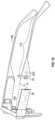
- FIG. 1 Ais a side view of electronics enabled eyewear having an electrical component residing in a removable portion of a temple.
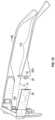
- FIG. 1 Bis the side view of the eyewear of FIG. 1 A with an electronic connector concealed from an exterior of the eyewear.
- FIG. 1 Cis a disassembled side view of the eyewear of FIG. 1 B with a portion of the temple removed from the eyewear, the removed portion of the temple having an electrical device and an electrical connector having conductors.
- FIG. 1 Dis a partial rear view of the eyewear of FIG. 1 A .
- FIG. 1 Eis an example of the electrical device comprising a battery.
- FIG. 1 Fis an example of the electrical device comprising a light.
- FIG. 1 Gis an example of then electrical device comprising a speaker.
- FIG. 1 His an example of the electrical device comprising a camera.
- FIGS. 2 A, 2 B, and 2 Care side views of eyewear temples depicting examples of insertion of one portion of the temple into another portion of the temple.
- FIG. 3is a side view of an example of a pivotal connection of a second portion of the temple with respect to a first portion of the temple connected to a frame.
- FIG. 4is a flowchart depicting an example of steps for charging an eyewear battery.
- FIG. 5is a block diagram depicting electronic components for use in the eyewear of FIG. 1 A .
- the term “on”means directly supported by an element or indirectly supported by the element through another element integrated into or supported by the element.
- Non-limiting examples shown in the drawingsgive directions or orientations of the eyewear and associated components only for illustration and discussion purposes. In operation for charging the battery, the eyewear may be oriented in other direction suitable to the particular application of the eyewear device, for example up, down, sideways, or any other orientation.
- FIGS. 1 A- 1 Dshow eyewear 10 according to one example.
- the eyewear 10includes a frame 12 having two sides, a first side 12 A and a second side 12 B.
- the frame 12supports at least one optical element 18 , including optical element 18 A on the first side 12 A.
- the optical element 18 Amay be, for example, a lens, a transparent piece of glass or plastic, a screen, a projector, a display, or other device for presenting visual images and/or through which a user may perceive visual images.
- the frame 12can include other arrangements, such as two optical elements 18 A and 18 B on the first and the second sides 12 A and 12 B, respectively, ( FIG.
- the first side 12 A of the frame 12may be dimensioned to accommodate various electronic components 24 , such as a battery 25 , a wireless transceiver, a data storage device, and a processor (see FIG. 5 and accompanying description).
- the eyewear 10also includes a temple 14 A adjacent the first side 12 A of the frame 12 .
- the temple 14 Aincludes a first portion 15 A and a second portion 17 A, which second portion 17 A releasably connects to the first portion 15 A.
- the first portion 15 Ais integrally formed with the frame 12 .
- the first portion 15 Aconnects to the frame 12 via a hinge 16 A ( FIG. 1 D ).
- the first portion 15 A of the temple 14 Aincludes an attachment point 13 where the first portion 15 A of the temple 14 A attaches to the second portion 17 A. In one state (a concealed state; FIG.
- the second portion 17 Ais connected to the first portion 15 A of the temple 14 A at the attachment point 13 such that it covers an electrical connector 28 embedded within the first portion 15 A.
- the second portion 17 Ais released/removed from the first portion 15 A of the temple 14 A at the attachment point 13 to expose the electrical connector 28 .
- the second portion 17 Amoves in a direction along a connection axis, e.g., an X-axis location coordinate ( FIG. 1 C ) resulting in the exposed state.
- the eyewear 10includes an electronic device 30 embedded in the second portion 17 A of the frame 12 .
- the eyewear 10also includes an electrical connector 26 having a mechanical portion and an electrical portion ( FIG. 1 C ) extending from the second portion 17 A of the temple 14 A.
- the electrical connector 26functions to both mechanically connect the second portion 17 A of the temple to the first portion 15 A at the attachment point 13 resulting in the concealed state ( FIG. 1 B ), and also to electrically connect the electronic device 30 to electronic components 24 in the frame 12 .
- This second portion 17 Ais thus considered electrical and smart, as opposed to the term dumb which refers to not having any electronic components.
- the mechanical portion of electrical connector 26functions to enable disconnection of the second portion 17 A of the temple from the first portion 15 A at the attachment point 13 resulting in the exposed state ( FIG. 1 C ).
- the electrical connector 26is configured to mate with the electrical connector 28 with a friction fit retaining the mechanical portion of electrical connector 26 within the electrical connector 28 and, thereby, the second portion 17 A attached to the first portion 15 A.
- the mechanical portion of the electrical connector 26includes a joint-type connection, a snap feature, a twist to lock connector, a release mechanism, a magnet etc.
- the electrical portion of electrical connector 26comprises multiple electrical conductors 32 that function to electrically connect the electronic device 30 embedded in the second portion 17 A to the electronic components 24 in the frame 12 .
- the electronic device 30may comprise of an active and/or passive electrical component or components.
- An example of an active electrical componentis a battery configured to power the electronic components 24 , a flashlight, a camera, a sensor, a microphone, and an augmented reality (AR) device such as sensors and/or a display.
- An example of a passive electrical componentis a non-amplified speaker.
- the batterymay be recharged by removal of the second portion 17 A from the first portion 15 A and connecting the second electrical connector 26 of the second portion 17 A to a charging source (not shown) via the electrical conductors 32 of electrical connector 26 .
- Additional second portions 17 Acan operate as spares.
- the electrical conductors 32provide a power and ground connection. This example alleviates the need to connect a power source to the frame 12 for charging proximate the optical elements 18 , and also reduces the chance for the optical elements 18 or frame 12 to be damaged during manipulation of the frame 12 during charging.
- the usermay have one or more second portions 17 A such that the unused second portion 17 A is a spare which can be easily interchanged to provide extended operating life of the frame 12 , such as between charges.
- the second portion 17 Acan have different size batteries, such that a user can select and use a second portion 17 A with a desired battery capacity and having a weight acceptable to the user.
- the electronic device 30can comprise of any number of different electrical components as previously discussed.
- electronic device 30can comprise a battery such as shown at 30 A in FIG. 1 E where the electrical conductors 32 serve as positive and negative leads to power electronic components 24 .
- the electronic device 30can comprise a light 30 B, such as a light emitting diode (LED), and an associated power switch 34 on an inside of the second portion 17 A.
- the light 30 Bcan be powered by a battery in the second portion 17 A so that the second portion 17 A can function as a standalone light when removed from first portion 15 A, or by electronic components 24 via electrical connectors 26 and 28 .
- electronic device 30can comprise a speaker such as shown at 30 C in FIG.
- the electronic device 30can comprise a camera as shown at 30 D in FIG. 1 H and configured to capture images on the side of the user and assist in rendering 270 degrees of view.
- the electronic device 30can comprise other components such as those supporting augmented reality (AR) features. Thus, limitation to the shown examples of electronic device 30 is not to be inferred.
- ARaugmented reality
- Examples of the snap featureincludes a snap-on connector, which is a coupling mechanism including corresponding protrusion and indentations on respective portions to enables connecting/mating with a straight push and disconnecting/unmating with a straight pull.
- a twist to lock connectoris a coupling mechanism in which the connector connects with a straight push and then a twist to lock the second portion in place, and disconnects by twisting in an opposite direction to unlock the second portion from the first portion and then unmates with a straight pull.
- a release mechanismincludes a connector that has a built-in lock/release collar to securely lock mated connectors and to enable quick disconnection by simply pulling on the release collar.
- the first or second portion of the templemay include a first magnet and the second or first portion of the temple may include metal or a second magnet.
- the second magnetis oriented to attract the first magnet in order to secure the second portion to the first portion in the concealed state while allowing disconnection of the second portion from the first portion to achieve the exposed state.
- Eyewear 10 in FIGS. 1 A and 1 Balso has a second temple 14 B adjacent to the second side 12 B of the frame 12 ( FIG. 1 C ).
- the second temple 14 Bmay be a single piece that does not include a releasable portion and is dumb.
- the second temple 14 Bmay have the same configuration as the first temple 14 A and have a first portion 15 B, and a second portion 17 B that is releasably attached to the first portion 15 B ( FIG. 1 D ).
- the second portion 17 Bmay also comprise a respective electronic device 30 which may or may not be configured to communicate with the electrical components 24 and is also smart.
- the outer dimensions of the second temple 14 Bmay be the same as the outer dimensions of the first temple 14 A so that the eyewear 12 has symmetry.
- each of the first portions 15 A and 15 B of the temples 14 A and 14 B, respectively,are attached to the opposing sides 12 A and 12 B, respectively, of the frame 12 by first and second hinges 16 A and 16 B respectively ( FIG. 1 D ).
- the mechanical portion of electrical connector 26is dimensioned to mate with the electrical connector 28 , and also disconnect from the electrical connector 28 of the first portion 15 A of the temple 14 A in the exposed state, which results in the electrical connector 26 being exposed from the exterior of the eyewear 10 ( FIG. 1 C ).
- the electrical connector 26is accessible to a user in the exposed state and is inaccessible to the user in the concealed state.
- the userin the exposed state ( FIG. 1 C ), the user can connect a power component (not shown) to the electrical connector 26 , which functions to deliver power to the electronic device 30 in the second portion 17 A.
- the electrical connector 26connects to the electrical connector 28 of the first portion 15 A of the temple 14 A in the concealed state, which results in both of the electrical connector 26 and the electrical connector 28 being concealed from an exterior of the eyewear 10 ( FIG. 1 B ).
- the userwears the eyewear 10 in the concealed state.
- the electrical connector 26 and the electrical connector 28are each a cable type connector, such as a USB type A, B, or C cable connector, each being mechanically and electrically mating to each other.
- FIGS. 2 A, 2 B and 2 Care side views depicting various examples of insertion of the second portion 17 A of the temple 14 A into the first portion of the temple 14 A as described in detail herein below.
- the electrical connector 26includes snaps 26 A and 26 B, and electrical interface 26 C, which are integrally attached to the second portion 17 A of the temple 14 A ( FIG. 2 A ), and the electrical connector 28 of first portion 15 A defines grooves 28 A and 28 B for receiving and accommodating the snaps 26 A and 26 B, respectively, and an electrical interface 26 C for receiving and connecting to electrical interface 28 C ( FIG. 2 A ).
- the second portion 17 Ais inserted directly into the first portion 15 A along a longitudinal insertion axis.
- the snaps 26 A and 26 Bare inserted into their corresponding grooves 28 A and 28 B ( FIG. 2 A ).
- the second portion 17 Ais first inserted into the first portion 15 A along a longitudinal insertion axis ( FIG. 2 B ) and then the second portion 17 A is rotated to lock the second portion 17 A in place ( FIG. 2 C ) to conceal the electrical connector 28 as well as electrical connector 26 .
- a protrusion 23 Ais initially inserted into a groove 23 B ( FIG. 2 B ).
- the second portion 17 Ais then rotated, causing the protrusion 23 A to lock into place within the groove 23 B ( FIG. 2 C ) in order to firmly connect the second portion 17 A to the first portion 15 A of the temple 14 A and electrically connect electrical connectors 26 and 28 .
- the processmay be reversed by rotating the second portion 17 A/protrusion 23 A in the opposite direction to unlock the protrusion 23 A from the groove 23 B and then pulling the second portion 17 A out in order to remove the second portion 17 A from the first portion 15 A of the temple 14 A.
- the second portion 17 A of the temple 14is pivotably connected to the first portion 15 A by a hinge 34 ( FIG. 3 ) such that the second portion 17 A is movable with respect to the first portion 15 A between concealed and exposed states.
- the second portion 17 Ain the exposed state, is moved away from the first portion 15 A about an axis of rotation defined by the hinge 34 , which disconnects the second portion 17 A from the first portion 15 A of the temple and exposes the electrical connector 26 such that the electrical device 30 can be charged by a power source (not shown).
- the second portion 17 Aconnects to the first portion 15 A about the axis of rotation defined by the hinge 36 to conceal electrical connectors 26 and 28 .
- FIG. 4is a flowchart depicting an example of interchanging different second portions 17 A, such as using a second portion having a battery to power the electronic component 24 , or operating the second portion as a standalone smart device. The steps are described with reference to the eyewear depicted in FIGS. 1 A- 1 H . One of skill in the art will understand from the description herein that the method may be implemented using other types of eyewear with different connectors for exchanging second temple portions 17 A.
- step 402place the temple 14 A in an exposed state by moving the second portion 17 A of the temple 14 A in the first direction to completely disconnect the second portion 17 A of the temple 14 A from the first portion 15 A ( FIG. 1 C ).
- the second portion 17 Aincludes a power component and attaching the second portion 17 A connects the power component to the electrical connector 28 via electrical connector 26 to transmit power through the electrical conductors 32 of electrical connector 26 to supply power to the eyewear 10 .
- a usermay have multiple second portions (e.g., a bulky second portion with a large capacity battery when available power is of concern and a sleeker second portion with a smaller capacity battery when available power is not of concern) or may upgrade by purchasing a new second portion.
- replace the second portion 17 Awith another second portion 17 A having an LED and battery (e.g., which can operate as a standalone flashlight), a speaker, a sensor, a camera, and/or an AR component.
- FIG. 5depicts example electronic components 24 for use in eyewear 10 .
- the illustrated electronic components 24include the battery 25 , a wireless transceiver 52 , a data storage device 54 , and a processor 56 .
- Wireless transceiver 52enables communication between the eyewear 10 and external devices, e.g., a mobile device, a Wi-Fi hotspot, or other communication device.
- Data storage device 54may include static and/or dynamic memory. Data storage device 54 stores information received from processor 56 and includes instructions for execution by processor 56 to implement functionality of eyewear 10 .
- Processor 56receives power from battery 25 and executes instructions stored in data storage device 54 to perform functionality of eyewear 10 such as controlling operation of eyewear 10 and communicating with external devices via transceiver 52 .
- inventive subject matterhas been described with reference to specific example embodiments, various modifications and changes may be made to these embodiments without departing from the broader scope of embodiments of the present disclosure.
- inventive subject mattermay be referred to herein, individually or collectively, by the term “invention” merely for convenience and without intending to voluntarily limit the scope of this application to any single disclosure or inventive concept if more than one is, in fact, disclosed.
Landscapes
- Physics & Mathematics (AREA)
- Health & Medical Sciences (AREA)
- General Physics & Mathematics (AREA)
- Ophthalmology & Optometry (AREA)
- Optics & Photonics (AREA)
- Acoustics & Sound (AREA)
- General Health & Medical Sciences (AREA)
- Otolaryngology (AREA)
- Eyeglasses (AREA)
- Charge And Discharge Circuits For Batteries Or The Like (AREA)
Abstract
Description
Claims (14)
Priority Applications (2)
| Application Number | Priority Date | Filing Date | Title |
|---|---|---|---|
| US16/793,414US12181732B2 (en) | 2019-02-22 | 2020-02-18 | Modular eyewear temple |
| US18/977,070US20250102837A1 (en) | 2019-02-22 | 2024-12-11 | Modular eyewear temple |
Applications Claiming Priority (2)
| Application Number | Priority Date | Filing Date | Title |
|---|---|---|---|
| US201962808913P | 2019-02-22 | 2019-02-22 | |
| US16/793,414US12181732B2 (en) | 2019-02-22 | 2020-02-18 | Modular eyewear temple |
Related Child Applications (1)
| Application Number | Title | Priority Date | Filing Date |
|---|---|---|---|
| US18/977,070ContinuationUS20250102837A1 (en) | 2019-02-22 | 2024-12-11 | Modular eyewear temple |
Publications (2)
| Publication Number | Publication Date |
|---|---|
| US20200271961A1 US20200271961A1 (en) | 2020-08-27 |
| US12181732B2true US12181732B2 (en) | 2024-12-31 |
Family
ID=69844913
Family Applications (2)
| Application Number | Title | Priority Date | Filing Date |
|---|---|---|---|
| US16/793,414Active2040-12-06US12181732B2 (en) | 2019-02-22 | 2020-02-18 | Modular eyewear temple |
| US18/977,070PendingUS20250102837A1 (en) | 2019-02-22 | 2024-12-11 | Modular eyewear temple |
Family Applications After (1)
| Application Number | Title | Priority Date | Filing Date |
|---|---|---|---|
| US18/977,070PendingUS20250102837A1 (en) | 2019-02-22 | 2024-12-11 | Modular eyewear temple |
Country Status (5)
| Country | Link |
|---|---|
| US (2) | US12181732B2 (en) |
| EP (1) | EP3928149A1 (en) |
| KR (2) | KR102827036B1 (en) |
| CN (1) | CN113454521A (en) |
| WO (1) | WO2020172138A1 (en) |
Families Citing this family (2)
| Publication number | Priority date | Publication date | Assignee | Title |
|---|---|---|---|---|
| WO2022162497A1 (en) | 2021-01-28 | 2022-08-04 | 株式会社半導体エネルギー研究所 | Semiconductor device and electronic apparatus |
| EP4057051B1 (en)* | 2021-03-11 | 2024-10-09 | Lighthouse Tech Sagl | Temples of glasses for the blind or visually impaired |
Citations (48)
| Publication number | Priority date | Publication date | Assignee | Title |
|---|---|---|---|---|
| US1936319A (en)* | 1930-07-14 | 1933-11-21 | Wingate Gerald Henry | Folding spectacles |
| US3035127A (en)* | 1955-04-15 | 1962-05-15 | Charles W Strzalkowski | Hearing aids |
| US3883701A (en)* | 1971-03-18 | 1975-05-13 | Anthony Delorenzo | Eyeglass frame with hearing aid |
| US4756605A (en)* | 1985-02-01 | 1988-07-12 | Olympus Optical Co., Ltd. | Liquid crystal spectacles |
| US6163926A (en)* | 1999-11-12 | 2000-12-26 | Ppg Industries Ohio, Inc. | Split-pin hinge with wire extending therethrough |
| US6293673B1 (en)* | 2000-06-14 | 2001-09-25 | Pareto Corporation | Pull-down member for an eyeglass frame with improved coupling pin |
| US6582075B1 (en)* | 2001-10-18 | 2003-06-24 | Qr Spex, Inc. | Eyeglass temple attachment mechanism |
| US6929365B2 (en)* | 2001-04-30 | 2005-08-16 | Q.R. Spex, Inc. | Eyewear with exchangeable temples housing bluetooth enable apparatus |
| US20070200998A1 (en)* | 2006-02-24 | 2007-08-30 | Chemical Light, Inc. | Led illuminated novelty glasses |
| US20080106694A1 (en)* | 2006-10-27 | 2008-05-08 | Blum Ronald D | Spectacle hinge for providing on off power |
| US7607775B2 (en)* | 2008-02-26 | 2009-10-27 | Mr. Christmas Incorporated | Illuminating eyeglasses and eyeglasses frame structure |
| US20100045928A1 (en)* | 2008-08-25 | 2010-02-25 | Tri-Specs, Inc. | Fashion eyewear frame that houses circuitry to effect wireless audio communication while providing extraneous background noise cancellation capability |
| US7731354B1 (en)* | 2009-05-08 | 2010-06-08 | Faith Idea Limited | Spectacle frame |
| WO2010066176A1 (en)* | 2008-12-09 | 2010-06-17 | Zhang Zenghui | Eyeglasses with lamp |
| US7946705B1 (en)* | 2010-06-30 | 2011-05-24 | Sun And Young Sunglasses Co., Ltd. | Rechargeable illuminated eyeglasses |
| US7997724B1 (en)* | 2010-05-28 | 2011-08-16 | Sun And Young Sunglasses Co., Ltd. | Illuminated eyeglass |
| CN202033547U (en)* | 2011-05-09 | 2011-11-09 | 连斌 | Detachable illuminating spectacles with slide rails |
| CN202110334U (en) | 2011-06-20 | 2012-01-11 | 高亿实业有限公司 | 3D shutter glasses |
| US8109629B2 (en)* | 2003-10-09 | 2012-02-07 | Ipventure, Inc. | Eyewear supporting electrical components and apparatus therefor |
| US20120050667A1 (en)* | 2010-08-30 | 2012-03-01 | Ching-Hsiang Wang | Eyeglasses Capable of Being Recharged and Providing Three-Stage Lighting |
| EP2439580A1 (en) | 2010-10-01 | 2012-04-11 | Ophtimalia | Data exchange system |
| US8235524B2 (en)* | 2001-11-07 | 2012-08-07 | Michael Waters | Illuminated eyewear |
| US8465151B2 (en)* | 2003-04-15 | 2013-06-18 | Ipventure, Inc. | Eyewear with multi-part temple for supporting one or more electrical components |
| US8485682B2 (en)* | 2007-10-29 | 2013-07-16 | Waters Industries, Inc. | Illuminated eyeglass assembly |
| US8491118B2 (en)* | 2001-11-07 | 2013-07-23 | Michael Waters | Lighted reading glasses |
| US8514097B2 (en)* | 2009-08-14 | 2013-08-20 | Michael William Boise | Glasses with sound activated lights |
| US8545012B2 (en)* | 2005-05-17 | 2013-10-01 | Michael Waters | Illuminated eyewear |
| CN203241650U (en)* | 2013-05-24 | 2013-10-16 | 吴睿男 | Glasses with detachable miniature flashlights |
| US8783861B2 (en)* | 2010-07-02 | 2014-07-22 | Pixeloptics, Inc. | Frame design for electronic spectacles |
| US8801174B2 (en)* | 2011-02-11 | 2014-08-12 | Hpo Assets Llc | Electronic frames comprising electrical conductors |
| US8979259B2 (en)* | 2010-07-02 | 2015-03-17 | Mitsui Chemicals, Inc. | Electro-active spectacle frames |
| US8979295B2 (en)* | 2005-05-17 | 2015-03-17 | Michael Waters | Rechargeable lighted glasses |
| US20150212329A1 (en)* | 2012-10-24 | 2015-07-30 | Olympus Corporation | Eyeglass-type wearable device and front part of eyeglass-type wearable device |
| US9122083B2 (en)* | 2005-10-28 | 2015-09-01 | E-Vision Smart Optics, Inc. | Eyewear docking station and electronic module |
| WO2015141405A1 (en)* | 2014-03-19 | 2015-09-24 | 寺川英太郎 | Eyeglasses |
| US20160091731A1 (en)* | 2014-09-30 | 2016-03-31 | Zhejiang Hindar Optical Co., Ltd | Foldable eyeglasses |
| KR200480341Y1 (en)* | 2015-10-02 | 2016-05-12 | 조양호 | Folding glasses |
| CN105652473A (en)* | 2016-04-14 | 2016-06-08 | 上海理工大学 | Intelligent glasses framework |
| US20170255029A1 (en) | 2016-03-03 | 2017-09-07 | Vision Service Plan | Systems and methods for charging eyewear |
| US9921420B2 (en)* | 2015-09-25 | 2018-03-20 | Paul D. Bella | Eyeglasses and eyeglass attachment for directing filtered air over the eyes of a wearer |
| US9952452B1 (en) | 2015-04-15 | 2018-04-24 | Snap Inc. | Eyewear having selectively exposable feature |
| US9971169B1 (en)* | 2015-09-29 | 2018-05-15 | Snap Inc. | Eyewear with conductive temple joint |
| US9971171B1 (en)* | 2015-10-30 | 2018-05-15 | Snap Inc. | Battery assembly for a wearable electronic device |
| WO2018145085A1 (en) | 2017-02-06 | 2018-08-09 | Snap, Inc. | Heat management for electronic devices |
| US10268276B2 (en)* | 2013-03-15 | 2019-04-23 | Eyecam, LLC | Autonomous computing and telecommunications head-up displays glasses |
| US20200233238A1 (en)* | 2019-01-22 | 2020-07-23 | Snap Inc. | Electrical connector in eyewear |
| US10768451B1 (en)* | 2018-06-26 | 2020-09-08 | Snap Inc. | Diffusers in wearable devices |
| US10935815B1 (en)* | 2018-03-06 | 2021-03-02 | Snap Inc. | Eyewear having custom lighting |
- 2020
- 2020-02-18KRKR1020217029613Apatent/KR102827036B1/enactiveActive
- 2020-02-18KRKR1020257021106Apatent/KR20250099287A/enactivePending
- 2020-02-18WOPCT/US2020/018598patent/WO2020172138A1/ennot_activeCeased
- 2020-02-18EPEP20711709.4Apatent/EP3928149A1/enactivePending
- 2020-02-18USUS16/793,414patent/US12181732B2/enactiveActive
- 2020-02-18CNCN202080015362.1Apatent/CN113454521A/enactivePending
- 2024
- 2024-12-11USUS18/977,070patent/US20250102837A1/enactivePending
Patent Citations (50)
| Publication number | Priority date | Publication date | Assignee | Title |
|---|---|---|---|---|
| US1936319A (en)* | 1930-07-14 | 1933-11-21 | Wingate Gerald Henry | Folding spectacles |
| US3035127A (en)* | 1955-04-15 | 1962-05-15 | Charles W Strzalkowski | Hearing aids |
| US3883701A (en)* | 1971-03-18 | 1975-05-13 | Anthony Delorenzo | Eyeglass frame with hearing aid |
| US4756605A (en)* | 1985-02-01 | 1988-07-12 | Olympus Optical Co., Ltd. | Liquid crystal spectacles |
| US6163926A (en)* | 1999-11-12 | 2000-12-26 | Ppg Industries Ohio, Inc. | Split-pin hinge with wire extending therethrough |
| US6293673B1 (en)* | 2000-06-14 | 2001-09-25 | Pareto Corporation | Pull-down member for an eyeglass frame with improved coupling pin |
| US6929365B2 (en)* | 2001-04-30 | 2005-08-16 | Q.R. Spex, Inc. | Eyewear with exchangeable temples housing bluetooth enable apparatus |
| US6582075B1 (en)* | 2001-10-18 | 2003-06-24 | Qr Spex, Inc. | Eyeglass temple attachment mechanism |
| US8491118B2 (en)* | 2001-11-07 | 2013-07-23 | Michael Waters | Lighted reading glasses |
| US8235524B2 (en)* | 2001-11-07 | 2012-08-07 | Michael Waters | Illuminated eyewear |
| US8465151B2 (en)* | 2003-04-15 | 2013-06-18 | Ipventure, Inc. | Eyewear with multi-part temple for supporting one or more electrical components |
| US20170131575A1 (en) | 2003-04-15 | 2017-05-11 | Ingeniospec, Llc | Eyewear housing for charging embedded battery in eyewear frame |
| US8109629B2 (en)* | 2003-10-09 | 2012-02-07 | Ipventure, Inc. | Eyewear supporting electrical components and apparatus therefor |
| US8979295B2 (en)* | 2005-05-17 | 2015-03-17 | Michael Waters | Rechargeable lighted glasses |
| US8545012B2 (en)* | 2005-05-17 | 2013-10-01 | Michael Waters | Illuminated eyewear |
| US9122083B2 (en)* | 2005-10-28 | 2015-09-01 | E-Vision Smart Optics, Inc. | Eyewear docking station and electronic module |
| US20070200998A1 (en)* | 2006-02-24 | 2007-08-30 | Chemical Light, Inc. | Led illuminated novelty glasses |
| US20080106694A1 (en)* | 2006-10-27 | 2008-05-08 | Blum Ronald D | Spectacle hinge for providing on off power |
| US8485682B2 (en)* | 2007-10-29 | 2013-07-16 | Waters Industries, Inc. | Illuminated eyeglass assembly |
| US7607775B2 (en)* | 2008-02-26 | 2009-10-27 | Mr. Christmas Incorporated | Illuminating eyeglasses and eyeglasses frame structure |
| US20100045928A1 (en)* | 2008-08-25 | 2010-02-25 | Tri-Specs, Inc. | Fashion eyewear frame that houses circuitry to effect wireless audio communication while providing extraneous background noise cancellation capability |
| WO2010066176A1 (en)* | 2008-12-09 | 2010-06-17 | Zhang Zenghui | Eyeglasses with lamp |
| US7731354B1 (en)* | 2009-05-08 | 2010-06-08 | Faith Idea Limited | Spectacle frame |
| US8514097B2 (en)* | 2009-08-14 | 2013-08-20 | Michael William Boise | Glasses with sound activated lights |
| US7997724B1 (en)* | 2010-05-28 | 2011-08-16 | Sun And Young Sunglasses Co., Ltd. | Illuminated eyeglass |
| US7946705B1 (en)* | 2010-06-30 | 2011-05-24 | Sun And Young Sunglasses Co., Ltd. | Rechargeable illuminated eyeglasses |
| US8783861B2 (en)* | 2010-07-02 | 2014-07-22 | Pixeloptics, Inc. | Frame design for electronic spectacles |
| US8979259B2 (en)* | 2010-07-02 | 2015-03-17 | Mitsui Chemicals, Inc. | Electro-active spectacle frames |
| US20120050667A1 (en)* | 2010-08-30 | 2012-03-01 | Ching-Hsiang Wang | Eyeglasses Capable of Being Recharged and Providing Three-Stage Lighting |
| EP2439580A1 (en) | 2010-10-01 | 2012-04-11 | Ophtimalia | Data exchange system |
| US8801174B2 (en)* | 2011-02-11 | 2014-08-12 | Hpo Assets Llc | Electronic frames comprising electrical conductors |
| CN202033547U (en)* | 2011-05-09 | 2011-11-09 | 连斌 | Detachable illuminating spectacles with slide rails |
| CN202110334U (en) | 2011-06-20 | 2012-01-11 | 高亿实业有限公司 | 3D shutter glasses |
| US20150212329A1 (en)* | 2012-10-24 | 2015-07-30 | Olympus Corporation | Eyeglass-type wearable device and front part of eyeglass-type wearable device |
| US10268276B2 (en)* | 2013-03-15 | 2019-04-23 | Eyecam, LLC | Autonomous computing and telecommunications head-up displays glasses |
| CN203241650U (en)* | 2013-05-24 | 2013-10-16 | 吴睿男 | Glasses with detachable miniature flashlights |
| WO2015141405A1 (en)* | 2014-03-19 | 2015-09-24 | 寺川英太郎 | Eyeglasses |
| US20160091731A1 (en)* | 2014-09-30 | 2016-03-31 | Zhejiang Hindar Optical Co., Ltd | Foldable eyeglasses |
| US9952452B1 (en) | 2015-04-15 | 2018-04-24 | Snap Inc. | Eyewear having selectively exposable feature |
| US9921420B2 (en)* | 2015-09-25 | 2018-03-20 | Paul D. Bella | Eyeglasses and eyeglass attachment for directing filtered air over the eyes of a wearer |
| US9971169B1 (en)* | 2015-09-29 | 2018-05-15 | Snap Inc. | Eyewear with conductive temple joint |
| KR200480341Y1 (en)* | 2015-10-02 | 2016-05-12 | 조양호 | Folding glasses |
| US9971171B1 (en)* | 2015-10-30 | 2018-05-15 | Snap Inc. | Battery assembly for a wearable electronic device |
| US20170255029A1 (en) | 2016-03-03 | 2017-09-07 | Vision Service Plan | Systems and methods for charging eyewear |
| CN105652473A (en)* | 2016-04-14 | 2016-06-08 | 上海理工大学 | Intelligent glasses framework |
| WO2018145085A1 (en) | 2017-02-06 | 2018-08-09 | Snap, Inc. | Heat management for electronic devices |
| US10935815B1 (en)* | 2018-03-06 | 2021-03-02 | Snap Inc. | Eyewear having custom lighting |
| US10768451B1 (en)* | 2018-06-26 | 2020-09-08 | Snap Inc. | Diffusers in wearable devices |
| US20200233238A1 (en)* | 2019-01-22 | 2020-07-23 | Snap Inc. | Electrical connector in eyewear |
| WO2020154047A1 (en) | 2019-01-22 | 2020-07-30 | Snap Inc. | Electrical connector in eyewear |
Non-Patent Citations (2)
| Title |
|---|
| 4th Chinese Office Action for Chinese Application No. 202080015362.1, dated Jan. 27, 2024 (Jan. 27, 2024)—7 pages (English summary—2 pages). |
| International Search Report and Written Opinion for International Application No. PCT/US2020/018598, dated May 20, 2020 (May 20, 2020)—14 pages. |
Also Published As
| Publication number | Publication date |
|---|---|
| US20200271961A1 (en) | 2020-08-27 |
| CN113454521A (en) | 2021-09-28 |
| KR20250099287A (en) | 2025-07-01 |
| EP3928149A1 (en) | 2021-12-29 |
| KR20210127221A (en) | 2021-10-21 |
| KR102827036B1 (en) | 2025-06-27 |
| US20250102837A1 (en) | 2025-03-27 |
| WO2020172138A1 (en) | 2020-08-27 |
Similar Documents
| Publication | Publication Date | Title |
|---|---|---|
| US20250102837A1 (en) | Modular eyewear temple | |
| US11762224B2 (en) | Eyewear having extended endpieces to support electrical components | |
| US12189421B2 (en) | Eyewear with conductive temple joint | |
| US11204512B2 (en) | Eyewear supporting embedded and tethered electronic components | |
| US7581833B2 (en) | Eyewear supporting after-market electrical components | |
| US20170131575A1 (en) | Eyewear housing for charging embedded battery in eyewear frame | |
| US11733549B2 (en) | Eyewear having removable temples that support electrical components | |
| EP2439580A1 (en) | Data exchange system | |
| US20210376661A1 (en) | Wireless charging for optical device | |
| US20240036361A1 (en) | System for charging embedded battery in wireless head-worn personal electronic apparatus | |
| US12259594B2 (en) | Electrical connector in eyewear | |
| CN116830013A (en) | Headset with attachable accessory | |
| EP4542286A1 (en) | An eyewear system | |
| KR101625099B1 (en) | Computer with wireless recharging of mobile device | |
| US12332505B1 (en) | Eyewear tether with battery |
Legal Events
| Date | Code | Title | Description |
|---|---|---|---|
| FEPP | Fee payment procedure | Free format text:ENTITY STATUS SET TO UNDISCOUNTED (ORIGINAL EVENT CODE: BIG.); ENTITY STATUS OF PATENT OWNER: LARGE ENTITY | |
| STPP | Information on status: patent application and granting procedure in general | Free format text:APPLICATION DISPATCHED FROM PREEXAM, NOT YET DOCKETED | |
| STPP | Information on status: patent application and granting procedure in general | Free format text:DOCKETED NEW CASE - READY FOR EXAMINATION | |
| STPP | Information on status: patent application and granting procedure in general | Free format text:FINAL REJECTION MAILED | |
| STPP | Information on status: patent application and granting procedure in general | Free format text:DOCKETED NEW CASE - READY FOR EXAMINATION | |
| STPP | Information on status: patent application and granting procedure in general | Free format text:NON FINAL ACTION MAILED | |
| STPP | Information on status: patent application and granting procedure in general | Free format text:RESPONSE TO NON-FINAL OFFICE ACTION ENTERED AND FORWARDED TO EXAMINER | |
| STPP | Information on status: patent application and granting procedure in general | Free format text:FINAL REJECTION MAILED | |
| STPP | Information on status: patent application and granting procedure in general | Free format text:RESPONSE AFTER FINAL ACTION FORWARDED TO EXAMINER | |
| STPP | Information on status: patent application and granting procedure in general | Free format text:NOTICE OF ALLOWANCE MAILED -- APPLICATION RECEIVED IN OFFICE OF PUBLICATIONS | |
| AS | Assignment | Owner name:SNAP INC., CALIFORNIA Free format text:ASSIGNMENT OF ASSIGNORS INTEREST;ASSIGNORS:BEN-HAIM, YOAV;ARDISANA, JOHN BERNARD, II;DABOV, TEODOR;AND OTHERS;SIGNING DATES FROM 20190218 TO 20190220;REEL/FRAME:069348/0984 | |
| STPP | Information on status: patent application and granting procedure in general | Free format text:PUBLICATIONS -- ISSUE FEE PAYMENT VERIFIED | |
| STCF | Information on status: patent grant | Free format text:PATENTED CASE |