US12179032B2 - Wearable cardioverter defibrillator (WCD) segment based episode opening and confirmation periods - Google Patents
Wearable cardioverter defibrillator (WCD) segment based episode opening and confirmation periodsDownload PDFInfo
- Publication number
- US12179032B2 US12179032B2US17/546,892US202117546892AUS12179032B2US 12179032 B2US12179032 B2US 12179032B2US 202117546892 AUS202117546892 AUS 202117546892AUS 12179032 B2US12179032 B2US 12179032B2
- Authority
- US
- United States
- Prior art keywords
- segments
- wcd
- patient
- ecg
- ecg data
- Prior art date
- Legal status (The legal status is an assumption and is not a legal conclusion. Google has not performed a legal analysis and makes no representation as to the accuracy of the status listed.)
- Active, expires
Links
Images


Classifications
- A—HUMAN NECESSITIES
- A61—MEDICAL OR VETERINARY SCIENCE; HYGIENE
- A61B—DIAGNOSIS; SURGERY; IDENTIFICATION
- A61B5/00—Measuring for diagnostic purposes; Identification of persons
- A61B5/02—Detecting, measuring or recording for evaluating the cardiovascular system, e.g. pulse, heart rate, blood pressure or blood flow
- A61B5/024—Measuring pulse rate or heart rate
- A61B5/0245—Measuring pulse rate or heart rate by using sensing means generating electric signals, i.e. ECG signals
- A—HUMAN NECESSITIES
- A61—MEDICAL OR VETERINARY SCIENCE; HYGIENE
- A61B—DIAGNOSIS; SURGERY; IDENTIFICATION
- A61B5/00—Measuring for diagnostic purposes; Identification of persons
- A61B5/24—Detecting, measuring or recording bioelectric or biomagnetic signals of the body or parts thereof
- A61B5/25—Bioelectric electrodes therefor
- A61B5/279—Bioelectric electrodes therefor specially adapted for particular uses
- A61B5/28—Bioelectric electrodes therefor specially adapted for particular uses for electrocardiography [ECG]
- A61B5/282—Holders for multiple electrodes
- A—HUMAN NECESSITIES
- A61—MEDICAL OR VETERINARY SCIENCE; HYGIENE
- A61B—DIAGNOSIS; SURGERY; IDENTIFICATION
- A61B5/00—Measuring for diagnostic purposes; Identification of persons
- A61B5/24—Detecting, measuring or recording bioelectric or biomagnetic signals of the body or parts thereof
- A61B5/316—Modalities, i.e. specific diagnostic methods
- A61B5/318—Heart-related electrical modalities, e.g. electrocardiography [ECG]
- A61B5/339—Displays specially adapted therefor
- A61B5/341—Vectorcardiography [VCG]
- A—HUMAN NECESSITIES
- A61—MEDICAL OR VETERINARY SCIENCE; HYGIENE
- A61B—DIAGNOSIS; SURGERY; IDENTIFICATION
- A61B5/00—Measuring for diagnostic purposes; Identification of persons
- A61B5/24—Detecting, measuring or recording bioelectric or biomagnetic signals of the body or parts thereof
- A61B5/316—Modalities, i.e. specific diagnostic methods
- A61B5/318—Heart-related electrical modalities, e.g. electrocardiography [ECG]
- A61B5/346—Analysis of electrocardiograms
- A61B5/349—Detecting specific parameters of the electrocardiograph cycle
- A61B5/361—Detecting fibrillation
- A—HUMAN NECESSITIES
- A61—MEDICAL OR VETERINARY SCIENCE; HYGIENE
- A61B—DIAGNOSIS; SURGERY; IDENTIFICATION
- A61B5/00—Measuring for diagnostic purposes; Identification of persons
- A61B5/24—Detecting, measuring or recording bioelectric or biomagnetic signals of the body or parts thereof
- A61B5/316—Modalities, i.e. specific diagnostic methods
- A61B5/318—Heart-related electrical modalities, e.g. electrocardiography [ECG]
- A61B5/346—Analysis of electrocardiograms
- A61B5/349—Detecting specific parameters of the electrocardiograph cycle
- A61B5/363—Detecting tachycardia or bradycardia
- A—HUMAN NECESSITIES
- A61—MEDICAL OR VETERINARY SCIENCE; HYGIENE
- A61B—DIAGNOSIS; SURGERY; IDENTIFICATION
- A61B5/00—Measuring for diagnostic purposes; Identification of persons
- A61B5/24—Detecting, measuring or recording bioelectric or biomagnetic signals of the body or parts thereof
- A61B5/316—Modalities, i.e. specific diagnostic methods
- A61B5/318—Heart-related electrical modalities, e.g. electrocardiography [ECG]
- A61B5/346—Analysis of electrocardiograms
- A61B5/349—Detecting specific parameters of the electrocardiograph cycle
- A61B5/366—Detecting abnormal QRS complex, e.g. widening
- A—HUMAN NECESSITIES
- A61—MEDICAL OR VETERINARY SCIENCE; HYGIENE
- A61B—DIAGNOSIS; SURGERY; IDENTIFICATION
- A61B5/00—Measuring for diagnostic purposes; Identification of persons
- A61B5/48—Other medical applications
- A61B5/4836—Diagnosis combined with treatment in closed-loop systems or methods
- A—HUMAN NECESSITIES
- A61—MEDICAL OR VETERINARY SCIENCE; HYGIENE
- A61B—DIAGNOSIS; SURGERY; IDENTIFICATION
- A61B5/00—Measuring for diagnostic purposes; Identification of persons
- A61B5/72—Signal processing specially adapted for physiological signals or for diagnostic purposes
- A61B5/7203—Signal processing specially adapted for physiological signals or for diagnostic purposes for noise prevention, reduction or removal
- A—HUMAN NECESSITIES
- A61—MEDICAL OR VETERINARY SCIENCE; HYGIENE
- A61N—ELECTROTHERAPY; MAGNETOTHERAPY; RADIATION THERAPY; ULTRASOUND THERAPY
- A61N1/00—Electrotherapy; Circuits therefor
- A61N1/02—Details
- A61N1/025—Digital circuitry features of electrotherapy devices, e.g. memory, clocks, processors
- A—HUMAN NECESSITIES
- A61—MEDICAL OR VETERINARY SCIENCE; HYGIENE
- A61N—ELECTROTHERAPY; MAGNETOTHERAPY; RADIATION THERAPY; ULTRASOUND THERAPY
- A61N1/00—Electrotherapy; Circuits therefor
- A61N1/02—Details
- A61N1/04—Electrodes
- A61N1/0404—Electrodes for external use
- A61N1/0408—Use-related aspects
- A61N1/046—Specially adapted for shock therapy, e.g. defibrillation
- A—HUMAN NECESSITIES
- A61—MEDICAL OR VETERINARY SCIENCE; HYGIENE
- A61N—ELECTROTHERAPY; MAGNETOTHERAPY; RADIATION THERAPY; ULTRASOUND THERAPY
- A61N1/00—Electrotherapy; Circuits therefor
- A61N1/02—Details
- A61N1/04—Electrodes
- A61N1/0404—Electrodes for external use
- A61N1/0472—Structure-related aspects
- A61N1/0484—Garment electrodes worn by the patient
- A—HUMAN NECESSITIES
- A61—MEDICAL OR VETERINARY SCIENCE; HYGIENE
- A61N—ELECTROTHERAPY; MAGNETOTHERAPY; RADIATION THERAPY; ULTRASOUND THERAPY
- A61N1/00—Electrotherapy; Circuits therefor
- A61N1/18—Applying electric currents by contact electrodes
- A61N1/32—Applying electric currents by contact electrodes alternating or intermittent currents
- A61N1/38—Applying electric currents by contact electrodes alternating or intermittent currents for producing shock effects
- A61N1/39—Heart defibrillators
- A61N1/3904—External heart defibrillators [EHD]
- A61N1/39046—User protection from shock
- A—HUMAN NECESSITIES
- A61—MEDICAL OR VETERINARY SCIENCE; HYGIENE
- A61N—ELECTROTHERAPY; MAGNETOTHERAPY; RADIATION THERAPY; ULTRASOUND THERAPY
- A61N1/00—Electrotherapy; Circuits therefor
- A61N1/18—Applying electric currents by contact electrodes
- A61N1/32—Applying electric currents by contact electrodes alternating or intermittent currents
- A61N1/38—Applying electric currents by contact electrodes alternating or intermittent currents for producing shock effects
- A61N1/39—Heart defibrillators
- A61N1/3987—Heart defibrillators characterised by the timing or triggering of the shock
- A—HUMAN NECESSITIES
- A61—MEDICAL OR VETERINARY SCIENCE; HYGIENE
- A61N—ELECTROTHERAPY; MAGNETOTHERAPY; RADIATION THERAPY; ULTRASOUND THERAPY
- A61N1/00—Electrotherapy; Circuits therefor
- A61N1/18—Applying electric currents by contact electrodes
- A61N1/32—Applying electric currents by contact electrodes alternating or intermittent currents
- A61N1/38—Applying electric currents by contact electrodes alternating or intermittent currents for producing shock effects
- A61N1/39—Heart defibrillators
- A61N1/3993—User interfaces for automatic external defibrillators
- A—HUMAN NECESSITIES
- A61—MEDICAL OR VETERINARY SCIENCE; HYGIENE
- A61B—DIAGNOSIS; SURGERY; IDENTIFICATION
- A61B2562/00—Details of sensors; Constructional details of sensor housings or probes; Accessories for sensors
- A61B2562/02—Details of sensors specially adapted for in-vivo measurements
- A61B2562/0209—Special features of electrodes classified in A61B5/24, A61B5/25, A61B5/283, A61B5/291, A61B5/296, A61B5/053
- A61B2562/0214—Capacitive electrodes
- A—HUMAN NECESSITIES
- A61—MEDICAL OR VETERINARY SCIENCE; HYGIENE
- A61B—DIAGNOSIS; SURGERY; IDENTIFICATION
- A61B2562/00—Details of sensors; Constructional details of sensor housings or probes; Accessories for sensors
- A61B2562/02—Details of sensors specially adapted for in-vivo measurements
- A61B2562/0209—Special features of electrodes classified in A61B5/24, A61B5/25, A61B5/283, A61B5/291, A61B5/296, A61B5/053
- A61B2562/0215—Silver or silver chloride containing
Definitions
- WCDswearable cardioverter defibrillators
- Conventional wearable cardioverter defibrillatorsanalyze patient signals to determine if the patient is experiencing a cardiac arrest. If a ventricular tachycardia/ventricular fibrillation (VT/VF) arrest is suspected, the WCD will alarm to warn the patient and bystanders of an impending shock.
- Conventional WCDsoften alarm inappropriately, for example when the patient is not in cardiac arrest. It has been found that the only commercially available WCD with published clinical performance gives an inappropriate or false shock alarm about once every three patient-days on average. These inappropriate or false alarms can be distressing for the patient and could lead to an unnecessary shock if the patient does not take action to intervene before the shock is applied. If the false alarm rate is too high, then the patient is likely to discontinue wearing the WCD.
- FIG. 1 A through FIG. 1 Hillustrate a diagram of a wearable cardioverter defibrillator (WCD) in accordance with one or more embodiments.
- WCDwearable cardioverter defibrillator
- FIG. 2 Ais a diagram of a back view of a garment of a WCD in accordance with one or more embodiments.
- FIG. 2 Bis a diagram of an exploded view of the garment of a WCD in accordance with one or more embodiments.
- FIG. 3is a diagram of an electrocardiogram (ECG) electrode used in a WCD in accordance with one or more embodiments.
- ECGelectrocardiogram
- FIG. 4 A and FIG. 4 Billustrate a diagram of a front end of an ECG device used in a WCD in accordance with one or more embodiments.
- FIG. 5is a diagram of four ECG monitoring vectors used in a WCD in accordance with one or more embodiments.
- FIG. 6is a diagram of segment based processing used in a WCD in accordance with one or more embodiments.
- FIG. 7is a diagram of a shock decision method used in a WCD in accordance with one or more embodiments.
- FIG. 8is a diagram of an example QRS complex as part of a QRS width measuring process used in a WCD in accordance with one or more embodiments.
- FIG. 9 A through FIG. 9 Billustrate a diagram of an extended confirmation time for ventricular tachycardia (VT) in accordance with one or more embodiments.
- FIG. 10is a diagram of filter responses applied to ECG data in a WCD in accordance with one or more embodiments.
- FIG. 11is a diagram of a WCD that can operate with a lower false alarm rate in accordance with one or more embodiments.
- Coupledmay mean that two or more elements are in direct physical and/or electrical contact.
- coupledmay also mean that two or more elements may not be in direct contact with each other, but yet may still cooperate and/or interact with each other.
- “coupled”may mean that two or more elements do not contact each other but are indirectly joined together via another element or intermediate elements.
- “On,” “overlying,” and “over”may be used to indicate that two or more elements are in direct physical contact with each other. It should be noted, however, that “over” may also mean that two or more elements are not in direct contact with each other. For example, “over” may mean that one element is above another element but not contact each other and may have another element or elements in between the two elements.
- the term “and/or”may mean “and”, it may mean “or”, it may mean “exclusive-or”, it may mean “one”, it may mean “some, but not all”, it may mean “neither”, and/or it may mean “both”, although the scope of claimed subject matter is not limited in this respect.
- the terms “comprise” and “include,” along with their derivatives,may be used and are intended as synonyms for each other.
- a wearable cardioverter defibrillator (WCD) 100may protect an ambulatory patient by electrically restarting his or her heart if needed.
- WCD 100may have a number of components. These components can be provided separately as modules that can be interconnected, or can be combined with other components, and so on.
- FIG. 1 Adepicts a patient 110 .
- Patient 110may also be referred to as a person and/or wearer since the patient is wearing components of the WCD 100 .
- Patient 110can be ambulatory, which means that, while wearing the wearable portion of the WCD 100 , patient 110 can walk around and is not necessarily bed-ridden.
- patient 110may be considered to be also a “user” of the WCD 100 , this is not a requirement.
- a user of the wearable cardioverter defibrillator (WCD) 100also may be a clinician such as a doctor, nurse, emergency medical technician (EMT) or other similarly tasked individual or group of individuals. In some cases, a user may even be a bystander.
- EMTemergency medical technician
- a WCD 100can be configured to defibrillate the patient 110 who is wearing and/or carrying the designated parts of the WCD 100 .
- Defibrillatingcan be by the WCD 100 delivering an electrical charge to the patient's body in the form of an electric shock.
- the electric shockcan be delivered in one or more pulses.
- FIG. 1 A through FIG. 1 Halso depict components of a WCD 100 made according to embodiments.
- One such componentis a support structure or garment 112 that is wearable by ambulatory patient 110 .
- support structure 112is configured to be worn by ambulatory patient 110 for at least several hours per day, and for at least several days, even a few months.
- support structure 112is shown only generically in FIG. 1 A through FIG. 1 H , and in fact partly conceptually.
- FIG. 1 A through FIG. 1 Hare provided merely to illustrate concepts about support structure 112 and are not to be construed as limiting how support structure 112 is implemented, or how it is worn.
- Support structure 112can be implemented in many different ways. For example, it can be implemented in a single component or a combination of multiple components.
- support structure 112could include a vest, a half-vest, a garment, etc. In such embodiments such items can be worn similarly to analogous articles of clothing.
- support structure 112could include a harness, one or more belts or straps, etc. In such embodiments, such items can be worn by the patient 110 around the torso, hips, over the shoulder, etc.
- support structure 112can include a container or housing, which even can be waterproof. In such embodiments, the support structure 112 can be worn by being attached to the patient's body by adhesive material, for example as shown and described in U.S. Pat. No.
- Support structure 112can even be implemented as described for the support structure of US Pat. App. No. US2017/0056682 which is incorporated herein by reference in its entirety.
- additional components of the WCD 100can be in the housing of a support structure 112 instead of being attached externally to the support structure 112 , for example as described in the US2017/0056682 document. There can be other examples.
- FIG. 1 E , FIG. 1 F , FIG. 1 G , and FIG. 1 Hshow a sample external defibrillator 100 comprising a monitor 116 , also referred to as a Personal Electrocardiogram (ECG) Monitor (PEM) and a hub 114 .
- monitor 116may reside within monitor 116 which in turn may couple to support structure 112 via hub 114 which serves to route signals, power, and shock delivery between the patient 110 and monitor 116 via hub 114 .
- monitor 116may be contained in a housing such as a carry pack assembly 118 ( FIG. 1 A and FIG.
- WCD 100some aspects of WCD 100 include a housing and an energy storage module within the housing.
- monitor 116is sometimes called a main electronics module.
- the energy storage module in monitor 116can be configured to store an electrical charge.
- Other componentscan cause at least some of the stored electrical charge to be discharged via electrodes through the patient 110 so as to deliver one or more defibrillation shocks through the patient 110 .
- FIG. 1 Dshows sample defibrillation electrodes such as electrode 104 and electrode 108 which are coupled to monitor 116 via hub 114 via electrode leads.
- Defibrillation electrodes 104 and 108can be configured to be worn by patient 110 in a number of ways.
- monitor 116 and defibrillation electrodes 104 and 108can be coupled to support structure 112 either directly or indirectly.
- support structure 112can be configured to be worn by ambulatory patient 110 so as to maintain at least one of electrodes 104 and 108 on the body of ambulatory patient 110 while patient 110 is moving around, etc.
- the electrodecan be thus maintained on the body of the patient 110 by being attached to the skin of patient 110 , simply pressed against the skin directly or through garments, etc.
- the electrodeis not necessarily pressed against the skin but becomes biased that way upon sensing a condition that could merit intervention by the WCD 100 .
- many of the components of monitor 116can be considered coupled to support structure 112 either directly or indirectly via at least one of defibrillation electrodes 104 or 108 .
- monitor 116can administer, via electrodes 104 and 108 , a brief, strong electric pulse through the body of the patient 110 .
- a brief, strong electric pulseis also known as shock, defibrillation shock, therapy, electrotherapy, therapy shock, etc.
- the pulseis intended to go through and restart the heart of the patient 110 in an effort to save the life of the patient 110 .
- the pulsefurther can include one or more pacing pulses of lesser magnitude to simply pace the patient's heart if needed, and so on.
- Some prior defibrillatorsmay decide whether to defibrillate or not based on an electrocardiogram (ECG) signal of the patient 110 .
- ECGelectrocardiogram
- Monitor 116may initiate defibrillation or hold-off defibrillation based on a variety of inputs with the ECG signal merely being one of these inputs, and the scope of the disclosed subject matter is not limited in this respect.
- the WCD 100can obtain data from patient 110 .
- the WCD 100optionally may include an outside monitoring device (not shown) external to monitor 116 .
- Such a devicemay be called an “outside” device because it could be provided as a standalone device, for example not within the housing of monitor 116 .
- An outside monitoring devicecan be configured to sense or monitor at least one local parameter.
- a local parametercan be a parameter of patient 110 , a parameter of the WCD 100 , or a parameter of the environment, as will be described later in this document.
- an outside monitoring devicemay include one or more sensors or transducers. Each one of such sensors can be configured to sense a parameter of patient 110 , and to render an input responsive to the sensed parameter.
- the inputis quantitative, such as values of a sensed parameter.
- the inputis qualitative, such as informing whether or not a threshold is crossed, and so on.
- these inputs about patient 110are also called physiological inputs and patient inputs.
- a sensorcan be construed more broadly, as encompassing many individual sensors.
- an outside monitoring devicecan be physically coupled to support structure 112 .
- an outside monitoring devicemay be communicatively coupled with other components that are coupled to support structure 112 .
- Such communicationcan be implemented by a communication module, as will be deemed applicable by a person skilled in the art in view of this description.
- one or more of the components of the shown WCD 100may be customized for patient 110 .
- This customizationmay include a number of aspects.
- support structure 112can be fitted to the body of patient 110 .
- baseline physiological parameters of patient 110can be measured, such as the heart rate of patient 110 while resting, while walking, motion detector outputs while walking, etc.
- the measured values of such baseline physiological parameterscan be used to customize the WCD 100 in order to make its diagnoses more accurate, since patients' bodies differ from one another.
- such parameter valuescan be stored in a memory of the WCD 100 , and so on.
- a programming interfacecan be made according to embodiments, which receives such measured values of baseline physiological parameters. Such a programming interface may input automatically in the WCD 100 these, along with other data.
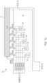
- WCD 100may comprise the following architecture.
- Support structure 112can comprise a garment such as a vest to be worn by the patient 110 .
- Support structure 112can include ECG electrodes such as electrode (ECG 1 ) 122 , electrode (ECG 2 ) 124 , electrode (ECG 3 ) 126 , and electrode (ECG 4 ) 128 , and right-leg drive (RLD) electrode 130 .
- ECG and RLD electrodes and defibrillation electrodes 104 and 108can connect to hub 114 which includes front end electronics, interconnects, conditioning, and routing for the electrodes.
- Hub 114can be attached to the support structure (vest or garment) 112 on the back of the support structure 112 so that the hub 114 is positioned on the patient's back when the patient 110 is wearing the garment.
- the circuitry of hub 114includes an ECG acquisition system which uses five communication lines E 1 _ECG, E 2 _ECG, E 3 _ECG, E 4 _ECG, and RLD to connect to the ECG electrodes 122 - 128 including the RLD electrode 130 of support structure 112 .
- the ECG electrodesconnect to the patient's skin to obtain ECG signals from the patient 110 .
- Hub 114can include a preamplifier 132 and an isolation barrier 134 which will be discussed in more detail with respect to FIG. 4 A and FIG. 4 B , below.
- An alert button 120can connect to hub 114 and may include a speaker and vibrator.
- alert button 120can include a button to allow the patient 110 to divert or abort a defibrillator shock in the event the patient 110 believes an impending shock to be unnecessary.
- Alert button 120can also be referred to as a stop button, a divert button, or a user interface, and the scope of the disclosed subject matter is not limited in this respect.
- Hub 114can connect the electrodes of support structure 112 and the alert button 120 to monitor 116 which houses the main electronics and other components of WCD 100 , which may be contained within a carry pack assembly 118 that may be carried by the patient 110 or worn on the patient's hip.
- Monitor 116may include the battery 142 , the defibrillator capacitor 136 , user interface 140 , and main processor 138 of WCD 100 .
- the processor 138is a TORPEDO System on Module (SOM) available from Logic PD, Inc. of Eden Prairie, Minn., USA, although the scope of the disclosed subject matter is not limited in this respect.
- SOMSystem on Module
- Processor 138is used to run some portions of the shock decision algorithm to determine when WCD 100 should apply a shock to the patient 110 and is capable of applying filters on four channels simultaneously while also controlling wireless communications and other functions of WCD 100 .
- at least some portions of the shock algorithmmay be run by a controller or processor 410 located in the hub 114 as shown in and described with respect to FIG. 4 A and FIG. 4 B , below, and the scope of the disclosed subject matter is not limited in this respect.
- Monitor 116also may include a user interface (UI) 140 to allow a user to control and interact with WCD 100 .
- UIuser interface
- the usermay stop or divert an impending shock via the user interface 140 , or via the alert button 120 .
- Monitor 116also includes a speaker that provides audible alerts and some status indicators.
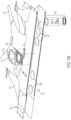
- FIG. 2 Aa diagram of a back view of a garment of a WCD in accordance with one or more embodiments will be discussed.
- the garment shown in FIG. 2 Acomprises the support structure 112 of FIG. 1 A , FIG. 1 C , and FIGS. 1 D and 1 s shown in a vest configuration.
- the garmentmay include shoulder straps 210 and 212 to be placed over the shoulders of the patient 110 and for support of the support structure 112 .
- the garmentmay include a belt portion 214 to be fastened around the waist of the patient 110 .
- the belt portion 214may include various fasteners 216 and 218 , for example closure snaps, to allow the garment to be fitted to different sized users.
- Hub 114can be attached to the back side of the garment, for example on or near the belt portion 214 , to allow various cables to be connected to hub 114 including alert button (divert button) 120 and cabling to connect to the therapy/defibrillator electrodes and ECG electrodes (not shown).
- support structure 112can comprise a vest-like fabric garment to be worn on the patient's body underneath an outer shirt or other clothing to allow the electrodes to contact the patient's skin and hold the electrodes in close proximity to and/or direct contact with the patient's skin. Such an arrangement allows for the WCD 100 to obtain ECG signals from the patient and to allow the shock to be applied to the patient 110 when appropriate.
- support structure 112can comprise a garment made of a soft, stretchy fabric that conforms to the patient's body.
- Multiple sets of closure mechanisms or fasteners 216 and 218may comprise, for example, nine fastening structures on one side of belt portion 214 to selectively mate or couple with three fastening structures on another side of belt portion 214 on an outer layer of the garment as to allow the tightness or fit of the garment to be adjusted to the size of the patient 110 .
- the shoulder straps 210 and 212can be adjustable as well.
- the ECG electrodescan comprise structures 220 integrated into the garment so as to be firmly retained. Wiring from the electrodes 220 to a hub connector 222 can be internal to the garment, for example disposed between the layers of the garment.
- FIG. 2 Ashows an exploded view 224 of one of the electrodes 220 which is shown in and described in further detail with respect to FIG. 3 , below.
- hub 114 as shown in FIG. 2 Acan snap of fit into the hub connector 222 shown in FIG. 2 B to make connections between the electronics of the hub 114 and the patient 110 .
- Embodiments of the garmentare disclosed in U.S. patent application Ser. No. 15/889,040 filed Feb. 5, 2018 which is incorporated herein by reference in its entirety.
- FIG. 3illustrates an exploded view of one of the ECG electrodes 220 shown in FIG. 2 A , above.
- the ECG electrodes 220can comprise a solid silver metal disk electrode such as disk 310 that is resistive rather than capacitive.
- the disk 310 of the ECG electrode 220can be silver plated copper on its face.
- ECG electrode 220can include a printed circuit board assembly (PCBA) 318 including a resistor 316 wherein the back of the PCBA 318 includes a ground plane that provides electromagnetic shielding for the electrode 220 .
- PCBAprinted circuit board assembly
- the ECG cable 320can be shielded as well in some embodiments.
- the assembly 224 of the ECG electrode 220can further include a polyimide structure 312 , a premold structure 314 , and an overmold structure 322 to form the back side of the ECG electrodes 220 .
- the ECG electrodes 220are “dry” electrodes in that they are placed in direct contact against the skin with no gel or electrolyte on the surface of the electrode disk 310 or the patient's skin.
- the solid metal face of the electrode disk 310is non-breathable and traps moisture against the skin. In some embodiments such moisture can enhance pickup of the ECG signal.
- a capacitive electrode systemmay be able to pick up an ECG signal without moisture at the electrode-skin interface. Such capacitive electrodes, however, may be more subject to noise pickup because any motion that modulates the electrode-skin capacitance is readily converted to ECG artifacts that can alter the ECG signal and interfere with ECG analysis.
- the resistive property of the ECG electrode 220is less susceptible to such ECG artifacts to help reduce the likelihood of a false or unnecessary shock event.
- adhesive electrodesmay contain an electrolyte that facilitates ECG signal pickup, adhesive electrodes need to be replaced periodically, and the electrolyte may dry out over time and become more susceptible to interfering with proper ECG analysis.
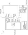
- the ECG front end circuitry 400 in the hub 114comprises a preamplifier 132 that is isolated from processor 410 via an isolation barrier 134 .
- preamplifier 132can comprise an ADAS1000 preamplifier available from Analog Devices, Inc. of Norwood, Mass., USA
- processor 410can comprise a KINETIS K22 microcontroller available from NXP Semiconductors N.V. of Eindhoven, The Netherlands, although the scope of the disclosed subject matter is not limited in this respect.
- Isolation barrier 134serves to isolate the preamplifier from processor 410 and the rest of the WCD 100 system. Signals from the ECG electrodes are provided to the preamplifier 132 which converts the ECG signals into digital signals using analog-to-digital converters (ADCs) 144 . The digital signals are passed from the preamplifier 132 through the isolation barrier 134 to processor 410 through digital isolator 412 .
- the processor 410has a Universal Serial Bus (USB) interface that goes to the monitor 116 and the rest of the WCD 100 system.
- the isolation barrier 134can also include a power isolator 416 to isolate the power provided to the preamplifier 132 from the power provided to the processor 410 .
- ECG front end circuitry 400includes an isolation barrier configured to electrically isolate preamplifier 132 from the main circuit ground to which other circuits of WCD 100 are connected, for example the circuitry of monitor 116 .
- Isolation barrier 134may in turn include an additional circuit ground isolated from the main circuit ground. This isolation enhances the quality of the acquired ECG data, which may result in fewer false alarms and increased patient safety.
- Non-isolated ECG acquisition systemsare susceptible to environmental noise sources such as 60 Hz fields in the vicinity of the WCD 100 . Patient leakage currents could be difficult to control. Further, electrical noise generated by switch mode power supplies or high voltage charging circuits could couple into the ECG acquisition system of the WCD 100 .
- preamplifier 132may have its own ground reference which is different from and isolated from the ground reference used by processor 410 and the remaining circuits of the WCD 100 including the circuits of monitor 116 .
- isolation barrier 134can include digital isolator 412 and power isolator 416 .
- Digital isolator 412can comprise any one or more types of isolators such as galvanic couplers, such as provided by inductance or capacitance devices, such as an isolation transformer or an isolation capacitor, or by a non-electrical means, such as an opto-isolator comprising for example photodiodes and/or phototransistors, and the scope of the disclosed subject matter is not limited in this respect.
- the isolation barrier 134provides protection from the voltages applied by the defibrillator discharge circuit provided by monitor 116 .
- Power isolator 416can be configured to transfer power across the isolation barrier 134 without providing DC coupling across the isolation barrier 134 , for example using a transformer, although the scope of the disclosed subject matter is not limited in this respect.
- the preamplifier 132has four single-ended ECG inputs receiving the ECG signals, an active right-leg drive, a wide dynamic range, and direct-current (DC) leads-off detection.
- preamplifier 132supports DC leads-off detection, and in other embodiments preamplifier supports alternating-current (AC) leads-off detection, or both, and the scope of the disclosed subject matter is not limited in this respect.
- preamplifier 132includes circuitry to measure the patient impedance values between the ECG electrodes. These impedance values can be used to detect the patient's respiration, for example as shown in U.S. application Ser. No. 15/792,860 filed Oct.
- the lines E 1 _ECG, E 2 _ECG, E 3 _ECG, and E 4 _ECGconnect to the ECG electrodes in the garment or support structure 112 .
- the RLD lineconnects to another electrode that is used as a right-leg drive.
- the preamplifier 132digitizes the ECG signals so that digitized values of the ECG signals, not the actual ECG signals, are passed through the isolation barrier 134 to the processor 410 .
- the ECG front end circuitry 400is all contained in a small module comprising the hub 114 that is attached to the garment or support structure 112 , for example in the middle of the patient's back as shown in FIG. 2 A .
- the hub 114may be attached to various other locations on the garment or support structure 112 other than the middle of the patient's back.
- the hub 114may be located at a shoulder area, a side area, or a front or chest area of the patient 110 when the patient 110 is wearing the support structure, and the scope of the disclosed subject matter is not limited in this respect.
- ECG front end circuitry 400also can include a motion sensor 414 such as, for example, a 3-axis accelerometer in the same package comprising the hub 114 .
- the microprocessorsends the ECG signals, the ECG leads-off signals, and the accelerometer signals over a USB connection to monitor 116 which performs most of the signal processing of the WCD 100 .
- ECG leads-offis detected by injecting a low-level DC current into each electrode. The return path for this current is through the RLD line. If an electrode becomes disconnected from the patient 110 , the current injection causes the DC voltage at the electrode to hit the upper rail. When an electrode voltage hits the rail, it is flagged as being “off.”
- the isolation barrier 134 shown in FIG. 4 Bmay contribute to the enhanced performance of the WCD system because the isolation barrier 134 operates to greatly enhance the common-mode rejection of the WCD 100 .
- the preamplifier 132has an input voltage range of 0 V to 2.6 V.
- the ground referenceis nominally at 1.3 V. Any channel with a DC level of greater than 2.4 V or less than 0.2 V can be considered “off”.
- This arrangementgives the ECG front end circuitry 400 a usable dynamic range of +/ ⁇ 1.1 V, which is relatively large compared to the size of the cardiac signal of interest, which is typically around 1 mV. Such a wide dynamic range allows at least most of the ECG filtering to happen in software without the signal being clipped.
- Digital filterscan be very effective at removing artifacts and may contribute to the enhanced false positive performance of the WCD 100 according to embodiments as described herein.
- the preamplifier 132has a very high sample rate so the anti-aliasing filters have little impact on the ECG signal quality.
- the preamplifier 132is to provide data to the processor 410 at a 2 kHz rate with a bandwidth from DC to 250 Hz.
- the softwaredown samples to 500 Hz and further bandlimits the signal for algorithm processing.
- ECG monitoring vectorsused in a WCD in accordance with one or more embodiments will be discussed.
- all the digitized ECG signalsare referenced to the isolated ground of the ECG front end circuitry 400 .
- Differential vectorscan be formed by subtracting two digitized ECG signals. ECG rhythm analysis then can be performed on these four vectors.
- Such differential vectorsmay include, for example, vector (E 24 ) 510 , vector (E 34 ) 512 , vector (E 1 ) 514 , and vector (E 13 ) 516 .
- the defibrillator shock vector 518may be generated between the anterior defibrillation pad 104 and the posterior defibrillation pad 108 .
- the ECG analysis algorithmincludes provisions for excluding vectors that have noise or when a leads-off condition or situation is detected. Monitoring four vectors rather than monitoring two vectors is believed to contribute to enhanced ECG signal analysis and processing of the shock application algorithm to reduce the number of false shock events.
- the signals from four ECG electrodescan be combined to form six different vectors.
- WCD 100uses four vectors for QRS complex analysis and/or heart rate analysis to determine if a shock should be applied.
- the WCD 100is also capable of performing the analysis and shock application determination if one or more of the vectors is noisy or one or more of the ECG leads is in a lead-off condition wherein the lead is not contacting the patient's skin or is not sufficiently contacting the patient's skin to allow an ECG signal to be obtained with that ECG lead.
- three ECG electrodesmay be used and three ECG vectors may be analyzed. In other embodiments, five or six ECG vectors may be analyzed using four ECG electrodes.
- a single vectoris used and analyzed. It should be noted that in general WCD 100 may use and analyze fewer than four vectors or greater than four vectors, and the number of vectors can be increased beyond six vectors by using additional ECG electrodes, and the scope of the disclosed subject matter is not limited in this respect.
- the ECG electrodesare placed circumferentially around the torso of the patient 110 so that the garment or support structure 112 can be used to ensure adequate electrode-skin contact with the patient's skin.
- adhesive electrode embodimentscan provide flexibility in electrode placement in selected locations of the patient's body and may achieve better signal pickup at these selected locations.
- electrode locationscan be selected during a patient-fitting process in which various electrode locations can be changed, and those locations with better or the best ECG signals can be selected, although the scope of the disclosed subject matter is not limited in this respect.
- FIG. 6a diagram of segment based processing used in a WCD in accordance with one or more embodiments will be discussed.
- the segment-based processing analysis 600 shown in FIG. 6is utilized by WCD 100 to make shock/no-shock decisions based at least in part on successive segments of ECG data.
- the segmentscan be 4.8 seconds in duration, although the scope of the disclosed subject matter is not limited in this respect.
- the WCD 100monitors and analyzes ECG data 610 to make a shock/no-shock decision.
- a gatekeeper function 612may be used to provide an early indication that an arrhythmia may be present in the patient 110 .
- An example embodiment of this gatekeeper functionalityis disclosed in U.S. application Ser. No. 15/715,500 filed Sep. 26, 2017 which is incorporated herein by reference in its entirety.
- the main rhythm analysis algorithm 614is triggered to start analyzing successive segments 618 of ECG data, and a shock/no-shock decision is made for each of the individual segments 618 .
- an episodeis opened (Open Episode) 620 in a state machine 616 .
- thisstarts an internal storage of ECG information in a memory of the WCD 100 for later review.
- the shockable rhythmpersists for a confirmation period, for example for two or more segments for ventricular fibrillation (VF) or nineteen or more segments for ventricular tachycardia (VT) in some embodiments
- the patient alert sequence(Alert Patient) 624 is initiated. If the patient 110 does not respond within a specified amount of time after initiation of the patient alert sequence, for example after 20 seconds, then a shock (Shock) 626 is delivered to the patient 110 .
- processor 138is configured to implement the rhythm analysis algorithm 614 to analyze the string of segments to allow for one or more segments of no shock decisions that may, for example, be caused by a false negative decision.
- a VF episodeis opened when five of six consecutive segments are determined to be shockable for VF, and VF is confirmed if the next two segments are confirmed at VF.
- a VT episodeis opened when five of six consecutive segments are determined to be shockable for VT, and VT is confirmed when fifteen of nineteen segments are determined to be shockable for VT.
- the number of no shock segments that are tolerated in the stringcan be based on the accuracy of the shock/no shock algorithm. For example, in embodiments in which a very accurate algorithm is used by processor 138 , a smaller number of no shock segments could be tolerated to reduce the number of false positive episode opening and/or VT/VF confirmations.
- the strings of consecutive segmentsmay be of different lengths, and the criteria for opening an episode and/or confirming VT or VF can be based on different numbers of segments determined to be shockable.
- a shorter string for opening an episodemay increase sensitivity and reduce specificity. That is, a shorter string for opening an episode may result in more episodes being opened but with an increased risk of false alarms that may lead to unneeded shocks.
- a longer stringmay reduce sensitivity and increase specificity, resulting in fewer episodes being opened but the risk of failing to detect VT or VF would increase.
- the number of consecutive segments in a string for opening an episodecan be based on time.
- an episode opening timeis selected to be fifteen seconds, but in other embodiments opening different times can be used.
- a shorter opening timemay increase sensitivity and reduce specificity, which can result in more episodes being opened but with increased false positives.
- a longer opening timemay reduce sensitivity and increase specificity, which can result in fewer episodes being opened but the risk of failing to detect VT or VF would increase.
- the selected timecan determine the number of segments based on the duration of the segments and the amount of overlap between segments. For example, six segments would be needed to achieve an opening time of about fifteen seconds using 4.8 second segments with 50% overlap.
- the number of consecutive segments in a string for confirming VF or VTcan be based on time.
- the VT confirmationis selected to be forty-five seconds to allow for a VT rhythm to spontaneously terminate and/or transient noise to subside.
- the VF confirmationis selected to be five seconds to initiate the patient alert sequence and a potential shock more quickly if the patient alert sequence completes without the patient responding.
- a shorter confirmation timemay result in more patient alert sequences being initiated but with more sequences being aborted by the patient.
- a longer confirmation timemay result in fewer patient alert sequences being initiated but the risk of failing to confirm actual VT or VF would increase.
- the string length or time duration for opening episodes and/or confirming VF/VT and/or the number of tolerated false negative segmentsare selected to meet time to treatment, accuracy, sensitivity and/or specificity criteria.
- WCD 100can utilize a rhythm analysis algorithm (RAA) to make shock/no-shock decisions based on the patient's heart rate and QRS width according to graph 700 .
- QRS 710 widthis shown on the vertical axis
- heart rate 712is shown on the horizontal axis.
- RAArhythm analysis algorithm
- VTcardiac tachycardia
- VFventricular fibrillation
- Table 1summarizes “zones” defining how WCD 100 can classify a patient's heart rhythm, according to some embodiments.
- the heart rate and QRS width values for defining zonescan be different.
- the patient's physicianmay program the WCD 100 with the thresholds for each of these zones.
- FIG. 8illustrates an example QRS complex 800 .
- an example method to measure the width of the QRS complex 800can be as follows. First, the positive peak (R) 810 of the QRS complex 800 is found. The positive peak 810 is used as a reference point for measuring pulse width. Next, the two negative peaks, (Q) 812 and (S) 814 are found. Then, the value and location of the maximum slope between the two negative peaks is found. This is the first reference point for measuring pulse width. The point where the slope has dropped by a specific fraction is found.
- arrhythmia detectionstarts with a 15 second initial arrhythmia detection period at block 910 . If the rhythm is detected as being shockable for 15 seconds, then an episode is opened at block 912 After an episode is opened, there is a pre-alert confirmation period at block 914 before an alarm is given. In some embodiments, for VF the confirmation period at block 914 is five seconds and for VT the confirmation period at block 914 is 45 seconds. In other embodiments, different confirmation periods may be utilized.
- the WCD 100alarms for a period of time referred to as the Initial Patient Response Delay at block 916 . If the patient 110 does not respond, then a shock is given at block 920 after an Initial Pre-Shock Warning Delay at block 918 which may be, for example, five seconds. A Post Shock Delay at block 922 occurs after shock delivery, followed by a Post Shock Patient Response Delay at block 924 . Depending on the state of VF or VT and whether there are shocks remaining to be delivered by WCD 100 , another shock delivery may occur at block 920 after Pre-Shock Warning Delay at block 926 .
- the energy to deliver one or more shockscan be stored in the battery 142 to charge the defibrillator capacitor 136 , which can comprise one or multiple capacitors in some embodiments.
- the amount of energy stored in battery 142can be sufficient to deliver one or more shocks during a given episode until the energy stored in the battery 142 is depleted.
- the defibrillator capacitor 136can be recharged one or more times to deliver one or more additional shocks.
- the defibrillator capacitor 136is recharged after every shock, and it typically takes about six seconds to charge the defibrillator capacitor 136 for each shock.
- the only physical limit to the number of shocks that can be deliveredis the energy in the battery 142 . If the battery 142 has enough energy remaining to charge the defibrillator capacitor 136 one or more times, then WCD 100 can be considered as having remaining shocks to be delivered during an episode. Multiple shocks can be delivered during an episode until the WCD 100 determines that an additional shock would not be effective. In some embodiments, the WCD 100 stops delivering shocks after five shocks have been delivered. Application of multiple shocks can occur via a loop comprising block 920 , block 922 , block 924 , and block 926 . This loop can be repeated depending on the state of VF or VT and whether there are any remaining shocks to be delivered based on the amount of energy remaining in the battery 142 .
- the episodecan be closed at block 930 .
- the battery 142 and/or the defibrillator capacitor 136can be recharged for future use.
- WCD 100can use the VT confirmation time for both VT and VF rhythm types.
- methods of detecting noise in an ECG signalcan be as disclosed in U.S. Pat. No. 9,757,581 which is incorporated herein by reference in its entirety.
- a slow alarm pathway when ECG noise is detectedcan be as disclosed in U.S. Patent Application No. 62/538,159 filed Jul. 28, 2017 which is incorporated herein by reference in its entirety.
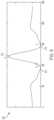
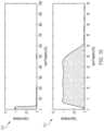
- FIG. 10a diagram of filter responses applied to ECG data in a WCD in accordance with one or more embodiments will be discussed.
- the QRS detector algorithmmay be utilized with robust filtering including fixed finite impulse response (FIR) filters and an adaptive matched filter.
- ECG data presented to the rhythm analysis algorithm implemented by WCD 100is initially filtered with a fixed 2.75 Hz FIR high pass filter and a fixed 25 Hz FIR low pass filter.
- FIG. 10illustrates the frequency response of these filters.
- the frequency response of the algorithm datais shown on graph 1010
- the frequency response of a zoom in passband filteris shown on graph 1012 .
- the ECG data that is fed to the QRS detector in processor 138is also filtered with a matched filter. Since the QRS waveform has a known shape, the matched filter can be used to identify the QRS waveform in the incoming ECG data. Embodiments of such a matched filter can be as described in U.S. patent application Ser. No. 15/724,317 filed Oct. 4, 2017 which is incorporated herein by reference in its entirety.
- a wearable cardioverter defibrillatorincludes electrodes that render an ECG signal of the patient 110 , and a processor 138 that receives ECG data are derived from the rendered ECG signal.
- the processor 138may filter the received ECG data with a matched filter or a matched difference filter to detect QRS complexes and can compute a heart rate from the detected QRS complexes.
- the matched filter or matched difference filteritself can have coefficient values associated with a baseline QRS complex, which enhances detection.
- Processor 138renders the ECG signal internally and can include an optional initial filter.
- the initial filtermay perform one or more types of filtering to the rendered ECG signal, such as passband filtering between 2.75 Hz to 25 Hz to remove artifacts at different frequencies, etc.
- the initial filtercan be implemented by a conventional Finite Impulse Response (FIR) filter.
- FIRFinite Impulse Response
- the initial filtercan be provided within processor 138 , operating digitally.
- QRS complexesmay be detected from outputs of the filters, and a heart rate (HR) can be computed from the detection results.
- HRheart rate
- the WCD 100 shown in FIG. 11incorporates one or more of the features discussed herein to enhance ECG and QRS complex signal data detection along with heart rate data detection in order to achieve a lower false alarm rate.
- the ECG electrodes, ECG 1 122 , ECG 2 124 , ECG 3 126 , and ECG 4 128can comprise silver or silver plated copper electrodes that “dry” attach to the skin of the patient 110 .
- the ECG electrodesprovide ECG/QRS data to preamplifier 132 .
- the preamplifier 132may have a wide dynamic range at its input, for example +/ ⁇ 1.1 V which is much larger than the amplitude of the ECG signals which are about 1 mV.
- the preamplifierincludes analog-to-digital converters (ADCs) 144 to convert the ECG signals into a digital format.
- a right-leg drive (RLD) electrode 130is used to provide a common mode signal so that the ECG signal from the ECG electrodes may be provided to preamplifier 132 as differential signals.
- the digital ECG signalsare provided from the preamplifier 132 eventually to the main processor 138 of monitor 116 via an isolation barrier 134 which operates to electrically isolate the preamplifier 132 and the ECG signals from the rest of the circuitry of WCD 100 .
- the processor 138processes the digital ECG/QRS data received from the preamplifier 132 with one or more digital filters 1112 . Since the preamplifier 132 has a wide dynamic range that is much wider than the amplitude range of the ECG signals, digital filters 1112 may be utilized to process the ECG/QRS data without concern for clipping the incoming signals. One of the digital filters 1112 may include a matched filter to facilitate identification of QRS pulses in the incoming data stream. The wide dynamic range of the preamplifier 132 allows at least most of the ECG filtering to happen in software without the signal being clipped. Digital filters 1112 can be very effective at removing artifacts from the ECG/QRS data and may contribute to the enhanced false positive performance, that is a lower false positive rate, of the WCD 100 according to embodiments as described herein.
- the processor 138can apply the rhythm analysis algorithm (RAA) 1114 using QRS width information and heart rate data extracted from the digital ECG data using the segment-based processing analysis 600 of FIG. 6 and the QRS width versus heart rate graph 700 of FIG. 7 to make a shock or no-shock determination.
- the RAA 1114receives the digitized ECG signal and calculates the heart rate and QRS width for each segment.
- the digitized ECG signalis passed over the isolation barrier 134 , and the heart rate is derived from the digitized ECG signal.
- the heart rate and QRS widthare used for making a shock/no-shock decision for each segment, which then can lead to an alarm and a shock.
- the processor 138will open a tachycardia episode to start the shock process according to method 900 of FIG. 9 A and FIG. 9 B .
- the processor 138can send a shock signal to the high voltage subsystem 132 which will apply a defibrillation voltage across the defib front electrode 104 and the defib back electrode 108 to apply one or more therapeutic shocks until there is no longer any shockable event (VT or VF) or until the energy in the battery 142 is depleted.
- VT or VFshockable event
- the digital filters 1112 coupled with the wide dynamic range of the preamplifier 132 of the ECG front end circuitry 400may allow analysis of signals that otherwise would be clipped in systems with a more limited dynamic range.
- the matched filter of the digital filters 1112preferentially highlights complexes similar to the patient's normal rhythm. As a result, artifacts that otherwise may be difficult to discriminate using other methods may be significantly attenuated by the matched filter to result in a lower false alarm rate of the WCD 100 .
- An example for computing outputs for a filtermay be as follows, for example for a matched filter.
- the above equationis similar to one for convolution, and in particular discrete convolution.
- the convolution of two finite sequencesis defined by extending the sequences to finitely supported functions on the set of integers.
- f(m)are the data values of the ECG signal.
- filter equationis similar to convolution, it is not identical to it. Indeed, while convolution uses the indexes g(n-m), a matched filter uses them in reverse order, which is also time order g(m-n).
- matched filter in the filter equationgo are the coefficient values that define the kernel, and are chosen from a representation of the QRS signal that is to be detected.
- the plot of the matched filter coefficientswould look like a QRS complex.
- a matched filteris sensitive to a specific shape.
- Matched filteringenhances ECG detection, for example by detecting a higher number of the QRS complexes.
- Matched filters for detecting QRS complexesare suitable for WCD 100 .
- Most ECG monitorsuse adhesive electrodes, and if the ECG signal is too noisy, then better skin preparation is likely the best remedy.
- WCD 100 described hereinextreme noise can be tolerated even with using “dry” electrodes, which potentially can be very noisy.
- Patient motioncan cause problems when the “dry” electrodes move relative to the patient's skin which can cause a motion artifact in the ECG.
- a matched filtercan be suitable for segment-based ECG processing as shown in and described with respect to FIG. 6 , above. When continuous processing is applied, an adaptive filter may be more appropriate.
- any one or more of the features of WCD 100may contribute to WCD 100 having an average false alarm rate of less than one false alarm event every ten patient-days.
- Any one or more of the features of WCD 100also may contribute to WCD 100 being required to store data from patient episodes an average of less than one every ten patient-days, thereby reducing the amount of storage need for the data and requiring less analysis of the patient episode data by medical professionals.
- any one or more of the features of WCD 100also may contribute to WCD 100 requiring fewer patient interactions, for example requiring the patient 110 to intervene and stop a false alarm event using alert button 120 .
- any one or more of the following features of WCD 100 described belowalso can contribute to a lower false alarm rate.
- the rhythm analysis algorithm utilized by WCD 100measures the heart rate and QRS width for all channels, for example four channels in some embodiments, excluding those with obvious noise.
- the QRS widthis simply taken from the channel that gives the widest measured width and applied to the rhythm analysis algorithm as described with respect to FIG. 7 , above.
- the heart rate channel selectionis a multi-step process.
- embodiments of the overall channel selection processare described in U.S. Application No. 62/630,398 which is incorporated herein by reference in its entirety.
- an early operationis to estimate the heart rate error using the heart rate “Agreement” and QRS “Organization.”
- the Agreementis an assessment of whether an individual channel is consistent with other channels.
- the QRS Organizationis a measure of whether the morphology of the complexes is similar throughout the segment 618 . Segments 618 with a high Agreement and Organization are judged to have less heart rate error.
- the R-R intervals between QRS complexes 800are “pooled” and the mode, the most common, R-R interval is used for determining the heart rate. For example, it is possible that the chosen heart rate does not correspond with the heart rate calculated for any given channel, which may raise questions.
- the processormay detect sequential peaks within the ECG signal, measure durations of time intervals between the peaks, including between non-sequential peaks, and identify a representative duration. The representative duration is the one that occurs the most often, i.e., the mode.
- a heart ratecan be computed from a duration indicated by the representative duration and, if the heart rate meets a shock condition, the WCD 100 may deliver a shock to the patient 110 .
- the representative durationcan be close to a good R-R interval measurement of a patient, notwithstanding any noise in the ECG signal.
- a WCD 100 incorporating this methodmay have logic for deciding when to use the heart rate mode or when to use a simpler method. The mode tends to be useful when there is a substantial disagreement in the heart rate between channels and there is not an obvious reason for disqualifying one or more channels such as a dislodged ECG lead.
- the pooling processis described in U.S. Application No. 62/501,009 filed May 3, 2017 and is child application Ser. No. 15/948,884 filed Apr. 9, 2018 which are incorporated herein by reference in their entireties.
- WCD 100is designed to select the ECG channel judged to have the least heart rate error regardless of noise.
- noise on the signalmay or may not interfere with the heart rate measurement.
- heart rate datamay be less susceptible to noise than ECG data.
- accelerometer-based motion analysiscan preclude a shock decision while a patient is walking while wearing the WCD 100 .
- the hub 114may include accelerometer 414 to provide accelerometer information to an Accelerometer Algorithm (AA).
- AAAccelerometer Algorithm
- the accelerator algorithmmay be implemented as disclosed in U.S. Patent Application No. 62/446,820 filed Jan. 16, 2017 which is incorporated herein by reference in its entirety.
- Embodiments of the AAwill cause the Rhythm Analysis Algorithm (RAA) to not classify a segment 618 with a shock result if the AA judges that the patient 110 is walking.
- RAARhythm Analysis Algorithm
- the AAcan be configured to detect other types of patient motion in addition to walking.
- a patient 110 in cardiac arrestwill not be moving voluntarily but may exhibit reflexive skeletal muscle convulsions in which case the patient 110 may appear to gasp for breath in a manner known as agonal breathing.
- a patient 110may experience cardiac arrest in a moving vehicle, and WCD 100 can be configured to not mistakenly inhibit therapy because of that motion.
- WCD 100can be configured to detect other voluntary patient motion such as running, riding a bicycle, dancing, performing calisthenics, exercising on a stepper or elliptical machine, and so on, that would indicate that the patient 110 is not in cardiac arrest, while still rejecting movements that are consistent with a person in cardiac arrest such as reflexive skeletal muscle convulsion and agonal breathing described above.
- WCD 100can be configured to prevent false shock alarms for a wide range of patient activities in addition to walking.
- the WCD 100is configured to have noise detection that is capable of distinguishing high-amplitude artifacts from QRS complexes 800.
- Example noise detectionis disclosed in U.S. patent application Ser. No. 15/861,463 filed Jan. 3, 2018 which is incorporated herein by reference in its entirety.
- the WCD 100can detect high amplitude noise such as QRS complexes or a baseline shift larger than a threshold such as 5 mV, and high frequency noise as a number of baseline crossings or number of extremely narrow ECG peaks greater than a threshold.
- the WCD 100uses the VT pathway as described with respect to FIG. 9 A and FIG. 9 B above which has an extended confirmation time.
- the WCD 100classifies the segment as “Noisy” rather than shock/no-shock.
- the WCD 100is configured to utilize “Sticky” leads-off and noise processing detects periods of leads-off and noise and precludes rhythm analysis until the signals have cleared up.
- the WCD 100can be configured to keep a circular buffer of noise analysis results, and if the number of the “Noisy” results exceed a threshold, then the WCD 100 enters a “Noise State”. For example, in some embodiments, if two out of the last five analysis results are noisy, then the WCD 100 enters the Noise State. Further rhythm analysis is inhibited while the WCD 100 is in the Noise State. The WCD 100 stays in the Noise State until five successive segments 618 yield a non-noisy result.
- the WCD 100if one ECG lead is detected as being “off”, that is not touching the patient's skin, then the vectors derived from that electrode are excluded from further analysis. The WCD 100 , however, continues to analyze the remaining vectors. Further, in some four-channel embodiments, if two ECG leads are detected as being “off” then the segment 618 is marked as Analysis Not Possible (ANP). If three out of five segments 618 are marked as ANP, then the WCD 100 enters the ANP state. Further rhythm analysis is suspended while the WCD 100 is in the ANP state. The WCD 100 stays in the ANP state until five successive segments 618 are detected not to be ANP.
- ANPAnalysis Not Possible
- Both the Noise State and the ANP statemay be referred to as being “sticky” in some embodiments because once the WCD 100 enters either state, it is relatively difficult for WCD 100 to leave that state. This is so because ECG signals actually may be corrupted without tripping either the leads-off or the noise thresholds. If some segments 618 trip either a noise or leads-off threshold, it is likely that subsequent segments 618 may be corrupted even if the WCD 100 is unable to detect the corruption. To avoid this problem, in some embodiments the WCD 100 is configured to wait for a series of apparently clean segments before resuming analysis. Embodiments of this approach are described in more detail in U.S. Patent Application No. 62/538,145 filed on Jul. 28, 2017 which is incorporated herein by reference in its entirety.
- the wearable cardioverter defibrillator WCD 100 as disclosed hereinis capable of operating with a reduced false alarm rate.
- Conventional WCDsanalyze patient signals to determine if the patient is experiencing a cardiac arrest. If a VT/VF arrest is suspected, the WCD 100 will alarm to warn the patient and bystanders of an impending shock.
- Conventional WCDsoften alarm inappropriately, that is when the patient is not in cardiac arrest.
- the Zoll LifeVestis the only WCD with published clinical performance. It has been discovered that the Zoll LifeVest WCD gives an inappropriate shock alarm about once every three patient-days on average.
- the WCD 100in order to assess the effect of device-triggered episodes, stores an episode such as a short clip or duration of the ECG data when the WCD 100 detects a potentially shockable rhythm. If the rhythm spontaneously converts, or if the algorithm changes its shock decision, or if the patient 110 presses the divert/alert/stop shock button, then the patient 110 does not receive a shock. Even though the patient 110 is not shocked, the episode is stored for analysis. Stored episodes can be of diagnostic value to clinicians.
- the low false alarm rate of WCD 100may apply to cardiac patients with a low ejection fraction, for example less than about 40%, who are wearing the WCD 100 during normal daily activities, although the scope of the disclosed subject matter is not limited in this respect.
- WCD 100has a low false alarm rate. Furthermore, WCD 100 also has a low false episode rate.
- WCD 100makes a determination that a patient 110 has an arrhythmia, WCD 100 opens an episode and begins to store data related to the episode.
- processor 138 of monitor 116stores the episode data in a non-volatile or flash memory such as an internal memory or in a removable memory card such as Secure Digital (SD) card and/or Multimedia Card (MMC) (SD/MMC) or similar. If the arrythmia persists, then the WCD 100 generates an alarm.
- SDSecure Digital
- MMCMultimedia Card
- the WCD 100delivers a therapeutic shock to the patient 110 .
- Episode datais stored so that a physician can review the episode data to analyze what the patient's heart rhythm looked like during the episode in order to understand what is wrong with the patient even when a shock is not delivered.
- False episodesmay be incurred due to noise or signal artifacts just like false alarms. False episodes can be annoying to the physician because there could be nothing wrong with the patient's heart even though an episode occurred. As a result, the physician may need to review a large number of false episodes in order to find one true episode from a set of episodes. Sifting through such a large number of false episodes, however, may be a tedious and inefficient task for the physician, and as a result the physician may be disinclined to review the stored episodes at all if the vast majority of them are merely due to noise and not any issue with the patient's heart. Thus, providing a WCD 100 with a low false episode rate can facilitate physician review of the patient's episode data.
- the same mechanisms discussed herein that contribute to WCD 100 having a low false alarm ratealso contribute to WCD 100 having a low false episode rate.
- unnecessary shocksalso can be problematic. A WCD that is confused by noise on the ECG would also be more prone to giving unnecessary shocks. Unnecessary shocks can be very traumatic for the patient 110 because the shocks can be painful, and it is possible that an unnecessary shock could trigger the patient 110 into a life-threatening arrhythmia.
- the same mechanisms discussed herein that contribute to WCD 100 having a low false alarm ratealso contribute to WCD 100 having a low unnecessary or false shock rate.
- a low false alarm ratecan be achieved by incorporating additional patient monitoring parameters.
- ECG analysiscan be coupled with a pulse detection circuit to confirm cardiac arrest before alarming the patient 110 .
- a wearable cardioverter defibrillatorcomprises a plurality of electrocardiography (ECG) electrodes, a right-leg drive (RLD) electrode, and a plurality of defibrillator electrodes to contact the patient's skin when the WCD is delivering therapy to the patient, a user interface, a preamplifier coupled to the ECG electrodes and the RLD electrode to obtain ECG data from the patient as one or more ECG vectors, a processor to receive ECG data from the preamplifier and an abort signal from the user interface, an isolation barrier to isolate the preamplifier from the processor, and a high voltage subsystem to provide a defibrillation voltage to the patient through the plurality of defibrillator electrodes in response to a shock signal received from the processor.
- ECGelectrocardiography
- RLDright-leg drive
- defibrillator electrodesto contact the patient's skin when the WCD is delivering therapy to the patient
- a user interfacea preamplifier
- the processoris to determine when a shock criterion is met based on the ECG data from the preamplifier, and to provide the shock signal in the event the shock criterion is met and the abort signal is not received within a predetermined time period of the shock criterion being met.
- the processoris to determine QRS width data and heart rate data from the ECG data, and to determine when the shock criterion is met based on the QRS width data and the heart rate data.
- the preamplifierincludes one or more analog-to-digital converters (ADCs) to convert the ECG data into digitized ECG data that is provided across the isolation barrier to the processor.
- the one or more vectorscomprises four vectors.
- the processoris to monitor the one or more ECG vectors, and is configured to determine when the shock criterion is met when one or more of the ECG vectors is noisy or when one or more of the plurality of ECG electrodes is in a lead-off condition.
- the preamplifieris configured to receive the ECG data as differential signals using a voltage of the RLD electrode as a common mode signal or a common mode potential.
- the preamplifierhas a dynamic range at an input that is an order of magnitude or greater than a magnitude of the ECG data.
- the ECG data received by the processor from the preamplifieris processed using one or more digital filters.
- one or more QRS pulsesare identified in the ECG data using a matched filter in the processor to determine the QRS width data and/or the heart rate data.
- one or more of the plurality of ECG electrodescomprises a dry electrode to directly contact the patient's skin without using a gel or an adhesive.
- one or more of the ECG electrodescomprises a silver disk or a silver plated copper disk.
- one or more of the ECG electrodescomprises a resistive electrode.
- the processoris to process the ECG data received from the preamplifier in segments of ECG data, wherein the shock criterion is met when a string of a predetermined number of segments indicate a shock decision should be made.
- the preamplifieris configured to obtain one or more impedance values between the ECG electrodes, and to provide digitized impedance values to the processor across the isolation barrier.
- the processorincurs less than one false alarm indicating the shock criterion has been met every ten patient-days.
- a method to determine whether a defibrillation shock should be applied with a wearable cardioverter defibrillatorcomprises receiving electrocardiography (ECG) data from a patient using the WCD with a preamplifier coupled to one or more ECG electrodes and a right-leg drive (RLD) electrode coupled to the patient's skin to obtain ECG data from the patient as one or more ECG vectors, receiving ECG data from the preamplifier with a processor through an isolation barrier to electrically isolate the preamplifier from the processor, determining with the processor if a shock criterion is met based on a combination of heart rate data and a width of one or more QRS pulses identified in the ECG data, signaling the patient that the defibrillation shock is about to be applied, and applying the defibrillation shock to the patient unless a stop shock signal is caused by the patient within a predetermined period of time after signaling the patient.
- ECGelectrocardiography
- RLDright-leg drive
- the methodfurther comprises converting the ECG data into digitized ECG data and providing the digitized ECG data across the isolation barrier to the processor.
- the one or more vectorscomprises four vectors.
- said determining when the shock criterion is metoccurs even when one or more of the ECG vectors is noisy or when one or more of the ECG electrodes is in a lead-off condition.
- the methodfurther comprises processing the ECG data with the processor using one or more digital filters.
- the methodfurther comprises identifying the one or more QRS pulses in the ECG data using a matched filter in the processor.
- the methodfurther comprises processing the ECG data with the processor in segments of ECG data, wherein the shock criterion is met when a string of a predetermined number of segments indicate a shock decision should be made.
- the methodfurther comprises obtaining one or more impedance values between the ECG electrodes with the preamplifier, and providing digitized impedance values to the processor across the isolation barrier.
- the methodfurther comprises incurring less than one false alarm indicating the shock criterion has been met every ten patient-days.
- wearable cardioverter defibrillator (WCD) systemcomprises a support structure comprising a plurality of electrocardiography (ECG) electrodes, a right-leg drive (RLD) electrode, and a plurality of defibrillator electrodes to contact the patient's skin when the WCD is delivering therapy to the patient, a hub comprising a preamplifier coupled to the ECG electrodes and the RLD electrode to obtain ECG data from the patient as one or more ECG vectors, and an isolation barrier to electrically isolate the preamplifier, an alert button coupled to the hub, and a monitor coupled to the hub and comprising a processor to receive the ECG data from the preamplifier through the isolation barrier, and a high voltage subsystem to provide a defibrillation voltage to the patient through the plurality of defibrillator electrodes in response to a shock signal received from the processor in the event a shock criterion is met and a stop shock signal is not received from the patient via the alert button
- the processoris to determine if the shock criterion is met based on a combination of the heart rate data identified in the ECG data and a width of one or more QRS pulses identified in the ECG data.
- the preamplifierhas a dynamic range at an input that is an order of magnitude or greater than a magnitude of the ECG data, wherein the dynamic range allows the ECG data received by the processor to be processed using one or more digital filters without clipping.
- the one or more QRS pulsesare identified in the ECG data using a matched filter in the processor.
- the processoris to process the ECG data received from the preamplifier in periodic segments, wherein the shock criterion is evaluated for each of the segments of ECG data, and a shock decision is made when the shock criterion is met for a predetermined number of successive segments.
- the processorincurs less than one false alarm indicating the shock criterion has been met every ten patient-days.
- a wearable cardioverter defibrillatorcomprises a plurality of electrocardiography (ECG) electrodes and a plurality of therapy electrodes, the plurality of ECG electrodes and the plurality of therapy electrodes arranged to operatively contact a patient's skin when the WCD is operably attached to the patient, an amplifier coupled to the plurality of ECG electrodes to obtain multi-vector ECG data from the patient, an energy storage device configured to store an electrical charge, a high voltage subsystem coupled to the energy storage device and the plurality of therapy electrodes, and a processor coupled to the amplifier, the high voltage subsystem, and a user interface.
- ECGelectrocardiography
- therapy electrodesarranged to operatively contact a patient's skin when the WCD is operably attached to the patient
- an amplifiercoupled to the plurality of ECG electrodes to obtain multi-vector ECG data from the patient
- an energy storage deviceconfigured to store an electrical charge
- a high voltage subsystemcoupled to the energy storage device and the plurality of therapy electrodes
- the processoris configured to issue an alarm if a shock criterion is met, wherein the alarm is issued with a false alarm rate of less than one false alarm in ten patient days, and cause the high voltage subsystem to discharge the stored electrical charge from the energy storage device to the patient in response to the patient failing to respond to the alarm via the user interface within a predetermined time.
- the WCDfurther comprises a right-leg drive (RLD) electrode coupled to the amplifier to provide a common mode reference for the multi-vector ECG data.
- the WCDfurther comprises an isolation barrier to isolate the amplifier from the processor, wherein the amplifier is configured to transmit a digitized version of the multi-vector ECG data across the isolation barrier to the processor.
- At least one parameter of the multi-vector ECG datacomprises heart rate, QRS width, QRS organization, or accelerometer data, or a combination thereof.
- the processoris configured to determine QRS width, heart rate, or QRS organization, or a combination thereof, from the multi-vector ECG data.
Landscapes
- Health & Medical Sciences (AREA)
- Life Sciences & Earth Sciences (AREA)
- Engineering & Computer Science (AREA)
- Cardiology (AREA)
- Animal Behavior & Ethology (AREA)
- General Health & Medical Sciences (AREA)
- Veterinary Medicine (AREA)
- Biomedical Technology (AREA)
- Public Health (AREA)
- Heart & Thoracic Surgery (AREA)
- Molecular Biology (AREA)
- Surgery (AREA)
- Physics & Mathematics (AREA)
- Pathology (AREA)
- Medical Informatics (AREA)
- Biophysics (AREA)
- Radiology & Medical Imaging (AREA)
- Nuclear Medicine, Radiotherapy & Molecular Imaging (AREA)
- Signal Processing (AREA)
- Physiology (AREA)
- Artificial Intelligence (AREA)
- Computer Vision & Pattern Recognition (AREA)
- Psychiatry (AREA)
- Human Computer Interaction (AREA)
- Electrotherapy Devices (AREA)
- Measurement And Recording Of Electrical Phenomena And Electrical Characteristics Of The Living Body (AREA)
Abstract
Description
| TABLE 1 |
| No Shock, VT, SVT and VF Zones |
| Parameter | No Shock | VT | VF | SVT |
| Heart Rate | <170 BPM | >170 | BPM | >200 | BPM | >170 | BPM |
| QRS Width | — | >80 | ms | >80 | ms | <80 | ms |
Output(n)=Σm=0length(f)f(m)*g(m−n)
The above equation is similar to one for convolution, and in particular discrete convolution. The convolution of two finite sequences is defined by extending the sequences to finitely supported functions on the set of integers. In the above equation, f(m) are the data values of the ECG signal. While filter equation is similar to convolution, it is not identical to it. Indeed, while convolution uses the indexes g(n-m), a matched filter uses them in reverse order, which is also time order g(m-n). Moreover, for the matched filter in the filter equation, go are the coefficient values that define the kernel, and are chosen from a representation of the QRS signal that is to be detected. In other words, for a QRS detector the plot of the matched filter coefficients would look like a QRS complex. Rather than being frequency selective, a matched filter is sensitive to a specific shape.
Claims (21)
Priority Applications (2)
| Application Number | Priority Date | Filing Date | Title |
|---|---|---|---|
| US17/546,892US12179032B2 (en) | 2018-02-14 | 2021-12-09 | Wearable cardioverter defibrillator (WCD) segment based episode opening and confirmation periods |
| US19/006,883US20250213878A1 (en) | 2018-02-14 | 2024-12-31 | Wearable cardioverter defibrillator (wcd) segment based episode opening and confirmation periods |
Applications Claiming Priority (4)
| Application Number | Priority Date | Filing Date | Title |
|---|---|---|---|
| US201862630695P | 2018-02-14 | 2018-02-14 | |
| US16/382,575US11160990B1 (en) | 2018-02-14 | 2019-04-12 | Wearable cardioverter defibrillator (WCD) alarms |
| US17/503,065US11844953B2 (en) | 2018-02-14 | 2021-10-15 | Wearable cardioverter defibrillator (WCD) |
| US17/546,892US12179032B2 (en) | 2018-02-14 | 2021-12-09 | Wearable cardioverter defibrillator (WCD) segment based episode opening and confirmation periods |
Related Parent Applications (1)
| Application Number | Title | Priority Date | Filing Date |
|---|---|---|---|
| US17/503,065Continuation-In-PartUS11844953B2 (en) | 2018-02-14 | 2021-10-15 | Wearable cardioverter defibrillator (WCD) |
Related Child Applications (1)
| Application Number | Title | Priority Date | Filing Date |
|---|---|---|---|
| US19/006,883ContinuationUS20250213878A1 (en) | 2018-02-14 | 2024-12-31 | Wearable cardioverter defibrillator (wcd) segment based episode opening and confirmation periods |
Publications (2)
| Publication Number | Publication Date |
|---|---|
| US20220143389A1 US20220143389A1 (en) | 2022-05-12 |
| US12179032B2true US12179032B2 (en) | 2024-12-31 |
Family
ID=81454933
Family Applications (2)
| Application Number | Title | Priority Date | Filing Date |
|---|---|---|---|
| US17/546,892Active2040-03-01US12179032B2 (en) | 2018-02-14 | 2021-12-09 | Wearable cardioverter defibrillator (WCD) segment based episode opening and confirmation periods |
| US19/006,883PendingUS20250213878A1 (en) | 2018-02-14 | 2024-12-31 | Wearable cardioverter defibrillator (wcd) segment based episode opening and confirmation periods |
Family Applications After (1)
| Application Number | Title | Priority Date | Filing Date |
|---|---|---|---|
| US19/006,883PendingUS20250213878A1 (en) | 2018-02-14 | 2024-12-31 | Wearable cardioverter defibrillator (wcd) segment based episode opening and confirmation periods |
Country Status (1)
| Country | Link |
|---|---|
| US (2) | US12179032B2 (en) |
Families Citing this family (1)
| Publication number | Priority date | Publication date | Assignee | Title |
|---|---|---|---|---|
| WO2025111300A1 (en)* | 2023-11-22 | 2025-05-30 | Zoll Medical Corporation | Tachyarrhythmia discrimination |
Citations (165)
| Publication number | Priority date | Publication date | Assignee | Title |
|---|---|---|---|---|
| US3724455A (en) | 1970-06-02 | 1973-04-03 | P Unger | Cardiac warning device |
| US4291699A (en) | 1978-09-21 | 1981-09-29 | Purdue Research Foundation | Method of and apparatus for automatically detecting and treating ventricular fibrillation |
| US4583524A (en) | 1984-11-21 | 1986-04-22 | Hutchins Donald C | Cardiopulmonary resuscitation prompting |
| US4617938A (en) | 1984-12-26 | 1986-10-21 | Yair Shimoni | Method and system for distinguishing R-wave electrocardiograph signals for synchronizing purposes |
| US4619265A (en) | 1984-03-08 | 1986-10-28 | Physio-Control Corporation | Interactive portable defibrillator including ECG detection circuit |
| US4895151A (en) | 1987-07-20 | 1990-01-23 | Telectronics N.V. | Apparatus and method for therapy adjustment in implantable |
| US4928690A (en) | 1988-04-25 | 1990-05-29 | Lifecor, Inc. | Portable device for sensing cardiac function and automatically delivering electrical therapy |
| US4955381A (en) | 1988-08-26 | 1990-09-11 | Cardiotronics, Inc. | Multi-pad, multi-function electrode |
| US5078134A (en) | 1988-04-25 | 1992-01-07 | Lifecor, Inc. | Portable device for sensing cardiac function and automatically delivering electrical therapy |
| US5228449A (en) | 1991-01-22 | 1993-07-20 | Athanasios G. Christ | System and method for detecting out-of-hospital cardiac emergencies and summoning emergency assistance |
| US5348008A (en) | 1991-11-25 | 1994-09-20 | Somnus Corporation | Cardiorespiratory alert system |
| US5376104A (en) | 1992-02-07 | 1994-12-27 | Nihon Kohden Corporation | Defibrillator with electrocardiogram monitor |
| US5381803A (en) | 1993-03-12 | 1995-01-17 | Hewlett-Packard Corporation | QRS detector for defibrillator/monitor |
| US5394892A (en) | 1990-04-02 | 1995-03-07 | K J Mellet Nominees Pty Ltd | CPR prompting apparatus |
| US5405362A (en) | 1991-04-29 | 1995-04-11 | The Board Of Regents For The University Of Texas System | Interactive external defibrillation and drug injection system |
| US5425749A (en) | 1993-09-16 | 1995-06-20 | Angeion Corporation | Preemptive cardioversion therapy in an implantable cardioverter defibrillator |
| US5474574A (en) | 1992-06-24 | 1995-12-12 | Cardiac Science, Inc. | Automatic external cardioverter/defibrillator |
| US5554174A (en) | 1995-10-18 | 1996-09-10 | Pacesetter, Inc. | System and method for automatically adjusting cardioverter and defibrillator shock energy as a function of time-to-therapy |
| US5601612A (en) | 1993-08-06 | 1997-02-11 | Heartstream, Inc. | Method for applying a multiphasic waveform |
| US5630834A (en) | 1995-05-03 | 1997-05-20 | Medtronic, Inc. | Atrial defibrillator with means for delivering therapy in response to a determination that the patient is likely asleep |
| US5662690A (en) | 1994-12-08 | 1997-09-02 | Heartstream, Inc. | Defibrillator with training features and pause actuator |
| US5709215A (en) | 1995-09-06 | 1998-01-20 | Angeion Corporation | R-wave detection method for implantable cardioverter defibrillators |
| US5769872A (en) | 1996-12-18 | 1998-06-23 | Zmd Corporation | Electrotherapy circuit and method for shaping current waveforms |
| US5782878A (en) | 1994-12-07 | 1998-07-21 | Heartstream, Inc. | External defibrillator with communications network link |
| US5792204A (en) | 1996-05-08 | 1998-08-11 | Pacesetter, Inc. | Methods and apparatus for controlling an implantable device programmer using voice commands |
| US5803927A (en) | 1993-08-06 | 1998-09-08 | Heartstream, Inc. | Electrotherapy method and apparatus for external defibrillation |
| WO1998039061A2 (en) | 1997-03-07 | 1998-09-11 | Cadent Medical Corporation | Wearable defibrillation system |
| US5819007A (en) | 1996-03-15 | 1998-10-06 | Siemens Medical Systems, Inc. | Feature-based expert system classifier |
| US5902249A (en) | 1995-03-03 | 1999-05-11 | Heartstream, Inc. | Method and apparatus for detecting artifacts using common-mode signals in differential signal detectors |
| US5913685A (en) | 1996-06-24 | 1999-06-22 | Hutchins; Donald C. | CPR computer aiding |
| US5944669A (en) | 1997-11-20 | 1999-08-31 | Lifecor, Inc. | Apparatus and method for sensing cardiac function |
| US6047203A (en) | 1997-03-17 | 2000-04-04 | Nims, Inc. | Physiologic signs feedback system |
| US6065154A (en) | 1998-04-07 | 2000-05-23 | Lifecor, Inc. | Support garments for patient-worn energy delivery apparatus |
| US6068651A (en) | 1998-03-26 | 2000-05-30 | Pacesetter, Inc. | Atrial defibrillation lock out feature |
| US6108197A (en) | 1992-05-15 | 2000-08-22 | Via, Inc. | Flexible wearable computer |
| US6201992B1 (en) | 1999-04-01 | 2001-03-13 | Agilent Technologies, Inc. | Defibrillator interface capable of generating video images |
| US6263238B1 (en) | 1998-04-16 | 2001-07-17 | Survivalink Corporation | Automatic external defibrillator having a ventricular fibrillation detector |
| US6287328B1 (en) | 1999-04-08 | 2001-09-11 | Agilent Technologies, Inc. | Multivariable artifact assessment |
| US6319011B1 (en) | 1995-04-06 | 2001-11-20 | Michael J. Motti | Automatic training defibrillator simulator and method |
| US6334070B1 (en) | 1998-11-20 | 2001-12-25 | Medtronic Physio-Control Manufacturing Corp. | Visual and aural user interface for an automated external defibrillator |
| US6351671B1 (en) | 1998-12-11 | 2002-02-26 | Laerdal Medical As | System for measuring and analyzing cardio-pulmonary-resuscitation (CPR) parameters for use with and by an external defibrillator (AED) or a training defibrillator |
| US6356785B1 (en) | 1997-11-06 | 2002-03-12 | Cecily Anne Snyder | External defibrillator with CPR prompts and ACLS prompts and methods of use |
| US6437083B1 (en) | 2001-12-06 | 2002-08-20 | General Electric Company | Process for preparing branched aromatic polycarbonates |
| US6529875B1 (en) | 1996-07-11 | 2003-03-04 | Sega Enterprises Ltd. | Voice recognizer, voice recognizing method and game machine using them |
| US20030158593A1 (en) | 2002-02-19 | 2003-08-21 | Heilman Marlin S. | Cardiac garment |
| US20030187479A1 (en) | 2002-03-28 | 2003-10-02 | Tran Thong | Method and apparatus for preventing heart tachyarrhythmia |
| US6681003B2 (en) | 1999-10-05 | 2004-01-20 | Lifecor, Inc. | Data collection and system management for patient-worn medical devices |
| US6694187B1 (en) | 2000-06-23 | 2004-02-17 | Koninklijke Philips Electronics N.V. | External defibrillator instruction system and method |
| US20040049117A1 (en) | 2002-09-10 | 2004-03-11 | Ideker Raymond E. | Devices for detecting the presence of cardiac activity following administration of defibrillation therapy |
| US6762917B1 (en) | 2001-06-12 | 2004-07-13 | Novx Corporation | Method of monitoring ESC levels and protective devices utilizing the method |
| US20040220623A1 (en) | 2003-04-30 | 2004-11-04 | Medtronic, Inc. | Configurable cardioversion and defibrillation therapies in the presence of coexisting atrial and ventricular arrhythmia |
| US20040230105A1 (en) | 2003-05-15 | 2004-11-18 | Widemed Ltd. | Adaptive prediction of changes of physiological/pathological states using processing of biomedical signals |
| US20050107834A1 (en) | 2003-11-13 | 2005-05-19 | Freeman Gary A. | Multi-path transthoracic defibrillation and cardioversion |
| US20050131476A1 (en) | 2003-12-11 | 2005-06-16 | Jaeho Kim | Cardiac response classification using multiple classification windows |
| US6941168B2 (en) | 2001-12-12 | 2005-09-06 | Cardiac Pacemakers, Inc. | System and method for treating an adverse cardiac condition using combined pacing and drug delivery |
| US20060017575A1 (en) | 2004-07-20 | 2006-01-26 | Medtronic, Inc. | Alert system and method for an implantable medical device |
| US7065401B2 (en) | 2002-05-08 | 2006-06-20 | Michael Worden | Method of applying electrical signals to a patient and automatic wearable external defibrillator |
| US20060173364A1 (en) | 2004-10-29 | 2006-08-03 | Worcester Polytechnic Institute | Multi-channel electrophysiologic signal data acquisition system on an integrated circuit |
| US7149576B1 (en) | 2000-07-10 | 2006-12-12 | Cardiodynamics International Corporation | Apparatus and method for defibrillation of a living subject |
| US20070179539A1 (en) | 2006-01-31 | 2007-08-02 | Degroot Paul J | Method and apparatus for controlling arrhythmia detection and treatment based on patient posture |
| US20070203418A1 (en) | 2006-02-27 | 2007-08-30 | Cardiosoft L.L.P. | Multi-Channel System for Beat to Beat QT Interval Variability |
| US20080033495A1 (en) | 2006-08-01 | 2008-02-07 | Kumar Uday N | External Defibrillator |
| US7336994B2 (en) | 2004-01-16 | 2008-02-26 | Medtronic, Inc. | Control of atrial defibrillation therapy based on hemodynamic sensor feedback |
| US7379771B2 (en) | 2004-11-01 | 2008-05-27 | Cardiac Pacemakers, Inc. | Conduction based automatic therapy selection |
| US20080208070A1 (en) | 2005-06-23 | 2008-08-28 | Koninklijke Philips Electronics N.V. | Defibrillator with Automatic Shock First/Cpr First Algorithm |
| US20080215103A1 (en) | 2005-06-24 | 2008-09-04 | Koninklijke Philips Electronics N.V. | Aed Having Mandatory Pause for Administrating Cpr |
| US7460900B1 (en) | 2005-09-14 | 2008-12-02 | Pacesetter, Inc. | Method and apparatus for detecting ischemia using changes in QRS morphology |
| US20080306560A1 (en) | 2007-06-06 | 2008-12-11 | Macho John D | Wearable defibrillator with audio input/output |
| US20080312709A1 (en) | 2007-06-13 | 2008-12-18 | Volpe Shane S | Wearable medical treatment device with motion/position detection |
| US20080312708A1 (en) | 2005-12-16 | 2008-12-18 | Koninklijke Philips Electronics, N.V. | Automatic External Defibrillator with Increased Cpr Administration Time |
| US20090005827A1 (en) | 2007-06-26 | 2009-01-01 | David Weintraub | Wearable defibrillator |
| US20090018595A1 (en) | 2007-07-11 | 2009-01-15 | Pacesetter, Inc. | Systems and methods for employing multiple filters to detect t-wave oversensing and to improve tachyarrhythmia detection within an implantable medical device |
| US7559902B2 (en) | 2003-08-22 | 2009-07-14 | Foster-Miller, Inc. | Physiological monitoring garment |
| US20100007413A1 (en) | 2006-11-10 | 2010-01-14 | Koninklijke Philips Electronics N.V. | Ecg electrode contact quality measurement system |
| US20100114248A1 (en) | 2008-10-31 | 2010-05-06 | Medtronic, Inc. | Isolation of sensing and stimulation circuitry |
| US20100298899A1 (en) | 2007-06-13 | 2010-11-25 | Donnelly Edward J | Wearable medical treatment device |
| US20100331904A1 (en) | 2009-06-29 | 2010-12-30 | Cameron Health, Inc. | Adaptive Confirmation of Treatable Arrhythmia in Implantable Cardiac Stimulus Devices |
| US7865238B2 (en) | 2004-09-29 | 2011-01-04 | Koninklijke Philips Electronics N.V. | High-voltage module for an external defibrillator |
| US7870761B2 (en) | 2002-05-14 | 2011-01-18 | Koninklijke Philips Electronics N.V. | Garment and method for producing the same |
| US7894894B2 (en) | 2006-03-29 | 2011-02-22 | Medtronic, Inc. | Method and apparatus for detecting arrhythmias in a subcutaneous medical device |
| US20110202101A1 (en)* | 2010-02-12 | 2011-08-18 | Qing Tan | Defibrillator Charging |
| US8036746B2 (en) | 2003-10-30 | 2011-10-11 | Cardiac Pacemakers, Inc. | Temporary disablement feature for implantable device with anti-tachyarrhythmia functions |
| US20110288605A1 (en) | 2010-05-18 | 2011-11-24 | Zoll Medical Corporation | Wearable ambulatory medical device with multiple sensing electrodes |
| US20110288604A1 (en) | 2010-05-18 | 2011-11-24 | Kaib Thomas E | Wearable therapeutic device |
| US20120022355A1 (en) | 2002-01-16 | 2012-01-26 | Charles Bryan Byrd | Integrated electrophysiology and ultrasound imaging system |
| US20120059270A1 (en) | 2009-06-12 | 2012-03-08 | Bard Access Systems, Inc. | Apparatus and method for catheter navigation using endovascular energy mapping |
| US8135462B2 (en) | 2002-08-26 | 2012-03-13 | Physio-Control, Inc. | Pulse detection using patient physiological signals |
| US20120108911A1 (en) | 2009-03-30 | 2012-05-03 | DanMedical Ltd. | Medical apparatus |
| US20120112903A1 (en) | 2010-11-08 | 2012-05-10 | Zoll Medical Corporation | Remote medical device alarm |
| US20120150008A1 (en) | 2010-12-09 | 2012-06-14 | Kaib Thomas E | Electrode with redundant impedance reduction |
| US20120144551A1 (en) | 2010-12-09 | 2012-06-14 | Eric Guldalian | Conductive Garment |
| US20120158075A1 (en) | 2010-12-16 | 2012-06-21 | Kaib Thomas E | Water resistant wearable medical device |
| US20120265265A1 (en) | 2011-04-13 | 2012-10-18 | Mehdi Razavi | Automated External Defibrillator Pad System |
| US20120277638A1 (en) | 2008-07-11 | 2012-11-01 | Medtronic, Inc. | Obtaining baseline patient information |
| US20120283794A1 (en) | 2011-05-02 | 2012-11-08 | Kaib Thomas E | Patient-worn energy delivery apparatus and techniques for sizing same |
| US20120293323A1 (en) | 2011-03-25 | 2012-11-22 | Zoll Medical Corporation | System and method for adapting alarms in a wearable medical device |
| US20120302860A1 (en) | 2011-03-25 | 2012-11-29 | Zoll Medical Corporation | Selection of optimal channel for rate determination |
| US20120310315A1 (en) | 2009-03-17 | 2012-12-06 | Savage Walter T | Device and method for reducing patient transthoracic impedance for the purpose of delivering a therapeutic current |
| US20120316611A1 (en) | 2009-11-13 | 2012-12-13 | Antonis Armoundas | Method and apparatus for the detection and control of repolarization alternans |
| US20130085538A1 (en) | 2011-09-01 | 2013-04-04 | Zoll Medical Corporation | Wearable monitoring and treatment device |
| US20130231711A1 (en) | 2012-03-02 | 2013-09-05 | Thomas E. Kaib | Systems and methods for configuring a wearable medical monitoring and/or treatment device |
| US20130245388A1 (en) | 2011-09-01 | 2013-09-19 | Mc10, Inc. | Electronics for detection of a condition of tissue |
| US8548557B2 (en) | 2010-08-12 | 2013-10-01 | Covidien Lp | Medical electrodes |
| US20130274565A1 (en) | 2012-04-13 | 2013-10-17 | Alois Antonin Langer | Outpatient health emergency warning system |
| CN103405851A (en) | 2013-08-05 | 2013-11-27 | 郑巍 | Wearable defibrillator |
| US20130317852A1 (en) | 2012-05-22 | 2013-11-28 | Geneva Healthcare, LLC | Medical device information portal |
| US20130325078A1 (en) | 2012-05-31 | 2013-12-05 | Zoll Medical Corporation | Medical monitoring and treatment device with external pacing |
| US8615295B2 (en) | 2009-03-17 | 2013-12-24 | Cardiothrive, Inc. | External defibrillator |
| US20140025131A1 (en) | 2012-07-20 | 2014-01-23 | Physio-Control, Inc. | Wearable defibrillator with voice prompts and voice recognition |
| US20140025132A1 (en) | 2012-07-20 | 2014-01-23 | Cyberonics, Inc. | Implantable neurostimulator-implemented method for managing bradycardia through vagus nerve stimulation |
| US20140070957A1 (en) | 2012-09-11 | 2014-03-13 | Gianluigi LONGINOTTI-BUITONI | Wearable communication platform |
| US20140081162A1 (en) | 2012-09-19 | 2014-03-20 | Pacesetter, Inc. | Method and system for st morphology discrimination utilizing reference morphology templates |
| US20140150781A1 (en) | 2012-11-30 | 2014-06-05 | Christopher A. Di Capua | Automated ventilator with assisted compressions |
| US20140163663A1 (en) | 2012-12-11 | 2014-06-12 | Piyush Poddar | Method and system for switching shock vectors and decreasing transthoracic impedance for cardioversion and defibrillation |
| US20140163395A1 (en) | 2011-06-24 | 2014-06-12 | Dalhousie University | Computer-Aided Localization of Site of Origin of Cardiac Activation |
| US8825154B2 (en) | 2011-03-23 | 2014-09-02 | Koninklijke Philips N.V. | Defibrillator with protocol for selectively interrupting CPR |
| US8838235B2 (en) | 2012-08-10 | 2014-09-16 | Physio-Control. Inc. | Wearable defibrillator system communicating via mobile communication device |
| US8904214B2 (en) | 2010-07-09 | 2014-12-02 | Zoll Medical Corporation | System and method for conserving power in a medical device |
| US20140378812A1 (en) | 2011-12-20 | 2014-12-25 | Sensible Medical Innovatons | Thoracic garment of positioning electromagnetic (em) transducers and methods of using such thoracic garment |
| US20150037636A1 (en) | 2013-08-01 | 2015-02-05 | Zoll Medical Corporation | Mechanical Aspects of a Battery Pack for a Medical Therapy Device |
| US20150039053A1 (en) | 2013-06-28 | 2015-02-05 | Zoll Medical Corporation | Systems and methods of delivering therapy using an ambulatory medical device |
| US8996101B2 (en) | 2012-03-12 | 2015-03-31 | Medtronic, Inc. | Heart sound sensing to reduce inappropriate tachyarrhythmia therapy |
| US20150105835A1 (en) | 2013-10-15 | 2015-04-16 | Cardiac Pacemakers, Inc. | Methods and apparatus for detecting heart failure event using impedance vector switching |
| US9089685B2 (en) | 2013-02-25 | 2015-07-28 | West Affum Holdings Corp. | Wearable defibrillator with a multivector shock waveform |
| CA2942933A1 (en) | 2014-02-24 | 2015-08-27 | Element Science, Inc. | External defibrillator |
| US9132267B2 (en) | 2013-03-04 | 2015-09-15 | Zoll Medical Corporation | Flexible therapy electrode system |
| US20150265845A1 (en) | 2014-03-19 | 2015-09-24 | West Affum Holdings Corp. | Wearable cardiac defibrillator system emitting cpr prompts |
| US20150273227A1 (en)* | 2014-04-01 | 2015-10-01 | Medtronic, Inc. | Method and apparatus for discriminating tachycardia events in a medical device |
| US20150273229A1 (en)* | 2014-04-01 | 2015-10-01 | Medtronic, Inc. | Method and apparatus for discriminating tachycardia events in a medical device |
| US20150297107A1 (en) | 2012-03-27 | 2015-10-22 | Physio-Control, Inc. | System and method for electrocardiogram analysis and optimization of cardiopulmonary resuscitation and therapy delivery |
| US20150328472A1 (en) | 2014-05-13 | 2015-11-19 | Physio-Control, Inc. | Wearable cardioverter defibrillator components discarding ecg signals prior to making shock/no shock determination |
| US20160000349A1 (en) | 2014-07-07 | 2016-01-07 | Zoll Medical Corporation | System and Method for Distinguishing a Cardiac Event From Noise in an Electrocardiogram (ECG) Signal |
| US20160004831A1 (en) | 2014-07-07 | 2016-01-07 | Zoll Medical Corporation | Medical device with natural language processor |
| US20160007877A1 (en) | 2013-09-25 | 2016-01-14 | Bardy Diagnostics, Inc. | Ambulatory Electrocardiography Monitor Recorder Optimized For Capturing Low Amplitude Cardiac Action Potential Propagation |
| US20160015329A1 (en) | 2013-03-06 | 2016-01-21 | Koninklijke Philips N.V. | Systems and methods for reducing the impact of alarm sounds on patients |
| US20160067514A1 (en) | 2013-02-25 | 2016-03-10 | West Affum Holdings Corp. | Wearable cardioverter defibrillator (wcd) system making shock/no shock determinations from multiple patient parameters |
| US20160074667A1 (en) | 2014-09-12 | 2016-03-17 | West Affum Holdings Corp. | Wearable cardiac defibrillator system diagnosing differently depending on motion |
| US20160082277A1 (en)* | 2013-02-25 | 2016-03-24 | West Affum Holdings Corp. | Wearable cardioverter defibrillator (wcd) system informing patient that it is validating just-detected cardiac arrhythmia |
| US20160106332A1 (en) | 2014-04-25 | 2016-04-21 | Kabushiki Kaisha Toshiba | Ecg waveform detecting apparatus and imaging apparatus |
| US20160121100A1 (en) | 2014-10-30 | 2016-05-05 | West Affum Holdings Corp. | Wearable cardiac defibrillation system with flexible electrodes |
| US20160220833A1 (en)* | 2010-02-12 | 2016-08-04 | Zoll Medical Corporation | Defibrillator Charging |
| US20160235320A1 (en) | 2015-02-18 | 2016-08-18 | Medtronic, Inc. | Method and apparatus for atrial arrhythmia episode detection |
| US20160278698A1 (en) | 2015-03-24 | 2016-09-29 | Zoll Medical Corporation | Using ph and smo2 from a spectral sensor as an indication of subject down time |
| US20160331984A1 (en) | 2014-01-02 | 2016-11-17 | Koninklijke Philips N.V. | Consistency monitoring for ecg shock advisory decisions |
| US20160353996A1 (en) | 2015-06-05 | 2016-12-08 | The Arizona Board Of Regents On Behalf Of The University Of Arizona | Systems and methods for real-time signal processing and fitting |
| US9533165B1 (en) | 2015-08-19 | 2017-01-03 | Medtronic, Inc. | Detection of medical electrical lead issues and therapy control |
| US20170157416A1 (en) | 2015-12-04 | 2017-06-08 | West Affum Holdings Corp. | Wearable cardioverter defibrillator (wcd) system with isolated patient parameter component |
| US20170225001A1 (en)* | 2016-01-16 | 2017-08-10 | Zoll Medical Corporation | Fast identification of shockable or non-shockable rhythms in ecg data |
| US20170252571A1 (en) | 2016-02-26 | 2017-09-07 | Zoll Medical Corporation | Pediatric and Adult Defibrillator |
| US20180028083A1 (en) | 2016-07-27 | 2018-02-01 | Medtronic, Inc. | Cardiac electrical signal noise detection for tachyarrhythmia episode rejection |
| US20180093102A1 (en) | 2016-10-04 | 2018-04-05 | West Affum Holdings Corp. | Wearable cardioverter defibrillator (wcd) with power-saving function |
| US20180117299A1 (en) | 2016-11-03 | 2018-05-03 | West Affum Holdings Corp. | Wearable cardioverter defibrillator (wcd) system measuring patient's respiration |
| US20180116537A1 (en) | 2014-07-07 | 2018-05-03 | Zoll Medical Corporation | System and Method for Distinguishing a Cardiac Event From Noise in an Electrocardiogram (ECG) Signal |
| US20180153765A1 (en)* | 2011-04-08 | 2018-06-07 | Zoll Medical Corporation | System for Assisting Rescuers in Performing Cardio-Pulmonary Resuscitation (CPR) on a Patient |
| US20180185662A1 (en)* | 2017-01-05 | 2018-07-05 | West Affum Holdings Corp. | Wearable cardioverter defibrillator having adjustable alarm time |
| US20180184933A1 (en)* | 2017-01-05 | 2018-07-05 | West Affum Holdings Corp. | Wearable cardioverter defibrillator having reduced noise prompts |
| US20180221648A1 (en) | 2017-01-07 | 2018-08-09 | West Affum Holdings Corp. | Wearable cardioverter defibrillator with breast support |
| US20180264279A1 (en) | 2017-03-16 | 2018-09-20 | West Affum Holdings Corp. | Wearable cardioverter defibrillator (wcd) system evaluating its ecg signals for noise according to tall peak counts |
| US20180318593A1 (en) | 2017-05-03 | 2018-11-08 | West Affum Holdings Corp. | Wearable cardioverter defibrillator (wcd) system computing heart rate from noisy ecg signal |
| US20190030352A1 (en) | 2017-07-28 | 2019-01-31 | West Affum Holdings Corp. | Wearable cardioverter defibrillator (wcd) system reacting to high-amplitude ecg noise |
| US20190030351A1 (en) | 2017-07-28 | 2019-01-31 | West Affum Holdings Corp. | Wearable cardioverter defibrillator (wcd) system reacting to high-frequency ecg noise |
| US20200164217A1 (en) | 2013-02-25 | 2020-05-28 | West Affum Holdings Corp. | Wearable cardioverter defibrillator (wcd) system making shock/no shock determinations from multiple patient parameters |
| US11077310B1 (en) | 2016-10-04 | 2021-08-03 | West Affum Holdings Corp. | Wearable cardioverter defibrillator (WCD) system detecting QRS complexes in ECG signal by matched difference filter |
| US11160990B1 (en) | 2018-02-14 | 2021-11-02 | West Affum Holdings Corp. | Wearable cardioverter defibrillator (WCD) alarms |
| US11331508B1 (en) | 2018-04-25 | 2022-05-17 | West Affum Holdings Corp. | Wearable cardioverter defibrillator with a non-invasive blood pressure monitor |
- 2021
- 2021-12-09USUS17/546,892patent/US12179032B2/enactiveActive
- 2024
- 2024-12-31USUS19/006,883patent/US20250213878A1/enactivePending
Patent Citations (194)
| Publication number | Priority date | Publication date | Assignee | Title |
|---|---|---|---|---|
| US3724455A (en) | 1970-06-02 | 1973-04-03 | P Unger | Cardiac warning device |
| US4291699A (en) | 1978-09-21 | 1981-09-29 | Purdue Research Foundation | Method of and apparatus for automatically detecting and treating ventricular fibrillation |
| US4619265A (en) | 1984-03-08 | 1986-10-28 | Physio-Control Corporation | Interactive portable defibrillator including ECG detection circuit |
| USRE34800E (en) | 1984-11-21 | 1994-11-29 | Hutchins; Donald C. | Cardiopulmonary resuscitation prompting |
| US4583524A (en) | 1984-11-21 | 1986-04-22 | Hutchins Donald C | Cardiopulmonary resuscitation prompting |
| US4617938A (en) | 1984-12-26 | 1986-10-21 | Yair Shimoni | Method and system for distinguishing R-wave electrocardiograph signals for synchronizing purposes |
| US4895151A (en) | 1987-07-20 | 1990-01-23 | Telectronics N.V. | Apparatus and method for therapy adjustment in implantable |
| US4928690A (en) | 1988-04-25 | 1990-05-29 | Lifecor, Inc. | Portable device for sensing cardiac function and automatically delivering electrical therapy |
| US5078134A (en) | 1988-04-25 | 1992-01-07 | Lifecor, Inc. | Portable device for sensing cardiac function and automatically delivering electrical therapy |
| US4955381A (en) | 1988-08-26 | 1990-09-11 | Cardiotronics, Inc. | Multi-pad, multi-function electrode |
| US5394892A (en) | 1990-04-02 | 1995-03-07 | K J Mellet Nominees Pty Ltd | CPR prompting apparatus |
| US5228449A (en) | 1991-01-22 | 1993-07-20 | Athanasios G. Christ | System and method for detecting out-of-hospital cardiac emergencies and summoning emergency assistance |
| US5405362A (en) | 1991-04-29 | 1995-04-11 | The Board Of Regents For The University Of Texas System | Interactive external defibrillation and drug injection system |
| US5348008A (en) | 1991-11-25 | 1994-09-20 | Somnus Corporation | Cardiorespiratory alert system |
| US5353793A (en) | 1991-11-25 | 1994-10-11 | Oishi-Kogyo Company | Sensor apparatus |
| US5376104A (en) | 1992-02-07 | 1994-12-27 | Nihon Kohden Corporation | Defibrillator with electrocardiogram monitor |
| US6108197A (en) | 1992-05-15 | 2000-08-22 | Via, Inc. | Flexible wearable computer |
| US5474574A (en) | 1992-06-24 | 1995-12-12 | Cardiac Science, Inc. | Automatic external cardioverter/defibrillator |
| US5381803A (en) | 1993-03-12 | 1995-01-17 | Hewlett-Packard Corporation | QRS detector for defibrillator/monitor |
| US5601612A (en) | 1993-08-06 | 1997-02-11 | Heartstream, Inc. | Method for applying a multiphasic waveform |
| US5803927A (en) | 1993-08-06 | 1998-09-08 | Heartstream, Inc. | Electrotherapy method and apparatus for external defibrillation |
| US5425749A (en) | 1993-09-16 | 1995-06-20 | Angeion Corporation | Preemptive cardioversion therapy in an implantable cardioverter defibrillator |
| US5782878A (en) | 1994-12-07 | 1998-07-21 | Heartstream, Inc. | External defibrillator with communications network link |
| US5662690A (en) | 1994-12-08 | 1997-09-02 | Heartstream, Inc. | Defibrillator with training features and pause actuator |
| US5902249A (en) | 1995-03-03 | 1999-05-11 | Heartstream, Inc. | Method and apparatus for detecting artifacts using common-mode signals in differential signal detectors |
| US6319011B1 (en) | 1995-04-06 | 2001-11-20 | Michael J. Motti | Automatic training defibrillator simulator and method |
| US5630834A (en) | 1995-05-03 | 1997-05-20 | Medtronic, Inc. | Atrial defibrillator with means for delivering therapy in response to a determination that the patient is likely asleep |
| US5709215A (en) | 1995-09-06 | 1998-01-20 | Angeion Corporation | R-wave detection method for implantable cardioverter defibrillators |
| US5554174A (en) | 1995-10-18 | 1996-09-10 | Pacesetter, Inc. | System and method for automatically adjusting cardioverter and defibrillator shock energy as a function of time-to-therapy |
| US5819007A (en) | 1996-03-15 | 1998-10-06 | Siemens Medical Systems, Inc. | Feature-based expert system classifier |
| US5792204A (en) | 1996-05-08 | 1998-08-11 | Pacesetter, Inc. | Methods and apparatus for controlling an implantable device programmer using voice commands |
| US5913685A (en) | 1996-06-24 | 1999-06-22 | Hutchins; Donald C. | CPR computer aiding |
| US6529875B1 (en) | 1996-07-11 | 2003-03-04 | Sega Enterprises Ltd. | Voice recognizer, voice recognizing method and game machine using them |
| US5769872A (en) | 1996-12-18 | 1998-06-23 | Zmd Corporation | Electrotherapy circuit and method for shaping current waveforms |
| US20110022105A9 (en) | 1997-03-07 | 2011-01-27 | Owen James M | Defibrillation system |
| US6304780B1 (en) | 1997-03-07 | 2001-10-16 | Cardiac Science Inc. | External defibrillator system with diagnostic module |
| WO1998039061A2 (en) | 1997-03-07 | 1998-09-11 | Cadent Medical Corporation | Wearable defibrillation system |
| US6148233A (en)* | 1997-03-07 | 2000-11-14 | Cardiac Science, Inc. | Defibrillation system having segmented electrodes |
| US6546285B1 (en) | 1997-03-07 | 2003-04-08 | Cardiac Science, Inc. | Long term wear electrode for defibrillation system |
| US6671545B2 (en) | 1997-03-07 | 2003-12-30 | Cardiac Science, Inc. | Defibrillator with controller operating in a low power mode |
| US6427083B1 (en) | 1997-03-07 | 2002-07-30 | Cardiac Science, Inc. | Defibrillation system |
| US6047203A (en) | 1997-03-17 | 2000-04-04 | Nims, Inc. | Physiologic signs feedback system |
| US6356785B1 (en) | 1997-11-06 | 2002-03-12 | Cecily Anne Snyder | External defibrillator with CPR prompts and ACLS prompts and methods of use |
| US5944669A (en) | 1997-11-20 | 1999-08-31 | Lifecor, Inc. | Apparatus and method for sensing cardiac function |
| US6068651A (en) | 1998-03-26 | 2000-05-30 | Pacesetter, Inc. | Atrial defibrillation lock out feature |
| US6065154A (en) | 1998-04-07 | 2000-05-23 | Lifecor, Inc. | Support garments for patient-worn energy delivery apparatus |
| US6263238B1 (en) | 1998-04-16 | 2001-07-17 | Survivalink Corporation | Automatic external defibrillator having a ventricular fibrillation detector |
| US6334070B1 (en) | 1998-11-20 | 2001-12-25 | Medtronic Physio-Control Manufacturing Corp. | Visual and aural user interface for an automated external defibrillator |
| US6351671B1 (en) | 1998-12-11 | 2002-02-26 | Laerdal Medical As | System for measuring and analyzing cardio-pulmonary-resuscitation (CPR) parameters for use with and by an external defibrillator (AED) or a training defibrillator |
| US6201992B1 (en) | 1999-04-01 | 2001-03-13 | Agilent Technologies, Inc. | Defibrillator interface capable of generating video images |
| US6287328B1 (en) | 1999-04-08 | 2001-09-11 | Agilent Technologies, Inc. | Multivariable artifact assessment |
| US6681003B2 (en) | 1999-10-05 | 2004-01-20 | Lifecor, Inc. | Data collection and system management for patient-worn medical devices |
| US6694187B1 (en) | 2000-06-23 | 2004-02-17 | Koninklijke Philips Electronics N.V. | External defibrillator instruction system and method |
| US7149576B1 (en) | 2000-07-10 | 2006-12-12 | Cardiodynamics International Corporation | Apparatus and method for defibrillation of a living subject |
| US6762917B1 (en) | 2001-06-12 | 2004-07-13 | Novx Corporation | Method of monitoring ESC levels and protective devices utilizing the method |
| US6437083B1 (en) | 2001-12-06 | 2002-08-20 | General Electric Company | Process for preparing branched aromatic polycarbonates |
| US6941168B2 (en) | 2001-12-12 | 2005-09-06 | Cardiac Pacemakers, Inc. | System and method for treating an adverse cardiac condition using combined pacing and drug delivery |
| US20120022355A1 (en) | 2002-01-16 | 2012-01-26 | Charles Bryan Byrd | Integrated electrophysiology and ultrasound imaging system |
| US20030158593A1 (en) | 2002-02-19 | 2003-08-21 | Heilman Marlin S. | Cardiac garment |
| US20030187479A1 (en) | 2002-03-28 | 2003-10-02 | Tran Thong | Method and apparatus for preventing heart tachyarrhythmia |
| US7065401B2 (en) | 2002-05-08 | 2006-06-20 | Michael Worden | Method of applying electrical signals to a patient and automatic wearable external defibrillator |
| US7870761B2 (en) | 2002-05-14 | 2011-01-18 | Koninklijke Philips Electronics N.V. | Garment and method for producing the same |
| US8135462B2 (en) | 2002-08-26 | 2012-03-13 | Physio-Control, Inc. | Pulse detection using patient physiological signals |
| US20040049117A1 (en) | 2002-09-10 | 2004-03-11 | Ideker Raymond E. | Devices for detecting the presence of cardiac activity following administration of defibrillation therapy |
| US20040220623A1 (en) | 2003-04-30 | 2004-11-04 | Medtronic, Inc. | Configurable cardioversion and defibrillation therapies in the presence of coexisting atrial and ventricular arrhythmia |
| US20040230105A1 (en) | 2003-05-15 | 2004-11-18 | Widemed Ltd. | Adaptive prediction of changes of physiological/pathological states using processing of biomedical signals |
| US7559902B2 (en) | 2003-08-22 | 2009-07-14 | Foster-Miller, Inc. | Physiological monitoring garment |
| US8036746B2 (en) | 2003-10-30 | 2011-10-11 | Cardiac Pacemakers, Inc. | Temporary disablement feature for implantable device with anti-tachyarrhythmia functions |
| US20050107834A1 (en) | 2003-11-13 | 2005-05-19 | Freeman Gary A. | Multi-path transthoracic defibrillation and cardioversion |
| US20050107833A1 (en) | 2003-11-13 | 2005-05-19 | Freeman Gary A. | Multi-path transthoracic defibrillation and cardioversion |
| US20050131476A1 (en) | 2003-12-11 | 2005-06-16 | Jaeho Kim | Cardiac response classification using multiple classification windows |
| US7336994B2 (en) | 2004-01-16 | 2008-02-26 | Medtronic, Inc. | Control of atrial defibrillation therapy based on hemodynamic sensor feedback |
| US20060017575A1 (en) | 2004-07-20 | 2006-01-26 | Medtronic, Inc. | Alert system and method for an implantable medical device |
| US7865238B2 (en) | 2004-09-29 | 2011-01-04 | Koninklijke Philips Electronics N.V. | High-voltage module for an external defibrillator |
| US20060173364A1 (en) | 2004-10-29 | 2006-08-03 | Worcester Polytechnic Institute | Multi-channel electrophysiologic signal data acquisition system on an integrated circuit |
| US7379771B2 (en) | 2004-11-01 | 2008-05-27 | Cardiac Pacemakers, Inc. | Conduction based automatic therapy selection |
| US20080208070A1 (en) | 2005-06-23 | 2008-08-28 | Koninklijke Philips Electronics N.V. | Defibrillator with Automatic Shock First/Cpr First Algorithm |
| US20080215103A1 (en) | 2005-06-24 | 2008-09-04 | Koninklijke Philips Electronics N.V. | Aed Having Mandatory Pause for Administrating Cpr |
| US7460900B1 (en) | 2005-09-14 | 2008-12-02 | Pacesetter, Inc. | Method and apparatus for detecting ischemia using changes in QRS morphology |
| US20080312708A1 (en) | 2005-12-16 | 2008-12-18 | Koninklijke Philips Electronics, N.V. | Automatic External Defibrillator with Increased Cpr Administration Time |
| US20070179539A1 (en) | 2006-01-31 | 2007-08-02 | Degroot Paul J | Method and apparatus for controlling arrhythmia detection and treatment based on patient posture |
| US20070203418A1 (en) | 2006-02-27 | 2007-08-30 | Cardiosoft L.L.P. | Multi-Channel System for Beat to Beat QT Interval Variability |
| US7894894B2 (en) | 2006-03-29 | 2011-02-22 | Medtronic, Inc. | Method and apparatus for detecting arrhythmias in a subcutaneous medical device |
| US8024037B2 (en) | 2006-08-01 | 2011-09-20 | Kumar Uday N | External defibrillator |
| US20080033495A1 (en) | 2006-08-01 | 2008-02-07 | Kumar Uday N | External Defibrillator |
| US20100007413A1 (en) | 2006-11-10 | 2010-01-14 | Koninklijke Philips Electronics N.V. | Ecg electrode contact quality measurement system |
| US8369944B2 (en) | 2007-06-06 | 2013-02-05 | Zoll Medical Corporation | Wearable defibrillator with audio input/output |
| US8965500B2 (en) | 2007-06-06 | 2015-02-24 | Zoll Medical Corporation | Wearable defibrillator with audio input/output |
| US20140324112A1 (en) | 2007-06-06 | 2014-10-30 | Zoll Medical Corporation | Wearable defibrillator with audio input/output |
| US20080306560A1 (en) | 2007-06-06 | 2008-12-11 | Macho John D | Wearable defibrillator with audio input/output |
| US7974689B2 (en) | 2007-06-13 | 2011-07-05 | Zoll Medical Corporation | Wearable medical treatment device with motion/position detection |
| US8140154B2 (en) | 2007-06-13 | 2012-03-20 | Zoll Medical Corporation | Wearable medical treatment device |
| US20080312709A1 (en) | 2007-06-13 | 2008-12-18 | Volpe Shane S | Wearable medical treatment device with motion/position detection |
| US20100298899A1 (en) | 2007-06-13 | 2010-11-25 | Donnelly Edward J | Wearable medical treatment device |
| US20090005827A1 (en) | 2007-06-26 | 2009-01-01 | David Weintraub | Wearable defibrillator |
| US20090018595A1 (en) | 2007-07-11 | 2009-01-15 | Pacesetter, Inc. | Systems and methods for employing multiple filters to detect t-wave oversensing and to improve tachyarrhythmia detection within an implantable medical device |
| US20120277638A1 (en) | 2008-07-11 | 2012-11-01 | Medtronic, Inc. | Obtaining baseline patient information |
| US20100114248A1 (en) | 2008-10-31 | 2010-05-06 | Medtronic, Inc. | Isolation of sensing and stimulation circuitry |
| US20120310315A1 (en) | 2009-03-17 | 2012-12-06 | Savage Walter T | Device and method for reducing patient transthoracic impedance for the purpose of delivering a therapeutic current |
| US8615295B2 (en) | 2009-03-17 | 2013-12-24 | Cardiothrive, Inc. | External defibrillator |
| US20120108911A1 (en) | 2009-03-30 | 2012-05-03 | DanMedical Ltd. | Medical apparatus |
| US20120059270A1 (en) | 2009-06-12 | 2012-03-08 | Bard Access Systems, Inc. | Apparatus and method for catheter navigation using endovascular energy mapping |
| US20100331904A1 (en) | 2009-06-29 | 2010-12-30 | Cameron Health, Inc. | Adaptive Confirmation of Treatable Arrhythmia in Implantable Cardiac Stimulus Devices |
| US20120316611A1 (en) | 2009-11-13 | 2012-12-13 | Antonis Armoundas | Method and apparatus for the detection and control of repolarization alternans |
| US20110202101A1 (en)* | 2010-02-12 | 2011-08-18 | Qing Tan | Defibrillator Charging |
| US20160220833A1 (en)* | 2010-02-12 | 2016-08-04 | Zoll Medical Corporation | Defibrillator Charging |
| US20110288604A1 (en) | 2010-05-18 | 2011-11-24 | Kaib Thomas E | Wearable therapeutic device |
| US9008801B2 (en) | 2010-05-18 | 2015-04-14 | Zoll Medical Corporation | Wearable therapeutic device |
| US20110288605A1 (en) | 2010-05-18 | 2011-11-24 | Zoll Medical Corporation | Wearable ambulatory medical device with multiple sensing electrodes |
| US9454219B2 (en) | 2010-07-09 | 2016-09-27 | Zoll Medical Corporation | System and method for conserving power in a medical device |
| US8904214B2 (en) | 2010-07-09 | 2014-12-02 | Zoll Medical Corporation | System and method for conserving power in a medical device |
| US8548557B2 (en) | 2010-08-12 | 2013-10-01 | Covidien Lp | Medical electrodes |
| US20120112903A1 (en) | 2010-11-08 | 2012-05-10 | Zoll Medical Corporation | Remote medical device alarm |
| US20120144551A1 (en) | 2010-12-09 | 2012-06-14 | Eric Guldalian | Conductive Garment |
| US20120150008A1 (en) | 2010-12-09 | 2012-06-14 | Kaib Thomas E | Electrode with redundant impedance reduction |
| US20120158075A1 (en) | 2010-12-16 | 2012-06-21 | Kaib Thomas E | Water resistant wearable medical device |
| US8825154B2 (en) | 2011-03-23 | 2014-09-02 | Koninklijke Philips N.V. | Defibrillator with protocol for selectively interrupting CPR |
| US9408548B2 (en) | 2011-03-25 | 2016-08-09 | Zoll Medical Corporation | Selection of optimal channel for rate determination |
| US8897860B2 (en) | 2011-03-25 | 2014-11-25 | Zoll Medical Corporation | Selection of optimal channel for rate determination |
| US20120302860A1 (en) | 2011-03-25 | 2012-11-29 | Zoll Medical Corporation | Selection of optimal channel for rate determination |
| US20120293323A1 (en) | 2011-03-25 | 2012-11-22 | Zoll Medical Corporation | System and method for adapting alarms in a wearable medical device |
| US20180153765A1 (en)* | 2011-04-08 | 2018-06-07 | Zoll Medical Corporation | System for Assisting Rescuers in Performing Cardio-Pulmonary Resuscitation (CPR) on a Patient |
| US20120265265A1 (en) | 2011-04-13 | 2012-10-18 | Mehdi Razavi | Automated External Defibrillator Pad System |
| US20120283794A1 (en) | 2011-05-02 | 2012-11-08 | Kaib Thomas E | Patient-worn energy delivery apparatus and techniques for sizing same |
| US20140163395A1 (en) | 2011-06-24 | 2014-06-12 | Dalhousie University | Computer-Aided Localization of Site of Origin of Cardiac Activation |
| US8644925B2 (en) | 2011-09-01 | 2014-02-04 | Zoll Medical Corporation | Wearable monitoring and treatment device |
| US20130245388A1 (en) | 2011-09-01 | 2013-09-19 | Mc10, Inc. | Electronics for detection of a condition of tissue |
| US9131901B2 (en) | 2011-09-01 | 2015-09-15 | Zoll Medical Corporation | Wearable monitoring and treatment device |
| US20130085538A1 (en) | 2011-09-01 | 2013-04-04 | Zoll Medical Corporation | Wearable monitoring and treatment device |
| US20140378812A1 (en) | 2011-12-20 | 2014-12-25 | Sensible Medical Innovatons | Thoracic garment of positioning electromagnetic (em) transducers and methods of using such thoracic garment |
| US20130231711A1 (en) | 2012-03-02 | 2013-09-05 | Thomas E. Kaib | Systems and methods for configuring a wearable medical monitoring and/or treatment device |
| US8996101B2 (en) | 2012-03-12 | 2015-03-31 | Medtronic, Inc. | Heart sound sensing to reduce inappropriate tachyarrhythmia therapy |
| US20150297107A1 (en) | 2012-03-27 | 2015-10-22 | Physio-Control, Inc. | System and method for electrocardiogram analysis and optimization of cardiopulmonary resuscitation and therapy delivery |
| US20130274565A1 (en) | 2012-04-13 | 2013-10-17 | Alois Antonin Langer | Outpatient health emergency warning system |
| US20130317852A1 (en) | 2012-05-22 | 2013-11-28 | Geneva Healthcare, LLC | Medical device information portal |
| US20130325078A1 (en) | 2012-05-31 | 2013-12-05 | Zoll Medical Corporation | Medical monitoring and treatment device with external pacing |
| US20140025131A1 (en) | 2012-07-20 | 2014-01-23 | Physio-Control, Inc. | Wearable defibrillator with voice prompts and voice recognition |
| US20140025132A1 (en) | 2012-07-20 | 2014-01-23 | Cyberonics, Inc. | Implantable neurostimulator-implemented method for managing bradycardia through vagus nerve stimulation |
| US8838235B2 (en) | 2012-08-10 | 2014-09-16 | Physio-Control. Inc. | Wearable defibrillator system communicating via mobile communication device |
| US20140070957A1 (en) | 2012-09-11 | 2014-03-13 | Gianluigi LONGINOTTI-BUITONI | Wearable communication platform |
| US20140081162A1 (en) | 2012-09-19 | 2014-03-20 | Pacesetter, Inc. | Method and system for st morphology discrimination utilizing reference morphology templates |
| US20140150781A1 (en) | 2012-11-30 | 2014-06-05 | Christopher A. Di Capua | Automated ventilator with assisted compressions |
| US20140163663A1 (en) | 2012-12-11 | 2014-06-12 | Piyush Poddar | Method and system for switching shock vectors and decreasing transthoracic impedance for cardioversion and defibrillation |
| US9089685B2 (en) | 2013-02-25 | 2015-07-28 | West Affum Holdings Corp. | Wearable defibrillator with a multivector shock waveform |
| US9757579B2 (en) | 2013-02-25 | 2017-09-12 | West Affum Holdings Corp. | Wearable cardioverter defibrillator (WCD) system informing patient that it is validating just-detected cardiac arrhythmia |
| US9592403B2 (en) | 2013-02-25 | 2017-03-14 | West Affum Holdings Corp. | Wearable cardioverter defibrillator (WCD) system making shock/no shock determinations from multiple patient parameters |
| US20200164217A1 (en) | 2013-02-25 | 2020-05-28 | West Affum Holdings Corp. | Wearable cardioverter defibrillator (wcd) system making shock/no shock determinations from multiple patient parameters |
| US10016614B2 (en) | 2013-02-25 | 2018-07-10 | West Affum Holdings Corp. | Wearable cardioverter defibrillator (WCD) system making shock/no shock determinations by aggregating aspects of multiple patient parameters |
| US20160082277A1 (en)* | 2013-02-25 | 2016-03-24 | West Affum Holdings Corp. | Wearable cardioverter defibrillator (wcd) system informing patient that it is validating just-detected cardiac arrhythmia |
| US20160067514A1 (en) | 2013-02-25 | 2016-03-10 | West Affum Holdings Corp. | Wearable cardioverter defibrillator (wcd) system making shock/no shock determinations from multiple patient parameters |
| US9132267B2 (en) | 2013-03-04 | 2015-09-15 | Zoll Medical Corporation | Flexible therapy electrode system |
| US20160015329A1 (en) | 2013-03-06 | 2016-01-21 | Koninklijke Philips N.V. | Systems and methods for reducing the impact of alarm sounds on patients |
| US20150039053A1 (en) | 2013-06-28 | 2015-02-05 | Zoll Medical Corporation | Systems and methods of delivering therapy using an ambulatory medical device |
| US20150037636A1 (en) | 2013-08-01 | 2015-02-05 | Zoll Medical Corporation | Mechanical Aspects of a Battery Pack for a Medical Therapy Device |
| CN103405851A (en) | 2013-08-05 | 2013-11-27 | 郑巍 | Wearable defibrillator |
| US20160007877A1 (en) | 2013-09-25 | 2016-01-14 | Bardy Diagnostics, Inc. | Ambulatory Electrocardiography Monitor Recorder Optimized For Capturing Low Amplitude Cardiac Action Potential Propagation |
| US20150105835A1 (en) | 2013-10-15 | 2015-04-16 | Cardiac Pacemakers, Inc. | Methods and apparatus for detecting heart failure event using impedance vector switching |
| US20160331984A1 (en) | 2014-01-02 | 2016-11-17 | Koninklijke Philips N.V. | Consistency monitoring for ecg shock advisory decisions |
| CA2942933A1 (en) | 2014-02-24 | 2015-08-27 | Element Science, Inc. | External defibrillator |
| US20170056682A1 (en) | 2014-02-24 | 2017-03-02 | Element Science, Inc. | External defibrillator |
| US20150265845A1 (en) | 2014-03-19 | 2015-09-24 | West Affum Holdings Corp. | Wearable cardiac defibrillator system emitting cpr prompts |
| US20150273229A1 (en)* | 2014-04-01 | 2015-10-01 | Medtronic, Inc. | Method and apparatus for discriminating tachycardia events in a medical device |
| US20150273227A1 (en)* | 2014-04-01 | 2015-10-01 | Medtronic, Inc. | Method and apparatus for discriminating tachycardia events in a medical device |
| US20160106332A1 (en) | 2014-04-25 | 2016-04-21 | Kabushiki Kaisha Toshiba | Ecg waveform detecting apparatus and imaging apparatus |
| US20150328472A1 (en) | 2014-05-13 | 2015-11-19 | Physio-Control, Inc. | Wearable cardioverter defibrillator components discarding ecg signals prior to making shock/no shock determination |
| US9757581B2 (en) | 2014-05-13 | 2017-09-12 | West Affum Holdings Corp. | Wearable cardioverter defibrillator components making aggregate shock/no shock determination from two or more ECG signals |
| US20180116537A1 (en) | 2014-07-07 | 2018-05-03 | Zoll Medical Corporation | System and Method for Distinguishing a Cardiac Event From Noise in an Electrocardiogram (ECG) Signal |
| US20160000349A1 (en) | 2014-07-07 | 2016-01-07 | Zoll Medical Corporation | System and Method for Distinguishing a Cardiac Event From Noise in an Electrocardiogram (ECG) Signal |
| US20160004831A1 (en) | 2014-07-07 | 2016-01-07 | Zoll Medical Corporation | Medical device with natural language processor |
| US20160074667A1 (en) | 2014-09-12 | 2016-03-17 | West Affum Holdings Corp. | Wearable cardiac defibrillator system diagnosing differently depending on motion |
| US20160121100A1 (en) | 2014-10-30 | 2016-05-05 | West Affum Holdings Corp. | Wearable cardiac defibrillation system with flexible electrodes |
| US20160235320A1 (en) | 2015-02-18 | 2016-08-18 | Medtronic, Inc. | Method and apparatus for atrial arrhythmia episode detection |
| US20160278698A1 (en) | 2015-03-24 | 2016-09-29 | Zoll Medical Corporation | Using ph and smo2 from a spectral sensor as an indication of subject down time |
| US20160353996A1 (en) | 2015-06-05 | 2016-12-08 | The Arizona Board Of Regents On Behalf Of The University Of Arizona | Systems and methods for real-time signal processing and fitting |
| US9533165B1 (en) | 2015-08-19 | 2017-01-03 | Medtronic, Inc. | Detection of medical electrical lead issues and therapy control |
| US20170157416A1 (en) | 2015-12-04 | 2017-06-08 | West Affum Holdings Corp. | Wearable cardioverter defibrillator (wcd) system with isolated patient parameter component |
| US10322291B2 (en) | 2015-12-04 | 2019-06-18 | West Affum Holdings Corp. | Wearable cardioverter defibrillator (WCD) system with isolated patient parameter component |
| US20170225001A1 (en)* | 2016-01-16 | 2017-08-10 | Zoll Medical Corporation | Fast identification of shockable or non-shockable rhythms in ecg data |
| US20170252571A1 (en) | 2016-02-26 | 2017-09-07 | Zoll Medical Corporation | Pediatric and Adult Defibrillator |
| US20180028083A1 (en) | 2016-07-27 | 2018-02-01 | Medtronic, Inc. | Cardiac electrical signal noise detection for tachyarrhythmia episode rejection |
| US20180093102A1 (en) | 2016-10-04 | 2018-04-05 | West Affum Holdings Corp. | Wearable cardioverter defibrillator (wcd) with power-saving function |
| US11077310B1 (en) | 2016-10-04 | 2021-08-03 | West Affum Holdings Corp. | Wearable cardioverter defibrillator (WCD) system detecting QRS complexes in ECG signal by matched difference filter |
| US20180117299A1 (en) | 2016-11-03 | 2018-05-03 | West Affum Holdings Corp. | Wearable cardioverter defibrillator (wcd) system measuring patient's respiration |
| US20180184933A1 (en)* | 2017-01-05 | 2018-07-05 | West Affum Holdings Corp. | Wearable cardioverter defibrillator having reduced noise prompts |
| US20180185662A1 (en)* | 2017-01-05 | 2018-07-05 | West Affum Holdings Corp. | Wearable cardioverter defibrillator having adjustable alarm time |
| US20180221648A1 (en) | 2017-01-07 | 2018-08-09 | West Affum Holdings Corp. | Wearable cardioverter defibrillator with breast support |
| US20180264279A1 (en) | 2017-03-16 | 2018-09-20 | West Affum Holdings Corp. | Wearable cardioverter defibrillator (wcd) system evaluating its ecg signals for noise according to tall peak counts |
| US20180318593A1 (en) | 2017-05-03 | 2018-11-08 | West Affum Holdings Corp. | Wearable cardioverter defibrillator (wcd) system computing heart rate from noisy ecg signal |
| US20190030351A1 (en) | 2017-07-28 | 2019-01-31 | West Affum Holdings Corp. | Wearable cardioverter defibrillator (wcd) system reacting to high-frequency ecg noise |
| US20190030352A1 (en) | 2017-07-28 | 2019-01-31 | West Affum Holdings Corp. | Wearable cardioverter defibrillator (wcd) system reacting to high-amplitude ecg noise |
| US11103717B2 (en) | 2017-07-28 | 2021-08-31 | West Affum Holdings Corp. | Wearable cardioverter defibrillator (WCD) system reacting to high-frequency ECG noise |
| US11160990B1 (en) | 2018-02-14 | 2021-11-02 | West Affum Holdings Corp. | Wearable cardioverter defibrillator (WCD) alarms |
| US20220032077A1 (en) | 2018-02-14 | 2022-02-03 | West Affum Holdings Corp. | Wearable cardioverter defibrillator (wcd) with low false alarm rate |
| US11331508B1 (en) | 2018-04-25 | 2022-05-17 | West Affum Holdings Corp. | Wearable cardioverter defibrillator with a non-invasive blood pressure monitor |
Non-Patent Citations (21)
| Title |
|---|
| Duncker et al. "Real-world Experience of 355 Consecutive Patients with a Wearable Cardioverter/Debrillator—Single Centre Analysis" Europace 2017, No. 19 Supplemental 3, iii304. |
| EPO Search Report mailed Dec. 19, 2018 on EP Application No. 1816221.0-1224. |
| EPO Search report mailed Sep. 27, 2018 on EP Application 18186229.3-1224. |
| European Search Report of European Application 16202067.1-1666, dated Apr. 25, 2017. |
| First Office action and Search Report issued on Aug. 30, 2018, to CN Patent Application No. 2016111063501. |
| Heartstart MRx and XL AED Algorithm—Application Note, Jul. 2001, Edition 2 Philips Healthcare, USA. |
| Klein, H. U., Goldenberg I., & Moss, A. J., Risk Stratification for Implantable Cardioverter Defibrillator Therapy: The Role of the Wearable Cardioverter-Defibrillator, Clinical update, European Heart Journal, May 31, 2013, pp. 1-14, doi:10.1093/eurheartj/eht167, European Society of Cardiology. |
| Lifecor LifeVest System Model WCD 3100 Operator's Manual, 2006, PN 20B0040 Rev FI, Zoll Lifecor Corporation, Pittsburgh, PA. |
| LifeVest Model 4000 Patient Manual, Zoll, 2009, PN 20B0047 Rev B. |
| Olgin JE, Pletcher MJ, Vittinghoff E, et al., "Wearable Cardioverter-Defibrillator after Myocardial Infarction," N Engl J Med Sep. 27, 2018; 379(13):1205-1215. |
| Pagan-Carlo, et al., "Encircling Overlapping Multipulse Shock Waveforms for Transthoracic Defibrillation," JACC Journals, Dec. 1998, vol. 32 Issue 7, p. 2065-2071. |
| Schuhmann et al., "Experience with the wearable cardioverter defibrillator (WCD) in high risk cardiac patients from a German single center cohort", Heart Rhythm 2016;13(5):S254. |
| Second Office Action issued on May 18, 2020, to CN Patent Application No. 2016111106350.1. |
| The LifeVest Network/Patient Data Management System, Zoll, 2015, 2000503 Rev A. |
| U.S. Appl. No. 15/880,853, filed Jan. 26, 2018, Joseph L. Sullivan. |
| U.S. Appl. No. 16/268,870, filed Feb. 6, 2019, Joseph L. Sullivan. |
| U.S. Appl. No. 16/360,984, filed Mar. 21, 2019, Joseph L. Sullivan. |
| U.S. Appl. No. 16/366,313, filed Mar. 27, 2019, Joseph L. Sullivan. |
| U.S. Appl. No. 16/554,410, filed Aug. 28, 2019, Joseph L. Sullivan. |
| U.S. Appl. No. 62/630,398, filed Feb. 14, 2018, Sullivan. |
| WCD Performance for Clinical Review, Sullivan et al., "A Novel Wearable Cardioverter Defibrillator With Reduced False Alarm Rate," AHA 2017. |
Also Published As
| Publication number | Publication date |
|---|---|
| US20220143389A1 (en) | 2022-05-12 |
| US20250213878A1 (en) | 2025-07-03 |
Similar Documents
| Publication | Publication Date | Title |
|---|---|---|
| US11844953B2 (en) | Wearable cardioverter defibrillator (WCD) | |
| US12023510B2 (en) | Wearable cardioverter defibrillator (WCD) system reacting to high-frequency ECG noise | |
| US10016614B2 (en) | Wearable cardioverter defibrillator (WCD) system making shock/no shock determinations by aggregating aspects of multiple patient parameters | |
| US11331508B1 (en) | Wearable cardioverter defibrillator with a non-invasive blood pressure monitor | |
| US20250213878A1 (en) | Wearable cardioverter defibrillator (wcd) segment based episode opening and confirmation periods | |
| US11351391B2 (en) | Wearable cardioverter defibrillator (WCD) system making shock/no shock determinations from multiple patient parameters | |
| US11484271B2 (en) | Alert presentation based on ancillary device conditions | |
| US11865351B2 (en) | Medical device with enhanced electrocardiogram channel selection | |
| US11400303B2 (en) | Detecting walking in a wearable cardioverter defibrillator system | |
| US20250177755A1 (en) | Asystole and complete heart block detection | |
| US20190344090A1 (en) | Wearable cardioverter defibrillator using cpap information | |
| US20240050042A1 (en) | Identifying reliable vectors | |
| US11918377B2 (en) | Dry electrodes in a wearable garment | |
| US20240041381A1 (en) | Arrhythmia detection in a wearable medical system | |
| US20250082251A1 (en) | Method and system for noise filtering from ecg signals | |
| US12097379B2 (en) | Wearable cardioverter defibrillator (WCD) system making shock/no shock determinations from multiple patient parameters | |
| US11938333B2 (en) | Detecting walking in a wearable cardioverter defibrillator system | |
| US20240082584A1 (en) | Pacing capture verification in wearable medical system | |
| US12337185B1 (en) | Detecting shockable polymorphic ventricular tachycardia | |
| US20250303185A1 (en) | Wearable cardioverter defibrillator (wcd) system selecting previously identified preferred channel for attempting to detect pacing artifacts |
Legal Events
| Date | Code | Title | Description |
|---|---|---|---|
| FEPP | Fee payment procedure | Free format text:ENTITY STATUS SET TO UNDISCOUNTED (ORIGINAL EVENT CODE: BIG.); ENTITY STATUS OF PATENT OWNER: LARGE ENTITY | |
| AS | Assignment | Owner name:WEST AFFUM HOLDINGS CORP., CAYMAN ISLANDS Free format text:ASSIGNMENT OF ASSIGNORS INTEREST;ASSIGNOR:PHYSIO-CONTROL, INC.;REEL/FRAME:058385/0655 Effective date:20200728 Owner name:STRYKER CORP, MICHIGAN Free format text:ASSIGNMENT OF ASSIGNORS INTEREST;ASSIGNORS:SULLIVAN, JOSEPH L.;FINCH, DAVID P.;MEDEMA, DOUGLAS K.;AND OTHERS;SIGNING DATES FROM 20190502 TO 20190510;REEL/FRAME:058385/0432 | |
| AS | Assignment | Owner name:STRYKER CORPORATION, MICHIGAN Free format text:ASSIGNMENT OF ASSIGNORS INTEREST;ASSIGNORS:SULLIVAN, JOSEPH L.;FINCH, DAVID P.;MEDEMA, DOUGLAS K.;AND OTHERS;SIGNING DATES FROM 20211222 TO 20220118;REEL/FRAME:058774/0630 | |
| STPP | Information on status: patent application and granting procedure in general | Free format text:DOCKETED NEW CASE - READY FOR EXAMINATION | |
| AS | Assignment | Owner name:WEST AFFUM HOLDINGS DAC, IRELAND Free format text:ASSIGNMENT OF ASSIGNORS INTEREST;ASSIGNOR:WEST AFFUM HOLDINGS CORP.;REEL/FRAME:060389/0694 Effective date:20220427 | |
| AS | Assignment | Owner name:PERCEPTIVE CREDIT HOLDINGS IV, LP, NEW YORK Free format text:SECURITY AGREEMENT;ASSIGNOR:WEST AFFUM HOLDINGS DESIGNATED ACTIVITY COMPANY;REEL/FRAME:065116/0049 Effective date:20230929 | |
| STPP | Information on status: patent application and granting procedure in general | Free format text:NON FINAL ACTION MAILED | |
| STPP | Information on status: patent application and granting procedure in general | Free format text:RESPONSE TO NON-FINAL OFFICE ACTION ENTERED AND FORWARDED TO EXAMINER | |
| STPP | Information on status: patent application and granting procedure in general | Free format text:NOTICE OF ALLOWANCE MAILED -- APPLICATION RECEIVED IN OFFICE OF PUBLICATIONS | |
| STPP | Information on status: patent application and granting procedure in general | Free format text:PUBLICATIONS -- ISSUE FEE PAYMENT VERIFIED | |
| STCF | Information on status: patent grant | Free format text:PATENTED CASE |