US12178729B2 - Hinge assembly for an orthopedic device - Google Patents
Hinge assembly for an orthopedic deviceDownload PDFInfo
- Publication number
- US12178729B2 US12178729B2US16/831,392US202016831392AUS12178729B2US 12178729 B2US12178729 B2US 12178729B2US 202016831392 AUS202016831392 AUS 202016831392AUS 12178729 B2US12178729 B2US 12178729B2
- Authority
- US
- United States
- Prior art keywords
- hinge
- hinge assembly
- end portion
- hinge arm
- axis
- Prior art date
- Legal status (The legal status is an assumption and is not a legal conclusion. Google has not performed a legal analysis and makes no representation as to the accuracy of the status listed.)
- Active, expires
Links
Images


Classifications
- A—HUMAN NECESSITIES
- A61—MEDICAL OR VETERINARY SCIENCE; HYGIENE
- A61F—FILTERS IMPLANTABLE INTO BLOOD VESSELS; PROSTHESES; DEVICES PROVIDING PATENCY TO, OR PREVENTING COLLAPSING OF, TUBULAR STRUCTURES OF THE BODY, e.g. STENTS; ORTHOPAEDIC, NURSING OR CONTRACEPTIVE DEVICES; FOMENTATION; TREATMENT OR PROTECTION OF EYES OR EARS; BANDAGES, DRESSINGS OR ABSORBENT PADS; FIRST-AID KITS
- A61F5/00—Orthopaedic methods or devices for non-surgical treatment of bones or joints; Nursing devices ; Anti-rape devices
- A61F5/01—Orthopaedic devices, e.g. long-term immobilising or pressure directing devices for treating broken or deformed bones such as splints, casts or braces
- A61F5/0102—Orthopaedic devices, e.g. long-term immobilising or pressure directing devices for treating broken or deformed bones such as splints, casts or braces specially adapted for correcting deformities of the limbs or for supporting them; Ortheses, e.g. with articulations
- A61F5/0123—Orthopaedic devices, e.g. long-term immobilising or pressure directing devices for treating broken or deformed bones such as splints, casts or braces specially adapted for correcting deformities of the limbs or for supporting them; Ortheses, e.g. with articulations for the knees
- A—HUMAN NECESSITIES
- A61—MEDICAL OR VETERINARY SCIENCE; HYGIENE
- A61F—FILTERS IMPLANTABLE INTO BLOOD VESSELS; PROSTHESES; DEVICES PROVIDING PATENCY TO, OR PREVENTING COLLAPSING OF, TUBULAR STRUCTURES OF THE BODY, e.g. STENTS; ORTHOPAEDIC, NURSING OR CONTRACEPTIVE DEVICES; FOMENTATION; TREATMENT OR PROTECTION OF EYES OR EARS; BANDAGES, DRESSINGS OR ABSORBENT PADS; FIRST-AID KITS
- A61F5/00—Orthopaedic methods or devices for non-surgical treatment of bones or joints; Nursing devices ; Anti-rape devices
- A61F5/01—Orthopaedic devices, e.g. long-term immobilising or pressure directing devices for treating broken or deformed bones such as splints, casts or braces
- A61F5/0102—Orthopaedic devices, e.g. long-term immobilising or pressure directing devices for treating broken or deformed bones such as splints, casts or braces specially adapted for correcting deformities of the limbs or for supporting them; Ortheses, e.g. with articulations
- A61F2005/0132—Additional features of the articulation
- A61F2005/0137—Additional features of the articulation with two parallel pivots
- A61F2005/0139—Additional features of the articulation with two parallel pivots geared
Definitions
- the disclosurerelates to a hinge assembly for use with an orthopedic or prosthetic device.
- Many orthopedic devicesinclude hinges that support joints and control and limit joint movements.
- Such jointscan include the knee, elbow, shoulder, hip, ankle, and wrist joints.
- the knee jointcomprises two joints, lateral and medial, between the femur and tibia, and one arthrodial joint between the patella and femur.
- the primary movements of the kneecomprise flexion (i.e., rearward rotational movement of the tibia relative the femur), and extension (i.e., forward rotational movement of the tibia relative the femur).
- the flexion and extension movements of the knee jointare not pivotal movements about a fixed axis. Instead, during flexion, the axis around which movement takes place shifts backward, and during extension, the axis shifts forward. This movement differs from a more typical hinge joint, such as an elbow, where the axis of rotation does not shift during movement.
- the tibiarotates inward or rearward, and the joint orients in a “locked” position with the ligaments taut. This orientation gives the joint greater stability in the extended position.
- the tibiainitially lowers or moves downwardly with small external rotation of the tibia unlocking the joint and subsequently, the tibia rotates or rolls about the joint to full flexion. The initial unlocking of the knee joint during flexion precedes actual full rotation of the knee.
- a knee-brace hingemust be able to simulate the complex anatomical movements of the knee, including the shifting of the axis as described above. Incorporating such movement into the hinge is useful, as the knee brace must optimally support the knee joint of its user throughout the normal range of motion and use for increased comfort, compliance, and efficacy.
- the knee-brace hingecan also assist in applying loads to the knee that will improve in the healing of injuries or relief from osteoarthritic complications and improve comfort for and compliance by a user.
- Hinge assembly embodiments described hereinare adapted to more accurately imitate anatomical knee motion and create desired loads on the knee more simply and effectively than in the prior art.
- the hinge assemblycan be adapted for use with orthopedic devices and prosthetic devices and other devices and other joints as suitable.
- the hinge assemblydefines a motion path formed by variable translation in a polycentric hinge.
- the hinge assemblyincludes a first hinge arm including a first end portion and a second hinge arm including a second end portion.
- the first and second end portionsare arranged to engage one another and have differently sized radii relative to one another.
- Each of the first and second hinge armshas a plurality of teeth arranged to interact with corresponding teeth on the other hinge arm.
- the first hinge armhas a first plurality of teeth corresponding to and arranged to cooperate with a second plurality of teeth defined by the second hinge arm.
- the first hinge armcooperates with the second hinge arm only about the first and second gear profiles or end portions.
- the first and second end portions including the radii and teethcan be selected or varied to allow the second hinge arm to travel along a defined motion path relative to the first hinge arm, for example, to simulate accurate anatomical movement.
- the defined motion pathcan include a complex hinge motion.
- a “complex hinge motion” as defined hereinis when at least one of the hinge arms translates relative to the other in a variable manner.
- a complex hinge motioncan include translation of the second hinge arm relative to the first hinge arm to generally match anatomical knee motion and to apply loads to the knee.
- the hinge assemblymay be a polycentric hinge with axes of rotation offset from each other to form a defined motion path that more accurately simulates the anatomical movement of the knee.
- the complex hinge motionmay cause the second hinge arm, corresponding in embodiments to the lower leg, to move backward relative to the first hinge arm, corresponding in embodiments to the upper leg, during rotation.
- the interaction between the first and second end portionsprovides robust control over the relative motion between the hinge arms, allowing for many functional designs, improved customization for individual users' needs, and improved accuracy of simulating the natural anatomical movement of a human knee.
- the hinge assembly embodiments according to the present disclosurefurther allow for a simpler construction and operation than the four-bar hinges of the prior art, resulting in hinges easier to use and construct, more cost-effective to produce, more robust, and more intuitive to design.
- the hinge assembly embodiments of the disclosureattain the simplicity, cost-effectiveness, and structural advantages, such as being of lighter weight, of existing polycentric hinges and the anatomical advantages of existing four-bar hinges while mitigating the drawbacks of both.
- Embodiments of the disclosurefurther provide an improved extension stop for a hinge assembly in an orthopedic device.
- existing extension stopsmay be arranged simply for interacting with a corresponding surface of a hinge arm to arrest flexion or extension past a certain degree of motion, usually with a “hard stop,” there is a need for extension stops that provide improved comfort to a user during use and cushioning for a hinge assembly against hard impacts that may damage components of the hinge.
- an extension stopmay be provided with a soft or resilient extension stop that improves comfort by compressing before contact between a hinge arm and the extension stop. This arrangement slows the rate of contact and provides a softer landing than existing extension stops, and offers means for damping the hinge assembly as it approaches a predetermined extension angle.
- the extension stopinstalls without disassembly of the hinge assembly, and advantageously may be replaced by extension stops each defining a different predetermined extension angle.
- the extension stopmay be secured to the hinge assembly without an external tool due to cooperating locking features with the hinge assembly. It may be retained with the hinge assembly based on such cooperating locking features. Additional securing means may be provided by a fastener accessible external of or to the hinge assembly.
- Embodimentsalso provide an improved flexion stop that may be inserted and removed without disassembly of the hinge assembly.
- the flexion stophas locking features cooperating with the hinge assembly to lock the flexion stop relative to the hinge assembly, but such locking features permit easy removal of the flexion stop without disassembly of the hinge assembly.
- Embodimentsenable installation and removal of the flexion stop without tool or fasteners, as the locking features are inherent in constructing the flexion stop and hinge assembly.
- the hinge assemblymay be completely constructed from polymeric materials. While prior art hinges may mix polymeric, metal and composite materials, constructing the hinge assembly facilitates the hinge assembly to be formed as part of frame members of an orthopedic device because the hinge assembly may be injection molded or otherwise formed monolithically as part of hinge arms.
- Frame members or arms of the orthopedic device from which the hinge assembly dependsmay be constructed continuously with the material as teeth that mesh together in operating the polycentric hinge. While a four-bar hinge is often understood to better mimic the motion of a knee, an offset arrangement of axes about which hinge arms rotate approximates the same motion of a four-bar hinge in a polycentric hinge, which enables the hinge assembly to be formed with the frame components in simplified form.
- the hinge assembly embodimentsattain the advantageous features of polycentric hinges and four-bar hinges while mitigating the respective drawbacks of each.
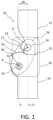
- FIG. 1is a schematic elevational view of a hinge assembly according to the disclosure.
- FIG. 2is an exemplary elevational view of another hinge assembly in an orthopedic device on a leg according to the disclosure.
- FIG. 3is a schematic view of the hinge assembly of FIG. 2 in an idealized full extension configuration whereby both the first and second hinge arms are aligned.
- FIG. 4is a schematic view of the hinge assembly of FIG. 2 in an idealized flexion configuration.
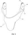
- FIG. 5is a perspective view of a lower frame in an orthopedic device forming the hinge arms with a body of the frame.
- FIG. 6is a graph depicting vertical versus horizontal displacement over different types of hinge assembly embodiments including the hinge assembly of the disclosure.
- FIG. 7 Ais a perspective view of the hinge assembly in FIG. 2 including extension and flexion stops with the hinge assembly in extension and an outer plate removed.
- FIG. 7 Bis a perspective view of the hinge assembly in FIG. 7 A with the hinge assembly in flexion.
- FIG. 8 Ais a perspective view of the hinge assembly in FIG. 7 A with the outer plate covering the hinge assembly and in an unsecured configuration to the inner plate.
- FIG. 8 Bis a perspective view of the hinge assembly in FIG. 8 A with the outer plate in a secured configuration to the inner plate.
- FIG. 9 Ais an elevational view of an orthopedic device having the hinge assembly according to the disclosure.
- FIG. 9 Bis a cross-sectional view of the orthopedic device of FIG. 9 A taken along line 9 B- 9 B.
- FIG. 9 Cis a cross-sectional view of the orthopedic device of FIG. 9 A taken along line 9 C- 9 C.
- FIG. 9 Dis a cross-sectional view of the orthopedic device of FIG. 9 A taken along line 9 D- 9 D.
- FIG. 9 Eis a cross-sectional view of the orthopedic device of FIG. 9 A taken along line 9 E- 9 E.
- FIG. 9 Fis an embodiment of a strap attachment in the orthopedic device of FIG. 9 A .
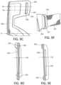
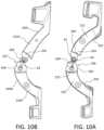
- FIG. 10 Ais an elevational view of the orthopedic device of FIG. 9 A having a hinge oriented at 15°.
- FIG. 10 Bis an elevational view of a variation of the orthopedic device of FIG. 9 A having a hinge oriented at 25°.
- FIGS. 10 C- 10 Eare schematic elevational views of the orthopedic device of FIG. 9 A over a flexion cycle.
- FIG. 10 Fis a graph depicting hinge type displacement of vertical over horizontal.
- FIG. 11 Ais a perspective view of a condyle pad in the embodiment of FIG. 9 A .
- FIG. 11 Bis a schematic view of the condyle pad of FIG. 11 A secured to a hinge plate of FIG. 9 A .
- FIG. 11 Cis an elevational view of the condyle pad of FIG. 11 A showing an exterior side.
- FIG. 11 Dis an elevational view of the condyle pad of FIG. 11 A showing an anterior side.
- FIG. 11 Eis an elevational view of the condyle pad of FIG. 11 A showing a posterior side.
- FIG. 11 Fis a top view of the condyle pad of FIG. 11 A .
- FIG. 12 Ais an elevational view of an exterior side of a liner for use in the orthopedic device of FIG. 9 A .
- FIG. 12 Bis an elevational view of an interior side of the liner of FIG. 12 A .
- FIG. 12 Cis a cross-sectional view of the liner of FIG. 12 A taken along line 12 C- 12 C.
- FIG. 13 Ais an elevational view of an orthopedic device worn according to the embodiments and worn on a leg.
- FIG. 13 Bis an elevational view of an orthopedic device according to FIG. 13 A worn on a leg.
- orthopedic device embodiments and componentsfor use therewith are described herein, with particular focus given to braces and components directed to the knee joint and surrounding areas.
- the orthopedic brace embodimentsmay serve in protective, preventive or remedial capacities. While the orthopedic brace is described within the context of a preferred embodiment directed to securing the knee joint, many features described herein may be extended to orthopedic braces and components that secure other joints and body parts, such as the wrist, elbow, shoulder, ankle and neck.
- brace embodiments and components for use therewithmay be dimensioned to accommodate different types, shapes, and sizes of human joints and appendages.
- embodimentsmay be modified to orient principal forces exerted by strap systems of the embodiments at any desirable location to secure the brace onto a leg to stabilize the knee.
- the knee jointcomprises two joints, lateral and medial, between the femur and tibia, and one arthrodial joint between the patella and femur.
- the primary movements of the kneecomprise flexion, i.e., rearward rotational movement of the tibia relative to the femur, and extension, i.e., forward rotational movement of the tibia relative to the femur.
- each orthopedic brace embodiment or component thereof describedmay be divided into sections denoted by general anatomical terms for the human body. Such anatomical terms are provided to distinguish various elements of the brace embodiments from one another, but which are not to be considered to limit the scope of the invention.
- proximal and distalgenerally refer to locations of the brace that correspond to the location of the leg relative to the point of attachment of the leg to the body.
- upper and lowermay be used in combination with “proximal” and “distal” to connote gradations in the location of “proximal” and “distal.”
- the location at where the brace corresponds to the knee jointis used herein to generally delimit the proximal and distal sections of the brace.
- the embodiments of the knee bracecan also be considered to fall within “anterior” and “posterior” sections by an anterior-posterior plane.
- the anterior-posterior planegenerally corresponds to the coronal or frontal plane of a human leg, which lies along the central longitudinal axis of a body. A posterior side or element is therefore located behind this anterior-posterior plane, whereas an anterior side or element is located in front of the anterior-posterior plane.
- inwardly or “inner”may be used herein to distinguish the side of the brace that may be directed to the interior side of the brace and specifically adjacent to the leg of the wearer of the brace. Contrariwise, the term “outwardly” or “outer” are used to denote the side of the brace that is opposite to the inwardly side.
- medial and lateralare relative terms that are generally understood as indicating location near the midsagittal plane or midline. Therefore, elements that are located near the midline are referred to as “medial,” and those elements that are further from the midline are considered to be “lateral.”
- centralis used to denote the area along the midline of a joint, thereby dividing and sharing regions of the medial and lateral regions.
- the anterior section of the bracehas these quadrants: (I) proximal-medial, (II) distal-medial, (III) distal-lateral, and (IV) proximal-lateral.
- the posterior section of the bracehas these quadrants: (V) proximal-medial, (VI) distal-medial, (VII) distal-lateral, and (VIII) proximal-lateral. Structural members and features thereof will fall within one quadrant as referenced explicitly in relation to such quadrant, either in its entirety or partially.
- rigidand “flexible” may be used herein to distinguish characteristics of portions of the hinge or brace.
- the term “rigid”should denote that the frame is generally devoid of flexibility. Within the context of frame members or components that are “rigid,” it should indicate that they may break if bent with sufficient force. But the term “flexible” should denote that features are capable of repeated bending. The word “resilient” is used to qualify such flexible features as generally returning to the initially molded shape without permanent deformation.
- hinge assembly embodimentsare described herein, with particular focus given to the knee joint and surrounding areas.
- the hinge assembly embodimentsmay serve in protective, preventive or remedial capacities. While the hinge assembly is described within the context of a preferred embodiment directed to treating the knee, many features described may be extended to orthopedic devices and components that secure other joints and body parts. It should be appreciated that the hinge assembly embodiments may be dimensioned to accommodate different types, shapes, and sizes of human joints and appendages. It should also be appreciated that the hinge assembly can be adapted for prosthetic devices, medical devices, or other devices.
- the hinge assembly embodimentsmay be formed from a rigid polymeric material or a fiber-reinforced polymeric material, for example, in monolithic construction with other components, such as a frame, strut, or otherwise, of an orthopedic, prosthetic, medical, or other devices. Due to the simplified construction, as will be apparent in the exemplary embodiments, other materials may likewise form the hinge assembly such as metals or composites, and the embodiments are not limited to only polymeric materials. The cost and complexity of producing and using hinge assemblies may be reduced by constructing a hinge assembly according to the embodiments of the disclosure.
- the hinge assemblyis formed from the same materials as frame components of the orthopedic device, as opposed to the orthopedic device being an assembly of components, the hinge assembly can be formed simultaneously with frame elements of an orthopedic device, greatly simplifying manufacture of an orthopedic device and improving the structural stability.
- the hinge assemblymay be continuous and monolithic with hinge arms extending from the frame and may be formed from the same material as the hinge arms, so the interlocking ends of the hinge assembly are an extension of the frame itself rather than additional and inserted parts. Providing the hinge components separately from other frame components is also contemplated.
- the hinge assemblyis a “polycentric” hinge commonly understood in the art of orthopedic braces as including a pair of rigid support arms having cooperating, interlocking proximal ends, a pair of pivot pins and a hinge plate.
- the armsare rotatably coupled at their proximal ends to the hinge plate through the pivot pins and are rotatable between an adjustable extension position and an adjustable flexion position.
- An example of a polycentric hingeis described in U.S. Pat. No. 5,443,444, granted Aug. 22, 1995, and an example of a four-bar hinge is described in U.S. Pat. No. 8,979,782, granted on Mar. 17, 2015, each of which is incorporated herein by reference.
- FIG. 1depicts a hinge assembly 10 including a first hinge arm 12 having a first longitudinal axis C 1 .
- the first hinge arm 12defines a first end portion 16 having a first opening 20 having a first axis A.
- the first axis Amay be orthogonal to the first longitudinal axis C 1 .
- the first hinge arm 12is pivotable about the first axis A.
- the hinge assembly 10includes a second hinge arm 14 having a second longitudinal axis C 2 .
- the second hinge arm 14defines a second end portion 18 having a second opening 22 defining a second axis B and the second hinge arm 14 is pivotable about the second axis B.
- the second axis Bmay be orthogonal to the second longitudinal axis C 2 .
- Suitable pins or pin elementsmay be provided in the first and second openings 20 , 22 in and/or about which the first and second hinge arms 12 , 14 pivot, and such pins generally remain in a fixed spatial relationship while the first and second hinge arms 12 , 14 rotate.
- the first and second longitudinal axes C 1 , C 2are coaxial when in an idealized extension configuration.
- the second opening 22is arranged along a third longitudinal axis D parallel to the first and second longitudinal axes C 1 , C 2 and is offset therefrom by a distance 28 .
- This arrangementis unlike conventional polycentric hinges wherein the openings would be arranged along the same longitudinal axis.
- FIG. 1exemplifies how a four-bar hinge 26 would connect to the first and second end portions 16 , 18 , which would not engage one another but rather would have a spatial rotational relationship relative to one another.
- first end portion 16 and the second end portion 18preferably define first and second geared profiles 17 , 19 , respectively, arranged to cooperate with one another, as in a conventional polycentric hinge. Yet the first and second end portions 16 , 18 of embodiments according to the disclosure are offset as described above to mimic a four-bar hinge.
- An extension stopmay be formed at or as an interface 25 defined by cooperating surfaces of the first and second hinge arms 12 , 14 .
- a hinge plate 30is used to retain the first and second end portions 16 , 18 connected, aside from their preferable geared profiles.
- the first and second geared profiles 17 , 19 , respectively, of each the first end portion 16 and the second end portion 18preferably form an identical amount or number of teeth.
- the teeth of the first and second end portions 16 , 18are preferably similarly sized.
- the teethmay be formed only about a limited periphery of the first and second geared profiles 17 , 19 .
- the limited periphery forming the teethmay have a uniform radius or curvature about the respective end portion or geared profile.
- adjacent peripheral portionsmay have a different configuration or different curvatures, or irregularly dimensioned profiles.
- the first end portion 16may have a first radius R 1 smaller than a second radius R 2 of the second end portion 18 , at least about the limited periphery of the first and second geared profiles 17 , 19 .
- the difference between and dimensions of radii of corresponding end portionsmay help define an anatomically accurate define motion path and may take any suitable configuration or shape.
- the offset or distance 28 among the first and second end portions 16 , 18enables the hinge 10 to provide a motion that better mimics or approximates the natural movement of a knee over a conventional polycentric hinge.
- the second axis Bis offset and arranged along with the third longitudinal axis D, and the third longitudinal axis D is parallel and offset relative to the second longitudinal axis C 2 , enabling the second hinge arm 14 to travel through the desired curvature and/or path relative to the first arm 12 when the hinge 10 is bent in flexion.
- the first axis Ais preferably centrally arranged on the first end portion 16 .
- the second axis Bby contrast, is depicted as an offset from a center of the second end portion 18 .
- the depicted arrangement of the first and second axes A, Bis by no means limiting.
- FIG. 2shows an orthopedic device or knee brace embodiment 100 having a hinge assembly 101 similar to the hinge assembly 10 of FIG. 1 and cooperating with a sleeve 118 .
- a first hinge arm 102is generally fixed relative to a user's femur and extends from a first frame member 128 , such as a frame member about an upper leg L, and has a first longitudinal axis M 1 .
- the first hinge arm 102defines a first end portion 106 .
- a second hinge arm 104may extend from a second frame member 130 about a lower leg and is arranged to rotate and translate relative to the first hinge arm 102 during gait, and has a second longitudinal axis M 2 .
- the movement of the second hinge arm 104 about or relative to the upper hinge arm 102is based at least in part on the force applied to a second end portion 108 of the second hinge arm 104 during gait relative to an instantaneous center of rotation “ICoR” of the second hinge arm 104 .
- the ICoR of the second hinge arm 104is a point about which the second hinge arm 104 rotates as the hinge assembly 101 moves between extension and knee flexion.
- the first and second hinge arms 102 , 104may comprise openings offset relative to each other by a distance 126 . Whereas an opening of the first hinge arm 102 may be aligned along with the first longitudinal axis M 1 , an opening of the second hinge arm 104 may be aligned along with a third longitudinal axis N distinct from the second longitudinal axis M 2 of the second hinge arm 104 .
- the hinge assembly 101assists in defining a dynamic ICoR that better imitates the natural movement of the knee joint.
- the location of the ICoR of the second hinge arm 104can depend on the relative sizes, profiles, and/or arrangements between the first and second end portions 106 , 108 , and the position of corresponding first and second teeth 114 , 116 , as seen in FIG. 3 .
- the ICoR of the second hinge arm 104shifts as the user's knee K moves through extension E and flexion F because the point of contact between the first teeth 114 and second teeth 116 moves as the second hinge arm 104 rotates relative to the first hinge arm 102 , as illustrated from comparing the hinge assembly 101 in extension E in FIG. 3 to the same hinge assembly 101 in flexion F in FIG. 4 .
- the hinge assembly 101may further comprise an extension stop 112 arresting extension past a desired degree.
- the extension stop 112may be arranged on or proximate a plate 110 enclosing the hinge assembly 101 and facilitating rotation and operation thereof.
- the ICoRmoves along an ICoR path.
- An ICoR pathis generally a path along which an ICoR of an object moves while the object is rotating.
- the ICoR of the second hinge arm 104 and its corresponding frame member in an orthopedic device 100may be arranged to imitate the complex movement of a lower leg relative to an upper leg during flexion and extension.
- the profiles of the first and second end portions 106 , 108 along with the first and second teeth 114 , 116at least in part define the movement of the ICoR of the second hinge arm 104 relative to the first hinge arm 102 .
- the profiles of the first and second end portions 106 , 108 along with the first and second teeth 114 , 116can be selected or varied as needed to match a defined motion path, including a complex hinge motion, e.g., when at least one of the hinge arms translates relative to the other in a non-linear or variable manner.
- Thisis advantageous over traditionally geared hinges, which, while being relatively simple and cost-effective to manufacture, produce only one simple motion relationship that is neither anatomical nor provides loads to heal a knee injury.
- a first profile of the first end portion 106generally follows a segment of a circle and is larger than a second profile of the second end portion 108 , which also generally follows a segment of a circle.
- the ICoR of the second hinge arm 104moves along the ICoR path.
- the ICoR pathextends along an arcuate line through the first teeth 114 of the first end portion 106 , generally corresponding to the first profile.
- first and second end portions of the present disclosurecan vary together such that at any specific or particular rotational position of the lower or second hinge arm 104 relative to the upper or first hinge arm 102 , the radius of the first end portion 106 or gear plus the radius of the second end portion 108 or gear is generally constant. It will be understood that the disclosed example is not limiting and that any relationship between any dimensions of portions of the hinge assembly 101 or an orthopedic device 100 of which the hinge assembly 101 is a part may be defined in any suitable manner.
- verticalis defined as a direction generally along the tibial axis
- horizontalis defined as a direction generally perpendicular to the tibial axis in the sagittal plane.
- the terms vertical and horizontalcan be relative to any corresponding limb and are not limited to the leg or in a fixed Cartesian space. Measurements provided herein are generally in reference to a traditional single point hinge, where the ICoR of a second or lower hinge arm 104 is fixed. There is no ICoR path because the ICoR does not move. There is no vertical or horizontal translation when the lower hinge arm 104 rotates relative to an upper hinge arm 102 . Vertical shifting away from the knee center is defined as positive. Horizontal shifting towards the femoral frame is defined as positive.
- the contact or interaction between the teeth 114 , 116 along with the profiles of the first and second end portions 106 , 108can move the second hinge arm 104 horizontally H and/or vertically V back toward its original position according to a desired path of rotation Rot 1 corresponding, for example, to a particular joint of the body.
- the pivoting movement of the second hinge arm 104 about an axis B over an opening 111 offset by the distance 126 according to the description of FIG. 1 relative to an axis A over an opening 109 of the first hinge arm 102is defined or limited by the interaction between the first and second teeth 114 , 116 .
- the hinge assembly 101is advantageously more robust and provides for greater control over the relative motion of the first and second hinge arms 102 , 104 than prior art four-bar hinges, allowing for more versatile functional designs and reduced cost and complexity of use and manufacture.
- the axes A, Bmay be orthogonal to the longitudinal axes M 1 , M 2 , N.
- the ICoR of the second hinge arm 104is generally located at the point of contact between the first and second end portions 106 , 108 along with the first teeth 114 on the first hinge arm 102 . Because the ICoR is at or near the periphery of the second hinge arm 104 , the translational movement of the second hinge arm 104 relative to the first hinge arm 102 can be limited for each degree of rotation. For instance, there may be a horizontal H shifting of the second hinge arm 104 during a specified range of flexion F or extension E. The desired shifting may vary from patient to patient, in that one patient may require a first amount of shifting whereas another patient having different anatomical proportions may require another amount of shifting. The orientation and profiles of the first and second end portions 106 , 108 can be arranged according to the patient's individual needs accordingly.
- FIG. 5illustrates how the second frame member 130 may be continuously formed with the second hinge arm 104 , such that the second end portion 108 and second plurality of teeth 116 are all formed continuously from the same material and part.
- An accommodating featuresuch as a recessed profile 132 , may be provided to accommodate a hinge plate and movement of the hinge assembly 101 .
- FIG. 6shows a graph depicting the progression of vertical v. horizontal displacement during rotation over different types of hinge-assembly devices, including the hinge assembly of embodiments of the disclosure.
- a standard polycentric hinge 122comprises hinge arms that follow a particular path of vertical v. horizontal displacement during rotation.
- a standard four-bar hinge 120comprises hinge arms that follow a different path of vertical v. horizontal displacement, which path more closely approximates the natural motion of a knee joint but disadvantageously comprises a more complex and costly construction and is less robust than standard polycentric hinges.
- a hinge assembly 124likewise comprises hinge arms that follow a particular path during rotation.
- the vertical v. horizontal displacement path followed by the hinge assembly 124 embodimentsadvantageously track the path defined by a standard four-bar hinge 120 with greater accuracy than the standard polycentric hinge 122 , and with improved cost, increased robustness, and reduced complexity relative to four-bar hinges 120 .
- the path defined by the hinge assembly 124 of the disclosure and four-bar hinges 120is virtually indistinguishable, resulting in a hinge movement, and consequently, a joint movement, that closely tracks the natural movement of a knee and with the structural advantages of the embodiments.
- FIGS. 7 A- 7 B and 8 A- 8 Bexemplify the hinge assembly 101 of FIG. 2 with an extension stop 150 and a flexion stop 180 .
- a first or inner hinge cover 132may be arranged for cooperating with the hinge assembly 101 according to principles of the disclosed embodiments, and may further provide a hinge plate 134 arranged for attaching to the first and second ends 106 , 108 of the hinge assembly 101 , and to a second or outer hinge cover 160 .
- the first plate 134defines a bias element 136 about which the extension stop 150 removably secures.
- the bias element 136may define a guiding surface 140 , a biasing surface 141 , and a stabilizing extension 142 , discussed in greater detail hereafter.
- First and second pin extensions 144 , 146each form an elongate projection generally extending perpendicular from the first plate 134 and are adapted to extend through corresponding apertures or openings 109 , 111 of the first and second hinge arms 102 , 104 .
- a base portion of the first and second pin extensions 144 , 146serve as bearing surfaces about which the first and second hinge arms 102 , 104 may rotate.
- Distal end portions 145 a , 145 b of the pin extensions 144 , 146are adapted to extend through openings 168 a, 168 b formed by the second plate 162 of the second hinge cover 160 and project beyond the second plate 162 prior to coupling or welding of the first and second covers 132 , 160 .
- An outer surface of the second plate 162may form recesses 170 to enable coupling of the second cover 160 to the first cover 132 by serving as a location into which the distal end portions 145 a , 145 b may settle due to ultrasonic heat staking of the distal end portions 145 a , 145 b .
- the distal end portions 145 a , 145 bare illustrated prior to ultrasonic heat staking in that they extend beyond the second plate 162 .
- FIG. 8 Billustrates the distal end portions 145 a , 145 b after they have been ultrasonically heat staked in which they are essentially melted or shaped to be flush with the second plate 162 and settle in the recesses 170 to form a bond with the second plate 162 , improving the aesthetics and the security of the attachment of the hinge assembly 101 .
- the second plate 162likewise forms an opening 165 for accommodating a stabilizing extension 142 , which projects beyond the second plate 162 before coupling of the first and second covers 132 , 160 , and ultrasonic heat staking, as illustrated in FIG. 8 A .
- the stabilizing extension 142interlocks with the second plate 162 to stabilize the first and second covers 132 , 160 relative to one another.
- a recess 167extends about the opening 165 , and when ultrasonically heat staked, the stabilizing extension 142 fills the recess 167 to bond and extend flush against and with the second plate 162 .
- the stabilizing extension 142may be ultrasonically heat staked to be flush against and with a surface of the plate 162 .
- the extension stop 150serves as an extension limit and may comprise an arm 152 extending from a base rotation portion 155 and a compression element 154 extending from the arm 152 .
- the base rotation portion 155may receive a fastener 138 extending from and/or removably securing to one of the first and second covers 132 , 160 .
- the fastener 138may be a screw extending through a threaded aperture 139 defined by the second cover 160 .
- the extension stop 150forms an opening 156 at the base rotation portion 155 that receives the fastener 138 . If it is desired to remove the extension stop 150 , the fastener 138 may be removed, and the extension stop 150 can resiliently be removed from the bias element 136 by rotating the base rotation portion 155 away from the bias element 136 .
- the extension stop 150may be arranged within or between the hinge plates 134 , 162 , and limit a degree of flexion or extension in a more comfortable and effective manner than existing devices.
- the compression element 154may be formed from a resilient material such that, as rotation of the hinge arms 102 , 104 brings the extension stop 150 into contact with a bias element 136 , the compression element 154 is compressed between the biasing surface 141 and the stop-forming surface 153 , the biasing surface 141 extending on an opposing side of a guiding surface 140 .
- the compression element 154may have a geometrical shape, such as an arcuate shape, to facilitate compression along with the material composition forming the compression element 154 .
- the act of compressing the compression element 154 in this mannerprovides a soft bump or a damping effect as the limit on extension is reached, enhancing comfort for a user over a sudden, hard stop as in existing extension limits.
- the arm 152may be formed from a less resilient material than the compression element 154 ; alternatively, a substantial entirety of the extension stop 150 may be formed from a resilient material.
- the extension stop 150further protects the user and components of the hinge assembly from damage from hard impacts between hinge arms and conventional flexion/extension stops.
- the extension stop 150may be engaged around a guiding surface 140 of the bias element 136 at which flexion/extension is to be limited, and selectively removed when no limit is needed.
- the extension stop 150may be configured to correspond to a configuration of the bias element 136 , so the arm 152 may define a profile complementary to a profile of the guiding surface 140 , thereby ensuring intuitive and reliable engagement.
- the base portion 155has a corresponding profile to a base of the bias element 136 so as to fittingly secure therewith, just as the arm 152 has a corresponding profile to the guiding surface 140 whereby the compression element 154 resiliently biases against the biasing surface 141 .
- the compression element 154which forms an arch with the arm 152 , is placed over a top of the bias element 136 , and the base portion 155 is rotated to engage the base of the bias element 136 to snap-fit with the bias element 136 as the compression element 154 counteracts the base portion 155 .
- the base portion 155may be rotated away from the base of the bias element 136 , and the compression element 154 is elevated above the bias element 136 and removed. In either installation or removal, it is preferable that the hinge assembly 101 is in a flexion position to offer sufficient clearance for moving the extension stop 150 relative to the bias element 136 .
- the compression element 154may define an arcuate profile 157 and biases against a biasing surface 141 of the bias element 136 or may have an end portion bias against the biasing surface 141 , with a gap 151 between the compression element 154 and the biasing surface 141 except for the end portion.
- the gap 151 between the biasing surface 141 and the compression element 154reduces; the compression element 154 increasingly provides resistance into extension.
- the end portionmay slide along the biasing surface 141 as the hinge 101 goes into extension to accommodate flattening of the compression element 154 as it is increasingly wedged between the biasing surface 141 and a stop-forming surface 153 of the first end portion 128 .
- FIG. 8 Ashows the hinge assembly 101 generally in extension
- FIG. 8 Bshows the hinge in flexion
- FIG. 8 Ashows the extension stop 150 cooperating with the first frame member 128 and the first end portion 106 , engaging both to nestle and compress therebetween and prevent further extension of the hinge 101
- FIG. 8 Bshows how the extension stop 150 is effectively relieved of compression while the compression element 154 may slidably engage the stop-forming surface 153 of the first end portion 106 .
- Extension stops 150may be engaged at different points around the hinge 101 and are not limited in shape, configuration, number, properties, or otherwise to the depicted embodiments.
- the extension stop 150may be arranged for removal from the hinge assembly 101 in any suitable manner, including by being removed from between the hinge plates 134 , 162 in a lateral manner, or by being inserted/removed from the hinge assembly 101 by removing one of the hinge plates 134 , 162 and lifting the extension stop 150 out of the hinge assembly.
- Multiple extension stops 150 having different propertiesmay be provided so the damping or other properties may be closely tailored to a user or patient's individual needs.
- a flexion stop 180may also or alternatively be provided on an opposite side of the hinge assembly 101 .
- the flexion stop 180may be selected from many flexion angles to stop rotation of the hinge assembly 101 at such selected angle.
- the flexion stop 180is removably secured to the hinge assembly 101 and has a profile arranged for cooperating with the first and second end portions 106 , 108 to arrest rotation of the of the hinge assembly 101 at the prescribed flexion angle.
- the flexion stop 180has a top portion 182 engaging a stop surface 192 of the first end portion 106 .
- the flexion stop 180forms a first stop portion 183 engageable with the first teeth 114 and a second stop portion 184 engageable with the second teeth 116 , which serve as a wedge to prevent further rotation.
- the flexion stop 180is retained by the second end portion 108 , particularly from an outside perspective.
- the outside perspectiveenables a user to snap fit a snap element 186 into a receptacle 190 formed along a surface of the second end portion 108 accessible from outside of the first and second covers 132 , 160 .
- a prong 188extends from the flexion stop 180 and generally beyond the snap element 186 to enable a user to articulate the flexion stop 180 into and from the receptacle 190 .
- the prong 188provides stability to the flexion stop 180 when retained by second end portion 108 as it extends along the periphery of the second end portion 108 , but also serves as a leverage arm for disengaging the snap element 186 from the receptacle 190 .
- the problem of hinges insufficiently tracking the natural anatomical movement of a jointis addressed, as is the problem of existing solutions providing costly, complex, and non-robust four-bar hinges to provide accurate tracking of natural movement.
- the hinge assembly of the disclosureadvantageously provides a cost-effective, robust, and intuitive solution that closely approximates natural movement. Further, by providing an improved flexion/extension stop, a user is provided with a hinge assembly having greater comfort, interchangeability, and durability than existing flexion/extension stops.
- hinge assembly embodiments of the disclosuremay be used with other limbs, joints and anatomical portions including the torso, shoulder, elbow, wrist/hand, hip, knee, and foot/ankle.
- Embodiments of the hinge assemblymay be used in other orthopedic, prosthetic, medical, and other devices, and are not limited to the embodiments shown.
- FIG. 9 Aillustrates an orthopedic device in a knee brace 200 that may include the aforementioned hinge assembly embodiments.
- the knee brace 200includes a first or upper frame component 202 adapted to secure about a user's upper leg and correspond to a femur.
- the first frame component 202is connected to a second or lower frame component 204 adapted to secure about a user's lower leg and correspond to a tibia.
- the first and second frame components 202 , 204are connected to one another by a hinge assembly 206 , preferably formed integrally from at least part of the first and second end portions of the first and second frame components 202 , 204 .
- the knee brace 200is arranged to be used for increased anterior-posterior and medial-lateral stability around the knee, including anterior-cruciate ligament, medial-cruciate ligament and posterior cruciate ligament, rotary and combined instabilities.
- the first frame component 202is arranged relative to the second frame component 204 to create three main points of contact: (1) lateral tibia; (2) medial condyle; and (3) lateral thigh.
- the three main points of contactprevent side impact blows to protect the aforementioned ligaments of the knee.
- the first frame component 202defines a first mast 208 generally depending centrally from a first central segment 214 extending between a first medial strut 210 and a first lateral strut 212 .
- the second frame component 204likewise has a second mast 222 generally depending centrally from a second central segment 228 extending between a second medial strut 224 and a second lateral strut 226 .
- the first and second frame components 202 , 204laterally sway from a central vertical axis X-X.
- the lateral swayis formed at least in part to accommodate a standard Q-angle to provide near-universal fit, thereby providing a knee brace arranged to accommodate near universality in sizing for users.
- the Q-angleis measured by extending a line through the center of the patella to the anterior superior iliac spine and another line from the tibial tubercle through the center of the patella.
- the direction and magnitude of force produced by the quadriceps musclehas great influence on patellofemoral joint biomechanics.
- the line of force exerted by the quadricepsis lateral to the joint line, mainly due to the large cross-sectional area and force potential of the vastus lateralis. Since there exists an association between patellofemoral pathology and excessive lateral tracking of the patella, assessing the overall lateral line of pull of the quadriceps relative to the patella is a meaningful clinical measure.
- the lateral sway of the first frame component 202is evidenced by the sway of arrows 242 , 244
- the second frame component 204is evidenced by the sway of arrows 246 , 248 , relative to the vertical axis X-X.
- the first and second masts 208 , 228are angled relative to the vertical axis X-X to accommodate the Q-angle, as evidenced by arrows 236 , 238 .
- the first and second masts 208 , 228may be arranged at angle A 1 , A 2 6° ⁇ 2° from the vertical axis X-X, and more specifically 3° ⁇ 1.0°, to provide for the near-universal fit.
- the knee brace 200may be arranged as an off-the-shelf brace, the lateral sway and Q-angle arrangement of the first and second frame components 202 , 204 are provided to create “brace to bone” contact. While in a custom brace a clinician can exaggerate the lower frame profile to best capture an individual's tibia/tibialis, it is more difficult to do with an off-the-shelf knee brace, particularly if an individual does not fall within parameters of a knee brace profile (i.e., more varus or valgus tilt). Such poor-fitting may cause undesirable tibial pressure or other pressure points along with the masts 208 , 222 .
- the criticality of the lateral sway and accommodation of the Q-angle in a preferred range, but not limitative, of 3° ⁇ 1.0° rangesoftens the profile of the knee brace to accommodate a wider range of individuals.
- a standard Q-angle of 6° ⁇ 2°may be found in conventional off-the-shelf prior art knee braces, but while such a Q-angle may be a median angle for a wide field of users, the prior art knee braces are found to mismatch with many users, particularly once considered in combination with hinges, liners and throughout gait (extension to flexion), which may vary the fit even further so on the individual. Such mismatch makes many off-the-shelf knee braces less desirable for use.
- the profile of the knee brace 200is provided in combination with liners, as discussed in connection with condyle pads of FIGS. 11 A- 11 F and liners of FIGS. 12 A- 12 C , that provide sufficient capture and tunability of the knee brace to a greater field of users, while the rigid or semi-rigid first and second frame components have a softer Q-angle configuration over conventional off-the-shelf knee braces.
- FIG. 9 Bshows how the first and second frame components 202 , 204 , may have recesses and other features for accommodating accessories, as in the D-rings 250 .
- the first and second frame components 202 , 204have a contoured recess 254 accounting for rotational movement relative to the first and second frame components 202 , 204 .
- the contoured recess 254is preferably configured to limit the extent by which the D-rings 250 rotate relative to the first and second frame components 202 , 204 .
- the D-rings 250may be secured to the first and second frame components 202 , 204 , by a fastener 252 .
- contoured recess 254is configured to eliminate pressure points on a patient or user's skin.
- the D-rings 250may be supported and exert forces against a surface of the orthopedic device 200 rather than exerting all of the forces applied by the D-rings 250 directly onto a user or patient's skin.
- medial and lateral arms 216 , 218extend from the first mast 208 a distance D 1 from the first central segment 214 . Because of the first and second masts 208 , 222 , the first and second central segments 214 , 228 are more proximate to the knee and create a frame configuration the limits that lengths of the first and second medial and lateral segments 224 , 226 , 210 , 212 , thereby maintaining the first and second central segments 214 , 228 closer to the knee.
- Such low profile of the first and second frame components 202 , 204 about the kneeis particularly advantageous when the knee brace 200 is worn during physical activities as the first and second frame components 202 , 204 , aside from the first and second masts 208 , 222 , extend minimally along the user's leg, while providing sufficient support and security to the user's leg.
- the masts 208 , 222may be rigid and may “lean into” the lateral arms 216 , 218 , 230 , 232 , as depicted in FIG. 9 A .
- a transition of rigidity to relative flexibilitymay be formed, and not significantly apply pressure points on the flesh and bone of the user.
- Such more natural transition from the rigid masts 208 , 222 to the lateral arms 216 , 218 , 230 , 232may likewise improve anti-migration properties of the knee brace 200 as it is more ergonomically contoured universally over prior art knee braces, with some give allowing for a better fit as the lateral arms 216 , 218 , 230 , 232 transition away from the rigid masts 208 , 222 .
- the first mast 208is preferably rigid, although, as shown in FIG. 9 B , the first mast 208 has a tapered thickness, such that the thickness T 4 is greater at a distal end compared to a proximal end at thickness T 3 .
- the thickness T 4is greater than the thickness T 3 in part as it extends from the first central segment 214 and enables the insertion of features, such as supporting fasteners for a patella cup and other accessories.
- the greater thickness T 4blends with the first central segment 214 and is integrally formed therewith, and increases the central mass rigidity of the knee brace 200 .
- the second mast 222is arranged similarly as the first mast 208 regarding the tapering of thickness T 5 at the second central segment to the distal end having thickness T 6 .
- Both the first and second masts 208 , 222have a crescent-shaped relief edge 220 , 234 whereat the thickness of the first and second masts 208 , 222 is most minimal, as depicted in FIG. 9 B .
- the crescent-shaped relief edgereduces possible pressure the first and second masts 208 , 222 may apply to the femur and tibia, respectively, and provide an improved fit over conventional orthopedic devices having a more pointed configuration.
- the first mast 208has first medial and lateral arms 216 , 218
- the second mast 222has second medial and lateral arms 230 , 232 .
- the lateral arms 218 , 230provide increased support in comparison to flexible subshells in prior art braces and are integrally formed from the first and second masts 208 , 222 , which are, in turn integrally formed from the first and second central segments 214 , 228 .
- the lateral arms 218 , 232are arranged to resist a load exerted thereon, and are arranged to extend or rotate less than a quarter of a circumference of a user's leg, such as less than 60° from the vertical axis X-X, and more particularly less than 45° from the vertical axis X-X.
- FIG. 9 Cillustrates how the thickness of the first mast 208 may have a variable taper extending from a distal end at thickness T 7 to the proximal end at thickness T 9 in a generally vertical direction.
- the thicknessmay also vary generally horizontally at thickness T 8 along transition regions 209 of the first mast 208 .
- the thickness of the first mast 208 relative to the first medial and lateral arms 216 , 218may likewise vary from distal to proximal directions D, Pr along the vertical axis X-X, to provide a gentle transition in rigidity to the medial and lateral arms 216 , 218 .
- the lateral arms 218 , 222exemplified by the first lateral arm 218 , has tapered thickness T 10 , T 11 , as the lateral arm 218 extends away from the first mast 208 .
- the lateral arm 218becomes increasingly thinner as it extends away from the first mast 208 , and is consequently more flexible than the first mast 208 .
- the first mast 208is arranged to be rigid or semi-rigid, preferably very rigid, by the lateral arm 218 becomes relatively progressively more flexible to provide more flexibility or give to accommodate a wide spectrum of users while providing sufficient support in loading scenarios of the knee brace 200 .
- the tapered thicknessachieves a fine balance of rigidity for support, and flexibility for improved fit, perception of fit, and comfort.
- the lateral arm 218has thickened first or upper and second or lower edge portions 260 , 262 , while the center portion 258 between such first and second edge portions 260 , 262 remains thinner.
- the first and second edge portions 260 , 262 in combination with an end edge portion 263may form the center portion 258 as being recessed relative to the edge portions 260 , 262 , 263 , with the edge portions 260 , 262 , 263 providing the superstructure to maintain sufficient rigidity.
- the center portion 258may enable some give when a strap 221 is secured therewith, as depicted in FIG. 9 F .
- the strap 221may be anchored to the lateral arm 218 by a retainer 223 , which is sized larger than a slot 256 having a periphery 258 , formed by the lateral arm 218 .
- the strap 221extends from the retainer 223 and through the slot 256 .
- the first and second frame components 202 , 204are preferably constructed from long fiber reinforced thermoplastic materials.
- long fiberthe fibers are defined as individual reinforcing fibers having a uniform length and in parallel alignment with each other.
- the individual reinforcing fibersare aligned regarding each other and are generally exactly as long as a pellet using in the injection molding process.
- short fiber reinforced thermoplastic materialscontain reinforcing fibers of various short lengths randomly oriented in the resin pellet.
- first and second frame components 202 , 204they are formed from long fiber individual reinforcing fibers, which enable the first and second frame components 202 , 204 to have superior and predictable mechanical performance as compared to short fiber reinforced thermoplastic materials.
- An exemplary long fiber reinforced thermoplastic materialis provided by Plasticomp LLC of Winona, MN, under the product name Compl ⁇ t LCF40-PA66 M T 1014 NAT. The product uses a thermoplastic resin of Nylon 66, and the long fiber is carbon, with a fiber content of 40%.
- the material properties of the first and second frame components 202 , 204have improved material properties, such as tensile and impact strength, weight and dimensional stability, and with discrete zones of relative enhanced rigidity (i.e., struts, central segment, and masts) relative to other zones (as in the medial and lateral arms).
- the long fiber reinforced thermoplastic material forming the first and second frame componentsforms an improved bearing surface, which enables the hinge arms themselves to be formed from the first and second frame components, as opposed to using metal inserts commonly found in knee braces constructed from thermoset resin impregnated carbon fiber.
- thermoset resin impregnated carbon knee bracesare typically made by hand-laid processing, as opposed to the injection-molded design of the orthopedic device.
- the high strength-to-weight ratio of the long fiber-reinforced thermoplastic materialreduces the weight of the knee brace over conventional knee braces formed from metal and/or carbon fiber composite using a thermoset polymer.
- the knee brace of FIG. 9 A of comparative sizehas a weight of 430 grams, due to the long fiber reinforced thermoplastic material construction of the first and second frame components 202 , 204 .
- first and second frame components 202 , 204are injection molded to shape, minimal post-mold finish work is necessary.
- the first and second frame components 202 , 204are molded into a definitive shape, so that preferably no sanding, bonding, or paint is necessarily required.
- FIGS. 10 A- 10 Fexemplify how the motion tracking of the hinge assembly 207 compares to similar hinge assembly designs.
- FIG. 10 Ashows how the hinge assembly 207 including first and second hinge arms 264 , 266 are formed integrally as part of the first and second frame components 202 , 204 of the same material and simultaneously when the first and second frame components 202 , 204 are injection molded.
- the first and second hinge arms 264 , 266are preferably continuous with the medial and lateral struts, without interruption, being of the same material and structure, so the material forming the first and second hinge arms 264 , 266 blends with the same material forming the medial and lateral struts.
- Surface reliefs 268 , 270may be formed to accommodate hinge plates (as discussed above) and reduce a thickness of the first and second hinge arms 264 , 266 relative to the medial and lateral struts of the first and second frame components.
- FIG. 10 Ashows how the hinge assembly 206 is arranged at angle A 3 , generally corresponding to a hinge orientation wherein the hinge orientation is 15° relative to a vertical plane 269 .
- FIG. 10 Bshows how the hinge assembly 207 is oriented at 25° relative to the vertical plane 269 .
- the first and second lateral struts 212 , 226 of the first and second frame components 202 , 204are more consistently shaped similarly relative to one another than in the first and second frame components 202 A, 204 A relative to the first and second lateral struts 212 A, 226 A.
- Such arrangementallows for better capture of the first and second frame components 202 , 204 to a universal fit of a leg, relative to the first and second frame components 202 A, 204 A, without significantly diverging from the desired tracking motion.
- the arrangement of the first and second frame components without sacrificing the tracking motionalso allows for improved lateral support by the shape of the first and second frame components in FIG. 10 A and improved brace performance.
- FIGS. 10 C- 10 Eillustrate the general motion of the first frame component 202 relative to the second frame component 204 of the hinge assembly 206 , whereas FIG. 10 C illustrates extension, FIG. 10 D illustrates flexion at 90° and FIG. 10 E illustrates flexion at about 120°.
- the hinge assembly 206operates as the hinge assembly of foregoing embodiments.
- FIG. 10 Fexemplifies how the hinge assembly of FIG. 10 A has hinge motion tracking compared to a standard four-bar hinge, as discussed in U.S. Pat. No. 8,979,782, granted on Mar. 17, 2015, and U.S. Pat. No. 4,856,501, granted Aug. 15, 1989, each of which is incorporated by reference, and a polycentric hinge, as discussed in U.S. Pat. No. 10,588,770, granted Mar. 17, 2020, and incorporated by reference.
- Different hinge arm anglesare compared, with the 15° exemplifying little difference in hinge arm tracking compared to a standard four-bar hinge and 25° and 17° hinges while possessing improved frame leg capture due to the shape of the 15° hinge assembly in the knee brace of FIG. 10 A .
- FIGS. 11 A- 11 Fillustrate a condyle pad 300 anatomically configured to account for the Q-angle and lateral shift and offers improved capture and tunability for comfort and usability.
- FIG. 11 Ashows the condyle pad 300 as having a body 302 , a tread pattern 304 extending from the body 302 along an exterior side (the side facing the user), and a recess 306 along the interior side (the side facing the hinge assembly). Concerning the recess 306 , it is generally shaped to a corresponding shape of the hinge plate 134 , including surface reliefs 308 , 310 adapted for grasping the hinge plate 134 , and corresponding to the contours of the hinge plate 134 and bias element 136 .
- the depth of the hinge plate 134is proximate to a thickness of the hinge plate 134 .
- the condyle pad 300preferably is formed from EVA (ethylene-vinyl acetate), which provides superior softness and flexibility over foam-based condyle pads. Because of the EVA construction, the condyle pad 300 is resilient to fit over the hinge plate 134 tightly and adapted for repeated removal and application without losing its shape.
- EVAethylene-vinyl acetate
- the tread pattern 304defines a plurality of treads 316 spaced by a plurality of channels 314 .
- the tread pattern 304is preferably formed according to the anatomy of the condyle pad 300 to accommodate the knee during gait.
- the body 302has a compound curved shape.
- FIG. 11 Dshows the thickness as varying from proximal to distal ends with a greater thickness T 12 toward the center of the body 302 along an anterior side of the condyle pad 300 , whereby the plurality of treads 316 may generally extend uniformly from the body with a thickness T 13 .
- the posterior side of the body 302may have a generally uniform thickness T 14 . From the top or proximal side of the body, the thickness T 16 at the anterior side may progressively increase relative to the thickness T 15 toward the posterior side.
- the condyle pad 300can better fit the anatomy of a user's condyle, and offer a universal fit, as the EVA material may compress upon being between the rigid frame of the knee brace 200 and the user's condyle, accounting for the Q-angle and lateral shift of the first and second frame components 202 , 204 .
- FIGS. 12 A- 12 Cexemplify a liner 320 contoured with a profile arranged for the second frame component 204 ; however, a liner may be likewise be provided with a profile arranged for the first frame component 202 and having similar properties.
- the liner 320is preferably formed from EVA, as in the condyle pad 300 .
- the liner 320preferably forms a plurality treads 322 extending from an exterior side E 2 and corresponding channels 324 .
- the plurality of treads 322 and channels 324are adapted to correspond to a user's leg with treads 322 adapted to grab and provide traction against the user's leg.
- the liner 320is adapted for the second frame component 204 and corresponding to the tibia, it may be formed thicker than a liner corresponding to the first frame component 202 to offer greater compression and bite, and to aid in impact attenuation.
- a center set of treads 326is shaped to correspond to the anterior tibia, with a corresponding channel 334 extending along a length of the liner to minimize pressure on the anterior tibia.
- the channel 334extends slightly obliquely relative to a vertical axis X-X of the orthopedic device, corresponding to the lateral shift and Q-angle.
- Within the treads 326there are lateral recesses 325 adapted to the shape of the second frame component 204 to grasp the user's leg better.
- Flattened regions 328are provided where minimal compression is required and treads 338 may transition in thickness to the flattened regions 328 .
- indicia or messaging 336may be molded into the liner for informational purposes.
- FIG. 12 Cshows how the treads 322 have varying heights and profiles according to their location and how they match up to the anatomy of a leg.
- the treads 322are arranged to naturally wrap to the profile of the second frame component 204 to avoid any wrinkling or the liner 320 fighting placement.
- the treads 322may define one or more channels or recesses 334 , 324 , 325 extending in substantially a similar direction, and divided by one or more individual treads forming walls 348 , 350 between the channels 334 , 324 , 325 .
- the wall 350may have a shallower profile than a profile of the wall 348 ; that is, the wall 350 may extend between a bottommost surface of the channel 325 and the topmost surface of an adjacent tread more gradually than the wall 348 extends between a bottommost surface of the channel 334 and the topmost surface of an adjacent tread.
- the channels 334 , 324 , 325may extend the same distance or thickness into the liner 320 .
- the liner 320may have a substantially flat backing layer 346 on an opposed or exterior side of the liner 320 from the treads 322 .
- a profile 328transitions the liner 320 from the treads 322 toward an outer edge portion 328 , with a channel 343 generally extending perpendicularly from the treads 322 and the channels 334 , 325 .
- the profile 328may extend between the topmost surface of the treads 322 and the topmost surface of the 328 more gradually than the wall 348 and the wall 350 , but is not limited to such an arrangement and may take any suitable form or configuration.
- FIG. 12 Bshows an interior side 12 of the liner 320 .
- the interior side 12defines a recessed section 346 contoured for the second frame component to fit therewith snugly. Portions outside the recessed section 346 extend outwardly therefrom and frame about the second frame component.
- the liner 320forms strap sections 330 , 331 , whereby the strap sections 330 , 331 enable a strap to be generally retained within the liner 320 to distribute better circumferential pressure exerted on a leg.
- the strap sections 330 , 331serve as an interface between the strap and user's leg.
- the strap sections 330 , 331define strap loops 342 a , 342 b , 342 c to retain the strap against the liner, and through which the strap sections 330 , 331 extend.
- the strap sections 330 , 331form borders 341 and a recessed portion 332 located therebetween to yet further retain the straps against the liner.
- the liner 320forms additional recesses 344 a , 344 b adapted at the corresponding medial and lateral arms of the second frame component 204 .
- FIGS. 13 A, 13 BAn orthopedic device according to the disclosed embodiments is shown in FIGS. 13 A, 13 B .
- An orthopedic device 400is shown on a leg 401 of a user via an x-ray image.
- the orthopedic device 400may comprise upper or first and lower or second frame components 402 , 404 joined by a hinge assembly 406 as described in the embodiments of the disclosure.
- the first and second frame components 402 , 404may define rigid masts 408 , 422 , respectively.
- the orthopedic device 400is shown mounted on a leg 401 , which may define an axis corresponding to the femur AF and an axis corresponding to the tibia AT.
- the rigid masts 408 , 422may correspond as described in the embodiments disclosed to the axes AF, AT, which, as shown are offset relative to each other relative to a knee K.
- an orthopedic device 450is shown in FIG. 13 B on a leg 451 of a user via x-ray image.
- the orthopedic device 450comprises first and second frame components 452 , 454 joined by a hinge assembly 456 according to the present disclosure.
- the first and second components 452 , 454may define rigid masts 458 , 472 as described above.
- the rigid masts 458 , 472may advantageously follow and/or correspond to offset axes defined according to the femur AF and the tibia AT.
- the configuration of the orthopedic devices 400 , 450advantageously follow the natural contours and naturally offset axes of a human leg above and below a knee, improving the contact between the components of the orthopedic devices 400 , 450 and the leg 401 , 451 across the orthopedic devices 400 , 450 , minimizing uncomfortable pressure points, and enabling an off-the-shelf orthopedic device better configured to correspond to and comfortably fit and support a user's dimensions.
- an orthopedic devicecomprising a hinge assembly according to the embodiments, and having one or more of the above-described condyle pad, liner, and frame components according to the embodiments, the problem of orthopedic devices being poorly adapted to fit a variety of users in off-the-shelf applications and of putting undue pressure on portions of the anatomy are addressed.
- the orthopedic device embodimentsadvantageously provide for improved adaptation of an orthopedic device to better fit against, provide comfort for, and support a patient or user in rehabilitation, osteoarthritic complications, or other conditions.
- hinge assemblyhas been disclosed in certain preferred embodiments and examples, it therefore will be understood by those skilled in the art that the present disclosure extends beyond the disclosed embodiments to other alternative embodiments or uses of the hinge assembly and apparent modifications and equivalents. It is intended that the scope of the present hinge assembly disclosed should not be limited by the disclosed embodiments described above but should be determined only by a fair reading of the claims that follow.
Landscapes
- Health & Medical Sciences (AREA)
- Nursing (AREA)
- Orthopedic Medicine & Surgery (AREA)
- Engineering & Computer Science (AREA)
- Biomedical Technology (AREA)
- Heart & Thoracic Surgery (AREA)
- Vascular Medicine (AREA)
- Life Sciences & Earth Sciences (AREA)
- Animal Behavior & Ethology (AREA)
- General Health & Medical Sciences (AREA)
- Public Health (AREA)
- Veterinary Medicine (AREA)
- Prostheses (AREA)
Abstract
Description
Claims (8)
Priority Applications (2)
| Application Number | Priority Date | Filing Date | Title |
|---|---|---|---|
| US16/831,392US12178729B2 (en) | 2019-03-26 | 2020-03-26 | Hinge assembly for an orthopedic device |
| US18/958,346US20250082485A1 (en) | 2019-03-26 | 2024-11-25 | Hinge assembly for an orthopedic device |
Applications Claiming Priority (2)
| Application Number | Priority Date | Filing Date | Title |
|---|---|---|---|
| US201962823847P | 2019-03-26 | 2019-03-26 | |
| US16/831,392US12178729B2 (en) | 2019-03-26 | 2020-03-26 | Hinge assembly for an orthopedic device |
Related Child Applications (1)
| Application Number | Title | Priority Date | Filing Date |
|---|---|---|---|
| US18/958,346ContinuationUS20250082485A1 (en) | 2019-03-26 | 2024-11-25 | Hinge assembly for an orthopedic device |
Publications (2)
| Publication Number | Publication Date |
|---|---|
| US20200306070A1 US20200306070A1 (en) | 2020-10-01 |
| US12178729B2true US12178729B2 (en) | 2024-12-31 |
Family
ID=70289503
Family Applications (2)
| Application Number | Title | Priority Date | Filing Date |
|---|---|---|---|
| US16/831,392Active2040-11-12US12178729B2 (en) | 2019-03-26 | 2020-03-26 | Hinge assembly for an orthopedic device |
| US18/958,346PendingUS20250082485A1 (en) | 2019-03-26 | 2024-11-25 | Hinge assembly for an orthopedic device |
Family Applications After (1)
| Application Number | Title | Priority Date | Filing Date |
|---|---|---|---|
| US18/958,346PendingUS20250082485A1 (en) | 2019-03-26 | 2024-11-25 | Hinge assembly for an orthopedic device |
Country Status (3)
| Country | Link |
|---|---|
| US (2) | US12178729B2 (en) |
| EP (1) | EP3946174B1 (en) |
| WO (1) | WO2020198489A1 (en) |
Families Citing this family (5)
| Publication number | Priority date | Publication date | Assignee | Title |
|---|---|---|---|---|
| ES2969892T3 (en) | 2017-02-03 | 2024-05-23 | Roam Robotics Inc | System and method for user intent recognition |
| EP4072498B1 (en)* | 2019-12-13 | 2025-08-27 | Roam Robotics Inc. | Powered device to benefit a wearer during skiing |
| EP4498995A1 (en) | 2022-03-31 | 2025-02-05 | Ossur Iceland Ehf | Impact guard for knee brace |
| WO2024006311A1 (en)* | 2022-06-29 | 2024-01-04 | Ossur Iceland Ehf | Polymeric polycentric hinge |
| WO2025117361A1 (en) | 2023-12-01 | 2025-06-05 | Ossur Iceland Ehf | Hinge assembly |
Citations (237)
| Publication number | Priority date | Publication date | Assignee | Title |
|---|---|---|---|---|
| GB190626961A (en) | 1905-12-14 | 1907-04-25 | Arthur Vernet | Improvements in Articulated Handle-bars for Cycles. |
| US1390915A (en) | 1918-05-07 | 1921-09-13 | Loth Julius Alwin | Artificial limb and the like |
| US2531486A (en) | 1947-11-07 | 1950-11-28 | Andrew J Weber | Orthopedic device |
| US2883982A (en) | 1956-09-06 | 1959-04-28 | Fred E Rainey | Leg brace |
| US3030634A (en) | 1958-10-30 | 1962-04-24 | Milford M Bair | Prosthesis for below-knee amputees |
| US3099488A (en) | 1960-12-05 | 1963-07-30 | Eckenrod Kathleen | Skirt guarding attachment for armless chairs |
| US3259910A (en) | 1963-05-14 | 1966-07-12 | Daignault Gustave Rene | Limb protector for hockey players and the like |
| US3387305A (en) | 1966-02-09 | 1968-06-11 | Rocky Mountain Sports | Knee protector |
| US3669105A (en) | 1969-10-28 | 1972-06-13 | Ignatius F Castiglia | Brace for articulated limbs |
| US3779654A (en) | 1971-08-06 | 1973-12-18 | R Horne | Artificial joint |
| US3785372A (en) | 1973-01-02 | 1974-01-15 | W Craig | Extension desubluxation hinge appliance |
| US3817244A (en) | 1972-03-03 | 1974-06-18 | Kendall & Co | Knee brace |
| US3900898A (en) | 1974-09-23 | 1975-08-26 | Eugene J Ackerman | Athletic shield |
| US3901223A (en) | 1973-05-31 | 1975-08-26 | Hanger & Co Ltd J E | Knee joints for leg irons |
| US3902482A (en) | 1974-05-21 | 1975-09-02 | George A Taylor | Mechanical joint for an orthopedic brace or prosthesis |
| US3923047A (en) | 1974-03-08 | 1975-12-02 | Vessa Ltd | Joints for orthopaedic appliances |
| US3928872A (en) | 1974-09-18 | 1975-12-30 | Albert F Johnson | Leg support device for skiing |
| US3958569A (en) | 1975-05-19 | 1976-05-25 | Vosburgh Arthur E | Knee protector and brace |
| US4068312A (en) | 1976-11-10 | 1978-01-17 | Thomas Ledesma | Athletic knee guard |
| US4088130A (en) | 1977-05-16 | 1978-05-09 | Surgical Appliance Industries, Inc. | Hinge for knee brace |
| US4136404A (en) | 1977-03-14 | 1979-01-30 | Lange Robert B | Athletic leg brace apparatus |
| US4169467A (en) | 1976-07-23 | 1979-10-02 | Institut National De La Sante Et De La Recherche Medicale - I.N.S.E.R.M. | Orthopaedic appliance for enabling paralytics to stand erect |
| US4241730A (en) | 1976-09-20 | 1980-12-30 | Helfet Arthur Jacob | Knee support |
| US4271831A (en) | 1979-03-12 | 1981-06-09 | Deibert Daniel T | Knee brace |
| US4361142A (en) | 1981-08-20 | 1982-11-30 | Northwestern University | Knee orthosis and joint construction therefor |
| EP0070411A1 (en) | 1981-07-20 | 1983-01-26 | United States Manufacturing Company | Knee brace |
| US4381769A (en) | 1980-08-22 | 1983-05-03 | Ipos Gesellschaft Fur Integrierte Prothesen-Entwicklung Und Orthopadietechnischen Service Mbh & Co. Kg | Protective element for producing the closure edges of plaster bandages on the human body, and a plaster bandage made using such protective member |
| USD269379S (en) | 1981-01-02 | 1983-06-14 | Medical Designs, Inc. | Articulate knee brace |
| US4407276A (en) | 1981-01-22 | 1983-10-04 | Medical Designs, Inc. | Brace for articulated limbs |
| US4428369A (en) | 1980-02-25 | 1984-01-31 | Arthur C. Peckham | Corrective and protective knee brace |
| US4487200A (en) | 1983-04-25 | 1984-12-11 | Medical Designs, Inc. | Brace for knee |
| US4489718A (en) | 1983-03-08 | 1984-12-25 | Medical Designs, Inc. | Knee brace hinge |
| US4493316A (en) | 1983-03-10 | 1985-01-15 | Donjoy, Inc. | Articulating knee stabilizer |
| US4494534A (en) | 1983-03-07 | 1985-01-22 | Medical Designs, Inc. | Universal leg brace system |
| US4503846A (en) | 1983-07-06 | 1985-03-12 | Medical Designs, Inc. | Derotation leg brace |
| US4520804A (en) | 1981-08-04 | 1985-06-04 | Digeorge Michael A | Double-locking ratchet for orthopedic brace |
| US4523585A (en) | 1983-10-03 | 1985-06-18 | Lamb Steve R | Anatomic fracture brace for the knee |
| US4524764A (en) | 1983-09-06 | 1985-06-25 | Miller Harold E | Knee brace |
| US4554913A (en) | 1983-11-07 | 1985-11-26 | Scott Orthopedics, Inc. | Adjustable joint for a knee brace |
| US4599998A (en) | 1984-06-01 | 1986-07-15 | Castillo James D | Adjustable polycentric orthopedic appliance hinge |
| USD284702S (en) | 1982-11-01 | 1986-07-15 | Castillo James D | Leg brace |
| US4599748A (en) | 1985-03-22 | 1986-07-15 | Francis R. Shearer | Protective knee guard |
| US4603690A (en) | 1984-07-10 | 1986-08-05 | Skeen Solomon L | Sliding pivot knee joint |
| US4614181A (en) | 1983-11-08 | 1986-09-30 | Rehband Anatomiska Ab | Hinge for knee joint bandage |
| US4614454A (en) | 1984-01-11 | 1986-09-30 | Aprica Kassai Kabushikikaisha | Baby carriage grip rod locking mechanism |
| US4620532A (en) | 1983-09-26 | 1986-11-04 | Lenox Hill Brace Shop, Inc. | Adjustment device for an articulated joint brace |
| US4621624A (en) | 1984-01-13 | 1986-11-11 | Rayboy Eric R | Liner for orthopedic cast |
| US4628916A (en) | 1984-06-30 | 1986-12-16 | United States Manufacturing Co. | Braces for preventing injuries to the knee joint |
| US4633867A (en) | 1984-06-27 | 1987-01-06 | James H. Kausek | Knee brace for control of ligament instability |
| US4665905A (en) | 1986-06-09 | 1987-05-19 | Brown Charles S | Dynamic elbow and knee extension brace |
| US4681097A (en) | 1986-01-23 | 1987-07-21 | Pansiera Timothy T | Orthopedic brace |
| US4697583A (en) | 1985-01-29 | 1987-10-06 | Don Joy Orthopedic, Inc. | Four-point anterior cruciate ligament brace |
| US4699129A (en) | 1986-09-05 | 1987-10-13 | Aaserude Gordon V | Polycentric variable axis hinge |
| US4715363A (en)* | 1986-09-26 | 1987-12-29 | Detty Garnett E | Knee brace with extension angle establishing means |
| US4723539A (en) | 1984-08-13 | 1988-02-09 | Townsend Industries, Inc. | Multiaxis controlled motion knee orthosis |
| US4732143A (en) | 1987-02-13 | 1988-03-22 | Spectrum Orthopedics, Ltd. | Selectable extension stop for a polycentric hinge |
| US4753240A (en) | 1986-05-13 | 1988-06-28 | Sparks Danny R | Device for immobilizing and applying heat or cold to a body joint |
| USD298568S (en) | 1986-02-27 | 1988-11-15 | Scott Orthotic Labs, Inc. | Knee orthosis with strap |
| US4791916A (en) | 1987-05-04 | 1988-12-20 | Camp International, Inc. | Suspended knee brace having limited range of motion hinge |
| US4802372A (en) | 1985-06-20 | 1989-02-07 | Kransco | Selectable ratio transmission and visual identification of the ratio |
| US4803975A (en) | 1987-03-31 | 1989-02-14 | Meyers Andrew H | Orthotic device for controlling knee instabilities |
| US4821707A (en) | 1987-12-28 | 1989-04-18 | Andre Audette | Mechanical articulated joint for knee braces |
| US4854308A (en) | 1986-12-29 | 1989-08-08 | Drillio Robert C | Knee orthosis having offset within hinges and anti-rotation straps |
| EP0327286A2 (en) | 1988-02-02 | 1989-08-09 | Protectair Limited | Adjustable bipivotal hinge |
| US4856501A (en) | 1987-06-29 | 1989-08-15 | Innovation Sports, Inc. | Knee brace having adjustable width frame pivoted to cuffs |
| US4886054A (en) | 1987-06-29 | 1989-12-12 | Innovation Sports, Inc. | Knee brace with cammed stop lever |
| US4890607A (en) | 1988-09-28 | 1990-01-02 | Townsend Jeffrey H | Multiaxis controlled motion knee orthosis |
| US4938207A (en) | 1986-10-20 | 1990-07-03 | Alexander C. Vargo | Knee brace having plurality of fluid filled chambers surrounding knee |
| US4940044A (en) | 1989-02-08 | 1990-07-10 | Innovation Sports, Inc. | Knee brace incorporating adjustment means to accommodate anatomical variations of the knee joint and leg |
| US4961416A (en) | 1989-06-12 | 1990-10-09 | Orthopedic Systems, Inc. | Knee brace |
| US4964402A (en) | 1988-08-17 | 1990-10-23 | Royce Medical Company | Orthopedic device having gel pad with phase change material |
| US4966133A (en) | 1988-09-08 | 1990-10-30 | Kausek James H | Knee brace for control of ligament stability |
| WO1990014807A1 (en) | 1989-06-01 | 1990-12-13 | Anthony Alan Richardson | Improvements relating to joint support devices |
| US4986264A (en) | 1989-09-29 | 1991-01-22 | Miller Marion E | Knee brace |
| EP0413424A1 (en) | 1989-08-14 | 1991-02-20 | Protectair Limited | Orthopaedic bipivotal hinge and pivot control system therefor |
| US5000169A (en) | 1990-01-16 | 1991-03-19 | Clinitex Corporation | Adjustable flexion-extension hinge for hinged limb immobilizer |
| US5005565A (en) | 1988-06-07 | 1991-04-09 | Fratesi Gary R | Thigh and knee protective device |
| US5022391A (en) | 1989-06-05 | 1991-06-11 | Weidenburner William K | Knee orthosis |
| US5025782A (en) | 1990-02-12 | 1991-06-25 | Ambulatory Traction Inc. | Adjustable rack and pinion knee brace |
| US5031606A (en) | 1991-01-17 | 1991-07-16 | Randolph Austin Company | Brace and hinge apparatus and method |
| USD318736S (en) | 1989-09-05 | 1991-07-30 | Innovation Sports, Inc. | Athletic knee brace |
| US5038763A (en) | 1989-09-15 | 1991-08-13 | Wiggins Christopher N | Knee brace |
| US5062858A (en) | 1989-05-30 | 1991-11-05 | Vanden Broeck | Connecting device for two members of an artificial joint |
| US5063916A (en) | 1990-06-01 | 1991-11-12 | Minnesota Mining And Manufacturing Company | Knee brace having freecentric locking hinge |
| US5072970A (en) | 1991-01-22 | 1991-12-17 | Ski Technology Holdings, Inc. | Performance enhancement assembly for skiers or the like |
| US5078127A (en) | 1991-02-06 | 1992-01-07 | Orthopedic Technology, Inc. | Knee brace with articulating brace hinge axis |
| US5107823A (en) | 1989-08-10 | 1992-04-28 | Fratesi Gary R | Thigh and knee protective device |
| US5121742A (en) | 1989-10-27 | 1992-06-16 | Baylor College Of Medicine | Lower extremity orthotic device |
| US5131684A (en) | 1991-01-22 | 1992-07-21 | Ski Technology Holdings, Inc. | Performance enhancement assembly for skiers or the like including ski pants |
| US5131685A (en) | 1991-01-22 | 1992-07-21 | Ski Technology Holdings, Inc. | Performance enhancement assembly for skiers or the like including ski poles with storage compartment |
| US5135469A (en) | 1991-05-02 | 1992-08-04 | Innovation Sports, Inc. | Post-surgical knee brace with incremental adjustment |
| US5168865A (en) | 1991-05-06 | 1992-12-08 | Orthopedic Systems, Inc. | Knee brace with pivot lock |
| EP0546330A1 (en) | 1991-11-11 | 1993-06-16 | BIEDERMANN MOTECH GmbH | Motion brace |
| US5222733A (en) | 1991-06-18 | 1993-06-29 | Brunty Steven H | Throwing arm training device |
| US5230697A (en) | 1991-05-02 | 1993-07-27 | Innovation Sports, Inc. | Knee brace |
| US5230696A (en) | 1992-07-20 | 1993-07-27 | Silver Daniel M | Polycentric variable axis hinge for an orthopedic knee brace |
| US5259832A (en) | 1991-03-06 | 1993-11-09 | Jeffrey H. Townsend | Multiaxis controlled motion knee brace with a four bar joint and method for producing same |
| USD346028S (en) | 1991-12-09 | 1994-04-12 | Biedermann Motech Gmbh | Orthesis |
| US5334135A (en) | 1993-02-16 | 1994-08-02 | Grim Tracy E | Formed resilient orthopaedic support |
| US5333604A (en) | 1992-09-16 | 1994-08-02 | Sutter Corporation | Patella exercising apparatus |
| EP0615734A1 (en) | 1993-03-19 | 1994-09-21 | Hugh Steeper Limited | Lockable orthopoedic brace |
| US5356370A (en) | 1993-09-09 | 1994-10-18 | Generation Ii Orthotics Inc. | Antifriction mechanical joint for an orthopedic knee brace |
| US5372572A (en) | 1989-09-30 | 1994-12-13 | Tamagni Ag | Knee orthesis appliance |
| US5376134A (en) | 1991-11-11 | 1994-12-27 | Biedermann Motech Gmbh | Adjustable orthesis joint |
| US5403002A (en) | 1991-06-18 | 1995-04-04 | Brunty; Steven H. | Throwing arm training device |
| USD357070S (en) | 1994-01-24 | 1995-04-04 | Castillo Edward L | Orthopedic knee brace |
| US5443444A (en) | 1994-07-19 | 1995-08-22 | Professional Care Products Incorporated | Orthopaedic polycentric hinge |
| US5445602A (en) | 1993-07-29 | 1995-08-29 | Royce Medical Company | Flexible ankle brace |
| USD367536S (en) | 1995-01-30 | 1996-02-27 | Professional Products, Inc. | Knee brace |
| USD370261S (en) | 1995-01-09 | 1996-05-28 | Professional Products, Inc. | Knee brace |
| USD370533S (en) | 1995-01-17 | 1996-06-04 | Professional Products, Inc. | Knee brace |
| US5554104A (en) | 1992-12-18 | 1996-09-10 | Royce Medical Company | Custom formable knee brace |
| US5641322A (en) | 1995-01-03 | 1997-06-24 | S. R. Orthopedic Laboratories Inc. | Orthopedic knee brace suspension system which includes non-slippage inflatable air pillows and a pump |
| US5658243A (en) | 1995-08-28 | 1997-08-19 | Boston Brace International, Inc. | Knee brace |
| US5662596A (en) | 1995-08-30 | 1997-09-02 | Young; David Ernest | True bi-pivotal orthopedic and orthotic hinge with incremental motion control |
| US5674188A (en) | 1995-08-31 | 1997-10-07 | Young; David Ernest | Construction for orthopedic hinges requiring condylar or other joint pads |
| US5695452A (en) | 1993-02-16 | 1997-12-09 | Grim; Tracy E. | Formed resilient orthopaedic device |
| US5713837A (en) | 1995-12-28 | 1998-02-03 | Royce Medical Company | Unitary orthopaedic brace |
| US5716335A (en) | 1993-07-29 | 1998-02-10 | Royce Medical Company | Ankle brace with adjustable heel strap |
| US5741221A (en) | 1994-10-07 | 1998-04-21 | Wetz; Hans Henning | Knee-joint orthesis having different medical and lateral hinge mechanisms |
| US5743865A (en) | 1997-02-12 | 1998-04-28 | Townsend Industries, Inc. | Knee brace for applying corrective load |
| US5766140A (en) | 1996-05-01 | 1998-06-16 | Smith & Nephew Donjoy, Inc. | Angular compensation device for a joint brace |
| US5772618A (en) | 1996-05-31 | 1998-06-30 | Breg, Inc. | Hinge for an orthopedic brace |
| US5782780A (en) | 1996-07-31 | 1998-07-21 | Breg, Inc. | Method of forming a contoured orthotic member |
| US5792084A (en) | 1993-08-10 | 1998-08-11 | Smith & Nephew, Inc. | Knee brace having an inflatable pad circumscribing the patella |
| US5794261A (en) | 1997-03-12 | 1998-08-18 | Rawlings Sporting Goods Company, Inc. | Protective joint guard |
| US5807294A (en) | 1997-03-21 | 1998-09-15 | Breg, Inc. | Adjustable hinge assembly for an osteoarthritic knee brace |
| US5823931A (en) | 1996-02-21 | 1998-10-20 | Bodyworks Healthcare Limited | Knee brace |
| US5865777A (en) | 1998-05-01 | 1999-02-02 | Detty; Gerald D. | Geriatric knee brace |
| US5891071A (en) | 1995-12-07 | 1999-04-06 | Lenox Hill, A Division Fo Dobi-Symplex | Leg brace |
| US5921946A (en) | 1997-10-22 | 1999-07-13 | Smith & Nephew, Inc. | Joint brace hinges |
| DE29823435U1 (en) | 1997-04-24 | 1999-07-29 | Otto Bock Orthopädische Industrie Besitz- und Verwaltungs-Kommanditgesellschaft, 37115 Duderstadt | Foot insert for an artificial foot |
| WO1999039668A1 (en) | 1998-02-06 | 1999-08-12 | Edwin Clary Bartlett | Knee brace |
| US5951504A (en) | 1993-07-29 | 1999-09-14 | Royce Medical Products | Ankle brace with adjustable heel strap |
| USD416624S (en) | 1998-10-23 | 1999-11-16 | Nauert Richard S | Knee brace |
| US6001075A (en) | 1997-12-12 | 1999-12-14 | Ex. P.H. | Dynamic splint |
| US6024712A (en) | 1995-12-28 | 2000-02-15 | Royce Medical Company | Orthopaedic devices with plastic injection molded onto fabric |
| US6027466A (en) | 1998-09-04 | 2000-02-22 | Diefenbacher; Beat | Adjustable orthopedic device joint |
| EP1010409A1 (en) | 1998-12-15 | 2000-06-21 | Heinrich Caroli e.K. | System joint for knee and ankle redression |
| USD431295S (en) | 1999-04-12 | 2000-09-26 | Rothenberg Russell A | Orthopedic knee brace |
| US6129689A (en) | 1998-06-26 | 2000-10-10 | Becker Orthopedic Appliance Co., Inc. | Quick connect apparatus and method for orthotic and prosthetics devices |
| USD433756S (en) | 1999-11-02 | 2000-11-14 | Castillo Edward L | Osteoarthritis knee brace |
| WO2001010360A1 (en) | 1999-08-10 | 2001-02-15 | Nauert Richard S | Knee brace operating hinge |
| US6205583B1 (en) | 1999-09-01 | 2001-03-27 | Bauer Nike Hockey Inc. | Adjustable elbow pad |
| USRE37297E1 (en) | 1997-11-24 | 2001-07-24 | Smith, Iii Kirby | Dynamic orthopedic knee brace assembly |
| US6290664B1 (en) | 1998-10-23 | 2001-09-18 | Richard S. Nauert | User customizable knee brace |
| USD451644S1 (en) | 2000-04-03 | 2001-12-04 | Mizuno Corporation | Baseball leg guard |
| US6393610B1 (en) | 2001-03-07 | 2002-05-28 | Jt Usa, Inc. | Articulated knee and shin guard |
| US20020107462A1 (en) | 2001-02-02 | 2002-08-08 | Brad Freeman | Anatomical joint brace with adjustable joint extension limiter |
| US20020107464A1 (en) | 2000-05-24 | 2002-08-08 | Castillo James D. | Joint brace with limb-conforming arcuately adjustable cuffs |
| USD463886S1 (en) | 2002-01-14 | 2002-10-01 | Hector Cantu, Jr. | Shin and knee guard |
| US6461318B2 (en) | 2001-01-29 | 2002-10-08 | Brad Freeman | Anatomical brace with rapid-release securement members |
| US6464657B1 (en) | 2000-05-24 | 2002-10-15 | James D. Castillo | Anatomical joint brace field of the invention |
| US20020183674A1 (en) | 2000-01-18 | 2002-12-05 | Castillo Edward L. | Osteo-arthritis knee brace |
| US6500139B1 (en)* | 2000-10-24 | 2002-12-31 | Townsend Design | Orthopedic knee brace joint assembly having a trigger locking mechanism |
| US6540709B1 (en) | 1998-09-25 | 2003-04-01 | Camp Scandinavia Ab | Knee brace with sagittal adjustment |
| US20040002674A1 (en)* | 2002-06-28 | 2004-01-01 | Generation Ii Usa, Incorporated | Anatomically designed orthopedic knee brace |
| US6676617B1 (en) | 2000-11-01 | 2004-01-13 | Boston Brace International, Inc. | Body brace with adjustable hinge mechanism |
| US20040019949A1 (en) | 2002-07-31 | 2004-02-05 | Joseph Crockett | Method and apparatus for attachment protective pads |
| US20040054307A1 (en) | 2000-09-22 | 2004-03-18 | Breg, Inc. | Orthosis providing dynamic tracking of the patello-femoral joint |
| US20040097859A1 (en) | 2000-05-23 | 2004-05-20 | Jeffrey Stearns | Orthopaedic brace assembly |
| US6752775B2 (en) | 2002-02-11 | 2004-06-22 | Dj Orthopedics, Llc | Brace hinge with telescoping condyle pad |
| US20040167452A1 (en) | 2000-09-22 | 2004-08-26 | Mason Jeffrey T. | Knee brace providing dynamic tracking of the patello-femoral joint |
| WO2004078078A1 (en) | 2003-03-06 | 2004-09-16 | Fgp Srl | Articulated joint for a knee brace with adjustable angular extension |
| US6793641B2 (en) | 2001-01-29 | 2004-09-21 | Asterisk.Asterisk, Llc | Joint brace with rapid-release securement members |
| USD501690S1 (en) | 2004-05-12 | 2005-02-08 | Recar Racer Sporting Goods Co., Ltd. | Catcher's leg guard |
| US6878126B2 (en) | 2001-08-31 | 2005-04-12 | Dj Orthopedics, Llc | Contoured knee brace frame |
| USD504981S1 (en) | 2004-08-10 | 2005-05-10 | John Vanderhoef | Knee pad |
| US6890314B2 (en) | 2001-08-31 | 2005-05-10 | Dj Orthopedics, Llc | Knee brace hinge deflector |
| US20050148918A1 (en) | 2004-01-06 | 2005-07-07 | Nathanson Jeremy J. | Orthopedic brace suspension system |
| US20050148915A1 (en) | 2004-01-07 | 2005-07-07 | Nathanson Jeremy J. | Knee brace hinges having dual axes of rotation |
| US20050165338A1 (en) | 1995-12-28 | 2005-07-28 | Iglesias Joseph M. | Molded orthopaedic devices |
| AU2005203062A1 (en) | 1999-12-21 | 2005-08-11 | Djo, Llc | Hinge assembly for an orthopedic knee brace and knee brace incorporating the hinge assembly |
| US20050192523A1 (en) | 2004-02-27 | 2005-09-01 | Townsend Industries, Inc. | Knee brace medial/lateral shift compensation |
| US20060009722A1 (en) | 2004-06-24 | 2006-01-12 | Scott Seligman | Motion controlling hinge for orthopedic brace |
| US6988999B1 (en) | 2004-09-01 | 2006-01-24 | Henkel Lin | Knee pad assembly having an upper pad and a lower pad separately connected to the upper pad to avoid movement impedence to the patella |
| USD517248S1 (en) | 2004-10-12 | 2006-03-14 | Asterisk.Asterisk, Llc | Patella cup protector |
| EP1639970A2 (en) | 2004-09-22 | 2006-03-29 | Gibaud | Textil knee orthesis with geared polycentric hinge |
| US20060100561A1 (en) | 2004-11-05 | 2006-05-11 | Robert Gilmour | Knee brace having an adaptable thigh pad |
| US7044925B2 (en) | 2002-12-30 | 2006-05-16 | Innovation Sports, Llc | Hinge system for regulating knee joint flexion and extension |
| US20060135903A1 (en) | 2004-12-22 | 2006-06-22 | Ossur Hf | Knee brace and method for securing the same |
| US20060135901A1 (en) | 2004-12-22 | 2006-06-22 | Ossur Hf | Knee brace and method for securing the same |
| US20060167394A1 (en) | 2005-01-22 | 2006-07-27 | Ceriani Dylann D | Frame for an orthopedic brace including offset hinges |
| US20060167396A1 (en) | 2003-09-26 | 2006-07-27 | Yann Berger | Guard structure for protecting the lower limbs of the human body |
| US20060287624A1 (en) | 2005-06-21 | 2006-12-21 | William Popp | Orthopedic polycentric hinge |
| US7235058B2 (en) | 2002-09-11 | 2007-06-26 | Djo, Llc | Lockable hinge |
| US20070225824A1 (en) | 2006-03-24 | 2007-09-27 | Palmi Einarsson | Ventilated prosthesis system |
| US20070293798A1 (en) | 2002-07-23 | 2007-12-20 | Irving Hu | Versatile orthopaedic leg mounted walker |
| US7311687B2 (en) | 2004-04-21 | 2007-12-25 | Djo, Llc | Osteoarthritis brace |
| USD558884S1 (en) | 2007-02-12 | 2008-01-01 | Ossur Hf | Knee brace |
| US20080108922A1 (en) | 2006-11-02 | 2008-05-08 | Asterisk.Asterisk, Llc | Joint brace with improved adjustable limb extension regulator |
| US20080188784A1 (en) | 2000-02-22 | 2008-08-07 | Ceriani Dylann D | Hinge assembly for an orthopedic knee brace and knee brace incorporating the hinge assembly |
| US20090030356A1 (en) | 2004-11-19 | 2009-01-29 | Pod I.P. Pty Ltd | Movable Joint Having up to Six Degrees of Freedom |
| US7507215B2 (en) | 2005-07-08 | 2009-03-24 | Jri Development Group, Llc | Orthotic brace |
| US7544174B2 (en) | 2006-09-29 | 2009-06-09 | Djo, Llc | Quiet flexion/extension stop for orthopedic brace and orthopedic brace incorporating a quiet flexion/extension stop |
| US20090182254A1 (en) | 2008-01-11 | 2009-07-16 | Sang Deog Cho | Orthopedic brace of knee joint |
| WO2009092798A1 (en) | 2008-01-25 | 2009-07-30 | Tryonic Limited | Protective device for a joint, particularly for a knee |
| US7578799B2 (en) | 2006-06-30 | 2009-08-25 | Ossur Hf | Intelligent orthosis |
| US20090299244A1 (en) | 2008-05-27 | 2009-12-03 | Plus Meditech Co., Ltd. | Knee brace for rehabilitation |
| US7662119B2 (en) | 2008-07-21 | 2010-02-16 | Anatomical Concepts, Inc. | Multiple function ratcheting orthotic device |
| US20100049108A1 (en) | 2008-08-25 | 2010-02-25 | Ebi, Llc | Adjustable hinge for orthopedic brace |
| US7682322B2 (en) | 2005-02-15 | 2010-03-23 | Engelman Ian K | Articulated orthosis providing lift support |
| US7699798B2 (en) | 2002-02-15 | 2010-04-20 | Hipbolt I.P., Inc. | Articulating joint for an orthopedic brace |
| US7749183B2 (en) | 2007-02-12 | 2010-07-06 | Ossur Hf | Orthopedic brace including a protector assembly |
| US7762972B2 (en) | 2006-01-09 | 2010-07-27 | Davincimeditec Co., Ltd. | Orthopedic knee joint brace |
| US20110152736A1 (en) | 2009-05-19 | 2011-06-23 | Djo, Llc | Brace having a Force Indicator |
| US20120059296A1 (en) | 2010-09-08 | 2012-03-08 | Kompa Joshua J | Hinge for orthopedic devices |
| US8202325B2 (en) | 2006-12-13 | 2012-06-19 | Otto Bock Healthcare Gmbh | Orthopedic device |
| US8292838B2 (en) | 2007-11-05 | 2012-10-23 | Ossur Hf | Orthopedic device having anteroposterior articulation |
| US20120271211A1 (en) | 2011-04-21 | 2012-10-25 | Medical Technology Inc. | Orthopedic knee brace with dynamically changing medial and lateral hinges |
| US20130331754A1 (en) | 2012-05-31 | 2013-12-12 | Ossur Hf | Hinge for an orthopedic device |
| US20140094351A1 (en)* | 2009-03-23 | 2014-04-03 | Steven M. Cersonsky | Resistance Brace |
| WO2014067698A1 (en) | 2012-10-30 | 2014-05-08 | F.G.P. S.R.L. | Articulated joint for orthopedic orthoses or braces designed for joint rehabilitation |
| US20140207040A1 (en) | 2013-01-24 | 2014-07-24 | Ossur Hf | Orthopedic device for treating complications of the hip |
| US8795212B2 (en) | 2009-08-07 | 2014-08-05 | Djo, Llc | Hinge brace assembly having a structural outer plate |
| US20140330393A1 (en) | 2013-05-03 | 2014-11-06 | Springactive, Inc. | Quasi-Active Prosthetic Joint System |
| EP2823792A1 (en) | 2013-07-10 | 2015-01-14 | Sony Corporation | Movement support apparatus |
| US8939924B1 (en) | 2009-05-18 | 2015-01-27 | The Lonnie and Shannon Paulos Trust | Magnet assisted orthotic brace |
| US20150038889A1 (en)* | 2013-07-30 | 2015-02-05 | United Surgical Associates, Inc. | Orthopedic brace securing and tensioning system |
| US8979782B2 (en) | 2011-12-07 | 2015-03-17 | Ossur Hf | Hinge used for the treatment of anterior and posterior cruciate ligament injury and method for using the same |
| US20150223958A1 (en) | 2014-02-11 | 2015-08-13 | Ossur Hf | Hinge for an Orthopedic Device |
| US9125730B2 (en) | 2011-10-31 | 2015-09-08 | Ossur Hf | Orthopedic device for dynamically treating the knee |
| US20150267450A1 (en) | 2014-03-20 | 2015-09-24 | Sinher Technology Inc. | Synchronous moving double-axis hinge |
| WO2015157723A1 (en) | 2014-04-11 | 2015-10-15 | össur hf | Prosthetic foot with removable flexible members |
| US9220625B2 (en) | 2009-11-04 | 2015-12-29 | Ossur Hf | Thoracic lumbar sacral orthosis |
| US20150374530A1 (en) | 2014-06-25 | 2015-12-31 | Ortho-Team AG | Knee orthosis for support of a knee joint |
| US20160008157A1 (en) | 2014-07-10 | 2016-01-14 | Ossur Hf | Versatile orthopedic device |
| US20160038327A1 (en)* | 2014-08-05 | 2016-02-11 | United Surgical Associates, Inc. | Knee brace with adjustable strut length and dynamic strut lengthening |
| US20160058596A1 (en)* | 2014-08-27 | 2016-03-03 | Plus Meditech Co., Ltd. | Joint orthosis |
| US9333107B2 (en)* | 2013-08-15 | 2016-05-10 | Google Inc. | Brace system |
| US20160143763A1 (en) | 2014-11-20 | 2016-05-26 | Ossur Iceland Ehf | Polymeric polycentric hinge |
| WO2016100791A1 (en) | 2014-12-18 | 2016-06-23 | Orthocare Innovations Llc | Prosthetic joint with a mechanical response system to position and rate of change |
| US20160278947A1 (en) | 2002-04-12 | 2016-09-29 | James Jay Martin | Electronically controlled prosthetic system |
| US20170110937A1 (en) | 2015-10-14 | 2017-04-20 | Bionic Power Inc. | Steady ratio four-bar linkage for genuflective energy harvesting |
| WO2017075143A1 (en) | 2015-10-30 | 2017-05-04 | Ossur Iceland Ehf | Hinge assembly for an orthopedic device |
| US20170298981A1 (en) | 2016-04-14 | 2017-10-19 | Ossur Iceland Ehf | Hinge assembly for an orthopedic device |
| US20180153711A1 (en) | 2016-12-06 | 2018-06-07 | Ossur Iceland Ehf | Movable joint for use in a prosthetic or orthopedic system |
- 2020
- 2020-03-26USUS16/831,392patent/US12178729B2/enactiveActive
- 2020-03-26WOPCT/US2020/024984patent/WO2020198489A1/ennot_activeCeased
- 2020-03-26EPEP20719312.9Apatent/EP3946174B1/enactiveActive
- 2024
- 2024-11-25USUS18/958,346patent/US20250082485A1/enactivePending
Patent Citations (276)
| Publication number | Priority date | Publication date | Assignee | Title |
|---|---|---|---|---|
| GB190626961A (en) | 1905-12-14 | 1907-04-25 | Arthur Vernet | Improvements in Articulated Handle-bars for Cycles. |
| US1390915A (en) | 1918-05-07 | 1921-09-13 | Loth Julius Alwin | Artificial limb and the like |
| US2531486A (en) | 1947-11-07 | 1950-11-28 | Andrew J Weber | Orthopedic device |
| US2883982A (en) | 1956-09-06 | 1959-04-28 | Fred E Rainey | Leg brace |
| US3030634A (en) | 1958-10-30 | 1962-04-24 | Milford M Bair | Prosthesis for below-knee amputees |
| US3099488A (en) | 1960-12-05 | 1963-07-30 | Eckenrod Kathleen | Skirt guarding attachment for armless chairs |
| US3259910A (en) | 1963-05-14 | 1966-07-12 | Daignault Gustave Rene | Limb protector for hockey players and the like |
| US3387305A (en) | 1966-02-09 | 1968-06-11 | Rocky Mountain Sports | Knee protector |
| US3669105A (en) | 1969-10-28 | 1972-06-13 | Ignatius F Castiglia | Brace for articulated limbs |
| US3779654A (en) | 1971-08-06 | 1973-12-18 | R Horne | Artificial joint |
| US3817244A (en) | 1972-03-03 | 1974-06-18 | Kendall & Co | Knee brace |
| US3785372A (en) | 1973-01-02 | 1974-01-15 | W Craig | Extension desubluxation hinge appliance |
| US3901223A (en) | 1973-05-31 | 1975-08-26 | Hanger & Co Ltd J E | Knee joints for leg irons |
| US3923047A (en) | 1974-03-08 | 1975-12-02 | Vessa Ltd | Joints for orthopaedic appliances |
| US3902482A (en) | 1974-05-21 | 1975-09-02 | George A Taylor | Mechanical joint for an orthopedic brace or prosthesis |
| US3928872A (en) | 1974-09-18 | 1975-12-30 | Albert F Johnson | Leg support device for skiing |
| US3900898A (en) | 1974-09-23 | 1975-08-26 | Eugene J Ackerman | Athletic shield |
| US3958569A (en) | 1975-05-19 | 1976-05-25 | Vosburgh Arthur E | Knee protector and brace |
| US4169467A (en) | 1976-07-23 | 1979-10-02 | Institut National De La Sante Et De La Recherche Medicale - I.N.S.E.R.M. | Orthopaedic appliance for enabling paralytics to stand erect |
| US4241730A (en) | 1976-09-20 | 1980-12-30 | Helfet Arthur Jacob | Knee support |
| US4068312A (en) | 1976-11-10 | 1978-01-17 | Thomas Ledesma | Athletic knee guard |
| US4136404A (en) | 1977-03-14 | 1979-01-30 | Lange Robert B | Athletic leg brace apparatus |
| US4088130A (en) | 1977-05-16 | 1978-05-09 | Surgical Appliance Industries, Inc. | Hinge for knee brace |
| US4271831A (en) | 1979-03-12 | 1981-06-09 | Deibert Daniel T | Knee brace |
| US4428369A (en) | 1980-02-25 | 1984-01-31 | Arthur C. Peckham | Corrective and protective knee brace |
| US4381769A (en) | 1980-08-22 | 1983-05-03 | Ipos Gesellschaft Fur Integrierte Prothesen-Entwicklung Und Orthopadietechnischen Service Mbh & Co. Kg | Protective element for producing the closure edges of plaster bandages on the human body, and a plaster bandage made using such protective member |
| USD269379S (en) | 1981-01-02 | 1983-06-14 | Medical Designs, Inc. | Articulate knee brace |
| US4407276A (en) | 1981-01-22 | 1983-10-04 | Medical Designs, Inc. | Brace for articulated limbs |
| EP0070411A1 (en) | 1981-07-20 | 1983-01-26 | United States Manufacturing Company | Knee brace |
| US4372298A (en) | 1981-07-20 | 1983-02-08 | U.S. Manufacturing Co. | Knee brace |
| US4520804A (en) | 1981-08-04 | 1985-06-04 | Digeorge Michael A | Double-locking ratchet for orthopedic brace |
| US4361142A (en) | 1981-08-20 | 1982-11-30 | Northwestern University | Knee orthosis and joint construction therefor |
| USD284702S (en) | 1982-11-01 | 1986-07-15 | Castillo James D | Leg brace |
| US4494534A (en) | 1983-03-07 | 1985-01-22 | Medical Designs, Inc. | Universal leg brace system |
| US4489718A (en) | 1983-03-08 | 1984-12-25 | Medical Designs, Inc. | Knee brace hinge |
| US4493316A (en) | 1983-03-10 | 1985-01-15 | Donjoy, Inc. | Articulating knee stabilizer |
| US4487200A (en) | 1983-04-25 | 1984-12-11 | Medical Designs, Inc. | Brace for knee |
| US4503846A (en) | 1983-07-06 | 1985-03-12 | Medical Designs, Inc. | Derotation leg brace |
| US4524764A (en) | 1983-09-06 | 1985-06-25 | Miller Harold E | Knee brace |
| US4620532A (en) | 1983-09-26 | 1986-11-04 | Lenox Hill Brace Shop, Inc. | Adjustment device for an articulated joint brace |
| US4523585A (en) | 1983-10-03 | 1985-06-18 | Lamb Steve R | Anatomic fracture brace for the knee |
| US4554913A (en) | 1983-11-07 | 1985-11-26 | Scott Orthopedics, Inc. | Adjustable joint for a knee brace |
| US4614181A (en) | 1983-11-08 | 1986-09-30 | Rehband Anatomiska Ab | Hinge for knee joint bandage |
| US4614454A (en) | 1984-01-11 | 1986-09-30 | Aprica Kassai Kabushikikaisha | Baby carriage grip rod locking mechanism |
| US4621624A (en) | 1984-01-13 | 1986-11-11 | Rayboy Eric R | Liner for orthopedic cast |
| US4599998A (en) | 1984-06-01 | 1986-07-15 | Castillo James D | Adjustable polycentric orthopedic appliance hinge |
| US4633867A (en) | 1984-06-27 | 1987-01-06 | James H. Kausek | Knee brace for control of ligament instability |
| US4628916A (en) | 1984-06-30 | 1986-12-16 | United States Manufacturing Co. | Braces for preventing injuries to the knee joint |
| US4603690A (en) | 1984-07-10 | 1986-08-05 | Skeen Solomon L | Sliding pivot knee joint |
| US4723539A (en) | 1984-08-13 | 1988-02-09 | Townsend Industries, Inc. | Multiaxis controlled motion knee orthosis |
| US4697583A (en) | 1985-01-29 | 1987-10-06 | Don Joy Orthopedic, Inc. | Four-point anterior cruciate ligament brace |
| US4599748A (en) | 1985-03-22 | 1986-07-15 | Francis R. Shearer | Protective knee guard |
| US4802372A (en) | 1985-06-20 | 1989-02-07 | Kransco | Selectable ratio transmission and visual identification of the ratio |
| US4681097A (en) | 1986-01-23 | 1987-07-21 | Pansiera Timothy T | Orthopedic brace |
| USD298568S (en) | 1986-02-27 | 1988-11-15 | Scott Orthotic Labs, Inc. | Knee orthosis with strap |
| US4753240A (en) | 1986-05-13 | 1988-06-28 | Sparks Danny R | Device for immobilizing and applying heat or cold to a body joint |
| US4665905A (en) | 1986-06-09 | 1987-05-19 | Brown Charles S | Dynamic elbow and knee extension brace |
| US4699129A (en) | 1986-09-05 | 1987-10-13 | Aaserude Gordon V | Polycentric variable axis hinge |
| US4715363A (en)* | 1986-09-26 | 1987-12-29 | Detty Garnett E | Knee brace with extension angle establishing means |
| US4938207A (en) | 1986-10-20 | 1990-07-03 | Alexander C. Vargo | Knee brace having plurality of fluid filled chambers surrounding knee |
| US4854308A (en) | 1986-12-29 | 1989-08-08 | Drillio Robert C | Knee orthosis having offset within hinges and anti-rotation straps |
| US4732143A (en) | 1987-02-13 | 1988-03-22 | Spectrum Orthopedics, Ltd. | Selectable extension stop for a polycentric hinge |
| US4803975A (en) | 1987-03-31 | 1989-02-14 | Meyers Andrew H | Orthotic device for controlling knee instabilities |
| US4791916A (en) | 1987-05-04 | 1988-12-20 | Camp International, Inc. | Suspended knee brace having limited range of motion hinge |
| US4856501A (en) | 1987-06-29 | 1989-08-15 | Innovation Sports, Inc. | Knee brace having adjustable width frame pivoted to cuffs |
| US4886054A (en) | 1987-06-29 | 1989-12-12 | Innovation Sports, Inc. | Knee brace with cammed stop lever |
| EP0454186A2 (en) | 1987-06-29 | 1991-10-30 | Innovation Sports Inc. | A hinge for use in an orthopaedic knee brace |
| US4821707A (en) | 1987-12-28 | 1989-04-18 | Andre Audette | Mechanical articulated joint for knee braces |
| EP0327286A2 (en) | 1988-02-02 | 1989-08-09 | Protectair Limited | Adjustable bipivotal hinge |
| US5005565A (en) | 1988-06-07 | 1991-04-09 | Fratesi Gary R | Thigh and knee protective device |
| US4964402A (en) | 1988-08-17 | 1990-10-23 | Royce Medical Company | Orthopedic device having gel pad with phase change material |
| US4991571A (en) | 1988-09-08 | 1991-02-12 | Kausek James H | Modular knee brace for control of ligament instability |
| US4966133A (en) | 1988-09-08 | 1990-10-30 | Kausek James H | Knee brace for control of ligament stability |
| US4890607A (en) | 1988-09-28 | 1990-01-02 | Townsend Jeffrey H | Multiaxis controlled motion knee orthosis |
| EP0382976A1 (en) | 1989-02-08 | 1990-08-22 | Innovation Sports Inc. | Knee Brace |
| US4940044A (en) | 1989-02-08 | 1990-07-10 | Innovation Sports, Inc. | Knee brace incorporating adjustment means to accommodate anatomical variations of the knee joint and leg |
| US5062858A (en) | 1989-05-30 | 1991-11-05 | Vanden Broeck | Connecting device for two members of an artificial joint |
| WO1990014807A1 (en) | 1989-06-01 | 1990-12-13 | Anthony Alan Richardson | Improvements relating to joint support devices |
| US5022391A (en) | 1989-06-05 | 1991-06-11 | Weidenburner William K | Knee orthosis |
| US4961416A (en) | 1989-06-12 | 1990-10-09 | Orthopedic Systems, Inc. | Knee brace |
| US5107823A (en) | 1989-08-10 | 1992-04-28 | Fratesi Gary R | Thigh and knee protective device |
| US5038765A (en) | 1989-08-14 | 1991-08-13 | Protectair Limited | Orthopaedic bipivotal hinge and pivot control system therefor |
| EP0413424A1 (en) | 1989-08-14 | 1991-02-20 | Protectair Limited | Orthopaedic bipivotal hinge and pivot control system therefor |
| USD318736S (en) | 1989-09-05 | 1991-07-30 | Innovation Sports, Inc. | Athletic knee brace |
| US5038763A (en) | 1989-09-15 | 1991-08-13 | Wiggins Christopher N | Knee brace |
| US4986264A (en) | 1989-09-29 | 1991-01-22 | Miller Marion E | Knee brace |
| US5372572A (en) | 1989-09-30 | 1994-12-13 | Tamagni Ag | Knee orthesis appliance |
| US5121742A (en) | 1989-10-27 | 1992-06-16 | Baylor College Of Medicine | Lower extremity orthotic device |
| US5000169A (en) | 1990-01-16 | 1991-03-19 | Clinitex Corporation | Adjustable flexion-extension hinge for hinged limb immobilizer |
| US5025782A (en) | 1990-02-12 | 1991-06-25 | Ambulatory Traction Inc. | Adjustable rack and pinion knee brace |
| US5063916A (en) | 1990-06-01 | 1991-11-12 | Minnesota Mining And Manufacturing Company | Knee brace having freecentric locking hinge |
| US5031606A (en) | 1991-01-17 | 1991-07-16 | Randolph Austin Company | Brace and hinge apparatus and method |
| US5072970A (en) | 1991-01-22 | 1991-12-17 | Ski Technology Holdings, Inc. | Performance enhancement assembly for skiers or the like |
| US5131684A (en) | 1991-01-22 | 1992-07-21 | Ski Technology Holdings, Inc. | Performance enhancement assembly for skiers or the like including ski pants |
| US5131685A (en) | 1991-01-22 | 1992-07-21 | Ski Technology Holdings, Inc. | Performance enhancement assembly for skiers or the like including ski poles with storage compartment |
| USRE34818E (en) | 1991-02-06 | 1995-01-03 | Orthopedic Technology, Inc. | Knee brace with articulating brace hinge axis |
| US5078127A (en) | 1991-02-06 | 1992-01-07 | Orthopedic Technology, Inc. | Knee brace with articulating brace hinge axis |
| US5259832A (en) | 1991-03-06 | 1993-11-09 | Jeffrey H. Townsend | Multiaxis controlled motion knee brace with a four bar joint and method for producing same |
| US5135469A (en) | 1991-05-02 | 1992-08-04 | Innovation Sports, Inc. | Post-surgical knee brace with incremental adjustment |
| US5230697A (en) | 1991-05-02 | 1993-07-27 | Innovation Sports, Inc. | Knee brace |
| US5288287A (en) | 1991-05-02 | 1994-02-22 | Innovation Sports, Inc. | Knee brace |
| US5168865A (en) | 1991-05-06 | 1992-12-08 | Orthopedic Systems, Inc. | Knee brace with pivot lock |
| US5222733A (en) | 1991-06-18 | 1993-06-29 | Brunty Steven H | Throwing arm training device |
| US5403002A (en) | 1991-06-18 | 1995-04-04 | Brunty; Steven H. | Throwing arm training device |
| EP0546330A1 (en) | 1991-11-11 | 1993-06-16 | BIEDERMANN MOTECH GmbH | Motion brace |
| US5490822A (en) | 1991-11-11 | 1996-02-13 | Biedermann Motech Gmbh | Orthesis joint |
| US5376134A (en) | 1991-11-11 | 1994-12-27 | Biedermann Motech Gmbh | Adjustable orthesis joint |
| USD346028S (en) | 1991-12-09 | 1994-04-12 | Biedermann Motech Gmbh | Orthesis |
| US5230696A (en) | 1992-07-20 | 1993-07-27 | Silver Daniel M | Polycentric variable axis hinge for an orthopedic knee brace |
| US5333604A (en) | 1992-09-16 | 1994-08-02 | Sutter Corporation | Patella exercising apparatus |
| US5554104A (en) | 1992-12-18 | 1996-09-10 | Royce Medical Company | Custom formable knee brace |
| US5695452A (en) | 1993-02-16 | 1997-12-09 | Grim; Tracy E. | Formed resilient orthopaedic device |
| US5334135A (en) | 1993-02-16 | 1994-08-02 | Grim Tracy E | Formed resilient orthopaedic support |
| EP0615734A1 (en) | 1993-03-19 | 1994-09-21 | Hugh Steeper Limited | Lockable orthopoedic brace |
| US5445602A (en) | 1993-07-29 | 1995-08-29 | Royce Medical Company | Flexible ankle brace |
| US5951504A (en) | 1993-07-29 | 1999-09-14 | Royce Medical Products | Ankle brace with adjustable heel strap |
| US5716335A (en) | 1993-07-29 | 1998-02-10 | Royce Medical Company | Ankle brace with adjustable heel strap |
| US5792084A (en) | 1993-08-10 | 1998-08-11 | Smith & Nephew, Inc. | Knee brace having an inflatable pad circumscribing the patella |
| US5356370A (en) | 1993-09-09 | 1994-10-18 | Generation Ii Orthotics Inc. | Antifriction mechanical joint for an orthopedic knee brace |
| USD357070S (en) | 1994-01-24 | 1995-04-04 | Castillo Edward L | Orthopedic knee brace |
| US5443444A (en) | 1994-07-19 | 1995-08-22 | Professional Care Products Incorporated | Orthopaedic polycentric hinge |
| EP0693276A1 (en) | 1994-07-19 | 1996-01-24 | Professional Care Products Inc. | Improved orthopaedic polycentric hinge |
| US5741221A (en) | 1994-10-07 | 1998-04-21 | Wetz; Hans Henning | Knee-joint orthesis having different medical and lateral hinge mechanisms |
| US5641322A (en) | 1995-01-03 | 1997-06-24 | S. R. Orthopedic Laboratories Inc. | Orthopedic knee brace suspension system which includes non-slippage inflatable air pillows and a pump |
| USD370261S (en) | 1995-01-09 | 1996-05-28 | Professional Products, Inc. | Knee brace |
| USD370533S (en) | 1995-01-17 | 1996-06-04 | Professional Products, Inc. | Knee brace |
| USD367536S (en) | 1995-01-30 | 1996-02-27 | Professional Products, Inc. | Knee brace |
| US5658243A (en) | 1995-08-28 | 1997-08-19 | Boston Brace International, Inc. | Knee brace |
| US5662596A (en) | 1995-08-30 | 1997-09-02 | Young; David Ernest | True bi-pivotal orthopedic and orthotic hinge with incremental motion control |
| US5674188A (en) | 1995-08-31 | 1997-10-07 | Young; David Ernest | Construction for orthopedic hinges requiring condylar or other joint pads |
| US5891071A (en) | 1995-12-07 | 1999-04-06 | Lenox Hill, A Division Fo Dobi-Symplex | Leg brace |
| US7311686B1 (en) | 1995-12-28 | 2007-12-25 | Ossur Hf | Molded orthopaedic devices |
| US6024712A (en) | 1995-12-28 | 2000-02-15 | Royce Medical Company | Orthopaedic devices with plastic injection molded onto fabric |
| US20050165338A1 (en) | 1995-12-28 | 2005-07-28 | Iglesias Joseph M. | Molded orthopaedic devices |
| US5713837A (en) | 1995-12-28 | 1998-02-03 | Royce Medical Company | Unitary orthopaedic brace |
| US5823931A (en) | 1996-02-21 | 1998-10-20 | Bodyworks Healthcare Limited | Knee brace |
| US5766140A (en) | 1996-05-01 | 1998-06-16 | Smith & Nephew Donjoy, Inc. | Angular compensation device for a joint brace |
| US5772618A (en) | 1996-05-31 | 1998-06-30 | Breg, Inc. | Hinge for an orthopedic brace |
| US5782780A (en) | 1996-07-31 | 1998-07-21 | Breg, Inc. | Method of forming a contoured orthotic member |
| US5743865A (en) | 1997-02-12 | 1998-04-28 | Townsend Industries, Inc. | Knee brace for applying corrective load |
| US5794261A (en) | 1997-03-12 | 1998-08-18 | Rawlings Sporting Goods Company, Inc. | Protective joint guard |
| US5807294A (en) | 1997-03-21 | 1998-09-15 | Breg, Inc. | Adjustable hinge assembly for an osteoarthritic knee brace |
| DE29823435U1 (en) | 1997-04-24 | 1999-07-29 | Otto Bock Orthopädische Industrie Besitz- und Verwaltungs-Kommanditgesellschaft, 37115 Duderstadt | Foot insert for an artificial foot |
| US5921946A (en) | 1997-10-22 | 1999-07-13 | Smith & Nephew, Inc. | Joint brace hinges |
| EP1388330A1 (en) | 1997-10-22 | 2004-02-11 | dj Orthopedics, LLC | Joint brace hinges |
| USRE37297E1 (en) | 1997-11-24 | 2001-07-24 | Smith, Iii Kirby | Dynamic orthopedic knee brace assembly |
| US6001075A (en) | 1997-12-12 | 1999-12-14 | Ex. P.H. | Dynamic splint |
| US6074355A (en) | 1998-02-06 | 2000-06-13 | Bartlett; Edwin Clary | Knee brace |
| WO1999039668A1 (en) | 1998-02-06 | 1999-08-12 | Edwin Clary Bartlett | Knee brace |
| US5865777A (en) | 1998-05-01 | 1999-02-02 | Detty; Gerald D. | Geriatric knee brace |
| US6129689A (en) | 1998-06-26 | 2000-10-10 | Becker Orthopedic Appliance Co., Inc. | Quick connect apparatus and method for orthotic and prosthetics devices |
| US6736567B1 (en) | 1998-06-26 | 2004-05-18 | Becker Orthopedic Appliance Company, Inc. | Quick connect apparatus and method for orthotic and prosthetic devices |
| US6027466A (en) | 1998-09-04 | 2000-02-22 | Diefenbacher; Beat | Adjustable orthopedic device joint |
| US6540709B1 (en) | 1998-09-25 | 2003-04-01 | Camp Scandinavia Ab | Knee brace with sagittal adjustment |
| US6290664B1 (en) | 1998-10-23 | 2001-09-18 | Richard S. Nauert | User customizable knee brace |
| USD416624S (en) | 1998-10-23 | 1999-11-16 | Nauert Richard S | Knee brace |
| EP1010409A1 (en) | 1998-12-15 | 2000-06-21 | Heinrich Caroli e.K. | System joint for knee and ankle redression |
| USD431295S (en) | 1999-04-12 | 2000-09-26 | Rothenberg Russell A | Orthopedic knee brace |
| US6402711B1 (en) | 1999-08-10 | 2002-06-11 | Richard S. Nauert | Knee brace operating hinge |
| WO2001010360A1 (en) | 1999-08-10 | 2001-02-15 | Nauert Richard S | Knee brace operating hinge |
| US6205583B1 (en) | 1999-09-01 | 2001-03-27 | Bauer Nike Hockey Inc. | Adjustable elbow pad |
| USD433756S (en) | 1999-11-02 | 2000-11-14 | Castillo Edward L | Osteoarthritis knee brace |
| AU2005203062A1 (en) | 1999-12-21 | 2005-08-11 | Djo, Llc | Hinge assembly for an orthopedic knee brace and knee brace incorporating the hinge assembly |
| US20020183674A1 (en) | 2000-01-18 | 2002-12-05 | Castillo Edward L. | Osteo-arthritis knee brace |
| US6875187B2 (en) | 2000-01-18 | 2005-04-05 | Innovation Sports, Inc. | Osteo-arthritis knee brace |
| US20080188784A1 (en) | 2000-02-22 | 2008-08-07 | Ceriani Dylann D | Hinge assembly for an orthopedic knee brace and knee brace incorporating the hinge assembly |
| US8062242B2 (en) | 2000-02-22 | 2011-11-22 | Djo, Llc | Hinge assembly for an orthopedic knee brace and knee brace incorporating the hinge assembly |
| USD451644S1 (en) | 2000-04-03 | 2001-12-04 | Mizuno Corporation | Baseball leg guard |
| US20040097859A1 (en) | 2000-05-23 | 2004-05-20 | Jeffrey Stearns | Orthopaedic brace assembly |
| US7534219B2 (en) | 2000-05-23 | 2009-05-19 | Ebi, Llc | Orthopaedic brace assembly |
| US6740054B2 (en) | 2000-05-23 | 2004-05-25 | Ebi, L.P. | Orthopaedic brace assembly |
| US6689080B2 (en) | 2000-05-24 | 2004-02-10 | Asterisk.Asterisk Llc | Joint brace with limb-conforming arcuately adjustable cuffs |
| US20020107464A1 (en) | 2000-05-24 | 2002-08-08 | Castillo James D. | Joint brace with limb-conforming arcuately adjustable cuffs |
| US6464657B1 (en) | 2000-05-24 | 2002-10-15 | James D. Castillo | Anatomical joint brace field of the invention |
| US7059329B2 (en) | 2000-09-22 | 2006-06-13 | Breg, Inc. | Knee brace providing dynamic tracking of the patello-femoral joint |
| US20040167452A1 (en) | 2000-09-22 | 2004-08-26 | Mason Jeffrey T. | Knee brace providing dynamic tracking of the patello-femoral joint |
| US20040054307A1 (en) | 2000-09-22 | 2004-03-18 | Breg, Inc. | Orthosis providing dynamic tracking of the patello-femoral joint |
| US6500139B1 (en)* | 2000-10-24 | 2002-12-31 | Townsend Design | Orthopedic knee brace joint assembly having a trigger locking mechanism |
| US6676617B1 (en) | 2000-11-01 | 2004-01-13 | Boston Brace International, Inc. | Body brace with adjustable hinge mechanism |
| US6461318B2 (en) | 2001-01-29 | 2002-10-08 | Brad Freeman | Anatomical brace with rapid-release securement members |
| US6793641B2 (en) | 2001-01-29 | 2004-09-21 | Asterisk.Asterisk, Llc | Joint brace with rapid-release securement members |
| US6796951B2 (en) | 2001-02-02 | 2004-09-28 | Asterisk.Asterisk. Llc | Anatomical joint brace with adjustable joint extension limiter |
| US20020107462A1 (en) | 2001-02-02 | 2002-08-08 | Brad Freeman | Anatomical joint brace with adjustable joint extension limiter |
| US6393610B1 (en) | 2001-03-07 | 2002-05-28 | Jt Usa, Inc. | Articulated knee and shin guard |
| US6878126B2 (en) | 2001-08-31 | 2005-04-12 | Dj Orthopedics, Llc | Contoured knee brace frame |
| US6890314B2 (en) | 2001-08-31 | 2005-05-10 | Dj Orthopedics, Llc | Knee brace hinge deflector |
| USD463886S1 (en) | 2002-01-14 | 2002-10-01 | Hector Cantu, Jr. | Shin and knee guard |
| US6752775B2 (en) | 2002-02-11 | 2004-06-22 | Dj Orthopedics, Llc | Brace hinge with telescoping condyle pad |
| US7699798B2 (en) | 2002-02-15 | 2010-04-20 | Hipbolt I.P., Inc. | Articulating joint for an orthopedic brace |
| US20160278947A1 (en) | 2002-04-12 | 2016-09-29 | James Jay Martin | Electronically controlled prosthetic system |
| US20040002674A1 (en)* | 2002-06-28 | 2004-01-01 | Generation Ii Usa, Incorporated | Anatomically designed orthopedic knee brace |
| US20070293798A1 (en) | 2002-07-23 | 2007-12-20 | Irving Hu | Versatile orthopaedic leg mounted walker |
| US20040019949A1 (en) | 2002-07-31 | 2004-02-05 | Joseph Crockett | Method and apparatus for attachment protective pads |
| US7722555B2 (en) | 2002-09-11 | 2010-05-25 | Djo, Llc | Lockable hinge |
| US7235058B2 (en) | 2002-09-11 | 2007-06-26 | Djo, Llc | Lockable hinge |
| US7044925B2 (en) | 2002-12-30 | 2006-05-16 | Innovation Sports, Llc | Hinge system for regulating knee joint flexion and extension |
| WO2004078078A1 (en) | 2003-03-06 | 2004-09-16 | Fgp Srl | Articulated joint for a knee brace with adjustable angular extension |
| US20060173392A1 (en) | 2003-03-06 | 2006-08-03 | Alberto Turrini | Articulated joint for a knee brace with adjustable angular extension |
| US20060167396A1 (en) | 2003-09-26 | 2006-07-27 | Yann Berger | Guard structure for protecting the lower limbs of the human body |
| US7967765B2 (en) | 2004-01-06 | 2011-06-28 | Djo, Llc | Orthopedic brace suspension system |
| US20050148918A1 (en) | 2004-01-06 | 2005-07-07 | Nathanson Jeremy J. | Orthopedic brace suspension system |
| US20050148915A1 (en) | 2004-01-07 | 2005-07-07 | Nathanson Jeremy J. | Knee brace hinges having dual axes of rotation |
| US8043243B2 (en) | 2004-01-07 | 2011-10-25 | Djo, Llc | Knee brace hinges having dual axes of rotation |
| US20050192523A1 (en) | 2004-02-27 | 2005-09-01 | Townsend Industries, Inc. | Knee brace medial/lateral shift compensation |
| US7311687B2 (en) | 2004-04-21 | 2007-12-25 | Djo, Llc | Osteoarthritis brace |
| USD501690S1 (en) | 2004-05-12 | 2005-02-08 | Recar Racer Sporting Goods Co., Ltd. | Catcher's leg guard |
| US7811242B2 (en) | 2004-06-24 | 2010-10-12 | Djo, Llc | Motion controlling hinge for orthopedic brace |
| EP2345393A1 (en) | 2004-06-24 | 2011-07-20 | Djo, Llc | Motion controlling hinge for orthopaedic brace |
| US20060009722A1 (en) | 2004-06-24 | 2006-01-12 | Scott Seligman | Motion controlling hinge for orthopedic brace |
| USD504981S1 (en) | 2004-08-10 | 2005-05-10 | John Vanderhoef | Knee pad |
| US6988999B1 (en) | 2004-09-01 | 2006-01-24 | Henkel Lin | Knee pad assembly having an upper pad and a lower pad separately connected to the upper pad to avoid movement impedence to the patella |
| EP1639970A2 (en) | 2004-09-22 | 2006-03-29 | Gibaud | Textil knee orthesis with geared polycentric hinge |
| USD517248S1 (en) | 2004-10-12 | 2006-03-14 | Asterisk.Asterisk, Llc | Patella cup protector |
| US20060100561A1 (en) | 2004-11-05 | 2006-05-11 | Robert Gilmour | Knee brace having an adaptable thigh pad |
| US20090030356A1 (en) | 2004-11-19 | 2009-01-29 | Pod I.P. Pty Ltd | Movable Joint Having up to Six Degrees of Freedom |
| US20060135903A1 (en) | 2004-12-22 | 2006-06-22 | Ossur Hf | Knee brace and method for securing the same |
| US20060135901A1 (en) | 2004-12-22 | 2006-06-22 | Ossur Hf | Knee brace and method for securing the same |
| US8864692B2 (en) | 2004-12-22 | 2014-10-21 | Ossur Hf | Knee brace and method for securing the same |
| US20060167394A1 (en) | 2005-01-22 | 2006-07-27 | Ceriani Dylann D | Frame for an orthopedic brace including offset hinges |
| US7682322B2 (en) | 2005-02-15 | 2010-03-23 | Engelman Ian K | Articulated orthosis providing lift support |
| US7189212B2 (en) | 2005-06-21 | 2007-03-13 | Bradley Lineberger | Orthopedic polycentric hinge |
| US20060287624A1 (en) | 2005-06-21 | 2006-12-21 | William Popp | Orthopedic polycentric hinge |
| US7507215B2 (en) | 2005-07-08 | 2009-03-24 | Jri Development Group, Llc | Orthotic brace |
| US7762972B2 (en) | 2006-01-09 | 2010-07-27 | Davincimeditec Co., Ltd. | Orthopedic knee joint brace |
| US20070225824A1 (en) | 2006-03-24 | 2007-09-27 | Palmi Einarsson | Ventilated prosthesis system |
| US7578799B2 (en) | 2006-06-30 | 2009-08-25 | Ossur Hf | Intelligent orthosis |
| US7985193B2 (en) | 2006-06-30 | 2011-07-26 | Ossur Hf | Intelligent orthosis |
| US7544174B2 (en) | 2006-09-29 | 2009-06-09 | Djo, Llc | Quiet flexion/extension stop for orthopedic brace and orthopedic brace incorporating a quiet flexion/extension stop |
| US20080108922A1 (en) | 2006-11-02 | 2008-05-08 | Asterisk.Asterisk, Llc | Joint brace with improved adjustable limb extension regulator |
| US8202325B2 (en) | 2006-12-13 | 2012-06-19 | Otto Bock Healthcare Gmbh | Orthopedic device |
| US8048013B2 (en) | 2007-02-12 | 2011-11-01 | Ossur Hf | Orthopedic brace and component for use therewith |
| USD577828S1 (en) | 2007-02-12 | 2008-09-30 | Ossur, Hf | Knee brace |
| USD558884S1 (en) | 2007-02-12 | 2008-01-01 | Ossur Hf | Knee brace |
| US7749183B2 (en) | 2007-02-12 | 2010-07-06 | Ossur Hf | Orthopedic brace including a protector assembly |
| US8292838B2 (en) | 2007-11-05 | 2012-10-23 | Ossur Hf | Orthopedic device having anteroposterior articulation |
| US20090182254A1 (en) | 2008-01-11 | 2009-07-16 | Sang Deog Cho | Orthopedic brace of knee joint |
| WO2009092798A1 (en) | 2008-01-25 | 2009-07-30 | Tryonic Limited | Protective device for a joint, particularly for a knee |
| US8287476B2 (en) | 2008-01-25 | 2012-10-16 | Tryonic Limited | Protective device for a joint, particularly for a knee |
| US20100286579A1 (en) | 2008-01-25 | 2010-11-11 | Silvano Bettiol | Protective device for a joint, particularly for a knee |
| US20090299244A1 (en) | 2008-05-27 | 2009-12-03 | Plus Meditech Co., Ltd. | Knee brace for rehabilitation |
| US7662119B2 (en) | 2008-07-21 | 2010-02-16 | Anatomical Concepts, Inc. | Multiple function ratcheting orthotic device |
| US20100049108A1 (en) | 2008-08-25 | 2010-02-25 | Ebi, Llc | Adjustable hinge for orthopedic brace |
| US20140094351A1 (en)* | 2009-03-23 | 2014-04-03 | Steven M. Cersonsky | Resistance Brace |
| US8939924B1 (en) | 2009-05-18 | 2015-01-27 | The Lonnie and Shannon Paulos Trust | Magnet assisted orthotic brace |
| US20110152736A1 (en) | 2009-05-19 | 2011-06-23 | Djo, Llc | Brace having a Force Indicator |
| US8795212B2 (en) | 2009-08-07 | 2014-08-05 | Djo, Llc | Hinge brace assembly having a structural outer plate |
| US9220625B2 (en) | 2009-11-04 | 2015-12-29 | Ossur Hf | Thoracic lumbar sacral orthosis |
| US20120059296A1 (en) | 2010-09-08 | 2012-03-08 | Kompa Joshua J | Hinge for orthopedic devices |
| US20120271211A1 (en) | 2011-04-21 | 2012-10-25 | Medical Technology Inc. | Orthopedic knee brace with dynamically changing medial and lateral hinges |
| US9125730B2 (en) | 2011-10-31 | 2015-09-08 | Ossur Hf | Orthopedic device for dynamically treating the knee |
| US8979782B2 (en) | 2011-12-07 | 2015-03-17 | Ossur Hf | Hinge used for the treatment of anterior and posterior cruciate ligament injury and method for using the same |
| US20130331754A1 (en) | 2012-05-31 | 2013-12-12 | Ossur Hf | Hinge for an orthopedic device |
| US9345605B2 (en) | 2012-05-31 | 2016-05-24 | Ossur Hf | Hinge for an orthopedic device |
| WO2014067698A1 (en) | 2012-10-30 | 2014-05-08 | F.G.P. S.R.L. | Articulated joint for orthopedic orthoses or braces designed for joint rehabilitation |
| US20140207040A1 (en) | 2013-01-24 | 2014-07-24 | Ossur Hf | Orthopedic device for treating complications of the hip |
| US20140330393A1 (en) | 2013-05-03 | 2014-11-06 | Springactive, Inc. | Quasi-Active Prosthetic Joint System |
| EP2823792A1 (en) | 2013-07-10 | 2015-01-14 | Sony Corporation | Movement support apparatus |
| US20150038889A1 (en)* | 2013-07-30 | 2015-02-05 | United Surgical Associates, Inc. | Orthopedic brace securing and tensioning system |
| US9333107B2 (en)* | 2013-08-15 | 2016-05-10 | Google Inc. | Brace system |
| US20150223958A1 (en) | 2014-02-11 | 2015-08-13 | Ossur Hf | Hinge for an Orthopedic Device |
| US9788986B2 (en) | 2014-02-11 | 2017-10-17 | Ossur Hf | Hinge for an orthopedic device |
| US20150267450A1 (en) | 2014-03-20 | 2015-09-24 | Sinher Technology Inc. | Synchronous moving double-axis hinge |
| WO2015157723A1 (en) | 2014-04-11 | 2015-10-15 | össur hf | Prosthetic foot with removable flexible members |
| US20150374530A1 (en) | 2014-06-25 | 2015-12-31 | Ortho-Team AG | Knee orthosis for support of a knee joint |
| US20160008157A1 (en) | 2014-07-10 | 2016-01-14 | Ossur Hf | Versatile orthopedic device |
| US10588770B2 (en) | 2014-07-10 | 2020-03-17 | Ossur Hf | Versatile orthopedic device |
| US20160038327A1 (en)* | 2014-08-05 | 2016-02-11 | United Surgical Associates, Inc. | Knee brace with adjustable strut length and dynamic strut lengthening |
| US20160058596A1 (en)* | 2014-08-27 | 2016-03-03 | Plus Meditech Co., Ltd. | Joint orthosis |
| US20160143763A1 (en) | 2014-11-20 | 2016-05-26 | Ossur Iceland Ehf | Polymeric polycentric hinge |
| US9668903B2 (en) | 2014-11-20 | 2017-06-06 | Ossur Iceland Ehf | Polymeric polycentric hinge |
| WO2016100791A1 (en) | 2014-12-18 | 2016-06-23 | Orthocare Innovations Llc | Prosthetic joint with a mechanical response system to position and rate of change |
| US20170110937A1 (en) | 2015-10-14 | 2017-04-20 | Bionic Power Inc. | Steady ratio four-bar linkage for genuflective energy harvesting |
| WO2017075143A1 (en) | 2015-10-30 | 2017-05-04 | Ossur Iceland Ehf | Hinge assembly for an orthopedic device |
| US20170119569A1 (en) | 2015-10-30 | 2017-05-04 | Ossur Iceland Ehf | Hinge assembly for an orthopedic device |
| US20170298981A1 (en) | 2016-04-14 | 2017-10-19 | Ossur Iceland Ehf | Hinge assembly for an orthopedic device |
| US20180153711A1 (en) | 2016-12-06 | 2018-06-07 | Ossur Iceland Ehf | Movable joint for use in a prosthetic or orthopedic system |
Non-Patent Citations (6)
| Title |
|---|
| Innovation Sports, Products, Knee, OTS "Aspire", 1 page, available at least as early as Feb. 12, 2007. |
| Innovation Sports, Products, Knee, OTS "Edge", 1 page, available at least as early as Feb. 12, 2007. |
| Innovation Sports, Products, Knee, OTS "Morph", 1 page, available at least as early as Feb. 12, 2007. |
| Innovation Sports, Products, Knee, Ots "PCL", 1 page, available at least as early as Feb. 12, 2007. |
| International Search Report from PCT Application No. PCT/US2020/024984, Aug. 18, 2020. |
| National Cancer Institute—Anatomical Terminology (Year: 2022).* |
Also Published As
| Publication number | Publication date |
|---|---|
| WO2020198489A1 (en) | 2020-10-01 |
| EP3946174A1 (en) | 2022-02-09 |
| EP3946174B1 (en) | 2023-08-16 |
| US20250082485A1 (en) | 2025-03-13 |
| US20200306070A1 (en) | 2020-10-01 |
Similar Documents
| Publication | Publication Date | Title |
|---|---|---|
| US12178729B2 (en) | Hinge assembly for an orthopedic device | |
| US11529250B2 (en) | Orthopedic device | |
| US10898363B2 (en) | Orthopedic device for dynamically treating the knee | |
| DE60124620T2 (en) | Modular adjustable hip orthosis and adduction / abduction joint | |
| EP2825139B1 (en) | Patellofemoral device | |
| US8292838B2 (en) | Orthopedic device having anteroposterior articulation | |
| US7597675B2 (en) | Knee brace and method for securing the same | |
| EP1928372B1 (en) | Knee brace having a rigid frame and patellofemoral support | |
| US9788988B2 (en) | Hinge for orthopedic devices | |
| KR101112119B1 (en) | Orthopedic knee joint brace | |
| US9265644B2 (en) | Wearable device | |
| US7794418B2 (en) | Knee brace and method for securing the same | |
| US7198610B2 (en) | Knee brace and method for securing the same | |
| US8241234B2 (en) | Knee brace and method for securing the same | |
| US7963933B2 (en) | Osteoarthritis knee orthosis | |
| US9345605B2 (en) | Hinge for an orthopedic device | |
| US7850632B2 (en) | Knee brace having an adaptable thigh pad | |
| JP2002525171A (en) | Knee brace with sagittal adjustment | |
| US6565523B1 (en) | Single jointed knee brace | |
| CA2586249C (en) | Knee brace having an adaptable thigh pad | |
| CA2251142A1 (en) | Single jointed knee brace | |
| CA3167082A1 (en) | Multi axis corrective knee brace | |
| CN111035496A (en) | Human lower limb orthopedic brace and mapping device and manufacturing method thereof |
Legal Events
| Date | Code | Title | Description |
|---|---|---|---|
| FEPP | Fee payment procedure | Free format text:ENTITY STATUS SET TO UNDISCOUNTED (ORIGINAL EVENT CODE: BIG.); ENTITY STATUS OF PATENT OWNER: LARGE ENTITY | |
| AS | Assignment | Owner name:OSSUR ICELAND EHF, ICELAND Free format text:ASSIGNMENT OF ASSIGNORS INTEREST;ASSIGNORS:HSU, HENRY;MCMORROW, TIM;REEL/FRAME:052244/0649 Effective date:20200326 | |
| STPP | Information on status: patent application and granting procedure in general | Free format text:APPLICATION DISPATCHED FROM PREEXAM, NOT YET DOCKETED | |
| STPP | Information on status: patent application and granting procedure in general | Free format text:DOCKETED NEW CASE - READY FOR EXAMINATION | |
| STPP | Information on status: patent application and granting procedure in general | Free format text:NON FINAL ACTION MAILED | |
| STPP | Information on status: patent application and granting procedure in general | Free format text:RESPONSE TO NON-FINAL OFFICE ACTION ENTERED AND FORWARDED TO EXAMINER | |
| STPP | Information on status: patent application and granting procedure in general | Free format text:FINAL REJECTION MAILED | |
| STPP | Information on status: patent application and granting procedure in general | Free format text:RESPONSE AFTER FINAL ACTION FORWARDED TO EXAMINER | |
| STPP | Information on status: patent application and granting procedure in general | Free format text:AWAITING TC RESP., ISSUE FEE NOT PAID | |
| STPP | Information on status: patent application and granting procedure in general | Free format text:NOTICE OF ALLOWANCE MAILED -- APPLICATION RECEIVED IN OFFICE OF PUBLICATIONS | |
| STPP | Information on status: patent application and granting procedure in general | Free format text:PUBLICATIONS -- ISSUE FEE PAYMENT RECEIVED | |
| STPP | Information on status: patent application and granting procedure in general | Free format text:PUBLICATIONS -- ISSUE FEE PAYMENT VERIFIED | |
| STCF | Information on status: patent grant | Free format text:PATENTED CASE |