US12178604B2 - Devices and methods for determination of electrical dipole densities on a cardiac surface - Google Patents
Devices and methods for determination of electrical dipole densities on a cardiac surfaceDownload PDFInfo
- Publication number
- US12178604B2 US12178604B2US17/063,901US202017063901AUS12178604B2US 12178604 B2US12178604 B2US 12178604B2US 202017063901 AUS202017063901 AUS 202017063901AUS 12178604 B2US12178604 B2US 12178604B2
- Authority
- US
- United States
- Prior art keywords
- ultrasound
- electrodes
- patient
- heart
- dipole
- Prior art date
- Legal status (The legal status is an assumption and is not a legal conclusion. Google has not performed a legal analysis and makes no representation as to the accuracy of the status listed.)
- Active, expires
Links
Images


Classifications
- A—HUMAN NECESSITIES
- A61—MEDICAL OR VETERINARY SCIENCE; HYGIENE
- A61B—DIAGNOSIS; SURGERY; IDENTIFICATION
- A61B5/00—Measuring for diagnostic purposes; Identification of persons
- A61B5/48—Other medical applications
- A61B5/4836—Diagnosis combined with treatment in closed-loop systems or methods
- A—HUMAN NECESSITIES
- A61—MEDICAL OR VETERINARY SCIENCE; HYGIENE
- A61B—DIAGNOSIS; SURGERY; IDENTIFICATION
- A61B18/00—Surgical instruments, devices or methods for transferring non-mechanical forms of energy to or from the body
- A61B18/02—Surgical instruments, devices or methods for transferring non-mechanical forms of energy to or from the body by cooling, e.g. cryogenic techniques
- A—HUMAN NECESSITIES
- A61—MEDICAL OR VETERINARY SCIENCE; HYGIENE
- A61B—DIAGNOSIS; SURGERY; IDENTIFICATION
- A61B18/00—Surgical instruments, devices or methods for transferring non-mechanical forms of energy to or from the body
- A61B18/04—Surgical instruments, devices or methods for transferring non-mechanical forms of energy to or from the body by heating
- A61B18/12—Surgical instruments, devices or methods for transferring non-mechanical forms of energy to or from the body by heating by passing a current through the tissue to be heated, e.g. high-frequency current
- A61B18/14—Probes or electrodes therefor
- A61B18/1492—Probes or electrodes therefor having a flexible, catheter-like structure, e.g. for heart ablation
- A—HUMAN NECESSITIES
- A61—MEDICAL OR VETERINARY SCIENCE; HYGIENE
- A61B—DIAGNOSIS; SURGERY; IDENTIFICATION
- A61B18/00—Surgical instruments, devices or methods for transferring non-mechanical forms of energy to or from the body
- A61B18/18—Surgical instruments, devices or methods for transferring non-mechanical forms of energy to or from the body by applying electromagnetic radiation, e.g. microwaves
- A61B18/1815—Surgical instruments, devices or methods for transferring non-mechanical forms of energy to or from the body by applying electromagnetic radiation, e.g. microwaves using microwaves
- A—HUMAN NECESSITIES
- A61—MEDICAL OR VETERINARY SCIENCE; HYGIENE
- A61B—DIAGNOSIS; SURGERY; IDENTIFICATION
- A61B18/00—Surgical instruments, devices or methods for transferring non-mechanical forms of energy to or from the body
- A61B18/18—Surgical instruments, devices or methods for transferring non-mechanical forms of energy to or from the body by applying electromagnetic radiation, e.g. microwaves
- A61B18/20—Surgical instruments, devices or methods for transferring non-mechanical forms of energy to or from the body by applying electromagnetic radiation, e.g. microwaves using laser
- A—HUMAN NECESSITIES
- A61—MEDICAL OR VETERINARY SCIENCE; HYGIENE
- A61B—DIAGNOSIS; SURGERY; IDENTIFICATION
- A61B3/00—Apparatus for testing the eyes; Instruments for examining the eyes
- A61B3/10—Objective types, i.e. instruments for examining the eyes independent of the patients' perceptions or reactions
- A61B3/113—Objective types, i.e. instruments for examining the eyes independent of the patients' perceptions or reactions for determining or recording eye movement
- A—HUMAN NECESSITIES
- A61—MEDICAL OR VETERINARY SCIENCE; HYGIENE
- A61B—DIAGNOSIS; SURGERY; IDENTIFICATION
- A61B5/00—Measuring for diagnostic purposes; Identification of persons
- A61B5/0033—Features or image-related aspects of imaging apparatus, e.g. for MRI, optical tomography or impedance tomography apparatus; Arrangements of imaging apparatus in a room
- A61B5/0036—Features or image-related aspects of imaging apparatus, e.g. for MRI, optical tomography or impedance tomography apparatus; Arrangements of imaging apparatus in a room including treatment, e.g., using an implantable medical device, ablating, ventilating
- A—HUMAN NECESSITIES
- A61—MEDICAL OR VETERINARY SCIENCE; HYGIENE
- A61B—DIAGNOSIS; SURGERY; IDENTIFICATION
- A61B5/00—Measuring for diagnostic purposes; Identification of persons
- A61B5/02—Detecting, measuring or recording for evaluating the cardiovascular system, e.g. pulse, heart rate, blood pressure or blood flow
- A61B5/0205—Simultaneously evaluating both cardiovascular conditions and different types of body conditions, e.g. heart and respiratory condition
- A—HUMAN NECESSITIES
- A61—MEDICAL OR VETERINARY SCIENCE; HYGIENE
- A61B—DIAGNOSIS; SURGERY; IDENTIFICATION
- A61B5/00—Measuring for diagnostic purposes; Identification of persons
- A61B5/103—Measuring devices for testing the shape, pattern, colour, size or movement of the body or parts thereof, for diagnostic purposes
- A61B5/107—Measuring physical dimensions, e.g. size of the entire body or parts thereof
- A61B5/1072—Measuring physical dimensions, e.g. size of the entire body or parts thereof measuring distances on the body, e.g. measuring length, height or thickness
- A—HUMAN NECESSITIES
- A61—MEDICAL OR VETERINARY SCIENCE; HYGIENE
- A61B—DIAGNOSIS; SURGERY; IDENTIFICATION
- A61B5/00—Measuring for diagnostic purposes; Identification of persons
- A61B5/24—Detecting, measuring or recording bioelectric or biomagnetic signals of the body or parts thereof
- A61B5/25—Bioelectric electrodes therefor
- A61B5/279—Bioelectric electrodes therefor specially adapted for particular uses
- A61B5/28—Bioelectric electrodes therefor specially adapted for particular uses for electrocardiography [ECG]
- A61B5/282—Holders for multiple electrodes
- A—HUMAN NECESSITIES
- A61—MEDICAL OR VETERINARY SCIENCE; HYGIENE
- A61B—DIAGNOSIS; SURGERY; IDENTIFICATION
- A61B5/00—Measuring for diagnostic purposes; Identification of persons
- A61B5/24—Detecting, measuring or recording bioelectric or biomagnetic signals of the body or parts thereof
- A61B5/25—Bioelectric electrodes therefor
- A61B5/279—Bioelectric electrodes therefor specially adapted for particular uses
- A61B5/28—Bioelectric electrodes therefor specially adapted for particular uses for electrocardiography [ECG]
- A61B5/283—Invasive
- A61B5/287—Holders for multiple electrodes, e.g. electrode catheters for electrophysiological study [EPS]
- A—HUMAN NECESSITIES
- A61—MEDICAL OR VETERINARY SCIENCE; HYGIENE
- A61B—DIAGNOSIS; SURGERY; IDENTIFICATION
- A61B5/00—Measuring for diagnostic purposes; Identification of persons
- A61B5/24—Detecting, measuring or recording bioelectric or biomagnetic signals of the body or parts thereof
- A61B5/25—Bioelectric electrodes therefor
- A61B5/279—Bioelectric electrodes therefor specially adapted for particular uses
- A61B5/291—Bioelectric electrodes therefor specially adapted for particular uses for electroencephalography [EEG]
- A—HUMAN NECESSITIES
- A61—MEDICAL OR VETERINARY SCIENCE; HYGIENE
- A61B—DIAGNOSIS; SURGERY; IDENTIFICATION
- A61B5/00—Measuring for diagnostic purposes; Identification of persons
- A61B5/24—Detecting, measuring or recording bioelectric or biomagnetic signals of the body or parts thereof
- A61B5/316—Modalities, i.e. specific diagnostic methods
- A61B5/318—Heart-related electrical modalities, e.g. electrocardiography [ECG]
- A61B5/333—Recording apparatus specially adapted therefor
- A—HUMAN NECESSITIES
- A61—MEDICAL OR VETERINARY SCIENCE; HYGIENE
- A61B—DIAGNOSIS; SURGERY; IDENTIFICATION
- A61B5/00—Measuring for diagnostic purposes; Identification of persons
- A61B5/24—Detecting, measuring or recording bioelectric or biomagnetic signals of the body or parts thereof
- A61B5/316—Modalities, i.e. specific diagnostic methods
- A61B5/318—Heart-related electrical modalities, e.g. electrocardiography [ECG]
- A61B5/339—Displays specially adapted therefor
- A—HUMAN NECESSITIES
- A61—MEDICAL OR VETERINARY SCIENCE; HYGIENE
- A61B—DIAGNOSIS; SURGERY; IDENTIFICATION
- A61B5/00—Measuring for diagnostic purposes; Identification of persons
- A61B5/24—Detecting, measuring or recording bioelectric or biomagnetic signals of the body or parts thereof
- A61B5/316—Modalities, i.e. specific diagnostic methods
- A61B5/318—Heart-related electrical modalities, e.g. electrocardiography [ECG]
- A61B5/346—Analysis of electrocardiograms
- A61B5/349—Detecting specific parameters of the electrocardiograph cycle
- A—HUMAN NECESSITIES
- A61—MEDICAL OR VETERINARY SCIENCE; HYGIENE
- A61B—DIAGNOSIS; SURGERY; IDENTIFICATION
- A61B5/00—Measuring for diagnostic purposes; Identification of persons
- A61B5/68—Arrangements of detecting, measuring or recording means, e.g. sensors, in relation to patient
- A61B5/6801—Arrangements of detecting, measuring or recording means, e.g. sensors, in relation to patient specially adapted to be attached to or worn on the body surface
- A61B5/6802—Sensor mounted on worn items
- A61B5/6804—Garments; Clothes
- A61B5/6805—Vests, e.g. shirts or gowns
- A—HUMAN NECESSITIES
- A61—MEDICAL OR VETERINARY SCIENCE; HYGIENE
- A61B—DIAGNOSIS; SURGERY; IDENTIFICATION
- A61B6/00—Apparatus or devices for radiation diagnosis; Apparatus or devices for radiation diagnosis combined with radiation therapy equipment
- A61B6/02—Arrangements for diagnosis sequentially in different planes; Stereoscopic radiation diagnosis
- A61B6/03—Computed tomography [CT]
- A61B6/032—Transmission computed tomography [CT]
- A—HUMAN NECESSITIES
- A61—MEDICAL OR VETERINARY SCIENCE; HYGIENE
- A61B—DIAGNOSIS; SURGERY; IDENTIFICATION
- A61B8/00—Diagnosis using ultrasonic, sonic or infrasonic waves
- A61B8/08—Clinical applications
- A61B8/0883—Clinical applications for diagnosis of the heart
- A—HUMAN NECESSITIES
- A61—MEDICAL OR VETERINARY SCIENCE; HYGIENE
- A61B—DIAGNOSIS; SURGERY; IDENTIFICATION
- A61B8/00—Diagnosis using ultrasonic, sonic or infrasonic waves
- A61B8/12—Diagnosis using ultrasonic, sonic or infrasonic waves in body cavities or body tracts, e.g. by using catheters
- A—HUMAN NECESSITIES
- A61—MEDICAL OR VETERINARY SCIENCE; HYGIENE
- A61B—DIAGNOSIS; SURGERY; IDENTIFICATION
- A61B8/00—Diagnosis using ultrasonic, sonic or infrasonic waves
- A61B8/44—Constructional features of the ultrasonic, sonic or infrasonic diagnostic device
- A61B8/4416—Constructional features of the ultrasonic, sonic or infrasonic diagnostic device related to combined acquisition of different diagnostic modalities, e.g. combination of ultrasound and X-ray acquisitions
- A—HUMAN NECESSITIES
- A61—MEDICAL OR VETERINARY SCIENCE; HYGIENE
- A61B—DIAGNOSIS; SURGERY; IDENTIFICATION
- A61B8/00—Diagnosis using ultrasonic, sonic or infrasonic waves
- A61B8/46—Ultrasonic, sonic or infrasonic diagnostic devices with special arrangements for interfacing with the operator or the patient
- A61B8/461—Displaying means of special interest
- A61B8/464—Displaying means of special interest involving a plurality of displays
- A—HUMAN NECESSITIES
- A61—MEDICAL OR VETERINARY SCIENCE; HYGIENE
- A61B—DIAGNOSIS; SURGERY; IDENTIFICATION
- A61B8/00—Diagnosis using ultrasonic, sonic or infrasonic waves
- A61B8/56—Details of data transmission or power supply
- A61B8/565—Details of data transmission or power supply involving data transmission via a network
- A—HUMAN NECESSITIES
- A61—MEDICAL OR VETERINARY SCIENCE; HYGIENE
- A61B—DIAGNOSIS; SURGERY; IDENTIFICATION
- A61B18/00—Surgical instruments, devices or methods for transferring non-mechanical forms of energy to or from the body
- A61B2018/00994—Surgical instruments, devices or methods for transferring non-mechanical forms of energy to or from the body combining two or more different kinds of non-mechanical energy or combining one or more non-mechanical energies with ultrasound
- A—HUMAN NECESSITIES
- A61—MEDICAL OR VETERINARY SCIENCE; HYGIENE
- A61B—DIAGNOSIS; SURGERY; IDENTIFICATION
- A61B2562/00—Details of sensors; Constructional details of sensor housings or probes; Accessories for sensors
- A61B2562/04—Arrangements of multiple sensors of the same type
- A61B2562/046—Arrangements of multiple sensors of the same type in a matrix array
- A—HUMAN NECESSITIES
- A61—MEDICAL OR VETERINARY SCIENCE; HYGIENE
- A61B—DIAGNOSIS; SURGERY; IDENTIFICATION
- A61B2576/00—Medical imaging apparatus involving image processing or analysis
- A61B2576/02—Medical imaging apparatus involving image processing or analysis specially adapted for a particular organ or body part
- A61B2576/023—Medical imaging apparatus involving image processing or analysis specially adapted for a particular organ or body part for the heart
- G—PHYSICS
- G16—INFORMATION AND COMMUNICATION TECHNOLOGY [ICT] SPECIALLY ADAPTED FOR SPECIFIC APPLICATION FIELDS
- G16H—HEALTHCARE INFORMATICS, i.e. INFORMATION AND COMMUNICATION TECHNOLOGY [ICT] SPECIALLY ADAPTED FOR THE HANDLING OR PROCESSING OF MEDICAL OR HEALTHCARE DATA
- G16H30/00—ICT specially adapted for the handling or processing of medical images
- G16H30/40—ICT specially adapted for the handling or processing of medical images for processing medical images, e.g. editing
Definitions
- the present inventionis generally related to treatment of cardiac arrhythmias, and more particularly to devices and methods for dipole density mapping.
- a method using external sensorsmeasures the electrical activity of the heart from the body surface using electrocardiographic techniques that include, for example, electrocardiograms (ECG) and vectorcardiography (VCG). These external sensor techniques can be limited in their ability to provide information and/or data on regional electrocardiac activity. These methods can also fail to localize bioelectric events in the heart.
- ECGelectrocardiograms
- VCGvectorcardiography
- a method using external sensors for the localization of cardiac arrhythmiasutilizes body surface mapping.
- multiple electrodesare attached to the entire surface of the thorax and the information of the cardiac electrograms (surface ECG) is measured in voltages that are accumulated into maps of cardiac activation.
- This measurementcan be problematic because the electrical activity is time dependent and spatially distributed throughout the myocardium and also fails to localize bioelectric events in the heart.
- Complex mathematical methodsare required to determine the electric activation upon the outer surface of a heart model (i.e. epicardium), for instance, one obtained from CT or MRI imaging giving information on cardiac size and orientation within the thoracic cavity.
- recordings of potentials at locations on the torsocan provide body surface potential maps (BSPMs) over the torso surface.
- BSPMscan indicate regional cardiac electrical activity in a manner that can be different from conventional ECG techniques
- these BSPM techniquesgenerally provide a comparatively low resolution, smoothed projection of cardiac electrical activity that does not facilitate visual detection or identification of cardiac event locations (e.g., sites of initiation of cardiac arrhythmias) and details of regional activity (e.g., number and location of arrythmogenic foci in the heart).
- the present inventionincludes one or more electrodes configured to record electrical activity of tissue.
- one or more ultrasound transducers, ultrasound sensors, and/or combinations of thesecan be included.
- the electrodes, transducers and sensorsare located proximate the torso surface, and can be coupled to a wearable garment, such as a vest, shirt or bib.
- the deviceis constructed and arranged to produce continuous, real-time geometries of a patient's tissue, as well as information related to electrical activity present in the tissue.
- the devicecan also be capable of providing tissue information, for example, tissue movement and tissue thickness. Additionally, the device can be configured to produce distance measurements by analyzing at least one of the sensors recorded angles or amplitudes or frequency changes. Non-limiting examples of distance measurements include: distance between the one or more electrodes and the epicardial surface and distance between the one or more electrodes and the one or more transducers and/or sensors.
- the devicecan be configured to provide a tissue diagnostic through an analysis of both tissue motion information and cell electrical signals.
- the cell electrical signalscan be recorded by the one or more electrodes, while tissue motion information can be gathered by the one or more electrodes and/or sensors.
- the devicecan be configured to provide exact foci and conduction-gap position information, such that ablation can be performed with an increased level of precision. Small conduction paths, including “gaps” in a line, are equally relevant as foci.
- the devicecan be used with an ablation device, such as robotic or manually controlled catheter ablation device.
- the devicecan also be used with a pacing system, such as a system for delivering pacing electrodes into the heart and for stimulating the heart with pacing pulses delivered through the pacing electrodes.
- a devicegenerates a table of dipole densities ⁇ (P′,t) that embody an ionic nature of cellular membranes across the epicardium of a given heart of a patient.
- the devicecomprises: a measuring and recording unit that measures and records electric potential data Ve at given positions P proximate the patient's torso surface; an a/d-converter that converts the electric potential data Ve into digital voltage data; a processor that transforms the digital voltage data into cellular membrane dipole density data; and a memory that stores the electric potential data Ve and the transformed cellular membrane dipole density data.
- the measuring and recording unitincludes multiple electrodes positioned proximate the patient's torso surface.
- the devicecan further comprise a wearable garment, and the multiple electrodes can be coupled to the wearable garment.
- the wearable garmentcan be flexible and conform closely to the patient's torso surface.
- the wearable garmentcan be configured to urge the multiple electrodes against the torso surface with a consistent position to prevent movement of at least one of the multiple electrodes.
- the wearable garmentcan be selected from the group consisting of: vest; shirt; bib; arm band; torso band; any patient-attachable assembly capable of maintaining the one or more electrodes in contact with the torso surface or sufficiently close thereto that a monitorable signal is detectable; and/or combinations thereof.
- the processorexecutes a computer program embodying an algorithm for transforming the digital voltage data into cellular membrane dipole density data.
- the computer programcan be stored in a storage device, e.g., an electrical, magnetic, and/or optical storage device.
- the storage devicecan be a non-transitory storage device.
- the devicefurther comprises one or more ultrasound transducers positioned proximate the patient's torso surface, the one or more ultrasound transducers being configured to emit waves toward an epicardial surface; and one or more ultrasound sensors positioned proximate the patient's torso surface, the one or more ultrasound sensors being configured to receive reflections of the waves from the epicardial surface and produce sensor data.
- the processorcan be configured to receive the sensor data from the one or more sensors and generate distance measurements from the epicardial surface.
- the processorcan be configured to produce the distance measurements by analyzing at least one of: timing of received signal; recorded signal amplitude; sensor recorded angle; or signal frequency changes.
- the devicecan further comprise at least one wearable garment, and the at least one of the multiple electrodes, one or more ultrasound transducers, or one or more ultrasound sensors can be coupled to the at least one wearable garment.
- the at least one wearable garmentcan comprise a first wearable garment and a second wearable garment, and the multiple electrodes can be coupled to the first wearable garment, and the one or more ultrasound transducers and one or more ultrasound sensors can be coupled to the second wearable garment.
- the at least one wearable garmentcan be selected from the group consisting of: vest; shirt; bib; arm band; torso band; any patient-attachable assembly capable of maintaining the one or more electrodes, one or more ultrasound transducers, and/or one or more ultrasound sensors in contact with the torso surface, or sufficiently close thereto that a monitorable signal is detectable; and/or combinations thereof.
- the devicecan be configured to diagnose at least one of: an arrhythmia; ischemia; or compromised myocardial function.
- the devicecan be configured to treat at least one of: an arrhythmia; ischemia; or compromised myocardial function.
- a device for creating a database of dipole densities d(y) at an epicardial surface of the heart of a patientcomprises: multiple electrodes positioned proximate the patient's torso surface; a first receiver configured to receive mapping information from the multiple electrodes; a second receiver configured to receive an anatomical depiction of the heart; a dipole density module configured to generate the database of dipole densities d(y) of polygonal shaped projections onto the epicardial surface, wherein the dipole density module computes the dipole density at all vertices of the polygonal shaped projections, wherein if the dipole density is d(y), the total measured potential V(x) at a location x is the sum over all vertices of d(y) times a matrix ⁇ acute over ( ⁇ ) ⁇ (x,y), and wherein: a) x represents a series of locations on the torso surface; and b) V(x) is
- the dipole density modulecan generates the database of dipole densities d(y) using a finite elements method.
- the polygonal shaped projectionscan be substantially the same size.
- the dipole densitycan be determined by a number of polygonal shaped projections, wherein the number can be determined by the size of the epicardial surface.
- the polygonal shaped projectionscan be selected from the group consisting of: triangles; squares; tetrahedral shapes; hexagonal shapes; any other suitable shape compatible with finite elements method; and/or combinations thereof.
- the devicecan further comprise a wearable garment, and the multiple electrodes can be coupled to the wearable garment.
- the wearable garmentcan be flexible and conform closely to the patient's torso surface.
- the wearable garmentcan be configured to urge the multiple electrodes against the torso surface with a consistent position to prevent movement of the electrodes.
- the wearable garmentcan be selected from the group consisting of: vest; shirt; bib; arm band; torso band; any patient-attachable assembly capable of maintaining the one or more electrodes in contact with the torso surface or sufficiently close thereto that a monitorable signal is detectable; and/or combinations thereof.
- the anatomical depiction of the heartcan comprise previous anatomical imaging and/or real-time anatomical imaging from one or more of CT; MRI; internal ultrasound; external ultrasound; or other imaging apparatus.
- the anatomical depiction of the heartcan comprise a generic model of a heart.
- the devicecan further comprise: one or more ultrasound transducers positioned proximate the patient's torso surface, the one or more ultrasound transducers being configured to emit waves toward the epicardial surface; and one or more ultrasound sensors positioned proximate the patient's torso surface, the one or more ultrasound sensors being configured to receive reflections of the waves from the epicardial surface.
- the devicecan further comprise at least one wearable garment, and at least one of the multiple electrodes, one or more ultrasound transducers, and/or one or more ultrasound sensors can be coupled to the at least one wearable garment.
- the at least one wearable garmentcan comprise a first wearable garment and a second wearable garment, and the multiple electrodes can be coupled to the first wearable garment, and the one or more ultrasound transducers and/or one or more ultrasound sensors can be coupled to the second wearable garment.
- the at least one wearable garmentcan be selected from the group consisting of: vest; shirt; bib; arm band; torso band; any patient-attachable assembly capable of maintaining the one or more electrodes, one or more ultrasound transducers, and/or one or more ultrasound sensors in contact with the torso surface, or sufficiently close thereto that a monitorable signal is detectable; and/or combinations thereof.
- the anatomical depiction of the heartcan comprise real-time anatomical imaging from the one or more ultrasound transducers and the one or more ultrasound sensors.
- the devicecan be configured to diagnose at least one of: anarrhythmia; ischemia; or compromised myocardial function.
- the devicecan be configured to treat at least one of: an arrhythmia; ischemia; or compromised myocardial function.
- a method of creating a database of dipole densities d(y) at the epicardial surface of the heart of a patientcomprises: placing an array of multiple electrodes proximate the patient's torso surface; and calculating dipole densities d(y) by: receiving mapping information from the multiple electrodes; receiving an anatomical depiction of the heart; and generating the database of dipole densities d(y) with a dipole density module, wherein the dipole density module determines dipole densities d(y) of polygonal shaped projections onto the epicardial surface, wherein the dipole density module computes the dipole density at all vertices of the polygonal shaped projections, wherein if the dipole density is d(y), the total measured potential V(x) at a location x is the sum over all vertices of d(y) times a matrix ⁇ acute over ( ⁇ ) ⁇ (x,y), and wherein: a
- the dipole density modulecan generate the database of dipole densities d(y) using a finite elements method.
- the methodcan further comprise providing a wearable garment, and the multiple electrodes can be coupled to the wearable garment.
- the wearable garmentcan be configured to urge the multiple electrodes against the torso surface with a consistent position to prevent movement of the electrodes.
- the wearable garmentcan be selected from the group consisting of: vest; shirt; bib; arm band; torso band; any patient-attachable assembly capable of maintaining the one or more electrodes in contact with the torso surface or sufficiently close thereto that a monitorable signal is detectable; and/or combinations thereof.
- the methodcan include using the dipole densities d(y) to locate an origin of abnormal electrical activity of a heart.
- the methodcan include using the dipole densities d(y) to diagnose at least one of: an arrhythmia; ischemia; or compromised myocardial function.
- the methodcan include using the dipole densities d(y) to treat at least one of: an arrhythmia; ischemia; or compromised myocardial function.
- calculating the dipole densities d(y)can include a processor executing a computer program stored in a memory, the computer program embodying an algorithm for generating a table of dipole densities in the memory.
- the memorycan be a non-transitory storage device, such as an electrical, magnetic, and/or optical storage device, as examples.
- a device for creating a database of dipole densities d(y) and distance measurements at an epicardial surface of a patientcomprises: an array of multiple electrodes positioned proximate the patient's torso surface; one or more ultrasound transducers positioned proximate the patient's torso surface, the one or more ultrasound transducers being configured to emit waves toward the epicardial surface; one or more ultrasound sensors positioned proximate the patient's torso surface, the one or more ultrasound sensors being configured to receive reflections of the waves from the epicardial surface; and a computer coupled to the multiple electrodes, one or more ultrasound transducers, and one or more ultrasound sensors, wherein the computer is configured to receive mapping information from the multiple electrodes and sensor data from the one or more sensors, and generate the database of dipole densities d(y) and distance measurements.
- the devicecan further comprise at least one wearable garment, and at least one of the multiple electrodes, one or more ultrasound transducers, and/or one or more ultrasound sensors can be coupled to the at least one wearable garment.
- the wearable garmentcan be flexible and conform closely to the body of the patient.
- the wearable garmentcan be configured to urge electrodes, sensors and/or transducers against the torso surface with a consistent position to prevent movement of the electrodes, sensors and/or transducers.
- the at least one wearable garmentcan be selected from the group consisting of: vest; shirt; bib; arm band; torso band; any patient-attachable assembly capable of maintaining the one or more electrodes, one or more ultrasound transducers, and one or more ultrasound sensors in contact with the torso surface, or sufficiently close thereto that a monitorable signal is detectable; and combinations thereof.
- the at least one wearable garmentcan comprise a first wearable garment and a second wearable garment, and the multiple electrodes can be coupled to the first wearable garment, and the one or more ultrasound transducers and/or one or more ultrasound sensors can be coupled to the second wearable garment.
- the computercan be coupled to the wearable garment.
- the computercan include: a dipole density module configured to generate a three dimensional database of dipole densities d(y), and wherein the dipole density module determines a dipole density for polygonal shaped projections onto the epicardial surface and computes the dipole density at all vertices of the polygonal shaped projections, wherein if the dipole density is d(y), the total measured potential V(x) at a location x is the sum over all vertices of d(y) times a matrix ⁇ acute over ( ⁇ ) ⁇ (x,y), and wherein: a) x represents a series of locations on the torso surface; and b) V(x) is a measured potential at point x, said measured potential recorded by the multiple electrodes.
- a dipole density moduleconfigured to generate a three dimensional database of dipole densities d(y)
- the dipole density moduledetermines a dipole density for polygonal shaped projections onto the epicardial surface and computes the
- the dipole density modulecan generate the database of dipole densities d(y) using a finite elements method.
- the polygonal shaped projectionscan be substantially the same size.
- the dipole densitycan be determined by a number of polygonal shaped projections, the number determined by the size of an epicardial surface.
- Such modulecan include or be embodied in, as examples, hardware, computer program code, firmware, and/or combinations thereof.
- the devicecan be configured to provide epicardial surface motion information of the heart.
- the devicecan be configured to provide tissue diagnostic information by analyzing both motion information and cell electrical signals.
- the cell electrical signalscan be recorded by the multiple electrodes.
- the devicecan further include a display configured to display real time motion.
- the computercan be configured to produce a geometrical depiction of the heart.
- the devicecan be further configured to determine properties of the cardiac wall.
- the propertiescan include cardiac wall thickness information.
- the propertiescan include precise foci, conduction-gaps, and/or conduction channels position information.
- the distance measurementcan comprise the distance between at least one of the multiple electrodes and at least one epicardial surface.
- the devicecan be configured to produce the distance measurement by analyzing at least one of: timing of received signal; recorded signal amplitude; sensor recorded angle; or signal frequency changes.
- the devicecan be configured to provide epicardial surface information during a cardiac ablation procedure.
- the ablation procedurecan comprise delivery of RF, ultrasound, microwave, cryogenic and/or laser energy to tissue.
- At least one of the sensors and at least one of the transducerscan comprise a single component.
- At least one of the sensors and at least one of the transducerscan be integral to at least one electrode of the multiple electrodes.
- the computercan be configured to determine a map of dipole densities d(y) at corresponding time intervals.
- the computercan be configured to generate a synthesis of maps that represents a cascade of activation sequences of each corresponding heart beat from a series of heart beats.
- the devicecan be configured to diagnose at least one of: an arrhythmia; ischemia; or compromised myocardial function.
- the devicecan be configured to treat at least one of: an arrhythmia; ischemia; or compromised myocardial function.
- a method of creating a database of dipole densities d(y) and distance measurements at an epicardial surface of a patientcomprises: placing an array of multiple electrodes, one or more ultrasound transducers, and one or more ultrasound sensors proximate the patient's torso surface; and calculating dipole densities d(y) by: receiving mapping information from the multiple electrodes; emitting waves toward the epicardial surface with the one or more ultrasound transducers; receiving reflections of the waves from the epicardial surface with the one or more ultrasound sensors; producing a geometrical depiction of the epicardial surface; generating the database of dipole densities d(y) with a dipole density module, wherein the dipole density module determines dipole densities d(y) of polygonal shaped projections onto the epicardial surface, wherein the dipole density module computes the dipole density at all vertices of the polygonal shaped projections, wherein if the dipole density is d
- the dipole density modulecan be configured to generate the database of dipole densities d(y) using a finite elements method.
- the methodcan further comprise providing at least one wearable garment, wherein at least one of the multiple electrodes, one or more ultrasound transducers, and one or more ultrasound sensors can be coupled to the at least one wearable garment.
- the at least one wearable garmentcan be configured to urge the electrodes, sensors and/or transducers against the torso surface with a consistent position to prevent movement of the electrodes, sensors and/or transducers.
- the at least one wearable garmentcan be selected from the group consisting of: vest; shirt; bib; arm band; torso band; any patient-attachable assembly capable of maintaining the one or more electrodes in contact with the torso surface or sufficiently close thereto that a monitorable signal is detectable; and/or combinations thereof.
- the at least one wearable garmentcan comprise a first wearable garment and a second wearable garment and the multiple electrodes can be coupled to the first wearable garment, and the one or more ultrasound transducers and one or more ultrasound sensors can be coupled to the second wearable garment.
- calculating distance informationcan comprise calculating tissue thickness information.
- the methodcan include using the dipole densities d(y) to locate an origin of abnormal electrical activity of a heart.
- the methodcan include using the dipole densities d(y) to diagnose at least one of: an arrhythmia; ischemia; or compromised myocardial function.
- the methodcan include using the dipole densities d(y) to treat at least one of: an arrhythmia; ischemia; or compromised myocardial function.
- calculating the dipole densities d(y)can include a processor executing a computer program stored in a memory, the computer program embodying an algorithm for generating a table of dipole densities in the memory.
- At least one ultrasound transducercan comprise at least one ultrasound sensor.
- a device for creating a database of dipole densities d(y) at the epicardial surface and endocardial surface of the heart of a patientcomprises: an external array of multiple electrodes positioned proximate the patient's torso surface; an internal array of multiple electrodes positioned within a chamber of the heart; a first receiver configured to receive mapping information from the external and internal array of multiple electrodes; a second receiver configured to receive an anatomical depiction of the heart; a dipole density module configured to generate the database of dipole densities d(y) of polygonal shaped projections onto the epicardial surface and endocardial surface, wherein the dipole density module computes the dipole density at all vertices of the polygonal shaped projections, wherein if the dipole density is d(y), the total measured potential V(x) at a location x is the sum over all vertices of d(y) times a matrix ⁇ acute over ( ⁇ )
- the dipole density modulecan be configured to generate the database of dipole densities d(y) using a finite elements method.
- the polygonal shaped projectionscan be substantially the same size.
- the dipole densitycan be determined by a number of polygonal shaped projections, wherein the number can be determined by the size of an epicardial surface and endocardial surface.
- the devicecan further comprise a wearable garment, and the external array of multiple electrodes can be coupled to the wearable garment.
- the devicecan further comprise a catheter, and the internal array of multiple electrodes can be coupled to the catheter.
- the anatomical depiction of the heartcan comprise a generic model of a heart.
- the devicecan further comprise: one or more external ultrasound transducers positioned proximate the patient's torso surface, the one or more ultrasound transducers being configured to emit waves toward the epicardial surface; and one or more external ultrasound sensors positioned proximate the patient's torso surface, the one or more ultrasound sensors being configured to receive reflections of the waves from the epicardial surface.
- the devicecan further comprise at least one wearable garment, and the at least one of the multiple external electrodes, one or more external ultrasound transducers, or one or more external ultrasound sensors can be coupled to at least one wearable garment.
- the anatomical depiction of the epicardial surface of the heartcan comprise real-time anatomical imaging from the one or more external ultrasound transducers and the one or more external ultrasound sensors.
- the devicecan further comprise: one or more internal ultrasound transducers positioned within a chamber of the heart, the one or more ultrasound transducers being configured to emit waves toward the endocardial surface; and one or more internal ultrasound sensors positioned within a chamber of the heart, the one or more ultrasound sensors being configured to receive reflections of the waves from the endocardial surface.
- the at least one of the multiple internal electrodes, one or more internal ultrasound transducers, or one or more internal ultrasound sensorscan be coupled to a catheter.
- the anatomical depiction of the endocardial surface of the heartcan comprise real-time anatomical imaging from the one or more internal ultrasound transducers and the one or more internal ultrasound sensors.
- the devicecan be configured to diagnose at least one of: an arrhythmia; ischemia; or compromised myocardial function.
- the devicecan be configured to treat at least one of: an arrhythmia; ischemia; or compromised myocardial function.
- a portable system for obtaining mapping information at an epicardial surface of the heart of a patientcomprises: a wearable garment proximate the patient's torso; an array of multiple electrodes coupled to the wearable garment proximate the patient's torso surface; and a device configured to receive mapping information from the multiple electrodes.
- the multiple electrodescan be wired and/or wirelessly connected to the device.
- the devicecan include a recording device configured to record the mapping information.
- the devicecan include a communication system configured to transmit the mapping information to a remote location.
- the devicecan include a computer configured to receive the mapping information from the multiple electrodes and generate a database of dipole densities d(y).
- the computercan be further configured to transmit the mapping information and/or dipole densities d(y) to a remote location.
- the devicecan be coupled to the wearable garment.
- the portable systemcan further comprise: one or more ultrasound transducers coupled to the wearable garment, the one or more ultrasound transducers being configured to emit waves toward the epicardial surface; and one or more ultrasound sensors coupled to the wearable garment, the one or more ultrasound sensors being configured to receive reflections of the waves from the epicardial surface; wherein the portable system is configured to receive information from the ultrasound sensors.
- the portable systemcan include a recording device coupled to the one or more ultrasound sensors and configured to receive and record sensor data from the one or more ultrasound sensors.
- the portable systemcan include a communication system coupled to the one or more ultrasound transducers and one or more ultrasound sensors and configured to transmit the sensor data from the one or more sensors to a remote location.
- the portable systemcan include a computer coupled to the one or more ultrasound transducers and one or more ultrasound sensors, and the computer can be configured to receive sensor data from the one or more sensors and to determine distance measurements to the epicardial surface.
- the portable systemcan further comprise one or more functional elements, the one or more functional elements comprising one or more elements selected from the group consisting of: a pressure sensor such as a blood pressure sensor; a pH sensor; a glucose sensor; a respiration sensor; a salinity or other sweat level sensor; an EEG sensor such as an EEG sensor placed on the scalp of the patient; an oxygen level sensor such as an oxygen level sensor placed on the finger of the patient; an eye gaze sensor; and/or combinations of these.
- the one or more functional elementscan be coupled to the wearable garment.
- the portable systemcan include a recording device operably coupled to the one or more functional elements and configured to receive and record data from the one or more functional elements.
- the portable systemcan include a communication system operably coupled to the one or more functional elements and configured to transmit data from the one or more functional elements to a remote location.
- the portable systemcan include a computer operably coupled to the one or more functional elements, and the computer can be configured to receive data from the one or more functional elements.
- the computercan comprise one or more algorithms constructed and arranged, when executed by at least one computer processor, to analyze one or more of: cardiac geometry; cardiac electrical activity; blood pressure; pH; glucose; respiration; sweat level; brain activity; and/or blood oxygen level.
- the computercan be configured to analyze cardiac electrical activity and at least one physiologic parameter selected from the group consisting of: blood pressure; pH; glucose; respiration; sweat level; brain activity; and/or blood oxygen level.
- the systemcan be configured to diagnose at least one of: an arrhythmia; ischemia; or compromised myocardial function.
- the systemcan be configured to treat at least one of: an arrhythmia; ischemia; or compromised myocardial function.
- a portable system for obtaining information at an epicardial surface of the heart of a patientcomprises: a wearable garment positioned proximate the patient's torso surface having array of multiple electrodes, one or more transducers, one or more sensors and/or one or more functional elements coupled to the wearable garment; and a portable device configured to receive information from the electrodes, transducers, sensors and/or functional elements.
- the wearable garmentcan be selected from the group consisting of: vest; shirt; bib; arm band; torso band; any patient-attachable assembly capable of maintaining the one or more electrodes, one or more ultrasound transducers, and/or one or more ultrasound sensors in contact with the torso surface, or sufficiently close thereto that a monitorable signal is detectable; and/or combinations thereof.
- the functional elementscan include an element selected from the group consisting of: a pressure sensor such as a blood pressure sensor; a pH sensor; a glucose sensor; a respiration sensor; a salinity or other sweat level sensor; an EEG sensor such as an EEG sensor placed on the scalp of the patient; an oxygen level sensor such as an oxygen level sensor placed on the finger of the patient; an eye gaze sensor; and/or combinations of these.
- the portable systemcan include a computer, and the computer can comprise one or more algorithms constructed and arranged to, when executed by at least one computer processor, analyze one or more of: cardiac geometry; cardiac electrical activity; blood pressure; pH; glucose; respiration; sweat level; brain activity; and blood oxygen level.
- the computercan be configured to analyze cardiac electrical activity and at least one physiologic parameter selected from the group consisting of: blood pressure; pH; glucose; respiration; sweat level; brain activity; and/or blood oxygen level.
- the wearable garmentincludes multiple wearable garments, and the array of multiple electrodes, one or more transducers, one or more sensors and/or one or more functional elements can be coupled to one or more of the multiple wearable garments.
- the portable systemincludes a computer coupled to the multiple electrodes and the computer can include one or more algorithms constructed and arranged to analyze mapping information from the multiple electrodes and generate the database of dipole densities d(y).
- the portable systemincludes a computer coupled to the one or more ultrasound transducers and one or more ultrasound sensors: the one or more ultrasound transducers being configured to emit waves toward the epicardial surface; the one or more ultrasound sensors being configured to receive reflections of the waves from the epicardial surface; and wherein the computer includes one or more algorithms constructed and arranged to receive sensor data from the one or more sensors to determine distance measurements to the epicardial surface.
- the systemcan be configured to diagnose at least one of: an arrhythmia; ischemia; or compromised myocardial function.
- the systemcan be configured to treat at least one of: an arrhythmia; ischemia; or compromised myocardial function.
- FIG. 1illustrates an exemplary embodiment of a mapping system, in accordance with aspects of the present invention.
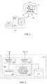
- FIG. 2illustrates a computer architecture forming part of the mapping system of FIG. 1 , in accordance with aspects of the present invention.
- FIG. 3illustrates a schematic view for determining a database table of dipole densities d(y), in accordance with aspects of the present invention.
- FIG. 4illustrates a schematic view for determining a database table of dipole densities d(y) using finite elements, in accordance with aspects of the present invention.
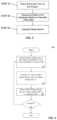
- FIG. 5illustrates a flow chart of a method for determining a database table of dipole densities, in accordance with aspects of the present invention.
- FIG. 6is an example embodiment of a method of determining and storing dipole densities, in accordance with aspects of the present invention.
- FIG. 7illustrates a schematic view combining both external and internal systems for determining dipole densities d(y) using finite elements, in accordance with aspects of the present invention.
- FIG. 8illustrates an exemplary embodiment of a home usable mapping system capable of recording or communicating with the physician, in accordance with aspects of the present invention.
- spatially relative termssuch as “beneath,” “below,” “lower,” “above,” “upper” and the like can be used to describe an element and/or feature's relationship to another element(s) and/or feature(s) as, for example, illustrated in the figures. It will be understood that the spatially relative terms are intended to encompass different orientations of the device in use and/or operation in addition to the orientation depicted in the figures. For example, if the device in the figures is turned over, elements described as “below” and/or “beneath” other elements or features would then be oriented “above” the other elements or features. The device can be otherwise oriented (e.g., rotated 90 degrees or at other orientations) and the spatially relative descriptors used herein interpreted accordingly.
- exemplary embodimentsare described herein with reference illustrations of idealized or representative structures and intermediate structures. As such, variations from the shapes of the illustrations as a result, for example, of manufacturing techniques and/or tolerances, are to be expected. Thus, exemplary embodiments should not be construed as limited to the particular shapes of regions illustrated herein but are to include deviations in shapes that result, for example, from manufacturing.
- catheters and other devices described in accordance with aspects of the present inventioncan include numerous forms of diagnostic catheters, such as catheters including one or more electrodes, or therapeutic catheters such as tissue ablation catheters.
- Catheterscan be introduced percutaneously into a patient's heart, such as to record electrical activity, measure distances between structures, or deliver energy.
- External devices and systemscan be included, such as body surface electrodes used to record electrical activity or deliver an electric signal, or visualization devices such as external ultrasound or fluoroscopic imaging systems.
- Any of these catheters or other devicescan include one or more electrodes and/or one or more ultrasound elements (e.g. one or more ultrasound sensors and/or ultrasound transducers).
- the electrodes and/or ultrasound elements of the present inventioncan be positioned at any location on the device, for example at a distal or proximal portion of the device, and can be positioned internal or external to a patient's body.
- any or all of the ultrasound elements (e.g. ultrasound transducers and/or ultrasound sensors) of the present inventioncan be used to measure a distance between a sensor and/or a transducer and a surface, as is known in the art.
- One exampleincludes measuring the distance between an ultrasound element comprising a sensor-transducer pair and a wall of a chamber of the heart.
- any or all of the electrodes of the present inventioncan be used to record electric “signals” (e.g. voltages and/or currents) at or between one or more electrode locations. Recorded electric signals can be used to map electrical activity of tissue. The mapped electrical activity can be further processed (e.g. in terms of sources of charge and charge density and correlated with various physiologic parameters related to the function of the heart) and the mapped electrical activity and other recorded and calculated information can be provided visually to one or more operators of the system of the present invention.
- signalse.g. voltages and/or currents
- Recorded electric signalscan be used to map electrical activity of tissue.
- the mapped electrical activitycan be further processed (e.g. in terms of sources of charge and charge density and correlated with various physiologic parameters related to the function of the heart) and the mapped electrical activity and other recorded and calculated information can be provided visually to one or more operators of the system of the present invention.
- any or all of the electrodes of the present inventioncan be used to deliver and/or record electric signals that are generated by the system. Such delivered signals can be emitted from any one or more electrodes, and can be delivered between any two or more electrodes.
- Recorded signalscan comprise a signal present at a single electrode location or at multiple electrode locations (e.g. a signal representing a comparison of two or more signals present at two or more electrode locations). Recorded signals can be measured, for example, synchronously or asynchronously in terms of voltage and/or current.
- Recorded signalscan be further processed in terms of, for example, resistive and reactive components of impedance and/or the combined magnitude of impedance with any original or processed signal “values” (e.g. those represented by a parameter selected from the group consisting of: instantaneous amplitude; phase; peak; Root-Mean-Square (rms); demodulated magnitude; and combinations of these).
- mapand “mapping” shall include, but need not be limited to, “electrical map”, “electrical mapping”, “anatomical map”, “anatomical mapping”, “device map” and “device mapping”, each of which is defined herein below.
- electrical mapand “electrical mapping” shall include, but need not be limited to, recording, processing and/or displaying electrical information, such as electrical information recorded by one or more electrodes described or understood in accordance with the present invention.
- This electrical informationincludes, but is not limited to: cardiac or other tissue voltage measurements; cardiac or other tissue bipolar and/or unipolar electrograms; cardiac or other tissue surface charge data; cardiac or other tissue dipole density data; cardiac or other tissue monophasic action potentials; and combinations of these.
- anatomical mapand “anatomical mapping” shall include, but need not be limited to, recording, processing and/or displaying anatomical information, such as anatomical information provided by one or more ultrasound elements of the present invention and/or one or more electrodes described or understood in accordance with the present invention.
- This anatomical informationincludes, but is not limited to: two-dimensional (2D) or three-dimensional (3D) representations of tissue, such as one or more chambers of a heart; tissue wall thicknesses such as the thickness of an atrial or ventricular wall; distance between two tissue surfaces; and combinations of these.
- a dipole density map and/or surface charge map(hereinafter singly or collectively dipole density map) is provided by using information provided by multiple electrodes and multiple ultrasound elements, such as is described in Applicant's co-pending international application, Serial Number PCT/US2012/028593, entitled “Device and Method For the Geometric Determination of Electrical Dipole Densities on the Cardiac Wall”, the entirety of which is incorporated herein.
- device mapand “device mapping” shall include, but need not be limited to, recording, processing and/or displaying of device distance information, such as information comprising the distance between a device or device component and another object, such as tissue or another device or device component.
- any pair of electrodes described or understood in accordance with the present inventioncan be constructed and arranged to provide distance information, such as the distance between that pair of electrodes, or the distance between one of the electrodes and one or more proximate components (e.g. a component at a known distance from one or both of the electrodes in the pair).
- the signalcan by processed and/or calibrated according to one or more known separation distances (e.g. the separation distance between two electrodes fixedly mounted to a rigid structure at a pre-determined distance). Calibrated signal values can be combined across adjacent sets of electrode pairs to accurately estimate the distance between any pair (e.g.
- Known and calculated separation distancescan be used as “reference” electrodes and combined to triangulate the unknown position of one or more “marker” electrodes, such as an electrode positioned on the present invention or on a separate or external device and positioned proximate the present invention.
- the process of triangulationcan be used to dynamically localize the three-dimensional position of any or all of the electrodes either individually and/or as a combined entity in three-dimensional space.
- any or all electrodes described or understood in accordance with the present inventioncan be used to deliver electric energy, such as radiofrequency energy.
- the dipole densitiescan be determined by a finite elements method, avoiding the errors encountered using previous extrapolation algorithms.
- the surface charge densitymeans surface charge (Coulombs) per unit area (cm 2 ).
- a dipoleas such, is a neutral element, wherein a part comprises a positive charge and the other part comprises the same but negative charge.
- a dipolecan better represent the electric nature of cellular membranes, because in a biological environment ion charges are not macroscopically separated.
- the '517 publicationdisclosed devices, systems, and methods for determining the dipole densities on heart walls using one or more catheters placed into the heart chamber.
- a triangularization of the heart wallis performed in which the dipole density at each vertex correlate to the potential measured at various locations within the associated chamber of the heart.
- mapping information recorded by one or more electrodes located on one or more catheters and anatomical informationis used.
- one or more ultrasound elementsare provided on the catheter.
- '313 patent, '690 publication and '517 publicationdisclose devices, systems, and methods for creating an image of the heart based on information recorded from one or more internal electrodes (e.g. creating an anatomical and/or electrical representation of the heart)
- some embodiments of the present inventiondisclose devices, systems, and methods for creating a heart image with external sensors (i.e. external sensors only), while other embodiments disclose devices, systems, and methods using both internal and external sensors to create the heart image.
- one or more electrodes outside the bodycan be positioned proximate the surface of the patient's torso.
- one or more ultrasound elementse.g. one or more ultrasound transducers, sensors or combined transducer-sensors, hereinafter “ultrasound element”
- ultrasound elementcan also be used with the one or more electrodes outside the body, such as one or more ultrasound elements also positioned proximate the surface of the patient's torso.
- the external one or more electrodes disclosed in the present inventionare used with internal (inside the body) electrodes disclosed in the internal sensor-based devices, systems, and methods of the '313 patent, '690 publication and '517, combining heart chamber geometry with internal and external sensor (voltage) readings, such that dipole densities can be depicted as an animated color map of activation for each heart beat across the epicardial and/or endocardium surface.
- the informationcan be used to diagnose and/or treat a patient with a cardiac arrhythmia, such as atrial fibrillation, or an inadequately synchronized activation sequence, such as in heart failure.
- Other information obtainedcan include precise location of foci, conduction-gaps, and/or position of conduction channels.
- a dipole density librarycan be created in computer memory by combining the electrode voltage readings from one or more electrodes proximate the surface of the patient's torso with anatomical imaging from an imaging instrument, such as CT; MRI; ultrasound; and/or a generic model of a heart.
- This anatomical imagingcan be generated in real-time and/or imported from previous imaging from one or more of CT, MRI, ultrasound (internal or external), or other imaging apparatus.
- the dipole density libraryis created by combining the electrode voltage readings from one or more electrodes with ultrasound readings recorded by the one or more ultrasound elements proximate the surface of the patient's torso.
- the dipole density libraryis created by combining the electrode voltage readings from one or more electrodes with ultrasound readings recorded by one or more ultrasound elements positioned within the patient's body, such as one or more ultrasound elements positioned within one or more chambers of the patient's heart.
- the system of the present inventioncomprises an external device, for example a vest, having one or more electrodes, and optionally, one or more ultrasound elements.
- FIG. 1shows an example embodiment of a mapping system 100 that can be used for real time dipole density mapping of a heart 12 of a human 10 .
- System 100can include a computer 110 having known types of input devices and output devices, such as a display 120 and printer 130 , coupled to a patient attachment device, vest 140 , having one or more electrodes 142 .
- vest 140can further include one or more ultrasound elements 144 .
- Ultrasound elements 144can include one or more ultrasound transducers configured to transmit ultrasound waves, such as sound waves configured to reflect off of one or more structures of the heart, and be recorded or otherwise received by one or more ultrasound sensors.
- ultrasound elements 144can include one or more ultrasound sensors, such as one or more ultrasound sensors which receive the reflected sound waves.
- one or more ultrasound elements 144can include both an ultrasound transmitter and an ultrasound sensor, such as a single element that both transmits and receives ultrasound waves.
- a vestis shown, numerous alternative patient attachment device types can be used, including, for example, shirts, bibs, arm bands, torso bands and/or any other patient-attachable assembly capable of maintaining the one or more electrodes 142 and/or ultrasound elements 144 in contact with the wearer's body, or sufficiently close thereto, such that a signal can be detected and/or transmitted by each signal-detecting element.
- the one or more electrodes 142 and/or ultrasound elements 144can be attached directly to the skin.
- multiple discrete attachmentscan be used with a combination of garments, (e.g. shirt plus armband or torso band plus armband), or a combination of a garment with direct skin attachment(s).
- vest 140can only include one or more electrodes 142 , with no ultrasound elements. In other embodiments, vest 140 can include one or more ultrasound elements 144 , and not have any electrodes. In still other embodiments a combination of garments can be used with different elements being positioned on different garments. For example, in a combination of shirt plus armband, the shirt can have one or more electrodes 142 while the armband can have one or more ultrasound elements 144 .
- vest 140is flexible and conforms closely to the body of the patient and can be made of any suitable materials. Vest 140 can be configured so that the one or more electrodes 142 and/or ultrasound elements 144 are urged against the skin at a consistent position, such as to prevent movement of the element across the skin. In some embodiments, the one or more electrodes 142 and/or ultrasound elements 144 can be positioned on both the front and the back of the patient. In other embodiments, the one or more electrodes 142 and/or ultrasound elements 144 can be positioned only on the front or back of the patient, depending on application.
- the one or more electrodes 142 and/or ultrasound elements 144can be connected to computer 110 , such as via a wired and/or wireless connection (see FIG. 8 ).
- Computer 110can control the operation of the one or more electrodes 142 and/or ultrasound elements 144 .
- computer 110can shut off selected electrodes 142 and/or ultrasound elements 144 , leaving only the associated electrodes 142 and/or ultrasound elements 144 that cover one or more areas of interest being turned on.
- the System 100can be used to create a three-dimensional database of dipole densities d(y) and distance measurements at the epicardial surface of the heart.
- the distance measurementscan include, but are not limited to: the distance between at least one of the electrodes 142 and the epicardial surface, the distance between at least one of the electrodes 142 and an ultrasound element 144 , and the distance between the epicardial surface and an ultrasound element 144 . Knowing the speed of sound in the particular environment, as well as the timing of the delivery of sound waves by the transducer, the distance between an ultrasound transducer, a reflected surface, and an ultrasound sensor can be calculated, as described herein below.
- the distance measurementscan be calculated by analyzing the received signal amplitude, a shift in frequency between transmitted and received signals, and/or an ultrasound sensor recorded angle.
- System 100can also be configured to produce continuous, real time geometries of the tissue of a patient.
- System 100can provide one or more of: tissue geometry information such as tissue position, tissue thickness (e.g. cardiac wall thickness) and tissue motion (e.g. cardiac wall motion) information; distance information such as distance between two tissue locations, and distance between a tissue location and a device component location; tissue electrical activity information; status of ablation of a portion of tissue; status of resynchronization pacing, and/or combinations of these.
- the present inventionincorporates one or more ultrasound elements 144 comprising both an ultrasound transducer and an ultrasound sensor, each preferably contained in a single component.
- the ultrasound sensoris configured to record or otherwise detect the wave reflections that result from the ultrasound waves emitted from one or more ultrasound transducers.
- the detected wave reflectionscan be used to determine real-time continuous measurements of the position of at least one of the electrodes 142 and/or at least one ultrasound element 144 . This information can be used to enhance one or more dipole density d(y) calculations. Measurements can be taken to determine the thickness of an object, such as the thickness of cardiac tissue, which can be used to determine an ablation parameter such as power or time of energy delivery.
- an ultrasound element 144comprising a piezo crystal transmits acoustic waves and receives the reflections of those waves.
- the timing between transmitting and receivingcan be used to determine the distance between the transmitting and receiving surfaces, and one or more reflective surfaces (e.g. reflective tissue surfaces).
- precise distances and dimensions of target cardiac tissueis determined, resulting in a more precise and effective diagnosis and/or therapy.
- one or more ultrasound elements 144are constructed and arranged to produce sound waves in at least one of either constant or pulsed excitation, such as sounds waves between 3 megahertz and 18 megahertz.
- the waves emitted by one or more ultrasound elements 144can be at constant frequency and/or produced by a chirp of changing frequency (to allow pulse compression or demodulation on reception).
- the precision in dipole density calculations along with the distance measurementswill allow for the precise detailing of the electrical activity in the cardiac cells and will allow for the precise identification of which cells are the earliest sites of activation.
- one or more ultrasound elements 144can be configured to automatically detect the distance from one or more ultrasound elements 144 to the epicardial surface via a first reflection and further detect the cardiac wall thickness via a second reflection.
- one or more ultrasound elements 144integrate multiple reflections to construct an anatomical geometry including an epicardial surface of the heart and the thickness of the associated myocardium.
- one or more ultrasound elements 144include at least one crystal, typically comprised of a piezoelectric material, which is positioned proximate to the center of each electrode 142 within an electrode array.
- one or more ultrasound elements 144include at least one crystal positioned between two or more electrodes 142 , such as to create a device with a ratio of mapping electrodes 142 to ultrasound elements 144 of 1:1, 2:1, 5:2, 3:1, 4:1 or another ratio.
- the at least one crystalcan be constructed and arranged to transmit ultrasonic signals and/or to receive ultrasonic signals (e.g. receive ultrasonic signals transmitted by the same or different crystals and/or the reflections of those signals).
- one or more ultrasound elements 144comprise a plurality of crystals, such as a plurality of crystals arranged in an array.
- one or more ultrasound elements 144comprise a piezoelectric film covering one or more electrodes 142 , such as one or more electrodes 142 within an array. In some embodiments, one or more ultrasound elements 144 can be constructed as part of an electrode 142 .
- system 100can comprise a sensor/electrode combination.
- FIG. 2provides an example embodiment of a computer architecture 200 that can form part of mapping system 100 .
- Architecture 200includes interface module 210 for interfacing with the vest 140 , interface module 220 for interfacing with output devices 120 , 130 , and at least one processor 240 .
- the computer 110includes at least one computer memory 250 .
- the foregoingare generally known, however the present invention further includes an electric-potential to surface-charge-density and/or dipole-density converter module 230 .
- Converter module 230includes instructions necessary for carrying out the methods described herein, when executed by processor 240 , wherein the results of such processing are stored in memory 250 , as would be understood by one skilled in the art having the benefit of this disclosure.
- the 3D geometrycan be accommodated by integrating anatomical data from CT/MRI scans with the epicardial geometry determined from analysis of the received acoustic signals.
- the CT/MRI scanscan include data to determine torso geometry.
- the CT/MRI scanscan also provide data associated with an epicardial surface surrounding the heart, where those of ordinary skill would understand that the epicardial surface can be used to register the CT/MRI data with data calculated from the devices of the present invention. Further, locating the epicardial surface can include determining or otherwise providing data to be associated with the location of the heart within the torso.
- system 100is configured to generate a table of dipole densities v(P′, t) that embody an ionic nature of cellular membranes across the epicardium of a given heart of a patient, comprising:
- architecture 200includes a measuring and recording unit, such as interface module 210 which is configured to obtain electric potential data V e at given positions P proximate the patient's torso surface, the converter module 230 includes an aid-converter that converts the electric potentials V e into digital voltage data, the processor 240 transforms the digital voltage data into dipole charge density data, and the memory 250 stores the electric potential data V e and the transformed cellular membrane dipole density data.
- a measuring and recording unitsuch as interface module 210 which is configured to obtain electric potential data V e at given positions P proximate the patient's torso surface
- the converter module 230includes an aid-converter that converts the electric potentials V e into digital voltage data
- the processor 240transforms the digital voltage data into dipole charge density data
- the memory 250stores the electric potential data V e and the transformed cellular membrane dipole density data.
- the measuring and recording unitincludes multiple electrodes positioned proximate the patient's torso surface.
- the systemcan further include a wearable garment and at least one of the multiple electrodes can be coupled to the wearable garment.
- the wearable garmentis flexible and conforms closely to the patient's torso surface and can urge one or more electrodes against the torso surface with a consistent position to prevent movement of the one or more electrodes.
- the wearable garmentcan be selected from the group consisting of: vest; shirt; bib; arm band; torso band; any patient-attachable assembly capable of maintaining the one or more electrodes in contact with the torso surface or sufficiently close thereto; and/or combinations thereof.
- the processorincludes a computer program embodying an algorithm that, when executed, transforms the digital voltage data into cellular membrane dipole density data.
- the systemfurther includes one or more ultrasound transducers positioned proximate the patient's torso surface, the one or more ultrasound transducers being configured to emit waves toward an epicardial surface, and one or more ultrasound sensors positioned proximate the patient's torso surface, the one or more ultrasound sensors being configured to receive reflections of the waves from the epicardial surface, wherein the measuring and recording unit further measures and records the sensor information.
- one or more ultrasound transducersare further configured to function as an ultrasound sensor.
- the processoris configured to receive sensor data from the one or more sensors and generate distance measurements from the epicardial surface.
- the distance measurementcan be produced by analyzing at least one of: timing of received signal; recorded signal amplitude; sensor recorded angle; or signal frequency changes
- the systemincludes more than one wearable garment and the multiple electrodes, ultrasound transducers, or ultrasound sensors are coupled to different wearable garments.
- the multiple electrodesare coupled to a first wearable garment
- the ultrasound transducers and ultrasound sensorsare coupled to a second wearable garment.
- the wearable garmentscan be selected from the group consisting of: vest; shirt; bib; arm band; torso band; any patient-attachable assembly capable of maintaining the one or more electrodes, one or more ultrasound transducers, and one or more ultrasound sensors in contact with the torso surface, or sufficiently close thereto that a monitorable signal is detectable.
- the systemfurther includes an imaging unit that represents the cellular membrane dipole densities v(P′,t) as a two-dimensional image or time-dependent sequence of images
- the systemfurther includes an imaging unit that represents the cellular membrane dipole densities v(P′,t) as a three-dimensional image or time-dependent sequence of images.
- FIG. 3shows a schematic view of some elements of computer 110 used for determining a database table of dipole densities d(y).
- Computer 110includes a first receiver 310 configured to receive electrical potentials from the one or more electrodes, such as electrodes 142 of FIG. 1 .
- Computer 110further includes a second receiver 320 configured to receive cardiac geometry information from an imaging instrument, such as CT; MRI; ultrasound; or a generic model of a heart. This anatomical imaging can be generated in real-time and/or imported from previous imaging from one or more of CT, MRI, ultrasound (internal or external), or other imaging apparatus.
- Dipole density processor 330receives electrical information from first receiver 310 and cardiac geometry information from the second receiver 320 .
- Dipole density processor 330which can comprise converter module 230 and processor 240 , includes a mathematical processing element or other electronic module including software and/or hardware for performing mathematical or other calculations.
- Dipole density processor 330preferably uses one or more algorithms to process the received electrical and geometry information to produce a database table of dipole densities d(y) 350 .
- dipole density processor 330can be configured to produce a database table of surface charge information.
- the vest 140can further include one or more ultrasound transducers and/or one or more ultrasound sensors to provide cardiac geometry information to the second receiver 320 .
- the one or more ultrasound transducerstransmit ultrasound waves, such as waves configured to reflect off one or more structures of the heart, and be recorded by the ultrasound sensors (e.g. reflections from the epicardial surface and one or more of the inner surfaces or structures of the heart).
- Dipole density processor 330receives electrical information from first receiver 310 and ultrasound cardiac geometry information from the second receiver 320 .
- Dipole density processor 330which can comprise converter module 230 and processor 240 , includes a mathematical processing element or other electronic module including software and/or hardware for performing mathematical or other calculations.
- Dipole density processor 330preferably uses one or more algorithms to process the received electrical and geometry information to produce a database table of dipole densities d(y) 350 .
- the geometric model of the epicardial surfacecan be processed by the dipole density processor 330 into multiple small triangles (triangularization) and/or other polygonal shapes (e.g., squares, tetrahedral, hexagonal, and others). When the polygons are sufficiently small, the dipole density has a small variation over the polygon. In a preferred embodiment, the number of triangles is determined by dipole density processor 330 . With the electrodes positioned by a clinician, such as an electrophysiologist, the potentials at each electrode are recorded. The dipole density processor 330 computes the dipole density at all vertices of the triangles.
- the total measured potential V(x) at a location xis the sum over all vertices y of d(y) times a matrix W(x,y).
- dipole density processor 330implements a progressive algorithm that can be modified and/or refined in order to improve spatial and/or time resolution of the database of dipole densities that are produced.
- the dipole densities d(y)can be obtained by solving a linear system of equations. Thereby a map of dipole densities can be created at each corresponding time interval. The synthesis of the maps generates a cascade of the activation sequence of each corresponding heart beat that can be used to diagnose cardiac wall tissue, such as to identify an origin of aberrant electrical activity or otherwise diagnose an arrhythmia.
- the measuring electrodes used in the present inventionare placed on or proximate the torso surface. Due to the inhomogeneous structure of the body, it is difficult to localize the actual sources of the skin electrode measured potentials. A highly complicated boundary value problem must be solved with boundary conditions that are poorly known. Prior art attempts at determining the “action potential” from body surface ECG (alone) have not been very successful.
- the present inventioncalculates the dipole densities using external electrodes on the vest, in combination with cardiac geometry information from an imaging instrument (such as CT; MRI; ultrasound); or the optional external ultrasound transducers and/or ultrasound sensors on the vest.
- an imaging instrumentsuch as CT; MRI; ultrasound
- System 100shown in FIG. 1 , is configured to create a database table of three-dimensional dipole densities d(y) based on voltage potentials and image information relating to the heart, as has been described above.
- triangle T 1defined by system 100 is at location Y 1 .
- the contribution of triangle T 1 to the potential at location X 1can be computed from the dipole density at the vertices of T 1 .
- the dipole density processor 330determines the desired dipole density d(y) from the total measured potential V(x), which is the sum resulting from all the triangles defined by system 100 .
- the dipole density d(y) at many equally distributed vertices y on the epicardial surfaceis calculated (e.g. from 10 to 50,000 with increasing number of calculated potentials providing more detailed results) by solving a system of linear equations.
- the measured and/or calculated potentialse.g. with application of splines
- their numbercan be increased to a higher number of regions.
- This calculation of dipole densityresults, such as via an automatic computer program forming at least part of dipole density processor 330 .
- the resultsare presented in a visual, anatomical format, such as depicting the dipole densities on a geometric model of the epicardial surface in relation to time (t).
- This formatallows a clinician, such as an electrophysiologist, to determine the activation sequence, or other electrical and mechanical measures, on the epicardial surface, such as to determine treatment locations for a cardiac arrhythmia or other inadequacy in cardiac tissue health, such as force of tissue contraction and motion of the epicardial surface.
- the resultscan be shown on a display unit 120 , or on a separate display not shown, such as a color display.
- the device of the present inventionis implemented as, or includes, a software program that is executable by at least one processor.
- the software programcan be integrated into one or more of: an ECG system; a cardiac tissue ablation system; an imaging system; a computer; and combinations of these.
- FIG. 5illustrates one embodiment of a method for determining a database table of dipole densities d(y) of the epicardial surface of a patient's heart.
- a vest having an array of one or more electrodese.g. vest 140 of system 100 of FIG. 1
- the geometry of the epicardial surfacecan be obtained in relation to the positions of the one or more electrodes disposed within the electrode array.
- the magnitude and other properties of motion of cardiac wall tissuecan be determined.
- the thickness of a patient's heart tissuecan be determined.
- the geometry of the epicardial surfaceis obtained in relation to the electrode array position, such as by importing a geometry model from an imaging study (e.g., using computed tomography, MRI and/or ultrasound).
- the surface of the geometry of the corresponding epicardial surfaceis generally divided into small polygons, such as in the form of at least 1000 triangles of similar size.
- the dipole density d(y)can be calculated at each vertex y from the measured potential values x.
- the measurementscan be repeated successively during the cardiac cycle, such as once each millisecond, giving the electrophysiologist a dynamic progression of the activation sequence.
- the information of the time dependent dipole densitiescan be depicted as an animated color map of activation for each heart beat across the epicardial surface.
- the informationcan be used to diagnose and/or treat a patient with a cardiac arrhythmia, such as atrial fibrillation, or an inadequately synchronized activation sequence, such as in heart failure.
- Other information obtainedcan include precise location of foci, conduction-gaps, and/or position of conduction channels.
- the dipole density informationcan be used to determine cardiac tissue treatment locations for lesion creation, such as a lesion created by a catheter-based ablation system.
- the lesioncan be created by an RF, ultrasound, microwave, laser and/or cryogenic energy ablation catheter.
- the informationcan also be used to determine the location of pacing electrodes for cardiac resynchronization therapy.
- ablating the cardiac tissuecan be based upon the tissue diagnosis.
- the anatomical informationcomprising tissue thickness information and at least one of the magnitude of ablation energy or the time period in which ablation energy is delivered, is adjusted based on the tissue thickness information recorded by one or more ultrasound sensors.
- FIG. 6summarizes one method 400 for determining and storing surface charge densities and/or dipole densities in accordance with aspects of the present invention, which have been described in detail above.
- mapping system 100is used to measure and/or calculate one or more electric potential(s) Ve in one or more position(s) P at a given time t.
- Veis transformed into a surface charge density ⁇ (P′,t) and/or dipole density d(P′,t)
- Step 406the surface charge density ⁇ (P′,t) and/or dipole density d(P′,t) is stored in a database table. The method is repeated if there is another P, in Step 408 .
- FIG. 7shows an embodiment using both external sensor systems and internal sensor systems together.
- the present systems and methods disclosed above for external sensor-based imaging of the heartcan be combined with the devices, systems, and methods using internal sensor-based imaging of the heart disclosed in the '313 patent, '690 publication and '517 publication.
- FIG. 7shows the present vest system in combination with system 500 , described in detail in the '690 publication and '517 publication, each of which is hereby incorporated by reference.
- This combination of internal and external electrodescan be used to augment accuracy, specificity, etc., and combining heart chamber geometry with internal and external sensor (voltage) readings can provide simultaneous maps of the epicardium and endocardium walls.
- System 500includes a mapping catheter with a shaft 311 , which is inserted into a chamber of a patient's heart, such as the Left Atrium (LA).
- a mapping catheterwith a shaft 311 , which is inserted into a chamber of a patient's heart, such as the Left Atrium (LA).
- LALeft Atrium
- Electrode array 315including multiple electrodes 316 .
- Electrode array 315is shown in a basket construction, but numerous other constructions can be used including multiple independent arms, spiral arrays, electrode covered balloons, and other constructions configured to place multiple electrodes into a three-dimensional space.
- Any catheter with one or more electrodescan be used to supply mapping information to system 100 , which is configured to create a database table of three-dimensional dipole densities d(y) based on voltage potentials and image information relating to the heart, as has been described above.
- triangle T 2is at location Y 2 on the endocardial surface and electrode 316 a is at location X 2 .
- the contribution of triangle T 2 to the potential at location X 2can be computed from the dipole density at the vertices of T 1 .
- the dipole density processor 330determines the desired dipole density d(y) from the total measured potential V(x), which is the sum resulting from all the triangles defined by system 100 .
- the dipole density d(y) at many equally distributed vertices y on the endocardial surfacecan be calculated (e.g. from 10 to 50,000 with increasing number of calculated potentials providing more detailed results) by solving a system of linear equations.
- the measured and/or calculated potentialse.g. with application of splines
- their numbercan be increased to a higher number of regions.
- the resultsare presented in a visual, anatomical format, such as on a display depicting the dipole densities on a geometric model of the endocardial surface and epicardial surface in relation to time (t).
- This formatallows a clinician, such as an electrophysiologist, to determine the activation sequence, or other electrical and mechanical measures, on the endocardial surface and/or epicardial surface, such as to determine treatment locations for a cardiac arrhythmia or other inadequacy in cardiac tissue health, such as force of tissue contraction and motion of an endocardial surface and/or an epicardial surface.
- the resultscan be shown on a display unit 120 , or on a separate display not shown, such as a color display.
- FIG. 8shows embodiments for a mapping system 600 for monitoring of a patient at their home or otherwise remote from a clinical setting.
- the system 600can use many of the elements and methods described above for determination of dipole densities.
- the system 600includes a vest 640 , which can use the same or similar features as vest 140 described above, and a recording device 604 a , computer 604 b and/or communication system 604 c.
- Vest 640can include one or more electrodes 642 .
- vest 640can further include one or more ultrasound elements 644 , such as one or more ultrasound transducers and/or ultrasound sensors.
- Vest 640can be flexible and conform closely to the body of the patient and can be made of any suitable materials.
- Vest 640can be configured so that the one or more electrodes 642 and/or ultrasound elements 644 are urged against the torso surface or skin at a consistent position, such as to prevent movement of the element across the skin.
- the one or more electrodes 642 and/or ultrasound elements 644can be positioned on both the front and the back of the patient.
- the one or more electrodes 642 and/or ultrasound elements 644can be positioned on only the front or back of the patient, depending on application.
- the one or more electrodes 642 and/or ultrasound elements 644can be attached directly to the skin. While the description discloses one or more electrodes 642 and/or one or more ultrasound elements 644 used with the vest, garment, or direct skin attachment, the invention also envisions embodiments that only include electrodes 642 or only ultrasound elements 644 .
- vest 640 or another component of system 600includes one or more additional sensors or transducers, functional element 645 .
- Functional elements 645can comprise an element selected from the group consisting of: a pressure sensor such as a blood pressure sensor; a pH sensor; a glucose sensor; a respiration sensor; a salinity or other sweat level sensor; an EEG sensor such as an EEG sensor placed on the scalp of the patient; an oxygen level sensor such as an oxygen level sensor placed on the finger of the patient; an eye gaze sensor; and combinations of these.
- the one or more electrodes 642 , ultrasound elements 644 , and/or functional elements 645can be coupled to the recording device 604 a , computer 604 b and/or communication system 604 c , with either a wired (not shown) or wireless connection (e.g., Bluetooth, Wi-Fi, or other wireless means).
- the recording device 604 a , computer 604 b and/or communication system 604 ccan control the operation of the one or more electrodes 642 , ultrasound elements 644 , and/or functional elements 645 .
- This control featurecan be programmed into their systems or can be done remotely via a remote connection (e.g., from a physician's office 608 ).
- the recording device 604 a , computer 604 b and/or communication system 604 ccan turn on or shut off selected electrodes 642 , ultrasound elements 644 , and/or functional elements 645 , leaving only the associated electrodes 642 , ultrasound elements 644 , and/or functional elements 645 that cover one or more areas of interest being turned on.
- the recording device 604 acan be a portable device for monitoring and recording various electrical and/or other signal activities of the one or more electrodes 642 , ultrasound elements 644 , and/or functional elements 645 , similar to a Holter or other mobile-patient monitor.
- the recording device 604 acan be configured to continuously monitor and record, or only record on an as needed basis when a recordable event happens. Once the data is recorded, the recording device 604 a can be transmitted to the physician's office to be analyzed.
- the recording device 604 acan be a smart phone, such as a Galaxy S4, having an application for recording the signal activities. Once recorded, the smart phone can also be capable of transmitting the information, for example, to the physician's office.
- the computer 604 bcan have the capability of continuously monitoring various signal activities of the one or more electrodes 642 , ultrasound elements 644 , and/or functional elements 645 .
- the computer 604 bcan also have the capability of analyzing the data from the one or more electrodes 642 , ultrasound elements 644 , and/or functional elements 645 , similar to system 100 described above.
- computer 604 bcomprises one or more algorithms constructed and arranged to analyze one or more of: cardiac geometry; cardiac electrical activity; blood pressure; pH; glucose; respiration; sweat level; brain activity; or blood oxygen level.
- computer 604 banalyzes cardiac electrical activity and at least one physiologic parameter selected from the group consisting of: blood pressure; pH; glucose; respiration; sweat level; brain activity; or blood oxygen level.
- the computer 604 bcan save the monitored or analyzed data in memory, such as on memory card or flash device card or copy it to a disk.
- the computer 604 bcan further have the capability of transmitting the analyzed data, for example, to the physician's office, giving the physician real-time feedback as to the health and condition of their patient.
- communication system 604 ccan include a means of communicating with the physician's office on a real-time basis for remote medical patient monitoring, such as over the internet or other direct communication means (e.g., smart phone).
- the physiciancan monitor the patient 24 hours a day and/or at any time.
- the systemcan further include two way communications such that the physician can view the data in real-time while speaking with the patient.
- the physiciancan also turn on or shut off selected electrodes 642 , ultrasound elements 644 and/or functional elements 645 , leaving only the associated electrodes 642 , ultrasound elements 644 and/or functional elements 645 that cover one or more areas of interest being turned on.
Landscapes
- Health & Medical Sciences (AREA)
- Life Sciences & Earth Sciences (AREA)
- Engineering & Computer Science (AREA)
- Surgery (AREA)
- Medical Informatics (AREA)
- Molecular Biology (AREA)
- Animal Behavior & Ethology (AREA)
- Biomedical Technology (AREA)
- Heart & Thoracic Surgery (AREA)
- Public Health (AREA)
- General Health & Medical Sciences (AREA)
- Veterinary Medicine (AREA)
- Physics & Mathematics (AREA)
- Biophysics (AREA)
- Pathology (AREA)
- Cardiology (AREA)
- Nuclear Medicine, Radiotherapy & Molecular Imaging (AREA)
- Radiology & Medical Imaging (AREA)
- Otolaryngology (AREA)
- Physiology (AREA)
- Electromagnetism (AREA)
- Pulmonology (AREA)
- Optics & Photonics (AREA)
- Dentistry (AREA)
- Oral & Maxillofacial Surgery (AREA)
- High Energy & Nuclear Physics (AREA)
- Theoretical Computer Science (AREA)
- Human Computer Interaction (AREA)
- Ophthalmology & Optometry (AREA)
- Computer Networks & Wireless Communication (AREA)
- Plasma & Fusion (AREA)
- Measurement And Recording Of Electrical Phenomena And Electrical Characteristics Of The Living Body (AREA)
- Measuring Pulse, Heart Rate, Blood Pressure Or Blood Flow (AREA)
- Ultra Sonic Daignosis Equipment (AREA)
- Apparatus For Radiation Diagnosis (AREA)
- Magnetic Resonance Imaging Apparatus (AREA)
Abstract
Description
- a) a measuring and recording unit that measures and records electric potential data Veat given positions P proximate the patient's torso surface,
- b) an aid-converter that converts the at least one electric potentials Veinto digital voltage data,
- c) a processor that transforms the digital voltage data into dipole charge density data, and
- d) a memory that stores the electric potential data Veand the transformed cellular membrane dipole density data.
Claims (15)
Priority Applications (1)
| Application Number | Priority Date | Filing Date | Title |
|---|---|---|---|
| US17/063,901US12178604B2 (en) | 2013-09-13 | 2020-10-06 | Devices and methods for determination of electrical dipole densities on a cardiac surface |
Applications Claiming Priority (4)
| Application Number | Priority Date | Filing Date | Title |
|---|---|---|---|
| US201361877617P | 2013-09-13 | 2013-09-13 | |
| PCT/US2014/054942WO2015038607A2 (en) | 2013-09-13 | 2014-09-10 | Devices and methods for determination of electrical dipole densities on a cardiac surface |
| US201614916056A | 2016-03-02 | 2016-03-02 | |
| US17/063,901US12178604B2 (en) | 2013-09-13 | 2020-10-06 | Devices and methods for determination of electrical dipole densities on a cardiac surface |
Related Parent Applications (2)
| Application Number | Title | Priority Date | Filing Date |
|---|---|---|---|
| US14/916,056ContinuationUS10828011B2 (en) | 2013-09-13 | 2014-09-10 | Devices and methods for determination of electrical dipole densities on a cardiac surface |
| PCT/US2014/054942ContinuationWO2015038607A2 (en) | 2013-09-13 | 2014-09-10 | Devices and methods for determination of electrical dipole densities on a cardiac surface |
Publications (2)
| Publication Number | Publication Date |
|---|---|
| US20210153843A1 US20210153843A1 (en) | 2021-05-27 |
| US12178604B2true US12178604B2 (en) | 2024-12-31 |
Family
ID=52666502
Family Applications (2)
| Application Number | Title | Priority Date | Filing Date |
|---|---|---|---|
| US14/916,056ActiveUS10828011B2 (en) | 2013-09-13 | 2014-09-10 | Devices and methods for determination of electrical dipole densities on a cardiac surface |
| US17/063,901Active2036-01-10US12178604B2 (en) | 2013-09-13 | 2020-10-06 | Devices and methods for determination of electrical dipole densities on a cardiac surface |
Family Applications Before (1)
| Application Number | Title | Priority Date | Filing Date |
|---|---|---|---|
| US14/916,056ActiveUS10828011B2 (en) | 2013-09-13 | 2014-09-10 | Devices and methods for determination of electrical dipole densities on a cardiac surface |
Country Status (6)
| Country | Link |
|---|---|
| US (2) | US10828011B2 (en) |
| EP (1) | EP3043701B1 (en) |
| JP (1) | JP6681332B2 (en) |
| AU (2) | AU2014318872B2 (en) |
| CA (1) | CA2922941C (en) |
| WO (1) | WO2015038607A2 (en) |
Cited By (1)
| Publication number | Priority date | Publication date | Assignee | Title |
|---|---|---|---|---|
| US20250000482A1 (en)* | 2023-06-29 | 2025-01-02 | Fujifilm Sonosite, Inc. | Registration system for cardiac ultrasound |
Families Citing this family (24)
| Publication number | Priority date | Publication date | Assignee | Title |
|---|---|---|---|---|
| WO2008014629A2 (en) | 2006-08-03 | 2008-02-07 | Christoph Scharf | Method and device for determining and presenting surface charge and dipole densities on cardiac walls |
| EP2737849A3 (en) | 2008-01-17 | 2014-10-29 | Christoph Scharf | A device and method for the geometric determination of electrical dipole densities on the cardiac wall |
| US9757044B2 (en) | 2011-03-10 | 2017-09-12 | Acutus Medical, Inc. | Device and method for the geometric determination of electrical dipole densities on the cardiac wall |
| EP2890292B1 (en) | 2012-08-31 | 2021-01-13 | Acutus Medical, Inc. | Catheter system for the heart |
| CN105358070B (en) | 2013-02-08 | 2018-03-23 | 阿库图森医疗有限公司 | Expandable catheter assembly with flexible printed circuit board |
| CA2922941C (en) | 2013-09-13 | 2021-11-16 | Acutus Medical, Inc. | Devices and methods for determination of electrical dipole densities on a cardiac surface |
| US9554718B2 (en) | 2014-01-29 | 2017-01-31 | Biosense Webster (Israel) Ltd. | Double bipolar configuration for atrial fibrillation annotation |
| JP6739346B2 (en) | 2014-03-25 | 2020-08-12 | アクタス メディカル インクAcutus Medical,Inc. | Method of operating system of cardiac analysis user interface |
| US10593234B2 (en) | 2015-05-12 | 2020-03-17 | Acutus Medical, Inc. | Cardiac virtualization test tank and testing system and method |
| CN115299988A (en) | 2015-05-12 | 2022-11-08 | 阿库图森医疗有限公司 | Ultrasonic sequencing systems and methods |
| US10653318B2 (en) | 2015-05-13 | 2020-05-19 | Acutus Medical, Inc. | Localization system and method useful in the acquisition and analysis of cardiac information |
| US11219769B2 (en)* | 2016-02-26 | 2022-01-11 | Medtronic, Inc. | Noninvasive methods and systems of determining the extent of tissue capture from cardiac pacing |
| CA3022806A1 (en) | 2016-05-03 | 2017-11-09 | Acutus Medical, Inc. | Cardiac mapping system with efficiency algorithm |
| WO2018218244A1 (en) | 2017-05-26 | 2018-11-29 | Cardioinsight Technologies, Inc. | Ultrasound-based geometry determination for electrophysiological mapping |
| US10575746B2 (en) | 2017-12-14 | 2020-03-03 | Biosense Webster (Israel) Ltd. | Epicardial mapping |
| US20200397329A1 (en)* | 2018-03-06 | 2020-12-24 | St. Jude Medical, Cardiology Division, Inc. | Methods and systems for transmural tissue mapping |
| EP3844710B1 (en)* | 2018-08-28 | 2025-06-18 | Technion Research & Development Foundation Limited | Correcting motion-related distortions in radiographic scans |
| US12178582B2 (en) | 2018-11-09 | 2024-12-31 | Acutus Medical, Inc. | Systems and methods for calculating patient information |
| EP3669758A1 (en)* | 2018-12-18 | 2020-06-24 | Koninklijke Philips N.V. | Electrocardiographic imaging system |
| CA3135773A1 (en) | 2019-06-04 | 2020-12-10 | Acutus Medical, Inc. | Systems and methods for performing localization within a body |
| WO2021102230A1 (en) | 2019-11-22 | 2021-05-27 | Acutus Medical, Inc. | Tissue treatment systems, devices, and methods |
| EP4199817A4 (en)* | 2020-08-19 | 2024-08-21 | OtoNexus Medical Technologies, Inc. | PORTABLE AUSCULTATION DEVICE |
| US20230063364A1 (en)* | 2021-08-30 | 2023-03-02 | Koninklijke Philips N.V. | Ultrasound-controlled training program for individualized and automatic weaning |
| US20240335215A1 (en)* | 2023-04-10 | 2024-10-10 | Fujifilm Sonosite, Inc. | Wearable ultrasound |
Citations (200)
| Publication number | Priority date | Publication date | Assignee | Title |
|---|---|---|---|---|
| US4173228A (en) | 1977-05-16 | 1979-11-06 | Applied Medical Devices | Catheter locating device |
| US4841977A (en) | 1987-05-26 | 1989-06-27 | Inter Therapy, Inc. | Ultra-thin acoustic transducer and balloon catheter using same in imaging array subassembly |
| US5041973A (en) | 1988-10-25 | 1991-08-20 | London Health Association | Cardiac mapping system simulator |
| US5156151A (en) | 1991-02-15 | 1992-10-20 | Cardiac Pathways Corporation | Endocardial mapping and ablation system and catheter probe |
| US5293868A (en) | 1992-06-30 | 1994-03-15 | American Cardiac Ablation Co., Inc. | Cardiac ablation catheter having resistive mapping electrodes |
| WO1994006349A1 (en) | 1992-09-23 | 1994-03-31 | Endocardial Therapeutics, Inc. | Endocardial mapping system |
| US5482472A (en) | 1993-11-17 | 1996-01-09 | Board Of Regents, The University Of Texas System | Electrical signal generator interface with three-dimensional electrical pathway and transparent heart and method of visually simulating cardiac waveforms in three dimensions |
| US5499981A (en) | 1993-03-16 | 1996-03-19 | Ep Technologies, Inc. | Flexible interlaced multiple electrode assemblies |
| JPH08504333A (en) | 1992-09-25 | 1996-05-14 | イーピー・テクノロジーズ・インコーポレーテッド | Electrode-supported splines for the cardiac system |
| JPH08164140A (en) | 1995-06-06 | 1996-06-25 | Matsushita Electric Ind Co Ltd | Ultrasonic diagnostic equipment |
| US5555883A (en) | 1992-02-24 | 1996-09-17 | Avitall; Boaz | Loop electrode array mapping and ablation catheter for cardiac chambers |
| US5595183A (en) | 1995-02-17 | 1997-01-21 | Ep Technologies, Inc. | Systems and methods for examining heart tissue employing multiple electrode structures and roving electrodes |
| US5601084A (en) | 1993-06-23 | 1997-02-11 | University Of Washington | Determining cardiac wall thickness and motion by imaging and three-dimensional modeling |
| US5647367A (en) | 1996-05-31 | 1997-07-15 | Hewlett-Packard Company | Scanning ultrasonic probe with locally-driven sweeping ultrasonic source |
| US5662108A (en) | 1992-09-23 | 1997-09-02 | Endocardial Solutions, Inc. | Electrophysiology mapping system |
| US5722416A (en) | 1995-02-17 | 1998-03-03 | Ep Technologies, Inc. | Systems and methods for analyzing biopotential morphologies in heart tissue to locate potential ablation sites |
| US5722402A (en) | 1994-10-11 | 1998-03-03 | Ep Technologies, Inc. | Systems and methods for guiding movable electrode elements within multiple-electrode structures |
| US5740808A (en) | 1996-10-28 | 1998-04-21 | Ep Technologies, Inc | Systems and methods for guilding diagnostic or therapeutic devices in interior tissue regions |
| US5749833A (en) | 1995-08-15 | 1998-05-12 | Hakki; A-Hamid | Combined echo-electrocardiographic probe |
| US5759158A (en) | 1995-07-28 | 1998-06-02 | E.P. Technologies, Inc. | Systems and methods for conducting electrophysiological testing using high-voltage energy pulses to stun heart tissue |
| US5782239A (en) | 1992-06-30 | 1998-07-21 | Cordis Webster, Inc. | Unique electrode configurations for cardiovascular electrode catheter with built-in deflection method and central puller wire |
| US5795299A (en) | 1997-01-31 | 1998-08-18 | Acuson Corporation | Ultrasonic transducer assembly with extended flexible circuits |
| US5795298A (en) | 1995-03-28 | 1998-08-18 | Sonometrics Corporation | System for sharing electrocardiogram electrodes and transducers |
| US5820568A (en) | 1996-10-15 | 1998-10-13 | Cardiac Pathways Corporation | Apparatus and method for aiding in the positioning of a catheter |
| US5830144A (en) | 1995-03-28 | 1998-11-03 | Vesely; Ivan | Tracking data sheath |
| US5846198A (en) | 1996-05-31 | 1998-12-08 | Siemens Aktiengesellschaft | Apparatus for localizing action currents in the heart |
| WO1999005971A1 (en) | 1997-08-01 | 1999-02-11 | Cardiac Pathways Corporation | System for electrode localization using ultrasound |
| US5876336A (en) | 1994-10-11 | 1999-03-02 | Ep Technologies, Inc. | Systems and methods for guiding movable electrode elements within multiple-electrode structure |
| US5928228A (en) | 1993-03-16 | 1999-07-27 | Ep Technologies, Inc. | Flexible high density multiple electrode circuit assemblies employing ribbon cable |
| US5944022A (en) | 1997-04-28 | 1999-08-31 | American Cardiac Ablation Co. Inc. | Catheter positioning system |
| US5968040A (en) | 1994-03-04 | 1999-10-19 | Ep Technologies, Inc. | Systems and methods using asymmetric multiple electrode arrays |
| US6014590A (en) | 1974-03-04 | 2000-01-11 | Ep Technologies, Inc. | Systems and methods employing structures having asymmetric mechanical properties to support diagnostic or therapeutic elements in contact with tissue in interior body regions |
| US6024703A (en) | 1997-05-07 | 2000-02-15 | Eclipse Surgical Technologies, Inc. | Ultrasound device for axial ranging |
| WO2000007501A1 (en) | 1998-08-03 | 2000-02-17 | Cardiac Pathways Corporation | A dynamically alterable three-dimensional graphical model of a body region |
| US6066096A (en) | 1998-05-08 | 2000-05-23 | Duke University | Imaging probes and catheters for volumetric intraluminal ultrasound imaging and related systems |
| US6086532A (en) | 1997-09-26 | 2000-07-11 | Ep Technologies, Inc. | Systems for recording use of structures deployed in association with heart tissue |
| WO2000040166A1 (en) | 1999-01-06 | 2000-07-13 | Boston Scientific Limited | Ultrasound-guided ablation catheter and methods of use |
| US6107699A (en) | 1998-05-22 | 2000-08-22 | Scimed Life Systems, Inc. | Power supply for use in electrophysiological apparatus employing high-voltage pulses to render tissue temporarily unresponsive |
| US6115626A (en) | 1998-03-26 | 2000-09-05 | Scimed Life Systems, Inc. | Systems and methods using annotated images for controlling the use of diagnostic or therapeutic instruments in instruments in interior body regions |
| JP2000358299A (en) | 1999-06-16 | 2000-12-26 | Ngk Spark Plug Co Ltd | Wave transmitting and receiving element for ultrasonic probe, its production method and ultrasonic probe using the same element |
| US6187032B1 (en) | 1997-10-30 | 2001-02-13 | Kabushiki Kaisha Toshiba | Measurement of intracardiac electrophysiological phenomena |
| US6188928B1 (en) | 1996-11-18 | 2001-02-13 | Pacesetter Ab | Apparatus for tissue stimulation |
| JP2001070269A (en) | 1999-09-06 | 2001-03-21 | Toshiba Corp | Electrophysiology mapping device |
| US6216043B1 (en) | 1994-03-04 | 2001-04-10 | Ep Technologies, Inc. | Asymmetric multiple electrode support structures |
| US6240307B1 (en) | 1993-09-23 | 2001-05-29 | Endocardial Solutions, Inc. | Endocardial mapping system |
| US20010007070A1 (en) | 1999-04-05 | 2001-07-05 | Medtronic, Inc. | Ablation catheter assembly and method for isolating a pulmonary vein |
| US6301496B1 (en) | 1998-07-24 | 2001-10-09 | Biosense, Inc. | Vector mapping of three-dimensionally reconstructed intrabody organs and method of display |
| EP1166714A1 (en) | 2000-06-21 | 2002-01-02 | Biosense, Inc. | Rapid mapping of electrical activity in the heart |
| US20020026118A1 (en) | 2000-08-18 | 2002-02-28 | Assaf Govari | Three-dimensional reconstruction using ultrasound |
| US20020045810A1 (en) | 1993-07-20 | 2002-04-18 | Shlomo Ben-Haim | Method for mapping a heart using catheters having ultrasonic position sensors |
| US20020099292A1 (en) | 1998-11-16 | 2002-07-25 | Cardiac Pathways Corporation | Catheter including ultrasound transducer with emissions attenuation |
| US20020128565A1 (en) | 1997-07-31 | 2002-09-12 | Case Western Reserve University | System and method for non-invasive electrocardiographic imaging |
| US20020165441A1 (en) | 2000-01-27 | 2002-11-07 | Coleman James H. | Bidirectional catheter having mapping assembly |
| US6514249B1 (en) | 1997-07-08 | 2003-02-04 | Atrionix, Inc. | Positioning system and method for orienting an ablation element within a pulmonary vein ostium |
| JP2003509145A (en) | 1999-09-16 | 2003-03-11 | メイヨ フオンデーシヨン フオー メデイカル エジユケーシヨン アンド リサーチ | How to draw medical images in real time |
| JP2003511098A (en) | 1998-04-14 | 2003-03-25 | ジーエムピー・ドラツグ・デリバリー・インコーポレーテツド | Iontophoresis, electroporation and combination catheters for local drug delivery to arteries and other body tissues |
| US20030065271A1 (en) | 2001-09-27 | 2003-04-03 | Baylor College Of Medicine | Cardiac catheter imaging system |
| US20030078494A1 (en) | 2001-10-24 | 2003-04-24 | Scimed Life Systems, Inc. | Systems and methods for guiding and locating functional elements on medical devices positioned in a body |
| US6574492B1 (en) | 1996-01-08 | 2003-06-03 | Biosense, Inc. | Catheter having multiple arms with electrode and position sensor |
| US20030120318A1 (en) | 1998-06-30 | 2003-06-26 | Hauck John A. | Congestive heart failure pacing optimization method and device |
| US20030158477A1 (en) | 2001-11-09 | 2003-08-21 | Dorin Panescu | Systems and methods for guiding catheters using registered images |
| US20030163046A1 (en) | 2002-01-30 | 2003-08-28 | Wilk Ultrasound Of Canada, Inc. | 3D ultrasonic imaging apparatus and method |
| US20030231789A1 (en) | 2002-06-18 | 2003-12-18 | Scimed Life Systems, Inc. | Computer generated representation of the imaging pattern of an imaging device |
| US20030236466A1 (en) | 2002-06-21 | 2003-12-25 | Tarjan Peter P. | Single or multi-mode cardiac activity data collection, processing and display obtained in a non-invasive manner |
| US20040039312A1 (en) | 2002-02-20 | 2004-02-26 | Liposonix, Inc. | Ultrasonic treatment and imaging of adipose tissue |
| WO2004026134A1 (en) | 2002-08-24 | 2004-04-01 | Krishnan Subramaniam C | Method and apparatus for locating the fossa ovalis and performing transseptal puncture |
| US20040082870A1 (en) | 1997-07-31 | 2004-04-29 | Yoram Rudy | Systems and methods for determining a surface geometry |
| EP1415608A2 (en) | 2002-10-21 | 2004-05-06 | Biosense, Inc. | Real-time monitoring and mapping of ablation lesion formation in the heart |
| US20040113498A1 (en) | 2002-12-12 | 2004-06-17 | Thomas Kroenke | Electrical isolation interface for medical instrumentation |
| US6773402B2 (en) | 2001-07-10 | 2004-08-10 | Biosense, Inc. | Location sensing with real-time ultrasound imaging |
| JP2004350702A (en) | 2003-05-26 | 2004-12-16 | Olympus Corp | Ultrasonic diagnosis probe apparatus |
| US20040254437A1 (en) | 1998-06-30 | 2004-12-16 | Hauck John A. | Method and apparatus for catheter navigation and location and mapping in the heart |
| US6839588B1 (en) | 1997-07-31 | 2005-01-04 | Case Western Reserve University | Electrophysiological cardiac mapping system based on a non-contact non-expandable miniature multi-electrode catheter and method therefor |
| US20050059880A1 (en) | 2003-09-11 | 2005-03-17 | Mathias Sanjay George | ECG driven image reconstruction for cardiac imaging |
| US20050113665A1 (en) | 2003-11-26 | 2005-05-26 | Mohr Kelly A. | Cardiac display methods and apparatus |
| US20050148836A1 (en) | 2003-11-26 | 2005-07-07 | Martin Kleen | Catheter device |
| US6939309B1 (en) | 1993-09-23 | 2005-09-06 | Endocardial Solutions, Inc. | Electrophysiology mapping system |
| US20060058676A1 (en) | 2002-04-17 | 2006-03-16 | Tomoyuki Yagi | Ultrasonic probe in body cavity |
| US20060116576A1 (en) | 2004-12-01 | 2006-06-01 | Scimed Life Systems, Inc. | System and use thereof to provide indication of proximity between catheter and location of interest in 3-D space |
| CN1856213A (en) | 2005-04-19 | 2006-11-01 | 日东电工株式会社 | Flexible printed circuit board for catheter, catheter using same, and production method of catheter |
| JP2006525072A (en) | 2003-05-02 | 2006-11-09 | ボストン サイエンティフィック リミテッド | Multi-function medical catheter |
| US20070016007A1 (en) | 2005-07-15 | 2007-01-18 | Assaf Govari | Hybrid magnetic-based and impedance-based position sensing |
| EP1760661A2 (en) | 2005-08-30 | 2007-03-07 | Biosense Webster, Inc. | Segmentation and registration of multimodal images using physiological data |
| US20070055150A1 (en) | 2005-08-16 | 2007-03-08 | General Electric Company | Method and system for mapping physiology information onto ultrasound-based anatomic structure |
| US20070060832A1 (en) | 2005-08-26 | 2007-03-15 | Michael Levin | Detection of skin impedance |
| US20070083194A1 (en) | 2005-06-20 | 2007-04-12 | Kunis Christopher G | Ablation catheter |
| EP1779787A2 (en) | 2005-10-28 | 2007-05-02 | Biosense Webster, Inc. | Synchronization of ultrasound imaging data with electrical mapping |
| US20070167722A1 (en) | 1992-08-14 | 2007-07-19 | British Telecommunications Public Limited Company | Surgical navigation |
| US20070177770A1 (en)* | 2006-01-30 | 2007-08-02 | Derchak P A | System and method for identity confirmation using physiologic biometrics to determine a physiologic fingerprint |
| CN101048100A (en) | 2004-09-08 | 2007-10-03 | 奥林巴斯株式会社 | capsule medical device |
| US20070232949A1 (en) | 2006-03-31 | 2007-10-04 | Ep Medsystems, Inc. | Method For Simultaneous Bi-Atrial Mapping Of Atrial Fibrillation |
| US7291146B2 (en) | 2003-09-12 | 2007-11-06 | Minnow Medical, Inc. | Selectable eccentric remodeling and/or ablation of atherosclerotic material |
| US20080009758A1 (en) | 2006-05-17 | 2008-01-10 | Voth Eric J | System and method for mapping electrophysiology information onto complex geometry |
| WO2008014629A2 (en) | 2006-08-03 | 2008-02-07 | Christoph Scharf | Method and device for determining and presenting surface charge and dipole densities on cardiac walls |
| CA2825736A1 (en) | 2006-11-03 | 2008-05-08 | Research Triangle Institute | Enhanced ultrasound imaging probes using flexure mode piezoelectric transducers |
| US20080146937A1 (en) | 2006-12-14 | 2008-06-19 | General Electric Company | Mechanically expanding transducer assembly |
| US20080287777A1 (en) | 2007-05-16 | 2008-11-20 | General Electric Company | System and method to register a tracking system with an intracardiac echocardiography (ice) imaging system |
| US20080319297A1 (en) | 2007-06-20 | 2008-12-25 | Kenneth Danehorn | Electrode catheter positioning system |
| US20090024086A1 (en) | 2007-07-20 | 2009-01-22 | Qiming Zhang | Micro-steerable catheter |
| US7505810B2 (en) | 2006-06-13 | 2009-03-17 | Rhythmia Medical, Inc. | Non-contact cardiac mapping, including preprocessing |
| US20090076483A1 (en) | 2007-09-14 | 2009-03-19 | Kenneth Danehorn | Catheter localization system |
| US20090082691A1 (en) | 2007-09-26 | 2009-03-26 | Medtronic, Inc. | Frequency selective monitoring of physiological signals |
| CN201223445Y (en) | 2008-06-23 | 2009-04-22 | 北京有色金属研究总院 | Radio frequency ablation catheter |
| US20090131930A1 (en) | 2007-11-16 | 2009-05-21 | Daniel Gelbart | Medical device for use in bodily lumens, for example an atrium |
| US20090143651A1 (en) | 2006-06-01 | 2009-06-04 | Bengt Kallback | Device for Invasive Use |
| US20090148012A1 (en) | 2007-12-05 | 2009-06-11 | Andres Claudio Altmann | Anatomical modeling from a 3-d image and a surface mapping |
| JP2009135109A (en) | 2009-03-09 | 2009-06-18 | Advanced Systems Japan Inc | Sheet-like connecting terminal and method of connecting fpc substrate using this |
| US20090171274A1 (en) | 2007-12-28 | 2009-07-02 | Doron Harlev | Non contact mapping catheter |
| CN201275144Y (en) | 2007-08-10 | 2009-07-22 | 北京美中双和医疗器械有限公司 | Electrophysiologic ablation device |
| WO2009090547A2 (en) | 2008-01-17 | 2009-07-23 | Christoph Scharf | A device and method for the geometric determination of electrical dipole densities on the cardiac wall |
| US7573182B2 (en) | 2005-06-01 | 2009-08-11 | Prorhythm, Inc. | Ultrasonic transducer |
| US20100023004A1 (en) | 2008-07-28 | 2010-01-28 | David Francischelli | Systems and methods for cardiac tissue electroporation ablation |
| US20100076426A1 (en) | 2007-05-09 | 2010-03-25 | De La Rama Alan | Basket catheter having multiple electrodes |
| US20100094279A1 (en) | 2006-10-10 | 2010-04-15 | Kauphusman James V | Circuit for a catheter or sheath and method of forming same |
| US20100168578A1 (en) | 2007-06-12 | 2010-07-01 | University Of Virginia Patent Foundation | System and Method for Combined ECG-Echo for Cardiac Diagnosis |
| US20100279263A1 (en) | 2009-04-29 | 2010-11-04 | Scott Duryea | Polysomnography Training Apparatus |
| US20100286551A1 (en) | 2009-05-08 | 2010-11-11 | Rhythmia Medical, Inc. | Impedance Based Anatomy Generation |
| US7841986B2 (en) | 2006-05-10 | 2010-11-30 | Regents Of The University Of Minnesota | Methods and apparatus of three dimensional cardiac electrophysiological imaging |
| JP2011504363A (en) | 2007-11-23 | 2011-02-10 | ディーエスエム アイピー アセッツ ビー.ブイ. | Production of improved bioactive peptides |
| US20110077526A1 (en) | 2008-05-27 | 2011-03-31 | Gil Zwirn | Ultrasound garment |
| US20110092809A1 (en) | 2009-04-07 | 2011-04-21 | Pacesetter, Inc. | Cardiac coordinate system for motion analysis |
| US20110118726A1 (en) | 2009-11-13 | 2011-05-19 | St. Jude Medical, Inc. | Assembly of staggered ablation elements |
| US20110125172A1 (en) | 2006-05-19 | 2011-05-26 | Kardium Inc. | Automatic atherectomy system |
| US20110144510A1 (en) | 2009-12-16 | 2011-06-16 | Pacesetter, Inc. | Methods to identify damaged or scarred tissue based on position information and physiological information |
| US20110201951A1 (en) | 2010-02-12 | 2011-08-18 | Siemens Medical Solutions Usa, Inc. | System for cardiac arrhythmia detection and characterization |
| US20110213231A1 (en) | 2007-05-09 | 2011-09-01 | Hall Sacha C | Bendable catheter arms having varied flexibility |
| US20110230775A1 (en) | 2008-11-24 | 2011-09-22 | Koninklijke Philips Electronics N.V. | Imaging apparatus for imaging a heart |
| WO2011136867A1 (en) | 2010-04-28 | 2011-11-03 | Medtronic Ablation Frontiers Llc | Systems and methods of performing medical procedures |
| US8147486B2 (en) | 2003-09-22 | 2012-04-03 | St. Jude Medical, Atrial Fibrillation Division, Inc. | Medical device with flexible printed circuit |
| US20120082969A1 (en) | 2010-10-05 | 2012-04-05 | Yitzhack Schwartz | Simulation of an invasive procedure |
| US20120123296A1 (en) | 2009-08-03 | 2012-05-17 | Dune Medical Devices Ltd. | Surgical tool |
| WO2012068471A1 (en) | 2010-11-19 | 2012-05-24 | Boston Scientific Scimed, Inc. | Renal nerve detection and ablation apparatus and method |
| US20120136231A1 (en) | 2006-07-25 | 2012-05-31 | Gal Markel | Wearable items providing physiological, environmental and situational parameter monitoring |
| US20120143298A1 (en) | 2010-12-02 | 2012-06-07 | Just Dale E | Catheter electrode assemblies and methods of construction therefor |
| US20120165667A1 (en) | 2010-12-22 | 2012-06-28 | Andres Claudio Altmann | Lasso catheter with ultrasound transducer |
| WO2012092016A1 (en) | 2010-12-30 | 2012-07-05 | St. Jude Medical, Atrial Fibrillation Division, Inc. | System and method for diagnosing arrhythmias and directing catheter therapies |
| US20120172702A1 (en) | 2010-12-29 | 2012-07-05 | Koyrakh Lev A | Dynamic adaptive respiration compensation with automatic gain control |
| US20120172859A1 (en) | 2011-01-05 | 2012-07-05 | Medtronic Ablation Frontiers Llc | Multipolarity epicardial radiofrequency ablation |
| US20120184863A1 (en) | 2011-01-13 | 2012-07-19 | Rhythmia Medical, Inc. | Electroanatomical mapping |
| WO2012100185A2 (en) | 2011-01-21 | 2012-07-26 | Kardium Inc. | Enhanced medical device for use in bodily cavities, for example an atrium |
| WO2012110942A1 (en) | 2011-02-17 | 2012-08-23 | Koninklijke Philips Electronics N.V. | System for providing an electrical activity map using optical shape sensing |
| CA2829626A1 (en) | 2011-03-10 | 2012-09-13 | Acutus Medical, Inc. | Device and method for the geometric determination of electrical dipole densities on the cardiac wall |
| US20120265054A1 (en) | 2011-04-14 | 2012-10-18 | Olson Eric S | System and Method for Registration of Multiple Navigation Systems to a Common Coordinate Frame |
| US20120271139A1 (en) | 2011-04-22 | 2012-10-25 | Topera, Inc. | Basket style cardiac mapping catheter having spline bends for detection of cardiac rhythm disorders |
| US20120302912A1 (en) | 2011-05-27 | 2012-11-29 | Boston Scientific Neuromodulation Corporation | Collection of clinical data for graphical representation and analysis |
| US20120310064A1 (en) | 2011-06-01 | 2012-12-06 | Mcgee David L | Ablation probe with ultrasonic imaging capabilities |
| US20130006238A1 (en) | 2011-06-30 | 2013-01-03 | Tom Allen Ditter | Catheter with variable arcuate distal section |
| US20130085361A1 (en) | 2010-04-01 | 2013-04-04 | Ecole Polytechnique Federale De Lausanne | Device for interacting with neurological tissue and methods of making and using the same |
| US20130096432A1 (en) | 1998-06-30 | 2013-04-18 | John A. Hauck | System and method for navigating an ultrasound catheter to image a beating heart |
| US8428690B2 (en) | 2007-05-16 | 2013-04-23 | General Electric Company | Intracardiac echocardiography image reconstruction in combination with position tracking system |
| US20130158537A1 (en) | 2010-06-30 | 2013-06-20 | Koninklijke Philips Electronics N.V. | Energy application apparatus for applying energy to an object |
| US20130165916A1 (en) | 2011-12-23 | 2013-06-27 | Vessix Vascular, Inc. | Methods and apparatuses for remodeling tissue of or adjacent to a body passage |
| US20130172715A1 (en) | 2011-12-30 | 2013-07-04 | Dale E. Just | Electrode support structure assemblies |
| WO2013101257A1 (en) | 2011-12-29 | 2013-07-04 | St. Jude Medical, Atrial Fibrillation Division, Inc. | Method and system for constructing an electrophysiology map |
| US20130190587A1 (en) | 2011-01-21 | 2013-07-25 | Kardium Inc. | High-density electrode-based medical device system |
| US20130197614A1 (en) | 2005-05-03 | 2013-08-01 | Vessix Vascular, Inc. | Selective accumulation of energy with or without knowledge of tissue topography |
| WO2013123549A1 (en) | 2012-02-20 | 2013-08-29 | Adelaide Research & Innovation Pty Ltd | Method for identifying a cardiac region for ablation |
| US20130245433A1 (en) | 2010-11-18 | 2013-09-19 | Koninklijke Philips Electronics N.V. | Location determination apparatus |
| US20130245621A1 (en) | 2012-03-16 | 2013-09-19 | St. Jude Medical Ab | Ablation stent and method of using an ablation stent |
| US20130241929A1 (en) | 2012-03-13 | 2013-09-19 | Fady Massarwa | Selectably transparent electrophysiology map |
| US20130267853A1 (en) | 2010-12-03 | 2013-10-10 | Research Triangle Institute | Ultrasound device, and associated cable assembly |
| US20130282084A1 (en) | 2004-09-10 | 2013-10-24 | Vessix Vascular, Inc. | Apparatus and Method for Treatment of In-Stent Restenosis |
| US20130304062A1 (en) | 2012-05-14 | 2013-11-14 | Biosense Webster (Irael), Ltd. | Catheter with helical end section for vessel ablation |
| US20130310827A1 (en) | 2012-05-21 | 2013-11-21 | Kardium Inc. | Systems and methods for selecting, activating, or selecting and activating transducers |
| US20130330701A1 (en) | 2012-06-12 | 2013-12-12 | Vladimir Rubinstein | Physical heart simulator |
| WO2014036439A2 (en) | 2012-08-31 | 2014-03-06 | Acutus Medical, Inc. | Catheter system and methods of medical uses of same, including diagnostic and treatment uses for the heart |
| US20140095105A1 (en) | 2012-10-03 | 2014-04-03 | Lev Abramovich Koyrakh | Scaling of electrical impedance-based navigation space using inter-electrode spacing |
| US20140221803A1 (en) | 2008-09-30 | 2014-08-07 | Biosense Webster (Israel), Ltd. | Current localization tracker |
| WO2014124231A1 (en) | 2013-02-08 | 2014-08-14 | Acutus Medical, Inc. | Expandable catheter assembly with flexible printed circuit board |
| US20140235988A1 (en) | 2013-02-21 | 2014-08-21 | Medtronic, Inc. | Methods for simultaneous cardiac substrate mapping using spatial correlation maps between neighboring unipolar electrograms |
| US20140249505A1 (en) | 2013-03-02 | 2014-09-04 | Vladislav Bukhman | Method and System of Utilizing ECG Signal for Central Venous Catheter Tip Positioning |
| US20140257071A1 (en) | 2013-03-05 | 2014-09-11 | Timothy G. Curran | System and Method for Detecting Sheathing and Unsheathing of Localization Elements |
| US20140257069A1 (en) | 2013-03-08 | 2014-09-11 | St. Jude Medical, Atrial Fibrillation Division, Inc. | Basket for a multi-electrode array catheter |
| US20140276789A1 (en) | 2013-03-15 | 2014-09-18 | Boston Scientific Scimed, Inc. | Methods and apparatuses for remodeling tissue of or adjacent to a body passage |
| US20140276733A1 (en) | 2013-03-14 | 2014-09-18 | St. Jude Medical, Cardiology Division, Inc. | Mediguide-enabled renal denervation system for ensuring wall contact and mapping lesion locations |
| US20140276746A1 (en) | 2013-03-15 | 2014-09-18 | St. Jude Medical, Cardiology Division, Inc. | Feedback systems and methods utilizing two or more sites along denervation catheter |
| US20140358143A1 (en) | 2013-05-31 | 2014-12-04 | Medtronic Ablation Frontiers Llc | Adjustable catheter for ostial, septal, and roof ablation in atrial fibrillation patients |
| WO2015038607A2 (en) | 2013-09-13 | 2015-03-19 | Acutus Medical, Inc. | Devices and methods for determination of electrical dipole densities on a cardiac surface |
| CN104462650A (en) | 2014-11-10 | 2015-03-25 | 张建卿 | Materialized heart 3D model manufacturing method capable of achieving internal and external structures |
| US20150196217A1 (en) | 2006-06-13 | 2015-07-16 | Rhythmia Medical, Inc. | Cardiac mapping |
| US20150208938A1 (en) | 2014-01-29 | 2015-07-30 | Biosense Webster (Israel) Ltd. | Hybrid bipolar/unipolar detection of activation wavefront |
| US20150257825A1 (en) | 2014-03-13 | 2015-09-17 | Medtronic Ardian Luxembourg S.A.R.L. | Low Profile Catheter Assemblies and Associated Systems and Methods |
| US20150257732A1 (en) | 2013-03-15 | 2015-09-17 | Stephen Eric Ryan | Distance, diameter and area determining device |
| WO2015148470A1 (en) | 2014-03-25 | 2015-10-01 | Acutus Medical, Inc. | Cardiac analysis user interface system and method |
| US20150294082A1 (en) | 2014-04-10 | 2015-10-15 | Siemens Aktiengesellschaft | System and method for patient-specific image-based guidance of cardiac arrhythmia therapies |
| US20150342491A1 (en) | 2014-06-03 | 2015-12-03 | Boston Scientific Scimed, Inc. | Electrode assembly having an atraumatic distal tip |
| US20150374252A1 (en) | 2007-05-23 | 2015-12-31 | St. Jude Medical, Cardiology Division, Inc. | Flexible high-density mapping catheter tips and flexible ablation catheter tips with onboard high-density mapping electrodes |
| US20160051321A1 (en) | 2013-04-08 | 2016-02-25 | Amr Salahieh | Tissue ablation and monitoring |
| USD758596S1 (en) | 2015-04-17 | 2016-06-07 | Micron Devices Llc | Flexible circuit for an implantable neural stimulator |
| US20160256112A1 (en) | 2009-11-03 | 2016-09-08 | Vivaquant Llc | System for processing physiological data |
| WO2016183468A1 (en) | 2015-05-13 | 2016-11-17 | Acutus Medical, Inc. | Localization system and method useful in the acquisition and analysis of cardiac information |
| WO2016183179A1 (en) | 2015-05-12 | 2016-11-17 | Acutus Medical, Inc. | Cardiac virtualization test tank and testing system and method |
| WO2016183285A1 (en) | 2015-05-12 | 2016-11-17 | Acutus Medical, Inc. | Ultrasound sequencing system and method |
| US20170065204A1 (en) | 2015-09-04 | 2017-03-09 | Biosense Webster (Israel) Ltd. | Field-based location coordinate correction |
| US20170319180A1 (en) | 2014-12-11 | 2017-11-09 | Koninklijke Philips N.V. | Catheter transducer with staggered columns of micromachined ultrasonic transducers |
| WO2017192775A1 (en) | 2016-05-03 | 2017-11-09 | Acutus Medical, Inc. | Cardiac mapping system with efficiency algorithm |
| WO2017192769A1 (en) | 2016-05-03 | 2017-11-09 | Acutus Medical, Inc. | Cardiac information dynamic display system and method |
| WO2019144103A1 (en) | 2018-01-21 | 2019-07-25 | Acutus Medical, Inc. | System for identifying cardiac conduction patterns |
| WO2019217430A1 (en) | 2018-05-08 | 2019-11-14 | Acutus Medical, Inc. | Cardiac information processing system |
| WO2020097438A1 (en) | 2018-11-09 | 2020-05-14 | Acutus Medical, Inc. | Systems and methods for calculating patient information |
Family Cites Families (4)
| Publication number | Priority date | Publication date | Assignee | Title |
|---|---|---|---|---|
| CH6808A (en) | 1893-05-12 | 1893-11-15 | Massau Peter Paul | Frame that can be pushed together and apart |
| CH125106A (en) | 1926-03-04 | 1928-04-16 | Westinghouse Freins & Signaux | Supply valve device for pressurized fluid brakes. |
| CN100515100C (en) | 2005-04-29 | 2009-07-15 | 华为技术有限公司 | System and method for exchanging modules in switch |
| CA2685957C (en) | 2007-06-22 | 2012-02-21 | The University Of British Columbia | Adaptive sunlight redirector |
- 2014
- 2014-09-10CACA2922941Apatent/CA2922941C/enactiveActive
- 2014-09-10USUS14/916,056patent/US10828011B2/enactiveActive
- 2014-09-10EPEP14843283.4Apatent/EP3043701B1/enactiveActive
- 2014-09-10WOPCT/US2014/054942patent/WO2015038607A2/enactiveApplication Filing
- 2014-09-10AUAU2014318872Apatent/AU2014318872B2/enactiveActive
- 2014-09-10JPJP2016542062Apatent/JP6681332B2/ennot_activeExpired - Fee Related
- 2018
- 2018-12-13AUAU2018278959Apatent/AU2018278959B2/enactiveActive
- 2020
- 2020-10-06USUS17/063,901patent/US12178604B2/enactiveActive
Patent Citations (398)
| Publication number | Priority date | Publication date | Assignee | Title |
|---|---|---|---|---|
| US6014590A (en) | 1974-03-04 | 2000-01-11 | Ep Technologies, Inc. | Systems and methods employing structures having asymmetric mechanical properties to support diagnostic or therapeutic elements in contact with tissue in interior body regions |
| US4173228A (en) | 1977-05-16 | 1979-11-06 | Applied Medical Devices | Catheter locating device |
| US4841977A (en) | 1987-05-26 | 1989-06-27 | Inter Therapy, Inc. | Ultra-thin acoustic transducer and balloon catheter using same in imaging array subassembly |
| US5041973A (en) | 1988-10-25 | 1991-08-20 | London Health Association | Cardiac mapping system simulator |
| US5156151A (en) | 1991-02-15 | 1992-10-20 | Cardiac Pathways Corporation | Endocardial mapping and ablation system and catheter probe |
| US5555883A (en) | 1992-02-24 | 1996-09-17 | Avitall; Boaz | Loop electrode array mapping and ablation catheter for cardiac chambers |
| US5293868A (en) | 1992-06-30 | 1994-03-15 | American Cardiac Ablation Co., Inc. | Cardiac ablation catheter having resistive mapping electrodes |
| US5782239A (en) | 1992-06-30 | 1998-07-21 | Cordis Webster, Inc. | Unique electrode configurations for cardiovascular electrode catheter with built-in deflection method and central puller wire |
| US20070167722A1 (en) | 1992-08-14 | 2007-07-19 | British Telecommunications Public Limited Company | Surgical navigation |
| US8200314B2 (en) | 1992-08-14 | 2012-06-12 | British Telecommunications Public Limited Company | Surgical navigation |
| US6826421B1 (en) | 1992-09-23 | 2004-11-30 | Graydon Ernest Beatty | Endocardial mapping catheter |
| US20060052716A1 (en) | 1992-09-23 | 2006-03-09 | Endocardial Solutions, Inc. | Delivering ablation therapy in a heart chamber |
| WO1994006349A1 (en) | 1992-09-23 | 1994-03-31 | Endocardial Therapeutics, Inc. | Endocardial mapping system |
| US20060058692A1 (en) | 1992-09-23 | 2006-03-16 | Endocardial Solutions, Inc. | Mapping physiological data in a heart chamber |
| US6640119B1 (en) | 1992-09-23 | 2003-10-28 | Endocardial Solutions, Inc. | Method for orienting an electrode array |
| US5662108A (en) | 1992-09-23 | 1997-09-02 | Endocardial Solutions, Inc. | Electrophysiology mapping system |
| US6990370B1 (en) | 1992-09-23 | 2006-01-24 | Endocardial Solutions, Inc. | Method for mapping heart electrophysiology |
| US20050101874A1 (en) | 1992-09-23 | 2005-05-12 | Beatty Graydon E. | Software for mapping potential distribution of a heart chamber |
| US20030176799A1 (en) | 1992-09-23 | 2003-09-18 | Beatty Graydon Ernest | Software for mapping potential distribution of a heart chamber |
| US20060084971A1 (en) | 1992-09-23 | 2006-04-20 | Endocardial Solutions, Inc. | Mapping physiological data in a heart chamber |
| US6728562B1 (en) | 1992-09-23 | 2004-04-27 | Endocardial Solutions, Inc. | Method for creating a virtual electrogram |
| US6826420B1 (en) | 1992-09-23 | 2004-11-30 | Endocardial Solutions, Inc. | Method of mapping a plug in a mapping catheter |
| JPH08501477A (en) | 1992-09-23 | 1996-02-20 | エンドカーディアル・セラピューティクス・インコーポレーテッド | Endocardial mapping system |
| US8208998B2 (en) | 1992-09-23 | 2012-06-26 | St. Jude Medical, Atrial Fibrillation Division, Inc. | Representing the geometry of a heart chamber |
| US7289843B2 (en) | 1992-09-23 | 2007-10-30 | St. Jude Medical, Atrial Fibrillation Division, Inc. | Software for mapping potential distribution of a heart chamber |
| US20060084970A1 (en) | 1992-09-23 | 2006-04-20 | Endocardial Solutions, Inc. | Mapping physiological data in a heart chamber |
| US6978168B2 (en) | 1992-09-23 | 2005-12-20 | Endocardial Solutions, Inc. | Software for mapping potential distribution of a heart chamber |
| US20060084884A1 (en) | 1992-09-23 | 2006-04-20 | Endocardial Solutions, Inc. | Mapping electrophysiological data in a heart chamber |
| US20060084972A1 (en) | 1992-09-23 | 2006-04-20 | Endocardial Solutions, Inc. | Delivering ablation therapy in a heart chamber |
| US20060058693A1 (en) | 1992-09-23 | 2006-03-16 | Endocardial Solutions, Inc. | Mapping electrophysiological data in a heart chamber |
| JPH08504333A (en) | 1992-09-25 | 1996-05-14 | イーピー・テクノロジーズ・インコーポレーテッド | Electrode-supported splines for the cardiac system |
| US5928228A (en) | 1993-03-16 | 1999-07-27 | Ep Technologies, Inc. | Flexible high density multiple electrode circuit assemblies employing ribbon cable |
| US5499981A (en) | 1993-03-16 | 1996-03-19 | Ep Technologies, Inc. | Flexible interlaced multiple electrode assemblies |
| US5601084A (en) | 1993-06-23 | 1997-02-11 | University Of Washington | Determining cardiac wall thickness and motion by imaging and three-dimensional modeling |
| US20020045810A1 (en) | 1993-07-20 | 2002-04-18 | Shlomo Ben-Haim | Method for mapping a heart using catheters having ultrasonic position sensors |
| US6240307B1 (en) | 1993-09-23 | 2001-05-29 | Endocardial Solutions, Inc. | Endocardial mapping system |
| US6939309B1 (en) | 1993-09-23 | 2005-09-06 | Endocardial Solutions, Inc. | Electrophysiology mapping system |
| US5482472A (en) | 1993-11-17 | 1996-01-09 | Board Of Regents, The University Of Texas System | Electrical signal generator interface with three-dimensional electrical pathway and transparent heart and method of visually simulating cardiac waveforms in three dimensions |
| US5968040A (en) | 1994-03-04 | 1999-10-19 | Ep Technologies, Inc. | Systems and methods using asymmetric multiple electrode arrays |
| US6216043B1 (en) | 1994-03-04 | 2001-04-10 | Ep Technologies, Inc. | Asymmetric multiple electrode support structures |
| US5876336A (en) | 1994-10-11 | 1999-03-02 | Ep Technologies, Inc. | Systems and methods for guiding movable electrode elements within multiple-electrode structure |
| US5722402A (en) | 1994-10-11 | 1998-03-03 | Ep Technologies, Inc. | Systems and methods for guiding movable electrode elements within multiple-electrode structures |
| US5595183A (en) | 1995-02-17 | 1997-01-21 | Ep Technologies, Inc. | Systems and methods for examining heart tissue employing multiple electrode structures and roving electrodes |
| US5722416A (en) | 1995-02-17 | 1998-03-03 | Ep Technologies, Inc. | Systems and methods for analyzing biopotential morphologies in heart tissue to locate potential ablation sites |
| US5830144A (en) | 1995-03-28 | 1998-11-03 | Vesely; Ivan | Tracking data sheath |
| US5795298A (en) | 1995-03-28 | 1998-08-18 | Sonometrics Corporation | System for sharing electrocardiogram electrodes and transducers |
| JPH11504541A (en) | 1995-05-01 | 1999-04-27 | コーディス ウェブスター,インコーポレイティド | Intrinsic electrode configuration for cardiovascular electrode catheters with integrated flexure and central puller wire |
| JPH08164140A (en) | 1995-06-06 | 1996-06-25 | Matsushita Electric Ind Co Ltd | Ultrasonic diagnostic equipment |
| US5759158A (en) | 1995-07-28 | 1998-06-02 | E.P. Technologies, Inc. | Systems and methods for conducting electrophysiological testing using high-voltage energy pulses to stun heart tissue |
| US5749833A (en) | 1995-08-15 | 1998-05-12 | Hakki; A-Hamid | Combined echo-electrocardiographic probe |
| US6574492B1 (en) | 1996-01-08 | 2003-06-03 | Biosense, Inc. | Catheter having multiple arms with electrode and position sensor |
| US5647367A (en) | 1996-05-31 | 1997-07-15 | Hewlett-Packard Company | Scanning ultrasonic probe with locally-driven sweeping ultrasonic source |
| US5846198A (en) | 1996-05-31 | 1998-12-08 | Siemens Aktiengesellschaft | Apparatus for localizing action currents in the heart |
| JPH10137207A (en) | 1996-07-12 | 1998-05-26 | Ep Technol Inc | System and method for guiding movable electrode element within multiple-electrode structure |
| US5820568A (en) | 1996-10-15 | 1998-10-13 | Cardiac Pathways Corporation | Apparatus and method for aiding in the positioning of a catheter |
| US5740808A (en) | 1996-10-28 | 1998-04-21 | Ep Technologies, Inc | Systems and methods for guilding diagnostic or therapeutic devices in interior tissue regions |
| US6188928B1 (en) | 1996-11-18 | 2001-02-13 | Pacesetter Ab | Apparatus for tissue stimulation |
| US5795299A (en) | 1997-01-31 | 1998-08-18 | Acuson Corporation | Ultrasonic transducer assembly with extended flexible circuits |
| JP2000510250A (en) | 1997-03-06 | 2000-08-08 | ソノメトリクス コーポレイション | Tracking data generation sheath |
| JP2000510030A (en) | 1997-03-07 | 2000-08-08 | ソノメトリクス コーポレイション | Electrocardiogram electrode and transducer sharing system |
| US5944022A (en) | 1997-04-28 | 1999-08-31 | American Cardiac Ablation Co. Inc. | Catheter positioning system |
| JP2001522288A (en) | 1997-04-28 | 2001-11-13 | アメリカン カーディアック アブレイション カンパニー インコーポレイテッド | Catheter positioning system |
| US6024703A (en) | 1997-05-07 | 2000-02-15 | Eclipse Surgical Technologies, Inc. | Ultrasound device for axial ranging |
| US6514249B1 (en) | 1997-07-08 | 2003-02-04 | Atrionix, Inc. | Positioning system and method for orienting an ablation element within a pulmonary vein ostium |
| US20040082870A1 (en) | 1997-07-31 | 2004-04-29 | Yoram Rudy | Systems and methods for determining a surface geometry |
| US20020128565A1 (en) | 1997-07-31 | 2002-09-12 | Case Western Reserve University | System and method for non-invasive electrocardiographic imaging |
| US6839588B1 (en) | 1997-07-31 | 2005-01-04 | Case Western Reserve University | Electrophysiological cardiac mapping system based on a non-contact non-expandable miniature multi-electrode catheter and method therefor |
| US6772004B2 (en) | 1997-07-31 | 2004-08-03 | Case Western Reserve University | System and method for non-invasive electrocardiographic imaging |
| WO1999005971A1 (en) | 1997-08-01 | 1999-02-11 | Cardiac Pathways Corporation | System for electrode localization using ultrasound |
| US20030036696A1 (en) | 1997-08-01 | 2003-02-20 | Cardiac Pathways Corporation | System for electrode localization using ultrasound |
| US6490474B1 (en) | 1997-08-01 | 2002-12-03 | Cardiac Pathways Corporation | System and method for electrode localization using ultrasound |
| US6970733B2 (en) | 1997-08-01 | 2005-11-29 | Scimed Life Systems, Inc. | System and method for electrode localization using ultrasound |
| US20060058663A1 (en) | 1997-08-01 | 2006-03-16 | Scimed Life Systems, Inc. | System and method for marking an anatomical structure in three-dimensional coordinate system |
| US6216027B1 (en) | 1997-08-01 | 2001-04-10 | Cardiac Pathways Corporation | System for electrode localization using ultrasound |
| US8412307B2 (en) | 1997-08-01 | 2013-04-02 | Boston Scientific Scimed, Inc. | System and method for marking an anatomical structure in three-dimensional coordinate system |
| US20130225983A1 (en) | 1997-08-01 | 2013-08-29 | Boston Scientific Scimed, Inc. | System and method for marking an anatomical structure in three-dimensional coordinate system |
| US6086532A (en) | 1997-09-26 | 2000-07-11 | Ep Technologies, Inc. | Systems for recording use of structures deployed in association with heart tissue |
| US6187032B1 (en) | 1997-10-30 | 2001-02-13 | Kabushiki Kaisha Toshiba | Measurement of intracardiac electrophysiological phenomena |
| US6115626A (en) | 1998-03-26 | 2000-09-05 | Scimed Life Systems, Inc. | Systems and methods using annotated images for controlling the use of diagnostic or therapeutic instruments in instruments in interior body regions |
| JP2003511098A (en) | 1998-04-14 | 2003-03-25 | ジーエムピー・ドラツグ・デリバリー・インコーポレーテツド | Iontophoresis, electroporation and combination catheters for local drug delivery to arteries and other body tissues |
| US6066096A (en) | 1998-05-08 | 2000-05-23 | Duke University | Imaging probes and catheters for volumetric intraluminal ultrasound imaging and related systems |
| US6107699A (en) | 1998-05-22 | 2000-08-22 | Scimed Life Systems, Inc. | Power supply for use in electrophysiological apparatus employing high-voltage pulses to render tissue temporarily unresponsive |
| US7187973B2 (en) | 1998-06-30 | 2007-03-06 | Endocardial Solutions, Inc. | Congestive heart failure pacing optimization method and device |
| US20040254437A1 (en) | 1998-06-30 | 2004-12-16 | Hauck John A. | Method and apparatus for catheter navigation and location and mapping in the heart |
| US20030120318A1 (en) | 1998-06-30 | 2003-06-26 | Hauck John A. | Congestive heart failure pacing optimization method and device |
| US20130096432A1 (en) | 1998-06-30 | 2013-04-18 | John A. Hauck | System and method for navigating an ultrasound catheter to image a beating heart |
| US7263397B2 (en) | 1998-06-30 | 2007-08-28 | St. Jude Medical, Atrial Fibrillation Division, Inc. | Method and apparatus for catheter navigation and location and mapping in the heart |
| US6301496B1 (en) | 1998-07-24 | 2001-10-09 | Biosense, Inc. | Vector mapping of three-dimensionally reconstructed intrabody organs and method of display |
| JP2002522106A (en) | 1998-08-03 | 2002-07-23 | カーディアック・パスウェイズ・コーポレーション | Dynamically changeable 3D graphic model of the human body |
| US20050203375A1 (en) | 1998-08-03 | 2005-09-15 | Scimed Life Systems, Inc. | System and method for passively reconstructing anatomical structure |
| US6950689B1 (en) | 1998-08-03 | 2005-09-27 | Boston Scientific Scimed, Inc. | Dynamically alterable three-dimensional graphical model of a body region |
| WO2000007501A1 (en) | 1998-08-03 | 2000-02-17 | Cardiac Pathways Corporation | A dynamically alterable three-dimensional graphical model of a body region |
| US20020099292A1 (en) | 1998-11-16 | 2002-07-25 | Cardiac Pathways Corporation | Catheter including ultrasound transducer with emissions attenuation |
| US6695785B2 (en) | 1998-11-16 | 2004-02-24 | Cardiac Pathways Corporation | Catheter including ultrasound transducer with emissions attenuation |
| US20030153907A1 (en) | 1999-01-06 | 2003-08-14 | Scimed Life Systems, Inc. | Ultrasound-guided ablation catheter and methods of use |
| WO2000040166A1 (en) | 1999-01-06 | 2000-07-13 | Boston Scientific Limited | Ultrasound-guided ablation catheter and methods of use |
| US6824515B2 (en) | 1999-01-06 | 2004-11-30 | Scimed Life Systems, Inc. | Ultrasound-guided ablation catheter and methods of use |
| US6556695B1 (en) | 1999-02-05 | 2003-04-29 | Mayo Foundation For Medical Education And Research | Method for producing high resolution real-time images, of structure and function during medical procedures |
| US7285119B2 (en) | 1999-04-05 | 2007-10-23 | Medtronic, Inc. | Ablation catheter assembly and method for isolating a pulmonary vein |
| US20010007070A1 (en) | 1999-04-05 | 2001-07-05 | Medtronic, Inc. | Ablation catheter assembly and method for isolating a pulmonary vein |
| US20040082948A1 (en) | 1999-04-05 | 2004-04-29 | Medtronic, Inc. | Ablation catheter assembly and method for isolating a pulmonary vein |
| JP2000358299A (en) | 1999-06-16 | 2000-12-26 | Ngk Spark Plug Co Ltd | Wave transmitting and receiving element for ultrasonic probe, its production method and ultrasonic probe using the same element |
| US6396198B1 (en) | 1999-06-16 | 2002-05-28 | Ngk Spark Plug Co. Ltd. | Wave transmission-reception element for use in ultrasound probe, method for manufacturing the wave transmission-reception element and ultrasound probe incorporating the transmission-reception element |
| JP2001070269A (en) | 1999-09-06 | 2001-03-21 | Toshiba Corp | Electrophysiology mapping device |
| JP2003509145A (en) | 1999-09-16 | 2003-03-11 | メイヨ フオンデーシヨン フオー メデイカル エジユケーシヨン アンド リサーチ | How to draw medical images in real time |
| US20020165441A1 (en) | 2000-01-27 | 2002-11-07 | Coleman James H. | Bidirectional catheter having mapping assembly |
| US6400981B1 (en) | 2000-06-21 | 2002-06-04 | Biosense, Inc. | Rapid mapping of electrical activity in the heart |
| JP2002051998A (en) | 2000-06-21 | 2002-02-19 | Biosense Inc | High-speed mapping of cardiac electrical activity |
| EP1166714A1 (en) | 2000-06-21 | 2002-01-02 | Biosense, Inc. | Rapid mapping of electrical activity in the heart |
| US20020026118A1 (en) | 2000-08-18 | 2002-02-28 | Assaf Govari | Three-dimensional reconstruction using ultrasound |
| JP2002113004A (en) | 2000-08-18 | 2002-04-16 | Biosense Inc | Three-dimensional reconstruction using ultrasonic wave |
| US6716166B2 (en) | 2000-08-18 | 2004-04-06 | Biosense, Inc. | Three-dimensional reconstruction using ultrasound |
| WO2002045608A2 (en) | 2000-12-08 | 2002-06-13 | Medtronic, Inc. | Ablation catheter assembly and method for isolating a pulmonary vein |
| US6773402B2 (en) | 2001-07-10 | 2004-08-10 | Biosense, Inc. | Location sensing with real-time ultrasound imaging |
| US20030065271A1 (en) | 2001-09-27 | 2003-04-03 | Baylor College Of Medicine | Cardiac catheter imaging system |
| WO2003026722A2 (en) | 2001-09-27 | 2003-04-03 | Baylor College Of Medicine | Cardiac catheter imaging system |
| US7187964B2 (en) | 2001-09-27 | 2007-03-06 | Dirar S. Khoury | Cardiac catheter imaging system |
| US6895267B2 (en) | 2001-10-24 | 2005-05-17 | Scimed Life Systems, Inc. | Systems and methods for guiding and locating functional elements on medical devices positioned in a body |
| US20030078494A1 (en) | 2001-10-24 | 2003-04-24 | Scimed Life Systems, Inc. | Systems and methods for guiding and locating functional elements on medical devices positioned in a body |
| US20030158477A1 (en) | 2001-11-09 | 2003-08-21 | Dorin Panescu | Systems and methods for guiding catheters using registered images |
| US8175680B2 (en) | 2001-11-09 | 2012-05-08 | Boston Scientific Scimed, Inc. | Systems and methods for guiding catheters using registered images |
| US20120277574A1 (en) | 2001-11-09 | 2012-11-01 | Boston Scientific Scimed, Inc. | Systems and methods for guiding catheters using registered images |
| US20030163046A1 (en) | 2002-01-30 | 2003-08-28 | Wilk Ultrasound Of Canada, Inc. | 3D ultrasonic imaging apparatus and method |
| US7285094B2 (en) | 2002-01-30 | 2007-10-23 | Nohara Timothy J | 3D ultrasonic imaging apparatus and method |
| US7258674B2 (en) | 2002-02-20 | 2007-08-21 | Liposonix, Inc. | Ultrasonic treatment and imaging of adipose tissue |
| US20040039312A1 (en) | 2002-02-20 | 2004-02-26 | Liposonix, Inc. | Ultrasonic treatment and imaging of adipose tissue |
| US7766838B2 (en) | 2002-04-17 | 2010-08-03 | Hitachi Medical Corporation | Ultrasonic probe in body cavity |
| US20060058676A1 (en) | 2002-04-17 | 2006-03-16 | Tomoyuki Yagi | Ultrasonic probe in body cavity |
| US20030231789A1 (en) | 2002-06-18 | 2003-12-18 | Scimed Life Systems, Inc. | Computer generated representation of the imaging pattern of an imaging device |
| US20030236466A1 (en) | 2002-06-21 | 2003-12-25 | Tarjan Peter P. | Single or multi-mode cardiac activity data collection, processing and display obtained in a non-invasive manner |
| JP2005536313A (en) | 2002-08-24 | 2005-12-02 | サブラマニアム シー. クリシュナン | Method and apparatus for identifying the position of the foveal fossa |
| WO2004026134A1 (en) | 2002-08-24 | 2004-04-01 | Krishnan Subramaniam C | Method and apparatus for locating the fossa ovalis and performing transseptal puncture |
| EP1415608A2 (en) | 2002-10-21 | 2004-05-06 | Biosense, Inc. | Real-time monitoring and mapping of ablation lesion formation in the heart |
| US20040113498A1 (en) | 2002-12-12 | 2004-06-17 | Thomas Kroenke | Electrical isolation interface for medical instrumentation |
| JP2006511296A (en) | 2002-12-18 | 2006-04-06 | ボストン サイエンティフィック リミテッド | Catheter guidance system using registered images |
| JP2006525072A (en) | 2003-05-02 | 2006-11-09 | ボストン サイエンティフィック リミテッド | Multi-function medical catheter |
| JP2004350702A (en) | 2003-05-26 | 2004-12-16 | Olympus Corp | Ultrasonic diagnosis probe apparatus |
| US20050059880A1 (en) | 2003-09-11 | 2005-03-17 | Mathias Sanjay George | ECG driven image reconstruction for cardiac imaging |
| US7291146B2 (en) | 2003-09-12 | 2007-11-06 | Minnow Medical, Inc. | Selectable eccentric remodeling and/or ablation of atherosclerotic material |
| US8147486B2 (en) | 2003-09-22 | 2012-04-03 | St. Jude Medical, Atrial Fibrillation Division, Inc. | Medical device with flexible printed circuit |
| US20050148836A1 (en) | 2003-11-26 | 2005-07-07 | Martin Kleen | Catheter device |
| US7479141B2 (en) | 2003-11-26 | 2009-01-20 | Siemens Aktiengesellschaft | Ablation tip catheter device with integrated imaging, ECG and positioning devices |
| US7689261B2 (en) | 2003-11-26 | 2010-03-30 | General Electric Company | Cardiac display methods and apparatus |
| US20050113665A1 (en) | 2003-11-26 | 2005-05-26 | Mohr Kelly A. | Cardiac display methods and apparatus |
| CN101048100A (en) | 2004-09-08 | 2007-10-03 | 奥林巴斯株式会社 | capsule medical device |
| US20130282084A1 (en) | 2004-09-10 | 2013-10-24 | Vessix Vascular, Inc. | Apparatus and Method for Treatment of In-Stent Restenosis |
| US9713730B2 (en) | 2004-09-10 | 2017-07-25 | Boston Scientific Scimed, Inc. | Apparatus and method for treatment of in-stent restenosis |
| WO2006060613A1 (en) | 2004-12-01 | 2006-06-08 | Boston Scientific Scimed, Inc. | System and use thereof to provide indication of proximity between catheter and location of interest |
| US20060116576A1 (en) | 2004-12-01 | 2006-06-01 | Scimed Life Systems, Inc. | System and use thereof to provide indication of proximity between catheter and location of interest in 3-D space |
| US7351914B2 (en) | 2005-04-19 | 2008-04-01 | Nitto Denko Corporation | Flexible printed circuit board for catheter, catheter using same, and production method of catheter |
| CN1856213A (en) | 2005-04-19 | 2006-11-01 | 日东电工株式会社 | Flexible printed circuit board for catheter, catheter using same, and production method of catheter |
| US20060244177A1 (en) | 2005-04-19 | 2006-11-02 | Masayuki Kaneto | Flexible printed circuit board for catheter, catheter using same, and production method of catheter |
| US9486355B2 (en) | 2005-05-03 | 2016-11-08 | Vessix Vascular, Inc. | Selective accumulation of energy with or without knowledge of tissue topography |
| US20130197614A1 (en) | 2005-05-03 | 2013-08-01 | Vessix Vascular, Inc. | Selective accumulation of energy with or without knowledge of tissue topography |
| US7573182B2 (en) | 2005-06-01 | 2009-08-11 | Prorhythm, Inc. | Ultrasonic transducer |
| US20070083194A1 (en) | 2005-06-20 | 2007-04-12 | Kunis Christopher G | Ablation catheter |
| US7536218B2 (en) | 2005-07-15 | 2009-05-19 | Biosense Webster, Inc. | Hybrid magnetic-based and impedance-based position sensing |
| US20070016007A1 (en) | 2005-07-15 | 2007-01-18 | Assaf Govari | Hybrid magnetic-based and impedance-based position sensing |
| US20070055150A1 (en) | 2005-08-16 | 2007-03-08 | General Electric Company | Method and system for mapping physiology information onto ultrasound-based anatomic structure |
| US20070060832A1 (en) | 2005-08-26 | 2007-03-15 | Michael Levin | Detection of skin impedance |
| EP1760661A2 (en) | 2005-08-30 | 2007-03-07 | Biosense Webster, Inc. | Segmentation and registration of multimodal images using physiological data |
| US7918793B2 (en) | 2005-10-28 | 2011-04-05 | Biosense Webster, Inc. | Synchronization of ultrasound imaging data with electrical mapping |
| US20070106146A1 (en) | 2005-10-28 | 2007-05-10 | Altmann Andres C | Synchronization of ultrasound imaging data with electrical mapping |
| EP1779787A2 (en) | 2005-10-28 | 2007-05-02 | Biosense Webster, Inc. | Synchronization of ultrasound imaging data with electrical mapping |
| US20070177770A1 (en)* | 2006-01-30 | 2007-08-02 | Derchak P A | System and method for identity confirmation using physiologic biometrics to determine a physiologic fingerprint |
| US20100256627A1 (en) | 2006-02-10 | 2010-10-07 | Beijing Amsino Medical Co., Ltd. | Electrophysiology ablation device |
| US20070232949A1 (en) | 2006-03-31 | 2007-10-04 | Ep Medsystems, Inc. | Method For Simultaneous Bi-Atrial Mapping Of Atrial Fibrillation |
| US7841986B2 (en) | 2006-05-10 | 2010-11-30 | Regents Of The University Of Minnesota | Methods and apparatus of three dimensional cardiac electrophysiological imaging |
| US20080009758A1 (en) | 2006-05-17 | 2008-01-10 | Voth Eric J | System and method for mapping electrophysiology information onto complex geometry |
| US8150499B2 (en) | 2006-05-19 | 2012-04-03 | Kardium Inc. | Automatic atherectomy system |
| US20110125172A1 (en) | 2006-05-19 | 2011-05-26 | Kardium Inc. | Automatic atherectomy system |
| US20090143651A1 (en) | 2006-06-01 | 2009-06-04 | Bengt Kallback | Device for Invasive Use |
| US20150196217A1 (en) | 2006-06-13 | 2015-07-16 | Rhythmia Medical, Inc. | Cardiac mapping |
| US7953475B2 (en) | 2006-06-13 | 2011-05-31 | Rhythmia Medical, Inc. | Preprocessing for cardiac mapping |
| US9730602B2 (en) | 2006-06-13 | 2017-08-15 | Boston Scientific Scimed Inc. | Cardiac mapping |
| US7505810B2 (en) | 2006-06-13 | 2009-03-17 | Rhythmia Medical, Inc. | Non-contact cardiac mapping, including preprocessing |
| US20120136231A1 (en) | 2006-07-25 | 2012-05-31 | Gal Markel | Wearable items providing physiological, environmental and situational parameter monitoring |
| US20160007869A1 (en) | 2006-08-03 | 2016-01-14 | Christoph Scharf | Method and device for determining and presenting surface charge and dipole densities on cardiac walls |
| US8700119B2 (en) | 2006-08-03 | 2014-04-15 | Christoph Scharf | Method and device for determining and presenting surface charge and dipole densities on cardiac walls |
| EP2051625A2 (en) | 2006-08-03 | 2009-04-29 | Christoph Scharf | Method and device for determining and presenting surface charge and dipole densities on cardiac walls |
| US8918158B2 (en) | 2006-08-03 | 2014-12-23 | Christoph Scharf | Method and device for determining and presenting surface charge and dipole densities on cardiac walls |
| US20140180150A1 (en) | 2006-08-03 | 2014-06-26 | Christoph Scharf | Method and device for determining and presenting surface charge and dipole densities on cardiac walls |
| WO2008014629A2 (en) | 2006-08-03 | 2008-02-07 | Christoph Scharf | Method and device for determining and presenting surface charge and dipole densities on cardiac walls |
| US8417313B2 (en) | 2006-08-03 | 2013-04-09 | Christoph Scharf | Method and device for determining and presenting surface charge and dipole densities on cardiac walls |
| US9610024B2 (en) | 2006-08-03 | 2017-04-04 | Christoph Scharf | Method and device for determining and presenting surface charge and dipole densities on cardiac walls |
| US20200187801A1 (en) | 2006-08-03 | 2020-06-18 | Christoph Scharf | Method and device for determining and presenting surface charge and dipole densities on cardiac walls |
| US9167982B2 (en) | 2006-08-03 | 2015-10-27 | Christoph Scharf | Method and device for determining and presenting surface charge and dipole densities on cardiac walls |
| US20150196219A1 (en) | 2006-08-03 | 2015-07-16 | Christoph Scharf | Method and device for determining and presenting surface charge and dipole densities on cardiac walls |
| US20130226017A1 (en) | 2006-08-03 | 2013-08-29 | Christoph Scharf | Method and device for determining and presenting surface charge and dipole densities on cardiac walls |
| US20170258347A1 (en) | 2006-08-03 | 2017-09-14 | Christoph Scharf | Method and device for determining and presenting surface charge and dipole densities on cardiac walls |
| US20090264781A1 (en) | 2006-08-03 | 2009-10-22 | Christoph Scharf | Method and device for determining and presenting surface charge and dipole densities on cardiac walls |
| US8968299B2 (en) | 2006-10-10 | 2015-03-03 | St. Jude Medical, Atrial Fibrillation Division, Inc. | Circuit for a catheter or sheath and method of forming same |
| US20100094279A1 (en) | 2006-10-10 | 2010-04-15 | Kauphusman James V | Circuit for a catheter or sheath and method of forming same |
| CA2825736A1 (en) | 2006-11-03 | 2008-05-08 | Research Triangle Institute | Enhanced ultrasound imaging probes using flexure mode piezoelectric transducers |
| US20080146937A1 (en) | 2006-12-14 | 2008-06-19 | General Electric Company | Mechanically expanding transducer assembly |
| JP2008149132A (en) | 2006-12-14 | 2008-07-03 | General Electric Co <Ge> | Mechanically expanding transducer assembly |
| US20110213231A1 (en) | 2007-05-09 | 2011-09-01 | Hall Sacha C | Bendable catheter arms having varied flexibility |
| US20100076426A1 (en) | 2007-05-09 | 2010-03-25 | De La Rama Alan | Basket catheter having multiple electrodes |
| US8428690B2 (en) | 2007-05-16 | 2013-04-23 | General Electric Company | Intracardiac echocardiography image reconstruction in combination with position tracking system |
| US20080287777A1 (en) | 2007-05-16 | 2008-11-20 | General Electric Company | System and method to register a tracking system with an intracardiac echocardiography (ice) imaging system |
| US8989842B2 (en) | 2007-05-16 | 2015-03-24 | General Electric Company | System and method to register a tracking system with intracardiac echocardiography (ICE) imaging system |
| US20150374252A1 (en) | 2007-05-23 | 2015-12-31 | St. Jude Medical, Cardiology Division, Inc. | Flexible high-density mapping catheter tips and flexible ablation catheter tips with onboard high-density mapping electrodes |
| US20100168578A1 (en) | 2007-06-12 | 2010-07-01 | University Of Virginia Patent Foundation | System and Method for Combined ECG-Echo for Cardiac Diagnosis |
| US20080319297A1 (en) | 2007-06-20 | 2008-12-25 | Kenneth Danehorn | Electrode catheter positioning system |
| US8311613B2 (en) | 2007-06-20 | 2012-11-13 | Siemens Aktiengesellschaft | Electrode catheter positioning system |
| US20090024086A1 (en) | 2007-07-20 | 2009-01-22 | Qiming Zhang | Micro-steerable catheter |
| US8454596B2 (en) | 2007-08-10 | 2013-06-04 | Beijing Amsino Medical Co., Ltd. | Electrophysiology ablation device |
| CN201275144Y (en) | 2007-08-10 | 2009-07-22 | 北京美中双和医疗器械有限公司 | Electrophysiologic ablation device |
| US8825134B2 (en) | 2007-09-14 | 2014-09-02 | Siemens Aktiengesellschaft | Catheter localization system |
| US20090076483A1 (en) | 2007-09-14 | 2009-03-19 | Kenneth Danehorn | Catheter localization system |
| US20090082691A1 (en) | 2007-09-26 | 2009-03-26 | Medtronic, Inc. | Frequency selective monitoring of physiological signals |
| WO2009065042A2 (en) | 2007-11-16 | 2009-05-22 | Kardium Inc. | Medical device for use in bodily lumens, for example an atrium background |
| US20090131930A1 (en) | 2007-11-16 | 2009-05-21 | Daniel Gelbart | Medical device for use in bodily lumens, for example an atrium |
| US20110172658A1 (en) | 2007-11-16 | 2011-07-14 | Kardium Inc. | Medical device for use in bodily lumens, for example an atrium |
| US20110045130A1 (en) | 2007-11-23 | 2011-02-24 | Luppo Edens | Bioactive peptide production |
| JP2011504363A (en) | 2007-11-23 | 2011-02-10 | ディーエスエム アイピー アセッツ ビー.ブイ. | Production of improved bioactive peptides |
| JP2009136679A (en) | 2007-12-05 | 2009-06-25 | Biosense Webster Inc | Anatomical modeling with 3-D images and surface mapping |
| US20090148012A1 (en) | 2007-12-05 | 2009-06-11 | Andres Claudio Altmann | Anatomical modeling from a 3-d image and a surface mapping |
| US8320711B2 (en) | 2007-12-05 | 2012-11-27 | Biosense Webster, Inc. | Anatomical modeling from a 3-D image and a surface mapping |
| JP2011507656A (en) | 2007-12-28 | 2011-03-10 | リズミア メディカル インコーポレイテッド | Non-contact mapping catheter |
| US8447377B2 (en) | 2007-12-28 | 2013-05-21 | Rhythmia Medical, Inc. | Cardiac mapping catheter |
| US20090171274A1 (en) | 2007-12-28 | 2009-07-02 | Doron Harlev | Non contact mapping catheter |
| US20130253298A1 (en) | 2007-12-28 | 2013-09-26 | Rhythmia, Medical, Inc. | Cardiac mapping catheter |
| US20140275921A1 (en) | 2007-12-28 | 2014-09-18 | Rhythmia Medical, Inc. | Cardiac mapping catheter |
| US8103327B2 (en) | 2007-12-28 | 2012-01-24 | Rhythmia Medical, Inc. | Cardiac mapping catheter |
| US8755861B2 (en) | 2007-12-28 | 2014-06-17 | Rhythmia Medical, Inc. | Cardiac mapping catheter |
| US20120078077A1 (en) | 2007-12-28 | 2012-03-29 | Rhythmia Medical, Inc. | Cardiac mapping catheter |
| US20170100049A1 (en) | 2008-01-17 | 2017-04-13 | Christoph Scharf | Device and method for the geometric determination of electrical dipole densities on the cardiac wall |
| US20200138317A1 (en) | 2008-01-17 | 2020-05-07 | Christoph Scharf | Device and method for the geometric determination of electrical dipole densities on the cardiac wall |
| WO2009090547A2 (en) | 2008-01-17 | 2009-07-23 | Christoph Scharf | A device and method for the geometric determination of electrical dipole densities on the cardiac wall |
| US9504395B2 (en) | 2008-01-17 | 2016-11-29 | Christoph Scharf | Device and method for the geometric determination of electrical dipole densities on the cardiac wall |
| US9192318B2 (en) | 2008-01-17 | 2015-11-24 | Christoph Scharf | Device and method for the geometric determination of electrical dipole densities on the cardiac wall |
| US20100298690A1 (en) | 2008-01-17 | 2010-11-25 | Christoph Scharf | Device and method for the geometric determination of electrical dipole densities on the cardiac wall |
| US8512255B2 (en) | 2008-01-17 | 2013-08-20 | Christoph Scharf | Device and method for the geometric determination of electrical dipole densities on the cardiac wall |
| US9913589B2 (en) | 2008-01-17 | 2018-03-13 | Christoph Scharf | Device and method for the geometric determination of electrical dipole densities on the cardiac wall |
| US20160038051A1 (en) | 2008-01-17 | 2016-02-11 | Christoph Scharf | Device and method for the geometric determination of electrical dipole densities on the cardiac wall |
| US20140024910A1 (en) | 2008-01-17 | 2014-01-23 | Christoph Scharf | Device and method for the geometric determination of electrical dipole densities on the cardiac wall |
| EP2252203A2 (en) | 2008-01-17 | 2010-11-24 | Christoph Scharf | A device and method for the geometric determination of electrical dipole densities on the cardiac wall |
| US20110077526A1 (en) | 2008-05-27 | 2011-03-31 | Gil Zwirn | Ultrasound garment |
| US8465433B2 (en) | 2008-05-27 | 2013-06-18 | Volusonics Medical Imaging Ltd. | Ultrasound garment |
| CN201223445Y (en) | 2008-06-23 | 2009-04-22 | 北京有色金属研究总院 | Radio frequency ablation catheter |
| US20100023004A1 (en) | 2008-07-28 | 2010-01-28 | David Francischelli | Systems and methods for cardiac tissue electroporation ablation |
| US8221411B2 (en) | 2008-07-28 | 2012-07-17 | Medtronic, Inc. | Systems and methods for cardiac tissue electroporation ablation |
| US9023027B2 (en) | 2008-09-30 | 2015-05-05 | Biosense Webster (Israel), Ltd. | Current localization tracker |
| US20140221803A1 (en) | 2008-09-30 | 2014-08-07 | Biosense Webster (Israel), Ltd. | Current localization tracker |
| US20110230775A1 (en) | 2008-11-24 | 2011-09-22 | Koninklijke Philips Electronics N.V. | Imaging apparatus for imaging a heart |
| JP2012509701A (en) | 2008-11-24 | 2012-04-26 | コーニンクレッカ フィリップス エレクトロニクス エヌ ヴィ | Imaging device for imaging the heart |
| JP2009135109A (en) | 2009-03-09 | 2009-06-18 | Advanced Systems Japan Inc | Sheet-like connecting terminal and method of connecting fpc substrate using this |
| US8478388B2 (en) | 2009-04-07 | 2013-07-02 | Pacesetter, Inc. | Cardiac coordinate system for motion analysis |
| US20110092809A1 (en) | 2009-04-07 | 2011-04-21 | Pacesetter, Inc. | Cardiac coordinate system for motion analysis |
| US8360786B2 (en) | 2009-04-29 | 2013-01-29 | Scott Duryea | Polysomnography training apparatus |
| US20100279263A1 (en) | 2009-04-29 | 2010-11-04 | Scott Duryea | Polysomnography Training Apparatus |
| US8571647B2 (en) | 2009-05-08 | 2013-10-29 | Rhythmia Medical, Inc. | Impedance based anatomy generation |
| US20100286551A1 (en) | 2009-05-08 | 2010-11-11 | Rhythmia Medical, Inc. | Impedance Based Anatomy Generation |
| CN102770085A (en) | 2009-08-03 | 2012-11-07 | 沙丘医疗设备有限公司 | Surgical tool |
| US9498192B2 (en) | 2009-08-03 | 2016-11-22 | Dune Medical Devices Ltd. | Surgical tool |
| US20120123296A1 (en) | 2009-08-03 | 2012-05-17 | Dune Medical Devices Ltd. | Surgical tool |
| US10028706B2 (en) | 2009-11-03 | 2018-07-24 | Vivaquant Llc | System for processing physiological data |
| US20160256112A1 (en) | 2009-11-03 | 2016-09-08 | Vivaquant Llc | System for processing physiological data |
| US20110118726A1 (en) | 2009-11-13 | 2011-05-19 | St. Jude Medical, Inc. | Assembly of staggered ablation elements |
| US8979839B2 (en) | 2009-11-13 | 2015-03-17 | St. Jude Medical, Inc. | Assembly of staggered ablation elements |
| US20110144510A1 (en) | 2009-12-16 | 2011-06-16 | Pacesetter, Inc. | Methods to identify damaged or scarred tissue based on position information and physiological information |
| US20110201951A1 (en) | 2010-02-12 | 2011-08-18 | Siemens Medical Solutions Usa, Inc. | System for cardiac arrhythmia detection and characterization |
| US8233972B2 (en) | 2010-02-12 | 2012-07-31 | Siemens Medical Solutions Usa, Inc. | System for cardiac arrhythmia detection and characterization |
| US9549708B2 (en) | 2010-04-01 | 2017-01-24 | Ecole Polytechnique Federale De Lausanne | Device for interacting with neurological tissue and methods of making and using the same |
| US20130085361A1 (en) | 2010-04-01 | 2013-04-04 | Ecole Polytechnique Federale De Lausanne | Device for interacting with neurological tissue and methods of making and using the same |
| US20110270237A1 (en) | 2010-04-28 | 2011-11-03 | Medtronic Ablation Frontiers Llc | Systems and methods of performing medical procedures |
| WO2011136867A1 (en) | 2010-04-28 | 2011-11-03 | Medtronic Ablation Frontiers Llc | Systems and methods of performing medical procedures |
| US20130158537A1 (en) | 2010-06-30 | 2013-06-20 | Koninklijke Philips Electronics N.V. | Energy application apparatus for applying energy to an object |
| US20120082969A1 (en) | 2010-10-05 | 2012-04-05 | Yitzhack Schwartz | Simulation of an invasive procedure |
| US20130245433A1 (en) | 2010-11-18 | 2013-09-19 | Koninklijke Philips Electronics N.V. | Location determination apparatus |
| US10405828B2 (en) | 2010-11-18 | 2019-09-10 | Koninklijke Philips N.V. | Location determination apparatus |
| WO2012068471A1 (en) | 2010-11-19 | 2012-05-24 | Boston Scientific Scimed, Inc. | Renal nerve detection and ablation apparatus and method |
| US20120143298A1 (en) | 2010-12-02 | 2012-06-07 | Just Dale E | Catheter electrode assemblies and methods of construction therefor |
| US20130267853A1 (en) | 2010-12-03 | 2013-10-10 | Research Triangle Institute | Ultrasound device, and associated cable assembly |
| US20120165667A1 (en) | 2010-12-22 | 2012-06-28 | Andres Claudio Altmann | Lasso catheter with ultrasound transducer |
| US20120172702A1 (en) | 2010-12-29 | 2012-07-05 | Koyrakh Lev A | Dynamic adaptive respiration compensation with automatic gain control |
| US9113807B2 (en) | 2010-12-29 | 2015-08-25 | St. Jude Medical, Atrial Fibrillation Division, Inc. | Dynamic adaptive respiration compensation with automatic gain control |
| US20170311833A1 (en) | 2010-12-30 | 2017-11-02 | St. Jude Medical, Atrial Fibrillation Division, Inc. | System and method for diagnosing arrhythmias and directing catheter therapies |
| US20130274582A1 (en) | 2010-12-30 | 2013-10-17 | Valtino X. Afonso | System and Method for Diagnosing Arrhythmias and Directing Catheter Therapies |
| US20160100770A1 (en) | 2010-12-30 | 2016-04-14 | St. Jude Medical, Atrial Fibrillation Division, Inc. | System and method for diagnosing arrhythmias and directing catheter therapies |
| JP2014506171A (en) | 2010-12-30 | 2014-03-13 | セント・ジュード・メディカル・エイトリアル・フィブリレーション・ディヴィジョン・インコーポレーテッド | System and method for arrhythmia diagnosis and catheter therapy |
| US9675266B2 (en) | 2010-12-30 | 2017-06-13 | St. Jude Medical, Atrial Fibrillation Division, Inc. | System and method for diagnosing arrhythmias and directing catheter therapies |
| US9186081B2 (en) | 2010-12-30 | 2015-11-17 | St. Jude Medical, Atrial Fibrillation Division, Inc. | System and method for diagnosing arrhythmias and directing catheter therapies |
| WO2012092016A1 (en) | 2010-12-30 | 2012-07-05 | St. Jude Medical, Atrial Fibrillation Division, Inc. | System and method for diagnosing arrhythmias and directing catheter therapies |
| US20120172859A1 (en) | 2011-01-05 | 2012-07-05 | Medtronic Ablation Frontiers Llc | Multipolarity epicardial radiofrequency ablation |
| US9044245B2 (en) | 2011-01-05 | 2015-06-02 | Medtronic Ablation Frontiers Llc | Multipolarity epicardial radiofrequency ablation |
| US8948837B2 (en) | 2011-01-13 | 2015-02-03 | Rhythmia Medical, Inc. | Electroanatomical mapping |
| US20120184863A1 (en) | 2011-01-13 | 2012-07-19 | Rhythmia Medical, Inc. | Electroanatomical mapping |
| US9526573B2 (en) | 2011-01-21 | 2016-12-27 | Kardium Inc. | Enhanced medical device for use in bodily cavities, for example an atrium |
| US20130190587A1 (en) | 2011-01-21 | 2013-07-25 | Kardium Inc. | High-density electrode-based medical device system |
| US9480525B2 (en) | 2011-01-21 | 2016-11-01 | Kardium, Inc. | High-density electrode-based medical device system |
| US9492228B2 (en) | 2011-01-21 | 2016-11-15 | Kardium Inc. | Enhanced medical device for use in bodily cavities, for example an atrium |
| US20170035486A1 (en) | 2011-01-21 | 2017-02-09 | Kardium Inc. | Enhanced medical device for use in bodily cavities, for example an atrium |
| US9492227B2 (en) | 2011-01-21 | 2016-11-15 | Kardium Inc. | Enhanced medical device for use in bodily cavities, for example an atrium |
| US20130304065A1 (en) | 2011-01-21 | 2013-11-14 | Kardium Inc. | Enhanced medical device for use in bodily cavities, for example an atrium |
| WO2012100184A2 (en) | 2011-01-21 | 2012-07-26 | Kardium Inc. | Enhanced medical device for use in bodily cavities, for example an atrium |
| WO2012100185A2 (en) | 2011-01-21 | 2012-07-26 | Kardium Inc. | Enhanced medical device for use in bodily cavities, for example an atrium |
| US20150038862A1 (en) | 2011-02-17 | 2015-02-05 | Koninklijke Philips N.V. | System for providing an electrical activity map |
| WO2012110942A1 (en) | 2011-02-17 | 2012-08-23 | Koninklijke Philips Electronics N.V. | System for providing an electrical activity map using optical shape sensing |
| US20140148677A1 (en) | 2011-02-17 | 2014-05-29 | Koninklijke Philips N.V. | System for providing an electrical activity map using optical shape sensing |
| CA2829626A1 (en) | 2011-03-10 | 2012-09-13 | Acutus Medical, Inc. | Device and method for the geometric determination of electrical dipole densities on the cardiac wall |
| US9757044B2 (en) | 2011-03-10 | 2017-09-12 | Acutus Medical, Inc. | Device and method for the geometric determination of electrical dipole densities on the cardiac wall |
| WO2012122517A2 (en) | 2011-03-10 | 2012-09-13 | Acutus Medical, Inc. | Device and method for the geometric determination of electrical dipole densities on the cardiac wall |
| JP2014514031A (en) | 2011-03-10 | 2014-06-19 | アクタス メディカル インク | Apparatus and method for geometric measurement of heart wall electric dipole density |
| US20180055374A1 (en) | 2011-03-10 | 2018-03-01 | Acutus Medical, Inc. | Device and method for the geometric determination of electrical dipole densities on the cardiac wall |
| EP2683293A2 (en) | 2011-03-10 | 2014-01-15 | Acutus Medical, Inc. | Device and method for the geometric determination of electrical dipole densities on the cardiac wall |
| US20140121470A1 (en) | 2011-03-10 | 2014-05-01 | Acutus Medical, Inc. | Device and method for the geometric determination of electrical dipole densities on the cardiac wall |
| US9968268B2 (en) | 2011-03-10 | 2018-05-15 | Acutus Medical, Inc. | Device and method for the geometric determination of electrical dipole densities on the cardiac wall |
| US9901303B2 (en) | 2011-04-14 | 2018-02-27 | St. Jude Medical, Atrial Fibrillation Division, Inc. | System and method for registration of multiple navigation systems to a common coordinate frame |
| US20120265054A1 (en) | 2011-04-14 | 2012-10-18 | Olson Eric S | System and Method for Registration of Multiple Navigation Systems to a Common Coordinate Frame |
| US20120271139A1 (en) | 2011-04-22 | 2012-10-25 | Topera, Inc. | Basket style cardiac mapping catheter having spline bends for detection of cardiac rhythm disorders |
| US8364234B2 (en) | 2011-04-22 | 2013-01-29 | Topera, Inc. | Basket style cardiac mapping catheter having spline bends for detection of cardiac rhythm disorders |
| US20120271138A1 (en) | 2011-04-22 | 2012-10-25 | Topera, Inc. | Basket style cardiac mapping catheter having a flexible electrode assembly for detection of cardiac rhythm disorders |
| US8346339B2 (en) | 2011-04-22 | 2013-01-01 | Topera, Inc. | Basket style cardiac mapping catheter having a flexible electrode assembly for detection of cardiac rhythm disorders |
| US9358398B2 (en) | 2011-05-27 | 2016-06-07 | Boston Scientific Neuromodulation Corporation | Collection of clinical data for graphical representation and analysis |
| US20120302912A1 (en) | 2011-05-27 | 2012-11-29 | Boston Scientific Neuromodulation Corporation | Collection of clinical data for graphical representation and analysis |
| JP2014516723A (en) | 2011-06-01 | 2014-07-17 | ボストン サイエンティフィック サイムド,インコーポレイテッド | Ablation probe with ultrasound imaging capability |
| US20120310064A1 (en) | 2011-06-01 | 2012-12-06 | Mcgee David L | Ablation probe with ultrasonic imaging capabilities |
| US9241687B2 (en) | 2011-06-01 | 2016-01-26 | Boston Scientific Scimed Inc. | Ablation probe with ultrasonic imaging capabilities |
| US20160128771A1 (en) | 2011-06-30 | 2016-05-12 | Biosense Webster (Israel), Ltd. | Catheter with adjustable arcuate distal section |
| US20130006238A1 (en) | 2011-06-30 | 2013-01-03 | Tom Allen Ditter | Catheter with variable arcuate distal section |
| US9717559B2 (en) | 2011-06-30 | 2017-08-01 | Biosense Webster (Israel) Ltd. | Catheter with adjustable arcuate distal section |
| US9037259B2 (en) | 2011-12-23 | 2015-05-19 | Vessix Vascular, Inc. | Methods and apparatuses for remodeling tissue of or adjacent to a body passage |
| US20130165916A1 (en) | 2011-12-23 | 2013-06-27 | Vessix Vascular, Inc. | Methods and apparatuses for remodeling tissue of or adjacent to a body passage |
| WO2013101257A1 (en) | 2011-12-29 | 2013-07-04 | St. Jude Medical, Atrial Fibrillation Division, Inc. | Method and system for constructing an electrophysiology map |
| US20130172715A1 (en) | 2011-12-30 | 2013-07-04 | Dale E. Just | Electrode support structure assemblies |
| US8825130B2 (en) | 2011-12-30 | 2014-09-02 | St. Jude Medical, Atrial Fibrillation Division, Inc. | Electrode support structure assemblies |
| WO2013123549A1 (en) | 2012-02-20 | 2013-08-29 | Adelaide Research & Innovation Pty Ltd | Method for identifying a cardiac region for ablation |
| US20130241929A1 (en) | 2012-03-13 | 2013-09-19 | Fady Massarwa | Selectably transparent electrophysiology map |
| JP2013188476A (en) | 2012-03-13 | 2013-09-26 | Biosense Webster (Israel) Ltd | Selectively transparent electrophysiology map |
| US8934988B2 (en) | 2012-03-16 | 2015-01-13 | St. Jude Medical Ab | Ablation stent with meander structure |
| US20130245621A1 (en) | 2012-03-16 | 2013-09-19 | St. Jude Medical Ab | Ablation stent and method of using an ablation stent |
| US20130304062A1 (en) | 2012-05-14 | 2013-11-14 | Biosense Webster (Irael), Ltd. | Catheter with helical end section for vessel ablation |
| US9717555B2 (en) | 2012-05-14 | 2017-08-01 | Biosense Webster (Israel), Ltd. | Catheter with helical end section for vessel ablation |
| US20160128772A1 (en) | 2012-05-21 | 2016-05-12 | Kardium Inc. | Systems and methods for activating transducers |
| US20130310827A1 (en) | 2012-05-21 | 2013-11-21 | Kardium Inc. | Systems and methods for selecting, activating, or selecting and activating transducers |
| US9011423B2 (en) | 2012-05-21 | 2015-04-21 | Kardium, Inc. | Systems and methods for selecting, activating, or selecting and activating transducers |
| US20130330701A1 (en) | 2012-06-12 | 2013-12-12 | Vladimir Rubinstein | Physical heart simulator |
| US20150223757A1 (en) | 2012-08-31 | 2015-08-13 | Acutus Medical, Inc. | Catheter system and methods of medical uses of same, including diagnostic and treatment uses for the heart |
| WO2014036439A2 (en) | 2012-08-31 | 2014-03-06 | Acutus Medical, Inc. | Catheter system and methods of medical uses of same, including diagnostic and treatment uses for the heart |
| US10004459B2 (en) | 2012-08-31 | 2018-06-26 | Acutus Medical, Inc. | Catheter system and methods of medical uses of same, including diagnostic and treatment uses for the heart |
| USD782686S1 (en) | 2012-08-31 | 2017-03-28 | Acutus Medical, Inc. | Transducer-electrode pair for a catheter |
| US10082395B2 (en) | 2012-10-03 | 2018-09-25 | St. Jude Medical, Atrial Fibrillation Division, Inc. | Scaling of electrical impedance-based navigation space using inter-electrode spacing |
| US20140095105A1 (en) | 2012-10-03 | 2014-04-03 | Lev Abramovich Koyrakh | Scaling of electrical impedance-based navigation space using inter-electrode spacing |
| US20150366508A1 (en) | 2013-02-08 | 2015-12-24 | Acutus Medical., Inc. | Expandable catheter assembly with flexible printed circuit board (pcb) electrical pathways |
| WO2014124231A1 (en) | 2013-02-08 | 2014-08-14 | Acutus Medical, Inc. | Expandable catheter assembly with flexible printed circuit board |
| US20190159729A1 (en) | 2013-02-08 | 2019-05-30 | Acutus Medical, Inc. | Expandable catheter assembly with flexible printed circuit board (pcb) electrical pathways |
| JP2016511026A (en) | 2013-02-08 | 2016-04-14 | アクタス メディカル インク | Expandable catheter assembly with flexible printed circuit board |
| US10201311B2 (en) | 2013-02-08 | 2019-02-12 | Acutus Medical, Inc. | Expandable catheter assembly with flexible printed circuit board (PCB) electrical pathways |
| EP2953550A1 (en) | 2013-02-08 | 2015-12-16 | Acutus Medical Inc. | Expandable catheter assembly with flexible printed circuit board |
| US20140235988A1 (en) | 2013-02-21 | 2014-08-21 | Medtronic, Inc. | Methods for simultaneous cardiac substrate mapping using spatial correlation maps between neighboring unipolar electrograms |
| WO2014130169A1 (en) | 2013-02-21 | 2014-08-28 | Medtronic, Inc. | Methods for simultaneous cardiac substrate mapping using spatial correlation maps between neighboring unipolar electrograms |
| US9031642B2 (en) | 2013-02-21 | 2015-05-12 | Medtronic, Inc. | Methods for simultaneous cardiac substrate mapping using spatial correlation maps between neighboring unipolar electrograms |
| US9603651B2 (en) | 2013-02-21 | 2017-03-28 | Medtronic, Inc. | Methods for simultaneous cardiac substrate mapping using spatial correlation maps between neighboring unipolar electrograms |
| US20150223863A1 (en) | 2013-02-21 | 2015-08-13 | Medtronic, Inc. | Methods for simultaneous cardiac substrate mapping using spatial correlation maps between neighboring unipolar electrograms |
| US9220432B2 (en) | 2013-03-02 | 2015-12-29 | C. R. Bard, Inc. | Method and system of utilizing ECG signal for central venous catheter tip positioning |
| US20140249505A1 (en) | 2013-03-02 | 2014-09-04 | Vladislav Bukhman | Method and System of Utilizing ECG Signal for Central Venous Catheter Tip Positioning |
| US9026196B2 (en) | 2013-03-05 | 2015-05-05 | St. Jude Medical, Atrial Fibrillation Division, Inc. | System and method for detecting sheathing and unsheathing of localization elements |
| US20140257071A1 (en) | 2013-03-05 | 2014-09-11 | Timothy G. Curran | System and Method for Detecting Sheathing and Unsheathing of Localization Elements |
| WO2014137897A1 (en) | 2013-03-05 | 2014-09-12 | St. Jude Medical, Atrial Fibrillation Division, Inc. | System and method for detecting sheathing and unsheathing of localization elements |
| US9474486B2 (en) | 2013-03-08 | 2016-10-25 | St. Jude Medical, Atrial Fibrillation Division, Inc. | Basket for a multi-electrode array catheter |
| US20140257069A1 (en) | 2013-03-08 | 2014-09-11 | St. Jude Medical, Atrial Fibrillation Division, Inc. | Basket for a multi-electrode array catheter |
| US20140276733A1 (en) | 2013-03-14 | 2014-09-18 | St. Jude Medical, Cardiology Division, Inc. | Mediguide-enabled renal denervation system for ensuring wall contact and mapping lesion locations |
| US20150257732A1 (en) | 2013-03-15 | 2015-09-17 | Stephen Eric Ryan | Distance, diameter and area determining device |
| US20140276746A1 (en) | 2013-03-15 | 2014-09-18 | St. Jude Medical, Cardiology Division, Inc. | Feedback systems and methods utilizing two or more sites along denervation catheter |
| US20140276789A1 (en) | 2013-03-15 | 2014-09-18 | Boston Scientific Scimed, Inc. | Methods and apparatuses for remodeling tissue of or adjacent to a body passage |
| US9827039B2 (en) | 2013-03-15 | 2017-11-28 | Boston Scientific Scimed, Inc. | Methods and apparatuses for remodeling tissue of or adjacent to a body passage |
| US9186212B2 (en) | 2013-03-15 | 2015-11-17 | St. Jude Medical, Cardiology Division, Inc. | Feedback systems and methods utilizing two or more sites along denervation catheter |
| US20160051321A1 (en) | 2013-04-08 | 2016-02-25 | Amr Salahieh | Tissue ablation and monitoring |
| US20140358143A1 (en) | 2013-05-31 | 2014-12-04 | Medtronic Ablation Frontiers Llc | Adjustable catheter for ostial, septal, and roof ablation in atrial fibrillation patients |
| US9351789B2 (en) | 2013-05-31 | 2016-05-31 | Medtronic Ablation Frontiers Llc | Adjustable catheter for ostial, septal, and roof ablation in atrial fibrillation patients |
| WO2015038607A2 (en) | 2013-09-13 | 2015-03-19 | Acutus Medical, Inc. | Devices and methods for determination of electrical dipole densities on a cardiac surface |
| US20160192902A1 (en) | 2013-09-13 | 2016-07-07 | Acutus Medical, Inc. | Devices and methods for determination of electrical dipole densities on a cardiac surface |
| US20150208938A1 (en) | 2014-01-29 | 2015-07-30 | Biosense Webster (Israel) Ltd. | Hybrid bipolar/unipolar detection of activation wavefront |
| US9380953B2 (en) | 2014-01-29 | 2016-07-05 | Biosense Webster (Israel) Ltd. | Hybrid bipolar/unipolar detection of activation wavefront |
| US9579149B2 (en) | 2014-03-13 | 2017-02-28 | Medtronic Ardian Luxembourg S.A.R.L. | Low profile catheter assemblies and associated systems and methods |
| US20150257825A1 (en) | 2014-03-13 | 2015-09-17 | Medtronic Ardian Luxembourg S.A.R.L. | Low Profile Catheter Assemblies and Associated Systems and Methods |
| WO2015148470A1 (en) | 2014-03-25 | 2015-10-01 | Acutus Medical, Inc. | Cardiac analysis user interface system and method |
| US20170202469A1 (en) | 2014-03-25 | 2017-07-20 | Acutus Medical ,Inc. | Cardiac analysis user interface system and method |
| JP2017514553A (en) | 2014-03-25 | 2017-06-08 | アクタス メディカル インク | Cardiac analysis user interface system and method |
| US20150294082A1 (en) | 2014-04-10 | 2015-10-15 | Siemens Aktiengesellschaft | System and method for patient-specific image-based guidance of cardiac arrhythmia therapies |
| US10296707B2 (en) | 2014-04-10 | 2019-05-21 | Siemens Healthcare Gmbh | System and method for patient-specific image-based guidance of cardiac arrhythmia therapies |
| US9585588B2 (en) | 2014-06-03 | 2017-03-07 | Boston Scientific Scimed, Inc. | Electrode assembly having an atraumatic distal tip |
| US20150342491A1 (en) | 2014-06-03 | 2015-12-03 | Boston Scientific Scimed, Inc. | Electrode assembly having an atraumatic distal tip |
| CN104462650A (en) | 2014-11-10 | 2015-03-25 | 张建卿 | Materialized heart 3D model manufacturing method capable of achieving internal and external structures |
| US20170319180A1 (en) | 2014-12-11 | 2017-11-09 | Koninklijke Philips N.V. | Catheter transducer with staggered columns of micromachined ultrasonic transducers |
| USD758596S1 (en) | 2015-04-17 | 2016-06-07 | Micron Devices Llc | Flexible circuit for an implantable neural stimulator |
| WO2016183285A1 (en) | 2015-05-12 | 2016-11-17 | Acutus Medical, Inc. | Ultrasound sequencing system and method |
| US20180146948A1 (en) | 2015-05-12 | 2018-05-31 | Acutus Medical, Inc. | Ultrasound sequencing system and method |
| WO2016183179A1 (en) | 2015-05-12 | 2016-11-17 | Acutus Medical, Inc. | Cardiac virtualization test tank and testing system and method |
| WO2016183468A1 (en) | 2015-05-13 | 2016-11-17 | Acutus Medical, Inc. | Localization system and method useful in the acquisition and analysis of cardiac information |
| US20170065204A1 (en) | 2015-09-04 | 2017-03-09 | Biosense Webster (Israel) Ltd. | Field-based location coordinate correction |
| WO2017192769A1 (en) | 2016-05-03 | 2017-11-09 | Acutus Medical, Inc. | Cardiac information dynamic display system and method |
| WO2017192775A1 (en) | 2016-05-03 | 2017-11-09 | Acutus Medical, Inc. | Cardiac mapping system with efficiency algorithm |
| WO2019144103A1 (en) | 2018-01-21 | 2019-07-25 | Acutus Medical, Inc. | System for identifying cardiac conduction patterns |
| WO2019217430A1 (en) | 2018-05-08 | 2019-11-14 | Acutus Medical, Inc. | Cardiac information processing system |
| WO2020097438A1 (en) | 2018-11-09 | 2020-05-14 | Acutus Medical, Inc. | Systems and methods for calculating patient information |
Non-Patent Citations (109)
| Title |
|---|
| Anatomy Warehouse, "Axis Heart Model", 2014, pp. 1-3, at http://www.anatomywarehouse.com/axis-scientific-2-part-deluxe-life-size-human-heart-a-104269. (Year: 2014). |
| Australian Examination Report dated Feb. 8, 2019 issued in corresponding Australian Application No. 2018250516. |
| Australian Examination Report dated Jun. 28, 2018 issued in corresponding Australian Patent Application No. 2014318872. |
| Australian Office Action dated Dec. 22, 2019 issued in corresponding Australian Application No. 2018278959. |
| Australian Office Action dated Feb. 26, 2018 issued in Australian Application No. 2017201560. |
| Australian Office Action dated Jan. 15, 2020 issued in corresponding Australian Application No. 2016262547. |
| Australian Office Action dated Jan. 26, 2019 issued in corresponding Australian Application No. 2018211348. |
| Australian Office Action dated Jul. 6, 2017 issued in corresponding Australian Application No. 2014214756. |
| Australian Office Action dated Jun. 14, 2018 issued in Australian Application No. 2014214756. |
| Australian Office Action dated Jun. 27, 2017 issued in corresponding Australian Application No. 2013308531. |
| Australian Office Action dated Mar. 16, 2020 issued in corresponding Australian Application No. 2016260522. |
| Australian Office Action dated Mar. 17, 2018 issued in corresponding Australian Application No. 2013308531. |
| Australian Office Action dated May 30, 2016 issued in related Australian Application No. 2012225250. |
| Australian Office Action dated Sep. 21, 2016 issued in corresponding Australian Application No. 2012225250. |
| Canadian Office Action dated Apr. 26, 2017 issued in corresponding Canadian Application No. 2932956. |
| Canadian Office Action dated Apr. 27, 2016 issued in corresponding Canadian Application No. 2747859. |
| Canadian Office Action dated Dec. 22 2015 issued in corresponding Canadian Application No. 2656898. |
| Canadian Office Action dated Jan. 22, 2018 issued in corresponding Canadian Application No. 2932956. |
| Canadian Office Action dated Jul. 12, 2019 issued in corresponding Canadian Application No. 2881457. |
| Canadian Office Action dated Mar. 30, 2017 issued in corresponding Canadian Application No. 2747859. |
| Canadian Office Action dated May 20, 2020 issued in corresponding Canadian Application No. 2881457. |
| Canadian Office Action dated Nov. 27, 2017 issued in corresponding Canadian Application No. 2829626. |
| Canadian Office Action dated Nov. 7, 2018 issued in corresponding Canadian Application No. 2932956. |
| Canadian Office Action dated Oct. 29, 2018 issued in corresponding Canadian Application No. 2829626. |
| Canadian Office Action dated Oct. 4, 2013 issued in corresponding Canadian Application No. 2659898. |
| Chinese Office Action dated Apr. 17, 2017 issued in corresponding Chinese Application No. 201480018328.4. |
| Chinese Office Action dated Apr. 8, 2020 issued in corresponding Chinese Application No. 201810153436.2. |
| Chinese Office Action dated Sep. 8, 2021 issued in corresponding Chinese Application No. 201680040709.1. |
| Christoph Scharf et al. Declaration under 37 C.F.R. 1.132, Nov. 15, 2012. |
| Communication Under Rule 71(3) EPC dated Nov. 15, 2021 issued in corresponding European Application No. 15768711.2. |
| Decision dated Jan. 16, 2018 issued for European Patent Application No. 09702094.5. |
| Decision dated Jan. 18, 2018 issued for European Patent Application No. 13176658.6. |
| Della Bella et al. "Non-contact mapping to guide catheter ablation of untolerated ventrical tachycardia" European Heart Journal, May 2002, 23(9)742-752. |
| European Office Action dated Apr. 23, 2018 issued in corresponding European Application No. 07785075.8. |
| European Office Action dated Apr. 28, 2014 issued in corresponding European Application No. 09702094.5. |
| European Office Action dated Feb. 29, 2016 issued in corresponding European Application No. 07785075.8. |
| European Office Action dated Feb. 6, 2019 issued in corresponding European Application No. 14843283.4. |
| European Office Action dated Jan. 28, 2019 issued in corresponding European Application No. 14748567.6. |
| European Office Action dated Jan. 31, 2018 issued in corresponding European Application No. 13763151.1. |
| European Office Action dated Jun. 15, 2020 issued in corresponding European Application No. 15768711.2. |
| European Office Action dated Mar. 21, 2017 issued in corresponding European Application No. 07785075.8. |
| European Office Action dated Mar. 9, 2016 issued in corresponding European Application No. 09702094.5. |
| European Office Action dated Mar. 9, 2016 issued in corresponding European Application No. 13176658.6. |
| European Office Action dated Nov. 7, 2017 issued in corresponding European Application No. 15768711. |
| Extended European Search Report dated Aug. 10, 2021 issued in corresponding European Application No. 19741310.7. |
| Extended European Search Report dated Dec. 3, 2021 issued in corresponding European Application No. 19800090.3. |
| Extended European Search Report dated Dec. 5, 2018 issued in corresponding European Application No. 16793622.8. |
| Extended European Search Report dated Jul. 23, 2021 issued in corresponding European Application No. 21150862.7. |
| Extended European Search Report dated Jul. 8, 2016 issued in corresponding European Application No. 14748567.6. |
| Extended European Search Report dated Mar. 14, 2017 issued in corresponding European Application No. 14843283.4. |
| Extended European Search Report dated Nov. 26, 2019 issued in corresponding European Application No. 19184148.5. |
| Extended European Search Report dated Oct. 18, 2017 issued in European Application No. 15768711. |
| Extended European Search Report dated Oct. 4, 2018 issued in corresponding European Application No. 16793503.0. |
| Extended European Search Report dated Sep. 29, 2014 issued in corresponding European Application No. 13176658. |
| Flavia et al. "Wave Similarity Mapping Shows the Spatiotemporal Distribution of Fibrillatory Wave Complexity in the Human Right Atrium During Paroxysmal and Chronic Atrial Fibrillation", Journal of Cardiovascular Electrophysiology, vol. 16, No. 10 (Oct. 2005) pp. 1071-1076. |
| Gupta et al. "Point of View Cardiac Mapping: Utility or Futility?", Indian Pacing and Electrophysiology Journal, vol. 2, No. 1, 2002, pp. 20-32. |
| He et al. "An equivalent body surface charge model representing three-dimensional bioelectrical activity" IEEE Transactions on Biomedical Engineering, 42.7 (Jul. 7, 1995) pp. 637-646. |
| http://search.credoreference.com/content/entry/heliconhe/what_is_a_database/0?institutionld=743 (Year: 2018).* |
| International Search Report and Written Opinion dated Apr. 8, 2019, issued in corresponding International Application No. PCT/US19/14498. |
| International Search Report and Written Opinion dated Aug. 11, 2016 issued in corresponding International Application No. PCT/US2016/032017. |
| International Search Report and Written Opinion dated Aug. 18, 2016 issued in corresponding International Application No. PCT/US16/32420. |
| International Search Report and Written Opinion dated Aug. 4, 2017 issued in corresponding International Application No. PCT/US17/30915. |
| International Search Report and Written Opinion dated Aug. 8, 2016 issued in corresponding European Application No. PCT/US2016/031823. |
| International Search Report and Written Opinion dated Dec. 12, 2017 issued in corresponding International Application No. PCT/US2017/056064. |
| International Search Report and Written Opinion dated Jan. 14, 2020 issued in International Application No. PCT/US2019/060433. |
| International Search Report and Written Opinion dated Jul. 21, 2020 issued in corresponding International Application No. PCT/US2020/028779. |
| International Search Report and Written Opinion dated Jul. 23, 2019 issued in corresponding International Application No. PCT/US2019/031131. |
| International Search Report and Written Opinion dated Jun. 26, 2015 issued in International Application No. PCT/US2015/022187. |
| International Search Report and Written Opinion dated Jun. 5, 2014 issued in corresponding International Application No. PCT/US2013/057579. |
| International Search Report and Written Opinion dated Mar. 10, 2015 issued in corresponding International Application No. PCT/US14/54942. |
| International Search Report and Written Opinion dated Mar. 5, 2013 issued in corresponding International Application No. PCT/US2012/028593. |
| International Search Report and Written Opinion dated May 20, 2014 issued in corresponding International Application No. PCT/US14/15261. |
| International Search Report and Written Opinion dated Sep. 14, 2020 issued in corresponding International Application No. PCT/US2020/036110. |
| International Search Report and Written Opinion dated Sep. 25, 2017, issued in corresponding Application No. PCT/US17/30922. |
| International Search Report dated Oct. 7, 2009 issued in corresponding International Application No. PCT/IB2009/000071. |
| International Search Report issued Apr. 21, 2008 in related International Application No. PCT/CH2007/000380. |
| Invitation to Pay Additional Fees issued on Jan. 8, 2014 in corresponding International Application No. PCT/US2013/057579. |
| Jackson, JD, "Surface Distributions of Charges and Dipoles and Discontinuities in the Electric Field and Potential", Classical Electrodynamics, 3rd edition, Dec. 1998, pp. 31-34. |
| Japanese Notice of Allowance dated Feb. 27, 2018 issued in corresponding Japanese Application No. 2015-530101. |
| Japanese Notice of Allowance dated Jul. 11, 2017 issued in corresponding Japanese Application No. 2013-557-926, with English language summary. |
| Japanese Notice of Allowance dated Jul. 7, 2020 issued in corresponding Japanese Application No. 2016558799, with English translation of allowed claims. |
| Japanese Notice of Allowance dated Jun. 11, 2019 issued in corresponding Japanese Application No. 2018-024907, with English translation. |
| Japanese Notice of Allowance dated Mar. 5, 2019 issued in corresponding Japanese Application No. 2018061040, with English translation. |
| Japanese Notice of Allowance dated Sep. 18, 2018 issued in corresponding Japanese Application No. 2015-557091, with English language translation. |
| Japanese Office Action dated Aug. 28, 2018 issued in corresponding Japanese Application No. 2016-542062, with machine translation to English. |
| Japanese Office Action dated Dec. 11, 2018 issued in corresponding Japanese Application No. 2018-024907, with machine translation to English. |
| Japanese Office Action dated Feb. 16, 2016 issued in corresponding Japanese Application No. 2013-557-926, with English language summary. |
| Japanese Office Action dated Feb. 19, 2019 issued in corresponding Japanese Application No. 2016-558799, with machine translation to English. |
| Japanese Office Action dated Jan. 31, 2017 issued in corresponding Japanese Application No. 2013-557-926, with English language summary. |
| Japanese Office Action dated Jan. 7, 2020 issued in corresponding Japanese Application No. 2016-558799, with machine translation to English. |
| Japanese Office Action dated Jul. 23, 2019 issued in corresponding Japanese Application No. 2016-542062, with machine translation to English. |
| Japanese Office Action dated Jul. 28, 2020 issued in corresponding Japanese Application No. 2018-195960, with machine translation to English. |
| Japanese Office Action dated Jun. 27, 2017 issued in corresponding Japanese Application No. 2015-530101, with English language translation. |
| Japanese Office Action dated Jun. 29, 2021 issued in corresponding Japanese Application No. 2020-081074, with machine translation to English. |
| Japanese Office Action dated Jun. 30, 2020 issued in corresponding Japanese Application No. 2017559317, with machine translation to English. |
| Japanese Office Action dated Mar. 10, 2020 issued in corresponding Japanese Application No. 2017-559320, with machine translation to English. |
| Japanese Office Action dated Mar. 17, 2020 issued in corresponding Japanese Application No. 2019-071004, with machine translation to English. |
| Japanese Office Action dated Nov. 2, 2021 issued in corresponding Japanese Application No. 2020-192741, with English translation. |
| Japanese Office Action dated Oct. 10, 2017 issued in corresponding Japanese Application No. 2015-557091, with machine translation to English. |
| Japanese Office Action dated Oct. 15, 2019 issued in corresponding Japanese Application No. 2018-195960, with machine translation to English. |
| Japanese Office Action dated Sep. 26, 2017 issued in corresponding Japanese Application No. 2017-155346, with English translation. |
| Japanese Office Notice of Allowance dated Sep. 1, 2020 issued in corresponding Japanese Application No. 2017-559320, with English summary. |
| Leif et al., "Geometric modeling based on polygonal meshes". Eurographics 2000 Tutorial, Aug. 21, 2000. |
| Partial European Search Report dated Apr. 29, 2014 issued in corresponding European Application No. 13176658. |
| Pullan et al. "The inverse problem of electrocardiology" Northeastern University Electrical and Computer Engineering, Feb. 23, 2007. |
| Stevenson et al. "Recording Techniques for Clinical Electrophysiology", Journal of Cardiovascular Electrophysiology, vol. 16, No. 9, Sep. 2005, pp. 1017-1022. |
| Summons to Attend Oral Proceedings dated Dec. 20, 2019 issued in corresponding European Application No. 13763151.1. |
| Van Oosterom A: "Solidifying the solid angle." 2002 Journal of Electrocardiology 2002 vol. 35 suppl pp. 181-192 ISSN: 0022-0736. |
| Wolfgang Nolting: Elektrodynamik—Grundkurs Theoretische Physik 3, Springer Spectrum, p. 89-91. |
Cited By (1)
| Publication number | Priority date | Publication date | Assignee | Title |
|---|---|---|---|---|
| US20250000482A1 (en)* | 2023-06-29 | 2025-01-02 | Fujifilm Sonosite, Inc. | Registration system for cardiac ultrasound |
Also Published As
| Publication number | Publication date |
|---|---|
| CA2922941C (en) | 2021-11-16 |
| EP3043701A4 (en) | 2017-04-12 |
| EP3043701B1 (en) | 2024-02-21 |
| AU2014318872B2 (en) | 2018-09-13 |
| CA2922941A1 (en) | 2015-03-19 |
| US20160192902A1 (en) | 2016-07-07 |
| JP2016533243A (en) | 2016-10-27 |
| WO2015038607A3 (en) | 2015-05-07 |
| JP6681332B2 (en) | 2020-04-15 |
| US10828011B2 (en) | 2020-11-10 |
| AU2014318872A1 (en) | 2016-04-21 |
| AU2018278959A1 (en) | 2019-01-17 |
| US20210153843A1 (en) | 2021-05-27 |
| WO2015038607A2 (en) | 2015-03-19 |
| EP3043701A2 (en) | 2016-07-20 |
| AU2018278959B2 (en) | 2020-12-24 |
Similar Documents
| Publication | Publication Date | Title |
|---|---|---|
| US12178604B2 (en) | Devices and methods for determination of electrical dipole densities on a cardiac surface | |
| US12102417B2 (en) | Device and method for the geometric determination of electrical dipole densities on the cardiac wall | |
| JP5883888B2 (en) | System to provide electrical activity map using light shape detection | |
| JP5566580B2 (en) | Mechanical evaluation of the heart using ultrasound | |
| CN112617842A (en) | 3D intracardiac activity demonstration | |
| CN107666856A (en) | Magnetic Sensing Provides Geometry Information | |
| JP2015093201A (en) | Reverse ecg mapping | |
| JP2022091148A (en) | Signal processing of velocity streams of signal flow for coherent mapping of anatomical structures | |
| JP2025020050A (en) | Method and system for shaving anatomical maps - Patents.com |
Legal Events
| Date | Code | Title | Description |
|---|---|---|---|
| FEPP | Fee payment procedure | Free format text:ENTITY STATUS SET TO UNDISCOUNTED (ORIGINAL EVENT CODE: BIG.); ENTITY STATUS OF PATENT OWNER: SMALL ENTITY | |
| FEPP | Fee payment procedure | Free format text:ENTITY STATUS SET TO SMALL (ORIGINAL EVENT CODE: SMAL); ENTITY STATUS OF PATENT OWNER: SMALL ENTITY | |
| AS | Assignment | Owner name:ACUTUS MEDICAL, INC., CALIFORNIA Free format text:ASSIGNMENT OF ASSIGNORS INTEREST;ASSIGNORS:WERNETH, RANDELL L.;BEATTY, GRAYDON E.;SCHARF, CHRISTOPH;AND OTHERS;SIGNING DATES FROM 20131002 TO 20140107;REEL/FRAME:054766/0112 | |
| STPP | Information on status: patent application and granting procedure in general | Free format text:APPLICATION DISPATCHED FROM PREEXAM, NOT YET DOCKETED | |
| STPP | Information on status: patent application and granting procedure in general | Free format text:DOCKETED NEW CASE - READY FOR EXAMINATION | |
| AS | Assignment | Owner name:WILMINGTON TRUST, NATIONAL ASSOCIATION, AS ADMINISTRATIVE AGENT, MINNESOTA Free format text:SECURITY INTEREST;ASSIGNOR:ACUTUS MEDICAL, INC.;REEL/FRAME:060367/0655 Effective date:20220630 | |
| STPP | Information on status: patent application and granting procedure in general | Free format text:NON FINAL ACTION MAILED | |
| STPP | Information on status: patent application and granting procedure in general | Free format text:RESPONSE TO NON-FINAL OFFICE ACTION ENTERED AND FORWARDED TO EXAMINER | |
| STPP | Information on status: patent application and granting procedure in general | Free format text:FINAL REJECTION MAILED | |
| STPP | Information on status: patent application and granting procedure in general | Free format text:DOCKETED NEW CASE - READY FOR EXAMINATION | |
| STPP | Information on status: patent application and granting procedure in general | Free format text:NOTICE OF ALLOWANCE MAILED -- APPLICATION RECEIVED IN OFFICE OF PUBLICATIONS | |
| STPP | Information on status: patent application and granting procedure in general | Free format text:PUBLICATIONS -- ISSUE FEE PAYMENT VERIFIED | |
| STCF | Information on status: patent grant | Free format text:PATENTED CASE | |
| AS | Assignment | Owner name:ENCHANNEL MEDICAL, LTD., CALIFORNIA Free format text:ASSIGNMENT OF ASSIGNORS INTEREST;ASSIGNOR:ACUTUS MEDICAL, INC.;REEL/FRAME:071698/0777 Effective date:20250627 |