US12178582B2 - Systems and methods for calculating patient information - Google Patents
Systems and methods for calculating patient informationDownload PDFInfo
- Publication number
- US12178582B2 US12178582B2US17/275,690US201917275690AUS12178582B2US 12178582 B2US12178582 B2US 12178582B2US 201917275690 AUS201917275690 AUS 201917275690AUS 12178582 B2US12178582 B2US 12178582B2
- Authority
- US
- United States
- Prior art keywords
- patient
- recording
- locations
- transfer matrix
- electrodes
- Prior art date
- Legal status (The legal status is an assumption and is not a legal conclusion. Google has not performed a legal analysis and makes no representation as to the accuracy of the status listed.)
- Active, expires
Links
Images


Classifications
- A—HUMAN NECESSITIES
- A61—MEDICAL OR VETERINARY SCIENCE; HYGIENE
- A61B—DIAGNOSIS; SURGERY; IDENTIFICATION
- A61B5/00—Measuring for diagnostic purposes; Identification of persons
- A61B5/24—Detecting, measuring or recording bioelectric or biomagnetic signals of the body or parts thereof
- A61B5/25—Bioelectric electrodes therefor
- A61B5/279—Bioelectric electrodes therefor specially adapted for particular uses
- A61B5/28—Bioelectric electrodes therefor specially adapted for particular uses for electrocardiography [ECG]
- A61B5/283—Invasive
- A—HUMAN NECESSITIES
- A61—MEDICAL OR VETERINARY SCIENCE; HYGIENE
- A61B—DIAGNOSIS; SURGERY; IDENTIFICATION
- A61B5/00—Measuring for diagnostic purposes; Identification of persons
- A61B5/05—Detecting, measuring or recording for diagnosis by means of electric currents or magnetic fields; Measuring using microwaves or radio waves
- A61B5/053—Measuring electrical impedance or conductance of a portion of the body
- A61B5/0535—Impedance plethysmography
- A—HUMAN NECESSITIES
- A61—MEDICAL OR VETERINARY SCIENCE; HYGIENE
- A61B—DIAGNOSIS; SURGERY; IDENTIFICATION
- A61B5/00—Measuring for diagnostic purposes; Identification of persons
- A61B5/05—Detecting, measuring or recording for diagnosis by means of electric currents or magnetic fields; Measuring using microwaves or radio waves
- A61B5/053—Measuring electrical impedance or conductance of a portion of the body
- A61B5/0538—Measuring electrical impedance or conductance of a portion of the body invasively, e.g. using a catheter
- A—HUMAN NECESSITIES
- A61—MEDICAL OR VETERINARY SCIENCE; HYGIENE
- A61B—DIAGNOSIS; SURGERY; IDENTIFICATION
- A61B5/00—Measuring for diagnostic purposes; Identification of persons
- A61B5/24—Detecting, measuring or recording bioelectric or biomagnetic signals of the body or parts thereof
- A61B5/25—Bioelectric electrodes therefor
- A61B5/251—Means for maintaining electrode contact with the body
- A61B5/256—Wearable electrodes, e.g. having straps or bands
- A—HUMAN NECESSITIES
- A61—MEDICAL OR VETERINARY SCIENCE; HYGIENE
- A61B—DIAGNOSIS; SURGERY; IDENTIFICATION
- A61B5/00—Measuring for diagnostic purposes; Identification of persons
- A61B5/24—Detecting, measuring or recording bioelectric or biomagnetic signals of the body or parts thereof
- A61B5/25—Bioelectric electrodes therefor
- A61B5/263—Bioelectric electrodes therefor characterised by the electrode materials
- A61B5/265—Bioelectric electrodes therefor characterised by the electrode materials containing silver or silver chloride
- A—HUMAN NECESSITIES
- A61—MEDICAL OR VETERINARY SCIENCE; HYGIENE
- A61B—DIAGNOSIS; SURGERY; IDENTIFICATION
- A61B5/00—Measuring for diagnostic purposes; Identification of persons
- A61B5/24—Detecting, measuring or recording bioelectric or biomagnetic signals of the body or parts thereof
- A61B5/25—Bioelectric electrodes therefor
- A61B5/263—Bioelectric electrodes therefor characterised by the electrode materials
- A61B5/266—Bioelectric electrodes therefor characterised by the electrode materials containing electrolytes, conductive gels or pastes
- A—HUMAN NECESSITIES
- A61—MEDICAL OR VETERINARY SCIENCE; HYGIENE
- A61B—DIAGNOSIS; SURGERY; IDENTIFICATION
- A61B5/00—Measuring for diagnostic purposes; Identification of persons
- A61B5/24—Detecting, measuring or recording bioelectric or biomagnetic signals of the body or parts thereof
- A61B5/25—Bioelectric electrodes therefor
- A61B5/279—Bioelectric electrodes therefor specially adapted for particular uses
- A61B5/28—Bioelectric electrodes therefor specially adapted for particular uses for electrocardiography [ECG]
- A61B5/282—Holders for multiple electrodes
- A—HUMAN NECESSITIES
- A61—MEDICAL OR VETERINARY SCIENCE; HYGIENE
- A61B—DIAGNOSIS; SURGERY; IDENTIFICATION
- A61B5/00—Measuring for diagnostic purposes; Identification of persons
- A61B5/24—Detecting, measuring or recording bioelectric or biomagnetic signals of the body or parts thereof
- A61B5/25—Bioelectric electrodes therefor
- A61B5/279—Bioelectric electrodes therefor specially adapted for particular uses
- A61B5/28—Bioelectric electrodes therefor specially adapted for particular uses for electrocardiography [ECG]
- A61B5/283—Invasive
- A61B5/287—Holders for multiple electrodes, e.g. electrode catheters for electrophysiological study [EPS]
- A—HUMAN NECESSITIES
- A61—MEDICAL OR VETERINARY SCIENCE; HYGIENE
- A61B—DIAGNOSIS; SURGERY; IDENTIFICATION
- A61B5/00—Measuring for diagnostic purposes; Identification of persons
- A61B5/24—Detecting, measuring or recording bioelectric or biomagnetic signals of the body or parts thereof
- A61B5/316—Modalities, i.e. specific diagnostic methods
- A61B5/318—Heart-related electrical modalities, e.g. electrocardiography [ECG]
- A61B5/367—Electrophysiological study [EPS], e.g. electrical activation mapping or electro-anatomical mapping
- A—HUMAN NECESSITIES
- A61—MEDICAL OR VETERINARY SCIENCE; HYGIENE
- A61B—DIAGNOSIS; SURGERY; IDENTIFICATION
- A61B5/00—Measuring for diagnostic purposes; Identification of persons
- A61B5/72—Signal processing specially adapted for physiological signals or for diagnostic purposes
- A61B5/7203—Signal processing specially adapted for physiological signals or for diagnostic purposes for noise prevention, reduction or removal
- A61B5/7207—Signal processing specially adapted for physiological signals or for diagnostic purposes for noise prevention, reduction or removal of noise induced by motion artifacts
- A—HUMAN NECESSITIES
- A61—MEDICAL OR VETERINARY SCIENCE; HYGIENE
- A61B—DIAGNOSIS; SURGERY; IDENTIFICATION
- A61B5/00—Measuring for diagnostic purposes; Identification of persons
- A61B5/74—Details of notification to user or communication with user or patient; User input means
- A61B5/7475—User input or interface means, e.g. keyboard, pointing device, joystick
- A—HUMAN NECESSITIES
- A61—MEDICAL OR VETERINARY SCIENCE; HYGIENE
- A61B—DIAGNOSIS; SURGERY; IDENTIFICATION
- A61B5/00—Measuring for diagnostic purposes; Identification of persons
- A61B5/0002—Remote monitoring of patients using telemetry, e.g. transmission of vital signals via a communication network
- A61B5/0004—Remote monitoring of patients using telemetry, e.g. transmission of vital signals via a communication network characterised by the type of physiological signal transmitted
- A61B5/0006—ECG or EEG signals
- A—HUMAN NECESSITIES
- A61—MEDICAL OR VETERINARY SCIENCE; HYGIENE
- A61B—DIAGNOSIS; SURGERY; IDENTIFICATION
- A61B5/00—Measuring for diagnostic purposes; Identification of persons
- A61B5/0033—Features or image-related aspects of imaging apparatus, e.g. for MRI, optical tomography or impedance tomography apparatus; Arrangements of imaging apparatus in a room
- A61B5/0036—Features or image-related aspects of imaging apparatus, e.g. for MRI, optical tomography or impedance tomography apparatus; Arrangements of imaging apparatus in a room including treatment, e.g., using an implantable medical device, ablating, ventilating
- A—HUMAN NECESSITIES
- A61—MEDICAL OR VETERINARY SCIENCE; HYGIENE
- A61B—DIAGNOSIS; SURGERY; IDENTIFICATION
- A61B5/00—Measuring for diagnostic purposes; Identification of persons
- A61B5/0033—Features or image-related aspects of imaging apparatus, e.g. for MRI, optical tomography or impedance tomography apparatus; Arrangements of imaging apparatus in a room
- A61B5/004—Features or image-related aspects of imaging apparatus, e.g. for MRI, optical tomography or impedance tomography apparatus; Arrangements of imaging apparatus in a room adapted for image acquisition of a particular organ or body part
- A61B5/0044—Features or image-related aspects of imaging apparatus, e.g. for MRI, optical tomography or impedance tomography apparatus; Arrangements of imaging apparatus in a room adapted for image acquisition of a particular organ or body part for the heart
- A—HUMAN NECESSITIES
- A61—MEDICAL OR VETERINARY SCIENCE; HYGIENE
- A61B—DIAGNOSIS; SURGERY; IDENTIFICATION
- A61B5/00—Measuring for diagnostic purposes; Identification of persons
- A61B5/0048—Detecting, measuring or recording by applying mechanical forces or stimuli
- A—HUMAN NECESSITIES
- A61—MEDICAL OR VETERINARY SCIENCE; HYGIENE
- A61B—DIAGNOSIS; SURGERY; IDENTIFICATION
- A61B5/00—Measuring for diagnostic purposes; Identification of persons
- A61B5/0059—Measuring for diagnostic purposes; Identification of persons using light, e.g. diagnosis by transillumination, diascopy, fluorescence
- A61B5/0082—Measuring for diagnostic purposes; Identification of persons using light, e.g. diagnosis by transillumination, diascopy, fluorescence adapted for particular medical purposes
- A61B5/0084—Measuring for diagnostic purposes; Identification of persons using light, e.g. diagnosis by transillumination, diascopy, fluorescence adapted for particular medical purposes for introduction into the body, e.g. by catheters
- A—HUMAN NECESSITIES
- A61—MEDICAL OR VETERINARY SCIENCE; HYGIENE
- A61B—DIAGNOSIS; SURGERY; IDENTIFICATION
- A61B5/00—Measuring for diagnostic purposes; Identification of persons
- A61B5/02—Detecting, measuring or recording for evaluating the cardiovascular system, e.g. pulse, heart rate, blood pressure or blood flow
- A61B5/024—Measuring pulse rate or heart rate
- A61B5/02416—Measuring pulse rate or heart rate using photoplethysmograph signals, e.g. generated by infrared radiation
- A61B5/02427—Details of sensor
- A—HUMAN NECESSITIES
- A61—MEDICAL OR VETERINARY SCIENCE; HYGIENE
- A61B—DIAGNOSIS; SURGERY; IDENTIFICATION
- A61B5/00—Measuring for diagnostic purposes; Identification of persons
- A61B5/02—Detecting, measuring or recording for evaluating the cardiovascular system, e.g. pulse, heart rate, blood pressure or blood flow
- A61B5/024—Measuring pulse rate or heart rate
- A61B5/02438—Measuring pulse rate or heart rate with portable devices, e.g. worn by the patient
- A—HUMAN NECESSITIES
- A61—MEDICAL OR VETERINARY SCIENCE; HYGIENE
- A61B—DIAGNOSIS; SURGERY; IDENTIFICATION
- A61B5/00—Measuring for diagnostic purposes; Identification of persons
- A61B5/02—Detecting, measuring or recording for evaluating the cardiovascular system, e.g. pulse, heart rate, blood pressure or blood flow
- A61B5/024—Measuring pulse rate or heart rate
- A61B5/0245—Measuring pulse rate or heart rate by using sensing means generating electric signals, i.e. ECG signals
- A—HUMAN NECESSITIES
- A61—MEDICAL OR VETERINARY SCIENCE; HYGIENE
- A61B—DIAGNOSIS; SURGERY; IDENTIFICATION
- A61B5/00—Measuring for diagnostic purposes; Identification of persons
- A61B5/24—Detecting, measuring or recording bioelectric or biomagnetic signals of the body or parts thereof
- A—HUMAN NECESSITIES
- A61—MEDICAL OR VETERINARY SCIENCE; HYGIENE
- A61B—DIAGNOSIS; SURGERY; IDENTIFICATION
- A61B5/00—Measuring for diagnostic purposes; Identification of persons
- A61B5/24—Detecting, measuring or recording bioelectric or biomagnetic signals of the body or parts thereof
- A61B5/25—Bioelectric electrodes therefor
- A61B5/251—Means for maintaining electrode contact with the body
- A61B5/257—Means for maintaining electrode contact with the body using adhesive means, e.g. adhesive pads or tapes
- A—HUMAN NECESSITIES
- A61—MEDICAL OR VETERINARY SCIENCE; HYGIENE
- A61B—DIAGNOSIS; SURGERY; IDENTIFICATION
- A61B5/00—Measuring for diagnostic purposes; Identification of persons
- A61B5/24—Detecting, measuring or recording bioelectric or biomagnetic signals of the body or parts thereof
- A61B5/25—Bioelectric electrodes therefor
- A61B5/279—Bioelectric electrodes therefor specially adapted for particular uses
- A61B5/28—Bioelectric electrodes therefor specially adapted for particular uses for electrocardiography [ECG]
- A—HUMAN NECESSITIES
- A61—MEDICAL OR VETERINARY SCIENCE; HYGIENE
- A61B—DIAGNOSIS; SURGERY; IDENTIFICATION
- A61B5/00—Measuring for diagnostic purposes; Identification of persons
- A61B5/24—Detecting, measuring or recording bioelectric or biomagnetic signals of the body or parts thereof
- A61B5/30—Input circuits therefor
- A61B5/307—Input circuits therefor specially adapted for particular uses
- A61B5/308—Input circuits therefor specially adapted for particular uses for electrocardiography [ECG]
- A—HUMAN NECESSITIES
- A61—MEDICAL OR VETERINARY SCIENCE; HYGIENE
- A61B—DIAGNOSIS; SURGERY; IDENTIFICATION
- A61B5/00—Measuring for diagnostic purposes; Identification of persons
- A61B5/24—Detecting, measuring or recording bioelectric or biomagnetic signals of the body or parts thereof
- A61B5/316—Modalities, i.e. specific diagnostic methods
- A61B5/318—Heart-related electrical modalities, e.g. electrocardiography [ECG]
- A61B5/346—Analysis of electrocardiograms
- A—HUMAN NECESSITIES
- A61—MEDICAL OR VETERINARY SCIENCE; HYGIENE
- A61B—DIAGNOSIS; SURGERY; IDENTIFICATION
- A61B5/00—Measuring for diagnostic purposes; Identification of persons
- A61B5/68—Arrangements of detecting, measuring or recording means, e.g. sensors, in relation to patient
- A61B5/6801—Arrangements of detecting, measuring or recording means, e.g. sensors, in relation to patient specially adapted to be attached to or worn on the body surface
- A61B5/6802—Sensor mounted on worn items
Definitions
- PCT/US2013/057579entitled “Catheter System and Methods of Medical Uses of Same, Including Diagnostic and Treatment Uses for the Heart”, filed Aug. 30, 2013, which claims priority to U.S. Patent Provisional Application Ser. No. 61/695,535, entitled “System and Method for Diagnosing and Treating Heart Tissue”, filed Aug. 31, 2012, each of which is hereby incorporated by reference.
- the present inventionrelates generally to medical diagnostic and treatment systems, and in particular, systems which record physiologic data from a first location to provide patient information at a different location.
- Systems used by a clinician to perform a medical procedureusually require assessment of one or more patient parameters, such as electrical and/or mechanical properties of tissue, as well as other patient information useful in performing the medical procedure.
- Procedures in which tissue is treatedoften include an assessment of untreated tissue (e.g. before treatment), partially treated tissue (e.g. during treatment), and/or treated tissue (e.g. after treatment). It is often difficult to perform the assessment at the treatment site, due to limited space and other reasons. Accuracy and specificity of available assessments can be limited, and lead to lack of safety and/or lack of effectiveness of the treatment.
- a method of calculating information of a patientcomprising: determining a transfer matrix; recording electric potentials via a first set of recording electrodes located at a first set of recording locations to create a first set of recorded signals; and calculating patient information for a set of target locations by applying the transfer matrix to the first set of recorded signals.
- the first set of recording electrodescomprises one or more electrodes.
- the first set of recording electrodescomprises two or more electrodes.
- the first set of recording electrodescomprises one or more electrodes selected from the group consisting of: body surface electrodes; intrabody electrodes; percutaneous electrodes; subcutaneous electrodes; and combinations thereof.
- the first set of recording electrodescomprises: at least one electrode positioned on the patient's skin; at least one electrode positioned on the endocardial surface of a heart chamber; and/or at least one electrode within a heart chamber offset from the endocardial wall of the heart chamber.
- the first set of electrodescomprises a set of electrodes configured to be positioned on the patient's skin, and comprises a material selected from the group consisting of: platinum iridium; gold; a polymer, such as a polymer coating; carbon; copper; silver-silver chloride; a conductive gel; and combinations thereof.
- the first set of electrodescomprises a set of electrodes configured to be positioned within the patient's body, and comprises a material selected from the group consisting of: platinum iridium; gold; a polymer, such as a polymer coating; carbon; and combinations thereof.
- the first set of recording electrodescomprises one, two, or more electrodes selected from the group consisting of: one or more electrodes configured to emit and/or receive a localization signal; multiple electrodes configured to produce an ECG signal, such as an ECG array of at least 9 or at least 12 electrodes; multiple electrodes configured to produce a high density ECGi signal; one or more electrodes configured to deliver cardiac pacing energy; one or more electrodes configured to deliver defibrillation energy; one or more electrodes configured to deliver therapeutic energy; and combinations thereof.
- the one, two, or more electrodescan be positioned on and/or within a patient garment.
- the patient garmentcan comprise a garment selected from the group consisting of: vest; shirt; strap; belt; and combinations thereof.
- the first set of recording electrodesare positioned on and/or within a patient garment.
- the patient garmentcan comprise a garment selected from the group consisting of: vest; shirt; strap; belt; and combinations thereof.
- the first set of recording electrodescan be positioned in a vertical arrangement, a horizontal arrangement, a diagonal arrangement, and/or a spiral arrangement relative to the patient.
- the first set of electrodescan be positioned on and/or within the patient garment in a defined pattern, and the pattern can define a coordinate system.
- the first set of electrodescan be configured to provide: arrhythmia monitoring; localization of devices positioned within the patient; and/or a map of electrical information of the patient's heart, such as voltage information, dipole density information, and/or surface charge information.
- the first set of recording locationscomprise one or more locations on the skin of the patient.
- the first set of recording locationscan comprise a location selected from the group consisting of: chest; back; torso; shoulder, abdomen; skull; face; arm; leg; groin; and combinations thereof.
- the set of target locationscan further comprise one or more locations within the patient.
- the one or more locations within the patientcan comprise locations proximate the patient's heart.
- the one or more locations within the patientcan comprise one or more locations selected from the group consisting of: epicardial surface; within heart tissue; endocardial surface; within a heart chamber; pericardial cavity; pericardium; and combinations thereof.
- the first set of recording locationscomprises one or more locations within the patient.
- the first set of recording locationscan comprise one or more intrabody locations selected from the group consisting of: within a heart chamber; on an endocardial surface; on an epicardial surface; and combinations thereof.
- the first set of recording locationscan comprise one or more intrabody locations selected from the group consisting of: esophagus; epicardium; pericardium; interstitial fluid and/or other tissue structures surrounding the heart; interstitial fluid and/or other tissue structures under the skin; subcutaneous tissue; spine tissue; brain tissue; and combinations thereof.
- the first set of recording locationscan comprise one or more locations within and/or otherwise proximate the patient's heart.
- the first set of recording locationscan comprise one or more locations selected from the group consisting of: epicardial surface; within heart tissue; endocardial surface; within a heart chamber; pericardial cavity; pericardium; and combinations thereof.
- the first set of recording locationscomprises locations on the skin of the patient and locations within the patient.
- the systemcan be configured to multiplex sourcing and sinking between electrodes on the skin of the patient and recording electrodes within the patient.
- the calculated patient informationcomprises information selected from the group consisting of: electrical information; voltage information; surface charge information; tissue charge information; dipole density information; tissue density information; electrographic flow information; impedance information; phase information; and combinations thereof.
- the calculated patient informationcomprises tissue density information.
- the tissue density informationcan comprise information related to changes in tissue density over time.
- the change in tissue density over timecan comprise changes caused by ablation of the tissue.
- the transfer matrixcomprises a characterization of electrical properties of tissue between the first set of recording locations and the set of target locations.
- the determining the transfer matrixcomprises: emitting a set of drive signals via a set of drive electrodes located at a set of drive locations; and recording the emitted drive signals via a second set of recording electrodes located at a second set of recording locations to create a second set of recorded signals.
- the transfer matrixcan be determined by comparing the second set of recorded signals to the emitted set of drive signals.
- the set of drive electrodescan comprise one or more electrodes.
- the set of drive electrodescan comprise two or more electrodes. The two or more electrodes can be positioned at least 2 mm apart from each other.
- the set of drive electrodescan be positioned on and/or within a patient garment.
- the patient garmentcan comprise a garment selected from the group consisting of: vest; shirt; strap; belt; and combinations thereof.
- the set of drive locationscan comprise locations within the patient.
- the set of drive locationscan comprise a location selected from the group consisting of: within a chamber of the heart; endocardial surface; epicardial surface, pericardial cavity; esophagus; and combinations thereof.
- the set of drive locationscan comprise a location inside the heart.
- the second set of recording locationscan comprise locations on the skin of the patient.
- the set of drive locationscan comprise locations on the skin of the patient.
- the set of drive locationscan comprise skin locations selected from the group consisting of: chest; back; torso; shoulder; abdomen; thorax; and combinations thereof.
- the second set of recording locationscan comprise locations within the patient.
- the second set of recording locationscan comprise locations selected from the group consisting of: within a heart chamber; on an endocardial surface; on an epicardial surface; pericardium; esophagus; interstitial fluid and/or other tissue structures surrounding the heart; interstitial fluid and/or other tissue structures under the skin; subcutaneous tissue; spine tissue; brain tissue; and combinations thereof.
- the drive signalscan comprise: a first drive signal from a first drive electrode at a first frequency; and a second drive signal from a second drive electrode at a second frequency. The first frequency and the second frequency can be different. The first drive signal and the second drive signal can be delivered simultaneously.
- the drive signalscan comprise: a first drive signal from a first drive electrode at a first frequency; and a second drive signal from a second drive electrode at a second frequency.
- the first drive signal and the second drive signalcan be delivered sequentially.
- the first frequency and the second frequencycan be the same frequency.
- the transfer matrixcan be determined using the magnitude and/or phase of the second set of recorded signals.
- the transfer matrixcan comprise a numerical scale factor based on a comparison of the magnitude and/or phase of the second set of recorded signals to the magnitude and/or phase of the set of drive signals.
- the transfer matrixcan be determined using the magnitude and phase of the second set of recorded signals.
- the emitting of the set of drive signals and the recording of the emitted drive signalscan occur over at least one physiologic cycle of the patient.
- the physiologic cyclecan comprise a cycle selected from the group consisting of: a cardiac cycle; a respiratory cycle; a pressure cycle; and combinations thereof.
- the transfer matrixcan compensate for respiration of the patient.
- the transfer matrixcan compensate for cardiac motion of the patient.
- the transfer matrixcan comprise a time-dependent transfer matrix including one or more components/factors that vary in unison with the physiologic cycle.
- the calculating of the calculated patient informationcan include aligning the time-dependent transfer matrix with the physiologic cycle.
- the transfer matrixcan be proportionally adaptable over time.
- the determining the transfer matrixcan further comprise incorporating information from a calculated and/or selected standardized transfer matrix.
- the determining of the transfer matrixcomprises calculating and/or selecting a standardized transfer matrix.
- the standardized transfer matrixcan be selected based on a patient parameter.
- the patient parametercan comprise a parameter selected from the group consisting of: gender; weight; height; body or body portion size; body mass index (BMI); thoracic cavity circumference; location of the esophagus; size of an atrium; filling of an atrial volume; atrial pressure; fat to water ratio; air to water to fat ratio; bone location; medications being taken; level of medication; electrolyte level; pH; pO2; pCO2; water weight; and combinations thereof.
- BMIbody mass index
- transfer matrixis modified over time.
- the transfer matrixcan be modified based on at least one varying patient parameter.
- the at least one varying patient parametercan comprise at least two varying patient parameters, and the transfer matrix can be modified based on the at least two varying patient parameters.
- the varying patient parametercan comprise at least one cyclically varying patient parameter, and the transfer matrix can be modified based on the at least one cyclically varying patient parameter.
- the transfer matrixcan be modified to compensate for respiration of the patient.
- the transfer matrixcan be modified to compensate for cardiac motion of the patient.
- the methodcan further comprise monitoring the at least one varying patient parameter.
- the monitoringcan comprise continuous monitoring of the at least one varying patient parameter.
- the transfer matrixcan be modified continuously.
- the monitoringcan comprise intermittent monitoring of the at least one varying patient parameter.
- the transfer matrixcan be modified intermittently.
- the applying of the transfer matrix to the first set of recorded signalscomprises applying a linear geometric function of the transfer matrix to the first set of recorded signals.
- the methodfurther comprises gathering patient physiologic data.
- the patient physiologic datacan comprise data selected from the group consisting of: physiologic cycle data; cardiac data; respiration data; patient medication data; skin impedance data; perspiration data; thoracic and/or abdominal cavity dimensional data; water weight data; hematocrit level data; wall thickness data; cardiac wall thickness data; and combinations thereof.
- the patient physiologic datacan be gathered by at least one sensor.
- the patient physiologic datacan be gathered by at least two sensors.
- the at least one sensorcan comprise one, two, three or more sensors selected from the group consisting of: magnetic sensor; water sensor; perspiration sensor; skin impedance sensor; glucose sensor; pH sensor; pO2 sensor; pCO2 sensor; SpO2 sensor; heart rate sensor; pressure sensor; blood pressure sensor; spine sensor; brain electrode; brain sensor; flow sensor; blood flow sensor; movement sensor; and combinations thereof.
- the at least one sensorcan be positioned on and/or within a patient garment.
- the patient garmentcan comprise a garment selected from the group consisting of: vest; shirt; strap; belt; and combinations thereof.
- the methodcan further comprise identifying changes to physiologic data over time and can modify the transfer matrix based on the identified changes.
- the methodfurther comprises: recording voltages of the patient at an alpha location; and determining electrical information at a beta location.
- the beta locationcan be a different location than the alpha location.
- the determined electrical informationcan be based on the output of an inverse solution, and the transfer matrix can be applied to improve the quality of the determined electrical information.
- the transfer matrixcan account for spatial anisotropy and/or temporal anisotropy.
- the methodfurther comprises performing a device localization procedure to determine device location information.
- the transfer matrixcan be applied to improve the quality of the determined device location information.
- the methodcan further comprise performing real-time updates of localization data.
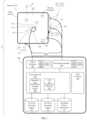
- FIG. 1illustrates a schematic view of a system for calculating information related to one or more parameters of a patient, consistent with the present inventive concepts.
- FIG. 1 Aillustrates a schematic view of a system for calculating information related to one or more parameters of a patient's heart, consistent with the present inventive concepts.
- FIG. 2illustrates a flow chart of a method for using a transfer matrix to calculate patient information based on recorded signals, consistent with the present inventive concepts.
- FIG. 3illustrates a flow chart of a method for determining a transfer matrix and using the transfer matrix to calculate patient information based on recorded signals, consistent with the present inventive concepts.
- first elementwhen a first element is referred to as being “in”, “on” and/or “within” a second element, the first element can be positioned: within an internal space of the second element, within a portion of the second element (e.g. within a wall of the second element); positioned on an external and/or internal surface of the second element; and combinations of one or more of these.
- proximatewhen used to describe proximity of a first component or location to a second component or location, is to be taken to include one or more locations near to the second component or location, as well as locations in, on and/or within the second component or location.
- a component positioned proximate an anatomical sitee.g. a target tissue location
- spatially relative termssuch as “beneath,” “below,” “lower,” “above,” “upper” and the like may be used to describe an element and/or feature's relationship to another element(s) and/or feature(s) as, for example, illustrated in the figures. It will be further understood that the spatially relative terms are intended to encompass different orientations of the device in use and/or operation in addition to the orientation depicted in the figures. For example, if the device in a figure is turned over, elements described as “below” and/or “beneath” other elements or features would then be oriented “above” the other elements or features. The device can be otherwise oriented (e.g. rotated 90 degrees or at other orientations) and the spatially relative descriptors used herein interpreted accordingly.
- one or morecan mean one, two, three, four, five, six, seven, eight, nine, ten, or more, up to any number.
- a component, process, and/or other item selected from the group consisting of: A; B; C; and combinations thereofshall include a set of one or more components that comprise: one, two, three or more of item A; one, two, three or more of item B; and/or one, two, three, or more of item C.
- the expression “configured (or set) to” used in the present disclosuremay be used interchangeably with, for example, the expressions “suitable for”, “having the capacity to”, “designed to”, “adapted to”, “made to” and “capable of” according to a situation.
- the expression “configured (or set) to”does not mean only “specifically designed to” in hardware.
- the expression “a device configured to”may mean that the device “can” operate together with another device or component.
- a system parameterrefers to a maximum level, a minimum level, and/or range of values correlating to a desired or undesired state.
- a system parameteris maintained above a minimum threshold, below a maximum threshold. within a threshold range of values and/or outside a threshold range of values, to cause a desired effect (e.g. efficacious therapy) and/or to prevent or otherwise reduce (hereinafter “prevent”) an undesired event (e.g. a device and/or clinical adverse event).
- a system parameteris maintained above a first threshold (e.g. above a first temperature threshold to cause a desired therapeutic effect to tissue) and below a second threshold (e.g.
- a threshold valueis determined to include a safety margin, such as to account for patient variability, system variability, tolerances, and the like.
- “exceeding a threshold”relates to a parameter going above a maximum threshold, below a minimum threshold, within a range of threshold values and/or outside of a range of threshold values.
- diameterwhere used herein to describe a non-circular geometry is to be taken as the diameter of a hypothetical circle approximating the geometry being described.
- the term “diameter”shall be taken to represent the diameter of a hypothetical circle with the same cross sectional area as the cross section of the component being described.
- major axis and “minor axis” of a component where used hereinare the length and diameter, respectively, of the smallest volume hypothetical cylinder which can completely surround the component.
- a functional elementis to be taken to include one or more elements constructed and arranged to perform a function.
- a functional elementcan comprise a sensor and/or a transducer.
- a functional elementis configured to deliver energy and/or otherwise treat tissue (e.g. a functional element configured as a treatment element).
- a functional elemente.g. a functional element comprising a sensor
- a sensor or other functional elementis configured to perform a diagnostic function (e.g.
- a functional elementis configured to perform a therapeutic function (e.g. to deliver therapeutic energy and/or a therapeutic agent).
- a functional elementcomprises one or more elements constructed and arranged to perform a function selected from the group consisting of: deliver energy; extract energy (e.g. to cool a component); deliver a drug or other agent; manipulate a system component or patient tissue; record or otherwise sense a parameter such as a patient physiologic parameter or a system parameter; and combinations of one or more of these.
- a “functional assembly”can comprise an assembly constructed and arranged to perform a function, such as a diagnostic and/or therapeutic function.
- a functional assemblycan comprise an expandable assembly.
- a functional assemblycan comprise one or more functional elements.
- a transducerwhere used herein is to be taken to include any component or combination of components that receives energy or any input and produces an output.
- a transducercan include an electrode that receives electrical energy and distributes the electrical energy to tissue (e.g. based on the size of the electrode).
- a transducerconverts an electrical signal into any output, such as light (e.g. a transducer comprising a light emitting diode or light bulb), sound (e.g. a transducer comprising a piezo crystal configured to deliver ultrasound energy), pressure, heat energy, cryogenic energy, chemical energy; mechanical energy (e.g.
- a transducercomprising a motor or a solenoid), magnetic energy, and/or a different electrical signal (e.g. a Bluetooth or other wireless communication element).
- a transducercan convert a physical quantity (e.g. variations in a physical quantity) into an electrical signal.
- a transducercan include any component that delivers energy and/or an agent to tissue, such as a transducer configured to deliver one or more of: electrical energy to tissue (e.g. a transducer comprising one or more electrodes); light energy to tissue (e.g. a transducer comprising a laser, light emitting diode and/or optical component such as a lens or prism); mechanical energy to tissue (e.g. a transducer comprising a tissue manipulating element); sound energy to tissue (e.g. a transducer comprising a piezo crystal); chemical energy; electromagnetic energy; magnetic energy; and combinations of one or more of these.
- electrical energy to tissuee.g. a transducer comprising one or
- mapping procedureshall include a clinical procedure performed on a patient that produces electrical activity information related to tissue of the patient, such as organ tissue (e.g. brain or heart tissue).
- organ tissuee.g. brain or heart tissue
- the term “localization procedure”shall include the process of establishing a coordinate system, and using one or more signals, such as electrical signals, to determine the position of one or more objects or portions of objects (“objects” herein) within that system.
- the process of localizationincorporates one or more signals generated from one or more sources (e.g. electrodes), the signals changing as a function of space and/or time, and a sensor (e.g. an electrode) that measures the generated signals from a recording location.
- the recording location of the sensorcan be on the object being localized or it can be separate from the object being localized.
- Analysis of and/or calculation performed on the measured signalcan be used to determine a positional relationship of the sensor and/or the object to the one or more sources of the generated signal.
- the method of localizationcan incorporate two or more generated signals to increase the number or accuracy of positional relationships between the sensor and the signal source.
- the sensor and the objectcan be a single component and/or they can be multiple components that are co-located.
- the signal change as a function of time and/or spaceincludes interactions of the signal with the measurement environment.
- the process of localizationmeasures an intrinsic or existing characteristic of the object, sensor, or measurement environment, such as by measuring a signal from an accelerometer positioned on the object or sensor and incorporating information from the accelerometer signal in the analysis.
- ablation procedureshall include an ablative treatment procedure performed on patient tissue that has been identified as contributing to undesired electrical activity—such as activity associated with an arrhythmia of the heart (e.g. atrial fibrillation) or undesired state of the brain (e.g. seizure or tremor).
- undesired electrical activitysuch as activity associated with an arrhythmia of the heart (e.g. atrial fibrillation) or undesired state of the brain (e.g. seizure or tremor).
- a transfer matrixis used to determine patient information at one or more target locations that can be remote from the recording locations.
- Electrical informationcan be recorded by electrodes placed on the skin of the patient and/or within the patient, and electrical and/or other patient information can be calculated at target locations, such as target locations including an organ of the patient (e.g. the heart or the brain).
- Systems of the present inventive conceptscan include components used to determine the transfer matrix, such as electrodes or other sensors that characterize tissue properties between a recording location and a target location, the characterization performed on the patient for whom the patient information is to be calculated, and/or one or more similar mammalian subjects.
- System 10comprises recording assembly 300 , which is configured to receive information from a set of one or more sensors, recording electrodes 311 , each of which is placed at one or more associated recording locations 312 of a patient, such as patient P 1 shown.
- System 10can further comprise a console 200 , including processing unit 250 , which receives, via recording assembly 300 , the signals produced by recording electrodes 311 , and stores (e.g. in electronic memory 252 ) associated recorded signals 313 .
- Processing unit 250includes an algorithm 255 and transfer matrix 290 .
- Processing unit 250can be configured such that algorithm 255 applies transfer matrix 290 to convert the recorded signals 313 into calculated patient information 95 , where information 95 represents patient physiologic parameter information at one or more patient locations 90 (e.g. one or more skin locations and/or one or more internal locations of the patient).
- patient locations 90e.g. one or more skin locations and/or one or more internal locations of the patient.
- Transfer matrix 290is a mathematical characterization of (all applicable) tissue, volume V X , applicable to determining patient information 95 at one or more patient locations 90 based on recordings made at one or more recording locations 312 .
- Recording locations 312 and a single patient location 90define an intervening volume (e.g. volume of tissue and/or gas-filled space), volume V I1 , where volume V I1 is defined by the space within a set of points (e.g. a convex hull) represented collectively by recording locations 312 and the patient location 90 .
- one or more patient locations 90lie within a tissue region or volume (“region” or “volume” herein) that is defined by recording locations 312 alone.
- Calculated patient information 95 at a single patient location 90is highly dependent on the tissue and/or other material within volume V I1 . This calculated patient information 95 is also dependent (however less dependent) on a volume outside of the primary contributing volume V I1 , but proximate thereto, volume V P1 .
- the total contributing volume, volume V T1is defined by the primary contributing volume V I1 combined with volume V P1 .
- Volume V Xcan comprise one or more volumes V T1 (e.g. a volume V T1 for each patient location 90 ), such that each volume V T1 is a subset of Volume V X .
- Volume V Xcan comprise various forms of tissue (e.g. skin, subdermal tissue, blood vessel wall tissue, blood, heart, and/or other organ tissue, bone, and/or bone marrow), interstitial space, and/or open space (e.g. space within a patient's lung).
- Transfer matrix 290can be configured to account for variations in tissue and/or other variations from one location to another location within volume V X .
- Volume V Xcan comprise a time-varying volume, such as a volume that varies during a cardiac cycle (e.g. due to expansion and contraction of the heart and subsequent movement of surrounding tissue) and/or a respiratory cycle (e.g. due to expansion and contraction of the lungs and subsequent movement of surrounding tissue).
- Transfer matrix 290can be configured to account for a time-varying volume of volume V X .
- Volume V Xcan comprise tissue that has one or more tissue parameters, tissue parameter information 80 shown, that vary over time, such as: impedance (e.g. impedance changes due to respiration); pH; temperature; pO2; and/or pCO2 that varies over time.
- Transfer matrix 290can be configured to account for temporal variations of these tissue parameters within volume V X .
- transfer matrix 290compensates for electrode changes, such as transpiration of surface electrodes (e.g. polarization from electric current) and/or oxidation of electrodes (e.g. from blood reactant).
- processing unit 250stores one or more tissue parameter information 80 (e.g. for processing by algorithm 255 ).
- heart movement during systolecan be determined by measuring changes of impedance between internal electrodes (e.g. one or more internal electrodes) and surface electrodes (e.g. one or more surface electrodes).
- This measured impedance changecan represent the actual change in position, geometry, and/or other properties of the heart and it can be used to monitor heart function (e.g. tissue contractility, ejection fraction) during a clinical procedure, such as to monitor left ventricular volume over time.
- heart functione.g. tissue contractility, ejection fraction
- transfer matrix 290is determined from information (e.g. electrical activity) recorded from patient P 1 , such as during a transfer matrix 290 creation procedure as described herebelow.
- transfer matrix 290can be determined from information (e.g. electrical activity) recorded from a different patient, patient P 2 (e.g. a different mammalian subject with similar physiologic attributes as patient P 1 ), also as described herebelow.
- volume V Xcan comprise an intervening volume V I2 defined by the space within a convex hull of a set of points represented by recording locations 312 , and one or more drive locations (e.g. drive locations 412 described herebelow) from which drive signals (e.g. drive signals 413 , also described herebelow) are emitted while transfer matrix 290 is determined.
- Transfer matrix 290can be determined as described herebelow.
- the convex hull of recording locations 312encompasses each drive location 412
- volume V I2is defined by the convex hull of recording locations 312 alone. Transfer matrix 290 is primarily dependent on the tissue characteristics within volume V I2 .
- Volume V Xcan further comprise a volume V P2 outside of the volume V I1 , but proximate thereto. Transfer matrix 290 is also dependent (however less dependent) on the tissue characteristics within volume V P2 .
- a volume V XP1can be defined as described hereabove for a first patient P 1
- a volume V XP2 of a second patient P 2can approximate volume V XP1 (e.g. approximate the size, shape, and physiologic characteristics of V XP1 ).
- volume V Xcomprises an intervening volume V I2 defined by the space between an arbitrary distribution of a set of points represented by recording locations 312 , and the one or more drive locations 412 from which drive signals 413 are emitted while transfer matrix 290 is determined.
- Transfer matrix 290can be determined as described herein.
- the arbitrary distribution of recording locations 312encompasses each drive location 412
- volume V I2is defined by the distribution of recording locations 312 alone.
- Transfer matrix 290is primarily dependent on the tissue characteristics within volume V I2 .
- Volume V Xcan further comprise a volume V P2 outside of the volume V I1 , but proximate the volume V I1 .
- Transfer matrix 290is also dependent (however less dependent) on the tissue characteristics within volume V P2 .
- a volume V XP1can be defined (e.g. as described hereabove) for a first patient P 1
- a volume V XP2 of a second patient P 2can approximate the volume V XP1 (e.g. approximate the size, shape, and/or physiologic characteristics of V XP1 ).
- console 200 or other component of system 10includes an electronics assembly configured to deliver electrical energy (e.g. to deliver drive signals), signal generator 400 shown.
- system 10further comprises a set of one or more energy-delivering transducers, drive electrodes 411 , which deliver drive signals 413 to tissue of a patient at one or more drive locations 412 .
- Drive locations 412can comprise one or more locations external to the patient location (e.g. on the skin of the patient), such as drive locations 412 s shown, and/or one or more locations within the patient (e.g. under the skin of the patient), drive locations 412 i shown.
- Drive signals 413 emitted by drive electrodes 411can be used to determine and/or adjust (“determine” or “calculate” herein) transfer matrix 290 (e.g. as described herebelow), to perform a localization procedure (e.g. as described herebelow), to calibrate a localization coordinate system (e.g. an impedance field used to localize one or more devices positioned within the field), and/or to perform another function.
- Drive signalse.g. drive signals 413
- one or more drive signalsare implemented based on electrical properties or other characteristics of the applicable tissue.
- system 10comprises one or more patient insertable devices, such as device 100 shown.
- Device 100can comprise a catheter or other patient insertable device, such as a device that includes drive electrodes 411 (as shown in FIG. 1 ).
- system 10includes one or more patient-attachable garments or other patient-attachable components, garment 50 shown, which can be used to position one or more sensors of system 10 at one or more locations relative to patient P 1 , such as to position recording electrodes 311 relative to a patient. Recording electrodes 311 can be positioned on and/or within garment 50 .
- system 10is configured to generate, receive, and/or process information using two or more modalities (e.g. drive signal and/or received signal modalities), for example: electric potential and ultrasound, electric potential and impedance (e.g. complex impedance such as dielectric properties), and/or other combinations of modalities (e.g. combinations of drive signal and/or received signal forms).
- modalitiese.g. drive signal and/or received signal modalities
- modalitiese.g. drive signal and/or received signal modalities
- modalitiese.g. drive signal and/or received signal modalities
- modalitiese.g. drive signal and/or received signal modalities
- modalitiese.g. drive signal and/or received signal modalities
- modalitiese.g. drive signal and/or received signal modalities
- One or more transfer matrices of the present inventive conceptscan then be generated, and subsequently used (e.g. two or more transfer matrices used in conjunction) to differentiate
- spatial or temporal changes in respiratory pattern and/or respiratory volumemay be sensitive to both impedance and ultrasound modalities, and yet to a lesser degree to cardiac electric potential modalities, while spatial and/or temporal changes in tissue conductivity would be sensitively measured via impedance while measurements using ultrasound are less sensitive.
- System 10can comprise one or more sensors (e.g. electrodes configured to record electrical activity as defined herein) which are positioned on and/or under the skin of the patient.
- System 10can further comprise one or more energy delivery elements (e.g. electrodes configured to deliver an electrical signal as defined herein) which are positioned on and/or under the skin of the patient.
- system 10comprises a vest or other garment, garment 50 , which positions one or more sensors, transducers, and/or other functional elements relative to the patient's anatomy.
- the functional elements positioned in garment 50can be used to perform one or more diagnostic and/or one or more therapeutic procedures on a patient.
- garment 50comprises one or more sensors configured to record patient physiologic data used to produce diagnostic information selected from the group consisting of: ECG and other cardiac electrical information; blood pressure measurements; blood flow measurements; respiration measurements; heart sound measurements; p0 2 measurements; pCO 2 measurements; ejection fraction measurements; organ function measurements; brain activity measurements; seizure activity measurements; and combinations of these.
- system 10further includes one or more sensors positioned under the patient's skin (e.g. proximate the heart, brain, and/or other organ), in which data from the skin-contacting sensors and internal sensors are processed (e.g. by algorithm 255 ) to produce diagnostic output.
- system 10creates a coordinate system to identify anatomical locations of the patient, such as when an Einthoven's triangle is used as a coordinate system. In some embodiments, system 10 creates a coordinate system based on the position of one or more surface electrodes (e.g. based on the position of garment 50 comprising one or more surface electrodes).
- a coordinate systemis based on the position of one or more internal electrodes (e.g. a coordinate system based one or more drive electrodes positioned within the heart).
- the coordinate systemcan be configured relative to a drive electrode used as a coordinate reference or origin.
- the coordinate systemcan be configured relative to one or more surface electrodes used as a coordinate reference (e.g. origin).
- the coordinate systemcan be configured relative to an anatomical location (e.g. a structure or boundary) used as a coordinate reference (e.g. origin).
- system 10comprises one or more sensors on the skin of the patient (e.g. electrodes 311 S , 321 S , 411 S , and/or an electrode-based functional element 99 S ) as well as one or more sensors positioned in the heart of the patient (e.g. electrodes 311 I , 321 I , 411 I , and/or an electrode-based functional element 99 I .
- the sensors (e.g. electrodes) positioned in the heart of the patientcan comprise at least one sensor on the endocardial surface of a heart chamber (e.g. a contacting electrode on the endocardial surface of the left atrium), and at least one sensor positioned in the heart chamber offset from the endocardial wall (e.g.
- Patient information 95can be determined based on signals (data) received from one or more of at least one skin surface sensor, at least one endocardial surface contacting sensor, and/or at least one non-contacting sensor.
- the electrodes and/or other sensors of system 10can comprise various shapes, surface areas, and materials of construction.
- one or more skin contacting electrodes used to record electrical activity and/or deliver electrical energye.g. electrodes 311 S , 321 S , 411 S , and/or an electrode-based functional element 99 S
- one or more electrodes positioned under the skin of the patient to record electrical activity and/or deliver electrical energye.g.
- electrodes 311 I , 321 I , 411 I , and/or an electrode-based functional element 99 Icomprise one or more materials selected from the group consisting of: platinum-iridium; gold; carbon; a polymer (e.g. a polymer coating); copper; silver-silver chloride; a conductive gel; and combinations of these.
- the electrodes and/or other sensors of system 10are positioned on the skin of the patient (e.g. electrodes 311 S , 321 S , 411 S , and/or an electrode-based functional element 99 S ) in a vertical arrangement, a horizontal arrangement, a diagonal arrangement, and/or a spiral arrangement relative to the patient.
- these sensorscan be positioned in these and/or other geometric arrangements via garment 50 (e.g. via secure attachment to garment 50 and/or via pockets of garment 50 that accept the sensors) and are in such an arrangement.
- Console 200can comprise one or more discrete components, such as when console 200 comprises one or more housings which collectively surround the components of processing unit 250 , user interface 260 , recording assembly 300 , and/or signal generator 400 .
- Console 200can comprise multiple discrete components (e.g. each include a discrete housing) that transfer information, signals, and/or power between those components via wired and/or wireless connections.
- Console 200can comprise an assembly configured to be transported from one room to another room (e.g. transported between storage and clinical procedure rooms of a hospital).
- Processing unit 250can comprise one or more components which receive, store, analyze, and/or otherwise process information, such as information recorded by recording assembly 300 .
- Processing unit 250can comprise one or more components which generate and/or otherwise provide information, such as information provided to signal generator 400 , and used by signal generator 400 to produce drive signals (e.g. drive signals 413 for drive electrodes 411 ).
- Processing unit 250can comprise one or more central processing units, such as CPU 251 shown.
- Processing unit 250can comprise one or more electronic memory modules, such as memory 252 shown.
- CPU 251can include one or more digital signal processors (DSPs) that can analyze signals received from one or more electrodes or other sensors of system 10 , as described here, for calculating patient information (e.g. patient electrical information, patient motion, and the like).
- DSPsdigital signal processors
- Console 200can comprise a user interface, user interface 260 shown, which can receive information and/or provide information to a user of system 10 , such as a clinician of patient P 1 and/or P 2 described herein.
- User interface 260can comprise one or more user input components, such as an input component selected from the group consisting of: a keyboard; a mouse; a touch screen; a joystick; a haptic controller; a microphone; a switch; a keypad; and combinations of these.
- User interface 260can comprise one or more user output components, such as an output component selected from the group consisting of: a display (e.g. a video monitor); a speaker; a tactile transducer; and combinations of these.
- Transfer matrix 290can comprise a characterization of electrical properties of tissue (e.g. bone, fat, skin, lung, blood, and/or connective tissue) between a first set of recording locations (e.g. a first set of recording locations 312 ) and a set of target locations (e.g. a set of target locations 90 ).
- tissuee.g. bone, fat, skin, lung, blood, and/or connective tissue
- Transfer matrix 290 of system 10can be used to calculate patient information at one or more patient locations 90 (e.g. one or more patient skin locations 90 s and/or one or more locations internal to the patient, internal locations 90 i ), based on information recorded at one or more recording locations 312 (e.g. one or more patient skin locations 312 s and/or one or more locations internal to the patient, internal locations 312 i ).
- patient locations 90e.g. one or more patient skin locations 90 s and/or one or more locations internal to the patient, internal locations 90 i
- recording locations 312e.g. one or more patient skin locations 312 s and/or one or more locations internal to the patient, internal locations 312 i .
- Transfer matrix 290represents a matrix in which a series of measurements at a first location (e.g. a set of first locations) can be related to characteristics at a second location (e.g. a set of second locations), the characteristics determined by applying the transfer matrix to the series of measurements at the first location.
- Transfer matrix 290can be generated by delivering drive signals (e.g. from areas proximate the second location or otherwise), and by performing recordings at the first location. A number of recordings, at one or more similar or dissimilar anatomical locations, can be performed to create transfer matrix 290 .
- Transfer matrix 290represents the mathematical correspondence between measurements made in two separate domains.
- the two separate domainscan comprise: a first domain internal to the patient's body and a second domain external to the patient's body; a first domain on a specific region of the patient's body and a second domain on another region of the patient's body; a first domain internal to an organ within the body of the patient and a second domain external to an organ within the body of the patient; and/or combinations of these.
- Transfer matrix 290mathematically describes the relationship between measurements made in a first domain, and characteristics (e.g. tissue characteristics and/or electrical conditions) in the corresponding, second domain. Such a transfer matrix 290 , can also describe the relationship between measurements made in the second domain, and characteristics of the first domain.
- Application of transfer matrix 290can be used to computationally account for characteristic differences (both static and dynamic, as imposed by physiology and environment as described above) between two domains, and it enables the use of measurements from both domains to be used in conjunction.
- a known electrical signal(electrical potential or current) is emitted from a first drive electrode (e.g. an internal electrode) and recorded by one or more (e.g. all) recording electrodes (e.g. surface electrodes). Subsequently, a known signal is emitted from a second drive electrode (e.g. an internal electrode) and recorded by one or more (e.g. all) recording electrodes (e.g. surface electrodes). In some embodiments, subsequently, a known signal is emitted from a third, fourth, etc. drive electrode, such as until all drive electrodes have been used.
- This implementationprovides a set of drive signals (voltage or current) from all drive electrodes (e.g. all internal electrodes) for each recording electrode (e.g. each surface electrode).
- the intrinsic cardiac signalse.g. atrial electrograms
- Transfer matrix 290The relationship (e.g. ratio) of the drive signal to the recorded second signal serves as a basis for transfer matrix 290 , and can be used to determine calculated patient information 95 , as described herein.
- Transfer matrix 290can be continuously updated (e.g. between measurements made to produce calculated patient information 95 ), such as to account for changes in: body fluid status; electrolyte concentrations; skin resistance; and/or electrode position (e.g. recording electrode position).
- system 10is configured to create transfer matrix 290 , such as is described in reference to FIG. 3 herebelow.
- system 10can include one or more electrodes or other transducers configured to deliver electrical energy (e.g. deliver a drive signal), such as drive electrodes 411 shown.
- Drive electrodes 411can be positioned at various drive locations 412 , from which the drive signals 413 are emitted.
- System 10can include a set of recording electrodes 321 , which can be positioned at multiple recording locations 322 , and create a set of recorded signals 323 .
- recording locations 322are the same as recording locations 312 described hereabove (e.g.
- recording locations 322 and recording locations 312comprise different locations (e.g. all the locations are different or at least one is different), such as when locations 322 comprise locations on a different mammalian subject (e.g. used to create a generic transfer matrix 290 ), or locations 322 comprise different locations on the same patient.
- Transfer matrix 290can be determined (e.g. by algorithm 255 ) by comparing the set of recorded signals 323 to the set of drive signals 413 emitted from drive locations 412 .
- drive locations 412comprise locations within the patient and recording locations 322 comprise locations on the surface (skin) of the patient.
- drive locations 412can comprise locations on the surface of the patient and/or recording locations 322 comprise locations within the patient.
- at least one of drive locations 412 and/or recording locations 322comprise locations both on the surface and within the patient.
- at least one of drive locations 412 and/or recording locations 322is limited to locations on the surface of the patient (i.e. limited to only include locations on the surface of the patient).
- at least one of drive locations 412 and/or recording locations 322is limited to locations within the patient (i.e. limited to only include locations within the patient).
- drive electrodes 411can comprise at least 1 electrode(s), at least 2 electrodes, and/or at least 48 electrodes, and recording electrodes 321 can comprise at least 4 electrodes, at least 10 electrodes, and/or at least 200 electrodes.
- drive electrodes 411can be positioned at drive locations 412 that are at least 1 mm apart from each other, such as at least 2 mm apart, and/or at least 4 mm apart, and/or at least 10 mm apart
- recording electrodes 321can be positioned at recording locations 322 that are at least 2 mm apart from each other, such as at least 3 mm apart, at least 10 mm apart, and/or at least 20 mm apart.
- drive locations 412comprise one or more locations within the patient, such as a drive location selected from the group consisting of: within a chamber of the heart; on endocardial surface of a heart chamber; on epicardial surface of the heart; in a blood vessel (e.g. a vein or artery) of the heart; in the pericardial cavity; in the esophagus; in and/or proximate the brain; in a blood vessel (e.g. a vein or artery) of the brain; and combinations thereof.
- device 100can include one or more drive electrodes 411 (e.g.
- the associated set of recording locations 322can comprise locations within the patient, on the skin of the patient, or both.
- Recording electrodes 321can be positioned at one or more recording locations 322 selected from the group consisting of: chest; back; torso; shoulder; abdomen; thorax; head; and combinations of these.
- system 10comprises at least 6 recording electrodes.
- recording electrodes 321comprise surface electrodes 321 S that are positioned to cover the region surrounding the heart in all three dimensions (e.g. anterior-posterior, cranio-caudal and right to left).
- the surface electrodes 321 Sare configured to deliver signals or other energy to perform localization, cardioversion, and the like (e.g. to avoid a location conflict with a separate electrode used to perform those additional functions).
- drive signals 413 used to determine transfer matrix 290can be delivered from one or more drive locations 412 that are on the skin of the patient, such as one or more drive locations selected from the group consisting of: chest; back; torso; shoulder; abdomen; thorax; head; and combinations of these.
- the associated set of recording locations 322can comprise locations within the patient, on the skin of the patient, or both.
- Recording electrodes 321can be positioned at one or more recording locations 322 selected from the group consisting of: within a chamber of the heart; on endocardial surface of a heart chamber; on epicardial surface of the heart; in a blood vessel (e.g.
- a vein or arteryof the heart; in the pericardial cavity; in the esophagus; in and/or proximate the brain; in a blood vessel (e.g. a vein or artery) of the brain; and combinations of these.
- a set of surface electrodescan comprise: 4 surface electrodes positioned to form a tetrahedron transecting the body; 5 surface electrodes in which 4 form a tetrahedron and the fifth serves as a differentiating electrode out-of-plane with any of the tetrahedral faces; 6 surface electrodes forming 3 orthogonal or near-orthogonal Cartesian axes; 6 surface electrodes wherein 3 surface electrodes form a triangle on one side of the body, and the other 3 surface electrodes form an inverted triangle on an opposing side of the body (e.g. chest and back).
- transfer matrix 290is determined by one or more drive electrodes 411 a delivering a drive signal 413 a comprising a first frequency, and one or more drive electrodes 411 b delivering a drive signal 413 b comprising a different, second frequency.
- drive signals 413 a and 413 bcan be delivered simultaneously (e.g. and correspondingly received simultaneously by recording electrodes 321 ).
- transfer matrix 290is determined by one or more drive electrodes 411 a delivering a drive signal 413 a comprising a first frequency, and one or more drive electrodes 411 b delivering a drive signal 413 b comprising a similar or different, second frequency.
- drive signals 413 a and 413 bcan be delivered sequentially (e.g. and correspondingly received sequentially by recording electrodes 321 ).
- transfer matrix 290is determined by assessing the magnitude and/or phase of a set of recorded signals 323 (e.g. recorded by recording electrodes 321 positioned at recording locations 322 ).
- the transfer matrix 290can comprise a numerical scale factor which is based on a comparison of the magnitude and/or phase of the set of recorded signals 323 to the magnitude and/or phase, respectively, of a set of drive signals 413 (e.g. delivered by drive electrodes 411 positioned at drive locations 412 ).
- the comparisonis based on both magnitude and phase for each set of signals.
- the emitting of drive signals 413 and the associated recording of recorded signals 323occur over at least one physiologic cycle of the patient, and the resultant transfer matrix 290 comprises a time-dependent (e.g. cycle-time-dependent) transfer matrix.
- the associated physiologic cyclecan comprise a cardiac cycle (e.g. a cycle including systole and diastole), a respiratory cycle, a pressure-varying cycle (e.g. cyclically varying blood pressure), and/or other repeating physiologic cycle of a patient. Recordings can be made over multiple cycles, such as at least 2 cycles, at least 3 cycles, or at least 5 cycles.
- Transfer matrix 290can comprise one or more parameters that are proportionally adaptable over time.
- Transfer matrix 290can include information as it relates to changes within a physiologic cycle, such as when transfer matrix 290 comprises a time-dependent transfer matrix including one or more components that vary in relative unison with signals recorded by electrodes 311 , such as to correlate these recordings made by electrodes 311 over similar physiologic cycles (e.g. a compensation performed when calculating patient information 95 and compensating for variations within a physiologic cycle).
- algorithm 255can be configured to compensate for: a cardiac cycle (e.g. to compensate for heart motion), a respiratory cycle (e.g. to compensate for lung motion and/or other patient respiration parameter), or both.
- algorithm 255calculates patient information 90 by aligning a time-dependent transfer matrix 290 with a physiologic cycle of the patient.
- Parameters of transfer matrix 290can vary according to a functional and/or biological process, such as a process which varies cyclically and/or spatially (e.g. blood flow or other cyclically varying cardiovascular process).
- one or more parameters of transfer matrix 290can vary temporally, linearly, and/or exponentially. These parameters can comprise values that are expanding and/or drifting. Variation with time and/or across space does not need to be purely cyclical.
- These non-cyclic variationscan also be modeled, such as a model created via a learning algorithm and trained to compensate for variations. Variations can also be compensated for by extrapolating from previous variation data (e.g. data recorded in patient P 1 or a different mammal such as patient P 2 ), such as data configured and used as a comparative model.
- signals recorded during the respiratory cycleare averaged and/or signals recorded during the cardiac cycle (e.g. changes due to blood movement and/or systolic movement of heart and heart wall and electrode) are averaged (e.g. at a frequency corresponding to the heart rate) to create transfer matrix 290 (e.g. the averaging resulting in a more stable transfer matrix 290 , such as a transfer matrix 290 with improved stability over one or more respiratory and/or cardiac cycles).
- system 10accounts for one or more physiologic and/or anatomic parameters of the patient (e.g. patient P 1 and/or patient P 2 ), such as a parameter selected from the group consisting of: rotation of the heart (e.g. toward the right side or left side of the patient); circumference of the thorax in relation to the heart; location of the heart in the thorax (e.g. low-weight patients have a relatively high positioned diaphragm, emphysema, and COPD patients have a relatively low positioned diaphragm); and combinations of these.
- These parameterscan be determined by analyzing geometric properties of the patient, such as the thoracic circumference (which, as an example, may be calculated based on the distances between surface electrodes, wherein the distances may be determined using impedance-based measurements); the number and angle between the surface electrodes, which surround the body; and/or the rotation and/or location of the heart in relation to the surface electrodes.
- the standardized position of the surface electrodese.g. electrodes used to provide ECG recordings
- diagnostic bioelectrical signals measured from surface electrodesmay be used in the assessment of physiologic and/or anatomic conditions of the patient.
- the presence of certain signal characteristics in leads V 1 or V 2may be indicative of a rightward bias in heart position.
- signal characteristics in V 4 - 5may be indicative of a leftward bias of the heart position, and still other signal characteristics may be representative of a higher or lower heart position.
- system 10modifies transfer matrix 290 at least one time, such as at least one time during a single procedure on a single patient.
- system 10can modify transfer matrix 290 intermittently and/or relatively continuously (“continuously” herein) over time, such as in a closed loop fashion.
- the modification performed by system 10can be based on at least one patient parameter that varies over time.
- the modification performed by system 10can be based on at least two, or at least three patient parameters that vary over time.
- the modification performed by system 10can be based on one or more patient parameters that vary cyclically over time, such as parameters that vary related to the patient's respiratory cycle and/or cardiac cycle. Patient parameters can vary linearly and/or exponentially.
- system 10can include one or more sensors, such as electrodes 311 , 321 , and/or 411 , and/or functional element 99 described herebelow, configured to produce a signal related to the varying patient parameter used to adjust transfer matrix 290 .
- the monitoringcan be performed continuously (e.g. such as when transfer matrix 290 is continuously modified), and/or intermittently (e.g. such as when transfer matrix 290 is intermittently modified).
- transfer matrix 290 used on a patient P 1comprises or at least includes information incorporated from a previously calculated (e.g. from at least one other mammalian subject such as patient P 2 ) and/or otherwise standardized transfer matrix, standardized transfer matrix 290 ′.
- transfer matrix 290can comprise a standardized transfer matrix 290 ′ (e.g. a transfer matrix based on one or more separate mammals, patient P 2 ).
- Transfer matrix 290can comprise a transfer matrix based solely on data from patient(s) P 2 , based solely on data from patient P 1 , or a transfer matrix based on data from patient(s) P 2 and data from patient P 1 .
- a standardized transfer matrix 290 ′(or a portion of it) can be selected based on characteristics of the patient for which it is to be used (characteristics of patient P 1 ). For example, multiple different standardized transfer matrices 290 ′ can be determined, each based on one or more mammalian subjects (e.g. patient P 2 ) with one or more particular patient characteristics (e.g. one or more similar patient parameter levels).
- a single standardized transfer matrix 290 ′can accommodate various patient characteristics, such as when this standardized transfer matrix 290 ′ is customized based on one or more particular patient characteristics.
- a standardized transfer matrix 290 ′can be chosen and/or customized for use as transfer matrix 290 based on patient P 1 's parameter levels being similar to the subjects used to create the standardized transfer matrix 290 ′.
- applicable patient parameters used for selection and/or customizationcomprise parameters selected from the group consisting of: gender; weight; height; body or body portion size; body mass index (BMI); thoracic cavity circumference (e.g.
- a functional element 99comprising an imaging device such as a CT scanner or MRI); location of the esophagus; size of an atrium; filling of an atrial volume; atrial pressure; fat to water ratio; air to water to fat ratio; bone location (e.g. as determined by MRI); medications being taken; level of medication; electrolyte level; pH; pO 2 ; pCO 2 ; water weight; and combinations thereof.
- an imaging devicesuch as a CT scanner or MRI
- location of the esophagussize of an atrium; filling of an atrial volume; atrial pressure; fat to water ratio; air to water to fat ratio; bone location (e.g. as determined by MRI); medications being taken; level of medication; electrolyte level; pH; pO 2 ; pCO 2 ; water weight; and combinations thereof.
- transfer matrix 290includes a standardized transfer matrix 290 ′ (e.g. a transfer matrix based on one or more mammals, patient P 2 , different than patient P 1 ), where differences in locations of recording electrodes on patient P 2 used to create the standardized transfer matrix 290 ′ and locations of recording electrodes on patient P 1 used to produce calculated patient information 95 are accounted for by system 10 .
- a standardized transfer matrix 290 ′e.g. a transfer matrix based on one or more mammals, patient P 2 , different than patient P 1 .
- a standardized transfer matrix 290 ′can be derived by analysis of a collection of data sets from multiple (i.e. two or more) patients P 2 .
- the data setsinclude measured information from each individual patient P 2 , such as location information (e.g. locations of anatomical structures and/or sensors and other objects), tissue information (e.g. tissue properties, characteristics, and/or qualitative classes), information related to physiologic processes (e.g. respiration and/or cardiac motion and which may include recordings from sensors, and/or data calculated from these recordings, over a period of time), environmental information (e.g. background electrical noise or equipment interconnections) and/or cardiac information (e.g.
- the data setsinclude transfer matrices 290 calculated from measurements within each individual patient P 2 and image data (e.g. CT and/or MRI data) from each individual patient P 2 .
- Memory 252can be used to store the collection of data sets from multiple patients P 2 .
- the collection of data sets from multiple patientscan encompass a diverse population of patients P 2 with varied characteristics (e.g. sex, size, presence of a disease such as emphysema, age, heart location) which can also be included in the patient data sets.
- Analysis of the collection of data sets from multiple patients P 2can be performed to identify patterns, correlations, correspondences, and/or other like relationships between the data set elements (such as the measured information, measured transfer matrices 290 , the varied patient characteristics, and/or the image data across the collection).
- This analysis of the collection of data setscan be a ‘training’ or ‘learning’ step in a computational and/or algorithmic process, such as a machine-learning method.
- the analysisyields one or more quantitative entities (e.g. a set of equations or a computational ‘model’) that describes the complex relationships between the data set elements across the population of patients P 2 .
- the analysiscan be performed using computational methods such as: classification, collaborative filtering, regression, clustering, and/or dimensionality reduction and the like.
- the quantitative entitiescan be applied in a second step wherein one or more of the data set elements from patient P 1 are provided as an input and are then used to compute, select, customize, optimize, update, and/or predict the standardized transfer matrix 290 ′ to use for patient P 1 .
- the data set elements from patient P 1are only a subset of the data set elements used to compute the quantitative entities, thereby reducing or eliminating an acquisition or measurement step for patient P 1 .
- the standardized transfer matrix 290 ′ computed, selected, customized, optimized, updated and/or predicted for patient P 1has improved accuracy or reduced artifacts as compared to a transfer matrix directly measured in P 1 , independently, due to potential vulnerabilities or limitations of measurement (such as environmental interference or human error).
- the data set elements from patient P 1can be provided a single time to produce a single standardized transfer matrix 290 ′, and/or it can be provided multiple times in succession (e.g. at intervals or continuously), such as to produce multiple standardized transfer matrices 290 ′ that are applied in succession in order to provide dynamic updates of time-variant relationships.
- the data set elements used to produce the quantitative entitiesmay contain time-variant information, and the data set elements from patient P 1 need only be applied once or a limited number of times in order for multiple standardized transfer matrices 290 ′ to be produced to provide dynamic updates more frequently than information from P 1 is provided—thereby providing greater temporal resolution in updating the standardized transfer matrices 290 ′.
- system 10can produce calculated patient information 95 using a standardized transfer matrix 290 ′ (e.g. transfer matrix 290 comprises a standardized transfer matrix 290 ′ only).
- a patient imagee.g. an MRI or CT scan
- is not usede.g.
- a suitable standardized transfer matrix 290 ′can be chosen and/or customized based on characteristics of patient P 1 (e.g. characteristics such as size, weight, thoracic circumference, and/or rotation and/or location of the heart).
- system 10utilizes dynamic feedback and/or machine learning to determine transfer matrix 290 and/or in using transfer matrix 290 to determine calculated patient information 95 based on recorded signals 313 .
- the collection of data sets from one or more patients P 2can include therapy information.
- standardized transfer matrix 290 ′can be based on one, two, or more therapy parameters selected from the group consisting of: duration (e.g. duration of energy delivery); intensity (e.g. intensity of energy delivery); amplitude (e.g. amplitude of energy delivery); temperature (e.g. temperature of tissue receiving energy); power (e.g. power of energy delivery); impedance (e.g.
- Standardized transfer matrix 290 ′can be based on a tissue parameter (e.g. tissue parameter information 80 stored by system 10 ) related to the applied therapy, such as one, two, or more tissue parameters (e.g. parameters of tissue receiving ablation energy and/or other treatment) selected from the group consisting of: size; depth; thickness; density; composition; and combinations of these.
- tissue parameter information 80stored by system 10
- tissue parameterse.g. parameters of tissue receiving ablation energy and/or other treatment
- Standardized transfer matrix 290 ′can be based on the effectiveness of a therapy (e.g. an ablation therapy) on local and/or regional electrical properties of tissue.
- Standardized transfer matrix 290 ′can be based on acute (i.e. short-term) effectiveness and/or chronic (e.g.
- Applicable short-term and/or long-term therapy effectiveness parametersinclude but are not limited to: elimination of conduction; change in conduction, velocity, amplitude, and/or direction of electrical signals in tissue; change in measured electrical signal amplitude, frequency, and/or rate; change in rate, pattern, and/or frequency of a cardiac cycle; conversion of a cardiac rhythm; change in duty cycle and/or duration of an intermittent rhythm; maintenance of a desired cardiac rhythm; conversion to an alternate rhythm (e.g. a desired or undesired rhythm); and/or duty factor of a resultant rhythm (e.g. a desired or undesired rhythm).
- Standardized transfer matrix 290 ′can be based on a short-term and/or long-term therapy effectiveness parameter related to a change in local, regional, and/or global mechanical and/or functional properties of tissue, such as a parameter related to: a change or maintenance of cardiac output and function; and/or a change in tissue stiffness, contractility, displacement, and/or strain.
- the analysis of the collection of data sets from one or more patients P 2can be performed by system 10 (e.g. by algorithm 255 ) and the results used to provide calculated patient information 95 to compute, select, customize, predict, update, and/or otherwise enhance therapy (e.g. therapeutic energy delivery and/or pharmaceutical therapy strategy) for patient P 1 .
- transfer matrix 290is based on a reduced set of data (a subset of a complete data set) recorded from patient P 1 , which is used in combination with data (e.g. a full set) recorded from one or more patients P 2 .
- enhancement of therapycan be achieved without acquisition or other measurement of the remaining data set from patient P 1 , thereby reducing cost, time, and/or procedural complexity.
- assessments of one or more lesions created during a treatment procedurecan be eliminated or at least reduced, based on the included patient P 2 data.
- system 10utilizes machine learning, such as is described hereabove.
- System 10can be configured to obtain sequential measurements from one or more (e.g. all) surface electrodes configured to record sequentially emitted signals from each of one or more internal electrodes, and to track changes (e.g. physiologic changes correlating to signal changes) over time.
- System 10can assess respiratory and/or cardiac cycles, and it can perform compensation (e.g. subtraction and/or cancellation) to reduce undesired effects of these variations (e.g. as described hereabove).
- System 10can determine heart movement throughout the cardiac cycle by assessing changes of impedance between internal electrodes and surface electrodes.
- This heart movement determinationcan be used to calculate mechanical, dynamic, and/or other functional characteristics of the heart, such as contractility, volume, volume changes over time, ejection fraction, wall motion, wall displacement, strain, and/or pressure, and it can be used to monitor heart function during the clinical procedure (e.g. to assess safety of the procedure).
- the function of the ventriclecan be measured, such as by measuring transthoracic impedance (e.g. combined with signals provided and/or recorded by internal electrodes).
- the atrial and the ventricular functioncan be separated by a time window: such as when ventricular function is assessed 200 ms to 500 ms after the QRS complex, when systole takes place.
- the geometry of the thoraxe.g.
- ⁇is determined based on measurements made by two or more surface electrodes, and changes to the geometry in relation to respiration (e.g. changes related to respiratory excursion and/or respiratory frequency).
- measurement of location of heart in relation to surface electrodese.g. a 12 lead ECG, electrodes 311 , 321 , and/or 411 positioned on the skin
- the heart's rotation, position and/or displacemente.g. up and down
- Heart movement during systolecan be determined in different heart rhythms (e.g. sinus rhythm, flutter, and/or fibrillation).
- System 10can integrate anatomical information (e.g.
- Transfer matrix 290e.g. information related to air/fat/water ratio; location of bones, vertebral column, and/or ribs; dimensions of thorax diameter; and/or angle and/or rotation of the heart
- System 10can be configured to create transfer matrix 290 , and it can also be configured to update (e.g. adapt or otherwise modify) transfer matrix 290 (e.g. update transfer matrix 290 continuously or at least repeatedly).
- System 10can be configured to perform a localization procedure, such as to determine the location of one or more electrodes (e.g. internal drive and/or internal recording electrodes) relative to a localization coordinate system.
- system 10is configured to deliver a vector pulse of energy from one or more electrodes positioned on the skin of the patient (e.g. one or more of electrodes 311 S , 321 S , 411 S , and/or electrode-based functional elements 99 S ) to one or more electrodes positioned within the patient (e.g. one or more of electrodes 311 I , 321 I , 411 I , and/or electrode-based functional elements 99 I ), such as one or more electrodes integrated onto a distal portion of device 100 .
- the one or more skin electrodescan immediately begin recording after delivery of the vector pulse (and/or separate skin electrodes can record) such as to determine characteristics of the tissue based on the recordings, such as to determine electrical conduction properties and/or physical properties (e.g. scar, fibrosis, fiber orientation, and the like) based on the response of the tissue to the vector pulse.
- Electrical activation of tissuecan be detected immediately in the region of tissue around an intracardiac catheter. This method is analogous to the CRT-devices that use electrical vectors to activate tissue from a housing (e.g. an implantable metal housing) to a lead. Magnitude and phase information can also be acquired to determine if the impulse activated the region of tissue in the direction of the vector.
- This determinationcan be performed for a subset of surface electrodes to an intracardiac electrode to determine if the tissue in the direction of the vector is viable.
- This vectoris rotated around the patient's body and/or modulated by creating a vector using different subgroups of the surface electrodes to the intracardiac catheter electrode to create a 3D map of the viability of tissue.
- system 10can be configured to deliver a vector pulse of energy between surface electrodes.
- Recording assembly 300can be integral to console 200 and/or it can comprise a second standalone console operably attached to console 200 .
- Recording assembly 300can be configured to record signals of one or more electrodes or other sensors of system 10 , such as recording electrodes 311 .
- Recording assembly 300can record signals from one or more other electrodes of system 10 , such as an electrode that is also configured as a drive electrode, such as drive electrode 411 S comprising one or more drive electrodes on the skin of the patient, and/or drive electrode 411 I comprising one or more electrodes positioned within the patient (e.g. when included on patient-inserted device 100 ).
- Recording assembly 300can be connected to one or more electrodes via wired or wireless connections as shown in FIG. 1 (connection to recording electrodes 311 and 321 shown via solid lines, and connection to drive electrodes 411 shown via dashed line connected to solid line).
- Recording assembly 300can include circuitry, patient isolation circuitry 301 shown, configured to isolate a patient (e.g. patient P 1 or P 2 shown) from undesired electrical shock or other undesired interaction with recording assembly 300 .
- Recording assembly 300can include one or more analog-to-digital converters, A2D 302 shown, which can be configured to convert recorded analog signals to digital signals (e.g. digital signals received by processing unit 250 from recording assembly 300 ).
- Recording assembly 300can include one or more signal filters, filter 303 shown, which can be configured to filter out undesired noise or other undesired signals.
- Recording assembly 300can include other signal recording and/or other signal processing circuitry known to one of skill in the art, such as a wireless receiver configured to receive wireless signals from garment 50 , a wirelessly transmitting electrode of system 10 , and/or another wireless transmitter.
- recording assembly 300is configured to multiplex (e.g. includes multiplexing circuitry) connections to multiple sensors, such that a first set of one or more sensors (e.g. electrodes configured to record electrical activity) are recorded for a first time period, after which a second set of one or more sensors (e.g. electrodes configured to record electrical activity) are recorded for a subsequent second time period.
- a first set of one or more sensorse.g. electrodes configured to record electrical activity
- second set of one or more sensorse.g. electrodes configured to record electrical activity
- three or more sets of sensorsare multiplexed.
- Recording assembly 300can be configured to perform dynamic impedance and/or dynamic voltage measurements related to the patient's respiratory cycle and/or physiologic cycle changes, as described hereabove.
- Recording assembly 300can be configured to record from multiple electrodes collectively (e.g. via multiplexing or other scheme) to form “macroelectrodes”, such as to take advantage of electrical and/or geometric advantages of more than one electrode and/or more than one recording channel. Examples of some advantages include larger effective electrode surface area (from multiple electrodes) and lower input impedance (through multiple parallel recording channels).
- Recording electrodes 311can include one or more electrodes placed on the skin of the patient, electrodes 311 s shown, and/or one or more electrodes placed within the patient, electrodes 311 i shown. Recording electrodes 311 can comprise two or more electrodes, such as at least 2, at least 4, at least 6, or at least 10 electrodes.
- recording electrodes 311comprise at least 3 electrodes (e.g. 3 electrodes included in a standard 6 limb-lead used for ECG recordings). In some embodiments, recording electrodes 311 comprise at least 9 electrodes (e.g. 9 electrodes included in a standard 12-lead ECG). In some embodiments, recording electrodes 311 comprise no more than 1000 electrodes (e.g. up to 1000 surface electrodes included in garment 50 , such as at least 50 electrodes, at least 100 electrodes, and/or at least 250 electrodes positioned in garment 50 ). In some embodiments, recording electrodes 311 are positioned in a relatively uniform pattern on the surface of the patient (e.g. a uniform pattern provided by garment 50 ). The number of recording electrodes 311 can be determined by the use of the coordinate system used, such as when at least 2 electrodes 311 (e.g. at least 2 surface electrodes) are used for each axis of the coordinate system used.
- Recording electrodes 311can include one, two, or more electrodes positioned on the skin of the patient, such as at locations 312 S selected from the group consisting of: chest; back; torso; shoulder; abdomen; skull; face; arm; leg; groin; and combinations of these.
- target locations 90can comprise one or more locations within the patient, such as one or more locations on and/or within an organ of the patient.
- recording locations 312can comprise one or more locations selected from the group consisting of: chest; back; torso; shoulder; and/or abdomen; and the target locations 90 can comprise one or more heart locations; such as a heart location selected from the group consisting of: epicardial surface of the heart; within heart tissue (subendocardial); endocardial surface of a heart chamber; within a heart chamber; pericardial cavity; pericardium; and combinations thereof.
- recording electrodes 311comprise at least one electrode positioned in each of the following locations: in the cardiac chamber, on the skin, and in the esophagus.
- recording electrodes 311comprise one internal location and at least one non-intracardiac location (e.g.
- recording electrodes 311comprise at least 9 or at least 12 recording electrodes 311 (e.g. 9 or 12 electrodes further configured as a 12-lead EKG device).
- Recording electrodes 311can include one, two, or more electrodes positioned on the skin of the patient at locations 312 S via garment 50 .
- Garment 50can be configured to position the recording electrodes 311 at various positions relative to each other, and/or relative to the anatomy of the patient.
- Recording electrodes 311can include one, two, or more electrodes positioned within the patient, such as at recording locations 312 I on and/or within an organ of the patient.
- recording locations 312 Icomprise heart locations selected from the group consisting of: locations within a chamber of the heart; locations on an endocardial surface of the heart; locations on an epicardial surface of the heart; and combinations thereof.
- recording locations 312 Icomprise one or more locations selected from the group consisting of: esophagus; epicardium (e.g. accessed via a transthoracic or subxiphoid approach); pericardium (e.g. via a subxiphoid approach); proximate but external to the heart; and combinations thereof.
- recording locations 312 Icomprise locations containing interstitial fluid (e.g. tissues surrounding the heart and/or subcutaneous tissue locations). In some embodiments, recording locations 312 I comprise locations within and/or at least proximate the spine and/or locations within and/or at least proximate the brain.
- interstitial fluide.g. tissues surrounding the heart and/or subcutaneous tissue locations.
- recording locations 312 Icomprise locations within and/or at least proximate the spine and/or locations within and/or at least proximate the brain.
- recording electrodes 311comprise at least one recording electrode positioned on the skin of the patient, and at least one recording electrode positioned within the patient.
- externally-placed recording electrodes 311 Se.g. on the skin
- internally placed recording electrodes 311 Ie.g. within the patient
- sourcee.g. provide function as a recording electrode
- sinke.g. provide function as a drive electrode
- Multiplexing of electrodese.g. recording electrodes 311
- recording electrodes 311comprises one, two, three, or more electrodes selected from the group consisting of: body surface electrodes; intrabody electrodes (e.g. electrodes placed within the body, under the patient's skin); percutaneous electrodes; subcutaneous electrodes; epicardial electrodes; pericardial electrodes; spine electrodes; brain electrodes; and combinations of these.
- body surface electrodese.g. electrodes placed within the body, under the patient's skin
- intrabody electrodese.g. electrodes placed within the body, under the patient's skin
- percutaneous electrodese.g. electrodes placed within the body, under the patient's skin
- subcutaneous electrodese.g. electrodes placed within the body, under the patient's skin
- percutaneous electrodese.g. electrodes placed within the body, under the patient's skin
- subcutaneous electrodese.g. electrodes placed within the body, under the patient's skin
- percutaneous electrodese.g. electrodes placed within the body, under the patient'
- recording electrodes 311comprises one, two, three, or more electrodes selected from the group consisting of: one or more electrodes configured to emit and/or receive a localization signal; multiple electrodes configured to produce an ECG signal, such as at least 9 electrodes of a 12-lead ECG device; multiple electrodes configured to produce a high density ECGi signal; one or more electrodes configured to deliver cardiac pacing energy; one or more electrodes configured to deliver defibrillation energy; one or more electrodes configured to deliver therapeutic energy; and combinations of these (e.g. such as to avoid the need for standard ECG patch electrodes, pacing components, and/or defibrillation components).
- recording electrodes 311are configured to emit and/or receive a localization signal, such as a localization signal used to identify the position of one or more devices positioned within the patient (e.g. device 100 described herein).
- signal generator 400can provide a localization signal to drive electrodes 411 that is received by recording electrodes 311 .
- signal generator 400can be electrically attached to recording electrodes 311 (e.g. via a conduit represented by the dashed line), and signal generator 400 can provide a localization signal to recording electrodes 311 (e.g. that is received by drive electrodes 411 , electrodes 321 , and/or other electrode of system 10 ).
- recording electrodes 311are positioned (relative to the patient) in a defined pattern (e.g. a standardized pattern), such as a pattern defined by a coordinate system.
- a defined patterne.g. a standardized pattern
- one or more recording electrodes 311can be positioned in garment 50 , and garment 50 positioned relative to the patient, to position recording electrodes 311 in a particular pattern relative to the patient (e.g. the coordinate system can be standardized via garment 50 ).
- recording electrodes 311comprise one or more electrodes further configured to record an ECG signal of the patient, such as when recording electrodes 311 comprise: at least 9 electrodes of a 12-lead ECG device and/or multiple electrodes configured to produce a high density ECGi signal. Recording electrodes 311 can be configured to provide arrhythmia monitoring of the patient. In these embodiments, the recording electrodes 311 can be specifically positioned relative to the patient's anatomy by garment 50 .
- recording electrodes 311are further configured to deliver pacing energy and/or defibrillation energy to the patient, such as pacing energy and/or defibrillation energy provided by signal generator 400 .
- the recording electrodes 311can be specifically positioned relative to the patient's anatomy by garment 50 .
- Recording electrodes 321can include one or more electrodes placed on the skin of the patient, electrodes 321 s shown, and/or one or more electrodes placed within the patient, electrodes 321 i shown. Recording electrodes 321 can comprise two or more electrodes, such as at least 2, at least 4, or at least 10 electrodes. In some embodiments, recording electrodes 321 comprise at least two times the number of axes present in a coordinate system used by system 10 , and/or recording electrodes 321 comprise a quantity of electrodes that is at least one more than the number of axes present in a coordinate system (e.g. 4 electrodes for a 3-axis coordinate system). In some embodiments, recording electrodes 321 comprise at least 9 electrodes (e.g. at least 9 electrodes further configured as a standard 12-lead ECG device). In some embodiments, recording electrodes 321 comprise at least 3 electrodes (e.g. 3 electrodes further configured as a standard 6 limb-lead ECG).
- Recording electrodes 321can include one, two, or more electrodes positioned on the skin of the patient, such as at locations 322 S selected from the group consisting of: chest; back; torso; shoulder; abdomen; skull; face; arm; leg; groin; and combinations of these.
- recording electrodes 321comprise at least one electrode positioned in each of the following locations: limbs of the patient (e.g. on the leg or arm of the patient), and torso of the patient (e.g. at least 2, 4, or 6 electrodes across the torso of the patient).
- Recording electrodes 321can include one, two, or more electrodes positioned on the skin of the patient at locations 322 S via garment 50 .
- Garment 50can be configured to position the recording electrodes 321 at various positions relative to each other, and/or relative to the anatomy of the patient.
- Recording electrodes 321can include one, two, or more electrodes positioned within the patient, such as at recording locations 322 I on and/or within an organ of the patient.
- recording locations 322 Icomprise heart locations selected from the group consisting of: locations within a chamber of the heart; locations on an endocardial surface of the heart; locations on an epicardial surface of the heart; and combinations thereof.
- recording locations 322 Icomprise one or more locations selected from the group consisting of: esophagus; epicardium (e.g. accessed via a transthoracic or subxiphoid approach); pericardium (e.g. via a subxiphoid approach); proximate but external to the heart; and combinations thereof.
- recording locations 322 Icomprise locations containing interstitial fluid (e.g. tissues surrounding the heart and/or subcutaneous tissue locations). In some embodiments, recording locations 322 I comprise locations within and/or at least proximate the spine, and/or locations within and/or at least proximate the brain.
- interstitial fluide.g. tissues surrounding the heart and/or subcutaneous tissue locations.
- recording locations 322 Icomprise locations within and/or at least proximate the spine, and/or locations within and/or at least proximate the brain.
- recording electrodes 321comprise at least one recording electrode positioned on the skin of the patient, and at least one recording electrode positioned within the patient.
- externally-placed recording electrodes 321 Se.g. on the skin
- internally placed recording electrodes 321 Ie.g. within the patient
- sourcee.g. provide function as a recording electrode
- sinke.g. provide function as a drive electrode
- Multiplexing of electrodescan be performed to form a group of electrodes that function as a single source and/or a single sink.
- recording electrodes 321comprises one, two, three, or more electrodes selected from the group consisting of: body surface electrodes; intrabody electrodes; percutaneous electrodes; subcutaneous electrodes; epicardial electrodes; pericardial electrodes; spine electrodes; brain electrodes; and combinations of these.
- Signal generator 400can be electrically attached to recording electrodes 321 (e.g. via a conduit represented by the dashed line), and signal generator 400 can provide a drive signal (e.g. drive signal 413 ) or other electrical energy to recording electrodes 321 (e.g. that is received by drive electrodes 411 , electrodes 311 , and/or other electrode of system 10 ).
- a drive signale.g. drive signal 413
- other electrical energye.g. that is received by drive electrodes 411 , electrodes 311 , and/or other electrode of system 10 .
- recording electrodes 321are positioned (relative to the patient) in a defined pattern (e.g. a standardized pattern), such as a pattern defined by a coordinate system.
- a defined patterne.g. a standardized pattern
- one or more recording electrodes 321can be positioned in garment 50 , and garment 50 positioned relative to the patient, to position recording electrodes 321 in a particular pattern relative to the patient (e.g. the coordinate system can be standardized via garment 50 ).
- Signal generator 400can be integral to console 200 and/or it can comprise a second standalone console operably attached to console 200 .
- Signal generator 400is configured to produce signals provided to one or more electrodes or other transducers of system 10 , such as drive electrodes 411 .
- Signal generator 400can include circuitry, patient isolation circuitry 401 shown, configured to isolate a patient (e.g. patient P 1 or P 2 shown) from undesired electrical shock or other undesired interaction with signal generator 400 .
- Signal generator 400can include one or more digital-to-analog converters, D2A 402 shown, which can be configured to convert digital signals (e.g. digital information received from processing unit 250 ) to analog signals.
- Signal generator 400can include one or more signal filters, filter 403 shown, which can be configured to filter out undesired noise or other undesired signals.
- Signal generator 400can include other signal generator and/or other signal processing circuitry known to one of skill in the art.
- signal generator 400is configured to provide a localization signal, such as a localization signal provided to drive electrodes 411 , recording electrodes 311 (e.g. recording electrodes 311 positioned in garment 50 ), and/or other electrodes of system 10 .
- a localization signalsuch as a localization signal provided to drive electrodes 411 , recording electrodes 311 (e.g. recording electrodes 311 positioned in garment 50 ), and/or other electrodes of system 10 .
- signal generator 400is configured to provide energy to pace and/or defibrillate the heart of the patient, such as pacing and/or defibrillation energy provided to recording electrodes 311 (e.g. recording electrodes 311 positioned in garment 50 ), drive electrodes 411 , functional element 99 , and/or other electrodes of system 10 .
- recording electrodes 311e.g. recording electrodes 311 positioned in garment 50
- drive electrodes 411e.g. recording electrodes 311 positioned in garment 50
- functional element 99e.g., pacing and/or defibrillation energy provided to recording electrodes 311 (e.g. recording electrodes 311 positioned in garment 50 ), drive electrodes 411 , functional element 99 , and/or other electrodes of system 10 .
- signal generator 400is configured to multiplex (e.g. includes multiplexing circuitry) connections to multiple transducers, such that a first set of one or more transducers (e.g. electrodes configured to deliver an electrical signal and/or other electrical energy) are provided energy for a first time period, after which a second set of one or more transducers (e.g. electrodes configured to deliver an electrical signal and/or other electrical energy) are provided energy for a subsequent second time period.
- three or more sets of transducersare multiplexed.
- Drive electrodescan be configured (e.g. via multiplexing or another scheme) to be interconnected to form macroelectrodes, as described hereabove.
- Grouping of drive electrodescan be patterned to provide geometric and/or electrical advantages, for example, shaping the sourced field in the body, maximizing linearity of a sourced field, maximizing field curvature of a sourced field, and/or maximizing or minimizing edge effects by creating or eliminating ‘holes’ in the electrode group.
- signal generator 400transmits from a first set of electrodes positioned within the patient (e.g. electrodes 411 I ) while recording assembly 300 simultaneously records signals from a second set of electrodes positioned on the skin of the patient (e.g. electrodes 311 S ), after which signal generator 400 transmits from the second set of electrodes positioned on the skin of the patient (e.g. electrodes 311 S ) while simultaneously recording signals from the first set of electrodes within the patient (e.g. electrodes 411 I ).
- This alternating sourcing and sinkingcan be continued for multiple cycles.
- algorithm 255is configured to determine timing of each portion of the cycle, and/or to determine in which electrodes to deliver a signal and record a signal.
- the combination of multiplexing to achieve source and sink variations of the electrodes of system 10allows flexibility in establishing, shaping, and/or modulating the geometric orientation and shape of the source and sink signal paths (e.g. a field) through the body.
- the geometric orientation and shape of the signal paths through the bodycan be varied as a function of time to produce a spatio-temporally varying sequence or pattern.
- At least one drive electrode 411is positioned on the skin of the patient (e.g. via garment 50 ), and potentially maintained in position by garment 50 (e.g. garment 50 comprises one or more drive electrodes 411 ).
- drive electrode 411can be configured to deliver a drive signal 413 that is used to determine transfer matrix 290 (as described herein), to deliver a localization signal, to deliver cardiac pacing energy, to deliver defibrillation energy, deliver therapeutic energy (e.g. deliver energy to suppress a seizure, headache, or other neurological condition and/or otherwise treat an adverse patient condition), and/or to perform another function.
- Device 100can comprise one or more devices configured for insertion into a patient (e.g. into the vasculature system of the patient and/or otherwise under the skin of the patient).
- device 100includes a distal portion configured for insertion into a chamber of the heart of patient P 1 .
- Device 100can include a set of electrodes configured to provide a drive signal, drive electrodes 411 .
- Device 100can comprise a mapping and/or an ablation device, such as an ablation device that is localized via a localization signal provided by system 10 (e.g. a localization signal delivered by recording electrodes 311 ).
- a localization signalprovided by system 10 (e.g. a localization signal delivered by recording electrodes 311 ).
- Garment 50can comprise one or more different forms that position one or more of the recording electrodes 311 at locations relative to the patient's anatomy (e.g. on the skin of the patient at particular anatomical positions).
- Garment 50can comprise a garment selected from the group consisting of: vest; shirt; strap; belt; and combinations of these.
- Garment 50can comprise a wireless transmitter (e.g. functional element 99 S configured as a wireless transmitter), such as a wireless transmitter configured to wirelessly transmit recordings made by one or more electrodes and/or other sensors of garment 50 to a receiving element of recording assembly 300 .
- a wireless transmittere.g. functional element 99 S configured as a wireless transmitter
- a wireless transmitterconfigured to wirelessly transmit recordings made by one or more electrodes and/or other sensors of garment 50 to a receiving element of recording assembly 300 .
- system 10utilizes one or more electrodes of garment 50 (e.g. one or more electrodes 311 S , 321 S , 411 S , and/or electrode-based functional elements 99 S ) to perform impedance tomography of the patient's torso.
- electrodes of garment 50e.g. one or more electrodes 311 S , 321 S , 411 S , and/or electrode-based functional elements 99 S .
- garment 50is configured simply as a template, such as when garment 50 is placed on the patient to mark locations for sensor placement, and/or includes openings through which sensors are placed on the skin of the patient (e.g. after which garment 50 is removed).
- Calculated patient information 95can comprise a map of electrical activity of an organ of a patient, such as the heart or brain. Mapped electrical activity can include voltage information, dipole density information, and/or surface charge information.
- the target locations 90 associated with the calculated patient information 95can include locations on the endocardial surface, locations within heart tissue, and/or locations on the epicardial surface.
- the target locations 90 associated with the calculated patient information 95can include locations on the surface of the brain and/or within the brain (e.g. in the cerebral cortex and/or within the deep brain).
- Calculated patient information 95can comprise information types selected from the group consisting of: electrical information (e.g. voltage information, surface charge information, tissue charge information, and/or dipole density information); tissue; structural or mechanical information (e.g. density, and/or a difference in a mechanical property such as density, size, and/or shape of a region of a change in a mechanical property such as density); tissue composition information (e.g. damaged tissue, inflamed tissue, and/or denatured tissue, such as denatured protein, collagen, fibrosis, fat, and/or nerves); electrographic flow information; impedance information; phase information (e.g. for phase mapping); and combinations of these.
- electrical informatione.g. voltage information, surface charge information, tissue charge information, and/or dipole density information
- tissuestructural or mechanical information (e.g. density, and/or a difference in a mechanical property such as density, size, and/or shape of a region of a change in a mechanical property such as density)
- tissue composition informatione.
- calculated patient information 95can comprise tissue density information which has been modified in a tissue ablation procedure (e.g. an RF or other cardiac tissue ablation procedure to treat an arrhythmia), such as to assess the quality of the ablation performed.
- calculated patient information 95can comprise a combination of electrical information (such as surface charge information) and mechanical and/or compositional properties of tissue (density or presence of denatured protein or other indicators of structural formation of an ablation lesion or other treated tissue), such that the effectiveness of a delivered therapy can be categorized as complete or incomplete.
- electrical information gathered by system 10can indicate loss of electrical conduction while structural formation of a lesion (e.g.
- a lesion created via delivery of ablation energyremains incomplete, which may indicate a lesion that is only temporarily effective (e.g. undesired conduction may reoccur in the future).
- Gathered electrical informationcan indicate continued conduction through a treated area and mechanical and/or compositional information can suggest the formation of edema rather than a fully transmural (ablation) lesion which may motivate a change in therapeutic strategy.
- Gathered electrical informationcan indicate elimination of electrical conduction through an area and structural and/or compositional information can indicate formation of a fully transmural (ablation) lesion, which may increase the probability that the lesion will remain effective for long periods of time, which increases confidence in the therapy delivered.
- calculated patient information 95can comprise tissue composition information.
- Tissue compositioncan be locally assessed by system 10 via optical measurement (e.g. spectroscopically or fluoroscopically).
- System 10can be configured to determine fluorescence, reflectance, and/or absorption from tissue (e.g. using a fiber-optic or a CCD camera enabled catheter).
- System 10via algorithm 255 , can assess the degree to which the tissue fluoresces, reflects, and/or absorbs light. These responses to particular two or more wavelengths of light can add further specificity, as different biomaterial compositions fluoresce, reflect, and/or absorb light in specific ways.
- system 10analyzes a lesion by monitoring for the fluoroscopic signature of NADH.
- NADHis a coenzyme that is present within all intact cells and fluoresces when illuminated with certain wavelengths of light (such as UV).
- RF ablationOnce cells are damaged (e.g. by RF ablation), NADH is released from the mitochondria of the cells and/or converted to its oxidized form, and its fluorescence markedly declines.
- cell damageis the desired outcome of a clinical procedure (e.g. an ablation procedure configured to treat an arrhythmia such as atrial fibrillation).
- the tissue and/or other body response to the therapy under some conditionscan vary. For example, while attempting to deliver RF ablation to cardiac tissue, the inflammatory response of the body accumulates extracellular fluid to the affected area (edema), thereby protecting the cells from further damage.
- system 10creates a standardized transfer matrix 290 ′ based on one or more patients P 2 , by recording treatment information related to an ablation procedure (e.g. a cardiac ablation procedure) performed on the patients P 2 .
- ablation proceduree.g. a cardiac ablation procedure
- the treatment informationcan include: electrical information; anatomy information (e.g. as recorded by an imaging device); tissue impedance information. This information can be combined with measurements of tissue composition, and then system 10 (e.g. using a machine learning algorithm) can sensitively and specifically identify hallmarks of tissue composition, which can be correlated to a procedure performed on patient P 1 , without having to do the actual measurement of composition directly in patient P 1 .
- calculated patient information 95comprises dipole density and/or surface charge information that is determined (e.g. by algorithm 255 ) using the devices and methods such as is described in applicant's co-pending U.S. patent application Ser. No. 16/533,028, titled “Method and Device for Determining and Presenting Surface Charge and Dipole Densities on Cardiac Walls”, filed Aug. 6, 2019, and/or applicant's co-pending U.S. patent application Ser. No. 16/568,768, titled “Device and Method for the Geometric Determination of Electrical Dipole Densities on the Cardiac Wall”, filed Sep. 12, 2019, the content of each of which is included herein by reference in its entirety for all purposes.
- calculated patient information 95comprises information types selected from the group consisting of: medication information; electrolyte information; pH information; and combinations thereof.
- system 10is configured to gather other physiologic data of the patient (e.g. data other than that recorded by recording electrodes 311 , 321 and/or drive electrodes 411 ).
- system 10can include functional element 99 comprising one, two, three, or more sensors or other data acquiring components.
- functional element 99can comprise one or more sensors or other functional elements positioned within the patient, functional element 99 I , and/or one or more sensors or other functional elements positioned on the patient's skin, functional element 99 S , each as shown.
- Functional element 99 Scan comprise one or more functional elements positioned on and/or within garment 50 (as shown in FIG. 1 ).
- Functional element 99 Ican comprise one or more functional elements positioned on and/or within device 100 (e.g. on a basket or other distal portion of device 100 as shown).
- functional element 99comprises one or more components configured to gather data selected from the group consisting of: physiologic cycle data; cardiac data; respiration data; patient medication data; skin impedance data; perspiration data; thoracic and/or abdominal cavity dimensional data (e.g. as measured manually and/or by an imaging device such as a CT or MRI); water weight data; hematocrit level data; wall thickness data (e.g. cardiac wall thickness data); and combinations of these.
- functional element 99can comprise a manual measurement device (e.g. a tape measure or ruler) and/or an imaging device (e.g.
- functional element 99comprises one, two, three, or more sensors selected from the group consisting of: magnetic sensor; water sensor; perspiration sensor; skin impedance sensor; glucose sensor; pH sensor; pO 2 sensor; pCO 2 sensor; SpO 2 sensor; heart rate sensor; pressure sensor; blood pressure sensor; spine sensor; brain electrode; brain sensor; flow sensor; blood flow sensor; movement sensor; and combinations of these.
- algorithm 255can be configured to include this additional patient information, such as in an analysis to calculate patient information 95 , to determine and/or modify transfer matrix 290 (e.g.
- transfer matrix 290is used to modify transfer matrix 290 in a continuous and/or intermittent manner), to determine and/or modify a system 10 parameter; and/or to perform another function.
- transfer matrix 290is used to measure cardiac function (e.g. change of blood volume over time) as described herein, such as during a cardiac ablation or other heart procedure.
- functional element 99comprises one or more electrodes or other transducers configured to deliver an electrical signal and/or electrical energy to the patient.
- functional element 99can comprise one or more electrodes configured to: deliver a drive signal (e g similar to drive signal 413 ) that is used to determine transfer matrix 290 (as described herein); deliver a localization signal; deliver cardiac pacing energy; deliver defibrillation energy; and/or to perform another function.
- a drive signale g similar to drive signal 413
- transfer matrix 290as described herein
- functional element 99comprises one or more magnets used by system 10 for spatial tracking (e.g. respiration tracking and/or other patient movement tracking).
- garment 50can comprise the one or more magnets, such as to position the one or more magnets at one or more pre-determined locations relative to the patient.
- functional element 99comprises one or more ultrasound elements (e.g. sensors and/or transducers) used to measure distances, such as to create a 2D or 3D image of patient tissue and/or devices of system 10 positioned on and/or within the patient.
- garment 50can comprise the one or more ultrasound elements, such as to position the one or more ultrasound elements at one or more pre-determined locations relative to the patient.
- functional element 99comprises a microphone for recording heart sounds, such as a microphone integrated into patient garment 50 to position the microphone at a particular location relative to the patient.
- functional element 99comprises an accelerometer such as an accelerometer configured to track motion of a portion of the patient (e.g. when integral to garment 50 ), and/or an accelerometer included in another component of system 10 (e.g. included in device 100 to track patient tissue motion and/or device 100 motion).
- an accelerometersuch as an accelerometer configured to track motion of a portion of the patient (e.g. when integral to garment 50 ), and/or an accelerometer included in another component of system 10 (e.g. included in device 100 to track patient tissue motion and/or device 100 motion).
- one or more drive electrodes of system 10positioned within the patient (e.g. within the patient's heart) at one or more known locations (e.g. in the blood within the chamber, offset from the heart wall), emit drive signals (e.g. one or more drive signals) of known magnitude.
- System 10includes one or more recording electrodes positioned on the skin surface of the patient at one or more locations (e.g. one or more arbitrary locations), which measure a response to the drive signals. The ratio of these recorded signals to the drive signals can be used by system 10 to produce transfer matrix 290 . These ratios depend on various patient characteristics (e.g.
- system 10transforms the electrical activity measured by the surface electrodes to produce a first map of potentials on the heart wall (e.g. as a ratiometric proportion, scaled by the transfer matrix 290 itself).
- system 10produces a map of potentials on the heart wall while avoiding the use of an inverse solution, such as when voltages V i at points “i” on the heart wall are determined (e.g. via algorithm 255 ) by their linear relation to voltage values W k on the body surface, such as by using the equation (1) immediately herebelow:
- V i⁇ k ⁇ M ik ⁇ W k Equation ⁇ ⁇ ( 1 )
- Drive signalsare applied to “k” surface electrodes (SE k ) and the response V i is measured on “i” heart-wall electrodes (HW i ).
- HW iheart-wall electrodes
- system 10can include a minimum number of surface electrodes providing the drive signals k (e.g. electrodes 312 S and/or 322 S configured as drive electrodes), such as at least 3, at least 6, at least 9, or at least 12 surface electrodes.
- a minimum number of surface electrodes providing the drive signals ke.g. electrodes 312 S and/or 322 S configured as drive electrodes, such as at least 3, at least 6, at least 9, or at least 12 surface electrodes.
- the applying of transfer matrix 290 by system 10 to a first set of recorded signals 313comprises applying a ratiometric function of transfer matrix 290 to the first set of recorded signals 313 .
- the ratiometric functioncan comprise an “identity function” for which the resultant set of recorded values (e.g. calculated patient information 95 ) are determined (e.g. solely by transfer matrix 290 itself).
- the ratiometric functioncan also be configured to linearly scale transfer matrix 290 as a “linear proportion function”. Alternatively or additionally, the ratiometric function can be configured to nonlinearly scale transfer matrix 290 (e.g. as a “nonlinear proportion function”).
- the applying of transfer matrix 290 by system 10 to a first set of recorded signals 313comprises applying a nonlinear geometric function of transfer matrix 290 to the first set of recorded signals 313 .
- system 10transforms (e.g. using an inverse solution) the electrical activity measured by the internal electrodes to produce a second map of potentials on the heart wall.
- System 10can be configured to produce a third map of potentials on the heart wall, based on the first map and the second map, wherein the third map is more accurate than the first or second maps alone.
- use of an internal electrodeis avoided, and system 10 is configured to produce a map of cardiac wall potential data using surface electrodes only.
- transfer matrix 290can be determined using a patient P 2 , and the cardiac electrical activity calculated for a separate patient P 1 , such as when patient P 2 has a similar heart size or other similar characteristics to those of patient P 1 .
- the degree of similarity between the patients P 2 and P 1can be assessed, and correction factors employed to account for differences (e.g. differences in body weight, size, heart dimensions, and the like).
- system 10records voltage information at a first, alpha location, and determines electrical activity information at a second, different, beta location.
- recording electrodes 311e.g. positioned on the skin of the patient
- system 10can produce calculated patient information 95 comprising electrical activity information at target locations 90 comprising locations within the patient, such as locations on and/or within a patient organ such as the heart or brain.
- the electrical activity informationcomprises voltage information, surface charge information, and/or dipole density information, such as is described in applicant's co-pending U.S. patent application Ser. No.
- an inverse solutioncan be used to determine calculated patient information 95 , such as an inverse solution used in conjunction with transfer matrix 290 to improve the accuracy of the calculated patient information 95 .
- System 10can use transfer matrix 290 to compensate for spatial and/or temporal anisotropy.
- system 10comprises: device 100 including one or more electrodes configured to record electrical activity from inside the patient's heart (e.g. one or more electrodes 411 I and/or electrode-based functional elements 99 I ); one or more electrodes positioned on the patient's skin (e.g. via garment 50 ) configured to record electrical activity on the surface of the patient; and algorithm 255 configured to calculate electrical information of the heart (e.g. voltage information, dipole density information, and/or surface charge information). In these embodiments, algorithm 255 can calculate an inverse solution to determine the electrical information using the recorded electrical activity from inside the patient's heart and from the surface of the patient.
- device 100including one or more electrodes configured to record electrical activity from inside the patient's heart (e.g. one or more electrodes 411 I and/or electrode-based functional elements 99 I ); one or more electrodes positioned on the patient's skin (e.g. via garment 50 ) configured to record electrical activity on the surface of the patient; and algorithm 255 configured to calculate electrical information of the heart (e.g.
- the inverse solutionis constrained to (limited to) normal, strictly tangential and/or strictly scalar density-magnitudes of dipoles.
- the additional recorded datacan be used to “doubly constrain” the inverse solution or provide a corroborating or correcting data set to improve accuracy of the inverse solution.
- the additional recorded dataconstrains the inverse solution sufficiently such that the inverse solution can allow for directionally-unconstrained vector dipoles (i.e. linear combinations of normal dipoles and tangential dipoles).
- the additional recorded datacan be used to calculate electrical information of the heart by applying algorithm 255 at locations of a heart surface (e.g. on a three-dimensional shell with no thickness).
- the additional recorded datacan be used to calculate electrical information of the heart applying algorithm 255 within and/or throughout tissue, such as through or throughout the transmural thickness of one or more heart chambers, and/or within a three-dimensional structure that includes variations in tissue thickness representative of structural anatomy, such as myocardial tissue between the endocardium and epicardium, interatrial septum, interventricular septum, and the like.
- the additional recorded datacan be used by algorithm 255 to improve the accuracy of the inverse solution at one or more cardiac locations, such as one or more left atrial locations such as locations proximate the pulmonary veins, the left atrial appendage, and/or the mitral valve.
- the internal and surface recorded datacan be recorded simultaneously and used by algorithm 255 to improve the modeling of the ventricular component of the electrical information, such as for V-wave (QRST) removal.
- system 10can be configured to perform a localization procedure, such as a procedure that determines the position of one or more portions of device 100 and/or another device that has been inserted into the patient.
- system 10can be configured to improve the accuracy of the position information utilizing transfer matrix 290 .
- system 10can be configured to improve the accuracy in real-time or at least near-real-time (“real-time” herein), throughout a patient procedure (e.g. a patient mapping and/or ablation procedure).
- system 10is configured to perform real-time updates of localization data, using skin placed electrodes (e.g. electrodes 311 S , 321 S , 411 S , and/or electrode-based functional element 99 S ) and electrical information determined by continual transmitting and recording by internal and external electrodes.
- system 10includes a distribution of electrodes which are configured for multiple purposes, such as multiple electrodes positioned via garment 50 on and/or proximate the patient's skin (herein “on the patient's skin”) at particular locations relative to the patient's anatomy.
- the multiple electrodesare used to determine electrical information related to the patient's heart, such as voltage maps, dipole density maps, and/or surface charge maps of a heart surface, such as is described herein.
- one or more of the electrodese.g.
- electrodes 311 , 321 , and/or electrode-based functional elements 99are configured to deliver electrical signals and/or electrical energy, such as to perform a localization procedure, to deliver cardiac pacing energy, deliver cardiac defibrillation energy, and/or deliver therapeutic energy.
- the one or more electrodesare configured to provide an electric ground (e.g. a return path for one or more signals, such as a return path for delivery of ablation energy) and/or a reference signal (e.g. a reference voltage).
- system 10includes a first set of one or more electrodes for positioning on the patient's skin (e.g. via garment 50 ) to perform a first function, and a second, different set of one or more electrodes for positioning on the patient's skin (e.g. via garment 50 ) to perform a second, different function.
- one set of electrodescan comprise a size and/or set of materials configured to perform cardiac pacing and/or fibrillation, while a different set of electrodes comprises a size and/or set of material configured to record electrical signals.
- system 10includes a set of multiple electrodes that are multiplexed (e.g. via a switching network) such that a first subset of one or more electrodes is used for a first function and one or more different additional subsets of one or more electrodes can be used for different functions.
- a first subset of one or more electrodesis used for a first function and one or more different additional subsets of one or more electrodes can be used for different functions.
- one subsetcan be used to record signals to create a voltage, surface charge, and/or dipole density map of a heart surface
- one subsetcan be used to create an ECG (e.g.
- subsets of electrodes for a particular functioncan be modified by an operator of system 10 , such as a modification made during a procedure to improve recording and/or energy delivery.
- system 10can comprise multiple electrodes that are interconnected (e.g. “grouped”) into one or more sets of electrodes, such as one or more electrode sets that each perform a function (e.g. a diagnostic function and/or a therapeutic function).
- sets of particular electrodese.g. sets for particular functions are pre-defined and/or automatically adjusted by system 10 .
- sets of particular electrodescan be selected and/or adjusted by a user of system 10 (e.g. a clinician of the patient). Different sets can be configured to perform different functions. Additionally or alternatively, different sets can be configured to perform the same function, such as when a first set of electrodes is used to perform a function, after which a second set is used to perform the same function, such as to optimize the performance of that function. In some embodiments, a combination of multiple sets of electrodes are configured to perform a single function, such as multiple sets of one or more electrodes configured as “localization patches”.
- system 10can be configured such that sets of one or more electrodes are configured as localization patches, these patches being dynamically adjustable without having to remove and reapply electrodes.
- These sets of electrodescan be set and/or adjusted (e.g. electrodes at particular anatomical positions are selected or adjusted), such as an adjustment in which orthogonal axes are modified and/or additional axes are included.
- a lateral shift of 1-2 pairs of sets of electrodescan be performed, such as to account for dextrocardia (heart is more rightward).
- system 10can be configured such that sets of one or more electrodes are configured as cardiac pacing and/or defibrillation electrodes, these sets of electrodes being dynamically adjustable to optimize pacing and/or defibrillation, without having to remove and reapply electrodes.
- pacing and/or defibrillation electrode placementis chosen based on physician preference.
- one or more pacing and/or defibrillation electrodes that are also used for a different function(s)are disconnected from other functional circuitry prior to delivering the pacing and/or defibrillation energy.
- system 10can be configured to rapidly switch one or more of the electrodes (and/or other electrodes) to a mapping mode, such as to record heart electrical information soon after pacing and/or defibrillation, allowing the creation of maps of pacing recovery, defibrillation recovery, and/or arrhythmia onset (e.g. atrial fibrillation onset).
- system 10can be configured to deliver electrical energy to a non-cardiac organ of the patient, such as a patient's brain, such as to treat a neurological condition such as epilepsy, migraine headaches, depression, and the like.
- system 10can be configured such that sets of one or more electrodes can be selected to deliver energy in a particular pattern, such as to optimize energy delivery to a location (e.g. the heart, the brain, and/or another organ of the patient).
- a locatione.g. the heart, the brain, and/or another organ of the patient.
- one or more sets of energy-delivering electrodescan be switched and/or adjusted to successfully cardiovert a patient, and/or to prevent or at least reduce a seizure.
- a pattern of electrodesis selected to reduce required energy delivery.
- a spiral pattern of electrodescan be included.
- a pattern of electrodescan be tuned (adjusted) based on mapped electrical activity (e.g. of the heart or brain) and/or the physiologic substrate (e.g. of the heart or brain).
- system 10is configured to determine transmural conduction within heart tissue (e.g. endocardial to epicardial, and vice versa), such as when algorithm 255 analyzes data recorded by sensors placed on the skin of the patient (e.g. via garment 50 , such as electrodes 311 S , 321 S , 411 S , and/or electrode-based functional element 99 S ) as well as data recorded by sensors within the patient (e.g. via device 100 , such as electrodes 311 I , 321 I , 411 I , and/or electrode-based functional element 99 I ).
- Algorithm 255can make the determination using one or more boundary conditions, such as the endocardial, epicardial, and/or pericardial voltage (e.g.
- algorithm 255can utilize additional recorded data (e.g. surface data) to “doubly constrain” a mathematical transform (e.g. an inverse solution) and/or provide a corroborating or correcting data set to improve accuracy of output of algorithm 255 .
- additional recorded datae.g. surface data
- a mathematical transforme.g. an inverse solution
- System 10 of FIG. 1 Acan be of similar construction and arrangement to system 10 of FIG. 1 described hereabove, and it can include similar components.
- system 10is arranged and configured to calculate patient information 95 that is related to a patient's heart, such as information related to one or more target locations 90 in the patient's left atrium.
- Patient information 95can be determined using transfer matrix 290 and be based on signals 313 recorded by one or more recording electrodes 311 positioned at one or more skin-based recording locations 312 .
- Recorded signals 313can be recorded by recording assembly 300 (e.g. and stored in memory 252 of processing unit 250 ).
- Recording electrodes 311can be included in patient garment 50 , and/or patient garment 50 can be used simply as a template to position electrodes 311 in particular anatomical locations on the patient's skin.
- system 10is configured to determine transfer matrix 290 , such as when system 10 includes one or more drive electrodes 411 positioned at one or more drive locations 412 and configured to deliver drive signals 413 (e.g. drive signals 413 provided by signal generator 400 ).
- a set of recording electrodes 321are included and positioned at locations 322 to record signals 323 .
- drive electrodes 411are positioned at drive locations 412 within the patient (e.g. drive electrodes 411 are included in an expandable cage or other distal portion of a body-inserted device 100 , such as at a location within a chamber of the patient's heart) and recording electrodes 321 are positioned on the skin of the patient at locations 322 .
- recording locations 322are the same or at least similar to recording locations 322 (e.g. recording electrodes 321 are the same or at least similar to recording electrodes 311 ) as shown in FIG. 1 A .
- recording electrodes 321comprise different electrodes and/or recording locations 322 comprise different locations than recording electrodes 311 and recording locations 312 , respectively.
- Algorithm 255can produce transfer matrix 290 based on an analysis of the recorded signals 323 compared to the drive signals 413 .
- Method 2000 of FIG. 2provides a method of recording electrical activity at one or more recording locations and applying a transfer matrix to the recordings to determine patient information at one or more target locations. Method 2000 will be described using system 10 and its various components described hereabove in reference to FIG. 1 .
- transfer matrix 290is determined.
- Transfer matrix 290can be determined based on information recorded from a single patient (e.g. patient P 1 described hereabove in reference to FIG. 1 ), and/or multiple patients, (e.g. patients P 1 , P 2 and/or other mammalian patients).
- Transfer matrix 290can be determined by generating drive signals 413 from one or more recording locations 322 via a set of one or more recording electrodes 321 , as described hereabove in reference to FIG. 1 .
- transfer matrix 290is determined as described herebelow in reference to FIG. 3 .
- electrical potentialsare recorded.
- a first set of recording electrodes, recording electrodes 311record electric potentials at a first set of recording locations, recording locations 312 , to create a set of recorded signals, recorded signals 313 stored in console 200 , such as is described hereabove in reference to FIG. 1 .
- patient informationis calculated.
- patient information 95can be calculated for a set of target locations, such as target locations 90 comprising one or more locations on and/or within the patient.
- Patient information 95can be calculated by applying transfer matrix 255 to the recorded signals 313 , such as is described hereabove in reference to FIG. 1 .
- Method 3000 of FIG. 3provides a method of determining a transfer matrix. The method further provides recording electrical activity at one or more recording locations, and applying the transfer matrix to the recordings to determine patient information at one or more target locations. Method 3000 will be described using system 10 and its various components described hereabove in reference to FIG. 1 .
- drive signalsare emitted or otherwise delivered to tissue, such as via a set of one or more drive electrodes 411 , from one or more drive locations 412 .
- the drive signals 413are recorded, such as via a set of one or more recording electrodes 321 from one or more recording locations 322 , to create a set of recorded signals 323 which can be stored in console 200 , such as is described hereabove in reference to FIG. 1 .
- transfer matrix 290is determined based on the recorded signals 323 recorded in Step 3050 .
- STEP 3200electrical potentials are recorded.
- a first set of recording electrodes, recording electrodes 311record electric potentials at a first set of recording locations, recording locations 312 , to create a set of recorded signals, recorded signals 313 stored in console 200 , such as is described hereabove in reference to FIGS. 1 and/or 2 .
- patient informationis calculated.
- patient information 95can be calculated for a set of target locations, such as target locations 90 comprising one or more locations on and/or within the patient.
- Patient information 95can be calculated by applying transfer matrix 255 to the recorded signals 313 , such as is described hereabove in reference to FIGS. 1 and/or 2 .
Landscapes
- Health & Medical Sciences (AREA)
- Life Sciences & Earth Sciences (AREA)
- Engineering & Computer Science (AREA)
- Surgery (AREA)
- General Health & Medical Sciences (AREA)
- Biophysics (AREA)
- Pathology (AREA)
- Veterinary Medicine (AREA)
- Biomedical Technology (AREA)
- Heart & Thoracic Surgery (AREA)
- Medical Informatics (AREA)
- Molecular Biology (AREA)
- Public Health (AREA)
- Animal Behavior & Ethology (AREA)
- Physics & Mathematics (AREA)
- Cardiology (AREA)
- Physiology (AREA)
- Signal Processing (AREA)
- Nuclear Medicine, Radiotherapy & Molecular Imaging (AREA)
- Radiology & Medical Imaging (AREA)
- Artificial Intelligence (AREA)
- Computer Vision & Pattern Recognition (AREA)
- Psychiatry (AREA)
- Hematology (AREA)
- Measurement And Recording Of Electrical Phenomena And Electrical Characteristics Of The Living Body (AREA)
- Measuring Pulse, Heart Rate, Blood Pressure Or Blood Flow (AREA)
- Electrotherapy Devices (AREA)
Abstract
Description
Drive signals are applied to “k” surface electrodes (SEk) and the response Viis measured on “i” heart-wall electrodes (HWi). In the summation of equation (1), there is only one term, for which:
Accordingly, Wkis measured and Viis obtained from equation (1) by multiplication with Mikitself. In these embodiments,
Claims (26)
Priority Applications (1)
| Application Number | Priority Date | Filing Date | Title |
|---|---|---|---|
| US17/275,690US12178582B2 (en) | 2018-11-09 | 2019-11-08 | Systems and methods for calculating patient information |
Applications Claiming Priority (3)
| Application Number | Priority Date | Filing Date | Title |
|---|---|---|---|
| US201862757961P | 2018-11-09 | 2018-11-09 | |
| PCT/US2019/060433WO2020097438A1 (en) | 2018-11-09 | 2019-11-08 | Systems and methods for calculating patient information |
| US17/275,690US12178582B2 (en) | 2018-11-09 | 2019-11-08 | Systems and methods for calculating patient information |
Related Parent Applications (1)
| Application Number | Title | Priority Date | Filing Date |
|---|---|---|---|
| PCT/US2019/060433A-371-Of-InternationalWO2020097438A1 (en) | 2018-11-09 | 2019-11-08 | Systems and methods for calculating patient information |
Related Child Applications (1)
| Application Number | Title | Priority Date | Filing Date |
|---|---|---|---|
| US18/948,611ContinuationUS20250302357A1 (en) | 2018-11-09 | 2024-11-15 | Systems and methods for calculating patient information |
Publications (2)
| Publication Number | Publication Date |
|---|---|
| US20220095980A1 US20220095980A1 (en) | 2022-03-31 |
| US12178582B2true US12178582B2 (en) | 2024-12-31 |
Family
ID=70611349
Family Applications (2)
| Application Number | Title | Priority Date | Filing Date |
|---|---|---|---|
| US17/275,690Active2042-01-10US12178582B2 (en) | 2018-11-09 | 2019-11-08 | Systems and methods for calculating patient information |
| US18/948,611PendingUS20250302357A1 (en) | 2018-11-09 | 2024-11-15 | Systems and methods for calculating patient information |
Family Applications After (1)
| Application Number | Title | Priority Date | Filing Date |
|---|---|---|---|
| US18/948,611PendingUS20250302357A1 (en) | 2018-11-09 | 2024-11-15 | Systems and methods for calculating patient information |
Country Status (8)
| Country | Link |
|---|---|
| US (2) | US12178582B2 (en) |
| EP (1) | EP3876833A1 (en) |
| JP (1) | JP2022506734A (en) |
| CN (1) | CN112888364B (en) |
| AU (1) | AU2019377121A1 (en) |
| CA (1) | CA3114620A1 (en) |
| IL (1) | IL281160A (en) |
| WO (1) | WO2020097438A1 (en) |
Families Citing this family (19)
| Publication number | Priority date | Publication date | Assignee | Title |
|---|---|---|---|---|
| US9757044B2 (en) | 2011-03-10 | 2017-09-12 | Acutus Medical, Inc. | Device and method for the geometric determination of electrical dipole densities on the cardiac wall |
| EP2890292B1 (en) | 2012-08-31 | 2021-01-13 | Acutus Medical, Inc. | Catheter system for the heart |
| CA2922941C (en) | 2013-09-13 | 2021-11-16 | Acutus Medical, Inc. | Devices and methods for determination of electrical dipole densities on a cardiac surface |
| JP6739346B2 (en) | 2014-03-25 | 2020-08-12 | アクタス メディカル インクAcutus Medical,Inc. | Method of operating system of cardiac analysis user interface |
| US10328268B2 (en) | 2014-09-04 | 2019-06-25 | AtaCor Medical, Inc. | Cardiac pacing |
| US11097109B2 (en) | 2014-11-24 | 2021-08-24 | AtaCor Medical, Inc. | Cardiac pacing sensing and control |
| CN115299988A (en) | 2015-05-12 | 2022-11-08 | 阿库图森医疗有限公司 | Ultrasonic sequencing systems and methods |
| US10653318B2 (en) | 2015-05-13 | 2020-05-19 | Acutus Medical, Inc. | Localization system and method useful in the acquisition and analysis of cardiac information |
| US12178582B2 (en) | 2018-11-09 | 2024-12-31 | Acutus Medical, Inc. | Systems and methods for calculating patient information |
| EP4527449A3 (en) | 2019-05-29 | 2025-04-30 | Atacor Medical, Inc. | Implantable electrical leads and associated delivery systems |
| CA3135773A1 (en) | 2019-06-04 | 2020-12-10 | Acutus Medical, Inc. | Systems and methods for performing localization within a body |
| US11666771B2 (en)* | 2020-05-29 | 2023-06-06 | AtaCor Medical, Inc. | Implantable electrical leads and associated delivery systems |
| TW202241542A (en)* | 2021-02-03 | 2022-11-01 | 澳大利亞商希爾艾德生命救援私人有限公司 | Automated external defibrillators with multiple, multifunctional electrode pairs |
| KR102721800B1 (en)* | 2021-06-03 | 2024-10-25 | 연세대학교 산학협력단 | Apparatus and method for calculating atrial wall thickness |
| US20240197198A1 (en)* | 2022-12-20 | 2024-06-20 | Biosense Webster (Israel) Ltd. | Decreasing iegm hazards in time division multiplexed system |
| CN119547067A (en)* | 2023-11-29 | 2025-02-28 | 马奎特紧急护理公司 | Training data for classification of catheter position relative to the septum |
| US12396927B2 (en) | 2023-11-29 | 2025-08-26 | Maquet Critical Care Ab | Classifying of a position of a catheter in relation to a diaphragm |
| US20250246316A1 (en)* | 2024-01-30 | 2025-07-31 | The Vektor Group, Inc. | Delivery plan evaluation system |
| WO2025177122A1 (en)* | 2024-02-22 | 2025-08-28 | Cochlear Limited | Personalization of cochlea health monitoring |
Citations (199)
| Publication number | Priority date | Publication date | Assignee | Title |
|---|---|---|---|---|
| US4173228A (en) | 1977-05-16 | 1979-11-06 | Applied Medical Devices | Catheter locating device |
| US4841977A (en) | 1987-05-26 | 1989-06-27 | Inter Therapy, Inc. | Ultra-thin acoustic transducer and balloon catheter using same in imaging array subassembly |
| US5041973A (en) | 1988-10-25 | 1991-08-20 | London Health Association | Cardiac mapping system simulator |
| US5156151A (en) | 1991-02-15 | 1992-10-20 | Cardiac Pathways Corporation | Endocardial mapping and ablation system and catheter probe |
| US5293868A (en) | 1992-06-30 | 1994-03-15 | American Cardiac Ablation Co., Inc. | Cardiac ablation catheter having resistive mapping electrodes |
| WO1994006349A1 (en) | 1992-09-23 | 1994-03-31 | Endocardial Therapeutics, Inc. | Endocardial mapping system |
| US5482472A (en) | 1993-11-17 | 1996-01-09 | Board Of Regents, The University Of Texas System | Electrical signal generator interface with three-dimensional electrical pathway and transparent heart and method of visually simulating cardiac waveforms in three dimensions |
| US5499981A (en) | 1993-03-16 | 1996-03-19 | Ep Technologies, Inc. | Flexible interlaced multiple electrode assemblies |
| JPH08504333A (en) | 1992-09-25 | 1996-05-14 | イーピー・テクノロジーズ・インコーポレーテッド | Electrode-supported splines for the cardiac system |
| JPH08164140A (en) | 1995-06-06 | 1996-06-25 | Matsushita Electric Ind Co Ltd | Ultrasonic diagnostic equipment |
| US5555883A (en) | 1992-02-24 | 1996-09-17 | Avitall; Boaz | Loop electrode array mapping and ablation catheter for cardiac chambers |
| US5595183A (en) | 1995-02-17 | 1997-01-21 | Ep Technologies, Inc. | Systems and methods for examining heart tissue employing multiple electrode structures and roving electrodes |
| US5601084A (en) | 1993-06-23 | 1997-02-11 | University Of Washington | Determining cardiac wall thickness and motion by imaging and three-dimensional modeling |
| US5647367A (en) | 1996-05-31 | 1997-07-15 | Hewlett-Packard Company | Scanning ultrasonic probe with locally-driven sweeping ultrasonic source |
| US5662108A (en) | 1992-09-23 | 1997-09-02 | Endocardial Solutions, Inc. | Electrophysiology mapping system |
| US5722416A (en) | 1995-02-17 | 1998-03-03 | Ep Technologies, Inc. | Systems and methods for analyzing biopotential morphologies in heart tissue to locate potential ablation sites |
| US5722402A (en) | 1994-10-11 | 1998-03-03 | Ep Technologies, Inc. | Systems and methods for guiding movable electrode elements within multiple-electrode structures |
| US5740808A (en) | 1996-10-28 | 1998-04-21 | Ep Technologies, Inc | Systems and methods for guilding diagnostic or therapeutic devices in interior tissue regions |
| US5749833A (en) | 1995-08-15 | 1998-05-12 | Hakki; A-Hamid | Combined echo-electrocardiographic probe |
| US5759158A (en) | 1995-07-28 | 1998-06-02 | E.P. Technologies, Inc. | Systems and methods for conducting electrophysiological testing using high-voltage energy pulses to stun heart tissue |
| US5782239A (en) | 1992-06-30 | 1998-07-21 | Cordis Webster, Inc. | Unique electrode configurations for cardiovascular electrode catheter with built-in deflection method and central puller wire |
| US5795298A (en) | 1995-03-28 | 1998-08-18 | Sonometrics Corporation | System for sharing electrocardiogram electrodes and transducers |
| US5795299A (en) | 1997-01-31 | 1998-08-18 | Acuson Corporation | Ultrasonic transducer assembly with extended flexible circuits |
| US5820568A (en) | 1996-10-15 | 1998-10-13 | Cardiac Pathways Corporation | Apparatus and method for aiding in the positioning of a catheter |
| US5830144A (en) | 1995-03-28 | 1998-11-03 | Vesely; Ivan | Tracking data sheath |
| US5846198A (en) | 1996-05-31 | 1998-12-08 | Siemens Aktiengesellschaft | Apparatus for localizing action currents in the heart |
| WO1999005971A1 (en) | 1997-08-01 | 1999-02-11 | Cardiac Pathways Corporation | System for electrode localization using ultrasound |
| US5876336A (en) | 1994-10-11 | 1999-03-02 | Ep Technologies, Inc. | Systems and methods for guiding movable electrode elements within multiple-electrode structure |
| US5928228A (en) | 1993-03-16 | 1999-07-27 | Ep Technologies, Inc. | Flexible high density multiple electrode circuit assemblies employing ribbon cable |
| US5944022A (en) | 1997-04-28 | 1999-08-31 | American Cardiac Ablation Co. Inc. | Catheter positioning system |
| US5968040A (en) | 1994-03-04 | 1999-10-19 | Ep Technologies, Inc. | Systems and methods using asymmetric multiple electrode arrays |
| US6014590A (en) | 1974-03-04 | 2000-01-11 | Ep Technologies, Inc. | Systems and methods employing structures having asymmetric mechanical properties to support diagnostic or therapeutic elements in contact with tissue in interior body regions |
| US6024703A (en) | 1997-05-07 | 2000-02-15 | Eclipse Surgical Technologies, Inc. | Ultrasound device for axial ranging |
| US6066096A (en) | 1998-05-08 | 2000-05-23 | Duke University | Imaging probes and catheters for volumetric intraluminal ultrasound imaging and related systems |
| US6086532A (en) | 1997-09-26 | 2000-07-11 | Ep Technologies, Inc. | Systems for recording use of structures deployed in association with heart tissue |
| WO2000040166A1 (en) | 1999-01-06 | 2000-07-13 | Boston Scientific Limited | Ultrasound-guided ablation catheter and methods of use |
| US6107699A (en) | 1998-05-22 | 2000-08-22 | Scimed Life Systems, Inc. | Power supply for use in electrophysiological apparatus employing high-voltage pulses to render tissue temporarily unresponsive |
| US6115626A (en) | 1998-03-26 | 2000-09-05 | Scimed Life Systems, Inc. | Systems and methods using annotated images for controlling the use of diagnostic or therapeutic instruments in instruments in interior body regions |
| JP2000358299A (en) | 1999-06-16 | 2000-12-26 | Ngk Spark Plug Co Ltd | Wave transmitting and receiving element for ultrasonic probe, its production method and ultrasonic probe using the same element |
| US6188928B1 (en) | 1996-11-18 | 2001-02-13 | Pacesetter Ab | Apparatus for tissue stimulation |
| US6187032B1 (en) | 1997-10-30 | 2001-02-13 | Kabushiki Kaisha Toshiba | Measurement of intracardiac electrophysiological phenomena |
| JP2001070269A (en) | 1999-09-06 | 2001-03-21 | Toshiba Corp | Electrophysiology mapping device |
| US6216043B1 (en) | 1994-03-04 | 2001-04-10 | Ep Technologies, Inc. | Asymmetric multiple electrode support structures |
| US6240307B1 (en) | 1993-09-23 | 2001-05-29 | Endocardial Solutions, Inc. | Endocardial mapping system |
| US20010007070A1 (en) | 1999-04-05 | 2001-07-05 | Medtronic, Inc. | Ablation catheter assembly and method for isolating a pulmonary vein |
| US6301496B1 (en) | 1998-07-24 | 2001-10-09 | Biosense, Inc. | Vector mapping of three-dimensionally reconstructed intrabody organs and method of display |
| EP1166714A1 (en) | 2000-06-21 | 2002-01-02 | Biosense, Inc. | Rapid mapping of electrical activity in the heart |
| US20020026118A1 (en) | 2000-08-18 | 2002-02-28 | Assaf Govari | Three-dimensional reconstruction using ultrasound |
| US20020045810A1 (en) | 1993-07-20 | 2002-04-18 | Shlomo Ben-Haim | Method for mapping a heart using catheters having ultrasonic position sensors |
| JP2002522106A (en) | 1998-08-03 | 2002-07-23 | カーディアック・パスウェイズ・コーポレーション | Dynamically changeable 3D graphic model of the human body |
| US20020099292A1 (en) | 1998-11-16 | 2002-07-25 | Cardiac Pathways Corporation | Catheter including ultrasound transducer with emissions attenuation |
| US20020128565A1 (en) | 1997-07-31 | 2002-09-12 | Case Western Reserve University | System and method for non-invasive electrocardiographic imaging |
| US20020165441A1 (en) | 2000-01-27 | 2002-11-07 | Coleman James H. | Bidirectional catheter having mapping assembly |
| US6514249B1 (en) | 1997-07-08 | 2003-02-04 | Atrionix, Inc. | Positioning system and method for orienting an ablation element within a pulmonary vein ostium |
| JP2003509145A (en) | 1999-09-16 | 2003-03-11 | メイヨ フオンデーシヨン フオー メデイカル エジユケーシヨン アンド リサーチ | How to draw medical images in real time |
| JP2003511098A (en) | 1998-04-14 | 2003-03-25 | ジーエムピー・ドラツグ・デリバリー・インコーポレーテツド | Iontophoresis, electroporation and combination catheters for local drug delivery to arteries and other body tissues |
| US20030065271A1 (en) | 2001-09-27 | 2003-04-03 | Baylor College Of Medicine | Cardiac catheter imaging system |
| US20030078494A1 (en) | 2001-10-24 | 2003-04-24 | Scimed Life Systems, Inc. | Systems and methods for guiding and locating functional elements on medical devices positioned in a body |
| US6574492B1 (en) | 1996-01-08 | 2003-06-03 | Biosense, Inc. | Catheter having multiple arms with electrode and position sensor |
| US20030120318A1 (en) | 1998-06-30 | 2003-06-26 | Hauck John A. | Congestive heart failure pacing optimization method and device |
| US20030158477A1 (en) | 2001-11-09 | 2003-08-21 | Dorin Panescu | Systems and methods for guiding catheters using registered images |
| US20030163046A1 (en) | 2002-01-30 | 2003-08-28 | Wilk Ultrasound Of Canada, Inc. | 3D ultrasonic imaging apparatus and method |
| US20030231789A1 (en) | 2002-06-18 | 2003-12-18 | Scimed Life Systems, Inc. | Computer generated representation of the imaging pattern of an imaging device |
| US20030236466A1 (en) | 2002-06-21 | 2003-12-25 | Tarjan Peter P. | Single or multi-mode cardiac activity data collection, processing and display obtained in a non-invasive manner |
| US20040039312A1 (en) | 2002-02-20 | 2004-02-26 | Liposonix, Inc. | Ultrasonic treatment and imaging of adipose tissue |
| US20040082870A1 (en) | 1997-07-31 | 2004-04-29 | Yoram Rudy | Systems and methods for determining a surface geometry |
| EP1415608A2 (en) | 2002-10-21 | 2004-05-06 | Biosense, Inc. | Real-time monitoring and mapping of ablation lesion formation in the heart |
| US20040113498A1 (en) | 2002-12-12 | 2004-06-17 | Thomas Kroenke | Electrical isolation interface for medical instrumentation |
| US6773402B2 (en) | 2001-07-10 | 2004-08-10 | Biosense, Inc. | Location sensing with real-time ultrasound imaging |
| US20040254437A1 (en) | 1998-06-30 | 2004-12-16 | Hauck John A. | Method and apparatus for catheter navigation and location and mapping in the heart |
| JP2004350702A (en) | 2003-05-26 | 2004-12-16 | Olympus Corp | Ultrasonic diagnosis probe apparatus |
| US6839588B1 (en) | 1997-07-31 | 2005-01-04 | Case Western Reserve University | Electrophysiological cardiac mapping system based on a non-contact non-expandable miniature multi-electrode catheter and method therefor |
| US20050059880A1 (en) | 2003-09-11 | 2005-03-17 | Mathias Sanjay George | ECG driven image reconstruction for cardiac imaging |
| US20050113665A1 (en) | 2003-11-26 | 2005-05-26 | Mohr Kelly A. | Cardiac display methods and apparatus |
| US20050148836A1 (en) | 2003-11-26 | 2005-07-07 | Martin Kleen | Catheter device |
| US6939309B1 (en) | 1993-09-23 | 2005-09-06 | Endocardial Solutions, Inc. | Electrophysiology mapping system |
| JP2005536313A (en) | 2002-08-24 | 2005-12-02 | サブラマニアム シー. クリシュナン | Method and apparatus for identifying the position of the foveal fossa |
| US20060058676A1 (en) | 2002-04-17 | 2006-03-16 | Tomoyuki Yagi | Ultrasonic probe in body cavity |
| US20060116576A1 (en) | 2004-12-01 | 2006-06-01 | Scimed Life Systems, Inc. | System and use thereof to provide indication of proximity between catheter and location of interest in 3-D space |
| CN1856213A (en) | 2005-04-19 | 2006-11-01 | 日东电工株式会社 | Flexible printed circuit board for catheter, catheter using same, and production method of catheter |
| JP2006525072A (en) | 2003-05-02 | 2006-11-09 | ボストン サイエンティフィック リミテッド | Multi-function medical catheter |
| US20070016007A1 (en) | 2005-07-15 | 2007-01-18 | Assaf Govari | Hybrid magnetic-based and impedance-based position sensing |
| EP1760661A2 (en) | 2005-08-30 | 2007-03-07 | Biosense Webster, Inc. | Segmentation and registration of multimodal images using physiological data |
| US20070055150A1 (en) | 2005-08-16 | 2007-03-08 | General Electric Company | Method and system for mapping physiology information onto ultrasound-based anatomic structure |
| US20070060832A1 (en) | 2005-08-26 | 2007-03-15 | Michael Levin | Detection of skin impedance |
| US20070083194A1 (en) | 2005-06-20 | 2007-04-12 | Kunis Christopher G | Ablation catheter |
| EP1779787A2 (en) | 2005-10-28 | 2007-05-02 | Biosense Webster, Inc. | Synchronization of ultrasound imaging data with electrical mapping |
| US20070167722A1 (en) | 1992-08-14 | 2007-07-19 | British Telecommunications Public Limited Company | Surgical navigation |
| CN101048100A (en) | 2004-09-08 | 2007-10-03 | 奥林巴斯株式会社 | capsule medical device |
| US20070232949A1 (en) | 2006-03-31 | 2007-10-04 | Ep Medsystems, Inc. | Method For Simultaneous Bi-Atrial Mapping Of Atrial Fibrillation |
| US7291146B2 (en) | 2003-09-12 | 2007-11-06 | Minnow Medical, Inc. | Selectable eccentric remodeling and/or ablation of atherosclerotic material |
| US20080009758A1 (en) | 2006-05-17 | 2008-01-10 | Voth Eric J | System and method for mapping electrophysiology information onto complex geometry |
| WO2008014629A2 (en) | 2006-08-03 | 2008-02-07 | Christoph Scharf | Method and device for determining and presenting surface charge and dipole densities on cardiac walls |
| CA2825736A1 (en) | 2006-11-03 | 2008-05-08 | Research Triangle Institute | Enhanced ultrasound imaging probes using flexure mode piezoelectric transducers |
| US20080146937A1 (en) | 2006-12-14 | 2008-06-19 | General Electric Company | Mechanically expanding transducer assembly |
| US20080287777A1 (en) | 2007-05-16 | 2008-11-20 | General Electric Company | System and method to register a tracking system with an intracardiac echocardiography (ice) imaging system |
| US20080319297A1 (en) | 2007-06-20 | 2008-12-25 | Kenneth Danehorn | Electrode catheter positioning system |
| US20090024086A1 (en) | 2007-07-20 | 2009-01-22 | Qiming Zhang | Micro-steerable catheter |
| US7505810B2 (en) | 2006-06-13 | 2009-03-17 | Rhythmia Medical, Inc. | Non-contact cardiac mapping, including preprocessing |
| US20090076483A1 (en) | 2007-09-14 | 2009-03-19 | Kenneth Danehorn | Catheter localization system |
| US20090082691A1 (en) | 2007-09-26 | 2009-03-26 | Medtronic, Inc. | Frequency selective monitoring of physiological signals |
| CN201223445Y (en) | 2008-06-23 | 2009-04-22 | 北京有色金属研究总院 | Radio frequency ablation catheter |
| US20090131930A1 (en) | 2007-11-16 | 2009-05-21 | Daniel Gelbart | Medical device for use in bodily lumens, for example an atrium |
| US20090143651A1 (en) | 2006-06-01 | 2009-06-04 | Bengt Kallback | Device for Invasive Use |
| US20090148012A1 (en) | 2007-12-05 | 2009-06-11 | Andres Claudio Altmann | Anatomical modeling from a 3-d image and a surface mapping |
| JP2009135109A (en) | 2009-03-09 | 2009-06-18 | Advanced Systems Japan Inc | Sheet-like connecting terminal and method of connecting fpc substrate using this |
| US20090171274A1 (en) | 2007-12-28 | 2009-07-02 | Doron Harlev | Non contact mapping catheter |
| CN201275144Y (en) | 2007-08-10 | 2009-07-22 | 北京美中双和医疗器械有限公司 | Electrophysiologic ablation device |
| WO2009090547A2 (en) | 2008-01-17 | 2009-07-23 | Christoph Scharf | A device and method for the geometric determination of electrical dipole densities on the cardiac wall |
| US7573182B2 (en) | 2005-06-01 | 2009-08-11 | Prorhythm, Inc. | Ultrasonic transducer |
| US20100023004A1 (en) | 2008-07-28 | 2010-01-28 | David Francischelli | Systems and methods for cardiac tissue electroporation ablation |
| US20100076426A1 (en) | 2007-05-09 | 2010-03-25 | De La Rama Alan | Basket catheter having multiple electrodes |
| US20100094279A1 (en) | 2006-10-10 | 2010-04-15 | Kauphusman James V | Circuit for a catheter or sheath and method of forming same |
| US20100168578A1 (en) | 2007-06-12 | 2010-07-01 | University Of Virginia Patent Foundation | System and Method for Combined ECG-Echo for Cardiac Diagnosis |
| US20100279263A1 (en) | 2009-04-29 | 2010-11-04 | Scott Duryea | Polysomnography Training Apparatus |
| US20100286551A1 (en) | 2009-05-08 | 2010-11-11 | Rhythmia Medical, Inc. | Impedance Based Anatomy Generation |
| US7841986B2 (en) | 2006-05-10 | 2010-11-30 | Regents Of The University Of Minnesota | Methods and apparatus of three dimensional cardiac electrophysiological imaging |
| JP2011504363A (en) | 2007-11-23 | 2011-02-10 | ディーエスエム アイピー アセッツ ビー.ブイ. | Production of improved bioactive peptides |
| US20110077526A1 (en) | 2008-05-27 | 2011-03-31 | Gil Zwirn | Ultrasound garment |
| US20110092809A1 (en) | 2009-04-07 | 2011-04-21 | Pacesetter, Inc. | Cardiac coordinate system for motion analysis |
| US20110118726A1 (en) | 2009-11-13 | 2011-05-19 | St. Jude Medical, Inc. | Assembly of staggered ablation elements |
| US20110125172A1 (en) | 2006-05-19 | 2011-05-26 | Kardium Inc. | Automatic atherectomy system |
| US20110144510A1 (en) | 2009-12-16 | 2011-06-16 | Pacesetter, Inc. | Methods to identify damaged or scarred tissue based on position information and physiological information |
| US20110201951A1 (en) | 2010-02-12 | 2011-08-18 | Siemens Medical Solutions Usa, Inc. | System for cardiac arrhythmia detection and characterization |
| US20110213231A1 (en) | 2007-05-09 | 2011-09-01 | Hall Sacha C | Bendable catheter arms having varied flexibility |
| US20110230775A1 (en) | 2008-11-24 | 2011-09-22 | Koninklijke Philips Electronics N.V. | Imaging apparatus for imaging a heart |
| US20110270237A1 (en) | 2010-04-28 | 2011-11-03 | Medtronic Ablation Frontiers Llc | Systems and methods of performing medical procedures |
| US8147486B2 (en) | 2003-09-22 | 2012-04-03 | St. Jude Medical, Atrial Fibrillation Division, Inc. | Medical device with flexible printed circuit |
| US20120082969A1 (en) | 2010-10-05 | 2012-04-05 | Yitzhack Schwartz | Simulation of an invasive procedure |
| US20120123296A1 (en) | 2009-08-03 | 2012-05-17 | Dune Medical Devices Ltd. | Surgical tool |
| US20120136231A1 (en) | 2006-07-25 | 2012-05-31 | Gal Markel | Wearable items providing physiological, environmental and situational parameter monitoring |
| US20120143298A1 (en) | 2010-12-02 | 2012-06-07 | Just Dale E | Catheter electrode assemblies and methods of construction therefor |
| US20120165667A1 (en) | 2010-12-22 | 2012-06-28 | Andres Claudio Altmann | Lasso catheter with ultrasound transducer |
| US20120172859A1 (en) | 2011-01-05 | 2012-07-05 | Medtronic Ablation Frontiers Llc | Multipolarity epicardial radiofrequency ablation |
| US20120172702A1 (en) | 2010-12-29 | 2012-07-05 | Koyrakh Lev A | Dynamic adaptive respiration compensation with automatic gain control |
| US20120184863A1 (en) | 2011-01-13 | 2012-07-19 | Rhythmia Medical, Inc. | Electroanatomical mapping |
| CA2829626A1 (en) | 2011-03-10 | 2012-09-13 | Acutus Medical, Inc. | Device and method for the geometric determination of electrical dipole densities on the cardiac wall |
| US20120265054A1 (en) | 2011-04-14 | 2012-10-18 | Olson Eric S | System and Method for Registration of Multiple Navigation Systems to a Common Coordinate Frame |
| US20120271138A1 (en) | 2011-04-22 | 2012-10-25 | Topera, Inc. | Basket style cardiac mapping catheter having a flexible electrode assembly for detection of cardiac rhythm disorders |
| US20120302912A1 (en) | 2011-05-27 | 2012-11-29 | Boston Scientific Neuromodulation Corporation | Collection of clinical data for graphical representation and analysis |
| US20120310064A1 (en) | 2011-06-01 | 2012-12-06 | Mcgee David L | Ablation probe with ultrasonic imaging capabilities |
| US20130006238A1 (en) | 2011-06-30 | 2013-01-03 | Tom Allen Ditter | Catheter with variable arcuate distal section |
| US20130085361A1 (en) | 2010-04-01 | 2013-04-04 | Ecole Polytechnique Federale De Lausanne | Device for interacting with neurological tissue and methods of making and using the same |
| US20130096432A1 (en) | 1998-06-30 | 2013-04-18 | John A. Hauck | System and method for navigating an ultrasound catheter to image a beating heart |
| US8428690B2 (en) | 2007-05-16 | 2013-04-23 | General Electric Company | Intracardiac echocardiography image reconstruction in combination with position tracking system |
| US20130158537A1 (en) | 2010-06-30 | 2013-06-20 | Koninklijke Philips Electronics N.V. | Energy application apparatus for applying energy to an object |
| US20130165916A1 (en) | 2011-12-23 | 2013-06-27 | Vessix Vascular, Inc. | Methods and apparatuses for remodeling tissue of or adjacent to a body passage |
| WO2013101257A1 (en) | 2011-12-29 | 2013-07-04 | St. Jude Medical, Atrial Fibrillation Division, Inc. | Method and system for constructing an electrophysiology map |
| US20130172715A1 (en) | 2011-12-30 | 2013-07-04 | Dale E. Just | Electrode support structure assemblies |
| US20130190587A1 (en) | 2011-01-21 | 2013-07-25 | Kardium Inc. | High-density electrode-based medical device system |
| US20130197614A1 (en) | 2005-05-03 | 2013-08-01 | Vessix Vascular, Inc. | Selective accumulation of energy with or without knowledge of tissue topography |
| WO2013123549A1 (en) | 2012-02-20 | 2013-08-29 | Adelaide Research & Innovation Pty Ltd | Method for identifying a cardiac region for ablation |
| US20130245433A1 (en) | 2010-11-18 | 2013-09-19 | Koninklijke Philips Electronics N.V. | Location determination apparatus |
| US20130245621A1 (en) | 2012-03-16 | 2013-09-19 | St. Jude Medical Ab | Ablation stent and method of using an ablation stent |
| US20130241929A1 (en) | 2012-03-13 | 2013-09-19 | Fady Massarwa | Selectably transparent electrophysiology map |
| US20130267853A1 (en) | 2010-12-03 | 2013-10-10 | Research Triangle Institute | Ultrasound device, and associated cable assembly |
| US20130274582A1 (en) | 2010-12-30 | 2013-10-17 | Valtino X. Afonso | System and Method for Diagnosing Arrhythmias and Directing Catheter Therapies |
| US20130282084A1 (en) | 2004-09-10 | 2013-10-24 | Vessix Vascular, Inc. | Apparatus and Method for Treatment of In-Stent Restenosis |
| US20130304065A1 (en) | 2011-01-21 | 2013-11-14 | Kardium Inc. | Enhanced medical device for use in bodily cavities, for example an atrium |
| US20130304062A1 (en) | 2012-05-14 | 2013-11-14 | Biosense Webster (Irael), Ltd. | Catheter with helical end section for vessel ablation |
| US20130310827A1 (en) | 2012-05-21 | 2013-11-21 | Kardium Inc. | Systems and methods for selecting, activating, or selecting and activating transducers |
| US20130330701A1 (en) | 2012-06-12 | 2013-12-12 | Vladimir Rubinstein | Physical heart simulator |
| WO2014036439A2 (en) | 2012-08-31 | 2014-03-06 | Acutus Medical, Inc. | Catheter system and methods of medical uses of same, including diagnostic and treatment uses for the heart |
| US20140095105A1 (en) | 2012-10-03 | 2014-04-03 | Lev Abramovich Koyrakh | Scaling of electrical impedance-based navigation space using inter-electrode spacing |
| US20140148677A1 (en) | 2011-02-17 | 2014-05-29 | Koninklijke Philips N.V. | System for providing an electrical activity map using optical shape sensing |
| US20140221803A1 (en) | 2008-09-30 | 2014-08-07 | Biosense Webster (Israel), Ltd. | Current localization tracker |
| WO2014124231A1 (en) | 2013-02-08 | 2014-08-14 | Acutus Medical, Inc. | Expandable catheter assembly with flexible printed circuit board |
| US20140235988A1 (en) | 2013-02-21 | 2014-08-21 | Medtronic, Inc. | Methods for simultaneous cardiac substrate mapping using spatial correlation maps between neighboring unipolar electrograms |
| US20140249505A1 (en) | 2013-03-02 | 2014-09-04 | Vladislav Bukhman | Method and System of Utilizing ECG Signal for Central Venous Catheter Tip Positioning |
| US20140257069A1 (en) | 2013-03-08 | 2014-09-11 | St. Jude Medical, Atrial Fibrillation Division, Inc. | Basket for a multi-electrode array catheter |
| US20140257071A1 (en) | 2013-03-05 | 2014-09-11 | Timothy G. Curran | System and Method for Detecting Sheathing and Unsheathing of Localization Elements |
| US20140276789A1 (en) | 2013-03-15 | 2014-09-18 | Boston Scientific Scimed, Inc. | Methods and apparatuses for remodeling tissue of or adjacent to a body passage |
| US20140276746A1 (en) | 2013-03-15 | 2014-09-18 | St. Jude Medical, Cardiology Division, Inc. | Feedback systems and methods utilizing two or more sites along denervation catheter |
| US20140276733A1 (en) | 2013-03-14 | 2014-09-18 | St. Jude Medical, Cardiology Division, Inc. | Mediguide-enabled renal denervation system for ensuring wall contact and mapping lesion locations |
| US20140278129A1 (en)* | 2013-03-15 | 2014-09-18 | St. Jude Medical, Atrial Fibrillation Division, Inc. | Regularization schemes for non-contact mapping with a medical device |
| US20140358143A1 (en) | 2013-05-31 | 2014-12-04 | Medtronic Ablation Frontiers Llc | Adjustable catheter for ostial, septal, and roof ablation in atrial fibrillation patients |
| WO2015038607A2 (en) | 2013-09-13 | 2015-03-19 | Acutus Medical, Inc. | Devices and methods for determination of electrical dipole densities on a cardiac surface |
| CN104462650A (en) | 2014-11-10 | 2015-03-25 | 张建卿 | Materialized heart 3D model manufacturing method capable of achieving internal and external structures |
| US20150196217A1 (en) | 2006-06-13 | 2015-07-16 | Rhythmia Medical, Inc. | Cardiac mapping |
| US20150208938A1 (en) | 2014-01-29 | 2015-07-30 | Biosense Webster (Israel) Ltd. | Hybrid bipolar/unipolar detection of activation wavefront |
| US20150257732A1 (en) | 2013-03-15 | 2015-09-17 | Stephen Eric Ryan | Distance, diameter and area determining device |
| US20150257825A1 (en) | 2014-03-13 | 2015-09-17 | Medtronic Ardian Luxembourg S.A.R.L. | Low Profile Catheter Assemblies and Associated Systems and Methods |
| WO2015148470A1 (en) | 2014-03-25 | 2015-10-01 | Acutus Medical, Inc. | Cardiac analysis user interface system and method |
| US20150294082A1 (en) | 2014-04-10 | 2015-10-15 | Siemens Aktiengesellschaft | System and method for patient-specific image-based guidance of cardiac arrhythmia therapies |
| US20150342491A1 (en) | 2014-06-03 | 2015-12-03 | Boston Scientific Scimed, Inc. | Electrode assembly having an atraumatic distal tip |
| US20150374252A1 (en) | 2007-05-23 | 2015-12-31 | St. Jude Medical, Cardiology Division, Inc. | Flexible high-density mapping catheter tips and flexible ablation catheter tips with onboard high-density mapping electrodes |
| US20160051321A1 (en) | 2013-04-08 | 2016-02-25 | Amr Salahieh | Tissue ablation and monitoring |
| USD758596S1 (en) | 2015-04-17 | 2016-06-07 | Micron Devices Llc | Flexible circuit for an implantable neural stimulator |
| US20160256112A1 (en) | 2009-11-03 | 2016-09-08 | Vivaquant Llc | System for processing physiological data |
| WO2016183468A1 (en) | 2015-05-13 | 2016-11-17 | Acutus Medical, Inc. | Localization system and method useful in the acquisition and analysis of cardiac information |
| WO2016183179A1 (en) | 2015-05-12 | 2016-11-17 | Acutus Medical, Inc. | Cardiac virtualization test tank and testing system and method |
| WO2016183285A1 (en) | 2015-05-12 | 2016-11-17 | Acutus Medical, Inc. | Ultrasound sequencing system and method |
| US20170065204A1 (en) | 2015-09-04 | 2017-03-09 | Biosense Webster (Israel) Ltd. | Field-based location coordinate correction |
| US20170319180A1 (en) | 2014-12-11 | 2017-11-09 | Koninklijke Philips N.V. | Catheter transducer with staggered columns of micromachined ultrasonic transducers |
| WO2017192775A1 (en) | 2016-05-03 | 2017-11-09 | Acutus Medical, Inc. | Cardiac mapping system with efficiency algorithm |
| WO2017192769A1 (en) | 2016-05-03 | 2017-11-09 | Acutus Medical, Inc. | Cardiac information dynamic display system and method |
| WO2019144103A1 (en) | 2018-01-21 | 2019-07-25 | Acutus Medical, Inc. | System for identifying cardiac conduction patterns |
| WO2019217430A1 (en) | 2018-05-08 | 2019-11-14 | Acutus Medical, Inc. | Cardiac information processing system |
| WO2020097438A1 (en) | 2018-11-09 | 2020-05-14 | Acutus Medical, Inc. | Systems and methods for calculating patient information |
Family Cites Families (2)
| Publication number | Priority date | Publication date | Assignee | Title |
|---|---|---|---|---|
| US10172665B2 (en)* | 2014-09-18 | 2019-01-08 | Covidien Lp | System and method for controlling operation of an electrosurgical system |
| US9636164B2 (en)* | 2015-03-25 | 2017-05-02 | Advanced Cardiac Therapeutics, Inc. | Contact sensing systems and methods |
- 2019
- 2019-11-08USUS17/275,690patent/US12178582B2/enactiveActive
- 2019-11-08EPEP19881896.5Apatent/EP3876833A1/ennot_activeWithdrawn
- 2019-11-08AUAU2019377121Apatent/AU2019377121A1/ennot_activeAbandoned
- 2019-11-08CACA3114620Apatent/CA3114620A1/enactivePending
- 2019-11-08WOPCT/US2019/060433patent/WO2020097438A1/ennot_activeCeased
- 2019-11-08JPJP2021524304Apatent/JP2022506734A/enactivePending
- 2019-11-08CNCN201980067430.6Apatent/CN112888364B/enactiveActive
- 2021
- 2021-02-28ILIL281160Apatent/IL281160A/enunknown
- 2024
- 2024-11-15USUS18/948,611patent/US20250302357A1/enactivePending
Patent Citations (396)
| Publication number | Priority date | Publication date | Assignee | Title |
|---|---|---|---|---|
| US6014590A (en) | 1974-03-04 | 2000-01-11 | Ep Technologies, Inc. | Systems and methods employing structures having asymmetric mechanical properties to support diagnostic or therapeutic elements in contact with tissue in interior body regions |
| US4173228A (en) | 1977-05-16 | 1979-11-06 | Applied Medical Devices | Catheter locating device |
| US4841977A (en) | 1987-05-26 | 1989-06-27 | Inter Therapy, Inc. | Ultra-thin acoustic transducer and balloon catheter using same in imaging array subassembly |
| US5041973A (en) | 1988-10-25 | 1991-08-20 | London Health Association | Cardiac mapping system simulator |
| US5156151A (en) | 1991-02-15 | 1992-10-20 | Cardiac Pathways Corporation | Endocardial mapping and ablation system and catheter probe |
| US5555883A (en) | 1992-02-24 | 1996-09-17 | Avitall; Boaz | Loop electrode array mapping and ablation catheter for cardiac chambers |
| US5293868A (en) | 1992-06-30 | 1994-03-15 | American Cardiac Ablation Co., Inc. | Cardiac ablation catheter having resistive mapping electrodes |
| US5782239A (en) | 1992-06-30 | 1998-07-21 | Cordis Webster, Inc. | Unique electrode configurations for cardiovascular electrode catheter with built-in deflection method and central puller wire |
| US8200314B2 (en) | 1992-08-14 | 2012-06-12 | British Telecommunications Public Limited Company | Surgical navigation |
| US20070167722A1 (en) | 1992-08-14 | 2007-07-19 | British Telecommunications Public Limited Company | Surgical navigation |
| US20060084971A1 (en) | 1992-09-23 | 2006-04-20 | Endocardial Solutions, Inc. | Mapping physiological data in a heart chamber |
| US20060084884A1 (en) | 1992-09-23 | 2006-04-20 | Endocardial Solutions, Inc. | Mapping electrophysiological data in a heart chamber |
| WO1994006349A1 (en) | 1992-09-23 | 1994-03-31 | Endocardial Therapeutics, Inc. | Endocardial mapping system |
| US7289843B2 (en) | 1992-09-23 | 2007-10-30 | St. Jude Medical, Atrial Fibrillation Division, Inc. | Software for mapping potential distribution of a heart chamber |
| US20030176799A1 (en) | 1992-09-23 | 2003-09-18 | Beatty Graydon Ernest | Software for mapping potential distribution of a heart chamber |
| US5662108A (en) | 1992-09-23 | 1997-09-02 | Endocardial Solutions, Inc. | Electrophysiology mapping system |
| US6640119B1 (en) | 1992-09-23 | 2003-10-28 | Endocardial Solutions, Inc. | Method for orienting an electrode array |
| JPH08501477A (en) | 1992-09-23 | 1996-02-20 | エンドカーディアル・セラピューティクス・インコーポレーテッド | Endocardial mapping system |
| US6978168B2 (en) | 1992-09-23 | 2005-12-20 | Endocardial Solutions, Inc. | Software for mapping potential distribution of a heart chamber |
| US20060084970A1 (en) | 1992-09-23 | 2006-04-20 | Endocardial Solutions, Inc. | Mapping physiological data in a heart chamber |
| US6990370B1 (en) | 1992-09-23 | 2006-01-24 | Endocardial Solutions, Inc. | Method for mapping heart electrophysiology |
| US6826420B1 (en) | 1992-09-23 | 2004-11-30 | Endocardial Solutions, Inc. | Method of mapping a plug in a mapping catheter |
| US20060058693A1 (en) | 1992-09-23 | 2006-03-16 | Endocardial Solutions, Inc. | Mapping electrophysiological data in a heart chamber |
| US6728562B1 (en) | 1992-09-23 | 2004-04-27 | Endocardial Solutions, Inc. | Method for creating a virtual electrogram |
| US20060052716A1 (en) | 1992-09-23 | 2006-03-09 | Endocardial Solutions, Inc. | Delivering ablation therapy in a heart chamber |
| US20050101874A1 (en) | 1992-09-23 | 2005-05-12 | Beatty Graydon E. | Software for mapping potential distribution of a heart chamber |
| US20060084972A1 (en) | 1992-09-23 | 2006-04-20 | Endocardial Solutions, Inc. | Delivering ablation therapy in a heart chamber |
| US20060058692A1 (en) | 1992-09-23 | 2006-03-16 | Endocardial Solutions, Inc. | Mapping physiological data in a heart chamber |
| US6826421B1 (en) | 1992-09-23 | 2004-11-30 | Graydon Ernest Beatty | Endocardial mapping catheter |
| US8208998B2 (en) | 1992-09-23 | 2012-06-26 | St. Jude Medical, Atrial Fibrillation Division, Inc. | Representing the geometry of a heart chamber |
| JPH08504333A (en) | 1992-09-25 | 1996-05-14 | イーピー・テクノロジーズ・インコーポレーテッド | Electrode-supported splines for the cardiac system |
| US5928228A (en) | 1993-03-16 | 1999-07-27 | Ep Technologies, Inc. | Flexible high density multiple electrode circuit assemblies employing ribbon cable |
| US5499981A (en) | 1993-03-16 | 1996-03-19 | Ep Technologies, Inc. | Flexible interlaced multiple electrode assemblies |
| US5601084A (en) | 1993-06-23 | 1997-02-11 | University Of Washington | Determining cardiac wall thickness and motion by imaging and three-dimensional modeling |
| US20020045810A1 (en) | 1993-07-20 | 2002-04-18 | Shlomo Ben-Haim | Method for mapping a heart using catheters having ultrasonic position sensors |
| US6939309B1 (en) | 1993-09-23 | 2005-09-06 | Endocardial Solutions, Inc. | Electrophysiology mapping system |
| US6240307B1 (en) | 1993-09-23 | 2001-05-29 | Endocardial Solutions, Inc. | Endocardial mapping system |
| US5482472A (en) | 1993-11-17 | 1996-01-09 | Board Of Regents, The University Of Texas System | Electrical signal generator interface with three-dimensional electrical pathway and transparent heart and method of visually simulating cardiac waveforms in three dimensions |
| US5968040A (en) | 1994-03-04 | 1999-10-19 | Ep Technologies, Inc. | Systems and methods using asymmetric multiple electrode arrays |
| US6216043B1 (en) | 1994-03-04 | 2001-04-10 | Ep Technologies, Inc. | Asymmetric multiple electrode support structures |
| US5876336A (en) | 1994-10-11 | 1999-03-02 | Ep Technologies, Inc. | Systems and methods for guiding movable electrode elements within multiple-electrode structure |
| US5722402A (en) | 1994-10-11 | 1998-03-03 | Ep Technologies, Inc. | Systems and methods for guiding movable electrode elements within multiple-electrode structures |
| US5595183A (en) | 1995-02-17 | 1997-01-21 | Ep Technologies, Inc. | Systems and methods for examining heart tissue employing multiple electrode structures and roving electrodes |
| US5722416A (en) | 1995-02-17 | 1998-03-03 | Ep Technologies, Inc. | Systems and methods for analyzing biopotential morphologies in heart tissue to locate potential ablation sites |
| US5795298A (en) | 1995-03-28 | 1998-08-18 | Sonometrics Corporation | System for sharing electrocardiogram electrodes and transducers |
| US5830144A (en) | 1995-03-28 | 1998-11-03 | Vesely; Ivan | Tracking data sheath |
| JPH11504541A (en) | 1995-05-01 | 1999-04-27 | コーディス ウェブスター,インコーポレイティド | Intrinsic electrode configuration for cardiovascular electrode catheters with integrated flexure and central puller wire |
| JPH08164140A (en) | 1995-06-06 | 1996-06-25 | Matsushita Electric Ind Co Ltd | Ultrasonic diagnostic equipment |
| US5759158A (en) | 1995-07-28 | 1998-06-02 | E.P. Technologies, Inc. | Systems and methods for conducting electrophysiological testing using high-voltage energy pulses to stun heart tissue |
| US5749833A (en) | 1995-08-15 | 1998-05-12 | Hakki; A-Hamid | Combined echo-electrocardiographic probe |
| US6574492B1 (en) | 1996-01-08 | 2003-06-03 | Biosense, Inc. | Catheter having multiple arms with electrode and position sensor |
| US5846198A (en) | 1996-05-31 | 1998-12-08 | Siemens Aktiengesellschaft | Apparatus for localizing action currents in the heart |
| US5647367A (en) | 1996-05-31 | 1997-07-15 | Hewlett-Packard Company | Scanning ultrasonic probe with locally-driven sweeping ultrasonic source |
| JPH10137207A (en) | 1996-07-12 | 1998-05-26 | Ep Technol Inc | System and method for guiding movable electrode element within multiple-electrode structure |
| US5820568A (en) | 1996-10-15 | 1998-10-13 | Cardiac Pathways Corporation | Apparatus and method for aiding in the positioning of a catheter |
| US5740808A (en) | 1996-10-28 | 1998-04-21 | Ep Technologies, Inc | Systems and methods for guilding diagnostic or therapeutic devices in interior tissue regions |
| US6188928B1 (en) | 1996-11-18 | 2001-02-13 | Pacesetter Ab | Apparatus for tissue stimulation |
| US5795299A (en) | 1997-01-31 | 1998-08-18 | Acuson Corporation | Ultrasonic transducer assembly with extended flexible circuits |
| JP2000510250A (en) | 1997-03-06 | 2000-08-08 | ソノメトリクス コーポレイション | Tracking data generation sheath |
| JP2000510030A (en) | 1997-03-07 | 2000-08-08 | ソノメトリクス コーポレイション | Electrocardiogram electrode and transducer sharing system |
| JP2001522288A (en) | 1997-04-28 | 2001-11-13 | アメリカン カーディアック アブレイション カンパニー インコーポレイテッド | Catheter positioning system |
| US5944022A (en) | 1997-04-28 | 1999-08-31 | American Cardiac Ablation Co. Inc. | Catheter positioning system |
| US6024703A (en) | 1997-05-07 | 2000-02-15 | Eclipse Surgical Technologies, Inc. | Ultrasound device for axial ranging |
| US6514249B1 (en) | 1997-07-08 | 2003-02-04 | Atrionix, Inc. | Positioning system and method for orienting an ablation element within a pulmonary vein ostium |
| US6772004B2 (en) | 1997-07-31 | 2004-08-03 | Case Western Reserve University | System and method for non-invasive electrocardiographic imaging |
| US20020128565A1 (en) | 1997-07-31 | 2002-09-12 | Case Western Reserve University | System and method for non-invasive electrocardiographic imaging |
| US20040082870A1 (en) | 1997-07-31 | 2004-04-29 | Yoram Rudy | Systems and methods for determining a surface geometry |
| US6839588B1 (en) | 1997-07-31 | 2005-01-04 | Case Western Reserve University | Electrophysiological cardiac mapping system based on a non-contact non-expandable miniature multi-electrode catheter and method therefor |
| US6490474B1 (en) | 1997-08-01 | 2002-12-03 | Cardiac Pathways Corporation | System and method for electrode localization using ultrasound |
| US20030036696A1 (en) | 1997-08-01 | 2003-02-20 | Cardiac Pathways Corporation | System for electrode localization using ultrasound |
| US8412307B2 (en) | 1997-08-01 | 2013-04-02 | Boston Scientific Scimed, Inc. | System and method for marking an anatomical structure in three-dimensional coordinate system |
| US6216027B1 (en) | 1997-08-01 | 2001-04-10 | Cardiac Pathways Corporation | System for electrode localization using ultrasound |
| US6970733B2 (en) | 1997-08-01 | 2005-11-29 | Scimed Life Systems, Inc. | System and method for electrode localization using ultrasound |
| US20060058663A1 (en) | 1997-08-01 | 2006-03-16 | Scimed Life Systems, Inc. | System and method for marking an anatomical structure in three-dimensional coordinate system |
| WO1999005971A1 (en) | 1997-08-01 | 1999-02-11 | Cardiac Pathways Corporation | System for electrode localization using ultrasound |
| US20130225983A1 (en) | 1997-08-01 | 2013-08-29 | Boston Scientific Scimed, Inc. | System and method for marking an anatomical structure in three-dimensional coordinate system |
| US6086532A (en) | 1997-09-26 | 2000-07-11 | Ep Technologies, Inc. | Systems for recording use of structures deployed in association with heart tissue |
| US6187032B1 (en) | 1997-10-30 | 2001-02-13 | Kabushiki Kaisha Toshiba | Measurement of intracardiac electrophysiological phenomena |
| US6115626A (en) | 1998-03-26 | 2000-09-05 | Scimed Life Systems, Inc. | Systems and methods using annotated images for controlling the use of diagnostic or therapeutic instruments in instruments in interior body regions |
| JP2003511098A (en) | 1998-04-14 | 2003-03-25 | ジーエムピー・ドラツグ・デリバリー・インコーポレーテツド | Iontophoresis, electroporation and combination catheters for local drug delivery to arteries and other body tissues |
| US6066096A (en) | 1998-05-08 | 2000-05-23 | Duke University | Imaging probes and catheters for volumetric intraluminal ultrasound imaging and related systems |
| US6107699A (en) | 1998-05-22 | 2000-08-22 | Scimed Life Systems, Inc. | Power supply for use in electrophysiological apparatus employing high-voltage pulses to render tissue temporarily unresponsive |
| US20030120318A1 (en) | 1998-06-30 | 2003-06-26 | Hauck John A. | Congestive heart failure pacing optimization method and device |
| US7187973B2 (en) | 1998-06-30 | 2007-03-06 | Endocardial Solutions, Inc. | Congestive heart failure pacing optimization method and device |
| US7263397B2 (en) | 1998-06-30 | 2007-08-28 | St. Jude Medical, Atrial Fibrillation Division, Inc. | Method and apparatus for catheter navigation and location and mapping in the heart |
| US20130096432A1 (en) | 1998-06-30 | 2013-04-18 | John A. Hauck | System and method for navigating an ultrasound catheter to image a beating heart |
| US20040254437A1 (en) | 1998-06-30 | 2004-12-16 | Hauck John A. | Method and apparatus for catheter navigation and location and mapping in the heart |
| US6301496B1 (en) | 1998-07-24 | 2001-10-09 | Biosense, Inc. | Vector mapping of three-dimensionally reconstructed intrabody organs and method of display |
| US20050203375A1 (en) | 1998-08-03 | 2005-09-15 | Scimed Life Systems, Inc. | System and method for passively reconstructing anatomical structure |
| JP2002522106A (en) | 1998-08-03 | 2002-07-23 | カーディアック・パスウェイズ・コーポレーション | Dynamically changeable 3D graphic model of the human body |
| US6950689B1 (en) | 1998-08-03 | 2005-09-27 | Boston Scientific Scimed, Inc. | Dynamically alterable three-dimensional graphical model of a body region |
| US20020099292A1 (en) | 1998-11-16 | 2002-07-25 | Cardiac Pathways Corporation | Catheter including ultrasound transducer with emissions attenuation |
| US6695785B2 (en) | 1998-11-16 | 2004-02-24 | Cardiac Pathways Corporation | Catheter including ultrasound transducer with emissions attenuation |
| US6824515B2 (en) | 1999-01-06 | 2004-11-30 | Scimed Life Systems, Inc. | Ultrasound-guided ablation catheter and methods of use |
| US20030153907A1 (en) | 1999-01-06 | 2003-08-14 | Scimed Life Systems, Inc. | Ultrasound-guided ablation catheter and methods of use |
| WO2000040166A1 (en) | 1999-01-06 | 2000-07-13 | Boston Scientific Limited | Ultrasound-guided ablation catheter and methods of use |
| US6556695B1 (en) | 1999-02-05 | 2003-04-29 | Mayo Foundation For Medical Education And Research | Method for producing high resolution real-time images, of structure and function during medical procedures |
| US7285119B2 (en) | 1999-04-05 | 2007-10-23 | Medtronic, Inc. | Ablation catheter assembly and method for isolating a pulmonary vein |
| US20010007070A1 (en) | 1999-04-05 | 2001-07-05 | Medtronic, Inc. | Ablation catheter assembly and method for isolating a pulmonary vein |
| US20040082948A1 (en) | 1999-04-05 | 2004-04-29 | Medtronic, Inc. | Ablation catheter assembly and method for isolating a pulmonary vein |
| US6396198B1 (en) | 1999-06-16 | 2002-05-28 | Ngk Spark Plug Co. Ltd. | Wave transmission-reception element for use in ultrasound probe, method for manufacturing the wave transmission-reception element and ultrasound probe incorporating the transmission-reception element |
| JP2000358299A (en) | 1999-06-16 | 2000-12-26 | Ngk Spark Plug Co Ltd | Wave transmitting and receiving element for ultrasonic probe, its production method and ultrasonic probe using the same element |
| JP2001070269A (en) | 1999-09-06 | 2001-03-21 | Toshiba Corp | Electrophysiology mapping device |
| JP2003509145A (en) | 1999-09-16 | 2003-03-11 | メイヨ フオンデーシヨン フオー メデイカル エジユケーシヨン アンド リサーチ | How to draw medical images in real time |
| US20020165441A1 (en) | 2000-01-27 | 2002-11-07 | Coleman James H. | Bidirectional catheter having mapping assembly |
| EP1166714A1 (en) | 2000-06-21 | 2002-01-02 | Biosense, Inc. | Rapid mapping of electrical activity in the heart |
| JP2002051998A (en) | 2000-06-21 | 2002-02-19 | Biosense Inc | High-speed mapping of cardiac electrical activity |
| US6400981B1 (en) | 2000-06-21 | 2002-06-04 | Biosense, Inc. | Rapid mapping of electrical activity in the heart |
| JP2002113004A (en) | 2000-08-18 | 2002-04-16 | Biosense Inc | Three-dimensional reconstruction using ultrasonic wave |
| US6716166B2 (en) | 2000-08-18 | 2004-04-06 | Biosense, Inc. | Three-dimensional reconstruction using ultrasound |
| US20020026118A1 (en) | 2000-08-18 | 2002-02-28 | Assaf Govari | Three-dimensional reconstruction using ultrasound |
| US6773402B2 (en) | 2001-07-10 | 2004-08-10 | Biosense, Inc. | Location sensing with real-time ultrasound imaging |
| US20030065271A1 (en) | 2001-09-27 | 2003-04-03 | Baylor College Of Medicine | Cardiac catheter imaging system |
| US7187964B2 (en) | 2001-09-27 | 2007-03-06 | Dirar S. Khoury | Cardiac catheter imaging system |
| US20030078494A1 (en) | 2001-10-24 | 2003-04-24 | Scimed Life Systems, Inc. | Systems and methods for guiding and locating functional elements on medical devices positioned in a body |
| US6895267B2 (en) | 2001-10-24 | 2005-05-17 | Scimed Life Systems, Inc. | Systems and methods for guiding and locating functional elements on medical devices positioned in a body |
| US8175680B2 (en) | 2001-11-09 | 2012-05-08 | Boston Scientific Scimed, Inc. | Systems and methods for guiding catheters using registered images |
| US20120277574A1 (en) | 2001-11-09 | 2012-11-01 | Boston Scientific Scimed, Inc. | Systems and methods for guiding catheters using registered images |
| US20030158477A1 (en) | 2001-11-09 | 2003-08-21 | Dorin Panescu | Systems and methods for guiding catheters using registered images |
| US7285094B2 (en) | 2002-01-30 | 2007-10-23 | Nohara Timothy J | 3D ultrasonic imaging apparatus and method |
| US20030163046A1 (en) | 2002-01-30 | 2003-08-28 | Wilk Ultrasound Of Canada, Inc. | 3D ultrasonic imaging apparatus and method |
| US20040039312A1 (en) | 2002-02-20 | 2004-02-26 | Liposonix, Inc. | Ultrasonic treatment and imaging of adipose tissue |
| US7258674B2 (en) | 2002-02-20 | 2007-08-21 | Liposonix, Inc. | Ultrasonic treatment and imaging of adipose tissue |
| US7766838B2 (en) | 2002-04-17 | 2010-08-03 | Hitachi Medical Corporation | Ultrasonic probe in body cavity |
| US20060058676A1 (en) | 2002-04-17 | 2006-03-16 | Tomoyuki Yagi | Ultrasonic probe in body cavity |
| US20030231789A1 (en) | 2002-06-18 | 2003-12-18 | Scimed Life Systems, Inc. | Computer generated representation of the imaging pattern of an imaging device |
| US20030236466A1 (en) | 2002-06-21 | 2003-12-25 | Tarjan Peter P. | Single or multi-mode cardiac activity data collection, processing and display obtained in a non-invasive manner |
| JP2005536313A (en) | 2002-08-24 | 2005-12-02 | サブラマニアム シー. クリシュナン | Method and apparatus for identifying the position of the foveal fossa |
| EP1415608A2 (en) | 2002-10-21 | 2004-05-06 | Biosense, Inc. | Real-time monitoring and mapping of ablation lesion formation in the heart |
| US20040113498A1 (en) | 2002-12-12 | 2004-06-17 | Thomas Kroenke | Electrical isolation interface for medical instrumentation |
| JP2006511296A (en) | 2002-12-18 | 2006-04-06 | ボストン サイエンティフィック リミテッド | Catheter guidance system using registered images |
| JP2006525072A (en) | 2003-05-02 | 2006-11-09 | ボストン サイエンティフィック リミテッド | Multi-function medical catheter |
| JP2004350702A (en) | 2003-05-26 | 2004-12-16 | Olympus Corp | Ultrasonic diagnosis probe apparatus |
| US20050059880A1 (en) | 2003-09-11 | 2005-03-17 | Mathias Sanjay George | ECG driven image reconstruction for cardiac imaging |
| US7291146B2 (en) | 2003-09-12 | 2007-11-06 | Minnow Medical, Inc. | Selectable eccentric remodeling and/or ablation of atherosclerotic material |
| US8147486B2 (en) | 2003-09-22 | 2012-04-03 | St. Jude Medical, Atrial Fibrillation Division, Inc. | Medical device with flexible printed circuit |
| US20050113665A1 (en) | 2003-11-26 | 2005-05-26 | Mohr Kelly A. | Cardiac display methods and apparatus |
| US20050148836A1 (en) | 2003-11-26 | 2005-07-07 | Martin Kleen | Catheter device |
| US7479141B2 (en) | 2003-11-26 | 2009-01-20 | Siemens Aktiengesellschaft | Ablation tip catheter device with integrated imaging, ECG and positioning devices |
| US7689261B2 (en) | 2003-11-26 | 2010-03-30 | General Electric Company | Cardiac display methods and apparatus |
| CN101048100A (en) | 2004-09-08 | 2007-10-03 | 奥林巴斯株式会社 | capsule medical device |
| US9713730B2 (en) | 2004-09-10 | 2017-07-25 | Boston Scientific Scimed, Inc. | Apparatus and method for treatment of in-stent restenosis |
| US20130282084A1 (en) | 2004-09-10 | 2013-10-24 | Vessix Vascular, Inc. | Apparatus and Method for Treatment of In-Stent Restenosis |
| WO2006060613A1 (en) | 2004-12-01 | 2006-06-08 | Boston Scientific Scimed, Inc. | System and use thereof to provide indication of proximity between catheter and location of interest |
| US20060116576A1 (en) | 2004-12-01 | 2006-06-01 | Scimed Life Systems, Inc. | System and use thereof to provide indication of proximity between catheter and location of interest in 3-D space |
| US20060244177A1 (en) | 2005-04-19 | 2006-11-02 | Masayuki Kaneto | Flexible printed circuit board for catheter, catheter using same, and production method of catheter |
| CN1856213A (en) | 2005-04-19 | 2006-11-01 | 日东电工株式会社 | Flexible printed circuit board for catheter, catheter using same, and production method of catheter |
| US7351914B2 (en) | 2005-04-19 | 2008-04-01 | Nitto Denko Corporation | Flexible printed circuit board for catheter, catheter using same, and production method of catheter |
| US20130197614A1 (en) | 2005-05-03 | 2013-08-01 | Vessix Vascular, Inc. | Selective accumulation of energy with or without knowledge of tissue topography |
| US9486355B2 (en) | 2005-05-03 | 2016-11-08 | Vessix Vascular, Inc. | Selective accumulation of energy with or without knowledge of tissue topography |
| US7573182B2 (en) | 2005-06-01 | 2009-08-11 | Prorhythm, Inc. | Ultrasonic transducer |
| US20070083194A1 (en) | 2005-06-20 | 2007-04-12 | Kunis Christopher G | Ablation catheter |
| US20070016007A1 (en) | 2005-07-15 | 2007-01-18 | Assaf Govari | Hybrid magnetic-based and impedance-based position sensing |
| US7536218B2 (en) | 2005-07-15 | 2009-05-19 | Biosense Webster, Inc. | Hybrid magnetic-based and impedance-based position sensing |
| US20070055150A1 (en) | 2005-08-16 | 2007-03-08 | General Electric Company | Method and system for mapping physiology information onto ultrasound-based anatomic structure |
| US20070060832A1 (en) | 2005-08-26 | 2007-03-15 | Michael Levin | Detection of skin impedance |
| EP1760661A2 (en) | 2005-08-30 | 2007-03-07 | Biosense Webster, Inc. | Segmentation and registration of multimodal images using physiological data |
| US7918793B2 (en) | 2005-10-28 | 2011-04-05 | Biosense Webster, Inc. | Synchronization of ultrasound imaging data with electrical mapping |
| EP1779787A2 (en) | 2005-10-28 | 2007-05-02 | Biosense Webster, Inc. | Synchronization of ultrasound imaging data with electrical mapping |
| US20070106146A1 (en) | 2005-10-28 | 2007-05-10 | Altmann Andres C | Synchronization of ultrasound imaging data with electrical mapping |
| US20100256627A1 (en) | 2006-02-10 | 2010-10-07 | Beijing Amsino Medical Co., Ltd. | Electrophysiology ablation device |
| US20070232949A1 (en) | 2006-03-31 | 2007-10-04 | Ep Medsystems, Inc. | Method For Simultaneous Bi-Atrial Mapping Of Atrial Fibrillation |
| US7841986B2 (en) | 2006-05-10 | 2010-11-30 | Regents Of The University Of Minnesota | Methods and apparatus of three dimensional cardiac electrophysiological imaging |
| US20080009758A1 (en) | 2006-05-17 | 2008-01-10 | Voth Eric J | System and method for mapping electrophysiology information onto complex geometry |
| US20110125172A1 (en) | 2006-05-19 | 2011-05-26 | Kardium Inc. | Automatic atherectomy system |
| US8150499B2 (en) | 2006-05-19 | 2012-04-03 | Kardium Inc. | Automatic atherectomy system |
| US20090143651A1 (en) | 2006-06-01 | 2009-06-04 | Bengt Kallback | Device for Invasive Use |
| US7953475B2 (en) | 2006-06-13 | 2011-05-31 | Rhythmia Medical, Inc. | Preprocessing for cardiac mapping |
| US9730602B2 (en) | 2006-06-13 | 2017-08-15 | Boston Scientific Scimed Inc. | Cardiac mapping |
| US20150196217A1 (en) | 2006-06-13 | 2015-07-16 | Rhythmia Medical, Inc. | Cardiac mapping |
| US7505810B2 (en) | 2006-06-13 | 2009-03-17 | Rhythmia Medical, Inc. | Non-contact cardiac mapping, including preprocessing |
| US20120136231A1 (en) | 2006-07-25 | 2012-05-31 | Gal Markel | Wearable items providing physiological, environmental and situational parameter monitoring |
| US20200187801A1 (en) | 2006-08-03 | 2020-06-18 | Christoph Scharf | Method and device for determining and presenting surface charge and dipole densities on cardiac walls |
| US20140180150A1 (en) | 2006-08-03 | 2014-06-26 | Christoph Scharf | Method and device for determining and presenting surface charge and dipole densities on cardiac walls |
| US8700119B2 (en) | 2006-08-03 | 2014-04-15 | Christoph Scharf | Method and device for determining and presenting surface charge and dipole densities on cardiac walls |
| US9610024B2 (en) | 2006-08-03 | 2017-04-04 | Christoph Scharf | Method and device for determining and presenting surface charge and dipole densities on cardiac walls |
| US20090264781A1 (en) | 2006-08-03 | 2009-10-22 | Christoph Scharf | Method and device for determining and presenting surface charge and dipole densities on cardiac walls |
| US20160007869A1 (en) | 2006-08-03 | 2016-01-14 | Christoph Scharf | Method and device for determining and presenting surface charge and dipole densities on cardiac walls |
| US8918158B2 (en) | 2006-08-03 | 2014-12-23 | Christoph Scharf | Method and device for determining and presenting surface charge and dipole densities on cardiac walls |
| US9167982B2 (en) | 2006-08-03 | 2015-10-27 | Christoph Scharf | Method and device for determining and presenting surface charge and dipole densities on cardiac walls |
| US20170258347A1 (en) | 2006-08-03 | 2017-09-14 | Christoph Scharf | Method and device for determining and presenting surface charge and dipole densities on cardiac walls |
| US20130226017A1 (en) | 2006-08-03 | 2013-08-29 | Christoph Scharf | Method and device for determining and presenting surface charge and dipole densities on cardiac walls |
| EP2051625A2 (en) | 2006-08-03 | 2009-04-29 | Christoph Scharf | Method and device for determining and presenting surface charge and dipole densities on cardiac walls |
| US20150196219A1 (en) | 2006-08-03 | 2015-07-16 | Christoph Scharf | Method and device for determining and presenting surface charge and dipole densities on cardiac walls |
| US8417313B2 (en) | 2006-08-03 | 2013-04-09 | Christoph Scharf | Method and device for determining and presenting surface charge and dipole densities on cardiac walls |
| WO2008014629A2 (en) | 2006-08-03 | 2008-02-07 | Christoph Scharf | Method and device for determining and presenting surface charge and dipole densities on cardiac walls |
| US8968299B2 (en) | 2006-10-10 | 2015-03-03 | St. Jude Medical, Atrial Fibrillation Division, Inc. | Circuit for a catheter or sheath and method of forming same |
| US20100094279A1 (en) | 2006-10-10 | 2010-04-15 | Kauphusman James V | Circuit for a catheter or sheath and method of forming same |
| CA2825736A1 (en) | 2006-11-03 | 2008-05-08 | Research Triangle Institute | Enhanced ultrasound imaging probes using flexure mode piezoelectric transducers |
| US20080146937A1 (en) | 2006-12-14 | 2008-06-19 | General Electric Company | Mechanically expanding transducer assembly |
| JP2008149132A (en) | 2006-12-14 | 2008-07-03 | General Electric Co <Ge> | Mechanically expanding transducer assembly |
| US20100076426A1 (en) | 2007-05-09 | 2010-03-25 | De La Rama Alan | Basket catheter having multiple electrodes |
| US20110213231A1 (en) | 2007-05-09 | 2011-09-01 | Hall Sacha C | Bendable catheter arms having varied flexibility |
| US8989842B2 (en) | 2007-05-16 | 2015-03-24 | General Electric Company | System and method to register a tracking system with intracardiac echocardiography (ICE) imaging system |
| US20080287777A1 (en) | 2007-05-16 | 2008-11-20 | General Electric Company | System and method to register a tracking system with an intracardiac echocardiography (ice) imaging system |
| US8428690B2 (en) | 2007-05-16 | 2013-04-23 | General Electric Company | Intracardiac echocardiography image reconstruction in combination with position tracking system |
| US20150374252A1 (en) | 2007-05-23 | 2015-12-31 | St. Jude Medical, Cardiology Division, Inc. | Flexible high-density mapping catheter tips and flexible ablation catheter tips with onboard high-density mapping electrodes |
| US20100168578A1 (en) | 2007-06-12 | 2010-07-01 | University Of Virginia Patent Foundation | System and Method for Combined ECG-Echo for Cardiac Diagnosis |
| US8311613B2 (en) | 2007-06-20 | 2012-11-13 | Siemens Aktiengesellschaft | Electrode catheter positioning system |
| US20080319297A1 (en) | 2007-06-20 | 2008-12-25 | Kenneth Danehorn | Electrode catheter positioning system |
| US20090024086A1 (en) | 2007-07-20 | 2009-01-22 | Qiming Zhang | Micro-steerable catheter |
| CN201275144Y (en) | 2007-08-10 | 2009-07-22 | 北京美中双和医疗器械有限公司 | Electrophysiologic ablation device |
| US8454596B2 (en) | 2007-08-10 | 2013-06-04 | Beijing Amsino Medical Co., Ltd. | Electrophysiology ablation device |
| US20090076483A1 (en) | 2007-09-14 | 2009-03-19 | Kenneth Danehorn | Catheter localization system |
| US8825134B2 (en) | 2007-09-14 | 2014-09-02 | Siemens Aktiengesellschaft | Catheter localization system |
| US20090082691A1 (en) | 2007-09-26 | 2009-03-26 | Medtronic, Inc. | Frequency selective monitoring of physiological signals |
| US20110172658A1 (en) | 2007-11-16 | 2011-07-14 | Kardium Inc. | Medical device for use in bodily lumens, for example an atrium |
| WO2009065042A2 (en) | 2007-11-16 | 2009-05-22 | Kardium Inc. | Medical device for use in bodily lumens, for example an atrium background |
| US20090131930A1 (en) | 2007-11-16 | 2009-05-21 | Daniel Gelbart | Medical device for use in bodily lumens, for example an atrium |
| JP2011504363A (en) | 2007-11-23 | 2011-02-10 | ディーエスエム アイピー アセッツ ビー.ブイ. | Production of improved bioactive peptides |
| US20110045130A1 (en) | 2007-11-23 | 2011-02-24 | Luppo Edens | Bioactive peptide production |
| JP2009136679A (en) | 2007-12-05 | 2009-06-25 | Biosense Webster Inc | Anatomical modeling with 3-D images and surface mapping |
| US20090148012A1 (en) | 2007-12-05 | 2009-06-11 | Andres Claudio Altmann | Anatomical modeling from a 3-d image and a surface mapping |
| US8320711B2 (en) | 2007-12-05 | 2012-11-27 | Biosense Webster, Inc. | Anatomical modeling from a 3-D image and a surface mapping |
| US8103327B2 (en) | 2007-12-28 | 2012-01-24 | Rhythmia Medical, Inc. | Cardiac mapping catheter |
| US8755861B2 (en) | 2007-12-28 | 2014-06-17 | Rhythmia Medical, Inc. | Cardiac mapping catheter |
| US20120078077A1 (en) | 2007-12-28 | 2012-03-29 | Rhythmia Medical, Inc. | Cardiac mapping catheter |
| US20140275921A1 (en) | 2007-12-28 | 2014-09-18 | Rhythmia Medical, Inc. | Cardiac mapping catheter |
| US20130253298A1 (en) | 2007-12-28 | 2013-09-26 | Rhythmia, Medical, Inc. | Cardiac mapping catheter |
| US8447377B2 (en) | 2007-12-28 | 2013-05-21 | Rhythmia Medical, Inc. | Cardiac mapping catheter |
| JP2011507656A (en) | 2007-12-28 | 2011-03-10 | リズミア メディカル インコーポレイテッド | Non-contact mapping catheter |
| US20090171274A1 (en) | 2007-12-28 | 2009-07-02 | Doron Harlev | Non contact mapping catheter |
| US20170100049A1 (en) | 2008-01-17 | 2017-04-13 | Christoph Scharf | Device and method for the geometric determination of electrical dipole densities on the cardiac wall |
| US8512255B2 (en) | 2008-01-17 | 2013-08-20 | Christoph Scharf | Device and method for the geometric determination of electrical dipole densities on the cardiac wall |
| US9913589B2 (en) | 2008-01-17 | 2018-03-13 | Christoph Scharf | Device and method for the geometric determination of electrical dipole densities on the cardiac wall |
| EP2252203A2 (en) | 2008-01-17 | 2010-11-24 | Christoph Scharf | A device and method for the geometric determination of electrical dipole densities on the cardiac wall |
| US20200138317A1 (en) | 2008-01-17 | 2020-05-07 | Christoph Scharf | Device and method for the geometric determination of electrical dipole densities on the cardiac wall |
| WO2009090547A2 (en) | 2008-01-17 | 2009-07-23 | Christoph Scharf | A device and method for the geometric determination of electrical dipole densities on the cardiac wall |
| US9192318B2 (en) | 2008-01-17 | 2015-11-24 | Christoph Scharf | Device and method for the geometric determination of electrical dipole densities on the cardiac wall |
| US20160038051A1 (en) | 2008-01-17 | 2016-02-11 | Christoph Scharf | Device and method for the geometric determination of electrical dipole densities on the cardiac wall |
| US9504395B2 (en) | 2008-01-17 | 2016-11-29 | Christoph Scharf | Device and method for the geometric determination of electrical dipole densities on the cardiac wall |
| US20100298690A1 (en) | 2008-01-17 | 2010-11-25 | Christoph Scharf | Device and method for the geometric determination of electrical dipole densities on the cardiac wall |
| US20140024910A1 (en) | 2008-01-17 | 2014-01-23 | Christoph Scharf | Device and method for the geometric determination of electrical dipole densities on the cardiac wall |
| US20110077526A1 (en) | 2008-05-27 | 2011-03-31 | Gil Zwirn | Ultrasound garment |
| US8465433B2 (en) | 2008-05-27 | 2013-06-18 | Volusonics Medical Imaging Ltd. | Ultrasound garment |
| CN201223445Y (en) | 2008-06-23 | 2009-04-22 | 北京有色金属研究总院 | Radio frequency ablation catheter |
| US8221411B2 (en) | 2008-07-28 | 2012-07-17 | Medtronic, Inc. | Systems and methods for cardiac tissue electroporation ablation |
| US20100023004A1 (en) | 2008-07-28 | 2010-01-28 | David Francischelli | Systems and methods for cardiac tissue electroporation ablation |
| US20140221803A1 (en) | 2008-09-30 | 2014-08-07 | Biosense Webster (Israel), Ltd. | Current localization tracker |
| US9023027B2 (en) | 2008-09-30 | 2015-05-05 | Biosense Webster (Israel), Ltd. | Current localization tracker |
| JP2012509701A (en) | 2008-11-24 | 2012-04-26 | コーニンクレッカ フィリップス エレクトロニクス エヌ ヴィ | Imaging device for imaging the heart |
| US20110230775A1 (en) | 2008-11-24 | 2011-09-22 | Koninklijke Philips Electronics N.V. | Imaging apparatus for imaging a heart |
| JP2009135109A (en) | 2009-03-09 | 2009-06-18 | Advanced Systems Japan Inc | Sheet-like connecting terminal and method of connecting fpc substrate using this |
| US8478388B2 (en) | 2009-04-07 | 2013-07-02 | Pacesetter, Inc. | Cardiac coordinate system for motion analysis |
| US20110092809A1 (en) | 2009-04-07 | 2011-04-21 | Pacesetter, Inc. | Cardiac coordinate system for motion analysis |
| US20100279263A1 (en) | 2009-04-29 | 2010-11-04 | Scott Duryea | Polysomnography Training Apparatus |
| US8360786B2 (en) | 2009-04-29 | 2013-01-29 | Scott Duryea | Polysomnography training apparatus |
| US20100286551A1 (en) | 2009-05-08 | 2010-11-11 | Rhythmia Medical, Inc. | Impedance Based Anatomy Generation |
| US8571647B2 (en) | 2009-05-08 | 2013-10-29 | Rhythmia Medical, Inc. | Impedance based anatomy generation |
| US9498192B2 (en) | 2009-08-03 | 2016-11-22 | Dune Medical Devices Ltd. | Surgical tool |
| US20120123296A1 (en) | 2009-08-03 | 2012-05-17 | Dune Medical Devices Ltd. | Surgical tool |
| CN102770085A (en) | 2009-08-03 | 2012-11-07 | 沙丘医疗设备有限公司 | Surgical tool |
| US20160256112A1 (en) | 2009-11-03 | 2016-09-08 | Vivaquant Llc | System for processing physiological data |
| US10028706B2 (en) | 2009-11-03 | 2018-07-24 | Vivaquant Llc | System for processing physiological data |
| US20110118726A1 (en) | 2009-11-13 | 2011-05-19 | St. Jude Medical, Inc. | Assembly of staggered ablation elements |
| US8979839B2 (en) | 2009-11-13 | 2015-03-17 | St. Jude Medical, Inc. | Assembly of staggered ablation elements |
| US20110144510A1 (en) | 2009-12-16 | 2011-06-16 | Pacesetter, Inc. | Methods to identify damaged or scarred tissue based on position information and physiological information |
| US20110201951A1 (en) | 2010-02-12 | 2011-08-18 | Siemens Medical Solutions Usa, Inc. | System for cardiac arrhythmia detection and characterization |
| US8233972B2 (en) | 2010-02-12 | 2012-07-31 | Siemens Medical Solutions Usa, Inc. | System for cardiac arrhythmia detection and characterization |
| US20130085361A1 (en) | 2010-04-01 | 2013-04-04 | Ecole Polytechnique Federale De Lausanne | Device for interacting with neurological tissue and methods of making and using the same |
| US9549708B2 (en) | 2010-04-01 | 2017-01-24 | Ecole Polytechnique Federale De Lausanne | Device for interacting with neurological tissue and methods of making and using the same |
| US20110270237A1 (en) | 2010-04-28 | 2011-11-03 | Medtronic Ablation Frontiers Llc | Systems and methods of performing medical procedures |
| WO2011136867A1 (en) | 2010-04-28 | 2011-11-03 | Medtronic Ablation Frontiers Llc | Systems and methods of performing medical procedures |
| US20130158537A1 (en) | 2010-06-30 | 2013-06-20 | Koninklijke Philips Electronics N.V. | Energy application apparatus for applying energy to an object |
| US20120082969A1 (en) | 2010-10-05 | 2012-04-05 | Yitzhack Schwartz | Simulation of an invasive procedure |
| US20130245433A1 (en) | 2010-11-18 | 2013-09-19 | Koninklijke Philips Electronics N.V. | Location determination apparatus |
| US10405828B2 (en) | 2010-11-18 | 2019-09-10 | Koninklijke Philips N.V. | Location determination apparatus |
| US20120143298A1 (en) | 2010-12-02 | 2012-06-07 | Just Dale E | Catheter electrode assemblies and methods of construction therefor |
| US20130267853A1 (en) | 2010-12-03 | 2013-10-10 | Research Triangle Institute | Ultrasound device, and associated cable assembly |
| US20120165667A1 (en) | 2010-12-22 | 2012-06-28 | Andres Claudio Altmann | Lasso catheter with ultrasound transducer |
| US9113807B2 (en) | 2010-12-29 | 2015-08-25 | St. Jude Medical, Atrial Fibrillation Division, Inc. | Dynamic adaptive respiration compensation with automatic gain control |
| US20120172702A1 (en) | 2010-12-29 | 2012-07-05 | Koyrakh Lev A | Dynamic adaptive respiration compensation with automatic gain control |
| JP2014506171A (en) | 2010-12-30 | 2014-03-13 | セント・ジュード・メディカル・エイトリアル・フィブリレーション・ディヴィジョン・インコーポレーテッド | System and method for arrhythmia diagnosis and catheter therapy |
| US9675266B2 (en) | 2010-12-30 | 2017-06-13 | St. Jude Medical, Atrial Fibrillation Division, Inc. | System and method for diagnosing arrhythmias and directing catheter therapies |
| US20130274582A1 (en) | 2010-12-30 | 2013-10-17 | Valtino X. Afonso | System and Method for Diagnosing Arrhythmias and Directing Catheter Therapies |
| US20160100770A1 (en) | 2010-12-30 | 2016-04-14 | St. Jude Medical, Atrial Fibrillation Division, Inc. | System and method for diagnosing arrhythmias and directing catheter therapies |
| US9186081B2 (en) | 2010-12-30 | 2015-11-17 | St. Jude Medical, Atrial Fibrillation Division, Inc. | System and method for diagnosing arrhythmias and directing catheter therapies |
| US9044245B2 (en) | 2011-01-05 | 2015-06-02 | Medtronic Ablation Frontiers Llc | Multipolarity epicardial radiofrequency ablation |
| US20120172859A1 (en) | 2011-01-05 | 2012-07-05 | Medtronic Ablation Frontiers Llc | Multipolarity epicardial radiofrequency ablation |
| US20120184863A1 (en) | 2011-01-13 | 2012-07-19 | Rhythmia Medical, Inc. | Electroanatomical mapping |
| US8948837B2 (en) | 2011-01-13 | 2015-02-03 | Rhythmia Medical, Inc. | Electroanatomical mapping |
| US9526573B2 (en) | 2011-01-21 | 2016-12-27 | Kardium Inc. | Enhanced medical device for use in bodily cavities, for example an atrium |
| US20170035486A1 (en) | 2011-01-21 | 2017-02-09 | Kardium Inc. | Enhanced medical device for use in bodily cavities, for example an atrium |
| US20130190587A1 (en) | 2011-01-21 | 2013-07-25 | Kardium Inc. | High-density electrode-based medical device system |
| US20130304065A1 (en) | 2011-01-21 | 2013-11-14 | Kardium Inc. | Enhanced medical device for use in bodily cavities, for example an atrium |
| US9480525B2 (en) | 2011-01-21 | 2016-11-01 | Kardium, Inc. | High-density electrode-based medical device system |
| US9492228B2 (en) | 2011-01-21 | 2016-11-15 | Kardium Inc. | Enhanced medical device for use in bodily cavities, for example an atrium |
| US9492227B2 (en) | 2011-01-21 | 2016-11-15 | Kardium Inc. | Enhanced medical device for use in bodily cavities, for example an atrium |
| US20150038862A1 (en) | 2011-02-17 | 2015-02-05 | Koninklijke Philips N.V. | System for providing an electrical activity map |
| US20140148677A1 (en) | 2011-02-17 | 2014-05-29 | Koninklijke Philips N.V. | System for providing an electrical activity map using optical shape sensing |
| US9968268B2 (en) | 2011-03-10 | 2018-05-15 | Acutus Medical, Inc. | Device and method for the geometric determination of electrical dipole densities on the cardiac wall |
| EP2683293A2 (en) | 2011-03-10 | 2014-01-15 | Acutus Medical, Inc. | Device and method for the geometric determination of electrical dipole densities on the cardiac wall |
| US20180055374A1 (en) | 2011-03-10 | 2018-03-01 | Acutus Medical, Inc. | Device and method for the geometric determination of electrical dipole densities on the cardiac wall |
| WO2012122517A2 (en) | 2011-03-10 | 2012-09-13 | Acutus Medical, Inc. | Device and method for the geometric determination of electrical dipole densities on the cardiac wall |
| CA2829626A1 (en) | 2011-03-10 | 2012-09-13 | Acutus Medical, Inc. | Device and method for the geometric determination of electrical dipole densities on the cardiac wall |
| JP2014514031A (en) | 2011-03-10 | 2014-06-19 | アクタス メディカル インク | Apparatus and method for geometric measurement of heart wall electric dipole density |
| US20140121470A1 (en) | 2011-03-10 | 2014-05-01 | Acutus Medical, Inc. | Device and method for the geometric determination of electrical dipole densities on the cardiac wall |
| US9757044B2 (en) | 2011-03-10 | 2017-09-12 | Acutus Medical, Inc. | Device and method for the geometric determination of electrical dipole densities on the cardiac wall |
| US9901303B2 (en) | 2011-04-14 | 2018-02-27 | St. Jude Medical, Atrial Fibrillation Division, Inc. | System and method for registration of multiple navigation systems to a common coordinate frame |
| US20120265054A1 (en) | 2011-04-14 | 2012-10-18 | Olson Eric S | System and Method for Registration of Multiple Navigation Systems to a Common Coordinate Frame |
| US20120271138A1 (en) | 2011-04-22 | 2012-10-25 | Topera, Inc. | Basket style cardiac mapping catheter having a flexible electrode assembly for detection of cardiac rhythm disorders |
| US8346339B2 (en) | 2011-04-22 | 2013-01-01 | Topera, Inc. | Basket style cardiac mapping catheter having a flexible electrode assembly for detection of cardiac rhythm disorders |
| US20120271139A1 (en) | 2011-04-22 | 2012-10-25 | Topera, Inc. | Basket style cardiac mapping catheter having spline bends for detection of cardiac rhythm disorders |
| US8364234B2 (en) | 2011-04-22 | 2013-01-29 | Topera, Inc. | Basket style cardiac mapping catheter having spline bends for detection of cardiac rhythm disorders |
| US9358398B2 (en) | 2011-05-27 | 2016-06-07 | Boston Scientific Neuromodulation Corporation | Collection of clinical data for graphical representation and analysis |
| US20120302912A1 (en) | 2011-05-27 | 2012-11-29 | Boston Scientific Neuromodulation Corporation | Collection of clinical data for graphical representation and analysis |
| US20120310064A1 (en) | 2011-06-01 | 2012-12-06 | Mcgee David L | Ablation probe with ultrasonic imaging capabilities |
| US9241687B2 (en) | 2011-06-01 | 2016-01-26 | Boston Scientific Scimed Inc. | Ablation probe with ultrasonic imaging capabilities |
| JP2014516723A (en) | 2011-06-01 | 2014-07-17 | ボストン サイエンティフィック サイムド,インコーポレイテッド | Ablation probe with ultrasound imaging capability |
| US20130006238A1 (en) | 2011-06-30 | 2013-01-03 | Tom Allen Ditter | Catheter with variable arcuate distal section |
| US20160128771A1 (en) | 2011-06-30 | 2016-05-12 | Biosense Webster (Israel), Ltd. | Catheter with adjustable arcuate distal section |
| US9717559B2 (en) | 2011-06-30 | 2017-08-01 | Biosense Webster (Israel) Ltd. | Catheter with adjustable arcuate distal section |
| US20130165916A1 (en) | 2011-12-23 | 2013-06-27 | Vessix Vascular, Inc. | Methods and apparatuses for remodeling tissue of or adjacent to a body passage |
| US9037259B2 (en) | 2011-12-23 | 2015-05-19 | Vessix Vascular, Inc. | Methods and apparatuses for remodeling tissue of or adjacent to a body passage |
| WO2013101257A1 (en) | 2011-12-29 | 2013-07-04 | St. Jude Medical, Atrial Fibrillation Division, Inc. | Method and system for constructing an electrophysiology map |
| US8825130B2 (en) | 2011-12-30 | 2014-09-02 | St. Jude Medical, Atrial Fibrillation Division, Inc. | Electrode support structure assemblies |
| US20130172715A1 (en) | 2011-12-30 | 2013-07-04 | Dale E. Just | Electrode support structure assemblies |
| WO2013123549A1 (en) | 2012-02-20 | 2013-08-29 | Adelaide Research & Innovation Pty Ltd | Method for identifying a cardiac region for ablation |
| US20130241929A1 (en) | 2012-03-13 | 2013-09-19 | Fady Massarwa | Selectably transparent electrophysiology map |
| JP2013188476A (en) | 2012-03-13 | 2013-09-26 | Biosense Webster (Israel) Ltd | Selectively transparent electrophysiology map |
| US8934988B2 (en) | 2012-03-16 | 2015-01-13 | St. Jude Medical Ab | Ablation stent with meander structure |
| US20130245621A1 (en) | 2012-03-16 | 2013-09-19 | St. Jude Medical Ab | Ablation stent and method of using an ablation stent |
| US20130304062A1 (en) | 2012-05-14 | 2013-11-14 | Biosense Webster (Irael), Ltd. | Catheter with helical end section for vessel ablation |
| US9717555B2 (en) | 2012-05-14 | 2017-08-01 | Biosense Webster (Israel), Ltd. | Catheter with helical end section for vessel ablation |
| US9011423B2 (en) | 2012-05-21 | 2015-04-21 | Kardium, Inc. | Systems and methods for selecting, activating, or selecting and activating transducers |
| US20130310827A1 (en) | 2012-05-21 | 2013-11-21 | Kardium Inc. | Systems and methods for selecting, activating, or selecting and activating transducers |
| US20160128772A1 (en) | 2012-05-21 | 2016-05-12 | Kardium Inc. | Systems and methods for activating transducers |
| US20130330701A1 (en) | 2012-06-12 | 2013-12-12 | Vladimir Rubinstein | Physical heart simulator |
| US10004459B2 (en) | 2012-08-31 | 2018-06-26 | Acutus Medical, Inc. | Catheter system and methods of medical uses of same, including diagnostic and treatment uses for the heart |
| WO2014036439A2 (en) | 2012-08-31 | 2014-03-06 | Acutus Medical, Inc. | Catheter system and methods of medical uses of same, including diagnostic and treatment uses for the heart |
| USD782686S1 (en) | 2012-08-31 | 2017-03-28 | Acutus Medical, Inc. | Transducer-electrode pair for a catheter |
| US20150223757A1 (en) | 2012-08-31 | 2015-08-13 | Acutus Medical, Inc. | Catheter system and methods of medical uses of same, including diagnostic and treatment uses for the heart |
| US20140095105A1 (en) | 2012-10-03 | 2014-04-03 | Lev Abramovich Koyrakh | Scaling of electrical impedance-based navigation space using inter-electrode spacing |
| US10082395B2 (en) | 2012-10-03 | 2018-09-25 | St. Jude Medical, Atrial Fibrillation Division, Inc. | Scaling of electrical impedance-based navigation space using inter-electrode spacing |
| US20150366508A1 (en) | 2013-02-08 | 2015-12-24 | Acutus Medical., Inc. | Expandable catheter assembly with flexible printed circuit board (pcb) electrical pathways |
| US20190159729A1 (en) | 2013-02-08 | 2019-05-30 | Acutus Medical, Inc. | Expandable catheter assembly with flexible printed circuit board (pcb) electrical pathways |
| US10201311B2 (en) | 2013-02-08 | 2019-02-12 | Acutus Medical, Inc. | Expandable catheter assembly with flexible printed circuit board (PCB) electrical pathways |
| JP2016511026A (en) | 2013-02-08 | 2016-04-14 | アクタス メディカル インク | Expandable catheter assembly with flexible printed circuit board |
| WO2014124231A1 (en) | 2013-02-08 | 2014-08-14 | Acutus Medical, Inc. | Expandable catheter assembly with flexible printed circuit board |
| EP2953550A1 (en) | 2013-02-08 | 2015-12-16 | Acutus Medical Inc. | Expandable catheter assembly with flexible printed circuit board |
| WO2014130169A1 (en) | 2013-02-21 | 2014-08-28 | Medtronic, Inc. | Methods for simultaneous cardiac substrate mapping using spatial correlation maps between neighboring unipolar electrograms |
| US20150223863A1 (en) | 2013-02-21 | 2015-08-13 | Medtronic, Inc. | Methods for simultaneous cardiac substrate mapping using spatial correlation maps between neighboring unipolar electrograms |
| US9031642B2 (en) | 2013-02-21 | 2015-05-12 | Medtronic, Inc. | Methods for simultaneous cardiac substrate mapping using spatial correlation maps between neighboring unipolar electrograms |
| US9603651B2 (en) | 2013-02-21 | 2017-03-28 | Medtronic, Inc. | Methods for simultaneous cardiac substrate mapping using spatial correlation maps between neighboring unipolar electrograms |
| US20140235988A1 (en) | 2013-02-21 | 2014-08-21 | Medtronic, Inc. | Methods for simultaneous cardiac substrate mapping using spatial correlation maps between neighboring unipolar electrograms |
| US20140249505A1 (en) | 2013-03-02 | 2014-09-04 | Vladislav Bukhman | Method and System of Utilizing ECG Signal for Central Venous Catheter Tip Positioning |
| US9220432B2 (en) | 2013-03-02 | 2015-12-29 | C. R. Bard, Inc. | Method and system of utilizing ECG signal for central venous catheter tip positioning |
| WO2014137897A1 (en) | 2013-03-05 | 2014-09-12 | St. Jude Medical, Atrial Fibrillation Division, Inc. | System and method for detecting sheathing and unsheathing of localization elements |
| US9026196B2 (en) | 2013-03-05 | 2015-05-05 | St. Jude Medical, Atrial Fibrillation Division, Inc. | System and method for detecting sheathing and unsheathing of localization elements |
| US20140257071A1 (en) | 2013-03-05 | 2014-09-11 | Timothy G. Curran | System and Method for Detecting Sheathing and Unsheathing of Localization Elements |
| US20140257069A1 (en) | 2013-03-08 | 2014-09-11 | St. Jude Medical, Atrial Fibrillation Division, Inc. | Basket for a multi-electrode array catheter |
| US9474486B2 (en) | 2013-03-08 | 2016-10-25 | St. Jude Medical, Atrial Fibrillation Division, Inc. | Basket for a multi-electrode array catheter |
| US20140276733A1 (en) | 2013-03-14 | 2014-09-18 | St. Jude Medical, Cardiology Division, Inc. | Mediguide-enabled renal denervation system for ensuring wall contact and mapping lesion locations |
| US20140276746A1 (en) | 2013-03-15 | 2014-09-18 | St. Jude Medical, Cardiology Division, Inc. | Feedback systems and methods utilizing two or more sites along denervation catheter |
| CN105025783A (en) | 2013-03-15 | 2015-11-04 | 圣犹达医疗用品电生理部门有限公司 | Regularization schemes for non-contact mapping with a medical device |
| US9827039B2 (en) | 2013-03-15 | 2017-11-28 | Boston Scientific Scimed, Inc. | Methods and apparatuses for remodeling tissue of or adjacent to a body passage |
| US20150257732A1 (en) | 2013-03-15 | 2015-09-17 | Stephen Eric Ryan | Distance, diameter and area determining device |
| US20140276789A1 (en) | 2013-03-15 | 2014-09-18 | Boston Scientific Scimed, Inc. | Methods and apparatuses for remodeling tissue of or adjacent to a body passage |
| US20140278129A1 (en)* | 2013-03-15 | 2014-09-18 | St. Jude Medical, Atrial Fibrillation Division, Inc. | Regularization schemes for non-contact mapping with a medical device |
| US9186212B2 (en) | 2013-03-15 | 2015-11-17 | St. Jude Medical, Cardiology Division, Inc. | Feedback systems and methods utilizing two or more sites along denervation catheter |
| US20160051321A1 (en) | 2013-04-08 | 2016-02-25 | Amr Salahieh | Tissue ablation and monitoring |
| US20140358143A1 (en) | 2013-05-31 | 2014-12-04 | Medtronic Ablation Frontiers Llc | Adjustable catheter for ostial, septal, and roof ablation in atrial fibrillation patients |
| US9351789B2 (en) | 2013-05-31 | 2016-05-31 | Medtronic Ablation Frontiers Llc | Adjustable catheter for ostial, septal, and roof ablation in atrial fibrillation patients |
| US20160192902A1 (en) | 2013-09-13 | 2016-07-07 | Acutus Medical, Inc. | Devices and methods for determination of electrical dipole densities on a cardiac surface |
| WO2015038607A2 (en) | 2013-09-13 | 2015-03-19 | Acutus Medical, Inc. | Devices and methods for determination of electrical dipole densities on a cardiac surface |
| US9380953B2 (en) | 2014-01-29 | 2016-07-05 | Biosense Webster (Israel) Ltd. | Hybrid bipolar/unipolar detection of activation wavefront |
| US20150208938A1 (en) | 2014-01-29 | 2015-07-30 | Biosense Webster (Israel) Ltd. | Hybrid bipolar/unipolar detection of activation wavefront |
| US20150257825A1 (en) | 2014-03-13 | 2015-09-17 | Medtronic Ardian Luxembourg S.A.R.L. | Low Profile Catheter Assemblies and Associated Systems and Methods |
| US9579149B2 (en) | 2014-03-13 | 2017-02-28 | Medtronic Ardian Luxembourg S.A.R.L. | Low profile catheter assemblies and associated systems and methods |
| US20170202469A1 (en) | 2014-03-25 | 2017-07-20 | Acutus Medical ,Inc. | Cardiac analysis user interface system and method |
| JP2017514553A (en) | 2014-03-25 | 2017-06-08 | アクタス メディカル インク | Cardiac analysis user interface system and method |
| WO2015148470A1 (en) | 2014-03-25 | 2015-10-01 | Acutus Medical, Inc. | Cardiac analysis user interface system and method |
| US10296707B2 (en) | 2014-04-10 | 2019-05-21 | Siemens Healthcare Gmbh | System and method for patient-specific image-based guidance of cardiac arrhythmia therapies |
| US20150294082A1 (en) | 2014-04-10 | 2015-10-15 | Siemens Aktiengesellschaft | System and method for patient-specific image-based guidance of cardiac arrhythmia therapies |
| US20150342491A1 (en) | 2014-06-03 | 2015-12-03 | Boston Scientific Scimed, Inc. | Electrode assembly having an atraumatic distal tip |
| US9585588B2 (en) | 2014-06-03 | 2017-03-07 | Boston Scientific Scimed, Inc. | Electrode assembly having an atraumatic distal tip |
| CN104462650A (en) | 2014-11-10 | 2015-03-25 | 张建卿 | Materialized heart 3D model manufacturing method capable of achieving internal and external structures |
| US20170319180A1 (en) | 2014-12-11 | 2017-11-09 | Koninklijke Philips N.V. | Catheter transducer with staggered columns of micromachined ultrasonic transducers |
| USD758596S1 (en) | 2015-04-17 | 2016-06-07 | Micron Devices Llc | Flexible circuit for an implantable neural stimulator |
| US20180146948A1 (en) | 2015-05-12 | 2018-05-31 | Acutus Medical, Inc. | Ultrasound sequencing system and method |
| US20180315347A1 (en) | 2015-05-12 | 2018-11-01 | Acutus Medical, Inc. | Cardiac virtualization test tank and testing system and method |
| WO2016183285A1 (en) | 2015-05-12 | 2016-11-17 | Acutus Medical, Inc. | Ultrasound sequencing system and method |
| US10593234B2 (en) | 2015-05-12 | 2020-03-17 | Acutus Medical, Inc. | Cardiac virtualization test tank and testing system and method |
| WO2016183179A1 (en) | 2015-05-12 | 2016-11-17 | Acutus Medical, Inc. | Cardiac virtualization test tank and testing system and method |
| US20180296114A1 (en) | 2015-05-13 | 2018-10-18 | Acutus Medical, Inc. | Localization system and method useful in the acquisition and analysis of cardiac information |
| WO2016183468A1 (en) | 2015-05-13 | 2016-11-17 | Acutus Medical, Inc. | Localization system and method useful in the acquisition and analysis of cardiac information |
| US10653318B2 (en) | 2015-05-13 | 2020-05-19 | Acutus Medical, Inc. | Localization system and method useful in the acquisition and analysis of cardiac information |
| US20170065204A1 (en) | 2015-09-04 | 2017-03-09 | Biosense Webster (Israel) Ltd. | Field-based location coordinate correction |
| WO2017192775A1 (en) | 2016-05-03 | 2017-11-09 | Acutus Medical, Inc. | Cardiac mapping system with efficiency algorithm |
| US20190200886A1 (en)* | 2016-05-03 | 2019-07-04 | Acutus Medical, Inc. | Cardiac mapping system with efficiency algorithm |
| WO2017192769A1 (en) | 2016-05-03 | 2017-11-09 | Acutus Medical, Inc. | Cardiac information dynamic display system and method |
| WO2019144103A1 (en) | 2018-01-21 | 2019-07-25 | Acutus Medical, Inc. | System for identifying cardiac conduction patterns |
| US20210068694A1 (en) | 2018-01-21 | 2021-03-11 | Acutus Medical, Inc. | System for identifying cardiac conduction patterns |
| WO2019217430A1 (en) | 2018-05-08 | 2019-11-14 | Acutus Medical, Inc. | Cardiac information processing system |
| WO2020097438A1 (en) | 2018-11-09 | 2020-05-14 | Acutus Medical, Inc. | Systems and methods for calculating patient information |
| US20220095980A1 (en) | 2018-11-09 | 2022-03-31 | Acutus Medical, Inc. | Systems and methods for calculating patient information |
Non-Patent Citations (111)
| Title |
|---|
| Anatomy Warehouse, "Axis Heart Model", 2014, pp. 1-3, at http://www.anatomywarehouse.com/axis-scientific-2-part-deluxe-life-size-human-heart-a-104269. (Year: 2014). |
| Australian Examination Report dated Feb. 8, 2019 issued in corresponding Australian Application No. 2018250516. |
| Australian Examination Report dated Jun. 28, 2018 issued in corresponding Australian Patent Application No. 2014318872. |
| Australian Office Action dated Dec. 22, 2019 issued in corresponding Australian Application No. 2018278959. |
| Australian Office Action dated Feb. 26, 2018 issued in Australian Application No. 2017201560. |
| Australian Office Action dated Jan. 15, 2020 issued in corresponding Australian Application No. 2016262547. |
| Australian Office Action dated Jan. 26, 2019 issued in corresponding Australian Application No. 2018211348. |
| Australian Office Action dated Jul. 5, 2024 issued in Australian Application No. 2019377121. |
| Australian Office Action dated Jul. 6, 2017 issued in corresponding Australian Application No. 2014214756. |
| Australian Office Action dated Jun. 14, 2018 issued in Australian Application No. 2014214756. |
| Australian Office Action dated Jun. 27, 2017 issued in corresponding Australian Application No. 2013308531. |
| Australian Office Action dated Mar. 16, 2020 issued in corresponding Australian Application No. 2016260522. |
| Australian Office Action dated Mar. 17, 2018 issued in corresponding Australian Application No. 2013308531. |
| Australian Office Action dated May 30, 2016 issued in related Australian Application No. 2012225250. |
| Australian Office Action dated Sep. 21, 2016 issued in corresponding Australian Application No. 2012225250. |
| Canadian Office Action dated Apr. 26, 2017 issued in corresponding Canadian Application No. 2932956. |
| Canadian Office Action dated Apr. 27, 2016 issued in corresponding Canadian Application No. 2747859. |
| Canadian Office Action dated Dec. 22 2015 issued in corresponding Canadian Application No. 2656898. |
| Canadian Office Action dated Jan. 22, 2018 issued in corresponding Canadian Application No. 2932956. |
| Canadian Office Action dated Jul. 12, 2019 issued in corresponding Canadian Application No. 2881457. |
| Canadian Office Action dated Mar. 30, 2017 issued in corresponding Canadian Application No. 2747859. |
| Canadian Office Action dated May 20, 2020 issued in corresponding Canadian Application No. 2881457. |
| Canadian Office Action dated Nov. 27, 2017 issued in corresponding Canadian Application No. 2829626. |
| Canadian Office Action dated Nov. 7, 2018 issued in corresponding Canadian Application No. 2932956. |
| Canadian Office Action dated Oct. 29, 2018 issued in corresponding Canadian Application No. 2829626. |
| Canadian Office Action dated Oct. 4, 2013 issued in corresponding Canadian Application No. 2659898. |
| Chinese Office Action dated Apr. 17, 2017 issued in corresponding Chinese Application No. 201480018328.4. |
| Chinese Office Action dated Apr. 8, 2020 issued in corresponding Chinese Application No. 201810153436.2. |
| Chinese Office Action dated Jun. 22, 2024 issued in Chinese Application No. 201980067430.6, with machine translation to English. |
| Chinese Office Action dated Sep. 8, 2021 issued in corresponding Chinese Application No. 201680040709.1. |
| Christoph Scharf et al. Declaration under 37 C.F.R. 1.132, Nov. 15, 2012. |
| Communication Under Rule 71(3) EPC dated Nov. 15, 2021 issued in corresponding European Application No. 15768711.2. |
| Decision dated Jan. 16, 2018 issued for European Patent Application No. 09702094.5. |
| Decision dated Jan. 18, 2018 issued for European Patent Application No. 13176658.6. |
| Della Bella et al. "Non-contact mapping to guide catheter ablation of untolerated ventrical tachycardia" European Heart Journal, May 2002, 23(9)742-752. |
| European Office Action dated Apr. 23, 2018 issued in corresponding European Application No. 07785075.8. |
| European Office Action dated Apr. 28, 2014 issued in corresponding European Application No. 09702094.5. |
| European Office Action dated Feb. 29, 2016 issued in corresponding European Application No. 07785075.8. |
| European Office Action dated Feb. 6, 2019 issued in corresponding European Application No. 14843283.4. |
| European Office Action dated Jan. 28, 2019 issued in corresponding European Application No. 14748567.6. |
| European Office Action dated Jan. 31, 2018 issued in corresponding European Application No. 13763151.1. |
| European Office Action dated Jun. 15, 2020 issued in corresponding European Application No. 15768711.2. |
| European Office Action dated Mar. 21, 2017 issued in corresponding European Application No. 07785075.8. |
| European Office Action dated Mar. 9, 2016 issued in corresponding European Application No. 09702094.5. |
| European Office Action dated Mar. 9, 2016 issued in corresponding European Application No. 13176658.6. |
| European Office Action dated Nov. 7, 2017 issued in corresponding European Application No. 15768711. |
| Extended European Search Report dated Aug. 10, 2021 issued in corresponding European Application No. 19741310.7. |
| Extended European Search Report dated Dec. 13, 2021 issued in corresponding European Application No. 19800090.3. |
| Extended European Search Report dated Dec. 5, 2018 issued in corresponding European Application No. 16793622.8. |
| Extended European Search Report dated Jul. 23, 2021 issued in corresponding European Application No. 21150862.7. |
| Extended European Search Report dated Jul. 8, 2016 issued in corresponding European Application No. 14748567.6. |
| Extended European Search Report dated Mar. 14, 2017 issued in corresponding European Application No: 14843283.4. |
| Extended European Search Report dated Nov. 26, 2019 issued in corresponding European Application No. 19184148.5. |
| Extended European Search Report dated Oct. 18, 2017 issued in European Application No. 15768711. |
| Extended European Search Report dated Oct. 4, 2018 issued in corresponding European Application No. 16793503.0. |
| Extended European Search Report dated Sep. 29, 2014 issued in corresponding European Application No. 13176658. |
| Flavia et al. "Wave Similarity Mapping Shows the Spatiotemporal Distribution of Fibrillatory Wave Complexity in the Human Right Atrium During Paroxysmal and Chronic Atrial Fibrillation", Journal of Cardiovascular Electrophysiology, vol. 16, No. 10 (Oct. 2005) pp. 1071-1076. |
| Gupta et al. "Point of View Cardiac Mapping: Utility or Futility?", Indian Pacing and Electrophysiology Journal, vol. 2, No. 1, 2002, pp. 20-32. |
| He et al. "An equivalent body surface charge model representing three-dimensional bioelectrical activity" IEEE Transactions on Biomedical Engineering, 42.7 (Jul. 7, 1995) pp. 637-646. |
| International Search Report and Written Opinion dated Apr. 8, 2019, issued in corresponding International Application No. PCT/US19/14498. |
| International Search Report and Written Opinion dated Aug. 11, 2016 issued in corresponding International Application No. PCT/US2016/032017. |
| International Search Report and Written Opinion dated Aug. 18, 2016 issued in corresponding International Application No. PCT/US16/32420. |
| International Search Report and Written Opinion dated Aug. 4, 2017 issued in corresponding International Application No. PCT/US17/30915. |
| International Search Report and Written Opinion dated Aug. 8, 2016 issued in corresponding European Application No. PCT/US2016/031823. |
| International Search Report and Written Opinion dated Dec. 12, 2017 issued in corresponding International Application No. PCT/US2017/056064. |
| International Search Report and Written Opinion dated Jan. 14, 2020 issued in International Application No. PCT/US2019/060433. |
| International Search Report and Written Opinion dated Jul. 21, 2020 issued in corresponding International Application No. PCT/US2020/028779. |
| International Search Report and Written Opinion dated Jul. 23, 2019 issued in corresponding International Application No. PCT/US2019/031131. |
| International Search Report and Written Opinion dated Jun. 26, 2015 issued in International Application No. PCT/US2015/022187. |
| International Search Report and Written Opinion dated Jun. 5, 2014 issued in corresponding International Application No. PCT/US2013/057579. |
| International Search Report and Written Opinion dated Mar. 10, 2015 issued in corresponding International Application No. PCT/US14/54942. |
| International Search Report and Written Opinion dated Mar. 5, 2013 issued in corresponding International Application No. PCT/US2012/028593. |
| International Search Report and Written Opinion dated May 20, 2014 issued in corresponding International Application No. PCT/US14/15261. |
| International Search Report and Written Opinion dated Sep. 14, 2020 issued in corresponding International Application No. PCT/US2020/036110. |
| International Search Report and Written Opinion dated Sep. 25, 2017, issued in corresponding Application No. PCT/US17/30922. |
| International Search Report dated Oct. 7, 2009 issued in corresponding International Application No. PCT/IB2009/000071. |
| International Search Report issued Apr. 21, 2008 in related International Application No. PCT/CH2007/000380. |
| Invitation to Pay Additional Fees issued on Jan. 8, 2014 in corresponding International Application No. PCT/US2013/057579. |
| Israel Office Action dated Dec. 5, 2023 issued in Israel Application No. 281160, with English translation. |
| Jackson, JD, "Surface Distributions of Charges and Dipoles and Discontinuities in the Electric Field and Potential", Classical Electrodynamics, 3rd edition, Dec. 1998, pp. 31-34. |
| Japanese Notice of Allowance dated Feb. 27, 2018 issued in corresponding Japanese Application No. 2015-530101. |
| Japanese Notice of Allowance dated Jul. 11, 2017 issued in corresponding Japanese Application No. 2013-557-926, with English language summary. |
| Japanese Notice of Allowance dated Jul. 7, 2020 issued in corresponding Japanese Application No. 2016558799, with English translation of allowed claims. |
| Japanese Notice of Allowance dated Jun. 11, 2019 issued in corresponding Japanese Application No. 2018-024907, with English translation. |
| Japanese Notice of Allowance dated Mar. 5, 2019 issued in corresponding Japanese Application No. 2018061040, with English translation. |
| Japanese Notice of Allowance dated Sep. 1, 2020 issued in corresponding Japanese Application No. 2017-559320, with English summary. |
| Japanese Notice of Allowance dated Sep. 18, 2018 issued in corresponding Japanese Application No. 2015-557091, with English language translation. |
| Japanese Office Action dated Aug. 28, 2018 issued in corresponding Japanese Application No. 2016-542062, with machine translation to English. |
| Japanese Office Action dated Dec. 11, 2018 issued in corresponding Japanese Application No. 2018-024907, with machine translation to English. |
| Japanese Office Action dated Feb. 16, 2016 issued in corresponding Japanese Application No. 2013-557-926, with English language summary. |
| Japanese Office Action dated Feb. 19, 2019 issued in corresponding Japanese Application No. 2016-558799, with machine translation to English. |
| Japanese Office Action dated Jan. 31, 2017 issued in corresponding Japanese Application No. 2013-557-926, with English language summary. |
| Japanese Office Action dated Jan. 7, 2020 issued in corresponding Japanese Application No. 2016-558799, with machine translation to English. |
| Japanese Office Action dated Jul. 23, 2019 issued in corresponding Japanese Application No. 2016-542062, with machine translation to English. |
| Japanese Office Action dated Jul. 28, 2020 issued in corresponding Japanese Application No. 2018-195960, with machine translation to English. |
| Japanese Office Action dated Jun. 27, 2017 issued in corresponding Japanese Application No. 2015-530101, with English language translation. |
| Japanese Office Action dated Jun. 29, 2021 issued in corresponding Japanese Application No. 2020-081074, with machine translation to English. |
| Japanese Office Action dated Jun. 30, 2020 issued in corresponding Japanese Application No. 2017559317, with machine translation to English. |
| Japanese Office Action dated Mar. 10, 2020 issued in corresponding Japanese Application No. 2017-559320, with machine translation to English. |
| Japanese Office Action dated Mar. 17, 2020 issued in corresponding Japanese Application No. 2019-071004, with machine translation to English. |
| Japanese Office Action dated Nov. 2, 2021 issued in corresponding Japanese Application No. 2020-192741, with English translation. |
| Japanese Office Action dated Oct. 10, 2017 issued in corresponding Japanese Application No. 2015-557091, with machine translation to English. |
| Japanese Office Action dated Oct. 15, 2019 issued in corresponding Japanese Application No. 2018-195960, with machine translation to English. |
| Japanese Office Action dated Sep. 26, 2017 issued in corresponding Japanese Application No. 2017-155346, with English translation. |
| Leif et al., "Geometric modeling based on polygonal meshes". Eurographics 2000 Tutorial, Aug. 21, 2000. |
| Partial European Search Report dated Apr. 29, 2014 issued in corresponding European Application No. 13176658. |
| Pullan et al. "The inverse problem of electrocardiology" Northeastern University Electrical and Computer Engineering, Feb. 23, 2007. |
| Stevenson et al. "Recording Techniques for Clinical Electrophysiology", Journal of Cardiovascular Electrophysiology, vol. 16, No. 9, Sep. 2005, pp. 1017-1022. |
| Summons To Attend Oral Proceedings dated Dec. 20, 2019 issued in corresponding European Application No. 13763151.1. |
| Van Oosterom A: "Solidifying the solid angle." 2002 Journal of Electrocardiology 2002 vol. 35 Suppl pp. 181-192 ISSN: 0022-0736. |
| Wolfgang Nolting: Elektrodynamik—Grundkurs Theoretische Physik 3, Springer Spectrum, p. 89-91. |
Also Published As
| Publication number | Publication date |
|---|---|
| CN112888364B (en) | 2025-04-04 |
| JP2022506734A (en) | 2022-01-17 |
| US20250302357A1 (en) | 2025-10-02 |
| IL281160A (en) | 2021-04-29 |
| EP3876833A1 (en) | 2021-09-15 |
| CN112888364A (en) | 2021-06-01 |
| US20220095980A1 (en) | 2022-03-31 |
| AU2019377121A1 (en) | 2021-03-18 |
| CA3114620A1 (en) | 2020-05-14 |
| WO2020097438A1 (en) | 2020-05-14 |
Similar Documents
| Publication | Publication Date | Title |
|---|---|---|
| US20250302357A1 (en) | Systems and methods for calculating patient information | |
| US12178604B2 (en) | Devices and methods for determination of electrical dipole densities on a cardiac surface | |
| CA2357729C (en) | Method and apparatus for characterizing cardiac tissue from local electrograms | |
| US20220047237A1 (en) | Systems and methods of body motion management during non-invasive imaging and treatment procedures | |
| JP6534516B2 (en) | Inverted ECG mapping | |
| US20220386924A1 (en) | Biosignal-Based Intracardiac Navigation Systems, Devices, Components and Methods | |
| US20230225800A1 (en) | Systems, Devices, Components and Methods for Electroanatomical Mapping of the Heart Using 3D Reconstructions Derived from Biosignals | |
| US10891728B2 (en) | Method and system for identifying an isthmus in a three-dimensional map | |
| Sánchez et al. | Enhancing premature ventricular contraction localization through electrocardiographic imaging and cardiac digital twins | |
| US20240350070A1 (en) | Intracardiac unipolar far field cancelation using multiple electrode catheters and methods for creating an ecg depth and radial lens | |
| EP4248859A1 (en) | Systems, devices, components and methods for electroanatomical mapping of the heart using 3d reconstructions derived from biosignals | |
| US20230321446A1 (en) | Using implantable medical devices to augment noninvasive cardiac mapping | |
| Li et al. | Noninvasive localization of the site of origin of paced cardiac activation in human by means of a 3-D heart model | |
| US20250152250A1 (en) | Controlled Constant Current Systems, Devices, Components and Methods for Navigating, Positioning, and/or Imaging a Medical Device Inside a Patient's Body | |
| KR102848795B1 (en) | Method and device for multidimensional analysis of cardiac activity dynamics | |
| Lozoya | Radiofrequency ablation planning for cardiac arrhythmia treatment using modeling and machine learning approaches | |
| Seger et al. | Non-invasive imaging of atrial flutter | |
| WO2024259236A1 (en) | Electrocardiography based determination of a cardiac activation area | |
| CN119214666A (en) | Intracardiac unipolar far-field cancellation using multiple electrode catheters and methods for creating ECG depth and radial lenses | |
| WO2025090478A1 (en) | Systems, devices, and methods for cardiac source modeling | |
| CN118382394A (en) | Intracardiac unipolar far-field cancellation using a multi-electrode catheter | |
| Barley | Bioelectrical strategies for image-guided therapies | |
| Lv | A novel means of cardiac catheter guidance for ablation therapy of ventricular tachycardia | |
| Lozoya | THÈSE DOCTORALE |
Legal Events
| Date | Code | Title | Description |
|---|---|---|---|
| FEPP | Fee payment procedure | Free format text:ENTITY STATUS SET TO UNDISCOUNTED (ORIGINAL EVENT CODE: BIG.); ENTITY STATUS OF PATENT OWNER: SMALL ENTITY | |
| AS | Assignment | Owner name:ACUTUS MEDICAL, INC., CALIFORNIA Free format text:ASSIGNMENT OF ASSIGNORS INTEREST;ASSIGNORS:SCHARF, GUNTER;SCHARF, CHRISTOPH;CHOU, DERRICK REN-YU;AND OTHERS;SIGNING DATES FROM 20191113 TO 20191202;REEL/FRAME:055588/0857 | |
| FEPP | Fee payment procedure | Free format text:ENTITY STATUS SET TO SMALL (ORIGINAL EVENT CODE: SMAL); ENTITY STATUS OF PATENT OWNER: SMALL ENTITY | |
| STPP | Information on status: patent application and granting procedure in general | Free format text:DOCKETED NEW CASE - READY FOR EXAMINATION | |
| AS | Assignment | Owner name:WILMINGTON TRUST, NATIONAL ASSOCIATION, AS ADMINISTRATIVE AGENT, MINNESOTA Free format text:SECURITY INTEREST;ASSIGNOR:ACUTUS MEDICAL, INC.;REEL/FRAME:060367/0655 Effective date:20220630 | |
| STPP | Information on status: patent application and granting procedure in general | Free format text:NON FINAL ACTION MAILED | |
| STPP | Information on status: patent application and granting procedure in general | Free format text:RESPONSE TO NON-FINAL OFFICE ACTION ENTERED AND FORWARDED TO EXAMINER | |
| STPP | Information on status: patent application and granting procedure in general | Free format text:FINAL REJECTION MAILED | |
| STPP | Information on status: patent application and granting procedure in general | Free format text:RESPONSE AFTER FINAL ACTION FORWARDED TO EXAMINER | |
| STPP | Information on status: patent application and granting procedure in general | Free format text:NOTICE OF ALLOWANCE MAILED -- APPLICATION RECEIVED IN OFFICE OF PUBLICATIONS | |
| STPP | Information on status: patent application and granting procedure in general | Free format text:PUBLICATIONS -- ISSUE FEE PAYMENT VERIFIED | |
| STCF | Information on status: patent grant | Free format text:PATENTED CASE | |
| CC | Certificate of correction | ||
| AS | Assignment | Owner name:ENCHANNEL MEDICAL, LTD., CALIFORNIA Free format text:ASSIGNMENT OF ASSIGNORS INTEREST;ASSIGNOR:ACUTUS MEDICAL, INC.;REEL/FRAME:071698/0777 Effective date:20250627 |