US12178474B2 - Uterine manipulator - Google Patents
Uterine manipulatorDownload PDFInfo
- Publication number
- US12178474B2 US12178474B2US17/699,787US202217699787AUS12178474B2US 12178474 B2US12178474 B2US 12178474B2US 202217699787 AUS202217699787 AUS 202217699787AUS 12178474 B2US12178474 B2US 12178474B2
- Authority
- US
- United States
- Prior art keywords
- cup
- perimeter
- handle
- manipulator tube
- longitudinal axis
- Prior art date
- Legal status (The legal status is an assumption and is not a legal conclusion. Google has not performed a legal analysis and makes no representation as to the accuracy of the status listed.)
- Active
Links
Images


Classifications
- A—HUMAN NECESSITIES
- A61—MEDICAL OR VETERINARY SCIENCE; HYGIENE
- A61B—DIAGNOSIS; SURGERY; IDENTIFICATION
- A61B17/00—Surgical instruments, devices or methods
- A61B17/42—Gynaecological or obstetrical instruments or methods
- A61B17/4241—Instruments for manoeuvring or retracting the uterus, e.g. during laparoscopic surgery
- A—HUMAN NECESSITIES
- A61—MEDICAL OR VETERINARY SCIENCE; HYGIENE
- A61B—DIAGNOSIS; SURGERY; IDENTIFICATION
- A61B17/00—Surgical instruments, devices or methods
- A61B17/00234—Surgical instruments, devices or methods for minimally invasive surgery
- A—HUMAN NECESSITIES
- A61—MEDICAL OR VETERINARY SCIENCE; HYGIENE
- A61B—DIAGNOSIS; SURGERY; IDENTIFICATION
- A61B17/00—Surgical instruments, devices or methods
- A61B17/02—Surgical instruments, devices or methods for holding wounds open, e.g. retractors; Tractors
- A61B17/0218—Surgical instruments, devices or methods for holding wounds open, e.g. retractors; Tractors for minimally invasive surgery
- A—HUMAN NECESSITIES
- A61—MEDICAL OR VETERINARY SCIENCE; HYGIENE
- A61B—DIAGNOSIS; SURGERY; IDENTIFICATION
- A61B17/00—Surgical instruments, devices or methods
- A61B17/42—Gynaecological or obstetrical instruments or methods
- A—HUMAN NECESSITIES
- A61—MEDICAL OR VETERINARY SCIENCE; HYGIENE
- A61M—DEVICES FOR INTRODUCING MEDIA INTO, OR ONTO, THE BODY; DEVICES FOR TRANSDUCING BODY MEDIA OR FOR TAKING MEDIA FROM THE BODY; DEVICES FOR PRODUCING OR ENDING SLEEP OR STUPOR
- A61M25/00—Catheters; Hollow probes
- A61M25/10—Balloon catheters
- A61M25/1018—Balloon inflating or inflation-control devices
- A61M25/10184—Means for controlling or monitoring inflation or deflation
- A61M25/10185—Valves
- A—HUMAN NECESSITIES
- A61—MEDICAL OR VETERINARY SCIENCE; HYGIENE
- A61M—DEVICES FOR INTRODUCING MEDIA INTO, OR ONTO, THE BODY; DEVICES FOR TRANSDUCING BODY MEDIA OR FOR TAKING MEDIA FROM THE BODY; DEVICES FOR PRODUCING OR ENDING SLEEP OR STUPOR
- A61M5/00—Devices for bringing media into the body in a subcutaneous, intra-vascular or intramuscular way; Accessories therefor, e.g. filling or cleaning devices, arm-rests
- A61M5/007—Devices for bringing media into the body in a subcutaneous, intra-vascular or intramuscular way; Accessories therefor, e.g. filling or cleaning devices, arm-rests for contrast media
- A—HUMAN NECESSITIES
- A61—MEDICAL OR VETERINARY SCIENCE; HYGIENE
- A61B—DIAGNOSIS; SURGERY; IDENTIFICATION
- A61B17/00—Surgical instruments, devices or methods
- A61B2017/00535—Surgical instruments, devices or methods pneumatically or hydraulically operated
- A61B2017/00557—Surgical instruments, devices or methods pneumatically or hydraulically operated inflatable
- A—HUMAN NECESSITIES
- A61—MEDICAL OR VETERINARY SCIENCE; HYGIENE
- A61M—DEVICES FOR INTRODUCING MEDIA INTO, OR ONTO, THE BODY; DEVICES FOR TRANSDUCING BODY MEDIA OR FOR TAKING MEDIA FROM THE BODY; DEVICES FOR PRODUCING OR ENDING SLEEP OR STUPOR
- A61M29/00—Dilators with or without means for introducing media, e.g. remedies
Definitions
- the present disclosurerelates generally to devices and methods for manipulation of the uterus and cervix in surgical and diagnostic procedures.
- U.S. Pat. No. 5,209,754describes a vaginal cervical retractor generally consisting of a proximal (to the patient) half-length curved outer shaft (corresponding to the curve of the posterior pelvis) and a straight distal half connected to a handle, an inner cap positioned within an outer cap and a circular disc located at the proximal end of the outer tube, and an inner plastic tube positioned through the outer tube and the circular disc, inner cap and outer cap (which can include one cervical cup in certain conventional devices) with a balloon on the proximal end.
- the vaginal cervical retractoris used to maneuver and visualize the uterus during various medical examinations and laparoscopic procedures while maintaining pneumoperitoneum.
- examinations and proceduresinclude a complete, total laparoscopic hysterectomy, a partial laparoscopic hysterectomy, and a colpotomy.
- vaginal cervical retractormaneuvers the uterus during a complete, total laparoscopic hysterectomy, for example, by, in part, positioning and inflating the balloon within the uterine cavity, capturing the vaginal fornix in the inner cap, and maintaining the pneumoperitoneum by properly positioning the disc
- a laparoscopecan be inserted through a surgically formed incision in the wall of the patient's abdomen to allow for visualization of the peritoneal cavity and the uterus to assist with the hysterectomy.
- Other conventional forms of uterine manipulators and vaginal cervical retractorsexist and contain similar features.
- some conventional uterine manipulators and vaginal cervical retractorsdo not include a mechanism or structural configuration to sufficiently maintain the cervical cup on the inner or manipulator tube during a particular medical procedure (as described above). Additionally, some conventional uterine manipulators and vaginal cervical retractors do not include a configuration to sufficiently fit and retain the balloon on the proximal end of the inner or manipulator tube. Indeed, the balloon of such conventional uterine manipulators and vaginal cervical retractors often bunches up during assembly implicating certain potential safety concerns during the particular medical procedure.
- a uterine manipulator devicethat includes a manipulator tube and a cervical cup with a hole feature (preferably centralized) positioned at the base of the cervical cup through which the manipulator tube is positioned.
- the distal portion of the perimeter of the hole featurecan be (but does not need to be) chamfered (i.e., angled from a longitudinal axis positioned through the hole) to aid in sliding the cup along the shaft of the manipulator tube.
- the proximal portion of the perimetercan be straight and not chamfered/angled from the longitudinal axis to increase the retention force of the cup on the manipulator tube and to aid in preventing detachment of the cup from the manipulator tube.
- Other combinations of chamfering and not chamfering configurationsare contemplated (as should be understood by a person of ordinary skill in the art in conjunction with a review of this disclosure).
- the distal portion of the holecan be chamfered and the proximal portion can be straight/not angled, or each of the distal portion and the proximal portion can be partially chamfered (which may or may not be chamfered at an equal amount).
- FIG. 1Other embodiments and implementations herein are directed to a device that includes a balloon that is tapered at its distal end (or angled away from the longitudinal axis) to sufficiently fit over a portion of a cup retention mechanism positioned on a proximal portion of the manipulator tube and to retain the balloon on the cup retention mechanism.
- a particular non-limiting goal of utilization of the embodiments and implementations hereinis to provide a device for manipulation of the uterus and injection of fluids or gases during laparoscopic procedures such as laparoscopic assisted vaginal hysterectomy (LAVH), total laparoscopic hysterectomy (TLH), minilap, laparoscopic tubal occlusion or diagnostic laparoscopy (and other similar procedures as should be understood by a person of ordinary skill in the art in conjunction with a review of this disclosure), and for the maintenance of a pneumoperitoneum by sealing the vagina during such procedures.
- LAVHlaparoscopic assisted vaginal hysterectomy
- THtotal laparoscopic hysterectomy
- minilapminilap
- laparoscopic tubal occlusion or diagnostic laparoscopyand other similar procedures as should be understood by a person of ordinary skill in the art in conjunction with a review of this disclosure
- the uterine manipulator device of an embodimentallows a medical practitioner to more easily access key surgical targets in the pelvic cavity by creating clear visibility of surgical landmarks and superior mobility of the uterus maximizing safe operative margins from the pelvic wall.
- the devicecan be structured and/or configured to displace the cervix away from the ureters, displace the bladder anetriorially, define the dissecting plane of a colpotomy, and prevent loss of pneumoperitoneum during the colpotomy (as noted above). Applicant has recognized and appreciated that it would be beneficial for medical practitioners to be able to approach such procedures with a higher degree of confidence in performing a consistent, predictable and repeatable procedure.
- a uterine manipulator deviceincludes: an elongated cannulated tube comprising a proximal end and a distal end; a cervical cup having a top proximal portion of a first diameter and a base distal portion of a second smaller diameter, wherein: the base distal portion includes a hole formed therein having a perimeter including a distal end and a proximal end, and including a longitudinal axis positioned therethrough; one of the proximal end of the perimeter and the distal end of the perimeter is angled away from the longitudinal axis and the other of the proximal end of the perimeter and the distal end of the perimeter is in line with the longitudinal axis; and the elongated cannulated tube is positioned through the hole in the cervical cup.
- a uterine manipulator deviceincludes: an elongated cannulated tube comprising a proximal end and a distal end; a cervical cup having a top proximal portion of a first diameter and a base distal portion of a second smaller diameter, wherein: the base distal portion includes a hole formed therein having a perimeter including a distal end and a proximal end, and including a longitudinal axis positioned therethrough; the elongated cannulated tube is positioned through the hole in the cervical cup; a retention mechanism positioned on the elongated cannulated tube proximally to the cervical cup, wherein the retention mechanism is configured to prevent detachment of the cervical cup from the manipulator tube; and an intrauterine balloon positioned on the proximal end of the elongated cannulated tube and having a proximal end and a distal end, wherein the distal end of the intrauterine balloon is angled away from the longitudinal axis.
- distal and proximalare used to describe locations of embodiments of the device from the perspective of a patient.
- FIG. 1is a schematic representation of a uterine manipulator device according to an embodiment.
- FIG. 2 Ais a schematic representation of the proximal end of the uterine manipulator device according to an embodiment.
- FIG. 2 Bis a schematic representation of the cervical cup of the uterine manipulator device taken along A-A of FIG. 1 according to an embodiment.
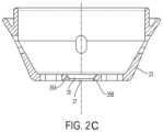
- FIG. 2 Cis a schematic representation of the cervical cup of the uterine manipulator device taken along A-A of FIG. 1 according to an alternative embodiment.
- FIG. 3 Ais a schematic representation of the proximal end of the uterine manipulator device according to an embodiment.
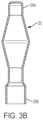
- FIG. 3 Bis a schematic representation of the intrauterine balloon of the uterine manipulator device taken along A-A of FIG. 3 A according to an embodiment.
- FIG. 4is a schematic representation of the use of the uterine manipulator device according to an embodiment.
- the uterine manipulator device 100can include (from the distal end 1 to the proximal end 3 ) a handle 5 , a dye injection port 7 positioned in the handle 5 (preferably through the distal end, and communicatively coupled to the intrauterine balloon 25 ), an inflation valve 9 (communicatively coupled to the intrauterine balloon 25 ), to which a syringe (e.g., 10 cc syringe, not shown) can be attached, and a pilot balloon 11 are attached to the handle 5 (preferably through the proximal end), and a cannulated manipulator tube 13 .
- a syringee.g., 10 cc syringe, not shown
- the cannulated manipulator tube 13is curved at its proximal end and is straight at its distal end for easy introduction of the device 100 , for manipulation of both retroverted and anteverted uteri, and for maintaining proper attitude of the uterus at the distal end.
- the cannulated manipulator tube 13is connected to the handle 5 (preferably at the proximal end of the handle 5 ) and to the dye injection port 1 , inflation valve 9 , and pilot balloon 11 through the handle 5 .
- the manipulator tube 13is configured to anatomically conform to the angle of the sacral curve, and to allow for easy manipulation of the uterus.
- the manipulator tube 13can be marked with reference graduations (not shown) from the proximal end 3 .
- the graduationscan be provided as a guide for comparison to a graduated uterine sound, and can aid in attaining proper depth of insertion during use.
- the handle 5which can provide for the positioning of all four fingers on one side and the thumb on the opposite side (which can include a gripping/non-smooth surface such as a plurality of raised portions or other non-smooth surface structure as should be appreciated by a person of skill in the art in conjunction with a review of this disclosure), allows for easy manipulation of the uterus up, down and sideways.
- the uterine manipulator device 100incorporates a system of cup-like elevators positioned on the manipulator tube 13 (which is positioned through a hole formed at the base of each cup) to provide manipulation of the uterus, and retraction and elevation of the cervix.
- cup-like elevatorscan include a vaginal cup 19 and a cervical cup 23 .
- the vaginal cup 19tapers from a top distal portion with a first diameter to a base proximal portion with a second smaller diameter and can include a cylindrical/tubular tail 21 positioned on the outside of the manipulator tube 13 .
- a locking assemblyis positioned distally to the tubular tail 21 and includes a cylindrical portion 17 and a thumbscrew 15 .
- the cervical cup 23is positioned on the proximal end of the manipulator tube 13 , and can include sites/holes for suturing positioned through the side of the cervical cup 23 .
- the cervical cupcan include various volumes and diameters, examples of which are shown in Table 1 below:
- An intrauterine balloon 25is also shown, and is positioned on the most proximal portion of the manipulator tube 13 .
- the balloone.g., 10 cc inflatable balloon
- the balloonis configured and positioned to reduce the risk of uterine perforation and is used to stabilize the manipulator tube 13 within the uterine cavity 303 (see FIG. 4 ) during use.
- FIG. 2 Ais a schematic representation of the proximal end 3 of the uterine manipulator device 100 .
- the vaginal cup 19 and cervical cup 23have been removed to show the retention mechanism for the cervical cup 23 positioned on the manipulator tube 13 , which includes a retention ring 27 flanked by thermally fused heat shrink tubular portions 29 and 31 (which are configured to hold the retention ring in place on the manipulator tube 13 ).
- the retention ring 27in conjunction with the heat shrink portions 29 and 31 , is positioned on the manipulator tube 13 and configured to prevent detachment of the cervical cup 23 from the manipulator tube 13 .
- the intrauterine balloon 25has also been removed from FIG.
- the proximal portion of the manipulator tube 13 exposed by the removal of the intrauterine balloon 25includes an opening with a proximal end of a tube 33 connected to the inflation valve 9 and pilot balloon 11 for inflating the intrauterine balloon 25 , and to the dye injection port 7 .
- FIG. 2 Bis a schematic representation of the cervical cup 23 taken along A-A of FIG. 1 .
- the cervical cup 23tapers from a top proximal portion with a first diameter to a base distal portion with a second smaller diameter including a central hole 37 having a perimeter 35 .
- the perimeteris chamfered/angled away from the longitudinal axis A at the distal end 35 B, and is straight/not angled with respect to the longitudinal axis A at the proximal end 35 A. The chamfering of the perimeter aids in the movement of the cervical cup 23 along the manipulator tube 13 .
- the straight/not angled perimeter portionaids in increasing the retention force of the cervical cup 23 on the manipulator tube 13 and in preventing detachment of the cup from the manipulator tube 13 .
- the hole 37 diameterwas decreased (from 2.15 cm to 2.05 cm).
- the combination of the straight/not angled perimeter portion and the narrowing of the diameter of the hole 37significantly increased the retention force of the cervical cup 23 on the manipulator tube 13 .
- FIG. 2 Ca configuration opposite FIG. 2 B is depicted where end 35 A is angled away and end 35 B is straight with respect to the longitudinal axis A to aid in the movement of the cervical cup 23 along the manipulator tube 13 .
- FIG. 3 Ais a schematic representation of the proximal end 3 of the uterine manipulator device 100 .
- the vaginal cup 19 and cervical cup 23have been removed.
- the intrauterine balloon 25is shown with a proximal end 25 A positioned over the proximal end 3 of the device 100 , and a distal end 25 B positioned over the retention mechanism.
- FIG. 3 Bis a schematic representation of the intrauterine balloon 25 taken along A-A of FIG. 3 A .
- the distal end 25 B of the intrauterine balloon 25is angled a certain amount (e.g., three degrees total) from the longitudinal axis to sufficiently fit over a portion of the retention mechanism and to retain the intrauterine balloon 25 on the cup retention mechanism.
- Such a structure and configuration of the distal end 25 B of the intrauterine balloon 25assists with a proper and clean assembly (no “bunching”) of the intrauterine balloon 25 on the device 100 .
- FIG. 4is a schematic representation of the use of the uterine manipulator device 100 .
- the uterine manipulator device 100is shown positioned through the vagina 305 with the intrauterine balloon 25 in the uterine cavity 303 and the vaginal fornix 301 positioned within the cervical cup 23 .
- a syringeis attached to the inflation valve 9 to inflate the intrauterine balloon 25 (with, e.g. 7 cc of air and up to, e.g., 10 cc of air).
- the syringeis then removed to prevent spontaneous deflation of the intrauterine balloon 25 by backward pressure.
- the cervical cup 23is then slid proximally along the manipulator tube 13 until its outer edges surround the vaginal fornix 301 (as shown).
- the cervical cup 23can optionally be sutured in place.
- the vaginal cup 19is then slid proximally along the manipulator tube 13 until it meets the distal edge of the cervical cup 23 and is completely seated against the vaginal 305 walls and is configured, structured and/or positioned to ensure maintenance of pneumoperitoneum as needed.
- the locking assemblyis slid proximally to meet the cylindrical/tubular tail 21 of the vaginal cup 19 and secured in place by turning the thumbscrew until it is tight.
- Manipulation of the uteruscan then be carried out as may be necessary based on the particular procedure (as should be understood by a person of ordinary skill in the art in conjunction with a review of this disclosure), and various devices including visualization and other surgical devices ( 200 , 201 ) can be inserted through incisions made in the abdomen of the patient.
Landscapes
- Health & Medical Sciences (AREA)
- Life Sciences & Earth Sciences (AREA)
- Surgery (AREA)
- Heart & Thoracic Surgery (AREA)
- Veterinary Medicine (AREA)
- Engineering & Computer Science (AREA)
- Animal Behavior & Ethology (AREA)
- General Health & Medical Sciences (AREA)
- Public Health (AREA)
- Biomedical Technology (AREA)
- Medical Informatics (AREA)
- Molecular Biology (AREA)
- Nuclear Medicine, Radiotherapy & Molecular Imaging (AREA)
- Gynecology & Obstetrics (AREA)
- Reproductive Health (AREA)
- Pregnancy & Childbirth (AREA)
- Hematology (AREA)
- Anesthesiology (AREA)
- Vascular Medicine (AREA)
- Child & Adolescent Psychology (AREA)
- Biophysics (AREA)
- Pulmonology (AREA)
- Surgical Instruments (AREA)
- Pathology (AREA)
- Endoscopes (AREA)
Abstract
Description
| TABLE 1 | ||
| Cervical Cup | Cervical Cup | Cervical Cup |
| Volume | Diameter | Designation |
| 9.7 cm3(0.59 in3) | 32 mm (1.26 in) | S |
| 14.3 cm3(0.87 in3) | 34 mm (1.34 in) | M |
| 20.7 cm3(1.26 in3) | 37 mm (1.46 in) | L |
| 26.7 cm3(1.63 in3) | 40 mm (1.57 in) | XL |
Claims (12)
Priority Applications (1)
| Application Number | Priority Date | Filing Date | Title |
|---|---|---|---|
| US17/699,787US12178474B2 (en) | 2016-06-09 | 2022-03-21 | Uterine manipulator |
Applications Claiming Priority (4)
| Application Number | Priority Date | Filing Date | Title |
|---|---|---|---|
| US201662347781P | 2016-06-09 | 2016-06-09 | |
| US15/617,299US11278322B2 (en) | 2016-06-09 | 2017-06-08 | Uterine manipulator |
| US17/198,506US11877772B2 (en) | 2016-06-09 | 2021-03-11 | Uterine manipulator |
| US17/699,787US12178474B2 (en) | 2016-06-09 | 2022-03-21 | Uterine manipulator |
Related Parent Applications (1)
| Application Number | Title | Priority Date | Filing Date |
|---|---|---|---|
| US17/198,506ContinuationUS11877772B2 (en) | 2016-06-09 | 2021-03-11 | Uterine manipulator |
Related Child Applications (1)
| Application Number | Title | Priority Date | Filing Date |
|---|---|---|---|
| US19/004,582ContinuationUS20250318856A1 (en) | 2024-12-30 | Uterine Manipulator |
Publications (2)
| Publication Number | Publication Date |
|---|---|
| US20220202449A1 US20220202449A1 (en) | 2022-06-30 |
| US12178474B2true US12178474B2 (en) | 2024-12-31 |
Family
ID=59153292
Family Applications (3)
| Application Number | Title | Priority Date | Filing Date |
|---|---|---|---|
| US15/617,299Active2038-09-26US11278322B2 (en) | 2016-06-09 | 2017-06-08 | Uterine manipulator |
| US17/198,506Active2037-12-17US11877772B2 (en) | 2016-06-09 | 2021-03-11 | Uterine manipulator |
| US17/699,787ActiveUS12178474B2 (en) | 2016-06-09 | 2022-03-21 | Uterine manipulator |
Family Applications Before (2)
| Application Number | Title | Priority Date | Filing Date |
|---|---|---|---|
| US15/617,299Active2038-09-26US11278322B2 (en) | 2016-06-09 | 2017-06-08 | Uterine manipulator |
| US17/198,506Active2037-12-17US11877772B2 (en) | 2016-06-09 | 2021-03-11 | Uterine manipulator |
Country Status (9)
| Country | Link |
|---|---|
| US (3) | US11278322B2 (en) |
| EP (3) | EP3468490B1 (en) |
| JP (1) | JP7003066B2 (en) |
| KR (4) | KR102534950B1 (en) |
| CN (1) | CN109310455A (en) |
| AU (1) | AU2017277650B2 (en) |
| CA (2) | CA3132699C (en) |
| ES (2) | ES2935414T3 (en) |
| WO (1) | WO2017214381A1 (en) |
Families Citing this family (12)
| Publication number | Priority date | Publication date | Assignee | Title |
|---|---|---|---|---|
| WO2017214381A1 (en) | 2016-06-09 | 2017-12-14 | Conmed Corporation | Uterine manipulator |
| WO2018039250A1 (en)* | 2016-08-24 | 2018-03-01 | Inpress Technologies, Inc. | Uterine hemorrhage controlling system and method |
| US10695092B2 (en) | 2018-02-20 | 2020-06-30 | Conmed Corporation | Uterine manipulator |
| CN110179532A (en)* | 2019-06-25 | 2019-08-30 | 李委佳 | Adjustable type vagina cerclage inflates uterus raising device |
| US11547782B2 (en)* | 2020-01-31 | 2023-01-10 | Covidien Lp | Fluid collecting sheaths for endoscopic devices and systems |
| AU2021292298B2 (en) | 2020-06-18 | 2024-06-13 | Conmed Corporation | Uterine manipulator with balloon occluder |
| US20220061839A1 (en)* | 2020-08-27 | 2022-03-03 | Timothy Hardy | Needle Containment Assistant Device for Laparoscopic Surgery |
| US20220142653A1 (en)* | 2020-11-12 | 2022-05-12 | Pramand LLC | Transcervical access systems for intrauterine fluid exchange, such as placement of hydrogels formed in situ |
| US12343454B2 (en) | 2020-11-12 | 2025-07-01 | Pramand LLC | Hydrogels formed in situ and composition design for intrauterine use |
| CN113116432B (en)* | 2021-04-19 | 2023-09-01 | 甘肃省武威肿瘤医院(武威医学科学研究院) | Cervical operation stitching assisting device and stitching assisting method thereof |
| US20230073783A1 (en)* | 2021-09-08 | 2023-03-09 | Cilag Gmbh International | Robotically controlled uterine manipulator with sensing |
| CN115645014A (en)* | 2022-10-17 | 2023-01-31 | 无锡海鹰医疗科技股份有限公司 | Uterine manipulator for assisting HIFU ablation treatment |
Citations (10)
| Publication number | Priority date | Publication date | Assignee | Title |
|---|---|---|---|---|
| US20050004592A1 (en)* | 2003-05-08 | 2005-01-06 | Criscuolo Christopher J. | Balloon dissector with balloon tip cannula |
| US20050120810A1 (en)* | 2003-11-19 | 2005-06-09 | William A. Cook Australia Pty. Ltd. | Bung for an aspiration assembly |
| US20100106163A1 (en)* | 2008-10-24 | 2010-04-29 | Coopersurgical, Inc. | Uterine Manipulator Assemblies and Related Components and Methods |
| US20100305578A1 (en) | 2009-05-27 | 2010-12-02 | Coopersurgical, Inc. | Uterine Manipulators and Related Components and Methods |
| US20130197536A1 (en)* | 2011-04-07 | 2013-08-01 | Jai Singh | General uterine manipulator and system |
| US20140135587A1 (en) | 2011-09-29 | 2014-05-15 | Blake Hess | Tissue Removal and Manipulator Device for LAVH and Related Surgeries |
| US20140172067A1 (en)* | 2012-02-23 | 2014-06-19 | Covidien Lp | Luminal stenting |
| US20150164629A1 (en)* | 2013-12-12 | 2015-06-18 | Carey Tasca Pty Ltd | Surgical methods and devices for treatment of prolapsed uterus |
| US20160157697A1 (en)* | 2013-07-26 | 2016-06-09 | Arai Medphoton Research Laboratories, Corporation | Medical device and light-emitting probe mounting kit for medical device |
| US20160270819A1 (en)* | 2015-03-17 | 2016-09-22 | Prabhat Kumar Ahluwalia | Uterine manipulator |
Family Cites Families (71)
| Publication number | Priority date | Publication date | Assignee | Title |
|---|---|---|---|---|
| US749725A (en) | 1904-01-19 | Method of producing heddles | ||
| US4775362A (en)* | 1987-05-21 | 1988-10-04 | Kronner Richard F | Uterine manipulator with externally securable clamp |
| US5209754A (en)* | 1992-04-02 | 1993-05-11 | Ahluwalia Prabhat K | Vaginal cervical retractor elevator |
| US5338302A (en) | 1993-05-03 | 1994-08-16 | Hasson Harrith M | Vaginal stabilizer cannula |
| US5643285A (en)* | 1994-10-18 | 1997-07-01 | Blairden Precision Instruments, Inc. | Vaginal extender for colpotomy surgery |
| US5520698A (en) | 1994-10-19 | 1996-05-28 | Blairden Precision Instruments, Inc. | Simplified total laparoscopic hysterectomy method employing colpotomy incisions |
| AU2917497A (en) | 1996-05-24 | 1998-01-05 | Michael Charles East | Surgical apparatus |
| US5935098A (en) | 1996-12-23 | 1999-08-10 | Conceptus, Inc. | Apparatus and method for accessing and manipulating the uterus |
| US5928249A (en)* | 1997-07-11 | 1999-07-27 | Gynecare, Inc. | Cervical dam |
| US6086603A (en) | 1998-12-14 | 2000-07-11 | Syntheon, Llc | Luminal port device having internal and external sealing mechanisms |
| WO2002065924A2 (en) | 2001-02-20 | 2002-08-29 | Marcus Vincent Van Heerden | A uterine manipulator device |
| US6802825B2 (en) | 2001-07-03 | 2004-10-12 | Coopersurgical, Inc. | Access catheter apparatus for use in minimally invasive surgery and diagnostic procedures in the uterus and fallopian tubes |
| IL149687A0 (en) | 2002-05-15 | 2002-11-10 | Alexander Condrea | Cervical dilator |
| US20050055043A1 (en) | 2002-12-12 | 2005-03-10 | Os Technology, Llc. | Cervical canal dilator |
| US20050107665A1 (en) | 2003-11-18 | 2005-05-19 | Nady Nady E. | Device for sealing a body canal and method of use |
| AU2005244142B2 (en) | 2004-04-28 | 2011-02-24 | Bayer Essure, Inc. | Endoscopic delivery of medical devices |
| CN100367916C (en) | 2005-02-05 | 2008-02-13 | 暨南大学 | Special vaginal vault positioning retractor for laparoscopic hysterectomy |
| NZ540710A (en) | 2005-06-10 | 2008-07-31 | Insitu Systems Ltd | Surgical apparatus for enabling establishment of a pneumoperitoneum and for uterus manipulation during a vaginal hysterectomy procedure |
| US20070066990A1 (en) | 2005-09-19 | 2007-03-22 | Andrew Marsella | Device for forming a fluid tight seal during a procedure within a hollow organ |
| US20070288051A1 (en) | 2006-04-17 | 2007-12-13 | Bruce Beyer | Fluid-filled cervical dilator |
| CN2917679Y (en)* | 2006-07-20 | 2007-07-04 | 李瑞刚 | Handle type uterine neck suction cup |
| JP2010516351A (en) | 2007-01-25 | 2010-05-20 | レベル・スリー・イノベイションズ・プロプライエタリー・リミテッド | Tube expansion device |
| CN101254129B (en) | 2007-02-27 | 2010-05-26 | 复旦大学附属妇产科医院 | Multi-directional leak-free air lifter |
| USD592849S1 (en) | 2007-10-10 | 2009-05-26 | Robert William Creelman | Walking cane with pistol handle |
| US20090270835A1 (en) | 2008-04-24 | 2009-10-29 | Kushner David M | Steerable sonohysterographic injection catheter for uterine cancer sentinel lymph node mapping |
| US20100168784A1 (en) | 2008-12-16 | 2010-07-01 | Terri Lynne Behrman Pustilnik | Laparoscopic Vaginal Cuff Occluder |
| EP3345558A1 (en) | 2009-06-25 | 2018-07-11 | University of Maryland, Baltimore | Electrosurgical element and uterine manipulator for total laparoscopic hysterectomy |
| US9173677B2 (en) | 2009-07-08 | 2015-11-03 | Covidien Lp | Apparatus and method for transvaginal surgery |
| DE102009056705A1 (en) | 2009-12-02 | 2011-06-09 | Richard Wolf Gmbh | uterine manipulator |
| US8770200B2 (en) | 2010-04-21 | 2014-07-08 | Minimally Invasive Surgical Technologies, Inc. | Fornix manipulator |
| WO2011141866A2 (en) | 2010-05-13 | 2011-11-17 | Noel Elman | Stent devices for support, controlled drug delivery and pain management after vaginal surgery |
| US20120016185A1 (en) | 2010-07-16 | 2012-01-19 | Charles Sherts | Vaginal Manipulator Tips and Related Systems and Methods |
| US10039666B2 (en) | 2010-10-13 | 2018-08-07 | Contipi Medical Ltd. | Apparatuses and methods of intravaginal support and/or distension |
| US8939988B2 (en) | 2010-11-01 | 2015-01-27 | Coopersurgical, Inc. | Uterine manipulators and related components and methods |
| US8608738B2 (en) | 2010-12-06 | 2013-12-17 | Soulor Surgical, Inc. | Apparatus for treating a portion of a reproductive system and related methods of use |
| US8562623B2 (en) | 2011-02-09 | 2013-10-22 | ROSS ALAN McDONALD | Vaginal occlusion device |
| US8603105B2 (en) | 2011-06-21 | 2013-12-10 | Lsi Solutions, Inc. | Ergonomic, lighted uterine manipulator with cautery |
| US9936974B2 (en) | 2011-07-12 | 2018-04-10 | Jerome V. Ponder | Laparoscopic uterine manipulator assembly and methodology for use |
| US20130023896A1 (en) | 2011-07-20 | 2013-01-24 | Quimby Jennifer C | Surgical manipulation and occlusion device |
| EP2790590A4 (en) | 2011-12-16 | 2015-04-15 | Univ South Florida | TRANSVAGINAL SAMPLE EXTRACTION DEVICE |
| JP5849842B2 (en) | 2011-12-21 | 2016-02-03 | ソニー株式会社 | Power supply device, power supply system, and electronic device |
| US9629660B2 (en) | 2012-01-30 | 2017-04-25 | The Brigham And Women's Hospital | Functional uterine manipulator |
| US9622646B2 (en) | 2012-06-25 | 2017-04-18 | Coopersurgical, Inc. | Low-cost instrument for endoscopically guided operative procedures |
| US20140012305A1 (en) | 2012-07-05 | 2014-01-09 | Clinical Innovations, Llc | Colpotomy cup-like structure and intrauterine manipulator including same |
| US20140257322A1 (en) | 2013-03-11 | 2014-09-11 | Gyrus ACMI, Inc., d.b.a., Olympus Surgical Technologies America | Uterine manipulator |
| BR112015022686B1 (en)* | 2013-03-12 | 2022-10-04 | Puja Ahluwalia | UTERINE MANIPULATOR |
| US9011433B2 (en) | 2013-03-15 | 2015-04-21 | Gyrus Acmi, Inc. | Bipolar colpotomy device |
| US9743955B2 (en) | 2014-06-04 | 2017-08-29 | David Allen Hill | Intracorporeal transilluminator of tissue using LED array |
| US20140378751A1 (en) | 2013-06-21 | 2014-12-25 | Previvo Genetics, Llc | Uterine lavage for embryo retrieval |
| US10092323B2 (en) | 2013-11-01 | 2018-10-09 | Lsi Solutions, Inc. | Ergonomic, lighted uterine manipulator with cautery |
| US9101391B2 (en) | 2013-11-11 | 2015-08-11 | Cross Bay Medical, Inc. | Apparatus and methods for accessing and sealing bodily vessels and cavities |
| US9144454B2 (en) | 2013-11-12 | 2015-09-29 | Gyrus Acmi, Inc. | Electrosurgical colpotomy device |
| CN106573132B (en) | 2014-06-29 | 2020-09-08 | 导管医疗有限公司 | Cervical canal dilator |
| US9649130B2 (en) | 2014-10-09 | 2017-05-16 | Coopersurgical, Inc. | Uterine manipulators and related components and methods |
| DE102015112390A1 (en)* | 2015-07-29 | 2017-02-02 | Bentley Innomed Gmbh | balloon catheter |
| US10806522B2 (en) | 2016-02-10 | 2020-10-20 | Covidien Lp | Colpotomy system for total laparoscopic hysterectomy |
| US20170325844A1 (en) | 2016-05-10 | 2017-11-16 | Covidien Lp | Uterine manipulator |
| WO2017214381A1 (en) | 2016-06-09 | 2017-12-14 | Conmed Corporation | Uterine manipulator |
| US11033720B2 (en) | 2016-12-18 | 2021-06-15 | AQUEDUCT MEDICAL Ltd. | Cervical canal dilation device |
| US11090082B2 (en) | 2017-05-12 | 2021-08-17 | Covidien Lp | Colpotomy systems, devices, and methods with rotational cutting |
| US11213320B2 (en) | 2017-05-12 | 2022-01-04 | Covidien Lp | Uterine manipulator with detachable cup and locking occluder |
| US10813589B2 (en) | 2017-06-03 | 2020-10-27 | Sentinel Medical Technologies, LLC | Catheter for monitoring uterine contraction pressure |
| US20190000486A1 (en) | 2017-06-29 | 2019-01-03 | Covidien Lp | Expandable occlusion devices, systems, and methods |
| US10980571B2 (en) | 2017-08-15 | 2021-04-20 | Covidien Lp | Occlusion devices, systems, and methods |
| WO2019040461A1 (en) | 2017-08-21 | 2019-02-28 | Brigham And Women's Hospital, Inc. | Uterine manipulator |
| WO2019118520A1 (en) | 2017-12-11 | 2019-06-20 | Crossbay Medical, Inc. | Apparatus and method for everting catheter for embryo transfer using transvaginal ultrasound |
| US11172815B2 (en) | 2017-12-21 | 2021-11-16 | Gyrus Acmi, Inc. | Uterine cavity biocompatible seal |
| US10695092B2 (en) | 2018-02-20 | 2020-06-30 | Conmed Corporation | Uterine manipulator |
| US10932819B2 (en) | 2018-04-18 | 2021-03-02 | Coopersurgical, Inc. | Uterine manipulators and related components and methods |
| US11524146B2 (en) | 2019-03-15 | 2022-12-13 | Covidien Lp | Methods and devices for transcervical treatment of endometrial cancer and hyperplasia |
| US10820926B1 (en) | 2019-09-30 | 2020-11-03 | José Gerardo Garza Leal | Uterine manipulation device |
- 2017
- 2017-06-08WOPCT/US2017/036528patent/WO2017214381A1/ennot_activeCeased
- 2017-06-08ESES19208497Tpatent/ES2935414T3/enactiveActive
- 2017-06-08CNCN201780035919.6Apatent/CN109310455A/enactivePending
- 2017-06-08JPJP2018563835Apatent/JP7003066B2/enactiveActive
- 2017-06-08CACA3132699Apatent/CA3132699C/enactiveActive
- 2017-06-08EPEP17732660.0Apatent/EP3468490B1/enactiveActive
- 2017-06-08KRKR1020217036414Apatent/KR102534950B1/enactiveActive
- 2017-06-08CACA3023410Apatent/CA3023410C/enactiveActive
- 2017-06-08USUS15/617,299patent/US11278322B2/enactiveActive
- 2017-06-08EPEP19208497.8Apatent/EP3628248B1/enactiveActive
- 2017-06-08KRKR1020247026686Apatent/KR102865629B1/enactiveActive
- 2017-06-08EPEP22203376.3Apatent/EP4162888A1/enactivePending
- 2017-06-08ESES17732660Tpatent/ES2928403T3/enactiveActive
- 2017-06-08AUAU2017277650Apatent/AU2017277650B2/enactiveActive
- 2017-06-08KRKR1020227043839Apatent/KR102694865B1/enactiveActive
- 2017-06-08KRKR1020187037629Apatent/KR102327303B1/enactiveActive
- 2021
- 2021-03-11USUS17/198,506patent/US11877772B2/enactiveActive
- 2022
- 2022-03-21USUS17/699,787patent/US12178474B2/enactiveActive
Patent Citations (10)
| Publication number | Priority date | Publication date | Assignee | Title |
|---|---|---|---|---|
| US20050004592A1 (en)* | 2003-05-08 | 2005-01-06 | Criscuolo Christopher J. | Balloon dissector with balloon tip cannula |
| US20050120810A1 (en)* | 2003-11-19 | 2005-06-09 | William A. Cook Australia Pty. Ltd. | Bung for an aspiration assembly |
| US20100106163A1 (en)* | 2008-10-24 | 2010-04-29 | Coopersurgical, Inc. | Uterine Manipulator Assemblies and Related Components and Methods |
| US20100305578A1 (en) | 2009-05-27 | 2010-12-02 | Coopersurgical, Inc. | Uterine Manipulators and Related Components and Methods |
| US20130197536A1 (en)* | 2011-04-07 | 2013-08-01 | Jai Singh | General uterine manipulator and system |
| US20140135587A1 (en) | 2011-09-29 | 2014-05-15 | Blake Hess | Tissue Removal and Manipulator Device for LAVH and Related Surgeries |
| US20140172067A1 (en)* | 2012-02-23 | 2014-06-19 | Covidien Lp | Luminal stenting |
| US20160157697A1 (en)* | 2013-07-26 | 2016-06-09 | Arai Medphoton Research Laboratories, Corporation | Medical device and light-emitting probe mounting kit for medical device |
| US20150164629A1 (en)* | 2013-12-12 | 2015-06-18 | Carey Tasca Pty Ltd | Surgical methods and devices for treatment of prolapsed uterus |
| US20160270819A1 (en)* | 2015-03-17 | 2016-09-22 | Prabhat Kumar Ahluwalia | Uterine manipulator |
Non-Patent Citations (1)
| Title |
|---|
| "KR Office Action, Application No. 10-2022-7043839, dated Oct. 27, 2023, entire document",KR Office Action, Application No. 10-2022-7043839, dated Oct. 27, 2023, entire document. |
Also Published As
| Publication number | Publication date |
|---|---|
| AU2017277650A1 (en) | 2018-11-29 |
| US11278322B2 (en) | 2022-03-22 |
| CA3132699C (en) | 2024-05-28 |
| KR102534950B1 (en) | 2023-05-26 |
| CN109310455A (en) | 2019-02-05 |
| JP2019519302A (en) | 2019-07-11 |
| KR102865629B1 (en) | 2025-09-26 |
| US20210196321A1 (en) | 2021-07-01 |
| KR20230003623A (en) | 2023-01-06 |
| EP3628248B1 (en) | 2022-12-07 |
| KR102694865B1 (en) | 2024-08-12 |
| US20220202449A1 (en) | 2022-06-30 |
| EP3628248A1 (en) | 2020-04-01 |
| KR20210138786A (en) | 2021-11-19 |
| ES2928403T3 (en) | 2022-11-17 |
| AU2017277650B2 (en) | 2019-12-05 |
| US11877772B2 (en) | 2024-01-23 |
| CA3132699A1 (en) | 2017-12-14 |
| KR20190012204A (en) | 2019-02-08 |
| CA3023410A1 (en) | 2017-12-14 |
| US20170354436A1 (en) | 2017-12-14 |
| KR20240124439A (en) | 2024-08-16 |
| EP4162888A1 (en) | 2023-04-12 |
| EP3468490B1 (en) | 2022-08-17 |
| ES2935414T3 (en) | 2023-03-06 |
| JP7003066B2 (en) | 2022-02-04 |
| WO2017214381A1 (en) | 2017-12-14 |
| KR102327303B1 (en) | 2021-11-17 |
| CA3023410C (en) | 2021-11-23 |
| EP3468490A1 (en) | 2019-04-17 |
Similar Documents
| Publication | Publication Date | Title |
|---|---|---|
| US12178474B2 (en) | Uterine manipulator | |
| US11737784B2 (en) | Uterine manipulator | |
| US20250318856A1 (en) | Uterine Manipulator | |
| KR20250150153A (en) | Uterine manipulator |
Legal Events
| Date | Code | Title | Description |
|---|---|---|---|
| AS | Assignment | Owner name:CONMED CORPORATION, NEW YORK Free format text:ASSIGNMENT OF ASSIGNORS INTEREST;ASSIGNORS:HUGHES, DAVID;HOLBROOKS, ASHLEY;FITZGERALD, RACHELLE D.;AND OTHERS;SIGNING DATES FROM 20060103 TO 20170620;REEL/FRAME:059326/0727 | |
| FEPP | Fee payment procedure | Free format text:ENTITY STATUS SET TO UNDISCOUNTED (ORIGINAL EVENT CODE: BIG.); ENTITY STATUS OF PATENT OWNER: LARGE ENTITY | |
| STPP | Information on status: patent application and granting procedure in general | Free format text:DOCKETED NEW CASE - READY FOR EXAMINATION | |
| STPP | Information on status: patent application and granting procedure in general | Free format text:NON FINAL ACTION MAILED | |
| STPP | Information on status: patent application and granting procedure in general | Free format text:RESPONSE TO NON-FINAL OFFICE ACTION ENTERED AND FORWARDED TO EXAMINER | |
| STPP | Information on status: patent application and granting procedure in general | Free format text:FINAL REJECTION MAILED | |
| STPP | Information on status: patent application and granting procedure in general | Free format text:RESPONSE AFTER FINAL ACTION FORWARDED TO EXAMINER | |
| STPP | Information on status: patent application and granting procedure in general | Free format text:ADVISORY ACTION MAILED | |
| STPP | Information on status: patent application and granting procedure in general | Free format text:DOCKETED NEW CASE - READY FOR EXAMINATION | |
| STPP | Information on status: patent application and granting procedure in general | Free format text:NON FINAL ACTION MAILED | |
| STPP | Information on status: patent application and granting procedure in general | Free format text:RESPONSE TO NON-FINAL OFFICE ACTION ENTERED AND FORWARDED TO EXAMINER | |
| STPP | Information on status: patent application and granting procedure in general | Free format text:NOTICE OF ALLOWANCE MAILED -- APPLICATION RECEIVED IN OFFICE OF PUBLICATIONS | |
| STPP | Information on status: patent application and granting procedure in general | Free format text:PUBLICATIONS -- ISSUE FEE PAYMENT VERIFIED | |
| STCF | Information on status: patent grant | Free format text:PATENTED CASE | |
| AS | Assignment | Owner name:JPMORGAN CHASE BANK, N.A., AS ADMINISTRATIVE AGENT, ILLINOIS Free format text:SECURITY INTEREST;ASSIGNORS:CONMED CORPORATION;BIOREZ, INC.;BUFFALO FILTER LLC;AND OTHERS;REEL/FRAME:072097/0762 Effective date:20250610 |