US12178248B2 - Electronic cigarette and heating assembly and heating member thereof - Google Patents
Electronic cigarette and heating assembly and heating member thereofDownload PDFInfo
- Publication number
- US12178248B2 US12178248B2US16/969,828US201816969828AUS12178248B2US 12178248 B2US12178248 B2US 12178248B2US 201816969828 AUS201816969828 AUS 201816969828AUS 12178248 B2US12178248 B2US 12178248B2
- Authority
- US
- United States
- Prior art keywords
- heating
- electronic cigarette
- porous body
- sheet
- heating portion
- Prior art date
- Legal status (The legal status is an assumption and is not a legal conclusion. Google has not performed a legal analysis and makes no representation as to the accuracy of the status listed.)
- Active, expires
Links
Images


Classifications
- A—HUMAN NECESSITIES
- A24—TOBACCO; CIGARS; CIGARETTES; SIMULATED SMOKING DEVICES; SMOKERS' REQUISITES
- A24F—SMOKERS' REQUISITES; MATCH BOXES; SIMULATED SMOKING DEVICES
- A24F40/00—Electrically operated smoking devices; Component parts thereof; Manufacture thereof; Maintenance or testing thereof; Charging means specially adapted therefor
- A24F40/40—Constructional details, e.g. connection of cartridges and battery parts
- A24F40/46—Shape or structure of electric heating means
- A—HUMAN NECESSITIES
- A24—TOBACCO; CIGARS; CIGARETTES; SIMULATED SMOKING DEVICES; SMOKERS' REQUISITES
- A24F—SMOKERS' REQUISITES; MATCH BOXES; SIMULATED SMOKING DEVICES
- A24F40/00—Electrically operated smoking devices; Component parts thereof; Manufacture thereof; Maintenance or testing thereof; Charging means specially adapted therefor
- A24F40/40—Constructional details, e.g. connection of cartridges and battery parts
- A24F40/44—Wicks
- H—ELECTRICITY
- H05—ELECTRIC TECHNIQUES NOT OTHERWISE PROVIDED FOR
- H05B—ELECTRIC HEATING; ELECTRIC LIGHT SOURCES NOT OTHERWISE PROVIDED FOR; CIRCUIT ARRANGEMENTS FOR ELECTRIC LIGHT SOURCES, IN GENERAL
- H05B1/00—Details of electric heating devices
- H05B1/02—Automatic switching arrangements specially adapted to apparatus ; Control of heating devices
- H05B1/0227—Applications
- H—ELECTRICITY
- H05—ELECTRIC TECHNIQUES NOT OTHERWISE PROVIDED FOR
- H05B—ELECTRIC HEATING; ELECTRIC LIGHT SOURCES NOT OTHERWISE PROVIDED FOR; CIRCUIT ARRANGEMENTS FOR ELECTRIC LIGHT SOURCES, IN GENERAL
- H05B3/00—Ohmic-resistance heating
- H05B3/10—Heating elements characterised by the composition or nature of the materials or by the arrangement of the conductor
- H05B3/18—Heating elements characterised by the composition or nature of the materials or by the arrangement of the conductor the conductor being embedded in an insulating material
- A—HUMAN NECESSITIES
- A24—TOBACCO; CIGARS; CIGARETTES; SIMULATED SMOKING DEVICES; SMOKERS' REQUISITES
- A24F—SMOKERS' REQUISITES; MATCH BOXES; SIMULATED SMOKING DEVICES
- A24F40/00—Electrically operated smoking devices; Component parts thereof; Manufacture thereof; Maintenance or testing thereof; Charging means specially adapted therefor
- A24F40/10—Devices using liquid inhalable precursors
- H—ELECTRICITY
- H05—ELECTRIC TECHNIQUES NOT OTHERWISE PROVIDED FOR
- H05B—ELECTRIC HEATING; ELECTRIC LIGHT SOURCES NOT OTHERWISE PROVIDED FOR; CIRCUIT ARRANGEMENTS FOR ELECTRIC LIGHT SOURCES, IN GENERAL
- H05B2203/00—Aspects relating to Ohmic resistive heating covered by group H05B3/00
- H05B2203/002—Heaters using a particular layout for the resistive material or resistive elements
- H05B2203/003—Heaters using a particular layout for the resistive material or resistive elements using serpentine layout
- H—ELECTRICITY
- H05—ELECTRIC TECHNIQUES NOT OTHERWISE PROVIDED FOR
- H05B—ELECTRIC HEATING; ELECTRIC LIGHT SOURCES NOT OTHERWISE PROVIDED FOR; CIRCUIT ARRANGEMENTS FOR ELECTRIC LIGHT SOURCES, IN GENERAL
- H05B2203/00—Aspects relating to Ohmic resistive heating covered by group H05B3/00
- H05B2203/016—Heaters using particular connecting means
- H—ELECTRICITY
- H05—ELECTRIC TECHNIQUES NOT OTHERWISE PROVIDED FOR
- H05B—ELECTRIC HEATING; ELECTRIC LIGHT SOURCES NOT OTHERWISE PROVIDED FOR; CIRCUIT ARRANGEMENTS FOR ELECTRIC LIGHT SOURCES, IN GENERAL
- H05B2203/00—Aspects relating to Ohmic resistive heating covered by group H05B3/00
- H05B2203/021—Heaters specially adapted for heating liquids
Definitions
- the present disclosurerelates to smoking products, and more particularly, to an electronic cigarette, and a heating assembly and a heating element thereof.
- Electronic cigarettesare also known as virtual cigarettes or electronic atomizers. Electronic cigarettes are used as substitutes for cigarette products and are often used for quitting smoking. The electronic cigarettes have similar appearance and flavor to cigarette products, but generally are free of harmful chemicals such as tar, aerosol, or the like in the cigarettes.
- the electronic cigarettemainly includes an atomizer and a power supply assembly.
- the atomizer of the electronic cigarettemostly includes a capillary structure for guiding liquid and a heating element cooperating with the capillary structure, which can meet the needs for atomization to a certain extent.
- a heating elementmay have a problem of uneven heating during heating, as a result, the e-liquid is atomized at different temperatures and the mouthfeel of the smoke is poor.
- the temperature of a certain portion of the heating elementis too high, it will cause the e-liquid to decompose into toxic substances and endanger the health of the user.
- the technical problem to be solved by the present disclosureis to provide an improved electronic cigarette, and a heating assembly and a heating element thereof.
- a heating assembly of an electronic cigarettewhich includes a porous body configured for adsorbing e-liquid and at least one heating element configured for heating and atomizing the e-liquid adsorbed into the porous body.
- the at least one heating elementincludes an elongated sheet heating portion, at least partial section of the sheet heating portion is at least partially embedded in the porous body, and the porous body includes an atomizing surface corresponding to the at least partial section.
- the at least partial sectionis provided with a through hole configured for adjusting resistance distribution.
- the at least partial sectionincludes a plurality of through holes, and in a length direction of the sheet heating portion, a density of the through holes in the middle is less than that of the through holes at both ends.
- the at least partial sectionincludes a plurality of through holes, and a distribution density of the through holes in a width direction of the sheet heating portion changes gradually or changes stepwise.
- the at least partial sectionis embedded in the porous body with a width direction thereof following along a movement direction of the e-liquid and/or smoke in the porous body.
- the at least partial section in the width direction thereofis substantially perpendicular to a plane where the atomizing surface is located.
- the at least partial sectionextends in a length direction thereof along a direction parallel to a plane where the atomizing surface is located.
- two opposite surfaces of the at least partial section defined by length and widthare in direct contact with the porous body.
- the porous bodyincludes a sintered porous body, the at least partial section is integrally formed with the sintered porous body by sintering.
- the at least partial sectionincludes a plurality of flat portions parallel to each other and a plurality of bending portions sequentially connecting the plurality of flat portions in series, the flat portions are arranged at intervals in a direction parallel to a plane where the atomizing surface is located, and the intervals are larger in the middle and smaller at both sides, or smaller in the middle and larger at the both sides.
- the porous bodyincludes a first layer adjacent to the atomizing surface and a second layer away from the atomizing surface, a thermal conductivity of the first layer is greater than that of the second layer.
- the at least partial sectionis embedded in the first layer.
- the at least partial sectionincludes a plurality of flat portions parallel to each other and a plurality of bending portions sequentially connecting the plurality of flat portions in series, the atomizing surface is provided in a wavy shape, and the plurality of flat portions are disposed corresponding to troughs of the atomizing surface, respectively.
- a thermal conductivity of the porous bodygradually increases in a direction from an area away from the atomizing surface to an area adjacent to the atomizing surface.
- the at least one heating elementincludes two electrical connecting portions integrally connected to both ends of the sheet heating portion, respectively; each of the electrical connecting portions includes a lower portion protruding from a lower edge of the sheet heating portion and an upper portion protruding from an upper edge of the sheet heating portion.
- the at least partial sectionis integrally embedded in the porous body.
- a heating element of an electronic cigaretteincludes an elongated sheet heating portion.
- the sheet heating portionis provided with a through hole configured for adjusting resistance distribution.
- the sheet heating portionincludes a plurality of through holes, and in a length direction of the sheet heating portion, a density of the through holes in the middle is greater than that of the through holes at both ends.
- the sheet heating portionincludes a plurality of through holes, and in a length direction of the sheet heating portion, a density of the through holes in the middle is less than that of the through holes at both ends.
- the sheet heating portionincludes a plurality of through holes, and a distribution density of the through holes in a width direction of the sheet heating portion changes gradually or changes stepwise.
- An electronic cigarettewhich includes the heating assembly of the electronic cigarette in any one of the embodiments described above, or the heating element of the electronic cigarette in any one of the embodiments described above.
- the present disclosurehas the beneficial effects that, by providing through holes configured for adjusting resistance distribution on the sheet heating portion, some heat accumulation problems in the electronic cigarette can be handled very easily, so that the heat distribution can better meet the needs of the design thereof.
- FIG. 1is a schematic three-dimension assembled view of a heating assembly in accordance with some embodiments of the present disclosure
- FIG. 2is a schematic three-dimension exploded view of the heating assembly of FIG. 1 ;
- FIG. 3is a schematic longitudinal sectional view of the heating assembly of FIG. 1 ;
- FIG. 4is a schematic partial enlarged view of a portion A of the heating assembly of FIG. 3 ;
- FIG. 5is a schematic partial enlarged view of a portion A in a first alternative solution of the heating assembly of FIG. 1 ;
- FIG. 6is a schematic partial enlarged view of a portion A in a second alternative solution of the heating assembly of FIG. 1 ;
- FIG. 7is a schematic partial enlarged view of a portion A in a third alternative solution of the heating assembly of FIG. 1 ;
- FIG. 8is a schematic partial enlarged view of a portion A in a fourth alternative solution of the heating assembly of FIG. 1 ;
- FIG. 9is a schematic partial enlarged view of a portion A in a fifth alternative solution of the heating assembly of FIG. 1 ;
- FIG. 10is a schematic partial enlarged view of a portion A in a sixth alternative solution of the heating assembly of FIG. 1 ;
- FIG. 11is a schematic partial enlarged view of a portion A in a seventh alternative solution of the heating assembly of FIG. 1 ;
- FIG. 12is a schematic longitudinal sectional view of an eighth alternative solution of the heating assembly of FIG. 1 ;
- FIG. 14is a schematic longitudinal sectional view of a tenth alternative solution of the heating assembly of FIG. 1 ;
- FIG. 15is a schematic longitudinal sectional view of an eleventh alternative solution of the heating assembly of FIG. 1 ;
- FIG. 16is a schematic longitudinal sectional view of a twelfth alternative solution of the heating assembly of FIG. 1 ;
- FIG. 17is a schematic longitudinal sectional view of a thirteenth alternative solution of the heating assembly of FIG. 1 ;
- FIG. 18is a schematic view of a first alternative solution of a heating element of the heating assembly of FIG. 1 ;
- FIG. 19is a schematic view of a second alternative solution of the heating element of the heating assembly of FIG. 1 ;
- FIG. 20is a schematic view of a third alternative solution of the heating element of the heating assembly of FIG. 1 ;
- FIG. 22is a schematic view of a fifth alternative solution of the heating element of the heating assembly of FIG. 1 ;
- FIG. 23is a schematic view of a sixth alternative solution of the heating element of the heating assembly of FIG. 1 ;
- FIG. 24is a schematic three-dimension view of a fourteenth alternative solution of the heating assembly of FIG. 1 ;
- FIG. 25is a schematic longitudinal sectional view of the heating assembly of FIG. 24 ;
- FIG. 26is a schematic three-dimension assembled view of an electronic cigarette with the heating assembly of FIG. 24 ;
- FIG. 27is a schematic three-dimension exploded view of the electronic cigarette of FIG. 26 ;
- FIG. 28is a schematic three-dimension exploded view of an atomizer of the electronic cigarette of FIG. 26 ;
- FIG. 29is a further schematic three-dimension exploded view of the atomizer of the electronic cigarette of FIG. 26 ;
- FIG. 30is a schematic two-dimension exploded view of the atomizer of the electronic cigarette of FIG. 26 ;
- FIG. 31is a schematic general cross-sectional exploded view of the atomizer of the electronic cigarette of FIG. 26 ;
- FIG. 32is a schematic longitudinal sectional assembled view of the atomizer of the electronic cigarette of FIG. 26 ;
- FIG. 33is a schematic three-dimension view of a fifteenth alternative solution of the heating assembly of FIG. 1 ;
- FIG. 34is a schematic three-dimension view of a sixteenth alternative solution of the heating assembly of FIG. 1 ;
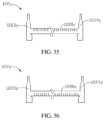
- FIG. 35is a schematic view of a first alternative solution of the heating element of the heating assembly of FIG. 18 ;
- FIG. 36is a schematic view of a second alternative solution of the heating element of the heating assembly of FIG. 18 .
- FIG. 1 to FIG. 3illustrate a heating assembly 12 of an electronic cigarette in some embodiments of the present disclosure.
- the heating assembly 12can be applied in an atomizer of the electronic cigarette to heat and atomize e-liquid.
- the heating assembly 12may include a porous body 121 for adsorbing the e-liquid from a liquid storage cavity of the atomizer and a heating element 122 for heating and atomizing the e-liquid adsorbed into the porous body 121 .
- the heating element 122includes an elongated sheet heating portion which is embedded in the porous body 121 , so that all or most of a surface area of the sheet heating portion is in contact with the porous body 121 , which brings effects such as high atomization efficiency, low loss of heat, prevention or great reduction of dry burning and so on.
- the sheet heating portionis embedded in the porous body 121 in such a manner that a movement direction of the e-liquid and/or smoke in the porous body 121 follows along a width direction of the sheet heating portion, so that the movement of the e-liquid and/or the smoke can be smoother on one hand, and more heat can be concentrated near an atomizing surface 1211 instead of being transferred towards a liquid adsorbing surface 1212 along an opposite direction on the other hand, so as to improve the utilization of the heat.
- the porous body 121in some embodiments, can be made of hard capillary structures such as porous ceramics, porous glass ceramics, porous glass, and so on.
- the sheet heating portion of the heating element 122in some embodiments, can be made of stainless steel, nickel-chromium alloy, iron-chromium-aluminum alloy, titanium and so on.
- the sheet heating portion of the heating element 122can be integrally formed with the porous body 121 by sintering.
- the porous body 121is made of the porous ceramics
- a green body of the porous body 121can be first formed using the Kaolin clay mass, and then the sheet heating portion of the heating element 122 can be embedded into the green body, which can be baked and sintered thereafter.
- the sheet heating portionis a coated sheet heating portion
- the sheet heating portioncan be first coated on an organic film, and then the organic film coated with the sheet heating portion is inserted into the green body, which is baked and sintered thereafter. The organic film is burnt off in the sintering process, and only the coated sheet heating portion is tightly coupled with the porous body.
- the sheet heating portionCompared with a heating wire, the sheet heating portion has a larger specific surface area.
- the thickness of the sheet heating portioncan be greatly smaller than the diameter of the heating wire (the heating wire with too small diameter is easy to break). Therefore, the sheet heating portion can be made very thin to lead to low internal accumulation of heat and high atomization efficiency.
- the sheet heating portioncan have a thickness of 0.04 mm to 0.1 mm and a width of 0.3 mm to 0.6 mm. In some cases, the thickness of the sheet heating portion can be even smaller, for example, about 0.008 mm.
- the porous body 121can be substantially, but not limited to, in a shape of a cuboid in some embodiments.
- the porous body 121includes the atomizing surface 1211 and the liquid adsorbing surface 1212 parallel to the atomizing surface 1211 .
- the liquid adsorbing surface 1212is used to be in communication with the liquid storage cavity such that the e-liquid can flow into the porous body 121 .
- the e-liquidis heated and atomized in the porous body 121 and then escapes through the atomizing surface 1211 .
- the porous body 121includes a receiving groove 1210 for receiving the sheet heating portion of the heating element 122 .
- the receiving groove 1210extends, in a length direction, along a direction parallel to a plane where the atomizing surface 1211 is located, and extends, in a depth direction, along a direction away from the atomizing surface 1211 .
- the movement directions of the e-liquid and the smoke in the porous body 121are both perpendicular to the atomizing surface 1211 .
- the receiving groove 1210in the depth direction thereof, is perpendicular to the plane where the atomizing surface 1211 is located, so that when the sheet heating portion of the heating element 122 is received therein, the sheet heating portion of the heating element 122 , in the width direction thereof, is also perpendicular to the plane where the atomizing surface 1211 is located.
- the sheet heating portion of the heating element 122 in the width direction thereofis perpendicular to the atomizing surface 1211 , on one hand, the movement of the smoke and the e-liquid in the porous body 121 will be smoother, and on the other hand, the manufacturing of the heating element 122 is more convenient.
- the main heat-conducting surfaces (that is, the front surface and the rear surface defined by the length and width) of the sheet heating portion of the heating element 122are located in the lateral direction to heat the e-liquid near the atomizing surface 1211 and thus improve the atomization efficiency.
- the sheet heating portion of the heating element 122is relatively thin, and an upper surface and a lower surface defined by the thickness and the length are both small, the e-liquid away from the atomizing surface 1211 adsorbs less heat, which can reduce the waste of heat and save energy.
- the sheet heating portion of the heating element 122is not limited to one having the width direction perpendicular to the plane where the atomizing surface 1211 is located. In some embodiments, it is preferable to be slightly inclined, that is, the sheet heating portion of the heating element 122 is substantially perpendicular to the atomizing surface 1211 . Preferably, an angle between the width direction of the sheet heating portion of the heating element 122 and a normal direction of the atomizing surface 1211 is within 20 degrees.
- the sheet heating portion of the heating element 122is not limited to a unique corresponding relationship that the heating portion is substantially perpendicular in its whole section in the entire length to the plane where the atomizing surface 1211 is located. Some advantages disclosed in the embodiments can be obtained as long as some sections of the heating portion satisfies such relationship. Preferably, at least half or more of the heating portion satisfies such relationship.
- the arrangement of the sheet heating portion of the heating element 122may preferably be adjusted accordingly such that the width direction of the sheet heating portion is parallel to or follows along the movement direction of the e-liquid and/or the smoke in the porous body 121 as much as possible.
- the sheet heating portion of the heating element 122need to be distributed uniformly in the porous body 121 near the atomizing surface 1211 as much as possible.
- the sheet heating portion of the heating element 122can be provided in an S-shape in the length direction, which includes a plurality of flat portions 1221 arranged in parallel with each other at equal intervals, and a plurality of bending portions 1222 connecting the plurality of flat portions 1221 together in series.
- the receiving groove 1210is also provided in an S-shape, and the size of which is adapted to the size of the sheet heating portion of the heating element 122 , so that the sheet heating portion of the heating element 122 can be better received therein and the receiving groove 1210 is in close contact with the sheet heating portion of the heating element 122 .
- the sheet heating portion of the heating element 122is not limited to be provided in the S-shape, and can also be provided in other shapes such as a flat strip shape, a tape shape, and a wavy shape as required.
- the width of the sheet heating portion of the heating element 122is equal to the depth of the receiving groove 1210 .
- a top surface of the sheet heating portionis flush with the atomizing surface 1211 , that is, the plane where the sheet heating portion of the heating element 122 is located is parallel to the atomizing surface 1211 . Since the top surface (an upper surface defined by the length and thickness) of the sheet heating portion of the heating element 122 is exposed to the outside, the heating assembly 12 can atomize the e-liquid near the top surface more quickly, and the advantages of quick smoke generation and convenient manufacturing are provided.
- a thermal conductivity of the porous body 121is uniform in a direction from the liquid adsorbing surface 1212 to the atomizing surface 1211 .
- the thermal conductivity of the porous body 121gradually increases in the direction from the liquid adsorbing surface 1212 to the atomizing surface 1211 .
- the sheet heating portion of the heating element 122is embedded in the porous body 121 along the width direction, the sheet heating portion of the heating element 122 has a large contact area with the porous body 121 , thus, the heating efficiency is high and the coupling is firm and uneasy to shed off. Further, such a configuration allow the sheet heating portion of the heating element 122 to be as thin as possible, and the exposed portion of the sheet heating portion of the heating element 122 is relatively narrow, which can therefore greatly reduce the occurrence of dry burning of the exposed portion.
- FIG. 5illustrates a heating assembly 12 a in some embodiments of the present disclosure.
- the heating assembly 12 ais different from the heating assembly 12 mainly in that a width of a sheet heating portion of a heating element 122 a is smaller than a depth of a receiving groove 1210 a , as a result, when the sheet heating portion of the heating element 122 a is received in the receiving groove 1210 a along a width direction, a top surface of the sheet heating portion is lower than an atomizing surface 1211 a .
- Such configurationcan allow for accumulation of the e-liquid in a slot channel between the top surface and the atomizing surface 1211 a , avoiding the exposure of the top surface and further reducing dry burning.
- FIG. 6illustrates a heating assembly 12 b in some embodiments of the present disclosure.
- the heating assembly 12 bis different from the heating assembly 12 mainly in that a width of a sheet heating portion of a heating element 122 b is greater than a depth of a receiving groove 1210 b , as a result, when the sheet heating portion of the heating element 122 b is received in the receiving groove 1210 b along a width direction, a top surface of the sheet heating portion protrudes from an atomizing surface 1211 b .
- multiple atomization temperaturescan be provided to achieve the effect of diversified mouthfeel, so as to meet the needs of different users.
- FIG. 7illustrates a heating assembly 12 c in some embodiments of the present disclosure.
- the heating assembly 12 cis different from the heating assembly 12 mainly in that a sheet heating portion of a heating element 122 c , in a width direction thereof, is perpendicular to an atomizing surface 1211 c , and the sheet heating portion is totally embedded into a porous body 121 c . With such configuration, the occurrence of dry burning of the heating element 122 c can be avoided.
- FIG. 8illustrates a heating assembly 12 d in some embodiments of the present disclosure.
- a width of a sheet heating portion of a heating element 122 dis equal to a depth of a receiving groove 1210 d , and when the sheet heating portion of the heating element 122 d is received in the receiving groove 1210 d along a width direction, a top surface of the sheet heating portion is flush with an atomizing surface 1211 d .
- a thickness of the sheet heating portion of the heating element 122 dgradually increases along a depth direction of the receiving groove 1210 d , such that a resistance of the sheet heating portion of the heating element 122 d gradually decreases along the depth direction of the receiving groove 1210 d.
- FIG. 9illustrates a heating assembly 12 e in some embodiments of the present disclosure.
- a width of a sheet heating portion of a heating element 122 eis equal to a depth of a receiving groove 1210 e , when the sheet heating portion of the heating element 122 e is received in the receiving groove 1210 e along a width direction, a top surface of the sheet heating portion is flush with an atomizing surface 1211 e .
- a thickness of the sheet heating portion of the heating element 122 egradually decreases along a depth direction of the receiving groove 1210 e , such that a resistance of the sheet heating portion of the heating element 122 e gradually increases along the depth direction of the receiving groove 1210 e.
- FIG. 10illustrates a heating assembly 12 f in some embodiments of the present disclosure.
- a width of a sheet heating portion of a heating element 122 fis equal to a depth of a receiving groove 1210 f , when the sheet heating portion of the heating element 122 f is received in the receiving groove 1210 f along a width direction, a top surface of the sheet heating portion is flush with an atomizing surface 1211 f .
- a thickness of a portion of the sheet heating portion of the heating element 122 f adjacent to the atomizing surface 1211 fis greater than a thickness of a portion thereof away from the atomizing surface 1211 f , that is, the sheet heating portion of the heating element 122 f has a stepped thickness.
- a resistance of the portion of the sheet heating portion of the heating element 122 f adjacent to the atomizing surface 1211 fis greater than a resistance of the portion thereof away from the atomizing surface 1211 f.
- FIG. 11illustrates a heating assembly 12 g in some embodiments of the present disclosure.
- a width of a sheet heating portion of a heating element 122 gis equal to a depth of a receiving groove 1210 g , when the sheet heating portion of the heating element 122 g is received in the receiving groove 1210 g along a width direction, a top surface of the sheet heating portion is flush with an atomizing surface 1211 g .
- a resistance of the portion of the sheet heating portion of the heating element 122 g adjacent to the atomizing surface 1211 gis lower than a resistance of the portion thereof away from the atomizing surface 1211 g.
- a porous body 121 hincludes a first layer 1213 h adjacent to the atomizing surface 1211 h and a second layer 1214 h away from the atomizing surface 1211 h , and a thermal conductivity of the first layer 1213 h is greater than that of the second layer 1214 h , so that the heat in the portion adjacent to 1211 h can be transferred faster, resulting in better atomization efficiency.
- FIG. 13illustrates a heating assembly 12 i in some embodiments of the present disclosure.
- a width of a sheet heating portion of a heating element 122 iis equal to a depth of a receiving groove 1210 i , when the sheet heating portion of the heating element 122 i is received in the receiving groove 1210 i along a width direction, a top surface of the sheet heating portion is flush with an atomizing surface 1211 i .
- the heating assembly 12As an alternative solution for the heating assembly 12 mentioned above, it is different from the heating assembly 12 mainly in that flat portions 1221 i of the sheet heating portion of the heating element 122 i are arranged at intervals in a direction parallel to a plane where the atomizing surface is located, and the intervals are larger in the middle and smaller at both sides, so that the heating is more uniform. It can be understood that, in some embodiments, the flat portions 1221 i of the sheet heating portion of the heating element 122 i are arranged at intervals in the direction parallel to the plane where the atomizing surface is located, and the intervals are smaller in the middle and larger at the both sides.
- FIG. 14illustrates a heating assembly 12 j in some embodiments of the present disclosure.
- a width of a sheet heating portion of a heating element 122 jis equal to a depth of a receiving groove 1210 j , when the sheet heating portion of the heating element 122 j is received in the receiving groove 1210 j along a width direction, a top surface of the sheet heating portion is flush with an atomizing surface 1211 j .
- FIG. 15illustrates a heating assembly 12 k in some embodiments of the present disclosure.
- a width of a sheet heating portion of a heating element 122 kis equal to a depth of a receiving groove 1210 k , when the sheet heating portion of the heating element 122 k is received in the receiving groove 1210 k along a width direction, a top surface of the sheet heating portion is flush with an atomizing surface 1211 k .
- FIG. 16illustrates a heating assembly 12 m in some embodiments of the present disclosure.
- a width of a sheet heating portion of a heating element 122 mis equal to a depth of a receiving groove 1210 m , when the sheet heating portion of the heating element 122 m is received in the receiving groove 1210 m along a width direction, a top surface of the sheet heating portion is flush with an atomizing surface 1211 m .
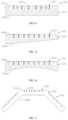
- FIG. 17illustrates a heating assembly 12 n in some embodiments of the present disclosure.
- a porous body 121 n of the heating assembly 12 nincludes three atomizing surfaces 1211 n and three liquid adsorbing surfaces 1212 n .
- Each atomizing surface 1211 ncorresponds to a sheet heating portion of one heating element 122 n
- a width of the sheet heating portion of each heating element 122 nis equal to a depth of a corresponding receiving groove 1210 n .
- each liquid adsorbing surface 1212 nis parallel to the corresponding atomizing surface 1211 n . It can be understood that the number of the atomizing surfaces 1211 n can also be two or more than three.
- FIG. 18illustrates a sheet heating portion of a heating element 122 p in some embodiments of the present disclosure.
- the heating element 122 of the heating assembly 12it is different mainly in that the heating element 122 p includes an elongated sheet heating portion in the middle and two electrical connecting portions 1223 p , 1224 p connected to both ends of the heating portion, respectively.
- the elongated sheet heating portion as shown in the figureis in the shape of a strip.
- the heating portionis integrally formed with the two electrical connecting portions 1223 p , 1224 p , and lower portions of the two electrical connecting portions 1223 p , 1224 p protrude from a lower edge of the heating portion, respectively, such that when the sheet heating portion of the heating element 122 p is inserted into a porous body, the two electrical connecting portions 1223 p , 1224 p can be inserted more deeply to be engaged with the porous body more firmly to avoid the loosening caused by pulling of lead wires.
- Upper portions of the two electrical connecting portions 1223 p , 1224 pprotrude from an upper edge of the heating portion, respectively, to act as electrical lead wires.
- FIG. 19illustrates a sheet heating portion of a heating element 122 q in some embodiments of the present disclosure.
- the sheet heating portion of the heating element 122 qis provided in an S-shaped long strip shape, which includes a plurality of flat portions 1221 q parallel to each other and a plurality of bending portions 1222 q connecting the flat portions 1221 q in series.
- the sheet heating portion of the heating element 122 of the heating assembly 12is different mainly in that a thickness of the bending portion 1222 q of the sheet heating portion of the heating element 122 q is greater than a thickness of the flat portion 1221 q thereof, so that a resistance of the bending portion 1222 q is reduced, and thus the heat accumulation generated at the bending portion 1222 q can be reduced.
- the bending portion 1222 qcan also be widened to reduce the resistance at the corners.
- the solutionis not limited to the sheet heating portion, a heating wire and a coated sheet heating element can also be applied. Specifically, when the heating wire has a flat portion and a bending portion, the bending portion can be designed to be larger directly, while for the coated heating element, the coat on the bending portion can be made thicker or wider.
- FIG. 20illustrates a sheet heating portion of a heating element 122 r in some embodiments of the present disclosure.
- the sheet heating portion of the heating element 122 ris provided with a plurality of through holes 1220 r extending through the thickness direction thereof.
- a density of the through holes 1220 r in the middleis greater than that of the through holes at both ends.
- a resistance of the sheet heating portion of the heating element 122 r in the middleis greater than that of the sheet heating portion at both ends to meet requirements of specific heating assemblies and allow the distribution of the heat in the porous body to meet specific requirements.
- FIG. 21illustrates a sheet heating portion of a heating element 122 s in some embodiments of the present disclosure.
- the sheet heating portion of the heating element 122 sis provided with a plurality of through holes 1220 s extending through the thickness direction thereof.
- a density of the through holes 1220 r in the middleis lower than that of the through holes at both ends.
- a resistance of the sheet heating portion of the heating element 122 r in the middleis lower than that of the sheet heating portion at both ends to meet requirements of specific heating assemblies.
- FIG. 22illustrates a sheet heating portion of a heating element 122 t in some embodiments of the present disclosure.
- the sheet heating portion of the heating element 122 tis provided with a plurality of through holes 1220 t extending through the thickness direction thereof.
- a distribution density of the through holes 1220 tgradually changes (for example, gradually increases or decreases) or changes stepwise.
- a resistance of the sheet heating portion of the heating element 122 tgradually changes or changes stepwise in the width direction to meet the requirements of different heating assemblies.
- FIG. 23illustrates a sheet heating portion of a heating element 122 u in some embodiments of the present disclosure.
- the sheet heating portion of the heating element 122 uis a heating net which includes a plurality of meshes 1220 u
- the distribution of the meshes 1220 u in a length direction of the sheet heating portion of the heating element 122 uincludes one of the following types: (1) the meshes are uniformly distributed, such that the resistance is uniformly distributed in the length direction; (2) the density of the meshes in the middle is lower than that of the meshes at both ends, and the density changes gradually or stepwise; (3) the density of the meshes in the middle is greater than that of the meshes at both ends, and the density changes gradually or stepwise.
- the distribution of the meshes 1220 u in a width direction of the sheet heating portion of the heating element 122 uincludes one of the following types: (1) the meshes are uniformly distributed; (2) the density of the meshes on one side is greater than that of the meshes on another side, and the density changes gradually or stepwise.
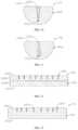
- FIG. 24 and FIG. 25illustrate a heating assembly 12 v in some embodiments of the present disclosure.
- the heating assembly 12 vincludes a porous body 121 v and a sheet heating portion of a heating element 122 v provided in the porous body 121 v .
- a surface of a liquid adsorbing surface of the porous body 121 v of the heating element 12 vis recessed downwardly to form a groove 120 v such that the whole porous body 121 v is in the shape of a bowl, and an inner surface of a bottom wall of the porous body 121 v forms a liquid adsorbing surface 1212 v , while an outer surface of the bottom wall thereof forms an atomizing surface 1211 v .
- the sheet heating portion of the heating element 122 vis embedded in the atomizing surface 1211 v .
- the porous body 121 vis provided in the shape of a bowl, the whole porous body 121 v is high enough to facilitate the mounting of the heating assembly 12 v and the arrangement of a sealing sleeve 115 . Besides, it is ensured that the distance from the liquid adsorbing surface 1212 v to the atomizing surface 1211 v is close enough to ensure the atomization effect while facilitating the mounting.
- the heating element 122 vcan be any one of the heating elements mentioned above.
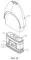
- FIG. 26 and FIG. 27illustrate an electronic cigarette in some embodiments of the present disclosure.
- the heating assembly 12 v shown in FIG. 24 and FIG. 25is adopted in the electronic cigarette. It can be understood that any one of the heating assemblies mentioned above can also be adaptable to the electronic cigarette.
- the electronic cigarettecan be in a flat shape, which can include an atomizer 1 and a battery assembly 2 detachably connected to the atomizer 1 .
- the atomizer 1is configured for accommodating e-liquid and generating smoke.
- the battery assembly 2is configured for supplying power for the atomizer 1 .
- a lower end of the atomizer 1is inserted into an upper end of the battery assembly 2 , the atomizer 1 and the battery assembly 2 can be coupled together through magnetic attraction.
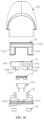
- the atomizer 1can include an atomizing assembly 10 and a liquid storage device 20 sleeved on the atomizing assembly 10 .
- the atomizing assembly 10can be used to heat and atomize the e-liquid, while the liquid storage device 20 can be used to store the e-liquid to be supplied to the atomizing assembly 10 .
- the atomizing assembly 10includes a lower holder 11 , the heating assembly 12 v disposed on the lower holder 11 , a sealing sleeve 13 sleeved on the heating assembly 12 v , an upper holder 14 disposed on the lower holder 11 and abutted against the sealing sleeve 13 , and a sleeve 15 sleeved on the upper holder 14 .
- the heating assembly 12 vis tightly clamped between the lower holder 11 and the upper holder 14 .
- the presence of the sealing sleeve 13can achieve the sealing between the heating assembly 12 v and the upper holder 14 to prevent leakage of e-liquid and can also make the positioning of the heating assembly 12 v in the horizontal direction more tightly.
- the lower holder 11may include a base 111 , a first supporting arm 112 standing on a top surface of the base 111 , and a second supporting arm 113 standing on the top surface of the base 111 and disposed opposite to the first supporting arm 112 .
- the heating assembly 12 vis supported between the first supporting arm 112 and the second supporting arm 113 , with the atomizing surface 1211 v thereof facing the base 111 directly and spaced from the base 111 at an interval. The interval forms an atomizing cavity 110 to achieve the mixing of the smoke and the air.
- the base 111can be in a shape of a rectangle plate.
- a bottom surface of the base 111is recessed inwardly to form two receiving grooves 1110 for receiving two magnetic elements 16 therein, respectively.
- the magnetic elements 16are used for magnetically attracting the atomizer 1 and the battery assembly 2 together.
- the base 111is also provided with engaging hooks 1112 respectively on two opposite end surfaces thereof configured for engaging with the liquid storage device 20 .
- the base 111can also be provided with two electrode columns 1114 electrically connected to the heating assembly 12 v on the bottom thereof, which are used to be electrically connected to positive and negative electrodes of the battery assembly 2 , respectively.
- the first supporting arm 112 and the second supporting arm 113can be in a shape of a plate. Inner side surfaces of the first supporting arm 112 and the second supporting arm 113 are respectively recessed to form accommodating grooves 1122 , 1132 for an embedded portion 142 of the upper holder 14 to be embedded therein.
- the accommodating grooves 1122 , 1132are formed in upper half portions of the first supporting arm 112 and the second supporting arm 113 , respectively; and steps 1126 , 1136 are formed on the first supporting arm 112 and the second supporting arm 113 , respectively. Both ends of the heating assembly 12 v are supported on the steps 1126 , 1136 , respectively.
- first supporting arm 112 and the second supporting arm 113are further provided with engaging portions 1124 , 1134 for engaging with the upper holder 14 , respectively.
- first supporting arm 112 and the second supporting arm 113are left-right symmetrically arranged to facilitate the assembly, that is, there is no need for an operator to distinguish beforehand which is the left end and which is the right end during the assembly.
- the lower holder 11can also include a U-shaped air inlet groove structure 114 and a U-shaped air outlet groove structure 115 .
- the air inlet groove structure 114 and the air outlet groove structure 115are connected to outer sides of the first supporting arm 112 and the second supporting arm 113 , respectively, and extend outwards horizontally.
- a through hole 1120 providing communication between the air inlet groove structure 114 and the atomizing cavity 110is formed on the first supporting arm 112
- a through hole 1130providing communication between the air outlet groove structure 115 and the atomizing cavity 110 is formed on the second supporting arm 113 , so as to introduce air to carry away the smoke in the atomizing cavity 110 .
- the through holes 1120 , 1130are located under the accommodating grooves 1122 , 1132 , respectively.
- the upper holder 14can include a main body portion 141 having a substantially rectangular parallelepiped shape, the embedded portion 142 extending downwards from the middle of a bottom surface of the main body portion 141 , and a second air inlet channel 143 extending downwards from the right end of the bottom surface of the main body portion 141 .
- the embedded portion 142is annular, and is accommodated in the accommodating grooves 1122 , 1132 between the first supporting arm 112 and the second supporting arm 113 of the lower holder 111 , and is sleeved on the periphery of the sealing sleeve 13 .
- the upper holder 14further includes two liquid channels 144 extending from the top surface to the bottom surface of the main body portion 141 , a slot channel 145 formed on a side wall and surrounding the liquid channel 144 on the right side and in communication with the second air inlet channel 143 , and a second air outlet channel 146 in communication with the slot channel 145 .
- the second air outlet channel 146extends through to be in communication with the slot channel 145 from the middle of the top surface of the upper holder 14 .
- the left end of the top surface of the upper holder 14is also recessed downwardly to form two positioning holes 147 to cooperate with the sleeve 15 , thereby playing the functions of positioning and fool proofing.
- the upper holder 14also includes an engaging hook 148 extending downwardly to be hooked onto the lower holder 11 .
- the sleeve 15can be a silicone sleeve, which can include a top wall 151 , an annular first blocking wall 152 extending downwards from a periphery of the top wall 151 , and two U-shaped second blocking walls 153 , 154 extending downwards respectively from two ends of the first blocking wall 152 .
- Two liquid inlet holes 155 and a sleeve air outlet channel 156are formed on the top wall 151 .
- the two liquid inlet holes 155correspond to the two liquid channels 144 of the upper holder 14 , respectively.
- the sleeve air outlet channel 156is inserted into the second air outlet channel 146 of the upper holder 14 and is in communication with the second air outlet channel 146 .
- the first blocking wall 152is used to enclose the side wall of the main body portion 141 of the upper holder 112 and cover the slot channel 145 on the side wall to form an air-tight annular connecting channel for the upper holder.
- the second blocking walls 153 , 154cover the air inlet groove structure 1114 and the air outlet groove structure 1115 of the lower holder 111 , respectively, and form an air-tight first air inlet channel and an air-tight first air outlet channel respectively together with the first supporting arm 1112 and the second supporting arm 115 .
- a first air inlet hole 157is formed on the second blocking wall 153 located on the left side, the first air inlet hole 157 is configured to be in communication with the external environment to introduce air into the first air inlet channel.
- the first air outlet channelis in communication with the second air inlet channel 143 .
- Two positioning columns 158extend downwards from the left end of the bottom surface of the top wall 151 of the sleeve 15 to respectively cooperate with the two positioning holes 147 of the upper holder 14 , mainly to allow the first air inlet hole 157 located on the left side of the sleeve 15 to be precisely located on the left side of the assembly of the upper holder 112 and the lower holder 111 , so as to ensure that the first air inlet hole 157 is in communication with the first air inlet channel, thereby playing the function of fool proofing.
- the liquid storage device 20includes a housing 21 provided with an air outlet 210 , and an airflow tube 22 disposed in the housing 21 and in communication with the air outlet 210 .
- the housing 21includes a liquid storage portion 211 and a sleeve portion 212 connected to the liquid storage portion 211 .
- a liquid storage cavity 23is formed between the liquid storage portion 211 and the airflow tube 22 .
- the liquid storage cavity 23includes a liquid outlet 230 , and the sleeve portion 212 is connected to a periphery of the liquid outlet 230 to be tightly sleeved on the atomizing assembly 10 .
- a step 213is formed between an inner wall surface of the sleeve portion 212 and an inner wall surface of the liquid storage portion 211 .
- the step 213abuts against the top surface of the atomizing assembly 10 .
- the sleeve portion 212is integrally formed with the liquid storage portion 211 .
- the air outlet 210can be provided to be a suction nozzle in the shape of a flat trumpet.
- the airflow tube 22extends from the air outlet 210 towards the liquid outlet 230 , with a distal end thereof extending into the sleeve portion 212 and inserted into the air outlet channel 156 of the sleeve 15 , so as to be in communication with the second air outlet channel 146 .
- the sleeve portion 212is further provided with second air inlet holes 2120 on the left and right sides thereof, wherein the second air inlet hole 2120 on the left side is in communication with the first air inlet hole 157 of the sleeve 15 , so that the air outside the housing 21 can enter the first air inlet channel which is formed by the sleeve 15 and the lower holder 11 .
- the housing 21is symmetrically arranged as a whole to facilitate the assembling, because if there is only one side provided with the second air inlet hole 2120 , workers have to perform an additional step of judging whether the second air inlet holes 2120 are located on the same side as the first air inlet hole 157 during assembling.
- Engaging slots 2122are formed in inner walls of the left and right sides of the sleeve portion 212 to cooperate with the engaging hooks 1112 of the lower holder 11 , respectively, so that the housing 21 and the lower holder 111 can be easily engaged together.
- the flow path of the air in the atomizer 1is shown by the arrow in FIG. 32 : the air first flows into the first air inlet channel through the second air inlet hole 2120 and the first air inlet hole 157 , and then flows into the atomizing cavity 110 through the through hole 1120 to be mixed with the smoke.
- the mixture of smoke and airflows into the first air outlet channel through the through hole 1130 and then flows into the second air inlet channel 143 .
- the mixture of smoke and airthen flows into the annular connecting channel for the upper holder and flows into the second air outlet channel 1466 .
- the mixture of smoke and airfinally flows into the airflow tube 22 , and is finally exhausted out of the atomizer 1 through the air outlet 210 .
- the e-liquid in the liquid storage cavity 23flows sequentially through the liquid inlet hole 155 of the sleeve 15 and the liquid channel 144 of the upper holder 14 , and then flows into the groove 120 of the heating assembly 12 v to be in contact with the liquid adsorbing surface 1212 v , thereby achieving the delivery of the e-liquid.
- the location of the second air inlet hole 2120is higher than that of the atomizing cavity 110 , which can better prevent the leakage of the e-liquid from the second air inlet hole 2120 in a normal use state.
- the bottom of the whole airflow tube of the atomizer 1is substantially U-shaped.
- the direction of the airflow at the atomizing cavity 110is parallel to the atomizing surface 1211 v of the heating assembly 12 v , so that the smoke atomized at the atomizing surface 1211 v can be carried away more easily.
- the porous body 121 v of the heating assembly 12 vhas a groove on the top surface thereof. After the e-liquid enters the groove, the efficiency of liquid guiding can be increased. Specifically, on the one hand, the arrangement of the groove increases the contact area between the porous body and the e-liquid; on the other hand, the distance between the bottom surface of the groove and the outer surface of the bottom of the porous body 121 v is very small, which can reduce the flow resistance of the e-liquid reaching the outer surface of the bottom of the porous body 121 v .
- the porous body 121 vneeds to have a certain height to meet the requirements of the arrangement of the sealing element and the rigidity requirement of the porous body 121 v itself.
- the heating assembly 12 v of the electronic cigarette mentioned abovecan also use other suitable heating assemblies.
- the heating portion of the heating element 122 vis not limited to be in the shape of an elongated sheet, it can also be in other shapes such as a filament and so on.
- FIG. 33illustrates a heating assembly 12 w in some embodiments of the present disclosure.
- a porous body 121 w of the heating assembly 12 wincludes a wave-shaped atomizing surface 1211 w
- flat portions 1221 w of a sheet heating portion of a heating element 122 ware respectively disposed corresponding to troughs of the wave-shaped atomizing surface 1211 w and are perpendicular to a plane where the wave-shaped atomizing surface 1211 w is located, thereby reducing the dry burning effect through the e-liquid accumulated at the troughs.
- FIG. 34illustrates a heating assembly 12 x in some embodiments of the present disclosure.
- a width of a sheet heating portion of a heating element 122 x of the heating assembly 12 xis smaller than a depth of a receiving groove 1210 x . Therefore, when the sheet heating portion of the heating element 122 x is received in the receiving groove 1210 x in a width direction, a top surface thereof is lower than an atomizing surface 1211 x .
- the heating assembly 12 a mentioned aboveit is different mainly in that an angle is formed between the width direction of the sheet heating portion of the heating element 122 x of the heating assembly 12 x and a normal direction of the atomizing surface 1211 x . Preferably, the angle is smaller than 20 degrees.
- FIG. 35illustrates a heating element 122 y in some embodiments of the present disclosure.
- the heating element 122 yincludes a strip-shaped heating portion in the middle and two electrical connecting portions 1223 y , 1224 y respectively integrally connected to two ends of the heating portion.
- the sheet heating portion of the heating element 122 yis provided with a plurality of through holes or blind holes 1220 y at positions adjacent to an atomizing surface of a porous body to improve the resistance of the area.
- FIG. 36illustrates a heating element 122 z in some embodiments of the present disclosure.
- the heating element 122 zincludes an elongated sheet heating portion in the middle and two electrical connecting portions 1223 z , 1224 z respectively integrally connected to two ends of the heating portion.
- the heating portion of the heating element 122 zis provided with a plurality of through holes or blind holes 1220 z at positions away from an atomizing surface of a porous body to improve the resistance of the area.
- heating element in any embodiment above mentionedcan cooperate with the porous body in any embodiment, and any heating assembly above mentioned can be applied to the electronic cigarette.
Landscapes
- Disinfection, Sterilisation Or Deodorisation Of Air (AREA)
- Resistance Heating (AREA)
Abstract
Description
- (1) the sealing
sleeve 13 is first sleeved on theheating assembly 12v; - (2) the assembly of the sealing
sleeve 13 and theheating assembly 12vis inserted into the embeddedportion 142 of theupper holder 14; - (3) the
upper holder 14 is then covered on thelower holder 11 to allow theengaging hook 148 of the heating assembly of theupper holder 14 to be engaged with the engagingportions 1124,1134 of thelower holder 11, such that theupper holder 14 is engaged to thelower holder 11; and the electrode lead wires of theheating assembly 12vis electrically connected to theelectrode columns 1114 on thelower holder 11; - (4) the
sleeve 15 is then sleeved on theupper holder 14 to finish the assembling of the atomizingassembly 10; and - (5) the
atomizing assembly 10 is inserted from below into the sleeving portion212 of theliquid storage device 20 filled with the e-liquid, so that the top surface thereof abuts against thestep 213 to block theliquid outlet 230 of the liquid storage cavity23, and the engaginghooks 1112 of thelower holder 11 are engaged into the engagingslots 2122 of the sleeve portion212 to achieve the assembling of the atomizer1, which is convenient and quick.
- (1) the sealing
Claims (16)
Applications Claiming Priority (1)
| Application Number | Priority Date | Filing Date | Title |
|---|---|---|---|
| PCT/CN2018/076691WO2019157647A1 (en) | 2018-02-13 | 2018-02-13 | Electronic cigarette and heating assembly and heating member thereof |
Publications (2)
| Publication Number | Publication Date |
|---|---|
| US20200367564A1 US20200367564A1 (en) | 2020-11-26 |
| US12178248B2true US12178248B2 (en) | 2024-12-31 |
Family
ID=67619703
Family Applications (1)
| Application Number | Title | Priority Date | Filing Date |
|---|---|---|---|
| US16/969,828Active2040-11-03US12178248B2 (en) | 2018-02-13 | 2018-02-13 | Electronic cigarette and heating assembly and heating member thereof |
Country Status (3)
| Country | Link |
|---|---|
| US (1) | US12178248B2 (en) |
| EP (1) | EP3753426B1 (en) |
| WO (1) | WO2019157647A1 (en) |
Families Citing this family (18)
| Publication number | Priority date | Publication date | Assignee | Title |
|---|---|---|---|---|
| EP3753425B1 (en)* | 2018-02-13 | 2024-12-18 | Shenzhen Smoore Technology Limited | Heating assembly for an electronic cigarette |
| US12121061B2 (en)* | 2018-02-13 | 2024-10-22 | Shenzhen Smoore Technology Limited | Electronic cigarette and heating assembly thereof |
| CN108185536B (en) | 2018-02-13 | 2020-01-21 | 深圳麦克韦尔科技有限公司 | Electronic cigarette and atomizer thereof |
| WO2019157651A1 (en) | 2018-02-13 | 2019-08-22 | 深圳麦克韦尔股份有限公司 | Electronic cigarette and heating assembly and heating member thereof |
| WO2019157647A1 (en) | 2018-02-13 | 2019-08-22 | 深圳麦克韦尔股份有限公司 | Electronic cigarette and heating assembly and heating member thereof |
| US20200323269A1 (en)* | 2018-08-17 | 2020-10-15 | Shenzhen Relx Technology Co., Ltd. | Vaporization device and method thereof |
| CN209284320U (en)* | 2018-10-08 | 2019-08-23 | 深圳麦克韦尔股份有限公司 | Electronic cigarette and its atomizer and heat generating component |
| CN209376696U (en)* | 2018-11-29 | 2019-09-13 | 深圳市合元科技有限公司 | Electronic cigarette vaporizer and electronic cigarette containing the same |
| CN109622259A (en)* | 2019-01-25 | 2019-04-16 | 深圳市华诚达精密工业有限公司 | A kind of three-dimensional heated porous drain material atomizing device |
| CN110250578A (en)* | 2019-06-24 | 2019-09-20 | 深圳市合元科技有限公司 | Atomizing component and electronic cigarette |
| CN111035070A (en)* | 2020-01-08 | 2020-04-21 | 深圳麦时科技有限公司 | Aerosol generating device and heating assembly thereof |
| KR102399212B1 (en)* | 2020-01-31 | 2022-05-17 | 주식회사 케이티앤지 | Vaporizer and aerosol-generating apparatus including the same |
| US11659864B2 (en)* | 2020-07-28 | 2023-05-30 | Ruyun Guo | Electronic cigarette burner element |
| WO2022136004A1 (en)* | 2020-12-22 | 2022-06-30 | Philip Morris Products S.A. | Heater assembly |
| WO2022136006A1 (en)* | 2020-12-22 | 2022-06-30 | Philip Morris Products S.A. | Heater assembly |
| CN216088899U (en)* | 2021-08-19 | 2022-03-22 | 比亚迪精密制造有限公司 | Atomizing core subassembly, electron smog spinning disk atomiser and electron cigarette |
| US11533950B1 (en) | 2022-02-09 | 2022-12-27 | Clear IP Corporation | Atomizer cartridge with integrally formed internal fluid reservoir and mouthpiece portion |
| GB202217024D0 (en)* | 2022-11-15 | 2022-12-28 | Nicoventures Trading Ltd | Heater assembly and method |
Citations (86)
| Publication number | Priority date | Publication date | Assignee | Title |
|---|---|---|---|---|
| JP2007117970A (en) | 2005-10-31 | 2007-05-17 | Matsushita Electric Works Ltd | Electrostatic atomizing device |
| EP2574247A1 (en) | 2011-09-28 | 2013-04-03 | Philip Morris Products S.A. | Permeable electric heat resistant foil for evaporating liquids out of disposable mouthpieces with evaporator nozzles |
| GB2504074A (en) | 2012-07-16 | 2014-01-22 | Nicoventures Holdings Ltd | Electronic cigarette |
| WO2014019024A1 (en) | 2012-08-02 | 2014-02-06 | Deakin University | Cd133 aptamers for detection of cancer stem cells |
| WO2014079024A1 (en) | 2012-11-22 | 2014-05-30 | Liu Qiuming | Electronic cigarette and electronic cigarette device |
| CN103960782A (en) | 2013-09-29 | 2014-08-06 | 深圳市麦克韦尔科技有限公司 | Electronic cigarette |
| WO2014151040A2 (en) | 2013-03-15 | 2014-09-25 | R. J. Reynolds Tobacco Company | Cartridge and control body of an aerosol delivery device including anti-rotation mechanism and related method |
| CN203851804U (en) | 2014-03-19 | 2014-10-01 | 深圳市合元科技有限公司 | Atomization device of electronic cigarette and electronic cigarette |
| CN204070542U (en) | 2014-07-11 | 2015-01-07 | 深圳市合元科技有限公司 | Atomising device and electronic cigarette |
| CN104522891A (en) | 2014-12-19 | 2015-04-22 | 深圳市麦克韦尔科技有限公司 | Electronic cigarette and atomization device thereof |
| US20150189919A1 (en) | 2013-04-10 | 2015-07-09 | Kimree Hi-Tech Inc. | Electronic cigarette with a built-in battery rod |
| CN104824853A (en) | 2015-04-22 | 2015-08-12 | 卓尔悦(常州)电子科技有限公司 | Atomizer and its aerosol generating device |
| CN204796739U (en) | 2015-04-22 | 2015-11-25 | 卓尔悦(常州)电子科技有限公司 | Atomizer and aerosol generating device thereof |
| EP2946678A1 (en) | 2014-05-23 | 2015-11-25 | Shenzhen First Union Technology Co., Ltd. | Atomizer and electronic cigarette having same |
| CN204949517U (en) | 2015-07-17 | 2016-01-13 | 深圳市艾维普思科技股份有限公司 | Structure of generating heat, atomizer and electron cigarette of atomizer |
| CN105310114A (en) | 2015-10-21 | 2016-02-10 | 深圳麦克韦尔股份有限公司 | Electronic cigarette and manufacturing method of atomizing component thereof |
| CN105394816A (en) | 2015-10-22 | 2016-03-16 | 深圳麦克韦尔股份有限公司 | Electronic cigarette and atomization assembly and atomization element thereof |
| US20160073692A1 (en) | 2014-09-17 | 2016-03-17 | Fontem Holdings 2 B.V. | Device for storing and vaporizing liquid media |
| US9289014B2 (en) | 2012-02-22 | 2016-03-22 | Altria Client Services Llc | Electronic smoking article and improved heater element |
| CN205106385U (en) | 2015-11-03 | 2016-03-30 | 张明军 | Ceramic heater body of oily function is led to electron smog spinning disk atomiser with area |
| CN105433446A (en) | 2015-12-31 | 2016-03-30 | 陈家太 | Ceramic evaporation body, atomization core, atomizer and electronic cigarette |
| US20160106153A1 (en) | 2014-10-21 | 2016-04-21 | Xiaochun Zhu | Heating assemblies for e-cigarette vaporizers |
| EP3020292A1 (en) | 2014-11-14 | 2016-05-18 | Shenzhen First Union Technology Co., Ltd. | Atomizing device and electronic cigarette having same |
| US20160143358A1 (en) | 2014-11-25 | 2016-05-26 | Xiaochun Zhu | Heating assembly for electronic cigarette vaporizer |
| US20160192707A1 (en) | 2015-01-05 | 2016-07-07 | Shenzhen First Union Technology Co., Ltd. | Replaceable atomizing unit, atomizer and electronic cigarette having same |
| WO2016107767A1 (en) | 2014-12-29 | 2016-07-07 | British American Tobacco (Investments) Limited | Heating device for apparatus for heating smokable material and method of manufacture |
| CN105768229A (en) | 2016-04-13 | 2016-07-20 | 湖南中烟工业有限责任公司 | Atomizer and electronic cigarette |
| WO2016119170A1 (en) | 2015-01-29 | 2016-08-04 | 惠州市吉瑞科技有限公司 | Atomization assembly and electronic cigarette |
| CN205512338U (en) | 2015-12-25 | 2016-08-31 | 深圳瀚星翔科技有限公司 | Atomizing core and electron smog spinning disk atomiser |
| WO2016154792A1 (en) | 2015-03-27 | 2016-10-06 | 惠州市吉瑞科技有限公司 | Electronic cigarette |
| CN205624481U (en) | 2016-04-27 | 2016-10-12 | 深圳市合元科技有限公司 | Pottery heat -generating body and electron smog spinning disk atomiser with temperature control function |
| WO2016161554A1 (en) | 2015-04-07 | 2016-10-13 | 深圳麦克韦尔股份有限公司 | Electronic cigarette and atomizing apparatus thereof |
| US20160309785A1 (en) | 2015-04-23 | 2016-10-27 | Arie Holtz | Unitary heating element and heater assemblies, cartridges, and e-vapor devices including a unitary heating element |
| CN205695698U (en) | 2016-03-15 | 2016-11-23 | 惠州市吉瑞科技有限公司深圳分公司 | Electronic smoke atomizer and heater shaped device thereof |
| CN106136327A (en) | 2016-07-29 | 2016-11-23 | 深圳麦克韦尔股份有限公司 | Electronic cigarette and its atomizer |
| EP3099190A1 (en) | 2014-01-29 | 2016-12-07 | Batmark Limited | Aerosol-forming member |
| US20160353802A1 (en) | 2014-02-10 | 2016-12-08 | Philip Morris Products S.A. | Cartridge for an aerosol-generating system |
| WO2016198417A1 (en) | 2015-06-12 | 2016-12-15 | Philip Morris Products S.A. | Cartridge for aerosol-generating system |
| CN205813574U (en) | 2016-05-24 | 2016-12-21 | 深圳麦克韦尔股份有限公司 | Electronic cigarette and nebulizer thereof |
| WO2017005471A1 (en) | 2015-07-09 | 2017-01-12 | Philip Morris Products S.A. | Heater assembly for an aerosol-generating system |
| WO2017016715A1 (en) | 2015-07-27 | 2017-02-02 | Intel IP Corporation | Power optimization for channel state reports in a wireless communication network |
| US9603389B2 (en) | 2013-09-29 | 2017-03-28 | Shenzhen Smoore Technology Limited | Electronic cigarette |
| CN206062123U (en) | 2016-10-10 | 2017-04-05 | 韩力 | Gas heating type smoking article |
| CN206062138U (en) | 2016-09-14 | 2017-04-05 | 昂纳自动化技术(深圳)有限公司 | Atomization core assembly and electronic cigarette atomization device |
| CN206079042U (en) | 2016-09-29 | 2017-04-12 | 深圳市合元科技有限公司 | Conducting structure and applied this conducting structure's split type electron cigarette |
| US20170105455A1 (en) | 2015-04-22 | 2017-04-20 | Joyetech Europe Holding Gmbh | Atomizer and aerosol generating device thereof |
| EP3162778A1 (en) | 2014-06-16 | 2017-05-03 | Shenzhen Smoore Technology Limited | Method for preparing porous ceramics, porous ceramics, and electronic cigarette |
| CN106723372A (en) | 2016-12-21 | 2017-05-31 | 欧俊彪 | A kind of electronic smoke atomizer fever tablet |
| US20170150755A1 (en) | 2014-07-11 | 2017-06-01 | Philip Morris Products S.A. | Aerosol-generating system comprising cartridge detection |
| CN106820269A (en) | 2017-01-12 | 2017-06-13 | 深圳市康泓威科技有限公司 | Electronic smoke atomizer |
| CN106820272A (en) | 2017-03-07 | 2017-06-13 | 昂纳自动化技术(深圳)有限公司 | Electronic cigarette leakage-proof liquid device |
| CN206260849U (en) | 2016-12-14 | 2017-06-20 | 常州市派腾电子技术服务有限公司 | Cigarette bullet and the electronic cigarette with the cigarette bullet |
| EP3188570A2 (en) | 2016-04-22 | 2017-07-05 | Shenzhen First Union Technology Co., Ltd. | Atomizer of electronic cigarette, ceramic heating atomizing core and ceramic heater therein |
| EP3200559A2 (en) | 2016-04-21 | 2017-08-02 | Shenzhen First Union Technology Co., Ltd. | Heating device, atomizing unit, atomizer and electronic cigarette having same |
| CN206390306U (en) | 2017-01-16 | 2017-08-11 | 常州市派腾电子技术服务有限公司 | Atomizer and its electronic cigarette |
| CN206507320U (en) | 2016-11-22 | 2017-09-22 | 卓尔悦欧洲控股有限公司 | A kind of atomizer and its electronic cigarette |
| CN206518143U (en) | 2017-01-05 | 2017-09-26 | 深圳市优维尔科技有限公司 | A kind of atomization core of flat heating wire |
| WO2017163052A1 (en) | 2016-03-24 | 2017-09-28 | Nicoventures Holdings Limited | Vapour provision system |
| WO2017163050A1 (en) | 2016-03-24 | 2017-09-28 | Nicoventures Holdings Limited | Vapour provision device |
| WO2017163051A1 (en) | 2016-03-24 | 2017-09-28 | Nicoventures Holdings Limited | Vapour provision device |
| CN206525553U (en) | 2017-01-06 | 2017-09-29 | 深圳麦克韦尔股份有限公司 | Electronic cigarette and its atomizer |
| CA3022340A1 (en) | 2016-04-27 | 2017-11-02 | Nicoventures Holdings Limited | Electronic aerosol provision system and vaporizer therefor |
| US20170340012A1 (en)* | 2016-05-31 | 2017-11-30 | Oleg Mironov | Fluid permeable heater assembly for aerosol-generating systems and flat electrically conductive filament arrangement for fluid permeable heater assemblies |
| US20170340015A1 (en) | 2016-05-31 | 2017-11-30 | Michel THORENS | Heat diffuser for an aerosol-generating system |
| CN206729211U (en) | 2017-04-19 | 2017-12-12 | 昂纳自动化技术(深圳)有限公司 | Electronic cigarette and its atomising device |
| CN206729208U (en) | 2017-03-27 | 2017-12-12 | 深圳市博迪科技开发有限公司 | A kind of piston pushes away oily formula electronic cigarette |
| CN206808661U (en) | 2016-06-22 | 2017-12-29 | 深圳市合元科技有限公司 | Oil storage cup and atomizer for atomizer |
| WO2018007965A1 (en) | 2016-07-06 | 2018-01-11 | Rai Strategic Holdings, Inc. | Aerosol delivery device with a reservoir housing and a vaporizer assembly |
| WO2018019485A1 (en) | 2016-07-25 | 2018-02-01 | Philip Morris Products S.A. | Cartridge for an aerosol-generating system with heater protection |
| US20180035720A1 (en) | 2016-08-02 | 2018-02-08 | Joyetech Europe Holding Gmbh | Atomizing head, atomizing device and electronic cigarette |
| US20180184714A1 (en)* | 2015-10-21 | 2018-07-05 | Shenzhen Smoore Technology Limited | Electronic Cigarette and Method for Manufacturing Atomizing Assembly Thereof |
| CN207898958U (en) | 2017-10-27 | 2018-09-25 | 歌尔科技有限公司 | Intelligent experience apparatus |
| WO2018172765A1 (en) | 2017-03-24 | 2018-09-27 | Nicoventures Holdings Limited | Aerosol source for a vapour provision system |
| CN207978958U (en) | 2018-02-13 | 2018-10-19 | 深圳麦克韦尔股份有限公司 | Electronic cigarette and its heat generating component |
| CN207978959U (en) | 2018-02-13 | 2018-10-19 | 深圳麦克韦尔股份有限公司 | Electronic cigarette and its heat generating component and heater |
| CN207987958U (en) | 2018-02-13 | 2018-10-19 | 四平电力设计有限公司 | A kind of pedestal of the tablet formula power equipment assembly foundation structure |
| CN207978957U (en) | 2018-02-13 | 2018-10-19 | 深圳麦克韦尔股份有限公司 | Electronic cigarette and its heat generating component |
| CN208048028U (en) | 2018-02-13 | 2018-11-06 | 深圳麦克韦尔股份有限公司 | Electronic cigarette and its heat generating component and heater |
| CN208113970U (en) | 2018-02-13 | 2018-11-20 | 深圳麦克韦尔股份有限公司 | Electronic cigarette and its atomizer |
| US20190350263A1 (en) | 2016-11-22 | 2019-11-21 | Joyetech Europe Holding Gmbh | E-liquid storage assembly, atomizer and electronic cigarette having same |
| US10687557B2 (en) | 2017-12-29 | 2020-06-23 | Altria Client Services Llc | Electronic vaping device with outlet-end illumination |
| US20200367564A1 (en) | 2018-02-13 | 2020-11-26 | Shenzhen Smoore Technology Limited | Electronic cigarette and heating assembly and heating member thereof |
| US20200397043A1 (en) | 2018-02-13 | 2020-12-24 | Shenzhen Smoore Technology Limited | Electronic cigarette and heating assembly thereof |
| US20210000179A1 (en) | 2018-02-13 | 2021-01-07 | Shenzhen Smoore Technology Limited | Electronic cigarette and heating assembly and heating member thereof |
| US20210000181A1 (en) | 2018-02-13 | 2021-01-07 | Shenzhen Smoore Technology Limited | Electronic cigarette and heating assembly thereof |
| US10973262B2 (en) | 2018-02-13 | 2021-04-13 | Shenzhen Smoore Technology Limited | Electronic cigaratte with porous body and atomizer thereof |
- 2018
- 2018-02-13WOPCT/CN2018/076691patent/WO2019157647A1/ennot_activeCeased
- 2018-02-13EPEP18906272.2Apatent/EP3753426B1/enactiveActive
- 2018-02-13USUS16/969,828patent/US12178248B2/enactiveActive
Patent Citations (101)
| Publication number | Priority date | Publication date | Assignee | Title |
|---|---|---|---|---|
| JP2007117970A (en) | 2005-10-31 | 2007-05-17 | Matsushita Electric Works Ltd | Electrostatic atomizing device |
| EP2574247A1 (en) | 2011-09-28 | 2013-04-03 | Philip Morris Products S.A. | Permeable electric heat resistant foil for evaporating liquids out of disposable mouthpieces with evaporator nozzles |
| US9877516B2 (en) | 2012-02-22 | 2018-01-30 | Altria Client Services, Llc | Electronic smoking article and improved heater element |
| US9289014B2 (en) | 2012-02-22 | 2016-03-22 | Altria Client Services Llc | Electronic smoking article and improved heater element |
| GB2504074A (en) | 2012-07-16 | 2014-01-22 | Nicoventures Holdings Ltd | Electronic cigarette |
| WO2014019024A1 (en) | 2012-08-02 | 2014-02-06 | Deakin University | Cd133 aptamers for detection of cancer stem cells |
| WO2014079024A1 (en) | 2012-11-22 | 2014-05-30 | Liu Qiuming | Electronic cigarette and electronic cigarette device |
| WO2014151040A2 (en) | 2013-03-15 | 2014-09-25 | R. J. Reynolds Tobacco Company | Cartridge and control body of an aerosol delivery device including anti-rotation mechanism and related method |
| US20150189919A1 (en) | 2013-04-10 | 2015-07-09 | Kimree Hi-Tech Inc. | Electronic cigarette with a built-in battery rod |
| US9603389B2 (en) | 2013-09-29 | 2017-03-28 | Shenzhen Smoore Technology Limited | Electronic cigarette |
| CN103960782A (en) | 2013-09-29 | 2014-08-06 | 深圳市麦克韦尔科技有限公司 | Electronic cigarette |
| EP3099190A1 (en) | 2014-01-29 | 2016-12-07 | Batmark Limited | Aerosol-forming member |
| US20160353802A1 (en) | 2014-02-10 | 2016-12-08 | Philip Morris Products S.A. | Cartridge for an aerosol-generating system |
| CN203851804U (en) | 2014-03-19 | 2014-10-01 | 深圳市合元科技有限公司 | Atomization device of electronic cigarette and electronic cigarette |
| EP2946678A1 (en) | 2014-05-23 | 2015-11-25 | Shenzhen First Union Technology Co., Ltd. | Atomizer and electronic cigarette having same |
| US9861129B2 (en) | 2014-06-16 | 2018-01-09 | Shenzhen Smoore Technology Limited | Preparation method of porous ceramic, porous ceramic, and electronic cigarette |
| EP3162778A1 (en) | 2014-06-16 | 2017-05-03 | Shenzhen Smoore Technology Limited | Method for preparing porous ceramics, porous ceramics, and electronic cigarette |
| US20170150755A1 (en) | 2014-07-11 | 2017-06-01 | Philip Morris Products S.A. | Aerosol-generating system comprising cartridge detection |
| CN204070542U (en) | 2014-07-11 | 2015-01-07 | 深圳市合元科技有限公司 | Atomising device and electronic cigarette |
| US20160073692A1 (en) | 2014-09-17 | 2016-03-17 | Fontem Holdings 2 B.V. | Device for storing and vaporizing liquid media |
| US9795168B2 (en) | 2014-10-21 | 2017-10-24 | Xiaochun Zhu | Heating assemblies for E-cigarette vaporizers |
| US20160106153A1 (en) | 2014-10-21 | 2016-04-21 | Xiaochun Zhu | Heating assemblies for e-cigarette vaporizers |
| EP3020292A1 (en) | 2014-11-14 | 2016-05-18 | Shenzhen First Union Technology Co., Ltd. | Atomizing device and electronic cigarette having same |
| US9814269B2 (en) | 2014-11-14 | 2017-11-14 | Shenzhen First Union Technology Co., Ltd. | Atomizing device and electronic cigarette having same |
| US20160143358A1 (en) | 2014-11-25 | 2016-05-26 | Xiaochun Zhu | Heating assembly for electronic cigarette vaporizer |
| CN104522891A (en) | 2014-12-19 | 2015-04-22 | 深圳市麦克韦尔科技有限公司 | Electronic cigarette and atomization device thereof |
| WO2016107767A1 (en) | 2014-12-29 | 2016-07-07 | British American Tobacco (Investments) Limited | Heating device for apparatus for heating smokable material and method of manufacture |
| US20160192707A1 (en) | 2015-01-05 | 2016-07-07 | Shenzhen First Union Technology Co., Ltd. | Replaceable atomizing unit, atomizer and electronic cigarette having same |
| WO2016119170A1 (en) | 2015-01-29 | 2016-08-04 | 惠州市吉瑞科技有限公司 | Atomization assembly and electronic cigarette |
| WO2016154792A1 (en) | 2015-03-27 | 2016-10-06 | 惠州市吉瑞科技有限公司 | Electronic cigarette |
| WO2016161554A1 (en) | 2015-04-07 | 2016-10-13 | 深圳麦克韦尔股份有限公司 | Electronic cigarette and atomizing apparatus thereof |
| WO2016169115A1 (en) | 2015-04-22 | 2016-10-27 | 卓尔悦(常州)电子科技有限公司 | Atomizer and aerosol generation device thereof |
| CN104824853A (en) | 2015-04-22 | 2015-08-12 | 卓尔悦(常州)电子科技有限公司 | Atomizer and its aerosol generating device |
| US20170105455A1 (en) | 2015-04-22 | 2017-04-20 | Joyetech Europe Holding Gmbh | Atomizer and aerosol generating device thereof |
| CN204796739U (en) | 2015-04-22 | 2015-11-25 | 卓尔悦(常州)电子科技有限公司 | Atomizer and aerosol generating device thereof |
| US20160309785A1 (en) | 2015-04-23 | 2016-10-27 | Arie Holtz | Unitary heating element and heater assemblies, cartridges, and e-vapor devices including a unitary heating element |
| WO2016198417A1 (en) | 2015-06-12 | 2016-12-15 | Philip Morris Products S.A. | Cartridge for aerosol-generating system |
| US20200260787A1 (en)* | 2015-07-09 | 2020-08-20 | Philip Morris Products S.A. | Heater assembly for an aerosol-generating system |
| WO2017005471A1 (en) | 2015-07-09 | 2017-01-12 | Philip Morris Products S.A. | Heater assembly for an aerosol-generating system |
| CN204949517U (en) | 2015-07-17 | 2016-01-13 | 深圳市艾维普思科技股份有限公司 | Structure of generating heat, atomizer and electron cigarette of atomizer |
| WO2017016715A1 (en) | 2015-07-27 | 2017-02-02 | Intel IP Corporation | Power optimization for channel state reports in a wireless communication network |
| CN105310114A (en) | 2015-10-21 | 2016-02-10 | 深圳麦克韦尔股份有限公司 | Electronic cigarette and manufacturing method of atomizing component thereof |
| US20180184714A1 (en)* | 2015-10-21 | 2018-07-05 | Shenzhen Smoore Technology Limited | Electronic Cigarette and Method for Manufacturing Atomizing Assembly Thereof |
| CN105394816A (en) | 2015-10-22 | 2016-03-16 | 深圳麦克韦尔股份有限公司 | Electronic cigarette and atomization assembly and atomization element thereof |
| US20170112193A1 (en) | 2015-10-22 | 2017-04-27 | Shenzhen Smoore Technology Limited | Electronic Cigarette and Atomizing Assembly and Atomizing Element Thereof |
| CN205106385U (en) | 2015-11-03 | 2016-03-30 | 张明军 | Ceramic heater body of oily function is led to electron smog spinning disk atomiser with area |
| CN205512338U (en) | 2015-12-25 | 2016-08-31 | 深圳瀚星翔科技有限公司 | Atomizing core and electron smog spinning disk atomiser |
| CN105433446A (en) | 2015-12-31 | 2016-03-30 | 陈家太 | Ceramic evaporation body, atomization core, atomizer and electronic cigarette |
| CN205695698U (en) | 2016-03-15 | 2016-11-23 | 惠州市吉瑞科技有限公司深圳分公司 | Electronic smoke atomizer and heater shaped device thereof |
| WO2017163052A1 (en) | 2016-03-24 | 2017-09-28 | Nicoventures Holdings Limited | Vapour provision system |
| US20190046745A1 (en) | 2016-03-24 | 2019-02-14 | Nicoventures Holdings Limited | Electronic vapor provision system |
| US20190099562A1 (en) | 2016-03-24 | 2019-04-04 | Nicoventures Holdings Limited | Vapour provision device |
| WO2017163051A1 (en) | 2016-03-24 | 2017-09-28 | Nicoventures Holdings Limited | Vapour provision device |
| WO2017163050A1 (en) | 2016-03-24 | 2017-09-28 | Nicoventures Holdings Limited | Vapour provision device |
| CN105768229A (en) | 2016-04-13 | 2016-07-20 | 湖南中烟工业有限责任公司 | Atomizer and electronic cigarette |
| US20170215481A1 (en) | 2016-04-21 | 2017-08-03 | Shenzhen First Union Technology Co., Ltd. | Heating device, atomizing unit, atomizer and electronic cigarette having same |
| EP3200559A2 (en) | 2016-04-21 | 2017-08-02 | Shenzhen First Union Technology Co., Ltd. | Heating device, atomizing unit, atomizer and electronic cigarette having same |
| EP3188570A2 (en) | 2016-04-22 | 2017-07-05 | Shenzhen First Union Technology Co., Ltd. | Atomizer of electronic cigarette, ceramic heating atomizing core and ceramic heater therein |
| CA3022340A1 (en) | 2016-04-27 | 2017-11-02 | Nicoventures Holdings Limited | Electronic aerosol provision system and vaporizer therefor |
| CN205624481U (en) | 2016-04-27 | 2016-10-12 | 深圳市合元科技有限公司 | Pottery heat -generating body and electron smog spinning disk atomiser with temperature control function |
| WO2017187148A1 (en) | 2016-04-27 | 2017-11-02 | Nicoventures Holdings Limited | Electronic aerosol provision system and vaporizer therefor |
| CN205813574U (en) | 2016-05-24 | 2016-12-21 | 深圳麦克韦尔股份有限公司 | Electronic cigarette and nebulizer thereof |
| US20170340015A1 (en) | 2016-05-31 | 2017-11-30 | Michel THORENS | Heat diffuser for an aerosol-generating system |
| US20170340012A1 (en)* | 2016-05-31 | 2017-11-30 | Oleg Mironov | Fluid permeable heater assembly for aerosol-generating systems and flat electrically conductive filament arrangement for fluid permeable heater assemblies |
| CN206808661U (en) | 2016-06-22 | 2017-12-29 | 深圳市合元科技有限公司 | Oil storage cup and atomizer for atomizer |
| WO2018007965A1 (en) | 2016-07-06 | 2018-01-11 | Rai Strategic Holdings, Inc. | Aerosol delivery device with a reservoir housing and a vaporizer assembly |
| WO2018019485A1 (en) | 2016-07-25 | 2018-02-01 | Philip Morris Products S.A. | Cartridge for an aerosol-generating system with heater protection |
| CN106136327A (en) | 2016-07-29 | 2016-11-23 | 深圳麦克韦尔股份有限公司 | Electronic cigarette and its atomizer |
| US20180035720A1 (en) | 2016-08-02 | 2018-02-08 | Joyetech Europe Holding Gmbh | Atomizing head, atomizing device and electronic cigarette |
| CN206062138U (en) | 2016-09-14 | 2017-04-05 | 昂纳自动化技术(深圳)有限公司 | Atomization core assembly and electronic cigarette atomization device |
| CN206079042U (en) | 2016-09-29 | 2017-04-12 | 深圳市合元科技有限公司 | Conducting structure and applied this conducting structure's split type electron cigarette |
| CN206062123U (en) | 2016-10-10 | 2017-04-05 | 韩力 | Gas heating type smoking article |
| CN206507320U (en) | 2016-11-22 | 2017-09-22 | 卓尔悦欧洲控股有限公司 | A kind of atomizer and its electronic cigarette |
| US20190350263A1 (en) | 2016-11-22 | 2019-11-21 | Joyetech Europe Holding Gmbh | E-liquid storage assembly, atomizer and electronic cigarette having same |
| CN206260849U (en) | 2016-12-14 | 2017-06-20 | 常州市派腾电子技术服务有限公司 | Cigarette bullet and the electronic cigarette with the cigarette bullet |
| CN106723372A (en) | 2016-12-21 | 2017-05-31 | 欧俊彪 | A kind of electronic smoke atomizer fever tablet |
| CN206518143U (en) | 2017-01-05 | 2017-09-26 | 深圳市优维尔科技有限公司 | A kind of atomization core of flat heating wire |
| CN206525553U (en) | 2017-01-06 | 2017-09-29 | 深圳麦克韦尔股份有限公司 | Electronic cigarette and its atomizer |
| CN106820269A (en) | 2017-01-12 | 2017-06-13 | 深圳市康泓威科技有限公司 | Electronic smoke atomizer |
| US20190364972A1 (en) | 2017-01-12 | 2019-12-05 | Shenzhen Happy Vaping Technology | Electronic cigarette vaporizer |
| EP3569072A1 (en) | 2017-01-12 | 2019-11-20 | Shenzhen Happy Vaping Technology Limited | Electronic cigarette atomizer |
| CN206390306U (en) | 2017-01-16 | 2017-08-11 | 常州市派腾电子技术服务有限公司 | Atomizer and its electronic cigarette |
| CN106820272A (en) | 2017-03-07 | 2017-06-13 | 昂纳自动化技术(深圳)有限公司 | Electronic cigarette leakage-proof liquid device |
| US20200352238A1 (en) | 2017-03-24 | 2020-11-12 | Nicoventures Holdings Limited | Aerosol source for a vapor provision system |
| WO2018172765A1 (en) | 2017-03-24 | 2018-09-27 | Nicoventures Holdings Limited | Aerosol source for a vapour provision system |
| CN206729208U (en) | 2017-03-27 | 2017-12-12 | 深圳市博迪科技开发有限公司 | A kind of piston pushes away oily formula electronic cigarette |
| CN206729211U (en) | 2017-04-19 | 2017-12-12 | 昂纳自动化技术(深圳)有限公司 | Electronic cigarette and its atomising device |
| CN207898958U (en) | 2017-10-27 | 2018-09-25 | 歌尔科技有限公司 | Intelligent experience apparatus |
| US10687557B2 (en) | 2017-12-29 | 2020-06-23 | Altria Client Services Llc | Electronic vaping device with outlet-end illumination |
| CN207978959U (en) | 2018-02-13 | 2018-10-19 | 深圳麦克韦尔股份有限公司 | Electronic cigarette and its heat generating component and heater |
| CN207987958U (en) | 2018-02-13 | 2018-10-19 | 四平电力设计有限公司 | A kind of pedestal of the tablet formula power equipment assembly foundation structure |
| CN207978958U (en) | 2018-02-13 | 2018-10-19 | 深圳麦克韦尔股份有限公司 | Electronic cigarette and its heat generating component |
| CN207978957U (en) | 2018-02-13 | 2018-10-19 | 深圳麦克韦尔股份有限公司 | Electronic cigarette and its heat generating component |
| CN208113970U (en) | 2018-02-13 | 2018-11-20 | 深圳麦克韦尔股份有限公司 | Electronic cigarette and its atomizer |
| CN208048028U (en) | 2018-02-13 | 2018-11-06 | 深圳麦克韦尔股份有限公司 | Electronic cigarette and its heat generating component and heater |
| US20200367564A1 (en) | 2018-02-13 | 2020-11-26 | Shenzhen Smoore Technology Limited | Electronic cigarette and heating assembly and heating member thereof |
| US20200397043A1 (en) | 2018-02-13 | 2020-12-24 | Shenzhen Smoore Technology Limited | Electronic cigarette and heating assembly thereof |
| US20210000179A1 (en) | 2018-02-13 | 2021-01-07 | Shenzhen Smoore Technology Limited | Electronic cigarette and heating assembly and heating member thereof |
| US20210000181A1 (en) | 2018-02-13 | 2021-01-07 | Shenzhen Smoore Technology Limited | Electronic cigarette and heating assembly thereof |
| US10973262B2 (en) | 2018-02-13 | 2021-04-13 | Shenzhen Smoore Technology Limited | Electronic cigaratte with porous body and atomizer thereof |
| EP3524069B1 (en) | 2018-02-13 | 2022-12-14 | Shenzhen Smoore Technology Limited | Electronic cigarette and atomizer thereof |
Non-Patent Citations (60)
| Title |
|---|
| Communication of Notices of Opposition for European 18174503.5 mailed Sep. 28, 2023. |
| Communication Pursuant to Article 94(3) EPC for European Application No. 18905927.2 mailed Jul. 19, 2023. |
| Communication Pursuant to Article 94(3) EPC for European Application No. 18906621.0 mailed Jul. 20, 2023. |
| Decision of Reexamination for Chinese Application No. 201810150539.3 mailed Jul. 16, 2020. |
| Decision of Reexamination for Chinese Application No. 201810150677.1 mailed Apr. 8, 2022. |
| Decision of Reexamination for Chinese Application No. CN201810150549.7 mailed Mar. 31, 2022. |
| Decision of Reexamination of Chinese Application No. 201810150560.3 mailed Jul. 16, 2020. |
| Decision of Rejection for Chinese Application No. 201810150539.3 mailed Mar. 19, 2020. |
| Decision of Rejection for Chinese Application No. 201810150549.7 mailed Apr. 20, 2020. |
| Decision of Rejection for Chinese Application No. 201810150560.3 mailed Mar. 19, 2020. |
| Decision of Rejection for Chinese Application No. 201810150677.1 mailed Apr. 22, 2020. |
| European Office Action dated Apr. 30, 2021 for EP181745035. |
| European Office Action dated Dec. 3, 2021 for EP181745035. |
| European Search Report dated Jan. 4, 2019 for EP181745035. |
| Evaluation Report dated Feb. 13, 2018 for CN2018202606170. |
| Extended European Search Report European Application No. 18905927.2 mailed Jul. 13, 2021. |
| Extended European Search Report for European Application No. 18906379.5 mailed Aug. 10, 2021. |
| Extended European Search Report for European Application No. 18906621.0 mailed Jul. 12, 2021. |
| Extended European Search Report for European Patent Application No. 22212991.8 mailed Apr. 5, 2023. |
| Extended European Search Report for European Patent Application No. 23157027.6 mailed Apr. 5, 2023. |
| Extended European Search Report issued in European Application No. 18906272.2, mailed on Aug. 6, 2021, 8 pages. |
| First Notice of Opposition for European Application No. 18174503.5 mailed Sep. 19, 2023. |
| First Office Action for Chinese Application No. 201810150539.3 mailed Mar. 22, 2019. |
| First Office Action for Chinese Application No. 201810150549.7 mailed Mar. 22, 2019. |
| First Office Action for Chinese Application No. 201810150560.3 mailed Mar. 25, 2019. |
| First Office Action for Chinese Application No. 201810150677.1 mailed Mar. 25, 2019. |
| International Search Report and Written Opinion dated Sep. 20, 2018 for PCT/CN2018/076694. |
| International Search Report and Written Opinion for International Application No. PCT/CN2018/076695 mailed Oct. 23, 2018. |
| International Search Report and Written Opinion from International Application No. PCT/CN2018/076688 mailed Sep. 10, 2018. |
| International Search Report and Written Opinion from International Application No. PCT/CN2018/076692 mailed Oct. 25, 2018. |
| International Search Report from International Application No. PCT/CN2018/076691 mailed Oct. 18, 2018. |
| Non-Final Office Action for U.S. Appl. No. 16/969,653 mailed Aug. 11, 2023. |
| Non-Final Office Action for U.S. Appl. No. 16/969,686 mailed Aug. 14, 2023. |
| Non-Final Office Action for U.S. Appl. No. 16/969,800 mailed Sep. 28, 2023. |
| Notice of Allowance for U.S. Appl. No. 16/969,653 mailed Feb. 20, 2024. |
| Notice of Allowance for U.S. Appl. No. 16/969,686 mailed Oct. 3, 2023. |
| Notice of Allowance for U.S. Appl. No. 16/969,800 mailed Apr. 4, 2020. |
| Notice of Allowance for U.S. Appl. No. 17/189,904 mailed Jun. 15, 2023. |
| Notice of Allowance for U.S. Appl. No. 17/196,971 mailed Jun. 30, 2023. |
| Notice of Allowance for U.S. Appl. No. 17/198,511 mailed Jul. 28, 2023. |
| Notice of Allowance for U.S. Appl. No. 17/199,828 mailed Aug. 1, 2023. |
| Notice of Grant for Chinese Application No. 201810150549.7 mailed Apr. 28, 2022. |
| Notice of Grant for Chinese Application No. 201810150560.3 mailed Aug. 13, 2020. |
| Notice of Grant for Chinese Application No. 201810150677.1 mailed Apr. 21, 2022. |
| Notification of Grant dated Dec. 10, 2019 for CN2018101506907. |
| Notification of Grant for Chinese Application No. 201810150539.3 mailed Aug. 24, 2020. |
| Notification of Reexamination for Chinese Application No. 201810150549.7 mailed Nov. 5, 2021. |
| Notification of Reexamination for Chinese Application No. 201810150677.1 mailed Nov. 5, 2021. |
| Office Action Aug. 14, 2019 for CN20180101506907. |
| Office Action dated Dec. 23, 2022 for U.S. Appl. No. 17/189,904. |
| Office Action dated Feb. 14, 2023 for U.S. Appl. No. 17/196,971. |
| Office Action dated Feb. 15, 2023 for U.S. Appl. No. 17/198,511. |
| Office Action dated Feb. 15, 2023 for U.S. Appl. No. 17/199,828. |
| Office Action dated Mar. 27, 2019 for CN2018101506907. |
| Second Notice of Opposition for European Application No. 18174503.5 mailed Sep. 20, 2023. |
| Second Office Action for Chinese Application No. 201810150549.7 mailed Dec. 25, 2019. |
| Second Office Action for Chinese Application No. 201810150560.3 mailed Dec. 25, 2019. |
| Second Office Action for Chinese Application No. 201810150677.1 mailed Nov. 26, 2019. |
| Second Office Action for U.S. Application No. 201810150539.3 mailed Sep. 27, 2019. |
| Written Opinion for International Application No. PCT/CN2018/076691 mailed Oct. 18, 2018. |
Also Published As
| Publication number | Publication date |
|---|---|
| EP3753426A4 (en) | 2021-09-08 |
| WO2019157647A1 (en) | 2019-08-22 |
| US20200367564A1 (en) | 2020-11-26 |
| EP3753426B1 (en) | 2024-10-09 |
| EP3753426A1 (en) | 2020-12-23 |
Similar Documents
| Publication | Publication Date | Title |
|---|---|---|
| US12178248B2 (en) | Electronic cigarette and heating assembly and heating member thereof | |
| US12150482B2 (en) | Electronic cigarette and heating assembly thereof | |
| US11903419B2 (en) | Electronic cigarette and heating assembly and heating member thereof | |
| US12121061B2 (en) | Electronic cigarette and heating assembly thereof | |
| US12016378B2 (en) | Electronic cigarette and atomizer thereof with heating assembly | |
| CN108308716B (en) | Electronic cigarette and heating assembly thereof | |
| CN108308715B (en) | Electronic cigarette, heating assembly and heating body thereof | |
| CN213639660U (en) | Electronic cigarette and atomizer thereof | |
| CN221128829U (en) | Electronic atomizing device and atomizer thereof | |
| CN109007980B (en) | Atomization devices and electronic cigarettes | |
| CN210520094U (en) | Atomizer and electronic cigarette | |
| CN210869884U (en) | Atomizers and Electronic Cigarettes | |
| CN209768989U (en) | Atomizing device and electronic atomizing equipment | |
| CN108185535A (en) | Electronic cigarette and its heat generating component and heater | |
| CN217487672U (en) | Electronic atomization device and atomizer and atomization core thereof | |
| CN212393869U (en) | Electronic atomization device and atomizer and atomization assembly thereof | |
| WO2025113346A1 (en) | Atomizer and electronic atomization device | |
| JP7425125B2 (en) | Atomization body and aerosol generation device |
Legal Events
| Date | Code | Title | Description |
|---|---|---|---|
| AS | Assignment | Owner name:SHENZHEN SMOORE TECHNOLOGY LIMITED, CHINA Free format text:ASSIGNMENT OF ASSIGNORS INTEREST;ASSIGNORS:LI, XIAOPING;YI, CHANGYONG;JIANG, ZHENLONG;REEL/FRAME:053489/0406 Effective date:20200806 | |
| FEPP | Fee payment procedure | Free format text:ENTITY STATUS SET TO UNDISCOUNTED (ORIGINAL EVENT CODE: BIG.); ENTITY STATUS OF PATENT OWNER: LARGE ENTITY | |
| STPP | Information on status: patent application and granting procedure in general | Free format text:DOCKETED NEW CASE - READY FOR EXAMINATION | |
| STPP | Information on status: patent application and granting procedure in general | Free format text:NON FINAL ACTION MAILED | |
| STPP | Information on status: patent application and granting procedure in general | Free format text:RESPONSE TO NON-FINAL OFFICE ACTION ENTERED AND FORWARDED TO EXAMINER | |
| STPP | Information on status: patent application and granting procedure in general | Free format text:FINAL REJECTION MAILED | |
| STPP | Information on status: patent application and granting procedure in general | Free format text:RESPONSE AFTER FINAL ACTION FORWARDED TO EXAMINER | |
| STPP | Information on status: patent application and granting procedure in general | Free format text:NOTICE OF ALLOWANCE MAILED -- APPLICATION RECEIVED IN OFFICE OF PUBLICATIONS | |
| STPP | Information on status: patent application and granting procedure in general | Free format text:AWAITING TC RESP., ISSUE FEE NOT PAID | |
| STPP | Information on status: patent application and granting procedure in general | Free format text:NOTICE OF ALLOWANCE MAILED -- APPLICATION RECEIVED IN OFFICE OF PUBLICATIONS | |
| STPP | Information on status: patent application and granting procedure in general | Free format text:DOCKETED NEW CASE - READY FOR EXAMINATION | |
| STPP | Information on status: patent application and granting procedure in general | Free format text:NOTICE OF ALLOWANCE MAILED -- APPLICATION RECEIVED IN OFFICE OF PUBLICATIONS | |
| STPP | Information on status: patent application and granting procedure in general | Free format text:PUBLICATIONS -- ISSUE FEE PAYMENT RECEIVED | |
| STPP | Information on status: patent application and granting procedure in general | Free format text:PUBLICATIONS -- ISSUE FEE PAYMENT VERIFIED | |
| STCF | Information on status: patent grant | Free format text:PATENTED CASE |