US12173965B2 - Hybrid loop heat pipe with integrated magnetically levitating bearingless pump - Google Patents
Hybrid loop heat pipe with integrated magnetically levitating bearingless pumpDownload PDFInfo
- Publication number
- US12173965B2 US12173965B2US17/210,407US202117210407AUS12173965B2US 12173965 B2US12173965 B2US 12173965B2US 202117210407 AUS202117210407 AUS 202117210407AUS 12173965 B2US12173965 B2US 12173965B2
- Authority
- US
- United States
- Prior art keywords
- bearingless
- loop
- pump
- pumps
- magnetically levitating
- Prior art date
- Legal status (The legal status is an assumption and is not a legal conclusion. Google has not performed a legal analysis and makes no representation as to the accuracy of the status listed.)
- Active
Links
- 239000012530fluidSubstances0.000claimsabstractdescription20
- 239000007788liquidSubstances0.000claimsdescription11
- 230000010355oscillationEffects0.000claimsdescription6
- 230000008901benefitEffects0.000description7
- 238000004590computer programMethods0.000description7
- 238000012545processingMethods0.000description4
- 238000013461designMethods0.000description3
- PXHVJJICTQNCMI-UHFFFAOYSA-NNickelChemical compound[Ni]PXHVJJICTQNCMI-UHFFFAOYSA-N0.000description2
- 230000009471actionEffects0.000description2
- 230000000712assemblyEffects0.000description2
- 238000000429assemblyMethods0.000description2
- 230000003190augmentative effectEffects0.000description2
- 230000008859changeEffects0.000description2
- 238000001816coolingMethods0.000description2
- 230000003292diminished effectEffects0.000description2
- 230000010354integrationEffects0.000description2
- 230000003993interactionEffects0.000description2
- 239000000314lubricantSubstances0.000description2
- 239000011148porous materialSubstances0.000description2
- 238000011160researchMethods0.000description2
- 239000004065semiconductorSubstances0.000description2
- QGZKDVFQNNGYKY-UHFFFAOYSA-NAmmoniaChemical compoundNQGZKDVFQNNGYKY-UHFFFAOYSA-N0.000description1
- 230000004075alterationEffects0.000description1
- 239000008280bloodSubstances0.000description1
- 210000004369bloodAnatomy0.000description1
- 239000000356contaminantSubstances0.000description1
- 238000001514detection methodMethods0.000description1
- 238000006073displacement reactionMethods0.000description1
- 238000005516engineering processMethods0.000description1
- 230000004907fluxEffects0.000description1
- 238000007710freezingMethods0.000description1
- 230000008014freezingEffects0.000description1
- 230000007246mechanismEffects0.000description1
- 239000002184metalSubstances0.000description1
- 229910052751metalInorganic materials0.000description1
- 229910021645metal ionInorganic materials0.000description1
- 238000000034methodMethods0.000description1
- 239000000203mixtureSubstances0.000description1
- 238000012986modificationMethods0.000description1
- 230000004048modificationEffects0.000description1
- 229910052759nickelInorganic materials0.000description1
- 238000012827research and developmentMethods0.000description1
- 230000003068static effectEffects0.000description1
- 238000012360testing methodMethods0.000description1
- 238000012546transferMethods0.000description1
- 230000001052transient effectEffects0.000description1
- 238000011144upstream manufacturingMethods0.000description1
- 230000008016vaporizationEffects0.000description1
- 238000009834vaporizationMethods0.000description1
Images


Classifications
- F—MECHANICAL ENGINEERING; LIGHTING; HEATING; WEAPONS; BLASTING
- F04—POSITIVE - DISPLACEMENT MACHINES FOR LIQUIDS; PUMPS FOR LIQUIDS OR ELASTIC FLUIDS
- F04D—NON-POSITIVE-DISPLACEMENT PUMPS
- F04D29/00—Details, component parts, or accessories
- F04D29/05—Shafts or bearings, or assemblies thereof, specially adapted for elastic fluid pumps
- F04D29/056—Bearings
- F04D29/058—Bearings magnetic; electromagnetic
- F—MECHANICAL ENGINEERING; LIGHTING; HEATING; WEAPONS; BLASTING
- F28—HEAT EXCHANGE IN GENERAL
- F28D—HEAT-EXCHANGE APPARATUS, NOT PROVIDED FOR IN ANOTHER SUBCLASS, IN WHICH THE HEAT-EXCHANGE MEDIA DO NOT COME INTO DIRECT CONTACT
- F28D15/00—Heat-exchange apparatus with the intermediate heat-transfer medium in closed tubes passing into or through the conduit walls ; Heat-exchange apparatus employing intermediate heat-transfer medium or bodies
- F28D15/02—Heat-exchange apparatus with the intermediate heat-transfer medium in closed tubes passing into or through the conduit walls ; Heat-exchange apparatus employing intermediate heat-transfer medium or bodies in which the medium condenses and evaporates, e.g. heat pipes
- F28D15/025—Heat-exchange apparatus with the intermediate heat-transfer medium in closed tubes passing into or through the conduit walls ; Heat-exchange apparatus employing intermediate heat-transfer medium or bodies in which the medium condenses and evaporates, e.g. heat pipes having non-capillary condensate return means
- F—MECHANICAL ENGINEERING; LIGHTING; HEATING; WEAPONS; BLASTING
- F28—HEAT EXCHANGE IN GENERAL
- F28D—HEAT-EXCHANGE APPARATUS, NOT PROVIDED FOR IN ANOTHER SUBCLASS, IN WHICH THE HEAT-EXCHANGE MEDIA DO NOT COME INTO DIRECT CONTACT
- F28D15/00—Heat-exchange apparatus with the intermediate heat-transfer medium in closed tubes passing into or through the conduit walls ; Heat-exchange apparatus employing intermediate heat-transfer medium or bodies
- F28D15/02—Heat-exchange apparatus with the intermediate heat-transfer medium in closed tubes passing into or through the conduit walls ; Heat-exchange apparatus employing intermediate heat-transfer medium or bodies in which the medium condenses and evaporates, e.g. heat pipes
- F28D15/0266—Heat-exchange apparatus with the intermediate heat-transfer medium in closed tubes passing into or through the conduit walls ; Heat-exchange apparatus employing intermediate heat-transfer medium or bodies in which the medium condenses and evaporates, e.g. heat pipes with separate evaporating and condensing chambers connected by at least one conduit; Loop-type heat pipes; with multiple or common evaporating or condensing chambers
- F—MECHANICAL ENGINEERING; LIGHTING; HEATING; WEAPONS; BLASTING
- F28—HEAT EXCHANGE IN GENERAL
- F28D—HEAT-EXCHANGE APPARATUS, NOT PROVIDED FOR IN ANOTHER SUBCLASS, IN WHICH THE HEAT-EXCHANGE MEDIA DO NOT COME INTO DIRECT CONTACT
- F28D15/00—Heat-exchange apparatus with the intermediate heat-transfer medium in closed tubes passing into or through the conduit walls ; Heat-exchange apparatus employing intermediate heat-transfer medium or bodies
- F28D15/02—Heat-exchange apparatus with the intermediate heat-transfer medium in closed tubes passing into or through the conduit walls ; Heat-exchange apparatus employing intermediate heat-transfer medium or bodies in which the medium condenses and evaporates, e.g. heat pipes
- F28D15/04—Heat-exchange apparatus with the intermediate heat-transfer medium in closed tubes passing into or through the conduit walls ; Heat-exchange apparatus employing intermediate heat-transfer medium or bodies in which the medium condenses and evaporates, e.g. heat pipes with tubes having a capillary structure
- F28D15/043—Heat-exchange apparatus with the intermediate heat-transfer medium in closed tubes passing into or through the conduit walls ; Heat-exchange apparatus employing intermediate heat-transfer medium or bodies in which the medium condenses and evaporates, e.g. heat pipes with tubes having a capillary structure forming loops, e.g. capillary pumped loops
- F—MECHANICAL ENGINEERING; LIGHTING; HEATING; WEAPONS; BLASTING
- F28—HEAT EXCHANGE IN GENERAL
- F28F—DETAILS OF HEAT-EXCHANGE AND HEAT-TRANSFER APPARATUS, OF GENERAL APPLICATION
- F28F2250/00—Arrangements for modifying the flow of the heat exchange media, e.g. flow guiding means; Particular flow patterns
- F28F2250/08—Fluid driving means, e.g. pumps, fans
Definitions
- the present inventionrelates generally to fluid cooling loops, and more particularly to a hybrid loop heat pipe with a magnetically levitating pump.
- Loop heat pipesare robust and effective thermal management systems that are long-life and maintenance-free, making them ideal for use in unmanned spacecraft. Integrating a mechanical pump into a LHP system can drastically improve the system's heat transport capacity through increased mass flowrate of the working fluid. Like LHP, maglev bearingless pumps are also maintenance-free, which is a necessity in the space environment.
- a LHPis a passive device consisting of an evaporator with an attached reservoir and a heat exchanger, as shown in FIG. 1 .
- This conventional LHP designrelies upon the capillary action developed in the porous wick of the evaporator to generate a pressure head in the loop and drive the working fluid through the system.
- a heat loadis applied to the external surface of the evaporator, causing the liquid at the outer edge of the porous wick to evaporate and to draw new liquid through the porous wick to the outer edge of the wick in a continuous cycle.
- the vaporflows out of the evaporator to a condenser, where the vapor condenses to liquid before flowing back into the evaporator.
- This passive heat transport cyclecontinues indefinitely, as long as sufficient heat load is applied to the evaporator to result in a phase change of the working fluid.
- a reservoiris included in the system to allow for liquid expansion at the maximum operating temperature.
- a secondary wickconnects the reservoir to the primary wick in the evaporator, ensuring that the primary wick can always draw fluid.
- the maximum mass flowrate through the traditional LHP, and therefore the heat transport capacity,is limited by the pressure head generated by the capillary action in the evaporator, which is a function of the evaporator design and the applied heat load.
- Integrating a magnetically levitating (maglev) bearingless pump in a loop heat pipe (LHP)augments the pressure head generated in the LHP, and thereby increase the mass flowrate through the system and its heat transport capacity, without compromising the LHP system requirement of long-life, maintenance-free operation on manned or unmanned aircraft and spacecraft.
- a LHP augmented with a maglev bearingless mechanical pump(s)is hereafter referred to as a hybrid loop heat pipe (HLHP).
- a hybrid capillary and mechanically pumped loop heat pipeincludes a fluid loop having, an evaporator thermally coupled to a heat load, a condenser thermally coupled to a heat sink, a reservoir, and one or more magnetically levitating pumps configured to pump fluid through the loop thereby improving heat transport capacity and system stability without compromising maintenance-free, long life operation of a conventional loop heat pipe.
- the one or more magnetically levitating pumpsare two or more pumps fluidly connected in series, thereby providing additional pressure, variable operating regimes, and improved reliability through redundancy.
- the HLHPincludes a processor configured to selectively operate the one or more magnetically levitating pumps to minimize dynamic oscillations in mass flowrate through the loop.
- FIG. 1shows a schematic of a capillary-pumped loop heat pipe.
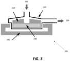
- FIG. 2shows a simplified schematic of a maglev bearingless pump.
- FIG. 3shows a schematic of an exemplary hybrid loop heat pipe with an integrated bearingless pump.
- FIG. 4shows a schematic of an exemplary hybrid loop heat pipe with two integrated bearingless pumps in series.
- FIG. 2shows a simplified schematic of a maglev bearingless pump 200 .
- the working fluidflows into the pump casing 210 through the inlet 212 , is accelerated by the impeller 220 , and exits the pump casing 210 through the outlet 214 at a higher static pressure than at the inlet 212 .
- a permanent magnet 230is embedded in the impeller.
- the stator 240 surrounding the pump casing 210generates a magnetic field which acts to both levitate the embedded impeller magnet at a desired position in the pump casing and cause the impeller to revolve at a prescribed rate.
- Magnetically levitating bearingless pumpshave previously been used to pump blood, as they do not contaminate the fluid being pumped with particulate or lubricant.
- Other applicationsinclude the semiconductor industry, where it is crucial that no metal particulate enter the pumped fluid because metal ions could change the semiconductor properties.
- FIG. 3is a schematic showing the major components of a HLHP 300 .
- the reservoir 310is not attached to the evaporator 320 (thermally coupled to a heat load 325 ) as it is in a traditional LHP.
- the evaporator in a HLHPis designed such that liquid can flow through and exit without changing phase. This is necessary because the mass flowrate through the loop with the mechanical pump 330 operating may, under some heat loads, be in excess of the mass flowrate of liquid that can be vaporized within the evaporator.
- the maglev bearingless pump 330is installed on the liquid return line, downstream of the condenser 350 (thermally coupled to a heat sink 355 ) and reservoir 310 and upstream of the evaporator 320 .
- the HLHP 400is substantially the same as the above-referenced HLHP 300 , and consequently the same reference numerals but indexed by 100 are used to denote structures corresponding to similar structures in the HLHP 300 .
- the foregoing description of the HLHP 300is equally applicable to the HLHP 400 except as noted below.
- aspects of the HLHPsmay be substituted for one another or used in conjunction with one another where applicable.
- FIG. 4shows a schematic of an exemplary system 400 having two pumps 430 , 431 .
- the pumpsare integrated into the HLHP, with the ability to operate the system using one, both, or neither pumps.
- the systemis said to be running in traditional LHP mode, where the pumps are not powered and are bypassed by the liquid return.
- Both the evaporator and heat exchangermay be sized to accommodate heat loads of up to 5 KW, e.g.
- the wick in the evaporatormay be fabricated of sintered nickel with 1.2 ⁇ m pores (35% porosity), with a 0.5 in. outside diameter and length of 18 in.
- An exemplary working fluidis anhydrous liquid ammonia, which is, in many cases, the most desirable for space applications due to its low freezing point and high latent heat of vaporization.
- Another advantage provided when operating in HLHP modeis the diminished oscillations observed in the total mass flowrate through the loop. Oscillations in mass flowrate through the evaporator are undesirable for steady system operation. The oscillations occur in a capillary-pumped LHP due to complex thermal-fluid interactions in the LHP system; understanding the underlying physics of these interactions is an active field of research. In the HLHP operating mode, however, the mass flowrate oscillations are significantly diminished or non-existent, due to the mechanical pump providing stable mass flowrate through the system at all times. Additionally, the integration of the bearingless pump does not compromise the long-life operation of the HLHP.
- the heat load applied to the evaporatorwould govern whether one or multiple pumps were powered. If the heat load increases to the point where a single pump cannot provide sufficient mass flowrate through the evaporator to prevent dry out of the primary wick, the external evaporator temperature would begin to increase in the same manner as for unstable operation on an LHP. At the earliest detection of this increase in temperature, a second pump would then be powered on to provide the additional mass flowrate required, and so on with multiple pumps until a stable evaporator temperature was maintained for the given heat load.
- Any representative processing functions described hereincan be implemented using computer processors, computer logic, application specific integrated circuits (ASIC), digital signal processors, etc., as will be understood by those skilled in the art based on the discussion given herein. Accordingly, any processor that performs the processing functions described herein is within the scope and spirit of the present disclosure.
- ASICapplication specific integrated circuits
- the above systems and methodsmay be implemented as a computer program executing on a machine, as a computer program product, or as a tangible and/or non-transitory computer-readable medium having stored instructions.
- the functions described hereincould be embodied by computer program instructions that are executed by a computer processor or any one of the hardware devices listed above.
- the computer program instructionscause the processor to perform the signal processing functions described herein.
- the computer program instructionse.g., software
- Such mediainclude a memory device such as a RAM or ROM, or other type of computer storage medium such as a computer disk or CD ROM. Accordingly, any tangible non-transitory computer storage medium having computer program code that cause a processor to perform the signal processing functions described herein are within the scope and spirit of the present disclosure.
Landscapes
- Engineering & Computer Science (AREA)
- Physics & Mathematics (AREA)
- Mechanical Engineering (AREA)
- General Engineering & Computer Science (AREA)
- Life Sciences & Earth Sciences (AREA)
- Sustainable Development (AREA)
- Thermal Sciences (AREA)
- Electromagnetism (AREA)
- Structures Of Non-Positive Displacement Pumps (AREA)
Abstract
Description
Claims (3)
Priority Applications (1)
| Application Number | Priority Date | Filing Date | Title |
|---|---|---|---|
| US17/210,407US12173965B2 (en) | 2020-03-23 | 2021-03-23 | Hybrid loop heat pipe with integrated magnetically levitating bearingless pump |
Applications Claiming Priority (2)
| Application Number | Priority Date | Filing Date | Title |
|---|---|---|---|
| US202062993492P | 2020-03-23 | 2020-03-23 | |
| US17/210,407US12173965B2 (en) | 2020-03-23 | 2021-03-23 | Hybrid loop heat pipe with integrated magnetically levitating bearingless pump |
Publications (2)
| Publication Number | Publication Date |
|---|---|
| US20210302104A1 US20210302104A1 (en) | 2021-09-30 |
| US12173965B2true US12173965B2 (en) | 2024-12-24 |
Family
ID=77854463
Family Applications (1)
| Application Number | Title | Priority Date | Filing Date |
|---|---|---|---|
| US17/210,407ActiveUS12173965B2 (en) | 2020-03-23 | 2021-03-23 | Hybrid loop heat pipe with integrated magnetically levitating bearingless pump |
Country Status (4)
| Country | Link |
|---|---|
| US (1) | US12173965B2 (en) |
| EP (1) | EP4127591A4 (en) |
| KR (1) | KR20220163975A (en) |
| WO (1) | WO2021195145A1 (en) |
Families Citing this family (1)
| Publication number | Priority date | Publication date | Assignee | Title |
|---|---|---|---|---|
| GB201809208D0 (en)* | 2018-06-05 | 2018-07-25 | Univ Brunel | Thermal transfer loop |
Citations (35)
| Publication number | Priority date | Publication date | Assignee | Title |
|---|---|---|---|---|
| US4470450A (en) | 1981-10-22 | 1984-09-11 | Lockheed Missiles & Space Co. | Pump-assisted heat pipe |
| WO1991003688A1 (en) | 1989-08-31 | 1991-03-21 | Myson Group Plc | A pump module |
| US5103897A (en)* | 1991-06-05 | 1992-04-14 | Martin Marietta Corporation | Flowrate controller for hybrid capillary/mechanical two-phase thermal loops |
| US5178543A (en)* | 1991-04-30 | 1993-01-12 | The United States Of America As Represented By The United States Department Of Energy | Basic fluid system trainer |
| US20010016170A1 (en) | 1999-12-27 | 2001-08-23 | Ntn Corporation | Magnetically levitated pump |
| US20030136555A1 (en)* | 2002-01-22 | 2003-07-24 | Khanh Dinh | Heat pipe loop with pump assistance |
| US6658861B1 (en)* | 2002-12-06 | 2003-12-09 | Nanocoolers, Inc. | Cooling of high power density devices by electrically conducting fluids |
| US6810946B2 (en) | 2001-12-21 | 2004-11-02 | Tth Research, Inc. | Loop heat pipe method and apparatus |
| US6879074B2 (en) | 2000-07-16 | 2005-04-12 | Levitronix Llc | Stator field providing torque and levitation |
| US20050139345A1 (en)* | 2003-12-31 | 2005-06-30 | Himanshu Pokharna | Apparatus for using fluid laden with nanoparticles for application in electronic cooling |
| US6948556B1 (en) | 2003-11-12 | 2005-09-27 | Anderson William G | Hybrid loop cooling of high powered devices |
| US6990816B1 (en) | 2004-12-22 | 2006-01-31 | Advanced Cooling Technologies, Inc. | Hybrid capillary cooling apparatus |
| US20080217483A1 (en)* | 2007-02-26 | 2008-09-11 | Thales | Thermal control device on board a spacecraft |
| US20100326628A1 (en)* | 2009-06-25 | 2010-12-30 | International Business Machines Corporation | Condenser fin structures facilitating vapor condensation cooling of coolant |
| US20120007265A1 (en)* | 2010-07-08 | 2012-01-12 | See Michael D | Plastics processing method and apparatus |
| US20130022481A1 (en) | 2011-07-20 | 2013-01-24 | Levitronix Gmbh | Magnetic rotor and rotary pump having a magnetic rotor |
| US20130118710A1 (en)* | 2011-11-11 | 2013-05-16 | Inventec Corporation | Heat dissipation system |
| US20130186121A1 (en)* | 2010-06-24 | 2013-07-25 | University Of Sakatchewan | Liquid-to-air membrane energy exchanger |
| US8496874B2 (en) | 2006-12-07 | 2013-07-30 | Thoratec Llc | Integrated centrifugal blood pump-oxygenator, an extracorporeal life support system and a method of de-bubbling and priming an extracorporeal life support system |
| US20140069614A1 (en)* | 2012-09-13 | 2014-03-13 | Asia Vital Components Co., Ltd. | Heat dissipaion device and thermal module using same |
| KR20140049675A (en) | 2012-10-18 | 2014-04-28 | 제주대학교 산학협력단 | The pump for the cryogenic fluid circulation |
| US20150007598A1 (en)* | 2013-07-02 | 2015-01-08 | Lg Electronics Inc. | Cooling system and control method thereof |
| US20150183404A1 (en)* | 2012-02-23 | 2015-07-02 | Bowles Fluidics Corporation | Adaptive, multi-mode washer system and control method |
| US20150192368A1 (en)* | 2011-06-27 | 2015-07-09 | Ebullient, Llc | Method of condensing vapor in two-phase flow within a cooling apparatus |
| US20150285245A1 (en)* | 2012-12-19 | 2015-10-08 | Helmuth Weber | Multiple Pump Arrangement |
| US20150338171A1 (en) | 2012-12-28 | 2015-11-26 | Ibérica Del Espacio, S.A. | Loop heat pipe apparatus for heat transfer and thermal control |
| US20160124474A1 (en)* | 2014-11-04 | 2016-05-05 | Fujitsu Limited | Evaporator, cooling device, and electronic apparatus |
| US20160131141A1 (en) | 2014-11-06 | 2016-05-12 | Ebara Corporation | Magnetic levitated pump |
| US20170268516A1 (en)* | 2014-12-08 | 2017-09-21 | Wilo Se | Adaptation of the delivery head of a centrifugal pump to a changing volumetric flow rate |
| US20180231329A1 (en)* | 2017-02-10 | 2018-08-16 | Hamilton Sundstrand Corporation | Two-phase thermal loop with rotary separation |
| US20190013747A1 (en)* | 2017-07-04 | 2019-01-10 | Levitronix Gmbh | Magnetically levitated rotor and a rotary machine with such a rotor |
| WO2019085090A1 (en) | 2017-10-31 | 2019-05-09 | 华中科技大学 | Micropump-assisted loop heat pipe for heat dissipation from multiple heat sources |
| US20190327856A1 (en)* | 2018-04-23 | 2019-10-24 | Asia Vital Components Co., Ltd. | Water-replenishing and gas-removing structure for water cooling device |
| US20190356195A1 (en) | 2018-05-18 | 2019-11-21 | Levitronix Gmbh | Electromagnetic rotary drive and rotational device |
| US20200021166A1 (en) | 2018-07-12 | 2020-01-16 | Levitronix Gmbh | Electromagnetic rotary drive and a rotational device |
- 2021
- 2021-03-23USUS17/210,407patent/US12173965B2/enactiveActive
- 2021-03-23EPEP21775851.5Apatent/EP4127591A4/ennot_activeWithdrawn
- 2021-03-23WOPCT/US2021/023774patent/WO2021195145A1/ennot_activeCeased
- 2021-03-23KRKR1020227036888Apatent/KR20220163975A/enactivePending
Patent Citations (36)
| Publication number | Priority date | Publication date | Assignee | Title |
|---|---|---|---|---|
| US4470450A (en) | 1981-10-22 | 1984-09-11 | Lockheed Missiles & Space Co. | Pump-assisted heat pipe |
| WO1991003688A1 (en) | 1989-08-31 | 1991-03-21 | Myson Group Plc | A pump module |
| US5178543A (en)* | 1991-04-30 | 1993-01-12 | The United States Of America As Represented By The United States Department Of Energy | Basic fluid system trainer |
| US5103897A (en)* | 1991-06-05 | 1992-04-14 | Martin Marietta Corporation | Flowrate controller for hybrid capillary/mechanical two-phase thermal loops |
| US20010016170A1 (en) | 1999-12-27 | 2001-08-23 | Ntn Corporation | Magnetically levitated pump |
| US6879074B2 (en) | 2000-07-16 | 2005-04-12 | Levitronix Llc | Stator field providing torque and levitation |
| US6810946B2 (en) | 2001-12-21 | 2004-11-02 | Tth Research, Inc. | Loop heat pipe method and apparatus |
| US6745830B2 (en) | 2002-01-22 | 2004-06-08 | Khanh Dinh | Heat pipe loop with pump assistance |
| US20030136555A1 (en)* | 2002-01-22 | 2003-07-24 | Khanh Dinh | Heat pipe loop with pump assistance |
| US6658861B1 (en)* | 2002-12-06 | 2003-12-09 | Nanocoolers, Inc. | Cooling of high power density devices by electrically conducting fluids |
| US6948556B1 (en) | 2003-11-12 | 2005-09-27 | Anderson William G | Hybrid loop cooling of high powered devices |
| US20050139345A1 (en)* | 2003-12-31 | 2005-06-30 | Himanshu Pokharna | Apparatus for using fluid laden with nanoparticles for application in electronic cooling |
| US6990816B1 (en) | 2004-12-22 | 2006-01-31 | Advanced Cooling Technologies, Inc. | Hybrid capillary cooling apparatus |
| US8496874B2 (en) | 2006-12-07 | 2013-07-30 | Thoratec Llc | Integrated centrifugal blood pump-oxygenator, an extracorporeal life support system and a method of de-bubbling and priming an extracorporeal life support system |
| US20080217483A1 (en)* | 2007-02-26 | 2008-09-11 | Thales | Thermal control device on board a spacecraft |
| US20100326628A1 (en)* | 2009-06-25 | 2010-12-30 | International Business Machines Corporation | Condenser fin structures facilitating vapor condensation cooling of coolant |
| US20130186121A1 (en)* | 2010-06-24 | 2013-07-25 | University Of Sakatchewan | Liquid-to-air membrane energy exchanger |
| US20120007265A1 (en)* | 2010-07-08 | 2012-01-12 | See Michael D | Plastics processing method and apparatus |
| US20150192368A1 (en)* | 2011-06-27 | 2015-07-09 | Ebullient, Llc | Method of condensing vapor in two-phase flow within a cooling apparatus |
| US20130022481A1 (en) | 2011-07-20 | 2013-01-24 | Levitronix Gmbh | Magnetic rotor and rotary pump having a magnetic rotor |
| US20130118710A1 (en)* | 2011-11-11 | 2013-05-16 | Inventec Corporation | Heat dissipation system |
| US20150183404A1 (en)* | 2012-02-23 | 2015-07-02 | Bowles Fluidics Corporation | Adaptive, multi-mode washer system and control method |
| US20140069614A1 (en)* | 2012-09-13 | 2014-03-13 | Asia Vital Components Co., Ltd. | Heat dissipaion device and thermal module using same |
| KR20140049675A (en) | 2012-10-18 | 2014-04-28 | 제주대학교 산학협력단 | The pump for the cryogenic fluid circulation |
| US20150285245A1 (en)* | 2012-12-19 | 2015-10-08 | Helmuth Weber | Multiple Pump Arrangement |
| US20150338171A1 (en) | 2012-12-28 | 2015-11-26 | Ibérica Del Espacio, S.A. | Loop heat pipe apparatus for heat transfer and thermal control |
| US20150007598A1 (en)* | 2013-07-02 | 2015-01-08 | Lg Electronics Inc. | Cooling system and control method thereof |
| US20160124474A1 (en)* | 2014-11-04 | 2016-05-05 | Fujitsu Limited | Evaporator, cooling device, and electronic apparatus |
| US20160131141A1 (en) | 2014-11-06 | 2016-05-12 | Ebara Corporation | Magnetic levitated pump |
| US20170268516A1 (en)* | 2014-12-08 | 2017-09-21 | Wilo Se | Adaptation of the delivery head of a centrifugal pump to a changing volumetric flow rate |
| US20180231329A1 (en)* | 2017-02-10 | 2018-08-16 | Hamilton Sundstrand Corporation | Two-phase thermal loop with rotary separation |
| US20190013747A1 (en)* | 2017-07-04 | 2019-01-10 | Levitronix Gmbh | Magnetically levitated rotor and a rotary machine with such a rotor |
| WO2019085090A1 (en) | 2017-10-31 | 2019-05-09 | 华中科技大学 | Micropump-assisted loop heat pipe for heat dissipation from multiple heat sources |
| US20190327856A1 (en)* | 2018-04-23 | 2019-10-24 | Asia Vital Components Co., Ltd. | Water-replenishing and gas-removing structure for water cooling device |
| US20190356195A1 (en) | 2018-05-18 | 2019-11-21 | Levitronix Gmbh | Electromagnetic rotary drive and rotational device |
| US20200021166A1 (en) | 2018-07-12 | 2020-01-16 | Levitronix Gmbh | Electromagnetic rotary drive and a rotational device |
Non-Patent Citations (7)
| Title |
|---|
| English Translation of KR 20140049675 (translation provided by Google Patents), translated Jul. 22, 2024 (4 pages). |
| Extended European Search Report in related EP Application No. 21775851.5 (National Phase of PCT Application PCT/US2021/023774), Mar. 11, 2024 (7 pages). |
| Holman et al., "Thermal-Fluid Oscillations in a Loop Heat Pipe with Attached Mass", 15th International Energy Conversion Engineering Conference, No. AIAA 2017-4695, Jul. 2017, 12 pages. |
| International Preliminary Report on Patentability in corresponding PCT Application PCT/US2021/023774, Sep. 22, 2022 (4 pages). |
| International Search Report in corresponding PCT Application PCT/US2021/023774, mailed Jul. 7, 2021 (3 pages). |
| Written Opinion of the International Searching Authority in corresponding PCT Application PCT/US2021/023774, mailed Jul. 7, 2021 (3 pages). |
| Xiaodong Sun, Long Chen, Zebin Yang, "Overview of Bearingless Induction Motors", Mathematical Problems in Engineering, vol. 2014, Article ID 570161, 10 pages, 2014. https://doi.org/10.1155/2014/570161 (Year: 2014).* |
Also Published As
| Publication number | Publication date |
|---|---|
| US20210302104A1 (en) | 2021-09-30 |
| EP4127591A4 (en) | 2024-04-10 |
| WO2021195145A1 (en) | 2021-09-30 |
| KR20220163975A (en) | 2022-12-12 |
| EP4127591A1 (en) | 2023-02-08 |
Similar Documents
| Publication | Publication Date | Title |
|---|---|---|
| EP2985556B1 (en) | Advanced control two phase heat transfer loop | |
| EP3361201B1 (en) | Dual-mode thermal management loop | |
| US20170370364A1 (en) | Centrifugal compressor assembly and method of operation with an airconditioner | |
| US10962304B2 (en) | Two-phase thermal loop with rotary separation | |
| US12173965B2 (en) | Hybrid loop heat pipe with integrated magnetically levitating bearingless pump | |
| CN109838940A (en) | A kind of closed heat pump/refrigeration system from cooling self-lubricating | |
| CN109477511A (en) | Integrated journal bearing | |
| US10712100B2 (en) | Two-phase thermal loop with membrane separation | |
| EP3284929B1 (en) | Heat exchanger arrangement for a gas turbine | |
| KR102266037B1 (en) | Passive two-phase cooling circuit | |
| CN103299142B (en) | For the cooling device of the synchronous motor of superconductor and superconduction | |
| US20250122973A1 (en) | Bearing lubrication systems and methods for operating the same | |
| EP3904811A1 (en) | Heat conveyance system and conveyance machinery | |
| CN113597515A (en) | Turbo refrigerator | |
| US5240069A (en) | Integral cooling system for a jet engine integral starter/generator and the like | |
| US12429288B2 (en) | Architecture and operational modes of pump-augmented loop heat pipe with multiple evaporators | |
| JP2016200104A (en) | Pump, cooling device and electronic equipment | |
| Bartholomé et al. | New concept for high-efficient cooling systems based on solid-state caloric materials as refrigerant | |
| Chen et al. | Development of a Miniature, Reliable Ammonia Pump for Spaceborne Two-Phase Pumped Loops | |
| US20200032813A1 (en) | Electromechanical actuators for refrigerant flow control | |
| Scaringe et al. | Development of heat pump loop thermal control system for manned spacecraft habitats | |
| Mugurusa et al. | Development of a Low Specific Speed, Centrifugal, Mini Pump for a Two Phase Mechanically Pumped Fluid Loop | |
| Park et al. | Hybrid Loop Thermal Bus Technology for Vehicle Thermal Management | |
| RU2667249C1 (en) | Thermal control system on the basis of the two-phase thermal circuit | |
| Singh et al. | Innovative multi-environment, multimode thermal control system |
Legal Events
| Date | Code | Title | Description |
|---|---|---|---|
| FEPP | Fee payment procedure | Free format text:ENTITY STATUS SET TO UNDISCOUNTED (ORIGINAL EVENT CODE: BIG.); ENTITY STATUS OF PATENT OWNER: LARGE ENTITY | |
| STPP | Information on status: patent application and granting procedure in general | Free format text:DOCKETED NEW CASE - READY FOR EXAMINATION | |
| STPP | Information on status: patent application and granting procedure in general | Free format text:NON FINAL ACTION MAILED | |
| STPP | Information on status: patent application and granting procedure in general | Free format text:RESPONSE TO NON-FINAL OFFICE ACTION ENTERED AND FORWARDED TO EXAMINER | |
| STPP | Information on status: patent application and granting procedure in general | Free format text:FINAL REJECTION MAILED | |
| STPP | Information on status: patent application and granting procedure in general | Free format text:RESPONSE AFTER FINAL ACTION FORWARDED TO EXAMINER | |
| STPP | Information on status: patent application and granting procedure in general | Free format text:NOTICE OF ALLOWANCE MAILED -- APPLICATION RECEIVED IN OFFICE OF PUBLICATIONS | |
| STPP | Information on status: patent application and granting procedure in general | Free format text:DOCKETED NEW CASE - READY FOR EXAMINATION | |
| STPP | Information on status: patent application and granting procedure in general | Free format text:NOTICE OF ALLOWANCE MAILED -- APPLICATION RECEIVED IN OFFICE OF PUBLICATIONS | |
| AS | Assignment | Owner name:GOVERNMENT OF THE UNITED STATES OF AMERICA, AS REPRESENTED BY THE SECRETARY OF THE NAVY, VIRGINIA Free format text:ASSIGNMENT OF ASSIGNORS INTEREST;ASSIGNORS:HYDE, EVAN;BALDAUFF, ROBERT;GOODWIN, GABRIEL;AND OTHERS;SIGNING DATES FROM 20241017 TO 20241031;REEL/FRAME:069250/0001 | |
| STPP | Information on status: patent application and granting procedure in general | Free format text:AWAITING TC RESP, ISSUE FEE PAYMENT VERIFIED | |
| STPP | Information on status: patent application and granting procedure in general | Free format text:PUBLICATIONS -- ISSUE FEE PAYMENT VERIFIED | |
| STCF | Information on status: patent grant | Free format text:PATENTED CASE |