US12173464B2 - Trench box and method of assembly - Google Patents
Trench box and method of assemblyDownload PDFInfo
- Publication number
- US12173464B2 US12173464B2US17/706,534US202217706534AUS12173464B2US 12173464 B2US12173464 B2US 12173464B2US 202217706534 AUS202217706534 AUS 202217706534AUS 12173464 B2US12173464 B2US 12173464B2
- Authority
- US
- United States
- Prior art keywords
- side panel
- lateral support
- trench box
- releasable connection
- connection
- Prior art date
- Legal status (The legal status is an assumption and is not a legal conclusion. Google has not performed a legal analysis and makes no representation as to the accuracy of the status listed.)
- Active
Links
- 238000000034methodMethods0.000titleclaimsdescription47
- 238000009412basement excavationMethods0.000claimsdescription9
- 230000002093peripheral effectEffects0.000description7
- 230000006378damageEffects0.000description4
- 229910003460diamondInorganic materials0.000description3
- 239000010432diamondSubstances0.000description3
- 208000027418Wounds and injuryDiseases0.000description2
- 208000014674injuryDiseases0.000description2
- 239000000463materialSubstances0.000description2
- 238000010276constructionMethods0.000description1
- 238000005096rolling processMethods0.000description1
- 238000000926separation methodMethods0.000description1
Images


Classifications
- E—FIXED CONSTRUCTIONS
- E02—HYDRAULIC ENGINEERING; FOUNDATIONS; SOIL SHIFTING
- E02D—FOUNDATIONS; EXCAVATIONS; EMBANKMENTS; UNDERGROUND OR UNDERWATER STRUCTURES
- E02D17/00—Excavations; Bordering of excavations; Making embankments
- E02D17/06—Foundation trenches ditches or narrow shafts
- E02D17/08—Bordering or stiffening the sides of ditches trenches or narrow shafts for foundations
- E—FIXED CONSTRUCTIONS
- E02—HYDRAULIC ENGINEERING; FOUNDATIONS; SOIL SHIFTING
- E02D—FOUNDATIONS; EXCAVATIONS; EMBANKMENTS; UNDERGROUND OR UNDERWATER STRUCTURES
- E02D17/00—Excavations; Bordering of excavations; Making embankments
- E02D17/02—Foundation pits
- E02D17/04—Bordering surfacing or stiffening the sides of foundation pits
- E—FIXED CONSTRUCTIONS
- E02—HYDRAULIC ENGINEERING; FOUNDATIONS; SOIL SHIFTING
- E02D—FOUNDATIONS; EXCAVATIONS; EMBANKMENTS; UNDERGROUND OR UNDERWATER STRUCTURES
- E02D17/00—Excavations; Bordering of excavations; Making embankments
- E02D17/06—Foundation trenches ditches or narrow shafts
- E02D17/08—Bordering or stiffening the sides of ditches trenches or narrow shafts for foundations
- E02D17/083—Shoring struts
- E—FIXED CONSTRUCTIONS
- E02—HYDRAULIC ENGINEERING; FOUNDATIONS; SOIL SHIFTING
- E02D—FOUNDATIONS; EXCAVATIONS; EMBANKMENTS; UNDERGROUND OR UNDERWATER STRUCTURES
- E02D2200/00—Geometrical or physical properties
- E02D2200/15—Geometrical or physical properties including at least a hinge
- E—FIXED CONSTRUCTIONS
- E02—HYDRAULIC ENGINEERING; FOUNDATIONS; SOIL SHIFTING
- E02D—FOUNDATIONS; EXCAVATIONS; EMBANKMENTS; UNDERGROUND OR UNDERWATER STRUCTURES
- E02D2220/00—Temporary installations or constructions
- E—FIXED CONSTRUCTIONS
- E02—HYDRAULIC ENGINEERING; FOUNDATIONS; SOIL SHIFTING
- E02D—FOUNDATIONS; EXCAVATIONS; EMBANKMENTS; UNDERGROUND OR UNDERWATER STRUCTURES
- E02D2600/00—Miscellaneous
- E02D2600/20—Miscellaneous comprising details of connection between elements
Definitions
- Thisrelates to a trench box and a method of assembling a trench box.
- Trench boxesare used for protection during excavation. Trench boxes may be used when installing pipelines, underground cabling, or performing other operations that require below-ground access.
- a typical trench boxwill include side panels that are separated and held in place by struts, which may be length-adjustable to meet the needs of the particular trench. It is necessary to construct the panels and struts from materials that are able withstand the loads that will be applied.
- Trench boxesare generally assembled by laying a side panel flat on the ground, attaching the struts so they extend up from the side panel, and then lowering the other side panel onto the struts. Given the weight of the various components, lifting equipment is normally required, and personnel are required to ensure the various pieces are properly aligned as they are manipulated by the lifting equipment.
- a trench boxcomprising first and second side panels connected in parallel spaced relation by one or more lateral supports.
- Each lateral supportcomprises connection points at a first end and a second end of each lateral support that connect the first and second side panels to the one or more lateral supports, the connection points maintaining the first and second side panels in parallel spaced relation and the one or more lateral supports in parallel spaced relation between the first and second side panels.
- Each connection pointcomprises a pivot connection that permits pivotal movement of the side panels relative to the one or more lateral supports about a pivot axis, and a releasable connection spaced from the pivot connection in a direction perpendicular to the pivot axis, the releasable connection being selectively releasable to permit the respective first or second side panel to pivot about the pivot axis such that the panels are not parallel.
- the trench boxmay further comprise side supports mounted between the side panels and the one or more lateral supports, the side supports extending along the side panels in a direction perpendicular to the pivot axis.
- the connection pointsmay connect the lateral support to the side supports.
- the side panelsmay be removably mounted to the side supports. When the releasable connections are released, the side supports may pivot sufficiently about the pivot axis to permit the one or more stands to engage the ground surface, or the side supports may be fixedly mounted to the lateral supports such that the side panels pivot relative to the lateral supports and the side supports.
- the pivot connectionis spaced from the releasable connection and may be above the releasable connection.
- the releasable connectionsmay be spring-loaded connections.
- the lateral supportsmay be length-adjustable to adjust a spacing between the first and second side panels.
- the height of the first and second side panelsmay be greater than a height of the lateral supports, such that, when the lateral support is supported by the one or more stands on the ground surface, the first and second side panels are angled downward and outward relative to the lateral supports.
- each lateral supportmay comprise lifting lugs that permit the lateral supports to be suspended by a lifting device such that the side panels are free to pivot about the pivot connections when the lateral supports are lifted sufficiently.
- the trench boxmay further comprise one or more third side panel that attaches to one or more of the first and second side panels.
- the one or more third side panelmay attach to the first side panels using a corner engagement member, the corner engagement member having an engagement profile that secures the one or more third side panel perpendicularly to the first side panel.
- the one or more third side panelsmay attach to a top edge of the first or second side panel using an engagement member, the engagement member having an engagement profile that secures the one or more third side panels in a common plane with at least one of the first and second side panels.
- a perimeter of the first and second side panelsmay comprise a universal engagement profile that is engaged by a universal engagement member.
- each side panelmay comprise at least one snubber for controlling the pivotal movement of each side panel relative to the lateral supports.
- a method of assembling a trench boxcomprising the steps of: positioning one or more lateral supports in parallel spaced relation and in a vertical orientation.
- Each lateral supportcomprises connection points at a first end and a second end of each lateral support, each connection point comprising a pivot connection, and a releasable connection spaced below the pivot connection when the lateral support is in the vertical orientation; and one or more stands for supporting the support structure in the vertical orientation.
- the methodfurther comprises the steps of pivotally attaching a first side panels to the pivot connections at the first end of each lateral support, and a second side panel to the pivot connections at the second end of each lateral support, the side panels being angled down and away relative to the lateral supports; lifting the lateral supports such that the first and second side panels pivot toward the lateral supports; and engaging the releasable connection such that the first and second side panels are secured in parallel spaced relation with the one or more lateral supports in parallel spaced relation between the first and second side panels.
- a method of disassembling a trench boxcomprising the steps of: providing a trench box, comprising one or more side panels connected in parallel spaced relation by first and second lateral supports.
- Each lateral supportcomprising connection points at a first end and a second end of each lateral support that attach the first and second side panels to the one or more lateral supports, the connection points maintaining the first and second side panels in parallel spaced relation and the one or more lateral supports in parallel spaced relation between the first and second side panels;
- each connection pointcomprising a pivot connection that permits pivotal movement of the side panels relative to the lateral supports about a pivot axis, and a releasable connection spaced from the pivot connection in a direction perpendicular to the pivot axis, the releasable connection being selectively releasable to permit the respective first or second side panel to pivot about the pivot axis such that the panels are not parallel; at least one snubber for controlling the pivotal movement of each side panel relative to
- the methodfurther comprises the steps of positioning the trench box on a ground surface such that the trench box is supported on a bottom edge of the first and second side panels with the lateral supports parallel to the ground surface; releasing the releasable connection of the first side panel, and applying a force to the first side panel that causes it to pivot about the pivot connection until it is angled downward and away from the lateral support, the pivotal movement of the first side panel being controlled by one or more of the snubbers; releasing the releasable connection of the second side panel, and applying a force to the second side panel that causes it to pivot about the pivot connection until it is angled downward and away from the lateral support and such that the one or more stands engages the ground surface, the pivotal movement of the second side panel being controlled by one or more of the snubbers; and removing the first and second side panels from the lateral support.
- the releasable connection of the first and second side panelsmay be released together such that the first and second side panels pivot at the same time.
- a method of disassembling a trench boxcomprising the steps of: providing a trench box, comprising first and second side panels connected in parallel spaced relation by one or more lateral supports.
- Each lateral supportcomprises connection points at a first end and a second end of each lateral support that attach the first and second side panels to the one or more lateral supports, the connection points maintaining the first and second side panels in parallel spaced relation and the one or more lateral supports in parallel spaced relation between the first and second side panels;
- each connection pointcomprising a pivot connection that permits pivotal movement of the side panels relative to the lateral supports about a pivot axis, and a releasable connection spaced from the pivot connection in a direction perpendicular to the pivot axis, the releasable connection being selectively releasable to permit the respective first or second side panel to pivot about the pivot axis such that the panels are not parallel.
- the methodmay further comprise the steps of: positioning the trench box such that a top edge of the first and second side panels engages a ground surface; releasing the releasable connections of the first and second side panels; and pivotally lowering the first and second side panels until an outer face of the first side panel and an outer face of the second side panel engage the ground surface.
- a method of disassembling a trench boxcomprising the steps of:
- a trench boxcomprising first and second side panels, each side panel having an inner face and an outer face, the inner face having an upper attachment point having a first part of an upper attachment and a lower attachment having a first part of a lower attachment, one or more support structures, each support structure comprising first and second sides supports separated by a lateral support, wherein in use, the lateral support maintains the first side support in a fixed position and orientation relative to the second side support, each of the first and second side supports carrying a second part of the upper attachment and a second part of a lower attachment, the second part of the upper attachment pivotally engaging the first part of the upper attachment and the second part of the lower attachment fixedly engaging the first part of the lower attachment, each of the upper attachment and the lower attachment being selectively engaged and disengaged, and a stand for supporting the support structure in a vertical orientation with the second part of the upper attachment above the second part of the lower attachment.
- At least one of the upper attachment and the lower attachmentmay be pin connected.
- At least one of the upper attachment and the lower attachmentmay be spring-loaded connectors.
- the lateral support of the support structuresmay be length-adjustable to adjust a spacing between the first and second side supports.
- the standmay be removably attached to the second part of the lower attachment, the stand being removed to permit the first parts of the lower attachments to connect to the respective second part of the lower attachments.
- one of the first part and the second part of the lower attachmentmay comprise an engagement face and the other of the second part and the first part of the lower attachment may comprise a receiver having a pin that slides along the engagement face to retain the engagement face that is received within the receiver.
- a first distance between the first part of the upper attachment and a lower edge of the respective panelmay be greater than a second distance between the second part of the upper attachment and the stand, such that, when the first and second parts of the upper attachment are connected and the stand supports the support structure on a ground surface, the first and second panels are angled downward and outward relative to the support structure.
- each support structuremay comprise lifting lugs that permit the support structures to be suspended by a lifting device such that the panels are free to pivot about the upper attachments when the support structure is lifted sufficiently.
- the trench boxmay further comprise one or more third side panels that attach to and extend between the first and second side panels.
- the one or more third side panelsmay attach to the first side panel using a corner engagement member, the corner engagement member having an engagement profile that secures the one or more third side panel perpendicularly to the first panel.
- the trench boxmay further comprise one or more third side panels, each third side panel being attached to and extending above a top edge of one of the first and second side panels.
- the one or more third side panelsmay attach to the top edge of the respective side panels using an engagement member having an engagement profile that secures the one or more third side panels in a common plane with at least one of the first and second side panels.
- a perimeter of the side panelsmay comprise a universal engagement profile that is engaged by a universal engagement member.
- a method of assembling a trench boxcomprising the steps of positioning one or more support structures in spaced relation and in a vertical orientations, each support structure comprising first and second sides supports separated by a lateral support, wherein in use, the lateral support maintains the first side support in a fixed position and orientation relative to the second side support, one or more stands for supporting the support structure in the vertical orientation, attaching first and second side panels to the one or more support structures using a pivotal attachment, the pivotal attachment being positioned toward a top of each of the first and second side panels and the one or more support structures, the first and second side panels being angled down and away from the one or more support structures, lifting the support structures such that the first and second side panels pivot toward the support structures, removing the one or more stands, and attaching the first and second side panels to the support structures at a point below the pivotal attachments.
- attaching the first and second side panels to the one or more support structuresmay comprise using at least one pin connection.
- attaching the first and second side panels to the one or more support structuresmay comprise using at least one spring-loaded connector.
- attaching the first and second side panels to the support structure at a point below the pivotal attachmentsmay comprise inserting a pin connector into a pin receiver.
- the lateral supports of the support structuresmay be length-adjustable, and the method may further comprising the step of adjusting a spacing between the first and second side supports by adjusting the length of the lateral supports.
- the standmay be removably attached to the second part of the lower attachment, and the method may further comprise removing the stand and connecting the first parts of the lower attachments to the respective second part of the lower attachments.
- attaching the first and second side panels to the support structures at a point below the pivotal attachmentsmay comprise sliding a pin being carried by a receiver on one of the first part and the second part of the lower attachment along an engagement face, the other of the first part and the second part of the lower attachment comprising the engagement face, to retain the engagement face within the receiver.
- a first distance between the first part of the upper attachment and a lower edge of the respective panelmay be greater than a second distance between the second part of the upper attachment and the stand, such that, when the first and second parts of the upper attachment are connected and the stand supports the support structure on a ground surface, the first and second panels are angled downward and outward relative to the support structure.
- the methodmay further comprise the step of suspending the support structures with a lifting device connected to lifting lugs on each support structure such that the panels are free to pivot about the upper attachments.
- the methodmay further comprise the step of attaching one or more one third side panels to the first and second side panels such that the one or more third side panels extend between the first and second side panels.
- the one or more third side panelsmay attach to the first side panel using a corner engagement member, the corner engagement member having an engagement face that secures the one or more third side panels perpendicularly to the first side panel.
- the methodmay further comprise the step of attaching one or more third side panels to a top edge of one of the first and second side panels such that the one or more third side panels extend above a top edge of at least one of the first and second side panels.
- the one or more third side panelsmay attach to the top edge of the respective side panels using an engagement member.
- a perimeter of the first and second side panelsmay comprise an engagement profile that is engaged by an engagement member having an engagement profile that secures the one or more third side panels in a common plane with at least one of the first and second side panels.
- a trench boxcomprising first and second side panels, each side panel having an inner face, an outer face and an outer peripheral edge, one or more support structures attached between the inner faces of the first and second side panels to maintain the first side panel in a fixed position and orientation relative to the second side panel, a universal connector on the outer peripheral edge of each of the first and second side panels, the universal connector comprising a plurality of connection points that are evenly spaced along the outer peripheral edge, and a removable connector that selectively connects to the universal connector.
- a trench box assembled for use in an excavationcomprising a plurality of panels comprising at least a first panel, a second panel, and a third panel.
- Each panelcomprises a connection profile comprising a plurality of straight edge segments along the peripheral edges of the panel, each straight edge segment having a plurality of evenly spaced connection points, wherein the spacing of connection points on each straight edge segment is equal.
- the first and second panelsare secured in parallel, spaced relation.
- a plurality of connectorsconnect between connection profiles. At least one connector connects the third panel and the first panel to secure the third panel relative to the first and second panels.
- first and second panelsmay be secured in parallel, spaced relation by one or more lateral supports that have a first end connected to the first panel and a second end connected to the second panel.
- the plurality of connectorsfurther connect the third panel and the second panel.
- the plurality of connectorsmay further connect a fourth panel to the first and second panels, wherein the first and second panels are secured in parallel, spaced relation by the third and fourth panels.
- the third and fourth panelsmay be in parallel spaced relation.
- the third panelmay be connected parallel to and in alignment with the first panel, or at an angle to the first panel.
- each panelmay be rectangular and have a length and a width, the connection profile extending along each of the length and the width of each panel, wherein at least the length and the width of the third panel are non-equal, such that each of the length and the width of the third panel can be connected to each of the length and the width of the first panel.
- a method of installing a trench box or use in an excavation having sidewallscomprising the step of: providing a plurality of panels comprising at least a first panel, a second panel, and a third panel, each panel comprising a connection profile having a plurality of straight edge segments along the peripheral edges of the panel, each straight edge segment having a plurality of evenly spaced connection points, wherein the spacing of connection points on each straight edge segment is equal; providing a plurality of connectors that connect between connection profiles; assembling the trench box by: securing the first and second panels together in parallel, spaced relation; and using one or more connectors to connect the third panel and the first panel to secure the third panel relative to the first and second panels.
- first and second panelsmay be secured in parallel, spaced relation by one or more lateral supports that have a first end connected to the first panel and a second end connected to the second panel.
- one or more connectorsmay be used to connect the third panel and the second panel.
- the methodmay further comprise the step of using the connectors to connect a fourth panel to the first and second panels, wherein the first and second panels are secured in parallel, spaced relation by the third and fourth panels.
- the third and fourth panelsmay be in parallel spaced relation.
- the third panelmay be connected parallel to and in alignment with the first panel, or at an angle to the first panel.
- each panelmay be rectangular and have a length and a width, the connection profile extending along each of the length and the width of each panel, wherein at least the length and the width of the third panel are non-equal, and further comprising the steps of: identifying a plurality of arrangements in which the length and the width of the third panel can be connected to each of the length and the width of the first panel, and selecting one of the plurality of arrangements.
- the methodmay further comprise the step of installing the trench box in the excavation to support at least a portion of the sidewalls of the excavation.
- FIG. 1is a perspective view of an embodiment of a trench box.
- FIG. 2is a perspective view of a support structure.
- FIG. 3is a perspective view of two support structures spaced apart from each other.
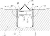
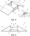
- FIG. 4is a perspective view of the trench box of FIG. 1 with panels attached to upper attachments.
- FIG. 5is a side elevation view of the trench box of FIG. 1 with panels attached to upper attachments.
- FIG. 6is a side elevation view of the trench box of FIG. 1 being lifted away from a stand.
- FIG. 7is a side elevation view of the trench box of FIG. 1 with panels attached to the upper and lower attachments.
- FIG. 7 Ais a side elevation view of the trench box of FIG. 1 being lowered into a trench.
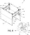
- FIG. 8is a perspective view of the trench box of FIG. 1 with panels attached to the upper and lower attachments showing a detailed view of a lower attachment.
- FIG. 9is a perspective view of a trench box with an alternate support structure.
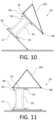
- FIG. 10is a side elevation view of the trench box of FIG. 9 being rotated for disassembly.
- FIG. 11is a side elevation view of the trench box of FIG. 9 on its side.
- FIG. 12is a side elevation view of the trench box of FIG. 9 being rotated further for disassembly.
- FIG. 13is a side elevation view of the trench box of FIG. 9 that has been rotated upside down for disassembly.
- FIG. 14is a perspective view of the trench box of FIG. 9 showing a detailed view of a lower attachment.
- FIG. 15is a side elevation view of the trench box of FIG. 9 showing the process of a side panel rotating about a lower attachment to lay flat.
- FIG. 16is a side elevation view of the trench box of FIG. 9 showing the second side panel rotating about a lower attachment such that both panels lay flat.
- FIG. 17is a side elevation view of the trench box of FIG. 9 showing the support structures being lifted away from the side panels.
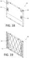
- FIG. 18is a perspective view of a side panel.
- FIG. 19is a perspective view of a side panel showing the interior structure.
- FIG. 20is a perspective view of a portion of a side panel showing an upper attachment with a closed safety latch.
- FIG. 21is a perspective view of a portion of a side panel showing an upper attachment with an open safety latch.
- FIG. 22is a side elevation view in section of a trench box with an alternate attachment system.
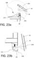
- FIG. 23 ais a side elevation view of the trench box of FIG. 22 showing a detailed view of an upper attachment.
- FIG. 23 bis a side elevation view of the trench box of FIG. 22 showing a detailed view of a lower attachment.
- FIG. 24is a perspective view of two side panels assembled using a corner bracket.
- FIG. 25is a perspective view of a corner bracket.
- FIG. 26is a perspective view of two side panels assembled using an inline bracket.
- FIG. 27is a perspective view of an inline bracket.
- FIG. 28is a perspective view of side panels assembled using both corner and inline brackets.
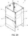
- FIG. 29is a perspective view of a trench box assembled using both corner and inline brackets.
- FIG. 30is a perspective view of a side panel having a knife edge component.
- FIG. 31is a side elevation view of the trench box of FIG. 22 with a lifting sling attached.
- FIG. 32is a side elevation view of the trench box of FIG. 22 being rotated for disassembly.
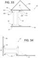
- FIG. 33is a side elevation view of the trench box of FIG. 22 on its side.
- FIG. 34is a side elevation view of the trench box of FIG. 22 showing the process of a side panel rotating about a lower attachment to lay flat.
- FIG. 35is a side elevation view of the trench box of FIG. 22 showing the second side panel rotating about a lower attachment such that both panels lay flat.
- FIG. 36is a side elevation view of the trench box of FIG. 22 showing the support structures being lifted away from the side panels.
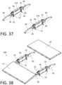
- FIG. 37is a perspective view of lateral supports for a larger format trench box.
- FIG. 38is a perspective view of side panels being installed on the lateral supports of FIG. 37 .
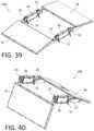
- FIG. 39is a perspective view of side panels installed on the lateral supports of FIG. 37 .
- FIG. 40is a perspective view of one side panel in an operational position relative to the lateral supports.
- FIG. 41is a perspective view of a larger format trench box in an operational position.
- FIGS. 42 and 43are detailed perspective views of a releasable connection.
- FIGS. 44 and 45are detailed perspective views of a snubbing device.
- FIG. 46is a side elevation view in section of a snubbing device.
- FIG. 47is a detailed perspective view of a side support with a latch in a latched position.
- FIG. 48is a detailed side elevation view of a side support with a latch in a latched position.
- FIG. 49is a detailed side elevation view of a side support with a latch in an unlatched position.
- FIG. 50is a perspective view of four side panels assembled into a box using corner brackets.
- FIG. 51is a perspective view of eight side panels assembled into a vertically extended box using corner brackets.
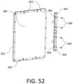
- FIG. 52is a perspective view of a corner connector being attached to one side of a panel.
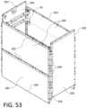
- FIG. 53is a perspective view of six side panels of equal size assembled into a box by varying the orientation and using corner brackets.
- FIG. 54is a perspective view of a trench box vertically extended using edge brackets.
- FIG. 55is a side elevation view of a locking pin on a connecting bracket showing detail of a pin keeper.
- FIG. 56is a perspective view of a locking pin being installed on a connecting bracket showing detail of a locking slot.
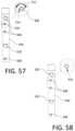
- FIG. 57is a side elevation view of a locking pin being installed on a connecting bracket showing the pin in an unlocked position.
- FIG. 58is a side elevation view of a locking pin being installed on a connecting bracket showing the pin rotated to a locked position.
- FIG. 59is a side elevation view showing details of a diamond shaped pin receiver for locking pins.
- FIG. 60is a perspective view of a side panel having attached extension feet.
- FIG. 61is a perspective view of a knife edge component being installed on a side panel.
- FIG. 62is a perspective view of two side panels being connected inline using edge brackets.
- FIG. 63is a perspective view of two side panels connected together inline using edge brackets.
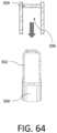
- FIG. 64is a detailed top plan view of an edge bracket being connected to a connection profile on a side panel.
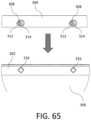
- FIG. 65is a detailed side elevation view of an edge bracket being connected to a connection profile on a side panel.
- trench boxThere will be given below a general description of a trench box, after which two examples of trench boxes will be given, namely, a smaller format trench box, described with respect to FIG. 1 through 36 , and a larger format trench box, described with respect to FIG. 37 through 46 . Additional details regarding a universal connection system for both the smaller format and larger format trench box will be described with respect to FIGS. 24 - 30 and FIG. 50 - 65 .
- the terms “smaller format” and “larger format”are intended to be relative to each other, and may be designed to the particular size required by the end user. It will also be understood that, while the overall designs of the different formats share many design concepts, there are some differences that arise based on the particular considerations related to the size and weight of the respective trench box.
- Trench boxes 10 and 200have a first side panel 12 with an inner face 14 and an outer face 16 , and a second side panel 18 with an inner face 20 and an outer face 22 .
- Trench boxes 10 and 200are assembled with side panels 12 and 18 being attached to lateral supports 36 , of which there are shown two, but there may be only one, or three or more.
- Each lateral support 36has connection points 25 at either end of the lateral support that connect first and second side panels 12 and 18 to lateral supports 36 .
- Each connection pointhas a pivot connection 28 and a releasable connection 34 .
- Pivot connection 28permits pivotal movement of the side panels relative to lateral supports 36 about a pivot axis that is parallel to side panels 12 or 18 and perpendicular to lateral supports 36 .
- Releasable connection 34is spaced from pivot connection 28 in a direction perpendicular to the pivot axis, and generally below pivot connection 28 to facilitate construction and operation.
- Releasable connection 34is selectively releasable to permit side panels 12 and 18 to pivot about the pivot axis.
- lateral support 36may have stands 52 that support the lateral support with pivot connection 28 above releasable connection 34 .
- trench boxes 10 and 200may be designed with pivot connection 28 below releasable connection 34 .
- Stands 52may be integrally formed (not shown), removable (as shown in FIG. 6 ), or retractable (as shown in FIGS. 44 and 45 ). The number, location, and size of stands 52 may vary depending on the requirements or preferences of the user. Stands 52 permit lateral supports to remain upright on a ground surface. If lateral supports were suspended from above, stands 52 may not be required.
- smaller inner faces 14 and 20have upper attachment points 24 and 26 , respectively.
- Upper attachment points 24 and 26are the first part of a two-part upper attachment 28 .
- Inner faces 14 and 20also have lower attachment points 30 and 32 , respectively.
- Lower attachment points 30 and 32are the first part of a two-part lower attachment 34 .
- Trench box 10is assembled and secured using lateral supports 36 .
- trench box 10has two lateral supports 36 .
- lateral support 36has a first side support 38 and a second side support 40 .
- Side supports 38 and 40are separated and stabilized by lateral supports 36 .
- Lateral supports 36may be formed from two separate lateral components 42 as shown in FIG. 2 . Lateral supports 36 maintain first side support 38 in a fixed position and orientation relative to second side support 40 .
- Side supports 38 and 40may be fixedly attached to lateral supports 36 , removable, or pivotally movable relative to lateral supports 36 , as will be described elsewhere.
- lateral supports 36may be length-adjustable to adjust the spacing between the first and second side supports. Once the length has been adjusted, lateral supports 36 maintain the relative positions of side supports 38 and 40 at the desired spacing.
- lateral supports 36may be of a fixed length and constructed as a single piece, as shown in FIG. 9 . In this case, different sizes of lateral supports may be provided to allow for different sizes of trench boxes.
- First and second side supports 38 and 40have upper attachment points 44 and 46 , respectively.
- Upper attachments points 44 and 46are the second part of the two-part upper attachments 28 , and pivotally engage the first parts 24 and 26 of upper attachments 28 .
- First and second side supports 38 and 40also have lower attachment points 48 and 50 , respectively.
- Lower attachments points 48 and 50are the second parts of the two-part lower attachments 34 , and fixedly engage the first parts 30 and 32 of lower attachment 34 .
- Each of upper attachment 28 and lower attachment 34selectively engage and disengage.
- Upper attachment 28 and lower attachment 34may be a variety of types of connections, as will be understood by a person skilled in the art. For example, either or both of upper attachment 28 and lower attachment 34 may be pin connected, as shown.
- second parts 48 and 50 of lower attachment 34have an engagement surface 54 , such as an angled face in a preferred example, and first parts 30 and 32 of lower attachment 34 have a receiver 56 having a pin 58 that slides along engagement surface 54 to retain engagement surface 54 where it is received within receiver 56 .
- Upper attachment 28is a pin connection, which permits a pivotal movement, and lower attachment 34 also preferably has a pin connection to provide an additional connection point, while engagement surface 54 and pin 58 provide a tighter and stronger connection. While the drawings show engagement surfaces 54 on lateral supports 36 and pin 58 on panels 12 and 18 , it will be understood that this could be reversed, e.g. with engagement surfaces 54 on panels 12 and 18 and pins 58 could be on lateral supports 36 .
- either or both of upper attachment 28 and lower attachment 34may be spring loaded attachments as shown in FIG. 22 and FIG. 23 .
- upper attachment point 26 and lower attachment point 32 of second side panel 18have brackets and posts 104 allowing them to be placed into spring loaded connectors 106 of upper attachment point 46 and lower attachment point 50 .
- the brackets and posts 104may also be carried by upper attachment point 44 and lower attachment point 50
- upper attachment point 26 and lower attachment point 32may be spring loaded connectors 106 .
- upper attachment 28is formed by engaging bracket and post 104 with spring loaded connector 106 .
- a safety pin 108may then be inserted into opening 110 to prevent accidental disengagement of upper attachment 28 .
- lower attachment 34may be formed by engaging bracket and post 104 with spring loaded connector 106 .
- Safety pin 108may be inserted into opening 112 .
- upper attachment 28 and lower attachment 34may both be spring loaded attachments, or they may be used in combination with other attachments, such as those previously described.
- upper attachment 28may be a fixed attachment as shown in FIG. 4
- lower attachment 34may be a spring loaded attachment as shown in FIG. 23 b .
- Other combinationsmay be used, as will be understood by those skilled in the art.
- Trench box 10further has stands 52 for supporting lateral support 36 in a vertical orientation with second parts 44 and 46 of upper attachments 28 above second parts 48 and 50 of lower attachments 34 .
- stand 52is removably attached to the second parts 48 and 50 of lower attachment 34 .
- stand 52may also be shaped to be integrally formed with lateral support 36 , or may be attached to different areas of lateral support 36 , depending on the application.
- stand 52may be flanges that are attached to the sides or bottom of lateral support 36 , may be attached by a hinge such that they can be folded back, or lateral support 36 may have a flat bottom that is wide enough to stand on its own on some surfaces.
- Stand 52is useful for allowing lateral support 36 to be self-supporting in order to facilitate the connection of upper attachments 28 between lateral supports 36 and panels 12 and 18 with lateral supports 36 in an upright position. As shown, stand 52 may be removably connected to second parts 48 and 50 of lower attachment 34 . Stand 52 may then be removed to allow lower attachment 34 to be connected.
- support stands 52are preferably shorter than the height of panels 12 and 18 , and are connected below the upper edge of first and second panels 12 and 18 such that, when the first parts 12 and 18 , and second parts 44 and 46 , of the upper attachment 28 are connected and the stand 52 supports lateral support 36 on a ground surface, first and second panels 12 and 18 are angled downward and outward relative to lateral support 36 .
- upper attachment 28is positioned on first and second panels 12 and 18 such that a first distance between the first parts 24 and 26 of upper attachment 28 and a lower edge of the respective panel 12 or 18 is greater than a second distance between the second parts 44 and 46 of upper attachment 28 and the stand 52 .
- each lateral support 36preferably has lifting lugs 60 that permit lateral supports 36 to be suspended by a lifting device (not shown) such as a crane, excavator bucket, etc. so that the panels 12 and 18 are free to pivot about upper attachments 28 when lateral support 36 is lifted sufficiently, i.e. to about the height of the panels 12 and 18 .
- a lifting devicesuch as a crane, excavator bucket, etc.
- trench box 10may be assembled with additional panels connected to first and second side panels 12 and 18 .
- trench box 10may be assembled with one or more third side panels 62 that attach to and extend between first side panel 12 and second side panel 18 .
- Additional side panelsmay be attached using a variety of means, as will be understood by those skilled in the art.
- third side panel 62is attached using a corner engagement member 64 , or bracket. Corner bracket 64 has perpendicular slots 66 as shown in FIG. 25 that engage first and second side panels 12 and 18 , as well as third side panel 62 .
- third side panel 62may also be attached to and extend above a top edge of one of the first and second side panels 12 and 18 .
- Third side panel 62may be attached using a variety of engagement methods known in the art.
- third side panel 62is attached to the top edge of second side panel 18 using an H-shaped engagement member 68 , or bracket, as shown in FIG. 27 .
- Bracket 68is described as being H-shaped because of the slots that receive the respective panels. It will be understood that bracket 68 may have a different type of engagement profile, as with corner bracket 64 , that secures third side panel 62 in the desired orientation and position; in this case, in parallel and in plane with first or second side panel 12 or 18 , as the case may be.
- first and second side panels 12 and 18preferably have a universal engagement profile 65 on the perimeter of the panels that has a plurality of connection points that are evenly spaced along the outer peripheral edge of panels 12 and 18 .
- the connection pointsextend along the entire peripheral edge as shown, but the connection points may also be only on a portion of each side, or a portion of one or more sides, as the case may be.
- a removable connector(not shown) is provided that engages engagement profile 65 in a selected location.
- Engagement profile 65 and the connectorare designed such that the connector may be connected at one or more connection points (depending on the size and shape of the connector) at any point along engagement profile 65 .
- Engagement profile 65allows panels 12 and 18 to have a universal connection system that allows a variety of connections to be made.
- engagement profile 65allows for trench box 10 to be assembled in a variety of configurations as needed using corner engagement member 64 or H-shaped engagement member 68 as shown. As shown, one panel is shown rotated 90 degrees to a portrait orientation as opposed to the landscape orientation.
- Engagement profile 65also allows detachable connections to be made with other equipment, such as with accessories, safety devices, tools, sensors, etc.
- first and second side panels 12 and 18are shown as having a knife edge 100 attached using engagement profile 65 , which is useful when installing trench box 10 during excavation.
- the universal connectormay be part of brackets 64 and 66 , or the universal connectors may mount to, or extend through, brackets 64 and 66 .
- panels 12 , 18 , and 62are preferably designed with a thin outer wall 71 and an internal lateral support 70 , such as a diamond shape as shown in FIG. 19 . This allows panels 12 , 18 , and 62 to be lighter, while still being able to withstand the necessary loads.
- Lateral supports 36are assembled, as required, and in the case that lateral supports 36 have length-adjustable lateral supports 36 , lateral supports 36 are adjusted to provide the required separation between first and second side supports 38 and 40 .
- Lateral supports 36may be adjusted with a pin connection as shown, or with any other length-adjustable connection known in the art, such as threadably adjustable connections, hydraulically adjustable connections, etc.
- Lateral supports 36are installed into stands 52 , which may be formed with lateral supports 36 , or, as shown, may be removably connected. As shown, stands 52 are secured to lateral supports 36 with lock pins 78 . Referring to FIG.
- lateral supports 36are positioned in spaced relation with a spacing 80 , as required for the application, and in a vertical orientation on stands 52 . Spacing 80 will be determined by the dimensions of the first and second side panels 12 and 18 , and specifically, by the distance between upper attachment points 24 and 26 , as well as the distance between lower attachment points 30 and 32 . Referring to FIG. 4 , side panels 12 and 18 are then set against lateral supports 36 such that upper attachment points 24 and 26 engage with upper attachment points 44 and 46 to form upper attachments 28 . Panels 12 and 18 may need to be manipulated by a crane or other lifting device, or may be light enough to be manipulated manually by workers. When connected, upper attachments 28 form a pivotal attachment 82 , as shown.
- Pivotal attachment 82may be formed by inserting a pin connector 90 into a pin receiver 92 , or upper attachments 28 may be otherwise designed with a hinge, and has sufficient movement to allow panels 12 and 18 to be at an angle that still allows lateral supports 36 to rest on the ground. Upper attachments 28 are positioned toward the top of each of the first and second panels 12 and 18 and toward the top of the lateral supports 36 . As shown in FIG. 4 and FIG. 5 , when attached, first and second side panels 12 and 18 are angled down and away from lateral supports 36 and rest on the ground surface.
- Upper attachments 28preferably have a safety latch 84 in addition to pivotal attachment 82 , and safety latch 84 preferably has a lock pin 86 to prevent accidental disengagement of safety latch 84 and pivotal attachment 82 .
- FIG. 20 and FIG. 21show one embodiment of a safety latch 84 in a closed positon and an open position, respectively.
- a lifting devicesuch as a crane, excavator bucket, or other device known in the art and represented by lifting sling 102 , may then be attached using lifting lugs 60 .
- stands 52When stands 52 are removably attached to lateral supports 36 , the connection between lateral supports 36 and stands 52 are disengaged. As shown, lock pins 78 are removed from stands 52 , and lateral supports 36 are lifted. As shown, this results in first and second panels 12 and 18 pivoting about upper attachments 28 toward the lateral supports 36 . As shown in FIG. 7 , when lateral supports 36 are lifted sufficiently, first and second panels will contact lateral supports 36 and will be vertically oriented.
- Stands 52may be removed by disconnecting them once panels 12 and 18 are attached, such that lateral supports 36 are lifted out of stands 52 as sling 102 lifts trench box 10 .
- lower attachment points 30 and 32 of first and second panels 12 and 18contact lower attachment points of 48 and 50 at a point below pivotal attachment 82 .
- Receiver 56 of lower attachment points 30 and 32receives angled surface 54 of lower attachment points 48 and 50 .
- Pin 58can be slid into receiver 46 and slides along angled surface 54 to provide a tight angled lock connection, retaining angled surface 54 within the retainer.
- Lower attachment 34also preferably has a locking pin 88 to prevent accidental disengagement of lower attachment 34 .
- Lower attachment 34may initially be formed by inserting pin connector 94 into pin receiver 96 .
- Pin connector 94may be the same as locking pin 88 , or separate pin connectors may be provided, depending on the requirement of the application.
- FIG. 20 and FIG. 21also show one embodiment of an angled lock connection in a closed positon and an open position, respectively. Trench box 10 is then inspected to ensure that all attachments are secure, all safety pins and latches are properly installed, and the angled lock is tight. Trench box 10 may then be lowered into the trench 11 formed in ground surface 13 , as shown in FIG. 7 A .
- Additional panelsmay also be installed on trench box 10 , depending on the application.
- one or more third side panels 62may be attached by sliding corner engagement members 64 onto the sides of first side panel 12 and second side panel 18 and only third side panel 62 , or by sliding H-shaped engagement member 68 onto the top edge first side panel 12 or second side panel 18 and inserting third side panel 62 .
- Thismay be done to create an enclosed trench box 10 , a box with higher sides, or even, by attaching panels of different sizes, an enclosed trench box 10 with access openings.
- the components described aboveallow for a modular trench box 10 design, where the ultimate size, shape and configuration can be designed according to the requirements of the situation.
- Trench box 10is lifted out from the trench using sling 102 attached to lifting lugs 60 . Once trench box 10 is on a ground surface, trench box 10 is then rotated using corner lift points 98 as shown in FIG. 10 . Alternatively, trench box 10 could also be rotated on its side using lifting lugs 60 or other attachment points, according to the preferences of the user. Trench box 10 is first positioned on one side, as shown in FIG. 11 , and the corner lift points 98 are changed, as shown in FIG. 12 , allowing trench box 10 to be placed upside-down as shown in FIG. 13 . After placing trench box 10 upside down, corner lift points 98 are detached from the lifting device.
- pin 58is then slid away from angled surface 54 , allowing the angled lock connection to be disengaged.
- locking pin 88can be removed, allowing lower attachment 34 to be detached.
- FIG. 15 and FIG. 16this allows first and second panels 12 and 18 to pivot about upper attachments 28 and be laid flat onto the ground surface. This may be accomplished through the use of the lifting device and the corner lift points 98 in order to control the decent of first and second panels 12 and 18 .
- lock pins 86may then be removed, and safety latch 84 may be disengaged, such that upper attachments 28 are disconnected, and lateral support 36 may be lifted away from first and second panels 12 and 18 . In all cases above, lock pins may be reinserted after the connections are detached for storage of the lock pins.
- trench box 10is lifted out from the trench using sling 102 attached to lifting lugs 60 .
- FIG. 32once trench box 10 is on a ground surface, trench box 10 is rotated using lifting lugs 60 to be placed on its side as shown in FIG. 33 . Sling 102 may then be attached to corner lift points 98 , and safety pins 108 may be removed from openings 112 of lower attachment 34 , and the spring loaded connector 106 of lower attachment 34 can be released. Using sling 102 or other means, side panels 12 and 18 may then be released to pivot about upper attachments 28 and be laid flat on the ground as shown in FIGS. 34 and 35 .
- Sling 102may be attached to lifting lugs 60 , safety pins 108 may be removed from openings 110 of upper attachment 28 , and the spring loaded connector 106 of upper attachment 28 can be released to allow lateral support 36 to be lifted away from first and second panels 12 and 18 as described above.
- the second described disassembly methodmay be preferred when the spacing between side panels 12 and 18 is small enough that lower connections 34 may be disengaged from ground level, while the first described disassembly method may be preferred when the spacing between side panels 12 and 18 is larger and it is preferred to turn the trench box 10 entirely upside down.
- a larger trench boxis required than those depicted and discussed above, such as one that may have a high arch that has sufficient clearance to allow vehicles or equipment to pass below.
- an increase in sizeresults in an increase in weight and safety requirements for assembly and disassembly.
- a variation on the smaller format trench box 10will now be described. It will be understood that a larger format trench box 200 may be designed that incorporates various features described above with respect to smaller format trench box 10 , and that various features described below with respect to larger format trench box 200 may also be incorporated into smaller format trench box 10 .
- connection points 25are between lateral support 36 and side panels 12 and 18 , via side supports 38 and 40 , which are fixedly mounted to lateral supports 36 such that side panels 12 and 18 pivot relative to lateral supports 36 and side supports 38 and 40 .
- connection points 25are between lateral support 36 and side supports 38 and 40 .
- side supports 38 and 40are removably attached to, and extend alongside panels 12 and 18 in a direction perpendicular to the pivot axis of pivot connections 28 .
- releasable connection 34is depicted as a manually operated latch 220 that is operated by a lever 221 , as shown in FIGS. 42 and 43 engages a pin 222 .
- latch 220engages pin 222
- side panels 12 / 18are locked in position, and when latch 220 is lifted out of engagement with pin 222 , side panels 12 / 18 are permitted to rotate, as shown in FIG. 40 .
- Latch 220may also be spring-loaded, depending on the preferences of the user.
- lateral supports 36are preferably length adjustable, which may be accomplished by removing pins 224 or bolts, sliding the sections of lateral supports 36 apart, and replacing pins 224 in the desired openings once the desired size has been reached.
- trench box 200is also provided with a snubber 226 at each connection point 25 , which is used to control the pivotal movement of panels 12 and 18 relative to lateral supports 36 .
- Snubbers 226are positioned between lateral supports 36 and side panels 12 . Snubbers 226 may be directly between lateral supports 36 and side panels 12 , or between lateral supports 36 and side supports 38 / 40 .
- snubbers 226are used to reduce the speed at which panels 12 and 18 will pivot to reduce the risk of damage or injury during disassembly. Snubbers 226 are generally not required for assembly due to the decrease in risk, although there may be some designs in which that could be useful.
- snubbers 226are hydraulic cylinders with a flow restrictor that only allows a certain flow rate, which slows the motion of panels 12 and 18 relative to lateral supports 36 .
- the term “snubber”refers to any type of device that can be used to control or slow the movement.
- Other types of snubbersmay include different types of hydraulic snubber designs, mechanical snubbers, magnetic snubbers or electrically powered snubbers, etc.
- snubbers 226may be controlled by an external power source, and may be used as actuators that assist in the assembly and disassembly of trench box 220 by applying a force to pivot panels 12 and 18 relative to lateral supports 36 toward and away from the assembled position. This may avoid or reduce the need for other lifting equipment.
- FIG. 37 - 41the steps in the assembly of trench box 200 is shown.
- the stepsare similar to the method of assembling the smaller format trench box 10 , except that panels 12 and 18 are first mounted to side supports 38 and 40 as shown in FIGS. 38 and 39 , and connection points 25 are connected between side supports 38 / 40 and lateral supports 36 as trench box 200 is lifted.
- it may be preferable to lift one side at a time, as shown in FIG. 40rather than both at the same time as described above, to reduce any possibility of damage or injury.
- thiswill depend on the available equipment and the preferences of the user.
- stands 52are pivoted up and out of the way, as shown in FIGS. 44 and 45 , at a convenient time during the process.
- the method of disassembling larger format trench box 200is different than the method described with respect to smaller format trench box 10 .
- the steps of assembling trench box 200is merely reversed, where side panel 18 (or 12 ) is released and lowered to the position shown in FIG. 40 .
- Thismay be done by releasing releasable connection 34 , and applying a force on side panel 18 , such as a pulling force, a lifting force, or combination thereof to cause the bottom edges of panels 12 / 18 to move away from each other such that panels 12 / 18 extend at an angle downward and away from lateral support 36 .
- the other side panel 12 (or 18 )may then be released and lowered to the position shown in FIG. 39 .
- Side panels 12 and 18can then be disconnected and removed from lateral supports 36 .
- Side panels 12 and 18may be pivoted outward individually, or at the same time.
- connection systemfor both the smaller format and larger format trench box will be described. It will be understood that elements of this connection system may be incorporated into any of the trench boxes described above, and that the universal system may also be used with other styles of trench boxes that do not operate as above.
- trench box 10may be assembled with additional panels connected to first and second side panels 12 and 18 , and may have one or more third side panels 62 .
- side panels 300may be provided in a variety of different configurations, and may not be assembled or disassembled as described above.
- the description belowwill refer to side panels 300 generally, which may include first and second side panels 12 and 18 , third side panels 62 , or other side panels as desired.
- side panels 300are preferably planar. Side panels 300 are connected together using a universal engagement profile 302 , having equally spaced connection points 316 positioned around the outside perimeter of side panels 300 .
- connection points 316are provided on the four sides of panels 300 , side panels 300 may also be provided with additional attachment points 322 as discussed further below.
- Trench box 10is then assembled with the use of connecting brackets 304 .
- trench box 10is shown with four side panels 300 connected with ninety degree angled connecting brackets 304 , as shown in FIG. 25 . It will be understood that similar structures can be formed using other angles between the receiving slots 306 ( FIG. 64 ) of the connecting brackets 304 . For example, receiving slots 306 may be angled to form triangular trench boxes having three sides 300 , or to form trench boxes having five, six, or eight sides 300 . It will be understood that the number of sides 300 will be determined based on the particular application and the needs of the user. As shown in FIG. 50 , trench box 10 has two vertically spaced connecting brackets 304 on each corner of trench box 10 . However, it will be understood that trench box 10 may be connected by a single connecting bracket 304 on each corner, or with multiple connecting brackets 304 on each corner, depending on the application.
- trench box 10is shown with connecting brackets 304 spanning between lower and upper side panels 300 .
- Placing the bracket 304 between side panels 300 both vertically and horizontallyresults in a connection between a single bracket 304 and four side panels 300 .
- Thisallows trench box 10 to be built up vertically as high as may be needed for the application, and provides structural strength to the connection as connecting bracket 304 spans a portion of each of the panel.
- providing engagement profile 302 on the four sides of side panels 300also allows for the orientation of side panels 300 to be varied, while still attaching with connecting bracket 304 .
- the panels shown making up trench box 10are all the same size, with two horizontally oriented panels making up each of the long sides of trench box 10 , and one vertically oriented panel making up each of the short sides of trench box 10 . As shown, the two end panels on the short sides are vertically offset from the panels of the short sides. Engagement profile 302 allows for panels to be connected at any of the points along engagement profile 302 , which permits vertical and horizontal offsets of panels.
- connecting bracket 304has a receiving slot 306 that receives engagement profile 302 .
- Pins 308are then inserted into the openings of engagement profile 302 .
- connecting bracket 304may also be provided with one receiving slot 306 to connect vertically stacked panels 300 together. This allows multiple side panels 300 to be stacked when trench box 10 is formed with only first and second side panels 12 and 18 as described above.
- FIG. 55 through 58depict an example of a connecting bracket 304 having only one receiving slot 306 and pin connectors 308 .
- Pin connectors 308may be provided with a locking engagement, such as a spring-biased pin or locking dowel 310 .
- lifting lug 320which may be used to move panels 300 or trench box 10 as described further below.
- a profilemay be provided on the pin receiving opening 312 of the connecting bracket 304 .
- Locking dowel 310can be oriented such that it faces towards the point 314 of the profile.
- point 314may also be a slot as shown instead of a smooth profile.
- Locking dowel 310may be inserted such that locking dowel 310 of pin 308 faces towards slot 314 . Referring to FIGS.
- engagement profile 302 of side panels 300may be provided with diamond shaped openings 316 that allow locking dowel 310 to pass through openings 316 in different orientations, allowing for different connections to be formed with engagement profile 300 .
- engagement profile 302may be used to form detachable connections with other equipment, such as with accessories, safety devices, tools, sensors, etc., as described above.
- FIG. 60shows a side panel 300 having extension feet 318 . Extension feet 318 may be used, for example, to lift side panel 300 off of the ground surface, or to allow passage of tubes or cables underneath side panel 300 .
- FIG. 61shows the attachment of a knife edge 100 as shown in FIG. 30 . Knife edge 100 is attached using pins 308 as shown. In the depicted example knife edge 100 is attached to additional attachment points 322 , although it will be understood that knife edge 100 may also be attached to connection points 316 .
- connecting bracket 304may have two receiving slots 306 in parallel as shown, allowing for panels 300 to be connected inline in order to provide longer panels. As shown, two panels 300 are connected together using one h-shaped connecting bracket 304 that receives the engagement profile 302 on the end of each panel 300 , and top and bottom connecting brackets 304 that receive a portion of the top engagement profile 302 and span the two panels.
- FIG. 64 and FIG. 65further details of the connection between receiving slots 306 of connecting bracket 304 and engagement profile 302 are shown.
- engagement profile 302is received within receiving slot 306 as shown.
- pins 308engage with pin receiving openings 312 on connecting bracket 304 , as well as openings 316 of engagement profile 302 on side panel 300 .
- the U-shaped receiving slot 306 of connecting bracket 304engages with both sides of engagement profile 302 of side panel 300 , providing structural strength to the connection and supporting against forces applied to side panel 300 from either direction.
- Additional connection points 322may also be provided in order to stabilize side panels 300 using additional connectors, such as bracket 68 , shown in FIG. 26 and FIG. 27 , and previously described.
- Trench box 10may be assembled without the use of lateral supports and pivoting attachments for some applications, such as where the required trench box 10 is relatively small, and lightweight side panels 300 may be used, which can be assembled by hand.
- Trench box 10may be assembled by attaching connecting brackets 304 to the engagement profile 302 of a first side panel 300 . Connecting brackets 304 are slid over engagement profile 302 such that engagement profile 302 is received within the receiving slot 306 of connecting bracket 304 .
- the pin receiving openings 312 on connecting bracket 304are aligned with openings 316 on engagement profile 302 .
- Pins 308are then inserted through openings 312 and 316 , and may be locked in place using locking dowel 310 , or other locking techniques, such as by applying a standard pin and receiver arrangement as is known in the art.
- the first side panel 300may be vertical, or it may be placed horizontally on a ground surface with the outer face contacting the ground surface to allow connections to be formed without the requirement to support first side panel 300 . Once connecting brackets 304 have been attached to first side panel 300 , another side panel 300 may be connected to the connecting bracket 304 on any of the sides of first side panel 300 .
- trench box 10may be assembled while on an outer face of a side panel 300 , or it may also be assembled while standing on an edge of engagement profile 302 .
- Panels 300may be assembled vertically on top of other panels 300 as shown in FIG. 51 , or horizontally beside other panels 300 as shown in FIG. 62 and FIG. 63 . Panels 300 may also be assembled in different orientations and alignments, as shown in FIG. 53 .
- lifting lugs 320 provided on connecting brackets 304may be used.
- a crane or other lifting machinerymay be connected to lifting lugs 320 to allow trench box 10 to be lifted and lowered into a trench 11 , as shown in FIG. 7 A , or other excavation to provide required shoring.
- Providing lifting lugs 320 on connecting bracket 304allows connections to be formed on various positions on trench box 10 , allowing different configurations of trench box 10 to be manipulated.
Landscapes
- Engineering & Computer Science (AREA)
- Mining & Mineral Resources (AREA)
- Life Sciences & Earth Sciences (AREA)
- General Life Sciences & Earth Sciences (AREA)
- Paleontology (AREA)
- Civil Engineering (AREA)
- General Engineering & Computer Science (AREA)
- Structural Engineering (AREA)
- Connection Of Plates (AREA)
- Hinges (AREA)
- Underground Structures, Protecting, Testing And Restoring Foundations (AREA)
- Vehicle Step Arrangements And Article Storage (AREA)
- Conveying And Assembling Of Building Elements In Situ (AREA)
- Forms Removed On Construction Sites Or Auxiliary Members Thereof (AREA)
- Rigid Containers With Two Or More Constituent Elements (AREA)
- Lining And Supports For Tunnels (AREA)
- Cultivation Receptacles Or Flower-Pots, Or Pots For Seedlings (AREA)
- Tents Or Canopies (AREA)
- Handcart (AREA)
- Assembled Shelves (AREA)
Abstract
Description
- providing a trench box that comprises first and second side panels connected in parallel spaced relation by one or more lateral supports, each lateral support comprising connection points at a first end and a second end of each lateral support that attach the first and second side panels to the one or more lateral supports, the connection points maintaining the first and second side panels in parallel spaced relation and the one or more lateral supports in parallel spaced relation between the first and second side panels; and each connection point comprising a pivot connection that permits pivotal movement of the side panels relative to the one or more lateral supports about a pivot axis, and a releasable connection spaced from the pivot connection in a direction perpendicular to the pivot axis, the releasable connection being selectively releasable to permit the respective first or second side panel to pivot about the pivot axis such that the panels are not parallel;
- positioning the trench box such that an outer surface of the first side panels engages a ground surface;
- lifting the second side panel such that the second side panel moves pivotally relative to the first side panel, and lowering the second side panel until an outer surface of the second side panel engages the ground surface spaced from the first side panel by the one or more lateral supports, the releasable connections being released to permit relative movement of the first and second side panels; and
- removing the one or more lateral supports from the first and second side panels.
Claims (21)
Priority Applications (1)
| Application Number | Priority Date | Filing Date | Title |
|---|---|---|---|
| US17/706,534US12173464B2 (en) | 2015-07-22 | 2022-03-28 | Trench box and method of assembly |
Applications Claiming Priority (7)
| Application Number | Priority Date | Filing Date | Title |
|---|---|---|---|
| CA2898002 | 2015-07-22 | ||
| CACA2898002 | 2015-07-22 | ||
| CA2898002ACA2898002A1 (en) | 2015-07-22 | 2015-07-22 | Trench box and method of assembly |
| PCT/CA2016/050868WO2017011921A1 (en) | 2015-07-22 | 2016-07-22 | Trench box and method of assembly |
| US201815746177A | 2018-01-19 | 2018-01-19 | |
| US16/797,458US11286634B2 (en) | 2015-07-22 | 2020-02-21 | Trench box and method of assembly |
| US17/706,534US12173464B2 (en) | 2015-07-22 | 2022-03-28 | Trench box and method of assembly |
Related Parent Applications (1)
| Application Number | Title | Priority Date | Filing Date |
|---|---|---|---|
| US16/797,458DivisionUS11286634B2 (en) | 2015-07-22 | 2020-02-21 | Trench box and method of assembly |
Publications (2)
| Publication Number | Publication Date |
|---|---|
| US20220220689A1 US20220220689A1 (en) | 2022-07-14 |
| US12173464B2true US12173464B2 (en) | 2024-12-24 |
Family
ID=57833518
Family Applications (3)
| Application Number | Title | Priority Date | Filing Date |
|---|---|---|---|
| US15/746,177ActiveUS10604906B2 (en) | 2015-07-22 | 2016-07-22 | Trench box and method of assembly |
| US16/797,458ActiveUS11286634B2 (en) | 2015-07-22 | 2020-02-21 | Trench box and method of assembly |
| US17/706,534ActiveUS12173464B2 (en) | 2015-07-22 | 2022-03-28 | Trench box and method of assembly |
Family Applications Before (2)
| Application Number | Title | Priority Date | Filing Date |
|---|---|---|---|
| US15/746,177ActiveUS10604906B2 (en) | 2015-07-22 | 2016-07-22 | Trench box and method of assembly |
| US16/797,458ActiveUS11286634B2 (en) | 2015-07-22 | 2020-02-21 | Trench box and method of assembly |
Country Status (17)
| Country | Link |
|---|---|
| US (3) | US10604906B2 (en) |
| EP (2) | EP4446499A3 (en) |
| JP (1) | JP6890585B2 (en) |
| KR (1) | KR102610336B1 (en) |
| CN (1) | CN108026710B (en) |
| AU (1) | AU2016297711B2 (en) |
| BR (1) | BR112018001312B1 (en) |
| CA (3) | CA2898002A1 (en) |
| CL (1) | CL2018000181A1 (en) |
| MX (1) | MX2018000938A (en) |
| MY (1) | MY188627A (en) |
| PH (1) | PH12018500143A1 (en) |
| RU (1) | RU2709041C2 (en) |
| SA (1) | SA518390773B1 (en) |
| UA (1) | UA124257C2 (en) |
| WO (1) | WO2017011921A1 (en) |
| ZA (1) | ZA201800745B (en) |
Families Citing this family (18)
| Publication number | Priority date | Publication date | Assignee | Title |
|---|---|---|---|---|
| GB2579598B (en)* | 2018-12-05 | 2023-08-02 | Secure Ground Solutions Ltd | Trench shoring apparatus and its method of use |
| US11913214B2 (en)* | 2019-01-07 | 2024-02-27 | Infra-Sga, Inc. | Bioretentional system and method of construction thereof |
| PL243822B1 (en)* | 2019-02-17 | 2023-10-16 | Isps Spolka Z Ograniczona Odpowiedzialnoscia | Method of expanding caps in the retaining structure of the excavation lining and arrangement of elements for implementing this method |
| KR102213361B1 (en)* | 2019-05-03 | 2021-02-08 | (주)핸스 | Connection device for strut |
| US12134892B2 (en)* | 2019-06-25 | 2024-11-05 | Abd Elaziz GHET | Modular structural system and construction method thereof |
| CN110485435B (en)* | 2019-09-18 | 2021-06-25 | 陕西建工第九建设集团有限公司 | Building construction foundation pit retaining structure |
| CN111141362A (en)* | 2020-03-02 | 2020-05-12 | 宁波中灌润茵节水设备有限公司 | High-precision open beam flowmeter mounting equipment |
| CN111691427B (en)* | 2020-04-01 | 2021-07-23 | 安徽金联地矿科技有限公司 | Deep soil pit supporting mechanism |
| US11946221B2 (en)* | 2020-09-24 | 2024-04-02 | One Pass Innovators, LLC | Ground excavation shield apparatus with guide rails |
| CN112411562A (en)* | 2020-11-04 | 2021-02-26 | 河南五建建设集团有限公司 | Detachable foundation pit supporting structure and using method thereof |
| CN113089679B (en)* | 2021-04-15 | 2022-04-12 | 中铁隧道局集团有限公司 | Method for preventing muck from accumulating on upper surface of foundation pit supporting beam |
| CN113338298B (en)* | 2021-06-05 | 2022-11-15 | 安徽鑫鸿源建设工程有限公司 | Waist rail supporting device based on foundation pit slope protection pile |
| CN114000512B (en)* | 2021-08-27 | 2023-02-28 | 广州地铁设计研究院股份有限公司 | Connecting beam and using method |
| GB2613559A (en)* | 2021-12-03 | 2023-06-14 | Autoshore Ltd | Hydraulically operable trench shoring apparatus and its method of use |
| CN116240926B (en)* | 2023-05-09 | 2023-07-18 | 四川坚卓装配式建筑科技有限公司 | Spliced electric power working well |
| CN116254854B (en)* | 2023-05-10 | 2023-07-18 | 山西一建集团有限公司 | Inner support connecting device of deep foundation pit supporting system |
| WO2025156033A1 (en)* | 2024-01-22 | 2025-07-31 | Equipements Leiko Inc. | Modular trench box system and method |
| CN118345839B (en)* | 2024-06-18 | 2024-08-30 | 青岛亿联建设集团股份有限公司 | Protection device that sinks is prevented in foundation pit |
Citations (151)
| Publication number | Priority date | Publication date | Assignee | Title |
|---|---|---|---|---|
| US1329292A (en)* | 1918-05-03 | 1920-01-27 | Christin Louis | Reinforced hollow board |
| US2482367A (en)* | 1948-05-12 | 1949-09-20 | Harry K Nyberg | Trench jack |
| US2741341A (en)* | 1948-05-03 | 1956-04-10 | Whirlpool Seeger Corp | Sectional walk-in cooler |
| US2922283A (en)* | 1958-05-19 | 1960-01-26 | Fred S Porter | Excavation shoring devices |
| US2940296A (en)* | 1957-01-14 | 1960-06-14 | Lester G Gaspar | Spaced panel wall structure |
| US3029607A (en)* | 1959-05-01 | 1962-04-17 | Paul A Millerbernd | Device for preventing cave-ins |
| US3274739A (en)* | 1962-06-07 | 1966-09-27 | Gregoire Engineering And Dev C | Sheet panel assembly and supporting members therefor |
| US3276797A (en)* | 1961-12-06 | 1966-10-04 | Parametrics Res & Dev Co Inc | Spline fastening device |
| US3300919A (en)* | 1964-02-10 | 1967-01-31 | Us Plywood Corp | Movable fireproof wall and joint |
| US3331210A (en)* | 1964-08-24 | 1967-07-18 | Robert E Wenninger | Shoring structure |
| US3348459A (en)* | 1967-01-03 | 1967-10-24 | Harvey Aluminum Inc | Interlocking matting and coupling bar therefor |
| US3362168A (en)* | 1966-01-24 | 1968-01-09 | Dotlich Rade | Trench wall retainer |
| US3379018A (en)* | 1965-05-14 | 1968-04-23 | Wenninger | Shoring structure |
| US3572224A (en)* | 1968-10-14 | 1971-03-23 | Kaiser Aluminium Chem Corp | Load supporting plank system |
| US3574981A (en)* | 1968-09-25 | 1971-04-13 | Scepter Inc | Adjustable brace |
| US3621660A (en)* | 1969-11-08 | 1971-11-23 | Josef Krings | Building set for the sheeting of service ditches |
| US3755982A (en)* | 1971-07-13 | 1973-09-04 | C Schmidt | Building panels |
| US3782052A (en)* | 1972-09-25 | 1974-01-01 | W Vetovitz | Apparatus and method for building construction |
| US3784043A (en)* | 1968-11-29 | 1974-01-08 | M Presnick | Lightweight collapsible structures |
| US3788026A (en)* | 1972-03-10 | 1974-01-29 | J Cook | Stack-wall |
| US3888055A (en)* | 1973-09-25 | 1975-06-10 | Roberto A Gallo | Crypt wall construction having removable fronts secured by concealed fasteners and method of construction |
| US3967454A (en)* | 1975-02-03 | 1976-07-06 | Barnes Miles W | Trench shoring apparatus |
| DE2509675A1 (en) | 1975-03-06 | 1976-09-09 | Josef Ing Grad Emunds | Support shoring for sides of trenches - has threaded sleeve ends fastened to abutments over spindle threads |
| US3981116A (en)* | 1973-06-14 | 1976-09-21 | Alcan Aluminum Corporation | Sheathing system for building structures |
| US4056940A (en)* | 1976-10-26 | 1977-11-08 | Griswold Machine & Engineering, Inc. | Trench box height adaptor |
| US4068427A (en)* | 1976-09-23 | 1978-01-17 | Gaspare Camardo | Wall bracing assembly and method |
| US4199278A (en)* | 1977-06-10 | 1980-04-22 | Koehl Jean Marie G R | Interlocking members for excavation liners |
| US4204375A (en)* | 1976-09-30 | 1980-05-27 | Harter Corporation | Frame construction for a divider wall |
| US4211043A (en)* | 1978-01-06 | 1980-07-08 | Coday Jerry F | Precast concrete building module form |
| GB2053314A (en) | 1979-07-02 | 1981-02-04 | Osato K | Trench shoring |
| US4294051A (en)* | 1979-05-21 | 1981-10-13 | Hughes Jr William J | Modular building system |
| US4372709A (en) | 1979-07-16 | 1983-02-08 | Josef Krings | Excavation or trenching plate |
| EP0095193A1 (en) | 1982-05-25 | 1983-11-30 | Josef Emunds | Shoring frame for retaining panels |
| US4541509A (en)* | 1982-01-15 | 1985-09-17 | Harsco Corporation | Shoring frame |
| US4594829A (en)* | 1983-08-05 | 1986-06-17 | Herrgord Donald E | Joint interlocking system |
| US4659260A (en)* | 1986-04-24 | 1987-04-21 | Aldo Morelli | Trench box |
| US4676039A (en) | 1986-01-17 | 1987-06-30 | Gittle Leiter | Quick assembly and knockdown building structure |
| US4685837A (en)* | 1986-06-09 | 1987-08-11 | Cicanese William C | Portable safety trench and pit form system |
| US4722146A (en)* | 1986-03-04 | 1988-02-02 | Kemeny Matthias D | Portable display panel apparatus |
| US4813196A (en) | 1986-05-22 | 1989-03-21 | Greyhound Exhibitgroup Inc. | Structural system |
| US4897976A (en)* | 1988-06-15 | 1990-02-06 | Williams Mark F | Building enclosure assemblies |
| US4905334A (en) | 1989-06-23 | 1990-03-06 | Oppenhuizen Donald E | Refurbishing panel system for space divider partition walls |
| US4959937A (en)* | 1986-03-24 | 1990-10-02 | Emil Mayer | Glass block panel construction and device for use in same |
| US4993880A (en)* | 1989-05-03 | 1991-02-19 | Maybe Hire Company Limited | Trench-box panel |
| US5035099A (en)* | 1986-10-31 | 1991-07-30 | Lapish Ernest B | Wall tie |
| US5062246A (en)* | 1988-11-16 | 1991-11-05 | Sykes Christopher C | Partition structures and frame elements therefor |
| US5096334A (en)* | 1990-09-28 | 1992-03-17 | Plank Michael J | Shoring shield |
| US5105594A (en)* | 1990-12-10 | 1992-04-21 | Skyline Displays, Inc. | Hinged connector for flat display panels |
| US5123785A (en)* | 1990-10-29 | 1992-06-23 | Orfei Louis A | Trench-shoring appartus |
| US5134826A (en) | 1991-04-23 | 1992-08-04 | Precision Manufacturing, Inc. | Structural panel connector for space dividing system |
| US5226755A (en) | 1992-04-13 | 1993-07-13 | Dennis Tweedt | Angle bracket for attachment of metal studs |
| US5247773A (en)* | 1988-11-23 | 1993-09-28 | Weir Richard L | Building structures |
| US5310290A (en)* | 1993-03-12 | 1994-05-10 | Spencer Dennis I | Protective structure for excavations |
| US5456555A (en) | 1992-11-09 | 1995-10-10 | Boekeler; Hans-Joerg | Structural set of angle elements fitting into one another |
| US5477595A (en) | 1994-02-14 | 1995-12-26 | Burlington Industries, Inc. | Knitted fabric construction for an industrially launderable soft hand knitted garment |
| JPH0813496A (en) | 1994-06-30 | 1996-01-16 | Sumitomo Kinzoku Plantec Kk | Horizontal turning type beam device |
| WO1996002712A1 (en) | 1994-07-18 | 1996-02-01 | Caswold Hickson Lee | Building blocks and method of building construction |
| EP0464774B1 (en) | 1990-07-02 | 1996-02-14 | Haworth, Inc. | Cabinet with panel-attachment corner detail |
| US5503504A (en)* | 1992-08-10 | 1996-04-02 | Emunds And Staudinger Gmbh | Sheeting device |
| US5526628A (en)* | 1991-12-19 | 1996-06-18 | Knudson; Gary A. | Building and method and apparatus for making, panel assemblies and connecting apparatus |
| US5533838A (en) | 1995-04-13 | 1996-07-09 | Kundel; Robert | Modular trench box sheeting |
| US5657583A (en)* | 1995-11-24 | 1997-08-19 | Tennant; Donald | Portable knock-down utility shed |
| US5806258A (en)* | 1996-06-07 | 1998-09-15 | Haworth, Inc. | Wall panel system |
| US5816001A (en)* | 1996-07-26 | 1998-10-06 | Steelcase Inc. | Partition construction including interconnection system and removable covers |
| US5839707A (en) | 1996-03-22 | 1998-11-24 | Efficiency Production, Inc. | Trench shield stacking device |
| US5839240A (en)* | 1996-07-26 | 1998-11-24 | Steelcase Inc. | Partition construction and trim system therefor |
| US5852904A (en)* | 1996-08-05 | 1998-12-29 | Haworth, Inc. | Panel arrangement |
| US5890337A (en)* | 1997-10-14 | 1999-04-06 | Boeshart; Patrick E. | Double tie |
| US6000179A (en)* | 1996-12-13 | 1999-12-14 | Steelcase Inc. | Stacking panel and off-module panel connections |
| US6023907A (en)* | 1993-05-10 | 2000-02-15 | Valinge Aluminium Ab | Method for joining building boards |
| US6047508A (en)* | 1998-03-10 | 2000-04-11 | Steelcase Development Inc. | Wall panel partition system |
| US6085469A (en)* | 1996-08-09 | 2000-07-11 | Wolfe; Michael J. | Structural connector system for the assembly of structural panel buildings |
| US6119410A (en)* | 1996-08-09 | 2000-09-19 | Wolfe; Michael J. | Adjustable connector assembly for vertically coupling the adjacent lateral edges of construction wall panels |
| US6119427A (en)* | 1998-04-29 | 2000-09-19 | Louisville Cooler Manufacturing Co. | Apparatus and method of modular panel construction |
| US6122880A (en)* | 1996-04-15 | 2000-09-26 | Josef Kolb | Building module and building module system for producing flat construction, especially walls |
| US6128877A (en)* | 1998-03-10 | 2000-10-10 | Steelcase Development Inc. | Variable width end panel |
| US6151856A (en)* | 1996-04-04 | 2000-11-28 | Shimonohara; Takeshige | Panels for construction and a method of jointing the same |
| US6155750A (en)* | 1999-04-14 | 2000-12-05 | Institute Of Occupational Safety And Health, Council Of Labor Affairs | Trench shield having wheels simultaneously provided for protection and rolling purposes |
| US6185878B1 (en)* | 1998-05-27 | 2001-02-13 | Rubbermaid Incorporated | Modular panel construction system |
| US6216410B1 (en)* | 1999-01-11 | 2001-04-17 | Kurt Evan Haberman | Interlocking panel system |
| US6230462B1 (en)* | 1998-12-23 | 2001-05-15 | BéLIVEAU JEAN-LOUIS | Concrete wall form and connectors therefor |
| US6295764B1 (en) | 1999-06-04 | 2001-10-02 | Herman Miller, Inc. | Stackable wall panel system |
| US20010025460A1 (en)* | 1998-09-25 | 2001-10-04 | Harl-Heinz Auer | Partition wall |
| US6298619B1 (en)* | 2000-03-02 | 2001-10-09 | William D. Davie | Modular building frame system |
| US20010027631A1 (en)* | 1998-01-16 | 2001-10-11 | Moore James Daniel | Latching system for components used in forming concrete structures |
| US6318040B1 (en)* | 1999-10-25 | 2001-11-20 | James D. Moore, Jr. | Concrete form system and method |
| US6349516B1 (en)* | 1999-06-04 | 2002-02-26 | Haworth, Inc. | Frame arrangement for a wall panel system |
| US6352657B1 (en)* | 1996-12-13 | 2002-03-05 | 888804 Ontario Limited | Method and apparatus for making foam/concrete building panels |
| US20020026761A1 (en)* | 1998-01-16 | 2002-03-07 | Moore James Daniel | Concrete structure |
| US6367212B1 (en)* | 1997-06-30 | 2002-04-09 | Noel Christopher Manning | Fire-retardant roof construction |
| US6401419B1 (en)* | 2000-02-11 | 2002-06-11 | Polyform A.G.P. Inc. | Stackable construction panel |
| US20020092253A1 (en)* | 1999-04-16 | 2002-07-18 | Polyform A.G.P. Inc. | Concrete wall form and connectors therefor |
| US20020116889A1 (en)* | 2001-02-27 | 2002-08-29 | Eco-Block | Corner web member and corner of a form system |
| US6443665B1 (en)* | 2001-02-07 | 2002-09-03 | Robert Kundel, Sr. | Trench shielding and shoring device |
| US6493995B2 (en) | 2000-08-21 | 2002-12-17 | Mckenzie Alexander L. | Modular exhibit panel and locking system |
| US6502357B1 (en)* | 2000-02-24 | 2003-01-07 | The Gsi Group | PVC wall panel system |
| US20030031514A1 (en)* | 2001-07-20 | 2003-02-13 | Leslie Nicholson | Support structure |
| US20030041540A1 (en)* | 2001-04-06 | 2003-03-06 | Gravel Donald P. | Cover panel attachment system for partitions |
| US6543164B1 (en) | 2000-04-24 | 2003-04-08 | Skyline Displays, Inc. | Panel display system |
| US20030066943A1 (en)* | 2001-10-05 | 2003-04-10 | Robert Daniels | Apparatus for building foundation stem wall forms |
| US6619008B1 (en) | 2002-06-10 | 2003-09-16 | Smed International Inc. | Corner connector for upright panels |
| US20040103609A1 (en)* | 2002-12-02 | 2004-06-03 | Wostal Terry K. | Collapsible concrete forms |
| US6789977B2 (en)* | 2001-07-20 | 2004-09-14 | Affordable Building Systems | Combined connecting and alignment system for composite fiber building panels |
| US20050028466A1 (en)* | 2003-08-06 | 2005-02-10 | Anthony Titishov | Insulated concrete wall forming system and hinged bridging webs |
| US20050074300A1 (en)* | 2003-10-03 | 2005-04-07 | Max Kadiu | Trench shoring device |
| US6962027B2 (en)* | 2001-03-20 | 2005-11-08 | Zawinsky Michael L | Masonry attachment pin and method of use |
| US20050284093A1 (en)* | 2004-06-07 | 2005-12-29 | Foucher Brian R | Transportable forms for concrete buildings and components and methods of manufacture and use of same |
| US20060024137A1 (en)* | 2004-07-27 | 2006-02-02 | Cerda Victor M | Shoring assembly and method |
| US20060174577A1 (en)* | 2005-01-27 | 2006-08-10 | O'neil John P | Hidden stiffening panel connector and connecting method |
| US20070175108A1 (en) | 2005-12-29 | 2007-08-02 | Stein Robert J | Plastic utility shed wall system |
| US7258511B1 (en)* | 2006-09-12 | 2007-08-21 | Cerda Industries, Inc. | Shoring system |
| US20070294970A1 (en)* | 2006-06-14 | 2007-12-27 | Dale Marshall | Insulated concrete form |
| US20080005991A1 (en)* | 2005-02-07 | 2008-01-10 | Serge Meilleur | Concrete Wall Formwork Module |
| US20080115433A1 (en)* | 2006-11-22 | 2008-05-22 | Steelcase Development Corporation | Stack-on panel assembly |
| US20080155929A1 (en)* | 2006-12-15 | 2008-07-03 | Herron Burke A | Construction Block |
| US20080168735A1 (en)* | 2007-01-16 | 2008-07-17 | Clement Guevremont | Building panel |
| US20090013629A1 (en)* | 2007-07-09 | 2009-01-15 | Boeshart Patrick E | Method and Apparatus for Using Foam Panels As Forms For Making Concrete Walls |
| US20090100780A1 (en)* | 2007-10-19 | 2009-04-23 | Mathis John P | Structural insulated panel system |
| US20090110490A1 (en)* | 2006-04-26 | 2009-04-30 | Wilhelm Hess | Method and Device for Shoring Trenches |
| US7537417B2 (en) | 2000-05-11 | 2009-05-26 | Meyer John H | Corner connection for temporary shoring |
| US7603821B2 (en)* | 2005-01-13 | 2009-10-20 | Steelcase Inc. | Partition panel system and method |
| US20090308014A1 (en)* | 2007-07-20 | 2009-12-17 | Moritz Muehlebach | Flooring system |
| US20100034597A1 (en)* | 2008-08-08 | 2010-02-11 | Kundel Sr Robert | Trench shield with adjustable vertical panels |
| US20100251657A1 (en)* | 2007-11-09 | 2010-10-07 | Cfs Concrete Forming Systems Inc. A Corporation | Pivotally activated connector components for form-work systems and methods for use of same |
| US7837413B1 (en)* | 2008-01-23 | 2010-11-23 | Kundel Sr Robert | Adjustable trench box and spreader bar |
| US20110000161A1 (en)* | 2007-02-02 | 2011-01-06 | Les Materiaux De Construction Oldcastle Canada, Inc. | Wall with decorative facing |
| DE102009042356A1 (en) | 2009-09-23 | 2011-04-28 | Manfred Passler | Lining plate for set of lining plates for lining plate unit for trench- or channel support, has side wall that has overlapping element or overlapping area for partial overlapping with adjacent lining plate |
| US20110099932A1 (en)* | 2008-07-11 | 2011-05-05 | Roger Saulce | Panel interlocking system |
| US20110131916A1 (en)* | 2009-12-04 | 2011-06-09 | Mannington Mills, Inc. | Connecting System For Surface Coverings |
| US20110192107A1 (en)* | 2007-08-02 | 2011-08-11 | Mach Systems Pty Ltd | Building panel and locking device therefor |
| US20110203202A1 (en)* | 2008-10-24 | 2011-08-25 | 2158484 Ontario Inc. | Concrete form block and form block structure |
| US8015767B2 (en) | 2006-11-06 | 2011-09-13 | Haworth, Inc. | Connector arrangement for a wall panel system |
| US8024901B2 (en) | 2004-08-17 | 2011-09-27 | Dirtt Environmental Solutions Ltd. | Integrated reconfigurable wall system |
| US20110265414A1 (en)* | 2008-12-15 | 2011-11-03 | Gianfranco Ciccarelli | Foldable form panel block for building walls |
| US20120085047A1 (en)* | 2010-10-07 | 2012-04-12 | ARXX Building Products | Hinged corner form for an insulating concrete form system |
| US8161697B1 (en)* | 2007-06-27 | 2012-04-24 | Bamcore LLC | Studless load bearing panel wall system |
| US8534003B2 (en)* | 2006-04-27 | 2013-09-17 | Ledgetech Holdings, Llc | Roll-out structure/hurricane sheathing |
| US20140248093A1 (en)* | 2011-10-19 | 2014-09-04 | Quickway Constructions Pty Ltd. | Shoring box system and method |
| US20140259990A1 (en)* | 2013-03-12 | 2014-09-18 | Reward Wall Systems, Inc. | Insulating concrete form (icf) system with modular tie members and associated icf tooling |
| US8845238B1 (en)* | 2011-11-23 | 2014-09-30 | Roger F. Fontaine | Trench box and panel assembly therefor |
| US8845239B2 (en) | 2011-10-28 | 2014-09-30 | Taymurt Shoring, LLC | Shoring box and related methods |
| US20140298747A1 (en)* | 2013-02-25 | 2014-10-09 | Les Materiaux De Construction Oldcastle Canada Inc. | Wall assembly |
| US20140298745A1 (en) | 2011-12-14 | 2014-10-09 | Marion Investments Ltd. | Apparatus, systems and methods for modular construction |
| US8869492B2 (en) | 2009-06-29 | 2014-10-28 | Charles H. Leahy | Structural building panels with interlocking seams |
| US8919726B2 (en)* | 2009-03-19 | 2014-12-30 | Dinesol Plastic, Inc. | Flexible, multi-piece, multi-configuration concrete form system |
| WO2015126767A1 (en) | 2014-02-20 | 2015-08-27 | Dirtt Environmental Solutions Inc. | Interface for mounting interchangable components |
| US9127429B2 (en) | 2012-10-23 | 2015-09-08 | John David Pateuk | Device for supporting the walls of an excavation |
| US20150259897A1 (en)* | 2014-03-14 | 2015-09-17 | Margie K. Carroll | Panel construction device |
| US9228337B2 (en) | 2010-04-23 | 2016-01-05 | E6-Xtrusion Structures Inc. | Quick connect structural system |
| US9297138B2 (en) | 2012-01-30 | 2016-03-29 | Stenger Aps | Trench box with plane walls |
| US20160108599A1 (en) | 2014-10-17 | 2016-04-21 | Peter Robert Spry | Trenching panels, panel assembly, system and method |
Family Cites Families (12)
| Publication number | Priority date | Publication date | Assignee | Title |
|---|---|---|---|---|
| SU1004571A1 (en)* | 1981-09-28 | 1983-03-15 | Днепропетровский инженерно-строительный институт | Method and apparatus for mounting panel forms |
| FR2576340B1 (en)* | 1985-01-18 | 1987-04-24 | Fel Jean Louis | PROCESS FOR CONSTRUCTING CAVITIES BELOW EXISTING PREMISES, AS WELL AS MEANS AND MATERIAL FOR IMPLEMENTING THE PROCESS |
| SU1296688A1 (en)* | 1985-04-29 | 1987-03-15 | Днепропетровский инженерно-строительный институт | Arrangement for reinforcing trench walls |
| DE9419151U1 (en)* | 1993-12-03 | 1995-03-30 | Allround Baugeräte Handelsges. m.b.H., Langenzersdorf | Canal installation device |
| US5477594A (en) | 1993-12-29 | 1995-12-26 | Christian Memorial Cultural Center | Niche panel |
| GB9507020D0 (en)* | 1995-04-05 | 1995-05-31 | Mechplant Limited | Apparatus for supporting excavation |
| JP2912929B1 (en)* | 1998-06-04 | 1999-06-28 | 伸光企業株式会社 | Retaining method and wall material for excavation trench side wall surface |
| DE102005019034B4 (en)* | 2005-04-23 | 2008-01-03 | Werner Fritsch | shoring |
| KR100563272B1 (en)* | 2005-08-24 | 2006-03-27 | 주식회사 진광건설 엔지니어링 건축사사무소 | Earthworks for construction excavation |
| RU2366781C2 (en)* | 2007-04-26 | 2009-09-10 | ОАО "Пластик" | Design of barrier for reinforcement of trench walls in performance of earth works |
| KR101341673B1 (en)* | 2013-04-03 | 2013-12-16 | 주식회사 남흥토건 | Retaining pannel with guide |
| EP3108073A4 (en) | 2014-02-20 | 2018-01-10 | DIRTT Environmental Solutions, Ltd. | Reconfigurable wall system |
- 2015
- 2015-07-22CACA2898002Apatent/CA2898002A1/ennot_activeAbandoned
- 2016
- 2016-07-22UAUAA201801718Apatent/UA124257C2/enunknown
- 2016-07-22KRKR1020187004993Apatent/KR102610336B1/enactiveActive
- 2016-07-22CNCN201680051761.7Apatent/CN108026710B/enactiveActive
- 2016-07-22RURU2018106496Apatent/RU2709041C2/enactive
- 2016-07-22WOPCT/CA2016/050868patent/WO2017011921A1/ennot_activeCeased
- 2016-07-22CACA3138125Apatent/CA3138125A1/enactivePending
- 2016-07-22USUS15/746,177patent/US10604906B2/enactiveActive
- 2016-07-22BRBR112018001312-9Apatent/BR112018001312B1/enactiveIP Right Grant
- 2016-07-22JPJP2018522831Apatent/JP6890585B2/enactiveActive
- 2016-07-22MXMX2018000938Apatent/MX2018000938A/enunknown
- 2016-07-22MYMYPI2018700212Apatent/MY188627A/enunknown
- 2016-07-22AUAU2016297711Apatent/AU2016297711B2/enactiveActive
- 2016-07-22EPEP24198296.6Apatent/EP4446499A3/enactivePending
- 2016-07-22EPEP16826975.1Apatent/EP3325726B8/enactiveActive
- 2016-07-22CACA2992636Apatent/CA2992636C/enactiveActive
- 2018
- 2018-01-18PHPH12018500143Apatent/PH12018500143A1/enunknown
- 2018-01-21SASA518390773Apatent/SA518390773B1/enunknown
- 2018-01-22CLCL2018000181Apatent/CL2018000181A1/enunknown
- 2018-02-05ZAZA2018/00745Apatent/ZA201800745B/enunknown
- 2020
- 2020-02-21USUS16/797,458patent/US11286634B2/enactiveActive
- 2022
- 2022-03-28USUS17/706,534patent/US12173464B2/enactiveActive
Patent Citations (159)
| Publication number | Priority date | Publication date | Assignee | Title |
|---|---|---|---|---|
| US1329292A (en)* | 1918-05-03 | 1920-01-27 | Christin Louis | Reinforced hollow board |
| US2741341A (en)* | 1948-05-03 | 1956-04-10 | Whirlpool Seeger Corp | Sectional walk-in cooler |
| US2482367A (en)* | 1948-05-12 | 1949-09-20 | Harry K Nyberg | Trench jack |
| US2940296A (en)* | 1957-01-14 | 1960-06-14 | Lester G Gaspar | Spaced panel wall structure |
| US2922283A (en)* | 1958-05-19 | 1960-01-26 | Fred S Porter | Excavation shoring devices |
| US3029607A (en)* | 1959-05-01 | 1962-04-17 | Paul A Millerbernd | Device for preventing cave-ins |
| US3276797A (en)* | 1961-12-06 | 1966-10-04 | Parametrics Res & Dev Co Inc | Spline fastening device |
| US3274739A (en)* | 1962-06-07 | 1966-09-27 | Gregoire Engineering And Dev C | Sheet panel assembly and supporting members therefor |
| US3300919A (en)* | 1964-02-10 | 1967-01-31 | Us Plywood Corp | Movable fireproof wall and joint |
| US3331210A (en)* | 1964-08-24 | 1967-07-18 | Robert E Wenninger | Shoring structure |
| US3379018A (en)* | 1965-05-14 | 1968-04-23 | Wenninger | Shoring structure |
| US3362168A (en)* | 1966-01-24 | 1968-01-09 | Dotlich Rade | Trench wall retainer |
| US3348459A (en)* | 1967-01-03 | 1967-10-24 | Harvey Aluminum Inc | Interlocking matting and coupling bar therefor |
| US3574981A (en)* | 1968-09-25 | 1971-04-13 | Scepter Inc | Adjustable brace |
| US3572224A (en)* | 1968-10-14 | 1971-03-23 | Kaiser Aluminium Chem Corp | Load supporting plank system |
| US3784043A (en)* | 1968-11-29 | 1974-01-08 | M Presnick | Lightweight collapsible structures |
| US3621660A (en)* | 1969-11-08 | 1971-11-23 | Josef Krings | Building set for the sheeting of service ditches |
| US3755982A (en)* | 1971-07-13 | 1973-09-04 | C Schmidt | Building panels |
| US3788026A (en)* | 1972-03-10 | 1974-01-29 | J Cook | Stack-wall |
| US3782052A (en)* | 1972-09-25 | 1974-01-01 | W Vetovitz | Apparatus and method for building construction |
| US3981116A (en)* | 1973-06-14 | 1976-09-21 | Alcan Aluminum Corporation | Sheathing system for building structures |
| US3888055A (en)* | 1973-09-25 | 1975-06-10 | Roberto A Gallo | Crypt wall construction having removable fronts secured by concealed fasteners and method of construction |
| US3967454A (en)* | 1975-02-03 | 1976-07-06 | Barnes Miles W | Trench shoring apparatus |
| DE2509675A1 (en) | 1975-03-06 | 1976-09-09 | Josef Ing Grad Emunds | Support shoring for sides of trenches - has threaded sleeve ends fastened to abutments over spindle threads |
| US4068427A (en)* | 1976-09-23 | 1978-01-17 | Gaspare Camardo | Wall bracing assembly and method |
| US4204375A (en)* | 1976-09-30 | 1980-05-27 | Harter Corporation | Frame construction for a divider wall |
| US4056940A (en)* | 1976-10-26 | 1977-11-08 | Griswold Machine & Engineering, Inc. | Trench box height adaptor |
| US4199278A (en)* | 1977-06-10 | 1980-04-22 | Koehl Jean Marie G R | Interlocking members for excavation liners |
| US4211043A (en)* | 1978-01-06 | 1980-07-08 | Coday Jerry F | Precast concrete building module form |
| US4294051A (en)* | 1979-05-21 | 1981-10-13 | Hughes Jr William J | Modular building system |
| GB2053314A (en) | 1979-07-02 | 1981-02-04 | Osato K | Trench shoring |
| US4372709A (en) | 1979-07-16 | 1983-02-08 | Josef Krings | Excavation or trenching plate |
| US4541509A (en)* | 1982-01-15 | 1985-09-17 | Harsco Corporation | Shoring frame |
| EP0095193A1 (en) | 1982-05-25 | 1983-11-30 | Josef Emunds | Shoring frame for retaining panels |
| US4594829A (en)* | 1983-08-05 | 1986-06-17 | Herrgord Donald E | Joint interlocking system |
| US4676039A (en) | 1986-01-17 | 1987-06-30 | Gittle Leiter | Quick assembly and knockdown building structure |
| US4722146A (en)* | 1986-03-04 | 1988-02-02 | Kemeny Matthias D | Portable display panel apparatus |
| US4959937A (en)* | 1986-03-24 | 1990-10-02 | Emil Mayer | Glass block panel construction and device for use in same |
| US4659260A (en)* | 1986-04-24 | 1987-04-21 | Aldo Morelli | Trench box |
| US4813196A (en) | 1986-05-22 | 1989-03-21 | Greyhound Exhibitgroup Inc. | Structural system |
| US4685837A (en)* | 1986-06-09 | 1987-08-11 | Cicanese William C | Portable safety trench and pit form system |
| US5035099A (en)* | 1986-10-31 | 1991-07-30 | Lapish Ernest B | Wall tie |
| US4897976A (en)* | 1988-06-15 | 1990-02-06 | Williams Mark F | Building enclosure assemblies |
| US5062246A (en)* | 1988-11-16 | 1991-11-05 | Sykes Christopher C | Partition structures and frame elements therefor |
| US5247773A (en)* | 1988-11-23 | 1993-09-28 | Weir Richard L | Building structures |
| US4993880A (en)* | 1989-05-03 | 1991-02-19 | Maybe Hire Company Limited | Trench-box panel |
| US4905334A (en) | 1989-06-23 | 1990-03-06 | Oppenhuizen Donald E | Refurbishing panel system for space divider partition walls |
| EP0464774B1 (en) | 1990-07-02 | 1996-02-14 | Haworth, Inc. | Cabinet with panel-attachment corner detail |
| US5096334A (en)* | 1990-09-28 | 1992-03-17 | Plank Michael J | Shoring shield |
| US5096334B1 (en)* | 1990-09-28 | 1998-07-14 | Speed Shore Corp | Shoring shield |
| US5123785A (en)* | 1990-10-29 | 1992-06-23 | Orfei Louis A | Trench-shoring appartus |
| US5105594A (en)* | 1990-12-10 | 1992-04-21 | Skyline Displays, Inc. | Hinged connector for flat display panels |
| US5134826A (en) | 1991-04-23 | 1992-08-04 | Precision Manufacturing, Inc. | Structural panel connector for space dividing system |
| US5526628A (en)* | 1991-12-19 | 1996-06-18 | Knudson; Gary A. | Building and method and apparatus for making, panel assemblies and connecting apparatus |
| US5226755A (en) | 1992-04-13 | 1993-07-13 | Dennis Tweedt | Angle bracket for attachment of metal studs |
| US5503504A (en)* | 1992-08-10 | 1996-04-02 | Emunds And Staudinger Gmbh | Sheeting device |
| US5456555A (en) | 1992-11-09 | 1995-10-10 | Boekeler; Hans-Joerg | Structural set of angle elements fitting into one another |
| US5310290A (en)* | 1993-03-12 | 1994-05-10 | Spencer Dennis I | Protective structure for excavations |
| US6023907A (en)* | 1993-05-10 | 2000-02-15 | Valinge Aluminium Ab | Method for joining building boards |
| US5477595A (en) | 1994-02-14 | 1995-12-26 | Burlington Industries, Inc. | Knitted fabric construction for an industrially launderable soft hand knitted garment |
| JPH0813496A (en) | 1994-06-30 | 1996-01-16 | Sumitomo Kinzoku Plantec Kk | Horizontal turning type beam device |
| WO1996002712A1 (en) | 1994-07-18 | 1996-02-01 | Caswold Hickson Lee | Building blocks and method of building construction |
| US5533838A (en) | 1995-04-13 | 1996-07-09 | Kundel; Robert | Modular trench box sheeting |
| US5657583A (en)* | 1995-11-24 | 1997-08-19 | Tennant; Donald | Portable knock-down utility shed |
| US5839707A (en) | 1996-03-22 | 1998-11-24 | Efficiency Production, Inc. | Trench shield stacking device |
| US6151856A (en)* | 1996-04-04 | 2000-11-28 | Shimonohara; Takeshige | Panels for construction and a method of jointing the same |
| US6122880A (en)* | 1996-04-15 | 2000-09-26 | Josef Kolb | Building module and building module system for producing flat construction, especially walls |
| US5806258A (en)* | 1996-06-07 | 1998-09-15 | Haworth, Inc. | Wall panel system |
| US5816001A (en)* | 1996-07-26 | 1998-10-06 | Steelcase Inc. | Partition construction including interconnection system and removable covers |
| US5839240A (en)* | 1996-07-26 | 1998-11-24 | Steelcase Inc. | Partition construction and trim system therefor |
| US5816001B1 (en)* | 1996-07-26 | 2000-06-06 | Steelcase Inc | Partition construction including interconnection system and removable covers |
| US5852904A (en)* | 1996-08-05 | 1998-12-29 | Haworth, Inc. | Panel arrangement |
| US7055287B2 (en) | 1996-08-05 | 2006-06-06 | Haworth, Inc. | Panel arrangement |
| US6119410A (en)* | 1996-08-09 | 2000-09-19 | Wolfe; Michael J. | Adjustable connector assembly for vertically coupling the adjacent lateral edges of construction wall panels |
| US6085469A (en)* | 1996-08-09 | 2000-07-11 | Wolfe; Michael J. | Structural connector system for the assembly of structural panel buildings |
| US6000179A (en)* | 1996-12-13 | 1999-12-14 | Steelcase Inc. | Stacking panel and off-module panel connections |
| US6352657B1 (en)* | 1996-12-13 | 2002-03-05 | 888804 Ontario Limited | Method and apparatus for making foam/concrete building panels |
| US6367212B1 (en)* | 1997-06-30 | 2002-04-09 | Noel Christopher Manning | Fire-retardant roof construction |
| US5890337A (en)* | 1997-10-14 | 1999-04-06 | Boeshart; Patrick E. | Double tie |
| US20010027631A1 (en)* | 1998-01-16 | 2001-10-11 | Moore James Daniel | Latching system for components used in forming concrete structures |
| US20020026761A1 (en)* | 1998-01-16 | 2002-03-07 | Moore James Daniel | Concrete structure |
| US6128877A (en)* | 1998-03-10 | 2000-10-10 | Steelcase Development Inc. | Variable width end panel |
| US6047508A (en)* | 1998-03-10 | 2000-04-11 | Steelcase Development Inc. | Wall panel partition system |
| US6119427A (en)* | 1998-04-29 | 2000-09-19 | Louisville Cooler Manufacturing Co. | Apparatus and method of modular panel construction |
| US6185878B1 (en)* | 1998-05-27 | 2001-02-13 | Rubbermaid Incorporated | Modular panel construction system |
| US6446414B1 (en) | 1998-05-27 | 2002-09-10 | Rubbermaid Incorporated | Modular panel construction system |
| US20010025460A1 (en)* | 1998-09-25 | 2001-10-04 | Harl-Heinz Auer | Partition wall |
| US6230462B1 (en)* | 1998-12-23 | 2001-05-15 | BéLIVEAU JEAN-LOUIS | Concrete wall form and connectors therefor |
| US6216410B1 (en)* | 1999-01-11 | 2001-04-17 | Kurt Evan Haberman | Interlocking panel system |
| US6155750A (en)* | 1999-04-14 | 2000-12-05 | Institute Of Occupational Safety And Health, Council Of Labor Affairs | Trench shield having wheels simultaneously provided for protection and rolling purposes |
| US20020092253A1 (en)* | 1999-04-16 | 2002-07-18 | Polyform A.G.P. Inc. | Concrete wall form and connectors therefor |
| US6349516B1 (en)* | 1999-06-04 | 2002-02-26 | Haworth, Inc. | Frame arrangement for a wall panel system |
| US6295764B1 (en) | 1999-06-04 | 2001-10-02 | Herman Miller, Inc. | Stackable wall panel system |
| US6318040B1 (en)* | 1999-10-25 | 2001-11-20 | James D. Moore, Jr. | Concrete form system and method |
| US6401419B1 (en)* | 2000-02-11 | 2002-06-11 | Polyform A.G.P. Inc. | Stackable construction panel |
| US6502357B1 (en)* | 2000-02-24 | 2003-01-07 | The Gsi Group | PVC wall panel system |
| US6298619B1 (en)* | 2000-03-02 | 2001-10-09 | William D. Davie | Modular building frame system |
| US6543164B1 (en) | 2000-04-24 | 2003-04-08 | Skyline Displays, Inc. | Panel display system |
| US7537417B2 (en) | 2000-05-11 | 2009-05-26 | Meyer John H | Corner connection for temporary shoring |
| US6493995B2 (en) | 2000-08-21 | 2002-12-17 | Mckenzie Alexander L. | Modular exhibit panel and locking system |
| US6443665B1 (en)* | 2001-02-07 | 2002-09-03 | Robert Kundel, Sr. | Trench shielding and shoring device |
| US20020116889A1 (en)* | 2001-02-27 | 2002-08-29 | Eco-Block | Corner web member and corner of a form system |
| US6962027B2 (en)* | 2001-03-20 | 2005-11-08 | Zawinsky Michael L | Masonry attachment pin and method of use |
| US20030041540A1 (en)* | 2001-04-06 | 2003-03-06 | Gravel Donald P. | Cover panel attachment system for partitions |
| US6789977B2 (en)* | 2001-07-20 | 2004-09-14 | Affordable Building Systems | Combined connecting and alignment system for composite fiber building panels |
| US20030031514A1 (en)* | 2001-07-20 | 2003-02-13 | Leslie Nicholson | Support structure |
| US20030066943A1 (en)* | 2001-10-05 | 2003-04-10 | Robert Daniels | Apparatus for building foundation stem wall forms |
| US6619008B1 (en) | 2002-06-10 | 2003-09-16 | Smed International Inc. | Corner connector for upright panels |
| US20040103609A1 (en)* | 2002-12-02 | 2004-06-03 | Wostal Terry K. | Collapsible concrete forms |
| US6915613B2 (en)* | 2002-12-02 | 2005-07-12 | Cellox Llc | Collapsible concrete forms |
| US20050028466A1 (en)* | 2003-08-06 | 2005-02-10 | Anthony Titishov | Insulated concrete wall forming system and hinged bridging webs |
| US20050074300A1 (en)* | 2003-10-03 | 2005-04-07 | Max Kadiu | Trench shoring device |
| US20050284093A1 (en)* | 2004-06-07 | 2005-12-29 | Foucher Brian R | Transportable forms for concrete buildings and components and methods of manufacture and use of same |
| US20060024137A1 (en)* | 2004-07-27 | 2006-02-02 | Cerda Victor M | Shoring assembly and method |
| US8024901B2 (en) | 2004-08-17 | 2011-09-27 | Dirtt Environmental Solutions Ltd. | Integrated reconfigurable wall system |
| US7603821B2 (en)* | 2005-01-13 | 2009-10-20 | Steelcase Inc. | Partition panel system and method |
| US20060174577A1 (en)* | 2005-01-27 | 2006-08-10 | O'neil John P | Hidden stiffening panel connector and connecting method |
| US20080005991A1 (en)* | 2005-02-07 | 2008-01-10 | Serge Meilleur | Concrete Wall Formwork Module |
| US20070175108A1 (en) | 2005-12-29 | 2007-08-02 | Stein Robert J | Plastic utility shed wall system |
| US20090110490A1 (en)* | 2006-04-26 | 2009-04-30 | Wilhelm Hess | Method and Device for Shoring Trenches |
| US8534003B2 (en)* | 2006-04-27 | 2013-09-17 | Ledgetech Holdings, Llc | Roll-out structure/hurricane sheathing |
| US20070294970A1 (en)* | 2006-06-14 | 2007-12-27 | Dale Marshall | Insulated concrete form |
| US8468761B2 (en)* | 2006-06-14 | 2013-06-25 | Encon Environmental Construction Solutions Inc. | Insulated concrete form |
| US8037652B2 (en)* | 2006-06-14 | 2011-10-18 | Encon Environmental Construction Solutions Inc. | Insulated concrete form |
| US7258511B1 (en)* | 2006-09-12 | 2007-08-21 | Cerda Industries, Inc. | Shoring system |
| US8015767B2 (en) | 2006-11-06 | 2011-09-13 | Haworth, Inc. | Connector arrangement for a wall panel system |
| US20080115433A1 (en)* | 2006-11-22 | 2008-05-22 | Steelcase Development Corporation | Stack-on panel assembly |
| US20080155929A1 (en)* | 2006-12-15 | 2008-07-03 | Herron Burke A | Construction Block |
| US20080168735A1 (en)* | 2007-01-16 | 2008-07-17 | Clement Guevremont | Building panel |
| US20110000161A1 (en)* | 2007-02-02 | 2011-01-06 | Les Materiaux De Construction Oldcastle Canada, Inc. | Wall with decorative facing |
| US8161697B1 (en)* | 2007-06-27 | 2012-04-24 | Bamcore LLC | Studless load bearing panel wall system |
| US20090013629A1 (en)* | 2007-07-09 | 2009-01-15 | Boeshart Patrick E | Method and Apparatus for Using Foam Panels As Forms For Making Concrete Walls |
| US20090308014A1 (en)* | 2007-07-20 | 2009-12-17 | Moritz Muehlebach | Flooring system |
| US20110192107A1 (en)* | 2007-08-02 | 2011-08-11 | Mach Systems Pty Ltd | Building panel and locking device therefor |
| US20090100780A1 (en)* | 2007-10-19 | 2009-04-23 | Mathis John P | Structural insulated panel system |
| US20100251657A1 (en)* | 2007-11-09 | 2010-10-07 | Cfs Concrete Forming Systems Inc. A Corporation | Pivotally activated connector components for form-work systems and methods for use of same |
| US7837413B1 (en)* | 2008-01-23 | 2010-11-23 | Kundel Sr Robert | Adjustable trench box and spreader bar |
| US20110099932A1 (en)* | 2008-07-11 | 2011-05-05 | Roger Saulce | Panel interlocking system |
| US20100034597A1 (en)* | 2008-08-08 | 2010-02-11 | Kundel Sr Robert | Trench shield with adjustable vertical panels |
| US20110203202A1 (en)* | 2008-10-24 | 2011-08-25 | 2158484 Ontario Inc. | Concrete form block and form block structure |
| US8479469B2 (en)* | 2008-12-15 | 2013-07-09 | Cicabloc Industrie | Foldable form panel block for building walls |
| US20110265414A1 (en)* | 2008-12-15 | 2011-11-03 | Gianfranco Ciccarelli | Foldable form panel block for building walls |
| US8919726B2 (en)* | 2009-03-19 | 2014-12-30 | Dinesol Plastic, Inc. | Flexible, multi-piece, multi-configuration concrete form system |
| US8869492B2 (en) | 2009-06-29 | 2014-10-28 | Charles H. Leahy | Structural building panels with interlocking seams |
| DE102009042356A1 (en) | 2009-09-23 | 2011-04-28 | Manfred Passler | Lining plate for set of lining plates for lining plate unit for trench- or channel support, has side wall that has overlapping element or overlapping area for partial overlapping with adjacent lining plate |
| US20110131916A1 (en)* | 2009-12-04 | 2011-06-09 | Mannington Mills, Inc. | Connecting System For Surface Coverings |
| US9228337B2 (en) | 2010-04-23 | 2016-01-05 | E6-Xtrusion Structures Inc. | Quick connect structural system |
| US20120085047A1 (en)* | 2010-10-07 | 2012-04-12 | ARXX Building Products | Hinged corner form for an insulating concrete form system |
| US20140248093A1 (en)* | 2011-10-19 | 2014-09-04 | Quickway Constructions Pty Ltd. | Shoring box system and method |
| US8845239B2 (en) | 2011-10-28 | 2014-09-30 | Taymurt Shoring, LLC | Shoring box and related methods |
| US8845238B1 (en)* | 2011-11-23 | 2014-09-30 | Roger F. Fontaine | Trench box and panel assembly therefor |
| US20140298745A1 (en) | 2011-12-14 | 2014-10-09 | Marion Investments Ltd. | Apparatus, systems and methods for modular construction |
| US9297138B2 (en) | 2012-01-30 | 2016-03-29 | Stenger Aps | Trench box with plane walls |
| US9127429B2 (en) | 2012-10-23 | 2015-09-08 | John David Pateuk | Device for supporting the walls of an excavation |
| US20140298747A1 (en)* | 2013-02-25 | 2014-10-09 | Les Materiaux De Construction Oldcastle Canada Inc. | Wall assembly |
| US20140259990A1 (en)* | 2013-03-12 | 2014-09-18 | Reward Wall Systems, Inc. | Insulating concrete form (icf) system with modular tie members and associated icf tooling |
| WO2015126767A1 (en) | 2014-02-20 | 2015-08-27 | Dirtt Environmental Solutions Inc. | Interface for mounting interchangable components |
| US20150259897A1 (en)* | 2014-03-14 | 2015-09-17 | Margie K. Carroll | Panel construction device |
| US20160108599A1 (en) | 2014-10-17 | 2016-04-21 | Peter Robert Spry | Trenching panels, panel assembly, system and method |
Non-Patent Citations (6)
| Title |
|---|
| Direct Equipment West "Aluminum Shoring & Shielding" http://dewest.ca/aluminum-shoring-shielding/ (Jul. 20, 2016). |
| Efficiency Production, Inc. "Build-a-box™ Modular Aluminum Trench Shielding System" www.efficiencyproduction.com/build-a-box (Jul. 20, 2016). |
| European Search Report issued in corresponding European Patent Application No. 16826975.1 dated Jan. 7, 2019. |
| International Search Report Corresponding to PCT/CA2016/050868 mailed Nov. 1, 2016. |
| Shapira, A. and Goldfinger , D., "Work-input model for assembly and disassembly of high shoring lowers" Construction Management and Economics 18, 467-477 (2000). |
| Written Opinion Corresponding to PCT/CA2016/050868 mailed Nov. 1, 2016. |
Also Published As
Similar Documents
| Publication | Publication Date | Title |
|---|---|---|
| US12173464B2 (en) | Trench box and method of assembly | |
| US6578892B2 (en) | Articulated lifting devices for lifting objects under overhangs | |
| US7748193B2 (en) | Pumping tower support system and method of use | |
| US8684335B2 (en) | Portable hoist for hand trucks | |
| US10501906B2 (en) | Trenching panels, panel assembly, system and method | |
| EP4249706A2 (en) | Tool arrangement for unloading a tower or a tower segment from a transportation vehicle and/or for storing the tower or the tower segment | |
| DK201770028A1 (en) | Lifting tool for mounting and removing the frame of a skylight in a sloping roof as well as the method of mounting and removing using the lifting tool | |
| US11657738B2 (en) | Foldable spaceframe and method of setting up spaceframe structure | |
| WO2015049520A1 (en) | Tower construction | |
| CN109667724B (en) | Rainproof cover for tower barrel | |
| DK181420B1 (en) | Lifting yoke, use thereof and a method for lifting a heavy element | |
| TW201619540A (en) | Chain tensioning arrangement as well as pump station | |
| CN110893904B (en) | Equipment loading mechanism, mooring system and method of using equipment loading mechanism | |
| KR101826166B1 (en) | rope horizontal extension unit | |
| US20250188700A1 (en) | Adjustable foundation | |
| CN114735586A (en) | Equipment hoisting device and hoisting method in confined space | |
| CN120683989A (en) | Scaffold easy to disassemble and assemble | |
| BR202015011637U2 (en) | STACKING CONCH |
Legal Events
| Date | Code | Title | Description |
|---|---|---|---|
| FEPP | Fee payment procedure | Free format text:ENTITY STATUS SET TO UNDISCOUNTED (ORIGINAL EVENT CODE: BIG.); ENTITY STATUS OF PATENT OWNER: SMALL ENTITY | |
| FEPP | Fee payment procedure | Free format text:ENTITY STATUS SET TO SMALL (ORIGINAL EVENT CODE: SMAL); ENTITY STATUS OF PATENT OWNER: SMALL ENTITY | |
| STPP | Information on status: patent application and granting procedure in general | Free format text:DOCKETED NEW CASE - READY FOR EXAMINATION | |
| AS | Assignment | Owner name:2307050 ALBERTA LTD., CANADA Free format text:ASSIGNMENT OF ASSIGNORS INTEREST;ASSIGNORS:FOLEY, JIM;GRAHAM, DEVON;MAYER, BENEDIKT;AND OTHERS;REEL/FRAME:060491/0251 Effective date:20160722 | |
| STPP | Information on status: patent application and granting procedure in general | Free format text:NON FINAL ACTION MAILED | |
| STPP | Information on status: patent application and granting procedure in general | Free format text:FINAL REJECTION MAILED | |
| STPP | Information on status: patent application and granting procedure in general | Free format text:ADVISORY ACTION MAILED | |
| STPP | Information on status: patent application and granting procedure in general | Free format text:DOCKETED NEW CASE - READY FOR EXAMINATION | |
| STPP | Information on status: patent application and granting procedure in general | Free format text:NON FINAL ACTION MAILED | |
| STPP | Information on status: patent application and granting procedure in general | Free format text:RESPONSE TO NON-FINAL OFFICE ACTION ENTERED AND FORWARDED TO EXAMINER | |
| STPP | Information on status: patent application and granting procedure in general | Free format text:FINAL REJECTION MAILED | |
| STPP | Information on status: patent application and granting procedure in general | Free format text:DOCKETED NEW CASE - READY FOR EXAMINATION | |
| STPP | Information on status: patent application and granting procedure in general | Free format text:NOTICE OF ALLOWANCE MAILED -- APPLICATION RECEIVED IN OFFICE OF PUBLICATIONS | |
| STPP | Information on status: patent application and granting procedure in general | Free format text:PUBLICATIONS -- ISSUE FEE PAYMENT VERIFIED | |
| STCF | Information on status: patent grant | Free format text:PATENTED CASE |