US12172379B2 - Cleaning system for additive manufacturing - Google Patents
Cleaning system for additive manufacturingDownload PDFInfo
- Publication number
- US12172379B2 US12172379B2US17/883,940US202217883940AUS12172379B2US 12172379 B2US12172379 B2US 12172379B2US 202217883940 AUS202217883940 AUS 202217883940AUS 12172379 B2US12172379 B2US 12172379B2
- Authority
- US
- United States
- Prior art keywords
- adaptor
- manifold
- cleaning
- component
- cleaning system
- Prior art date
- Legal status (The legal status is an assumption and is not a legal conclusion. Google has not performed a legal analysis and makes no representation as to the accuracy of the status listed.)
- Active
Links
- 238000004140cleaningMethods0.000titleclaimsabstractdescription346
- 238000004519manufacturing processMethods0.000titledescription20
- 239000000654additiveSubstances0.000titledescription18
- 230000000996additive effectEffects0.000titledescription18
- 239000012530fluidSubstances0.000claimsabstractdescription152
- 239000000463materialSubstances0.000claimsdescription124
- 239000007788liquidSubstances0.000claimsdescription119
- 239000011800void materialSubstances0.000claimsdescription24
- 238000000034methodMethods0.000description72
- 239000007789gasSubstances0.000description63
- 230000008569processEffects0.000description36
- 230000008878couplingEffects0.000description16
- 238000010168coupling processMethods0.000description16
- 238000005859coupling reactionMethods0.000description16
- 239000000945fillerSubstances0.000description13
- 239000000203mixtureSubstances0.000description9
- 239000002245particleSubstances0.000description9
- 230000000717retained effectEffects0.000description8
- 239000011347resinSubstances0.000description7
- 229920005989resinPolymers0.000description7
- 230000014759maintenance of locationEffects0.000description6
- 238000012545processingMethods0.000description6
- 239000007787solidSubstances0.000description6
- 230000000712assemblyEffects0.000description5
- 238000000429assemblyMethods0.000description5
- 239000002904solventSubstances0.000description5
- 238000011144upstream manufacturingMethods0.000description5
- 230000008901benefitEffects0.000description4
- 230000008859changeEffects0.000description4
- 238000013461designMethods0.000description4
- 239000000843powderSubstances0.000description4
- ZWEHNKRNPOVVGH-UHFFFAOYSA-N2-ButanoneChemical compoundCCC(C)=OZWEHNKRNPOVVGH-UHFFFAOYSA-N0.000description3
- LFQSCWFLJHTTHZ-UHFFFAOYSA-NEthanolChemical compoundCCOLFQSCWFLJHTTHZ-UHFFFAOYSA-N0.000description3
- KFZMGEQAYNKOFK-UHFFFAOYSA-NIsopropanolChemical compoundCC(C)OKFZMGEQAYNKOFK-UHFFFAOYSA-N0.000description3
- OKKJLVBELUTLKV-UHFFFAOYSA-NMethanolChemical compoundOCOKKJLVBELUTLKV-UHFFFAOYSA-N0.000description3
- 239000000919ceramicSubstances0.000description3
- 238000000576coating methodMethods0.000description3
- 238000011960computer-aided designMethods0.000description3
- 238000011010flushing procedureMethods0.000description3
- 239000006260foamSubstances0.000description3
- 229910052751metalInorganic materials0.000description3
- 239000002184metalSubstances0.000description3
- 239000007769metal materialSubstances0.000description3
- 230000010355oscillationEffects0.000description3
- 239000007921spraySubstances0.000description3
- 230000003068static effectEffects0.000description3
- XEEYBQQBJWHFJM-UHFFFAOYSA-NIronChemical compound[Fe]XEEYBQQBJWHFJM-UHFFFAOYSA-N0.000description2
- PXHVJJICTQNCMI-UHFFFAOYSA-NNickelChemical compound[Ni]PXHVJJICTQNCMI-UHFFFAOYSA-N0.000description2
- 239000011230binding agentSubstances0.000description2
- 230000015556catabolic processEffects0.000description2
- 239000013626chemical specieSubstances0.000description2
- 239000011248coating agentSubstances0.000description2
- 238000004891communicationMethods0.000description2
- 230000006835compressionEffects0.000description2
- 238000007906compressionMethods0.000description2
- 238000006731degradation reactionMethods0.000description2
- 238000006073displacement reactionMethods0.000description2
- 238000004146energy storageMethods0.000description2
- 238000005516engineering processMethods0.000description2
- 239000011521glassSubstances0.000description2
- 239000008187granular materialSubstances0.000description2
- 239000011261inert gasSubstances0.000description2
- 230000000670limiting effectEffects0.000description2
- 150000002739metalsChemical class0.000description2
- 229920001084poly(chloroprene)Polymers0.000description2
- 229920000642polymerPolymers0.000description2
- -1polytetrafluoroethylenePolymers0.000description2
- 229920001343polytetrafluoroethylenePolymers0.000description2
- 239000004810polytetrafluoroethyleneSubstances0.000description2
- 238000000926separation methodMethods0.000description2
- 238000007619statistical methodMethods0.000description2
- 238000012360testing methodMethods0.000description2
- 238000009423ventilationMethods0.000description2
- 229910052727yttriumInorganic materials0.000description2
- UOCLXMDMGBRAIB-UHFFFAOYSA-N1,1,1-trichloroethaneChemical compoundCC(Cl)(Cl)ClUOCLXMDMGBRAIB-UHFFFAOYSA-N0.000description1
- 229910000838Al alloyInorganic materials0.000description1
- OKTJSMMVPCPJKN-UHFFFAOYSA-NCarbonChemical compound[C]OKTJSMMVPCPJKN-UHFFFAOYSA-N0.000description1
- VYZAMTAEIAYCRO-UHFFFAOYSA-NChromiumChemical compound[Cr]VYZAMTAEIAYCRO-UHFFFAOYSA-N0.000description1
- 239000004593EpoxySubstances0.000description1
- 229910000640Fe alloyInorganic materials0.000description1
- 244000043261Hevea brasiliensisSpecies0.000description1
- FYYHWMGAXLPEAU-UHFFFAOYSA-NMagnesiumChemical compound[Mg]FYYHWMGAXLPEAU-UHFFFAOYSA-N0.000description1
- 229910000861Mg alloyInorganic materials0.000description1
- 229910000990Ni alloyInorganic materials0.000description1
- 229910001069Ti alloyInorganic materials0.000description1
- RTAQQCXQSZGOHL-UHFFFAOYSA-NTitaniumChemical compound[Ti]RTAQQCXQSZGOHL-UHFFFAOYSA-N0.000description1
- 229910045601alloyInorganic materials0.000description1
- 239000000956alloySubstances0.000description1
- 229910052782aluminiumInorganic materials0.000description1
- XAGFODPZIPBFFR-UHFFFAOYSA-NaluminiumChemical compound[Al]XAGFODPZIPBFFR-UHFFFAOYSA-N0.000description1
- 230000009286beneficial effectEffects0.000description1
- 230000015572biosynthetic processEffects0.000description1
- 238000004364calculation methodMethods0.000description1
- 229910017052cobaltInorganic materials0.000description1
- 239000010941cobaltSubstances0.000description1
- GUTLYIVDDKVIGB-UHFFFAOYSA-Ncobalt atomChemical compound[Co]GUTLYIVDDKVIGB-UHFFFAOYSA-N0.000description1
- 150000001875compoundsChemical class0.000description1
- 239000004567concreteSubstances0.000description1
- 239000004020conductorSubstances0.000description1
- 238000007596consolidation processMethods0.000description1
- 238000010276constructionMethods0.000description1
- 239000000356contaminantSubstances0.000description1
- 230000008021depositionEffects0.000description1
- 229910003460diamondInorganic materials0.000description1
- 239000010432diamondSubstances0.000description1
- 239000003989dielectric materialSubstances0.000description1
- 238000004141dimensional analysisMethods0.000description1
- 230000000694effectsEffects0.000description1
- 229920001971elastomerPolymers0.000description1
- 239000000806elastomerSubstances0.000description1
- 239000013536elastomeric materialSubstances0.000description1
- 238000010894electron beam technologyMethods0.000description1
- 239000000835fiberSubstances0.000description1
- 239000011888foilSubstances0.000description1
- 230000006870functionEffects0.000description1
- 229910002804graphiteInorganic materials0.000description1
- 239000010439graphiteSubstances0.000description1
- 231100001261hazardousToxicity0.000description1
- 229910001026inconelInorganic materials0.000description1
- 238000002329infrared spectrumMethods0.000description1
- 239000003999initiatorSubstances0.000description1
- 230000000977initiatory effectEffects0.000description1
- 229910052500inorganic mineralInorganic materials0.000description1
- 229910052742ironInorganic materials0.000description1
- 230000001788irregularEffects0.000description1
- 229910052749magnesiumInorganic materials0.000description1
- 239000011777magnesiumSubstances0.000description1
- 239000011707mineralSubstances0.000description1
- 229920003052natural elastomerPolymers0.000description1
- 229920001194natural rubberPolymers0.000description1
- 229910052759nickelInorganic materials0.000description1
- 239000000615nonconductorSubstances0.000description1
- 239000003960organic solventSubstances0.000description1
- 230000008520organizationEffects0.000description1
- 230000002572peristaltic effectEffects0.000description1
- 239000004033plasticSubstances0.000description1
- 229920003023plasticPolymers0.000description1
- 238000006116polymerization reactionMethods0.000description1
- 239000002243precursorSubstances0.000description1
- 239000010453quartzSubstances0.000description1
- 239000002994raw materialSubstances0.000description1
- 230000003134recirculating effectEffects0.000description1
- 238000011084recoveryMethods0.000description1
- 230000002829reductive effectEffects0.000description1
- 238000009877renderingMethods0.000description1
- 238000011160researchMethods0.000description1
- 230000004044responseEffects0.000description1
- 230000000284resting effectEffects0.000description1
- 239000004576sandSubstances0.000description1
- 229910052594sapphireInorganic materials0.000description1
- 239000010980sapphireSubstances0.000description1
- 239000013049sedimentSubstances0.000description1
- 229910052710siliconInorganic materials0.000description1
- 239000010703siliconSubstances0.000description1
- VYPSYNLAJGMNEJ-UHFFFAOYSA-Nsilicon dioxideInorganic materialsO=[Si]=OVYPSYNLAJGMNEJ-UHFFFAOYSA-N0.000description1
- 238000005245sinteringMethods0.000description1
- 239000002002slurrySubstances0.000description1
- 239000002689soilSubstances0.000description1
- 229910001220stainless steelInorganic materials0.000description1
- 239000010935stainless steelSubstances0.000description1
- 238000003860storageMethods0.000description1
- 229910000601superalloyInorganic materials0.000description1
- 229910052719titaniumInorganic materials0.000description1
- 239000010936titaniumSubstances0.000description1
- 239000012780transparent materialSubstances0.000description1
- 238000002211ultraviolet spectrumMethods0.000description1
- 238000001429visible spectrumMethods0.000description1
- 239000002918waste heatSubstances0.000description1
- XLYOFNOQVPJJNP-UHFFFAOYSA-NwaterSubstancesOXLYOFNOQVPJJNP-UHFFFAOYSA-N0.000description1
Images


Classifications
- B—PERFORMING OPERATIONS; TRANSPORTING
- B08—CLEANING
- B08B—CLEANING IN GENERAL; PREVENTION OF FOULING IN GENERAL
- B08B3/00—Cleaning by methods involving the use or presence of liquid or steam
- B08B3/04—Cleaning involving contact with liquid
- B08B3/10—Cleaning involving contact with liquid with additional treatment of the liquid or of the object being cleaned, e.g. by heat, by electricity or by vibration
- B08B3/12—Cleaning involving contact with liquid with additional treatment of the liquid or of the object being cleaned, e.g. by heat, by electricity or by vibration by sonic or ultrasonic vibrations
- B—PERFORMING OPERATIONS; TRANSPORTING
- B08—CLEANING
- B08B—CLEANING IN GENERAL; PREVENTION OF FOULING IN GENERAL
- B08B5/00—Cleaning by methods involving the use of air flow or gas flow
- B08B5/02—Cleaning by the force of jets, e.g. blowing-out cavities
- B—PERFORMING OPERATIONS; TRANSPORTING
- B29—WORKING OF PLASTICS; WORKING OF SUBSTANCES IN A PLASTIC STATE IN GENERAL
- B29C—SHAPING OR JOINING OF PLASTICS; SHAPING OF MATERIAL IN A PLASTIC STATE, NOT OTHERWISE PROVIDED FOR; AFTER-TREATMENT OF THE SHAPED PRODUCTS, e.g. REPAIRING
- B29C64/00—Additive manufacturing, i.e. manufacturing of three-dimensional [3D] objects by additive deposition, additive agglomeration or additive layering, e.g. by 3D printing, stereolithography or selective laser sintering
- B29C64/30—Auxiliary operations or equipment
- B29C64/35—Cleaning
- B—PERFORMING OPERATIONS; TRANSPORTING
- B08—CLEANING
- B08B—CLEANING IN GENERAL; PREVENTION OF FOULING IN GENERAL
- B08B3/00—Cleaning by methods involving the use or presence of liquid or steam
- B08B3/02—Cleaning by the force of jets or sprays
- B—PERFORMING OPERATIONS; TRANSPORTING
- B08—CLEANING
- B08B—CLEANING IN GENERAL; PREVENTION OF FOULING IN GENERAL
- B08B3/00—Cleaning by methods involving the use or presence of liquid or steam
- B08B3/04—Cleaning involving contact with liquid
- B08B3/10—Cleaning involving contact with liquid with additional treatment of the liquid or of the object being cleaned, e.g. by heat, by electricity or by vibration
- B08B3/102—Cleaning involving contact with liquid with additional treatment of the liquid or of the object being cleaned, e.g. by heat, by electricity or by vibration with means for agitating the liquid
- B—PERFORMING OPERATIONS; TRANSPORTING
- B08—CLEANING
- B08B—CLEANING IN GENERAL; PREVENTION OF FOULING IN GENERAL
- B08B5/00—Cleaning by methods involving the use of air flow or gas flow
- B08B5/04—Cleaning by suction, with or without auxiliary action
- B—PERFORMING OPERATIONS; TRANSPORTING
- B08—CLEANING
- B08B—CLEANING IN GENERAL; PREVENTION OF FOULING IN GENERAL
- B08B9/00—Cleaning hollow articles by methods or apparatus specially adapted thereto
- B08B9/02—Cleaning pipes or tubes or systems of pipes or tubes
- B08B9/023—Cleaning the external surfaces
- B—PERFORMING OPERATIONS; TRANSPORTING
- B08—CLEANING
- B08B—CLEANING IN GENERAL; PREVENTION OF FOULING IN GENERAL
- B08B9/00—Cleaning hollow articles by methods or apparatus specially adapted thereto
- B08B9/02—Cleaning pipes or tubes or systems of pipes or tubes
- B08B9/027—Cleaning the internal surfaces; Removal of blockages
- B08B9/032—Cleaning the internal surfaces; Removal of blockages by the mechanical action of a moving fluid, e.g. by flushing
- B08B9/0321—Cleaning the internal surfaces; Removal of blockages by the mechanical action of a moving fluid, e.g. by flushing using pressurised, pulsating or purging fluid
- B08B9/0323—Arrangements specially designed for simultaneous and parallel cleaning of a plurality of conduits
- B—PERFORMING OPERATIONS; TRANSPORTING
- B08—CLEANING
- B08B—CLEANING IN GENERAL; PREVENTION OF FOULING IN GENERAL
- B08B9/00—Cleaning hollow articles by methods or apparatus specially adapted thereto
- B08B9/02—Cleaning pipes or tubes or systems of pipes or tubes
- B08B9/027—Cleaning the internal surfaces; Removal of blockages
- B08B9/032—Cleaning the internal surfaces; Removal of blockages by the mechanical action of a moving fluid, e.g. by flushing
- B08B9/0321—Cleaning the internal surfaces; Removal of blockages by the mechanical action of a moving fluid, e.g. by flushing using pressurised, pulsating or purging fluid
- B08B9/0328—Cleaning the internal surfaces; Removal of blockages by the mechanical action of a moving fluid, e.g. by flushing using pressurised, pulsating or purging fluid by purging the pipe with a gas or a mixture of gas and liquid
- B—PERFORMING OPERATIONS; TRANSPORTING
- B22—CASTING; POWDER METALLURGY
- B22F—WORKING METALLIC POWDER; MANUFACTURE OF ARTICLES FROM METALLIC POWDER; MAKING METALLIC POWDER; APPARATUS OR DEVICES SPECIALLY ADAPTED FOR METALLIC POWDER
- B22F10/00—Additive manufacturing of workpieces or articles from metallic powder
- B22F10/60—Treatment of workpieces or articles after build-up
- B22F10/68—Cleaning or washing
- B—PERFORMING OPERATIONS; TRANSPORTING
- B33—ADDITIVE MANUFACTURING TECHNOLOGY
- B33Y—ADDITIVE MANUFACTURING, i.e. MANUFACTURING OF THREE-DIMENSIONAL [3-D] OBJECTS BY ADDITIVE DEPOSITION, ADDITIVE AGGLOMERATION OR ADDITIVE LAYERING, e.g. BY 3-D PRINTING, STEREOLITHOGRAPHY OR SELECTIVE LASER SINTERING
- B33Y40/00—Auxiliary operations or equipment, e.g. for material handling
- B33Y40/20—Post-treatment, e.g. curing, coating or polishing
- Y—GENERAL TAGGING OF NEW TECHNOLOGICAL DEVELOPMENTS; GENERAL TAGGING OF CROSS-SECTIONAL TECHNOLOGIES SPANNING OVER SEVERAL SECTIONS OF THE IPC; TECHNICAL SUBJECTS COVERED BY FORMER USPC CROSS-REFERENCE ART COLLECTIONS [XRACs] AND DIGESTS
- Y02—TECHNOLOGIES OR APPLICATIONS FOR MITIGATION OR ADAPTATION AGAINST CLIMATE CHANGE
- Y02P—CLIMATE CHANGE MITIGATION TECHNOLOGIES IN THE PRODUCTION OR PROCESSING OF GOODS
- Y02P10/00—Technologies related to metal processing
- Y02P10/25—Process efficiency
Definitions
- the present subject matterrelates generally to cleaning systems for additively manufactured components.
- Additive manufacturingis a process in which material is built up layer-by-layer from a build material, such as organic or inorganic powders, binders, and/or resins to form a component. Once the component is formed, the build material may be retained on the component and/or within various features of the component due to the layer-by-layer formation of the component. Accordingly, it may be beneficial to create a cleaning system that is configured to remove the residual build material from the component.
- a build materialsuch as organic or inorganic powders, binders, and/or resins
- a cleaning system for an additively manufactured componentincludes a tank configured to store a cleaning liquid.
- a fluid circuitis operably coupled with the tank.
- a pumpis coupled with the fluid circuit.
- a manifoldis configured to receive fluid from the fluid circuit through the pump.
- the cleaning systemfurther includes at least one of a coupler defined by the manifold or a hose coupled with the manifold. The at least one of the coupler defined by the manifold or the hose is configured to couple with said additively manufactured component.
- a method of cleaning an additive manufacturing componentincludes coupling an additively manufactured component to an adaptor.
- the methodalso includes fluidly coupling a manifold to the adaptor.
- the methodincludes lowering a support panel into a tank, the tank having a cleaning liquid therein.
- the methodfurther includes vibrating the cleaning liquid with the additively manufactured component at least partially in the cleaning liquid.
- the methodincludes raising the support panel above the cleaning liquid.
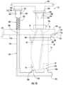
- an adaptor for a cleaning system for additively manufactured componentsincludes a first portion defining an adaptor inlet, an adaptor outlet, one or more channels extending between the adaptor inlet and the adaptor outlet, and an adjustment assembly void.
- a second portionis separated from the first portion through an adjustment assembly.
- An energy deviceis operably coupled with the adjustment assembly and configured to urge the second portion towards the first portion.
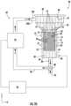
- FIG. 1is a schematic side view of an additive manufacturing apparatus in accordance with various aspects of the present disclosure
- FIG. 2 Ais a schematic side view of a cleaning system in accordance with various aspects of the present disclosure
- FIG. 2 Bis a schematic side view of a cleaning system in accordance with various aspects of the present disclosure
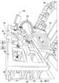
- FIG. 3is a schematic side view of a cleaning system having a support panel and an arm actuator in accordance with various aspects of the present disclosure
- FIG. 4is a front perspective view of a manifold and a support panel operably coupled with the arm actuator in accordance with various aspects of the present disclosure
- FIG. 5is a top perspective view of the manifold and the support panel in accordance with various aspects of the present disclosure
- FIG. 6is a front perspective view of the manifold and the support panel in accordance with various aspects of the present disclosure
- FIG. 7is a side perspective view of the manifold operably coupled with a manifold actuator that alters a position of the manifold relative to the support panel in accordance with various aspects of the present disclosure
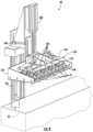
- FIG. 8is a side perspective view of the manifold operably coupled with the manifold actuator with the manifold positioned over a plurality of components positioned within the support panel in accordance with various aspects of the present disclosure
- FIG. 9is a side perspective view of the manifold operably coupled with the manifold actuator with the manifold having a plurality of couplers fluidly coupled with one or more adaptors in accordance with various aspects of the present disclosure
- FIG. 10is a cross-sectional view of an adaptor configured to couple a component to the support panel taken along the line X-X of FIG. 9 in accordance with various aspects of the present disclosure
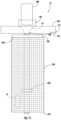
- FIG. 11is a side schematic view of the adaptor configured as a basket that retains the component therein with the basket in a first position in accordance with various aspects of the present disclosure
- FIG. 12is a side schematic view of the adaptor configured as a basket that retains the component therein with the basket in a second position in accordance with various aspects of the present disclosure
- FIG. 13depicts an exemplary computing system within the cleaning system in accordance with various aspects of the present disclosure
- FIG. 14is an illustration of one display of a human-machine interface (HMI) operably coupled with the cleaning system computing system in accordance with various aspects of the present disclosure.
- HMIhuman-machine interface
- FIG. 15is a method of operating the cleaning system in accordance with various aspects of the present disclosure.
- first,” “second,” and “third”may be used interchangeably to distinguish one component from another and are not intended to signify a location or importance of the individual components.
- directional termssuch as top, bottom, left, right, up, down, over, above, below, beneath, rear, back, and front, may be used with respect to the accompanying drawings. These and similar directional terms should not be construed to limit the scope of the disclosure in any manner.
- the apparatus and/or any component described heremay be oriented in one or more orientations that are rotationally offset from those illustrated without departing from the scope of the present disclosure.
- upstream and downstreamrefer to the relative direction with respect to fluid movement through the cleaning system.
- upstreamrefers to the direction from which the fluid moves
- downstreamrefers to the direction to which the fluid moves.
- selectiverefers to a component's ability to operate in various states (e.g., an ON state and an OFF state) based on manual and/or automatic control of the component.
- Approximating languageis applied to modify any quantitative representation that could permissibly vary without resulting in a change in the basic function to which it is related. Accordingly, a value modified by a term or terms, such as “about,” “approximately,” “generally,” and “substantially,” is not to be limited to the precise value specified. In at least some instances, the approximating language may correspond to the precision of an instrument for measuring the value, or the precision of the methods or apparatus for constructing or manufacturing the components and/or systems. For example, the approximating language may refer to being within a ten percent margin.
- the term “and/or,” when used in a list of two or more items,means that any one of the listed items can be employed by itself, or any combination of two or more of the listed items can be employed.
- the composition or assemblycan contain A alone; B alone; C alone; A and B in combination; A and C in combination; B and C in combination; or A, B, and C in combination.
- the present disclosureis generally directed to a cleaning system for an additively manufactured component or any other manufactured component.
- the additively manufactured componentmay be formed such that successive layers of materials are provided on each other to “build-up,” layer-by-layer, a three-dimensional component.
- the successive layersgenerally consolidate together to form a monolithic component which may have a variety of integral sub-components. Due to the component being formed in a layer-by-layer fashion, residual, unconsolidated or partially unconsolidated build material may be retained within the component and/or on the component.
- component accuracy or qualitymay be enhanced through removal of the residual, unconsolidated build material from the component through one or more cleaning processes that individually or in combination remove at least a portion of the residual build material from the component.
- the various cleaning processesmay be implemented in any order for any duration of time based on the component to be cleaned.
- the order of the cleaning processesmay be predefined and/or operator selected.
- the duration of each process and/or the order of processesmay be altered through a Human-Machine Interface (HMI) and/or through any other practicable device.
- HMIHuman-Machine Interface
- one of the various cleaning processescan include flushing a cleaning fluid, which may be in the form of a cleaning liquid and/or a cleaning gas, along the component and/or within one or more features of the component.
- a cleaning fluidwhich may be in the form of a cleaning liquid and/or a cleaning gas
- the features of the componentmay include a channel, a void, a cavity, and/or any other attribute that may be formed within the component.
- one of the various cleaning processesmay also include at least partially submerging the component within the cleaning liquid to remove the residual build material.
- the support panelmay be movable from a first position to a second position. In the first position, the component may be positioned above the cleaning liquid. In the second position, the component may be at least partially submerged in the cleaning liquid within the tank. By moving between the first and second positions, the cleaning liquid may be provided along the component and/or within one or more features of the component, which is then exhausted from the component with the residual build material when the component is returned to the first position.
- one of the various cleaning processesmay also include vibrating (or otherwise agitating) the cleaning fluid with the component at least partially submerged therein to separate the residual build material from the component.
- a vibration modulemay be operably coupled with the tank and configured to oscillate the cleaning liquid within the tank. The movement of the cleaning liquid may further encourage the removal of the residual build material from the component.
- the cleaning systemmay include an adaptor that operably couples with the component.
- the adaptormay include one or more channels therethrough that align with one or more features of the component for directing the cleaning fluid towards the predefined features and/or predefined locations.
- FIG. 1schematically illustrates an example of one type of suitable apparatus 10 for forming a component layer by layer.
- the component 12is created through a stacked arrangement of one or more consolidated layers 14 formed from a build material, such as organic or inorganic powders, binders, and/or resins.
- the apparatus 10can include one or more of a support plate 16 , a window 18 , a stage 20 that is movable relative to the window 18 , and a radiant energy device 22 , which, in combination, may be used to form any number (e.g., one or more) of additively manufactured components 12 .
- the apparatus 10includes a feed module 24 and a take-up module 26 that are spaced-apart with a build material support 28 , such as a flexible tape, a foil, or another type of build material support, extending therebetween.
- a build material support 28such as a flexible tape, a foil, or another type of build material support, extending therebetween.
- Suitable mechanical supportsmay be provided for the feed module 24 , the take-up module 26 , and the support plate 16 .
- the feed module 24 and/or the take-up module 26can be configured to control the speed and direction of the build material support 28 such that the desired tension and speed is maintained in the build material support 28 through a drive system.
- the drive systemcan include various components, such as motors, actuators, feedback sensors, and/or controls to maintain the build material support 28 tensioned between the feed module 24 and the take-up module 26 and to translate the build material support 28 along a path from the feed module 24 to the take-up module 26 .
- the window 18is transparent and can be operably supported by the support plate 16 .
- the build material support 28is also transparent or includes portions that are transparent.
- the terms “transparent” and “radiotransparent”refer to a material that allows at least a portion of radiant energy of a selected wavelength to pass through.
- the radiant energy that passes through the window 18 and the build material support 28can be in the ultraviolet spectrum, the infrared spectrum, the visible spectrum, or any other practicable radiant energy.
- Non-limiting examples of transparent materialsinclude polymers, glass, and crystalline minerals, such as sapphire or quartz.
- the build material support 28defines a first side 30 that defines a “resin surface,” which is shown as being planar, but could alternatively be arcuate.
- the first side 30may be positioned to face the stage 20 with the window 18 on an opposing, second side 32 of the build material support 28 from the stage 20 .
- the first side 30may be considered to be oriented parallel to an X-Y plane of the apparatus 10 , and a direction perpendicular to the X-Y plane is denoted as a Z-axis direction (X, Y, and Z being three mutually perpendicular directions).
- the X-axisrefers to the machine direction along the length of the build material support 28 .
- the Y-axisrefers to the transverse direction across the width of the build material support 28 and generally perpendicular to the machine direction.
- the Z-axisrefers to the stage direction that can be defined as the direction of movement of the stage 20 relative to the window 18 .
- the first side 30may be configured to be “non-stick,” that is, resistant to adhesion of a consolidated build material.
- the non-stick propertiesmay be embodied by a combination of variables such as the chemistry of the build material support 28 , a surface finish of the build material support 28 , and/or coatings applied to the build material support 28 .
- a permanent or semi-permanent non-stick coatingmay be applied.
- a suitable coatingis polytetrafluoroethylene (“PTFE”).
- PTFEpolytetrafluoroethylene
- all or a portion of the first side 30may incorporate a controlled roughness or surface texture (e.g. protrusions, dimples, grooves, ridges, etc.) with nonstick properties.
- the build material support 28may be made in whole or in part from an oxygen-permeable material.
- an area or volume immediately surrounding the location of the build material support 28 and the window 18 or transparent portion defined by the support plate 16may be defined as a “build zone,” labeled 34 .
- a material depositor 36may be upstream of the build zone 34 .
- the material depositor 36may be any device or combination of devices that is operable to apply a build material on the resin support 28 .
- the material depositor 36may optionally include a device or combination of devices to define a height of the build material on the resin support 28 and/or to level the build material on the build material support 28 .
- suitable material deposition devicesinclude chutes, hoppers, pumps, spray nozzles, spray bars, or printheads (e.g. inkjets).
- a doctor blademay be used to control the thickness of build material applied to the build material support 28 , as the build material support 28 passes the material depositor 36 .
- the build materialincludes any material that is capable of adhering or binding together the filler (if used) in the consolidated state.
- the term “radiant-energy curable”refers to any material which solidifies or partially solidifies in response to the application of radiant energy of a frequency and energy level.
- the build materialmay include a photopolymer resin containing photo-initiator compounds functioning to trigger a polymerization reaction, causing the build material to change from a liquid (or powdered) state to a solid state.
- the build materialmay include a material that contains a solvent that may be evaporated out by the application of radiant energy.
- the unconsolidated build materialmay be provided in solid (e.g. granular) or liquid form, including a paste or slurry.
- the build materialcan have a relatively high viscosity fluid that will not “slump” or run off during the build process.
- the composition of the build materialmay be selected as desired to suit an application. Mixtures of different compositions may be used.
- the build materialmay be selected to have the ability to out-gas or burn off during further processing, such as a sintering process.
- the build materialmay incorporate a filler.
- the fillermay be pre-mixed with the build material, then loaded into the material depositor 36 .
- the fillerincludes particles, which may be defined as “a small bit of matter.”
- the fillermay include any material that is chemically and physically compatible with the selected build material.
- the particlesmay be regular or irregular in shape, may be uniform or non-uniform in size, and may have variable aspect ratios.
- the particlesmay take the form of powder, of small spheres or granules, or may be shaped like small rods or fibers.
- the composition of the fillermay be selected as desired to suit an application.
- the fillermay be metallic, ceramic, polymeric, and/or organic.
- Other examples of potential fillersinclude diamond, silicon, and graphite. Mixtures of different compositions may be used.
- the filler compositionmay be selected for its electrical or electromagnetic properties, e.g. it may specifically be an electrical insulator, a dielectric material, an electrical conductor, and/or magnetic.
- the fillermay be “fusible,” meaning it is capable of consolidation into a mass upon via application of enough energy.
- fusibilityis a characteristic of many available powders including, but not limited to, polymeric, ceramic, glass, and/or metallic materials.
- the proportion of filler to build materialmay be selected to suit an application. Generally, any amount of filler may be used so long as the combined material is capable of flowing and being leveled, and there is enough build material to hold together the particles of the filler in the consolidated state.
- the stage 20is capable of being oriented parallel to the first side 30 or the X-Y plane.
- Various devicesmay be provided for moving the stage 20 relative to the window 18 parallel to the Z-axis direction.
- the movementmay be provided through an actuator 38 connected between the stage 20 and a static support 40 and configured to change a relative position of the stage 20 relative to the radiant energy device 22 , the support plate 16 , the window 18 , and/or any other static component of the apparatus 10 .
- the actuator 38may be configured as a ballscrew electric actuator, linear electric actuator, pneumatic cylinder, hydraulic cylinder, delta drive, or any other practicable device may additionally or alternatively be used for this purpose.
- the build material support 28could be movable parallel to the Z-axis direction.
- the radiant energy device 22may be configured as any device or combination of devices operable to generate and project radiant energy on the build material in a suitable pattern and with a suitable energy level and other operating characteristics to cure the build material during the build process.
- the radiant energy device 22may include a projector 42 , which may generally refer to any device operable to generate a radiant energy patterned image of suitable energy level and other operating characteristics to cure the build material.
- the term “patterned image”refers to a projection of radiant energy comprising an array of one or more individual pixels.
- Non-limiting examples of patterned imaged devicesinclude a DLP projector or another digital micromirror device, a two-dimensional array of LEDs, a two-dimensional array of lasers, and/or optically addressed light valves.
- the projector 42includes a radiant energy source 44 such as a UV lamp, an image forming apparatus 46 operable to receive a source beam 48 from the radiant energy source 44 and generate a patterned image 50 to be projected onto the surface of the build material, and optionally focusing optics 52 , such as one or more lenses.
- the image forming apparatus 46may include one or more mirrors, prisms, and/or lenses and is provided with suitable actuators and arranged so that the source beam 48 from the radiant energy source 44 can be transformed into a pixelated image in an X-Y plane coincident with the surface of the build material.
- the image forming apparatus 46may be a digital micro-mirror device.
- the projector 42may incorporate additional components, such as actuators, mirrors, etc. configured to selectively move the image forming apparatus 46 or other part of the projector 42 with the effect of rastering or shifting the location of the patterned image on the first side 30 . Stated another way, the patterned image may be moved away from a nominal or starting location.
- the radiant energy device 22may include a “scanned beam apparatus” used herein to refer generally to any device operable to generate a radiant energy beam of suitable energy level and other operating characteristics to cure the build material and to scan the beam over the surface of the build material in a desired pattern.
- the scanned beam apparatuscan include a radiant energy source 44 and a beam steering apparatus.
- the radiant energy source 44may include any device operable to generate a beam of suitable power and other operating characteristics to cure the build material.
- suitable radiant energy sources 44include lasers or electron beam guns.
- the apparatus 10may be operably coupled with an apparatus computing system 54 .
- the apparatus computing system 54 in FIG. 1is a generalized representation of the hardware and software that may be implemented to control the operation of the apparatus 10 , including some or all of the stage 20 , the radiant energy device 22 , the actuator 38 , and the various parts of the apparatus 10 described herein.
- the apparatus computing system 54may be embodied, for example, by software running on one or more processors embodied in one or more devices such as a programmable logic controller (“PLC”) or a microcomputer.
- PLCprogrammable logic controller
- Such processorsmay be coupled to process sensors and operating components, for example, through wired or wireless connections.
- the same processor or processorsmay be used to retrieve and analyze sensor data, for statistical analysis, for feedback control, and/or feedforward control. Numerous aspects of the apparatus 10 may be subject to closed-loop control.
- the components of the apparatus 10may be surrounded by an apparatus housing 56 , which may be used to provide a shielding or inert gas (e.g., a “process gas”) atmosphere using housing ports 56 A.
- a shielding or inert gase.g., a “process gas”
- pressure within the apparatus housing 56could be maintained at a desired level greater than or less than atmospheric.
- the apparatus housing 56could be temperature and/or humidity controlled.
- ventilation of the apparatus housing 56could be controlled based on factors such as a time interval, temperature, humidity, and/or chemical species concentration.
- the apparatus housing 56can be maintained at a pressure that is different than an atmospheric pressure.
- FIG. 1is for illustrative purposes. Accordingly, any other additive manufacturing process or subtractive manufacturing process may be used in conjunction with or in lieu of the additive manufacturing apparatus 10 described in FIG. 1 to form the component 12 without departing from the scope of the present disclosure.
- the cleaning system 60may be capable of conducting one or more processes that may individually or in combination remove at least a portion of the residual build material 58 from the component 12 , which may enhance component accuracy or quality.
- the cleaning system 60may be configured to flush a cleaning fluid 70 (e.g., a cleaning liquid and/or a cleaning gas) along the component 12 and/or within one or more features 78 of the component 12 .
- the cleaning system 60may be further configured to at least partially surround the component 12 within a cleaning liquid to remove the residual build material 58 .
- the cleaning fluid 70may be vibrated to separate the residual build material 58 from the component 12 .
- the various cleaning processesmay be implemented in any order for any duration of time based on the component 12 to be cleaned.
- the cleaning system 60may include a trough or tank 62 that includes tank walls 64 and a tank floor 66 , which generally define an interior volume 68 for holding a cleaning fluid 70 .
- the tank walls 64 and tank floor 66can be fabricated in a sealed arrangement that that may be formed from a metallic material, a polymeric material, and/or any other practicable material without any openings therethrough, except for fluid lines.
- the tank 62may include an asymmetrical cross-sectional area that is configured to alter a flow rate of the cleaning fluid 70 .
- the tank 62may include a funnel section that feeds a constriction section.
- the tank 62may have a first flow rate prior to the constriction section and a second flow rate within the constriction section with the second flow rate being higher than the first flow rate.
- the second flow ratemay be between 0.25 meters per second (m/s) and 3.5 m/s.
- the first flow rate and the second flow ratemay be any desired flow rate without departing form the scope of the present disclosure.
- each of the first flow rate and the second flow ratemay be laminar or turbulent based on the design of the component 12 .
- one or more fluid movement assemblies 74may be disposed within the funnel section, upstream of the constriction section, and/or near the one or more channels 76 to increase fluid flow along the component 12 and/or through the one or more features 78 of the component 12 .
- the fluid movement assemblymay be configured to alter a flow rate along a first portion of the component 12 relative to a second portion of the component 12 .
- the fluid movement assembly 74may be configured to generate a turbulent flow along the perimeter of the component while maintained a laminar flow through one or more features 78 of the component, or vice versa.
- the tank 62may include a funnel section downstream of the constriction section.
- the tank 62may have a first flow rate within the constriction section and a second flow rate within the funnel section with the second flow rate being lower than the first flow rate.
- the first flow ratemay be between 0.25 meters per second (m/s) and 3.5 m/s.
- the first flow rate and the second flow ratemay be any desired flow rate without departing form the scope of the present disclosure.
- each of the first flow rate and the second flow ratemay be laminar or turbulent based on the design of the component 12 .
- the tank 62may alternatively have any other different geometric cross sections without departing from the scope of the present disclosure. Suitable volumes for the interior volume 68 may also vary depending on particular needs.
- the one or more fluid movement assemblies 74may be disposed within the funnel section, downstream of the constriction section, and/or downstream of the component 12 to increase fluid flow along the component 12 and/or through the one or more features 78 of the component 12 .
- the fluid movement assembly 74may be configured to alter a flow rate along a first portion of the component 12 relative to a second portion of the component 12 .
- the fluid movement assembly 74may be configured to generate a turbulent flow along the perimeter of the component while maintained a laminar flow through one or more features 78 of the component, or vice versa.
- the tank 62may include one or more fluid movement assemblies 74 along one or more of the sidewalls 64 of the tank 62 .
- the one or more fluid movement assemblies 74may be configured to provide a suction away from the component 12 and/or a flow towards the component 12 from the sidewall 64 .
- the one or more fluid movement assemblies 74 along the one or more of the sidewalls 64 of the tank 62may also alter a flow path of the cleaning fluid 70 as the cleaning fluid 70 passes along and/or through the component 12 .
- the component 12may be selectively retained within the tank 62 through an adaptor 72 .
- the adaptor 72may suspend the component 12 within the tank 62 so that the cleaning fluid 70 may generally surround the component 12 .
- the adaptor 72may define one or more channels 76 that may align with a perimeter of the component 12 and/or one or more features 78 of the component 12 .
- the adaptor 72may include a mesh, sieve, or any other structure with channels 76 to allow fluid to pass therethrough with minimal disruption.
- the component 12may be oriented such that one or more of the features 78 are oriented in a predefined manner to encourage flow through preselected features. For instance, the component 12 may be aligned with the adaptor 72 such that the largest features 78 of the component 12 are oriented upwardly to encourage more fluid to enter the component 12 from a fluid circuit 84 . Additionally and/or alternatively, the component 12 may be aligned with the adaptor 72 such that the largest features 78 of the component 12 are oriented downwardly to encourage residual build material 58 to exit the component instead of being trapped within the one or more features 78 . In other embodiments, the component 12 may be oriented in any other direction based on various design considerations.
- a reservoir 80may be fluidly coupled with the tank 62 .
- the reservoir 80may receive the cleaning fluid 70 therein, which, in turn, is delivered to the tank 62 .
- a cover 82may be secured to the reservoir 80 such that the cover 82 may be moved between a closed position to cover the reservoir 80 and an open position to permit access to the reservoir 80 .
- the reservoir 80may be fluidly coupled with the tank 62 in any other fashion without departing from the scope of the present disclosure.
- the cleaning fluid 70may be removed from the tank 62 and introduced into the reservoir 80 through a fluid circuit 84 .
- the fluid circuit 84may include an outlet line 86 through which the cleaning fluid 70 may exit the tank 62 .
- a valve 88may be coupled with the outlet line 86 and configured to selectively deliver the cleaning fluid 70 to a supply line 90 and/or a drain 92 .
- the supply line 90can be a fluid line for transferring the cleaning fluid 70 from the tank 62 through the fluid circuit 84 and back to the tank 62 and/or to the reservoir 80 .
- the drain 92may be used for discarding the cleaning fluid 70 from the tank 62 .
- the batch volume of the cleaning fluid 70may be drained from the tank 62 and/or the reservoir 80 , and a fresh batch cleaning fluid 70 may be introduced for subsequent use.
- a pump 94is positioned along the fluid circuit 84 and configured to move the cleaning fluid 70 from the outlet line 86 to the reservoir 80 .
- the pump 94may be an explosion-proof pump that is rated for use in a hazardous environment as defined by relevant standards within the industry and field. For instance, those who work in the industry and field understand that industry standards organizations set standards and that products are submitted for testing in accordance with such standards in order to receive a certification from one or more of such industry standards organizations. One such organization is Underwriters Laboratories or “UL.” Another is Factory Mutual Research of Norwood, Mass. or “FM”. A pump submitted for testing by FM and approved as rated to meet an FM standard may be said to have an FM Listing for that standard and be so marked.
- the pump 94 of the cleaning system 60may meet the UL standard, the FM standard, and/or any other standard for being defined as an explosion-proof pump.
- the pump 94may be configured as a centrifugal pump, a positive displacement pump, and/or any other pump to hydraulically convey and circulate the cleaning fluid 70 between the tank 62 and/or the reservoir 80 .
- the cleaning fluid 70can be any liquid and/or a gas that can remove any of the residual build material 58 provided on the component 12 .
- the cleaning liquidmay include water and/or solvents.
- the suitable solventsdepend on the build material 58 , but can, in general, include organic solvents, which may be of intermediate polarity, such as methanol, methylethylketone, ethanol, isopropyl alcohol, trichloroethane, or the like.
- the gasmay be of any practicable form.
- the gasmay be a process gas that is provided by one or more modules (i.e., any device or combination of devices) of the cleaning system 60 , such as the pump 94 .
- the pump 94may be operably coupled with a cleaning system computing system 96 for selective actuation thereof.
- the cleaning system computing system 96 in FIGS. 2 A and 2 Bis a generalized representation of the hardware and software that may be implemented to control the operation of the cleaning system 60 described herein.
- the cleaning system computing system 96may be embodied, for example, by software running on one or more processors embodied in one or more devices such as a programmable logic controller (“PLC”) or a microcomputer.
- PLCprogrammable logic controller
- Such processorsmay be coupled to process sensors and operating components, for example, through wired or wireless connections.
- the same processor or processorsmay be used to retrieve and analyze sensor data, for statistical analysis, for feedback control, and/or feedforward control.
- the cleaning system computing system 96may be operably coupled with and/or integrated with the apparatus computing system 54 .
- the apparatus computing system 54 and the apparatus computing system 54may be a common component.
- the cleaning fluid 70may be moved from the tank 62 , to the fluid circuit 84 , and onto the reservoir 80 . As the cleaning fluid is circulated, the cleaning fluid may contact the residual build material 58 on the component 12 and remove the residual build material 58 from the component 12 .
- the cleaning system 60can include at least one vibration module 98 operably coupled with the tank 62 .
- the vibration module 98can be any suitable vibratory transducer.
- the vibration module 98can include a pneumatically-driven vibration device.
- One or more vibration modules 98can be placed on the outside of and/or within the tank 62 in any suitable location to transmit vibrations to the cleaning fluid 70 , which in turn, may assist in separating the residual build material 58 from the additively manufactured component 12 when the additively manufactured component 12 is within the tank 62 .
- a filter system 100may be positioned along a cleaning fluid flow path, which is exemplarily illustrated by arrows within the fluid circuit 84 illustrated in FIGS. 2 A and 2 B .
- the filter system 100may be positioned within the fluid circuit 84 .
- the filter system 100may include at least one filter 100 A configured to remove at least a portion of the residual build material 58 within the cleaning fluid 70 prior to the cleaning fluid 70 being returned to the reservoir 80 , the adaptor 72 , and/or the tank 62 .
- the filter system 100may be removable such that the filter 100 A may be interchangeable based on the type of residual build material 58 , a soil level, etc., and/or cleaned and returned to the cleaning system 60 once the residual build material 58 is removed from the filter system 100 .
- the stage 20 of the apparatus 10 described in reference to FIG. 1may also form the adaptor 72 .
- the stage 20may allow the cleaning fluid 70 to pass therethrough.
- the stage 20may include one or more channels 76 that align with the one or more features 78 of the component 12 .
- the stage, or a portion thereofmay be removed from the apparatus 10 and placed within the cleaning system 60 with the component 12 attached thereto.
- the cleaning systemmay surround the stage 20 with the stage 20 remaining the apparatus 10 and the tank 62 surrounding a portion of the stage 20 .
- the one or more channels 76 of the stage 20 and/or the adaptor 72may be plugged during a building operation and unplugged during a cleaning operation.
- the cleaning system 60may be configured to remove the residual build material 58 ( FIGS. 2 A and 2 B ) from the component 12 through one or more cleaning processes.
- the cleaning system 60may be configured to remove residual build material 58 from the component 12 by submerging the component 12 within the cleaning fluid, vibrating the cleaning liquid with the component 12 submerged therein, and/or flushing the cleaning liquid along the component 12 and/or through one or more features 78 ( FIG. 7 ) of the component 12 .
- Certain additively manufactured components 12may benefit from exposure to the cleaning liquid several times and/or in different orientations to enhance residual build material removal. As such, each of the cleaning processes may be completed in any order for any duration of time. Dimensional analysis can be performed on a component 12 to ensure geometric stability of the component 12 for the given duration of exposure in the cleaning liquid.
- the cleaning system 60includes a tank 62 having tank walls 64 and a tank floor 66 , which define interior volume 68 for holding the cleaning liquid.
- an agitator 102may be coupled with the tank floor 66 and configured to reduce separation of the residual build material 58 and the cleaning liquid in the tank 62 .
- the agitator 102may include a movable element 104 (e.g., a magnetic spinner) within the tank 62 and an actuation device 106 positioned externally from the tank 62 .
- the tank floor 66may be considered to be oriented parallel to an X-Y plane of the cleaning system 60 , and a direction perpendicular to the X-Y plane is denoted as a Z-axis direction (X, Y, and Z being three mutually perpendicular directions).
- An arm actuator 108may be positioned proximately to the tank 62 and configured to move a support panel 110 affixed thereto between at least a first position and a second position.
- the support panel 110may be configured to support the component 12 either through coupling the component 12 to the support panel 110 , either with or without an adaptor 72 .
- the arm actuator 108may be coupled with a static support 109 .
- the support panel 110In the first position, the support panel 110 may be located a first distance d 1 from the tank floor 66 . In the second position, the support panel 110 may be located a second distance d 2 (as shown in FIG. 3 ) from the tank floor 66 . In various examples, the second distance is less than the first distance.
- the arm actuator 108may be configured as a pneumatic cylinder. Additionally, or alternatively, the arm actuator 108 may be configured as one or more of a ballscrew electric actuator, linear electric actuator, hydraulic cylinder, delta drive, or any other practicable device.
- the tank 62In addition to, or as an alternative to, making the support panel 110 movable, the tank 62 may be operably coupled with the arm actuator 108 .
- the support panel 110may be configured to retain one or more components 12 there along. In some instances, one or more components 12 may extend downwardly from the support panel 110 . However, the one or more components 12 may also extend upwardly and/or generally align with the support panel 110 without departing from the teachings provided herein. In various examples, the support panel 110 may be formed from a metallic material, a polymeric material, and/or any other material that may be capable of contact with the cleaning fluid 70 with minimal to no degradation.
- an adaptor 72may be utilized for coupling each of the components 12 to the support panel 110 .
- the adaptor 72may have a retention assembly 112 for maintaining a generally constant position of the adaptor 72 relative to the support panel 110 while maintaining each of the components 12 in a predefined position.
- the cleaning system 60may further include a vibration module 98 that may be operably coupled with the tank 62 and configured to vibrate the cleaning liquid within the tank 62 at a pre-defined pressure.
- a pneumatic pressuremay dictate the amplitude of the vibration.
- the vibration module 98can be a pneumatic vibratory transducer that includes a pneumatically-driven vibration module 98 .
- One or more vibration modules 98can be placed on the outside of and/or within the tank 62 in any suitable location to transmit vibrations/oscillations to the cleaning liquid, which in turn, may assist in separating the residual build material 58 from the additively manufactured component 12 when the support panel 110 is placed in the second position.
- the tank 62may be supported by vibration-isolating feet 114 that may assist in isolating the vibration of the tank 62 from the remaining modules of the cleaning system 60 .
- the vibrationmay be produced as the cleaning liquid within the tank 62 is oscillated, when the agitator 102 is operated, when the support panel 110 is moved between the first and second positions, and/or through the actuation of any other module of the cleaning system 60 .
- the vibration-isolating feet 114include a support structure 116 and base structure 118 .
- the support structure 116may be operably coupled with the tank 62 on a first portion thereof and with the base structure 118 on a second portion of the support structure 116 .
- the length of the support structure 116may be adjustable to place the tank 62 in a desired orientation.
- the base structure 118may be positioned between the second portion of the support structure 116 and a cleaning system housing 120 , a ground structure, and/or any other structure.
- the base structure 118may be formed from a motion attenuating material, such as any of a wide variety of elastomers including, but not limited to, natural rubber and polychloroprene, also known as neoprene.
- the tank 62may be coupled with a fluid circuit 84 , in which the fluid circuit may accept the cleaning fluid 70 from the tank through an outlet line 86 .
- the fluid circuit 84may direct fluid from the tank 62 through a pump 94 , one or more filters 100 A, 100 B, a temperature control system 122 , and back to the tank 62 .
- the cleaning liquid 70may be returned to the tank 62 through a conduit 124 and/or through a manifold 126 .
- the manifold 126may include one or more hoses 128 and/or couplers 242 ( FIG. 7 ) that are operably coupled with the component 12 and/or the adaptor 72 for directing the cleaning liquid into the one or more features 78 ( FIG. 10 ) of the component 12 and/or along the component 12 .
- the one or more pumps 94may be used to move the cleaning fluid 70 through the fluid circuit 84 .
- the pump 94may be configured as a centrifugal pump, a positive displacement pump, and/or any other pump to hydraulically convey and circulate the cleaning liquid in and through the tank 62 and/or the reservoir 80 .
- the pump 94may be an explosion-proof pump, as discussed with reference to the embodiment described in FIGS. 2 A and 2 B .
- the filter system 100may include one or more filters 100 A, 100 B that are positioned upstream and/or downstream of the pump 94 .
- the filter system 100may be configured to remove at least a portion of the residual build material 58 within the cleaning liquid prior to the cleaning liquid being delivered to the reservoir 80 ( FIG. 2 A ), the manifold 126 , the adaptor 72 , and/or the tank 62 .
- the one or more filters 100 A, 100 Bmay be determined based on the type of build material 58 used to create the component 12 .
- the types of filterscan also influence a size of the pump size and/or a power of the pump within the fluid circuit 84 .
- an explosion-proof pump 94may be configured to move the cleaning liquid through the fluid circuit 84 and through the manifold 126 .
- a first, explosion-proof pump 94may be utilized to move the cleaning fluid through the filter system 100 and a second pump 94 , which may be a peristaltic pump, may push the cleaning liquid through the manifold 126 .
- Each of the filters 100 A, 100 Bmay include a casing 130 and a filter element 132 within each respective casing 130 .
- the filter elements 132may prevent various suspended solids contained in the cleaning liquid (e.g., residual build material 58 , sediment, dirt, etc.) from passing through the filter 100 A, 100 B.
- the filter element 132may retain dissolved contaminants in the cleaning liquid (e.g., residual build material 58 ) and particulates down to 5, microns, 3 microns, 1 micron, 0.5 microns, 0.1 microns, and/or any other size.
- each filter 100 A, 100 Bmay be of a varied type and/or configured to filter a varied size of particle.
- each of the one or more filters 100 A, 100 Bmay be configured as a surface filter (e.g., a solid sieve which traps the solid particles, with or without the aid of filter paper such as a Buchner funnel, belt filter, rotary vacuum-drum filter, crossflow filters, screen filter), a depth filter (e.g., a bed of granular material which retains the solid particles as it passes, such as a sand filter), and/or any other type of practicable filter.
- a surface filtere.g., a solid sieve which traps the solid particles, with or without the aid of filter paper such as a Buchner funnel, belt filter, rotary vacuum-drum filter, crossflow filters, screen filter
- a depth filtere.g., a bed of granular material which retains the solid particles as it passes, such as a sand filter
- the temperature control system 122may be operably coupled with the fluid circuit 84 .
- the temperature control system 122may be configured to raise and/or reduce a temperature of the cleaning liquid as the cleaning liquid passes through the fluid circuit 84 , which may increase the efficiency of the cleaning system 60 and/or provide any other benefit.
- the temperature control system 122may include a chiller and/or a heat exchanger.
- the heat exchangermay be configured as a shell and tube heat exchanger, a plate heat exchanger, a plate and shell heat exchanger, an adiabatic wheel heat exchanger, a plate fin heat exchanger, a pillow plate heat exchanger, a fluid heat exchanger, a waste heat recovery unit, a dynamic scraped surface heat exchanger, a phase-change heat exchanger, a direct contact heat exchanger, a microchannel heat exchanger, and/or any other type of heat exchanger.
- a three-way valve 134may be positioned between the pump 94 , a conduit 124 , and a by-pass pipe 136 .
- the three-way valve 134may direct the cleaning liquid within the fluid circuit 84 from the pump 94 to the conduit 124 .
- the conduit 124in turn, can direct the cleaning liquid towards the manifold 126 through one or more conduit outlets 138 and/or through a tank return line 140 .
- the manifold 126is operably coupled with the one or more conduit outlets 138 through one or more manifold lines 152 .
- a two-way valve 142may separate the tank return line 140 from the one or more conduit outlets 138 .
- the cleaning liquidis directed through the one or more conduit outlets 138 .
- the cleaning liquidis directed through the one or more conduit outlets 138 and through the tank return line 140 .
- the three-way valve 134may direct the cleaning liquid within the fluid circuit 84 from the pump 94 to the by-pass pipe 136 .
- the by-pass pipe 136may be fluidly coupled with the conduit 124 at a position between the two-way valve 142 and the tank return line 140 .
- the cleaning liquidmay by-pass the one or more conduit outlets 138 and returned to the tank 62 .
- the cleaning system 60may include a gas supply 144 operably coupled to the manifold 126 .
- the gas supply 144may be configured to provide a cleaning gas through the manifold 126 and along the component 12 and/or into one or more features 78 ( FIG. 10 ) of the component 12 .
- the cleaning gasmay generally be high volume, low pressure (HVLP) to prevent degradation of the structure of the component 12 while removing the residual build material 58 from the component 12 .
- HVLPhigh volume, low pressure
- the gas supply 144may be shop gas (e.g., process air) that is provided through the operation of a module of the cleaning system 60 and/or provided by a blower/compressor 146 .
- the cleaning gasmay be directed through a filter 148 , which may be configured as a high efficiency particulate arrester (HEPA) filter and/or any other type of practicable filter. From the filter 148 , the cleaning gas may be passed through a regulator 150 , which may reduce (or increase) a pressure of the cleaning gas prior to the cleaning gas entering the manifold 126 , which may then direct the cleaning gas to one or more of the additively manufactured components 12 .
- HEPAhigh efficiency particulate arrester
- the manifold 126may be coupled to the arm actuator 108 in a fixed relationship and/or in a translatable manner relative to the support panel 110 (e.g., through a separate actuator).
- the manifold 126may move in conjunction with the support panel 110 as the support panel 110 is moved between the first and second positions.
- the manifold 126may be positioned above the cleaning liquid within the tank 62 when the support panel 110 is in both of the first and second positioned. It will be appreciated that, in other embodiments, the manifold 126 may be affixed to any other module or structure without departing from the teachings provided herein.
- the manifold 126may include one or more hoses 128 that can be operably coupled with the component 12 and/or the adaptor 72 for directing the cleaning liquid into the one or more features 78 ( FIG. 10 ) of the component 12 and/or along the component 12 .
- each of the one or more hoses 128may have a first length as the hoses 128 also move in conjunction with the manifold 126 and the support panel 110 .
- the one or more hoses 128may be of a second length. In various embodiments, the second length may be longer than the first to accommodate for the change in distance between the manifold 126 and the support panel 110 as the support panel 110 is moved between the first position and the second position.
- the manifold 126may include one or more segments 156 , 158 with each segment 156 , 158 being fed a cleaning liquid from the fluid circuit 84 through a respective manifold line 152 operably coupled with the fluid circuit 84 and/or a cleaning gas from the gas supply 144 through a respective gas line 154 .
- various segments 156 , 158may be provided with a cleaning fluid 70 through a common supply line.
- Each of the one or more segments 156 , 158 of the manifold 126may be independently controllable relative to one another.
- the first segment 156 and the second segment 158may each include a respective solenoid bank.
- Each solenoid bankmay include one or more valves for controlling the cleaning liquid output through each hose 128 .
- each hose 128may be fluidly coupled with a pair of valves within a respective solenoid bank.
- a cleaning liquidmay be provided through the respective hose 128 .
- a cleaning gasmay be provided through the respective hose 128 .
- a mixed cleaning liquidmay be provided through the respective hose 128 , which may create a foam in which the cleaning liquid includes bubbles generated by the cleaning gas.
- the hose 128may be free from cleaning liquid flow.
- any other system capable of allowing a cleaning liquid, a cleaning gas, a mixed cleaning fluid 70 , and/or a blockage of cleaning fluid 70 through the hose 128may be used in place of or in conjunction with the system described herein, such as a three-way valve.
- a tank sweep device 177may be positioned within the tank 62 and fluidly coupled with a sweep outlet 178 through a sweep line 179 .
- the tank sweep device 177may define a plurality of openings 180 there along that are configured to direct cleaning fluid 70 along a lower portion of the tank 62 .
- the movement of the cleaning fluid 70 along the lower portion of the tank 62may be configured to reduce separation of the residual build material 58 and the cleaning fluid 70 in the tank 62 .
- the cleaning system 60may include a cleaning system housing 120 , which may be used to provide a shielding or inert gas (e.g., a “process gas”) atmosphere using gas ports 162 .
- a shielding or inert gase.g., a “process gas”
- pressure within the cleaning system housing 120could be maintained at a desired level greater than or less than atmospheric.
- the cleaning system housing 120could be temperature and/or humidity controlled.
- ventilation of the cleaning system housing 120could be controlled based on factors such as a time interval, temperature, humidity, and/or chemical species concentration.
- the cleaning system housing 120can be maintained at a pressure that is different than an atmospheric pressure.
- the cleaning fluid 70 utilized within the cleaning system 60may be a solvent that may be flammable.
- the vibration module 98 and the arm actuator 108may be pneumatically controlled.
- portions of the pump 94 , the temperature control system 122 , and/or the gas supply 144 that are positioned within the cleaning system housing 120may generally be explosion-proof to mitigate any operational issues.
- the cleaning system computing system 96may be communicatively coupled with a human-machine interface (HMI) 160 , each of which may be positioned externally from the cleaning system housing 120 .
- the HMI 160may provide information related to the cleaning system 60 to the operator and/or allow the operator to interface with the cleaning system computing system 96 to alter one or more settings or operations of the cleaning system 60 .
- the support panel 110may include a backing plate 164 , a pair of side plates 166 , and a base plate 168 .
- the backing plate 164 and the side plates 166may be coupled to or integrally formed with the base plate 168 .
- the base plate 168may define one or more through-holes 170 .
- Each through-hole 170allows the cleaning liquid within the tank 62 to pass therethrough as the support panel 110 is moved from the first position to the second position and/or the second position to the first position thereby reducing the amount of resistance provided by the support panel 110 on the arm actuator 108 during movement. By reducing the amount of resistance provided by the support panel 110 during movement between the second position and the first position, or vice versa, the amount of power needed to actuate the arm actuator 108 may be reduced.
- the one or more through-holes 170may reduce cavitation as the support panel 110 is moved from the first position to the second position and/or the second position to the first position. Additionally or alternatively, the one or more through-holes 170 may minimize cycle time from an oscillation process to a vibration process by reducing the liquid cavitation and, thus, a dwell process after the oscillation and vibration processes allowing the cleaning solution to settle in less time.
- the base plate 168may further define one or more component voids 172 .
- a component 12may be suspended within a respective component void 172 .
- the component 12may be coupled with the adaptor 72 , which is then further coupled to the base plate 168 to retain the component 12 within the component void 172 .
- the retention assembly 112may be used to removably couple the adaptor 72 to the support panel 110 .
- the retention assembly 112may include a pair of magnets 174 , 176 with a first magnet 174 positioned within the support panel 110 and a second magnet 176 positioned within the adaptor 72 .
- the adaptor 72may be retained on the support panel 110 .
- each of the first magnet 174 and the second magnet 176may be positioned in defined position to create a poka-yoke design in which the adaptor 72 is aligned in a predefined orientation when the first and second magnets 174 , 176 are aligned with one another.
- the retention assembly 112may additionally or alternatively include a clamp, a clip, and/or any other device capable of retaining the adaptor 72 in a defined position relative to the support panel 110 .
- the manifold 126includes first and second segments 156 , 158 .
- Each segment 156 , 158includes a manifold line 152 that can receive the cleaning liquid from the fluid circuit 84 ( FIG. 3 ) and a cleaning gas line 154 from the gas supply 144 ( FIG. 3 ).
- Each of the manifold line 152 and the gas line 154may be directed along the arm actuator 108 and positioned within a retainer system 182 .
- the retainer system 182may be configured to maintain each of the manifold line 152 and the gas line 154 as the position of the manifold 126 is altered.
- the manifold 126may include one or more pressure gauges 184 that are configured to monitor a pressure of the cleaning fluid 70 ( FIG. 3 ) (e.g., cleaning liquid and/or the cleaning gas).
- the one or more pressure gauges 184may be operably coupled with the cleaning system computing system 96 and/or the HMI 160 . When a pressure falls outside of a predefined range, as detected by the one or more pressure gauges 184 , a notification may be provided on the HMI 160 and/or through any other practicable device.
- Each segment 156 , 158 of the manifold 126can include one or more hoses 128 that may be operably coupled with the adaptor 72 and/or the additively manufactured component 12 .
- a connector assembly 186may be coupled to an end portion of each respective hose 128 that allows for fluid coupling of the hose 128 to the additively manufactured component 12 , with or without an adaptor 72 .
- the arm actuator 108may be configured to translate both the manifold 126 and the support panel 110 simultaneously between a plurality of positions, including at least a position in which the support panel 110 is within the tank 62 and a position in which the support panel 110 is above the tank 62 .
- the manifold 126may be operably coupled with a manifold actuator 240 that translates the manifold 126 towards and away from the support panel 110 .
- the manifold actuator 240may be configured as a pneumatic cylinder.
- the manifold actuator 240may be configured as one or more of a ballscrew electric actuator, linear electric actuator, hydraulic cylinder, delta drive, or any other practicable device.
- the manifold 126may include a plurality of couplers 242 extending from the manifold 126 that can be positioned within the component 12 and/or the adaptor 72 for directing the cleaning liquid into the one or more features 78 ( FIG. 10 ) of the component 12 and/or along the component 12 .
- the manifold 126may include one or more segments 156 , 158 with each segment 156 , 158 being fed a cleaning liquid from the fluid circuit 84 ( FIG. 3 ) through a respective manifold line 152 operably coupled with the fluid circuit 84 and/or a cleaning gas from the gas supply 144 ( FIG. 3 ) through a respective gas line 154 .
- various segments 156 , 158may be provided with a cleaning fluid 70 through a common supply line.
- Each of the one or more segments 156 , 158 of the manifold 126may be independently controllable relative to one another.
- the first segment 156 and the second segment 158may each include a respective solenoid bank.
- Each solenoid bankmay include one or more valves for controlling the cleaning liquid output through each coupler 242 .
- each coupler 242may be fluidly coupled with a pair of valves within a respective solenoid bank. When the first valve is opened and the second valve is closed, a cleaning liquid may be provided through the respective coupler 242 . When the first valve is closed and the second valve is opened, a cleaning gas may be provided through the respective coupler 242 .
- a mixed cleaning liquidmay be provided through the respective coupler 242 , which may create a foam in which the cleaning liquid includes bubbles generated by the cleaning gas.
- the coupler 242may be free from cleaning liquid flow.
- any other system capable of allowing a cleaning liquid, a cleaning gas, a mixed cleaning fluid, and/or a blockage of cleaning fluid through the coupler 242may be used in place of or in conjunction with the system described herein, such as a three-way valve.
- the manifold 126 and the support panel 110may be positioned above the tank 62 with the manifold 126 separated from the support panel 110 .
- the component 12may be positioned within a component void 172 .
- the component 12may be coupled with the adaptor 72 ( FIG. 8 ), which is then further coupled to the base plate 168 to retain the component 12 within the component void 172 .
- the manifold 126may be translated towards the support panel 110 .
- each of the plurality of couplers 242 defined by the manifold 126may align with the adaptors 72 .
- the manifold 126may continue to translate towards the support panel 110 until the manifold 126 is separated from the support panel 110 by a predefined distance and/or until the plurality of couplers 242 are fluidly coupled with the components 12 and/or the adaptors 72 .
- the cleaning system 60may be configured to fluidly couple the manifold 126 to the components 12 , with or without an adaptor 72 and with or without operator intervention.
- the manifold actuator 240is operably coupled with the computing system 96 and is configured to move a defined distance to separate and couple with the components 12 and/or the adaptors 72 .
- the manifold 126 and/or the manifold actuator 240may include a position sensor 244 that is configured to determine a movement location of the manifold 126 based on a detected condition.
- the detected conditionmay be a pressure sensed as the manifold 126 is pressed against the components 12 and/or the adaptors 72 . Additionally or alternatively, the detected condition may be the support panel 110 , the components 12 , and/or the adaptors 72 being within a predefined distance of the manifold 126 . It will be appreciated that the detected condition may be any condition and the sensor 244 may be of any practicable type for detecting a defined condition.
- the support panel 110may be movable relative to the manifold 126 rather than the manifold 126 being movable relative to the support panel 110 without departing from the teachings of the present disclosure.
- the adaptor 72may be configured to retain the component 12 in a generally predefined position during operation of the cleaning system 60 .
- the adaptor 72may include a first portion 190 and a second portion 192 .
- the additively manufactured component 12may be compressively retained between the first portion 190 and the second portion 192 .
- An adjustment assembly 194may operably couple the second portion 192 to the first portion 190 and allow for movement of the second portion 192 relative to the first portion 190 .
- the first portion 190 of the adaptor 72can define an adaptor inlet 196 , an adaptor outlet 198 , one or more channels 76 extending between the adaptor inlet 196 and the adaptor outlet 198 , and/or an adjustment assembly void 200 .
- the adaptor inlet 196may define a retention structure, such as threads or another retention structure.
- a first interface 208may be attached to the adaptor inlet 196 on a bottom portion (or any other portion) of the first interface 208 .
- a top portion (or any other portion) of the first interface 208may be operably coupled with the coupler 242 of the manifold and/or with the connector assembly 186 ( FIG. 6 ) of the hose 128 such that the cleaning fluid 70 may be accepted from the manifold through the first interface 208 and into the one or more channels 76 ( FIG. 10 ) of the adaptor 72 .
- the adaptor outlet 198may include a rim 202 that at least partially surrounds a portion of the additively manufactured component 12 .
- the adaptor outlet 198is configured to exhaust the cleaning fluid 70 towards one or more features 78 of the additively manufactured component 12 and/or along the additively manufactured component 12 .
- an adaptor gasket 204may be positioned within the adaptor outlet 198 and configured to be at least partially positioned between the adaptor outlet 198 and the additively manufactured component 12 when the additively manufactured component 12 is positioned within the adaptor 72 .
- the adaptor outlet 198 of the first portion 190may define a groove that the adaptor gasket 204 is partially nested within.
- the adaptor gasket 204may be formed from an elastomeric material and/or any other compressible material. As such, the adaptor gasket 204 may be capable of establishing a generally fluid-tight seal between the adaptor outlet 198 and the additively manufactured component 12 .
- the second portion 192 of the adaptor 72may define one or more locators 206 that are configured to mate with various features 78 of the additively manufactured component 12 to assist in retaining the component 12 between the first and second portions 190 , 192 .
- the second portion 192covers less than the full bottom portion of the component 12 and/or is positioned away from one or more features 78 of the component 12 .
- the cleaning liquid 70FIG. 3
- the cleaning liquid 70may enter various features 78 of the component 12 to remove the residual build material 58 .
- the adjustment assembly 194may include a rod 210 that may be slidably positioned through the adjustment assembly void 200 of the first portion 190 and/or otherwise coupled with the first portion 190 of the adaptor 72 .
- the rod 210may be coupled with the second portion 192 of the adaptor 72 on a first side of the adjustment assembly void 200 and a stop 212 on the second side of the adjustment assembly void 200 .
- the stop 212may be configured as a second interface 214 that is configured to couple with a coupler 242 and/or the connector assembly 186 ( FIG. 6 ) of a hose 128 ( FIG. 6 ).
- the second interface 214may direct cleaning fluid ( FIG. 3 ) into a passage 216 defined by the rod 210 .
- the cleaning fluid 70may then be directed through one or more apertures 218 within the second portion 192 of the adaptor 72 .
- the one or more apertures 218align with various features 78 of the additively manufactured component 12 .
- the one or more apertures 218may be defined within the one or more locators 206 .
- the stop 212may be any structure that is fixed to the rod 210 on an opposing side of the adjustment assembly void 200 from the second portion 192 of the adaptor 72 .
- the adjustment assembly 194may also be used as a handle and/or a handle may be otherwise incorporated onto the adaptor 72 .
- the coupler 242may define a nozzle 246 .
- a nozzle gasket 248is positioned about the nozzle 246 .
- An obstruction 250may be positioned on an opposing side of the nozzle gasket 248 from the nozzle 246 and is configured to prevent the nozzle gasket 248 from moving upwardly beyond a predefined position.
- the nozzle gasket 248may be compressed between the first interface and the obstruction 250 and/or the second interface and the obstruction 250 .
- the nozzle gasket 248may be formed from a resilient and/or deformable material so that the nozzle gasket 248 may be compressed and substantially return to its original shape.
- an energy storage device 220may be operably coupled with the rod 210 and positioned between the stop 212 and the first portion 190 of the adaptor 72 and/or the first portion 190 of the adaptor 72 and the second portion 192 of the adaptor 72 .
- the energy storage device 220is configured as a compression spring 222 that is disposed about the rod 210 between the second interface 214 and the first portion 190 of the adaptor 72 .
- the spring 222may be a compression spring configured to urge the second portion 192 of the adaptor 72 towards the first portion 190 of the adaptor 72 .
- an expansion springmay be disposed about the rod 210 and coupled with the first portion 190 of the adaptor 72 and the second portion 192 of the adaptor 72 .
- any other energy storing devicemay be used for retainment of the component 12 within the adaptor 72 .
- the adaptor 72may also be additively manufactured to align with the features 78 and/or the general shape of the component 12 .
- an operatormay designate various features 78 of the component 12 for the one or more channels 76 of the first portion 190 and/or the apertures 218 of the second portion 192 to align with.
- an adaptor 72 that aligns with those features 78may be formed through the apparatus 10 described in FIG. 1 and/or through any other manufacturing process (both additive and/or subtractive).
- CADcomputer aided design
- similar filemay be created of the adaptor 72 and/or the manifold 126 .
- the CAD file of the adaptor 72 and/or the manifold 126may then be converted into a layer-by-layer format that includes a plurality of build parameters for each layer of the adaptor 72 and/or the manifold 126 to form a build file.
- an additive manufacturing apparatus 10is operated to generate the adaptor 72 and/or the manifold 126 by implementing the layer-by-layer manufacturing process.
- the exemplary layer-by-layer additive manufacturing processdoes not use a pre-existing article as the precursor to the final adaptor 72 , rather the process produces the adaptor 72 and/or the manifold 126 from a raw material in a configurable form, such as any of the build materials 58 provided herein.
- the second portion 192 of the adaptor 72may be configured as a basket 224 or other structure that is configured to retain one or more components 12 therein.
- the adaptor 72may be used for a wide range of components 12 rather than each component 12 having a specific adaptor 72 .
- the first portion 190 of the adaptor 72may define the adaptor inlet 196 , the adaptor outlet 198 , and/or one or more channels 76 .
- the rod 210 of the adjustment assembly 194may align with the adaptor outlet 198 and include a first stop 226 on an upper portion of the rod 210 of the adjustment assembly 194 .
- the first stop 226may be positioned on the rod 210 and positioned on an opposing side thereof from the interface 208 .
- a second stop 228may be positioned below the first stop 226 on the rod 210 .
- a top portion 230 of the basket 224may be slidable along the rod 210 between the first and second stops 226 , 228 .
- the basket 224may be removably coupled with the first stop 226 such that the first stop 226 forms a top closure (e.g., covers at least a fraction of the top portion 230 ) of the basket 224 .
- one or more components 12 stored within the basket 224may be accessible when the basket 224 is separated from the first stop 226 and retained within the basket 224 when the basket 224 is coupled to the first stop 226 .
- the first or second interface 208 , 214may be connected with a coupler 242 and/or a hose 128 to direct the cleaning fluid 70 ( FIG. 3 ) through a passage 216 defined by the rod 210 .
- the rod 210may include a plurality of orifices 232 that create a spray along the basket 224 , which may be used to clean one or more components 12 within the basket 224 .
- the orifices 232could be uniform, or they could be at different angles or have different shapes.
- the adaptor 72may be free of components 12 and utilized for moving the cleaning liquid within the tank 62 when the support panel 110 is placed in the second position.
- the cleaning fluid 70 being exhausted through the one or more orifices 232may create a curtain of fluid driving across the tank floor 66 to sweep particles, such as the residual build material 58 , out of the tank 62 through the outlet line 86 thereby preventing the particles of the residual build material 58 from recirculating.
- the cleaning system computing system 96can include one or more computing devices 96 A which may be used to implement the method 300 such as described herein.
- the computing devices 96 Acan include one or more processors 96 B and one or more memory devices 96 C.
- the one or more processors 96 Bcan include any suitable processing device, such as a microprocessor, microcontroller, integrated circuit, an application specific integrated circuit (ASIC), a digital signal processor (DSP), a field-programmable gate array (FPGA), logic device, one or more central processing units (CPUs), graphics processing units (GPUs) (e.g., dedicated to efficiently rendering images), processing units performing other specialized calculations, etc.
- the memory devices 96 Ccan include one or more non-transitory computer-readable storage mediums, such as RAM, ROM, EEPROM, EPROM, flash memory devices, magnetic disks, etc., and/or combinations thereof.
- the memory devices 96 Ccan include one or more computer-readable media and can store information accessible by the one or more processors 96 B, including instructions 96 D that can be executed by the one or more processors 96 B.
- the instructions 96 Dmay include one or more steps of the method 300 described herein, such as to execute operations of the cleaning system 60 described herein.
- the memory devices 96 Ccan store instructions 96 D for running one or more software applications, displaying a user interface, receiving user input, processing user input, etc.
- the instructions 96 Dcan be executed by the one or more processors 96 B to cause the one or more processors 96 B to perform operations, e.g., such as one or more portions of methods described herein.
- the instructions 96 Dcan be software written in any suitable programming language or can be implemented in hardware. Additionally, and/or alternatively, the instructions 96 D can be executed in logically and/or virtually separate threads on processors 96 B.
- the one or more memory devices 96 Ccan also store data 96 E that can be retrieved, manipulated, created, or stored by the one or more processors 96 B.
- the data 96 Ecan include, for instance, data to facilitate performance of the method 300 described herein.
- the data 96 Ecan be stored in one or more databases.
- the one or more databasescan be connected to cleaning system computing system 96 by a high bandwidth LAN or WAN or can also be connected to the cleaning system computing system 96 through networks (not shown).
- the one or more databasescan be split up so that they are located in multiple locales.
- the data 96 Ecan be received from another device.
- the computing devices 96 Acan also include a communication module or interface 96 F used to communicate with one or more other modules of the cleaning system computing system 96 or the additive manufacturing apparatus 10 over the networks.
- the communication interface 96 Fcan include any suitable components for interfacing with one or more networks, including for example, transmitters, receivers, ports, controllers, antennas, or other suitable components.
- the cleaning system computing system 96may be operably coupled with one or more modules of the cleaning system 60 , including, but not limited to, the pump 94 , the gas blower/compressor 146 , the arm actuator 108 , the vibration module 98 , the temperature control system 122 , the agitator 102 , and/or the manifold actuator 240 .
- the cleaning system computing system 96may alter operation of the pump 94 between a first state in which the pump 94 directs fluid through the fluid circuit 84 ( FIG. 3 ) and a second state in which the cleaning fluid is not moved by the pump 94 .
- the gas blower/compressor 146may be actuated between a first state in which a cleaning gas is provided to the manifold 126 and a second state in which the gas blower/compressor 146 does not produce a cleaning gas for the manifold 126 .
- the cleaning system computing system 96may actuate the arm actuator 108 , which moves the support arm (and, possibly, the manifold 126 ) between various positions.
- the various positionsmay include a first position in which a component 12 coupled to the support panel 110 is at least partially above a cleaning liquid within the tank 62 and a second position in which the component 12 coupled to the support panel 110 is at least partially submerged in the cleaning liquid within the tank 62 .
- Each of the vibration module 98 , the temperature control system 122 , and the agitator 102may also be actuated between various states through the cleaning system computing system 96 .
- the cleaning system computing system 96may alter the operation of any of the elements of the cleaning system 60 .
- the altering of any operationmay be accomplished through the HMI 160 that is operably coupled with the cleaning system computing system 96 .
- the HMI 160may include a display 236 having a touchscreen 238 .
- the display 236may be capable of displaying information related to the cleaning system 60 or any other information.
- the HMI 160may include a user-input device in the form of circuitry within the touchscreen 238 to receive an input corresponding with a location over the display 236 .
- Other forms of input, including one or more joysticks, input pads, or the likecan be used in place or in addition to the touchscreen 238 .
- a predefined cleaning patternmay be set, either as an initial/default pattern or as an operator defined pattern through the touchscreen 238 and/or any other user-input device.
- the HMI 160may be used to define a cleaning pattern for each segment 156 , 158 of the manifold 126 .
- an order of cleaning processesmay be defined along with a duration for each of the cleaning processes.
- the one or more processes that may individually or in combinationremove at least a portion of the residual build material 58 from the component 12 .
- the various cleaning processescan include flushing a cleaning fluid 70 ( FIG. 3 ), which may be in the form of a liquid and/or a gas, along the component 12 and/or within one or more features 78 ( FIG. 10 ) of the component 12 .
- the various cleaning processesmay further include at least partially submerging the component 12 within the cleaning fluid 70 to remove the residual build material 58 .
- the cleaning fluid 70may be vibrated for separating the residual build material 58 from the component 12 .
- the processesmay be implemented in any order for any amount of time based on the component 12 to be cleaned.
- a method 300 for operating an additive manufacturing apparatusis provided.
- the method 300can be used to operate the additive manufacturing apparatus and the one or more accumulators, or any other suitable additive manufacturing apparatus having any type and configuration of positioning assembly. It will be appreciated that the example method 300 is discussed herein only to describe example aspects of the present subject matter and is not intended to be limiting.
- the method 300includes, at step 302 , coupling an additively manufactured component to an adaptor.
- the adaptormay include a first portion and a second portion separated from the first portion.
- An adjustment assemblycan be operably coupled with the second portion and configured to alter a distance between the first portion and the second portion.
- the methodcan include coupling the adaptor to a support panel of the cleaning system.
- the coupling of the adaptormay include, at step 306 , placing the additively manufactured component within a component void defined by the support panel.
- the methodincludes attaching the adaptor to the support panel through a retainment assembly.
- the retainment assemblymay include one or more magnets embedded within the first portion of the adaptor that are configured to magnetically couple the first portion to a support panel.
- the attaching of the adaptor to the support panel through a retainment assemblymay include resting the first portion of the adaptor on the support panel and/or utilizing any other retainment device, such as a clamp, clip, and the like.
- the methodincludes coupling one or more hoses from a manifold to the adaptor. Additionally, or alternatively, as step 312 , the method includes initiating a manifold actuator to place a coupler within the adaptor. Once the manifold is fluidly coupled with the adaptor at step 310 and/or step 312 , the manifold may direct a cleaning fluid from the manifold, through the adaptor, and into one or more features of the component and/or along various portions of the component.
- each adaptormay receive a cleaning liquid, a cleaning gas, and/or a mixed cleaning fluid, which may create a foam in which the cleaning liquid includes bubbles generated by the cleaning gas.
- the methodincludes lowering the support panel into a tank with the tank having a cleaning liquid therein.
- the support panelmay be moved by an arm actuator that supports the support panel and, in some cases, the manifold.
- the arm actuatormoves the support panel at least between a first position in which the support panel is a first distance from a tank floor and a second position in which the support panel is a second distance from a tank floor. The second distance being less than the first distance.
- the componentis at least partially submerged within the cleaning fluid that is retained within the tank.
- the methodincludes vibrating the cleaning liquid with the additively manufactured component at least partially in the cleaning liquid.
- the vibration of the cleaning liquidmay be created by a vibration module that is in the form of any suitable vibratory transducer.
- the vibration modulecan include a pneumatic vibration module that creates movement of the cleaning liquid within the tank.
- the methodincludes raising the support panel above the cleaning liquid. Once the support panel is lifted, possibly back to the first position, the method can include lowering the support panel into the tank filled with the cleaning liquid at step 320 . Once the component is again at least partially submerged, the method, at step 322 , includes vibrating the cleaning liquid with the additively manufactured component at least partially in the cleaning liquid.
- an inside portion of the componentcan be cleaned while submerged due to the vibrating and submerging of the component within the cleaning liquid, which may also be referred to as a macro cleaning.
- the cleaning liquidcan be disposed within a bottom portion of the component, even with the adaptor as the adaptor may not completely seal the features of the component. As such, the cleaning liquid may get inside the one or more features. When the component is moved to a position above the tank, the cleaning liquid may be drained from the component.
- air (or gas) within the componentmay get displaced by the cleaning liquid thereby forcing cleaning of the component and/or removal of the residual build material from the component through altering cleaning gas and cleaning fluid within the component.
- the methodcan include actuating a pump within a fluid circuit.
- the fluid circuitcan be operably coupled with the tank and configured to filter the cleaning liquid of the tank as the cleaning liquid is directed therethrough.
- the method, at step 326can include operating the fluid circuit in a cleaning mode by providing cleaning liquid from the fluid circuit to a manifold and towards the additively manufactured component.
- the cleaning liquid passed through the manifold and to the componentis at a sufficiently low pressure that the cleaning liquid may not be capable of moving through the one or more features while the component is at least partially submerged. The low pressure may be used to maintain the integrity of the component.
- a pressure gaugemay measure a pressure within the manifold. In some instances, if a pressure is greater than a predefined value, the back pressure may be predicted to be a clog within the component and/or one or more channels within the adaptor are misaligned with the component. In either situation, an HMI may provide a notification of the pressure exceeding the predefined value.
- the methodcan include operating the fluid circuit in a bypass mode by removing cleaning liquid from the tank and returning the cleaning liquid thereto.
- the cleaning liquidmay be returned to the tank through a bypass pipe that is operably coupled with the fluid circuit that directs at least a portion of the cleaning liquid to the tank rather than the manifold.
- one or more filters within the fluid circuitmay intermittently or continuously filter the cleaning liquid.
- the cleaning mode provided in step 326 and the by-pass mode provided in step 328may be conducted simultaneously.
- the methodcan include providing a cleaning gas to the manifold and towards the additively manufactured component.
- the cleaning gasmay be provided from the gas supply.
- the gas supplymay include a gas supply in the form of process gas from a device of the cleaning system and/or from a blower/compressor. The gas may then be directed through a filter and a regulator to ensure that the gas is directed to the manifold at a predefined volume and/or pressure. The pressure may be determined based on the features of the component to ensure that the residual build material may be separated from the component while maintaining the integrity of the component.
- the steps, the duration of each step, the pressure of the cleaning gas being introduced into the part, and/or the pressure of the cleaning liquid being introduced into the partcan be modified based on predefined algorithms within the cleaning system computing system and/or via the HMI that is operably coupled with the cleaning system computing system.
- a maximum cleaning durationis determined based on the amount of time that the component may be in contact with the cleaning liquid before the component starts to lose structural integrity. Based on the maximum amount of time, the number of cleaning processes and/or the duration of each step may be adjusted.
- the cleaning systemis described herein only for the purpose of explaining aspects of the present subject matter.
- the cleaning systemmay have any other suitable configuration and may use any other technology.
- the cleaning system and processes or methods described hereinmay be used for cleaning components formed from any suitable material.
- the materialmay be plastic, metal, concrete, ceramic, polymer, epoxy, photopolymer resin, or any other suitable material.
- the additively manufactured components described hereinmay be formed in part, in whole, or in some combination of materials including but not limited to pure metals, nickel alloys, chrome alloys, titanium, titanium alloys, magnesium, magnesium alloys, aluminum, aluminum alloys, iron, iron alloys, stainless steel, and nickel or cobalt based superalloys (e.g., those available under the name Inconel® available from Special Metals Corporation). These materials are examples of materials suitable for use in the additive manufacturing processes described herein and may be generally referred to as “additive materials” that create the residual build material described herein.
- a cleaning system for an additively manufactured componentcomprising: a tank configured to store a cleaning liquid; a fluid circuit operably coupled with the tank; a pump coupled with the fluid circuit; a manifold configured to receive fluid from the fluid circuit through the pump; and at least one of a coupler defined by the manifold or a hose coupled with the manifold, wherein the at least one of the coupler defined by the manifold or the hose is configured to couple with said additively manufactured component.
- the cleaning system of one or more of these clausesfurther comprising: a filter system within the fluid circuit, the filter system configured to remove a residual build material from the cleaning liquid before the cleaning liquid is directed to the manifold.
- the cleaning system of one or more of these clausesfurther comprising: an arm actuator supporting a support panel and the manifold, wherein the arm actuator moves the support panel between a first position in which the support panel is a first distance from a tank floor and a second position in which the support panel is a second distance from the tank floor, the second distance being less than the first distance.
- the cleaning system of one or more of these clausesfurther comprising: a vibration module operably coupled with the tank and configured to oscillate the cleaning liquid at a predefined frequency when a support panel is positioned within the cleaning liquid.
- the cleaning system of one or more of these clausesfurther comprising: a gas supply operably coupled with the manifold, the gas supply configured to provide a high volume, low pressure cleaning gas to the manifold.
- the adaptorcomprising: a first portion defining an adaptor inlet, an adaptor outlet, one or more channels extending between the adaptor inlet and the adaptor outlet, and an adjustment assembly void; a second portion separated from the first portion; and an adjustment assembly operably coupled with the second portion and positioned through the adjustment assembly void, wherein the adjustment assembly is configured to alter a distance between the first portion and the second portion.
- the cleaning system of one or more of these clausesfurther comprising: a spring operably coupled with the adaptor and configured to urge the second portion of the adaptor towards the first portion of the adaptor.
- the cleaning system of one or more of these clausesfurther comprising: one or more magnets embedded within the first portion of the adaptor and configured to magnetically couple the first portion to a support panel.
- a method of cleaning an additive manufacturing componentcomprising: coupling an additively manufactured component to an adaptor; fluidly coupling a manifold to the adaptor; lowering a support panel into a tank, the tank having a cleaning liquid therein; vibrating the cleaning liquid with the additively manufactured component at least partially in the cleaning liquid; and raising the support panel above the cleaning liquid.
- coupling the adaptor to the support panelfurther comprises: placing the additively manufactured component within a component void defined by the support panel; attaching the adaptor to the support panel through a retainment assembly; and coupling the manifold to the adaptor.
- An adaptor for a cleaning system for additively manufactured componentscomprising: a first portion defining an adaptor inlet, an adaptor outlet, one or more channels extending between the adaptor inlet and the adaptor outlet, and an adjustment assembly void; a second portion separated from the first portion through an adjustment assembly; and an energy device operably coupled with the adjustment assembly and configured to urge the second portion towards the first portion.
- the adaptor of one or more of these clausesfurther comprising: one or more magnets embedded within the first portion and configured to magnetically couple the first portion to a support panel of said cleaning system.
- the adaptor of one or more of these clausesfurther comprising: an adaptor gasket positioned within the adaptor outlet of the first portion.
Landscapes
- Engineering & Computer Science (AREA)
- Mechanical Engineering (AREA)
- Chemical & Material Sciences (AREA)
- Manufacturing & Machinery (AREA)
- Materials Engineering (AREA)
- Physics & Mathematics (AREA)
- Optics & Photonics (AREA)
- Cleaning By Liquid Or Steam (AREA)
Abstract
Description
Claims (14)
Priority Applications (2)
| Application Number | Priority Date | Filing Date | Title |
|---|---|---|---|
| US17/883,940US12172379B2 (en) | 2021-08-11 | 2022-08-09 | Cleaning system for additive manufacturing |
| US18/961,801US20250091293A1 (en) | 2021-08-11 | 2024-11-27 | Cleaning system for additive manufacturing |
Applications Claiming Priority (2)
| Application Number | Priority Date | Filing Date | Title |
|---|---|---|---|
| US202163231966P | 2021-08-11 | 2021-08-11 | |
| US17/883,940US12172379B2 (en) | 2021-08-11 | 2022-08-09 | Cleaning system for additive manufacturing |
Related Child Applications (1)
| Application Number | Title | Priority Date | Filing Date |
|---|---|---|---|
| US18/961,801DivisionUS20250091293A1 (en) | 2021-08-11 | 2024-11-27 | Cleaning system for additive manufacturing |
Publications (2)
| Publication Number | Publication Date |
|---|---|
| US20230051575A1 US20230051575A1 (en) | 2023-02-16 |
| US12172379B2true US12172379B2 (en) | 2024-12-24 |
Family
ID=83191842
Family Applications (2)
| Application Number | Title | Priority Date | Filing Date |
|---|---|---|---|
| US17/883,940ActiveUS12172379B2 (en) | 2021-08-11 | 2022-08-09 | Cleaning system for additive manufacturing |
| US18/961,801PendingUS20250091293A1 (en) | 2021-08-11 | 2024-11-27 | Cleaning system for additive manufacturing |
Family Applications After (1)
| Application Number | Title | Priority Date | Filing Date |
|---|---|---|---|
| US18/961,801PendingUS20250091293A1 (en) | 2021-08-11 | 2024-11-27 | Cleaning system for additive manufacturing |
Country Status (2)
| Country | Link |
|---|---|
| US (2) | US12172379B2 (en) |
| EP (1) | EP4134175A3 (en) |
Families Citing this family (3)
| Publication number | Priority date | Publication date | Assignee | Title |
|---|---|---|---|---|
| US10544539B2 (en)* | 2017-02-27 | 2020-01-28 | Whirlpool Corporation | Heat exchanger filter for self lint cleaning system in dryer appliance |
| CN116638756B (en)* | 2023-05-04 | 2023-11-28 | 南京工业大学 | An LCD light-curing 3D printer capable of post-curing |
| CN117862123A (en)* | 2024-03-08 | 2024-04-12 | 山东和顺电气有限公司 | An automated maintenance and cleaning device for rail transit couplings |
Citations (285)
| Publication number | Priority date | Publication date | Assignee | Title |
|---|---|---|---|---|
| US2910390A (en) | 1956-06-29 | 1959-10-27 | Hermes Sonic Corp | Machine for cleaning small parts |
| US4575330A (en) | 1984-08-08 | 1986-03-11 | Uvp, Inc. | Apparatus for production of three-dimensional objects by stereolithography |
| JPS61114817A (en) | 1984-11-09 | 1986-06-02 | Fujitsu Ltd | Apparatus for forming solid configuration |
| JPS61114818A (en) | 1984-11-09 | 1986-06-02 | Fujitsu Ltd | Apparatus for forming solid configuration |
| JPS61116322A (en) | 1984-11-09 | 1986-06-03 | Fujitsu Ltd | Three-dimensional shape forming device |
| US4752498A (en) | 1987-03-02 | 1988-06-21 | Fudim Efrem V | Method and apparatus for production of three-dimensional objects by photosolidification |
| US5026146A (en) | 1989-04-03 | 1991-06-25 | Hug William F | System for rapidly producing plastic parts |
| US5031120A (en) | 1987-12-23 | 1991-07-09 | Itzchak Pomerantz | Three dimensional modelling apparatus |
| US5038014A (en) | 1989-02-08 | 1991-08-06 | General Electric Company | Fabrication of components by layered deposition |
| US5088047A (en) | 1989-10-16 | 1992-02-11 | Bynum David K | Automated manufacturing system using thin sections |
| US5096530A (en) | 1990-06-28 | 1992-03-17 | 3D Systems, Inc. | Resin film recoating method and apparatus |
| JPH0499203A (en) | 1990-08-10 | 1992-03-31 | Nippon Telegr & Teleph Corp <Ntt> | Light forming method |
| US5104592A (en) | 1988-04-18 | 1992-04-14 | 3D Systems, Inc. | Method of and apparatus for production of three-dimensional objects by stereolithography with reduced curl |
| US5126529A (en) | 1990-12-03 | 1992-06-30 | Weiss Lee E | Method and apparatus for fabrication of three-dimensional articles by thermal spray deposition |
| US5143663A (en) | 1989-06-12 | 1992-09-01 | 3D Systems, Inc. | Stereolithography method and apparatus |
| US5171490A (en) | 1988-11-29 | 1992-12-15 | Fudim Efrem V | Method and apparatus for production of three-dimensional objects by irradiation of photopolymers |
| US5174931A (en) | 1988-09-26 | 1992-12-29 | 3D Systems, Inc. | Method of and apparatus for making a three-dimensional product by stereolithography |
| US5182055A (en) | 1988-04-18 | 1993-01-26 | 3D Systems, Inc. | Method of making a three-dimensional object by stereolithography |
| US5192559A (en) | 1990-09-27 | 1993-03-09 | 3D Systems, Inc. | Apparatus for building three-dimensional objects with sheets |
| US5204055A (en) | 1989-12-08 | 1993-04-20 | Massachusetts Institute Of Technology | Three-dimensional printing techniques |
| US5203944A (en) | 1991-10-10 | 1993-04-20 | Prinz Fritz B | Method for fabrication of three-dimensional articles by thermal spray deposition using masks as support structures |
| US5207371A (en) | 1991-07-29 | 1993-05-04 | Prinz Fritz B | Method and apparatus for fabrication of three-dimensional metal articles by weld deposition |
| US5216616A (en) | 1989-06-26 | 1993-06-01 | Masters William E | System and method for computer automated manufacture with reduced object shape distortion |
| US5236637A (en) | 1984-08-08 | 1993-08-17 | 3D Systems, Inc. | Method of and apparatus for production of three dimensional objects by stereolithography |
| US5248456A (en) | 1989-06-12 | 1993-09-28 | 3D Systems, Inc. | Method and apparatus for cleaning stereolithographically produced objects |
| US5256340A (en) | 1988-04-18 | 1993-10-26 | 3D Systems, Inc. | Method of making a three-dimensional object by stereolithography |
| US5258146A (en) | 1988-09-26 | 1993-11-02 | 3D Systems, Inc. | Method of and apparatus for measuring and controlling fluid level in stereolithography |
| US5303141A (en) | 1991-01-03 | 1994-04-12 | International Business Machines Corporation | Model generation system having closed-loop extrusion nozzle positioning |
| US5352405A (en) | 1992-12-18 | 1994-10-04 | Dtm Corporation | Thermal control of selective laser sintering via control of the laser scan |
| US5387380A (en) | 1989-12-08 | 1995-02-07 | Massachusetts Institute Of Technology | Three-dimensional printing techniques |
| US5432045A (en) | 1992-05-28 | 1995-07-11 | Cmet, Inc. | Photo-solidification modeling apparatus and photo-solidification modeling method having an improved recoating process |
| US5447822A (en) | 1989-09-28 | 1995-09-05 | 3D Systems, Inc. | Apparatus and related method for forming a substantially flat stereolithographic working surface |
| US5454069A (en) | 1992-08-25 | 1995-09-26 | University Of Kentucky Research Foundation | Process for converting serial image to the sterolithography apparatus (SLA) slice file with automatic base and support generation |
| US5496682A (en) | 1993-10-15 | 1996-03-05 | W. R. Grace & Co.-Conn. | Three dimensional sintered inorganic structures using photopolymerization |
| US5573721A (en) | 1995-02-16 | 1996-11-12 | Hercules Incorporated | Use of a support liquid to manufacture three-dimensional objects |
| US5626919A (en) | 1990-03-01 | 1997-05-06 | E. I. Du Pont De Nemours And Company | Solid imaging apparatus and method with coating station |
| US5650260A (en) | 1993-10-14 | 1997-07-22 | Teijin Seiki Co., Ltd. | Method and apparatus for fabricating three-dimensional object |
| US5660621A (en) | 1995-12-29 | 1997-08-26 | Massachusetts Institute Of Technology | Binder composition for use in three dimensional printing |
| US5665401A (en) | 1995-04-25 | 1997-09-09 | Eos Gmbh Electro Optical Systems | Apparatus for producing an object using stereolithography |
| US5678584A (en) | 1995-08-31 | 1997-10-21 | Mcdonnell Douglas Corporation | Tube cleaning apparatus |
| US5697043A (en) | 1996-05-23 | 1997-12-09 | Battelle Memorial Institute | Method of freeform fabrication by selective gelation of powder suspensions |
| US5718279A (en) | 1995-11-09 | 1998-02-17 | Toyota Jidosha Kabushiki Kaisha | Method for laminate forming a sand mould and a method for producing a casting using the same |
| WO1998006560A1 (en) | 1996-08-08 | 1998-02-19 | Sri International | Apparatus for automated fabrication of three-dimensional objects, and associated methods of use |
| US5940674A (en) | 1997-04-09 | 1999-08-17 | Massachusetts Institute Of Technology | Three-dimensional product manufacture using masks |
| US5970674A (en) | 1997-03-10 | 1999-10-26 | Guy; John H. | Apparatus for dimensionally uniform building construction using interlocking connectors |
| US5985204A (en) | 1997-04-25 | 1999-11-16 | Toyota Jidosha Kabushiki Kasiha | Method for producing laminated object |
| US6051179A (en) | 1997-03-19 | 2000-04-18 | Replicator Systems, Inc. | Apparatus and method for production of three-dimensional models by spatial light modulator |
| US6146567A (en) | 1993-02-18 | 2000-11-14 | Massachusetts Institute Of Technology | Three dimensional printing methods |
| US6149856A (en) | 1998-11-13 | 2000-11-21 | Anvik Corporation | Ultraviolet-based, large-area scanning system for photothermal processing of composite structures |
| US6193923B1 (en) | 1995-09-27 | 2001-02-27 | 3D Systems, Inc. | Selective deposition modeling method and apparatus for forming three-dimensional objects and supports |
| US6200646B1 (en) | 1999-08-25 | 2001-03-13 | Spectra Group Limited, Inc. | Method for forming polymeric patterns, relief images and colored polymeric bodies using digital light processing technology |
| US6200514B1 (en) | 1999-02-09 | 2001-03-13 | Baker Hughes Incorporated | Process of making a bit body and mold therefor |
| US6206672B1 (en) | 1994-03-31 | 2001-03-27 | Edward P. Grenda | Apparatus of fabricating 3 dimensional objects by means of electrophotography, ionography or a similar process |
| US6363606B1 (en) | 1998-10-16 | 2002-04-02 | Agere Systems Guardian Corp. | Process for forming integrated structures using three dimensional printing techniques |
| US6376148B1 (en) | 2001-01-17 | 2002-04-23 | Nanotek Instruments, Inc. | Layer manufacturing using electrostatic imaging and lamination |
| US6401002B1 (en) | 1999-04-29 | 2002-06-04 | Nanotek Instruments, Inc. | Layer manufacturing apparatus and process |
| US6403002B1 (en) | 1997-05-14 | 2002-06-11 | Buss Muller Technology Gmbh | Method and device for producing a shaped body |
| US6436520B1 (en) | 1999-09-01 | 2002-08-20 | Toda Kogyo Corporation | Magnetic display device |
| US6471800B2 (en) | 2000-11-29 | 2002-10-29 | Nanotek Instruments, Inc. | Layer-additive method and apparatus for freeform fabrication of 3-D objects |
| US6500378B1 (en) | 2000-07-13 | 2002-12-31 | Eom Technologies, L.L.C. | Method and apparatus for creating three-dimensional objects by cross-sectional lithography |
| US6596224B1 (en) | 1996-05-24 | 2003-07-22 | Massachusetts Institute Of Technology | Jetting layers of powder and the formation of fine powder beds thereby |
| US6660208B2 (en) | 2001-03-30 | 2003-12-09 | 3D Systems, Inc. | Detoxification of solid freeform fabrication materials |
| US6663718B1 (en) | 2000-06-12 | 2003-12-16 | Paul George Mush | Internal combustion engine cleaning apparatus and method |
| US20040060683A1 (en) | 2002-09-27 | 2004-04-01 | Sercombe Timothy Barry | Infiltrated aluminum preforms |
| US6780368B2 (en) | 2001-04-10 | 2004-08-24 | Nanotek Instruments, Inc. | Layer manufacturing of a multi-material or multi-color 3-D object using electrostatic imaging and lamination |
| US6838035B1 (en) | 1999-10-08 | 2005-01-04 | Voxeljet Technology Gmbh | Rapid-prototyping method and apparatus |
| US6850334B1 (en) | 2000-01-18 | 2005-02-01 | Objet Geometries Ltd | System and method for three dimensional model printing |
| US6896839B2 (en) | 2001-02-07 | 2005-05-24 | Minolta Co., Ltd. | Three-dimensional molding apparatus and three-dimensional molding method |
| US6916441B2 (en) | 2001-10-03 | 2005-07-12 | 3D Systems, Inc. | Post processing three-dimensional objects formed by solid freeform fabrication |
| US6930144B2 (en) | 2003-06-24 | 2005-08-16 | Hewlett-Packard Development Company, L.P. | Cement system including a binder for use in freeform fabrication |
| US6966960B2 (en) | 2003-05-07 | 2005-11-22 | Hewlett-Packard Development Company, L.P. | Fusible water-soluble films for fabricating three-dimensional objects |
| US6986654B2 (en) | 2002-07-03 | 2006-01-17 | Therics, Inc. | Apparatus, systems and methods for use in three-dimensional printing |
| DE102004053719B3 (en) | 2004-11-06 | 2006-04-06 | Dr.Ing.H.C. F. Porsche Ag | Apparatus for cleaning channels in models, especially stereo-lithography models, e.g. for wind tunnel tests, comprising sources of compressed air and cleaning agent connectable to channel inlets |
| US7034246B2 (en) | 2004-08-10 | 2006-04-25 | The Boeing Company | Selective laser sintering reduced volume feed mechanism |
| US7052263B2 (en) | 2001-04-20 | 2006-05-30 | Envisiontec Gmbh | Apparatus for manufacturing a three-dimensional object |
| WO2006077665A1 (en) | 2005-01-20 | 2006-07-27 | National University Corporation NARA Institute of Science and Technology | Projection device, control method for projection device, composite projection system, control program for projection device, and recording medium having projection device control program recorded therein |
| US7087109B2 (en) | 2002-09-25 | 2006-08-08 | Z Corporation | Three dimensional printing material system and method |
| US7195472B2 (en) | 2001-04-23 | 2007-03-27 | Envisiontec Gmbh | Apparatus and method for the non-destructive separation of hardened material layers from a flat construction plane |
| US20070075460A1 (en) | 2005-09-30 | 2007-04-05 | 3D Systems, Inc. | Rapid prototyping and manufacturing system and method |
| US7270528B2 (en) | 2002-05-07 | 2007-09-18 | 3D Systems, Inc. | Flash curing in selective deposition modeling |
| US7300613B2 (en) | 2003-05-09 | 2007-11-27 | Fujifilm Corporation | Process for producing three-dimensional model, and three-dimensional model |
| US20080170112A1 (en) | 2007-01-17 | 2008-07-17 | Hull Charles W | Build pad, solid image build, and method for building build supports |
| WO2008118263A1 (en) | 2007-03-22 | 2008-10-02 | Stratasys, Inc. | Extrusion-based layered deposition systems using selective radiation exposure |
| US7455804B2 (en) | 2001-02-15 | 2008-11-25 | Huntsman Advanced Materials Americas Inc. | Three-dimensional structured printing |
| US7550518B2 (en) | 2000-04-14 | 2009-06-23 | Z Corporation | Methods and compositions for three-dimensional printing of solid objects |
| US7578958B2 (en) | 2001-05-24 | 2009-08-25 | Huntsman Advanced Materials Americas Inc. | Three-dimensional structured printing |
| US7614866B2 (en) | 2007-01-17 | 2009-11-10 | 3D Systems, Inc. | Solid imaging apparatus and method |
| WO2009136861A1 (en) | 2008-05-05 | 2009-11-12 | Metalform Asia Pte Ltd | Apparatus and method for depositing and curing flowable material |
| US20090304952A1 (en) | 2008-06-05 | 2009-12-10 | Kritchman Eliahu M | Apparatus and method for solid freeform fabrication |
| US7636610B2 (en) | 2006-07-19 | 2009-12-22 | Envisiontec Gmbh | Method and device for producing a three-dimensional object, and computer and data carrier useful therefor |
| US20100003619A1 (en) | 2008-05-05 | 2010-01-07 | Suman Das | Systems and methods for fabricating three-dimensional objects |
| WO2010045950A1 (en) | 2008-10-20 | 2010-04-29 | Ivoclar Vivadent Ag | Device and method for processing light-polymerizable material for the layered assembly of molds |
| US7783371B2 (en) | 2006-04-28 | 2010-08-24 | Envisiontec Gmbh | Device and method for producing a three-dimensional object by means of mask exposure |
| US7785093B2 (en) | 2004-10-08 | 2010-08-31 | 3D Systems, Inc. | Stereolithographic apparatus |
| US7790093B2 (en) | 2004-05-10 | 2010-09-07 | Envisiontec Gmbh | Process for the production of a three-dimensional object with resolution improvement by “pixel-shift” |
| US7795349B2 (en) | 1999-11-05 | 2010-09-14 | Z Corporation | Material systems and methods of three-dimensional printing |
| US7815826B2 (en) | 2004-05-12 | 2010-10-19 | Massachusetts Institute Of Technology | Manufacturing process, such as three-dimensional printing, including solvent vapor filming and the like |
| US20100283188A1 (en) | 2009-05-11 | 2010-11-11 | Ivoclar Vivadent Ag | Method and device for the generative production of a shaped body having non-planar layers |
| US7867302B2 (en) | 2005-02-22 | 2011-01-11 | Saint-Gobain Abrasives, Inc. | Rapid tooling system and methods for manufacturing abrasive articles |
| US7894921B2 (en) | 2006-04-28 | 2011-02-22 | Envisiontec Gmbh | Device and method for producing a three-dimensional object by means of mask exposure |
| US7892474B2 (en) | 2006-11-15 | 2011-02-22 | Envisiontec Gmbh | Continuous generative process for producing a three-dimensional object |
| US7896639B2 (en) | 2003-05-01 | 2011-03-01 | Objet Geometries Ltd. | Rapid prototyping apparatus |
| US7946840B2 (en) | 2006-11-22 | 2011-05-24 | Eos Gmbh Electro Optical Systems | Device and method for a layerwise manufacturing of a three-dimensional object |
| US7959847B2 (en) | 2004-07-30 | 2011-06-14 | The Board Of Regents Of The University Of Texas System | Methods for multi-material stereolithography |
| US8003040B2 (en) | 2007-10-26 | 2011-08-23 | Envisiontec Gmbh | Process and freeform fabrication system for producing a three-dimensional object |
| US8071055B2 (en) | 2002-12-04 | 2011-12-06 | Blue Water Technologies, Inc. | Water treatment techniques |
| US20110309554A1 (en) | 2008-10-20 | 2011-12-22 | Technische Universitat Wien | Device And Method For Processing Light-Polymerizable Material For Building Up An Object In Layers |
| US8096262B2 (en) | 2004-02-19 | 2012-01-17 | Ingo Ederer | Method and device for applying fluids |
| US8157908B2 (en) | 2006-12-08 | 2012-04-17 | 3D Systems, Inc. | Three dimensional printing material system and method using peroxide cure |
| US8185229B2 (en) | 2006-05-26 | 2012-05-22 | 3D Systems, Inc. | Apparatus and methods for handling materials in a 3-D printer |
| US8211226B2 (en) | 2010-01-15 | 2012-07-03 | Massachusetts Institute Of Technology | Cement-based materials system for producing ferrous castings using a three-dimensional printer |
| US20120195994A1 (en) | 2011-01-31 | 2012-08-02 | Global Filtration Systems | Method and apparatus for making three-dimensional objects from multiple solidifiable materials |
| EP2505341A1 (en) | 2011-03-29 | 2012-10-03 | Ivoclar Vivadent AG | Method for layered construction of a moulded part from highly viscous photopolymerisable material |
| US8318452B2 (en) | 2006-07-10 | 2012-11-27 | Alain Rambach | Solid culture medium for the detection and/or the species discrimination of glycopeptide-resistant enterococci |
| US8326024B2 (en) | 2009-04-14 | 2012-12-04 | Global Filtration Systems | Method of reducing the force required to separate a solidified object from a substrate |
| US8394313B2 (en) | 2004-05-07 | 2013-03-12 | Envisiontec Gmbh | Process for the production of a three-dimensional object with an improved separation of hardened material layers from a construction plane |
| US8444903B2 (en) | 2007-07-13 | 2013-05-21 | The Boeing Company | Method of fabricating three dimensional printed part |
| US8475946B1 (en) | 2007-03-20 | 2013-07-02 | Bowling Green State University | Ceramic article and method of manufacture |
| US8506862B2 (en) | 2007-02-22 | 2013-08-13 | 3D Systems, Inc. | Three dimensional printing material system and method using plasticizer-assisted sintering |
| US8506870B2 (en) | 2003-06-16 | 2013-08-13 | Voxeljet Technology Gmbh | Methods of manufacturing layered three-dimensional forms |
| US8568649B1 (en) | 2007-03-20 | 2013-10-29 | Bowling Green State University | Three-dimensional printer, ceramic article and method of manufacture |
| US8616872B2 (en) | 2010-02-02 | 2013-12-31 | Sony Corporation | Three-dimensional modeling apparatus, method of manufacturing a three-dimensional object and three-dimensional object |
| US8636494B2 (en) | 2002-12-03 | 2014-01-28 | Stratasys Ltd. | Apparatus for printing of three-dimensional objects |
| US8666142B2 (en) | 2008-11-18 | 2014-03-04 | Global Filtration Systems | System and method for manufacturing |
| US20140084517A1 (en) | 2012-09-25 | 2014-03-27 | 3D Systems, Inc. | Solid Imaging Systems, Components Thereof, and Methods of Solid Imaging |
| US8715832B2 (en) | 2008-11-20 | 2014-05-06 | Voxeljet Ag | Method for the layered construction of plastic models |
| US8741194B1 (en) | 2000-09-25 | 2014-06-03 | Voxeljet Ag | Method for producing a part using a depostion technique |
| US8761918B2 (en) | 2003-01-16 | 2014-06-24 | 3D Systems, Inc. | Printing system for forming three dimensional objects |
| US8815141B2 (en) | 2010-09-22 | 2014-08-26 | Stratasys, Inc. | Method for building three-dimensional models with extrusion-based additive manufacturing systems |
| US20140275317A1 (en) | 2013-03-15 | 2014-09-18 | 3D Systems, Inc. | Three dimensional printing material system and method |
| US8844133B2 (en) | 2008-02-28 | 2014-09-30 | The Aerospace Corporation | Stereolithographic rocket motor manufacturing method |
| US8845983B2 (en) | 2010-02-12 | 2014-09-30 | Scp Science | Independent heating of samples in a sample holder |
| US8845316B2 (en) | 2007-07-04 | 2014-09-30 | Envisiontec Gmbh | Process and device for producing a three-dimensional object |
| US8876513B2 (en) | 2008-04-25 | 2014-11-04 | 3D Systems, Inc. | Selective deposition modeling using CW UV LED curing |
| US20140328964A1 (en) | 2013-03-22 | 2014-11-06 | Markforged, Inc. | Three dimensional printing |
| US20140328963A1 (en) | 2013-03-22 | 2014-11-06 | Markforged, Inc. | Apparatus for fiber reinforced additive manufacturing |
| US20140361460A1 (en) | 2013-06-05 | 2014-12-11 | Markforged, Inc. | Methods for fiber reinforced additive manufacturing |
| US8915728B2 (en) | 2012-01-27 | 2014-12-23 | United Technologies Corporation | Multi-dimensional component build system and process |
| US8926879B2 (en) | 2008-07-08 | 2015-01-06 | Bego Medical Gmbh | Method for the production of heavily inclined surfaces in layers |
| US8926304B1 (en) | 2013-11-20 | 2015-01-06 | Xyzprinting, Inc. | Three-dimensional printing apparatus |
| US8932511B2 (en) | 2000-03-13 | 2015-01-13 | Stratasys Ltd. | Method of making a composite material by three-dimensional ink-jet printing |
| US8968625B2 (en) | 2009-11-26 | 2015-03-03 | Yu En Tan | Process for building three-dimensional objects |
| US8974213B1 (en) | 2013-09-02 | 2015-03-10 | Massivit 3D Printing Technologies Ltd | Large shells manufacturing apparatus |
| US8991211B1 (en) | 2009-11-01 | 2015-03-31 | The Exone Company | Three-dimensional printing glass articles |
| US8998601B2 (en) | 2010-05-17 | 2015-04-07 | Dws S.R.L. | Stereolithography machine |
| US20150102531A1 (en) | 2013-10-11 | 2015-04-16 | Global Filtration Systems, A Dba Of Gulf Filtration Systems Inc. | Apparatus and method for forming three-dimensional objects using a curved build platform |
| US9011136B1 (en) | 2014-02-19 | 2015-04-21 | Massivit 3D Printing Technologies Ltd | Additive manufacturing device |
| US20150108677A1 (en) | 2013-03-22 | 2015-04-23 | Markforged, Inc. | Three dimensional printer with composite filament fabrication |
| US20150145174A1 (en) | 2013-11-22 | 2015-05-28 | Stratasys, Inc. | Magnetic platen assembly for additive manufacturing system |
| US20150165695A1 (en) | 2013-12-13 | 2015-06-18 | Xyzprinting, Inc. | Three dimensional printing apparatus |
| US20150165691A1 (en) | 2013-03-22 | 2015-06-18 | Markforged, Inc. | Methods for fiber reinforced additive manufacturing |
| US20150183168A1 (en) | 2014-01-02 | 2015-07-02 | Old World Labs | Apparatus for production of three-dimensional objects by stereolithography |
| US9075409B2 (en) | 2011-06-28 | 2015-07-07 | Global Filtration Systems | Apparatus and method for forming three-dimensional objects using linear solidification |
| US9073260B2 (en) | 2011-06-28 | 2015-07-07 | Global Filtration Systems | Apparatus and method for forming three-dimensional objects using linear solidification |
| NL2012087C2 (en) | 2014-01-15 | 2015-07-16 | Admatec Europ B V | Additive manufacturing system for manufacturing a three dimensional object. |
| US20150210012A1 (en) | 2012-07-30 | 2015-07-30 | Dws S.R.L. | System and Method for Mixing a Stereolithography Resin |
| US20150210007A1 (en) | 2013-03-22 | 2015-07-30 | Markforged, Inc. | 3d printing with kinematic coupling |
| US9101321B1 (en) | 2014-02-11 | 2015-08-11 | Brian Kieser | Unique device identification through high data density structural encoding |
| US20150224710A1 (en) | 2014-02-10 | 2015-08-13 | Global Filtration Systems, A Dba Of Gulf Filtration Systems Inc. | Apparatus and method for forming three-dimensional objects from solidifiable paste |
| US20150231831A1 (en) | 2014-02-20 | 2015-08-20 | Global Filtration Systems, A Dba Of Gulf Filtration Systems Inc. | Apparatus and method for forming three-dimensional objects using a tilting solidification substrate |
| US9120270B2 (en) | 2012-04-27 | 2015-09-01 | University Of Southern California | Digital mask-image-projection-based additive manufacturing that applies shearing force to detach each added layer |
| US9126365B1 (en) | 2013-03-22 | 2015-09-08 | Markforged, Inc. | Methods for composite filament fabrication in three dimensional printing |
| US9126367B1 (en) | 2013-03-22 | 2015-09-08 | Markforged, Inc. | Three dimensional printer for fiber reinforced composite filament fabrication |
| US20150273762A1 (en) | 2014-03-26 | 2015-10-01 | Seiko Epson Corporation | Three-dimensional structure manufacturing apparatus, method of manufacturing three-dimensional structure, and three-dimensional structure |
| US20150290875A1 (en) | 2013-03-22 | 2015-10-15 | Markforged, Inc. | Three dimensional printing of composite reinforced structures |
| US20150314531A1 (en) | 2013-03-22 | 2015-11-05 | Markforged, Inc. | Methods for composite filament threading in three dimensional printing |
| US20150314534A1 (en) | 2014-04-30 | 2015-11-05 | Massivit 3D Printing Technologies Ltd | Large Shells Manufacturing Apparatus |
| US20150343705A1 (en) | 2014-06-03 | 2015-12-03 | Xyzprinting, Inc. | Three dimensional structure and three dimensional printing method |
| US9205601B2 (en) | 2013-02-12 | 2015-12-08 | Carbon3D, Inc. | Continuous liquid interphase printing |
| US20150355553A1 (en) | 2013-01-09 | 2015-12-10 | Prodways | Production of a volume object by lithography, having improved spatial resolution |
| US20150352782A1 (en) | 2014-06-08 | 2015-12-10 | Massivit 3D Printing Technologies Ltd | Method and apparatus for manufacture of 3d objects |
| US9233504B2 (en) | 2012-10-29 | 2016-01-12 | Makerbot Industries, Llc | Tagged build material for three-dimensional printing |
| US9248600B2 (en) | 2014-05-28 | 2016-02-02 | Makerbot Industries, Llc | Build platform leveling and homing |
| US20160031010A1 (en) | 2013-03-05 | 2016-02-04 | United Technologies Corporation | Build platforms for additive manufacturing |
| US20160046075A1 (en) | 2014-08-12 | 2016-02-18 | Carbon3D, Inc. | Three-dimensional printing with supported build plates |
| US20160059485A1 (en) | 2014-08-29 | 2016-03-03 | Xyzprinting, Inc. | Three-dimensional printing apparatus and method for three-dimensional printing |
| US20160066187A1 (en) | 2012-07-25 | 2016-03-03 | Devicescape Software, Inc. | Systems and methods for enhanced engagement |
| US20160067928A1 (en) | 2013-03-22 | 2016-03-10 | Markforged, Inc. | Multilayer fiber reinforcement design for 3d printing |
| US20160096324A1 (en) | 2010-10-27 | 2016-04-07 | File2Part, Inc. | Process and apparatus for fabrication of three-dimensional objects |
| US20160096332A1 (en) | 2014-10-02 | 2016-04-07 | Xyzprinting, Inc. | Three dimensional printing apparatus and printing method thereof |
| US20160107379A1 (en) | 2013-03-22 | 2016-04-21 | Markforged, Inc. | Composite filament 3d printing using complementary reinforcement formations |
| US20160107387A1 (en) | 2013-06-28 | 2016-04-21 | Cmet Inc. | Three-dimensional fabricating apparatus and method of fabricate three-dimensional shaped object |
| EP3012079A1 (en) | 2013-06-17 | 2016-04-27 | Biomedical 3D Printing Co., Ltd | Curing apparatus for 3d printer, using ultraviolet light emitting diode |
| US9327385B2 (en) | 2011-12-30 | 2016-05-03 | Diamond Innovations, Inc. | Near-net cutting tool insert |
| US20160129631A1 (en) | 2014-11-10 | 2016-05-12 | Xyzprinting, Inc. | Three dimensional printing apparatus |
| US9360757B2 (en) | 2013-08-14 | 2016-06-07 | Carbon3D, Inc. | Continuous liquid interphase printing |
| US20160166359A1 (en) | 2013-07-17 | 2016-06-16 | Bego Implant Systems Gmbh & Co., Kg | Dental implant with coronal groove structure |
| US20160192741A1 (en) | 2015-01-05 | 2016-07-07 | Markforged, Inc. | Footwear fabrication by composite filament 3d printing |
| US20160193785A1 (en) | 2015-01-02 | 2016-07-07 | Voxel8, Inc. | 3d printer for printing a plurality of material types |
| WO2016112084A1 (en) | 2015-01-06 | 2016-07-14 | Carbon3D, Inc. | Build plate for three dimensional printing having a rough or patterned surface |
| US20160214327A1 (en) | 2011-03-02 | 2016-07-28 | Bego Medical Gmbh | Device for the generative manufacturing of three-dimensional components |
| US20160221262A1 (en) | 2008-05-05 | 2016-08-04 | Suman Das | Systems and methods for fabricating three-dimensional objects |
| WO2016125138A2 (en) | 2015-02-02 | 2016-08-11 | Massivit 3D Printing Technologies Ltd | A curing system for printing of 3d objects |
| US9415544B2 (en) | 2006-08-29 | 2016-08-16 | 3D Systems, Inc. | Wall smoothness, feature accuracy and resolution in projected images via exposure levels in solid imaging |
| US9429104B2 (en) | 2011-08-01 | 2016-08-30 | The Aerospace Corporation | Systems and methods for casting hybrid rocket motor fuel grains |
| US20160250807A1 (en) | 2015-02-28 | 2016-09-01 | Xerox Corporation | Systems and methods for implementing multi-layer addressable curing of ultraviolet (uv) light curable inks for three dimensional (3d) printed parts and components |
| US9434107B2 (en) | 2010-01-12 | 2016-09-06 | Dws S.R.L. | Modeling plate for a stereolithography machine, stereolithography machine using said modeling plate and tool for cleaning said modeling plate |
| US9453142B2 (en) | 2014-06-23 | 2016-09-27 | Carbon3D, Inc. | Polyurethane resins having multiple mechanisms of hardening for use in producing three-dimensional objects |
| WO2016153106A1 (en) | 2015-03-20 | 2016-09-29 | Lg Electronics Inc. | 3d printing apparatus |
| US20160288413A1 (en) | 2015-04-02 | 2016-10-06 | Massivit 3D Printing Technologies Ltd | Additive Manufacturing Device |
| US20160297141A1 (en) | 2015-04-07 | 2016-10-13 | Global Filtration Systems, A Dba Of Gulf Filtration Systems Inc. | Apparatus and method for forming three-dimensional objects using linear solidification and a vacuum blade |
| US9469074B2 (en) | 2007-10-21 | 2016-10-18 | Voxeljet Ag | Method and device for conveying particulate material during the layer-wise production of patterns |
| US20160311165A1 (en) | 2013-03-22 | 2016-10-27 | Markforged, Inc. | Multiaxis fiber reinforcement for 3d printing |
| US9487443B2 (en) | 2014-03-14 | 2016-11-08 | Ricoh Company, Ltd. | Layer stack formation powder material, powder layer stack formation hardening liquid, layer stack formation material set, and layer stack object formation method |
| US9498920B2 (en) | 2013-02-12 | 2016-11-22 | Carbon3D, Inc. | Method and apparatus for three-dimensional fabrication |
| US9517591B2 (en) | 2012-09-05 | 2016-12-13 | Aprecia Pharmaceuticals Company | Three-dimensional printing system and equipment assembly |
| US20160361869A1 (en) | 2013-03-22 | 2016-12-15 | Markforged, Inc. | Three dimensional printer for fiber reinforced composite filament fabrication |
| US20160368512A1 (en) | 2015-01-16 | 2016-12-22 | Crrc Qingdao Sifang Co., Ltd. | Railway vehicle and axle box structure thereof |
| US9529371B2 (en) | 2013-07-10 | 2016-12-27 | Roland Dg Corporation | Image projection system and image projection method |
| US20170001377A1 (en) | 2014-10-07 | 2017-01-05 | Meisner Inc. | Three-dimensional modelling and/or manufacturing apparatus, and related processes |
| US20170008234A1 (en) | 2013-03-15 | 2017-01-12 | 3D Systems, Inc. | Powder Distribution for Laser Sintering Systems |
| US20170008236A1 (en) | 2012-03-02 | 2017-01-12 | Dynamic Material Systems, LLC | Additive Manufacturing 3D Printing of Advanced Ceramics |
| US9545753B2 (en) | 2011-04-20 | 2017-01-17 | Dws S.R.L. | Method for producing a three-dimensional object and stereolithography machine employing said method |
| WO2017009368A1 (en) | 2015-07-15 | 2017-01-19 | Admatec Europe B.V. | Additive manufacturing device for manufacturing a three dimensional object |
| US20170015060A1 (en) | 2015-07-17 | 2017-01-19 | Lawrence Livermore National Security, Llc | Additive manufacturing continuous filament carbon fiber epoxy composites |
| US20170015059A1 (en) | 2015-07-17 | 2017-01-19 | Lawrence Livermore National Securty, Llc | High performance, rapid thermal/uv curing epoxy resin for additive manufacturing of short and continuous carbon fiber epoxy composites |
| US9555584B2 (en) | 2012-07-27 | 2017-01-31 | Dws S.R.L. | Stereolithography machine with cartridge containing a reservoir |
| NL2015169B1 (en) | 2015-07-15 | 2017-02-01 | Admatec Europe B V | Additive manufacturing device for manufacturing a three dimensional object. |
| US9578695B2 (en) | 2011-03-24 | 2017-02-21 | Fundacio Privada Ascamm | Method and devices for solid structure formation by localized microwaves |
| US20170049583A1 (en) | 2015-08-18 | 2017-02-23 | Yale University | Multi-Grasp Prosthetic Hand |
| US9579852B2 (en) | 2014-01-30 | 2017-02-28 | Seiko Epson Corporation | Method for manufacturing three-dimensional shaped object |
| US20170057177A1 (en) | 2015-08-28 | 2017-03-02 | Formlabs, Inc. | Techniques for surface preparation during additive fabrication and related systems and methods |
| US20170056966A1 (en) | 2015-08-24 | 2017-03-02 | Desktop Metal, Inc. | Three-dimensional electrohydrodynamic printing of metallic objects |
| US20170057178A1 (en) | 2015-08-28 | 2017-03-02 | Formlabs, Inc. | Techniques for additive fabrication process optimization and related systems and methods |
| US20170057166A1 (en) | 2015-08-26 | 2017-03-02 | Rohr, Inc. | Additive manufacturing fiber-reinforced, thrust reverser cascade |
| US20170066196A1 (en) | 2015-09-04 | 2017-03-09 | Feetz, Inc. | Systems and methods for wave function based additive manufacturing |
| US9592635B2 (en) | 2012-06-04 | 2017-03-14 | Ivoclar Vivadent Ag | Method for the construction of a shaped body |
| WO2017043747A1 (en) | 2015-09-08 | 2017-03-16 | 임은석 | 3d printer and method for manufacturing 3d object |
| US9604411B2 (en) | 2014-05-04 | 2017-03-28 | Eoplex Limited | Multi-material three dimensional printer |
| US20170087632A1 (en) | 2015-09-24 | 2017-03-30 | Markforged, Inc. | Molten metal jetting for additive manufacturing |
| US9610616B2 (en) | 2014-08-28 | 2017-04-04 | Xyzprinting, Inc. | Cleaning apparatus for a model |
| US20170100897A1 (en) | 2015-10-13 | 2017-04-13 | Xyzprinting, Inc. | Three-dimensional printing device |
| US20170102679A1 (en) | 2015-10-07 | 2017-04-13 | Autodesk, Inc. | Sub-pixel grayscale three-dimensional printing |
| US20170100895A1 (en) | 2015-10-13 | 2017-04-13 | Xyzprinting, Inc. | Methof for calibrating a light of a three-dimensional object generating apparatus |
| US9632983B2 (en) | 2014-04-08 | 2017-04-25 | Roland Dg Corporation | Image projection system and image projection method |
| US20170113409A1 (en) | 2015-10-23 | 2017-04-27 | Makerbot Industries, Llc | Build patterns for surfaces of a three-dimensionally printed object |
| US9636873B2 (en) | 2012-05-03 | 2017-05-02 | B9Creations, LLC | Solid image apparatus with improved part separation from the image plate |
| US20170120538A1 (en) | 2015-10-30 | 2017-05-04 | Seurat Technologie, Inc. | Recycling powdered material for additive manufacturing |
| US20170120519A1 (en) | 2013-03-22 | 2017-05-04 | Markforged, Inc. | Embedding 3d printed fiber reinforcement in molded articles |
| US20170120536A1 (en) | 2014-05-08 | 2017-05-04 | The Exone Company | Three-Dimensional Printing Excess Deposited Particulate Handling |
| US9649812B2 (en) | 2011-01-05 | 2017-05-16 | Voxeljet Ag | Device and method for constructing a laminar body comprising at least one position-adjustable body defining the working area |
| US9649815B2 (en) | 2015-04-22 | 2017-05-16 | Xerox Corporation | Coating for precision rails and a system for cleaning precision rails in three-dimensional object printing systems |
| US20170136688A1 (en) | 2015-11-13 | 2017-05-18 | Paxis Llc | Additive Manufacturing Apparatus, System, and Method |
| US9670371B2 (en) | 2013-01-11 | 2017-06-06 | Ceraloc Innovation Ab | Digital thermal binder and powder printing |
| WO2017091913A1 (en) | 2015-12-04 | 2017-06-08 | Coobx Ag | Additive manufacturing device |
| US20170157848A1 (en) | 2013-03-14 | 2017-06-08 | Stratasys Ltd. | System and method for three-dimensional printing |
| US9676143B2 (en) | 2006-08-10 | 2017-06-13 | Voxeljet Ag | Self-hardening material and process for layerwise formation of models |
| US20170165916A1 (en) | 2015-12-11 | 2017-06-15 | Global Filtration Systems, A Dba Of Gulf Filtration Systems Inc. | Method and apparatus for concurrently making multiple three-dimensional objects from multiple solidifiable materials |
| US9682425B2 (en) | 2009-12-08 | 2017-06-20 | Baker Hughes Incorporated | Coated metallic powder and method of making the same |
| US9682166B2 (en) | 2014-08-11 | 2017-06-20 | Ricoh Company, Ltd. | Additive manufacturing powder and method of manufacturing the same |
| US20170173868A1 (en) | 2013-03-22 | 2017-06-22 | Markforged, Inc. | Continuous and random reinforcement in a 3d printed part |
| US20170173693A1 (en) | 2015-12-16 | 2017-06-22 | Desktop Metal, Inc. | Joule heating for improved interlayer bonding in fused filament fabrication of metallic objects |
| US20170173865A1 (en) | 2014-02-10 | 2017-06-22 | Stratasys Ltd. | Composition and method for additive manufacturing of an object |
| US20170182708A1 (en) | 2015-12-09 | 2017-06-29 | Autodesk, Inc. | Multi-material stereolithographic three dimensional printing |
| US20170190120A1 (en) | 2016-01-06 | 2017-07-06 | Autodesk, Inc. | Controllable release build plate for 3d printer |
| US20170197363A1 (en) | 2015-12-31 | 2017-07-13 | Formlabs, Inc. | Systems and methods of flexible substrates for additive fabrication |
| US20170232674A1 (en) | 2013-03-22 | 2017-08-17 | Markforged, Inc. | Wear resistance in 3d printing of composites |
| US20170252821A1 (en) | 2016-03-03 | 2017-09-07 | Desktop Metal, Inc. | Magnetohydrodynamic deposition of metal in manufacturing |
| US20170252820A1 (en) | 2016-03-03 | 2017-09-07 | Desktop Metal, Inc. | Semi-solid metallic additive fabrication with temperature control using force feedback |
| US20170252851A1 (en) | 2016-03-02 | 2017-09-07 | Desktop Metal, Inc. | Additive manufacturing with metallic composites |
| US20170252811A1 (en) | 2016-03-03 | 2017-09-07 | Desktop Metal, Inc. | Selective pneumatic jetting of metal for additive manufacturing |
| US20170252830A1 (en) | 2016-03-03 | 2017-09-07 | Desktop Metal, Inc. | Controlling meniscus position for magnetohydrodynamic metal manufacturing |
| US20170266880A1 (en) | 2016-03-16 | 2017-09-21 | Ricoh Company, Ltd. | Device to fabricate solid freeform fabrication object, non-transitory recording medium, and method of fabricating solid freeform fabrication object |
| US20170266890A1 (en) | 2016-03-15 | 2017-09-21 | Incodema3D, LLC | Additive manufacturing device |
| US20170266876A1 (en) | 2014-12-01 | 2017-09-21 | Sabic Global Technologies B.V. | Nozzle tool changing for material extrusion additive manufacturing |
| US20170297099A1 (en) | 2016-04-14 | 2017-10-19 | Desktop Metal, Inc. | Fused filament fabrication system configured to fabricate interface layers for breakaway support |
| US20170369731A1 (en) | 2014-06-08 | 2017-12-28 | Massivit 3D Printing Technologies Ltd | Method and apparatus for manufacture of 3d objects |
| FR3059920A1 (en) | 2016-12-09 | 2018-06-15 | Zodiac Hydraulics | FINISHING COMMUNICATION CHANNELS OBTAINED BY ADDITIVE MANUFACTURING |
| US20180272608A1 (en) | 2017-03-24 | 2018-09-27 | Korea Institute Of Machinery & Materials | 3d printing device for multiple materials and 3d printing method for multiple materials |
| US20180311900A1 (en) | 2016-05-16 | 2018-11-01 | Audubon Machinery Corp. | Machine for Removing Substrate Material from Parts Produced by a 3-D Printer |
| US20190016046A1 (en) | 2017-07-11 | 2019-01-17 | Young Optics Inc. | Three dimensional printing device |
| US10220409B2 (en) | 2014-04-15 | 2019-03-05 | Empire Technology Development Llc | Methods and systems for increasing surface smoothness of three-dimensional printed article |
| WO2019063242A1 (en) | 2017-09-26 | 2019-04-04 | Siemens Aktiengesellschaft | METHOD FOR CARRYING OUT FILLING MATERIAL FROM A HOLLOWING COMPONENT, CLEANING DEVICE FOR CARRYING OUT FILLING MATERIAL, METHOD FOR THE PRODUCTION THEREOF AND A PROGRAM FOR CARRYING OUT THIS METHOD |
| US20190126536A1 (en) | 2017-11-02 | 2019-05-02 | General Electric Company | Cartridge vat-based additive manufacturing apparatus and method |
| US20190126548A1 (en) | 2017-11-02 | 2019-05-02 | General Electric Company | Vatless additive manufacturing apparatus and method |
| US20190126535A1 (en) | 2017-11-02 | 2019-05-02 | General Electric Company | Cartridge plate-based additive manufacturing apparatus and method |
| US20190126533A1 (en) | 2017-11-02 | 2019-05-02 | General Electric Company | Plate-based additive manufacturing apparatus and method |
| US20190143601A1 (en) | 2017-11-13 | 2019-05-16 | Eos Gmbh Electro Optical Systems | 3d-printing device and method |
| US20190232560A1 (en) | 2018-01-26 | 2019-08-01 | General Electric Company | Multi-level vat for additive manufacturing |
| US20190322038A1 (en) | 2018-04-23 | 2019-10-24 | General Electric Company | Apparatus and method for fabrication with curable resins by extrusion and photo curing |
| US20200282645A1 (en) | 2017-10-17 | 2020-09-10 | Csir | Build platform guiding arrangement for an additive manufacturing apparatus |
| WO2021028333A1 (en) | 2019-08-09 | 2021-02-18 | Lufthansa Technik Ag | Component cleaning device using a cleaning fluid |
| US20210060651A1 (en) | 2019-08-23 | 2021-03-04 | Desktop Metal, Inc. | Techniques for depowdering additively fabricated parts through fluid immersion and related systems and methods |
| US20220134657A1 (en) | 2019-02-28 | 2022-05-05 | Dentsply Sirona Inc. | Transportable assembly unit for an additive manufacturing device |
| US11491724B2 (en)* | 2017-12-05 | 2022-11-08 | Postprocess Technologies, Inc. | Method and apparatus for surface finishing and support material removal (deci duo) |
- 2022
- 2022-08-09USUS17/883,940patent/US12172379B2/enactiveActive
- 2022-08-11EPEP22189836.4Apatent/EP4134175A3/enactivePending
- 2024
- 2024-11-27USUS18/961,801patent/US20250091293A1/enactivePending
Patent Citations (422)
| Publication number | Priority date | Publication date | Assignee | Title |
|---|---|---|---|---|
| US2910390A (en) | 1956-06-29 | 1959-10-27 | Hermes Sonic Corp | Machine for cleaning small parts |
| US4575330A (en) | 1984-08-08 | 1986-03-11 | Uvp, Inc. | Apparatus for production of three-dimensional objects by stereolithography |
| US4575330B1 (en) | 1984-08-08 | 1989-12-19 | ||
| US5236637A (en) | 1984-08-08 | 1993-08-17 | 3D Systems, Inc. | Method of and apparatus for production of three dimensional objects by stereolithography |
| JPS61114817A (en) | 1984-11-09 | 1986-06-02 | Fujitsu Ltd | Apparatus for forming solid configuration |
| JPS61114818A (en) | 1984-11-09 | 1986-06-02 | Fujitsu Ltd | Apparatus for forming solid configuration |
| JPS61116322A (en) | 1984-11-09 | 1986-06-03 | Fujitsu Ltd | Three-dimensional shape forming device |
| US4752498A (en) | 1987-03-02 | 1988-06-21 | Fudim Efrem V | Method and apparatus for production of three-dimensional objects by photosolidification |
| US5031120A (en) | 1987-12-23 | 1991-07-09 | Itzchak Pomerantz | Three dimensional modelling apparatus |
| US5182055A (en) | 1988-04-18 | 1993-01-26 | 3D Systems, Inc. | Method of making a three-dimensional object by stereolithography |
| US5104592A (en) | 1988-04-18 | 1992-04-14 | 3D Systems, Inc. | Method of and apparatus for production of three-dimensional objects by stereolithography with reduced curl |
| US5256340A (en) | 1988-04-18 | 1993-10-26 | 3D Systems, Inc. | Method of making a three-dimensional object by stereolithography |
| US5258146A (en) | 1988-09-26 | 1993-11-02 | 3D Systems, Inc. | Method of and apparatus for measuring and controlling fluid level in stereolithography |
| US5174931A (en) | 1988-09-26 | 1992-12-29 | 3D Systems, Inc. | Method of and apparatus for making a three-dimensional product by stereolithography |
| US5171490A (en) | 1988-11-29 | 1992-12-15 | Fudim Efrem V | Method and apparatus for production of three-dimensional objects by irradiation of photopolymers |
| US5038014A (en) | 1989-02-08 | 1991-08-06 | General Electric Company | Fabrication of components by layered deposition |
| US5026146A (en) | 1989-04-03 | 1991-06-25 | Hug William F | System for rapidly producing plastic parts |
| US5248456A (en) | 1989-06-12 | 1993-09-28 | 3D Systems, Inc. | Method and apparatus for cleaning stereolithographically produced objects |
| US5143663A (en) | 1989-06-12 | 1992-09-01 | 3D Systems, Inc. | Stereolithography method and apparatus |
| US5216616A (en) | 1989-06-26 | 1993-06-01 | Masters William E | System and method for computer automated manufacture with reduced object shape distortion |
| US5447822A (en) | 1989-09-28 | 1995-09-05 | 3D Systems, Inc. | Apparatus and related method for forming a substantially flat stereolithographic working surface |
| US5088047A (en) | 1989-10-16 | 1992-02-11 | Bynum David K | Automated manufacturing system using thin sections |
| US5340656A (en) | 1989-12-08 | 1994-08-23 | Massachusetts Institute Of Technology | Three-dimensional printing techniques |
| US5387380A (en) | 1989-12-08 | 1995-02-07 | Massachusetts Institute Of Technology | Three-dimensional printing techniques |
| US5204055A (en) | 1989-12-08 | 1993-04-20 | Massachusetts Institute Of Technology | Three-dimensional printing techniques |
| US5807437A (en) | 1989-12-08 | 1998-09-15 | Massachusetts Institute Of Technology | Three dimensional printing system |
| US5626919A (en) | 1990-03-01 | 1997-05-06 | E. I. Du Pont De Nemours And Company | Solid imaging apparatus and method with coating station |
| US5096530A (en) | 1990-06-28 | 1992-03-17 | 3D Systems, Inc. | Resin film recoating method and apparatus |
| JPH0499203A (en) | 1990-08-10 | 1992-03-31 | Nippon Telegr & Teleph Corp <Ntt> | Light forming method |
| US5192559A (en) | 1990-09-27 | 1993-03-09 | 3D Systems, Inc. | Apparatus for building three-dimensional objects with sheets |
| US5126529A (en) | 1990-12-03 | 1992-06-30 | Weiss Lee E | Method and apparatus for fabrication of three-dimensional articles by thermal spray deposition |
| US5303141A (en) | 1991-01-03 | 1994-04-12 | International Business Machines Corporation | Model generation system having closed-loop extrusion nozzle positioning |
| US5207371A (en) | 1991-07-29 | 1993-05-04 | Prinz Fritz B | Method and apparatus for fabrication of three-dimensional metal articles by weld deposition |
| US5203944A (en) | 1991-10-10 | 1993-04-20 | Prinz Fritz B | Method for fabrication of three-dimensional articles by thermal spray deposition using masks as support structures |
| US5432045A (en) | 1992-05-28 | 1995-07-11 | Cmet, Inc. | Photo-solidification modeling apparatus and photo-solidification modeling method having an improved recoating process |
| US5454069A (en) | 1992-08-25 | 1995-09-26 | University Of Kentucky Research Foundation | Process for converting serial image to the sterolithography apparatus (SLA) slice file with automatic base and support generation |
| US5352405A (en) | 1992-12-18 | 1994-10-04 | Dtm Corporation | Thermal control of selective laser sintering via control of the laser scan |
| US6146567A (en) | 1993-02-18 | 2000-11-14 | Massachusetts Institute Of Technology | Three dimensional printing methods |
| US5650260A (en) | 1993-10-14 | 1997-07-22 | Teijin Seiki Co., Ltd. | Method and apparatus for fabricating three-dimensional object |
| US5496682A (en) | 1993-10-15 | 1996-03-05 | W. R. Grace & Co.-Conn. | Three dimensional sintered inorganic structures using photopolymerization |
| US6206672B1 (en) | 1994-03-31 | 2001-03-27 | Edward P. Grenda | Apparatus of fabricating 3 dimensional objects by means of electrophotography, ionography or a similar process |
| US5573721A (en) | 1995-02-16 | 1996-11-12 | Hercules Incorporated | Use of a support liquid to manufacture three-dimensional objects |
| US5665401A (en) | 1995-04-25 | 1997-09-09 | Eos Gmbh Electro Optical Systems | Apparatus for producing an object using stereolithography |
| US5678584A (en) | 1995-08-31 | 1997-10-21 | Mcdonnell Douglas Corporation | Tube cleaning apparatus |
| US6193923B1 (en) | 1995-09-27 | 2001-02-27 | 3D Systems, Inc. | Selective deposition modeling method and apparatus for forming three-dimensional objects and supports |
| US5718279A (en) | 1995-11-09 | 1998-02-17 | Toyota Jidosha Kabushiki Kaisha | Method for laminate forming a sand mould and a method for producing a casting using the same |
| US5660621A (en) | 1995-12-29 | 1997-08-26 | Massachusetts Institute Of Technology | Binder composition for use in three dimensional printing |
| US5851465A (en) | 1995-12-29 | 1998-12-22 | Massachusetts Institute Of Technology | Binder composition for use in three dimensional printing |
| US5697043A (en) | 1996-05-23 | 1997-12-09 | Battelle Memorial Institute | Method of freeform fabrication by selective gelation of powder suspensions |
| US6596224B1 (en) | 1996-05-24 | 2003-07-22 | Massachusetts Institute Of Technology | Jetting layers of powder and the formation of fine powder beds thereby |
| WO1998006560A1 (en) | 1996-08-08 | 1998-02-19 | Sri International | Apparatus for automated fabrication of three-dimensional objects, and associated methods of use |
| US5970674A (en) | 1997-03-10 | 1999-10-26 | Guy; John H. | Apparatus for dimensionally uniform building construction using interlocking connectors |
| US6051179A (en) | 1997-03-19 | 2000-04-18 | Replicator Systems, Inc. | Apparatus and method for production of three-dimensional models by spatial light modulator |
| US5940674A (en) | 1997-04-09 | 1999-08-17 | Massachusetts Institute Of Technology | Three-dimensional product manufacture using masks |
| US5985204A (en) | 1997-04-25 | 1999-11-16 | Toyota Jidosha Kabushiki Kasiha | Method for producing laminated object |
| US6403002B1 (en) | 1997-05-14 | 2002-06-11 | Buss Muller Technology Gmbh | Method and device for producing a shaped body |
| US6363606B1 (en) | 1998-10-16 | 2002-04-02 | Agere Systems Guardian Corp. | Process for forming integrated structures using three dimensional printing techniques |
| US6149856A (en) | 1998-11-13 | 2000-11-21 | Anvik Corporation | Ultraviolet-based, large-area scanning system for photothermal processing of composite structures |
| US6200514B1 (en) | 1999-02-09 | 2001-03-13 | Baker Hughes Incorporated | Process of making a bit body and mold therefor |
| US6401002B1 (en) | 1999-04-29 | 2002-06-04 | Nanotek Instruments, Inc. | Layer manufacturing apparatus and process |
| US6200646B1 (en) | 1999-08-25 | 2001-03-13 | Spectra Group Limited, Inc. | Method for forming polymeric patterns, relief images and colored polymeric bodies using digital light processing technology |
| US6436520B1 (en) | 1999-09-01 | 2002-08-20 | Toda Kogyo Corporation | Magnetic display device |
| US6838035B1 (en) | 1999-10-08 | 2005-01-04 | Voxeljet Technology Gmbh | Rapid-prototyping method and apparatus |
| US7795349B2 (en) | 1999-11-05 | 2010-09-14 | Z Corporation | Material systems and methods of three-dimensional printing |
| US6850334B1 (en) | 2000-01-18 | 2005-02-01 | Objet Geometries Ltd | System and method for three dimensional model printing |
| US8932511B2 (en) | 2000-03-13 | 2015-01-13 | Stratasys Ltd. | Method of making a composite material by three-dimensional ink-jet printing |
| US7550518B2 (en) | 2000-04-14 | 2009-06-23 | Z Corporation | Methods and compositions for three-dimensional printing of solid objects |
| US6663718B1 (en) | 2000-06-12 | 2003-12-16 | Paul George Mush | Internal combustion engine cleaning apparatus and method |
| US6500378B1 (en) | 2000-07-13 | 2002-12-31 | Eom Technologies, L.L.C. | Method and apparatus for creating three-dimensional objects by cross-sectional lithography |
| US9403324B2 (en) | 2000-09-25 | 2016-08-02 | Voxeljet Ag | Method for producing a part using a deposition technique |
| US8741194B1 (en) | 2000-09-25 | 2014-06-03 | Voxeljet Ag | Method for producing a part using a depostion technique |
| US6471800B2 (en) | 2000-11-29 | 2002-10-29 | Nanotek Instruments, Inc. | Layer-additive method and apparatus for freeform fabrication of 3-D objects |
| US6376148B1 (en) | 2001-01-17 | 2002-04-23 | Nanotek Instruments, Inc. | Layer manufacturing using electrostatic imaging and lamination |
| US6896839B2 (en) | 2001-02-07 | 2005-05-24 | Minolta Co., Ltd. | Three-dimensional molding apparatus and three-dimensional molding method |
| US7455804B2 (en) | 2001-02-15 | 2008-11-25 | Huntsman Advanced Materials Americas Inc. | Three-dimensional structured printing |
| US7767132B2 (en) | 2001-02-15 | 2010-08-03 | Huntsman Advanced Materials Americas, Inc. | Three-dimensional structured printing |
| US6660208B2 (en) | 2001-03-30 | 2003-12-09 | 3D Systems, Inc. | Detoxification of solid freeform fabrication materials |
| US6780368B2 (en) | 2001-04-10 | 2004-08-24 | Nanotek Instruments, Inc. | Layer manufacturing of a multi-material or multi-color 3-D object using electrostatic imaging and lamination |
| US7052263B2 (en) | 2001-04-20 | 2006-05-30 | Envisiontec Gmbh | Apparatus for manufacturing a three-dimensional object |
| US7195472B2 (en) | 2001-04-23 | 2007-03-27 | Envisiontec Gmbh | Apparatus and method for the non-destructive separation of hardened material layers from a flat construction plane |
| US7438846B2 (en) | 2001-04-23 | 2008-10-21 | Envisiontec Gmbh | Apparatus and method for the non-destructive separation of hardened material layers from a flat construction plane |
| US7578958B2 (en) | 2001-05-24 | 2009-08-25 | Huntsman Advanced Materials Americas Inc. | Three-dimensional structured printing |
| US6916441B2 (en) | 2001-10-03 | 2005-07-12 | 3D Systems, Inc. | Post processing three-dimensional objects formed by solid freeform fabrication |
| US7270528B2 (en) | 2002-05-07 | 2007-09-18 | 3D Systems, Inc. | Flash curing in selective deposition modeling |
| US6986654B2 (en) | 2002-07-03 | 2006-01-17 | Therics, Inc. | Apparatus, systems and methods for use in three-dimensional printing |
| US7008209B2 (en) | 2002-07-03 | 2006-03-07 | Therics, Llc | Apparatus, systems and methods for use in three-dimensional printing |
| US7087109B2 (en) | 2002-09-25 | 2006-08-08 | Z Corporation | Three dimensional printing material system and method |
| US20040060683A1 (en) | 2002-09-27 | 2004-04-01 | Sercombe Timothy Barry | Infiltrated aluminum preforms |
| US8636494B2 (en) | 2002-12-03 | 2014-01-28 | Stratasys Ltd. | Apparatus for printing of three-dimensional objects |
| US8071055B2 (en) | 2002-12-04 | 2011-12-06 | Blue Water Technologies, Inc. | Water treatment techniques |
| US8761918B2 (en) | 2003-01-16 | 2014-06-24 | 3D Systems, Inc. | Printing system for forming three dimensional objects |
| US9364848B2 (en) | 2003-01-16 | 2016-06-14 | 3D Systems, Inc. | 3-D object system incorporating two materials in one layer |
| US7896639B2 (en) | 2003-05-01 | 2011-03-01 | Objet Geometries Ltd. | Rapid prototyping apparatus |
| US6966960B2 (en) | 2003-05-07 | 2005-11-22 | Hewlett-Packard Development Company, L.P. | Fusible water-soluble films for fabricating three-dimensional objects |
| US7300613B2 (en) | 2003-05-09 | 2007-11-27 | Fujifilm Corporation | Process for producing three-dimensional model, and three-dimensional model |
| US8506870B2 (en) | 2003-06-16 | 2013-08-13 | Voxeljet Technology Gmbh | Methods of manufacturing layered three-dimensional forms |
| US6930144B2 (en) | 2003-06-24 | 2005-08-16 | Hewlett-Packard Development Company, L.P. | Cement system including a binder for use in freeform fabrication |
| US8096262B2 (en) | 2004-02-19 | 2012-01-17 | Ingo Ederer | Method and device for applying fluids |
| US9463488B2 (en) | 2004-02-19 | 2016-10-11 | Voxeljet Ag | Method for applying particle material including a metering system and leveling element |
| US8394313B2 (en) | 2004-05-07 | 2013-03-12 | Envisiontec Gmbh | Process for the production of a three-dimensional object with an improved separation of hardened material layers from a construction plane |
| US7790093B2 (en) | 2004-05-10 | 2010-09-07 | Envisiontec Gmbh | Process for the production of a three-dimensional object with resolution improvement by “pixel-shift” |
| US7815826B2 (en) | 2004-05-12 | 2010-10-19 | Massachusetts Institute Of Technology | Manufacturing process, such as three-dimensional printing, including solvent vapor filming and the like |
| US7959847B2 (en) | 2004-07-30 | 2011-06-14 | The Board Of Regents Of The University Of Texas System | Methods for multi-material stereolithography |
| US7034246B2 (en) | 2004-08-10 | 2006-04-25 | The Boeing Company | Selective laser sintering reduced volume feed mechanism |
| US7785093B2 (en) | 2004-10-08 | 2010-08-31 | 3D Systems, Inc. | Stereolithographic apparatus |
| DE102004053719B3 (en) | 2004-11-06 | 2006-04-06 | Dr.Ing.H.C. F. Porsche Ag | Apparatus for cleaning channels in models, especially stereo-lithography models, e.g. for wind tunnel tests, comprising sources of compressed air and cleaning agent connectable to channel inlets |
| WO2006077665A1 (en) | 2005-01-20 | 2006-07-27 | National University Corporation NARA Institute of Science and Technology | Projection device, control method for projection device, composite projection system, control program for projection device, and recording medium having projection device control program recorded therein |
| US7867302B2 (en) | 2005-02-22 | 2011-01-11 | Saint-Gobain Abrasives, Inc. | Rapid tooling system and methods for manufacturing abrasive articles |
| US7520740B2 (en) | 2005-09-30 | 2009-04-21 | 3D Systems, Inc. | Rapid prototyping and manufacturing system and method |
| US20070075460A1 (en) | 2005-09-30 | 2007-04-05 | 3D Systems, Inc. | Rapid prototyping and manufacturing system and method |
| US8126580B2 (en) | 2006-04-26 | 2012-02-28 | Envisiontec Gmbh | Device and method for producing a three-dimensional object by means of mask exposure |
| US8815143B2 (en) | 2006-04-28 | 2014-08-26 | Envisiontec Gmbh | Method for producing a three-dimensional object by means of mask exposure |
| US7894921B2 (en) | 2006-04-28 | 2011-02-22 | Envisiontec Gmbh | Device and method for producing a three-dimensional object by means of mask exposure |
| US7783371B2 (en) | 2006-04-28 | 2010-08-24 | Envisiontec Gmbh | Device and method for producing a three-dimensional object by means of mask exposure |
| US8185229B2 (en) | 2006-05-26 | 2012-05-22 | 3D Systems, Inc. | Apparatus and methods for handling materials in a 3-D printer |
| JP5237942B2 (en) | 2006-07-10 | 2013-07-17 | アラン ランバック | Solid culture medium for detection and / or species identification of glycopeptide-resistant enterococci |
| US8318452B2 (en) | 2006-07-10 | 2012-11-27 | Alain Rambach | Solid culture medium for the detection and/or the species discrimination of glycopeptide-resistant enterococci |
| US7636610B2 (en) | 2006-07-19 | 2009-12-22 | Envisiontec Gmbh | Method and device for producing a three-dimensional object, and computer and data carrier useful therefor |
| US9676143B2 (en) | 2006-08-10 | 2017-06-13 | Voxeljet Ag | Self-hardening material and process for layerwise formation of models |
| US9415544B2 (en) | 2006-08-29 | 2016-08-16 | 3D Systems, Inc. | Wall smoothness, feature accuracy and resolution in projected images via exposure levels in solid imaging |
| US7892474B2 (en) | 2006-11-15 | 2011-02-22 | Envisiontec Gmbh | Continuous generative process for producing a three-dimensional object |
| US7946840B2 (en) | 2006-11-22 | 2011-05-24 | Eos Gmbh Electro Optical Systems | Device and method for a layerwise manufacturing of a three-dimensional object |
| US8157908B2 (en) | 2006-12-08 | 2012-04-17 | 3D Systems, Inc. | Three dimensional printing material system and method using peroxide cure |
| US20080170112A1 (en) | 2007-01-17 | 2008-07-17 | Hull Charles W | Build pad, solid image build, and method for building build supports |
| US7614866B2 (en) | 2007-01-17 | 2009-11-10 | 3D Systems, Inc. | Solid imaging apparatus and method |
| US8506862B2 (en) | 2007-02-22 | 2013-08-13 | 3D Systems, Inc. | Three dimensional printing material system and method using plasticizer-assisted sintering |
| US8845953B1 (en) | 2007-03-20 | 2014-09-30 | Tethon Corporation | Three-dimensional printer, ceramic article and method of manufacture |
| US8475946B1 (en) | 2007-03-20 | 2013-07-02 | Bowling Green State University | Ceramic article and method of manufacture |
| US8568649B1 (en) | 2007-03-20 | 2013-10-29 | Bowling Green State University | Three-dimensional printer, ceramic article and method of manufacture |
| WO2008118263A1 (en) | 2007-03-22 | 2008-10-02 | Stratasys, Inc. | Extrusion-based layered deposition systems using selective radiation exposure |
| US20150246487A1 (en) | 2007-07-04 | 2015-09-03 | Envisiontec Gmbh | Process and device for producing a three-dimensional object |
| US8845316B2 (en) | 2007-07-04 | 2014-09-30 | Envisiontec Gmbh | Process and device for producing a three-dimensional object |
| US8444903B2 (en) | 2007-07-13 | 2013-05-21 | The Boeing Company | Method of fabricating three dimensional printed part |
| US9469074B2 (en) | 2007-10-21 | 2016-10-18 | Voxeljet Ag | Method and device for conveying particulate material during the layer-wise production of patterns |
| US8003040B2 (en) | 2007-10-26 | 2011-08-23 | Envisiontec Gmbh | Process and freeform fabrication system for producing a three-dimensional object |
| US8110135B2 (en) | 2007-10-26 | 2012-02-07 | Envisiontec Gmbh | Process and freeform fabrication system for producing a three-dimensional object |
| US8844133B2 (en) | 2008-02-28 | 2014-09-30 | The Aerospace Corporation | Stereolithographic rocket motor manufacturing method |
| US8876513B2 (en) | 2008-04-25 | 2014-11-04 | 3D Systems, Inc. | Selective deposition modeling using CW UV LED curing |
| US20140103581A1 (en) | 2008-05-05 | 2014-04-17 | The Regents Of The University Of Michigan | Systems and methods for fabricating three-dimensional objects |
| US20160221262A1 (en) | 2008-05-05 | 2016-08-04 | Suman Das | Systems and methods for fabricating three-dimensional objects |
| US9403322B2 (en) | 2008-05-05 | 2016-08-02 | Georgia Tech Research Corporation | Systems and methods for fabricating three-dimensional objects |
| WO2009136861A1 (en) | 2008-05-05 | 2009-11-12 | Metalform Asia Pte Ltd | Apparatus and method for depositing and curing flowable material |
| US20170136708A1 (en) | 2008-05-05 | 2017-05-18 | Georgia Tech Research Corporation | Systems and methods for fabricating three-dimensional objects |
| US20100003619A1 (en) | 2008-05-05 | 2010-01-07 | Suman Das | Systems and methods for fabricating three-dimensional objects |
| US8636496B2 (en) | 2008-05-05 | 2014-01-28 | Georgia Tech Research Corporation | Systems and methods for fabricating three-dimensional objects |
| US9561622B2 (en) | 2008-05-05 | 2017-02-07 | Georgia Tech Research Corporation | Systems and methods for fabricating three-dimensional objects |
| US20090304952A1 (en) | 2008-06-05 | 2009-12-10 | Kritchman Eliahu M | Apparatus and method for solid freeform fabrication |
| US8926879B2 (en) | 2008-07-08 | 2015-01-06 | Bego Medical Gmbh | Method for the production of heavily inclined surfaces in layers |
| US8623264B2 (en) | 2008-10-20 | 2014-01-07 | Ivoclar Vivadent Ag | Device and method for processing light-polymerizable material for building up an object in layers |
| US20110310370A1 (en) | 2008-10-20 | 2011-12-22 | Technische Universitat Wien | Device And Method For Processing Light-Polymerizable Material For Building Up An Object In Layers |
| WO2010045950A1 (en) | 2008-10-20 | 2010-04-29 | Ivoclar Vivadent Ag | Device and method for processing light-polymerizable material for the layered assembly of molds |
| US20110309554A1 (en) | 2008-10-20 | 2011-12-22 | Technische Universitat Wien | Device And Method For Processing Light-Polymerizable Material For Building Up An Object In Layers |
| US9067359B2 (en) | 2008-10-20 | 2015-06-30 | Ivoclar Vivadent Ag | Device and method for processing light-polymerizable material for building up an object in layers |
| US8741203B2 (en) | 2008-10-20 | 2014-06-03 | Ivoclar Vivadent Ag | Device and method for processing light-polymerizable material for building up an object in layers |
| US8666142B2 (en) | 2008-11-18 | 2014-03-04 | Global Filtration Systems | System and method for manufacturing |
| US8715832B2 (en) | 2008-11-20 | 2014-05-06 | Voxeljet Ag | Method for the layered construction of plastic models |
| US8326024B2 (en) | 2009-04-14 | 2012-12-04 | Global Filtration Systems | Method of reducing the force required to separate a solidified object from a substrate |
| US20100283188A1 (en) | 2009-05-11 | 2010-11-11 | Ivoclar Vivadent Ag | Method and device for the generative production of a shaped body having non-planar layers |
| US8991211B1 (en) | 2009-11-01 | 2015-03-31 | The Exone Company | Three-dimensional printing glass articles |
| US8968625B2 (en) | 2009-11-26 | 2015-03-03 | Yu En Tan | Process for building three-dimensional objects |
| US9682425B2 (en) | 2009-12-08 | 2017-06-20 | Baker Hughes Incorporated | Coated metallic powder and method of making the same |
| US9434107B2 (en) | 2010-01-12 | 2016-09-06 | Dws S.R.L. | Modeling plate for a stereolithography machine, stereolithography machine using said modeling plate and tool for cleaning said modeling plate |
| US8211226B2 (en) | 2010-01-15 | 2012-07-03 | Massachusetts Institute Of Technology | Cement-based materials system for producing ferrous castings using a three-dimensional printer |
| US8616872B2 (en) | 2010-02-02 | 2013-12-31 | Sony Corporation | Three-dimensional modeling apparatus, method of manufacturing a three-dimensional object and three-dimensional object |
| US8845983B2 (en) | 2010-02-12 | 2014-09-30 | Scp Science | Independent heating of samples in a sample holder |
| US8998601B2 (en) | 2010-05-17 | 2015-04-07 | Dws S.R.L. | Stereolithography machine |
| US8815141B2 (en) | 2010-09-22 | 2014-08-26 | Stratasys, Inc. | Method for building three-dimensional models with extrusion-based additive manufacturing systems |
| US20160096324A1 (en) | 2010-10-27 | 2016-04-07 | File2Part, Inc. | Process and apparatus for fabrication of three-dimensional objects |
| US9649812B2 (en) | 2011-01-05 | 2017-05-16 | Voxeljet Ag | Device and method for constructing a laminar body comprising at least one position-adjustable body defining the working area |
| US20140319735A1 (en) | 2011-01-31 | 2014-10-30 | Global Filtration Systems, A Dba Of Gulf Filtration Systems Inc. | Method and apparatus for making three-dimensional objects from multiple solidifiable materials |
| US8801418B2 (en) | 2011-01-31 | 2014-08-12 | Global Filtration Systems | Method and apparatus for making three-dimensional objects from multiple solidifiable materials |
| US20120195994A1 (en) | 2011-01-31 | 2012-08-02 | Global Filtration Systems | Method and apparatus for making three-dimensional objects from multiple solidifiable materials |
| WO2012106256A1 (en) | 2011-01-31 | 2012-08-09 | Global Filtration Systems | Method and apparatus for making three-dimensional objects from multiple solidifiable materials |
| US9561623B2 (en) | 2011-01-31 | 2017-02-07 | Global Filtration Systems | Method and apparatus for making three-dimensional objects from multiple solidifiable materials |
| US20140322374A1 (en) | 2011-01-31 | 2014-10-30 | Global Filtration Systems, A Dba Of Gulf Filtration Systems Inc. | Method and apparatus for making three-dimensional objects from multiple solidifiable materials |
| US20170100899A1 (en) | 2011-01-31 | 2017-04-13 | Global Filtration Systems, A Dba Of Gulf Filtration Systems Inc. | Method and apparatus for making three-dimensional objects from multiple solidifiable materials |
| US9533450B2 (en) | 2011-01-31 | 2017-01-03 | Global Filtration Systems | Method and apparatus for making three-dimensional objects from multiple solidifiable materials |
| US20170072635A1 (en) | 2011-01-31 | 2017-03-16 | Global Filtration Systems, A Dba Of Gulf Filtration Systems Inc. | Method and apparatus for making three-dimensional objects from multiple solidifiable materials |
| US20160214327A1 (en) | 2011-03-02 | 2016-07-28 | Bego Medical Gmbh | Device for the generative manufacturing of three-dimensional components |
| US9456884B2 (en) | 2011-03-02 | 2016-10-04 | Bego Medical Gmbh | Device for the generative manufacturing of three-dimensional components |
| US9578695B2 (en) | 2011-03-24 | 2017-02-21 | Fundacio Privada Ascamm | Method and devices for solid structure formation by localized microwaves |
| US20120248657A1 (en) | 2011-03-29 | 2012-10-04 | Technische Universitat Wien | Method for the layered construction of a shaped body made of highly viscous photopolymerizable material |
| US9079357B2 (en) | 2011-03-29 | 2015-07-14 | Ivoclar Vivadent Ag | Method for the layered construction of a shaped body made of highly viscous photopolymerizable material |
| EP2505341A1 (en) | 2011-03-29 | 2012-10-03 | Ivoclar Vivadent AG | Method for layered construction of a moulded part from highly viscous photopolymerisable material |
| US9545753B2 (en) | 2011-04-20 | 2017-01-17 | Dws S.R.L. | Method for producing a three-dimensional object and stereolithography machine employing said method |
| US9075409B2 (en) | 2011-06-28 | 2015-07-07 | Global Filtration Systems | Apparatus and method for forming three-dimensional objects using linear solidification |
| US9073261B2 (en) | 2011-06-28 | 2015-07-07 | Global Filtration Systems | Apparatus and method for forming three-dimensional objects using linear solidification |
| US9073260B2 (en) | 2011-06-28 | 2015-07-07 | Global Filtration Systems | Apparatus and method for forming three-dimensional objects using linear solidification |
| US9073262B2 (en) | 2011-06-28 | 2015-07-07 | Global Filtration Systems | Apparatus and method for forming three-dimensional objects using linear solidification |
| US9079355B2 (en) | 2011-06-28 | 2015-07-14 | Global Filtration Systems | Apparatus and method for forming three-dimensional objects using linear solidification |
| US9429104B2 (en) | 2011-08-01 | 2016-08-30 | The Aerospace Corporation | Systems and methods for casting hybrid rocket motor fuel grains |
| US9327385B2 (en) | 2011-12-30 | 2016-05-03 | Diamond Innovations, Inc. | Near-net cutting tool insert |
| US8915728B2 (en) | 2012-01-27 | 2014-12-23 | United Technologies Corporation | Multi-dimensional component build system and process |
| US20170008236A1 (en) | 2012-03-02 | 2017-01-12 | Dynamic Material Systems, LLC | Additive Manufacturing 3D Printing of Advanced Ceramics |
| US9120270B2 (en) | 2012-04-27 | 2015-09-01 | University Of Southern California | Digital mask-image-projection-based additive manufacturing that applies shearing force to detach each added layer |
| US9636873B2 (en) | 2012-05-03 | 2017-05-02 | B9Creations, LLC | Solid image apparatus with improved part separation from the image plate |
| US9592635B2 (en) | 2012-06-04 | 2017-03-14 | Ivoclar Vivadent Ag | Method for the construction of a shaped body |
| US20160066187A1 (en) | 2012-07-25 | 2016-03-03 | Devicescape Software, Inc. | Systems and methods for enhanced engagement |
| US9555584B2 (en) | 2012-07-27 | 2017-01-31 | Dws S.R.L. | Stereolithography machine with cartridge containing a reservoir |
| US20150210012A1 (en) | 2012-07-30 | 2015-07-30 | Dws S.R.L. | System and Method for Mixing a Stereolithography Resin |
| US9517591B2 (en) | 2012-09-05 | 2016-12-13 | Aprecia Pharmaceuticals Company | Three-dimensional printing system and equipment assembly |
| US9517592B2 (en) | 2012-09-05 | 2016-12-13 | Aprecia Pharmaceuticals Company | Three-dimensional printing system and equipment assembly |
| US20140084517A1 (en) | 2012-09-25 | 2014-03-27 | 3D Systems, Inc. | Solid Imaging Systems, Components Thereof, and Methods of Solid Imaging |
| US9233504B2 (en) | 2012-10-29 | 2016-01-12 | Makerbot Industries, Llc | Tagged build material for three-dimensional printing |
| US9632420B2 (en) | 2013-01-09 | 2017-04-25 | Prodways | Production of a volume object by lithography, having improved spatial resolution |
| US20150355553A1 (en) | 2013-01-09 | 2015-12-10 | Prodways | Production of a volume object by lithography, having improved spatial resolution |
| US9670371B2 (en) | 2013-01-11 | 2017-06-06 | Ceraloc Innovation Ab | Digital thermal binder and powder printing |
| US9216546B2 (en) | 2013-02-12 | 2015-12-22 | Carbon3D, Inc. | Method and apparatus for three-dimensional fabrication with feed through carrier |
| US9205601B2 (en) | 2013-02-12 | 2015-12-08 | Carbon3D, Inc. | Continuous liquid interphase printing |
| US9211678B2 (en) | 2013-02-12 | 2015-12-15 | Carbon3D, Inc. | Method and apparatus for three-dimensional fabrication |
| US9498920B2 (en) | 2013-02-12 | 2016-11-22 | Carbon3D, Inc. | Method and apparatus for three-dimensional fabrication |
| US20160031010A1 (en) | 2013-03-05 | 2016-02-04 | United Technologies Corporation | Build platforms for additive manufacturing |
| US20170157848A1 (en) | 2013-03-14 | 2017-06-08 | Stratasys Ltd. | System and method for three-dimensional printing |
| US20140275317A1 (en) | 2013-03-15 | 2014-09-18 | 3D Systems, Inc. | Three dimensional printing material system and method |
| US20170008234A1 (en) | 2013-03-15 | 2017-01-12 | 3D Systems, Inc. | Powder Distribution for Laser Sintering Systems |
| US9327452B2 (en) | 2013-03-22 | 2016-05-03 | Markforged, Inc. | Methods for composite filament fabrication in three dimensional printing |
| US20160144566A1 (en) | 2013-03-22 | 2016-05-26 | Markforged, Inc. | Three dimensional printing of composite reinforced structures |
| US20160009030A1 (en) | 2013-03-22 | 2016-01-14 | Markforged, Inc. | Methods for composite filament fabrication in three dimensional printing |
| US20150165691A1 (en) | 2013-03-22 | 2015-06-18 | Markforged, Inc. | Methods for fiber reinforced additive manufacturing |
| US9186846B1 (en) | 2013-03-22 | 2015-11-17 | Markforged, Inc. | Methods for composite filament threading in three dimensional printing |
| US20170173868A1 (en) | 2013-03-22 | 2017-06-22 | Markforged, Inc. | Continuous and random reinforcement in a 3d printed part |
| US9186848B2 (en) | 2013-03-22 | 2015-11-17 | Markforged, Inc. | Three dimensional printing of composite reinforced structures |
| US20160067928A1 (en) | 2013-03-22 | 2016-03-10 | Markforged, Inc. | Multilayer fiber reinforcement design for 3d printing |
| US20150375457A1 (en) | 2013-03-22 | 2015-12-31 | Markforged, Inc. | Three dimensional printer for fiber reinforced composite filament fabrication |
| US20140328964A1 (en) | 2013-03-22 | 2014-11-06 | Markforged, Inc. | Three dimensional printing |
| US20160107379A1 (en) | 2013-03-22 | 2016-04-21 | Markforged, Inc. | Composite filament 3d printing using complementary reinforcement formations |
| US9539762B2 (en) | 2013-03-22 | 2017-01-10 | Markforged, Inc. | 3D printing with kinematic coupling |
| US20150210007A1 (en) | 2013-03-22 | 2015-07-30 | Markforged, Inc. | 3d printing with kinematic coupling |
| US20150314531A1 (en) | 2013-03-22 | 2015-11-05 | Markforged, Inc. | Methods for composite filament threading in three dimensional printing |
| US9327453B2 (en) | 2013-03-22 | 2016-05-03 | Markforged, Inc. | Three dimensional printer for fiber reinforced composite filament fabrication |
| US20150108677A1 (en) | 2013-03-22 | 2015-04-23 | Markforged, Inc. | Three dimensional printer with composite filament fabrication |
| US20160129643A1 (en) | 2013-03-22 | 2016-05-12 | Markforged, Inc. | Three dimensional printing |
| US9694544B2 (en) | 2013-03-22 | 2017-07-04 | Markforged, Inc. | Methods for fiber reinforced additive manufacturing |
| US20160144565A1 (en) | 2013-03-22 | 2016-05-26 | Markforged, Inc. | Methods for composite filament threading in three dimensional printing |
| US9688028B2 (en) | 2013-03-22 | 2017-06-27 | Markforged, Inc. | Multilayer fiber reinforcement design for 3D printing |
| US20140328963A1 (en) | 2013-03-22 | 2014-11-06 | Markforged, Inc. | Apparatus for fiber reinforced additive manufacturing |
| US9579851B2 (en) | 2013-03-22 | 2017-02-28 | Markforged, Inc. | Apparatus for fiber reinforced additive manufacturing |
| US20160368213A1 (en) | 2013-03-22 | 2016-12-22 | Markforged, Inc. | Methods for fiber reinforced additive manufacturing |
| US20160361869A1 (en) | 2013-03-22 | 2016-12-15 | Markforged, Inc. | Three dimensional printer for fiber reinforced composite filament fabrication |
| US9126365B1 (en) | 2013-03-22 | 2015-09-08 | Markforged, Inc. | Methods for composite filament fabrication in three dimensional printing |
| US20170297275A1 (en) | 2013-03-22 | 2017-10-19 | Markforged, Inc. | Multilayer fiber reinforcement design for 3d printing |
| US20160346998A1 (en) | 2013-03-22 | 2016-12-01 | Markforged, Inc. | Methods for composite filament fabrication in three dimensional printing |
| US20170120519A1 (en) | 2013-03-22 | 2017-05-04 | Markforged, Inc. | Embedding 3d printed fiber reinforcement in molded articles |
| US20160200047A1 (en) | 2013-03-22 | 2016-07-14 | Markforged, Inc. | Three dimensional printer with composite filament fabrication |
| US20150290875A1 (en) | 2013-03-22 | 2015-10-15 | Markforged, Inc. | Three dimensional printing of composite reinforced structures |
| US9156205B2 (en) | 2013-03-22 | 2015-10-13 | Markforged, Inc. | Three dimensional printer with composite filament fabrication |
| US9149988B2 (en) | 2013-03-22 | 2015-10-06 | Markforged, Inc. | Three dimensional printing |
| US20170232674A1 (en) | 2013-03-22 | 2017-08-17 | Markforged, Inc. | Wear resistance in 3d printing of composites |
| US20160311165A1 (en) | 2013-03-22 | 2016-10-27 | Markforged, Inc. | Multiaxis fiber reinforcement for 3d printing |
| US20150266243A1 (en) | 2013-03-22 | 2015-09-24 | Markforged, Inc. | Three dimensional printer for fiber reinforced composite filament fabrication |
| US9126367B1 (en) | 2013-03-22 | 2015-09-08 | Markforged, Inc. | Three dimensional printer for fiber reinforced composite filament fabrication |
| US20140361460A1 (en) | 2013-06-05 | 2014-12-11 | Markforged, Inc. | Methods for fiber reinforced additive manufacturing |
| US9370896B2 (en) | 2013-06-05 | 2016-06-21 | Markforged, Inc. | Methods for fiber reinforced additive manufacturing |
| EP3012079A1 (en) | 2013-06-17 | 2016-04-27 | Biomedical 3D Printing Co., Ltd | Curing apparatus for 3d printer, using ultraviolet light emitting diode |
| US20160107387A1 (en) | 2013-06-28 | 2016-04-21 | Cmet Inc. | Three-dimensional fabricating apparatus and method of fabricate three-dimensional shaped object |
| US9529371B2 (en) | 2013-07-10 | 2016-12-27 | Roland Dg Corporation | Image projection system and image projection method |
| US20160166359A1 (en) | 2013-07-17 | 2016-06-16 | Bego Implant Systems Gmbh & Co., Kg | Dental implant with coronal groove structure |
| US9360757B2 (en) | 2013-08-14 | 2016-06-07 | Carbon3D, Inc. | Continuous liquid interphase printing |
| US9162391B2 (en) | 2013-09-02 | 2015-10-20 | Massivit 3D Printing Technologies Ltd. | Large shells manufacturing apparatus |
| US20150217516A1 (en) | 2013-09-02 | 2015-08-06 | Massivit 3D Printing Technologies Ltd | Large Shells Manufacturing Apparatus |
| US8974213B1 (en) | 2013-09-02 | 2015-03-10 | Massivit 3D Printing Technologies Ltd | Large shells manufacturing apparatus |
| US20150102531A1 (en) | 2013-10-11 | 2015-04-16 | Global Filtration Systems, A Dba Of Gulf Filtration Systems Inc. | Apparatus and method for forming three-dimensional objects using a curved build platform |
| US20150140152A1 (en) | 2013-11-20 | 2015-05-21 | Xyzprinting, Inc. | Three-dimensional printing apparatus |
| US8926304B1 (en) | 2013-11-20 | 2015-01-06 | Xyzprinting, Inc. | Three-dimensional printing apparatus |
| US9259880B2 (en) | 2013-11-20 | 2016-02-16 | Xyzprinting, Inc. | Three-dimensional printing apparatus |
| US20150145174A1 (en) | 2013-11-22 | 2015-05-28 | Stratasys, Inc. | Magnetic platen assembly for additive manufacturing system |
| US20150165695A1 (en) | 2013-12-13 | 2015-06-18 | Xyzprinting, Inc. | Three dimensional printing apparatus |
| US20150183168A1 (en) | 2014-01-02 | 2015-07-02 | Old World Labs | Apparatus for production of three-dimensional objects by stereolithography |
| EP3094478A1 (en) | 2014-01-15 | 2016-11-23 | Admatec Europe B.V. | Additive manufacturing system for manufacturing a three dimensional object |
| US20160332386A1 (en) | 2014-01-15 | 2016-11-17 | Admatec Europe B.V. | Additive manufacturing system for manufacturing a three dimensional object |
| WO2015107066A1 (en) | 2014-01-15 | 2015-07-23 | Admatec Europe B.V. | Additive manufacturing system for manufacturing a three dimensional object |
| NL2012087C2 (en) | 2014-01-15 | 2015-07-16 | Admatec Europ B V | Additive manufacturing system for manufacturing a three dimensional object. |
| US9579852B2 (en) | 2014-01-30 | 2017-02-28 | Seiko Epson Corporation | Method for manufacturing three-dimensional shaped object |
| US9527244B2 (en) | 2014-02-10 | 2016-12-27 | Global Filtration Systems | Apparatus and method for forming three-dimensional objects from solidifiable paste |
| US20160361872A1 (en) | 2014-02-10 | 2016-12-15 | Global Filtration Systems, A Dba Of Gulf Filtration Systems Inc. | Apparatus and method for forming three-dimensional objects from solidifiable paste |
| US20170173865A1 (en) | 2014-02-10 | 2017-06-22 | Stratasys Ltd. | Composition and method for additive manufacturing of an object |
| US20150224710A1 (en) | 2014-02-10 | 2015-08-13 | Global Filtration Systems, A Dba Of Gulf Filtration Systems Inc. | Apparatus and method for forming three-dimensional objects from solidifiable paste |
| US9101321B1 (en) | 2014-02-11 | 2015-08-11 | Brian Kieser | Unique device identification through high data density structural encoding |
| US9623607B2 (en) | 2014-02-19 | 2017-04-18 | Massivit 3D Printing Technologies Ltd | Additive manufacturing device |
| US9011136B1 (en) | 2014-02-19 | 2015-04-21 | Massivit 3D Printing Technologies Ltd | Additive manufacturing device |
| US20150231827A1 (en) | 2014-02-19 | 2015-08-20 | Massivit 3D Printing Technologies Ltd | Additive Manufacturing Device |
| US20150231831A1 (en) | 2014-02-20 | 2015-08-20 | Global Filtration Systems, A Dba Of Gulf Filtration Systems Inc. | Apparatus and method for forming three-dimensional objects using a tilting solidification substrate |
| US9487443B2 (en) | 2014-03-14 | 2016-11-08 | Ricoh Company, Ltd. | Layer stack formation powder material, powder layer stack formation hardening liquid, layer stack formation material set, and layer stack object formation method |
| US20150273762A1 (en) | 2014-03-26 | 2015-10-01 | Seiko Epson Corporation | Three-dimensional structure manufacturing apparatus, method of manufacturing three-dimensional structure, and three-dimensional structure |
| US9632983B2 (en) | 2014-04-08 | 2017-04-25 | Roland Dg Corporation | Image projection system and image projection method |
| US10220409B2 (en) | 2014-04-15 | 2019-03-05 | Empire Technology Development Llc | Methods and systems for increasing surface smoothness of three-dimensional printed article |
| US20150314534A1 (en) | 2014-04-30 | 2015-11-05 | Massivit 3D Printing Technologies Ltd | Large Shells Manufacturing Apparatus |
| US9527243B2 (en) | 2014-04-30 | 2016-12-27 | Massivit 3D Printing Technologies Ltd | Large shells manufacturing apparatus |
| US9604411B2 (en) | 2014-05-04 | 2017-03-28 | Eoplex Limited | Multi-material three dimensional printer |
| US20170120536A1 (en) | 2014-05-08 | 2017-05-04 | The Exone Company | Three-Dimensional Printing Excess Deposited Particulate Handling |
| US9248600B2 (en) | 2014-05-28 | 2016-02-02 | Makerbot Industries, Llc | Build platform leveling and homing |
| US20150343705A1 (en) | 2014-06-03 | 2015-12-03 | Xyzprinting, Inc. | Three dimensional structure and three dimensional printing method |
| US20170369731A1 (en) | 2014-06-08 | 2017-12-28 | Massivit 3D Printing Technologies Ltd | Method and apparatus for manufacture of 3d objects |
| US20160152860A1 (en) | 2014-06-08 | 2016-06-02 | Massivit 3D Printing Technologies Ltd | Method and appratus for manufacture of 3d objects |
| US9216543B1 (en) | 2014-06-08 | 2015-12-22 | Massivit 3D Printing Technologies Ltd | Method of forming a three-dimensional object |
| US20150352782A1 (en) | 2014-06-08 | 2015-12-10 | Massivit 3D Printing Technologies Ltd | Method and apparatus for manufacture of 3d objects |
| US10240066B2 (en) | 2014-06-23 | 2019-03-26 | Carbon, Inc. | Methods of producing polyurea three-dimensional objects from materials having multiple mechanisms of hardening |
| US10155882B2 (en) | 2014-06-23 | 2018-12-18 | Carbon, Inc. | Methods of producing EPOXY three-dimensional objects from materials having multiple mechanisms of hardening |
| US9453142B2 (en) | 2014-06-23 | 2016-09-27 | Carbon3D, Inc. | Polyurethane resins having multiple mechanisms of hardening for use in producing three-dimensional objects |
| US9676963B2 (en) | 2014-06-23 | 2017-06-13 | Carbon, Inc. | Methods of producing three-dimensional objects from materials having multiple mechanisms of hardening |
| US9682166B2 (en) | 2014-08-11 | 2017-06-20 | Ricoh Company, Ltd. | Additive manufacturing powder and method of manufacturing the same |
| US20160046075A1 (en) | 2014-08-12 | 2016-02-18 | Carbon3D, Inc. | Three-dimensional printing with supported build plates |
| US9610616B2 (en) | 2014-08-28 | 2017-04-04 | Xyzprinting, Inc. | Cleaning apparatus for a model |
| US20160059485A1 (en) | 2014-08-29 | 2016-03-03 | Xyzprinting, Inc. | Three-dimensional printing apparatus and method for three-dimensional printing |
| US20160096332A1 (en) | 2014-10-02 | 2016-04-07 | Xyzprinting, Inc. | Three dimensional printing apparatus and printing method thereof |
| US20170100891A1 (en) | 2014-10-07 | 2017-04-13 | Voxel 3D Llc | Three-dimensional modelling and/or manufacturing apparatus, and related processes |
| US20170100893A1 (en) | 2014-10-07 | 2017-04-13 | Voxel 3D Llc | Three-dimensional modelling and/or manufacturing apparatus, and related processes |
| US20170001377A1 (en) | 2014-10-07 | 2017-01-05 | Meisner Inc. | Three-dimensional modelling and/or manufacturing apparatus, and related processes |
| US9511546B2 (en) | 2014-11-10 | 2016-12-06 | Xyzprinting, Inc. | Three dimensional printing apparatus |
| US20160129631A1 (en) | 2014-11-10 | 2016-05-12 | Xyzprinting, Inc. | Three dimensional printing apparatus |
| US20170266876A1 (en) | 2014-12-01 | 2017-09-21 | Sabic Global Technologies B.V. | Nozzle tool changing for material extrusion additive manufacturing |
| US20160193785A1 (en) | 2015-01-02 | 2016-07-07 | Voxel8, Inc. | 3d printer for printing a plurality of material types |
| US20160192741A1 (en) | 2015-01-05 | 2016-07-07 | Markforged, Inc. | Footwear fabrication by composite filament 3d printing |
| WO2016112084A1 (en) | 2015-01-06 | 2016-07-14 | Carbon3D, Inc. | Build plate for three dimensional printing having a rough or patterned surface |
| US20160368512A1 (en) | 2015-01-16 | 2016-12-22 | Crrc Qingdao Sifang Co., Ltd. | Railway vehicle and axle box structure thereof |
| WO2016125138A2 (en) | 2015-02-02 | 2016-08-11 | Massivit 3D Printing Technologies Ltd | A curing system for printing of 3d objects |
| US20160250807A1 (en) | 2015-02-28 | 2016-09-01 | Xerox Corporation | Systems and methods for implementing multi-layer addressable curing of ultraviolet (uv) light curable inks for three dimensional (3d) printed parts and components |
| WO2016153106A1 (en) | 2015-03-20 | 2016-09-29 | Lg Electronics Inc. | 3d printing apparatus |
| US20160288413A1 (en) | 2015-04-02 | 2016-10-06 | Massivit 3D Printing Technologies Ltd | Additive Manufacturing Device |
| US20160297141A1 (en) | 2015-04-07 | 2016-10-13 | Global Filtration Systems, A Dba Of Gulf Filtration Systems Inc. | Apparatus and method for forming three-dimensional objects using linear solidification and a vacuum blade |
| US9649815B2 (en) | 2015-04-22 | 2017-05-16 | Xerox Corporation | Coating for precision rails and a system for cleaning precision rails in three-dimensional object printing systems |
| NL2015169B1 (en) | 2015-07-15 | 2017-02-01 | Admatec Europe B V | Additive manufacturing device for manufacturing a three dimensional object. |
| US20180200948A1 (en) | 2015-07-15 | 2018-07-19 | Admatec Europe B.V. | Additive manufacturing device for manufacturing a three dimensional object |
| WO2017009368A1 (en) | 2015-07-15 | 2017-01-19 | Admatec Europe B.V. | Additive manufacturing device for manufacturing a three dimensional object |
| US20170015060A1 (en) | 2015-07-17 | 2017-01-19 | Lawrence Livermore National Security, Llc | Additive manufacturing continuous filament carbon fiber epoxy composites |
| US20170015059A1 (en) | 2015-07-17 | 2017-01-19 | Lawrence Livermore National Securty, Llc | High performance, rapid thermal/uv curing epoxy resin for additive manufacturing of short and continuous carbon fiber epoxy composites |
| US20170049583A1 (en) | 2015-08-18 | 2017-02-23 | Yale University | Multi-Grasp Prosthetic Hand |
| US20170056966A1 (en) | 2015-08-24 | 2017-03-02 | Desktop Metal, Inc. | Three-dimensional electrohydrodynamic printing of metallic objects |
| US20170056970A1 (en) | 2015-08-24 | 2017-03-02 | Desktop Metal, Inc. | Control of a three-dimensional printing process using estimated thermal parameters |
| US20170056967A1 (en) | 2015-08-24 | 2017-03-02 | Desktop Metal, Inc. | Control of metallic electrohydrodynamic three-dimensional printing using feedback of surface characteristics |
| US20170057166A1 (en) | 2015-08-26 | 2017-03-02 | Rohr, Inc. | Additive manufacturing fiber-reinforced, thrust reverser cascade |
| US20170057177A1 (en) | 2015-08-28 | 2017-03-02 | Formlabs, Inc. | Techniques for surface preparation during additive fabrication and related systems and methods |
| US20170057178A1 (en) | 2015-08-28 | 2017-03-02 | Formlabs, Inc. | Techniques for additive fabrication process optimization and related systems and methods |
| US20170066196A1 (en) | 2015-09-04 | 2017-03-09 | Feetz, Inc. | Systems and methods for wave function based additive manufacturing |
| WO2017043747A1 (en) | 2015-09-08 | 2017-03-16 | 임은석 | 3d printer and method for manufacturing 3d object |
| US20170087632A1 (en) | 2015-09-24 | 2017-03-30 | Markforged, Inc. | Molten metal jetting for additive manufacturing |
| US20170102679A1 (en) | 2015-10-07 | 2017-04-13 | Autodesk, Inc. | Sub-pixel grayscale three-dimensional printing |
| US20170100897A1 (en) | 2015-10-13 | 2017-04-13 | Xyzprinting, Inc. | Three-dimensional printing device |
| US20170100895A1 (en) | 2015-10-13 | 2017-04-13 | Xyzprinting, Inc. | Methof for calibrating a light of a three-dimensional object generating apparatus |
| US20170113409A1 (en) | 2015-10-23 | 2017-04-27 | Makerbot Industries, Llc | Build patterns for surfaces of a three-dimensionally printed object |
| US20170120332A1 (en) | 2015-10-30 | 2017-05-04 | Seurat Technologies, Inc. | Additive Manufacturing System And Method |
| US20170120518A1 (en) | 2015-10-30 | 2017-05-04 | Seurat Technologies, Inc. | Additive Manufacturing System And Method |
| US20170120336A1 (en) | 2015-10-30 | 2017-05-04 | Seurat Technologies, Inc. | Long And High Resolution Structures Formed By Additive Manufacturing Techniques |
| US20170120334A1 (en) | 2015-10-30 | 2017-05-04 | Seurat Technologies, Inc. | Chamber Systems For Additive Manufacturing |
| US20170123237A1 (en) | 2015-10-30 | 2017-05-04 | Seurat Technologies, Inc. | Light recycling for additive manufacturing optimization |
| US20170120387A1 (en) | 2015-10-30 | 2017-05-04 | Seurat Technologies, Inc. | Part Manipulation Using Printed Manipulation Points |
| US20170120529A1 (en) | 2015-10-30 | 2017-05-04 | Seurat Technologies, Inc. | Multi-Functional Ingester System For Additive Manufacturing |
| US20170120530A1 (en) | 2015-10-30 | 2017-05-04 | Seurat Technologies, Inc. | Dynamic Optical Assembly For Laser-Based Additive Manufacturing |
| US20170120537A1 (en) | 2015-10-30 | 2017-05-04 | Seurat Technologies, Inc. | Chamber systems for additive manufacturing |
| US20170123222A1 (en) | 2015-10-30 | 2017-05-04 | Seurat Technologies, Inc. | Polarization combining system in additive manufacturing |
| US20170120538A1 (en) | 2015-10-30 | 2017-05-04 | Seurat Technologie, Inc. | Recycling powdered material for additive manufacturing |
| US20170120333A1 (en) | 2015-10-30 | 2017-05-04 | Seurat Technologies, Inc. | Enclosed Additive Manufacturing System |
| US20170120335A1 (en) | 2015-10-30 | 2017-05-04 | Seurat Technologies, Inc. | Variable Print Chamber Walls For Powder Bed Fusion Additive Manufacturing |
| US20170136688A1 (en) | 2015-11-13 | 2017-05-18 | Paxis Llc | Additive Manufacturing Apparatus, System, and Method |
| WO2017091913A1 (en) | 2015-12-04 | 2017-06-08 | Coobx Ag | Additive manufacturing device |
| US20170182708A1 (en) | 2015-12-09 | 2017-06-29 | Autodesk, Inc. | Multi-material stereolithographic three dimensional printing |
| US20170165916A1 (en) | 2015-12-11 | 2017-06-15 | Global Filtration Systems, A Dba Of Gulf Filtration Systems Inc. | Method and apparatus for concurrently making multiple three-dimensional objects from multiple solidifiable materials |
| US20170173878A1 (en) | 2015-12-16 | 2017-06-22 | Desktop Metal, Inc. | Fused filament fabrication nozzle with controllable exit shape |
| US20170173694A1 (en) | 2015-12-16 | 2017-06-22 | Desktop Metal, Inc. | Bulk metallic glass printer with shearing engine in feed path |
| US20170173877A1 (en) | 2015-12-16 | 2017-06-22 | Desktop Metal, Inc. | Layer-forming nozzle exit for fused filament fabrication process |
| US20170173697A1 (en) | 2015-12-16 | 2017-06-22 | Desktop Metal, Inc. | Removable support structure with an interface formed between thermally mismatched bulk metallic glasses |
| US20170173879A1 (en) | 2015-12-16 | 2017-06-22 | Desktop Metal, Inc. | Fused filament fabrication extrusion nozzle with concentric rings |
| US20170173695A1 (en) | 2015-12-16 | 2017-06-22 | Desktop Metal, Inc. | Additive manufacturing with temporal and spatial tracking of thermal information |
| US20170182560A1 (en) | 2015-12-16 | 2017-06-29 | Desktop Metal, Inc. | Removable support structure with an interface formed by crystallization of bulk metallic glass |
| US20170173692A1 (en) | 2015-12-16 | 2017-06-22 | Desktop Metal, Inc. | Metal printer with vibrating ultrasound nozzle |
| US20170173693A1 (en) | 2015-12-16 | 2017-06-22 | Desktop Metal, Inc. | Joule heating for improved interlayer bonding in fused filament fabrication of metallic objects |
| US20170197363A1 (en) | 2015-12-31 | 2017-07-13 | Formlabs, Inc. | Systems and methods of flexible substrates for additive fabrication |
| US20170190120A1 (en) | 2016-01-06 | 2017-07-06 | Autodesk, Inc. | Controllable release build plate for 3d printer |
| US20170252851A1 (en) | 2016-03-02 | 2017-09-07 | Desktop Metal, Inc. | Additive manufacturing with metallic composites |
| US20170252821A1 (en) | 2016-03-03 | 2017-09-07 | Desktop Metal, Inc. | Magnetohydrodynamic deposition of metal in manufacturing |
| US20170252824A1 (en) | 2016-03-03 | 2017-09-07 | Desktop Metal, Inc. | Controlling quiescent operation of magnetohydrodynamic systems for metal manufacturing |
| US20170252810A1 (en) | 2016-03-03 | 2017-09-07 | Desktop Metal, Inc. | Sediment controlling in pneumatic jetting of metal for additive manufacturing |
| US20170252816A1 (en) | 2016-03-03 | 2017-09-07 | Desktop Metal, Inc. | Z-axis position detection in additive manufacturing |
| US20170252827A1 (en) | 2016-03-03 | 2017-09-07 | Desktop Metal, Inc. | Magnetohydrodynamic deposition rate control for metal manufacturing |
| US20170252815A1 (en) | 2016-03-03 | 2017-09-07 | Desktop Metal, Inc. | Monitoring temperature with seebeck effect |
| US20170252830A1 (en) | 2016-03-03 | 2017-09-07 | Desktop Metal, Inc. | Controlling meniscus position for magnetohydrodynamic metal manufacturing |
| US20170252819A1 (en) | 2016-03-03 | 2017-09-07 | Desktop Metal, Inc. | Build surfaces for semi-solid metallic additive fabrication |
| US20170252813A1 (en) | 2016-03-03 | 2017-09-07 | Desktop Metal, Inc. | Energy directors for additive fabrication using semi-solid metallic extrusion |
| US20170252814A1 (en) | 2016-03-03 | 2017-09-07 | Desktop Metal, Inc. | Plasma depassivation |
| US20170252817A1 (en) | 2016-03-03 | 2017-09-07 | Desktop Metal, Inc. | Nozzle cleaning for semi-solid deposition nozzles |
| US20170252823A1 (en) | 2016-03-03 | 2017-09-07 | Desktop Metal, Inc. | Controlling wetting for magnetohydrodynamic metal manufacturing |
| US20170252822A1 (en) | 2016-03-03 | 2017-09-07 | Desktop Metal, Inc. | Material interfaces for magnetohydrodynamic metal manufacturing |
| US20170252809A1 (en) | 2016-03-03 | 2017-09-07 | Desktop Metal, Inc. | Tuning pneumatic jetting of metal for additive manufacturing |
| US20170252808A1 (en) | 2016-03-03 | 2017-09-07 | Desktop Metal, Inc. | Pneumatic jetting of metal for additive manufacturing |
| US20170252829A1 (en) | 2016-03-03 | 2017-09-07 | Desktop Metal, Inc. | Molten material interfaces for magnetohydrodynamic metal manufacturing |
| US20170252828A1 (en) | 2016-03-03 | 2017-09-07 | Desktop Metal, Inc. | Material supply for magnetohydrodynamic metal manufacturing |
| US20170252825A1 (en) | 2016-03-03 | 2017-09-07 | Desktop Metal, Inc. | Magnetohydrodynamic formation of support structures for metal manufacturing |
| US20170252812A1 (en) | 2016-03-03 | 2017-09-07 | Desktop Metal, Inc. | Spread forming deposition |
| US20170252820A1 (en) | 2016-03-03 | 2017-09-07 | Desktop Metal, Inc. | Semi-solid metallic additive fabrication with temperature control using force feedback |
| US20170252826A1 (en) | 2016-03-03 | 2017-09-07 | Desktop Metal, Inc. | Magnetic field control for magnetohydrodynamic metal manufacturing |
| US20170252818A1 (en) | 2016-03-03 | 2017-09-07 | Desktop Metal, Inc. | Dissolvable bulk metallic glass support materials |
| US20170252811A1 (en) | 2016-03-03 | 2017-09-07 | Desktop Metal, Inc. | Selective pneumatic jetting of metal for additive manufacturing |
| US20170266890A1 (en) | 2016-03-15 | 2017-09-21 | Incodema3D, LLC | Additive manufacturing device |
| US20170266880A1 (en) | 2016-03-16 | 2017-09-21 | Ricoh Company, Ltd. | Device to fabricate solid freeform fabrication object, non-transitory recording medium, and method of fabricating solid freeform fabrication object |
| US20170297109A1 (en) | 2016-04-14 | 2017-10-19 | Desktop Metal, Inc. | Three-dimensional fabrication with locally activated binding of sinterable powders |
| US20170297097A1 (en) | 2016-04-14 | 2017-10-19 | Desktop Metal, Inc. | Fabricating an interface layer for removable support |
| US20170297098A1 (en) | 2016-04-14 | 2017-10-19 | Desktop Metal, Inc. | Forming an interface layer for removable support |
| US20170297111A1 (en) | 2016-04-14 | 2017-10-19 | Desktop Metal, Inc. | Shrinkable support structures |
| US20170297103A1 (en) | 2016-04-14 | 2017-10-19 | Desktop Metal, Inc. | Sinterable article with removable support structures |
| US20170297106A1 (en) | 2016-04-14 | 2017-10-19 | Desktop Metal, Inc. | System for fabricating an interface layer to separate binder jetted objects from support structures |
| US20170297102A1 (en) | 2016-04-14 | 2017-10-19 | Desktop Metal, Inc. | Removable sinter supports |
| US20170297100A1 (en) | 2016-04-14 | 2017-10-19 | Desktop Metal, Inc. | Method for fabricating an interface layer to separate binder jetted objects from support structures |
| US20170297104A1 (en) | 2016-04-14 | 2017-10-19 | Desktop Metal, Inc. | Multi-part removable support structures |
| US20170297099A1 (en) | 2016-04-14 | 2017-10-19 | Desktop Metal, Inc. | Fused filament fabrication system configured to fabricate interface layers for breakaway support |
| US20170297108A1 (en) | 2016-04-14 | 2017-10-19 | Desktop Metal, Inc. | Three-dimensional fabrication with locally activated binding of sinterable powders |
| US20180311900A1 (en) | 2016-05-16 | 2018-11-01 | Audubon Machinery Corp. | Machine for Removing Substrate Material from Parts Produced by a 3-D Printer |
| FR3059920A1 (en) | 2016-12-09 | 2018-06-15 | Zodiac Hydraulics | FINISHING COMMUNICATION CHANNELS OBTAINED BY ADDITIVE MANUFACTURING |
| US20180272608A1 (en) | 2017-03-24 | 2018-09-27 | Korea Institute Of Machinery & Materials | 3d printing device for multiple materials and 3d printing method for multiple materials |
| US20190016046A1 (en) | 2017-07-11 | 2019-01-17 | Young Optics Inc. | Three dimensional printing device |
| WO2019063242A1 (en) | 2017-09-26 | 2019-04-04 | Siemens Aktiengesellschaft | METHOD FOR CARRYING OUT FILLING MATERIAL FROM A HOLLOWING COMPONENT, CLEANING DEVICE FOR CARRYING OUT FILLING MATERIAL, METHOD FOR THE PRODUCTION THEREOF AND A PROGRAM FOR CARRYING OUT THIS METHOD |
| US20200282645A1 (en) | 2017-10-17 | 2020-09-10 | Csir | Build platform guiding arrangement for an additive manufacturing apparatus |
| US20190126533A1 (en) | 2017-11-02 | 2019-05-02 | General Electric Company | Plate-based additive manufacturing apparatus and method |
| US20190126535A1 (en) | 2017-11-02 | 2019-05-02 | General Electric Company | Cartridge plate-based additive manufacturing apparatus and method |
| US20190126548A1 (en) | 2017-11-02 | 2019-05-02 | General Electric Company | Vatless additive manufacturing apparatus and method |
| US20190126536A1 (en) | 2017-11-02 | 2019-05-02 | General Electric Company | Cartridge vat-based additive manufacturing apparatus and method |
| US20190143601A1 (en) | 2017-11-13 | 2019-05-16 | Eos Gmbh Electro Optical Systems | 3d-printing device and method |
| US11491724B2 (en)* | 2017-12-05 | 2022-11-08 | Postprocess Technologies, Inc. | Method and apparatus for surface finishing and support material removal (deci duo) |
| US20190232560A1 (en) | 2018-01-26 | 2019-08-01 | General Electric Company | Multi-level vat for additive manufacturing |
| US20190322038A1 (en) | 2018-04-23 | 2019-10-24 | General Electric Company | Apparatus and method for fabrication with curable resins by extrusion and photo curing |
| US20220134657A1 (en) | 2019-02-28 | 2022-05-05 | Dentsply Sirona Inc. | Transportable assembly unit for an additive manufacturing device |
| WO2021028333A1 (en) | 2019-08-09 | 2021-02-18 | Lufthansa Technik Ag | Component cleaning device using a cleaning fluid |
| US20210060651A1 (en) | 2019-08-23 | 2021-03-04 | Desktop Metal, Inc. | Techniques for depowdering additively fabricated parts through fluid immersion and related systems and methods |
Non-Patent Citations (29)
| Title |
|---|
| Amazon, Convenience Concepts, Convenience Concepts 4-Tier Plant Stand. (Website Only) https://www.amazon.com/gp/product/B00LN7M6FO/ref=s9_acsd_zgift_hd_bw_b12Yll_c_x_w?pf_rd_m-ATVPDKIKX0DER&pf_rd_s=merchandised-search-8&pf_rd_r=D5YXP4DZ92ZNASF01MIH&pf_rd_t=101&pf_rd_p=d00c4aa4-6803-5be8-a81b-8c97f5da238d&pf_rd_i=15383751. |
| Amazon, ForLife Capsule Infuser. (Website Only) https://www.amazon.com/FORLIFE-592-SLS-Capsule-Infuser/dp/B00MVA1DSA/ref=pd_sim_79_1?_encoding=UTF8&pd_rd_i=B00MVA1DSA&pd_rd_r=4AQA3MA3HJH50EHYNYR5&pd_rd_w=i0cBj&pd_rd_wg=9SVMi&psc=1&refRID=4AQA3MA3HJH50EHYNYR5. |
| Amazon, House Again, House Again Tea Ball Infuser & Cooking Infuser, Extra Fine Mesh Tea Infuser Threaded Connection for Single Cup. (Website Only) https:/www.amazon.com/Infuser-Threaded-Connection-Stainless-Extended/dp/B075K57B73/ref=pd_sim_79_1?_encoding=UTF8&pd_rd_i=B075K57B73&pd_rd_r=YC4NPWJTTS9HF2YTK6ST&pd_rd_w=wOOOX&pd_rd_wg=oe9CX&psc=1&refRID=YC4NPWJTTS9HF2YTK6ST. |
| Amazon, Live Infused, Large Capacity Stainless Steel Tea Infuser by Live Infused—Silicone Covers Handles & Lid Prevent Burns, Spills. (Website Only) https://www.amazon.com/dp/B01IGSHS34/ref=sspa_dk_detail_3?psc=1&pd_rd_i=B01IGSHS34&pd_rd_wg=9SVMi&pd_rd_r=4AQA3MA3HJH50EHYNYR5&pd_rd_w=sHM2Q. |
| Amazon, XMIFER, 300 Micron Mesh Stainless Steel Dry Hopper Brewing Filter for Cornelius Kegs Corny Keg Home Brewing (Website Only) https://www.amazon.com/dp/B078R8Q84D/ref-sspa_dk_detail_2?psc-1&pd_rd_i=B078R8Q84D&pd_rd_wg=oe9CX&pd_rd_=YC4NPWJTTS9HF2YTK6ST&pd_rd_w=DbAbt. |
| Amazon, Y&M Planter Pots Indoor, 6 inch Modern Plans and Planters Garden White Ceramic Round Bowl with Metal Stand for Succulent Planter Cactus (White & Gold). (Website Only) https://www.amazon.com/MyM-Planter-Indoor-Ceramic-Succulent/dp/B076MVKHF1/ref=sr_1_19?s=lawn-garden&ie=UTF8&qid=1523453690&sr=1-19&keywords=flower+pot+stand. |
| Amazon, Yoassi, Yoassi 2 Pack 18/8 Stainless Steel Tea Infuser Mesh Strainer with Large Capacity & Perfect Size Double Handles for Hanging on Teapots, Mugs, Cups to steep Loose Leaf Tea and Coffee. (Website Only) https://www.amazon.com/dp/B078G9W16Q/ref=sspa_dk_detail_3?psc=1&pd_rd_i=B078G9W16Q&pd_rd_wg=L6Uxo&pd_rd_r=Y5HK8BYCSNE40Q73FHQ3&pd_rd_w=VpFTw. |
| Carbon, Carbon SpeedCell™: Additive Manufacturing Reinvented, SpeedCell Changes How Products Designed, Engineered, Made and Delivered with the Introduction of the M2 Printer and Smart Part Washer, 2017, https://www.carbon3d.com/news/carbon-speedcell-additive-manufacturing-reinvented/. |
| Cole-Parmer, Chemical Compatibility Database (Website Only) https://www.coleparmer.com/Chemical-Resistance. |
| FormLabs, Form Wash & Form Cure (Website Only) https://formlabs.com/tools/wash-cure/. |
| Grainger, Drip Pans and Spill Containment Trays. (Website Only) https://www.grainger.com/category/drip-pans-and-spill-containment-trays/spill-control-supplies/safety/ecatalog/N-k4s?searchSortKey=priceAsc. |
| Grainger, Funnel King, Plastic Drain Pan, 2 gal, Capacity. (Website Only) https://www.grainger.com/product/FUNNEL-KING-Drain-Pan-4CUR2. |
| Ikea (Website Only) https://www.ikea.com/us/en/catalog/products/S39896371/. |
| Ikea, Askholmen. (Website Only) https://www.ikea.com/us/en/catalog/products/10258669/. |
| Ikea, Ivar Pine Chair. (Website Only) https://www.ikea.com/us/en/catalog/products/90263902/. |
| KUDO3D, Post-Process Your SLA Prints in 4 Easy Steps, 7 Pages. https://www.kudo3d.com/post-process-your-sla-prints-in-4-easy-steps/. |
| Lee et al., Large-Area Compatible Laser Sintering Schemes with a Spatially Extended Focused Beam, Micromachines, Article 11, Seoul University—Seoul Korea, May 2017, 8 Pages. www.mdpi.com/journal/micromachines. |
| Lithoz. (Website Only) http://www.lithoz.com/en/our-products/cleaning-station. |
| Marine Depot, EcoTech Marine Vectra M1 Aquarium DC Water Pump, 6 Pages https://www.marinedepot.com/EcoTech_Marine_Vectra_M1_Aquarium_DC_Water_Pump_Over_1000_Gallons_Per_Hour_Submersible_Aquarium_Pumps-EcoTech_Marine-EM1240-FTWPSBTO-vi.html. |
| Marine Depot, Ecotech Marine Vectra S1 Aquarium DC Water Pump, Item EEM18742. (Web Page Only) https://www.marinedepot.com/EcoTech_Marine_Vectra_S1_Aquarium_DC_Water_Pump_Over_1000_Gallons_Per_Hour_Submersible_Aquarium_Pumps-EcoTech_Marine-EM18742-FTWPSBTO-vi.html. |
| Marine Depot, Reef Octopus VarioS-2 Controllable Circulation Pump, 4 Pages https://www.marinedepot.com/Reef_Octopus_VarioS_2_Controllable_DC_Circulation_Pump_Up_to_1000_Gallons_Per_Hour_External_Aquarium_Pumps-Reef_Octopus-CV25218-FTWPEPZT-vi.html. |
| Matthews et al., Diode-Based Additive Manufacturing of Metals Using an Optically- Addressable Light Valve, Optic Express Research Article, Lawrence Livermore National Laboratory, vol. 25, No. 10, Livermore, California, May 10, 2017. |
| Micron3D, Cleaning of Printed Models, Dec. 5, 2016 (YouTube Video) https://www.youtube.com/watch?v=soA1rSs1iBY. |
| Moritz et al., 4-Additive Manufacturing of Ceramic Components, Additive Manufacturing, Stereolithography, Science Direct, 2018, pp. 131-132. (Abstract Only) https://www.sciencedirect.com/science/article/pii/B9780128121559000049. |
| Morton, Facilities, University of Calgary. (Website Only) http://www.ucalgary.ca/cmorton/facilities. |
| Nussbaum et al., Evaluation of Processing Variables in Large Area Polymer Sintering of Single Layer Components, Solid Freeform Fabrication 2016: Proceedings of the 27th Annual International Solid Freeform Fabrication Symposium—An Additive Manufacturing Conference Reviewed Pater, University of Florida, Tampa, Florida, 15 Pages. |
| Ramco—Ram Tough—Fully Automated Wash/Rinse/Dry System, Jul. 9, 2013. (YouTube Video) https://www.youtube.com/watch?v=i8S5Oc3FVFU. |
| Ramkleen, Ramco Parts Washers (Website Only) https://ramkleen.com. |
| Ultrasonic Cleaning of 3D Printer Parts, Feb. 26, 2014 (Website Only) https://www.youtube.com/watch?v=Gxi47OS5ohk. |
Also Published As
| Publication number | Publication date |
|---|---|
| US20250091293A1 (en) | 2025-03-20 |
| EP4134175A3 (en) | 2023-05-03 |
| EP4134175A2 (en) | 2023-02-15 |
| US20230051575A1 (en) | 2023-02-16 |
Similar Documents
| Publication | Publication Date | Title |
|---|---|---|
| US12172379B2 (en) | Cleaning system for additive manufacturing | |
| US6923907B2 (en) | Separation column devices and fabrication methods | |
| US11590691B2 (en) | Plate-based additive manufacturing apparatus and method | |
| WO2019089497A1 (en) | Cartridge vat-based additive manufacturing apparatus and method | |
| US12390986B2 (en) | Resin management system for additive manufacturing | |
| US11958250B2 (en) | Reclamation system for additive manufacturing | |
| JP7568684B2 (en) | Additive manufacturing equipment and methods of operation of additive manufacturing equipment | |
| US20220339859A1 (en) | Systems and methods for additive manufacturing | |
| US11951679B2 (en) | Additive manufacturing system | |
| EP4137293A1 (en) | Material deposition assembly for additive manufacturing | |
| US20220402212A1 (en) | Peeling device for additive manufacturing | |
| WO2023114006A1 (en) | Material manipulation in additive manufacturing | |
| EP4049830B1 (en) | Accumulator assembly for additive manufacturing | |
| US11958249B2 (en) | Reclamation system for additive manufacturing | |
| US20250073783A1 (en) | Material detection, conveyance, and conditioning systems | |
| US20240033992A1 (en) | Systems and methods for additive manufacturing | |
| US20240033993A1 (en) | Systems and methods for additive manufacturing | |
| US12409604B2 (en) | Systems and methods for additive manufacturing | |
| US12403654B2 (en) | Systems and methods for additive manufacturing | |
| EP4105002A1 (en) | Peeling device for additive manufacturing |
Legal Events
| Date | Code | Title | Description |
|---|---|---|---|
| AS | Assignment | Owner name:UNISON INDUSTRIES, LLC, FLORIDA Free format text:ASSIGNMENT OF ASSIGNORS INTEREST;ASSIGNORS:LEWIS, JAMES PATRICK;SECHRIST, BRIAN PAUL;SIGNING DATES FROM 20210707 TO 20210713;REEL/FRAME:060756/0876 Owner name:GENERAL ELECTRIC COMPANY, NEW YORK Free format text:ASSIGNMENT OF ASSIGNORS INTEREST;ASSIGNORS:DELEON, JOHNNY;THOMPSON, MARY KATHRYN;BARNHILL, CHRISTOPHER DAVID;AND OTHERS;SIGNING DATES FROM 20210713 TO 20210715;REEL/FRAME:060756/0851 | |
| FEPP | Fee payment procedure | Free format text:ENTITY STATUS SET TO UNDISCOUNTED (ORIGINAL EVENT CODE: BIG.); ENTITY STATUS OF PATENT OWNER: LARGE ENTITY | |
| STPP | Information on status: patent application and granting procedure in general | Free format text:DOCKETED NEW CASE - READY FOR EXAMINATION | |
| STPP | Information on status: patent application and granting procedure in general | Free format text:NON FINAL ACTION MAILED | |
| STPP | Information on status: patent application and granting procedure in general | Free format text:RESPONSE TO NON-FINAL OFFICE ACTION ENTERED AND FORWARDED TO EXAMINER | |
| STPP | Information on status: patent application and granting procedure in general | Free format text:NOTICE OF ALLOWANCE MAILED -- APPLICATION RECEIVED IN OFFICE OF PUBLICATIONS | |
| STPP | Information on status: patent application and granting procedure in general | Free format text:PUBLICATIONS -- ISSUE FEE PAYMENT VERIFIED | |
| STCF | Information on status: patent grant | Free format text:PATENTED CASE |