US12172298B2 - Robotic end-effector having dynamic stiffening elements with resilient spacers for conforming object interaction - Google Patents
Robotic end-effector having dynamic stiffening elements with resilient spacers for conforming object interactionDownload PDFInfo
- Publication number
- US12172298B2 US12172298B2US18/503,034US202318503034AUS12172298B2US 12172298 B2US12172298 B2US 12172298B2US 202318503034 AUS202318503034 AUS 202318503034AUS 12172298 B2US12172298 B2US 12172298B2
- Authority
- US
- United States
- Prior art keywords
- jamming
- bladder
- resilient spacers
- elongate resilient
- conformal
- Prior art date
- Legal status (The legal status is an assumption and is not a legal conclusion. Google has not performed a legal analysis and makes no representation as to the accuracy of the status listed.)
- Active
Links
Images


Classifications
- B—PERFORMING OPERATIONS; TRANSPORTING
- B25—HAND TOOLS; PORTABLE POWER-DRIVEN TOOLS; MANIPULATORS
- B25J—MANIPULATORS; CHAMBERS PROVIDED WITH MANIPULATION DEVICES
- B25J15/00—Gripping heads and other end effectors
- B25J15/0023—Gripper surfaces directly activated by a fluid
- B—PERFORMING OPERATIONS; TRANSPORTING
- B25—HAND TOOLS; PORTABLE POWER-DRIVEN TOOLS; MANIPULATORS
- B25J—MANIPULATORS; CHAMBERS PROVIDED WITH MANIPULATION DEVICES
- B25J15/00—Gripping heads and other end effectors
- B25J15/08—Gripping heads and other end effectors having finger members
- B25J15/10—Gripping heads and other end effectors having finger members with three or more finger members
- B—PERFORMING OPERATIONS; TRANSPORTING
- B25—HAND TOOLS; PORTABLE POWER-DRIVEN TOOLS; MANIPULATORS
- B25J—MANIPULATORS; CHAMBERS PROVIDED WITH MANIPULATION DEVICES
- B25J19/00—Accessories fitted to manipulators, e.g. for monitoring, for viewing; Safety devices combined with or specially adapted for use in connection with manipulators
- B25J19/0004—Braking devices
- B—PERFORMING OPERATIONS; TRANSPORTING
- B25—HAND TOOLS; PORTABLE POWER-DRIVEN TOOLS; MANIPULATORS
- B25J—MANIPULATORS; CHAMBERS PROVIDED WITH MANIPULATION DEVICES
- B25J15/00—Gripping heads and other end effectors
- B25J15/0009—Gripping heads and other end effectors comprising multi-articulated fingers, e.g. resembling a human hand
- B—PERFORMING OPERATIONS; TRANSPORTING
- B25—HAND TOOLS; PORTABLE POWER-DRIVEN TOOLS; MANIPULATORS
- B25J—MANIPULATORS; CHAMBERS PROVIDED WITH MANIPULATION DEVICES
- B25J9/00—Programme-controlled manipulators
- B25J9/16—Programme controls
- B25J9/1612—Programme controls characterised by the hand, wrist, grip control
Definitions
- Robotic hands or gripperstypically grasp objects resulting in point or line contact and associated loads that can be awkward or less effective.
- Point or line contact and loadsis/are particularly a result of the rigid surfaces making up the robotic hands or grippers, such as the finger(s), palms or other elements of the robotic hand or gripper.
- Such rigid surfacesalso do not permit conforming of the robotic hand or gripper along its surfaces to the object being grasped. Stated differently, the rigid surfaces making up the robotic hand are not able to conform to the object being grasped.
- the development of robotic hands or grippersis an ongoing endeavor.
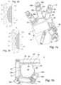
- FIG. 1 ais a front view of a robotic end-effector, namely a semi-anthropomorphic hand, with jamming conformal pads in accordance with an example.
- FIG. 1 Bis a side view of the robotic end-effector of FIG. 1 a shown gripping an object.
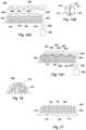
- FIG. 2 ais a schematic cross-sectional side view of the jamming conformal pad of FIG. 1 a shown in a non-contacting, compliant configuration.
- FIG. 2 bis a schematic cross-sectional side view of the jamming conformal pad of FIG. 1 a shown in a non-contacting, compliant configuration with the object.
- FIG. 3 ais a schematic cross-sectional side view of the jamming conformal pad of FIG. 1 a shown in a contacting, stiff configuration with the object.
- FIG. 3 bis a schematic cross-sectional side view of the jamming conformal pad of FIG. 1 a shown in a contacting, stiff configuration with the object removed.
- FIG. 4is a detailed schematic side view of the jamming conformal pad of FIG. 1 a taken along line 4 of FIG. 2 a , showing particles of a filler in a flowable configuration.
- FIG. 5is a detailed schematic side view of the jamming conformal pad of FIG. 1 a taken along line 5 of FIG. 3 a , showing particles of the filler in a static configuration.
- FIG. 6is a detailed schematic side view of a filler of a jamming conformal pad in one example, showing an interstitial material, namely a liquid, in interstices between the particles.
- FIG. 7is a detailed schematic side view of a filler of a jamming conformal pad in one example, showing particles having different sizes.
- FIG. 8is a detailed schematic side view of a filler of a jamming conformal pad in one example, showing particles having different shapes.
- FIG. 9is a detailed schematic side view of a filler of a jamming conformal pad in one example, showing a compressibility of the particles.
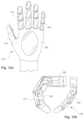
- FIG. 10is a perspective view of another end-effector, namely a hybrid magnetic and finger gripper, with jamming conformal pads in accordance with an example.
- FIG. 11is a perspective view of another end-effector, namely a morph hand, with jamming conformal pads in accordance with an example.
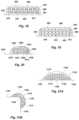
- FIG. 12 ais a front view of another end-effector, namely a plate or anthropomorphic hand, with jamming conformal pads in accordance with an example.
- FIG. 12 bis a side view of the end effector of FIG. 12 a.
- FIG. 13is a front view of another end-effector, namely a plate or anthropomorphic hand, with jamming conformal pads in accordance with an example.
- FIG. 14 ais a front view of another end-effector, namely a plate or anthropomorphic hand, with jamming conformal pads in accordance with an example.
- FIG. 14 bis a side view of the end effector of FIG. 14 a.
- FIG. 15 Ais a schematic cross-sectional side view of a jamming conformal pad shown in a non-contacting, compliant configuration in accordance with an example, with the jamming conformal pad comprising elongate resilient spacers anchored and extending upward from a lower surface.
- FIG. 15 Bis a side view of a single resilient spacer in accordance with an example.
- FIG. 15 Cis a schematic cross-sectional side view of the jamming conformal pad of FIG. 15 A shown in a contacting, stiff configuration interfacing with an object in accordance with an example.
- FIG. 16is a detailed schematic partial side view of the jamming conformal pad of FIG. 15 A taken along line 16 of FIG. 15 B , showing elongate resilient spacers and particles of the filler with the jamming conformal pad in the contacting, stiff configuration in accordance with an example.
- FIG. 17is a schematic cross-sectional side view of a jamming conformal pad shown in a non-contacting, compliant configuration in accordance with an example, with the jamming conformal pad comprising elongate resilient spacers attached or anchored to an inner surface of an upper portion of a membrane.
- FIG. 18is a schematic cross-sectional side view of a jamming conformal pad with unanchored and interconnected elongate resilient spacers in accordance with an example.
- FIG. 19is a schematic cross-sectional side view of a jamming conformal pad with elongate resilient spacers having non-uniform cross sections in accordance with an example.
- FIG. 20is a schematic cross-sectional side view of a jamming conformal pad with elongate resilient spacers having an opposing surface configuration in accordance with an example.
- FIG. 21 Ais a schematic side view of a stiffening element in accordance with an example, shown in a first position and a relaxed configuration.
- FIG. 21 Bis a schematic side view of the stiffening element of FIG. 21 A , shown in a second position and a stiff configuration in accordance with an example.
- FIG. 22illustrates a top view of a jamming conformal pad about a finger of an end-effector of a robotic device or system, in accordance with an example, wherein a portion of the external membrane is cut-away to show inside the hollow or interior volume of the jamming conformal pad, and wherein a portion of the mounting bracket is also cut-away to show the base substrate and resilient spacers supported thereon.
- the term “substantially”refers to the complete or nearly complete extent or degree of an action, characteristic, property, state, structure, item, or result.
- an object that is “substantially” enclosedwould mean that the object is either completely enclosed or nearly completely enclosed.
- the exact allowable degree of deviation from absolute completenessmay in some cases depend on the specific context. However, generally speaking the nearness of completion will be so as to have the same overall result as if absolute and total completion were obtained.
- the use of “substantially”is equally applicable when used in a negative connotation to refer to the complete or near complete lack of an action, characteristic, property, state, structure, item, or result.
- adjacentrefers to the proximity of two structures or elements. Particularly, elements that are identified as being “adjacent” may be either abutting or connected. Such elements may also be near or close to each other without necessarily contacting each other. The exact degree of proximity may in some cases depend on the specific context.
- the robotic end effectorcan comprise one or more fingers each having an inner portion and each operable in one or more degrees of freedom, and one or more jamming conformal pads.
- Each jamming conformal padcan be disposed on the inner portion of a corresponding finger of the one or more fingers.
- Each jamming conformal padcan comprise an exterior membrane conformable to a surface of an object, and a filler disposed between the membrane and the inner portion of the at least one finger.
- the fillercan comprise a plurality of elongate resilient spacers and a plurality of jamming particles.
- each of the one or more jamming conformal padscan be operable in at least one of two pad configurations.
- the first configurationcan be a compliant configuration in which a shape of the jamming conformal pad is changeable to achieve an engaged shape upon engagement of the pad with the surface of the object.
- a second configurationcan be a stiff configuration in which the jamming conformal pad maintains the engaged shape, and is relatively stiff compared to the jamming conformal pad in the compliant configuration. Additional configurations between the compliant and the stiff configurations can be achieved by varying the pressure within the jamming conformal pad, such as by providing a variable pressure source or varying pressure via one or more valves operable with the pressure source.
- a robotic end-effectorcomprising a pair of members being movable with respect to one another; a bladder on at least one of the members; and a filler within the bladder.
- the fillercan comprise a plurality of jamming particles and a plurality of elongate resilient spacers.
- the plurality of jamming particlescan be operable to flow within the bladder. Flow characteristics of the plurality of jamming particles about the plurality of elongate resilient spacers can vary with pressure within the bladder. Compliance of the bladder can vary with the flow characteristics of the jamming particles.
- the bladder with the filler thereincan be placed in one of two configurations: a compliant configuration in which a shape of the bladder and filler are changeable, and a stiff configuration in which change in the shape of the bladder and filler is resisted, and in which the bladder and filler are stiff as compared to the bladder and filler in the compliant configuration.
- additional configurations between the compliant and the stiff configurationscan be achieved by varying the pressure within the jamming conformal pad, such as by providing a variable pressure source or varying pressure via one or more valves operable with the pressure source.
- the stiffening element devicecan comprise a joint with a pair of movable members being movable with respect to one another about the joint, a bladder coupled to the pair of movable members, and a filler within the bladder.
- the fillercan comprise jamming particles and elongate resilient spacers.
- the jamming particlescan be flowable and the elongate resilient spacers can be deformable in the bladder. Flow characteristics of the jamming particles about the elongate resilient spacers can vary with pressure within the bladder. Resistance to movement of the pair of movable members can vary with the flow characteristics of the jamming particles about the elongate resilient spacers.
- FIGS. 1 a - 5depict an example robotic end-effector 8 , namely a semi-anthropomorphic hand with three-fingers 12 and an opposable thumb 16 extending from a palm 20 .
- FIG. 1 adepicts the end-effector 8 open or empty, and with one or more jamming conformal areas or pads, indicated collectively at 24 ; while FIG. 1 b depicts the end-effector 8 closed or grasping a workpiece or object 26 .
- the fingers 12 , the thumb 16 and the palm 20 of the end-effector 8can have an inner portion 30 (which can also be referred to as an engaging side or surface) that faces inwardly and that engages directly or indirectly (i.e., indirectly due to the presence of a bladder and associated exterior membrane that at least partially covers the inner portion or engaging side or surface 30 ) with the workpiece or object 26 .
- the fingers 12 and the thumb 16can be opposable and can oppose one another across a gap 34 that receives the workpiece or object 26 .
- the thumb 16can also be characterized as a finger 12 so that the end-effector 8 can have at least two opposing fingers 12 and 16 .
- the end-effector 8can have at least one finger 12 that can oppose another structure, such as the palm 20 , so that the finger 12 can oppose and close against the palm 20 .
- each of the fingers 12 and the thumb 16can be articulated and can have one or more degrees of freedom.
- the fingers 12 and/or the thumb 16can pivot with respect to the palm 20 or a base.
- each of the fingers 12 and the thumb 16can have a series of segments, indicated collectively at 38 , with adjacent segments movably coupled together at a joint, indicated collectively at 42 .
- the fingers 12 and the thumb 16can each have at least a proximal segment 38 a coupled to the palm 20 and a distal free segment 38 b .
- each finger 16 and thumb 16can have an intermediate segment 38 c intermediate the proximal and distal free segments 38 a and 38 b .
- each finger 12 and thumb 16can have three segments 38 .
- the fingers 12 and the thumb 16are movable with respect to one another and with respect to the palm 20 .
- the fingers 12 and the thumb 16can mover to vary the size of the gap 34 .
- the fingers 12 and the thumb 16can collapse on the gap 34 in order to grip the workpiece or object 26 .
- the segments 38 of each finger 12 and thumb 16can move with respect to an adjacent segment 38 , or the palm 20 , to grip the workpiece or object 26 .
- the fingers 12 and the thumb 16 , and the segments 38 thereofcan be operatively coupled to actuators and a controller to effect movement.
- the end-effector 8 , and the fingers 12 and the thumb 16 , and the segments 38 thereofcan be rigid members.
- the end-effector 8 , and the fingers 12 , the thumb 16 and/or the palm 20can have one or more jamming conformal areas or pads 24 .
- the jamming conformal areas or pads 24can be disposed on an inner portion 30 (e.g., the engaging sides) of the fingers 12 , the thumb 16 and/or the palm 20 , and carried or supported by the end-effector 8 .
- the jamming conformal areas or pads 24can be positioned to contact and engage the workpiece or object 26 , and can be disposed between the workpiece or object 26 , and the fingers 12 , thumb 16 and palm 20 .
- the fingers 12 , the thumb 16 and/or the palm 20can be separated from the workpiece or object 26 by the jamming conformal areas or pads 24 .
- a separate and distinct jamming conformal area or pad 24can be disposed on each component, or finger 12 , thumb 16 and palm 20 , of the end-effector 8 .
- a palm pad 46can be disposed on the palm 20
- a thumb pad 48can be disposed on the thumb 16
- finger pads 50can be disposed on the fingers 12 .
- separate and discrete jamming conformal areas or pads 24can be disposed on each segment 38 of the finger 13 and the thumb 16 .
- a proximal pad 24 acan be disposed on the proximal segment 38 a
- an intermediate pad 24 ccan be disposed on the intermediate segment 38 c
- a distal pad 24 bcan be disposed on the distal free segment 38 a
- separate and discrete jamming conformal areas or pads 46can be disposed on the palm 20
- the end-effector 8can have only certain jamming conformal areas or pads 24 .
- the end-effector 8may only have distal or fingertip pads 24 b on the distal free ends of the fingers 12 and the thumb 16 .
- the end-effector 8may have distal pads 24 b on the distal free ends of the fingers 12 and the thumb 16 , and the palm pad 46 on the palm 20 .
- the separate and discrete jamming conformal areas or pads 24can form different zones.
- FIG. 2 adepicts a jamming conformal area or pad 24 in a compliant configuration
- FIG. 3 adepicts the jamming conformal area or pad 24 in a stiff configuration and in contact or engagement with the workpiece or object 26
- FIG. 2 bdepicts the jamming conformal area or pad 24 in the compliant configuration prior to contact or engagement with the workpiece or object 26
- FIG. 3 bdepicts the jamming conformal area or pad 24 in the stiff configuration absent the workpiece or object 26 , of after releasing the workpiece or object 26 .
- the workpiece or object 26can have a surface 54 .
- the surface 54can comprise a contoured surface with indentations 56 and/or protrusions 58 .
- the surface 54 of the workpiece or object 26can be irregular and/or asymmetric.
- the surface 54 of the workpiece or object 26can be regular and/or symmetric, but can have a discontinuous surface configuration with the indentations 56 and/or protrusions 58 .
- the jamming conformal area or pad 24 or 24 bcan be compliant to distribute across the surface 54 of the workpiece or object 26 .
- the jamming conformal area or pad 24 or 24 bcan distribute across the surface 54 and infiltrate into the indentations 56 in the surface 54 (similar to how the fingers and palm of a human hand conform at least to some degree).
- the resulting contour or shape of the jamming conformal area or pad 24 or 24 bcan define a conformal engaging surface 62 ( FIG. 3 b ) that is operable to match and mate with the surface 54 of the workpiece or object 26 .
- the jamming conformal area or pad 24 or 24 bcan be compliant, conformal, flexible and susceptible to manipulation or movement or modification in which a shape of the jamming conformal pad is changeable in response to engagement of the jamming conformal area or pad with the surface of an object.
- the shape of the jamming conformal padcan be changed to achieve a plurality of different engaged shapes depending upon the object or objects to be grasped.
- the jamming conformal area or pad 24 or 24 bcan be free, relaxed and/or un-energized in the compliant configuration in order to allow the jamming conformal area or pad to be caused to at least partially, and in some cases fully, conform to a surface of an object.
- the jamming conformal areas or padscan achieve area contact (contact about an area of an object rather than just a point or line), and can exert and facilitate multi-directional distributed forces within the area contact, as well as area wide opposing forces between the surface and the end-effector 8 , with its associated fingers 12 , thumb 16 and/or palm 20 .
- These allfunction to increase the static and kinetic coefficient of friction between the object and the end effector 8 , and these functions are similar to that those that occur between the human hand and the surface of a grasped object.
- the jamming conformal area or pad 24 or 24 bcan be active or dynamic, or can be or can comprise and an active or dynamic pad or surface, and can be capable of changing character, state and/or responsiveness, such as compliant characteristics between compliant and stiff.
- the jamming conformal area or pad 24 and 24 bcan selectively alternate between configurations or states, such as compliant and stiff configurations, as well as achieve states in between these.
- the jamming conformal area or pad 24 or 24 bcan alternately change and maintain the a shape, such as an engaged shape (due to interaction with an object) or a shape achieved without engaging an object.
- the resulting engaged shape and contour of the conformal engaging surface 62can be maintained with the jamming conformal area or pad in the stiff configuration.
- the jamming conformal area or pad 24 or 24 bis stiff or relatively stiff compared to the compliant configuration.
- the jamming conformal area or pad 24 or 24 bcan substantially maintain any engaged shape and contour of the jamming conformal area or pad 24 or 24 b and its corresponding conformal engaging surface 62 .
- the jamming conformal area or pad 24 or 24 b , and/or the conformal engaging surface 62becomes substantially rigid or solid.
- the shape or contour of the conformal engaging surface 62 and the jamming conformal area or pad 24 or 24 bare controllable and active, as opposed to being passive.
- the conformal engaging surface 62has substantially the same shape and/or contour as the surface 54 (be it contoured, flat, or a combination of these) of the workpiece or object 26 , even if the workpiece or object 26 is removed, as shown in FIG. 3 b .
- the jamming conformal area or pad 24 or 24 bcan be energized, and is capable of actively maintaining the shape and/or contour of the conformal engaging surface 62 .
- the jamming conformal area or pad 24 or 24 b , and the conformal engaging surface 62can be adaptive to the surface 54 of the workpiece or object 26 , and can distribute forces over an area, and can extend into indentations 56 for a better grip, which are just some of the advantages provided. This can result in less slippage between the end effector 8 and the object, and can further facilitate a reduction in the amount of forces needed in the end effector 8 to both grasp and hold an object, particularly as compared with prior end effectors having only rigid gripping, palm or other surfaces intended to interact with objects that rely on point or line contact and associated loads.
- the jamming conformal area or pad 24 or 24 bcan be binary, and can have only the two compliant and stiff configurations. In another aspect, the jamming conformal area 24 or 24 b can be analog, and can have multiple varying degrees of stiffness between the compliant and stiff configurations, as described in greater detail below.
- the jamming conformal areas or pads 24can be operated collectively. Thus, each jamming conformal area or pad 24 can share a common state or configuration, such as all being compliant or all being stiff. Similarly, all may share a similar degree of stiffness or compliance. In another aspect, the jamming conformal areas or pads 24 can be operated independently with respect to one another. Thus, one jamming conformal area or pad 24 may be compliant while another jamming conformal area or pad 24 may be stiff. In addition, different jamming conformal areas or pads 24 may have different degrees of compliance or stiffness.
- jamming conformal area or pad 24 or 24 bhas been described above as being relaxed in the compliant configuration and energized or active in the stiff configuration, the jamming conformal area or pad 24 or 24 b can be configured to be relaxed or un-energized in the stiff configuration, and energized in the compliant configuration.
- the jamming conformal area or pad 24 or 24 bcomprises a bladder 66 on the inner portion 30 of the finger 12 , thumb 16 or palm 20 .
- the bladder 66can have an exterior membrane 68 conformable to the surface 54 of the workpiece or object 26 , and forming the conformal engaging surface 62 .
- the bladder 66can contain a filler 72 disposed in and flowable in the bladder 66 .
- the filler 72is behind the membrane 68 and between the membrane 68 and the inner portion 30 of the finger 12 , thumb 16 or palm 20 , or in other words in contained within the membrane 68 .
- the filler 72can comprise particles 76 .
- the filler 72can have at least two configurations, including a flowable configuration, as shown in FIGS. 2 a and 2 b , and a static configuration, as shown in FIGS. 3 a and 3 b .
- the flowable configurationcorresponds to the compliant configuration of the jamming conformal area or pad 24 .
- the filler 72flows as the exterior membrane 68 and bladder 66 conform to the surface 54 .
- the static configurationcorresponds to the stiff configuration of the jamming conformal area or pad 24 .
- the filler 72is static or relatively static with respect to the flowable configuration, and resists flow of the filler 72 .
- a flow characteristic of the filler 72varies with pressure within the bladder 66 .
- compliance of the bladder 66 , and the membrane 68 and the conformal engaging surface 62varies with the flow characteristics of the filler 72 .
- compliance of the bladder 66can vary with the ability of the filler 72 to flow within the bladder, such as whether the filler 72 can flow freely within the bladder 66 or whether flow of the filler 72 within the bladder is constricted.
- the bladder 66can be flexible and resilient, or elastic, and can be formed of any flexible and resilient, or elastic, material suitable for the purposes and functions described herein, and as will be recognized by those skilled in the art.
- the bladder 66can be formed of elastomers, such as natural rubber, silicone, neoprene, nitrile, butyl, and others; flexible/stretchy polymers, such as polyethylene, polypropylene, vinyl, and others.
- the bladder 66can be formed of a material that facilitates, and can comprise, a volume that is changeable.
- the bladder 66can be configured to collapse a given degree under a corresponding given pressure, and can have a volume that is changeable.
- the bladder 66can be configured to change shape and position as the bladder 66 or membrane 68 contacts the surface 54 of the workpiece or object 26 .
- the bladder 66can be formed of a single material, a laminate, or a reinforced material.
- the bladder 6can be sealed with respect to the surrounding environment, and can be hermetically sealed.
- the bladder 66can have an interior or hollow, and can define a pocket.
- the bladder 66can be formed of a pair of layers sealed around a perimeter.
- An inner layercan be substantially and/or relatively flat, while an exterior layer can be substantially and/or relatively convex to create the hollow.
- the inner layer of the bladder 66can be coupled or otherwise secured to the finger 12 , thumb 16 and/or palm 20 of the end-effector 8 .
- An inner surface of the inner layercan be coupled or otherwise secured to the end-effector 8 such that a majority, or substantially all, of the inner surface is coupled or secured to the end-effector 8 , or the inner portion 30 thereof.
- a perimeter of the inner layercan extend beyond the seal to form a flange or tabs that can be coupled or otherwise secured to the end-effector 8 .
- the bladder 6can be attached or coupled or otherwise secured to the finger 12 , thumb 16 and/or palm 20 using adhesives, fasteners and seals, and any other means or methods of attachment.
- the bladdercan be attached or otherwise supported by the end effector via being molded and adhered to the surface, or it can form the outer wall, with the gripper surface being the other side, and in which case the bladder can have its free edge clamped in such a way as to seal it and create a sealed volume.
- a filler 72can be disposed in the bladder 66 , and can be flowable or otherwise movable in the bladder 66 .
- flowableit is meant that the particles 76 can move relative to one another.
- the filler 72can comprise particles 76 that can flow and move with respect to one another, and that can bear against one another.
- the particles 76can substantially fill the bladder 66 in a loose manner, and can occupy a majority of the hollow of the bladder 66 or volume thereof.
- the filler 72flows, and the particles 76 move with respect to one another, within the bladder 66 as the bladder and the hollow or interior volume changes shape and position due to contact or engagement of the bladder 66 with the surface 54 of the workpiece of object 26 , and any contours or variations within the surface 54 .
- the filler 72can further comprise a gas, such as air, filling interstices between the particles 76 .
- the filler 72can be contained within and caused to be flowable in the bladder 66 , the filler 72 comprising particles 76 , wherein a flow characteristic of the filler 72 varies with pressure within the bladder 66 , and resistance to movement of the bladder 66 , the membrane 68 and the conformal engaging surface 62 , varies with the flow characteristics of the filler 72 .
- the stiffness of the bladder 66 or membrane 68can be characterized as being the increase in interaction forces between the particles 76 of the filler 72 .
- a pressure source 80can be operatively coupled to the bladder 66 (e.g., operable to induce a pressure within or about the bladder 66 ), and capable of varying a pressure within the bladder 66 .
- the pressure source 70can comprise a vacuum source configured to selectively withdraw an interstitial material or fluid, such as gas or air, from the bladder 66 .
- the vacuum sourcecan be a vacuum pump, such as a piston moveable within a cylinder.
- the bladder 66collapses, thus causing the flow characteristics of the filler material 72 and the particles 76 to vary.
- collapseit is meant that the bladder 66 collapses or reduces in volume at least some degree from its fully expanded state or condition.
- the pressure source 80 or vacuum sourcecan be selectively varied to selectively vary the stiffness or compliance of the bladder 66 .
- the stiffness or compliance of the jamming conformal areas or pads 24 and the bladder 66can be selectively varied through a continuous range of resistance between compliant and rigid.
- the stiffness or compliancecan be adjusted dynamically to be essentially soft or fluid all the way to completely stiff or rigid, and any state in between.
- the pressure source 80is capable of providing a variable degree/range of pressure within the bladder 66 to provide a variable degree/range of stiffness or compliance of the bladder 66 with the filler 72 .
- the pressure source 80is capable of varying pressure within the bladder 66 to provide compliance facilitating free movement of the membrane 68 or conformal engaging surface 62 , and stiffness or limited movement of the membrane 68 or conformal engaging surface 62 .
- the pressure source 80can be operable with one or more valves in fluid communication with the pressure source 80 and the bladder 66 , where the valves are controllable to vary the pressure within the bladder 66 .
- FIG. 4depicts a detailed schematic side view of the bladder 66 or jamming conformal area or pad 24 taken along line 4 of FIG. 2 a
- FIG. 5is a detailed schematic side view of the bladder 66 or jamming conformal area or pad 24 taken along line 5 of FIG. 3 a
- FIG. 4depicts the particles 76 of the filler 72 in the relaxed, flowable or conformal configuration of the bladder 66 or pad 24 corresponding to a relatively larger pressure, such as ambient pressure, within the bladder 66 .
- the particles 76can flow and move relative to one another, and while in contact one another, are not brought to bear against one another with any significant frictional force.
- FIG. 5depicts the particles 76 of the filler 72 in the static or stiff configuration of the bladder 66 or pad 24 corresponding to a relatively lower pressure, with respect to the larger pressure or ambient pressure.
- the bladder 66has been caused to collapse on the filler 72 , and thus the particles 76 are brought to bear against one another, and interfere with one another to restrict flow.
- the bladder 66 or conformal engaging surfacecan have relatively restricted movement, and can experience relatively larger resistance from the bladder 66 .
- the particles 76can be relatively loose under greater pressure, as shown in FIG.
- the particles 76can be relatively compacted under less pressure, as shown in FIG. 5 , and can have difficulty flowing with respect to one another.
- Compacting the particles 76can result in greater physical impediment to flow, and greater friction between the particles.
- the pressure source 80 or vacuumreduces pressure within the bladder 66
- the bladder 6collapses and compacts the particles 76 of the filler 72 , thus impeding the flow of the particles 76 and stiffening the jamming conformal area or pad 24 .
- the particles 76are forced together, thus increasing the kinetic coefficient of friction between them.
- the magnitude of the kinetic coefficient of frictioncan be varied by varying the pressure induced by the collapse of the bladder 66 and the resulting compaction of the particles 76 .
- the end-effectorcan further comprise one or more sensors and a controller 84 .
- the sensorscan sense a characteristic of the jamming conformal area or pad 24 , or the bladder 66 , such as pressure in the bladder 66 .
- a pressure sensorcan be operatively coupled to the bladder 66 , such as the bladder itself, the pressure source 80 , or a pressure line between the bladder and the pressure source.
- the pressure sensorcan be capable of providing feedback to the pressure source 80 and/or the controller 84 .
- the stiffnesscan be varied based on a pressure of the bladder 66 .
- the controller 84can be operatively coupled to the pressure source 80 (or alternatively one or more valves) to control the pressure source to selectively vary the pressure within the bladder 66 .
- a force sensorcan be used.
- pressure force and position sensorscan be used.
- the controller 84 and the pressure source 80can be used to vary the pressure within multiple bladders (e.g., via a bus arrangement in which a plurality of pressure lines (or branches of pressure lines) between the pressure source and the plurality of bladders are used).
- FIG. 6depicts a detailed schematic side view of filler 72 b of a jamming conformal area or pad 24 , or bladder 66 , showing an interstitial material 88 in interstices between the particles 76 .
- the interstitial material 88can comprise a liquid, such as oil to facilitate flow of the particles 76 .
- the interstitial material 88can be non-compressible.
- the interstitial material 88can fill the interstices between the particles 76 , and can substantially fill the bladder 66 .
- the interstitial material 88can substantially coat the particles 76 , defining coated particles, while of majority of the interstices between the particles 76 remains a gas.
- the interstitial material 88can comprise a fluid, such as a liquid or a gas.
- FIG. 7depicts a detailed schematic side view of filler 72 c of a jamming conformal area or pad 24 , or bladder 66 , showing particles having different sizes.
- the particles 76 and 76 c of the filler 72 ccan comprises at least two different sizes of particles, and in some examples three, four or more different sizes.
- smaller particles 76 ccan be disposed in the interstices between the larger particles 76 .
- the particles 76 and 76 ccan be formed of different materials, and can have different characteristics, such as different coefficients of friction, different compressibility, etc. Those skilled in the art will recognize that the size, configuration, material makeup or type, etc.
- the jamming conformal area or pad 24 , or bladder 66can be tuned as needed or desired.
- FIG. 8depicts a detailed schematic side view of filler 72 d of a jamming conformal area or pad 34 , or bladder 66 , showing particles 76 and 76 d having different shapes.
- the particles of the filler 72 dcan comprise at least two different shapes of particles, and in some examples three, four or more different shapes or configurations.
- some of the particles 76can be spherical, semi-spherical, or partially spherical (meaning substantially spherical while not a perfect sphere) while other particles 76 d can have flat surfaces.
- the shapes or configuration of the particles 76 dcan be random.
- the particles 76 and 76 dcan have different characteristics due to their respective shapes that can change the flow characteristics.
- the shapes of the particles 76 and 76 dcan be selected to obtain desired flow characteristics, and to tune the resistance characteristics of the jamming conformal area or pad 24 , or bladder 66 .
- FIG. 9depicts a detailed schematic side view of particles of a filler of a jamming conformal area or pad, or bladder, showing a compressibility of the particles 76 e .
- the particles 76 e of the fillercan be elastically compressible, as shown.
- the particlescan be relatively rigid.
- the particles 76 e of the fillercan have an elastic modulus, which is a measure of elastic deformation in response to an applied load, and/or a yield strength, which is the onset of plastic deformation at a given stress level.
- the particlescan comprise rubber, which essentially does not have a yield strength, but rather elastically deforms until it fractures.
- the particles of the fillercan have a relatively low modulus (Young's Modulus of Elasticity), such as 0.01-3.5 GPa, and can comprise a polymer, such as rubber (Young's Modulus of 0.01-0.1 GPa or 1.45-14.5 ⁇ 10 ⁇ 3 Mpsi), Acrylonitrile Butadiene Styrene (ABS) (Young's Modulus of 1.4-1.3 GPa or 2.3 GPa), nylon (Young's Modulus of 2-4 GPa or 0.29-0.58 Mpsi; yield strength of 45 MPa), low-density polyethylene (Young's Modulus of 0.11-0.86 GPa or 1.6-6.5 ⁇ 10 ⁇ 3 Mpsi), high-density polyethylene (Young's Modulus of 0.8 GPa or 0.116 Mpsi), polypropylene (Young's Modulus of 1.5-2 GPa or 0.22-0.29 Mpsi), polypropylene
- the particles of the fillercan have a relatively high modulus, such as 50-100 GPa, and can comprise sand (7-80 MPa), aluminum (Young's Modulus of 69 GPa or 10 Mpsi; yield strength of 95 MPa), glass (Young's Modulus of 50-90 GPa or 7.25-13.1 Mpsi), etc.
- the particle of the fillercan be light-weight materials to facilitate mobility.
- the moduli of the materialcan be selected based on material properties temperature ranges of interest.
- the particles of the fillercan have at least two different moduli.
- FIG. 10depicts another example of an end-effector 108 , namely a hybrid magnetic and finger gripper, with jamming conformal areas or pads 124 , or bladders, which is similar in most respects to that described above, and which description is hereby incorporated herein where applicable, as will be recognized by those skilled in the art.
- the end-effector 108can have opposing fingers 112 that can have an obtuse angle between adjacent or contiguous segments.
- corresponding jamming conformal areas or pads 124can match the obtuse angle of the fingers 112 .
- the jamming conformal areas or pads 124can have a substantially constant thickness from the fingers 112 outwardly along the segments, and even while spanning the apex between the segments.
- different and/or multiple jamming conformal areas or padscan be disposed on each linear segment of the fingers.
- FIG. 11depicts another example of an end-effector 208 , namely a morph hand, with jamming conformal areas or pads 224 , or bladders, which is similar in most respects to those described above, and which descriptions are hereby incorporated herein where applicable, as will be recognized by those skilled in the art.
- the end-effector 208can have opposing fingers 212 that can have an obtuse angle between adjacent or contiguous segments.
- corresponding jamming conformal areas or pads 224can match the obtuse angle of the fingers 212 .
- the fingers 212 , and thus the jamming conformal areas or pads 224can be long and slender, such as a length along the finger much greater than a width of the finger.
- different and/or multiple jamming conformal areas or padscan be disposed on each segment of the fingers.
- FIGS. 12 a and 12 bdepict another example of an end-effector 308 , namely a plate or anthropomorphic hand, with jamming conformal areas or pads 324 , or bladders, which is similar in most respects to those described above, and which descriptions are hereby incorporated herein where applicable, as will be recognized by those skilled in the art.
- the end-effector 308can have four fingers 312 , an opposable thumb 316 and a palm 320 .
- separate and discrete jamming conformal areas or pads 324can be disposed on each segment of the finger 312 and the thumb 315 and the palm 320 .
- FIG. 13depicts another example of an end-effector 408 , namely a plate or anthropomorphic hand, with jamming conformal areas or pads 424 , or bladders, which is similar in most respects to those described above, and which descriptions are hereby incorporated herein where applicable, as will be recognized by those skilled in the art.
- the end-effectorcan have four fingers 312 , an opposable thumb 316 and a palm 320 .
- a separate and distinct jamming conformal area or pad 424can be disposed on each component, or finger 312 and thumb 316 , and the palm 320 of the end-effector.
- a palm pad 446can be disposed on the palm 320
- a thumb pad 448can be disposed on the thumb 316
- finger pads 424can be disposed on the fingers 312 .
- the jamming conformal area or pad 424can be a single jamming conformal area or pad disposed on the articulated finger 312 and spanning the series of segments and intermediate joints.
- FIGS. 14 a and 14 bdepict another example of an end-effector 508 , namely a plate or anthropomorphic hand, with a jamming conformal area or pad 524 , or bladder, which is similar in most respects to those described above, and which descriptions are hereby incorporated herein where applicable, as will be recognized by those skilled in the art.
- the end-effector 508can have four fingers 312 , an opposable thumb 316 and a palm 320 .
- a single jamming conformal area or pad 524can be disposed on the end-effector 508 , and can extend along each segment of the finger 312 and the thumb 316 , and between the palm 320 and the fingers 312 and thumb 316 .
- the jamming conformal areais a single jamming conformal area or pad 524 spanning the palm 320 , the four fingers 312 and the thumb 316 .
- FIGS. 15 A- 21 Billustrate additional examples of jamming conformal pads operable with a robot and/or a robot end-effector as taught herein.
- the jamming conformal padsare similar to those discussed above in many respects, and can comprise similar configurations, properties, functions, etc.
- the jamming conformal pads shown in FIGS. 15 A- 21 Bcomprise one or more elongate resilient spacers supported or disposed and operable within the interior volume of the bladder of the jamming conformal pad (or stiffening element).
- the discussion above with respect to FIGS. 1 A- 14 Bis applicable here, and can be referred to for an understanding of the jamming conformal pads/stiffening elements shown in FIGS.
- any of the jamming conformal pads discussed abovecan be modified in accordance with the teachings herein to comprise one or more elongate resilient spacers.
- resilient spaceras referred to herein, shall be understood to mean a structure formed from one or more materials possessing a property of elasticity (a modulus of elasticity), that is/are elastically deformable, and that enables the resilient spacer to undergo elastic deformation in response to an applied load, wherein the resilient spacer returns or partially returns to its original size and shape upon removal or partial removal of the applied load.
- the materials selectedcan exhibit linear or nonlinear properties of elasticity.
- Example materialsinclude, but are not limited to elastomers, natural rubbers, synthetic rubbers, or combinations of these.
- the resilient spacerscan be self-supporting, meaning that they are sized, shaped and configured to be able to stand and not collapse under the influence of gravity and under natural ambient environment conditions.
- the resilient spacerscan be configured to be collapsible under the influence of gravity and under natural ambient environment conditions.
- FIG. 15 Ais a schematic cross-sectional side view of an example jamming conformal pad 624 shown in a non-contacting, compliant configuration.
- the jamming conformal pad 624can be part of a robot or robotic device, such as a robotic end-effector, or other type of structure or system, and supported on a segment 638 of a finger 612 of the robotic end-effector.
- the finger 612can be similar to any of the fingers described above, and can be incorporated on a robot end-effector, such as those described herein. While the jamming conformal pad 624 is described as being on a finger 612 of a robot-end-effector, the jamming conformal pad 624 is not limited to being supported on a finger.
- the jamming conformal pad 624can be incorporated on (attached to or integrally formed with) a thumb, a palm, or any other portion or combination of portions of a robotic end-effector, such as any portion or portions of the robotic end-effector that interface(s) with an object or other surface.
- the jamming conformal pad 624can be attached to an inner portion 630 of the finger 612 .
- an exterior membrane 668 defining a bladdercan attach to the inner portion 630 of the finger 612 .
- the jamming conformal pad 624can comprise a filler 672 disposed within the bladder, in this example between the exterior membrane 668 and the inner portion 630 of the finger 612 .
- the filler 672can be operable to facilitate transition of the jamming conformal pad 624 from a compliant configuration to a stiff configuration similar to the various other jamming conformal pads discussed herein.
- the bladdercan be configured in any manner as discussed herein.
- the filler 672 of the jamming conformal pad 624can comprise jamming particles 676 , one or more elongate resilient spacers 690 , and an interstitial material (e.g., air, gas, or a fluid) disposed in interstices between the jamming particles 676 and the elongate resilient spacers 690 .
- an interstitial materiale.g., air, gas, or a fluid
- the elongate resilient spacers 690can comprise an elongate member having a high aspect ratio in that it has a length longer than its width or thickness (i.e., a measurement taken along a distance between two points along or within a plane of a cross-sectional area of the elongate resilient spacer that is perpendicular to the longitudinal axis of the resilient spacer, such as a diameter measurement of a circular elongate resilient spacer).
- the elongate resilient spacers 690can comprise an elongate member that has a length between two and fifty times longer than its width or thickness measured in the same dimensions.
- the elongate resilient spacers 690can comprise an elongate member having a length that is two and five times longer than its width or thickness. In another example, the elongate resilient spacers 690 can comprise an elongate member that has a length at least five times longer than its width or thickness, such as between five and 10 times longer than its width or thickness. In another example, the elongate resilient spacers 690 can comprise an elongate member that has a length at least ten times longer than its width or thickness, such as between 10 and 15 times longer than its width or thickness.
- the elongate resilient spacers 690can comprise an elongate member that has a length at least fifteen times longer than its width or thickness, such as between 15 and 20 times longer than its width or thickness. In another example, the elongate resilient spacers 690 can comprise an elongate member that has a length at least twenty times longer than its width or thickness, such as between 20 and 25 times longer than its width or thickness. In another example, the elongate resilient spacers 690 can comprise an elongate member that has a length between twenty and fifty times longer than its width or thickness. However, these ratios are not intended to be limiting in any way.
- the elongate resilient spacers 690can each be formed from a resilient material that is elastically deformable when acted upon by a sufficient force, but that tends to return to an undeformed, original position when the force is removed.
- all or a part of the elongate resilient spacers 690can be deformable in a number of ways, such as by bending, collapsing in one or more directions along one or more axes, folding, being mashed or smashed, twisting, stretching, and/or buckling when acted upon by a sufficient force.
- the resilient material used for the elongate resilient spacers 690can be any suitable resilient material, such as natural or synthetic rubber, silicone, or others as will be recognized by those skilled in the art.
- the jamming conformal pad 624can comprise a plurality of elongate resilient spacers 690 that form a matrix of elongate resilient spacers 690 (i.e. a regular or irregular two-dimensional or three-dimensional configuration, which may or may not be formed in a pattern) contained within the interior volume or hollow of the bladder, in this example as formed by the membrane 668 .
- the elongate resilient spacers 690can each comprise an elongate member 691 having a first end 692 and a second end 693 .
- FIGS. 15 A and 15 Billustrates a single elongate resilient spacer 690 for illustrative purposes, comprising an elongate member 691 having a first end 692 and a second end 693 .
- the first end 692 of each respective elongate member 691can be anchored, attached, integrally formed with, or otherwise fixed to the inner portion or inner surface 630 of the finger 612 (or to a membrane of the jamming conformal pad 624 that is disposed and supported on the inner portion or surface 630 of the finger 612 ).
- the respective elongate members of the elongate spacers 690can extend upward from the inner portion or surface 630 towards the exterior membrane 668 of the jamming conformal pad 624 and can terminate at the respective second ends 693 .
- the second ends of the respective elongate members of the elongate resilient spacers 690can comprise a free end that can extend all the way to and terminate at the inner surface of the exterior membrane 668 of the jamming conformal pad 624 .
- the respective elongate members of the elongate resilient spacers 690can extend upward, but with the second or free ends terminating at a distance such that the ends of the elongate resilient spacers 690 are located a distance away from (or in other words do not contact) the inner surface of the exterior membrane 668 .
- a combination of different sized and configured elongate resilient spacers 690can be present within the bladder of the jamming conformal pad 624 , such that one or more of the resilient spacers 690 are differently configured and/or sized than one or more other of the resilient spacers 690 .
- elongate resilient spacers 690can be included within the bladder, depending upon the desired performance properties of the jamming conformal pad 624 .
- the elongate resilient spacers 690(e.g., at the first end) can be one of attached to, anchored to, mounted to, integrally formed with, or otherwise fixed to the inner surface of the external membrane 668 in accordance with any attachment method known to those skilled in the art.
- the first end of one or more respective elongate resilient spacers 690can be attached using adhesives, bonding, a mechanical mounting device or system (e.g., fasteners, mounting bracket, or others) or any other process.
- first end of one or more respective elongate resilient spacers 690can be integrally formed with the external membrane 668 . Still, in one example, the first end of one or more resilient spacers 690 can be mounted or anchored or attached to the surface 612 of the finger 630 in support of the bladder. In the example shown, the first ends of the respective elongate resilient spacers 690 are mounted directly to the surface 612 of the finger 630 (e.g., using an adhesive).
- the elongate resilient spacers 690can comprise a number of different sizes and configurations depending upon the particular intended application in which they are to be used.
- each of the elongate resilient spacers 690can be formed having the same size and configuration.
- each of the elongate resilient spacers 690can have a circular cross section having the same or a substantially similar diameter and having the same or a substantially similar length.
- each of the elongate resilient spacers 690can comprise a non-uniform cross-sectional area along their respective lengths (e.g., along a longitudinal axis). In the example shown in FIG.
- the length of the elongate resilient spacers 690can be similar to or slightly shorter than a distance between the inner portion or surface 630 of the finger and an inner surface of the exterior membrane 668 .
- some of the of elongate resilient spacers 690can be sized and/or configured differently than some others of the elongate resilient spacers 690 .
- at least some of the elongate resilient spacers 690can be formed to have different dimensions, makeup, and/or configurations.
- the elongate resilient spacers 690can be thicker and/or longer than other elongate resilient spacers 690 , some can have different cross-sectional areas, some can have varying cross-sectional areas along a longitudinal length or other axis that differ from the cross-sectional areas of others, some can comprise a composite material makeup, some can be attached to the membrane, and/or some or all can be free-floating. This is true with any of the example resilient spacers discussed herein in any of the examples.
- a length of each of the elongate resilient spacers 690can be based on a desired or pre-determined profile of the exterior membrane 668 of the jamming conformal pad 624 , and their relative position within the jamming conformal pad 624 .
- the jamming conformal pad 624can be operatively coupled to a pressure source 680 that can change a pressure in the jamming conformal pad 624 by adding or evacuating fluid into and out of the jamming conformal pad 624 .
- the pressure source 680can be controlled by a controller 684 in a manner similar as described above.
- the jamming conformal pad 624can be configured to help grip an object 626 or other surface similar to the jamming conformal pads described above.
- the object 626can comprise a surface 654 that can have one or more indentations 656 and/or protrusions 658 .
- An outer surface of the exterior membrane 668 of the jamming conformal pad 624can define an engaging surface 662 .
- FIG. 15 Athe jamming conformal pad 624 is shown in a compliant state, such that when the engaging surface 662 is brought into contact with the surface 654 of the object 626 , the engaging surface 662 can conform to the surface 654 of the object 626 including the indentations 656 and/or the protrusions 658 .
- the elongate resilient spacers 690are caused to deform in one or more ways, such as to buckle, fold, collapse, stretch, etc. as the engaging surface 662 conforms to the surface 654 of the object 626 and the exterior membrane 668 takes a profile similar to the surface 654 of the object 626 .
- the jamming particles 676are operable to flow in the interstitial material (e.g., air, gas, liquid (e.g., oil), or other fluid) relative to other jamming particles 676 and to the elongate resilient spacers 690 .
- FIG. 15 Cis a schematic cross-sectional side view of the jamming conformal pad of FIG. 15 A shown in operation in a contacting, stiff configuration as engaged with the object 626 , and with the outer engaging surface 662 of the membrane 668 .
- the filler 672 , with the resilient spacers 690 , and with the pressure reduced within the volume of the bladder of the jamming conformal pad 624can be operable to cause the jamming conformal pad 624 to transition to a stiff or static state, such that the engaging surface 662 of the jamming conformal pad 624 remains conformed, or at least partially conformed, to the surface 654 of the object 626 to facilitate gripping of the object 626 .
- the controller 684can cause the pressure source 680 to evacuate at least a portion of the fluid from the jamming conformal pad 624 .
- the fluidis evacuated from the jamming conformal pad 624 , flow characteristics of the jamming particles 676 change, such that the jamming particles 676 are no longer able to flow relative to other jamming particles 676 and to the elongate resilient spacers 690 .
- FIGS. 15 A- 16FIG. 16 is a detailed schematic partial side view of the jamming conformal pad 624 of FIG. 15 A taken along line 16 of FIG.
- FIG. 15 Cshowing the elongate resilient spacers 690 and the jamming particles 676 of the filler 672 in a stiff configuration.
- the jamming particles 676can be displaced where they can become lodged against and between the elongate resilient spacers 690 and/or other jamming particles 676 .
- one or more of the elongate resilient spacers 690can be caused to deform in one or more ways.
- one or more of the elongate resilient spacers 690are in a deformed (e.g., mashed, smashed, buckled, bent, twisted, folded, stretched, and/or collapsed) condition, with the jamming particles 676 lodged against and between the elongate resilient spacers 690 and/or other jamming particles 676 so as to form a stiff structural lattice.
- a deformede.g., mashed, smashed, buckled, bent, twisted, folded, stretched, and/or collapsed
- the stiff structural lattice formed by the jamming particles 676 and the elongate resilient spacers 690is operable to maintain the profile of the engaging surface 662 of the jamming conformal pad 624 , such that as the jamming conformal pad 624 is caused to maintain a conformed interface with the surface 654 of the object 626 , the jamming conformal pad 624 facilitates gripping of the object 626 .
- the controller 684can be operable to variably transition the jamming conformal pad 624 between the stiff configuration and the compliant configuration, and to hold such a configuration, or an intermediate configuration between these, by controlling the pressure source 680 to add fluid to the jamming conformal pad 624 or draw fluid from the jamming conformal pad 624 .
- the jamming particles 676become free to flow again relative to the elongate resilient spacers 690 and other jamming particles 676 .
- the use of the elongate resilient spacers 690 in connection with the jamming particles 676can provide several advantages to a jamming conformal pad over a similar jamming conformal pad without such resilient spacers.
- the elongate resilient spacers 690can deform elastically, such as by buckling, bending, or otherwise when an object 626 impinges on the jamming conformal pad 624 , thereby influencing the conformal behavior of the jamming conformal pad 624 .
- the elongate resilient spacers 690functions to aid the return of the jamming conformal pad 624 to an original size and shape via the elastic/resilient nature of the elongate resilient spacers 690 .
- the resilient spacers 690can operate to apply a force (direct or indirect depending upon the configuration of the jamming conformal pad) to the deformed membrane 668 of the bladder to facilitate its return to an original size and shape.
- This application of forcecan occur directly (i.e., the resilient spacers 690 directly act upon the membrane 668 ), or indirectly, wherein the application of force is applied by the resilient spacers 690 to the jamming particles 667 , which can subsequently transfer the force to the membrane 668 .
- the number, size and spacing of the elongate resilient spacers 690 within the matrix of elongate resilient spacerscan be established so as to enable a reduced number of jamming particles 676 to be present in the jamming conformal pad 624 while still achieving the intended function of the jamming conformal pad 624 as compared with a jamming conformal pad without resilient spacers. In this manner, a jamming mechanism and function similar to the jamming conformal pads described above is achieved and effective.
- the stiff structural lattice formed in the bladder with the jamming conformal pad 624 in the stiff configuration when fluid is evacuated from the jamming conformal pad 624is able to be strengthened due to the presence of the resilient spacers 690 , which, when deformed, function to facilitate an increase in the surface to surface contact with the particles 676 by filling, at least partially, the interstitial voids between the particles 676 and contacting a greater surface area of the particles 676 than would an adjacent particle 676 .
- the resilient spacers 690can conform to and partially wrap around the jamming particles 676 .
- the elongate resilient spacers 690also have the advantage of taking up volume within the interior pocket or hollow of the bladder of the jamming conformal pad 624 .
- the jamming conformal pad 624can more quickly and easily transition from a compliant configuration to a stiff configuration because less interstitial material, such as a fluid (e.g. a difference of an amount of fluid equal to the volume occupied by the elongate resilient spacers), needs to be removed from the jamming conformal pad 624 to achieve the proper jamming and the stiff configuration as compared to a jamming conformal pad without elongate resilient spacers.
- a fluide.g. a difference of an amount of fluid equal to the volume occupied by the elongate resilient spacers
- Each elongate resilient spacer 790can be configured to extend away from the external membrane 768 toward the inner portion 730 of the finger 712 , and into the interior volume or hollow of the bladder of the jamming conformal pad 724 .
- the length of the elongate resilient spacers 790can be such that the second end terminates at a distance equal to or slightly shorter than a distance between the external membrane 768 and the inner portion 730 of the finger 712 with the membrane in an extended, compliant configuration as shown.
- the elongate resilient spacers 790can each comprise the same size and/or configuration, or different ones can comprise different size and/or configurations, as with the elongate resilient spacers 690 of FIGS. 15 A- 15 C .
- the jamming conformal pad 724can be put into operation in a similar manner as the jamming conformal pad 624 , as well as other jamming conformal pads described herein. Thus, the above-described details of the operation of the jamming conformal pad 724 is omitted here for brevity.
- the elongate resilient spacers 790and namely the respective first ends of the elongate members of the elongate resilient spacers 790 , as supported by the external membrane 768 , can be one of attached to, anchored to, mounted to, integrally formed with, or otherwise fixed to the inner surface of the external membrane 768 in accordance with any attachment method known to those skilled in the art.
- the one or more elongate resilient spacers 790can be attached using adhesives, bonding, or any other process.
- the elongate resilient spacers 790can be integrally formed with the external membrane 768 . While FIG.
- FIG. 17shows the first ends of the elongate members of the elongate resilient spacers 790 attached to an upper portion of the external membrane 768 , this is not intended to be limiting in any way. Indeed, the first ends of the elongate members of one or more elongate resilient spacers 790 can be attached or anchored or otherwise fixed to the external membrane 768 at any location along the inner surface of the external membrane 768 . In addition, different elongate resilient spacers 790 can be attached or anchored or otherwise fixed to the internal surface of the external membrane 768 , such that the plurality of elongate resilient spacers 790 extend in multiple respective directions with respect to the external membrane 768 and/or the inner portion 730 of the finger 712 .
- the spacing between the plurality of elongate resilient spacers 790can be uniform, or the same at their base (i.e., at the mounting location). In another aspect, the spacing can be non-uniform or random. Or, a combination of these is contemplated, with some evenly spaced apart from one another, and with others differently spaced apart from one another. Still, in another example, the resilient spacers 790 can be mounted, anchored, attached or otherwise fixed to the surface 712 of the finger 730 in support of the bladder (similar to the resilient spacers 690 of FIGS. 15 A- 15 C ) in addition to being mounted or anchored or attached to the external membrane 768 .
- the jamming conformal padcan comprise a combination of elongate resilient spacers as shown in FIGS. 15 A and 17 , or more generally speaking, a plurality of elongate resilient spacers supported by any two or more, or all, of the surfaces that define the interior volume of the bladder.
- the elongate resilient spacers 790can be configured to provide the bladder and the external membrane 768 with a pre-determined, designed volumetric shape or configuration and a corresponding outer surface configuration as the elongate resilient spacers 790 act or function to exert a force between the external membrane 768 and the finger 712 .
- This pre-determined shapecan be designed or tuned by varying the size, number, configuration, and/or the material makeup, of the elongate resilient spacers 790 , as well as other properties of the jamming conformal pad 724 , such as the number, size, configuration, and/or material makeup of the jamming particles within the bladder that interact with the elongate resilient spacers 790 , and the material makeup and configuration of the membrane 768 .
- the resilient elongate spacers 790can be caused to elastically deform as discussed herein, with these returning to an original size and shape upon removal of the pressure within the bladder.
- the elongate resilient spacershave a first end that is attached, coupled to, integrally formed with, or otherwise fixed, and a second end that comprises a free end, or in other words, an end not attached or coupled to any structure (i.e., a floating end).
- FIG. 18is a schematic cross-sectional side view of a jamming conformal pad with unanchored or free-floating elongate resilient spacers.
- a jamming conformal pad 824can be similar to the jamming conformal pads 624 and 724 in many respects.
- the jamming conformal pad 824can comprise a bladder comprising an external membrane 868 operable with a finger or other part of a robot end effector, with the external membrane 868 having and defining a conformal engaging surface 862 that interfaces with an object to facilitate engagement with the object.
- the jamming conformal pad 824can be disposed on an inner portion 830 of a segment 838 of a finger 812 , as shown.
- the external membrane 868 of the bladdercan have a single layer, or in another example, the bladder can comprise a membrane having multiple layers, such as an inner layer and an outer layer that each define the interior volume or hollow of the bladder and the jamming conformal pad 824 .
- a filler 872can comprise jamming particles 876 and elongate resilient spacers 890 contained within the bladder.
- the elongate resilient spacers 890can be unanchored or free-floating within the bladder, with the jamming particles 876 interspersed within the bladder, such that the elongate resilient spacers 890 are disposed within and about the jamming particles 876 .
- no part of the elongate resilient spacers 890 in this exampleis connected to either of the inner portion 830 of the finger 812 or to the external membrane 868 .
- the elongate resilient spacers 890can be spaced from one another and formed in a matrix by being interconnected to one another via one or more lateral connections 891 .
- each one of the plurality of elongate resilient spacers 890are interconnected with another one of the elongate resilient spacers 890 , but this is not intended to be limiting in any way.
- two or more elongate resilient spacerscan be interconnected using more than one lateral connection.
- the length of the elongate resilient spacers 890can be a distance equal to or slightly shorter than a distance between the external membrane 868 and the inner portion 830 of the finger 812 .
- the lengths and/or configurations of one or more of the plurality of elongate resilient spacers 890can be all the same, or different elongate resilient spacers 890 can have different lengths and/or configurations one from another.
- differing lengthscan contribute or help facilitate to a pre-defined desired volumetric configuration of the jamming conformal pad 824 , as well as a corresponding outer surface configuration of the jamming conformal pad 824 with the pressure source operable with the jamming conformal pad 824 inactive and the jamming conformal pad 824 in a compliant configuration (i.e., absent any object interaction and prior to activation of the system to draw pressure from the jamming conformal pad) as the elongate resilient spacers 890 act or function to exert a force between the external membrane 868 and the finger 812 .
- a compliant configurationi.e., absent any object interaction and prior to activation of the system to draw pressure from the jamming conformal pad
- the pre-determined size, shape or configuration of the jamming conformal pad 824can be designed or tuned by varying the size, number, configuration, and/or the material makeup, of the elongate resilient spacers 890 , the lateral connections 891 , as well as other properties of the jamming conformal pad 824 , such as the number, size, configuration, and/or material makeup of the particles within the bladder that interact with the elongate resilient spacers 890 .
- the resilient elongate spacers 890can be caused to elastically deform as discussed herein, with these returning to an original size and shape upon removal of the pressure within the bladder.
- the elongate resilient spacers 890can comprise any number, size and/or configuration, and can all be made of the same material, or some or all can be made of different materials.
- the jamming conformal pad 824can operate similar to the jamming conformal pads 624 and 724 , and the elongate resilient spacers 890 can operate and function similar to the elongate resilient spacers 690 and 790 , wherein they are configured to elastically deform and interact with the jamming particles 876 .
- the above-described details of the operation of the jamming conformal pad 824is omitted for brevity.
- the elongate resilient spacers 890can be more free to move within the bladder than other elongate resilient spacers discussed herein, such as elongate resilient spacers 690 and 790 , as they are not attached or otherwise fixed to the finger or the membrane of the bladder, or in other words as they are free-floating.
- FIG. 19is a schematic cross-sectional side view of a jamming conformal pad with elongate resilient spacers having non-uniform cross sections.
- a jamming conformal pad 924can be similar to the jamming conformal pads 624 , 724 , and 824 in many respects.
- the jamming conformal pad 924can comprise a bladder having an external membrane 968 operable with a finger or other part of a robot end effector, with the external membrane 968 having and defining a conformal engaging surface 962 that interfaces with an object to facilitate engagement with the object.
- the jamming conformal pad 924can be disposed on an inner portion 930 of a segment 938 of a finger 912 , as shown.
- the external membrane 968 of the bladdercan have a single layer, or in another example, the bladder can comprise a membrane having multiple layers, such as an inner layer and an outer layer that each define the interior volume or hollow of the bladder and the jamming conformal pad 924 .
- a filler 972can comprise jamming particles 976 and one or more elongate resilient spacers 990 .
- the elongate resilient spacers 990comprise an elongate member having a first end and a second end. Each of the first ends of the elongate members of the respective elongate resilient spacers 990 can be anchored or mounted to an inner portion of the external membrane 968 (or directly to a surface of the finger 912 )(and along a top and/or bottom of the membrane 968 ), and can have a non-uniform cross-section along a length of the elongate resilient spacers 990 .
- the elongate resilient spacers 990comprise one or more protruding portions 992 .
- the protruding portions 992are shown to comprise a spherical or semi-spherical shape in FIG. 19 .
- the protruding portions 992can comprise any size, shape or configuration.
- a non-uniform cross section of the elongate resilient spacers 990can enhance the jamming of the jamming particles 976 when the jamming conformal pad 924 is in the stiff configuration by further enabling the jamming particles 976 to lodge into and between the elongate resilient spacers 990 .
- the elongate resilient spacers 990 with their protruding portions 992can further take up a larger volume within the jamming conformal pad 924 (as compared to a resilient spacer without protruding portions, such as that shown in FIG. 15 A ) while allowing for the jamming particles 976 to flow within the jamming conformal pad 924 .
- the elongate resilient spacers 990can be fixed at the first end, with the elongate member being configured to extend away from the external membrane 968 toward the inner portion 930 of the finger 912 , and into the interior volume or hollow of the bladder of the jamming conformal pad 924 with the elongate member terminating at the second end, which in this example comprises a free end.
- Operation of the jamming conformal pad 924can be similar to the operation of the other jamming conformal pads discussed herein, and thus the operation is not repeated here.
- the purpose and function of the filler 972 , the jamming particles 976 , and the elongate resilient spacers 990can be the same or similar to the other fillers, jamming particles, and elongate resilient spacers described herein.
- FIG. 20is a schematic cross-sectional side view of a jamming conformal pad with elongate resilient spacers having opposing extended surfaces providing increased surface area to each of the respective elongate resilient spacers over the other elongate resilient spacers discussed herein.
- a jamming conformal pad 1024can be similar in at least some aspects to the jamming conformal pad 624 , 724 , 824 , 924 .
- the jamming conformal pad 1024can comprise a bladder having an external membrane 1068 operable with a finger or other part of a robot end effector, or other structure or system, with the external membrane 1068 having and defining a conformal engaging surface 1062 that interfaces with an object to facilitate engagement with the object.
- the jamming conformal pad 1024can be disposed on an inner portion 1030 of a segment 1038 of a finger 1012 , as shown.
- the external membrane 1068 of the bladdercan have a single layer, or in another example, the bladder can comprise a membrane having multiple layers, such as an inner layer and an outer layer that each define the interior volume or hollow of the bladder and the jamming conformal pad 1024 .
- a filler 1072can comprise jamming particles 1096 and elongate resilient spacers 1090 .
- the elongate resilient spacers 1090can comprise a thin plate-like or blade-like configuration with opposing surfaces that each have a width defining a surface area at least three times greater than a cross-sectional surface area measured along a plane perpendicular to a longitudinal axis of the elongate resilient spacers 1090 .
- the surface area of the opposing surfacescan be 3-4 times greater, 3-5 times greater, 3-6 times greater, 3-7 times greater, 3-8 times greater, 3-9 times greater, 3-10 times greater, 10-15 times greater, 10-20 times greater, or more, than the cross-sectional surface area measured along a plane perpendicular to a longitudinal axis of the elongate resilient spacers 1090 .
- the opposing surfacescan comprise a planar configuration. However, this is not intended to be limiting in any way as one or both of the surfaces can comprise any other type of configuration (e.g., non-planar or curved, a combination of planar and non-planar, and others).
- the one or both of the opposing surfacescan be smooth, rough, or configured with a pattern of protrusions/indentations.
- the elongate resilient spacers 1090with opposing surfaces, the elongate resilient members can be operable to resist bending or buckling on one direction while enabling bending and buckling in another direction. In this manner, the conformance of the jamming conformal pad 1024 can be better controlled than other jamming conformal pads discussed herein that support elongate resilient spacers having higher aspect ratios.
- the opposing surfaces of the elongate resilient spacers 1090can provide an increase in the surface area available to interact with the various jamming particles 1096 , wherein a greater number of jamming particles 1096 can interact with and come in contact with any one or more of the various elongate resilient spacers 1090 .
- various jamming conformal padsare described that can help enable a robotic end-effector to grip an object or other surface.
- the various jamming conformal pads as described hereincan also function as a stiffening element for a robotic joint. Examples of such stiffening elements are described in detail in U.S. Patent Application Publication No. 2019/0184576, the contents of which are hereby incorporated by reference in their entirety.
- the filler 1172can comprise jamming particles 1176 and one or more elongate resilient spacers 1190 , as taught herein.
- the joint stiffening element 1124can be operable to have a compliant configuration or state and a stiff configuration or state. In the compliant configuration, the first and second members 1195 , 1197 can move about the joint 1199 without the joint stiffening element 1124 applying a force operable to resist rotation of the first and second members 1195 , 1197 about the joint 1199 (other than a negligible resistance force due to friction between the elements within the bladder).
- the joint stiffening element 1124can act as a brake to impede and/or prevent rotational motion of the first and second members 1195 , 1197 about the joint 1199 when the joint stiffening element 1124 is caused to transition between the compliant configuration and the stiff configuration in a similar manner as the jamming conformal pads as taught herein.
- FIG. 21 Bis a schematic side view of the joint stiffening element of FIG. 21 A , shown in a second position and in a stiff configuration.
- an interstitial materiale.g., air, gas, fluid
- an interstitial materialcan be evacuated all or in part from the joint stiffening element 1124 , thus causing the jamming particles 1176 to become lodged or increasingly frictionally engaged (e.g., the coefficient of friction between the particles 1176 themselves and the particles 1176 and the elongate resilient members 1190 with increasing pressure reduction within the bladder) with the elongate resilient members 1190 and other jamming particles 1176 .
- the pressure source (or the pressure source in connection with one or more valves) operable with the joint stiffening element 1124can be configured to vary the pressure within the bladder of the joint stiffening element 1124 .
- the pressure within the bladdercan be varied to vary the braking force applied to the joint 1199 .
- the pressurecan be varied such that the joint stiffening element 1124 can be caused to enter into different variable configurations or states at or between the compliant and stiff configurations.
- the pressurecan be caused to be sufficient so as to cause the joint stiffening element 1124 to enter the stiff configuration, wherein the jamming particles 1176 and the elongate resilient spacers 1190 no longer move, but are locked into place, thus forming a structural lattice within the bladder, and thus preventing rotational motion of the first and second members 1195 , 1197 about the joint 1199 .
- the joint stiffening element 1124can be connected to the pressure source (or pressure source in connection with one or more valves) to control the pressure within the joint stiffening element 1124 .
- Flow characteristics of the jamming particles 1176can vary with the pressure within the joint stiffening element 1124 . As the pressure decreases, the jamming particles' 1176 ability to flow decreases and the joint stiffening element 1124 transitions toward the stiff configuration. As the pressure increases, the jamming particles' 1176 ability to flow increases and the joint stiffening element 1124 transitions towards the relaxed or compliant configuration.
- a first end of each of the plurality of resilient spacers 690 ′can be integrally formed with and supported by a base substrate 692 ′, wherein the resilient spacers 690 ′ are configured to extend away from an upper surface 694 ′ of the base substrate 692 ′ terminating at a second end, which comprises a free end.
- the base substrate 692 ′can be formed of the same material as the resilient spacers 690 ′, or from a different material.
- the base substrate 692 ′can be any size, shape or configuration, and can support any number of resilient spacers 690 ′ arranged in any manner.
- the base substrate 692 ′comprises a rectangular configuration in support of ten columns and seven rows of resilient spacers 690 ′.
- thisis not intended to be limiting in any way as any number of resilient spacers 690 ′ can be supported from the base substrate 692 ′ in any pattern or arrangement, including uniform and random locations on the base substrate 692 ′ and spacing from one another.
- the riser 696 ′can be sized to receive the base substrate 692 ′, and can comprise a plurality of holes 699 ′ formed therein that are configured to receive a respective one of the plurality of resilient spacers 690 ′, wherein the resilient spacers 690 ′ extend upward through the holes 699 ′ and into the volume or hollow of the bladder formed by the external membrane 668 ′ of the jamming confirming pad 624 ′.
- the resilient spacers 690can be attached or mounted to the finger 612 ′ of the end-effector, such that they maintain a consistent position within the bladder and from one another.
- the base substrate 692 ′can be mounted directly to the finger 612 ′ (or to a membrane of the jamming conformal pad 624 ′ that is disposed and supported on the inner portion or surface 630 ′ of the finger 612 ′) without the use of a mounting bracket 695 ′.
- the base substrate 692 ′ with its resilient spacers 690 ′can be mounted to the finger 612 ′ using adhesives, one or more fasteners, or a combination of these.
Landscapes
- Engineering & Computer Science (AREA)
- Robotics (AREA)
- Mechanical Engineering (AREA)
- Manipulator (AREA)
Abstract
Description
- 1. A robotic end-effector configured to provide conformal object interaction, comprising:
- one or more fingers, each having an inner portion and each operable in one or more degrees of freedom; and
- one or more jamming conformal pads, each pad disposed on the inner portion of a corresponding finger of the one or more fingers, each jamming conformal pad comprising:
- an exterior membrane conformable to a surface of an object, and
- a filler disposed between the membrane and the inner portion of the at least one finger, the filler comprising a plurality of elongate resilient spacers and a plurality of jamming particles.
- 2. The robotic end-effector of example 1, wherein each of the one or more jamming conformal pads is operable in at least one of two pad configurations, the at least two pad configurations comprising:
- a compliant configuration in which a shape of the jamming conformal pad is changeable to achieve an engaged shape upon engagement of the pad with the surface of the object; and
- a stiff configuration in which the jamming conformal pad maintains the engaged shape, and is relatively stiff compared to the jamming conformal pad in the compliant configuration.
- 3. The robotic end-effector of any preceding example, wherein the elongate resilient spacers each comprise a first end fixed to the inner portion of the at least one finger, and a second end comprising a free end.
- 4. The robotic end-effector of any preceding example, wherein the respective second ends of the elongate resilient spacers extend upward from the inner portion of the at least one finger toward the exterior membrane, and terminate at a distance away from the exterior membrane.
- 5. The robotic end-effector of any preceding example, wherein the respective second ends of the elongate resilient spacers extend upward from the inner portion of the at least one finger toward the exterior membrane, and terminate at the exterior membrane so as to be in contact with the exterior membrane.
- 6. The robotic end-effector of any preceding example, wherein the elongate resilient spacers apply a force to the exterior membrane to provide a pre-determined shape to the exterior membrane.
- 7. The robotic end effector of any preceding example, wherein at least some of the plurality of elongate resilient spacers have a uniform cross-section along a length of the elongate resilient spacers.
- 8. The robotic end effector of any preceding example, wherein the plurality of elongate resilient spacers define a matrix of elongate resilient spacers.
- 9. The robotic end effector of any preceding example, wherein at least some of the plurality of elongate resilient spacers are interconnected with one another.
- 10. The robotic end effector of any preceding example, wherein the elongate resilient spacers are configured to deform elastically to achieve the engaged shape upon engagement of the jamming conformal pad with the surface of the object, and wherein the elongate resilient spacers at least partially recover to an original, undeformed condition upon disengagement of the jamming conformal pad from the surface of the object.
- 11. The robotic end effector of any preceding example, wherein, in the stiff configuration, the jamming particles and the elongate resilient spacers form a stiff structural lattice.
- 12. The robotic end-effector of any preceding example, wherein the jamming conformal pad is operable to distribute across the surface of the object and at least partially infiltrate into any indentations in the surface, defining a conformal engaging surface configured to match and mate with the surface of the object, and wherein the one or more jamming conformal pads comprises an active area capable of changing compliant characteristics to alternately change and maintain a contour of the conformal engaging surface.
- 13. The robotic end-effector of any preceding example, wherein the conformal engaging surface is an active surface capable of alternately changing and maintaining a contour.
- 14. The robotic end-effector of any preceding example, wherein the filler has at least two configurations, the configurations comprising:
- a flowable configuration, corresponding to the compliant configuration of the jamming conformal pad, in which the jamming particles of the filler flow and the elongate resilient spacers deform as the exterior membrane conforms to the surface; and
- a static configuration, corresponding to the stiff configuration of the jamming conformal pad, in which the jamming particles are lodged between the elongate resilient spacers of the filler, and in which the jamming particles and the elongate resilient spacers are static as compared to flowable configuration.
- 15. The robotic end-effector of any preceding example, wherein the jamming conformal pad is binary, and operable only in the compliant and stiff configurations.
- 16. The robotic end-effector of any preceding example, wherein the jamming conformal pad is analog, and is operable in multiple varying degrees of stiffness between the compliant and stiff configurations.
- 17. The robotic end-effector of any preceding example, wherein the jamming conformal pad further comprises:
- a bladder defined by the exterior membrane, the bladder being supported on the inner portion of the at least one finger,
- wherein flow characteristics of the jamming particles interacting with the plurality of elongate resilient spacers of the filler vary with pressure within the bladder, and compliance of the bladder varies with the flow characteristics of the jamming particles and the elongate resilient spacers.
- 18. The robotic end-effector of any preceding example, wherein the bladder changes shape upon contact with the object; and wherein the jamming particles flow and move with respect to the elongate resilient spacers, and the elongate resilient spacers deform within the bladder, as the bladder changes shape.
- 19. The robotic end-effector of any preceding example, wherein the filler further comprises an interstitial material disposed in interstices between the jamming particles and the elongate resilient spacers.
- 20. The robotic end-effector of any preceding example, wherein the filler further comprises a fluid disposed in interstices between the jamming particles and the elongate resilient spacers.
- 21. The robotic end-effector of any preceding example, wherein at least some of the plurality of elongate resilient spacers comprise a non-uniform cross-section along a longitudinal axis of the elongate resilient spacers.
- 22. The robotic end-effector of any preceding example, wherein at least some of the plurality of elongate resilient spacers comprise opposing surfaces, each opposing surface having a surface area greater than a cross-sectional surface area measured along a plane perpendicular to a longitudinal axis of the elongate resilient spacers, respectively.
- 23. The robotic end-effector of any preceding example, wherein at least some of the plurality of elongate resilient spacers are integrally formed with the exterior membrane.
- 24. The robotic end-effector of any preceding example, wherein at least some of the plurality of elongate resilient spacers are fixed to at least one of the exterior membrane or the inner portion of the finger using at least one of an adhesive or a bonding agent.
- 25. The robotic end-effector of any preceding example, wherein at least some of the plurality of elongate resilient spacers are fixed to at least one of the exterior membrane or the inner portion of the finger via a mechanical mounting device.
- 26. The robotic end-effector of any preceding example, wherein the plurality of elongate resilient spacers are integrally formed with a base substrate, and extend away from the base.
- 27. The robotic end-effector of any preceding example, further comprising a mounting bracket operable to mount the base and the elongate resilient spacers to the finger.
- 28. The robotic end-effector of any preceding example, further comprising a pressure source operatively coupled to the jamming conformal pad and operable to vary the pressure within the jamming conformal pad.
- 29. The robotic end-effector of any preceding example, wherein the pressure source is operable to provide a variable range of pressures within the jamming conformal pad to provide a variable degree of compliance to the jamming conformal pad between the compliant and stiff configurations.
- 30. A robotic end-effector, comprising:
- a pair of members being movable with respect to one another;
- a bladder on at least one of the members; and
- a filler within the bladder comprising a plurality of jamming particles and a plurality of elongate resilient spacers, wherein each of the plurality of jamming particles is operable to flow within the bladder, wherein flow characteristics of the plurality of jamming particles about themselves and the plurality of elongate resilient spacers vary with pressure within the bladder, and wherein compliance of the bladder varies with the flow characteristics of the jamming particles;
- wherein the bladder with the filler therein has at least two configurations, comprising:
- a compliant configuration in which a shape of the bladder and filler are changeable; and
- a stiff configuration in which change in the shape of the bladder and filler is resisted, and in which the bladder and filler are stiff as compared to the bladder and filler in the compliant configuration.
- 31. The robotic end-effector of any preceding example, wherein the bladder changes shape upon contact with the object; and wherein the jamming particles flow and move with respect to the elongate resilient spacers, and the elongate resilient spacers deform within the bladder, as the bladder changes shape.
- 32. The robotic end-effector of any preceding example, wherein the filler further comprises an interstitial material disposed in interstices between the jamming particles and the elongate resilient spacers.
- 33. The robotic end-effector of any preceding example, wherein the filler further comprises a fluid disposed in interstices between the jamming particles and the elongate resilient spacers.
- 34. The robotic end-effector of any preceding example, wherein at least some of the plurality of elongate resilient spacers comprise a non-uniform cross-section along a longitudinal axis of the elongate resilient spacers.
- 35. The robotic end-effector of any preceding example, wherein at least some of the plurality of elongate resilient spacers comprise opposing surfaces, each opposing surface having a surface area greater than a cross-sectional surface area measured along a plane perpendicular to a longitudinal axis of the elongate resilient spacers, respectively.
- 36. The robotic end-effector of any preceding example, wherein at least some of the plurality of elongate resilient spacers are integrally formed with the exterior membrane.
- 37. The robotic end-effector of any preceding example, wherein at least some of the plurality of elongate resilient spacers are fixed to at least one of the exterior membrane or the inner portion of the finger using at least one of an adhesive or a bonding agent.
- 38. The robotic end-effector of any preceding example, wherein at least some of the plurality of elongate resilient spacers are fixed to at least one of the exterior membrane or the inner portion of the finger via a mechanical mounting device.
- 39. The robotic end-effector of any preceding example, wherein the plurality of elongate resilient spacers are integrally formed with a base substrate, and extend away from the base.
- 40. The robotic end-effector of any preceding example, further comprising a mounting bracket operable to mount the base and the elongate resilient spacers to the finger.
- 41. The robotic end-effector of any preceding example, further comprising a pressure source operatively coupled to the jamming conformal pad and operable to vary the pressure within the jamming conformal pad.
- 42. The robotic end-effector of any preceding example, wherein the pressure source is operable to provide a variable range of pressures within the jamming conformal pad to provide a variable degree of compliance to the jamming conformal pad between the compliant and stiff configurations.
- 43. The robotic end-effector of any preceding example, wherein the elongate resilient spacers each comprise a first end fixed to the inner portion of the at least one finger, and a second end comprising a free end.
- 44. The robotic end-effector of any preceding example, wherein the respective second ends of the elongate resilient spacers extend upward from the inner portion of the at least one finger toward the exterior membrane, and terminate at a distance away from the exterior membrane.
- 45. The robotic end-effector of any preceding example, wherein the respective second ends of the elongate resilient spacers extend upward from the inner portion of the at least one finger toward the exterior membrane, and terminate at the exterior membrane so as to be in contact with the exterior membrane.
- 46. The robotic end-effector of any preceding example, wherein the elongate resilient spacers apply a force to the exterior membrane to provide a pre-determined shape to the exterior membrane.
- 47. The robotic end effector of any preceding example, wherein at least some of the plurality of elongate resilient spacers have a uniform cross-section along a length of the elongate resilient spacers.
- 48. The robotic end effector of any preceding example, wherein the plurality of elongate resilient spacers define a matrix of elongate resilient spacers.
- 49. The robotic end effector of any preceding example, wherein at least some of the plurality of elongate resilient spacers are interconnected with one another.
- 50. The robotic end effector of any preceding example, wherein the elongate resilient spacers are configured to deform elastically to achieve the engaged shape upon engagement of the jamming conformal pad with the surface of the object, and wherein the elongate resilient spacers at least partially recover to an original, undeformed condition upon disengagement of the jamming conformal pad from the surface of the object.
- 51. The robotic end effector of any preceding example, wherein, in the stiff configuration, the jamming particles and the elongate resilient spacers form a stiff structural lattice.
- 52. A joint stiffening device configured to provide variable resistance, the device comprising:
- a bladder coupled to a pair of movable members being movable with respect to one another about a joint; and
- a filler within the bladder comprising jamming particles and elongate resilient spacers, wherein the jamming particles are flowable and the elongate resilient spacers are deformable in the bladder, wherein flow characteristics of the jamming particles about themselves and the elongate resilient spacers vary with pressure within the bladder, and wherein resistance to movement of the pair of movable members varies with the flow characteristics of the jamming particles about the elongate resilient spacers.
- 53. The device of any preceding example, further comprising a pressure source operatively coupled to the bladder and operable to vary the pressure within the bladder.
- 54. The device of any preceding example, wherein the pressure source is operable to provide a variable range of pressures within the bladder to provide a variable degree of resistance to movement of the pair of movable members about the joint.
- 55. The device of any preceding example, wherein the pressure source is capable of varying pressure within the bladder to provide resistance to movement of the pair of movable members between, and including, a zero resistance within the joint and a locked joint.
- 56. The device of any preceding example, wherein the bladder changes shape upon contact with the object; and wherein the jamming particles flow and move with respect to the elongate resilient spacers, and the elongate resilient spacers deform within the bladder, as the bladder changes shape.
- 57. The device of any preceding example, wherein the filler further comprises an interstitial material disposed in interstices between the jamming particles and the elongate resilient spacers.
- 58. The device of any preceding example, wherein the filler further comprises a fluid disposed in interstices between the jamming particles and the elongate resilient spacers.
- 59. The device of any preceding example, wherein at least some of the plurality of elongate resilient spacers comprise a non-uniform cross-section along a longitudinal axis of the elongate resilient spacers.
- 60. The device of any preceding example, wherein at least some of the plurality of elongate resilient spacers comprise opposing surfaces, each opposing surface having a surface area greater than a cross-sectional surface area measured along a plane perpendicular to a longitudinal axis of the elongate resilient spacers, respectively.
- 61. The device of any preceding example, wherein at least some of the plurality of elongate resilient spacers are integrally formed with the bladder.
- 62. The device of any preceding example, wherein at least some of the plurality of elongate resilient spacers are fixed to at least one of the bladder or the inner portion of the finger using at least one of an adhesive or a bonding agent.
- 63. The device of any preceding example, wherein at least some of the plurality of elongate resilient spacers are fixed to at least one of the bladder or the inner portion of the finger via a mechanical mounting device.
- 64. The device of any preceding example, wherein the plurality of elongate resilient spacers are integrally formed with a base substrate, and extend away from the base.
- 65. The device of any preceding example, further comprising a mounting bracket operable to mount the base and the elongate resilient spacers to the finger.
- 66. The device of any preceding example, further comprising a pressure source operatively coupled to the jamming conformal pad and operable to vary the pressure within the jamming conformal pad.
- 67. The device of any preceding example, wherein the pressure source is operable to provide a variable range of pressures within the jamming conformal pad to provide a variable degree of compliance to the jamming conformal pad between the compliant and stiff configurations.
- 68. The device of any preceding example, wherein the elongate resilient spacers each comprise a first end fixed to the inner portion of the at least one finger, and a second end comprising a free end.
- 69. The device of any preceding example, wherein the respective second ends of the elongate resilient spacers extend upward from the inner portion of the at least one finger toward a portion of the bladder, and terminate at a distance away from the bladder.
- 70. The device of any preceding example, wherein the respective second ends of the elongate resilient spacers extend upward from the inner portion of the at least one finger toward a portion of the bladder, and terminate at the bladder so as to be in contact with the bladder.
- 71. The device of any preceding example, wherein the elongate resilient spacers apply a force to the bladder to provide a pre-determined shape to the bladder.
- 72. The device of any preceding example, wherein at least some of the plurality of elongate resilient spacers have a uniform cross-section along a length of the elongate resilient spacers.
- 73. The device of any preceding example, wherein the plurality of elongate resilient spacers define a matrix of elongate resilient spacers.
- 74. The device of any preceding example, wherein at least some of the plurality of elongate resilient spacers are interconnected with one another.
- 75. The device of any preceding example, wherein the elongate resilient spacers are configured to deform elastically to achieve the engaged shape upon engagement of the jamming conformal pad with the surface of the object, and wherein the elongate resilient spacers at least partially recover to an original, undeformed condition upon disengagement of the jamming conformal pad from the surface of the object.
- 76. The device of any preceding example, wherein, in the stiff configuration, the jamming particles and the elongate resilient spacers form a stiff structural lattice.
- 1. A robotic end-effector configured to provide conformal object interaction, comprising:
Claims (34)
Priority Applications (1)
| Application Number | Priority Date | Filing Date | Title |
|---|---|---|---|
| US18/503,034US12172298B2 (en) | 2022-11-04 | 2023-11-06 | Robotic end-effector having dynamic stiffening elements with resilient spacers for conforming object interaction |
Applications Claiming Priority (2)
| Application Number | Priority Date | Filing Date | Title |
|---|---|---|---|
| US202263422870P | 2022-11-04 | 2022-11-04 | |
| US18/503,034US12172298B2 (en) | 2022-11-04 | 2023-11-06 | Robotic end-effector having dynamic stiffening elements with resilient spacers for conforming object interaction |
Publications (2)
| Publication Number | Publication Date |
|---|---|
| US20240157576A1 US20240157576A1 (en) | 2024-05-16 |
| US12172298B2true US12172298B2 (en) | 2024-12-24 |
Family
ID=89321895
Family Applications (1)
| Application Number | Title | Priority Date | Filing Date |
|---|---|---|---|
| US18/503,034ActiveUS12172298B2 (en) | 2022-11-04 | 2023-11-06 | Robotic end-effector having dynamic stiffening elements with resilient spacers for conforming object interaction |
Country Status (2)
| Country | Link |
|---|---|
| US (1) | US12172298B2 (en) |
| WO (1) | WO2024098070A1 (en) |
Families Citing this family (1)
| Publication number | Priority date | Publication date | Assignee | Title |
|---|---|---|---|---|
| US12162139B1 (en)* | 2021-10-25 | 2024-12-10 | Amazon Technologies, Inc. | Gripping tool with expandable, compliant grippers, and related systems and methods |
Citations (477)
| Publication number | Priority date | Publication date | Assignee | Title |
|---|---|---|---|---|
| US1880138A (en) | 1929-03-13 | 1932-09-27 | Hubl Franz | Arrangement for performing mechanical works |
| GB686237A (en) | 1948-10-08 | 1953-01-21 | Bendix Aviat Corp | Improvements in or relating to toothed clutches |
| US2850189A (en) | 1956-05-14 | 1958-09-02 | M P Mccaffrey Inc | Grapple |
| US2981198A (en) | 1958-08-12 | 1961-04-25 | Nettel Frederick | Reciprocating variable delivery pump |
| US3171549A (en) | 1961-07-21 | 1965-03-02 | Molins Machine Co Ltd | Mechanical handling apparatus |
| US3280991A (en) | 1964-04-28 | 1966-10-25 | Programmed & Remote Syst Corp | Position control manipulator |
| US3306646A (en) | 1965-07-30 | 1967-02-28 | Flexicore Company Inc | Lifting hook assembly |
| US3358678A (en) | 1964-07-29 | 1967-12-19 | Kultsar Emery | Moving and support system for the human body |
| US3449008A (en) | 1967-06-08 | 1969-06-10 | Gen Dynamics Corp | Object handling system with remote manual control |
| US3449769A (en) | 1966-06-27 | 1969-06-17 | Cornell Aeronautical Labor Inc | Powered exoskeletal apparatus for amplifying human strength in response to normal body movements |
| US3535711A (en) | 1967-11-01 | 1970-10-27 | Gen Electric | Cutaneous stimuli sensor and transmission network |
| US3759563A (en) | 1970-12-26 | 1973-09-18 | Seiko Instr & Electronics | Manipulator device for use with industrial robots |
| US3858468A (en) | 1972-02-18 | 1975-01-07 | Lacrex Brevetti Sa | Clamping tool |
| JPS506043A (en) | 1973-05-22 | 1975-01-22 | ||
| JPS509803A (en) | 1973-06-02 | 1975-01-31 | ||
| JPS5213252A (en) | 1975-07-19 | 1977-02-01 | Sumitomo Heavy Ind Ltd | Electromagnet for suspension |
| JPS5267730U (en) | 1975-11-14 | 1977-05-19 | ||
| US4046262A (en) | 1974-01-24 | 1977-09-06 | The United States Of America As Represented By The Administrator Of The National Aeronautics And Space Administration | Anthropomorphic master/slave manipulator system |
| JPS52134985A (en) | 1976-05-06 | 1977-11-11 | Hitachi Ltd | Remote controller with force sense |
| US4179233A (en) | 1977-07-14 | 1979-12-18 | National Advanced Drilling Machines, Inc. | Vertical motion compensated crane apparatus |
| US4200596A (en) | 1978-05-18 | 1980-04-29 | Honda Giken Kogyo Kabushiki Kaisha (Honda Motor Co., Ltd.) | Throttle valve apparatus in an internal combustion engine and its method of operation |
| US4251791A (en) | 1978-12-08 | 1981-02-17 | Kanetsu Kogyo Kabushiki Kaisha | Magnetic base |
| JPS56114688A (en) | 1980-02-07 | 1981-09-09 | Sintokogio Ltd | Method of holding body |
| JPS56140510A (en) | 1980-04-03 | 1981-11-02 | Matsushita Electric Ind Co Ltd | Disk type recording and reproducing device |
| EP0039578A1 (en) | 1980-05-02 | 1981-11-11 | Edward P. Davis | Leg aid device |
| US4367891A (en) | 1978-05-30 | 1983-01-11 | Pfaff Industriemaschinen Gmbh | Industrial robot with a gripping mechanism |
| JPS58113586A (en) | 1981-12-28 | 1983-07-06 | Denki Kagaku Keiki Co Ltd | Plunger pump with multiple construction |
| US4398110A (en) | 1982-05-05 | 1983-08-09 | Westinghouse Electric Corp. | Harmonic electric actuator |
| US4483407A (en) | 1982-03-26 | 1984-11-20 | Hitachi, Ltd. | Variable configuration track laying vehicle |
| JPS60177883U (en) | 1984-05-02 | 1985-11-26 | 株式会社学習研究社 | game toys |
| US4561686A (en) | 1983-08-22 | 1985-12-31 | Raymond Atchley | End effector |
| US4567417A (en) | 1981-11-24 | 1986-01-28 | La Calhene, Societe Anonyme | Actuator |
| US4575297A (en) | 1981-12-24 | 1986-03-11 | Hans Richter | Assembly robot |
| US4591944A (en) | 1984-09-10 | 1986-05-27 | Gmf Robotics Corporation | Electronic circuit for tactile sensors |
| US4598601A (en) | 1982-09-17 | 1986-07-08 | Ole Molaug | Means for counterbalancing mass in mechanisms such as a robot arm |
| US4603896A (en) | 1983-10-28 | 1986-08-05 | S.A. Atecmi | Method and gripping head for gripping a layer of containers arranged on a plane |
| US4661032A (en) | 1984-12-20 | 1987-04-28 | Agency Of Industrial Science & Technology, Ministry Of International Trade & Industry | Bilateral master-slave manipulator control device |
| US4666357A (en) | 1985-04-17 | 1987-05-19 | Vmw Industries, Inc. | Ship transport system |
| JPS62193784A (en) | 1986-02-17 | 1987-08-25 | 株式会社東芝 | Master/slave manipulator device |
| JPS62200600A (en) | 1986-02-28 | 1987-09-04 | Yamatake Honeywell Co Ltd | Life deciding device for storage element |
| US4723353A (en) | 1984-05-14 | 1988-02-09 | Monforte Mathew L | Exchangeable multi-function end effector tools |
| US4762455A (en) | 1987-06-01 | 1988-08-09 | Remote Technology Corporation | Remote manipulator |
| US4768143A (en) | 1986-10-09 | 1988-08-30 | The Babcock & Wilcox Company | Apparatus and method using adaptive gain scheduling algorithm |
| US4821594A (en) | 1988-06-10 | 1989-04-18 | Mark E. Rosheim | Robot joints |
| US4834443A (en) | 1986-11-19 | 1989-05-30 | The Secretary Of State For Defence In Her Britannic Majesty's Government Of The United Kingdom Of Great Britain And Northern Ireland | Robotic gripping device having linkage actuated finger sections |
| US4853874A (en) | 1986-12-12 | 1989-08-01 | Hitachi, Ltd. | Master-slave manipulators with scaling |
| US4883400A (en) | 1988-08-24 | 1989-11-28 | Martin Marietta Energy Systems, Inc. | Dual arm master controller for a bilateral servo-manipulator |
| JPH01295772A (en) | 1988-05-19 | 1989-11-29 | Mitsubishi Heavy Ind Ltd | Robot for space |
| US4884720A (en) | 1987-06-05 | 1989-12-05 | The Coca-Cola Company | Post-mix beverage dispenser valve with continuous solenoid modulation |
| US4915437A (en) | 1989-03-27 | 1990-04-10 | Kim Cherry | Tool tray |
| JPH0251083U (en) | 1988-09-30 | 1990-04-10 | ||
| US4921292A (en) | 1988-09-23 | 1990-05-01 | The United States Of America As Represented By The Administrator Of The National Aeronautics And Space Administration | Magnetic attachment mechanism |
| JPH02298480A (en) | 1989-05-11 | 1990-12-10 | Toshiba Corp | Bilateral master-slave manipulator |
| FR2651220A1 (en) | 1989-08-29 | 1991-03-01 | Koehl Jean Marie | Retractable grab with electromagnet |
| US4997095A (en) | 1989-04-20 | 1991-03-05 | The United States Of America As Represented By The United States Department Of Energy | Methods of and system for swing damping movement of suspended objects |
| US5004391A (en) | 1989-08-21 | 1991-04-02 | Rutgers University | Portable dextrous force feedback master for robot telemanipulation |
| US5038089A (en) | 1988-03-23 | 1991-08-06 | The United States Of America As Represented By The Administrator Of The National Aeronautics And Space Administration | Synchronized computational architecture for generalized bilateral control of robot arms |
| JPH0385398U (en) | 1989-12-20 | 1991-08-29 | ||
| US5072361A (en) | 1990-02-01 | 1991-12-10 | Sarcos Group | Force-reflective teleoperation control system |
| US5080682A (en) | 1990-07-05 | 1992-01-14 | Schectman Leonard A | Artificial robotic hand |
| US5101472A (en) | 1990-10-04 | 1992-03-31 | Repperger Daniel W | Military robotic controller with majorizing function and nonlinear torque capability |
| US5105367A (en) | 1988-10-19 | 1992-04-14 | Hitachi, Ltd. | Master slave manipulator system |
| JPH0444296U (en) | 1990-08-20 | 1992-04-15 | ||
| US5117814A (en) | 1990-03-16 | 1992-06-02 | Q-Motus, Inc. | Dynamic splint |
| US5144943A (en) | 1990-03-16 | 1992-09-08 | O-Motus, Inc. | Dynamic ankle splint |
| US5172951A (en) | 1990-08-06 | 1992-12-22 | University Of Utah Research Foundation | Robotic grasping apparatus |
| JPH054177A (en) | 1991-06-28 | 1993-01-14 | Takenaka Komuten Co Ltd | Manipulator control device |
| JPH0523989A (en) | 1991-07-15 | 1993-02-02 | Hitachi Ltd | Magnet type end effector for space robot |
| US5230147A (en) | 1991-09-13 | 1993-07-27 | Molex Incorporated | Electrical hardness termination apparatus and method |
| US5239246A (en) | 1992-07-08 | 1993-08-24 | The United States Of America As Represented By The Administrator Of The National Aeronautics And Space Administration | Force reflection with compliance control |
| US5246216A (en) | 1992-10-30 | 1993-09-21 | Oberst E Ernest | Vise jaw attachment for irregular shaped workpieces |
| US5280981A (en) | 1991-02-01 | 1994-01-25 | Odetics, Inc. | End effector with load-sensitive digit actuation mechanisms |
| US5282460A (en) | 1992-01-06 | 1994-02-01 | Joyce Ann Boldt | Three axis mechanical joint for a power assist device |
| JPH06213266A (en) | 1993-01-18 | 1994-08-02 | Nissan Motor Co Ltd | Supply flow control device for fluid type suspension |
| US5336982A (en) | 1993-03-24 | 1994-08-09 | The United States Of America As Represented By The Administrator Of The National Aeronautics And Space Administration | Dual-arm generalized compliant motion with shared control |
| EP0616275A2 (en) | 1993-03-16 | 1994-09-21 | Francis M. Fulton | Adaptive control man-augmentation system for a suspended work station |
| JPH06315879A (en) | 1993-02-24 | 1994-11-15 | Fanuc Robotics North America Inc | Electric rotary joint and assembly of modular robot using the same |
| GB2278041A (en) | 1993-03-12 | 1994-11-23 | Israel State | Exoskeletal system |
| WO1994029605A1 (en) | 1993-06-04 | 1994-12-22 | Michel Martial Revest | Spherical rolling ball joint device |
| JPH071366A (en) | 1993-05-13 | 1995-01-06 | Meidensha Corp | Control device for industrial manipulator |
| JPH075129Y2 (en) | 1991-04-10 | 1995-02-08 | ナショナル住宅産業株式会社 | Pillar / floor panel connection structure |
| US5389849A (en) | 1993-01-20 | 1995-02-14 | Olympus Optical Co., Ltd. | Tactility providing apparatus and manipulating device using the same |
| JPH0760679A (en) | 1993-08-31 | 1995-03-07 | Takenaka Komuten Co Ltd | Manipulator |
| US5399951A (en) | 1992-05-12 | 1995-03-21 | Universite Joseph Fourier | Robot for guiding movements and control method thereof |
| US5402690A (en) | 1992-09-30 | 1995-04-04 | Mitsubishi Denki Kabushiki Kaisha | Robot |
| JPH07112377A (en) | 1993-10-15 | 1995-05-02 | Komatsu Ltd | Bilateral master-slave control system |
| JPH0731291U (en) | 1993-11-01 | 1995-06-13 | 株式会社アイチコーポレーション | Manipulator device |
| JPH07246578A (en) | 1994-03-11 | 1995-09-26 | Yaskawa Electric Corp | Master hand device |
| US5516249A (en) | 1994-05-10 | 1996-05-14 | Technical Research Associates, Inc. | Exoskeleton with kinesthetic feedback and robotic control |
| JPH08126984A (en) | 1994-09-09 | 1996-05-21 | Honda Motor Co Ltd | Link device and artificial hand |
| US5577417A (en) | 1993-11-08 | 1996-11-26 | Commissariat A L'energie Atomique | Tactile and/or kinesthetic manual information return control member |
| US5577902A (en) | 1994-05-16 | 1996-11-26 | Director-General Of Agency Of Industrial Science And Technology | Robot hand for forging working |
| US5588688A (en) | 1990-08-06 | 1996-12-31 | Sarcos, Inc. | Robotic grasping apparatus |
| JPH0911176A (en) | 1995-06-21 | 1997-01-14 | Aichi Corp | Manipulator magnet hand device |
| JPH09190207A (en) | 1995-11-08 | 1997-07-22 | Denso Corp | Movable range restriction device for multiple joints robot |
| US5664636A (en) | 1993-10-29 | 1997-09-09 | Yamaha Hatsudoki Kabushiki Kaisha | Vehicle with electric motor |
| US5704945A (en) | 1995-02-24 | 1998-01-06 | Otto Bock Orthopaedische Industrie Besitzund Verwaltungs-Kommanditgesells chaft | Brake-action knee joint |
| US5762390A (en) | 1996-07-16 | 1998-06-09 | Universite Laval | Underactuated mechanical finger with return actuation |
| US5784542A (en) | 1995-09-07 | 1998-07-21 | California Institute Of Technology | Decoupled six degree-of-freedom teleoperated robot system |
| US5785505A (en) | 1996-10-21 | 1998-07-28 | Caterpillar Inc. | Integral fluid pump and internal combustion engine |
| US5797615A (en) | 1996-12-31 | 1998-08-25 | Harley Murray, Inc. | Heavy equipment trailer with adjustable tower |
| US5845540A (en) | 1995-06-30 | 1998-12-08 | Ross-Hime Designs, Incorporated | Robotic manipulator |
| US5865770A (en) | 1995-12-06 | 1999-02-02 | Schectman; Leonard A. | Device to counteract paralysis |
| JPH1156931A (en) | 1997-08-21 | 1999-03-02 | Tadao Totsuka | Transfer support robot |
| US5898599A (en) | 1993-10-01 | 1999-04-27 | Massachusetts Institute Of Technology | Force reflecting haptic interface |
| JPH11130279A (en) | 1997-10-31 | 1999-05-18 | Murata Mach Ltd | Plate material separating device |
| US5912658A (en) | 1993-10-08 | 1999-06-15 | Scuola Superiore Di Studi Universitari E Di Perfezionamento S. Anna | Device operable to supply a force feedback to a physiological unit to be used in particular as an advanced interface for machines and computers |
| US5949686A (en) | 1994-09-21 | 1999-09-07 | Komatsu Ltd. | Master/slave manipulator and control method therefor |
| US5957981A (en) | 1995-02-21 | 1999-09-28 | Gramtec Innovation Ab | Adjustable prosthesis joint |
| US5961476A (en) | 1997-07-28 | 1999-10-05 | Technology Research Association Of Medical And Welfare Apparatus | Walk assisting apparatus |
| US5967580A (en) | 1995-06-30 | 1999-10-19 | Ross-Hine Designs, Incorporated | Robotic manipulator |
| US5994864A (en) | 1995-09-11 | 1999-11-30 | Kabushiki Kaisha Yaskawa Denki | Robot controller |
| US6016385A (en) | 1997-08-11 | 2000-01-18 | Fanu America Corp | Real time remotely controlled robot |
| EP1037264A2 (en) | 1999-03-18 | 2000-09-20 | Applied Materials, Inc. | Mechanical gripper for wafer handling robots |
| US6170162B1 (en) | 1999-05-27 | 2001-01-09 | Sarcos, L.C. | Rotary displacement system using differential measuring |
| US6202013B1 (en) | 1998-01-15 | 2001-03-13 | Schwing America, Inc. | Articulated boom monitoring system |
| SE515372C2 (en) | 2000-07-05 | 2001-07-23 | Abb Ab | Industrial robot with a balancing device in the form of a leaf spring, as well as a method for manufacturing and a method for balancing an industrial robot |
| US6272924B1 (en) | 1999-02-19 | 2001-08-14 | Lockheed Martin Energy Research Corporation | Apparatus and methods for a human extender |
| US6301526B1 (en) | 1999-03-12 | 2001-10-09 | Institute Of Science And Technology | Master device having force reflection function |
| US20010033146A1 (en) | 2000-02-10 | 2001-10-25 | Tetsuaki Kato | Controller for machine |
| US20010043847A1 (en) | 1990-02-02 | 2001-11-22 | James Kramer | Force feedback and texture simulating interface device |
| US6338605B1 (en) | 1999-08-30 | 2002-01-15 | Kalmar Industries Usa Inc. | Tractor and system for unloading trailers from railcars |
| US6340065B1 (en) | 2000-04-14 | 2002-01-22 | Airtrax Corporation | Low vibration omni-directional wheel |
| US6360166B1 (en) | 2000-04-24 | 2002-03-19 | Caterpillar Lnc. | Apparatus and method for removing logs from a forestry site |
| US6394731B1 (en) | 1998-09-17 | 2002-05-28 | Toyota Jidosha Kabushiki Kaisha | Work assist device |
| JP2002161547A (en) | 2000-11-27 | 2002-06-04 | Takahashiworks Co Ltd | Loading type twin arm working vehicle |
| US20020075233A1 (en) | 2000-12-20 | 2002-06-20 | White Christopher Daniel | Ergonomic pointing device |
| US20020094919A1 (en) | 2000-07-26 | 2002-07-18 | Rennex Brain G. | Energy-efficient running aid |
| US6425865B1 (en) | 1998-06-12 | 2002-07-30 | The University Of British Columbia | Robotically assisted medical ultrasound |
| US6430473B1 (en) | 1999-10-13 | 2002-08-06 | Agency Of Industrial Science & Technology, Ministry Of International Trade & Industry | Power assist apparatus and control method for same |
| US6435794B1 (en) | 1998-11-18 | 2002-08-20 | Scott L. Springer | Force display master interface device for teleoperation |
| EP1258324A2 (en) | 2001-05-17 | 2002-11-20 | Famatec S.r.l. | Servocontrolled magnetic gripping device |
| US20030005896A1 (en) | 2001-07-05 | 2003-01-09 | Sarcos, Lc | Rapid response power conversion device |
| WO2003002309A1 (en) | 2001-06-27 | 2003-01-09 | Honda Giken Kogyo Kabushiki Kaisha | Method of estimating floor reactions of bipedal walking body, and method of estimating joint moments of bipedal walking body |
| US6507163B1 (en) | 1993-12-20 | 2003-01-14 | Mark A. Allen | Robotic bridge maintenance system |
| US6508058B1 (en) | 2001-03-15 | 2003-01-21 | Louis A. Seaverson | Hydraulic control system with tactile force and position feedback |
| JP2003089084A (en) | 2001-09-14 | 2003-03-25 | National Institute Of Advanced Industrial & Technology | Multi-link mechanism real-time interference check method and system |
| US20030060808A1 (en) | 2000-10-04 | 2003-03-27 | Wilk Peter J. | Telemedical method and system |
| JP2003103480A (en) | 2001-09-27 | 2003-04-08 | Honda Motor Co Ltd | Leg joint assist device for legged mobile robot |
| US6554342B1 (en) | 2001-10-16 | 2003-04-29 | Scott A Burnett | Storage structure for vehicles |
| JP2003146575A (en) | 2001-11-07 | 2003-05-21 | Kato Kunio | Hydraulic operation type clamping device for cargo handling work of industrial waste or the like |
| JP2003194104A (en) | 2001-11-21 | 2003-07-09 | Borgwarner Inc | Ball ramp clutch having force amplifying configuration |
| US20030146720A1 (en) | 2000-06-21 | 2003-08-07 | Alain Riwan | Control arm with two parallel branches |
| US20030152452A1 (en) | 2002-02-08 | 2003-08-14 | J.C. Bamford Excavators Limited | Control apparatus |
| WO2003081762A1 (en) | 2002-03-18 | 2003-10-02 | Sri International | Electroactive polymer devices for moving fluid |
| US6641371B2 (en) | 2000-08-31 | 2003-11-04 | Nuovo Pignone Holding S.P.A. | Device for continuous regulation of the gas flow rate processed by a reciprocating compressor |
| US20030223844A1 (en) | 2002-05-22 | 2003-12-04 | Organisation Intergouvernementale Dite Agence Spatiale Europeenne | Exoskeleton for the human arm, in particular for space applications |
| US6659939B2 (en) | 1998-11-20 | 2003-12-09 | Intuitive Surgical, Inc. | Cooperative minimally invasive telesurgical system |
| US6659703B1 (en) | 1998-04-28 | 2003-12-09 | Oceantech Plc | Stabilized ship-borne access apparatus and control method for the same |
| US20040004362A1 (en) | 2002-07-02 | 2004-01-08 | Dan Love | Magnetic grapple |
| JP2004041279A (en) | 2002-07-09 | 2004-02-12 | Japan Science & Technology Corp | Electric prosthesis |
| US20040037681A1 (en) | 2002-08-13 | 2004-02-26 | Neil Marcotte | Road transportable loading machine for gondola cars |
| US6714839B2 (en) | 1998-12-08 | 2004-03-30 | Intuitive Surgical, Inc. | Master having redundant degrees of freedom |
| JP2004105261A (en) | 2002-09-13 | 2004-04-08 | Matsushita Electric Ind Co Ltd | Body-mounted power assist equipment |
| US6740125B2 (en) | 2002-03-28 | 2004-05-25 | Otto Bock Healthcare Gmbh | Knee-joint prosthesis with a hydraulic damping cylinder |
| US20040102723A1 (en) | 2002-11-25 | 2004-05-27 | Horst Robert W. | Active muscle assistance device and method |
| US20040106881A1 (en) | 2002-11-21 | 2004-06-03 | Mcbean John M. | Powered orthotic device |
| US20040116836A1 (en) | 2002-09-23 | 2004-06-17 | Masakazu Kawai | Method and processor for obtaining moments and torques in a biped walking system |
| JP2004195576A (en) | 2002-12-17 | 2004-07-15 | Japan Science & Technology Agency | Flexible joint manipulator using functional fluid |
| US20040246769A1 (en) | 2001-10-16 | 2004-12-09 | Tetsuya Ido | Walking condition determining device and method |
| US20040250644A1 (en) | 2001-11-19 | 2004-12-16 | Florian Gosselin | Articulated mechanism comprising a cable reduction gear for use in a robot arm |
| US6855170B2 (en) | 2000-08-25 | 2005-02-15 | Gramtec Innovation Ab | Device in a leg prosthesis |
| US20050059908A1 (en) | 2003-09-11 | 2005-03-17 | The Cleveland Clinic Foundation | Apparatus for assisting body movement |
| KR20050037754A (en) | 2003-10-20 | 2005-04-25 | 현대자동차주식회사 | A drum brake for vehicle |
| JP2005118938A (en) | 2003-10-16 | 2005-05-12 | Sanyo Electric Co Ltd | Leg part mechanism for robot device |
| US20050099386A1 (en) | 1999-07-19 | 2005-05-12 | Makoto Kukita | Hand-held portable electronic apparatus |
| US6920374B2 (en) | 2000-05-19 | 2005-07-19 | Honda Giken Kogyo Kabushiki Kaisha | Floor shape estimation system of legged mobile robot |
| US20050159850A1 (en) | 2004-01-16 | 2005-07-21 | Emanuel Melman | Shift knob computer operating device |
| US20050166413A1 (en) | 2003-04-28 | 2005-08-04 | Crampton Stephen J. | CMM arm with exoskeleton |
| US20050193451A1 (en) | 2003-12-30 | 2005-09-01 | Liposonix, Inc. | Articulating arm for medical procedures |
| JP2005237504A (en) | 2004-02-25 | 2005-09-08 | Honda Motor Co Ltd | Method for controlling generated torque of leg exercise assistive device |
| DE102004029513B3 (en) | 2004-06-18 | 2005-09-29 | Fraunhofer-Gesellschaft zur Förderung der angewandten Forschung e.V. | Handicapped person moving ability supporting device, has sensors detecting state of rest and movement of persons, and control unit producing control signals based on sensor and control instruction signals to control actuator |
| US20050251110A1 (en) | 2004-05-04 | 2005-11-10 | Intuitive Surgical, Inc. | Tool grip calibration for robotic surgery |
| JP2005334999A (en) | 2004-05-25 | 2005-12-08 | Yaskawa Electric Corp | Assist device |
| JP2006007337A (en) | 2004-06-23 | 2006-01-12 | Honda Motor Co Ltd | Component mounting method and apparatus |
| JP2006016916A (en) | 2004-07-05 | 2006-01-19 | Hitachi Constr Mach Co Ltd | Display device for construction machine |
| JP2006028953A (en) | 2004-07-20 | 2006-02-02 | Shin Caterpillar Mitsubishi Ltd | Manual operating device of working machine |
| JP2006051558A (en) | 2004-08-10 | 2006-02-23 | Tokai Univ | Biped robot |
| US20060052732A1 (en) | 2004-09-08 | 2006-03-09 | Honda Motor Co., Ltd. | Walking assistance device provided with a force sensor |
| US20060064047A1 (en) | 2004-09-21 | 2006-03-23 | Honda Motor Co., Ltd. | Walking assistance system |
| US20060069449A1 (en) | 2004-05-07 | 2006-03-30 | Bisbee Charles R Iii | Dynamic seals for a prosthetic knee |
| US20060130594A1 (en) | 2004-12-17 | 2006-06-22 | Honda Motor Co., Ltd. | Support moment control method for leg motion support orthosis |
| JP2006167223A (en) | 2004-12-16 | 2006-06-29 | Honda Motor Co Ltd | External force control method, external force control system, and external force control program |
| US20060149419A1 (en) | 2004-11-30 | 2006-07-06 | Kabushiki Kaisha Toshiba | Movable robot without falling over |
| US20060184275A1 (en) | 2003-03-25 | 2006-08-17 | Hirofumi Hosokawa | Robot simulation device, and robot simulation program |
| US20060197049A1 (en) | 2003-04-03 | 2006-09-07 | Takeshi Hamada | Fluid operating valve |
| US20060245897A1 (en) | 2005-03-25 | 2006-11-02 | Fanuc Ltd | Robot handling system |
| US20060249315A1 (en) | 2005-03-31 | 2006-11-09 | Massachusetts Institute Of Technology | Artificial human limbs and joints employing actuators, springs, and variable-damper elements |
| US7168748B2 (en) | 2002-09-26 | 2007-01-30 | Barrett Technology, Inc. | Intelligent, self-contained robotic hand |
| US20070056592A1 (en) | 2005-04-13 | 2007-03-15 | The Regents Of University Of California | Semi-powered lower extremity exoskeleton |
| JP3909770B2 (en) | 2004-03-29 | 2007-04-25 | 川崎重工業株式会社 | Substrate gripping device |
| US20070105070A1 (en) | 2005-11-08 | 2007-05-10 | Luther Trawick | Electromechanical robotic soldier |
| US20070123997A1 (en) | 2005-03-31 | 2007-05-31 | Massachusetts Institute Of Technology | Exoskeletons for running and walking |
| JP2007130234A (en) | 2005-11-10 | 2007-05-31 | Matsushita Electric Ind Co Ltd | Human body motion assist device |
| KR20070057209A (en) | 2004-09-22 | 2007-06-04 | 혼다 기켄 고교 가부시키가이샤 | Leg joint assist device of legged mobile robot |
| US20070129653A1 (en) | 2003-04-24 | 2007-06-07 | Thomas Sugar | Spring-over-muscle actuator |
| JP2007252514A (en) | 2006-03-22 | 2007-10-04 | Yoshiyuki Yamaumi | Rotation adjustment device and control method of the rotation device |
| JP2007307216A (en) | 2006-05-19 | 2007-11-29 | Toyota Motor Corp | Walking aid |
| WO2007144629A2 (en) | 2006-06-14 | 2007-12-21 | Coventry University | Control system for earth moving and working apparatus |
| US20080009771A1 (en) | 2006-03-29 | 2008-01-10 | Joel Perry | Exoskeleton |
| US7319919B2 (en) | 2002-04-26 | 2008-01-15 | Honda Giken Kogyo Kabushiki Kaisha | Control device and footstep determination device for legged mobile robot |
| US20080023974A1 (en) | 2006-07-25 | 2008-01-31 | Pohang Institute Of Intelligent Robotics | Joint apparatus and hand apparatus for robot using the same |
| US7337040B2 (en) | 2002-04-26 | 2008-02-26 | Honda Giken Kogyo Kabushiki Kaisha | Self-position estimating device for leg type movable robots |
| US7379789B2 (en) | 2003-06-27 | 2008-05-27 | Honda Motor Co., Ltd. | Gait generating device of legged mobile robot and legged mobile robot controller |
| JP2008143449A (en) | 2006-12-13 | 2008-06-26 | Nihon Bisoh Co Ltd | Working machine lifting and supporting truck device for structure and its operation method |
| US20080156363A1 (en) | 2005-05-27 | 2008-07-03 | Honda Motor Co., Ltd. | Walking Assisting Device |
| US7396057B2 (en) | 2003-10-24 | 2008-07-08 | Daesung Magnet Co., Ltd. | Lifting magnet |
| CN101214653A (en) | 2008-01-04 | 2008-07-09 | 清华大学 | Multi-fingered hand device for underactuated modular humanoid robot with variable grip force on wheels |
| US7405531B2 (en) | 2005-04-13 | 2008-07-29 | The Board Of Trustees Of The Leland Stanford Junior University | Torque-position transformer for task control of position controlled robots |
| US7409882B2 (en) | 2002-12-31 | 2008-08-12 | Bergamasco Massimo | Exoskeleton interface apparatus |
| US20080269027A1 (en) | 2007-04-27 | 2008-10-30 | Zhi-Ting Chen | Ankle therapy apparatus |
| US20080271942A1 (en) | 2005-10-28 | 2008-11-06 | Toyota Jidosha Kabushiki Kaisha | Power Steering System |
| US20080281468A1 (en) | 2007-05-08 | 2008-11-13 | Raytheon Sarcos, Llc | Variable primitive mapping for a robotic crawler |
| US20090036815A1 (en) | 2005-07-13 | 2009-02-05 | Honda Motor Co., Ltd. | Walking assistance device |
| JP2009023828A (en) | 2007-07-24 | 2009-02-05 | Miyagi Prefecture | Half-sitting work supporting device |
| US20090038258A1 (en) | 2005-12-30 | 2009-02-12 | Gold Wing Nominees Pty Ltd | Automated brick laying system for constructing a building from a plurality of bricks |
| US20090039579A1 (en) | 2007-08-10 | 2009-02-12 | Clifford Scott J | Magnetic tool for robots |
| US7509905B2 (en) | 2004-12-02 | 2009-03-31 | Raytheon Sarcos, Llc | Pressure control valve having intrinsic mechanical feedback system |
| WO2009040908A1 (en) | 2007-09-27 | 2009-04-02 | Yoshiyuki Sankai | Turn adjusting apparatus and method for controlling turning apparatus |
| US20090149993A1 (en) | 2007-12-10 | 2009-06-11 | Honda Motor Co., Ltd. | Robot |
| JP2009167673A (en) | 2008-01-15 | 2009-07-30 | Hitachi Constr Mach Co Ltd | Work device |
| JP2009178253A (en) | 2008-01-29 | 2009-08-13 | Toyota Motor Corp | Leg aid |
| US20090199883A1 (en) | 2005-05-27 | 2009-08-13 | Honda Motor Co., Ltd. | Walking assisting device |
| US20090210093A1 (en) | 2006-07-17 | 2009-08-20 | Jacobsen Stephen C | Contact displacement actuator system |
| JP2009219650A (en) | 2008-03-14 | 2009-10-01 | Gifu Univ | Wearable motion assisting device |
| JP2009240488A (en) | 2008-03-31 | 2009-10-22 | Institute Of National Colleges Of Technology Japan | Walking support apparatus |
| JP2009268839A (en) | 2008-05-12 | 2009-11-19 | Shibaura Institute Of Technology | Scapular and clavicular mechanism |
| WO2009143377A2 (en) | 2008-05-21 | 2009-11-26 | Georgia Tech Research Corporation | Force balancing mobile robotic system |
| US20090294238A1 (en) | 2008-05-30 | 2009-12-03 | American Axle & Manufacturing, Inc. | Electromechanical actuator for friction clutches |
| US7628766B1 (en) | 2003-10-29 | 2009-12-08 | The Regents Of The University Of California | Lower extremity enhancer |
| US20100017033A1 (en) | 2008-07-18 | 2010-01-21 | Remus Boca | Robotic systems with user operable robot control terminals |
| US20100050947A1 (en) | 2008-08-26 | 2010-03-04 | Lely Patent N.V. | Automatic milking device and method of controlling an automatic milking device |
| WO2010025409A1 (en) | 2008-08-28 | 2010-03-04 | Raytheon Sarcos, Llc | A biomimetic mechanical joint |
| WO2010027968A2 (en) | 2008-09-04 | 2010-03-11 | Iwalk, Inc. | Hybrid terrain-adaptive lower-extremity systems |
| US20100089855A1 (en) | 2004-09-29 | 2010-04-15 | Kjolseth Paul M | Rig supply handler |
| US20100094185A1 (en) | 2008-05-20 | 2010-04-15 | University Of California At Berkeley | Device and Method for Decreasing Oxygen Consumption of a Person During Steady Walking by Use of a Load-Carrying Exoskeleton |
| JP2010098130A (en) | 2008-10-16 | 2010-04-30 | Hirata Corp | End effector |
| JP2010110381A (en) | 2008-11-04 | 2010-05-20 | Toyota Motor Corp | Walking aid device |
| JP2010110465A (en) | 2008-11-06 | 2010-05-20 | Honda Motor Co Ltd | Ankle joint structure for walking aids |
| US20100152630A1 (en) | 2008-12-17 | 2010-06-17 | Honda Motor Co., Ltd. | Walking assistance device and controller for the same |
| US20100198402A1 (en) | 2007-04-16 | 2010-08-05 | Alexander Greer | Methods, devices, and systems for non-mechanically restricting and/or programming movement of a tool of a manipulator along a single axis |
| US7783384B2 (en) | 2006-05-31 | 2010-08-24 | Kraft Brett W | Ambidextrous robotic master controller |
| CN101823517A (en) | 2010-05-11 | 2010-09-08 | 浙江大学 | Flexible foot mechanism of humanoid robot |
| US20100234996A1 (en) | 2007-10-20 | 2010-09-16 | Kuka Roboter Gmbh | Manipulator, Particularly Industrial Robot, Having A Redundant Sensor Arrangement, And Method For The Control Thereof |
| US20100241242A1 (en) | 2005-03-31 | 2010-09-23 | Massachusetts Institute Of Technology | Artificial Joints Using Agonist-Antagonist Actuators |
| KR20100112670A (en) | 2009-04-10 | 2010-10-20 | 한국과학기술연구원 | Robot hand device |
| JP2010263761A (en) | 2009-05-07 | 2010-11-18 | Planet Techno:Kk | Motor apparatus with built-in transmission |
| US20100295497A1 (en) | 2009-05-25 | 2010-11-25 | Kabushiki Kaisha Yaskawa Denki | Motor control device and motor control system |
| US7862522B1 (en) | 2005-08-08 | 2011-01-04 | David Barclay | Sensor glove |
| US7862524B2 (en) | 2006-03-23 | 2011-01-04 | Carignan Craig R | Portable arm exoskeleton for shoulder rehabilitation |
| US20110010012A1 (en) | 2008-02-27 | 2011-01-13 | Toyota Jidosha Kabushiki Kaisha | Power assist device and method of controlling the power assist device |
| US20110015786A1 (en) | 2009-02-03 | 2011-01-20 | Olympus Medical Systems Corp. | Manipulator |
| US7883546B2 (en) | 2006-03-09 | 2011-02-08 | The Regents Of The University Of California | Power generating leg |
| CN101121424B (en) | 2007-09-07 | 2011-02-23 | 哈尔滨工程大学 | Double-foot robot lower limb mechanism with multiple freedom degree |
| US20110046781A1 (en) | 2009-08-21 | 2011-02-24 | Harris Corporation, Corporation Of The State Of Delaware | Coordinated action robotic system and related methods |
| US20110066088A1 (en) | 2007-12-26 | 2011-03-17 | Richard Little | Self contained powered exoskeleton walker for a disabled user |
| KR101025512B1 (en) | 2009-06-16 | 2011-04-04 | 경상대학교산학협력단 | Adaptive walk assistance device for increased walking stability |
| JP2011067941A (en) | 2009-09-22 | 2011-04-07 | Gm Global Technology Operations Inc | Visual perception system and method for humanoid robot |
| JP2011073127A (en) | 2009-10-02 | 2011-04-14 | Toyota Motor Corp | Multi-articulated robot |
| US7947004B2 (en) | 2005-01-18 | 2011-05-24 | The Regents Of The University Of California | Lower extremity exoskeleton |
| US7965006B2 (en) | 2006-09-04 | 2011-06-21 | Korea Institute Of Science And Technology | Device for generating stiffness and joint of robot manipulator comprising the same |
| JP2011156171A (en) | 2010-02-01 | 2011-08-18 | Univ Of Tsukuba | Wearing type motion-assisting device |
| DE102010023914A1 (en) | 2010-03-02 | 2011-09-08 | Marcel Reese | Method and device for controlling a governor |
| US20110219899A1 (en) | 2010-03-11 | 2011-09-15 | Hdt Robotics, Inc. | HIGH DEGREE OF FREEDOM (DoF) CONTROL ACTUATOR |
| US8024071B2 (en) | 2008-02-06 | 2011-09-20 | Panasonic Corporation | Robot, controlling device and controlling method for robot, and controlling program for robot-controlling device |
| JP2011193899A (en) | 2010-03-17 | 2011-10-06 | Toyota Motor Corp | Lower-extremity orthotic |
| US8051764B2 (en) | 2007-02-28 | 2011-11-08 | Raytheon Company | Fluid control system having selective recruitable actuators |
| JP2011230260A (en) | 2010-04-28 | 2011-11-17 | Toyota Motor Corp | Gripping device |
| DE102010029088A1 (en) | 2010-05-18 | 2011-11-24 | Deutsches Zentrum für Luft- und Raumfahrt e.V. | Shape-variable, reconfigurable structural element with switchable rigidity |
| US20120000891A1 (en) | 2010-06-30 | 2012-01-05 | Kabushiki Kaisha Yaskawa Denki | Robot system |
| US8100451B2 (en) | 2006-11-24 | 2012-01-24 | Panasonic Corporation | Multi-fingered robot hand |
| US8112179B2 (en) | 2006-06-26 | 2012-02-07 | Toyota Jidosha Kabushiki Kaisha | Multi-joint robot and control program thereof |
| US8132835B2 (en) | 2008-09-30 | 2012-03-13 | Fanuc Ltd | Workpiece gripping device |
| US20120065902A1 (en) | 2010-09-14 | 2012-03-15 | Canon Kabushiki Kaisha | Sensor apparatus and robot apparatus |
| US20120060322A1 (en) | 2010-09-10 | 2012-03-15 | Simonelli David J | Method and apparatus for assisting pivot motion of a handle in a floor treatment device |
| US20120073930A1 (en) | 2010-09-27 | 2012-03-29 | Lansberry Geoffrey B | Drive system for mobile robot arm |
| WO2012042471A1 (en) | 2010-09-28 | 2012-04-05 | C.N.R. Consiglio Nazionale Ricerche | Biomedical device for robotized rehabilitation of a human upper limb, particularly for neuromotor rehabilitation of the shoulder and elbow joint |
| US8151401B2 (en) | 2007-10-25 | 2012-04-10 | Brian Cheyne | Variable strength magnetic window cleaning device |
| US8182010B2 (en) | 2008-12-22 | 2012-05-22 | Samsung Electronics Co., Ltd. | Robot hand and humanoid robot having the same |
| US20120137667A1 (en) | 2010-12-02 | 2012-06-07 | Jacobsen Stephen C | Regenerative Hydraulic Pump |
| US8204626B2 (en) | 2009-07-23 | 2012-06-19 | Honda Motor Co., Ltd. | Control device for mobile body |
| JP2012125279A (en) | 2010-12-13 | 2012-07-05 | Toyota Motor Corp | Leg orthosis |
| US20120191245A1 (en) | 2010-08-31 | 2012-07-26 | Fudaba Yudai | Control apparatus and method for master-slave robot, master-slave robot, control program, and integrated electronic circuit |
| US8245728B2 (en) | 2007-05-08 | 2012-08-21 | Raytheon Company | Quantum fluid transfer system |
| US20120216671A1 (en) | 2011-02-28 | 2012-08-30 | Gammon James H | Piston pump |
| JP2012176476A (en) | 2011-02-28 | 2012-09-13 | Ihi Corp | Shape-free suction gripper and method of gripping using the same |
| US20120237319A1 (en) | 2011-03-17 | 2012-09-20 | Raytheon Company | Robotic Lift Device with Human Interface Operation |
| KR20120105194A (en) | 2011-03-15 | 2012-09-25 | 한국생산기술연구원 | Hydraulic device for wearable robot |
| JP2012183291A (en) | 2011-02-18 | 2012-09-27 | Aisin Seiki Co Ltd | Lumbago preventing device and lumbago prevention method |
| US20120259429A1 (en) | 2011-01-10 | 2012-10-11 | Zhixiu Han | Powered joint orthosis |
| US8295975B2 (en) | 2008-07-04 | 2012-10-23 | Fanuc Ltd | Object picking device |
| US20120277911A1 (en) | 2011-04-29 | 2012-11-01 | Raytheon Company | Variable Strength Magnetic End Effector For Lift Systems |
| US20120277901A1 (en) | 2011-04-29 | 2012-11-01 | Raytheon Company | Platform Perturbation Compensation |
| CN101486191B (en) | 2009-02-26 | 2012-11-21 | 清华大学 | Displacement under-actuated robot hand apparatus |
| US8336420B2 (en) | 2010-06-02 | 2012-12-25 | Disney Enterprises, Inc. | Three-axis robotic joint using four-bar linkages to drive differential side gears |
| US20120328395A1 (en) | 2011-04-29 | 2012-12-27 | Raytheon Company | Teleoperated Robotic System |
| KR20130001409A (en) | 2011-06-27 | 2013-01-04 | 대우조선해양 주식회사 | Variable length link, wareable robot with variable length link and control method thereof |
| KR101219795B1 (en) | 2011-10-26 | 2013-01-09 | 한양대학교 에리카산학협력단 | Wearable robot to assist muscular strength |
| US20130011220A1 (en) | 2011-04-29 | 2013-01-10 | Raytheon Company | System and Method For Controlling A Teleoperated Robotic Agile Lift System |
| US20130013108A1 (en) | 2011-04-29 | 2013-01-10 | Raytheon Company | Robotic Agile Lift System With Extremity Control |
| US20130023803A1 (en) | 2011-07-21 | 2013-01-24 | National Taiwan University Of Science And Technology | Movement facilitative device |
| JP2013022091A (en) | 2011-07-15 | 2013-02-04 | Univ Of Tsukuba | Wearable motion assistance device |
| US8375982B2 (en) | 2009-09-28 | 2013-02-19 | The United States Of America, As Represented By The Administrator Of The U.S. Environmental Protection Agency | Hydraulic circuit and manifold with multifunction valve |
| US20130057001A1 (en) | 2011-09-01 | 2013-03-07 | Ching-Hui Tsai | Gripping Device with Claw and Electrical-Operated Magnetic Disk |
| US20130090580A1 (en) | 2011-10-05 | 2013-04-11 | Korea Institute Of Science And Technology | Exoskeleton mechanism for joint movement assistance |
| US20130106127A1 (en) | 2010-04-15 | 2013-05-02 | Cornell University | Gripping and releasing apparatus and method |
| US20130106128A1 (en) | 2011-11-02 | 2013-05-02 | Honda Motor Co., Ltd. | Multi-fingered type hand device |
| KR20130045777A (en) | 2011-10-26 | 2013-05-06 | 한양대학교 에리카산학협력단 | Wearable robot to assist muscular strength |
| US8435309B2 (en) | 2007-01-05 | 2013-05-07 | Victhom Human Bionics | Joint actuation mechanism for a prosthetic and/or orthotic device having a compliant transmission |
| JP2013090693A (en) | 2011-10-24 | 2013-05-16 | Honda Motor Co Ltd | Action-assist device and walking assist device |
| JP2013123786A (en) | 2011-12-16 | 2013-06-24 | Thk Co Ltd | Joint mechanism and hand |
| JP2013142445A (en) | 2012-01-11 | 2013-07-22 | Hitachi Ltd | Electric brake device and assisting device |
| US20130192406A1 (en) | 2012-01-31 | 2013-08-01 | Johnny Godowski | Fast Runner Limb Articulation System |
| US8511192B2 (en) | 2010-03-29 | 2013-08-20 | Hitec Luxembourg S.A. | System and method of positional control with backlash compensation |
| JP5267730B2 (en) | 2010-11-25 | 2013-08-21 | トヨタ自動車株式会社 | Walking support device |
| US20130226048A1 (en) | 2011-09-28 | 2013-08-29 | Ozer Unluhisarcikli | Lower Extremity Exoskeleton for Gait Retraining |
| US20130223204A1 (en) | 2012-02-29 | 2013-08-29 | Siemens Aktiengesellschaft | Communication Device for a Redundantly Operable Industrial Communication Network and Method for Operating the Communication Device |
| JP2013176429A (en) | 2012-02-28 | 2013-09-09 | Univ Of Tsukuba | Multiple-degree-of-freedom assist device |
| US8529582B2 (en) | 1996-12-12 | 2013-09-10 | Intuitive Surgical Operations, Inc. | Instrument interface of a robotic surgical system |
| US8534728B1 (en) | 2012-11-19 | 2013-09-17 | Harris Corporation | Adaptive robotic gripper |
| US20130253385A1 (en) | 2012-03-21 | 2013-09-26 | Amit Goffer | Motorized exoskeleton unit |
| JP2013208293A (en) | 2012-03-30 | 2013-10-10 | Equos Research Co Ltd | Walking support device and walking support program |
| JP2013220496A (en) | 2012-04-13 | 2013-10-28 | Honda Motor Co Ltd | Power transmission device |
| US20130296746A1 (en) | 2012-02-24 | 2013-11-07 | Massachusetts Institute Of Technology | Elastic Element Exoskeleton and Method of Using Same |
| US20130302129A1 (en) | 2012-05-14 | 2013-11-14 | Raytheon Company | End effector for a robotic arm |
| US20130306430A1 (en) | 2010-04-28 | 2013-11-21 | Matteo Laffranchi | Elastic rotary actuators |
| DE202013009698U1 (en) | 2013-11-02 | 2013-11-27 | Steffen Schmidt | Human non-redundant parallel kinematics for an orthosis or an exoskeleton with lateral coupling sites |
| JP2013248699A (en) | 2012-05-31 | 2013-12-12 | Thk Co Ltd | Lower limb structure for legged robot, and legged robot |
| US20130331744A1 (en) | 2010-11-24 | 2013-12-12 | Kawasaki Jukogyo Kabushiki Kaisha | Wearable motion supporting device |
| US20130333368A1 (en) | 2012-06-18 | 2013-12-19 | Regents Of The University Of Minnesota | System and method for the production of compressed fluids |
| US8626326B1 (en) | 2010-03-25 | 2014-01-07 | Vecna Technologies, Inc. | Task flexibility for actuators |
| US8640723B2 (en) | 2007-02-22 | 2014-02-04 | Raytheon Company | First-stage pilot valve |
| CN103610524A (en) | 2013-12-16 | 2014-03-05 | 哈尔滨工业大学 | Portable energy-storage type external skeleton assisting robot |
| US20140067124A1 (en) | 2012-08-28 | 2014-03-06 | Matthew Murray Williamson | Monitoring robot sensor consistency |
| CN203495949U (en) | 2013-09-10 | 2014-03-26 | 郭庆翔 | Anthropopathic robot hand device with capsule sand bag attached to surface |
| JP2014054273A (en) | 2012-09-11 | 2014-03-27 | Univ Of Tsukuba | Drive unit, and wearable movement assisting device including the same |
| US20140088728A1 (en) | 2002-07-15 | 2014-03-27 | Iwalk, Inc. | Variable-mechanical-impedance artificial legs |
| US20140100492A1 (en) | 2012-10-04 | 2014-04-10 | Sony Corporation | Motion assist device and motion assist method |
| JP2014073199A (en) | 2012-10-03 | 2014-04-24 | Equos Research Co Ltd | Walking support device and walking support program |
| CN103802907A (en) | 2013-01-17 | 2014-05-21 | 常州先进制造技术研究所 | Humanoid robot feet |
| US8747486B2 (en) | 2010-09-24 | 2014-06-10 | Gifu University | Humanoid electric hand |
| US20140190289A1 (en) | 2011-08-05 | 2014-07-10 | Ohio University | Motorized drive system and method for articulating a joint |
| US20140195052A1 (en) | 2013-01-10 | 2014-07-10 | Panasonic Corporation | Control apparatus and method for master-slave robot, master-slave robot, and control program |
| CN203752160U (en) | 2014-03-25 | 2014-08-06 | 甘肃农业大学 | Quick under-actuated absorbing picking manipulator |
| US8821338B2 (en) | 2011-09-23 | 2014-09-02 | Fondazione Istituto Italiano Di Technologia | Elastic rotary actuator |
| JP2014200853A (en) | 2013-04-01 | 2014-10-27 | トヨタ自動車株式会社 | Robot hand and operation control method for the same |
| US8888864B2 (en) | 2005-03-29 | 2014-11-18 | Motion Control | Energy storing foot plate |
| US8920517B2 (en) | 2011-05-04 | 2014-12-30 | The Cleveland Clinic Foundation | Modeling and desired control of an energy-storing prosthetic knee |
| EP2548543B1 (en) | 2010-03-17 | 2015-01-14 | Toyota Jidosha Kabushiki Kaisha | Leg assistance device |
| JP2015020246A (en) | 2013-07-19 | 2015-02-02 | 国立大学法人金沢大学 | Object holding method and contact mechanism |
| US20150073595A1 (en) | 2013-09-06 | 2015-03-12 | Panasonic Corporation | Control apparatus and control method for master slave robot, robot, control program for master slave robot, and integrated electronic circuit for control of master slave robot |
| US20150073596A1 (en) | 2013-09-06 | 2015-03-12 | Panasonic Corporation | Control apparatus and control method for master slave robot, robot, control program for master slave robot, and integrated electronic circuit for control of master slave robot |
| JP2015112649A (en) | 2013-12-09 | 2015-06-22 | 富士通株式会社 | Gripping device and gripping method of gripping object |
| US20150173929A1 (en) | 2012-09-07 | 2015-06-25 | The Regents Of The University Of California | Controllable passive artificial knee |
| US20150209214A1 (en) | 2013-12-16 | 2015-07-30 | Massachusetts Institute Of Technology | Optimal design of a lower limb exoskeleton or orthosis |
| US20150224638A1 (en) | 2014-02-07 | 2015-08-13 | Control Interfaces LLC | Remotely operated manipulator and rov control systems and methods |
| CN104843484A (en) | 2015-04-23 | 2015-08-19 | 柳州金茂机械有限公司 | Mechanical claw for conveying steel coil |
| WO2015123128A1 (en) | 2014-02-11 | 2015-08-20 | Empire Robotics, Inc. | Jamming grippers and methods of use |
| US20150278263A1 (en) | 2014-03-25 | 2015-10-01 | Brian Bowles | Activity environment and data system for user activity processing |
| US20150272749A1 (en) | 2012-10-25 | 2015-10-01 | Cornell University | Robotic apparatus, method, and applications |
| US20150289995A1 (en) | 2014-04-11 | 2015-10-15 | Harris Corporation | Robotic exoskeleton multi-modal control system |
| EP2942162A2 (en) | 2014-05-06 | 2015-11-11 | Sarcos LC | Energy recovering legged robotic device |
| US20150321340A1 (en) | 2014-05-06 | 2015-11-12 | Sarcos Lc | Legged Robotic Device Utilizing Modifiable Linkage Mechanism |
| JP2015208814A (en) | 2014-04-28 | 2015-11-24 | 川崎重工業株式会社 | Industrial robot |
| JP2015212010A (en) | 2014-05-06 | 2015-11-26 | サルコス・エルシー | Forward or rearward oriented exoskeleton |
| US9205560B1 (en) | 2013-06-24 | 2015-12-08 | Redwood Robotics, Inc. | System and method for failure detection of a robot actuator |
| US20150351995A1 (en) | 2012-12-11 | 2015-12-10 | Ekso Bionics, Inc. | Reconfigurable Exoskeleton |
| US20160003268A1 (en) | 2014-06-26 | 2016-01-07 | President And Fellows Of Harvard College | Pneumatic Insect Robots |
| CN105411813A (en) | 2015-12-29 | 2016-03-23 | 华南理工大学 | Wearable bionic exoskeleton mechanical leg rehabilitation device |
| US9295604B2 (en) | 2010-09-17 | 2016-03-29 | Ekso Bionics, Inc. | Human machine interface for human exoskeleton |
| WO2016049622A1 (en) | 2014-09-26 | 2016-03-31 | Norgren Automation Solutions, Llc | Automatically positionable joints and transfer tooling assemblies including automatically positionable joints |
| US20160114482A1 (en) | 2014-06-09 | 2016-04-28 | Joshua Aaron Lessing | Soft robotic actuators utilizing asymmetric surfaces |
| US9346165B1 (en) | 2014-06-02 | 2016-05-24 | Google Inc. | Robotic devices with multi-degree of freedom (DOF) load cell for shear beam sensing |
| CN205250544U (en) | 2015-12-09 | 2016-05-25 | 江苏天宏自动化科技有限公司 | Automatic rubber coating device cell of robot sole |
| US20160153508A1 (en) | 2010-09-15 | 2016-06-02 | Inventus Engineering Gmbh | Magnetorheological transmission device |
| CN105818143A (en) | 2016-05-26 | 2016-08-03 | 南京理工大学 | Flexible multi-arm pneumatic gripper based on active wrapping and passive shaping |
| CN105856190A (en) | 2016-03-17 | 2016-08-17 | 西南交通大学 | Wearable handling assistor |
| US9446510B2 (en) | 2005-09-30 | 2016-09-20 | Irobot Corporation | Companion robot for personal interaction |
| US20160279793A1 (en) | 2015-03-24 | 2016-09-29 | Toyota Jidosha Kabushiki Kaisha | Robot communication of intent and functioning |
| US20160279788A1 (en) | 2013-11-07 | 2016-09-29 | Muscle Corporation | Master-Slave System |
| US20160332305A1 (en) | 2013-12-06 | 2016-11-17 | Commissariat Á L'Énergie Ato-Mique Et Aux Énergies Alternatives | Control device with multidirectional force feedback |
| US20160332312A1 (en) | 2013-10-22 | 2016-11-17 | Korea University Research And Business Foundation | Multi-degree of freedom torque-free linkage unit |
| US20160331556A1 (en) | 2013-12-26 | 2016-11-17 | The Board Of Regents Of University Of Texas System | Fluid-driven bubble actuator arrays |
| US20160332302A1 (en) | 2014-12-21 | 2016-11-17 | Google Inc. | Devices and Methods for Encoder Calibration |
| US20160331572A1 (en) | 2015-05-14 | 2016-11-17 | Worcester Polytechnic Institute | Variable Stiffness Devices and Methods of Use |
| US9526636B2 (en) | 2003-11-18 | 2016-12-27 | Victhom Laboratory Inc. | Instrumented prosthetic foot |
| CN106264989A (en) | 2016-07-29 | 2017-01-04 | 瑞安市智造科技有限公司 | A kind of lower limb exoskeleton power-assisting robot |
| US20170050310A1 (en) | 2014-04-30 | 2017-02-23 | Muscle Corporation | Master-Slave System |
| US9618937B1 (en) | 2014-08-25 | 2017-04-11 | Google Inc. | Slip detection using robotic limbs |
| US20170119132A1 (en) | 2015-10-30 | 2017-05-04 | Ekso Bionics, Inc. | Human Exoskeleton Devices for Heavy Tool Support and Use |
| US9643323B2 (en) | 2012-11-14 | 2017-05-09 | Thk Co., Ltd. | Robot hand |
| DE102016201540A1 (en) | 2016-02-02 | 2017-08-03 | Deutsches Zentrum für Luft- und Raumfahrt e.V. | Robotic gripper and method of operating such |
| US9727076B2 (en) | 2012-10-31 | 2017-08-08 | Sarcos Lc | Hand control device for controlling a peripheral system |
| WO2017148499A1 (en) | 2016-02-29 | 2017-09-08 | Abb Schweiz Ag | A multiple disc brake for an industrial robot and an industrial robot including the multiple disc brake |
| WO2017159504A1 (en) | 2016-03-14 | 2017-09-21 | Thk株式会社 | Hand mechanism |
| US20170326737A1 (en) | 2016-05-16 | 2017-11-16 | Kurion, Inc. | System and method for a robotic manipulator system |
| CN107471203A (en) | 2017-09-21 | 2017-12-15 | 广州市妙伊莲科技有限公司 | A kind of manipulator with rewinding and heap azido functional |
| US9862090B2 (en) | 2014-07-25 | 2018-01-09 | California Institute Of Technology | Surrogate: a body-dexterous mobile manipulation robot with a tracked base |
| US9926025B1 (en) | 2014-08-25 | 2018-03-27 | Boston Dynamics, Inc. | Slip avoidance |
| US20180098864A1 (en) | 2016-10-06 | 2018-04-12 | Otto Bock Healthcare Products Gmbh | Actuator-damper unit |
| US20180126548A1 (en) | 2016-11-09 | 2018-05-10 | Kabushiki Kaisha Toshiba | Arm structure and transferring apparatus |
| US20180133906A1 (en) | 2016-11-11 | 2018-05-17 | Sarcos Corp. | Clutched Joint Modules Having a Quasi-Passive Elastic Actuator for a Robotic Assembly |
| US20180133905A1 (en) | 2016-11-11 | 2018-05-17 | Sarcos Corp. | Clutched Joint Modules for a Robotic System |
| CN108081303A (en) | 2017-12-26 | 2018-05-29 | 重庆英拓机电设备有限公司 | Windscreen wiper connecting rod catching robot |
| EP3326760A1 (en) | 2016-11-11 | 2018-05-30 | Sarcos Corp. | Tunable actuator joint modules having energy recovering quasi-passive elastic actuators for use within a robotic system |
| CN106426097B (en) | 2016-10-26 | 2018-06-15 | 北京航空航天大学 | A kind of lower limb exoskeleton servomechanism |
| WO2018118004A1 (en) | 2016-12-19 | 2018-06-28 | Intel Corporation | Wearable assistive jamming apparatus and related methods |
| US20180194000A1 (en) | 2016-11-11 | 2018-07-12 | Sarcos Corp. | Tunable Actuator Joint Modules Having Energy Recovering Quasi-Passive Elastic Actuators with Internal Valve Arrangements |
| US10028844B2 (en) | 2016-12-27 | 2018-07-24 | Ken Dall Enterprise Co., Ltd. | Hydraulic ankle joint |
| US20180221237A1 (en) | 2017-02-03 | 2018-08-09 | Other Lab, Llc | System and method for user intent recognition |
| DE202018104980U1 (en) | 2017-05-30 | 2018-09-07 | Johann Bernhardt | Exoskeleton to relieve the body |
| US10071485B2 (en) | 2012-11-14 | 2018-09-11 | European Space Agency | Hand controller device |
| JP2018143572A (en) | 2017-03-07 | 2018-09-20 | トヨタ自動車株式会社 | Leg orthosis |
| US20180290309A1 (en) | 2015-09-25 | 2018-10-11 | Schunk Gmbh & Co. Kg Spann-Und Greiftechnik | Gripping device |
| US20180298976A1 (en) | 2015-10-15 | 2018-10-18 | Inventus Engineering Gmbh | Rotary damper |
| JP2018167375A (en) | 2017-03-30 | 2018-11-01 | ダブル技研株式会社 | Finger mechanism and manipulator |
| WO2018211869A1 (en) | 2017-05-18 | 2018-11-22 | Smc Corporation | Workpiece holding device |
| WO2018215705A1 (en) | 2017-05-22 | 2018-11-29 | Psa Automobiles Sa | Gripper for manipulator, provided with gripping arm comprising branches linked by state-changing hinge members |
| KR20180128731A (en) | 2017-05-24 | 2018-12-04 | 한국생산기술연구원 | Hydaulic gripper |
| US20190022853A1 (en) | 2016-03-04 | 2019-01-24 | Korea Institute Of Machinery & Materials | Variable gravitational torque compensation apparatus and control method therefor |
| US20190042509A1 (en) | 2017-08-07 | 2019-02-07 | Oracle International Corporation | Systems and methods for modular expansion in data storage libraries |
| US10216177B2 (en) | 2015-02-23 | 2019-02-26 | Kindred Systems Inc. | Facilitating device control |
| CN109431752A (en) | 2018-11-14 | 2019-03-08 | 北京大艾机器人科技有限公司 | Retractable structure and exoskeleton robot with it |
| WO2019060791A1 (en) | 2017-09-22 | 2019-03-28 | North Carolina State University | Hip exoskeleton |
| US20190105777A1 (en) | 2015-12-14 | 2019-04-11 | Parker-Hannifin Corporation | Safety monitoring and control system and methods for a legged mobility exoskeleton device |
| US20190138423A1 (en) | 2018-12-28 | 2019-05-09 | Intel Corporation | Methods and apparatus to detect anomalies of a monitored system |
| US20190176320A1 (en) | 2017-12-07 | 2019-06-13 | Sarcos Corp. | Resistance-Based Joint Constraint for a Master Robotic System |
| US20190184576A1 (en) | 2017-12-18 | 2019-06-20 | Sarcos Corp. | Dynamically Controlled Robotic Stiffening Element |
| US20190217482A1 (en)* | 2017-03-13 | 2019-07-18 | Kabushiki Kaisha Toshiba | Gripping tool and gripping system |
| US20190254854A1 (en) | 2018-02-20 | 2019-08-22 | Lg Electronics Inc. | Wearable assistive device having foot support |
| US10390974B2 (en) | 2014-04-11 | 2019-08-27 | össur hf. | Prosthetic foot with removable flexible members |
| EP3536297A1 (en) | 2018-02-23 | 2019-09-11 | LG Electronics Inc. | Wearable assistive device that efficiently delivers assistive force |
| KR20190108386A (en) | 2018-03-14 | 2019-09-24 | 엘지전자 주식회사 | Power assisting apparatus comprising shoes holding unit improving control convenience |
| US20190328937A1 (en) | 2018-04-30 | 2019-10-31 | Bucknell University | Closed loop granular jamming apparatus |
| US10518404B2 (en) | 2015-07-17 | 2019-12-31 | Lockheed Martin Corporation | Variable force exoskeleton hip joint |
| US10533542B2 (en) | 2014-05-06 | 2020-01-14 | Sarcos Lc | Rapidly modulated hydraulic supply for a robotic device |
| US10561564B2 (en) | 2014-11-07 | 2020-02-18 | Unlimited Tomorrow, Inc. | Low profile exoskeleton |
| US10566914B2 (en) | 2014-08-25 | 2020-02-18 | Sony Corporation | Transducer and electronic device |
| US20200067570A1 (en) | 2018-08-27 | 2020-02-27 | Aptiv Technologies Limited | Partitioned wireless communication system with redundant data links and power lines |
| JP2020037164A (en) | 2018-09-05 | 2020-03-12 | ファナック株式会社 | Maintenance jig for robot balancer |
| US10609896B2 (en) | 2016-10-28 | 2020-04-07 | Lely Patent N.V. | Milking robot |
| US20200164523A1 (en) | 2018-11-27 | 2020-05-28 | Kindred Systems Inc. | Under-actuated robotic manipulators |
| CN111267992A (en) | 2020-01-19 | 2020-06-12 | 之江实验室 | Biped robot sole structure with quick shock absorption and pavement adaptability |
| US20200206948A1 (en) | 2018-12-31 | 2020-07-02 | Sarcos Corp. | Robotic End-Effector Having Dynamic Stiffening Elements for Conforming Object Interaction |
| US20200215701A1 (en)* | 2017-09-26 | 2020-07-09 | Kabushiki Kaisha Toshiba | Gripping tool, gripping system, and method for manufacturing resin member |
| US10709633B2 (en) | 2017-11-20 | 2020-07-14 | The Regents Of The University Of California | Exoskeleton support mechanism for a medical exoskeleton |
| CN111450492A (en) | 2020-05-11 | 2020-07-28 | 上海傅利叶智能科技有限公司 | Hip width adjusting device |
| JP6748374B2 (en) | 2016-09-27 | 2020-09-02 | 日本電気株式会社 | Sensor management system |
| WO2020175949A1 (en) | 2019-02-28 | 2020-09-03 | 한국기술교육대학교 산학협력단 | Gravity compensation assembly, and robot waist structure including same |
| CN111616914A (en) | 2020-05-07 | 2020-09-04 | 广西科技大学 | An exoskeleton leg length adjustment mechanism |
| US20200281803A1 (en) | 2019-03-05 | 2020-09-10 | Free Bionics Taiwan Inc. | Exoskeleton robot control system and methods for controlling exoskeleton robot |
| US20200312109A1 (en) | 2016-07-04 | 2020-10-01 | Sony Corporation | Robot, robot system, and storage medium |
| CN109262596B (en) | 2018-11-19 | 2020-10-27 | 西安交通大学 | A power-assisted exoskeleton robot |
| US20200346009A1 (en) | 2018-02-13 | 2020-11-05 | Parker-Hannifin Corporation | Structural integration and enhanced control of functional electrical stimulation in an exoskeleton device |
| US20200368094A1 (en) | 2019-05-20 | 2020-11-26 | Jtekt Corporation | Power assist suit |
| US20200405417A1 (en) | 2019-06-27 | 2020-12-31 | Ethicon Llc | Cooperative operation of robotic arms |
| CN112237528A (en) | 2020-12-08 | 2021-01-19 | 新疆大学 | Wearable lower limb exoskeleton robot for rehabilitation |
| US20210023693A1 (en) | 2010-04-09 | 2021-01-28 | Willow Garage, Llc | Humanoid robotics system and methods |
| US20210039269A1 (en) | 2019-08-09 | 2021-02-11 | Lg Electronics Inc. | Robot arm |
| US20210059780A1 (en) | 2017-12-28 | 2021-03-04 | Orbsurgical Ltd. | Microsurgery-specific haptic hand controller |
| WO2021053623A1 (en) | 2019-09-18 | 2021-03-25 | Labminds Ltd | Automated solution dispenser |
| CN112692812A (en) | 2020-12-31 | 2021-04-23 | 安杰莱科技(杭州)有限公司 | Exoskeleton waist module and exoskeleton robot |
| CN112891150A (en) | 2020-12-16 | 2021-06-04 | 山东科技大学 | Three-degree-of-freedom hip joint exoskeleton for assistance application |
| US11148279B1 (en) | 2020-06-04 | 2021-10-19 | Dephy, Inc. | Customized configuration for an exoskeleton controller |
| US20210369536A1 (en) | 2020-06-02 | 2021-12-02 | Dephy, Inc. | Systems and methods for a compressed controller for an active exoskeleton |
| US20210378903A1 (en) | 2020-06-05 | 2021-12-09 | Dephy, Inc. | Real-time feedback-based optimization of an exoskeleton |
| US11241801B2 (en) | 2018-12-31 | 2022-02-08 | Sarcos Corp. | Robotic end effector with dorsally supported actuation mechanism |
| CN114260881A (en) | 2021-12-23 | 2022-04-01 | 湖南中联重科应急装备有限公司 | Ankle joint assistance exoskeleton for emergency rescue and assistance exoskeleton device |
| US20220105633A1 (en) | 2021-12-17 | 2022-04-07 | Intel Corporation | Integrity and safety checking for robots |
| US20220117825A1 (en) | 2018-11-28 | 2022-04-21 | Bo Yuan | Hip exoskeleton |
| US20220176561A1 (en) | 2020-12-07 | 2022-06-09 | Sarcos Corp. | Sensor Suite Discrepancy Detection System for Safe Operation of an Exoskeleton |
| JP2022113444A (en) | 2021-01-25 | 2022-08-04 | 国立大学法人九州工業大学 | robot structure |
| US20230023083A1 (en) | 2021-07-22 | 2023-01-26 | Cilag Gmbh International | Method of surgical system power management, communication, processing, storage and display |
| US20230165649A1 (en) | 2020-04-29 | 2023-06-01 | Seva Robotics Llc | A collaborative surgical robotic platform for autonomous task execution |
| US11697497B2 (en) | 2018-10-03 | 2023-07-11 | Sarcos Corp. | Aerial vehicles having countermeasures deployed from a platform for neutralizing target aerial vehicles |
| US11717956B1 (en) | 2022-08-29 | 2023-08-08 | Sarcos Corp. | Robotic joint system with integrated safety |
| US11738452B1 (en) | 2022-07-29 | 2023-08-29 | Sarcos Corp. | Sole with various compliant regions for robots |
- 2023
- 2023-11-06WOPCT/US2023/078847patent/WO2024098070A1/ennot_activeCeased
- 2023-11-06USUS18/503,034patent/US12172298B2/enactiveActive
Patent Citations (534)
| Publication number | Priority date | Publication date | Assignee | Title |
|---|---|---|---|---|
| US1880138A (en) | 1929-03-13 | 1932-09-27 | Hubl Franz | Arrangement for performing mechanical works |
| GB686237A (en) | 1948-10-08 | 1953-01-21 | Bendix Aviat Corp | Improvements in or relating to toothed clutches |
| US2850189A (en) | 1956-05-14 | 1958-09-02 | M P Mccaffrey Inc | Grapple |
| US2981198A (en) | 1958-08-12 | 1961-04-25 | Nettel Frederick | Reciprocating variable delivery pump |
| US3171549A (en) | 1961-07-21 | 1965-03-02 | Molins Machine Co Ltd | Mechanical handling apparatus |
| US3280991A (en) | 1964-04-28 | 1966-10-25 | Programmed & Remote Syst Corp | Position control manipulator |
| US3358678A (en) | 1964-07-29 | 1967-12-19 | Kultsar Emery | Moving and support system for the human body |
| US3306646A (en) | 1965-07-30 | 1967-02-28 | Flexicore Company Inc | Lifting hook assembly |
| US3449769A (en) | 1966-06-27 | 1969-06-17 | Cornell Aeronautical Labor Inc | Powered exoskeletal apparatus for amplifying human strength in response to normal body movements |
| US3449008A (en) | 1967-06-08 | 1969-06-10 | Gen Dynamics Corp | Object handling system with remote manual control |
| US3535711A (en) | 1967-11-01 | 1970-10-27 | Gen Electric | Cutaneous stimuli sensor and transmission network |
| US3759563A (en) | 1970-12-26 | 1973-09-18 | Seiko Instr & Electronics | Manipulator device for use with industrial robots |
| US3858468A (en) | 1972-02-18 | 1975-01-07 | Lacrex Brevetti Sa | Clamping tool |
| JPS506043A (en) | 1973-05-22 | 1975-01-22 | ||
| JPS509803A (en) | 1973-06-02 | 1975-01-31 | ||
| US4046262A (en) | 1974-01-24 | 1977-09-06 | The United States Of America As Represented By The Administrator Of The National Aeronautics And Space Administration | Anthropomorphic master/slave manipulator system |
| JPS5213252A (en) | 1975-07-19 | 1977-02-01 | Sumitomo Heavy Ind Ltd | Electromagnet for suspension |
| JPS5267730U (en) | 1975-11-14 | 1977-05-19 | ||
| JPS52134985A (en) | 1976-05-06 | 1977-11-11 | Hitachi Ltd | Remote controller with force sense |
| JPS5845724B2 (en) | 1976-05-06 | 1983-10-12 | 株式会社日立製作所 | Remote control device with force sensation |
| US4179233A (en) | 1977-07-14 | 1979-12-18 | National Advanced Drilling Machines, Inc. | Vertical motion compensated crane apparatus |
| US4200596A (en) | 1978-05-18 | 1980-04-29 | Honda Giken Kogyo Kabushiki Kaisha (Honda Motor Co., Ltd.) | Throttle valve apparatus in an internal combustion engine and its method of operation |
| US4367891A (en) | 1978-05-30 | 1983-01-11 | Pfaff Industriemaschinen Gmbh | Industrial robot with a gripping mechanism |
| US4251791A (en) | 1978-12-08 | 1981-02-17 | Kanetsu Kogyo Kabushiki Kaisha | Magnetic base |
| JPS56114688A (en) | 1980-02-07 | 1981-09-09 | Sintokogio Ltd | Method of holding body |
| JPS56140510A (en) | 1980-04-03 | 1981-11-02 | Matsushita Electric Ind Co Ltd | Disk type recording and reproducing device |
| EP0039578A1 (en) | 1980-05-02 | 1981-11-11 | Edward P. Davis | Leg aid device |
| US4567417A (en) | 1981-11-24 | 1986-01-28 | La Calhene, Societe Anonyme | Actuator |
| US4575297A (en) | 1981-12-24 | 1986-03-11 | Hans Richter | Assembly robot |
| JPS58113586A (en) | 1981-12-28 | 1983-07-06 | Denki Kagaku Keiki Co Ltd | Plunger pump with multiple construction |
| US4483407A (en) | 1982-03-26 | 1984-11-20 | Hitachi, Ltd. | Variable configuration track laying vehicle |
| US4398110A (en) | 1982-05-05 | 1983-08-09 | Westinghouse Electric Corp. | Harmonic electric actuator |
| US4598601A (en) | 1982-09-17 | 1986-07-08 | Ole Molaug | Means for counterbalancing mass in mechanisms such as a robot arm |
| US4561686A (en) | 1983-08-22 | 1985-12-31 | Raymond Atchley | End effector |
| US4603896A (en) | 1983-10-28 | 1986-08-05 | S.A. Atecmi | Method and gripping head for gripping a layer of containers arranged on a plane |
| JPS60177883U (en) | 1984-05-02 | 1985-11-26 | 株式会社学習研究社 | game toys |
| US4723353A (en) | 1984-05-14 | 1988-02-09 | Monforte Mathew L | Exchangeable multi-function end effector tools |
| US4591944A (en) | 1984-09-10 | 1986-05-27 | Gmf Robotics Corporation | Electronic circuit for tactile sensors |
| US4661032A (en) | 1984-12-20 | 1987-04-28 | Agency Of Industrial Science & Technology, Ministry Of International Trade & Industry | Bilateral master-slave manipulator control device |
| US4666357A (en) | 1985-04-17 | 1987-05-19 | Vmw Industries, Inc. | Ship transport system |
| JPS62193784A (en) | 1986-02-17 | 1987-08-25 | 株式会社東芝 | Master/slave manipulator device |
| JPS62200600A (en) | 1986-02-28 | 1987-09-04 | Yamatake Honeywell Co Ltd | Life deciding device for storage element |
| US4768143A (en) | 1986-10-09 | 1988-08-30 | The Babcock & Wilcox Company | Apparatus and method using adaptive gain scheduling algorithm |
| US4834443A (en) | 1986-11-19 | 1989-05-30 | The Secretary Of State For Defence In Her Britannic Majesty's Government Of The United Kingdom Of Great Britain And Northern Ireland | Robotic gripping device having linkage actuated finger sections |
| US4853874A (en) | 1986-12-12 | 1989-08-01 | Hitachi, Ltd. | Master-slave manipulators with scaling |
| US4762455A (en) | 1987-06-01 | 1988-08-09 | Remote Technology Corporation | Remote manipulator |
| US4884720A (en) | 1987-06-05 | 1989-12-05 | The Coca-Cola Company | Post-mix beverage dispenser valve with continuous solenoid modulation |
| US5038089A (en) | 1988-03-23 | 1991-08-06 | The United States Of America As Represented By The Administrator Of The National Aeronautics And Space Administration | Synchronized computational architecture for generalized bilateral control of robot arms |
| JPH01295772A (en) | 1988-05-19 | 1989-11-29 | Mitsubishi Heavy Ind Ltd | Robot for space |
| US4821594A (en) | 1988-06-10 | 1989-04-18 | Mark E. Rosheim | Robot joints |
| US4883400A (en) | 1988-08-24 | 1989-11-28 | Martin Marietta Energy Systems, Inc. | Dual arm master controller for a bilateral servo-manipulator |
| US4921292A (en) | 1988-09-23 | 1990-05-01 | The United States Of America As Represented By The Administrator Of The National Aeronautics And Space Administration | Magnetic attachment mechanism |
| JPH0251083U (en) | 1988-09-30 | 1990-04-10 | ||
| US5105367A (en) | 1988-10-19 | 1992-04-14 | Hitachi, Ltd. | Master slave manipulator system |
| US4915437A (en) | 1989-03-27 | 1990-04-10 | Kim Cherry | Tool tray |
| US4997095A (en) | 1989-04-20 | 1991-03-05 | The United States Of America As Represented By The United States Department Of Energy | Methods of and system for swing damping movement of suspended objects |
| JPH02298480A (en) | 1989-05-11 | 1990-12-10 | Toshiba Corp | Bilateral master-slave manipulator |
| US5004391A (en) | 1989-08-21 | 1991-04-02 | Rutgers University | Portable dextrous force feedback master for robot telemanipulation |
| FR2651220A1 (en) | 1989-08-29 | 1991-03-01 | Koehl Jean Marie | Retractable grab with electromagnet |
| JPH0385398U (en) | 1989-12-20 | 1991-08-29 | ||
| US5072361A (en) | 1990-02-01 | 1991-12-10 | Sarcos Group | Force-reflective teleoperation control system |
| US20010043847A1 (en) | 1990-02-02 | 2001-11-22 | James Kramer | Force feedback and texture simulating interface device |
| US5117814A (en) | 1990-03-16 | 1992-06-02 | Q-Motus, Inc. | Dynamic splint |
| US5144943A (en) | 1990-03-16 | 1992-09-08 | O-Motus, Inc. | Dynamic ankle splint |
| US5080682A (en) | 1990-07-05 | 1992-01-14 | Schectman Leonard A | Artificial robotic hand |
| US5172951A (en) | 1990-08-06 | 1992-12-22 | University Of Utah Research Foundation | Robotic grasping apparatus |
| US5588688A (en) | 1990-08-06 | 1996-12-31 | Sarcos, Inc. | Robotic grasping apparatus |
| US5328224A (en) | 1990-08-06 | 1994-07-12 | University Of Utah Research Foundation | Robotic grasping apparatus |
| JPH0444296U (en) | 1990-08-20 | 1992-04-15 | ||
| US5101472A (en) | 1990-10-04 | 1992-03-31 | Repperger Daniel W | Military robotic controller with majorizing function and nonlinear torque capability |
| US5280981A (en) | 1991-02-01 | 1994-01-25 | Odetics, Inc. | End effector with load-sensitive digit actuation mechanisms |
| JPH075129Y2 (en) | 1991-04-10 | 1995-02-08 | ナショナル住宅産業株式会社 | Pillar / floor panel connection structure |
| JPH054177A (en) | 1991-06-28 | 1993-01-14 | Takenaka Komuten Co Ltd | Manipulator control device |
| JPH0523989A (en) | 1991-07-15 | 1993-02-02 | Hitachi Ltd | Magnet type end effector for space robot |
| US5230147A (en) | 1991-09-13 | 1993-07-27 | Molex Incorporated | Electrical hardness termination apparatus and method |
| US5282460A (en) | 1992-01-06 | 1994-02-01 | Joyce Ann Boldt | Three axis mechanical joint for a power assist device |
| US5399951A (en) | 1992-05-12 | 1995-03-21 | Universite Joseph Fourier | Robot for guiding movements and control method thereof |
| US5239246A (en) | 1992-07-08 | 1993-08-24 | The United States Of America As Represented By The Administrator Of The National Aeronautics And Space Administration | Force reflection with compliance control |
| US5402690A (en) | 1992-09-30 | 1995-04-04 | Mitsubishi Denki Kabushiki Kaisha | Robot |
| US5246216A (en) | 1992-10-30 | 1993-09-21 | Oberst E Ernest | Vise jaw attachment for irregular shaped workpieces |
| JPH06213266A (en) | 1993-01-18 | 1994-08-02 | Nissan Motor Co Ltd | Supply flow control device for fluid type suspension |
| US5389849A (en) | 1993-01-20 | 1995-02-14 | Olympus Optical Co., Ltd. | Tactility providing apparatus and manipulating device using the same |
| JPH06315879A (en) | 1993-02-24 | 1994-11-15 | Fanuc Robotics North America Inc | Electric rotary joint and assembly of modular robot using the same |
| GB2278041A (en) | 1993-03-12 | 1994-11-23 | Israel State | Exoskeletal system |
| EP0616275A3 (en) | 1993-03-16 | 1995-04-19 | Francis M Fulton | Adaptive control man-augmentation system for a suspended work station. |
| EP0616275A2 (en) | 1993-03-16 | 1994-09-21 | Francis M. Fulton | Adaptive control man-augmentation system for a suspended work station |
| US5336982A (en) | 1993-03-24 | 1994-08-09 | The United States Of America As Represented By The Administrator Of The National Aeronautics And Space Administration | Dual-arm generalized compliant motion with shared control |
| JPH071366A (en) | 1993-05-13 | 1995-01-06 | Meidensha Corp | Control device for industrial manipulator |
| WO1994029605A1 (en) | 1993-06-04 | 1994-12-22 | Michel Martial Revest | Spherical rolling ball joint device |
| JPH0760679A (en) | 1993-08-31 | 1995-03-07 | Takenaka Komuten Co Ltd | Manipulator |
| US5898599A (en) | 1993-10-01 | 1999-04-27 | Massachusetts Institute Of Technology | Force reflecting haptic interface |
| US5912658A (en) | 1993-10-08 | 1999-06-15 | Scuola Superiore Di Studi Universitari E Di Perfezionamento S. Anna | Device operable to supply a force feedback to a physiological unit to be used in particular as an advanced interface for machines and computers |
| JPH07112377A (en) | 1993-10-15 | 1995-05-02 | Komatsu Ltd | Bilateral master-slave control system |
| US5664636A (en) | 1993-10-29 | 1997-09-09 | Yamaha Hatsudoki Kabushiki Kaisha | Vehicle with electric motor |
| JPH0731291U (en) | 1993-11-01 | 1995-06-13 | 株式会社アイチコーポレーション | Manipulator device |
| US5577417A (en) | 1993-11-08 | 1996-11-26 | Commissariat A L'energie Atomique | Tactile and/or kinesthetic manual information return control member |
| US6507163B1 (en) | 1993-12-20 | 2003-01-14 | Mark A. Allen | Robotic bridge maintenance system |
| JPH07246578A (en) | 1994-03-11 | 1995-09-26 | Yaskawa Electric Corp | Master hand device |
| US5516249A (en) | 1994-05-10 | 1996-05-14 | Technical Research Associates, Inc. | Exoskeleton with kinesthetic feedback and robotic control |
| US5577902A (en) | 1994-05-16 | 1996-11-26 | Director-General Of Agency Of Industrial Science And Technology | Robot hand for forging working |
| JPH08126984A (en) | 1994-09-09 | 1996-05-21 | Honda Motor Co Ltd | Link device and artificial hand |
| US5949686A (en) | 1994-09-21 | 1999-09-07 | Komatsu Ltd. | Master/slave manipulator and control method therefor |
| US5957981A (en) | 1995-02-21 | 1999-09-28 | Gramtec Innovation Ab | Adjustable prosthesis joint |
| US5704945A (en) | 1995-02-24 | 1998-01-06 | Otto Bock Orthopaedische Industrie Besitzund Verwaltungs-Kommanditgesells chaft | Brake-action knee joint |
| JPH0911176A (en) | 1995-06-21 | 1997-01-14 | Aichi Corp | Manipulator magnet hand device |
| US5967580A (en) | 1995-06-30 | 1999-10-19 | Ross-Hine Designs, Incorporated | Robotic manipulator |
| US5845540A (en) | 1995-06-30 | 1998-12-08 | Ross-Hime Designs, Incorporated | Robotic manipulator |
| US5784542A (en) | 1995-09-07 | 1998-07-21 | California Institute Of Technology | Decoupled six degree-of-freedom teleoperated robot system |
| US5994864A (en) | 1995-09-11 | 1999-11-30 | Kabushiki Kaisha Yaskawa Denki | Robot controller |
| JPH09190207A (en) | 1995-11-08 | 1997-07-22 | Denso Corp | Movable range restriction device for multiple joints robot |
| US5865770A (en) | 1995-12-06 | 1999-02-02 | Schectman; Leonard A. | Device to counteract paralysis |
| US5762390A (en) | 1996-07-16 | 1998-06-09 | Universite Laval | Underactuated mechanical finger with return actuation |
| US5785505A (en) | 1996-10-21 | 1998-07-28 | Caterpillar Inc. | Integral fluid pump and internal combustion engine |
| US8529582B2 (en) | 1996-12-12 | 2013-09-10 | Intuitive Surgical Operations, Inc. | Instrument interface of a robotic surgical system |
| US5797615A (en) | 1996-12-31 | 1998-08-25 | Harley Murray, Inc. | Heavy equipment trailer with adjustable tower |
| US5961476A (en) | 1997-07-28 | 1999-10-05 | Technology Research Association Of Medical And Welfare Apparatus | Walk assisting apparatus |
| US6016385A (en) | 1997-08-11 | 2000-01-18 | Fanu America Corp | Real time remotely controlled robot |
| JPH1156931A (en) | 1997-08-21 | 1999-03-02 | Tadao Totsuka | Transfer support robot |
| JPH11130279A (en) | 1997-10-31 | 1999-05-18 | Murata Mach Ltd | Plate material separating device |
| US6202013B1 (en) | 1998-01-15 | 2001-03-13 | Schwing America, Inc. | Articulated boom monitoring system |
| US6659703B1 (en) | 1998-04-28 | 2003-12-09 | Oceantech Plc | Stabilized ship-borne access apparatus and control method for the same |
| US6425865B1 (en) | 1998-06-12 | 2002-07-30 | The University Of British Columbia | Robotically assisted medical ultrasound |
| US6394731B1 (en) | 1998-09-17 | 2002-05-28 | Toyota Jidosha Kabushiki Kaisha | Work assist device |
| US6435794B1 (en) | 1998-11-18 | 2002-08-20 | Scott L. Springer | Force display master interface device for teleoperation |
| US6659939B2 (en) | 1998-11-20 | 2003-12-09 | Intuitive Surgical, Inc. | Cooperative minimally invasive telesurgical system |
| US6714839B2 (en) | 1998-12-08 | 2004-03-30 | Intuitive Surgical, Inc. | Master having redundant degrees of freedom |
| US6272924B1 (en) | 1999-02-19 | 2001-08-14 | Lockheed Martin Energy Research Corporation | Apparatus and methods for a human extender |
| US6301526B1 (en) | 1999-03-12 | 2001-10-09 | Institute Of Science And Technology | Master device having force reflection function |
| EP1037264A2 (en) | 1999-03-18 | 2000-09-20 | Applied Materials, Inc. | Mechanical gripper for wafer handling robots |
| US6170162B1 (en) | 1999-05-27 | 2001-01-09 | Sarcos, L.C. | Rotary displacement system using differential measuring |
| US20050099386A1 (en) | 1999-07-19 | 2005-05-12 | Makoto Kukita | Hand-held portable electronic apparatus |
| US6338605B1 (en) | 1999-08-30 | 2002-01-15 | Kalmar Industries Usa Inc. | Tractor and system for unloading trailers from railcars |
| US6430473B1 (en) | 1999-10-13 | 2002-08-06 | Agency Of Industrial Science & Technology, Ministry Of International Trade & Industry | Power assist apparatus and control method for same |
| US20010033146A1 (en) | 2000-02-10 | 2001-10-25 | Tetsuaki Kato | Controller for machine |
| US6340065B1 (en) | 2000-04-14 | 2002-01-22 | Airtrax Corporation | Low vibration omni-directional wheel |
| US6360166B1 (en) | 2000-04-24 | 2002-03-19 | Caterpillar Lnc. | Apparatus and method for removing logs from a forestry site |
| US6920374B2 (en) | 2000-05-19 | 2005-07-19 | Honda Giken Kogyo Kabushiki Kaisha | Floor shape estimation system of legged mobile robot |
| US20030146720A1 (en) | 2000-06-21 | 2003-08-07 | Alain Riwan | Control arm with two parallel branches |
| SE515372C2 (en) | 2000-07-05 | 2001-07-23 | Abb Ab | Industrial robot with a balancing device in the form of a leaf spring, as well as a method for manufacturing and a method for balancing an industrial robot |
| US20020094919A1 (en) | 2000-07-26 | 2002-07-18 | Rennex Brain G. | Energy-efficient running aid |
| US6855170B2 (en) | 2000-08-25 | 2005-02-15 | Gramtec Innovation Ab | Device in a leg prosthesis |
| US6641371B2 (en) | 2000-08-31 | 2003-11-04 | Nuovo Pignone Holding S.P.A. | Device for continuous regulation of the gas flow rate processed by a reciprocating compressor |
| US20030060808A1 (en) | 2000-10-04 | 2003-03-27 | Wilk Peter J. | Telemedical method and system |
| JP2002161547A (en) | 2000-11-27 | 2002-06-04 | Takahashiworks Co Ltd | Loading type twin arm working vehicle |
| US20020075233A1 (en) | 2000-12-20 | 2002-06-20 | White Christopher Daniel | Ergonomic pointing device |
| US6508058B1 (en) | 2001-03-15 | 2003-01-21 | Louis A. Seaverson | Hydraulic control system with tactile force and position feedback |
| EP1258324A2 (en) | 2001-05-17 | 2002-11-20 | Famatec S.r.l. | Servocontrolled magnetic gripping device |
| US6663154B2 (en) | 2001-05-17 | 2003-12-16 | Famatec S.R.L. | Servocontrolled magnetic gripping device |
| WO2003002309A1 (en) | 2001-06-27 | 2003-01-09 | Honda Giken Kogyo Kabushiki Kaisha | Method of estimating floor reactions of bipedal walking body, and method of estimating joint moments of bipedal walking body |
| US20030005896A1 (en) | 2001-07-05 | 2003-01-09 | Sarcos, Lc | Rapid response power conversion device |
| JP2003089084A (en) | 2001-09-14 | 2003-03-25 | National Institute Of Advanced Industrial & Technology | Multi-link mechanism real-time interference check method and system |
| EP1442846A1 (en) | 2001-09-27 | 2004-08-04 | Honda Giken Kogyo Kabushiki Kaisha | Leg joint assist device for leg type movable robot |
| JP2003103480A (en) | 2001-09-27 | 2003-04-08 | Honda Motor Co Ltd | Leg joint assist device for legged mobile robot |
| US6554342B1 (en) | 2001-10-16 | 2003-04-29 | Scott A Burnett | Storage structure for vehicles |
| US20040246769A1 (en) | 2001-10-16 | 2004-12-09 | Tetsuya Ido | Walking condition determining device and method |
| JP2003146575A (en) | 2001-11-07 | 2003-05-21 | Kato Kunio | Hydraulic operation type clamping device for cargo handling work of industrial waste or the like |
| US20040250644A1 (en) | 2001-11-19 | 2004-12-16 | Florian Gosselin | Articulated mechanism comprising a cable reduction gear for use in a robot arm |
| JP2003194104A (en) | 2001-11-21 | 2003-07-09 | Borgwarner Inc | Ball ramp clutch having force amplifying configuration |
| US20030152452A1 (en) | 2002-02-08 | 2003-08-14 | J.C. Bamford Excavators Limited | Control apparatus |
| WO2003081762A1 (en) | 2002-03-18 | 2003-10-02 | Sri International | Electroactive polymer devices for moving fluid |
| US6740125B2 (en) | 2002-03-28 | 2004-05-25 | Otto Bock Healthcare Gmbh | Knee-joint prosthesis with a hydraulic damping cylinder |
| US7319919B2 (en) | 2002-04-26 | 2008-01-15 | Honda Giken Kogyo Kabushiki Kaisha | Control device and footstep determination device for legged mobile robot |
| US7337040B2 (en) | 2002-04-26 | 2008-02-26 | Honda Giken Kogyo Kabushiki Kaisha | Self-position estimating device for leg type movable robots |
| US20030223844A1 (en) | 2002-05-22 | 2003-12-04 | Organisation Intergouvernementale Dite Agence Spatiale Europeenne | Exoskeleton for the human arm, in particular for space applications |
| US7410338B2 (en) | 2002-05-22 | 2008-08-12 | Organisation Intergouvernementale Dite Agence Spatiale Europeenne | Exoskeleton for the human arm, in particular for space applications |
| US20040004362A1 (en) | 2002-07-02 | 2004-01-08 | Dan Love | Magnetic grapple |
| JP2004041279A (en) | 2002-07-09 | 2004-02-12 | Japan Science & Technology Corp | Electric prosthesis |
| US20140088728A1 (en) | 2002-07-15 | 2014-03-27 | Iwalk, Inc. | Variable-mechanical-impedance artificial legs |
| US20040037681A1 (en) | 2002-08-13 | 2004-02-26 | Neil Marcotte | Road transportable loading machine for gondola cars |
| JP2004105261A (en) | 2002-09-13 | 2004-04-08 | Matsushita Electric Ind Co Ltd | Body-mounted power assist equipment |
| US20040116836A1 (en) | 2002-09-23 | 2004-06-17 | Masakazu Kawai | Method and processor for obtaining moments and torques in a biped walking system |
| US7168748B2 (en) | 2002-09-26 | 2007-01-30 | Barrett Technology, Inc. | Intelligent, self-contained robotic hand |
| US20040106881A1 (en) | 2002-11-21 | 2004-06-03 | Mcbean John M. | Powered orthotic device |
| US20040102723A1 (en) | 2002-11-25 | 2004-05-27 | Horst Robert W. | Active muscle assistance device and method |
| JP2004195576A (en) | 2002-12-17 | 2004-07-15 | Japan Science & Technology Agency | Flexible joint manipulator using functional fluid |
| US7409882B2 (en) | 2002-12-31 | 2008-08-12 | Bergamasco Massimo | Exoskeleton interface apparatus |
| US20060184275A1 (en) | 2003-03-25 | 2006-08-17 | Hirofumi Hosokawa | Robot simulation device, and robot simulation program |
| US20060197049A1 (en) | 2003-04-03 | 2006-09-07 | Takeshi Hamada | Fluid operating valve |
| US20070129653A1 (en) | 2003-04-24 | 2007-06-07 | Thomas Sugar | Spring-over-muscle actuator |
| US20050166413A1 (en) | 2003-04-28 | 2005-08-04 | Crampton Stephen J. | CMM arm with exoskeleton |
| US7379789B2 (en) | 2003-06-27 | 2008-05-27 | Honda Motor Co., Ltd. | Gait generating device of legged mobile robot and legged mobile robot controller |
| US20050059908A1 (en) | 2003-09-11 | 2005-03-17 | The Cleveland Clinic Foundation | Apparatus for assisting body movement |
| JP2005118938A (en) | 2003-10-16 | 2005-05-12 | Sanyo Electric Co Ltd | Leg part mechanism for robot device |
| KR20050037754A (en) | 2003-10-20 | 2005-04-25 | 현대자동차주식회사 | A drum brake for vehicle |
| US7396057B2 (en) | 2003-10-24 | 2008-07-08 | Daesung Magnet Co., Ltd. | Lifting magnet |
| US7628766B1 (en) | 2003-10-29 | 2009-12-08 | The Regents Of The University Of California | Lower extremity enhancer |
| US9526636B2 (en) | 2003-11-18 | 2016-12-27 | Victhom Laboratory Inc. | Instrumented prosthetic foot |
| US20050193451A1 (en) | 2003-12-30 | 2005-09-01 | Liposonix, Inc. | Articulating arm for medical procedures |
| US20050159850A1 (en) | 2004-01-16 | 2005-07-21 | Emanuel Melman | Shift knob computer operating device |
| US20070054777A1 (en) | 2004-02-25 | 2007-03-08 | Honda Motor Co., Ltd. | Generated torque control method for leg body exercise assistive apparatus |
| JP2005237504A (en) | 2004-02-25 | 2005-09-08 | Honda Motor Co Ltd | Method for controlling generated torque of leg exercise assistive device |
| EP1721593A1 (en) | 2004-02-25 | 2006-11-15 | HONDA MOTOR CO., Ltd. | Generated torque control method for leg body exercise assistive apparatus |
| JP3909770B2 (en) | 2004-03-29 | 2007-04-25 | 川崎重工業株式会社 | Substrate gripping device |
| US20050251110A1 (en) | 2004-05-04 | 2005-11-10 | Intuitive Surgical, Inc. | Tool grip calibration for robotic surgery |
| US8452447B2 (en) | 2004-05-04 | 2013-05-28 | Intuitive Surgical Operations, Inc. | Tool grip calibration for robotic surgery |
| US20060069449A1 (en) | 2004-05-07 | 2006-03-30 | Bisbee Charles R Iii | Dynamic seals for a prosthetic knee |
| JP2005334999A (en) | 2004-05-25 | 2005-12-08 | Yaskawa Electric Corp | Assist device |
| DE102004029513B3 (en) | 2004-06-18 | 2005-09-29 | Fraunhofer-Gesellschaft zur Förderung der angewandten Forschung e.V. | Handicapped person moving ability supporting device, has sensors detecting state of rest and movement of persons, and control unit producing control signals based on sensor and control instruction signals to control actuator |
| JP2006007337A (en) | 2004-06-23 | 2006-01-12 | Honda Motor Co Ltd | Component mounting method and apparatus |
| JP2006016916A (en) | 2004-07-05 | 2006-01-19 | Hitachi Constr Mach Co Ltd | Display device for construction machine |
| JP2006028953A (en) | 2004-07-20 | 2006-02-02 | Shin Caterpillar Mitsubishi Ltd | Manual operating device of working machine |
| JP2006051558A (en) | 2004-08-10 | 2006-02-23 | Tokai Univ | Biped robot |
| US20060052732A1 (en) | 2004-09-08 | 2006-03-09 | Honda Motor Co., Ltd. | Walking assistance device provided with a force sensor |
| US20060064047A1 (en) | 2004-09-21 | 2006-03-23 | Honda Motor Co., Ltd. | Walking assistance system |
| KR20070057209A (en) | 2004-09-22 | 2007-06-04 | 혼다 기켄 고교 가부시키가이샤 | Leg joint assist device of legged mobile robot |
| US20100089855A1 (en) | 2004-09-29 | 2010-04-15 | Kjolseth Paul M | Rig supply handler |
| US20060149419A1 (en) | 2004-11-30 | 2006-07-06 | Kabushiki Kaisha Toshiba | Movable robot without falling over |
| US7509905B2 (en) | 2004-12-02 | 2009-03-31 | Raytheon Sarcos, Llc | Pressure control valve having intrinsic mechanical feedback system |
| JP2006167223A (en) | 2004-12-16 | 2006-06-29 | Honda Motor Co Ltd | External force control method, external force control system, and external force control program |
| US20060130594A1 (en) | 2004-12-17 | 2006-06-22 | Honda Motor Co., Ltd. | Support moment control method for leg motion support orthosis |
| US7947004B2 (en) | 2005-01-18 | 2011-05-24 | The Regents Of The University Of California | Lower extremity exoskeleton |
| US20060245897A1 (en) | 2005-03-25 | 2006-11-02 | Fanuc Ltd | Robot handling system |
| US8888864B2 (en) | 2005-03-29 | 2014-11-18 | Motion Control | Energy storing foot plate |
| US8870967B2 (en) | 2005-03-31 | 2014-10-28 | Massachusetts Institute Of Technology | Artificial joints using agonist-antagonist actuators |
| US9333097B2 (en) | 2005-03-31 | 2016-05-10 | Massachusetts Institute Of Technology | Artificial human limbs and joints employing actuators, springs, and variable-damper elements |
| US20110040216A1 (en) | 2005-03-31 | 2011-02-17 | Massachusetts Institute Of Technology | Exoskeletons for running and walking |
| US20060249315A1 (en) | 2005-03-31 | 2006-11-09 | Massachusetts Institute Of Technology | Artificial human limbs and joints employing actuators, springs, and variable-damper elements |
| US20100241242A1 (en) | 2005-03-31 | 2010-09-23 | Massachusetts Institute Of Technology | Artificial Joints Using Agonist-Antagonist Actuators |
| US20070123997A1 (en) | 2005-03-31 | 2007-05-31 | Massachusetts Institute Of Technology | Exoskeletons for running and walking |
| US20110264230A1 (en) | 2005-03-31 | 2011-10-27 | Massachusetts Institute Of Technology | Artificial Human Limbs and Joints Employing Actuators, Springs, and Variable-Damper Elements |
| US7405531B2 (en) | 2005-04-13 | 2008-07-29 | The Board Of Trustees Of The Leland Stanford Junior University | Torque-position transformer for task control of position controlled robots |
| US20070056592A1 (en) | 2005-04-13 | 2007-03-15 | The Regents Of University Of California | Semi-powered lower extremity exoskeleton |
| US20080156363A1 (en) | 2005-05-27 | 2008-07-03 | Honda Motor Co., Ltd. | Walking Assisting Device |
| EP2168548B1 (en) | 2005-05-27 | 2016-10-19 | Honda Motor Co., Ltd. | Walking assisting device |
| US20090199883A1 (en) | 2005-05-27 | 2009-08-13 | Honda Motor Co., Ltd. | Walking assisting device |
| US20090036815A1 (en) | 2005-07-13 | 2009-02-05 | Honda Motor Co., Ltd. | Walking assistance device |
| US7862522B1 (en) | 2005-08-08 | 2011-01-04 | David Barclay | Sensor glove |
| US9446510B2 (en) | 2005-09-30 | 2016-09-20 | Irobot Corporation | Companion robot for personal interaction |
| US20080271942A1 (en) | 2005-10-28 | 2008-11-06 | Toyota Jidosha Kabushiki Kaisha | Power Steering System |
| US20070105070A1 (en) | 2005-11-08 | 2007-05-10 | Luther Trawick | Electromechanical robotic soldier |
| JP2007130234A (en) | 2005-11-10 | 2007-05-31 | Matsushita Electric Ind Co Ltd | Human body motion assist device |
| US20090038258A1 (en) | 2005-12-30 | 2009-02-12 | Gold Wing Nominees Pty Ltd | Automated brick laying system for constructing a building from a plurality of bricks |
| US7883546B2 (en) | 2006-03-09 | 2011-02-08 | The Regents Of The University Of California | Power generating leg |
| JP2007252514A (en) | 2006-03-22 | 2007-10-04 | Yoshiyuki Yamaumi | Rotation adjustment device and control method of the rotation device |
| US7862524B2 (en) | 2006-03-23 | 2011-01-04 | Carignan Craig R | Portable arm exoskeleton for shoulder rehabilitation |
| US20120179075A1 (en) | 2006-03-29 | 2012-07-12 | University Of Washington | Exoskeleton |
| US20080009771A1 (en) | 2006-03-29 | 2008-01-10 | Joel Perry | Exoskeleton |
| JP2007307216A (en) | 2006-05-19 | 2007-11-29 | Toyota Motor Corp | Walking aid |
| US7783384B2 (en) | 2006-05-31 | 2010-08-24 | Kraft Brett W | Ambidextrous robotic master controller |
| WO2007144629A2 (en) | 2006-06-14 | 2007-12-21 | Coventry University | Control system for earth moving and working apparatus |
| US8112179B2 (en) | 2006-06-26 | 2012-02-07 | Toyota Jidosha Kabushiki Kaisha | Multi-joint robot and control program thereof |
| US8849457B2 (en) | 2006-07-17 | 2014-09-30 | Raytheon Company | Contact displacement actuator system |
| US20090210093A1 (en) | 2006-07-17 | 2009-08-20 | Jacobsen Stephen C | Contact displacement actuator system |
| US20080023974A1 (en) | 2006-07-25 | 2008-01-31 | Pohang Institute Of Intelligent Robotics | Joint apparatus and hand apparatus for robot using the same |
| US7965006B2 (en) | 2006-09-04 | 2011-06-21 | Korea Institute Of Science And Technology | Device for generating stiffness and joint of robot manipulator comprising the same |
| US8100451B2 (en) | 2006-11-24 | 2012-01-24 | Panasonic Corporation | Multi-fingered robot hand |
| JP2008143449A (en) | 2006-12-13 | 2008-06-26 | Nihon Bisoh Co Ltd | Working machine lifting and supporting truck device for structure and its operation method |
| US8435309B2 (en) | 2007-01-05 | 2013-05-07 | Victhom Human Bionics | Joint actuation mechanism for a prosthetic and/or orthotic device having a compliant transmission |
| US8640723B2 (en) | 2007-02-22 | 2014-02-04 | Raytheon Company | First-stage pilot valve |
| US8051764B2 (en) | 2007-02-28 | 2011-11-08 | Raytheon Company | Fluid control system having selective recruitable actuators |
| US8560118B2 (en) | 2007-04-16 | 2013-10-15 | Neuroarm Surgical Ltd. | Methods, devices, and systems for non-mechanically restricting and/or programming movement of a tool of a manipulator along a single axis |
| US20100198402A1 (en) | 2007-04-16 | 2010-08-05 | Alexander Greer | Methods, devices, and systems for non-mechanically restricting and/or programming movement of a tool of a manipulator along a single axis |
| US20080269027A1 (en) | 2007-04-27 | 2008-10-30 | Zhi-Ting Chen | Ankle therapy apparatus |
| US8794262B2 (en) | 2007-05-08 | 2014-08-05 | Raytheon Company | Quantum fluid transfer system |
| US20080281468A1 (en) | 2007-05-08 | 2008-11-13 | Raytheon Sarcos, Llc | Variable primitive mapping for a robotic crawler |
| US8245728B2 (en) | 2007-05-08 | 2012-08-21 | Raytheon Company | Quantum fluid transfer system |
| JP2009023828A (en) | 2007-07-24 | 2009-02-05 | Miyagi Prefecture | Half-sitting work supporting device |
| US20090039579A1 (en) | 2007-08-10 | 2009-02-12 | Clifford Scott J | Magnetic tool for robots |
| CN101121424B (en) | 2007-09-07 | 2011-02-23 | 哈尔滨工程大学 | Double-foot robot lower limb mechanism with multiple freedom degree |
| EP2198810A1 (en) | 2007-09-27 | 2010-06-23 | University of Tsukuba | Turn adjusting apparatus and method for controlling turning apparatus |
| WO2009040908A1 (en) | 2007-09-27 | 2009-04-02 | Yoshiyuki Sankai | Turn adjusting apparatus and method for controlling turning apparatus |
| US20100234996A1 (en) | 2007-10-20 | 2010-09-16 | Kuka Roboter Gmbh | Manipulator, Particularly Industrial Robot, Having A Redundant Sensor Arrangement, And Method For The Control Thereof |
| US8151401B2 (en) | 2007-10-25 | 2012-04-10 | Brian Cheyne | Variable strength magnetic window cleaning device |
| US20090149993A1 (en) | 2007-12-10 | 2009-06-11 | Honda Motor Co., Ltd. | Robot |
| US20110066088A1 (en) | 2007-12-26 | 2011-03-17 | Richard Little | Self contained powered exoskeleton walker for a disabled user |
| CN101214653A (en) | 2008-01-04 | 2008-07-09 | 清华大学 | Multi-fingered hand device for underactuated modular humanoid robot with variable grip force on wheels |
| JP2009167673A (en) | 2008-01-15 | 2009-07-30 | Hitachi Constr Mach Co Ltd | Work device |
| JP2009178253A (en) | 2008-01-29 | 2009-08-13 | Toyota Motor Corp | Leg aid |
| US8024071B2 (en) | 2008-02-06 | 2011-09-20 | Panasonic Corporation | Robot, controlling device and controlling method for robot, and controlling program for robot-controlling device |
| US20110010012A1 (en) | 2008-02-27 | 2011-01-13 | Toyota Jidosha Kabushiki Kaisha | Power assist device and method of controlling the power assist device |
| JP2009219650A (en) | 2008-03-14 | 2009-10-01 | Gifu Univ | Wearable motion assisting device |
| JP2009240488A (en) | 2008-03-31 | 2009-10-22 | Institute Of National Colleges Of Technology Japan | Walking support apparatus |
| JP2009268839A (en) | 2008-05-12 | 2009-11-19 | Shibaura Institute Of Technology | Scapular and clavicular mechanism |
| US20100094185A1 (en) | 2008-05-20 | 2010-04-15 | University Of California At Berkeley | Device and Method for Decreasing Oxygen Consumption of a Person During Steady Walking by Use of a Load-Carrying Exoskeleton |
| US20110071677A1 (en) | 2008-05-21 | 2011-03-24 | Georgia Tech Research Corporation | Force balancing mobile robotic system |
| WO2009143377A2 (en) | 2008-05-21 | 2009-11-26 | Georgia Tech Research Corporation | Force balancing mobile robotic system |
| US20090294238A1 (en) | 2008-05-30 | 2009-12-03 | American Axle & Manufacturing, Inc. | Electromechanical actuator for friction clutches |
| US8295975B2 (en) | 2008-07-04 | 2012-10-23 | Fanuc Ltd | Object picking device |
| US20100017033A1 (en) | 2008-07-18 | 2010-01-21 | Remus Boca | Robotic systems with user operable robot control terminals |
| US20100050947A1 (en) | 2008-08-26 | 2010-03-04 | Lely Patent N.V. | Automatic milking device and method of controlling an automatic milking device |
| WO2010025409A1 (en) | 2008-08-28 | 2010-03-04 | Raytheon Sarcos, Llc | A biomimetic mechanical joint |
| US20110214524A1 (en) | 2008-08-28 | 2011-09-08 | Raytheon Company | Biomimetic Mechanical Joint |
| US8516918B2 (en) | 2008-08-28 | 2013-08-27 | Raytheon Company | Biomimetic mechanical joint |
| JP2012501739A (en) | 2008-09-04 | 2012-01-26 | アイウォーク・インコーポレーテッド | Hybrid terrain adaptive lower limb system |
| WO2010027968A2 (en) | 2008-09-04 | 2010-03-11 | Iwalk, Inc. | Hybrid terrain-adaptive lower-extremity systems |
| US8132835B2 (en) | 2008-09-30 | 2012-03-13 | Fanuc Ltd | Workpiece gripping device |
| JP2010098130A (en) | 2008-10-16 | 2010-04-30 | Hirata Corp | End effector |
| JP2010110381A (en) | 2008-11-04 | 2010-05-20 | Toyota Motor Corp | Walking aid device |
| JP2010110465A (en) | 2008-11-06 | 2010-05-20 | Honda Motor Co Ltd | Ankle joint structure for walking aids |
| US20100152630A1 (en) | 2008-12-17 | 2010-06-17 | Honda Motor Co., Ltd. | Walking assistance device and controller for the same |
| JP2010142351A (en) | 2008-12-17 | 2010-07-01 | Honda Motor Co Ltd | Walking assistance device and controller for the same |
| US8182010B2 (en) | 2008-12-22 | 2012-05-22 | Samsung Electronics Co., Ltd. | Robot hand and humanoid robot having the same |
| US20110015786A1 (en) | 2009-02-03 | 2011-01-20 | Olympus Medical Systems Corp. | Manipulator |
| CN101486191B (en) | 2009-02-26 | 2012-11-21 | 清华大学 | Displacement under-actuated robot hand apparatus |
| KR20100112670A (en) | 2009-04-10 | 2010-10-20 | 한국과학기술연구원 | Robot hand device |
| JP2010263761A (en) | 2009-05-07 | 2010-11-18 | Planet Techno:Kk | Motor apparatus with built-in transmission |
| US20100295497A1 (en) | 2009-05-25 | 2010-11-25 | Kabushiki Kaisha Yaskawa Denki | Motor control device and motor control system |
| KR101025512B1 (en) | 2009-06-16 | 2011-04-04 | 경상대학교산학협력단 | Adaptive walk assistance device for increased walking stability |
| US8204626B2 (en) | 2009-07-23 | 2012-06-19 | Honda Motor Co., Ltd. | Control device for mobile body |
| US20110046781A1 (en) | 2009-08-21 | 2011-02-24 | Harris Corporation, Corporation Of The State Of Delaware | Coordinated action robotic system and related methods |
| US8473101B2 (en) | 2009-08-21 | 2013-06-25 | Harris Corporation | Coordinated action robotic system and related methods |
| JP2011067941A (en) | 2009-09-22 | 2011-04-07 | Gm Global Technology Operations Inc | Visual perception system and method for humanoid robot |
| US8375982B2 (en) | 2009-09-28 | 2013-02-19 | The United States Of America, As Represented By The Administrator Of The U.S. Environmental Protection Agency | Hydraulic circuit and manifold with multifunction valve |
| JP2011073127A (en) | 2009-10-02 | 2011-04-14 | Toyota Motor Corp | Multi-articulated robot |
| JP2011156171A (en) | 2010-02-01 | 2011-08-18 | Univ Of Tsukuba | Wearing type motion-assisting device |
| DE102010023914A1 (en) | 2010-03-02 | 2011-09-08 | Marcel Reese | Method and device for controlling a governor |
| US20110219899A1 (en) | 2010-03-11 | 2011-09-15 | Hdt Robotics, Inc. | HIGH DEGREE OF FREEDOM (DoF) CONTROL ACTUATOR |
| US8881616B2 (en) | 2010-03-11 | 2014-11-11 | Hdt Robotics, Inc. | High degree of freedom (DoF) controller |
| EP2548543B1 (en) | 2010-03-17 | 2015-01-14 | Toyota Jidosha Kabushiki Kaisha | Leg assistance device |
| JP2011193899A (en) | 2010-03-17 | 2011-10-06 | Toyota Motor Corp | Lower-extremity orthotic |
| US8626326B1 (en) | 2010-03-25 | 2014-01-07 | Vecna Technologies, Inc. | Task flexibility for actuators |
| US8511192B2 (en) | 2010-03-29 | 2013-08-20 | Hitec Luxembourg S.A. | System and method of positional control with backlash compensation |
| US20210023693A1 (en) | 2010-04-09 | 2021-01-28 | Willow Garage, Llc | Humanoid robotics system and methods |
| US20130106127A1 (en) | 2010-04-15 | 2013-05-02 | Cornell University | Gripping and releasing apparatus and method |
| US20150217457A1 (en) | 2010-04-15 | 2015-08-06 | Cornell University | Gripping and releasing apparatus and method |
| US20130033050A1 (en) | 2010-04-28 | 2013-02-07 | Toyota Jidosha Kabushiki Kaisha | Grasping apparatus having bag members filled by a granular substance |
| JP2011230260A (en) | 2010-04-28 | 2011-11-17 | Toyota Motor Corp | Gripping device |
| US20130306430A1 (en) | 2010-04-28 | 2013-11-21 | Matteo Laffranchi | Elastic rotary actuators |
| US8651543B2 (en)* | 2010-04-28 | 2014-02-18 | Toyota Jidosha Kabushiki Kaisha | Grasping apparatus having bag members filled by a granular substance |
| CN101823517A (en) | 2010-05-11 | 2010-09-08 | 浙江大学 | Flexible foot mechanism of humanoid robot |
| DE102010029088A1 (en) | 2010-05-18 | 2011-11-24 | Deutsches Zentrum für Luft- und Raumfahrt e.V. | Shape-variable, reconfigurable structural element with switchable rigidity |
| US8336420B2 (en) | 2010-06-02 | 2012-12-25 | Disney Enterprises, Inc. | Three-axis robotic joint using four-bar linkages to drive differential side gears |
| US20120000891A1 (en) | 2010-06-30 | 2012-01-05 | Kabushiki Kaisha Yaskawa Denki | Robot system |
| US20120191245A1 (en) | 2010-08-31 | 2012-07-26 | Fudaba Yudai | Control apparatus and method for master-slave robot, master-slave robot, control program, and integrated electronic circuit |
| US20120060322A1 (en) | 2010-09-10 | 2012-03-15 | Simonelli David J | Method and apparatus for assisting pivot motion of a handle in a floor treatment device |
| US8667643B2 (en) | 2010-09-10 | 2014-03-11 | Euro-Pro Operating Llc | Method and apparatus for assisting pivot motion of a handle in a floor treatment device |
| US20120065902A1 (en) | 2010-09-14 | 2012-03-15 | Canon Kabushiki Kaisha | Sensor apparatus and robot apparatus |
| US20160153508A1 (en) | 2010-09-15 | 2016-06-02 | Inventus Engineering Gmbh | Magnetorheological transmission device |
| US9295604B2 (en) | 2010-09-17 | 2016-03-29 | Ekso Bionics, Inc. | Human machine interface for human exoskeleton |
| US8747486B2 (en) | 2010-09-24 | 2014-06-10 | Gifu University | Humanoid electric hand |
| US20120073930A1 (en) | 2010-09-27 | 2012-03-29 | Lansberry Geoffrey B | Drive system for mobile robot arm |
| WO2012042471A1 (en) | 2010-09-28 | 2012-04-05 | C.N.R. Consiglio Nazionale Ricerche | Biomedical device for robotized rehabilitation of a human upper limb, particularly for neuromotor rehabilitation of the shoulder and elbow joint |
| US20130331744A1 (en) | 2010-11-24 | 2013-12-12 | Kawasaki Jukogyo Kabushiki Kaisha | Wearable motion supporting device |
| JP5267730B2 (en) | 2010-11-25 | 2013-08-21 | トヨタ自動車株式会社 | Walking support device |
| US20120137667A1 (en) | 2010-12-02 | 2012-06-07 | Jacobsen Stephen C | Regenerative Hydraulic Pump |
| JP2012125279A (en) | 2010-12-13 | 2012-07-05 | Toyota Motor Corp | Leg orthosis |
| US20120259429A1 (en) | 2011-01-10 | 2012-10-11 | Zhixiu Han | Powered joint orthosis |
| JP2012183291A (en) | 2011-02-18 | 2012-09-27 | Aisin Seiki Co Ltd | Lumbago preventing device and lumbago prevention method |
| JP2012176476A (en) | 2011-02-28 | 2012-09-13 | Ihi Corp | Shape-free suction gripper and method of gripping using the same |
| US20120216671A1 (en) | 2011-02-28 | 2012-08-30 | Gammon James H | Piston pump |
| KR20120105194A (en) | 2011-03-15 | 2012-09-25 | 한국생산기술연구원 | Hydraulic device for wearable robot |
| US20120237319A1 (en) | 2011-03-17 | 2012-09-20 | Raytheon Company | Robotic Lift Device with Human Interface Operation |
| US9314921B2 (en) | 2011-03-17 | 2016-04-19 | Sarcos Lc | Robotic lift device with human interface operation |
| US8977388B2 (en) | 2011-04-29 | 2015-03-10 | Sarcos Lc | Platform perturbation compensation |
| US20130013108A1 (en) | 2011-04-29 | 2013-01-10 | Raytheon Company | Robotic Agile Lift System With Extremity Control |
| US20180193999A1 (en) | 2011-04-29 | 2018-07-12 | Sarcos Lc | Teleoperated Robotic System |
| US8942846B2 (en) | 2011-04-29 | 2015-01-27 | Raytheon Company | System and method for controlling a teleoperated robotic agile lift system |
| US8977398B2 (en) | 2011-04-29 | 2015-03-10 | Sarcos Lc | Multi-degree of freedom torso support for a robotic agile lift system |
| US9533411B2 (en) | 2011-04-29 | 2017-01-03 | Sarcos Lc | System and method for controlling a teleoperated robotic agile lift system |
| US20120277911A1 (en) | 2011-04-29 | 2012-11-01 | Raytheon Company | Variable Strength Magnetic End Effector For Lift Systems |
| US20120277901A1 (en) | 2011-04-29 | 2012-11-01 | Raytheon Company | Platform Perturbation Compensation |
| US9789603B2 (en) | 2011-04-29 | 2017-10-17 | Sarcos Lc | Teleoperated robotic system |
| US8892258B2 (en) | 2011-04-29 | 2014-11-18 | Raytheon Company | Variable strength magnetic end effector for lift systems |
| US20130011220A1 (en) | 2011-04-29 | 2013-01-10 | Raytheon Company | System and Method For Controlling A Teleoperated Robotic Agile Lift System |
| US20120277915A1 (en) | 2011-04-29 | 2012-11-01 | Raytheon Company | Multi-Degree of Freedom Torso Support For a Robotic Agile Lift System |
| US20120328395A1 (en) | 2011-04-29 | 2012-12-27 | Raytheon Company | Teleoperated Robotic System |
| US8920517B2 (en) | 2011-05-04 | 2014-12-30 | The Cleveland Clinic Foundation | Modeling and desired control of an energy-storing prosthetic knee |
| KR20130001409A (en) | 2011-06-27 | 2013-01-04 | 대우조선해양 주식회사 | Variable length link, wareable robot with variable length link and control method thereof |
| JP2013022091A (en) | 2011-07-15 | 2013-02-04 | Univ Of Tsukuba | Wearable motion assistance device |
| US20130023803A1 (en) | 2011-07-21 | 2013-01-24 | National Taiwan University Of Science And Technology | Movement facilitative device |
| US20140190289A1 (en) | 2011-08-05 | 2014-07-10 | Ohio University | Motorized drive system and method for articulating a joint |
| US20130057001A1 (en) | 2011-09-01 | 2013-03-07 | Ching-Hui Tsai | Gripping Device with Claw and Electrical-Operated Magnetic Disk |
| US8821338B2 (en) | 2011-09-23 | 2014-09-02 | Fondazione Istituto Italiano Di Technologia | Elastic rotary actuator |
| US20130226048A1 (en) | 2011-09-28 | 2013-08-29 | Ozer Unluhisarcikli | Lower Extremity Exoskeleton for Gait Retraining |
| US20130090580A1 (en) | 2011-10-05 | 2013-04-11 | Korea Institute Of Science And Technology | Exoskeleton mechanism for joint movement assistance |
| JP2013090693A (en) | 2011-10-24 | 2013-05-16 | Honda Motor Co Ltd | Action-assist device and walking assist device |
| KR101219795B1 (en) | 2011-10-26 | 2013-01-09 | 한양대학교 에리카산학협력단 | Wearable robot to assist muscular strength |
| KR20130045777A (en) | 2011-10-26 | 2013-05-06 | 한양대학교 에리카산학협력단 | Wearable robot to assist muscular strength |
| US8672378B2 (en) | 2011-11-02 | 2014-03-18 | Honda Motor Co., Ltd. | Multi-fingered type hand device |
| US20130106128A1 (en) | 2011-11-02 | 2013-05-02 | Honda Motor Co., Ltd. | Multi-fingered type hand device |
| JP2013123786A (en) | 2011-12-16 | 2013-06-24 | Thk Co Ltd | Joint mechanism and hand |
| JP2013142445A (en) | 2012-01-11 | 2013-07-22 | Hitachi Ltd | Electric brake device and assisting device |
| US20130192406A1 (en) | 2012-01-31 | 2013-08-01 | Johnny Godowski | Fast Runner Limb Articulation System |
| US20130296746A1 (en) | 2012-02-24 | 2013-11-07 | Massachusetts Institute Of Technology | Elastic Element Exoskeleton and Method of Using Same |
| JP2013176429A (en) | 2012-02-28 | 2013-09-09 | Univ Of Tsukuba | Multiple-degree-of-freedom assist device |
| US20130223204A1 (en) | 2012-02-29 | 2013-08-29 | Siemens Aktiengesellschaft | Communication Device for a Redundantly Operable Industrial Communication Network and Method for Operating the Communication Device |
| US20130253385A1 (en) | 2012-03-21 | 2013-09-26 | Amit Goffer | Motorized exoskeleton unit |
| JP2013208293A (en) | 2012-03-30 | 2013-10-10 | Equos Research Co Ltd | Walking support device and walking support program |
| JP2013220496A (en) | 2012-04-13 | 2013-10-28 | Honda Motor Co Ltd | Power transmission device |
| US20130302129A1 (en) | 2012-05-14 | 2013-11-14 | Raytheon Company | End effector for a robotic arm |
| US9616580B2 (en) | 2012-05-14 | 2017-04-11 | Sarcos Lc | End effector for a robotic arm |
| JP2013248699A (en) | 2012-05-31 | 2013-12-12 | Thk Co Ltd | Lower limb structure for legged robot, and legged robot |
| US20130333368A1 (en) | 2012-06-18 | 2013-12-19 | Regents Of The University Of Minnesota | System and method for the production of compressed fluids |
| US9079305B2 (en) | 2012-08-28 | 2015-07-14 | Rethink Robotics, Inc. | Monitoring robot sensor consistency |
| US20140067124A1 (en) | 2012-08-28 | 2014-03-06 | Matthew Murray Williamson | Monitoring robot sensor consistency |
| US20150173929A1 (en) | 2012-09-07 | 2015-06-25 | The Regents Of The University Of California | Controllable passive artificial knee |
| JP2014054273A (en) | 2012-09-11 | 2014-03-27 | Univ Of Tsukuba | Drive unit, and wearable movement assisting device including the same |
| JP2014073199A (en) | 2012-10-03 | 2014-04-24 | Equos Research Co Ltd | Walking support device and walking support program |
| US20140100492A1 (en) | 2012-10-04 | 2014-04-10 | Sony Corporation | Motion assist device and motion assist method |
| JP2014073222A (en) | 2012-10-04 | 2014-04-24 | Sony Corp | Exercise assisting device, and exercise assisting method |
| US20150272749A1 (en) | 2012-10-25 | 2015-10-01 | Cornell University | Robotic apparatus, method, and applications |
| US9727076B2 (en) | 2012-10-31 | 2017-08-08 | Sarcos Lc | Hand control device for controlling a peripheral system |
| US10071485B2 (en) | 2012-11-14 | 2018-09-11 | European Space Agency | Hand controller device |
| US9643323B2 (en) | 2012-11-14 | 2017-05-09 | Thk Co., Ltd. | Robot hand |
| US8534728B1 (en) | 2012-11-19 | 2013-09-17 | Harris Corporation | Adaptive robotic gripper |
| US20150351995A1 (en) | 2012-12-11 | 2015-12-10 | Ekso Bionics, Inc. | Reconfigurable Exoskeleton |
| US20140195052A1 (en) | 2013-01-10 | 2014-07-10 | Panasonic Corporation | Control apparatus and method for master-slave robot, master-slave robot, and control program |
| CN103802907A (en) | 2013-01-17 | 2014-05-21 | 常州先进制造技术研究所 | Humanoid robot feet |
| JP2014200853A (en) | 2013-04-01 | 2014-10-27 | トヨタ自動車株式会社 | Robot hand and operation control method for the same |
| US9205560B1 (en) | 2013-06-24 | 2015-12-08 | Redwood Robotics, Inc. | System and method for failure detection of a robot actuator |
| JP2015020246A (en) | 2013-07-19 | 2015-02-02 | 国立大学法人金沢大学 | Object holding method and contact mechanism |
| US20150073595A1 (en) | 2013-09-06 | 2015-03-12 | Panasonic Corporation | Control apparatus and control method for master slave robot, robot, control program for master slave robot, and integrated electronic circuit for control of master slave robot |
| US20150073596A1 (en) | 2013-09-06 | 2015-03-12 | Panasonic Corporation | Control apparatus and control method for master slave robot, robot, control program for master slave robot, and integrated electronic circuit for control of master slave robot |
| US9329587B2 (en) | 2013-09-06 | 2016-05-03 | Panasonic Intellectual Property Management Co., Ltd. | Control apparatus and control method for master slave robot, robot, control program for master slave robot, and integrated electronic circuit for control of master slave robot |
| CN203495949U (en) | 2013-09-10 | 2014-03-26 | 郭庆翔 | Anthropopathic robot hand device with capsule sand bag attached to surface |
| US20160332312A1 (en) | 2013-10-22 | 2016-11-17 | Korea University Research And Business Foundation | Multi-degree of freedom torque-free linkage unit |
| DE202013009698U1 (en) | 2013-11-02 | 2013-11-27 | Steffen Schmidt | Human non-redundant parallel kinematics for an orthosis or an exoskeleton with lateral coupling sites |
| US20160279788A1 (en) | 2013-11-07 | 2016-09-29 | Muscle Corporation | Master-Slave System |
| US20160332305A1 (en) | 2013-12-06 | 2016-11-17 | Commissariat Á L'Énergie Ato-Mique Et Aux Énergies Alternatives | Control device with multidirectional force feedback |
| US9895812B2 (en) | 2013-12-06 | 2018-02-20 | Commissariat A L'energie Atomique Et Aux Energies Alternatives | Control device with multidirectional force feedback |
| JP2016539017A (en) | 2013-12-06 | 2016-12-15 | コミッサリア ア レネルジー アトミーク エ オ ゼネルジ ザルタナテイヴ | Control device with multidirectional force feedback |
| JP2015112649A (en) | 2013-12-09 | 2015-06-22 | 富士通株式会社 | Gripping device and gripping method of gripping object |
| CN103610524A (en) | 2013-12-16 | 2014-03-05 | 哈尔滨工业大学 | Portable energy-storage type external skeleton assisting robot |
| US20150209214A1 (en) | 2013-12-16 | 2015-07-30 | Massachusetts Institute Of Technology | Optimal design of a lower limb exoskeleton or orthosis |
| US20160331556A1 (en) | 2013-12-26 | 2016-11-17 | The Board Of Regents Of University Of Texas System | Fluid-driven bubble actuator arrays |
| US20150224638A1 (en) | 2014-02-07 | 2015-08-13 | Control Interfaces LLC | Remotely operated manipulator and rov control systems and methods |
| WO2015123128A1 (en) | 2014-02-11 | 2015-08-20 | Empire Robotics, Inc. | Jamming grippers and methods of use |
| US20150278263A1 (en) | 2014-03-25 | 2015-10-01 | Brian Bowles | Activity environment and data system for user activity processing |
| CN203752160U (en) | 2014-03-25 | 2014-08-06 | 甘肃农业大学 | Quick under-actuated absorbing picking manipulator |
| US10390974B2 (en) | 2014-04-11 | 2019-08-27 | össur hf. | Prosthetic foot with removable flexible members |
| US20150289995A1 (en) | 2014-04-11 | 2015-10-15 | Harris Corporation | Robotic exoskeleton multi-modal control system |
| JP2015208814A (en) | 2014-04-28 | 2015-11-24 | 川崎重工業株式会社 | Industrial robot |
| US20170050310A1 (en) | 2014-04-30 | 2017-02-23 | Muscle Corporation | Master-Slave System |
| US20200001450A1 (en) | 2014-05-06 | 2020-01-02 | Sarcos Lc | Energy Recovering Legged Robotic Device |
| JP2015212010A (en) | 2014-05-06 | 2015-11-26 | サルコス・エルシー | Forward or rearward oriented exoskeleton |
| US10533542B2 (en) | 2014-05-06 | 2020-01-14 | Sarcos Lc | Rapidly modulated hydraulic supply for a robotic device |
| JP2015214019A (en) | 2014-05-06 | 2015-12-03 | サルコス・エルシー | Walking robot system that regenerates energy |
| US20150321342A1 (en) | 2014-05-06 | 2015-11-12 | Sarcos Lc | Energy Recovering Legged Robotic Device |
| US10512583B2 (en) | 2014-05-06 | 2019-12-24 | Sarcos Lc | Forward or rearward oriented exoskeleton |
| US20150321340A1 (en) | 2014-05-06 | 2015-11-12 | Sarcos Lc | Legged Robotic Device Utilizing Modifiable Linkage Mechanism |
| US10406676B2 (en) | 2014-05-06 | 2019-09-10 | Sarcos Lc | Energy recovering legged robotic device |
| EP2942162A2 (en) | 2014-05-06 | 2015-11-11 | Sarcos LC | Energy recovering legged robotic device |
| US9346165B1 (en) | 2014-06-02 | 2016-05-24 | Google Inc. | Robotic devices with multi-degree of freedom (DOF) load cell for shear beam sensing |
| US20160114482A1 (en) | 2014-06-09 | 2016-04-28 | Joshua Aaron Lessing | Soft robotic actuators utilizing asymmetric surfaces |
| US20160003268A1 (en) | 2014-06-26 | 2016-01-07 | President And Fellows Of Harvard College | Pneumatic Insect Robots |
| US9862090B2 (en) | 2014-07-25 | 2018-01-09 | California Institute Of Technology | Surrogate: a body-dexterous mobile manipulation robot with a tracked base |
| US9926025B1 (en) | 2014-08-25 | 2018-03-27 | Boston Dynamics, Inc. | Slip avoidance |
| US9618937B1 (en) | 2014-08-25 | 2017-04-11 | Google Inc. | Slip detection using robotic limbs |
| US10566914B2 (en) | 2014-08-25 | 2020-02-18 | Sony Corporation | Transducer and electronic device |
| US10300969B1 (en) | 2014-08-25 | 2019-05-28 | Boston Dynamics, Inc. | Slip detection for robotic locomotion |
| WO2016049622A1 (en) | 2014-09-26 | 2016-03-31 | Norgren Automation Solutions, Llc | Automatically positionable joints and transfer tooling assemblies including automatically positionable joints |
| US10561564B2 (en) | 2014-11-07 | 2020-02-18 | Unlimited Tomorrow, Inc. | Low profile exoskeleton |
| US20160332302A1 (en) | 2014-12-21 | 2016-11-17 | Google Inc. | Devices and Methods for Encoder Calibration |
| US10216177B2 (en) | 2015-02-23 | 2019-02-26 | Kindred Systems Inc. | Facilitating device control |
| US20160279793A1 (en) | 2015-03-24 | 2016-09-29 | Toyota Jidosha Kabushiki Kaisha | Robot communication of intent and functioning |
| CN104843484A (en) | 2015-04-23 | 2015-08-19 | 柳州金茂机械有限公司 | Mechanical claw for conveying steel coil |
| US20160331572A1 (en) | 2015-05-14 | 2016-11-17 | Worcester Polytechnic Institute | Variable Stiffness Devices and Methods of Use |
| US10518404B2 (en) | 2015-07-17 | 2019-12-31 | Lockheed Martin Corporation | Variable force exoskeleton hip joint |
| US20180290309A1 (en) | 2015-09-25 | 2018-10-11 | Schunk Gmbh & Co. Kg Spann-Und Greiftechnik | Gripping device |
| US20180298976A1 (en) | 2015-10-15 | 2018-10-18 | Inventus Engineering Gmbh | Rotary damper |
| US20170119132A1 (en) | 2015-10-30 | 2017-05-04 | Ekso Bionics, Inc. | Human Exoskeleton Devices for Heavy Tool Support and Use |
| CN205250544U (en) | 2015-12-09 | 2016-05-25 | 江苏天宏自动化科技有限公司 | Automatic rubber coating device cell of robot sole |
| US20190105777A1 (en) | 2015-12-14 | 2019-04-11 | Parker-Hannifin Corporation | Safety monitoring and control system and methods for a legged mobility exoskeleton device |
| CN105411813A (en) | 2015-12-29 | 2016-03-23 | 华南理工大学 | Wearable bionic exoskeleton mechanical leg rehabilitation device |
| DE102016201540A1 (en) | 2016-02-02 | 2017-08-03 | Deutsches Zentrum für Luft- und Raumfahrt e.V. | Robotic gripper and method of operating such |
| WO2017148499A1 (en) | 2016-02-29 | 2017-09-08 | Abb Schweiz Ag | A multiple disc brake for an industrial robot and an industrial robot including the multiple disc brake |
| US20190022853A1 (en) | 2016-03-04 | 2019-01-24 | Korea Institute Of Machinery & Materials | Variable gravitational torque compensation apparatus and control method therefor |
| WO2017159504A1 (en) | 2016-03-14 | 2017-09-21 | Thk株式会社 | Hand mechanism |
| CN105856190A (en) | 2016-03-17 | 2016-08-17 | 西南交通大学 | Wearable handling assistor |
| US20170326737A1 (en) | 2016-05-16 | 2017-11-16 | Kurion, Inc. | System and method for a robotic manipulator system |
| CN105818143A (en) | 2016-05-26 | 2016-08-03 | 南京理工大学 | Flexible multi-arm pneumatic gripper based on active wrapping and passive shaping |
| US20200312109A1 (en) | 2016-07-04 | 2020-10-01 | Sony Corporation | Robot, robot system, and storage medium |
| CN106264989A (en) | 2016-07-29 | 2017-01-04 | 瑞安市智造科技有限公司 | A kind of lower limb exoskeleton power-assisting robot |
| JP6748374B2 (en) | 2016-09-27 | 2020-09-02 | 日本電気株式会社 | Sensor management system |
| US20180098864A1 (en) | 2016-10-06 | 2018-04-12 | Otto Bock Healthcare Products Gmbh | Actuator-damper unit |
| CN106426097B (en) | 2016-10-26 | 2018-06-15 | 北京航空航天大学 | A kind of lower limb exoskeleton servomechanism |
| US10609896B2 (en) | 2016-10-28 | 2020-04-07 | Lely Patent N.V. | Milking robot |
| US20180126548A1 (en) | 2016-11-09 | 2018-05-10 | Kabushiki Kaisha Toshiba | Arm structure and transferring apparatus |
| US10765537B2 (en) | 2016-11-11 | 2020-09-08 | Sarcos Corp. | Tunable actuator joint modules having energy recovering quasi-passive elastic actuators for use within a robotic system |
| US20180193172A1 (en) | 2016-11-11 | 2018-07-12 | Sarcos Corp. | Tunable Actuator Joint Modules Having Energy Recovering Quasi-Passive Elastic Actuators for Use within a Robotic System |
| EP3326760A1 (en) | 2016-11-11 | 2018-05-30 | Sarcos Corp. | Tunable actuator joint modules having energy recovering quasi-passive elastic actuators for use within a robotic system |
| US20180194000A1 (en) | 2016-11-11 | 2018-07-12 | Sarcos Corp. | Tunable Actuator Joint Modules Having Energy Recovering Quasi-Passive Elastic Actuators with Internal Valve Arrangements |
| EP3326759A1 (en) | 2016-11-11 | 2018-05-30 | Sarcos Corp. | Clutched joint modules for a robotic system |
| US10828767B2 (en) | 2016-11-11 | 2020-11-10 | Sarcos Corp. | Tunable actuator joint modules having energy recovering quasi-passive elastic actuators with internal valve arrangements |
| US20180133905A1 (en) | 2016-11-11 | 2018-05-17 | Sarcos Corp. | Clutched Joint Modules for a Robotic System |
| US20180133906A1 (en) | 2016-11-11 | 2018-05-17 | Sarcos Corp. | Clutched Joint Modules Having a Quasi-Passive Elastic Actuator for a Robotic Assembly |
| WO2018118004A1 (en) | 2016-12-19 | 2018-06-28 | Intel Corporation | Wearable assistive jamming apparatus and related methods |
| US10028844B2 (en) | 2016-12-27 | 2018-07-24 | Ken Dall Enterprise Co., Ltd. | Hydraulic ankle joint |
| US20180221237A1 (en) | 2017-02-03 | 2018-08-09 | Other Lab, Llc | System and method for user intent recognition |
| JP2018143572A (en) | 2017-03-07 | 2018-09-20 | トヨタ自動車株式会社 | Leg orthosis |
| US20190217482A1 (en)* | 2017-03-13 | 2019-07-18 | Kabushiki Kaisha Toshiba | Gripping tool and gripping system |
| JP2018167375A (en) | 2017-03-30 | 2018-11-01 | ダブル技研株式会社 | Finger mechanism and manipulator |
| WO2018211869A1 (en) | 2017-05-18 | 2018-11-22 | Smc Corporation | Workpiece holding device |
| WO2018215705A1 (en) | 2017-05-22 | 2018-11-29 | Psa Automobiles Sa | Gripper for manipulator, provided with gripping arm comprising branches linked by state-changing hinge members |
| KR20180128731A (en) | 2017-05-24 | 2018-12-04 | 한국생산기술연구원 | Hydaulic gripper |
| DE202018104980U1 (en) | 2017-05-30 | 2018-09-07 | Johann Bernhardt | Exoskeleton to relieve the body |
| US20190042509A1 (en) | 2017-08-07 | 2019-02-07 | Oracle International Corporation | Systems and methods for modular expansion in data storage libraries |
| CN107471203A (en) | 2017-09-21 | 2017-12-15 | 广州市妙伊莲科技有限公司 | A kind of manipulator with rewinding and heap azido functional |
| WO2019060791A1 (en) | 2017-09-22 | 2019-03-28 | North Carolina State University | Hip exoskeleton |
| US20200215701A1 (en)* | 2017-09-26 | 2020-07-09 | Kabushiki Kaisha Toshiba | Gripping tool, gripping system, and method for manufacturing resin member |
| US11426882B2 (en)* | 2017-09-26 | 2022-08-30 | Kabushiki Kaisha Toshiba | Gripping tool, gripping system, and method for manufacturing resin member |
| US10709633B2 (en) | 2017-11-20 | 2020-07-14 | The Regents Of The University Of California | Exoskeleton support mechanism for a medical exoskeleton |
| US20190176320A1 (en) | 2017-12-07 | 2019-06-13 | Sarcos Corp. | Resistance-Based Joint Constraint for a Master Robotic System |
| US20190184576A1 (en) | 2017-12-18 | 2019-06-20 | Sarcos Corp. | Dynamically Controlled Robotic Stiffening Element |
| CN108081303A (en) | 2017-12-26 | 2018-05-29 | 重庆英拓机电设备有限公司 | Windscreen wiper connecting rod catching robot |
| US20210059780A1 (en) | 2017-12-28 | 2021-03-04 | Orbsurgical Ltd. | Microsurgery-specific haptic hand controller |
| US20200346009A1 (en) | 2018-02-13 | 2020-11-05 | Parker-Hannifin Corporation | Structural integration and enhanced control of functional electrical stimulation in an exoskeleton device |
| US20190254854A1 (en) | 2018-02-20 | 2019-08-22 | Lg Electronics Inc. | Wearable assistive device having foot support |
| EP3536297A1 (en) | 2018-02-23 | 2019-09-11 | LG Electronics Inc. | Wearable assistive device that efficiently delivers assistive force |
| KR20190108386A (en) | 2018-03-14 | 2019-09-24 | 엘지전자 주식회사 | Power assisting apparatus comprising shoes holding unit improving control convenience |
| US20190328937A1 (en) | 2018-04-30 | 2019-10-31 | Bucknell University | Closed loop granular jamming apparatus |
| US20200067570A1 (en) | 2018-08-27 | 2020-02-27 | Aptiv Technologies Limited | Partitioned wireless communication system with redundant data links and power lines |
| JP2020037164A (en) | 2018-09-05 | 2020-03-12 | ファナック株式会社 | Maintenance jig for robot balancer |
| US11697497B2 (en) | 2018-10-03 | 2023-07-11 | Sarcos Corp. | Aerial vehicles having countermeasures deployed from a platform for neutralizing target aerial vehicles |
| CN109431752A (en) | 2018-11-14 | 2019-03-08 | 北京大艾机器人科技有限公司 | Retractable structure and exoskeleton robot with it |
| CN109262596B (en) | 2018-11-19 | 2020-10-27 | 西安交通大学 | A power-assisted exoskeleton robot |
| US20200164523A1 (en) | 2018-11-27 | 2020-05-28 | Kindred Systems Inc. | Under-actuated robotic manipulators |
| US20220117825A1 (en) | 2018-11-28 | 2022-04-21 | Bo Yuan | Hip exoskeleton |
| US20190138423A1 (en) | 2018-12-28 | 2019-05-09 | Intel Corporation | Methods and apparatus to detect anomalies of a monitored system |
| US11241801B2 (en) | 2018-12-31 | 2022-02-08 | Sarcos Corp. | Robotic end effector with dorsally supported actuation mechanism |
| US20200206948A1 (en) | 2018-12-31 | 2020-07-02 | Sarcos Corp. | Robotic End-Effector Having Dynamic Stiffening Elements for Conforming Object Interaction |
| WO2020175949A1 (en) | 2019-02-28 | 2020-09-03 | 한국기술교육대학교 산학협력단 | Gravity compensation assembly, and robot waist structure including same |
| US20200281803A1 (en) | 2019-03-05 | 2020-09-10 | Free Bionics Taiwan Inc. | Exoskeleton robot control system and methods for controlling exoskeleton robot |
| US20200368094A1 (en) | 2019-05-20 | 2020-11-26 | Jtekt Corporation | Power assist suit |
| US20200405417A1 (en) | 2019-06-27 | 2020-12-31 | Ethicon Llc | Cooperative operation of robotic arms |
| US20210039269A1 (en) | 2019-08-09 | 2021-02-11 | Lg Electronics Inc. | Robot arm |
| WO2021053623A1 (en) | 2019-09-18 | 2021-03-25 | Labminds Ltd | Automated solution dispenser |
| CN111267992A (en) | 2020-01-19 | 2020-06-12 | 之江实验室 | Biped robot sole structure with quick shock absorption and pavement adaptability |
| US20230165649A1 (en) | 2020-04-29 | 2023-06-01 | Seva Robotics Llc | A collaborative surgical robotic platform for autonomous task execution |
| CN111616914A (en) | 2020-05-07 | 2020-09-04 | 广西科技大学 | An exoskeleton leg length adjustment mechanism |
| CN111450492A (en) | 2020-05-11 | 2020-07-28 | 上海傅利叶智能科技有限公司 | Hip width adjusting device |
| US20210369536A1 (en) | 2020-06-02 | 2021-12-02 | Dephy, Inc. | Systems and methods for a compressed controller for an active exoskeleton |
| US11148279B1 (en) | 2020-06-04 | 2021-10-19 | Dephy, Inc. | Customized configuration for an exoskeleton controller |
| US20210378903A1 (en) | 2020-06-05 | 2021-12-09 | Dephy, Inc. | Real-time feedback-based optimization of an exoskeleton |
| US20220176561A1 (en) | 2020-12-07 | 2022-06-09 | Sarcos Corp. | Sensor Suite Discrepancy Detection System for Safe Operation of an Exoskeleton |
| CN112237528A (en) | 2020-12-08 | 2021-01-19 | 新疆大学 | Wearable lower limb exoskeleton robot for rehabilitation |
| CN112891150A (en) | 2020-12-16 | 2021-06-04 | 山东科技大学 | Three-degree-of-freedom hip joint exoskeleton for assistance application |
| CN112692812A (en) | 2020-12-31 | 2021-04-23 | 安杰莱科技(杭州)有限公司 | Exoskeleton waist module and exoskeleton robot |
| JP2022113444A (en) | 2021-01-25 | 2022-08-04 | 国立大学法人九州工業大学 | robot structure |
| US20230023083A1 (en) | 2021-07-22 | 2023-01-26 | Cilag Gmbh International | Method of surgical system power management, communication, processing, storage and display |
| US20220105633A1 (en) | 2021-12-17 | 2022-04-07 | Intel Corporation | Integrity and safety checking for robots |
| CN114260881A (en) | 2021-12-23 | 2022-04-01 | 湖南中联重科应急装备有限公司 | Ankle joint assistance exoskeleton for emergency rescue and assistance exoskeleton device |
| US11738452B1 (en) | 2022-07-29 | 2023-08-29 | Sarcos Corp. | Sole with various compliant regions for robots |
| US11717956B1 (en) | 2022-08-29 | 2023-08-08 | Sarcos Corp. | Robotic joint system with integrated safety |
Non-Patent Citations (82)
| Title |
|---|
| Aghili et al., Sensing the torque in a robot's joints, www.memagazine.org/backissues/september98/features/torque/torque.btml, 1998, pp. 1-9, The American Society of Mechanical Engineers. |
| Albu-Schaffer et al., A Unified Passivity Based Control Framework for Position, Torque and Impedance Control of Flexible Joint Robots, Institute of Robotics and Mechatronics, 2007, vol. 26, 17 pages, Germany. |
| Aliens (Movie), Starring Sigourney Weaver, Directed by James Cameron, Written by James Cameron, David Giler, Walter Hill, Dan O'Bannon, and Ronald Shuset, Released 1985 by Twentieth Century Fox, Scenes at Playtime 88:26:31-00:26:59 & 00:27:40-00:28:05 & 02:08:25-02:10:39 Non-Patent Literature documentation; Aliens(1986)—IMDb; downloaded Sep. 27, 2014; 4 pages; http://www.imdb.com/title/tt10090605/. |
| Amikabir University of Technology, Manipulator Dynamics (Power Point), Computer Engineering and Information Technology Department, to the best of applicant's knowledge article was available before the application filing date, 44 pages. |
| Bao et al., A unified modeling and control design for precision transmission system with friction and backlash, Advances in Mechanical Engineering, 2016, vol. 8(5), 11 pages. |
| Barras, Stabilization of a Biped Robot with its arms—A Practical Approach, http://biorob.eptfl.ch/files/content/sites/biorob/filed/users/170220/public/Report.pdf; May 2010, 33 pages, EPFL Biorobotics Laboratory (BioRob), Switzerland. |
| Bauman, Utah Firm Markets on Big Gorilla of an Arm, Deseret News; Jan. 27, 1993, 2 pages, Deseret News Publishing Company, Salt Lake City, Utah. |
| Claeyssen et al., Magnetostrictive actuators compared to piezoelectric actuators, Proceedings of SPIE—The International Society for Optical Engineering 4763, Mar. 2003, 6 pages. |
| David et al., Study of an External Passive Shock-absorbing Mechanism for Walking Robots, 8th IEEE International Conference on Humanoid Robots, Dec. 1-3, 2008, pp. 435-440, Institute of Electrical and Electronics Engineers, Piscataway, New Jersey. |
| Desai et al., Robust Swing Leg Placement under Leg Disturbances, 2012 IEEE International Conference on Robotics and Biomimetics, Dec. 11-14, 2012, pp. 265-270, China. |
| Digital World Tokyo, Giant Robot Grabbing Hands Grab All They Can, www.digitalworldtokyo.com/index.php/digital_tokyo/articles/giant_robot_grabbing_hands_grab_all_they_can/, Jul. 17, 2007, 3 pages. |
| Elliott et al., Design of a Clutch-Spring Knee Exoskeleton for Running, Journal of Medical Devices, Sep. 2014, 11 pages, vol. 8, The American Society of Mechanical Engineers, New York City, New York. |
| Elliott et al., The Biomechanics and Energetics of Human Running using an Elastic Knee Exoskeleton, Jun. 2013, 7 pages, IEEE International Conference on Rehabilitation Robotics, Seattle, Washington. |
| Endo et al., A quasi-passive model of human leg function in level-ground walking, 2006 IEEE/RSJ International Conference on Intelligent Robots and Systems, Oct. 9-15, 2006, pp. 4935-4939, Institute of Electrical and Electronics Engineers, Piscataway, New Jersey. |
| Filippeschi et al., Survey of Motion Tracking Methods on Inertial Sensors: A Focus on Upper Limb Human Motion, www.mdpi.com/journal/sensors, 2017, 40 pages, Sensors, Switzerland. |
| Gauthier et al., Magnetic Shape Memory Alloy and Actuator Design, Conference: 5th International Workshop on Microfactories (IWMF'06), Oct. 2006, 5 pages, Besançon, France. |
| Grabowski et al., Exoskeletons for Running and Hopping Augmentation, Journal of Applied Physiology, http://biomech.media.mit.edu/portfolio_page/load-bearing-exoskeleton-for-augmentation-of-human-running/, 2009, 4 pages, vol. 107, No. 3, American Physiological Society, United States. |
| Hauser et al., JammJoint: A Variable Stiffness Device Based on Granular Jamming for Wearable Joint Support, IEEE Robotics and Automation Letters, Apr. 2017, 7 pages, vol. 2, Issue 2, Institute of Electrical and Electronics Engineers, Piscataway, New Jersey. |
| Huber et al., The selection of mechanical actuators based on performance indices, Oct. 8, 1997, pp. 2185-2205, vol. 453 Issue 1965, The Royal Society, London. |
| Hunter et al., Fast Reversible NiTi Fibers For Use In Microrobotics, Proceedings. IEEE Micro Electro Mechanical Systems, Jan. 30-Feb. 2, 1991, pp. 166-170, Institute of Electrical and Electronics Engineers, Piscataway, New Jersey. |
| Industrial Magnetics, Inc., PowerLift® Magnets; www.magnetics.com/product.asp?ProductID=1; as accessed Nov. 6, 2012, 2 pages; Boyne City, Michigan. |
| International Search Report for International Application No. PCT/US2023/036723 dated Mar. 1, 2024, 13 pages. |
| International Search Report for International Application No. PCT/US2023/072422 dated Dec. 18, 2023, 12 pages. |
| International Search Report for International Application No. PCT/US2023/078847 dated Mar. 11, 2024, 12 pages. |
| International Search Report for International Application No. PCT/US2023/080394 dated Mar. 11, 2024, 11 pages. |
| International Search Report for International Application No. PCT/US2023/080401 dated Feb. 28, 2024, 12 pages. |
| International Search Report for International Application No. PCT/US2024/010604 dated Apr. 23, 2024, 12 pages. |
| Invitation to Pay Additional Fees for International Application No. PCT/US2023/074396 dated Dec. 19, 2023, 11 pages. |
| Jacobsen et al., Design of the Utah/M.I.T. Dextrous Hand, IEEE International Conference on Robotics and Automation, 1986, pp. 1520-1532, Institute of Electrical and Electronics Engineers, Piscataway, New Jersey. |
| Jacobsen et al., Development of the Utah Artificial Arm, IEEE Transactions on Biomedical Engineering, Apr. 1982, pp. 249-269, vol. BME-29, No. 4, Institute of Electrical and Electronics Engineers, Piscataway, New Jersey. |
| Jacobsen et al., Research Robots for Application in Al, Teleoperation and Entertainment, Proceedings of the International Fluid Power Exposition and Technical Conference, Mar. 24-24, 1992, pp. 1-19, Chicago, Illinois. |
| Jacobsen et al., Research Robots for Applications in Artificial Intelligence, Teleoperation and Entertainment; The International Journal of Robotics Research; Apr.-May 2004, pp. 319-330, vol. 23, No. 4-5, SAGE Publications, Thousand Oaks, California. |
| Jacobsen, Science, Robotics, and Superheroes, Presented at Department of Science University of Utah Science at Breakfast, Mar. 17, 2010, 16 pages. |
| Jafari et al., A Novel Actuator with Adjustable Stiffness (AwAS), Oct. 18-22, 2010, 6 pages, IEEE/RSJ International Conference on Intelligent Robots and Systems, Taiwan. |
| Jansen et al., Exoskeleton for Soldier Enhancement Systems Feasibility Study, Sep. 2000, 44 pages, Oak Ridge National Laboratory, Oak Ridge, Tennessee. |
| Kaslin et al., Towards a Passive Adaptive Planar Foot with Ground Orientation and Contact Force Sensing for Legged Robots, IEEE International Conference on Intelligent Robots and Systems, Oct. 1-5, 2018, pp. 2707-2714, Institute of Electrical and Electronics Engineers, Piscataway, New Jersey. |
| Kazerooni, Berkeley Lower Extremity Exoskeleton (BLEEX), to the best of applicant's knowledge article was available before the application filing date, 3 pages, University of California, Berkeley, Berkeley, California. |
| Kim et al., A Force Reflected Exoskeleton-Type Masterarm for Human-Robot Interaction, IEEE Transactions on Systems, Man and Cybertentics—Part A: Systems and Humans, Mar. 2005, pp. 198-212, vol. 35, No. 2, Institute of Electrical and Electronics Engineers, Piscataway, New Jersey. |
| Kim, Development of a small 6-axis force/moment sensor for robot's fingers, Measurement Science and Technology, Sep. 30, 2004, 2 pages, Issue 11, Institute of Physics and IOP Publishing Limited. |
| Kulick, An Unpowered Exoskeleton Springs Into Action: Researchers Increase Walking Efficiency, http://www.cmu.edu/me/news/archive/2015/collins-clutch.html, Apr. 1, 2015, 2 pages, Carnegie Mellon University Mechanical Engineering, Pittsburgh, Pennsylvania. |
| Laliberte et al., Underactuation in Space Robotic Hands, Proceeding of the 6th International Symposium on Artificial Intelligence and Robotics & Automation in Space, Jun. 18-22, 2001, 8 pages, Canadian Space Agency, Canada. |
| Liu et al., Cat-inspired Mechanical Design of Self-Adaptive Toes for a Legged Robot, IEEE International Conference on Intelligent Robots and Systems, Oct. 9-14, 2016, pp. 2425-2430, Institute of Electrical and Electronics Engineers, Piscataway, New Jersey. |
| Liu et al., Concept and Design of a Lightweight Biped Robot for Walking on Rough Terrain, IEEE International Conference on Robotics and Biomimetics, 2017, 6 pages, Institute of Electrical and Electronics Engineers, Piscataway, New Jersey. |
| Magnetic Base, www.ask.com/wiki/magnetic_base; page last updated Sep. 12, 2012, 2 pages, retrieved from www.ask.com/wiki/magnetic_base. |
| Miao et al., Mechanical Design of Hybrid Leg Exoskeleton to Augment Load-Carrying for Walking, International Journal of Advanced Robotic Systems, Mar. 28, 2013, 11 pages, vol. 10, Intech open science open minds, Europe. |
| Mirfakhrai et al., Polymer artificial muscles, materialstoday, Apr. 2007, pp. 30-38, vol. 10 No. 4, Elsevier, Netherlands. |
| Mombaur et al., HEiKA-EXO: Optimization-based development and control of an exoskeleton for medical applications, http://typo.iwr.uni-heidelberg.de/groups/orb/research/heika-exo/, Optimization in Robotics & Biomechanics, Oct. 20, 2014, 3 pages, Germany. |
| Moosavian et al., Dynamics Modeling and Tip-Over Stability of Suspended Wheeled Mobile Robots with Multiple Arms, 2007 IEEE/RSJ International Conference on Intelligent Robots and Systems, Oct. 29-Nov. 2, 2007; pp. 1210-1215, Institute of Electrical and Electronics Engineers, Piscataway, New Jersey. |
| Newport Corporation, Heavy-Duty Magnetic Base, 300 lb (1334 N) Holding Force, 1/4-20 Thread, http://search.newport.com/?q=*&x2=sku&q2=200, as accessed Apr. 23, 2011, 1 page, Irvine, CA. |
| Oak Ridge National Laboratory, Foot Force-Torque Sensor Novel Sensor for Measuring Forces and Torques at the Foot, www.ornl.gov, to the best of applicant's knowledge article was available before the application filing date, 1 page, Oak Ridge National Laboratory, Oak Ridge, Tennessee. |
| Omega, Load Cell Designs, www.omega.com/literature/transactions/volume3/load3.html, Nov. 1, 2005, 3 pages. |
| Ostling, Wearable Robots, Technology Review, Jul./Aug. 2004, pp. 70-73, Elizabeth Bramson-Boudreau, Cambridge, Massachusetts. |
| Ott et al., Admittance Control using a Base Force/Torque Sensor, Department of Mechano-Informatics, 2009, 6 pages, University of Tokyo, Japan. |
| Pan, Improved Design of a Three-degree of Freedom Hip Exoskeleton Based on Biomimetic Parallel Structure, Jul. 2011, 132 pages, University of Ontario Institute of Technology, Canada. |
| Partial European Search Report for European Application No. 23192598.3 dated Jan. 4, 2024, 12 pages. |
| Pelrine et al., Dielectric Elastomer Artificial Muscle Actuators: Toward Biomimetic Motion, Proceedings of SPIE—The International Society for Optical Engineering, Jul. 2002, pp. 126-137, vol. 4695, SPIE, Bellingham, WA. |
| Pelrine et al., Electrostriction of polymer dielectrics with compliant electrodes as a means of actuation, Sensors and Actuators A: Physical, Jan. 1998, pp. 77-85, vol. 64 Issue 1, Elsevier, Netherlands. |
| Pelrine et al., High-field deformation of elastomeric dielectrics for actuators, Materials Science and Engineering, Nov. 28, 2000, pp. 89-100, vol. 11 Issue 2, Elsevier, Netherlands. |
| Pin, Wearable Robotics Presented to New Horizons in Science Briefing, Oct. 2003, 34 pages, Knoxville, Tennessee. |
| Pratt et al., The RoboKnee: An Exoskeleton for Enhancing Strength and Endurance During Walking, International Conference on Robotics & Automation, Apr. 2004, 6 pages, IEEE, New Orleans, LA. |
| Robotics Research Group, Degrees of Freedom, www.robotics.utexas.edu/rrg/learn_more/low_ed/dof/, Oct. 25, 2006, 2 pages, University of Texas. |
| Roetenberg et al., Xsens MVN: Full 6DOF Human Motion Tracking Using Miniature Inertial Sensors, XSENS—Inertial Motion Capture, Jan. 2009, 9 pages, XSENS Technologies. |
| Rouse et al., Clutchable Series-Elastic Actuator: Design of a Robotic Knee Prosthesis for Minimum Energy Consumption, 2013 IEEE 13th International Conference on Rehabilitation Robotics (ICORR), Jun. 24-26, 2013, 6 pages, Institute of Electrical and Electronics Engineers, Piscataway, New Jersey. |
| Schuler et al., Dextrous Robot Arm, in Proceedings of the 8th ESA Workshop on Advanced Space Technologies for Robotic and Automation 'ASTRA 2004' ESTEC, Nov. 2-4, 2004, 8 pages, Noordwijk, The Netherlands. |
| Searchmap Blog, Scientists Develop Mechanical Spring-Loaded Leg Brace to Improve Walking, http://www.searchmap.en/blog/scientists-develop-mechanical-spring-loaded-leg-brace-to-improve-walking/, Apr. 1, 2015, 5 pages, Searchmap Blog. |
| Seppala, These exoskeleton heels could help stroke victims walk again, https://www.engadget.com/2015/04/02/feet-exoskeletons/, Apr. 2, 2015, Engadget, San Francisco, California. |
| Shamaei et al., Estimation of Quasi-Stiffness of the Human Knee in the Stance Phase of Walking, Mar. 22, 2013, 10 pages, vol. 8 Issue 3, PLOS One, San Francisco, California. |
| Siddharth et al., Design and Analysis of a 1-DOF Walking Mechanism, http://siddharthswaminathan.in/files/WalkingMechanism.pdf , Nov. 2012, 7 pages, India. |
| Smith et al., Integrated thin-film piezoelectric traveling wave ultrasonic motors, Sensors and Actuators A: Physical, Dec. 2012, pp. 305-311, vol. 188, Elsevier, Netherlands. |
| Song et al, Kinematics Analysis and Implementation of a Motion-Following Task for a Humanoid Slave Robot Controlled by an Exoskeleton Master Robot, International Journal of Control, Automation and Systems, Dec. 2007, pp. 681-690, vol. 5, No. 6, Korean Institute of Electrical Engineers, South Korea. |
| Suitx, Phoenix Medical Exoskeleton, https://www.suitx.com/phoenix-medical-exoskeleton, 3 pages, to the best of the applicant's knowledge article was available before the application filing date, US Bionics, Inc., Berkeley, California. |
| Suleiman, Engineering an affordable exoskeleton, Phys.org, https://phys.org/news/2014-06-exoskeleton.html, Jun. 12, 2014, 5 pages, Science X Network. |
| Szczesna et al., Inertial Motion Capture Costume Design Study, 2017, 21 pages, Sensors, Switzerland. |
| Tmsuk, Rescue Robot "T-53" release Control Technologies to Control the Synchronous Operation of the Arm, http:/robot.watch.impress.co.jp/cda/news/2007/07/18/564.html, as accessed Sep. 1, 2011 5 pages, Robot Watch website. |
| Ueda et al., Large Effective-Strain Piezoelectric Actuators Using Nested Cellular Architecture With Exponential Strain Amplification Mechanisms, IEEE/ASME Transactions on Mechatronics, Oct. 2010, pp. 770-782, vol. 15 Issue 5, Institute of Electrical and Electronics Engineers, Piscataway, New Jersey. |
| Vanderborght et al., Variable impedance actuators: A review, Robotics and Autonomous Systems, Dec. 2013, 14 pages, vol. 61, Issue 12, Elsevier, Netherlands. |
| Walsh et al., A Quasi-Passive Leg Exoskeleton for Load-Carrying Augmentation, International Journal of Humanoid Robotics, Mar. 8, 2007, 20 pages, vol. 4, No. 3, World Scientific Publishing Company. |
| Walsh, Biomimetic Design of an Under-Actuated Leg Exoskeleton For Load-Carrying Augmentation, Massachusetts Institute of Technology, Feb. 2006, 97 pages, Massachusetts. |
| Wang et al., A highly-underactuated robotic hand with force and joint angle sensors, 2011 IEEE/RSJ International Conference on Intelligent Robots and Systems, Sep. 25-30, 2011, 6 pages, Institute of Electrical and Electronics Engineers, Piscataway, New Jersey. |
| Yeates, Utah-built robot safeguards the workplace, http://www.ksl.com?nid=148&sid=17654421&autostart=y; Oct. 13, 2011, 3 pages, KSL Broadcasting, Salt Lake City, Utah. |
| Yip et al., High-Performance Robotic Muscles from Conductive Nylon Sewing Thread, 2015 IEEE International Conference on Robotics and Automation (ICRA), May 26-30, 2015, 6 pages, Seattle, Washington. |
| Zubrycki et al., Novel haptic glove-based interface using jamming principle, Proceedings of the 10th International Workshop on Robot Motion and Control, Jul. 6-8, 2015, 6 pages, IEEE, Poland. |
Also Published As
| Publication number | Publication date |
|---|---|
| US20240157576A1 (en) | 2024-05-16 |
| WO2024098070A1 (en) | 2024-05-10 |
Similar Documents
| Publication | Publication Date | Title |
|---|---|---|
| US11351675B2 (en) | Robotic end-effector having dynamic stiffening elements for conforming object interaction | |
| Jiang et al. | A variable stiffness gripper based on differential drive particle jamming | |
| Shintake et al. | Soft robotic grippers | |
| Alici et al. | Modeling and experimental evaluation of bending behavior of soft pneumatic actuators made of discrete actuation chambers | |
| Shah et al. | Jamming skins that control system rigidity from the surface | |
| Mizushima et al. | Multi-fingered robotic hand based on hybrid mechanism of tendon-driven and jamming transition | |
| Fei et al. | A novel fabric-based versatile and stiffness-tunable soft gripper integrating soft pneumatic fingers and wrist | |
| Liu et al. | Soft humanoid hands with large grasping force enabled by flexible hybrid pneumatic actuators | |
| Li et al. | Passive particle jamming and its stiffening of soft robotic grippers | |
| Maruyama et al. | Delicate grasping by robotic gripper with incompressible fluid-based deformable fingertips | |
| Nishimura et al. | Variable-grasping-mode underactuated soft gripper with environmental contact-based operation | |
| Jain et al. | A multimodal, reconfigurable workspace soft gripper for advanced grasping tasks | |
| JP7278597B2 (en) | Structure for robot end effector | |
| US12172298B2 (en) | Robotic end-effector having dynamic stiffening elements with resilient spacers for conforming object interaction | |
| WO2015006613A1 (en) | End effector, apparatus, system and method for gripping and releasing articles and the like | |
| Li et al. | A novel versatile robotic palm inspired by human hand | |
| Manti et al. | An under-actuated and adaptable soft robotic gripper | |
| Mitsuda et al. | Active bending mechanism employing granular jamming and vacuum-controlled adaptable gripper | |
| Hu et al. | A dual-mode and enclosing soft robotic gripper with stiffness-tunable and high-load capacity | |
| Bogue | Artificial muscles and soft gripping: a review of technologies and applications | |
| Zhang et al. | Layer jamming skin‐based bionic webbed foot soft gripper with variable stiffness and envelopment | |
| Sun et al. | A versatile and high-load soft gripper enabled by vacuum-assisted bio-inspired interfacial adhesion | |
| Liu et al. | Soft actuator using sponge units with constrained film and layer jamming | |
| Wang et al. | Design and development of a new bioinspired hybrid robotic gripper for multi-mode robust grasping | |
| Park et al. | Development of a hybrid gripper with soft material and rigid structures |
Legal Events
| Date | Code | Title | Description |
|---|---|---|---|
| FEPP | Fee payment procedure | Free format text:ENTITY STATUS SET TO UNDISCOUNTED (ORIGINAL EVENT CODE: BIG.); ENTITY STATUS OF PATENT OWNER: SMALL ENTITY | |
| AS | Assignment | Owner name:SARCOS CORP., UTAH Free format text:ASSIGNMENT OF ASSIGNORS INTEREST;ASSIGNORS:SMITH, FRASER M.;OLIVIER, MARC X.;REEL/FRAME:065502/0181 Effective date:20231106 | |
| FEPP | Fee payment procedure | Free format text:ENTITY STATUS SET TO SMALL (ORIGINAL EVENT CODE: SMAL); ENTITY STATUS OF PATENT OWNER: SMALL ENTITY | |
| STPP | Information on status: patent application and granting procedure in general | Free format text:DOCKETED NEW CASE - READY FOR EXAMINATION | |
| STPP | Information on status: patent application and granting procedure in general | Free format text:NOTICE OF ALLOWANCE MAILED -- APPLICATION RECEIVED IN OFFICE OF PUBLICATIONS | |
| STPP | Information on status: patent application and granting procedure in general | Free format text:AWAITING TC RESP., ISSUE FEE NOT PAID | |
| STPP | Information on status: patent application and granting procedure in general | Free format text:NOTICE OF ALLOWANCE MAILED -- APPLICATION RECEIVED IN OFFICE OF PUBLICATIONS | |
| STPP | Information on status: patent application and granting procedure in general | Free format text:AWAITING TC RESP, ISSUE FEE PAYMENT VERIFIED | |
| STPP | Information on status: patent application and granting procedure in general | Free format text:PUBLICATIONS -- ISSUE FEE PAYMENT VERIFIED | |
| STCF | Information on status: patent grant | Free format text:PATENTED CASE |