US12171622B2 - Heat exchange and temperature sensing device and method of use - Google Patents
Heat exchange and temperature sensing device and method of useDownload PDFInfo
- Publication number
- US12171622B2 US12171622B2US16/637,315US201816637315AUS12171622B2US 12171622 B2US12171622 B2US 12171622B2US 201816637315 AUS201816637315 AUS 201816637315AUS 12171622 B2US12171622 B2US 12171622B2
- Authority
- US
- United States
- Prior art keywords
- heat exchanger
- heat
- balloon
- esophagus
- heat exchange
- Prior art date
- Legal status (The legal status is an assumption and is not a legal conclusion. Google has not performed a legal analysis and makes no representation as to the accuracy of the status listed.)
- Active, expires
Links
Images


Classifications
- A—HUMAN NECESSITIES
- A61—MEDICAL OR VETERINARY SCIENCE; HYGIENE
- A61B—DIAGNOSIS; SURGERY; IDENTIFICATION
- A61B18/00—Surgical instruments, devices or methods for transferring non-mechanical forms of energy to or from the body
- A61B18/04—Surgical instruments, devices or methods for transferring non-mechanical forms of energy to or from the body by heating
- A61B18/12—Surgical instruments, devices or methods for transferring non-mechanical forms of energy to or from the body by heating by passing a current through the tissue to be heated, e.g. high-frequency current
- A61B18/14—Probes or electrodes therefor
- A61B18/1492—Probes or electrodes therefor having a flexible, catheter-like structure, e.g. for heart ablation
- A—HUMAN NECESSITIES
- A61—MEDICAL OR VETERINARY SCIENCE; HYGIENE
- A61B—DIAGNOSIS; SURGERY; IDENTIFICATION
- A61B90/00—Instruments, implements or accessories specially adapted for surgery or diagnosis and not covered by any of the groups A61B1/00 - A61B50/00, e.g. for luxation treatment or for protecting wound edges
- A61B90/04—Protection of tissue around surgical sites against effects of non-mechanical surgery, e.g. laser surgery
- A—HUMAN NECESSITIES
- A61—MEDICAL OR VETERINARY SCIENCE; HYGIENE
- A61B—DIAGNOSIS; SURGERY; IDENTIFICATION
- A61B18/00—Surgical instruments, devices or methods for transferring non-mechanical forms of energy to or from the body
- A61B18/02—Surgical instruments, devices or methods for transferring non-mechanical forms of energy to or from the body by cooling, e.g. cryogenic techniques
- A—HUMAN NECESSITIES
- A61—MEDICAL OR VETERINARY SCIENCE; HYGIENE
- A61B—DIAGNOSIS; SURGERY; IDENTIFICATION
- A61B18/00—Surgical instruments, devices or methods for transferring non-mechanical forms of energy to or from the body
- A61B18/04—Surgical instruments, devices or methods for transferring non-mechanical forms of energy to or from the body by heating
- A—HUMAN NECESSITIES
- A61—MEDICAL OR VETERINARY SCIENCE; HYGIENE
- A61B—DIAGNOSIS; SURGERY; IDENTIFICATION
- A61B5/00—Measuring for diagnostic purposes; Identification of persons
- A61B5/01—Measuring temperature of body parts ; Diagnostic temperature sensing, e.g. for malignant or inflamed tissue
- A—HUMAN NECESSITIES
- A61—MEDICAL OR VETERINARY SCIENCE; HYGIENE
- A61B—DIAGNOSIS; SURGERY; IDENTIFICATION
- A61B5/00—Measuring for diagnostic purposes; Identification of persons
- A61B5/05—Detecting, measuring or recording for diagnosis by means of electric currents or magnetic fields; Measuring using microwaves or radio waves
- A61B5/055—Detecting, measuring or recording for diagnosis by means of electric currents or magnetic fields; Measuring using microwaves or radio waves involving electronic [EMR] or nuclear [NMR] magnetic resonance, e.g. magnetic resonance imaging
- A—HUMAN NECESSITIES
- A61—MEDICAL OR VETERINARY SCIENCE; HYGIENE
- A61B—DIAGNOSIS; SURGERY; IDENTIFICATION
- A61B5/00—Measuring for diagnostic purposes; Identification of persons
- A61B5/24—Detecting, measuring or recording bioelectric or biomagnetic signals of the body or parts thereof
- A61B5/25—Bioelectric electrodes therefor
- A61B5/279—Bioelectric electrodes therefor specially adapted for particular uses
- A61B5/28—Bioelectric electrodes therefor specially adapted for particular uses for electrocardiography [ECG]
- A—HUMAN NECESSITIES
- A61—MEDICAL OR VETERINARY SCIENCE; HYGIENE
- A61B—DIAGNOSIS; SURGERY; IDENTIFICATION
- A61B5/00—Measuring for diagnostic purposes; Identification of persons
- A61B5/42—Detecting, measuring or recording for evaluating the gastrointestinal, the endocrine or the exocrine systems
- A61B5/4222—Evaluating particular parts, e.g. particular organs
- A61B5/4233—Evaluating particular parts, e.g. particular organs oesophagus
- A—HUMAN NECESSITIES
- A61—MEDICAL OR VETERINARY SCIENCE; HYGIENE
- A61B—DIAGNOSIS; SURGERY; IDENTIFICATION
- A61B5/00—Measuring for diagnostic purposes; Identification of persons
- A61B5/68—Arrangements of detecting, measuring or recording means, e.g. sensors, in relation to patient
- A61B5/6846—Arrangements of detecting, measuring or recording means, e.g. sensors, in relation to patient specially adapted to be brought in contact with an internal body part, i.e. invasive
- A61B5/6847—Arrangements of detecting, measuring or recording means, e.g. sensors, in relation to patient specially adapted to be brought in contact with an internal body part, i.e. invasive mounted on an invasive device
- A61B5/6852—Catheters
- A61B5/6853—Catheters with a balloon
- A—HUMAN NECESSITIES
- A61—MEDICAL OR VETERINARY SCIENCE; HYGIENE
- A61B—DIAGNOSIS; SURGERY; IDENTIFICATION
- A61B6/00—Apparatus or devices for radiation diagnosis; Apparatus or devices for radiation diagnosis combined with radiation therapy equipment
- A61B6/02—Arrangements for diagnosis sequentially in different planes; Stereoscopic radiation diagnosis
- A61B6/03—Computed tomography [CT]
- A61B6/032—Transmission computed tomography [CT]
- A—HUMAN NECESSITIES
- A61—MEDICAL OR VETERINARY SCIENCE; HYGIENE
- A61B—DIAGNOSIS; SURGERY; IDENTIFICATION
- A61B6/00—Apparatus or devices for radiation diagnosis; Apparatus or devices for radiation diagnosis combined with radiation therapy equipment
- A61B6/48—Diagnostic techniques
- A61B6/486—Diagnostic techniques involving generating temporal series of image data
- A61B6/487—Diagnostic techniques involving generating temporal series of image data involving fluoroscopy
- A—HUMAN NECESSITIES
- A61—MEDICAL OR VETERINARY SCIENCE; HYGIENE
- A61F—FILTERS IMPLANTABLE INTO BLOOD VESSELS; PROSTHESES; DEVICES PROVIDING PATENCY TO, OR PREVENTING COLLAPSING OF, TUBULAR STRUCTURES OF THE BODY, e.g. STENTS; ORTHOPAEDIC, NURSING OR CONTRACEPTIVE DEVICES; FOMENTATION; TREATMENT OR PROTECTION OF EYES OR EARS; BANDAGES, DRESSINGS OR ABSORBENT PADS; FIRST-AID KITS
- A61F7/00—Heating or cooling appliances for medical or therapeutic treatment of the human body
- A61F7/0085—Devices for generating hot or cold treatment fluids
- A—HUMAN NECESSITIES
- A61—MEDICAL OR VETERINARY SCIENCE; HYGIENE
- A61F—FILTERS IMPLANTABLE INTO BLOOD VESSELS; PROSTHESES; DEVICES PROVIDING PATENCY TO, OR PREVENTING COLLAPSING OF, TUBULAR STRUCTURES OF THE BODY, e.g. STENTS; ORTHOPAEDIC, NURSING OR CONTRACEPTIVE DEVICES; FOMENTATION; TREATMENT OR PROTECTION OF EYES OR EARS; BANDAGES, DRESSINGS OR ABSORBENT PADS; FIRST-AID KITS
- A61F7/00—Heating or cooling appliances for medical or therapeutic treatment of the human body
- A61F7/12—Devices for heating or cooling internal body cavities
- A61F7/123—Devices for heating or cooling internal body cavities using a flexible balloon containing the thermal element
- A—HUMAN NECESSITIES
- A61—MEDICAL OR VETERINARY SCIENCE; HYGIENE
- A61B—DIAGNOSIS; SURGERY; IDENTIFICATION
- A61B17/00—Surgical instruments, devices or methods
- A61B2017/00535—Surgical instruments, devices or methods pneumatically or hydraulically operated
- A61B2017/00557—Surgical instruments, devices or methods pneumatically or hydraulically operated inflatable
- A—HUMAN NECESSITIES
- A61—MEDICAL OR VETERINARY SCIENCE; HYGIENE
- A61B—DIAGNOSIS; SURGERY; IDENTIFICATION
- A61B18/00—Surgical instruments, devices or methods for transferring non-mechanical forms of energy to or from the body
- A61B2018/00005—Cooling or heating of the probe or tissue immediately surrounding the probe
- A61B2018/00011—Cooling or heating of the probe or tissue immediately surrounding the probe with fluids
- A61B2018/00023—Cooling or heating of the probe or tissue immediately surrounding the probe with fluids closed, i.e. without wound contact by the fluid
- A—HUMAN NECESSITIES
- A61—MEDICAL OR VETERINARY SCIENCE; HYGIENE
- A61B—DIAGNOSIS; SURGERY; IDENTIFICATION
- A61B18/00—Surgical instruments, devices or methods for transferring non-mechanical forms of energy to or from the body
- A61B2018/00005—Cooling or heating of the probe or tissue immediately surrounding the probe
- A61B2018/00011—Cooling or heating of the probe or tissue immediately surrounding the probe with fluids
- A61B2018/00029—Cooling or heating of the probe or tissue immediately surrounding the probe with fluids open
- A61B2018/00035—Cooling or heating of the probe or tissue immediately surrounding the probe with fluids open with return means
- A—HUMAN NECESSITIES
- A61—MEDICAL OR VETERINARY SCIENCE; HYGIENE
- A61B—DIAGNOSIS; SURGERY; IDENTIFICATION
- A61B18/00—Surgical instruments, devices or methods for transferring non-mechanical forms of energy to or from the body
- A61B2018/00053—Mechanical features of the instrument of device
- A61B2018/00214—Expandable means emitting energy, e.g. by elements carried thereon
- A61B2018/0022—Balloons
- A—HUMAN NECESSITIES
- A61—MEDICAL OR VETERINARY SCIENCE; HYGIENE
- A61B—DIAGNOSIS; SURGERY; IDENTIFICATION
- A61B18/00—Surgical instruments, devices or methods for transferring non-mechanical forms of energy to or from the body
- A61B2018/00053—Mechanical features of the instrument of device
- A61B2018/00273—Anchoring means for temporary attachment of a device to tissue
- A61B2018/00279—Anchoring means for temporary attachment of a device to tissue deployable
- A61B2018/00285—Balloons
- A—HUMAN NECESSITIES
- A61—MEDICAL OR VETERINARY SCIENCE; HYGIENE
- A61B—DIAGNOSIS; SURGERY; IDENTIFICATION
- A61B18/00—Surgical instruments, devices or methods for transferring non-mechanical forms of energy to or from the body
- A61B2018/00053—Mechanical features of the instrument of device
- A61B2018/00273—Anchoring means for temporary attachment of a device to tissue
- A61B2018/00291—Anchoring means for temporary attachment of a device to tissue using suction
- A—HUMAN NECESSITIES
- A61—MEDICAL OR VETERINARY SCIENCE; HYGIENE
- A61B—DIAGNOSIS; SURGERY; IDENTIFICATION
- A61B18/00—Surgical instruments, devices or methods for transferring non-mechanical forms of energy to or from the body
- A61B2018/00315—Surgical instruments, devices or methods for transferring non-mechanical forms of energy to or from the body for treatment of particular body parts
- A61B2018/00345—Vascular system
- A61B2018/00351—Heart
- A61B2018/00357—Endocardium
- A—HUMAN NECESSITIES
- A61—MEDICAL OR VETERINARY SCIENCE; HYGIENE
- A61B—DIAGNOSIS; SURGERY; IDENTIFICATION
- A61B18/00—Surgical instruments, devices or methods for transferring non-mechanical forms of energy to or from the body
- A61B2018/00315—Surgical instruments, devices or methods for transferring non-mechanical forms of energy to or from the body for treatment of particular body parts
- A61B2018/00482—Digestive system
- A61B2018/00488—Esophagus
- A—HUMAN NECESSITIES
- A61—MEDICAL OR VETERINARY SCIENCE; HYGIENE
- A61B—DIAGNOSIS; SURGERY; IDENTIFICATION
- A61B18/00—Surgical instruments, devices or methods for transferring non-mechanical forms of energy to or from the body
- A61B2018/00571—Surgical instruments, devices or methods for transferring non-mechanical forms of energy to or from the body for achieving a particular surgical effect
- A61B2018/00577—Ablation
- A—HUMAN NECESSITIES
- A61—MEDICAL OR VETERINARY SCIENCE; HYGIENE
- A61B—DIAGNOSIS; SURGERY; IDENTIFICATION
- A61B18/00—Surgical instruments, devices or methods for transferring non-mechanical forms of energy to or from the body
- A61B2018/00636—Sensing and controlling the application of energy
- A61B2018/00773—Sensed parameters
- A61B2018/00791—Temperature
- A61B2018/00797—Temperature measured by multiple temperature sensors
- A—HUMAN NECESSITIES
- A61—MEDICAL OR VETERINARY SCIENCE; HYGIENE
- A61B—DIAGNOSIS; SURGERY; IDENTIFICATION
- A61B18/00—Surgical instruments, devices or methods for transferring non-mechanical forms of energy to or from the body
- A61B2018/00636—Sensing and controlling the application of energy
- A61B2018/00773—Sensed parameters
- A61B2018/00839—Bioelectrical parameters, e.g. ECG, EEG
- A—HUMAN NECESSITIES
- A61—MEDICAL OR VETERINARY SCIENCE; HYGIENE
- A61B—DIAGNOSIS; SURGERY; IDENTIFICATION
- A61B18/00—Surgical instruments, devices or methods for transferring non-mechanical forms of energy to or from the body
- A61B2018/0091—Handpieces of the surgical instrument or device
- A—HUMAN NECESSITIES
- A61—MEDICAL OR VETERINARY SCIENCE; HYGIENE
- A61B—DIAGNOSIS; SURGERY; IDENTIFICATION
- A61B18/00—Surgical instruments, devices or methods for transferring non-mechanical forms of energy to or from the body
- A61B18/02—Surgical instruments, devices or methods for transferring non-mechanical forms of energy to or from the body by cooling, e.g. cryogenic techniques
- A61B2018/0212—Surgical instruments, devices or methods for transferring non-mechanical forms of energy to or from the body by cooling, e.g. cryogenic techniques using an instrument inserted into a body lumen, e.g. catheter
- A—HUMAN NECESSITIES
- A61—MEDICAL OR VETERINARY SCIENCE; HYGIENE
- A61B—DIAGNOSIS; SURGERY; IDENTIFICATION
- A61B34/00—Computer-aided surgery; Manipulators or robots specially adapted for use in surgery
- A61B34/20—Surgical navigation systems; Devices for tracking or guiding surgical instruments, e.g. for frameless stereotaxis
- A61B2034/2046—Tracking techniques
- A61B2034/2051—Electromagnetic tracking systems
- A—HUMAN NECESSITIES
- A61—MEDICAL OR VETERINARY SCIENCE; HYGIENE
- A61B—DIAGNOSIS; SURGERY; IDENTIFICATION
- A61B90/00—Instruments, implements or accessories specially adapted for surgery or diagnosis and not covered by any of the groups A61B1/00 - A61B50/00, e.g. for luxation treatment or for protecting wound edges
- A61B90/04—Protection of tissue around surgical sites against effects of non-mechanical surgery, e.g. laser surgery
- A61B2090/0409—Specification of type of protection measures
- A61B2090/0418—Compensation
- A—HUMAN NECESSITIES
- A61—MEDICAL OR VETERINARY SCIENCE; HYGIENE
- A61B—DIAGNOSIS; SURGERY; IDENTIFICATION
- A61B90/00—Instruments, implements or accessories specially adapted for surgery or diagnosis and not covered by any of the groups A61B1/00 - A61B50/00, e.g. for luxation treatment or for protecting wound edges
- A61B90/04—Protection of tissue around surgical sites against effects of non-mechanical surgery, e.g. laser surgery
- A61B2090/0463—Protection of tissue around surgical sites against effects of non-mechanical surgery, e.g. laser surgery against cooling or freezing
- A—HUMAN NECESSITIES
- A61—MEDICAL OR VETERINARY SCIENCE; HYGIENE
- A61B—DIAGNOSIS; SURGERY; IDENTIFICATION
- A61B90/00—Instruments, implements or accessories specially adapted for surgery or diagnosis and not covered by any of the groups A61B1/00 - A61B50/00, e.g. for luxation treatment or for protecting wound edges
- A61B90/06—Measuring instruments not otherwise provided for
- A61B2090/061—Measuring instruments not otherwise provided for for measuring dimensions, e.g. length
- A—HUMAN NECESSITIES
- A61—MEDICAL OR VETERINARY SCIENCE; HYGIENE
- A61B—DIAGNOSIS; SURGERY; IDENTIFICATION
- A61B90/00—Instruments, implements or accessories specially adapted for surgery or diagnosis and not covered by any of the groups A61B1/00 - A61B50/00, e.g. for luxation treatment or for protecting wound edges
- A61B90/06—Measuring instruments not otherwise provided for
- A61B2090/064—Measuring instruments not otherwise provided for for measuring force, pressure or mechanical tension
- A61B2090/065—Measuring instruments not otherwise provided for for measuring force, pressure or mechanical tension for measuring contact or contact pressure
- A—HUMAN NECESSITIES
- A61—MEDICAL OR VETERINARY SCIENCE; HYGIENE
- A61B—DIAGNOSIS; SURGERY; IDENTIFICATION
- A61B90/00—Instruments, implements or accessories specially adapted for surgery or diagnosis and not covered by any of the groups A61B1/00 - A61B50/00, e.g. for luxation treatment or for protecting wound edges
- A61B90/36—Image-producing devices or illumination devices not otherwise provided for
- A61B90/37—Surgical systems with images on a monitor during operation
- A61B2090/374—NMR or MRI
- A—HUMAN NECESSITIES
- A61—MEDICAL OR VETERINARY SCIENCE; HYGIENE
- A61B—DIAGNOSIS; SURGERY; IDENTIFICATION
- A61B90/00—Instruments, implements or accessories specially adapted for surgery or diagnosis and not covered by any of the groups A61B1/00 - A61B50/00, e.g. for luxation treatment or for protecting wound edges
- A61B90/36—Image-producing devices or illumination devices not otherwise provided for
- A61B90/37—Surgical systems with images on a monitor during operation
- A61B2090/376—Surgical systems with images on a monitor during operation using X-rays, e.g. fluoroscopy
- A61B2090/3762—Surgical systems with images on a monitor during operation using X-rays, e.g. fluoroscopy using computed tomography systems [CT]
- A—HUMAN NECESSITIES
- A61—MEDICAL OR VETERINARY SCIENCE; HYGIENE
- A61B—DIAGNOSIS; SURGERY; IDENTIFICATION
- A61B90/00—Instruments, implements or accessories specially adapted for surgery or diagnosis and not covered by any of the groups A61B1/00 - A61B50/00, e.g. for luxation treatment or for protecting wound edges
- A61B90/39—Markers, e.g. radio-opaque or breast lesions markers
- A61B2090/3966—Radiopaque markers visible in an X-ray image
- A—HUMAN NECESSITIES
- A61—MEDICAL OR VETERINARY SCIENCE; HYGIENE
- A61B—DIAGNOSIS; SURGERY; IDENTIFICATION
- A61B90/00—Instruments, implements or accessories specially adapted for surgery or diagnosis and not covered by any of the groups A61B1/00 - A61B50/00, e.g. for luxation treatment or for protecting wound edges
- A61B90/39—Markers, e.g. radio-opaque or breast lesions markers
- A61B2090/3983—Reference marker arrangements for use with image guided surgery
- A—HUMAN NECESSITIES
- A61—MEDICAL OR VETERINARY SCIENCE; HYGIENE
- A61B—DIAGNOSIS; SURGERY; IDENTIFICATION
- A61B5/00—Measuring for diagnostic purposes; Identification of persons
- A61B5/24—Detecting, measuring or recording bioelectric or biomagnetic signals of the body or parts thereof
- A61B5/25—Bioelectric electrodes therefor
- A61B5/279—Bioelectric electrodes therefor specially adapted for particular uses
- A61B5/28—Bioelectric electrodes therefor specially adapted for particular uses for electrocardiography [ECG]
- A61B5/283—Invasive
- A61B5/287—Holders for multiple electrodes, e.g. electrode catheters for electrophysiological study [EPS]
- A—HUMAN NECESSITIES
- A61—MEDICAL OR VETERINARY SCIENCE; HYGIENE
- A61F—FILTERS IMPLANTABLE INTO BLOOD VESSELS; PROSTHESES; DEVICES PROVIDING PATENCY TO, OR PREVENTING COLLAPSING OF, TUBULAR STRUCTURES OF THE BODY, e.g. STENTS; ORTHOPAEDIC, NURSING OR CONTRACEPTIVE DEVICES; FOMENTATION; TREATMENT OR PROTECTION OF EYES OR EARS; BANDAGES, DRESSINGS OR ABSORBENT PADS; FIRST-AID KITS
- A61F7/00—Heating or cooling appliances for medical or therapeutic treatment of the human body
- A61F2007/0054—Heating or cooling appliances for medical or therapeutic treatment of the human body with a closed fluid circuit, e.g. hot water
- A61F2007/0056—Heating or cooling appliances for medical or therapeutic treatment of the human body with a closed fluid circuit, e.g. hot water for cooling
- A—HUMAN NECESSITIES
- A61—MEDICAL OR VETERINARY SCIENCE; HYGIENE
- A61F—FILTERS IMPLANTABLE INTO BLOOD VESSELS; PROSTHESES; DEVICES PROVIDING PATENCY TO, OR PREVENTING COLLAPSING OF, TUBULAR STRUCTURES OF THE BODY, e.g. STENTS; ORTHOPAEDIC, NURSING OR CONTRACEPTIVE DEVICES; FOMENTATION; TREATMENT OR PROTECTION OF EYES OR EARS; BANDAGES, DRESSINGS OR ABSORBENT PADS; FIRST-AID KITS
- A61F7/00—Heating or cooling appliances for medical or therapeutic treatment of the human body
- A61F2007/0059—Heating or cooling appliances for medical or therapeutic treatment of the human body with an open fluid circuit
- A—HUMAN NECESSITIES
- A61—MEDICAL OR VETERINARY SCIENCE; HYGIENE
- A61F—FILTERS IMPLANTABLE INTO BLOOD VESSELS; PROSTHESES; DEVICES PROVIDING PATENCY TO, OR PREVENTING COLLAPSING OF, TUBULAR STRUCTURES OF THE BODY, e.g. STENTS; ORTHOPAEDIC, NURSING OR CONTRACEPTIVE DEVICES; FOMENTATION; TREATMENT OR PROTECTION OF EYES OR EARS; BANDAGES, DRESSINGS OR ABSORBENT PADS; FIRST-AID KITS
- A61F7/00—Heating or cooling appliances for medical or therapeutic treatment of the human body
- A61F7/007—Heating or cooling appliances for medical or therapeutic treatment of the human body characterised by electric heating
- A61F2007/0075—Heating or cooling appliances for medical or therapeutic treatment of the human body characterised by electric heating using a Peltier element, e.g. near the spot to be heated or cooled
- A—HUMAN NECESSITIES
- A61—MEDICAL OR VETERINARY SCIENCE; HYGIENE
- A61F—FILTERS IMPLANTABLE INTO BLOOD VESSELS; PROSTHESES; DEVICES PROVIDING PATENCY TO, OR PREVENTING COLLAPSING OF, TUBULAR STRUCTURES OF THE BODY, e.g. STENTS; ORTHOPAEDIC, NURSING OR CONTRACEPTIVE DEVICES; FOMENTATION; TREATMENT OR PROTECTION OF EYES OR EARS; BANDAGES, DRESSINGS OR ABSORBENT PADS; FIRST-AID KITS
- A61F7/00—Heating or cooling appliances for medical or therapeutic treatment of the human body
- A61F2007/0086—Heating or cooling appliances for medical or therapeutic treatment of the human body with a thermostat
- A—HUMAN NECESSITIES
- A61—MEDICAL OR VETERINARY SCIENCE; HYGIENE
- A61F—FILTERS IMPLANTABLE INTO BLOOD VESSELS; PROSTHESES; DEVICES PROVIDING PATENCY TO, OR PREVENTING COLLAPSING OF, TUBULAR STRUCTURES OF THE BODY, e.g. STENTS; ORTHOPAEDIC, NURSING OR CONTRACEPTIVE DEVICES; FOMENTATION; TREATMENT OR PROTECTION OF EYES OR EARS; BANDAGES, DRESSINGS OR ABSORBENT PADS; FIRST-AID KITS
- A61F7/00—Heating or cooling appliances for medical or therapeutic treatment of the human body
- A61F2007/0091—Heating or cooling appliances for medical or therapeutic treatment of the human body inflatable
- A—HUMAN NECESSITIES
- A61—MEDICAL OR VETERINARY SCIENCE; HYGIENE
- A61F—FILTERS IMPLANTABLE INTO BLOOD VESSELS; PROSTHESES; DEVICES PROVIDING PATENCY TO, OR PREVENTING COLLAPSING OF, TUBULAR STRUCTURES OF THE BODY, e.g. STENTS; ORTHOPAEDIC, NURSING OR CONTRACEPTIVE DEVICES; FOMENTATION; TREATMENT OR PROTECTION OF EYES OR EARS; BANDAGES, DRESSINGS OR ABSORBENT PADS; FIRST-AID KITS
- A61F7/00—Heating or cooling appliances for medical or therapeutic treatment of the human body
- A61F2007/0095—Heating or cooling appliances for medical or therapeutic treatment of the human body with a temperature indicator
- A61F2007/0096—Heating or cooling appliances for medical or therapeutic treatment of the human body with a temperature indicator with a thermometer
- A—HUMAN NECESSITIES
- A61—MEDICAL OR VETERINARY SCIENCE; HYGIENE
- A61F—FILTERS IMPLANTABLE INTO BLOOD VESSELS; PROSTHESES; DEVICES PROVIDING PATENCY TO, OR PREVENTING COLLAPSING OF, TUBULAR STRUCTURES OF THE BODY, e.g. STENTS; ORTHOPAEDIC, NURSING OR CONTRACEPTIVE DEVICES; FOMENTATION; TREATMENT OR PROTECTION OF EYES OR EARS; BANDAGES, DRESSINGS OR ABSORBENT PADS; FIRST-AID KITS
- A61F7/00—Heating or cooling appliances for medical or therapeutic treatment of the human body
- A61F7/10—Cooling bags, e.g. ice-bags
- A61F2007/101—Cooling bags, e.g. ice-bags for cooling organs in the body before or during surgery
- A—HUMAN NECESSITIES
- A61—MEDICAL OR VETERINARY SCIENCE; HYGIENE
- A61F—FILTERS IMPLANTABLE INTO BLOOD VESSELS; PROSTHESES; DEVICES PROVIDING PATENCY TO, OR PREVENTING COLLAPSING OF, TUBULAR STRUCTURES OF THE BODY, e.g. STENTS; ORTHOPAEDIC, NURSING OR CONTRACEPTIVE DEVICES; FOMENTATION; TREATMENT OR PROTECTION OF EYES OR EARS; BANDAGES, DRESSINGS OR ABSORBENT PADS; FIRST-AID KITS
- A61F7/00—Heating or cooling appliances for medical or therapeutic treatment of the human body
- A61F7/12—Devices for heating or cooling internal body cavities
- A61F2007/126—Devices for heating or cooling internal body cavities for invasive application, e.g. for introducing into blood vessels
- A—HUMAN NECESSITIES
- A61—MEDICAL OR VETERINARY SCIENCE; HYGIENE
- A61M—DEVICES FOR INTRODUCING MEDIA INTO, OR ONTO, THE BODY; DEVICES FOR TRANSDUCING BODY MEDIA OR FOR TAKING MEDIA FROM THE BODY; DEVICES FOR PRODUCING OR ENDING SLEEP OR STUPOR
- A61M25/00—Catheters; Hollow probes
- A61M25/10—Balloon catheters
- A61M25/1011—Multiple balloon catheters
- A61M2025/1013—Multiple balloon catheters with concentrically mounted balloons, e.g. being independently inflatable
- A—HUMAN NECESSITIES
- A61—MEDICAL OR VETERINARY SCIENCE; HYGIENE
- A61M—DEVICES FOR INTRODUCING MEDIA INTO, OR ONTO, THE BODY; DEVICES FOR TRANSDUCING BODY MEDIA OR FOR TAKING MEDIA FROM THE BODY; DEVICES FOR PRODUCING OR ENDING SLEEP OR STUPOR
- A61M25/00—Catheters; Hollow probes
- A61M25/10—Balloon catheters
- A61M2025/1043—Balloon catheters with special features or adapted for special applications
- A61M2025/1084—Balloon catheters with special features or adapted for special applications having features for increasing the shape stability, the reproducibility or for limiting expansion, e.g. containments, wrapped around fibres, yarns or strands
- A—HUMAN NECESSITIES
- A61—MEDICAL OR VETERINARY SCIENCE; HYGIENE
- A61M—DEVICES FOR INTRODUCING MEDIA INTO, OR ONTO, THE BODY; DEVICES FOR TRANSDUCING BODY MEDIA OR FOR TAKING MEDIA FROM THE BODY; DEVICES FOR PRODUCING OR ENDING SLEEP OR STUPOR
- A61M2210/00—Anatomical parts of the body
- A61M2210/10—Trunk
- A61M2210/1042—Alimentary tract
- A61M2210/105—Oesophagus
- A—HUMAN NECESSITIES
- A61—MEDICAL OR VETERINARY SCIENCE; HYGIENE
- A61M—DEVICES FOR INTRODUCING MEDIA INTO, OR ONTO, THE BODY; DEVICES FOR TRANSDUCING BODY MEDIA OR FOR TAKING MEDIA FROM THE BODY; DEVICES FOR PRODUCING OR ENDING SLEEP OR STUPOR
- A61M25/00—Catheters; Hollow probes
- A61M25/10—Balloon catheters
- A61M25/1002—Balloon catheters characterised by balloon shape
- A—HUMAN NECESSITIES
- A61—MEDICAL OR VETERINARY SCIENCE; HYGIENE
- A61N—ELECTROTHERAPY; MAGNETOTHERAPY; RADIATION THERAPY; ULTRASOUND THERAPY
- A61N1/00—Electrotherapy; Circuits therefor
- A61N1/02—Details
- A61N1/04—Electrodes
- A61N1/05—Electrodes for implantation or insertion into the body, e.g. heart electrode
- A61N1/0517—Esophageal electrodes
- A—HUMAN NECESSITIES
- A61—MEDICAL OR VETERINARY SCIENCE; HYGIENE
- A61N—ELECTROTHERAPY; MAGNETOTHERAPY; RADIATION THERAPY; ULTRASOUND THERAPY
- A61N1/00—Electrotherapy; Circuits therefor
- A61N1/18—Applying electric currents by contact electrodes
- A61N1/32—Applying electric currents by contact electrodes alternating or intermittent currents
- A61N1/36—Applying electric currents by contact electrodes alternating or intermittent currents for stimulation
- A61N1/362—Heart stimulators
Definitions
- the disclosurerelates to the field of heating and cooling tissue, in particular the temperature management of tissue using a heat exchange and temperature sensing device.
- the problem of preventing injury to an esophagus caused by heat or cold being delivered to the heart or other nearby tissuemay be solved by regulating the temperature of the esophagus using a heat exchange device having a heat exchanger which has a cross section substantially corresponding with the collapsed/relaxed/natural cross section of the inside of the esophagus.
- the heat exchangeris a balloon, and inflation of the balloon substantially maintains the esophagus in its natural shape and location (i.e., the esophagus is not displaced towards the left atrium).
- Some alternative embodimentsincludes providing a heat exchanger that substantially conforms to or corresponds with the cross section of an esophagus by means other than inflation while substantially maintaining the natural shape and location of the esophagus.
- embodiments of the present inventionare for a heat exchange and temperature sensing device regulating a temperature of an esophagus when heat or cold is delivered to a left atrium, the method including altering a heat exchange device from an insertable configuration to a heat exchanging configuration which substantially conforms to and corresponds with a cross-section of an inside of the esophagus such that the esophagus is substantially maintained in its natural shape and location, whereby the esophagus is not substantially displaced towards the left atrium.
- embodiments of the present inventionare for a method of regulating a temperature of an esophagus when heat or cold is delivered to a left atrium, the method including the steps of (a) inflating a heat exchange device from an collapsed configuration to an inflated configuration which substantially conforms to and corresponds with a cross-section of an inside of the esophagus such that the esophagus is substantially maintained in its natural shape and location, whereby the esophagus is not substantially displaced towards the left atrium; and (b) regulating the temperature of the esophagus using the heat exchange device.
- embodiments of the present inventionare for a method of regulating a temperature of an esophagus when heat or cold is delivered to a left atrium.
- the methodcomprises the steps of: (1) measuring the esophagus and selecting a size of a heat exchange device which fits the esophagus; (2) delivering the heat exchange device to a target site; (3) confirming a desired location of the heat exchange device; (4) exchanging heat with the esophagus; (5) confirming that the target site is protected; and (6) retrieving the heat exchange device.
- step (1)comprises using imaging such as fluoroscopy, CT, MRI, or EAM.
- the heat exchange devicecomprises a balloon and a main shaft
- the methodincludes, before step (2), the step of deflating or collapsing the balloon and wrapping or folding the balloon around the main shaft.
- the heat exchange devicecomprises a balloon
- the methodincludes, before step (2), the step of priming the heat exchange device to replace air with fluid.
- step (2)comprises advancing the heat exchange device through a nostril.
- the heat exchange devicefurther comprising imaging markers and step (2) includes using an imaging system to position the heat exchange device.
- step (2)comprises advancing an outer sheath with the heat exchanger and pulling back on the outer sheath when the heat exchanger is positioned to expose the heat exchanger.
- step (3)comprises confirming an orientation of the heat exchange device relative to a known anatomical marker by imaging of imaging markers on the heat exchange device.
- the known anatomical markeris the left atrium.
- step (4)includes begin circulating a heat exchange fluid through the heat exchange device before heat or cold is delivered to the left atrium.
- Such embodimentstypically include stopping circulating the heat exchange fluid through the heat exchange device after heat or cold is delivered to the left atrium.
- step (5)comprises imaging of a tissue of the esophagus to determine if the tissue has been changed. Some embodiments include step (5) comprising monitoring a physiological parameter which indicates a health factor of a tissue of the esophagus.
- step (6)includes removing the heat exchange fluid from the heat exchange device.
- the heat exchange fluidis removed by vacuuming.
- step (6)includes removing the heat exchange device from a patient.
- embodiments of the present inventionare for a method of monitoring a temperature of a tissue of an esophagus, the method including (a) inflating a device from a collapsed configuration to an inflated configuration which conforms and corresponds with a cross-section of an inside of the esophagus such that the esophagus is maintained in its natural shape and location, whereby the esophagus is not displaced towards a left atrium, and (b) monitoring the temperature of the tissue using sensors on the outside of the device.
- step (b)comprises using sensors on one side of the device.
- embodiments of the present inventionare for a heat exchange and temperature sensing device which regulates the temperature of an esophagus when heat or cold is delivered to a left atrium.
- the devicecomprising an insertable configuration and a heat exchanging configuration.
- the insertable configurationthe device has a low profile such that it may be readily inserted into an esophagus.
- an expandable portion of the devicemay be expanded such that the expandable portion substantially conforms to and corresponds with a cross-section of an inside of the esophagus such that the esophagus is substantially maintained in its natural shape and location, whereby the esophagus is not substantially displaced towards the left atrium.
- the devicecomprises an elongated shaft comprising a distal end and a proximal end.
- the elongated shaftdefines at least a first lumen and a second lumen.
- the devicescomprises a handle attached to the proximal end of the elongated shaft; and a heat exchanger attached to the distal end of the elongated shaft.
- the heat exchangercomprises a cavity between a distal end and a proximal end. The cavity is in fluid communication with the first lumen and the second lumen of the elongated shaft.
- the shape of the heat exchangeris constrained by at least one tie which is attached at one end to a posterior surface of the heat exchanger and at the other end to an anterior surface of the heat exchanger.
- the shape of the heat exchangeris constrained by a weld pattern.
- the weld patterncomprises at least one weld which attaches at least part of an anterior surface of the heat exchanger and a posterior surface of the heat exchanger.
- the at least one weldis a plurality of welds oriented such that heat exchange fluid flowing through the heat exchanger is channeled towards a pair of side edges of the heat exchanger.
- the plurality of weldsare oriented as a series of consecutive chevrons along the length of the heat exchanger.
- the plurality of weldsare oriented as at least one continuous line running along the length of the heat exchanger.
- the plurality of weldsare oriented as a dotted or broken line.
- the heat exchangercomprises at least a pair of parallel tubular members extending between the proximal end and the distal end of the heat exchanger, each parallel tubular member defining a lumen for receiving heat exchange fluid.
- the first lumencomprises a fluid inflow port to allow heat exchange fluid to flow into the heat exchanger.
- the fluid inflow portis proximate a distal end of said heat exchanger.
- the second lumencomprises a fluid outflow port to allow heat exchange fluid to flow out of the heat exchanger.
- the fluid outflow portis proximate a proximal end of said heat exchanger.
- the heat exchangercomprises an anterior surface and a posterior surface, wherein the anterior surface is positioned proximate an anterior wall of the esophagus and the posterior surface is positioned proximate a posterior wall of the esophagus, and wherein the posterior wall comprises a heat insulating layer for insulating the posterior wall of the esophagus from heat exchange fluid circulating through the heat exchanger.
- the heat exchangerfurther comprises temperature sensors for measuring the temperature of a target site within the esophagus.
- the devicecomprises at least two radiopaque markers, one of said at least one radiopaque markers being positioned adjacent the proximal end of the heat exchanger, and one of said at least one radiopaque markers being positioned adjacent the distal end of the heat exchanger.
- the devicecomprises force sensors attached to the heat exchanger for determining the amount of force being applied by the heat exchanger to the esophagus.
- the devicecomprises at least two electroanatomic mapping electrodes for determining the position of the heat exchanger relative to a target therapy site, one of said at least one electrodes being positioned adjacent the proximal end of the heat exchanger, and one of said at least one electrodes being positioned adjacent the distal end of the heat exchanger.
- the devicecomprises at least one pacing electrode for delivering a pacing signal to the heart.
- the devicecomprises at least one electrocardiogram electrode for detecting electrocardiogram signals.
- the devicecomprises an outer sheath, wherein the outer sheath is movable between a first position and a second position, wherein when the outer sheath is in the first position, the heat exchanger is within the outer sheath, and when the outer sheath is in the second position, the heat exchanger is exposed.
- the cross-sectional shape of the heat exchangeris substantially oblong.
- the devicecomprises an outer balloon surrounding the heat exchanger.
- the handlecomprises a fluid inflow connector in fluid communication with the first lumen for connection with a heat exchange fluid source and a fluid outflow connector in fluid communication with the second lumen for connection with a heat exchange fluid return repository.
- heat exchange fluidis circulated in a closed loop.
- heat exchange fluidis circulated in an open loop.
- the heat exchangeris a balloon.
- the heat exchangeris spaced apart from the distal end of the elongated shaft such that a portion of the elongate shaft extends beyond the heat exchanger.
- Temperature sensorsare attached to the distal end of the elongated shaft for measuring a core body temperature.
- the elongated shaftdefines a first lumen, a second lumen, and a third lumen.
- the cavity of the heat exchangercomprises a first shaping lumen and a heat exchange lumen.
- the heat exchange lumenis in fluid communication with the first lumen and the second lumen of the elongated shaft.
- the shaping lumenis in fluid communication with the third lumen of the elongated shaft.
- the third lumen of the elongated shaftallows fluid flow into the shaping lumen of the heat exchanger to inflate the heat exchanger from the insertable configuration to the heat exchanging configuration.
- the handlecomprises a shaping lumen connector in communication with the third lumen for connection with a shaping fluid source.
- embodiments of the present inventionare for a heat exchange and temperature sensing device which regulates the temperature of an esophagus when heat or cold is delivered to a left atrium.
- the devicecomprises an elongated shaft which comprises a distal end and a proximal end, the elongated shaft defining at least a first lumen, and a second lumen.
- a heat exchangeris attached to the distal end of the elongated shaft.
- the heat exchangercomprises a distal end, the distal end comprising a distal blocking member dimensioned in one configuration to substantially conform to and correspond with a cross-section of an inside surface of the esophagus such that the esophagus is substantially maintained in its natural shape and location [NL1].
- the heat exchangercomprises at least one irrigation port for dispensing heat exchange fluid within the esophagus, the first lumen being in fluid communication with the at least one irrigation port.
- the devicecomprises at least one suction port for removing heat exchange fluid.
- the at least one suction portis in fluid communication with the second lumen. In use, heat exchange fluid dispensed from the at least one irrigation port is prevented from advancing past the distal blocking member to a stomach.
- the heat exchangercomprises an insertable configuration and a heat exchanging configuration, where a cross-section of the heat exchanger in the insertable configuration is smaller than a cross-section of the heat exchanger in the heat exchanging configuration.
- the proximal blocking member and the distal blocking memberare inflated to provide the heat exchanging configuration, and deflated to provide the insertable configuration.
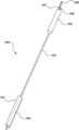
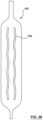
- FIG. 1is an illustration of a heat exchange device
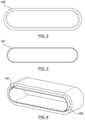
- FIG. 2is an illustration of a cross section of an esophagus
- FIG. 3is an illustration of a cross section of a balloon heat exchanger
- FIG. 4is an illustration of a balloon heat exchanger expanded in an esophagus
- FIG. 5is an illustration of three balloons side-by-side
- FIG. 6is an illustration of balloons with centered necks
- FIG. 7is an illustration of balloons with offset necks
- FIG. 8is an illustration of a serpentine welded balloon
- FIG. 9is an illustration of a welded balloons with ties
- FIG. 10is an illustration of a welded balloon with fins
- FIG. 11is an illustration of a welded balloon with pockets
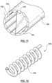
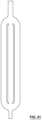
- FIG. 12is an illustration of a coiled tube heat exchanger
- FIG. 13is an illustration of a multiple-tube heat exchanger
- FIG. 14is an illustration of a helical-tube heat exchanger
- FIG. 15is an illustration of a serpentine-tube heat exchanger
- FIG. 16is an illustration of an inlet port with a single hole
- FIG. 17is an illustration of an inlet port with multiple holes
- FIG. 18is an illustration of temperature sensors affixed to balloon surface
- FIG. 19is an illustration of temperature sensors mounted on the embodiments depicted in FIGS. 13 and 14 ;
- FIG. 20is an illustration of temperature sensors mounted on struts made from a catheter shaft
- FIG. 21is an illustration of temperature sensors affixed to textile
- FIG. 22is an illustration of temperature sensors affixed to strands
- FIG. 23is an illustration of a heat exchanger with an insulating air balloon inside
- FIG. 24is an illustration of a heat exchanger with an insulating air balloon outside
- FIG. 25is an illustration of open irrigation of a fluid with suction
- FIG. 26is a flowchart of a method
- FIG. 27is an illustration of a balloon with a weld line
- FIG. 28is an illustration of a balloon with tack welds
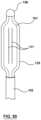
- FIG. 29is another embodiment of a heat exchange device which includes an outer sheath
- FIG. 30is an exploded view of a balloon
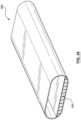
- FIG. 31is an illustration of a coiled tube heat exchanger with an oblong cross-sectional profile
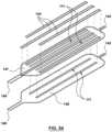
- FIG. 32is an illustration of a multiple-tube heat exchanger with an oblong cross-sectional profile
- FIG. 33is an illustration of a helical-tube heat exchanger with an oblong cross-sectional profile
- FIG. 34is an illustration of a heat exchanger with an insulating portion
- FIG. 35is an illustration of a heat exchanger with a shaping lumen and a heat exchanging lumen
- FIG. 36is an illustration of temperature sensors mounted on the embodiment depicted in FIG. 32 ;
- FIG. 37is an illustration of temperature sensors mounted on the embodiment depicted in FIG. 33 ;
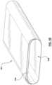
- FIG. 38is an illustration of a balloon with a pair of wavy weld lines
- FIG. 39is an illustration of a further embodiment of a balloon with a pair of wavy weld lines
- FIG. 40is an illustration of a balloon with a pair of wavy weld lines and multiple tack welds
- FIG. 41is an illustration of a balloon with a pair of curved weld lines
- FIG. 42is an illustration of a further embodiment of a balloon with tack welds
- FIG. 43is an illustration of a balloon with a pair of broken weld lines
- FIG. 44is an illustration of a further embodiment of a balloon with a pair of broken weld lines
- FIG. 45is an illustration of yet another embodiment of a balloon with a pair of broken weld lines
- FIG. 46is an illustration of a balloon with a pair of broken weld lines and a pair of tack welds
- FIG. 47is an illustration of a balloon with chevron pattern welds
- FIG. 48is an illustration of a further embodiment of a balloon with chevron pattern welds
- FIG. 49is an illustration of yet another embodiment of a balloon with chevron pattern welds
- FIG. 50is an illustration of a welded balloon with an outer balloon
- FIG. 51is an illustration of an irrigation heat exchanger
- FIG. 52is an illustration of the embodiment of FIG. 51 disposed in a body lumen
- FIG. 53is a side view of the embodiment depicted in FIG. 52 ;
- FIG. 54is an exploded view of a an embodiment
- FIG. 55is an illustration of a heat exchanger comprising a pocket
- FIG. 56is a cross-sectional plan view of a heat exchanger attached to a shaft and an inlet tube;
- FIG. 57is a cross-sectional plan view of a heat exchanger attached to a shaft, an inlet tube, and an outlet tube.
- Inadvertent thermal injury to the esophagusis a dangerous complication of left atrial ablation due to the close proximity of the esophagus to the posterior aspect of the human heart.
- These thermal injuriescan include esophageal mucosal changes, tissue necrosis, ulcer formation, and atrial-esophageal fistula formation.
- Current preventative optionsinclude reducing the power or duration of ablation when targeting the posterior wall of the left atrium, and monitoring luminal esophageal temperature during ablation so that the ablation can be stopped if there is an unacceptable temperature change in the esophagus. These options may reduce the effectiveness of an ablation treatment.
- One of the limitations of such balloonsis that the balloons typically expand and/or displace the esophagus.
- a balloonexpands and displaces an esophagus to a position closer to the posterior wall of the heart which is the location of heating by delivery of energy for ablation. In such cases, the cooling by the balloon may not be sufficient to protect the esophagus from thermal injury.
- the present inventorshave conceived of and reduced to practice embodiments of a heat exchange and temperature sensing device and a method of use of said device which is able to prevent injury to an esophagus caused by heat or cold being delivered to the left atrium of the heart.
- the deviceregulates the temperature of the esophagus by providing a heat exchanger which can be placed in the esophagus.
- the heating/cooling balloonhas an inflatable cross section corresponding with the collapsed/relaxed/natural cross section of the inside of the esophagus. Inflation of the balloon maintains the esophagus in its natural shape and location such that the esophagus is not displaced towards the left atrium.
- the balloonIn its collapsed or insertable state, the balloon is low in profile and flexible so that it can be inserted into the nose or mouth and advanced to the esophagus. Once positioned in the esophagus, it is expandable to take on a shape with a profile and dimensions corresponding to the collapsed/relaxed/natural cross section of the internal lumen defined by a human esophagus. When fully expanded, the heat exchange balloon makes contact with the endoluminal surface of the esophagus without substantially displacing it from its natural location.
- the outer surface of the balloonis in intimate contact with the mucosal layer of the esophagus. It supplies or removes thermal energy in order to keep the esophagus at a desired temperature throughout an ablation procedure. This includes cooling the esophagus during heat-based ablation procedures, (such as radio frequency/RF or high intensity focused ultrasound ablation/HIFU), or warming the esophagus during cold-based ablation procedures (such as cryoablation).
- heat-based ablation proceduressuch as radio frequency/RF or high intensity focused ultrasound ablation/HIFU
- cryoablationwarming the esophagus during cold-based ablation procedures
- This method and devicemay be used during left atrial ablation procedures, which are procedures for treating atrial fibrillation in humans. These procedures may include RF/HIFU ablations and cryoablations. In these types of procedures, ablations are performed to create lesions around the ostia of the pulmonary veins, some of which are typically very close to the esophagus. Before the veins are ablated, the balloon portion of the device is positioned in the esophageal lumen and posterior to the left atrium. Once activated, the device either removes thermal energy from the esophagus, or delivers thermal energy to the esophagus to keep it in a desired temperature range throughout the procedure.
- the inventioncan also be used in other cardiac procedures where the temperatures in the heart reach undesired levels. It can also be used in other areas of the body where temperature management is required to protect sensitive structures, for example ablation of the prostate to treat cancer. Additionally, the invention can be used to control patient temperature, for example to induce and maintain hypothermia in critically ill patients, or to warm patients with body temperatures below normal, such as when they are under general anesthesia and undergoing surgery.
- Heat exchanging fluid device 100comprises a main shaft 103 which has balloon heat exchanger 101 at one end, with temperature sensor 104 being associated with balloon heat exchanger 101 .
- Handle 105is at the other end of main shaft 103 .
- the end of heat exchange device 100 having handle 105also includes fluid inflow 106 , fluid outflow 107 , and temperature sensor connector 108 .
- FIG. 29Another embodiment of heat exchange and temperature sensing device 100 is shown in FIG. 29 . As will be described in more detail below, heat is exchanged by allowing fluid to be circulated through the balloon 101 via fluid inflow 106 and fluid outflow 107 .
- the fluidis made substantially of water.
- the fluidmay be distilled water or saline.
- the fluidmay be a substance that is not substantially water, such as an oil based or petroleum product.
- the fluidmay contain additives, for example a disinfectant, or stabilizer.
- the temperature, flow rate, and pressure of the fluidis managed through an external controller which includes a pump.
- the heat exchanging fluid device of the present inventionis described in greater detail below.
- the heat exchanging fluid devicecomprises inlet port(s) and outlet port(s).
- the inlet port(s)is the location where the fluid enters the heat exchanger (e.g. a balloon). There may be one or multiple inlet ports which service different locations in the heat exchanger.
- the inlet port 116is a hole on tube 127 located inside the heat exchanger 101 (e.g. FIG. 16 . Inlet port with single hole). The fluid advances through fluid inflow 106 and tube 127 until it reaches the hole 116 and enters the heat exchanger 101 . Fluid inflow 106 and tube 127 are in fluid communication to allow fluid to be supplied to the heat exchanger via fluid inflow 106 .
- the tube 127is made of plastic, possibly reinforced with materials such as a metal coil or braid within the tube wall.
- the hole 116may be at the distal end of the heat exchanger 101 , or the proximal end of the heat exchanger 101 , or at any location in between.
- inlet port(s)are in fluid communication with fluid inflow 106 . In some embodiments, inlet port(s) are part of fluid inflow 106 .
- heat exchange fluidis circulated in a closed loop. After heat exchange fluid leaves the heat exchange device via fluid outflow, the heat exchange fluid is re-heated/re-cooled then introduced back into the heat exchange device via fluid inflow. Heat exchange fluid may thus be continuously recirculated.
- heat exchange fluidis circulated in an open loop. Heat exchange fluid leaving the heat exchange device is discarded or disposed of.
- the tubehas multiple holes spaced along the tube (e.g. FIG. 17 .
- the fluidadvances through the tube until it reaches one of the multiple holes, and enters the heat exchanger in multiple locations simultaneously.
- the holesmay be spaced linearly at regular intervals, or in a helical pattern around the tube, or in any other type of pattern along the tube.
- the holesare located to optimize one of the features of the heat exchange. For example, the holes may be located to maximize the thermal performance of the heat exchanger, or to control pressure inside the heat exchanger.
- the outlet portis the location where the fluid exits the heat exchanger. There may be one or multiple outlet ports which service different locations in the heat exchanger.
- the outlet portis a tube with a single hole located inside the heat exchanger. The fluid enters the heat exchanger at the inlet port(s), travels through the heat exchanger, and exits at the outlet port.
- the tubeis made of plastic, possibly reinforced with materials such as a metal coil or braid within the tube wall.
- the holemay be at the distal end of the heat exchanger, or the proximal end of the heat exchanger, or at any location in between.
- outlet port(s)are in fluid communication with fluid outflow 107 . In some embodiments, outlet port(s) are part of fluid outflow 107 .
- the tube 127has multiple holes spaced along its length.
- the fluid in the heat exchangerexits through one of the multiple holes simultaneously.
- the holesmay be spaced linearly at regular intervals, or in a helical pattern around the tube, or in any other type of pattern along the tube.
- the holesare located to optimize one of the features of the heat exchange. For example, the holes may be located to maximize the thermal performance of the heat exchanger, or to control pressure inside the heat exchanger.
- the heat exchange device 100may comprise a sheath or sleeve.
- a sheath 152is depicted in FIG. 29 .
- a heat exchanger 101may be collapsed/wrapped/deflated around a shaft 103 such that the heat exchanger 101 may be received into a sheath 152 .
- sheath 152is dimensioned to receive heat exchanger 101 when it is in a collapsed/wrapped/deflated configuration. This feature may be provided to avoid damage to the body lumen when the heat exchanger is being advanced therethrough.
- Heat exchanger 101may be provided with radiopaque (RO) markers or electroanatomic mapping (EAM) 153 for using imaging techniques to determine the location of the heat exchanger 101 relative to known anatomical markers.
- the embodiment depicted in FIG. 29is provided with a body temperature sensor 155 .
- Body temperature sensor 155is spaced apart from heat exchanger 101 such that the temperature sensed by sensor 155 is of the body lumen and not of the heat exchanger 101 .
- Items 154are additional electrodes for either pacing or detecting electric signals. For pacing, pacing electrodes would be provided. For detecting electric signals, electrocardiogram electrodes would be provided.
- the various sensors and electrodesmay be connected to one or more external devices through connector 108 .
- FIG. 56illustrates an embodiment of heat exchanger 101 with inlet and outlet ports.
- the heat exchanger 101comprises proximal neck portion 146 and distal neck portion 134 .
- inlet ports 116are positioned proximate the distal end of heat exchanger 101 .
- Fluidtravels through tube 127 along the arrows shown in the figure. When the fluid reaches the outlet ports 116 , fluid exits tube 127 and enters the heat exchanger 101 . The fluid then follows a return path towards a proximal end of the heat exchanger 101 (i.e., towards proximal neck portion 146 ) and leaves the heat exchanger 101 via outlet ports 150 .
- outlet ports 150are formed by providing a circumferential gap between the proximal neck portion 146 of the heat exchanger 101 and the tube 127 .
- the diameter of tube 127is somewhat narrower than the inner diameter of shaft 103 to permit fluid to flow there between and back towards the fluid outflow 107 .
- Tube 127is attached via welding or other means to distal neck portion 146 such that fluid is prevented from escaping the heat exchanger 101 out from the distal neck portion 146 .
- Proximal neck portion 146is attached via welding or other means to shaft 103 such that fluid is prevented from escaping the heat exchanger 101 and shaft 103 .
- FIG. 57illustrates a further embodiment of a heat exchanger 101 with inlet and outlet ports.
- an inner inlet tube 152 and an outer outlet tube 153are provided. Fluid flows into the heat exchanger 101 via ports 116 . Both the inner inlet tube 152 and the outer outlet tube 153 comprise ports 116 to allow fluid to pass therethrough. Means are provided to prevent fluid from flowing into the space between inner inlet tube 152 and outer outlet tube 153 .
- O-rings 151are placed on either side of ports 116 . The O-rings 151 prevent fluid from flowing into the space between the inner inlet tube 152 and the outer outlet tube 153 .
- Outer outlet tube 153comprise outlet ports 150 . Fluid leaving the heat exchanger 101 flows into the outlet ports 150 and towards a fluid outflow.
- a heat exchanger(a cavity for circulation of fluid).
- the cavityis a balloon—this embodiment will be described in greater detail below.
- Some embodiments of balloonsare made of a non-compliant material such as Nylon 12 or PET.
- Alternative balloon embodimentsare made of a compliant material such as Pebax® or urethane.
- Controllable heat exchanger sizeThis feature includes the heat exchanger being expandable or contractable to fit the size of the esophagus and promote contact with the tissue.
- the change in sizemay be controlled with pressure, such as the internal pressure in a balloon, or external pressure exerted by the anatomy on the device.
- the sizemay be controlled with a mechanical expansion/contraction mechanism, which may further comprise a feedback loop from the forces exerted on the device (detected via force sensors) to achieve the optimal contact force.
- Conformable heat exchanger shapeThis feature includes the expansion of the heat exchanger being constrained in one or more axes, using the balloon designs outlined above and through the use of compliant and non-compliant materials, thin films with ties or welds, and shape memory materials.
- the heat exchangeris moldable to the esophagus shape through the use of compliant materials that respond to forces exerted by the tissue.
- the heat exchange devicemay have an anchoring feature or features such as notches, necks, collars, or hooks that allow the device to engage internally with anatomical features to hold it in place.
- the devicehas an anchoring feature such as tape, Velcro, and straps that allow it to engage externally with other devices such as an endotracheal tube or a nasal bridle to hold it in place.
- the heat exchange devicemay incorporate suction to hold the tissue against the surface of the device to ensure appropriate tissue contact. Tissue suction may also be used to ensure that tissue is pulled away from the area where heat is being applied. For example, when esophagus tissue is pulled towards the heat exchanger, it may be consequently pulled away from the left atrium of the heart where ablation is taking place.
- forcemay be applied to the esophagus or the device to maintain adequate tissue contact. This may be a force external to the patient, or applied from within the patient from the heat exchange device, or from another device (for example, by suction feature as described above).
- the heat exchange devicemay comprise force sensors to measure the amount of force between the tissue and the heat exchanger. This force may be used in a feedback loop in communication with the device to maintain optimal force between the heat exchanger and the tissue.
- Yet another technique to ensure proper heat exchangeis to use heat flux sensors to measure the heat flux at any given part of the tissue at the target site. A greater heat flux measurement represents greater heat transfer between the tissue and the heat exchanger.
- Some embodiments of the heat exchanging fluid device described hereincomprise a balloon heat exchanger 101 ( FIG. 1 ).
- the balloon 101comprises a cavity for circulation of fluid. Embodiments of such heat exchange balloons are illustrated in FIGS. 2 , 5 - 15 , 18 - 24 , 26 - 30 , 34 - 35 , and 38 - 50 .
- a human esophagus 109In its collapsed shape, a human esophagus 109 typically has a cross-section of around 1.5-3 cm wide and around 0-0.5 cm high (e.g. FIG. 2 . cross section of esophagus).
- the balloon of the inventione.g. FIG. 3 .
- cross section of balloon heat exchanger 101maintains a cross-section of similar dimensions in order to make intimate contact with the mucosal layer of the esophagus without displacing it, i.e., the balloon is expandable but is restrained in one or more axes to reduce forces exerted on the abutting surfaces of the esophagus (e.g. FIG. 4 . balloon heat exchanger 101 expanded in esophagus 109 ).
- the desired shape of the balloon heat exchanger 101can be realized in a number of ways.
- at least two cylindrical balloonsare abutted and held side-by-side.
- the overall dimensions of the cross-section of the heat exchanger (when expanded)is approximately 15 mm wide and 5 mm tall.
- both the number of cylindrical balloons and the inflated diameter of the balloonscan be varied to vary the overall dimensions of the cross-section of the heat exchanger.
- balloonsabutted side-by-side.
- these balloonsare cylindrical with balloon necks 110 in the middle of the balloon ( FIG. 6 . balloons with centered necks), or in some other embodiments, with offset balloon necks 110 located away from the center of the balloon ( FIG. 7 . balloons with offset necks).
- Balloon necks 110may be in fluid communication with the main body of balloon 128 .
- Balloon necks 110may be connected with input ports or output ports to allow fluid flow through the balloon.
- the desired shape of the balloonis achieved by welding thin films together.
- the filmsmay be plastic such as urethane, or another material that is formable in thin film.
- the filmsare welded in a serpentine shape.
- FIG. 8illustrates a serpentine welded balloon having top and bottom films (when in the orientation of FIG. 8 ) welded together along weld lines 111 . The top and bottom films, when welded, result in a lumen 149 through which fluid may be circulated to perform the heat exchange.
- the welding techniqueis used to add singular or multiple ties inside a balloon to prevent it from expanding in undesired axes.
- FIG. 9shows two examples of welded balloons with ties with the balloon on the left having a single tie 112 and the balloon on the right of the figure having two lies.
- Weld lines 111weld the ties in place.
- FIGS. 27 - 28 , 30 , and 38 - 50feature balloon heat exchangers with a variety of weld patterns. Varying the weld patterns impact the lengthwise and widthwise inflatability and rigidity of the balloon as well as the flow of fluid through the balloon.
- FIGS. 28 and 42illustrate balloons with tack welds 126 (or spot welds).
- the weld pattern in this embodimentresults in multiple fluid flow channels that extend along the length and the width of the balloon. These channels are “open” such that fluid flowing within one channel may flow to another channel. This allows fluid to flow into any particular area of the balloon, even if the balloon is bent, folded, or otherwise restricted from freely inflating in that area.
- These fluid channelsallow the balloon to be more easily inflated and deployed in applications where the balloon is introduced into the esophagus deflated and wrapped around a central shaft (such as shown in FIG. 29 ) along the balloon's lengthwise axis. Also, these embodiments allow the mixing of flow amongst the various fluid channels, which promotes heat exchange across the entire surface of the balloon.
- the balloon heat exchanger 101 of FIG. 27includes a balloon with a weld line 111 creating two fluid flow channels.
- FIGS. 38 , 39 , and 40includes a balloon 101 with two wavy welds creating three fluid flow channels—the wavy welds in these embodiments creates multiple hinge axis, and each axis resists hinge-like behavior giving the balloon added widthwise rigidity when the balloon is inflated, which may be desirable in certain applications.
- FIG. 41includes a balloon 101 with two weld lines which are curved at their end. The curved ends correspond with an outer contour of the balloon. By providing these curves, the cross-sectional area at the ends of the balloon 101 are somewhat reduced, thereby reducing the stress on the material when inflated.
- FIGS. 38 , 39 , and 40includes a balloon 101 with two wavy welds creating three fluid flow channels—the wavy welds in these embodiments creates multiple hinge axis, and each axis resists hinge-like behavior giving
- 27 , 38 , 39 , 40 , and 41each create multiple fluid channels along the length of the balloon such that fluid which is introduced at one end (e.g., the distal end) may naturally flow through the channels towards the other end (e.g., the proximal end). Continuous fluid flow through the length of the balloon enables more efficient heat exchange as the target area is continuously provided with heated or cooled fluids.
- FIGS. 43 , 44 , 45 , and 46illustrate balloons with broken line welds.
- This designenables the mixing of fluid flow between the lengthwise fluid channels, which may be desirable in applications where the fluid in a particular channel is being cooled or heated more than the fluid in the other lumens.
- These fluid channelsare “open” such that fluid from one lengthwise channel may flow to a different lengthwise channel, the balloon may provide more even heat exchange to an area of the esophagus that is experiencing the most extreme temperatures. It also allows the balloon to be more easily inflated within the esophagus because there are multiple pathways for fluid to flow into a given area of the balloon.
- FIGS. 47 , 48 , and 49illustrate balloons with a chevron pattern. This pattern allows fluid flow mixing across the fluid flow channels.
- the diagonal alignment of the weldsincreases widthwise rigidity which allows the balloon to be more easily deployed and inflated after being introduced into the esophagus in applications where the balloon is introduced into the esophagus deflated and wrapped around a central shaft along the balloon's lengthwise axis.
- FIG. 30is an exploded view of a balloon 101 before welding.
- a pocket 144is welded in between an anterior balloon surface 147 and a posterior balloon surface 148 .
- This embodiment of balloon 101further comprises a distal neck portion 145 and a proximal neck portion 146 .
- Pocket 144may comprise temperature sensors, heat flux sensors, force sensors, or other sensors (not shown).
- FIG. 54is an exploded view of a further embodiment of balloon 101 before welding.
- three pockets 144are welded to the outer surface of the anterior balloon surface 147 (i.e., the surface closest to the target area), allowing various sensors to be spread across the width of the balloon.
- Weld lines 111are provided creating three fluid flow channels. Pockets 144 are positioned along the fluid flow channels.
- FIG. 55depicts a heat exchanger 101 comprising a pocket 144 .
- Pocket 144may be formed by attaching a piece of material on the outside of the heat exchanger 101 , thereby creating a pocket 144 adjacent to lumen 149 .
- Some alternative embodiments of the heat exchanger 101have fins or fingers that expand to the desired shape once inflated.
- the example of FIG. 10includes a welded balloon with fins 113 .
- FIG. 11 embodiment of balloon heat exchanger 101comprises an inner film 131 , an outer film 132 , and a tie 112 .
- the inner film 131 and outer film 132are welded together to form a series of longitudinal pockets 114 (that is, along the length of the balloon). Fluid flows through the longitudinal pockets in order to perform heat exchange.
- Tie 112is attached between two sides of an inner diameter of the balloon heat exchanger 101 to produce a desired cross-sectional shape. In FIG. 11 , the cross-sectional shape of the balloon heat exchanger is circular.
- the balloon heat exchangeris more preferably oblong to better conform to the cross-sectional area of the collapsed esophagus and reduce the resulting displacement of the esophagus.
- the length and position of tie 112may be adjusted to change the shape of the balloon heat exchanger when it is in its inflated or expanded configuration.
- balloon heat exchangersIn addition to using welding to construct balloon heat exchangers, other means known to those skilled in the art may also be used. For example, other adhesive techniques or blow molding techniques may be employed.
- an outer balloon 135 without any sharp edgesmay be provided and covers the inner welded balloon 101 (see FIG. 50 ).
- the outer balloonmay be perforated or may be vacuum sealed against the inner balloon.
- the outer balloonmay be constructed by flipping a welded balloon inside-out, blow molding, or other techniques known to those skilled in the art.
- a blunt tip 156may be provided to prevent damage to the body lumen.
- a sheath 152is also provided for receiving the heat exchanger 101 .
- the outer edges of the welded balloonmay comprise small cuts along the outer edge.
- the rigid outer edgeis rendered soft, and reduces the likelihood of damage to the esophagus while the balloon is being introduced through the esophagus.
- Other techniquesmay be used to blunt or soften the outer edge, including:
- the outer edgemay be widened such that the welded outer edge is softened.
- the outer edgemay be folded over and welded, glued, or bonded to create a rounded outer edge.
- the outer edgemay be melted to blunt the outer edge.
- FIG. 35illustrates a further embodiment of a balloon heat exchanger 101 .
- the balloon 101comprises a shaping lumen 132 and a heat exchanging lumen 133 .
- the shaping lumen 132 and heat exchanging lumen 133are isolated from one another such that fluid in one lumen does not flow to or from the other.
- fluidflows through the heat exchanging lumen 133 .
- the temperature and flow rate of the fluidmay be varied to change the rate at which heat is being exchanged between the heat exchanger 101 and the surrounding environment (i.e., the tissue in the esophagus when the heat exchanger 101 is inserted therein).
- balloon 101further comprises a shaping lumen 132 .
- Shaping lumen 132may be supplied with a separate fluid (e.g., air or water) which inflates the shaping lumen 132 to its inflated form. Unlike the heat exchanging lumen 133 , fluid need not flow through the shaping lumen 132 in order for the shaping lumen 132 to perform its function. Once inflated, it is possible to maintain the shape of the shaping lumen 132 without providing any fluid flow. Thus, the shape of balloon 101 may be controlled independently from the fluid flow rate and pressure inside the heat exchanging lumen 133 . Those skilled in the art will appreciate that this allows greater flexibility in varying the parameters to arrive at an appropriate rate of heat exchange.
- a separate fluide.g., air or water
- the cavity for circulation of fluidis an arrangement of thermally conductive tubes.
- the tubesare preferably arranged to fill a cross-sectional area with outside dimensions similar to the collapsed state of a human esophagus.
- FIG. 12illustrates a tubular heat exchanger 102 having coils 115 .
- the profile of the tubular heat exchanger 102 of FIG. 12is circular.
- the tubesare arranged in parallel and in a circular orientation, such as in the example of tubular heat exchanger 102 FIG. 13 .
- the tubular heat exchanger 102 of FIG. 12includes a number of exposed tubes 129 while alternative embodiments may include separate lumens in a single tube (not shown).
- the tubes 129are arranged in a helix (e.g. FIG. 14 . Helical-tube heat exchanger).
- each tube 129is spiral-shaped and is helically arranged adjacent to other spiral-shaped tubes.
- heat exchanger 102further comprise a pair of end portions 130 .
- Each of the tubes 129are fixed between the two end portions 130 to maintain the relative orientation between the tubes.
- FIGS. 12 , 13 , and 14comprise a circular cross-sectional profile. More preferably, the cross-sectional profile of the heat exchanger 102 is oblong to better conform to the cross-sectional area of the inside of a collapsed human esophagus. Examples of such embodiments are illustrated in FIGS. 31 , 32 , and 33 .
- Some alternative embodimentshave a serpentine-shaped tube, such as shown in FIG. 15 .
- the surface of the heat exchangeris thermally conductive to facilitate the transfer of heat at the desired treatment zone.
- the surfaceis a film substantially thin enough to allow transfer of thermal energy, e.g. with a thickness between around 0.001′′ to around 0.003′′.
- the surfaceis made of a thermally conductive material, such as metal foil.
- a thermally conductive gel or coatingmay be applied to the heat exchanger, or to the target tissue site. This may fill any gaps that might exist between the tissue and the heat exchanger.
- a method of regulating a temperature of an esophagus when heat or cold is delivered to a left atriumincludes the steps of:
- Step 1Measuring the Esophagus and Selecting a Size of a Heat Exchange Device which Fits the Esophagus
- the esophagusis measured in order to select the appropriate device size for the patient. Ways of doing this include:
- the heat exchange device of best fitcan be chosen from a selection of devices that cover the range of most anatomical variations.
- Step 2Delivering the Heat Exchange Device to a Target Site
- Delivering the heat exchange device to the target site in the esophagusincludes inserting it through a small orifice such as the mouth or nostril, and then advancing the heat exchange device through tortuous path defined by the esophagus until the heat exchange device is positioned at the posterior aspect of the left atrium.
- a small orificesuch as the mouth or nostril
- a number of featuresenable the heat exchange device to enter a small orifice.
- the heat exchangermay be collapsible, foldable, and wrappable such that it can be delivered through a substantially round hole with a diameter of about 0.2 cm to about 0.6 cm.
- the heat exchangeris a balloon that can be deflated and wrapped or folded around a main shaft such that it can be delivered to the desired treatment area through a small orifice.
- Some embodiments of the heat exchange device 100have an outer diameter equal to or less than 18 F.
- the heat exchangeris made of tubes that can be twisted, pulled, or otherwise re-arranged such that they maintain an outer diameter in the desired range and be delivered through a small orifice.
- the tubesthemselves may collapse when they are evacuated.
- the heat exchange devicecould have a folding or collapsing metal structure such as a stent-like configuration (see FIG. 20 ).
- the delivery orificemay be an access point on the patient, such as the nasal or oral passageway.
- the delivery orificemay be a delivery tube.
- the heat exchangercan be loaded inside the delivery tube, and the delivery tube delivered through an access point on the patient.
- Typical embodiments of the heat exchange balloonmay be tapered at the ends to promote gradual dilation of the small orifice.
- the heat exchangerthe balloon
- the delivery tubecould be retracted to expose the heat exchanger.
- the delivery of the heat exchange devicemay be augmented by the addition of a lubricious coating on the outside surface of the heat exchange device or on the inner surface of the small orifice.
- the flexibility of the devicemay be modifiable with a selection of features:
- the heat exchange and temperature sensing devicemay have a selection of features:
- the heat exchange devicemay have features to promote atraumatic delivery. These features may include floppy portions, tapered ends, soft portions, steerable portions, and a soft covering sheath.
- the heat exchange deviceIf the heat exchange device is collapsed/folded/wrapped, it must be expanded once it reaches the target location of the esophagus.
- the heat exchange devicemay be expanded in a number of ways:
- the userconfirms that the device is in the correct location. This may be achieved by a number of means:
- thermoelectric device(b) Measurement of a physiological parameter.
- Some embodiments of the heat exchange deviceare capable of measuring a physiological parameter indicative of location in the body through the use of sensors or electrodes. Examples of the parameter which may be measured include ECG, tissue impedance, temperature, blood perfusion rate, oxygen saturation, and others.
- Step 4Exchanging Heat with the Esophagus
- heatmay be exchanged within the esophagus using a heat exchange fluid device, such as those embodiments described above in the section titled “Heat Exchange Fluid Device”.
- the fluid used in the deviceis comprised substantially of water.
- the fluidmay be distilled water or saline.
- the fluidmay be a substance that is not substantially water, such as an oil based or petroleum product.
- the fluidmay contain additives, for example a disinfectant, or stabilizer.
- the temperature, flow rate, and pressure of the fluidis managed through an external controller which includes a pump.
- fluidflows through an inlet port into the heat exchanger of the heat exchanging fluid device and circulates through the body of the heat exchanger.
- An outlet portis also provided to allow fluid to flow out of the heat exchanger. Fluid may continuously flow through the heat exchanger so that there is continuous heat exchange with the esophagus.
- the heat exchange fluid 125is delivered directly to the desired treatment zone in an open-irrigated system.
- the heat exchange device 100is connected to an external controller that provides the heat exchange fluid 125 .
- the fluidis delivered through a fluid spray tube 122 and sprayed circumferentially toward the endoluminal surface of the esophagus. Fluid is removed using fluid suction tube 123 .
- the tubehas multiple holes along its length and around its circumference in order to deliver an even spray of fluid to the desired treatment zone.
- the fluidis allowed to travel through the esophagus to the stomach.
- the esophagusis blocked by an esophageal blocking balloon 124 , and the fluid is collected cranial to the blocking balloon 124 and suctioned from the esophagus.
- FIGS. 51 - 53A further alternative embodiment is depicted in FIGS. 51 - 53 . Similar to the embodiment depicted in FIG. 25 , heat exchange fluid 125 is delivered directly to the desired treatment zone.
- the irrigation heat exchanger 136delivers heat exchange fluid through an irrigation surface 137 with a series of irrigation ports 138 from which heat exchange fluid is sprayed.
- the heat exchanger 136may further comprise a proximal blocking balloon 142 and a distal blocking balloon 143 which prevents fluid from escaping into the stomach or the larynx respectively.
- the heat exchanger 136may further comprise a distal suction component 140 and a proximal suction 141 component which captures fluid after it has been sprayed from the irrigation ports 138 .
- the heat exchanger 136may be connected to or integral with a tube 139 .
- Tube 139may comprise an inlet tube and outlet tube (not depicted) for supplying fluid to and removing fluid from the desired treatment zone.
- the other end of tube 139may be connected with an external controller that provides heat exchange fluid 125 .
- the heat exchangeris a Peltier device which may heat or cool the esophagus with thermoelectric heat exchange.
- the heat exchange deviceis connected to an external controller that powers the Peltier device.
- An alternate method of cooling the esophagusis to deliver a coolant directly to the endoluminal surface of the esophagus.
- the heat exchange deviceis connected to an external controller that provides the coolant.
- the coolantis sprayed in a mist mixed with a gas such as air or oxygen to the surface of the esophagus.
- the coolantrapidly evaporates due to the gas flow.
- the esophageal surfaceis cooled as a result of the evaporation.
- Some embodiments of the heat exchangermake use of a vortex tube, a mechanical device that separates a compressed gas into a hot stream and a cold stream. Either stream could be used for heat exchange, so this type of heat exchanger could be used to either warm or cool the esophagus.
- Step 5Confirming that the Target Site is Protected
- the userconfirms that the tissue is protected.
- Imaging modalitiessuch as MRI or ultrasound may be used to monitor tissue changes in the esophagus. An absence of lesion growth or tissue changes supports the lack of tissue damage.
- a physiological parameter indicative of tissue viability/healthmay include temperature, tissue impedance, blood perfusion rate, oxygen saturation, or nerve function (for example vagus or phrenic nerve).
- Some embodiments of the heat exchange devicecomprise a means to measure these parameters.
- the heat exchange devicemay be connected to an external controller that interprets/displays/analyses the signals produced from the heat exchange device.
- the measured physiological parametersmay be used in a control loop to alert the user of unsafe levels.
- the control loopmay be connected to the ablation therapy device to stop ablation before a critical level is reached.
- the control loopmay include a mathematical model of changes in the physiological parameter that can predict when irreversible damage may occur, and stop the ablation energy before the dangerous levels are reached.
- the temperature measuredmay be one of a number of temperatures, including the temperature of the desired treatment area, or the patient's core body temperature. Temperature may be measured by any of a number of sensors, including thermocouples, thermistors, fiber optics, or by another method such as ultrasound, MRI, infrared, or microwave radiometry.
- the means of measuring temperatureis affixed to the heat exchange surface.
- individual thermocouple pairs, or a flexible circuit containing thermocouples and/or thermistors, or a fiber optic cablemay be affixed to the surface of the heat exchanger with adhesives.
- the temperature sensorsmay be spray or dip coated onto the surface of the heat exchanger with a flexible material such as urethane.
- the temperature sensorsmay be laminated onto the surface of the heat exchange surface with a thin film, or they may be laminated between two thin film layers, which may then be used to create the heat exchanger.
- the temperature sensorsmay be positioned inside pockets welded to the surface of the heat exchanger.
- the temperature sensorsWhen positioned on the surface of the heat exchanger, the temperature sensors measure the temperature of the desired treatment area once the heat exchanger makes contact with the desired treatment area (e.g. FIG. 18 . Temperature sensors 104 affixed to balloon surface of balloon heat exchanger 101 ).
- the temperature sensorsare drawn onto the surface of the balloon with conductive ink.
- the temperature sensors of some embodimentsare thermocouples made by crossing a line of conductive silver ink with a line of conductive nickel ink.
- the temperature sensorsare affixed to the shaft with adhesives, thermal welding, or another means.
- a temperature sensormay be added to the distal end of the shaft, which is positioned in the patient's stomach to monitor core body temperature.
- the temperature sensors 104are mounted on a frame 117 that is separate from the heat exchanger.
- the frame 117may be made of expandable and collapsible struts that can be deployed around the heat exchanger to measure the temperature of the desired treatment area (e.g. FIG. 19 temperature sensors mounted on frame separate from heat exchanger).
- the strutsmay be in one of a number of configurations, such as linear (top of FIG. 19 ), helical (bottom of FIG. 19 ), intersecting, or asymmetrical.
- the strutsmay be expanded and collapsed with the use of a mechanical mechanism such as a pull wire.
- the strutsmay be made of a number of materials, for example, a flexible metal such as Nitinol, or a plastic such as Pebax, or a shape memory alloy or shape memory polymer.
- the shape memory polymermay be activated to take on the desired shape by thermal or electrical inputs.
- the strutsmay be part of the shaft.
- the embodiment of FIG. 20includes temperature sensors 104 mounted on struts 118 made from main shaft 103 .
- the balloon heat exchangeris more preferably oblong to better conform to the cross-sectional area of the collapsed esophagus and reduce the resulting displacement of the esophagus. Accordingly, the embodiments illustrated in FIGS. 19 and 20 may be provided with a more oblong cross-sectional shape.
- FIGS. 36 and 37illustrate further embodiments comprising tubes 129 and temperature sensors 104 which feature a more oblong cross-sectional profile.
- the temperature sensors 104are affixed to or woven into a textile 119 (i.e. a fabric material) that surrounds the heat exchanger (e.g. FIG. 21 temperature sensors affixed to textile).
- a textile 119i.e. a fabric material
- the fabricmay expand around it, allowing the temperature sensors to make contact with and measure the temperature of the desired treatment area.
- the temperature sensors 104are affixed to strands 120 connected at one end of the heat exchanger so that they hang freely about the other end of the heat exchanger.
- the example of FIG. 22includes temperature sensors 104 affixed to strands 120 which are attached to main shaft 103 .
- Strands 120are flexible and atraumatic such that as they are advanced through the esophagus, the esophagus is not damaged.
- an array of temperature sensorsmay be used.
- the sensorsmay be positioned in such a way that an algorithm may be used to interpolate the temperatures between the sensors in order to produce a temperature map of the esophageal surface.
- a temperature mapmay be produced using IR or microwave temperature measuring modalities.
- the antenna effectOne concern some users may have with respect to the sensors is what is known as the antenna effect.
- metal electrodes in the esophagusmay promote thermal injury as a result of electrical or thermal interactions with the ablation catheter.
- the electrodes on some embodiments of the heat exchange deviceare insulated, or made of a non-conductive material.
- the electrodesmay be positioned such that the electrical or thermal interactions will not affect them, for example, the electrodes may be located on the posterior wall of the heat exchanger so that the heat exchanger insulates the electrodes from the interactions.
- filtersmay be built into the external device where the signals are interpreted and displayed to eliminate these interactions.
- the heat exchangeris typically collapsed for removal from the patient.
- the heat exchangeris evacuated by pulling a vacuum at the outlet port or the inlet port. Once evacuated, the heat exchanger can be pulled back through the delivery orifice and removed from the patient.
- the heat exchangeris collapsed using a sleeve around the heat exchanger.
- This sleevemay comprise a fabric mesh structure, a metal structure, such as a structure similar to a stent, or a polymer cage.
- the sleeveis a sheath.
- the sleeveis collapsed using a mechanical mechanism.
- the sleeveis collapsed using shape memory material properties.
- the heat exchange devicemay be pulled into the delivery orifice, or the delivery orifice may be advanced over the heat exchange device.
- the heat exchange devicemay be inverted (inside-out) as it is pulled into the delivery orifice.
- the delivery orificeis the patient's nose or mouth.
- the delivery orificeis a sheath separate from the device.
- the sheathmay have a telescoping feature.
- the sheathmay be integrated with the heat exchange device. For example, it may comprise expanding and contracting struts that are part of the body of the heat exchange device, or it may be a translating portion of the heat exchange device body.
- the heat exchange deviceis removed from the patient.
- the usermay be concerned about affecting the patient's core body temperature as a result of exchanging heat in the esophagus. There are a number of optional features and surgical techniques to mitigate this risk.
- Focus heat exchange at areas of highest riskThis may be achieved by monitoring a physiological parameter at different locations on the esophagus and using a control loop in the external controller to determine the high-risk areas and focus heat exchange in those areas.
- a control loopmay be used to automatically balance the heat exchanged.
- the heat exchange devicemay be used to supply opposite and optionally equal heat exchange while the ablation therapy is not being applied.
- Some embodiments of the devicemay comprise the following insulative features at the non-therapy areas to minimize overall heat exchange and focus heat exchange only in the target area:
- the heat exchange devicemay have a temperature sensor at a location away from the heat exchange area to monitor core body temperature.
- the temperature sensoris at the distal end of the device and is positioned in the patient's stomach.
- a control loopmay be used to feedback the patient's core temperature to the user and alert the user of dangerous temperatures. Alternately, the control loop could be used to control the amount of heat being exchanged in the patient.
- (f)Determining a safe heat exchange operating range based on patient characteristics, the bio-heat equation, and other pertinent information. Some embodiments of the method include monitoring the amount of heat exchanged by the heat exchange device and confirming that it does not exceed the calculated safe amount.
- a feedback loopmay also be used to maximize the therapeutic energy delivered while the esophagus is not in danger. This may be achieved by monitoring a physiological parameter indicative of tissue heath/viability as described above, and using that data in a control loop to stop or decrease ablative therapy when the esophageal tissue is in danger, and increase/optimize ablative therapy when the esophageal tissue is not affected.
- the datamay also be used to focus the heat exchange at high risk areas in the esophagus to minimize the impact on the therapeutic energy delivery.
- the datamay also be used to decrease or stop the heat exchange during ablations when the esophagus is not at risk.
- additional steps in the methodmay include pacing the heart and performing a cardiac EP exam using the heat exchange device.
- some embodiments of the heat exchange devicecomprise pacing and ECG electrodes on the body of heat exchange device. This technique can be performed during step 3 ( FIG. 26 ) of the above described method.
- a heat exchange devicehaving a heating/cooling balloon (or sac) which has an inflated cross section corresponding with the collapsed/relaxed/natural cross section of the inside of the esophagus whereby inflation of the balloon maintains the esophagus in its natural shape and location and avoids not displacing the esophagus towards the left atrium.
- Some alternative embodimentsincludes altering a configuration of the balloon to conform to or correspond with the cross section of an esophagus by means other than inflation.
- a method of regulating a temperature of an esophagus when heat or cold is delivered to a left atriumcomprises altering a heat exchange device from an insertable configuration to a heat exchanging configuration which substantially conforms and corresponds with a cross-section of an inside of the esophagus such that the esophagus is substantially maintained in its natural shape and location whereby the esophagus is substantially not displaced towards the left atrium.
- a method of regulating a temperature of an esophagus when heat or cold is delivered to a left atriumcomprises (a) inflating a heat exchange device from an collapsed configuration to an inflated configuration which substantially conforms and corresponds with a cross-section of an inside of the esophagus such that the esophagus is substantially maintained in its natural shape and location whereby the esophagus is substantially not displaced towards the left atrium and (b) regulating the temperature of the esophagus using the heat exchange device.
- a method of regulating a temperature of an esophagus when heat or cold is delivered to a left atriumincludes the steps of:
- step (1)comprises using imaging such as fluoroscopy, CT, MRI, or EAM.
- the heat exchange devicecomprises a balloon and a main shaft
- the methodincludes, before step (2), the step of deflating or collapsing the balloon and wrapping or folding the balloon around the main shaft.
- step (2)comprises advancing the heat exchange device through a nostril.
- step (2)includes using an imaging system to position the heat exchange device.
- step (2)comprises advancing an outer sheath with the heat exchange device and pulling back on the outer sheath when the heat exchange device is positioned to expose the heat exchange device.
- step (3)comprises confirming an orientation of the heat exchange device relative to a known anatomical marker by imaging of imaging markers on the heat exchange device.
- step (4)includes begin circulating a heat exchange fluid through the heat exchange device before heat or cold is delivered to the left atrium.
- step (4)includes stop circulating the heat exchange fluid through the heat exchange device after heat or cold is delivered to the left atrium.
- step (5)comprises imaging of a tissue of the esophagus to determine if the tissue has been changed.
- step (5)comprises monitoring a physiological parameter which indicates a health factor of a tissue of the esophagus.
- the methodincludes vacuuming the heat exchange fluid from the heat exchange device.
- the methodincludes advancing the outer sheath to cover the heat exchange device, thereby reducing a diameter of the heat exchange device.
- step (6)includes removing the heat exchange device from a patient.
- a method of monitoring a temperature of a tissue of an esophagusincludes (a) inflating a device from an collapsed configuration to an inflated configuration which conforms and corresponds with a cross-section of an inside of the esophagus such that the esophagus is maintained in its natural shape and location whereby the esophagus is not displaced towards a left atrium and (b) monitoring the temperature of the tissue using sensors on an outside of the device.
- step (b)comprises using sensors on one side of the device.
Landscapes
- Health & Medical Sciences (AREA)
- Life Sciences & Earth Sciences (AREA)
- Engineering & Computer Science (AREA)
- Biomedical Technology (AREA)
- Veterinary Medicine (AREA)
- Public Health (AREA)
- General Health & Medical Sciences (AREA)
- Animal Behavior & Ethology (AREA)
- Heart & Thoracic Surgery (AREA)
- Surgery (AREA)
- Physics & Mathematics (AREA)
- Medical Informatics (AREA)
- Molecular Biology (AREA)
- Pathology (AREA)
- Biophysics (AREA)
- Nuclear Medicine, Radiotherapy & Molecular Imaging (AREA)
- Vascular Medicine (AREA)
- Thermal Sciences (AREA)
- Otolaryngology (AREA)
- Radiology & Medical Imaging (AREA)
- High Energy & Nuclear Physics (AREA)
- Plasma & Fusion (AREA)
- Cardiology (AREA)
- Optics & Photonics (AREA)
- Oral & Maxillofacial Surgery (AREA)
- Physiology (AREA)
- Gastroenterology & Hepatology (AREA)
- Endocrinology (AREA)
- Pulmonology (AREA)
- Theoretical Computer Science (AREA)
- Thermotherapy And Cooling Therapy Devices (AREA)
Abstract
Description
- (1) measuring the esophagus and selecting a size of a heat exchange device which fits the esophagus;
- (2) delivering the heat exchange device to a target site;
- (3) confirming a desired location of the heat exchange device;
- (4) exchanging heat with the esophagus;
- (5) confirming that the target site is protected; and
- (6) retrieving the heat exchange device.
- (a) Using an internal measurement device. One example is a device that expands until optimal force, impedance, or another parameter indicative of size is measured by the device. Another technique is inserting a series of devices of different sizes into the esophagus until adequate force, impedance, or other parameter is measured by the device.
- (b) Using imaging, such as fluoroscopy, CT, MRI, EAM, etc. Measurements of the anatomy can be taken using methods known to those skilled in these areas of imaging.
- (c) Using a combination of internal measurement devices and imaging. For example, inserting devices of different sizes into the esophagus and viewing them with an imaging modality to determine proper fit. Another technique is inserting an internal ruler device into the esophagus and taking measurements with the imaging system.
- (d) Estimating the size of the esophagus based on external anatomical features.
- (a) varying stiffness along the body of the device, and
- (b) bend points built into the device. For example, instead of a singular heat exchange balloon there may be a number of heat exchange balloon in series along the body of the device, with bend points between them. Alternately, there may be spring-like joints or bendy-straw style joints at desired bend points along the body of the device.
- (a) steerable portions,
- (b) weighted portions, and/or
- (c) a stylet that may be removable. The stylet may be super-elastic, have a shape-set memory, may be steerable, or may change the shape of the heat exchange device as it is advanced and retracted within.
- (a) Expanded with pressure, such as with a balloon or tubes inflated with heat exchange fluid. In some embodiments, the device may operate at more than one pressure. For example, fluid provided at a first higher pressure may be used to expand or inflate the balloon or tube. Once the balloon or tubes have been expanded, the heat exchange device may operate at a lower pressure so that the balloon or tubes are less rigid. A balloon or tubes which are less rigid are more likely to make good contact with the esophagus while minimizing displacement of the esophagus.
- (b) Expanded with shape memory. The heat exchange device may employ shape memory metals or polymers that may be expanded into the desired shape through thermal or electrical activation.
- (c) Expanded with a mechanical mechanism, such as with a stent-like configuration.
- (d) With any of these expansion methods, the heat exchange device may expand to perforate a delivery sheath that was holding the folded/collapsed/wrapped portions within.
Step 3: Confirming a Desired Location of the Heat Exchange Device
- (i) a coating of insulative material,
- (ii) an insulating lubricant or gel,
- (iii) an air filled lumen or space, or
- (iv) an air filled balloon inside (or outside) of the heat exchanger.
FIG.23 illustrates aballoon heat exchanger 101 with an insulatingballoon 121 on the inside.FIGS.24 and34 illustrates aballoon heat exchanger 101 with an insulatingballoon 121 on the outside.
In an ablation procedure, the “non-therapy area” is the side of the esophagus farthest away from the heart. By insulating the side of the esophagus farthest away from the heart, the heat exchange directed away from the “non-therapy area” and focused on the target area, which is the side of the esophagus closest to the heart.FIG.34 illustrates another embodiment of aheat exchanger 101 which comprises an insulatingportion 131. The insulatingportion 131 may comprise one or more of an insulating lubricant or gel, a coating of insulating material, or air.
- (1) measuring the esophagus and selecting a size a heat exchange device which fits the esophagus;
- (2) delivering the heat exchange device to a target site;
- (3) confirming a desired location of the heat exchange device;
- (4) exchanging heat with the esophagus;
- (5) confirming that the target site is protected; and
- (6) retrieving the heat exchange device.
Claims (18)
Priority Applications (1)
| Application Number | Priority Date | Filing Date | Title |
|---|---|---|---|
| US16/637,315US12171622B2 (en) | 2017-08-10 | 2018-08-10 | Heat exchange and temperature sensing device and method of use |
Applications Claiming Priority (3)
| Application Number | Priority Date | Filing Date | Title |
|---|---|---|---|
| US201762543635P | 2017-08-10 | 2017-08-10 | |
| PCT/IB2018/056059WO2019030733A2 (en) | 2017-08-10 | 2018-08-10 | Heat exchange and temperature sensing device and method of use |
| US16/637,315US12171622B2 (en) | 2017-08-10 | 2018-08-10 | Heat exchange and temperature sensing device and method of use |
Publications (2)
| Publication Number | Publication Date |
|---|---|
| US20200253682A1 US20200253682A1 (en) | 2020-08-13 |
| US12171622B2true US12171622B2 (en) | 2024-12-24 |
Family
ID=65271199
Family Applications (3)
| Application Number | Title | Priority Date | Filing Date |
|---|---|---|---|
| US16/637,315Active2041-03-23US12171622B2 (en) | 2017-08-10 | 2018-08-10 | Heat exchange and temperature sensing device and method of use |
| US17/266,663Active2041-10-24US12396820B2 (en) | 2017-08-10 | 2019-02-13 | Heat exchange and temperature sensing device and method of use |
| US17/429,381AbandonedUS20220125629A1 (en) | 2017-08-10 | 2020-02-12 | Heat exchange and temperature sensing device and method of use |
Family Applications After (2)
| Application Number | Title | Priority Date | Filing Date |
|---|---|---|---|
| US17/266,663Active2041-10-24US12396820B2 (en) | 2017-08-10 | 2019-02-13 | Heat exchange and temperature sensing device and method of use |
| US17/429,381AbandonedUS20220125629A1 (en) | 2017-08-10 | 2020-02-12 | Heat exchange and temperature sensing device and method of use |
Country Status (8)
| Country | Link |
|---|---|
| US (3) | US12171622B2 (en) |
| EP (2) | EP3664755B1 (en) |
| KR (1) | KR20200030610A (en) |
| CN (2) | CN116785068A (en) |
| AU (1) | AU2018315484A1 (en) |
| BR (1) | BR112020011128A2 (en) |
| CA (3) | CA3074129A1 (en) |
| WO (3) | WO2019030733A2 (en) |
Families Citing this family (5)
| Publication number | Priority date | Publication date | Assignee | Title |
|---|---|---|---|---|
| BR112020011128A2 (en) | 2017-08-10 | 2021-05-04 | Baylis Medical Company Inc. | heat exchange device and temperature sensor and method of use |
| EP3743023A4 (en)* | 2018-01-23 | 2021-10-27 | E-Safe Medical, Inc. | Esophageal probes and methods |
| WO2022204008A1 (en)* | 2021-03-22 | 2022-09-29 | PAVmed Inc. | Continuous flow balloon catheter systems and methods of use |
| JPWO2023149094A1 (en)* | 2022-02-07 | 2023-08-10 | ||
| WO2025076149A1 (en)* | 2023-10-02 | 2025-04-10 | The Medical College Of Wisconsin, Inc. | Electro-catheter with inner lumen for drug delivery |
Citations (307)
| Publication number | Priority date | Publication date | Assignee | Title |
|---|---|---|---|---|
| US175254A (en) | 1876-03-28 | Improvement in game apparatus | ||
| US827626A (en) | 1905-02-15 | 1906-07-31 | Alexis F Gillet | Game apparatus. |
| US848711A (en) | 1906-06-28 | 1907-04-02 | Daniel Weaver | Game apparatus. |
| US1072954A (en) | 1913-03-29 | 1913-09-09 | Frank B Junn | Game apparatus. |
| US1279654A (en) | 1916-04-14 | 1918-09-24 | Horace M Charlesworth | Game apparatus. |
| US1918094A (en) | 1931-04-04 | 1933-07-11 | Demetrius G Geekas | Game device |
| US1996986A (en) | 1932-05-13 | 1935-04-09 | Weinberg Alexander | Game apparatus |
| US2021989A (en) | 1931-12-08 | 1935-11-26 | Master Matthew J De | Ball tossing game |
| US2146636A (en) | 1937-01-09 | 1939-02-07 | Walter F Lipchow | Baseball game |
| US3429574A (en) | 1965-08-12 | 1969-02-25 | Charles L Williams | Game with ball-receiving spaced divider members |
| US3448739A (en) | 1966-08-22 | 1969-06-10 | Edwards Lab Inc | Double lumen diagnostic balloon catheter |
| US3575415A (en) | 1968-05-17 | 1971-04-20 | Franklin G Fulp | Pocketed ball-receiving target |
| US3595239A (en) | 1969-04-04 | 1971-07-27 | Roy A Petersen | Catheter with electrical cutting means |
| US4129129A (en) | 1977-03-18 | 1978-12-12 | Sarns, Inc. | Venous return catheter and a method of using the same |
| US4244362A (en) | 1978-11-29 | 1981-01-13 | Anderson Charles C | Endotracheal tube control device |
| US4401124A (en) | 1981-08-13 | 1983-08-30 | Technicare Corporation | Reflection enhancement of a biopsy needle |
| US4639252A (en) | 1985-04-05 | 1987-01-27 | Research Medical, Inc. | Venous return catheter |
| US4641649A (en) | 1985-10-30 | 1987-02-10 | Rca Corporation | Method and apparatus for high frequency catheter ablation |
| US4669467A (en) | 1985-03-22 | 1987-06-02 | Massachusetts Institute Of Technology | Mode mixer for a laser catheter |
| US4682596A (en) | 1984-05-22 | 1987-07-28 | Cordis Corporation | Electrosurgical catheter and method for vascular applications |
| US4790809A (en) | 1985-08-29 | 1988-12-13 | Medical Engineering Corporation | Ureteral stent |
| US4790311A (en) | 1986-06-03 | 1988-12-13 | Ruiz Oscar F | Radio frequency angioplasty catheter system |
| US4793350A (en) | 1987-01-06 | 1988-12-27 | Advanced Cardiovascular Systems, Inc. | Liquid filled low profile dilatation catheter |
| US4807620A (en) | 1987-05-22 | 1989-02-28 | Advanced Interventional Systems, Inc. | Apparatus for thermal angioplasty |
| US4832048A (en) | 1987-10-29 | 1989-05-23 | Cordis Corporation | Suction ablation catheter |
| US4840622A (en) | 1987-10-06 | 1989-06-20 | Menlo Care, Inc. | Kink resistant catheter |
| US4863441A (en) | 1987-07-17 | 1989-09-05 | Minnesota Mining And Manufacturing Company | Venous return catheter |
| US4884567A (en) | 1987-12-03 | 1989-12-05 | Dimed Inc. | Method for transvenous implantation of objects into the pericardial space of patients |
| US4892104A (en) | 1988-09-02 | 1990-01-09 | Nihon Kohden Corp. | Apparatus for inspecting an electrically stimulated heart |
| US4896671A (en) | 1988-08-01 | 1990-01-30 | C. R. Bard, Inc. | Catheter with contoured ablation electrode |
| US4928693A (en) | 1989-03-13 | 1990-05-29 | Schneider (Usa), Inc. | Pressure monitor catheter |
| US4936281A (en) | 1989-04-13 | 1990-06-26 | Everest Medical Corporation | Ultrasonically enhanced RF ablation catheter |
| US4960410A (en) | 1989-03-31 | 1990-10-02 | Cordis Corporation | Flexible tubular member for catheter construction |
| US4977897A (en) | 1988-08-17 | 1990-12-18 | Robert Hurwitz | Amniocentesis needle with improved sonographic visibility |
| US4998933A (en) | 1988-06-10 | 1991-03-12 | Advanced Angioplasty Products, Inc. | Thermal angioplasty catheter and method |
| US5006119A (en) | 1989-05-25 | 1991-04-09 | Engineering & Research Associates, Inc. | Hollow core coaxial catheter |
| US5019076A (en) | 1986-09-12 | 1991-05-28 | Yamanashi William S | Radio frequency surgical tool and method |
| US5047026A (en) | 1989-09-29 | 1991-09-10 | Everest Medical Corporation | Electrosurgical implement for tunneling through tissue |
| US5081997A (en) | 1989-03-09 | 1992-01-21 | Vance Products Incorporated | Echogenic devices, material and method |
| US5098431A (en) | 1989-04-13 | 1992-03-24 | Everest Medical Corporation | RF ablation catheter |
| US5112048A (en) | 1990-11-05 | 1992-05-12 | Kienle Robert N | Garage roof party game |
| US5154724A (en) | 1990-05-14 | 1992-10-13 | Andrews Winston A | Atherectomy catheter |
| US5201756A (en) | 1990-06-20 | 1993-04-13 | Danforth Biomedical, Inc. | Radially-expandable tubular elements for use in the construction of medical devices |
| US5209741A (en) | 1991-07-08 | 1993-05-11 | Endomedix Corporation | Surgical access device having variable post-insertion cross-sectional geometry |
| US5211183A (en) | 1987-05-13 | 1993-05-18 | Wilson Bruce C | Steerable memory alloy guide wires |
| US5221256A (en) | 1992-02-10 | 1993-06-22 | Mahurkar Sakharam D | Multiple-lumen catheter |
| US5230349A (en) | 1988-11-25 | 1993-07-27 | Sensor Electronics, Inc. | Electrical heating catheter |
| US5281216A (en) | 1992-03-31 | 1994-01-25 | Valleylab, Inc. | Electrosurgical bipolar treating apparatus |
| US5300069A (en) | 1992-08-12 | 1994-04-05 | Daniel Hunsberger | Electrosurgical apparatus for laparoscopic procedures and method of use |
| US5300068A (en) | 1992-04-21 | 1994-04-05 | St. Jude Medical, Inc. | Electrosurgical apparatus |
| US5314418A (en) | 1990-09-21 | 1994-05-24 | Toyo Boseki Kabushiki Kaisha | Cannula |
| US5318525A (en) | 1992-04-10 | 1994-06-07 | Medtronic Cardiorhythm | Steerable electrode catheter |
| US5327905A (en) | 1992-02-14 | 1994-07-12 | Boaz Avitall | Biplanar deflectable catheter for arrhythmogenic tissue ablation |
| US5364393A (en) | 1990-07-02 | 1994-11-15 | Heart Technology, Inc. | Tissue dissipative recanalization catheter |
| US5372596A (en) | 1993-07-27 | 1994-12-13 | Valleylab Inc. | Apparatus for leakage control and method for its use |
| US5380304A (en) | 1991-08-07 | 1995-01-10 | Cook Incorporated | Flexible, kink-resistant, introducer sheath and method of manufacture |
| US5397304A (en) | 1992-04-10 | 1995-03-14 | Medtronic Cardiorhythm | Shapable handle for steerable electrode catheter |
| US5403338A (en) | 1992-01-21 | 1995-04-04 | Scanlan International, Inc. | Punch for opening passages between two compartments |
| US5423809A (en) | 1992-01-21 | 1995-06-13 | Valleylab Inc. | Electrosurgical control for a trocar |
| US5425382A (en) | 1993-09-14 | 1995-06-20 | University Of Washington | Apparatus and method for locating a medical tube in the body of a patient |
| US5490859A (en) | 1992-11-13 | 1996-02-13 | Scimed Life Systems, Inc. | Expandable intravascular occlusion material removal devices and methods of use |
| US5497774A (en) | 1993-11-03 | 1996-03-12 | Daig Corporation | Guiding introducer for left atrium |
| US5501667A (en)* | 1994-03-15 | 1996-03-26 | Cordis Corporation | Perfusion balloon and method of use and manufacture |
| US5507751A (en) | 1988-11-09 | 1996-04-16 | Cook Pacemaker Corporation | Locally flexible dilator sheath |
| US5509411A (en) | 1993-01-29 | 1996-04-23 | Cardima, Inc. | Intravascular sensing device |
| US5540681A (en) | 1992-04-10 | 1996-07-30 | Medtronic Cardiorhythm | Method and system for radiofrequency ablation of tissue |
| US5545200A (en) | 1993-07-20 | 1996-08-13 | Medtronic Cardiorhythm | Steerable electrophysiology catheter |
| US5555618A (en) | 1993-10-12 | 1996-09-17 | Arrow International Investment Corp. | Method of making electrode-carrying catheter |
| US5571088A (en) | 1993-07-01 | 1996-11-05 | Boston Scientific Corporation | Ablation catheters |
| US5575766A (en) | 1993-11-03 | 1996-11-19 | Daig Corporation | Process for the nonsurgical mapping and treatment of atrial arrhythmia using catheters guided by shaped guiding introducers |
| US5599347A (en) | 1991-02-13 | 1997-02-04 | Applied Medical Resources Corporation | Surgical trocar with cutoff circuit |
| US5605162A (en) | 1991-10-15 | 1997-02-25 | Advanced Cardiovascular Systems, Inc. | Method for using a variable stiffness guidewire |
| US5617878A (en) | 1996-05-31 | 1997-04-08 | Taheri; Syde A. | Stent and method for treatment of aortic occlusive disease |
| US5624430A (en) | 1994-11-28 | 1997-04-29 | Eton; Darwin | Magnetic device to assist transcorporeal guidewire placement |
| US5667488A (en) | 1992-08-12 | 1997-09-16 | Vidamed, Inc. | Transurethral needle ablation device and method for the treatment of the prostate |
| US5674208A (en) | 1993-08-18 | 1997-10-07 | Scimed Life Systems, Inc. | Thin-walled catheter |
| US5673695A (en) | 1995-08-02 | 1997-10-07 | Ep Technologies, Inc. | Methods for locating and ablating accessory pathways in the heart |
| US5683366A (en) | 1992-01-07 | 1997-11-04 | Arthrocare Corporation | System and method for electrosurgical tissue canalization |
| US5720744A (en) | 1995-06-06 | 1998-02-24 | Valleylab Inc | Control system for neurosurgery |
| US5741249A (en) | 1996-10-16 | 1998-04-21 | Fidus Medical Technology Corporation | Anchoring tip assembly for microwave ablation catheter |
| US5766135A (en) | 1995-03-08 | 1998-06-16 | Terwilliger; Richard A. | Echogenic needle tip |
| US5779688A (en) | 1994-10-28 | 1998-07-14 | Intella Interventional Systems, Inc. | Low profile balloon-on-a-wire catheter with shapeable and/or deflectable tip and method |
| US5830214A (en) | 1994-11-08 | 1998-11-03 | Heartport, Inc. | Fluid-evacuating electrosurgical device |
| US5836875A (en) | 1995-10-06 | 1998-11-17 | Cordis Webster, Inc. | Split tip electrode catheter |
| US5849011A (en) | 1995-06-19 | 1998-12-15 | Vidamed, Inc. | Medical device with trigger actuation assembly |
| US5851210A (en) | 1997-03-21 | 1998-12-22 | Torossian; Richard | Stent delivery system and method |
| US5885227A (en) | 1997-03-25 | 1999-03-23 | Radius Medical Technologies, Inc. | Flexible guidewire with radiopaque plastic tip |
| US5888201A (en) | 1996-02-08 | 1999-03-30 | Schneider (Usa) Inc | Titanium alloy self-expanding stent |
| US5893885A (en) | 1996-11-01 | 1999-04-13 | Cordis Webster, Inc. | Multi-electrode ablation catheter |
| US5893848A (en) | 1996-10-24 | 1999-04-13 | Plc Medical Systems, Inc. | Gauging system for monitoring channel depth in percutaneous endocardial revascularization |
| US5904679A (en) | 1989-01-18 | 1999-05-18 | Applied Medical Resources Corporation | Catheter with electrosurgical cutter |
| US5916210A (en) | 1990-01-26 | 1999-06-29 | Intraluminal Therapeutics, Inc. | Catheter for laser treatment of atherosclerotic plaque and other tissue abnormalities |
| US5921957A (en) | 1994-07-12 | 1999-07-13 | Scimed Life Systems, Inc. | Intravascular dilation catheter |
| US5931818A (en) | 1997-08-29 | 1999-08-03 | Stereotaxis, Inc. | Method of and apparatus for intraparenchymal positioning of medical devices |
| US5944023A (en) | 1995-12-07 | 1999-08-31 | Sims Deltec, Inc. | Systems and methods for determining the location of an implanted device including a magnet |
| US5951482A (en) | 1997-10-03 | 1999-09-14 | Intraluminal Therapeutics, Inc. | Assemblies and methods for advancing a guide wire through body tissue |
| US5957842A (en) | 1994-01-27 | 1999-09-28 | Cardima, Inc. | High resolution intravascular signal detection |
| US5964757A (en) | 1997-09-05 | 1999-10-12 | Cordis Webster, Inc. | Steerable direct myocardial revascularization catheter |
| US5967976A (en) | 1994-08-19 | 1999-10-19 | Novoste Corporation | Apparatus and methods for procedures related to the electrophysiology of the heart |
| US5989276A (en) | 1996-11-08 | 1999-11-23 | Advanced Bypass Technologies, Inc. | Percutaneous bypass graft and securing system |
| US6007555A (en) | 1997-04-25 | 1999-12-28 | Surgical Design Corp | Ultrasonic needle for surgical emulsification |
| US6009877A (en) | 1994-06-24 | 2000-01-04 | Edwards; Stuart D. | Method for treating a sphincter |
| US6013072A (en) | 1997-07-09 | 2000-01-11 | Intraluminal Therapeutics, Inc. | Systems and methods for steering a catheter through body tissue |
| US6018676A (en) | 1993-08-31 | 2000-01-25 | Medtronic, Inc. | Ultrasound biopsy needle |
| US6017340A (en) | 1994-10-03 | 2000-01-25 | Wiltek Medical Inc. | Pre-curved wire guided papillotome having a shape memory tip for controlled bending and orientation |
| US6030380A (en) | 1996-12-09 | 2000-02-29 | Bsc Northwest Technology Center, Inc. | Radio frequency transmyocardial revascularization |
| US6048349A (en) | 1997-07-09 | 2000-04-11 | Intraluminal Therapeutics, Inc. | Systems and methods for guiding a medical instrument through a body |
| US6053870A (en) | 1997-11-08 | 2000-04-25 | Angiodynamics, Inc. | Ultrasonic visible surgical needle |
| US6053904A (en) | 1996-04-05 | 2000-04-25 | Robert M. Scribner | Thin wall catheter introducer system |
| US6056747A (en) | 1997-08-04 | 2000-05-02 | Gynecare, Inc. | Apparatus and method for treatment of body tissues |
| US6093185A (en) | 1998-03-05 | 2000-07-25 | Scimed Life Systems, Inc. | Expandable PMR device and method |
| US6106520A (en) | 1997-09-30 | 2000-08-22 | Hearten Medical, Inc. | Endocardial device for producing reversible damage to heart tissue |
| US6106515A (en) | 1998-08-13 | 2000-08-22 | Intraluminal Therapeutics, Inc. | Expandable laser catheter |
| US6117131A (en) | 1995-06-09 | 2000-09-12 | Engineering & Research Associates, Inc. | Multi-electrode probe for thermal ablation |
| US6142992A (en) | 1993-05-10 | 2000-11-07 | Arthrocare Corporation | Power supply for limiting power in electrosurgery |
| US6146380A (en) | 1998-01-09 | 2000-11-14 | Radionics, Inc. | Bent tip electrical surgical probe |
| US6155264A (en) | 1997-03-06 | 2000-12-05 | Scimed Life Systems, Inc. | Percutaneous bypass by tunneling through vessel wall |
| US6156031A (en) | 1995-08-09 | 2000-12-05 | Eclipse Surgical Technologies | Transmyocardial revascularization using radiofrequency energy |
| US6171305B1 (en) | 1998-05-05 | 2001-01-09 | Cardiac Pacemakers, Inc. | RF ablation apparatus and method having high output impedance drivers |
| US6179824B1 (en) | 1993-05-10 | 2001-01-30 | Arthrocare Corporation | System and methods for electrosurgical restenosis of body lumens |
| US6193676B1 (en) | 1997-10-03 | 2001-02-27 | Intraluminal Therapeutics, Inc. | Guide wire assembly |
| US6193715B1 (en) | 1999-03-19 | 2001-02-27 | Medical Scientific, Inc. | Device for converting a mechanical cutting device to an electrosurgical cutting device |
| US6210408B1 (en) | 1999-02-24 | 2001-04-03 | Scimed Life Systems, Inc. | Guide wire system for RF recanalization of vascular blockages |
| US6217575B1 (en) | 1999-02-24 | 2001-04-17 | Scimed Life Systems, Inc. | PMR catheter |
| US6221061B1 (en) | 1993-05-12 | 2001-04-24 | Target Therapeutics, Inc. | Lubricious catheters |
| US6228076B1 (en) | 1999-01-09 | 2001-05-08 | Intraluminal Therapeutics, Inc. | System and method for controlling tissue ablation |
| US6245054B1 (en) | 1998-11-09 | 2001-06-12 | Kristine B. Fuimaono | Guiding sheath exchange system |
| US6267758B1 (en) | 1994-01-18 | 2001-07-31 | Esc Medical Systems Ltd. | Apparatus for in situ saphenous vein bypass and less-invasive varicose vein treatment |
| US6283983B1 (en) | 1995-10-13 | 2001-09-04 | Transvascular, Inc. | Percutaneous in-situ coronary bypass method and apparatus |
| US20010021867A1 (en) | 1993-03-16 | 2001-09-13 | Kordis Thomas F. | Cardiac mapping and ablation systems |
| US6292678B1 (en) | 1999-05-13 | 2001-09-18 | Stereotaxis, Inc. | Method of magnetically navigating medical devices with magnetic fields and gradients, and medical devices adapted therefor |
| US6293945B1 (en) | 2000-03-06 | 2001-09-25 | Everest Medical Corporation | Electrosurgical instrument with suction capability |
| US6296615B1 (en) | 1999-03-05 | 2001-10-02 | Data Sciences International, Inc. | Catheter with physiological sensor |
| US6304769B1 (en) | 1997-10-16 | 2001-10-16 | The Regents Of The University Of California | Magnetically directable remote guidance systems, and methods of use thereof |
| US6302898B1 (en) | 1994-06-24 | 2001-10-16 | Advanced Closure Systems, Inc. | Devices for sealing punctures in body vessels |
| US6315777B1 (en) | 1998-07-07 | 2001-11-13 | Medtronic, Inc. | Method and apparatus for creating a virtual electrode used for the ablation of tissue |
| US6328699B1 (en) | 2000-01-11 | 2001-12-11 | Cedars-Sinai Medical Center | Permanently implantable system and method for detecting, diagnosing and treating congestive heart failure |
| US20020019644A1 (en) | 1999-07-12 | 2002-02-14 | Hastings Roger N. | Magnetically guided atherectomy |
| US20020022781A1 (en) | 1998-11-06 | 2002-02-21 | Gregory Mclntire | Products and methods for brachytherapy |
| US20020022836A1 (en) | 1999-03-05 | 2002-02-21 | Gyrus Medical Limited | Electrosurgery system |
| US20020035361A1 (en) | 1999-06-25 | 2002-03-21 | Houser Russell A. | Apparatus and methods for treating tissue |
| US6364877B1 (en) | 1995-06-23 | 2002-04-02 | Gyrus Medical Limited | Electrosurgical generator and system |
| US6385472B1 (en) | 1999-09-10 | 2002-05-07 | Stereotaxis, Inc. | Magnetically navigable telescoping catheter and method of navigating telescoping catheter |
| US6395002B1 (en) | 2000-01-18 | 2002-05-28 | Alan G. Ellman | Electrosurgical instrument for ear surgery |
| US6394976B1 (en) | 2000-01-31 | 2002-05-28 | Intraluminal Therapeutics, Inc. | Catheter for controlling the advancement of a guide wire |
| US20020087156A1 (en) | 1997-07-08 | 2002-07-04 | Maguire Mark A. | Medical device with sensor cooperating with expandable member |
| US20020087153A1 (en) | 1999-08-05 | 2002-07-04 | Broncus Technologies, Inc. | Devices for creating collateral channels |
| US6419674B1 (en) | 1996-11-27 | 2002-07-16 | Cook Vascular Incorporated | Radio frequency dilator sheath |
| US6428551B1 (en) | 1999-03-30 | 2002-08-06 | Stereotaxis, Inc. | Magnetically navigable and/or controllable device for removing material from body lumens and cavities |
| US20020111618A1 (en) | 1999-04-05 | 2002-08-15 | Stewart Mark T. | Ablation catheter assembly with radially decreasing helix and method of use |
| US20020123749A1 (en) | 2001-03-01 | 2002-09-05 | Jain Mudit K. | Ablation catheter with transducer for providing one or more of pressure, temperature and fluid flow data for use in controlling ablation therapy |
| US6450989B2 (en) | 1998-04-27 | 2002-09-17 | Artemis Medical, Inc. | Dilating and support apparatus with disease inhibitors and methods for use |
| US20020147485A1 (en) | 2000-11-15 | 2002-10-10 | George Mamo | Minimally invasive apparatus for implanting a sacral stimulation lead |
| US6475214B1 (en) | 2000-05-01 | 2002-11-05 | Biosense Webster, Inc. | Catheter with enhanced ablation electrode |
| US20020169377A1 (en) | 2000-04-13 | 2002-11-14 | Khairkhahan Alexander K. | Method and apparatus for accessing the left atrial appendage |
| US20020188302A1 (en) | 1998-11-06 | 2002-12-12 | St. Jude Medical Atg, Inc. | Minimally invasive revascularization apparatus and methods |
| US20020198521A1 (en) | 1997-07-08 | 2002-12-26 | Maguire Mark A. | Circumferential ablation device assembly and methods of use and manufacture providing an ablative circumferential band along an expandable member |
| US6508754B1 (en) | 1997-09-23 | 2003-01-21 | Interventional Therapies | Source wire for radiation treatment |
| US20030032929A1 (en) | 1998-12-09 | 2003-02-13 | Mcguckin James F. | Hollow curved superelastic medical needle and method |
| US6524303B1 (en) | 2000-09-08 | 2003-02-25 | Stereotaxis, Inc. | Variable stiffness magnetic catheter |
| US20030040742A1 (en) | 1998-02-20 | 2003-02-27 | Arthrocare Corporation | Systems and methods for electrosurgical spine surgery |
| US20030040782A1 (en) | 2001-02-22 | 2003-02-27 | Walker Blair D. | Heat exchange catheter having a helically wrapped heat exchanger |
| US6530923B1 (en) | 1998-02-10 | 2003-03-11 | Artemis Medical, Inc. | Tissue removal methods and apparatus |
| US6554827B2 (en) | 2000-12-11 | 2003-04-29 | Scimed Life Systems, Inc. | Radio frequency ablation system |
| US6562049B1 (en) | 2000-03-01 | 2003-05-13 | Cook Vascular Incorporated | Medical introducer apparatus |
| US6565562B1 (en) | 1997-06-27 | 2003-05-20 | Baylis Medical Company Inc. | Method for the radio frequency perforation and the enlargement of a body tissue |
| US6592612B1 (en) | 2000-05-04 | 2003-07-15 | Cardeon Corporation | Method and apparatus for providing heat exchange within a catheter body |
| US20030144658A1 (en) | 2002-01-31 | 2003-07-31 | Yitzhack Schwartz | Radio frequency pulmonary vein isolation |
| US6607529B1 (en) | 1995-06-19 | 2003-08-19 | Medtronic Vidamed, Inc. | Electrosurgical device |
| US20030158480A1 (en) | 2000-05-15 | 2003-08-21 | Audun Tornes | Grooved medical devices with enhanced ultrasound visibility |
| US20030163153A1 (en) | 2002-02-28 | 2003-08-28 | Scheib Mark S. | Retractable dilator needle |
| US6632222B1 (en) | 1993-11-08 | 2003-10-14 | Rita Medical Systems, Inc. | Tissue ablation apparatus |
| US6639999B1 (en) | 1999-11-04 | 2003-10-28 | Eastman Kodak Company | Apparatus for assessing overall quality of hardcopy images |
| US6641603B2 (en) | 2001-04-13 | 2003-11-04 | Alsius Corporation | Heat exchange catheter having helically wound reinforcement |
| US6650923B1 (en) | 2000-04-13 | 2003-11-18 | Ev3 Sunnyvale, Inc. | Method for accessing the left atrium of the heart by locating the fossa ovalis |
| US6651672B2 (en) | 1993-02-22 | 2003-11-25 | Heartport, Inc. | Devices for less-invasive intracardiac interventions |
| US20030225392A1 (en) | 2002-05-31 | 2003-12-04 | Kimberly-Clark Worldwide, Inc. | Low profile transpyloric jejunostomy system and method to enable |
| US6662034B2 (en) | 2000-11-15 | 2003-12-09 | Stereotaxis, Inc. | Magnetically guidable electrophysiology catheter |
| US20040015162A1 (en) | 2002-07-22 | 2004-01-22 | Medtronic Vidamed, Inc. | Method for treating tissue with a wet electrode and apparatus for using same |
| US20040024396A1 (en) | 1999-12-27 | 2004-02-05 | Eggers Philip E. | Electrosurgical accessing of tissue with controlled collateral thermal phenomena |
| US20040030328A1 (en) | 2001-07-12 | 2004-02-12 | Eggers Philip E. | Electrosurgical generator |
| US20040044350A1 (en) | 1999-04-09 | 2004-03-04 | Evalve, Inc. | Steerable access sheath and methods of use |
| US6709444B1 (en) | 1996-02-02 | 2004-03-23 | Transvascular, Inc. | Methods for bypassing total or near-total obstructions in arteries or other anatomical conduits |
| US20040073243A1 (en) | 2000-06-29 | 2004-04-15 | Concentric Medical, Inc., A Delaware Corporation | Systems, methods and devices for removing obstructions from a blood vessel |
| US6723052B2 (en) | 2001-06-07 | 2004-04-20 | Stanley L. Mills | Echogenic medical device |
| US20040077948A1 (en) | 1996-11-06 | 2004-04-22 | Sts Biopolymers, Inc. | Echogenic coatings with overcoat |
| US6733511B2 (en) | 1998-10-02 | 2004-05-11 | Stereotaxis, Inc. | Magnetically navigable and/or controllable device for removing material from body lumens and cavities |
| US20040116851A1 (en) | 2002-12-16 | 2004-06-17 | Intraluminal Therapeutics, Inc. | Deflecting catheter |
| US6752800B1 (en) | 2000-02-18 | 2004-06-22 | Intraluminal Therapeutics Inc. | Catheter handle for controlling the advancement of a guide wire |
| US6755816B2 (en) | 1999-10-04 | 2004-06-29 | Stereotaxis, Inc. | Method for safely and efficiently navigating magnetic devices in the body |
| US20040127963A1 (en) | 1999-01-25 | 2004-07-01 | Uchida Andy H. | Intervertebral decompression |
| US20040133130A1 (en) | 2003-01-06 | 2004-07-08 | Ferry Steven J. | Magnetically navigable medical guidewire |
| US20040133113A1 (en) | 2002-08-24 | 2004-07-08 | Krishnan Subramaniam C. | Method and apparatus for locating the fossa ovalis and performing transseptal puncture |
| US20040143256A1 (en) | 2003-01-21 | 2004-07-22 | Bednarek Michael C. | Ablation catheter and electrode |
| US20040147950A1 (en) | 2003-01-24 | 2004-07-29 | Mueller Richard L. | Atraumatic dilator for human mammary duct |
| US20040181213A1 (en) | 2003-03-11 | 2004-09-16 | Masakatsu Gondo | Electrode rod for treating biological tissue |
| US20040210281A1 (en)* | 2003-03-17 | 2004-10-21 | Elizabeth Dzeng | Transesophageal heat exchange catheter for cooling of the heart |
| US6811544B2 (en) | 1999-05-11 | 2004-11-02 | Alan K. Schaer | Catheter positioning system |
| US20040230188A1 (en) | 2003-05-12 | 2004-11-18 | Iulian Cioanta | Treatment catheters with thermally insulated regions |
| US6820614B2 (en) | 2000-12-02 | 2004-11-23 | The Bonutti 2003 Trust -A | Tracheal intubination |
| US6834201B2 (en) | 2001-01-29 | 2004-12-21 | Stereotaxis, Inc. | Catheter navigation within an MR imaging device |
| US6842639B1 (en) | 1997-10-03 | 2005-01-11 | Intraluminal Therapeutics, Inc. | Method and apparatus for determining neovascular flow through tissue in a vessel |
| US20050010208A1 (en) | 2002-06-11 | 2005-01-13 | Winston Thomas R. | Radio frequency guide wire assembly with optical coherence reflectometry guidance |
| US6855143B2 (en) | 1997-06-13 | 2005-02-15 | Arthrocare Corporation | Electrosurgical systems and methods for recanalization of occluded body lumens |
| US6860856B2 (en) | 2002-01-11 | 2005-03-01 | Scimed Life Systems, Inc. | Echogenic surface for enhanced ultasonic visibility |
| US20050049628A1 (en) | 2002-08-29 | 2005-03-03 | Medical Components, Inc. | Releasably locking dilator and sheath assembly |
| US20050059966A1 (en) | 2002-02-12 | 2005-03-17 | Mcclurken Michael E. | Fluid-assisted medical devices, systems and methods |
| US20050065507A1 (en) | 2003-09-19 | 2005-03-24 | Baylis Medical Company Inc. | Surgical perforation device with curve |
| US20050085806A1 (en) | 2002-06-06 | 2005-04-21 | Map Technologies, Llc | Methods and devices for electrosurgery |
| US20050096529A1 (en) | 1999-08-05 | 2005-05-05 | Broncus Technologies, Inc. | Methods for treating chronic obstructive pulmonary disease |
| US20050101984A1 (en) | 2003-11-06 | 2005-05-12 | Nmt Medical, Inc. | Transseptal puncture apparatus |
| US20050123702A1 (en)* | 2003-12-03 | 2005-06-09 | Jim Beckham | Non-compliant medical balloon having a longitudinal fiber layer |
| US20050137527A1 (en) | 2003-12-23 | 2005-06-23 | Medical Components, Inc. | Graduated sheath and dilator assembly |
| US20050149012A1 (en) | 2000-02-22 | 2005-07-07 | Gyrus Medical Limited | Tissue resurfacing |
| US20050203504A1 (en) | 1998-10-23 | 2005-09-15 | Wham Robert H. | Method and system for controlling output of RF medical generator |
| US20050203507A1 (en) | 2004-03-12 | 2005-09-15 | Surgrx, Inc. | Electrosurgical instrument and method of use |
| US6951555B1 (en) | 1998-03-16 | 2005-10-04 | Chase Medical, L.P. | Catheter having integral expandable/collapsible lumen |
| US20050261607A1 (en) | 2003-04-10 | 2005-11-24 | Intraluminal Therapeutics, Inc. | Shapeable intraluminal device and method therefor |
| US6980843B2 (en) | 2003-05-21 | 2005-12-27 | Stereotaxis, Inc. | Electrophysiology catheter |
| US20050288631A1 (en) | 1998-02-03 | 2005-12-29 | Lewis Brian D | Methods and systems for treating ischemia |
| US20060041253A1 (en) | 2004-08-17 | 2006-02-23 | Newton David W | System and method for performing an electrosurgical procedure |
| US20060074398A1 (en) | 2004-09-30 | 2006-04-06 | Whiting James S | Transmembrane access systems and methods |
| US20060079769A1 (en) | 2004-09-30 | 2006-04-13 | Whiting James S | Transmembrane access systems and methods |
| US20060079884A1 (en) | 2004-10-08 | 2006-04-13 | Intuitive Surgical Inc. | Robotic tool with wristed monopolar electrosurgical end effectors |
| US7029470B2 (en) | 2001-04-26 | 2006-04-18 | Medtronic, Inc. | Ablation system and method of use |
| US20060085054A1 (en) | 2004-09-09 | 2006-04-20 | Zikorus Arthur W | Methods and apparatus for treatment of hollow anatomical structures |
| US20060089638A1 (en) | 2004-10-27 | 2006-04-27 | Yuval Carmel | Radio-frequency device for passivation of vascular plaque and method of using same |
| US20060106375A1 (en) | 2004-11-15 | 2006-05-18 | Werneth Randell L | Ablation system with feedback |
| US20060135962A1 (en) | 2004-09-09 | 2006-06-22 | Kick George F | Expandable trans-septal sheath |
| US20060142756A1 (en) | 2003-01-21 | 2006-06-29 | Baylis Medical Company Inc. | Method of surgical perforation via the delivery of energy |
| US20060149166A1 (en) | 2003-01-16 | 2006-07-06 | Galil Medical | Device, system, and Method for detecting and localizing obstruction within a blood vessel |
| US7083566B2 (en) | 2000-05-15 | 2006-08-01 | Ge Healthcare Limited | Grooved brachytherapy sources |
| US20060189972A1 (en) | 2005-02-02 | 2006-08-24 | Gynesonics, Inc. | Method and device for uterine fibroid treatment |
| US7112197B2 (en) | 2003-01-21 | 2006-09-26 | Baylis Medical Company Inc. | Surgical device with pressure monitoring ability |
| US20060241586A1 (en) | 2005-04-22 | 2006-10-26 | Wilk Patent, Llc | Intra-abdominal medical device and associated method |
| US20060247672A1 (en) | 2005-04-27 | 2006-11-02 | Vidlund Robert M | Devices and methods for pericardial access |
| US20060264927A1 (en) | 2005-03-04 | 2006-11-23 | Gyrus Ent, L.L.C. | Surgical instrument and method |
| US20060276710A1 (en) | 2005-03-03 | 2006-12-07 | Krishnan Subramaniam C | Method and apparatus for locating the fossa ovalis, creating a virtual fossa ovalis and performing transseptal puncture |
| US20060276552A1 (en) | 2005-05-13 | 2006-12-07 | Denise Barbut | Methods and devices for non-invasive cerebral and systemic cooling |
| US20070038277A1 (en) | 2001-02-21 | 2007-02-15 | Radiant Medical, Inc. | Inhibition of platelet activation, aggregation and/or adhesion by hypothermia |
| US20070055328A1 (en) | 2005-09-02 | 2007-03-08 | Mayse Martin L | Device and method for esophageal cooling |
| US20070060879A1 (en) | 2001-02-15 | 2007-03-15 | Hansen Medical, Inc. | Coaxial catheter system |
| US20070066975A1 (en) | 2003-01-21 | 2007-03-22 | Christine Wong | Method for creating a channel through an occlusion and apparatus therefor |
| US20070118099A1 (en) | 2005-08-15 | 2007-05-24 | Trout Hugh H Iii | Method and apparatus for endovascular graft cutting |
| US20070123964A1 (en) | 2003-01-21 | 2007-05-31 | Baylis Medical Company | Magnetically guidable energy delivery apparatus and method of using same |
| US20070167775A1 (en) | 2005-12-15 | 2007-07-19 | Galil Medical Ltd. | Method and apparatus for protecting the rectal wall during cryoablation |
| US20070208256A1 (en) | 2006-03-03 | 2007-09-06 | Medtronic Vascular, Inc. | Multiple Branch Tubular Prosthesis and Methods |
| US20070225681A1 (en) | 2006-03-21 | 2007-09-27 | Medtronic Vascular | Catheter Having a Selectively Formable Distal Section |
| US20070270791A1 (en) | 2006-05-16 | 2007-11-22 | Huisun Wang | Ablation electrode assembly and methods for improved control of temperature and minimization of coagulation and tissue damage |
| US20080039865A1 (en) | 2006-08-08 | 2008-02-14 | Maasal Shaher | Maasal cervical dilator |
| US20080042360A1 (en) | 2006-08-15 | 2008-02-21 | Veikley Aaron M | Hybrid bag toss and card game |
| US7335197B2 (en) | 2004-10-13 | 2008-02-26 | Medtronic, Inc. | Transurethral needle ablation system with flexible catheter tip |
| US20080086120A1 (en) | 2006-09-29 | 2008-04-10 | Mahmood Mirza | Radiofrequency perforation apparatus |
| US20080097213A1 (en) | 2004-10-14 | 2008-04-24 | Cook Incorporated | Echogenic Medical Device and Method of Forming Echogenic Surface |
| US20080108987A1 (en) | 2006-11-07 | 2008-05-08 | Medtronic Vascular, Inc. | Cutting Radio Frequency Catheter for Creating Fenestrations in Graft Cloth |
| US20080146918A1 (en) | 2005-02-08 | 2008-06-19 | Magnin Paul A | Apparatus and methods for low-cost intravascular ultrasound imaging and for crossing severe vascular occlusions |
| US20080171934A1 (en) | 2007-01-12 | 2008-07-17 | Medtronic Vascular, Inc. | Vessel Position and Configuration Imaging Apparatus and Methods |
| US20080208121A1 (en) | 2006-09-29 | 2008-08-28 | Biadillah Youssef | Method for creating a channel through a foreign material |
| US20080243112A1 (en) | 2005-08-19 | 2008-10-02 | Werner Francois De Neve | Device and Method For Assisting Heat Ablation Treatment of the Heart |
| US20080275439A1 (en) | 2002-01-25 | 2008-11-06 | David Francischelli | Cardiac ablation and electrical interface system and instrument |
| US20080312644A1 (en)* | 2007-06-14 | 2008-12-18 | Boston Scientific Scimed, Inc. | Cryogenic balloon ablation instruments and systems |
| US20090105742A1 (en) | 2007-10-19 | 2009-04-23 | Pressure Products Medical Supplies Inc. | Transseptal guidewire |
| US20090138009A1 (en) | 2007-11-05 | 2009-05-28 | Viswanathan Raju R | Magnetically guided energy delivery apparatus |
| US20090163850A1 (en) | 2006-05-23 | 2009-06-25 | Vertech, Inc. | Radiofrequency Catheter without Needle for Effectuating RF Treatment |
| US20090177114A1 (en) | 2007-12-13 | 2009-07-09 | Yem Chin | Echogenic needle aspiration device |
| US20090264977A1 (en) | 2008-04-21 | 2009-10-22 | Medtronic Vascular, Inc. | Family of Electrodes for Use in Performing in Situ Fenestration Using a Plasma RF Catheter |
| US7651492B2 (en) | 2006-04-24 | 2010-01-26 | Covidien Ag | Arc based adaptive control system for an electrosurgical unit |
| US7678081B2 (en) | 2004-07-12 | 2010-03-16 | Pacesetter, Inc. | Methods and devices for transseptal access |
| US7682360B2 (en) | 2006-12-07 | 2010-03-23 | Tyco Healthcare Group Lp | Bipolar tissue debrider and method |
| US20100087789A1 (en) | 2008-08-29 | 2010-04-08 | AUST Development, LLC | Apparatus and methods for making coated liners and tubular devices including such liners |
| US20100125282A1 (en) | 2008-11-14 | 2010-05-20 | Medtronic Vascular, Inc. | Robotically Steered RF Catheter |
| US20100168684A1 (en) | 2008-12-30 | 2010-07-01 | Shawn Ryan | Echogenic Enhancement for a Needle |
| US20100168624A1 (en)* | 2008-12-30 | 2010-07-01 | Sliwa John W | Ablation system with blood leakage minimization and tissue protective capabilities |
| US20100179632A1 (en) | 2009-01-12 | 2010-07-15 | Medtronic Vascular, Inc. | Robotic Fenestration Device Having Impedance Measurement |
| US20100191142A1 (en) | 2008-12-29 | 2010-07-29 | Saurav Paul | Anatomical thermal sensing device and method |
| US20100194047A1 (en) | 2009-02-05 | 2010-08-05 | Sauerwine Dean N | Weighted bag toss game |
| US20110046619A1 (en) | 2009-08-19 | 2011-02-24 | Wilson-Cook Medical Inc. | Echogenic Electrosurgical Device |
| US7900928B2 (en) | 2007-01-29 | 2011-03-08 | Sapo U.S.A. Corp. | Target game |
| US20110082488A1 (en) | 2009-10-06 | 2011-04-07 | Niazi Imran K | Intra-esophageal balloon system |
| US20110152716A1 (en) | 2009-12-23 | 2011-06-23 | Rafal Chudzik | Biopsy probe mechanism having multiple echogenic features |
| US20110160592A1 (en) | 2008-07-29 | 2011-06-30 | Coco Research PTY Ltd. | Echogenic medical needle |
| US20110166633A1 (en) | 2002-01-16 | 2011-07-07 | Zoll Circulation, Inc. | Method of gastric cooling using balloon catheter |
| US20110190763A1 (en) | 2010-01-29 | 2011-08-04 | Medtronic, Inc. | Needle Design for Recording Monophasic Action Potential and Delivery of Therapy |
| US8257323B2 (en) | 2005-08-03 | 2012-09-04 | Medtronic, Inc. | Cannula system and method |
| US20120265055A1 (en) | 2011-04-15 | 2012-10-18 | Melsheimer Jeffry S | Tubular feeding device having shapeable distal end |
| US20120330156A1 (en) | 2010-12-31 | 2012-12-27 | Volcano Corporation | Pulmonary Embolism Therapeutic Methods Using Therapeutic Ablation Devices and Systems |
| US20130006139A1 (en)* | 2011-07-01 | 2013-01-03 | Joseph Tiano | Medical probe and method of using same |
| US20130110098A1 (en)* | 2011-10-27 | 2013-05-02 | Medtronic Cryocath Lp | Cryogenic balloon device with radiofrequency tip |
| US20130184551A1 (en) | 2012-01-13 | 2013-07-18 | Jude V. Paganelli | Neuromonitoring dilator |
| US20130184735A1 (en) | 2012-01-12 | 2013-07-18 | Fischell Innovations Llc | Carotid sheath with entry and tracking rapid exchange dilators and method of use |
| US20130190796A1 (en)* | 2010-07-13 | 2013-07-25 | Loma Vista Medical, Inc. | "inflatable medical devices" |
| US8500697B2 (en) | 2007-10-19 | 2013-08-06 | Pressure Products Medical Supplies, Inc. | Transseptal guidewire |
| US20130282084A1 (en) | 2004-09-10 | 2013-10-24 | Vessix Vascular, Inc. | Apparatus and Method for Treatment of In-Stent Restenosis |
| US20140206987A1 (en) | 2003-01-21 | 2014-07-24 | Baylis Medical Company Inc. | Medical apparatus for fluid communication |
| US20140296769A1 (en) | 2013-03-28 | 2014-10-02 | Silk Road Medical, Inc. | Methods and Systems for Establishing Retrograde Carotid Arterial Blood Flow |
| US20150165170A1 (en) | 2012-07-24 | 2015-06-18 | Clearstream Technologies Limited | Balloon catheter with enhanced locatability |
| US9126035B2 (en)* | 2011-10-26 | 2015-09-08 | Radiadyne Llc | Shaped conforming medical balloons |
| EP2952162A1 (en) | 2014-06-02 | 2015-12-09 | Gelanus B.V. | Assembly, esophagus catheter and method for controlling a temperature of at least a part of a person, in particular the brain of the person |
| US20160199224A1 (en) | 1998-08-24 | 2016-07-14 | Zoll Circulation, Inc. | Multiple lumen heat exchange catheters |
| US20160220741A1 (en) | 2014-03-21 | 2016-08-04 | Route 92 Medical, Inc. | Rapid aspiration thrombectomy system and method |
| WO2017064134A1 (en) | 2015-10-12 | 2017-04-20 | Acandis Gmbh & Co. Kg | Balloon catheter for endovascular temperature control |
| US10004550B2 (en)* | 2010-08-05 | 2018-06-26 | Medtronic Ardian Luxembourg S.A.R.L. | Cryoablation apparatuses, systems, and methods for renal neuromodulation |
| US20180360651A1 (en) | 2005-06-29 | 2018-12-20 | Zoll Circulation, Inc. | Devices, systems and methods for rapid endovascular cooling |
| US20190021763A1 (en) | 2017-07-20 | 2019-01-24 | Terumo Kabushiki Kaisha | Introducer sheath and introducer |
| US20190247035A1 (en) | 2016-10-25 | 2019-08-15 | Muffin Incorporated | Vascular anchoring introducer sheath |
| WO2020030985A1 (en) | 2017-08-10 | 2020-02-13 | Baylis Medical Company Inc. | Heat exchange and temperature sensing device and method of use |
| US11339579B1 (en) | 2017-05-17 | 2022-05-24 | Kenneth W Stearns | Electrically powered pool vacuum cleaner |
Family Cites Families (13)
| Publication number | Priority date | Publication date | Assignee | Title |
|---|---|---|---|---|
| US5196024A (en) | 1990-07-03 | 1993-03-23 | Cedars-Sinai Medical Center | Balloon catheter with cutting edge |
| US20030032963A1 (en)* | 2001-10-24 | 2003-02-13 | Kyphon Inc. | Devices and methods using an expandable body with internal restraint for compressing cancellous bone |
| US6673098B1 (en)* | 1998-08-24 | 2004-01-06 | Radiant Medical, Inc. | Disposable cassette for intravascular heat exchange catheter |
| US6432102B2 (en)* | 1999-03-15 | 2002-08-13 | Cryovascular Systems, Inc. | Cryosurgical fluid supply |
| US6944490B1 (en) | 2002-09-25 | 2005-09-13 | Advanced Cardiovascular Systems, Inc. | Apparatus and method for positioning and delivering a therapeutic tool to the inside of a heart |
| US8246682B2 (en)* | 2008-12-16 | 2012-08-21 | Depuy Spine, Inc. | Methods and devices for expanding a spinal canal using balloons |
| WO2011041638A2 (en)* | 2009-10-02 | 2011-04-07 | Cardiofocus, Inc. | Cardiac ablation system with automatic safety shut-off feature |
| US20130109758A1 (en) | 2010-01-06 | 2013-05-02 | The University Of British Columbia | Bisphenol derivative therapeutics and methods for their use |
| CN103619274A (en)* | 2011-05-02 | 2014-03-05 | 美敦力 | Compliant cannula with attached wire structure for cryoablation |
| US20130123621A1 (en)* | 2011-11-10 | 2013-05-16 | John ISHAM | Dual chamber irradiation balloons |
| WO2013120042A1 (en)* | 2012-02-10 | 2013-08-15 | Intermountain Invention Management, Llc | Esophageal heat sensors |
| US9668638B2 (en) | 2013-02-08 | 2017-06-06 | Ninepoint Medical Inc. | Balloon system including registration marking |
| EP3267955B1 (en)* | 2015-03-10 | 2025-06-04 | PAVmed Inc. | Continuous flow balloon catheter systems and methods of use |
- 2018
- 2018-08-10BRBR112020011128-7Apatent/BR112020011128A2/ennot_activeApplication Discontinuation
- 2018-08-10CACA3074129Apatent/CA3074129A1/enactivePending
- 2018-08-10AUAU2018315484Apatent/AU2018315484A1/ennot_activeAbandoned
- 2018-08-10WOPCT/IB2018/056059patent/WO2019030733A2/ennot_activeCeased
- 2018-08-10EPEP18843576.2Apatent/EP3664755B1/enactiveActive
- 2018-08-10CNCN202310836581.1Apatent/CN116785068A/enactivePending
- 2018-08-10KRKR1020207006423Apatent/KR20200030610A/ennot_activeCeased
- 2018-08-10EPEP23181091.2Apatent/EP4230122A1/ennot_activeWithdrawn
- 2018-08-10CNCN201880059820.4Apatent/CN111065358B/enactiveActive
- 2018-08-10USUS16/637,315patent/US12171622B2/enactiveActive
- 2019
- 2019-02-13USUS17/266,663patent/US12396820B2/enactiveActive
- 2019-02-13WOPCT/IB2019/051168patent/WO2020030985A1/ennot_activeCeased
- 2019-02-13CACA3109086Apatent/CA3109086A1/enactivePending
- 2020
- 2020-02-12USUS17/429,381patent/US20220125629A1/ennot_activeAbandoned
- 2020-02-12WOPCT/IB2020/051156patent/WO2020165804A1/ennot_activeCeased
- 2020-02-12CACA3129589Apatent/CA3129589A1/enactivePending
Patent Citations (344)
| Publication number | Priority date | Publication date | Assignee | Title |
|---|---|---|---|---|
| US175254A (en) | 1876-03-28 | Improvement in game apparatus | ||
| US827626A (en) | 1905-02-15 | 1906-07-31 | Alexis F Gillet | Game apparatus. |
| US848711A (en) | 1906-06-28 | 1907-04-02 | Daniel Weaver | Game apparatus. |
| US1072954A (en) | 1913-03-29 | 1913-09-09 | Frank B Junn | Game apparatus. |
| US1279654A (en) | 1916-04-14 | 1918-09-24 | Horace M Charlesworth | Game apparatus. |
| US1918094A (en) | 1931-04-04 | 1933-07-11 | Demetrius G Geekas | Game device |
| US2021989A (en) | 1931-12-08 | 1935-11-26 | Master Matthew J De | Ball tossing game |
| US1996986A (en) | 1932-05-13 | 1935-04-09 | Weinberg Alexander | Game apparatus |
| US2146636A (en) | 1937-01-09 | 1939-02-07 | Walter F Lipchow | Baseball game |
| US3429574A (en) | 1965-08-12 | 1969-02-25 | Charles L Williams | Game with ball-receiving spaced divider members |
| US3448739A (en) | 1966-08-22 | 1969-06-10 | Edwards Lab Inc | Double lumen diagnostic balloon catheter |
| US3575415A (en) | 1968-05-17 | 1971-04-20 | Franklin G Fulp | Pocketed ball-receiving target |
| US3595239A (en) | 1969-04-04 | 1971-07-27 | Roy A Petersen | Catheter with electrical cutting means |
| US4129129A (en) | 1977-03-18 | 1978-12-12 | Sarns, Inc. | Venous return catheter and a method of using the same |
| US4244362A (en) | 1978-11-29 | 1981-01-13 | Anderson Charles C | Endotracheal tube control device |
| US4401124A (en) | 1981-08-13 | 1983-08-30 | Technicare Corporation | Reflection enhancement of a biopsy needle |
| US4682596A (en) | 1984-05-22 | 1987-07-28 | Cordis Corporation | Electrosurgical catheter and method for vascular applications |
| US4669467A (en) | 1985-03-22 | 1987-06-02 | Massachusetts Institute Of Technology | Mode mixer for a laser catheter |
| US4639252A (en) | 1985-04-05 | 1987-01-27 | Research Medical, Inc. | Venous return catheter |
| US4790809A (en) | 1985-08-29 | 1988-12-13 | Medical Engineering Corporation | Ureteral stent |
| US4641649A (en) | 1985-10-30 | 1987-02-10 | Rca Corporation | Method and apparatus for high frequency catheter ablation |
| US4790311A (en) | 1986-06-03 | 1988-12-13 | Ruiz Oscar F | Radio frequency angioplasty catheter system |
| US5019076A (en) | 1986-09-12 | 1991-05-28 | Yamanashi William S | Radio frequency surgical tool and method |
| US4793350A (en) | 1987-01-06 | 1988-12-27 | Advanced Cardiovascular Systems, Inc. | Liquid filled low profile dilatation catheter |
| US5211183A (en) | 1987-05-13 | 1993-05-18 | Wilson Bruce C | Steerable memory alloy guide wires |
| US4807620A (en) | 1987-05-22 | 1989-02-28 | Advanced Interventional Systems, Inc. | Apparatus for thermal angioplasty |
| US4863441A (en) | 1987-07-17 | 1989-09-05 | Minnesota Mining And Manufacturing Company | Venous return catheter |
| US4840622A (en) | 1987-10-06 | 1989-06-20 | Menlo Care, Inc. | Kink resistant catheter |
| US4832048A (en) | 1987-10-29 | 1989-05-23 | Cordis Corporation | Suction ablation catheter |
| US4884567A (en) | 1987-12-03 | 1989-12-05 | Dimed Inc. | Method for transvenous implantation of objects into the pericardial space of patients |
| US4998933A (en) | 1988-06-10 | 1991-03-12 | Advanced Angioplasty Products, Inc. | Thermal angioplasty catheter and method |
| US4896671A (en) | 1988-08-01 | 1990-01-30 | C. R. Bard, Inc. | Catheter with contoured ablation electrode |
| US4977897A (en) | 1988-08-17 | 1990-12-18 | Robert Hurwitz | Amniocentesis needle with improved sonographic visibility |
| US4892104A (en) | 1988-09-02 | 1990-01-09 | Nihon Kohden Corp. | Apparatus for inspecting an electrically stimulated heart |
| US5507751A (en) | 1988-11-09 | 1996-04-16 | Cook Pacemaker Corporation | Locally flexible dilator sheath |
| US5230349A (en) | 1988-11-25 | 1993-07-27 | Sensor Electronics, Inc. | Electrical heating catheter |
| US5904679A (en) | 1989-01-18 | 1999-05-18 | Applied Medical Resources Corporation | Catheter with electrosurgical cutter |
| US5081997A (en) | 1989-03-09 | 1992-01-21 | Vance Products Incorporated | Echogenic devices, material and method |
| US4928693A (en) | 1989-03-13 | 1990-05-29 | Schneider (Usa), Inc. | Pressure monitor catheter |
| US4960410A (en) | 1989-03-31 | 1990-10-02 | Cordis Corporation | Flexible tubular member for catheter construction |
| US5098431A (en) | 1989-04-13 | 1992-03-24 | Everest Medical Corporation | RF ablation catheter |
| US4936281A (en) | 1989-04-13 | 1990-06-26 | Everest Medical Corporation | Ultrasonically enhanced RF ablation catheter |
| US5006119A (en) | 1989-05-25 | 1991-04-09 | Engineering & Research Associates, Inc. | Hollow core coaxial catheter |
| US5047026A (en) | 1989-09-29 | 1991-09-10 | Everest Medical Corporation | Electrosurgical implement for tunneling through tissue |
| US5916210A (en) | 1990-01-26 | 1999-06-29 | Intraluminal Therapeutics, Inc. | Catheter for laser treatment of atherosclerotic plaque and other tissue abnormalities |
| US5154724A (en) | 1990-05-14 | 1992-10-13 | Andrews Winston A | Atherectomy catheter |
| US5201756A (en) | 1990-06-20 | 1993-04-13 | Danforth Biomedical, Inc. | Radially-expandable tubular elements for use in the construction of medical devices |
| US5364393A (en) | 1990-07-02 | 1994-11-15 | Heart Technology, Inc. | Tissue dissipative recanalization catheter |
| US5314418A (en) | 1990-09-21 | 1994-05-24 | Toyo Boseki Kabushiki Kaisha | Cannula |
| US5112048A (en) | 1990-11-05 | 1992-05-12 | Kienle Robert N | Garage roof party game |
| US5599347A (en) | 1991-02-13 | 1997-02-04 | Applied Medical Resources Corporation | Surgical trocar with cutoff circuit |
| US5209741A (en) | 1991-07-08 | 1993-05-11 | Endomedix Corporation | Surgical access device having variable post-insertion cross-sectional geometry |
| US5380304A (en) | 1991-08-07 | 1995-01-10 | Cook Incorporated | Flexible, kink-resistant, introducer sheath and method of manufacture |
| US5605162A (en) | 1991-10-15 | 1997-02-25 | Advanced Cardiovascular Systems, Inc. | Method for using a variable stiffness guidewire |
| US5683366A (en) | 1992-01-07 | 1997-11-04 | Arthrocare Corporation | System and method for electrosurgical tissue canalization |
| US5810764A (en) | 1992-01-07 | 1998-09-22 | Arthrocare Corporation | Resecting loop electrode and method for electrosurgical cutting and ablation |
| US6032674A (en) | 1992-01-07 | 2000-03-07 | Arthrocare Corporation | Systems and methods for myocardial revascularization |
| US5403338A (en) | 1992-01-21 | 1995-04-04 | Scanlan International, Inc. | Punch for opening passages between two compartments |
| US5423809A (en) | 1992-01-21 | 1995-06-13 | Valleylab Inc. | Electrosurgical control for a trocar |
| US5221256A (en) | 1992-02-10 | 1993-06-22 | Mahurkar Sakharam D | Multiple-lumen catheter |
| US5327905A (en) | 1992-02-14 | 1994-07-12 | Boaz Avitall | Biplanar deflectable catheter for arrhythmogenic tissue ablation |
| US5281216A (en) | 1992-03-31 | 1994-01-25 | Valleylab, Inc. | Electrosurgical bipolar treating apparatus |
| US5397304A (en) | 1992-04-10 | 1995-03-14 | Medtronic Cardiorhythm | Shapable handle for steerable electrode catheter |
| US5318525A (en) | 1992-04-10 | 1994-06-07 | Medtronic Cardiorhythm | Steerable electrode catheter |
| US5540681A (en) | 1992-04-10 | 1996-07-30 | Medtronic Cardiorhythm | Method and system for radiofrequency ablation of tissue |
| US5300068A (en) | 1992-04-21 | 1994-04-05 | St. Jude Medical, Inc. | Electrosurgical apparatus |
| US5667488A (en) | 1992-08-12 | 1997-09-16 | Vidamed, Inc. | Transurethral needle ablation device and method for the treatment of the prostate |
| US5300069A (en) | 1992-08-12 | 1994-04-05 | Daniel Hunsberger | Electrosurgical apparatus for laparoscopic procedures and method of use |
| US5490859A (en) | 1992-11-13 | 1996-02-13 | Scimed Life Systems, Inc. | Expandable intravascular occlusion material removal devices and methods of use |
| US5509411A (en) | 1993-01-29 | 1996-04-23 | Cardima, Inc. | Intravascular sensing device |
| US6651672B2 (en) | 1993-02-22 | 2003-11-25 | Heartport, Inc. | Devices for less-invasive intracardiac interventions |
| US20010021867A1 (en) | 1993-03-16 | 2001-09-13 | Kordis Thomas F. | Cardiac mapping and ablation systems |
| US6360128B2 (en) | 1993-03-16 | 2002-03-19 | Ep Technologies, Inc. | Cardiac mapping and ablation systems |
| US6142992A (en) | 1993-05-10 | 2000-11-07 | Arthrocare Corporation | Power supply for limiting power in electrosurgery |
| US6179824B1 (en) | 1993-05-10 | 2001-01-30 | Arthrocare Corporation | System and methods for electrosurgical restenosis of body lumens |
| US6221061B1 (en) | 1993-05-12 | 2001-04-24 | Target Therapeutics, Inc. | Lubricious catheters |
| US5575772A (en) | 1993-07-01 | 1996-11-19 | Boston Scientific Corporation | Albation catheters |
| US5571088A (en) | 1993-07-01 | 1996-11-05 | Boston Scientific Corporation | Ablation catheters |
| US5545200A (en) | 1993-07-20 | 1996-08-13 | Medtronic Cardiorhythm | Steerable electrophysiology catheter |
| US5372596A (en) | 1993-07-27 | 1994-12-13 | Valleylab Inc. | Apparatus for leakage control and method for its use |
| US5674208A (en) | 1993-08-18 | 1997-10-07 | Scimed Life Systems, Inc. | Thin-walled catheter |
| US6018676A (en) | 1993-08-31 | 2000-01-25 | Medtronic, Inc. | Ultrasound biopsy needle |
| US5425382A (en) | 1993-09-14 | 1995-06-20 | University Of Washington | Apparatus and method for locating a medical tube in the body of a patient |
| US5622169A (en) | 1993-09-14 | 1997-04-22 | University Of Washington | Apparatus and method for locating a medical tube in the body of a patient |
| US5555618A (en) | 1993-10-12 | 1996-09-17 | Arrow International Investment Corp. | Method of making electrode-carrying catheter |
| US5814028A (en) | 1993-11-03 | 1998-09-29 | Daig Corporation | Curved guiding introducers for cardiac access |
| US5575766A (en) | 1993-11-03 | 1996-11-19 | Daig Corporation | Process for the nonsurgical mapping and treatment of atrial arrhythmia using catheters guided by shaped guiding introducers |
| US5497774A (en) | 1993-11-03 | 1996-03-12 | Daig Corporation | Guiding introducer for left atrium |
| US6632222B1 (en) | 1993-11-08 | 2003-10-14 | Rita Medical Systems, Inc. | Tissue ablation apparatus |
| US6267758B1 (en) | 1994-01-18 | 2001-07-31 | Esc Medical Systems Ltd. | Apparatus for in situ saphenous vein bypass and less-invasive varicose vein treatment |
| US5957842A (en) | 1994-01-27 | 1999-09-28 | Cardima, Inc. | High resolution intravascular signal detection |
| US5501667A (en)* | 1994-03-15 | 1996-03-26 | Cordis Corporation | Perfusion balloon and method of use and manufacture |
| US6296636B1 (en) | 1994-05-10 | 2001-10-02 | Arthrocare Corporation | Power supply and methods for limiting power in electrosurgery |
| US6009877A (en) | 1994-06-24 | 2000-01-04 | Edwards; Stuart D. | Method for treating a sphincter |
| US6302898B1 (en) | 1994-06-24 | 2001-10-16 | Advanced Closure Systems, Inc. | Devices for sealing punctures in body vessels |
| US5921957A (en) | 1994-07-12 | 1999-07-13 | Scimed Life Systems, Inc. | Intravascular dilation catheter |
| US5967976A (en) | 1994-08-19 | 1999-10-19 | Novoste Corporation | Apparatus and methods for procedures related to the electrophysiology of the heart |
| US6017340A (en) | 1994-10-03 | 2000-01-25 | Wiltek Medical Inc. | Pre-curved wire guided papillotome having a shape memory tip for controlled bending and orientation |
| US5779688A (en) | 1994-10-28 | 1998-07-14 | Intella Interventional Systems, Inc. | Low profile balloon-on-a-wire catheter with shapeable and/or deflectable tip and method |
| US5830214A (en) | 1994-11-08 | 1998-11-03 | Heartport, Inc. | Fluid-evacuating electrosurgical device |
| US5624430A (en) | 1994-11-28 | 1997-04-29 | Eton; Darwin | Magnetic device to assist transcorporeal guidewire placement |
| US5766135A (en) | 1995-03-08 | 1998-06-16 | Terwilliger; Richard A. | Echogenic needle tip |
| US5720744A (en) | 1995-06-06 | 1998-02-24 | Valleylab Inc | Control system for neurosurgery |
| US6117131A (en) | 1995-06-09 | 2000-09-12 | Engineering & Research Associates, Inc. | Multi-electrode probe for thermal ablation |
| US5849011A (en) | 1995-06-19 | 1998-12-15 | Vidamed, Inc. | Medical device with trigger actuation assembly |
| US6607529B1 (en) | 1995-06-19 | 2003-08-19 | Medtronic Vidamed, Inc. | Electrosurgical device |
| US6364877B1 (en) | 1995-06-23 | 2002-04-02 | Gyrus Medical Limited | Electrosurgical generator and system |
| US5673695A (en) | 1995-08-02 | 1997-10-07 | Ep Technologies, Inc. | Methods for locating and ablating accessory pathways in the heart |
| US6156031A (en) | 1995-08-09 | 2000-12-05 | Eclipse Surgical Technologies | Transmyocardial revascularization using radiofrequency energy |
| US5836875A (en) | 1995-10-06 | 1998-11-17 | Cordis Webster, Inc. | Split tip electrode catheter |
| US6283983B1 (en) | 1995-10-13 | 2001-09-04 | Transvascular, Inc. | Percutaneous in-situ coronary bypass method and apparatus |
| US5944023A (en) | 1995-12-07 | 1999-08-31 | Sims Deltec, Inc. | Systems and methods for determining the location of an implanted device including a magnet |
| US6709444B1 (en) | 1996-02-02 | 2004-03-23 | Transvascular, Inc. | Methods for bypassing total or near-total obstructions in arteries or other anatomical conduits |
| US5888201A (en) | 1996-02-08 | 1999-03-30 | Schneider (Usa) Inc | Titanium alloy self-expanding stent |
| US6053904A (en) | 1996-04-05 | 2000-04-25 | Robert M. Scribner | Thin wall catheter introducer system |
| US5617878A (en) | 1996-05-31 | 1997-04-08 | Taheri; Syde A. | Stent and method for treatment of aortic occlusive disease |
| US5741249A (en) | 1996-10-16 | 1998-04-21 | Fidus Medical Technology Corporation | Anchoring tip assembly for microwave ablation catheter |
| US5893848A (en) | 1996-10-24 | 1999-04-13 | Plc Medical Systems, Inc. | Gauging system for monitoring channel depth in percutaneous endocardial revascularization |
| US5893885A (en) | 1996-11-01 | 1999-04-13 | Cordis Webster, Inc. | Multi-electrode ablation catheter |
| US20040077948A1 (en) | 1996-11-06 | 2004-04-22 | Sts Biopolymers, Inc. | Echogenic coatings with overcoat |
| US5989276A (en) | 1996-11-08 | 1999-11-23 | Advanced Bypass Technologies, Inc. | Percutaneous bypass graft and securing system |
| US6419674B1 (en) | 1996-11-27 | 2002-07-16 | Cook Vascular Incorporated | Radio frequency dilator sheath |
| US6030380A (en) | 1996-12-09 | 2000-02-29 | Bsc Northwest Technology Center, Inc. | Radio frequency transmyocardial revascularization |
| US6155264A (en) | 1997-03-06 | 2000-12-05 | Scimed Life Systems, Inc. | Percutaneous bypass by tunneling through vessel wall |
| US5851210A (en) | 1997-03-21 | 1998-12-22 | Torossian; Richard | Stent delivery system and method |
| US5885227A (en) | 1997-03-25 | 1999-03-23 | Radius Medical Technologies, Inc. | Flexible guidewire with radiopaque plastic tip |
| US6007555A (en) | 1997-04-25 | 1999-12-28 | Surgical Design Corp | Ultrasonic needle for surgical emulsification |
| US6855143B2 (en) | 1997-06-13 | 2005-02-15 | Arthrocare Corporation | Electrosurgical systems and methods for recanalization of occluded body lumens |
| US6565562B1 (en) | 1997-06-27 | 2003-05-20 | Baylis Medical Company Inc. | Method for the radio frequency perforation and the enlargement of a body tissue |
| US6869431B2 (en) | 1997-07-08 | 2005-03-22 | Atrionix, Inc. | Medical device with sensor cooperating with expandable member |
| US20020198521A1 (en) | 1997-07-08 | 2002-12-26 | Maguire Mark A. | Circumferential ablation device assembly and methods of use and manufacture providing an ablative circumferential band along an expandable member |
| US20020087156A1 (en) | 1997-07-08 | 2002-07-04 | Maguire Mark A. | Medical device with sensor cooperating with expandable member |
| US6970732B2 (en) | 1997-07-09 | 2005-11-29 | Intraluminal Therapeutics, Inc. | Method for guiding a medical instrument through a body |
| US6063093A (en) | 1997-07-09 | 2000-05-16 | Intraluminal Therapeutics, Inc. | Systems and methods for guiding a medical instrument through a body |
| US6048349A (en) | 1997-07-09 | 2000-04-11 | Intraluminal Therapeutics, Inc. | Systems and methods for guiding a medical instrument through a body |
| US6013072A (en) | 1997-07-09 | 2000-01-11 | Intraluminal Therapeutics, Inc. | Systems and methods for steering a catheter through body tissue |
| US6663621B1 (en) | 1997-07-09 | 2003-12-16 | Intraluminal Therapeutics, Inc. | Systems and methods for steering a catheter through body tissue |
| US6056747A (en) | 1997-08-04 | 2000-05-02 | Gynecare, Inc. | Apparatus and method for treatment of body tissues |
| US5931818A (en) | 1997-08-29 | 1999-08-03 | Stereotaxis, Inc. | Method of and apparatus for intraparenchymal positioning of medical devices |
| US5964757A (en) | 1997-09-05 | 1999-10-12 | Cordis Webster, Inc. | Steerable direct myocardial revascularization catheter |
| US6508754B1 (en) | 1997-09-23 | 2003-01-21 | Interventional Therapies | Source wire for radiation treatment |
| US6106520A (en) | 1997-09-30 | 2000-08-22 | Hearten Medical, Inc. | Endocardial device for producing reversible damage to heart tissue |
| US6193676B1 (en) | 1997-10-03 | 2001-02-27 | Intraluminal Therapeutics, Inc. | Guide wire assembly |
| US5951482A (en) | 1997-10-03 | 1999-09-14 | Intraluminal Therapeutics, Inc. | Assemblies and methods for advancing a guide wire through body tissue |
| US6842639B1 (en) | 1997-10-03 | 2005-01-11 | Intraluminal Therapeutics, Inc. | Method and apparatus for determining neovascular flow through tissue in a vessel |
| US6304769B1 (en) | 1997-10-16 | 2001-10-16 | The Regents Of The University Of California | Magnetically directable remote guidance systems, and methods of use thereof |
| US6053870A (en) | 1997-11-08 | 2000-04-25 | Angiodynamics, Inc. | Ultrasonic visible surgical needle |
| US6146380A (en) | 1998-01-09 | 2000-11-14 | Radionics, Inc. | Bent tip electrical surgical probe |
| US20050288631A1 (en) | 1998-02-03 | 2005-12-29 | Lewis Brian D | Methods and systems for treating ischemia |
| US6530923B1 (en) | 1998-02-10 | 2003-03-11 | Artemis Medical, Inc. | Tissue removal methods and apparatus |
| US20030040742A1 (en) | 1998-02-20 | 2003-02-27 | Arthrocare Corporation | Systems and methods for electrosurgical spine surgery |
| US6093185A (en) | 1998-03-05 | 2000-07-25 | Scimed Life Systems, Inc. | Expandable PMR device and method |
| US6951555B1 (en) | 1998-03-16 | 2005-10-04 | Chase Medical, L.P. | Catheter having integral expandable/collapsible lumen |
| US6450989B2 (en) | 1998-04-27 | 2002-09-17 | Artemis Medical, Inc. | Dilating and support apparatus with disease inhibitors and methods for use |
| US6171305B1 (en) | 1998-05-05 | 2001-01-09 | Cardiac Pacemakers, Inc. | RF ablation apparatus and method having high output impedance drivers |
| US6315777B1 (en) | 1998-07-07 | 2001-11-13 | Medtronic, Inc. | Method and apparatus for creating a virtual electrode used for the ablation of tissue |
| US6485485B1 (en) | 1998-08-13 | 2002-11-26 | Intraluminal Therapeutics, Inc. | Expandable laser catheter |
| US6106515A (en) | 1998-08-13 | 2000-08-22 | Intraluminal Therapeutics, Inc. | Expandable laser catheter |
| US20160199224A1 (en) | 1998-08-24 | 2016-07-14 | Zoll Circulation, Inc. | Multiple lumen heat exchange catheters |
| US20180055687A1 (en) | 1998-08-24 | 2018-03-01 | Zoll Circulation, Inc. | Multiple lumen heat exchange catheters |
| US20050004585A1 (en) | 1998-10-02 | 2005-01-06 | Hall Andrew F. | Magnetically navigable and/or controllable device for removing material from body lumens and cavities |
| US6733511B2 (en) | 1998-10-02 | 2004-05-11 | Stereotaxis, Inc. | Magnetically navigable and/or controllable device for removing material from body lumens and cavities |
| US6740103B2 (en) | 1998-10-02 | 2004-05-25 | Stereotaxis, Inc. | Magnetically navigable and/or controllable device for removing material from body lumens and cavities |
| US20050203504A1 (en) | 1998-10-23 | 2005-09-15 | Wham Robert H. | Method and system for controlling output of RF medical generator |
| US20020022781A1 (en) | 1998-11-06 | 2002-02-21 | Gregory Mclntire | Products and methods for brachytherapy |
| US20020188302A1 (en) | 1998-11-06 | 2002-12-12 | St. Jude Medical Atg, Inc. | Minimally invasive revascularization apparatus and methods |
| US6245054B1 (en) | 1998-11-09 | 2001-06-12 | Kristine B. Fuimaono | Guiding sheath exchange system |
| US20030032929A1 (en) | 1998-12-09 | 2003-02-13 | Mcguckin James F. | Hollow curved superelastic medical needle and method |
| US6228076B1 (en) | 1999-01-09 | 2001-05-08 | Intraluminal Therapeutics, Inc. | System and method for controlling tissue ablation |
| US20040127963A1 (en) | 1999-01-25 | 2004-07-01 | Uchida Andy H. | Intervertebral decompression |
| US20010012934A1 (en) | 1999-02-24 | 2001-08-09 | Scimed Life Systems, Inc. | Guide wire system for RF recanalization of vascular blockages |
| US6562031B2 (en) | 1999-02-24 | 2003-05-13 | Scime Life Systems, Inc. | Guide wire system for RF recanalization of vascular blockages |
| US6210408B1 (en) | 1999-02-24 | 2001-04-03 | Scimed Life Systems, Inc. | Guide wire system for RF recanalization of vascular blockages |
| US6217575B1 (en) | 1999-02-24 | 2001-04-17 | Scimed Life Systems, Inc. | PMR catheter |
| US6296615B1 (en) | 1999-03-05 | 2001-10-02 | Data Sciences International, Inc. | Catheter with physiological sensor |
| US20020022836A1 (en) | 1999-03-05 | 2002-02-21 | Gyrus Medical Limited | Electrosurgery system |
| US6193715B1 (en) | 1999-03-19 | 2001-02-27 | Medical Scientific, Inc. | Device for converting a mechanical cutting device to an electrosurgical cutting device |
| US6428551B1 (en) | 1999-03-30 | 2002-08-06 | Stereotaxis, Inc. | Magnetically navigable and/or controllable device for removing material from body lumens and cavities |
| US6702811B2 (en) | 1999-04-05 | 2004-03-09 | Medtronic, Inc. | Ablation catheter assembly with radially decreasing helix and method of use |
| US20020111618A1 (en) | 1999-04-05 | 2002-08-15 | Stewart Mark T. | Ablation catheter assembly with radially decreasing helix and method of use |
| US20040044350A1 (en) | 1999-04-09 | 2004-03-04 | Evalve, Inc. | Steerable access sheath and methods of use |
| US6811544B2 (en) | 1999-05-11 | 2004-11-02 | Alan K. Schaer | Catheter positioning system |
| US6292678B1 (en) | 1999-05-13 | 2001-09-18 | Stereotaxis, Inc. | Method of magnetically navigating medical devices with magnetic fields and gradients, and medical devices adapted therefor |
| US20020035361A1 (en) | 1999-06-25 | 2002-03-21 | Houser Russell A. | Apparatus and methods for treating tissue |
| US6911026B1 (en) | 1999-07-12 | 2005-06-28 | Stereotaxis, Inc. | Magnetically guided atherectomy |
| US20020019644A1 (en) | 1999-07-12 | 2002-02-14 | Hastings Roger N. | Magnetically guided atherectomy |
| US20020087153A1 (en) | 1999-08-05 | 2002-07-04 | Broncus Technologies, Inc. | Devices for creating collateral channels |
| US20050096529A1 (en) | 1999-08-05 | 2005-05-05 | Broncus Technologies, Inc. | Methods for treating chronic obstructive pulmonary disease |
| US6385472B1 (en) | 1999-09-10 | 2002-05-07 | Stereotaxis, Inc. | Magnetically navigable telescoping catheter and method of navigating telescoping catheter |
| US6755816B2 (en) | 1999-10-04 | 2004-06-29 | Stereotaxis, Inc. | Method for safely and efficiently navigating magnetic devices in the body |
| US6639999B1 (en) | 1999-11-04 | 2003-10-28 | Eastman Kodak Company | Apparatus for assessing overall quality of hardcopy images |
| US20040024396A1 (en) | 1999-12-27 | 2004-02-05 | Eggers Philip E. | Electrosurgical accessing of tissue with controlled collateral thermal phenomena |
| US6328699B1 (en) | 2000-01-11 | 2001-12-11 | Cedars-Sinai Medical Center | Permanently implantable system and method for detecting, diagnosing and treating congestive heart failure |
| US6395002B1 (en) | 2000-01-18 | 2002-05-28 | Alan G. Ellman | Electrosurgical instrument for ear surgery |
| US6394976B1 (en) | 2000-01-31 | 2002-05-28 | Intraluminal Therapeutics, Inc. | Catheter for controlling the advancement of a guide wire |
| US6752800B1 (en) | 2000-02-18 | 2004-06-22 | Intraluminal Therapeutics Inc. | Catheter handle for controlling the advancement of a guide wire |
| US20050149012A1 (en) | 2000-02-22 | 2005-07-07 | Gyrus Medical Limited | Tissue resurfacing |
| US6562049B1 (en) | 2000-03-01 | 2003-05-13 | Cook Vascular Incorporated | Medical introducer apparatus |
| US6293945B1 (en) | 2000-03-06 | 2001-09-25 | Everest Medical Corporation | Electrosurgical instrument with suction capability |
| US7056294B2 (en) | 2000-04-13 | 2006-06-06 | Ev3 Sunnyvale, Inc | Method and apparatus for accessing the left atrial appendage |
| US20020169377A1 (en) | 2000-04-13 | 2002-11-14 | Khairkhahan Alexander K. | Method and apparatus for accessing the left atrial appendage |
| US6650923B1 (en) | 2000-04-13 | 2003-11-18 | Ev3 Sunnyvale, Inc. | Method for accessing the left atrium of the heart by locating the fossa ovalis |
| US6475214B1 (en) | 2000-05-01 | 2002-11-05 | Biosense Webster, Inc. | Catheter with enhanced ablation electrode |
| US6592612B1 (en) | 2000-05-04 | 2003-07-15 | Cardeon Corporation | Method and apparatus for providing heat exchange within a catheter body |
| US20040143312A1 (en) | 2000-05-04 | 2004-07-22 | Wilfred Samson | Method and apparatus for providing heat exchange within a catheter body |
| US7083566B2 (en) | 2000-05-15 | 2006-08-01 | Ge Healthcare Limited | Grooved brachytherapy sources |
| US20030158480A1 (en) | 2000-05-15 | 2003-08-21 | Audun Tornes | Grooved medical devices with enhanced ultrasound visibility |
| US20040073243A1 (en) | 2000-06-29 | 2004-04-15 | Concentric Medical, Inc., A Delaware Corporation | Systems, methods and devices for removing obstructions from a blood vessel |
| US6524303B1 (en) | 2000-09-08 | 2003-02-25 | Stereotaxis, Inc. | Variable stiffness magnetic catheter |
| US6662034B2 (en) | 2000-11-15 | 2003-12-09 | Stereotaxis, Inc. | Magnetically guidable electrophysiology catheter |
| US20020147485A1 (en) | 2000-11-15 | 2002-10-10 | George Mamo | Minimally invasive apparatus for implanting a sacral stimulation lead |
| US6820614B2 (en) | 2000-12-02 | 2004-11-23 | The Bonutti 2003 Trust -A | Tracheal intubination |
| US6554827B2 (en) | 2000-12-11 | 2003-04-29 | Scimed Life Systems, Inc. | Radio frequency ablation system |
| US6834201B2 (en) | 2001-01-29 | 2004-12-21 | Stereotaxis, Inc. | Catheter navigation within an MR imaging device |
| US20050119556A1 (en) | 2001-01-29 | 2005-06-02 | Gillies George T. | Catheter navigation within an MR imaging device |
| US20070060879A1 (en) | 2001-02-15 | 2007-03-15 | Hansen Medical, Inc. | Coaxial catheter system |
| US20070038277A1 (en) | 2001-02-21 | 2007-02-15 | Radiant Medical, Inc. | Inhibition of platelet activation, aggregation and/or adhesion by hypothermia |
| US20030040782A1 (en) | 2001-02-22 | 2003-02-27 | Walker Blair D. | Heat exchange catheter having a helically wrapped heat exchanger |
| US20020123749A1 (en) | 2001-03-01 | 2002-09-05 | Jain Mudit K. | Ablation catheter with transducer for providing one or more of pressure, temperature and fluid flow data for use in controlling ablation therapy |
| US6955675B2 (en) | 2001-03-01 | 2005-10-18 | Cardiac Pacemakers, Inc. | Ablation catheter with transducer for providing one or more of pressure, temperature and fluid flow data for use in controlling ablation therapy |
| US6641603B2 (en) | 2001-04-13 | 2003-11-04 | Alsius Corporation | Heat exchange catheter having helically wound reinforcement |
| US7029470B2 (en) | 2001-04-26 | 2006-04-18 | Medtronic, Inc. | Ablation system and method of use |
| US6723052B2 (en) | 2001-06-07 | 2004-04-20 | Stanley L. Mills | Echogenic medical device |
| US20040030328A1 (en) | 2001-07-12 | 2004-02-12 | Eggers Philip E. | Electrosurgical generator |
| US6860856B2 (en) | 2002-01-11 | 2005-03-01 | Scimed Life Systems, Inc. | Echogenic surface for enhanced ultasonic visibility |
| US20110166633A1 (en) | 2002-01-16 | 2011-07-07 | Zoll Circulation, Inc. | Method of gastric cooling using balloon catheter |
| US20140277304A1 (en) | 2002-01-16 | 2014-09-18 | Zoll Circulation, Inc. | Method of gastric cooling using balloon catheter |
| US20080275439A1 (en) | 2002-01-25 | 2008-11-06 | David Francischelli | Cardiac ablation and electrical interface system and instrument |
| US20030144658A1 (en) | 2002-01-31 | 2003-07-31 | Yitzhack Schwartz | Radio frequency pulmonary vein isolation |
| US6814733B2 (en) | 2002-01-31 | 2004-11-09 | Biosense, Inc. | Radio frequency pulmonary vein isolation |
| US20050059966A1 (en) | 2002-02-12 | 2005-03-17 | Mcclurken Michael E. | Fluid-assisted medical devices, systems and methods |
| US7618430B2 (en) | 2002-02-28 | 2009-11-17 | Biosense Webster, Inc. | Retractable dilator needle |
| US20030163153A1 (en) | 2002-02-28 | 2003-08-28 | Scheib Mark S. | Retractable dilator needle |
| US20030225392A1 (en) | 2002-05-31 | 2003-12-04 | Kimberly-Clark Worldwide, Inc. | Low profile transpyloric jejunostomy system and method to enable |
| US20050085806A1 (en) | 2002-06-06 | 2005-04-21 | Map Technologies, Llc | Methods and devices for electrosurgery |
| US6852109B2 (en) | 2002-06-11 | 2005-02-08 | Intraluminal Therapeutics, Inc. | Radio frequency guide wire assembly with optical coherence reflectometry guidance |
| US20050010208A1 (en) | 2002-06-11 | 2005-01-13 | Winston Thomas R. | Radio frequency guide wire assembly with optical coherence reflectometry guidance |
| US20040015162A1 (en) | 2002-07-22 | 2004-01-22 | Medtronic Vidamed, Inc. | Method for treating tissue with a wet electrode and apparatus for using same |
| US20040133113A1 (en) | 2002-08-24 | 2004-07-08 | Krishnan Subramaniam C. | Method and apparatus for locating the fossa ovalis and performing transseptal puncture |
| US20050049628A1 (en) | 2002-08-29 | 2005-03-03 | Medical Components, Inc. | Releasably locking dilator and sheath assembly |
| US20040116851A1 (en) | 2002-12-16 | 2004-06-17 | Intraluminal Therapeutics, Inc. | Deflecting catheter |
| US6951554B2 (en) | 2002-12-16 | 2005-10-04 | Intraluminal Therapeutics Inc. | Deflecting catheter |
| US20040133130A1 (en) | 2003-01-06 | 2004-07-08 | Ferry Steven J. | Magnetically navigable medical guidewire |
| US20060149166A1 (en) | 2003-01-16 | 2006-07-06 | Galil Medical | Device, system, and Method for detecting and localizing obstruction within a blood vessel |
| US20060142756A1 (en) | 2003-01-21 | 2006-06-29 | Baylis Medical Company Inc. | Method of surgical perforation via the delivery of energy |
| US20040143256A1 (en) | 2003-01-21 | 2004-07-22 | Bednarek Michael C. | Ablation catheter and electrode |
| US20070123964A1 (en) | 2003-01-21 | 2007-05-31 | Baylis Medical Company | Magnetically guidable energy delivery apparatus and method of using same |
| US7828796B2 (en) | 2003-01-21 | 2010-11-09 | Baylis Medical Company Inc. | Method for creating a channel through an occlusion and apparatus therefor |
| US20070066975A1 (en) | 2003-01-21 | 2007-03-22 | Christine Wong | Method for creating a channel through an occlusion and apparatus therefor |
| US7112197B2 (en) | 2003-01-21 | 2006-09-26 | Baylis Medical Company Inc. | Surgical device with pressure monitoring ability |
| US20140206987A1 (en) | 2003-01-21 | 2014-07-24 | Baylis Medical Company Inc. | Medical apparatus for fluid communication |
| US20040147950A1 (en) | 2003-01-24 | 2004-07-29 | Mueller Richard L. | Atraumatic dilator for human mammary duct |
| US20040181213A1 (en) | 2003-03-11 | 2004-09-16 | Masakatsu Gondo | Electrode rod for treating biological tissue |
| US20040210281A1 (en)* | 2003-03-17 | 2004-10-21 | Elizabeth Dzeng | Transesophageal heat exchange catheter for cooling of the heart |
| US20050261607A1 (en) | 2003-04-10 | 2005-11-24 | Intraluminal Therapeutics, Inc. | Shapeable intraluminal device and method therefor |
| US20040230188A1 (en) | 2003-05-12 | 2004-11-18 | Iulian Cioanta | Treatment catheters with thermally insulated regions |
| US6980843B2 (en) | 2003-05-21 | 2005-12-27 | Stereotaxis, Inc. | Electrophysiology catheter |
| US20050065507A1 (en) | 2003-09-19 | 2005-03-24 | Baylis Medical Company Inc. | Surgical perforation device with curve |
| US7666203B2 (en) | 2003-11-06 | 2010-02-23 | Nmt Medical, Inc. | Transseptal puncture apparatus |
| US20050101984A1 (en) | 2003-11-06 | 2005-05-12 | Nmt Medical, Inc. | Transseptal puncture apparatus |
| US20050123702A1 (en)* | 2003-12-03 | 2005-06-09 | Jim Beckham | Non-compliant medical balloon having a longitudinal fiber layer |
| US20050137527A1 (en) | 2003-12-23 | 2005-06-23 | Medical Components, Inc. | Graduated sheath and dilator assembly |
| US20050203507A1 (en) | 2004-03-12 | 2005-09-15 | Surgrx, Inc. | Electrosurgical instrument and method of use |
| US7678081B2 (en) | 2004-07-12 | 2010-03-16 | Pacesetter, Inc. | Methods and devices for transseptal access |
| US20060041253A1 (en) | 2004-08-17 | 2006-02-23 | Newton David W | System and method for performing an electrosurgical procedure |
| US20060085054A1 (en) | 2004-09-09 | 2006-04-20 | Zikorus Arthur W | Methods and apparatus for treatment of hollow anatomical structures |
| US20060135962A1 (en) | 2004-09-09 | 2006-06-22 | Kick George F | Expandable trans-septal sheath |
| US20130282084A1 (en) | 2004-09-10 | 2013-10-24 | Vessix Vascular, Inc. | Apparatus and Method for Treatment of In-Stent Restenosis |
| US20060079787A1 (en) | 2004-09-30 | 2006-04-13 | Whiting James S | Transmembrane access systems and methods |
| US20060079769A1 (en) | 2004-09-30 | 2006-04-13 | Whiting James S | Transmembrane access systems and methods |
| US20060074398A1 (en) | 2004-09-30 | 2006-04-06 | Whiting James S | Transmembrane access systems and methods |
| US20060079884A1 (en) | 2004-10-08 | 2006-04-13 | Intuitive Surgical Inc. | Robotic tool with wristed monopolar electrosurgical end effectors |
| US7335197B2 (en) | 2004-10-13 | 2008-02-26 | Medtronic, Inc. | Transurethral needle ablation system with flexible catheter tip |
| US20080097213A1 (en) | 2004-10-14 | 2008-04-24 | Cook Incorporated | Echogenic Medical Device and Method of Forming Echogenic Surface |
| US20060089638A1 (en) | 2004-10-27 | 2006-04-27 | Yuval Carmel | Radio-frequency device for passivation of vascular plaque and method of using same |
| US20060106375A1 (en) | 2004-11-15 | 2006-05-18 | Werneth Randell L | Ablation system with feedback |
| WO2006055286A2 (en) | 2004-11-15 | 2006-05-26 | Ablation Frontiers | Ablation system with feedback |
| US20060189972A1 (en) | 2005-02-02 | 2006-08-24 | Gynesonics, Inc. | Method and device for uterine fibroid treatment |
| US20080146918A1 (en) | 2005-02-08 | 2008-06-19 | Magnin Paul A | Apparatus and methods for low-cost intravascular ultrasound imaging and for crossing severe vascular occlusions |
| US20060276710A1 (en) | 2005-03-03 | 2006-12-07 | Krishnan Subramaniam C | Method and apparatus for locating the fossa ovalis, creating a virtual fossa ovalis and performing transseptal puncture |
| US20060264927A1 (en) | 2005-03-04 | 2006-11-23 | Gyrus Ent, L.L.C. | Surgical instrument and method |
| US20060241586A1 (en) | 2005-04-22 | 2006-10-26 | Wilk Patent, Llc | Intra-abdominal medical device and associated method |
| US20060247672A1 (en) | 2005-04-27 | 2006-11-02 | Vidlund Robert M | Devices and methods for pericardial access |
| US20060276552A1 (en) | 2005-05-13 | 2006-12-07 | Denise Barbut | Methods and devices for non-invasive cerebral and systemic cooling |
| US20180360651A1 (en) | 2005-06-29 | 2018-12-20 | Zoll Circulation, Inc. | Devices, systems and methods for rapid endovascular cooling |
| US8257323B2 (en) | 2005-08-03 | 2012-09-04 | Medtronic, Inc. | Cannula system and method |
| US20070118099A1 (en) | 2005-08-15 | 2007-05-24 | Trout Hugh H Iii | Method and apparatus for endovascular graft cutting |
| US20080243112A1 (en) | 2005-08-19 | 2008-10-02 | Werner Francois De Neve | Device and Method For Assisting Heat Ablation Treatment of the Heart |
| US20070055328A1 (en) | 2005-09-02 | 2007-03-08 | Mayse Martin L | Device and method for esophageal cooling |
| US20070167775A1 (en) | 2005-12-15 | 2007-07-19 | Galil Medical Ltd. | Method and apparatus for protecting the rectal wall during cryoablation |
| US20070208256A1 (en) | 2006-03-03 | 2007-09-06 | Medtronic Vascular, Inc. | Multiple Branch Tubular Prosthesis and Methods |
| US20070225681A1 (en) | 2006-03-21 | 2007-09-27 | Medtronic Vascular | Catheter Having a Selectively Formable Distal Section |
| US7651492B2 (en) | 2006-04-24 | 2010-01-26 | Covidien Ag | Arc based adaptive control system for an electrosurgical unit |
| US20070270791A1 (en) | 2006-05-16 | 2007-11-22 | Huisun Wang | Ablation electrode assembly and methods for improved control of temperature and minimization of coagulation and tissue damage |
| US20090163850A1 (en) | 2006-05-23 | 2009-06-25 | Vertech, Inc. | Radiofrequency Catheter without Needle for Effectuating RF Treatment |
| US20080039865A1 (en) | 2006-08-08 | 2008-02-14 | Maasal Shaher | Maasal cervical dilator |
| US20080042360A1 (en) | 2006-08-15 | 2008-02-21 | Veikley Aaron M | Hybrid bag toss and card game |
| US20120232546A1 (en) | 2006-09-29 | 2012-09-13 | Baylis Medical Company | Radiofrequency Perforation Apparatus |
| US20080208121A1 (en) | 2006-09-29 | 2008-08-28 | Biadillah Youssef | Method for creating a channel through a foreign material |
| US8192425B2 (en) | 2006-09-29 | 2012-06-05 | Baylis Medical Company Inc. | Radiofrequency perforation apparatus |
| US20080086120A1 (en) | 2006-09-29 | 2008-04-10 | Mahmood Mirza | Radiofrequency perforation apparatus |
| US20080108987A1 (en) | 2006-11-07 | 2008-05-08 | Medtronic Vascular, Inc. | Cutting Radio Frequency Catheter for Creating Fenestrations in Graft Cloth |
| US7682360B2 (en) | 2006-12-07 | 2010-03-23 | Tyco Healthcare Group Lp | Bipolar tissue debrider and method |
| US20080171934A1 (en) | 2007-01-12 | 2008-07-17 | Medtronic Vascular, Inc. | Vessel Position and Configuration Imaging Apparatus and Methods |
| US7900928B2 (en) | 2007-01-29 | 2011-03-08 | Sapo U.S.A. Corp. | Target game |
| US20080312644A1 (en)* | 2007-06-14 | 2008-12-18 | Boston Scientific Scimed, Inc. | Cryogenic balloon ablation instruments and systems |
| US20090105742A1 (en) | 2007-10-19 | 2009-04-23 | Pressure Products Medical Supplies Inc. | Transseptal guidewire |
| US8500697B2 (en) | 2007-10-19 | 2013-08-06 | Pressure Products Medical Supplies, Inc. | Transseptal guidewire |
| US20090138009A1 (en) | 2007-11-05 | 2009-05-28 | Viswanathan Raju R | Magnetically guided energy delivery apparatus |
| US20090177114A1 (en) | 2007-12-13 | 2009-07-09 | Yem Chin | Echogenic needle aspiration device |
| US20090264977A1 (en) | 2008-04-21 | 2009-10-22 | Medtronic Vascular, Inc. | Family of Electrodes for Use in Performing in Situ Fenestration Using a Plasma RF Catheter |
| US20110160592A1 (en) | 2008-07-29 | 2011-06-30 | Coco Research PTY Ltd. | Echogenic medical needle |
| US20100087789A1 (en) | 2008-08-29 | 2010-04-08 | AUST Development, LLC | Apparatus and methods for making coated liners and tubular devices including such liners |
| US20100125282A1 (en) | 2008-11-14 | 2010-05-20 | Medtronic Vascular, Inc. | Robotically Steered RF Catheter |
| US20100191142A1 (en) | 2008-12-29 | 2010-07-29 | Saurav Paul | Anatomical thermal sensing device and method |
| US8388549B2 (en) | 2008-12-29 | 2013-03-05 | St. Jude Medical, Atrial Fibrillation Division, Inc. | Anatomical thermal sensing device and method |
| US20100168624A1 (en)* | 2008-12-30 | 2010-07-01 | Sliwa John W | Ablation system with blood leakage minimization and tissue protective capabilities |
| US20100168684A1 (en) | 2008-12-30 | 2010-07-01 | Shawn Ryan | Echogenic Enhancement for a Needle |
| US20100179632A1 (en) | 2009-01-12 | 2010-07-15 | Medtronic Vascular, Inc. | Robotic Fenestration Device Having Impedance Measurement |
| US20100194047A1 (en) | 2009-02-05 | 2010-08-05 | Sauerwine Dean N | Weighted bag toss game |
| US20110046619A1 (en) | 2009-08-19 | 2011-02-24 | Wilson-Cook Medical Inc. | Echogenic Electrosurgical Device |
| US20110082488A1 (en) | 2009-10-06 | 2011-04-07 | Niazi Imran K | Intra-esophageal balloon system |
| US20110152716A1 (en) | 2009-12-23 | 2011-06-23 | Rafal Chudzik | Biopsy probe mechanism having multiple echogenic features |
| US20110190763A1 (en) | 2010-01-29 | 2011-08-04 | Medtronic, Inc. | Needle Design for Recording Monophasic Action Potential and Delivery of Therapy |
| US20130190796A1 (en)* | 2010-07-13 | 2013-07-25 | Loma Vista Medical, Inc. | "inflatable medical devices" |
| US10004550B2 (en)* | 2010-08-05 | 2018-06-26 | Medtronic Ardian Luxembourg S.A.R.L. | Cryoablation apparatuses, systems, and methods for renal neuromodulation |
| US20120330156A1 (en) | 2010-12-31 | 2012-12-27 | Volcano Corporation | Pulmonary Embolism Therapeutic Methods Using Therapeutic Ablation Devices and Systems |
| US20120265055A1 (en) | 2011-04-15 | 2012-10-18 | Melsheimer Jeffry S | Tubular feeding device having shapeable distal end |
| US20130006139A1 (en)* | 2011-07-01 | 2013-01-03 | Joseph Tiano | Medical probe and method of using same |
| US9126035B2 (en)* | 2011-10-26 | 2015-09-08 | Radiadyne Llc | Shaped conforming medical balloons |
| US20130110098A1 (en)* | 2011-10-27 | 2013-05-02 | Medtronic Cryocath Lp | Cryogenic balloon device with radiofrequency tip |
| US20130184735A1 (en) | 2012-01-12 | 2013-07-18 | Fischell Innovations Llc | Carotid sheath with entry and tracking rapid exchange dilators and method of use |
| US20130184551A1 (en) | 2012-01-13 | 2013-07-18 | Jude V. Paganelli | Neuromonitoring dilator |
| US20150165170A1 (en) | 2012-07-24 | 2015-06-18 | Clearstream Technologies Limited | Balloon catheter with enhanced locatability |
| US20140296769A1 (en) | 2013-03-28 | 2014-10-02 | Silk Road Medical, Inc. | Methods and Systems for Establishing Retrograde Carotid Arterial Blood Flow |
| US20160220741A1 (en) | 2014-03-21 | 2016-08-04 | Route 92 Medical, Inc. | Rapid aspiration thrombectomy system and method |
| EP2952162A1 (en) | 2014-06-02 | 2015-12-09 | Gelanus B.V. | Assembly, esophagus catheter and method for controlling a temperature of at least a part of a person, in particular the brain of the person |
| US20170105871A1 (en) | 2014-06-02 | 2017-04-20 | Gelanus B.V. | Assembly, esophagus catheter and method for controlling a temperature of at least a part of a person, in particular the brain of the person |
| US20180303663A1 (en) | 2015-10-12 | 2018-10-25 | Acandis Gmbh & Co. Kg | Balloon catheter for endovascular temperature control |
| WO2017064134A1 (en) | 2015-10-12 | 2017-04-20 | Acandis Gmbh & Co. Kg | Balloon catheter for endovascular temperature control |
| US20190247035A1 (en) | 2016-10-25 | 2019-08-15 | Muffin Incorporated | Vascular anchoring introducer sheath |
| US11339579B1 (en) | 2017-05-17 | 2022-05-24 | Kenneth W Stearns | Electrically powered pool vacuum cleaner |
| US20190021763A1 (en) | 2017-07-20 | 2019-01-24 | Terumo Kabushiki Kaisha | Introducer sheath and introducer |
| WO2020030985A1 (en) | 2017-08-10 | 2020-02-13 | Baylis Medical Company Inc. | Heat exchange and temperature sensing device and method of use |
Non-Patent Citations (3)
| Title |
|---|
| International Search Report and Written Opinion received for PCT Patent Application No. PCT/IB2018/056059, mailed on Mar. 21, 2019, 31 pages. |
| International Search Report and Written Opinion received for PCT Patent Application No. PCT/IB2019/051168, mailed on Jun. 3, 2019, 13 pages. |
| International Search Report and Written Opinion received for PCT Patent Application No. PCT/IB2020/051156, mailed on May 20, 2020, 15 pages. |
Also Published As
| Publication number | Publication date |
|---|---|
| CA3074129A1 (en) | 2019-02-14 |
| CN116785068A (en) | 2023-09-22 |
| EP3664755A2 (en) | 2020-06-17 |
| WO2019030733A2 (en) | 2019-02-14 |
| WO2020030985A1 (en) | 2020-02-13 |
| CA3109086A1 (en) | 2020-02-13 |
| US20200253682A1 (en) | 2020-08-13 |
| EP4230122A1 (en) | 2023-08-23 |
| US12396820B2 (en) | 2025-08-26 |
| EP3664755A4 (en) | 2021-04-14 |
| CN111065358A (en) | 2020-04-24 |
| KR20200030610A (en) | 2020-03-20 |
| WO2019030733A3 (en) | 2019-05-09 |
| BR112020011128A2 (en) | 2021-05-04 |
| US20220125629A1 (en) | 2022-04-28 |
| US20210298862A1 (en) | 2021-09-30 |
| EP3664755B1 (en) | 2023-08-02 |
| AU2018315484A1 (en) | 2020-02-27 |
| CA3129589A1 (en) | 2020-08-20 |
| WO2020165804A1 (en) | 2020-08-20 |
| CN111065358B (en) | 2023-07-18 |
Similar Documents
| Publication | Publication Date | Title |
|---|---|---|
| US12171622B2 (en) | Heat exchange and temperature sensing device and method of use | |
| US20230414279A1 (en) | Ablation catheters and related systems and methods | |
| CN103118620B (en) | Small Profile Electrode Assembly | |
| US9168093B2 (en) | Cooling systems for electrode arrays | |
| ES2757682T3 (en) | Power delivery device and usage procedures | |
| ES2774402T3 (en) | Catheter with helical end section for vessel ablation | |
| JP6033312B2 (en) | Self-centered patient temperature control catheter | |
| US20140316398A1 (en) | Systems and methods related to selective heating of cryogenic balloons for targeted cryogenic neuromodulation | |
| CN109199578A (en) | It is melted using the temperature controlled short duration of multiple electrodes | |
| US20110160726A1 (en) | Apparatus and methods for fluid cooled electrophysiology procedures | |
| US20080161890A1 (en) | Methods, systems, and apparatuses for protecting esophageal tissue during ablation | |
| CN105188587A (en) | Steerable ablation device with linear ionically conductive balloon | |
| CN113825464B (en) | Methods and devices for endovascular ablation of visceral nerves | |
| CN106456986A (en) | Apparatus and methods for therapeutic heat treatment | |
| JP7707494B2 (en) | Electrode short circuit | |
| US20240398473A1 (en) | Distal assembly for catheter with lumens running along spines | |
| CN114098946A (en) | Proximal Electrode Cooling | |
| CN117729958A (en) | Methods, devices and systems for treating patients with GSN ablation |
Legal Events
| Date | Code | Title | Description |
|---|---|---|---|
| FEPP | Fee payment procedure | Free format text:ENTITY STATUS SET TO UNDISCOUNTED (ORIGINAL EVENT CODE: BIG.); ENTITY STATUS OF PATENT OWNER: LARGE ENTITY | |
| STPP | Information on status: patent application and granting procedure in general | Free format text:APPLICATION DISPATCHED FROM PREEXAM, NOT YET DOCKETED | |
| STPP | Information on status: patent application and granting procedure in general | Free format text:DOCKETED NEW CASE - READY FOR EXAMINATION | |
| AS | Assignment | Owner name:BAYLIS MEDICAL COMPANY INC., CANADA Free format text:ASSIGNMENT OF ASSIGNORS INTEREST;ASSIGNORS:HARTLEY, AMANDA;DAVIES, GARETH;CENTAZZO-COLELLA, AMANDA;AND OTHERS;SIGNING DATES FROM 20180912 TO 20210924;REEL/FRAME:058775/0424 | |
| AS | Assignment | Owner name:BOSTON SCIENTIFIC MEDICAL DEVICE LIMITED, IRELAND Free format text:ASSIGNMENT OF ASSIGNORS INTEREST;ASSIGNOR:BAYLIS MEDICAL COMPANY INC.;REEL/FRAME:060938/0731 Effective date:20220601 | |
| STPP | Information on status: patent application and granting procedure in general | Free format text:NON FINAL ACTION MAILED | |
| STPP | Information on status: patent application and granting procedure in general | Free format text:NON FINAL ACTION MAILED | |
| STPP | Information on status: patent application and granting procedure in general | Free format text:RESPONSE TO NON-FINAL OFFICE ACTION ENTERED AND FORWARDED TO EXAMINER | |
| STPP | Information on status: patent application and granting procedure in general | Free format text:FINAL REJECTION MAILED | |
| STPP | Information on status: patent application and granting procedure in general | Free format text:ADVISORY ACTION MAILED | |
| STPP | Information on status: patent application and granting procedure in general | Free format text:DOCKETED NEW CASE - READY FOR EXAMINATION | |
| STPP | Information on status: patent application and granting procedure in general | Free format text:NON FINAL ACTION MAILED | |
| STPP | Information on status: patent application and granting procedure in general | Free format text:RESPONSE TO NON-FINAL OFFICE ACTION ENTERED AND FORWARDED TO EXAMINER | |
| STPP | Information on status: patent application and granting procedure in general | Free format text:FINAL REJECTION MAILED | |
| STPP | Information on status: patent application and granting procedure in general | Free format text:RESPONSE AFTER FINAL ACTION FORWARDED TO EXAMINER | |
| STPP | Information on status: patent application and granting procedure in general | Free format text:ADVISORY ACTION MAILED | |
| STPP | Information on status: patent application and granting procedure in general | Free format text:DOCKETED NEW CASE - READY FOR EXAMINATION | |
| STPP | Information on status: patent application and granting procedure in general | Free format text:NON FINAL ACTION MAILED | |
| STPP | Information on status: patent application and granting procedure in general | Free format text:RESPONSE TO NON-FINAL OFFICE ACTION ENTERED AND FORWARDED TO EXAMINER | |
| STPP | Information on status: patent application and granting procedure in general | Free format text:NOTICE OF ALLOWANCE MAILED -- APPLICATION RECEIVED IN OFFICE OF PUBLICATIONS | |
| STPP | Information on status: patent application and granting procedure in general | Free format text:PUBLICATIONS -- ISSUE FEE PAYMENT VERIFIED | |
| STCF | Information on status: patent grant | Free format text:PATENTED CASE |