US12171613B2 - Computed tomography (CT) device with energy storage system - Google Patents
Computed tomography (CT) device with energy storage systemDownload PDFInfo
- Publication number
- US12171613B2 US12171613B2US17/626,785US202017626785AUS12171613B2US 12171613 B2US12171613 B2US 12171613B2US 202017626785 AUS202017626785 AUS 202017626785AUS 12171613 B2US12171613 B2US 12171613B2
- Authority
- US
- United States
- Prior art keywords
- energy storage
- storage system
- voltage
- rotor portion
- inverter
- Prior art date
- Legal status (The legal status is an assumption and is not a legal conclusion. Google has not performed a legal analysis and makes no representation as to the accuracy of the status listed.)
- Active, expires
Links
Images

Classifications
- A—HUMAN NECESSITIES
- A61—MEDICAL OR VETERINARY SCIENCE; HYGIENE
- A61B—DIAGNOSIS; SURGERY; IDENTIFICATION
- A61B6/00—Apparatus or devices for radiation diagnosis; Apparatus or devices for radiation diagnosis combined with radiation therapy equipment
- A61B6/56—Details of data transmission or power supply, e.g. use of slip rings
- A—HUMAN NECESSITIES
- A61—MEDICAL OR VETERINARY SCIENCE; HYGIENE
- A61B—DIAGNOSIS; SURGERY; IDENTIFICATION
- A61B6/00—Apparatus or devices for radiation diagnosis; Apparatus or devices for radiation diagnosis combined with radiation therapy equipment
- A61B6/02—Arrangements for diagnosis sequentially in different planes; Stereoscopic radiation diagnosis
- A61B6/03—Computed tomography [CT]
- A61B6/032—Transmission computed tomography [CT]
- A61B6/035—Mechanical aspects of CT
- A—HUMAN NECESSITIES
- A61—MEDICAL OR VETERINARY SCIENCE; HYGIENE
- A61B—DIAGNOSIS; SURGERY; IDENTIFICATION
- A61B6/00—Apparatus or devices for radiation diagnosis; Apparatus or devices for radiation diagnosis combined with radiation therapy equipment
- A61B6/04—Positioning of patients; Tiltable beds or the like
- A61B6/0407—Supports, e.g. tables or beds, for the body or parts of the body
- A—HUMAN NECESSITIES
- A61—MEDICAL OR VETERINARY SCIENCE; HYGIENE
- A61B—DIAGNOSIS; SURGERY; IDENTIFICATION
- A61B6/00—Apparatus or devices for radiation diagnosis; Apparatus or devices for radiation diagnosis combined with radiation therapy equipment
- A61B6/44—Constructional features of apparatus for radiation diagnosis
- A61B6/4429—Constructional features of apparatus for radiation diagnosis related to the mounting of source units and detector units
- A61B6/4435—Constructional features of apparatus for radiation diagnosis related to the mounting of source units and detector units the source unit and the detector unit being coupled by a rigid structure
- A—HUMAN NECESSITIES
- A61—MEDICAL OR VETERINARY SCIENCE; HYGIENE
- A61B—DIAGNOSIS; SURGERY; IDENTIFICATION
- A61B6/00—Apparatus or devices for radiation diagnosis; Apparatus or devices for radiation diagnosis combined with radiation therapy equipment
- A61B6/54—Control of apparatus or devices for radiation diagnosis
- H—ELECTRICITY
- H01—ELECTRIC ELEMENTS
- H01R—ELECTRICALLY-CONDUCTIVE CONNECTIONS; STRUCTURAL ASSOCIATIONS OF A PLURALITY OF MUTUALLY-INSULATED ELECTRICAL CONNECTING ELEMENTS; COUPLING DEVICES; CURRENT COLLECTORS
- H01R39/00—Rotary current collectors, distributors or interrupters
- H01R39/02—Details for dynamo electric machines
- H01R39/08—Slip-rings
- H—ELECTRICITY
- H02—GENERATION; CONVERSION OR DISTRIBUTION OF ELECTRIC POWER
- H02J—CIRCUIT ARRANGEMENTS OR SYSTEMS FOR SUPPLYING OR DISTRIBUTING ELECTRIC POWER; SYSTEMS FOR STORING ELECTRIC ENERGY
- H02J7/00—Circuit arrangements for charging or depolarising batteries or for supplying loads from batteries
- H02J7/0068—Battery or charger load switching, e.g. concurrent charging and load supply
- H—ELECTRICITY
- H02—GENERATION; CONVERSION OR DISTRIBUTION OF ELECTRIC POWER
- H02J—CIRCUIT ARRANGEMENTS OR SYSTEMS FOR SUPPLYING OR DISTRIBUTING ELECTRIC POWER; SYSTEMS FOR STORING ELECTRIC ENERGY
- H02J2207/00—Indexing scheme relating to details of circuit arrangements for charging or depolarising batteries or for supplying loads from batteries
- H02J2207/20—Charging or discharging characterised by the power electronics converter
- H—ELECTRICITY
- H02—GENERATION; CONVERSION OR DISTRIBUTION OF ELECTRIC POWER
- H02J—CIRCUIT ARRANGEMENTS OR SYSTEMS FOR SUPPLYING OR DISTRIBUTING ELECTRIC POWER; SYSTEMS FOR STORING ELECTRIC ENERGY
- H02J7/00—Circuit arrangements for charging or depolarising batteries or for supplying loads from batteries
- H02J7/34—Parallel operation in networks using both storage and other DC sources, e.g. providing buffering
- H02J7/345—Parallel operation in networks using both storage and other DC sources, e.g. providing buffering using capacitors as storage or buffering devices
Definitions
- the present inventionrelates to the field of medical instruments, and more particularly, to a computed tomography (CT) device with an energy storage system.
- CTcomputed tomography
- a CT deviceneeds to be stably powered with high quality power source.
- the prior CT deviceis generally powered by an alternating current (AC) of a power grid.
- ACalternating current
- the CT devicecannot be used because it cannot be powered.
- a mobile CT devicecannot be used either in some places if there is no satisfactory AC of the power grid.
- the dependence on the power gridlimits application scenarios of the CT device.
- the patent document with publication number CN 109646037Adiscloses a CT instrument including a scanning gantry.
- the scanning gantryis U-shaped, and includes a base plate, a first mounting plate, and a second mounting plate; a rotating rack, where two ends of the rotating rack are rotatably connected to the first mounting plate and the second mounting plate respectively, and the first mounting plate is provided with a first through hole right against the rotating rack, such that a to-be-scanned object can enter the rotating rack through the first through hole; and a scanning assembly, including an X-ray source and a detector that are disposed on a side wall of the rotating rack.
- the U-shaped scanning gantryis used to install the rotating rack, and the two ends of the rotating rack are rotatably connected to the first mounting plate and the second mounting plate respectively, so that during rotation of the rotating rack, the base plate receives a uniform force.
- the uniform forcereduces a weight requirement for the base plate, thereby reducing the weight of the CT instrument and obtaining a CT instrument with relatively small mass.
- such a CT instrumentneeds to be powered by the power grid and is inconvenient to move. As a result, the CT instrument is not suitable for special extreme applications, such as a disaster relief site in which the power grid collapses.
- the present inventionis intended to provide a CT device with an energy storage system.
- a CT device with an energy storage system provided in the present inventionincludes an energy storage system, a scanning gantry, a diagnostic couch and a console.
- the energy storage systemis respectively connected to the scanning gantry, the diagnostic couch and the console, and can supply power for the scanning gantry, the diagnostic couch and the console.
- the energy storage systemincludes a charging part, an energy storage module and an output part, the charging part is connected to the energy storage module, and the energy storage module is connected to the output part.
- the charging partis connected to a charging device or a power supply network through a charging interface to charge the energy storage module.
- the charging interfaceincludes a direct current (DC) charging interface and/or an AC charging interface.
- DCdirect current
- the energy storage moduleincludes one or more supercapacitor modules.
- the output partincludes at least one high-voltage output channel and at least one low-voltage output channel.
- a DC voltage output by the high-voltage output channelranges from 455 V to 620 V
- a DC voltage output by the low-voltage output channelranges from 90 V to 135 V.
- the scanning gantryincludes a rotor portion and a stator portion.
- the rotor portionincludes a slip ring, a high-voltage generator, an X-ray tube, a rotor portion DC-DC converter, a rotor portion control board, a CT detector, a rotor portion DC-AC inverter and a heat exchange apparatus.
- the rotor portion control boardis respectively connected to the high-voltage generator, the X-ray tube, the CT detector and the heat exchange apparatus.
- a high-voltage rail input end of the slip ringis connected to a high-voltage output channel of an output part of the energy storage system, a high-voltage rail output end of the slip ring is connected to an input end of the high-voltage generator, and an output end of the high-voltage generator is connected to an input end of the X-ray tube.
- a low-voltage rail input end of the slip ringis connected to a low-voltage output channel of the output part of the energy storage system, a low-voltage rail output end of the slip ring is respectively connected to an input end of the rotor portion DC-DC converter and an input end of the rotor portion DC-AC inverter, an output end of the rotor portion DC-DC converter is respectively connected to the rotor portion control board and the CT detector, and an output end of the rotor portion DC-AC inverter is connected to the heat exchange apparatus.
- the stator portionincludes a rotating driver, a rotating motor, a stator portion DC-DC converter and a stator portion control board.
- the rotating motordrives the rotor portion to rotate.
- the stator portion control boardis connected to the rotating driver.
- An input end of the rotating driveris connected to the high-voltage output channel of the output part of the energy storage system, and an output end of the rotating driver is connected to the rotating motor.
- An input end of the stator portion DC-DC converteris connected to the low-voltage output channel of the output part of the energy storage system, and an output end of the stator portion DC-DC converter is connected to the stator portion control board.
- the slip ringincludes one or more conductive rails, each conductive rail is an annular broad-stripe copper bar, each conductive rail can separately transfer a power supply, and the conductive rails are disposed on the rotor portion.
- the slip ringfurther includes one or more conductive brushes, the conductive brushes are connected to the output part of the energy storage system, the conductive brushes are connected to the conductive rails in one-to-one correspondence to realize conduction, and the conductive brushes are disposed on the stator portion.
- the diagnostic couchincludes a diagnostic couch DC-AC inverter, a vertical driver, and a horizontal driver, an input end of the diagnostic couch DC-AC inverter is connected to a low-voltage output channel of an output part of the energy storage system, and an output end of the diagnostic couch DC-AC inverter is respectively connected to the vertical driver and the horizontal driver.
- the vertical driverdrives the diagnostic couch to move vertically
- the horizontal driverdrives the diagnostic couch to move horizontally
- the consoleincludes a console DC-AC inverter and a main control computer, an input end of the console DC-AC inverter is connected to a low-voltage output channel of an output part of the energy storage system, and an output end of the console DC-AC inverter is connected to the main control computer.
- each two of the rotor portion control board, the stator portion control board, and the consoleare connected through a signal.
- the present inventionhas the following beneficial effects.
- the present inventionuses the energy storage system to supply power to the whole CT device, without reducing or degrading performance of the CT device, to resolve a problem that a traditional CT device can only be installed in a fixed place because it is powered by the power supply network.
- the CT device provided in the present inventioncan be mobile and is suitable for disaster relief scenes, and can also be mounted on a vehicle, such that the CT device can be used conveniently in more scenarios.
- the present inventionuses the DC-AC inverter to convert a DC of the energy storage system into an AC for power supply, to resolve a problem that some components of the CT device cannot be directly powered by a DC power supply.
- the present inventionuses the DC-DC converter to convert a voltage of the energy storage system into different voltages for power supply, to resolve a problem that some components of the CT device need to be powered by a safe low-voltage DC power supply.
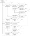
- FIG. 1is a schematic block diagram of power supply according to the present invention.
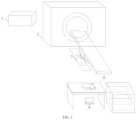
- FIG. 2is a schematic structural diagram of the present invention.
- the present inventionuses an energy storage system to supply power to a whole CT device, such that the CT device can work when there is no power supply network, thereby expanding application scenarios of the CT device and promoting the development of mobile medical devices.
- An energy storage system 1provides a DC power supply for a scanning gantry 2 , a diagnostic couch 3 , and a console 4 .
- some support DC high-voltage power supply, some support DC low-voltage power supply, and some support AC power supplyare powered by using a high-voltage output channel of the energy storage system 1 .
- the components supporting DC low-voltage power supplyare powered after a DC-DC converter reduces a voltage output by a low-voltage output channel of the energy storage system 1 .
- the DC-DC convertercan not only reduce the voltage, but also increase the voltage.
- the components supporting AC power supplyare powered after a DC-AC inverter converts a DC voltage output by the low-voltage channel of the energy storage system 1 into an AC voltage.
- the DC-AC invertercan not only convert a DC into an AC, but also can change the output voltage.
- the present inventionuses the energy storage system to supply power to the whole CT device, and performance of the CT device is not reduced or degraded. On the contrary, some individual indexes are higher than those achieved when the CT device is powered by a traditional power supply network of a same level.
- a CT device with an energy storage systemincludes an energy storage system 1 , a scanning gantry 2 , a diagnostic couch 3 , and a console 4 .
- the energy storage system 1is respectively connected to the scanning gantry 2 , the diagnostic couch 3 and the console 4 , and can supply power for the scanning gantry 2 , the diagnostic couch 3 and the console 4 .
- the energy storage system 1is a new energy storage system, which is a power source storage system made of new energy, new materials, composite materials or environmental protection materials.
- the connections described hereinare all electrical connections.
- the energy storage system 1includes a charging part, an energy storage module and an output part, the charging part is connected to the energy storage module, and the energy storage module is connected to the output part.
- the charging partis connected to a charging device or a power supply network through a charging interface to charge the energy storage module, or charges the energy storage module by using solar energy.
- the charging interfaceincludes a DC charging interface and/or an AC charging interface.
- the energy storage moduleincludes one or more supercapacitor modules.
- the energy storage system 1can be charged and discharged simultaneously.
- the output partincludes at least one high-voltage output channel and at least one low-voltage output channel.
- a DC voltage output by the high-voltage output channelranges from 455 V to 620 V, and a DC voltage output by the low-voltage output channel ranges from 90 V to 135 V.
- the energy storage system 1further includes a power management part.
- the power management partmonitors a temperature, a voltage, a current, and an electric quantity of the energy storage module, and can report an alarm for an abnormality.
- the output partincludes an output control board.
- the output control boardis configured to perform power-on and power-off timing control by driving a DC contactor of the output channel, and set a cut-off voltage for each output channel. When a voltage of each output channel is higher than the cut-off voltage, the energy storage system 1 is discharging. When the voltage of each output channel is lower than the cut-off voltage, the energy storage system 1 is charging and reports an alarm automatically.
- the scanning gantry 2includes a rotor portion 201 and a stator portion 202 .
- the rotor portionincludes a slip ring 2011 , a high-voltage generator 2012 , an X-ray tube 2013 , a rotor portion DC-DC converter 2014 , a rotor portion control board 2015 , a CT detector 2016 , a rotor portion DC-AC inverter 2017 and a heat exchange apparatus 2018 .
- the rotor portion control board 2015is respectively connected to the high-voltage generator 2012 , the X-ray tube 2013 , the CT detector 2016 and the heat exchange apparatus 2018 .
- a high-voltage rail input end of the slip ring 2011is connected to a high-voltage output channel of an output part of the energy storage system 1 , a high-voltage rail output end of the slip ring 2011 is connected to an input end of the high-voltage generator 2012 , and an output end of the high-voltage generator 2012 is connected to an input end of the X-ray tube 2013 .
- a low-voltage rail input end of the slip ring 2011is connected to a low-voltage output channel of the output part of the energy storage system 1
- a low-voltage rail output end of the slip ring 2011is respectively connected to an input end of the rotor portion DC-DC converter 2014 and an input end of the rotor portion DC-AC inverter 2017
- an output end of the rotor portion DC-DC converter 2014is respectively connected to the rotor portion control board 2015 and the CT detector 2016
- an output end of the rotor portion DC-AC inverter 2017is connected to the heat exchange apparatus 2018 .
- the stator portion 202includes a rotating driver 2021 , a rotating motor 2022 , a stator portion DC-DC converter 2023 and a stator portion control board 2024 .
- the rotating motor 2022drives the rotor portion 201 to rotate, and the stator portion control board 2024 is connected to the rotating driver 2021 .
- An input end of the rotating driver 2021is connected to the high-voltage output channel of the output part of the energy storage system 1 , and an output end of the rotating driver 2021 is connected to the rotating motor 2022 .
- An input end of the stator portion DC-DC converter 2023is connected to the low-voltage output channel of the output part of the energy storage system 1 , and an output end of the stator portion DC-DC converter 2023 is connected to the stator portion control board 2024 .
- the rotating driver 2021can be directly powered by a high-voltage output power supply of the energy storage system 1 .
- the rotating driver 2021is configured to provide a sufficient dynamic power supply for the rotating motor 2022 and realize motion control for the rotating motor 2022 .
- the rotating motor 2022is configured to drag a belt to drive a bearing to enable the rotor portion 201 to rotate.
- the stator portion DC-DC converter 2023is configured to convert a low-voltage DC output by the energy storage system 1 into a lower DC voltage.
- a 90 V to 135 V DC voltageis converted into a 24 V DC voltage to supply power for the stator portion control board 2024 .
- the stator portion control board 2024is configured to send an instruction to the rotating driver 2021 or receive a signal from the rotating driver 2021 , perform signal transmission with the rotor portion control board 2015 , and communicate with the console 4 .
- the slip ring 2011includes one or more conductive rails, each conductive rail is an annular broad-stripe copper bar, each conductive rail can separately transfer a power supply, and the conductive rails are disposed on the rotor portion 201 .
- the slip ring 2011further includes one or more conductive brushes, the conductive brushes are connected to the output part of the energy storage system 1 , the conductive brushes are connected to the conductive rails in one-to-one correspondence to realize conduction, and the conductive brushes are disposed on the stator portion 202 .
- the conductive brushis a carbon brush.
- a power supply of the rotor portion 201is transferred from the energy storage system 1 to the rotor portion 201 through the slip ring 2011 .
- the slip ring 2011is a conductive component connecting the stator portion 202 and the rotor portion 201 .
- the slip ring 2011is a structure that is composed of an annular broad-stripe copper bar and a carbon brush and that is used to replace a cable.
- a plurality of railscan be used to transfer a plurality of independent power supplies.
- the bearing installed on the slip ring 2011is dragged by the belt of the rotating motor 2022 to perform continuous unidirectional rotation.
- the carbon brushis fixed on the stator portion.
- the rotor portion 201 and the stator portion 202are conducted between the conductive rail and the carbon brush of the slip ring 2011 , such that the CT device can perform spiral scanning at a high speed without a power failure.
- a high-voltage power supply output by the energy storage system 1is connected to a head of a carbon brush corresponding to a high-voltage rail of the slip ring 2011 by using a power cable, and then connected to an input end of a main power supply of the high-voltage generator 2012 by using a power cable through an output end of a high-voltage rail on a rear side of the slip ring 2011 , to drive the high-voltage generator 2012 to provide the X-ray tube 2013 with a stable DC high voltage with sufficient power and obtained after high frequency inversion, and to provide a voltage for a driving circuit of a rotating anode.
- a filament current control circuitis provided for a filament of the X-ray tube 2013 to generate a stable tube current.
- the X-ray tube 2013is configured to perform X-ray emission and temperature control.
- the rotor portion DC-DC converter 2014is configured to perform voltage reduction on a low-voltage DC power supply transferred from the energy storage system 1 to the rotor portion 201 through the slip ring 2011 .
- the 90 V to 135 V DC voltageis converted into the 24 V DC voltage to supply power for the rotor portion control board 2015 and CT detector 2016 .
- the rotor portion control board 2015is configured to control X-ray scanning, data generation and transmission, abnormality reporting, and other processing.
- the CT detector 2016is configured to convert X-ray energy into an electrical signal.
- the CT detector 2016is opposite to the X-ray tube 2013 .
- the CT detector 2016is disposed in an arc shape to form a sector region with the X-ray tube 2013 , such that X-rays are mapped onto the CT detector 2016 .
- the rotor portion DC-AC inverter 2017is configured to invert the low-voltage DC power supply transferred from the energy storage system 1 to the rotor portion 201 through the slip ring 2011 .
- the 90 V to 135 V DC voltageis inverted into a 220 V AC voltage to supply power required by the heat exchange apparatus 2018 .
- the heat exchanger apparatus 2018performs heat dissipation for the X-ray tube 2013 through oil circulation and air cooling.
- the diagnostic couch 3includes a diagnostic couch DC-AC inverter 301 , a vertical driver 302 , and a horizontal driver 303 .
- An input end of the diagnostic couch DC-AC inverter 301is connected to the low-voltage output channel of the output part of the energy storage system 1 , and an output end of the diagnostic couch DC-AC inverter 301 is respectively connected to the vertical driver 302 and the horizontal driver 303 .
- the vertical driver 302drives the diagnostic couch 3 to move vertically, and the horizontal driver 303 drives the diagnostic couch 3 to move horizontally.
- the diagnostic couch DC-AC inverter 301is configured to invert the low-voltage DC power supply provided by the energy storage system 1 into an AC power supply. In an embodiment, the 90 V to 135 V DC voltage is inverted into the 220 V AC voltage.
- the diagnostic couch 3has a maximum load of 250 kg.
- the console 4includes a console DC-AC inverter 401 and a main control computer 402 .
- An input end of the console DC-AC inverter 401is connected to the low-voltage output channel of the output part of the energy storage system 1 , and an output end of the console DC-AC inverter 401 is connected to the main control computer 402 .
- the console DC-AC inverter 401is configured to invert the low-voltage DC power supply provided by the energy storage system into the AC power supply. In an embodiment, a 90 V to 135 V DC power supply is inverted into a 220 V AC power supply that is provided for the main control computer 402 .
- the main control computer 402is configured to reconstruct, process, and store an image obtained through CT scanning.
- Each two of the rotor portion control board 2015 , the stator portion control board 2024 , and the console 4are connected through a signal to realize mutual communication and information transmission.
Landscapes
- Health & Medical Sciences (AREA)
- Life Sciences & Earth Sciences (AREA)
- Engineering & Computer Science (AREA)
- Medical Informatics (AREA)
- Heart & Thoracic Surgery (AREA)
- Animal Behavior & Ethology (AREA)
- Biophysics (AREA)
- Nuclear Medicine, Radiotherapy & Molecular Imaging (AREA)
- Optics & Photonics (AREA)
- Pathology (AREA)
- Radiology & Medical Imaging (AREA)
- Biomedical Technology (AREA)
- Physics & Mathematics (AREA)
- Molecular Biology (AREA)
- Surgery (AREA)
- High Energy & Nuclear Physics (AREA)
- General Health & Medical Sciences (AREA)
- Public Health (AREA)
- Veterinary Medicine (AREA)
- Pulmonology (AREA)
- Theoretical Computer Science (AREA)
- Computer Networks & Wireless Communication (AREA)
- Power Engineering (AREA)
- Apparatus For Radiation Diagnosis (AREA)
- X-Ray Techniques (AREA)
Abstract
Description
| Diagnostic couch 3 | |||
| Rotor portion DC-AC inverter | Diagnostic couch DC-AC | ||
| 2017 | |||
| High- | |||
| Rotor portion DC- | Rotating motor | 2022 | Console DC-AC |
| converter | |||
| 2014 | Stator portion DC-DC | 401 | |
| Rotor portion | converter | 2023 | |
| 2015 | Stator | ||
| 2024 | |||
Claims (7)
Applications Claiming Priority (3)
| Application Number | Priority Date | Filing Date | Title |
|---|---|---|---|
| CN201910629822.9ACN110327070B (en) | 2019-07-12 | 2019-07-12 | CT apparatus with energy storage system |
| CN201910629822.9 | 2019-07-12 | ||
| PCT/CN2020/099740WO2021008369A1 (en) | 2019-07-12 | 2020-07-01 | Ct device provided with energy storage system |
Publications (2)
| Publication Number | Publication Date |
|---|---|
| US20220249051A1 US20220249051A1 (en) | 2022-08-11 |
| US12171613B2true US12171613B2 (en) | 2024-12-24 |
Family
ID=68146660
Family Applications (1)
| Application Number | Title | Priority Date | Filing Date |
|---|---|---|---|
| US17/626,785Active2040-12-30US12171613B2 (en) | 2019-07-12 | 2020-07-01 | Computed tomography (CT) device with energy storage system |
Country Status (3)
| Country | Link |
|---|---|
| US (1) | US12171613B2 (en) |
| CN (1) | CN110327070B (en) |
| WO (1) | WO2021008369A1 (en) |
Families Citing this family (6)
| Publication number | Priority date | Publication date | Assignee | Title |
|---|---|---|---|---|
| CN110327070B (en)* | 2019-07-12 | 2024-07-12 | 山东大骋医疗科技有限公司 | CT apparatus with energy storage system |
| CN111887879B (en)* | 2020-08-31 | 2024-02-27 | 上海大骋医疗科技有限公司 | Energy storage CT energy management system and method |
| CN111870265A (en)* | 2020-08-31 | 2020-11-03 | 上海大骋医疗科技有限公司 | Energy storage CT power supply control system and method |
| CN114252826A (en)* | 2020-09-21 | 2022-03-29 | 西门子(深圳)磁共振有限公司 | Bed assembly of magnetic resonance imaging device and magnetic resonance imaging device |
| CN112260258A (en)* | 2020-11-10 | 2021-01-22 | 明峰医疗系统股份有限公司 | Full-direct-current power supply CT system |
| CN112510693B (en)* | 2020-11-25 | 2022-07-26 | 明峰医疗系统股份有限公司 | Power distribution method and system for CT machine |
Citations (99)
| Publication number | Priority date | Publication date | Assignee | Title |
|---|---|---|---|---|
| US5023768A (en) | 1989-11-24 | 1991-06-11 | Varian Associates, Inc. | High voltage high power DC power supply |
| US5226064A (en)* | 1990-05-17 | 1993-07-06 | Kabushiki Kaisha Toshiba | Computerized tomographic scanning apparatus driven by rechargeable batteries |
| US5608771A (en) | 1995-10-23 | 1997-03-04 | General Electric Company | Contactless power transfer system for a rotational load |
| US5808376A (en)* | 1994-11-28 | 1998-09-15 | Analogic Corporation | Method of and apparatus for power management and distribution in a medical imaging system |
| US6671345B2 (en)* | 2000-11-14 | 2003-12-30 | Koninklijke Philips Electronics N.V. | Data acquisition for computed tomography |
| US6674836B2 (en)* | 2000-01-17 | 2004-01-06 | Kabushiki Kaisha Toshiba | X-ray computer tomography apparatus |
| US20040022351A1 (en)* | 2002-07-30 | 2004-02-05 | Ge Medical Systems Global Technology Company, Llc | Thermoelectrically controlled x-ray detector array |
| US20040264642A1 (en)* | 2003-06-30 | 2004-12-30 | Katcha Jason S. | X-ray generator and slip ring for a ct system |
| US20050226380A1 (en)* | 2004-04-01 | 2005-10-13 | General Electric Company | Multichannel contactless power transfer system for a computed tomography system |
| US20050281377A1 (en)* | 2003-11-27 | 2005-12-22 | Udo Heinze | X-ray apparatus with an ultra-capacitor for storing energy |
| US20050287008A1 (en)* | 2004-06-25 | 2005-12-29 | General Electric Company | Method and system for a variable speed fan control for thermal management |
| US20060239397A1 (en) | 2005-04-25 | 2006-10-26 | Ge Medical Systems Global Technology Company, Llc | Imaging apparatus and subject moving apparatus |
| US7197113B1 (en)* | 2005-12-01 | 2007-03-27 | General Electric Company | Contactless power transfer system |
| US20070253540A1 (en)* | 2006-04-27 | 2007-11-01 | General Electric Company | Methods and apparatus for mobile imaging systems |
| US20080069296A1 (en)* | 2006-09-14 | 2008-03-20 | General Electric Company | Thermal stabilization methods and apparatus |
| US20080112537A1 (en)* | 2006-11-14 | 2008-05-15 | Jason Stuart Katcha | Power Handling Methods and Apparatus |
| US7397896B2 (en)* | 2006-03-15 | 2008-07-08 | Siemens Aktiengesellschaft | X-ray device |
| US7447293B2 (en)* | 2005-03-15 | 2008-11-04 | Kabushiki Kaisha Toshiba | X-ray computer tomographic imaging apparatus and control method thereof |
| US20090095926A1 (en)* | 2007-10-12 | 2009-04-16 | Macneish Iii William Jack | Physiological parameter detector |
| US20090257548A1 (en)* | 2008-04-14 | 2009-10-15 | Ashutosh Joshi | Computed tomography system |
| US7668295B2 (en)* | 2007-05-14 | 2010-02-23 | General Electric Co. | System and method for high voltage transient suppression and spit protection in an x-ray tube |
| US7684538B2 (en)* | 2003-04-25 | 2010-03-23 | Rapiscan Systems, Inc. | X-ray scanning system |
| US7755055B2 (en)* | 2005-06-06 | 2010-07-13 | Schleifring Und Apparatebau Gmbh | Data transmission system for computer tomographs |
| US20100220837A1 (en)* | 2009-02-24 | 2010-09-02 | Wolfgang Bressel | Imaging tomography apparatus with built-in energy storage to cover high power operation |
| US20110019797A1 (en)* | 2003-04-25 | 2011-01-27 | Edward James Morton | X-Ray Tomographic Inspection System for the Identification of Specific Target Items |
| US7929663B2 (en)* | 2003-04-25 | 2011-04-19 | Rapiscan Systems, Inc. | X-ray monitoring |
| US7932693B2 (en)* | 2005-07-07 | 2011-04-26 | Eaton Corporation | System and method of controlling power to a non-motor load |
| CN102047359A (en) | 2008-06-02 | 2011-05-04 | 皇家飞利浦电子股份有限公司 | Rotary power transformer for use in a high-voltage generator circuitry for inductively transmitting two or more independently controllable supply voltages to the power supply terminals of a load |
| US8041002B2 (en)* | 2007-08-31 | 2011-10-18 | Morpho Detection, Inc. | Methods, systems, and apparatuses for increasing efficiency in computed tomography detection |
| US20110291108A1 (en)* | 2010-05-25 | 2011-12-01 | U.S. Government As Represented By The Secretary Of The Army | Semiconductor photodetector with transparent interface charge control layer and method thereof |
| US20110302432A1 (en)* | 2010-06-08 | 2011-12-08 | Microsoft Corporation | Super capacitor supplemented server power |
| US8076943B2 (en)* | 2008-02-21 | 2011-12-13 | Genesis Medical Imaging, Inc. | Impedance-based arc detector for computed tomography scanner and method of use thereof |
| US8135110B2 (en)* | 2005-12-16 | 2012-03-13 | Rapiscan Systems, Inc. | X-ray tomography inspection systems |
| US8164929B2 (en)* | 2009-08-17 | 2012-04-24 | Schleifring Und Apparatebau Gmbh | Controlled contactless power transmission |
| US8194818B2 (en)* | 2008-11-21 | 2012-06-05 | Ge Medical Systems Global Technology Company, Llc | CT scanner apparatus |
| US8223919B2 (en)* | 2003-04-25 | 2012-07-17 | Rapiscan Systems, Inc. | X-ray tomographic inspection systems for the identification of specific target items |
| US20120219116A1 (en)* | 2011-02-24 | 2012-08-30 | William Thompson | Optimization of the Source Firing Pattern for X-Ray Scanning Systems |
| US20120256099A1 (en)* | 2011-04-07 | 2012-10-11 | Mobius Imaging, Llc | Mobile x-ray imaging system |
| US8519721B2 (en)* | 2010-03-10 | 2013-08-27 | Schleifring Und Apparatebau Gmbh | Method for compensation of system tolerances in inductive couplers |
| US8563941B1 (en)* | 2009-03-26 | 2013-10-22 | Koninklijke Philips N.V. | Data acquisition |
| US8581437B2 (en)* | 2006-12-20 | 2013-11-12 | Analogic Corporation | Non-contact rotary power transfer system |
| US8670272B2 (en)* | 2006-03-01 | 2014-03-11 | Micron Technology, Inc. | Memory with weighted multi-page read |
| US20140070812A1 (en)* | 2012-09-10 | 2014-03-13 | Toshiba Medical Systems Corporation | Image diagnosis apparatus and power control method of an image diagnosis apparatus |
| US8696201B2 (en)* | 2010-11-19 | 2014-04-15 | Siemens Aktiengesellschaft | Device and method for calibrating an X-ray detector, calibration apparatus and X-ray apparatus |
| US20140211916A1 (en)* | 2013-01-31 | 2014-07-31 | Rapiscan Systems, Inc. | Portable Security Inspection System |
| US8804899B2 (en)* | 2003-04-25 | 2014-08-12 | Rapiscan Systems, Inc. | Imaging, data acquisition, data transmission, and data distribution methods and systems for high data rate tomographic X-ray scanners |
| CN103997966A (en) | 2011-09-30 | 2014-08-20 | Analogic公司 | Power delivery to a moving unit |
| US8861678B2 (en)* | 2012-05-11 | 2014-10-14 | General Electric Company | Power and communication interface between a digital X-ray detector and an X-ray imaging system |
| US8861681B2 (en)* | 2010-12-17 | 2014-10-14 | General Electric Company | Method and system for active resonant voltage switching |
| US8891733B2 (en)* | 2012-05-11 | 2014-11-18 | General Electric Company | Power and communication interface between a digital X-ray detector and an X-ray imaging system |
| US9008275B2 (en)* | 2012-05-01 | 2015-04-14 | Analogic Corporation | Voltage switching in an imaging modality that utilizes radiation to image an object |
| US9048061B2 (en)* | 2005-12-16 | 2015-06-02 | Rapiscan Systems, Inc. | X-ray scanners and X-ray sources therefor |
| US9084335B2 (en)* | 2013-09-25 | 2015-07-14 | General Electric Company | High frequency power distribution unit for a CT system |
| US9113839B2 (en)* | 2003-04-25 | 2015-08-25 | Rapiscon Systems, Inc. | X-ray inspection system and method |
| US9138195B2 (en)* | 2012-04-23 | 2015-09-22 | Analogic Corporation | Contactless communication signal transfer |
| US9154014B2 (en)* | 2010-04-15 | 2015-10-06 | Siemens Aktiengesellschaft | Device for electromagnetically bearing and driving a tiltable part of a gantry of a computer tomography apparatus, and a computer tomography apparatus embodying same |
| WO2015158180A1 (en) | 2014-04-17 | 2015-10-22 | 深圳迈瑞生物医疗电子股份有限公司 | Medical diagnostic high-frequency x-ray machine and power supply apparatus |
| US20150319830A1 (en)* | 2014-05-03 | 2015-11-05 | General Electric Company | Packaging design for ct detector |
| US9186120B2 (en)* | 2010-04-27 | 2015-11-17 | Schleifring Und Apparatebau Gmbh | Inductive rotating transmission devices with ripple compensation for computer tomographs |
| US20150342543A1 (en)* | 2013-12-20 | 2015-12-03 | General Electric Company | Compact gantry system using independently controllable detectors |
| US9205281B2 (en)* | 2008-03-14 | 2015-12-08 | Reflexion Medical, Inc. | Method and apparatus for emission guided radiation therapy |
| US9223050B2 (en)* | 2005-04-15 | 2015-12-29 | Rapiscan Systems, Inc. | X-ray imaging system having improved mobility |
| US9285498B2 (en)* | 2003-06-20 | 2016-03-15 | Rapiscan Systems, Inc. | Relocatable X-ray imaging system and method for inspecting commercial vehicles and cargo containers |
| US9332624B2 (en)* | 2008-05-20 | 2016-05-03 | Rapiscan Systems, Inc. | Gantry scanner systems |
| US20160181791A1 (en)* | 2014-12-18 | 2016-06-23 | Schleifring Und Apparatebau Gmbh | Inductive Rotary Joint with Secondary Safety Circuit |
| US20160174920A1 (en)* | 2014-12-18 | 2016-06-23 | General Electric Company | System and method for thermal management of a ct detector |
| US9429530B2 (en)* | 2008-02-28 | 2016-08-30 | Rapiscan Systems, Inc. | Scanning systems |
| US9438120B2 (en)* | 2014-01-22 | 2016-09-06 | General Electric Company | Systems and methods for fast kilovolt switching in an X-ray system |
| US20170112454A1 (en)* | 2015-10-23 | 2017-04-27 | Samsung Electronics Co., Ltd. | Computed tomography apparatus |
| US9675306B2 (en)* | 2003-04-25 | 2017-06-13 | Rapiscan Systems, Inc. | X-ray scanning system |
| US10024935B2 (en)* | 2012-07-25 | 2018-07-17 | Koninklijke Philips N.V. | MRI gradient amplifier operable at different slew rates |
| US10050471B2 (en)* | 2014-12-18 | 2018-08-14 | Schleifring Gmbh | Inductive rotary joint with multimode inverter |
| US20180325477A1 (en)* | 2015-11-13 | 2018-11-15 | Rensselaer Polytechnic Institute | Simultaneous interior mri x-ray imaging system (mrx) |
| US10175381B2 (en)* | 2003-04-25 | 2019-01-08 | Rapiscan Systems, Inc. | X-ray scanners having source points with less than a predefined variation in brightness |
| US10251252B2 (en)* | 2016-08-03 | 2019-04-02 | Samsung Electronics Co., Ltd. | Mobile X-ray apparatus |
| CN109620279A (en) | 2018-12-30 | 2019-04-16 | 上海医乐信息科技有限公司 | A kind of new energy computer tomography equipment |
| CN109646037A (en) | 2018-10-16 | 2019-04-19 | 深圳市艾克瑞电气有限公司 | CT instrument |
| US10349505B2 (en)* | 2015-07-22 | 2019-07-09 | Siemens Healthcare Gmbh | High-voltage supply and an x-ray emitter having the high-voltage supply |
| US10342506B2 (en)* | 2014-01-31 | 2019-07-09 | Siemens Healthcare Gmbh | Medical imaging device including a power transmission link |
| CN110313929A (en) | 2019-07-12 | 2019-10-11 | 山东大骋医疗科技有限公司 | No slip ring power supply CT equipment |
| US20190336795A1 (en)* | 2018-05-02 | 2019-11-07 | Shanghai United Imaging Healthcare Co., Ltd. | Radiation systems for radition treatment and imaging |
| US10478133B2 (en)* | 2016-10-20 | 2019-11-19 | General Electric Company | Systems and methods for calibrating a nuclear medicine imaging system |
| US10488532B2 (en)* | 2014-10-20 | 2019-11-26 | Analogic Corporation | Detector unit for detector array of radiation imaging modality |
| US20200074123A1 (en)* | 2018-08-29 | 2020-03-05 | Varex Imaging Corporation | Detection of unauthorized components |
| US10585207B2 (en)* | 2008-02-28 | 2020-03-10 | Rapiscan Systems, Inc. | Scanning systems |
| US10620281B2 (en)* | 2016-03-31 | 2020-04-14 | General Electric Company | Systems and methods for handling peak power requirements of a medical imaging device |
| US10646192B2 (en)* | 2017-03-20 | 2020-05-12 | General Electric Company | Peak shave enabled computed tomography system with built-in uninterruptible power supply and stabilizer |
| US10652988B2 (en)* | 2016-08-03 | 2020-05-12 | Samsung Electronics Co., Ltd. | Mobile x-ray apparatus including a battery management system |
| US10670769B2 (en)* | 2002-07-23 | 2020-06-02 | Rapiscan Systems, Inc. | Compact mobile cargo scanning system |
| US10695586B2 (en)* | 2016-11-15 | 2020-06-30 | Reflexion Medical, Inc. | System for emission-guided high-energy photon delivery |
| CN210990354U (en) | 2019-07-12 | 2020-07-14 | 山东大骋医疗科技有限公司 | CT device with energy storage system |
| US20210212653A1 (en)* | 2018-09-27 | 2021-07-15 | Fujifilm Corporation | Radiography apparatus |
| US20220249051A1 (en)* | 2019-07-12 | 2022-08-11 | Shandong Dacheng Medical Technology Co., Ltd. | Computed tomography (ct) device with energy storage system |
| US11558082B2 (en)* | 2020-12-09 | 2023-01-17 | Siemens Healthcare Gmbh | EMC shielding for contactless data transmission |
| US11594001B2 (en)* | 2020-01-20 | 2023-02-28 | Rapiscan Systems, Inc. | Methods and systems for generating three-dimensional images that enable improved visualization and interaction with objects in the three-dimensional images |
| US11596808B2 (en)* | 2015-12-31 | 2023-03-07 | Shanghai United Imaging Healthcare Co., Ltd. | Radiation therapy system |
| US11611230B2 (en)* | 2020-08-19 | 2023-03-21 | Siemens Healthcare Gmbh | Power supply facility for a magnetic resonance facility, magnetic resonance system, and method for operating a power supply facility |
| US11726220B2 (en)* | 2021-01-19 | 2023-08-15 | Analogic Corporation | Radiation detectors for scanning systems, and related scanning systems |
| US20240312642A1 (en)* | 2021-04-12 | 2024-09-19 | Whiterabbit.Ai Inc. | Methods and systems for optimized customer relationship management in healthcare |
- 2019
- 2019-07-12CNCN201910629822.9Apatent/CN110327070B/enactiveActive
- 2020
- 2020-07-01WOPCT/CN2020/099740patent/WO2021008369A1/ennot_activeCeased
- 2020-07-01USUS17/626,785patent/US12171613B2/enactiveActive
Patent Citations (134)
| Publication number | Priority date | Publication date | Assignee | Title |
|---|---|---|---|---|
| US5023768A (en) | 1989-11-24 | 1991-06-11 | Varian Associates, Inc. | High voltage high power DC power supply |
| US5226064A (en)* | 1990-05-17 | 1993-07-06 | Kabushiki Kaisha Toshiba | Computerized tomographic scanning apparatus driven by rechargeable batteries |
| US5808376A (en)* | 1994-11-28 | 1998-09-15 | Analogic Corporation | Method of and apparatus for power management and distribution in a medical imaging system |
| US5608771A (en) | 1995-10-23 | 1997-03-04 | General Electric Company | Contactless power transfer system for a rotational load |
| US6674836B2 (en)* | 2000-01-17 | 2004-01-06 | Kabushiki Kaisha Toshiba | X-ray computer tomography apparatus |
| US6671345B2 (en)* | 2000-11-14 | 2003-12-30 | Koninklijke Philips Electronics N.V. | Data acquisition for computed tomography |
| US10670769B2 (en)* | 2002-07-23 | 2020-06-02 | Rapiscan Systems, Inc. | Compact mobile cargo scanning system |
| US20040022351A1 (en)* | 2002-07-30 | 2004-02-05 | Ge Medical Systems Global Technology Company, Llc | Thermoelectrically controlled x-ray detector array |
| US20040071259A1 (en)* | 2002-07-30 | 2004-04-15 | Lacey Joseph J. | Thermoelectrically controlled X-ray detector array statement regarding federally sponsored research |
| US10175381B2 (en)* | 2003-04-25 | 2019-01-08 | Rapiscan Systems, Inc. | X-ray scanners having source points with less than a predefined variation in brightness |
| US20110019797A1 (en)* | 2003-04-25 | 2011-01-27 | Edward James Morton | X-Ray Tomographic Inspection System for the Identification of Specific Target Items |
| US8804899B2 (en)* | 2003-04-25 | 2014-08-12 | Rapiscan Systems, Inc. | Imaging, data acquisition, data transmission, and data distribution methods and systems for high data rate tomographic X-ray scanners |
| US8451974B2 (en)* | 2003-04-25 | 2013-05-28 | Rapiscan Systems, Inc. | X-ray tomographic inspection system for the identification of specific target items |
| US8885794B2 (en)* | 2003-04-25 | 2014-11-11 | Rapiscan Systems, Inc. | X-ray tomographic inspection system for the identification of specific target items |
| US8223919B2 (en)* | 2003-04-25 | 2012-07-17 | Rapiscan Systems, Inc. | X-ray tomographic inspection systems for the identification of specific target items |
| US10591424B2 (en)* | 2003-04-25 | 2020-03-17 | Rapiscan Systems, Inc. | X-ray tomographic inspection systems for the identification of specific target items |
| US20150110240A1 (en)* | 2003-04-25 | 2015-04-23 | Rapiscan Systems, Inc. | X-ray Tomographic Inspection System for the Identification of Specific Target Items |
| US9113839B2 (en)* | 2003-04-25 | 2015-08-25 | Rapiscon Systems, Inc. | X-ray inspection system and method |
| US20130336447A1 (en)* | 2003-04-25 | 2013-12-19 | Rapiscan Systems, Inc. | X-ray Tomographic Inspection System for the Identification of Specific Target Items |
| US9183647B2 (en)* | 2003-04-25 | 2015-11-10 | Rapiscan Systems, Inc. | Imaging, data acquisition, data transmission, and data distribution methods and systems for high data rate tomographic X-ray scanners |
| US20160231454A1 (en)* | 2003-04-25 | 2016-08-11 | Rapiscan Systems, Inc. | X-ray Tomographic Inspection System for the Identification of Specific Target Items |
| US9675306B2 (en)* | 2003-04-25 | 2017-06-13 | Rapiscan Systems, Inc. | X-ray scanning system |
| US7929663B2 (en)* | 2003-04-25 | 2011-04-19 | Rapiscan Systems, Inc. | X-ray monitoring |
| US7684538B2 (en)* | 2003-04-25 | 2010-03-23 | Rapiscan Systems, Inc. | X-ray scanning system |
| US9747705B2 (en)* | 2003-04-25 | 2017-08-29 | Rapiscan Systems, Inc. | Imaging, data acquisition, data transmission, and data distribution methods and systems for high data rate tomographic X-ray scanners |
| US20180038988A1 (en)* | 2003-04-25 | 2018-02-08 | Rapiscan Systems, Inc. | X-ray Tomographic Inspection System for the Identification of Specific Target Items |
| US9285498B2 (en)* | 2003-06-20 | 2016-03-15 | Rapiscan Systems, Inc. | Relocatable X-ray imaging system and method for inspecting commercial vehicles and cargo containers |
| US20050243964A1 (en)* | 2003-06-30 | 2005-11-03 | Katcha Jason S | X-ray generator and slip ring for a ct system |
| US6975698B2 (en)* | 2003-06-30 | 2005-12-13 | General Electric Company | X-ray generator and slip ring for a CT system |
| US20040264642A1 (en)* | 2003-06-30 | 2004-12-30 | Katcha Jason S. | X-ray generator and slip ring for a ct system |
| US7110488B2 (en)* | 2003-06-30 | 2006-09-19 | General Electric Company | X-ray generator and slip ring for a CT system |
| CN1575759A (en) | 2003-06-30 | 2005-02-09 | Ge医药系统环球科技公司 | X-ray generator and slip ring for a ct system |
| US20050281377A1 (en)* | 2003-11-27 | 2005-12-22 | Udo Heinze | X-ray apparatus with an ultra-capacitor for storing energy |
| US20050226380A1 (en)* | 2004-04-01 | 2005-10-13 | General Electric Company | Multichannel contactless power transfer system for a computed tomography system |
| US7054411B2 (en)* | 2004-04-01 | 2006-05-30 | General Electric Company | Multichannel contactless power transfer system for a computed tomography system |
| US20050287008A1 (en)* | 2004-06-25 | 2005-12-29 | General Electric Company | Method and system for a variable speed fan control for thermal management |
| US7447293B2 (en)* | 2005-03-15 | 2008-11-04 | Kabushiki Kaisha Toshiba | X-ray computer tomographic imaging apparatus and control method thereof |
| US9223050B2 (en)* | 2005-04-15 | 2015-12-29 | Rapiscan Systems, Inc. | X-ray imaging system having improved mobility |
| US20060239397A1 (en) | 2005-04-25 | 2006-10-26 | Ge Medical Systems Global Technology Company, Llc | Imaging apparatus and subject moving apparatus |
| US7755055B2 (en)* | 2005-06-06 | 2010-07-13 | Schleifring Und Apparatebau Gmbh | Data transmission system for computer tomographs |
| US7932693B2 (en)* | 2005-07-07 | 2011-04-26 | Eaton Corporation | System and method of controlling power to a non-motor load |
| US20150362440A1 (en)* | 2005-10-25 | 2015-12-17 | Rapiscan Systems, Inc. | Optimization of the Source Firing Pattern for X-Ray Scanning Systems |
| US7197113B1 (en)* | 2005-12-01 | 2007-03-27 | General Electric Company | Contactless power transfer system |
| US8135110B2 (en)* | 2005-12-16 | 2012-03-13 | Rapiscan Systems, Inc. | X-ray tomography inspection systems |
| US9048061B2 (en)* | 2005-12-16 | 2015-06-02 | Rapiscan Systems, Inc. | X-ray scanners and X-ray sources therefor |
| US10295483B2 (en)* | 2005-12-16 | 2019-05-21 | Rapiscan Systems, Inc. | Data collection, processing and storage systems for X-ray tomographic images |
| US10976271B2 (en)* | 2005-12-16 | 2021-04-13 | Rapiscan Systems, Inc. | Stationary tomographic X-ray imaging systems for automatically sorting objects based on generated tomographic images |
| US8670272B2 (en)* | 2006-03-01 | 2014-03-11 | Micron Technology, Inc. | Memory with weighted multi-page read |
| US7397896B2 (en)* | 2006-03-15 | 2008-07-08 | Siemens Aktiengesellschaft | X-ray device |
| US20070253540A1 (en)* | 2006-04-27 | 2007-11-01 | General Electric Company | Methods and apparatus for mobile imaging systems |
| US20080069296A1 (en)* | 2006-09-14 | 2008-03-20 | General Electric Company | Thermal stabilization methods and apparatus |
| US20080112537A1 (en)* | 2006-11-14 | 2008-05-15 | Jason Stuart Katcha | Power Handling Methods and Apparatus |
| US8581437B2 (en)* | 2006-12-20 | 2013-11-12 | Analogic Corporation | Non-contact rotary power transfer system |
| US7668295B2 (en)* | 2007-05-14 | 2010-02-23 | General Electric Co. | System and method for high voltage transient suppression and spit protection in an x-ray tube |
| US8041002B2 (en)* | 2007-08-31 | 2011-10-18 | Morpho Detection, Inc. | Methods, systems, and apparatuses for increasing efficiency in computed tomography detection |
| US20090095926A1 (en)* | 2007-10-12 | 2009-04-16 | Macneish Iii William Jack | Physiological parameter detector |
| US8076943B2 (en)* | 2008-02-21 | 2011-12-13 | Genesis Medical Imaging, Inc. | Impedance-based arc detector for computed tomography scanner and method of use thereof |
| US9429530B2 (en)* | 2008-02-28 | 2016-08-30 | Rapiscan Systems, Inc. | Scanning systems |
| US10585207B2 (en)* | 2008-02-28 | 2020-03-10 | Rapiscan Systems, Inc. | Scanning systems |
| US10327716B2 (en)* | 2008-03-14 | 2019-06-25 | Reflexion Medical, Inc. | Method and apparatus for emission guided radiation therapy |
| US9205281B2 (en)* | 2008-03-14 | 2015-12-08 | Reflexion Medical, Inc. | Method and apparatus for emission guided radiation therapy |
| US20090257548A1 (en)* | 2008-04-14 | 2009-10-15 | Ashutosh Joshi | Computed tomography system |
| US9332624B2 (en)* | 2008-05-20 | 2016-05-03 | Rapiscan Systems, Inc. | Gantry scanner systems |
| US10098214B2 (en)* | 2008-05-20 | 2018-10-09 | Rapiscan Systems, Inc. | Detector support structures for gantry scanner systems |
| CN102047359A (en) | 2008-06-02 | 2011-05-04 | 皇家飞利浦电子股份有限公司 | Rotary power transformer for use in a high-voltage generator circuitry for inductively transmitting two or more independently controllable supply voltages to the power supply terminals of a load |
| US8194818B2 (en)* | 2008-11-21 | 2012-06-05 | Ge Medical Systems Global Technology Company, Llc | CT scanner apparatus |
| US8218726B2 (en)* | 2009-02-24 | 2012-07-10 | Siemens Aktiengesellschaft | Imaging tomography apparatus with built-in energy storage to cover high power operation |
| US20100220837A1 (en)* | 2009-02-24 | 2010-09-02 | Wolfgang Bressel | Imaging tomography apparatus with built-in energy storage to cover high power operation |
| US8563941B1 (en)* | 2009-03-26 | 2013-10-22 | Koninklijke Philips N.V. | Data acquisition |
| US8164929B2 (en)* | 2009-08-17 | 2012-04-24 | Schleifring Und Apparatebau Gmbh | Controlled contactless power transmission |
| US8519721B2 (en)* | 2010-03-10 | 2013-08-27 | Schleifring Und Apparatebau Gmbh | Method for compensation of system tolerances in inductive couplers |
| US9154014B2 (en)* | 2010-04-15 | 2015-10-06 | Siemens Aktiengesellschaft | Device for electromagnetically bearing and driving a tiltable part of a gantry of a computer tomography apparatus, and a computer tomography apparatus embodying same |
| US9186120B2 (en)* | 2010-04-27 | 2015-11-17 | Schleifring Und Apparatebau Gmbh | Inductive rotating transmission devices with ripple compensation for computer tomographs |
| US20110291108A1 (en)* | 2010-05-25 | 2011-12-01 | U.S. Government As Represented By The Secretary Of The Army | Semiconductor photodetector with transparent interface charge control layer and method thereof |
| US20110302432A1 (en)* | 2010-06-08 | 2011-12-08 | Microsoft Corporation | Super capacitor supplemented server power |
| CN102279643A (en) | 2010-06-08 | 2011-12-14 | 微软公司 | Super capacitor supplemented server power |
| US8696201B2 (en)* | 2010-11-19 | 2014-04-15 | Siemens Aktiengesellschaft | Device and method for calibrating an X-ray detector, calibration apparatus and X-ray apparatus |
| US8861681B2 (en)* | 2010-12-17 | 2014-10-14 | General Electric Company | Method and system for active resonant voltage switching |
| US20120219116A1 (en)* | 2011-02-24 | 2012-08-30 | William Thompson | Optimization of the Source Firing Pattern for X-Ray Scanning Systems |
| US20120256099A1 (en)* | 2011-04-07 | 2012-10-11 | Mobius Imaging, Llc | Mobile x-ray imaging system |
| US11559270B2 (en)* | 2011-04-07 | 2023-01-24 | Mobius Imaging, Llc | Mobile X-ray imaging system |
| CN103997966A (en) | 2011-09-30 | 2014-08-20 | Analogic公司 | Power delivery to a moving unit |
| US20140239715A1 (en)* | 2011-09-30 | 2014-08-28 | Hans J. Weedon | Power delivery to a moving unit |
| US9722429B2 (en)* | 2011-09-30 | 2017-08-01 | Analogic Corporation | Power delivery to a moving unit |
| US9138195B2 (en)* | 2012-04-23 | 2015-09-22 | Analogic Corporation | Contactless communication signal transfer |
| US9008275B2 (en)* | 2012-05-01 | 2015-04-14 | Analogic Corporation | Voltage switching in an imaging modality that utilizes radiation to image an object |
| US8861678B2 (en)* | 2012-05-11 | 2014-10-14 | General Electric Company | Power and communication interface between a digital X-ray detector and an X-ray imaging system |
| US8891733B2 (en)* | 2012-05-11 | 2014-11-18 | General Electric Company | Power and communication interface between a digital X-ray detector and an X-ray imaging system |
| US10024935B2 (en)* | 2012-07-25 | 2018-07-17 | Koninklijke Philips N.V. | MRI gradient amplifier operable at different slew rates |
| US20140070812A1 (en)* | 2012-09-10 | 2014-03-13 | Toshiba Medical Systems Corporation | Image diagnosis apparatus and power control method of an image diagnosis apparatus |
| US10048337B2 (en)* | 2012-09-10 | 2018-08-14 | Toshiba Medical Systems Corporation | Image diagnosis apparatus and power control method of an image diagnosis apparatus |
| US20140211916A1 (en)* | 2013-01-31 | 2014-07-31 | Rapiscan Systems, Inc. | Portable Security Inspection System |
| US11550077B2 (en)* | 2013-01-31 | 2023-01-10 | Rapiscan Systems, Inc. | Portable vehicle inspection portal with accompanying workstation |
| US9791590B2 (en)* | 2013-01-31 | 2017-10-17 | Rapiscan Systems, Inc. | Portable security inspection system |
| US20180128935A1 (en)* | 2013-01-31 | 2018-05-10 | Rapiscan Systems, Inc. | Portable Security Inspection System |
| US10317566B2 (en)* | 2013-01-31 | 2019-06-11 | Rapiscan Systems, Inc. | Portable security inspection system |
| US9084335B2 (en)* | 2013-09-25 | 2015-07-14 | General Electric Company | High frequency power distribution unit for a CT system |
| US20150342543A1 (en)* | 2013-12-20 | 2015-12-03 | General Electric Company | Compact gantry system using independently controllable detectors |
| US9438120B2 (en)* | 2014-01-22 | 2016-09-06 | General Electric Company | Systems and methods for fast kilovolt switching in an X-ray system |
| US10342506B2 (en)* | 2014-01-31 | 2019-07-09 | Siemens Healthcare Gmbh | Medical imaging device including a power transmission link |
| WO2015158180A1 (en) | 2014-04-17 | 2015-10-22 | 深圳迈瑞生物医疗电子股份有限公司 | Medical diagnostic high-frequency x-ray machine and power supply apparatus |
| US9364187B2 (en)* | 2014-05-03 | 2016-06-14 | General Electric Company | Packaging design for CT detector |
| US20150319830A1 (en)* | 2014-05-03 | 2015-11-05 | General Electric Company | Packaging design for ct detector |
| US10488532B2 (en)* | 2014-10-20 | 2019-11-26 | Analogic Corporation | Detector unit for detector array of radiation imaging modality |
| CN105720698A (en) | 2014-12-18 | 2016-06-29 | 滑动环及设备制造有限公司 | Inductive rotary joint with secondary safety circuit |
| US20160174920A1 (en)* | 2014-12-18 | 2016-06-23 | General Electric Company | System and method for thermal management of a ct detector |
| US20160181791A1 (en)* | 2014-12-18 | 2016-06-23 | Schleifring Und Apparatebau Gmbh | Inductive Rotary Joint with Secondary Safety Circuit |
| US9649085B2 (en)* | 2014-12-18 | 2017-05-16 | Schleifring Und Apparatebau Gmbh | Inductive rotary joint with secondary safety circuit |
| US10050471B2 (en)* | 2014-12-18 | 2018-08-14 | Schleifring Gmbh | Inductive rotary joint with multimode inverter |
| US10349505B2 (en)* | 2015-07-22 | 2019-07-09 | Siemens Healthcare Gmbh | High-voltage supply and an x-ray emitter having the high-voltage supply |
| US20170112454A1 (en)* | 2015-10-23 | 2017-04-27 | Samsung Electronics Co., Ltd. | Computed tomography apparatus |
| US20180325477A1 (en)* | 2015-11-13 | 2018-11-15 | Rensselaer Polytechnic Institute | Simultaneous interior mri x-ray imaging system (mrx) |
| US11596808B2 (en)* | 2015-12-31 | 2023-03-07 | Shanghai United Imaging Healthcare Co., Ltd. | Radiation therapy system |
| US10620281B2 (en)* | 2016-03-31 | 2020-04-14 | General Electric Company | Systems and methods for handling peak power requirements of a medical imaging device |
| US10728995B2 (en)* | 2016-08-03 | 2020-07-28 | Samsung Electronics Co., Ltd. | Mobile X-ray apparatus |
| US10251252B2 (en)* | 2016-08-03 | 2019-04-02 | Samsung Electronics Co., Ltd. | Mobile X-ray apparatus |
| US10652988B2 (en)* | 2016-08-03 | 2020-05-12 | Samsung Electronics Co., Ltd. | Mobile x-ray apparatus including a battery management system |
| US10478133B2 (en)* | 2016-10-20 | 2019-11-19 | General Electric Company | Systems and methods for calibrating a nuclear medicine imaging system |
| US10695586B2 (en)* | 2016-11-15 | 2020-06-30 | Reflexion Medical, Inc. | System for emission-guided high-energy photon delivery |
| US10646192B2 (en)* | 2017-03-20 | 2020-05-12 | General Electric Company | Peak shave enabled computed tomography system with built-in uninterruptible power supply and stabilizer |
| US20190336795A1 (en)* | 2018-05-02 | 2019-11-07 | Shanghai United Imaging Healthcare Co., Ltd. | Radiation systems for radition treatment and imaging |
| US20200074120A1 (en)* | 2018-08-29 | 2020-03-05 | Varex Imaging Corporation | Anti-tamper circuitry |
| US20200074123A1 (en)* | 2018-08-29 | 2020-03-05 | Varex Imaging Corporation | Detection of unauthorized components |
| US20210212653A1 (en)* | 2018-09-27 | 2021-07-15 | Fujifilm Corporation | Radiography apparatus |
| CN109646037A (en) | 2018-10-16 | 2019-04-19 | 深圳市艾克瑞电气有限公司 | CT instrument |
| CN109620279A (en) | 2018-12-30 | 2019-04-16 | 上海医乐信息科技有限公司 | A kind of new energy computer tomography equipment |
| CN110313929A (en) | 2019-07-12 | 2019-10-11 | 山东大骋医疗科技有限公司 | No slip ring power supply CT equipment |
| US20220249051A1 (en)* | 2019-07-12 | 2022-08-11 | Shandong Dacheng Medical Technology Co., Ltd. | Computed tomography (ct) device with energy storage system |
| CN210990354U (en) | 2019-07-12 | 2020-07-14 | 山东大骋医疗科技有限公司 | CT device with energy storage system |
| US11594001B2 (en)* | 2020-01-20 | 2023-02-28 | Rapiscan Systems, Inc. | Methods and systems for generating three-dimensional images that enable improved visualization and interaction with objects in the three-dimensional images |
| US11611230B2 (en)* | 2020-08-19 | 2023-03-21 | Siemens Healthcare Gmbh | Power supply facility for a magnetic resonance facility, magnetic resonance system, and method for operating a power supply facility |
| US11558082B2 (en)* | 2020-12-09 | 2023-01-17 | Siemens Healthcare Gmbh | EMC shielding for contactless data transmission |
| US11726220B2 (en)* | 2021-01-19 | 2023-08-15 | Analogic Corporation | Radiation detectors for scanning systems, and related scanning systems |
| US20240312642A1 (en)* | 2021-04-12 | 2024-09-19 | Whiterabbit.Ai Inc. | Methods and systems for optimized customer relationship management in healthcare |
Also Published As
| Publication number | Publication date |
|---|---|
| WO2021008369A1 (en) | 2021-01-21 |
| CN110327070A (en) | 2019-10-15 |
| US20220249051A1 (en) | 2022-08-11 |
| CN110327070B (en) | 2024-07-12 |
Similar Documents
| Publication | Publication Date | Title |
|---|---|---|
| US12171613B2 (en) | Computed tomography (CT) device with energy storage system | |
| US4995069A (en) | X-ray tube apparatus with protective resistors | |
| US10238000B2 (en) | Power shelf for computer servers | |
| CN110151207B (en) | Medical diagnosis high-frequency X-ray machine and power supply device | |
| US8379797B2 (en) | Power management of CT systems | |
| JP2020511251A (en) | Peak shaving enabled computer tomography system with built-in uninterruptible power supply and ballast | |
| CN1200812A (en) | UPS for medical imaging system | |
| WO2014132452A1 (en) | Power supply system | |
| CN110140275A (en) | The UPS device that rack for data center is installed | |
| US20250260264A1 (en) | Wireless power transmission apparatus and imaging device comprising same | |
| CN110313929A (en) | No slip ring power supply CT equipment | |
| CN102570570A (en) | Device for supplying electrical power to e.g. X-ray device, for scanning certain body regions of patients in e.g. hospitals, has storage network whose output side adjusts operation direct voltage to perform operation of medical device | |
| CN210990354U (en) | CT device with energy storage system | |
| CN117175682A (en) | Light stores up fills system | |
| CN110855158A (en) | Converter module and converter | |
| JP5570746B2 (en) | X-ray computed tomography system | |
| CN111509697A (en) | Subway regenerative braking energy recovery control system and method based on flywheel energy storage array | |
| JP2022135953A (en) | Systems and methods for powering imaging system | |
| CN211155848U (en) | Non-slip ring power supply CT device | |
| CN112467858A (en) | Integrated charging and discharging system | |
| CN214592100U (en) | Power supply device for mobile CT | |
| CN213693149U (en) | Full-direct-current power supply CT system | |
| CN116316526A (en) | Power supply backup system and method | |
| CN115833295A (en) | Power supply system of vehicle-mounted CT system and vehicle-mounted CT system | |
| CN113497563A (en) | Three-level power module and three-phase inverter system |
Legal Events
| Date | Code | Title | Description |
|---|---|---|---|
| FEPP | Fee payment procedure | Free format text:ENTITY STATUS SET TO UNDISCOUNTED (ORIGINAL EVENT CODE: BIG.); ENTITY STATUS OF PATENT OWNER: SMALL ENTITY | |
| AS | Assignment | Owner name:SHANDONG DACHENG MEDICAL TECHNOLOGY CO., LTD., CHINA Free format text:ASSIGNMENT OF ASSIGNORS INTEREST;ASSIGNORS:CHEN, MU;WANG, MEILING;WU, CHENGFENG;AND OTHERS;REEL/FRAME:058638/0032 Effective date:20211201 | |
| FEPP | Fee payment procedure | Free format text:ENTITY STATUS SET TO SMALL (ORIGINAL EVENT CODE: SMAL); ENTITY STATUS OF PATENT OWNER: SMALL ENTITY | |
| STPP | Information on status: patent application and granting procedure in general | Free format text:DOCKETED NEW CASE - READY FOR EXAMINATION | |
| STPP | Information on status: patent application and granting procedure in general | Free format text:NON FINAL ACTION MAILED | |
| STPP | Information on status: patent application and granting procedure in general | Free format text:RESPONSE TO NON-FINAL OFFICE ACTION ENTERED AND FORWARDED TO EXAMINER | |
| STPP | Information on status: patent application and granting procedure in general | Free format text:FINAL REJECTION MAILED | |
| STPP | Information on status: patent application and granting procedure in general | Free format text:RESPONSE AFTER FINAL ACTION FORWARDED TO EXAMINER | |
| STPP | Information on status: patent application and granting procedure in general | Free format text:NOTICE OF ALLOWANCE MAILED -- APPLICATION RECEIVED IN OFFICE OF PUBLICATIONS | |
| STPP | Information on status: patent application and granting procedure in general | Free format text:PUBLICATIONS -- ISSUE FEE PAYMENT VERIFIED | |
| STCF | Information on status: patent grant | Free format text:PATENTED CASE |