US12171300B2 - Sole structure of an article of footwear - Google Patents
Sole structure of an article of footwearDownload PDFInfo
- Publication number
- US12171300B2 US12171300B2US16/825,294US202016825294AUS12171300B2US 12171300 B2US12171300 B2US 12171300B2US 202016825294 AUS202016825294 AUS 202016825294AUS 12171300 B2US12171300 B2US 12171300B2
- Authority
- US
- United States
- Prior art keywords
- lobe
- sole structure
- fluid
- filled chamber
- lobes
- Prior art date
- Legal status (The legal status is an assumption and is not a legal conclusion. Google has not performed a legal analysis and makes no representation as to the accuracy of the status listed.)
- Active, expires
Links
Images


Classifications
- A—HUMAN NECESSITIES
- A43—FOOTWEAR
- A43B—CHARACTERISTIC FEATURES OF FOOTWEAR; PARTS OF FOOTWEAR
- A43B13/00—Soles; Sole-and-heel integral units
- A43B13/02—Soles; Sole-and-heel integral units characterised by the material
- A43B13/12—Soles with several layers of different materials
- A43B13/125—Soles with several layers of different materials characterised by the midsole or middle layer
- A—HUMAN NECESSITIES
- A43—FOOTWEAR
- A43B—CHARACTERISTIC FEATURES OF FOOTWEAR; PARTS OF FOOTWEAR
- A43B1/00—Footwear characterised by the material
- A43B1/0072—Footwear characterised by the material made at least partially of transparent or translucent materials
- A—HUMAN NECESSITIES
- A43—FOOTWEAR
- A43B—CHARACTERISTIC FEATURES OF FOOTWEAR; PARTS OF FOOTWEAR
- A43B13/00—Soles; Sole-and-heel integral units
- A43B13/14—Soles; Sole-and-heel integral units characterised by the constructive form
- A43B13/18—Resilient soles
- A43B13/181—Resiliency achieved by the structure of the sole
- A43B13/186—Differential cushioning region, e.g. cushioning located under the ball of the foot
- A—HUMAN NECESSITIES
- A43—FOOTWEAR
- A43B—CHARACTERISTIC FEATURES OF FOOTWEAR; PARTS OF FOOTWEAR
- A43B13/00—Soles; Sole-and-heel integral units
- A43B13/14—Soles; Sole-and-heel integral units characterised by the constructive form
- A43B13/18—Resilient soles
- A43B13/189—Resilient soles filled with a non-compressible fluid, e.g. gel, water
- A—HUMAN NECESSITIES
- A43—FOOTWEAR
- A43B—CHARACTERISTIC FEATURES OF FOOTWEAR; PARTS OF FOOTWEAR
- A43B13/00—Soles; Sole-and-heel integral units
- A43B13/14—Soles; Sole-and-heel integral units characterised by the constructive form
- A43B13/18—Resilient soles
- A43B13/20—Pneumatic soles filled with a compressible fluid, e.g. air, gas
- A—HUMAN NECESSITIES
- A43—FOOTWEAR
- A43B—CHARACTERISTIC FEATURES OF FOOTWEAR; PARTS OF FOOTWEAR
- A43B21/00—Heels; Top-pieces or top-lifts
- A43B21/24—Heels; Top-pieces or top-lifts characterised by the constructive form
- A43B21/26—Resilient heels
- A43B21/265—Resilient heels filled with a non-compressible fluid, e.g. gel, water
- A—HUMAN NECESSITIES
- A43—FOOTWEAR
- A43B—CHARACTERISTIC FEATURES OF FOOTWEAR; PARTS OF FOOTWEAR
- A43B21/00—Heels; Top-pieces or top-lifts
- A43B21/24—Heels; Top-pieces or top-lifts characterised by the constructive form
- A43B21/26—Resilient heels
- A43B21/28—Pneumatic heels filled with a compressible fluid, e.g. air, gas
- A—HUMAN NECESSITIES
- A43—FOOTWEAR
- A43B—CHARACTERISTIC FEATURES OF FOOTWEAR; PARTS OF FOOTWEAR
- A43B3/00—Footwear characterised by the shape or the use
- A43B3/0036—Footwear characterised by the shape or the use characterised by a special shape or design
- A43B3/0047—Footwear characterised by the shape or the use characterised by a special shape or design parts having a male and corresponding female profile to fit together, e.g. form-fit
- A—HUMAN NECESSITIES
- A43—FOOTWEAR
- A43B—CHARACTERISTIC FEATURES OF FOOTWEAR; PARTS OF FOOTWEAR
- A43B7/00—Footwear with health or hygienic arrangements
- A43B7/14—Footwear with health or hygienic arrangements with foot-supporting parts
- A43B7/1405—Footwear with health or hygienic arrangements with foot-supporting parts with pads or holes on one or more locations, or having an anatomical or curved form
- A43B7/1415—Footwear with health or hygienic arrangements with foot-supporting parts with pads or holes on one or more locations, or having an anatomical or curved form characterised by the location under the foot
- A43B7/144—Footwear with health or hygienic arrangements with foot-supporting parts with pads or holes on one or more locations, or having an anatomical or curved form characterised by the location under the foot situated under the heel, i.e. the calcaneus bone
Definitions
- the present disclosurerelates generally to sole structures for articles of footwear, and more particularly to sole structures incorporating a fluid-filled chamber.
- Articles of footweartypically include an upper and a sole structure.
- the uppergenerally forms a footwear body that extends over a portion of a foot to retain the article of footwear on the foot and may extend over an instep and toe areas of the foot, along medial and lateral sides of the foot, and/or around a heel area of the foot.
- the uppermay be formed from one or more material elements, such as textiles, polymer sheet layers, foam layers, leather, synthetic leather, and other materials. These materials may be attached together, such as by stitching or adhesive bonding.
- the uppermay be configured to form an interior of the footwear that comfortably and securely receives a foot. An opening of the upper may facilitate entry and removal of a foot from the interior of the upper.
- a closure systemsuch as lacing, cinches, and/or straps may allow a wearer to adjust a fit of the article of footwear by selectively tightening and loosening the upper.
- the sole structureis generally attached to the upper and disposed between a foot and a ground surface.
- a sole structuremay be attached to a lower portion of the upper.
- the sole structuremay include one or more components, including one or more of an outsole, a midsole, an insole, an insert, and a bladder or a fluid-filled chamber, such as an airbag.
- the sole structuremay also include other components or elements, such as ground surface traction elements, depending on the intended use of the article of footwear. Regardless of the particular construction of the sole structure, the sole structure may cooperate with the upper to provide a comfortable article of footwear configured to benefit a wearer engaged in any of a variety of activities.
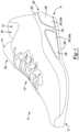
- FIG. 1is a perspective view of an article of footwear including an outsole component, a fluid-filled chamber component, and a midsole component having an inter-fitted configuration, in accordance with principles of the present disclosure
- FIG. 2is a top view of the article of footwear of FIG. 1 ;
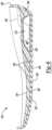
- FIG. 3is a side view of the article of footwear of FIG. 1 ;
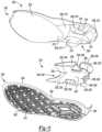
- FIG. 4is an exploded view from a top perspective of the article of footwear of FIG. 1 ;
- FIG. 5is an exploded view from a bottom perspective of a sole structure of the article of footwear of FIG. 1 ;
- FIG. 6is a cross-sectional view of the sole structure of FIG. 5 taken along line 6 - 6 of FIG. 2 ;
- FIG. 7 Ais a top perspective view of a fluid-filled chamber component of the article of footwear of FIG. 1 ;
- FIG. 7 Bis a bottom perspective view of the fluid-filled chamber component of FIG. 7 A ;
- FIG. 7 Cis a plan view of a top of the fluid-filled chamber component of FIG. 7 A ;
- FIG. 7 Dis a plan view of a side of the fluid-filled chamber component of FIG. 7 A ;
- FIG. 7 Eis a plan view of a rear of the fluid-filled chamber component of FIG. 7 A ;
- FIG. 7 Fis a plan view of a front of the fluid-filled chamber component of FIG. 7 A ;
- FIG. 7 Gis a cross-sectional view of the fluid-filled chamber component of FIG. 7 A taken along line 7 G- 7 G of FIG. 7 C ;
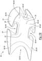
- FIG. 8is a plan view of a top of another fluid-filled chamber component of the article of footwear of FIG. 1 .
- Example configurationswill now be described more fully with reference to the accompanying drawings.
- Example configurationsare provided so that this disclosure will be thorough, and will fully convey the scope of the disclosure to those of ordinary skill in the art. Specific details are set forth such as examples of specific components, devices, and methods, to provide a thorough understanding of configurations of the present disclosure. It will be apparent to those of ordinary skill in the art that specific details need not be employed, that example configurations may be embodied in many different forms, and that the specific details and the example configurations should not be construed to limit the scope of the disclosure.
- first, second, third, etc.may be used herein to describe various elements, components, regions, layers and/or sections. These elements, components, regions, layers and/or sections should not be limited by these terms. These terms may be only used to distinguish one element, component, region, layer or section from another region, layer or section. Terms such as “first,” “second,” and other numerical terms do not imply a sequence or order unless clearly indicated by the context. Thus, a first element, component, region, layer or section discussed below could be termed a second element, component, region, layer or section without departing from the teachings of the example configurations.
- the sole structureincludes a midsole having a plurality of projections, at least one of the plurality of projections forming a first portion of a peripheral side wall of the sole structure.
- the sole structurealso includes a fluid-filled chamber having a central portion, a plurality of lobes extending outward from the central portion, and a plurality of channels formed between the plurality of lobes.
- a first lobe of the plurality of lobesis disposed between at least two of the plurality of projections such that the first lobe forms a second portion of the peripheral side wall of the sole structure.
- the plurality of channelsincludes a first channel and a second channel.
- the first lobedefines a first distance extending between the first channel and the second channel and a second distance extending from a bottom surface of the fluid-filled chamber to a top surface of the fluid-filled chamber, the first distance being substantially equal to the second distance.
- the midsoleincludes an upper surface and a lower surface opposite the upper surface, the plurality of projections being disposed within the plurality of channels from a top surface of the fluid-filled chamber to a bottom surface of the fluid-filled chamber.
- exposed side walls of the plurality of projectionsform the first portion of the peripheral side wall of the sole structure.
- the plurality of lobeseach define a distal end wall and the plurality of projections each define an exposed side wall, a plurality of the distal end walls and a plurality of the exposed side walls alternating in an inter-fitted configuration to form the peripheral side wall of the sole structure.
- the at least some of the distal end wallsmay be flush with at least some of the exposed side walls to form the peripheral side wall.
- the at least some of the distal end wallsmay be offset from at least some of the exposed side walls to form the peripheral side wall of the sole structure.
- the sole structureincludes an outsole having an exposed surface and a non-exposed surface opposite the exposed surface, where the fluid-filled chamber engages a first portion of the non-exposed surface, and the midsole engages a second portion of the non-exposed surface of the outsole.
- the outsolemay include a lip disposed in a mid-foot region of the sole structure and configured to inhibit movement of the fluid-filled chamber toward a forefoot region of the sole structure.
- the outsolemay include at least one protrusion disposed within at least one of the plurality of channels.
- the midsolemay engage the at least one protrusion.
- fluid-filled chamberincludes a membrane defining a fluid-filled chamber and the midsole is non-hollow.
- the fluid-filled chambermay be tapered between a posterior end and an anterior end of the sole structure.
- the sole structureincludes a fluid-filled chamber having a central portion and a plurality of lobes extending outward from the central portion.
- the plurality of lobesform a first portion of a peripheral side wall of the sole structure.
- the sole structurealso includes a midsole having a plurality of projections inter-fitted with the plurality of lobes and forming a second portion of the peripheral side wall of the sole structure.
- Implementations of this aspect of the disclosuremay include one or more of the following optional features.
- the plurality of lobesdefine a first channel and a second channel, a first lobe of the plurality of lobes defining a first distance extending between the first channel and the second channel and a second distance extending from a bottom surface of the fluid-filled chamber to a top surface of the fluid-filled chamber, the first distance being substantially equal to the second distance.
- the midsolemay include an upper surface and a lower surface opposite the upper surface.
- At least one of the plurality of projectionsmay be disposed between two lobes of the plurality of lobes from the top surface to the bottom surface and exposed side walls of the plurality of projections may form the first portion of the peripheral side wall of the sole structure.
- the plurality of lobeseach define a distal end wall and the plurality of projections each define an exposed side wall, a plurality of the distal end walls and a plurality of the exposed side walls alternating in an inter-fitted configuration to form the peripheral side wall of the sole structure.
- the at least some of the distal end wallsmay be flush with at least some of the exposed side walls to form the peripheral side wall.
- the at least some of the distal end wallsmay be offset from at least some of the exposed side walls to form the peripheral side wall of the sole structure.
- the sole structuremay include an outsole having an exposed surface and a non-exposed surface opposite the exposed surface, where the fluid-filled chamber engages a first portion of the non-exposed surface, and the midsole engages a second portion of the non-exposed surface of the outsole.
- the outsolemay include a lip disposed in a mid-foot region of the sole structure and configured to inhibit movement of the fluid-filled chamber toward a forefoot region of the sole structure.
- the outsolemay include at least one protrusion disposed between at least two of the plurality of lobes. When the outsole includes at least one protrusion disposed between at least two of the plurality of lobes, the midsole may engage the at least one protrusion.
- the fluid-filled chamberincludes a membrane defining a fluid-filled chamber and the midsole is non-hollow.
- the fluid-filled chambermay also be tapered between a posterior end and an anterior end of the sole structure.
- a sole structure for an article of footwearincluding a midsole having a plurality of projections, at least one of the plurality of projections forming a first portion of a peripheral side wall of the sole structure.
- the sole structurefurther includes a fluid-filled chamber having a central portion, a plurality of lobes extending outward from the central portion and between respective projections of the plurality of projections to form a second portion of the peripheral side wall of the sole structure, a plurality of tunnels fluidly coupling respective lobes of the plurality of lobes to the central portion, and a plurality of channels defined by adjacent lobes of the plurality of lobes and adjacent tunnels of the plurality of tunnels, at least one channel of the plurality of channels having a different shape than an adjacent channel of the plurality of channels.
- the fluid-filled chambermay be asymmetric about a central, longitudinal axis of the fluid-filled chamber. Additionally or alternatively, the fluid-filled chamber may be asymmetric about a central axis extending between a medial side of the fluid-filled chamber and a lateral side of the fluid-filled chamber and substantially perpendicular to the longitudinal axis.
- the plurality of lobesmay include a first lobe, a second lobe, a third lobe, and a fourth lobe, at least two of the first lobe, the second lobe, the third lobe, and the fourth lobe including the same shape.
- the other two of the first lobe, the second lobe, the third lobe, and the fourth lobe(i) may include a different shape than the at least two of the first lobe, the second lobe, the third lobe, and the fourth lobe and (ii) may have the same shape as one another.
- the at least two of the first lobe, the second lobe, the third lobe, and the fourth lobemay be disposed on opposite sides of the fluid-filled chamber. Additionally or alternatively, the first lobe, the second lobe, the third lobe, and the fourth lobe may extend around a heel region of the sole structure.
- Each tunnel of the plurality of tunnelsmay include approximately the same size and shape.
- An article of footwearmay incorporate the sole structure described above.
- a sole structure for an article of footwearincluding a midsole having a plurality of projections, at least one of the plurality of projections forming a first portion of a peripheral side wall of the sole structure.
- the sole structurefurther includes a fluid-filled chamber having a central portion, a plurality of lobes extending outward from the central portion and between respective projections of the plurality of projections to form a second portion of the peripheral side wall of the sole structure, a plurality of tunnels fluidly coupling respective lobes of the plurality of lobes to the central portion, and a plurality of channels defined by adjacent lobes of the plurality of lobes and adjacent tunnels of the plurality of tunnels, the fluid-filled chamber being asymmetric about a central, longitudinal axis of the fluid-filled chamber.
- Implementations of this aspect of the disclosuremay include one or more of the following optional features.
- at least one channel of the plurality of channelsmay have a different shape than an adjacent channel of the plurality of channels.
- the fluid-filled chambermay be asymmetric about a central axis extending between a medial side of the fluid-filled chamber and a lateral side of the fluid-filled chamber and substantially perpendicular to the longitudinal axis.
- the plurality of lobesmay include a first lobe, a second lobe, a third lobe, and a fourth lobe, at least two of the first lobe, the second lobe, the third lobe, and the fourth lobe including the same shape.
- the other two of the first lobe, the second lobe, the third lobe, and the fourth lobemay include a different shape than the at least two of the first lobe, the second lobe, the third lobe, and the fourth lobe and (ii) may have the same shape as one another.
- the at least two of the first lobe, the second lobe, the third lobe, and the fourth lobemay be disposed on opposite sides of the fluid-filled chamber. Additionally or alternatively, the first lobe, the second lobe, the third lobe, and the fourth lobe may extend around a heel region of the sole structure.
- Each tunnel of the plurality of tunnelsmay include approximately the same size and shape.
- An article of footwearmay incorporate the sole structure described above.
- an article of footwear 10includes an upper 100 and a sole structure 200 .
- the footwear 10may further include an anterior end 12 associated with a forward-most point of the footwear, and a posterior end 14 corresponding to a rearward-most point of the footwear 10 .
- a longitudinal axis A F of the footwear 10extends along a length of the footwear 10 from the anterior end 12 to the posterior end 14 parallel to a ground surface, and generally divides the footwear 10 into a medial side 16 and a lateral side 18 . Accordingly, the medial side 16 and the lateral side 18 respectively correspond with opposite sides of the footwear 10 and extend from the anterior end 12 to the posterior end 14 .
- a longitudinal directionrefers to the direction extending from the anterior end 12 to the posterior end 14
- a lateral directionrefers to the direction transverse to the longitudinal direction and extending from the medial side 16 to the lateral side 18
- the article of footwear 10may be divided into one or more regions.
- the regionsmay include a forefoot region 20 , a mid-foot region 22 , and a heel region 24 .
- the mid-foot region 22may correspond with an arch area of the foot
- the heel region 24may correspond with rear portions of the foot, including a calcaneus bone.
- the upper 100includes interior surfaces that define an interior void 102 operable to receive and secure a foot for support on the sole structure 200 .
- the upper 100may be formed from one or more materials that are stitched or adhesively bonded together to form the interior void 102 .
- Suitable materials of the upper 100may include, but are not limited to, mesh, textiles, foam, leather, and synthetic leather. The materials may be selected and located to impart properties of durability, air-permeability, wear-resistance, flexibility, and comfort.
- the upper 100includes a strobel 104 having a bottom surface opposing the sole structure 200 and an opposing top surface defining a footbed 106 of the interior void 102 . Stitching or adhesives may secure the strobel 104 to the upper 100 .
- the footbed 106may be contoured to conform to a profile of the bottom surface (e.g., plantar) of the foot.
- the upper 100may also incorporate additional layers such as an insole 108 or sockliner that may be disposed upon the strobel 104 and reside within the interior void 102 of the upper 100 to receive a plantar surface of the foot to enhance the comfort of the article of footwear 10 .
- An ankle opening 112 in the heel region 24may provide access to the interior void 102 .
- the ankle opening 112may receive a foot to secure the foot within the interior void 102 and to facilitate entry and removal of the foot to and from the interior void 102 .
- one or more fasteners 110extend along the upper 100 to adjust a fit of the interior void 102 around the foot and to accommodate entry and removal of the foot therefrom.
- the upper 100may include apertures, such as eyelets and/or other engagement features such as fabric or mesh loops that receive the fasteners 110 .
- the fasteners 110may include laces, straps, cords, hook-and-loop, or any other suitable type of fastener.
- the upper 100may include a tongue portion 114 that extends between the interior void 102 and the fasteners.
- the sole structure 200may include a midsole component 202 , a fluid-filled chamber component 204 , and an outsole component 206 .
- the sole structure 200may be secured to a lower surface of upper 100 , such as by stitching or adhesive bonding.
- the fluid-filled chamber component 204may be attached to the midsole component 202 , such as by adhesive bonding, and the outsole component 206 may be secured to the midsole component 202 or the fluid-filled chamber component 204 , such as by adhesive bonding.
- Those skilled in the artwill appreciate alternative materials for, and methods suitable for attaching, the upper 100 , the midsole component 202 , the fluid-filled chamber component 204 , and the outsole component 206 .
- the sole structure 200generally operates to attenuate impact and other ground reaction forces and absorb energy as, for example, the sole structure 200 contacts a ground surface during active use.
- the midsole component 202is located adjacent a foot when the foot is disposed in an interior of the upper 100 .
- the midsole component 202generally conforms to contours of the foot and provides the foot with cushioning during walking, running, or other activities.
- the midsole component 202 and the fluid-filled chamber component 204inter-fit with the outsole component 206 to form an assembled sole structure 200 , as shown in FIGS. 1 - 3 .
- the midsole component 202 , the fluid-filled chamber component 204 , and the outsole component 206may be inter-fitted with one another during a manufacturing process to form the assembled sole structure 200 .
- the fluid-filled chamber component 204 and the outsole component 206may be manufactured separately and laid up in a mold cavity of a molding system for molding a sole structure, and the inter-fitted midsole component 202 may be formed by injection molding a molding material, such as a polymer foam material, into the mold cavity of the molding system, including the laid-up sole component(s), to achieve a sole structure 200 having an inter-fitted configuration.
- the midsole component 202 , the fluid-filled chamber component 204 , and the outsole component 206are manufactured separately, such as by various molding processes using separate molding systems and mold materials, and then bonded together in an inter-fitted configuration to form the assembled sole structure 200 .
- the midsole component 202may include at least one midsole component or element. As shown in FIGS. 4 and 5 , in some implementations, the midsole component 202 includes a single midsole component or element. In some implementations, the midsole component 202 is substantially solid or non-hollow. In some implementations, the midsole component 202 is formed of a foam material, such as a polymer foam material having an open or closed cell foam structure. The foam material may beneficially compress resiliently under an applied load. In some implementations, the midsole component 202 is formed of a material that is mold compatible or otherwise suitable for bonding with the fluid-filled chamber component 204 and/or the outsole component 206 , such as by adhesive or thermal bonding.
- the midsole component 202may include a plurality of projections 208 , such as a rear projection 210 , a front projection 212 , a medial projection 214 , and a lateral projection 216 , that may be inserted through and inter-fitted with structures of the fluid-filled the chamber component 204 and/or the outsole component 206 .
- a plurality of projections 208 , 210 , 212 , 214 , 216are provided with outer (e.g., peripheral) side walls 218 .
- the outer side walls 218may be exposed within the fluid-filled chamber component 204 to define at least a portion of a peripheral side wall of the sole structure 200 .
- the midsole component 202generally has a top or upper surface 220 , a bottom or lower surface 222 opposite the upper surface 220 , and the plurality of projections 208 , 210 , 212 , 214 , 216 that extend away from (e.g., downward) the lower surface 222 .
- the upper surface 220may have a smooth finish that follows contours of a foot and provides a comfortable fit.
- the projections 208 , 210 , 212 , 214 , 216generally are wider nearer to a central portion (e.g., nearer the axis A F ) of the midsole component 202 than at the side walls 218 .
- a distal end (e.g., offset from the lower surface 222 ) of the projections 208 , 210 , 212 , 214 , 216may be wider nearer the axis A F of the midsole component 202 than at the side walls 218 .
- Example resilient polymeric materials for the midsole component 202may include those based on foaming or molding one or more polymers, such as one or more elastomers (e.g., thermoplastic elastomers (TPE)).
- the one or more polymersmay include aliphatic polymers, aromatic polymers, or mixtures of both; and may include homopolymers, copolymers (including terpolymers), or mixtures of both.
- the one or more polymersmay include olefinic homopolymers, olefinic copolymers, or blends thereof.
- olefinic polymersinclude polyethylene, polypropylene, and combinations thereof.
- the one or more polymersmay include one or more ethylene copolymers, such as, ethylene-vinyl acetate (EVA) copolymers, EVOH copolymers, ethylene-ethyl acrylate copolymers, ethylene-unsaturated mono-fatty acid copolymers, and combinations thereof.
- EVAethylene-vinyl acetate
- the one or more polymersmay include one or more polyacrylates, such as polyacrylic acid, esters of polyacrylic acid, polyacrylonitrile, polyacrylic acetate, polymethyl acrylate, polyethyl acrylate, polybutyl acrylate, polymethyl methacrylate, and polyvinyl acetate; including derivatives thereof, copolymers thereof, and any combinations thereof.
- polyacrylatessuch as polyacrylic acid, esters of polyacrylic acid, polyacrylonitrile, polyacrylic acetate, polymethyl acrylate, polyethyl acrylate, polybutyl acrylate, polymethyl methacrylate, and polyvinyl acetate; including derivatives thereof, copolymers thereof, and any combinations thereof.
- the one or more polymersmay include one or more ionomeric polymers.
- the ionomeric polymersmay include polymers with carboxylic acid functional groups, sulfonic acid functional groups, salts thereof (e.g., sodium, magnesium, potassium, etc.), and/or anhydrides thereof.
- the ionomeric polymer(s)may include one or more fatty acid-modified ionomeric polymers, polystyrene sulfonate, ethylene-methacrylic acid copolymers, and combinations thereof.
- the one or more polymersmay include one or more styrenic block copolymers, such as acrylonitrile butadiene styrene block copolymers, styrene acrylonitrile block copolymers, styrene ethylene butylene styrene block copolymers, styrene ethylene butadiene styrene block copolymers, styrene ethylene propylene styrene block copolymers, styrene butadiene styrene block copolymers, and combinations thereof.
- styrenic block copolymerssuch as acrylonitrile butadiene styrene block copolymers, styrene acrylonitrile block copolymers, styrene ethylene butylene styrene block copolymers, styrene ethylene butadiene styrene block
- the one or more polymersmay include one or more polyamide copolymers (e.g., polyamide-polyether copolymers) and/or one or more polyurethanes (e.g., cross-linked polyurethanes and/or thermoplastic polyurethanes).
- the one or more polymersmay include one or more natural and/or synthetic rubbers, such as butadiene and isoprene.
- the foamed materialmay be foamed using a physical blowing agent which phase transitions to a gas based on a change in temperature and/or pressure, or a chemical blowing agent which forms a gas when heated above its activation temperature.
- the chemical blowing agentmay be an azo compound such as adodicarbonamide, sodium bicarbonate, and/or an isocyanate.
- the foamed polymeric materialis a crosslinked foamed material.
- a peroxide-based crosslinking agentsuch as dicumyl peroxide may be used.
- the foamed polymeric materialmay include one or more fillers such as pigments, modified or natural clays, modified or unmodified synthetic clays, talc glass fiber, powdered glass, modified or natural silica, calcium carbonate, mica, paper, wood chips, and the like.
- the resilient polymeric materialmay be formed using a molding process.
- the uncured elastomere.g., rubber
- a curing packagesuch as a sulfur-based or peroxide-based curing package, calendared, formed into shape, placed in a mold, and vulcanized.
- the resilient polymeric materialwhen the resilient polymeric material is a foamed material, the material may be foamed during a molding process, such as an injection molding process.
- a thermoplastic polymeric materialmay be melted in the barrel of an injection molding system and combined with a physical or chemical blowing agent and optionally a crosslinking agent, and then injected into a mold under conditions which activate the blowing agent, forming a molded foam.
- the foamed materialwhen the resilient polymeric material is a foamed material, the foamed material may be a compression molded foam. Compression molding may be used to alter the physical properties (e.g., density, stiffness and/or durometer) of a foam, or to alter the physical appearance of the foam (e.g., to fuse two or more pieces of foam, to shape the foam, etc.), or both.
- Compression moldingmay be used to alter the physical properties (e.g., density, stiffness and/or durometer) of a foam, or to alter the physical appearance of the foam (e.g., to fuse two or more pieces of foam, to shape the foam, etc.), or both.
- the compression molding processdesirably starts by forming one or more foam preforms, such as by injection molding and foaming a polymeric material, by forming foamed particles or beads, by cutting foamed sheet stock, and the like.
- the compression molded foammay then be made by placing the one or more preforms formed of foamed polymeric material(s) in a compression mold, and applying sufficient pressure to the one or more preforms to compress the one or more preforms in a closed mold.
- the moldis closed, sufficient heat and/or pressure is applied to the one or more preforms in the closed mold for a sufficient duration of time to alter the preform(s) by forming a skin on the outer surface of the compression molded foam, fuse individual foam particles to each other, permanently increase the density of the foam(s), or any combination thereof.
- the moldis opened and the molded foam article is removed from the mold.
- the fluid-filled chamber component 204generally is disposed between the midsole component 202 and the outsole component 206 .
- the fluid-filled chamber component 204may be made of any material suitable for holding a desired fluid in a sealed manner within a sole construction.
- the fluid-filled chamber component 204is made of a polymer material that is substantially impermeable to fluid.
- the fluid-filled chamber component 204is made of a thermoplastic elastomer.
- the fluid-filled chamber component 204may be manufactured using a variety of techniques.
- the fluid-filled chamber component 204may be made by blow molding, thermoforming, rotational molding, or other molding processes.
- the midsole component 202is inter-fitted with the fluid-filled chamber component 204 in a manner that presents the sole structure 200 and the article of footwear 10 having an aesthetically pleasing side profile.
- the fluid-filled chamber component 204may include one or more fluid-filled chamber components or elements.
- multiple fluid-filled chamber components or elements having different characteristicse.g., having different sizes, configurations, volumes, fluids, pressures, or other compression or performance characteristics, are provided in respective impact zones of the article of footwear 10 .
- Such configurationsmay enable customization of compression characteristics of the fluid-filled chamber component(s) and associated performance characteristics of the sole structure 200 and the article of footwear 10 .
- the fluid filled chamber component 204is located in the heel region 24 of the article of footwear 10 .
- the fluid-filled chamber component 204may provide inflation and performance characteristics suitable for attenuating impact and ground reaction forces associated with the heel region 24 of the article of footwear 10 , such as a heel strike portion of a running stride.
- Those skilled in the artwill be able to select a number, configuration, and arrangement of fluid-filled chamber component(s) suitable for desired performance characteristics of a sole structure in view of the present disclosure.
- the fluid-filled chamber component 204may include a central portion 224 and a plurality of lobes 226 extending outward from the central portion 224 .
- the plurality of lobes 226may include a rear medial lobe 228 , a rear lateral lobe 230 , a front medial lobe 232 , and a front lateral lobe 234 .
- Each of the lobes 226 , 228 , 230 , 232 , 234may include a distal end wall 236 disposed at a peripheral side surface of the sole structure 200 in the assembled configuration.
- Each of the lobes 226 , 228 , 230 , 232 , 234may generally be wider near the distal end walls 236 than near the central portion 224 .
- each of the lobes 226 , 228 , 230 , 232 , 234may be widest at the distal end walls 236 .
- each of the distal end walls 236are exposed to form a portion of the peripheral side surface of the sole structure 200 in the assembled configuration, while the outer side walls 218 may be exposed within the fluid-filled chamber component 204 to define at least another portion of a peripheral side wall of the sole structure 200 , as previously described.
- one or more of the outer side walls 218may be substantially flush (e.g., coplanar) with one or more of the distal end walls 236 such that the peripheral side wall of the sole structure defines a smooth outer surface.
- one or more of the outer side walls 218may be offset (e.g., stepped) from one or more of the distal end walls 236 such that the peripheral side wall of the sole structure defines a stepped outer surface.
- the distal end wall 236 of the rear lateral lobe 230 or the rear medial lobe 228defines a substantially rhomboidal shape, while the distal end wall of the front lateral lobe 234 or the front medial lobe 232 defines a substantially triangular shape.
- a portion of the rear medial or lateral lobe 228 , 230may define a rear longitudinal axis 276 along the peripheral side surface and a portion of the front lateral lobe 234 may define a front longitudinal axis 278 along the peripheral side surface.
- the rear longitudinal axis 276may be substantially parallel to the front longitudinal axis 278 .
- the rear longitudinal axis 276may have any suitable relationship relative to the front longitudinal axis 278 .
- a similar relationshipmay be formed between the rear medial lobe 228 and the front medial lobe 232 .
- the fluid-filled chamber component 204includes a plurality of tunnels 280 extending between the central portion 224 and the plurality of lobes 226 .
- the tunnels 280may provide lateral and sagittal shear stability to the fluid-filled chamber component 204 , provide structure to the peripheral side surface of the sole structure 200 in the assembled configuration, and reduce excessive displacement and collapse.
- the plurality of tunnels 280include a rear medial tunnel 282 extending from the central portion 224 to the rear medial lobe 228 and a rear lateral tunnel 284 extending from the central portion 224 to the rear lateral lobe 230 .
- the tunnels 280define a first distance D 1 , also referred to as a height, and a second distance D 2 , also referred to as a width.
- the first distance D 1may extend from a top surface 250 of the fluid-filled chamber component 204 (e.g., the top surface 250 proximate the tunnel 280 ) to a bottom surface 252 of the fluid-filled chamber component 204 (e.g., the bottom surface 250 proximate the tunnel 280 ).
- the first distance D 1extends at a substantially right angle relative to one or both of the top surface 250 or the bottom surface 252 . As shown in FIG.
- the second distance D 2may extend along the top surface 250 or the bottom surface 252 from the rear channel 240 (e.g., an edge of the fluid-filled chamber component 204 defining the rear channel 240 ) to the medial channel 244 (e.g., an edge of the fluid-filled chamber component 204 defining the medial channel 244 ) or to the lateral channel 246 (e.g., an edge of the fluid-filled chamber component 204 defining the lateral channel 246 ).
- the second distance D 2may be twice as large as the first distance D 1 .
- the first distance D 1may be equal to the second distance D 2 .
- the first distance D 1 and the second distance D 2may have any suitable relationship with each other.
- a ratio of the second distance D 2 to the first distance D 1varies in a direction extending along the second distance D 2 .
- a value of the first distance D 1may increase or decrease as measured along the distance D 2 , such that the ratio of the second distance D 2 to the first distance D 1 increases or decreases between 2:1 and 1:1.
- the fluid-filled chamber component 204may further include a plurality of channels 238 .
- the channels 238include a rear channel 240 , a front channel 242 , a medial channel 244 , and a lateral channel 246 .
- Each channel 240 , 242 , 244 , 246may be disposed between two different adjacent lobes of the plurality of lobes 228 , 230 , 232 , 234 .
- any two of the lobes 228 , 230 , 232 , 234 of the plurality of lobes 226may define one of the channels 240 , 242 , 244 , 246 of the plurality of channels 238 .
- the rear medial lobe 228 and the rear lateral lobe 230may define the rear channel 240
- the front medial lobe 232 and the front lateral lobe 234may define the front channel 242
- the rear medial lobe 228 and the front medial lobe 232may define the medial channel 244
- the rear lateral lobe 230 and the front lateral lobe 234may define the lateral channel 246 .
- the rear longitudinal axis 276 and the front longitudinal axis 278are defined by portions of the peripheral side surface of the lobes 228 , 230 , 232 , 234 such that the rear longitudinal axis 276 is substantially parallel to the front longitudinal axis 278 .
- the front and rear longitudinal axes 276 , 278are disposed along opposed portions of the peripheral side surface of the lobes 228 , 230 , 232 , 234 such that the front and rear longitudinal axes 276 , 278 are disposed at non-orthogonal angles relative to the bottom surface 252 .
- the medial channel 244may define a distance from the rear medial lobe 228 to the front medial lobe 232 equal to the sum of a third distance D 3 and a fourth distance D 4 .
- the lateral channel 246may include a distance from the rear lateral lobe 230 to the front lateral lobe 234 equal to the sum of the third distance D 3 and the fourth distance D 4 .
- the third distance D 3may extend from the rear medial lobe 228 or the rear lateral lobe 230 to a midpoint 286 between the rear medial lobe 228 and the front medial lobe 232 or between the rear lateral lobe 230 and the front lateral lobe 234 along the peripheral side surface.
- the fourth distance D 4may extend from the front medial lobe 232 or the front lateral lobe 230 to the midpoint 286 .
- the third distance D 3is equal to the fourth distance D 4 , such that the medial channel 244 and the lateral channel 246 are substantially symmetrical relative to the midpoint 286 .
- the third distance D 3is not equal to the fourth distance D 4 , such that the medial channel 244 and the lateral channel 246 are substantially asymmetrical relative to the midpoint 286 .
- the third distance D 3may be greater than the fourth distance D 4 .
- the third distance D 3 and the fourth distance D 4may each be modified by modifying a size of at least one of the lobes 226 or the tunnels 280 .
- the fluid-filled chamber component 204may include a wedge portion 248 disposed between the front medial lobe 232 and the front lateral lobe 234 .
- the wedge portion 248may be formed as a component of the front medial lobe 232 and the front lateral lobe 234 .
- the wedge portion 248may be a component separate from the front medial lobe 232 and the front lateral lobe 234 .
- the wedge portion 248may taper outward from the central portion 224 . For example, as illustrated in FIG.
- the wedge portion 248may have a first thickness T 1 at a first location and a second thickness T 2 at a second location closer to the posterior end 14 than the first location, the first thickness T 1 being less than the second thickness T 2 .
- the wedge portion 248defines a constant taper in a direction extending toward the anterior end 12 from the central portion 224 .
- the fluid-filled chamber component 204may include a top surface 250 and the bottom surface 252 .
- the top surface 250may generally face the bottom surface 222 of the midsole component 202
- the bottom surface 252may generally face a top surface 258 of the outsole component 206 .
- At least a portion of the top surface 250may be concave.
- the top surface 250may contact the bottom surface 222 of the midsole component 202
- the bottom surface 252may contact the top surface 258 of the outsole component 206 .
- the taper of the wedge portion 248is defined by the top surface 250 converging toward the bottom surface 252 in the direction extending toward the anterior end 12 from the central portion 224 .
- one or more of the plurality of channels 238extend continuously through an entire thickness of the fluid-filled chamber component 204 from the top surface 250 to the bottom surface 252 .
- the fluid-filled chamber component 204may include a membrane 254 that defines a fluid-filled chamber 256 of the fluid-filled chamber component 204 .
- one or more of the central portion 224 , the rear medial lobe 228 , the rear lateral lobe 230 , the front medial lobe 232 , or the front lateral lobe 234collectively define a single chamber.
- the membrane 254is produced (e.g., thermoformed or blow molded) from a monolayer film (e.g., a single layer). In other implementations, the membrane 254 is produced (e.g., thermoformed or blow molded) from a multilayer film (e.g., multiple sublayers). In either aspect, the membrane 254 can have a film thickness ranging from about 0.2 micrometers to about be about 1 millimeter. In further implementations, the film thickness for the membrane 254 can range from about 0.5 micrometers to about 500 micrometers. In yet further implementations, the film thickness for the membrane 254 can range from about 1 micrometer to about 100 micrometers.
- formation of the membrane 254 and the chamber 256forms a parting line 274 of the fluid-filled chamber component 204 .
- the parting line 274may define an edge where a perimeter of a cavity and a core of an extrusion blow mold meet during a blow molding process.
- the parting line 274 of the rear lateral lobe 230may terminate at or near the rear longitudinal axis 276
- the parting line 274 of the front lateral lobe 234may terminate at or near the front longitudinal axis 278 .
- the parting line 274 of the rear lateral lobe 230may terminate at a lower region of the fluid-filled chamber component 204 —at or near the bottom surface 252 of the fluid-filled chamber component 204 .
- the parting line 274 of the front lateral lobe 234may terminate at an upper region of the fluid-filled chamber component 204 —at or near the top surface 250 of the fluid-filled chamber component 204 .
- the parting line 274extends arcuately (e.g., transverse to the top or bottom surfaces 250 , 252 ) from the front lateral lobe 234 to the rear lateral lobe 230 .
- a similar relationshipmay be formed between the parting line 274 of the rear medial lobe 228 and the parting line 274 of the front medial lobe 232 .
- the membrane 254can be transparent, translucent, and/or opaque.
- transparentfor a membrane and/or a fluid-filled chamber means that light passes through the membrane in substantially straight lines and a viewer can see through the membrane. In comparison, for an opaque membrane, light does not pass through the membrane and one cannot see clearly through the membrane at all.
- a translucent membranefalls between a transparent membrane and an opaque membrane, in that light passes through a translucent layer but some of the light is scattered so that a viewer cannot see clearly through the layer.
- the membrane 254can be produced from an elastomeric material that includes one or more thermoplastic polymers and/or one or more cross-linkable polymers.
- the elastomeric materialcan include one or more thermoplastic elastomeric materials, such as one or more thermoplastic polyurethane (TPU) copolymers, one or more ethylene-vinyl alcohol (EVOH) copolymers, and the like.
- polyurethanerefers to a copolymer (including oligomers) that contains a urethane group (—N(C ⁇ O)O—).
- urethane groupscan contain additional groups such as ester, ether, urea, allophanate, biuret, carbodiimide, oxazolidinyl, isocynaurate, uretdione, carbonate, and the like, in addition to urethane groups.
- one or more of the polyurethanescan be produced by polymerizing one or more isocyanates with one or more polyols to produce copolymer chains having (—N(C ⁇ O)O—) linkages.
- suitable isocyanates for producing the polyurethane copolymer chainsinclude diisocyanates, such as aromatic diisocyanates, aliphatic diisocyanates, and combinations thereof.
- suitable aromatic diisocyanatesinclude toluene diisocyanate (TDI), TDI adducts with trimethyloylpropane (TMP), methylene diphenyl diisocyanate (MDI), xylene diisocyanate (XDI), tetramethylxylylene diisocyanate (TMXDI), hydrogenated xylene diisocyanate (HXDI), naphthalene 1,5-diisocyanate (NDI), 1,5-tetrahydronaphthalene diisocyanate, para-phenylene diisocyanate (PPDI), 3,3′-dimethyldiphenyl-4, 4′-diisocyanate (DDDI), 4,4′-dibenzyl diisocyanate (DBD
- the polyurethane polymer chainsare produced from diisocynates including HMDI, TDI, MDI, H12 aliphatics, and combinations thereof.
- the thermoplastic TPUcan include polyester-based TPU, polyether-based TPU, polycaprolactone-based TPU, polycarbonate-based TPU, polysiloxane-based TPU, or combinations thereof.
- the polymeric layercan be formed of one or more of the following: EVOH copolymers, poly(vinyl chloride), polyvinylidene polymers and copolymers (e.g., polyvinylidene chloride), polyamides (e.g., amorphous polyamides), amide-based copolymers, acrylonitrile polymers (e.g., acrylonitrile-methyl acrylate copolymers), polyethylene terephthalate, polyether imides, polyacrylic imides, and other polymeric materials known to have relatively low gas transmission rates. Blends of these materials as well as with the TPU copolymers described herein and optionally including combinations of polyimides and crystalline polymers, are also suitable.
- the chamber 256can be produced using any suitable technique, such as thermoforming (e.g. vacuum thermoforming), blow molding, extrusion, injection molding, vacuum molding, rotary molding, transfer molding, pressure forming, heat sealing, casting, low-pressure casting, spin casting, reaction injection molding, radio frequency (RF) welding, and the like.
- thermoforminge.g. vacuum thermoforming
- blow moldingextrusion
- injection moldingvacuum molding
- rotary moldingtransfer molding
- pressure formingheat sealing
- castinglow-pressure casting
- spin castingreaction injection molding
- reaction injection moldingradio frequency (RF) welding
- RFradio frequency
- the chamber 256can be provided in a fluid-filled or in an unfilled state.
- the chamber 256can be filled to include any suitable fluid, such as a gas or liquid.
- the gascan include air, nitrogen (N 2 ), or any other suitable gas.
- chamber 256can alternatively include other media, such as pellets, beads, ground recycled material, and the like (e.g., foamed beads and/or rubber beads).
- the fluid provided to the chamber 256can result in the chamber 256 being pressurized.
- the fluid provided to the chamber 256can be at atmospheric pressure such that the chamber 256 is not pressurized but, rather, simply contains a volume of fluid at atmospheric pressure.
- the chamber 256desirably has a low gas transmission rate to preserve its retained gas pressure.
- the chamber 256has a gas transmission rate for nitrogen gas that is at least about ten (10) times lower than a nitrogen gas transmission rate for a butyl rubber layer of substantially the same dimensions.
- the chamber 256has a nitrogen gas transmission rate of 15 cubic-centimeter/square-meter ⁇ atmosphere ⁇ day (cm 3 /m 2 ⁇ atm ⁇ day) or less for an average film thickness of 500 micrometers (based on thicknesses of the membrane 254 ).
- the transmission rateis 10 cm 3 /m 2 ⁇ atm ⁇ day or less, 5 cm 3 /m 2 ⁇ atm ⁇ day or less, or 1 cm 3 /m 2 ⁇ atm ⁇ day or less.
- FIG. 8another example of a fluid-filled chamber component 204 a for use with the article of footwear 10 ( FIG. 1 ) is generally shown.
- like reference numeralsare used hereinafter and in the drawings to identify like components while like reference numerals containing letter extensions or prime symbols are used to identify those components that have been modified.
- a rear medial lobe 228 amay have a different shape than the rear medial lobe 228 .
- a front medial lobe 232 amay have a different shape than the front medial lobe 232
- a medial channel 244 amay have a different shape than the medial channel 244
- a rear medial tunnel 282 amay have a different shape than the rear medial tunnel 282 .
- the first distance D 1( FIG.
- a second distance D 2 ′extending from the rear channel 240 to the medial channel 244 a (e.g., an edge of the fluid-filled chamber component 204 defining the medial channel 244 a ) or to the lateral channel 246 (e.g., an edge of the fluid-filled chamber component 204 defining the lateral channel 246 ).
- At least one of a third distance D 3 ′ or a fourth distance D 4 ′may be modified (e.g., increased or decreased) to modify the relationship between the second distance D 2 ′ and the first distance D 1 .
- the third distance D 3 ′ and/or the fourth distance D 4 ′may be increased relative to the third distance D 3 and the fourth distance D 4 , to maintain a 1:1 ratio of the second distance D 2 ′ to the first distance D 1 .
- the fluid-filled chamber component 204 aincludes a resulting structure that is asymmetrical about a central, longitudinal axis of the fluid-filled chamber component 204 a .
- the fluid-filled chamber component 204 aalso may be asymmetrical about a central, lateral axis that extends between a medial side of the fluid-filled chamber component 204 a and a lateral side of the fluid-filled chamber component 204 a (i.e., an axis that is substantially perpendicular to a longitudinal axis of the fluid-filled chamber component 204 a ) due to one or both distances D 3 ′, D 4 ′ being different than D 3 , D 4 , respectively. See, for example, FIG. 8 .
- the midsole component 202may substantially inter-fit with the fluid-filled chamber component 204 , 204 a such that the bottom surface 222 of the midsole component 202 directly abuts the top surface 250 of the fluid-filled chamber component 204 , 204 a in the heel region 24 .
- the projections 208 , 210 , 212 , 214 , 216 of the midsole component 202may be disposed within the channels 238 , 240 , 242 , 244 / 244 a , 246 of the fluid-filled chamber component 204 , 204 a such that the projections 208 , 210 , 212 , 214 , 216 inter-fit with the lobes 226 , 228 , 230 , 232 , 234 .
- Each of the projections 208 , 210 , 212 , 214 , 216may have a shape that generally corresponds to the shape of a corresponding channel 238 , 240 , 242 , 244 / 244 a , 246 .
- the rear projection 210may inter-fit with the rear channel 240
- the front projection 212may inter-fit with the front channel 242
- the medial projection 214may inter-fit with the medial channel 244 / 244 a
- the lateral projection 216may inter-fit with the lateral channel 246 .
- Each of the projections 208 , 210 , 212 , 214 , 216may substantially fill the corresponding channel 238 , 240 , 242 , 244 / 244 a , 246 .
- the rear projection 210may substantially fill the rear channel 240
- the front projection 212may substantially fill the front channel 242
- the medial projection 214may substantially fill the medial channel 244 / 244 a
- the lateral projection 216may substantially fill the lateral channel 246 .
- the outsole component 206generally engages a ground surface and imparts traction to the article of footwear 10 .
- the outsole component 206is formed of a durable, wear-resistant material that engages a ground surface and imparts traction during use.
- the outsole component 206includes a top, non-exposed surface 258 and at least one traction element 272 disposed on an exposed, ground-contacting surface 260 (opposite the non-exposed surface 258 ) to engage a ground surface and impart traction during use.
- the outsole component 206may be disposed below the midsole component 202 and the fluid-filled chamber component 204 / 204 a , and may be formed of an abrasion resistant material suitable for contact with a ground surface.
- the outsole component 206may be disposed below the midsole component 202 and the fluid-filled chamber component 204 / 204 a in the heel region 24 to protect these components from abrasive contact with a ground surface in the heel region 24 during heel-strike events, for example.
- outsole component 206may be disposed below the midsole component 202 and/or the fluid-filled chamber component 204 / 204 a in the forefoot region 20 to protect these components from abrasive contact with a ground surface during pivoting movements, for example.
- the outsole component 206may have a peripheral shape that generally corresponds to a peripheral shape of the midsole component 202 .
- the outsole component 206may have a lip 262 disposed on the top surface 258 near or in the mid-foot region 22 .
- the lip 262may receive the front medial lobe 232 and the front lateral lobe 234 of the fluid-filled chamber component 204 / 204 a .
- the lip 262may prohibit the fluid-filled chamber component 204 / 204 a from moving toward the forefoot region 20 .
- the outsole component 206may include a rear flange 264 , a medial protrusion 266 and a lateral protrusion 268 .
- the rear flange 264may extend from the top surface 258 toward the midsole component 202 , and the rear flange 264 may prohibit the fluid-filled chamber component 204 / 204 a from moving beyond the anterior end 12 .
- the medial protrusion 266may engage the medial channel 244 of the fluid-filled chamber component 204 / 204 a and the lateral protrusion 268 may engage the lateral channel 246 of the fluid-filled chamber component 204 / 204 a .
- the medial protrusion 266 and the lateral protrusion 268may prohibit movement of the fluid-filled chamber component 204 / 204 a relative to the outsole component 206 .
- portions of the bottom surface 222 of the midsole component 202 disposed on the projections 208 , 210 , 212 , 214 , 216may extend through the channels 238 , 240 , 242 , 244 / 244 a , 246 and directly abut the top surface 258 of the outsole component 206 .
- each of the projections 208 , 210 , 212 , 214 , 216may include a distal surface 270 disposed on the bottom surface 222 of the midsole component 202 .
- the distal surfaces 270may extend through the channels 238 , 240 , 242 , 244 / 244 a , 246 and directly abut the outsole component 206 .
- the distal surface 270 of the rear projection 210may abut the rear flange 264 of the outsole component 206
- the distal surface 270 of the front projection 212may abut the top surface 258 of the outsole component 206
- the distal surface 270 of the medial projection 214may abut the medial protrusion 266 of the outsole component 206
- the distal surface 270 of the lateral projection 216may abut the lateral protrusion 268 of the outsole component 206 .
- the sole structure 200including the midsole component 202 , the fluid-filled chamber component 204 / 204 a , and the outsole component 206 may provide inflation and performance characteristics suitable for attenuating impact and ground reaction forces associated with a heel region of article of footwear 10 , such as a heel strike portion of a running stride.
- a sole structure for an article of footwearcomprising a midsole having a plurality of projections, at least one of the plurality of projections forming a first portion of a peripheral side wall of the sole structure and a fluid-filled chamber having a central portion, a plurality of lobes extending outward from the central portion, and a plurality of channels formed between the plurality of lobes, a first lobe of the plurality of lobes disposed between at least two of the plurality of projections such that the first lobe forms a second portion of the peripheral side wall of the sole structure.
- Clause 2The sole structure according to Clause 1, wherein the plurality of channels includes a first channel and a second channel, the first lobe defining a first distance extending between the first channel and the second channel and a second distance extending from a bottom surface of the fluid-filled chamber to a top surface of the fluid-filled chamber, the first distance being substantially equal to the second distance.
- Clause 3The sole structure according to Clause 1, wherein the midsole includes an upper surface and a lower surface opposite the upper surface, the plurality of projections disposed within the plurality of channels from a top surface of the fluid-filled chamber to a bottom surface of the fluid-filled chamber, and wherein exposed side walls of the plurality of projections form the first portion of the peripheral side wall of the sole structure.
- Clause 4The sole structure according to Clause 1, wherein the plurality of lobes each define a distal end wall and the plurality of projections each define an exposed side wall, a plurality of the distal end walls and a plurality of the exposed side walls alternating in an inter-fitted configuration to form the peripheral side wall of the sole structure.
- Clause 5The sole structure according to Clause 4, wherein the at least some of the distal end walls are flush with at least some of the exposed side walls to form the peripheral side wall.
- Clause 6The sole structure according to Clause 4, wherein the at least some of the distal end walls are offset from at least some of the exposed side walls to form the peripheral side wall of the sole structure.
- Clause 7The sole structure according to Clause 1, further comprising an outsole having an exposed surface and a non-exposed surface opposite the exposed surface, wherein the fluid-filled chamber engages a first portion of the non-exposed surface, and the midsole engages a second portion of the non-exposed surface of the outsole.
- Clause 8The sole structure according to Clause 7, wherein the outsole includes a lip disposed in a mid-foot region of the sole structure and configured to inhibit movement of the fluid-filled chamber toward a forefoot region of the sole structure.
- Clause 9The sole structure according to Clause 7, wherein the outsole includes at least one protrusion disposed within at least one of the plurality of channels.
- Clause 10The sole structure according to Clause 9, wherein the midsole engages the at least one protrusion.
- Clause 11The sole structure according to Clause 1, wherein the fluid-filled chamber includes a membrane defining a fluid-filled chamber and the midsole is non-hollow.
- Clause 12The sole structure according to Clause 1, wherein the fluid-filled chamber is tapered between a posterior end and an anterior end of the sole structure.
- a sole structure for an article of footwearcomprising a fluid-filled chamber having a central portion and a plurality of lobes extending outward from the central portion, the plurality of lobes forming a first portion of a peripheral side wall of the sole structure and a midsole having a plurality of projections inter-fitted with the plurality of lobes and forming a second portion of the peripheral side wall of the sole structure.
- Clause 14The sole structure according to Clause 13, wherein the plurality of lobes define a first channel and a second channel, a first lobe of the plurality of lobes defining a first distance extending between the first channel and the second channel and a second distance extending from a bottom surface of the fluid-filled chamber to a top surface of the fluid-filled chamber, the first distance being substantially equal to the second distance.
- Clause 15The sole structure according to Clause 14, wherein the midsole includes an upper surface and a lower surface opposite the upper surface, at least one of the plurality of projections disposed between two lobes of the plurality of lobes from the top surface to the bottom surface, and wherein exposed side walls of the plurality of projections form the first portion of the peripheral side wall of the sole structure.
- Clause 16The sole structure according to Clause 13, wherein the plurality of lobes each define a distal end wall and the plurality of projections each define an exposed side wall, a plurality of the distal end walls and a plurality of the exposed side walls alternating in an inter-fitted configuration to form the peripheral side wall of the sole structure.
- Clause 17The sole structure according to Clause 16, wherein the at least some of the distal end walls are flush with at least some of the exposed side walls to form the peripheral side wall.
- Clause 18The sole structure according to Clause 16, wherein the at least some of the distal end walls are offset from at least some of the exposed side walls to form the peripheral side wall of the sole structure.
- Clause 19The sole structure according to Clause 13, further comprising an outsole having an exposed surface and a non-exposed surface opposite the exposed surface, wherein the fluid-filled chamber engages a first portion of the non-exposed surface, and the midsole engages a second portion of the non-exposed surface of the outsole.
- Clause 20The sole structure according to Clause 19, wherein the outsole includes a lip disposed in a mid-foot region of the sole structure and configured to inhibit movement of the fluid-filled chamber toward a forefoot region of the sole structure.
- Clause 21The sole structure according to Clause 19, wherein the outsole includes at least one protrusion disposed between at least two of the plurality of lobes.
- Clause 22The sole structure according to Clause 21, wherein the midsole engages the at least one protrusion.
- Clause 23The sole structure according to Clause 13, wherein the fluid-filled chamber includes a membrane defining a fluid-filled chamber and the midsole is non-hollow.
- Clause 24The sole structure according to Clause 13, wherein the fluid-filled chamber is tapered between a posterior end and an anterior end of the sole structure.
Landscapes
- Chemical & Material Sciences (AREA)
- Engineering & Computer Science (AREA)
- Materials Engineering (AREA)
- Health & Medical Sciences (AREA)
- Epidemiology (AREA)
- General Health & Medical Sciences (AREA)
- Public Health (AREA)
- Footwear And Its Accessory, Manufacturing Method And Apparatuses (AREA)
Abstract
Description
Claims (18)
Priority Applications (8)
| Application Number | Priority Date | Filing Date | Title |
|---|---|---|---|
| US16/825,294US12171300B2 (en) | 2019-03-28 | 2020-03-20 | Sole structure of an article of footwear |
| TW110146153ATWI858302B (en) | 2019-03-28 | 2020-03-27 | Sole structure of an article of footwear |
| EP23203284.7AEP4285766A3 (en) | 2019-03-28 | 2020-03-27 | Sole structure of an article of footwear |
| EP20721018.8AEP3945922B1 (en) | 2019-03-28 | 2020-03-27 | Sole structure of an article of footwear |
| EP23203303.5AEP4285767A3 (en) | 2019-03-28 | 2020-03-27 | Sole structure of an article of footwear |
| PCT/US2020/025238WO2020198596A1 (en) | 2019-03-28 | 2020-03-27 | Sole structure of an article of footwear |
| TW109110672ATWI752448B (en) | 2019-03-28 | 2020-03-27 | Sole structure of an article of footwear |
| CN202080037167.9ACN113873912A (en) | 2019-03-28 | 2020-03-27 | Sole structure for an article of footwear |
Applications Claiming Priority (2)
| Application Number | Priority Date | Filing Date | Title |
|---|---|---|---|
| US201962825339P | 2019-03-28 | 2019-03-28 | |
| US16/825,294US12171300B2 (en) | 2019-03-28 | 2020-03-20 | Sole structure of an article of footwear |
Publications (2)
| Publication Number | Publication Date |
|---|---|
| US20200305549A1 US20200305549A1 (en) | 2020-10-01 |
| US12171300B2true US12171300B2 (en) | 2024-12-24 |
Family
ID=72604521
Family Applications (1)
| Application Number | Title | Priority Date | Filing Date |
|---|---|---|---|
| US16/825,294Active2040-07-03US12171300B2 (en) | 2019-03-28 | 2020-03-20 | Sole structure of an article of footwear |
Country Status (5)
| Country | Link |
|---|---|
| US (1) | US12171300B2 (en) |
| EP (3) | EP4285767A3 (en) |
| CN (1) | CN113873912A (en) |
| TW (2) | TWI858302B (en) |
| WO (1) | WO2020198596A1 (en) |
Families Citing this family (27)
| Publication number | Priority date | Publication date | Assignee | Title |
|---|---|---|---|---|
| US9687044B2 (en)* | 2014-07-24 | 2017-06-27 | Nike, Inc. | Footwear with sole structure incorporating lobed fluid-filled chamber with protruding end wall portions |
| US10149513B1 (en) | 2018-01-31 | 2018-12-11 | Nike, Inc. | Sole structure for article of footwear |
| US11452334B2 (en) | 2018-01-31 | 2022-09-27 | Nike, Inc. | Airbag for article of footwear |
| USD874104S1 (en)* | 2018-05-18 | 2020-02-04 | Nike, Inc. | Shoe |
| USD933341S1 (en)* | 2018-05-18 | 2021-10-19 | Nike, Inc. | Shoe |
| USD877467S1 (en)* | 2018-07-09 | 2020-03-10 | Puma SE | Shoe sole |
| US10524540B1 (en) | 2018-07-17 | 2020-01-07 | Nike, Inc. | Airbag for article of footwear |
| US11026476B2 (en) | 2018-07-17 | 2021-06-08 | Nike, Inc. | Airbag for article of footwear |
| US11291271B2 (en) | 2019-09-25 | 2022-04-05 | Nike, Inc. | Sole structure for an article of footwear |
| US11490679B2 (en)* | 2019-09-25 | 2022-11-08 | Nike, Inc. | Foot support components for articles of footwear |
| USD929712S1 (en)* | 2019-12-10 | 2021-09-07 | Cole Haan Llc | Shoe sole |
| USD935144S1 (en)* | 2019-12-10 | 2021-11-09 | Cole Haan Llc | Shoe sole |
| USD929711S1 (en)* | 2019-12-10 | 2021-09-07 | Cole Haan Llc | Shoe sole |
| USD929713S1 (en)* | 2019-12-10 | 2021-09-07 | Cole Haan Llc | Shoe sole |
| USD930336S1 (en)* | 2019-12-13 | 2021-09-14 | Saucony, Inc. | Footwear component |
| USD927157S1 (en)* | 2020-01-31 | 2021-08-10 | Nike, Inc. | Shoe |
| USD954417S1 (en)* | 2020-03-10 | 2022-06-14 | Acushnet Company | Golf shoe outsole |
| USD932165S1 (en)* | 2020-03-13 | 2021-10-05 | Nike, Inc. | Shoe |
| USD938146S1 (en)* | 2020-04-02 | 2021-12-14 | Cole Haan Llc | Shoe sole |
| USD935147S1 (en)* | 2020-04-02 | 2021-11-09 | Cole Haan Llc | Shoe sole |
| USD937546S1 (en)* | 2020-04-02 | 2021-12-07 | Cole Haan Llc | Shoe sole |
| USD941003S1 (en)* | 2020-04-02 | 2022-01-18 | Cole Haan Llc | Shoe sole |
| USD937545S1 (en)* | 2020-04-02 | 2021-12-07 | Cole Haan Llc | Shoe sole |
| USD910988S1 (en)* | 2020-07-08 | 2021-02-23 | Nike, Inc. | Shoe |
| EP4518716A1 (en)* | 2022-05-05 | 2025-03-12 | Guadalajara, Jason | Method of producing a custom orthotic insole |
| US12426679B2 (en) | 2022-09-01 | 2025-09-30 | Nike, Inc. | Article of footwear with stacked forefoot bladders |
| WO2024123934A1 (en) | 2022-12-06 | 2024-06-13 | CSR Developments, LLC | Interchangeable footbed for footwear and a modular shoe system having an interchangeable footbed |
Citations (98)
| Publication number | Priority date | Publication date | Assignee | Title |
|---|---|---|---|---|
| US2080469A (en)* | 1933-05-17 | 1937-05-18 | Levi L Gilbert | Pneumatic foot support |
| US2645865A (en)* | 1952-07-25 | 1953-07-21 | Edward W Town | Cushioning insole for shoes |
| US4670995A (en)* | 1985-03-13 | 1987-06-09 | Huang Ing Chung | Air cushion shoe sole |
| US5005299A (en)* | 1990-02-12 | 1991-04-09 | Whatley Ian H | Shock absorbing outsole for footwear |
| US5014449A (en)* | 1989-09-22 | 1991-05-14 | Avia Group International, Inc. | Shoe sole construction |
| US5046267A (en)* | 1987-11-06 | 1991-09-10 | Nike, Inc. | Athletic shoe with pronation control device |
| US5185943A (en)* | 1988-07-29 | 1993-02-16 | Avia Group International, Inc. | Athletic shoe having an insert member in the outsole |
| US5337492A (en)* | 1990-11-07 | 1994-08-16 | Adidas Ag | Shoe bottom, in particular for sports shoes |
| US5367791A (en)* | 1993-02-04 | 1994-11-29 | Asahi, Inc. | Shoe sole |
| US5425184A (en)* | 1993-03-29 | 1995-06-20 | Nike, Inc. | Athletic shoe with rearfoot strike zone |
| US5625964A (en)* | 1993-03-29 | 1997-05-06 | Nike, Inc. | Athletic shoe with rearfoot strike zone |
| US5669161A (en)* | 1990-02-26 | 1997-09-23 | Huang; Ing-Jing | Shock-absorbing cushion |
| US5692322A (en)* | 1996-10-03 | 1997-12-02 | Lombardino; Thomas D. | Combination athletic shoes and plometric training device |
| US5718063A (en)* | 1995-07-17 | 1998-02-17 | Asics Corporation | Midsole cushioning system |
| USD391751S (en)* | 1997-05-16 | 1998-03-10 | Nike, Inc. | Bladder for a shoe sole |
| US5753061A (en)* | 1995-06-05 | 1998-05-19 | Robert C. Bogert | Multi-celled cushion and method of its manufacture |
| US5771606A (en)* | 1994-10-14 | 1998-06-30 | Reebok International Ltd. | Support and cushioning system for an article of footwear |
| US5794359A (en)* | 1996-07-15 | 1998-08-18 | Energaire Corporation | Sole and heel structure with peripheral fluid filled pockets |
| US5901467A (en)* | 1997-12-11 | 1999-05-11 | American Sporting Goods Corporation | Shoe construction including pneumatic shock attenuation members |
| US5930918A (en)* | 1997-11-18 | 1999-08-03 | Converse Inc. | Shoe with dual cushioning component |
| US5979078A (en)* | 1994-12-02 | 1999-11-09 | Nike, Inc. | Cushioning device for a footwear sole and method for making the same |
| US6009637A (en)* | 1998-03-02 | 2000-01-04 | Pavone; Luigi Alessio | Helium footwear sole |
| US6026593A (en)* | 1997-12-05 | 2000-02-22 | New Balance Athletic Shoe, Inc. | Shoe sole cushion |
| US6158149A (en)* | 1994-11-28 | 2000-12-12 | Robert C. Bogert | Article of footwear having multiple fluid containing members |
| US6266897B1 (en)* | 1994-10-21 | 2001-07-31 | Adidas International B.V. | Ground-contacting systems having 3D deformation elements for use in footwear |
| US20010042321A1 (en)* | 2000-03-16 | 2001-11-22 | Tawney John C. | Bladder with multi-stage regionalized cushioning |
| US6374514B1 (en)* | 2000-03-16 | 2002-04-23 | Nike, Inc. | Footwear having a bladder with support members |
| US6385864B1 (en)* | 2000-03-16 | 2002-05-14 | Nike, Inc. | Footwear bladder with controlled flex tensile member |
| US6402879B1 (en)* | 2000-03-16 | 2002-06-11 | Nike, Inc. | Method of making bladder with inverted edge seam |
| US6430843B1 (en)* | 2000-04-18 | 2002-08-13 | Nike, Inc. | Dynamically-controlled cushioning system for an article of footwear |
| US20020121031A1 (en)* | 1998-01-30 | 2002-09-05 | Steven Smith | 2a improvements |
| US20030056400A1 (en)* | 2001-09-21 | 2003-03-27 | Potter Daniel R. | Footwear with bladder type stabilizer |
| US6568102B1 (en)* | 2000-02-24 | 2003-05-27 | Converse Inc. | Shoe having shock-absorber element in sole |
| US6582786B1 (en)* | 1998-09-11 | 2003-06-24 | Nike, Inc. | Flexible membranes |
| US20030208929A1 (en)* | 2002-03-22 | 2003-11-13 | Adidas International Marketing B.V. | Shoe cartridge cushioning system |
| US20050011085A1 (en)* | 2003-07-16 | 2005-01-20 | Nike, Inc. | Footwear with a sole structure incorporating a lobed fluid-filled chamber |
| US20050028403A1 (en)* | 2003-08-04 | 2005-02-10 | Nike, Inc. | Footwear sole structure incorporating a cushioning component |
| US6962008B2 (en)* | 2002-09-24 | 2005-11-08 | Adidas International Marketing B.V. | Full bearing 3D cushioning system |
| US20060041321A1 (en)* | 2003-10-21 | 2006-02-23 | Christensen Roland J | Prosthetic foot with an adjustable ankle and method |
| US20060117604A1 (en)* | 2004-12-08 | 2006-06-08 | Nike, Inc. | Article incorporating an illusionary structure |
| US20060137221A1 (en)* | 2003-12-23 | 2006-06-29 | Nike, Inc. | Article of footwear having a fluid-filled bladder with a reinforcing structure |
| US7076891B2 (en)* | 2003-11-12 | 2006-07-18 | Nike, Inc. | Flexible fluid-filled bladder for an article of footwear |
| US7080467B2 (en)* | 2003-06-27 | 2006-07-25 | Reebok International Ltd. | Cushioning sole for an article of footwear |
| US7086179B2 (en)* | 2003-12-23 | 2006-08-08 | Nike, Inc. | Article of footwear having a fluid-filled bladder with a reinforcing structure |
| US20060277794A1 (en)* | 2003-07-16 | 2006-12-14 | Nike, Inc. | Footwear with a sole structure incorporating a lobed fluid-filled chamber |
| US20070119075A1 (en)* | 2003-07-16 | 2007-05-31 | Nike, Inc. | Footwear With A Sole Structure Incorporating A Lobed Fluid-Filled Chamber |
| US20070169376A1 (en)* | 2006-01-24 | 2007-07-26 | Nike, Inc. | Article of footwear having a fluid-filled chamber with flexion zones |
| US20070220778A1 (en)* | 2006-03-21 | 2007-09-27 | Nike Inc. | Article of footwear with a lightweight foam midsole |
| US7331124B2 (en)* | 2003-08-22 | 2008-02-19 | Akeva L.L.C. | Plate support for athletic shoe |
| US7353625B2 (en)* | 2003-11-03 | 2008-04-08 | Reebok International, Ltd. | Resilient cushioning device for the heel portion of a sole |
| US7401419B2 (en)* | 2002-07-31 | 2008-07-22 | Adidas International Marketing B.V, | Structural element for a shoe sole |
| US20080184595A1 (en)* | 2007-02-06 | 2008-08-07 | Nike, Inc. | Interlocking Fluid-Filled Chambers For An Article Of Footwear |
| US7421805B2 (en)* | 2003-07-17 | 2008-09-09 | Red Wing Shoe Company, Inc. | Integral spine structure for footwear |
| US7451556B2 (en)* | 2002-01-04 | 2008-11-18 | New Balance Athletic Shoe, Inc. | Shoe sole and cushion for a shoe sole |
| US7464489B2 (en)* | 2005-07-27 | 2008-12-16 | Aci International | Footwear cushioning device |
| US20090013558A1 (en)* | 2007-07-13 | 2009-01-15 | Nike, Inc. | Article of footwear incorporating foam-filled elements and methods for manufacturing the foam-filled elements |
| US20090090025A1 (en)* | 2007-10-09 | 2009-04-09 | Nike, Inc. | Article of Footwear with Sole Structure |
| US20090151196A1 (en)* | 2007-12-17 | 2009-06-18 | Nike, Inc. | Article Of Footwear Having A Sole Structure With A Fluid-Filled Chamber |
| US20090151093A1 (en)* | 2007-12-17 | 2009-06-18 | Nike, Inc. | Method Of Manufacturing An Article Of Footwear With A Fluid-Filled Chamber |
| US20090178300A1 (en)* | 2008-01-16 | 2009-07-16 | One Bowerman Drive | Fluid-Filled Chamber With A Reinforcing Element |
| US7565754B1 (en)* | 2006-04-07 | 2009-07-28 | Reebok International Ltd. | Article of footwear having a cushioning sole |
| US20100236096A1 (en)* | 2009-03-23 | 2010-09-23 | New Balance Athletic Shoe, Inc. | Shoe sole for increasing instability |
| US20100269376A1 (en)* | 2009-04-27 | 2010-10-28 | Nike, Inc. | Article of Footwear with Vertical Grooves |
| US20110185590A1 (en)* | 2008-09-30 | 2011-08-04 | Asics Corporation | Shoe sole of athletic shoe with high running efficiency |
| US20110197469A1 (en)* | 2008-10-27 | 2011-08-18 | Tsuyoshi Nishiwaki | Shoe sole suitable for suppressing pronation |
| US20110232130A1 (en)* | 2010-03-26 | 2011-09-29 | Reebok International Ltd. | Article of Footwear with Support Element |
| CN102258234A (en) | 2010-05-28 | 2011-11-30 | 基恩瑞士公司 | Shoe outsole having tubes |
| US20120102783A1 (en)* | 2010-11-02 | 2012-05-03 | Nike, Inc. | Strand-Wound Bladder |
| US8225533B2 (en)* | 2003-08-22 | 2012-07-24 | Akeva, L.L.C. | Component for use in a shoe |
| US20120233885A1 (en)* | 2011-03-16 | 2012-09-20 | Nike, Inc. | Footwear Sole Structure Incorporating A Plurality Of Chambers |
| US8535390B1 (en)* | 2011-09-16 | 2013-09-17 | össur hf | Traction device and associated attachment device for a prosthetic running foot |
| US20130239443A1 (en)* | 2012-03-13 | 2013-09-19 | Ming-Han Lin | Essence-replaceable, ventilative, and releasable shoe |
| US8732984B2 (en)* | 2012-10-16 | 2014-05-27 | Yong-ho Ha | Shock absorbing shoes with triangle shock absorbing space |
| US20140150298A1 (en)* | 2011-08-01 | 2014-06-05 | SR Holdings, LLC | Articles of footwear |
| US8782924B2 (en)* | 2010-05-11 | 2014-07-22 | Nike, Inc. | Article of footwear having a sole structure with a framework-chamber arrangement |
| US20140202031A1 (en)* | 2011-08-25 | 2014-07-24 | Woo Seung SEO | Lightweight shoe sole having structure displaying shock absorption and rebound elasticity |
| US20140276500A1 (en)* | 2013-03-12 | 2014-09-18 | James Gordon Scott | Medical device, method of making and using the same |
| US20140259769A1 (en)* | 2013-03-15 | 2014-09-18 | New Balance Athletic Shoe, Inc. | Cambered sole |
| US20140259789A1 (en)* | 2013-03-15 | 2014-09-18 | Nike, Inc. | Sole structures and articles of footwear having a lightweight midsole member with protective elements |
| US8839531B2 (en)* | 2011-07-19 | 2014-09-23 | Saucony Ip Holdings Llc | Footwear |
| US8844165B2 (en)* | 2011-04-06 | 2014-09-30 | Nike, Inc. | Adjustable bladder system with external valve for an article of footwear |
| US20140331517A1 (en)* | 2011-08-25 | 2014-11-13 | Woo Seung SEO | Customized shoe sole having multi-level cushion column |
| US8914998B2 (en)* | 2011-02-23 | 2014-12-23 | Nike, Inc. | Sole assembly for article of footwear with interlocking members |
| CN104273791A (en) | 2014-10-10 | 2015-01-14 | 乔丹体育股份有限公司 | Active breathable sole with external-support-type air cushion |
| US20150230549A1 (en)* | 2014-02-19 | 2015-08-20 | On Clouds Gmbh | Sole for a flexible shoe |
| US9119439B2 (en)* | 2009-12-03 | 2015-09-01 | Nike, Inc. | Fluid-filled structure |
| US20160021974A1 (en)* | 2014-07-24 | 2016-01-28 | Nike, Inc. | Footwear with sole structure incorporating lobed fluid-filled chamber with protruding end wall portions |
| US9271543B2 (en)* | 2012-01-11 | 2016-03-01 | Nike, Inc. | Article of footwear with support assembly having sealed chamber |
| US20160192737A1 (en)* | 2013-02-21 | 2016-07-07 | Nike, Inc. | Article of footwear with first and second outsole components and method of manufacturing an article of footwear |
| US20160331558A1 (en)* | 2014-01-17 | 2016-11-17 | Otto Bock Healthcare Products Gmbh | Ankle brace |
| US9510646B2 (en)* | 2012-07-17 | 2016-12-06 | Nike, Inc. | Article of footwear having a flexible fluid-filled chamber |
| TW201642772A (en) | 2015-03-09 | 2016-12-16 | 耐克創新有限合夥公司 | Article of footwear having a sole structure including a fluid-filled chamber and an outsole, the sole structure, and methods for manufacturing |
| US20170020228A1 (en)* | 2015-07-24 | 2017-01-26 | Chinook Asia Llc | Footwear having a sole with a plurality of chambers |
| US20170095034A1 (en)* | 2015-10-02 | 2017-04-06 | Nike, Inc. | Plate with foam for footwear |
| US20170150778A1 (en)* | 2015-12-01 | 2017-06-01 | Nike, Inc. | Articles of Footwear and Sole Structures for Articles of Footwear |
| US9867427B2 (en)* | 2013-10-10 | 2018-01-16 | Asics Corporation | Shoe sole |
| US10070691B2 (en)* | 2015-11-03 | 2018-09-11 | Nike, Inc. | Article of footwear including a bladder element having a cushioning component with a single central opening and a cushioning component with multiple connecting features and method of manufacturing |
| US11793271B2 (en)* | 2017-05-23 | 2023-10-24 | Nike, Inc. | Midsole system with graded response |
Family Cites Families (6)
| Publication number | Priority date | Publication date | Assignee | Title |
|---|---|---|---|---|
| US6631571B2 (en)* | 2001-08-08 | 2003-10-14 | Mcmullin Faris W. | Shoe cleat connector |
| US9750307B2 (en)* | 2013-02-21 | 2017-09-05 | Nike, Inc. | Article of footwear having a sole structure including a fluid-filled chamber and an outsole, the sole structure, and methods for manufacturing |
| TWI548359B (en)* | 2011-04-22 | 2016-09-11 | Air cushion structure with multiple air pressure mode | |
| TWM464031U (en)* | 2013-04-23 | 2013-11-01 | Shui Mu Internat Co Ltd | Three-dimensional air cushion with pressure relief support |
| EP3788901B1 (en)* | 2015-11-03 | 2023-03-22 | Nike Innovate C.V. | Article of footwear including a bladder element having a cushioning component with a single central opening and a cushioning component with multiple connecting features and method of manufacturing |
| TWI647086B (en)* | 2017-09-08 | 2019-01-11 | 加久企業股份有限公司 | Foam sole forming method and mould thereof and sole structure thereof |
- 2020
- 2020-03-20USUS16/825,294patent/US12171300B2/enactiveActive
- 2020-03-27EPEP23203303.5Apatent/EP4285767A3/enactivePending
- 2020-03-27CNCN202080037167.9Apatent/CN113873912A/enactivePending
- 2020-03-27TWTW110146153Apatent/TWI858302B/enactive
- 2020-03-27TWTW109110672Apatent/TWI752448B/enactive
- 2020-03-27EPEP20721018.8Apatent/EP3945922B1/enactiveActive
- 2020-03-27EPEP23203284.7Apatent/EP4285766A3/enactivePending
- 2020-03-27WOPCT/US2020/025238patent/WO2020198596A1/ennot_activeCeased
Patent Citations (111)
| Publication number | Priority date | Publication date | Assignee | Title |
|---|---|---|---|---|
| US2080469A (en)* | 1933-05-17 | 1937-05-18 | Levi L Gilbert | Pneumatic foot support |
| US2645865A (en)* | 1952-07-25 | 1953-07-21 | Edward W Town | Cushioning insole for shoes |
| US4670995A (en)* | 1985-03-13 | 1987-06-09 | Huang Ing Chung | Air cushion shoe sole |
| US5046267A (en)* | 1987-11-06 | 1991-09-10 | Nike, Inc. | Athletic shoe with pronation control device |
| US5185943A (en)* | 1988-07-29 | 1993-02-16 | Avia Group International, Inc. | Athletic shoe having an insert member in the outsole |
| US5014449A (en)* | 1989-09-22 | 1991-05-14 | Avia Group International, Inc. | Shoe sole construction |
| US5005299A (en)* | 1990-02-12 | 1991-04-09 | Whatley Ian H | Shock absorbing outsole for footwear |
| US5669161A (en)* | 1990-02-26 | 1997-09-23 | Huang; Ing-Jing | Shock-absorbing cushion |
| US5337492A (en)* | 1990-11-07 | 1994-08-16 | Adidas Ag | Shoe bottom, in particular for sports shoes |
| US5367791A (en)* | 1993-02-04 | 1994-11-29 | Asahi, Inc. | Shoe sole |
| US5425184A (en)* | 1993-03-29 | 1995-06-20 | Nike, Inc. | Athletic shoe with rearfoot strike zone |
| US5625964A (en)* | 1993-03-29 | 1997-05-06 | Nike, Inc. | Athletic shoe with rearfoot strike zone |
| US5771606A (en)* | 1994-10-14 | 1998-06-30 | Reebok International Ltd. | Support and cushioning system for an article of footwear |
| US6266897B1 (en)* | 1994-10-21 | 2001-07-31 | Adidas International B.V. | Ground-contacting systems having 3D deformation elements for use in footwear |
| US6158149A (en)* | 1994-11-28 | 2000-12-12 | Robert C. Bogert | Article of footwear having multiple fluid containing members |
| US5979078A (en)* | 1994-12-02 | 1999-11-09 | Nike, Inc. | Cushioning device for a footwear sole and method for making the same |
| US5753061A (en)* | 1995-06-05 | 1998-05-19 | Robert C. Bogert | Multi-celled cushion and method of its manufacture |
| US5718063A (en)* | 1995-07-17 | 1998-02-17 | Asics Corporation | Midsole cushioning system |
| US5794359A (en)* | 1996-07-15 | 1998-08-18 | Energaire Corporation | Sole and heel structure with peripheral fluid filled pockets |
| US5692322A (en)* | 1996-10-03 | 1997-12-02 | Lombardino; Thomas D. | Combination athletic shoes and plometric training device |
| USD391751S (en)* | 1997-05-16 | 1998-03-10 | Nike, Inc. | Bladder for a shoe sole |
| US5930918A (en)* | 1997-11-18 | 1999-08-03 | Converse Inc. | Shoe with dual cushioning component |
| US6026593A (en)* | 1997-12-05 | 2000-02-22 | New Balance Athletic Shoe, Inc. | Shoe sole cushion |
| US5901467A (en)* | 1997-12-11 | 1999-05-11 | American Sporting Goods Corporation | Shoe construction including pneumatic shock attenuation members |
| US20020121031A1 (en)* | 1998-01-30 | 2002-09-05 | Steven Smith | 2a improvements |
| US6009637A (en)* | 1998-03-02 | 2000-01-04 | Pavone; Luigi Alessio | Helium footwear sole |
| US6582786B1 (en)* | 1998-09-11 | 2003-06-24 | Nike, Inc. | Flexible membranes |
| US6568102B1 (en)* | 2000-02-24 | 2003-05-27 | Converse Inc. | Shoe having shock-absorber element in sole |
| US6571490B2 (en)* | 2000-03-16 | 2003-06-03 | Nike, Inc. | Bladder with multi-stage regionalized cushioning |
| US6374514B1 (en)* | 2000-03-16 | 2002-04-23 | Nike, Inc. | Footwear having a bladder with support members |
| US6402879B1 (en)* | 2000-03-16 | 2002-06-11 | Nike, Inc. | Method of making bladder with inverted edge seam |
| US6385864B1 (en)* | 2000-03-16 | 2002-05-14 | Nike, Inc. | Footwear bladder with controlled flex tensile member |
| US20010042321A1 (en)* | 2000-03-16 | 2001-11-22 | Tawney John C. | Bladder with multi-stage regionalized cushioning |
| CN100407955C (en) | 2000-03-16 | 2008-08-06 | 耐克国际有限公司 | Bladder with inverted edge seam and method of making the bladder |
| CN1213672C (en) | 2000-03-16 | 2005-08-10 | 耐克国际有限公司 | Bladder with multi-stage regionalized cushioning |
| US7132032B2 (en)* | 2000-03-16 | 2006-11-07 | Nike, Inc. | Bladder with multi-stage regionalized cushioning |
| US6430843B1 (en)* | 2000-04-18 | 2002-08-13 | Nike, Inc. | Dynamically-controlled cushioning system for an article of footwear |
| US20030056400A1 (en)* | 2001-09-21 | 2003-03-27 | Potter Daniel R. | Footwear with bladder type stabilizer |
| US7451556B2 (en)* | 2002-01-04 | 2008-11-18 | New Balance Athletic Shoe, Inc. | Shoe sole and cushion for a shoe sole |
| US20030208929A1 (en)* | 2002-03-22 | 2003-11-13 | Adidas International Marketing B.V. | Shoe cartridge cushioning system |
| US7401419B2 (en)* | 2002-07-31 | 2008-07-22 | Adidas International Marketing B.V, | Structural element for a shoe sole |
| US6962008B2 (en)* | 2002-09-24 | 2005-11-08 | Adidas International Marketing B.V. | Full bearing 3D cushioning system |
| US7080467B2 (en)* | 2003-06-27 | 2006-07-25 | Reebok International Ltd. | Cushioning sole for an article of footwear |
| US20070119075A1 (en)* | 2003-07-16 | 2007-05-31 | Nike, Inc. | Footwear With A Sole Structure Incorporating A Lobed Fluid-Filled Chamber |
| US20050011085A1 (en)* | 2003-07-16 | 2005-01-20 | Nike, Inc. | Footwear with a sole structure incorporating a lobed fluid-filled chamber |
| US20100170109A1 (en)* | 2003-07-16 | 2010-07-08 | Nike, Inc. | Footwear With A Sole Structure Incorporating A Lobed Fluid-Filled Chamber |
| US20060277794A1 (en)* | 2003-07-16 | 2006-12-14 | Nike, Inc. | Footwear with a sole structure incorporating a lobed fluid-filled chamber |
| US7707744B2 (en)* | 2003-07-16 | 2010-05-04 | Nike, Inc. | Footwear with a sole structure incorporating a lobed fluid-filled chamber |
| US7421805B2 (en)* | 2003-07-17 | 2008-09-09 | Red Wing Shoe Company, Inc. | Integral spine structure for footwear |
| US6931764B2 (en)* | 2003-08-04 | 2005-08-23 | Nike, Inc. | Footwear sole structure incorporating a cushioning component |
| US20050028403A1 (en)* | 2003-08-04 | 2005-02-10 | Nike, Inc. | Footwear sole structure incorporating a cushioning component |
| US8225533B2 (en)* | 2003-08-22 | 2012-07-24 | Akeva, L.L.C. | Component for use in a shoe |
| US7331124B2 (en)* | 2003-08-22 | 2008-02-19 | Akeva L.L.C. | Plate support for athletic shoe |
| US20060041321A1 (en)* | 2003-10-21 | 2006-02-23 | Christensen Roland J | Prosthetic foot with an adjustable ankle and method |
| US7353625B2 (en)* | 2003-11-03 | 2008-04-08 | Reebok International, Ltd. | Resilient cushioning device for the heel portion of a sole |
| US7076891B2 (en)* | 2003-11-12 | 2006-07-18 | Nike, Inc. | Flexible fluid-filled bladder for an article of footwear |
| US7086179B2 (en)* | 2003-12-23 | 2006-08-08 | Nike, Inc. | Article of footwear having a fluid-filled bladder with a reinforcing structure |
| US20060137221A1 (en)* | 2003-12-23 | 2006-06-29 | Nike, Inc. | Article of footwear having a fluid-filled bladder with a reinforcing structure |
| US20060117604A1 (en)* | 2004-12-08 | 2006-06-08 | Nike, Inc. | Article incorporating an illusionary structure |
| US7464489B2 (en)* | 2005-07-27 | 2008-12-16 | Aci International | Footwear cushioning device |
| US20070169376A1 (en)* | 2006-01-24 | 2007-07-26 | Nike, Inc. | Article of footwear having a fluid-filled chamber with flexion zones |
| US20070220778A1 (en)* | 2006-03-21 | 2007-09-27 | Nike Inc. | Article of footwear with a lightweight foam midsole |
| US7565754B1 (en)* | 2006-04-07 | 2009-07-28 | Reebok International Ltd. | Article of footwear having a cushioning sole |
| CN101547620A (en) | 2006-12-29 | 2009-09-30 | 耐克国际有限公司 | Footwear having a sole structure incorporating a fluid-filled chamber with lugs |
| US20080184595A1 (en)* | 2007-02-06 | 2008-08-07 | Nike, Inc. | Interlocking Fluid-Filled Chambers For An Article Of Footwear |
| US20100192409A1 (en)* | 2007-02-06 | 2010-08-05 | Nike, Inc. | Interlocking Fluid-Filled Chambers For An Article Of Footwear |
| US20090013558A1 (en)* | 2007-07-13 | 2009-01-15 | Nike, Inc. | Article of footwear incorporating foam-filled elements and methods for manufacturing the foam-filled elements |
| US20090090025A1 (en)* | 2007-10-09 | 2009-04-09 | Nike, Inc. | Article of Footwear with Sole Structure |
| US20090151196A1 (en)* | 2007-12-17 | 2009-06-18 | Nike, Inc. | Article Of Footwear Having A Sole Structure With A Fluid-Filled Chamber |
| US20090151093A1 (en)* | 2007-12-17 | 2009-06-18 | Nike, Inc. | Method Of Manufacturing An Article Of Footwear With A Fluid-Filled Chamber |
| US20090178300A1 (en)* | 2008-01-16 | 2009-07-16 | One Bowerman Drive | Fluid-Filled Chamber With A Reinforcing Element |
| US20110185590A1 (en)* | 2008-09-30 | 2011-08-04 | Asics Corporation | Shoe sole of athletic shoe with high running efficiency |
| US20110197469A1 (en)* | 2008-10-27 | 2011-08-18 | Tsuyoshi Nishiwaki | Shoe sole suitable for suppressing pronation |
| US20100236096A1 (en)* | 2009-03-23 | 2010-09-23 | New Balance Athletic Shoe, Inc. | Shoe sole for increasing instability |
| US20100269376A1 (en)* | 2009-04-27 | 2010-10-28 | Nike, Inc. | Article of Footwear with Vertical Grooves |
| US9119439B2 (en)* | 2009-12-03 | 2015-09-01 | Nike, Inc. | Fluid-filled structure |
| US20110232130A1 (en)* | 2010-03-26 | 2011-09-29 | Reebok International Ltd. | Article of Footwear with Support Element |
| US8782924B2 (en)* | 2010-05-11 | 2014-07-22 | Nike, Inc. | Article of footwear having a sole structure with a framework-chamber arrangement |
| CN102258234A (en) | 2010-05-28 | 2011-11-30 | 基恩瑞士公司 | Shoe outsole having tubes |
| US20120102783A1 (en)* | 2010-11-02 | 2012-05-03 | Nike, Inc. | Strand-Wound Bladder |
| US8914998B2 (en)* | 2011-02-23 | 2014-12-23 | Nike, Inc. | Sole assembly for article of footwear with interlocking members |
| US20120233885A1 (en)* | 2011-03-16 | 2012-09-20 | Nike, Inc. | Footwear Sole Structure Incorporating A Plurality Of Chambers |
| US8844165B2 (en)* | 2011-04-06 | 2014-09-30 | Nike, Inc. | Adjustable bladder system with external valve for an article of footwear |
| US8839531B2 (en)* | 2011-07-19 | 2014-09-23 | Saucony Ip Holdings Llc | Footwear |
| US20140150298A1 (en)* | 2011-08-01 | 2014-06-05 | SR Holdings, LLC | Articles of footwear |
| US20140202031A1 (en)* | 2011-08-25 | 2014-07-24 | Woo Seung SEO | Lightweight shoe sole having structure displaying shock absorption and rebound elasticity |
| US20140331517A1 (en)* | 2011-08-25 | 2014-11-13 | Woo Seung SEO | Customized shoe sole having multi-level cushion column |
| US8535390B1 (en)* | 2011-09-16 | 2013-09-17 | össur hf | Traction device and associated attachment device for a prosthetic running foot |
| US9271543B2 (en)* | 2012-01-11 | 2016-03-01 | Nike, Inc. | Article of footwear with support assembly having sealed chamber |
| US20130239443A1 (en)* | 2012-03-13 | 2013-09-19 | Ming-Han Lin | Essence-replaceable, ventilative, and releasable shoe |
| US9510646B2 (en)* | 2012-07-17 | 2016-12-06 | Nike, Inc. | Article of footwear having a flexible fluid-filled chamber |
| US8732984B2 (en)* | 2012-10-16 | 2014-05-27 | Yong-ho Ha | Shock absorbing shoes with triangle shock absorbing space |
| US20160192737A1 (en)* | 2013-02-21 | 2016-07-07 | Nike, Inc. | Article of footwear with first and second outsole components and method of manufacturing an article of footwear |
| US20140276500A1 (en)* | 2013-03-12 | 2014-09-18 | James Gordon Scott | Medical device, method of making and using the same |
| US20140259789A1 (en)* | 2013-03-15 | 2014-09-18 | Nike, Inc. | Sole structures and articles of footwear having a lightweight midsole member with protective elements |
| US20140259769A1 (en)* | 2013-03-15 | 2014-09-18 | New Balance Athletic Shoe, Inc. | Cambered sole |
| US9867427B2 (en)* | 2013-10-10 | 2018-01-16 | Asics Corporation | Shoe sole |
| US20160331558A1 (en)* | 2014-01-17 | 2016-11-17 | Otto Bock Healthcare Products Gmbh | Ankle brace |
| US20150230549A1 (en)* | 2014-02-19 | 2015-08-20 | On Clouds Gmbh | Sole for a flexible shoe |
| US20160021974A1 (en)* | 2014-07-24 | 2016-01-28 | Nike, Inc. | Footwear with sole structure incorporating lobed fluid-filled chamber with protruding end wall portions |
| TWI549618B (en) | 2014-07-24 | 2016-09-21 | 耐基創新公司 | Footwear with sole structure incorporating lobed fluid-filled chamber with protruding end wall portions |
| CN106793847A (en) | 2014-07-24 | 2017-05-31 | 耐克创新有限合伙公司 | Footwear having a sole structure incorporating lobe fluid-filled chambers incorporating protruding end wall portions |
| US9687044B2 (en)* | 2014-07-24 | 2017-06-27 | Nike, Inc. | Footwear with sole structure incorporating lobed fluid-filled chamber with protruding end wall portions |
| US20170273402A1 (en)* | 2014-07-24 | 2017-09-28 | Nike, Inc. | Footwear with sole structure incorporating lobed fluid-filled chamber with protruding end wall portions |
| CN104273791A (en) | 2014-10-10 | 2015-01-14 | 乔丹体育股份有限公司 | Active breathable sole with external-support-type air cushion |
| TW201642772A (en) | 2015-03-09 | 2016-12-16 | 耐克創新有限合夥公司 | Article of footwear having a sole structure including a fluid-filled chamber and an outsole, the sole structure, and methods for manufacturing |
| US20170020228A1 (en)* | 2015-07-24 | 2017-01-26 | Chinook Asia Llc | Footwear having a sole with a plurality of chambers |
| US20170095034A1 (en)* | 2015-10-02 | 2017-04-06 | Nike, Inc. | Plate with foam for footwear |
| US10070691B2 (en)* | 2015-11-03 | 2018-09-11 | Nike, Inc. | Article of footwear including a bladder element having a cushioning component with a single central opening and a cushioning component with multiple connecting features and method of manufacturing |
| US20170150778A1 (en)* | 2015-12-01 | 2017-06-01 | Nike, Inc. | Articles of Footwear and Sole Structures for Articles of Footwear |
| US11793271B2 (en)* | 2017-05-23 | 2023-10-24 | Nike, Inc. | Midsole system with graded response |
Non-Patent Citations (15)
| Title |
|---|
| European Patent Office as ISA, International Search Report and Written Opinion for PCT Application No. PCT/2020/025238, mailed Jun. 26, 2020. |
| European Patent Office, Communication pursuant to Article 94(3) EPC for Application No. 15744838.2, mailed Feb. 22, 2019. |
| European Patent Office, First Office Action for EP Application No. 20721018.8 mailed Jun. 21, 2022. |
| International Searching Authority, International Search Report and Written Opinion for PCT Application No. PCT/US2015/041489, mailed Oct. 15, 2015. |
| State Intellectual Property Office (PRC), First Office Action for CN App. No. 202080037167.9, mailed Oct. 25, 2022. |
| State Intellectual Property Office (PRC), Office Action for CN Application No. 201580046215.X, mailed Mar. 30, 2018. |
| State Intellectual Property Office (PRC), Second Office Action for CN Application No. 201580046215.X, mailed Dec. 25, 2018. |
| State Intellectual Property Office (PRC), Third Office Action for CN Application No. 201580046215.X, mailed May 15, 2019. |
| Taiwan Intellectual Property Office, Office Action for Application No. 109110672 , mailed Apr. 30, 2021. |
| Taiwan Intellectual Property Office, Office Action for TW Application No. 106134938, mailed Aug. 10, 2018. |
| Taiwan Intellectual Property Office, Official Letter and Search Report for Application No. 105119165, mailed Mar. 3, 2017. |
| United States Patent and Trademark Office, Office Action for U.S. Appl. No. 14/340,374, mailed Aug. 5, 2016. |
| United States Patent and Trademark Office, Office Action for U.S. Appl. No. 14/340,374, mailed Jan. 29, 2016. |
| United States Patent and Trademark Office, Office Action for U.S. Appl. No. 15/622,397, mailed Jan. 29, 2019. |
| United States Patent and Trademark Office, Office Action for U.S. Appl. No. 15/622,397, mailed Jun. 6, 2019. |
Also Published As
| Publication number | Publication date |
|---|---|
| CN113873912A (en) | 2021-12-31 |
| TW202038789A (en) | 2020-11-01 |
| EP4285766A3 (en) | 2024-02-28 |
| EP4285767A3 (en) | 2024-02-28 |
| EP3945922B1 (en) | 2023-10-25 |
| EP3945922A1 (en) | 2022-02-09 |
| TWI858302B (en) | 2024-10-11 |
| TWI752448B (en) | 2022-01-11 |
| US20200305549A1 (en) | 2020-10-01 |
| WO2020198596A1 (en) | 2020-10-01 |
| TW202209994A (en) | 2022-03-16 |
| EP4285766A2 (en) | 2023-12-06 |
| EP4285767A2 (en) | 2023-12-06 |
Similar Documents
| Publication | Publication Date | Title |
|---|---|---|
| US12171300B2 (en) | Sole structure of an article of footwear | |
| US12279671B2 (en) | Airbag for article of footwear | |
| US12161187B2 (en) | Airbag for article of footwear | |
| US12414604B2 (en) | Sole structure for article of footwear | |
| US11666117B2 (en) | Sole structure for article of footwear | |
| US11903442B2 (en) | Sole structure for article of footwear | |
| US11612212B2 (en) | Sole structure for an article of footwear | |
| US20230404210A1 (en) | Bladder for an article of footwear | |
| US20240415229A1 (en) | Bladder for an article of footwear | |
| US20240197034A1 (en) | Sole structure for article of footwear | |
| US20250212996A1 (en) | Sole structure for an article of footwear | |
| US20250311812A1 (en) | Sole structure for an article of footwear | |
| US20250185755A1 (en) | Sole structure for article of footwear | |
| WO2025144864A1 (en) | Sole structure for an article of footwear | |
| EP4539695A1 (en) | Bladder for an article of footwear | |
| WO2024259396A1 (en) | Bladder for an article of footwear |
Legal Events
| Date | Code | Title | Description |
|---|---|---|---|
| FEPP | Fee payment procedure | Free format text:ENTITY STATUS SET TO UNDISCOUNTED (ORIGINAL EVENT CODE: BIG.); ENTITY STATUS OF PATENT OWNER: LARGE ENTITY | |
| STPP | Information on status: patent application and granting procedure in general | Free format text:APPLICATION DISPATCHED FROM PREEXAM, NOT YET DOCKETED | |
| STPP | Information on status: patent application and granting procedure in general | Free format text:DOCKETED NEW CASE - READY FOR EXAMINATION | |
| STPP | Information on status: patent application and granting procedure in general | Free format text:NON FINAL ACTION MAILED | |
| AS | Assignment | Owner name:NIKE, INC., OREGON Free format text:ASSIGNMENT OF ASSIGNORS INTEREST;ASSIGNORS:BAILLY, DEVIN;FLANAGAN, WADE;SCHINDLER, ERIC S.;REEL/FRAME:057701/0313 Effective date:20210923 | |
| STPP | Information on status: patent application and granting procedure in general | Free format text:RESPONSE TO NON-FINAL OFFICE ACTION ENTERED AND FORWARDED TO EXAMINER | |
| STPP | Information on status: patent application and granting procedure in general | Free format text:NON FINAL ACTION MAILED | |
| STPP | Information on status: patent application and granting procedure in general | Free format text:RESPONSE TO NON-FINAL OFFICE ACTION ENTERED AND FORWARDED TO EXAMINER | |
| STPP | Information on status: patent application and granting procedure in general | Free format text:FINAL REJECTION MAILED | |
| STPP | Information on status: patent application and granting procedure in general | Free format text:DOCKETED NEW CASE - READY FOR EXAMINATION | |
| STPP | Information on status: patent application and granting procedure in general | Free format text:NON FINAL ACTION MAILED | |
| STPP | Information on status: patent application and granting procedure in general | Free format text:RESPONSE TO NON-FINAL OFFICE ACTION ENTERED AND FORWARDED TO EXAMINER | |
| STPP | Information on status: patent application and granting procedure in general | Free format text:FINAL REJECTION MAILED | |
| STPP | Information on status: patent application and granting procedure in general | Free format text:RESPONSE AFTER FINAL ACTION FORWARDED TO EXAMINER | |
| STPP | Information on status: patent application and granting procedure in general | Free format text:NOTICE OF ALLOWANCE MAILED -- APPLICATION RECEIVED IN OFFICE OF PUBLICATIONS | |
| STPP | Information on status: patent application and granting procedure in general | Free format text:PUBLICATIONS -- ISSUE FEE PAYMENT VERIFIED | |
| STCF | Information on status: patent grant | Free format text:PATENTED CASE |