US12171261B2 - Vaporization system - Google Patents
Vaporization systemDownload PDFInfo
- Publication number
- US12171261B2 US12171261B2US16/189,459US201816189459AUS12171261B2US 12171261 B2US12171261 B2US 12171261B2US 201816189459 AUS201816189459 AUS 201816189459AUS 12171261 B2US12171261 B2US 12171261B2
- Authority
- US
- United States
- Prior art keywords
- control device
- cartridge
- vaporization system
- wall
- tank
- Prior art date
- Legal status (The legal status is an assumption and is not a legal conclusion. Google has not performed a legal analysis and makes no representation as to the accuracy of the status listed.)
- Active, expires
Links
Images


Classifications
- A—HUMAN NECESSITIES
- A24—TOBACCO; CIGARS; CIGARETTES; SIMULATED SMOKING DEVICES; SMOKERS' REQUISITES
- A24F—SMOKERS' REQUISITES; MATCH BOXES; SIMULATED SMOKING DEVICES
- A24F40/00—Electrically operated smoking devices; Component parts thereof; Manufacture thereof; Maintenance or testing thereof; Charging means specially adapted therefor
- A24F40/10—Devices using liquid inhalable precursors
- A—HUMAN NECESSITIES
- A24—TOBACCO; CIGARS; CIGARETTES; SIMULATED SMOKING DEVICES; SMOKERS' REQUISITES
- A24B—MANUFACTURE OR PREPARATION OF TOBACCO FOR SMOKING OR CHEWING; TOBACCO; SNUFF
- A24B15/00—Chemical features or treatment of tobacco; Tobacco substitutes, e.g. in liquid form
- A24B15/10—Chemical features of tobacco products or tobacco substitutes
- A24B15/16—Chemical features of tobacco products or tobacco substitutes of tobacco substitutes
- A24B15/167—Chemical features of tobacco products or tobacco substitutes of tobacco substitutes in liquid or vaporisable form, e.g. liquid compositions for electronic cigarettes
- A—HUMAN NECESSITIES
- A24—TOBACCO; CIGARS; CIGARETTES; SIMULATED SMOKING DEVICES; SMOKERS' REQUISITES
- A24D—CIGARS; CIGARETTES; TOBACCO SMOKE FILTERS; MOUTHPIECES FOR CIGARS OR CIGARETTES; MANUFACTURE OF TOBACCO SMOKE FILTERS OR MOUTHPIECES
- A24D1/00—Cigars; Cigarettes
- A24D1/002—Cigars; Cigarettes with additives, e.g. for flavouring
- A—HUMAN NECESSITIES
- A24—TOBACCO; CIGARS; CIGARETTES; SIMULATED SMOKING DEVICES; SMOKERS' REQUISITES
- A24D—CIGARS; CIGARETTES; TOBACCO SMOKE FILTERS; MOUTHPIECES FOR CIGARS OR CIGARETTES; MANUFACTURE OF TOBACCO SMOKE FILTERS OR MOUTHPIECES
- A24D1/00—Cigars; Cigarettes
- A24D1/14—Tobacco cartridges for pipes
- A—HUMAN NECESSITIES
- A24—TOBACCO; CIGARS; CIGARETTES; SIMULATED SMOKING DEVICES; SMOKERS' REQUISITES
- A24F—SMOKERS' REQUISITES; MATCH BOXES; SIMULATED SMOKING DEVICES
- A24F40/00—Electrically operated smoking devices; Component parts thereof; Manufacture thereof; Maintenance or testing thereof; Charging means specially adapted therefor
- A24F40/40—Constructional details, e.g. connection of cartridges and battery parts
- A24F40/42—Cartridges or containers for inhalable precursors
- A—HUMAN NECESSITIES
- A24—TOBACCO; CIGARS; CIGARETTES; SIMULATED SMOKING DEVICES; SMOKERS' REQUISITES
- A24F—SMOKERS' REQUISITES; MATCH BOXES; SIMULATED SMOKING DEVICES
- A24F40/00—Electrically operated smoking devices; Component parts thereof; Manufacture thereof; Maintenance or testing thereof; Charging means specially adapted therefor
- A24F40/40—Constructional details, e.g. connection of cartridges and battery parts
- A24F40/46—Shape or structure of electric heating means
- A—HUMAN NECESSITIES
- A24—TOBACCO; CIGARS; CIGARETTES; SIMULATED SMOKING DEVICES; SMOKERS' REQUISITES
- A24F—SMOKERS' REQUISITES; MATCH BOXES; SIMULATED SMOKING DEVICES
- A24F40/00—Electrically operated smoking devices; Component parts thereof; Manufacture thereof; Maintenance or testing thereof; Charging means specially adapted therefor
- A24F40/40—Constructional details, e.g. connection of cartridges and battery parts
- A24F40/48—Fluid transfer means, e.g. pumps
- A—HUMAN NECESSITIES
- A24—TOBACCO; CIGARS; CIGARETTES; SIMULATED SMOKING DEVICES; SMOKERS' REQUISITES
- A24F—SMOKERS' REQUISITES; MATCH BOXES; SIMULATED SMOKING DEVICES
- A24F40/00—Electrically operated smoking devices; Component parts thereof; Manufacture thereof; Maintenance or testing thereof; Charging means specially adapted therefor
- A24F40/50—Control or monitoring
- A24F40/51—Arrangement of sensors
- A—HUMAN NECESSITIES
- A24—TOBACCO; CIGARS; CIGARETTES; SIMULATED SMOKING DEVICES; SMOKERS' REQUISITES
- A24F—SMOKERS' REQUISITES; MATCH BOXES; SIMULATED SMOKING DEVICES
- A24F40/00—Electrically operated smoking devices; Component parts thereof; Manufacture thereof; Maintenance or testing thereof; Charging means specially adapted therefor
- A24F40/60—Devices with integrated user interfaces
- A—HUMAN NECESSITIES
- A24—TOBACCO; CIGARS; CIGARETTES; SIMULATED SMOKING DEVICES; SMOKERS' REQUISITES
- A24F—SMOKERS' REQUISITES; MATCH BOXES; SIMULATED SMOKING DEVICES
- A24F40/00—Electrically operated smoking devices; Component parts thereof; Manufacture thereof; Maintenance or testing thereof; Charging means specially adapted therefor
- A24F40/90—Arrangements or methods specially adapted for charging batteries thereof
- A—HUMAN NECESSITIES
- A24—TOBACCO; CIGARS; CIGARETTES; SIMULATED SMOKING DEVICES; SMOKERS' REQUISITES
- A24F—SMOKERS' REQUISITES; MATCH BOXES; SIMULATED SMOKING DEVICES
- A24F7/00—Mouthpieces for pipes; Mouthpieces for cigar or cigarette holders
- A—HUMAN NECESSITIES
- A24—TOBACCO; CIGARS; CIGARETTES; SIMULATED SMOKING DEVICES; SMOKERS' REQUISITES
- A24F—SMOKERS' REQUISITES; MATCH BOXES; SIMULATED SMOKING DEVICES
- A24F7/00—Mouthpieces for pipes; Mouthpieces for cigar or cigarette holders
- A24F7/02—Mouthpieces for pipes; Mouthpieces for cigar or cigarette holders with detachable connecting members
- A—HUMAN NECESSITIES
- A61—MEDICAL OR VETERINARY SCIENCE; HYGIENE
- A61M—DEVICES FOR INTRODUCING MEDIA INTO, OR ONTO, THE BODY; DEVICES FOR TRANSDUCING BODY MEDIA OR FOR TAKING MEDIA FROM THE BODY; DEVICES FOR PRODUCING OR ENDING SLEEP OR STUPOR
- A61M11/00—Sprayers or atomisers specially adapted for therapeutic purposes
- A61M11/04—Sprayers or atomisers specially adapted for therapeutic purposes operated by the vapour pressure of the liquid to be sprayed or atomised
- A61M11/041—Sprayers or atomisers specially adapted for therapeutic purposes operated by the vapour pressure of the liquid to be sprayed or atomised using heaters
- A61M11/042—Sprayers or atomisers specially adapted for therapeutic purposes operated by the vapour pressure of the liquid to be sprayed or atomised using heaters electrical
- A—HUMAN NECESSITIES
- A61—MEDICAL OR VETERINARY SCIENCE; HYGIENE
- A61M—DEVICES FOR INTRODUCING MEDIA INTO, OR ONTO, THE BODY; DEVICES FOR TRANSDUCING BODY MEDIA OR FOR TAKING MEDIA FROM THE BODY; DEVICES FOR PRODUCING OR ENDING SLEEP OR STUPOR
- A61M15/00—Inhalators
- A61M15/0001—Details of inhalators; Constructional features thereof
- A61M15/0021—Mouthpieces therefor
- A—HUMAN NECESSITIES
- A61—MEDICAL OR VETERINARY SCIENCE; HYGIENE
- A61M—DEVICES FOR INTRODUCING MEDIA INTO, OR ONTO, THE BODY; DEVICES FOR TRANSDUCING BODY MEDIA OR FOR TAKING MEDIA FROM THE BODY; DEVICES FOR PRODUCING OR ENDING SLEEP OR STUPOR
- A61M15/00—Inhalators
- A61M15/06—Inhaling appliances shaped like cigars, cigarettes or pipes
- H—ELECTRICITY
- H01—ELECTRIC ELEMENTS
- H01R—ELECTRICALLY-CONDUCTIVE CONNECTIONS; STRUCTURAL ASSOCIATIONS OF A PLURALITY OF MUTUALLY-INSULATED ELECTRICAL CONNECTING ELEMENTS; COUPLING DEVICES; CURRENT COLLECTORS
- H01R13/00—Details of coupling devices of the kinds covered by groups H01R12/70 or H01R24/00 - H01R33/00
- H01R13/02—Contact members
- H01R13/15—Pins, blades or sockets having separate spring member for producing or increasing contact pressure
- H01R13/17—Pins, blades or sockets having separate spring member for producing or increasing contact pressure with spring member on the pin
- H—ELECTRICITY
- H01—ELECTRIC ELEMENTS
- H01R—ELECTRICALLY-CONDUCTIVE CONNECTIONS; STRUCTURAL ASSOCIATIONS OF A PLURALITY OF MUTUALLY-INSULATED ELECTRICAL CONNECTING ELEMENTS; COUPLING DEVICES; CURRENT COLLECTORS
- H01R13/00—Details of coupling devices of the kinds covered by groups H01R12/70 or H01R24/00 - H01R33/00
- H01R13/62—Means for facilitating engagement or disengagement of coupling parts or for holding them in engagement
- H01R13/6205—Two-part coupling devices held in engagement by a magnet
- H—ELECTRICITY
- H05—ELECTRIC TECHNIQUES NOT OTHERWISE PROVIDED FOR
- H05B—ELECTRIC HEATING; ELECTRIC LIGHT SOURCES NOT OTHERWISE PROVIDED FOR; CIRCUIT ARRANGEMENTS FOR ELECTRIC LIGHT SOURCES, IN GENERAL
- H05B1/00—Details of electric heating devices
- H05B1/02—Automatic switching arrangements specially adapted to apparatus ; Control of heating devices
- H05B1/0227—Applications
- H05B1/023—Industrial applications
- H05B1/0244—Heating of fluids
- H—ELECTRICITY
- H05—ELECTRIC TECHNIQUES NOT OTHERWISE PROVIDED FOR
- H05B—ELECTRIC HEATING; ELECTRIC LIGHT SOURCES NOT OTHERWISE PROVIDED FOR; CIRCUIT ARRANGEMENTS FOR ELECTRIC LIGHT SOURCES, IN GENERAL
- H05B3/00—Ohmic-resistance heating
- H05B3/20—Heating elements having extended surface area substantially in a two-dimensional plane, e.g. plate-heater
- A—HUMAN NECESSITIES
- A61—MEDICAL OR VETERINARY SCIENCE; HYGIENE
- A61M—DEVICES FOR INTRODUCING MEDIA INTO, OR ONTO, THE BODY; DEVICES FOR TRANSDUCING BODY MEDIA OR FOR TAKING MEDIA FROM THE BODY; DEVICES FOR PRODUCING OR ENDING SLEEP OR STUPOR
- A61M11/00—Sprayers or atomisers specially adapted for therapeutic purposes
- A61M11/04—Sprayers or atomisers specially adapted for therapeutic purposes operated by the vapour pressure of the liquid to be sprayed or atomised
- A61M11/041—Sprayers or atomisers specially adapted for therapeutic purposes operated by the vapour pressure of the liquid to be sprayed or atomised using heaters
- A—HUMAN NECESSITIES
- A61—MEDICAL OR VETERINARY SCIENCE; HYGIENE
- A61M—DEVICES FOR INTRODUCING MEDIA INTO, OR ONTO, THE BODY; DEVICES FOR TRANSDUCING BODY MEDIA OR FOR TAKING MEDIA FROM THE BODY; DEVICES FOR PRODUCING OR ENDING SLEEP OR STUPOR
- A61M16/00—Devices for influencing the respiratory system of patients by gas treatment, e.g. ventilators; Tracheal tubes
- A61M16/0003—Accessories therefor, e.g. sensors, vibrators, negative pressure
- A61M2016/0015—Accessories therefor, e.g. sensors, vibrators, negative pressure inhalation detectors
- A61M2016/0018—Accessories therefor, e.g. sensors, vibrators, negative pressure inhalation detectors electrical
- A61M2016/0024—Accessories therefor, e.g. sensors, vibrators, negative pressure inhalation detectors electrical with an on-off output signal, e.g. from a switch
- A—HUMAN NECESSITIES
- A61—MEDICAL OR VETERINARY SCIENCE; HYGIENE
- A61M—DEVICES FOR INTRODUCING MEDIA INTO, OR ONTO, THE BODY; DEVICES FOR TRANSDUCING BODY MEDIA OR FOR TAKING MEDIA FROM THE BODY; DEVICES FOR PRODUCING OR ENDING SLEEP OR STUPOR
- A61M2205/00—General characteristics of the apparatus
- A61M2205/02—General characteristics of the apparatus characterised by a particular materials
- A61M2205/0272—Electro-active or magneto-active materials
- A61M2205/0288—Electro-rheological or magneto-rheological materials
- A—HUMAN NECESSITIES
- A61—MEDICAL OR VETERINARY SCIENCE; HYGIENE
- A61M—DEVICES FOR INTRODUCING MEDIA INTO, OR ONTO, THE BODY; DEVICES FOR TRANSDUCING BODY MEDIA OR FOR TAKING MEDIA FROM THE BODY; DEVICES FOR PRODUCING OR ENDING SLEEP OR STUPOR
- A61M2205/00—General characteristics of the apparatus
- A61M2205/14—Detection of the presence or absence of a tube, a connector or a container in an apparatus
- A—HUMAN NECESSITIES
- A61—MEDICAL OR VETERINARY SCIENCE; HYGIENE
- A61M—DEVICES FOR INTRODUCING MEDIA INTO, OR ONTO, THE BODY; DEVICES FOR TRANSDUCING BODY MEDIA OR FOR TAKING MEDIA FROM THE BODY; DEVICES FOR PRODUCING OR ENDING SLEEP OR STUPOR
- A61M2205/00—General characteristics of the apparatus
- A61M2205/27—General characteristics of the apparatus preventing use
- A61M2205/276—General characteristics of the apparatus preventing use preventing unwanted use
- A—HUMAN NECESSITIES
- A61—MEDICAL OR VETERINARY SCIENCE; HYGIENE
- A61M—DEVICES FOR INTRODUCING MEDIA INTO, OR ONTO, THE BODY; DEVICES FOR TRANSDUCING BODY MEDIA OR FOR TAKING MEDIA FROM THE BODY; DEVICES FOR PRODUCING OR ENDING SLEEP OR STUPOR
- A61M2205/00—General characteristics of the apparatus
- A61M2205/33—Controlling, regulating or measuring
- A61M2205/3368—Temperature
- A—HUMAN NECESSITIES
- A61—MEDICAL OR VETERINARY SCIENCE; HYGIENE
- A61M—DEVICES FOR INTRODUCING MEDIA INTO, OR ONTO, THE BODY; DEVICES FOR TRANSDUCING BODY MEDIA OR FOR TAKING MEDIA FROM THE BODY; DEVICES FOR PRODUCING OR ENDING SLEEP OR STUPOR
- A61M2205/00—General characteristics of the apparatus
- A61M2205/50—General characteristics of the apparatus with microprocessors or computers
- A61M2205/502—User interfaces, e.g. screens or keyboards
- A61M2205/505—Touch-screens; Virtual keyboard or keypads; Virtual buttons; Soft keys; Mouse touches
- A—HUMAN NECESSITIES
- A61—MEDICAL OR VETERINARY SCIENCE; HYGIENE
- A61M—DEVICES FOR INTRODUCING MEDIA INTO, OR ONTO, THE BODY; DEVICES FOR TRANSDUCING BODY MEDIA OR FOR TAKING MEDIA FROM THE BODY; DEVICES FOR PRODUCING OR ENDING SLEEP OR STUPOR
- A61M2205/00—General characteristics of the apparatus
- A61M2205/58—Means for facilitating use, e.g. by people with impaired vision
- A61M2205/583—Means for facilitating use, e.g. by people with impaired vision by visual feedback
- A61M2205/584—Means for facilitating use, e.g. by people with impaired vision by visual feedback having a color code
- A—HUMAN NECESSITIES
- A61—MEDICAL OR VETERINARY SCIENCE; HYGIENE
- A61M—DEVICES FOR INTRODUCING MEDIA INTO, OR ONTO, THE BODY; DEVICES FOR TRANSDUCING BODY MEDIA OR FOR TAKING MEDIA FROM THE BODY; DEVICES FOR PRODUCING OR ENDING SLEEP OR STUPOR
- A61M2205/00—General characteristics of the apparatus
- A61M2205/58—Means for facilitating use, e.g. by people with impaired vision
- A61M2205/587—Lighting arrangements
- A—HUMAN NECESSITIES
- A61—MEDICAL OR VETERINARY SCIENCE; HYGIENE
- A61M—DEVICES FOR INTRODUCING MEDIA INTO, OR ONTO, THE BODY; DEVICES FOR TRANSDUCING BODY MEDIA OR FOR TAKING MEDIA FROM THE BODY; DEVICES FOR PRODUCING OR ENDING SLEEP OR STUPOR
- A61M2205/00—General characteristics of the apparatus
- A61M2205/82—Internal energy supply devices
- A61M2205/8206—Internal energy supply devices battery-operated
- H—ELECTRICITY
- H01—ELECTRIC ELEMENTS
- H01M—PROCESSES OR MEANS, e.g. BATTERIES, FOR THE DIRECT CONVERSION OF CHEMICAL ENERGY INTO ELECTRICAL ENERGY
- H01M2220/00—Batteries for particular applications
- H01M2220/30—Batteries in portable systems, e.g. mobile phone, laptop
- H—ELECTRICITY
- H05—ELECTRIC TECHNIQUES NOT OTHERWISE PROVIDED FOR
- H05B—ELECTRIC HEATING; ELECTRIC LIGHT SOURCES NOT OTHERWISE PROVIDED FOR; CIRCUIT ARRANGEMENTS FOR ELECTRIC LIGHT SOURCES, IN GENERAL
- H05B2203/00—Aspects relating to Ohmic resistive heating covered by group H05B3/00
- H05B2203/021—Heaters specially adapted for heating liquids
- Y—GENERAL TAGGING OF NEW TECHNOLOGICAL DEVELOPMENTS; GENERAL TAGGING OF CROSS-SECTIONAL TECHNOLOGIES SPANNING OVER SEVERAL SECTIONS OF THE IPC; TECHNICAL SUBJECTS COVERED BY FORMER USPC CROSS-REFERENCE ART COLLECTIONS [XRACs] AND DIGESTS
- Y02—TECHNOLOGIES OR APPLICATIONS FOR MITIGATION OR ADAPTATION AGAINST CLIMATE CHANGE
- Y02E—REDUCTION OF GREENHOUSE GAS [GHG] EMISSIONS, RELATED TO ENERGY GENERATION, TRANSMISSION OR DISTRIBUTION
- Y02E60/00—Enabling technologies; Technologies with a potential or indirect contribution to GHG emissions mitigation
- Y02E60/10—Energy storage using batteries
Definitions
- the present disclosurerelates to aerosol delivery devices such as smoking articles, and more particularly to aerosol delivery devices that may utilize electrically generated heat for the production of aerosol (e.g., smoking articles commonly referred to as electronic cigarettes).
- the smoking articlesmay be configured to heat an aerosol precursor, which may incorporate materials that may be made or derived from tobacco or otherwise incorporate tobacco, the precursor being capable of forming an inhalable substance for human consumption.
- the present disclosurerelates to aerosol delivery devices, methods of forming such devices, and elements of such devices.
- the disclosureparticularly can relate to an aerosol delivery system formed of a one or a plurality of cartridges that are interchangeably connectable to one or a plurality of devices, which in turn are connectable to an external connector (e.g., for charging and/or for data or information transfer).
- the control devicecan include a device window present in the device outer housing, said window being positioned to provide visual access into the device chamber.
- the flangecomprises a magnetic component and the inwardly projecting lip comprises a metal component configured for magnetic attraction; the inwardly projecting lip comprises a magnetic component and the flange comprises a metal component configured for magnetic attraction; the flange comprises a magnetic component and the inwardly projecting lip comprises a magnetic component.
- the cartridgecan comprise an air entry positioned in the outer mouthpiece wall.
- the control devicecan comprise a pressure drop aperture positioned in the device inner frame.
- the systemcan comprise a first cartridge and a second cartridge that is different from the first cartridge.
- the first cartridgecan include a first tank having a first volume
- the second cartridgeincludes a second tank having a second volume that is different from the first volume of the first tank.
- the first cartridgecan include a first liquid transport element
- the second cartridgeincludes a second liquid transport element that is different from the first liquid transport element
- the vaporization systemfurther can comprise an external connector configured for electrical contact with the control device external connection element.
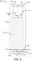
- FIG. 1is a perspective view of a device according to example embodiments of the present disclosure
- the vaporization chamber ( 342 , 442 ) and the cooling chamber ( 344 , 444 )can be configured to have a defined relative volume ratio.
- the volume ratio of the vaporization chamber ( 342 , 442 ) to the cooling chamber ( 344 , 444 )can be about 2:1 to about 1:4, about 1:1 to about 1:4, or about 1:1.5 to about 1:3.
- the cartridge ( 300 , 400 )can be configured such that the mouthpiece wall ( 311 , 411 ) can include a flange positioned between the proximal end ( 313 , 413 ) and the distal end ( 317 , 417 ) thereof.
- a flange 350can be present and can extend circumferentially from the mouthpiece wall 311 around substantially the entirety of the mouthpiece 309 .
- the distance that the flange 350 extends from the mouthpiece wall 311can be substantially uniform around the entire circumference of the mouthpiece 309 .
- the overall cartridge 300 and/or the mouthpiece 309thus may be defined in relation to a total length along the longitudinal axis (L), a total width along the first transverse axis (T 1 ), and a total depth along the second longitudinal axis (T 2 ).
- the lengthmay be greater than the width, which in turn may be greater than the depth.
- the distance that the flange 350 extends away from the mouthpiece wall 311may be greater along the second transverse axis (T 2 ) than along the first transverse axis (T 1 ).
- a distance (d 2 ) between the mouthpiece wall 311 and an outer edge of the flange 350 as measured along the second transverse axis (T 2 )may be greater than a distance (d 1 ) between the mouthpiece wall and an outer edge of the flange as measured along the first transverse axis (T 1 ).
- Said distances (d 1 , d 2 )particularly may be as measured at about a midpoint of each of the first transverse axis (T 1 ) and the second transverse axis (T 2 ).
- a flange 450can be present and can extend circumferentially from the mouthpiece wall 411 around substantially the entirety of the mouthpiece 409 .
- the distance that the flange 450 extends from the mouthpiece wall 411can be substantially uniform around the entire circumference of the mouthpiece 409 .
- the distance that the flange 450 extends from the mouthpiece wall 411can vary at one or more points around the circumference of the mouthpiece 409 .
- the overall cartridge 400 or the mouthpiece 409separately can be defined in relation to a longitudinal axis (L), a first transverse axis (T 1 ) that is perpendicular to the longitudinal axis, and a second transverse axis (T 2 ) that is perpendicular to the longitudinal axis and is perpendicular to the first transverse axis.
- Llongitudinal axis
- T 1first transverse axis
- T 2second transverse axis
- the electrical contacts ( 325 , 425 ), when present in the mouthpiece wall ( 311 , 411 )preferably can be positioned longitudinally between the flange ( 350 , 450 ) and the distal end ( 317 , 417 ) of the mouthpiece ( 309 , 409 ). Further, in some embodiments, the flange ( 350 , 450 ) can be substantially in line with the interior upper wall ( 332 , 432 ). As such, the flange ( 35 , 450 ) can be substantially parallel with and/or may be substantially in the same horizontal plane with the interior upper wall ( 332 , 432 ).
- the first rim wall 122extends downwardly from the proximal end 108 a short distance, which distance can substantially correspond to a thickness of the flange ( 350 , 450 ) of the cartridge ( 300 , 400 ) and/or the thickness of a further element that may be present adjacent the flange.
- the first rim wall 122 forming the downwardly extending recessmay have a height (i.e., as measured from a top surface of the inwardly projecting lip 121 to the first device proximal end 108 ) of about 1 mm to about 8 mm, about 1 mm to about 6 mm, or about 1 mm to about 5 mm.
- the second inwardly projecting lip 121may have a substantially constant width around the entire circumference of the opening 110 .
- the second inwardly extending lip 121may be discontinuous and thus may be formed of one or a plurality of inwardly extending lips spaced around the opening 110 .
- the flange ( 350 , 450 ) and/or the inwardly projecting lip ( 121 , 221 )may be configured to bias the cartridge ( 300 , 400 ) into connection with the device ( 100 , 200 ).
- a magnetic connectionmay be utilized.
- the first cartridge 300may include a first magnet 352 positioned adjacent a bottom surface of the first flange 350
- the second cartridge 400may include a second magnet 452 positioned adjacent a bottom surface of the second flange 450 .
- the magnet ( 352 , 452 )may extend substantially completely around the circumference of the mouthpiece ( 309 , 409 ) or may be discontinuous so as be configured as one or a plurality of discrete magnets.
- the magnet ( 352 , 452 )may be adhered to the mouthpiece wall ( 311 , 411 ), may be adhered to the flange ( 350 , 450 ), or may be adhered to both the mouthpiece wall and the flange.
- the inwardly projecting lip ( 121 , 221 )may be formed of a metal or other material to which the magnet ( 352 , 452 ) will be attracted by magnetic force.
- the magnet ( 352 , 452 )may be positioned on the first device 100 or second device 200 . Specifically, the magnet ( 352 , 452 ) may be adhered to the inwardly extending lip ( 121 , 221 ).
- the flange ( 350 , 450 )may be formed of a metal or other material to which the magnet ( 352 , 452 ) will be attracted by magnetic force.
- the magnet ( 352 , 452 )may be present on the cartridge ( 300 , 400 ) as well as the device ( 100 , 200 ).
- a magnet present adjacent the lower surface of the flange ( 350 , 450 ) on the cartridge ( 300 , 400 )may be attracted by magnetic force to a magnet present adjacent the upper surface of the inwardly projecting lip ( 121 , 221 ) on the device ( 100 , 200 ).
- the combined thickness of the magnet and the flange ( 350 , 450 )is substantially identical to the height of the rim wall ( 122 , 222 ) on the device ( 100 , 200 ) so that an upper surface of flange is substantially flush with the proximal end ( 108 , 208 ) of the device when the cartridge and the device are engaged.
- first device 100 and the second device 200can be configured to be interchangeably connectable with one or both of the first cartridge 300 and the second cartridge 400 (or even further cartridges) such that at least a portion of the tank ( 301 , 401 ) is separately receivable within the chamber ( 112 , 212 ) of the device ( 100 , 200 ) to form the vaporization system in a functioning combination.
- the vaporization systemcan be configured so that different combinations of a device ( 100 , 200 ) and a cartridge ( 300 , 400 ) result in a system with one or more different functionalities.
- two or more cartridges combinable with a single devicemay exhibit one or more different structures and/or functions.
- two or more devices combinable with a single cartridgemay exhibit one or more different structures and/or functions.
- a vaporization systemcomprising at least two devices and at least one cartridge can be configured so that the at least two devices differ from one another in one or more aspects.
- a first control devicecan differ from a second control device in that the first device outer housing and the second device outer housing are each formed of a different material.
- an outer wall of a first device and an outer wall of a second devicecan each have a different surface finish.
- a battery in a first devicecan be different from a battery in a second device (e.g., differing in one or more of battery type, maximum voltage, and capacity).
- a PCBA in a first devicecan be different from a PCBA in a second device (e.g., the PCBA's may differ in one or more of memory, user programmability, heater control capability, and feedback functionality).
- an external connection element of a first devicecan be different from an external connection element on a second device.
- a vaporization systemcomprising at least two cartridges and at least one device can be configured so that the at least two cartridges differ from one another in one or more aspects.
- a first cartridgecan include a first heater, and a second cartridge can include a second heater that is different from the first heater.
- a first cartridgecan include a first tank having a first volume, and a second cartridge can include a second tank having a second volume that is different from the first volume of the first tank.
- a first cartridgecan include a first liquid transport element, and a second cartridge can include a second liquid transport element that is different from the first liquid transport element.
- the device ( 100 , 200 )can be configured in some embodiments so that at least a portion of the tank ( 301 , 401 ) is visible when the cartridge ( 300 , 400 ) is engaged with the device.
- at least a portion of the outer tank wall ( 303 , 403 )can be configured to be at least partially transparent or translucent so that the liquid ( 323 , 423 ) contained therein is visible externally.
- the outer wall ( 104 , 204 ) of the device ( 100 , 200 )can be configured to include a window through which the outer tank wall ( 303 , 403 ) and optionally any liquid ( 323 , 423 ) present in the tank ( 301 , 401 ) can be visible when the cartridge ( 300 , 400 ) is engaged with the device ( 100 , 200 ).
- a first window 135is configured as a cut-out in the outer wall 104 of the device 100 that is positioned near the proximal end 108 of the device. The window preferably is positioned to provide visual access into the first device chamber 112 .
- the window 135may be completely open or the window may have a transparent member (e.g., glass or plastic) positioned in the opening defined by the window or covering the window on one or both of the inner surface and outer surface of the outer wall 104 of the device 100 .
- a transparent membere.g., glass or plastic
- a window 235may be expressly excluded from the device 200 .
- the window 235may be completely open or the window may have a transparent member (e.g., glass or plastic) positioned in the opening defined by the window or covering the window on one or both of the inner surface and outer surface of the outer wall 204 of the device 200 .
- a transparent membere.g., glass or plastic
- the first device 100may include a first light source 139 and at least one opening 137 through the outer wall 104 of the first device through which light from the first light source is visible.
- the first light source 139may comprise, for example, one or more light emitting diodes (LED) capable of providing one or more colors of lighting.
- the first light source 139can be positioned directly on the printed circuit board (PCB) 141 on which further control components (e.g., a microcontroller and/or memory components) may be included.
- the opening 137may be provided in any desired shape and may particularly be positioned near the distal end 106 of the first device 100 .
- the fitmay be such that air is capable of passing between the outer surface of the tank wall ( 303 , 403 ) and the inner surface of the device inner frame ( 112 , 212 ).
- the vaporization system formed by any combination of one or device(s) and one or more cartridge(s)can further include an external connector 500 configured for electrical contact with each of the device external connection element (e.g., first device external connection element 118 and the second device external connection element 218 ).
- the external connector 500can include a first connector end 503 and a second connector end 505 interconnected by a union 507 , which may be, for example, a cord of variable length.
- the first connector end 503can be configured for electrical and, optionally, mechanical connection with the device ( 100 , 200 ).
- the first connector end 503can include an inset wall 503 a that can be received within a well (e.g., first well 106 a at the distal end 106 of the first device 100 or the second well 206 b at the distal end 206 of the second device 200 ) present at the distal end ( 106 , 206 ) of the device ( 100 , 200 ).
- the external connector 500can include a plurality of electrical pins 511 interior to the inset wall 503 a configured for making a charging and/or information transferring connection with the device external connection element ( 118 , 218 ).
- the aerosol precursor compositionmost preferably incorporates tobacco or components derived from tobacco.
- the tobaccomay be provided as parts or pieces of tobacco, such as finely ground, milled or powdered tobacco lamina. Tobacco beads, pellets, or other solid forms may be included, such as described in U.S. Pat. Pub. No. 2015/0335070 to Sears et al., the disclosure of which is incorporated herein by reference.
- the tobaccomay be provided in the form of an extract, such as a spray dried extract that incorporates many of the water soluble components of tobacco.
- tobacco extractsmay have the form of relatively high nicotine content extracts, which extracts also incorporate minor amounts of other extracted components derived from tobacco.
- aerosol precursor compositionsare sold under the brand names BLACK NOTE, COSMIC FOG, THE MILKMAN E-LIQUID, FIVE PAWNS, THE VAPOR CHEF, VAPE WILD, BOOSTED, THE STEAM FACTORY, MECH SAUCE, CASEY JONES MAINLINE RESERVE, MITTEN VAPORS, DR.
Landscapes
- Health & Medical Sciences (AREA)
- Engineering & Computer Science (AREA)
- Life Sciences & Earth Sciences (AREA)
- Animal Behavior & Ethology (AREA)
- Veterinary Medicine (AREA)
- Public Health (AREA)
- Anesthesiology (AREA)
- Biomedical Technology (AREA)
- Heart & Thoracic Surgery (AREA)
- Hematology (AREA)
- General Health & Medical Sciences (AREA)
- Chemical Kinetics & Catalysis (AREA)
- Chemical & Material Sciences (AREA)
- General Chemical & Material Sciences (AREA)
- Bioinformatics & Cheminformatics (AREA)
- Pulmonology (AREA)
- Human Computer Interaction (AREA)
- Disinfection, Sterilisation Or Deodorisation Of Air (AREA)
- Containers And Packaging Bodies Having A Special Means To Remove Contents (AREA)
- Battery Mounting, Suspending (AREA)
- Charge And Discharge Circuits For Batteries Or The Like (AREA)
- Feeding, Discharge, Calcimining, Fusing, And Gas-Generation Devices (AREA)
Abstract
Description
Claims (23)
Priority Applications (16)
| Application Number | Priority Date | Filing Date | Title |
|---|---|---|---|
| US16/189,459US12171261B2 (en) | 2018-10-12 | 2018-11-13 | Vaporization system |
| IL282194AIL282194B2 (en) | 2018-10-12 | 2019-10-10 | Evaporation system |
| MX2021004243AMX2021004243A (en) | 2018-10-12 | 2019-10-10 | VAPORIZATION SYSTEM. |
| NZ775681ANZ775681B2 (en) | 2019-10-10 | Vaporization system | |
| UAA202102084AUA128531C2 (en) | 2018-10-12 | 2019-10-10 | Vaporization system |
| AU2019359552AAU2019359552B2 (en) | 2018-10-12 | 2019-10-10 | Vaporization system |
| BR112021006472-9ABR112021006472A2 (en) | 2018-10-12 | 2019-10-10 | vaporization system |
| PCT/IB2019/058666WO2020075119A1 (en) | 2018-10-12 | 2019-10-10 | Vaporization system |
| JP2021519887AJP7451510B2 (en) | 2018-10-12 | 2019-10-10 | vaporization system |
| EP19787471.2AEP3863450A1 (en) | 2018-10-12 | 2019-10-10 | Vaporization system |
| CA3116169ACA3116169A1 (en) | 2018-10-12 | 2019-10-10 | Vaporization system |
| CN202510048805.1ACN119606062A (en) | 2018-10-12 | 2019-10-10 | Evaporation system |
| KR1020217014347AKR102863838B1 (en) | 2018-10-12 | 2019-10-10 | vaporization system |
| CN201980082961.2ACN113194762B (en) | 2018-10-12 | 2019-10-10 | Evaporation system |
| JP2024032727AJP2024059960A (en) | 2018-10-12 | 2024-03-05 | Vaporization system |
| US18/970,646US20250089778A1 (en) | 2018-10-12 | 2024-12-05 | Vaporization system |
Applications Claiming Priority (2)
| Application Number | Priority Date | Filing Date | Title |
|---|---|---|---|
| US201862744978P | 2018-10-12 | 2018-10-12 | |
| US16/189,459US12171261B2 (en) | 2018-10-12 | 2018-11-13 | Vaporization system |
Related Child Applications (1)
| Application Number | Title | Priority Date | Filing Date |
|---|---|---|---|
| US18/970,646ContinuationUS20250089778A1 (en) | 2018-10-12 | 2024-12-05 | Vaporization system |
Publications (2)
| Publication Number | Publication Date |
|---|---|
| US20200113240A1 US20200113240A1 (en) | 2020-04-16 |
| US12171261B2true US12171261B2 (en) | 2024-12-24 |
Family
ID=87517836
Family Applications (2)
| Application Number | Title | Priority Date | Filing Date |
|---|---|---|---|
| US16/189,459Active2041-03-01US12171261B2 (en) | 2018-10-12 | 2018-11-13 | Vaporization system |
| US18/970,646PendingUS20250089778A1 (en) | 2018-10-12 | 2024-12-05 | Vaporization system |
Family Applications After (1)
| Application Number | Title | Priority Date | Filing Date |
|---|---|---|---|
| US18/970,646PendingUS20250089778A1 (en) | 2018-10-12 | 2024-12-05 | Vaporization system |
Country Status (12)
| Country | Link |
|---|---|
| US (2) | US12171261B2 (en) |
| EP (1) | EP3863450A1 (en) |
| JP (2) | JP7451510B2 (en) |
| KR (1) | KR102863838B1 (en) |
| CN (2) | CN119606062A (en) |
| AU (1) | AU2019359552B2 (en) |
| BR (1) | BR112021006472A2 (en) |
| CA (1) | CA3116169A1 (en) |
| IL (1) | IL282194B2 (en) |
| MX (1) | MX2021004243A (en) |
| UA (1) | UA128531C2 (en) |
| WO (1) | WO2020075119A1 (en) |
Families Citing this family (3)
| Publication number | Priority date | Publication date | Assignee | Title |
|---|---|---|---|---|
| GB201917441D0 (en)* | 2019-11-29 | 2020-01-15 | Nicoventures Trading Ltd | Aerosol provision system |
| KR102437768B1 (en)* | 2019-12-27 | 2022-08-29 | 주식회사 케이티앤지 | Aerosol generating device |
| KR20230008835A (en)* | 2020-05-18 | 2023-01-16 | 필립모리스 프로덕츠 에스.에이. | Mouthpiece for aerosol generating device |
Citations (110)
| Publication number | Priority date | Publication date | Assignee | Title |
|---|---|---|---|---|
| US2057353A (en) | 1936-10-13 | Vaporizing unit fob therapeutic | ||
| US2104266A (en) | 1935-09-23 | 1938-01-04 | William J Mccormick | Means for the production and inhalation of tobacco fumes |
| US3200819A (en) | 1963-04-17 | 1965-08-17 | Herbert A Gilbert | Smokeless non-tobacco cigarette |
| US4922901A (en) | 1988-09-08 | 1990-05-08 | R. J. Reynolds Tobacco Company | Drug delivery articles utilizing electrical energy |
| US5060671A (en) | 1989-12-01 | 1991-10-29 | Philip Morris Incorporated | Flavor generating article |
| US5093894A (en) | 1989-12-01 | 1992-03-03 | Philip Morris Incorporated | Electrically-powered linear heating element |
| US5894841A (en) | 1993-06-29 | 1999-04-20 | Ponwell Enterprises Limited | Dispenser |
| US6125853A (en) | 1996-06-17 | 2000-10-03 | Japan Tobacco, Inc. | Flavor generation device |
| US6155268A (en) | 1997-07-23 | 2000-12-05 | Japan Tobacco Inc. | Flavor-generating device |
| WO2004080216A1 (en) | 2003-03-14 | 2004-09-23 | Best Partners Worldwide Limited | A flameless electronic atomizing cigarette |
| CN1541577A (en) | 2003-04-29 | 2004-11-03 | Non-combustible electronic spray cigarette | |
| US20050016550A1 (en) | 2003-07-17 | 2005-01-27 | Makoto Katase | Electronic cigarette |
| CN2719043Y (en) | 2004-04-14 | 2005-08-24 | 韩力 | Atomized electronic cigarette |
| US7117867B2 (en) | 1998-10-14 | 2006-10-10 | Philip Morris Usa | Aerosol generator and methods of making and using an aerosol generator |
| WO2007131449A1 (en) | 2006-05-16 | 2007-11-22 | Li Han | Aerosol electronic cigrarette |
| US20080092912A1 (en) | 2006-10-18 | 2008-04-24 | R. J. Reynolds Tobacco Company | Tobacco-Containing Smoking Article |
| US20090151717A1 (en) | 2007-12-18 | 2009-06-18 | Adam Bowen | Aerosol devices and methods for inhaling a substance and uses thereof |
| US20090188490A1 (en) | 2006-11-10 | 2009-07-30 | Li Han | Aerosolizing Inhalation Device |
| US20090272379A1 (en) | 2008-04-30 | 2009-11-05 | Philip Morris Usa Inc. | Electrically heated smoking system having a liquid storage portion |
| US20090320863A1 (en) | 2008-04-17 | 2009-12-31 | Philip Morris Usa Inc. | Electrically heated smoking system |
| CN201379072Y (en) | 2009-02-11 | 2010-01-13 | 韩力 | An improved atomized electronic cigarette |
| US20110094523A1 (en)* | 2009-10-27 | 2011-04-28 | Philip Morris Usa Inc. | Smoking system having a liquid storage portion |
| US20110126848A1 (en) | 2009-11-27 | 2011-06-02 | Philip Morris Usa Inc. | Electrically heated smoking system with internal or external heater |
| US20110155718A1 (en) | 2009-12-30 | 2011-06-30 | Philip Morris Usa Inc. | Shaped heater for an aerosol generating system |
| US20110265806A1 (en) | 2010-04-30 | 2011-11-03 | Ramon Alarcon | Electronic smoking device |
| US8314591B2 (en) | 2010-05-15 | 2012-11-20 | Nathan Andrew Terry | Charging case for a personal vaporizing inhaler |
| US20130037041A1 (en) | 2011-08-09 | 2013-02-14 | R. J. Reynolds Tobacco Company | Smoking articles and use thereof for yielding inhalation materials |
| US20130042865A1 (en)* | 2011-08-16 | 2013-02-21 | Ploom, Inc. | Low temperature electronic vaporization device and methods |
| US20130087160A1 (en)* | 2011-10-06 | 2013-04-11 | Alexandru Gherghe | Electronic pipe personal vaporizer with concealed removable atomizer/ cartomizer |
| US20130168880A1 (en)* | 2011-12-29 | 2013-07-04 | Brent Duke | Electronic vaporizing device |
| US8499766B1 (en) | 2010-09-15 | 2013-08-06 | Kyle D. Newton | Electronic cigarette with function illuminator |
| US8528569B1 (en) | 2011-06-28 | 2013-09-10 | Kyle D. Newton | Electronic cigarette with liquid reservoir |
| US20130306084A1 (en) | 2010-12-24 | 2013-11-21 | Philip Morris Products S.A. | Aerosol generating system with means for disabling consumable |
| US20130319435A1 (en) | 2010-12-24 | 2013-12-05 | Philip Morris Products Sa | Aerosol generating system having means for handling consumption of a liquid subtrate |
| US20140000638A1 (en) | 2012-06-28 | 2014-01-02 | R.J. Reynolds Tobacco Company | Reservoir and heater system for controllable delivery of multiple aerosolizable materials in an electronic smoking article |
| US20140041655A1 (en) | 2012-08-11 | 2014-02-13 | Grenco Science, Inc | Portable Vaporizer |
| US20140096782A1 (en) | 2012-10-08 | 2014-04-10 | R.J. Reynolds Tobacco Company | Electronic smoking article and associated method |
| US20140096781A1 (en) | 2012-10-08 | 2014-04-10 | R. J. Reynolds Tobacco Company | Electronic smoking article and associated method |
| US20140253144A1 (en) | 2013-03-07 | 2014-09-11 | R.J. Reynolds Tobacco Company | Spent cartridge detection method and system for an electronic smoking article |
| US8833364B2 (en) | 2008-10-23 | 2014-09-16 | Batmark Limited | Inhaler |
| US20140261408A1 (en) | 2013-03-15 | 2014-09-18 | R.J. Reynolds Tobacco Company | Cartridge for an aerosol delivery device and method for assembling a cartridge for a smoking article |
| US20140261487A1 (en) | 2013-03-14 | 2014-09-18 | R. J. Reynolds Tobacco Company | Electronic smoking article with improved storage and transport of aerosol precursor compositions |
| US20140261486A1 (en) | 2013-03-12 | 2014-09-18 | R.J. Reynolds Tobacco Company | Electronic smoking article having a vapor-enhancing apparatus and associated method |
| US20140366898A1 (en) | 2013-06-14 | 2014-12-18 | Ploom, Inc. | Multiple heating elements with separate vaporizable materials in an electric vaporization device |
| US20150020832A1 (en) | 2012-01-03 | 2015-01-22 | Philip Morris Products S.A. | Aerosol-generating device and system |
| CN104621716A (en) | 2013-11-12 | 2015-05-20 | Vmr产品有限责任公司 | Evaporator |
| US20150150308A1 (en) | 2005-07-19 | 2015-06-04 | Ploom, Inc. | Method and system for vaporization of a substance |
| US20150164142A1 (en) | 2013-12-13 | 2015-06-18 | Shenzhen First Union Technology Co., Ltd. | Electronic cigarette, atomizing device, power pole and charger connector |
| US20150208729A1 (en) | 2013-12-23 | 2015-07-30 | Ploom, Inc. | Vaporization device systems and methods |
| US20150313287A1 (en) | 2014-05-01 | 2015-11-05 | Vmr Products Llc | Vaporizer |
| US9220304B2 (en) | 2012-01-03 | 2015-12-29 | Philip Morris Products S.A. | Power supply system for portable aerosol-generating device |
| WO2016026811A1 (en) | 2014-08-21 | 2016-02-25 | Philip Morris Products Sa | Aerosol-generating device and system |
| KR20160082576A (en) | 2014-12-30 | 2016-07-08 | 김한기 | Structure for Supplying Nicotine Solution in Electric Cigarette |
| US9462831B2 (en) | 2013-07-15 | 2016-10-11 | Huizhou Kimree Technology Co., Ltd. Shenzhen Branch | Electronic cigarette and electrode assembly thereof |
| US20160345629A1 (en)* | 2014-02-10 | 2016-12-01 | Philip Morris Products S.A. | Aerosol-generating system comprising a device and a cartridge, in which the device ensures electrical contact with the cartridge |
| US20170027226A1 (en) | 2014-02-10 | 2017-02-02 | Philip Morris Products S.A. | Aerosol-generating system having a fluid-permeable heater assembly |
| US20170071256A1 (en) | 2014-05-01 | 2017-03-16 | Vmr Products Llc | Vaporizer |
| WO2017051006A1 (en) | 2015-09-24 | 2017-03-30 | Philip Morris Products S.A. | Aerosol-generating device with electrodes for measuring an electrical load |
| US20170095005A1 (en) | 2013-12-23 | 2017-04-06 | James Monsees | Vaporization device systems and methods |
| US20170135404A1 (en) | 2015-11-17 | 2017-05-18 | Tony Reevell | Cartridge for an aerosol-generating system with identification inductor |
| US20170135405A1 (en) | 2015-11-17 | 2017-05-18 | Tony Reevell | Cartridge for an aerosol-generating system with customizable indentification resistance |
| US20170143042A1 (en) | 2014-07-11 | 2017-05-25 | Philip Morris Products S.A. | Aerosol-generating system comprising a removable heater |
| US20170215485A1 (en) | 2014-10-14 | 2017-08-03 | Fontem Holdings 1 B.V. | Electronic smoking device and capsule |
| US20170231282A1 (en) | 2013-03-15 | 2017-08-17 | Pax Labs, Inc. | Securely attaching cartridges for vaporizer devices |
| US20170231281A1 (en) | 2013-03-15 | 2017-08-17 | Pax Labs, Inc. | Vaporizer devices with blow discrimination |
| CN107072314A (en) | 2014-07-11 | 2017-08-18 | Rai策略控股有限公司 | Heater for aerosol delivery device and method of forming same |
| US9737093B2 (en) | 2012-04-26 | 2017-08-22 | Fontem Holdings 1 B.V. | Electronic cigarette with sealed cartridge |
| US20170251722A1 (en) | 2016-03-03 | 2017-09-07 | Altria Client Services Llc | Flavor assembly for electronic vaping device |
| US20170325289A1 (en) | 2014-11-14 | 2017-11-09 | Huizhou Kimree Technology Co., Ltd. | Electronic cigarette and atomization control method thereof |
| JP2017533726A (en) | 2014-11-17 | 2017-11-16 | マクニール アーベーMcneil Ab | Disposable cartridge for use in electronic nicotine delivery system |
| US20170340012A1 (en) | 2016-05-31 | 2017-11-30 | Oleg Mironov | Fluid permeable heater assembly for aerosol-generating systems and flat electrically conductive filament arrangement for fluid permeable heater assemblies |
| US20170340011A1 (en)* | 2016-05-31 | 2017-11-30 | Rui Nuno BATISTA | Heater and wick assembly for an aerosol generating system |
| US20170347711A1 (en) | 2014-12-29 | 2017-12-07 | British American Tobacco (Investments) Limited | Cartridge for use with apparatus for heating smokable material |
| WO2017207442A1 (en) | 2016-05-31 | 2017-12-07 | Philip Morris Products S.A. | Electrically operated aerosol-generating system with means to detect a tubular aerosol-generating article |
| US20170347712A1 (en) | 2014-12-29 | 2017-12-07 | British American Tobacco (Investments) Limited | Apparatus for heating smokable material |
| US20180000160A1 (en) | 2016-06-16 | 2018-01-04 | Pax Labs, Inc. | On-demand, portable convection vaporizer |
| US20180000157A1 (en) | 2015-01-28 | 2018-01-04 | Philip Morris Products S.A. | Aerosol-generating article with integral heating element |
| US20180014575A1 (en) | 2016-07-14 | 2018-01-18 | Oleg FURSA | Fluid permeable heater assembly and cartridge for an aerosol-generating system |
| US20180020731A1 (en) | 2016-07-25 | 2018-01-25 | Dennis Rasmussen | Electronic cigarette power supply portion |
| US20180020736A1 (en) | 2016-07-25 | 2018-01-25 | Patrick Charles SILVESTRINI | Cartridge for an aerosol-generating system with heater protection |
| US9877508B2 (en) | 2013-03-15 | 2018-01-30 | Altria Client Services Llc | Electronic cigarette |
| US20180035717A1 (en) | 2014-12-15 | 2018-02-08 | Philip Morris Products S.A. | E-liquid collapsible cartridge |
| US20180043114A1 (en) | 2016-05-25 | 2018-02-15 | Juul Labs, Inc. | Control of an electronic vaporizer |
| US20180042306A1 (en) | 2016-08-05 | 2018-02-15 | Juul Labs, Inc. | Anemometric-assisted control of a vaporizer |
| US20180077967A1 (en) | 2016-09-22 | 2018-03-22 | Pax Labs, Inc. | Leak-resistant vaporizer device |
| US20180084828A1 (en) | 2016-09-23 | 2018-03-29 | Rai Strategic Holdings, Inc. | Aerosol delivery device with replaceable wick and heater assembly |
| US20180084831A1 (en) | 2015-04-07 | 2018-03-29 | Philip Morris Products S.A. | Sachet of aerosol-forming substrate, method of manufacturing same, and aerosol-generating device for use with sachet |
| US20180103685A1 (en)* | 2015-04-22 | 2018-04-19 | Fontem Holdings 1 B.V. | Electronic smoking device |
| US20180132525A1 (en) | 2016-11-11 | 2018-05-17 | Altria Client Services Llc | Electronic vaping device and connector assembly |
| US20180140019A1 (en) | 2016-11-24 | 2018-05-24 | Shenzhen First Union Technology Co., Ltd. | Atomizer and electronic cigarette having same |
| US20180153220A1 (en) | 2016-12-02 | 2018-06-07 | Vmr Products Llc | Vaporizer with cartridge |
| US20180177230A1 (en) | 2016-12-27 | 2018-06-28 | Altria Client Services Llc | E-vaping device including e-vaping case with sliding mechanism for initiating vapor generation |
| CN108289505A (en) | 2015-10-15 | 2018-07-17 | 方特慕控股第私人有限公司 | Electronic cigarette with multicell liquid memory |
| US10028537B1 (en) | 2015-04-22 | 2018-07-24 | Altria Client Services Llc | Pod assembly, dispensing body, and E-vapor apparatus including the same |
| US20180213850A1 (en) | 2014-05-23 | 2018-08-02 | Rai Strategic Holdings, Inc. | Sealed cartridge for an aerosol delivery device and related assembly method |
| US10058125B2 (en) | 2015-10-13 | 2018-08-28 | Rai Strategic Holdings, Inc. | Method for assembling an aerosol delivery device |
| US20180242643A1 (en) | 2017-02-24 | 2018-08-30 | Patrick Charles SILVESSTRINI | Cartridge with mount for an aerosol-generating element in an aerosol-generating system |
| US10076139B2 (en) | 2013-12-23 | 2018-09-18 | Juul Labs, Inc. | Vaporizer apparatus |
| WO2018167166A1 (en) | 2017-03-16 | 2018-09-20 | Project Paradise Limited | A mouthpiece and heater assembly for an inhalation device |
| US10080851B2 (en) | 2014-06-30 | 2018-09-25 | Syqe Medical Ltd. | Method and device for vaporization and inhalation of isolated substances |
| US20180280637A1 (en) | 2017-03-28 | 2018-10-04 | Advanced Grow Labs Technologies, Llc | Vaporizing device system and method |
| US10092037B2 (en) | 2012-01-31 | 2018-10-09 | Altria Client Services Llc | Electronic cigarette |
| US20180295888A1 (en) | 2015-04-22 | 2018-10-18 | Altria Client Services Llc | Pod assembly and e-vapor apparatus including the same |
| US20180296777A1 (en) | 2010-05-15 | 2018-10-18 | Rai Strategic Holdings, Inc. | Vaporizer related systems, methods, and apparatus |
| US10104913B2 (en) | 2015-04-22 | 2018-10-23 | Altria Client Services Llc | Pod assembly, dispensing body, and E-vapor apparatus including the same |
| US10117463B2 (en) | 2014-01-03 | 2018-11-06 | Robert P Thomas, Jr. | Vapor delivery device |
| WO2018202732A1 (en) | 2017-05-02 | 2018-11-08 | Philip Morris Products S.A. | Aerosol-generating system with case |
| US10206429B2 (en) | 2015-07-24 | 2019-02-19 | Rai Strategic Holdings, Inc. | Aerosol delivery device with radiant heating |
| US10279934B2 (en) | 2013-03-15 | 2019-05-07 | Juul Labs, Inc. | Fillable vaporizer cartridge and method of filling |
| US11089660B2 (en) | 2015-01-22 | 2021-08-10 | Fontem Holdings 1 B.V. | Electronic vaporization devices |
Family Cites Families (50)
| Publication number | Priority date | Publication date | Assignee | Title |
|---|---|---|---|---|
| US4735217A (en) | 1986-08-21 | 1988-04-05 | The Procter & Gamble Company | Dosing device to provide vaporized medicament to the lungs as a fine aerosol |
| US4947874A (en) | 1988-09-08 | 1990-08-14 | R. J. Reynolds Tobacco Company | Smoking articles utilizing electrical energy |
| US5154192A (en) | 1989-07-18 | 1992-10-13 | Philip Morris Incorporated | Thermal indicators for smoking articles and the method of application of the thermal indicators to the smoking article |
| US5261424A (en) | 1991-05-31 | 1993-11-16 | Philip Morris Incorporated | Control device for flavor-generating article |
| US5372148A (en) | 1993-02-24 | 1994-12-13 | Philip Morris Incorporated | Method and apparatus for controlling the supply of energy to a heating load in a smoking article |
| US5934289A (en) | 1996-10-22 | 1999-08-10 | Philip Morris Incorporated | Electronic smoking system |
| US6040560A (en) | 1996-10-22 | 2000-03-21 | Philip Morris Incorporated | Power controller and method of operating an electrical smoking system |
| US5954979A (en) | 1997-10-16 | 1999-09-21 | Philip Morris Incorporated | Heater fixture of an electrical smoking system |
| US5967148A (en) | 1997-10-16 | 1999-10-19 | Philip Morris Incorporated | Lighter actuation system |
| EP2295619B1 (en) | 2001-01-26 | 2014-04-23 | MEMC Electronic Materials, Inc. | Process for producing Low Defect Density Silicon Having a Vacancy-Dominated Core Substantially Free of Oxidation Induced Stacking Faults |
| CN1700934B (en) | 2002-09-06 | 2011-08-03 | 菲利普莫里斯美国公司 | Liquid aerosol preparation and aerosol generating device and method for preparing aerosol |
| EP2100525A1 (en) | 2008-03-14 | 2009-09-16 | Philip Morris Products S.A. | Electrically heated aerosol generating system and method |
| EP2143346A1 (en) | 2008-07-08 | 2010-01-13 | Philip Morris Products S.A. | A flow sensor system |
| WO2010009469A2 (en) | 2008-07-18 | 2010-01-21 | Peckerar Martin C | Thin flexible rechargeable electrochemical energy cell and method of fabrication |
| EP2201850A1 (en) | 2008-12-24 | 2010-06-30 | Philip Morris Products S.A. | An article including identification information for use in an electrically heated smoking system |
| CN101518361B (en) | 2009-03-24 | 2010-10-06 | 北京格林世界科技发展有限公司 | High-simulation electronic cigarette |
| US9254002B2 (en) | 2009-08-17 | 2016-02-09 | Chong Corporation | Tobacco solution for vaporized inhalation |
| US9420895B2 (en) | 2009-12-17 | 2016-08-23 | Stryker Corporation | Patient support |
| CN102349699B (en) | 2011-07-04 | 2013-07-03 | 郑俊祥 | Preparation method for electronic cigarette liquid |
| US20130180553A1 (en) | 2012-01-12 | 2013-07-18 | Meiko Maschinenbau Gmbh & Co. Kg | Dishwasher |
| WO2013138384A2 (en) | 2012-03-12 | 2013-09-19 | Uptoke Llc | Electronic vaporizing device and methods for use |
| KR20140063532A (en) | 2012-03-23 | 2014-05-27 | 엔조이, 인코포레이티드 | Electronic cigarette configured to simulate the natural burn of a traditional cigarette |
| US20130255702A1 (en) | 2012-03-28 | 2013-10-03 | R.J. Reynolds Tobacco Company | Smoking article incorporating a conductive substrate |
| US8881737B2 (en) | 2012-09-04 | 2014-11-11 | R.J. Reynolds Tobacco Company | Electronic smoking article comprising one or more microheaters |
| US11457605B2 (en) | 2012-09-11 | 2022-10-04 | Pioneer Pet Products, Llc | Extruded self-clumping cat litter |
| US10058122B2 (en)* | 2012-10-25 | 2018-08-28 | Matthew Steingraber | Electronic cigarette |
| US20140123989A1 (en) | 2012-11-05 | 2014-05-08 | The Safe Cig, Llc | Device and method for vaporizing a fluid |
| US8910640B2 (en) | 2013-01-30 | 2014-12-16 | R.J. Reynolds Tobacco Company | Wick suitable for use in an electronic smoking article |
| US9423152B2 (en) | 2013-03-15 | 2016-08-23 | R. J. Reynolds Tobacco Company | Heating control arrangement for an electronic smoking article and associated system and method |
| US9609893B2 (en) | 2013-03-15 | 2017-04-04 | Rai Strategic Holdings, Inc. | Cartridge and control body of an aerosol delivery device including anti-rotation mechanism and related method |
| US9491974B2 (en) | 2013-03-15 | 2016-11-15 | Rai Strategic Holdings, Inc. | Heating elements formed from a sheet of a material and inputs and methods for the production of atomizers |
| CN105263345A (en) | 2013-05-06 | 2016-01-20 | 派克斯实验公司 | Nicotine salt formulations for aerosol devices and methods thereof |
| US11229239B2 (en) | 2013-07-19 | 2022-01-25 | Rai Strategic Holdings, Inc. | Electronic smoking article with haptic feedback |
| UA122320C2 (en) | 2013-07-19 | 2020-10-26 | Олтріа Клайєнт Сервісиз Ллк | Liquid aerosol formulation of an electronic smoking article |
| US10251422B2 (en) | 2013-07-22 | 2019-04-09 | Altria Client Services Llc | Electronic smoking article |
| US20150216232A1 (en) | 2014-02-03 | 2015-08-06 | R.J. Reynolds Tobacco Company | Aerosol Delivery Device Comprising Multiple Outer Bodies and Related Assembly Method |
| US9451791B2 (en) | 2014-02-05 | 2016-09-27 | Rai Strategic Holdings, Inc. | Aerosol delivery device with an illuminated outer surface and related method |
| US9839238B2 (en) | 2014-02-28 | 2017-12-12 | Rai Strategic Holdings, Inc. | Control body for an electronic smoking article |
| US11696604B2 (en) | 2014-03-13 | 2023-07-11 | Rai Strategic Holdings, Inc. | Aerosol delivery device and related method and computer program product for controlling an aerosol delivery device based on input characteristics |
| US20150335070A1 (en) | 2014-05-20 | 2015-11-26 | R.J. Reynolds Tobacco Company | Electrically-powered aerosol delivery system |
| US10500600B2 (en) | 2014-12-09 | 2019-12-10 | Rai Strategic Holdings, Inc. | Gesture recognition user interface for an aerosol delivery device |
| JP6637486B2 (en)* | 2015-04-02 | 2020-01-29 | 日本たばこ産業株式会社 | Flavor inhaler |
| GB201511361D0 (en)* | 2015-06-29 | 2015-08-12 | Nicoventures Holdings Ltd | Electronic vapour provision system |
| CN204949520U (en)* | 2015-08-14 | 2016-01-13 | 深圳威铂利科技有限公司 | Novel electronic cigarette |
| US10092036B2 (en) | 2015-12-28 | 2018-10-09 | Rai Strategic Holdings, Inc. | Aerosol delivery device including a housing and a coupler |
| US10194694B2 (en)* | 2016-01-05 | 2019-02-05 | Rai Strategic Holdings, Inc. | Aerosol delivery device with improved fluid transport |
| DE202016101676U1 (en)* | 2016-03-29 | 2016-05-04 | Marco Born | Mouthpiece for an electronic cigarette or e-hookah |
| US9795169B1 (en)* | 2016-07-05 | 2017-10-24 | Xiaochun Zhu | Replaceable vaporizer assembly and electronic cigarette having the same |
| CN208425510U (en)* | 2016-07-25 | 2019-01-25 | 惠州市吉瑞科技有限公司深圳分公司 | an atomizing component |
| JP7256738B2 (en)* | 2016-07-25 | 2023-04-12 | フィリップ・モーリス・プロダクツ・ソシエテ・アノニム | heater management |
- 2018
- 2018-11-13USUS16/189,459patent/US12171261B2/enactiveActive
- 2019
- 2019-10-10JPJP2021519887Apatent/JP7451510B2/enactiveActive
- 2019-10-10ILIL282194Apatent/IL282194B2/enunknown
- 2019-10-10CNCN202510048805.1Apatent/CN119606062A/enactivePending
- 2019-10-10BRBR112021006472-9Apatent/BR112021006472A2/enactiveSearch and Examination
- 2019-10-10WOPCT/IB2019/058666patent/WO2020075119A1/ennot_activeCeased
- 2019-10-10EPEP19787471.2Apatent/EP3863450A1/enactivePending
- 2019-10-10KRKR1020217014347Apatent/KR102863838B1/enactiveActive
- 2019-10-10UAUAA202102084Apatent/UA128531C2/enunknown
- 2019-10-10CACA3116169Apatent/CA3116169A1/enactivePending
- 2019-10-10CNCN201980082961.2Apatent/CN113194762B/enactiveActive
- 2019-10-10MXMX2021004243Apatent/MX2021004243A/enunknown
- 2019-10-10AUAU2019359552Apatent/AU2019359552B2/enactiveActive
- 2024
- 2024-03-05JPJP2024032727Apatent/JP2024059960A/enactivePending
- 2024-12-05USUS18/970,646patent/US20250089778A1/enactivePending
Patent Citations (126)
| Publication number | Priority date | Publication date | Assignee | Title |
|---|---|---|---|---|
| US2057353A (en) | 1936-10-13 | Vaporizing unit fob therapeutic | ||
| US2104266A (en) | 1935-09-23 | 1938-01-04 | William J Mccormick | Means for the production and inhalation of tobacco fumes |
| US3200819A (en) | 1963-04-17 | 1965-08-17 | Herbert A Gilbert | Smokeless non-tobacco cigarette |
| US4922901A (en) | 1988-09-08 | 1990-05-08 | R. J. Reynolds Tobacco Company | Drug delivery articles utilizing electrical energy |
| US5060671A (en) | 1989-12-01 | 1991-10-29 | Philip Morris Incorporated | Flavor generating article |
| US5093894A (en) | 1989-12-01 | 1992-03-03 | Philip Morris Incorporated | Electrically-powered linear heating element |
| US5894841A (en) | 1993-06-29 | 1999-04-20 | Ponwell Enterprises Limited | Dispenser |
| US6125853A (en) | 1996-06-17 | 2000-10-03 | Japan Tobacco, Inc. | Flavor generation device |
| US6155268A (en) | 1997-07-23 | 2000-12-05 | Japan Tobacco Inc. | Flavor-generating device |
| US7117867B2 (en) | 1998-10-14 | 2006-10-10 | Philip Morris Usa | Aerosol generator and methods of making and using an aerosol generator |
| WO2004080216A1 (en) | 2003-03-14 | 2004-09-23 | Best Partners Worldwide Limited | A flameless electronic atomizing cigarette |
| CN1541577A (en) | 2003-04-29 | 2004-11-03 | Non-combustible electronic spray cigarette | |
| EP1618803A1 (en) | 2003-04-29 | 2006-01-25 | Lik Hon | A flameless electronic atomizing cigarette |
| US20060196518A1 (en) | 2003-04-29 | 2006-09-07 | Lik Hon | Flameless electronic atomizing cigarette |
| US20050016550A1 (en) | 2003-07-17 | 2005-01-27 | Makoto Katase | Electronic cigarette |
| US20110168194A1 (en) | 2004-04-14 | 2011-07-14 | Lik Hon | Electronic atomization cigarette |
| US7832410B2 (en) | 2004-04-14 | 2010-11-16 | Best Partners Worldwide Limited | Electronic atomization cigarette |
| CN2719043Y (en) | 2004-04-14 | 2005-08-24 | 韩力 | Atomized electronic cigarette |
| WO2005099494A1 (en) | 2004-04-14 | 2005-10-27 | Lik Hon | An aerosol electronic cigarette |
| US20150150308A1 (en) | 2005-07-19 | 2015-06-04 | Ploom, Inc. | Method and system for vaporization of a substance |
| WO2007131449A1 (en) | 2006-05-16 | 2007-11-22 | Li Han | Aerosol electronic cigrarette |
| US20090095311A1 (en) | 2006-05-16 | 2009-04-16 | Li Han | Aerosol Electronic Cigarette |
| US20090126745A1 (en) | 2006-05-16 | 2009-05-21 | Lik Hon | Emulation Aerosol Sucker |
| US8365742B2 (en) | 2006-05-16 | 2013-02-05 | Ruyan Investment (Holdings) Limited | Aerosol electronic cigarette |
| US20080092912A1 (en) | 2006-10-18 | 2008-04-24 | R. J. Reynolds Tobacco Company | Tobacco-Containing Smoking Article |
| US20090188490A1 (en) | 2006-11-10 | 2009-07-30 | Li Han | Aerosolizing Inhalation Device |
| US20090151717A1 (en) | 2007-12-18 | 2009-06-18 | Adam Bowen | Aerosol devices and methods for inhaling a substance and uses thereof |
| US20090320863A1 (en) | 2008-04-17 | 2009-12-31 | Philip Morris Usa Inc. | Electrically heated smoking system |
| US20090272379A1 (en) | 2008-04-30 | 2009-11-05 | Philip Morris Usa Inc. | Electrically heated smoking system having a liquid storage portion |
| US8833364B2 (en) | 2008-10-23 | 2014-09-16 | Batmark Limited | Inhaler |
| CN201379072Y (en) | 2009-02-11 | 2010-01-13 | 韩力 | An improved atomized electronic cigarette |
| US20110094523A1 (en)* | 2009-10-27 | 2011-04-28 | Philip Morris Usa Inc. | Smoking system having a liquid storage portion |
| US20110126848A1 (en) | 2009-11-27 | 2011-06-02 | Philip Morris Usa Inc. | Electrically heated smoking system with internal or external heater |
| US20110155718A1 (en) | 2009-12-30 | 2011-06-30 | Philip Morris Usa Inc. | Shaped heater for an aerosol generating system |
| US20110265806A1 (en) | 2010-04-30 | 2011-11-03 | Ramon Alarcon | Electronic smoking device |
| US8314591B2 (en) | 2010-05-15 | 2012-11-20 | Nathan Andrew Terry | Charging case for a personal vaporizing inhaler |
| US20180296777A1 (en) | 2010-05-15 | 2018-10-18 | Rai Strategic Holdings, Inc. | Vaporizer related systems, methods, and apparatus |
| US8499766B1 (en) | 2010-09-15 | 2013-08-06 | Kyle D. Newton | Electronic cigarette with function illuminator |
| US20130306084A1 (en) | 2010-12-24 | 2013-11-21 | Philip Morris Products S.A. | Aerosol generating system with means for disabling consumable |
| US20130319435A1 (en) | 2010-12-24 | 2013-12-05 | Philip Morris Products Sa | Aerosol generating system having means for handling consumption of a liquid subtrate |
| US8528569B1 (en) | 2011-06-28 | 2013-09-10 | Kyle D. Newton | Electronic cigarette with liquid reservoir |
| US20130037041A1 (en) | 2011-08-09 | 2013-02-14 | R. J. Reynolds Tobacco Company | Smoking articles and use thereof for yielding inhalation materials |
| US20130042865A1 (en)* | 2011-08-16 | 2013-02-21 | Ploom, Inc. | Low temperature electronic vaporization device and methods |
| US20130087160A1 (en)* | 2011-10-06 | 2013-04-11 | Alexandru Gherghe | Electronic pipe personal vaporizer with concealed removable atomizer/ cartomizer |
| US20130168880A1 (en)* | 2011-12-29 | 2013-07-04 | Brent Duke | Electronic vaporizing device |
| US9220304B2 (en) | 2012-01-03 | 2015-12-29 | Philip Morris Products S.A. | Power supply system for portable aerosol-generating device |
| US20150020832A1 (en) | 2012-01-03 | 2015-01-22 | Philip Morris Products S.A. | Aerosol-generating device and system |
| US10092037B2 (en) | 2012-01-31 | 2018-10-09 | Altria Client Services Llc | Electronic cigarette |
| US9737093B2 (en) | 2012-04-26 | 2017-08-22 | Fontem Holdings 1 B.V. | Electronic cigarette with sealed cartridge |
| US20140000638A1 (en) | 2012-06-28 | 2014-01-02 | R.J. Reynolds Tobacco Company | Reservoir and heater system for controllable delivery of multiple aerosolizable materials in an electronic smoking article |
| US20140041655A1 (en) | 2012-08-11 | 2014-02-13 | Grenco Science, Inc | Portable Vaporizer |
| US20140096781A1 (en) | 2012-10-08 | 2014-04-10 | R. J. Reynolds Tobacco Company | Electronic smoking article and associated method |
| US20140096782A1 (en) | 2012-10-08 | 2014-04-10 | R.J. Reynolds Tobacco Company | Electronic smoking article and associated method |
| US20140253144A1 (en) | 2013-03-07 | 2014-09-11 | R.J. Reynolds Tobacco Company | Spent cartridge detection method and system for an electronic smoking article |
| US20140261486A1 (en) | 2013-03-12 | 2014-09-18 | R.J. Reynolds Tobacco Company | Electronic smoking article having a vapor-enhancing apparatus and associated method |
| US20140261487A1 (en) | 2013-03-14 | 2014-09-18 | R. J. Reynolds Tobacco Company | Electronic smoking article with improved storage and transport of aerosol precursor compositions |
| US20140261408A1 (en) | 2013-03-15 | 2014-09-18 | R.J. Reynolds Tobacco Company | Cartridge for an aerosol delivery device and method for assembling a cartridge for a smoking article |
| US10279934B2 (en) | 2013-03-15 | 2019-05-07 | Juul Labs, Inc. | Fillable vaporizer cartridge and method of filling |
| US9877508B2 (en) | 2013-03-15 | 2018-01-30 | Altria Client Services Llc | Electronic cigarette |
| US20170231282A1 (en) | 2013-03-15 | 2017-08-17 | Pax Labs, Inc. | Securely attaching cartridges for vaporizer devices |
| US20170231281A1 (en) | 2013-03-15 | 2017-08-17 | Pax Labs, Inc. | Vaporizer devices with blow discrimination |
| US20140366898A1 (en) | 2013-06-14 | 2014-12-18 | Ploom, Inc. | Multiple heating elements with separate vaporizable materials in an electric vaporization device |
| US9462831B2 (en) | 2013-07-15 | 2016-10-11 | Huizhou Kimree Technology Co., Ltd. Shenzhen Branch | Electronic cigarette and electrode assembly thereof |
| US10085481B2 (en) | 2013-11-12 | 2018-10-02 | VMR Products, LLC | Vaporizer |
| US10039321B2 (en) | 2013-11-12 | 2018-08-07 | Vmr Products Llc | Vaporizer |
| CN104621716A (en) | 2013-11-12 | 2015-05-20 | Vmr产品有限责任公司 | Evaporator |
| US20150164142A1 (en) | 2013-12-13 | 2015-06-18 | Shenzhen First Union Technology Co., Ltd. | Electronic cigarette, atomizing device, power pole and charger connector |
| US10076139B2 (en) | 2013-12-23 | 2018-09-18 | Juul Labs, Inc. | Vaporizer apparatus |
| US20170095005A1 (en) | 2013-12-23 | 2017-04-06 | James Monsees | Vaporization device systems and methods |
| US20180070645A1 (en)* | 2013-12-23 | 2018-03-15 | Juul Labs, Inc. | Vaporization device systems and methods |
| US20150208729A1 (en) | 2013-12-23 | 2015-07-30 | Ploom, Inc. | Vaporization device systems and methods |
| US10117463B2 (en) | 2014-01-03 | 2018-11-06 | Robert P Thomas, Jr. | Vapor delivery device |
| US20160345629A1 (en)* | 2014-02-10 | 2016-12-01 | Philip Morris Products S.A. | Aerosol-generating system comprising a device and a cartridge, in which the device ensures electrical contact with the cartridge |
| US10015990B2 (en) | 2014-02-10 | 2018-07-10 | Phillip Morris Products S.A. | Aerosol-generating system comprising a device and a cartridge, in which the device ensures electrical contact with the cartridge |
| US20170027226A1 (en) | 2014-02-10 | 2017-02-02 | Philip Morris Products S.A. | Aerosol-generating system having a fluid-permeable heater assembly |
| US20150313287A1 (en) | 2014-05-01 | 2015-11-05 | Vmr Products Llc | Vaporizer |
| US20170071256A1 (en) | 2014-05-01 | 2017-03-16 | Vmr Products Llc | Vaporizer |
| US20180213850A1 (en) | 2014-05-23 | 2018-08-02 | Rai Strategic Holdings, Inc. | Sealed cartridge for an aerosol delivery device and related assembly method |
| US10080851B2 (en) | 2014-06-30 | 2018-09-25 | Syqe Medical Ltd. | Method and device for vaporization and inhalation of isolated substances |
| CN107072314A (en) | 2014-07-11 | 2017-08-18 | Rai策略控股有限公司 | Heater for aerosol delivery device and method of forming same |
| US10058123B2 (en) | 2014-07-11 | 2018-08-28 | R. J. Reynolds Tobacco Company | Heater for an aerosol delivery device and methods of formation thereof |
| US20170143042A1 (en) | 2014-07-11 | 2017-05-25 | Philip Morris Products S.A. | Aerosol-generating system comprising a removable heater |
| WO2016026811A1 (en) | 2014-08-21 | 2016-02-25 | Philip Morris Products Sa | Aerosol-generating device and system |
| US20170215485A1 (en) | 2014-10-14 | 2017-08-03 | Fontem Holdings 1 B.V. | Electronic smoking device and capsule |
| US20170325289A1 (en) | 2014-11-14 | 2017-11-09 | Huizhou Kimree Technology Co., Ltd. | Electronic cigarette and atomization control method thereof |
| JP2017533726A (en) | 2014-11-17 | 2017-11-16 | マクニール アーベーMcneil Ab | Disposable cartridge for use in electronic nicotine delivery system |
| US10226076B2 (en) | 2014-11-17 | 2019-03-12 | Mcneil Ab | Disposable cartridge for use in an electronic nicotine delivery system |
| US20180035717A1 (en) | 2014-12-15 | 2018-02-08 | Philip Morris Products S.A. | E-liquid collapsible cartridge |
| US20170347712A1 (en) | 2014-12-29 | 2017-12-07 | British American Tobacco (Investments) Limited | Apparatus for heating smokable material |
| US20170347711A1 (en) | 2014-12-29 | 2017-12-07 | British American Tobacco (Investments) Limited | Cartridge for use with apparatus for heating smokable material |
| KR20160082576A (en) | 2014-12-30 | 2016-07-08 | 김한기 | Structure for Supplying Nicotine Solution in Electric Cigarette |
| US11089660B2 (en) | 2015-01-22 | 2021-08-10 | Fontem Holdings 1 B.V. | Electronic vaporization devices |
| US20180000157A1 (en) | 2015-01-28 | 2018-01-04 | Philip Morris Products S.A. | Aerosol-generating article with integral heating element |
| US20180084831A1 (en) | 2015-04-07 | 2018-03-29 | Philip Morris Products S.A. | Sachet of aerosol-forming substrate, method of manufacturing same, and aerosol-generating device for use with sachet |
| US10028537B1 (en) | 2015-04-22 | 2018-07-24 | Altria Client Services Llc | Pod assembly, dispensing body, and E-vapor apparatus including the same |
| US20180103685A1 (en)* | 2015-04-22 | 2018-04-19 | Fontem Holdings 1 B.V. | Electronic smoking device |
| US10117467B2 (en) | 2015-04-22 | 2018-11-06 | Altria Client Services Llc | Pod assembly, dispensing body, and e-vapor apparatus including the same |
| US20180295888A1 (en) | 2015-04-22 | 2018-10-18 | Altria Client Services Llc | Pod assembly and e-vapor apparatus including the same |
| US10104913B2 (en) | 2015-04-22 | 2018-10-23 | Altria Client Services Llc | Pod assembly, dispensing body, and E-vapor apparatus including the same |
| US10206429B2 (en) | 2015-07-24 | 2019-02-19 | Rai Strategic Holdings, Inc. | Aerosol delivery device with radiant heating |
| WO2017051006A1 (en) | 2015-09-24 | 2017-03-30 | Philip Morris Products S.A. | Aerosol-generating device with electrodes for measuring an electrical load |
| US10058125B2 (en) | 2015-10-13 | 2018-08-28 | Rai Strategic Holdings, Inc. | Method for assembling an aerosol delivery device |
| US10869505B2 (en) | 2015-10-15 | 2020-12-22 | Fontem Holdings 1 B.V. | Electronic cigarette with multicameral liquid reservoir |
| CN108289505A (en) | 2015-10-15 | 2018-07-17 | 方特慕控股第私人有限公司 | Electronic cigarette with multicell liquid memory |
| US20170135404A1 (en) | 2015-11-17 | 2017-05-18 | Tony Reevell | Cartridge for an aerosol-generating system with identification inductor |
| US20170135405A1 (en) | 2015-11-17 | 2017-05-18 | Tony Reevell | Cartridge for an aerosol-generating system with customizable indentification resistance |
| US20170251722A1 (en) | 2016-03-03 | 2017-09-07 | Altria Client Services Llc | Flavor assembly for electronic vaping device |
| US20180043114A1 (en) | 2016-05-25 | 2018-02-15 | Juul Labs, Inc. | Control of an electronic vaporizer |
| WO2017207442A1 (en) | 2016-05-31 | 2017-12-07 | Philip Morris Products S.A. | Electrically operated aerosol-generating system with means to detect a tubular aerosol-generating article |
| US20170340011A1 (en)* | 2016-05-31 | 2017-11-30 | Rui Nuno BATISTA | Heater and wick assembly for an aerosol generating system |
| US20170340012A1 (en) | 2016-05-31 | 2017-11-30 | Oleg Mironov | Fluid permeable heater assembly for aerosol-generating systems and flat electrically conductive filament arrangement for fluid permeable heater assemblies |
| US20180000160A1 (en) | 2016-06-16 | 2018-01-04 | Pax Labs, Inc. | On-demand, portable convection vaporizer |
| US20180014575A1 (en) | 2016-07-14 | 2018-01-18 | Oleg FURSA | Fluid permeable heater assembly and cartridge for an aerosol-generating system |
| US20180020731A1 (en) | 2016-07-25 | 2018-01-25 | Dennis Rasmussen | Electronic cigarette power supply portion |
| US20180020736A1 (en) | 2016-07-25 | 2018-01-25 | Patrick Charles SILVESTRINI | Cartridge for an aerosol-generating system with heater protection |
| US20180042306A1 (en) | 2016-08-05 | 2018-02-15 | Juul Labs, Inc. | Anemometric-assisted control of a vaporizer |
| US20180077967A1 (en) | 2016-09-22 | 2018-03-22 | Pax Labs, Inc. | Leak-resistant vaporizer device |
| US20180084828A1 (en) | 2016-09-23 | 2018-03-29 | Rai Strategic Holdings, Inc. | Aerosol delivery device with replaceable wick and heater assembly |
| US20180132525A1 (en) | 2016-11-11 | 2018-05-17 | Altria Client Services Llc | Electronic vaping device and connector assembly |
| US20180140019A1 (en) | 2016-11-24 | 2018-05-24 | Shenzhen First Union Technology Co., Ltd. | Atomizer and electronic cigarette having same |
| US20180153220A1 (en) | 2016-12-02 | 2018-06-07 | Vmr Products Llc | Vaporizer with cartridge |
| US20180177230A1 (en) | 2016-12-27 | 2018-06-28 | Altria Client Services Llc | E-vaping device including e-vaping case with sliding mechanism for initiating vapor generation |
| US20180242643A1 (en) | 2017-02-24 | 2018-08-30 | Patrick Charles SILVESSTRINI | Cartridge with mount for an aerosol-generating element in an aerosol-generating system |
| WO2018167166A1 (en) | 2017-03-16 | 2018-09-20 | Project Paradise Limited | A mouthpiece and heater assembly for an inhalation device |
| US20180280637A1 (en) | 2017-03-28 | 2018-10-04 | Advanced Grow Labs Technologies, Llc | Vaporizing device system and method |
| WO2018202732A1 (en) | 2017-05-02 | 2018-11-08 | Philip Morris Products S.A. | Aerosol-generating system with case |
Non-Patent Citations (1)
| Title |
|---|
| CN Office Action dated Dec. 29, 2023 from related CN Application No. 201980082961.2, filed Jun. 15, 2021; 13 pages. |
Also Published As
| Publication number | Publication date |
|---|---|
| AU2019359552A1 (en) | 2021-06-03 |
| CN113194762A (en) | 2021-07-30 |
| NZ775681A (en) | 2024-10-25 |
| JP2024059960A (en) | 2024-05-01 |
| BR112021006472A2 (en) | 2021-07-13 |
| US20200113240A1 (en) | 2020-04-16 |
| EP3863450A1 (en) | 2021-08-18 |
| CN119606062A (en) | 2025-03-14 |
| IL282194B1 (en) | 2024-05-01 |
| CN113194762B (en) | 2025-02-11 |
| MX2021004243A (en) | 2021-05-27 |
| KR20210076948A (en) | 2021-06-24 |
| CA3116169A1 (en) | 2020-04-16 |
| UA128531C2 (en) | 2024-08-07 |
| JP7451510B2 (en) | 2024-03-18 |
| IL282194B2 (en) | 2024-09-01 |
| WO2020075119A1 (en) | 2020-04-16 |
| IL282194A (en) | 2021-05-31 |
| JP2022504747A (en) | 2022-01-13 |
| US20250089778A1 (en) | 2025-03-20 |
| AU2019359552B2 (en) | 2025-04-10 |
| KR102863838B1 (en) | 2025-09-26 |
Similar Documents
| Publication | Publication Date | Title |
|---|---|---|
| AU2019356253B2 (en) | Aerosol delivery device with visible indicator | |
| AU2019356264B2 (en) | Heater and liquid transport for an aerosol delivery system | |
| US20250089778A1 (en) | Vaporization system | |
| US11974603B2 (en) | Aerosol delivery device with visible indicator | |
| US11678700B2 (en) | Aerosol delivery device with visible indicator | |
| RU2825850C2 (en) | Evaporation system | |
| KR20250150652A (en) | Vaporization system |
Legal Events
| Date | Code | Title | Description |
|---|---|---|---|
| FEPP | Fee payment procedure | Free format text:ENTITY STATUS SET TO UNDISCOUNTED (ORIGINAL EVENT CODE: BIG.); ENTITY STATUS OF PATENT OWNER: LARGE ENTITY | |
| AS | Assignment | Owner name:RAI STRATEGIC HOLDINGS, INC., NORTH CAROLINA Free format text:ASSIGNMENT OF ASSIGNORS INTEREST;ASSIGNORS:ALLER, JARED;NOVAK, CHARLES JACOB, III;GALLOWAY, MICHAEL RYAN;SIGNING DATES FROM 20181120 TO 20190423;REEL/FRAME:049583/0961 | |
| STPP | Information on status: patent application and granting procedure in general | Free format text:NON FINAL ACTION MAILED | |
| STPP | Information on status: patent application and granting procedure in general | Free format text:FINAL REJECTION MAILED | |
| STPP | Information on status: patent application and granting procedure in general | Free format text:DOCKETED NEW CASE - READY FOR EXAMINATION | |
| STPP | Information on status: patent application and granting procedure in general | Free format text:NON FINAL ACTION MAILED | |
| STPP | Information on status: patent application and granting procedure in general | Free format text:RESPONSE TO NON-FINAL OFFICE ACTION ENTERED AND FORWARDED TO EXAMINER | |
| STPP | Information on status: patent application and granting procedure in general | Free format text:FINAL REJECTION MAILED | |
| STCV | Information on status: appeal procedure | Free format text:NOTICE OF APPEAL FILED | |
| STCV | Information on status: appeal procedure | Free format text:APPEAL BRIEF (OR SUPPLEMENTAL BRIEF) ENTERED AND FORWARDED TO EXAMINER | |
| STCV | Information on status: appeal procedure | Free format text:EXAMINER'S ANSWER TO APPEAL BRIEF MAILED | |
| STCV | Information on status: appeal procedure | Free format text:ON APPEAL -- AWAITING DECISION BY THE BOARD OF APPEALS | |
| STCV | Information on status: appeal procedure | Free format text:BOARD OF APPEALS DECISION RENDERED | |
| STPP | Information on status: patent application and granting procedure in general | Free format text:NOTICE OF ALLOWANCE MAILED -- APPLICATION RECEIVED IN OFFICE OF PUBLICATIONS | |
| STPP | Information on status: patent application and granting procedure in general | Free format text:PUBLICATIONS -- ISSUE FEE PAYMENT VERIFIED | |
| STCF | Information on status: patent grant | Free format text:PATENTED CASE |