US12170443B2 - Establishing communication and power sharing links between components of a distributed energy system - Google Patents
Establishing communication and power sharing links between components of a distributed energy systemDownload PDFInfo
- Publication number
- US12170443B2 US12170443B2US18/168,429US202318168429AUS12170443B2US 12170443 B2US12170443 B2US 12170443B2US 202318168429 AUS202318168429 AUS 202318168429AUS 12170443 B2US12170443 B2US 12170443B2
- Authority
- US
- United States
- Prior art keywords
- microgrid
- power
- requesting
- microgrids
- generation capabilities
- Prior art date
- Legal status (The legal status is an assumption and is not a legal conclusion. Google has not performed a legal analysis and makes no representation as to the accuracy of the status listed.)
- Active
Links
- 238000004891communicationMethods0.000titledescription14
- 238000000034methodMethods0.000claimsabstractdescription36
- 238000010248power generationMethods0.000claimsdescription12
- 238000004146energy storageMethods0.000claimsdescription8
- 238000003860storageMethods0.000description22
- 238000012545processingMethods0.000description5
- 230000005611electricityEffects0.000description4
- 230000008569processEffects0.000description4
- 230000008878couplingEffects0.000description3
- 238000010168coupling processMethods0.000description3
- 238000005859coupling reactionMethods0.000description3
- 238000013500data storageMethods0.000description3
- 238000010586diagramMethods0.000description3
- 238000012423maintenanceMethods0.000description3
- 238000007726management methodMethods0.000description3
- 238000012546transferMethods0.000description3
- 230000002411adverseEffects0.000description2
- 230000006399behaviorEffects0.000description2
- 230000008901benefitEffects0.000description2
- 230000008859changeEffects0.000description2
- 230000001419dependent effectEffects0.000description2
- 230000003287optical effectEffects0.000description2
- 230000000694effectsEffects0.000description1
- 238000005516engineering processMethods0.000description1
- 230000006870functionEffects0.000description1
- ZZUFCTLCJUWOSV-UHFFFAOYSA-NfurosemideChemical compoundC1=C(Cl)C(S(=O)(=O)N)=CC(C(O)=O)=C1NCC1=CC=CO1ZZUFCTLCJUWOSV-UHFFFAOYSA-N0.000description1
- 238000005304joiningMethods0.000description1
- 238000004519manufacturing processMethods0.000description1
- 238000012986modificationMethods0.000description1
- 230000004048modificationEffects0.000description1
- 238000005086pumpingMethods0.000description1
- 238000011084recoveryMethods0.000description1
- 230000004044responseEffects0.000description1
- 230000009897systematic effectEffects0.000description1
- XLYOFNOQVPJJNP-UHFFFAOYSA-NwaterSubstancesOXLYOFNOQVPJJNP-UHFFFAOYSA-N0.000description1
Images


Classifications
- H—ELECTRICITY
- H02—GENERATION; CONVERSION OR DISTRIBUTION OF ELECTRIC POWER
- H02J—CIRCUIT ARRANGEMENTS OR SYSTEMS FOR SUPPLYING OR DISTRIBUTING ELECTRIC POWER; SYSTEMS FOR STORING ELECTRIC ENERGY
- H02J3/00—Circuit arrangements for AC mains or AC distribution networks
- H02J3/003—Load forecast, e.g. methods or systems for forecasting future load demand
- G—PHYSICS
- G05—CONTROLLING; REGULATING
- G05B—CONTROL OR REGULATING SYSTEMS IN GENERAL; FUNCTIONAL ELEMENTS OF SUCH SYSTEMS; MONITORING OR TESTING ARRANGEMENTS FOR SUCH SYSTEMS OR ELEMENTS
- G05B15/00—Systems controlled by a computer
- G05B15/02—Systems controlled by a computer electric
- H—ELECTRICITY
- H02—GENERATION; CONVERSION OR DISTRIBUTION OF ELECTRIC POWER
- H02J—CIRCUIT ARRANGEMENTS OR SYSTEMS FOR SUPPLYING OR DISTRIBUTING ELECTRIC POWER; SYSTEMS FOR STORING ELECTRIC ENERGY
- H02J3/00—Circuit arrangements for AC mains or AC distribution networks
- H02J3/007—Arrangements for selectively connecting the load or loads to one or several among a plurality of power lines or power sources
- Y—GENERAL TAGGING OF NEW TECHNOLOGICAL DEVELOPMENTS; GENERAL TAGGING OF CROSS-SECTIONAL TECHNOLOGIES SPANNING OVER SEVERAL SECTIONS OF THE IPC; TECHNICAL SUBJECTS COVERED BY FORMER USPC CROSS-REFERENCE ART COLLECTIONS [XRACs] AND DIGESTS
- Y02—TECHNOLOGIES OR APPLICATIONS FOR MITIGATION OR ADAPTATION AGAINST CLIMATE CHANGE
- Y02B—CLIMATE CHANGE MITIGATION TECHNOLOGIES RELATED TO BUILDINGS, e.g. HOUSING, HOUSE APPLIANCES OR RELATED END-USER APPLICATIONS
- Y02B90/00—Enabling technologies or technologies with a potential or indirect contribution to GHG emissions mitigation
- Y02B90/20—Smart grids as enabling technology in buildings sector
- Y—GENERAL TAGGING OF NEW TECHNOLOGICAL DEVELOPMENTS; GENERAL TAGGING OF CROSS-SECTIONAL TECHNOLOGIES SPANNING OVER SEVERAL SECTIONS OF THE IPC; TECHNICAL SUBJECTS COVERED BY FORMER USPC CROSS-REFERENCE ART COLLECTIONS [XRACs] AND DIGESTS
- Y04—INFORMATION OR COMMUNICATION TECHNOLOGIES HAVING AN IMPACT ON OTHER TECHNOLOGY AREAS
- Y04S—SYSTEMS INTEGRATING TECHNOLOGIES RELATED TO POWER NETWORK OPERATION, COMMUNICATION OR INFORMATION TECHNOLOGIES FOR IMPROVING THE ELECTRICAL POWER GENERATION, TRANSMISSION, DISTRIBUTION, MANAGEMENT OR USAGE, i.e. SMART GRIDS
- Y04S10/00—Systems supporting electrical power generation, transmission or distribution
- Y04S10/50—Systems or methods supporting the power network operation or management, involving a certain degree of interaction with the load-side end user applications
- Y—GENERAL TAGGING OF NEW TECHNOLOGICAL DEVELOPMENTS; GENERAL TAGGING OF CROSS-SECTIONAL TECHNOLOGIES SPANNING OVER SEVERAL SECTIONS OF THE IPC; TECHNICAL SUBJECTS COVERED BY FORMER USPC CROSS-REFERENCE ART COLLECTIONS [XRACs] AND DIGESTS
- Y04—INFORMATION OR COMMUNICATION TECHNOLOGIES HAVING AN IMPACT ON OTHER TECHNOLOGY AREAS
- Y04S—SYSTEMS INTEGRATING TECHNOLOGIES RELATED TO POWER NETWORK OPERATION, COMMUNICATION OR INFORMATION TECHNOLOGIES FOR IMPROVING THE ELECTRICAL POWER GENERATION, TRANSMISSION, DISTRIBUTION, MANAGEMENT OR USAGE, i.e. SMART GRIDS
- Y04S20/00—Management or operation of end-user stationary applications or the last stages of power distribution; Controlling, monitoring or operating thereof
Definitions
- the present disclosureis directed to providing and sharing power between various components of a distributed energy system. More specifically, embodiments of the present disclosure are directed to microgrids in a distributed energy system that may share and receive power and information with other components or microgrids within the distributed energy system based on current and/or forecasted power needs.
- Embodiments disclosed hereinare directed to a system and method for providing data and energy links between various nodes of a distributed energy system. More specifically, embodiments of the present disclosure are directed to components of a distributed energy system that provide power or serve as a load to other components of the distributed energy system based on a defined set of rules.
- the embodiments described hereinare directed to receiving, at a microgrid, data from a plurality of data sources.
- the received datais analyzed to determine and/or forecast power needs of various components associated with or otherwise dependent on the microgrid.
- the microgridmay determine whether and when to share power with the requesting component.
- the requesting componentmay be a child microgrid, a parent microgrid or other component or module that requests or otherwise requires power.
- Such examplesinclude energy storage modules, energy generation modules, energy sinks or loads, sensors and so on.
- FIG. 1illustrates an exemplary distributed energy system according to one or more embodiments of the present disclosure
- FIG. 2illustrates an exemplary microgrid according to one or more embodiments of the present disclosure
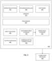
- FIG. 3illustrates an exemplary method for distributing energy according to one or more embodiments of the present disclosure
- FIG. 4is a block diagram illustrating physical components of an exemplary computing device that may be used with one or more embodiments of the present disclosure.
- fractalis a mathematical set that exhibits a repeating or closely-repeating pattern. The pattern also displays the same architecture at every scale.
- FRACTALGRIDis a type of distributed and networked microgrid architecture in which a larger microgrid is comprised of smaller microgrid nodes or fractal units.
- Each microgrid or fractal unithas self-similar attributes that enable interoperability with other microgrids and also enable various microgrids to be integrated into a similar, often larger architecture with ease.
- a FRACTALGRIDmay provide a reliable source of electricity generation as the FRACTALGRID is configured to integrate locally-available renewable resources. More specifically, the FRACTALGRID may utilize localized renewable resources for electricity generation and can also integrate renewable energy with the local utility grid via semi-autonomous controls that may enhance the ability of a consumer to maintain energy delivery during outage events or shortfalls in energy availability. This capability, combined with a cybersecure information-sharing platform, greatly enhances energy security and reliability.
- a microgridmay be more resilient to adverse grid conditions such as voltage and frequency anomalies and power outages than conventional power grids or subsystems of conventional power grids. For example, when such adverse grid conditions or events are detected, the microgrid is capable of disconnecting from the utility grid and autonomously sustaining power for minutes to weeks depending upon local distributed resource generation, energy storage, and intelligent energy management strategies. The microgrid can also detect the recovery of normal grid behavior and reconnect for normal parallel operation after syncing reference voltage and frequency.
- a microgridmay have many operational modes and operational sub-modes. Some of these include, but are not limited to peak-shaving, load-shifting, and load-leveling. These operational modes may allow consumers or other users to offset energy and power consumption from the utility through locally produced renewable energy and energy storage.
- embodiments described hereinare directed to distributed energy systems and more particularly to enabling one or more components of a distributed energy system to communicate with other components of the distributed energy system.
- embodiments described hereinalso enable the various components of the distributed energy system to share power with other components of the system.
- the sharing of powermay be based on a defined set of rules or priorities that is commonly shared among the different components of the distributed energy system.
- the distributed energy system described hereinmay include one or more microgrids.
- a microgridis an electrical system that is configured to locally generate, store and distribute power.
- microgridsinclude but are not limited to renewable energy sources such as solar power, wind power, geothermal power, hydro power, electrical transfer switches, energy generation modules, energy storage modules, loads, local sensors and so on.
- Microgridscan function independently and may also be connected to large electrical grids or macrogrids. That is, a microgrid can not only generate its own power, but it can both receive power from a macrogrid and provide power to a macrogrid.
- a microgridcan receive requests for power from other components in the distributed energy system, and determine, based on historical, current and/or forecasted power needs, whether and when to share power with the requesting components.
- FIG. 1illustrates an exemplary distributed energy system 100 according to one or more embodiments of the present disclosure.
- the distributed energy system 100may include a number of different components or modules that are communicatively and/or electrically coupled together. This coupling may enable each component within the distributed energy system 100 to share data and/or power with other components of the distributed energy system 100 .
- the distributed energy system 100includes a macrogrid 110 .
- the macrogrid 110may be a centralized power grid such as a power station that is configured to generate or otherwise provide power to various locations, components, loads, modules and the like.
- Exemplary power stationsinclude nuclear power plants, coal-fired power plants, hydroelectric dams, large scale solar panels/plants and so on.
- the macrogrid 110may be electrically and/or communicatively coupled to one or more child microgrids such as shown in FIG. 1 .
- the link between the microgrids and the macrogrid 110enables the macrogrid 110 , and each of the microgrids in the distributed energy system 100 , to share data and power with each member in its family tree. That is, power may be transmitted from one parent microgrid in the distributed energy system 100 to one or more child microgrids and so on. Likewise, power may be provided from a child microgrid to a parent microgrid.
- macrogrid 110is communicatively and/or electrically coupled to microgrid 1 120 , microgrid 2 130 and microgrid 3 140 .
- Such a couplingenables the macrogrid 110 to share power and data with, and receive power and data from, each of microgrid 1 120 , microgrid 2 130 and microgrid 3 140 .
- the coupling of the components of the distributed energy system 100enables each microgrid to communicate and share power with other microgrids in the distributed energy system 100 .
- microgrid 1 120has a plurality of child microgrids 122
- microgrid 2 130has a plurality of child microgrids 132
- microgrid 3 140has a plurality of child microgrids 142 .
- Each family of microgrids in the distributed energy system 100may be configured to communicate and share power with other microgrids in its family. That is, microgrid 1 120 may share power with and receive power from one or more of its child microgrids 122 . Likewise, microgrid 1 120 may share power and data with and/or receive data and power from microgrid 2 130 and/or child microgrids 132 .
- each microgridis shown having multiple child microgrids, such a configuration is not required. That is, a microgrid may have no children or many children. Likewise, children may be removed or added as new microgrids become available or are otherwise discoverable by a particular microgrid or macrogrid. Regardless of the number of child microgrids a given microgrid may have, power and data may be shared between parent and child and child and parent.
- the sharing of data and/or power between sibling microgridsmay be accomplished through the parent microgrid although this is not required. For example, if microgrid 1 120 requests power and/or data from microgrid 2 130 , the power and/or data would be sent to the requesting microgrid via macrogrid 110 .
- the size of the distributed energy system 100may be scalable. More specifically, the size of the system may change in real-time, substantially real-time or based on current and/or forecasted power needs.
- a single microgrid, or set of microgrids in a given systemmay be configured to determine whether or not it wants to be absorbed or otherwise included with another larger (or smaller) system.
- a single microgridmay be configured to provide power or otherwise produce power to sustain a particular load (e.g., a house, a water pumping station, a cell phone tower etc.).
- This single microgridcan be aggregated into larger microgrids to sustain larger areas with larger power needs.
- these aggregated microgridscan be combined with otherwise aggregated into other microgrids that may supply power on yet a larger scale.
- the microgridcan determine whether it wants to be part of the larger system. For example, the microgrid may determine that based on historical, current and/or forecasted power usage of a load that it services, there is no benefit to the microgrid joining the larger system. In other embodiments, the microgrid may determine, based on received data or historical use data, that it will not have sufficient power to serve the load when requested. As such, the microgrid may join or otherwise request to join a larger distributed energy system. In still yet other embodiments, a parent (either a current parent, a former parent or a requesting parent microgrid) may request that the microgrid join and/or leave the distributed energy system 100 . As such, the overall distributed energy system 100 may be scalable. Further, since each microgrid is autonomous the overall system may be maintained with rather low complexity.
- the systemmay also shrink when a system, or a component of the system, requires less power. That is, the size of the system may dynamically change in real-time or substantially real-time depending on current or forecasted power needs of the distributed energy system 100 .
- a microgridmay be manually or automatically removed from the distributed energy system 100 in response to a perceived or actual threat (e.g., physical attack or a cyber-attack), reduced power generation (e.g., over a period of time) or when maintenance is to be or is being performed on the microgrid. Once the microgrid has been serviced or is otherwise operating as expected, the microgrid may again join the system (either automatically or manually).
- FIG. 2illustrates an exemplary microgrid 200 according to one or more embodiments of the present disclosure.
- the microgrid 200may be part of or otherwise associated with one or more of the microgrids discussed above with respect to FIG. 1 .
- a microgridmay be an autonomous unit that may be connected or disconnected (islanded) from a larger grid (such as a utility grid, another microgrid, a macrogrid or other such distributed energy system and so on) at any time.
- the microgrid 200may interact with a parent microgrid and one or more child microgrids using various communication protocols. These communication protocols allow for the sharing of resources, including power and data, and also enables the microgrid to connect to and disconnect from parent microgrids, and/or child microgrids in cases of maintenance, emergencies, cyber-attacks, physical attacks and so on such as described above.
- the microgrid 200may include a controller 210 , a data storage module 220 , a data processing module 230 and a communication module 240 . Although shown separately, in some embodiments, some or all of these components may be combined into a single unit such as, for example, the controller 210 .
- the controller 210is a computing device or other such processing device that receives and processes requests and/or data. More specifically, the controller 210 may be a processor, a processing unit, a programmable logic controller, a remote terminal unit and may be configured to collect data, code the data into a format that is transmittable between various microgrids and transmit the data between the microgrids.
- a microgridmay include one or more subsystems such as, for example, subsystem 1 270 and subsystem N 280 .
- These subsystemsmay include, but are not limited to, electrical transfer switches, energy generation modules, energy storage modules, loads, local sensors, and so on.
- the controller 210may include software, hardware or other logic and modules that determines energy resource management including, but not limited to which subsystems and microgrids need or are requesting power and whether the microgrid 200 itself should be connected to or disconnected from a distributed energy system. Because each microgrid includes a controller, each microgrid is an autonomous unit and it can perform or otherwise instruct various modules to act in accordance with the best interest of the microgrid and/or in the best interest of the subsystems the microgrid services.
- the microgrid 200may receive data from another microgrid or another data source.
- the datamay be received using the communication module 240 and stored in a data storage module 220 .
- the communication module 240may include an industrial control system (ICS) or supervisory control and data acquisition (SCADA) system that enables communication and power transfers between microgrids and/or subsystems.
- ICSindustrial control system
- SCADAsupervisory control and data acquisition
- the data processing module 230may process the data to determine current power needs of system serviced by the microgrid 200 and may also determine how much power the microgrid 200 is producing. In addition, the data processing module 230 may be able to forecast power requirements of the system and whether the power produced by the microgrid 200 can meet the power demands of the system.
- the controller 210may be configured to determine whether it has, or has access to, the power that will be required by a particular system. If the microgrid 200 has access to sufficient power, that power may be provided to the requesting system over a communication and/or electrical connection. If the microgrid 200 does not have sufficient power, the controller 210 may communicate with other macrogrids or microgrids (e.g., microgrid 1 250 ) and request power from and/or request to join a distributed energy system associated with microgrid 1 250 .
- other macrogrids or microgridse.g., microgrid 1 250
- the controller 210may also be configured for energy management. More specifically, the controller 210 may be configured to determine a priority of power flow. That is, the controller 210 may be configured to provide power to various requesting modules in an ordered and systematic way. Table 1 below shows an exemplary preference chart in which a lower number indicates a higher priority power flow.
- Microgrid(s)Microgrid Local 1 6 6 12 16 (Renewable) Energy Sources Local Energy 2 7 N/A 13 16 Storage Child 3 8 10 14 16 Microgrid(s) Parent 4 9 11 15 N/A Microgrid Local (Non- 5 N/A N/A N/A N/A Renewable) Energy Sources
- the microgrid 200when using the above priority chart, the microgrid 200 , or other local renewable energy source, would first supply power to any requesting subsystem that has been identified as a critical load. If the local renewable energy source does not have enough power to meet the needs of the critical load, a local energy storage component or module may be used to satisfy the power demands of the critical load. Requests for power may then come from a child microgrid, a parent microgrid and finally a local, non-renewable energy source.
- the determination of power requirementsmay be made in real-time or substantially real-time by the controller 210 in each microgrid 200 .
- the controller 210may use received data to forecast data usage of the critical load and/or other subsystems or components.
- the microgrid 200may determine that any excess energy (e.g., energy that is not needed by the critical load) should be stored in local storage rather than being supplied to non-critical loads (as shown in the chart above with each entry having priority 6) as peak energy usage of a critical load may be upcoming.
- the microgrid 200may determine that power should be provided to non-critical loads prior to storing any excess power.
- the priority of such a tablemay be customizable.
- each of the categories in the table belowmay be sub-divided into various sub-categories.
- the non-critical load categorymay further be divided into a “sheddable” category and an “essential” category. If the non-critical load is categorized as sheddable, power may not be provided to the requesting system when there is a shortage of power. If the non-critical load is categorized as essential, the essential loads take priority over the sheddable loads. In some implementations, each essential load may also be ordered or otherwise prioritized.
- each microgridmay also be customized and/or controlled by an operator. As such, an operator may manually set priorities and perform maintenance activities on each microgrid.
- FIG. 3illustrates an exemplary method 300 for distributing energy among components of distributed energy system according to one or more embodiments of the present disclosure.
- the method 300may be used by one or more microgrids to determine how to provide or otherwise allocate power to various components and modules associated with or otherwise dependent on the microgrid.
- some of the operations of the method 300 described belowmay occur simultaneously or substantially simultaneously.
- operation 320 and 330may occur simultaneously or substantially simultaneously and operations 340 and 350 may occur simultaneously or substantially simultaneously.
- operation 310may be occurring concurrently as previously received data is being processed by operations 320 through 370 are being performed.
- Method 300begins at operation 310 in which data is received from various sources.
- the sourcesmay include weather stations and power stations.
- the datamay be received from one or more subsystems and/or microgrids associated with the microgrid.
- a microgridmay receive data from one or more child microgrids or a parent microgrid.
- the datamay include historical weather patterns, current weather information, historical power usage, current power usage, current power generation, historical power generation and so on.
- the data that is receivedmay indicate power usage of one or more modules or components that draws power from the microgrid at certain times of the day when the temperature outside reaches various thresholds.
- the datamay include current or historical usages of power on a weekend.
- the datais analyzed to determine current and/or forecast energy needs. More specifically, the received data may be analyzed to determine current energy needs and/or amounts of energy that may be needed in the future. For example, if a microgrid is located on an office building on a weekend in which minimal power is being used, the data may be analyzed to determine that the microgrid typically has to request power from other microgrids come Monday morning. As a result, the microgrid may opt to store the generated power rather than provide it to other requesting microgrids or other subsystems.
- the microgridmay analyze the received data to determine whether it has sufficient power to provide its critical loads. If not, the microgrid may be configured to request power from a parent microgrid, a child microgrid, an energy storage module and/or a non-renewable energy source depending on its internal priority table such as described above.
- the microgridprovides energy to its critical loads.
- the microgridacting as an autonomous unit, can determine in real-time or substantially real-time, whether it generates enough energy to satisfy its critical load requirements. If not, the microgrid may request power from other sources such as described above.
- each microgriddetermines a priority of noncritical load versus storage.
- each microgridmay determine that it should store energy for upcoming requests rather than provide energy to non-critical loads.
- the microgridmay determine that providing power to non-critical loads is, at the moment, more important than storing the power for subsequent use.
- the priority between the non-critical load and the storagemay vary from time to time.
- the microgridmay also be configured to determine power needs and/or requirements of one or more child microgrids and its parent microgrid.
- the microgridmay be configured to receive data and/or power requests from child and parent microgrids. Once the data is received, the microgrid can determine whether and when to provide the requested power to the requesting microgrids.
- microgriddetermines that is has sufficient power or otherwise determines it wants to provide power to the requesting microgrids
- flowproceeds to operation 370 and the microgrid provides the requested power to one or more child microgrids and to a parent microgrid.
- the priority between child microgrids and parent microgridsmay be established using a priority table such as described above. The method 300 may then cycle back to operation 320 and the process may be repeated for another set of data.
- FIG. 4is a block diagram illustrating exemplary components, such as, for example, hardware components of a computing device 400 according to one or more embodiments of the present disclosure.
- the computing device 400may be part of a distributed energy system such as, for example, a component of the distributed energy system.
- the computing device 400or various components or modules of the computing device 400 may be part of or otherwise included with a microgrid.
- connections and communication channels between each of the componentsare omitted for simplicity.
- the computing device 400may include at least one controller or processor 405 and an associated memory 410 .
- the memory 410may include, but is not limited to, volatile storage such as random access memory, non-volatile storage such as read-only memory, flash memory, or any combination thereof.
- the memory 410may store an operating system 415 and one or more program modules 420 suitable for running software applications 455 .
- the operating system 415may be configured to control the computing device 400 and/or one or more software applications 455 being executed by the operating system 415 .
- the program modules 420 or software applications 455may include modules and programs for requesting data, analyzing received data, determining the priority of energy requestors as well as providing communications between modules and components of the microgrid and/or other components and modules of a distributed energy system and so on.
- the computing device 400may have additional features or functionality than those expressly described herein.
- the computing device 400may also include additional data storage devices, removable and non-removable, such as, for example, magnetic disks, optical disks, or tape.
- additional data storage devicessuch as, for example, magnetic disks, optical disks, or tape.
- Exemplary storage devicesare illustrated in FIG. 4 by removable storage device 425 and a non-removable storage device 430 .
- various program modules and data filesmay be stored in the system memory 410 .
- the program modules 420 and the processor 405may perform processes that include one or more of the operations of method 300 shown and described with respect to FIG. 3 .
- the computing device 400may include one or more input devices 435 .
- the input devices 435may include a keyboard, a mouse, a pen or stylus, a sound input device, a touch input device, and the like.
- the computing device 400may also include one or more output devices 440 .
- the output devices 440may include a display, one or more speakers, a printer, and the like.
- the computing device 400also includes communication connections 445 that facilitate communications with additional computing devices 450 .
- Such communication connections 445may include internet capabilities, a RF transmitter, a receiver, and/or transceiver circuitry, universal serial bus (USB) communications, parallel ports and/or serial ports.
- USBuniversal serial bus
- Computer readable mediamay include computer storage media.
- Computer storage mediamay include volatile and nonvolatile media and/or removable and non-removable media for the storage of information. Examples include computer-readable instructions, data structures, and program modules.
- the memory 410 , the removable storage device 425 , and the non-removable storage device 430are all examples of computer storage media.
- Computer storage mediamay include RAM, ROM, electrically erasable read-only memory (EEPROM), flash memory or other memory technology, CD-ROM, digital versatile disks (DVD) or other optical storage, magnetic cassettes, magnetic tape, magnetic disk storage or other magnetic storage devices, or any other article of manufacture which can be used to store information and which can be accessed by the computing device 400 . Any such computer storage media may be part of the computing device 400 .
- Embodiments of the present disclosureare described above with reference to block diagrams and operational illustrations of methods and the like.
- the operations describedmay occur out of the order as shown in any of the figures. Additionally, one or more operations may be removed or executed substantially concurrently. For example, two blocks shown in succession may be executed substantially concurrently. Additionally, the blocks may be executed in the reverse order.
Landscapes
- Engineering & Computer Science (AREA)
- Power Engineering (AREA)
- General Engineering & Computer Science (AREA)
- Physics & Mathematics (AREA)
- General Physics & Mathematics (AREA)
- Automation & Control Theory (AREA)
- Supply And Distribution Of Alternating Current (AREA)
- Remote Monitoring And Control Of Power-Distribution Networks (AREA)
Abstract
Description
| TABLE 1 | ||
| To | ||
| Critical | Non-Critical | Local Energy | Child | Parent | |
| From | Loads | Loads | Storage | Microgrid(s) | |
| Local | |||||
| 1 | 6 | 6 | 12 | 16 | |
| (Renewable) | |||||
| Energy | |||||
| Local Energy | |||||
| 2 | 7 | N/A | 13 | 16 | |
| Child | |||||
| 3 | 8 | 10 | 14 | 16 | |
| Microgrid(s) | |||||
| Parent | 4 | 9 | 11 | 15 | N/A |
| Microgrid | |||||
| Local (Non- | 5 | N/A | N/A | N/A | N/A |
| Renewable) | |||||
| Energy Sources | |||||
Claims (20)
Priority Applications (1)
| Application Number | Priority Date | Filing Date | Title |
|---|---|---|---|
| US18/168,429US12170443B2 (en) | 2014-04-06 | 2023-02-13 | Establishing communication and power sharing links between components of a distributed energy system |
Applications Claiming Priority (6)
| Application Number | Priority Date | Filing Date | Title |
|---|---|---|---|
| US201461975829P | 2014-04-06 | 2014-04-06 | |
| US14/666,177US20150288183A1 (en) | 2014-04-06 | 2015-03-23 | Establishing communication and power sharing links between components of a distributed energy system |
| US14/885,627US9941696B2 (en) | 2014-04-06 | 2015-10-16 | Establishing communication and power sharing links between components of a distributed energy system |
| US15/944,478US10658839B2 (en) | 2014-04-06 | 2018-04-03 | Establishing communication and power sharing links between components of a distributed energy system |
| US16/876,720US11581732B2 (en) | 2014-04-06 | 2020-05-18 | Establishing communication and power sharing links between components of a distributed energy system |
| US18/168,429US12170443B2 (en) | 2014-04-06 | 2023-02-13 | Establishing communication and power sharing links between components of a distributed energy system |
Related Parent Applications (1)
| Application Number | Title | Priority Date | Filing Date |
|---|---|---|---|
| US16/876,720ContinuationUS11581732B2 (en) | 2014-04-06 | 2020-05-18 | Establishing communication and power sharing links between components of a distributed energy system |
Publications (2)
| Publication Number | Publication Date |
|---|---|
| US20230198257A1 US20230198257A1 (en) | 2023-06-22 |
| US12170443B2true US12170443B2 (en) | 2024-12-17 |
Family
ID=54210588
Family Applications (5)
| Application Number | Title | Priority Date | Filing Date |
|---|---|---|---|
| US14/666,177AbandonedUS20150288183A1 (en) | 2014-04-06 | 2015-03-23 | Establishing communication and power sharing links between components of a distributed energy system |
| US14/885,627ActiveUS9941696B2 (en) | 2014-04-06 | 2015-10-16 | Establishing communication and power sharing links between components of a distributed energy system |
| US15/944,478Active2035-09-16US10658839B2 (en) | 2014-04-06 | 2018-04-03 | Establishing communication and power sharing links between components of a distributed energy system |
| US16/876,720Active2035-04-16US11581732B2 (en) | 2014-04-06 | 2020-05-18 | Establishing communication and power sharing links between components of a distributed energy system |
| US18/168,429ActiveUS12170443B2 (en) | 2014-04-06 | 2023-02-13 | Establishing communication and power sharing links between components of a distributed energy system |
Family Applications Before (4)
| Application Number | Title | Priority Date | Filing Date |
|---|---|---|---|
| US14/666,177AbandonedUS20150288183A1 (en) | 2014-04-06 | 2015-03-23 | Establishing communication and power sharing links between components of a distributed energy system |
| US14/885,627ActiveUS9941696B2 (en) | 2014-04-06 | 2015-10-16 | Establishing communication and power sharing links between components of a distributed energy system |
| US15/944,478Active2035-09-16US10658839B2 (en) | 2014-04-06 | 2018-04-03 | Establishing communication and power sharing links between components of a distributed energy system |
| US16/876,720Active2035-04-16US11581732B2 (en) | 2014-04-06 | 2020-05-18 | Establishing communication and power sharing links between components of a distributed energy system |
Country Status (1)
| Country | Link |
|---|---|
| US (5) | US20150288183A1 (en) |
Families Citing this family (25)
| Publication number | Priority date | Publication date | Assignee | Title |
|---|---|---|---|---|
| US20150288183A1 (en) | 2014-04-06 | 2015-10-08 | CleanSpark Technologies LLC | Establishing communication and power sharing links between components of a distributed energy system |
| US9965016B2 (en)* | 2016-03-09 | 2018-05-08 | International Power Supply AD | Power asset command and control architecture |
| US10128659B2 (en)* | 2016-05-12 | 2018-11-13 | Solarcity Corporation | Energy generation interactions bypassing the grid |
| US10361563B2 (en) | 2016-12-20 | 2019-07-23 | International Power Supply AD | Smart power and storage transfer architecture |
| CA3090944A1 (en) | 2017-02-08 | 2018-08-16 | Upstream Data Inc. | Blockchain mine at oil or gas facility |
| EP4451551A3 (en) | 2018-01-11 | 2025-01-22 | Lancium Llc | Method and system for dynamic power delivery to a flexible datacenter using unutilized energy sources |
| EP3542434B1 (en)* | 2018-01-17 | 2020-01-22 | Siemens Aktiengesellschaft | A communication-free decentralized control framework for distributed power generation in microgrids |
| US11016553B2 (en) | 2018-09-14 | 2021-05-25 | Lancium Llc | Methods and systems for distributed power control of flexible datacenters |
| US11031787B2 (en) | 2018-09-14 | 2021-06-08 | Lancium Llc | System of critical datacenters and behind-the-meter flexible datacenters |
| US11025060B2 (en) | 2018-09-14 | 2021-06-01 | Lancium Llc | Providing computational resource availability based on power-generation signals |
| US10873211B2 (en) | 2018-09-14 | 2020-12-22 | Lancium Llc | Systems and methods for dynamic power routing with behind-the-meter energy storage |
| US10367353B1 (en) | 2018-10-30 | 2019-07-30 | Lancium Llc | Managing queue distribution between critical datacenter and flexible datacenter |
| US11031813B2 (en) | 2018-10-30 | 2021-06-08 | Lancium Llc | Systems and methods for auxiliary power management of behind-the-meter power loads |
| US11025089B2 (en)* | 2018-11-13 | 2021-06-01 | Siemens Aktiengesellschaft | Distributed energy resource management system |
| US10452127B1 (en) | 2019-01-11 | 2019-10-22 | Lancium Llc | Redundant flexible datacenter workload scheduling |
| US11128165B2 (en) | 2019-02-25 | 2021-09-21 | Lancium Llc | Behind-the-meter charging station with availability notification |
| CA3139776A1 (en) | 2019-05-15 | 2020-11-19 | Upstream Data Inc. | Portable blockchain mining system and methods of use |
| US11397999B2 (en) | 2019-08-01 | 2022-07-26 | Lancium Llc | Modifying computing system operations based on cost and power conditions |
| US11868106B2 (en) | 2019-08-01 | 2024-01-09 | Lancium Llc | Granular power ramping |
| US10618427B1 (en) | 2019-10-08 | 2020-04-14 | Lancium Llc | Behind-the-meter branch loads for electrical vehicle charging |
| US11016458B2 (en) | 2019-10-28 | 2021-05-25 | Lancium Llc | Methods and systems for adjusting power consumption based on dynamic power option agreement |
| US11042948B1 (en) | 2020-02-27 | 2021-06-22 | Lancium Llc | Computing component arrangement based on ramping capabilities |
| CA3076653A1 (en) | 2020-03-21 | 2021-09-21 | Upstream Data Inc. | Portable blockchain mining systems and methods of use |
| CA3189144A1 (en) | 2020-08-14 | 2022-02-17 | Andrew GRIMSHAW | Power aware scheduling |
| CN111969658B (en)* | 2020-08-26 | 2021-12-28 | 重庆大学 | Defensiveness of generation and transmission system considering wind power-conventional coordinated planning method |
Citations (62)
| Publication number | Priority date | Publication date | Assignee | Title |
|---|---|---|---|---|
| US6751562B1 (en) | 2000-11-28 | 2004-06-15 | Power Measurement Ltd. | Communications architecture for intelligent electronic devices |
| US6882904B1 (en) | 2000-12-29 | 2005-04-19 | Abb Technology Ag | Communication and control network for distributed power resource units |
| US6944555B2 (en) | 1994-12-30 | 2005-09-13 | Power Measurement Ltd. | Communications architecture for intelligent electronic devices |
| US7183667B2 (en) | 2003-12-19 | 2007-02-27 | Square D Company | Method and apparatus for power inverter synchronization |
| US7216043B2 (en) | 1997-02-12 | 2007-05-08 | Power Measurement Ltd. | Push communications architecture for intelligent electronic devices |
| US7456523B2 (en) | 2004-03-23 | 2008-11-25 | Canon Kabushiki Kaisha | Power generation system, and administration apparatus and administration method of power generation system |
| US7489990B2 (en) | 2006-07-17 | 2009-02-10 | Fehr Stephen L | Systems and methods for calculating and predicting near term production cost, incremental heat rate, capacity and emissions of electric generation power plants based on current operating and, optionally, atmospheric conditions |
| US7577005B2 (en) | 2004-12-16 | 2009-08-18 | Fronius International Gmbh | Method for recognizing the load of an island inverter and island inverter |
| US7582986B2 (en) | 2004-10-08 | 2009-09-01 | Schweitzer Engineering Laboratories, Inc. | Compensated inverse-time undervoltage load shedding systems |
| US7652394B2 (en) | 2003-11-07 | 2010-01-26 | Responsiveload Limited | Responsive electricity grid substation |
| US7787272B2 (en) | 2007-03-01 | 2010-08-31 | Wisconsin Alumni Research Foundation | Inverter based storage in dynamic distribution systems including distributed energy resources |
| US7834479B2 (en) | 2005-03-01 | 2010-11-16 | Beacon Power Corporation | Methods and systems for intentionally isolating distributed power generation sources |
| US7839027B2 (en) | 2008-10-09 | 2010-11-23 | The Aes Corporation | Frequency responsive charge sustaining control of electricity storage systems for ancillary services on an electrical power grid |
| US7881814B2 (en) | 2006-05-04 | 2011-02-01 | General Electric Company | Method and system for rapid modeling and verification of excitation systems for synchronous generators |
| US7899632B2 (en) | 2007-07-16 | 2011-03-01 | Enphase Energy, Inc. | Method and apparatus for anti-islanding of distributed power generation systems |
| US20110082596A1 (en) | 2009-10-01 | 2011-04-07 | Edsa Micro Corporation | Real time microgrid power analytics portal for mission critical power systems |
| US8008804B2 (en) | 2003-08-15 | 2011-08-30 | Beacon Power Corporation | Methods, systems and apparatus for regulating frequency of generated power using flywheel energy storage systems with varying load and/or power generation |
| US8019697B2 (en) | 2009-01-14 | 2011-09-13 | Ozog Michael T | Optimization of microgrid energy use and distribution |
| US8060259B2 (en) | 2003-08-08 | 2011-11-15 | Electric Power Group, Llc | Wide-area, real-time monitoring and visualization system |
| US8068938B2 (en) | 2009-05-15 | 2011-11-29 | General Electric Company | Method and system for managing a load demand on an electrical grid |
| US20120104847A1 (en) | 2009-05-14 | 2012-05-03 | Rolls-Royce Plc | Distributed power generation |
| US20120116602A1 (en) | 2010-11-04 | 2012-05-10 | Silver Spring Networks, Inc. | Physically secured authorization for utility applications |
| US20120130556A1 (en) | 2010-11-18 | 2012-05-24 | Marhoefer John J | Virtual power plant system and method incorporating renewal energy, storage and scalable value-based optimization |
| US20120158196A1 (en) | 2010-12-21 | 2012-06-21 | Palo Alto Research Center Incorporated | Tactical smart grids |
| US8234876B2 (en) | 2003-10-15 | 2012-08-07 | Ice Energy, Inc. | Utility managed virtual power plant utilizing aggregated thermal energy storage |
| US20120310438A1 (en) | 2011-06-03 | 2012-12-06 | Karl Kaiser | High dynamic dc-voltage controller for photovoltaic inverter |
| US20130085624A1 (en) | 2011-09-30 | 2013-04-04 | Abb Research Ltd. | Systems and Methods for Integrating Demand Response with Service Restoration in an Electric Distribution System |
| US8415830B2 (en) | 2010-06-03 | 2013-04-09 | Briggs & Stratton Corporation | Active load management system |
| US8433452B2 (en) | 2008-09-15 | 2013-04-30 | Aclara Power-Line Systems, Inc. | Method for load control using temporal measurements of energy for individual pieces of equipment |
| US8447435B1 (en) | 2010-04-15 | 2013-05-21 | Science Applications International Corporation | System and method for routing power across multiple microgrids having DC and AC buses |
| US20130198847A1 (en) | 2012-02-01 | 2013-08-01 | Radhakrishna G. SAMPIGETHAYA | Methods and systems for cyber-physical security modeling, simulation and architecture for the smart grid |
| US8519568B2 (en) | 2011-09-16 | 2013-08-27 | General Electric Company | Inrush current protection for wind turbines and wind farms |
| US8527252B2 (en) | 2006-07-28 | 2013-09-03 | Emerson Process Management Power & Water Solutions, Inc. | Real-time synchronized control and simulation within a process plant |
| US20130253718A1 (en) | 2012-03-23 | 2013-09-26 | Power Analytics Corporation | Systems and methods for integrated, model, and role-based management of a microgrid based on real-time power management |
| US20130270908A1 (en) | 2012-04-17 | 2013-10-17 | Francis X. Wedel | Load Shed Control Module For Use With Electrical Generator |
| US8566266B2 (en) | 2010-08-27 | 2013-10-22 | Mitsubishi Electric Research Laboratories, Inc. | Method for scheduling the operation of power generators using factored Markov decision process |
| US8626351B2 (en) | 2008-02-29 | 2014-01-07 | Kabushiki Kaisha Toshiba | Method and device for operation scheduling for energy storage equipment |
| US20140025217A1 (en) | 2011-03-25 | 2014-01-23 | Zhuhai Unitech Power Technology Co., Ltd. | Device and method for self-healing control of a multi-level power grid |
| US8653692B2 (en) | 2010-06-03 | 2014-02-18 | Briggs & Stratton Corporation | Dynamic load shedding system for a standby generator |
| US8666520B2 (en) | 2010-10-12 | 2014-03-04 | General Electric Company | Methods, systems, and apparatus for shedding loads from an electrical grid |
| US20140091622A1 (en) | 2011-04-15 | 2014-04-03 | Deka Products Limited Partnership | Modular Power Conversion System |
| US20140097683A1 (en) | 2012-10-08 | 2014-04-10 | Eaton Corporation | Generator dispatching or load shedding control method and system for microgrid applications |
| US8706309B2 (en) | 2010-04-10 | 2014-04-22 | Schweitzer Engineering Laboratories Inc | Systems and method for obtaining a load model and related parameters based on load dynamics |
| US20140111006A1 (en) | 2012-10-19 | 2014-04-24 | John Baldassarre | Energy management system for auxiliary power source |
| US20140148960A1 (en) | 2012-11-29 | 2014-05-29 | International Business Machines Corporation | Configuring, optimizing and managing micro-grids |
| US8751036B2 (en) | 2011-09-28 | 2014-06-10 | Causam Energy, Inc. | Systems and methods for microgrid power generation management with selective disconnect |
| US20140229031A1 (en) | 2013-02-14 | 2014-08-14 | Petra Solar, Inc. | Micro-Inverter Based AC-Coupled Photovoltaic Microgrid System with Wireless Smart-Grid Controls |
| US8816531B2 (en) | 2011-01-27 | 2014-08-26 | General Electric Company | Systems, methods, and apparatus for integrated volt/VAR control in power distribution networks |
| US20140249686A1 (en) | 2013-03-01 | 2014-09-04 | Honeywell International, Inc. Patent Services M/S AB/2B | System and method of large area microgrid stability controls |
| US8831789B2 (en) | 2010-09-29 | 2014-09-09 | Rockwell Automation Technologies, Inc. | Goal-based load management |
| US8831788B2 (en) | 2011-04-20 | 2014-09-09 | General Electric Company | Systems, methods, and apparatus for maintaining stable conditions within a power grid |
| US20140277599A1 (en) | 2013-03-13 | 2014-09-18 | Oracle International Corporation | Innovative Approach to Distributed Energy Resource Scheduling |
| US8842456B2 (en) | 2011-08-23 | 2014-09-23 | National Cheng Kung University | Analog controller for inverter |
| US8855792B2 (en) | 2006-12-15 | 2014-10-07 | Robert Bosch Gmbh | Automated creation and adaption of a machine or system model |
| US8862279B2 (en) | 2011-09-28 | 2014-10-14 | Causam Energy, Inc. | Systems and methods for optimizing microgrid power generation and management with predictive modeling |
| US20140371936A1 (en) | 2011-11-28 | 2014-12-18 | Expanergy, Llc | System and methods to aggregate instant and forecasted excess renewable energy |
| US20140379156A1 (en) | 2011-06-15 | 2014-12-25 | Expanergy, Llc | System and methods to wirelessly control distributed renewable energy on the grid or microgrid |
| US20150039145A1 (en) | 2013-07-31 | 2015-02-05 | Abb Technology Ag | Microgrid Energy Management System and Method for Controlling Operation of a Microgrid |
| US20150112501A1 (en) | 2013-10-21 | 2015-04-23 | Restore Nv | Portfolio managed, demand-side response system |
| US9020650B2 (en) | 2007-02-13 | 2015-04-28 | General Electric Company | Utility grid, controller, and method for controlling the power generation in a utility grid |
| US9031707B2 (en) | 2010-12-23 | 2015-05-12 | Electronics And Telecommunications Research Institute | Method and system for providing energy management in smart grid environment, electrical power producing apparatus in smart grid environment |
| US20150288183A1 (en) | 2014-04-06 | 2015-10-08 | CleanSpark Technologies LLC | Establishing communication and power sharing links between components of a distributed energy system |
Family Cites Families (1)
| Publication number | Priority date | Publication date | Assignee | Title |
|---|---|---|---|---|
| GB811058A (en) | 1956-12-24 | 1959-03-25 | Metallgesellschaft Ag | Method of producing concentrated sulphuric acid and oleum from gases containing hydrogen sulphide |
- 2015
- 2015-03-23USUS14/666,177patent/US20150288183A1/ennot_activeAbandoned
- 2015-10-16USUS14/885,627patent/US9941696B2/enactiveActive
- 2018
- 2018-04-03USUS15/944,478patent/US10658839B2/enactiveActive
- 2020
- 2020-05-18USUS16/876,720patent/US11581732B2/enactiveActive
- 2023
- 2023-02-13USUS18/168,429patent/US12170443B2/enactiveActive
Patent Citations (70)
| Publication number | Priority date | Publication date | Assignee | Title |
|---|---|---|---|---|
| US6944555B2 (en) | 1994-12-30 | 2005-09-13 | Power Measurement Ltd. | Communications architecture for intelligent electronic devices |
| US7216043B2 (en) | 1997-02-12 | 2007-05-08 | Power Measurement Ltd. | Push communications architecture for intelligent electronic devices |
| US7734380B2 (en) | 1997-02-12 | 2010-06-08 | Power Measurement Ltd. | Push communications architecture for intelligent electronic devices |
| US6751562B1 (en) | 2000-11-28 | 2004-06-15 | Power Measurement Ltd. | Communications architecture for intelligent electronic devices |
| US6882904B1 (en) | 2000-12-29 | 2005-04-19 | Abb Technology Ag | Communication and control network for distributed power resource units |
| US8060259B2 (en) | 2003-08-08 | 2011-11-15 | Electric Power Group, Llc | Wide-area, real-time monitoring and visualization system |
| US8008804B2 (en) | 2003-08-15 | 2011-08-30 | Beacon Power Corporation | Methods, systems and apparatus for regulating frequency of generated power using flywheel energy storage systems with varying load and/or power generation |
| US8234876B2 (en) | 2003-10-15 | 2012-08-07 | Ice Energy, Inc. | Utility managed virtual power plant utilizing aggregated thermal energy storage |
| US8528345B2 (en) | 2003-10-15 | 2013-09-10 | Ice Energy, Inc. | Managed virtual power plant utilizing aggregated storage |
| US7652394B2 (en) | 2003-11-07 | 2010-01-26 | Responsiveload Limited | Responsive electricity grid substation |
| US7183667B2 (en) | 2003-12-19 | 2007-02-27 | Square D Company | Method and apparatus for power inverter synchronization |
| US7456523B2 (en) | 2004-03-23 | 2008-11-25 | Canon Kabushiki Kaisha | Power generation system, and administration apparatus and administration method of power generation system |
| US7582986B2 (en) | 2004-10-08 | 2009-09-01 | Schweitzer Engineering Laboratories, Inc. | Compensated inverse-time undervoltage load shedding systems |
| US7577005B2 (en) | 2004-12-16 | 2009-08-18 | Fronius International Gmbh | Method for recognizing the load of an island inverter and island inverter |
| US7834479B2 (en) | 2005-03-01 | 2010-11-16 | Beacon Power Corporation | Methods and systems for intentionally isolating distributed power generation sources |
| US7881814B2 (en) | 2006-05-04 | 2011-02-01 | General Electric Company | Method and system for rapid modeling and verification of excitation systems for synchronous generators |
| US7489990B2 (en) | 2006-07-17 | 2009-02-10 | Fehr Stephen L | Systems and methods for calculating and predicting near term production cost, incremental heat rate, capacity and emissions of electric generation power plants based on current operating and, optionally, atmospheric conditions |
| US8527252B2 (en) | 2006-07-28 | 2013-09-03 | Emerson Process Management Power & Water Solutions, Inc. | Real-time synchronized control and simulation within a process plant |
| US8855792B2 (en) | 2006-12-15 | 2014-10-07 | Robert Bosch Gmbh | Automated creation and adaption of a machine or system model |
| US9020650B2 (en) | 2007-02-13 | 2015-04-28 | General Electric Company | Utility grid, controller, and method for controlling the power generation in a utility grid |
| US7787272B2 (en) | 2007-03-01 | 2010-08-31 | Wisconsin Alumni Research Foundation | Inverter based storage in dynamic distribution systems including distributed energy resources |
| US7899632B2 (en) | 2007-07-16 | 2011-03-01 | Enphase Energy, Inc. | Method and apparatus for anti-islanding of distributed power generation systems |
| US8626351B2 (en) | 2008-02-29 | 2014-01-07 | Kabushiki Kaisha Toshiba | Method and device for operation scheduling for energy storage equipment |
| US8433452B2 (en) | 2008-09-15 | 2013-04-30 | Aclara Power-Line Systems, Inc. | Method for load control using temporal measurements of energy for individual pieces of equipment |
| US7839027B2 (en) | 2008-10-09 | 2010-11-23 | The Aes Corporation | Frequency responsive charge sustaining control of electricity storage systems for ancillary services on an electrical power grid |
| US8019697B2 (en) | 2009-01-14 | 2011-09-13 | Ozog Michael T | Optimization of microgrid energy use and distribution |
| US8364609B2 (en) | 2009-01-14 | 2013-01-29 | Integral Analytics, Inc. | Optimization of microgrid energy use and distribution |
| US20120104847A1 (en) | 2009-05-14 | 2012-05-03 | Rolls-Royce Plc | Distributed power generation |
| US8068938B2 (en) | 2009-05-15 | 2011-11-29 | General Electric Company | Method and system for managing a load demand on an electrical grid |
| US8321194B2 (en) | 2009-10-01 | 2012-11-27 | Power Analytics Corporation | Real time microgrid power analytics portal for mission critical power systems |
| US20110082596A1 (en) | 2009-10-01 | 2011-04-07 | Edsa Micro Corporation | Real time microgrid power analytics portal for mission critical power systems |
| US8706309B2 (en) | 2010-04-10 | 2014-04-22 | Schweitzer Engineering Laboratories Inc | Systems and method for obtaining a load model and related parameters based on load dynamics |
| US8447435B1 (en) | 2010-04-15 | 2013-05-21 | Science Applications International Corporation | System and method for routing power across multiple microgrids having DC and AC buses |
| US8415830B2 (en) | 2010-06-03 | 2013-04-09 | Briggs & Stratton Corporation | Active load management system |
| US8653692B2 (en) | 2010-06-03 | 2014-02-18 | Briggs & Stratton Corporation | Dynamic load shedding system for a standby generator |
| US8566266B2 (en) | 2010-08-27 | 2013-10-22 | Mitsubishi Electric Research Laboratories, Inc. | Method for scheduling the operation of power generators using factored Markov decision process |
| US8831789B2 (en) | 2010-09-29 | 2014-09-09 | Rockwell Automation Technologies, Inc. | Goal-based load management |
| US8666520B2 (en) | 2010-10-12 | 2014-03-04 | General Electric Company | Methods, systems, and apparatus for shedding loads from an electrical grid |
| US20120116602A1 (en) | 2010-11-04 | 2012-05-10 | Silver Spring Networks, Inc. | Physically secured authorization for utility applications |
| US20120130556A1 (en) | 2010-11-18 | 2012-05-24 | Marhoefer John J | Virtual power plant system and method incorporating renewal energy, storage and scalable value-based optimization |
| US20120158196A1 (en) | 2010-12-21 | 2012-06-21 | Palo Alto Research Center Incorporated | Tactical smart grids |
| US9031707B2 (en) | 2010-12-23 | 2015-05-12 | Electronics And Telecommunications Research Institute | Method and system for providing energy management in smart grid environment, electrical power producing apparatus in smart grid environment |
| US8816531B2 (en) | 2011-01-27 | 2014-08-26 | General Electric Company | Systems, methods, and apparatus for integrated volt/VAR control in power distribution networks |
| US20140025217A1 (en) | 2011-03-25 | 2014-01-23 | Zhuhai Unitech Power Technology Co., Ltd. | Device and method for self-healing control of a multi-level power grid |
| US20140091622A1 (en) | 2011-04-15 | 2014-04-03 | Deka Products Limited Partnership | Modular Power Conversion System |
| US8831788B2 (en) | 2011-04-20 | 2014-09-09 | General Electric Company | Systems, methods, and apparatus for maintaining stable conditions within a power grid |
| US20120310438A1 (en) | 2011-06-03 | 2012-12-06 | Karl Kaiser | High dynamic dc-voltage controller for photovoltaic inverter |
| US20140379156A1 (en) | 2011-06-15 | 2014-12-25 | Expanergy, Llc | System and methods to wirelessly control distributed renewable energy on the grid or microgrid |
| US8842456B2 (en) | 2011-08-23 | 2014-09-23 | National Cheng Kung University | Analog controller for inverter |
| US8519568B2 (en) | 2011-09-16 | 2013-08-27 | General Electric Company | Inrush current protection for wind turbines and wind farms |
| US8862279B2 (en) | 2011-09-28 | 2014-10-14 | Causam Energy, Inc. | Systems and methods for optimizing microgrid power generation and management with predictive modeling |
| US8751036B2 (en) | 2011-09-28 | 2014-06-10 | Causam Energy, Inc. | Systems and methods for microgrid power generation management with selective disconnect |
| US20130085624A1 (en) | 2011-09-30 | 2013-04-04 | Abb Research Ltd. | Systems and Methods for Integrating Demand Response with Service Restoration in an Electric Distribution System |
| US20140371936A1 (en) | 2011-11-28 | 2014-12-18 | Expanergy, Llc | System and methods to aggregate instant and forecasted excess renewable energy |
| US20130198847A1 (en) | 2012-02-01 | 2013-08-01 | Radhakrishna G. SAMPIGETHAYA | Methods and systems for cyber-physical security modeling, simulation and architecture for the smart grid |
| US20130253718A1 (en) | 2012-03-23 | 2013-09-26 | Power Analytics Corporation | Systems and methods for integrated, model, and role-based management of a microgrid based on real-time power management |
| US9088180B2 (en) | 2012-04-17 | 2015-07-21 | Generac Power Systems, Inc. | Load shed control module for use with electrical generator |
| US20130270908A1 (en) | 2012-04-17 | 2013-10-17 | Francis X. Wedel | Load Shed Control Module For Use With Electrical Generator |
| US20140097683A1 (en) | 2012-10-08 | 2014-04-10 | Eaton Corporation | Generator dispatching or load shedding control method and system for microgrid applications |
| US20140111006A1 (en) | 2012-10-19 | 2014-04-24 | John Baldassarre | Energy management system for auxiliary power source |
| US20140148960A1 (en) | 2012-11-29 | 2014-05-29 | International Business Machines Corporation | Configuring, optimizing and managing micro-grids |
| US20140229031A1 (en) | 2013-02-14 | 2014-08-14 | Petra Solar, Inc. | Micro-Inverter Based AC-Coupled Photovoltaic Microgrid System with Wireless Smart-Grid Controls |
| US20140249686A1 (en) | 2013-03-01 | 2014-09-04 | Honeywell International, Inc. Patent Services M/S AB/2B | System and method of large area microgrid stability controls |
| US20140277599A1 (en) | 2013-03-13 | 2014-09-18 | Oracle International Corporation | Innovative Approach to Distributed Energy Resource Scheduling |
| US20150039145A1 (en) | 2013-07-31 | 2015-02-05 | Abb Technology Ag | Microgrid Energy Management System and Method for Controlling Operation of a Microgrid |
| US20150112501A1 (en) | 2013-10-21 | 2015-04-23 | Restore Nv | Portfolio managed, demand-side response system |
| US20150288183A1 (en) | 2014-04-06 | 2015-10-08 | CleanSpark Technologies LLC | Establishing communication and power sharing links between components of a distributed energy system |
| US9941696B2 (en) | 2014-04-06 | 2018-04-10 | CleanSpark Technologies LLC | Establishing communication and power sharing links between components of a distributed energy system |
| US10658839B2 (en) | 2014-04-06 | 2020-05-19 | Cleanspark, Inc. | Establishing communication and power sharing links between components of a distributed energy system |
| US20200280186A1 (en) | 2014-04-06 | 2020-09-03 | Cleanspark, Inc. | Establishing Communication and Power Sharing Links Between Components of a Distributed Energy System |
Non-Patent Citations (12)
| Title |
|---|
| Abe et al., "Digital Grid: Communicative Electrical Grids of the Future", IEEE Transactions on Smart Grid, vol. 2, No. 2, Jun. 2011 (Year: 2011). |
| C.M. Colson, "Algorithm for distributed Decision-Making for Multi-agent Microgrid Power Management", IEEE 2011. |
| Colet-Subirachs, Alba, et al. "Centralized and distributed active and reactive power control of a utility connected microgrid using IEC61850." IEEE Systems Journal 6.1 (2011): 58-67. (Year: 2011).* |
| Conti, Stefania, and Santi Agatino Rizzo. "Modelling of microgrid-renewable generators accounting for power-output correlation." IEEE transactions on power delivery 28.4 (2013): 2124-2133. (Year: 2013).* |
| Kato et al., Analysis on Battery Storage Utilization in Decentralized Solar Energy Networks Based on a Mathematical Programming Model:, SCIS-ISIS 2012, Kobe, Japan, Nov. 20-24, 2012 (Year: 2012). |
| Lee et al., "Fractal-based Control and Monitoring System for Smart grid (FrCMSG)", Dec. 2009 APIEMS. (Year: 2009). |
| Li, Peng, et al. "Multi-agent approach for service restoration of microgrid." 2010 5th IEEE Conference on Industrial Electronics and Applications. IEEE, 2010. (Year: 2010).* |
| Nordman, Bruce. "Evolving our electricity systems from the bottom up." In Darnell Green Power Forum. 2009 (Year: 2009). |
| Nunna, HSVS Kumar, and Suryanarayana Doolla. "Demand response in smart distribution system with multiple microgrids." IEEE transactions on smart grid 3.4 (2012): 1641-1649. (Year: 2012).* |
| Ortjohann, E., et al. "Cluster fractal model—A flexible network model for future power systems." 2013, Clean Electrical Power (ICCEP), 2013 International Conference on. IEEE, 2013. pp 293-297. (retrieved from IEEEXplore http://ieeexplore.ieee.org/abstractidocumenti6587004/ Mar. 29, 2017). |
| Pipattanasomporn, Manisa, Hassan Feroze, and Saifur Rahman. "Securing critical loads in a PV-based microgrid with a multi-agent system." Renewable Energy 39.1 (2012): 166-174. (Year: 2012).* |
| Tsikalakis, Antonis G., and Nikos D. Hatziargyriou. "Centralized control for optimizing microgrids operation." 2011 IEEE power and energy society general meeting. IEEE, 2011. (Year: 2011).* |
Also Published As
| Publication number | Publication date |
|---|---|
| US20180226794A1 (en) | 2018-08-09 |
| US11581732B2 (en) | 2023-02-14 |
| US20200280186A1 (en) | 2020-09-03 |
| US20230198257A1 (en) | 2023-06-22 |
| US10658839B2 (en) | 2020-05-19 |
| US20160043552A1 (en) | 2016-02-11 |
| US20150288183A1 (en) | 2015-10-08 |
| US9941696B2 (en) | 2018-04-10 |
Similar Documents
| Publication | Publication Date | Title |
|---|---|---|
| US12170443B2 (en) | Establishing communication and power sharing links between components of a distributed energy system | |
| US9489701B2 (en) | Adaptive energy management system | |
| US9118219B2 (en) | Methods and systems for determining an association between nodes and phases via a smart grid | |
| Shahryari et al. | Demand side management using the internet of energy based on fog and cloud computing | |
| US10848338B2 (en) | Systems and methods relating to a smart home manager | |
| US9830672B2 (en) | Power management message bus system | |
| Liu et al. | Restoration of power distribution systems with multiple data centers as critical loads | |
| Naveen et al. | Cloud computing for energy management in smart grid-an application survey | |
| WO2019148976A1 (en) | Energy information processing method and device thereof, and energy internet system | |
| Nwauka et al. | Virtual power plant basic requirements for integration of distributed energy resourcesdriven by industry 4.0 | |
| Sehloff et al. | Self-sufficient participation in cloud-based demand response | |
| CN113783233B (en) | Active power distribution network partition optimization operation scheduling method and device and terminal equipment | |
| Wu et al. | Optimal black start strategy for microgrids considering the uncertainty using a data‐driven chance constrained approach | |
| Alghamdi et al. | Resilience of modern power distribution networks with active coordination of EVs and smart restoration | |
| Tembine | Mean-field-type optimization for demand-supply management under operational constraints in smart grid | |
| Karnouskos et al. | Prosumer interactions for efficient energy management in smartgrid neighborhoods | |
| CN108985655A (en) | resource flexibility evaluation method and device | |
| Zhu et al. | Approximate dynamic programming‐based decentralised robust optimisation approach for multi‐area economic dispatch considering wind power uncertainty | |
| Martínez et al. | Enabling renewable resource integration: The balance between robustness and flexibility | |
| Minhas | Load balancing in smart dc micro-grid using delay tolerant user demands | |
| Aragón et al. | Optimization Framework for short-term control of Energy Storage Systems | |
| Javed et al. | Fog paradigm for local energy management systems | |
| US20210036908A1 (en) | Autonomous semantic data discovery for distributed networked systems | |
| US20250307959A1 (en) | Logical data center | |
| Ali et al. | A comprehensive study of advancement of electrical power grid and middleware based smart grid communication platform |
Legal Events
| Date | Code | Title | Description |
|---|---|---|---|
| FEPP | Fee payment procedure | Free format text:ENTITY STATUS SET TO UNDISCOUNTED (ORIGINAL EVENT CODE: BIG.); ENTITY STATUS OF PATENT OWNER: SMALL ENTITY | |
| FEPP | Fee payment procedure | Free format text:ENTITY STATUS SET TO SMALL (ORIGINAL EVENT CODE: SMAL); ENTITY STATUS OF PATENT OWNER: SMALL ENTITY | |
| STPP | Information on status: patent application and granting procedure in general | Free format text:DOCKETED NEW CASE - READY FOR EXAMINATION | |
| AS | Assignment | Owner name:FORTRESS POWER LLC, PENNSYLVANIA Free format text:ASSIGNMENT OF ASSIGNORS INTEREST;ASSIGNORS:CLEANSPARK, INC.;CLEANSPARK, LLC;CLEANSPARK II, LLC;REEL/FRAME:063265/0744 Effective date:20221118 Owner name:CLEANSPARK II, LLC, UTAH Free format text:ASSIGNMENT OF ASSIGNORS INTEREST;ASSIGNOR:CLEANSPARK TECHNOLOGIES, LLC;REEL/FRAME:063265/0736 Effective date:20160629 Owner name:CLEANSPARK TECHNOLOGIES LLC, CALIFORNIA Free format text:ASSIGNMENT OF ASSIGNORS INTEREST;ASSIGNORS:VILLANUEVA, ARTURO N, JR;WORRALL, JENNIFER M;REEL/FRAME:063265/0730 Effective date:20150320 | |
| STPP | Information on status: patent application and granting procedure in general | Free format text:NON FINAL ACTION MAILED | |
| STPP | Information on status: patent application and granting procedure in general | Free format text:RESPONSE TO NON-FINAL OFFICE ACTION ENTERED AND FORWARDED TO EXAMINER | |
| STPP | Information on status: patent application and granting procedure in general | Free format text:FINAL REJECTION MAILED | |
| STPP | Information on status: patent application and granting procedure in general | Free format text:RESPONSE AFTER FINAL ACTION FORWARDED TO EXAMINER | |
| STPP | Information on status: patent application and granting procedure in general | Free format text:ADVISORY ACTION MAILED | |
| STPP | Information on status: patent application and granting procedure in general | Free format text:DOCKETED NEW CASE - READY FOR EXAMINATION | |
| STPP | Information on status: patent application and granting procedure in general | Free format text:NON FINAL ACTION MAILED | |
| STPP | Information on status: patent application and granting procedure in general | Free format text:RESPONSE TO NON-FINAL OFFICE ACTION ENTERED AND FORWARDED TO EXAMINER | |
| STPP | Information on status: patent application and granting procedure in general | Free format text:NOTICE OF ALLOWANCE MAILED -- APPLICATION RECEIVED IN OFFICE OF PUBLICATIONS | |
| STPP | Information on status: patent application and granting procedure in general | Free format text:PUBLICATIONS -- ISSUE FEE PAYMENT VERIFIED | |
| STCF | Information on status: patent grant | Free format text:PATENTED CASE | |
| CC | Certificate of correction |