US12170140B2 - Customizable multimodality image hanging protocols - Google Patents
Customizable multimodality image hanging protocolsDownload PDFInfo
- Publication number
- US12170140B2 US12170140B2US17/296,287US201917296287AUS12170140B2US 12170140 B2US12170140 B2US 12170140B2US 201917296287 AUS201917296287 AUS 201917296287AUS 12170140 B2US12170140 B2US 12170140B2
- Authority
- US
- United States
- Prior art keywords
- building block
- workspace
- viewports
- image
- mri
- Prior art date
- Legal status (The legal status is an assumption and is not a legal conclusion. Google has not performed a legal analysis and makes no representation as to the accuracy of the status listed.)
- Active, expires
Links
Images


Classifications
- G—PHYSICS
- G16—INFORMATION AND COMMUNICATION TECHNOLOGY [ICT] SPECIALLY ADAPTED FOR SPECIFIC APPLICATION FIELDS
- G16H—HEALTHCARE INFORMATICS, i.e. INFORMATION AND COMMUNICATION TECHNOLOGY [ICT] SPECIALLY ADAPTED FOR THE HANDLING OR PROCESSING OF MEDICAL OR HEALTHCARE DATA
- G16H30/00—ICT specially adapted for the handling or processing of medical images
- G16H30/20—ICT specially adapted for the handling or processing of medical images for handling medical images, e.g. DICOM, HL7 or PACS
- G—PHYSICS
- G06—COMPUTING OR CALCULATING; COUNTING
- G06F—ELECTRIC DIGITAL DATA PROCESSING
- G06F3/00—Input arrangements for transferring data to be processed into a form capable of being handled by the computer; Output arrangements for transferring data from processing unit to output unit, e.g. interface arrangements
- G06F3/01—Input arrangements or combined input and output arrangements for interaction between user and computer
- G06F3/048—Interaction techniques based on graphical user interfaces [GUI]
- G06F3/0481—Interaction techniques based on graphical user interfaces [GUI] based on specific properties of the displayed interaction object or a metaphor-based environment, e.g. interaction with desktop elements like windows or icons, or assisted by a cursor's changing behaviour or appearance
- G06F3/0482—Interaction with lists of selectable items, e.g. menus
- G—PHYSICS
- G06—COMPUTING OR CALCULATING; COUNTING
- G06F—ELECTRIC DIGITAL DATA PROCESSING
- G06F3/00—Input arrangements for transferring data to be processed into a form capable of being handled by the computer; Output arrangements for transferring data from processing unit to output unit, e.g. interface arrangements
- G06F3/01—Input arrangements or combined input and output arrangements for interaction between user and computer
- G06F3/048—Interaction techniques based on graphical user interfaces [GUI]
- G06F3/0484—Interaction techniques based on graphical user interfaces [GUI] for the control of specific functions or operations, e.g. selecting or manipulating an object, an image or a displayed text element, setting a parameter value or selecting a range
- G06F3/04845—Interaction techniques based on graphical user interfaces [GUI] for the control of specific functions or operations, e.g. selecting or manipulating an object, an image or a displayed text element, setting a parameter value or selecting a range for image manipulation, e.g. dragging, rotation, expansion or change of colour
- G—PHYSICS
- G06—COMPUTING OR CALCULATING; COUNTING
- G06F—ELECTRIC DIGITAL DATA PROCESSING
- G06F3/00—Input arrangements for transferring data to be processed into a form capable of being handled by the computer; Output arrangements for transferring data from processing unit to output unit, e.g. interface arrangements
- G06F3/01—Input arrangements or combined input and output arrangements for interaction between user and computer
- G06F3/048—Interaction techniques based on graphical user interfaces [GUI]
- G06F3/0484—Interaction techniques based on graphical user interfaces [GUI] for the control of specific functions or operations, e.g. selecting or manipulating an object, an image or a displayed text element, setting a parameter value or selecting a range
- G06F3/0486—Drag-and-drop
- G—PHYSICS
- G06—COMPUTING OR CALCULATING; COUNTING
- G06F—ELECTRIC DIGITAL DATA PROCESSING
- G06F3/00—Input arrangements for transferring data to be processed into a form capable of being handled by the computer; Output arrangements for transferring data from processing unit to output unit, e.g. interface arrangements
- G06F3/01—Input arrangements or combined input and output arrangements for interaction between user and computer
- G06F3/048—Interaction techniques based on graphical user interfaces [GUI]
- G06F3/0487—Interaction techniques based on graphical user interfaces [GUI] using specific features provided by the input device, e.g. functions controlled by the rotation of a mouse with dual sensing arrangements, or of the nature of the input device, e.g. tap gestures based on pressure sensed by a digitiser
- G06F3/0488—Interaction techniques based on graphical user interfaces [GUI] using specific features provided by the input device, e.g. functions controlled by the rotation of a mouse with dual sensing arrangements, or of the nature of the input device, e.g. tap gestures based on pressure sensed by a digitiser using a touch-screen or digitiser, e.g. input of commands through traced gestures
- G06F3/04883—Interaction techniques based on graphical user interfaces [GUI] using specific features provided by the input device, e.g. functions controlled by the rotation of a mouse with dual sensing arrangements, or of the nature of the input device, e.g. tap gestures based on pressure sensed by a digitiser using a touch-screen or digitiser, e.g. input of commands through traced gestures for inputting data by handwriting, e.g. gesture or text
- G—PHYSICS
- G06—COMPUTING OR CALCULATING; COUNTING
- G06F—ELECTRIC DIGITAL DATA PROCESSING
- G06F3/00—Input arrangements for transferring data to be processed into a form capable of being handled by the computer; Output arrangements for transferring data from processing unit to output unit, e.g. interface arrangements
- G06F3/01—Input arrangements or combined input and output arrangements for interaction between user and computer
- G06F3/048—Interaction techniques based on graphical user interfaces [GUI]
- G06F3/0487—Interaction techniques based on graphical user interfaces [GUI] using specific features provided by the input device, e.g. functions controlled by the rotation of a mouse with dual sensing arrangements, or of the nature of the input device, e.g. tap gestures based on pressure sensed by a digitiser
- G06F3/0488—Interaction techniques based on graphical user interfaces [GUI] using specific features provided by the input device, e.g. functions controlled by the rotation of a mouse with dual sensing arrangements, or of the nature of the input device, e.g. tap gestures based on pressure sensed by a digitiser using a touch-screen or digitiser, e.g. input of commands through traced gestures
- G06F3/04886—Interaction techniques based on graphical user interfaces [GUI] using specific features provided by the input device, e.g. functions controlled by the rotation of a mouse with dual sensing arrangements, or of the nature of the input device, e.g. tap gestures based on pressure sensed by a digitiser using a touch-screen or digitiser, e.g. input of commands through traced gestures by partitioning the display area of the touch-screen or the surface of the digitising tablet into independently controllable areas, e.g. virtual keyboards or menus
- G—PHYSICS
- G16—INFORMATION AND COMMUNICATION TECHNOLOGY [ICT] SPECIALLY ADAPTED FOR SPECIFIC APPLICATION FIELDS
- G16H—HEALTHCARE INFORMATICS, i.e. INFORMATION AND COMMUNICATION TECHNOLOGY [ICT] SPECIALLY ADAPTED FOR THE HANDLING OR PROCESSING OF MEDICAL OR HEALTHCARE DATA
- G16H30/00—ICT specially adapted for the handling or processing of medical images
- G16H30/40—ICT specially adapted for the handling or processing of medical images for processing medical images, e.g. editing
- G—PHYSICS
- G16—INFORMATION AND COMMUNICATION TECHNOLOGY [ICT] SPECIALLY ADAPTED FOR SPECIFIC APPLICATION FIELDS
- G16H—HEALTHCARE INFORMATICS, i.e. INFORMATION AND COMMUNICATION TECHNOLOGY [ICT] SPECIALLY ADAPTED FOR THE HANDLING OR PROCESSING OF MEDICAL OR HEALTHCARE DATA
- G16H40/00—ICT specially adapted for the management or administration of healthcare resources or facilities; ICT specially adapted for the management or operation of medical equipment or devices
- G16H40/60—ICT specially adapted for the management or administration of healthcare resources or facilities; ICT specially adapted for the management or operation of medical equipment or devices for the operation of medical equipment or devices
- G16H40/63—ICT specially adapted for the management or administration of healthcare resources or facilities; ICT specially adapted for the management or operation of medical equipment or devices for the operation of medical equipment or devices for local operation
- G—PHYSICS
- G06—COMPUTING OR CALCULATING; COUNTING
- G06F—ELECTRIC DIGITAL DATA PROCESSING
- G06F2203/00—Indexing scheme relating to G06F3/00 - G06F3/048
- G06F2203/048—Indexing scheme relating to G06F3/048
- G06F2203/04803—Split screen, i.e. subdividing the display area or the window area into separate subareas
Definitions
- Medical imaging proceduresare often used to screen, detect, or diagnose abnormalities within the human body. For instance, mammography or tomosynthesis imaging techniques are often used for screening for breast cancer. Once the images are acquired through a mammography or tomography imaging device, however, the images must be analyzed to determine if there are any abnormalities within the breast. That analysis is commonly performed by a radiologist. Each radiologist may have a particular procedure for which he or she requires or prefers to perform the analysis of the images. In the past, with film-based images, the radiologist would physically “hang” each of the physical films in a light box to perform the analysis. The manner in which the physical films were hung was referred to as a “hanging protocol.”
- the technologyrelates to a computer-implemented method for generating a customized hanging protocol for the display of medical images.
- the methodincludes receiving an indication to create a first hanging step of the hanging protocol; displaying a workspace having a plurality of viewports for displaying medical images; displaying a plurality of building blocks corresponding to different types of medical images; receiving a selection of a first building block in the plurality of building blocks, wherein the first building block corresponds to a first type of medical image; receiving an indication of a location in the workspace for the first building block to be placed; and based on the indication of the location in the workspace for the first building block, filling one or more of the plurality of viewports with the first building block.
- the methodalso includes receiving a selection of a second building block in the plurality of building blocks, wherein the second building block corresponds to a second type of medical image; receiving an indication of a location in the workspace for the second building block to be placed; based on the indication of the location in the workspace for the second building block; and storing the first hanging step of the hanging protocol for importation of medical images of a patient according to the filled viewports in the workspace.
- the first building blockcorresponds to a first imaging modality and the second building block corresponds to a second imaging modality.
- the workspaceincludes a plurality of hotspots, each of the hotspots configured to expand a building block across at least two viewports.
- the plurality of hotspotsinclude at least one of a column hotspot, a row hotspot, a quadruple hotspot, or an octuple hotspot.
- the indication of a location in the workspace for the first building blockis received via a drag and drop interaction.
- the methodalso includes displaying a drop zone outline based on the type of building block.
- the first building blockis a composite building block.
- the plurality of building blocksare displayed in an editor bar with a plurality of building block category options.
- the methodfurther includes, based on the type of the first building block, updating the layout of the workspace upon selection the first building block.
- the methodfurther includes, receiving an indication to create a second hanging step of the hanging protocol; displaying a second workspace having a plurality of viewports for displaying medical images; displaying a plurality of building blocks corresponding to different types of medical images; receiving a selection of a third building block in the plurality of building blocks; receiving an indication of a location in the second workspace for the third building block to be placed; based on the indication of the location in the second workspace for the third building block, filling one or more of the plurality of viewports with the first building block; and storing the second hanging step of the hanging protocol for importation of medical images of a patient according the filled viewports in the workspace.
- the methodfurther includes displaying, within a viewport filled with the first building block, a layer option for editing a stack of images associated with the first building block; receiving a selection of the layer option; upon receiving the selection of the layer option, displaying an layer ordering menu that includes a plurality of stacked layers corresponding to medical images; receiving an indication to reorder the stacked layers; and storing the reordering of stacked layers.
- the methodfurther includes receiving a selection of a patient for which medical images are to be imported; accessing the stored hanging protocol; importing the medical images for the patient; and displaying the imported medical images according to the stored hanging protocol.
- the technologyin another aspect, relates to a computer-implemented method for displaying medical images according to a stored hanging protocol.
- the methodincludes receiving a selection of a patient for which medical images are to be imported; receiving a selection stored hanging protocol; importing the medical images for the patient; displaying the imported medical images according to the stored hanging protocol; displaying a set of tools for analyzing or modifying the displayed medical images; receiving an indication to add a selected tool of the set of tools in a shortcut section; in response to receiving the indication, adding the selected tool to the shortcut section; and based on adding the selected tool to the shortcut section, making the tool available in a secondary selection menu when a secondary selection input is received.
- the secondary selection inputis at least one of a right-click of an input device or a long-press of a touch screen.
- the shortcut sectionis displayed in a chrome displayed adjacent to the displayed medical images.
- the selected toolis one of magnification, continuous zoom, ellipse, ruler, reset, or close study.
- the technologyin another aspect, relates to a computer-implemented method for generating a customized hanging protocol for displaying medical images.
- the methodincludes displaying a workspace comprising a plurality of viewports and hotspots; displaying a plurality of building blocks corresponding to different types of medical images; receiving a selection of a first building block of the plurality of building blocks; receiving a dragging indication of the first building block across the workspace; while the first building block is dragged across the workspace, display and dynamically update a drop zone outline based on a location of the building block relative to the workspace as it is being dragged, wherein the drop zone outline highlights one or more of the plurality of viewports for which the first building block will fill if it were dropped at the location.
- the locationis over a hotspot, and the drop zone outline highlights multiple viewports.
- the methodfurther includes receiving a selection of a second building block; and based on the dimensions of the second building block, altering or removing from the display at least one of the displayed hotspots.
- the technologyin another aspect, relates to a system for displaying medical images.
- the systemincludes a cluster of workstations, each of the workstations within the cluster being in communication with one another, wherein a first workstation is the cluster is configured to be a super node and a second workstation in the cluster is configured to be a standby super node, the super node storing patient database.
- the systemalso includes a load balancer in communication with at least one of the workstations in the cluster of workstations and a picture archive and communication system (PACS), wherein the load balancer is configured to propagate Digital Imaging and Communications in Medicine (DICOM) objects to at least one of the workstations within the cluster of workstations via a distributed downloading protocol.
- DICOMDigital Imaging and Communications in Medicine
- the technologyin another aspect, relates to a computer-implemented method for displaying medical images.
- the methodincludes accessing MRI data; analyzing the MRI data to categorize the MRI data; generating a first label for the MRI data, the first label including a first digit representing a first level of information of the MRI data and a second digit representing a second level of information of the MRI data; receiving a request to display a specific type of MRI image; based on the generated first label, identifying the MRI data as the specific type of MRI image; and displaying the MRI data in response to the request to display the specific type of MRI image.
- the first level of informationrelates to the basic functional type of the MRI data.
- the first digit of the first labelrepresents one of: a T1-weighted sequence, a T2-weighted sequence, a diffusion weighted sequence, or a susceptibility weighted sequence.
- the second level of informationrelates to whether fat saturation has been used in the MRI data.
- the first labelincludes a third digit representing a third level of information of the MRI data.
- the third level of informationrelates to subtypes of the functional data type represented by the first digit of the first label.
- the third digitrepresents one of: low spatial resolution, high spatial resolution, low temporal resolution, or high temporal resolution.
- the labelincludes a fourth digit representing a fourth level of information of the MRI data.
- the first labelincludes a fourth digit representing a fourth level of information of the MRI data.
- the fourth level of informationrelates to motion correction.
- the fourth digitrepresents whether motion correction was performed on the MRI data.
- the methodfurther includes generating a second label for the MRI data, the second label representing characteristics of a mapping generated for the MRI data; identifying a map for the identified MRI data based on the second label; and displaying the identified map as an overlay of the MRI data.
- the second labelincludes a first digit that represents a mapping type and a second digit that represents additional mapping labels.
- the first digit of the second labelrepresents once of: a dynamic contrast enhancement (DCE) mapping or a diffusion mapping.
- the second digit of the second labelrepresents one of: an ADC mapping, a direction mapping, or a vector mapping.
- the technologyin another aspect, relates to a method for displaying orientation data for medical imagery.
- the methodincludes accessing a first medical image; determining a first orientation of the first medical image; generating a first orientation indicator for the determined orientation, wherein the orientation indicator is an image of a human figurine in the determined first orientation; and concurrently displaying the first medical image and the first orientation indicator.
- the methodfurther includes accessing a second medical image; determining a second orientation of the second medical image, the second orientation being different from the first orientation; generating a second orientation indicator for the determined orientation, wherein the orientation indicator is an image of a human figurine in the determined first orientation; and concurrently displaying the second medical image and the second orientation indicator.
- the methodfurther includes receiving an interaction with the displayed first orientation indicator; based on the interaction, determining a new orientation; retrieving a second medical image corresponding to the determined new orientation; displaying the retrieved second medical image.
- the interactionis a drag or swipe.
- the technologyin another aspect, relates to a method that includes accessing a medical image having an image type; displaying a compact image reference identifier indicating the type for the medical image; displaying, adjacent to the compact image reference identifier, an elapsed time indicator that indicates a time that elapsed since the medical image was acquired; and displaying, adjacent to the compact image reference identifier, a prior image indicator that indicates a prior image number for the accessed medical image.
- the elapsed time indicatoris displayed as a superscript to the compact image reference identifier.
- the prior image indicatoris displayed as a subscript to the compact image reference identifier.
- FIG. 1 Adepicts a system for generating and using a multimodality hanging protocol.
- FIG. 1 Bdepicts an example of a suitable operating environment for incorporation into the system of FIG. 1 A .
- FIG. 2 Adepicts an example user interface for creating a multimodality hanging protocol.
- FIG. 2 Bdepicts another example of an editor bar within the example user interface.
- FIG. 2 Cdepicts another example of an editor bar within the example user interface.
- FIG. 2 Ddepicts another example of an editor bar within the example user interface.
- FIG. 2 Edepicts another example of an editor bar within the example user interface.
- FIG. 2 Fdepicts another example user interface for creating a multimodality hanging protocol with a building block having stacked layers.
- FIG. 3 Adepicts an example user interface for creating a multimodality hanging protocol with a composite building block.
- FIG. 3 Bdepicts the example user interface of FIG. 3 A with the composite building block being dragged onto the workspace.
- FIG. 3 Cdepicts the example user interface of FIG. 3 A with the composite building block being dragged onto the quadruple hotspot.
- FIG. 3 Ddepicts the example user interface of FIG. 3 A with the composite building block being dragged onto the octuple hotspot.
- FIG. 4 Adepicts an example user interface for creating a multimodality hanging protocol with a building block.
- FIG. 4 Bdepicts the example user interface of FIG. 4 A with the building block being dragged onto the workspace.
- FIG. 4 Cdepicts the example user interface of FIG. 4 A with the building block being dragged onto the column hotspot.
- FIG. 4 Ddepicts the example user interface of FIG. 4 A with the building block being dragged onto the row hotspot.
- FIG. 4 Edepicts the examples user interface of FIG. 4 A with the building block being dragged onto the quadruple hotspot.
- FIG. 5 Adepicts an example user interface for creating a hanging protocol that extends across a first display screen and a second display screen.
- FIG. 5 Bdepicts another example user interface for creating a hanging protocol that extends across a first display screen and a second display screen.
- FIG. 6depicts an example user interface for resizing a building block in generating a hanging protocol.
- FIG. 7 Adepicts an example display of a hanging step of a hanging protocol populated with medical images of a patient.
- FIG. 7 Bdepicts an example display of an MRI image.
- FIG. 7 Cdepicts another example display of an MRI image.
- FIG. 7 Ddepicts another example display with a human orientation indicator.
- FIG. 7 Edepicts another example display with a human orientation indicator.
- FIG. 7 Fdepicts another example display with a human orientation indicator.
- FIG. 7 Gdepicts an example method for displaying orientation data for medical imagery
- FIG. 8 Adepicts an example method for generating and using a customized hanging protocol.
- FIG. 8 Bdepicts an example method for configuring a stack of images or views in a viewport of a hanging protocol.
- FIG. 8 Cdepicts an example method for displaying medical images of a patient according to a stored hanging protocol.
- FIG. 9 Adepicts an example first label and table defining the first label.
- FIG. 9 Bdepicts an example second label and table defining the second label.
- FIG. 10represents an example method for populating a viewport of a hanging protocol.
- the display of multiple modalities within the same screenmay provide a wealth of additional knowledge to the radiologist. As such, there is need to provide tools for generating a customizable multimodality hanging protocol that can provide a more efficient and effective display of medical images for analysis by radiologists, even where each radiologist may have different requirements for the display of such images.
- the present technologyprovides such tools in the form of systems and methods for generating a customizable multimodality hanging protocol that can be directly edited by the radiologist.
- a radiologistmay start by selecting a new hanging protocol to generate.
- the hanging protocolmay include a series of hanging steps, and the radiologist may customize the number of steps as well as the display for each of the steps.
- the display for each stepmay begin as a workspace that can be filled by the radiologist for the respective views the radiologist requires or desires to complete his or her analysis.
- the workspacemay include a smart grid that guides the creation of the workspace, and the workspace may be populated by dragging and dropping building blocks thereon. Each building block may correspond to a particular view and modality.
- one building blockmay correspond to a cranio-caudal (CC) view of a left breast and another building block may correspond to an axial view of a magnetic resonance (MR) image.
- the smart gridmay also adjust automatically based on the type of building block that is selected. The location of where the building block is dropped on the smart grid may also alter the size of the image when ultimately displayed.
- a workspace for a second hanging stepmay be populated. The process continues until the radiologist has developed the desired number of hanging steps.
- the customized hanging protocolmay then be saved or stored. When the radiologist then selects a patient for which to view images, the saved customized hanging protocol is used to display the images for the patient.
- the saved customized hanging protocolmay also be shared with other radiologists and may be automatically modified based on saved preferences for the other radiologists. Tools for enhancing displayed images, such as measurement and magnification tools, may also be customized.
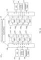
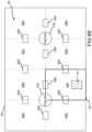
- FIG. 1 Adepicts a system 100 for generating and using a multimodality hanging protocol.
- the system 100includes a plurality of medical imaging devices, such as a first magnetic resonance imaging (MRI) machine 102 , a first ultrasound imaging machine 104 , and a first mammogram/tomosynthesis imaging machine 106 . While not depicted, other types of imaging devices, such as computed tomography (CT) or positron-emission tomography (PET), may also be included.
- CTcomputed tomography
- PETpositron-emission tomography
- the medical imaging devicesare configured to generate medical images of at least some portions of a patient.
- the output of the medical imaging devicesis generally a plurality of images. The images from the various medical imaging devices are communicated to a first load balancer 108 .
- the first load balancer 108may then communicate the medical images from the medical imaging devices to a picture archive and communication system (PACS) and/or one or more workstations 110 A-D to allow for viewing and analysis of the images.
- PACSpicture archive and communication system
- the first load balancer 108may be omitted and the images from the medical imaging devices may be communicated directly to the PACS 122 and/or one or more of the workstations 110 A-D.
- some of the medical imaging devicesmay not have a network connection to the first load balancer 108 or the workstations 110 A-D. In such examples, the medical images from those medical imaging devices may be communicated to the PACS 122 and then accessed by the workstations 110 A-D via the PACS 122 .
- the workstations 110 A-Dare organized in a first cluster 124 .
- the cluster 124 of workstations 110 A-Dis typically indicative of each of the workstations 110 A-D being able to communicate with each other workstation 110 A-D.
- all the workstations 110 A-D within the clusterare located within the same facility and may be able to communicate within one another on local network at a higher bandwidth than communications with devices located outside the facility.
- one or more of the workstations 110 A-Dmay be located physically remote from one another but still located within the same network.
- one of the workstations 110 A-Dmay be designated as a super node.
- workstation 110 Amay be designated as a super node.
- the remaining workstations 110 B-Dare designated as regular nodes.
- One of the workstations 110 B-D, such as workstation 110 B,may also be designated as a standby super node.
- a patient databasemay be stored on the super node and may also be replicated or mirrored to the standby super node to support high availability.
- all calls to the supernodemay be automatically redirected to the standby super node. Automatically redirecting the calls to the standby super node may be accomplished through a failover feature programmed into the load balancer 108 .
- the database servicesmay be exposed through the use a database application programming interface (API).
- APIdatabase application programming interface
- the RESTful APImay be used.
- the RESTful APIis based on representational state transfer (REST) technology, and generally uses HyperText Transfer Protocol (HTTP) operations and requests such as GET, PUT, POST and DELETE data.
- HTTPHyperText Transfer Protocol
- GET, PUT, POST and DELETE datadata that requests to and from external devices, such as PACS
- DICOMDigital Imaging and Communications in Medicine
- DICOMDigital Imaging and Communications in Medicine
- PACSDigital Imaging and Communications in Medicine
- DICOM storage requests from external devicesmay be routed to every node in the cluster 108 .
- the DICOM objects receivedmay be propagated to all nodes in the cluster using a distributed downloading protocol, such as the BITTORRENT protocol.
- the databasemay then be updated by the receiving node by calling the database service API of the super node. Every node in the cluster 124 may then retrieve the patient list from the super node through service API calls and open images stored locally to achieve higher performance.
- the patient listmay be a subset of patients that are filtered by one or more criteria.
- the patients in the patient listhave associated medical images that may be retrieved and viewed on one or more of workstations 110 A-D.
- the load balancer 108receives the request and passes it to the super node.
- the super nodethen fetches images from the PACS 122 and propagates the images to all nodes in the cluster 124 through the same distribution process.
- a node other than the super nodemay fetch the images from the PACS 122 .
- the cluster 124utilizes a peer-to-peer distribution system for images with information about each image stored in the super node as an index.
- the indexcomprises a directory of the images on the cluster 124 and which of the workstations contains the image.
- a node retrieving requesting an imagemay access the super node in the cluster 124 and obtain portions of the image from all the nodes in the cluster 124 according to the index.
- the system 100may also include a second facility or network with second plurality of medical imaging devices, such as a second magnetic resonance imaging (MRI) machine 112 , a second ultrasound imaging machine 114 , and a second mammogram/tomosynthesis imaging machine 116 .
- the second plurality of medical imaging devicesmay be connected to a second load balancer 118 and a second cluster 126 of workstations 120 A-D.
- the communication between the PACS 122 , the second cluster 126 of workstations 120 A-D, the second load balancer 118 , and the second plurality of medical imaging devicesmay be substantially the same as discussed above with respect to the first cluster 124 .
- the second load balancer 118may be omitted, and the second cluster 126 may be in communication with the first load balancer 118 which may serve the second cluster 126 in a similar manner as to how the first load balancer 118 serves the first cluster 124 .
- FIG. 1 Bdepicts an example of a suitable operating environment for incorporation into the system 100 of FIG. 1 A .
- the operating environmentmay be suitable for incorporation and use with the workstations of system 100 .
- operating environment 150typically includes at least one processing unit 152 and memory 154 .
- memory 154storing instructions to perform the active monitoring embodiments disclosed herein
- memory 154may be volatile (such as RAM), non-volatile (such as ROM, flash memory, etc.), or some combination of the two.
- This most basic configurationis illustrated in FIG. 1 B by dashed line 156 .
- environment 150may also include storage devices (removable 158 , and/or non-removable 160 ) including, but not limited to, solid-state storage, magnetic or optical disks or tape.
- environment 150may also have input device(s) 164 such as keyboard, mouse, pen, voice input, touch input, etc. and/or output device(s) 166 such as a display, speakers, printer, etc.
- input device(s) 164such as keyboard, mouse, pen, voice input, touch input, etc.
- output device(s) 166such as a display, speakers, printer, etc.
- the environment 150may include a touchscreen that allows for both display and input.
- the input devices 164may also include one or more antennas to detect signals emitted from the various the performance tracking devices 102 .
- connections 162may be operable to facilitate point-to-point communications, connection-oriented communications, connectionless communications, etc.
- Operating environment 150typically includes at least some form of computer readable media.
- Computer readable mediacan be any available media that can be accessed by processing unit 152 or other devices comprising the operating environment.
- Computer readable mediamay comprise computer storage media and communication media.
- Computer storage mediaincludes volatile and nonvolatile, removable and non-removable media implemented in any method or technology for storage of information such as computer readable instructions, data structures, program modules or other data.
- Computer storage mediaincludes, RAM, ROM, EEPROM, flash memory or other memory technology, CD-ROM, digital versatile disks (DVD) or other optical storage, magnetic cassettes, magnetic tape, magnetic disk storage or other magnetic storage devices, or any other non-transitory medium that can be used to store the desired information.
- Computer storage mediadoes not include communication media.
- Computer storage mediamay be referred to as computer storage devices.
- Communication mediaembodies computer readable instructions, data structures, program modules, or other data in a modulated data signal such as a carrier wave or other transport mechanism and includes any information delivery media.
- modulated data signalmeans a signal that has one or more of its characteristics set or changed in such a manner as to encode information in the signal.
- communication mediaincludes wired media such as a wired network or direct-wired connection, and wireless media such as acoustic, RF, infrared, microwave, and other wireless media. Combinations of the any of the above should also be included within the scope of computer readable media.
- the operating environment 150may be a single computer operating in a networked environment using logical connections to one or more remote computers.
- the remote computermay be a personal computer, a server, a router, a network PC, a peer device or other common network node, and typically includes many or all of the elements described above as well as others not so mentioned.
- the logical connectionsmay include any method supported by available communications media.
- FIG. 2 Adepicts an example user interface 200 for creating a multimodality hanging protocol.
- the user interface 200includes a workspace 202 having a plurality of viewports 204 A-H.
- the workspace 202is split into a plurality of segments, and in the present example, the workspace is split into eight segments, or octants, with each octant being a separate viewport 204 A-H.
- Each of the viewports 204 A-Hmay also be referred to herein as tiles.
- the user interface 200also includes an editor bar 218 with a plurality of building blocks 214 and a display of the current hanging step 212 .
- the display of the current hanging step 212shows a miniature live view of the workspace 202 for the particular hanging step.
- the display of the current hanging step 212also indicates the number of the hanging step. For example, the display of the current hanging step 212 displayed indicates in the upper left-hand corner that it is the first hanging step in the hanging protocol with the number “01.” If the “Back to Steps” option above the display of the current hanging step 212 is selected, the editor bar 218 displays a sequence of hanging steps that may be edited. A particular hanging step from the sequence of hanging steps may then be selected for further editing.
- the building blocks 214represent medical images that will be displayed for a patient.
- the building block 214is associated with a modality and a view.
- the building block “Left CC”is an x-ray image, such a mammography or tomosynthesis image, of the left breast taken at the cranio-caudal (CC) view.
- the “Right MLO” building blockis an x-ray image, such as a mammography or tomosynthesis image, of the right breast taken at the medio-lateral oblique view.
- other building blocks 214 for other modalitiessuch as MRI, CT, PET, and/or ultrasound, may also be displayed for use.
- Additional building blocksmay also be accessed by selecting a different building block category option 216 .
- the hanging protocolmay be specific to medical images of breasts.
- the hanging protocolmay relate to other portions of the body and the building blocks may be specific to that portion of the body.
- the building blockscan be dragged and dropped into the workspace 202 to fill the viewports.
- viewport 204 A and viewport 204 Bhave already been filled with building blocks 214 .
- viewport 204 Ahas been filled with the “Right CC” building block and viewport 204 B has been filled with the “Left CC” building block.
- the remaining viewports 204 C-Hare empty and may receive a building block.
- a menu of options 220is displayed for further configuration of the building block 214 in the particular viewport.
- the menu of options 220may include options for laterality (i.e., left or right breast), view, modifiers, image type, time point (e.g., current or a number of prior images), and chest wall location (i.e., is the chest wall on the left or right side of the image).
- Each optionmay be modified through the use of a drop down menu or similar menus.
- the optionsmay also be set to “User Preference,” which is the example option displayed for “Image Type” in FIG. 2 A .
- the image that is importedwill be displayed according to the particular user preferences of the radiologist accessing images according to the customized hanging protocol. For instance, a first radiologist may generate the hanging protocol and share it with a second radiologist. Each radiologist may have stored user preferences that differ from those of other radiologists. As such, the hanging protocol may still be used by the second radiologist, but the user preferences of the second radiologist will be applied rather than the personal preferences of the first radiologist.
- Layer options 222may also be displayed in a filled viewport, such as viewports 204 A-B. By selecting the arrows in the layer option 222 , current or prior images may be selected for display.
- the layersmay also include other views or images that that are not related by time points, such as equivalent or modified views.
- the viewports 204 A-Hare visually separated with dashed separation lines of a smart grid.
- the vertical separation lines(which separate columns) may include a column hotspot 206 A-D.
- the column hotspots 206 A-Dallow for an automatic expansion of a building block 214 into two columns when the building block 214 is dragged onto one of the column hotspots 206 A-D. For instance, if the building block 214 is dropped on the column hotspot 206 A, the building block 214 fills both viewport 204 C and viewport 204 D.
- the horizontal separation lines(which separate rows) may include a row hotspot 208 A-B.
- the row hotspots 208 A-Ballow for an automatic expansion of a building block 214 into two rows when the building block 214 is dragged onto one of the row hotspots 208 A-B. For instance, if the building block 214 is dragged onto hotspot 208 A, the building block 214 fills both viewport 204 C and viewport 204 G. At the intersection of the vertical and horizontal separation lines, a quadrant hotspot 210 may be displayed. The quadruple hotspot 210 allows for an automatic expansion of a building block 214 into the four viewports surrounding the quadruple hotspot 210 .
- the hotspotsallow for more efficient, quick, customizable and intuitive way of resizing and filling of building blocks 214 into the workspace 202 .
- the hotspot functionalityallows for the user to quickly fill the building blocks in the hanging protocols just in the way that the user would prefer.
- the quadruple hotspot 210may also be referred to as a single tile hotpot.
- Some categories of building blocksmay include composite building blocks that fill more than one viewport.
- the composite building blocksare effectively a combination of multiple individual building blocks.
- An example composite building blockmay be a “Right CC” building block and a “Left CC” building block paired together. Such a composite building block is two columns wide and one row high. As such, if the composite building block is dragged into viewport 204 E, it fills viewports 204 E- 204 F. Additional sizes and configurations of composite building blocks are also contemplated, such as: one row by three columns; one row by four columns; two rows by one column; two rows by two columns; two rows by three columns; two rows by four columns; and so on.
- Composite building blocksmay also be composed of a combination of individual building blocks of different imaging modalities.
- FIG. 2 Bdepicts another example of the editor bar 218 with the “Compare Current-All Priors” category option 216 selected.
- the editor bar 218is populated with composite building blocks 214 that have a dimension of one row by two columns.
- one composite building block 214is “Current/All Priors RCC.” That building block includes the current right breast CC image and all the prior right breast CC images in a stack displayed adjacent the current right breast CC image. Stacked images are discussed in further detail below with respect to FIG. 2 F .
- FIG. 2 Cdepicts another example of the editor bar with the “Overview” category option 216 selected.
- the editor bar 218is populated with composite building blocks 214 that have a dimension of two rows by four columns.
- Each of the composite building blocks 214 in the “Overview” categoryare intended to fill the entire workspace 202 .
- the composite building blocks 214include individual building blocks arranged so as to provide a desired overview of the breast images.
- FIG. 2 Ddepicts another example of the editor bar 218 with the “MRI” category option 216 selected. With the “MRI” category option 216 selected, the editor bar 218 is populated with building blocks 214 related to MRI images.
- FIG. 2 Edepicts another example of the editor bar 218 with the “Ultrasound” category option 216 selected. With the “Ultrasound” category option 216 selected, the editor bar 218 is populated with building blocks 214 related to ultrasound images.
- FIG. 2 Fanother example user interface 200 for creating a multimodality hanging protocol with a stacked building block in a viewport.
- that building blockmay include additional prior layers.
- a “Left CC” building blockmay also be configured to include prior CC images of left breast.
- the prior images included with the building blockare stacked such that one medical image for the patient will be displayed in the respective viewport, and the prior images can be scrolled or stepped through via user interaction.
- the order and number of prior images that are to be stacked according to the hanging protocolcan be configured through the user interface features depicted in FIG. 2 F . For example, by selecting the layer option 222 , a drop down layer ordering menu 224 may be displayed.
- the layer ordering menu 224provides a list of the view or images that are stacked in the current viewport or building block. Each view or image in the list includes a numerical indicator that indicates a relative to one another. For instance, the image “RMLO1” was taken more recently than the image “RMLO2.”
- the ordering of the imagesmay be altered by the user creating/editing the hanging protocol. The image ordering may be altered by using the up or down arrows shown next to each image or the images can be dragged and dropped in a new order. When actual medical images are imported according to the hanging protocol, they will be stacked according to the order set in the ordering menu 224 . The user may then click through or scroll through the images. Images other than prior images may also be stacked.
- modified or equivalent viewsmay also be added to the stack. Adding additional images to the stack may be accomplished by selecting the add layer option 223 . Accordingly, even where a building block may not initially include stacked views or images, layers corresponding to different views or images can be added to create a stack by selecting the add layer option 223 . In some examples, layers may be added to the stack by dragging additional building blocks onto a filled viewport. Layers may also be deleted through the selection of a delete layer option 225 . In some examples, the delete layer option 225 may also be used to remove the building block that fills the viewport.
- FIG. 3 Adepicts an example user interface 300 for creating a multimodality hanging protocol with a composite building block 314 .
- the user interface 300is substantially similar to the user interface 200 discussed above with reference to FIG. 2 A and may be displayed when a composite building block of one row by two columns is selected.
- user interface 300includes a workspace 302 that includes a plurality of viewports 304 A-H.
- the workspace 302also includes two quadruple hotspots 310 A-B.
- the workspace 302also includes an octuple hotspot 330 .
- the octuple hotspot 330allows for an automatic expansion of the composite building block into all eight viewports 304 A-H.
- the octuple hotspot 330may also be referred to as a double tile hotspot.
- FIG. 3 Bdepicts the example user interface 300 of FIG. 3 A with the composite building block 314 being dragged onto the workspace 302 .
- a drop zone outline 332is displayed to indicate which of the viewports 304 A-H will be filled with the composite building block 314 .
- the drop zone outline 332may be a color indicator, a bolding of the borders of the viewports that will be filled, or any other highlighting or indicator that indicates which viewports will be filled by the composite building block.
- the composite building block 314has been dragged over viewport 304 F. Because the composite building block 314 is one row high and two columns wide, the drop zone outline 332 indicates that both viewport 304 E and viewport 304 F will be filled by the composite building block 314 .
- FIG. 3 Cdepicts the example user interface 300 of FIG. 3 A with the composite building block 314 being dragged onto the quadruple hotspot 310 A.
- the drop zone outline 332updates to show that viewports 304 A-F will be filled if the composite building block 314 is dropped in that location.
- FIG. 3 Ddepicts the example user interface 300 of FIG. 3 A with the composite building block 314 being dragged onto the octuple hotspot 330 .
- the drop zone outline 332updates to show that all the viewports (i.e., viewports 304 A-H) will be filled if the composite building block 314 is dropped in that location.
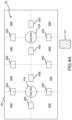
- FIG. 4 Adepicts an example user interface 400 for creating a multimodality hanging protocol with a building block 414 .
- the user interface 400is substantially similar to the user interface 200 depicted in FIG. 2 A , with the exception that all the viewports 404 A-H are empty in user interface 400 .
- the user interface 400includes a workspace 402 which has a plurality of column hotspots 406 A-F, a plurality of row hotspots 408 A-D and a plurality of quadruple hotspots 410 A-B.
- FIG. 4 Bdepicts the example user interface 400 of FIG. 4 A with the building block 414 being dragged onto the workspace 402 .
- a drop zone outline 432is displayed to indicate which of the viewports 404 A-H will be filled with the composite building block 414 .
- the building block 414has been dragged over viewport 404 F. Because the building block 414 is one row high and one column wide, the drop zone outline 432 indicates that only viewport 404 F will be filled by the building block 414 .
- FIG. 4 Cdepicts the example user interface 400 of FIG. 4 A with the building block 414 being dragged onto the column hotspot 406 D.
- the drop zone outline 432updates to show that the viewports 404 E-F will be filled by the building block 414 if the building block 414 is dropped at that location.
- FIG. 4 Ddepicts the example user interface 400 of FIG. 4 A with the building block 414 being dragged onto the row hotspot 408 A.
- the drop zone outline 432updates to show that the viewport 404 A and the viewport 404 E will be filled by the building block 414 if the building block 414 is dropped at that location.
- FIG. 4 Edepicts the examples user interface 400 of FIG. 4 A with the building block 414 being dragged onto the quadruple hotspot 410 A.
- the drop zone outline 432updates to show that the viewports 404 A-B and the viewports 404 E-F will be filled by the building block 414 .
- Different workspacesmay be displayed depending on the type of building block that is selected from the editor bar.
- the workspace displayed in the user interfacemay dynamically update based on the type of building block that is selected to be added to the hanging protocol.
- the workspace 400 depicted in FIG. 4 Amay be displayed.
- the workspace 300 depicted in FIG. 3 Amay be displayed.
- the different workspacesinclude different hotspots that are specific to the type or size of the building block. As such, the user is provided with additional dynamic information as to where the building block may be placed.
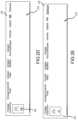
- FIG. 5 Adepicts an example user interface 500 for creating a hanging protocol that extends across a first display screen 501 and a second display screen 503 .
- the first display screen 501 and the second display screen 503may be physically separate screens, or they may be virtual display screens such that a hanging protocol for two screens can be configured from a single screen.
- the user interface 500is substantially similar to the user interface 300 depicted in FIG. 3 A .
- the user interface 500includes workspace 502 A that has a plurality of viewports 504 A-H, two quadruple hotspots 510 A-B, and an octuple hotspot 530 .
- the octuple hotspot 530is split over the two different display screens.
- the workspace 502 Ais most often used when a composite building block, such as composite building block 514 , is selected.
- FIG. 5 Bdepicts another example user interface 500 for creating a hanging protocol that extends across a first display screen 501 and a second display screen 503 .
- the user interface 500includes a workspace 502 B that is most often used when a building block having a one row by one column dimension, such as building block 514 , is selected.
- the workspace 502 Bincludes a plurality of viewports 506 A-H, two quadruple hotspots 510 A-B, four column hotspots 506 A-D, and four row hotspots 508 A-D.
- the workspace 502 Bis similar to the workspace 400 depicted in FIG. 4 A with exception that workspace 502 B has been split between two display screens and the middle column hotspots and quadruple hotspot have been removed.
- FIG. 6depicts an example user interface 600 for resizing a building block 614 in generating a hanging protocol.
- a building block 614may be resized, and a drop zone outline 632 is displayed to show where the building block will be displayed.
- the display of the building block 614is constrained to fit the entirety of one or more of the viewports 604 A-H.
- a drop zone outline 632is displayed to indicate the final size of the building block 614 if the user was to stop dragging the edge of the building block 614 . That is, if the building block 614 was let go at the point depicted in FIG. 6 , the building block would snap to fill viewports 604 A-B.
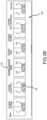
- FIG. 7 Adepicts an example display 700 of a hanging step of a hanging protocol populated with medical images of a patient.
- the display 700resulted from a hanging protocol that had a Right CC building block in viewport 704 A, a Left CC building block in viewport 704 B, an ultrasound building block extending across viewports 704 C-D, a Right MLO building block in viewport 704 E, a Left MLO building block in viewport 704 F, and an MRI building block extending across viewports 704 G-H.
- each of the viewportshas been populated with the corresponding medical image.
- each viewport(or combination of viewports) showing the medical images, and at least a portion of those tools or options may be specific to the type of imaging modality used to capture the image.
- an options icon 710is displayed within the viewports 704 G-H.
- the options icon 710when selected, displays a set of options for modifying the displayed MRI image that are specific to the MRI imaging modality, such as colorization.
- the options icon 710may also be moved or dragged to other locations within the display of the MRI image if desired.
- Other options icons 710may be generated or placed over other displayed images.
- the options associated with the respective options icons 710are context sensitive in that the options will be based on the imaging modality for which the options icon is placed or associated.
- Additional advantagesmay be achieved by having multiple modalities and context-sensitive tools and options being displayed concurrently on the same display. For instance, an abnormality that appears in on one imaging modality can now be more easily and efficiently be viewed on a second imaging modality concurrently and, optionally, even side-by-side, to help facilitate diagnoses and analysis by the radiologist. This is particularly helpful when the images from varying modalities are acquired at different times, thus, making more critical the potential need to see the same abnormality across different imaging modalities.
- Additional options and toolsare displayed within the lower toolbar or chrome 712 .
- a plurality of toolswill be displayed. Tools may include magnification, continuous zoom, ellipse, ruler, reset, and close study tools.
- each displayed toolmay be dragged and dropped into the shortcut section 716 of the chrome 712 .
- the toolis also then available in a secondary selection menu that is displayed when a user provides a secondary selection input, such as a right-click or a long press on a touch screen device. For example, a user may right-click anywhere on the display to generate the secondary selection menu.
- Other options and toolsmay also be dragged into the shortcut section 716 as well.
- the toolsmay also be dragged to other areas of the display to allow quick access to the tools in a certain location.
- the tools for each radiologistmay be customized by the radiologist herself.
- the ordering the toolsmay also be altered by the radiologist.
- the ordering of the toolsmay be altered by dragging and dropping the tools in the shortcut section 716 .
- the altered orderingmay also be reflected in the secondary selection menu.
- the tools that have been placed into the shortcut section 716may be saved as personal preferences for the radiologist. By providing the customization features the radiologist does not need to navigate away from the images to find the proper tools to analyze the images.
- the customizationsare also achieved without the need to visit other pages, such as a settings page.
- FIG. 7 Bdepicts the results of an example MRI building block in a viewport 718 during image review.
- the example MRI building block in FIG. 7 Bmay be the MRI building block extending across viewports 704 G-H in FIG. 7 A .
- the viewport 718includes an example of the options icon 710 after it has been selected, which causes the display of the MRI toolbar 720 .
- the MRI toolbar 702includes a set of options or tools that are applicable to the MRI building block.
- the options displayed in the MRI toolbar 720depend on the type of MRI building block or MRI image.
- the options displayed in the MRI toolbar 720may change based on the type of MRI building block or MRI image.
- the order of the options in the MRI toolbar 720may also change based on the type of MRI building block or MRI image.
- the options in the MRI toolbar 720may include a variety of options for manipulating the MRI image displayed in the viewport 718 .
- a MIP optionmay be included.
- the maximum intensity projection (MIP) option 722allows for toggling between a two-dimensional (2D) and a MIP view.
- a views option 724may also be included in the MRI toolbar 720 .
- the views option 724when selected, may provide views for the MRI image that may be selected. For example, the displayed “AX” indicates the current view is an axial view.
- Other potential selectable views from the views option 724may include sagittal views or coronal views.
- a subtraction option 726may also be included in the MRI toolbar 720 .
- the subtraction option 726allows for MRI subtraction to be toggled on or off.
- a color option 728may also be included in the MRI toolbar 720 .
- the color option 728allows for colorization to be toggled on or off. In some examples, the colorization may also be set to a different threshold (i.e. 50%) through the color option 728 .
- a noise option 730may also be included in the MRI toolbar 720 .
- the noise option 730allows for toggling different colorization noise filters for the displayed MRI image. For instance, the colorization noise level may be set to off, low, or high.
- a lesion highlight option 732may also be included in the MRI toolbar 720 .
- the lesion highlight option 732allows for toggling a lesion highlight and focus feature on or off.
- the lesion highlight option 732may be set to off, lesion highlight, or lesion highlight and focus (LH/F).
- a graph option 734may also be included in the MRI toolbar 720 .
- the graph option 734allows for the display of a graph (i.e. contrast enhancement curve) to be turned on and off.
- a treatment response option 736may also be included in the MRI toolbar 720 .
- the treatment response option 736allows for the display of treatment response features to be turned on and off. For each of the options in the MRI toolbar 720 , hovering a pointer over any menu option will cause additional information about the particular menu option to provide additional insight to the particular menu option.
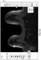
- FIG. 7 Cdepicts another example display 750 of an MRI image.
- the example display 750also includes the options icon and the MRI toolbar 720 .
- the MRI imagealso includes an orientation square 752 and an orientation circle 754 .
- the orientation square 752 and the orientation circle 754indicate the orientation of the patient.
- the orientation square 752includes a set of orientation indicators that correspond to the patient orientation, such as “A” for anterior, “P” for posterior, “R” for right, “L” for left, “H” for head and “F” for foot.
- the orientation circle 754includes many similar orientation indicator representations. While the orientation square 752 and the orientation circle 754 provide some indications of orientation, such interface elements can often lead to confusion and may not provide clear guidance regarding the orientation of the MRI image that is being displayed.
- the present technologyprovides a new guidance system for conveying orientation information of a patient.
- the present technologymay utilize a human figurine in place of the orientation square 752 and/or the orientation circle 754 .
- FIG. 7 Ddepicts an example display 760 with the human orientation indicator 762 .
- the orientation of the patient that corresponds to MRI imageis much easier to discern from the human orientation indicator 762 .
- a quick look at the human orientation indicator 762reveals that in the MRI image in the example display 760 , the view is looking from the patient's feet towards the patient's head, and the right-hand side of the image is the patient's left-hand side.
- the human orientation indicator 762may rotate as different images of different orientations are displayed in the display 760 .
- the present technologymay determine the orientation for the image by analyzing header information, such as DICOM header information, or analyzing other properties of the displayed image.
- the human orientation indicator 762is displayed in the corresponding orientation.
- the example display 760also displays another example of the MRI toolbar 720 .
- FIG. 7 Edepicts another example display 764 with the human orientation indicator 762 in another orientation. From the orientation of the human orientation indicator 762 in the display 764 , a quick determination may be made that the displayed image is of the patient facing the viewer with the head of the patient towards the top of the display 764 and the foot of the patient towards the bottom of the display 764 . Changing the orientation of the displayed image will dynamically change the orientation of the human orientation indicator.
- the display 764also includes a compact image reference identifier 770 .
- the image identifier 770includes the type of image, which is represented by the “DYN”.
- the amount of time that has elapsed since the image was takenis identified by an elapsed time indicator, which is displayed as a superscript to the compact image reference identifier 700 in the example depicted in FIG. 7 D .
- the superscriptmay also include a color to indicate if the elapsed time is within expected, predetermined, or recommended limits. For example, in breast cancer screening, a screen may be expected or recommended to have occurred annually.
- the superscriptmay appear green. If the time elapsed is between one year and two years, the superscript may appear yellow, and if the time elapsed is greater than two years, the superscript may appear red. Other indicators besides color that connote similar concepts may also be used. In addition, other time frames may also be used.
- the elapsed time indicatormay be in a form other than a subscript number of the compact reference identifier 770 . For instance, the elapsed time indicator may be displayed adjacent to the compact reference identifier 770 , but not necessarily as a superscript.
- a subscript of the compact image reference identifier 770may indicate a prior image indicator indicating how many images the displayed image is prior to the most recent acquired image.
- the prior image indicatormay be in the form a subscript number of the compact image reference identifier 770 .
- the “1” subscript for the compact image reference identifier 770 in FIG. 7 Dindicates that the displayed image was the first prior image acquired prior to the most recent acquired image (the most recent acquired image may have a subscript value of 0).
- the prior image indicatormay also include a color to represent the relative prior number of images. For example, the prior image indicator for prior images 1 - 3 may appear green.
- the prior image indicatormay appear yellow, and for prior images greater than or equal to 7, the prior image indicator may appear red.
- Other indicators besides color that connote similar conceptsmay also be used, and other ranges of prior images may also be used.
- the prior image indicatormay be in a form other than a subscript number of the compact reference identifier 770 . For instance, the prior image indicator may be displayed adjacent to the compact reference identifier 770 , but not necessarily as a subscript.
- FIG. 7 Fdepicts another example display 766 with the human orientation indicator 762 in yet another orientation.
- a quick determinationmay be made that the displayed image is of the patient's left-hand side facing the viewer with the patient's head towards the top of the display 766 .
- FIG. 7 Gdepicts an example method 701 for displaying orientation data for medical imagery.
- a medical imageis accessed.
- the medical imagemay be an MRI image or an image from another imaging modality.
- an orientation of the medical imageis determined.
- the orientation of the medical imageis the orientation of the patient relative to the imaging modality.
- the orientation of the medical imagemay be determined by analyzing data in the header of the medical image or through an analysis of the medical image itself.
- the displayed image orientationmay be different than acquired image orientation.
- the displayed image orientationmay be used for the orientation determination in operation 705 .
- an orientation indicatoris generated for the determined orientation at operation 709 .
- the orientation indicatormay be one of the human orientation indicators discussed above.
- the orientation indicatormay be an image of a human figurine in the determined orientation.
- the orientation indicatormay also be a graphical or schematic depiction of the tissue, anatomy, or portion of the patient that is being imaged.
- the generated orientation indicatoris displayed concurrently with the accessed medical image.
- the orientation indicatoris interactive and may be manipulated to retrieve medical images at different orientations.
- the method 700may continue to operation 711 where an interaction with the orientation indicator is received.
- the interactionmay include a selection of the orientation indicator with an input device, such as a mouse, pointer, or touch, and a drag or swipe motion to rotate the orientation indicator.
- the interactionmay indicate a rotation about the saggital axis, the frontal axis, and/or the vertical axis of the patient.
- a new orientationis determined at operation 713 . For example, where the orientation indicator is rotated, the resultant orientation of the orientation indicator is determined to be the new orientation.
- a second medical imageis retrieved that corresponds to the new orientation determined at operation 713 .
- the second medical imageis displayed and may be displayed concurrently with the orientation indicator in an updated orientation corresponding to the orientation resulting from the interaction in operation 711 .
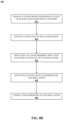
- FIG. 8 Adepicts an example method 800 for generating and using a customized hanging protocol.
- an indicationis received to create a hanging step of the hanging protocol.
- the indicationmay be a user selection to create a new hanging protocol or a new step with the hanging protocol. Where a new hanging protocol is being created, the indicated may be to create a first step of the hanging protocol. Where a hanging protocol is already being developed or customized, the indication may be to create a second or third hanging step.
- a workspaceis displayed that has a plurality of viewports or tiles for displaying medical images. The viewports may be indicated by a smart grid that separates the viewports based on columns and rows.
- the workspacemay have eight viewports that are displayed in two rows and four columns.
- the workspacemay also include a plurality of hotspots.
- the hotspotsare configured to expand a building block across at least two of the viewports within the workspace.
- the plurality of hotspotsmay include at least one of a column hotspot, a row hotspot, a quadruple hotspot, or an octuple hotspot.
- a plurality of building blocksare displayed.
- the building blockscorrespond to different types or view of medical images.
- the building blocksmay include any of the building blocks discussed above, such as singular or composite building blocks.
- the building blocksmay be displayed in an editor bar that includes a plurality of building block category options. Selection of the building block category options causes the display of additional or different building blocks associated with the category.
- a selection of a building block from the plurality of the building blocksis received.
- the selectionmay be received via an input device, such as the click of a mouse or through touch input.
- the display of the workspacemay optionally be updated at operation 810 based on the type of building block selected in operation 808 .
- the displayed hotspotsmay change based on whether the selected building block is a single building block or a composite building block.
- an indication of a location in the workspace for the building block to be placedis received. The indication of the location may be part of a drag-and-drop interaction where the building block is dragged across the workspace to a desired location.
- the building blockmay be selected and then the location for the building block may be subsequently selected.
- a drop zone outline for the building blockmay be displayed based on the location of the building block and, in some examples, the type of the building block and/or the dimensions of the building block. For instance, as the building block is being dragged across the workspace, the drop zone outline is displayed based on the current location of the building block as it is being dragged across the workspace. In an example, while the selected building block is dragged across the workspace, the drop zone outline is displayed and dynamically updated based on a location of the building block relative to the workspace as it is being dragged.
- the drop zone outlinedynamically highlights one or more of the plurality of viewports for which the first building block will fill if it were dropped at the present location during the drag operation. For example, if the building block is dragged over a hotspot, the number of viewports that are highlighted by the drop zone outline corresponds to the type of hotspot.
- one or more of the plurality of viewportsis filled with the selected building block based on the indicated location in the workspace received in operation 812 . The number of viewports that are filled depends on whether the indicated location is a hotspot and the type or dimensions of the selected building block.
- the different building blocks used to fill the workspacemay correspond to different imaging modalities.
- a first building blockmay correspond to a first imaging modality, such as an x-ray imaging modality
- the second building blockmay correspond to a second imaging modality, such as an MRI imaging modality.
- the processflows from operation 820 to operation 822 where the hanging protocol as customized by method 800 is stored for later importation of medical images of a patient according to the filled viewports of the workspace.
- the customized hanging protocolmay be stored locally or remotely such that it can be accessed from different devices or workstations.
- the hanging protocolmay also be stored such that others have limited access to access or edit the hanging protocol.
- FIG. 8 Bdepicts an example method 830 for configuring a stack of images or views in a viewport of a hanging protocol.
- the method 830may be performed as part of, or in conjunction with, the method 800 depicted in FIG. 8 A .
- a layer optionis displayed within a viewport that has been filled with a building block.
- the layer optionis provided for editing layers of images or views associated with the filled viewport.
- a selection of the layer optionis received, and upon receiving the selection of the layer option, a layer ordering menu is displayed at operation 836 .
- the layer ordering menuincludes a plurality of stacked layers corresponding to medical images.
- an indicationis received to add, remove, or reorder one or more of the layers in the stacked layers.
- the indication to add one or more layersmay be received via a selection of an add layer option and the indication to remove one or more layers may be received via a selection of a delete layer option.
- the indication to reorder the layersmay be received via a drag and drop reordering of the displayed layers in the layer ordering menu.
- the indication to reorder the layersmay also be made through the selection of up and down arrows (or similar indicators) displayed within each of the displayed layers in the layer ordering menu.
- the reordering of the stacked layersmay be stored. Storing the reordering of the stacked layers may be triggering by the selection of a confirmatory option, such as an apply button, displayed within the layer ordering menu.
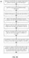
- FIG. 8 Cdepicts an example method 850 for displaying medical images of a patient according to a stored hanging protocol.
- a selection of a patient for which medical images are to be importedis received. The selection may be received from a user selecting the patient's name from a list of patient names for which medical images are available.
- a selection of a stored hanging protocolis received. The selection may be received from a user, such as a radiologist, selected a hanging protocol that the radiologist previously customized and stored. The selected hanging protocol may also be a hanging protocol that was customized by another radiologist and shared, or otherwise made accessible, to the current user or radiologist.
- the selection of the stored hanging protocolmay be made automatically according to a default hanging protocol that is associated with the current user or radiologist.
- the stored hanging protocolmay also be modified by stored personal preferences of the user or radiologist performing the review. For example, where certain options of a building block or viewport of the hanging protocol have been set to a value of “user preference” (or equivalent setting), the stored user settings for the present user selecting the hanging protocol in operation 854 may be accessed or retrieved. Those accessed user preferences may then be used to modify the selected hanging protocol according to the options set within the hanging protocol.
- medical images for the selected patientare imported.
- the medical imagesmay be present locally on the device executing the method 850 or may be retrieved from a remote source, such as one or more other workstations within a cluster or from a PACS.
- a remote sourcesuch as one or more other workstations within a cluster or from a PACS.
- the imported medical imagesare displayed according the selected stored hanging protocol.
- a set of tools for analyzing or modifying the displayed medical imagesis displayed.
- the set of toolsmay be displayed in a chrome displayed adjacent to the medical images.
- the set of toolsmay also be displayed upon the selection of a tools icon, which also may be displayed within the chrome.
- the set of toolsmay include at least one of a magnification, continuous zoom, ellipse, ruler, reset, or close study tool.
- an indication to add a selected tool of the set of tools into a shortcut sectionis received.
- the shortcut sectionmay be displayed in the chrome.
- the shortcut sectionmay be moved or relocated to other areas of the workspace.
- the indication to add the selected tool to the shortcut sectionmay be received as a drag-and-drop operation.
- a usermay drag the tool from the set of tools into the shortcut section.
- the selected toolis added to the shortcut section in operation 864 .
- the selecting toolis made available, or added to, a secondary selection menu that is accessible from a secondary selection, such as a right-click of a mouse or long press on a touch screen.
- a secondary selection menuis accessible from a secondary selection, such as a right-click of a mouse or long press on a touch screen.
- a radiologistWhen a radiologist identifies a potential abnormality in a medical image, the radiologist does not want to navigate away from the identified abnormality to continue the analysis.
- the radiologistBy having the desired tools for additional markup or analysis readily available at any location where an abnormality may be identified provides a useful improvement to the user interface for the radiologist.
- the medical image corresponding to the building blockis retrieved and displayed.
- Images from some imaging modalitiesare easier to identify and retrieve than others.
- mammographyoffers well defined and standardized view labels with associated modifiers, which uniquely identify and represent each acquired image/view, thus allowing the creation of well-defined hanging protocols for image review on a diagnostic workstation.
- MRIdoes not offer similar standardized labeling to associate the different types of images or volumes acquired during a breast MRI examination.
- MRI imagingthree dimensional (i.e., volumetric) imaging information of a region of a patient's body is acquired and displayed for diagnostic purposes.
- the MRI informationmay be acquired using a variety of modalities or protocols and a number of different acquisition devices.
- polarizing field B 0When a substance such as human tissue is subjected to a uniform magnetic field (polarizing field B 0 ), the individual magnetic moments of the excited nuclei in the tissue attempt to align with this polarizing field, but process about it in random order at their characteristic Larmor frequency. If the substance, or tissue, is subjected to a magnetic field (excitation field B 1 ) which is in the x-y plane and which is near the Larmor frequency, the net aligned moment, M z , may be rotated, or “tipped”, into the x-y plane to produce a net transverse magnetic moment Mt. A signal is emitted by the excited nuclei or “spins”, after the excitation signal B 1 is terminated, and this signal may be received and processed to form an image.
- magnetic field gradientsG x , G y and G z
- the region to be imagedis scanned by a sequence of measurement cycles in which these gradients vary according to the particular localization method being used.
- the resulting set of received MR signalsare digitized and processed to reconstruct the image using one of many well-known reconstruction techniques.
- the measurement cycle used to acquire each MR signalis performed under the direction of a pulse sequence produced by a pulse sequencer.
- Clinically available MRI systemsfor example, store a library of such pulse sequences that can be prescribed to meet the needs of many different clinical applications.
- MR image filesare usually in a vendor-independent format called Digital Imaging and Communications in Medicine (“DICOM”).
- DICOMDigital Imaging and Communications in Medicine
- each MR image filehas a header portion and a body portion.
- the header portioncontains information similar to that located in the raw data header as well as information about the specific corresponding imaging slice, e.g. image slice number.
- the body portioncontains the actual image data.
- each MR image filecontains image data about one imaging slice.
- TRrepetition time
- TEecho time
- ⁇flip angle
- T 1 and T 2relaxation times
- T 1 and T 2are two different relaxation constants that result in different image contrast highlighting different tissue components.
- T 1 -weighted imagemagnetization of the tissue is allowed to recover before measuring the MR signal by changing the TR. This image weighting is useful for post-contrast imaging.
- T 2 -weighted imagemagnetization of the tissue is allowed to decay before measuring the MR signal by changing the TE.
- the MRI imagecan be biased toward either T 1 -weighted or T 2 -weighted images, and thereby vary the contrast between tissue components (e.g., fat, muscle, and water), by choosing imaging parameters for the MRI scan, resulting in different image acquisition protocols.
- tissue componentse.g., fat, muscle, and water
- imaging parameters for the MRI scanresulting in different image acquisition protocols.
- T 1 -weighted MRI imagesfat has higher contrast and water has lower contrast.
- T 2 -weighted MRI imageswater has lower contrast and fat has higher contrast.
- air and dense bone (no fat)has the lowest contrast.
- MRI displaysfor the study of breast tissue, e.g., to identify the presence and location of cancer lesions, are well-known.
- Such MRI displays for breast tissuetypically display images showing various two-dimensional slices taken through one or both breasts, and provide the reviewer with the ability to scroll through the respective tissue image slices using a common device, such as mouse. This scrolling enables the reviewer to readily view different slices, eventually covering the entire breast region.
- a system operatormay employ the MRI scanner to acquire volumetric image information of the patient tissue (e.g., a breast) using different MRI parameters to emphasize different physiological information.
- T 2 -weighted imagesmay be acquired with one set of acquisition parameters, and would show different information from T 1 -weighted images acquired with different scanner parameters.
- a set of imagese.g., T 1 -weighted
- T 1 -weightedmay be acquired before the administration of a contrast agent, and thereafter for several time periods after the contrast agent has entered the blood stream.
- Typical MRI image acquisition protocolsinclude T 2 -weighted and multi-phase T 1 -weighted series/sequences. Some MRI image acquisition protocols also include high-resolution T 1 -weighted sequences for anatomy clinical readout only. Multi-phase T 1 -weighted sequences can include pre-contrast and post-contrast T 1 -w sequences and dynamic series. Other MRI image acquisition protocols also include advanced diffusion sequences, which measure the diffusion of water molecules in biological tissues.
- HPsvary between acquisition system manufacturers and between acquisition systems. HPs also vary depending on specific MRI parameters as set forth by a system operator for each acquisition system. Accordingly, one way to improve reading efficiency and throughput is to implement a universal HP that is not dependent on manufacturer, acquisition system or operator-set parameters, but rather sorts the MRI data based on relevant physiological parameters/data of interest to the reviewer.
- Different functional series/sequences in MRI datacan be differentiated by analyzing acquisition settings in the MRI data's DICOM header. For instance, a limited number of consistent functional sequences are used in breast MRI image acquisition protocols. These include T 1 -weighted and T 2 -weighted sequences.
- T 1 -weighted and T 2 -weighted images/sequencescan be differentiated using TR and TE.
- T 1 -weighted images/sequencestypically have a short TR and a short TE.
- T 2 -weighted images/sequencestypically have a long TR and a long TE.
- Proton density-weighted (“Rho-weighed”) sequencestypically have a long TR and a short TE.
- TEis typically shorter than TR.
- a short TRis typically less than 500 ms (the approximate average TR for a T 1 -weighted image/sequence).
- a longis typically greater than 1,500 ms.
- a short TEis typically less than 30 ms.
- a long TEis typically greater than 90 ms.
- MRI image acquisition protocolsinclude only T 1 -weighted and T 2 -weighted (with or without fat saturation) sequences to reduce procedure time.
- MRI image acquisition protocolscan also include the following classes of sequences: dynamic sequences; pre-contrast dynamic T 1 -weighted; first post-contrast dynamic T 1 -weighted; delay post-contrast dynamic T 1 -weighted; pre or post high resolution T 1 -weighted (with or without fat saturation); diffusion weighted imaging (“DWI”); and derived series images with motion correction (“MOCO”).
- a computermay receive the MRI data in the DICOM format, including the DICOM header.
- the computermay then extract the protocol details from the DICOM header.
- Protocol detailsmay include at least: TR; TE; fractional anisotropy (“FA”); inversion time (“TI”); strength of magnetic gradient (“b-value”); sequence type; and derived/secondary.
- the MRI datais categorized as a derived series with MOCO. If b-values are identified in the DICOM header, the MRI data is categorized as DWI. Diffusion sequences (DWI) can be identified by identifying b-values in their DICOM headings. Diffusion sequences can also be identified by their distinctive echo planar (EPI) sequences. If TR from the DICOM header is less than 500 ms and TE from the DICOM header is less than 30 ms, the MRI data is categorized as a T 1 -weighted sequence. On the other hand, if TR from the DICOM header is greater than 1,200 ms and TE from the DICOM header is greater than 90 ms, the MRI data is categorized as a T 2 -weighted sequence.
- DWIDiffusion sequences
- EPIdistinctive echo planar
- the DICOM headermay be further analyzed.
- the MRI dataif the spatial resolution from the DICOM header is high, the MRI data is categorized as a high resolution T 1 -weighted sequence. If the spatial resolution from the DICOM header is low, the MRI data is categorized as a low resolution T 1 -weighted sequence. While high and low spatial resolution are relative terms, in some embodiments, high spatial resolution can be any resolution smaller than 0.8-1.0 mm and low spatial resolution can be any resolution larger than 0.8-1.0 mm.
- the sequenceis additionally categorized as having fat saturation. If the DICOM header does not include an inversion time, the sequence is additionally categorized as not having fat saturation.
- the MRI datais categorized as an individual low resolution T 1 -weighted sequence. If the DICOM header does include identical TR and TE with a delay of less than 0.5 ms, the MRI data is categorized as a potential dynamic sequence.
- the sequenceis additionally categorized as having fat saturation. If the DICOM header does not include an inversion time, the sequence is additionally categorized as not having fat saturation.
- the MRI dataFor MRI data categorized as a potential dynamic sequence, if the DICOM header includes identical fractional anisotropy values, the MRI data is categorized as a raw dynamic sequence. If the DICOM header does not include identical fractional anisotropy values, the MRI data is categorized as a potential T 1 mapping sequence.
- MRI data categorized as a raw dynamic sequenceif the DICOM header includes slice numbers and left and right orientation values, then MRI data is further categorized as a dynamic sequence. Further, timing information in the DICOM header can be used to further categorize the MRI data as pre-contrast, first post-contrast, and delay post-contrast dynamic T 1 -weighted sequences, with first and delay subtractions. As described above, dynamic sequences can also be distinguished from high resolution T 1 -weighted sequences by comparing imaging spatial resolutions.
- the MRI datais categorized as a T1 mapping sequence.
- the various flip angle T1 mapping sequencescan include dynamic pre data. In such cases, the various T1 mapping acquisition sequences can repeat dynamic pre data with the only changed parameter being the flip angle.
- the sequenceis additionally categorized as having fat saturation. If the DICOM header does not include an inversion time, the sequence is additionally categorized as not having fat saturation.
- FIG. 9 Adepicts a sample first tag or label as well as a table 902 that defines the sample first tag.
- the first tag or labeloffers multiple levels of information within a single multi-digit label.
- Each digit of the labelrepresents a different feature, property, and or characteristic of the MRI data that has been analyzed.
- the first digitmay represent a first level of information, such basic functions of the MRI data (e.g., contrast enhancing dynamic sequence).
- the second digitrepresents a second level of information, such as the type of fat separation technique that was used during acquisition of the MRI data.
- the third digitrepresents a third level of information, such as subtypes of functional groups (e.g., low vs. high spatial resolution).
- the fourth digitrepresents a third level of information, such as whether motion correction was performed.
- the fifth digitmay represent a fifth level of information, such as version information for the MRI data.
- the table 902provides an example of how a five-digit label may be defined. For example, if the MRI data is a T 1 -weighted sequence, the first digit of the label is a 1. If the MRI data is a T 2 -weighted sequence, the first digit of the label is a 2. If the MRI data is a dynamic sequence, the first digit of the label is a 3. If the MRI data is a diffusion weighted sequence, the first digit of the label is a 4. If the MRI data is a susceptibility weighted sequence, the first digit of the label is a 5. If the MRI data cannot be categorized in one of the foregoing categories, the first digit of the label may be a 6, representing miscellaneous or uncategorized data.
- the fat separation of the MRI datais represented. For example, if the MRI data is non fat saturated (non FAT SAT), the second digit of the label is a 1. If the MRI data is fat saturated (FAT SAT), the second digit of the label is a 2.
- the third digit of the labelis a 1.
- the third digit of the labelis a 2.
- the third digit of the labelis a 1.
- the third digit of labelis a 2.
- the third digit of labelis a 3.
- the third digit of the labelis a 1.
- qualifierssuch as motion correction may be represented. For example, if motion correction (MOCO) has been applied, the fourth digit of the label is a 1. If no motion correction has been applied, the fourth digit may be a zero or omitted.
- the version of the motion correctionmay be represented by the actual version number. For instance, if the version of motion correction is the first version, the fifth digit in the tag is a 1.
- the example tag in FIG. 9 A(i.e., 32112) thus represents a dynamic sequence that is FAT SAT with a low temporal resolution that has had a second version of motion correction applied. While the specific example above uses numbers and five digits for the label, it should be appreciated that letters or other indicia may also be utilized for the label to represent similar information, and the number of digits may be greater or fewer than five. In addition, the digits may appear in different orders and in some examples, represent additional or different information regarding the MRI data.
- the labelmay be stored in the head of the analyzed MRI data or otherwise stored as associated with the MRI data. For instance, the label may be stored as metadata of the MRI data.
- FIG. 9 Bdepicts an example second tag or label as well as a table 902 that defines the sample second tag.
- the first tag or labeloffers multiple levels of information within a single multi-digit label. Each digit of the label represents a different feature, property, and or characteristic of the MRI data that has been analyzed.
- the second labelrepresents additional information about post-processing maps that have been generated on top of the original MRI data.
- the first digitrepresents a mapping type. For example, if the mapping is a diffusion mapping, the first digit of the label is a 1. If the mapping is a DCE mapping, the first digit of the label is a 2. Additional mapping labels may be represented by the second digit of the label. For diffusion mappings, if the mapping is an apparent diffusion coefficient (ADC) mapping, the second digit is a 1. If the mapping is a direction mapping, the second digit is a two, and if the mapping is a vector mapping, the second digit is a 3.
- ADCapparent diffusion coefficient
- the mappingis a standard or semi-quantitative DCE map
- the second digit of the labelis a 1.
- the mappingis a K trans mapping
- the second digit of the labelis a 2.
- the mappingis K ep mapping
- the second digit of the labelis a 3
- the mappingis an initial area under the time-to-signal intensity curve (IAUC) mapping
- the second digit of the labelis a 4.
- the third digit of the second labelrepresents mapping version information.
- the mappingis pixel value based version, then the third digit of the label is a 1. If the mapping is a concentration version, the third digit of the label is a 2.
- the sample second tag in FIG. 9 Bi.e., 222), represents a concentration estimation based K trans DCE mapping.
- FIG. 10represents an example method 1000 for populating a viewport of a hanging protocol with the above categorizations and tags.
- MRI datais accessed by a computer or processing device.
- the MRI datais analyzed to categorize the MRI data. Categorizing and analyzing the MRI data may be accomplished by performing the processes discussed above.
- at least one label or tagis generated for the MRI data based on the categorization for the MRI data in operation 1004 .
- operation 1006may include generating a first label, such as the example first label discussed above with reference to FIG. 9 A .
- Operation 1006may also include generating a second label, such as the example second label discussed above with reference to FIG. 9 B .
- the generated labelsmay be stored in the MRI data, such as a header or other associated metadata.
- a request to display a specific type of MRI imageis received.
- the requestmay be associated with a viewport of a hanging protocol.
- a building block for a specific type of MRI datamay be in a hanging protocol.
- a request for images corresponding to the building blocksmay be generated.
- the MRI datais identified as the specific type of MRI image that was requested in operation 1008 .
- properties of the specific type of MRI imagemay be translated or converted to a format that is the same as the label(s). That converted information may be used to query a dataset including the MRI data.
- the queryresults in MRI data having a matching label.
- the specific type of MRI image requestedmay also be compared against the generated label(s) to identify the MRI data as the specific type of MRI image that has been requested.
- the MRI datamay then be displayed in operation 1012 in response to the request received in operation 1008 .
- a systemmay have at least one processor and memory storing instructions that, when executed by the at least one processor, cause the system to perform the methods described herein.
Landscapes
- Engineering & Computer Science (AREA)
- General Engineering & Computer Science (AREA)
- Theoretical Computer Science (AREA)
- Health & Medical Sciences (AREA)
- Human Computer Interaction (AREA)
- Physics & Mathematics (AREA)
- General Physics & Mathematics (AREA)
- Epidemiology (AREA)
- General Health & Medical Sciences (AREA)
- Medical Informatics (AREA)
- Primary Health Care (AREA)
- Public Health (AREA)
- Biomedical Technology (AREA)
- Nuclear Medicine, Radiotherapy & Molecular Imaging (AREA)
- Radiology & Medical Imaging (AREA)
- Business, Economics & Management (AREA)
- General Business, Economics & Management (AREA)
- Medical Treatment And Welfare Office Work (AREA)
- Magnetic Resonance Imaging Apparatus (AREA)
- Apparatus For Radiation Diagnosis (AREA)
Abstract
Description
Claims (14)
Priority Applications (1)
| Application Number | Priority Date | Filing Date | Title |
|---|---|---|---|
| US17/296,287US12170140B2 (en) | 2018-11-25 | 2019-11-22 | Customizable multimodality image hanging protocols |
Applications Claiming Priority (4)
| Application Number | Priority Date | Filing Date | Title |
|---|---|---|---|
| US201862771127P | 2018-11-25 | 2018-11-25 | |
| US201962817352P | 2019-03-12 | 2019-03-12 | |
| PCT/US2019/062841WO2020107019A1 (en) | 2018-11-25 | 2019-11-22 | Multimodality hanging protocols |
| US17/296,287US12170140B2 (en) | 2018-11-25 | 2019-11-22 | Customizable multimodality image hanging protocols |
Related Parent Applications (1)
| Application Number | Title | Priority Date | Filing Date |
|---|---|---|---|
| PCT/US2019/062841A-371-Of-InternationalWO2020107019A1 (en) | 2018-11-25 | 2019-11-22 | Multimodality hanging protocols |
Related Child Applications (1)
| Application Number | Title | Priority Date | Filing Date |
|---|---|---|---|
| US18/936,424ContinuationUS20250132016A1 (en) | 2018-11-25 | 2024-11-04 | Multimodality hanging protocols |
Publications (2)
| Publication Number | Publication Date |
|---|---|
| US20220020475A1 US20220020475A1 (en) | 2022-01-20 |
| US12170140B2true US12170140B2 (en) | 2024-12-17 |
Family
ID=69063863
Family Applications (2)
| Application Number | Title | Priority Date | Filing Date |
|---|---|---|---|
| US17/296,287Active2041-05-18US12170140B2 (en) | 2018-11-25 | 2019-11-22 | Customizable multimodality image hanging protocols |
| US18/936,424PendingUS20250132016A1 (en) | 2018-11-25 | 2024-11-04 | Multimodality hanging protocols |
Family Applications After (1)
| Application Number | Title | Priority Date | Filing Date |
|---|---|---|---|
| US18/936,424PendingUS20250132016A1 (en) | 2018-11-25 | 2024-11-04 | Multimodality hanging protocols |
Country Status (7)
| Country | Link |
|---|---|
| US (2) | US12170140B2 (en) |
| EP (1) | EP3884499A1 (en) |
| JP (1) | JP7430720B2 (en) |
| KR (1) | KR20210095137A (en) |
| AU (1) | AU2019384828B2 (en) |
| DE (1) | DE202019006040U1 (en) |
| WO (1) | WO2020107019A1 (en) |
Cited By (1)
| Publication number | Priority date | Publication date | Assignee | Title |
|---|---|---|---|---|
| USD1080644S1 (en)* | 2022-05-16 | 2025-06-24 | Shimadzu Corporation | Display screen or portion thereof with animated graphical user interface of X-ray CT apparatus |
Families Citing this family (5)
| Publication number | Priority date | Publication date | Assignee | Title |
|---|---|---|---|---|
| WO2020068767A1 (en) | 2018-09-28 | 2020-04-02 | Hologic, Inc. | System and method for synthetic breast tissue image generation by high density element suppression |
| USD918932S1 (en)* | 2019-03-12 | 2021-05-11 | Hologic, Inc. | Electronic display screen with graphical user interface with patient orientation element |
| DE202020006044U1 (en) | 2019-03-29 | 2024-07-02 | Hologic Inc. | Report generation for cropped digital images |
| US12186119B2 (en) | 2021-10-05 | 2025-01-07 | Hologic, Inc. | Interactive model interface for image selection in medical imaging systems |
| CN120604204A (en)* | 2022-10-11 | 2025-09-05 | 德蓝福马特有限责任公司 | System and method for overlaying one or more applications |
Citations (220)
| Publication number | Priority date | Publication date | Assignee | Title |
|---|---|---|---|---|
| US3502878A (en) | 1967-09-22 | 1970-03-24 | Us Health Education & Welfare | Automatic x-ray apparatus for limiting the field size of a projected x-ray beam in response to film size and to source-to-film distance |
| US3863073A (en) | 1973-04-26 | 1975-01-28 | Machlett Lab Inc | Automatic system for precise collimation of radiation |
| US3971950A (en) | 1975-04-14 | 1976-07-27 | Xerox Corporation | Independent compression and positioning device for use in mammography |
| US4160906A (en) | 1977-06-23 | 1979-07-10 | General Electric Company | Anatomically coordinated user dominated programmer for diagnostic x-ray apparatus |
| US4310766A (en) | 1978-09-06 | 1982-01-12 | Siemens Aktiengesellschaft | Motor driven x-ray grid and film-holder assembly |
| US4496557A (en) | 1981-08-27 | 1985-01-29 | Adir | Tricyclic ethers, their preparation and the pharmaceutical compositions containing them |
| US4559641A (en) | 1983-06-24 | 1985-12-17 | Thomson-Cgr | Retractable cassette holder for a radiological and radiographic examination apparatus |
| US4706269A (en) | 1985-03-11 | 1987-11-10 | Reina Leo J | Anti-scatter grid structure |
| US4744099A (en) | 1983-11-03 | 1988-05-10 | Siemens Aktiengesellschaft | X-ray diagnostic apparatus comprising radiation filters |
| US4773087A (en) | 1986-04-14 | 1988-09-20 | University Of Rochester | Quality of shadowgraphic x-ray images |
| US4773086A (en) | 1983-12-16 | 1988-09-20 | Yokogawa Medical Systems, Limited | Operator console for X-ray tomographs |
| US4819258A (en) | 1986-11-28 | 1989-04-04 | Bennett X-Ray Corp. | Auto-setting of KV in an x-ray machine after selection of technic factors |
| US4821727A (en) | 1986-10-30 | 1989-04-18 | Elscint Ltd. | Mammographic biopsy needle holder system |
| WO1990005485A1 (en) | 1988-11-23 | 1990-05-31 | Nrt-Nordisk Roentgen Teknik A/S | X-ray apparatus |
| US4969174A (en) | 1989-09-06 | 1990-11-06 | General Electric Company | Scanning mammography system with reduced scatter radiation |
| US4989227A (en) | 1989-04-28 | 1991-01-29 | General Electric Cgr S.A. | Cassette carrier adaptable in size and position for mammography |
| US5018176A (en) | 1989-03-29 | 1991-05-21 | General Electric Cgr S.A. | Mammograph equipped with an integrated device for taking stereotaxic photographs and a method of utilization of said mammograph |
| US5029193A (en) | 1989-07-03 | 1991-07-02 | Siemens Aktiengesellschaft | X-ray diagnostic installation for mammography exposures |
| USRE33634E (en) | 1986-09-23 | 1991-07-09 | Method and structure for optimizing radiographic quality by controlling X-ray tube voltage, current focal spot size and exposure time | |
| US5051904A (en) | 1988-03-24 | 1991-09-24 | Olganix Corporation | Computerized dynamic tomography system |
| US5078142A (en) | 1989-11-21 | 1992-01-07 | Fischer Imaging Corporation | Precision mammographic needle biopsy system |
| US5163075A (en) | 1991-08-08 | 1992-11-10 | Eastman Kodak Company | Contrast enhancement of electrographic imaging |
| US5164976A (en) | 1989-09-06 | 1992-11-17 | General Electric Company | Scanning mammography system with improved skin line viewing |
| US5199056A (en) | 1989-11-28 | 1993-03-30 | Darrah Carol J | Mammography compression paddle |
| US5240011A (en) | 1991-11-27 | 1993-08-31 | Fischer Imaging Corporation | Motorized biopsy needle positioner |
| US5289520A (en) | 1991-11-27 | 1994-02-22 | Lorad Corporation | Stereotactic mammography imaging system with prone position examination table and CCD camera |
| US5359637A (en) | 1992-04-28 | 1994-10-25 | Wake Forest University | Self-calibrated tomosynthetic, radiographic-imaging system, method, and device |
| US5365562A (en) | 1993-09-20 | 1994-11-15 | Fischer Imaging Corporation | Digital imaging apparatus |
| US5404152A (en) | 1992-02-25 | 1995-04-04 | Mitsubishi Denki Kabushiki Kaisha | Multi-dimension track-ring |
| US5415169A (en) | 1989-11-21 | 1995-05-16 | Fischer Imaging Corporation | Motorized mammographic biopsy apparatus |
| US5452367A (en) | 1993-11-29 | 1995-09-19 | Arch Development Corporation | Automated method and system for the segmentation of medical images |
| US5506877A (en) | 1994-11-23 | 1996-04-09 | The General Hospital Corporation | Mammography breast compression device and method |
| US5526394A (en) | 1993-11-26 | 1996-06-11 | Fischer Imaging Corporation | Digital scan mammography apparatus |
| US5539797A (en) | 1993-03-29 | 1996-07-23 | Ge Medical Systems Sa | Method and apparatus for digital stereotaxic mammography |
| US5553111A (en) | 1994-10-26 | 1996-09-03 | The General Hospital Corporation | Apparatus and method for improved tissue imaging |
| US5592562A (en) | 1994-01-19 | 1997-01-07 | International Business Machines Corporation | Inspection system for cross-sectional imaging |
| US5594769A (en) | 1991-11-27 | 1997-01-14 | Thermotrex Corporation | Method and apparatus for obtaining stereotactic mammographic guided needle breast biopsies |
| US5596200A (en) | 1992-10-14 | 1997-01-21 | Primex | Low dose mammography system |
| US5598454A (en) | 1994-04-26 | 1997-01-28 | Siemens Aktiengesellschaft | X-ray diagnostics installation |
| US5627869A (en) | 1995-11-22 | 1997-05-06 | Thermotrex Corporation | Mammography apparatus with proportional collimation |
| EP0775467A1 (en) | 1995-11-23 | 1997-05-28 | Planmed Oy | Method and system for controlling the functions of a mammography apparatus |
| US5657362A (en) | 1995-02-24 | 1997-08-12 | Arch Development Corporation | Automated method and system for computerized detection of masses and parenchymal distortions in medical images |
| US5668889A (en) | 1990-04-19 | 1997-09-16 | Fuji Photo Film Co., Ltd. | Apparatus for determining an image position, and method for adjusting read-out conditions and/or image processing conditions for a radiation image |
| WO1998016903A1 (en) | 1996-10-16 | 1998-04-23 | Vital Images, Inc. | Advanced diagnostic viewer |
| US5769086A (en) | 1995-12-06 | 1998-06-23 | Biopsys Medical, Inc. | Control system and method for automated biopsy device |
| US5818898A (en) | 1995-11-07 | 1998-10-06 | Kabushiki Kaisha Toshiba | X-ray imaging apparatus using X-ray planar detector |
| US5828722A (en) | 1996-05-17 | 1998-10-27 | Sirona Dental Systems Gmbh & Co., Kg | X-ray diagnostic apparatus for tomosynthesis having a detector that detects positional relationships |
| US5872828A (en) | 1996-07-23 | 1999-02-16 | The General Hospital Corporation | Tomosynthesis system for breast imaging |
| US5878104A (en) | 1996-05-17 | 1999-03-02 | Sirona Dental Systems Gmbh & Co. Kg | Method for producing tomosynthesis exposures employing a reference object formed by a region of the examination subject |
| US5896437A (en) | 1996-05-17 | 1999-04-20 | Sirona Dental Systems Gmbh & Co. Kg | X-ray diagnostics apparatus for tomosynthesis having a reference object in fixed relationship to a radiation emitter |
| US6005907A (en) | 1996-05-17 | 1999-12-21 | Sirona Dental Systems Gmbh & Co. Kg | Method and apparatus for producing tomosynthesis exposures employing a reference object composed of a number of sub-objects |
| EP0982001A1 (en) | 1998-08-25 | 2000-03-01 | General Electric Company | Protocol driven image reconstruction, display, and processing in a multislice imaging system |
| EP1004957A1 (en) | 1998-03-05 | 2000-05-31 | Mitsubishi Denki Kabushiki Kaisha | Portable terminal |
| US6075879A (en) | 1993-09-29 | 2000-06-13 | R2 Technology, Inc. | Method and system for computer-aided lesion detection using information from multiple images |
| US6091841A (en) | 1997-09-04 | 2000-07-18 | Qualia Computing, Inc. | Method and system for segmenting desired regions in digital mammograms |
| WO2000051484A2 (en) | 1998-11-25 | 2000-09-08 | Fischer Imaging Corporation | User interface system for mammographic imager |
| US6137527A (en) | 1996-12-23 | 2000-10-24 | General Electric Company | System and method for prompt-radiology image screening service via satellite |
| US6149301A (en) | 1998-12-30 | 2000-11-21 | General Electric Company | X-ray target centering apparatus for radiographic imaging system |
| JP2000322198A (en) | 1999-05-10 | 2000-11-24 | Alps Electric Co Ltd | Coordinate input device |
| US6175117B1 (en) | 1998-01-23 | 2001-01-16 | Quanta Vision, Inc. | Tissue analysis apparatus |
| US6196715B1 (en) | 1959-04-28 | 2001-03-06 | Kabushiki Kaisha Toshiba | X-ray diagnostic system preferable to two dimensional x-ray detection |
| US6216540B1 (en) | 1995-06-06 | 2001-04-17 | Robert S. Nelson | High resolution device and method for imaging concealed objects within an obscuring medium |
| US6233473B1 (en) | 1999-02-16 | 2001-05-15 | Hologic, Inc. | Determining body composition using fan beam dual-energy x-ray absorptiometry |
| US6243441B1 (en) | 1999-07-13 | 2001-06-05 | Edge Medical Devices | Active matrix detector for X-ray imaging |
| US6256370B1 (en) | 2000-01-24 | 2001-07-03 | General Electric Company | Method and apparatus for performing tomosynthesis |
| US6272207B1 (en) | 1999-02-18 | 2001-08-07 | Creatv Microtech, Inc. | Method and apparatus for obtaining high-resolution digital X-ray and gamma ray images |
| US6289235B1 (en) | 1998-03-05 | 2001-09-11 | Wake Forest University | Method and system for creating three-dimensional images using tomosynthetic computed tomography |
| US6292530B1 (en) | 1999-04-29 | 2001-09-18 | General Electric Company | Method and apparatus for reconstructing image data acquired by a tomosynthesis x-ray imaging system |
| US20010038681A1 (en) | 2000-02-11 | 2001-11-08 | Brandeis University | Method and system for low-dose three-dimensional imaging of a scene |
| US20010038861A1 (en) | 1999-12-16 | 2001-11-08 | Tsung-Min Hsu | Transdermal administration of nonsteroidal anti-inflammatory drugs using hydroxide-releasing agents as permeation enhancers |
| US6327336B1 (en) | 2000-06-05 | 2001-12-04 | Direct Radiography Corp. | Radiogram showing location of automatic exposure control sensor |
| US6341156B1 (en) | 1999-05-14 | 2002-01-22 | Siemens Aktiengesellschaft | X-ray diagnostic apparatus with relatively moved x-ray source and detector |
| US20020012450A1 (en) | 1998-01-09 | 2002-01-31 | Osamu Tsujii | Image processing apparatus and method |
| US6375352B1 (en) | 1999-10-01 | 2002-04-23 | General Electric Company | Apparatus and method for obtaining x-ray tomosynthesis data for mammography |
| US20020050986A1 (en) | 2000-08-11 | 2002-05-02 | Hitoshi Inoue | Image display apparatus and method, and storage medium |
| US20020075997A1 (en) | 2000-12-18 | 2002-06-20 | Unger Christopher David | Medical diagnostic method and apparatus to control dual energy exposure techniques based on image information |
| US6411836B1 (en) | 1999-12-30 | 2002-06-25 | General Electric Company | Method and apparatus for user preferences configuring in an image handling system |
| US6415015B2 (en) | 1999-12-28 | 2002-07-02 | Ge Medical Systems Sa | Method and system of compensation of thickness of an organ |
| US6442288B1 (en) | 1997-12-17 | 2002-08-27 | Siemens Aktiengesellschaft | Method for reconstructing a three-dimensional image of an object scanned in the context of a tomosynthesis, and apparatus for tomosynthesis |
| US20030018272A1 (en) | 2001-06-28 | 2003-01-23 | Treado Patrick J. | Method for Raman chemical imaging and characterization of calcification in tissue |
| US6515685B1 (en) | 2000-03-22 | 2003-02-04 | International Business Machines Corporation | Method and apparatus for dynamically changing hot spots on a draggable windows control |
| WO2003020114A2 (en) | 2001-08-31 | 2003-03-13 | Analogic Corporation | Image positioning method and system for tomosynthesis in a digital x-ray radiography system |
| US6556655B1 (en) | 1998-11-27 | 2003-04-29 | Ge Medical Systems Sa | Method for automatic detection of glandular tissue |
| US20030095624A1 (en) | 2001-11-21 | 2003-05-22 | Eberhard Jeffrey Wayne | Dose management system for mammographic tomosynthesis |
| US6597762B1 (en) | 2002-11-27 | 2003-07-22 | Ge Medical Systems Global Technology Co., Llc | Method and apparatus of lesion detection and validation based on multiple reviews of a CT image |
| US20030149364A1 (en) | 2002-02-01 | 2003-08-07 | Ajay Kapur | Methods, system and apparatus for digital imaging |
| US6611575B1 (en) | 2001-07-27 | 2003-08-26 | General Electric Company | Method and system for high resolution 3D visualization of mammography images |
| US6620111B2 (en) | 2001-04-20 | 2003-09-16 | Ethicon Endo-Surgery, Inc. | Surgical biopsy device having automatic rotation of the probe for taking multiple samples |
| US6626849B2 (en) | 2001-11-01 | 2003-09-30 | Ethicon Endo-Surgery, Inc. | MRI compatible surgical biopsy device |
| US6633674B1 (en) | 1999-11-24 | 2003-10-14 | General Electric Company | Picture archiving and communication system employing improved data compression |
| US20030194115A1 (en) | 2002-04-15 | 2003-10-16 | General Electric Company | Method and apparatus for providing mammographic image metrics to a clinician |
| US20030194121A1 (en) | 2002-04-15 | 2003-10-16 | General Electric Company | Computer aided detection (CAD) for 3D digital mammography |
| US20030194050A1 (en) | 2002-04-15 | 2003-10-16 | General Electric Company | Multi modality X-ray and nuclear medicine mammography imaging system and method |
| US20030194051A1 (en) | 2002-04-15 | 2003-10-16 | General Electric | Tomosynthesis X-ray mammogram system and method with automatic drive system |
| US6638235B2 (en) | 2000-11-06 | 2003-10-28 | Suros Surgical Systems, Inc. | Biopsy apparatus |
| US6647092B2 (en) | 2002-01-18 | 2003-11-11 | General Electric Company | Radiation imaging system and method of collimation |
| US20030210254A1 (en) | 2002-05-13 | 2003-11-13 | Doan William D. | Method, system and computer product for displaying axial images |
| US20030215120A1 (en) | 2002-05-15 | 2003-11-20 | Renuka Uppaluri | Computer aided diagnosis of an image set |
| US20040001094A1 (en)* | 2002-06-28 | 2004-01-01 | Johannes Unnewehr | Automatic identification of drop zones |
| US20040008809A1 (en) | 1998-07-24 | 2004-01-15 | Webber Richard L. | Method and system for creating task-dependent three-dimensional images |
| JP2004038947A (en) | 2002-06-28 | 2004-02-05 | Microsoft Corp | Input device |
| US20040066884A1 (en) | 2002-10-07 | 2004-04-08 | Hermann Claus Bernhard Erich | Continuous scan tomosynthesis system and method |
| US20040066882A1 (en) | 2002-10-07 | 2004-04-08 | Eberhard Jeffrey Wayne | Continuous scan RAD tomosynthesis system and method |
| US20040094167A1 (en) | 2000-03-17 | 2004-05-20 | Brady John Michael | Three-dimensional reconstructions of a breast from two x-ray mammographics |
| US20040101095A1 (en) | 2002-11-27 | 2004-05-27 | Hologic Inc. | Full field mammography with tissue exposure control, tomosynthesis, and dynamic field of view processing |
| US6748044B2 (en) | 2002-09-13 | 2004-06-08 | Ge Medical Systems Global Technology Company, Llc | Computer assisted analysis of tomographic mammography data |
| US20040109529A1 (en) | 2002-12-10 | 2004-06-10 | General Electric Company | Full field digital tomosynthesis method and apparatus |
| US6751780B1 (en)* | 1998-10-01 | 2004-06-15 | Hewlett-Packard Development Company, L.P. | User interface for initiating the export of an optimized scanned document using drag and drop |
| US20040171986A1 (en) | 1999-04-26 | 2004-09-02 | Scimed Life System, Inc. | Apparatus and methods for guiding a needle |
| US6813334B2 (en) | 2000-10-20 | 2004-11-02 | Koninklijke Philips Electronics N.V. | Tomosynthesis in a limited angular range |
| JP2004357789A (en) | 2003-06-02 | 2004-12-24 | Olympus Corp | Subject observation system and control method for subject observation system |
| US20050063509A1 (en) | 2001-10-19 | 2005-03-24 | Defreitas Kenneth F | Mammography system and method employing offset compression paddles automatic collimation and retractable anti-scatter grid |
| US20050078797A1 (en) | 2002-03-01 | 2005-04-14 | Mats Danielsson | X-ray protection device |
| US6885724B2 (en) | 2003-08-22 | 2005-04-26 | Ge Medical Systems Global Technology Company, Llc | Radiographic tomosynthesis image acquisition utilizing asymmetric geometry |
| US20050089205A1 (en) | 2003-10-23 | 2005-04-28 | Ajay Kapur | Systems and methods for viewing an abnormality in different kinds of images |
| US20050105679A1 (en) | 2003-02-12 | 2005-05-19 | Tao Wu | Tomosynthesis imaging system and method |
| US20050113715A1 (en) | 2000-11-06 | 2005-05-26 | Jeffrey Schwindt | Biopsy apparatus |
| US20050113681A1 (en) | 2002-11-27 | 2005-05-26 | Defreitas Kenneth F. | X-ray mammography with tomosynthesis |
| WO2005051197A2 (en) | 2003-11-26 | 2005-06-09 | Koninklijke Philips Electronics, N.V. | Workflow optimization for high throughput imaging environment |
| US20050129172A1 (en) | 2003-11-17 | 2005-06-16 | Thomas Mertelmeier | X-ray diagnostic apparatus for mammography examinations |
| US20050135664A1 (en) | 2003-12-23 | 2005-06-23 | Kaufhold John P. | Methods and apparatus for reconstruction of volume data from projection data |
| US20050135555A1 (en) | 2003-12-23 | 2005-06-23 | Claus Bernhard Erich H. | Method and system for simultaneously viewing rendered volumes |
| US20050140656A1 (en) | 2001-04-30 | 2005-06-30 | Microsoft Corporation | Keyboard with improved lateral region |
| US20050226375A1 (en) | 2004-03-31 | 2005-10-13 | Eberhard Jeffrey W | Enhanced X-ray imaging system and method |
| WO2005110230A1 (en) | 2004-05-14 | 2005-11-24 | Philips Intellectual Property & Standards Gmbh | System and method for diagnosing breast cancer |
| WO2005112767A1 (en) | 2004-05-21 | 2005-12-01 | Tissuomics Limited | Apparatus and method for penetrating radiation measurements |
| US6978040B2 (en) | 2001-12-19 | 2005-12-20 | Canon Kabushiki Kaisha | Optical recovery of radiographic geometry |
| US20060026535A1 (en) | 2004-07-30 | 2006-02-02 | Apple Computer Inc. | Mode-based graphical user interfaces for touch sensitive input devices |
| US20060074288A1 (en) | 2004-10-04 | 2006-04-06 | Thomas Kelly | Estimating visceral fat by dual-energy x-ray absorptiometry |
| US7025725B2 (en) | 2002-03-28 | 2006-04-11 | Ultrasound Detection Systems, Llc | Three-dimensional ultrasound computed tomography imaging system |
| US20060098855A1 (en) | 2002-11-27 | 2006-05-11 | Gkanatsios Nikolaos A | Image handling and display in X-ray mammography and tomosynthesis |
| WO2006055830A2 (en) | 2004-11-15 | 2006-05-26 | Hologic, Inc. | Matching geometry generation and display of mammograms and tomosynthesis images |
| WO2006058160A2 (en) | 2004-11-26 | 2006-06-01 | Hologic, Inc. | Integrated multi-mode mammography/tomosynthesis x-ray system and method |
| US7110502B2 (en) | 2003-05-12 | 2006-09-19 | Canon Kabushiki Kaisha | Radiographic apparatus and method for switching a grid |
| US7127091B2 (en) | 2000-12-22 | 2006-10-24 | Koninklijke Philips Electronics, N.V. | Method and apparatus for visualizing a limited part of a 3D medical image-point-related data set, through basing a rendered image on an intermediate region between first and second clipping planes, and including spectroscopic viewing of such region |
| JP2007029260A (en) | 2005-07-25 | 2007-02-08 | Konica Minolta Medical & Graphic Inc | Medical imaging supporting apparatus, method and program |
| US20070036265A1 (en) | 2005-08-15 | 2007-02-15 | Zhenxue Jing | X-ray mammography/tomosynthesis of patient's breast |
| US20070223651A1 (en) | 2006-03-21 | 2007-09-27 | Wagenaar Douglas J | Dual modality mammography device |
| JP2007282656A (en) | 2006-04-12 | 2007-11-01 | Toshiba Corp | Medical image display |
| JP2007330374A (en) | 2006-06-13 | 2007-12-27 | Fujifilm Corp | Diagnosis support method, diagnosis support apparatus, diagnosis support system, and diagnosis support program |
| US7315607B2 (en) | 2005-09-02 | 2008-01-01 | Siemens Aktiengesellschaft | Mammograph system with a face shield |
| US20080021877A1 (en) | 2006-07-20 | 2008-01-24 | Terarecon, Inc. | Medical image processing system in a wide-area network environment |
| US20080019581A1 (en) | 2002-11-27 | 2008-01-24 | Gkanatsios Nikolaos A | Image Handling and display in X-ray mammography and tomosynthesis |
| US7323692B2 (en) | 2004-08-10 | 2008-01-29 | Research Foundation Of State University Of New York | Flat-panel detector with avalanche gain |
| JP2008503253A (en) | 2004-06-18 | 2008-02-07 | シーメンス メディカル ソリューションズ ユーエスエー インコーポレイテッド | System and method for linking regions of interest across multiple time points to analyze disease progression or therapeutic effect |
| US20080045833A1 (en) | 2006-02-15 | 2008-02-21 | Defreitas Kenneth F | Breast biopsy and needle localization using tomosynthesis systems |
| JP2008073436A (en) | 2006-09-25 | 2008-04-03 | Toshiba Corp | Ultrasonic diagnostic apparatus, program used therefor, image display apparatus, and ultrasonic diagnostic system |
| US20080109740A1 (en) | 2006-11-03 | 2008-05-08 | Business Objects, S.A. | Apparatus and method for displaying a variety of visualizations linked to one or more data source queries |
| US20080187095A1 (en) | 2005-05-03 | 2008-08-07 | The Regents Of The University Of California | Biopsy Systems For Breast Computed Tomography |
| JP2008199293A (en) | 2007-02-13 | 2008-08-28 | Funai Electric Co Ltd | Remote controller and video processing device |
| US20080262874A1 (en) | 2006-10-03 | 2008-10-23 | Kabushiki Kaisha Toshiba | Medical report generating system and a medical report generating method |
| US20080267467A1 (en) | 2007-04-30 | 2008-10-30 | General Electric Company | Method and system for automatic adjustment of a diagnostic imaging display |
| US20090033522A1 (en) | 2007-07-30 | 2009-02-05 | Palm, Inc. | Electronic Device with Reconfigurable Keypad |
| US20090080594A1 (en) | 2006-08-03 | 2009-03-26 | Kenneth Brooks | Dedicated breast radiation imaging/therapy system |
| US20090135997A1 (en) | 2006-03-27 | 2009-05-28 | Hologic, Inc. | Breast Compression For Digital Mammography, Tomosynthesis And Other Modalities |
| US20090174663A1 (en) | 2008-01-03 | 2009-07-09 | Electronic Data Systems Corporation | Dynamically configurable keyboard for computer |
| US20090213034A1 (en) | 2006-06-14 | 2009-08-27 | Koninklijke Philips Electronics N. V. | Multi-modality medical image layout editor |
| US7606801B2 (en) | 2005-06-07 | 2009-10-20 | Varonis Inc. | Automatic management of storage access control |
| US20090268865A1 (en) | 2003-11-26 | 2009-10-29 | Baorui Ren | X-ray imaging with X-ray markers that provide adjunct information but preserve image quality |
| US7630533B2 (en) | 2007-09-20 | 2009-12-08 | Hologic, Inc. | Breast tomosynthesis with display of highlighted suspected calcifications |
| US20100054400A1 (en) | 2008-08-29 | 2010-03-04 | Hologic, Inc. | Multi-mode tomosynthesis/mammography gain calibration and image correction using gain map information from selected projection angles |
| US20100083154A1 (en) | 2008-09-30 | 2010-04-01 | Fujifilm Corporation | Apparatus, method and program for controlling drag and drop operation and computer terminal |
| US20100135558A1 (en) | 2002-11-27 | 2010-06-03 | Chris Ruth | System and Method for Generating a 2D Image from a Tomosynthesis Data Set |
| US7760924B2 (en) | 2002-11-27 | 2010-07-20 | Hologic, Inc. | System and method for generating a 2D image from a tomosynthesis data set |
| US20100194682A1 (en) | 2009-01-30 | 2010-08-05 | Research In Motion Limited | Method for tap detection and for interacting with a handheld electronic device, and a handheld electronic device configured therefor |
| US20100226475A1 (en) | 2009-03-03 | 2010-09-09 | Hologic Inc. | Mammography/tomosynthesis systems and methods automatically deriving breast characteristics from breast x-ray images and automatically adjusting image processing parameters accordingly |
| US7840905B1 (en)* | 2003-01-06 | 2010-11-23 | Apple Inc. | Creating a theme used by an authoring application to produce a multimedia presentation |
| US20100325088A1 (en) | 2009-06-23 | 2010-12-23 | Yuan Ze University | 12-lead ecg and image teleconsultation information system |
| WO2011044295A2 (en) | 2009-10-07 | 2011-04-14 | Hologic, Inc. | Processing and displaying computer-aided detection information associated with breast x-ray images |
| WO2011066486A2 (en) | 2009-11-25 | 2011-06-03 | The Board Of Regents Of The University Of Texas System | Advanced multimedia structured reporting |
| US20110137132A1 (en) | 2009-11-24 | 2011-06-09 | Gustafson Gregory A | Mammography Information System |
| US20110270358A1 (en) | 2010-04-30 | 2011-11-03 | Medtronic, Inc. | Implantable medical device programming using gesture-based control |
| US20110282686A1 (en) | 2010-05-12 | 2011-11-17 | General Electric Company | Medical conferencing systems and methods |
| US20110314405A1 (en) | 2010-06-18 | 2011-12-22 | Microsoft Corporation | Contextual control of dynamic input device |
| US20120131498A1 (en) | 2010-11-24 | 2012-05-24 | General Electric Company | Systems and methods for applying series level operations and comparing images using a thumbnail navigator |
| US20120133600A1 (en) | 2010-11-26 | 2012-05-31 | Hologic, Inc. | User interface for medical image review workstation |
| US20120154431A1 (en) | 2010-12-20 | 2012-06-21 | Dr Systems, Inc. | Dynamic customizable human-computer interaction behavior |
| US20120275656A1 (en) | 2011-04-28 | 2012-11-01 | Jan Boese | Method for supplying a 3d x-ray image data record for a moving object with highly absorbent material |
| US20130239063A1 (en)* | 2012-03-06 | 2013-09-12 | Apple Inc. | Selection of multiple images |
| US20130259193A1 (en) | 2012-04-03 | 2013-10-03 | Nathan J. Packard | Apparatus and method for breast imaging |
| US20140013280A1 (en) | 2012-07-03 | 2014-01-09 | Sony Corporation | Input apparatus and information processing system |
| US20140033126A1 (en) | 2008-12-08 | 2014-01-30 | Hologic, Inc. | Displaying Computer-Aided Detection Information With Associated Breast Tomosynthesis Image Information |
| JP2014068874A (en) | 2012-09-28 | 2014-04-21 | Fujifilm Corp | Image display system, radiation imaging system, image display control program and image display control method |
| US20140123183A1 (en) | 2011-04-15 | 2014-05-01 | Sharp Kabushiki Kaisha | Menu screen display control method and display control device |
| US20140143710A1 (en)* | 2012-11-21 | 2014-05-22 | Qi Zhao | Systems and methods to capture and save criteria for changing a display configuration |
| US20140140604A1 (en) | 2012-11-19 | 2014-05-22 | General Electric Company | Method for processing dual-energy radiological images |
| JP2014104099A (en) | 2012-11-27 | 2014-06-09 | Hitachi Information & Control Solutions Ltd | Medical information display apparatus and medical information display program |
| US20140282216A1 (en)* | 2013-03-15 | 2014-09-18 | Covidien Lp | Pathway planning system and method |
| EP2783632A1 (en) | 2013-03-26 | 2014-10-01 | FUJIFILM Corporation | Mobile terminal apparatus having radio communication interface |
| US20140314205A1 (en) | 2011-11-14 | 2014-10-23 | Koninjlike Philips N.V. | Positioning distance control for x-ray imaging systems |
| WO2014183183A1 (en) | 2013-05-15 | 2014-11-20 | Macalpine Jessie Leanne Preston | Non-selective, pre-emergence herbicide |
| US20150094581A1 (en) | 2013-09-27 | 2015-04-02 | Zoll Medical Corporation | Portable defibrillator used for display, hardcopy, and control for other devices |
| EP2913769A1 (en) | 2014-02-28 | 2015-09-02 | Samsung Medison Co., Ltd. | Apparatus and method of processing a medical image by using a plurality of input units |
| US20150260816A1 (en) | 2014-03-11 | 2015-09-17 | Hologic, Inc. | System and method for selecting and modifying a hanging protocol for displaying mri information |
| US20150317434A1 (en)* | 2014-04-09 | 2015-11-05 | Panasonic Corporation | Control method of information terminal and computer-readable recording medium |
| EP2952376A2 (en) | 2014-06-03 | 2015-12-09 | LG Electronics Inc. | Input system disposed in steering wheel and vehicle including the same |
| US20150374325A1 (en) | 2013-03-04 | 2015-12-31 | Kabushiki Kaisha Toshiba | X-ray diagnostic apparatus |
| US20160162163A1 (en) | 2014-12-08 | 2016-06-09 | Samsung Medison Co., Ltd. | Input apparatus and medical image apparatus comprising the same |
| US20160166222A1 (en) | 2014-12-12 | 2016-06-16 | Samsung Electronics Co., Ltd. | X-ray imaging apparatus |
| US20160235386A1 (en) | 2015-02-18 | 2016-08-18 | Siemens Aktiengesellschaft | Device and method for dynamically storing medical device positions, biomedical engineering imaging system, and computer program product |
| US20160296185A1 (en) | 2015-04-07 | 2016-10-13 | Siemens Healthcare Gmbh | Mobile c-arm system |
| US20160364122A1 (en)* | 2015-06-11 | 2016-12-15 | Takuya Shimomura | Methods and apparatus for obtaining a snapshot of a medical imaging display |
| US20160367120A1 (en) | 2015-06-19 | 2016-12-22 | Children's Medical Center Corporation | Optically Guided Surgical Devices |
| JP2017000664A (en) | 2015-06-16 | 2017-01-05 | コニカミノルタ株式会社 | Image processing system, tomographic image generation system, and program |
| US20170038914A1 (en)* | 2015-08-07 | 2017-02-09 | Canon Kabushiki Kaisha | Medical image display apparatus, medical image display system, medical image display method, and program |
| US20170065238A1 (en) | 2010-09-09 | 2017-03-09 | Hologic, Inc. | Methods and systems for dynamically modifying acquisition parameter during image acquisition |
| CN108135580A (en) | 2015-08-28 | 2018-06-08 | Eth苏黎世公司 | Hand-held medical ultrasonic device and the system for determining faultage image |
| US20180211421A1 (en) | 2017-01-20 | 2018-07-26 | Siemens Healthcare Gmbh | Method, x-ray unit and computer program product for determining a three-dimensional image data set |
| WO2018183548A1 (en) | 2017-03-30 | 2018-10-04 | Hologic, Inc. | System and method for hierarchical multi-level feature image synthesis and representation |
| WO2018183549A1 (en) | 2017-03-30 | 2018-10-04 | Hologic, Inc. | System and method for synthesizing low-dimensional image data from high-dimensional image data using an object grid enhancement |
| WO2018183550A1 (en) | 2017-03-30 | 2018-10-04 | Hologic, Inc. | System and method for targeted object enhancement to generate synthetic breast tissue images |
| US10111631B2 (en) | 2014-02-28 | 2018-10-30 | Hologic, Inc. | System and method for generating and displaying tomosynthesis image slabs |
| WO2019032558A1 (en) | 2017-08-07 | 2019-02-14 | Imago Systems, Inc. | System and method for the visualization and characterization of objects in images |
| US20190196662A1 (en) | 2017-12-21 | 2019-06-27 | International Business Machines Corporation | Graphical control of grid views |
| US20190221046A1 (en) | 2018-01-15 | 2019-07-18 | Canon Medical Systems Corporation | Medical information processing apparatus, x-ray diagnostic system, and medical information processing method |
| US20200363877A1 (en) | 2016-11-25 | 2020-11-19 | Hologic, Inc. | Healthcare information manipulation and visualization controllers |
| US20200373013A1 (en) | 2019-05-22 | 2020-11-26 | Theseus AI, Inc. | Method And System For Analysis Of Spine Anatomy And Spine Disease |
| US20220015731A1 (en) | 2018-09-28 | 2022-01-20 | Hologic, Inc. | System and method for synthetic breast tissue image generation by high density element suppression |
| US20220172824A1 (en) | 2019-03-29 | 2022-06-02 | Hologic, Inc. | Snip-triggered digital image report generation |
| US20230107616A1 (en) | 2021-10-05 | 2023-04-06 | Hologic, Inc. | Interactive model interface for image selection in medical imaging systems |
- 2019
- 2019-11-22WOPCT/US2019/062841patent/WO2020107019A1/ennot_activeCeased
- 2019-11-22EPEP19829718.6Apatent/EP3884499A1/enactivePending
- 2019-11-22DEDE202019006040.5Upatent/DE202019006040U1/enactiveActive
- 2019-11-22USUS17/296,287patent/US12170140B2/enactiveActive
- 2019-11-22JPJP2021521819Apatent/JP7430720B2/enactiveActive
- 2019-11-22AUAU2019384828Apatent/AU2019384828B2/enactiveActive
- 2019-11-22KRKR1020217014460Apatent/KR20210095137A/enactivePending
- 2024
- 2024-11-04USUS18/936,424patent/US20250132016A1/enactivePending
Patent Citations (290)
| Publication number | Priority date | Publication date | Assignee | Title |
|---|---|---|---|---|
| US6196715B1 (en) | 1959-04-28 | 2001-03-06 | Kabushiki Kaisha Toshiba | X-ray diagnostic system preferable to two dimensional x-ray detection |
| US3502878A (en) | 1967-09-22 | 1970-03-24 | Us Health Education & Welfare | Automatic x-ray apparatus for limiting the field size of a projected x-ray beam in response to film size and to source-to-film distance |
| US3863073A (en) | 1973-04-26 | 1975-01-28 | Machlett Lab Inc | Automatic system for precise collimation of radiation |
| US3971950A (en) | 1975-04-14 | 1976-07-27 | Xerox Corporation | Independent compression and positioning device for use in mammography |
| US4160906A (en) | 1977-06-23 | 1979-07-10 | General Electric Company | Anatomically coordinated user dominated programmer for diagnostic x-ray apparatus |
| US4310766A (en) | 1978-09-06 | 1982-01-12 | Siemens Aktiengesellschaft | Motor driven x-ray grid and film-holder assembly |
| US4496557A (en) | 1981-08-27 | 1985-01-29 | Adir | Tricyclic ethers, their preparation and the pharmaceutical compositions containing them |
| US4559641A (en) | 1983-06-24 | 1985-12-17 | Thomson-Cgr | Retractable cassette holder for a radiological and radiographic examination apparatus |
| US4744099A (en) | 1983-11-03 | 1988-05-10 | Siemens Aktiengesellschaft | X-ray diagnostic apparatus comprising radiation filters |
| US4773086A (en) | 1983-12-16 | 1988-09-20 | Yokogawa Medical Systems, Limited | Operator console for X-ray tomographs |
| US4706269A (en) | 1985-03-11 | 1987-11-10 | Reina Leo J | Anti-scatter grid structure |
| US4773087A (en) | 1986-04-14 | 1988-09-20 | University Of Rochester | Quality of shadowgraphic x-ray images |
| USRE33634E (en) | 1986-09-23 | 1991-07-09 | Method and structure for optimizing radiographic quality by controlling X-ray tube voltage, current focal spot size and exposure time | |
| US4821727A (en) | 1986-10-30 | 1989-04-18 | Elscint Ltd. | Mammographic biopsy needle holder system |
| US4819258A (en) | 1986-11-28 | 1989-04-04 | Bennett X-Ray Corp. | Auto-setting of KV in an x-ray machine after selection of technic factors |
| US5051904A (en) | 1988-03-24 | 1991-09-24 | Olganix Corporation | Computerized dynamic tomography system |
| WO1990005485A1 (en) | 1988-11-23 | 1990-05-31 | Nrt-Nordisk Roentgen Teknik A/S | X-ray apparatus |
| US5018176A (en) | 1989-03-29 | 1991-05-21 | General Electric Cgr S.A. | Mammograph equipped with an integrated device for taking stereotaxic photographs and a method of utilization of said mammograph |
| US4989227A (en) | 1989-04-28 | 1991-01-29 | General Electric Cgr S.A. | Cassette carrier adaptable in size and position for mammography |
| US5029193A (en) | 1989-07-03 | 1991-07-02 | Siemens Aktiengesellschaft | X-ray diagnostic installation for mammography exposures |
| US5164976A (en) | 1989-09-06 | 1992-11-17 | General Electric Company | Scanning mammography system with improved skin line viewing |
| US4969174A (en) | 1989-09-06 | 1990-11-06 | General Electric Company | Scanning mammography system with reduced scatter radiation |
| US5803912A (en) | 1989-11-21 | 1998-09-08 | Fischer Imaging Corporation | Positioning function mammographic biopsy function system with offset |
| US5078142A (en) | 1989-11-21 | 1992-01-07 | Fischer Imaging Corporation | Precision mammographic needle biopsy system |
| US6022325A (en) | 1989-11-21 | 2000-02-08 | Fischer Imaging Corporation | Mammographic biopsy apparatus |
| US5735264A (en) | 1989-11-21 | 1998-04-07 | Fischer Imaging Corporation | Motorized mammographic biopsy apparatus |
| US5415169A (en) | 1989-11-21 | 1995-05-16 | Fischer Imaging Corporation | Motorized mammographic biopsy apparatus |
| US5199056A (en) | 1989-11-28 | 1993-03-30 | Darrah Carol J | Mammography compression paddle |
| US5668889A (en) | 1990-04-19 | 1997-09-16 | Fuji Photo Film Co., Ltd. | Apparatus for determining an image position, and method for adjusting read-out conditions and/or image processing conditions for a radiation image |
| US5163075A (en) | 1991-08-08 | 1992-11-10 | Eastman Kodak Company | Contrast enhancement of electrographic imaging |
| US5240011A (en) | 1991-11-27 | 1993-08-31 | Fischer Imaging Corporation | Motorized biopsy needle positioner |
| US5426685A (en) | 1991-11-27 | 1995-06-20 | Thermotrex Corporation | Stereotactic mammography system imaging |
| US5594769A (en) | 1991-11-27 | 1997-01-14 | Thermotrex Corporation | Method and apparatus for obtaining stereotactic mammographic guided needle breast biopsies |
| US5289520A (en) | 1991-11-27 | 1994-02-22 | Lorad Corporation | Stereotactic mammography imaging system with prone position examination table and CCD camera |
| US5609152A (en) | 1991-11-27 | 1997-03-11 | Thermotrex Corporation | Prone position stereotactic mammography needle biopsy apparatus and method for using the same |
| US5404152A (en) | 1992-02-25 | 1995-04-04 | Mitsubishi Denki Kabushiki Kaisha | Multi-dimension track-ring |
| US5359637A (en) | 1992-04-28 | 1994-10-25 | Wake Forest University | Self-calibrated tomosynthetic, radiographic-imaging system, method, and device |
| US5596200A (en) | 1992-10-14 | 1997-01-21 | Primex | Low dose mammography system |
| US5539797A (en) | 1993-03-29 | 1996-07-23 | Ge Medical Systems Sa | Method and apparatus for digital stereotaxic mammography |
| US5365562A (en) | 1993-09-20 | 1994-11-15 | Fischer Imaging Corporation | Digital imaging apparatus |
| US6075879A (en) | 1993-09-29 | 2000-06-13 | R2 Technology, Inc. | Method and system for computer-aided lesion detection using information from multiple images |
| US5526394A (en) | 1993-11-26 | 1996-06-11 | Fischer Imaging Corporation | Digital scan mammography apparatus |
| US5452367A (en) | 1993-11-29 | 1995-09-19 | Arch Development Corporation | Automated method and system for the segmentation of medical images |
| US5719952A (en) | 1994-01-19 | 1998-02-17 | International Business Machines Corporation | Inspection system for cross-sectional imaging |
| US5592562A (en) | 1994-01-19 | 1997-01-07 | International Business Machines Corporation | Inspection system for cross-sectional imaging |
| US5598454A (en) | 1994-04-26 | 1997-01-28 | Siemens Aktiengesellschaft | X-ray diagnostics installation |
| US5553111A (en) | 1994-10-26 | 1996-09-03 | The General Hospital Corporation | Apparatus and method for improved tissue imaging |
| US5506877A (en) | 1994-11-23 | 1996-04-09 | The General Hospital Corporation | Mammography breast compression device and method |
| US5657362A (en) | 1995-02-24 | 1997-08-12 | Arch Development Corporation | Automated method and system for computerized detection of masses and parenchymal distortions in medical images |
| US6216540B1 (en) | 1995-06-06 | 2001-04-17 | Robert S. Nelson | High resolution device and method for imaging concealed objects within an obscuring medium |
| US5818898A (en) | 1995-11-07 | 1998-10-06 | Kabushiki Kaisha Toshiba | X-ray imaging apparatus using X-ray planar detector |
| US5627869A (en) | 1995-11-22 | 1997-05-06 | Thermotrex Corporation | Mammography apparatus with proportional collimation |
| EP0775467A1 (en) | 1995-11-23 | 1997-05-28 | Planmed Oy | Method and system for controlling the functions of a mammography apparatus |
| US5769086A (en) | 1995-12-06 | 1998-06-23 | Biopsys Medical, Inc. | Control system and method for automated biopsy device |
| US6005907A (en) | 1996-05-17 | 1999-12-21 | Sirona Dental Systems Gmbh & Co. Kg | Method and apparatus for producing tomosynthesis exposures employing a reference object composed of a number of sub-objects |
| US5828722A (en) | 1996-05-17 | 1998-10-27 | Sirona Dental Systems Gmbh & Co., Kg | X-ray diagnostic apparatus for tomosynthesis having a detector that detects positional relationships |
| US5878104A (en) | 1996-05-17 | 1999-03-02 | Sirona Dental Systems Gmbh & Co. Kg | Method for producing tomosynthesis exposures employing a reference object formed by a region of the examination subject |
| US5896437A (en) | 1996-05-17 | 1999-04-20 | Sirona Dental Systems Gmbh & Co. Kg | X-ray diagnostics apparatus for tomosynthesis having a reference object in fixed relationship to a radiation emitter |
| US5872828A (en) | 1996-07-23 | 1999-02-16 | The General Hospital Corporation | Tomosynthesis system for breast imaging |
| US20030073895A1 (en) | 1996-10-15 | 2003-04-17 | Nields Morgan W. | User interface system for mammographic imager |
| US5986662A (en) | 1996-10-16 | 1999-11-16 | Vital Images, Inc. | Advanced diagnostic viewer employing automated protocol selection for volume-rendered imaging |
| US6219059B1 (en) | 1996-10-16 | 2001-04-17 | Vital Images, Inc. | Interactive control of voxel attributes using selectable characteristics |
| WO1998016903A1 (en) | 1996-10-16 | 1998-04-23 | Vital Images, Inc. | Advanced diagnostic viewer |
| US6137527A (en) | 1996-12-23 | 2000-10-24 | General Electric Company | System and method for prompt-radiology image screening service via satellite |
| US6091841A (en) | 1997-09-04 | 2000-07-18 | Qualia Computing, Inc. | Method and system for segmenting desired regions in digital mammograms |
| US6442288B1 (en) | 1997-12-17 | 2002-08-27 | Siemens Aktiengesellschaft | Method for reconstructing a three-dimensional image of an object scanned in the context of a tomosynthesis, and apparatus for tomosynthesis |
| US20020012450A1 (en) | 1998-01-09 | 2002-01-31 | Osamu Tsujii | Image processing apparatus and method |
| US6175117B1 (en) | 1998-01-23 | 2001-01-16 | Quanta Vision, Inc. | Tissue analysis apparatus |
| EP1004957A1 (en) | 1998-03-05 | 2000-05-31 | Mitsubishi Denki Kabushiki Kaisha | Portable terminal |
| US6289235B1 (en) | 1998-03-05 | 2001-09-11 | Wake Forest University | Method and system for creating three-dimensional images using tomosynthetic computed tomography |
| US20040008809A1 (en) | 1998-07-24 | 2004-01-15 | Webber Richard L. | Method and system for creating task-dependent three-dimensional images |
| US6141398A (en) | 1998-08-25 | 2000-10-31 | General Electric Company | Protocol driven image reconstruction, display, and processing in a multislice imaging system |
| EP0982001A1 (en) | 1998-08-25 | 2000-03-01 | General Electric Company | Protocol driven image reconstruction, display, and processing in a multislice imaging system |
| US6751780B1 (en)* | 1998-10-01 | 2004-06-15 | Hewlett-Packard Development Company, L.P. | User interface for initiating the export of an optimized scanned document using drag and drop |
| WO2000051484A2 (en) | 1998-11-25 | 2000-09-08 | Fischer Imaging Corporation | User interface system for mammographic imager |
| US6459925B1 (en) | 1998-11-25 | 2002-10-01 | Fischer Imaging Corporation | User interface system for mammographic imager |
| US6556655B1 (en) | 1998-11-27 | 2003-04-29 | Ge Medical Systems Sa | Method for automatic detection of glandular tissue |
| US6149301A (en) | 1998-12-30 | 2000-11-21 | General Electric Company | X-ray target centering apparatus for radiographic imaging system |
| US6233473B1 (en) | 1999-02-16 | 2001-05-15 | Hologic, Inc. | Determining body composition using fan beam dual-energy x-ray absorptiometry |
| US6272207B1 (en) | 1999-02-18 | 2001-08-07 | Creatv Microtech, Inc. | Method and apparatus for obtaining high-resolution digital X-ray and gamma ray images |
| US20040171986A1 (en) | 1999-04-26 | 2004-09-02 | Scimed Life System, Inc. | Apparatus and methods for guiding a needle |
| US6292530B1 (en) | 1999-04-29 | 2001-09-18 | General Electric Company | Method and apparatus for reconstructing image data acquired by a tomosynthesis x-ray imaging system |
| JP2000322198A (en) | 1999-05-10 | 2000-11-24 | Alps Electric Co Ltd | Coordinate input device |
| US6525713B1 (en) | 1999-05-10 | 2003-02-25 | Alps Electric Co., Ltd. | Coordinate input device capable of inputting z-coordinate of image object |
| US6341156B1 (en) | 1999-05-14 | 2002-01-22 | Siemens Aktiengesellschaft | X-ray diagnostic apparatus with relatively moved x-ray source and detector |
| US6243441B1 (en) | 1999-07-13 | 2001-06-05 | Edge Medical Devices | Active matrix detector for X-ray imaging |
| US6375352B1 (en) | 1999-10-01 | 2002-04-23 | General Electric Company | Apparatus and method for obtaining x-ray tomosynthesis data for mammography |
| US6912319B1 (en) | 1999-11-24 | 2005-06-28 | Ge Medical Systems Information Technologies, Inc. | Method and system for lossless wavelet decomposition, compression and decompression of data |
| US6633674B1 (en) | 1999-11-24 | 2003-10-14 | General Electric Company | Picture archiving and communication system employing improved data compression |
| US20010038861A1 (en) | 1999-12-16 | 2001-11-08 | Tsung-Min Hsu | Transdermal administration of nonsteroidal anti-inflammatory drugs using hydroxide-releasing agents as permeation enhancers |
| US6415015B2 (en) | 1999-12-28 | 2002-07-02 | Ge Medical Systems Sa | Method and system of compensation of thickness of an organ |
| US6411836B1 (en) | 1999-12-30 | 2002-06-25 | General Electric Company | Method and apparatus for user preferences configuring in an image handling system |
| US6256370B1 (en) | 2000-01-24 | 2001-07-03 | General Electric Company | Method and apparatus for performing tomosynthesis |
| US6744848B2 (en) | 2000-02-11 | 2004-06-01 | Brandeis University | Method and system for low-dose three-dimensional imaging of a scene |
| US20010038681A1 (en) | 2000-02-11 | 2001-11-08 | Brandeis University | Method and system for low-dose three-dimensional imaging of a scene |
| US20040094167A1 (en) | 2000-03-17 | 2004-05-20 | Brady John Michael | Three-dimensional reconstructions of a breast from two x-ray mammographics |
| US6515685B1 (en) | 2000-03-22 | 2003-02-04 | International Business Machines Corporation | Method and apparatus for dynamically changing hot spots on a draggable windows control |
| US6327336B1 (en) | 2000-06-05 | 2001-12-04 | Direct Radiography Corp. | Radiogram showing location of automatic exposure control sensor |
| US20020050986A1 (en) | 2000-08-11 | 2002-05-02 | Hitoshi Inoue | Image display apparatus and method, and storage medium |
| US6813334B2 (en) | 2000-10-20 | 2004-11-02 | Koninklijke Philips Electronics N.V. | Tomosynthesis in a limited angular range |
| US20060129062A1 (en) | 2000-11-06 | 2006-06-15 | Nicoson Zachary R | Fluid control element for biopsy apparatus |
| US20050113715A1 (en) | 2000-11-06 | 2005-05-26 | Jeffrey Schwindt | Biopsy apparatus |
| US20060030784A1 (en) | 2000-11-06 | 2006-02-09 | Miller Michael E | Collection filter |
| US20050049521A1 (en) | 2000-11-06 | 2005-03-03 | Suros Surgical Systems, Inc. | Collection filter for biopsy apparatus |
| US20040267157A1 (en) | 2000-11-06 | 2004-12-30 | Miller Michael E | Biopsy apparatus |
| US20060155209A1 (en) | 2000-11-06 | 2006-07-13 | Miller Michael E | Selectively detachable outer cannula hub |
| US6638235B2 (en) | 2000-11-06 | 2003-10-28 | Suros Surgical Systems, Inc. | Biopsy apparatus |
| US6758824B1 (en) | 2000-11-06 | 2004-07-06 | Suros Surgical Systems, Inc. | Biopsy apparatus |
| US6501819B2 (en) | 2000-12-18 | 2002-12-31 | Ge Medical Systems Global Technology Company, Llc | Medical diagnostic method and apparatus to control dual energy exposure techniques based on image information |
| US20020075997A1 (en) | 2000-12-18 | 2002-06-20 | Unger Christopher David | Medical diagnostic method and apparatus to control dual energy exposure techniques based on image information |
| US7127091B2 (en) | 2000-12-22 | 2006-10-24 | Koninklijke Philips Electronics, N.V. | Method and apparatus for visualizing a limited part of a 3D medical image-point-related data set, through basing a rendered image on an intermediate region between first and second clipping planes, and including spectroscopic viewing of such region |
| US6620111B2 (en) | 2001-04-20 | 2003-09-16 | Ethicon Endo-Surgery, Inc. | Surgical biopsy device having automatic rotation of the probe for taking multiple samples |
| US20050140656A1 (en) | 2001-04-30 | 2005-06-30 | Microsoft Corporation | Keyboard with improved lateral region |
| US20030018272A1 (en) | 2001-06-28 | 2003-01-23 | Treado Patrick J. | Method for Raman chemical imaging and characterization of calcification in tissue |
| US6611575B1 (en) | 2001-07-27 | 2003-08-26 | General Electric Company | Method and system for high resolution 3D visualization of mammography images |
| WO2003020114A2 (en) | 2001-08-31 | 2003-03-13 | Analogic Corporation | Image positioning method and system for tomosynthesis in a digital x-ray radiography system |
| US7443949B2 (en) | 2001-10-19 | 2008-10-28 | Hologic, Inc. | Mammography system and method employing offset compression paddles, automatic collimation, and retractable anti-scatter grid |
| US20050063509A1 (en) | 2001-10-19 | 2005-03-24 | Defreitas Kenneth F | Mammography system and method employing offset compression paddles automatic collimation and retractable anti-scatter grid |
| US20070076844A1 (en) | 2001-10-19 | 2007-04-05 | Defreitas Kenneth F | Mammography system and method employing offset compression paddles, automatic collimation, and retractable anti-scatter grid |
| US7319735B2 (en) | 2001-10-19 | 2008-01-15 | Hologic, Inc. | Mammography system and method employing offset compression paddles, automatic collimation, and retractable anti-scatter grid |
| US6626849B2 (en) | 2001-11-01 | 2003-09-30 | Ethicon Endo-Surgery, Inc. | MRI compatible surgical biopsy device |
| US6751285B2 (en) | 2001-11-21 | 2004-06-15 | General Electric Company | Dose management system for mammographic tomosynthesis |
| US20030095624A1 (en) | 2001-11-21 | 2003-05-22 | Eberhard Jeffrey Wayne | Dose management system for mammographic tomosynthesis |
| US6978040B2 (en) | 2001-12-19 | 2005-12-20 | Canon Kabushiki Kaisha | Optical recovery of radiographic geometry |
| US6647092B2 (en) | 2002-01-18 | 2003-11-11 | General Electric Company | Radiation imaging system and method of collimation |
| US20040066904A1 (en) | 2002-01-18 | 2004-04-08 | Eberhard Jeffrey Wayne | Radiation imaging system and method of collimation |
| US20030149364A1 (en) | 2002-02-01 | 2003-08-07 | Ajay Kapur | Methods, system and apparatus for digital imaging |
| US20050078797A1 (en) | 2002-03-01 | 2005-04-14 | Mats Danielsson | X-ray protection device |
| US7025725B2 (en) | 2002-03-28 | 2006-04-11 | Ultrasound Detection Systems, Llc | Three-dimensional ultrasound computed tomography imaging system |
| US20030194050A1 (en) | 2002-04-15 | 2003-10-16 | General Electric Company | Multi modality X-ray and nuclear medicine mammography imaging system and method |
| US20030194115A1 (en) | 2002-04-15 | 2003-10-16 | General Electric Company | Method and apparatus for providing mammographic image metrics to a clinician |
| US20030194121A1 (en) | 2002-04-15 | 2003-10-16 | General Electric Company | Computer aided detection (CAD) for 3D digital mammography |
| US20030194051A1 (en) | 2002-04-15 | 2003-10-16 | General Electric | Tomosynthesis X-ray mammogram system and method with automatic drive system |
| US6882700B2 (en) | 2002-04-15 | 2005-04-19 | General Electric Company | Tomosynthesis X-ray mammogram system and method with automatic drive system |
| US20030210254A1 (en) | 2002-05-13 | 2003-11-13 | Doan William D. | Method, system and computer product for displaying axial images |
| US20030215120A1 (en) | 2002-05-15 | 2003-11-20 | Renuka Uppaluri | Computer aided diagnosis of an image set |
| US20040001094A1 (en)* | 2002-06-28 | 2004-01-01 | Johannes Unnewehr | Automatic identification of drop zones |
| JP2004038947A (en) | 2002-06-28 | 2004-02-05 | Microsoft Corp | Input device |
| US6748044B2 (en) | 2002-09-13 | 2004-06-08 | Ge Medical Systems Global Technology Company, Llc | Computer assisted analysis of tomographic mammography data |
| US6940943B2 (en) | 2002-10-07 | 2005-09-06 | General Electric Company | Continuous scan tomosynthesis system and method |
| US20040066882A1 (en) | 2002-10-07 | 2004-04-08 | Eberhard Jeffrey Wayne | Continuous scan RAD tomosynthesis system and method |
| US20040066884A1 (en) | 2002-10-07 | 2004-04-08 | Hermann Claus Bernhard Erich | Continuous scan tomosynthesis system and method |
| US20050113681A1 (en) | 2002-11-27 | 2005-05-26 | Defreitas Kenneth F. | X-ray mammography with tomosynthesis |
| US20080019581A1 (en) | 2002-11-27 | 2008-01-24 | Gkanatsios Nikolaos A | Image Handling and display in X-ray mammography and tomosynthesis |
| US20090010384A1 (en) | 2002-11-27 | 2009-01-08 | Hologic, Inc. | Full field mammography with tissue exposure control, tomosynthesis, and dynamic field of view processing |
| US20070030949A1 (en) | 2002-11-27 | 2007-02-08 | Zhenxue Jing | Full field mammography with tissue exposure control, tomosynthesis, and dynamic field of view processing |
| US7430272B2 (en) | 2002-11-27 | 2008-09-30 | Hologic, Inc. | Full field mammography with tissue exposure control, tomosynthesis, and dynamic field of view processing |
| US20100135558A1 (en) | 2002-11-27 | 2010-06-03 | Chris Ruth | System and Method for Generating a 2D Image from a Tomosynthesis Data Set |
| US7760924B2 (en) | 2002-11-27 | 2010-07-20 | Hologic, Inc. | System and method for generating a 2D image from a tomosynthesis data set |
| US20040101095A1 (en) | 2002-11-27 | 2004-05-27 | Hologic Inc. | Full field mammography with tissue exposure control, tomosynthesis, and dynamic field of view processing |
| US7123684B2 (en) | 2002-11-27 | 2006-10-17 | Hologic, Inc. | Full field mammography with tissue exposure control, tomosynthesis, and dynamic field of view processing |
| US6597762B1 (en) | 2002-11-27 | 2003-07-22 | Ge Medical Systems Global Technology Co., Llc | Method and apparatus of lesion detection and validation based on multiple reviews of a CT image |
| US7577282B2 (en) | 2002-11-27 | 2009-08-18 | Hologic, Inc. | Image handling and display in X-ray mammography and tomosynthesis |
| US20090296882A1 (en) | 2002-11-27 | 2009-12-03 | Hologic, Inc. | Image Handling And Display In X-Ray Mammography And Tomosynthess |
| US8571289B2 (en) | 2002-11-27 | 2013-10-29 | Hologic, Inc. | System and method for generating a 2D image from a tomosynthesis data set |
| US20060098855A1 (en) | 2002-11-27 | 2006-05-11 | Gkanatsios Nikolaos A | Image handling and display in X-ray mammography and tomosynthesis |
| EP1428473A2 (en) | 2002-12-10 | 2004-06-16 | General Electric Company | Full field digital tomosynthesis method and apparatus |
| US7110490B2 (en) | 2002-12-10 | 2006-09-19 | General Electric Company | Full field digital tomosynthesis method and apparatus |
| US20040109529A1 (en) | 2002-12-10 | 2004-06-10 | General Electric Company | Full field digital tomosynthesis method and apparatus |
| US20060291618A1 (en) | 2002-12-10 | 2006-12-28 | General Electric Company | Tomographic mammography method |
| US7840905B1 (en)* | 2003-01-06 | 2010-11-23 | Apple Inc. | Creating a theme used by an authoring application to produce a multimedia presentation |
| US20050105679A1 (en) | 2003-02-12 | 2005-05-19 | Tao Wu | Tomosynthesis imaging system and method |
| US7110502B2 (en) | 2003-05-12 | 2006-09-19 | Canon Kabushiki Kaisha | Radiographic apparatus and method for switching a grid |
| JP2004357789A (en) | 2003-06-02 | 2004-12-24 | Olympus Corp | Subject observation system and control method for subject observation system |
| US6885724B2 (en) | 2003-08-22 | 2005-04-26 | Ge Medical Systems Global Technology Company, Llc | Radiographic tomosynthesis image acquisition utilizing asymmetric geometry |
| US20050089205A1 (en) | 2003-10-23 | 2005-04-28 | Ajay Kapur | Systems and methods for viewing an abnormality in different kinds of images |
| US6999554B2 (en) | 2003-11-17 | 2006-02-14 | Siemens Aktiengesellschaft | X-ray diagnostic apparatus for mammography examinations |
| US20050129172A1 (en) | 2003-11-17 | 2005-06-16 | Thomas Mertelmeier | X-ray diagnostic apparatus for mammography examinations |
| WO2005051197A2 (en) | 2003-11-26 | 2005-06-09 | Koninklijke Philips Electronics, N.V. | Workflow optimization for high throughput imaging environment |
| US20090268865A1 (en) | 2003-11-26 | 2009-10-29 | Baorui Ren | X-ray imaging with X-ray markers that provide adjunct information but preserve image quality |
| US20050135664A1 (en) | 2003-12-23 | 2005-06-23 | Kaufhold John P. | Methods and apparatus for reconstruction of volume data from projection data |
| US20050135555A1 (en) | 2003-12-23 | 2005-06-23 | Claus Bernhard Erich H. | Method and system for simultaneously viewing rendered volumes |
| US7142633B2 (en) | 2004-03-31 | 2006-11-28 | General Electric Company | Enhanced X-ray imaging system and method |
| US20050226375A1 (en) | 2004-03-31 | 2005-10-13 | Eberhard Jeffrey W | Enhanced X-ray imaging system and method |
| US20070225600A1 (en) | 2004-05-14 | 2007-09-27 | Koninklijke Philips Electronics, N.V. | System And Method For Diagnosing Breast Cancer |
| WO2005110230A1 (en) | 2004-05-14 | 2005-11-24 | Philips Intellectual Property & Standards Gmbh | System and method for diagnosing breast cancer |
| WO2005112767A1 (en) | 2004-05-21 | 2005-12-01 | Tissuomics Limited | Apparatus and method for penetrating radiation measurements |
| JP2008503253A (en) | 2004-06-18 | 2008-02-07 | シーメンス メディカル ソリューションズ ユーエスエー インコーポレイテッド | System and method for linking regions of interest across multiple time points to analyze disease progression or therapeutic effect |
| US20060026535A1 (en) | 2004-07-30 | 2006-02-02 | Apple Computer Inc. | Mode-based graphical user interfaces for touch sensitive input devices |
| US8239784B2 (en) | 2004-07-30 | 2012-08-07 | Apple Inc. | Mode-based graphical user interfaces for touch sensitive input devices |
| US7323692B2 (en) | 2004-08-10 | 2008-01-29 | Research Foundation Of State University Of New York | Flat-panel detector with avalanche gain |
| US20060074288A1 (en) | 2004-10-04 | 2006-04-06 | Thomas Kelly | Estimating visceral fat by dual-energy x-ray absorptiometry |
| US9084579B2 (en) | 2004-11-15 | 2015-07-21 | Hologic, Inc. | Matching geometry generation and display of mammograms and tomosynthesis |
| US20180137385A1 (en) | 2004-11-15 | 2018-05-17 | Hologic, Inc. | Matching geometry generation and display of mammograms and tomosynthesis images |
| WO2006055830A2 (en) | 2004-11-15 | 2006-05-26 | Hologic, Inc. | Matching geometry generation and display of mammograms and tomosynthesis images |
| US20080130979A1 (en) | 2004-11-15 | 2008-06-05 | Baorui Ren | Matching Geometry Generation and Display of Mammograms and Tomosynthesis Images |
| US20190325255A1 (en) | 2004-11-15 | 2019-10-24 | Hologic, Inc. | Matching geometry generation and display of mammograms and tomosynthesis images |
| US10248882B2 (en) | 2004-11-15 | 2019-04-02 | Hologic, Inc. | Matching geometry generation and display of mammograms and tomosynthesis images |
| US8712127B2 (en) | 2004-11-15 | 2014-04-29 | Hologic, Inc. | Matching geometry generation and display of mammograms and tomosynthesis images |
| US7702142B2 (en) | 2004-11-15 | 2010-04-20 | Hologic, Inc. | Matching geometry generation and display of mammograms and tomosynthesis images |
| US10679095B2 (en) | 2004-11-15 | 2020-06-09 | Hologic, Inc. | Matching geometry generation and display of mammograms and tomosynthesis images |
| US9811758B2 (en) | 2004-11-15 | 2017-11-07 | Hologic, Inc. | Matching geometry generation and display of mammograms and tomosynthesis |
| US20100195882A1 (en) | 2004-11-15 | 2010-08-05 | Hologic, Inc. | Matching Geometry Generation And Display Of Mammograms And Tomosynthesis Images |
| US20090003519A1 (en) | 2004-11-26 | 2009-01-01 | Kenneth Defreitas | Integrated Multi-Mode Mammography/Tomosynthesis X-Ray System And Method |
| WO2006058160A2 (en) | 2004-11-26 | 2006-06-01 | Hologic, Inc. | Integrated multi-mode mammography/tomosynthesis x-ray system and method |
| US20080187095A1 (en) | 2005-05-03 | 2008-08-07 | The Regents Of The University Of California | Biopsy Systems For Breast Computed Tomography |
| US7606801B2 (en) | 2005-06-07 | 2009-10-20 | Varonis Inc. | Automatic management of storage access control |
| JP2007029260A (en) | 2005-07-25 | 2007-02-08 | Konica Minolta Medical & Graphic Inc | Medical imaging supporting apparatus, method and program |
| US20090304147A1 (en) | 2005-08-15 | 2009-12-10 | Hologic, Inc. | X-ray mammography/tomosynthesis of patient's breast |
| US20070036265A1 (en) | 2005-08-15 | 2007-02-15 | Zhenxue Jing | X-ray mammography/tomosynthesis of patient's breast |
| US7245694B2 (en) | 2005-08-15 | 2007-07-17 | Hologic, Inc. | X-ray mammography/tomosynthesis of patient's breast |
| US20070242800A1 (en) | 2005-08-15 | 2007-10-18 | Zhenxue Jing | X-ray mammography/tomosynthesis of patient's breast |
| US7315607B2 (en) | 2005-09-02 | 2008-01-01 | Siemens Aktiengesellschaft | Mammograph system with a face shield |
| US20080045833A1 (en) | 2006-02-15 | 2008-02-21 | Defreitas Kenneth F | Breast biopsy and needle localization using tomosynthesis systems |
| US20070223651A1 (en) | 2006-03-21 | 2007-09-27 | Wagenaar Douglas J | Dual modality mammography device |
| US20090135997A1 (en) | 2006-03-27 | 2009-05-28 | Hologic, Inc. | Breast Compression For Digital Mammography, Tomosynthesis And Other Modalities |
| JP2007282656A (en) | 2006-04-12 | 2007-11-01 | Toshiba Corp | Medical image display |
| JP2007330374A (en) | 2006-06-13 | 2007-12-27 | Fujifilm Corp | Diagnosis support method, diagnosis support apparatus, diagnosis support system, and diagnosis support program |
| US20090213034A1 (en) | 2006-06-14 | 2009-08-27 | Koninklijke Philips Electronics N. V. | Multi-modality medical image layout editor |
| US20080021877A1 (en) | 2006-07-20 | 2008-01-24 | Terarecon, Inc. | Medical image processing system in a wide-area network environment |
| US20090080602A1 (en) | 2006-08-03 | 2009-03-26 | Kenneth Brooks | Dedicated breast radiation imaging/therapy system |
| US20090080594A1 (en) | 2006-08-03 | 2009-03-26 | Kenneth Brooks | Dedicated breast radiation imaging/therapy system |
| JP2008073436A (en) | 2006-09-25 | 2008-04-03 | Toshiba Corp | Ultrasonic diagnostic apparatus, program used therefor, image display apparatus, and ultrasonic diagnostic system |
| US20080262874A1 (en) | 2006-10-03 | 2008-10-23 | Kabushiki Kaisha Toshiba | Medical report generating system and a medical report generating method |
| US20080109740A1 (en) | 2006-11-03 | 2008-05-08 | Business Objects, S.A. | Apparatus and method for displaying a variety of visualizations linked to one or more data source queries |
| JP2008199293A (en) | 2007-02-13 | 2008-08-28 | Funai Electric Co Ltd | Remote controller and video processing device |
| US20080267467A1 (en) | 2007-04-30 | 2008-10-30 | General Electric Company | Method and system for automatic adjustment of a diagnostic imaging display |
| US20090033522A1 (en) | 2007-07-30 | 2009-02-05 | Palm, Inc. | Electronic Device with Reconfigurable Keypad |
| US20100086188A1 (en) | 2007-09-20 | 2010-04-08 | Hologic, Inc. | Breast Tomosynthesis With Display Of Highlighted Suspected Calcifications |
| US7630533B2 (en) | 2007-09-20 | 2009-12-08 | Hologic, Inc. | Breast tomosynthesis with display of highlighted suspected calcifications |
| US20090174663A1 (en) | 2008-01-03 | 2009-07-09 | Electronic Data Systems Corporation | Dynamically configurable keyboard for computer |
| US20100054400A1 (en) | 2008-08-29 | 2010-03-04 | Hologic, Inc. | Multi-mode tomosynthesis/mammography gain calibration and image correction using gain map information from selected projection angles |
| US20100083154A1 (en) | 2008-09-30 | 2010-04-01 | Fujifilm Corporation | Apparatus, method and program for controlling drag and drop operation and computer terminal |
| JP2010086149A (en) | 2008-09-30 | 2010-04-15 | Fujifilm Corp | Drag and drop control apparatus, method and program, and computer terminal |
| US20140033126A1 (en) | 2008-12-08 | 2014-01-30 | Hologic, Inc. | Displaying Computer-Aided Detection Information With Associated Breast Tomosynthesis Image Information |
| US20100194682A1 (en) | 2009-01-30 | 2010-08-05 | Research In Motion Limited | Method for tap detection and for interacting with a handheld electronic device, and a handheld electronic device configured therefor |
| US20100226475A1 (en) | 2009-03-03 | 2010-09-09 | Hologic Inc. | Mammography/tomosynthesis systems and methods automatically deriving breast characteristics from breast x-ray images and automatically adjusting image processing parameters accordingly |
| US20100325088A1 (en) | 2009-06-23 | 2010-12-23 | Yuan Ze University | 12-lead ecg and image teleconsultation information system |
| WO2011044295A2 (en) | 2009-10-07 | 2011-04-14 | Hologic, Inc. | Processing and displaying computer-aided detection information associated with breast x-ray images |
| US20110137132A1 (en) | 2009-11-24 | 2011-06-09 | Gustafson Gregory A | Mammography Information System |
| US8799013B2 (en) | 2009-11-24 | 2014-08-05 | Penrad Technologies, Inc. | Mammography information system |
| WO2011066486A2 (en) | 2009-11-25 | 2011-06-03 | The Board Of Regents Of The University Of Texas System | Advanced multimedia structured reporting |
| US20110270358A1 (en) | 2010-04-30 | 2011-11-03 | Medtronic, Inc. | Implantable medical device programming using gesture-based control |
| US20110282686A1 (en) | 2010-05-12 | 2011-11-17 | General Electric Company | Medical conferencing systems and methods |
| US20110314405A1 (en) | 2010-06-18 | 2011-12-22 | Microsoft Corporation | Contextual control of dynamic input device |
| US20170065238A1 (en) | 2010-09-09 | 2017-03-09 | Hologic, Inc. | Methods and systems for dynamically modifying acquisition parameter during image acquisition |
| US20120131498A1 (en) | 2010-11-24 | 2012-05-24 | General Electric Company | Systems and methods for applying series level operations and comparing images using a thumbnail navigator |
| WO2012071429A1 (en) | 2010-11-26 | 2012-05-31 | Hologic, Inc. | User interface for medical image review workstation |
| US20150309712A1 (en) | 2010-11-26 | 2015-10-29 | Hologic, Inc. | User interface for medical image review workstation |
| US20120133600A1 (en) | 2010-11-26 | 2012-05-31 | Hologic, Inc. | User interface for medical image review workstation |
| US20120154431A1 (en) | 2010-12-20 | 2012-06-21 | Dr Systems, Inc. | Dynamic customizable human-computer interaction behavior |
| US20140123183A1 (en) | 2011-04-15 | 2014-05-01 | Sharp Kabushiki Kaisha | Menu screen display control method and display control device |
| US20120275656A1 (en) | 2011-04-28 | 2012-11-01 | Jan Boese | Method for supplying a 3d x-ray image data record for a moving object with highly absorbent material |
| US9795357B2 (en) | 2011-11-14 | 2017-10-24 | Koninklijke Philips N.V. | Positioning distance control for X-ray imaging systems |
| US20140314205A1 (en) | 2011-11-14 | 2014-10-23 | Koninjlike Philips N.V. | Positioning distance control for x-ray imaging systems |
| US20130239063A1 (en)* | 2012-03-06 | 2013-09-12 | Apple Inc. | Selection of multiple images |
| US8842806B2 (en) | 2012-04-03 | 2014-09-23 | Carestream Health, Inc. | Apparatus and method for breast imaging |
| US20130259193A1 (en) | 2012-04-03 | 2013-10-03 | Nathan J. Packard | Apparatus and method for breast imaging |
| US20140013280A1 (en) | 2012-07-03 | 2014-01-09 | Sony Corporation | Input apparatus and information processing system |
| JP2014068874A (en) | 2012-09-28 | 2014-04-21 | Fujifilm Corp | Image display system, radiation imaging system, image display control program and image display control method |
| US20140140604A1 (en) | 2012-11-19 | 2014-05-22 | General Electric Company | Method for processing dual-energy radiological images |
| US20140143710A1 (en)* | 2012-11-21 | 2014-05-22 | Qi Zhao | Systems and methods to capture and save criteria for changing a display configuration |
| JP2014104099A (en) | 2012-11-27 | 2014-06-09 | Hitachi Information & Control Solutions Ltd | Medical information display apparatus and medical information display program |
| US20150374325A1 (en) | 2013-03-04 | 2015-12-31 | Kabushiki Kaisha Toshiba | X-ray diagnostic apparatus |
| US20140282216A1 (en)* | 2013-03-15 | 2014-09-18 | Covidien Lp | Pathway planning system and method |
| EP2783632A1 (en) | 2013-03-26 | 2014-10-01 | FUJIFILM Corporation | Mobile terminal apparatus having radio communication interface |
| WO2014183183A1 (en) | 2013-05-15 | 2014-11-20 | Macalpine Jessie Leanne Preston | Non-selective, pre-emergence herbicide |
| US20150094581A1 (en) | 2013-09-27 | 2015-04-02 | Zoll Medical Corporation | Portable defibrillator used for display, hardcopy, and control for other devices |
| US10111631B2 (en) | 2014-02-28 | 2018-10-30 | Hologic, Inc. | System and method for generating and displaying tomosynthesis image slabs |
| EP2913769A1 (en) | 2014-02-28 | 2015-09-02 | Samsung Medison Co., Ltd. | Apparatus and method of processing a medical image by using a plurality of input units |
| US20150260816A1 (en) | 2014-03-11 | 2015-09-17 | Hologic, Inc. | System and method for selecting and modifying a hanging protocol for displaying mri information |
| US20150317434A1 (en)* | 2014-04-09 | 2015-11-05 | Panasonic Corporation | Control method of information terminal and computer-readable recording medium |
| EP2952376A2 (en) | 2014-06-03 | 2015-12-09 | LG Electronics Inc. | Input system disposed in steering wheel and vehicle including the same |
| US20160162163A1 (en) | 2014-12-08 | 2016-06-09 | Samsung Medison Co., Ltd. | Input apparatus and medical image apparatus comprising the same |
| US20160166222A1 (en) | 2014-12-12 | 2016-06-16 | Samsung Electronics Co., Ltd. | X-ray imaging apparatus |
| US10206644B2 (en) | 2014-12-12 | 2019-02-19 | Samsung Electronics Co., Ltd. | X-ray imaging apparatus |
| US20160235386A1 (en) | 2015-02-18 | 2016-08-18 | Siemens Aktiengesellschaft | Device and method for dynamically storing medical device positions, biomedical engineering imaging system, and computer program product |
| US9962138B2 (en) | 2015-02-18 | 2018-05-08 | Siemens Aktiengesellschaft | Device and method for dynamically storing medical device positions, biomedical engineering imaging system, and computer program product |
| US20160296185A1 (en) | 2015-04-07 | 2016-10-13 | Siemens Healthcare Gmbh | Mobile c-arm system |
| US10076295B2 (en) | 2015-04-07 | 2018-09-18 | Siemens Healthcare Gmbh | Mobile C-arm system |
| US20160364122A1 (en)* | 2015-06-11 | 2016-12-15 | Takuya Shimomura | Methods and apparatus for obtaining a snapshot of a medical imaging display |
| JP2017000664A (en) | 2015-06-16 | 2017-01-05 | コニカミノルタ株式会社 | Image processing system, tomographic image generation system, and program |
| US20160367120A1 (en) | 2015-06-19 | 2016-12-22 | Children's Medical Center Corporation | Optically Guided Surgical Devices |
| US20170038914A1 (en)* | 2015-08-07 | 2017-02-09 | Canon Kabushiki Kaisha | Medical image display apparatus, medical image display system, medical image display method, and program |
| CN108135580A (en) | 2015-08-28 | 2018-06-08 | Eth苏黎世公司 | Hand-held medical ultrasonic device and the system for determining faultage image |
| US11650672B2 (en) | 2016-11-25 | 2023-05-16 | Hologic, Inc. | Healthcare information manipulation and visualization controllers |
| US20200363877A1 (en) | 2016-11-25 | 2020-11-19 | Hologic, Inc. | Healthcare information manipulation and visualization controllers |
| US20180211421A1 (en) | 2017-01-20 | 2018-07-26 | Siemens Healthcare Gmbh | Method, x-ray unit and computer program product for determining a three-dimensional image data set |
| WO2018183549A1 (en) | 2017-03-30 | 2018-10-04 | Hologic, Inc. | System and method for synthesizing low-dimensional image data from high-dimensional image data using an object grid enhancement |
| WO2018183548A1 (en) | 2017-03-30 | 2018-10-04 | Hologic, Inc. | System and method for hierarchical multi-level feature image synthesis and representation |
| WO2018183550A1 (en) | 2017-03-30 | 2018-10-04 | Hologic, Inc. | System and method for targeted object enhancement to generate synthetic breast tissue images |
| WO2019032558A1 (en) | 2017-08-07 | 2019-02-14 | Imago Systems, Inc. | System and method for the visualization and characterization of objects in images |
| US20190196662A1 (en) | 2017-12-21 | 2019-06-27 | International Business Machines Corporation | Graphical control of grid views |
| US20190221046A1 (en) | 2018-01-15 | 2019-07-18 | Canon Medical Systems Corporation | Medical information processing apparatus, x-ray diagnostic system, and medical information processing method |
| US10922897B2 (en) | 2018-01-15 | 2021-02-16 | Canon Medical Systems Corporation | Medical information processing apparatus, X-ray diagnostic system, and medical information processing method |
| US20220015731A1 (en) | 2018-09-28 | 2022-01-20 | Hologic, Inc. | System and method for synthetic breast tissue image generation by high density element suppression |
| US11857358B2 (en) | 2018-09-28 | 2024-01-02 | Hologic, Inc. | System and method for synthetic breast tissue image generation by high density element suppression |
| US20220172824A1 (en) | 2019-03-29 | 2022-06-02 | Hologic, Inc. | Snip-triggered digital image report generation |
| US20200373013A1 (en) | 2019-05-22 | 2020-11-26 | Theseus AI, Inc. | Method And System For Analysis Of Spine Anatomy And Spine Disease |
| US20230107616A1 (en) | 2021-10-05 | 2023-04-06 | Hologic, Inc. | Interactive model interface for image selection in medical imaging systems |
Non-Patent Citations (16)
| Title |
|---|
| "Layer Basics—Adobe Press" Published on Apr. 6, 2017. https://www.adobepress.com/articles/article.asp?p=2756476&seqNum=4.* |
| Cole, Elodia, et al., "The Effects of Gray Scale Image Processing on Digital Mammography Interpretation Performance", Academic Radiology, vol. 12, No. 5, pp. 585-595, May 2005. |
| Digital Clinical Reports, Tomosynthesis, GE Brochure 98/5493, Nov. 1998. |
| Dobbins JT et al. "Digital x-ray tom osynthesis: current state of the art and clinical potential" Physics in Medicine and Biology vol. 48, No. 19, pp. 65-81 (2003). |
| Essentials for life: Senographe Essential Full-Field Digital Mammography System, GE Health-care Brochure, MM-0132-05.06-ENUS, 2006. |
| Filtered Back Projection, (NYGREN) published May 8, 2007;URL: http://web.archive.org/web/1999101013 I 715/http://www.owlnet.rice.edu/-elec539/Projects97/cult/node2.html. |
| Grant, DG, "Tomosynthesis, a three dimensional imagine technique", IEEE Trans. Biomed Engineering, vol. BME-19, #1, Jan. 1972, pp. 20-28. |
| Heang-Ping Chan et al., "ROC study of the effect of stereoscopic imaging on assessment of breast lesions", Medical Physics, vol. 32, No. 4, Apr. 2005. |
| International Search Report and Written Opinion of the International Searching Authority for International Patent Application No. PCT/US2019/062841 mailed Apr. 22, 2020, 19 pages. |
| Kita et al., "Correspondence between different view breast X-rays using simulation of breast deformation", Proceedings 1998 IEE Computer Society Conference on Computer Vision and Pattern Recognition, Santa Barbara, CA, Jun. 23-25, 1998, pp. 700-707. |
| Lorad Selenia Document B-BI-SEO US/Intl (May 2006) copyright Hologic 2006. |
| Mammographic Accreditation Phantom, http://www.cirsinc.com/pdfs/015cp.pdf. |
| PCT International Preliminary Report on Patentability in International Application PCT/US2019/062841, mailed Jun. 3, 2021, 13 pages. |
| Pediconi, Federica et al., "Color-coded automated signal intensity curve for detection and characterization of breast lesions: Preliminary evaluation of a new software for MR-based breast imaging", International Congress Series 1281 (2005) 1081-1086. |
| Senographe 700 & 800T (GE); 2-page download on Jun. 22, 2006 from www.gehealthcare.com/inen/rad/whe/products/mswh800t.html.; Figures 1-7 on 4 sheets relateral shift compression paddle. |
| Smith, A., "Fundamentals of Breast Tomosynthesis", White Paper, Hologic Inc., WP-00007, Jun. 2008. |
Cited By (1)
| Publication number | Priority date | Publication date | Assignee | Title |
|---|---|---|---|---|
| USD1080644S1 (en)* | 2022-05-16 | 2025-06-24 | Shimadzu Corporation | Display screen or portion thereof with animated graphical user interface of X-ray CT apparatus |
Also Published As
| Publication number | Publication date |
|---|---|
| JP7430720B2 (en) | 2024-02-13 |
| AU2019384828B2 (en) | 2025-06-26 |
| US20250132016A1 (en) | 2025-04-24 |
| KR20210095137A (en) | 2021-07-30 |
| EP3884499A1 (en) | 2021-09-29 |
| US20220020475A1 (en) | 2022-01-20 |
| JP2022505539A (en) | 2022-01-14 |
| WO2020107019A1 (en) | 2020-05-28 |
| DE202019006040U1 (en) | 2024-08-06 |
| AU2019384828A1 (en) | 2021-04-15 |
Similar Documents
| Publication | Publication Date | Title |
|---|---|---|
| US20250132016A1 (en) | Multimodality hanging protocols | |
| US8751961B2 (en) | Selection of presets for the visualization of image data sets | |
| US9665918B2 (en) | Medical data generating apparatus and medical data generating method | |
| JP6438395B2 (en) | Automatic detection and retrieval of previous annotations associated with image material for effective display and reporting | |
| US8244010B2 (en) | Image processing device and a control method and control program thereof | |
| RU2493593C2 (en) | Method of extracting data from set of data of medical images | |
| WO2010113479A1 (en) | Image processing apparatus and method and program | |
| KR101287382B1 (en) | Appratus and method for image processing and displaying using attribute and image characteristic information | |
| JP2009086765A (en) | Medical report system, medical report creation apparatus, and medical report creation method | |
| JP7000206B2 (en) | Medical image processing equipment, medical image processing methods, and medical image processing programs | |
| CA2429060A1 (en) | Workflow configuration and execution in medical imaging | |
| EP2620885A2 (en) | Medical image processing apparatus | |
| EP2373218A1 (en) | Reparametrized bull's eye plots | |
| AU2004266022A1 (en) | Computer-aided decision support systems and methods | |
| CN101271494A (en) | Method for image data recording using medical modality and related medical modality | |
| JP4786246B2 (en) | Image processing apparatus and image processing system | |
| US7548639B2 (en) | Diagnosis assisting system and storage medium having diagnosis assisting program stored therein | |
| CN102656586B (en) | Method and system for associating acquired images with objects | |
| JP6645904B2 (en) | Medical image display device and display program | |
| JP2023048742A (en) | MEDICAL IMAGE DISPLAY APPARATUS, METHOD AND PROGRAM | |
| JPWO2020105416A1 (en) | Medical information display devices, methods and programs, and a graphic user interface for displaying medical information | |
| JP2004334403A (en) | Remote image analyzing system and its method | |
| CN119920428A (en) | Modal device, information processing method, program product, storage medium and medical information system | |
| JPWO2020105415A1 (en) | Medical information display devices, methods and programs, and a graphic user interface for displaying medical information |
Legal Events
| Date | Code | Title | Description |
|---|---|---|---|
| FEPP | Fee payment procedure | Free format text:ENTITY STATUS SET TO UNDISCOUNTED (ORIGINAL EVENT CODE: BIG.); ENTITY STATUS OF PATENT OWNER: LARGE ENTITY | |
| AS | Assignment | Owner name:BANK OF AMERICA, N.A., AS COLLATERAL AGENT, NORTH CAROLINA Free format text:SECURITY INTEREST;ASSIGNORS:HOLOGIC, INC.;FAXITRON BIOPTICS, LLC;BIOTHERANOSTICS, INC.;AND OTHERS;REEL/FRAME:057787/0526 Effective date:20211007 | |
| STPP | Information on status: patent application and granting procedure in general | Free format text:DOCKETED NEW CASE - READY FOR EXAMINATION | |
| AS | Assignment | Owner name:HOLOGIC, INC., MASSACHUSETTS Free format text:ASSIGNMENT OF ASSIGNORS INTEREST;ASSIGNORS:CHEN, YUNG-MIN;CHEN, EDGAR WEIXIONG;GARFINKEL, BRIAN ALBERT;AND OTHERS;SIGNING DATES FROM 20210601 TO 20220330;REEL/FRAME:059447/0706 | |
| STPP | Information on status: patent application and granting procedure in general | Free format text:NON FINAL ACTION MAILED | |
| STPP | Information on status: patent application and granting procedure in general | Free format text:RESPONSE TO NON-FINAL OFFICE ACTION ENTERED AND FORWARDED TO EXAMINER | |
| STPP | Information on status: patent application and granting procedure in general | Free format text:FINAL REJECTION MAILED | |
| STPP | Information on status: patent application and granting procedure in general | Free format text:DOCKETED NEW CASE - READY FOR EXAMINATION | |
| STPP | Information on status: patent application and granting procedure in general | Free format text:NOTICE OF ALLOWANCE MAILED -- APPLICATION RECEIVED IN OFFICE OF PUBLICATIONS | |
| ZAAB | Notice of allowance mailed | Free format text:ORIGINAL CODE: MN/=. | |
| STPP | Information on status: patent application and granting procedure in general | Free format text:AWAITING TC RESP., ISSUE FEE NOT PAID | |
| STPP | Information on status: patent application and granting procedure in general | Free format text:NOTICE OF ALLOWANCE MAILED -- APPLICATION RECEIVED IN OFFICE OF PUBLICATIONS | |
| STPP | Information on status: patent application and granting procedure in general | Free format text:PUBLICATIONS -- ISSUE FEE PAYMENT VERIFIED | |
| STCF | Information on status: patent grant | Free format text:PATENTED CASE |