US12169716B2 - Microprocessor with a time counter for statically dispatching extended instructions - Google Patents
Microprocessor with a time counter for statically dispatching extended instructionsDownload PDFInfo
- Publication number
- US12169716B2 US12169716B2US17/725,476US202217725476AUS12169716B2US 12169716 B2US12169716 B2US 12169716B2US 202217725476 AUS202217725476 AUS 202217725476AUS 12169716 B2US12169716 B2US 12169716B2
- Authority
- US
- United States
- Prior art keywords
- instruction
- time
- extended
- register
- instructions
- Prior art date
- Legal status (The legal status is an assumption and is not a legal conclusion. Google has not performed a legal analysis and makes no representation as to the accuracy of the status listed.)
- Active, expires
Links
Images


Classifications
- G—PHYSICS
- G06—COMPUTING OR CALCULATING; COUNTING
- G06F—ELECTRIC DIGITAL DATA PROCESSING
- G06F9/00—Arrangements for program control, e.g. control units
- G06F9/06—Arrangements for program control, e.g. control units using stored programs, i.e. using an internal store of processing equipment to receive or retain programs
- G06F9/30—Arrangements for executing machine instructions, e.g. instruction decode
- G06F9/38—Concurrent instruction execution, e.g. pipeline or look ahead
- G06F9/3836—Instruction issuing, e.g. dynamic instruction scheduling or out of order instruction execution
- G—PHYSICS
- G06—COMPUTING OR CALCULATING; COUNTING
- G06F—ELECTRIC DIGITAL DATA PROCESSING
- G06F9/00—Arrangements for program control, e.g. control units
- G06F9/06—Arrangements for program control, e.g. control units using stored programs, i.e. using an internal store of processing equipment to receive or retain programs
- G06F9/30—Arrangements for executing machine instructions, e.g. instruction decode
- G06F9/30181—Instruction operation extension or modification
- G—PHYSICS
- G06—COMPUTING OR CALCULATING; COUNTING
- G06F—ELECTRIC DIGITAL DATA PROCESSING
- G06F9/00—Arrangements for program control, e.g. control units
- G06F9/06—Arrangements for program control, e.g. control units using stored programs, i.e. using an internal store of processing equipment to receive or retain programs
- G06F9/30—Arrangements for executing machine instructions, e.g. instruction decode
- G06F9/30098—Register arrangements
- G06F9/30101—Special purpose registers
- G—PHYSICS
- G06—COMPUTING OR CALCULATING; COUNTING
- G06F—ELECTRIC DIGITAL DATA PROCESSING
- G06F9/00—Arrangements for program control, e.g. control units
- G06F9/06—Arrangements for program control, e.g. control units using stored programs, i.e. using an internal store of processing equipment to receive or retain programs
- G06F9/30—Arrangements for executing machine instructions, e.g. instruction decode
- G06F9/30098—Register arrangements
- G06F9/3012—Organisation of register space, e.g. banked or distributed register file
- G06F9/30123—Organisation of register space, e.g. banked or distributed register file according to context, e.g. thread buffers
- G—PHYSICS
- G06—COMPUTING OR CALCULATING; COUNTING
- G06F—ELECTRIC DIGITAL DATA PROCESSING
- G06F9/00—Arrangements for program control, e.g. control units
- G06F9/06—Arrangements for program control, e.g. control units using stored programs, i.e. using an internal store of processing equipment to receive or retain programs
- G06F9/30—Arrangements for executing machine instructions, e.g. instruction decode
- G06F9/30145—Instruction analysis, e.g. decoding, instruction word fields
- G—PHYSICS
- G06—COMPUTING OR CALCULATING; COUNTING
- G06F—ELECTRIC DIGITAL DATA PROCESSING
- G06F9/00—Arrangements for program control, e.g. control units
- G06F9/06—Arrangements for program control, e.g. control units using stored programs, i.e. using an internal store of processing equipment to receive or retain programs
- G06F9/30—Arrangements for executing machine instructions, e.g. instruction decode
- G06F9/30181—Instruction operation extension or modification
- G06F9/30185—Instruction operation extension or modification according to one or more bits in the instruction, e.g. prefix, sub-opcode
- G—PHYSICS
- G06—COMPUTING OR CALCULATING; COUNTING
- G06F—ELECTRIC DIGITAL DATA PROCESSING
- G06F9/00—Arrangements for program control, e.g. control units
- G06F9/06—Arrangements for program control, e.g. control units using stored programs, i.e. using an internal store of processing equipment to receive or retain programs
- G06F9/30—Arrangements for executing machine instructions, e.g. instruction decode
- G06F9/38—Concurrent instruction execution, e.g. pipeline or look ahead
- G06F9/3836—Instruction issuing, e.g. dynamic instruction scheduling or out of order instruction execution
- G06F9/3838—Dependency mechanisms, e.g. register scoreboarding
- G06F9/384—Register renaming
- G—PHYSICS
- G06—COMPUTING OR CALCULATING; COUNTING
- G06F—ELECTRIC DIGITAL DATA PROCESSING
- G06F9/00—Arrangements for program control, e.g. control units
- G06F9/06—Arrangements for program control, e.g. control units using stored programs, i.e. using an internal store of processing equipment to receive or retain programs
- G06F9/46—Multiprogramming arrangements
- G06F9/48—Program initiating; Program switching, e.g. by interrupt
- G06F9/4806—Task transfer initiation or dispatching
- G06F9/4843—Task transfer initiation or dispatching by program, e.g. task dispatcher, supervisor, operating system
Definitions
- the present inventionrelates to the field of computer processors. More particularly, it relates to issuing and executing instructions based on a time count in a processor where the processor consists of a general-purpose microprocessor, a digital-signal processor, a single instruction multiple data processor, a vector processor, a graphics processor, or other type of microprocessor which executes instructions.
- the processorconsists of a general-purpose microprocessor, a digital-signal processor, a single instruction multiple data processor, a vector processor, a graphics processor, or other type of microprocessor which executes instructions.
- processorshave extended instruction sets.
- the new instruction setis built alongside the baseline instruction set and enables communication and execution with other processors such as floating point units, signal processing units, specialized graphics processors, etc.
- the baseline instruction setis “extended” to improve performance of various specialized applications.
- the extended instructionssometimes include requirements for additional register files and additional functional units in the execution pipeline. Unfortunately, as registers and functional units are added to the execution pipeline, the complexity of this traditional approach increases dramatically in both the finished design and in the design process.
- the disclosed embodimentsprovide a register scoreboard for a processor with a time counter and a method of using the register scoreboard for statically dispatching instructions to an execution pipeline with preset execution times based on a time count from the time counter.
- the time counterprovides a time count representing a specified time of the processor and is incremented periodically.
- An instruction issue unitis coupled to the time counter and receives all instructions, including extended instructions.
- the extended instructions described hereinare instructions that are specially implemented in a processor in addition to a baseline instruction set of a particular architecture implemented by the processor. For example, a baseline processor for many applications may not include the capability of executing floating point arithmetic calculations. In a particular application where floating point calculations are desired, an external floating point functional unit may be provided off chip from the processor, or the floating point unit may be added to the processor chip.
- baseline instructionrefers to the instruction(s) that is/are part of an instruction set implemented by a processor in order to be architecturally compatible with an instruction set.
- the baseline instructionsare the instructions required to be implemented in order for a processor to be compatible with a particular computer architecture.
- Certain architecturessuch as for example, the RISC V architecture, specify certain instructions, referred to herein as “standard extended instruction(s)” that are defined by certain opcodes but that are not required to be implemented by a processor to be compatible to the architecture.
- standard extended instructionswhile not required to be implemented, are similar to baseline instructions in that each standard extended instruction corresponds to an opcode defined in the architecture.
- a processor that implements a particular standard extended instructionmust respond by performing a predefined function or operation when presented with a predefined opcode.
- An example of a standard extended instructionmay be a floating-point operation that can be used to improve performance of certain applications.
- custom extended instruction(s)that are defined by certain reserved opcodes.
- custom extended instructionsare not required to be implemented by a processor to be architecturally compatible with a particular instruction set.
- a custom extended instructiondoes not have a predefined function or operation associated with a particular opcode. Instead, a custom extended instruction in any particular processor implementation may perform a function specific to that particular processor.
- extended instruction(s)refers collectively to “standard extended instruction(s)” and “custom extended instruction(s).”
- an execution queuereceives the time count and receives the baseline and extended instructions, then dispatches the instructions, to an appropriate functional unit when the time count reaches the preset execution time count.
- a disclosed approach to microprocessor designemploys static scheduling of instructions.
- a disclosed static scheduling algorithmis based on the assumption that a new instruction has a perfect view of all previous instructions in the execution pipeline, and thus it can be scheduled for execution at an exact time in the future, e.g., with reference to a time count from a counter. Assuming an instruction has 2 source operands and 1 destination operand, the instruction can be executed out-of-order when conditions are met of (1) no data dependencies, (2) availability of read buses to read data from the register file, (3) availability of a functional unit to execute the instruction, and (4) availability of a write bus to write result data back to the register file.
- the static scheduling described hereinissues both baseline and extended instructions as long as the above four conditions are met.
- the four conditions aboveare associated with time: (1) a time when all data dependencies are resolved, (2) a time the read buses are available to read source operands from a register file, (3) a subsequent time the functional unit is available to execute the instruction, and (4) a further subsequent time the write bus is available to write result data back to the register file.
- a time counterincrements with each clock cycle and the resulting count is used to statically schedule instruction execution. Instructions have known throughput and latency times, and thus can be scheduled for execution based on the time count. For example, an add instruction with throughput and latency time of 1 can be scheduled to execute when any data dependency is resolved. If the time count is 5 and the add has no data dependency at time 8 , then the available read buses are scheduled to read data from the register file at time 8 , the available arithmetic logic unit (ALU) is scheduled to execute the add instruction at time 9 , and the available write bus is scheduled to write result data from ALU to the register file at time 9 . The add instruction is dispatched to the ALU execution queue with the preset execution times.
- ALUarithmetic logic unit
- the read buses, the ALU, and the write busare scheduled to be busy at the preset times.
- the maximum time countis designed to accommodate the largest future time to schedule execution of instruction. For example, in some embodiments, the time count is 64 and no instruction can be scheduled to execute more than 64 cycles in the future.
- the RISC-V instruction set architecturesets aside instruction opcodes for extending the instruction set which includes custom extended instructions and standard extended instructions such as floating-point, digital signal, and vector processing instructions.
- the extended instructionsmay require both extended register files and/or special purpose functional units.
- a microprocessormay be configured to include either or both the custom and extended instructions.
- register files for both the custom instructions and the extended instructionsare incorporated into a single larger physical register file implemented with the benefit of a register renaming algorithm.
- the register renaming algorithmdata dependencies are resolved for all registers and the static scheduling is applied to all instructions regardless of the instruction type. With static scheduling of instructions based on the time count, the instructions are issued and executed, the complexity of dynamic scheduling is eliminated, and the hundreds of comparators for data dependencies are eliminated.
- the out-of-order execution of both custom and extended instructionsis the same as in a baseline out of order execution processor making static scheduling of instructions with a time count more efficient. The elimination of the extra components means the processor consumes less power. Instructions are efficiently executed out-of-order with preset times to retain the performance compared to traditional dynamic approaches.
- the number of issued instructionsis scalable from scalar to superscalar.
- FIG. 1is a block diagram illustrating a processor based data processing system in accordance with a preferred embodiment of the present invention
- FIG. 2is a block diagram illustrating a register file and a register scoreboard
- FIG. 3is a block diagram illustrating a time-resource matrix
- FIG. 4 A and FIG. 4 Bare block diagrams illustrating a read bus control and a write bus control
- FIG. 5is a block diagram illustrating an execution queue
- FIG. 6is a block diagram illustrating an embodiment for generating a disclosed processor design.
- first component coupled to a second componentincludes embodiments in which the two components are directly connected, as well as embodiments in which an additional component is disposed between the first and second components.
- present disclosurerepeats reference numerals in various examples. This repetition is for the purpose of clarity and does not in itself require an identical relationship between the embodiments.
- a processoris provided, typically implemented as a microprocessor, that schedules instructions to be executed at a preset time based on a time count from a time counter.
- the instructionsare scheduled to be executed using the known throughput and latency of each instruction to be executed.
- the ALU instructionshave throughput and latency times of 1
- the multiply instructionshave throughput time of 1 and the latency time of 2
- the load instructionshave the throughput time of 1 and latency time of 3 (based on a data cache hit)
- the divide instructionhave throughput and latency times of 32.
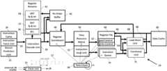
- FIG. 1is a block diagram of a microprocessor based data processing system.
- the exemplary systemincludes a microprocessor 10 having a clock unit 15 , an instruction fetch unit 20 , an instruction cache 24 , a branch prediction unit 22 , an instruction decode unit 30 , a register renaming unit 35 , a register scoreboard 40 , re-order buffers 45 , a time-resource matrix 50 , an instruction issue unit 55 , a register file 60 , a read control unit 62 , a write control unit 64 , a plurality of execution queues 70 , a plurality of functional units 75 , a load-store unit 80 , and a data cache 85 .
- the microprocessor 10includes a plurality of read buses 66 connecting the register files to the functional units 75 and load-store unit 80 .
- the systemalso includes a plurality of write buses 68 to write result data from the functional unit 75 , the load-store unit 80 , and the data cache 85 to the register file 60 .
- the re-order buffer 45is used to track the order of the instructions as they are decoded in order from the instruction decode unit 30 .
- Microprocessor 10is a synchronous microprocessor where the clock unit generates a clock signal (“elk”) which couples to all the units in the microprocessor 10 .
- the clock unit 15provides a continuously toggling logic signal 17 which toggles between 0 and 1 repeatedly at a clock frequency.
- Clock output signal (“clk”) of clock unit 15enables synchronization of the many different units and states in the microprocessor 10 .
- the clock signalis used to sequence data and instructions through the units that perform the various computations in the microprocessor 10 .
- the clock unit 15may include an external clock as input to synchronize the microprocessor 10 with external units (not shown).
- the clock unit 15may further include an enable signal to disable the clock unit when the microprocessor is in idle stage or not being used for instruction execution.
- the microprocessor 10also includes a time counter unit 90 which stores a time count incremented, in one embodiment, every clock cycle.
- the time counter unit 90is coupled to the clock unit 15 and uses the “clk” signal to increment the time count.
- the time countrepresents the time in clock cycles when an instruction in the instruction issue unit 55 is scheduled for execution. For example, if the current time count is 5 and an instruction is scheduled to be execute later in 22 cycles, then the instruction is sent to the execution queue 70 with the execution time count of 27. When the time count increments to 26 , the execution queue 70 issues the instruction to the functional unit 75 for execution in the next cycle (time count 27 ).
- the time counter unit 90is coupled to the register scoreboard 40 , the time-resource matrix 50 , the read control 62 , the write control 64 , and the plurality of execution queues 70 .
- the scoreboard 40resolves data dependencies in the instructions.
- the time-resource matrix 50checks availability of the various resources, which in one embodiment include the read buses 66 , the functional units 75 , the load-store unit 80 , and the write buses 68 .
- the read control unit 62 , the write control unit 64 , and the execution queues 70receive the scheduled times from the instruction issue unit 55 .
- the read control unit 62is set to read the source operands from the register file 60 on specific read buses 66 at a preset time.
- the write control unit 64writes the result data from a functional unit 75 or the load-store unit 80 or the data cache 85 to the register file 60 on a specific write bus 68 at a preset time.
- the execution queue 70is set to dispatch an instruction to a functional unit 75 or the load-store unit 80 at a preset time.
- the preset timeis the time determined by the decode/issue unit 30 .
- the preset timeis a future time that is based on the time count, so when the time count counts up to the preset time, then the specified action will be performed.
- the specified actioncan be reading data from the register file, writing data to the register file, issuing an instruction to a functional unit for execution, or some other action.
- the decode/issue unit 30determines when an instruction is free of data dependencies and the resource is available. This allows it to set the “preset time” for the instruction to be executed in the execution pipeline.
- the instruction fetch unit 20fetches the next instruction(s) from the instruction cache 24 to send to the instruction decode unit 30 .
- the multithreaded microprocessor 10keeps a program counter (not shown) for each thread.
- the instruction fetch unit 20fetches the next instruction(s) from the instruction cache 24 to send to the instruction decode unit 30 .
- One or more thread bit(s)are attached to each instruction for identification of the thread to which the instruction corresponds. Different algorithms of alternating thread instructions may be used to send instructions to the instruction decode unit 30 .
- the threadsuse a round robin algorithm to dispatch a number of instructions of one thread per cycle from the instruction fetch unit 20 to the instruction decode unit 30 .
- the number of instructions per cyclecan vary and is dependent on the number of instructions per cycle supported by the processor.
- the thread re-order buffer 45may send a signal to stall sending instructions for a particular thread.
- One or more instructionscan be fetched per clock cycle by the instruction fetch unit depending on the configuration of microprocessor 10 . For higher performance, microprocessor 10 fetches more instructions per clock cycle for the instruction decode unit 30 . For low-power and embedded applications, microprocessor 10 might fetch only a single instruction per clock cycle for the instruction decode unit 30 . If the instructions are not in the instruction cache 24 (commonly referred to as an instruction cache miss), then the instruction fetch unit 20 sends a request to external memory (not shown) to fetch the required instructions.
- the external memorymay consist of hierarchical memory subsystems, for example, an L2 cache, an L3 cache, read-only memory (ROM), dynamic random-access memory (DRAM), flash memory, or a disk drive.
- the external memoryis accessible by both the instruction cache 24 and the data cache 85 .
- the instruction fetch unit 20is also coupled to the branch prediction unit 22 for prediction of the next instruction address when a branch is detected and predicted by the branch prediction unit 22 .
- the instruction fetch unit 20 , the instruction cache 24 , and the branch prediction unit 22are described here for completeness. In other embodiments, other instruction fetch and branch prediction methods can be used to supply instructions to the instruction decode unit 30 for microprocessor 10 .
- the instruction decode unit 30is coupled to the instruction fetch unit 20 for new instructions and also coupled to the register renaming unit 35 and the register scoreboard 40 .
- the instruction decode unit 30decodes the instructions for instruction type, instruction throughput and latency tunes, and the register operands.
- the instruction decode unit 30decodes extended instructions in addition to the baseline instructions.
- the register operandsfor example, may consist of 2 source operands and 1 destination operand.
- the operandsare referenced to registers in the register file 60 .
- the source and destination registersare used here to represent the source and destination operands of the instruction.
- the source registerssupport solving read-after-write (RAW) data dependencies. If a later instruction has the same source register as the destination register of an earlier instruction, then the later instruction has RAW data dependency. The later instruction must wait for completion of the earlier instruction before it can start execution.
- RAWread-after-write
- WAWwrite-after-write
- WARwrite-after-read
- the WAW data dependencyoccurs when 2 instructions write back to the same destination register.
- the WAW dependencyrestricts the later instruction from writing back to the same destination register before the earlier instruction is written to it.
- every destination registeris renamed by the register renaming unit 35 where the later instruction is written to a different register from the earlier register, thus eliminating the WAW data dependency. For example, if three instructions have the same destination register R 5 , and which are renamed to R 37 , R 68 , R 74 then the three instructions can write to the destination register at any time. Without renaming, all three instructions will try to write to the same register R 5 which is a WAW dependency in that the third instruction cannot write to R 5 before the second instruction, which cannot write to R 5 before the first instruction.
- the register renaming unit 35also eliminates the WAR data dependency where the later instruction cannot write to a register until the earlier instruction reads the same register. Since the destination register of the later instruction is renamed, the earlier instruction can read the register at any time. In such an embodiment, as the destination registers are renamed, the instructions are executed out-of-order and written back to the renamed destination register out-of-order.
- the register scoreboard 40is used to keep track of the completion time of all destination registers. In a preferred embodiment the completion time is maintained in reference to the time count 90 .
- the register renaming unit 35consists of a register free list (RFL) 36 , a register alias table (RAT) 37 , and an architectural register table (ART) 38 .
- the RAT 37 and the ART 38include the integer registers as defined by the baseline instructions, the custom registers, the floating-point registers for the floating-point instructions, and any extended registers for any extended instructions.
- implementation of floating-point instructionsas an extension to the baseline instructions as one example for any or a combination of different extended instruction types.
- the baseline instructionsare integer instructions with 32-entry baseline registers and the floating-point instructions have 32-entry floating-point extended registers. There are also 64 temporary registers for renaming. This provides a total of 128 physical registers, collectively referred to as the register file 60 .
- the integer and floating-point registershave the same data width. In an embodiment where the data width of floating-point registers is smaller than the data width of the integer registers, then the upper bits of the register file 60 are not used when the registers are the floating-point registers.
- register scoreboard 40keeps the write back time for the 128 physical registers.
- the register scoreboard 40is associated with the physical register file 60 .
- the RFL 36keeps track of temporary registers (64 registers in this example) which have not been used.
- a free-list registeris used for renaming.
- the RAT 37stores the latest renamed registers of the architectural registers.
- the RAT 37keeps the renaming of R 5 to R 52 .
- any source operand which references to R 5will see R 52 instead of R 5 .
- the architectural register R 5is renamed to R 52 , eventually when register R 52 is retired, the architectural register R 5 becomes R 52 as stored in the ART 38 .
- the RAT 37keeps track of the architectural register renaming for both integer and floating-point registers will eventually retire to the ART 38 .
- the register scoreboard 40indicates the earliest time for availability of a source register of the register file 60 , independently of register type.
- the re-order buffer 45if instructions are executed out-of-order, then the re-order buffer 45 is needed to ensure correct program execution.
- the register renaming 35 and the instruction decode unit 30are coupled to the re-order buffer 45 to provide the order of issued instructions and the latest renaming of all architectural registers.
- the re-order buffer 45is needed to retire the instructions in order regardless of when the instructions are executed and written back to the register file 60 .
- re-order buffer 45takes the form of a first in first out (FIFO) buffer. Inputs are instructions from the decode unit 30 and instructions are retired in order after completion by the functional unit 75 or the load store unit 80 . In particular, the re-order buffer 45 flushes all instructions after a branch misprediction or instruction exception.
- FIFOfirst in first out
- the ART 38is updated only with the instructions before a branch misprediction or instruction exception.
- Another function of the re-order buffer 45is writing data to memory only in accordance with the order of the load and store execution.
- the data memory(including data cache 85 and external memory) should be written in order by retiring of the store instructions from the re-order buffer 45 . Retiring of store instructions is performed in order for each thread, so the store buffer (not shown) in the load store unit 80 is duplicated for each thread.
- time counter 90is a basic N-bit wrap-around counter incrementing by 1 every clock cycle.
- the time-resource matrix 50is preferably implemented as registers with entries read and written as with a conventional register structure.
- the integrated circuitry employed to implement the units shown in the block diagram of FIG. 1may be expressed in various forms including as a netlist which takes the form of a listing of the electronic components in a circuit and the list of nodes to which each component is connected. Such a netlist may be provided via an article of manufacture as described below.
- the units shown in the block diagram of FIG. 1can be implemented as software representations, for example in a hardware description language (such as for example Verilog) that describes the functions performed by the units of FIG. 1 at a Register Transfer Level (RTL) type description.
- the software representationscan be implemented employing computer-executable instructions, such as those included in program modules and/or code segments, being executed in a computing system on a target real or virtual processor.
- program modules and code segmentsinclude routines, programs, libraries, objects, classes, components, data structures, etc. that perform particular tasks or implement particular abstract data types.
- the program modules and/or code segmentsmay be obtained from another computer system, such as via the Internet, by downloading the program modules from the other computer system for execution on one or more different computer systems.
- Computer-executable instructions for program modules and/or code segmentsmay, be executed within a local or distributed computing system.
- the computer-executable instructionswhich may include data, instructions, and configuration parameters, may be provided via an article of manufacture including a non-transitory computer readable medium, which provides content that represents instructions that can be executed.
- a computer readable mediummay also include a storage or database from which content can be downloaded.
- a computer readable mediummay also include a device or product having content stored thereon at a time of sale or delivery. Thus, delivering a device with stored content, or offering content for download over a communication medium may be understood as providing an article of manufacture with such content described herein.
- the aforementioned implementations of software executed on a general-purpose, or special purpose, computing systemmay take the form of a computer-implemented method for implementing a microprocessor, and also as a computer program product for implementing a microprocessor, where the computer program product is stored on a non-transitory computer readable storage medium and include instructions for causing the computer system to execute a method.
- the aforementioned program nodules and/or code segmentsmay be executed on suitable computing system to perform the functions disclosed herein.
- Such a computing systemwill typically include one or more processing units, memory and non-transitory storage to execute computer-executable instructions.
- FIG. 2illustrates further details of the register file 60 and the register scoreboard 40 .
- the register file 60has 128 registers, numbered as registers 0 to 127 as illustrated.
- the register file 60consists of all physical registers of the processor 10 .
- Each register in the register file 60has a corresponding entry in the register scoreboard 40 .
- the register scoreboard 40stores the pending write status for the registers 60 .
- a valid bit field 42indicates a valid write back to the register file 60 at a future time in reference to the time count 90 , as specified by the write time field 46 from a specific functional unit in the “Funit” field 44 .
- register 0is written back at time count 21 from the load-store unit 80 .
- Register 1is written back at time count 27 from the floating-point multiply-accumulate (FMAC) unit (one of the functional units 75 ).
- Register 16is written back at time count 33 from the ALU 1 , (another of the functional units 75 ), etc.
- the write time 46is the time in reference to the time count 90 .
- the result datais written to the register file 60 .
- the datais not available from the register file 60 until the next clock cycle, but the result data can be forwarded from the corresponding functional unit 44 in the register scoreboard 40 .
- the load-store unit 80produces the result data in 2 clock cycles at time count 21 for writing back to the register file 60 .
- the “Funit” field 44is 5 bits which accommodate 32 different functional units 75 and load/store ports to data cache 85 .
- the number bits for “Funit” field 44is configurable for addition of baseline, custom, and extended functional units.
- the write back time from the functional unitis based on the known latency time of an instruction.
- the latency time of a load instructionis not fixed.
- the latency time of a load instructioncan be unpredictable as the load data may not be in the data cache 85 .
- For a data cache missthe data must be fetched from external memory as described above. In such a situation, the write back time in the scoreboard 40 for the destination register of a load instruction will no longer be correct. If processor 10 is implemented with a level 2 cache (not shown), then the latency time for a level 2 cache hit can be used to update the register scoreboard 40 .
- the write time of a destination registeris the read time for the subsequent instruction with RAW data dependency on the same destination register.
- the source registers of an instruction in the instruction decode unit 30access the register scoreboard 40 for the corresponding read times. If the valid bit 42 of a source register is not set in the register scoreboard 40 , then the data in the register file 60 can be accessed at any time, providing availability of the read buses 66 , otherwise the write time 46 is the earliest time to issue the instruction.
- the write time 46is when the result data from the functional unit 75 or the load store unit 80 are on the write bus 68 to the register file 60 .
- the result data from write bus 68can be forwarded to read bus 66 so that the result data is available on the read bus 66 in the same clock cycle in which it is written to the register file 60 .
- the “Funit” field 44indicates which functional unit will write back to the register file 60 , and the designated functional unit can restrict the aforementioned forwarding to the read bus 66 due to the presence of a critical timing path.
- the data from the data cacheis a critical timing path in which case forwarding is performed, in one embodiment, to only the ALUs. If the issued instruction is multiply, then the write time 46 from load store unit 80 should be incremented by 1 to be used as the read time for the multiply instruction.
- the multiply instructionreads the data from the register file 60 one cycle after the load data is written to the register file 60 .
- Forwarding of data from the data cache 85 to the ALUis normal and is the same as forwarding of any functional unit to any functional unit, while forwarding of data from data cache 85 to multiply unit is not allowed.
- the ALU instructionreads the register 0 of the register scoreboard 40 in FIG. 2
- the write time 46 of 21is used as the read time as data can be forwarded from the data cache 85 onto read bus 66 .
- the multiply instructionreads the same register 0 of the register scoreboard 40 in FIG.
- the read time of 22is used to read data from the register file 60 as the data from data cache 85 are written into the register file 60 in cycle 21 .
- This same restrictionis kept and does not permit the read control unit 62 to forward the load data from the data cache 85 to the multiply unit.
- An instructionreads source operand data at read time, executes the instruction with a functional unit 75 at execute time, and writes the result data back to the register file 60 at write time.
- the write timeis recorded in the write time field 46 of the register scoreboard 40 .
- a given instructionselects the later write time, of the two source registers, from the register scoreboard 40 as the read time for the instruction.
- the execute timeis the read time plus 1 time count where the functional unit 75 or the load-store unit 80 starts executing the instruction.
- the write time of the instructionis the read time plus the instruction latency time. If the instruction latency time is 1 (e.g., an ALU instruction), then the write time and execution time of the instruction are the same.
- Each instructionhas an execution latency time.
- the add instructionhas a latency time of 1
- the multiply instructionhas a latency time of 2
- the load instructionhas a latency time of 3 assuming a data cache hit.
- the current time countis 5 and the source registers of an add instruction receive write time counts of 22 and 24 from the register scoreboard 40 , then the read time count is set at 24. In this case, the execution and the write time counts are both 25 for the add instruction.
- the register scoreboard 40is coupled to the time-resource matrix 50 where the read, execute, and write times of an instruction access the time-resource matrix 50 to determine availability of the resources.
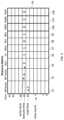
- FIG. 3illustrates further details of the time-resource matrix 50 .
- the time-resource matrix 50preferably includes the same number of time entries to match the time counter 90 . For example, if the time counter 90 is 64 cycles, then the time-resource matrix 50 has 64 entries. In one embodiment, the time counter is incremented every clock cycle and rotates back from the 63rd entry to the 0th entry.
- the columns in the time-resource matrix 50represent the available resources for the read buses 51 , the write buses 52 , the ALUs 53 , the load-store ports 56 , the multiply unit 57 , the divide unit 58 , the branch execution unit (BEU) 59 , the floating-point miscellaneous (FMIS) unit 156 , the floating-point multiply and accumulate (FMAC) unit 157 , and the floating-point divide (FDIV) unit 158 . If other custom functional units are provided by microprocessor 10 those are also included in the time-resource matrix 50 with each custom functional unit being assigned a separate column.
- the read buses column 51corresponds to the plurality of read buses 66 in FIG. 1 .
- the write buses column 52corresponds to the plurality of write buses 68 in FIG. 1 .
- the ALUs column 53 , the multiply column 57 , the divide column 58 , the branch execution unit column 59 , the floating-point miscellaneous column 156 , the floating-point multiply and accumulate column 157 , and the floating-point divide column 158correspond to the plurality of functional units 75 of FIG. 1 .
- the load-port ports column 56corresponds to the load-store unit 80 of FIG. 1 .
- the multiply unit 57 , the divide unit 58 , the FMIS unit 156 , the FMAC unit 157 , and the FDIV unit 158are single functional units in which case the columns of the time-resource matrix 50 can be duplicated to add additional functional units.
- a particular benefit of employing the static scheduling of instructions disclosed hereinthe ease with which additional functional units can be added during the design of a microprocessor.
- the duplication of the columns of the time-resource matrix 50can be done by a software script especially duplicating the additional floating-point resources, 156 - 158 from the multiply unit 57 .
- FIG. 3also shows an example of the information in the time-resource matrix 50 . Shown is data with a read time count of 24, an execution time count of 25, and a write time count of 25.
- the matrix 50shows that at read time 24 , there is 1 available read bus, and at execution time 25 , there are 2 available ALUs, 1 load-store port, 1 multiply unit, 1 BEU, and 1 FMAC unit for execution of an instruction.
- At write time 25there are 2 available write buses.
- All available resources for a required timeare read from the time-resource matrix 50 and sent to the instruction issue unit 55 for a decision of when to issue an instruction to the execution queue 70 . If the resources are available at the required times, then the instruction can be scheduled and sent to the execution queue 70 .
- the issued instructionupdates the register scoreboard 40 with the write time and updates the time-resource matrix 50 to correspondingly reduce the available resource values. All resources must be available at the required time counts for the instruction to be dispatched to the execution queue 70 . If all resources are not available, then the required time counts are incremented by one, and the time-resource matrix is checked as soon as the same cycle or next cycle.
- the particular number of read buses 66 , write buses 68 , and functional units 75 in FIG. 1is preferably chosen to minimize stalling of instructions in the instruction issue unit 55 .
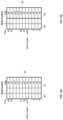
- FIG. 4 Aillustrates a single read bus of the read control unit 62 and FIG. 4 B illustrates a single write bus of the write control unit 64 .
- the read control unit 62 and the write control unit 64include a number of time entries to match the time counter 90 . As mentioned above, in a preferred embodiment the time count is incremented every clock cycle.
- the columns in the read control unit 62represent the source register 61 and a valid bit 63 .
- the columns in the write control unit 64represent the destination register 65 and a valid bit 67 in the write bus 65 .
- the register x 5 from the register field 61 of the read control 62is used to read the entry 5 from the register scoreboard 40 for the “Wr time” 46 and the “Funit” 44 . If the write time 46 is the same as the time count 90 , then the result data is written back to the register file 60 in the same clock cycle. The result data from the “Funit” 44 can be forwarded to the read bus 66 instead of being read from the register file 60 .
- the write time 46may have changed due to a cache miss of the load instruction, in which case the instruction cannot be executed yet because the source operand data is not valid.
- the RAW dependent instructionis rescheduled to be executed at later time.
- the register x 27 from the register field 61is used to read from the register file 60 .
- the read control unit 62is responsible for supplying the source operand data on a specific one of the read buses 66 .
- the execution queue 70keeps the information of which one of the read buses 66 is to receive source operand data.
- the execution queues 70 and read control unit 62are synchronized based on the time-resource matrix 50 .
- the read control unit 62provides centralized control for the read buses 66 , thus reducing complexity from the hundreds of instructions in dynamic scheduling architectures.
- the register x 5 from the register field 65 of the write control unit 64 at time count of 26is used to write to the register file 60 .
- the register x 5will also access the “Funit” 44 of the register scoreboard 40 to get the result data from a specific functional unit 75 .
- the execution queues 70 , the functional units 75 , and the write control unit 64are synchronized to transfer result data on a write bus 68 to write to the register file 60 .
- the valid (valid bit field 67 ) register 65 of write control unit 64is responsible to clear the valid bit 42 from the register scoreboard 40 of FIG. 2 if the corresponding “Wr time” field 46 is the same as the time count 90 .
- the write control unit 64operates as a centralized control for the write buses 68 which removes complexity compared to distributing such control among the plurality of functional units in dynamic scheduling.
- FIG. 5illustrates an example of a 4-entry execution queue 70 .
- the number of entries for the execution queue 70is only an illustration. The invention is not limited to any number of execution queue 70 entries and the execution queue 70 could take the form of a single-entry execution queue.
- Each entryis an instruction waiting for execution by one of the functional units 75 or the load/store unit 80 according to the time count in the read time column 77 .
- Each entry in the execution queue 70preferably consists of the following fields: the valid bit 71 , control data 72 , the immediate data 73 , the first source register select 74 , the second source register select 76 , the functional unit 79 , and the read time 77 .
- the valid bit 71when set to “1,” indicates that the entry is valid in the execution queue 70 .
- the control data 72specifies the specific operation to be used by the functional units 75 or the load/store unit 80 .
- the immediate data 73is an alternative to the second source register for the instruction.
- the valid indication for the immediate data 73may be included in the control data field 72 .
- Most instructionshave an option to use immediate data 73 instead of data from the second source register.
- the first source register select 74identifies which one of the read buses 66 has the operand data for the first source register.
- the second source register select 76identifies which one of the read buses 66 has the operand data for the second source register.
- the functional unit 79is optionally added if the execution queue 70 is coupled to multiple functional units 75 where the execution queue 70 can dispatch multiple instructions to multiple functional units 75 in the same clock cycle where comparators have multiple matches to the time count 90 .
- the source register selects 74 and 76may not be used for some instructions.
- the read control 62reads the register scoreboard 40 to ensure that the expected source operand data is still valid and is synchronized with the execution queue 70 to supply source data to the functional unit 75 . If the write time 46 from the scoreboard 40 is modified to be greater than the time count 90 , then the synchronized instruction in the execution queue 70 is replayed instead of going to the functional unit 75 . In one embodiment, the replay instruction uses the new write time from the register scoreboard 40 to calculate the new read time, execution time, and write time for accessing the time resource matrix 50 to reissue the instruction. The procedure is the same as for instructions in the instruction issue unit 55 .
- the destination registercan be, but does not need to be, kept with the instruction.
- the write control unit 64is responsible for directing the result data from a functional unit 75 to a write bus 68 to write to the register file 60 .
- the execution queues 70are only responsible for sending instructions to the functional units 75 or the load-store unit 80 .
- the read time field 77which has the read time of the instruction is synchronized with the read control unit 62 . When the read time 77 is the same as the time count 90 as detected by the comparators 78 , the instruction is issued to the functional units 75 or the load/store unit 80 . For the example in FIG. 5 , the entries are issued to the functional units out-of-order.
- the read time field 77indicates that the second entry is issued at time count 25 , the third entry is issued at time count 27 , and the first entry is issued at time count 32 .
- each functional unit 75has its own execution queue 70 .
- an execution queue 70dispatches instructions to multiple functional units 75 .
- the functional unit field 79can be added to the execution queue 70 to indicate the functional unit number for dispatching of instructions.
- the execution queue 70is configurable with a single functional unit, or multiple functional units, or multiple functional units of the same type such as ALU type for multiple ALUs or floating-point type for all floating-point functional units.
- the execution queue 70is duplicated for as needed for baseline or custom instructions where the functional unit field 79 stores different type of functional units.
- the functional units 75may be designed with the same interface signals for coupling to the execution queue 70 . In one embodiment, during development at the RTL level the execution queues 70 and functional units 75 may be duplicated and added for custom instructions by a software script.
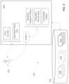
- FIG. 6illustrates by way of a block diagram an embodiment that operates to facilitate generation of a design of a processor as disclosed herein that implements one or more extended instructions.
- a user 200employs an electronic design automation system 202 to design a processor as disclosed herein.
- the system 202provides a visual user interface 204 by which the user 200 interacts with the system 202 to specify a design of a processor.
- the system 202provides to the user 200 a variety of pre-designed modules 206 , specified for example in an RTL type description and stored in digital storage 208 .
- the user 200may select certain pre-designed modules 206 such as for example a time counter, an instruction decode unit and an instruction issue unit as described herein.
- the user 200may specify a new design of one or more of such modules for example by way of an RTL type description.
- the system 202provides the user 200 with the ability to select a predefined stored script 210 to generate one or more modules to, in particular, implement one or more extended instructions.
- user 200has employed Script 1 to specify Baseline Architecture Register File(s), various Extended Resources and various Functional Unit(s).
- the scripts 210each take the form of a set of commands, recognizable by the system 202 , that execute various functions and operations performed by the system 202 .
- the scripts 210operate to automate manual tasks that would otherwise need to be performed by the user 200 .
- Each design specified by user 200 , or other users,is stored 212 to storage 208 for further editing and/or processing.
- each extended instructionis a line of code which can be added to the instruction decode code for a design by a software script 210 .
- the extended instructionscan be described by an instruction format, a list of features to define the operands, the immediate field, the extended functional unit type, the throughput and latency times which is converted to a line of code to be inserted into the instruction decode code.
- the execution queues 70are coupled to the load store unit (LSU) 80 and the functional units 75 .
- the execution queues 70issue the instructions to the functional units 75 or the load/store unit 80 when the read times 77 are the same as the time count 90 . If the instruction is a load/store, then it is dispatched to the LSU 80 , else it is dispatched to one of the functional units 75 .
- the LSU 80 and functional units 75are also coupled to the read buses 66 and write buses 68 to access the register file 60 .
- the source operand dataare fetched from register file 60 and transported on read buses 66 to the LSU 80 and functional units 75 .
- the result data from the LSU 80 and functional units 75are transported on write buses 68 to write to destination registers in the register file 60 .
- the LSU 80is also coupled to the data cache 85 .
- the LSU 80executes the load and store instructions to read and write data from the data cache 85 . If the data are not in the data cache 85 , then the cache miss causes that cache line to be fetched from external memory (not shown).
- the functional units 75perform different operations, e.g., ALU, multiply, divide, branch, etc. In other embodiments, the functional units 75 perform the same function, for example, multiple ALUs.
- the inventionis not limited to integer functional units. In other embodiments the functional units include floating point units, digital-signal processing units, vector processing units, or custom designed units.
- FIGS. 2 - 5are the same for baseline instructions, custom instructions, or extended instructions for microprocessor 10 .
- the static scheduling of instructions in a microprocessor with a time counter 90simplifies the design of a microprocessor with custom and/or extended instructions.
- the units related to the custom and extended instructions as shown in the block diagram of FIG. 1can be specified using software scripts. For example, a hardware description language (seeks as Verilog) that describes the functions performed by the additions of the custom and/or extended instructions of FIG. 1 can be modified by software scripts.
- the register rename 35is modified to add the floating-point registers to the RAT 37 and ART 38 .
- the execution queues 79 and the functional units 75may be designed to be configurable for any custom or extended instructions Which can be added to the microprocessor 10 by a software script.
- the software scriptsare part of the software representations can be implemented employing computer-executable instructions, such as those, included in program modules and/or code segments, being executed in a computing system on a target real or virtual processor.
- the functionality of the program modules and/or code segmentsmay be combined or split between program modules/segments as desired in various embodiments.
- Computer-executable instructions for program modules and/or code segmentsmay be executed within a local or distributed computing system.
- the computer-executable instructionsmay be provided via an article of manufacture including a non-transitory computer readable medium, which provides content that represents instructions that can be executed.
- a computer readable mediummay also include a storage or database from which content can be downloaded.
- a computer readable mediummay also include a device or product having content stored thereon at a time of sale or delivery. Thus, delivering a device with stored content, or offering content for download over a communication medium may be understood as providing an article of manufacture with such content described herein.
Landscapes
- Engineering & Computer Science (AREA)
- Software Systems (AREA)
- Theoretical Computer Science (AREA)
- Physics & Mathematics (AREA)
- General Engineering & Computer Science (AREA)
- General Physics & Mathematics (AREA)
- Advance Control (AREA)
Abstract
Description
Claims (24)
Priority Applications (2)
| Application Number | Priority Date | Filing Date | Title |
|---|---|---|---|
| US17/725,476US12169716B2 (en) | 2022-04-20 | 2022-04-20 | Microprocessor with a time counter for statically dispatching extended instructions |
| PCT/US2023/018970WO2023205166A1 (en) | 2022-04-20 | 2023-04-18 | Microprocessor with a time counter for statically dispatching extended instructions |
Applications Claiming Priority (1)
| Application Number | Priority Date | Filing Date | Title |
|---|---|---|---|
| US17/725,476US12169716B2 (en) | 2022-04-20 | 2022-04-20 | Microprocessor with a time counter for statically dispatching extended instructions |
Publications (2)
| Publication Number | Publication Date |
|---|---|
| US20230342153A1 US20230342153A1 (en) | 2023-10-26 |
| US12169716B2true US12169716B2 (en) | 2024-12-17 |
Family
ID=86387247
Family Applications (1)
| Application Number | Title | Priority Date | Filing Date |
|---|---|---|---|
| US17/725,476Active2043-02-27US12169716B2 (en) | 2022-04-20 | 2022-04-20 | Microprocessor with a time counter for statically dispatching extended instructions |
Country Status (2)
| Country | Link |
|---|---|
| US (1) | US12169716B2 (en) |
| WO (1) | WO2023205166A1 (en) |
Citations (84)
| Publication number | Priority date | Publication date | Assignee | Title |
|---|---|---|---|---|
| US5021985A (en) | 1990-01-19 | 1991-06-04 | Weitek Corporation | Variable latency method and apparatus for floating-point coprocessor |
| US5185868A (en) | 1990-01-16 | 1993-02-09 | Advanced Micro Devices, Inc. | Apparatus having hierarchically arranged decoders concurrently decoding instructions and shifting instructions not ready for execution to vacant decoders higher in the hierarchy |
| US5251306A (en) | 1990-01-16 | 1993-10-05 | Advanced Micro Devices, Inc. | Apparatus for controlling execution of a program in a computing device |
| US5655096A (en) | 1990-10-12 | 1997-08-05 | Branigin; Michael H. | Method and apparatus for dynamic scheduling of instructions to ensure sequentially coherent data in a processor employing out-of-order execution |
| US5699536A (en) | 1995-04-13 | 1997-12-16 | International Business Machines Corporation | Computer processing system employing dynamic instruction formatting |
| EP0840213A2 (en) | 1985-10-31 | 1998-05-06 | Biax Corporation | A branch executing system and method |
| US5799163A (en) | 1997-03-04 | 1998-08-25 | Samsung Electronics Co., Ltd. | Opportunistic operand forwarding to minimize register file read ports |
| US5802386A (en) | 1996-11-19 | 1998-09-01 | International Business Machines Corporation | Latency-based scheduling of instructions in a superscalar processor |
| US5809268A (en) | 1995-06-29 | 1998-09-15 | International Business Machines Corporation | Method and system for tracking resource allocation within a processor |
| US5835745A (en) | 1992-11-12 | 1998-11-10 | Sager; David J. | Hardware instruction scheduler for short execution unit latencies |
| US5860018A (en) | 1997-06-25 | 1999-01-12 | Sun Microsystems, Inc. | Method for tracking pipeline resources in a superscalar processor |
| US5881302A (en) | 1994-05-31 | 1999-03-09 | Nec Corporation | Vector processing unit with reconfigurable data buffer |
| EP0902360A2 (en) | 1997-09-12 | 1999-03-17 | Siemens Microelectronics, Inc. | Apparatus for read/write-access to registers in a central processing unit |
| US5903919A (en) | 1997-10-07 | 1999-05-11 | Motorola, Inc. | Method and apparatus for selecting a register bank |
| US5958041A (en) | 1997-06-26 | 1999-09-28 | Sun Microsystems, Inc. | Latency prediction in a pipelined microarchitecture |
| US5961630A (en) | 1997-12-30 | 1999-10-05 | Intel Corporation | Method and apparatus for handling dynamic structural hazards and exceptions by using post-ready latency |
| US5964867A (en) | 1997-11-26 | 1999-10-12 | Digital Equipment Corporation | Method for inserting memory prefetch operations based on measured latencies in a program optimizer |
| EP0959575A1 (en) | 1998-04-24 | 1999-11-24 | Motorola, Inc. | Radio with burst event execution apparatus and method therefore |
| US5996061A (en) | 1997-06-25 | 1999-11-30 | Sun Microsystems, Inc. | Method for invalidating data identified by software compiler |
| US5996064A (en) | 1997-12-30 | 1999-11-30 | Intel Corporation | Method and apparatus for guaranteeing minimum variable schedule distance by using post-ready latency |
| US6016540A (en) | 1997-01-08 | 2000-01-18 | Intel Corporation | Method and apparatus for scheduling instructions in waves |
| WO2000010076A1 (en) | 1998-08-11 | 2000-02-24 | Intel Corporation | Scheduling instructions with different latencies |
| US6035393A (en) | 1995-09-11 | 2000-03-07 | Intel Corporation | Stalling predicted prefetch to memory location identified as uncacheable using dummy stall instruction until branch speculation resolution |
| US6065105A (en) | 1997-01-08 | 2000-05-16 | Intel Corporation | Dependency matrix |
| US6247113B1 (en) | 1998-05-27 | 2001-06-12 | Arm Limited | Coprocessor opcode division by data type |
| US20010004755A1 (en) | 1997-04-03 | 2001-06-21 | Henry M Levy | Mechanism for freeing registers on processors that perform dynamic out-of-order execution of instructions using renaming registers |
| US6282634B1 (en) | 1998-05-27 | 2001-08-28 | Arm Limited | Apparatus and method for processing data having a mixed vector/scalar register file |
| US6304955B1 (en) | 1998-12-30 | 2001-10-16 | Intel Corporation | Method and apparatus for performing latency based hazard detection |
| WO2002008894A1 (en) | 2000-07-21 | 2002-01-31 | Antevista Gmbh | A microprocessor having an instruction format containing timing information |
| WO2002013005A1 (en) | 2000-08-09 | 2002-02-14 | Advanced Micro Devices, Inc. | Cpu accessing an extended register set in an extended register mode |
| US6425090B1 (en) | 1999-06-25 | 2002-07-23 | International Business Machines Corporation | Method for just-in-time delivery of load data utilizing alternating time intervals |
| US6453424B1 (en) | 1999-03-31 | 2002-09-17 | International Business Machines Corporation | System and method for temporally controlling instruction execution |
| US20030023646A1 (en) | 1994-12-01 | 2003-01-30 | Lin Derrick Chu | Processor capable of executing packed shift operations |
| US20040073779A1 (en) | 2002-10-11 | 2004-04-15 | Erdem Hokenek | Method and apparatus for register file port reduction in a multithreaded processor |
| US20050251657A1 (en) | 2004-05-04 | 2005-11-10 | Boucher Michael L | Methods and systems for grouping and managing memory instructions |
| US20060010305A1 (en) | 2004-07-06 | 2006-01-12 | Masaki Maeda | Processor system that controls data transfer between processor and coprocessor |
| US20060095732A1 (en) | 2004-08-30 | 2006-05-04 | Tran Thang M | Processes, circuits, devices, and systems for scoreboard and other processor improvements |
| US7069425B1 (en) | 1999-05-18 | 2006-06-27 | Sharp Kabushiki Kaisha | Real-time processor executing predetermined operation defined by program correctly at predetermined time |
| US20060218124A1 (en) | 2005-03-22 | 2006-09-28 | Arm Limited | Performance of a data processing apparatus |
| US20060259800A1 (en) | 2005-05-16 | 2006-11-16 | Semiconductor Technology Academic Research Center | Circuit system |
| US20060288194A1 (en)* | 2005-06-17 | 2006-12-21 | Lewis Innovative Technologies | Real-time processor |
| US20070038984A1 (en) | 2005-08-12 | 2007-02-15 | Gschwind Michael K | Methods for generating code for an architecture encoding an extended register specification |
| US20070260856A1 (en) | 2006-05-05 | 2007-11-08 | Tran Thang M | Methods and apparatus to detect data dependencies in an instruction pipeline |
| US7434032B1 (en) | 2005-12-13 | 2008-10-07 | Nvidia Corporation | Tracking register usage during multithreaded processing using a scoreboard having separate memory regions and storing sequential register size indicators |
| US20110099354A1 (en) | 2009-10-26 | 2011-04-28 | Sony Corporation | Information processing apparatus and instruction decoder for the information processing apparatus |
| US20110320765A1 (en) | 2010-06-28 | 2011-12-29 | International Business Machines Corporation | Variable width vector instruction processor |
| US20120047352A1 (en) | 2009-05-08 | 2012-02-23 | Panasonic Corporation | Processor |
| US8166281B2 (en) | 2005-08-12 | 2012-04-24 | International Business Machines Corporation | Implementing instruction set architectures with non-contiguous register file specifiers |
| US20130151816A1 (en) | 2011-12-07 | 2013-06-13 | International Business Machines Corporation | Delay identification in data processing systems |
| US20130297912A1 (en) | 2012-05-03 | 2013-11-07 | Freescale Semiconductor, Inc. | Apparatus and method for dynamic allocation of execution queues |
| US20130346985A1 (en) | 2012-06-20 | 2013-12-26 | Microsoft Corporation | Managing use of a field programmable gate array by multiple processes in an operating system |
| US20140059328A1 (en) | 2012-08-21 | 2014-02-27 | Jeffry E. Gonion | Mechanism for performing speculative predicated instructions |
| US20140082626A1 (en) | 2012-09-14 | 2014-03-20 | International Business Machines Corporation | Management of resources within a computing environment |
| US20150026435A1 (en) | 2013-07-22 | 2015-01-22 | International Business Machines Corporation | Instruction set architecture with extensible register addressing |
| US20150212972A1 (en) | 2014-01-28 | 2015-07-30 | Arm Limited | Data processing apparatus and method for performing scan operations |
| US20150227369A1 (en) | 2014-02-11 | 2015-08-13 | Apple Inc. | Completion Time Prediction for Vector Instructions |
| US9256428B2 (en) | 2013-02-06 | 2016-02-09 | International Business Machines Corporation | Load latency speculation in an out-of-order computer processor |
| US20160092238A1 (en) | 2014-09-26 | 2016-03-31 | Qualcomm Incorporated | Coprocessor for out-of-order loads |
| US20160275043A1 (en) | 2015-03-18 | 2016-09-22 | Edward T. Grochowski | Energy and area optimized heterogeneous multiprocessor for cascade classifiers |
| US20160371091A1 (en) | 2015-06-17 | 2016-12-22 | Ibm | Techniques for improving issue of instructions with variable latencies in a microprocessor |
| US20170177354A1 (en) | 2015-12-18 | 2017-06-22 | Intel Corporation | Instructions and Logic for Vector-Based Bit Manipulation |
| US20170357513A1 (en) | 2016-06-09 | 2017-12-14 | International Business Machines Corporation | Transmitting data between execution slices of a multi-slice processor |
| US20180181400A1 (en) | 2016-12-27 | 2018-06-28 | Intel Corporation | Apparatus and methods to support counted loop exits in a multi-strand loop processor |
| US20180196678A1 (en) | 2017-01-06 | 2018-07-12 | International Business Machines Corporation | Out-of-order processor and method for back to back instruction issue |
| US20180253310A1 (en) | 2015-10-14 | 2018-09-06 | Arm Limited | Vector load instruction |
| US20190079764A1 (en) | 2017-09-08 | 2019-03-14 | Oracle International Corporation | Efficient direct convolution using simd instructions |
| US10339095B2 (en) | 2015-02-02 | 2019-07-02 | Optimum Semiconductor Technologies Inc. | Vector processor configured to operate on variable length vectors using digital signal processing instructions |
| US20190243646A1 (en) | 2013-07-15 | 2019-08-08 | Texas Instruments Incorporated | Variable latency instructions |
| US20200004534A1 (en) | 2018-06-29 | 2020-01-02 | Intel Corporation | Register bank conflict reduction for multi-threaded processor |
| US20200004543A1 (en) | 2017-02-03 | 2020-01-02 | The University Court Of The University Of Edinburgh | Branch target buffer for a data processing apparatus |
| US20200319885A1 (en) | 2017-12-13 | 2020-10-08 | Arm Limited | Vector add-with-carry instruction |
| US20200387382A1 (en) | 2019-06-06 | 2020-12-10 | International Business Machines Corporation | Mechanism for instruction fusion using tags |
| US20210026639A1 (en) | 2019-07-22 | 2021-01-28 | Microsoft Technology Licensing, Llc | Latency-based instruction reservation clustering in a scheduler circuit in a processor |
| US11062200B2 (en) | 2017-04-17 | 2021-07-13 | Cerebras Systems Inc. | Task synchronization for accelerated deep learning |
| US11132199B1 (en) | 2020-03-31 | 2021-09-28 | Andes Technology Corporation | Processor having latency shifter and controlling method using the same |
| US20210311743A1 (en) | 2020-04-01 | 2021-10-07 | Andes Technology Corporation | Microprocessor having self-resetting register scoreboard |
| US11144319B1 (en) | 2020-07-28 | 2021-10-12 | International Business Machines Corporation | Redistribution of architected states for a processor register file |
| US20210326141A1 (en) | 2020-04-20 | 2021-10-21 | Andes Technology Corporation | Microprocessor with pipeline control for executing of instruction at a preset future time |
| US11263013B2 (en) | 2020-04-07 | 2022-03-01 | Andes Technology Corporation | Processor having read shifter and controlling method using the same |
| US11467841B1 (en) | 2021-06-01 | 2022-10-11 | Andes Technology Corporation | Microprocessor with shared functional unit for executing multi-type instructions |
| US20230068637A1 (en) | 2021-09-01 | 2023-03-02 | International Business Machines Corporation | Routing instruction results to a register block of a subdivided register file based on register block utilization rate |
| US20230244491A1 (en) | 2022-01-30 | 2023-08-03 | Simplex Micro, Inc. | Multi-threading microprocessor with a time counter for statically dispatching instructions |
| US20230244490A1 (en) | 2022-01-30 | 2023-08-03 | Simplex Micro, Inc. | Microprocessor with time counter for statically dispatching instructions |
| US12061906B2 (en) | 2015-07-31 | 2024-08-13 | Arm Limited | Apparatus and method for performing a splice of vectors based on location and length data |
- 2022
- 2022-04-20USUS17/725,476patent/US12169716B2/enactiveActive
- 2023
- 2023-04-18WOPCT/US2023/018970patent/WO2023205166A1/ennot_activeCeased
Patent Citations (89)
| Publication number | Priority date | Publication date | Assignee | Title |
|---|---|---|---|---|
| EP0840213A2 (en) | 1985-10-31 | 1998-05-06 | Biax Corporation | A branch executing system and method |
| US5185868A (en) | 1990-01-16 | 1993-02-09 | Advanced Micro Devices, Inc. | Apparatus having hierarchically arranged decoders concurrently decoding instructions and shifting instructions not ready for execution to vacant decoders higher in the hierarchy |
| US5251306A (en) | 1990-01-16 | 1993-10-05 | Advanced Micro Devices, Inc. | Apparatus for controlling execution of a program in a computing device |
| US5021985A (en) | 1990-01-19 | 1991-06-04 | Weitek Corporation | Variable latency method and apparatus for floating-point coprocessor |
| US5655096A (en) | 1990-10-12 | 1997-08-05 | Branigin; Michael H. | Method and apparatus for dynamic scheduling of instructions to ensure sequentially coherent data in a processor employing out-of-order execution |
| US5835745A (en) | 1992-11-12 | 1998-11-10 | Sager; David J. | Hardware instruction scheduler for short execution unit latencies |
| US5881302A (en) | 1994-05-31 | 1999-03-09 | Nec Corporation | Vector processing unit with reconfigurable data buffer |
| US20030023646A1 (en) | 1994-12-01 | 2003-01-30 | Lin Derrick Chu | Processor capable of executing packed shift operations |
| US5699536A (en) | 1995-04-13 | 1997-12-16 | International Business Machines Corporation | Computer processing system employing dynamic instruction formatting |
| US5809268A (en) | 1995-06-29 | 1998-09-15 | International Business Machines Corporation | Method and system for tracking resource allocation within a processor |
| US6035393A (en) | 1995-09-11 | 2000-03-07 | Intel Corporation | Stalling predicted prefetch to memory location identified as uncacheable using dummy stall instruction until branch speculation resolution |
| US5802386A (en) | 1996-11-19 | 1998-09-01 | International Business Machines Corporation | Latency-based scheduling of instructions in a superscalar processor |
| US6016540A (en) | 1997-01-08 | 2000-01-18 | Intel Corporation | Method and apparatus for scheduling instructions in waves |
| US6065105A (en) | 1997-01-08 | 2000-05-16 | Intel Corporation | Dependency matrix |
| US5799163A (en) | 1997-03-04 | 1998-08-25 | Samsung Electronics Co., Ltd. | Opportunistic operand forwarding to minimize register file read ports |
| US20010004755A1 (en) | 1997-04-03 | 2001-06-21 | Henry M Levy | Mechanism for freeing registers on processors that perform dynamic out-of-order execution of instructions using renaming registers |
| US5860018A (en) | 1997-06-25 | 1999-01-12 | Sun Microsystems, Inc. | Method for tracking pipeline resources in a superscalar processor |
| US5996061A (en) | 1997-06-25 | 1999-11-30 | Sun Microsystems, Inc. | Method for invalidating data identified by software compiler |
| US5958041A (en) | 1997-06-26 | 1999-09-28 | Sun Microsystems, Inc. | Latency prediction in a pipelined microarchitecture |
| EP0902360A2 (en) | 1997-09-12 | 1999-03-17 | Siemens Microelectronics, Inc. | Apparatus for read/write-access to registers in a central processing unit |
| US5903919A (en) | 1997-10-07 | 1999-05-11 | Motorola, Inc. | Method and apparatus for selecting a register bank |
| US5964867A (en) | 1997-11-26 | 1999-10-12 | Digital Equipment Corporation | Method for inserting memory prefetch operations based on measured latencies in a program optimizer |
| US5961630A (en) | 1997-12-30 | 1999-10-05 | Intel Corporation | Method and apparatus for handling dynamic structural hazards and exceptions by using post-ready latency |
| US5996064A (en) | 1997-12-30 | 1999-11-30 | Intel Corporation | Method and apparatus for guaranteeing minimum variable schedule distance by using post-ready latency |
| EP0959575A1 (en) | 1998-04-24 | 1999-11-24 | Motorola, Inc. | Radio with burst event execution apparatus and method therefore |
| US6247113B1 (en) | 1998-05-27 | 2001-06-12 | Arm Limited | Coprocessor opcode division by data type |
| US6282634B1 (en) | 1998-05-27 | 2001-08-28 | Arm Limited | Apparatus and method for processing data having a mixed vector/scalar register file |
| WO2000010076A1 (en) | 1998-08-11 | 2000-02-24 | Intel Corporation | Scheduling instructions with different latencies |
| US6304955B1 (en) | 1998-12-30 | 2001-10-16 | Intel Corporation | Method and apparatus for performing latency based hazard detection |
| US6453424B1 (en) | 1999-03-31 | 2002-09-17 | International Business Machines Corporation | System and method for temporally controlling instruction execution |
| US7069425B1 (en) | 1999-05-18 | 2006-06-27 | Sharp Kabushiki Kaisha | Real-time processor executing predetermined operation defined by program correctly at predetermined time |
| US6425090B1 (en) | 1999-06-25 | 2002-07-23 | International Business Machines Corporation | Method for just-in-time delivery of load data utilizing alternating time intervals |
| WO2002008894A1 (en) | 2000-07-21 | 2002-01-31 | Antevista Gmbh | A microprocessor having an instruction format containing timing information |
| US20030135712A1 (en) | 2000-07-21 | 2003-07-17 | Jean-Paul Theis | Microprocessor having an instruction format contianing timing information |
| WO2002013005A1 (en) | 2000-08-09 | 2002-02-14 | Advanced Micro Devices, Inc. | Cpu accessing an extended register set in an extended register mode |
| US20040073779A1 (en) | 2002-10-11 | 2004-04-15 | Erdem Hokenek | Method and apparatus for register file port reduction in a multithreaded processor |
| US20050251657A1 (en) | 2004-05-04 | 2005-11-10 | Boucher Michael L | Methods and systems for grouping and managing memory instructions |
| US20060010305A1 (en) | 2004-07-06 | 2006-01-12 | Masaki Maeda | Processor system that controls data transfer between processor and coprocessor |
| US20060095732A1 (en) | 2004-08-30 | 2006-05-04 | Tran Thang M | Processes, circuits, devices, and systems for scoreboard and other processor improvements |
| US20060218124A1 (en) | 2005-03-22 | 2006-09-28 | Arm Limited | Performance of a data processing apparatus |
| US20060259800A1 (en) | 2005-05-16 | 2006-11-16 | Semiconductor Technology Academic Research Center | Circuit system |
| US20060288194A1 (en)* | 2005-06-17 | 2006-12-21 | Lewis Innovative Technologies | Real-time processor |
| US20070038984A1 (en) | 2005-08-12 | 2007-02-15 | Gschwind Michael K | Methods for generating code for an architecture encoding an extended register specification |
| US8166281B2 (en) | 2005-08-12 | 2012-04-24 | International Business Machines Corporation | Implementing instruction set architectures with non-contiguous register file specifiers |
| US7434032B1 (en) | 2005-12-13 | 2008-10-07 | Nvidia Corporation | Tracking register usage during multithreaded processing using a scoreboard having separate memory regions and storing sequential register size indicators |
| US20070260856A1 (en) | 2006-05-05 | 2007-11-08 | Tran Thang M | Methods and apparatus to detect data dependencies in an instruction pipeline |
| US20120047352A1 (en) | 2009-05-08 | 2012-02-23 | Panasonic Corporation | Processor |
| US20110099354A1 (en) | 2009-10-26 | 2011-04-28 | Sony Corporation | Information processing apparatus and instruction decoder for the information processing apparatus |
| US20110320765A1 (en) | 2010-06-28 | 2011-12-29 | International Business Machines Corporation | Variable width vector instruction processor |
| US20130151816A1 (en) | 2011-12-07 | 2013-06-13 | International Business Machines Corporation | Delay identification in data processing systems |
| US20130297912A1 (en) | 2012-05-03 | 2013-11-07 | Freescale Semiconductor, Inc. | Apparatus and method for dynamic allocation of execution queues |
| US20130346985A1 (en) | 2012-06-20 | 2013-12-26 | Microsoft Corporation | Managing use of a field programmable gate array by multiple processes in an operating system |
| US20140059328A1 (en) | 2012-08-21 | 2014-02-27 | Jeffry E. Gonion | Mechanism for performing speculative predicated instructions |
| US20140082626A1 (en) | 2012-09-14 | 2014-03-20 | International Business Machines Corporation | Management of resources within a computing environment |
| US9256428B2 (en) | 2013-02-06 | 2016-02-09 | International Business Machines Corporation | Load latency speculation in an out-of-order computer processor |
| US20190243646A1 (en) | 2013-07-15 | 2019-08-08 | Texas Instruments Incorporated | Variable latency instructions |
| US20150026435A1 (en) | 2013-07-22 | 2015-01-22 | International Business Machines Corporation | Instruction set architecture with extensible register addressing |
| US20150212972A1 (en) | 2014-01-28 | 2015-07-30 | Arm Limited | Data processing apparatus and method for performing scan operations |
| US20150227369A1 (en) | 2014-02-11 | 2015-08-13 | Apple Inc. | Completion Time Prediction for Vector Instructions |
| US20160092238A1 (en) | 2014-09-26 | 2016-03-31 | Qualcomm Incorporated | Coprocessor for out-of-order loads |
| US10339095B2 (en) | 2015-02-02 | 2019-07-02 | Optimum Semiconductor Technologies Inc. | Vector processor configured to operate on variable length vectors using digital signal processing instructions |
| US20160275043A1 (en) | 2015-03-18 | 2016-09-22 | Edward T. Grochowski | Energy and area optimized heterogeneous multiprocessor for cascade classifiers |
| US20160371091A1 (en) | 2015-06-17 | 2016-12-22 | Ibm | Techniques for improving issue of instructions with variable latencies in a microprocessor |
| US12061906B2 (en) | 2015-07-31 | 2024-08-13 | Arm Limited | Apparatus and method for performing a splice of vectors based on location and length data |
| US20180253310A1 (en) | 2015-10-14 | 2018-09-06 | Arm Limited | Vector load instruction |
| US20170177354A1 (en) | 2015-12-18 | 2017-06-22 | Intel Corporation | Instructions and Logic for Vector-Based Bit Manipulation |
| US20170357513A1 (en) | 2016-06-09 | 2017-12-14 | International Business Machines Corporation | Transmitting data between execution slices of a multi-slice processor |
| US20180181400A1 (en) | 2016-12-27 | 2018-06-28 | Intel Corporation | Apparatus and methods to support counted loop exits in a multi-strand loop processor |
| US20180196678A1 (en) | 2017-01-06 | 2018-07-12 | International Business Machines Corporation | Out-of-order processor and method for back to back instruction issue |
| US20200004543A1 (en) | 2017-02-03 | 2020-01-02 | The University Court Of The University Of Edinburgh | Branch target buffer for a data processing apparatus |
| US11062200B2 (en) | 2017-04-17 | 2021-07-13 | Cerebras Systems Inc. | Task synchronization for accelerated deep learning |
| US20190079764A1 (en) | 2017-09-08 | 2019-03-14 | Oracle International Corporation | Efficient direct convolution using simd instructions |
| US20200319885A1 (en) | 2017-12-13 | 2020-10-08 | Arm Limited | Vector add-with-carry instruction |
| US20200004534A1 (en) | 2018-06-29 | 2020-01-02 | Intel Corporation | Register bank conflict reduction for multi-threaded processor |
| US20200387382A1 (en) | 2019-06-06 | 2020-12-10 | International Business Machines Corporation | Mechanism for instruction fusion using tags |
| US20210026639A1 (en) | 2019-07-22 | 2021-01-28 | Microsoft Technology Licensing, Llc | Latency-based instruction reservation clustering in a scheduler circuit in a processor |
| US11132199B1 (en) | 2020-03-31 | 2021-09-28 | Andes Technology Corporation | Processor having latency shifter and controlling method using the same |
| US11204770B2 (en) | 2020-04-01 | 2021-12-21 | Andes Technology Corporation | Microprocessor having self-resetting register scoreboard |
| US20210311743A1 (en) | 2020-04-01 | 2021-10-07 | Andes Technology Corporation | Microprocessor having self-resetting register scoreboard |
| US11263013B2 (en) | 2020-04-07 | 2022-03-01 | Andes Technology Corporation | Processor having read shifter and controlling method using the same |
| US20210326141A1 (en) | 2020-04-20 | 2021-10-21 | Andes Technology Corporation | Microprocessor with pipeline control for executing of instruction at a preset future time |
| US11163582B1 (en) | 2020-04-20 | 2021-11-02 | Andes Technology Corporation | Microprocessor with pipeline control for executing of instruction at a preset future time |
| US11144319B1 (en) | 2020-07-28 | 2021-10-12 | International Business Machines Corporation | Redistribution of architected states for a processor register file |
| US11467841B1 (en) | 2021-06-01 | 2022-10-11 | Andes Technology Corporation | Microprocessor with shared functional unit for executing multi-type instructions |
| US20230068637A1 (en) | 2021-09-01 | 2023-03-02 | International Business Machines Corporation | Routing instruction results to a register block of a subdivided register file based on register block utilization rate |
| US20230244491A1 (en) | 2022-01-30 | 2023-08-03 | Simplex Micro, Inc. | Multi-threading microprocessor with a time counter for statically dispatching instructions |
| US20230244490A1 (en) | 2022-01-30 | 2023-08-03 | Simplex Micro, Inc. | Microprocessor with time counter for statically dispatching instructions |
| US11829187B2 (en)* | 2022-01-30 | 2023-11-28 | Simplex Micro, Inc. | Microprocessor with time counter for statically dispatching instructions |
| US11954491B2 (en) | 2022-01-30 | 2024-04-09 | Simplex Micro, Inc. | Multi-threading microprocessor with a time counter for statically dispatching instructions |
Non-Patent Citations (15)
| Title |
|---|
| Anonymous: "RISC-V—Wikipedia", Apr. 16, 2022 (Apr. 16, 2022), XP093142703, Retrieved from the Internet: URL:https://en.wikipedia.org/w/index.php?title=RISC-V&oldid=1083030760 [retrieved on Mar. 27, 2024]. |
| Choi, W., Park, SJ., Dubois, M. (2009). Accurate Instruction Pre-scheduling in Dynamically Scheduled Processors. In: Stenström, P. (eds) Transactions on High-Performance Embedded Architectures and Compilers I. Lecture Notes in Computer Science, vol. 5470 Springer, Berlin, Heidelberg. pp. 107-127. (Year: 2009). |
| Diavastos, Andreas & Carlson, Trevor. (2021). Efficient Instruction Scheduling using Real-time Load Delay Tracking. (Year: 2021). |
| J. S. Hu, N. Vijaykrishnan and M. J. Irwin, "Exploring Wakeup-Free Instruction Scheduling," 10th International Symposium on High Performance Computer Architecture (HPCA'04), Madrid, Spain, pp. 232-232 (Year: 2004). |
| PCT/US2023/018970, International Preliminary Report on Patentability, Jul. 18, 2024. |
| PCT/US2023/018996, International Preliminary Report on Patentability, Jul. 19, 2024. |
| PCT/US2023/018996, Written Opinion of the International Preliminary Examining Authority, Apr. 8, 2024. |
| PCT/US2023/027497 Written Opinion of the International Searching Authority, Oct. 13, 2023. |
| PCTUS2023081682, Written Opinion of the International Searching Authority, Mar. 22, 2024. |
| U.S. Pat. Appl. No. 17/588,315, filed on Jan. 30, 2022, by Thang Minh Tran |
| U.S. Pat. Appl. No. 17/672,622, filed on Feb. 15, 2022, by Thang Minh Tran |
| Written Opinion of The International Preliminary Examining Authority, PCTUS2023/018970, Mar. 25, 2024. |
| Written Opinion of the International Searching Authority, PCT/S2022/052185, Apr. 3, 2023. |
| Written Opinion of the International Searching Authority, PCT/US2023/018970, Jun. 28, 2023. |
| Written Opinion of the International Searching Authority, PCT/US2023/018996, Jul. 3, 2023. |
Also Published As
| Publication number | Publication date |
|---|---|
| WO2023205166A1 (en) | 2023-10-26 |
| US20230342153A1 (en) | 2023-10-26 |
Similar Documents
| Publication | Publication Date | Title |
|---|---|---|
| US11954491B2 (en) | Multi-threading microprocessor with a time counter for statically dispatching instructions | |
| US11829187B2 (en) | Microprocessor with time counter for statically dispatching instructions | |
| US8069340B2 (en) | Microprocessor with microarchitecture for efficiently executing read/modify/write memory operand instructions | |
| US5778210A (en) | Method and apparatus for recovering the state of a speculatively scheduled operation in a processor which cannot be executed at the speculated time | |
| US12112172B2 (en) | Vector coprocessor with time counter for statically dispatching instructions | |
| US20040215936A1 (en) | Method and circuit for using a single rename array in a simultaneous multithread system | |
| US12147812B2 (en) | Out-of-order execution of loop instructions in a microprocessor | |
| JP2003523574A (en) | Secondary reorder buffer microprocessor | |
| WO2024015445A1 (en) | Vector processor with extended vector registers | |
| US11829767B2 (en) | Register scoreboard for a microprocessor with a time counter for statically dispatching instructions | |
| US12001848B2 (en) | Microprocessor with time counter for statically dispatching instructions with phantom registers | |
| US12106114B2 (en) | Microprocessor with shared read and write buses and instruction issuance to multiple register sets in accordance with a time counter | |
| US12282772B2 (en) | Vector processor with vector data buffer | |
| US11829762B2 (en) | Time-resource matrix for a microprocessor with time counter for statically dispatching instructions | |
| US12169716B2 (en) | Microprocessor with a time counter for statically dispatching extended instructions | |
| US12190116B2 (en) | Microprocessor with time count based instruction execution and replay | |
| US20250156189A1 (en) | Microprocessor with speculative and in-order register sets | |
| US12288065B2 (en) | Microprocessor with odd and even register sets | |
| US20240311157A1 (en) | Microprocessor with apparatus and method for handling of instructions with long throughput | |
| US20250284572A1 (en) | Dual-microprocessor in lock step with a time counter for statically dispatching instructions | |
| US20240311156A1 (en) | Microprocessor with apparatus and method for replaying load instructions | |
| US20230409489A1 (en) | Apparatus and Method for Selecting Dynamic Latency for Level 2 Cache | |
| US12124849B2 (en) | Vector processor with extended vector registers | |
| US20250298612A1 (en) | Apparatus and method for hiding vector load latency in a time-based vector coprocessor | |
| US12443412B2 (en) | Method and apparatus for a scalable microprocessor with time counter |
Legal Events
| Date | Code | Title | Description |
|---|---|---|---|
| FEPP | Fee payment procedure | Free format text:ENTITY STATUS SET TO UNDISCOUNTED (ORIGINAL EVENT CODE: BIG.); ENTITY STATUS OF PATENT OWNER: SMALL ENTITY | |
| FEPP | Fee payment procedure | Free format text:ENTITY STATUS SET TO SMALL (ORIGINAL EVENT CODE: SMAL); ENTITY STATUS OF PATENT OWNER: SMALL ENTITY | |
| STPP | Information on status: patent application and granting procedure in general | Free format text:DOCKETED NEW CASE - READY FOR EXAMINATION | |
| AS | Assignment | Owner name:SIMPLEX MICRO, INC., CALIFORNIA Free format text:ASSIGNMENT OF ASSIGNORS INTEREST;ASSIGNOR:TRAN, THANG MINH;REEL/FRAME:060035/0807 Effective date:20220420 | |
| STPP | Information on status: patent application and granting procedure in general | Free format text:NON FINAL ACTION MAILED | |
| STPP | Information on status: patent application and granting procedure in general | Free format text:RESPONSE TO NON-FINAL OFFICE ACTION ENTERED AND FORWARDED TO EXAMINER | |
| STPP | Information on status: patent application and granting procedure in general | Free format text:NOTICE OF ALLOWANCE MAILED -- APPLICATION RECEIVED IN OFFICE OF PUBLICATIONS | |
| STPP | Information on status: patent application and granting procedure in general | Free format text:AWAITING TC RESP., ISSUE FEE NOT PAID | |
| STPP | Information on status: patent application and granting procedure in general | Free format text:AWAITING TC RESP, ISSUE FEE PAYMENT VERIFIED | |
| STPP | Information on status: patent application and granting procedure in general | Free format text:PUBLICATIONS -- ISSUE FEE PAYMENT VERIFIED | |
| STCF | Information on status: patent grant | Free format text:PATENTED CASE |