US12169290B2 - Optical lens assemblies and related methods - Google Patents
Optical lens assemblies and related methodsDownload PDFInfo
- Publication number
- US12169290B2 US12169290B2US18/315,779US202318315779AUS12169290B2US 12169290 B2US12169290 B2US 12169290B2US 202318315779 AUS202318315779 AUS 202318315779AUS 12169290 B2US12169290 B2US 12169290B2
- Authority
- US
- United States
- Prior art keywords
- optical lens
- deformable element
- lens assembly
- deformable
- optical
- Prior art date
- Legal status (The legal status is an assumption and is not a legal conclusion. Google has not performed a legal analysis and makes no representation as to the accuracy of the status listed.)
- Active
Links
Images


Classifications
- G—PHYSICS
- G02—OPTICS
- G02B—OPTICAL ELEMENTS, SYSTEMS OR APPARATUS
- G02B1/00—Optical elements characterised by the material of which they are made; Optical coatings for optical elements
- G02B1/10—Optical coatings produced by application to, or surface treatment of, optical elements
- G—PHYSICS
- G02—OPTICS
- G02B—OPTICAL ELEMENTS, SYSTEMS OR APPARATUS
- G02B26/00—Optical devices or arrangements for the control of light using movable or deformable optical elements
- G02B26/004—Optical devices or arrangements for the control of light using movable or deformable optical elements based on a displacement or a deformation of a fluid
- G—PHYSICS
- G02—OPTICS
- G02B—OPTICAL ELEMENTS, SYSTEMS OR APPARATUS
- G02B26/00—Optical devices or arrangements for the control of light using movable or deformable optical elements
- G02B26/06—Optical devices or arrangements for the control of light using movable or deformable optical elements for controlling the phase of light
- G—PHYSICS
- G02—OPTICS
- G02B—OPTICAL ELEMENTS, SYSTEMS OR APPARATUS
- G02B26/00—Optical devices or arrangements for the control of light using movable or deformable optical elements
- G02B26/08—Optical devices or arrangements for the control of light using movable or deformable optical elements for controlling the direction of light
- G02B26/0875—Optical devices or arrangements for the control of light using movable or deformable optical elements for controlling the direction of light by means of one or more refracting elements
- G—PHYSICS
- G02—OPTICS
- G02B—OPTICAL ELEMENTS, SYSTEMS OR APPARATUS
- G02B27/00—Optical systems or apparatus not provided for by any of the groups G02B1/00 - G02B26/00, G02B30/00
- G02B27/01—Head-up displays
- G02B27/0101—Head-up displays characterised by optical features
- G—PHYSICS
- G02—OPTICS
- G02B—OPTICAL ELEMENTS, SYSTEMS OR APPARATUS
- G02B27/00—Optical systems or apparatus not provided for by any of the groups G02B1/00 - G02B26/00, G02B30/00
- G02B27/01—Head-up displays
- G02B27/017—Head mounted
- G—PHYSICS
- G02—OPTICS
- G02B—OPTICAL ELEMENTS, SYSTEMS OR APPARATUS
- G02B27/00—Optical systems or apparatus not provided for by any of the groups G02B1/00 - G02B26/00, G02B30/00
- G02B27/01—Head-up displays
- G02B27/017—Head mounted
- G02B27/0172—Head mounted characterised by optical features
- G—PHYSICS
- G02—OPTICS
- G02B—OPTICAL ELEMENTS, SYSTEMS OR APPARATUS
- G02B3/00—Simple or compound lenses
- G02B3/12—Fluid-filled or evacuated lenses
- G—PHYSICS
- G02—OPTICS
- G02B—OPTICAL ELEMENTS, SYSTEMS OR APPARATUS
- G02B3/00—Simple or compound lenses
- G02B3/12—Fluid-filled or evacuated lenses
- G02B3/14—Fluid-filled or evacuated lenses of variable focal length
- G—PHYSICS
- G02—OPTICS
- G02C—SPECTACLES; SUNGLASSES OR GOGGLES INSOFAR AS THEY HAVE THE SAME FEATURES AS SPECTACLES; CONTACT LENSES
- G02C7/00—Optical parts
- G02C7/02—Lenses; Lens systems ; Methods of designing lenses
- G02C7/06—Lenses; Lens systems ; Methods of designing lenses bifocal; multifocal ; progressive
- G—PHYSICS
- G02—OPTICS
- G02F—OPTICAL DEVICES OR ARRANGEMENTS FOR THE CONTROL OF LIGHT BY MODIFICATION OF THE OPTICAL PROPERTIES OF THE MEDIA OF THE ELEMENTS INVOLVED THEREIN; NON-LINEAR OPTICS; FREQUENCY-CHANGING OF LIGHT; OPTICAL LOGIC ELEMENTS; OPTICAL ANALOGUE/DIGITAL CONVERTERS
- G02F1/00—Devices or arrangements for the control of the intensity, colour, phase, polarisation or direction of light arriving from an independent light source, e.g. switching, gating or modulating; Non-linear optics
- G02F1/01—Devices or arrangements for the control of the intensity, colour, phase, polarisation or direction of light arriving from an independent light source, e.g. switching, gating or modulating; Non-linear optics for the control of the intensity, phase, polarisation or colour
- G02F1/13—Devices or arrangements for the control of the intensity, colour, phase, polarisation or direction of light arriving from an independent light source, e.g. switching, gating or modulating; Non-linear optics for the control of the intensity, phase, polarisation or colour based on liquid crystals, e.g. single liquid crystal display cells
- G02F1/133—Constructional arrangements; Operation of liquid crystal cells; Circuit arrangements
- G02F1/136—Liquid crystal cells structurally associated with a semi-conducting layer or substrate, e.g. cells forming part of an integrated circuit
- G02F1/1362—Active matrix addressed cells
- G02F1/136277—Active matrix addressed cells formed on a semiconductor substrate, e.g. of silicon
- G—PHYSICS
- G02—OPTICS
- G02B—OPTICAL ELEMENTS, SYSTEMS OR APPARATUS
- G02B3/00—Simple or compound lenses
- G02B2003/0093—Simple or compound lenses characterised by the shape
- G—PHYSICS
- G02—OPTICS
- G02B—OPTICAL ELEMENTS, SYSTEMS OR APPARATUS
- G02B27/00—Optical systems or apparatus not provided for by any of the groups G02B1/00 - G02B26/00, G02B30/00
- G02B27/01—Head-up displays
- G02B27/0101—Head-up displays characterised by optical features
- G02B27/0103—Head-up displays characterised by optical features comprising holographic elements
- G02B2027/0105—Holograms with particular structures
- G02B2027/0107—Holograms with particular structures with optical power
- G—PHYSICS
- G02—OPTICS
- G02B—OPTICAL ELEMENTS, SYSTEMS OR APPARATUS
- G02B27/00—Optical systems or apparatus not provided for by any of the groups G02B1/00 - G02B26/00, G02B30/00
- G02B27/01—Head-up displays
- G02B27/0101—Head-up displays characterised by optical features
- G02B2027/011—Head-up displays characterised by optical features comprising device for correcting geometrical aberrations, distortion
- G—PHYSICS
- G02—OPTICS
- G02B—OPTICAL ELEMENTS, SYSTEMS OR APPARATUS
- G02B27/00—Optical systems or apparatus not provided for by any of the groups G02B1/00 - G02B26/00, G02B30/00
- G02B27/01—Head-up displays
- G02B27/017—Head mounted
- G02B2027/0178—Eyeglass type
- G—PHYSICS
- G02—OPTICS
- G02B—OPTICAL ELEMENTS, SYSTEMS OR APPARATUS
- G02B3/00—Simple or compound lenses
- G02B3/02—Simple or compound lenses with non-spherical faces
- G02B3/04—Simple or compound lenses with non-spherical faces with continuous faces that are rotationally symmetrical but deviate from a true sphere, e.g. so called "aspheric" lenses
- G—PHYSICS
- G06—COMPUTING OR CALCULATING; COUNTING
- G06F—ELECTRIC DIGITAL DATA PROCESSING
- G06F3/00—Input arrangements for transferring data to be processed into a form capable of being handled by the computer; Output arrangements for transferring data from processing unit to output unit, e.g. interface arrangements
- G06F3/01—Input arrangements or combined input and output arrangements for interaction between user and computer
- G06F3/011—Arrangements for interaction with the human body, e.g. for user immersion in virtual reality
- G06F3/013—Eye tracking input arrangements
Definitions
- Adjustable-lens systemsmay be useful in a variety of devices, including eyeglasses, cameras, instrumentation, and virtual or augmented reality (“VR/AR”) systems, such as to adjust the focus of a display element (e.g., screen) or of a real-world image viewed by a user.
- a display elemente.g., screen
- VR/ARvirtual or augmented reality
- One example of an adjustable-lens systemis a “liquid lens” assembly.
- liquid lensesmay be varifocal, may have high transmissivity, and with proper optical design can achieve low off-axis aberration and distortion for high image quality over a range of optical powers.
- Liquid lensesmay often include a flexible membrane that is directly coupled to a rigid backplane and a fluid that is disposed between the rigid backplane and the membrane. Inducing a change in fluid pressure may result in a convex or concave lens shape, which may be defined by a flexible membrane defining the lens shape.
- the lens shape formed by the shaped flexible membranemay not be ideal for some applications. For example, the edge of the lens may have a shape that is distorted by forces applied by attachments of the membrane to mechanical support structures.
- HMDshead-mounted displays
- the present disclosureincludes optical lens assemblies that include a pre-strained deformable element that may exhibit at least one of a non-uniform mechanical strain or stress profile, a structural support element coupled to the pre-strained deformable element, and a deformable medium positioned between the pre-strained deformable element and the structural support element.
- the non-uniform mechanical strain or stress profilemay be a result of a variable pre-tension applied to the pre-strained deformable element, and/or may be a result of residual stress within the pre-strained deformable element.
- the pre-strained deformable elementmay include a central region and an edge region proximate a peripheral edge of the pre-strained deformable element, and the pre-strained deformable element may exhibit a mechanical strain or stress in the central region that is different than a mechanical strain or stress in the edge region.
- the mechanical strain or stress in the central regionmay be less than (e.g., at least about two percent less than) the mechanical strain or stress in the edge region.
- the mechanical strain or stress in the central regionmay be greater than the mechanical strain or stress in the edge region.
- the non-uniform mechanical strain or stress profilemay be configured to correct for at least a portion of a cylindrical error of a user's eye.
- the non-uniform mechanical strain or stress profilemay be based, at least in part, on an inter-pupillary distance of a user.
- the non-uniform mechanical strain or stress profilemay be configured to counter gravity sag in the pre-strained deformable element.
- a display elementmay be positioned proximate to the pre-strained deformable element. When deformed, the pre-strained deformable element may alter an optical property of the optical lens assembly.
- the present disclosureincludes methods of fabricating an optical lens assembly.
- at least one of a non-uniform mechanical strain or stress profilemay be induced in a deformable element.
- the deformable elementmay be positioned over a structural support element.
- a deformable mediummay be disposed between the deformable element and the structural support element.
- inducing the non-uniform mechanical strain or stress profile in the deformable elementmay include at least one of conditioning a material of the deformable element or stretching the material of the deformable element.
- Conditioning the material of the deformable elementmay include thermoforming a polymer to a non-planar profile.
- conditioning the material of the deformable elementmay include selectively exposing portions of the material of the deformable element to heat to induce residual strain or stress in the material of the deformable element, and/or selectively polymerizing portions of the material of the deformable element to induce residual strain or stress in the material of the deformable element.
- Stretching the material of the deformable elementmay include at least one of uniaxially stretching the material, biaxially stretching the material, or stretching the material along at least one axis that is angled from vertical and horizontal relative to an intended orientation of the optical lens assembly when in use. When deformed, the deformable element may alter an optical property of the optical lens assembly.
- the disclosed methods of fabricating an optical lens assemblymay include determining a set of desired optical properties of the optical lens assembly for a user, providing a deformable element having a central region encompassing an optical axis and an edge region proximate a peripheral edge of the deformable element, and inducing at least one of a non-uniform mechanical strain or stress profile in the deformable element.
- the non-uniform mechanical strain or stress profilemay be selected to substantially obtain the set of desired optical properties.
- the deformable elementmay be positioned over a structural support element.
- a deformable mediummay be disposed between the deformable element and the structural support element.
- the set of desired optical propertiesmay include at least one of a correction of at least one optical aberration, an optical centration location, or an ophthalmic correction.
- Inducing the non-uniform mechanical strain or stress profile in the deformable elementmay be performed before determining the set of desired optical properties of the optical lens assembly for the user.
- Providing the deformable elementmay include selecting the deformable element with the induced non-uniform mechanical strain or stress profile from a group of deformable elements with respective different mechanical strain or stress profiles.
- deformation of the deformable element positioned over the structural support elementmay alter at least one optical property of the optical lens assembly.
- Inducing the non-uniform mechanical strain or stress profile in the deformable elementmay include at least one of stretching a material of the deformable element, thermoforming the material of the deformable element to a non-planar profile, or selectively exposing portions of the material of the deformable element to heat to modify residual strain or stress in the material.
- FIG. 1is a cross-sectional side view of an optical lens assembly in an actuated state, according to an embodiment of the present application.
- FIG. 2is a cross-sectional side view of an optical lens assembly in an actuated state, according to another embodiment of the present application.
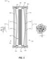
- FIG. 3is a perspective view of an HMD according to an embodiment of the present disclosure.
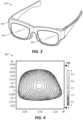
- FIG. 4is a graph illustrating a pre-formed profile of a deformable element of an optical lens assembly according to an embodiment of the present disclosure.
- FIG. 5is a graph showing principal strain values on an optical lens assembly after being pre-formed and uniformly stretched, according to an embodiment of the present disclosure.
- FIG. 6is a graph showing stress values on an optical lens assembly after being pre-formed and uniformly stretched, according to an embodiment of the present disclosure.
- FIG. 7is a plot showing reaction forces on a deformable optical element at various dimple heights and for different directions of actuation, according to an embodiment of the present disclosure.
- FIG. 8is a plot showing a velocity of a deformable optical element at various dimple heights and for different directions of actuation, according to an embodiment of the present disclosure.
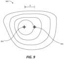
- FIG. 9is a plot illustrating a strain contour of an optical lens assembly according to an embodiment of the present disclosure.
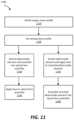
- FIGS. 10 and 11are flow diagrams illustrating methods of fabricating an optical lens assembly according to various embodiments of the present disclosure.
- embodiments of the present disclosuremay include optical lens assemblies that include a deformable element having a non-uniform mechanical strain or stress profile.
- the non-uniform mechanical strain or stress profilemay facilitate achieving desired optical properties upon deformation the deformable element.
- Methods of fabricating such optical lens assemblies and deformable elementsinclude inducing a non-uniform mechanical strain or stress profile in the deformable elements, such as by pre-forming the deformable elements to have a non-planar shape, pre-stretching the deformable elements, and/or selectively heating at least a portion of the deformable elements, etc. Such methods may result in commercially feasible adjustable optical lens assemblies that may address conventional difficulties in customization or achievement of certain optical properties.
- FIGS. 1 and 2detailed descriptions of example optical lens assemblies that include a deformable element that may have a non-uniform mechanical strain or stress profile.
- the description of FIG. 3relates to an embodiment of an HMD that includes optical lens assemblies according to the present disclosure.
- FIGS. 4 - 9the following will provide detailed descriptions of strain profiles and other properties of disclosed optical lens assemblies.
- the discussion relating to FIGS. 10 and 11will provide detailed descriptions of various methods of fabricating optical lens assemblies according to the present disclosure.
- FIG. 1shows a cross-sectional side view of an optical lens assembly 100 in an actuated state.
- the optical lens assembly 100may include a proximal optical lens subassembly 104 (also referred to as the “proximal subassembly 104 ” for simplicity) for positioning close to a user's eye, and a distal optical lens subassembly 106 (also referred to as the “distal subassembly 106 for simplicity) for positioning away from the user's eye.
- proximal optical lens subassembly 104also referred to as the “proximal subassembly 104 ” for simplicity
- distal optical lens subassembly 106also referred to as the “distal subassembly 106 for simplicity
- the optical lens assembly 100may also include a housing 140 (e.g., a frame element of an HMD) for supporting the optical lens subassemblies 104 , 106 , which may at least partially cover a peripheral edge of the optical lens subassemblies 104 , 106 .
- the housing 140may also support a display element 102 (e.g., an electronic display element, etc.) for displaying an image to the user.
- the display element 102may be positioned adjacent to and between the optical lens subassemblies 104 , 106 .
- the proximal subassembly 104may include a rigid or semi-rigid proximal structural support element 108 and a proximal deformable optical element 110 (including a proximal deformable element 112 and a proximal deformable medium 114 ) positioned over the structural support element 108 .
- proximal deformable element 112may be directly (e.g., bonded, adhered) or indirectly (e.g., via a separate component or material) coupled to the proximal structural support element 108 .
- an outer periphery of the proximal deformable element 112may define an edge seal for containing the proximal deformable medium 114 in a cavity defined between the proximal deformable element 112 and the proximal structural support element 108 .
- a force distributor ring 150which may also function as a pre-tension ring for maintaining a pre-tension in the proximal deformable element 112 , may be positioned over the proximal deformable element 112 proximate the outer periphery of the deformable element 112 .
- the distal subassembly 106may include a distal structural support element 116 and a distal deformable optical element 118 (including a distal deformable element 120 and a distal deformable medium 122 ).
- Another force distributor ring 150may be coupled to the distal deformable element 120 .
- the structural support elements 108 , 116may be positioned on external sides of the optical lens assembly 100
- the deformable optical elements 110 , 118may be positioned on internal sides of the optical lens assembly 100 facing the display element 102 .
- Each of the structural support elements 108 , 116 , the deformable elements 112 , 120 , and the deformable media 114 , 122may be substantially transparent to allow light to pass therethrough to an eye of a user. Accordingly, at least portions of the structural support elements 108 , 116 and of the deformable optical elements 110 , 118 may be positioned in an optical aperture of the optical lens assembly 100 , which may refer to a portion of the optical lens assembly 100 that allows the passage of light to a user's eye.
- the phrase “substantially transparent”may refer to an element exhibiting greater than about 20% transmissivity and less than about 10% haze in the visible light spectrum.
- the term “substantially,” in reference to a given parameter, property, or conditionmay generally refer to a degree that one of ordinary skill in the art would understand that the given parameter, property, or condition is met with a small degree of variance, such as within acceptable manufacturing tolerances.
- the parameter, property, or conditionmay be at least 90% met, at least 95% met, at least 99% met, etc.
- the phrase “deformable optical element”may refer to an element (including one or more materials or sub-elements) that is configured to be deformed to alter an optical property (e.g., an accommodative property or an adaptive optical property) of the optical lens assembly.
- the term “accommodative” or “accommodation”may refer to changes in an optical power.
- the term “adaptive”may refer to tunability for providing control, compensation, and/or correction of wave front errors such as distortion and aberration(s).
- “aberration”may generally refer to an optical image defect, including any deviation from diffraction-limited optical performance. Aberrations can be chromatic or monochromatic and include, for example, tilt, defocus, astigmatism, coma, distortion, field curvature, spherical errors, cylindrical errors, etc.
- the structural support elements 108 , 116 , deformable optical elements 110 , 118 , and force distributor rings 150may be coupled to and supported by the housing 140 (e.g., an eyeglass frame element, an AR or VR headset frame element, etc.).
- the deformable element 120 and deformable medium 122are shown in an actuated state, with an actuation force 160 acting on the force distributor rings 150 in a direction toward the user's eyes. Because of the actuation force 160 , the proximal deformable optical element 110 may have a convex shape to exhibit a positive-optical power, and the distal deformable optical element 118 may have a concave shape to exhibit a negative-optical power.
- a surface of the deformable elements 112 , 120may each have a substantially planar shape, and the optical lens assembly 100 may be configured and positioned to not substantially alter an image or view passing through the optical lens assembly 100 .
- the non-actuated statemay be a substantially zero-optical power state.
- FIG. 1illustrates separate actuation forces 160 respectively acting on both force distributor rings 150 of the proximal and distal subassemblies 104 , 106
- a single actuation force 160 applied by a single actuatormay act on both force distributor rings 150 of the proximal subassembly 104 and of the distal subassembly 106 .
- the proximal and distal subassembliesmay be jointly or separately actuated, as may be appropriate for different applications.
- the optical lens assembly 100 illustrated in FIG. 1may be used to reduce or eliminate the negative impact of a phenomenon known as the “vergence-accommodation conflict.”
- Traditional AR displaysmay attempt to create the illusion that a virtual object is set at a distance in the real-world environment by displaying virtual images to the left eye and to the right eye with a relative offset, such that a user's eyes converge on the desired real-world focal point to align the left- and right-side virtual images.
- the user's left and right eyesalso undergo accommodation to bring the respective left- and right-side virtual images into focus.
- the distance of the real-world focal pointmay frequently differ from the distance of the augmented-reality display, causing a difference between the apparent vergence distance and the apparent accommodation distance of a virtual object.
- the human visual systemis adapted to the expectation that the apparent vergence distance and the apparent accommodation distance of a real-world object will match, the mismatch frequently posed by traditional augmented reality systems may confuse a user's vision, potentially breaking a sense of immersion—or even causing physical discomfort.
- the optical lens assembly 100 illustrated in FIG. 1may be configured to address the vergence-accommodation conflict.
- an actuation force 160 from an actuatore.g., an electromechanical actuator
- FIG. 1an actuation force 160 from an actuator (e.g., an electromechanical actuator) is shown in FIG. 1 as being applied in a direction toward the user's eye, such that the proximal deformable optical element 110 forms a convex shape and the distal deformable optical element 118 forms a concave shape.
- the actuation force 160is applied in a direction away from the user's eye, the proximal deformable optical element 110 may form a concave shape and the distal deformable optical element 118 may form a convex shape.
- the proximal deformable optical element 110may be configured to adjust the user's view of an image rendered on the display element 102 .
- the distal deformable optical element 118may be configured to substantially counteract the adjustments of the proximal deformable optical element 110 with respect to the user's view of a surrounding real-world environment.
- the two deformable optical elements 110 , 118may together modify the apparent accommodation distance of a virtual object or scene shown on the display element 102 , while reducing or eliminating any distortion of the appearance of the real-world environment through the optical lens assembly 100 .
- the term “electromechanical actuator”may refer to a piezoelectric material or device, an electroactive polymer, an electrostrictive polymer, a shape memory alloy, a voice coil, a pneumatic actuator, an electromagnetic motor (including for example a servo motor, a stepper motor, a DC motor, or a similar motor), a hydraulic actuator, or a combination thereof.
- the term “electroactive”may refer to a property of a material or composite material that deforms in response to an application of electrical energy (e.g., a voltage) and may generate electrical energy when strained or deformed.
- Example electroactive materialsinclude piezoelectric materials, electrostrictor materials, dielectric elastomers, and ionic polymer conductors. Electroactive materials may function as transducers or as a component of transducers for actuating and deforming the deformable optical elements 110 , 118 .
- the structural support elements 108 , 116may be or include a substantially transparent material with a higher relative rigidity than the deformable elements 112 , 120 and the deformable media 114 , 122 .
- the structural support elements 108 , 116may be or include one or more of a glass material, a sapphire material, a crystal material (e.g., quartz), a polycarbonate material, another polymer material, or a non-polymeric material.
- the structural support elements 108 , 116may provide a protective barrier for the user's eye, for the deformable optical elements 110 , 118 , and for other components of the optical lens assembly 100 (e.g., the display element 102 , an actuator, etc.).
- the proximal structural support element 108may also include an eye-tracking element, which may be configured for estimating an inter-pupillary distance of the user's eyes, a gaze distance, and/or a focal point.
- the eye-tracking elementif present, may include a selective-transmission element that transmits light having a selected property and that does not transmit light that does not have the selected property.
- the proximal structural support element 108may include a coating or material that allows visible light to pass while reflecting non-visible light (e.g., infrared light).
- an infrared light sourcemay direct infrared light to the proximal structural support element 108 , which may be reflected onto the user's eye.
- An infrared cameramay detect infrared light that is reflected from the user's eye and back to the proximal structural support element 108 , to track the user's eye.
- the structural support elements 108 , 116may each be a substantially planar element that does not substantially alter an image viewed through the structural support elements 108 , 116 .
- the structural support elements 108 , 116may include a corrective ophthalmic lens (e.g., a positive-optical power lens, a negative-optical power lens, a lens for correction of an aberration, etc.), or another optical lens element.
- a corrective ophthalmic lense.g., a positive-optical power lens, a negative-optical power lens, a lens for correction of an aberration, etc.
- an anti-reflective coatingmay be applied to the structural support elements 108 , 116 .
- the outer periphery of the deformable elements 112 , 120may be directly or indirectly coupled to the respective structural support elements 108 , 116 , which may define cavities therebetween for containing the deformable media 114 , 122 .
- the deformable elements 112 , 120may include a substantially transparent, flexible film of a single material or multiple materials.
- the deformable elements 112 , 120may include at least one of a polymer material (e.g., a thermoset polymer, a thermoplastic polymer, an elastomer, a silicone material, polydimethylsiloxane, a polyurethane elastomer, a fluoropolymer material, polyvinylidene fluoride or a copolymer thereof, a polyolefin material, a polyacrylate material, etc.), a ceramic material, a glass material, a crystalline (e.g., substantially single-crystal) material, or a composite material.
- a polymer materiale.g., a thermoset polymer, a thermoplastic polymer, an elastomer, a silicone material, polydimethylsiloxane, a polyurethane elastomer, a fluoropol
- the deformable elements 112 , 120may be or include a single material or a multi-layer structure.
- the deformable elements 112 , 120may include a barrier material for controlling gas or liquid diffusion, an anti-reflective material, or a combination thereof.
- a material of the deformable elements 112 , 120may include a flexible, transparent, water-impermeable material, such as clear and elastic polyolefins, polycycloaliphatics, polyethers, polyesters, polyimides and/or polyurethanes, for example, polyvinylidene chloride films, including commercially available films.
- the deformable elements 112 , 120may be pre-tensioned to achieve a desired profile and response to actuation and/or to reduce the negative effects of so-called “gravity sag.”
- Gravity sagmay refer to a lower portion of the deformable optical elements 112 , 120 being thicker on average than an upper portion, due to gravity urging the deformable elements 112 , 120 and/or deformable media 114 , 122 downward.
- One or both of the deformable elements 112 , 120may have a non-uniform mechanical strain or stress profile when in a non-actuated state. Examples of deformable elements having non-uniform mechanical strain or stress profiles and example methods for achieving non-uniform mechanical strain or stress profiles are described below, such as with reference to FIGS. 4 - 11 .
- the deformable media 114 , 122may be a substantially transparent material with mechanical properties that allow for deformation upon actuation of the optical lens assembly 100 .
- the deformable media 114 , 122may be or include a gas (e.g., air, nitrogen, etc.), a liquid (e.g., water, degassed water, mineral oil, saline solution, a high-refractive index liquid, etc.), a polymer material, a gel (e.g., a silicone gel), or a foam (e.g., a silica aerogel), etc.
- a gase.g., air, nitrogen, etc.
- a liquide.g., water, degassed water, mineral oil, saline solution, a high-refractive index liquid, etc.
- a polymer materiale.g., a gel
- a foame.g., a silica aerogel
- FIG. 2shows an embodiment of an optical lens assembly 200 similar to the optical lens assembly 100 described above with reference to FIG. 1 , but with a curved proximal structural support element 208 and a curved distal structural support element 216 , rather than the substantially planar structural support elements 108 , 116 shown in FIG. 1 .
- one or both structural support elements 208 , 216may be or include a corrective ophthalmic lens or a curved zero-optical power lens (e.g., a zero-power meniscus lens).
- a shape of the proximal and/or distal structural support elements 208 , 216may, in some embodiments, be tailored to or selected in consideration of a specific user to correct vision impairments or to otherwise meet user preferences.
- the structural support elements 208 , 216 in FIG. 2can be zero-power meniscus lens elements for improved anti-reflective properties and easier integration with potentially non-flat optical eye-tracking and/or ophthalmic optical elements at the proximal structural support element 208 .
- a zero-optical power curved lensmay provide some advantages over a substantially planar lens for some applications, such as for improved anti-reflective properties and/or improved fit to a user's facial contours, for example.
- the optical lens assembly 200may include a proximal optical lens subassembly 204 and a distal optical lens subassembly 206 .
- the proximal optical lens subassembly 204may include the proximal structural support element 208 and a proximal deformable optical element 210 (including a proximal deformable element 212 and a proximal deformable medium 214 ).
- the distal optical lens subassembly 206may include the distal structural support element 216 , a distal deformable optical element 218 (including a distal deformable element 220 and a proximal deformable medium 222 ).
- a display element 202 and the optical lens subassemblies 204 , 206may be mounted on a housing 240 .
- FIG. 2illustrates an actuation mechanism different from that of the embodiment of FIG. 1 .
- the deformable elements 212 , 220 of FIG. 2may each include an electroactive material configured to deform upon application of a sufficient voltage by a driver circuit 270 .
- substantially transparent dielectric elastomerspiezoelectrics including polymers like polyvinylidene fluoride (“PVDF”) and its copolymers, and/or single crystal ceramics like lithium niobate, quartz, K 0.5 Na 0.5 NbO 3 (“KNN”), barium titanate, lithium niobate, lithium tetraborate, quartz, lead zirconate titanate, Pb(Mg 1/3 Nb 2/3 )O 3 —PbTiO 3 , and/or Pb(Zn 1/3 Nb 2/3 )O 3 —PbTiO 3 , etc. are electroactive materials that may be included in the deformable elements 212 , 220 .
- PVDFpolyvinylidene fluoride
- KNNK 0.5 Na 0.5 NbO 3
- Pb(Mg 1/3 Nb 2/3 )O 3 —PbTiO 3quartz, lead zirconate titanate
- the deformable elements 212 , 220may include rigid or semi-rigid structural materials for load bearing or for reducing or eliminating the level of pre-tension in the deformable elements 212 , 220 .
- alternative architectureswith a wider range of potential material selection, material geometries, and boundary conditions may improve performance and manufacturability.
- the deformable elements 212 , 220may include electrodes for electrically coupling the driver circuit 270 to the deformable elements 212 , 220 .
- the electrodesmay be or include a substantially transparent, electrically conductive material, such as a transparent conducting oxide, indium tin oxide, a nanocomposite material, carbon nanotubes, silver nanowires, and/or graphene.
- FIG. 2illustrates the optical lens assembly 200 in an actuated state.
- application of a sufficient voltage and polarity on the deformable elements 212 , 220 by the driver circuit 270may deform the deformable optical elements 210 , 218 .
- the proximal deformable optical element 210is shown as being deformed into a concave shape and the distal deformable optical element 218 is shown as being deformed into a convex shape.
- the application of a sufficient voltage of an opposite polarity to that shown in FIG. 2may result in the proximal deformable optical element 210 forming a convex shape and the distal deformable optical element 218 forming a concave shape.
- the optical lens assembly 200may be configured to address the vergence-accommodation conflict.
- FIG. 3illustrates an example HMD 300 (e.g., AR glasses, VR glasses) capable of incorporating the optical lens assemblies described herein.
- the HMD 300may be dimensioned to be worn on a head of a user.
- the HMD 300may include a frame element 302 for supporting at least one deformable optical lens assembly 304 according to the present disclosure.
- the optical lens assembly(ies) 304may be tailored to or selected in consideration of a particular user's eye.
- the frame element 302may also support other elements, such as an actuator, a driver circuit for the actuator, a power supply element (e.g., a battery), a communication component (e.g., a component for communication via Wi-Fi, BLUETOOTH, near-field communications (“NFC”), etc.), a display element, a graphics processing unit for rendering an image on the display element, an image sensor (e.g., a camera), an eye-tracking element, etc.
- the optical lens assembly 304may have an asymmetric shape.
- the HMD 300may have a different shape and design than is shown in FIG. 3 , such as in the form of a VR headset or another shape that suits user preferences or a particular application.
- the optical lens assembly (ies) 304may be or include, for example, any of the optical lens assemblies or subassemblies described in this disclosure.
- FIG. 4is a graph 400 that illustrates an example pre-formed profile of a deformable element according to some embodiments of the present disclosure.
- the deformable elementmay be thermoformed out of a polymer material, such as thermoplastic polyurethane (“TPU”).
- TPUthermoplastic polyurethane
- a number of customized thermoforming moldscan be used to produce a variety of stock keeping units (“SKUs”) of deformable elements or associated optical lens assemblies like the approach used for glasses in the ophthalmics industry.
- SKUsstock keeping units
- optical lens assembliesmay be fabricating to exhibit different sizes, shapes, and/or optical properties (e.g., ophthalmic correction values, maximum deformed optical powers, optical axis location to account for inter-pupillary distances for various users, etc.).
- cylindrical curvaturecan be introduced for astigmatism correction, etc.
- the example pre-formed TPU deformable element shown in FIG. 4may be formed with a non-planar (e.g., curved) mold to result in the profile illustrated in the graph 400 .
- the thermoforming of the deformable elementmay result in a central region of the deformable element having a highest relative elevation, sloping or tapering downward toward an outer periphery of the deformable element, which may have a lowest relative elevation.
- the profile shown in the graph 400may represent a shape of the deformable element upon formation, without application of an external force (e.g., an actuation force or a stretching force) on the deformable element.
- the deformable elementmay be substantially uniformly stretched and fixed to a pre-tensioning ring to hold the pre-tension in the deformable element.
- substantially uniform stretching of the deformable elementmay result in non-uniform mechanical strain and/or stress.
- Non-uniform strain and stress in the deformable elementsmay be desirable in some examples and applications, such as to counteract the negative effects of gravity sag or to modify the deformed, actuated profile of the associated optical lens assemblies for specific users or sets of users having certain ophthalmic needs (e.g., aberration corrections, inter-pupillary distances, etc.).
- the pre-formed profile of the deformable elementmay be adjusted to customize optical lens assemblies for specific users or groups of users.
- FIG. 5shows a graph 500 of the after-stretch principal strain
- FIG. 6shows a graph 600 of the after-stretch von Mises stress in the deformable element corresponding to the graph 400 of FIG. 4 , respectively.
- the stressmay vary by approximately 15% and the strain may vary by approximately 30% across an area of the deformable optical element.
- the strainmay vary by at least about 2%, such as by at least about 5%, or by at least about 10%. Accordingly, substantially uniform stretching of the pre-formed deformable element may result in non-uniform stress and strain in the deformable element.
- the principal strain in the substantially uniformly stretched deformable elementmay be lowest (e.g., about 0.106 in the example of FIG. 5 ) in a central region of the deformable element and may be highest (e.g., about 0.140 in the example of FIG. 5 ) near an outer periphery of the deformable element.
- the von Mises stressmay be lowest (e.g., about 3.2 MPa in the example of FIG. 6 ) in the central region and may be highest (e.g., about 4.2 MPa in the example of FIG. 6 ) near the outer periphery.
- the pre-tensionmay be stated in terms of nominal principle strain (e.g., 5%, 7%, 10%, 12%, etc.). Since the thickness dimension of the deformable element may be substantially less than the corresponding lateral dimensions, the out-of-plane stress may be considered negligible in calculating load variability, for example.
- the load variability across the deformable elementmay be given in terms of stress state (e.g., von Mises stress variability of 5%, 10%, 20%, 30%, etc.) because the in-plane stresses largely determine the deformation behavior.
- the pre-stress conditionmay scale with the level of pre-tension. Therefore, the applied pre-tension may be variable across the area of the deformable element, even though a substantially uniform pre-tension may be applied at the outer periphery of the deformable element. This variability can result in a non-uniform stress and/or strain profile for reducing gravity sag by, for example, applying a larger pre-stress near the peripheral edge than in a central region, to counteract the gravity-induced pressure change where the effects are largest (e.g., along a bottom edge of the deformable optical element). Alternatively, if edge effects are of concern, a higher pre-stress may be applied in the central region for alleviating gravity sag while reducing negative edge effects. In these cases, the nominal pre-stress or pre-strain may be less than with uniform tensioning and may be locally larger in certain areas to target gravity sag.
- FIG. 7is a plot 700 showing reaction forces of the deformable optical element, which may be approximately equivalent to applied actuation forces.
- a dimple heighti.e., a distance from a neutral, non-actuated deformable element to its highest or lowest point after actuation
- the corresponding pre-stress variationmay also increase.
- Embodiments with relatively larger dimple heights and pre-stress variationsmay exhibit a reduced actuation force requirement, as illustrated in the plot 700 .
- the pre-stress conditionmay affect a transient response of the deformable element to the applied force and displacement of the actuator through a non-uniform mechanical strain or stress profile, which may generally correlate to a stiffness profile.
- a stiffness profilemay be tuned to reduce or prevent undesired transient modes for high image quality and optical performance during actuation.
- the plot 700 of FIG. 7compares the reaction forces for upward movement and downward movement of the optical elements and for various dimple heights. In HMDs like those shown in FIGS. 1 and 2 , optical lens subassemblies having respective concave and convex curvatures may be simultaneously obtained upon actuation.
- approximately equal and opposite optical powers at the proximal and distal optical lens subassembliesmay improve optical quality through the two optical lens subassemblies, including during a transient response when one of the lenses is deformed to a concave shape and the other of the lenses is deformed to a convex shape.
- substantially matching the upward and downward reaction forcessuch as by pre-forming the deformable elements as described above with reference to FIGS. 4 - 6 , may improve a user's visual experience during actuation.
- FIG. 8shows a plot 800 illustrating a velocity of the deformable element as a function of dimple height and time during actuation.
- the height of the dimplecan be tuned to modify the transient response in the downward motion to more closely match that of the upward motion.
- the plot 800 of FIG. 8demonstrates how non-uniform pre-stress enables tunability of the transient response for an improved user experience.
- Introducing temperature-controlled viscoelastic creep in an elastomeric deformable elementis an example approach to obtain a non-uniform and customizable pre-stress condition.
- An elastomersuch as TPU, may be formed and stretched to create a uniformly pre-tensioned deformable element.
- a residual strain or stressmay be introduced to the material. Creep is both stress- and temperature-dependent. Therefore, selective heating with controlled temperature can be applied to induce a non-uniform mechanical strain or stress profile through thermal realization.
- conditioning the deformable element after stretchingmay facilitate customization of the resulting optical lens assembly at a later stage in the manufacturing process.
- optical lens assemblycan be fully assembled and then selectively heated to create a non-uniform strain or stress profile for an inter-pupillary distance or ophthalmic correction specifically tailored to an individual end user, for example.
- FIG. 9is a plot 900 qualitatively depicting a strain contour map of an asymmetric optical lens assembly with a location of an optical axis 904 adjusted from a geometric center 902 of the optical lens assembly, such as for adapting to a user's inter-pupillary distance and/or for obtaining an axisymmetric strain near the optical axis 904 .
- the distance d illustrated in the plot 900 of FIG. 9demonstrates a shift of the optical axis 904 from the geometric center 902 of the optical lens assembly.
- a desired optical centration locatione.g., a location of an optical axis at a center of the lens curvature
- an axisymmetric strain or stress profilemay induce a more axisymmetric deformation profile to reduce astigmatic aberrations.
- Such a strain or stress profilecan be introduced through the fabrication processes described in this disclosure, for example.
- FIG. 10is a flow chart illustrating a method 1000 of fabricating an optical lens assembly according to embodiments of the present disclosure.
- a target strain profilemay be defined, such as in consideration of a desired optical axis location, dimple height, optical properties (e.g., accommodative properties, adaptive properties, etc.), shape of the optical lens assembly, inter-pupillary distance, expected gravity sag, etc.
- the target strain profilemay be defined to substantially achieve a desired set of optical properties, such as to tailor the resulting optical lens assembly to a specific user or set of users.
- optical ray tracing and finite element simulationsmay be used to define the target strain profile for a specific user or for a set of users over a defined accommodative optical power range.
- the defined target strain profilemay be induced in a deformable element by performing operations 1020 , 1030 , and 1040 , as described below.
- a pre-form profile of the deformable elementmay be set to substantially achieve the defined target strain profile after further processing.
- the pre-form profilemay be set in consideration of factors such as material properties of the material of the deformable element, thickness of the deformable element, shape of the deformable element, etc.
- Finite element simulationspossibly including iterative operations and calculations, may be used to determine the pre-form profile to achieve the target strain profile.
- the deformable elementmay be thermoformed to the pre-form profile.
- a sheet of polymer materialmay be positioned on a mold surface having the pre-form profile.
- the sheet of polymer materialmay be pre-heated or heated on or in the mold to a sufficient temperature such that the polymer material may substantially form to the shape and contours of the mold surface.
- the sheet of polymer materialmay be formed to the shape of the mold surface, and the sheet of polymer material may be cooled to a sufficiently low temperature such that its molded shape is at least semi-permanent.
- the molded sheet of polymer materialmay then be removed from the thermoforming mold. If the molded sheet of polymer material is larger than a desired end shape, the sheet of polymer material may be trimmed to the desired end shape.
- the thermoformed deformable elementmay be stretched.
- the stretchingmay be a substantially uniform or non-uniform stretching, depending on the defined target strain profile, material properties of the deformable element, shape of the deformable element, desired optical properties, etc.
- the material of the deformable elementmay be uniaxially stretched.
- the material of the deformable elementmay be biaxially stretched, such as along two substantially perpendicular axes.
- the material of the deformable elementmay be stretched along at least one axis that is angled from vertical and horizontal relative to an intended orientation of the resulting optical lens assembly when in use.
- At least some element of the force used to pre-stretch the material of the deformable elementmay be tangential to an edge of the deformable element.
- a pre-tensioning ringmay be coupled to the deformable element to substantially maintain the stretched state of the deformable element when not actuated.
- the resulting pre-stretched deformable elementmay substantially exhibit the target strain profile defined in operation 1010 .
- the pre-strained deformable elementmay then be directly or indirectly coupled (e.g., bonded, adhered, coupled via a separate edge seal material, etc.) to a substantially transparent structural support element (e.g., a substantially planar lens element, a curved lens element, etc.).
- a substantially transparent deformable mediummay be disposed between the deformable element and the structural support element.
- the structural support element, deformable medium, and deformable elementmay be coupled to and supported by a housing (e.g., a frame element).
- An actuatore.g., an electromechanical actuator, a driver circuit for an electroactive material, etc.
- An actuatormay be coupled to the housing and to the deformable element to actuate and deform the deformable optical element, thus altering an optical property of the optical lens assembly upon actuation.
- FIG. 11is a flow chart illustrating a method 1100 of fabricating an optical lens assembly according to additional embodiments of the present disclosure.
- a target strain profile of a deformable elementmay be defined, as discussed above with reference to FIG. 10 .
- a temperature profilemay be set to substantially achieve the defined target strain profile.
- Application of sufficient heat to the deformable elementmay induce a residual strain or stress in the deformable element.
- the temperature profilemay include a selective application of heat, such as different amounts of heat and/or for different lengths of time in different regions of the deformable element, to substantially achieve the target strain profile.
- finite element simulationspossibly including iterative operations and calculations, may be performed to determine the appropriate temperature profile to achieve the target strain profile.
- the deformable elementmay be stretched, as described above with reference to FIG. 10 .
- the stretched deformable elementmay be assembled into an optical lens assembly, such as by coupling the deformable element to a pre-tensioning ring, directly or indirectly coupling the deformable element to a structural support element, and disposing a deformable medium in a cavity defined between the deformable element and the structural support element.
- heatmay be applied to the optical lens assembly according to the set temperature profile to induce a non-uniform mechanical strain or stress in the deformable element according to the defined target strain profile.
- Operations 1150 and 1160illustrate an alternative (compared to operations 1130 and 1140 described above) sequence for some procedures of fabricating an optical lens assembly.
- the deformable elementmay be stretched and heat may be applied to the stretched deformable element according to the set temperature profile.
- the stretched and heat-treated deformable elementmay be assembled into an optical lens assembly, such as by coupling the deformable element to a pre-tensioning ring, directly or indirectly coupling the deformable element to a structural support element, and disposing a deformable medium in a cavity defined between the deformable element and the structural support element.
- the set temperature profilemay be applied to the deformable element at various stages of fabricating the optical lens assembly.
- portions of the material of the deformable elementmay be selectively polymerized.
- the portions of the deformable elementmay be selectively exposed to actinic radiation to selectively polymerize those portions (or to induce additional cross-linking compared to portions that are not exposed to the actinic radiation).
- the selective polymerizationmay induce a residual strain or stress in the material of the deformable element.
- deformable elements and/or optical lens assemblies having a variety of desired mechanical strain or stress profiles and resulting optical propertiesmay be fabricated according to methods of this disclosure.
- a deformable element and/or optical lens assembly having a desired set of optical propertiesmay be selected from a group of deformable element and/or optical lens assemblies with respective different mechanical strain or stress profiles and optical properties.
- optical lens assemblies and associated HMDsthat include a deformable element that exhibits a non-uniform mechanical strain and/or mechanical stress profile.
- Various methods for achieving the non-uniform mechanical strain and/or mechanical stress profileare also disclosed.
- the disclosed apparatuses and methodsmay enable improved optical lens assemblies with desirable deformation responses to actuation, at commercially reasonable costs.
- Embodiments of the present disclosuremay include or be implemented in conjunction with an artificial reality system.
- Artificial realityis a form of reality that has been adjusted in some manner before presentation to a user, which may include, e.g., VR, AR, mixed reality (MR), hybrid reality, or some combination and/or derivatives thereof.
- Artificial reality contentmay include completely generated content or generated content combined with captured (e.g., real-world) content.
- the artificial reality contentmay include video, audio, haptic feedback, or some combination thereof, any of which may be presented in a single channel or in multiple channels (such as stereo video that produces a three-dimensional effect to the viewer).
- artificial realitymay also be associated with applications, products, accessories, services, or some combination thereof, that are used to, e.g., create content in an artificial reality and/or are otherwise used in (e.g., perform activities in) an artificial reality.
- the artificial reality system that provides the artificial reality contentmay be implemented on various platforms, including an HMD connected to a host computer system, a standalone HMD, a mobile device or computing system, or any other hardware platform capable of providing artificial reality content to one or more viewers.
Landscapes
- Physics & Mathematics (AREA)
- General Physics & Mathematics (AREA)
- Optics & Photonics (AREA)
- Health & Medical Sciences (AREA)
- Ophthalmology & Optometry (AREA)
- Nonlinear Science (AREA)
- General Health & Medical Sciences (AREA)
- Mathematical Physics (AREA)
- Microelectronics & Electronic Packaging (AREA)
- Chemical & Material Sciences (AREA)
- Crystallography & Structural Chemistry (AREA)
- Engineering & Computer Science (AREA)
- Prostheses (AREA)
- Mechanical Light Control Or Optical Switches (AREA)
- Surface Treatment Of Optical Elements (AREA)
- Lens Barrels (AREA)
Abstract
Description
Claims (20)
Priority Applications (1)
| Application Number | Priority Date | Filing Date | Title |
|---|---|---|---|
| US18/315,779US12169290B2 (en) | 2018-03-29 | 2023-05-11 | Optical lens assemblies and related methods |
Applications Claiming Priority (4)
| Application Number | Priority Date | Filing Date | Title |
|---|---|---|---|
| US201862650254P | 2018-03-29 | 2018-03-29 | |
| US16/018,746US10914871B2 (en) | 2018-03-29 | 2018-06-26 | Optical lens assemblies and related methods |
| US17/160,169US11686887B1 (en) | 2018-03-29 | 2021-01-27 | Optical lens assemblies and related methods |
| US18/315,779US12169290B2 (en) | 2018-03-29 | 2023-05-11 | Optical lens assemblies and related methods |
Related Parent Applications (1)
| Application Number | Title | Priority Date | Filing Date |
|---|---|---|---|
| US17/160,169ContinuationUS11686887B1 (en) | 2018-03-29 | 2021-01-27 | Optical lens assemblies and related methods |
Publications (2)
| Publication Number | Publication Date |
|---|---|
| US20230280506A1 US20230280506A1 (en) | 2023-09-07 |
| US12169290B2true US12169290B2 (en) | 2024-12-17 |
Family
ID=68054882
Family Applications (8)
| Application Number | Title | Priority Date | Filing Date |
|---|---|---|---|
| US16/018,752Active2038-08-14US11048075B1 (en) | 2018-03-29 | 2018-06-26 | Optical lens assemblies and related methods |
| US16/018,746Active2039-01-24US10914871B2 (en) | 2018-03-29 | 2018-06-26 | Optical lens assemblies and related methods |
| US16/021,650Active2040-01-26US11762130B1 (en) | 2018-03-29 | 2018-06-28 | Optical lens assemblies, head-mounted displays, and related methods |
| US16/021,580Active2039-05-28US10928558B1 (en) | 2018-03-29 | 2018-06-28 | Optical lens assemblies, head-mounted displays, and related methods |
| US17/160,169Active2038-12-16US11686887B1 (en) | 2018-03-29 | 2021-01-27 | Optical lens assemblies and related methods |
| US17/180,194Active2039-01-27US11686888B1 (en) | 2018-03-29 | 2021-02-19 | Optical lens assemblies, head-mounted displays, and related methods |
| US17/357,531ActiveUS11740392B1 (en) | 2018-03-29 | 2021-06-24 | Optical lens assemblies and related methods |
| US18/315,779ActiveUS12169290B2 (en) | 2018-03-29 | 2023-05-11 | Optical lens assemblies and related methods |
Family Applications Before (7)
| Application Number | Title | Priority Date | Filing Date |
|---|---|---|---|
| US16/018,752Active2038-08-14US11048075B1 (en) | 2018-03-29 | 2018-06-26 | Optical lens assemblies and related methods |
| US16/018,746Active2039-01-24US10914871B2 (en) | 2018-03-29 | 2018-06-26 | Optical lens assemblies and related methods |
| US16/021,650Active2040-01-26US11762130B1 (en) | 2018-03-29 | 2018-06-28 | Optical lens assemblies, head-mounted displays, and related methods |
| US16/021,580Active2039-05-28US10928558B1 (en) | 2018-03-29 | 2018-06-28 | Optical lens assemblies, head-mounted displays, and related methods |
| US17/160,169Active2038-12-16US11686887B1 (en) | 2018-03-29 | 2021-01-27 | Optical lens assemblies and related methods |
| US17/180,194Active2039-01-27US11686888B1 (en) | 2018-03-29 | 2021-02-19 | Optical lens assemblies, head-mounted displays, and related methods |
| US17/357,531ActiveUS11740392B1 (en) | 2018-03-29 | 2021-06-24 | Optical lens assemblies and related methods |
Country Status (2)
| Country | Link |
|---|---|
| US (8) | US11048075B1 (en) |
| WO (1) | WO2019190887A1 (en) |
Families Citing this family (32)
| Publication number | Priority date | Publication date | Assignee | Title |
|---|---|---|---|---|
| JP7263643B2 (en) | 2017-03-08 | 2023-04-25 | メタ プラットフォームズ テクノロジーズ, リミテッド ライアビリティ カンパニー | Wide angle variable neutral density filter |
| CN111108428A (en) | 2017-07-17 | 2020-05-05 | 加里夏普创新有限责任公司 | Wide angle compensation of uniaxial retarder stacks |
| EP3746822A4 (en) | 2018-01-29 | 2022-01-12 | Gary Sharp Innovations, LLC | Hollow triple-pass optical elements |
| US11249355B2 (en) | 2018-01-29 | 2022-02-15 | Gary Sharp Innovations, Llc | Color switch for reduced color cross-talk |
| US11320665B2 (en) | 2018-03-02 | 2022-05-03 | Gary Sharp Innovatnons, Llc | Retarder stack pairs for polarization basis vector transformations |
| US10962791B1 (en) | 2018-03-22 | 2021-03-30 | Facebook Technologies, Llc | Apparatuses, systems, and methods for fabricating ultra-thin adjustable lenses |
| US11245065B1 (en) | 2018-03-22 | 2022-02-08 | Facebook Technologies, Llc | Electroactive polymer devices, systems, and methods |
| US11048075B1 (en)* | 2018-03-29 | 2021-06-29 | Facebook Technologies, Llc | Optical lens assemblies and related methods |
| US10852553B2 (en)* | 2018-09-21 | 2020-12-01 | Apple Inc. | Electronic device with a tunable lens |
| US11256331B1 (en) | 2019-01-10 | 2022-02-22 | Facebook Technologies, Llc | Apparatuses, systems, and methods including haptic and touch sensing electroactive device arrays |
| US11614570B1 (en)* | 2019-03-26 | 2023-03-28 | Meta Platforms Technologies, Llc | Optical lens assemblies with adaptive elements and related systems and methods |
| US11624919B2 (en)* | 2019-05-24 | 2023-04-11 | Magic Leap, Inc. | Variable focus assemblies |
| WO2021010772A1 (en) | 2019-07-18 | 2021-01-21 | 삼성전자(주) | Image display device capable of expressing multiple depth |
| CN112241068B (en)* | 2019-07-18 | 2024-12-03 | 三星电子株式会社 | Image display device capable of expressing multiple depths |
| US20210132387A1 (en)* | 2019-11-05 | 2021-05-06 | Facebook Technologies, Llc | Fluid lens with output grating |
| CN212009104U (en)* | 2019-12-05 | 2020-11-24 | 晋城三赢精密电子有限公司 | Lens module and electronic device |
| CN111190289B (en)* | 2019-12-10 | 2022-01-07 | 山东新文化传媒科技股份有限公司 | Head-mounted VR intelligent equipment and wearing method thereof |
| US12153229B2 (en)* | 2020-03-12 | 2024-11-26 | Apple Inc. | Electronic devices with adjustable lenses |
| US11302289B2 (en)* | 2020-04-24 | 2022-04-12 | Rockwell Collins, Inc. | Display element, system, and method |
| WO2022098574A1 (en)* | 2020-11-05 | 2022-05-12 | Perdix Systems Llc | Electronic devices with liquid lenses |
| KR102435884B1 (en)* | 2020-11-30 | 2022-08-24 | 한국기계연구원 | Stretchable display panel device and method of correction image of the same |
| US11740391B1 (en) | 2020-12-31 | 2023-08-29 | Meta Platforms Technologies, Llc | Fluid lens operational feedback using sensor signal |
| CN114911076A (en)* | 2021-02-07 | 2022-08-16 | 奥普托图尼股份公司 | Tunable optics |
| JP2024514416A (en) | 2021-03-15 | 2024-04-02 | マジック リープ, インコーポレイテッド | Optical devices and head-mounted displays employing adjustable cylindrical lenses |
| KR20230155003A (en)* | 2021-04-14 | 2023-11-09 | 애플 인크. | Electronic device with a tunable lens with two tunable surfaces |
| WO2023023398A1 (en)* | 2021-08-20 | 2023-02-23 | Meta Platforms Technologies, Llc | Eyeglass devices and related methods |
| US12436410B2 (en) | 2021-08-20 | 2025-10-07 | Meta Platforms Technologies, Llc | Eyeglass devices and related methods |
| US20230341709A1 (en)* | 2022-04-26 | 2023-10-26 | Googles Llc | Adaptable frame for head mounted wearable device |
| US20240053598A1 (en)* | 2022-08-12 | 2024-02-15 | Meta Platforms Technologies, Llc | Pancake lens with controlled curvature |
| US12422682B2 (en)* | 2023-05-03 | 2025-09-23 | Apple Inc. | Adjusting a tunable lens in an electronic device |
| US20250028093A1 (en)* | 2023-07-21 | 2025-01-23 | Apple Inc. | Fluid-Filled Tunable Lens |
| WO2025128851A1 (en)* | 2023-12-13 | 2025-06-19 | Meta Platforms Technologies, Llc | Optical stack with varifocal component for mitigating vergence-accommodation conflict |
Citations (127)
| Publication number | Priority date | Publication date | Assignee | Title |
|---|---|---|---|---|
| US60109A (en) | 1866-11-27 | woodward | ||
| US3571555A (en) | 1965-10-11 | 1971-03-23 | Nasa | Laser machining apparatus |
| US3797922A (en) | 1973-05-10 | 1974-03-19 | Polaroid Corp | Azygous ophthalmic lens and spectacles for correcting presbyopia |
| GB1382367A (en) | 1971-12-29 | 1975-01-29 | Columbia Ribbon Carbon Mfg | Transfer elements and process |
| US4477158A (en) | 1981-10-15 | 1984-10-16 | Pollock Stephen C | Lens system for variable refraction |
| US5154862A (en) | 1986-03-07 | 1992-10-13 | Thermo Electron Corporation | Method of forming composite articles from CVD gas streams and solid particles of fibers |
| US5225244A (en) | 1990-12-17 | 1993-07-06 | Allied-Signal Inc. | Polymeric anti-reflection coatings and coated articles |
| US5663779A (en) | 1994-03-09 | 1997-09-02 | Ozmix, Inc. | Variable transmission light polarizing lens assembly |
| US5956183A (en) | 1998-05-26 | 1999-09-21 | Epstein; Saul | Field-customizable variable focal length lens |
| US6081388A (en) | 1996-03-26 | 2000-06-27 | Mannesmann Ag | Opto-electronic imaging system for industrial applications |
| CN1284025A (en) | 1997-12-24 | 2001-02-14 | 美孚石油公司 | OPaque oriented polypropylene film |
| CN1300792A (en) | 1999-11-12 | 2001-06-27 | 气体产品与化学公司 | Active methano-compound containing tertiary amine for improving stability of size of polyurethane |
| CN1325541A (en) | 1998-08-27 | 2001-12-05 | 联合讯号公司 | Nanoporous silica deposited through mixture |
| US6420441B1 (en) | 1999-10-01 | 2002-07-16 | Shipley Company, L.L.C. | Porous materials |
| JP2002243918A (en) | 2001-02-14 | 2002-08-28 | Olympus Optical Co Ltd | Variable focus lens, optical characteristic variable optical element, and optical device |
| US20030003295A1 (en) | 2000-11-27 | 2003-01-02 | Dreher Andreas W. | Apparatus and method of correcting higher-order aberrations of the human eye |
| US20030054115A1 (en) | 2001-09-14 | 2003-03-20 | Ralph Albano | Ultraviolet curing process for porous low-K materials |
| US20030067245A1 (en) | 2001-10-05 | 2003-04-10 | Sri International | Master/slave electroactive polymer systems |
| US20030083433A1 (en) | 2001-10-30 | 2003-05-01 | James Susan P. | Outer layer having entanglement of hydrophobic polymer host and hydrophilic polymer guest |
| US20030128496A1 (en) | 2001-11-26 | 2003-07-10 | Shipley Company, L.L.C. | Dielectric structure |
| EP1420439A2 (en) | 2002-11-14 | 2004-05-19 | Air Products And Chemicals, Inc. | Non-thermal process for forming porous low dielectric constant films |
| US20040096672A1 (en) | 2002-11-14 | 2004-05-20 | Lukas Aaron Scott | Non-thermal process for forming porous low dielectric constant films |
| US6747806B2 (en) | 2001-04-19 | 2004-06-08 | Creo Srl | Method for controlling light beam using adaptive micro-lens |
| US6918670B2 (en) | 1999-07-02 | 2005-07-19 | E-Vision, Llc | System, apparatus, and method for correcting vision using an electro-active lens |
| US20060024976A1 (en) | 2004-06-07 | 2006-02-02 | Carlo Waldfried | Ultraviolet assisted porogen removal and/or curing processes for forming porous low k dielectrics |
| US7008054B1 (en) | 2004-11-20 | 2006-03-07 | Lane Research, Llc | Actuation mechanism for variable focus spectacles |
| US20060072209A1 (en) | 2004-10-06 | 2006-04-06 | Seiko Epson Corporation | Projector |
| US20060073424A1 (en) | 2004-09-29 | 2006-04-06 | Koveshnikov Sergei V | Optical coatings |
| US7118219B2 (en) | 2002-03-18 | 2006-10-10 | Hoya Corporation | Test tool for optometry |
| US20060228092A1 (en) | 2005-04-06 | 2006-10-12 | 3M Innovative Properties Company | Optical bodies including rough strippable boundary layers and asymmetric surface structures |
| US7125508B2 (en) | 1997-03-31 | 2006-10-24 | Toshiba Kikai Kabushiki Kaisha | Method of manufacturing a molded multilayer article |
| US20060247404A1 (en) | 2005-04-29 | 2006-11-02 | Todd Michael A | Apparatus, precursors and deposition methods for silicon-containing materials |
| CN1869744A (en) | 2005-05-27 | 2006-11-29 | 富士胶片株式会社 | Phase difference film, and method for producing the same |
| CN1898305A (en) | 2003-11-06 | 2007-01-17 | 芬兰技术研究中心 | Method of producing a porous plastic film, and plastic film |
| US20070035839A1 (en) | 2003-09-16 | 2007-02-15 | Fuji Photo Film Co., Ltd. | Optical functional film, antireflection film, polarizing plate and image display device |
| US20080038561A1 (en) | 2005-01-27 | 2008-02-14 | Fujifilm Corporation | Coating Composition, Optical Film, Antireflective, Film, Polarizing Plate, And Display Device Using The Same |
| US20080049431A1 (en) | 2006-08-24 | 2008-02-28 | Heather Debra Boek | Light emitting device including anti-reflection layer(s) |
| US20080084532A1 (en) | 2006-10-10 | 2008-04-10 | Lane Research | Variable focus spectacles |
| US20080088793A1 (en) | 2006-09-25 | 2008-04-17 | Sverdrup Lawrence H | Methods and lenses for correction of chromatic aberration |
| US20080123049A1 (en) | 2006-10-25 | 2008-05-29 | Volk Donald A | Multi-layered multifocal lens with blended refractive index |
| US20080144185A1 (en) | 2006-12-15 | 2008-06-19 | Hand Held Products, Inc. | Apparatus and method comprising deformable lens element |
| US20080170299A1 (en) | 2007-01-15 | 2008-07-17 | Sony Corporation | Imaging device and an imaging apparatus including the imaging device |
| US20080171431A1 (en) | 2007-01-17 | 2008-07-17 | Chen-Hua Yu | Interconnects containing bilayer porous low-k dielectrics using different porogen to structure former ratio |
| US20080291394A1 (en) | 2000-11-03 | 2008-11-27 | Andrew Ishak | Dual-filter ophthalmic lens to reduce risk of macular degeneration |
| US20080290435A1 (en) | 2007-05-21 | 2008-11-27 | Micron Technology, Inc. | Wafer level lens arrays for image sensor packages and the like, image sensor packages, and related methods |
| WO2008156166A1 (en) | 2007-06-21 | 2008-12-24 | Panasonic Electric Works Co., Ltd. | Electric expansion/contraction mechanism and method for manufacturing the same, and actuator |
| US20090015786A1 (en) | 2007-07-13 | 2009-01-15 | David Andrew Harris | Tinted lens and method of making same |
| US20090027778A1 (en) | 2007-07-25 | 2009-01-29 | Wei Wu | Deformable optical element, methods of making and uses thereof |
| US20090096106A1 (en) | 2007-10-12 | 2009-04-16 | Air Products And Chemicals, Inc. | Antireflective coatings |
| US20090289529A1 (en) | 2006-11-13 | 2009-11-26 | Aisin Seiki Kabushiki Kaisha | Piezoelectric sensor and method for manufacturing the same |
| US20090304924A1 (en) | 2006-03-03 | 2009-12-10 | Prasad Gadgil | Apparatus and method for large area multi-layer atomic layer chemical vapor processing of thin films |
| US20100075056A1 (en) | 2008-09-25 | 2010-03-25 | Imec | Method of fabricating a porous elastomer |
| US20100109486A1 (en) | 2008-11-05 | 2010-05-06 | Artificial Muscle, Inc. | Surface deformation electroactive polymer transducers |
| US20100168409A1 (en) | 2006-01-13 | 2010-07-01 | Akihide Fujita | Thermoplastic resin film and method for producing same |
| WO2010078666A1 (en) | 2009-01-09 | 2010-07-15 | Optotune Ag | Electroactive optical device |
| US20100202054A1 (en) | 2007-08-11 | 2010-08-12 | David Niederer | Liquid Lens System |
| WO2010104904A2 (en) | 2009-03-13 | 2010-09-16 | Knowles Electronics, Llc | Lens assembly apparatus and method |
| US20100238400A1 (en) | 2006-10-25 | 2010-09-23 | Volk Donald A | Multi-layered gradient index progressive lens |
| US7864440B2 (en) | 2006-11-24 | 2011-01-04 | Varioptic, S.A. | Optical lens with variable focal length |
| US20110075096A1 (en) | 2006-03-20 | 2011-03-31 | High Performance Optics, Inc. | Photochromic ophthalmic systems that selectively filter specific blue light wavelengths |
| US20110085131A1 (en) | 2009-10-14 | 2011-04-14 | Adlens Beacon, Inc. | Aspheric Fluid Filled Lens Optic |
| US20110096411A1 (en) | 2007-02-12 | 2011-04-28 | Polight As | Flexible lens assembly with variable focal length |
| US20110120853A1 (en) | 2009-11-20 | 2011-05-26 | Chun Changmin | Porous Pyrolysis Reactor Materials And Methods |
| CN102099712A (en) | 2008-08-08 | 2011-06-15 | 奥普托图尼股份公司 | Electroactive optical device |
| US20110176105A1 (en) | 2007-07-13 | 2011-07-21 | Chromagen Vision Llc | Method of making and prescribing tinted lenses |
| US20110179861A1 (en) | 2008-07-16 | 2011-07-28 | Commissariat A L'energie Atomique Et Aux Ene Alt | Capacitive humidity detector with nanoporous hydrophilic dielectric |
| US20110235326A1 (en) | 2010-03-26 | 2011-09-29 | National Applied Research Laboratory | Apparatus and methods for controlling a three-dimensional optical field |
| US20110294305A1 (en) | 2005-12-21 | 2011-12-01 | Texas Instruments Incorporated | Antireflective Coating |
| CN202134789U (en) | 2011-05-27 | 2012-02-01 | 武汉奥新科技有限公司 | Tunable laser optical element connecting device |
| US20120029416A1 (en) | 2008-09-24 | 2012-02-02 | President And Fellows Of Harvard College | Porous electroactive hydrogels and uses thereof |
| US20120032559A1 (en) | 2010-08-05 | 2012-02-09 | Canon Kabushiki Kaisha | Actuator and actuator structure |
| US20120041553A1 (en) | 2010-08-12 | 2012-02-16 | Amitava Gupta | Fluid-Filled Lenses and their Ophthalmic Applications |
| US20120044571A1 (en) | 2010-08-18 | 2012-02-23 | Sony Corporation | Display apparatus |
| US20120063000A1 (en) | 2005-05-14 | 2012-03-15 | Holochip Corporation | Fluidic lens with reduced optical aberration |
| US20120087015A1 (en) | 2010-10-11 | 2012-04-12 | Adlens Beacon, Inc. | Perimeter Piezo Reservoir in a Lens |
| US20120092775A1 (en) | 2010-10-15 | 2012-04-19 | E-Vision, Llc | Systems, Devices, and/or Methods for Managing Variable Power Fluidic Lens |
| US8210678B1 (en) | 2009-12-21 | 2012-07-03 | Farwig Michael J | Multiband contrast-enhancing light filter and polarized sunglass lens comprising same |
| US20120170920A1 (en) | 2009-09-15 | 2012-07-05 | Commissariat A L'energie Atomique Et Aux Ene Alt | Optical device with a piezoelectrically actuated deformable membrane shaped as a continuous crown |
| CN102574151A (en) | 2009-10-24 | 2012-07-11 | 3M创新有限公司 | Process for gradient nanovoided article |
| US20120229754A1 (en) | 2011-03-10 | 2012-09-13 | Pixeloptics, Inc. | Electronic Lens Comprised of Hybrid Matertials |
| US20120250151A1 (en) | 2011-03-31 | 2012-10-04 | Samsung Electronics Co., Ltd. | Lenticular unit for two-dimensional/three-dimensional auto-stereoscopic display |
| US20120287512A1 (en) | 2010-11-10 | 2012-11-15 | Adlens Beacon, Inc. | Fluid-Filled Lenses and Actuation Systems Thereof |
| US8441737B2 (en) | 2008-04-10 | 2013-05-14 | Adlens, Ltd. | Variable focus lens and spectacles |
| US20130171546A1 (en) | 2011-12-30 | 2013-07-04 | Gvd Corporation | Coatings for Electrowetting and Electrofluidic Devices |
| US20130176628A1 (en) | 2010-02-16 | 2013-07-11 | Holochip Corporation | Adaptive optical devices with controllable focal power and aspheric shape |
| US20130300635A1 (en) | 2012-05-09 | 2013-11-14 | Nokia Corporation | Method and apparatus for providing focus correction of displayed information |
| US20140009039A1 (en) | 2010-11-03 | 2014-01-09 | Bayer Intellectual Property Gmbh | Polymer layer composite with ferroelectret properties and method for producing said composite |
| US20140078586A1 (en) | 2011-05-31 | 2014-03-20 | 3M Innovative Properties Company | Retroreflective articles having composite cube-corners and methods of making |
| US20140153102A1 (en) | 2012-12-03 | 2014-06-05 | Wistron Corporation | Head-mounted display |
| US20140186215A1 (en) | 2011-06-13 | 2014-07-03 | Nippon Steel & Sumikin Chemical Co., Ltd. | Sensor element, dew condensation sensor, humidity sensor, method for detecting dew condensation, and dew-point measurement device |
| US20140227548A1 (en) | 2012-06-27 | 2014-08-14 | James J. Myrick | Nanoparticles, Compositions, Manufacture and Applications |
| US20140300857A1 (en) | 2011-12-08 | 2014-10-09 | Essilor International (Compagnie Generale D'optiqu E) | Ophthalmic filter |
| US20140312737A1 (en) | 2011-03-07 | 2014-10-23 | Bayer Intellectual Property Gmbh | Layer composite comprising electroactive layers |
| US20150062719A1 (en) | 2013-08-28 | 2015-03-05 | Electronics And Telecommunications Research Institute | Shape-variable optical element |
| US20150116656A1 (en) | 2012-03-27 | 2015-04-30 | Adlens Ltd. | Deformable Membrane Assemblies |
| US20150138110A1 (en) | 2008-01-04 | 2015-05-21 | Tactus, Inc. | Dynamic tactile interface |
| US20150146161A1 (en) | 2013-11-27 | 2015-05-28 | Santa & Cole Neoseries S.L. | Ophthalmic lens comprising a base of polymeric material with a coating having an interferential, anti-reflective, anti-iridescent and ir filter multiple layer structure |
| US20150302990A1 (en) | 2012-11-21 | 2015-10-22 | 3M Innovative Properties Company | Multilayer film including first and second dielectric layers |
| US20150323812A1 (en) | 2013-05-05 | 2015-11-12 | High Performance Optics, Inc. | Selective wavelength filtering with reduced overall light transmission |
| US20160004099A1 (en) | 2013-02-18 | 2016-01-07 | Adlens Limited | Improvements in or Relating to the Manufacture of Variable Focus Fluid Lenses |
| US9292085B2 (en) | 2012-06-29 | 2016-03-22 | Microsoft Technology Licensing, Llc | Configuring an interaction zone within an augmented reality environment |
| US20160091635A1 (en) | 2014-09-30 | 2016-03-31 | Fujifilm Corporation | Antireflection film, manufacturing method of antireflection film, kit including antireflection film and cleaning cloth |
| US20160187985A1 (en) | 2014-12-31 | 2016-06-30 | Lg Display Co., Ltd. | Multilayer transformable device and display device comprising the same |
| KR101675093B1 (en) | 2015-04-16 | 2016-11-11 | 울산과학기술원 | Manufacturing method of flexible transparent substrate and flexible transparent substrate thereof |
| US20170021385A1 (en) | 2015-02-25 | 2017-01-26 | LiquiGlide Inc. | Methods of preparing solid particle solutions for forming textured surfaces |
| US20170045649A1 (en) | 2013-12-20 | 2017-02-16 | Webster Capital Llc | Optical device for stabilization of images |
| US20170160600A1 (en) | 2014-05-05 | 2017-06-08 | Lensvector Inc. | Tunable liquid crystal optical device |
| US20170177106A1 (en) | 2014-09-03 | 2017-06-22 | Murata Manufacturing Co., Ltd. | Touch input device and electronic device |
| US20170188021A1 (en) | 2015-12-24 | 2017-06-29 | Meta Company | Optical engine for creating wide-field of view fovea-based display |
| US20170184848A1 (en) | 2015-12-29 | 2017-06-29 | Tuomas Vallius | Augmented reality display system with variable focus |
| US20170192595A1 (en) | 2015-12-31 | 2017-07-06 | Lg Display Co., Ltd. | Contact sensitive device, display apparatus including the same and method of manufacturing the same |
| US20170261653A1 (en) | 2005-10-27 | 2017-09-14 | Gholam A. Peyman | Flexible Fluidic Mirror and Hybrid System |
| US20170299956A1 (en) | 2016-04-13 | 2017-10-19 | Thalmic Labs Inc. | Systems, devices, and methods for focusing laser projectors |
| US20170317269A1 (en) | 2014-11-12 | 2017-11-02 | The Trustees Of Dartmouth College | Porous piezoelectric material with dense surface, and associated methods and devices |
| US20170336641A1 (en) | 2017-08-07 | 2017-11-23 | Maximilian Ralph Peter von und zu Liechtenstein | Apparatus und Method for Rendering a Virtual Monitor on Smart Ophthalmic Devices in Augmented Reality Environments |
| US20180255250A1 (en) | 2017-03-03 | 2018-09-06 | Microsoft Technology Licensing, Llc | Pulsed, gated infrared illuminated camera systems and processes for eye tracking in high ambient light environments |
| US20180275394A1 (en) | 2017-03-22 | 2018-09-27 | Magic Leap, Inc. | Dynamic field of view variable focus display system |
| US20180335649A1 (en) | 2017-05-22 | 2018-11-22 | Inventec Appliances (Pudong) Corporation | Intelligent assisted vision glasses |
| US10187568B1 (en) | 2016-05-02 | 2019-01-22 | Bao Tran | Video smart phone |
| US20190173128A1 (en) | 2014-12-02 | 2019-06-06 | Polyplus Battery Company | Making and inspecting a web of vitreous lithium sulfide separator sheet and lithium electrode assemblies and battery cells |
| US20190243123A1 (en) | 2018-02-06 | 2019-08-08 | Microsoft Technology Licensing, Llc | Optical systems including a single actuator and multiple fluid-filled optical lenses for near-eye-display devices |
| US10409089B2 (en) | 2012-06-29 | 2019-09-10 | Johnson & Johnson Vision Care, Inc. | Multiple state electroactive ophthalmic device |
| WO2019183431A1 (en) | 2018-03-22 | 2019-09-26 | Facebook Technologies, Llc | Nanovoided electroactive polymer devices, systems, and methods |
| US20190302479A1 (en) | 2018-03-29 | 2019-10-03 | Oculus Vr, Llc | Optical lens assemblies and related methods |
| US20200166742A1 (en) | 2011-06-21 | 2020-05-28 | Gholam A. Peyman | System For Preventing Motion Sickness Resulting From Virtual Reality Or Augmented Reality |
| US10698224B1 (en) | 2018-03-22 | 2020-06-30 | Facebook Technologies, Llc | Optical lens assemblies, head-mounted displays, and methods of altering optical properties of optical lens assemblies |
| US20200251709A1 (en) | 2017-08-25 | 2020-08-06 | Sk Innovation Co., Ltd. | Porous Composite Separator and Manufacturing Method Therefor |
- 2018
- 2018-06-26USUS16/018,752patent/US11048075B1/enactiveActive
- 2018-06-26USUS16/018,746patent/US10914871B2/enactiveActive
- 2018-06-28USUS16/021,650patent/US11762130B1/enactiveActive
- 2018-06-28USUS16/021,580patent/US10928558B1/enactiveActive
- 2019
- 2019-03-21WOPCT/US2019/023485patent/WO2019190887A1/ennot_activeCeased
- 2021
- 2021-01-27USUS17/160,169patent/US11686887B1/enactiveActive
- 2021-02-19USUS17/180,194patent/US11686888B1/enactiveActive
- 2021-06-24USUS17/357,531patent/US11740392B1/enactiveActive
- 2023
- 2023-05-11USUS18/315,779patent/US12169290B2/enactiveActive
Patent Citations (141)
| Publication number | Priority date | Publication date | Assignee | Title |
|---|---|---|---|---|
| US60109A (en) | 1866-11-27 | woodward | ||
| US3571555A (en) | 1965-10-11 | 1971-03-23 | Nasa | Laser machining apparatus |
| GB1382367A (en) | 1971-12-29 | 1975-01-29 | Columbia Ribbon Carbon Mfg | Transfer elements and process |
| US3797922A (en) | 1973-05-10 | 1974-03-19 | Polaroid Corp | Azygous ophthalmic lens and spectacles for correcting presbyopia |
| US4477158A (en) | 1981-10-15 | 1984-10-16 | Pollock Stephen C | Lens system for variable refraction |
| US5154862A (en) | 1986-03-07 | 1992-10-13 | Thermo Electron Corporation | Method of forming composite articles from CVD gas streams and solid particles of fibers |
| US5225244A (en) | 1990-12-17 | 1993-07-06 | Allied-Signal Inc. | Polymeric anti-reflection coatings and coated articles |
| US5663779A (en) | 1994-03-09 | 1997-09-02 | Ozmix, Inc. | Variable transmission light polarizing lens assembly |
| US6081388A (en) | 1996-03-26 | 2000-06-27 | Mannesmann Ag | Opto-electronic imaging system for industrial applications |
| US7125508B2 (en) | 1997-03-31 | 2006-10-24 | Toshiba Kikai Kabushiki Kaisha | Method of manufacturing a molded multilayer article |
| CN1284025A (en) | 1997-12-24 | 2001-02-14 | 美孚石油公司 | OPaque oriented polypropylene film |
| US5956183A (en) | 1998-05-26 | 1999-09-21 | Epstein; Saul | Field-customizable variable focal length lens |
| CN1325541A (en) | 1998-08-27 | 2001-12-05 | 联合讯号公司 | Nanoporous silica deposited through mixture |
| US6918670B2 (en) | 1999-07-02 | 2005-07-19 | E-Vision, Llc | System, apparatus, and method for correcting vision using an electro-active lens |
| US6420441B1 (en) | 1999-10-01 | 2002-07-16 | Shipley Company, L.L.C. | Porous materials |
| CN1300792A (en) | 1999-11-12 | 2001-06-27 | 气体产品与化学公司 | Active methano-compound containing tertiary amine for improving stability of size of polyurethane |
| US20080291394A1 (en) | 2000-11-03 | 2008-11-27 | Andrew Ishak | Dual-filter ophthalmic lens to reduce risk of macular degeneration |
| US20030003295A1 (en) | 2000-11-27 | 2003-01-02 | Dreher Andreas W. | Apparatus and method of correcting higher-order aberrations of the human eye |
| JP2002243918A (en) | 2001-02-14 | 2002-08-28 | Olympus Optical Co Ltd | Variable focus lens, optical characteristic variable optical element, and optical device |
| US6747806B2 (en) | 2001-04-19 | 2004-06-08 | Creo Srl | Method for controlling light beam using adaptive micro-lens |
| US20030054115A1 (en) | 2001-09-14 | 2003-03-20 | Ralph Albano | Ultraviolet curing process for porous low-K materials |
| US20030067245A1 (en) | 2001-10-05 | 2003-04-10 | Sri International | Master/slave electroactive polymer systems |
| US20030083433A1 (en) | 2001-10-30 | 2003-05-01 | James Susan P. | Outer layer having entanglement of hydrophobic polymer host and hydrophilic polymer guest |
| US20030128496A1 (en) | 2001-11-26 | 2003-07-10 | Shipley Company, L.L.C. | Dielectric structure |
| US7118219B2 (en) | 2002-03-18 | 2006-10-10 | Hoya Corporation | Test tool for optometry |
| EP1420439A2 (en) | 2002-11-14 | 2004-05-19 | Air Products And Chemicals, Inc. | Non-thermal process for forming porous low dielectric constant films |
| US20040096672A1 (en) | 2002-11-14 | 2004-05-20 | Lukas Aaron Scott | Non-thermal process for forming porous low dielectric constant films |
| US20070035839A1 (en) | 2003-09-16 | 2007-02-15 | Fuji Photo Film Co., Ltd. | Optical functional film, antireflection film, polarizing plate and image display device |
| CN1898305A (en) | 2003-11-06 | 2007-01-17 | 芬兰技术研究中心 | Method of producing a porous plastic film, and plastic film |
| US20060024976A1 (en) | 2004-06-07 | 2006-02-02 | Carlo Waldfried | Ultraviolet assisted porogen removal and/or curing processes for forming porous low k dielectrics |
| US20060073424A1 (en) | 2004-09-29 | 2006-04-06 | Koveshnikov Sergei V | Optical coatings |
| US20060072209A1 (en) | 2004-10-06 | 2006-04-06 | Seiko Epson Corporation | Projector |
| US7008054B1 (en) | 2004-11-20 | 2006-03-07 | Lane Research, Llc | Actuation mechanism for variable focus spectacles |
| US20080038561A1 (en) | 2005-01-27 | 2008-02-14 | Fujifilm Corporation | Coating Composition, Optical Film, Antireflective, Film, Polarizing Plate, And Display Device Using The Same |
| US20060228092A1 (en) | 2005-04-06 | 2006-10-12 | 3M Innovative Properties Company | Optical bodies including rough strippable boundary layers and asymmetric surface structures |
| US20060247404A1 (en) | 2005-04-29 | 2006-11-02 | Todd Michael A | Apparatus, precursors and deposition methods for silicon-containing materials |
| US20120063000A1 (en) | 2005-05-14 | 2012-03-15 | Holochip Corporation | Fluidic lens with reduced optical aberration |
| CN1869744A (en) | 2005-05-27 | 2006-11-29 | 富士胶片株式会社 | Phase difference film, and method for producing the same |
| US20170261653A1 (en) | 2005-10-27 | 2017-09-14 | Gholam A. Peyman | Flexible Fluidic Mirror and Hybrid System |
| US20110294305A1 (en) | 2005-12-21 | 2011-12-01 | Texas Instruments Incorporated | Antireflective Coating |
| US20100168409A1 (en) | 2006-01-13 | 2010-07-01 | Akihide Fujita | Thermoplastic resin film and method for producing same |
| US20090304924A1 (en) | 2006-03-03 | 2009-12-10 | Prasad Gadgil | Apparatus and method for large area multi-layer atomic layer chemical vapor processing of thin films |
| US20110075096A1 (en) | 2006-03-20 | 2011-03-31 | High Performance Optics, Inc. | Photochromic ophthalmic systems that selectively filter specific blue light wavelengths |
| US20080049431A1 (en) | 2006-08-24 | 2008-02-28 | Heather Debra Boek | Light emitting device including anti-reflection layer(s) |
| US20080088793A1 (en) | 2006-09-25 | 2008-04-17 | Sverdrup Lawrence H | Methods and lenses for correction of chromatic aberration |
| US20080084532A1 (en) | 2006-10-10 | 2008-04-10 | Lane Research | Variable focus spectacles |
| US7866816B2 (en) | 2006-10-10 | 2011-01-11 | Lane Research, Llc | Variable focus spectacles |
| US20080123049A1 (en) | 2006-10-25 | 2008-05-29 | Volk Donald A | Multi-layered multifocal lens with blended refractive index |
| US20100238400A1 (en) | 2006-10-25 | 2010-09-23 | Volk Donald A | Multi-layered gradient index progressive lens |
| US20090289529A1 (en) | 2006-11-13 | 2009-11-26 | Aisin Seiki Kabushiki Kaisha | Piezoelectric sensor and method for manufacturing the same |
| US7864440B2 (en) | 2006-11-24 | 2011-01-04 | Varioptic, S.A. | Optical lens with variable focal length |
| US20080144185A1 (en) | 2006-12-15 | 2008-06-19 | Hand Held Products, Inc. | Apparatus and method comprising deformable lens element |
| US20080170299A1 (en) | 2007-01-15 | 2008-07-17 | Sony Corporation | Imaging device and an imaging apparatus including the imaging device |
| US20080171431A1 (en) | 2007-01-17 | 2008-07-17 | Chen-Hua Yu | Interconnects containing bilayer porous low-k dielectrics using different porogen to structure former ratio |
| US20110096411A1 (en) | 2007-02-12 | 2011-04-28 | Polight As | Flexible lens assembly with variable focal length |
| US20080290435A1 (en) | 2007-05-21 | 2008-11-27 | Micron Technology, Inc. | Wafer level lens arrays for image sensor packages and the like, image sensor packages, and related methods |
| WO2008156166A1 (en) | 2007-06-21 | 2008-12-24 | Panasonic Electric Works Co., Ltd. | Electric expansion/contraction mechanism and method for manufacturing the same, and actuator |
| US20090015786A1 (en) | 2007-07-13 | 2009-01-15 | David Andrew Harris | Tinted lens and method of making same |
| US20110176105A1 (en) | 2007-07-13 | 2011-07-21 | Chromagen Vision Llc | Method of making and prescribing tinted lenses |
| US20090027778A1 (en) | 2007-07-25 | 2009-01-29 | Wei Wu | Deformable optical element, methods of making and uses thereof |
| US20100202054A1 (en) | 2007-08-11 | 2010-08-12 | David Niederer | Liquid Lens System |
| US20090096106A1 (en) | 2007-10-12 | 2009-04-16 | Air Products And Chemicals, Inc. | Antireflective coatings |
| US20150138110A1 (en) | 2008-01-04 | 2015-05-21 | Tactus, Inc. | Dynamic tactile interface |
| US8441737B2 (en) | 2008-04-10 | 2013-05-14 | Adlens, Ltd. | Variable focus lens and spectacles |
| US20110179861A1 (en) | 2008-07-16 | 2011-07-28 | Commissariat A L'energie Atomique Et Aux Ene Alt | Capacitive humidity detector with nanoporous hydrophilic dielectric |
| US20110149410A1 (en) | 2008-08-08 | 2011-06-23 | Optotune Ag | Electroactive Optical Device |
| CN102099712A (en) | 2008-08-08 | 2011-06-15 | 奥普托图尼股份公司 | Electroactive optical device |
| US20120029416A1 (en) | 2008-09-24 | 2012-02-02 | President And Fellows Of Harvard College | Porous electroactive hydrogels and uses thereof |
| US20100075056A1 (en) | 2008-09-25 | 2010-03-25 | Imec | Method of fabricating a porous elastomer |
| US20100109486A1 (en) | 2008-11-05 | 2010-05-06 | Artificial Muscle, Inc. | Surface deformation electroactive polymer transducers |
| KR20110107812A (en) | 2009-01-09 | 2011-10-04 | 옵토투네 아게 | Electroactive optics |
| WO2010078666A1 (en) | 2009-01-09 | 2010-07-15 | Optotune Ag | Electroactive optical device |
| WO2010104904A2 (en) | 2009-03-13 | 2010-09-16 | Knowles Electronics, Llc | Lens assembly apparatus and method |
| US20120170920A1 (en) | 2009-09-15 | 2012-07-05 | Commissariat A L'energie Atomique Et Aux Ene Alt | Optical device with a piezoelectrically actuated deformable membrane shaped as a continuous crown |
| US20110085131A1 (en) | 2009-10-14 | 2011-04-14 | Adlens Beacon, Inc. | Aspheric Fluid Filled Lens Optic |
| CN102574151A (en) | 2009-10-24 | 2012-07-11 | 3M创新有限公司 | Process for gradient nanovoided article |
| US20110120853A1 (en) | 2009-11-20 | 2011-05-26 | Chun Changmin | Porous Pyrolysis Reactor Materials And Methods |
| US8210678B1 (en) | 2009-12-21 | 2012-07-03 | Farwig Michael J | Multiband contrast-enhancing light filter and polarized sunglass lens comprising same |
| US20130176628A1 (en) | 2010-02-16 | 2013-07-11 | Holochip Corporation | Adaptive optical devices with controllable focal power and aspheric shape |
| US20110235326A1 (en) | 2010-03-26 | 2011-09-29 | National Applied Research Laboratory | Apparatus and methods for controlling a three-dimensional optical field |
| US20120032559A1 (en) | 2010-08-05 | 2012-02-09 | Canon Kabushiki Kaisha | Actuator and actuator structure |
| US20120041553A1 (en) | 2010-08-12 | 2012-02-16 | Amitava Gupta | Fluid-Filled Lenses and their Ophthalmic Applications |
| US20120044571A1 (en) | 2010-08-18 | 2012-02-23 | Sony Corporation | Display apparatus |
| US20120087015A1 (en) | 2010-10-11 | 2012-04-12 | Adlens Beacon, Inc. | Perimeter Piezo Reservoir in a Lens |
| US20120092775A1 (en) | 2010-10-15 | 2012-04-19 | E-Vision, Llc | Systems, Devices, and/or Methods for Managing Variable Power Fluidic Lens |
| US20140009039A1 (en) | 2010-11-03 | 2014-01-09 | Bayer Intellectual Property Gmbh | Polymer layer composite with ferroelectret properties and method for producing said composite |
| US20120287512A1 (en) | 2010-11-10 | 2012-11-15 | Adlens Beacon, Inc. | Fluid-Filled Lenses and Actuation Systems Thereof |
| US20140312737A1 (en) | 2011-03-07 | 2014-10-23 | Bayer Intellectual Property Gmbh | Layer composite comprising electroactive layers |
| US20120229754A1 (en) | 2011-03-10 | 2012-09-13 | Pixeloptics, Inc. | Electronic Lens Comprised of Hybrid Matertials |
| US20120250151A1 (en) | 2011-03-31 | 2012-10-04 | Samsung Electronics Co., Ltd. | Lenticular unit for two-dimensional/three-dimensional auto-stereoscopic display |
| CN202134789U (en) | 2011-05-27 | 2012-02-01 | 武汉奥新科技有限公司 | Tunable laser optical element connecting device |
| US20140078586A1 (en) | 2011-05-31 | 2014-03-20 | 3M Innovative Properties Company | Retroreflective articles having composite cube-corners and methods of making |
| US20140186215A1 (en) | 2011-06-13 | 2014-07-03 | Nippon Steel & Sumikin Chemical Co., Ltd. | Sensor element, dew condensation sensor, humidity sensor, method for detecting dew condensation, and dew-point measurement device |
| US20200166742A1 (en) | 2011-06-21 | 2020-05-28 | Gholam A. Peyman | System For Preventing Motion Sickness Resulting From Virtual Reality Or Augmented Reality |
| US20140300857A1 (en) | 2011-12-08 | 2014-10-09 | Essilor International (Compagnie Generale D'optiqu E) | Ophthalmic filter |
| US20130171546A1 (en) | 2011-12-30 | 2013-07-04 | Gvd Corporation | Coatings for Electrowetting and Electrofluidic Devices |
| US20150116656A1 (en) | 2012-03-27 | 2015-04-30 | Adlens Ltd. | Deformable Membrane Assemblies |
| US20130300635A1 (en) | 2012-05-09 | 2013-11-14 | Nokia Corporation | Method and apparatus for providing focus correction of displayed information |
| US20140227548A1 (en) | 2012-06-27 | 2014-08-14 | James J. Myrick | Nanoparticles, Compositions, Manufacture and Applications |
| US10409089B2 (en) | 2012-06-29 | 2019-09-10 | Johnson & Johnson Vision Care, Inc. | Multiple state electroactive ophthalmic device |
| US9292085B2 (en) | 2012-06-29 | 2016-03-22 | Microsoft Technology Licensing, Llc | Configuring an interaction zone within an augmented reality environment |
| US20150302990A1 (en) | 2012-11-21 | 2015-10-22 | 3M Innovative Properties Company | Multilayer film including first and second dielectric layers |
| US20140153102A1 (en) | 2012-12-03 | 2014-06-05 | Wistron Corporation | Head-mounted display |
| US20160004099A1 (en) | 2013-02-18 | 2016-01-07 | Adlens Limited | Improvements in or Relating to the Manufacture of Variable Focus Fluid Lenses |
| US20150323812A1 (en) | 2013-05-05 | 2015-11-12 | High Performance Optics, Inc. | Selective wavelength filtering with reduced overall light transmission |
| US20150062719A1 (en) | 2013-08-28 | 2015-03-05 | Electronics And Telecommunications Research Institute | Shape-variable optical element |
| US20150146161A1 (en) | 2013-11-27 | 2015-05-28 | Santa & Cole Neoseries S.L. | Ophthalmic lens comprising a base of polymeric material with a coating having an interferential, anti-reflective, anti-iridescent and ir filter multiple layer structure |
| US20170045649A1 (en) | 2013-12-20 | 2017-02-16 | Webster Capital Llc | Optical device for stabilization of images |
| US20170160600A1 (en) | 2014-05-05 | 2017-06-08 | Lensvector Inc. | Tunable liquid crystal optical device |
| US20170177106A1 (en) | 2014-09-03 | 2017-06-22 | Murata Manufacturing Co., Ltd. | Touch input device and electronic device |
| US20160091635A1 (en) | 2014-09-30 | 2016-03-31 | Fujifilm Corporation | Antireflection film, manufacturing method of antireflection film, kit including antireflection film and cleaning cloth |
| US20170317269A1 (en) | 2014-11-12 | 2017-11-02 | The Trustees Of Dartmouth College | Porous piezoelectric material with dense surface, and associated methods and devices |
| US20190173128A1 (en) | 2014-12-02 | 2019-06-06 | Polyplus Battery Company | Making and inspecting a web of vitreous lithium sulfide separator sheet and lithium electrode assemblies and battery cells |
| US20160187985A1 (en) | 2014-12-31 | 2016-06-30 | Lg Display Co., Ltd. | Multilayer transformable device and display device comprising the same |
| US20170021385A1 (en) | 2015-02-25 | 2017-01-26 | LiquiGlide Inc. | Methods of preparing solid particle solutions for forming textured surfaces |
| KR101675093B1 (en) | 2015-04-16 | 2016-11-11 | 울산과학기술원 | Manufacturing method of flexible transparent substrate and flexible transparent substrate thereof |
| US20170188021A1 (en) | 2015-12-24 | 2017-06-29 | Meta Company | Optical engine for creating wide-field of view fovea-based display |
| US20170184848A1 (en) | 2015-12-29 | 2017-06-29 | Tuomas Vallius | Augmented reality display system with variable focus |
| US20170192595A1 (en) | 2015-12-31 | 2017-07-06 | Lg Display Co., Ltd. | Contact sensitive device, display apparatus including the same and method of manufacturing the same |
| CN107085466A (en) | 2015-12-31 | 2017-08-22 | 乐金显示有限公司 | Touch-sensitive device, display device including same, and manufacturing method thereof |
| US20170299956A1 (en) | 2016-04-13 | 2017-10-19 | Thalmic Labs Inc. | Systems, devices, and methods for focusing laser projectors |
| US10187568B1 (en) | 2016-05-02 | 2019-01-22 | Bao Tran | Video smart phone |
| US20180255250A1 (en) | 2017-03-03 | 2018-09-06 | Microsoft Technology Licensing, Llc | Pulsed, gated infrared illuminated camera systems and processes for eye tracking in high ambient light environments |
| US20180275394A1 (en) | 2017-03-22 | 2018-09-27 | Magic Leap, Inc. | Dynamic field of view variable focus display system |
| US20180335649A1 (en) | 2017-05-22 | 2018-11-22 | Inventec Appliances (Pudong) Corporation | Intelligent assisted vision glasses |
| US20170336641A1 (en) | 2017-08-07 | 2017-11-23 | Maximilian Ralph Peter von und zu Liechtenstein | Apparatus und Method for Rendering a Virtual Monitor on Smart Ophthalmic Devices in Augmented Reality Environments |
| US20200251709A1 (en) | 2017-08-25 | 2020-08-06 | Sk Innovation Co., Ltd. | Porous Composite Separator and Manufacturing Method Therefor |
| US20190243123A1 (en) | 2018-02-06 | 2019-08-08 | Microsoft Technology Licensing, Llc | Optical systems including a single actuator and multiple fluid-filled optical lenses for near-eye-display devices |
| US10754145B1 (en) | 2018-03-22 | 2020-08-25 | Facebook Technologies, Llc | Apparatuses, systems, and methods for adjusting fluid lenses |
| WO2019183431A1 (en) | 2018-03-22 | 2019-09-26 | Facebook Technologies, Llc | Nanovoided electroactive polymer devices, systems, and methods |
| US10698224B1 (en) | 2018-03-22 | 2020-06-30 | Facebook Technologies, Llc | Optical lens assemblies, head-mounted displays, and methods of altering optical properties of optical lens assemblies |
| US20190296218A1 (en) | 2018-03-22 | 2019-09-26 | Oculus Vr, Llc | Nanovoided electroactive polymer devices, systems, and methods |
| US10881287B1 (en) | 2018-03-22 | 2021-01-05 | Facebook Technologies, Llc | Multi-element prescription lenses with eye-tracking |
| US10928656B1 (en) | 2018-03-22 | 2021-02-23 | Facebook Technologies, Llc | Systems and methods for actuation of asymmetric optical elements |
| US10962791B1 (en) | 2018-03-22 | 2021-03-30 | Facebook Technologies, Llc | Apparatuses, systems, and methods for fabricating ultra-thin adjustable lenses |
| US11011739B1 (en) | 2018-03-22 | 2021-05-18 | Facebook Technologies, Llc | Electroactive polymer devices, systems, and methods |
| WO2019190887A1 (en) | 2018-03-29 | 2019-10-03 | Facebook Technologies, Llc | Optical lens assemblies and related methods |
| US20190302479A1 (en) | 2018-03-29 | 2019-10-03 | Oculus Vr, Llc | Optical lens assemblies and related methods |
| US10928558B1 (en) | 2018-03-29 | 2021-02-23 | Facebook Technolgies, LLC | Optical lens assemblies, head-mounted displays, and related methods |
| US11048075B1 (en) | 2018-03-29 | 2021-06-29 | Facebook Technologies, Llc | Optical lens assemblies and related methods |
| US11686887B1 (en)* | 2018-03-29 | 2023-06-27 | Meta Platforms Technologies, Llc | Optical lens assemblies and related methods |
Non-Patent Citations (75)
| Title |
|---|
| "Adjustable Reading Glasses," Retrieved on May 7, 2018, 1 page, Retrieved from internet URL: https://adlens.com/?gclid=EAlalQobChMljOjcsLj02glVklqGCh2GMAsiEAAYASAAEgL . . . . |
| "Focus Tunable Lenses," Optotune, Mar. 13, 2018, 2 Pages, Retrieved from the Internet: URL: http://www.optotune.com/technology/focus-tunable-lenses. |
| "How Does it Work," Polight, Retrieved on Mar. 13, 2018, 3 pages, Retrieved from the Internet: URL: http://www.polight.com/technology-and-products/how-does-it-work/default.aspx. |
| APC International, Ltd., "Piezoelectric Materials, New Materials, Piezo Theory," Retrieved on Mar. 15, 2018, 1 page, Retrieved from the Internet: URL: https://www.americanpiezo.com/knowledge-center/piezo-theory/new-materials.html. |
| Billah M., et al., "Microstructure Evolution and Electrical Characterization of Lanthanum Doped Barium Titanate (BaTiO3) Ceramics," International Conference on Mechanical Engineering, AIP Conference Proceedings 1754, Jul. 12, 2016, Article 030006, pp. 1-7. |
| Cao W., et al., "Grain Size and Domain Size Relations in Bulk Ceramic Ferroelectric Materials," Journal of Physics and Chemistry of Solids, Oct. 1996, vol. 57 (10), pp. 1499-1505. |
| Communication pursuant to Article 94(3) EPC for European Patent Application No. 19715707.6, mailed Mar. 22, 2021, 5 pages. |
| Cooke J.M., et al., "Optical Lens Assemblies, Head-Mounted Displays, and Methods of Altering Optical Properties Of Optical Lens Assemblies," U.S. Appl. No. 16/013,837, filed Jun. 20, 2018, 67 pages. |
| Cooke J.M., et al., "Optical Lens Assemblies, Head-Mounted Displays, and Related Methods," U.S. Appl. No. 16/021,580, filed Jun. 28, 2018, 49 pages. |
| Ding Z., et al., "Surface Profiling of an Aspherical Liquid Lens with a Varied Thickness Membrane," Optics Express, Feb. 20, 2017, vol. 25 (4), pp. 3122-3132. |
| Examiner-Initiated Interview Summary mailed Apr. 20, 2020 for U.S. Appl. No. 16/008,635, filed Jun. 14, 2018, 3 pages. |
| Final Office Action mailed Jun. 2, 2020 for U.S. Appl. No. 15/992,731, filed May 30, 2018, 25 Pages. |
| Final Office Action mailed Nov. 24, 2020 for U.S. Appl. No. 16/106,945, filed Aug. 21, 2018, 94 Pages. |
| Final Office Action mailed Nov. 30, 2020 for U.S. Appl. No. 16/018,752, filed Jun. 26, 2018, 41 Pages. |
| Final Office Action mailed Sep. 21, 2020 for U.S. Appl. No. 16/059,091, filed Aug. 9, 2018, 18 Pages. |
| Guha I.F., et al., "Creating Nanoscale Emulsions Using Condensation," Nature Communications, Published: Nov. 8, 2017, vol. 8, Article 1371, pp. 1-7. |
| Gurvich M.R., "On Characterization of Anisotropic Elastomeric Materials for Structural Analysis," Rubber Chemistry and Technology, Mar. 2004, vol. 76 (1), pp. 115-130. |
| He C., et al., "Linear Electro-Optic Properties of Orthorhombic PZN-8%PT Single Crystal," IEEE Transactions on Ultrasonics, Ferroelectrics, and Frequency Control, Jun. 1, 2011, vol. 58 (6), pp. 1118-1121. |
| Hocking L.M., "The Effect of Slip on the Motion of a Sphere Close to a Wall and of Two Adjacent Spheres," Journal of Engineering Mathamatics, 1973, vol. 7 (3), pp. 207-221. |
| International Preliminary Report on Patentability for International Application No. PCT/US2019/023484, mailed Oct. 1, 2020, 8 pages. |
| International Preliminary Report on Patentability for International Application No. PCT/US2019/023485, mailed Oct. 8, 2020, 8 Pages. |
| International Search Report and Written Opinion for International Application No. PCT/US2019/023484, mailed Jul. 3, 2019, 9 pages. |
| International Search Report and Written Opinion for International Application No. PCT/US2019/023485, mailed Jul. 4, 2019, 11 Pages. |
| Jiang H., et al., "Transparent Electro-Optic Ceramics and Devices," Optoelectronic Devices and Integration, Proceedings of Society of Photo-Optical Instrumentation Engineers (SPIE), Jan. 17, 2005, vol. 5644, pp. 380-394, Retrieved from the Internet: URL: https://doi.org/10.1117/12.582105. |
| Keplinger C., et al., "Stretchable, Transparent, Ionic Conductors," Science Magazine, Aug. 30, 2013, vol. 341, pp. 984-987. |
| Knapp K., et al., "Understanding Zirconia Crown Esthetics and Optical Properties," Retrieved on Jun. 12, 2018, vol. 2 (4), 17 pages, Retrieved from the Internet: URL: http://glidewelldental.com/education/inclusive-dental-implant-magazine-volume2-issue-4/. |
| Kong L.B., et al., "Chapter 2: Transparent Ceramic Materials," Topics in Mining, Metallurgy, and Materials Engineering, 2015, pp. 29-91. |
| Machine Translation of CN202134789U, 2012, 5 pages. |
| Merriam-Webster., "Porosity," Dictionary, Retrieved on Apr. 8, 2020, pp. 1-8, Retrieved on the Internet: URL: https://www.merriam-webster.com/dictionary/porosity. |
| Non-Final Office Action mailed Apr. 16, 2020 for U.S. Appl. No. 16/106,945, filed Aug. 21, 2018, 59 Pages. |
| Non-Final Office Action mailed Apr. 8, 2020 for U.S. Appl. No. 16/059,091, filed Aug. 9, 2018, 54 Pages. |
| Non-Final Office Action mailed Aug. 24, 2020 for U.S. Appl. No. 15/992,731, filed May 30, 2018, 27 Pages. |
| Non-Final Office Action mailed Jan. 23, 2020 for U.S. Appl. No. 16/013,837, filed Jun. 20, 2018, 22 Pages. |
| Non-Final Office Action mailed Jul. 30, 2020 for U.S. Appl. No. 16/041,634, filed Jul. 20, 2018, 24 Pages. |
| Non-Final Office Action mailed Jun. 10, 2021 for U.S. Appl. No. 16/035,562, filed Jul. 13, 2018, 36 Pages. |
| Non-Final Office Action mailed Jun. 16, 2021 for U.S. Appl. No. 16/016,428, filed Jun. 22, 2018, 43 Pages. |
| Non-Final Office Action mailed Mar. 12, 2021 for U.S. Appl. No. 16/016,428, filed Jun. 22, 2018, 56 Pages. |
| Non-Final Office Action mailed Mar. 30, 2021 for U.S. Appl. No. 16/106,945, filed Aug. 21, 2018, 111 Pages. |
| Notice of Allowance mailed Apr. 14, 2020 for U.S. Appl. No. 16/013,837, filed Jun. 20, 2018, 14 Pages. |
| Notice of Allowance mailed Aug. 28, 2020 for U.S. Appl. No. 16/041,634, filed Jul. 20, 2018, 31 Pages. |
| Notice of Allowance mailed Dec. 9, 2020 for U.S. Appl. No. 16/021,580, filed Jun. 28, 2018, 68 Pages. |
| Notice of Allowance mailed Mar. 10, 2021 for U.S. Appl. No. 16/018,752, filed Jun. 26, 2018, 32 Pages. |
| Notice of Allowance mailed May 4, 2020 for U.S. Appl. No. 16/008,635, filed Jun. 14, 2018, 32 Pages. |
| Notice of Allowance mailed Nov. 18, 2020 for U.S. Appl. No. 15/992,731, filed May 30, 2018, 37 Pages. |
| Notice of Allowance mailed Nov. 3, 2020 for U.S. Appl. No. 16/018,746, filed Jun. 26, 2018, 39 Pages. |
| Notice of Allowance mailed Oct. 16, 2020 for U.S. Appl. No. 15/972,794, filed May 7, 2018, 22 Pages. |
| Notice of Allowance mailed Sep. 17, 2020 for U.S. Appl. No. 16/018,746, filed Jun. 26, 2018, 24 pages. |
| Office Action mailed Apr. 19, 2024 for Chinese Application No. 201980021117.9, filed Mar. 21, 2019, 9 pages. |
| Ouderkirk A.J., et al., "Apparatuses, Systems, and Methods for Adjusting Fluid Lenses," U.S. Appl. No. 16/008,635, filed Jun. 14, 2018, 41 Pages. |
| Ouderkirk A.J., et al., "Electroactive Polymer Devices and Nanovoided Polymer Materials and Methods and Systems fabrication Thereof," U.S. Appl. No. 16/106,945, filed Aug. 21, 2018, 98 pages. |
| Ouderkirk A.J., et al., "Electroactive Polymer Devices, Systems, and Methods," U.S. Appl. No. 16/035,562, filed Jul. 13, 2018, 55 Pages. |
| Ouderkirk A.J., et al., "Electroactive Polymer Devices, Systems, and Methods," U.S. Appl. No. 16/059,091, filed Aug. 9, 2018, 68 Pages. |
| Ouderkirk A.J., et al., "Multi-Element Prescription Lenses With Eye-Tracking," for U.S. Appl. No. 16/041,634, filed Jul. 20, 2018, 87 Pages. |
| Ouderkirk A.J., et al., "Nanovoided Electroactive Polymer Devices, Systems, and Methods," U.S. Appl. No. 16/041,858, filed Jul. 23, 2018, 65 Pages. |
| Ouderkirk A.J., et al., "Optical Lens Assemblies and Related Methods," U.S. Appl. No. 16/018,752, filed Jun. 26, 2018, 35 pages. |
| Ouderkirk A.L., et al., "Optical Devices, Systems, And Methods Of Manufacturing," U.S. Appl. No. 62/646,900, filed Mar. 22, 2018, 13 pages. |
| Ouderkirk A.L., et al., "Optical Devices, Systems, And Methods Of Manufacturing," U.S. Appl. No. 62/650,254, filed Mar. 29, 2018, 9 pages. |
| Patra G.D., et al., "Comparison on Optical Properties of Pure and Doped Lithium Tetraborate Single Crystals and Glasses," Solid State Physics: Proceedings of the 56th DAE Solid State Physics Symposium 2011, AIP Conference Proceedings 1447, Dec. 11, 2012, pp. 1335-1336. |
| Piezo Technology, "Displacement Modes of Piezoelectric Actuators," Retrieved on Mar. 14, 2018, 12 pages, Retrieved from the Internet: URL: https://www.piceramic.com/enpiezo-technology/properties-piezo-actuators/ displacement-modes/. |
| Piezo Technology, "Highly Reliable Multilayer Piezo Actuators," Retrieved on Mar. 14, 2018, 8 pages. Retrieved from the Internet: URL: https://www.piceramic.com/en/piezo-technology/picma/. |
| Preinterview Final Office Action mailed Feb. 1, 2021 for U.S. Appl. No. 16/021,650, filed Jun. 28, 2018, 47 Pages. |
| Preinterview First Office Action mailed Aug. 4, 2020 for U.S. Appl. No. 16/021,580, filed Jun. 28, 2018, 48 Pages. |
| Preinterview First Office Action mailed Dec. 16, 2019 for U.S. Appl. No. 16/018,752, filed Jun. 26, 2018, 19 Pages. |
| Preinterview First Office Action mailed Jul. 14, 2020 for U.S. Appl. No. 16/018,746, filed Jun. 26, 2018, 20 Pages,. |
| Preinterview First Office Action mailed Sep. 27, 2019 for U.S. Appl. No. 15/992,731, filed May 30, 2018, 17 Pages. |
| Press Kit Home, "Adaptive Glasses," Retrieved on Mar. 13, 2018, 5 pages, Retrieved from the Internet: URL: http://tvc.utah.edu/ces/press-kit.php. |
| Riegler B., et al., "Index Matching Silicone for High Brightness LED Packaging," IMAPS International Conference on Device Packaging, March 13-16, Scottsdale, AZ., Mar. 18, 2005, 17 Pages. |
| Shian S., et al., "Tunable Lenses using Transparent Dielectric Elastomer Actuators," School of Engineering and Applied Sciences, Harvard University, Cambridge, Masschusetts 02138, USA, Optics Express, Mar. 26, 2013, vol. 21 (7), 8 pages. |
| Smyth K.M., et al., "Optical Lens Assemblies And Related Methods," U.S. Appl. No. 16/018,746, filed Jun. 26, 2018, 45 pages. |
| Smyth K.M., et al., "Optical Lens Assemblies, Head-Mounted Displays, and Related Methods," U.S. Appl. No. 16/016,428, filed Jun. 22, 2018, 78 pages. |
| Smyth K.M., et al., "Optical Lens Assemblies, Head-Mounted Displays, and Related Methods," U.S. Appl. No. 16/021,650, filed Jun. 28, 2018, 52 pages. |
| Smyth K.M., et al., "Systems And Methods For Actuation Of Asymmetric Optical Elements," U.S. Appl. No. 15/992,731, filed May 30, 2018, 65 pages. |
| UZOOM Adlens, "Adjustable Lens Glasses: How They Work," Retrieved on Mar. 28, 2018, 9 pages, Retrieved from the Internet: URL: https://adlens.com/how-it-works/. |
| Wang Y., et al., "A Highly Stretchable, Transparent, and Conductive Polymer," Science Advances, Mar. 10, 2017, vol. 3 (3), Article e1602076, pp. 1-10. |
| Zhao P., et al., "Spherical Aberration Free Liquid-Filled Tunable Lens with Variable Thickness Membrane," Optics Express, Aug. 5, 2015, vol. 23 (16), pp. 21264-21278, Retrieved from the Internet: URL: https://doi.org/10.1364/0.23.021264. |
Also Published As
| Publication number | Publication date |
|---|---|
| US10928558B1 (en) | 2021-02-23 |
| US20190302479A1 (en) | 2019-10-03 |
| US11686888B1 (en) | 2023-06-27 |
| US11048075B1 (en) | 2021-06-29 |
| US11762130B1 (en) | 2023-09-19 |
| US20230280506A1 (en) | 2023-09-07 |
| US11686887B1 (en) | 2023-06-27 |
| US10914871B2 (en) | 2021-02-09 |
| US11740392B1 (en) | 2023-08-29 |
| WO2019190887A1 (en) | 2019-10-03 |
Similar Documents
| Publication | Publication Date | Title |
|---|---|---|
| US12169290B2 (en) | Optical lens assemblies and related methods | |
| US11693262B1 (en) | Apparatuses and methods for actuation of optical elements | |
| KR102624410B1 (en) | adaptive lens | |
| US11531204B2 (en) | Relating to variable focusing power optical devices and an augmented reality headset or helmet incorporating such a device | |
| US11079518B1 (en) | Transparent tunable optical elements with structurally-modified electroactive polymer | |
| CN116113870A (en) | Adjustable cylindrical lens and head-mounted display including the adjustable cylindrical lens | |
| US11613090B1 (en) | Lens casting with deformable molds | |
| US11614570B1 (en) | Optical lens assemblies with adaptive elements and related systems and methods | |
| CN114616494A (en) | Fluid lens with output grating | |
| US20240411060A1 (en) | Liquid lens with gravity sag correction | |
| US11719960B1 (en) | Gravity sag compensation in fluid-filled lenses | |
| US12216285B2 (en) | User interfaces for adjusting a tunable lens | |
| US11885983B1 (en) | Coated multilayer optical barrier | |
| US20240262058A1 (en) | 3d systems and methods for pancake lens architectures | |
| WO2023244523A1 (en) | Piezoelectric optical element and system |
Legal Events
| Date | Code | Title | Description |
|---|---|---|---|
| FEPP | Fee payment procedure | Free format text:ENTITY STATUS SET TO UNDISCOUNTED (ORIGINAL EVENT CODE: BIG.); ENTITY STATUS OF PATENT OWNER: LARGE ENTITY | |
| STPP | Information on status: patent application and granting procedure in general | Free format text:DOCKETED NEW CASE - READY FOR EXAMINATION | |
| STPP | Information on status: patent application and granting procedure in general | Free format text:NON FINAL ACTION MAILED | |
| STPP | Information on status: patent application and granting procedure in general | Free format text:RESPONSE TO NON-FINAL OFFICE ACTION ENTERED AND FORWARDED TO EXAMINER | |
| STPP | Information on status: patent application and granting procedure in general | Free format text:NOTICE OF ALLOWANCE MAILED -- APPLICATION RECEIVED IN OFFICE OF PUBLICATIONS | |
| STPP | Information on status: patent application and granting procedure in general | Free format text:PUBLICATIONS -- ISSUE FEE PAYMENT VERIFIED | |
| STCF | Information on status: patent grant | Free format text:PATENTED CASE | |
| AS | Assignment | Owner name:OCULUS VR, LLC, CALIFORNIA Free format text:ASSIGNMENT OF ASSIGNORS INTEREST;ASSIGNORS:SMYTH, KATHERINE MARIE;OUDERKIRK, ANDREW JOHN;REEL/FRAME:070249/0517 Effective date:20180711 Owner name:META PLATFORMS TECHNOLOGIES, LLC, CALIFORNIA Free format text:CHANGE OF NAME;ASSIGNOR:FACEBOOK TECHNOLOGIES, LLC;REEL/FRAME:070253/0118 Effective date:20220318 Owner name:FACEBOOK TECHNOLOGIES, LLC, CALIFORNIA Free format text:CHANGE OF NAME;ASSIGNOR:OCULUS VR, LLC;REEL/FRAME:070253/0111 Effective date:20180904 |