US12168950B2 - Electrical current feed-through - Google Patents
Electrical current feed-throughDownload PDFInfo
- Publication number
- US12168950B2 US12168950B2US17/573,817US202217573817AUS12168950B2US 12168950 B2US12168950 B2US 12168950B2US 202217573817 AUS202217573817 AUS 202217573817AUS 12168950 B2US12168950 B2US 12168950B2
- Authority
- US
- United States
- Prior art keywords
- catalytic converter
- current feed
- electrically conductive
- conductive element
- insulation layer
- Prior art date
- Legal status (The legal status is an assumption and is not a legal conclusion. Google has not performed a legal analysis and makes no representation as to the accuracy of the status listed.)
- Active
Links
Images


Classifications
- F—MECHANICAL ENGINEERING; LIGHTING; HEATING; WEAPONS; BLASTING
- F01—MACHINES OR ENGINES IN GENERAL; ENGINE PLANTS IN GENERAL; STEAM ENGINES
- F01N—GAS-FLOW SILENCERS OR EXHAUST APPARATUS FOR MACHINES OR ENGINES IN GENERAL; GAS-FLOW SILENCERS OR EXHAUST APPARATUS FOR INTERNAL-COMBUSTION ENGINES
- F01N3/00—Exhaust or silencing apparatus having means for purifying, rendering innocuous, or otherwise treating exhaust
- F01N3/08—Exhaust or silencing apparatus having means for purifying, rendering innocuous, or otherwise treating exhaust for rendering innocuous
- F01N3/10—Exhaust or silencing apparatus having means for purifying, rendering innocuous, or otherwise treating exhaust for rendering innocuous by thermal or catalytic conversion of noxious components of exhaust
- F01N3/18—Exhaust or silencing apparatus having means for purifying, rendering innocuous, or otherwise treating exhaust for rendering innocuous by thermal or catalytic conversion of noxious components of exhaust characterised by methods of operation; Control
- F01N3/20—Exhaust or silencing apparatus having means for purifying, rendering innocuous, or otherwise treating exhaust for rendering innocuous by thermal or catalytic conversion of noxious components of exhaust characterised by methods of operation; Control specially adapted for catalytic conversion
- F01N3/2006—Periodically heating or cooling catalytic reactors, e.g. at cold starting or overheating
- F01N3/2013—Periodically heating or cooling catalytic reactors, e.g. at cold starting or overheating using electric or magnetic heating means
- F01N3/2026—Periodically heating or cooling catalytic reactors, e.g. at cold starting or overheating using electric or magnetic heating means directly electrifying the catalyst substrate, i.e. heating the electrically conductive catalyst substrate by joule effect
- F—MECHANICAL ENGINEERING; LIGHTING; HEATING; WEAPONS; BLASTING
- F01—MACHINES OR ENGINES IN GENERAL; ENGINE PLANTS IN GENERAL; STEAM ENGINES
- F01N—GAS-FLOW SILENCERS OR EXHAUST APPARATUS FOR MACHINES OR ENGINES IN GENERAL; GAS-FLOW SILENCERS OR EXHAUST APPARATUS FOR INTERNAL-COMBUSTION ENGINES
- F01N3/00—Exhaust or silencing apparatus having means for purifying, rendering innocuous, or otherwise treating exhaust
- F01N3/08—Exhaust or silencing apparatus having means for purifying, rendering innocuous, or otherwise treating exhaust for rendering innocuous
- F01N3/10—Exhaust or silencing apparatus having means for purifying, rendering innocuous, or otherwise treating exhaust for rendering innocuous by thermal or catalytic conversion of noxious components of exhaust
- F01N3/24—Exhaust or silencing apparatus having means for purifying, rendering innocuous, or otherwise treating exhaust for rendering innocuous by thermal or catalytic conversion of noxious components of exhaust characterised by constructional aspects of converting apparatus
- F01N3/28—Construction of catalytic reactors
- F—MECHANICAL ENGINEERING; LIGHTING; HEATING; WEAPONS; BLASTING
- F01—MACHINES OR ENGINES IN GENERAL; ENGINE PLANTS IN GENERAL; STEAM ENGINES
- F01N—GAS-FLOW SILENCERS OR EXHAUST APPARATUS FOR MACHINES OR ENGINES IN GENERAL; GAS-FLOW SILENCERS OR EXHAUST APPARATUS FOR INTERNAL-COMBUSTION ENGINES
- F01N2240/00—Combination or association of two or more different exhaust treating devices, or of at least one such device with an auxiliary device, not covered by indexing codes F01N2230/00 or F01N2250/00, one of the devices being
- F01N2240/16—Combination or association of two or more different exhaust treating devices, or of at least one such device with an auxiliary device, not covered by indexing codes F01N2230/00 or F01N2250/00, one of the devices being an electric heater, i.e. a resistance heater
- F—MECHANICAL ENGINEERING; LIGHTING; HEATING; WEAPONS; BLASTING
- F01—MACHINES OR ENGINES IN GENERAL; ENGINE PLANTS IN GENERAL; STEAM ENGINES
- F01N—GAS-FLOW SILENCERS OR EXHAUST APPARATUS FOR MACHINES OR ENGINES IN GENERAL; GAS-FLOW SILENCERS OR EXHAUST APPARATUS FOR INTERNAL-COMBUSTION ENGINES
- F01N2260/00—Exhaust treating devices having provisions not otherwise provided for
- F01N2260/02—Exhaust treating devices having provisions not otherwise provided for for cooling the device
- F—MECHANICAL ENGINEERING; LIGHTING; HEATING; WEAPONS; BLASTING
- F01—MACHINES OR ENGINES IN GENERAL; ENGINE PLANTS IN GENERAL; STEAM ENGINES
- F01N—GAS-FLOW SILENCERS OR EXHAUST APPARATUS FOR MACHINES OR ENGINES IN GENERAL; GAS-FLOW SILENCERS OR EXHAUST APPARATUS FOR INTERNAL-COMBUSTION ENGINES
- F01N2260/00—Exhaust treating devices having provisions not otherwise provided for
- F01N2260/08—Exhaust treating devices having provisions not otherwise provided for for preventing heat loss or temperature drop, using other means than layers of heat-insulating material
- F—MECHANICAL ENGINEERING; LIGHTING; HEATING; WEAPONS; BLASTING
- F01—MACHINES OR ENGINES IN GENERAL; ENGINE PLANTS IN GENERAL; STEAM ENGINES
- F01N—GAS-FLOW SILENCERS OR EXHAUST APPARATUS FOR MACHINES OR ENGINES IN GENERAL; GAS-FLOW SILENCERS OR EXHAUST APPARATUS FOR INTERNAL-COMBUSTION ENGINES
- F01N2260/00—Exhaust treating devices having provisions not otherwise provided for
- F01N2260/20—Exhaust treating devices having provisions not otherwise provided for for heat or sound protection, e.g. using a shield or specially shaped outer surface of exhaust device
- F—MECHANICAL ENGINEERING; LIGHTING; HEATING; WEAPONS; BLASTING
- F01—MACHINES OR ENGINES IN GENERAL; ENGINE PLANTS IN GENERAL; STEAM ENGINES
- F01N—GAS-FLOW SILENCERS OR EXHAUST APPARATUS FOR MACHINES OR ENGINES IN GENERAL; GAS-FLOW SILENCERS OR EXHAUST APPARATUS FOR INTERNAL-COMBUSTION ENGINES
- F01N2510/00—Surface coverings
- F01N2510/02—Surface coverings for thermal insulation
- Y—GENERAL TAGGING OF NEW TECHNOLOGICAL DEVELOPMENTS; GENERAL TAGGING OF CROSS-SECTIONAL TECHNOLOGIES SPANNING OVER SEVERAL SECTIONS OF THE IPC; TECHNICAL SUBJECTS COVERED BY FORMER USPC CROSS-REFERENCE ART COLLECTIONS [XRACs] AND DIGESTS
- Y02—TECHNOLOGIES OR APPLICATIONS FOR MITIGATION OR ADAPTATION AGAINST CLIMATE CHANGE
- Y02T—CLIMATE CHANGE MITIGATION TECHNOLOGIES RELATED TO TRANSPORTATION
- Y02T10/00—Road transport of goods or passengers
- Y02T10/10—Internal combustion engine [ICE] based vehicles
- Y02T10/12—Improving ICE efficiencies
Definitions
- the inventionrelates to a current feed-through for an electrically heatable catalytic converter, wherein the catalytic converter has in the interior thereof at least one electrical conductor, which is electrically contactable by the current feed-through, having a central electrically conductive element, which is guided from the interior of the catalytic converter through the outer housing wall thereof, having an electrical insulation layer, which surrounds the electrically conductive element on its radial outer face, and having a metallic sleeve, in which the electrically conductive element and the electrical insulation layer is received.
- Electrically heatable catalytic convertersare known in the prior art. These generally have a conductor, through which a current is passed and which is connected to a voltage source by means of electrical contact. Since the catalytic converters are designed to be outwardly gas-tight, there are special electrical feed-throughs, which are guided through the outer casing of the catalytic converter and are contacted with the heating conductor in the interior.
- the electrical feed-throughconsists here generally of an electrical conductor, which is embedded in an electrically non-conductive medium, for example a ceramic.
- the non-conductive materialcan in turn be surrounded by a metal sleeve, which by means of a joining technique can be connected to the metallic casing of the catalytic converter permanently and in a manner resistant to mechanical loads.
- the electrical feed-throughthus usually has a central current conductor, for example a pin, a ceramic insulation, and a metallic outer sleeve.
- a disadvantage of the current feed-throughs known in the prior artis in particular that, due to the integrally bonded connection between the current-conducting pin and the components in the interior of the catalytic converter that are to be electrically contacted, a high thermal load occurs in the outer region of the current feed-through.
- the thermal loadis created either by convection of the exhaust-gas energy towards the current feed-through or by the heating of the heating conductor itself, which is in direct integrally bonded connection to the current feed-through. If the thermal loads are too high, this can lead, in particular at the contact region of the current feed-through in the outer region, to damage to the insulation of the electrical feed line or the connection means between the feed line and the current feed-through.
- the object of the present inventionis therefore to create a current feed-through for an electrically heatable catalytic converter which has a thermal decoupling of the outer contact-making region and the inner region of the catalytic converter around which the exhaust gas flows.
- the object relating to the current feed-throughis achieved by a current feed-through having the features described herein.
- One exemplary embodiment of the inventionrelates to a current feed-through for an electrically heatable catalytic converter, wherein the catalytic converter has in the interior thereof at least one electrical conductor, which is electrically contactable by the current feed-through, having a central electrically conductive element, which is guided from the interior of the catalytic converter through the outer housing wall thereof, having an electrical insulation layer, which surrounds the electrically conductive element on its radial outer face, and having a metallic sleeve, in which the electrically conductive element and the electrical insulation layer is received, wherein at the current feed-through or directly adjacently to the current feed-through there is arranged a device for reducing the heat conduction from the interior of the catalytic converter along the current feed-through to a contact face arranged outside the catalytic converter.
- the region of the current feed-through protruding into the catalytic converteris also referred to generally as a “hot end,” since on the one hand the exhaust gas flowing through the catalytic converter contributes to a high temperature level, and on the other hand a high temperature level is generated by the energization of the electrical conductor itself in the interior of the catalytic converter.
- the end of the current feed-through arranged outside the catalytic converteris also referred to as the “cold end”, since much lower temperatures generally prevail here as compared to inside the catalytic converter.
- the cold end regionwhere for example the connection to a voltage source is produced, is sensitive to temperature. This is due firstly to the materials of the current conductors usually used, for example the insulation material of cables, and additionally to the selected connection method, for example soldering, crimping or spring clamping, between the current conductor and the contact face of the current feed-through.
- a device for reducing the heat conduction from the hot end to the externally arranged cold endserves here to keep the heat energy inside the catalytic converter or at least to keep to a minimum the heat transported outwardly along the current feed-through.
- the electrically conductive elementis formed by a pin.
- the pinhas a round cross section.
- the insulation layer and the metal sleeveis arranged concentrically with the pin.
- the deviceis formed by at least one portion of reduced thermal conductivity at the electrically conductive element.
- the heat conductivity reduced at least at one portionprevents the largest possible amount of the heat introduced at the hot end into the current feed-through from being transported to the cold end.
- a thermally insulating materialis selected for this purpose, which has a lower thermal conductivity than the electrically conductive element.
- the deviceis formed by a heat shield.
- a heat shieldserves to shield against heat convection.
- An exemplary embodimentis characterized in that the heat shield is arranged on the outer side of the housing wall to shield the contact face.
- a heat shieldis intended to prevent the heat radiation from the current feed-through itself, but also from the housing of the catalytic converter in the direction of the cold end.
- the heat shieldis arranged, for example, in the manner of a rosette around the current feed-through.
- the heat shieldis arranged on the inner side of the housing wall.
- a heat shield on the inner side of the housing wallserves the purpose of reducing the transfer of heat from the flowing exhaust gas to the current feed-through and to the housing regions surrounding the latter.
- a heat shield arranged inside the catalytic converteris arranged in the form of a rosette around the current feed-through.
- the deviceis formed by an additional thermal mass, which is thermally connected to the current feed-through.
- An additional thermal massis formed by a body of larger mass and serves to absorb and temporarily store the heat energy.
- the deviceis formed by an individual cooling rob or a plurality of cooling ribs, which is/are thermally connected to the current feed-through. Cooling ribs serve to transport heat away from the current feed-through and into the surrounding environment. The cooling ribs are arranged here on the portion of the current feed-through disposed outside the housing the catalytic converter.
- the deviceis formed by an electrically conductive element, which has a significantly reduced diameter at least in some portions.
- a material which for example has a lower specific resistancemay be selected in some portions. Due to the low diameter, the heat conduction is reduced, wherein, on account of the adjustment of the specific resistance, the electrical conductivity on the whole is not compromised.
- the deviceis formed by an extended electrically conductive element.
- the extension of the electrically conductive element beyond the amount that is necessarily requiredresults in the path over which heat is delivered from the current feed-through back into the surrounding environment is thus increased.
- the temperature level at the cold endmay thus also be reduced.
- the extensiondescribes a longer design than would be provided as standard.
- the deviceis formed by a segment of the current feed-through in which a phase change of a material is executed in order to convert thermal energy.
- a segment in which a phase change of a material is performedfor example the evaporation of water, causes thermal energy to be likewise removed and therefore the temperature level in the region of the current feed-through is reduced.
- FIG. 1shows a view of a current feed-through with a heat shield
- FIG. 2shows a view of a current feed-through with a diameter that is reduced in some portions
- FIG. 3shows a view of a current feed-through with a segment of reduced thermal conductivity.
- FIG. 1shows a current feed-through 1 .
- Thisis formed from an electrically conductive pin 2 , which is surrounded at least in some portions by an electrically non-conductive insulation layer 3 .
- a metallic sleeve 4In the region of the insulation layer 3 there is additionally arranged a metallic sleeve 4 , in which the electrically conductive pin 2 and the insulation layer 3 are received.
- the right-hand end 5 of the pin 2forms what is known as the hot end, which protrudes into the catalytic converter (not shown) and is in electrically conductive contact with the electrical conductor in the catalytic converter.
- the left end 6forms what is known as the cold end, which forms the contact region outside the catalytic converter.
- the heat shield 7is seen, which is arranged on the side of the metal sleeve 4 and the insulation layer 3 facing the cold end 6 .
- the heat shield 7serves to reduce the heat radiation from the catalytic converter (not shown) and from the direction of the hot end 5 of the current feed-through 1 .
- the heat shield 7is formed for example by a metal sheet. Alternatively or additionally, it may also be a thermally insulating material.
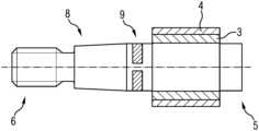
- FIG. 2shows an alternative embodiment of the current feed-through 8 , wherein the current feed-through 8 has a region of reduced diameter 9 .
- a material of low specific electrical resistanceis used in this region 9 , so that the same electrical conductivity is achieved, in spite of the modified diameter.
- the region of smaller diameter 9is likewise arranged on the side of the current feed-through 8 facing the cold end 6 .
- a further possibility herewould be to save the material of the current feed-through 1 at a point 9 and to fill the created groove with an alternative material which has a lower thermal conductivity and an equivalent electrical conductivity.
- FIG. 3shows a further alternative embodiment of a current feed-through 10 , wherein in this exemplary embodiment there is formed a segment 11 of reduced thermal conductivity.
- a material deviating from the rest of the pinis used to produce this segment.
- FIGS. 1 to 3are not of a limiting nature and serve for illustrating the concept of the invention.
Landscapes
- Chemical & Material Sciences (AREA)
- Engineering & Computer Science (AREA)
- Chemical Kinetics & Catalysis (AREA)
- Health & Medical Sciences (AREA)
- Toxicology (AREA)
- Combustion & Propulsion (AREA)
- Mechanical Engineering (AREA)
- General Engineering & Computer Science (AREA)
- Exhaust Gas After Treatment (AREA)
Abstract
Description
Claims (6)
Applications Claiming Priority (3)
| Application Number | Priority Date | Filing Date | Title |
|---|---|---|---|
| DE102019210368.5 | 2019-07-12 | ||
| DE102019210368.5ADE102019210368B4 (en) | 2019-07-12 | 2019-07-12 | Electrical power feedthrough |
| PCT/EP2020/067597WO2021008832A1 (en) | 2019-07-12 | 2020-06-24 | Electrical current feed-through |
Related Parent Applications (1)
| Application Number | Title | Priority Date | Filing Date |
|---|---|---|---|
| PCT/EP2020/067597ContinuationWO2021008832A1 (en) | 2019-07-12 | 2020-06-24 | Electrical current feed-through |
Publications (2)
| Publication Number | Publication Date |
|---|---|
| US20220136422A1 US20220136422A1 (en) | 2022-05-05 |
| US12168950B2true US12168950B2 (en) | 2024-12-17 |
Family
ID=71266640
Family Applications (1)
| Application Number | Title | Priority Date | Filing Date |
|---|---|---|---|
| US17/573,817ActiveUS12168950B2 (en) | 2019-07-12 | 2022-01-12 | Electrical current feed-through |
Country Status (7)
| Country | Link |
|---|---|
| US (1) | US12168950B2 (en) |
| EP (1) | EP3997313A1 (en) |
| JP (1) | JP2022539906A (en) |
| KR (1) | KR102755594B1 (en) |
| CN (1) | CN114072569A (en) |
| DE (1) | DE102019210368B4 (en) |
| WO (1) | WO2021008832A1 (en) |
Families Citing this family (3)
| Publication number | Priority date | Publication date | Assignee | Title |
|---|---|---|---|---|
| DE102021121835A1 (en)* | 2021-08-24 | 2023-03-02 | Purem GmbH | connection unit |
| DE102021128241A1 (en) | 2021-10-29 | 2023-05-04 | Purem GmbH | connector pin |
| US20230151749A1 (en)* | 2021-11-18 | 2023-05-18 | Faurecia Emissions Control Technologies, Usa, Llc | Exhaust aftertreatment system with electrical connector |
Citations (16)
| Publication number | Priority date | Publication date | Assignee | Title |
|---|---|---|---|---|
| US4505991A (en) | 1984-05-25 | 1985-03-19 | Ford Motor Company | Sodium heat engine electrical feedthrough |
| JPH05269387A (en) | 1992-03-26 | 1993-10-19 | Nissan Motor Co Ltd | Exhaust gas purifying catalystic converter |
| JPH07328453A (en) | 1994-06-15 | 1995-12-19 | Nippondenso Co Ltd | Self heating type honeycomb convertor |
| DE4435784A1 (en) | 1994-10-06 | 1996-04-11 | Roth Technik Gmbh | Electrically heated starter cat |
| JPH0932533A (en) | 1995-07-12 | 1997-02-04 | Nissan Motor Co Ltd | Exhaust gas purification device for internal combustion engine |
| US5670746A (en)* | 1994-07-29 | 1997-09-23 | Ngk Insulators, Ltd. | Structure of electrode unit |
| DE69501049T2 (en) | 1994-02-25 | 1998-03-26 | Nippon Soken | Electrically heated catalytic converter for an engine |
| US6031213A (en)* | 1994-12-07 | 2000-02-29 | Ngk Insulators, Ltd. | Electrode structure and electric heater comprising the same |
| US6060699A (en)* | 1996-05-14 | 2000-05-09 | Toyota Jidosha Kabushiki Kaisha | Electrode structure for high temperature heated body |
| US6176081B1 (en)* | 1998-03-12 | 2001-01-23 | Honda Giken Kogyo Kabushiki Kaisha | Heating device for an exhaust gas purification catalytic converter |
| US6255589B1 (en) | 1998-12-18 | 2001-07-03 | Alstom | Hermetically sealed current feedthrough for outdoor electrical gear |
| CN1258122C (en) | 2004-01-09 | 2006-05-31 | 中国科学院长春应用化学研究所 | Preparation method of gold film dot array for surface plasmon resonance image analysis |
| US20120247090A1 (en) | 2010-03-18 | 2012-10-04 | Toyota Jidosha Kabushiki Kaisha | Exhaust gas purifying device for internal combustion engine |
| US20130312394A1 (en) | 2011-02-16 | 2013-11-28 | Toyota Jidosha Kabushiki Kaisha | Electric heating catalyst |
| US20150083316A1 (en) | 2013-09-20 | 2015-03-26 | Denso Corporation | Method of manufacturing joint body of conductive ceramic body and metal body |
| DE102017216470A1 (en) | 2017-09-18 | 2019-03-21 | Continental Automotive Gmbh | Electrically heated heating disk for exhaust aftertreatment |
- 2019
- 2019-07-12DEDE102019210368.5Apatent/DE102019210368B4/enactiveActive
- 2020
- 2020-06-24EPEP20735118.0Apatent/EP3997313A1/ennot_activeWithdrawn
- 2020-06-24JPJP2022501353Apatent/JP2022539906A/enactivePending
- 2020-06-24CNCN202080049435.9Apatent/CN114072569A/enactivePending
- 2020-06-24KRKR1020227004776Apatent/KR102755594B1/enactiveActive
- 2020-06-24WOPCT/EP2020/067597patent/WO2021008832A1/ennot_activeCeased
- 2022
- 2022-01-12USUS17/573,817patent/US12168950B2/enactiveActive
Patent Citations (22)
| Publication number | Priority date | Publication date | Assignee | Title |
|---|---|---|---|---|
| US4505991A (en) | 1984-05-25 | 1985-03-19 | Ford Motor Company | Sodium heat engine electrical feedthrough |
| JPH05269387A (en) | 1992-03-26 | 1993-10-19 | Nissan Motor Co Ltd | Exhaust gas purifying catalystic converter |
| DE69501049T2 (en) | 1994-02-25 | 1998-03-26 | Nippon Soken | Electrically heated catalytic converter for an engine |
| US5744104A (en)* | 1994-02-25 | 1998-04-28 | Toyota Jidosha Kabushiki Kaisha | Electrically heated catalytic converter for an engine |
| JPH07328453A (en) | 1994-06-15 | 1995-12-19 | Nippondenso Co Ltd | Self heating type honeycomb convertor |
| US5670746A (en)* | 1994-07-29 | 1997-09-23 | Ngk Insulators, Ltd. | Structure of electrode unit |
| DE4435784A1 (en) | 1994-10-06 | 1996-04-11 | Roth Technik Gmbh | Electrically heated starter cat |
| US5904903A (en) | 1994-10-06 | 1999-05-18 | Heraeus Electro-Nite International N.V. | Electrically heatable primary catalytic converter |
| DE69533609T2 (en) | 1994-12-07 | 2005-10-13 | Ngk Insulators, Ltd., Nagoya | Electrode structure and electrical heating element containing the same |
| US6031213A (en)* | 1994-12-07 | 2000-02-29 | Ngk Insulators, Ltd. | Electrode structure and electric heater comprising the same |
| JPH0932533A (en) | 1995-07-12 | 1997-02-04 | Nissan Motor Co Ltd | Exhaust gas purification device for internal combustion engine |
| US6060699A (en)* | 1996-05-14 | 2000-05-09 | Toyota Jidosha Kabushiki Kaisha | Electrode structure for high temperature heated body |
| DE69732319T2 (en) | 1996-05-14 | 2005-12-22 | Toyota Jidosha K.K., Toyota | Electrode structure for high temperature heated bodies |
| US6176081B1 (en)* | 1998-03-12 | 2001-01-23 | Honda Giken Kogyo Kabushiki Kaisha | Heating device for an exhaust gas purification catalytic converter |
| US6255589B1 (en) | 1998-12-18 | 2001-07-03 | Alstom | Hermetically sealed current feedthrough for outdoor electrical gear |
| CN1258122C (en) | 2004-01-09 | 2006-05-31 | 中国科学院长春应用化学研究所 | Preparation method of gold film dot array for surface plasmon resonance image analysis |
| US20120247090A1 (en) | 2010-03-18 | 2012-10-04 | Toyota Jidosha Kabushiki Kaisha | Exhaust gas purifying device for internal combustion engine |
| US20130312394A1 (en) | 2011-02-16 | 2013-11-28 | Toyota Jidosha Kabushiki Kaisha | Electric heating catalyst |
| US20150083316A1 (en) | 2013-09-20 | 2015-03-26 | Denso Corporation | Method of manufacturing joint body of conductive ceramic body and metal body |
| JP2015059080A (en) | 2013-09-20 | 2015-03-30 | 株式会社デンソー | Method of manufacturing assembly |
| DE102017216470A1 (en) | 2017-09-18 | 2019-03-21 | Continental Automotive Gmbh | Electrically heated heating disk for exhaust aftertreatment |
| WO2019053250A1 (en)* | 2017-09-18 | 2019-03-21 | Continental Automotive Gmbh | ELECTRICALLY HEATABLE SCREEN FOR EXHAUST AFTER-TREATMENT |
Non-Patent Citations (4)
| Title |
|---|
| Chinese Office Action dated Jul. 29, 2023 for corresponding Patent Application No. 202080049435.9. |
| English Translation (Year: 2018).* |
| German Office Action dated Sep. 29, 2023 for corresponding German Patent Application No. 10 2019 210 368.5. |
| Japanese Office Action dated Feb. 17, 2023 for corresponding Patent Application No. 2022-501353. |
Also Published As
| Publication number | Publication date |
|---|---|
| JP2022539906A (en) | 2022-09-13 |
| EP3997313A1 (en) | 2022-05-18 |
| DE102019210368A1 (en) | 2021-01-14 |
| US20220136422A1 (en) | 2022-05-05 |
| KR102755594B1 (en) | 2025-01-21 |
| CN114072569A (en) | 2022-02-18 |
| DE102019210368B4 (en) | 2024-05-08 |
| KR20220050888A (en) | 2022-04-25 |
| WO2021008832A1 (en) | 2021-01-21 |
Similar Documents
| Publication | Publication Date | Title |
|---|---|---|
| US12168950B2 (en) | Electrical current feed-through | |
| JP7273462B2 (en) | High-voltage terminal cooling structure | |
| JP7196234B2 (en) | high temperature tubular heater | |
| US12069777B2 (en) | Terminal pin | |
| US9997302B2 (en) | Electrical component having an electrically conductive central element | |
| JP2019149331A (en) | Immersion heater | |
| JP4706983B2 (en) | Heating device including thermoelectric module | |
| US8251760B2 (en) | Terminal for electrical resistance element | |
| JP5600479B2 (en) | Sheath heater lead wire connection terminal | |
| JP2001068254A (en) | Ceramic heater | |
| JP2011176025A (en) | Bushing for superconducting device | |
| JP5284158B2 (en) | Current lead | |
| US2416455A (en) | Thermoelectric generating device | |
| JPS58106325A (en) | Direct heating preheating plug for internal combustion engines | |
| CN118339370A (en) | Electrical guidance device with touch protection device | |
| CN111543120A (en) | Heating element | |
| WO2020090827A1 (en) | Heater | |
| KR20070009820A (en) | Structure of heating element | |
| JPH0719474A (en) | Ceramic glow plug |
Legal Events
| Date | Code | Title | Description |
|---|---|---|---|
| FEPP | Fee payment procedure | Free format text:ENTITY STATUS SET TO UNDISCOUNTED (ORIGINAL EVENT CODE: BIG.); ENTITY STATUS OF PATENT OWNER: LARGE ENTITY | |
| STPP | Information on status: patent application and granting procedure in general | Free format text:DOCKETED NEW CASE - READY FOR EXAMINATION | |
| STPP | Information on status: patent application and granting procedure in general | Free format text:NON FINAL ACTION MAILED | |
| AS | Assignment | Owner name:VITESCO TECHNOLOGIES GMBH, GERMANY Free format text:ASSIGNMENT OF ASSIGNORS INTEREST;ASSIGNORS:BRUECK, ROLF;LANGENFELD, PHILIPP;BRUGGER, MARC;AND OTHERS;SIGNING DATES FROM 20211011 TO 20211117;REEL/FRAME:063110/0425 | |
| STPP | Information on status: patent application and granting procedure in general | Free format text:FINAL REJECTION MAILED | |
| STPP | Information on status: patent application and granting procedure in general | Free format text:RESPONSE AFTER FINAL ACTION FORWARDED TO EXAMINER | |
| STPP | Information on status: patent application and granting procedure in general | Free format text:ADVISORY ACTION MAILED | |
| STPP | Information on status: patent application and granting procedure in general | Free format text:DOCKETED NEW CASE - READY FOR EXAMINATION | |
| STPP | Information on status: patent application and granting procedure in general | Free format text:NON FINAL ACTION MAILED | |
| STPP | Information on status: patent application and granting procedure in general | Free format text:RESPONSE TO NON-FINAL OFFICE ACTION ENTERED AND FORWARDED TO EXAMINER | |
| STPP | Information on status: patent application and granting procedure in general | Free format text:NOTICE OF ALLOWANCE MAILED -- APPLICATION RECEIVED IN OFFICE OF PUBLICATIONS | |
| STPP | Information on status: patent application and granting procedure in general | Free format text:PUBLICATIONS -- ISSUE FEE PAYMENT VERIFIED | |
| STCF | Information on status: patent grant | Free format text:PATENTED CASE |