US12168880B2 - Scissor action stripping corner - Google Patents
Scissor action stripping cornerDownload PDFInfo
- Publication number
- US12168880B2 US12168880B2US17/458,705US202117458705AUS12168880B2US 12168880 B2US12168880 B2US 12168880B2US 202117458705 AUS202117458705 AUS 202117458705AUS 12168880 B2US12168880 B2US 12168880B2
- Authority
- US
- United States
- Prior art keywords
- extender
- axis
- rearward surface
- rearward
- stripping
- Prior art date
- Legal status (The legal status is an assumption and is not a legal conclusion. Google has not performed a legal analysis and makes no representation as to the accuracy of the status listed.)
- Active
Links
Images


Classifications
- E—FIXED CONSTRUCTIONS
- E04—BUILDING
- E04G—SCAFFOLDING; FORMS; SHUTTERING; BUILDING IMPLEMENTS OR AIDS, OR THEIR USE; HANDLING BUILDING MATERIALS ON THE SITE; REPAIRING, BREAKING-UP OR OTHER WORK ON EXISTING BUILDINGS
- E04G11/00—Forms, shutterings, or falsework for making walls, floors, ceilings, or roofs
- E04G11/06—Forms, shutterings, or falsework for making walls, floors, ceilings, or roofs for walls, e.g. curved end panels for wall shutterings; filler elements for wall shutterings; shutterings for vertical ducts
- E04G11/08—Forms, which are completely dismantled after setting of the concrete and re-built for next pouring
- E—FIXED CONSTRUCTIONS
- E04—BUILDING
- E04G—SCAFFOLDING; FORMS; SHUTTERING; BUILDING IMPLEMENTS OR AIDS, OR THEIR USE; HANDLING BUILDING MATERIALS ON THE SITE; REPAIRING, BREAKING-UP OR OTHER WORK ON EXISTING BUILDINGS
- E04G17/00—Connecting or other auxiliary members for forms, falsework structures, or shutterings
- E04G17/001—Corner fastening or connecting means for forming or stiffening elements
Definitions
- the present disclosureis directed toward stripping corners for formwork structures.
- interior and exterior wall formworksshould be erected in advance and set apart at a specific distance, so as to allow concrete to be poured in the space between the interior and exterior wall formworks.
- the exterior wall formworkcan be removed easily without the constraint of working space.
- the removal of the interior wall formworkis difficult due to the constraint of space and usually requires a worker to pry the formwork open, and thus it will likely generate side pressure against the wall that hasn't hardened completely, causing damage to the wall.
- the removal of the interior wallgenerally needs 24 hours after the concrete hardens, and it is really time consuming.
- An implementation of the of the present stripping cornermay include a first forward surface, a second forward surface, hingedly connected to the first forward surface, a first rearward surface, hingedly connected to the first forward surface, a second rearward surface hingedly connected to the second forward surface, and an extender coupling the first rearward surface to the second rearward surface.
- the extendermay be configured to receive an input torque about a first axis and may be configured to provide an output force along a second axis.
- the first axismay be substantially perpendicular to the second axis.
- the extendermay be configured to increase and decrease a distance between the first rearward surface and the second rearward surface.
- the extendermay be a scissor jack and may include a screw and bolt assembly configured to translate the input torque into the output force.
- a screw of the screw and bolt assemblymay be parallel to the first axis.
- the implementation of the stripping cornermay further include a sleeve around at least a portion of the screw.
- the screwmay be coupled at a first end region of the screw to the extender and may be uncoupled at a second end region of the screw.
- the implementation of the stripping cornermay further include a bolthead rotationally fixed to the screw and connected to the screw at a first end of the screw and may further include a second extender coupling the first rearward surface to the second rearward surface.
- the second extendermay be configured to receive a second input torque about the first axis and may be configured to provide a second output force along the second axis.
- a further implementation of the stripping cornermay include a first forward surface, a second forward surface, hingedly connected to the first forward surface, a first rearward surface, hingedly connected to the first forward surface, a second rearward surface hingedly connected to the second forward surface, and a first extender coupling the first rearward surface to the second rearward surface.
- the first extendermay be configured to receive an input torque about a first axis and may be configured to provide an output force along a second axis.
- the first axismay be substantially perpendicular to the second axis.
- the further implementationmay include a second extender coupling the first rearward surface to the second rearward surface.
- the second extendermay be configured to receive an input torque about the first axis and may be configured to provide an output force along the second axis.
- the first extender of the further implementationmay include a first threaded fastener configured to actuate a first four bar linkage on the first extender, and the second extender may include a second threaded fastener configured to actuate a second four bar linkage on the second extender.
- the further implementation of the stripping cornermay include a first sleeve around the first threaded fastener and a second sleeve around the second threaded fastener.
- the first threaded fastenermay be coupled at a first end region of the first threaded fastener to the first extender and may be uncoupled at a second end of the first threaded fastener.
- the second threaded fastenermay be coupled at a first end region of the second threaded fastener to the second extender and may be uncoupled at a second end of the second threaded fastener.
- the further implementation of the stripping cornermay include a first bolthead rotationally fixed to a first end of the first threaded fastener and a second bolthead rotationally fixed to a first end of the second threaded fastener.
- the first bolthead and second boltheadmay both be configured to simultaneously receive a first input torque at the first bolthead and a second input torque at the second bolthead.
- the input torquesmay be supplied by a single torquing device.
- a method for performing a pour processmay include pouring a material into a formwork that is at least partially secured by a stripping corner, curing the material, receiving an input torque at the stripping corner about a first axis, and providing an output force along a second axis that is substantially perpendicular to the first axis.
- the stripping cornermay be a scissor jack or a plurality of scissor jacks.
- FIG. 1 Aillustrates an implementation of formwork in a pour position
- FIG. 1 Billustrates the implementation of the formwork of FIG. 1 A in a stripping position
- FIG. 2 Aillustrates an implementation of a stripping corner in a pour position
- FIG. 2 Billustrates an implementation of a stripping corner in an intermediate position
- FIG. 2 Cillustrates an implementation of a stripping corner in a stripping position
- FIG. 3 Aillustrates a perspective view of the stripping corner in a pour position
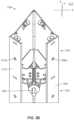
- FIG. 3 Billustrates a perspective view of the stripping corner of FIG. 3 A in a stripping position
- FIGS. 4 A and 4 Billustrate implementations of a single point stripping tool.
- FIG. 1 Aillustrates an implementation 100 of formwork in a pour position.
- FIG. 1 Billustrates the implementation of the formwork 100 in a stripping position.
- the formwork 100may include an exterior structure 102 and an interior structure 104 .
- the exterior structure 102may include forms 105 .
- the interior structure 104may include forms 105 and stripping corners 108 .
- forming material 106may be poured into the formwork 100 between the exterior structure 102 and the interior structure 104 .
- the exterior structure 102 and the interior structuremay define a workspace 107 between them.
- the exterior structure 102may be an outer boundary of the workspace 107 and the interior structure 104 may be an inner boundary of the workspace 107 .
- Uncured forming material 106may be poured into the workspace 107 and take on the shape defined by the exterior structure 102 and the interior structure 104 .
- the forms 105 of the exterior structure 102may be positioned in a desired position relative to the forms 105 of the interior structure 104 and vice versa.
- the thickness of the wallmay be dictated by a distance between the exterior structure 102 and the interior structure 104 .
- the distance between the formsmay be maintained and stabilized by tie-rods 110 .
- the stripping corners 108couple adjacent forms 105 and, therefore, may help define the workspace 107 .
- Forming material 106may be poured in the workspace 107 so that it assumes the form of the workspace 107 .
- FIGS. 1 A and 1 Billustrate a substantially rectilinear formwork 100 ; however, the formwork 100 is not limited to a rectilinear configuration.
- the formwork 100may have any shape such as a curved, polygonal, flat, irregular, circular, triangular, etc.
- the distance between forms 105 of the exterior structure 102 and the interior structure 104is illustrated in FIGS. 1 A and 1 B as being substantially constant throughout an entirety of the formwork 100 . However, it is not necessary that the distance between forms 105 of the exterior structure 102 and the interior structure 104 be constant.
- the distance between forms 105 of the exterior structure 102 and the interior structure 104may be constant or irregular throughout the entirety of the formwork 100 or constant throughout some portions of the formwork 100 and irregular throughout other portions of the formwork 100 .
- the formwork 100may be removed from the material 106 and the cured material 106 may support itself.
- the tie rods 110may be removed from the formwork 100 .
- the exterior structure 102may be pulled away from the cured material in a direction substantially perpendicular to the forms 105 .
- the interior structure 104may be retracted from the cured material 106 toward a center 112 of the formwork 100 by putting the stripping corners 108 in the stripping position.
- Each of the forms 105 of the interior structure 104may be retracted toward the center 112 of the formwork 100 simultaneously.
- the stripping position, the structure of the stripping corners 108 and the operability of the stripping cornerswill be described in more detail below.
- FIG. 2 Aillustrates the stripping corner 108 in the pour position.
- FIG. 2 Billustrates the stripping corner 108 in an intermediate position.
- FIG. 2 Cillustrates the stripping corner 108 in a stripping position.
- the stripping corner 108may include a first forward surface 202 , a second forward surface 204 , a first rearward surface 206 and a second rearward surface 208 .
- the first forward surface 202may be hingedly connected to the second forward surface 204 at hinge 207 .
- the first forward surface 202may be hingedly connected to the first rearward surface 206 at hinge 209 .
- the second forward surface 204may be hingedly connected to the second rearward surface 208 at hinge 211 .
- a first forward bracket 210may be fixedly connected to the first forward surface 202 and a second forward bracket 212 may be fixedly connected to the second forward surface 208 .
- the fixed connection between the forward brackets and the forward surfacescause motion of each member of the connection to be shared by the other member of the connection.
- Each of the forward brackets 210 and 212may define first through-holes 214 for receiving a respective locking pin (not shown).
- a first rearward bracket 216may be fixedly connected to the first rearward surface 206 and a second rearward bracket 218 may be fixedly connected to the second reward surface 208 .
- the fixed connection between the rearward brackets and the rearward surfacescause motion of each member of the connection to be shared by the other member of the connection.
- Each of the rearward brackets 216 and 218may define second through-holes 220 for receiving a respective locking pin (not shown).
- the first rearward through-holes 214may align with the second through-holes 220 to lock the stripping corner 108 in the pour position.
- An actuating mechanism 222may connect the first rearward bracket 216 to the second rearward bracket 218 .
- the actuating mechanism 222may be a scissor jack, an accordion jack, a pneumatic jack, a screw jack, etc.
- a scissor jack 224may include a threaded screw 226 , a bolthead and a four-bar linkage 230 .
- the threaded screw 226may be coupled to the scissor jack 224 at a proximal end region of the threaded screw 226 and may be uncoupled to any element at a second end region of the threaded screw 226 .
- the actuating mechanism 222may be controlled electronically and/or mechanically.
- motion of the actuating mechanism 222may be caused by the result of a force applied to the mechanism directly by a user or by a mechanical device such as a motor.
- motion of the actuating mechanism 222may be caused by providing an electrical current to the actuating mechanism 222 (i.e., a linear motor within the actuator) causing it to extend or retract.
- a tubular sheath 228may be included around the threaded screw 226 .
- the tubular sheath 228may help protect the threaded screw 226 from inadvertent contact with forming material 106 . For example, if forming material 106 contacts the threaded screw 226 and is allowed to cure, the threaded screw 226 may become inoperable for further use.
- ends 232 of each of links 234 of the four-bar linkage 230may include gears 236 .
- Gears of a first gear set 236 ainteract with each other and gears of a second gear set 236 b interact with each other to ensure that the first rearward surface 206 is positioned substantially ninety degrees apart from the second rearward surface 208 regardless of whether the stripping corner 108 is in a pour position or a stripping position.
- the scissor jack 224may operate by responding to rotation of the screw 226 .
- the links 234will separate from each other from the position illustrated in FIG. 2 A toward the position illustrated in FIG. 2 B and reconverge toward the position illustrated in FIG. 2 C .
- the surfaces 202 , 204 , 206 and 208therefore, converge toward each other due to their connection to the scissor jack 224 .
- the links 234will separate from the position illustrated in FIG. 2 C toward illustrated in FIG. 2 B and reconverge toward each other from the position illustrated in FIG. 2 B toward the positions illustrated in FIG. 2 A .
- FIGS. 3 A and 3 Billustrate perspective views of the stripping corner 108 .
- the stripping corner 108is illustrated in a pour position in FIG. 3 A and it is illustrated in a stripping position in FIG. 3 B .
- FIGS. 3 A and 3 Billustrate a single set of brackets and scissor jacks, multiple sets of brackets and scissor jacks may be used with a single stripping corner.
- second and third sets of brackets and scissor jacksmay be placed, respectively, at a second position 302 and a third position 304 .
- Providing multiple actuating mechanisms 222 connected to additional bracketsmay provide a uniform withdrawal of the stripping corner 108 from a cured surface.
- a stripping corner 108 having multiple actuating mechanisms 222 placed in multiple positions between ends of the stripping cornermay be actuated simultaneously to withdraw the entire stripping corner from a surface of the cured forming material 106 with one applied force instead of withdrawing a portion of the stripping corner 108 with a first force and then withdrawing a different portion of the stripping corner with a second force, withdrawing a yet further portion of the stripping corner with a third force, etc.
- Withdrawal of the stripping corner 108 from a surface of the cured forming material 106may also cause the forms 105 to withdraw from the surface of the cured forming material 106 .
- one form 105may be connected to a third rearward surface 308 and another form 105 may be connected to a fourth rearward surface 310 .
- a connectionmay be maintained by connecting fasteners (not shown) through third rearward surface through-holes 308 a and through fourth rearward surface through-holes 310 a .
- adjusting the stripping corner 108 from the pour position to the stripping positionmay cause the forms to move from a pour position in which the forms 105 are in contact with the forming material 106 to a stripping position in which the forms 105 are withdrawn from contact with the forming material 106 .
- bolthead 306may be fixedly attached to an end of the screw 226 in that the bolthead 306 rotates as a result of rotation of the screw 226 and the screw 226 rotates as a result of rotation of the bolthead 306 .
- bolthead 306may be a uniform cylinder or it may have a multi-faced cross-section, i.e., hexagonal, square, triangular, rectangular, etc.
- the bolthead 306may have a torque receiving recess on an end of the bolthead.
- the torque receiving recessmay be configured to receive a Philips head screw bit, a flat head screw bit, an Allen wrench bit, etc.
- each bolthead of each set of brackets and scissor jacksmay be simultaneously rotated by applying a single point stripping tool, i.e., a multiple head torque mechanism, to all of the bolts at once.
- a vector of an input force applied to the bolthead 306 by the single point stripping toolmay be in the same direction as a vector of an output force acting on the first rearward bracket 216 and on the second rearward bracket 218 . Therefore, the input force vector may be parallel with the output force vector.
- the vector of the input force applied to the bolthead 306 by the single point stripping toolmay be in a crosswise direction from the vector of the output force acting on the first rearward bracket 216 and on the second rearward bracket 218 .
- inputmay be applied rotationally about a z-axis of the coordinate axis 312 and output may be provided linearly about an x-axis of the coordinate axis 312 .
- the axes of input and output force vectorsmay, therefore, be substantially perpendicular to each other.
- a single point stripping toolmay be one in which input from a single torque mechanism (wrench, driver, etc.) may be translated to each of multiple sockets, wrenches, drivers, etc. to rotate all of the bolts at once, thereby enabling the simultaneous rotation of each bolthead of a respective stripping corner bracket set.
- a single torque mechanismtilt, driver, etc.
- FIGS. 4 A and 4 Billustrate first and second implementations 400 a and 400 b , respectively, of a single point stripping tool having multiple outputs.
- a single point stripping tool having multiple outputsmay include shafts 404 a or 404 b and bevel gearing 406 contained in a sealed housing 408 a or 408 b.
- single point stripping tool 400 a illustrated in FIG. 4 Amay include a single torque input bolthead 410 and four torque output sockets 402 .
- Single point stripping tool 400 bmay include a single input bolthead 410 and three outputs 402 .
- the bevel gears 406may be included to translate rotation about a first axis parallel to the shafts 404 a or 404 b to rotation about a second axis that may be substantially perpendicular to the first axis.
- the gear ratiomay be 1:1 wherein rotation at an input equals rotation at the output. Rotation may be instead be such that rotation at the input results in a greater rotation at the output or vice versa.
- the inputs and/or outputsmay be a male/female hex socket arrangement.
- Rotational translationmay be accomplished via electronic signaling from a controller wherein the controller receives a signal indicative of a rotational direction and magnitude and sends a signal to each of the outputs to rotate with a corresponding direction and magnitude, i.e., substantially within an acceptable input/output ratio.
- first, second, etc.may be used herein to describe various elements, these elements should not be limited by these terms. These terms are only used to distinguish one element from another.
- a first object or stepcould be termed a second object or step, and, similarly, a second object or step could be termed a first object or step, without departing from the scope of the invention.
- the first object or step, and the second object or stepare both objects or steps, respectively, but they are not to be considered the same object or step.
- the term “if”may be construed to mean “when” or “upon” or “in response to determining” or “in response to detecting,” depending on the context.
- the phrase “if it is determined” or “if [a stated condition or event] is detected”may be construed to mean “upon determining” or “in response to determining” or “upon detecting [the stated condition or event]” or “in response to detecting [the stated condition or event],” depending on the context.
Landscapes
- Engineering & Computer Science (AREA)
- Architecture (AREA)
- Mechanical Engineering (AREA)
- Civil Engineering (AREA)
- Structural Engineering (AREA)
- Forms Removed On Construction Sites Or Auxiliary Members Thereof (AREA)
- Mechanical Control Devices (AREA)
- Shovels (AREA)
Abstract
Description
Claims (16)
Priority Applications (5)
| Application Number | Priority Date | Filing Date | Title |
|---|---|---|---|
| US17/458,705US12168880B2 (en) | 2020-08-29 | 2021-08-27 | Scissor action stripping corner |
| CA3190575ACA3190575A1 (en) | 2020-08-29 | 2021-08-28 | Scissor action stripping corner |
| PCT/US2021/048114WO2022047267A1 (en) | 2020-08-29 | 2021-08-28 | Scissor action stripping corner |
| US18/946,413US20250067068A1 (en) | 2020-08-29 | 2024-11-13 | Scissor Action Stripping Corner |
| US18/946,448US20250067069A1 (en) | 2020-08-29 | 2024-11-13 | Scissor Action Stripping Corner |
Applications Claiming Priority (2)
| Application Number | Priority Date | Filing Date | Title |
|---|---|---|---|
| US202063072135P | 2020-08-29 | 2020-08-29 | |
| US17/458,705US12168880B2 (en) | 2020-08-29 | 2021-08-27 | Scissor action stripping corner |
Related Child Applications (2)
| Application Number | Title | Priority Date | Filing Date |
|---|---|---|---|
| US18/946,413DivisionUS20250067068A1 (en) | 2020-08-29 | 2024-11-13 | Scissor Action Stripping Corner |
| US18/946,448DivisionUS20250067069A1 (en) | 2020-08-29 | 2024-11-13 | Scissor Action Stripping Corner |
Publications (2)
| Publication Number | Publication Date |
|---|---|
| US20220064968A1 US20220064968A1 (en) | 2022-03-03 |
| US12168880B2true US12168880B2 (en) | 2024-12-17 |
Family
ID=80353326
Family Applications (3)
| Application Number | Title | Priority Date | Filing Date |
|---|---|---|---|
| US17/458,705ActiveUS12168880B2 (en) | 2020-08-29 | 2021-08-27 | Scissor action stripping corner |
| US18/946,448PendingUS20250067069A1 (en) | 2020-08-29 | 2024-11-13 | Scissor Action Stripping Corner |
| US18/946,413PendingUS20250067068A1 (en) | 2020-08-29 | 2024-11-13 | Scissor Action Stripping Corner |
Family Applications After (2)
| Application Number | Title | Priority Date | Filing Date |
|---|---|---|---|
| US18/946,448PendingUS20250067069A1 (en) | 2020-08-29 | 2024-11-13 | Scissor Action Stripping Corner |
| US18/946,413PendingUS20250067068A1 (en) | 2020-08-29 | 2024-11-13 | Scissor Action Stripping Corner |
Country Status (3)
| Country | Link |
|---|---|
| US (3) | US12168880B2 (en) |
| CA (1) | CA3190575A1 (en) |
| WO (1) | WO2022047267A1 (en) |
Citations (33)
| Publication number | Priority date | Publication date | Assignee | Title |
|---|---|---|---|---|
| US1020005A (en)* | 1910-11-17 | 1912-03-12 | Witthoefft Collapsible Concrete Forms Company | Mold for making concrete chimneys. |
| US1395553A (en)* | 1920-12-27 | 1921-11-01 | Brophy Daniel James | Clamping device for molds |
| US2557631A (en)* | 1948-06-12 | 1951-06-19 | Patrick J Callan | Collapsible form for forming window or door openings in concrete walls |
| FR1102525A (en)* | 1954-04-05 | 1955-10-24 | Entpr S Campenon Bernard | Expandable formwork |
| US2838276A (en)* | 1954-06-08 | 1958-06-10 | John B Perkins | Puller grip for a column strapper |
| US3754717A (en)* | 1971-07-12 | 1973-08-28 | Dana Corp | Collapsible mandrel |
| US3857540A (en)* | 1971-06-30 | 1974-12-31 | F Ecker | Apparatus for casting material using a collapsible structure |
| FR2288836A1 (en)* | 1975-04-04 | 1976-05-21 | Siler Ag | Collapsible internal shuttering - has flexible casing linked at several points to tightening mechanism |
| US4055321A (en)* | 1976-12-06 | 1977-10-25 | Symons Corporation | Inside concrete corewall form with particular three-way hinge assemblies therefor |
| DE2812974A1 (en)* | 1978-03-23 | 1979-10-04 | Schoenwald Ag | Rapid erection concrete formwork - has corner paired angle plates hinged to walls, with movement permitted |
| CH613744A5 (en)* | 1977-02-24 | 1979-10-15 | Buccheri Steiner Elisa | Mould for formwork for use in building |
| US4424951A (en)* | 1980-10-15 | 1984-01-10 | National Engineering & Contracting Company | Building form and method of assembly |
| US4447035A (en)* | 1982-09-30 | 1984-05-08 | Strickland Systems, Inc. | Joining concrete form panels to cast an inside corner wall structure |
| US4519570A (en)* | 1983-09-22 | 1985-05-28 | Strickland Systems, Inc. | Inside corner concrete form unit |
| US4520988A (en)* | 1984-04-23 | 1985-06-04 | Harsco Corporation | Concrete core-wall form and stripping assembly therefor |
| US4666643A (en)* | 1980-10-15 | 1987-05-19 | Spencer Robert B | Method for forming a concrete structure |
| EP0514189A1 (en)* | 1991-05-16 | 1992-11-19 | Strickland Industries, Inc. | Inside corner form |
| FR2692616A1 (en)* | 1992-06-23 | 1993-12-24 | Voisine Marc | Retractable frame for concrete openings - comprises metallic surround connected to internal triangular and pivoted arms controlled by central screw |
| EP0598695A1 (en)* | 1992-11-16 | 1994-05-25 | Klaus Goebel | Shuttering arrangement for building homes |
| KR950014492U (en) | 1993-11-08 | 1995-06-16 | Formwork for building concrete structures | |
| DE19600794A1 (en)* | 1996-01-11 | 1997-07-17 | Igor Patselya | Shuttering especially for door- or window opening in building |
| EP1653025A2 (en)* | 2004-10-26 | 2006-05-03 | Gianazza Angelo S.p.A. | Modular formwork for the construction of walls and pillars |
| KR100718801B1 (en) | 2006-11-29 | 2007-05-16 | (주) 선엔지니어링종합건축사사무소 | Inner corner foam for easy angle adjustment |
| WO2007091860A1 (en)* | 2006-02-08 | 2007-08-16 | Sunil Construction Co., Ltd. | Form panel for construction |
| US20090057533A1 (en)* | 2006-02-08 | 2009-03-05 | Sunil Construction Co., Ltd. | Form panel for construction |
| US20110006273A1 (en) | 2009-07-08 | 2011-01-13 | Shinn Fu Corporation | Scissor Jack |
| KR20130009382A (en)* | 2011-07-15 | 2013-01-23 | 김시용 | In-corner coupling implement for construction mold |
| KR101235677B1 (en) | 2011-10-10 | 2013-02-21 | 전북대학교산학협력단 | Device and method for mounting intervertebral fusion cage |
| KR20140089820A (en)* | 2013-01-07 | 2014-07-16 | 김시용 | In-corner coupling implement for construction mold |
| KR101496657B1 (en)* | 2014-05-09 | 2015-02-27 | 박윤수 | Hydraulic System Using Caisson Steel Form |
| KR101600427B1 (en) | 2015-04-21 | 2016-03-08 | 정옥순 | In-corner that fixing and angle control is easy |
| KR101722021B1 (en)* | 2015-12-04 | 2017-04-11 | (주)금강시스템즈스케폴딩 | System pillar form |
| US10753108B2 (en)* | 2017-04-26 | 2020-08-25 | Forming Concepts, Inc. | Power assisted stripping corner for forming concrete walls |
- 2021
- 2021-08-27USUS17/458,705patent/US12168880B2/enactiveActive
- 2021-08-28WOPCT/US2021/048114patent/WO2022047267A1/ennot_activeCeased
- 2021-08-28CACA3190575Apatent/CA3190575A1/enactivePending
- 2024
- 2024-11-13USUS18/946,448patent/US20250067069A1/enactivePending
- 2024-11-13USUS18/946,413patent/US20250067068A1/enactivePending
Patent Citations (33)
| Publication number | Priority date | Publication date | Assignee | Title |
|---|---|---|---|---|
| US1020005A (en)* | 1910-11-17 | 1912-03-12 | Witthoefft Collapsible Concrete Forms Company | Mold for making concrete chimneys. |
| US1395553A (en)* | 1920-12-27 | 1921-11-01 | Brophy Daniel James | Clamping device for molds |
| US2557631A (en)* | 1948-06-12 | 1951-06-19 | Patrick J Callan | Collapsible form for forming window or door openings in concrete walls |
| FR1102525A (en)* | 1954-04-05 | 1955-10-24 | Entpr S Campenon Bernard | Expandable formwork |
| US2838276A (en)* | 1954-06-08 | 1958-06-10 | John B Perkins | Puller grip for a column strapper |
| US3857540A (en)* | 1971-06-30 | 1974-12-31 | F Ecker | Apparatus for casting material using a collapsible structure |
| US3754717A (en)* | 1971-07-12 | 1973-08-28 | Dana Corp | Collapsible mandrel |
| FR2288836A1 (en)* | 1975-04-04 | 1976-05-21 | Siler Ag | Collapsible internal shuttering - has flexible casing linked at several points to tightening mechanism |
| US4055321A (en)* | 1976-12-06 | 1977-10-25 | Symons Corporation | Inside concrete corewall form with particular three-way hinge assemblies therefor |
| CH613744A5 (en)* | 1977-02-24 | 1979-10-15 | Buccheri Steiner Elisa | Mould for formwork for use in building |
| DE2812974A1 (en)* | 1978-03-23 | 1979-10-04 | Schoenwald Ag | Rapid erection concrete formwork - has corner paired angle plates hinged to walls, with movement permitted |
| US4424951A (en)* | 1980-10-15 | 1984-01-10 | National Engineering & Contracting Company | Building form and method of assembly |
| US4666643A (en)* | 1980-10-15 | 1987-05-19 | Spencer Robert B | Method for forming a concrete structure |
| US4447035A (en)* | 1982-09-30 | 1984-05-08 | Strickland Systems, Inc. | Joining concrete form panels to cast an inside corner wall structure |
| US4519570A (en)* | 1983-09-22 | 1985-05-28 | Strickland Systems, Inc. | Inside corner concrete form unit |
| US4520988A (en)* | 1984-04-23 | 1985-06-04 | Harsco Corporation | Concrete core-wall form and stripping assembly therefor |
| EP0514189A1 (en)* | 1991-05-16 | 1992-11-19 | Strickland Industries, Inc. | Inside corner form |
| FR2692616A1 (en)* | 1992-06-23 | 1993-12-24 | Voisine Marc | Retractable frame for concrete openings - comprises metallic surround connected to internal triangular and pivoted arms controlled by central screw |
| EP0598695A1 (en)* | 1992-11-16 | 1994-05-25 | Klaus Goebel | Shuttering arrangement for building homes |
| KR950014492U (en) | 1993-11-08 | 1995-06-16 | Formwork for building concrete structures | |
| DE19600794A1 (en)* | 1996-01-11 | 1997-07-17 | Igor Patselya | Shuttering especially for door- or window opening in building |
| EP1653025A2 (en)* | 2004-10-26 | 2006-05-03 | Gianazza Angelo S.p.A. | Modular formwork for the construction of walls and pillars |
| WO2007091860A1 (en)* | 2006-02-08 | 2007-08-16 | Sunil Construction Co., Ltd. | Form panel for construction |
| US20090057533A1 (en)* | 2006-02-08 | 2009-03-05 | Sunil Construction Co., Ltd. | Form panel for construction |
| KR100718801B1 (en) | 2006-11-29 | 2007-05-16 | (주) 선엔지니어링종합건축사사무소 | Inner corner foam for easy angle adjustment |
| US20110006273A1 (en) | 2009-07-08 | 2011-01-13 | Shinn Fu Corporation | Scissor Jack |
| KR20130009382A (en)* | 2011-07-15 | 2013-01-23 | 김시용 | In-corner coupling implement for construction mold |
| KR101235677B1 (en) | 2011-10-10 | 2013-02-21 | 전북대학교산학협력단 | Device and method for mounting intervertebral fusion cage |
| KR20140089820A (en)* | 2013-01-07 | 2014-07-16 | 김시용 | In-corner coupling implement for construction mold |
| KR101496657B1 (en)* | 2014-05-09 | 2015-02-27 | 박윤수 | Hydraulic System Using Caisson Steel Form |
| KR101600427B1 (en) | 2015-04-21 | 2016-03-08 | 정옥순 | In-corner that fixing and angle control is easy |
| KR101722021B1 (en)* | 2015-12-04 | 2017-04-11 | (주)금강시스템즈스케폴딩 | System pillar form |
| US10753108B2 (en)* | 2017-04-26 | 2020-08-25 | Forming Concepts, Inc. | Power assisted stripping corner for forming concrete walls |
Non-Patent Citations (1)
| Title |
|---|
| International Search Report and Written Opinion, PCT/US2021/048114, dated Dec. 24, 2021, pp. 1-13. |
Also Published As
| Publication number | Publication date |
|---|---|
| US20250067068A1 (en) | 2025-02-27 |
| CA3190575A1 (en) | 2022-03-03 |
| WO2022047267A1 (en) | 2022-03-03 |
| US20220064968A1 (en) | 2022-03-03 |
| US20250067069A1 (en) | 2025-02-27 |
Similar Documents
| Publication | Publication Date | Title |
|---|---|---|
| DE102020124757B4 (en) | ROBOT SYSTEM WITH RECONFIGURABLE END EFFECTOR ASSEMBLY | |
| EP3325396B1 (en) | Automated mounting device for performing installation operations in a lift shaft of a lift assembly | |
| CN111188418B (en) | Locking mechanism of assembled building | |
| CN110978060B (en) | Robot end tool quick replacing device and replacing method | |
| US12168880B2 (en) | Scissor action stripping corner | |
| US5326186A (en) | Robot friendly probe and socket assembly | |
| CN113183738B (en) | Battery lock and lock method | |
| CN117940252A (en) | System and method for assembling or disassembling a hammer tool | |
| US4498271A (en) | Fixing anchoring bars or the like in structures such as concrete | |
| US20060249329A1 (en) | Formwork construction method for inner wall and device thereof | |
| EP0595439A2 (en) | Drill pipe breakout device | |
| CN212146170U (en) | Emergency tool for operation under pressure | |
| CN212503496U (en) | An elevator triangular lock unlocking device | |
| JP3329914B2 (en) | Formwork for culvert block production | |
| CN115338986A (en) | Building drilling machinery supports positioner | |
| CN113800010A (en) | An operating platform for space station extravehicular on-orbit maintenance | |
| CN107444246B (en) | Locking device mounted on barrel equipment transport vehicle | |
| CN218758288U (en) | Secondary structure constructional column exempts from formwork device | |
| CN115552137A (en) | Coupling device, electric motor and industrial actuator | |
| US20180305992A1 (en) | Remote operated vehicle removable flexible joint elastomer protection tool | |
| EP1943058B1 (en) | Mandrel extraction tool and method of using same | |
| JP3529196B2 (en) | Formwork for manufacturing retaining wall blocks | |
| CN116372842B (en) | Clamping mechanism for overturning large-sized precise parts and semiconductor equipment | |
| CN211369543U (en) | Connecting assembly of inner formwork and outer formwork and modeling die with connecting assembly | |
| EP2694261B1 (en) | Device for connecting two parts of a female form for producing bottom parts of a shaft from concrete |
Legal Events
| Date | Code | Title | Description |
|---|---|---|---|
| FEPP | Fee payment procedure | Free format text:ENTITY STATUS SET TO UNDISCOUNTED (ORIGINAL EVENT CODE: BIG.); ENTITY STATUS OF PATENT OWNER: LARGE ENTITY | |
| STPP | Information on status: patent application and granting procedure in general | Free format text:DOCKETED NEW CASE - READY FOR EXAMINATION | |
| STPP | Information on status: patent application and granting procedure in general | Free format text:NON FINAL ACTION MAILED | |
| STPP | Information on status: patent application and granting procedure in general | Free format text:RESPONSE TO NON-FINAL OFFICE ACTION ENTERED AND FORWARDED TO EXAMINER | |
| AS | Assignment | Owner name:APACHE INDUSTRIAL SERVICES, INC., TEXAS Free format text:ASSIGNMENT OF ASSIGNORS INTEREST;ASSIGNOR:CHEVIS, KENNETH M.;REEL/FRAME:062617/0598 Effective date:20230207 | |
| AS | Assignment | Owner name:APACHE INDUSTRIAL SERVICES, INC., TEXAS Free format text:CORRECTIVE ASSIGNMENT TO CORRECT THE PCT/US21/48144 PREVIOUSLY RECORDED ON REEL 062617 FRAME 0598. ASSIGNOR(S) HEREBY CONFIRMS THE PCT/US21/48114;ASSIGNOR:CHEVIS, KENNETH M.;REEL/FRAME:062716/0061 Effective date:20230207 | |
| STPP | Information on status: patent application and granting procedure in general | Free format text:RESPONSE TO NON-FINAL OFFICE ACTION ENTERED AND FORWARDED TO EXAMINER | |
| STPP | Information on status: patent application and granting procedure in general | Free format text:FINAL REJECTION MAILED | |
| STPP | Information on status: patent application and granting procedure in general | Free format text:RESPONSE AFTER FINAL ACTION FORWARDED TO EXAMINER | |
| STPP | Information on status: patent application and granting procedure in general | Free format text:DOCKETED NEW CASE - READY FOR EXAMINATION | |
| STPP | Information on status: patent application and granting procedure in general | Free format text:NON FINAL ACTION MAILED | |
| STPP | Information on status: patent application and granting procedure in general | Free format text:RESPONSE TO NON-FINAL OFFICE ACTION ENTERED AND FORWARDED TO EXAMINER | |
| STPP | Information on status: patent application and granting procedure in general | Free format text:FINAL REJECTION MAILED | |
| STPP | Information on status: patent application and granting procedure in general | Free format text:ADVISORY ACTION MAILED | |
| STPP | Information on status: patent application and granting procedure in general | Free format text:DOCKETED NEW CASE - READY FOR EXAMINATION | |
| STPP | Information on status: patent application and granting procedure in general | Free format text:NOTICE OF ALLOWANCE MAILED -- APPLICATION RECEIVED IN OFFICE OF PUBLICATIONS | |
| STPP | Information on status: patent application and granting procedure in general | Free format text:PUBLICATIONS -- ISSUE FEE PAYMENT VERIFIED | |
| STCF | Information on status: patent grant | Free format text:PATENTED CASE | |
| AS | Assignment | Owner name:PNC BANK, NATIONAL ASSOCIATION, PENNSYLVANIA Free format text:SECURITY INTEREST;ASSIGNOR:APACHE INDUSTRIAL SERVICES, INC.;REEL/FRAME:071924/0523 Effective date:20250804 |