US12167877B2 - Shape adaptable intramedullary fixation device - Google Patents
Shape adaptable intramedullary fixation deviceDownload PDFInfo
- Publication number
- US12167877B2 US12167877B2US17/663,721US202217663721AUS12167877B2US 12167877 B2US12167877 B2US 12167877B2US 202217663721 AUS202217663721 AUS 202217663721AUS 12167877 B2US12167877 B2US 12167877B2
- Authority
- US
- United States
- Prior art keywords
- bone
- segments
- fibers
- medical apparatus
- segment
- Prior art date
- Legal status (The legal status is an assumption and is not a legal conclusion. Google has not performed a legal analysis and makes no representation as to the accuracy of the status listed.)
- Active
Links
Images


Classifications
- A—HUMAN NECESSITIES
- A61—MEDICAL OR VETERINARY SCIENCE; HYGIENE
- A61B—DIAGNOSIS; SURGERY; IDENTIFICATION
- A61B17/00—Surgical instruments, devices or methods
- A61B17/56—Surgical instruments or methods for treatment of bones or joints; Devices specially adapted therefor
- A61B17/58—Surgical instruments or methods for treatment of bones or joints; Devices specially adapted therefor for osteosynthesis, e.g. bone plates, screws or setting implements
- A61B17/68—Internal fixation devices, including fasteners and spinal fixators, even if a part thereof projects from the skin
- A61B17/72—Intramedullary devices, e.g. pins or nails
- A61B17/7208—Flexible pins, e.g. ENDER pins
- A—HUMAN NECESSITIES
- A61—MEDICAL OR VETERINARY SCIENCE; HYGIENE
- A61B—DIAGNOSIS; SURGERY; IDENTIFICATION
- A61B17/00—Surgical instruments, devices or methods
- A61B17/16—Instruments for performing osteoclasis; Drills or chisels for bones; Trepans
- A61B17/164—Instruments for performing osteoclasis; Drills or chisels for bones; Trepans intramedullary
- A—HUMAN NECESSITIES
- A61—MEDICAL OR VETERINARY SCIENCE; HYGIENE
- A61B—DIAGNOSIS; SURGERY; IDENTIFICATION
- A61B17/00—Surgical instruments, devices or methods
- A61B17/16—Instruments for performing osteoclasis; Drills or chisels for bones; Trepans
- A61B17/17—Guides or aligning means for drills, mills, pins or wires
- A61B17/1717—Guides or aligning means for drills, mills, pins or wires for applying intramedullary nails or pins
- A—HUMAN NECESSITIES
- A61—MEDICAL OR VETERINARY SCIENCE; HYGIENE
- A61B—DIAGNOSIS; SURGERY; IDENTIFICATION
- A61B17/00—Surgical instruments, devices or methods
- A61B17/56—Surgical instruments or methods for treatment of bones or joints; Devices specially adapted therefor
- A61B17/58—Surgical instruments or methods for treatment of bones or joints; Devices specially adapted therefor for osteosynthesis, e.g. bone plates, screws or setting implements
- A61B17/68—Internal fixation devices, including fasteners and spinal fixators, even if a part thereof projects from the skin
- A61B17/72—Intramedullary devices, e.g. pins or nails
- A61B17/7233—Intramedullary devices, e.g. pins or nails with special means of locking the nail to the bone
- A—HUMAN NECESSITIES
- A61—MEDICAL OR VETERINARY SCIENCE; HYGIENE
- A61B—DIAGNOSIS; SURGERY; IDENTIFICATION
- A61B17/00—Surgical instruments, devices or methods
- A61B17/56—Surgical instruments or methods for treatment of bones or joints; Devices specially adapted therefor
- A61B17/58—Surgical instruments or methods for treatment of bones or joints; Devices specially adapted therefor for osteosynthesis, e.g. bone plates, screws or setting implements
- A61B17/68—Internal fixation devices, including fasteners and spinal fixators, even if a part thereof projects from the skin
- A61B17/72—Intramedullary devices, e.g. pins or nails
- A61B17/7283—Intramedullary devices, e.g. pins or nails with special cross-section of the nail
- A—HUMAN NECESSITIES
- A61—MEDICAL OR VETERINARY SCIENCE; HYGIENE
- A61B—DIAGNOSIS; SURGERY; IDENTIFICATION
- A61B17/00—Surgical instruments, devices or methods
- A61B17/56—Surgical instruments or methods for treatment of bones or joints; Devices specially adapted therefor
- A61B17/58—Surgical instruments or methods for treatment of bones or joints; Devices specially adapted therefor for osteosynthesis, e.g. bone plates, screws or setting implements
- A61B17/88—Osteosynthesis instruments; Methods or means for implanting or extracting internal or external fixation devices
- A61B17/8897—Guide wires or guide pins
- A—HUMAN NECESSITIES
- A61—MEDICAL OR VETERINARY SCIENCE; HYGIENE
- A61B—DIAGNOSIS; SURGERY; IDENTIFICATION
- A61B17/00—Surgical instruments, devices or methods
- A61B17/34—Trocars; Puncturing needles
- A61B17/3417—Details of tips or shafts, e.g. grooves, expandable, bendable; Multiple coaxial sliding cannulas, e.g. for dilating
- A61B17/3421—Cannulas
Definitions
- Bone fracturesmay occur in straight bones, such as the femur, or in curved bones, such as pelvic bones. Repairing a bone fracture generally involves two steps: fracture reduction and fracture fixation.
- Reductionis the step of reducing the fracture by minimizing the distance between the bone fragments and aligning the bones anatomically to minimize deformity after healing. Both surgical and nonsurgical reduction methods exist.
- Fixationis the step of holding the bone fracture fragments mechanically stable and in close proximity to each other to promote bone healing which may take several weeks or more, depending on the type of fracture, type of bone and the general health of the patient suffering the injury.
- Fixing bone fracture fragments in a mechanically stable manner to eliminate motion across the fracture sitealso minimizes pain when patients apply weight across the fracture during everyday activities like sitting or walking.
- Fixation of bone fracturesmay be accomplished by either internal or external fixation.
- Internal fixationis defined by mechanically fixing the bone fracture fragments with implanted devices. Examples of internal fixation include bone screws inserted within the bone across the fracture site and bone plates which are applied to the surface of the bone across the fracture site. Bone plates are typically attached to healthy bone using two or more bone screws.
- External fixationis defined by methods and devices which mechanically fix the bone fracture fragments with devices or methods external to the body.
- the traditional use of a splint or castare examples of external fixation of a fractured bone.
- An example of an invasive external fixation deviceuses long screws that are inserted into bone on each side of the fracture.
- pelvic fracture workthe use of external skeletal fixation is common and involves placing long threaded pins into the iliac bones and then connecting them with an external frame. These screws are connected to a frame which is located outside the body.
- Invasiveness of both fracture reduction and fixation stepsvaries depending on the devices and/or methods used.
- Invasive open reductiontypically involves surgically dissecting to allow access the bone fracture. Dissection is performed through the skin, fat, and muscle layers, while avoiding injury to adjacent structures such as nerves, major blood vessels, and organs. Once dissection has been completed, the fracture may be reduced prior to definitive fixation and provisionally held using surgical clamps or other methods.
- Non-invasive closed reductionis typically performed by applying force to the patient's skin surface at different locations and/or to apply traction to a leg, to reduce the fracture.
- Minimally invasive reduction techniquesminimize the surgical dissection area by reducing the size of the surgical wound and by directly pushing on the bone with various long handled tools through the minimal surgical wound.
- Invasive open fixationtypically involves surgically dissecting to allow access to sufficient areas of healthy bone so that fixation devices such as surgical plates can be attached directly to the bone surface to fix the fracture site.
- Minimally invasive closed fixationtypically involves insertion of a device such as a bone screw or intramedullary rod (or nail) within the bone through a small incision in the skin, fat, and muscle layers.
- Minimally invasive reduction and fixationare typically used to repair long bone injuries such as the femur.
- an intramedullary rodalso known as an intramedullary nail (IM nail), inter-locking nail or Küntschner nail.
- Intramedullary nails in the femur and tibiaare load sharing devices and can well resist large bending and shearing forces, thereby allowing patients to leave hospital and manage with crutches in a short time.
- the mechanical strength of bone fixationis determined by both the strength of the implant and strength of the implant's attachment to healthy bone.
- the mechanical forces applied across the fracture during the healing processcan include shear, compression, tension (tensile), torsion, static loading and dynamic loading.
- straight intramedullary fixation devicesIn bones with complex curvature such as bones of the pelvis ( FIG. 1 ) or of the spine, straight intramedullary fixation devices have limitations. Bone curvature limits the mechanical strength of attaching a straight intramedullary fixation device within healthy bone tissue.
- pelvic and acetabular fracture fixationand example of a straight intramedullary device is a commonly used cannulated bone screw. These screws must be limited in length and diameter because they are a straight device in a curved tunnel.
- the diameter of the straight intramedullary screwwhen in a curved bone, is significantly smaller than the thickness of the cancellous bone layer between the two outer cortical bone layers. Since the cancellous bone is significantly weaker than cortical bone (and can have significantly compromised strength in the case of osteoporotic bone) straight intramedullary screws may allow for the bone fragments to move relative to each other due to inadequate vertical shear holding force of cancellous bone. Plates normally act, mechanically, as tension band plates, neutralization plates or compression plates.
- Difficult mechanical fixation issues associated with fixation of curved bonesmay be minimized or eliminated by using implantable devices that may be convertible between a flexible and a rigid state.
- implantable devicesmay include an elongate structure, a proximal bone interface, a main body, and a distal bone interface.
- the deviceIn a flexible state, the device may be inserted inside, and conform to a curved pathway, and in the rigid state, the device may support the tensile and vertical shear mechanical loads required to fix fractured bone segments. The insertion process may involve screwing the device into bone.
- a fixation systemmay include the curved intramedullary fixation device, a guide wire, a reamer, and an extraction tool.
- Methods of usemay include usages of a curved intramedullary fixation device for fixation of pelvic ring and acetabular fractures, intramedullary guide wire placement within curved bone, curved intramedullary fixation device implantation over a guide wire, intramedullary fixation device attachment to bone at implant distal end, intramedullary fixation device attachment to bone at proximal end, and in some embodiments device conversion between flexible and rigid states.
- the apparatushas a flexible body defining a main axis.
- the flexible bodyhas a proximal end and a distal end.
- the flexible bodyis made up of several individual segments having a mechanical engagement structure for non-rigidly interlocking the individual segments together.
- the segmentshave a plurality of channels or apertures arranged to generally form two or more lumens in the flexible body when the segments are in non-rigid mechanical engagement.
- the individual segmentsmay move relative to each other in a first and a second orthogonal plane relative to the main axis.
- the medical apparatushas a torque transmission member positioned substantially on the proximal end.
- There is a bone engagement featurepositioned substantially on the distal end.
- There are one or more fibersextending through the lumens such that the fibers provide a fixed shape to the flexible body when the fibers are fixed into position.
- a medical device for bone fixationhas an elongate tubular body defining a first axis, the body having a proximal end, a distal end and a lumen there through.
- the tubular bodyhas a series of slots, cuts or apertures in it.
- a medical device for fixation of fractured bonehas an elongated body defining a longitudinal axis, and having a proximal end and a distal end spaced longitudinally from the proximal end by a first distance.
- a flexible body portionextending along at least a portion of the first distance, the flexible body portion has a plurality of interconnected segments.
- Each segment of the interconnected segmentsdefines an axis portion of the longitudinal axis, and each segment is movable with respect to at least one adjacent segment to angularly offset the axis portion of each segment with the axis portion of the at least one adjacent segment.
- a transmission memberpositioned adjacent the proximal end for axially inserting the elongated body into the bone.
- a bone engagement devicepositioned adjacent the distal end for axially retaining the elongated body within the bone.
- there is a method of fixing a reduced bone fracture in a curved boneinvolving creating an entry into a curved bone, advancing a guidewire through an intramedullary space to a position distal to a reduced bone fracture, reaming a channel in the intramedullary space along the length of the guidewire, advancing a curved intramedullary fixation device through the channel and locking the curved intramedullary fixation device in place.
- FIG. 3 Ashow a bone with a fracture.
- FIGS. 4 A- 4 Dprovide various embodiments of a core for the device.
- FIGS. 5 A- 5 Eprovide various illustrations of device segments.
- FIG. 6illustrates a stack of device segments in two views.
- FIGS. 7 A- 7 Cprovide an alternative embodiment of a segment.
- FIG. 7 Dprovides an illustration of segments being threaded together.
- FIGS. 10 A- 10 Cprovide alternative embodiments of segments.
- FIGS. 11 A- 11 Cprovide alternative embodiments of segments.
- FIGS. 14 A- 14 Dprovide an alternative embodiment of a segment.
- FIGS. 15 A- 15 Bprovide a stack illustration of a segment embodiment.
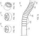
- FIG. 16provides a view of a device using a stack segment body.
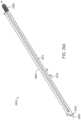
- FIG. 17provides an alternative embodiment of a device using a stack segment body.
- FIGS. 18 A- 18 Bprovide an alternative embodiment of a segment with a fulcrum engagement.
- FIGS. 19 A- 19 Bprovide two views of a distal section embodiment.
- FIG. 20 Ashows a profile view of a distal segment.
- FIG. 20 Bshows a cut away view of a distal segment.
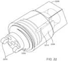
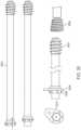
- FIGS. 21 and 22provide an illustration of proximal end cap.
- FIGS. 23 A- 23 Fprovide various alternative embodiments of proximal end sections.
- FIGS. 24 A- 24 Dillustrate a toothed interior embodiment.
- FIGS. 25 and 26illustrate a unibody type device.
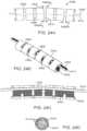
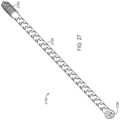
- FIGS. 27 and 28illustrate a unibody design with stress relief features.
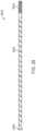
- FIGS. 29 A- 29 Billustrate a unibody design with a cut line.
- FIG. 30illustrates various embodiments of a proximal end.
- FIG. 31provides an alternative embodiment of a distal end.
- FIGS. 32 A- 32 Lillustrate a method of fixing a reduced bone fragment.
- FIG. 33illustrates a curved guidewire.
- Curved bonesmay be generally straight with a section having a curve or arc length, generally curved without a distinguishable straight segment, or a combination of the two.
- Curved bones or non-linear bonesinclude the zygoma, mandible (jaw bone), clavicle, scapula (the hemipelvis of the upper limb), ribs, spine, talus and calcaneus.
- the devicemay also have some applications in pediatric long bones.
- Treatment of an injury or weakness in these curved bonesmay involve the use of a bone reinforcement structure for deployment within the bones soft interior (marrow or bone channel).
- a bone reinforcement structurefor deployment within the bones soft interior (marrow or bone channel).
- the use of straight intramedullary nails and bone screws and platesare well known and often used for straight bones.
- Curved intramedullary nailsare used in the humerus and clavicle bones to reduce the invasiveness of the implantation procedure.
- curved intramedullary nailsare not used in the pelvis because the curvature of the pelvis varies significantly depending on the size of the patient and the location of the fracture(s).
- the deployment of a curved nail into curved pelvis boneswould be fraught with inherent difficulties, such as matching the curvature of the nail to the bone, penetrating the nail through the desired path in the bone without piecing the cortical bone and thus further weakening the bone structure, visualizing the deployment path, visualizing the placement in real time and removing the nail from the patient in the event the nail needs to be withdraw post procedure for any variety of reasons.
- Another problem with trying to put a preformed curved nail into the pelvic ring or anterior or posterior columns of the acetabulumis the paths formed are complex S shaped. To get the preformed device past the first part of the complex S into the second part is impossible.
- the complex S shaped curvesare three dimensional S's and have more than one S curve in them.
- proximalmeans the side or end of a device that tends to be the closest to the physician or operator when using the described embodiment.
- proximalmeans the side or end of an embodiment that is the last to enter a patient body.
- distalrefers to the end or side of the embodiment that is furthest away from the physician or operator.
- distalmay alternatively mean the end or side of the embodiment that is first to enter the patient body.
- This axisis an imaginary axis based on the shape of some of the embodiments of the device and refers to the long axis of the embodiments having one dimension (of height, length or width) clearly longer or greater than the other two dimensions.
- the dimension which is the greatestis the dimension on which the general axis runs parallel to.
- the general axismay not be a straight line, and may be curved or follow a tortuous path, so long as the axis is generally thought of as running parallel to the embodiment. Parallel may also include superimposed in the same line, whether straight or curved.
- Described hereinis a curved intramedullary fixation device with adaptable or alterable shape capable of deployment within a bone or boney structure while having a flexible or non-rigid form, then adapting to an inflexible or rigid form after deployment.
- the curved intramedullary fixation device with adaptable or alterable shapemay revert to a flexible or non-rigid form subsequent to deployment for either further adjustment or removal from the bone or boney structure.
- Other embodimentsare sufficiently flexible to be inserted along a curved path and sufficiently rigid after implantation without requiring a conversion step.
- any discussion of bone placementshall also refer to boney structures, bone like structures or other support organs of an animal
- the curved intramedullary fixation device with adaptable or alterable shapeshall also simply be referred to herein as the device, support device or the apparatus.
- the outer sheathmay be made entirely of a light weight polymer, and may be a mono-layer or multi-layer sheath.
- the sheathmay be reinforced (such as with a wire or wire ribbon braid) to promote pushability, or rely on the support device for both axial and radial support to prevent collapse.
- the sheathmay collapse and “shrink fit” on the support device, while in other embodiments the sheath may have a gap space between the body of the support device and the sheath. Such gap space may be used for the injection of fluids, medicines or antibacterial compounds.
- a segment 504may include six bores holes 524 disposed at a spacing of about 60° so that the bore holes maintain tensile fibers 512 at a distance from the center of the segment, as well as in a specific radial positions of about 0°, 60°, 120°, 180°, 240°, 300°, and 360° relative to one another about the central core 508 . Additional segment embodiments are discussed below.
- one or two bore holes 524may be used to change the shape of the body 500 .
- the body 500may have a predisposed bend to it and a single fiber 512 may be used to offset the predisposed bend to relax or reduce the curvature of the body 500 during deployment and shape fixing.
- two fibers 512may be used at various radial positions about the center to perform in a similar function.
- one or more fibersmay be disposed outside the body and under the sheath, and the fiber may be tensioned and fixed into position to cause the desired shape setting (not shown).
- the individual segments 700may have two or more bore holes or channels 702 , 704 ( FIG. 7 A ).
- a central bore hole or channel 704may be used for sliding over a guide wire or guide pin.
- the peripheral channels 702may be used for sliding over a fiber.
- the segments 700By stacking the segments 700 on top of each other ( FIG. 7 D ), the segments can be aligned using a form a generally contiguous body.
- the segmentscan align on the central collar or positive relief feature 710 .
- the positive relief feature 710may be raised above the angled plane 712 d of the top surface 712 of segment 700 .
- the difference in height between the edge of the segment 700 and the positive relief feature 710forms an angle 712 d .
- the segmentsWhen the segments are stacked 700 a - n over the fibers 708 a - n , they form the body of the multi-segmented device.
- the segmentscan bend relative to each other.
- the arthropod bodyis not flexible between segments, but collectively with a higher number of segments, the arthropod body is able to curve on itself.
- the individual segments 800may be tall, having a height dimension 800 h which is greater than the diameter 800 d ( FIGS. 8 A-D ).
- the segment 800may have a central bore hole or channel 802 and a raised neck or positive relief feature 804 . Any number of peripheral channels 806 may be formed in the segment 800 .
- These taller segmentsmay have a standard form with a top surface having a positive relief feature 804 and a bottom surface having a negative relief feature 810 ( FIG. 8 C ). Stacking these segments provides a deflection angle 804 a between each segment.
- the segments 900( FIGS. 9 A- 9 C ) include six bore holes 904 disposed around the central bore 902 and configured for a maximum of six tensioning fibers. As discussed earlier, each bore hole or channel 904 may not need to have a tensioning fiber there through, and thus a fixation device having segments 900 may include three, four, five or six tensioning fibers, occupying at least three positions spaced at 120° around the periphery. Segments 1000 of FIGS. 10 A- 10 C include eight bores 1004 disposed around the central bore holes 1002 and configured for a maximum of eight tensioning fibers.
- each bore hole or channel 1002may not need to have a tensioning fiber there through, and thus a fixation device having segments 1000 may include four, five, six, seven or eight tensioning fibers, occupying at least four positions spaced at 90° around the periphery.
- FIGS. 11 A- 11 CA few additional embodiments of segments 1100 , 1102 , 1104 are depicted in FIGS. 11 A- 11 C .
- the segmentsmay have various diameters, lengths, pivot configurations, number and size of bores, and surface inclination angles.
- the body of a fixation devicemay be formed from segments of varying configuration stacked together. For example a proximal segment 1202 , adjacent the proximal bone interface, may be longer if the initial portion of a bore in the proximal section of the bone to be treated is relatively straight.
- end segmentsmay longer that those segments that are fixed about the curve, but distal segments should be navigable about the curve the support device is designed to treat thus limiting to some degree the length of the most distal segments.
- a next section of segments 1204may have an intermediate height, for example about 160 mm, if the bore hole in the intermediate section is relatively straight with minimal bending.
- a distal set of segments 1206may have a smaller height, for example about 80 mm, to accommodate bending about smaller radii.
- proximal segments, such as segments 1202 , 1204may also have a diameter that is greater than distal segments, such as segments 1206 , possibly requiring that bore hole in the bone be drilled with sections of different diameters.
- the segmentmay include one or more fulcrum elements to facilitate or increase the off angle deflection between segments ( FIGS. 13 A-B ).
- the segment 1300has a base 1302 and a top surface 1310 .
- the top surfacehas a fulcrum element 1304 .
- the fulcrum element 1304may be rounded and symmetrical about the central channel 1312 .
- the fulcrum elementmay have a taper, being generally larger toward the center (+) and gradually narrowing toward the perimeter or circumference of the base.
- the fulcrumcan be slidably engaged with a channel 1308 or aperture of similar dimensions ( FIG. 13 A ).
- the fulcrum feature 1400can now be seen in greater detail with four different views of the segment.
- a plan viewFIG. 14 A
- the central channel 1418 and a group of peripheral channels 1416 a - ncan be seen.
- four peripheral channelsare shown, it should be understood that the number of peripheral channels may be as few as 1 or as many as can be designed into the segment.
- Two side views of the segment 1400are shown at 90 degree off sets.
- the side viewreveals the central channel creates a hole in the neck region.
- the neck regionraises the fulcrum above the top plate.
- the aperture for the fulcrum pin 1406can be seen.
- the fulcrum pin 1406 and fulcrum channel 1404are shown in parallel.
- the fulcrum pin 1406 and fulcrum channel 1404may be at any radial angle relative to each other.
- the fulcrum pin and fulcrum channelmay be offset anywhere from about 0 degrees to about 180 degrees where the fulcrum pin and the channel are symmetrical.
- the fulcrum pin and fulcrum channelmay be offset between 0 degrees and 360 degrees. Additional detail can be seen in a perspective view ( FIG. 14 D ) of the segment with a fulcrum style positive relieve element.
- a circular perimeter 1402can provide a smooth and atraumatic surface for the segment 1400 .
- the fulcrum pin 1406is a generally tapered pin (by way of analogy only the fulcrum pin may be thought of as a single piece wood rolling pin in shape) having a central channel 1418 through it.
- the central channel 1418exposes a hole 1426 on each side of the neck 1424 .
- a fulcrum channel 1404goes through the segment 1400 and defines a fulcrum channel axis 1414 .
- the fulcrumhas two slopes 1408 , 1410 from the central channel 1418 .
- the two slopes 1408 , 1410may be the same, or they may differ in pitch, angle, shape or length.
- FIGS. 15 A-BAn example of the fulcrum segments in a stacked arrangement is now shown in FIGS. 15 A-B .
- the various segments 1502 a - n of the stackare shown in a perspective view in FIG. 15 A .
- the individual segmentshave bendability in multiple planes, including a plane parallel to the direction of the fulcrum pin.
- a cross sectionFIG. 15 B ) shows the individual angle of deflection 1312 a of the main axis 1310 and the sum angle of deflection 1312 a - n.
- the fulcrum segmentsare shown with the fulcrum pins at 90 degree angles to the fulcrum channels ( FIG. 16 ).
- the device 1600has a distal end 1602 having a screw engagement device for engaging in the boney tissue.
- the main body 1604 of the device 1600is made up of fulcrum segments having fulcrum pins rotated 90 degrees from the fulcrum channels.
- the fulcrum pins and channelsare able to engage mechanically and provide deflection angles between each segment and a sum deflection angle that is the net of each individual deflection angle.
- a proximal end 1606is shown where individual fibers 1608 n may be tensioned to hold the device 1600 in a desired shape.
- An alternative view of the device 1700is provided in FIG. 17 , having a distal end 1702 , a body 1704 and proximal end 1706 .
- the fibers 1708 nextend from the proximal end.
- the segments 1800 a - n of the devicemay have replace the fulcrum pin and fulcrum channel individual round tabs 1802 ( FIGS. 18 A-B ) and corresponding round apertures 1806 for receiving the tabs 1802 .
- the orientation of the tabs and aperturesmay be parallel or at any radial angle relative to each other along the circumference of the segment 1800 .
- the segment tabsneed not be round, they may be ball shaped, or have acute angles.
- a shaped slot feature 1810may be made into one side of the segment to permit another segment to engage with the next segment. The sliding and stacking of the segments may be done one at a time or in groups of two or more.
- the distal end 1900may have a segment engagement portion 1906 to engage the fulcrum channel or fulcrum tabs for receiving a fulcrum pin/tab from a segment.
- the distal endmay also have a negative relief feature for receiving a positive relief feature of a segment.
- the distal endmay have a positive relief feature or fulcrum pin/tab for engaging a corresponding negative relief feature, channel or aperture on an adjacent segment.
- the distal endhas a bone engagement feature 1902 like a screw thread.
- the screw threadmay have optional detents 1908 , 1910 in the threading to facilitate cutting into the bone for both clockwise and counter clockwise rotation. This helps in both placement and removal of the device should removal be required.
- a guide wire aperture 1904may be provided so the distal end may slide over the guide wire.
- the distal endmay be a screw head having a generally tapered form with an oblong core ( FIG. 20 A ).
- the distal endmay have an internal negative relief feature for receiving a hex bolt or other connection element from an adjacent segment.
- the connection between the distal end and the distal most segmentmay be one where some angle of deflection is afforded to the overall device, or it may be a connection with a solid fit and not additional angle of deflection of the main axis is gained between the last segment of the main body and the distal end.
- An end cap 2100is provided for securing the proximal end of the main body ( FIG. 21 ).
- the end cap 2100fits over the proximal most segment 2102 of the main body.
- the proximal most segment 2102may have a fulcrum tab 2104 for engaging other segments of the main body.
- the proximal most segment 2102may also have a screw thread 2106 for engaging the end cap 2100 .
- One or more fiber channels 2112are provided for the fibers (not shown) to be gathered at the proximal end and drawn tight or simply fixed into position.
- the end cap 2100slides over the proximal most segment and can be screwed on to the proximal most segment to engage the threads 2106 .
- the end cap 2100may be tightened by hand by grasping or engaging the back section 2114 which may have a roughened surface to facilitate gripping.
- the back section 2114may be engaged using a torque driver.
- An optional aperture or hole 2110may be provided for the guidewire, fibers or other loose ends that may trail from the device to be threaded through and removed after the device is placed and capped.
- the deviceis driven in to the bone via a torque driver transmitting torque directly to the proximal most segment 2102 .
- the torque driver(not shown) would be adapted to accommodate the shape of the proximal end of the proximal most section.
- the devicemay be driven in to the bone with a torque driver applying torque to the end cap 2100 .
- the end cap 2200is now shown in a different perspective angle ( FIG. 22 ).
- the operatormay hold the fibers in a group and place them into the thread channels 2210 and secure them in place. Generally one fiber per channel, but the channels may be designed and cut to accommodate more than one fiber. Between the channels are tabs 2206 which are optionally intended to engage a torque transmission device to help drive the device into the bone. Once the fibers are secured, the end cap 2200 may be screwed into place over the proximal most segment 2202 . Note the proximal most segment has a pair of fulcrum tabs 2204 for illustration purposes only. The fulcrum or connection/engagement mechanism to other segments of the body may be any kind.
- the proximal endmay be any form that can receive a torque transmission device and transmit torque to the body and the distal end of the device.
- the relief feature for engaging a torque transmission deviceis a positive relief feature 2300 having an end flange 2304 to prevent the proximal end from being pushed into the bone past the hard cortical wall.
- a flange 2312 or other featureis used again to help prevent the proximal end from being driven past the hard bone wall.
- a hole or aperture 2306 , 2310is made in the proximal end for the passage of a guidewire.
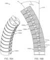
- FIG. 24 Ashows an alternative embodiment of a body 2400 having pairs 2402 , 2408 of slots disposed circumferentially around the body tube, and offset by about 90° from each other.
- the slotsmay have a width 2400 w .
- the body 2400is bent downwardly away from the linear axis 2406 and defines an offset axis 2412 wherein a width 2400 w b of at least one slot 2410 on the lower side may be narrowed and a width 2400 w a of at least one slot 2404 on the upper side may be increased to allow the body to bend downwardly.
- the body 2400may be locked in its bent configuration by providing radially inwardly disposed teeth 2422 on the interior surface of the body 2400 , which teeth extend through the main body.
- One or more externally toothed fibers 2414may be inserted within the central cannula 2424 .
- the toothed fibers 2414may include teeth 2420 that match the pitch of the teeth 2422 (or threads) on the inside of the outer member so that the teeth on the fibers may engage with the teeth on the interior surface.
- the internal fibers 2414 in the main bodyhave sufficient diametric clearance to translate axially through the main body.
- the tooth pitchis generally fine scale so a series of engaged teeth form between the inside of the body and the toothed fibers.
- the fine scale of the teethallows gaps and teeth to engage on a less than 1:1 or more than 1:1 ration and still provide gripping or engagement friction so the parts remain relatively stationary to each other when in a fixed shape.
- the entire main bodymay be converted to a rigid state upon the insertion of the filler 2418 , which pushes the teeth 2420 of the internal fibers 2414 against the teeth of the main body, meshing the threads/teeth of the internal members, creating a load path from one rigid section of the main body to the internal tension members, (bypassing the flexible section of the main body) to the next rigid section of the main body.
- the fibers 2414may terminate within the main body, or in members attached to either end of the main body, for example, the proximal or distal bone interfaces.
- the internal core, or filler 2418may be formed of materials that are flexible (bendable) for insertion along a curved path, but minimally compressible so that the fibers 2414 remain pressed into engagement with the interior surface.
- materials from which the filler 2418 may be constructedinclude, but are not limited to SS 316LVM, Titanium Grade 23 6A1-4V ELI, PPEK or any 236LVM Stainless steel, polyether ether ketone (PEEK), or other materials as described herein.
- the fibersmay be disposed at about 120° with respect to one another to thereby prohibit movement (bending) in all directions orthogonal to the longitudinal axis.
- additional fibersmay be disposed within the cannula to provide additional shape-locking capability.
- four fibersmay be circumferentially spaced at about 90° from one another, or six fibers may be circumferentially spaced at about 60° from one another, or eight fibers may be circumferentially spaced at about 45° from one another.
- the number of fibersmay be varied depending on the diameter of the body, and/or the intended use, such as severity and location of the fracture and stress that may be applied to the fractured bone.
- the body 2504 of the device 2500may be made of a single component ( FIG. 25 ).
- the bodymay be made of a flexible polymer material, a flexible metal or alloy tube or a combination of both.
- the flexible tubemay draw from existing manufacturing techniques for catheters, endoscopes and other minimally invasive medical device designs.
- the distal end 2502retains a screw thread for engaging boney tissue and a torque transmission proximal end 2506 to allow torque to be transferred from the proximal end, along the body and too the distal end.
- the bodymay be a multilayer polymer device with metal wire or ribbon braid. Such a design may have added rigidity to enhance pushability and torquability.
- a catheter or endoscope construction techniquecan allow for an enlarged central lumen, through which a multi segmented body or other core like device may be inserted.
- the single tube body devicemay have a flange on the proximal end to act as a stop and prevent the device from being inserted too far into the bone ( FIG. 26 ).
- the proximal endmay be equipped with a flange 2606 so the device 2600 does not become completely inserted into the intramedullary space of the bone. Such an insertion may make retrieval and removal of the device difficult.
- the device 2600has a body 2604 which may be a unibody design or a multi-segmented body. A distal end 2602 is also provided.
- the device 2700may use a tube or other design for the main body 2704 having a series of slots, apertures or other stress relief elements built into the body structure.
- a series of slots 2708 a-nare constructed as part of the body 2704 .
- the individual slots or apertures 2708 a-nprovide stress relief or enhance torque and flexibility, allowing the body to rotate on its axis and deliver torque to the distal end with compromising the structural integrity of the device.
- the body 2704may be solid or hollow, or multi lumen with various component layers. In some embodiments the body 2704 may have a large central lumen to accommodate a multi-segment core or other material to provide enhanced structural features, allowing pushability, torquability and radial stiffness.
- a unibody support device 2700may be constructed of a non-flexible, torsionally stiff material, such as, for example, titanium as presented above ( FIG. 27 ).
- the body 2704may be include a plurality of spaced apart slots 2708 a-n or other apertures that extend circumferentially about a portion of the exterior surface. The apertures may be arranged following a helical pattern around the tube shaped body.
- the slotsmay be configured as pairs, with each slot of a pair being disposed at about 180° from the other slot of the pair, thereby allowing for widening of the slot on one side, while the opposite slot is narrowed for bending in the direction of the narrowed slot.
- the slots 2708 a-nmay also be circumferentially offset from one another.
- the slotsmay be circumferentially offset from each other by about 60° to 90°, thereby allowing for bending of the body 2704 to occur in a multiplicity of directions, as may be required for cannulae of complex curvature, or curvature in more than one plane.
- the distal bone interface 2702 and the proximal bone interface 2706may be integral with the body 2704 , or may be separate attached components, of any of the embodiments as discussed herein.
- the proximal section 2706depicts a radial flange for axial bone fixation, and depicts a negative relief hex configuration for torque transmission, and the distal bone interface 2702 is depicted as a threaded screw head with bone cutting threads.
- the bone cutting threadsmay be regular pitch or variable pitch, continuous or interrupted/interval; type. In some embodiments, threads may be replaced or augmented with spikes, pins, nails or any other mechanism in addition or alternative to screw threads.
- FIG. 28having a profile view of the device 2800 with a proximal section 2806 , body section 2804 and a distal end 2802 .
- the device 2900may have a body 2904 made from a single tube, but cut using any acceptable cutting technique (laser, EDM, mechanical blade) to produce a long continuous scar or slice through the tubular body ( FIGS. 29 A- 29 B ).
- the cut 2910may be completely through the tube body so the cut punctures the shell of the tube, or the cut may be an etching or partial cut that produces a gouge or trench in the tube body without penetrating the tube body.
- the cut 2910may be alternating cuts through the tube body and gouges that do not penetrated to the interior of the tube body. One may imagine this sort of scoring as a dashed line of through cuts and partial cuts.
- the device 2900has a distal section 2906 and a proximal section 2902 .
- the device 2900 in a linear statedefines an axis 2908 , and the type of cut line 2910 and its depth in the body will define how far the device 2900 can be deflected or bent off its main axis.
- the cut line 2910may be made to start at one end of the tubular body and continue to the other end.
- the number of turns the cut line 2910 makes in a given unit of linear lengthdefines the frequency 2912 of the cut line. Generally the higher the frequency, the greater deflection off the main axis the device 2900 can make. Alternatively by increasing the width of the cut, a similar result (greater angle of deflection) can be achieved.
- the cut line 2910may have variable cut width as well as depth.
- the proximal endmay come in a variety of shapes, sizes and features.
- the flangeis generally intended to prevent the proximal section of the device 3000 from being inserted past the cortical wall of the bone being treated. Access to the proximal end is generally important in case the patient has a post operative complication which requires removal of the device. The medical professional then needs ready access to the device without being required to dig into the bone to retrieve the device.
- a flange or similar featuremay be used to prevent the device from being inserted too far into the intramedullary space.
- proximal end 3004may be tapered such that part of the proximal end can enter past the cortical wall and part of the proximal end cannot enter past the cortical wall.
- proximal endmay be threaded so there is a feature or element that will engage the cortical wall.
- the distal head 3002similarly may have a bone engagement thread.
- the distal endmay use articulable disks 3102 and clamps 3112 to engage the bone.
- the disks 3102are provided in a first position which is narrower in profile to allow insertion into the intramedullary bone space ( FIG. 31 ).
- the clamps 3112are in a low radius configuration to allow the device to be advanced.
- the disks 3104compresses on the clamps 3114 forcing the clamps radially outward, and thus engage the boney tissue. This action may occur when the fibers are drawn tight, or when the device is withdrawn slightly to cause the disks or clamps to engage the boney tissue, or the disks or clamps may be actuated using some sort of user control mechanism.
- Various non-limiting designs for the disks and clampsare provided 3106 , 3108 , 3110 .
- the clampsmay be similar to washers or lock washers in shape.
- placement of the devicemay be facilitated by using a curved intramedullary fixation (CIF) steerable guidewire, or simply guidewire 3300 ( FIG. 33 ).
- the guidewire 3300maybe one generally used in orthopedic procedures, and may be about 0.3 mm to 6.0 mm in diameter. The diameter of the guidewire can be selected by the medical professional and appropriate for the bone the guidewire will be used on.
- the guidewire 3300has a bend 3302 near the distal end 3304 , and the distal end may be tapered to a point.
- a medical professionalmay pass the guidewire 3300 down the bone and tap on the proximal end of the guidewire to incrementally advance the guidewire in the intramedullary space of the bone.
- the guidewireis rotated so the bend 3302 portion of the guidewire is angled toward the cortical wall.
- the distal endis deflected away from the cortical wall when the bend portion impacts the wall.
- the guidewiremay be continuously rotated by the medical professional under visualization so the guidewire creates a curved path through the intramedullary space.
- the guidewire, the device and other components as described here in,may be made from a wide range of materials.
- the device and the guidewiremay be composed from a polymer, a metal, an alloy, or a combination thereof, which may be biocompatible.
- the guidewire or devicecan be formed from Titanium Grade 23 6A1-4V ELI material or 316 LVM Stainless steel titanium or a titanium alloy.
- suitable metalsmay include stainless steel, cobalt-chromium alloys, and tantalum.
- metal alloys having shape memory capabilitysuch as nickel titanium or spring stainless steel alloys, may also be used.
- the guidewire and devicecan be formed from a suitable polymer including non-degradable polymers, such as polyetheretherketone (PEEK) and polyethylene (PE), as well as modified versions of these materials (for example, PEEK+calcium phosphates and PE+vitamin E, metal coatings, or surface texturing).
- PEEKpolyetheretherketone
- PEpolyethylene
- modified versions of these materialsfor example, PEEK+calcium phosphates and PE+vitamin E, metal coatings, or surface texturing.
- Additional non limiting polymersmay include; polyether-block co-polyamide polymers, copolyester elastomers, thermoset polymers, polyolefins (e.g., polypropylene or polyethylene, including high density polyethylene (HDPEs), low-density polyethylene (LDPEs), and ultrahigh molecular weight polyethylene (UHMWPE)), polytetrafluoroethylene, ethylene vinyl acetate, polyamides, polyimides, polyurethanes, polyvinyl chloride (PVC), fluoropolymers (e.g., fluorinated ethylene propylene, perfluoroalkoxy (PEA) polymer, polyvinylidenefluoride, etc.), polyetheretherketones (PEEKs), PEEK-carbon fiber composites, Polyetherketoneketones (PEKKs), poly(methylmethacrylate) (PMMA), polysulfone (PSU), epoxy resins and silicones. Additionally starch based polymers may be
- Additional materialsmay include carbon and polyaramid structures, glass or fiberglass derivatives, ceramic materials, and artificial biocompatible protein derivatives (recombinant derived collagen).
- the fracture stabilization devicemay be made of a metal and/or alloy segments with a polymer shell, or a sandwich style and coaxial extrusion composition of any number of layers of any of the materials listed herein. Various layers may be bonded to each other to provide for single layer composition of metal(s), alloys, and/or polymers.
- a polymer coremay be used with a metal and/or metal alloy shell, such as a wire or ribbon braid.
- the devicemay include a bone integration surface to promote bone ingrowth, on-growth, and/or through-growth between the segments, if desired.
- the bone integration surfacescan comprise a three-dimensional space to allow bone integration into and/or onto portions of the fracture stabilization device.
- the three dimensional spacecan be provided by a three-dimensional substrate, for example beads, and/or by the provision of holes through the bone integration portions.
- Other methods for achieving bone integrationcan include the provision of an appropriate surface topography, for example a roughened or textured area and/or by the provision of osteoconductive coatings, such as calcium phosphates.
- the bone integration surfacemay enable the fracture stabilization device to provide a metal and/or polymeric scaffold for tissue integration to be achieved through the fracture stabilization device.
- various materialsmay be used to facilitate, stimulate or activate bone growth.
- materialsmay include hydroxyapatite (HA) coatings, synthetic bioabsorbable polymers such as poly ( ⁇ -hydroxy esters), poly (L-lactic acid) (PLLA), poly(glycolic acid) (PGA) or their copolymers, poly(DL-lactic-co-glycolic acid) (PLGA), and poly( ⁇ -caprolactone) (PLC), poly(L-lactide) (LPLA), (DLPLA), poly( ⁇ -caprolactone) (PCL), poly(dioxanone) (PDO), poly(glycolide-co-trimethylene carbonate) (PGA-TMC), poly(lactide-co-glycolide), polyorthoesters, poly (anhydrides), polyhydroxybutyrate, poly(l-lactide-co-glycolide) (PGA-LPLA), cyanoacrylates, poly(dl-lactide-co-gly
- the support devicehas a proximal end, a distal end, and an elongate main body.
- the proximal endincludes a flexibility fixation element that serves to lock the support device into a rigid or inflexible shape when desired.
- the support devicemay include an optional sheath to enhance the atraumatic profile of the support device when used.
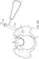
- a usermay strike the trocar with a hammer, cannulated hammer or other instrument 3206 to create a starting point in the bone for the procedure ( FIGS. 32 A-L ).
- the pelvis Phas suffered a break B in two locations. The break in the Sacrum is not treated in this example.
- a start drill 3208 or similar devicemay be inserted through the protective sleeve 3202 and advanced through the cortical bone. This creates a portal for all instruments and devices to pass through as they enter the bone P ( FIG. 32 B ).
- the start drillmay be removed and a steerable guide wire, guide pin or CIF steerable guide wire (collectively simply referred to herein as a “guidewire” 3210 ) may be inserted through the protective sleeve 3202 and the trocar 3204 .
- a physician or other medical professionalmay use fluoroscopy or other visualization technology to view the guidewire in the bone.
- the CIF guidewireis advanced through the medullary canal. By Rotating the CIF steerable Guidewire and applying force on the proximal end, a desired placement can be achieved.
- the guidewireis advanced to the proximity of the cortical wall of the Pubis symphysis and across the break B ( FIG. 32 C ).
- a cannulated flexible reamer 3212may be passed over the guidewire and used to ream the cancellous bone. The surgeon should exercise care not to ream through the bone past the distal end of the guidewire 3210 d ( FIG. 32 D ).
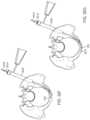
- a directional exchange tool 3214is introduced through the protective sleeve 3202 and into the recently reamed channel in the medullary canal. It may be useful to place the cone shaped geometry of the directional exchange tool adjacent to, and as normal as possible to, the cortical wall ( FIG. 32 E ).
- a trocar tipped guidewire 3216is then passed through the directional exchange tool 3214 .
- the trocar tipped guidewire 3216is placed down to the cortical wall CW ( FIG. 32 F ).
- the userthan applies force, either manually or via some mechanical advantage device) on the proximal end of the trocar tipped guidewire 3216 until both cortices of the Pubis Symphysis have been perforated ( FIG. 32 G ).
- the trocar tipped guidewireis removed and a second steerable guidewire 3218 is introduced. If the perforations in the cortical wall CW are not large enough, it may be necessary to ream the holes out until they are sufficiently large to accommodate the passing of the guidewire.
- the medical professionalthen crosses the guidewire to the Pubis Symphysis and medullary canal across the pubic arch ( FIG. 32 H ).
- a reamer 3220is used to finish creating the path between the two side of the pubic arch ( FIG. 32 I ).
- the medical professionalcan introduce an exchange tube 3222 over the guidewire 3218 .
- the exchange tube 3222is then advanced over the guidewire to the distal end of the guidewire ( FIG. 32 J ).
- the guidewiremay be removed and a trocar tipped guidewire 3224 is introduced and advanced to approximately the same distal location.
- the exchange tube 3222can then be removed ( FIG. 32 K ).
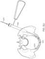
- the device 3200can now be advanced over the guidewire 3224 .
- the device 3200may need to be advanced using any appropriate torque driver 3226 , such as a hexalobe driver, screw driver or drill tool to name a few.
- the shape devicecan be secured in place by drawing tight any fibers in the device to secure the position of the segments, or simply deploying a proximal end with a bone engagement element to secure the device 3200 in the bone ( FIG. 32 L ).
Landscapes
- Health & Medical Sciences (AREA)
- Orthopedic Medicine & Surgery (AREA)
- Surgery (AREA)
- Life Sciences & Earth Sciences (AREA)
- Biomedical Technology (AREA)
- Public Health (AREA)
- Veterinary Medicine (AREA)
- Engineering & Computer Science (AREA)
- Nuclear Medicine, Radiotherapy & Molecular Imaging (AREA)
- Heart & Thoracic Surgery (AREA)
- Medical Informatics (AREA)
- Molecular Biology (AREA)
- Animal Behavior & Ethology (AREA)
- General Health & Medical Sciences (AREA)
- Neurology (AREA)
- Dentistry (AREA)
- Oral & Maxillofacial Surgery (AREA)
- Prostheses (AREA)
- Surgical Instruments (AREA)
Abstract
Description
- a flexible body defining a main axis, the flexible body having a proximal end and a distal end, the flexible body comprising:
- a plurality of individual segments having a mechanical engagement structure for non-rigidly interlocking the individual segments together;
- a plurality of apertures in each individual segment, the apertures arranged to generally form a plurality of lumens in the flexible body when the segments are in non-rigid mechanical engagement;
- wherein the individual segments may move relative to each other in a first and a second orthogonal plane relative to the main axis;
- a torque transmission member positioned substantially on the proximal end;
- a bone engagement feature positioned substantially on the distal end; and
- a plurality of fibers extending through the lumens such that the fibers provide a fixed shape to the flexible body when the fibers are fixed into position.
- a torque transmission member located substantially at the proximal end;
- wherein the plurality of apertures provide stress relief along the elongate body when the tubular body is under torque.
- a flexible body portion extending along at least a portion of the first distance, the flexible body portion comprising a plurality of interconnected segments, wherein each segment of the interconnected segments defines an axis portion of the longitudinal axis, and each segment is movable with respect to at least one adjacent segment to angularly offset the axis portion of each segment with the axis portion of the at least one adjacent segment;
- a transmission member positioned adjacent the proximal end for axially inserting the elongated body into the bone;
- a bone engagement device positioned adjacent the distal end for axially retaining the elongated body within the bone;
- a plurality of cables disposed longitudinally within the elongated body through at least the flexible body portion in circumferentially spaced relation to one another; and
- a cable tensioning system for tensioning individual ones of the plurality of cables to retain the interconnected segments in a fixed relationship with each of the plurality of cables and with one another.
- the plurality of interconnected segments comprises a plurality of individual interconnected segments; and
- each individual segment having a first end and a second end spaced axially from the first end; and
- at least one of the first end and the second end of each segment comprises a first engagement portion for pivotally engaging with the other of the first end and the second end of an adjacent segment to angularly offset the axis portion of the segment with the axis portion of the at least one adjacent segment.
- the first engagement portion comprises a protrusion extending axially from the first end; and
- the other of the first end and the second end comprises a recessed portion for receiving the protrusion therein.
- creating an entry into a curved bone;
- advancing a guidewire through an intramedullary space to a position distal to a reduced bone fracture;
- reaming a channel in the intramedullary space along the length of the guidewire;
- advancing a curved intramedullary fixation device through the channel; and
- locking the curved intramedullary fixation device in place.
Claims (23)
Priority Applications (2)
| Application Number | Priority Date | Filing Date | Title |
|---|---|---|---|
| US17/663,721US12167877B2 (en) | 2014-03-06 | 2022-05-17 | Shape adaptable intramedullary fixation device |
| US18/945,941US20250064489A1 (en) | 2014-03-06 | 2024-11-13 | Shape adaptable intramedullary fixation device |
Applications Claiming Priority (6)
| Application Number | Priority Date | Filing Date | Title |
|---|---|---|---|
| US201461949177P | 2014-03-06 | 2014-03-06 | |
| PCT/US2015/018969WO2015134750A1 (en) | 2014-03-06 | 2015-03-05 | Shape adaptable intramedullary fixation device |
| US14/727,576US9498264B2 (en) | 2014-03-06 | 2015-06-01 | Shape adaptable intramedullary fixation device |
| US15/285,811US10307188B2 (en) | 2014-03-06 | 2016-10-05 | Shape adaptable intramedullary fixation device |
| US16/414,435US11369421B2 (en) | 2014-03-06 | 2019-05-16 | Shape adaptable intramedullary fixation device |
| US17/663,721US12167877B2 (en) | 2014-03-06 | 2022-05-17 | Shape adaptable intramedullary fixation device |
Related Parent Applications (1)
| Application Number | Title | Priority Date | Filing Date |
|---|---|---|---|
| US16/414,435ContinuationUS11369421B2 (en) | 2014-03-06 | 2019-05-16 | Shape adaptable intramedullary fixation device |
Related Child Applications (1)
| Application Number | Title | Priority Date | Filing Date |
|---|---|---|---|
| US18/945,941ContinuationUS20250064489A1 (en) | 2014-03-06 | 2024-11-13 | Shape adaptable intramedullary fixation device |
Publications (2)
| Publication Number | Publication Date |
|---|---|
| US20220287744A1 US20220287744A1 (en) | 2022-09-15 |
| US12167877B2true US12167877B2 (en) | 2024-12-17 |
Family
ID=54055873
Family Applications (5)
| Application Number | Title | Priority Date | Filing Date |
|---|---|---|---|
| US14/727,576ActiveUS9498264B2 (en) | 2014-03-06 | 2015-06-01 | Shape adaptable intramedullary fixation device |
| US15/285,811ActiveUS10307188B2 (en) | 2014-03-06 | 2016-10-05 | Shape adaptable intramedullary fixation device |
| US16/414,435ActiveUS11369421B2 (en) | 2014-03-06 | 2019-05-16 | Shape adaptable intramedullary fixation device |
| US17/663,721ActiveUS12167877B2 (en) | 2014-03-06 | 2022-05-17 | Shape adaptable intramedullary fixation device |
| US18/945,941PendingUS20250064489A1 (en) | 2014-03-06 | 2024-11-13 | Shape adaptable intramedullary fixation device |
Family Applications Before (3)
| Application Number | Title | Priority Date | Filing Date |
|---|---|---|---|
| US14/727,576ActiveUS9498264B2 (en) | 2014-03-06 | 2015-06-01 | Shape adaptable intramedullary fixation device |
| US15/285,811ActiveUS10307188B2 (en) | 2014-03-06 | 2016-10-05 | Shape adaptable intramedullary fixation device |
| US16/414,435ActiveUS11369421B2 (en) | 2014-03-06 | 2019-05-16 | Shape adaptable intramedullary fixation device |
Family Applications After (1)
| Application Number | Title | Priority Date | Filing Date |
|---|---|---|---|
| US18/945,941PendingUS20250064489A1 (en) | 2014-03-06 | 2024-11-13 | Shape adaptable intramedullary fixation device |
Country Status (3)
| Country | Link |
|---|---|
| US (5) | US9498264B2 (en) |
| CA (1) | CA2978697A1 (en) |
| WO (1) | WO2015134750A1 (en) |
Cited By (3)
| Publication number | Priority date | Publication date | Assignee | Title |
|---|---|---|---|---|
| US12419668B2 (en) | 2019-11-21 | 2025-09-23 | Si-Bone Inc. | Rod coupling assemblies for bone stabilization constructs |
| US12427028B2 (en) | 2018-03-28 | 2025-09-30 | Si-Bone Inc. | Threaded implants and methods of use across bone segments |
| US12433733B2 (en) | 2023-08-15 | 2025-10-07 | Si-Bone Inc. | Pelvic stabilization implants, methods of use and manufacture |
Families Citing this family (60)
| Publication number | Priority date | Publication date | Assignee | Title |
|---|---|---|---|---|
| US20180228621A1 (en) | 2004-08-09 | 2018-08-16 | Mark A. Reiley | Apparatus, systems, and methods for the fixation or fusion of bone |
| US9949843B2 (en) | 2004-08-09 | 2018-04-24 | Si-Bone Inc. | Apparatus, systems, and methods for the fixation or fusion of bone |
| EP3326558B1 (en)* | 2011-11-14 | 2025-04-30 | The University of British Columbia | Intramedullary fixation system for management of pelvic and acetabular fractures |
| US10363140B2 (en) | 2012-03-09 | 2019-07-30 | Si-Bone Inc. | Systems, device, and methods for joint fusion |
| WO2014145902A1 (en) | 2013-03-15 | 2014-09-18 | Si-Bone Inc. | Implants for spinal fixation or fusion |
| US11147688B2 (en) | 2013-10-15 | 2021-10-19 | Si-Bone Inc. | Implant placement |
| US9839448B2 (en) | 2013-10-15 | 2017-12-12 | Si-Bone Inc. | Implant placement |
| WO2015090954A1 (en)* | 2013-12-17 | 2015-06-25 | Stichting Katholieke Universiteit | Intramedullary device for mid-shaft clavicle fractures |
| WO2015134750A1 (en) | 2014-03-06 | 2015-09-11 | University Of British Columbia | Shape adaptable intramedullary fixation device |
| US10064670B2 (en)* | 2014-05-12 | 2018-09-04 | DePuy Synthes Products, Inc. | Sacral fixation system |
| CA2949060A1 (en)* | 2014-05-12 | 2015-11-19 | DePuy Synthes Products, Inc. | Sacral fixation system |
| US10588642B2 (en) | 2014-05-15 | 2020-03-17 | Gauthier Biomedical, Inc. | Molding process and products formed thereby |
| JP6542362B2 (en) | 2014-09-18 | 2019-07-10 | エスアイ−ボーン・インコーポレイテッドSi−Bone, Inc. | Matrix implant |
| US10166033B2 (en) | 2014-09-18 | 2019-01-01 | Si-Bone Inc. | Implants for bone fixation or fusion |
| JP6389002B2 (en) | 2014-10-14 | 2018-09-12 | ザ ユニヴァーシティ オブ ブリティッシュ コロンビア | System and method for intramedullary bone fixation |
| US10478238B2 (en) | 2014-12-02 | 2019-11-19 | Activortho, Inc. | Active compression devices, methods of assembly and methods of use |
| US10376206B2 (en) | 2015-04-01 | 2019-08-13 | Si-Bone Inc. | Neuromonitoring systems and methods for bone fixation or fusion procedures |
| FR3036030B1 (en)* | 2015-05-11 | 2021-01-29 | Lokou David Fischer | IMPLANT FOR FIXING BONE ELEMENTS |
| US10499960B2 (en) | 2015-07-13 | 2019-12-10 | IntraFuse, LLC | Method of bone fixation |
| US10492838B2 (en) | 2015-07-13 | 2019-12-03 | IntraFuse, LLC | Flexible bone implant |
| US10485595B2 (en) | 2015-07-13 | 2019-11-26 | IntraFuse, LLC | Flexible bone screw |
| US10154863B2 (en)* | 2015-07-13 | 2018-12-18 | IntraFuse, LLC | Flexible bone screw |
| EP3402419B1 (en)* | 2016-01-17 | 2021-09-15 | T.A.G. Medical Devices - Agriculture Cooperative Ltd. | Flexible bone tool |
| CA3015902A1 (en) | 2016-02-26 | 2017-08-31 | Activortho, Inc. | Active compression apparatus, methods of assembly and methods of use |
| US11224467B2 (en) | 2016-02-26 | 2022-01-18 | Activortho, Inc. | Active compression apparatus, methods of assembly and methods of use |
| JP6811498B2 (en) | 2016-09-08 | 2021-01-13 | メダロック, エルエルシー | Implants and methods for long bone fixation |
| DE102016011947A1 (en)* | 2016-10-05 | 2018-04-05 | Bluewater Medical GmbH | Screw with a head part, a threaded part and a connecting part |
| EP3522803A4 (en)* | 2016-10-05 | 2020-05-27 | The University of British Columbia | Intramedullary fixation device with shape locking interface |
| US11793526B2 (en)* | 2017-03-03 | 2023-10-24 | The Johns Hopkins University | Steerable drill for minimally-invasive surgery |
| US11052229B2 (en)* | 2017-08-15 | 2021-07-06 | Corelink, Llc | Devices and methods for guidewire extension in spinal surgery |
| US11116519B2 (en) | 2017-09-26 | 2021-09-14 | Si-Bone Inc. | Systems and methods for decorticating the sacroiliac joint |
| US10874434B2 (en)* | 2017-10-18 | 2020-12-29 | Texas Scottish Rite Hospital For Children | Deformable dynamization device |
| EP3501457A1 (en)* | 2017-12-20 | 2019-06-26 | Materialise N.V. | Flexible porous implant fixation system |
| US11317949B2 (en) | 2018-04-25 | 2022-05-03 | Loubert S. Suddaby | Segmented alignment rod assembly |
| US11580268B2 (en) | 2018-04-25 | 2023-02-14 | Loubert S. Suddaby | Method of creating a customized segmented alignment rod for alignment of a spine |
| US10624683B2 (en) | 2018-04-25 | 2020-04-21 | Loubert S. Suddaby | Segmented alignment rod assembly |
| CN108720913B (en)* | 2018-06-29 | 2024-06-21 | 宁波市第六医院 | Intramedullary positioning device for anterior pelvic column |
| US11678990B2 (en)* | 2018-07-10 | 2023-06-20 | Adler Ortho S.P.A. | Device for facilitating the formation of new bone tissue |
| CN112912022A (en)* | 2018-10-17 | 2021-06-04 | 不列颠哥伦比亚大学 | Bone fixation device and system |
| CN112955087A (en)* | 2018-10-17 | 2021-06-11 | 库尔瓦菲克斯有限公司 | Intramedullary fixation device |
| EP4613244A2 (en) | 2019-02-14 | 2025-09-10 | SI-Bone Inc. | Implants for spinal fixation and or fusion |
| US11369419B2 (en) | 2019-02-14 | 2022-06-28 | Si-Bone Inc. | Implants for spinal fixation and or fusion |
| AU2020392121B2 (en) | 2019-11-27 | 2025-05-22 | Si-Bone, Inc. | Bone stabilizing implants and methods of placement across SI joints |
| EP4072452A4 (en) | 2019-12-09 | 2023-12-20 | SI-Bone, Inc. | Sacro-iliac joint stabilizing implants and methods of implantation |
| US11553933B2 (en)* | 2020-01-07 | 2023-01-17 | DePuy Synthes Products, Inc. | System and method for inserting an intramedullary nail |
| KR102372305B1 (en)* | 2020-01-20 | 2022-03-10 | 신승준 | Apparatus for operation |
| US11877934B2 (en)* | 2020-04-07 | 2024-01-23 | Globus Medical, Inc. | Pedicle-based intradiscal fixation devices and methods |
| US12310635B2 (en) | 2020-06-19 | 2025-05-27 | Iowa State University Research Foundation, Inc. | Tunable stiffness bone rod |
| EP4259015A4 (en) | 2020-12-09 | 2024-09-11 | SI-Bone, Inc. | SACROILIAC JOINT STABILIZATION IMPLANTS AND METHODS OF IMPLANTATION |
| US20240130770A1 (en)* | 2021-06-16 | 2024-04-25 | Board Of Regents, The University Of Texas System | Morphable bone fixation device, system and method |
| US12343050B2 (en) | 2021-08-17 | 2025-07-01 | Ps Ortho Llc | Bone fixation devices, systems, and methods |
| WO2023037328A1 (en) | 2021-09-13 | 2023-03-16 | DePuy Synthes Products, Inc. | Intramedullary bone fixation device for ribs |
| EP4169459A1 (en)* | 2021-10-19 | 2023-04-26 | Stryker European Operations Limited | Surgical instrument for transmitting torque |
| EP4169460A1 (en)* | 2021-10-19 | 2023-04-26 | Stryker European Operations Limited | Instrument for transmitting torque |
| US20230149059A1 (en)* | 2021-11-12 | 2023-05-18 | Conventus Orthopaedics, Inc. | Flexible intramedullary nail |
| CN113974808B (en)* | 2021-11-16 | 2024-11-08 | 武汉拓扑转化医学研究中心有限公司 | A bendable intramedullary nail and method of using the same |
| US20230248392A1 (en)* | 2022-02-04 | 2023-08-10 | Curvafix, Inc. | Devices, systems, and methods of use for delivery of materials in combination with intramedullary devices |
| US20230355287A1 (en)* | 2022-05-05 | 2023-11-09 | Stabiliz Orthopaedics, Inc. | Bone fracture fixation device |
| CN116509525A (en)* | 2023-05-06 | 2023-08-01 | 山东威高骨科材料股份有限公司 | Bendable locking intramedullary fixing device |
| WO2025109626A1 (en)* | 2023-11-22 | 2025-05-30 | Meril Healthcare Pvt. Ltd. | Orthopedic implant |
Citations (165)
| Publication number | Priority date | Publication date | Assignee | Title |
|---|---|---|---|---|
| US2328270A (en) | 1942-06-01 | 1943-08-31 | Greenberg Harry Daniel | Oscillatory hammer |
| US2724573A (en) | 1954-07-26 | 1955-11-22 | Axel E Lundquist | Percussion attachment for portable drills |
| US3371725A (en) | 1965-03-05 | 1968-03-05 | Jansen Johan Wilhelm | Electric hammer drill attachment |
| GB1494553A (en) | 1974-01-17 | 1977-12-07 | Legris France Sa | Quick release coupling socket member |
| US4098351A (en) | 1976-08-09 | 1978-07-04 | The Black And Decker Manufacturing Company | Hammer tool |
| EP0078619A2 (en) | 1981-11-02 | 1983-05-11 | Dyonics, Inc. | Tool collet and control means |
| US4489792A (en) | 1981-05-28 | 1984-12-25 | Fahim Atef E F | Hammer drill adapter |
| US4491443A (en) | 1982-10-29 | 1985-01-01 | Textron Inc. | Modified quick release adapter |
| US4605348A (en) | 1982-10-29 | 1986-08-12 | Textron Inc. | Quick release adapter |
| US4706659A (en) | 1984-12-05 | 1987-11-17 | Regents Of The University Of Michigan | Flexible connecting shaft for intramedullary reamer |
| US5108397A (en) | 1990-04-19 | 1992-04-28 | Joseph White | Method and apparatus for stabilization of pelvic fractures |
| US5167665A (en) | 1991-12-31 | 1992-12-01 | Mckinney William W | Method of attaching objects to bone |
| US5234435A (en) | 1991-03-08 | 1993-08-10 | Seagrave Jr Richard A | Surgical method and apparatus |
| US5300071A (en) | 1992-11-17 | 1994-04-05 | Ace Medical Company | Pelvic stabilizer |
| USD346218S (en) | 1991-11-12 | 1994-04-19 | White Joseph B | Iliac plate for posterior pelvic fracture stabilization apparatus |
| US5336224A (en) | 1992-11-30 | 1994-08-09 | Ace Medical Company | Bone fixation plate |
| US5527310A (en) | 1994-07-01 | 1996-06-18 | Cole; J. Dean | Modular pelvic fixation system and method |
| US5527309A (en) | 1993-04-21 | 1996-06-18 | The Trustees Of Columbia University In The City Of New York | Pelvo-femoral fixator |
| US5593407A (en) | 1991-10-26 | 1997-01-14 | Reis; Nicolas D. | Internal ilio-lumbar fixator |
| US5601550A (en) | 1994-10-25 | 1997-02-11 | Esser; Rene D. | Pelvic pin guide system for insertion of pins into iliac bone |
| US5649925A (en) | 1994-05-13 | 1997-07-22 | Jose Vicente Barbera Alacreu | System for setting cervical vertebrae from behind |
| US5879352A (en)* | 1994-10-14 | 1999-03-09 | Synthes (U.S.A.) | Osteosynthetic longitudinal alignment and/or fixation device |
| US5944719A (en) | 1998-11-10 | 1999-08-31 | Millennium Devices, L.L.C. | External fixator |
| US5993454A (en) | 1998-09-29 | 1999-11-30 | Stryker Corporation | Drill attachment for a surgical drill |
| US6209886B1 (en) | 1999-04-30 | 2001-04-03 | Medtronic, Inc. | Resecting tool with independent variable axial extension for tool implements and guide sleeves |
| US6340362B1 (en) | 1998-01-22 | 2002-01-22 | Impaq Gmbh Medizintechnik | Plate for joining a pelvic fracture |
| US20020032444A1 (en) | 1999-12-09 | 2002-03-14 | Mische Hans A. | Methods and devices for treatment of bone fractures |
| US6368326B1 (en) | 1998-09-28 | 2002-04-09 | Daos Limited | Internal cord fixation device |
| US20020077631A1 (en) | 1996-09-13 | 2002-06-20 | Lubbers Lawrence M. | Apparatus and methods for tendon or ligament repair |
| US20020087161A1 (en) | 2001-01-03 | 2002-07-04 | Randall Bernard L. | Cannulated locking screw system especially for transiliac implant |
| US20020198527A1 (en) | 2001-06-21 | 2002-12-26 | Helmut Muckter | Implantable screw for stabilization of a joint or a bone fracture |
| US20030078582A1 (en) | 2001-10-19 | 2003-04-24 | Heggeness Michael H. | Bone compression devices and systems and methods of contouring and using same |
| US20030181982A1 (en) | 2002-03-04 | 2003-09-25 | Spineology, Inc. | No-profile, lumbo-sacral fixation device and method |
| US20030187449A1 (en) | 2002-03-29 | 2003-10-02 | Mccleary Larry G. | Medical instrument for milling a curved path in bone and procedure |
| US20030229351A1 (en) | 2002-06-07 | 2003-12-11 | Medtronic, Inc. D/B/A Medtronic Midas Rex | Surgical instrument with a collet locking and indexing system |
| US20040011565A1 (en) | 2000-09-22 | 2004-01-22 | Lyon Leland H | Quick release drill bit for down-hole drills |
| US20040024409A1 (en) | 1997-08-13 | 2004-02-05 | Kyphon Inc. | Systems and methods for injecting flowable materials into bones |
| US20040050568A1 (en) | 2002-09-17 | 2004-03-18 | Efrem Orozco | Hammer drill attachment |
| US20040102778A1 (en) | 2002-11-19 | 2004-05-27 | Huebner Randall J. | Adjustable bone plates |
| US20040215191A1 (en) | 2003-04-25 | 2004-10-28 | Kitchen Michael S. | Spinal curvature correction device |
| CN2662839Y (en) | 2003-12-10 | 2004-12-15 | 上海光电技术有限公司 | Medical hollow operation electric drill |
| US20050055023A1 (en) | 2002-07-23 | 2005-03-10 | Advanced Orthopaedic Solutions, Inc. | Intramedullary nail for long bone fractures |
| US20050085819A1 (en) | 2003-08-28 | 2005-04-21 | Ellis Thomas J. | Bone plates |
| CN2699846Y (en) | 2004-06-03 | 2005-05-18 | 安洪 | Degradable bone screw made by nanometer hydroxyapatite composite material |
| US20050154390A1 (en) | 2003-11-07 | 2005-07-14 | Lutz Biedermann | Stabilization device for bones comprising a spring element and manufacturing method for said spring element |
| US20050165401A1 (en) | 2004-01-26 | 2005-07-28 | Larry Pack | Pelvic fixation plate |
| US20060074421A1 (en) | 2003-05-08 | 2006-04-06 | Bickley Barry T | Fixation augmentation device and related techniques |
| US20060264950A1 (en) | 2005-05-18 | 2006-11-23 | Nelson Charles L | Minimally Invasive Actuable Bone Fixation Devices |
| WO2007009123A2 (en) | 2005-07-14 | 2007-01-18 | Stout Medical Group, L.P. | Implant systems and methods for use |
| US20070083204A1 (en) | 2005-09-16 | 2007-04-12 | Sidebotham Christopher G | Multi-purpose bone plate system |
| US20070162132A1 (en) | 2005-12-23 | 2007-07-12 | Dominique Messerli | Flexible elongated chain implant and method of supporting body tissue with same |
| US7258692B2 (en) | 2000-03-07 | 2007-08-21 | Zimmer, Inc. | Method and apparatus for reducing femoral fractures |
| US20070208364A1 (en) | 2006-03-02 | 2007-09-06 | Kms Development, Llc | Variably flexible insertion device and method for variably flexing an insertion device |
| US20070233111A1 (en) | 2006-03-20 | 2007-10-04 | Orbay Jorge L | Bone Plate Shaping System |
| US20080051786A1 (en) | 2006-04-03 | 2008-02-28 | Acumed Llc | Bone plates with hybrid apertures |
| US20080058722A1 (en) | 2006-04-21 | 2008-03-06 | Abbott Laboratories | Stiffening Support Catheter and Methods for Using the Same |
| US20080077154A1 (en) | 2006-09-21 | 2008-03-27 | Edwards Scott G | System and method of bone compression and fixation |
| US20080077133A1 (en) | 2006-09-27 | 2008-03-27 | Depuy Products, Inc. | Flexible bone fixation device |
| US20080108989A1 (en) | 2006-11-06 | 2008-05-08 | Douglas Eric Parsell | Device and method for less invasive surgical stabilization of pelvic fractures |
| US20080161805A1 (en) | 2006-11-22 | 2008-07-03 | Sonoma Orthopedic Products, Inc. | Fracture fixation device, tools and methods |
| EP1941838A1 (en) | 2007-01-05 | 2008-07-09 | Biomet 3I, Inc. | Dental bit assembly for bone tissue including depth limiting feature |
| US20080181740A1 (en) | 2007-01-29 | 2008-07-31 | Waitszies Roland G | Drill bit extension |
| US7410489B2 (en) | 1998-09-28 | 2008-08-12 | Daos Limited | Internal cord fixation device |
| US7410483B2 (en) | 2003-05-23 | 2008-08-12 | Novare Surgical Systems, Inc. | Hand-actuated device for remote manipulation of a grasping tool |
| US20080195145A1 (en) | 2007-02-13 | 2008-08-14 | Bonutti Peter M | Tissue fixation system and method |
| WO2008116175A2 (en) | 2007-03-22 | 2008-09-25 | Novalign Orthopaedics, Inc. | Segmented intramedullary structure |
| US20080234676A1 (en) | 2007-02-13 | 2008-09-25 | Depuy Products, Inc. | Orthopaedic trauma bone plate kit |
| WO2008120877A1 (en) | 2007-03-30 | 2008-10-09 | Sang Jik Lee | Dental implant apparatus |
| US20080249628A1 (en) | 2007-04-09 | 2008-10-09 | Moti Altarac | Multi-component interbody device |
| US20080269745A1 (en) | 2007-04-24 | 2008-10-30 | Osteolign, Inc. | Thermo-chemically activated intramedullary bone stent |
| US20080294163A1 (en) | 2005-07-12 | 2008-11-27 | Siaw Meng Chou | Intramedullary Fixation Device for Fractures |
| US20080294164A1 (en) | 2007-01-26 | 2008-11-27 | Ebi, Llc. | Lockable intramedullary fixation device |
| US20080319455A1 (en) | 2007-03-13 | 2008-12-25 | Harris Peter S | Methods and devices for reducing gastric volume |
| US20090024174A1 (en) | 2007-07-17 | 2009-01-22 | Stark John G | Bone screws and particular applications to sacroiliac joint fusion |
| US20090048672A1 (en) | 2007-06-19 | 2009-02-19 | Juventas, Inc. | Bone support devices and methods |
| US20090062797A1 (en) | 2007-08-31 | 2009-03-05 | Huebner Randall J | Rod-based system for bone fixation |
| US20090149710A1 (en) | 2007-12-07 | 2009-06-11 | Ethicon Endo-Surgery, Inc. | Selective stiffening devices and methods |
| US20090192512A1 (en) | 2008-01-28 | 2009-07-30 | Sommers Mark B | Bone nail |
| WO2009143374A2 (en) | 2008-05-23 | 2009-11-26 | Novalign Orthopaedics, Inc. | Modular segmented intramedullary system, apparatus and associated methods |
| US20090299343A1 (en) | 2008-05-27 | 2009-12-03 | Intuitive Surgical, Inc. | Stiffening assembly |
| US7632277B2 (en) | 2004-03-29 | 2009-12-15 | Woll Bioorthopedics Llc | Orthopedic intramedullary fixation system |
| CN101633119A (en) | 2009-08-14 | 2010-01-27 | 广东志高空调有限公司 | Processing center of numerical-control machine tool |
| US20100023010A1 (en) | 2005-05-18 | 2010-01-28 | Nelson Charles L | Fracture fixation device, tools and methods |
| US20100076503A1 (en) | 2007-02-07 | 2010-03-25 | N.M.B. Medical Applications Ltd | Bone implant |
| US20100185290A1 (en) | 2007-06-29 | 2010-07-22 | Curtis Compton | Flexible chain implants and instrumentation |
| US20100217333A1 (en) | 2008-12-24 | 2010-08-26 | Mcshane Edward | Spline drive for threaded post-type bone anchors |
| US7785325B1 (en) | 2006-02-03 | 2010-08-31 | Milbank Miles C | Multi-articulated fracture fixation device with adjustable modulus of rigidity |
| US20100249944A1 (en) | 2009-03-31 | 2010-09-30 | Thomas Jonathan D | Multizone Implants |
| US20100249838A1 (en) | 2009-03-31 | 2010-09-30 | Joshua Stopek | Multizone Implants |
| US20100249854A1 (en) | 2009-03-31 | 2010-09-30 | Thomas Jonathan D | Multizone Implants |
| US20100249832A1 (en) | 2009-03-31 | 2010-09-30 | Joshua Stopek | Multizone Implants |
| US20100262239A1 (en) | 2009-04-14 | 2010-10-14 | Searete Llc, A Limited Liability Corporation Of The State Delaware | Adjustable orthopedic implant and method for treating an orthopedic condition in a subject |
| WO2010124230A1 (en) | 2009-04-23 | 2010-10-28 | University Of Massachusetts | Bone fixture assembly |
| US20100286692A1 (en) | 2008-01-22 | 2010-11-11 | Stout Medical Group, L.P. | Expandable orthopedic device and method |
| US20100298893A1 (en) | 2008-02-07 | 2010-11-25 | Simon Stucki | Pelvic Cable Solution |
| US20100318137A1 (en) | 2009-06-11 | 2010-12-16 | Simon Stucki | Internal Cable Fixator |
| US20100331842A1 (en) | 2006-02-03 | 2010-12-30 | Milbank Miles C | Multi-articulated fracture fixation device with adjustable modulus of rigidity |
| US20110015684A1 (en) | 2009-07-16 | 2011-01-20 | Tyco Healthcare Group Lp | Composite Fixation Device |
| US20110028974A1 (en) | 2008-02-27 | 2011-02-03 | Antonio Chemello | Device for reducing a bone fracture |
| US20110040282A1 (en) | 2006-02-15 | 2011-02-17 | Epflex Feinwerktechnik Gmbh | Controllably Stiffenable Tube |
| US20110046746A1 (en) | 2009-08-19 | 2011-02-24 | Illuminoss Medical, Inc. | Devices and methods for bone alignment, stabilization and distraction |
| US20110087227A1 (en) | 2008-12-18 | 2011-04-14 | Mazur Kal U | Bone fixation device, tools and methods |
| US20110098817A1 (en) | 2009-10-28 | 2011-04-28 | Warsaw Orthopedic, Inc. | Sacro-iliac joint implant system and method |
| US20110098816A1 (en) | 2009-10-28 | 2011-04-28 | Warsaw Orthopedic, Inc. | Sacro-iliac joint implant system and method |
| US20110098757A1 (en) | 2009-10-28 | 2011-04-28 | Craig Schelling | Compression plate kit and methods for repairing bone discontinuities |
| US20110119815A1 (en) | 2009-05-18 | 2011-05-26 | Roy Paulson | Balaclava |
| WO2011067668A1 (en) | 2009-12-01 | 2011-06-09 | Dalhousie University | Steerable femoral fracture reduction device |
| US20110144703A1 (en) | 2009-02-24 | 2011-06-16 | Krause William R | Flexible Screw |
| US20110144643A1 (en) | 2008-06-17 | 2011-06-16 | Kai-Uwe Lorenz | Device for externally fixing bone fractures |
| US20110153454A1 (en) | 2009-12-21 | 2011-06-23 | Avery Dennison Corporation | Advertising system and method and display tag arrangement for use therewith |
| US20110184520A1 (en) | 2010-01-27 | 2011-07-28 | Warsaw Orthopedic, Inc. | Sacro-iliac joint implant, method and apparatus |
| US20110184518A1 (en) | 2010-01-22 | 2011-07-28 | Warsaw Orthopedic, Inc. | Sacro-iliac joint implant |
| US20110184519A1 (en) | 2010-01-26 | 2011-07-28 | Warsaw Orthopedic, Inc. | Sacro-iliac joint implant system, method and instrument |
| US20110196435A1 (en) | 2008-10-31 | 2011-08-11 | Milux Holding Sa | Device and method for bone adjustment operating with wireless transmission energy |
| US20110230966A1 (en) | 2010-03-18 | 2011-09-22 | Warsaw Orthopedic, Inc. | Sacro-iliac implant system, method and apparatus |
| US20110238181A1 (en) | 2010-03-29 | 2011-09-29 | Warsaw Orthopedic, Inc., A Indiana Corporation | Sacro-iliac joint implant system and method |
| WO2011119815A2 (en) | 2010-03-26 | 2011-09-29 | The General Hospital Corporation | System and methods for in vivo adjustable bone plate |
| US8043347B2 (en) | 2005-12-29 | 2011-10-25 | Industrial Technology Research Institute | Device and method for fixing soft tissue |
| US20110264229A1 (en) | 2010-01-13 | 2011-10-27 | Jcbd, Llc | Sacroiliac joint fixation system |
| US20110288598A1 (en) | 2008-09-08 | 2011-11-24 | Saint Louis University | Locking screw device |
| WO2011153454A2 (en) | 2010-06-03 | 2011-12-08 | The University Of North Carolina At Chapel Hill | Threaded elastic intramedullary nails devices and methods |
| AT509852A4 (en) | 2010-10-08 | 2011-12-15 | Volkmar Dr Seyr | FLEXIBLE HUMERUS NAIL |
| US20110306975A1 (en) | 2009-08-31 | 2011-12-15 | Ozics Oy | Arrangement for internal bone support |
| US20110319944A1 (en) | 2008-11-21 | 2011-12-29 | Borodic Gary E | Submuscular Facial Fixation (Myo-Osseous Fixation) Using Microincision Microscrew Device, Injectable Glues and Adhesives, and Method and Device for Therapy of Migraine and Related Headaches |
| US20120010617A1 (en) | 2010-07-06 | 2012-01-12 | Luis Edgardo Ramos Maza | Devices, systems, and methods for acetabulum repair |
| US20120065638A1 (en) | 2009-05-21 | 2012-03-15 | Sonoma Orthopedic Products, Inc. | Snap and twist segmented intramedullary system, apparatus and associated methods |
| US20120078252A1 (en) | 2010-09-27 | 2012-03-29 | Huebner Randall J | Targeting guide with a radiopaque marker to facilitate positioning a bone plate on bone |
| US20120078311A1 (en) | 2010-09-27 | 2012-03-29 | Huebner Randall J | Bone plate supported by a leg member and used as a lever |
| US20120083895A1 (en) | 2010-06-08 | 2012-04-05 | Smith & Nephew, Inc. | Implant components and methods |
| US20120083847A1 (en) | 2010-10-05 | 2012-04-05 | Huebner Randall J | Fastener with serrated thread for attachment to a bone plate at a selectable angle |
| US20120101576A1 (en) | 2010-10-26 | 2012-04-26 | Warsaw Orthopedic | Expandable orthopedic implant system and method |
| US20120101533A1 (en) | 2010-10-20 | 2012-04-26 | Alphatec Spine, Inc. | Polyaxial bone screw with lateral connector |
| WO2012107913A2 (en) | 2011-02-13 | 2012-08-16 | Carbofix Orthopedics Ltd. | Flexible transparent bone implant |
| CN102793579A (en) | 2011-05-27 | 2012-11-28 | 练克俭 | Hollow bone grafting type dynamic hip screw |
| US20130006145A1 (en) | 2011-06-28 | 2013-01-03 | Toomey Ciaran | Flexible biopsy needle |
| US20130012942A1 (en) | 2005-05-18 | 2013-01-10 | Sonoma Orthopedic Products, Inc. | Segmented intramedullary fracture fixation devices and methods |
| US8409257B2 (en) | 2010-11-10 | 2013-04-02 | Warsaw Othopedic, Inc. | Systems and methods for facet joint stabilization |
| US8439916B2 (en) | 2010-12-31 | 2013-05-14 | Orthofix S.R.L. | Intramedullary nail with shape memory elements |
| WO2013071432A1 (en) | 2011-11-14 | 2013-05-23 | The University Of British Columbia | Intramedullary fixation system for management of pelvic and acetabular fractures |
| US20130144348A1 (en) | 2011-06-20 | 2013-06-06 | Rdc Holdings, Llc | Fixation System for Orthopedic Devices |
| CN103200887A (en) | 2010-06-07 | 2013-07-10 | 卡波菲克斯整形有限公司 | composite bone implant |
| US8632543B2 (en) | 2007-09-28 | 2014-01-21 | Biomet C.V. | Composite intramedullary nail |
| US20140114312A1 (en) | 2010-02-24 | 2014-04-24 | William R. Krause | Flexible Intramedullary Nail |
| CN103813764A (en) | 2011-04-06 | 2014-05-21 | 德普伊新特斯产品有限责任公司 | Instrument components for implantation of revision hip prosthesis and orthopedic procedures using it |
| WO2014075184A1 (en) | 2012-11-14 | 2014-05-22 | British Columbia Cancer Agency Branch | A drill attachment for cannulated surgical drills |
| US20140296853A1 (en) | 2013-03-28 | 2014-10-02 | Dietmar Wolter | Osteosynthesis system for the multidirectional, angular-stable treatment of fractures of tubular bones comprising an intramedullary nail and bone screws |
| US8961516B2 (en) | 2005-05-18 | 2015-02-24 | Sonoma Orthopedic Products, Inc. | Straight intramedullary fracture fixation devices and methods |
| US20150157370A1 (en) | 2012-09-23 | 2015-06-11 | Impetus Innovations, Inc. | Segmental reconstructive intramedullary nail and delivery system |
| US9060809B2 (en) | 2001-10-18 | 2015-06-23 | Orthoip, Llc | Lagwire system and method for the fixation of bone fractures |
| WO2015134750A1 (en) | 2014-03-06 | 2015-09-11 | University Of British Columbia | Shape adaptable intramedullary fixation device |
| US9144506B2 (en) | 2011-08-11 | 2015-09-29 | Jeff Phelps | Interbody axis cage |
| US9155574B2 (en) | 2006-05-17 | 2015-10-13 | Sonoma Orthopedic Products, Inc. | Bone fixation device, tools and methods |
| WO2016061173A1 (en) | 2014-10-14 | 2016-04-21 | Empire Technology Development Llc | Systems and methods for intermedullary bone fixation |
| US9482260B1 (en) | 2009-02-24 | 2016-11-01 | William R Krause | Flexible fastening device for industrial use |
| US20170014170A1 (en) | 2015-07-13 | 2017-01-19 | IntraFuse, LLC | Flexible bone screw |
| US20180092681A1 (en) | 2016-10-05 | 2018-04-05 | Bluewater Medical GmbH | Screw |
| WO2018067888A1 (en) | 2016-10-05 | 2018-04-12 | Empire Technology Development Llc | Intramedullary fixation device with shape locking interface |
| WO2020081855A1 (en) | 2018-10-17 | 2020-04-23 | Curvafix, Inc. | Intramedullary fixation device |
| WO2020077457A1 (en) | 2018-10-17 | 2020-04-23 | The University Of British Columbia | Bone-fixation device and system |
| US20200138492A1 (en) | 2018-11-07 | 2020-05-07 | Ethicon Llc | Bone screw with 3d printed thread locking feature |
| US20210322070A1 (en) | 2020-04-15 | 2021-10-21 | DePuy Synthes Products, Inc. | Intramedullary nail assembly |
| US11224467B2 (en) | 2016-02-26 | 2022-01-18 | Activortho, Inc. | Active compression apparatus, methods of assembly and methods of use |
| US20230248392A1 (en) | 2022-02-04 | 2023-08-10 | Curvafix, Inc. | Devices, systems, and methods of use for delivery of materials in combination with intramedullary devices |
| US11826262B2 (en) | 2020-04-07 | 2023-11-28 | Globus Medical Inc. | Pedicle-based intradiscal fixation devices and methods |
| US20230404636A1 (en) | 2022-06-21 | 2023-12-21 | Curvafix, Inc. | Fixation devices and associated systems and methods |
- 2015
- 2015-03-05WOPCT/US2015/018969patent/WO2015134750A1/enactiveApplication Filing
- 2015-03-05CACA2978697Apatent/CA2978697A1/ennot_activeAbandoned
- 2015-06-01USUS14/727,576patent/US9498264B2/enactiveActive
- 2016
- 2016-10-05USUS15/285,811patent/US10307188B2/enactiveActive
- 2019
- 2019-05-16USUS16/414,435patent/US11369421B2/enactiveActive
- 2022
- 2022-05-17USUS17/663,721patent/US12167877B2/enactiveActive
- 2024
- 2024-11-13USUS18/945,941patent/US20250064489A1/enactivePending
Patent Citations (223)
| Publication number | Priority date | Publication date | Assignee | Title |
|---|---|---|---|---|
| US2328270A (en) | 1942-06-01 | 1943-08-31 | Greenberg Harry Daniel | Oscillatory hammer |
| US2724573A (en) | 1954-07-26 | 1955-11-22 | Axel E Lundquist | Percussion attachment for portable drills |
| US3371725A (en) | 1965-03-05 | 1968-03-05 | Jansen Johan Wilhelm | Electric hammer drill attachment |
| GB1494553A (en) | 1974-01-17 | 1977-12-07 | Legris France Sa | Quick release coupling socket member |
| US4098351A (en) | 1976-08-09 | 1978-07-04 | The Black And Decker Manufacturing Company | Hammer tool |
| US4489792A (en) | 1981-05-28 | 1984-12-25 | Fahim Atef E F | Hammer drill adapter |
| EP0078619A2 (en) | 1981-11-02 | 1983-05-11 | Dyonics, Inc. | Tool collet and control means |
| US4491443A (en) | 1982-10-29 | 1985-01-01 | Textron Inc. | Modified quick release adapter |
| US4605348A (en) | 1982-10-29 | 1986-08-12 | Textron Inc. | Quick release adapter |
| US4706659A (en) | 1984-12-05 | 1987-11-17 | Regents Of The University Of Michigan | Flexible connecting shaft for intramedullary reamer |
| US5108397A (en) | 1990-04-19 | 1992-04-28 | Joseph White | Method and apparatus for stabilization of pelvic fractures |
| US5234435A (en) | 1991-03-08 | 1993-08-10 | Seagrave Jr Richard A | Surgical method and apparatus |
| US5593407A (en) | 1991-10-26 | 1997-01-14 | Reis; Nicolas D. | Internal ilio-lumbar fixator |
| USD346218S (en) | 1991-11-12 | 1994-04-19 | White Joseph B | Iliac plate for posterior pelvic fracture stabilization apparatus |
| US5167665A (en) | 1991-12-31 | 1992-12-01 | Mckinney William W | Method of attaching objects to bone |
| US5300071A (en) | 1992-11-17 | 1994-04-05 | Ace Medical Company | Pelvic stabilizer |
| US5336224A (en) | 1992-11-30 | 1994-08-09 | Ace Medical Company | Bone fixation plate |
| US5527309A (en) | 1993-04-21 | 1996-06-18 | The Trustees Of Columbia University In The City Of New York | Pelvo-femoral fixator |
| US5649925A (en) | 1994-05-13 | 1997-07-22 | Jose Vicente Barbera Alacreu | System for setting cervical vertebrae from behind |
| US5527310A (en) | 1994-07-01 | 1996-06-18 | Cole; J. Dean | Modular pelvic fixation system and method |
| US5879352A (en)* | 1994-10-14 | 1999-03-09 | Synthes (U.S.A.) | Osteosynthetic longitudinal alignment and/or fixation device |
| US5601550A (en) | 1994-10-25 | 1997-02-11 | Esser; Rene D. | Pelvic pin guide system for insertion of pins into iliac bone |
| US20020077631A1 (en) | 1996-09-13 | 2002-06-20 | Lubbers Lawrence M. | Apparatus and methods for tendon or ligament repair |
| US20040024409A1 (en) | 1997-08-13 | 2004-02-05 | Kyphon Inc. | Systems and methods for injecting flowable materials into bones |
| US6340362B1 (en) | 1998-01-22 | 2002-01-22 | Impaq Gmbh Medizintechnik | Plate for joining a pelvic fracture |
| US7410489B2 (en) | 1998-09-28 | 2008-08-12 | Daos Limited | Internal cord fixation device |
| US6368326B1 (en) | 1998-09-28 | 2002-04-09 | Daos Limited | Internal cord fixation device |
| US5993454A (en) | 1998-09-29 | 1999-11-30 | Stryker Corporation | Drill attachment for a surgical drill |
| US5944719A (en) | 1998-11-10 | 1999-08-31 | Millennium Devices, L.L.C. | External fixator |
| US6209886B1 (en) | 1999-04-30 | 2001-04-03 | Medtronic, Inc. | Resecting tool with independent variable axial extension for tool implements and guide sleeves |
| US20020032444A1 (en) | 1999-12-09 | 2002-03-14 | Mische Hans A. | Methods and devices for treatment of bone fractures |
| US7258692B2 (en) | 2000-03-07 | 2007-08-21 | Zimmer, Inc. | Method and apparatus for reducing femoral fractures |
| US20040011565A1 (en) | 2000-09-22 | 2004-01-22 | Lyon Leland H | Quick release drill bit for down-hole drills |
| US20020087161A1 (en) | 2001-01-03 | 2002-07-04 | Randall Bernard L. | Cannulated locking screw system especially for transiliac implant |
| US20020198527A1 (en) | 2001-06-21 | 2002-12-26 | Helmut Muckter | Implantable screw for stabilization of a joint or a bone fracture |
| US7625395B2 (en) | 2001-06-21 | 2009-12-01 | Novoplant Gmbh | Implantable screw for stabilization of a joint or a bone fracture |
| US9060809B2 (en) | 2001-10-18 | 2015-06-23 | Orthoip, Llc | Lagwire system and method for the fixation of bone fractures |
| US20030078582A1 (en) | 2001-10-19 | 2003-04-24 | Heggeness Michael H. | Bone compression devices and systems and methods of contouring and using same |
| US20030181982A1 (en) | 2002-03-04 | 2003-09-25 | Spineology, Inc. | No-profile, lumbo-sacral fixation device and method |
| US20030187449A1 (en) | 2002-03-29 | 2003-10-02 | Mccleary Larry G. | Medical instrument for milling a curved path in bone and procedure |
| US20030229351A1 (en) | 2002-06-07 | 2003-12-11 | Medtronic, Inc. D/B/A Medtronic Midas Rex | Surgical instrument with a collet locking and indexing system |
| US20050055023A1 (en) | 2002-07-23 | 2005-03-10 | Advanced Orthopaedic Solutions, Inc. | Intramedullary nail for long bone fractures |
| US20040050568A1 (en) | 2002-09-17 | 2004-03-18 | Efrem Orozco | Hammer drill attachment |
| US20040102778A1 (en) | 2002-11-19 | 2004-05-27 | Huebner Randall J. | Adjustable bone plates |
| US20040215191A1 (en) | 2003-04-25 | 2004-10-28 | Kitchen Michael S. | Spinal curvature correction device |
| US20060074421A1 (en) | 2003-05-08 | 2006-04-06 | Bickley Barry T | Fixation augmentation device and related techniques |
| US7410483B2 (en) | 2003-05-23 | 2008-08-12 | Novare Surgical Systems, Inc. | Hand-actuated device for remote manipulation of a grasping tool |
| US20050085819A1 (en) | 2003-08-28 | 2005-04-21 | Ellis Thomas J. | Bone plates |
| US20050154390A1 (en) | 2003-11-07 | 2005-07-14 | Lutz Biedermann | Stabilization device for bones comprising a spring element and manufacturing method for said spring element |
| CN2662839Y (en) | 2003-12-10 | 2004-12-15 | 上海光电技术有限公司 | Medical hollow operation electric drill |
| US20050165401A1 (en) | 2004-01-26 | 2005-07-28 | Larry Pack | Pelvic fixation plate |
| US7632277B2 (en) | 2004-03-29 | 2009-12-15 | Woll Bioorthopedics Llc | Orthopedic intramedullary fixation system |
| CN2699846Y (en) | 2004-06-03 | 2005-05-18 | 安洪 | Degradable bone screw made by nanometer hydroxyapatite composite material |
| US20100023010A1 (en) | 2005-05-18 | 2010-01-28 | Nelson Charles L | Fracture fixation device, tools and methods |
| US7846162B2 (en) | 2005-05-18 | 2010-12-07 | Sonoma Orthopedic Products, Inc. | Minimally invasive actuable bone fixation devices |
| CN101208053A (en) | 2005-05-18 | 2008-06-25 | 索诺玛整形外科产品公司 | Minimally invasive actuable bone fixation devices, system and method of using the same |
| US8961516B2 (en) | 2005-05-18 | 2015-02-24 | Sonoma Orthopedic Products, Inc. | Straight intramedullary fracture fixation devices and methods |
| US20060264950A1 (en) | 2005-05-18 | 2006-11-23 | Nelson Charles L | Minimally Invasive Actuable Bone Fixation Devices |
| US20130012942A1 (en) | 2005-05-18 | 2013-01-10 | Sonoma Orthopedic Products, Inc. | Segmented intramedullary fracture fixation devices and methods |
| US20080294163A1 (en) | 2005-07-12 | 2008-11-27 | Siaw Meng Chou | Intramedullary Fixation Device for Fractures |
| WO2007009123A2 (en) | 2005-07-14 | 2007-01-18 | Stout Medical Group, L.P. | Implant systems and methods for use |
| US20070083204A1 (en) | 2005-09-16 | 2007-04-12 | Sidebotham Christopher G | Multi-purpose bone plate system |
| US20070162132A1 (en) | 2005-12-23 | 2007-07-12 | Dominique Messerli | Flexible elongated chain implant and method of supporting body tissue with same |
| US8043347B2 (en) | 2005-12-29 | 2011-10-25 | Industrial Technology Research Institute | Device and method for fixing soft tissue |
| US20100331842A1 (en) | 2006-02-03 | 2010-12-30 | Milbank Miles C | Multi-articulated fracture fixation device with adjustable modulus of rigidity |
| US8372074B2 (en) | 2006-02-03 | 2013-02-12 | Miles C. Milbank | Multi-articulated fracture fixation device with adjustable modulus of rigidity |
| US7785325B1 (en) | 2006-02-03 | 2010-08-31 | Milbank Miles C | Multi-articulated fracture fixation device with adjustable modulus of rigidity |
| US20110040282A1 (en) | 2006-02-15 | 2011-02-17 | Epflex Feinwerktechnik Gmbh | Controllably Stiffenable Tube |
| US20070208364A1 (en) | 2006-03-02 | 2007-09-06 | Kms Development, Llc | Variably flexible insertion device and method for variably flexing an insertion device |
| US20070233111A1 (en) | 2006-03-20 | 2007-10-04 | Orbay Jorge L | Bone Plate Shaping System |
| US20080051786A1 (en) | 2006-04-03 | 2008-02-28 | Acumed Llc | Bone plates with hybrid apertures |
| US20080058722A1 (en) | 2006-04-21 | 2008-03-06 | Abbott Laboratories | Stiffening Support Catheter and Methods for Using the Same |
| US9155574B2 (en) | 2006-05-17 | 2015-10-13 | Sonoma Orthopedic Products, Inc. | Bone fixation device, tools and methods |
| US20080077154A1 (en) | 2006-09-21 | 2008-03-27 | Edwards Scott G | System and method of bone compression and fixation |
| US20080077133A1 (en) | 2006-09-27 | 2008-03-27 | Depuy Products, Inc. | Flexible bone fixation device |
| US20080108989A1 (en) | 2006-11-06 | 2008-05-08 | Douglas Eric Parsell | Device and method for less invasive surgical stabilization of pelvic fractures |
| US20110144645A1 (en) | 2006-11-22 | 2011-06-16 | Sonoma Orthopedic Products, Inc. | Fracture Fixation Device, Tools and Methods |
| US20080161805A1 (en) | 2006-11-22 | 2008-07-03 | Sonoma Orthopedic Products, Inc. | Fracture fixation device, tools and methods |
| EP1941838A1 (en) | 2007-01-05 | 2008-07-09 | Biomet 3I, Inc. | Dental bit assembly for bone tissue including depth limiting feature |
| US20080294164A1 (en) | 2007-01-26 | 2008-11-27 | Ebi, Llc. | Lockable intramedullary fixation device |
| US20080181740A1 (en) | 2007-01-29 | 2008-07-31 | Waitszies Roland G | Drill bit extension |
| US20100076503A1 (en) | 2007-02-07 | 2010-03-25 | N.M.B. Medical Applications Ltd | Bone implant |
| US20080195145A1 (en) | 2007-02-13 | 2008-08-14 | Bonutti Peter M | Tissue fixation system and method |
| US20080234676A1 (en) | 2007-02-13 | 2008-09-25 | Depuy Products, Inc. | Orthopaedic trauma bone plate kit |
| US20080319455A1 (en) | 2007-03-13 | 2008-12-25 | Harris Peter S | Methods and devices for reducing gastric volume |
| CN101636119A (en) | 2007-03-22 | 2010-01-27 | 诺瓦利恩整形公司 | Segmented intramedullary structure |
| US20090216232A1 (en) | 2007-03-22 | 2009-08-27 | Osteolign, Inc. | Modular segmented intramedullary system, apparatus and methods |
| US20080287951A1 (en) | 2007-03-22 | 2008-11-20 | Stoneburner James D | Segmented intramedullary structure |
| WO2008116175A2 (en) | 2007-03-22 | 2008-09-25 | Novalign Orthopaedics, Inc. | Segmented intramedullary structure |
| US20090228008A1 (en) | 2007-03-22 | 2009-09-10 | Osteolign, Inc. | Segmented intramedullary system and apparatus |
| US20130006245A1 (en) | 2007-03-22 | 2013-01-03 | Sonoma Orthopedic Products, Inc. | Segmented intramedullary structure |
| US8128627B2 (en) | 2007-03-22 | 2012-03-06 | Sonoma Orthopedic Products, Inc. | Segmented intramedullary system and apparatus |
| WO2008120877A1 (en) | 2007-03-30 | 2008-10-09 | Sang Jik Lee | Dental implant apparatus |
| US20080249628A1 (en) | 2007-04-09 | 2008-10-09 | Moti Altarac | Multi-component interbody device |
| US8128626B2 (en) | 2007-04-24 | 2012-03-06 | Flexfix, Llc | System and method for delivery conformation and removal of intramedullary bone fixation devices |
| US20080269745A1 (en) | 2007-04-24 | 2008-10-30 | Osteolign, Inc. | Thermo-chemically activated intramedullary bone stent |
| US20090048672A1 (en) | 2007-06-19 | 2009-02-19 | Juventas, Inc. | Bone support devices and methods |
| US20100185290A1 (en) | 2007-06-29 | 2010-07-22 | Curtis Compton | Flexible chain implants and instrumentation |
| US20090024174A1 (en) | 2007-07-17 | 2009-01-22 | Stark John G | Bone screws and particular applications to sacroiliac joint fusion |
| US20090062797A1 (en) | 2007-08-31 | 2009-03-05 | Huebner Randall J | Rod-based system for bone fixation |
| US8206389B2 (en) | 2007-08-31 | 2012-06-26 | Huebner Randall J | Rod-based system for bone fixation |
| US8632543B2 (en) | 2007-09-28 | 2014-01-21 | Biomet C.V. | Composite intramedullary nail |
| US20090149710A1 (en) | 2007-12-07 | 2009-06-11 | Ethicon Endo-Surgery, Inc. | Selective stiffening devices and methods |
| US20100286692A1 (en) | 2008-01-22 | 2010-11-11 | Stout Medical Group, L.P. | Expandable orthopedic device and method |
| US20090192512A1 (en) | 2008-01-28 | 2009-07-30 | Sommers Mark B | Bone nail |
| US20100298893A1 (en) | 2008-02-07 | 2010-11-25 | Simon Stucki | Pelvic Cable Solution |
| US20110028974A1 (en) | 2008-02-27 | 2011-02-03 | Antonio Chemello | Device for reducing a bone fracture |
| WO2009143374A2 (en) | 2008-05-23 | 2009-11-26 | Novalign Orthopaedics, Inc. | Modular segmented intramedullary system, apparatus and associated methods |
| US20090299343A1 (en) | 2008-05-27 | 2009-12-03 | Intuitive Surgical, Inc. | Stiffening assembly |
| US20110144643A1 (en) | 2008-06-17 | 2011-06-16 | Kai-Uwe Lorenz | Device for externally fixing bone fractures |
| US20110288598A1 (en) | 2008-09-08 | 2011-11-24 | Saint Louis University | Locking screw device |
| US20110196435A1 (en) | 2008-10-31 | 2011-08-11 | Milux Holding Sa | Device and method for bone adjustment operating with wireless transmission energy |
| US20110319944A1 (en) | 2008-11-21 | 2011-12-29 | Borodic Gary E | Submuscular Facial Fixation (Myo-Osseous Fixation) Using Microincision Microscrew Device, Injectable Glues and Adhesives, and Method and Device for Therapy of Migraine and Related Headaches |
| US20110087227A1 (en) | 2008-12-18 | 2011-04-14 | Mazur Kal U | Bone fixation device, tools and methods |
| US20100217333A1 (en) | 2008-12-24 | 2010-08-26 | Mcshane Edward | Spline drive for threaded post-type bone anchors |
| US20110144703A1 (en) | 2009-02-24 | 2011-06-16 | Krause William R | Flexible Screw |
| US9482260B1 (en) | 2009-02-24 | 2016-11-01 | William R Krause | Flexible fastening device for industrial use |
| US20100249944A1 (en) | 2009-03-31 | 2010-09-30 | Thomas Jonathan D | Multizone Implants |
| US20100249838A1 (en) | 2009-03-31 | 2010-09-30 | Joshua Stopek | Multizone Implants |
| US20100249854A1 (en) | 2009-03-31 | 2010-09-30 | Thomas Jonathan D | Multizone Implants |
| US20100249832A1 (en) | 2009-03-31 | 2010-09-30 | Joshua Stopek | Multizone Implants |
| US20100262239A1 (en) | 2009-04-14 | 2010-10-14 | Searete Llc, A Limited Liability Corporation Of The State Delaware | Adjustable orthopedic implant and method for treating an orthopedic condition in a subject |
| WO2010124230A1 (en) | 2009-04-23 | 2010-10-28 | University Of Massachusetts | Bone fixture assembly |
| US20110119815A1 (en) | 2009-05-18 | 2011-05-26 | Roy Paulson | Balaclava |
| US20120065638A1 (en) | 2009-05-21 | 2012-03-15 | Sonoma Orthopedic Products, Inc. | Snap and twist segmented intramedullary system, apparatus and associated methods |
| US20100318137A1 (en) | 2009-06-11 | 2010-12-16 | Simon Stucki | Internal Cable Fixator |
| US20110015684A1 (en) | 2009-07-16 | 2011-01-20 | Tyco Healthcare Group Lp | Composite Fixation Device |
| CN101633119A (en) | 2009-08-14 | 2010-01-27 | 广东志高空调有限公司 | Processing center of numerical-control machine tool |
| US20110046746A1 (en) | 2009-08-19 | 2011-02-24 | Illuminoss Medical, Inc. | Devices and methods for bone alignment, stabilization and distraction |
| US20110306975A1 (en) | 2009-08-31 | 2011-12-15 | Ozics Oy | Arrangement for internal bone support |
| US20110098816A1 (en) | 2009-10-28 | 2011-04-28 | Warsaw Orthopedic, Inc. | Sacro-iliac joint implant system and method |
| US20110098817A1 (en) | 2009-10-28 | 2011-04-28 | Warsaw Orthopedic, Inc. | Sacro-iliac joint implant system and method |
| US20110098757A1 (en) | 2009-10-28 | 2011-04-28 | Craig Schelling | Compression plate kit and methods for repairing bone discontinuities |
| WO2011067668A1 (en) | 2009-12-01 | 2011-06-09 | Dalhousie University | Steerable femoral fracture reduction device |
| US20110153454A1 (en) | 2009-12-21 | 2011-06-23 | Avery Dennison Corporation | Advertising system and method and display tag arrangement for use therewith |
| US20110264229A1 (en) | 2010-01-13 | 2011-10-27 | Jcbd, Llc | Sacroiliac joint fixation system |
| US20110184518A1 (en) | 2010-01-22 | 2011-07-28 | Warsaw Orthopedic, Inc. | Sacro-iliac joint implant |
| US20110184519A1 (en) | 2010-01-26 | 2011-07-28 | Warsaw Orthopedic, Inc. | Sacro-iliac joint implant system, method and instrument |
| US20110184520A1 (en) | 2010-01-27 | 2011-07-28 | Warsaw Orthopedic, Inc. | Sacro-iliac joint implant, method and apparatus |
| US20140114312A1 (en) | 2010-02-24 | 2014-04-24 | William R. Krause | Flexible Intramedullary Nail |
| US20110230966A1 (en) | 2010-03-18 | 2011-09-22 | Warsaw Orthopedic, Inc. | Sacro-iliac implant system, method and apparatus |
| WO2011119815A2 (en) | 2010-03-26 | 2011-09-29 | The General Hospital Corporation | System and methods for in vivo adjustable bone plate |
| US20110238181A1 (en) | 2010-03-29 | 2011-09-29 | Warsaw Orthopedic, Inc., A Indiana Corporation | Sacro-iliac joint implant system and method |
| WO2011153454A2 (en) | 2010-06-03 | 2011-12-08 | The University Of North Carolina At Chapel Hill | Threaded elastic intramedullary nails devices and methods |
| US20130131678A1 (en) | 2010-06-03 | 2013-05-23 | The University Of North Carolina At Chapel Hill | Threaded elastic intramedullary nails devices and methods |
| CN103200887A (en) | 2010-06-07 | 2013-07-10 | 卡波菲克斯整形有限公司 | composite bone implant |
| US20120083895A1 (en) | 2010-06-08 | 2012-04-05 | Smith & Nephew, Inc. | Implant components and methods |
| US20120010617A1 (en) | 2010-07-06 | 2012-01-12 | Luis Edgardo Ramos Maza | Devices, systems, and methods for acetabulum repair |
| US20120078311A1 (en) | 2010-09-27 | 2012-03-29 | Huebner Randall J | Bone plate supported by a leg member and used as a lever |
| US20120078252A1 (en) | 2010-09-27 | 2012-03-29 | Huebner Randall J | Targeting guide with a radiopaque marker to facilitate positioning a bone plate on bone |
| US20120083847A1 (en) | 2010-10-05 | 2012-04-05 | Huebner Randall J | Fastener with serrated thread for attachment to a bone plate at a selectable angle |
| AT509852B1 (en)* | 2010-10-08 | 2011-12-15 | Volkmar Dr Seyr | FLEXIBLE HUMERUS NAIL |
| AT509852A4 (en) | 2010-10-08 | 2011-12-15 | Volkmar Dr Seyr | FLEXIBLE HUMERUS NAIL |
| US20120101533A1 (en) | 2010-10-20 | 2012-04-26 | Alphatec Spine, Inc. | Polyaxial bone screw with lateral connector |
| US20120101576A1 (en) | 2010-10-26 | 2012-04-26 | Warsaw Orthopedic | Expandable orthopedic implant system and method |
| US8409257B2 (en) | 2010-11-10 | 2013-04-02 | Warsaw Othopedic, Inc. | Systems and methods for facet joint stabilization |
| US8439916B2 (en) | 2010-12-31 | 2013-05-14 | Orthofix S.R.L. | Intramedullary nail with shape memory elements |
| US20130325007A1 (en)* | 2011-02-13 | 2013-12-05 | Carbofix Orthopedics Ltd. | Segmented intramedullary implant |
| WO2012107913A2 (en) | 2011-02-13 | 2012-08-16 | Carbofix Orthopedics Ltd. | Flexible transparent bone implant |
| CN103813764A (en) | 2011-04-06 | 2014-05-21 | 德普伊新特斯产品有限责任公司 | Instrument components for implantation of revision hip prosthesis and orthopedic procedures using it |
| CN102793579A (en) | 2011-05-27 | 2012-11-28 | 练克俭 | Hollow bone grafting type dynamic hip screw |
| US20130144348A1 (en) | 2011-06-20 | 2013-06-06 | Rdc Holdings, Llc | Fixation System for Orthopedic Devices |
| US20130006145A1 (en) | 2011-06-28 | 2013-01-03 | Toomey Ciaran | Flexible biopsy needle |
| US9144506B2 (en) | 2011-08-11 | 2015-09-29 | Jeff Phelps | Interbody axis cage |
| WO2013063145A1 (en) | 2011-10-28 | 2013-05-02 | Sonoma Orthopedic Products, Inc. | Segmented intramedullary fracture fixation devices |
| WO2013071432A1 (en) | 2011-11-14 | 2013-05-23 | The University Of British Columbia | Intramedullary fixation system for management of pelvic and acetabular fractures |
| US20140358146A1 (en) | 2011-11-14 | 2014-12-04 | The University Of British Columbia | Intramedullary fixation system for management of pelvic and acetabular fractures |
| CN104203132A (en) | 2011-11-14 | 2014-12-10 | 不列颠哥伦比亚大学 | Intramedullary fixation system for management of pelvic and acetabular fractures |
| EP3326558A1 (en) | 2011-11-14 | 2018-05-30 | The University of British Columbia | Intramedullary fixation system for management of pelvic and acetabular fractures |
| US20140309636A1 (en) | 2011-11-14 | 2014-10-16 | The University Of British Columbia | Intramedullary fixation system for management of pelvic and acetabular fractures |
| US20180296227A1 (en) | 2011-11-14 | 2018-10-18 | The University Of British Columbia | Intramedullary fixation system for management of pelvic and acetabular fractures |
| US9839435B2 (en) | 2011-11-14 | 2017-12-12 | The University Of British Columbia | Intramedullary fixation system for management of pelvic and acetabular fractures |
| CN104203132B (en) | 2011-11-14 | 2017-08-01 | 不列颠哥伦比亚大学 | Intramedullary fixation system for the treatment of pelvic and acetabular fractures |
| EP2779928A1 (en) | 2011-11-14 | 2014-09-24 | The University of British Columbia | Intramedullary fixation system for management of pelvic and acetabular fractures |
| US11529148B2 (en) | 2011-11-14 | 2022-12-20 | The University Of British Columbia | Intramedullary fixation system for management of pelvic and acetabular fractures |
| US20230157708A1 (en) | 2011-11-14 | 2023-05-25 | The University Of British Columbia | Intramedullary fixation system for management of pelvic and acetabular fractures |
| US20150157370A1 (en) | 2012-09-23 | 2015-06-11 | Impetus Innovations, Inc. | Segmental reconstructive intramedullary nail and delivery system |
| US20150297245A1 (en) | 2012-11-14 | 2015-10-22 | British Columbia Cancer Agency Branch | A drill attachment for cannulated surgical drills |
| US9615835B2 (en) | 2012-11-14 | 2017-04-11 | British Columbia Cancer Agency Branch | Drill attachment for cannulated surgical drills |
| WO2014075165A1 (en) | 2012-11-14 | 2014-05-22 | British Columbia Cancer Agency Branch | Cannulated hammer drill attachment |
| US9532789B2 (en) | 2012-11-14 | 2017-01-03 | British Columbia Cancer Agency Branch | Cannulated hammer drill attachment |
| WO2014075184A1 (en) | 2012-11-14 | 2014-05-22 | British Columbia Cancer Agency Branch | A drill attachment for cannulated surgical drills |
| US20170164953A1 (en) | 2012-11-14 | 2017-06-15 | British Columbia Cancer Agency Branch | Drill attachment for cannulated surgical drills |
| US20170049460A1 (en) | 2012-11-14 | 2017-02-23 | British Columbia Cancer Agency Branch | Cannulated hammer drill attachment |
| US20150038970A1 (en) | 2012-11-14 | 2015-02-05 | British Columbia Cancer Agency Branch | Cannulated hammer drill attachment |
| US20140296853A1 (en) | 2013-03-28 | 2014-10-02 | Dietmar Wolter | Osteosynthesis system for the multidirectional, angular-stable treatment of fractures of tubular bones comprising an intramedullary nail and bone screws |
| US20170020585A1 (en) | 2014-03-06 | 2017-01-26 | University Of British Columbia | Shape adaptable intramedullary fixation device |
| US20150257800A1 (en) | 2014-03-06 | 2015-09-17 | University Of British Columbia | Shape adaptable intramedullary fixation device |
| US9498264B2 (en) | 2014-03-06 | 2016-11-22 | University Of British Columbia | Shape adaptable intramedullary fixation device |
| US11369421B2 (en)* | 2014-03-06 | 2022-06-28 | The University of British Columbia and British Columbia Cancer Agency Branch | Shape adaptable intramedullary fixation device |
| US20190282280A1 (en) | 2014-03-06 | 2019-09-19 | The University Of British Columbia | Shape adaptable intramedullary fixation device |
| WO2015134750A1 (en) | 2014-03-06 | 2015-09-11 | University Of British Columbia | Shape adaptable intramedullary fixation device |
| US10307188B2 (en) | 2014-03-06 | 2019-06-04 | The University Of British Columbia | Shape adaptable intramedullary fixation device |
| CN107106217A (en) | 2014-10-14 | 2017-08-29 | 英派尔科技开发有限公司 | Systems and methods for intramedullary bone fixation |
| US10973559B2 (en) | 2014-10-14 | 2021-04-13 | University Of British Columbia | Systems and methods for intermedullary bone fixation |
| US10258394B2 (en) | 2014-10-14 | 2019-04-16 | The University Of British Columbia | Systems and methods for intermedullary bone fixation |
| EP3206608A1 (en) | 2014-10-14 | 2017-08-23 | Empire Technology Development LLC | Systems and methods for intermedullary bone fixation |
| US20190231401A1 (en) | 2014-10-14 | 2019-08-01 | University Of British Columbia | Systems and methods for intermedullary bone fixation |
| EP3206608A4 (en) | 2014-10-14 | 2018-07-11 | Empire Technology Development LLC | Systems and methods for intermedullary bone fixation |
| WO2016061173A1 (en) | 2014-10-14 | 2016-04-21 | Empire Technology Development Llc | Systems and methods for intermedullary bone fixation |
| US20170238977A1 (en) | 2014-10-14 | 2017-08-24 | Empire Technology Development Llc | Systems and methods for intermedullary bone fixation |
| US20210220027A1 (en) | 2014-10-14 | 2021-07-22 | The University Of British Columbia | Systems and methods for intermedullary bone fixation |
| US20170014170A1 (en) | 2015-07-13 | 2017-01-19 | IntraFuse, LLC | Flexible bone screw |
| US11224467B2 (en) | 2016-02-26 | 2022-01-18 | Activortho, Inc. | Active compression apparatus, methods of assembly and methods of use |
| US20220354549A1 (en) | 2016-10-05 | 2022-11-10 | The University Of British Columbia | Intramedullary fixation device with shape locking interface |
| WO2018067888A1 (en) | 2016-10-05 | 2018-04-12 | Empire Technology Development Llc | Intramedullary fixation device with shape locking interface |
| US20180092681A1 (en) | 2016-10-05 | 2018-04-05 | Bluewater Medical GmbH | Screw |
| EP3522803A1 (en) | 2016-10-05 | 2019-08-14 | Empire Technology Development LLC | Intramedullary fixation device with shape locking interface |
| US11419645B2 (en) | 2016-10-05 | 2022-08-23 | University Of British Columbia | Intramedullary fixation device with shape locking interface |
| US20200054372A1 (en) | 2016-10-05 | 2020-02-20 | University Of British Columbia | Intramedullary fixation device with shape locking interface |
| US20210353338A1 (en) | 2018-10-17 | 2021-11-18 | The University Of British Columbia | Bone-fixation device and system |
| US20210386465A1 (en)* | 2018-10-17 | 2021-12-16 | Curvafix, Inc. | Intramedullary fixation device |
| WO2020081855A1 (en) | 2018-10-17 | 2020-04-23 | Curvafix, Inc. | Intramedullary fixation device |
| US20240081880A1 (en) | 2018-10-17 | 2024-03-14 | The University Of British Columbia | Bone-fixation device and system |
| EP3866712A1 (en) | 2018-10-17 | 2021-08-25 | Curvafix, Inc. | Intramedullary fixation device |
| WO2020077457A1 (en) | 2018-10-17 | 2020-04-23 | The University Of British Columbia | Bone-fixation device and system |
| CN112955087A (en) | 2018-10-17 | 2021-06-11 | 库尔瓦菲克斯有限公司 | Intramedullary fixation device |
| US11832856B2 (en) | 2018-10-17 | 2023-12-05 | The University Of British Columbia | Bone-fixation device and system |
| US20200138492A1 (en) | 2018-11-07 | 2020-05-07 | Ethicon Llc | Bone screw with 3d printed thread locking feature |
| US11826262B2 (en) | 2020-04-07 | 2023-11-28 | Globus Medical Inc. | Pedicle-based intradiscal fixation devices and methods |
| US20210322070A1 (en) | 2020-04-15 | 2021-10-21 | DePuy Synthes Products, Inc. | Intramedullary nail assembly |
| US20230248392A1 (en) | 2022-02-04 | 2023-08-10 | Curvafix, Inc. | Devices, systems, and methods of use for delivery of materials in combination with intramedullary devices |
| US20230404636A1 (en) | 2022-06-21 | 2023-12-21 | Curvafix, Inc. | Fixation devices and associated systems and methods |
Non-Patent Citations (11)
| Title |
|---|
| "International Search Report and Written Opinion mailed May 27, 2015, International Application No. PCT/US2015/018969, 5 pages". |
| "UT Southwest Medical Surgeons Market Pelvic Fracture Device", Accessed at http://www.texasbusiness.com/ut-southwest-medical-surgeons-market-pelvic-fracture-device-cms-4418, Texas Business.com, Apr. 22, 2011, pp. 1-5. |
| Barry , et al., "Flexible intramedullary nails for fractures in children", Aspects of Current Management, vol. 86-B, No. 7, British Editorial Society of Bone and Joint Surgery, Sep. 2004, pp. 1-7. |
| Ganz , et al., "Surgical dislocation of the adult hip", The Journal of Bone and Joint Surgery (Br), vol. 83-B, No. 8, British Editorial Society of Bone and Joint Surgery, Nov. 2004, pp. 1119-1124. |
| Griffin , et al., "Vertically Unstable Pelvic Fractures Fixed with Percutaneous iliosacral Screws: Does Posterior Injury Jattem Prediction Fixation Failure?", Journal of Orthopedic Trauma, vol. 17, No. 6, Lippincott Williams, and Wilkins, Inc., Jan. 2006, pp. 399-405. |
| Miller , et al., "Variations in Sacral Morphology and Implications for lliosacral Screw Fixation", Journal of the American Academy of Orthopaedic Surgeons, vol. 20, No. 1, American Academy of Orthopaedic Surgeons, Jan. 2012, pp. 8-16. |
| Novick , "Pelvic Fractures/Acetabular Fractures", Hospital for Special Surgery, Mar. 30, 2006, HSS.edu, Mar. 30, 2006, pp. 1-9. |
| Novick , "Pelvic Fractures/Acetabular Fractures-An Interview with Dr. David L. Helfet", Hospital for Special Surgery, accessed at http://www.hss.edu/conditions-pelvic-acetabulum-fractures.asp, Mar. 30, 2006, 10 Pages. |
| Starr , "Fractures of the Pelvic Ring", in Rockwood & Green's Fractures in Adults 6th Edition, Chapter-41, accessed on Feb. 4, 2014, Lippincott Williams & Wilkins, pp. 1-40. |
| Starr , et al., "Superior Pubic Ramus Fractures Fixed With Percutaneous Screws: What Predicts Fixation Failure?", Journal of Orthopaedic Trauma, vol. 22, No. 2, Lippincott Williams and Wilkins, Feb. 2008, pp. 81-87. |
| Vaidya, R. , et al., "Complications of Anterior Subcutaneous Internal Fixation for Unstable Pelvis Fractures: A Multicenter Study", Clinical Orthopaedics and Related Research, vol. 470, No. 8, Springer, Aug. 2012, pp. 1-8. |
Cited By (3)
| Publication number | Priority date | Publication date | Assignee | Title |
|---|---|---|---|---|
| US12427028B2 (en) | 2018-03-28 | 2025-09-30 | Si-Bone Inc. | Threaded implants and methods of use across bone segments |
| US12419668B2 (en) | 2019-11-21 | 2025-09-23 | Si-Bone Inc. | Rod coupling assemblies for bone stabilization constructs |
| US12433733B2 (en) | 2023-08-15 | 2025-10-07 | Si-Bone Inc. | Pelvic stabilization implants, methods of use and manufacture |
Also Published As
| Publication number | Publication date |
|---|---|
| US9498264B2 (en) | 2016-11-22 |
| US10307188B2 (en) | 2019-06-04 |
| WO2015134750A1 (en) | 2015-09-11 |
| US11369421B2 (en) | 2022-06-28 |
| CA2978697A1 (en) | 2015-09-11 |
| US20150257800A1 (en) | 2015-09-17 |
| US20250064489A1 (en) | 2025-02-27 |
| US20220287744A1 (en) | 2022-09-15 |
| US20170020585A1 (en) | 2017-01-26 |
| US20190282280A1 (en) | 2019-09-19 |
Similar Documents
| Publication | Publication Date | Title |
|---|---|---|
| US12167877B2 (en) | Shape adaptable intramedullary fixation device | |
| US11850156B2 (en) | Systems, devices, and methods for joint fusion | |
| US12042200B2 (en) | Systems and methods for intramedullary nail implantation | |
| US20220354549A1 (en) | Intramedullary fixation device with shape locking interface | |
| US20200093523A1 (en) | Method of bone fixation | |
| US8128627B2 (en) | Segmented intramedullary system and apparatus | |
| US9060820B2 (en) | Segmented intramedullary fracture fixation devices and methods | |
| US20230404636A1 (en) | Fixation devices and associated systems and methods | |
| US11951010B2 (en) | Sacroiliac joint stabilization system | |
| US12295850B2 (en) | Systems, methods, and devices for lateral and posterior sacroiliac joint fusion | |
| US20170056077A1 (en) | Flexible bone screw | |
| US20090112261A1 (en) | Minimally invasive spine internal fixation system | |
| US20250009520A1 (en) | Sacroiliac joint fusion implants, insertion instruments, and methods | |
| US11801078B2 (en) | Systems and methods for intramedullary nail implantation | |
| JP2023105819A (en) | Systems and methods for intramedullary nail implantation | |
| US20250248715A1 (en) | Systems, devices, and methods for preparing bone to receive an implant | |
| US20230225771A1 (en) | Flexible bone implant |
Legal Events
| Date | Code | Title | Description |
|---|---|---|---|
| FEPP | Fee payment procedure | Free format text:ENTITY STATUS SET TO UNDISCOUNTED (ORIGINAL EVENT CODE: BIG.); ENTITY STATUS OF PATENT OWNER: LARGE ENTITY | |
| STPP | Information on status: patent application and granting procedure in general | Free format text:DOCKETED NEW CASE - READY FOR EXAMINATION | |
| AS | Assignment | Owner name:THE UNIVERSITY OF BRITISH COLUMBIA, CANADA Free format text:ASSIGNMENT OF ASSIGNORS INTEREST;ASSIGNOR:EMPIRE TECHNOLOGY DEVELOPMENT LLC;REEL/FRAME:061263/0310 Effective date:20160331 Owner name:EMPIRE TECHNOLOGY DEVELOPMENT LLC, DELAWARE Free format text:ASSIGNMENT OF ASSIGNORS INTEREST;ASSIGNOR:STRATUMED, LLC;REEL/FRAME:061263/0266 Effective date:20151203 Owner name:STRATUMED, LLC, WASHINGTON Free format text:ASSIGNMENT OF ASSIGNORS INTEREST;ASSIGNORS:HARSHMAN, EDWARD SCOTT;DIMMER, STEVEN CHARLES;BAKER, DANIEL REED;AND OTHERS;SIGNING DATES FROM 20151203 TO 20160311;REEL/FRAME:061263/0221 Owner name:BRITISH COLUMBIA CANCER AGENCY BRANCH, CANADA Free format text:ASSIGNMENT OF ASSIGNORS INTEREST;ASSIGNORS:COOPE, ROBIN JOHN NOEL;LAM, LOK TIN;SIGNING DATES FROM 20151104 TO 20151115;REEL/FRAME:061263/0176 Owner name:THE UNIVERSITY OF BRITISH COLUMBIA, CANADA Free format text:ASSIGNMENT OF ASSIGNORS INTEREST;ASSIGNOR:MEEK, ROBERT N.;REEL/FRAME:061263/0161 Effective date:20150927 | |
| STPP | Information on status: patent application and granting procedure in general | Free format text:NON FINAL ACTION MAILED | |
| STPP | Information on status: patent application and granting procedure in general | Free format text:RESPONSE TO NON-FINAL OFFICE ACTION ENTERED AND FORWARDED TO EXAMINER | |
| STPP | Information on status: patent application and granting procedure in general | Free format text:FINAL REJECTION MAILED | |
| STPP | Information on status: patent application and granting procedure in general | Free format text:RESPONSE AFTER FINAL ACTION FORWARDED TO EXAMINER | |
| STPP | Information on status: patent application and granting procedure in general | Free format text:NOTICE OF ALLOWANCE MAILED -- APPLICATION RECEIVED IN OFFICE OF PUBLICATIONS | |
| STPP | Information on status: patent application and granting procedure in general | Free format text:PUBLICATIONS -- ISSUE FEE PAYMENT VERIFIED | |
| STCF | Information on status: patent grant | Free format text:PATENTED CASE | |
| CC | Certificate of correction |