US12167872B2 - Bottom loaded pivotal bone anchor assembly with locking and blocking rings and insert tool deployment - Google Patents
Bottom loaded pivotal bone anchor assembly with locking and blocking rings and insert tool deploymentDownload PDFInfo
- Publication number
- US12167872B2 US12167872B2US16/719,561US201916719561AUS12167872B2US 12167872 B2US12167872 B2US 12167872B2US 201916719561 AUS201916719561 AUS 201916719561AUS 12167872 B2US12167872 B2US 12167872B2
- Authority
- US
- United States
- Prior art keywords
- receiver
- insert
- shank
- head
- central bore
- Prior art date
- Legal status (The legal status is an assumption and is not a legal conclusion. Google has not performed a legal analysis and makes no representation as to the accuracy of the status listed.)
- Active
Links
- 210000000988bone and boneAnatomy0.000titleclaimsdescription76
- 230000000903blocking effectEffects0.000titleabstract3
- 239000007943implantSubstances0.000claimsabstractdescription26
- 230000013011matingEffects0.000claimsdescription13
- 238000006073displacement reactionMethods0.000claimsdescription9
- 238000004873anchoringMethods0.000claims3
- 238000000926separation methodMethods0.000claims3
- 230000006835compressionEffects0.000description22
- 238000007906compressionMethods0.000description22
- 238000000034methodMethods0.000description11
- 238000002513implantationMethods0.000description8
- 230000007935neutral effectEffects0.000description8
- 229910001069Ti alloyInorganic materials0.000description6
- 229920000642polymerPolymers0.000description6
- 239000010935stainless steelSubstances0.000description6
- 238000001356surgical procedureMethods0.000description6
- 238000013459approachMethods0.000description5
- 238000003780insertionMethods0.000description5
- 230000037431insertionEffects0.000description5
- 238000004519manufacturing processMethods0.000description5
- 239000012858resilient materialSubstances0.000description5
- 229910000684Cobalt-chromeInorganic materials0.000description4
- 230000000712assemblyEffects0.000description4
- 238000000429assemblyMethods0.000description4
- 230000008901benefitEffects0.000description4
- 239000010952cobalt-chromeSubstances0.000description4
- 229910001256stainless steel alloyInorganic materials0.000description4
- 230000008878couplingEffects0.000description3
- 238000010168coupling processMethods0.000description3
- 238000005859coupling reactionMethods0.000description3
- 230000002708enhancing effectEffects0.000description3
- 238000009434installationMethods0.000description3
- 238000007792additionMethods0.000description2
- 238000004891communicationMethods0.000description2
- 230000008602contractionEffects0.000description2
- 238000007373indentationMethods0.000description2
- 230000007246mechanismEffects0.000description2
- 229910052751metalInorganic materials0.000description2
- 239000002184metalSubstances0.000description2
- 230000035515penetrationEffects0.000description2
- 229910001220stainless steelInorganic materials0.000description2
- 239000012620biological materialSubstances0.000description1
- 239000002131composite materialSubstances0.000description1
- 238000012937correctionMethods0.000description1
- 230000003412degenerative effectEffects0.000description1
- 238000012217deletionMethods0.000description1
- 230000037430deletionEffects0.000description1
- 238000013461designMethods0.000description1
- 230000003993interactionEffects0.000description1
- 150000002739metalsChemical class0.000description1
- 238000012986modificationMethods0.000description1
- 230000004048modificationEffects0.000description1
- 239000007787solidSubstances0.000description1
- 239000011343solid materialSubstances0.000description1
- 239000000758substrateSubstances0.000description1
- 238000004381surface treatmentMethods0.000description1
- 238000013519translationMethods0.000description1
Images


Classifications
- A—HUMAN NECESSITIES
- A61—MEDICAL OR VETERINARY SCIENCE; HYGIENE
- A61B—DIAGNOSIS; SURGERY; IDENTIFICATION
- A61B17/00—Surgical instruments, devices or methods
- A61B17/56—Surgical instruments or methods for treatment of bones or joints; Devices specially adapted therefor
- A61B17/58—Surgical instruments or methods for treatment of bones or joints; Devices specially adapted therefor for osteosynthesis, e.g. bone plates, screws or setting implements
- A61B17/68—Internal fixation devices, including fasteners and spinal fixators, even if a part thereof projects from the skin
- A61B17/70—Spinal positioners or stabilisers, e.g. stabilisers comprising fluid filler in an implant
- A61B17/7001—Screws or hooks combined with longitudinal elements which do not contact vertebrae
- A61B17/7035—Screws or hooks, wherein a rod-clamping part and a bone-anchoring part can pivot relative to each other
- A61B17/7037—Screws or hooks, wherein a rod-clamping part and a bone-anchoring part can pivot relative to each other wherein pivoting is blocked when the rod is clamped
- A—HUMAN NECESSITIES
- A61—MEDICAL OR VETERINARY SCIENCE; HYGIENE
- A61B—DIAGNOSIS; SURGERY; IDENTIFICATION
- A61B17/00—Surgical instruments, devices or methods
- A61B17/56—Surgical instruments or methods for treatment of bones or joints; Devices specially adapted therefor
- A61B17/58—Surgical instruments or methods for treatment of bones or joints; Devices specially adapted therefor for osteosynthesis, e.g. bone plates, screws or setting implements
- A61B17/68—Internal fixation devices, including fasteners and spinal fixators, even if a part thereof projects from the skin
- A61B17/70—Spinal positioners or stabilisers, e.g. stabilisers comprising fluid filler in an implant
- A61B17/7001—Screws or hooks combined with longitudinal elements which do not contact vertebrae
- A61B17/7035—Screws or hooks, wherein a rod-clamping part and a bone-anchoring part can pivot relative to each other
- A61B17/7038—Screws or hooks, wherein a rod-clamping part and a bone-anchoring part can pivot relative to each other to a different extent in different directions, e.g. within one plane only
- A—HUMAN NECESSITIES
- A61—MEDICAL OR VETERINARY SCIENCE; HYGIENE
- A61B—DIAGNOSIS; SURGERY; IDENTIFICATION
- A61B17/00—Surgical instruments, devices or methods
- A61B17/56—Surgical instruments or methods for treatment of bones or joints; Devices specially adapted therefor
- A61B17/58—Surgical instruments or methods for treatment of bones or joints; Devices specially adapted therefor for osteosynthesis, e.g. bone plates, screws or setting implements
- A61B17/68—Internal fixation devices, including fasteners and spinal fixators, even if a part thereof projects from the skin
- A61B17/84—Fasteners therefor or fasteners being internal fixation devices
- A61B17/86—Pins or screws or threaded wires; nuts therefor
- A61B17/8605—Heads, i.e. proximal ends projecting from bone
- A—HUMAN NECESSITIES
- A61—MEDICAL OR VETERINARY SCIENCE; HYGIENE
- A61B—DIAGNOSIS; SURGERY; IDENTIFICATION
- A61B17/00—Surgical instruments, devices or methods
- A61B17/56—Surgical instruments or methods for treatment of bones or joints; Devices specially adapted therefor
- A61B17/58—Surgical instruments or methods for treatment of bones or joints; Devices specially adapted therefor for osteosynthesis, e.g. bone plates, screws or setting implements
- A61B17/68—Internal fixation devices, including fasteners and spinal fixators, even if a part thereof projects from the skin
- A61B17/84—Fasteners therefor or fasteners being internal fixation devices
- A61B17/86—Pins or screws or threaded wires; nuts therefor
- A61B17/8625—Shanks, i.e. parts contacting bone tissue
- A61B17/863—Shanks, i.e. parts contacting bone tissue with thread interrupted or changing its form along shank, other than constant taper
- A—HUMAN NECESSITIES
- A61—MEDICAL OR VETERINARY SCIENCE; HYGIENE
- A61B—DIAGNOSIS; SURGERY; IDENTIFICATION
- A61B17/00—Surgical instruments, devices or methods
- A61B17/56—Surgical instruments or methods for treatment of bones or joints; Devices specially adapted therefor
- A61B17/58—Surgical instruments or methods for treatment of bones or joints; Devices specially adapted therefor for osteosynthesis, e.g. bone plates, screws or setting implements
- A61B17/68—Internal fixation devices, including fasteners and spinal fixators, even if a part thereof projects from the skin
- A61B17/84—Fasteners therefor or fasteners being internal fixation devices
- A61B17/86—Pins or screws or threaded wires; nuts therefor
- A61B17/864—Pins or screws or threaded wires; nuts therefor hollow, e.g. with socket or cannulated
- A—HUMAN NECESSITIES
- A61—MEDICAL OR VETERINARY SCIENCE; HYGIENE
- A61B—DIAGNOSIS; SURGERY; IDENTIFICATION
- A61B90/00—Instruments, implements or accessories specially adapted for surgery or diagnosis and not covered by any of the groups A61B1/00 - A61B50/00, e.g. for luxation treatment or for protecting wound edges
- A61B90/03—Automatic limiting or abutting means, e.g. for safety
- A61B2090/037—Automatic limiting or abutting means, e.g. for safety with a frangible part, e.g. by reduced diameter
Definitions
- PCT/US15/56706claims the benefit of US Provisional Patent Application No. 62/212,253 filed Aug. 31, 2015, U.S. Provisional Patent Application No. 62/200,501 filed Aug. 3, 2015, U.S. Provisional Patent Application No. 62/200,491 filed Aug. 3, 2015, and U.S. Provisional Patent Application No. 62/194,955 filed Jul. 21, 2015, each of which is incorporated by reference in its entirety herein, and for all purposes.
- PCT/US2015/056706also claims the benefit of U.S. Provisional Patent Application No. 62/137,707 filed Mar. 24, 2015, U.S. Provisional Patent Application No. 62/137,713 filed Mar. 24, 2015, U.S. Provisional Patent Application No. 62/078,173 filed Nov. 11, 2014, U.S. Provisional Patent Application No. 62/078,154 filed Nov. 11, 2014, U.S. Provisional Patent Application No. 62/066,813 filed Oct. 21, 2014, and U.S. Provisional Patent Application No. 62/066,806 filed Oct. 21, 2014, each of which is incorporated by reference in its entirety herein, and for all purposes.
- the present disclosurerelates to medical apparatus and methods. More specifically, the present disclosure relates to configurable bone anchors and associated methods of manufacture and use.
- Bone fixation systemincluding screws and/or other bone anchors that are affixed to structures on a posterior aspect of a vertebra.
- the screwsmay be polyaxial (i.e., multi-planar) or uniplanar (i.e., monoplanar) screws that include a shank having thread features pivotally coupled with a head.
- the shankis conventionally coupled with the head by extending a distal end of the shank through a top opening in the head such that a proximal enlarged end of the shank resides in a cavity of the head where the cavity has a lower opening that restricts the proximal end portion of the head from extending through the lower opening in the head (i.e., top-loading).
- the proximal end portion of the shankmay then pivot within the cavity to provide movement through one or more planes (e.g., polyaxial, uniplanar).
- One or more rodsare conventionally affixed to the screw via a top-loading or side-loading arrangement.
- the rodsmay be affixed to multiple screws, which may be affixed to pedicles of multiple vertebral bodies. Together, the system of screws and rods may act to stabilize the instrumented vertebral column to aid in the correction or reconstruction of the patient's spine.
- one embodiment of the present disclosurecomprises a pivotal bone anchor assembly that includes a shank sub-assembly comprising a shank and a coupler, and a receiver sub-assembly comprising a receiver having a bore with an expansion chamber formed therein above a bottom opening, as well as a separate internal snap-fit assembly that is located within the receiver bore proximate the bottom opening.
- the snap-fit assemblygenerally comprises an insert, a retainer ring positioned within the receiver expansion chamber, and a positioner configured to hold the retainer ring in a centralized position within the expansion chamber.
- the shank sub-assemblyis uploaded through the receiver bottom opening such that the positioner is pushed up into a coupler chamber located above the expansion chamber while the retainer rings engages a circumferential locking groove of the coupler to secure the shank sub-assembly with the receiver sub-assembly with a snap-fit connection.
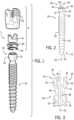
- FIG. 1is an exploded perspective view of a bone anchor assembly, in accordance with a representative embodiment of the present disclosure.
- FIG. 2is a perspective side view of the shank of FIG. 1 .
- FIG. 3is a cross-sectional side view of the head of the shank of FIG. 1 .
- FIG. 4is a perspective view of the receiver of FIG. 1 .
- FIG. 5is a cross-sectional side view of the receiver of FIG. 1 .
- FIG. 6is a perspective view of the insert of FIG. 1 .
- FIG. 7is a cross-sectional side view of the insert of FIG. 1 .
- FIG. 8is a perspective view of the positioner of FIG. 1 .
- FIG. 9is a cross-sectional side view of the positioner of FIG. 1 .
- FIG. 10is a perspective view of the retainer of FIG. 1 .
- FIG. 11is a cross-sectional side view of the retainer of FIG. 1 .
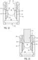
- FIG. 12is a cross-sectional side view of the receiver with the insert positioned therein.
- FIG. 13is a cross-sectional side view of the receiver with the insert and a distal end of a splay tool positioned therein.
- FIG. 14is a cross-sectional side view of the receiver with the insert and a distal end of the splay tool positioned therein, where the insert is proximally displaced.
- FIG. 15is a cross-sectional side view of the receiver with the insert positioned in its second axial position, where the positioner is being uploaded through the bottom opening of the receiver.
- FIG. 16is a cross-sectional side view of the receiver, insert, and positioner, where the retainer is proximally advanced through the bottom opening of the receiver and into the expansion chamber of the receiver.
- FIG. 17is a cross-sectional side view of the receiver, insert, and positioner, where the retainer is proximally advanced through the bottom opening of the receiver and into engagement with the positioner.
- FIG. 18is a cross-sectional side view of the receiver, insert, positioner, and retainer of FIG. 17 , with the shank being proximally advanced relative to the receiver.
- FIG. 19is a cross-sectional side view of the receiver, insert, positioner, and retainer of FIG. 17 , with the shank being further proximally advanced so as to radially expand the positioner and retainer within the receiver expansion chamber.
- FIG. 20is a cross-sectional side view of the receiver, insert, positioner, and retainer of FIG. 17 , with the shank being further proximally advanced past the positioner and retainer such that the retainer snaps onto a distal side of the head of the shank.
- FIG. 21is a cross-sectional side view of the receiver, insert, positioner, retainer, and shank of FIG. 20 , with the insert being distally advanced into engagement with the head end of the shank.
- FIG. 22is a cross-sectional side view of the receiver, insert, positioner, retainer, and shank, with a connecting rod and closure top securing the shank in a particular orientation relative to the receiver.
- FIG. 23is an exploded perspective view of a bone anchor assembly that can be selectively configured for multi-planar or mono-planar pivoting motion, in accordance with another representative embodiment of the present disclosure.
- FIG. 24is a perspective side view of the shank of FIG. 23 .
- FIG. 25is a cross-sectional side view of the head end of the shank of FIG. 23 .
- FIG. 26is a perspective view of the receiver of FIG. 23 .
- FIG. 27is a cross-sectional side view of the receiver of FIG. 23 .
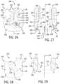
- FIG. 28is a perspective view of the insert of FIG. 23 .
- FIG. 29is a cross-sectional side view of the insert of FIG. 23 .
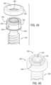
- FIG. 30is a perspective view of the positioner of FIG. 23 .
- FIG. 31is a cross-sectional side view of the positioner of FIG. 23 .
- FIG. 32is a perspective view of the retainer of FIG. 23 .
- FIG. 33is a cross-sectional side view of the retainer of FIG. 23 .
- FIG. 34is a cross-sectional side view of the receiver, the insert, and the positioner of FIG. 23 , with the insert and positioner being proximally advanced towards a distal opening of the receiver.
- FIG. 35is a cross-sectional side view of the receiver FIG. 34 with the insert and positioner being seated within the receiver.
- FIG. 36is a cross-sectional side view of the receiver, insert, and positioner of FIG. 34 , with the retainer being proximally advanced through the bottom opening of the receiver and into the receiver expansion chamber.
- FIG. 37is a cross-sectional side view of the receiver, insert, positioner, and retainer of FIG. 34 , with the insert and positioner being distally advanced so as to engage the retainer and thereby position the retainer and positioner within the receiver expansion chamber to form a receiver sub-assembly in an as-shipped configuration.
- FIG. 38is a perspective view of the collet members of FIG. 23 .
- FIG. 39is a cross-sectional side view of the collet members of FIG. 23 .
- FIG. 40is a perspective view of the collet lock sleeve of FIG. 23 .
- FIG. 41is a cross-sectional side view of the collet lock sleeve of FIG. 23 .
- FIG. 42is an exploded perspective view of the head end of the shank, a pair of collet members, ball bearings, and the collet lock sleeve of FIG. 23 .
- FIG. 43is a perspective view of the pair of collet members of FIG. 23 fitted to the head of the shank, and the ball bearings and the collet lock sleeve prior to assembly to the collet members.
- FIG. 44is a perspective view of the pair of collet members of FIG. 23 fitted to the head of the shank, the ball bearings fitted within openings in the collet members, and the collet lock sleeve prior to assembly around the collet members.
- FIG. 45is a perspective view of the of the assembly shank sub-assembly having the pair of collet members of FIG. 23 fitted to the head of the shank, the ball bearings fitted within openings in the collet members, and the collet lock sleeve fitted around the pair of collet members and ball bearings.
- FIG. 46is a cross-sectional side view of the shank sub-assembly of FIG. 23 with ball bearings.
- FIG. 47is a cross-sectional side view of the shank sub-assembly of FIG. 23 without ball bearings.
- FIG. 48is a cross-sectional side view of the shank sub-assembly of FIG. 23 with ball bearings and a receiver assembly including a receiver, insert, positioner, and retainer.
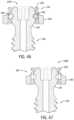
- FIG. 49is a cross-sectional side view of the shank sub-assembly of FIG. 48 with ball bearings being proximally advanced towards the receiver sub-assembly that includes the receiver, the insert, the positioner, and the retainer.
- FIG. 50is a cross-sectional side view of the shank sub-assembly of FIG. 48 with ball bearings being proximally advanced through a bottom opening of the receiver of the receiver sub-assembly.
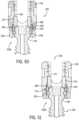
- FIG. 51is a cross-sectional side view of the shank sub-assembly of FIG. 48 with ball bearings being proximally further advanced within the receiver sub-assembly so as to proximally advance the insert and positioner and to allow the retainer ring to become engaged within a locking groove of the collet members.
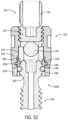
- FIG. 52is a cross-sectional side view of the shank sub-assembly of FIG. 23 with ball bearings secured within the receiver assembly of FIG. 23 , and with a connecting member and a closure further locking the shank in a particular mono-planar (into the paper) orientation relative to the receiver.
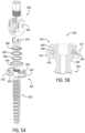
- FIG. 53is a cross-sectional side view of the shank sub-assembly of FIG. 23 , without ball bearings, secured within the receiver assembly of FIG. 23 , and with a connecting member and a closure further locking the shank in a particular multi-planar orientation relative to the receiver.
- FIG. 54is an exploded perspective view of a bone anchor assembly, in accordance with another representative embodiment of the present disclosure.
- FIG. 55is a perspective view of the bone clearing ring of FIG. 54 .
- FIG. 56is a perspective view of the pair of collet members of FIG. 54 .
- FIG. 57is a perspective view of the collet lock sleeve of FIG. 54 .
- FIG. 58is a cross-sectional side view of the shank sub-assembly and receiver sub-assembly of FIG. 54 with ball bearings and the bone clearing ring.
- FIG. 59is a cross-sectional side view of the shank sub-assembly and receiver sub-assembly of FIG. 54 with the bone clearing ring being moved downwardly by the distal end of the receiver as the shank sub-assembly is being proximally advanced through the bottom opening of the receiver.
- FIG. 60is a cross-sectional side view of the shank sub-assembly and receiver sub-assembly of FIG. 54 with the bone clearing ring being moved into the circumferential notch of the collet lock sleeve as the shank sub-assembly is being secured within the bottom opening of the receiver.
- FIGS. 1 - 22illustrate a bone anchor apparatus or assembly 1 configured for multi-planar or polyaxial motion, in accordance with one representative embodiment of the present disclosure.
- the bone anchor for the assembly 1is generally a polyaxial bone screw, such as spherical universal shank 20 , it is foreseen that the disclosure could be utilized with other types of spinal implants that utilize pressure inserts, such as polyaxial bone hooks or clamps, for example.
- the bone anchor assembly 1generally includes a spherical universal shank 20 and a receiver sub-assembly 4 that further includes a receiver 40 , a pressure insert 70 , a positioner 80 , and a retainer ring or retainer 90 .
- the bone anchor assembly 1can also include a closure 14 ( FIG. 22 ).
- the bone anchor assembly 1is generally adapted for use with an elongate rod or connecting member 10 ( FIG. 22 ).
- the receiver sub-assembly 4including the receiver 40 , the retainer ring 90 , the positioner 80 , and the insert 70 , may be pre-assembled at a manufacturing facility prior to shipping, and then may be further assembled with the spherical universal shank 20 either prior or subsequent to implantation of the shank 20 into a vertebra (not shown), as will be described in greater detail below.
- the receiver sub-assembly 4 and the spherical universal shank 20cooperate in such a manner that the receiver sub-assembly 4 and the shank 20 can be secured at any of a plurality of angles, angulation, articulations, or angular alignments relative to one another and within a selected range of angles from side to side and from front to rear, to enable flexible or articulated engagement of the receiver sub-assembly with respect to the shank 20 until both are locked or fixed relative to each other near the end of an implantation procedure, as seen, for example, in FIG. 22 , for optimal surgical relationship with the spinal column.
- the spherical universal shank 20can comprise an elongate body 22 having a distal end 21 and a proximal end 29 opposite the distal end.
- the elongate shank body 22can further include a helically wound bone implantable thread 26 (single or multi start thread forms, which can have various types of thread patterns and cross sections) extending from near the neck 28 to the tip 24 of the body 22 and extending radially outwardly therefrom.
- the body 22can utilize the thread 26 for gripping and advancement as it is implanted into the vertebra (not shown) leading with the tip 24 and driven down into the vertebra with a suitable installation or driving tool (not shown), so as to be implanted into the vertebra to up near the neck 28 .
- the shank 20can also have a longitudinal centerline axis of rotation 25 .
- the proximal end 29 of the spherical universal shank 20can further include a shank head 30 having a substantially spherically-shaped outer surface 31 , with two opposed, co-linear bores 32 extending radially inward from the outer surface 31 toward the longitudinal axis 25 of the shank 20 .
- the radial bores 32can be closed bores of predetermined diameter and depth, and can have a conically-shaped end walls of pre-determined size and shape.
- the radial bores 32are generally configured to receive a pair of spherical ball bearings that are operable, in combination with a coupler sub-assembly, to restrict or limit the motion of the spherical universal shank 20 relative to the receiver to mono-planar motion. Absent the ball bearings and the coupler sub-assembly, however, and per the embodiment of the bone anchor assembly 1 shown in FIG. 1 , the spherical universal shank 20 is free to move relative to the receiver 40 with polyaxial or multi-planar motion until locked into an angular position by the final engagement of the rod 10 and closure 14 within the receiver sub-assembly 4 , as shown in FIG. 22 .
- the shank head 30can also include a tool engagement structure 36 or drive feature aligned with the longitudinal axis 25 of the shank 20 and extending downwardly or inwardly from the top end 35 of the spherical head 30 .
- the top end 35 of the spherical head 30can further include a plurality of outwardly projecting insert engagement structures, such as concentric ridges 34 .
- the insert engagement structurescan be configured to engage or dig into a concave bottom surface of the pressure insert 70 ( FIG. 1 ) so as to establish a more secure friction or interference fit between the proximal end 29 of the shank 20 and the insert 70 when the two components are ultimately locked together, as shown in FIG. 22 .
- the receiver component 40 of the receiver sub-assembly 4is illustrated in detail in FIGS. 4 - 5 , and generally includes a substantially cylindrical base 42 having a central cavity or bore 44 that is centered around a longitudinal axis 45 of the receiver 40 .
- the bore 44opens to the bottom surface 47 of the base 42 through bottom or distal opening 43 .
- Integral with the base 42is a pair of opposed upstanding arms 50 and 51 forming a cradle and defining a channel 52 between the arms 50 and 51 with an upper opening, generally 58 , and a U-shaped lower seat 54 , the channel 52 having a width for operably receiving the rod 10 between the arms 50 , 51 , as best seen in FIG. 22 .
- Each of the arms 50 and 51has an interior surface 53 that includes various inner cylindrical profiles and a discontinuous partial helically-wound guide and advancement structure 56 located adjacent top surfaces of each of the arms 50 , 51 . It is foreseen that the receiver may further include extensions (not shown) attached to the arms 50 , 51 having break off junctures to the arms. The breakoff extensions can also have internal threads.
- the discontinuous guide and advancement structure 56can be a partial helically wound reverse angle thread form configured to mate under rotation with a similar fastener structure 15 formed into the closure 14 ( FIG. 22 ).
- the guide and advancement structure 56could alternatively be a square-shaped thread, a buttress thread, an interlocking flange form or other thread-like or non-thread-like helically wound and non-helically wound discontinuous advancement structure for operably guiding, under complete or partial rotation, and advancing the closure 14 downward between the arms 50 , 51 , as well as eventual torqueing when a bottom of the closure 14 abuts against the rod 10 .
- the closure 14need not have a breakoff head 16 in certain embodiments.
- an opposed pair of first tool receiving and engaging apertures or indentations 55can be formed into outer side surfaces of the illustrated arms 50 , 51 .
- an additional two pairs of second tool receiving and engaging apertures 57may be formed in front and rear surfaces of the arms 50 , 51 .
- Some or all of the apertures 55 and 57may be used for holding the receiver 40 during the implantation of the shank body 22 ( FIG. 2 ) into a vertebra when the shank is pre-assembled with the receiver 40 , and during assembly of the bone anchor assembly 1 with the rod 10 and the closure structure 14 .
- the tool receiving grooves or apertures 55 and 57may be configured in a variety of shapes and sizes and be disposed at other locations on the receiver arms 50 , 51 , such as near the top of the receiver arms in the form of horizontal radiused grooves.
- a discontinuous insert attachment structuresuch as rounded ridge 60 , that extends inwardly from the interior surface 53 of the receiver arms 50 , 51 .
- Adjacent to and located below the insert attachment ridge 60is a cylindrically-shaped surface 62 that is oriented substantially parallel to the receiver longitudinal axis 45 , and that is sized and shaped to receive the compression insert 70 , as will be described in greater detail below.
- the cylindrical surface 62extends downward from the insert attachment ridge 60 to surround the U-shaped lower seat 54 of the channel 52 . Above the seat 54 the cylindrical surface 62 is by definition discontinuous, while below the seat 54 the cylindrical surface 62 can smoothly merge into a continuous cylindrical sidewall surface that defines the upper portion of the bore 44 .
- the cylindrical surface 62can have an internal diameter that is sized to slidably receive the outer diameter of the insert 70 as it is inserted upwardly into the bore 44 and open channel 52 through the bottom opening 43 toward engagement with the insert attachment structure 60 .
- the interior surfaces 53 of the receiver arms 50 , 51can further include spaced-apart guide projections 59 projecting inward into the channel 52 below the insert attachment structure 60 and having opposing faces that define guide surfaces 69 which slidably engage with corresponding cut-out side surfaces 78 of the insert 70 to prevent the insert from rotating within the receiver 40 upon insertion into the bore 44 .
- An upper annular shelf or stop surface 63is located below the cylindrical surface 62 , and is disposed substantially perpendicular to the receiver longitudinal axis 45 to form an upper stop for the positioner 80 , prohibiting the positioner 80 from moving upwardly into the upper portion of the bore 44 that receives the compression insert 70 .
- the upper stop surface 63can further define the upper surface of an expansion chamber 48 , with cylindrical surface 64 and lower annular shelf or stop surface 65 further defining the sidewall surface and lower surface of the expansion chamber 48 , respectively.
- the lower annular stop surface 65is also disposed substantially perpendicular to the receiver longitudinal axis 45 , and has an inner boundary at a downwardly-extending intermediate cylindrical surface 66 having a diameter that is greater than the diameter of cylindrical surface 62 that defines the upper portion of the bore 44 .
- the intermediate cylindrical surface 66extends downward to a lower annular step or seating surface 67 .
- Lower annular step surface 67in turn extends inward to another downwardly-extending distal cylindrical surface 68 having a diameter less than the diameter of the intermediate cylindrical surface 66 , and that defines the distal or bottom opening 43 of the receiver 40 .
- the intermediate cylindrical surface 66 and lower annular step surface 67can together define, in stepwise fashion, a locking chamber 46 that ultimately receives and secures the non-pivoting retainer 90 to the receiver 40 upon completion of the bone anchor assembly, wherein the non-pivoting retainer 90 seated on the annular step surface 67 can expand slightly outward to frictionally engage the cylindrical surface 66 , when in a locked position, as is shown, for example, in FIG. 22 .
- the upper stop surface 63 , the sidewall cylindrical surface 64 , and the lower stop surface 65partially define a circumferential recess or expansion chamber 48 that is sized and shaped to house the positioner 80 and to receive the non-pivoting retainer 90 as it expands around the spherical head 30 of the shank as the head 30 moves upwardly through the bore 44 during assembly.
- the expansion chamber 48forms a restriction to prevent the positioner 80 from moving upwardly with the shank head 30 , with the annular upper stop surface 63 preventing the positioner 80 , and ultimately the non-pivoting retainer 60 from passing from the expansion chamber 48 into the upper portion of the bore 44 , whether the non-pivoting retainer 90 is in an expanded state or in a nominal or neutral state (i.e., without compression or tension).
- Distal cylindrical surface 68can be joined or connected to an exterior bottom surface 47 of the base 42 by one or more beveled, curved or conical surfaces, and defines the bottom opening 43 of the receiver 40 .
- the lower opening 43is circularly shaped having a diameter or width or radius (not shown) measured from one side of the distal cylindrical surface 68 to the next.
- the distal cylindrical surface 68can have a diameter that is substantially the same as the diameter of the cylindrical surface 62 of the upper bore 44 , allowing for slidable uploading of the compression insert 70 while requiring compression or squeezing of both the non-pivoting retainer 90 and the positioner 80 during their uploading into the receiver 40 through the lower opening 43 .
- the friction fit compression or pressure insert 70is sized and shaped to be loaded into the bore 44 of the receiver 40 , for example, through the bottom opening 43 .
- the illustrated insert 70has a central axis 75 operationally aligned with the central axis 45 of the receiver 40 .
- a concave shank head engagement surface 71 formed into the bottom face of the insert 70advantageously frictionally engages with the outer surface 31 of the bone screw shank head 30 , allowing for un-locked, but non-floppy placement of the angle of the shank 20 with respect to the receiver 40 during surgery, prior to locking of the shank 20 with respect to the receiver 40 near the end of the procedure with a rod or connecting member 10 and a closure 14 , as shown in FIG. 22 .
- the insert 70may be made from a resilient material, such as a stainless steel or titanium alloy, or a polymer, or some combination thereof, so that portions of the insert may be expanded about and then contracted, snapped or popped onto the shank head 30 as well as over the insert attachment ridge 60 . Furthermore, in operation, the insert 70 is suspended within the receiver 40 , being frictionally held in place by the insert attachment ridge 60 projecting inward from the inner surfaces 53 of the receiver upright arms 50 , 51 . In this way the insert 70 is be prohibited from moving upward or downward until deployed, even during the initial insertion of the shank head 30 into the receiver 40 .
- a resilient materialsuch as a stainless steel or titanium alloy, or a polymer, or some combination thereof
- the illustrated insert 70generally includes a substantially cylindrically shaped lower body 72 with a pair of spaced apart upstanding arms 76 having top surfaces 77 .
- the upstanding arms 76can have a cylindrically-shaped outer surface on each side which are substantially smooth and vertically or axially opposed, but radially spaced from the center axis 75 .
- the outer surface of each arm 76can further include a circumferentially-extending rounded receiver attachment recess 79 spaced a predetermined distance from the top surfaces 77 thereof.
- Each receiver attachment recess 79can extend discontinuously circumferentially about the outer surface of the arm 76 , and can have a width and radius of curvature that is substantially similar to the width and radius of curvature of the complimentary insert attachment ridge 60 projecting inward from the inner surfaces 53 of the receiver upright arms 50 , 51 ( FIGS. 4 - 5 ).
- the inner surfaces of the insert upstanding arms 76can include proximal-facing saddle or seating surfaces 73 that form a U-shaped insert channel 73 ′ therebetween for receiving and engaging the underside surface of the elongate rod.
- the bore 74is defined by an inner cylindrical surface that is at least partially bounded on the upper end by the U-shaped channel seating surfaces 73 and on the lower end by the concave shank head engagement surface 71 .
- the through bore 74is sized and shaped to receive a driving tool (not shown) there through that can engage with the shank tool engagement structure 36 when the shank body is driven into bone with the receiver attached or without.
- the insert shank head engagement surface 71may comprise a roughened or textured surface or surface finish, or may be scored, grit blasted, knurled, or the like, for enhancing frictional engagement with the shank head 30 .
- the sides of the insert upstanding arms 76can further include cut-out sections with flat side surfaces 78 that are size and shaped to be received between the spaced-apart guide projections 59 projecting inward into the receiver channel 52 below the insert attachment structure 60 .
- the insert flat side surfaces 78can slidably engage with the opposing receiver guide surfaces 69 in a manner that allows for upward and downward translation of the insert 70 within the receiver bore 44 while preventing rotation of the insert around the receiver longitudinal centerline axis 45 .
- the positioner 80can generally comprise an open ring-shaped body made from a resilient material, such as a stainless steel, titanium alloy, cobalt chrome, or the like, as well as polymers, or some combination thereof, so that the positioner 80 may be expanded and contracted during various steps of assembly, as will be described in greater detail below.
- the positioner 80can also have a central axis that is operationally aligned with both the receiver axis 45 and the central axis of the non-pivoting retainer 90 , and that may also be aligned with shank axis 25 .
- the ring-shaped positioner 80has a central aperture, generally 83 , that passes entirely through the positioner body from a top surface 81 to a bottom surface 89 thereof.
- the surfaces that define the aperture 83include a discontinuous upper inner cylindrical surface 84 adjacent the top surface 81 , a discontinuous shelf or abutment surface 85 adjacent the upper inner cylindrical surface 84 , and a discontinuous lower inner cylindrical surface 86 , with each surface being coaxial with the positioner axis 85 when the positioner 80 is in a neutral non-compressed, non-expanded orientation or state.
- the upper inner cylindrical surface 84can have a curvature similar to that of the outer surface 31 of the spherical shank head 30 , so as to mate better with the curved surface of the shank head 30 .
- the positioner 80further includes an outer cylindrical surface 88 that is also oriented parallel to the positioner central axis.
- the positioner 80can further include a lower lip 87 projecting inward from the bottom of the lower inner cylindrical surface 86 adjacent the bottom surface 89 .
- the lower lip 87can be useful for better capturing or securing the retaining ring within the positioner in the as-shipped configuration, as described in more detail below.
- the resilient positioner 80further includes first and second end surfaces 82 disposed in spaced relation to one another when the retainer is in a neutral non-compressed state. Both end surfaces 82 can be disposed substantially perpendicular to the top surface 81 and the bottom surface 89 . A gap having nominal width between the end surfaces 82 is determined by a desired amount of compressibility of the open positioner 80 when loaded into the receiver 40 .
- the space shown in FIG. 8provides adequate space between the end surfaces 82 for the positioner 80 to be pinched, with the end surfaces 82 compressed toward one another to a closely spaced or even touching configuration, if necessary, to an extent that the compressed positioner 80 is up or bottom loadable through the receiver bottom opening 43 , as shown in FIG. 15 .
- the positioner 80After passing through the receiver bottom opening 43 and upward to the upper annular shelf or stop surface 63 , the positioner 80 can be allowed to expand or spring back to an original uncompressed, rounded or collar-like configuration, as shown in FIG. 16 .
- the embodiment of the resilient positioner 80 shown in FIG. 8illustrates the end surfaces 82 as being substantially parallel; however, it is foreseen that it may be desirable to orient the end surfaces obliquely or at a slight angle depending upon the amount of compression desired during loading of the positioner 80 into the receiver 40 .
- the non-pivoting retainer 90can generally comprise an open ring-shaped body made from a resilient material, such as a stainless steel or titanium alloy, cobalt chrome, or the like, or a polymer, or some combination thereof, so that the non-pivoting retainer 90 may be expanded during various steps of assembly, as will be described in greater detail below. It is foreseen that the retainer 90 may be made of a softer metal compared to that of the positioner 80 , so that the positioner 80 is able to overpower or be structurally stronger than the non-pivoting retainer 90 in assembly.
- a resilient materialsuch as a stainless steel or titanium alloy, cobalt chrome, or the like, or a polymer, or some combination thereof.
- the retainer 90may be made of a softer metal compared to that of the positioner 80 , so that the positioner 80 is able to overpower or be structurally stronger than the non-pivoting retainer 90 in assembly.
- the non-pivoting retainer 90has a central aperture 93 that passes entirely through the retainer 90 from a top surface 91 to a bottom surface 99 thereof.
- the non-pivoting retainer 90is configured to not pivot with the shank 20 ( FIGS. 2 - 3 ), but is situated to ultimately stay within the confines of the receiver locking chamber 46 ( FIG. 5 ).
- Surfaces that define the central aperture 93include a discontinuous upper inner curvate surface 94 adjacent the top surface 91 and a discontinuous lower inner curvate surface 96 adjacent the bottom surface 99 .
- a narrow substantially-planar midline surface 95can separate the upper inner curvate surface 94 and the lower inner curvate surface 96 at the midline between the top surface 91 and the bottom surface 99 , as shown in FIGS. 10 - 11 .
- the upper and lower inner curvate surfacescan seamlessly merge together to form one continuous inner curvate surface that defines the central aperture 93 .
- the non-pivoting retainer 90further includes an outer cylindrical surface 98 extending between the top surface 91 and the bottom surface 99 .
- the outer surface 98is oriented parallel to the retainer axis 95 , and it is foreseen that the outer corners located about either the top surface 91 or bottom surface 99 could be rounded or beveled as needed. It is also foreseen that two or more evenly spaced notches or bumps (not shown) may be formed in the top surface 91 , outer surface 98 , or bottom surface 99 to more evenly distribute stress across the entire non-pivoting retainer 90 during contraction and expansion thereof.
- the resilient non-pivoting retainer 90further includes first and second end surfaces 92 disposed in opposed spaced relation to one another when the retainer 90 is in a neutral non-compressed state. Both end surfaces 92 can be disposed substantially perpendicular to the top surface 91 and the bottom surface 99 and parallel with retainer axis 95 .
- the embodiment shown in FIG. 10shows the slit or gap between the end surfaces 92 as being substantially parallel; however, it is foreseen that it may be desirable to orient the end surfaces obliquely or at a slight angle, depending upon the amount of compression desired during loading of the non-pivoting retainer 90 into the receiver 40 .
- a gap of nominal width between the end surfaces 92can be determined by a desired amount of compressibility of the open non-pivoting retainer ring 90 when loaded into the receiver 40 .
- the gapgenerally provides adequate space between the end surfaces 92 for the non-pivoting retainer 90 to be pinched, with the end surfaces being compressed toward one another to a closely spaced or even touching configuration, if necessary, to an extent that the compressed non-pivoting retainer 90 is up loadable through the receiver opening 43 , as seen in FIG. 16 .
- the non-pivoting retainer 90can be allowed to expand or spring back to its nominal and uncompressed collar-like shape.
- the end portions of the retainer 90 adjacent the end surfaces 92can be overlappingly compressed together in order to reduce the diameter of the retainer 90 to the point that the retainer will fit through the bottom opening 43 in the receiver 40 .
- top surface 91 and portions of the outer surface 98 of the retainer 90may additionally or alternatively include a roughened or textured surface or surface finish, or may be scored, knurled, grit blasted, or the like, for enhancing frictional engagement with the intermediate cylindrical inner surface 66 of the receiver locking chamber 46 , as well as the interior of the positioner 80 .
- the additional surface treatmentmay be useful for preventing or limiting rotational movement of the retainer 90 with respect to the positioner 80 and/or retainer 40 after assembly and before reaching the final locked configuration.
- FIGS. 12 - 17illustrate the sequential assembly of all the separate components of the receiver sub-assembly 4 into an ‘as-shipped’ configuration, at which the receiver sub-assembly 4 is configured for a simple ‘snap-fit’ assembly step onto the head 30 of the universal spherical shank 20 .
- the pre-assembly of the receiver sub-assembly 4can take place in a controlled factory or manufacturing setting.
- FIGS. 18 - 21then illustrate the assembly or coupling of the pre-assembled receiver sub-assembly 4 with the universal spherical shank 20 , such as would take place within or near to an operating room setting by a medical professional, such as by a surgical technician or by the surgeon herself.
- An illustration of one exemplary final configuration of the assembled bone screw assembly 1 that includes the elongate rod 10 secured within receiver channel 52 by the closure 14is then provided in FIG. 22 .
- the insert 70 , positioner 80 , and retainer ring 90can be bottom-loaded through the distal opening 43 of the receiver 40 during pre-assembly of the receiver sub-assembly 4 .
- the insert 70is first inserted through the distal opening 43 and proximally advanced through the bore 44 and into the channel 52 of the receiver 40 , until the top surfaces 77 of the insert upstanding arms 76 abut against the rounded bottom portion of the inwardly-projecting discontinuous insert attachment ridge 60 .
- the insert 70is in a first axial position with further proximal advancement of the insert 70 within the receiver 40 being restricted by the insert attachment ridge 60 .
- a distal end 9 of a splay tool 8can be advanced distally into the U-shaped channel 52 of the receiver 40 to separate, splay, or slightly outwardly flex the opposing upright arms 50 , 51 of the receiver 40 and temporarily expand the receiver channel 52 .
- the insert 70may then be further proximally advanced to a second, upper-most axial position in which the circumferential receiver attachment recesses 79 formed into the outer surface of the insert upstanding arms 76 are axially aligned with and cover the corresponding insert attachment ridge 60 projecting from the inner surface 53 of the receiver arms 50 , 51 , as shown in FIG. 14 .
- the splay tool 8may be removed so that the opposing upright arms 50 , 51 of the receiver 40 can return to their earlier non-flexed positions and the insert attachment ridge 60 is captured within the circumferential receiver attachment recesses 79 of the insert arms 76 ( FIGS. 6 - 7 ), so that downward pressure applied either by tooling or by the elongate rod member is now required to downwardly displace or deploy the insert 70 from its second axial position back to the first axial position.
- the insert 70can be firmly secured and maintained in its upper-most second axial position within the receiver 40 throughout shipping and even through the first snap-fit step of coupling the receiver sub-assembly 4 to the shank 20 with only the positioner 80 and retainer 90 , as described below.
- the positioner 80can be compressed or pinched (e.g. with an external force), as described above, so that its end surfaces 82 approach each other and its diameter is reduced sufficiently for the positioner 80 to be uploaded through the receiver distal or bottom opening 43 and proximally advanced into the expansion chamber 48 . As shown in FIG. 16 , the compression force can then be released and the positioner 80 allowed to expand back to its neutral or nominal size within the expansion chamber 48 .
- the diameter of the positioner's outer cylindrical surface 88can be greater than the diameter of the receiver's inner cylindrical surface 62 that defines the upper bore 44 , so that the top surface 81 of the positioner 80 in its nominal and uncompressed state will abut the upper annular shelf or stop surface 63 that defines the upper surface of the expansion chamber 48 and be prevented from moving further upward into the upper portion of the receiver bore 44 .
- the retainer 90can be compressed or pinched (e.g. with an external force) as described above, so that its end surfaces 92 approach or overlap each other and its diameter is reduced sufficiently for the retainer 90 to be uploaded through the receiver distal or bottom opening 43 and proximally advanced into the expansion chamber 48 to contact the overlying discontinuous shelf surface 85 of the positioner 80 . As shown in FIG.
- the compression forcecan then be released and the retainer 90 allowed to expand back toward its neutral or nominal size so as to be firmly captured by the internal surfaces of the positioner 80 , including the overlying shelf surface 85 , the lower inner cylindrical surface 86 , and the lower lip 87 projecting inward from the bottom of the lower inner cylindrical surface 86 .
- the non-pivoting retainer 90can be adjusted such that the retainer top surface 91 abuts against the overlying positioner shelf surface 85 while the retainer outer surface 98 mates against the positioner lower inner cylindrical surface 86 with a friction fit, and with the positioner 80 being designed to compress slightly the non-pivoting retainer 90 within the interior confines or surfaces of the aperture 83 , and thereby secure the retainer 90 into position within the positioner 80 .
- the gap between the positioner end faces 82can be held a little wider while the positioner 80 applies a compressive force to the retainer 90 , so that the gap between the retainer end faces 92 is at least partially closed.
- the structural interaction of the positioner 80 and the non-pivoting retainer ring 90can maintain the two components in a substantially concentric relationship and in a dynamic pre-loaded state.
- the retainer 90 and the positioner 80can also be situated or aligned together such that the gaps between their respective end faces 92 , 82 are situated parallel with each other. It will also be appreciated, however, that this configuration with aligned gaps is not required in order for the combination to function as intended.
- positioner 80 and retainer 90are uploaded separately into the retainer 40 in the illustrated embodiment, it will nevertheless be understood that the positioner 80 and the retainer 90 in combination may also be uploaded together into the receiver 40 , as opposed to loading them separately as shown.
- FIG. 17further illustrates a preferred ‘as-shipped’ configuration or shipping state of the completed receiver sub-assembly 4 , in which the retainer 90 is received within the positioner 80 while the positioner 80 , in turn, is received within the expansion chamber 48 formed into the lower portion of the bore 44 of the receiver 40 .
- the insert 70is also received and secured within the channel 52 and the upper portion of the receiver bore 44 in its uppermost second axial position.
- the bottom of the insertcan also be sufficiently spaced above the top surface 81 of the positioner 80 so as to provide adequate clearance for the later step of pushing the shank head 30 upward through the apertures 93 , 83 of the non-pivoting retainer 90 and positioner 80 , respectively, without the shank head 30 becoming prematurely engaged with or restricted by the concave shank head engagement surface 71 of the insert 70 .
- the pre-assembled receiver sub-assembly 4is now ready for shipment as well as for assembly with the shank 20 either at the factory, at the spine company, by surgery staff prior to implantation, or directly after implanting the shank 20 by the surgeon.
- the as-shipped receiver sub-assembly 4may be coupled or snap-fit with the shank 20 by proximally advancing the head 30 of spherical universal shank 20 (with empty radial bores 32 ) through the distal opening 43 of the receiver 40 until the upper surface 31 of the spherical head abuts against the non-pivoting retainer 90 , held down by the positioner 80 .
- the non-pivoting retainer 90 and positioner 80 in combinationare lifted up by the shank 20 .
- the proximal driving of the shank 20causes the top surface 81 of the positioner 80 to abut against the upper annular shelf or stop surface 63 ( FIG.
- the proximal (upward, as seen in FIG. 19 ) driving of the shank 20causes the upper spherical surface 31 of the shank head 30 to abut against the discontinuous lower inner curvate surface 96 of the retainer 90 , thereby causing the retainer 90 and the positioner 80 to radially expand as the shank head 30 proximally displaces into the confines of the bore 44 of the receiver 40 .
- the non-pivoting retainer 90 and positioner 80have reached a maximum expansion about the shank head 30 at the point where the narrow midline surface 95 of the retainer 90 is situated about the maximum diameter or equator of the spherical head 30 of the shank 20 , just prior to capture the shank head within the receiver 40 .
- the cylindrical outer surface 88 of the positioner 80also approaches the cylindrical inner sidewall surface 64 of the expansion chamber 48 .
- the shank head 30continues to move proximally until the upper inner cylindrical surface 84 of the positioner 80 becomes situated about the maximum diameter or equator of the spherical head 30 of the shank 20 , with the retainer moving slightly below the maximum diameter or equator of the spherical head 30 so that the upper inner curvate surface 94 of the retainer 90 presses against lower outer surface 31 of the shank head 30 .
- the angled interface at this positioncan create a downwardly directed force on the retainer 90 that causes the retainer 90 to release and separate from the positioner 80 and snap downward around the lower portion of shank head 30 as it re-establishes its nominal shape or state.
- the shankcan now be moved or pulled back downward until the retainer 90 enters and positions itself into the locking chamber 46 , thereby capturing the shank head 30 with the receiver 40 .
- the positioner 80which has also now contracted back into nominal shape, also prevents or limits upward movement of the non-pivoting retainer 90 once the retainer is seated within the locking chamber 46 .
- the positioner 80stays within the confines of the expansion chamber 48 . Therefore, distal or opposite displacement of the shank head 30 fully seats the retainer 90 against the lower annular seating surface 67 and the intermediate cylindrical surface 66 in the lower portion of the retainer bore 44 , also known as the locking chamber 46 .
- the seating of the retainer 90captures and prevents the shank head 30 from exiting the distal or bottom opening 43 in the receiver 40 , as the diameter of the shank head 30 exceeds the inner diameter of the retainer seated within the locking chamber 46 that is proximate to the distal opening 43 in the receiver 40 .
- the shank head 30 at this pointcannot be pulled out of the receiver 40 .
- the non-pivoting retainer 90is also stabilized, aligned, constrained, and restrained on the shank head 30 with respect to pivotal, rotational, and elevational alignments by means of the positioner 80 .
- the positioner 80cannot enter the locking chamber 46 , the positioner 80 does not participate in capturing the shank head 30 , and only the retainer 90 captures the shank and prevents the shank from exiting the lower opening of the receiver 40 . It is foreseen that while the positioner 80 may, in some aspects, include a friction fit with the shank, in such a case the positioner would not prohibit the downward escape of the shank 20 , but only serve to restrict upward or proximal movement of the shank.
- the compression insert 70is pressed or deployed downwardly by a tool, such as a screw driver (not shown), back toward the shank head 30 and the first axial position described above, in which the top surfaces 77 of the insert upstanding arms 76 once again abut against the rounded bottom portion of the inwardly-projecting discontinuous insert attachment ridge 60 .
- a toolsuch as a screw driver (not shown)
- the distance the insert 70 travels from the second uppermost axial position to the lower first axial positioncan generally correspond with the distance between the spherical concave engagement surface 71 formed into the bottom face of the insert 70 and the outer surface 31 of the spherical shank head 30 .
- the lower concave surface 71 of the insertcan become frictionally engaged with the outer surface 31 of the bone screw shank head 30 , without penetration of the insert engagement structures (e.g. upper ridges 34 ) into the surface of the insert concave surface, so as to create a tight, non-floppy, substantially spherical ball and socket joint between the shank head 30 and the spherical concave surface 71 of the insert 70 .
- the insert engagement structurese.g. upper ridges 34
- the friction fit between the compression insert 70 and the shank head 30is not totally locked or fixed, but at the same time is not loose or floppy either, advantageously allowing the user to articulate the shank 20 with respect to the receiver 40 by application of manual or tool associated pressure or force, but with some resistance, so that when the shank 20 is placed in a desired orientation with respect to the receiver 40 , the bone anchor assembly 1 remains substantially frictionally set in such desired orientation unless purposefully manipulated into another position.
- the shank 20(or an entire bone screw assembly 1 made up of the universal spherical shank 20 with or without, the non-pivoting retainer 90 , positioner 80 , receiver 40 , and compression insert 70 ) is screwed into a bone or vertebra, by rotation of the shank 20 using a suitable driving tool or tool assembly (not shown) that operably drives and rotates the shank body 22 by engagement thereof at the internal drive or tool engagement structure 36 .
- the shank 20 , the other bone screw assembly parts (also having a central lumen in some embodiments), the rod 10 and the closure top 14 (also with a central bore drive)can be inserted in a percutaneous or minimally invasive surgical manner, utilizing guide wires (not shown) with or without minimally invasive guide tools.
- the shank 20When the shank 20 is driven into the vertebra without the remainder of the bone screw assembly 1 , the shank 20 may either be driven to a desired final location or may be driven to a location slightly above the final location or “proud” to provide for ease in assembly with the receiver sub-assembly 4 .
- the pre-assembled receiver 40 , insert 70 , positioner 80 , and non-pivoting retainer 90can be placed above the shank head 30 until the shank head 30 is received within the distal or bottom opening 43 of the receiver 40 .
- the rod 10is eventually positioned in an open or percutaneous manner in cooperation with the at least two bone screw assemblies 1 .
- the closure 14is then inserted into and advanced between the upright arms 50 , 51 of the receiver 40 .
- the closure 14can comprise a fastener 15 with a break-off head 16 .
- the closure 14can further comprise any of a variety of different types of closure structures for use in conjunction with the present disclosure with suitable mating structure on the upstanding arms 50 , 51 of the receiver 40 .
- the closure 14can comprise a nested fastener, such as the nested fastener-type closure described in U.S. patent application Ser. No. 11/140,343, now U.S. Pat. No. 7,776,067, the entirety of which is incorporated by reference herein.
- the closure structure 14can press downwardly against the upper surface of the elongate rod 10 to bias the rod into engagement with the insert 70 , thereby urging the shank head 30 toward the lower opening 43 of the retainer 40 and into locking engagement with the non-pivoting retainer 90 that is frictionally abutting the lower annular step or seating surface 67 .
- This downwardly directed forcecan, in turn, cause the retainer 90 to expand slightly outward to the engage and lock against the intermediate cylindrical surface 66 . As shown in FIG.
- both the smooth spherical surface 31 and the stepped upper ridges 34 of the shank head 30can enter into frictional engagement with the concave spherical surface 71 of the compression insert 70 .
- a configurable pivotable bone anchor apparatus or assembly 100that can be selectively configured for multi-planar or mono-planar pivoting motion.
- the bone anchor for the assembly 100can generally be a polyaxial bone screw, such as a spherical universal shank 120
- the structure and features of the present disclosurecould also be utilized with other types of spinal implants that utilize pressure inserts, such as polyaxial bone hooks or clamps, and the like.
- the selectively configurable multi-planar or mono-planar bone anchor assembly 100generally includes a spherical universal shank 120 and a receiver sub-assembly 104 that generally includes a receiver 140 , a pressure insert 170 , a positioner 180 , and a retainer ring 190 .
- the bone anchor assembly 100is generally adapted for use with an elongate rod or connecting member 110 ( FIGS. 52 , 53 ), and can also can also include a closure 114 that secures the elongate rod 110 to the receiver sub-assembly 104 .
- the spherical universal shank 120can also be a component of a shank sub-assembly 102 that further includes a coupler 210 or split coupler assembly comprising a pair of collet members 220 , a collet lock sleeve 240 , and optionally, a pair of ball bearings 250 .
- the coupler 210can provide for a snap fit between the receiver sub-assembly 104 and the shank sub-assembly 102 .
- the receiver sub-assembly 104may be initially pre-assembled at a manufacturing facility prior to shipping.
- the shank sub-assembly 102including the spherical universal shank 210 , the collet 220 , the collet lock sleeve 240 , and optionally the ball bearings 250 , 252 may also be initially pre-assembled prior to shipping.
- the receiver sub-assembly 104 and the shank sub-assembly 102may be further assembled either prior or subsequent to implantation of the shank 120 into a vertebra (not shown), as will be described in greater detail below.
- the shank sub-assembly 102 and the receiver sub-assembly 104can cooperate in such a manner that the receiver sub-assembly 104 and the shank sub-assembly can be secured at any of a plurality of angles, angulation, articulations, or angular alignments relative to one another (i.e. multi-planar motion) and within a selected range of angles from side to side and from front to rear, to enable flexible or articulated engagement of the receiver sub-assembly with the shank sub-assembly until both are locked or fixed with respect to each other near the end of an implantation procedure.
- the bone anchor assembly 100may be selectively configured or confined to mono-planar motion. In the selectively-configured mono-planar embodiment, for example, the bone anchor assembly may be configured in a sagittal configuration or a transverse configuration.
- the spherical universal shank 120 depicted in FIGS. 23 - 25also includes a shank distal end 121 and a shank proximal end 129 opposite the shank distal end.
- the shank 120is elongate, with the shank body 122 having a helically wound bone implantable thread 126 (single or multi start thread forms, which can have various types of thread patterns and cross sections) extending from near the neck 128 to the tip 124 of the body 122 and extending radially outwardly therefrom.
- the body 122utilizes the thread 126 for gripping and advancement as it is implanted into the vertebra (not shown) leading with the tip 124 and driven down into the vertebra with a suitable installation or driving tool (not shown), so as to be implanted into the vertebra to up near the neck 128 .
- the shank 120has a longitudinal axis of rotation 125 .
- the proximal end 129 of the spherical universal shank 120can further include a shank head 130 having a substantially spherically-shaped outer surface 131 , with two opposed, co-linear bores 132 extending radially inward from the outer surface 131 toward the longitudinal axis 125 of the shank 120 .
- the radial bores 132can be closed bores of predetermined diameter and depth, and can have a conically-shaped end walls of pre-determined size and shape.
- the radial bores 132are generally configured to receive a pair of spherical ball bearings 250 that are operable, in combination with the coupler sub-assembly or coupler 210 , to restrict or limit the motion of the spherical universal shank 120 relative to the receiver 140 to mono-planar motion. Absent the ball bearings 250 , however, the spherical universal shank 120 is free to move relative to the receiver 140 with polyaxial or multi-planar motion until locked into an angular position or orientation by the final engagement of the rod 110 and closure 114 within the receiver sub-assembly 104 .
- the shank head 130can also include a tool engagement structure 136 or drive feature aligned with the longitudinal axis 125 of the shank 120 and extending downwardly or inwardly from the top end 135 of the spherical head 130 .
- the top end 135 of the spherical head 130can further include a plurality of projecting insert engagement structures, such as concentric ridges 134 .
- the insert engagement structurescan be configured to engage or dig into the concave bottom surface 171 of the pressure insert 170 ( FIG. 29 ) so as to establish a more secure friction or interference fit between the proximal end 129 of the shank 120 and the insert 170 when the two components are ultimately locked together, as shown in FIGS. 52 and 53 .
- the receiver component 140 of the receiver sub-assembly 104is illustrated in detail in FIGS. 26 - 27 , and generally includes a substantially cylindrical base 142 having a central cavity or bore 144 that is centered around a longitudinal axis 145 of the receiver 140 . At the distal end 141 of the receiver 140 the bore 144 opens to the bottom surface 147 of the base 142 through bottom or distal opening 143 .
- Integral with the base 142is a pair of opposed upstanding arms 150 and 151 forming a cradle and defining a channel 152 between the arms 150 and 151 with an upper opening, generally 158 , and a U-shaped lower seat 154 , the channel 152 having a width for operably receiving the rod 110 between the arms 150 , 151 , as best seen in FIGS. 52 - 53 .
- Each of the arms 150 and 151has an interior surface 153 that includes both inner cylindrical surface 160 and non-cylindrical surface 162 profiles, and a discontinuous partial helically-wound guide and advancement structure 156 located adjacent the top surfaces of each of the arms 150 , 151 .
- the receivermay further include extensions (not shown) attached to the arms 150 , 151 having break off junctures to the arms. The breakoff extensions can also have internal threads.
- the central bore 144 of the receiver 140is in communication with the U-shaped channel 152 and can extend upwardly from the bottom or distal opening 143 up to the upper or proximal opening 158 .
- the lower portion of the bore 144can include a cylindrical expansion chamber 148 for receiving the retainer 190 therein, as well as a cylindrical coupler chamber 146 for receiving both the positioner 180 and coupler 210 therein.
- the bore 144is in communication with the U-shaped channel 152 , and can include both the center channel surface 160 and the vertically-directed side recess 162 formed into the inner surfaces 153 of the upstanding arms 150 , 151 for slidably receiving at least of a portion of the insert 170 therein.
- the discontinuous guide and advancement structure 156can be a partial helically wound reverse angle thread form configured to mate under rotation with a similar fastener structure 115 formed into the closure 114 ( FIGS. 52 - 53 ).
- the guide and advancement structure 156could alternatively be a square-shaped thread, a buttress thread, an interlocking flange form or other thread-like or non-thread-like helically wound and non-helically wound discontinuous advancement structure for operably guiding, under complete or partial rotation, and advancing the closure 114 downward between the arms 150 , 151 , as well as eventual torqueing when a bottom of the closure 114 abuts against the rod 110 .
- the closure 114need not have a breakoff head 116 in certain embodiments.
- first tool receiving and engaging apertures or indentations 155can be formed into outer side surfaces of the illustrated arms 150 , 151 .
- second tool receiving and engaging apertures 157may be formed in front and rear surfaces of the arms 150 , 151 . Some or all of the apertures 155 and 157 may be used for holding the receiver 140 during the implantation of the shank body 122 ( FIG. 24 ) into a vertebra when the shank is pre-assembled with the receiver 140 , and during assembly of the bone anchor assembly 100 with the rod 110 and the closure structure 114 .
- the tool receiving grooves or apertures 155 and 157may be configured in a variety of shapes and sizes and be disposed at other locations on the receiver arms 150 , 151 , such as near the top of the receiver arms in the form of horizontal radiused grooves.
- each center channel surface 160is the vertically-directed side recess 162 having an upper stop surface 161 .
- the side recesscan be size and shaped to slidably receive the shaped upright arms 176 of the compression insert 170 so as to prevent the insert from rotating within the receiver 140 upon insertion into the bore 144 .
- An upper shelf or stop surface 163is located below both the center channel surface 16 and the side recess 162 , and is disposed substantially perpendicular to the receiver longitudinal axis 45 to form an upper stop for the positioner 180 , prohibiting the positioner 180 from moving upwardly into the upper portion of the bore 144 that receives the compression insert 70 .
- the upper stop surface 163can further define the upper surface of the coupler chamber 46 , with cylindrical surface 164 further defining the sidewall surface of the coupler chamber 146 that extends downwardly to an annular shelf or stop surface 165 that extends radially outward from cylindrical surface 164 .
- the upper stop surface 163 and the sidewall cylindrical surface 164partially define a cylindrical coupler chamber 146 that is sized and shaped to house the positioner 180 and a lower portion of the insert 170 prior to the uploading of the shank sub-assembly to the receiver sub-assembly.
- the coupler chamberis also sized and shaped to receive the coupler 210 surrounding the spherical head 130 of the shank 120 during uploading, as the shank sub-assembly 102 moves upwardly through the bore 144 during assembly.
- Annular shelf or stop surface 165defines the upper surface of the expansion chamber 148 , with cylindrical surface 166 and lower annular shelf or stop surface 167 further defining the sidewall surface and lower surface of the expansion chamber 148 , respectively.
- the lower annular stop surface 167is also disposed substantially perpendicular to the receiver longitudinal axis 145 , and has an inner boundary at a downwardly-extending distal cylindrical surface 168 that defines the distal or bottom opening 143 of the receiver 140 .
- distal cylindrical surface 168can have a diameter that is substantially the same as the diameter of the cylindrical surface 164 of the coupler chamber 146 , allowing for slidable uploading of the compression insert together with the positioner while requiring compression or squeezing of the non-pivoting retainer during uploading into the receiver through the lower opening 43 , as described in more detail below.
- Distal cylindrical surface 168can be joined or connected to an exterior base surface 147 of the base 142 by one or more beveled, curved or conical surfaces, and defines the bottom opening 143 of the receiver 140 .
- an insert attachment structuresuch as projecting ridges 169 , that extend inwardly from the lower interior surface 153 of the receiver arms 150 , 151 .
- the projecting insert attachment ridges 169are spaced apart by the side recess 162 and configured to engage within complimentary receiver attachment groove structures formed into the arms 176 of the insert 170 .
- the compression or pressure insert 170is sized and shaped to be loaded into the bore 144 of the receiver 140 through the bottom opening 143 .
- the illustrated insert 170has a central axis 175 operationally aligned with the central axis 145 of the receiver 140 .
- a concave shank head engagement surface 171 formed into the bottom face of the insert 170advantageously frictionally engages with the outer surface 131 of the bone screw shank head 130 , allowing for un-locked, but non-floppy placement of the angle of the shank 120 with respect to the receiver 140 during surgery, prior to locking of the shank 120 with respect to the receiver 140 near the end of the procedure with a rod or connecting member 110 and a closure 114 , as shown in FIGS. 52 - 53 .
- the insert 170may be made from a resilient material, such as a stainless steel or titanium alloy, or a polymer, or some combination thereof, so that portions of the insert may be expanded about and then contracted, snapped or popped onto the shank head 130 as well as over the insert attachment ridges 169 . Furthermore, in the as-shipped configuration ( FIG. 41 ) the insert 170 is suspended within the receiver 140 , being frictionally held in place by the insert attachment ridges 169 projecting inward from the lower inner surfaces 153 of the receiver upright arms 150 , 151 ( FIGS. 26 - 27 ).
- a resilient materialsuch as a stainless steel or titanium alloy, or a polymer, or some combination thereof
- the insert 170is prohibited from moving either upward or downward out of the receiver distal opening 143 during shipping and storage, and is held in place until deployment of the insert through the insertion of the shank sub-assembly 102 into the receiver sub-assembly 104 .
- the illustrated insert 170generally includes a substantially cylindrically shaped lower body 172 with a pair of spaced apart upstanding arms 176 having top surfaces 177 .
- the inner surfaces of the insert upstanding arms 176can include proximal-facing saddle or seating surfaces 173 that form a U-shaped insert channel 173 ′ therebetween for receiving and engaging the underside surface of the elongate rod.
- the bore 174is defined by an inner cylindrical surface that is at least partially bounded on the upper end by the U-shaped channel seating surfaces 713 and on the lower end by the concave shank head engagement surface 171 .
- the through bore 174is sized and shaped to receive a driving tool (not shown) therethrough that can engage with the shank tool engagement structure 136 when the shank body is driven into bone with the receiver attached.
- a driving tool(not shown)
- the insert shank head engagement surface 171may comprise a roughened or textured surface or surface finish, or may be scored, grit blasted, knurled, or the like (not shown), for enhancing frictional engagement with the shank head 30 .
- the center portion of the outer surface of the upstanding arms 176can be shaped with a curved but non-cylindrical profile that slidably engages with the vertically-directed side recess 162 formed into the interior surface 153 of the receiver arms 150 , 151 , so as to prevent the insert from rotating within the receiver 140 upon insertion into the bore 144 .
- each arm 176can further include one or more receiver attachment grooves 179 spaced a predetermined distance from the top surfaces 177 thereof.
- Each receiver attachment groove 179can have a width and radius of curvature that is substantially similar to the width and radius of curvature of the complimentary insert attachment ridges 169 projecting inward from the lower inner surfaces 153 of the receiver upright arms 150 , 151 ( FIGS. 26 - 27 ).
- the positioner 180can generally comprise a ring-shaped body made from a rigid solid material, such as a stainless steel, titanium alloy, cobalt chrome, or the like, as well as polymers, or some combination thereof, as is generally fixed in both size and shape.
- the positioner 180can also have a central axis that is operationally aligned with both the receiver axis 145 and the central axis of the non-pivoting retainer 190 , and that may also be aligned with shank axis 125 .
- the ring-shaped positioner 180has a central aperture, generally 183 , that passes entirely through the positioner body from a top surface 181 to a bottom surface 189 thereof.
- the central aperture 183can be sized to slide over the cylindrically shaped lower body 172 of the insert 170 with a small clearance.
- the surfaces that defines the aperture 183further include a discontinuous inner cylindrical surface 182 that is broken by opposed recesses or cutouts 184 having the same shape or profile as the outer surface of the upstanding arms 176 of the insert 170 . This allows the positioner 180 to slide up over the lower body 172 of the insert 170 and into a keyed or “clocked” arrangement with the outer surfaces of the insert arms, so as to prevent relative rotation between the two components.
- the positioner 180further includes an outer cylindrical surface 186 that is also oriented parallel to the positioner central axis.
- the outer cylindrical surface 186further includes an upper lip 185 and a lower lip 187 projecting radially outward from the upper and lower edges of the outer cylindrical surface 186 to form a shallow, laterally-directed recess that is sized to capture (or to be capture by) the thickness of the non-pivoting retainer 190 when positioned in the as-shipped configuration ( FIG. 41 ), as described in more detail below.
- shallow scalloped surfaces 188can be formed into the top surface 181 of the positioner 180 and orthogonal to the cut-outs 184 formed into the inner cylindrical surface 182 , so as to provide additional clearance for the elongate rod 110 or connecting member when the bone anchor assembly 100 is assembled into a final and locked configuration.
- the non-pivoting retainer 190can generally comprise an open ring-shaped body made from a resilient material, such as a stainless steel or titanium alloy, cobalt chrome, or the like, or a polymer, or some combination thereof, so that the non-pivoting retainer 190 may be expanded during various steps of assembly, as will be described in greater detail below
- the non-pivoting retainer 190has a central aperture 193 that passes entirely through the retainer 190 from a top surface 191 to a bottom surface 199 thereof.
- the non-pivoting retainer 190is configured to not pivot with the shank 120 or shank sub-assembly 102 , but is situated to ultimately stay within the confines of the receiver expansion chamber 148 ( FIG. 27 ).
- the central aperture 193can be defined by an inner cylindrical surface 194 extending between the top surface 191 and the bottom surface 199 , and it is foreseen that the inner corners located about either the top surface 191 or bottom surface 199 could be rounded or beveled as needed.
- the non-pivoting retainer 190further includes both an inner cylindrical surface 194 and an outer cylindrical surface 196 extending between the top surface 191 and the bottom surface 199 .
- the outer surface 196is oriented parallel to the retainer axis 195 , and it is foreseen that the outer corners located about either the top surface 191 or bottom surface 199 could also be rounded or beveled as needed. It is also foreseen that two or more evenly spaced notches or bumps (not shown) may be formed in the top surface 191 , outer surface 198 , or bottom surface 199 to more evenly distribute stress across the entire non-pivoting retainer 190 during contraction and expansion thereof.
- the resilient non-pivoting retainer 190further includes first and second end surfaces 192 disposed in opposed spaced relation to one another when the retainer 190 is in a nominal or neutral state (i.e., without compression or tension). Both end surfaces 192 can be disposed substantially perpendicular to the top surface 191 and the bottom surface 199 and parallel with retainer axis 195 .
- the embodiment shown in FIG. 32shows the slit or gap between the end surfaces 192 as being substantially parallel; however, it is foreseen that it may be desirable to orient the end surfaces obliquely or at a slight angle, depending upon the amount of compression desired during loading of the non-pivoting retainer 190 into the receiver 140 .
- a gap of nominal width between the end surfaces 192can be determined by a desired amount of compressibility of the open non-pivoting retainer ring 190 when loaded into the receiver 140 .
- the gapgenerally provides adequate space between the end surfaces 192 for the non-pivoting retainer 190 to be pinched, with the end surfaces being compressed toward one another to a closely spaced or even touching configuration, if necessary, to an extent that the compressed non-pivoting retainer 190 is up loadable through the receiver opening 143 , as seen in FIG. 40 .
- the non-pivoting retainer 190After passing upward through the retainer bottom opening 143 to the expansion chamber 148 , the non-pivoting retainer 190 is allowed to expand or spring back to its nominal and uncompressed collar-like shape.
- the end portions of the retainer 190 adjacent the end surfaces 193can be overlappingly compressed together in order to reduce the diameter of the retainer 190 to the point that the retainer will fit through the bottom opening 143 in the receiver 140
- FIGS. 34 - 37illustrate one representative method for assembling all the separate components of the receiver sub-assembly 104 into an ‘as-shipped’ configuration, at which the receiver sub-assembly 104 is configured for a simple ‘snap-fit’ assembly step onto the coupler 210 of the shank sub-assembly 102 .
- the pre-assembly of the receiver sub-assembly 4can take place in a controlled factory or manufacturing setting.
- FIGS. 52 - 53illustrate the assembly or coupling of the pre-assembled receiver sub-assembly 104 with the pre-assembled shank sub-assembly 102 , such as would take place within or near to an operating room setting by a medical professional, such as by a surgical technician or by the surgeon herself. Illustrations of two exemplary final configurations of the assembled bone screw assembly 100 that includes the elongate rod 110 secured within receiver channel 152 by the closure 114 , are then provided in FIGS. 52 - 53 .
- the positioner 180can be loosely assembled around the outer surface of the insert 170 , with the shaped outer profiles of the insert arms 176 being received into the cutouts 184 ( FIG. 30 ) formed into the inner cylindrical surface of the positioner 180 .
- the two componentscan then be uploaded together through the bottom opening 143 in the receiver 140 until the insert 170 is received within the upper portion of the bore 144 defined by the center channel surface 160 and the vertically-directed side recess 162 formed into the inner surfaces 153 of the upstanding arms 150 , 151 , as shown in FIG. 35 .
- the top surfaces 177 of the insert 170can abut against upper stop surface 161 of the side recess 162 and the top surface 181 of the positioner 180 abuts against upper shelf or stop surface 163 of the coupler chamber 146 .
- the retainer ring 190can then be compressed or pinched (e.g. with an external force) as described above, so that its end surfaces 192 approach or overlap each other and its diameter is reduced sufficiently for the retainer 190 to be uploaded through the receiver distal or bottom opening 143 and proximally advanced into the expansion chamber 148 , where it is allowed to expand back toward its neutral or nominal size so as to be captured within the expansion chamber 148 by the upper annular shelf or stop surface 165 and the lower annular shelf or stop surface 167 that define the upper and lower surfaces of the expansion chamber 148 , respectively.
- the insert 170 and positioner 180can then be moved together back downward toward the lower portion of the bore 144 until the receiver attachment grooves 179 ( FIG. 28 ) formed into the upper side surfaces of each insert arm 176 surround and engage with the insert attachment ridges 169 projecting inward from the lower inner surfaces 153 of the receiver upright arms 150 , 151 ( FIGS. 26 - 27 ). With the rounded upper outer portions of the insert arms 176 still received with the complimentary rounded lower portions of the side recesses 162 , the upper portion of the insert 170 is securely supported within the bore 144 of the receiver 140 .
- the outer cylindrical surface 186 of the positioner 180becomes engaged with the inner cylindrical surface 194 of the retainer ring 190 , thereby pushing the retainer ring further radially outward into the expansion chamber 148 .
- the upper lip 185 and the lower lip 187 projecting radially outward from the upper and lower edges of the positioner's outer cylindrical surface 186engage with the upper surface 191 and lower surface 199 of the retainer 190 .
- the coupler 210 or split coupler assemblyincludes a pair of symmetrical half-ring collet members 220 , a collet lock sleeve 240 , and optionally a pair of ball bearings 250 .
- the collet lock sleeve 240is configured to press fit the two symmetrical half ring collet members 220 together around the spherical head 130 of the universal spherical shank 120 such that the inner surfaces of the completed split coupler assembly 210 and outer surface 131 of the spherical head 130 have a friction fit arrangement.
- each half ring collet member 220 of the coupler 210has a top edge or surface 221 , a bottom edge or surface 229 , and includes an outer surface 222 with a circumferential locking groove 224 , a sleeve engagement surface 226 and a lower projecting flange 228 for engaging with a complimentary rabbet groove 249 formed into an inner surface 242 of the collet lock sleeve 240 .
- Each collet memberalso includes an inner surface 232 with a spherical portion 234 configured to surround and contact the spherical surface 131 of the spherical shank head 130 .
- the collet members 220may further include opposed spaced apart through bores 230 extending from the outer surface 222 to the inner surface 232 , and configured such that the bores 230 of the collet members 220 can be aligned with the bores 132 of the spherical shank head 130 when the combined collet members 220 surround the spherical shank head 130 . It will be appreciated that the spherical universal shank 120 and the coupler 210 may be pre-assembled together to form the shank sub-assembly 102 .
- the collet lock sleeve 240generally comprises a solid ring body having an inner surface 242 that defines a through bore 243 extending from the top surface to the bottom surface, and which inner surface can be configured to mate to the sleeve engagement surface 226 , in one aspect, with a slight press fit.
- the upper end surface 241 of the collet lock sleeve 240can also includes a shaped profile, such as angular profile 247 , which is configured to engage with a bottom edge surface of the receiver to form a second rabbet joint that firmly secures the coupler 210 to the bottom of the receiver 140 .
- FIGS. 42 - 45One representative method for assembling the coupler 210 or split coupler assembly around the spherical head 130 of the universal spherical shank 120 is illustrated in FIGS. 42 - 45 .
- the pair of symmetrical half-ring collet members 220are first positioned and clamped around the spherical head 130 , with the spherical portion 234 of each collet member's inner surface 232 becoming engaged with the spherical surface 131 of the spherical shank head 130 .
- either the clamped-together collet members 220can be rotated around the head 130 of the shank 120 , or the head of the shank can be rotated within the clamped-together collet members 220 , until the opposed through bores 230 of the collet members 220 align with the opposed radial bores 132 formed into the shank head 130 .
- the ball bearings 250can then be inserted into the through bores 230 until the outermost surfaces are flush with the outer sleeve engagement surface 226 of the collet members 220 .
- the shank sub-assembly 102 A, 102 Bmay be configured to facilitate different movements of the spherical universal shank 120 relative to the receiver sub-assembly (e.g., mono-planar, multi-planar, favored angle, sagittal, transverse) depending on a particular configuration of the coupler 210 .
- the bone anchor assembly 100can be configured for multi-planar and mono-planar motion of the universal spherical shank 120 either by excluding or by including the ball bearings 250 , respectively, within the bores 132 , 230 of the assembled spherical shank head 130 and half ring collet members 220 .
- the shank sub-assembly 102 Amay be configured to facilitate mono-planar motion of the shank 120 relative to the receiver 140 .
- the couplermay include the two ball bearings 250 , as seen in FIG. 46 , that are configured to fit within the bores 230 , 132 of the collet 220 and spherical shank head 130 to limit the bone anchor assembly 100 to movement in a single plane.
- the shank sub-assembly 102 Bmay be configured to facilitate multi-planar motion of the shank 120 relative to the receiver 140 .
- the bores of the collet 220 and spherical shank head 130remain empty, as seen in FIG. 47 . Leaving the bores empty 230 , 132 provides for the spherical shank head 130 to rotate and angulate freely within the collet 220 and receiver sub-assembly until all are locked or fixed relative to each other.
- the receiver sub-assembly 104 in the as-shipped configurationmay be coupled using a snap-fit arrangement with the shank sub-assembly 102 , also in the as-shipped configuration, with the shank subassembly 102 being moved towards the receiver subassembly 104 (or vice versa) so that the coupler 210 approaches the bottom or distal opening 143 of the receiver bore.
- the proximal end of the shank 120then comes into contact with the distal inner spherical surface 171 of the insert 170 as the shank sub-assembly is forced proximally relative to the receiver 140 .
- the retainer ring 190snaps into the locking groove 224 on the ring members 220 of the collet 220 .
- the retainer ring 190is positioned within the expansion chamber 148 and is constrained from proximal and distal movement by the opposing distal and proximal walls of the chamber 148 .
- the coupler and shank 120are also prevented or restrained from distally displacing relative to the receiver 140 .
- a rodmay be positioned within the U-shaped channel 152 , 173 ′ of the receiver 140 and insert 170 , respectively, and a closure 114 may be threadably engaged with the receiver 140 to secure a distal force on the rod, which in turn, is forced against the proximal cylindrical surface 173 of the insert 170 .
- the motion of the shank 120is limited to mono-planar motion (i.e. into and out of the plane of the paper) with respect to the receiver 140 .
- the motion of the shank 120is not limited to mono-planar motion, and may instead pivot with respect to the receiver 140 with a multi-planar or polyaxial motion.
- the bone anchor assembly 300may further include a bone clearing mechanism or ring 460 to prevent biological material from entering and clogging certain portions of the assembly.
- a bone clearing mechanism or ring 460to prevent biological material from entering and clogging certain portions of the assembly.
- bone debrismay fill the circumferential locking groove 424 on the outer surface of the half-ring collet members 420 .
- the shank sub-assembly 302may include a bone clearing ring 460 to protect the circumferential locking groove 424 from bone debris during implantation.
- the collet lock sleeve 440may further include an inner surface with a circumferential notch 448 .
- the bone clearing ring 446Prior to installation, the bone clearing ring 446 is configured to be positioned within the circumferential locking groove 424 of the half-ring collet members 420 , as seen in FIG. 58 .
- the bone clearing ring 460is pushed distally into the circumferential notch 448 in the collet lock sleeve 440 by the distal surface of the receiver 340 , as see in FIG. 59 .
- the bone clearing ring 460may abut the ball bearing 450 , if present, on one side and the distal surface of the receiver 340 on an adjacent side.
- the various components of the bone anchor assemblies described hereinmay include dissimilar metals selected for parts in mutual contact with each other to encourage component penetration under locking conditions.
- the bone anchor assemblies described hereininclude non-pivoting retainers (i.e., the retainer rings do not pivot with the shank relative to the receiver), it is foreseen that the bone anchor assemblies may include pivoting retainers, such as those described in PCT/US15/56706, which is incorporated by reference in its entirety into the present application.
Landscapes
- Health & Medical Sciences (AREA)
- Orthopedic Medicine & Surgery (AREA)
- Life Sciences & Earth Sciences (AREA)
- Surgery (AREA)
- Neurology (AREA)
- Heart & Thoracic Surgery (AREA)
- Engineering & Computer Science (AREA)
- Biomedical Technology (AREA)
- Nuclear Medicine, Radiotherapy & Molecular Imaging (AREA)
- Medical Informatics (AREA)
- Molecular Biology (AREA)
- Animal Behavior & Ethology (AREA)
- General Health & Medical Sciences (AREA)
- Public Health (AREA)
- Veterinary Medicine (AREA)
- Surgical Instruments (AREA)
Abstract
Description
Claims (20)
Priority Applications (4)
| Application Number | Priority Date | Filing Date | Title |
|---|---|---|---|
| US16/719,561US12167872B2 (en) | 2014-10-21 | 2019-12-18 | Bottom loaded pivotal bone anchor assembly with locking and blocking rings and insert tool deployment |
| US18/174,391US20230200861A1 (en) | 2014-10-21 | 2023-02-24 | Pivotal bone anchor assembly with insert configured for forced downward displacement by tooling |
| US18/313,000US12082853B2 (en) | 2014-10-21 | 2023-05-05 | Pivotal bone anchor assembly with positioner-retainer containment and insert tool deployment |
| US18/827,706US20240423683A1 (en) | 2014-10-21 | 2024-09-07 | Pivotal bone anchor assembly with pre-securement of an insert into a receiver |
Applications Claiming Priority (17)
| Application Number | Priority Date | Filing Date | Title |
|---|---|---|---|
| US201462066806P | 2014-10-21 | 2014-10-21 | |
| US201462066813P | 2014-10-21 | 2014-10-21 | |
| US201462078154P | 2014-11-11 | 2014-11-11 | |
| US201462078173P | 2014-11-11 | 2014-11-11 | |
| US201562137707P | 2015-03-24 | 2015-03-24 | |
| US201562137713P | 2015-03-24 | 2015-03-24 | |
| US201562194955P | 2015-07-21 | 2015-07-21 | |
| US201562200501P | 2015-08-03 | 2015-08-03 | |
| US201562200491P | 2015-08-03 | 2015-08-03 | |
| US201562212253P | 2015-08-31 | 2015-08-31 | |
| PCT/US2015/056706WO2016065033A1 (en) | 2014-10-21 | 2015-10-21 | Snap-on multi-planar and mono-planar receiver assemblies having integral and multi-part multipurpose positioners for pivoting and non-pivoting retainers |
| US201662352876P | 2016-06-21 | 2016-06-21 | |
| US201662362830P | 2016-07-15 | 2016-07-15 | |
| US201715521163A | 2017-04-21 | 2017-04-21 | |
| US15/629,709US9924975B2 (en) | 2014-10-21 | 2017-06-21 | Bone anchor having a snap-fit assembly |
| US15/897,486US10543021B2 (en) | 2014-10-21 | 2018-02-15 | Pivotal bone anchor assembly having an open ring positioner for a retainer |
| US16/719,561US12167872B2 (en) | 2014-10-21 | 2019-12-18 | Bottom loaded pivotal bone anchor assembly with locking and blocking rings and insert tool deployment |
Related Parent Applications (1)
| Application Number | Title | Priority Date | Filing Date |
|---|---|---|---|
| US15/897,486ContinuationUS10543021B2 (en) | 2014-10-21 | 2018-02-15 | Pivotal bone anchor assembly having an open ring positioner for a retainer |
Related Child Applications (1)
| Application Number | Title | Priority Date | Filing Date |
|---|---|---|---|
| US18/174,391ContinuationUS20230200861A1 (en) | 2014-10-21 | 2023-02-24 | Pivotal bone anchor assembly with insert configured for forced downward displacement by tooling |
Publications (2)
| Publication Number | Publication Date |
|---|---|
| US20200121368A1 US20200121368A1 (en) | 2020-04-23 |
| US12167872B2true US12167872B2 (en) | 2024-12-17 |
Family
ID=86898642
Family Applications (5)
| Application Number | Title | Priority Date | Filing Date |
|---|---|---|---|
| US15/897,486ActiveUS10543021B2 (en) | 2014-10-21 | 2018-02-15 | Pivotal bone anchor assembly having an open ring positioner for a retainer |
| US16/719,561ActiveUS12167872B2 (en) | 2014-10-21 | 2019-12-18 | Bottom loaded pivotal bone anchor assembly with locking and blocking rings and insert tool deployment |
| US18/174,391PendingUS20230200861A1 (en) | 2014-10-21 | 2023-02-24 | Pivotal bone anchor assembly with insert configured for forced downward displacement by tooling |
| US18/313,000ActiveUS12082853B2 (en) | 2014-10-21 | 2023-05-05 | Pivotal bone anchor assembly with positioner-retainer containment and insert tool deployment |
| US18/827,706PendingUS20240423683A1 (en) | 2014-10-21 | 2024-09-07 | Pivotal bone anchor assembly with pre-securement of an insert into a receiver |
Family Applications Before (1)
| Application Number | Title | Priority Date | Filing Date |
|---|---|---|---|
| US15/897,486ActiveUS10543021B2 (en) | 2014-10-21 | 2018-02-15 | Pivotal bone anchor assembly having an open ring positioner for a retainer |
Family Applications After (3)
| Application Number | Title | Priority Date | Filing Date |
|---|---|---|---|
| US18/174,391PendingUS20230200861A1 (en) | 2014-10-21 | 2023-02-24 | Pivotal bone anchor assembly with insert configured for forced downward displacement by tooling |
| US18/313,000ActiveUS12082853B2 (en) | 2014-10-21 | 2023-05-05 | Pivotal bone anchor assembly with positioner-retainer containment and insert tool deployment |
| US18/827,706PendingUS20240423683A1 (en) | 2014-10-21 | 2024-09-07 | Pivotal bone anchor assembly with pre-securement of an insert into a receiver |
Country Status (1)
| Country | Link |
|---|---|
| US (5) | US10543021B2 (en) |
Cited By (1)
| Publication number | Priority date | Publication date | Assignee | Title |
|---|---|---|---|---|
| US12295621B2 (en) | 2014-06-13 | 2025-05-13 | Orthopediatrics Corp. | Bottom loaded pedicle screw |
Families Citing this family (11)
| Publication number | Priority date | Publication date | Assignee | Title |
|---|---|---|---|---|
| US11219471B2 (en) | 2014-10-21 | 2022-01-11 | Roger P. Jackson | Pivotal bone anchor receiver having an insert with post-placement tool deployment |
| US10543021B2 (en) | 2014-10-21 | 2020-01-28 | Roger P. Jackson | Pivotal bone anchor assembly having an open ring positioner for a retainer |
| US11109895B2 (en)* | 2016-10-26 | 2021-09-07 | Warsaw Orthopedic, Inc. | Spinal construct |
| US10695102B2 (en)* | 2017-12-15 | 2020-06-30 | Warsaw Orthopedic, Inc. | Spinal implant system and methods of use |
| US10695100B2 (en)* | 2017-12-15 | 2020-06-30 | Warsaw Orthopedic, Inc. | Spinal implant system and methods of use |
| US11026723B2 (en)* | 2019-04-10 | 2021-06-08 | Warsaw Orthopedic, Inc. | Pedicle screw assemblies with 3D printed components |
| US11298170B2 (en)* | 2019-05-17 | 2022-04-12 | Warsaw Orthopedic, Inc. | Spinal implant system and methods of use |
| WO2021127251A1 (en)* | 2019-12-17 | 2021-06-24 | Jackson Roger P | Bone anchor assembly with closed ring retainer and internal snap ring |
| US12161318B2 (en)* | 2020-12-01 | 2024-12-10 | Dunamis Medical Technologies, Llc | Re-tensionable suture anchor system and related methods |
| US20230301689A1 (en)* | 2022-03-25 | 2023-09-28 | Globus Medical, Inc. | Stabilizing bones using screws and rods |
| US20230355279A1 (en)* | 2022-05-04 | 2023-11-09 | Corelink, Llc | Bone Screw for Attaching Rod to Bone |
Citations (186)
| Publication number | Priority date | Publication date | Assignee | Title |
|---|---|---|---|---|
| US5669911A (en) | 1995-04-13 | 1997-09-23 | Fastenetix, L.L.C. | Polyaxial pedicle screw |
| US5672176A (en) | 1995-03-15 | 1997-09-30 | Biedermann; Lutz | Anchoring member |
| US5733286A (en) | 1997-02-12 | 1998-03-31 | Third Millennium Engineering, Llc | Rod securing polyaxial locking screw and coupling element assembly |
| US5782833A (en) | 1996-12-20 | 1998-07-21 | Haider; Thomas T. | Pedicle screw system for osteosynthesis |
| US5797911A (en) | 1996-09-24 | 1998-08-25 | Sdgi Holdings, Inc. | Multi-axial bone screw assembly |
| US5885286A (en) | 1996-09-24 | 1999-03-23 | Sdgi Holdings, Inc. | Multi-axial bone screw assembly |
| US6010503A (en) | 1998-04-03 | 2000-01-04 | Spinal Innovations, Llc | Locking mechanism |
| US6063090A (en) | 1996-12-12 | 2000-05-16 | Synthes (U.S.A.) | Device for connecting a longitudinal support to a pedicle screw |
| US6074391A (en) | 1997-06-16 | 2000-06-13 | Howmedica Gmbh | Receiving part for a retaining component of a vertebral column implant |
| US6090111A (en) | 1998-06-17 | 2000-07-18 | Surgical Dynamics, Inc. | Device for securing spinal rods |
| US6146383A (en) | 1998-02-02 | 2000-11-14 | Sulzer Orthopadie Ag | Pivotal securing system at a bone screw |
| US6187005B1 (en) | 1998-09-11 | 2001-02-13 | Synthes (Usa) | Variable angle spinal fixation system |
| US6254602B1 (en) | 1999-05-28 | 2001-07-03 | Sdgi Holdings, Inc. | Advanced coupling device using shape-memory technology |
| US6280442B1 (en) | 1999-09-01 | 2001-08-28 | Sdgi Holdings, Inc. | Multi-axial bone screw assembly |
| US6471705B1 (en) | 1999-08-02 | 2002-10-29 | Lutz Biedermann | Bone screw |
| US6485491B1 (en) | 2000-09-15 | 2002-11-26 | Sdgi Holdings, Inc. | Posterior fixation system |
| US6530929B1 (en) | 1999-10-20 | 2003-03-11 | Sdgi Holdings, Inc. | Instruments for stabilization of bony structures |
| US6540748B2 (en) | 1999-09-27 | 2003-04-01 | Blackstone Medical, Inc. | Surgical screw system and method of use |
| US6554834B1 (en) | 1999-10-07 | 2003-04-29 | Stryker Spine | Slotted head pedicle screw assembly |
| US6565565B1 (en) | 1998-06-17 | 2003-05-20 | Howmedica Osteonics Corp. | Device for securing spinal rods |
| US20030149431A1 (en) | 2002-02-01 | 2003-08-07 | Varieur Michael S. | Closure system for spinal fixation instrumentation |
| US6626908B2 (en) | 2000-07-22 | 2003-09-30 | Corin Spinal Systems Limited | Pedicle attachment assembly |
| US6648888B1 (en) | 2002-09-06 | 2003-11-18 | Endius Incorporated | Surgical instrument for moving a vertebra |
| US6723100B2 (en) | 2001-07-27 | 2004-04-20 | Biedermann Motech Gmbh | Bone screw and fastening tool for same |
| US6740086B2 (en) | 2002-04-18 | 2004-05-25 | Spinal Innovations, Llc | Screw and rod fixation assembly and device |
| US20040102781A1 (en) | 2002-11-25 | 2004-05-27 | U & I Corporation | Bone fixation apparatus, method and tool for assembling the same |
| US20040186473A1 (en) | 2003-03-21 | 2004-09-23 | Cournoyer John R. | Spinal fixation devices of improved strength and rigidity |
| US20040260283A1 (en) | 2003-06-19 | 2004-12-23 | Shing-Cheng Wu | Multi-axis spinal fixation device |
| US6835093B1 (en) | 2002-12-13 | 2004-12-28 | Pic Wire & Cable/The Angelus Corporation | Multiple jack bulkhead feedthrough adapter |
| US6835196B2 (en) | 2001-03-27 | 2004-12-28 | Biedermann Motech Gmbh | Anchoring element |
| US6837889B2 (en) | 2002-03-01 | 2005-01-04 | Endius Incorporated | Apparatus for connecting a longitudinal member to a bone portion |
| US6905500B2 (en) | 2001-10-31 | 2005-06-14 | U & I Corporation | Bone fixation apparatus |
| US20050203516A1 (en) | 2004-03-03 | 2005-09-15 | Biedermann Motech Gmbh | Anchoring element and stabilization device for the dynamic stabilization of vertebrae or bones using such anchoring elements |
| US6945975B2 (en) | 2003-07-07 | 2005-09-20 | Aesculap, Inc. | Bone fixation assembly and method of securement |
| US20060058788A1 (en) | 2004-08-27 | 2006-03-16 | Hammer Michael A | Multi-axial connection system |
| US7066937B2 (en) | 2002-02-13 | 2006-06-27 | Endius Incorporated | Apparatus for connecting a longitudinal member to a bone portion |
| US20060161152A1 (en) | 2004-10-25 | 2006-07-20 | Alphaspine, Inc. | Bone fixation systems and methods of assembling and/or installing the same |
| US20060161153A1 (en) | 2004-10-25 | 2006-07-20 | Alphaspine, Inc. | Pedicle screw systems and methods of assembling/installing the same |
| US7087057B2 (en) | 2003-06-27 | 2006-08-08 | Depuy Acromed, Inc. | Polyaxial bone screw |
| US20060217716A1 (en) | 2005-03-22 | 2006-09-28 | Baker Daniel R | Spinal fixation locking mechanism |
| US7141051B2 (en) | 2003-02-05 | 2006-11-28 | Pioneer Laboratories, Inc. | Low profile spinal fixation system |
| US7163539B2 (en) | 2004-02-27 | 2007-01-16 | Custom Spine, Inc. | Biased angle polyaxial pedicle screw assembly |
| US7179261B2 (en) | 2003-12-16 | 2007-02-20 | Depuy Spine, Inc. | Percutaneous access devices and bone anchor assemblies |
| US7186255B2 (en) | 2004-08-12 | 2007-03-06 | Atlas Spine, Inc. | Polyaxial screw |
| US20070093827A1 (en) | 2005-10-04 | 2007-04-26 | Warnick David R | Pedicle screw system with provisional locking aspects |
| US20070118123A1 (en) | 2005-11-21 | 2007-05-24 | Strausbaugh William L | Polyaxial bone anchors with increased angulation |
| US7264621B2 (en) | 2004-06-17 | 2007-09-04 | Sdgi Holdings, Inc. | Multi-axial bone attachment assembly |
| EP1857064A1 (en) | 2006-05-15 | 2007-11-21 | Biomet Spain Orthopaedics S.L. | Surgical screw system |
| US20070270813A1 (en) | 2006-04-12 | 2007-11-22 | Laszlo Garamszegi | Pedicle screw assembly |
| US20070270807A1 (en) | 2006-04-10 | 2007-11-22 | Sdgi Holdings, Inc. | Multi-piece circumferential retaining ring |
| US7306606B2 (en) | 2004-12-15 | 2007-12-11 | Orthopaedic Innovations, Inc. | Multi-axial bone screw mechanism |
| US7311712B2 (en) | 2004-02-26 | 2007-12-25 | Aesculap Implant Systems, Inc. | Polyaxial locking screw plate assembly |
| US20080015579A1 (en)* | 2006-04-28 | 2008-01-17 | Whipple Dale E | Large diameter bone anchor assembly |
| US7377923B2 (en) | 2003-05-22 | 2008-05-27 | Alphatec Spine, Inc. | Variable angle spinal screw assembly |
| US20080269809A1 (en) | 2007-03-26 | 2008-10-30 | Laszlo Garamszegi | Bottom-loading pedicle screw assembly |
| US7445627B2 (en) | 2005-01-31 | 2008-11-04 | Alpinespine, Llc | Polyaxial pedicle screw assembly |
| US7479156B2 (en) | 2002-11-19 | 2009-01-20 | Choice Spine, Lp | Vertebral anchoring device and its blocking device on a polyaxial screw |
| WO2009055747A1 (en) | 2007-10-24 | 2009-04-30 | Nuvasive, Inc. | Surgical fixation system and related methods |
| US20090204155A1 (en) | 2005-12-19 | 2009-08-13 | Felix Aschmann | Polyaxial bone anchor with headless pedicle screw |
| US7604655B2 (en) | 2004-10-25 | 2009-10-20 | X-Spine Systems, Inc. | Bone fixation system and method for using the same |
| US7625396B2 (en) | 2004-11-23 | 2009-12-01 | Jackson Roger P | Polyaxial bone screw with multi-part shank retainer |
| US20100010540A1 (en) | 2008-07-09 | 2010-01-14 | Gi-Hoon Park | Device for vertebral stabilization |
| US7686834B2 (en) | 2001-03-15 | 2010-03-30 | Stryker Spine | Anchoring member with safety ring |
| US7695497B2 (en) | 2005-09-12 | 2010-04-13 | Seaspine, Inc. | Implant system for osteosynthesis |
| US7699876B2 (en) | 2006-11-08 | 2010-04-20 | Ebi, Llc | Multi-axial bone fixation apparatus |
| US7722654B2 (en) | 2004-10-05 | 2010-05-25 | Warsaw Orthopedic, Inc. | Spinal implants with multi-axial anchor assembly and methods |
| US20100152787A1 (en) | 2007-07-26 | 2010-06-17 | Biotechni America Spine Group, Inc. | Spinal fixation assembly |
| US7766945B2 (en) | 2004-08-10 | 2010-08-03 | Lanx, Inc. | Screw and rod fixation system |
| US7766915B2 (en) | 2004-02-27 | 2010-08-03 | Jackson Roger P | Dynamic fixation assemblies with inner core and outer coil-like member |
| US7776067B2 (en) | 2005-05-27 | 2010-08-17 | Jackson Roger P | Polyaxial bone screw with shank articulation pressure insert and method |
| US7789900B2 (en) | 2007-12-04 | 2010-09-07 | Expanding Orthopedics, Inc. | Double collet connector assembly for bone anchoring element |
| US7789896B2 (en) | 2005-02-22 | 2010-09-07 | Jackson Roger P | Polyaxial bone screw assembly |
| US7811310B2 (en) | 2005-05-04 | 2010-10-12 | Spinefrontier, Inc | Multistage spinal fixation locking mechanism |
| US7833251B1 (en) | 2004-01-06 | 2010-11-16 | Nuvasive, Inc. | System and method for performing spinal fixation |
| US7833250B2 (en) | 2004-11-10 | 2010-11-16 | Jackson Roger P | Polyaxial bone screw with helically wound capture connection |
| US7842073B2 (en) | 2002-04-18 | 2010-11-30 | Aesculap Ii, Inc. | Screw and rod fixation assembly and device |
| US20100331887A1 (en) | 2006-01-09 | 2010-12-30 | Jackson Roger P | Longitudinal connecting member with sleeved tensioned cords |
| US7875065B2 (en) | 2004-11-23 | 2011-01-25 | Jackson Roger P | Polyaxial bone screw with multi-part shank retainer and pressure insert |
| US20110040338A1 (en) | 2003-08-28 | 2011-02-17 | Jackson Roger P | Polyaxial bone anchor having an open retainer with conical, cylindrical or curvate capture |
| US7901436B2 (en) | 2003-09-04 | 2011-03-08 | Zimmer Spine S.A.S. | Spinal implant |
| US7905907B2 (en) | 2003-10-21 | 2011-03-15 | Theken Spine, Llc | Internal structure stabilization system for spanning three or more structures |
| US7909830B2 (en) | 2005-08-25 | 2011-03-22 | Synthes Usa, Llc | Methods of spinal fixation and instrumentation |
| US7914536B2 (en) | 2005-03-11 | 2011-03-29 | Aesculap Ag | Bone repair device and method |
| US20110098755A1 (en)* | 2009-06-15 | 2011-04-28 | Jackson Roger P | Polyaxial bone anchor with non-pivotable retainer and pop-on shank, some with friction fit |
| US7935135B2 (en) | 2004-06-09 | 2011-05-03 | Zimmer Spine, Inc. | Spinal fixation device |
| US7942909B2 (en) | 2009-08-13 | 2011-05-17 | Ortho Innovations, Llc | Thread-thru polyaxial pedicle screw system |
| US7947065B2 (en) | 2008-11-14 | 2011-05-24 | Ortho Innovations, Llc | Locking polyaxial ball and socket fastener |
| US7951172B2 (en) | 2005-03-04 | 2011-05-31 | Depuy Spine Sarl | Constrained motion bone screw assembly |
| US7951173B2 (en) | 2007-05-16 | 2011-05-31 | Ortho Innovations, Llc | Pedicle screw implant system |
| US7955359B2 (en) | 2005-07-12 | 2011-06-07 | Biedermann Motech Gmbh | Bone anchoring device |
| US7967850B2 (en) | 2003-06-18 | 2011-06-28 | Jackson Roger P | Polyaxial bone anchor with helical capture connection, insert and dual locking assembly |
| US20110160778A1 (en) | 2009-11-16 | 2011-06-30 | Nexxt Spine, LLC | Poly-Axial Implant Fixation System |
| US7972364B2 (en) | 2006-03-31 | 2011-07-05 | Biedermann Motech Gmbh | Locking assembly for securing a rod member in a receiver part for use in spinal or trauma surgery, bone anchoring device with such a locking assembly and tool therefor |
| US7988694B2 (en) | 2005-09-29 | 2011-08-02 | K2M, Inc. | Spinal fixation system having locking and unlocking devices for use with a multi-planar, taper lock screw |
| US8021397B2 (en) | 2003-08-20 | 2011-09-20 | Warsaw Orthopedic, Inc. | Multi-axial orthopedic device and system |
| US8034089B2 (en) | 2005-07-08 | 2011-10-11 | Biedermann Motech Gmbh | Bone anchoring device |
| US8048112B2 (en) | 2002-09-12 | 2011-11-01 | Showa Ika Kohgyo Co., Ltd. | Rod fixing apparatus for vertebra connecting member |
| US20110270321A1 (en) | 2010-04-30 | 2011-11-03 | Warsaw Orthopedic, Inc. | Engaging Member With a Cavity-Base for Engaging a Connecting Element to a Bone Anchor |
| US8066744B2 (en) | 2006-11-10 | 2011-11-29 | Warsaw Orthopedic, Inc. | Keyed crown orientation for multi-axial screws |
| US8075603B2 (en) | 2008-11-14 | 2011-12-13 | Ortho Innovations, Llc | Locking polyaxial ball and socket fastener |
| US8083776B2 (en) | 2006-06-05 | 2011-12-27 | Traiber, S.A. | Vertebral fixation device and tool for assembling the device |
| US20120035670A1 (en) | 2009-06-15 | 2012-02-09 | Jackson Roger P | Polyaxial bone anchors with pop-on shank, fully constrained friction fit retainer and lock and release insert |
| US8162985B2 (en) | 2004-10-20 | 2012-04-24 | The Board Of Trustees Of The Leland Stanford Junior University | Systems and methods for posterior dynamic stabilization of the spine |
| US20120143266A1 (en)* | 2009-06-15 | 2012-06-07 | Jackson Roger P | Polyaxial bone anchor with open planar retainer, pop-on shank and friction fit insert |
| US8197517B1 (en) | 2007-05-08 | 2012-06-12 | Theken Spine, Llc | Frictional polyaxial screw assembly |
| US8197518B2 (en) | 2007-05-16 | 2012-06-12 | Ortho Innovations, Llc | Thread-thru polyaxial pedicle screw system |
| US8221472B2 (en) | 2005-04-25 | 2012-07-17 | Synthes Usa, Llc | Bone anchor with locking cap and method of spinal fixation |
| US20120209336A1 (en) | 2009-06-15 | 2012-08-16 | Jackson Roger P | Polyaxial bone anchor with pop-on shank, friction fit retainer and winged insert |
| US8308782B2 (en) | 2004-11-23 | 2012-11-13 | Jackson Roger P | Bone anchors with longitudinal connecting member engaging inserts and closures for fixation and optional angulation |
| US20120310284A1 (en) | 2011-06-03 | 2012-12-06 | Royal Oak Industries | Polyaxial pedicle screw |
| US8328817B2 (en) | 2008-11-05 | 2012-12-11 | K2M, Inc. | Multiplanar taper lock screw and lock indicator gauge |
| US8353932B2 (en) | 2005-09-30 | 2013-01-15 | Jackson Roger P | Polyaxial bone anchor assembly with one-piece closure, pressure insert and plastic elongate member |
| US8361123B2 (en) | 2009-10-16 | 2013-01-29 | Depuy Spine, Inc. | Bone anchor assemblies and methods of manufacturing and use thereof |
| US8366753B2 (en) | 2003-06-18 | 2013-02-05 | Jackson Roger P | Polyaxial bone screw assembly with fixed retaining structure |
| US8382805B2 (en) | 2009-06-02 | 2013-02-26 | Alphatec Spine, Inc. | Bone screw assembly for limited angulation |
| US8398683B2 (en) | 2007-10-23 | 2013-03-19 | Pioneer Surgical Technology, Inc. | Rod coupling assembly and methods for bone fixation |
| US20130103098A1 (en) | 2009-06-15 | 2013-04-25 | Roger P. Jackson | Polyaxial bone anchor with pop-on shank, friction fit retainer and lateral alignment feature |
| US8439922B1 (en) | 2008-02-06 | 2013-05-14 | NiVasive, Inc. | Systems and methods for holding and implanting bone anchors |
| US8449578B2 (en) | 2009-11-09 | 2013-05-28 | Ebi, Llc | Multiplanar bone anchor system |
| US20130144346A1 (en) | 2004-11-23 | 2013-06-06 | Roger P. Jackson | Modular polyaxial bone anchor with retainer having interconnected pieces |
| US20130218213A1 (en) | 2012-02-22 | 2013-08-22 | Zimmer Spine, Inc. | Bone screw including a dual thread closure member |
| US8562652B2 (en) | 2003-05-07 | 2013-10-22 | Biedermann Technologies Gmbh & Co. Kg | Dynamic anchoring device and dynamic stabilization device for vertebrae |
| US8628558B2 (en) | 2008-11-03 | 2014-01-14 | DePuy Synthes Products, LLC | Uni-planer bone fixation assembly |
| US20140025119A1 (en) | 2012-07-18 | 2014-01-23 | Biedermann Technologies GmbH & Co., KG | Polyaxial bone anchoring device |
| US8663290B2 (en) | 2011-10-28 | 2014-03-04 | Ortho Innovations, Llc | Top loading polyaxial ball and socket fastener with saddle |
| US8663291B2 (en) | 2011-10-28 | 2014-03-04 | Ortho Innovations, Llc | Top loading polyaxial ball and socket fastener |
| US8663298B2 (en) | 2007-07-20 | 2014-03-04 | DePuy Synthes Products, LLC | Polyaxial bone fixation element |
| US8696712B2 (en) | 2005-08-03 | 2014-04-15 | Biedermann Technologies Gmbh & Co. Kg | Bone anchoring device |
| US20140121703A1 (en) | 2012-10-31 | 2014-05-01 | Roger P. Jackson | Polyaxial bone anchor with pop-on multi-thread shank, some with diametric interference fit inserts |
| US20140142634A1 (en) | 2012-11-16 | 2014-05-22 | DePuy Synthes Products, LLC | Bone fixation assembly |
| DE102013204726A1 (en) | 2013-03-18 | 2014-09-18 | Silony Medical International AG | osteosynthesis |
| US8876869B1 (en) | 2009-06-19 | 2014-11-04 | Nuvasive, Inc. | Polyaxial bone screw assembly |
| US8882817B2 (en) | 2010-08-20 | 2014-11-11 | K2M, Inc. | Spinal fixation system |
| US8888827B2 (en) | 2011-07-15 | 2014-11-18 | Globus Medical, Inc. | Orthopedic fixation devices and methods of installation thereof |
| US8926671B2 (en) | 2009-02-20 | 2015-01-06 | Biedermann Technologies Gmbh & Co. Kg | Receiving part for receiving a rod for coupling the rod to a bone anchoring element and a bone anchoring device with such a receiving part |
| US8951290B2 (en) | 2004-08-27 | 2015-02-10 | Blackstone Medical, Inc. | Multi-axial connection system |
| US8986349B1 (en) | 2009-11-11 | 2015-03-24 | Nuvasive, Inc. | Systems and methods for correcting spinal deformities |
| US9044272B2 (en) | 2009-11-09 | 2015-06-02 | Ebi, Llc | Multiplanar bone anchor system |
| US9060814B2 (en) | 2011-10-28 | 2015-06-23 | Ortho Innovations, Llc | Spring clip bottom loading polyaxial ball and socket fastener |
| US20150173816A1 (en) | 2013-12-19 | 2015-06-25 | Lutz Biedermann | Polyaxial bone anchoring device with enlarged pivot angle |
| US9078705B2 (en) | 2012-01-30 | 2015-07-14 | Biedermann Technologies Gmbh & Co. Kg | Bone anchoring device |
| US9119674B2 (en) | 2006-11-22 | 2015-09-01 | Biedermann Technologies Gmbh & Co. Kg | Bone anchoring device |
| US9155567B2 (en) | 2011-03-22 | 2015-10-13 | Medacta International Sa | Polyaxial pedicle screw and fixation system kit comprising the screw |
| US9168069B2 (en) | 2009-06-15 | 2015-10-27 | Roger P. Jackson | Polyaxial bone anchor with pop-on shank and winged insert with lower skirt for engaging a friction fit retainer |
| US9198695B2 (en) | 2010-08-30 | 2015-12-01 | Zimmer Spine, Inc. | Polyaxial pedicle screw |
| US9254150B2 (en) | 2009-08-20 | 2016-02-09 | Biedermann Technologies Gmbh & Co. Kg | Bone anchoring device, tool and method for assembling the same and tool for use with the same |
| US9259247B2 (en) | 2013-03-14 | 2016-02-16 | Medos International Sarl | Locking compression members for use with bone anchor assemblies and methods |
| US9358047B2 (en) | 2011-07-15 | 2016-06-07 | Globus Medical, Inc. | Orthopedic fixation devices and methods of installation thereof |
| US9439680B2 (en) | 2013-07-24 | 2016-09-13 | Biedermann Technologies Gmbh & Co. Kg | Coupling assembly for coupling a rod to a bone anchoring element, kit of such a coupling assembly different rod receiving elements and bone anchoring device |
| US9445847B2 (en) | 2011-12-23 | 2016-09-20 | Biedermann Technologies Gmbh & Co. Kg | Polyaxial bone anchoring device |
| US9480517B2 (en) | 2009-06-15 | 2016-11-01 | Roger P. Jackson | Polyaxial bone anchor with pop-on shank, shank, friction fit retainer, winged insert and low profile edge lock |
| US20160317206A1 (en)* | 2015-04-30 | 2016-11-03 | Warsaw Orthopedic, Inc. | Spinal implant system and methods of use |
| US9486246B2 (en) | 2009-12-21 | 2016-11-08 | Biedermann Technologies Gmbh & Co. Kg | Bone anchoring device |
| US9492204B2 (en) | 2013-11-14 | 2016-11-15 | Biedermann Technologies Gmbh & Co. Kg | Polyaxial bone anchoring device with enlarged pivot angle |
| US9526529B2 (en) | 2013-09-25 | 2016-12-27 | Blackstone Medical, Inc. | Bone screw systems with pressure caps having biasing members |
| US9566092B2 (en) | 2013-10-29 | 2017-02-14 | Roger P. Jackson | Cervical bone anchor with collet retainer and outer locking sleeve |
| US9603627B2 (en) | 2011-09-06 | 2017-03-28 | Aesculap Ag | Polyaxial pedicle screw having provisional fastening means |
| US9615858B2 (en) | 2013-07-18 | 2017-04-11 | Spinal Llc | Spring clip-bottom loading polyaxial ball and socket fastener |
| US9649134B2 (en) | 2013-04-12 | 2017-05-16 | Alphatec Spine, Inc. | Uniplanar screw assembly and methods of use |
| US9655652B2 (en) | 2006-08-24 | 2017-05-23 | Biedermann Technologies Gmbh & Co. Kg | Bone anchoring device |
| US9724145B2 (en) | 2013-03-14 | 2017-08-08 | Medos International Sarl | Bone anchor assemblies with multiple component bottom loading bone anchors |
| US9775660B2 (en) | 2013-03-14 | 2017-10-03 | DePuy Synthes Products, Inc. | Bottom-loading bone anchor assemblies and methods |
| US9924975B2 (en) | 2014-10-21 | 2018-03-27 | Roger P. Jackson | Bone anchor having a snap-fit assembly |
| US9924971B2 (en) | 2014-01-13 | 2018-03-27 | Biedermann Technologies Gmbh & Co. Kg | Coupling assembly for coupling a rod to a bone anchoring element, and polyaxial bone anchoring device |
| US10028770B2 (en) | 2014-10-20 | 2018-07-24 | Warsaw Orthopedic, Inc. | Spinal implant system and methods of use |
| US10039572B2 (en) | 2014-02-17 | 2018-08-07 | FloSpine LLC | Polyaxial bone anchor incorporating a two position saddle assembly |
| US10052136B2 (en) | 2015-03-12 | 2018-08-21 | Amedica Corporation | Spring cage spinal fixation systems |
| US10058354B2 (en) | 2013-01-28 | 2018-08-28 | Roger P. Jackson | Pivotal bone anchor assembly with frictional shank head seating surfaces |
| US10064657B2 (en) | 2014-04-02 | 2018-09-04 | FloSpine, LLC | Polyaxial bone anchor incorporating a threaded bone screw and compression saddle |
| US10064658B2 (en) | 2014-06-04 | 2018-09-04 | Roger P. Jackson | Polyaxial bone anchor with insert guides |
| US10117680B2 (en) | 2014-08-06 | 2018-11-06 | Silony Medical International AG | Osteosynthesis device |
| US10154859B2 (en) | 2008-09-29 | 2018-12-18 | DePuy Synthes Products, Inc. | Polyaxial bottom-loading screw and rod assembly |
| US10188432B2 (en)* | 2014-06-04 | 2019-01-29 | Roger P. Jackson | Snap-on multi-planar and mono-planar receiver assemblies having integral and multi-part multipurpose positioners for pivoting and non-pivoting retainers |
| US20190150990A1 (en) | 2014-10-21 | 2019-05-23 | Roger P. Jackson | Pivotal bone anchor receiver having an insert with post-placement tool deployment |
| US10335203B2 (en) | 2014-07-30 | 2019-07-02 | Medacta International Sa | Polyaxial screw for surgical implant |
| US10363070B2 (en) | 2009-06-15 | 2019-07-30 | Roger P. Jackson | Pivotal bone anchor assemblies with pressure inserts and snap on articulating retainers |
| US10463402B2 (en) | 2016-07-13 | 2019-11-05 | Medos International Sàrl | Bone anchor assemblies and related instrumentation |
| US10485594B2 (en) | 2016-10-04 | 2019-11-26 | Amendia, Inc. | Modular tulip assembly |
| US10507043B1 (en) | 2017-10-11 | 2019-12-17 | Seaspine Orthopedics Corporation | Collet for a polyaxial screw assembly |
| US10517645B2 (en) | 2015-06-09 | 2019-12-31 | Signus Medizintechnik Gmbh | Pedicle screw with tulip |
| US10543021B2 (en)* | 2014-10-21 | 2020-01-28 | Roger P. Jackson | Pivotal bone anchor assembly having an open ring positioner for a retainer |
| US10695100B2 (en) | 2017-12-15 | 2020-06-30 | Warsaw Orthopedic, Inc. | Spinal implant system and methods of use |
| US10751090B2 (en) | 2016-08-04 | 2020-08-25 | Biedermann Technologies Gmbh & Co. Kg | Polyaxial bone anchoring device and system including an instrument and a polyaxial bone anchoring device |
| US10792074B2 (en) | 2007-01-22 | 2020-10-06 | Roger P. Jackson | Pivotal bone anchor assemly with twist-in-place friction fit insert |
| US10898233B2 (en) | 2012-01-10 | 2021-01-26 | Roger P. Jackson | Medical implant receivers having dual lead in closure mating thread forms and curvate extending instrument engaging grooves |
| US10966760B2 (en) | 2016-10-28 | 2021-04-06 | Warsaw Orthopedic, Inc. | Spinal implant system and method |
Family Cites Families (87)
| Publication number | Priority date | Publication date | Assignee | Title |
|---|---|---|---|---|
| JP3308271B2 (en) | 1992-06-25 | 2002-07-29 | ジンテーズ アクチエンゲゼルシャフト,クール | Osteosynthesis fixation device |
| SE9402130D0 (en) | 1994-06-17 | 1994-06-17 | Sven Olerud | Device and method for plate fixation of legs |
| US5891145A (en) | 1997-07-14 | 1999-04-06 | Sdgi Holdings, Inc. | Multi-axial screw |
| US6241731B1 (en) | 1998-08-11 | 2001-06-05 | Daniel Fiz | Plate and screw assembly for fixing bones |
| US6440137B1 (en) | 2000-04-18 | 2002-08-27 | Andres A. Horvath | Medical fastener cap system |
| US20060025771A1 (en) | 2000-08-23 | 2006-02-02 | Jackson Roger P | Helical reverse angle guide and advancement structure with break-off extensions |
| US6726689B2 (en) | 2002-09-06 | 2004-04-27 | Roger P. Jackson | Helical interlocking mating guide and advancement structure |
| US7530992B2 (en) | 2002-03-27 | 2009-05-12 | Biedermann Motech Gmbh | Bone anchoring device for stabilising bone segments and seat part of a bone anchoring device |
| DE20207851U1 (en) | 2002-05-21 | 2002-10-10 | Metz-Stavenhagen, Peter, Dr.med., 34537 Bad Wildungen | Anchoring element for fastening a rod of a device for setting up a human or animal spine to a vertebral bone |
| US7001389B1 (en) | 2002-07-05 | 2006-02-21 | Navarro Richard R | Fixed and variable locking fixation assembly |
| US6730089B2 (en) | 2002-08-26 | 2004-05-04 | Roger P. Jackson | Nested closure plug and set screw with break-off heads |
| WO2006052796A2 (en) | 2004-11-10 | 2006-05-18 | Jackson Roger P | Helical guide and advancement flange with break-off extensions |
| US8257402B2 (en) | 2002-09-06 | 2012-09-04 | Jackson Roger P | Closure for rod receiving orthopedic implant having left handed thread removal |
| AU2003287273C1 (en) | 2002-10-30 | 2010-01-07 | Zimmer Spine, Inc. | Spinal stabilization system insertion and methods |
| US6716214B1 (en) | 2003-06-18 | 2004-04-06 | Roger P. Jackson | Polyaxial bone screw with spline capture connection |
| US8137386B2 (en) | 2003-08-28 | 2012-03-20 | Jackson Roger P | Polyaxial bone screw apparatus |
| US8257398B2 (en) | 2003-06-18 | 2012-09-04 | Jackson Roger P | Polyaxial bone screw with cam capture |
| US7322981B2 (en) | 2003-08-28 | 2008-01-29 | Jackson Roger P | Polyaxial bone screw with split retainer ring |
| US20050080415A1 (en) | 2003-10-14 | 2005-04-14 | Keyer Thomas R. | Polyaxial bone anchor and method of spinal fixation |
| US7678137B2 (en) | 2004-01-13 | 2010-03-16 | Life Spine, Inc. | Pedicle screw constructs for spine fixation systems |
| US7160300B2 (en) | 2004-02-27 | 2007-01-09 | Jackson Roger P | Orthopedic implant rod reduction tool set and method |
| US7678139B2 (en) | 2004-04-20 | 2010-03-16 | Allez Spine, Llc | Pedicle screw assembly |
| US7857834B2 (en) | 2004-06-14 | 2010-12-28 | Zimmer Spine, Inc. | Spinal implant fixation assembly |
| WO2006005198A1 (en) | 2004-07-12 | 2006-01-19 | Synthes Gmbh | Device for the dynamic fixation of bones |
| US8926672B2 (en) | 2004-11-10 | 2015-01-06 | Roger P. Jackson | Splay control closure for open bone anchor |
| US10076361B2 (en) | 2005-02-22 | 2018-09-18 | Roger P. Jackson | Polyaxial bone screw with spherical capture, compression and alignment and retention structures |
| WO2007041698A1 (en) | 2005-10-04 | 2007-04-12 | Alphaspine, Inc. | Modular pedicle screw systems and methods of intra-operatively assembling the same |
| US8075599B2 (en) | 2005-10-18 | 2011-12-13 | Warsaw Orthopedic, Inc. | Adjustable bone anchor assembly |
| US20070118117A1 (en) | 2005-10-20 | 2007-05-24 | Ebi, L.P. | Bone fixation assembly |
| US8002806B2 (en) | 2005-10-20 | 2011-08-23 | Warsaw Orthopedic, Inc. | Bottom loading multi-axial screw assembly |
| US8361129B2 (en) | 2006-04-28 | 2013-01-29 | Depuy Spine, Inc. | Large diameter bone anchor assembly |
| US20070270831A1 (en) | 2006-05-01 | 2007-11-22 | Sdgi Holdings, Inc. | Bone anchor system utilizing a molded coupling member for coupling a bone anchor to a stabilization member and method therefor |
| ATE505145T1 (en) | 2006-06-07 | 2011-04-15 | Disc Motion Technologies Inc | PEDICLE SCREW |
| US7922748B2 (en) | 2006-06-16 | 2011-04-12 | Zimmer Spine, Inc. | Removable polyaxial housing for a pedicle screw |
| ES2334811T3 (en) | 2006-11-17 | 2010-03-16 | Biedermann Motech Gmbh | OSEO ANCHORAGE DEVICE. |
| ES2395948T3 (en) | 2006-12-22 | 2013-02-18 | Biedermann Technologies Gmbh & Co. Kg | Bone anchoring device |
| US20080161853A1 (en) | 2006-12-28 | 2008-07-03 | Depuy Spine, Inc. | Spine stabilization system with dynamic screw |
| US8029544B2 (en) | 2007-01-02 | 2011-10-04 | Zimmer Spine, Inc. | Spine stiffening device |
| US8979904B2 (en) | 2007-05-01 | 2015-03-17 | Roger P Jackson | Connecting member with tensioned cord, low profile rigid sleeve and spacer with torsion control |
| US9439681B2 (en) | 2007-07-20 | 2016-09-13 | DePuy Synthes Products, Inc. | Polyaxial bone fixation element |
| DE102007042959B4 (en) | 2007-08-30 | 2011-03-31 | Aesculap Ag | Surgical retaining screw |
| DE102007042953B4 (en) | 2007-08-30 | 2015-01-22 | Aesculap Ag | Orthopedic retention system |
| DE102007042958B4 (en) | 2007-08-30 | 2015-03-19 | Aesculap Ag | Surgical holding system |
| US20090069852A1 (en) | 2007-09-06 | 2009-03-12 | Warsaw Orthopedic, Inc. | Multi-Axial Bone Anchor Assembly |
| US8038701B2 (en) | 2007-10-22 | 2011-10-18 | K2M, Inc. | Uni-planar, taper lock bone screw |
| GB0720762D0 (en) | 2007-10-24 | 2007-12-05 | Depuy Spine Sorl | Assembly for orthopaedic surgery |
| KR100895243B1 (en) | 2008-02-27 | 2009-04-30 | 최길운 | Buffered pedicle screws |
| EP2140824B1 (en) | 2008-07-01 | 2016-06-08 | Biedermann Technologies GmbH & Co. KG | Cannulated bone anchor with plug member and tool for inserting the plug member into the bone anchor |
| US8157846B2 (en) | 2008-07-24 | 2012-04-17 | Ingenium S.A. | Locking mechanism with two-piece washer |
| US8012186B2 (en) | 2008-10-10 | 2011-09-06 | Globus Medical, Inc. | Uniplanar screw |
| US8292934B2 (en) | 2008-10-17 | 2012-10-23 | Warsaw Orthopedic, Inc. | Dynamic anchor assembly for connecting elements in spinal surgical procedures |
| US8377101B2 (en) | 2008-11-05 | 2013-02-19 | K2M, Inc. | Multi-planar taper lock screw with increased rod friction |
| ES2378588T3 (en) | 2008-12-30 | 2012-04-16 | Biedermann Motech Gmbh | Receiving part for receiving a rod for coupling the rod in a bone anchoring element and bone anchoring device with such receiving part |
| US8636778B2 (en)* | 2009-02-11 | 2014-01-28 | Pioneer Surgical Technology, Inc. | Wide angulation coupling members for bone fixation system |
| US8211154B2 (en) | 2009-04-06 | 2012-07-03 | Lanx, Inc. | Bone plate assemblies with backout protection and visual indicator |
| US8202301B2 (en) | 2009-04-24 | 2012-06-19 | Warsaw Orthopedic, Inc. | Dynamic spinal rod and implantation method |
| US11229457B2 (en) | 2009-06-15 | 2022-01-25 | Roger P. Jackson | Pivotal bone anchor assembly with insert tool deployment |
| EP2283786B1 (en) | 2009-08-12 | 2015-06-17 | Biedermann Technologies GmbH & Co. KG | A receiving part for receiving a rod for coupling the rod to a bone anchoring element |
| EP2548525B1 (en) | 2009-09-25 | 2014-04-02 | Biedermann Technologies GmbH & Co. KG | Bone anchoring device |
| US20110196430A1 (en) | 2010-02-10 | 2011-08-11 | Walsh David A | Spinal fixation assembly with intermediate element |
| US9393049B2 (en) | 2010-08-20 | 2016-07-19 | K2M, Inc. | Spinal fixation system |
| US8491641B2 (en) | 2010-09-28 | 2013-07-23 | Spinofix, Inc. | Pedicle screws and dynamic adaptors |
| US10111694B2 (en) | 2010-10-05 | 2018-10-30 | Skeletal Design Partnership, Llc | Pedicle screw assembly and method of assembly |
| EP2637584A4 (en) | 2010-10-15 | 2015-01-28 | Alphatec Holdings Inc | FIXING SCREW ASSEMBLY |
| EP2457527B1 (en) | 2010-11-24 | 2014-04-16 | Biedermann Technologies GmbH & Co. KG | Polyaxial bone anchoring device with enlarged pivot angle |
| US8337530B2 (en) | 2011-03-09 | 2012-12-25 | Zimmer Spine, Inc. | Polyaxial pedicle screw with increased angulation |
| JP5865479B2 (en) | 2011-03-24 | 2016-02-17 | ロジャー・ピー・ジャクソン | Multiaxial bone anchor with compound joint and pop-mounted shank |
| US8771324B2 (en) | 2011-05-27 | 2014-07-08 | Globus Medical, Inc. | Securing fasteners |
| US9603635B2 (en) | 2011-07-15 | 2017-03-28 | Globus Medical, Inc | Orthopedic fixation devices and methods of installation thereof |
| US9999447B2 (en) | 2011-07-15 | 2018-06-19 | Globus Medical, Inc. | Orthopedic fixation devices and methods of installation thereof |
| US9681894B2 (en) | 2011-07-15 | 2017-06-20 | Globus Medical, Inc. | Orthopedic fixation devices and methods of installation thereof |
| ES2504067T3 (en) | 2011-08-18 | 2014-10-08 | Biedermann Technologies Gmbh & Co. Kg | Polyaxial bone anchoring device with extended turning angle |
| EP2559389B1 (en) | 2011-08-18 | 2013-04-03 | Biedermann Technologies GmbH & Co. KG | Polyaxial bone anchoring device |
| EP2559391B1 (en) | 2011-08-18 | 2014-06-18 | Biedermann Technologies GmbH & Co. KG | Polyaxial bone anchoring system |
| DE102011054203A1 (en) | 2011-10-05 | 2013-04-11 | Aesculap Ag | Readjustable polyaxial pedicle screw |
| ES2527766T3 (en) | 2012-05-29 | 2015-01-29 | Biedermann Technologies Gmbh & Co. Kg | Receiver piece for receiving and housing a bar in order to couple it with a bone anchoring element, and bone anchoring device with such a receiving piece |
| US9782204B2 (en) | 2012-09-28 | 2017-10-10 | Medos International Sarl | Bone anchor assemblies |
| EP2764840B1 (en) | 2013-02-11 | 2017-05-03 | Biedermann Technologies GmbH & Co. KG | Coupling assembly for coupling a rod to a bone anchoring element and bone anchoring device with such a coupling assembly |
| WO2014189481A1 (en) | 2013-05-20 | 2014-11-27 | Empire Technology Development, Llc | Object migration between cloud environments |
| EP2826429B1 (en) | 2013-07-19 | 2016-09-14 | Biedermann Technologies GmbH & Co. KG | Polyaxial bone anchoring device |
| US20150134006A1 (en) | 2013-11-08 | 2015-05-14 | Blackstone Medical, Inc. | Lockable Pedicle Fastener |
| EP3128933B1 (en) | 2014-04-08 | 2019-11-13 | Medacta International SA | Fixing device for a surgical anchor member |
| EP4183356B1 (en)* | 2014-06-13 | 2025-04-30 | OrthoPediatrics Corp. | Bottom loaded pedicle screw |
| EP2985001B1 (en) | 2014-08-11 | 2017-04-19 | Biedermann Technologies GmbH & Co. KG | Polyaxial bone anchoring device |
| US20160051289A1 (en) | 2014-08-21 | 2016-02-25 | Spineology Inc. | Screw retention cap for use in spine surgery |
| US20160220277A1 (en)* | 2015-02-04 | 2016-08-04 | Warsaw Orthopedic, Inc. | Spinal implant system and methods of use |
| US9974569B2 (en)* | 2015-08-10 | 2018-05-22 | Warsaw Orthopedic, Inc. | Spinal implant system and methods of use |
- 2018
- 2018-02-15USUS15/897,486patent/US10543021B2/enactiveActive
- 2019
- 2019-12-18USUS16/719,561patent/US12167872B2/enactiveActive
- 2023
- 2023-02-24USUS18/174,391patent/US20230200861A1/enactivePending
- 2023-05-05USUS18/313,000patent/US12082853B2/enactiveActive
- 2024
- 2024-09-07USUS18/827,706patent/US20240423683A1/enactivePending
Patent Citations (209)
| Publication number | Priority date | Publication date | Assignee | Title |
|---|---|---|---|---|
| US5672176A (en) | 1995-03-15 | 1997-09-30 | Biedermann; Lutz | Anchoring member |
| US5690630A (en) | 1995-04-13 | 1997-11-25 | Fastenetix, Llc | Polyaxial pedicle screw |
| US5669911A (en) | 1995-04-13 | 1997-09-23 | Fastenetix, L.L.C. | Polyaxial pedicle screw |
| US5885286A (en) | 1996-09-24 | 1999-03-23 | Sdgi Holdings, Inc. | Multi-axial bone screw assembly |
| US5797911A (en) | 1996-09-24 | 1998-08-25 | Sdgi Holdings, Inc. | Multi-axial bone screw assembly |
| US6063090A (en) | 1996-12-12 | 2000-05-16 | Synthes (U.S.A.) | Device for connecting a longitudinal support to a pedicle screw |
| US5782833A (en) | 1996-12-20 | 1998-07-21 | Haider; Thomas T. | Pedicle screw system for osteosynthesis |
| US6485494B1 (en) | 1996-12-20 | 2002-11-26 | Thomas T. Haider | Pedicle screw system for osteosynthesis |
| US5733286A (en) | 1997-02-12 | 1998-03-31 | Third Millennium Engineering, Llc | Rod securing polyaxial locking screw and coupling element assembly |
| US6074391A (en) | 1997-06-16 | 2000-06-13 | Howmedica Gmbh | Receiving part for a retaining component of a vertebral column implant |
| US6146383A (en) | 1998-02-02 | 2000-11-14 | Sulzer Orthopadie Ag | Pivotal securing system at a bone screw |
| US6010503A (en) | 1998-04-03 | 2000-01-04 | Spinal Innovations, Llc | Locking mechanism |
| US6355040B1 (en) | 1998-04-03 | 2002-03-12 | Spinal Innovations, L.L.C. | Locking mechanism |
| US6565565B1 (en) | 1998-06-17 | 2003-05-20 | Howmedica Osteonics Corp. | Device for securing spinal rods |
| US6090111A (en) | 1998-06-17 | 2000-07-18 | Surgical Dynamics, Inc. | Device for securing spinal rods |
| US6187005B1 (en) | 1998-09-11 | 2001-02-13 | Synthes (Usa) | Variable angle spinal fixation system |
| US6254602B1 (en) | 1999-05-28 | 2001-07-03 | Sdgi Holdings, Inc. | Advanced coupling device using shape-memory technology |
| US6471705B1 (en) | 1999-08-02 | 2002-10-29 | Lutz Biedermann | Bone screw |
| US6280442B1 (en) | 1999-09-01 | 2001-08-28 | Sdgi Holdings, Inc. | Multi-axial bone screw assembly |
| US6540748B2 (en) | 1999-09-27 | 2003-04-01 | Blackstone Medical, Inc. | Surgical screw system and method of use |
| US6554834B1 (en) | 1999-10-07 | 2003-04-29 | Stryker Spine | Slotted head pedicle screw assembly |
| US6530929B1 (en) | 1999-10-20 | 2003-03-11 | Sdgi Holdings, Inc. | Instruments for stabilization of bony structures |
| US6626908B2 (en) | 2000-07-22 | 2003-09-30 | Corin Spinal Systems Limited | Pedicle attachment assembly |
| US6485491B1 (en) | 2000-09-15 | 2002-11-26 | Sdgi Holdings, Inc. | Posterior fixation system |
| US7686834B2 (en) | 2001-03-15 | 2010-03-30 | Stryker Spine | Anchoring member with safety ring |
| US6835196B2 (en) | 2001-03-27 | 2004-12-28 | Biedermann Motech Gmbh | Anchoring element |
| US6723100B2 (en) | 2001-07-27 | 2004-04-20 | Biedermann Motech Gmbh | Bone screw and fastening tool for same |
| US6905500B2 (en) | 2001-10-31 | 2005-06-14 | U & I Corporation | Bone fixation apparatus |
| US20030149431A1 (en) | 2002-02-01 | 2003-08-07 | Varieur Michael S. | Closure system for spinal fixation instrumentation |
| US7144396B2 (en) | 2002-02-13 | 2006-12-05 | Endius Incorporated | Apparatus for connecting a longitudinal member to a bone portion |
| US7066937B2 (en) | 2002-02-13 | 2006-06-27 | Endius Incorporated | Apparatus for connecting a longitudinal member to a bone portion |
| US6837889B2 (en) | 2002-03-01 | 2005-01-04 | Endius Incorporated | Apparatus for connecting a longitudinal member to a bone portion |
| US6740086B2 (en) | 2002-04-18 | 2004-05-25 | Spinal Innovations, Llc | Screw and rod fixation assembly and device |
| US7842073B2 (en) | 2002-04-18 | 2010-11-30 | Aesculap Ii, Inc. | Screw and rod fixation assembly and device |
| US7618444B2 (en) | 2002-09-06 | 2009-11-17 | Zimmer Spine, Inc. | Surgical instrument for moving a vertebra |
| US6648888B1 (en) | 2002-09-06 | 2003-11-18 | Endius Incorporated | Surgical instrument for moving a vertebra |
| US8048112B2 (en) | 2002-09-12 | 2011-11-01 | Showa Ika Kohgyo Co., Ltd. | Rod fixing apparatus for vertebra connecting member |
| US7479156B2 (en) | 2002-11-19 | 2009-01-20 | Choice Spine, Lp | Vertebral anchoring device and its blocking device on a polyaxial screw |
| US20040102781A1 (en) | 2002-11-25 | 2004-05-27 | U & I Corporation | Bone fixation apparatus, method and tool for assembling the same |
| US6835093B1 (en) | 2002-12-13 | 2004-12-28 | Pic Wire & Cable/The Angelus Corporation | Multiple jack bulkhead feedthrough adapter |
| US7141051B2 (en) | 2003-02-05 | 2006-11-28 | Pioneer Laboratories, Inc. | Low profile spinal fixation system |
| US20040186473A1 (en) | 2003-03-21 | 2004-09-23 | Cournoyer John R. | Spinal fixation devices of improved strength and rigidity |
| US8562652B2 (en) | 2003-05-07 | 2013-10-22 | Biedermann Technologies Gmbh & Co. Kg | Dynamic anchoring device and dynamic stabilization device for vertebrae |
| US7377923B2 (en) | 2003-05-22 | 2008-05-27 | Alphatec Spine, Inc. | Variable angle spinal screw assembly |
| US7967850B2 (en) | 2003-06-18 | 2011-06-28 | Jackson Roger P | Polyaxial bone anchor with helical capture connection, insert and dual locking assembly |
| US8366753B2 (en) | 2003-06-18 | 2013-02-05 | Jackson Roger P | Polyaxial bone screw assembly with fixed retaining structure |
| US20040260283A1 (en) | 2003-06-19 | 2004-12-23 | Shing-Cheng Wu | Multi-axis spinal fixation device |
| US7087057B2 (en) | 2003-06-27 | 2006-08-08 | Depuy Acromed, Inc. | Polyaxial bone screw |
| US6945975B2 (en) | 2003-07-07 | 2005-09-20 | Aesculap, Inc. | Bone fixation assembly and method of securement |
| US8021397B2 (en) | 2003-08-20 | 2011-09-20 | Warsaw Orthopedic, Inc. | Multi-axial orthopedic device and system |
| US20110040338A1 (en) | 2003-08-28 | 2011-02-17 | Jackson Roger P | Polyaxial bone anchor having an open retainer with conical, cylindrical or curvate capture |
| US7901436B2 (en) | 2003-09-04 | 2011-03-08 | Zimmer Spine S.A.S. | Spinal implant |
| US7905907B2 (en) | 2003-10-21 | 2011-03-15 | Theken Spine, Llc | Internal structure stabilization system for spanning three or more structures |
| US7179261B2 (en) | 2003-12-16 | 2007-02-20 | Depuy Spine, Inc. | Percutaneous access devices and bone anchor assemblies |
| US7833251B1 (en) | 2004-01-06 | 2010-11-16 | Nuvasive, Inc. | System and method for performing spinal fixation |
| US7311712B2 (en) | 2004-02-26 | 2007-12-25 | Aesculap Implant Systems, Inc. | Polyaxial locking screw plate assembly |
| US7163539B2 (en) | 2004-02-27 | 2007-01-16 | Custom Spine, Inc. | Biased angle polyaxial pedicle screw assembly |
| US7766915B2 (en) | 2004-02-27 | 2010-08-03 | Jackson Roger P | Dynamic fixation assemblies with inner core and outer coil-like member |
| US20050203516A1 (en) | 2004-03-03 | 2005-09-15 | Biedermann Motech Gmbh | Anchoring element and stabilization device for the dynamic stabilization of vertebrae or bones using such anchoring elements |
| US7935135B2 (en) | 2004-06-09 | 2011-05-03 | Zimmer Spine, Inc. | Spinal fixation device |
| US7264621B2 (en) | 2004-06-17 | 2007-09-04 | Sdgi Holdings, Inc. | Multi-axial bone attachment assembly |
| US7766945B2 (en) | 2004-08-10 | 2010-08-03 | Lanx, Inc. | Screw and rod fixation system |
| US7186255B2 (en) | 2004-08-12 | 2007-03-06 | Atlas Spine, Inc. | Polyaxial screw |
| US20060058788A1 (en) | 2004-08-27 | 2006-03-16 | Hammer Michael A | Multi-axial connection system |
| US8951290B2 (en) | 2004-08-27 | 2015-02-10 | Blackstone Medical, Inc. | Multi-axial connection system |
| US7722654B2 (en) | 2004-10-05 | 2010-05-25 | Warsaw Orthopedic, Inc. | Spinal implants with multi-axial anchor assembly and methods |
| US8162985B2 (en) | 2004-10-20 | 2012-04-24 | The Board Of Trustees Of The Leland Stanford Junior University | Systems and methods for posterior dynamic stabilization of the spine |
| US20060161153A1 (en) | 2004-10-25 | 2006-07-20 | Alphaspine, Inc. | Pedicle screw systems and methods of assembling/installing the same |
| US20060161152A1 (en) | 2004-10-25 | 2006-07-20 | Alphaspine, Inc. | Bone fixation systems and methods of assembling and/or installing the same |
| US7604655B2 (en) | 2004-10-25 | 2009-10-20 | X-Spine Systems, Inc. | Bone fixation system and method for using the same |
| US7833250B2 (en) | 2004-11-10 | 2010-11-16 | Jackson Roger P | Polyaxial bone screw with helically wound capture connection |
| US8308782B2 (en) | 2004-11-23 | 2012-11-13 | Jackson Roger P | Bone anchors with longitudinal connecting member engaging inserts and closures for fixation and optional angulation |
| US7875065B2 (en) | 2004-11-23 | 2011-01-25 | Jackson Roger P | Polyaxial bone screw with multi-part shank retainer and pressure insert |
| US20130144346A1 (en) | 2004-11-23 | 2013-06-06 | Roger P. Jackson | Modular polyaxial bone anchor with retainer having interconnected pieces |
| US7625396B2 (en) | 2004-11-23 | 2009-12-01 | Jackson Roger P | Polyaxial bone screw with multi-part shank retainer |
| US7306606B2 (en) | 2004-12-15 | 2007-12-11 | Orthopaedic Innovations, Inc. | Multi-axial bone screw mechanism |
| US7445627B2 (en) | 2005-01-31 | 2008-11-04 | Alpinespine, Llc | Polyaxial pedicle screw assembly |
| US7789896B2 (en) | 2005-02-22 | 2010-09-07 | Jackson Roger P | Polyaxial bone screw assembly |
| US7951172B2 (en) | 2005-03-04 | 2011-05-31 | Depuy Spine Sarl | Constrained motion bone screw assembly |
| US7914536B2 (en) | 2005-03-11 | 2011-03-29 | Aesculap Ag | Bone repair device and method |
| US20060217716A1 (en) | 2005-03-22 | 2006-09-28 | Baker Daniel R | Spinal fixation locking mechanism |
| US8221472B2 (en) | 2005-04-25 | 2012-07-17 | Synthes Usa, Llc | Bone anchor with locking cap and method of spinal fixation |
| US7811310B2 (en) | 2005-05-04 | 2010-10-12 | Spinefrontier, Inc | Multistage spinal fixation locking mechanism |
| US20140018865A1 (en)* | 2005-05-27 | 2014-01-16 | Roger P. Jackson | Polyaxial bone screw with shank articulation pressure insert and method |
| US7776067B2 (en) | 2005-05-27 | 2010-08-17 | Jackson Roger P | Polyaxial bone screw with shank articulation pressure insert and method |
| US8034089B2 (en) | 2005-07-08 | 2011-10-11 | Biedermann Motech Gmbh | Bone anchoring device |
| US7955359B2 (en) | 2005-07-12 | 2011-06-07 | Biedermann Motech Gmbh | Bone anchoring device |
| US11234745B2 (en) | 2005-07-14 | 2022-02-01 | Roger P. Jackson | Polyaxial bone screw assembly with partially spherical screw head and twist in place pressure insert |
| US8696712B2 (en) | 2005-08-03 | 2014-04-15 | Biedermann Technologies Gmbh & Co. Kg | Bone anchoring device |
| US7909830B2 (en) | 2005-08-25 | 2011-03-22 | Synthes Usa, Llc | Methods of spinal fixation and instrumentation |
| US7695497B2 (en) | 2005-09-12 | 2010-04-13 | Seaspine, Inc. | Implant system for osteosynthesis |
| US7988694B2 (en) | 2005-09-29 | 2011-08-02 | K2M, Inc. | Spinal fixation system having locking and unlocking devices for use with a multi-planar, taper lock screw |
| US8353932B2 (en) | 2005-09-30 | 2013-01-15 | Jackson Roger P | Polyaxial bone anchor assembly with one-piece closure, pressure insert and plastic elongate member |
| US20070093827A1 (en) | 2005-10-04 | 2007-04-26 | Warnick David R | Pedicle screw system with provisional locking aspects |
| US7686835B2 (en)* | 2005-10-04 | 2010-03-30 | X-Spine Systems, Inc. | Pedicle screw system with provisional locking aspects |
| US20070118123A1 (en) | 2005-11-21 | 2007-05-24 | Strausbaugh William L | Polyaxial bone anchors with increased angulation |
| US20090204155A1 (en) | 2005-12-19 | 2009-08-13 | Felix Aschmann | Polyaxial bone anchor with headless pedicle screw |
| US20100331887A1 (en) | 2006-01-09 | 2010-12-30 | Jackson Roger P | Longitudinal connecting member with sleeved tensioned cords |
| US7972364B2 (en) | 2006-03-31 | 2011-07-05 | Biedermann Motech Gmbh | Locking assembly for securing a rod member in a receiver part for use in spinal or trauma surgery, bone anchoring device with such a locking assembly and tool therefor |
| US20070270807A1 (en) | 2006-04-10 | 2007-11-22 | Sdgi Holdings, Inc. | Multi-piece circumferential retaining ring |
| US20070270813A1 (en) | 2006-04-12 | 2007-11-22 | Laszlo Garamszegi | Pedicle screw assembly |
| US20080015579A1 (en)* | 2006-04-28 | 2008-01-17 | Whipple Dale E | Large diameter bone anchor assembly |
| EP1857064A1 (en) | 2006-05-15 | 2007-11-21 | Biomet Spain Orthopaedics S.L. | Surgical screw system |
| US8083776B2 (en) | 2006-06-05 | 2011-12-27 | Traiber, S.A. | Vertebral fixation device and tool for assembling the device |
| US9655652B2 (en) | 2006-08-24 | 2017-05-23 | Biedermann Technologies Gmbh & Co. Kg | Bone anchoring device |
| US7699876B2 (en) | 2006-11-08 | 2010-04-20 | Ebi, Llc | Multi-axial bone fixation apparatus |
| US8066744B2 (en) | 2006-11-10 | 2011-11-29 | Warsaw Orthopedic, Inc. | Keyed crown orientation for multi-axial screws |
| US9119674B2 (en) | 2006-11-22 | 2015-09-01 | Biedermann Technologies Gmbh & Co. Kg | Bone anchoring device |
| US10792074B2 (en) | 2007-01-22 | 2020-10-06 | Roger P. Jackson | Pivotal bone anchor assemly with twist-in-place friction fit insert |
| US8657858B2 (en) | 2007-03-26 | 2014-02-25 | Alphatec Spine, Inc. | Bottom-loading pedicle screw assembly |
| US20080269809A1 (en) | 2007-03-26 | 2008-10-30 | Laszlo Garamszegi | Bottom-loading pedicle screw assembly |
| US8197517B1 (en) | 2007-05-08 | 2012-06-12 | Theken Spine, Llc | Frictional polyaxial screw assembly |
| US8197518B2 (en) | 2007-05-16 | 2012-06-12 | Ortho Innovations, Llc | Thread-thru polyaxial pedicle screw system |
| US7951173B2 (en) | 2007-05-16 | 2011-05-31 | Ortho Innovations, Llc | Pedicle screw implant system |
| US8663298B2 (en) | 2007-07-20 | 2014-03-04 | DePuy Synthes Products, LLC | Polyaxial bone fixation element |
| US20100152787A1 (en) | 2007-07-26 | 2010-06-17 | Biotechni America Spine Group, Inc. | Spinal fixation assembly |
| US8398683B2 (en) | 2007-10-23 | 2013-03-19 | Pioneer Surgical Technology, Inc. | Rod coupling assembly and methods for bone fixation |
| WO2009055747A1 (en) | 2007-10-24 | 2009-04-30 | Nuvasive, Inc. | Surgical fixation system and related methods |
| US7789900B2 (en) | 2007-12-04 | 2010-09-07 | Expanding Orthopedics, Inc. | Double collet connector assembly for bone anchoring element |
| US8439922B1 (en) | 2008-02-06 | 2013-05-14 | NiVasive, Inc. | Systems and methods for holding and implanting bone anchors |
| US20100010540A1 (en) | 2008-07-09 | 2010-01-14 | Gi-Hoon Park | Device for vertebral stabilization |
| US9907574B2 (en) | 2008-08-01 | 2018-03-06 | Roger P. Jackson | Polyaxial bone anchors with pop-on shank, friction fit fully restrained retainer, insert and tool receiving features |
| US10154859B2 (en) | 2008-09-29 | 2018-12-18 | DePuy Synthes Products, Inc. | Polyaxial bottom-loading screw and rod assembly |
| US8628558B2 (en) | 2008-11-03 | 2014-01-14 | DePuy Synthes Products, LLC | Uni-planer bone fixation assembly |
| US8328817B2 (en) | 2008-11-05 | 2012-12-11 | K2M, Inc. | Multiplanar taper lock screw and lock indicator gauge |
| US8075603B2 (en) | 2008-11-14 | 2011-12-13 | Ortho Innovations, Llc | Locking polyaxial ball and socket fastener |
| US7947065B2 (en) | 2008-11-14 | 2011-05-24 | Ortho Innovations, Llc | Locking polyaxial ball and socket fastener |
| US8926671B2 (en) | 2009-02-20 | 2015-01-06 | Biedermann Technologies Gmbh & Co. Kg | Receiving part for receiving a rod for coupling the rod to a bone anchoring element and a bone anchoring device with such a receiving part |
| US8382805B2 (en) | 2009-06-02 | 2013-02-26 | Alphatec Spine, Inc. | Bone screw assembly for limited angulation |
| US8998959B2 (en) | 2009-06-15 | 2015-04-07 | Roger P Jackson | Polyaxial bone anchors with pop-on shank, fully constrained friction fit retainer and lock and release insert |
| US10363070B2 (en) | 2009-06-15 | 2019-07-30 | Roger P. Jackson | Pivotal bone anchor assemblies with pressure inserts and snap on articulating retainers |
| US8444681B2 (en) | 2009-06-15 | 2013-05-21 | Roger P. Jackson | Polyaxial bone anchor with pop-on shank, friction fit retainer and winged insert |
| US8556938B2 (en) | 2009-06-15 | 2013-10-15 | Roger P. Jackson | Polyaxial bone anchor with non-pivotable retainer and pop-on shank, some with friction fit |
| US20120143266A1 (en)* | 2009-06-15 | 2012-06-07 | Jackson Roger P | Polyaxial bone anchor with open planar retainer, pop-on shank and friction fit insert |
| US9168069B2 (en) | 2009-06-15 | 2015-10-27 | Roger P. Jackson | Polyaxial bone anchor with pop-on shank and winged insert with lower skirt for engaging a friction fit retainer |
| US9918745B2 (en) | 2009-06-15 | 2018-03-20 | Roger P. Jackson | Polyaxial bone anchor with pop-on shank and winged insert with friction fit compressive collet |
| US20130103098A1 (en) | 2009-06-15 | 2013-04-25 | Roger P. Jackson | Polyaxial bone anchor with pop-on shank, friction fit retainer and lateral alignment feature |
| US20120209336A1 (en) | 2009-06-15 | 2012-08-16 | Jackson Roger P | Polyaxial bone anchor with pop-on shank, friction fit retainer and winged insert |
| US9480517B2 (en) | 2009-06-15 | 2016-11-01 | Roger P. Jackson | Polyaxial bone anchor with pop-on shank, shank, friction fit retainer, winged insert and low profile edge lock |
| US9980753B2 (en) | 2009-06-15 | 2018-05-29 | Roger P Jackson | pivotal anchor with snap-in-place insert having rotation blocking extensions |
| US20110098755A1 (en)* | 2009-06-15 | 2011-04-28 | Jackson Roger P | Polyaxial bone anchor with non-pivotable retainer and pop-on shank, some with friction fit |
| US20120035670A1 (en) | 2009-06-15 | 2012-02-09 | Jackson Roger P | Polyaxial bone anchors with pop-on shank, fully constrained friction fit retainer and lock and release insert |
| US8876869B1 (en) | 2009-06-19 | 2014-11-04 | Nuvasive, Inc. | Polyaxial bone screw assembly |
| US7942909B2 (en) | 2009-08-13 | 2011-05-17 | Ortho Innovations, Llc | Thread-thru polyaxial pedicle screw system |
| US9572600B2 (en) | 2009-08-20 | 2017-02-21 | Biedermann Technologies Gmbh & Co. Kg | Bone anchoring device, tool and method for assembling the same and tool for use with the same |
| US9254150B2 (en) | 2009-08-20 | 2016-02-09 | Biedermann Technologies Gmbh & Co. Kg | Bone anchoring device, tool and method for assembling the same and tool for use with the same |
| US8361123B2 (en) | 2009-10-16 | 2013-01-29 | Depuy Spine, Inc. | Bone anchor assemblies and methods of manufacturing and use thereof |
| US8449578B2 (en) | 2009-11-09 | 2013-05-28 | Ebi, Llc | Multiplanar bone anchor system |
| US9044272B2 (en) | 2009-11-09 | 2015-06-02 | Ebi, Llc | Multiplanar bone anchor system |
| US8986349B1 (en) | 2009-11-11 | 2015-03-24 | Nuvasive, Inc. | Systems and methods for correcting spinal deformities |
| US20110160778A1 (en) | 2009-11-16 | 2011-06-30 | Nexxt Spine, LLC | Poly-Axial Implant Fixation System |
| US10172647B2 (en) | 2009-11-16 | 2019-01-08 | Nexxt Spine, LLC | Poly-axial implant fixation system |
| US9486246B2 (en) | 2009-12-21 | 2016-11-08 | Biedermann Technologies Gmbh & Co. Kg | Bone anchoring device |
| US20110270321A1 (en) | 2010-04-30 | 2011-11-03 | Warsaw Orthopedic, Inc. | Engaging Member With a Cavity-Base for Engaging a Connecting Element to a Bone Anchor |
| US8882817B2 (en) | 2010-08-20 | 2014-11-11 | K2M, Inc. | Spinal fixation system |
| US9198695B2 (en) | 2010-08-30 | 2015-12-01 | Zimmer Spine, Inc. | Polyaxial pedicle screw |
| US9155567B2 (en) | 2011-03-22 | 2015-10-13 | Medacta International Sa | Polyaxial pedicle screw and fixation system kit comprising the screw |
| US20120310284A1 (en) | 2011-06-03 | 2012-12-06 | Royal Oak Industries | Polyaxial pedicle screw |
| US8888827B2 (en) | 2011-07-15 | 2014-11-18 | Globus Medical, Inc. | Orthopedic fixation devices and methods of installation thereof |
| US9358047B2 (en) | 2011-07-15 | 2016-06-07 | Globus Medical, Inc. | Orthopedic fixation devices and methods of installation thereof |
| US9603627B2 (en) | 2011-09-06 | 2017-03-28 | Aesculap Ag | Polyaxial pedicle screw having provisional fastening means |
| US8663290B2 (en) | 2011-10-28 | 2014-03-04 | Ortho Innovations, Llc | Top loading polyaxial ball and socket fastener with saddle |
| US9060814B2 (en) | 2011-10-28 | 2015-06-23 | Ortho Innovations, Llc | Spring clip bottom loading polyaxial ball and socket fastener |
| US8663291B2 (en) | 2011-10-28 | 2014-03-04 | Ortho Innovations, Llc | Top loading polyaxial ball and socket fastener |
| US9445847B2 (en) | 2011-12-23 | 2016-09-20 | Biedermann Technologies Gmbh & Co. Kg | Polyaxial bone anchoring device |
| US10898233B2 (en) | 2012-01-10 | 2021-01-26 | Roger P. Jackson | Medical implant receivers having dual lead in closure mating thread forms and curvate extending instrument engaging grooves |
| US9078705B2 (en) | 2012-01-30 | 2015-07-14 | Biedermann Technologies Gmbh & Co. Kg | Bone anchoring device |
| US10335204B2 (en) | 2012-01-30 | 2019-07-02 | Biedermann Technologies Gmbh & Co. Kg | Bone anchoring device |
| US20130218213A1 (en) | 2012-02-22 | 2013-08-22 | Zimmer Spine, Inc. | Bone screw including a dual thread closure member |
| US20140025119A1 (en) | 2012-07-18 | 2014-01-23 | Biedermann Technologies GmbH & Co., KG | Polyaxial bone anchoring device |
| US20140121703A1 (en) | 2012-10-31 | 2014-05-01 | Roger P. Jackson | Polyaxial bone anchor with pop-on multi-thread shank, some with diametric interference fit inserts |
| US20140142634A1 (en) | 2012-11-16 | 2014-05-22 | DePuy Synthes Products, LLC | Bone fixation assembly |
| US9763702B2 (en) | 2012-11-16 | 2017-09-19 | DePuy Synthes Products, Inc. | Bone fixation assembly |
| US10058354B2 (en) | 2013-01-28 | 2018-08-28 | Roger P. Jackson | Pivotal bone anchor assembly with frictional shank head seating surfaces |
| US9775660B2 (en) | 2013-03-14 | 2017-10-03 | DePuy Synthes Products, Inc. | Bottom-loading bone anchor assemblies and methods |
| US9259247B2 (en) | 2013-03-14 | 2016-02-16 | Medos International Sarl | Locking compression members for use with bone anchor assemblies and methods |
| US9724145B2 (en) | 2013-03-14 | 2017-08-08 | Medos International Sarl | Bone anchor assemblies with multiple component bottom loading bone anchors |
| DE102013204726A1 (en) | 2013-03-18 | 2014-09-18 | Silony Medical International AG | osteosynthesis |
| US9649134B2 (en) | 2013-04-12 | 2017-05-16 | Alphatec Spine, Inc. | Uniplanar screw assembly and methods of use |
| US9615858B2 (en) | 2013-07-18 | 2017-04-11 | Spinal Llc | Spring clip-bottom loading polyaxial ball and socket fastener |
| US9439680B2 (en) | 2013-07-24 | 2016-09-13 | Biedermann Technologies Gmbh & Co. Kg | Coupling assembly for coupling a rod to a bone anchoring element, kit of such a coupling assembly different rod receiving elements and bone anchoring device |
| US9526529B2 (en) | 2013-09-25 | 2016-12-27 | Blackstone Medical, Inc. | Bone screw systems with pressure caps having biasing members |
| US9566092B2 (en) | 2013-10-29 | 2017-02-14 | Roger P. Jackson | Cervical bone anchor with collet retainer and outer locking sleeve |
| US9492204B2 (en) | 2013-11-14 | 2016-11-15 | Biedermann Technologies Gmbh & Co. Kg | Polyaxial bone anchoring device with enlarged pivot angle |
| US20150173816A1 (en) | 2013-12-19 | 2015-06-25 | Lutz Biedermann | Polyaxial bone anchoring device with enlarged pivot angle |
| US9924971B2 (en) | 2014-01-13 | 2018-03-27 | Biedermann Technologies Gmbh & Co. Kg | Coupling assembly for coupling a rod to a bone anchoring element, and polyaxial bone anchoring device |
| US10039572B2 (en) | 2014-02-17 | 2018-08-07 | FloSpine LLC | Polyaxial bone anchor incorporating a two position saddle assembly |
| US10064657B2 (en) | 2014-04-02 | 2018-09-04 | FloSpine, LLC | Polyaxial bone anchor incorporating a threaded bone screw and compression saddle |
| US10188432B2 (en)* | 2014-06-04 | 2019-01-29 | Roger P. Jackson | Snap-on multi-planar and mono-planar receiver assemblies having integral and multi-part multipurpose positioners for pivoting and non-pivoting retainers |
| US10064658B2 (en) | 2014-06-04 | 2018-09-04 | Roger P. Jackson | Polyaxial bone anchor with insert guides |
| US10335203B2 (en) | 2014-07-30 | 2019-07-02 | Medacta International Sa | Polyaxial screw for surgical implant |
| US10117680B2 (en) | 2014-08-06 | 2018-11-06 | Silony Medical International AG | Osteosynthesis device |
| US10028770B2 (en) | 2014-10-20 | 2018-07-24 | Warsaw Orthopedic, Inc. | Spinal implant system and methods of use |
| US9924975B2 (en) | 2014-10-21 | 2018-03-27 | Roger P. Jackson | Bone anchor having a snap-fit assembly |
| US11793553B2 (en) | 2014-10-21 | 2023-10-24 | Roger P. Jackson | Pivotal bone anchor assembly having first and second split rings and an insert with post-placement tool deployment |
| US20230200861A1 (en) | 2014-10-21 | 2023-06-29 | Roger P. Jackson | Pivotal bone anchor assembly with insert configured for forced downward displacement by tooling |
| US20190150990A1 (en) | 2014-10-21 | 2019-05-23 | Roger P. Jackson | Pivotal bone anchor receiver having an insert with post-placement tool deployment |
| US10543021B2 (en)* | 2014-10-21 | 2020-01-28 | Roger P. Jackson | Pivotal bone anchor assembly having an open ring positioner for a retainer |
| US11219471B2 (en) | 2014-10-21 | 2022-01-11 | Roger P. Jackson | Pivotal bone anchor receiver having an insert with post-placement tool deployment |
| US10052136B2 (en) | 2015-03-12 | 2018-08-21 | Amedica Corporation | Spring cage spinal fixation systems |
| US9707013B2 (en)* | 2015-04-30 | 2017-07-18 | Warsaw Orthopedic, Inc. | Spinal implant system and methods of use |
| US20160317206A1 (en)* | 2015-04-30 | 2016-11-03 | Warsaw Orthopedic, Inc. | Spinal implant system and methods of use |
| US10517645B2 (en) | 2015-06-09 | 2019-12-31 | Signus Medizintechnik Gmbh | Pedicle screw with tulip |
| US10463402B2 (en) | 2016-07-13 | 2019-11-05 | Medos International Sàrl | Bone anchor assemblies and related instrumentation |
| US10751090B2 (en) | 2016-08-04 | 2020-08-25 | Biedermann Technologies Gmbh & Co. Kg | Polyaxial bone anchoring device and system including an instrument and a polyaxial bone anchoring device |
| US10485594B2 (en) | 2016-10-04 | 2019-11-26 | Amendia, Inc. | Modular tulip assembly |
| US10966760B2 (en) | 2016-10-28 | 2021-04-06 | Warsaw Orthopedic, Inc. | Spinal implant system and method |
| US10507043B1 (en) | 2017-10-11 | 2019-12-17 | Seaspine Orthopedics Corporation | Collet for a polyaxial screw assembly |
| US10695100B2 (en) | 2017-12-15 | 2020-06-30 | Warsaw Orthopedic, Inc. | Spinal implant system and methods of use |
Non-Patent Citations (1)
| Title |
|---|
| Extended European Search Report, EP 15852384.5, dated Jun. 22, 2018. |
Cited By (1)
| Publication number | Priority date | Publication date | Assignee | Title |
|---|---|---|---|---|
| US12295621B2 (en) | 2014-06-13 | 2025-05-13 | Orthopediatrics Corp. | Bottom loaded pedicle screw |
Also Published As
| Publication number | Publication date |
|---|---|
| US20200121368A1 (en) | 2020-04-23 |
| US20180168697A1 (en) | 2018-06-21 |
| US20230270471A1 (en) | 2023-08-31 |
| US20230200861A1 (en) | 2023-06-29 |
| US20240423683A1 (en) | 2024-12-26 |
| US12082853B2 (en) | 2024-09-10 |
| US10543021B2 (en) | 2020-01-28 |
Similar Documents
| Publication | Publication Date | Title |
|---|---|---|
| US9924975B2 (en) | Bone anchor having a snap-fit assembly | |
| US12082853B2 (en) | Pivotal bone anchor assembly with positioner-retainer containment and insert tool deployment | |
| US11793553B2 (en) | Pivotal bone anchor assembly having first and second split rings and an insert with post-placement tool deployment | |
| US10973555B2 (en) | Medical implant receiver assembly with internal insert positioning and arm break-off extensions above horizontal tool engagement grooves | |
| US11000314B2 (en) | Cannulated polyaxial screw | |
| US10188432B2 (en) | Snap-on multi-planar and mono-planar receiver assemblies having integral and multi-part multipurpose positioners for pivoting and non-pivoting retainers | |
| US12137945B2 (en) | Pivotal bone anchor system with modular receiver sub-assemblies and universal bone anchors | |
| US20250057570A1 (en) | Method of assembling a pivotal bone anchor assembly with a downwardly displaceable collet insert | |
| EP2956074B1 (en) | Locking compression members for use with bone anchor assemblies | |
| US20120089196A1 (en) | Upload shank swivel head bone screw spinal implant | |
| EP2931154B1 (en) | Bone anchoring device | |
| US11464549B2 (en) | Pivotal bone anchor assembly with horizontal tool engagement grooves and insert with upright arms having flared outer portions | |
| US20250235244A1 (en) | Pivotal bone anchor assembly with a resilient open ring positioner for a retainer | |
| AU2013202510A1 (en) | Polyaxial bone screw with spline capture connection |
Legal Events
| Date | Code | Title | Description |
|---|---|---|---|
| AS | Assignment | Owner name:JACKSON, ROGER P., KANSAS Free format text:ASSIGNMENT OF ASSIGNORS INTEREST;ASSIGNOR:SURBER, JAMES L.;REEL/FRAME:051324/0859 Effective date:20171010 | |
| FEPP | Fee payment procedure | Free format text:ENTITY STATUS SET TO UNDISCOUNTED (ORIGINAL EVENT CODE: BIG.); ENTITY STATUS OF PATENT OWNER: SMALL ENTITY | |
| FEPP | Fee payment procedure | Free format text:ENTITY STATUS SET TO SMALL (ORIGINAL EVENT CODE: SMAL); ENTITY STATUS OF PATENT OWNER: SMALL ENTITY | |
| STPP | Information on status: patent application and granting procedure in general | Free format text:DOCKETED NEW CASE - READY FOR EXAMINATION | |
| STPP | Information on status: patent application and granting procedure in general | Free format text:NON FINAL ACTION MAILED | |
| STPP | Information on status: patent application and granting procedure in general | Free format text:RESPONSE TO NON-FINAL OFFICE ACTION ENTERED AND FORWARDED TO EXAMINER | |
| STPP | Information on status: patent application and granting procedure in general | Free format text:FINAL REJECTION MAILED | |
| STPP | Information on status: patent application and granting procedure in general | Free format text:RESPONSE AFTER FINAL ACTION FORWARDED TO EXAMINER | |
| STPP | Information on status: patent application and granting procedure in general | Free format text:ADVISORY ACTION MAILED | |
| STPP | Information on status: patent application and granting procedure in general | Free format text:DOCKETED NEW CASE - READY FOR EXAMINATION | |
| STPP | Information on status: patent application and granting procedure in general | Free format text:NON FINAL ACTION MAILED | |
| STPP | Information on status: patent application and granting procedure in general | Free format text:RESPONSE TO NON-FINAL OFFICE ACTION ENTERED AND FORWARDED TO EXAMINER | |
| STPP | Information on status: patent application and granting procedure in general | Free format text:FINAL REJECTION MAILED | |
| STPP | Information on status: patent application and granting procedure in general | Free format text:DOCKETED NEW CASE - READY FOR EXAMINATION | |
| STPP | Information on status: patent application and granting procedure in general | Free format text:NON FINAL ACTION MAILED | |
| STPP | Information on status: patent application and granting procedure in general | Free format text:RESPONSE TO NON-FINAL OFFICE ACTION ENTERED AND FORWARDED TO EXAMINER | |
| STPP | Information on status: patent application and granting procedure in general | Free format text:NOTICE OF ALLOWANCE MAILED -- APPLICATION RECEIVED IN OFFICE OF PUBLICATIONS | |
| STPP | Information on status: patent application and granting procedure in general | Free format text:PUBLICATIONS -- ISSUE FEE PAYMENT VERIFIED | |
| STCF | Information on status: patent grant | Free format text:PATENTED CASE |