US12162370B2 - Communication method between electric vehicle, supply equipment and power grid operation server - Google Patents
Communication method between electric vehicle, supply equipment and power grid operation serverDownload PDFInfo
- Publication number
- US12162370B2 US12162370B2US17/487,390US202117487390AUS12162370B2US 12162370 B2US12162370 B2US 12162370B2US 202117487390 AUS202117487390 AUS 202117487390AUS 12162370 B2US12162370 B2US 12162370B2
- Authority
- US
- United States
- Prior art keywords
- charge
- cost
- supply equipment
- electric vehicle
- communication controller
- Prior art date
- Legal status (The legal status is an assumption and is not a legal conclusion. Google has not performed a legal analysis and makes no representation as to the accuracy of the status listed.)
- Active, expires
Links
Images


Classifications
- B—PERFORMING OPERATIONS; TRANSPORTING
- B60—VEHICLES IN GENERAL
- B60L—PROPULSION OF ELECTRICALLY-PROPELLED VEHICLES; SUPPLYING ELECTRIC POWER FOR AUXILIARY EQUIPMENT OF ELECTRICALLY-PROPELLED VEHICLES; ELECTRODYNAMIC BRAKE SYSTEMS FOR VEHICLES IN GENERAL; MAGNETIC SUSPENSION OR LEVITATION FOR VEHICLES; MONITORING OPERATING VARIABLES OF ELECTRICALLY-PROPELLED VEHICLES; ELECTRIC SAFETY DEVICES FOR ELECTRICALLY-PROPELLED VEHICLES
- B60L53/00—Methods of charging batteries, specially adapted for electric vehicles; Charging stations or on-board charging equipment therefor; Exchange of energy storage elements in electric vehicles
- B60L53/60—Monitoring or controlling charging stations
- B60L53/66—Data transfer between charging stations and vehicles
- B—PERFORMING OPERATIONS; TRANSPORTING
- B60—VEHICLES IN GENERAL
- B60L—PROPULSION OF ELECTRICALLY-PROPELLED VEHICLES; SUPPLYING ELECTRIC POWER FOR AUXILIARY EQUIPMENT OF ELECTRICALLY-PROPELLED VEHICLES; ELECTRODYNAMIC BRAKE SYSTEMS FOR VEHICLES IN GENERAL; MAGNETIC SUSPENSION OR LEVITATION FOR VEHICLES; MONITORING OPERATING VARIABLES OF ELECTRICALLY-PROPELLED VEHICLES; ELECTRIC SAFETY DEVICES FOR ELECTRICALLY-PROPELLED VEHICLES
- B60L53/00—Methods of charging batteries, specially adapted for electric vehicles; Charging stations or on-board charging equipment therefor; Exchange of energy storage elements in electric vehicles
- B60L53/30—Constructional details of charging stations
- B60L53/305—Communication interfaces
- B—PERFORMING OPERATIONS; TRANSPORTING
- B60—VEHICLES IN GENERAL
- B60L—PROPULSION OF ELECTRICALLY-PROPELLED VEHICLES; SUPPLYING ELECTRIC POWER FOR AUXILIARY EQUIPMENT OF ELECTRICALLY-PROPELLED VEHICLES; ELECTRODYNAMIC BRAKE SYSTEMS FOR VEHICLES IN GENERAL; MAGNETIC SUSPENSION OR LEVITATION FOR VEHICLES; MONITORING OPERATING VARIABLES OF ELECTRICALLY-PROPELLED VEHICLES; ELECTRIC SAFETY DEVICES FOR ELECTRICALLY-PROPELLED VEHICLES
- B60L53/00—Methods of charging batteries, specially adapted for electric vehicles; Charging stations or on-board charging equipment therefor; Exchange of energy storage elements in electric vehicles
- B60L53/60—Monitoring or controlling charging stations
- B60L53/62—Monitoring or controlling charging stations in response to charging parameters, e.g. current, voltage or electrical charge
- B—PERFORMING OPERATIONS; TRANSPORTING
- B60—VEHICLES IN GENERAL
- B60L—PROPULSION OF ELECTRICALLY-PROPELLED VEHICLES; SUPPLYING ELECTRIC POWER FOR AUXILIARY EQUIPMENT OF ELECTRICALLY-PROPELLED VEHICLES; ELECTRODYNAMIC BRAKE SYSTEMS FOR VEHICLES IN GENERAL; MAGNETIC SUSPENSION OR LEVITATION FOR VEHICLES; MONITORING OPERATING VARIABLES OF ELECTRICALLY-PROPELLED VEHICLES; ELECTRIC SAFETY DEVICES FOR ELECTRICALLY-PROPELLED VEHICLES
- B60L53/00—Methods of charging batteries, specially adapted for electric vehicles; Charging stations or on-board charging equipment therefor; Exchange of energy storage elements in electric vehicles
- B60L53/60—Monitoring or controlling charging stations
- B60L53/64—Optimising energy costs, e.g. responding to electricity rates
- B—PERFORMING OPERATIONS; TRANSPORTING
- B60—VEHICLES IN GENERAL
- B60L—PROPULSION OF ELECTRICALLY-PROPELLED VEHICLES; SUPPLYING ELECTRIC POWER FOR AUXILIARY EQUIPMENT OF ELECTRICALLY-PROPELLED VEHICLES; ELECTRODYNAMIC BRAKE SYSTEMS FOR VEHICLES IN GENERAL; MAGNETIC SUSPENSION OR LEVITATION FOR VEHICLES; MONITORING OPERATING VARIABLES OF ELECTRICALLY-PROPELLED VEHICLES; ELECTRIC SAFETY DEVICES FOR ELECTRICALLY-PROPELLED VEHICLES
- B60L53/00—Methods of charging batteries, specially adapted for electric vehicles; Charging stations or on-board charging equipment therefor; Exchange of energy storage elements in electric vehicles
- B60L53/60—Monitoring or controlling charging stations
- B60L53/65—Monitoring or controlling charging stations involving identification of vehicles or their battery types
- B—PERFORMING OPERATIONS; TRANSPORTING
- B60—VEHICLES IN GENERAL
- B60L—PROPULSION OF ELECTRICALLY-PROPELLED VEHICLES; SUPPLYING ELECTRIC POWER FOR AUXILIARY EQUIPMENT OF ELECTRICALLY-PROPELLED VEHICLES; ELECTRODYNAMIC BRAKE SYSTEMS FOR VEHICLES IN GENERAL; MAGNETIC SUSPENSION OR LEVITATION FOR VEHICLES; MONITORING OPERATING VARIABLES OF ELECTRICALLY-PROPELLED VEHICLES; ELECTRIC SAFETY DEVICES FOR ELECTRICALLY-PROPELLED VEHICLES
- B60L53/00—Methods of charging batteries, specially adapted for electric vehicles; Charging stations or on-board charging equipment therefor; Exchange of energy storage elements in electric vehicles
- B60L53/60—Monitoring or controlling charging stations
- B60L53/66—Data transfer between charging stations and vehicles
- B60L53/665—Methods related to measuring, billing or payment
- B—PERFORMING OPERATIONS; TRANSPORTING
- B60—VEHICLES IN GENERAL
- B60L—PROPULSION OF ELECTRICALLY-PROPELLED VEHICLES; SUPPLYING ELECTRIC POWER FOR AUXILIARY EQUIPMENT OF ELECTRICALLY-PROPELLED VEHICLES; ELECTRODYNAMIC BRAKE SYSTEMS FOR VEHICLES IN GENERAL; MAGNETIC SUSPENSION OR LEVITATION FOR VEHICLES; MONITORING OPERATING VARIABLES OF ELECTRICALLY-PROPELLED VEHICLES; ELECTRIC SAFETY DEVICES FOR ELECTRICALLY-PROPELLED VEHICLES
- B60L58/00—Methods or circuit arrangements for monitoring or controlling batteries or fuel cells, specially adapted for electric vehicles
- B60L58/10—Methods or circuit arrangements for monitoring or controlling batteries or fuel cells, specially adapted for electric vehicles for monitoring or controlling batteries
- B60L58/12—Methods or circuit arrangements for monitoring or controlling batteries or fuel cells, specially adapted for electric vehicles for monitoring or controlling batteries responding to state of charge [SoC]
- G—PHYSICS
- G06—COMPUTING OR CALCULATING; COUNTING
- G06Q—INFORMATION AND COMMUNICATION TECHNOLOGY [ICT] SPECIALLY ADAPTED FOR ADMINISTRATIVE, COMMERCIAL, FINANCIAL, MANAGERIAL OR SUPERVISORY PURPOSES; SYSTEMS OR METHODS SPECIALLY ADAPTED FOR ADMINISTRATIVE, COMMERCIAL, FINANCIAL, MANAGERIAL OR SUPERVISORY PURPOSES, NOT OTHERWISE PROVIDED FOR
- G06Q50/00—Information and communication technology [ICT] specially adapted for implementation of business processes of specific business sectors, e.g. utilities or tourism
- G06Q50/06—Energy or water supply
- G—PHYSICS
- G06—COMPUTING OR CALCULATING; COUNTING
- G06Q—INFORMATION AND COMMUNICATION TECHNOLOGY [ICT] SPECIALLY ADAPTED FOR ADMINISTRATIVE, COMMERCIAL, FINANCIAL, MANAGERIAL OR SUPERVISORY PURPOSES; SYSTEMS OR METHODS SPECIALLY ADAPTED FOR ADMINISTRATIVE, COMMERCIAL, FINANCIAL, MANAGERIAL OR SUPERVISORY PURPOSES, NOT OTHERWISE PROVIDED FOR
- G06Q50/00—Information and communication technology [ICT] specially adapted for implementation of business processes of specific business sectors, e.g. utilities or tourism
- G06Q50/40—Business processes related to the transportation industry
- H—ELECTRICITY
- H04—ELECTRIC COMMUNICATION TECHNIQUE
- H04L—TRANSMISSION OF DIGITAL INFORMATION, e.g. TELEGRAPHIC COMMUNICATION
- H04L69/00—Network arrangements, protocols or services independent of the application payload and not provided for in the other groups of this subclass
- H04L69/26—Special purpose or proprietary protocols or architectures
- B—PERFORMING OPERATIONS; TRANSPORTING
- B60—VEHICLES IN GENERAL
- B60L—PROPULSION OF ELECTRICALLY-PROPELLED VEHICLES; SUPPLYING ELECTRIC POWER FOR AUXILIARY EQUIPMENT OF ELECTRICALLY-PROPELLED VEHICLES; ELECTRODYNAMIC BRAKE SYSTEMS FOR VEHICLES IN GENERAL; MAGNETIC SUSPENSION OR LEVITATION FOR VEHICLES; MONITORING OPERATING VARIABLES OF ELECTRICALLY-PROPELLED VEHICLES; ELECTRIC SAFETY DEVICES FOR ELECTRICALLY-PROPELLED VEHICLES
- B60L2240/00—Control parameters of input or output; Target parameters
- B60L2240/80—Time limits
- B—PERFORMING OPERATIONS; TRANSPORTING
- B60—VEHICLES IN GENERAL
- B60L—PROPULSION OF ELECTRICALLY-PROPELLED VEHICLES; SUPPLYING ELECTRIC POWER FOR AUXILIARY EQUIPMENT OF ELECTRICALLY-PROPELLED VEHICLES; ELECTRODYNAMIC BRAKE SYSTEMS FOR VEHICLES IN GENERAL; MAGNETIC SUSPENSION OR LEVITATION FOR VEHICLES; MONITORING OPERATING VARIABLES OF ELECTRICALLY-PROPELLED VEHICLES; ELECTRIC SAFETY DEVICES FOR ELECTRICALLY-PROPELLED VEHICLES
- B60L2250/00—Driver interactions
- B60L2250/14—Driver interactions by input of vehicle departure time
- B—PERFORMING OPERATIONS; TRANSPORTING
- B60—VEHICLES IN GENERAL
- B60L—PROPULSION OF ELECTRICALLY-PROPELLED VEHICLES; SUPPLYING ELECTRIC POWER FOR AUXILIARY EQUIPMENT OF ELECTRICALLY-PROPELLED VEHICLES; ELECTRODYNAMIC BRAKE SYSTEMS FOR VEHICLES IN GENERAL; MAGNETIC SUSPENSION OR LEVITATION FOR VEHICLES; MONITORING OPERATING VARIABLES OF ELECTRICALLY-PROPELLED VEHICLES; ELECTRIC SAFETY DEVICES FOR ELECTRICALLY-PROPELLED VEHICLES
- B60L2260/00—Operating Modes
- B60L2260/40—Control modes
- B60L2260/50—Control modes by future state prediction
- B60L2260/54—Energy consumption estimation
- B—PERFORMING OPERATIONS; TRANSPORTING
- B60—VEHICLES IN GENERAL
- B60L—PROPULSION OF ELECTRICALLY-PROPELLED VEHICLES; SUPPLYING ELECTRIC POWER FOR AUXILIARY EQUIPMENT OF ELECTRICALLY-PROPELLED VEHICLES; ELECTRODYNAMIC BRAKE SYSTEMS FOR VEHICLES IN GENERAL; MAGNETIC SUSPENSION OR LEVITATION FOR VEHICLES; MONITORING OPERATING VARIABLES OF ELECTRICALLY-PROPELLED VEHICLES; ELECTRIC SAFETY DEVICES FOR ELECTRICALLY-PROPELLED VEHICLES
- B60L53/00—Methods of charging batteries, specially adapted for electric vehicles; Charging stations or on-board charging equipment therefor; Exchange of energy storage elements in electric vehicles
- B60L53/60—Monitoring or controlling charging stations
- B60L53/63—Monitoring or controlling charging stations in response to network capacity
- B—PERFORMING OPERATIONS; TRANSPORTING
- B60—VEHICLES IN GENERAL
- B60L—PROPULSION OF ELECTRICALLY-PROPELLED VEHICLES; SUPPLYING ELECTRIC POWER FOR AUXILIARY EQUIPMENT OF ELECTRICALLY-PROPELLED VEHICLES; ELECTRODYNAMIC BRAKE SYSTEMS FOR VEHICLES IN GENERAL; MAGNETIC SUSPENSION OR LEVITATION FOR VEHICLES; MONITORING OPERATING VARIABLES OF ELECTRICALLY-PROPELLED VEHICLES; ELECTRIC SAFETY DEVICES FOR ELECTRICALLY-PROPELLED VEHICLES
- B60L55/00—Arrangements for supplying energy stored within a vehicle to a power network, i.e. vehicle-to-grid [V2G] arrangements
- B—PERFORMING OPERATIONS; TRANSPORTING
- B60—VEHICLES IN GENERAL
- B60Y—INDEXING SCHEME RELATING TO ASPECTS CROSS-CUTTING VEHICLE TECHNOLOGY
- B60Y2200/00—Type of vehicle
- B60Y2200/90—Vehicles comprising electric prime movers
- B60Y2200/91—Electric vehicles
- H—ELECTRICITY
- H02—GENERATION; CONVERSION OR DISTRIBUTION OF ELECTRIC POWER
- H02J—CIRCUIT ARRANGEMENTS OR SYSTEMS FOR SUPPLYING OR DISTRIBUTING ELECTRIC POWER; SYSTEMS FOR STORING ELECTRIC ENERGY
- H02J7/00—Circuit arrangements for charging or depolarising batteries or for supplying loads from batteries
- H02J7/007—Regulation of charging or discharging current or voltage
- H02J7/0071—Regulation of charging or discharging current or voltage with a programmable schedule
- Y—GENERAL TAGGING OF NEW TECHNOLOGICAL DEVELOPMENTS; GENERAL TAGGING OF CROSS-SECTIONAL TECHNOLOGIES SPANNING OVER SEVERAL SECTIONS OF THE IPC; TECHNICAL SUBJECTS COVERED BY FORMER USPC CROSS-REFERENCE ART COLLECTIONS [XRACs] AND DIGESTS
- Y02—TECHNOLOGIES OR APPLICATIONS FOR MITIGATION OR ADAPTATION AGAINST CLIMATE CHANGE
- Y02E—REDUCTION OF GREENHOUSE GAS [GHG] EMISSIONS, RELATED TO ENERGY GENERATION, TRANSMISSION OR DISTRIBUTION
- Y02E60/00—Enabling technologies; Technologies with a potential or indirect contribution to GHG emissions mitigation
- Y—GENERAL TAGGING OF NEW TECHNOLOGICAL DEVELOPMENTS; GENERAL TAGGING OF CROSS-SECTIONAL TECHNOLOGIES SPANNING OVER SEVERAL SECTIONS OF THE IPC; TECHNICAL SUBJECTS COVERED BY FORMER USPC CROSS-REFERENCE ART COLLECTIONS [XRACs] AND DIGESTS
- Y02—TECHNOLOGIES OR APPLICATIONS FOR MITIGATION OR ADAPTATION AGAINST CLIMATE CHANGE
- Y02T—CLIMATE CHANGE MITIGATION TECHNOLOGIES RELATED TO TRANSPORTATION
- Y02T10/00—Road transport of goods or passengers
- Y02T10/60—Other road transportation technologies with climate change mitigation effect
- Y02T10/70—Energy storage systems for electromobility, e.g. batteries
- Y—GENERAL TAGGING OF NEW TECHNOLOGICAL DEVELOPMENTS; GENERAL TAGGING OF CROSS-SECTIONAL TECHNOLOGIES SPANNING OVER SEVERAL SECTIONS OF THE IPC; TECHNICAL SUBJECTS COVERED BY FORMER USPC CROSS-REFERENCE ART COLLECTIONS [XRACs] AND DIGESTS
- Y02—TECHNOLOGIES OR APPLICATIONS FOR MITIGATION OR ADAPTATION AGAINST CLIMATE CHANGE
- Y02T—CLIMATE CHANGE MITIGATION TECHNOLOGIES RELATED TO TRANSPORTATION
- Y02T10/00—Road transport of goods or passengers
- Y02T10/60—Other road transportation technologies with climate change mitigation effect
- Y02T10/7072—Electromobility specific charging systems or methods for batteries, ultracapacitors, supercapacitors or double-layer capacitors
- Y—GENERAL TAGGING OF NEW TECHNOLOGICAL DEVELOPMENTS; GENERAL TAGGING OF CROSS-SECTIONAL TECHNOLOGIES SPANNING OVER SEVERAL SECTIONS OF THE IPC; TECHNICAL SUBJECTS COVERED BY FORMER USPC CROSS-REFERENCE ART COLLECTIONS [XRACs] AND DIGESTS
- Y02—TECHNOLOGIES OR APPLICATIONS FOR MITIGATION OR ADAPTATION AGAINST CLIMATE CHANGE
- Y02T—CLIMATE CHANGE MITIGATION TECHNOLOGIES RELATED TO TRANSPORTATION
- Y02T90/00—Enabling technologies or technologies with a potential or indirect contribution to GHG emissions mitigation
- Y02T90/10—Technologies relating to charging of electric vehicles
- Y02T90/12—Electric charging stations
- Y—GENERAL TAGGING OF NEW TECHNOLOGICAL DEVELOPMENTS; GENERAL TAGGING OF CROSS-SECTIONAL TECHNOLOGIES SPANNING OVER SEVERAL SECTIONS OF THE IPC; TECHNICAL SUBJECTS COVERED BY FORMER USPC CROSS-REFERENCE ART COLLECTIONS [XRACs] AND DIGESTS
- Y02—TECHNOLOGIES OR APPLICATIONS FOR MITIGATION OR ADAPTATION AGAINST CLIMATE CHANGE
- Y02T—CLIMATE CHANGE MITIGATION TECHNOLOGIES RELATED TO TRANSPORTATION
- Y02T90/00—Enabling technologies or technologies with a potential or indirect contribution to GHG emissions mitigation
- Y02T90/10—Technologies relating to charging of electric vehicles
- Y02T90/16—Information or communication technologies improving the operation of electric vehicles
- Y02T90/167—Systems integrating technologies related to power network operation and communication or information technologies for supporting the interoperability of electric or hybrid vehicles, i.e. smartgrids as interface for battery charging of electric vehicles [EV] or hybrid vehicles [HEV]
- Y—GENERAL TAGGING OF NEW TECHNOLOGICAL DEVELOPMENTS; GENERAL TAGGING OF CROSS-SECTIONAL TECHNOLOGIES SPANNING OVER SEVERAL SECTIONS OF THE IPC; TECHNICAL SUBJECTS COVERED BY FORMER USPC CROSS-REFERENCE ART COLLECTIONS [XRACs] AND DIGESTS
- Y04—INFORMATION OR COMMUNICATION TECHNOLOGIES HAVING AN IMPACT ON OTHER TECHNOLOGY AREAS
- Y04S—SYSTEMS INTEGRATING TECHNOLOGIES RELATED TO POWER NETWORK OPERATION, COMMUNICATION OR INFORMATION TECHNOLOGIES FOR IMPROVING THE ELECTRICAL POWER GENERATION, TRANSMISSION, DISTRIBUTION, MANAGEMENT OR USAGE, i.e. SMART GRIDS
- Y04S10/00—Systems supporting electrical power generation, transmission or distribution
- Y04S10/12—Monitoring or controlling equipment for energy generation units, e.g. distributed energy generation [DER] or load-side generation
- Y04S10/126—Monitoring or controlling equipment for energy generation units, e.g. distributed energy generation [DER] or load-side generation the energy generation units being or involving electric vehicles [EV] or hybrid vehicles [HEV], i.e. power aggregation of EV or HEV, vehicle to grid arrangements [V2G]
- Y—GENERAL TAGGING OF NEW TECHNOLOGICAL DEVELOPMENTS; GENERAL TAGGING OF CROSS-SECTIONAL TECHNOLOGIES SPANNING OVER SEVERAL SECTIONS OF THE IPC; TECHNICAL SUBJECTS COVERED BY FORMER USPC CROSS-REFERENCE ART COLLECTIONS [XRACs] AND DIGESTS
- Y04—INFORMATION OR COMMUNICATION TECHNOLOGIES HAVING AN IMPACT ON OTHER TECHNOLOGY AREAS
- Y04S—SYSTEMS INTEGRATING TECHNOLOGIES RELATED TO POWER NETWORK OPERATION, COMMUNICATION OR INFORMATION TECHNOLOGIES FOR IMPROVING THE ELECTRICAL POWER GENERATION, TRANSMISSION, DISTRIBUTION, MANAGEMENT OR USAGE, i.e. SMART GRIDS
- Y04S30/00—Systems supporting specific end-user applications in the sector of transportation
- Y04S30/10—Systems supporting the interoperability of electric or hybrid vehicles
- Y04S30/12—Remote or cooperative charging
- Y—GENERAL TAGGING OF NEW TECHNOLOGICAL DEVELOPMENTS; GENERAL TAGGING OF CROSS-SECTIONAL TECHNOLOGIES SPANNING OVER SEVERAL SECTIONS OF THE IPC; TECHNICAL SUBJECTS COVERED BY FORMER USPC CROSS-REFERENCE ART COLLECTIONS [XRACs] AND DIGESTS
- Y04—INFORMATION OR COMMUNICATION TECHNOLOGIES HAVING AN IMPACT ON OTHER TECHNOLOGY AREAS
- Y04S—SYSTEMS INTEGRATING TECHNOLOGIES RELATED TO POWER NETWORK OPERATION, COMMUNICATION OR INFORMATION TECHNOLOGIES FOR IMPROVING THE ELECTRICAL POWER GENERATION, TRANSMISSION, DISTRIBUTION, MANAGEMENT OR USAGE, i.e. SMART GRIDS
- Y04S30/00—Systems supporting specific end-user applications in the sector of transportation
- Y04S30/10—Systems supporting the interoperability of electric or hybrid vehicles
- Y04S30/14—Details associated with the interoperability, e.g. vehicle recognition, authentication, identification or billing
- Y—GENERAL TAGGING OF NEW TECHNOLOGICAL DEVELOPMENTS; GENERAL TAGGING OF CROSS-SECTIONAL TECHNOLOGIES SPANNING OVER SEVERAL SECTIONS OF THE IPC; TECHNICAL SUBJECTS COVERED BY FORMER USPC CROSS-REFERENCE ART COLLECTIONS [XRACs] AND DIGESTS
- Y04—INFORMATION OR COMMUNICATION TECHNOLOGIES HAVING AN IMPACT ON OTHER TECHNOLOGY AREAS
- Y04S—SYSTEMS INTEGRATING TECHNOLOGIES RELATED TO POWER NETWORK OPERATION, COMMUNICATION OR INFORMATION TECHNOLOGIES FOR IMPROVING THE ELECTRICAL POWER GENERATION, TRANSMISSION, DISTRIBUTION, MANAGEMENT OR USAGE, i.e. SMART GRIDS
- Y04S50/00—Market activities related to the operation of systems integrating technologies related to power network operation or related to communication or information technologies
- Y04S50/12—Billing, invoicing, buying or selling transactions or other related activities, e.g. cost or usage evaluation
Definitions
- the present inventionrelates to a vehicle-to-grid (V2G) communication interface.
- V2Gvehicle-to-grid
- V2Gis an abbreviation of Vehicle to Grid, which refers to the transfer of electric energy from an electric vehicle to a power grid. That is, V2G is a technology that connects a vehicle battery mounted on an electric vehicle and a power grid by using the vehicle battery as an energy storage device.
- the existing V2G communication standarddoes not define a specific communication interface related to a charge schedule and an efficient billing policy based on the charge schedule.
- the present inventionis directed to providing a communication method between an electric vehicle, a supply equipment, and a power grid system to define a communication interface related to a charge process for an effective billing policy, and a power transmission device embedded in the electric vehicle.
- a method of communicating between an electric vehicle, a supply equipment, and a power grid operation serverwhich is performed by an electric vehicle communication controller of the electric vehicle, the method including operations of transmitting a message related to the charge schedule including a mileage input by a vehicle user through a human-machine interface and the amount of energy charge calculated according to the mileage to a supply equipment communication controller of the supply equipment and to a power grid communication controller of the power grid operation server via the supply equipment communication controller, receiving a message related to a charge cost calculated according to the charge schedule as a charge cost to be paid to the supply equipment from the supply equipment communication controller, transmitting an authorization message for the charge cost to the supply equipment communication controller, and exchanging a message indicating that charging is ready with the supply equipment communication controller in order to start charging the electric vehicle.
- an electric vehicleincluding a human-machine interface configured to set up a charge schedule, an electric vehicle communication controller configured to communicate with a supply equipment communication controller of a supply equipment to exchange a message related to the charge schedule, and an on-board charger configured to receive electric energy from an off-board charger of the supply equipment according to the charge schedule, wherein the electric vehicle communication controller transmits, to the supply equipment communication controller, a message related to the charge schedule including a mileage input through the human-machine interface and the amount of charging energy, a charge start time, and a charge finish time calculated according to the mileage and receives, from the supply equipment communication controller, a message related to the charge cost calculated according to the charge schedule as a charge cost to be paid to the supply equipment.
- FIG. 1is an overall configuration diagram of a vehicle-to-grid (V2G) system according to an embodiment of the present invention.
- V2Gvehicle-to-grid
- FIG. 2is a diagram illustrating a local communication connection between an electric vehicle communication controller and a supply equipment communication controller using the open systems interconnection (OSI) layers according to an embodiment of the present invention.
- OSIopen systems interconnection
- FIG. 3is a diagram illustrating a remote communication connection between an electric vehicle communication controller and a supply equipment communication controller using the OSI layers according to another embodiment of the present invention.
- FIG. 4is a diagram illustrating a communication connection between a supply equipment communication controller and a power grid communication controller using the OSI layers according to still another embodiment of the present invention.
- FIG. 5is a flowchart illustrating a charge scenario according to an embodiment of the present invention.
- FIG. 6is a sequence diagram of messages exchanged between an electric vehicle, a supply equipment, and a power grid operation server on the basis of a charge scenario according to an embodiment of the present invention and also is a sequence diagram in the case of setting up a charge schedule in the electric vehicle.
- FIG. 7is a sequence diagram between an electric vehicle, a supply equipment, and a power grid operation server according to another embodiment of the present invention and also is a sequence diagram in the case of setting up a charge schedule in the supply equipment.
- FIG. 8is a sequence diagram of an electric vehicle, a supply equipment, and a power grid operation server according to still another embodiment of the present invention and also is a sequence diagram in the case of setting up a charge schedule in the power grid operation server.
- the present inventionis applicable to communication between an electric vehicle (EV2) and an electric vehicle supply equipment (EVSE).
- EV2electric vehicle
- EVSEelectric vehicle supply equipment
- the present inventionis also applicable to electric vehicles used for carriage of passengers, electric vehicles used for carriage of goods, and electric vehicles of other categories.
- the present inventionis applicable to high-level communication (HLC) related to conductive and wireless power transfer technologies.
- HLChigh-level communication
- the present inventionis applicable to technical fields in which energy is transferred from an EVSE to an EV to charge a battery of the EV and in which energy is transferred from an EV to an EVSE so that the energy can be supplied to homes, loads, or grids.
- the present inventionis applicable to technical fields related to charge or discharge control, payment, load leveling, and privacy.
- An EVCCis an in-vehicle system that implements communication between an EV and a supply equipment communication controller (SECC) in order to support specific functions. These specific functions include input and output channel control, encryption, data transfer between a vehicle and an SECC, and the like.
- SECCsupply equipment communication controller
- SECCSupply Equipment Communication Controller
- Electric Vehicle Supply Equipment IDAn EVSE ID is a unique ID of a charging place.
- a secondary actoris an entity that is indirectly involved in an energy transfer process including a charge process and a discharge process.
- the secondary actormay include, for example, an electric vehicle service operator information management office (E-Mobility Operator Clearing House), a demand information management office (Demand Clearing House), an electric vehicle operator (Fleet Operator), an electric vehicle service operator (E-Mobility Operator), a distribution system operation (Distribution System Operator), an electricity meter operator, an electric provider, and the like.
- E-Mobility Operator Clearing Housean electric vehicle service operator information management office
- Demand Clearing HouseDemand Information management office
- Fleet Operatorelectric vehicle operator
- E-Mobility Operatorelectric vehicle service operator
- Distribution System OperatorDistribution System Operator
- electricity meter operatoran electric provider, and the like.
- Examples of the secondary actorare defined in detail in ISO 15118-1.
- a payment unitis an internal device of a supply equipment that provides a payment method.
- the payment methodmay be external identification means (EIM), cash, credit card, etc.
- EIMrefers to an external means that allows a vehicle user to identify his or her contract or EV and may include, for example, near field communication (NFC), radio-frequency identification (RFID), short message service (SMS), and so on.
- NFCnear field communication
- RFIDradio-frequency identification
- SMSshort message service
- a payment unitinforms an SECC of whether a customer is authorized.
- the amount of energy dischargemay be energy required for an EV until departure time is reached.
- the amount of energy chargemay be, for example, energy at which the state of charge (SOC) of a vehicle battery is equal to or close to 100% (e.g., 80%).
- the departure timemay be the time when a vehicle user unplugs a vehicle's charging plug or the time when a vehicle user leaves a charging station.
- the amount of discharge amountmay be defined as energy transferred from an EV to an EVSE or to a power grid via an EVSE according to a target value or a discharge schedule set up by a user.
- a vehicle usermay be defined as an individual or legal entity that uses a vehicle and provides information necessary for driving and thus influences a charging pattern and/or a discharging pattern.
- Authenticationis a procedure performed between an EVCC and an SECC or between a vehicle user and an EVSE or a secondary actor in order to prove whether provided information (ID, etc.) is correct and valid or whether the provided information belongs to an EVCC, a vehicle user, and an SECC.
- a service providermay be defined as a secondary actor that provides value-added services to customers through an operator of an EVSE.
- Authorizationmay be defined as a procedure in which an EVSE checks whether an EV is authorized to be charged or discharged or vice versa.
- a chargermay be defined as a power conversion device that performs essential functions for charging and discharging batteries.
- a charge schedulemay be defined as a plan including charging limits of an EV for a specific period of time.
- a charge schedulemay be an energy transfer schedule related to energy transferred from a power grid to an EV.
- Charging limitsmay be defined as physical constraints (e.g., voltage, current, energy, and power) negotiated for a charging session during a V2G communication session.
- a charging sessionmay be defined as a period of time between the start (cable connection) and the end (cable disconnection) of a charge process.
- a discharge schedulemay be defined as a plan including discharging limits of an EV for a specific period of time.
- a discharge schedulemay be an energy transfer schedule related to energy transferred from an EV to a power grid.
- a BMSmay be defined as an electronic apparatus that controls or manages electrical and thermal functions of a vehicle battery and provides communication between the vehicle battery and another vehicle controller.
- Discharging limitsmay be defined as physical constraints (e.g., voltage, current, energy, and power) negotiated for a discharging session during a V2G communication session.
- a discharging sessionmay be defined as a period of time between the start (cable connection) and the end (cable disconnection) of a discharge process.
- a grid schedulemay be defined as a function of setting a power level at a specific time based on a local grid situation. Parameters for calculating the grid schedule may include, for example, an actual or predicted demand and supply situation of a local grid.
- Identificationmay be defined as a procedure in which an EVCC or a user provides identification information (identification code) for authentication or a procedure in which an SECC provides an EVSE ID to an EVCC.
- Sales Tariff TableA sales tariff table is used to provide an input value for calculating a charge schedule and/or a discharge schedule.
- a sales tariff tablemay be issued by a secondary actor, such as an electric provider and an electric vehicle service operator.
- a sales tariff tablereflects the “balance of supply and demand of an electric provider” and the “use of green energy.”
- a sales tariff tablemay be regularly updated.
- An electric provideris a secondary actor that supplies electricity.
- FIG. 1is an overall configuration diagram of a vehicle-to-grid (V2G) system according to an embodiment of the present invention.
- V2Gvehicle-to-grid
- a V2G system 500provides a communication interface related to a charge process for an effective billing policy.
- the V2G system 500includes an electric vehicle (EV) 100 , an electric vehicle supply equipment (EVSE) 200 , and a power grid operation server 300 .
- EVelectric vehicle
- EVSEelectric vehicle supply equipment
- the Electric Vehicle (EV) 100may be a battery-electric vehicle (BEV) or a plug-in hybrid electric vehicle (PHEV).
- BEVbattery-electric vehicle
- PHEVplug-in hybrid electric vehicle
- the EV 100is connected to a power grid 400 via the EVSE 200 . Also, the EV 100 receives electric energy (or power) from the power grid 400 via the EVSE 200 (charging) and supplies electric energy (or power) to the power grid 400 via the EVSE 200 (discharging).
- the EV 100includes a vehicle battery 110 , an on-board charger (OBC) 120 , an electronic control unit 130 , a human-machine interface (HMI) 140 , an electric vehicle communication controller (EVCC) 150 , and a battery management system (BMS) 160 .
- OBCon-board charger
- HMIhuman-machine interface
- EVCCelectric vehicle communication controller
- BMSbattery management system
- the vehicle battery 110is a high-voltage battery installed in the EV 100 and may be referred to as a rechargeable energy storage system (RESS).
- RESrechargeable energy storage system
- the OBC 120may be configured to include a power conversion device installed in the EV 100 .
- the power conversion devicemay be a two-way charger that performs an essential function for charging and discharging the vehicle battery 110 .
- the OBC 120may exchange commands and/or information related to the charging or discharge process with the EVCC 150 .
- the OBC 120may be configured to further include a control chip having a data processing function (including a processor, a memory, etc.) so as to exchange the information and/or commands with the EVCC 150 .
- a control chiphaving a data processing function (including a processor, a memory, etc.) so as to exchange the information and/or commands with the EVCC 150 .
- FIG. 1shows that the EVCC 150 and the OBC 120 are separated from each other, but the EVCC 150 may be consolidated into the OBC 120 .
- the OBC 120may be a device configured to include the power conversion device, the control chip, and the EVCC 150 .
- the electronic control unit 130may be a unit that provides information related to the EV 100 .
- the information related to the EV 100may be vehicle driving-related information.
- the HMI 140may have an interfacing function for displaying information related to the charging or discharge process and inputting information and/or commands related to the charging or discharge process.
- the input of all the information and/or commands and the display of all the information and/or commandsmay be performed through the HMI 140 .
- the HMI 140may be configured to include a “charge button” and a “discharge button” for a vehicle user to start the charging or discharge process.
- the HMI 140may be a display device having an input function for a vehicle user to input the information related to the charging or discharge process.
- the display devicemay be a central information display (CID) that has a cluster informing about the velocity, mileage, and battery status of EV 100 and about whether the EV 100 operates normally and audio, video, and navigation (AVN) functions embedded therein to display and control the operation states of various devices in the EV 100 .
- CIDcentral information display
- APNaudio, video, and navigation
- the display devicedisplays information related to the progress of the charging or discharge process in addition to the input of the information related to the charging or discharge process.
- the EVCC 150may be an in-vehicle system that implements communication between the EV 100 and a supply equipment communication controller (SECC) 230 so as to support specific functions.
- SECCsupply equipment communication controller
- the communication between the EVCC 150 and the SECC 230may be, for example, power line communication (PLC) communication. It is assumed that the term “electric vehicle” used herein refers to an electric vehicle with a PLC function.
- PLCpower line communication
- the PCLmay be referred to as power-line carrier, mains communication, power-line telecom (PLT), or power-line networking (PLN).
- PKTpower-line telecom
- PPNpower-line networking
- the PLCmay be used as a term to describe several different systems for carrying information over power lines.
- the EVCC 150may be configured to include a memory, a processor, and a communicator.
- the memoryincludes a volatile and/or non-volatile storage medium for storing messages related to the charging or discharge process based on a protocol agreed with the SECC 230 .
- the processorprocesses messages received from the SECC 230 or processes messages to be transmitted to the SECC 230 .
- the communicatormay be a hardware element configured to transmit a message related to the charging or discharge process to the SECC 230 or receive a message related to the charging or discharge process from the SECC 230 on the basis of an agreed communication method, e.g., PLC.
- the communicatormay include multiple hardware components for providing modulation, demodulation, filtering, and amplification functions.
- the EVSE 200may be a device configured to deliver energy (e.g., power, voltage, current, or the like) from the premises wiring to the EV 100 and receive energy (e.g., power, voltage, current, or the like) from the EV 100 .
- energye.g., power, voltage, current, or the like
- the EVSE 200may be configured to include a phase(s), neutrals, protective earth conductors, EV couplers, attached plugs, accessories, power outlets, electrical outlets or appliances, and the like.
- the EVSE 200may be configured to include an off-board charger 210 , an HMI 220 , an SECC 230 , and a payment unit 240 .
- the off-board charger 210may be configured to include a power conversion device installed in the EVSE 200 .
- the power conversion device in the off-board charger 210may be a two-way charger that transfers energy to the OBC 120 installed in the EV 100 or receives energy from the OBC 120 .
- transferring energy to the OBC 120indicates charging, and receiving energy from the OBC 120 indicates discharging.
- dischargingis transferring energy to an off-board charger and thus indicates electricity generation.
- the off-board charger 210exchanges commands and/or information related to the charging or discharge process with the SECC 230 .
- the off-board charger 210may be configured to further include a control chip that processes commands and/or information transmitted to the SECC 230 or received from SECC 230 .
- the control chipmay be configured to basically include a processor and a memory mounted on one board.
- FIG. 1shows that the off-board charger 210 and the SECC 230 are separated from each other, but the SECC 230 may be built in the off-board charger 210 .
- the off-board charger 210may be configured to include the power conversion device, the control chip, and the SECC 230 .
- the HMI 220has an interfacing function for displaying the commands and/or information related to the charging or discharge process and inputting the commands and/or information to the off-board charger 210 or the SECC 230 of the EVSE 200 .
- the input of all the information and/or commands and the display of all the information and/or commandsmay be performed through the HMI 220 .
- the HMI 220may be configured to include a “charge button” and a “discharge button” for a vehicle user to input commands and/or information related to a charge or discharge schedule and the charging or discharge process.
- the HMI 220may be a display device having an input function for a vehicle user to input commands and/or information related to the charge or discharge schedule and the charging or discharge process.
- the display devicedisplays various pieces of information associated with charging or discharging progress in addition to the input function.
- the SECC 230is an entity capable of communicating with one or multiple EVCCs and interacting with a secondary actor.
- the power grid operation server 300may be included in the secondary actor.
- FIG. 1shows one-to-one communication between one SECC 230 and one EVCC 150 .
- the present inventionis not limited thereto, and when one SECC 230 communicates with multiple EVCCs, the SECC 230 manages the multiple EVCCs and recognizes the clusters of the outlets to which the EVCCs are connected.
- the SECC 230may be configured to include a memory, a processor, and a communicator.
- the memorymay be a volatile or non-volatile storage medium for storing messages related to the charging or discharge process on the basis of a communication protocol (communication standard) agreed with the EVCC 150 .
- a communication protocolcommunication standard
- the processorprocesses messages received from the EVCC 150 or processes messages to be transmitted to the EVCC 150 .
- the communicatormay be a hardware element configured to transmit a message related to the charging or discharge process to the EVCC 150 or receive a message related to the charging or discharge process from the EVCC 150 on the basis of an agreed communication method, e.g., PLC.
- the communicatormay include multiple hardware components for providing modulation, demodulation, filtering, and amplification functions.
- the SECC 230may communicate with the power grid operation server 300 .
- a gateway, a router, and the likemay be interposed between the SECC 230 and the power grid operation server 300 .
- the SECC 230may transmit or receive any information and/or command related to the charging or discharge process to or from the power grid operation server 300 .
- the power grid operation server 300mediates between the SECC 230 and the power grid 400 .
- the power grid 400may be configured to include local transformers, distribution grids, power substations, transmission grids, transmission substations, and power plants (including renewable energy).
- the power grid operation server 300may be an entity for grid negotiation that provides information on the load of the grid.
- the power grid operation server 300collects and monitors any necessary information for any parts of the power grid 400 , for example, current and expected loads of local transformers, distribution grids, power substations, transmission grids, transmission substations, and power plants.
- the collected current load or expected loadis utilized for the EV 100 or the EVSE 200 to set up a charge or discharge schedule.
- the collected current load or expected loadis utilized to calculate the cost (charge cost and discharge cost) related to the charging or discharging of an EV.
- a sales tariff table for calculating the cost related to charging or dischargingis based on the current load or expected load.
- the power grid operation server 300may provide information required by the EVCC 150 or the SECC 230 to set up the charge or discharge schedule to the EVCC 150 or the SECC 230 .
- the collection and provision of the information performed by the power grid operation server 300may be performed by a power grid communication controller (PGCC) 310 .
- PGCCpower grid communication controller
- the PGCC 310is configured to include a memory configured to store information collected from the power grid 400 and information collected from the EV 100 and/or the EVSE 200 , a processor having a data processing function to process the collected information, and a communicator configured to transmit the processed information to the SECC 230 .
- An HMI 320 of the power grid operation server 300displays information collected by the power grid operation server 300 and delivers information input by an operator of the power grid operation server 300 to the PGCC 310 .
- the HMI 320may be a display device, and the display device has an input function.
- the display devicedisplays and provides any collected information to the operator of the power grid operation server 300 .
- a control unit 330 of the power grid operation server 300manages and controls the operations of the PGCC 310 and the HMI 320 .
- the control unit 330includes at least one processor having a data processing function and a computational function.
- the control unit 330creates and processes a message based on a communication protocol agreed between the PGCC 310 and the SECC 230 .
- the power grid operation server 300may consolidate grid information collected from the power grid 400 into grid profile and may provide the grid profile to the SECC 230 and/or the EVCC 150 .
- the EV 100 and the EVSE 200may set up the charge or discharge schedule on the basis of the grid profile provided from the power grid operation server 300 .
- the power grid operation server 300may provide a proposal for the charge or discharge schedule to the SECC 230 on the basis of the grid profile.
- the power grid operation server 300may inform the SECC 230 of necessity for an updated charge or discharge schedule (or an updated energy transfer schedule).
- the power grid operation server 300may be a server responsible for voltage stability in a distribution grid.
- the power grid 400may be used as a term including a distribution system network, and the distribution system network carries electricity from a transmission grid to consumers.
- the distribution system networkincludes medium-voltage power lines, electrical substations, low-voltage distribution wiring networks, associated equipment, and the like.
- a communication protocol defining communication between the EVCC 150 and the SECC 230may be the same as or different from a communication protocol defining communication between the SECC 230 and the PGCC 310 .
- the SECC 230may convert and process commands and/or information related to the charge or discharge schedule received from the EVCC 150 using a communication protocol agreed with the PGCC 310 .
- the SECC 230may convert and process commands and/or information related to the charge or discharge schedule received from the PGCC 310 using a communication protocol agreed with the EVCC 150 .
- the communication between the EVCC 150 and the SECC 230may be classified into a local communication connection and a remote communication connection.
- FIG. 2is a diagram illustrating a local communication connection between an electric vehicle communication controller and a supply equipment communication controller using the open systems interconnection (OSI) layers according to an embodiment of the present invention.
- OSIopen systems interconnection
- the EVCC 150 and the SECC 230when the EVCC 150 and the SECC 230 are locally connected, the EVCC 150 and the SECC 230 perform communication ( 21 ) in the same application layer through a bridge 20 .
- Physical 1 Layer of the EVCC 150performs communication ( 22 ) with Physical 1 Layer of the bridge 20 , and Physical 1 Layer of the bridge 20 and Physical 1 Layer of the SECC perform communication ( 23 ).
- the bridge 20a PLC chip for processing PLC, and the SECC 230 may be included in a circuit implemented in the same board (substrate).
- FIG. 3is a diagram illustrating a remote communication connection between an electric vehicle communication controller and a supply equipment communication controller using the OSI layers according to another embodiment of the present invention.
- a bridge 30 and a router 31may be designed therebetween.
- the bridge 30may be optional or have multiple bridges depending on the design architecture.
- the EVCC 150 and the SECC 230perform communication ( 32 ) in the same application layer.
- Physical 1 Layer of the EVCC 150 and physical 1 Layer of the bridge 30perform communication ( 33 )
- Physical 2 Layer of the bridge 30 and Physical 2 Layer of the router 31perform communication ( 34 )
- Physical 3 Layer of the router 31 and Physical 3 Layer of the SECC 230perform communication ( 35 ).
- FIG. 4is a diagram illustrating a communication connection between an SECC and a PGCC using the OSI layers according to still another embodiment of the present invention.
- a gateway 40 and a router 41may be designed therebetween.
- the designing of the router 41may be optional.
- the gateway 40 , the router 41 , a PLC chip, and the SECC 230may be mounted on the same board and configured as one circuit.
- the application layer of the SECC 230performs communication with Application 1 Layer of the gateway 40
- Application 2 Layer of the gateway 40performs communication with the application layer of the PGCC 310 through the router 41 .
- Physical 1 Layer of the SECC 230performs communication with Physical 1 Layer of the gateway 40
- Physical 2 Layer of the gateway 40may perform communication with Physical 2 Layer of the router 41
- Physical 3 Layer of the router 41performs communication with Physical 3 Layer of the PGCC 310 .
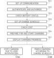
- FIG. 5is a flowchart illustrating a charge scenario according to an embodiment of the present invention.
- communication setupis performed between the EVCC 150 and the SECC 230 .
- the communication setupmay include procedures such as IP address assignment, SECC discovery, TCP or TLS connection setup, and V2G communication session setup.
- the V2G communication sessionmay be a session for exchanging a V2G message between the EVCC 150 and the SECC 230 .
- the V2G messagemay be a message exchanged in the application layer between the EVCC 150 and the SECC 230 .
- the communication setupmay further include a process in which the EVCC 150 and the SECC 230 exchange information on a communication protocol version.
- the EVSE 200performs authentication processing to check whether the EV 100 is subject to charging or discharging.
- the SECC 230 and the EVCC 150exchange their IDs.
- the SECC 230may deliver an ID (contract ID) of an EVCC associated with its own ID (EVSE ID) to the power grid operation server 300 .
- the authorization processingis started by the EVCC 150 .
- the power grid operation server 300may participate in the authentication and authorization processing for the EV 100 .
- the ID of the EVCC 150may be unique identification code, a contact ID, a vehicle ID, or a vehicle user ID of the EVCC 150 .
- the check of the battery statusis a necessary procedure for setting up a discharge schedule.
- Information for the discharge schedule setupmay include, for example, the capacity of a battery (Bat_kWh), the voltage of a battery (Bat_voltage), the current SOC value of a battery (Bat_SOC), and the like.
- the charge schedule setupmay be a target setup related to charging.
- the target setting related to the chargingmay be to set a time related to a charge process, the amount of energy charge, a charging method, etc,
- the charging method settingmay be to select a quick charging method and/or the cheapest charging method.
- the cost check processmay be a process of exchanging messages related to identification, authentication, and authorization performed between the EV, the EVSE, and the power grid operation server.
- the charging-related costis a cost that a vehicle user has to pay to the EVSE through the payment unit 240 of the EVSE 200 .
- the EV 100notifies the EVSE 200 that it is ready for charging, or conversely, the EVSE 200 notifies the EV 100 that it is ready for charging.
- a charge stop processis performed by user intervention while charging is in progress in operation 518 A, or a normal charge finish process is performed by a charge schedule in operation 518 B.
- the charge stopmay be a process of forcibly stopping a discharge process by the vehicle user, the operator of the EVSE 200 , or the operator of the power grid operation server 300 while charging is in progress.
- the charge stopmay be performed by the HMIs 140 , 220 , and 320 installed at the EV 100 , the EVSE 200 , and the power grid operation server 300 , respectively.
- the charge finishis to normally finish charging at a charge finish time reserved according to a charge schedule.
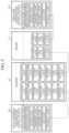
- FIG. 6is a sequence diagram of messages exchanged between an electric vehicle, a supply equipment, and a power grid operation server on the basis of a charge scenario according to an embodiment of the present invention and also is a sequence diagram in the case of setting up a charge schedule in the electric vehicle.
- the entities 120 , 140 , 150 , 210 , 230 , and 300exchange messages as shown in FIG. 6 .
- the term “message” shown in FIG. 6may be replaced with any one term among “data,” “signal,” “information,” “code,” and “command.” As shown in FIGS. 2 to 4 , the messages may be messages exchanged in the application layer, but the present invention is not limited thereto. That is, the messages shown in FIG. 6 may be defined as messages exchanged in other layers.
- each message shown in FIG. 6may have a message structure composed of a header and a payload.
- Information for payload processingmay be recorded in the header.
- a protocol version, a payload type, and a payload length (or a message length)may be recorded in the header.
- Application datae.g., each message shown in FIG. 6
- Each message recorded in the payloadmay be expressed using multiple bit arrays or a flag value of “0” or “1.”
- the power grid operation server 300transmits messages related to the sales tariff table to an EV 100 .
- the messages related to the sales tariff tableinclude Grid_time_cost, Gen_time_cost_change, Grid_day_cost, Grid_night_cost, etc.
- the message Grid_time_costmay indicate or include information related to a charge cost for each time according to a local grid situation or a grid schedule.
- the charge costis a cost that an EV (a vehicle user) has to pay to the EVSE 200 or the power grid operation server 300 in order to perform a charge process in which energy is transferred from the off-board charger 210 of the EVSE 200 to the OBC 120 of the EV 100 or a charge process in which energy is transferred from the power grid 400 to the OBC 120 of the EV 100 via the off-board charger 210 .
- the message Grid_time_costis transmitted from the power grid operation server 300 to the EV 100 via the PGCC 310 , the SECC 230 , and the EVCC 150 .
- a gateway and/or a routermay be additionally present between the SECC 230 and the PGCC 310 in a communication path of the message Grid_time_cost.
- a gateway and/or a routerare additionally present in a communication path between the SECC 230 and the PGCC 310 .
- the OBC 120delivers the message Grid_time_cost received through the EVCC 150 to the HMI 140 , and the HMI 140 displays and provides the message Grid_time_cost to the vehicle user.
- the message Grid_time_costis utilized to set up (or create) a charge schedule.
- the vehicle usermay check the message Grid_time_cost to set up an optimal charge time (charge reservation time).
- the optimal charge timerefers to a time at which the EV 100 may perform a charge process with the lowest charge cost.
- the charge timeincludes a charge start time (Char_start_time) and a charge finish time (Char_finish_time) to be described below.
- the message Gen_time_cost_changemay indicate or include information related to a variation of a charge cost for each time according to the local grid situation or grid schedule.
- the message Grid_time_cost_changeis transmitted from the power grid operation server 300 to the EV 100 via the PGCC 310 , the SECC 230 , and the EVCC 150 .
- the message Gen_time_cost_changeis utilized to set up a charge schedule.
- the message Grid_day_costmay indicate or include information related to a discharge cost during day time everyday on the basis of the local grid situation or grid schedule.
- the message Grid_day_costis transmitted from the power grid operation server 300 to the EV 100 via the PGCC 310 , the SECC 230 , and the EVCC 150 .
- the message Grid_day_costis utilized, for example, to set up a charge schedule related to an optimal charge time.
- the message Grid_night_costmay indicate or include information related to a charge cost during night time everyday on the basis of the local grid situation or the grid schedule.
- the message Grid_night_costis transmitted from the power grid operation server 300 to the EV 100 via the PGCC 310 , the SECC 230 , and the EVCC 150 .
- the message Grid_night_costis utilized, for example, to set up (or create) a charge schedule Char_schedule related to the setting of an optimal charge time.
- the power grid operation server 300may provide the messages Gen_time_cost, Gen_time_cost_change, Grid_day_cost, and Grid_night_cost to the electric vehicle 100 individually or may consolidate the messages Gen_time_cost, Gen_time_cost_change, Grid_day_cost, and Grid_night_cost into a sales tariff table and then provide the sales tariff table to the EV 100 .
- the message Grid_energy_limitmay indicate or include a limit value when it is necessary for the power grid 400 to limit the amount of energy discharge according to the local grid situation.
- the message Grid_energy_limitis transmitted from the power grid operation server 300 to the EV 100 via the PGCC 310 , the SECC 230 , and the EVCC 150 .
- the message Offgen_day_costmay indicate or include information related to a charge cost that is set differently for each off-board charger.
- the message Offgen_day_costis transmitted from the off-board charger 210 to the EV 100 via SECC 230 and the EVCC 150 .
- FIG. 1shows one off-board charger 210 , but when multiple off-board chargers are present in the EVSE 200 , each off-board charger has a different charge cost from the other off-board chargers.
- the vehicle user of the EV 100may check a charge cost for each off-board charger, select an appropriate off-board charger, and proceed with the charge process.
- the message Offchar_day_costis utilized to set up (or create) a charge schedule Char_schedule.
- the OBC 120delivers the messages Gen_time_cost, Gen_time_cost_change, Grid_day_cost, Grid_night_cost, and Offgen_day_cost to the HMI 140 , and the HMI 140 displays the messages Gen_time_cost, Gen_time_cost_change, Grid_day_cost, Grid_night_cost, and Offgen_day_cost so that the vehicle user can check the messages.
- the vehicle userAfter checking the messages Gen_time_cost, Gen_time_cost_change, Grid_day_cost, Grid_night_cost, and Offgen_day_cost displayed through the HMI 140 , the vehicle user sets up an appropriate charge schedule Char_schedule. For example, the vehicle user sets an optimal charge start time, an optimal charge finish time, etc.
- the messages Bat_kWh, Bat_voltage, and Bat_SOCare delivered from the BMS 160 to the HMI 140 , and the HMI 140 displays and provides the messages Bat_kWh, Bat_voltage, and Bat_SOC to the vehicle user to set up the charge schedule.
- the messages Bat_kWh, Bat_voltage, and Bat_SOCare delivered from the BMS 160 to the OBC 120 .
- the message Bat_kWhmay indicate or include information related to the current battery capacity (current battery capacity information) of the vehicle battery 110 .
- the OBC 120calculates a charge time on the basis of the battery capacity information.
- the charge timemay be a charge start time and a charge finish time.
- the charge timemay be a time taken to reach the amount of energy charge Char_energy that is set by the vehicle user.
- the charge timeis utilized to set up (or create) a charge schedule Char_schedule.
- the message Bat_voltagemay indicate or include battery voltage information.
- the OBC 120determines whether the battery voltage is abnormal using the battery voltage information, and then calculates the charge time.
- the OBC 120determines whether the battery voltage is abnormal at high temperature in summer using the battery voltage information, and the determination result is utilized to calculate the charge time (the charge start time and the charge finish time).
- the OBC 120determines whether the battery voltage is abnormal at low temperature in winter using the battery voltage information, and the determination result is utilized to calculate the charge time (the charge start time and the charge finish time).
- the message Bat_SOCmay indicate or include information related to the current state of charge of the vehicle battery.
- the OBC 120utilizes the information related to the current state of charge to calculate the charge time (the charge start time and the charge finish time).
- the state of charge (SOC)is utilized as a criterion for determining whether the vehicle battery can be currently discharged. For example, the OBC 120 determines whether the current SOC value falls within a preset chargeable SOC range.
- the charge processis started. Otherwise, the charge process is not started.
- the OBC 120checks the current SOC value to determine the current SOC value falls within chargeable SOC ranges that are set in spring and autumn. Also, the OBC 120 checks the current SOC value and determines whether the current SOC value falls within chargeable SOC ranges that are set in summer and winter.
- the message Char_energymay indicate or include the amount of energy charge that the OBC 120 intends to transfer to the off-board charger.
- the vehicle usersets the amount of energy discharge through the HMI 140 .
- the vehicle usersets the amount of energy charge in comprehensive consideration of the sales tariff table provided from the power grid operation server 300 , the message Offchar_day_cost provided from the off-board charger, and the messages Bat_kWh, Bat_voltage, and Bat_SOC provided from the BMS 160 .
- the message Char_start_timemay indicate or include a charge start time.
- the message Char_start_timeis transmitted to the EVSE 200 or the off-board charger 210 via the EVCC 150 and the SECC 230 .
- the message Char_start_timeis transmitted to the power grid operation server 300 via the EVCC 150 , the SECC 230 , and the PGCC 310 .
- the vehicle usersets a charge start time through the HMI 140 . Similar to the setting of the amount of energy charge, the vehicle user checks the sales tariff table provided from the power grid operation server 300 , the message Offchar_day_cost provided from the off-board charger, and the messages Bat_kWh, Bat_voltage, and Bat_SOC provided from the BMS and then sets the charge start time using an input function of the HMI 140 .
- the vehicle userAfter checking the messages Gen_time_cost, Gen_time_cost_change, Grid_day_cost, Grid_night_cost, and Offgen_day_cost through the HMI 140 , the vehicle user sets and reserves a charge start time with the lowest charge cost to be paid.
- the vehicle userchecks a charge cost (a fee for charging) for each day time and for each night time through the HMI 140 and then sets and reserves a charge start time with the lowest charge cost.
- a charge cost(a fee for charging) for each day time and for each night time through the HMI 140 and then sets and reserves a charge start time with the lowest charge cost.
- the vehicle userchecks a charge cost that varies daily or hourly and sets and reserves a charge start time with the lowest charge cost.
- the message Char_finish_timemay indicate or include a charge finish time.
- the message Char_finish_timeis transmitted to the off-board charger 210 via the EVCC 150 and the SECC 230 .
- the message Char_finish_timeis transmitted to the control unit 330 of the power grid operation server 300 via the EVCC 150 , the SECC 230 , and PGCC 310 .
- the vehicle userchecks, through the HMI 140 , the messages Bat_kWh, Bat_voltage, and Bat_SOC and the messages Grid_time_cost, Grid_time_cost_change, Grid_day_cost, Grid_night_cost, Offchar_day_cost received from the off-board charger 210 and/or the power grid operation server 300 and then sets and reserves, through the HMI 140 , an optimal charge finish time with the lowest charge cost to be paid.
- the message Drive_distancemay indicate or include information related to the mileage of an EV.
- the mileageis a distance that the vehicle user intends to travel using the EV.
- the HMI 140delivers the mileage to the OBC 120 , and the OBC 120 sets up a charge schedule on the basis of the mileage input through the HMI 140 .
- the OBC 120automatically calculates the amount of energy charge on the basis of the mileage input from the HMI 140 .
- the OBC 120calculates the amount of energy charge corresponding to the difference between the maximum mileage that the EV 100 can travel with the current battery capacity and the mileage input by the vehicle user through the HMI 140 .
- the OBC 120does not calculate the amount of energy charge.
- the OBC 120transfers the amount of energy charge calculated based on the mileage input by the vehicle user to the HMI 140 , and the HMI 140 displays the calculated amount of energy charge so that the vehicle user can check the amount of energy charge.
- the message Drive_distanceis transmitted from the EVCC 150 of the EV 100 to the SECC 230 of the EVSE 200 or is transmitted to the PGCC 310 of the power grid operation server 300 via the SECC 230 of the EVSE 200 .
- the message Char_schedulemay indicate or include charge schedule-related information including the messages Char_energy, Char_start_time, Char_finish_time, and Drive_distance.
- the message Char_scheduleis transmitted from the EVCC 150 of the EV 100 to the SECC 230 of the EVSE 200 or is transmitted to the PGCC 310 of the power grid operation server 300 via the SECC 230 of the EVSE 200 .
- the messages Char_energy, Char_start_time, Char_finish_time, and Drive_distancemay be individually transmitted to the SECC 230 of the EVSE 200 or the PGCC 310 of the power grid operation server 300 or may be consolidated into the message Char_schedule and transmitted to the SECC 230 of the EVSE 200 or the PGCC 310 of the power grid operation server 300 .
- the message Authorize_codemay indicate or include authorization code of a vehicle user.
- the message Authorize_codeis delivered from the HMI 140 to the OBC 120 .
- the authorization codewhich is special code assigned to each vehicle, is personal information used for cost settlement.
- the message Authorize responseis a message transmitted from the OBC 120 to the HMI 140 and is a response message to the message Authorize_code.
- the message Data_integrity_checkwhich is a message transmitted from the HMI 140 to the OBC 120 , is utilized to check identification code for a data integrity check.
- the message Cost_authorize_requestwhich is a message requesting authorization for a charge cost, is transmitted from the EVSE 200 to the EV 100 .
- the message Cost_authorize_requestmay be configured to include information related to the charge cost calculated by the EVSE 200 .
- the charge costis a calculated charge cost Cost_calc that the vehicle user has to pay through the payment unit 240 of the EVSE 200 when charging the EV 100 .
- the charge costmay be calculated by the off-board charger 210 of the EVSE 200 .
- the off-board charger 210receives a charge schedule Char_schedule from the EV 100 through the SECC 230 and calculates a charge cost on the basis of the received charge schedule.
- the power grid operation server 300may transmit the message Cost_authorize_request to the EVSE 200 and/or the EV 100 .
- the charge cost Cost_calc included in the message Cost_authorize_requestis delivered to the HMI 140 , and the HMI 140 displays the charge cost Cost_calc so that the vehicle user can check the charge cost.
- the vehicle userchecks information on the charge cost displayed from the HMI 140 and determines whether to authorize the charge cost.
- the determination of whether to authorize the charge costmay also be performed in the power grid operation server 300 .
- the EVSE 200transmits the message power Cost_authorize_request to the power grid operation server 300 , and an operator of the power grid operation server 300 checks a charge cost through the HMI 320 and determines whether to authorize the charge cost.
- the message Cost_authorizeis a response to the message Cost_authorize_request and is a message indicating authorization for the charge cost calculated by the off-board charger 210 .
- FIG. 6shows an example in which the message Cost_authorize is transmitted from the EV 100 to the EVSE 200
- the message Cost_authorizemay be transmitted to the power grid operation server 300 via the EVSE 200 .
- the off-board charger 210After receiving the authorization message Cost_authorize, the off-board charger 210 displays the authorization message Cost_authorize through the HMI 220 so that an administrator (an electric provider or an operator) of the off-board charger 210 can check the authorization message Cost_authorize.
- the message Char readyis a message indicating that it is ready for charging and is a message that the OBC 120 and the off-board charger 210 exchange with each other through respective communication controllers.
- the OBC 120 and the off-board charger 210start charging according to a charge schedule Gen_schedule set in the EV.
- the message Car_energy_stopis a message transmitted from the EV 100 to the EVSE 200 or to the power grid operation server 300 via the EVSE 200 in order for the vehicle user to forcibly stop charging while the charging of the EV 100 is in progress.
- the HMI 140delivers the message Car_energy_stop corresponding to the command to the OBC 120 , and the OBC 120 transmits the message Car_energy_stop to the SECC 230 through EVCC 150 .
- the SECC 230delivers the message Car_energy_stop received from the EVCC 150 to the off-board charger 210 , and the off-board charger 210 stops the charge process in response to the message Car_energy_stop.
- the SECC 230transmits the message Car_energy_stop received from the EVCC 150 to the PGCC 310 of the power grid operation server 300 to inform the power grid operation server 300 that the charge process is stopped.
- the EVSE 200 and/or the power grid operation server 300ignore the charge finish time determined according to the charge schedule and immediately stop the charge process.
- the vehicle usermay stop the charge process using a charge stop button displayed by the HMI 140 or a physical button installed in the EV 100 .
- the message Char_cost_refundmay indicate or include information related to a return cost deducted from the charge cost paid by the vehicle user to the payment unit 240 of the EVSE 200 when the charge process is forcibly stopped by the message Car_energy_stop.
- the return costis a difference cost between the charge cost calculated according to the amount of energy charge set by the vehicle user and the cost calculated according to the amount of energy charged up to when the charge process is forcibly stopped.
- the return costis calculated by the EVSE 200 .
- the return costmay be calculated by the off-board charger 210 of the EVSE 200 .
- the calculation of the return costmay also be performed by the power grid operation server 300 .
- the return costmay be calculated by the control unit 330 of the power grid operation server 300 .
- the message CO2 diminish_sumindicates or includes information related to the amount of carbon dioxide (CO2) reduction calculated based on the amount of energy consumption of the EV 100 or a value obtained by accumulating the amount of CO2 reduction and is transmitted from the OBC 120 of the EV 100 to the power grid operation server 300 or the off-board charger 210 of the EVSE 200 .
- CO2carbon dioxide
- the OBC 120periodically collects the amount of energy consumption of the EV 100 and calculates the amount of CO2 reduction on the basis of the collected amount of energy consumption.
- the amount of CO2 reductionmay be calculated by a conversion table or a conversion expression that represents a mapping relationship between the amount of energy consumption and the amount of CO2 reduction.
- the conversion table or the conversion expressionmay be provided from the EVSE 200 or the power grid operation server 300 .
- the amount of energy consumptionwhich is the consumption amount of electric energy charged in the vehicle battery 110 , may be calculated based on mileage and speed and may be provided from, for example, the BMS 160 . It will be appreciated that the OBC 120 may calculate the amount of energy consumption on the basis of battery information provided from the BMS 160 .
- the amount of energy consumptionmay be, for example, an SOC value, the amount of power consumption, etc.
- the amount of energy consumptionmay include at least one of the amount of energy charge and the amount of energy discharge.
- the calculation of the amount of CO2 reduction according to the amount of energy consumptionmay be performed by the BMS 160 .
- the BMS 160provides the calculated amount of CO2 reduction to the OBC 120 .
- the OBC 120may deliver the amount of CO2 reduction to the HMI 140 , and the HMI 140 may display and provide the amount of CO2 reduction to the vehicle user.
- the amount of CO2 reductionis utilized to provide credit or incentive to vehicle users who participate in CO2 emission regulation.
- the amount of CO2 reductionmay be utilized to calculate a cost deducted from a charge cost that a vehicle user has to pay to the payment unit 240 of the EVSE 200 when charging an EV.
- the incentive cost or deduction costmay be calculated by the EVSE 200 or the power grid operation server 300 .
- the off-board charger 210may calculate the incentive cost or the deduction cost on the basis of the amount of CO2 reduction received through the SECC 230 .
- the calculated incentive cost or deduction costmay be transmitted to the EV 100 and displayed through the HMI 140 in the EV 100 , and the vehicle user may check the incentive cost or the deduction cost displayed through the HMI 140 .
- the EV 100may transmit a message re-requesting the cost calculation to the EVSE 200 or the power grid operation server 300 .
- the vehicle usermay determine whether to authorize the cost.
- the EV 100may transmit a message indicating a result of the authorization for the incentive cost or the deduction cost to the EVSE 200 or the power grid operation server 300 .
- the calculation of the incentive cost or the deduction costmay be performed by the EV 100 .
- the OBC 120 or the electronic control unit 130 of the EV 100may calculate the incentive cost or the deduction cost for the amount of CO2 reduction.
- the authorization for the incentive cost or the deduction costis performed by the EVSE 200 or the power grid operation server 300 , and an authorization message is transmitted from the EVSE 200 or the power grid operation server 300 to an EV.
- FIG. 7is a sequence diagram between an electric vehicle, a supply equipment, and a power grid operation server according to another embodiment of the present invention and also is a sequence diagram in the case of setting up a charge schedule in the supply equipment.
- the term “message” shown in FIG. 7may be replaced with any one term among “data,” “signal,” “information,” “code,” and “command.” As shown in FIGS. 2 to 4 , the messages may be messages exchanged in the application layer. However, the present invention is not limited thereto, and the messages may be messaged exchanged in other layers.
- the message structure of FIG. 7may be composed of a header and a payload.
- the description of the message structure shown in FIG. 7is replaced with the description of the message structure described with reference to FIG. 6 .
- the message Authorize_requestmay indicate or include information related to an authentication authorization request.
- the information related to the authentication authorization requestmay be configured to include identification information ID of the off-board charger 210 or identification information EVSE ID of the EVSE 200 .
- An operator (electric provider) of the EVSE 200inputs the information related to the authentication authorization request through the HMI 220 of the EVSE 200 .
- the off-board charger 210delivers the information related to the authentication authorization request to the SECC 230 , and the SECC 230 configures the information related to the authentication authorization request into the message Authorize_request according to a communication protocol agreed with the EVCC 150 and transmits the message Authorize_request to the EVCC 150 .
- the EVCC 150delivers the message Authorize_request received from the SECC 230 to the OBC 120 of the EV 100 , and the OBC 120 delivers the message Authorize_request to the HMI 140 in the EV 100 .
- the HMI 140displays the message Authorize_request delivered from the OBC 120 so that the vehicle user can check the message Authorize_request.
- the message Authorize_request_tryoutis a message re-requesting authentication authorization from the EV 100 .
- the message Authorize_OK_resis a response message to the message Authorize_request and is a message allowing the authentication authorization requested by the EVSE 200 or the off-board charger 210 of the EVSE 200 .
- the off-board charger 210starts the charge process when receiving the message Authorize_OK_res from the EV 100 .
- the message Authorize_NOK_resis a response message to the message Authorize_request and is a message disallowing the authentication authorization request of the off-board charger 210 in case of authentication failure.
- the EVSE 200When receiving the message Authorize_NOK_res from the EV 100 , the EVSE 200 terminates the authorization process or transmits the message Authorize_request_tryout to the EV to re-request authentication authorization.
- the messages Bat_kWh, Bat_voltage, and Bat_SOCare the same as the messages Bat_kWh, Bat_voltage, and Bat_SOC described with reference to FIG. 6 .
- the messages Bat_kWh, Bat_voltage, and Bat_SOCare utilized for charge schedule setup performed in the EVSE 200 and are displayed through the HMI 220 of the EVSE 200 .
- An operator (or an electric provider) of the EVSE 200sets up a charge schedule on the basis of the messages Bat_kWh, Bat_voltage, Bat_SOC displayed from the HMI 220 .
- the charge schedule setup performed by the EVSE 200may also be performed by the vehicle user rather than the operator (or the electric provider) of the EVSE 200 .
- the vehicle usermay set up the charge schedule by inputting charge schedule-related information to the HMI 220 of the EVSE 200 .
- the message Offchar_energywhich is a message indicating or including the amount of energy charge of the off-board charger 210 , is transmitted from the EVSE 200 to the EV 100 .
- the vehicle user or the operator (electric provider) of the EVSE 200sets the amount of energy charge on the basis of the sales tariff table displayed from the HMI 220 and/or the messages Bat_kWh, Bat_voltage, and Bat_SOC provided from the EV 100 , and inputs the amount of energy charge to the HMI 220 .
- the sales tariff tableincludes the messages Grid_time_cost, Grid_time_cost_change, Grid_day_cost, and Grid_night_cost described with reference to FIG. 6 and is provided from the power grid operation server 300 .
- the HMI 220delivers the amount of energy charge to the off-board charger 210 , and the off-board charger 210 transmits the amount of energy charge transferred from the HMI 220 to the EV 100 through the SECC 230 .
- the amount of energy chargemay be one of the pieces of information constituting the charge schedule.
- the operator of the EVSE 200 or the vehicle user of the EV 100sets the most advantageous amount of energy charge on the basis of the sales tariff table.
- the setting of the amount of energy chargemay also be performed by the power grid operation server 300 .
- the power grid operation server 300may receive messages or information necessary to set the amount of energy charge from the EVSE 200 or from the EV 100 via the EVSE 200 .
- the message Offchar_start_timeindicates or includes a charge start time of the off-board charger 210 and is transmitted from the EVSE 200 to the EV 100 .
- the message Offgen_start_timemay be one of the pieces of information constituting the charge schedule.
- the operator of the EVSE 200may reserve and set the charge start time of the off-board charger 210 using the HMI 220 . At this time, the operator of the EVSE 200 may reserve and set an optimal charge start time on the basis of the sales tariff table provided from the power grid operation server 300 and the messages Bat_kWh, Bat_voltage, and Bat_SOC received through the SECC 230 .
- the optimal charge start timemay be a time at which the vehicle user or the operator of the EVSE 200 can perform a charge process with the lowest charge cost.
- the setting of the charge start timemay also be performed not by the operator of the EVSE 200 but by the vehicle user. For example, after moving to the EVSE 200 , the vehicle user may set the optimal charge start time using the HMI 220 of the EVSE 200 .
- the setting of the charge start timemay also be performed by the power grid operation server 300 .
- the power grid operation server 300may receive messages or information necessary to set the charge start time from the EVSE 200 or from the EV 100 via the EVSE 200 .
- the message Offgen_finish_timeindicates or includes a charge finish time of the off-board charger 210 and is transmitted from the EVSE 200 to the EV 100 .
- the charge finish timemay be one of the pieces of information constituting the charge schedule.
- the operator of the EVSE 200may reserve and set the charge finish time of the off-board charger 210 using the HMI 220 . At this time, the operator of the EVSE 200 may reserve and set the charge finish time on the basis of the sales tariff table provided in advance from the power grid operation server 300 and the messages Bat_kWh, Bat_voltage, and Bat_SOC provided from the EV 100 .
- the setting of the charge finish timemay be performed not by the operator of the EVSE 200 but by the vehicle user. For example, after moving to the EVSE 200 , the vehicle user may set the charge finish time using the HMI 220 of the EVSE 200 .
- the setting of the charge finish timemay also be performed by the power grid operation server 300 .
- the power grid operation server 300may receive messages or information necessary to set the charge finish time from the EVSE 200 or from the EV 100 via the EVSE 200 .
- the off-board charger 210configures a charge schedule Offchar_schedule based on the messages Offchar_energy, Offchar_start_time, and Offchar_finish_time input through the HMI 220 .
- the off-board charger 210transmits the charge schedule Offchar_schedule to the EV 100 through the SECC 230 .
- FIG. 7illustrates an example in which the off-board charger 210 transmits the charge schedule Offchar_schedule to the EV, but the off-board charger 210 may also transmit the charge schedule Offchar_schedule to the power grid operation server 300 .
- the HMI 140 of the EV 100displays the charge schedule Offchar_schedule received from the EVSE 200 so that the vehicle user can check the charge schedule Offchar_schedule.
- the HMI 320 of the power grid operation server 300displays the charge schedule Offchar_schedule received from the EVSE 200 so that the operator of the power grid operation server 300 can check the charge schedule Offchar_schedule.
- the message Cost_calcindicates or includes a charge cost calculated by the EVSE 200 and is transmitted to the EV 100 and the power grid operation server 300 .
- the charge costwhich is a cost that the vehicle user has to pay to the EVSE 200 , is calculated based on the charge schedule set by the EVSE 200 .
- the charge costis calculated based on the amount of energy charge, the charge start time, and the charge finish time.
- the calculation of the charge costis performed by the EVSE 200 .
- the charge costmay be calculated by the off-board charger 210 of the EVSE 200 or another control unit connected to the off-board charger 210 of the EVSE 200 .
- the charge costmay also be calculated by the power grid operation server 300 .
- the power grid operation server 300may receive a charge schedule from the EVSE 200 and may perform a charge cost calculation based on the received charge schedule.
- the power grid operation server 300may transmit the charge cost to the EVSE 200 and/or to the EV 100 via the EVSE 200 .
- the message Cost_authorize_requestwhich is a message requesting authorization for a calculated charge cost, is transmitted from the EVSE 200 to the EV 100 .
- the message Cost_authorize_requestis transmitted to the EVSE 200 or to the EV 100 via the EVSE 200 .
- the message Cost_Authorize_OK_resis a response message to the message Cost_authorize_request and is an authorization message for a charge cost.
- the message Cost_Authorize_OK_resis transmitted from the EV 100 to the EVSE 200 .
- the off-board charger 210 of the EVSE 200starts a charging process.
- the message Cost_Authorize_NOK_resis a response message to the message Cost_authorize_request and is a message disallowing the authorization for the charge cost.
- the EVSE 200receives the message Cost_Authorize_NOK_res, the EVSE 200 re-requests the authorization for the charge cost or finishes the cost authorization procedure.
- the message Offchar_readywhich is a message informing the electric vehicle 100 that the EVSE 200 is ready for charging, is transmitted from the EVSE 200 to the EV 100 .
- the OBC 120 of the EV 100starts charging when the message Offchar_ready is received from the EVSE 200 through the EVCC 150 .
- the vehicle usercommands the OBC 120 to start charging using the HMI 140 .
- the message Offchar_readymay also be transmitted to the power grid operation server 300 to inform the power grid operation server 300 that the off-board charger 210 is ready for charging.
- the message Offchar_energy_stopwhich is a message for stopping the charging before the charge finish time included in the charge schedule while charging is in progress according to the charge schedule, is transmitted from the EVSE 200 to the EV 100 and/or the power grid operation server 300 .
- the charge stopmay be performed by the HMI 220 of the EVSE 200 .
- the vehicle user or the operator of the EVSE 200may command the charge stop using the HMI 220 of the EVSE 200 .
- the charge stopmay be performed by the operator of the power grid operation server 300 , and in this case, the power grid operation server 300 transmits the message Offchar_energy_stop to the EVSE 200 and/or the EV 100 .
- the message Offchar_Cost_refundwhich is a cost deducted from the charge cost by forcibly stopping the charge process, may indicate or include information related to a cost returned to the vehicle user (hereinafter referred to as a return cost).
- the return costis a cost calculated by subtracting a charge cost calculated up to when the charging is stopped from a charge cost initially calculated according to the charge schedule.
- the message Offgen_Cost_refundis transmitted from the EVSE 200 to the EV 100 and the power grid operation server 300 .
- the HMI 140 of the EV 100displays the return cost corresponding to the message Offgen_Cost_refund so that the vehicle user can check the return cost.
- the HMI 320 of the power grid operation server 300displays the return cost according to the message Offgen_Cost_refund so that the operator of the power grid operation server 300 can check the return cost.
- the EVSE 200 and the EV 100may exchange messages related to the authorization procedure for the return cost.
- the EVSE 200 and the power grid operation server 300may exchange messages related to the authorization procedure for the return cost.
- the message Offgen_CO2 diminish_sumindicates or includes information related to the amount of CO2 reduction calculated based on the amount of energy consumption (the amount of electricity consumption) of the off-board charger 210 or a value of accumulating the amount of CO2 reduction and is transmitted from the EVSE 200 to the EV 100 .
- the off-board charger 210periodically collects the amount of energy consumption of the EV 100 or the amount of energy consumption of the off-board charger 210 through the SECC 230 and calculates the amount of CO2 reduction on the basis of the collected amount of energy consumption.
- the amount of CO2 reductionmay be calculated by a conversion table or a conversion expression that represents a mapping relationship between the amount of energy consumption and the amount of CO2 reduction.
- the conversion table or the conversion expressionmay be provided from the power grid operation server 300 .
- the conversion table or the conversion expressionmay be included in a sales tariff table provided by the power grid operation server 300 .
- the amount of energy consumption of the off-board charger 210may include at least one of the amount of electric energy transferred by the off-board charger 210 to the OBC 120 of the EV 100 (the charging of the EV) and the amount of electric energy supplied by the off-board charger 210 from the power grid 400 .
- Information related to the amount of CO2 reductionis transmitted to the HMI 140 of the EV 100 and the HMI 320 of the power grid operation server 300 , and the vehicle user and the operator of the power grid operation server 300 are informed of the information related to the amount of CO2 reduction.
- the amount of CO2 reductionis utilized to calculate credit or an incentive cost for vehicle users or operators of the EVSE 200 who participate in CO2 emission regulation.
- the amount of CO2 reductionmay be used to calculate a cost deducted from the charge cost that the vehicle user has to pay to the EVSE.
- the amount of CO2 reductionmay be used to calculate a cost deducted from a cost that the power grid operation server bills to the EVSE according to the amount of energy consumption of the EVSE.
- the message Offgen_energy_calculationindicates or includes information related to the amount of energy consumption of the off-board charger 210 and is delivered to the power grid operation server 300 .
- the power grid operation server 300checks the amount of energy consumption of the off-board charger 210 through the message Offgen_energy_calculation, and the message Offgen_energy_calculation is utilized to calculate a cost corresponding to the amount of energy consumption and a cost to be returned from the power grid to the EVSE 200 or the EV 100 .
- FIG. 8is a sequence diagram of an electric vehicle, a supply equipment, and a power grid operation server according to still another embodiment of the present invention and also is a sequence diagram in the case of setting up a charge schedule in the power grid operation server.
- the properties of the messages shown in FIG. 8are the same as those of the messages shown in FIGS. 6 and 7 . However, the messages have different origins and destinations. Accordingly, the description of each message replaces the description with reference to FIGS. 6 and 7 , and the origin and destination of each message will be briefly described below.
- the charge scheduleis set up by the power grid operation server 300 , which manages and monitors the power grid 400 . Accordingly, information and/or messages constituting the charge schedule, for example, the amount of energy charge Char_energy, the charge start time Char_start_time, and the charge finish time Char_finish_time are transmitted from the power grid operation server 300 to the EV 100 via the EVSE 200 .
- the mileage Drive_distance utilized to set the amount of energy chargeis transmitted from the EV 100 to the power grid operation server 300 via the EVSE 200 .
- the battery capacity information Bat_kWh, the battery voltage information Bat_voltage, and the battery status information Bat_SOC which are utilized to set up the charge scheduleare transmitted from the EV 100 to the power grid operation server 300 via the EVSE 200 .
- the charge costis calculated by the power grid operation server 300 . Accordingly, the charge cost is transmitted from the power grid operation server 300 to the EV 100 via the EVSE 200 .
- an authorization request message Cost_authorize_request for the charge costis also transmitted from the power grid operation server 300 to the EV 100 via the EVSE 200 .
- the response messages Cost_authorize_OK_res and Cost_authorize_NOK_res to the authorization request message Cost_authorize_requestare transmitted from the EV 100 to the power grid operation server 300 via the EVSE 200 .
- the forcible stop of the chargingis commanded by the power grid operation server 300 . Therefore, the message Char_energy_stop commanding the forcible stop of the charge process according to the charge schedule is transmitted from the power grid operation server 300 to the EV 100 via the EVSE 200 .
- the power grid operation server 300may determine to stop charging.
- a cost Cahr_cost_refund deducted from a charge cost calculated according to the charge schedule due to the forcible stop of the charge processis transmitted from the power grid operation server 300 to the EV 100 via the EVSE 200 .
- Information related to the amount of CO2 reductionis transmitted from the power grid operation server 300 to the EV 100 via the EVSE 200 .
- the present inventionby defining charge process-related messages exchanged between an electric vehicle, a supply equipment, and a power grid, it is possible to establish an efficient billing policy for each time, and also it is possible to efficiently operate the power grid. Also, it is possible to provide credit or incentive to a vehicle user and an operator of a supply equipment that participate in CO2 emission regulation.
Landscapes
- Engineering & Computer Science (AREA)
- Power Engineering (AREA)
- Transportation (AREA)
- Mechanical Engineering (AREA)
- Business, Economics & Management (AREA)
- Health & Medical Sciences (AREA)
- Economics (AREA)
- Tourism & Hospitality (AREA)
- Strategic Management (AREA)
- General Business, Economics & Management (AREA)
- General Health & Medical Sciences (AREA)
- Human Resources & Organizations (AREA)
- Marketing (AREA)
- Primary Health Care (AREA)
- Theoretical Computer Science (AREA)
- General Physics & Mathematics (AREA)
- Physics & Mathematics (AREA)
- Sustainable Development (AREA)
- Life Sciences & Earth Sciences (AREA)
- Sustainable Energy (AREA)
- Computing Systems (AREA)
- Computer Security & Cryptography (AREA)
- Computer Networks & Wireless Communication (AREA)
- Signal Processing (AREA)
- Public Health (AREA)
- Water Supply & Treatment (AREA)
- Charge And Discharge Circuits For Batteries Or The Like (AREA)
- Electric Propulsion And Braking For Vehicles (AREA)
- Operations Research (AREA)
Abstract
Description
Claims (11)
Applications Claiming Priority (2)
| Application Number | Priority Date | Filing Date | Title |
|---|---|---|---|
| KR1020200126300AKR102811314B1 (en) | 2020-09-28 | 2020-09-28 | Communication method between electric vehicle, power supply and power grid operation server |
| KR10-2020-0126300 | 2020-09-28 |
Publications (2)
| Publication Number | Publication Date |
|---|---|
| US20220097558A1 US20220097558A1 (en) | 2022-03-31 |
| US12162370B2true US12162370B2 (en) | 2024-12-10 |
Family
ID=77998757
Family Applications (1)
| Application Number | Title | Priority Date | Filing Date |
|---|---|---|---|
| US17/487,390Active2043-05-28US12162370B2 (en) | 2020-09-28 | 2021-09-28 | Communication method between electric vehicle, supply equipment and power grid operation server |
Country Status (4)
| Country | Link |
|---|---|
| US (1) | US12162370B2 (en) |
| EP (1) | EP3974242A1 (en) |
| KR (1) | KR102811314B1 (en) |
| CN (1) | CN114274837B (en) |
Families Citing this family (7)
| Publication number | Priority date | Publication date | Assignee | Title |
|---|---|---|---|---|
| JP7694212B2 (en)* | 2021-07-06 | 2025-06-18 | トヨタ自動車株式会社 | Control device and control method for electric vehicle |
| US20230406147A1 (en)* | 2022-05-18 | 2023-12-21 | Ford Global Technologies, Llc | Bidirectional electric vehicle charging system |
| US20240154451A1 (en)* | 2022-11-09 | 2024-05-09 | Lear Corporation | Battery charger to support multiple charging configurations |
| SE547379C2 (en)* | 2022-12-13 | 2025-07-22 | Volvo Truck Corp | A computer-implemented method for determining a route for an electric vehicle |
| DE102022134459A1 (en)* | 2022-12-22 | 2024-06-27 | Bayerische Motoren Werke Aktiengesellschaft | Method and system for charging an electric vehicle |
| CN115848191B (en)* | 2022-12-22 | 2023-07-07 | 深圳时代能创软件科技有限公司 | Charging control system and method for alternating-current charging pile of electric automobile |
| WO2025104099A1 (en)* | 2023-11-13 | 2025-05-22 | Volvo Car Corporation | Compliance of iso15118-20 with vde-ar-n 4105 p-monitoring |
Citations (81)
| Publication number | Priority date | Publication date | Assignee | Title |
|---|---|---|---|---|
| US20080052026A1 (en)* | 2006-08-23 | 2008-02-28 | Qurio Holdings, Inc. | Configuring a content capture device for one or more service providers |
| US20090021218A1 (en)* | 2007-07-18 | 2009-01-22 | Kurt Russell Kelty | Battery charging based on cost and life |
| US20090287578A1 (en)* | 2008-05-19 | 2009-11-19 | Michael Adam Paluszek | Charging station for electric and plug-in hybrid vehicles |
| US20090315512A1 (en)* | 2006-08-04 | 2009-12-24 | Toyota Jidosha Kabushiki Kaisha | Power system and method for managing charging state in that power system |
| US20100017249A1 (en)* | 2008-07-11 | 2010-01-21 | Fincham Carson C K | Systems and methods for electric vehicle charging and power management |
| US20100017045A1 (en)* | 2007-11-30 | 2010-01-21 | Johnson Controls Technology Company | Electrical demand response using energy storage in vehicles and buildings |
| US20100094496A1 (en)* | 2008-09-19 | 2010-04-15 | Barak Hershkovitz | System and Method for Operating an Electric Vehicle |
| CN101784413A (en) | 2007-08-24 | 2010-07-21 | 丰田自动车株式会社 | Hybrid vehicle, informing method for hybrid vehicle, and computer readable recording medium having recorded thereon program for causing computer to execute the informing method |
| US20100185357A1 (en)* | 2008-01-25 | 2010-07-22 | Kyushu Electric Power Co., Inc. | Electrically-driven apparatus charging system and method |
| JP2010239704A (en) | 2009-03-30 | 2010-10-21 | Tokyo Electric Power Co Inc:The | Greenhouse gas emission calculation device, greenhouse gas emission calculation method, and charging system |
| US20110133693A1 (en)* | 2009-12-17 | 2011-06-09 | Richard Lowenthal | Method and apparatus for electric vehicle charging station load management in a residence |
| US20110172837A1 (en)* | 2007-08-28 | 2011-07-14 | Forbes Jr Joseph W | System and method for estimating and providing dispatchable operating reserve energy capacity through use of active load management |
| US20110184585A1 (en)* | 2010-01-25 | 2011-07-28 | Seiichi Matsuda | Power management apparatus, electronic appliance, and method of registering electronic appliances |
| US20110202217A1 (en)* | 2010-02-18 | 2011-08-18 | University Of Delaware | Electric vehicle equipment for grid-integrated vehicles |
| US20110239116A1 (en)* | 2010-02-23 | 2011-09-29 | Optimization Technologies, Inc. | Electric vehicle charging stations with touch screen user interface |
| US20110276194A1 (en)* | 2010-05-10 | 2011-11-10 | Emalfarb Hal A | System and method for energy management |
| US20120086395A1 (en)* | 2010-10-12 | 2012-04-12 | Kia Motors Corporation | Telematics device for remote charging control and method of providing service thereof |
| US20120101659A1 (en)* | 2010-10-20 | 2012-04-26 | Hyundai Motor Company | Telematics device for electric vehicle and remote air-conditioning control method thereof |
| US20120268061A1 (en)* | 2011-04-21 | 2012-10-25 | International Business Machines Corporation | Real time system and method for optimizing and managing a load in an electrical grid |
| DE102011109422A1 (en)* | 2011-08-04 | 2013-02-07 | Daimler Ag | Method for charging a battery of a vehicle |
| US20130099741A1 (en)* | 2011-10-21 | 2013-04-25 | Denso Corporation | In-vehicle charge control system |
| US20130110296A1 (en)* | 2011-10-19 | 2013-05-02 | Zeco Systems Pte Ltd | Methods and Apparatuses for Charging of Electric Vehicles |
| US20130119920A1 (en)* | 2011-11-16 | 2013-05-16 | Industrial Technology Research Institute | Electric vehicle charging system and charging management method thereof |
| US20130179061A1 (en)* | 2010-06-10 | 2013-07-11 | The Regents Of The University Of California | Smart electric vehicle (ev) charging and grid integration apparatus and methods |
| US20130175974A1 (en)* | 2012-01-09 | 2013-07-11 | GM Global Technology Operations LLC | System and method for charging a plug-in electric vehicle |
| US20130320919A1 (en)* | 2008-02-14 | 2013-12-05 | Fernando Emilio Adames | Portable battery charger |
| US20130342164A1 (en)* | 2012-06-22 | 2013-12-26 | Lsis Co., Ltd. | Add-on communication apparatus attached to in-cable charging control device and operating method thereof |
| US20140006137A1 (en)* | 2012-06-28 | 2014-01-02 | Toyota Infotechnology Center Co., Ltd. | Event Control Schedule Management |
| US20140005848A1 (en)* | 2012-06-28 | 2014-01-02 | Toyota Infotechnology Center Co., Ltd. | Event Control Schedule Management |
| US20140091747A1 (en)* | 2012-09-28 | 2014-04-03 | Honda Motor Co., Ltd. | Clean Charging of Electric Vehicles |
| US20140125281A1 (en)* | 2011-06-21 | 2014-05-08 | Toyota Jidosha Kabushiki Kaisha | Charging device for power storage device and vehicle mounted with the same |
| US20140125279A1 (en)* | 2012-11-06 | 2014-05-08 | EV Connect, Inc. | Queue prioritization for electric vehicle charging stations |
| US20140188367A1 (en)* | 2012-09-04 | 2014-07-03 | Recargo, Inc. | Displaying information associated with an electric vehicle |
| US20140289082A1 (en)* | 2013-03-19 | 2014-09-25 | Kt Corporation | Electric charging management of electric vehicle |
| US20140300316A1 (en)* | 2011-10-18 | 2014-10-09 | Toyota Jidosha Kabushiki Kaisha | Power supply device and power supply method |
| US20140312841A1 (en)* | 2011-11-22 | 2014-10-23 | Panasonic Corporation | Electricity management device, electricity management program, and electricity distribution system |
| WO2014176838A1 (en)* | 2013-04-28 | 2014-11-06 | 海尔集团技术研发中心 | Method and system for identifying receiving end of multi-coil array-type wireless power supply system |
| US8890475B1 (en)* | 2010-09-28 | 2014-11-18 | Gilbert Scott Becker | Automobile charging and communications station |
| US20140358749A1 (en)* | 2013-05-29 | 2014-12-04 | General Motors Llc | Cross-Reference Electric Vehicle Charge Data for Billing |
| US20150095114A1 (en)* | 2013-09-30 | 2015-04-02 | Elwha Llc | Employment related information center associated with communication and control system and method for wireless electric vehicle electrical energy transfer |
| US20160031333A1 (en)* | 2014-08-04 | 2016-02-04 | Hyundai Mobis Co., Ltd. | Wireless power transmission device having user interface structure and method for controlling the same |
| US20160052413A1 (en)* | 2014-08-25 | 2016-02-25 | Toyota Jidosha Kabushiki Kaisha | Regional charging control service |
| US20160126639A1 (en)* | 2014-10-14 | 2016-05-05 | Samsung Electro-Mechanics Co., Ltd. | Coil structure and wireless power receiving apparatus including the same |
| US20160159239A1 (en)* | 2013-12-02 | 2016-06-09 | State Grid Chongqing Electric Power Co. Electric Power Research Institute | System and Method for Controlling Charging and Discharging of Electric Vehicle |
| US20160193931A1 (en)* | 2013-08-07 | 2016-07-07 | Panasonic Intellectual Property Management Co., Ltd. | Power supply system and discharge device |
| US20160232555A1 (en)* | 2013-10-30 | 2016-08-11 | Nec Corporation | Rewards information determining device and rewards information determining system |
| US20160318417A1 (en)* | 2013-12-20 | 2016-11-03 | Toyota Jidosha Kabushiki Kaisha | Electrical storage system |
| KR101716610B1 (en)* | 2016-02-05 | 2017-04-04 | 서창전기통신 주식회사 | Smart calculation system of charging fee for vehicle driven by electric |
| US20170138758A1 (en)* | 2015-11-13 | 2017-05-18 | NextEv USA, Inc. | Tracking power consumption and payment |
| US20170337646A1 (en)* | 2016-05-19 | 2017-11-23 | Hefei University Of Technology | Charging and discharging scheduling method for electric vehicles in microgrid under time-of-use price |
| US20180009325A1 (en)* | 2016-07-05 | 2018-01-11 | Hyundai Motor Company | Charging control apparatus and method for electric vehicle and billing system using the same |
| US20180072171A1 (en)* | 2016-09-12 | 2018-03-15 | Hyundai Motor Company | Method and apparatus for charging electric vehicle using alternating current (ac) charger |
| US9931952B2 (en)* | 2012-06-27 | 2018-04-03 | Qualcomm Incorporated | Electric vehicle wireless charging with monitoring of duration of charging operational mode |
| US10023062B2 (en)* | 2012-01-10 | 2018-07-17 | General Electric Company | Electric vehicle mobility modeling and energy resources scheduling |
| US20190106012A1 (en)* | 2016-03-02 | 2019-04-11 | Thomas Freund | Networked Gate Machines Gaging the Condition of Unmanned Platforms |
| US20200047622A1 (en)* | 2018-08-10 | 2020-02-13 | Ford Global Technologies, Llc | Vehicle energy consumption during charging |
| US20200057125A1 (en)* | 2018-08-16 | 2020-02-20 | Siemens Healthcare Gmbh | Local coil and wireless energy transfer system |
| EP3663124A1 (en) | 2018-12-07 | 2020-06-10 | David Timothy Patrick Watson | System and method for controlling charging of an electric energy storage system of an electric vehicle |
| JP2020091771A (en)* | 2018-12-07 | 2020-06-11 | コネクトジャパン株式会社 | Information processing system, calculation method of reduction amount of carbon dioxide and program |
| US20200180465A1 (en)* | 2018-12-07 | 2020-06-11 | Ohmenergy Limited | System and method for controlling charging of an electric energy storage system of an electric vehicle |
| US20200180460A1 (en)* | 2018-12-07 | 2020-06-11 | Ohmenergy Limited | System and method for selectively charging an electric vehicle |
| US20200262303A1 (en)* | 2019-02-15 | 2020-08-20 | Hyundai Mobis Co., Ltd. | Electric vehicle charging system and method |
| DE102019206334A1 (en)* | 2019-05-03 | 2020-11-05 | BSH Hausgeräte GmbH | Household appliance with energy transmission device |
| US20200361332A1 (en)* | 2019-05-14 | 2020-11-19 | Audi Ag | Method for electrically charging an energy storage of a motor vehicle, control device, and motor vehicle |
| US20210008996A1 (en)* | 2019-07-09 | 2021-01-14 | Hyundai Mobis Co., Ltd. | Method and apparatus of controlling bidirectional on-board charger for electric vehicles |
| US20210122261A1 (en)* | 2019-10-24 | 2021-04-29 | Weihua QIAO | Policy and Charging Control for a Vehicle Terminal |
| US20210210991A1 (en)* | 2019-08-01 | 2021-07-08 | Huawei Technologies Co., Ltd. | Foreign object detection apparatus and method for wireless charging system, and wireless charging system |
| US20220097552A1 (en)* | 2020-09-28 | 2022-03-31 | Hyundai Mobis Co., Ltd. | Communication method between electric vehicle, supply equipment and power grid operation server and power transmission device embedded in electric vehicle |
| US20220203861A1 (en)* | 2020-12-24 | 2022-06-30 | Hyundai Mobis Co., Ltd. | Communication method between electric vehicle, supply equipment, and power grid operation server |
| US20220305942A1 (en)* | 2021-03-23 | 2022-09-29 | Honda Motor Co., Ltd. | System and method for scheduling electric charging for vehicles |
| US20230064812A1 (en)* | 2021-08-19 | 2023-03-02 | Hyundai Mobis Co., Ltd. | Apparatus for charging and discharging battery of electric air vehicle |
| US20230060523A1 (en)* | 2021-08-19 | 2023-03-02 | Hyundai Mobis Co., Ltd. | Method of charging and discharging battery of electric air vehicle |
| US20230136908A1 (en)* | 2021-10-31 | 2023-05-04 | Beta Air, Llc | Systems and methods for regulating charging of an electric aircraft |
| US20230166619A1 (en)* | 2021-11-30 | 2023-06-01 | Hyundai Mobis Co., Ltd. | Wireless charging method for urban air mobility and device and system therefor |
| US20230166615A1 (en)* | 2021-11-30 | 2023-06-01 | Hyundai Mobis Co., Ltd. | Wireless charging method for urban air mobility and device and system therefor |
| US20230166618A1 (en)* | 2021-11-30 | 2023-06-01 | Hyundai Mobis Co., Ltd. | Wireless charging method for urban air mobility and device and system therefor |
| US20230166867A1 (en)* | 2021-11-30 | 2023-06-01 | Hyundai Mobis Co., Ltd. | Wireless charging method for urban air mobility and device and system therefor |
| US20230322117A1 (en)* | 2022-04-11 | 2023-10-12 | Hyundai Motor Company | Electrified vehicle and method of v2v power trading management control for the same |
| EP4292869A1 (en)* | 2022-06-15 | 2023-12-20 | Hyundai Mobis Co., Ltd. | Method, device and system for charging/discharging electric vehicle |
| US20230408273A1 (en)* | 2022-06-15 | 2023-12-21 | Hyundai Mobis Co., Ltd. | Method and apparatus for charging/discharging electric vehicle |
| US20230406144A1 (en)* | 2022-06-15 | 2023-12-21 | Hyundai Mobis Co., Ltd. | Method and apparatus for charging/discharging electric vehicle |
Family Cites Families (1)
| Publication number | Priority date | Publication date | Assignee | Title |
|---|---|---|---|---|
| US9751416B2 (en)* | 2008-06-16 | 2017-09-05 | International Business Machines Corporation | Generating energy transaction plans |
- 2020
- 2020-09-28KRKR1020200126300Apatent/KR102811314B1/enactiveActive
- 2021
- 2021-09-27EPEP21199187.2Apatent/EP3974242A1/enactivePending
- 2021-09-28CNCN202111144673.0Apatent/CN114274837B/enactiveActive
- 2021-09-28USUS17/487,390patent/US12162370B2/enactiveActive
Patent Citations (170)
| Publication number | Priority date | Publication date | Assignee | Title |
|---|---|---|---|---|
| US20090315512A1 (en)* | 2006-08-04 | 2009-12-24 | Toyota Jidosha Kabushiki Kaisha | Power system and method for managing charging state in that power system |
| US20080052026A1 (en)* | 2006-08-23 | 2008-02-28 | Qurio Holdings, Inc. | Configuring a content capture device for one or more service providers |
| US7719232B2 (en)* | 2007-07-18 | 2010-05-18 | Tesla Motors, Inc. | Method for battery charging based on cost and life |
| US20090021218A1 (en)* | 2007-07-18 | 2009-01-22 | Kurt Russell Kelty | Battery charging based on cost and life |
| US20090212745A1 (en)* | 2007-07-18 | 2009-08-27 | Tesla Motors, Inc. | Method for battery charging based on cost and life |
| US20090216688A1 (en)* | 2007-07-18 | 2009-08-27 | Tesla Motors, Inc. | System for battery charging based on cost and life |
| US7786704B2 (en)* | 2007-07-18 | 2010-08-31 | Tesla Motors, Inc. | System for battery charging based on cost and life |
| US7782021B2 (en)* | 2007-07-18 | 2010-08-24 | Tesla Motors, Inc. | Battery charging based on cost and life |
| US8831803B2 (en)* | 2007-08-24 | 2014-09-09 | Toyota Jidosha Kabushiki Kaisha | Hybrid vehicle, method of notification for hybrid vehicle, and computer-readable storage medium having program stored thereon for causing computer to execute method of notification for hybrid vehicle |
| CN101784413A (en) | 2007-08-24 | 2010-07-21 | 丰田自动车株式会社 | Hybrid vehicle, informing method for hybrid vehicle, and computer readable recording medium having recorded thereon program for causing computer to execute the informing method |
| US20110010030A1 (en)* | 2007-08-24 | 2011-01-13 | Toyota Jidosha Kabushiki Kaisha | Hybrid vehicle, method of notification for hybrid vehicle, and computer-readable storage medium having program stored thereon for causing computer to execute method of notification for hybrid vehicle |
| US8996183B2 (en)* | 2007-08-28 | 2015-03-31 | Consert Inc. | System and method for estimating and providing dispatchable operating reserve energy capacity through use of active load management |
| US20140365025A1 (en)* | 2007-08-28 | 2014-12-11 | Consert Inc. | System and method for estimating and providing dispatchable operating reserve energy capacity through use of active load management |
| US20110172837A1 (en)* | 2007-08-28 | 2011-07-14 | Forbes Jr Joseph W | System and method for estimating and providing dispatchable operating reserve energy capacity through use of active load management |
| US9881259B2 (en)* | 2007-08-28 | 2018-01-30 | Landis+Gyr Innovations, Inc. | System and method for estimating and providing dispatchable operating reserve energy capacity through use of active load management |
| US20100017045A1 (en)* | 2007-11-30 | 2010-01-21 | Johnson Controls Technology Company | Electrical demand response using energy storage in vehicles and buildings |
| US20100185357A1 (en)* | 2008-01-25 | 2010-07-22 | Kyushu Electric Power Co., Inc. | Electrically-driven apparatus charging system and method |
| US20130320919A1 (en)* | 2008-02-14 | 2013-12-05 | Fernando Emilio Adames | Portable battery charger |
| US20090287578A1 (en)* | 2008-05-19 | 2009-11-19 | Michael Adam Paluszek | Charging station for electric and plug-in hybrid vehicles |
| US20180131221A1 (en)* | 2008-07-11 | 2018-05-10 | Charge Fusion Technologies, Llc | Systems and methods for charging electric vehicles utilizing a touch-sensitive interface |
| US10998753B2 (en)* | 2008-07-11 | 2021-05-04 | Charge Fusion Technologies, Llc | Systems and methods for charging electric vehicles |
| US20100017249A1 (en)* | 2008-07-11 | 2010-01-21 | Fincham Carson C K | Systems and methods for electric vehicle charging and power management |
| US20230352963A1 (en)* | 2008-07-11 | 2023-11-02 | Charge Fusion Technologies, Llc | Systems and methods for graphical user interface (gui)-based charging of electric vehicles |
| US11631987B2 (en)* | 2008-07-11 | 2023-04-18 | Charge Fusion Technologies, Llc | Systems and methods for charging electric vehicles |
| US11575275B1 (en)* | 2008-07-11 | 2023-02-07 | Charge Fusion Technologies, Llc | Systems and methods for electric vehicle charging and power management |
| US11563338B1 (en)* | 2008-07-11 | 2023-01-24 | Charge Fusion Technologies, Llc | Systems and methods for electric vehicle charging and power management |
| US10819135B2 (en)* | 2008-07-11 | 2020-10-27 | Charge Fusion Technologies, Llc | Systems and methods for charging electric vehicles utilizing a touch-sensitive interface |
| US11990788B2 (en)* | 2008-07-11 | 2024-05-21 | Charge Fusion Technologies, Llc | Systems and methods for graphical user interface (GUI)-based charging of electric vehicles |
| US20200403437A1 (en)* | 2008-07-11 | 2020-12-24 | Charge Fusion Technologies, Llc | Systems and methods for charging electric vehicles |
| US20220302740A1 (en)* | 2008-07-11 | 2022-09-22 | Charge Fusion Technologies, Llc | Systems and methods for bi-directional, reverse, and cooperative charging of electric vehicles |
| US9853488B2 (en)* | 2008-07-11 | 2017-12-26 | Charge Fusion Technologies, Llc | Systems and methods for electric vehicle charging and power management |
| US20210273478A1 (en)* | 2008-07-11 | 2021-09-02 | Charge Fusion Technologies, Llc | Systems and methods for charging electric vehicles |
| US20100094496A1 (en)* | 2008-09-19 | 2010-04-15 | Barak Hershkovitz | System and Method for Operating an Electric Vehicle |
| JP2010239704A (en) | 2009-03-30 | 2010-10-21 | Tokyo Electric Power Co Inc:The | Greenhouse gas emission calculation device, greenhouse gas emission calculation method, and charging system |
| US20110133693A1 (en)* | 2009-12-17 | 2011-06-09 | Richard Lowenthal | Method and apparatus for electric vehicle charging station load management in a residence |
| US20110184585A1 (en)* | 2010-01-25 | 2011-07-28 | Seiichi Matsuda | Power management apparatus, electronic appliance, and method of registering electronic appliances |
| US20110202192A1 (en)* | 2010-02-18 | 2011-08-18 | University Of Delaware | Aggregation server for grid-integrated vehicles |
| US9754300B2 (en)* | 2010-02-18 | 2017-09-05 | University Of Delaware | Electric vehicle station equipment for grid-integrated vehicles |
| US20110202418A1 (en)* | 2010-02-18 | 2011-08-18 | University Of Delaware | Electric vehicle station equipment for grid-integrated vehicles |
| US20110202217A1 (en)* | 2010-02-18 | 2011-08-18 | University Of Delaware | Electric vehicle equipment for grid-integrated vehicles |
| US9043038B2 (en)* | 2010-02-18 | 2015-05-26 | University Of Delaware | Aggregation server for grid-integrated vehicles |
| US8509976B2 (en)* | 2010-02-18 | 2013-08-13 | University Of Delaware | Electric vehicle equipment for grid-integrated vehicles |
| US20140097795A1 (en)* | 2010-02-23 | 2014-04-10 | Optimization Technologies, Inc. | Electric vehicle charging stations with touch screen user interface |
| US20110239116A1 (en)* | 2010-02-23 | 2011-09-29 | Optimization Technologies, Inc. | Electric vehicle charging stations with touch screen user interface |
| US8604750B2 (en)* | 2010-02-23 | 2013-12-10 | Optimization Technologies, Inc. | Electric vehicle charging stations with touch screen user interface |
| US9180784B2 (en)* | 2010-02-23 | 2015-11-10 | Optimization Technologies, Inc. | Electric vehicle charging stations with touch screen user interface |
| US20110276194A1 (en)* | 2010-05-10 | 2011-11-10 | Emalfarb Hal A | System and method for energy management |
| US20130179061A1 (en)* | 2010-06-10 | 2013-07-11 | The Regents Of The University Of California | Smart electric vehicle (ev) charging and grid integration apparatus and methods |
| US9026347B2 (en)* | 2010-06-10 | 2015-05-05 | The Regents Of The University Of California | Smart electric vehicle (EV) charging and grid integration apparatus and methods |
| US8890475B1 (en)* | 2010-09-28 | 2014-11-18 | Gilbert Scott Becker | Automobile charging and communications station |
| US20120086395A1 (en)* | 2010-10-12 | 2012-04-12 | Kia Motors Corporation | Telematics device for remote charging control and method of providing service thereof |
| US20120101659A1 (en)* | 2010-10-20 | 2012-04-26 | Hyundai Motor Company | Telematics device for electric vehicle and remote air-conditioning control method thereof |
| US20120268061A1 (en)* | 2011-04-21 | 2012-10-25 | International Business Machines Corporation | Real time system and method for optimizing and managing a load in an electrical grid |
| US8937456B2 (en)* | 2011-04-21 | 2015-01-20 | International Business Machines Corporation | Real time system and method for optimizing and managing a load in an electrical grid |
| US20140125281A1 (en)* | 2011-06-21 | 2014-05-08 | Toyota Jidosha Kabushiki Kaisha | Charging device for power storage device and vehicle mounted with the same |
| DE102011109422A1 (en)* | 2011-08-04 | 2013-02-07 | Daimler Ag | Method for charging a battery of a vehicle |
| US20140300316A1 (en)* | 2011-10-18 | 2014-10-09 | Toyota Jidosha Kabushiki Kaisha | Power supply device and power supply method |
| US9254756B2 (en)* | 2011-10-18 | 2016-02-09 | Toyota Jidosha Kabushiki Kaisha | Power supply device and power supply method |
| US20210090140A1 (en)* | 2011-10-19 | 2021-03-25 | Zeco Systems Pte Ltd. | Methods and systems for charging of electric vehicles |
| US20160362016A1 (en)* | 2011-10-19 | 2016-12-15 | Zeco Systems Pte Ltd | Methods and apparatuses for charging of electric vehicles |
| US11715136B2 (en)* | 2011-10-19 | 2023-08-01 | Zeco Systems Pte Ltd. | Methods and apparatuses for charging of electric vehicles |
| US20190180336A1 (en)* | 2011-10-19 | 2019-06-13 | Zeco Systems Pte Ltd. | Methods and apparatuses for charging of electric vehicles |
| US20230401613A1 (en)* | 2011-10-19 | 2023-12-14 | Zeco Systems Pte Ltd. | Systems and methods for charging of electric vehicles with charge balancing between multiple electric vehicle charging stations in a local area network |
| US20230410162A1 (en)* | 2011-10-19 | 2023-12-21 | Zeco Systems Pte Ltd. | Systems and methods for charging of electric vehicles with charge balancing between multiple electric vehicle charging stations in a microgrid |
| US9348381B2 (en)* | 2011-10-19 | 2016-05-24 | Zeco Systems Pte Ltd | Methods and apparatuses for charging of electric vehicles |
| US11756086B2 (en)* | 2011-10-19 | 2023-09-12 | Zeco Systems Pte Ltd. | Methods and systems for charging of electric vehicles |
| US20190156384A1 (en)* | 2011-10-19 | 2019-05-23 | Zeco Systems Ptd Ltd. | Methods and apparatuses for charging of electric vehicles |
| US20190156382A1 (en)* | 2011-10-19 | 2019-05-23 | Zeco Systems Pte Ltd. | Methods and apparatuses for charging of electric vehicles |
| US20190156383A1 (en)* | 2011-10-19 | 2019-05-23 | Zeco Systems Pte Ltd. | Methods and apparatuses for charging of electric vehicles |
| US20160339792A1 (en)* | 2011-10-19 | 2016-11-24 | Zeco Systems Pte Ltd | Methods and apparatuses for charging of electric vehicles |
| US20160339793A1 (en)* | 2011-10-19 | 2016-11-24 | Zeco Systems Pte Ltd | Methods and apparatuses for charging of electric vehicles |
| US20160364658A1 (en)* | 2011-10-19 | 2016-12-15 | Zeco Systems Pte Ltd | Methods and apparatuses for charging of electric vehicles |
| US20160364776A1 (en)* | 2011-10-19 | 2016-12-15 | Zeco Systems Pte Ltd | Methods and apparatuses for charging of electric vehicles |
| US20190139107A1 (en)* | 2011-10-19 | 2019-05-09 | Zeco Systems Pte Ltd. | Methods and apparatuses for charging of electric vehicles |
| US20210110446A1 (en)* | 2011-10-19 | 2021-04-15 | Zeco Systems Pte Ltd. | Systems and methods for charging of electric vehicles with charge balancing between multiple electric vehicle charging stations |
| US20210090141A1 (en)* | 2011-10-19 | 2021-03-25 | Zeco Systems Pte Ltd. | Methods and systems for determining the availability of an electric vehicle charging station |
| US20210090139A1 (en)* | 2011-10-19 | 2021-03-25 | Zeco Systems Pte Ltd. | Methods and systems for charging of electric vehicles |
| US20130110296A1 (en)* | 2011-10-19 | 2013-05-02 | Zeco Systems Pte Ltd | Methods and Apparatuses for Charging of Electric Vehicles |
| US11748788B2 (en)* | 2011-10-19 | 2023-09-05 | Zeco Systems Pte Ltd. | Methods and systems for determining the availability of an electric vehicle charging station |
| US20210073876A1 (en)* | 2011-10-19 | 2021-03-11 | Zeco Systems Pte Ltd. | Methods and apparatuses for charging of electric vehicles |
| US11715138B2 (en)* | 2011-10-19 | 2023-08-01 | Zeco Systems Pte Ltd. | Methods and systems for charging of electric vehicles |
| US10210552B2 (en)* | 2011-10-19 | 2019-02-19 | Zeco Systems Pte Ltd. | Methods and apparatuses for charging of electric vehicles |
| US10586258B2 (en)* | 2011-10-19 | 2020-03-10 | Zeco Systems Pte Ltd. | Methods and apparatuses for charging of electric vehicles |
| US10839433B2 (en)* | 2011-10-19 | 2020-11-17 | Zeco Systems Pte Ltd. | Methods and apparatuses for charging of electric vehicles |
| US10192245B2 (en)* | 2011-10-19 | 2019-01-29 | Zeco Systems Pte Ltd. | Methods and apparatuses for charging of electric vehicles |
| US10872361B2 (en)* | 2011-10-19 | 2020-12-22 | Zeco Systems Pte Ltd. | Methods and apparatuses for charging of electric vehicles |
| US11756087B2 (en)* | 2011-10-19 | 2023-09-12 | Zeco Systems Pte Ltd. | Systems and methods for charging of electric vehicles with charge balancing between multiple electric vehicle charging stations |
| US10185977B2 (en)* | 2011-10-19 | 2019-01-22 | Zeco Systems Pte Ltd. | Methods and apparatuses for charging of electric vehicles |
| US10861066B2 (en)* | 2011-10-19 | 2020-12-08 | Zeco Systems Pte Ltd. | Methods and apparatuses for charging of electric vehicles |
| US10846763B2 (en)* | 2011-10-19 | 2020-11-24 | Zeco Systems Ptd Ltd. | Methods and apparatuses for charging of electric vehicles |
| US10169783B2 (en)* | 2011-10-19 | 2019-01-01 | Zeco Systems Pte Ltd. | Methods and apparatuses for charging of electric vehicles |
| US10185978B2 (en)* | 2011-10-19 | 2019-01-22 | Zeco Systems Pte Ltd. | Methods and apparatuses for charging of electric vehicles |
| US20130099741A1 (en)* | 2011-10-21 | 2013-04-25 | Denso Corporation | In-vehicle charge control system |
| US20130119920A1 (en)* | 2011-11-16 | 2013-05-16 | Industrial Technology Research Institute | Electric vehicle charging system and charging management method thereof |
| US10913371B2 (en)* | 2011-11-22 | 2021-02-09 | Panasonic Intellectual Property Management Co., Ltd. | Electricity management device, electricity management method, and electricity distribution system inside a house with electricity generating device, utility grid connection, and electric vehicle containing a rechargeable battery in a vehicle-to-grid connection with counter device |
| US20140312841A1 (en)* | 2011-11-22 | 2014-10-23 | Panasonic Corporation | Electricity management device, electricity management program, and electricity distribution system |
| US10406927B2 (en)* | 2011-11-22 | 2019-09-10 | Panasonic Intellectual Property Management Co., Ltd. | Electricity management device, electricity management method, and electricity distribution system inside a house with electricity generating device, utility grid connection, and electric vehicle containing a rechargeable battery in a vehicle-to-grid connection with counter device |
| US20190366871A1 (en)* | 2011-11-22 | 2019-12-05 | Panasonic Intellectual Property Management Co., Ltd. | Electricity management device, electricity management method, and electricity distribution system inside a house with electricity generating device, utility grid connection, and electric vehicle containing a rechargeable battery in a vehicle-to-grid connection with counter device |
| US20130175974A1 (en)* | 2012-01-09 | 2013-07-11 | GM Global Technology Operations LLC | System and method for charging a plug-in electric vehicle |
| US10023062B2 (en)* | 2012-01-10 | 2018-07-17 | General Electric Company | Electric vehicle mobility modeling and energy resources scheduling |
| US20130342164A1 (en)* | 2012-06-22 | 2013-12-26 | Lsis Co., Ltd. | Add-on communication apparatus attached to in-cable charging control device and operating method thereof |
| US9931952B2 (en)* | 2012-06-27 | 2018-04-03 | Qualcomm Incorporated | Electric vehicle wireless charging with monitoring of duration of charging operational mode |
| US20140006137A1 (en)* | 2012-06-28 | 2014-01-02 | Toyota Infotechnology Center Co., Ltd. | Event Control Schedule Management |
| US20140005848A1 (en)* | 2012-06-28 | 2014-01-02 | Toyota Infotechnology Center Co., Ltd. | Event Control Schedule Management |
| US20140188367A1 (en)* | 2012-09-04 | 2014-07-03 | Recargo, Inc. | Displaying information associated with an electric vehicle |
| US20140091747A1 (en)* | 2012-09-28 | 2014-04-03 | Honda Motor Co., Ltd. | Clean Charging of Electric Vehicles |
| US9024571B2 (en)* | 2012-09-28 | 2015-05-05 | Honda Motor Co., Ltd. | Charging of electric vehicles based on historical clean energy profiles |
| US20140125279A1 (en)* | 2012-11-06 | 2014-05-08 | EV Connect, Inc. | Queue prioritization for electric vehicle charging stations |
| US9142978B2 (en)* | 2012-11-06 | 2015-09-22 | EV Connect, Inc. | Queue prioritization for electric vehicle charging stations |
| US20140289082A1 (en)* | 2013-03-19 | 2014-09-25 | Kt Corporation | Electric charging management of electric vehicle |
| WO2014176838A1 (en)* | 2013-04-28 | 2014-11-06 | 海尔集团技术研发中心 | Method and system for identifying receiving end of multi-coil array-type wireless power supply system |
| US20140358749A1 (en)* | 2013-05-29 | 2014-12-04 | General Motors Llc | Cross-Reference Electric Vehicle Charge Data for Billing |
| US20160193931A1 (en)* | 2013-08-07 | 2016-07-07 | Panasonic Intellectual Property Management Co., Ltd. | Power supply system and discharge device |
| US20150095114A1 (en)* | 2013-09-30 | 2015-04-02 | Elwha Llc | Employment related information center associated with communication and control system and method for wireless electric vehicle electrical energy transfer |
| US20160232555A1 (en)* | 2013-10-30 | 2016-08-11 | Nec Corporation | Rewards information determining device and rewards information determining system |
| US20160159239A1 (en)* | 2013-12-02 | 2016-06-09 | State Grid Chongqing Electric Power Co. Electric Power Research Institute | System and Method for Controlling Charging and Discharging of Electric Vehicle |
| US10112499B2 (en)* | 2013-12-02 | 2018-10-30 | State Grid Chongqing Electric Power Co. Electric Power Research Institute | System and method for controlling charging and discharging of electric vehicle |
| US20160318417A1 (en)* | 2013-12-20 | 2016-11-03 | Toyota Jidosha Kabushiki Kaisha | Electrical storage system |
| US10195950B2 (en)* | 2014-08-04 | 2019-02-05 | Hyundai Mobis Co., Ltd. | Wireless power transmission device having user interface structure and method for controlling the same |
| US20160031333A1 (en)* | 2014-08-04 | 2016-02-04 | Hyundai Mobis Co., Ltd. | Wireless power transmission device having user interface structure and method for controlling the same |
| US20160052413A1 (en)* | 2014-08-25 | 2016-02-25 | Toyota Jidosha Kabushiki Kaisha | Regional charging control service |
| US9789779B2 (en)* | 2014-08-25 | 2017-10-17 | Toyota Jidosha Kabushiki Kaisha | Regional charging control service |
| US20160126639A1 (en)* | 2014-10-14 | 2016-05-05 | Samsung Electro-Mechanics Co., Ltd. | Coil structure and wireless power receiving apparatus including the same |
| US10753761B2 (en)* | 2015-11-13 | 2020-08-25 | Nio Usa, Inc. | Universal battery and modular power system |
| US9964415B2 (en)* | 2015-11-13 | 2018-05-08 | Nio Usa, Inc. | Tracking power consumption and payment |
| US20170138758A1 (en)* | 2015-11-13 | 2017-05-18 | NextEv USA, Inc. | Tracking power consumption and payment |
| US20170141368A1 (en)* | 2015-11-13 | 2017-05-18 | NextEv USA, Inc. | Universal battery and modular power system |
| KR101716610B1 (en)* | 2016-02-05 | 2017-04-04 | 서창전기통신 주식회사 | Smart calculation system of charging fee for vehicle driven by electric |
| US20190106012A1 (en)* | 2016-03-02 | 2019-04-11 | Thomas Freund | Networked Gate Machines Gaging the Condition of Unmanned Platforms |
| US20170337646A1 (en)* | 2016-05-19 | 2017-11-23 | Hefei University Of Technology | Charging and discharging scheduling method for electric vehicles in microgrid under time-of-use price |
| US10543754B2 (en)* | 2016-07-05 | 2020-01-28 | Hyundai Motor Company | Charging control apparatus and method for electric vehicle and billing system using the same |
| US20180009325A1 (en)* | 2016-07-05 | 2018-01-11 | Hyundai Motor Company | Charging control apparatus and method for electric vehicle and billing system using the same |
| US20180072171A1 (en)* | 2016-09-12 | 2018-03-15 | Hyundai Motor Company | Method and apparatus for charging electric vehicle using alternating current (ac) charger |
| US10124689B2 (en)* | 2016-09-12 | 2018-11-13 | Hyundai Motor Company | Method and apparatus for charging electric vehicle using alternating current (AC) charger |
| US20200047622A1 (en)* | 2018-08-10 | 2020-02-13 | Ford Global Technologies, Llc | Vehicle energy consumption during charging |
| US11110809B2 (en)* | 2018-08-10 | 2021-09-07 | Ford Global Technologies, Llc | Vehicle energy consumption during charging |
| US10989773B2 (en)* | 2018-08-16 | 2021-04-27 | Siemens Healthcare Gmbh | Local coil and wireless energy transfer system |
| US20200057125A1 (en)* | 2018-08-16 | 2020-02-20 | Siemens Healthcare Gmbh | Local coil and wireless energy transfer system |
| US20200180460A1 (en)* | 2018-12-07 | 2020-06-11 | Ohmenergy Limited | System and method for selectively charging an electric vehicle |
| US20200180465A1 (en)* | 2018-12-07 | 2020-06-11 | Ohmenergy Limited | System and method for controlling charging of an electric energy storage system of an electric vehicle |
| JP2020091771A (en)* | 2018-12-07 | 2020-06-11 | コネクトジャパン株式会社 | Information processing system, calculation method of reduction amount of carbon dioxide and program |
| EP3663124A1 (en) | 2018-12-07 | 2020-06-10 | David Timothy Patrick Watson | System and method for controlling charging of an electric energy storage system of an electric vehicle |
| US11292351B2 (en)* | 2019-02-15 | 2022-04-05 | Hyundai Mobis Co., Ltd. | Electric vehicle charging system and method |
| US20220203853A1 (en)* | 2019-02-15 | 2022-06-30 | Hyundai Mobis Co., Ltd. | Electric vehicle charging system and method |
| US20200262303A1 (en)* | 2019-02-15 | 2020-08-20 | Hyundai Mobis Co., Ltd. | Electric vehicle charging system and method |
| DE102019206334A1 (en)* | 2019-05-03 | 2020-11-05 | BSH Hausgeräte GmbH | Household appliance with energy transmission device |
| US11267359B2 (en)* | 2019-05-14 | 2022-03-08 | Audi Ag | Method for electrically charging an energy storage of a motor vehicle, control device, and motor vehicle |
| US20200361332A1 (en)* | 2019-05-14 | 2020-11-19 | Audi Ag | Method for electrically charging an energy storage of a motor vehicle, control device, and motor vehicle |
| US11267353B2 (en)* | 2019-07-09 | 2022-03-08 | Hyundai Mobis Co., Ltd. | Method and apparatus of controlling bidirectional on-board charger for electric vehicles |
| US20210008996A1 (en)* | 2019-07-09 | 2021-01-14 | Hyundai Mobis Co., Ltd. | Method and apparatus of controlling bidirectional on-board charger for electric vehicles |
| US20210210991A1 (en)* | 2019-08-01 | 2021-07-08 | Huawei Technologies Co., Ltd. | Foreign object detection apparatus and method for wireless charging system, and wireless charging system |
| US11329521B2 (en)* | 2019-08-01 | 2022-05-10 | Huawei Technologies Co., Ltd. | Foreign object detection apparatus and method for wireless charging system, and wireless charging system |
| US20210122261A1 (en)* | 2019-10-24 | 2021-04-29 | Weihua QIAO | Policy and Charging Control for a Vehicle Terminal |
| US20230122010A1 (en)* | 2019-10-24 | 2023-04-20 | Ofinno, Llc | Policy and Charging Control for a Vehicle Terminal |
| US20220097552A1 (en)* | 2020-09-28 | 2022-03-31 | Hyundai Mobis Co., Ltd. | Communication method between electric vehicle, supply equipment and power grid operation server and power transmission device embedded in electric vehicle |
| US20220203861A1 (en)* | 2020-12-24 | 2022-06-30 | Hyundai Mobis Co., Ltd. | Communication method between electric vehicle, supply equipment, and power grid operation server |
| US20220305942A1 (en)* | 2021-03-23 | 2022-09-29 | Honda Motor Co., Ltd. | System and method for scheduling electric charging for vehicles |
| US20230060523A1 (en)* | 2021-08-19 | 2023-03-02 | Hyundai Mobis Co., Ltd. | Method of charging and discharging battery of electric air vehicle |
| US20230064812A1 (en)* | 2021-08-19 | 2023-03-02 | Hyundai Mobis Co., Ltd. | Apparatus for charging and discharging battery of electric air vehicle |
| US20230136908A1 (en)* | 2021-10-31 | 2023-05-04 | Beta Air, Llc | Systems and methods for regulating charging of an electric aircraft |
| US11689043B2 (en)* | 2021-10-31 | 2023-06-27 | Beta Air, Llc | Systems and methods for regulating charging of an electric aircraft |
| US20230166867A1 (en)* | 2021-11-30 | 2023-06-01 | Hyundai Mobis Co., Ltd. | Wireless charging method for urban air mobility and device and system therefor |
| US20230166618A1 (en)* | 2021-11-30 | 2023-06-01 | Hyundai Mobis Co., Ltd. | Wireless charging method for urban air mobility and device and system therefor |
| US20230166615A1 (en)* | 2021-11-30 | 2023-06-01 | Hyundai Mobis Co., Ltd. | Wireless charging method for urban air mobility and device and system therefor |
| US20230166619A1 (en)* | 2021-11-30 | 2023-06-01 | Hyundai Mobis Co., Ltd. | Wireless charging method for urban air mobility and device and system therefor |
| US20230322117A1 (en)* | 2022-04-11 | 2023-10-12 | Hyundai Motor Company | Electrified vehicle and method of v2v power trading management control for the same |
| EP4292869A1 (en)* | 2022-06-15 | 2023-12-20 | Hyundai Mobis Co., Ltd. | Method, device and system for charging/discharging electric vehicle |
| US20230408273A1 (en)* | 2022-06-15 | 2023-12-21 | Hyundai Mobis Co., Ltd. | Method and apparatus for charging/discharging electric vehicle |
| US20230406144A1 (en)* | 2022-06-15 | 2023-12-21 | Hyundai Mobis Co., Ltd. | Method and apparatus for charging/discharging electric vehicle |
| US20230406143A1 (en)* | 2022-06-15 | 2023-12-21 | Hyundai Mobis Co., Ltd. | Method, device, and system for charging/discharging electric vehicle |
Non-Patent Citations (2)
| Title |
|---|
| JP2020091771_Description_Machine_Translation (Year: 2020).* |
| KR_101716610_Machine_Translation (Year: 2017).* |
Also Published As
| Publication number | Publication date |
|---|---|
| US20220097558A1 (en) | 2022-03-31 |
| CN114274837B (en) | 2024-05-14 |
| EP3974242A1 (en) | 2022-03-30 |
| CN114274837A (en) | 2022-04-05 |
| KR20220043989A (en) | 2022-04-06 |
| KR102811314B1 (en) | 2025-05-23 |
Similar Documents
| Publication | Publication Date | Title |
|---|---|---|
| US12103424B2 (en) | Communication method between electric vehicle, supply equipment and power grid operation server and power transmission device embedded in electric vehicle | |
| US12162370B2 (en) | Communication method between electric vehicle, supply equipment and power grid operation server | |
| US12172542B2 (en) | Communication method between electric vehicle, supply equipment and power grid operation server | |
| KR102860091B1 (en) | Communication method between electric vehicle, power supply and power grid operation server and power transmission device embedded in electric vehicle | |
| KR101800909B1 (en) | Aggregation server for grid-integrated vehicles | |
| JP5417280B2 (en) | Storage battery control device, charging stand and storage battery control method | |
| US8912753B2 (en) | Remote power usage management for plug-in vehicles | |
| WO2013100764A1 (en) | Method, system and charger for charging a battery of an electric vehicle | |
| KR102811317B1 (en) | Communication method between electric vehicle, power supply and power grid operation server | |
| KR102811312B1 (en) | Communication method between electric vehicle, power supply and power grid operation server | |
| KR102811313B1 (en) | Communication method between electric vehicle, power supply and power grid operation server | |
| KR102811316B1 (en) | Communication method between electric vehicle, power supply and power grid operation server | |
| KR102811315B1 (en) | Communication method between electric vehicle, power supply and power grid operation server and power transmission device embedded in electric vehicle | |
| JP2025112469A (en) | Management System |
Legal Events
| Date | Code | Title | Description |
|---|---|---|---|
| AS | Assignment | Owner name:HYUNDAI MOBIS CO., LTD., KOREA, REPUBLIC OF Free format text:ASSIGNMENT OF ASSIGNORS INTEREST;ASSIGNOR:DOW, YOUNG SOO;REEL/FRAME:057624/0372 Effective date:20210924 | |
| FEPP | Fee payment procedure | Free format text:ENTITY STATUS SET TO UNDISCOUNTED (ORIGINAL EVENT CODE: BIG.); ENTITY STATUS OF PATENT OWNER: LARGE ENTITY | |
| STPP | Information on status: patent application and granting procedure in general | Free format text:DOCKETED NEW CASE - READY FOR EXAMINATION | |
| STPP | Information on status: patent application and granting procedure in general | Free format text:NON FINAL ACTION MAILED | |
| STPP | Information on status: patent application and granting procedure in general | Free format text:RESPONSE TO NON-FINAL OFFICE ACTION ENTERED AND FORWARDED TO EXAMINER | |
| STPP | Information on status: patent application and granting procedure in general | Free format text:NOTICE OF ALLOWANCE MAILED -- APPLICATION RECEIVED IN OFFICE OF PUBLICATIONS | |
| ZAAB | Notice of allowance mailed | Free format text:ORIGINAL CODE: MN/=. | |
| STPP | Information on status: patent application and granting procedure in general | Free format text:AWAITING TC RESP., ISSUE FEE NOT PAID | |
| STPP | Information on status: patent application and granting procedure in general | Free format text:NOTICE OF ALLOWANCE MAILED -- APPLICATION RECEIVED IN OFFICE OF PUBLICATIONS | |
| STCF | Information on status: patent grant | Free format text:PATENTED CASE |