US12162028B2 - Air assist spray assembly - Google Patents
Air assist spray assemblyDownload PDFInfo
- Publication number
- US12162028B2 US12162028B2US17/201,615US202117201615AUS12162028B2US 12162028 B2US12162028 B2US 12162028B2US 202117201615 AUS202117201615 AUS 202117201615AUS 12162028 B2US12162028 B2US 12162028B2
- Authority
- US
- United States
- Prior art keywords
- air
- spray
- nozzles
- elongated member
- assist
- Prior art date
- Legal status (The legal status is an assumption and is not a legal conclusion. Google has not performed a legal analysis and makes no representation as to the accuracy of the status listed.)
- Active, expires
Links
Images


Classifications
- A—HUMAN NECESSITIES
- A01—AGRICULTURE; FORESTRY; ANIMAL HUSBANDRY; HUNTING; TRAPPING; FISHING
- A01M—CATCHING, TRAPPING OR SCARING OF ANIMALS; APPARATUS FOR THE DESTRUCTION OF NOXIOUS ANIMALS OR NOXIOUS PLANTS
- A01M7/00—Special adaptations or arrangements of liquid-spraying apparatus for purposes covered by this subclass
- A01M7/0003—Atomisers or mist blowers
- A01M7/0014—Field atomisers, e.g. orchard atomisers, self-propelled, drawn or tractor-mounted
- B—PERFORMING OPERATIONS; TRANSPORTING
- B05—SPRAYING OR ATOMISING IN GENERAL; APPLYING FLUENT MATERIALS TO SURFACES, IN GENERAL
- B05B—SPRAYING APPARATUS; ATOMISING APPARATUS; NOZZLES
- B05B12/00—Arrangements for controlling delivery; Arrangements for controlling the spray area
- B05B12/16—Arrangements for controlling delivery; Arrangements for controlling the spray area for controlling the spray area
- B05B12/18—Arrangements for controlling delivery; Arrangements for controlling the spray area for controlling the spray area using fluids, e.g. gas streams
- B—PERFORMING OPERATIONS; TRANSPORTING
- B05—SPRAYING OR ATOMISING IN GENERAL; APPLYING FLUENT MATERIALS TO SURFACES, IN GENERAL
- B05B—SPRAYING APPARATUS; ATOMISING APPARATUS; NOZZLES
- B05B1/00—Nozzles, spray heads or other outlets, with or without auxiliary devices such as valves, heating means
- B05B1/14—Nozzles, spray heads or other outlets, with or without auxiliary devices such as valves, heating means with multiple outlet openings; with strainers in or outside the outlet opening
- B05B1/20—Perforated pipes or troughs, e.g. spray booms; Outlet elements therefor
- B—PERFORMING OPERATIONS; TRANSPORTING
- B05—SPRAYING OR ATOMISING IN GENERAL; APPLYING FLUENT MATERIALS TO SURFACES, IN GENERAL
- B05B—SPRAYING APPARATUS; ATOMISING APPARATUS; NOZZLES
- B05B13/00—Machines or plants for applying liquids or other fluent materials to surfaces of objects or other work by spraying, not covered by groups B05B1/00 - B05B11/00
- B05B13/005—Machines or plants for applying liquids or other fluent materials to surfaces of objects or other work by spraying, not covered by groups B05B1/00 - B05B11/00 mounted on vehicles or designed to apply a liquid on a very large surface, e.g. on the road, on the surface of large containers
- B—PERFORMING OPERATIONS; TRANSPORTING
- B64—AIRCRAFT; AVIATION; COSMONAUTICS
- B64D—EQUIPMENT FOR FITTING IN OR TO AIRCRAFT; FLIGHT SUITS; PARACHUTES; ARRANGEMENT OR MOUNTING OF POWER PLANTS OR PROPULSION TRANSMISSIONS IN AIRCRAFT
- B64D1/00—Dropping, ejecting, releasing or receiving articles, liquids, or the like, in flight
- B64D1/16—Dropping or releasing powdered, liquid, or gaseous matter, e.g. for fire-fighting
- B64D1/18—Dropping or releasing powdered, liquid, or gaseous matter, e.g. for fire-fighting by spraying, e.g. insecticides
- B—PERFORMING OPERATIONS; TRANSPORTING
- B64—AIRCRAFT; AVIATION; COSMONAUTICS
- B64U—UNMANNED AERIAL VEHICLES [UAV]; EQUIPMENT THEREFOR
- B64U2101/00—UAVs specially adapted for particular uses or applications
- B64U2101/40—UAVs specially adapted for particular uses or applications for agriculture or forestry operations
- B—PERFORMING OPERATIONS; TRANSPORTING
- B64—AIRCRAFT; AVIATION; COSMONAUTICS
- B64U—UNMANNED AERIAL VEHICLES [UAV]; EQUIPMENT THEREFOR
- B64U2101/00—UAVs specially adapted for particular uses or applications
- B64U2101/45—UAVs specially adapted for particular uses or applications for releasing liquids or powders in-flight, e.g. crop-dusting
Definitions
- the present inventiongenerally relates to an air assist spray assembly for an aerial vehicle, and more particularly to an unmanned aerial vehicle.
- Crop dusting or aerial applicationhas been used to distribute chemicals or seeds to large swaths of land. Additionally, aerial vehicles have been recently adapted for delivering goods and products, surveillance, and other services, especially for unmanned aerial vehicles (UAVs). Further, aerial vehicles such as UAVs may be used to perform various tasks having implements such as seed or chemical dispensing mechanisms attached thereto.
- UAVsunmanned aerial vehicles
- aerial applicators and agricultural stakeholdershave been subject to inefficient application of chemicals and the market has a desire to promote the development of more efficient methods and implements for reducing the required dose rates by ensuring a correct deposition of the spraying agent.
- U.S. Pat. No. 4,982,898discloses an agricultural sprayer having a rigid outer tube with a flexible, internal air duct.
- U.S. Pat. No. 5,971,295discloses an agricultural sprayer with an air-flow generating assembly for a land vehicle that has been shown to provide controlled air outflow associated with spraying assemblies.
- these devicesrequire assembly to a ground vehicle which may cause disruption to the soil due to forces related to wheels or a
- an improved air assisted spray assemblythat is attachable to an aerial vehicle, such as an unmanned aerial vehicle or helicopter, to allow for it to fully and efficiently distribute a spraying agent in a an accurate application to a desired target area.
- the air assist spray assemblymay include a boom structure having a plurality of spray nozzles configured to dispense fine and course spray droplet sizes.
- the spray nozzlemay be an electrostatic type of nozzle.
- the boom structuremay include an air curtain system that includes an elongated air passageway with a plurality of air nozzles.
- the air curtain systemmay include a front air curtain and/or a rear air curtain to assist with directing the spray of electrostatically charged fine and coarse droplets from the spray nozzles towards vegetation.
- an air assist spray assembly for a rotorcraft type unmanned aerial vehiclecomprising a boom structure including a base frame configured to be attached to a rotorcraft type unmanned aerial vehicle, the boom structure includes a first elongated member extending outwardly from the base frame and a second elongated member extending outwardly from the base frame.
- a plurality of spray nozzlespositioned along the first elongated member and the second elongated member, the plurality of spray nozzles configured to dispense spray droplets therefrom.
- An air curtain systemthat includes an elongated air passageway positioned along at least one of the first elongated member and the second elongated member, the air curtain system configured to distribute pressurized air from the elongated air passageway wherein the air curtain system is configured to assist with directing the spray droplets from the plurality of spray nozzles towards a desired area while said rotorcraft type unmanned aerial vehicle is in flight.
- the assemblymay further comprise a pressurized air generating component in communication with the elongated air passageway of the air curtain system, the pressurized air generating component positioned on the base frame of the boom structure; and a storage container in fluid communication with the plurality of spray nozzles positioned along the first elongated member and the second elongated member, the storage container positioned on the base frame of the boom structure.
- At least one of the spray nozzlesmay be a rotary atomizer type spray nozzles or at least one of the spray nozzles is an electrostatic type spray nozzle.
- the spray nozzlesare configured to dispense both a fine spray droplet size and a course spray droplet size.
- the air curtain systemincludes a plurality of air nozzles aligned along a length of the air curtain system.
- the elongated fluid passageincludes an air manifold assembly with a plurality of first air nozzles and a plurality of second air nozzles, wherein the plurality of first air nozzles are configured to dispense air to form a first air curtain along a first direction of the boom structure and the plurality of second air nozzles are configured to dispense air to form a second air curtain along a second direction of the boom structure, wherein the first air nozzles are positioned along a first side of a plurality of spray nozzles and the second air nozzles are positioned along a second side of the plurality of spray nozzles, wherein the first side is generally opposite from the second side.
- the air manifold assemblymay be configured to toggle the air curtain system to at least one of (i) dispense air to only form the first air curtain, (ii) dispense air to only form the second air curtain, (iii) dispense air to form both the first air curtain and the second air curtain, (iv) not dispense air from either the first air curtain or the second air curtain.
- the elongated fluid passage and the air manifold assemblymay be positioned along both the first elongated member and the second elongated member.
- the boom structuremay be configured to be arranged in an extended operation position when configured to dispense fluid and a retracted storage position.
- the first elongated membermay includes a plurality of sections each section includes a coupling member therebetween wherein the coupling member is configured to allow for both fluid communication and pressurized air communication between adjacent sections and allow the first elongated member to be rotated between the extended operation position and the retracted storage position.
- the second elongated memberincludes a plurality of sections each section includes a coupling member therebetween wherein the coupling member is configured to allow for both fluid communication and pressurized air communication between adjacent sections and allow for the second elongated member to be rotated between the extended operation position and the retracted storage position.
- an air assist spray assembly for a rotorcraft type unmanned aerial vehiclecomprising a boom structure including a base frame configured to be attached to a rotorcraft type unmanned aerial vehicle, the boom structure includes a first elongated member extending outwardly from the base frame and a second elongated member extending outwardly from the base frame; a plurality of spray nozzles positioned along the first elongated member and the second elongated member, the plurality of spray nozzles configured to dispense spray droplets therefrom; and an air curtain system configured to distribute pressurized air, wherein the air curtain system is configured to assist with directing the spray droplets from the plurality of spray nozzles towards a desired area while said rotorcraft type unmanned aerial vehicle is in flight wherein at least one of the plurality of nozzles is an electrostatic spray nozzle.
- the air curtain systemmay include an elongated air passageway positioned along at least one of the first elongated member and the second elongated member, the air curtain system configured to distribute pressurized air from the elongated air passageway.
- the assemblymay further comprise a pressurized air generating component in communication with the elongated air passageway of the air curtain system, the pressurized air generating component positioned on the base frame of the boom structure; and a storage container in fluid communication with the plurality of spray nozzles positioned along the first elongated member and the second elongated member, the storage container positioned on the base frame of the boom structure. At least one of the spray nozzles may be a rotary atomizer type spray nozzle.
- the spray nozzlesmay be configured to dispense both a fine spray droplet size and a course spray droplet size.
- the air curtain systemincludes a plurality of air nozzles aligned along a length of the air curtain system.
- the air curtain systemincludes an air manifold assembly with a plurality of first air nozzles and a plurality of second air nozzles, wherein the plurality of first air nozzles are configured to dispense air to form a first air curtain along a first direction of the boom structure and the plurality of second air nozzles are configured to dispense air to form a second air curtain along a second direction of the boom structure, wherein the first air nozzles are positioned along a first side of a plurality of spray nozzles and the second air nozzles are positioned along a second side of the plurality of spray nozzles, wherein the first side is generally opposite from the second side.
- the air manifold assemblyis configured to toggle the air curtain system to at least one of (i) dispense air to only form the first air curtain, (ii) dispense air to only form the second air curtain, (iii) dispense air to form both the first air curtain and the second air curtain, (iv) not dispense air from either the first air nozzles or the second air nozzles.
- the boom structuremay be configured to be arranged in an extended operation position when configured to dispense fluid and a retracted storage position.
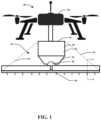
- FIG. 1is a schematic diagram of embodiments of an aerial vehicle with an air assist spray assembly in accordance with the instant disclosure
- FIG. 2is a schematic diagram of another embodiment of an aerial vehicle with an air assist spray assembly in accordance with the instant disclosure
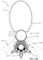
- FIG. 3is a cross sectional diagram of the air assist spray assembly through line A-A of FIGS. 1 and 2 in accordance with the instant disclosure;
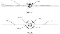
- FIG. 4is a plan view of an embodiment of the air assist spray assembly attached to a rotorcraft according to the instant disclosure
- FIG. 5is a top view of the air assist spray assembly attached to a rotorcraft according to FIG. 4 ;
- FIG. 6is a top view of an embodiment of the air assist spray assembly of the instant disclosure in a retracted position
- FIG. 7is a side view of the air assist spray assembly of FIG. 6 in a retracted position
- FIG. 8is a top view of an embodiment of the air assist spray assembly of the instant disclosure in a retracted position
- FIG. 9 Ais a side view of an embodiment of the air assist spray assembly of the instant disclosure in a retracted position
- FIG. 9 Bis an enlarged view of a coupling member of the air assist spray assembly of FIG. 9 A ;
- FIG. 10is a perspective view of an embodiment of the air assist spray assembly of the instant disclosure.
- FIG. 11 Ais an enlarged view of a portion of the air assist spray assembly of FIG. 10 ;
- FIG. 11 Bis an enlarged view of a portion of the air assist spray assembly of FIG. 10 ;
- FIG. 11 Cis an enlarged view of a portion of the air assist spray assembly of FIG. 10 ;
- FIG. 12is a top view of an embodiment of the air assist spray assembly of the instant disclosure in an extended position
- FIG. 13 Ais a side view of an embodiment of the air assist spray assembly of the instant disclosure in an extended position
- FIG. 13 Bis a cross sectional view of a portion of the air assist spray assembly of FIG. 13 A ;
- FIG. 13 Cis an enlarged view of a coupling member of the air assist spray assembly in the extended positon of FIG. 13 A ;
- FIG. 13 Dis a cross sectional view of the coupling member of FIG. 13 C ;
- FIG. 13 Eis a perspective cross sectional view of the coupling member of FIG. 13 C ;
- FIG. 14 Ais a top view of an embodiment of the air assist spray assembly of the instant application.
- FIG. 14 Bis a side view of an embodiment of the air assist spray assembly of the instant application.
- FIG. 14 Cis a cross sectional view of an embodiment of the air assist spray assembly of FIG. 14 B ;
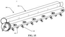
- FIG. 15is a perspective view of portions of the air assist spray assembly of the instant application.
- FIG. 16is an exploded perspective view of portions of the air assist spray assembly of the instant application.
- an air assist spray assembly 10that is adapted to dispense a fluid product such as an insecticide, fungicide, fertilizer, or other such fluid or chemical that may be desired to be applied to a large agricultural space.
- the air assist spray assembly 10is configured to be used and designed to be used with an aerial vehicle.
- the aerial vehiclemay be an unmanned aerial vehicle (UAV) 20 as illustrated by FIG. 1 , a airplane 22 as illustrated by FIG. 2 or other type of aircraft.
- UAVunmanned aerial vehicle
- FIG. 2a airplane 22 as illustrated by FIG. 2 or other type of aircraft.
- this disclosureis not limited as the air assist spray assembly 10 may be used with various different types of aerial vehicles such as helicopters, hovercrafts, fixed wing airplanes, balloons, transitional flight vehicles, gyroplanes, or gyrocopters.
- the air assist spray assembly 10will be discussed as attaching to an aerial vehicle herein. However, it has been identified to be particularly useful when attached to aerial vehicles considered rotorcraft.
- rotorcraftas used herein means any aerial vehicles that rely on rotary wings or rotor blades to generate lift by rotating around a vertically oriented mast.
- Rotorcraftcan include vertical take off and landing aircraft such as unmanned aerial vehicles (drones), helicopters, gyrocopters, gyroplanes, rotaplanes, gyrodynes, rotor kites, or even transitional flight vehicles such as the US Air Force's Osprey aircraft.
- unmanned aerial vehiclesdrones
- helicoptersgyrocopters
- gyroplanesrotaplanes
- gyrodynesrotaplanes
- rotor kitesor even transitional flight vehicles
- transitional flight vehiclessuch as the US Air Force's Osprey aircraft.
- the air assist spray assembly 10is configured to extend from an aerial vehicle 20 , 22 . It may be securely attached by a mount assembly 30 to the aerial vehicle to allow for structural stability during flight. In one embodiment, secured attachment and detachment may be performed using a hitch mount assembly as disclosed by U.S. Published Patent No. 2019/0061944 which is incorporated by reference in its entirety.
- a hitch mount assembly 30may include a gimbal system that may include associated control and sensing systems to allow for the air assist spray assembly 10 to be maintained at a generally level orientation relative to the desired region to receive the spray application.
- the air assist spray assembly 10may include a boom structure 40 that extends from the mount assembly 30 and includes a discharge channel intended for the discharge of a desired substance in liquid or in solid form.
- the boom structure 40includes two sections that extend across the field with each section extending laterally from each side of a mount assembly 30 .
- the mount assemblymay allow for pivoting of the boom structure 40 between a working position and a transport position.
- the boom structure 40may include a plurality of support sections and may include wire supports 42 and/or frame support members. In an embodiment, the boom structure may extend about 25 feet in length having any length is generally contemplated herein.
- the mount assembly 30may be configured to support a hopper or storage container 32 may define a cavity 34 capable of containing a liquid product.
- the container 32may be selectively attached to the boom structure 40 to provide the liquid product thereto for distribution therefrom.
- a pressurization device 36may be attached to the mount assembly 30 and in communication with the boom structure to provide pressurized air thereto for distribution therefrom.
- the pressurization device 36may be configured receive inlet air during operation and increase the pressure of the air to be provided along the boom structure 40 .
- a discharge valve 38may be provided at or near the coupling of the container 32 and or the pressurization device 36 and the air assist spreader assembly 10 . When closed, the discharge valve may hold any product within the container from entering into the spreader.
- FIG. 3illustrates a cross sectional view of the boom structure 40 along line A-A of both FIGS. 1 and 2 along vertical axis X and horizontal axis Y.
- the boom structure 40may include a discharge channel 50 , a plurality of spray nozzles 60 , and an elongated air passageway 70 .
- the discharge channel 50may be in fluid communication with the container 32 to allow liquid product to be provided to the plurality of spray nozzles 60 aligned along the discharge channel 50 .
- the discharge channel 50may be a generally elongated conduit having a perimeter.
- the perimeter shape of the discharge channelmay be generally cylindrical, or may have an airfoil shape (not shown) to assist with aerodynamic motion of the boom structure 40 when in use.
- the plurality of spray nozzles 60may be configured to distribute fluid product from the discharge channel 50 .
- the spray nozzles 60may be pivotally attached to the discharge channel 50 to allow for adjustment of the angle of the nozzle.
- the spray nozzle 60may be configured to process fluid therethrough in a way that would produce a spray of fluid droplets to be applied to vegetation below.
- the spray of fluid dropletsmay include various size droplets including fine droplets and coarse droplets to allow for the fluid product to apply and penetrate a vegetation canopy.
- the spray nozzlemay be configured to be adjusted to spray only fine droplets or only coarse droplets or a mixture of both types of fine and coarse droplets as desired. Notably, the heavier or larger the droplet size of the fluid spray the more inertia and penetration of fluid product would occur through the vegetation canopy.
- the spray nozzlemay include an air inlet 62 along its perimeter to allow ambient air to enter a nozzle head and be mixed with the fluid prior to be distributed through a nozzle exit.
- This air inlet 62may allow for adjustments and may allow a user to modify the fine/coarse spray sizes of fluid distributed therefrom.
- the plurality of spray nozzles 60may be an electrostatic spray nozzle.
- the spray nozzlemay include a conductor configured to produce a voltage charge to the flow of fluid through the nozzle head.
- the conductormay be configured to apply a positive or a negative charge to the fluid prior to it being emitted from the nozzle.
- Spray droplets emitted through the electrostatic spray nozzlemay be charged and when such charged droplets approach the vegetation, an opposite charge on the vegetation activates electrostatic forces and attracts the charged droplets to all sides of the vegetation.
- the boom structure 40may also include an air curtain system to assist with diverting the dispensed fluid from the plurality of spray nozzles 60 .
- the air curtain systemmay assist with directing sprayed fluid that may include fine or coarse charged droplets towards intended vegetation.
- the combination of an air curtain system along with an electrostatic charge to both fine and coarse sized dropletsmay cause improved canopy penetration and improve the efficiency of aerial application of fluid chemicals over an increased portion of the vegetation to increase application yield. This assembly and system to increase canopy penetration as well as reduce waist will reduce waste and volume of chemicals needed in the agriculture market.
- the air curtain systemmay include a rear air curtain 100 A.
- the air curtain systemmay include a front air curtain 100 B. Further, the air curtain system may include both front and rear air curtains 100 A, 100 B.
- Each of the front and rear air curtains 100 A, 100 Bmay include a plurality of air nozzles 80 A, 80 B.
- the air nozzlesmay be configured to receive pressurized air from the elongated air passageway 70 .
- the plurality of air nozzles 80 B along the front air curtain 100 Bmay be positioned adjacent the spray nozzles 60 but be positioned along a forward direction of the boom 40 .
- the plurality of air nozzles 80 A along the rear air curtain 100 Amay be positioned adjacent the spray nozzles 60 but be positioned along a rearward direction of the boom 40 .
- the elongated air passageway 70may be made of any material including hose, tube, nylon, polymers and may be generally rigid or generally flexible. Further, at least one valve may be positioned along the elongated air passageway 70 , preferably towards the ends away from the mounting assembly 30 to assist with regulating pressure therein.
- FIGS. 4 through 16illustrate another embodiment of the air assist spray assembly 110 disclosed herein.
- FIG. 4illustrates a front view of the assembly attached to a rotorcraft 120 .
- the rotorcraft 120is a vertical take off and landing unmanned aerial vehicle.
- the air assist spray assembly 110is configured to extend from the rotorcraft 120 as defined herein or even an airplane 22 .
- the air assist spray assembly 110may include a base frame 130 for secure attachment to the rotorcraft 120 .
- the base frame 130may be securely attached by a mount assembly as discussed above to allow for structural stability during flight.
- secured attachment and detachmentmay be performed using a hitch mount assembly as disclosed by U.S. Published Patent No.
- Such a hitch mount assemblymay include a gimbal system that may includes associated control and sensing systems to allow for the air assist spray assembly 110 and its boom structure to be maintained at a generally level orientation relative to the desired area intended to receive the spray application. It may also allow for controlled adjustment of the angle of the boom structure 140 relative to the rotorcraft 120 to allow the assembly 100 to traverse uneven terrain.
- the base frame 130 and mount assemblymay allow the boom structure 140 to adjust up to about 30 degrees relative to the horizon along the direction as annotated by arrows A of FIG. 4 while the rotorcraft 120 may maintain its level flight pattern.
- the boom structure 140may be supported by one or more wires 142 to allow the boom structure to extend outwardly from the rotorcraft 120 .
- the wires 142may be attached to one ore more portions of the boom structure 140 and one or more portions of the base frame 130 .
- the boom structuremay include a first elongated member 144 and a second elongated member 146 wherein each member may be extend from a base frame 130 .
- this disclosuremay incorporate any number and any size of elongated members as may be practical for the desired application.
- the base frame 130may be attached to the mount assembly which is attachable to the rotorcraft 120 .
- the first elongated member 144may extend and be aligned along a common axis with the second elongated member 146 that extends opposite from the rotorcraft 120 when in an extended operable position as illustrated by FIGS. 4 and 5 .
- the first elongated member 144 and second elongated member 146may also be configured to be arranged in a retracted position for storage or transport such as disclosed by FIGS. 6 - 9 B .
- the base frame 130may be configured to support a hopper or storage container 132 that may define a cavity capable of containing a liquid product.
- the container 132may be selectively attached to the base frame 130 or boom structure 140 to provide the liquid product thereto for distribution therefrom.
- the storage container 132may also include a fluid pressurization device 134 such as a pump and related fittings and hoses to distribute fluid from the container 132 to the spray nozzles positioned along an elongated discharge channels of the first and second elongated members 144 , 146 .
- the fluid pressurization device 134may be attached to the container 132 or positioned in a housing adjacent to the container 132 that is located on the base frame 130 .
- An air pressurization device 136may be attached to the base frame 130 and be configured in communication with the boom structure to provide pressurized air thereto for distribution therefrom.
- the pressurization device 136may be a motorized fan that is configured receive inlet air during operation and increase the pressure of the air to be provided along the boom structure 140 and in particular along an elongated air curtain system 200 and associated air passageway 170 as will be discussed more fully below.
- a discharge valve 138may be provided at or near the coupling of the container 132 and or the fluid pressurization device 134 .
- the discharge valve 138may be manually or automatically operated to toggle it between an opened and closed position. When closed, the discharge valve may prevent any fluid within the container from entering into the elongated members 144 , 146
- first elongated member 144 and second elongated member 146may each have a common length and configuration. However, the first and second elongated members may also have different configurations, lengths, configurations of spray and air nozzles, etc. which are contemplated herein.
- Eachmay include a plurality of sections 148 that are coupled to one another that will allow for each section to be supported in an elongated aligned configuration when in the operable positon (i.e., FIGS.
- FIG. 6illustrates a top view of the assembly 110 having sections 148 A of the first elongated member 144 positioned in general parallel alignment with sections 148 B of the second elongated member 146 .
- the first and second elongated members 144 , 146are moveably attached to the base frame and are capable of rotating relative to the base frame 130 to be positioned in generally parallel alignment.
- the boom structure 140may include fasteners that lock the first and second elongated members 144 , 146 in place in the operable position (i.e., FIGS. 5 and 5 ) while the first and second elongated members may be retracted by disengagement of fasteners or other hinge members to be placed in the retracted position.
- any type of fastener, hinge or other devicemay be applied to configure the boom structure 140 between the operable extended position and the various retracted positions. Further, the plurality of sections 148 may be swiveled, bent or rotated along coupling sections 150 to further brake down the assembly 120 into the various retracted positions.
- the first elongated member 144 and three sections 148 Aare illustrated in a retracted positon.
- the three sections 148 Ainclude a fuselage section 152 A positioned adjacent to the base frame 130 , an inboard section 154 A coupled to the fuselage section 152 A by coupling section 150 i , and an outboard section 156 A coupled to the inboard section 154 A by a second coupling section 150 ii .
- the outboard section 156 Ais illustrated as being swiveled about 180 degrees relative to the inboard section 154 A such that the outboard section 156 A is positioned to abut along the inboard section 154 A.
- the air passageway 170may be compressed or flattened between the outboard section 156 A and the inboard section 154 A.
- the retracted outboard section 156 A and inboard section 154 Amay also be swiveled along the coupling section 150 i between the inboard and fuselage sections to further retract the first elongated member 144 from the extended position to a retracted storage position.
- both the first and second elongated members 144 , 146are configured to be extended or retracted as disclosed herein.
- FIGS. 9 A and 9 Billustrate the coupling member 150 that includes a flexible hose assembly 158 that allows for the swiveling, bending, or rotating action between the sections 148 A, 148 B of the first and second elongated members 144 , 146 .
- the sections 148 A, 148 B along the first and second elongated members 144 , 146respectively may each include an air passageway portion 170 , a discharge channel portion 180 , and an air manifold portion 190 (See FIG. 13 B ).
- the coupling member 150allows for the respective air passageway portions 170 of adjacent sections to swivel between the extended position and retracted position while allowing for the communication of pressurized air along the air passageway portions 170 in the operating positon.
- the coupling member 150also allows for the respective discharge channel portions 180 of adjacent sections to swivel between the operating position and storage positions while allowing for the communication of pressurized fluid along the discharge channel portions 180 through the flexible hose assembly 158 .
- the coupling member 150also allows for respective air manifold portions 190 of adjacent sections to swivel between the extended operating position and retracted positions while allowing respective air manifold portions to toggle the air passageway portions 170 to allow pressurized air to be dispensed therefrom in the extended position.
- the air manifold portions 190are illustrated to be separated in FIG. 9 B wherein the separate ends are separated when in the retracted position and engaged in the extended position.
- the separate ends of adjacent air manifold portions 190may be made of a flexible material that allows the elongated manifold to be toggled to allow first and second air curtains to form from a plurality of air nozzles along both the front side and the rear side as will be described more fully below.
- FIG. 10is a perspective view of the first elongated member 144 of the air assist spray assembly when positioned in the extended operating position.
- FIGS. 11 A, 11 B, and 11 Cillustrate close up portions of the first elongated member 144 of FIG. 10 .
- FIG. 12is a fractioned top view of FIG. 10 and FIG. 13 A is a side view.
- each section 148 Amay be aligned along a common axis relative to one another and extends from the base frame 130 of the assembly.
- the base frame 130may be attached to the aerial vehicle by a hitch assembly (not shown).
- first elongated member 144is illustrated to include the plurality of sections 148 A wherein the description of the sections of the first elongated member 144 may also describe the plurality of sections 148 B of the second elongated member 146 .
- the elongated membersinclude a plurality of spray nozzles 160 positioned along an elongated discharge channel 162 .
- the elongated discharge channelmay comprise a plurality of sections or portions 180 attached to one another and in fluid communication relative to one another by way of the coupling members 150 and the flexible hose assemblies 158 .
- Each section or portion 180 of the elongated discharge channel 162may include the plurality of spray nozzles 160 configured to dispense spray droplets therefrom.
- the discharge channel 162is intended for the discharge of a desired fluid as it may be received from the storage container 132 .
- the spray nozzlesare rotary atomizer type nozzles.
- the spray nozzles 160may be electrostatic type nozzles.
- the plurality of spray nozzles 160may be any type or commination of spray nozzles configured to spray a liquid product from an aerial vehicle.
- the spray nozzles 160may be configured to dispense both a fine spray droplet size and a course spray droplet size or be toggled to dispense one or the other.
- the spray nozzles 160may receive a power from a local power supply positioned on the aerial vehicle 120 or base frame 130 .
- the plurality of nozzlesmay also be in communication with a control system 210 of the air assist spray assembly 110 .
- the control systemmay be configured to turn the sprays on or off or to toggle between fine and coarse sprays, operate the rotary atomizer, or toggle power to the electrostatic nozzles.
- the control system 210can also be configured to toggle various sections of spray nozzles between fine and coarse sprays or to toggle the electrostatic, or rotary function of such rotary atomizer nozzles as well as electrostatic nozzles of various sections 148 along the members 144 , 146 .
- FIGS. 11 A, 11 B, and 11 Cillustrate enlarged perspective views along portions of the elongated member 144 including the coupling member 150 , an end portion of the first elongated member 144 , and its attachment to the base frame 130 , storage container 132 , and pressurization device 136 .
- air manifold assembly 190may be attached to a portion of the base frame 130 at an actuator member 202 .
- the actuator member 202may be able to rotate a portion of the air manifold assembly 190 to toggle the air pressure distributed from a plurality of air nozzles or apertures aligned along the air passageways as will be discussed more below.
- FIG. 13 Ais a side view of the air assist assembly 110 attached to the aerial vehicle 120 and configured in the operating position.
- Cross sectional views of section 148 Aare shown along line 13 B- 13 B and an enlarged view of the coupling member 150 is illustrated by call out 13 C.
- FIG. 13 Billustrates a cross sectional view of the elongated air curtain system 200 and associated air passageway 170 of the air assist assembly 110 .
- the air curtain system 200that includes the elongated air passageway positioned along at least one of the first elongated member and the second elongated member, the air curtain system is configured to distribute pressurized air from the elongated air passageway 170 .
- the air curtain systemis configured to assist with directing the spray droplets from the plurality of spray nozzles towards a desired area while said rotorcraft type unmanned aerial vehicle is in flight. This particularly assists with reducing off target drift and may further be bolstered when using at least one electrostatic spray nozzle 160 .
- the air passageway 170may be made of a flexible material and attached to the air manifold assembly 190 .
- the air manifold assembly 190may include an air channel 192 and a baffle shroud 194 .
- the air channel 192may be positioned in the baffle shroud 194 to allow for the air channel 192 to slightly rotate relative to the baffle shroud 194 to route pressurized air through the air nozzles 198 along the baffle shroud to form a first air curtain 220 A and/or a second air curtain 220 B along both the front and/or the rear sides of the spray nozzles 160 .
- the air passagewaymay be attached to the air channel 192 to route pressurized air therethrough.
- the air passageway 170may be bonded to the air channel.
- the air channel 192may be an elongated channel along sections of the members 144 , 146 that extends between coupling members 150 and allows pressurized air from the air passage to be expressed from a plurality of slots or holes 196 (See FIG. 16 ).
- the baffle shroud 194may include a plurality of slots or holes considered air nozzles 198 that may be radially aligned along the baffle shroud 194 .
- the air nozzles 198may include louvers placed along the exterior of the baffle shroud 194 wherein the louvers may be manually or automatically adjusted to direct expressed air therefrom to allow for the adjustment of the direction of the formed air curtain.
- the air nozzles 198may be aligned with the plurality of slots 196 of the air channel 192 and may be rotated to be in or out of alignement.
- pressurized airmay be routed through the air passageway 170 and through the air channel 192 and the plurality of holes 196 to be expressed through the air nozzles 198 along the baffle shroud 194 .
- the first or second air curtainsmay be formed.
- the air channel 192may be controlled to be rotated to align the holes 196 with the air nozzles 198 of the baffle shroud 194 .
- the plurality of first air outlets 198 Amay form the first air curtain 220 A and the plurality of second air outlets 198 B may form the second air curtain 220 B.
- the first air curtain 220 Amay be directed a first direction from the boom structure 140 and the plurality of second air outlets 198 B are configured to dispense air to form the second air curtain 220 B along a second direction of the boom structure 140 , wherein the first air outlets 198 A are positioned along a first side of a plurality of spray nozzles 160 and the second air outlets 198 B are positioned along a second side of the plurality of spray nozzles 160 , wherein the first side is generally opposite from the second side as illustrated by FIG. 13 B .
- the air manifold assembly 190is configured to toggle the air curtain system to at least one of (i) dispense air to only form the first air curtain 220 A, (ii) dispense air to only form the second air curtain 220 B, (iii) dispense air to form both the first air curtain and the second air curtain, (iv) not dispense air from any of the air nozzles 198 .
- Thismay be accomplished by rotating the baffle shroud 194 relative to the air channel 192 to align the holes in predetermined relationships to rout pressurized air therefrom.
- the rotatable configuration between the baffle shroud 194 and air channel 192may be supported by elastic members to prevent the air channel 192 from disengagement with the baffle shroud 194 . Their may exist a small space between the air channel and baffle shroud to allow for rotation thereto.
- the elongated air passageway 70may be made of any material including hose, tube, nylon, polymers and may be generally rigid or generally flexible.
- the air passageway 170is made from a sealed material such as canvas, silk, Dacron, Kevlar, or Nylon or otherwise materials used in parachute fabrics.
- FIG. 13 C and FIG. 13 Dillustrate an enlarged view of the coupling member 150 and a cross sectional view of the coupling member 150 , respectively. It illustrates that end portions 195 of the baffle shroud 194 ( FIG. 13 E ) may be overlapped and otherwise engaged one another by respective end portions 195 .
- the end portions 195 of the baffle shrouds 194may be formed with a flexible material to allow for respective sections to be biased between the extended position and the retracted positions while allowing the end portions to be able to translate rotatable force between respective sections 148 along the elongated members 144 , 146 .
- the end portions 195 of the baffle shrouds 194may be generally complementary shaped to one another and otherwise overlap and be relatively flexible to allow for the baffle shroud 194 to be rotated relative to the air channel 192 from a rotatable force provided by the actuator member 202 at the base frame 130 .
- the elongated discharge channel 162may be in fluid communication with the container 132 to allow liquid product to be provided to the plurality of spray nozzles 160 aligned along the discharge channel 162 .
- the discharge channel 162may be a generally elongated conduit having a perimeter.
- the perimeter shape of the discharge channelmay be generally hexagonal, cylindrical, or may have an airfoil shape.
- the hexagonal shapeallows for a plurality of spray nozzles to be positioned along each flat side and dispersed separately as illustrated by FIG. 13 C . This configuration allows for three (3) spray nozzles 160 to be radially aligned to one another along the length of the discharge channel 162 and may be adjusted to provide desired spray volume and coverage.
- the plurality of spray nozzles 160may be configured to distribute fluid product directly from the discharge channel 162 .
- the spray nozzles 160may be pivotally attached to the discharge channel 162 to allow for adjustment of the angle of the nozzle.
- the spray nozzles 160may capped when not in use or be configured to process fluid therethrough in a way that would produce a spray of fluid droplets to be applied to vegetation below.
- the spray of fluid dropletsmay include various size droplets including fine droplets and coarse droplets to allow for the fluid product to apply and penetrate a vegetation canopy.
- the spray nozzles 160may be configured to be adjusted to spray only fine droplets or only coarse droplets or a mixture of both types of fine and coarse droplets as desired. Notably, the heavier or larger the droplet size of the fluid spray the more inertia and penetration of fluid product would occur through the vegetation canopy.
- FIGS. 14 A, 14 B, 14 C, and 15illustrate various images of an embodiment the instant application that does not include the air passageway 170 .
- airmay be routed through the air manifold 190 to form the first and second air curtains.
- At least one of the plurality of spray nozzles 160may be an electrostatic spray nozzle.
- the spray nozzlemay include a conductor configured to produce a voltage charge to the flow of fluid through the nozzle head.
- the conductormay be configured to apply a positive or a negative charge to the fluid prior to it being emitted from the nozzle.
- Spray droplets emitted through the electrostatic spray nozzlemay be charged and when such charged droplets approach the vegetation, an opposite charge on the vegetation activates electrostatic forces and attracts the charged droplets to all sides of the vegetation.
- the air curtain system 200assists with diverting the dispensed fluid from the plurality of spray nozzles 160 .
- the air curtain system 200may assist with directing sprayed fluid that may include fine or coarse charged droplets towards intended vegetation.
- the combination of an air curtain system along with an electrostatic charge to both fine and coarse sized dropletsmay cause improved canopy penetration and improve the efficiency of aerial application of fluid chemicals over an increased portion of the vegetation to increase application yield. This assembly and system to increase canopy penetration as well as reduce waist will reduce waste and volume of chemicals needed in the agriculture market.
- the air assist spray assembly 110may include a control system 210 configured to operate the fluid pressurization device 134 , the air pressurization device 136 , the discharge valve 138 , the actuator member 202 , and plurality of spray nozzles 160 .
- the control system 210may include a plurality of various sensors that are in communication with the rotorcraft 120 or a remote control device or remote interface. The control system may be configured to detect a level of fluid remaining in the container 132 as well as sense and toggle the level of pressure in both the air and fluid systems.
- the control system 210may also be programmed to perform specific adjustments to each of its components based on a desired or programmed flight path of the rotorcraft 120 to allow for automatic adjustments of the combined assembly and system.
- the air assist spray assembly 110is beneficial for any type of fluid aerial spraying applications that require precise spray control that allow for reduced drift of sprayed while also allowing electrostatic charged sprays for chemical applications.
- the described assembly and systemis configured to minimize drift, maximize efficiency of use, improve canopy penetration, increase the window of opportunity for spray application due to wind or climate, and increase vegetation coverage of desired fluid.
Landscapes
- Life Sciences & Earth Sciences (AREA)
- Engineering & Computer Science (AREA)
- Pest Control & Pesticides (AREA)
- Aviation & Aerospace Engineering (AREA)
- Insects & Arthropods (AREA)
- Wood Science & Technology (AREA)
- Zoology (AREA)
- Environmental Sciences (AREA)
- Catching Or Destruction (AREA)
- Medicinal Preparation (AREA)
Abstract
Description
Claims (19)
Priority Applications (1)
| Application Number | Priority Date | Filing Date | Title |
|---|---|---|---|
| US17/201,615US12162028B2 (en) | 2020-03-13 | 2021-03-15 | Air assist spray assembly |
Applications Claiming Priority (2)
| Application Number | Priority Date | Filing Date | Title |
|---|---|---|---|
| US202062988992P | 2020-03-13 | 2020-03-13 | |
| US17/201,615US12162028B2 (en) | 2020-03-13 | 2021-03-15 | Air assist spray assembly |
Publications (2)
| Publication Number | Publication Date |
|---|---|
| US20210283639A1 US20210283639A1 (en) | 2021-09-16 |
| US12162028B2true US12162028B2 (en) | 2024-12-10 |
Family
ID=75396893
Family Applications (1)
| Application Number | Title | Priority Date | Filing Date |
|---|---|---|---|
| US17/201,615Active2041-12-15US12162028B2 (en) | 2020-03-13 | 2021-03-15 | Air assist spray assembly |
Country Status (4)
| Country | Link |
|---|---|
| US (1) | US12162028B2 (en) |
| AU (1) | AU2021236407A1 (en) |
| CA (1) | CA3175306A1 (en) |
| WO (1) | WO2021183997A1 (en) |
Families Citing this family (9)
| Publication number | Priority date | Publication date | Assignee | Title |
|---|---|---|---|---|
| US12049317B2 (en)* | 2018-01-03 | 2024-07-30 | Wilcox Industries Corp. | Unmanned aerial system for crowd control |
| US11858630B2 (en)* | 2020-02-13 | 2024-01-02 | Biocarbon Engineering Ltd. | Planting system having oscillating seed agitator |
| CN113941468B (en)* | 2021-11-05 | 2022-11-01 | 武汉市工程科学技术研究院 | Multipurpose unmanned aerial vehicle shower nozzle |
| KR102427259B1 (en)* | 2021-12-08 | 2022-08-01 | 유웅재 | Drone for weeding at the photovolatic generating facilities |
| KR102409043B1 (en)* | 2021-12-31 | 2022-06-16 | 한국수산자원공단 | Drone for release of fry and young shellfish |
| CN114467455A (en)* | 2022-01-11 | 2022-05-13 | 山东省农业科学院 | A field corn foliar fertilizer spraying management and control system and method |
| CN114506457A (en)* | 2022-03-11 | 2022-05-17 | 山东理工大学 | Large-load plant protection unmanned aerial vehicle with adjustable spraying amplitude and pesticide application amount |
| JP7673715B2 (en) | 2022-08-26 | 2025-05-09 | トヨタ自動車株式会社 | Control device, control method, and program |
| CN119018350B (en)* | 2024-10-30 | 2025-01-28 | 山西观复智能科技有限公司 | A high-altitude UAV spraying efficiency enhancement device and UAV |
Citations (78)
| Publication number | Priority date | Publication date | Assignee | Title |
|---|---|---|---|---|
| US1142074A (en) | 1914-03-19 | 1915-06-08 | William Woodward | Internal-combustion engine. |
| US4553702A (en)* | 1982-02-05 | 1985-11-19 | Imperial Chemical Industries Plc | Spraying system |
| US4982898A (en) | 1989-01-06 | 1991-01-08 | Tecnoma | Device for projecting a treatment product onto plants |
| US5971295A (en) | 1993-12-17 | 1999-10-26 | Hardi International A/S | Agricultural sprayer unit and an air-flow generating assembly of an agricultural sprayer unit |
| US6457761B1 (en) | 2000-09-12 | 2002-10-01 | Grapple Works, Inc. | Detachable rotatable grapple |
| US20040016820A1 (en) | 2002-07-26 | 2004-01-29 | Peter Jones | Aircraft and spray booms for aircraft |
| DE102010010508A1 (en) | 2010-03-06 | 2011-09-08 | Diehl Bgt Defence Gmbh & Co. Kg | Unmanned aircraft for carrying and throwing missiles, comprises cargo space, which is closed in outer side with hatch, where hatch opens downward, such that cargo elements are ejected downward from cargo space |
| US8087315B2 (en) | 2006-10-10 | 2012-01-03 | Honeywell International Inc. | Methods and systems for attaching and detaching a payload device to and from, respectively, a gimbal system without requiring use of a mechanical tool |
| US8162263B2 (en) | 2009-03-31 | 2012-04-24 | Honeywell International Inc. | Payload quick release for an aerial system |
| US20120153087A1 (en) | 2008-08-06 | 2012-06-21 | Honeywell International Inc. | Modular Pods for Use with an Unmanned Aerial Vehicle |
| US8251307B2 (en) | 2007-06-11 | 2012-08-28 | Honeywell International Inc. | Airborne manipulator system |
| US8752796B2 (en) | 2011-09-02 | 2014-06-17 | Sikorsky Aircraft Corporation | Automatic jettison system for a rotorcraft |
| CN204110368U (en) | 2014-08-29 | 2015-01-21 | 深圳一电科技有限公司 | The Cloud Terrace rapid dismounting apparatus and unmanned plane |
| CN204527648U (en) | 2015-04-21 | 2015-08-05 | 刘亚敏 | For the grabbing device of multi-rotor aerocraft |
| CN204713430U (en) | 2015-04-16 | 2015-10-21 | 深圳一电科技有限公司 | For the clip of unmanned plane |
| CN105035336A (en) | 2015-07-23 | 2015-11-11 | 国网辽宁省电力有限公司葫芦岛供电公司 | Unmanned aerial vehicle hoisting device for electric transmission line parts |
| CN204776056U (en) | 2015-06-24 | 2015-11-18 | 哈瓦国际航空技术(深圳)有限公司 | Cloud platform quick assembly disassembly device |
| WO2015177760A2 (en) | 2014-05-23 | 2015-11-26 | Zhou Tiger | Unmanned drone, robot system for delivering mail, goods, humanoid security, crisis negotiation, mobile payments, smart humanoid mailbox and wearable personal exoskeleton heavy load flying machine |
| CN204871622U (en) | 2015-07-30 | 2015-12-16 | 零度智控(北京)智能科技有限公司 | Unmanned aerial vehicle GPS device |
| CN204871626U (en) | 2015-08-11 | 2015-12-16 | 深圳市前海疆域智能科技股份有限公司 | Cloud platform connection structure , cloud platform and aircraft |
| CN204895855U (en) | 2015-09-11 | 2015-12-23 | 辽宁力德航空科技有限公司 | Many rotors of oil -electricity hybrid vehicle unmanned vehicles |
| US20160023761A1 (en) | 2014-07-22 | 2016-01-28 | Jonathan McNally | Method for installing an object using an unmanned aerial vehicle |
| US9280038B1 (en) | 2014-04-28 | 2016-03-08 | SZ DJI Technology Co., Ltd. | Interchangeable mounting platform |
| CN105438491A (en) | 2015-12-07 | 2016-03-30 | 小米科技有限责任公司 | Quick disassembly and assembly structure of holder and unmanned aerial vehicle |
| US9346547B2 (en) | 2013-08-26 | 2016-05-24 | Google Inc. | Mechanisms for lowering a payload to the ground from a UAV |
| CN105697957A (en) | 2016-02-29 | 2016-06-22 | 深圳电航空技术有限公司 | Support workbench fixing mechanism and unmanned plane |
| US9382003B2 (en) | 2013-03-24 | 2016-07-05 | Bee Robotics Corporation | Aerial farm robot system for crop dusting, planting, fertilizing and other field jobs |
| US20160198088A1 (en) | 2014-12-23 | 2016-07-07 | SZ DJI Technology Co., Ltd | Uav panoramic imaging |
| US20160207627A1 (en) | 2015-01-16 | 2016-07-21 | International Business Machines Corporation | Package transport container and transport operations for an unmanned aerial vehicle |
| US9487292B2 (en) | 2013-03-07 | 2016-11-08 | Airbus Helicopters | System for fastening a load to a rotorcraft, and a rotorcraft |
| CN106081113A (en) | 2016-06-28 | 2016-11-09 | 安徽扫宝智能科技有限公司 | A kind of electric power overhead electrical network fire-fighting six rotorcraft |
| US9493232B2 (en) | 2013-07-31 | 2016-11-15 | SZ DJI Technology Co., Ltd. | Remote control method and terminal |
| CN106114879A (en) | 2016-08-01 | 2016-11-16 | 武汉拓普新科无人机科技有限公司 | A kind of unmanned plane carry Quick-disassembling mechanism |
| WO2016185572A1 (en) | 2015-05-19 | 2016-11-24 | 株式会社0 | Rotorcraft |
| WO2016190994A1 (en) | 2015-05-27 | 2016-12-01 | Gopro, Inc. | Camera system using stabilizing gimbal |
| WO2017000299A1 (en) | 2015-07-02 | 2017-01-05 | 深圳市大疆创新科技有限公司 | Limit device and unmanned aerial vehicle having same |
| CN205872497U (en) | 2016-04-29 | 2017-01-11 | 易瓦特科技股份公司 | Cloud platform quick detach formula unmanned aerial vehicle |
| CN205891249U (en) | 2016-07-02 | 2017-01-18 | 江西联博科技有限公司 | Plant protection unmanned plane |
| WO2017008533A1 (en) | 2015-07-16 | 2017-01-19 | 张萍 | Unmanned aerial vehicle deployment apparatus |
| WO2017019728A1 (en) | 2015-07-27 | 2017-02-02 | Xworks Corporation | Method for unattended operations using autonomous or remotely operated vehicles |
| CN205931259U (en) | 2016-08-22 | 2017-02-08 | 南京理工大学 | Unmanned aerial vehicle grabs thing device |
| US9567081B1 (en) | 2015-06-26 | 2017-02-14 | Amazon Technologies, Inc. | Maneuvering a package following in-flight release from an unmanned aerial vehicle (UAV) |
| US9573684B2 (en) | 2013-10-26 | 2017-02-21 | Amazon Technologies, Inc. | Unmanned aerial vehicle delivery system |
| CN106428598A (en) | 2016-12-21 | 2017-02-22 | 陈翔斌 | Unmanned aerial vehicle and pan-tilt thereof |
| CN205971822U (en) | 2016-07-05 | 2017-02-22 | 衢州赋腾信息科技有限公司 | Unmanned aerial vehicle's delivery host computer |
| FR3040688A1 (en) | 2015-09-04 | 2017-03-10 | Cyril Anger | DEVICE FOR ROBOTIC ARMS MANIPULATORS FIXED TO A DRONE |
| CN206012972U (en) | 2016-07-25 | 2017-03-15 | 乐视控股(北京)有限公司 | A kind of general hanging piece base of unmanned plane |
| US20170081043A1 (en) | 2015-09-23 | 2017-03-23 | Wal-Mart Stores, Inc. | Portable unmanned delivery aircraft launch systems, and methods of delivering products utilizing aircraft launch systems |
| CN206107589U (en) | 2016-06-14 | 2017-04-19 | 中科遥感科技集团有限公司 | Airborne operation device of aerial remote sensing platform |
| US9630715B2 (en) | 2014-07-08 | 2017-04-25 | X Development Llc | Interaction during delivery from aerial vehicle |
| CN106585990A (en) | 2016-11-30 | 2017-04-26 | 湖北大秀天域科技发展有限公司 | Release device applicable to unmanned aerial vehicle |
| WO2017069524A1 (en) | 2015-10-20 | 2017-04-27 | Cj Korea Express Corportaion | Flight unit-based freight falling apparatus and system using the same |
| CN106628217A (en) | 2016-12-23 | 2017-05-10 | 深圳市道通智能航空技术有限公司 | Detachable tripod head connection device and unmanned aerial vehicle |
| CN106672240A (en) | 2017-03-10 | 2017-05-17 | 太仓韬信信息科技有限公司 | Material carrying platform of unmanned aerial vehicle |
| US20170144759A1 (en) | 2015-11-25 | 2017-05-25 | Chien-Kai Chiu | Plug-and-play multifunctional attachment of remote control rotorcraft |
| CN106794902A (en) | 2016-10-18 | 2017-05-31 | 深圳市大疆灵眸科技有限公司 | Connecting device and drone with the connecting device |
| CN206196773U (en) | 2016-11-23 | 2017-05-31 | 芜湖元一航空科技有限公司 | Agricultural unmanned plane drives fowl device |
| WO2017096392A1 (en) | 2015-12-04 | 2017-06-08 | Skycart Inc. | Autonomous unmanned aerial vehicle system for logistical delivery |
| WO2017099058A1 (en) | 2015-12-07 | 2017-06-15 | 高木 邦夫 | Transport system using unmanned aerial vehicle |
| CN106864752A (en) | 2017-03-18 | 2017-06-20 | 芜湖元航空科技有限公司 | Fire extinguisher bomb bomb droping gear is unloaded in a kind of grabbing for fire-fighting unmanned plane |
| US9688404B1 (en) | 2014-12-02 | 2017-06-27 | Amazon Technologies, Inc. | Stabilized airborne drop delivery |
| CN106892117A (en) | 2017-04-17 | 2017-06-27 | 聊城职业技术学院 | A kind of automatic Spraying-drawing apparatus of unmanned plane |
| CN206299660U (en) | 2016-12-08 | 2017-07-04 | 中国特种飞行器研究所 | A kind of middle-size and small-size unmanned airship hanging quick-release coupling |
| US20170203857A1 (en) | 2014-12-09 | 2017-07-20 | Daniel S O'Toole | Drone Docking Station and Delivery System |
| US9714012B1 (en) | 2016-01-22 | 2017-07-25 | International Business Machines Corporation | Power source element replacement during vehicle operation |
| CN106986031A (en) | 2017-03-18 | 2017-07-28 | 芜湖元航空科技有限公司 | A kind of unmanned plane grabbing device |
| CN107108042A (en) | 2016-09-21 | 2017-08-29 | 深圳市大疆创新科技有限公司 | Lock uint, unmanned plane and electronic equipment |
| US20170253335A1 (en) | 2016-03-02 | 2017-09-07 | Wal-Mart Stores Inc. | Unmanned aircraft systems with a customer interface system and methods of delivery utilizing unmanned aircraft systems |
| CN206476116U (en) | 2017-02-15 | 2017-09-08 | 江西中轻智能设备有限公司 | A kind of many rotor plant protection unmanned planes |
| US20170267348A1 (en) | 2015-10-14 | 2017-09-21 | Flirtey Holdings, Inc. | Packaging container for drone delivery |
| KR101780454B1 (en) | 2016-06-14 | 2017-09-21 | 유콘시스템 주식회사 | Delivery device installed drone for parcel service |
| US20180319499A1 (en) | 2015-11-02 | 2018-11-08 | Pulse Aerospace LLC | Disbursement system for an unmanned aerial vehicle |
| US10399676B2 (en) | 2014-03-31 | 2019-09-03 | Working Drones, Inc. | Indoor and outdoor aerial vehicles for painting and related applications |
| CN110217397A (en) | 2019-07-09 | 2019-09-10 | 农业农村部南京农业机械化研究所 | A kind of anti-spraying mechanism that floats of plant protection unmanned aerial vehicle |
| US20200329690A1 (en)* | 2017-11-21 | 2020-10-22 | Basf Agro Trademarks Gmbh | Unmanned aerial vehicle |
| US11014668B2 (en) | 2016-11-24 | 2021-05-25 | SZ DJI Technology Co., Ltd. | Agricultural unmanned aerial vehicle |
| US11065636B2 (en) | 2018-02-15 | 2021-07-20 | Wagner Spray Tech Corporation | Aerial fluid spraying system |
| US20220023904A1 (en)* | 2019-09-27 | 2022-01-27 | Bayer Aktiengesellschaft | A spray vehicle |
Family Cites Families (1)
| Publication number | Priority date | Publication date | Assignee | Title |
|---|---|---|---|---|
| US11242147B2 (en) | 2017-08-31 | 2022-02-08 | Precision Drone Services Intellectual Property, Llc | Aerial vehicle implement hitch assembly |
- 2021
- 2021-03-15USUS17/201,615patent/US12162028B2/enactiveActive
- 2021-03-15AUAU2021236407Apatent/AU2021236407A1/ennot_activeAbandoned
- 2021-03-15WOPCT/US2021/022339patent/WO2021183997A1/ennot_activeCeased
- 2021-03-15CACA3175306Apatent/CA3175306A1/enactivePending
Patent Citations (79)
| Publication number | Priority date | Publication date | Assignee | Title |
|---|---|---|---|---|
| US1142074A (en) | 1914-03-19 | 1915-06-08 | William Woodward | Internal-combustion engine. |
| US4553702A (en)* | 1982-02-05 | 1985-11-19 | Imperial Chemical Industries Plc | Spraying system |
| US4982898A (en) | 1989-01-06 | 1991-01-08 | Tecnoma | Device for projecting a treatment product onto plants |
| US5971295A (en) | 1993-12-17 | 1999-10-26 | Hardi International A/S | Agricultural sprayer unit and an air-flow generating assembly of an agricultural sprayer unit |
| US6457761B1 (en) | 2000-09-12 | 2002-10-01 | Grapple Works, Inc. | Detachable rotatable grapple |
| US20040016820A1 (en) | 2002-07-26 | 2004-01-29 | Peter Jones | Aircraft and spray booms for aircraft |
| US8087315B2 (en) | 2006-10-10 | 2012-01-03 | Honeywell International Inc. | Methods and systems for attaching and detaching a payload device to and from, respectively, a gimbal system without requiring use of a mechanical tool |
| US8251307B2 (en) | 2007-06-11 | 2012-08-28 | Honeywell International Inc. | Airborne manipulator system |
| US20120153087A1 (en) | 2008-08-06 | 2012-06-21 | Honeywell International Inc. | Modular Pods for Use with an Unmanned Aerial Vehicle |
| US8162263B2 (en) | 2009-03-31 | 2012-04-24 | Honeywell International Inc. | Payload quick release for an aerial system |
| DE102010010508A1 (en) | 2010-03-06 | 2011-09-08 | Diehl Bgt Defence Gmbh & Co. Kg | Unmanned aircraft for carrying and throwing missiles, comprises cargo space, which is closed in outer side with hatch, where hatch opens downward, such that cargo elements are ejected downward from cargo space |
| US8752796B2 (en) | 2011-09-02 | 2014-06-17 | Sikorsky Aircraft Corporation | Automatic jettison system for a rotorcraft |
| US9487292B2 (en) | 2013-03-07 | 2016-11-08 | Airbus Helicopters | System for fastening a load to a rotorcraft, and a rotorcraft |
| US9382003B2 (en) | 2013-03-24 | 2016-07-05 | Bee Robotics Corporation | Aerial farm robot system for crop dusting, planting, fertilizing and other field jobs |
| US9493232B2 (en) | 2013-07-31 | 2016-11-15 | SZ DJI Technology Co., Ltd. | Remote control method and terminal |
| US9346547B2 (en) | 2013-08-26 | 2016-05-24 | Google Inc. | Mechanisms for lowering a payload to the ground from a UAV |
| US9573684B2 (en) | 2013-10-26 | 2017-02-21 | Amazon Technologies, Inc. | Unmanned aerial vehicle delivery system |
| US10399676B2 (en) | 2014-03-31 | 2019-09-03 | Working Drones, Inc. | Indoor and outdoor aerial vehicles for painting and related applications |
| US9280038B1 (en) | 2014-04-28 | 2016-03-08 | SZ DJI Technology Co., Ltd. | Interchangeable mounting platform |
| WO2015177760A2 (en) | 2014-05-23 | 2015-11-26 | Zhou Tiger | Unmanned drone, robot system for delivering mail, goods, humanoid security, crisis negotiation, mobile payments, smart humanoid mailbox and wearable personal exoskeleton heavy load flying machine |
| US9630715B2 (en) | 2014-07-08 | 2017-04-25 | X Development Llc | Interaction during delivery from aerial vehicle |
| US20160023761A1 (en) | 2014-07-22 | 2016-01-28 | Jonathan McNally | Method for installing an object using an unmanned aerial vehicle |
| CN204110368U (en) | 2014-08-29 | 2015-01-21 | 深圳一电科技有限公司 | The Cloud Terrace rapid dismounting apparatus and unmanned plane |
| US9688404B1 (en) | 2014-12-02 | 2017-06-27 | Amazon Technologies, Inc. | Stabilized airborne drop delivery |
| US20170203857A1 (en) | 2014-12-09 | 2017-07-20 | Daniel S O'Toole | Drone Docking Station and Delivery System |
| US20160198088A1 (en) | 2014-12-23 | 2016-07-07 | SZ DJI Technology Co., Ltd | Uav panoramic imaging |
| US20160207627A1 (en) | 2015-01-16 | 2016-07-21 | International Business Machines Corporation | Package transport container and transport operations for an unmanned aerial vehicle |
| CN204713430U (en) | 2015-04-16 | 2015-10-21 | 深圳一电科技有限公司 | For the clip of unmanned plane |
| CN204527648U (en) | 2015-04-21 | 2015-08-05 | 刘亚敏 | For the grabbing device of multi-rotor aerocraft |
| WO2016185572A1 (en) | 2015-05-19 | 2016-11-24 | 株式会社0 | Rotorcraft |
| WO2016190994A1 (en) | 2015-05-27 | 2016-12-01 | Gopro, Inc. | Camera system using stabilizing gimbal |
| CN204776056U (en) | 2015-06-24 | 2015-11-18 | 哈瓦国际航空技术(深圳)有限公司 | Cloud platform quick assembly disassembly device |
| US9567081B1 (en) | 2015-06-26 | 2017-02-14 | Amazon Technologies, Inc. | Maneuvering a package following in-flight release from an unmanned aerial vehicle (UAV) |
| WO2017000299A1 (en) | 2015-07-02 | 2017-01-05 | 深圳市大疆创新科技有限公司 | Limit device and unmanned aerial vehicle having same |
| WO2017008533A1 (en) | 2015-07-16 | 2017-01-19 | 张萍 | Unmanned aerial vehicle deployment apparatus |
| CN105035336A (en) | 2015-07-23 | 2015-11-11 | 国网辽宁省电力有限公司葫芦岛供电公司 | Unmanned aerial vehicle hoisting device for electric transmission line parts |
| WO2017019728A1 (en) | 2015-07-27 | 2017-02-02 | Xworks Corporation | Method for unattended operations using autonomous or remotely operated vehicles |
| CN204871622U (en) | 2015-07-30 | 2015-12-16 | 零度智控(北京)智能科技有限公司 | Unmanned aerial vehicle GPS device |
| CN204871626U (en) | 2015-08-11 | 2015-12-16 | 深圳市前海疆域智能科技股份有限公司 | Cloud platform connection structure , cloud platform and aircraft |
| FR3040688A1 (en) | 2015-09-04 | 2017-03-10 | Cyril Anger | DEVICE FOR ROBOTIC ARMS MANIPULATORS FIXED TO A DRONE |
| CN204895855U (en) | 2015-09-11 | 2015-12-23 | 辽宁力德航空科技有限公司 | Many rotors of oil -electricity hybrid vehicle unmanned vehicles |
| US20170081043A1 (en) | 2015-09-23 | 2017-03-23 | Wal-Mart Stores, Inc. | Portable unmanned delivery aircraft launch systems, and methods of delivering products utilizing aircraft launch systems |
| US20170267348A1 (en) | 2015-10-14 | 2017-09-21 | Flirtey Holdings, Inc. | Packaging container for drone delivery |
| WO2017069524A1 (en) | 2015-10-20 | 2017-04-27 | Cj Korea Express Corportaion | Flight unit-based freight falling apparatus and system using the same |
| US20180319499A1 (en) | 2015-11-02 | 2018-11-08 | Pulse Aerospace LLC | Disbursement system for an unmanned aerial vehicle |
| US11130573B2 (en) | 2015-11-02 | 2021-09-28 | Aerovironment, Inc. | Disbursement system for an unmanned aerial vehicle |
| US20170144759A1 (en) | 2015-11-25 | 2017-05-25 | Chien-Kai Chiu | Plug-and-play multifunctional attachment of remote control rotorcraft |
| WO2017096392A1 (en) | 2015-12-04 | 2017-06-08 | Skycart Inc. | Autonomous unmanned aerial vehicle system for logistical delivery |
| CN105438491A (en) | 2015-12-07 | 2016-03-30 | 小米科技有限责任公司 | Quick disassembly and assembly structure of holder and unmanned aerial vehicle |
| WO2017099058A1 (en) | 2015-12-07 | 2017-06-15 | 高木 邦夫 | Transport system using unmanned aerial vehicle |
| US9714012B1 (en) | 2016-01-22 | 2017-07-25 | International Business Machines Corporation | Power source element replacement during vehicle operation |
| CN105697957A (en) | 2016-02-29 | 2016-06-22 | 深圳电航空技术有限公司 | Support workbench fixing mechanism and unmanned plane |
| US20170253335A1 (en) | 2016-03-02 | 2017-09-07 | Wal-Mart Stores Inc. | Unmanned aircraft systems with a customer interface system and methods of delivery utilizing unmanned aircraft systems |
| CN205872497U (en) | 2016-04-29 | 2017-01-11 | 易瓦特科技股份公司 | Cloud platform quick detach formula unmanned aerial vehicle |
| KR101780454B1 (en) | 2016-06-14 | 2017-09-21 | 유콘시스템 주식회사 | Delivery device installed drone for parcel service |
| CN206107589U (en) | 2016-06-14 | 2017-04-19 | 中科遥感科技集团有限公司 | Airborne operation device of aerial remote sensing platform |
| CN106081113A (en) | 2016-06-28 | 2016-11-09 | 安徽扫宝智能科技有限公司 | A kind of electric power overhead electrical network fire-fighting six rotorcraft |
| CN205891249U (en) | 2016-07-02 | 2017-01-18 | 江西联博科技有限公司 | Plant protection unmanned plane |
| CN205971822U (en) | 2016-07-05 | 2017-02-22 | 衢州赋腾信息科技有限公司 | Unmanned aerial vehicle's delivery host computer |
| CN206012972U (en) | 2016-07-25 | 2017-03-15 | 乐视控股(北京)有限公司 | A kind of general hanging piece base of unmanned plane |
| CN106114879A (en) | 2016-08-01 | 2016-11-16 | 武汉拓普新科无人机科技有限公司 | A kind of unmanned plane carry Quick-disassembling mechanism |
| CN205931259U (en) | 2016-08-22 | 2017-02-08 | 南京理工大学 | Unmanned aerial vehicle grabs thing device |
| CN107108042A (en) | 2016-09-21 | 2017-08-29 | 深圳市大疆创新科技有限公司 | Lock uint, unmanned plane and electronic equipment |
| CN106794902A (en) | 2016-10-18 | 2017-05-31 | 深圳市大疆灵眸科技有限公司 | Connecting device and drone with the connecting device |
| CN206196773U (en) | 2016-11-23 | 2017-05-31 | 芜湖元一航空科技有限公司 | Agricultural unmanned plane drives fowl device |
| US11014668B2 (en) | 2016-11-24 | 2021-05-25 | SZ DJI Technology Co., Ltd. | Agricultural unmanned aerial vehicle |
| CN106585990A (en) | 2016-11-30 | 2017-04-26 | 湖北大秀天域科技发展有限公司 | Release device applicable to unmanned aerial vehicle |
| CN206299660U (en) | 2016-12-08 | 2017-07-04 | 中国特种飞行器研究所 | A kind of middle-size and small-size unmanned airship hanging quick-release coupling |
| CN106428598A (en) | 2016-12-21 | 2017-02-22 | 陈翔斌 | Unmanned aerial vehicle and pan-tilt thereof |
| CN106628217A (en) | 2016-12-23 | 2017-05-10 | 深圳市道通智能航空技术有限公司 | Detachable tripod head connection device and unmanned aerial vehicle |
| CN206476116U (en) | 2017-02-15 | 2017-09-08 | 江西中轻智能设备有限公司 | A kind of many rotor plant protection unmanned planes |
| CN106672240A (en) | 2017-03-10 | 2017-05-17 | 太仓韬信信息科技有限公司 | Material carrying platform of unmanned aerial vehicle |
| CN106864752A (en) | 2017-03-18 | 2017-06-20 | 芜湖元航空科技有限公司 | Fire extinguisher bomb bomb droping gear is unloaded in a kind of grabbing for fire-fighting unmanned plane |
| CN106986031A (en) | 2017-03-18 | 2017-07-28 | 芜湖元航空科技有限公司 | A kind of unmanned plane grabbing device |
| CN106892117A (en) | 2017-04-17 | 2017-06-27 | 聊城职业技术学院 | A kind of automatic Spraying-drawing apparatus of unmanned plane |
| US20200329690A1 (en)* | 2017-11-21 | 2020-10-22 | Basf Agro Trademarks Gmbh | Unmanned aerial vehicle |
| US11065636B2 (en) | 2018-02-15 | 2021-07-20 | Wagner Spray Tech Corporation | Aerial fluid spraying system |
| CN110217397A (en) | 2019-07-09 | 2019-09-10 | 农业农村部南京农业机械化研究所 | A kind of anti-spraying mechanism that floats of plant protection unmanned aerial vehicle |
| US20220023904A1 (en)* | 2019-09-27 | 2022-01-27 | Bayer Aktiengesellschaft | A spray vehicle |
Non-Patent Citations (2)
| Title |
|---|
| International Search Report for PCT/US2018/049063 dated Jan. 1, 2019, 5 pages. |
| Patent Cooperation Treaty (PCT), International Search Report and Written Opinion for Application PCT/US2021/022339 filed Mar. 15, 2021, dated May 21, 2021, International Searching Authority, EP. |
Also Published As
| Publication number | Publication date |
|---|---|
| WO2021183997A1 (en) | 2021-09-16 |
| AU2021236407A1 (en) | 2022-10-06 |
| CA3175306A1 (en) | 2021-09-16 |
| US20210283639A1 (en) | 2021-09-16 |
Similar Documents
| Publication | Publication Date | Title |
|---|---|---|
| US12162028B2 (en) | Air assist spray assembly | |
| CN111417305B (en) | drone | |
| JP3217561U (en) | Drone mounted sprayer | |
| AU2019246795B2 (en) | Automatic target recognition and dispensing system | |
| KR200432955Y1 (en) | Pharmaceutical spraying device using unmanned aerial vehicle | |
| US20160318607A1 (en) | Tethered drone assembly | |
| US10588309B2 (en) | Airfoil for facilitating fluid delivery | |
| WO2019046837A1 (en) | Seed distribution assembly for an aerial vehicle | |
| CN213677142U (en) | Many rotor unmanned vehicles's frame and agricultural plant protection unmanned aerial vehicle | |
| US10377491B1 (en) | Apparatus and method for delivering a dry material with an unmanned aerial vehicle | |
| US5402945A (en) | Method for spraying plants and apparatus for its practice | |
| EP2790838B1 (en) | Recapture sprayer shell | |
| JP6596631B1 (en) | Unmanned aerial vehicle | |
| US3804332A (en) | Air boom crop sprayer | |
| KR102088953B1 (en) | Crop Dusting Drones | |
| US20220340278A1 (en) | Method of spraying a field with an unmanned aerial vehicle | |
| US5320282A (en) | Aerial sprayer | |
| Parmar et al. | Bio-efficacy of Unmanned Aerial Vehicle based spraying to manage pests | |
| WO2021249429A1 (en) | Unmanned aerial vehicle having drip-application spray head, and method for applying pesticides using unmanned aerial vehicle | |
| NZ578627A (en) | Spraying apparatus | |
| KR20220058173A (en) | Unmanned aerial vehicle spreader for agriculture using the ventilation method | |
| CN213800193U (en) | Unmanned aerial vehicle plants insurance and uses sprinkler convenient to adjust shower nozzle and turn to | |
| KR20220058136A (en) | Agricultural unmanned aerial sprayer with detachable nozzle extension bar | |
| GB2181974A (en) | Spraying apparatus | |
| CN216994855U (en) | Folding pesticide spraying device for plant protection unmanned aerial vehicle |
Legal Events
| Date | Code | Title | Description |
|---|---|---|---|
| FEPP | Fee payment procedure | Free format text:ENTITY STATUS SET TO UNDISCOUNTED (ORIGINAL EVENT CODE: BIG.); ENTITY STATUS OF PATENT OWNER: SMALL ENTITY | |
| FEPP | Fee payment procedure | Free format text:ENTITY STATUS SET TO SMALL (ORIGINAL EVENT CODE: SMAL); ENTITY STATUS OF PATENT OWNER: SMALL ENTITY | |
| STPP | Information on status: patent application and granting procedure in general | Free format text:DOCKETED NEW CASE - READY FOR EXAMINATION | |
| STPP | Information on status: patent application and granting procedure in general | Free format text:NON FINAL ACTION MAILED | |
| STPP | Information on status: patent application and granting procedure in general | Free format text:RESPONSE TO NON-FINAL OFFICE ACTION ENTERED AND FORWARDED TO EXAMINER | |
| STPP | Information on status: patent application and granting procedure in general | Free format text:NOTICE OF ALLOWANCE MAILED -- APPLICATION RECEIVED IN OFFICE OF PUBLICATIONS | |
| STPP | Information on status: patent application and granting procedure in general | Free format text:DOCKETED NEW CASE - READY FOR EXAMINATION | |
| STPP | Information on status: patent application and granting procedure in general | Free format text:NOTICE OF ALLOWANCE MAILED -- APPLICATION RECEIVED IN OFFICE OF PUBLICATIONS | |
| STPP | Information on status: patent application and granting procedure in general | Free format text:NOTICE OF ALLOWANCE MAILED -- APPLICATION RECEIVED IN OFFICE OF PUBLICATIONS | |
| AS | Assignment | Owner name:PRECISION DRONE SERVICES INTELLECTUAL PROPERTY, LLC, OHIO Free format text:ASSIGNMENT OF ASSIGNORS INTEREST;ASSIGNOR:ZVARA, STEPHEN;REEL/FRAME:068781/0064 Effective date:20240715 | |
| STCF | Information on status: patent grant | Free format text:PATENTED CASE |