US12161956B2 - Filter cartridge, filter assembly, and methods - Google Patents
Filter cartridge, filter assembly, and methodsDownload PDFInfo
- Publication number
- US12161956B2 US12161956B2US17/473,716US202117473716AUS12161956B2US 12161956 B2US12161956 B2US 12161956B2US 202117473716 AUS202117473716 AUS 202117473716AUS 12161956 B2US12161956 B2US 12161956B2
- Authority
- US
- United States
- Prior art keywords
- filter cartridge
- core
- inner liner
- plate
- filter
- Prior art date
- Legal status (The legal status is an assumption and is not a legal conclusion. Google has not performed a legal analysis and makes no representation as to the accuracy of the status listed.)
- Active, expires
Links
Images


Classifications
- B—PERFORMING OPERATIONS; TRANSPORTING
- B01—PHYSICAL OR CHEMICAL PROCESSES OR APPARATUS IN GENERAL
- B01D—SEPARATION
- B01D29/00—Filters with filtering elements stationary during filtration, e.g. pressure or suction filters, not covered by groups B01D24/00 - B01D27/00; Filtering elements therefor
- B01D29/11—Filters with filtering elements stationary during filtration, e.g. pressure or suction filters, not covered by groups B01D24/00 - B01D27/00; Filtering elements therefor with bag, cage, hose, tube, sleeve or like filtering elements
- B01D29/13—Supported filter elements
- B01D29/15—Supported filter elements arranged for inward flow filtration
- B01D29/21—Supported filter elements arranged for inward flow filtration with corrugated, folded or wound sheets
- F—MECHANICAL ENGINEERING; LIGHTING; HEATING; WEAPONS; BLASTING
- F02—COMBUSTION ENGINES; HOT-GAS OR COMBUSTION-PRODUCT ENGINE PLANTS
- F02M—SUPPLYING COMBUSTION ENGINES IN GENERAL WITH COMBUSTIBLE MIXTURES OR CONSTITUENTS THEREOF
- F02M37/00—Apparatus or systems for feeding liquid fuel from storage containers to carburettors or fuel-injection apparatus; Arrangements for purifying liquid fuel specially adapted for, or arranged on, internal-combustion engines
- F02M37/22—Arrangements for purifying liquid fuel specially adapted for, or arranged on, internal-combustion engines, e.g. arrangements in the feeding system
- F02M37/32—Arrangements for purifying liquid fuel specially adapted for, or arranged on, internal-combustion engines, e.g. arrangements in the feeding system characterised by filters or filter arrangements
- F02M37/34—Arrangements for purifying liquid fuel specially adapted for, or arranged on, internal-combustion engines, e.g. arrangements in the feeding system characterised by filters or filter arrangements by the filter structure, e.g. honeycomb, mesh or fibrous
- B—PERFORMING OPERATIONS; TRANSPORTING
- B01—PHYSICAL OR CHEMICAL PROCESSES OR APPARATUS IN GENERAL
- B01D—SEPARATION
- B01D17/00—Separation of liquids, not provided for elsewhere, e.g. by thermal diffusion
- B01D17/02—Separation of non-miscible liquids
- B01D17/04—Breaking emulsions
- B01D17/045—Breaking emulsions with coalescers
- B—PERFORMING OPERATIONS; TRANSPORTING
- B01—PHYSICAL OR CHEMICAL PROCESSES OR APPARATUS IN GENERAL
- B01D—SEPARATION
- B01D17/00—Separation of liquids, not provided for elsewhere, e.g. by thermal diffusion
- B01D17/08—Thickening liquid suspensions by filtration
- B01D17/10—Thickening liquid suspensions by filtration with stationary filtering elements
- B—PERFORMING OPERATIONS; TRANSPORTING
- B01—PHYSICAL OR CHEMICAL PROCESSES OR APPARATUS IN GENERAL
- B01D—SEPARATION
- B01D35/00—Filtering devices having features not specifically covered by groups B01D24/00 - B01D33/00, or for applications not specifically covered by groups B01D24/00 - B01D33/00; Auxiliary devices for filtration; Filter housing constructions
- B01D35/14—Safety devices specially adapted for filtration; Devices for indicating clogging
- B01D35/147—Bypass or safety valves
- B—PERFORMING OPERATIONS; TRANSPORTING
- B01—PHYSICAL OR CHEMICAL PROCESSES OR APPARATUS IN GENERAL
- B01D—SEPARATION
- B01D36/00—Filter circuits or combinations of filters with other separating devices
- B01D36/001—Filters in combination with devices for the removal of gas, air purge systems
- F—MECHANICAL ENGINEERING; LIGHTING; HEATING; WEAPONS; BLASTING
- F02—COMBUSTION ENGINES; HOT-GAS OR COMBUSTION-PRODUCT ENGINE PLANTS
- F02M—SUPPLYING COMBUSTION ENGINES IN GENERAL WITH COMBUSTIBLE MIXTURES OR CONSTITUENTS THEREOF
- F02M37/00—Apparatus or systems for feeding liquid fuel from storage containers to carburettors or fuel-injection apparatus; Arrangements for purifying liquid fuel specially adapted for, or arranged on, internal-combustion engines
- F02M37/22—Arrangements for purifying liquid fuel specially adapted for, or arranged on, internal-combustion engines, e.g. arrangements in the feeding system
- F02M37/32—Arrangements for purifying liquid fuel specially adapted for, or arranged on, internal-combustion engines, e.g. arrangements in the feeding system characterised by filters or filter arrangements
- F02M37/42—Installation or removal of filters
- B—PERFORMING OPERATIONS; TRANSPORTING
- B01—PHYSICAL OR CHEMICAL PROCESSES OR APPARATUS IN GENERAL
- B01D—SEPARATION
- B01D2201/00—Details relating to filtering apparatus
- B01D2201/04—Supports for the filtering elements
- B01D2201/0415—Details of supporting structures
- B—PERFORMING OPERATIONS; TRANSPORTING
- B01—PHYSICAL OR CHEMICAL PROCESSES OR APPARATUS IN GENERAL
- B01D—SEPARATION
- B01D2201/00—Details relating to filtering apparatus
- B01D2201/04—Supports for the filtering elements
- B01D2201/043—Filter tubes connected to plates
- B01D2201/0453—Filter tubes connected to plates positioned between at least two plates
- B—PERFORMING OPERATIONS; TRANSPORTING
- B01—PHYSICAL OR CHEMICAL PROCESSES OR APPARATUS IN GENERAL
- B01D—SEPARATION
- B01D2201/00—Details relating to filtering apparatus
- B01D2201/16—Valves
- B—PERFORMING OPERATIONS; TRANSPORTING
- B01—PHYSICAL OR CHEMICAL PROCESSES OR APPARATUS IN GENERAL
- B01D—SEPARATION
- B01D2201/00—Details relating to filtering apparatus
- B01D2201/29—Filter cartridge constructions
- B01D2201/291—End caps
- B—PERFORMING OPERATIONS; TRANSPORTING
- B01—PHYSICAL OR CHEMICAL PROCESSES OR APPARATUS IN GENERAL
- B01D—SEPARATION
- B01D2201/00—Details relating to filtering apparatus
- B01D2201/30—Filter housing constructions
- B01D2201/301—Details of removable closures, lids, caps, filter heads
- B01D2201/304—Seals or gaskets
- B—PERFORMING OPERATIONS; TRANSPORTING
- B01—PHYSICAL OR CHEMICAL PROCESSES OR APPARATUS IN GENERAL
- B01D—SEPARATION
- B01D2201/00—Details relating to filtering apparatus
- B01D2201/31—Other construction details
- B01D2201/316—Standpipes
- B—PERFORMING OPERATIONS; TRANSPORTING
- B01—PHYSICAL OR CHEMICAL PROCESSES OR APPARATUS IN GENERAL
- B01D—SEPARATION
- B01D2201/00—Details relating to filtering apparatus
- B01D2201/64—Filters having floating elements
Definitions
- This disclosurerelates to filtration, for example, filtration for fuel filter assemblies. This disclosure also relates to the resulting assemblies and method of use.
- Some filtration assembliesare designed to prevent the flow of the component being filtered, such as fuel, to an engine if a filter cartridge is not correctly installed in the system.
- a filter cartridgecomprising: a first filter media construction defining an interior volume, and having a first end and a second end; a first end plate connected to the first end; a second end plate connected to the second end; an inner liner extending between the first end and second end and lining the interior volume of the first filter media construction; a tubular core within the inner liner and comprising first and second opposite ends with a sidewall of a second filter media construction extending therebetween; and wherein a fuel bypass is formed between the second end of the tubular core and a standpipe, when the filter cartridge is installed on a standpipe.
- Some example implementationsfurther include a perforated outer wrap covering the first filter media and extending from the first end plate to the second end plate.
- a combination of a filter housing and the filter cartridge as variously characterized abovecomprising the filter housing having a housing body with a side wall and an end wall defining a filter cartridge space, a standpipe extending from the end wall along a longitudinal axis into the filter cartridge space, the standpipe including an air flow passage, and at least one opening in the standpipe that places the air flow passage in communication with the filter cartridge space; and the filter cartridge configured for disposition within the filter cartridge space; wherein engagement of the projection with the at least one opening in the standpipe provides an air flow passage of air to outside of the filter cartridge.
- a filter cartridgecomprising: a first filter media construction defining an interior volume, and having a first end and a second end; a first end plate connected to the first end; a second end plate connected to the second end; an inner liner extending between the first end and second end and lining the interior volume of the first filter media construction; an inner plate, spaced from each of the first end plate and second plate, extending along a plane perpendicular to an central longitudinal axis of the liner; the inner plate having an open aperture therein; the inner liner being non-porous between the first end plate and the inner plate and defining an inner cavity structured to receive air; a tubular core, movably oriented within the inner liner, and having a projection; the core being movably oriented along a longitudinal axis between the second end plate and the inner plate; the projection defining a flow passage therethrough; the core being free-floating and movable from a first position, in which the core can move along the longitudinal axis of
- the tubular corehas first and second opposite ends; the first end of the core having the projection projecting from the first end and into an interior of the core; and the second end of the core being an open end.
- a combination of a filter housing and the filter cartridge as variously characterized abovecomprising: the filter housing having a housing body with a side wall and an end wall defining a filter cartridge space, a standpipe extending from the end wall along a longitudinal axis into the filter cartridge space, the standpipe including an air flow passage, and at least one opening in the standpipe that places the air flow passage in communication with the filter cartridge space; the filter cartridge configured for disposition within the filter cartridge space; wherein engagement of the projection with the at least one opening in the standpipe provides an air flow passage of air to outside of the filter cartridge.
- a method of installing a filter cartridge into a filter assemblycomprising: providing a filter housing having a housing body with a side wall and an end wall defining a filter cartridge space, a standpipe extending from the end wall along a longitudinal axis into the filter cartridge space, the standpipe including an air flow passage, and at least one opening in the standpipe that places the air flow passage in communication with the filter cartridge space; providing the filter cartridge as variously characterized above; positioning the filter cartridge over the standpipe and into the filter cartridge space to move the core from the first position to the sealed position; and aligning the flow passage through the projection with the aperture in the inner plate and engage the projection with the at least one opening in the standpipe to provide an air flow passage of air within the inner cavity of the filter cartridge to outside of the filter cartridge.
- the methodmay further include forming a seal between a grommet on the filter cartridge and the standpipe.
- a method of filtering fuelincludes providing a filter cartridge as characterized above, installed over a standpipe in a filter housing; and allowing some fuel to bypass the tubular core between the second end of the core and the standpipe.
- a method of installing a filter cartridge into a filter assemblycomprising: providing a filter housing having a housing body with a side wall and an end wall defining a filter cartridge space, a standpipe extending from the end wall into the filter cartridge space; providing the filter cartridge as variously characterized above; the filter cartridge have a central longitudinal axis; and positioning the filter cartridge over the standpipe and into the filter cartridge space to move the tubular core into an off axis position on the standpipe which is not co-linear with the central longitudinal axis of the filter cartridge.
- a kitcomprising: a filter cartridge including a first filter media construction defining an interior volume, and having a first end and a second end; a first end plate connected to the first end; a second end plate connected to the second end; and an inner liner extending between the first end and second end and lining the interior volume of the first filter media construction; and a tubular core sized to fit within the inner liner and comprising first and second opposite ends with a sidewall of a second filter media construction extending therebetween.
- FIG. 1is a schematic, cross-sectional view showing a prior art filter housing and standpipe, and showing the fluid flow path therethrough;
- FIG. 2is a schematic cross-sectional view of a prior art valve assembly used in the standpipe of FIG. 1 ;
- FIG. 3is another schematic cross-sectional view of valve assembly used in the standpipe of FIG. 1 ;
- FIG. 4is another schematic cross-sectional view of the valve assembly used in the standpipe of FIG. 1 ;
- FIG. 5is another schematic cross-sectional view of the valve assembly used in the standpipe of FIG. 1 ;
- FIG. 6is a schematic illustration of a filter system, constructed in accordance with principles of this disclosure.
- FIG. 7is a cross-sectional view of an embodiment of a filter cartridge usable in the system of FIG. 6 , constructed in accordance with principles of this disclosure;
- FIG. 8is an exploded perspective view of the filter cartridge of FIG. 7 ;
- FIG. 9is a cross-sectional view of another embodiment of a filter cartridge usable with the filter system of FIG. 6 , constructed in accordance with principles of this disclosure.
- FIG. 10is an exploded, perspective view of the filter cartridge of FIG. 9 ;
- FIG. 11is a schematic, cross-sectional view of the filter cartridge of FIG. 9 ;
- FIG. 12is a schematic, cross-sectional view showing one step of positioning the filter cartridge of FIG. 11 onto a standpipe, such as a standpipe shown in FIG. 1 ;
- FIG. 13is a schematic, cross-sectional view showing a final step of positioning the filter cartridge of FIG. 11 onto a standpipe, such as the standpipe shown in FIG. 1 ;
- FIG. 14is a close up view of a portion of the filter cartridge of FIG. 11 ;
- FIG. 15is a cross-sectional view of another embodiment of a filter cartridge usable in the system having a filter housing and a standpipe, constructed in accordance with principles of this disclosure;
- FIG. 16is an exploded, perspective view of the filter cartridge of FIG. 15 ;
- FIG. 17is another embodiment of a filter cartridge, similar to the embodiment of FIG. 15 , but showing different size proportions;
- FIG. 18is an exploded, perspective view of the filter cartridge of FIG. 17 ;
- FIG. 19is a schematic view of a system usable with the embodiment of FIGS. 15 - 18 ;
- FIG. 20is a schematic view of the system of FIG. 19 with one of the filter cartridges of FIGS. 15 - 18 installed therein;
- FIG. 21is a schematic view of a kit and steps of using the kit, constructed in accordance with principles of this disclosure.
- FIG. 22is a perspective view of an embodiment of a tubular core, usable in the system of FIG. 21 .
- FIGS. 1 - 5A. Existing Filter Systems, FIGS. 1 - 5
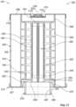
- FIGS. 1 - 5show an existing filter system at 20 .
- the system 20is a schematic illustration of parts of the system 20 including a filter housing 22 that is designed to receive a filter cartridge (not depicted in FIG. 1 ) for filtering fluid, such as fuel.
- the filter housing 22has a side wall 24 and an end wall 26 .
- the side wall 24 and end wall 26define a filter cartridge space 28 that is large enough to receive a filter cartridge therein, with the end wall 26 forming a closed end of the space 28 .
- the housing 22has an open end or mouth 30 opposite of the end wall 26 .
- the housing 22includes an inlet opening (not shown) through which a liquid, such as fuel, to be filtered enters the space 28 .
- a clean liquid outletis shown at 32 near the end wall 26 , through which the filtered liquid exits on its way to the engine.
- An air outlet 34is also near the end wall 26 through which air, in the filter housing 22 , returns to the fuel tank.
- a fluid passageway in the form of a standpipe 36is secured to the end wall 26 and extends upwardly into the space 28 toward the open mouth 20 of the housing 22 .
- the standpipe 36includes a generally cylindrical body having a side wall 38 extending from its bottom end 40 adjacent the end wall 26 to a terminal end 42 .
- the side wall 38encloses a space that is divided into an air flow passage 44 and a clean liquid (fuel) flow passage 46 by a divider 48 .
- the air flow passage 34is in communication with the air outlet 34 so that the air that enters the standpipe 36 can flow from the standpipe 36 and into the air outlet 34 to exit the fuel assembly and be directed back to the fuel tank.
- the clean fuel flow passage 46is in communication with the clean fuel outlet 32 so that the clean fuel that enters the standpipe 36 can flow from the standpipe 36 and into the clean fuel outlet 32 to the engine.
- a flow restriction valve assembly 50is disposed at the terminal end 42 of the standpipe 36 to control the flow of fuel into the standpipe 36 and to provide an air passage leading to the outside of the filter system 20 .
- the valve assembly 50can prevent fuel flow into the standpipe 36 when the filter cartridge (not shown) is not installed, or when an incorrect filter cartridge is installed.
- valve assembly 50is secured in the terminal end 42 .
- the valve assembly 50includes a valve ball 54 .
- the ball 54serves to block fuel flow through the clean fuel passage 46 . This prevents all fuel flow in the housing 22 when a filter cartridge is not installed or when an improperly fitting filter cartridge is installed.
- a projection 56dislodges the ball 54 , opening the air flow passage 44 and clean fuel passage 46 .
- the projection 56has an open passageway 57 extending therethrough.
- the projection 56engages a rubber member 180 and is in communication with the air flow passage 44 . This allows air and unfiltered fuel to flow therethrough and exit the housing 22 through the air outlet 34 .
- the open passageway 57 in the projection 56allows the air flow and unfiltered fuel to flow through.
- unfiltered fuelcontinues to flow (bleed) through the passageway 57 in the projection 56 and exit the housing 22 .
- Filtered fuelenters the standpipe 36 , flows around the ball 54 and around the projection 56 , and enters the clean fuel passageway 46 where it flows through the clean outlet 32 and to the engine.
- the system 60includes a housing 62 having a removable cover 64 .
- the housing 62includes a side wall 66 that surrounds and defines an interior volume 68 .
- An end wall 70closes the bottom of the housing 62 and is opposite the removable cover 64 .
- An unfiltered liquid flow inletpasses through the side wall 66 of the housing 62 and allows for the flow of unfiltered liquid, such as unfiltered fuel into the interior volume 68 of the housing 62 .
- a filtered liquid outlet 74is near the end wall 70 and allows filtered liquid to exit the system 60 where it flows to downstream equipment, such as the engine.
- An air outlet 76is also near the end wall 70 through which air 78 , in the filter housing 62 , returns to the fuel tank.
- a standpipe 80is secured to the end wall 70 and extends upwardly into the volume 68 toward the cover 64 of the housing 62 .
- the standpipe 80is generally the same construction as standpipe 36 , described previously with respect to FIG. 1 .
- the standpipe 80includes a generally cylindrical body having a sidewall 82 that is divided into an air flow passage 84 and a clean fuel flow passage 86 .
- the air flow passage 84is in communication with the air outlet 76 so that the air 78 that enters the standpipe 80 can flow from the standpipe 80 and into the air outlet 76 to exit the system 60 and be directed back to the fuel tank.
- a clean fuel passage 86is in communication with the clean fuel outlet 74 so that the clean fuel that enters the standpipe 82 can flow from the standpipe 82 and into the clean fuel outlet 74 and flow to the engine.
- an unfiltered fuel outlet 88At the base of the standpipe 80 , but located inside of the volume 68 of the housing 62 , is an unfiltered fuel outlet 88 .
- the unfiltered fuel outlet 88is covered schematically with an X to indicate that, in the view shown in FIG. 6 , it is sealed closed.
- the unfiltered fuel outlet 88allows unfiltered fuel that is within the volume 68 of the housing 62 to flow through the standpipe 80 and exit the housing 62 through the air outlet 76 and be returned to the fuel tank.
- the unfiltered fuel outlet 88is unsealed or opened when a filter cartridge is removed from the housing 62 during servicing. Example usable filter cartridges are described further below.
- the standpipe 80can include a valve assembly, such as the valve assembly 50 described previously in connection with FIGS. 1 - 5 .
- a valve assemblysuch as the valve assembly 50 described previously in connection with FIGS. 1 - 5 .
- the filter cartridge 92Located within the volume 68 and positioned over the standpipe 80 is a filter cartridge 92 .
- the filter cartridge 92in general, includes filter media 94 , which operates to remove particulate and debris from the fuel flowing into the system 60 through the unfiltered inlet 72 . After flowing through the media 74 , the filtered fuel then flows through a filtered port 96 in the standpipe 80 , where it enters the clean fuel passageway 86 and exits through the filtered liquid outlet 74 to be used by the engine.
- the filter cartridge 92includes a small bleed hole 98 in an upper portion thereof, which allows for air 78 to flow into the bleed passageway 90 and into the air flow passageway 84 to exit the system 60 through the air outlet 76 .
- the bleed hole 98also allows for a small amount of unfiltered fuel to pass through and flow back to the fuel tank through the bleed passageway 90 and air flow passageway 84 , and then through the air outlet 76 .
- the filter cartridge 92When the filter cartridge 92 is positioned over the standpipe 80 , it seals closed the unfiltered fuel outlet 88 in the standpipe 80 . When the filter cartridge 92 is removed from the housing 62 , after the cover 64 has been removed, the unfiltered fuel outlet is opened, and allows any fuel within the volume 68 of the housing 62 to drain through the unfiltered fuel outlet 88 and flow through the air outlet 76 back to the fuel tank.
- FIGS. 7 - 14Example Cartridges, FIGS. 7 - 14
- FIGS. 7 - 10depict two embodiments of filter cartridges 92 usable within the system 60 of FIG. 6 .
- the filter cartridges 92 shown in FIGS. 7 - 10include a filter cartridge 100 ( FIGS. 7 and 8 ) and a filter cartridge 101 ( FIGS. 9 and 10 ).
- Filter cartridges 100 , 101are identical in structure, with the exception of the length. That is, depending on the size of the system 60 , the appropriate filter cartridge 100 , 101 will be selected to fit within the system 60 .
- the description for the cartridges 100 , 101are the same, and will include the same reference numbers, generically, referring to both filter cartridges 100 , 101 , the cartridges will be referred to by reference numeral 92 .
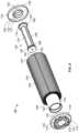
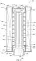
- the filter cartridge 92includes a first filter media construction 104 .
- the first filter media construction 104can be many different types of filter media, but generally is preferably pleated media 105 .
- the pleated media 105forms a tubular extension having a first end 106 and an opposite second end 107 .
- the tubular constructioncan be generally cylindrical, defining an open interior volume 108 .
- the filter cartridge 92further includes a first end plate 110 connected to the first end 106 , and a second end plate 112 connected to the second end 107 .
- the first end plate 110can be seen in perspective view in FIGS. 8 and 10 .
- the first end plate 110has a generally round outer shape with an axial surface 114 surrounded by an annular perimeter rim 116 . Extending from the axial surface 114 are a plurality of hooked projections 118 .
- the hooked projections 118can be constructed to interact with the cover 64 , in some embodiments.
- the bleed hole 122has a diameter of no greater than 1 cm, and is generally less than 10% of the overall diameter of the first end plate 110 .
- the bleed hole 122allows air 78 that is contained between the cover 64 and the housing 62 to be evacuated from the system 60 by way of flow through the bleed passageway 90 , the air flow passageway 84 , and then through the air outlet 76 .
- the second end plate 112can be seen in perspective view in FIGS. 8 and 10 .
- the second end plate 112is generally round with an axial section 124 surrounded by an annular perimeter rim 126 .
- the axial section 124 of the second end plate 112surrounds an open aperture 128 .
- An inner axially extending rim 130surrounds the open aperture 128 .
- the inner rim 130includes a first section 131 projecting into the interior volume 108 and a second section 132 projecting axially away from a remaining portion of the filter cartridge 92 .
- the filter cartridge 92includes a grommet 134 .
- the grommet 134is located at the second end 107 of the first filter media construction 104 .
- the grommet 134is for sealing closed the unfiltered outlet 88 on the standpipe 80 , when the filter cartridge 92 is removed from the standpipe 80 , the grommet 134 is removed from covering the unfiltered fuel outlet 88 , and any unfiltered fuel within the housing 62 can flow therethrough, into the air flow passageway 84 , and exit through the air outlet 76 .
- the grommet 134can be attached to the filter cartridge 92 in many different configurations.
- the grommet 134is held by a grommet holder 136 , which is defined by the second section 132 of the inner rim 130 of the second end plate 112 .
- the grommet holder 136extends axially away from a remaining part of the filter cartridge 92 .
- the grommet 134is positioned within a groove 138 in the grommet holder 136 .
- the grommet 134is inwardly radially directed between and against the second section 132 of the second end plate 112 and the outer side wall 82 of the standpipe 80 .
- the filter cartridge 92further includes an inner liner 140 .
- the inner liner 140extends between the first end 106 and second end 107 and lines the interior volume 108 of the first filter media construction 104 .
- the inner liner 140includes a porous section 142 , in which liquid is allowed to flow through the inner liner 140 to an interior 143 , and a non-porous section 144 .
- the non-porous section 144does not permit the flow of liquid through it.
- the filter cartridge 92further includes an inner plate 146 .
- the inner plate 146is spaced from each of the first end plate 110 and second end plate 112 .
- the inner plate 146extends along a plane perpendicular to a central longitudinal axis of the inner liner 140 , the longitudinal axis passing through the first end plate 110 and second end plate 112 .
- the inner plate 146is generally parallel to the first end plate 110 and second end plate 112 .
- the inner plate 146in this embodiment, is spaced closer to the first end plate 110 , than the second plate 112 .
- An inner cavity 148is defined between the first end plate 110 and inner plate 146 , with the non-porous section 144 of the inner liner 140 forming the surrounding wall to the cavity 148 .
- the non-porous section 144extends between the first end plate 110 and the inner plate 146 .
- the inner plate 146defines an open aperture 150 extending therethough.
- the open aperture 150is in fluid communication with the inner cavity 148 .
- the inner cavity 148is positioned to receive air therewithin.
- the filter cartridge 92includes a tubular core 152 .
- the tubular core 152is movably oriented within the inner liner 140 .
- the tubular core 152is movably oriented along a longitudinal axis along a longitudinal axis between the second end plate 112 and the inner plate 146 .
- the core 152is a free-floating core, which moves along a longitudinal axis of the core 152 .
- the tubular core 152has a first end 154 and an opposite second end 156 .
- a side wall 158extends between the first end 154 and second end 156 .
- the tubular core 152includes a pin or projection 160 .
- the projection 160may be formed as a single piece with the rest of the core 152 . In other embodiments, it could be a separate piece.
- the projection 160defines an open flow passage 162 therethrough. While many embodiments are possible, in the example shown, the projection 160 projects from the first end 154 and into an interior volume 164 of the core 152 .
- the first end 154 of the core 152is generally solid and non-porous, with the exception of the flow passage 162 defined by the projection 160 .
- the second end 156 of the core 152is an open end.
- the core 152is free-floating and movable between a first position, in which the core 152 can move along the longitudinal axis of the core 152 and a sealed position in which the core is removably sealed to the inner liner 140 .
- a flow passage 162 through the projection 160provides an air flow passage of air from within the inner cavity 148 to outside of the filter cartridge 92 by way of the aperture 150 in the inner plate 146 .
- the tubular core 152includes a seal member 166 .
- the seal member 166is used to form the releasable seal with the inner liner 140 , when the core 152 is in the sealed position.
- the seal member 166is an outwardly radially directed seal member 167 .
- the outward radially seal member 167can be located adjacent to the first end 154 of the core 152 and against the side wall 158 of the core 152 . As can be seen in FIGS. 7 and 9 , the outwardly radially inwardly seal member 167 circumscribes the first end 154 of the core 152 .
- the tubular core 152comprises a second filter media construction 170 .
- the second filter media construction 170can be various types of filter media, but when used in system 60 for a fuel filter, it is convenient for the second filter media construction 170 to comprise hydrophobic media.
- the hydrophobic mediawill repel and prevent water from penetrating. As such, it will encourage the formation of water droplets to coalesce and drip by gravity to the bottom of the filter cartridge 92 .
- the side wall 158 of the core 152has a conical shape that is larger at the second end 156 than the first end 154 , but in other arrangements, the core 152 can be a straight cylinder, without the conical shape.
- a fuel bypass 172( FIG. 13 ) is formed between the second end 156 of the core 152 and the standpipe 80 , during filtering operation, when the cartridge 92 is installed on the standpipe 80 .
- the side wall 158can have a draft angle from the first end 154 to the second end 156 of between 0.25-3 degrees to define the conical shape of the side wall 158 .
- the conical shape to the tubular core 152includes advantages.
- the shapecan help align the standpipe 80 into the core 152 as the cartridge 92 is being installed into the housing 62 .
- the core 152is narrower at the first end 154 to help ensure that the projection 160 can self-center into the standpipe 80 and engage properly. Self-centering onto the standpipe 80 will help to align the seal member 166 of the core 152 properly as it engages the corresponding sealing surface along the inside wall of the inner liner 140 .
- the outer flange 174has both inner radial clearance to the standpipe 80 and outer radial clearance to the inner liner 140 . These two clearances result in that the second end 156 of the core 152 has no significant contact constraining its degrees of freedom when fully installed. Instead, the installed contact points are located at the first end 154 of the core 152 by way of the seal member 166 and the engagement of the projection 160 with the standpipe 80 . This allows the core 152 to have more remaining freedom to self-align within the assembly and accommodate misalignment or assembly tolerance needed by the housing 62 and the standpipe 80 .
- the flow passage 162 in the projection 160allows the system 60 to evacuate air from the housing 62 with a simple cover 64 . Trapped air would prevent usage of the filter cartridge 92 , which would result in a premature end of life for the cartridge 92 .
- air 78is directed back to the fuel tank so it can be removed from the system 60 .
- unfiltered fuel from the outside of the first filter media construction 104follows this same path as the air 78 , by flowing through the bleed hole 122 , into the inner cavity 148 , through the flow passage 162 in the projection 160 , into the air flow passage 84 , and then out through the air outlet 76 .
- This unfiltered fuelacts as a constant bleed back to the fuel tank through the flow path in the projection 160 .
- the radial seal formed by the outwardly directed seal member 167 on the core 152avoids a constant bleed of unfiltered fuel from flowing through the clean fuel filter passageway 86 and to the engine.
- the free end or tip of the projection 160is made from a hard material, such as hard plastic.
- This projection 160seals radially when inserted into rubber member 180 ( FIGS. 2 - 5 ) on the inside of the standpipe 80 .
- the sealing engagement with the standpipe 80 and the projection 160 , and the correct size for the flow passage 162 through the projection 160contribute to controlling the return to the fuel tank and avoiding staving the engine of fuel.
- a bypass 172( FIG. 13 ) is formed.
- the bypass 172By using the bypass 172 , the face velocity to the second filter media construction 170 is lowered, and the differential pressure across the second filter media construction 170 is lowered.
- the advantages observed from reduction and face velocity and the pressure differentialoutweigh any effect of having a limiting amount of fuel bypass the second filter media construction 170 .
- the bypass 172contributes to controlling coalesced water droplets sized distributions that are discharged from the filter cartridge 92 .
- FIGS. 11 - 14show the filter cartridge 92 , in which the tubular core 152 is in the first position, and ready to be installed or positioned over the standpipe 80 .
- the seal member 166is away from the sealing surface 178 along the inner wall of the inner liner 140 , which is just adjacent to the inner plate 146 .
- FIG. 12shows a first step in positioning the filter cartridge 92 over the standpipe 80 .
- the filter cartridge 92is being positioned over the standpipe 80 and within the interior volume 68 , which is the filter cartridge space, within the housing 62 .
- FIGS. 12 and 13omit the housing 62 for purposes of clarity.
- the projection 160will engage the rubber member 180 ( FIGS. 2 - 5 ) in the interior of the standpipe 80 . This will then cause the tubular core 152 to move axially within the inner liner 140 from a direction from the second end plate 112 in a direction toward the inner plate 146 .
- the seal member 16 on the tubular core 152will come in contact with the sealing surface 178 of the inner liner 140 , and the first end 154 of the tubular core 152 may abut or engage the inner plate 146 .
- a sealis then formed between the seal member 166 and the sealing surface 178 of the inner liner, and the tubular core 152 is removably fixed in the sealed position ( FIG. 13 ).
- the flow passage 162 of the projection 160is aligned with the open aperture 150 in the inner plate 146 .
- the projection 160is engaged with the air flow passageway 84 in the standpipe 80 to provide air flow passage of air 78 and air within the inner cavity 148 of the filter cartridge 92 to outside of the filter cartridge 92 , for example, to the fuel tank.
- part of the method of installing the filter cartridge 92includes forming a seal between the grommet 134 on the filter cartridge 92 and the standpipe 80 .
- the projection 160When the filter cartridge is installed over the standpipe 80 , as shown in FIG. 13 , the projection 160 will engage the valve assembly 50 and move the valve ball 54 from the position of FIG. 2 to the position of FIG. 5 . This opens the clean fuel flow passage 86 in the standpipe 80 , as well as establish the air flow path between the flow passageway 162 in the projection 160 and the air flow passageway 84 in the standpipe 80 .
- a method of filtering fuelcan include using the filter cartridge 92 installed over a standpipe 80 in the filter housing 62 and allowing some fuel to bypass the tubular core 152 between the second end 156 of the core 152 and the standpipe 80 .
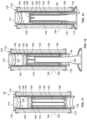
- FIGS. 15 - 18depict two more embodiments of filter cartridges 202 .
- the filter cartridges 202are usable within a system 302 similar to that shown in FIG. 6 , but with differences.
- the system 302 in which the cartridges 202 are usable inincludes a housing 362 , having a housing body 364 with a sidewall 366 and an end wall 368 defining a filter cartridge space 370 to accommodate the cartridge 202 therein.
- a standpipe 372extend from the end wall 368 into the filter cartridge space 370 .
- the filter cartridge 202can be mounted over the standpipe.
- filter cartridge depicted in FIGS. 15 and 16is depicted at 200
- cartridge depicted in FIGS. 17 and 18is depicted at 201
- Filter cartridges 200 , 201are identical in structure, with the exception of the length and width. That is, depending on the size of the system in which the filter cartridges 200 , 201 are used, the appropriate filter cartridges 200 , 201 will be selected to fit within the system.
- the description for the cartridges 200 , 201are the same, and will include the same reference numbers.
- the generic reference to both filter cartridges 200 , 201will be referred to by reference number 202 .
- the filter cartridge 202includes a first filter media construction 204 .
- the first filter media construction 204can be many different types of filter media, but generally is pleated media 205 .
- the pleated media 205forms a tubular extension having a first end 206 and an opposite second end 207 .
- the tubular constructioncan be generally cylindrical, defining an open interior volume 208 .
- the filter cartridge 202defines a central longitudinal axis 209 .
- the central axis 209is centered within the cartridge 202 and is centered within the first filter media construction 204 .
- the standpipe 372 which the filter cartridge 202 is fitted overwill be off-axis. That is, a central longitudinal axis 374 of the standpipe 372 will not be co-linear with the axis 209 (see FIG. 19 ).
- the filter cartridge 202further includes a first end plate 210 connected to the first end 206 , and a second end plate 212 connected to the second end 207 .
- the first end plate 210can be seen in perspective view in FIGS. 16 and 18 .
- the first end plate 210has a generally round outer shape, and an indented section 214 in a center portion.
- the first end plate 210is a closed surface, but at the center of the indented section 214 is a small hole arrangement 216 comprising one or more through holes and a burp valve arrangement 218 .
- the burp valve arrangement 218includes an umbrella burp valve 219 and a shroud 220 ( FIGS. 15 and 17 ).
- the hole arrangement 216 and burp valve arrangement 218allows air that is contained between a cover of the housing (such as cover 64 and housing 62 ) to be evacuated from the system by way of flow through the burp valve arrangement 218 .
- the second end plate 212is generally round with an axial section 224 .
- the axial section 224surrounds an open aperture 226 .
- the axial section 224defines a radial recess 228 for holding a seal member 230 .
- the radial recess 228is outwardly extending, such that the seal member 230 forms a radially outwardly extending seal member.
- the radial recess 228 and seal member 230could be radially inwardly extending.
- the filter cartridge 202further includes an inner liner 240 .
- the inner liner 240extends between the first end 206 and second end 207 and lines the interior volume 208 of the first filter media construction 204 .
- the inner liner 240is porous, to allow for liquid, which has passed through the first media construction 204 to flow through to an interior 242 .
- the inner liner 240includes a first section 244 having a first inner diameter.
- the first section 244engages against and is adjacent the second end plate 212 .
- the inner liner 240further includes a second section 246 having a second inner diameter.
- the second inner diameteris smaller than the first inner diameter of the first section 244 .
- the second section 246is axially spaced from the second end plate 212 , such that the first section 244 is axially between the second section 246 and the second end plate 212 .
- the first section 248has a diameter that is larger than the diameter of the second section 246 .
- the second section 246extends a majority of the length of the filter cartridge 202 , and is axially spaced from each of the first end plate 210 and second end plate 212 by the respective third section 248 and first section 244 .
- the filter cartridge 202includes a tubular core 252 .
- the tubular core 252is movably oriented within the inner liner 240 .
- the tubular core 252can be moved longitudinally within the inner liner 240 .
- the core 252is a free-floating core.
- the tubular core 252has a first end 254 and an opposite second end 256 .
- a side wall 258extends between the first end 254 and the second end 256 .
- the tubular core 252includes a second filter media construction 260 .
- the second filter media construction 260can be various types of filter media, but it is often convenient for the second filter media construction 260 to comprise hydrophobic media.
- the hydrophobic mediawill repel and prevent water from penetrating. As such, it will encourage the formation of water droplets to coalesce and drip by gravity to the bottom of the filter cartridge 202 .
- the tubular core 252includes an outwardly radially directed flange 262 adjacent the second end 256 of the core 252 . While shown here as a flange 262 , it should be understood, that the flange 262 can be segments, such that they are separate feet.
- the flange 262has an outer diameter, which is smaller than the first inner diameter of the first section 244 of the inner liner 240 .
- the flange 262 outer diameteris also larger than the second inner diameter of the second section 246 of the inner liner 240 .
- the tubular core 252is positioned within the inner liner 240 such that the flange 262 is positioned between the second end plate 212 and the second section 246 of the inner liner 240 .
- the second end plate 212has an internal axially extending wall 213 projecting into the interior of the filter cartridge 202 and within the first section 244 of the inner liner 240 .
- the axial extension 213has an outer diameter which is smaller than the outer diameter of the flange 262 .
- the flange 262can be movable within the first section 244 of the inner liner 240 , but is constrained in axial motion between engaging against the axial extension 213 of the second end plate 212 and the second section 246 of the inner liner 240 .
- the second section 246 of the inner liner 240has an axial surface 264 directed toward and facing the second end plate 212 .
- the axial surface 264forms an upper limiting portion of the motion of the core 252 .
- the sidewall 258 of the core 252has a conical shape that is larger at the second end 256 than the first end 254 . Due to the shape of the tubular core 252 , a fuel bypass 380 ( FIG. 20 ), analogous to that shown at 172 in FIG. 13 , is formed between the second end 256 of the core 252 and the standpipe 372 , during filtering operation, when the cartridge 202 is installed on the standpipe 372 .
- the sidewall 258has a draft angle from the first end 254 to the second end 256 of between 0.25-3°, to define the conical shape of the sidewall 258 .
- the bypass 380 that is created between the sidewall 258 and the standpipe 372has advantages. These advantages are discussed above with respect to the embodiment of FIG. 13 , and are applicable to the filter cartridge 202 shown in FIGS. 15 - 17 .
- the filter cartridge 202further includes a perforated outer wrap 270 .
- the outer wrap 270covers the first filter media construction 204 and extends from the first end plate 210 to the second end plate 212 .
- the outer wrap 270includes a solid unperforated section 272 extending from the first end plate 210 a distance of at least 25% of a length of the filter cartridge 202 .
- the lengthis typically less than 50%, and can be between 30-40% of a length of the filter cartridge 202 .
- the outer wrap 270further includes a perforated section 274 extending from the solid, perforated section 272 to the second end plate 212 .
- the standpipe 372has a central longitudinal axis 374 that is not in alignment or co-linear with the longitudinal axis 209 of the filter cartridge 202 .
- the filter cartridge 202is positioned over the standpipe 372 and into the filter cartridge space 370 of the housing 362 to move the tubular core 252 into an off-axis position on the standpipe 372 , which is not co-linear with the central longitudinal axis 209 of the filter cartridge 202 . See FIG. 20 .
- FIGS. 21 and 22shown an alternative embodiment of a filter and core, usable in the systems of FIG. 6 and FIG. 19 .
- a tubular core 352is used, similar to core 252 , but without a radially directed flange 262 . This permits the core 352 to pass through the second end plate 112 , 212 of the filter cartridge 92 , 202 .
- the core 352 and the filter cartridge 92 , 202are completely independent and separable members.
- FIG. 21shows a kit 400 and steps in a method for providing a filter assembly.
- the kit 400is provided having the core 352 and filter cartridge 92 , 202 .
- the core 352 and cartridge 92 , 202are provided separately.
- the core 352can be constructed as above for core 252 , but without the flange 262 . It has media, such as hydrophobic media 460 .
- step 2the core 352 is positioned or oriented onto the standpipe 80 , 372 of the housing 402 .
- the person installing the core 352can manually and visually align these components independently.
- step 3the filter cartridge 92 , 202 is positioned or oriented over the top of the core 352 and onto the standpipe 80 , 372 of the housing 402 . This allows the installer to manually and visually align the filter cartridge 92 , 202 independently.
- step 4the housing 402 is closed by installing and tightening a service cap 406 before priming the system.
Landscapes
- Chemical & Material Sciences (AREA)
- Chemical Kinetics & Catalysis (AREA)
- Engineering & Computer Science (AREA)
- Physics & Mathematics (AREA)
- Thermal Sciences (AREA)
- Combustion & Propulsion (AREA)
- Mechanical Engineering (AREA)
- General Engineering & Computer Science (AREA)
- Filtering Of Dispersed Particles In Gases (AREA)
- Filtration Of Liquid (AREA)
Abstract
Description
- the second filter media construction comprises hydrophobic media; or
- the sidewall of the tubular core has a conical shape, wherein the second end is larger in diameter than the first end; or
- the sidewall of the tubular core has a draft angle of between 0.25-3 degrees; or
- the tubular core has a projection formed as a single piece with the core; the projection defining a flow passage therethrough;
- the tubular core is movably oriented within the inner liner, and the tubular core is free-floating from a first position, in which the tubular core can move along a longitudinal axis of the tubular core, and a sealed position, in which the tubular core is sealed to the inner liner; or
- the tubular core includes a seal member, forming a seal with the inner liner; or
- the seal member is an outward radially directed seal member.
- an inner plate, spaced from each of the first end plate and second plate, extending along a plane perpendicular to an central longitudinal axis of the liner; the inner plate having an open aperture therein; the inner liner being non-porous between the first end plate and the inner plate and defining an inner cavity structured to receive air; or
- a grommet located at the second end of the first filter media construction.
- the second end plate has a grommet holder extending axially away from a remaining part of the filter cartridge, and the grommet is positioned within a groove in the grommet holder; or
- the grommet is inwardly radially directed; or
- the first end plate has an air bleed hole; or
- the inner liner includes a first section with a first inner diameter, adjacent the second end plate, and a second section with a second inner diameter smaller than the first inner diameter; the second section being axially spaced from the second end plate with the first section therebetween.
- the tubular core includes a radially directed flange adjacent the second end of the core; the flange having an outer diameter: (i) smaller than the first inner diameter of the first section of the inner liner; and (ii) larger than the second inner diameter of the second section of the inner liner; and wherein the tubular core is axially and radially movable within the inner liner and limited in motion by the flange engaging against either the second end plate or the second section of the inner liner; or
- the second end plate includes a radially directed seal member thereon; or
- the radially directed seal member is outwardly directed.
- the perforated outer wrap includes: a solid unperforated section extending from the first end plate a distance of at least 25% of a length of the filter cartridge; and a perforated section extending from the unperforated section to the second end plate; or
- the first end plate includes a burp valve arrangement; or
- the tubular core and a remaining portion of the filter cartridge are independently separable.
- the tubular core comprises a second filter media construction; or
- the second filter media construction comprises hydrophobic media; or
- the tubular core includes a seal member, forming a seal with the inner liner; or
- the seal member is an outward radially directed seal member.
- the seal member is an outward radially directed seal member circumscribing the first end of the core; or
- the tubular core includes a sidewall extending between the first end of the core and the second end of the core; the sidewall having a conical shape that is larger at the second end of the core than the first end of the core; or
- a fuel bypass is formed between the second end of the core and a standpipe, when the filter cartridge is installed on a standpipe; or
- further including a grommet located at the second end of the first filter media construction.
- the second end plate has a grommet holder extending axially away from a remaining part of the filter cartridge, and the grommet is positioned within a groove in the grommet holder; or
- the grommet is inwardly radially directed; or
- the first end plate has an air bleed hole; or
- the projection is formed as a single piece with the core.
- the tubular core includes a radially directed flange adjacent the second end of the core; and the step of positioning the filter cartridge includes moving the tubular core until the radially directed flange engages against the inner liner; or
- the step of positioning the filter cartridge over the standpipe includes: first, positioning the tubular core over the standpipe; and second, positioning the filter cartridge, separate of the tubular core, over the tubular core and onto the standpipe.
Claims (14)
Priority Applications (1)
| Application Number | Priority Date | Filing Date | Title |
|---|---|---|---|
| US17/473,716US12161956B2 (en) | 2020-09-21 | 2021-09-13 | Filter cartridge, filter assembly, and methods |
Applications Claiming Priority (2)
| Application Number | Priority Date | Filing Date | Title |
|---|---|---|---|
| US202063081048P | 2020-09-21 | 2020-09-21 | |
| US17/473,716US12161956B2 (en) | 2020-09-21 | 2021-09-13 | Filter cartridge, filter assembly, and methods |
Publications (2)
| Publication Number | Publication Date |
|---|---|
| US20220088509A1 US20220088509A1 (en) | 2022-03-24 |
| US12161956B2true US12161956B2 (en) | 2024-12-10 |
Family
ID=80473966
Family Applications (1)
| Application Number | Title | Priority Date | Filing Date |
|---|---|---|---|
| US17/473,716Active2042-08-26US12161956B2 (en) | 2020-09-21 | 2021-09-13 | Filter cartridge, filter assembly, and methods |
Country Status (3)
| Country | Link |
|---|---|
| US (1) | US12161956B2 (en) |
| CN (1) | CN114251209A (en) |
| DE (1) | DE102021123856A1 (en) |
Families Citing this family (1)
| Publication number | Priority date | Publication date | Assignee | Title |
|---|---|---|---|---|
| WO2023070112A1 (en)* | 2021-10-21 | 2023-04-27 | Treau, Inc. | Baffle strainer system and method |
Citations (189)
| Publication number | Priority date | Publication date | Assignee | Title |
|---|---|---|---|---|
| US1468906A (en) | 1921-10-08 | 1923-09-25 | Inman William | Fuel-oil filter |
| US2544244A (en) | 1946-07-29 | 1951-03-06 | Vokes Ltd | Filter |
| US2612270A (en) | 1951-02-12 | 1952-09-30 | Warner Lewis Company | Two-stage filter |
| US2843269A (en) | 1955-05-16 | 1958-07-15 | Purolator Products Inc | Center tubes for filters |
| US3246766A (en) | 1963-02-15 | 1966-04-19 | Pall Corp | Filter element |
| US3363762A (en) | 1964-12-29 | 1968-01-16 | Donald G Griswold | Removable element filter assembly having flow preventing means |
| US3503511A (en) | 1967-09-07 | 1970-03-31 | Carborundum Co | Centering means for filter elements |
| US3567130A (en) | 1969-08-07 | 1971-03-02 | Wix Corp | Diffuser |
| US3584194A (en) | 1969-05-23 | 1971-06-08 | Aro Corp | Fluid heating techniques |
| US3642141A (en) | 1970-07-21 | 1972-02-15 | Per Corp. | Filter tube and connection thereof to tube sheet |
| US3662893A (en) | 1969-08-25 | 1972-05-16 | Wix Corp | Filter cartridge |
| US3696932A (en) | 1970-09-30 | 1972-10-10 | Pall Corp | Disposable filter assembly |
| US3800948A (en) | 1973-07-26 | 1974-04-02 | Allis Chalmers | Dual hydraulic filter arrangement |
| US3836005A (en) | 1973-09-13 | 1974-09-17 | Gen Motors Corp | Dry cleaning filter element assembly |
| US3852196A (en) | 1972-09-08 | 1974-12-03 | Vital Res & Dev Inc | Fluid treatment system |
| US4029121A (en) | 1974-09-05 | 1977-06-14 | Fa.Hans Grohe Kg. | Valve construction for controlling a liquid supply to one or more discharge points |
| US4132641A (en) | 1975-06-30 | 1979-01-02 | General Electric Company | Filter assembly and method of filtering |
| US4272368A (en) | 1979-09-04 | 1981-06-09 | Parker-Hannifin Corporation | Fluid filter and indicator |
| US4303514A (en) | 1979-03-27 | 1981-12-01 | Mats Theorell | Filter device |
| US4354931A (en) | 1981-04-13 | 1982-10-19 | International Harvester Co. | Check valve assembly with actuator |
| US4364825A (en) | 1981-02-03 | 1982-12-21 | Wix Corporation | Liquid filter |
| US4422938A (en) | 1982-01-25 | 1983-12-27 | Quantum Systems Corporation | Backwashing-type filtering apparatus |
| US4442004A (en) | 1982-07-01 | 1984-04-10 | Osmonics, Inc. | Biasing arrangement and filter unit for a filtering apparatus |
| US4518501A (en) | 1982-09-25 | 1985-05-21 | Firma Boll & Kirch, Filterbau Gmbh | Flush-back filter |
| US4555337A (en) | 1984-10-23 | 1985-11-26 | The Wooster Brush Company | Plug and filter assembly for paint sprayer |
| US4588500A (en) | 1984-09-04 | 1986-05-13 | Kaydon Corporation | Fuel filter and dehydrator |
| US4621508A (en) | 1985-05-13 | 1986-11-11 | Sonoco Products Company | Textile yarn carrier and method of manufacturing same |
| US4687023A (en) | 1986-04-10 | 1987-08-18 | The Marley-Wylain Company | Ball check valve |
| US5049269A (en) | 1989-06-08 | 1991-09-17 | Sunstrand Corporation | Filter assembly with spring loaded valve |
| US5102542A (en) | 1990-01-25 | 1992-04-07 | Electrolux Water Systems, Inc. | Construction of canister-type filters |
| US5102541A (en) | 1990-08-25 | 1992-04-07 | Seitz-Filtewerke Theo & Geo Seitz Gmbh & Co. Kg | Supporting tube construction for filter modules |
| US5104534A (en) | 1991-06-20 | 1992-04-14 | Gerald Branchcomb | Filter design |
| US5118421A (en) | 1989-08-24 | 1992-06-02 | Albany International Corp. | Cylndrical filter media with support structure |
| US5132009A (en) | 1990-02-26 | 1992-07-21 | Allied-Signal Inc. | Filter for a fuel system |
| US5215655A (en) | 1991-10-28 | 1993-06-01 | Tokheim Corporation | Dispenser interlock fuel filter system disabled in response to filter removal |
| US5362390A (en) | 1993-06-28 | 1994-11-08 | Fleetguard, Inc. | Shut-off valve for spin-on filters |
| US5399264A (en) | 1993-03-22 | 1995-03-21 | Cuno, Incorporated | Compressible differential pressure energized seals for filter elements and the like |
| US5419373A (en) | 1991-07-25 | 1995-05-30 | May; Clifford H. | Filter support tube for a filter cartridge |
| US5458767A (en) | 1994-08-10 | 1995-10-17 | Parker-Hannifin Corporation | Fuel filter assembly with dual filter media and by-pass device |
| US5643446A (en) | 1985-05-14 | 1997-07-01 | Parker Hannifin Corporation | Fuel filter and priming pump |
| US5685985A (en) | 1995-12-20 | 1997-11-11 | Baldwin Filters, Inc. | Environmentally friendly filter cartridge |
| US5695637A (en) | 1993-06-30 | 1997-12-09 | Fleetguard, Inc. | Combination full flow and bypass filter with venturi nozzle |
| US5709242A (en) | 1993-09-01 | 1998-01-20 | Metalo Monti V.O.F. | Device for blocking a liquid flow through a pipe in one direction |
| US5714030A (en) | 1992-12-07 | 1998-02-03 | Tsuchiya Mfg. Co., Ltd. | Plastisol type adhesive composition used in filter for alcohol-containing fuel |
| US5718825A (en) | 1994-12-09 | 1998-02-17 | Ing. Walter Hengst Gmbh & Co. Kg | Liquid filter, in particular fuel or oil filter |
| US5730769A (en) | 1992-12-10 | 1998-03-24 | Filterwerk Mann & Hummel Gmbh | Air filter with scaling bead freely movable in the radial direction |
| US5770054A (en) | 1995-03-16 | 1998-06-23 | Firma Ing. Walter Hengst Gmbh & Co. Kg | Fluid filter with filter bypass valve and sealing surface on filter element side |
| US5770065A (en) | 1993-09-15 | 1998-06-23 | Parker Hannifin Corporation | Fuel filter assembly with replacement element |
| US5846417A (en) | 1997-07-21 | 1998-12-08 | Fleetguard, Inc. | Self closing filter centerpost |
| US5855780A (en) | 1996-11-04 | 1999-01-05 | Advanced Performance Technology, Inc. | Fuel filter element with flow actuator |
| US5858227A (en) | 1996-09-23 | 1999-01-12 | Parker-Hannifin Corporation | Fuel filter assembly with in-line valve |
| US5906737A (en) | 1997-05-01 | 1999-05-25 | Hoeppner; Michael A. | Filter core system |
| US5922199A (en) | 1993-09-15 | 1999-07-13 | Parker Hannifin Corporation | Double pass fuel filter assembly |
| US5958230A (en) | 1998-01-30 | 1999-09-28 | Eagle Fitter Corporation | Filter for gasoline and other liquids |
| US6027639A (en) | 1996-04-30 | 2000-02-22 | Stormwater Treatment Llc | Self-cleaning siphon-actuated radial flow filter basket |
| US6036853A (en) | 1998-04-16 | 2000-03-14 | Medtronic, Inc. | Articulated filter core element |
| US6045598A (en) | 1997-12-23 | 2000-04-04 | Firma Carl Freudenberg | Filter insert |
| US6053334A (en) | 1993-09-15 | 2000-04-25 | Parker Hannifin Customer Support Inc. | Fuel filter with valve device |
| US6113781A (en) | 1993-09-15 | 2000-09-05 | Parker-Hannifin Corporation | Fuel filter with dual flow |
| WO2001039859A1 (en) | 1999-12-03 | 2001-06-07 | Parker-Hannifin Corporation | Keyed latch valve for fuel filter |
| US6319402B1 (en) | 1999-12-17 | 2001-11-20 | Nelson Industries, Inc. | Extended life dual full-flow and bypass filter |
| US6328883B1 (en) | 2000-05-31 | 2001-12-11 | Parker-Hannifin Corporation | Fuel filter assembly with priming pump |
| US6471070B2 (en) | 2000-02-16 | 2002-10-29 | Stanadyne Corporation | Ecological fuel filter cartridge and element |
| US6495042B1 (en) | 1999-12-03 | 2002-12-17 | Parker-Hannifin Corporation | Filter cartridge for a fuel filter having a keyed latch shut-off valve |
| US6543625B1 (en) | 1998-11-16 | 2003-04-08 | Fleetguard, Inc. | Cartridge for filtering a liquid circulating in a hydraulic engine or equipment and corresponding filtering cartridge-sealing joint assembly |
| US6554139B1 (en) | 2000-06-01 | 2003-04-29 | Parker-Hannifin Corporation | Extension and locking assembly for dripless element, and container therefore |
| US6555000B2 (en) | 1999-12-03 | 2003-04-29 | Parker-Hannifin Corporation | Fuel filter with bypass valve |
| US6709588B2 (en) | 1999-07-22 | 2004-03-23 | Filterwerk Mann & Hummel Gmbh | Filter for internal combustion engine fuels |
| US20050027552A1 (en) | 2003-04-11 | 2005-02-03 | Massanelli Joseph A. | Systems and methods for claim processing in a recovery audit |
| US6884349B1 (en) | 2004-04-12 | 2005-04-26 | Fleetguard, Inc. | Oval centerpost and cooperating filter cartridge |
| US20050092665A1 (en) | 2003-08-27 | 2005-05-05 | Kirchner Richard A. | Water filter manifold with integral valve |
| US6902669B2 (en) | 2002-09-13 | 2005-06-07 | Fleetguard, Inc. | Filter cartridge with floating seal |
| US7014766B2 (en) | 2003-01-24 | 2006-03-21 | Mann & Hummel Gmbh | Self-venting filter element for a fuel filter arrangement |
| US7059481B2 (en) | 2000-12-21 | 2006-06-13 | Mann & Hummel Gmbh | Filter element |
| US20060191832A1 (en) | 2005-02-14 | 2006-08-31 | Richie Bryant L | Dual media fuel filter and fuel/water separator cartridge filter system |
| US7147110B2 (en) | 2003-08-01 | 2006-12-12 | Parker-Hannifin Corporation | Filter assembly with vented filter element |
| US7191903B2 (en) | 2003-01-20 | 2007-03-20 | Mann & Hummel Gmbh | Filter insert with variable length center tube |
| US20070084776A1 (en) | 2005-09-30 | 2007-04-19 | Sasur Timothy M | Water separation and filtration structure |
| US20070095744A1 (en) | 2005-11-01 | 2007-05-03 | Bagci Ismail C | Fluid filter with open-end flow, replaceable cartridge |
| US7237569B2 (en) | 2005-03-09 | 2007-07-03 | Globe Union Industrial Corp. | Ball check valve |
| US20070227964A1 (en) | 2006-03-31 | 2007-10-04 | Baldwin Filters, Inc. | Fluid filter element and bypass insert |
| US7299931B2 (en) | 2001-01-31 | 2007-11-27 | Hengst Gmbh & Co. Kg | Liquid filter comprising air vents |
| US7344581B2 (en) | 2004-08-05 | 2008-03-18 | Parker Hannifin Limited | Filter assembly |
| US7407058B2 (en) | 2002-07-24 | 2008-08-05 | Hydac Filtertechnik Gmbh | Filter element for filtering fluids |
| US7422119B2 (en) | 2001-03-23 | 2008-09-09 | Fleetguard, Inc. | Cylindrical element with sloping fins for filtering element and corresponding filtering assembly |
| US7479219B2 (en) | 2004-08-05 | 2009-01-20 | Guenther Rassinger | Filter device for fluids and method for filtering fluids |
| US7543711B1 (en) | 2005-02-01 | 2009-06-09 | Wix Filtration Corp Llc | Fluid filter element |
| WO2009095339A1 (en) | 2008-02-01 | 2009-08-06 | Mann+Hummel Gmbh | Liquid filter, in particular for fuel |
| US7572306B2 (en) | 2004-09-15 | 2009-08-11 | Cummins Filtration Ip Inc. | Filter system integrating pressure regulation and air vent |
| US7655140B2 (en) | 2004-10-26 | 2010-02-02 | Cummins Filtration Ip Inc. | Automatic water drain for suction fuel water separators |
| US20100044303A1 (en) | 2006-11-24 | 2010-02-25 | Cummins Filtration Ip Inc. | Filtration cartridge co-operating with a central tube and comprising a radially-retained seal mounted in a cavity for co-operating with said tube |
| BRPI0901923A2 (en)* | 2008-06-16 | 2010-04-13 | Baldwin Filters Inc | filter element and filter assembly including locking mechanism |
| WO2010044636A2 (en) | 2008-10-17 | 2010-04-22 | Kim Chang Yong | Filtration device having a spiral support member |
| US7717092B2 (en) | 2006-08-14 | 2010-05-18 | Cummins Filtration Ip Inc. | Fuel system with air venting and fuel anti-drainback |
| US7749383B2 (en) | 2007-09-06 | 2010-07-06 | Cummins Filtration Ip, Inc. | Filter cartridge with crush ribs |
| US20100294707A1 (en) | 2009-05-21 | 2010-11-25 | Cummins Filtration Ip Inc. | Multi-stage filter cartridge with snap fit filters |
| US7854329B2 (en) | 2005-03-25 | 2010-12-21 | Cummins Filtration Ip, Inc. | Hollow element for the support of a filter medium including support means in the form of spiral portions with a substantially constant slope, and a corresponding filter assembly |
| US7854839B2 (en) | 2007-10-09 | 2010-12-21 | Cummins Flitration IP, Inc. | Fuel filter assembly with flow restriction valve |
| US7857974B2 (en) | 2007-09-06 | 2010-12-28 | Cummins Filtration Ip, Inc. | Filter cartridge with snap fit connection |
| US7867387B2 (en) | 2007-07-19 | 2011-01-11 | Cummins Filtration Ip, Inc. | Standpipe with flow restriction valve, and filter cartridge |
| US20110024344A1 (en) | 2009-08-03 | 2011-02-03 | Cummins Filtration Ip, Inc. | No filter no run fluid filtration system |
| US20110084016A1 (en) | 2008-03-21 | 2011-04-14 | Cummins Filtration | Filtration assembly including a central tube interacting with a filtration cartridge and with a seal permanently mounted on said central tube |
| US7935255B2 (en) | 2007-09-06 | 2011-05-03 | Cummins Filtration Ip, Inc. | Filter cartridge |
| USD638034S1 (en) | 2009-03-11 | 2011-05-17 | Cummins Filtration Ip, Inc. | Engine filter |
| US7955500B2 (en) | 2007-11-16 | 2011-06-07 | Cummins Filtration Ip, Inc. | Oval seal cartridge with no dirty drip |
| US8002981B2 (en) | 2007-11-06 | 2011-08-23 | Cummins Filtration Ip, Inc. | Fuel filter assembly with flow restriction sleeve |
| US8020708B2 (en) | 2008-03-28 | 2011-09-20 | Cummins Filtration Ip, Inc. | Fuel filter housing with snap lock valve asssembly |
| US20120006731A1 (en) | 2010-07-06 | 2012-01-12 | Swift Jr Edwin C | Filter with reusable bypass valve and inner assembly |
| US8097061B2 (en) | 2008-09-18 | 2012-01-17 | Cummins Filtration Ip, Inc. | Elliptical seal interface for filter assembly |
| US8110016B2 (en) | 2008-12-11 | 2012-02-07 | Dow Global Technologies Llc | Fluid filter assembly including seal |
| US8128719B1 (en) | 2009-08-21 | 2012-03-06 | Cummins Filtration Ip Inc. | Filter element with percussion band |
| US8128818B2 (en) | 2005-08-25 | 2012-03-06 | Joma-Polytec Kunststofftechnik Gmbh | Oil filter |
| US8152876B2 (en) | 2007-10-02 | 2012-04-10 | Mann + Hummel Gmbh | Filter element having V-seal |
| US8168066B2 (en) | 2006-08-08 | 2012-05-01 | Cummins Filtration Ip, Inc. | Quick-drain filter |
| US8177972B2 (en) | 2008-07-03 | 2012-05-15 | Sartorius Stedim Biotech Gmbh | Adapter for fastening a filter element |
| US20120160760A1 (en) | 2009-09-08 | 2012-06-28 | Ufi Filters S.P.A. | Device for reducing dimensions of air bubbles in diesel fuel supplied to engines |
| US8216470B2 (en) | 2009-05-21 | 2012-07-10 | Cummins Filtration Ip, Inc. | Multi-stage filter cartridge with polyurethane endcaps |
| US8245851B2 (en) | 2007-11-27 | 2012-08-21 | Cummins Filtration Ip, Inc. | Noncircular replaceable fuel filter elements and systems including the same |
| US20120223001A1 (en) | 2011-03-04 | 2012-09-06 | Baldwin Filters, Inc. | Filter and center tube with helical fin |
| US8333890B2 (en) | 2008-10-27 | 2012-12-18 | Cummins Filtration Ip, Inc. | Filter cartridge having a filter within a filter, and an endplate sealing structure on an outer filter element |
| WO2013000807A1 (en) | 2011-06-29 | 2013-01-03 | Mahle International Gmbh | Filter element, in particular for fuel filters, and associated support body |
| US8356716B1 (en) | 2011-09-15 | 2013-01-22 | Whirlpool Corporation | Filter unit |
| US8360251B2 (en) | 2008-10-08 | 2013-01-29 | Cummins Filtration Ip, Inc. | Multi-layer coalescing media having a high porosity interior layer and uses thereof |
| WO2013024136A1 (en) | 2011-08-17 | 2013-02-21 | Josef Dagn | Separating vessel |
| US8388834B2 (en) | 2006-12-23 | 2013-03-05 | Mann+Hummel Gmbh | Fuel filter |
| US8440081B2 (en) | 2006-08-08 | 2013-05-14 | Cummins Filtration Ip, Inc. | Quick drain filter |
| US8496825B1 (en) | 2010-10-26 | 2013-07-30 | Dow Global Technologies Llc | Spiral wound module including membrane sheet with regions having different permeabilities |
| US8517183B2 (en) | 2009-05-04 | 2013-08-27 | Cummins Filtration Ip, Inc. | No filter no run fluid filtration system |
| US8523974B2 (en) | 2011-08-18 | 2013-09-03 | General Electric Company | Filter core for use with pleated filter cartridges |
| US8540805B2 (en) | 2010-11-10 | 2013-09-24 | General Electric Company | Filter assembly for use in a turbine system |
| US8551335B2 (en) | 2009-07-08 | 2013-10-08 | Cummins Filtration Ip, Inc. | Dual stage filtration with barrier for fuel water separation |
| US20130284661A1 (en) | 2012-04-26 | 2013-10-31 | Mann+Hummel Gmbh | Housing for Filter and Filter |
| US8580109B2 (en) | 2011-09-15 | 2013-11-12 | Whirlpool Corporation | Electronic interface for water filter system |
| US8591736B2 (en) | 2011-09-15 | 2013-11-26 | Whirlpool Corporation | Water filter unit |
| US8678202B2 (en) | 2008-10-08 | 2014-03-25 | Cummins Filtration Ip Inc. | Modular filter elements for use in a filter-in-filter cartridge |
| US20140116931A1 (en) | 2012-06-04 | 2014-05-01 | Ibs Filtran Kunststoff-/Metallerzeugnisse Gmbh | Suction-Type oil filter unit for transmissions or internal combustion engines |
| US20140124459A1 (en) | 2011-05-11 | 2014-05-08 | Cummins Filtration Ip Inc. | No filter no run feature for filter |
| US8764984B2 (en) | 2011-04-18 | 2014-07-01 | Cummins Filtration Ip, Inc. | Filter-in-filter with funnel shaped passageway |
| US8777018B2 (en) | 2006-10-25 | 2014-07-15 | Ets Trade S.A.R.L. | Filter device |
| US8845896B2 (en) | 2011-09-15 | 2014-09-30 | Whirlpool Corporation | Water filter system |
| US8852443B2 (en) | 2007-09-12 | 2014-10-07 | Cummins Filtration Ip, Inc. | Filtration system with a variable restriction orifice |
| US20140305861A1 (en)* | 2006-09-06 | 2014-10-16 | Donaldson Company, Inc. | Liquid filter assembly; components; and, methods |
| WO2014179852A1 (en) | 2013-05-10 | 2014-11-13 | Mahle Metal Leve S.A. | Filter element base and lid for fuel filter |
| US8920648B2 (en) | 2009-02-25 | 2014-12-30 | Cummins Filtration Ip Inc. | No filter no run fluid filtration systems |
| US20150075494A1 (en) | 2012-05-22 | 2015-03-19 | Mann+Hummel Gmbh | Filter Device for Absorbing a Water Fraction Contained in a Liquid |
| WO2015042348A1 (en)* | 2013-09-19 | 2015-03-26 | Cummins Filtration Ip, Inc. | Fuel water separator filter |
| US9011683B2 (en) | 2008-11-14 | 2015-04-21 | Cummins Filtration Ip Inc. | Filter cartridge centering device |
| US9044695B2 (en) | 2009-10-24 | 2015-06-02 | Hydac Filtertechnik Gmbh | Filter device and filter element for use with such a filter device |
| US9149748B2 (en) | 2012-11-13 | 2015-10-06 | Hollingsworth & Vose Company | Multi-layered filter media |
| US9149749B2 (en) | 2012-11-13 | 2015-10-06 | Hollingsworth & Vose Company | Pre-coalescing multi-layered filter media |
| US9168477B2 (en) | 2012-11-23 | 2015-10-27 | Mann + Hummel Gmbh | Support tube for a filter element |
| US9186602B2 (en) | 2012-04-13 | 2015-11-17 | Cummins Filtration Ip, Inc. | Filter element with automatic air bleeding |
| US9199185B2 (en) | 2009-05-15 | 2015-12-01 | Cummins Filtration Ip, Inc. | Surface coalescers |
| US20150343341A1 (en) | 2014-05-30 | 2015-12-03 | Pall Corporation | Filter elements and methods for filtering fluids |
| USD751666S1 (en) | 2011-09-15 | 2016-03-15 | Whirlpool Corporation | Water filter |
| USD752707S1 (en) | 2013-05-31 | 2016-03-29 | Kx Technologies Llc | Filter cartridge with handle end |
| WO2016106170A2 (en) | 2014-12-22 | 2016-06-30 | Cummins Filtration Ip, Inc. | Retrofittable no filter no run filtration system |
| US9486724B2 (en) | 2010-06-14 | 2016-11-08 | Mann+Hummel Gmbh | Filter device, in particular liquid filter |
| WO2016182976A1 (en) | 2015-05-08 | 2016-11-17 | Campbell Michael C | Improved filter for a propellant gas evacuation system |
| US20160332101A1 (en) | 2014-01-24 | 2016-11-17 | Cummins Filtration Ip, Inc | Filter including Spring Tube Bypass Assembly |
| US9504939B2 (en) | 2013-03-22 | 2016-11-29 | Caterpillar Inc. | Filter assembly |
| WO2017012932A1 (en) | 2015-07-21 | 2017-01-26 | Mann+Hummel Gmbh | Filter element and filter assembly |
| US20170087485A1 (en) | 2014-05-15 | 2017-03-30 | Eaton Corporation | Filter for the capture and retention of large debris |
| US20170106317A1 (en) | 2015-10-16 | 2017-04-20 | Wix Filtration Corp Llc | Filter Element With Air-Bleed Conduit |
| USD785142S1 (en) | 2015-06-19 | 2017-04-25 | S&P Industrial Pty Ltd | Suction strainer |
| US20170128862A1 (en) | 2014-06-24 | 2017-05-11 | Cummins Filtration Ip, Inc. | Gasket having an integral drain |
| US9694307B2 (en) | 2012-09-12 | 2017-07-04 | Camfil Ab | Filter assembly and filter assembly manufacturing method |
| US20170197162A1 (en) | 2014-07-28 | 2017-07-13 | Cummins Filtration Ip, Inc. | Filter cartridge having separable filter components |
| WO2017155974A1 (en) | 2016-03-08 | 2017-09-14 | Cummins Filtration Ip, Inc. | Retrofittable no filter no run filtration system |
| USD798918S1 (en) | 2015-11-25 | 2017-10-03 | Justrite Manufacturing Company, L.L.C. | Shield for puncturing device |
| US9782702B2 (en) | 2014-05-22 | 2017-10-10 | Pall Corporation | Filter assemblies, filter elements, and methods for filtering liquids |
| US9808842B2 (en) | 2011-08-18 | 2017-11-07 | Justrite Manufacturing Company, L.L.C. | Gas evacuation system with counter |
| US9845232B2 (en) | 2014-02-17 | 2017-12-19 | Justrite Manufacturing Company, Llc | Puncturing device for aerosol containers |
| US20170361250A1 (en) | 2014-12-18 | 2017-12-21 | Cummins Filtration Ip, Inc. | Auto Drain Plug for a Filtration Apparatus |
| US20170368487A1 (en) | 2014-12-19 | 2017-12-28 | Cummins Filtration Ip, Inc. | Pre-Cleaning Air Filter |
| US20180001238A1 (en) | 2014-12-22 | 2018-01-04 | Cummins Filtration Ip, Inc. | Filter Leak Path Prevention Via Interference Pin |
| WO2018019933A1 (en) | 2016-07-28 | 2018-02-01 | Plastic Omnium Advanced Innovation And Research | Valve device for ventilating and/or venting a tank for a motor vehicle, as well as tank system for a motor vehicle |
| US9884778B2 (en) | 2016-02-19 | 2018-02-06 | Meiju SHAO | Filter with magnet and protective bushing |
| US9884274B2 (en) | 2011-06-25 | 2018-02-06 | Hydac Filter Technik Gmbh | Filter apparatus |
| US9901851B2 (en) | 2014-03-27 | 2018-02-27 | Cummins Filtration Ip, Inc. | No filter no run fluid filtration system |
| DE102016217907A1 (en)* | 2016-09-19 | 2018-03-22 | Mahle International Gmbh | Filter device, in particular fuel or lubricating filter |
| US9975090B2 (en) | 2015-01-20 | 2018-05-22 | Parker-Hannifin Corporation | Double pass reverse osmosis separator module |
| WO2018125671A1 (en) | 2016-12-27 | 2018-07-05 | Cummins Filtration Ip, Inc. | Bi-directional no filter no run pin |
| US10016711B2 (en) | 2012-02-22 | 2018-07-10 | Cummins Filtration Ip, Inc. | Installation of correct filter cartridge in fluid filter assembly before allowing assembly to be completed |
| WO2018175289A1 (en)* | 2017-03-20 | 2018-09-27 | Cummins Filtration Ip, Inc. | Filter assembly with an inner filter element with a top rib |
| US10094347B2 (en) | 2010-07-30 | 2018-10-09 | Cummins Filtration Ip, Inc. | No filter no run filter assembly with air vent |
| US20180333662A1 (en) | 2017-05-19 | 2018-11-22 | Mann+Hummel Gmbh | Filter System with Central Element and Strainer Filter |
| US10138853B2 (en) | 2014-05-23 | 2018-11-27 | Cummins Filtration Ip, Inc. | Water discharge system and method |
| US10143949B2 (en) | 2012-03-20 | 2018-12-04 | Brita Gmbh | Method of manufacturing a cartridge for a fluid treatment system |
- 2021
- 2021-09-13USUS17/473,716patent/US12161956B2/enactiveActive
- 2021-09-15DEDE102021123856.0Apatent/DE102021123856A1/enactivePending
- 2021-09-18CNCN202111096715.8Apatent/CN114251209A/enactivePending
Patent Citations (208)
| Publication number | Priority date | Publication date | Assignee | Title |
|---|---|---|---|---|
| US1468906A (en) | 1921-10-08 | 1923-09-25 | Inman William | Fuel-oil filter |
| US2544244A (en) | 1946-07-29 | 1951-03-06 | Vokes Ltd | Filter |
| US2612270A (en) | 1951-02-12 | 1952-09-30 | Warner Lewis Company | Two-stage filter |
| US2843269A (en) | 1955-05-16 | 1958-07-15 | Purolator Products Inc | Center tubes for filters |
| US3246766A (en) | 1963-02-15 | 1966-04-19 | Pall Corp | Filter element |
| US3363762A (en) | 1964-12-29 | 1968-01-16 | Donald G Griswold | Removable element filter assembly having flow preventing means |
| US3503511A (en) | 1967-09-07 | 1970-03-31 | Carborundum Co | Centering means for filter elements |
| US3584194A (en) | 1969-05-23 | 1971-06-08 | Aro Corp | Fluid heating techniques |
| US3567130A (en) | 1969-08-07 | 1971-03-02 | Wix Corp | Diffuser |
| US3662893A (en) | 1969-08-25 | 1972-05-16 | Wix Corp | Filter cartridge |
| US3642141A (en) | 1970-07-21 | 1972-02-15 | Per Corp. | Filter tube and connection thereof to tube sheet |
| US3696932A (en) | 1970-09-30 | 1972-10-10 | Pall Corp | Disposable filter assembly |
| US3852196A (en) | 1972-09-08 | 1974-12-03 | Vital Res & Dev Inc | Fluid treatment system |
| US3800948A (en) | 1973-07-26 | 1974-04-02 | Allis Chalmers | Dual hydraulic filter arrangement |
| US3836005A (en) | 1973-09-13 | 1974-09-17 | Gen Motors Corp | Dry cleaning filter element assembly |
| US4029121A (en) | 1974-09-05 | 1977-06-14 | Fa.Hans Grohe Kg. | Valve construction for controlling a liquid supply to one or more discharge points |
| US4132641A (en) | 1975-06-30 | 1979-01-02 | General Electric Company | Filter assembly and method of filtering |
| US4303514A (en) | 1979-03-27 | 1981-12-01 | Mats Theorell | Filter device |
| US4272368A (en) | 1979-09-04 | 1981-06-09 | Parker-Hannifin Corporation | Fluid filter and indicator |
| US4364825A (en) | 1981-02-03 | 1982-12-21 | Wix Corporation | Liquid filter |
| US4354931A (en) | 1981-04-13 | 1982-10-19 | International Harvester Co. | Check valve assembly with actuator |
| US4422938A (en) | 1982-01-25 | 1983-12-27 | Quantum Systems Corporation | Backwashing-type filtering apparatus |
| US4442004A (en) | 1982-07-01 | 1984-04-10 | Osmonics, Inc. | Biasing arrangement and filter unit for a filtering apparatus |
| US4518501A (en) | 1982-09-25 | 1985-05-21 | Firma Boll & Kirch, Filterbau Gmbh | Flush-back filter |
| US4588500A (en) | 1984-09-04 | 1986-05-13 | Kaydon Corporation | Fuel filter and dehydrator |
| US4555337A (en) | 1984-10-23 | 1985-11-26 | The Wooster Brush Company | Plug and filter assembly for paint sprayer |
| US4621508A (en) | 1985-05-13 | 1986-11-11 | Sonoco Products Company | Textile yarn carrier and method of manufacturing same |
| US5643446A (en) | 1985-05-14 | 1997-07-01 | Parker Hannifin Corporation | Fuel filter and priming pump |
| US4687023A (en) | 1986-04-10 | 1987-08-18 | The Marley-Wylain Company | Ball check valve |
| US5049269A (en) | 1989-06-08 | 1991-09-17 | Sunstrand Corporation | Filter assembly with spring loaded valve |
| US5118421A (en) | 1989-08-24 | 1992-06-02 | Albany International Corp. | Cylndrical filter media with support structure |
| US5102542A (en) | 1990-01-25 | 1992-04-07 | Electrolux Water Systems, Inc. | Construction of canister-type filters |
| US5132009A (en) | 1990-02-26 | 1992-07-21 | Allied-Signal Inc. | Filter for a fuel system |
| US5102541A (en) | 1990-08-25 | 1992-04-07 | Seitz-Filtewerke Theo & Geo Seitz Gmbh & Co. Kg | Supporting tube construction for filter modules |
| US5104534A (en) | 1991-06-20 | 1992-04-14 | Gerald Branchcomb | Filter design |
| US5419373A (en) | 1991-07-25 | 1995-05-30 | May; Clifford H. | Filter support tube for a filter cartridge |
| US5215655A (en) | 1991-10-28 | 1993-06-01 | Tokheim Corporation | Dispenser interlock fuel filter system disabled in response to filter removal |
| US5714030A (en) | 1992-12-07 | 1998-02-03 | Tsuchiya Mfg. Co., Ltd. | Plastisol type adhesive composition used in filter for alcohol-containing fuel |
| US5730769A (en) | 1992-12-10 | 1998-03-24 | Filterwerk Mann & Hummel Gmbh | Air filter with scaling bead freely movable in the radial direction |
| US5399264A (en) | 1993-03-22 | 1995-03-21 | Cuno, Incorporated | Compressible differential pressure energized seals for filter elements and the like |
| US5362390A (en) | 1993-06-28 | 1994-11-08 | Fleetguard, Inc. | Shut-off valve for spin-on filters |
| US5695637A (en) | 1993-06-30 | 1997-12-09 | Fleetguard, Inc. | Combination full flow and bypass filter with venturi nozzle |
| US5709242A (en) | 1993-09-01 | 1998-01-20 | Metalo Monti V.O.F. | Device for blocking a liquid flow through a pipe in one direction |
| US5922199A (en) | 1993-09-15 | 1999-07-13 | Parker Hannifin Corporation | Double pass fuel filter assembly |
| US6053334A (en) | 1993-09-15 | 2000-04-25 | Parker Hannifin Customer Support Inc. | Fuel filter with valve device |
| US6171491B1 (en) | 1993-09-15 | 2001-01-09 | Parker-Hannifin Corporation | Fuel filter assembly with standpipe having valve element |
| US5770065A (en) | 1993-09-15 | 1998-06-23 | Parker Hannifin Corporation | Fuel filter assembly with replacement element |
| US6113781A (en) | 1993-09-15 | 2000-09-05 | Parker-Hannifin Corporation | Fuel filter with dual flow |
| US5458767A (en) | 1994-08-10 | 1995-10-17 | Parker-Hannifin Corporation | Fuel filter assembly with dual filter media and by-pass device |
| US5718825A (en) | 1994-12-09 | 1998-02-17 | Ing. Walter Hengst Gmbh & Co. Kg | Liquid filter, in particular fuel or oil filter |
| US5770054A (en) | 1995-03-16 | 1998-06-23 | Firma Ing. Walter Hengst Gmbh & Co. Kg | Fluid filter with filter bypass valve and sealing surface on filter element side |
| US5685985A (en) | 1995-12-20 | 1997-11-11 | Baldwin Filters, Inc. | Environmentally friendly filter cartridge |
| US6027639A (en) | 1996-04-30 | 2000-02-22 | Stormwater Treatment Llc | Self-cleaning siphon-actuated radial flow filter basket |
| US5858227A (en) | 1996-09-23 | 1999-01-12 | Parker-Hannifin Corporation | Fuel filter assembly with in-line valve |
| US5855780A (en) | 1996-11-04 | 1999-01-05 | Advanced Performance Technology, Inc. | Fuel filter element with flow actuator |
| US5906737A (en) | 1997-05-01 | 1999-05-25 | Hoeppner; Michael A. | Filter core system |
| US5846417A (en) | 1997-07-21 | 1998-12-08 | Fleetguard, Inc. | Self closing filter centerpost |
| US6045598A (en) | 1997-12-23 | 2000-04-04 | Firma Carl Freudenberg | Filter insert |
| US5958230A (en) | 1998-01-30 | 1999-09-28 | Eagle Fitter Corporation | Filter for gasoline and other liquids |
| US6036853A (en) | 1998-04-16 | 2000-03-14 | Medtronic, Inc. | Articulated filter core element |
| US6543625B1 (en) | 1998-11-16 | 2003-04-08 | Fleetguard, Inc. | Cartridge for filtering a liquid circulating in a hydraulic engine or equipment and corresponding filtering cartridge-sealing joint assembly |
| US6709588B2 (en) | 1999-07-22 | 2004-03-23 | Filterwerk Mann & Hummel Gmbh | Filter for internal combustion engine fuels |
| WO2001039859A1 (en) | 1999-12-03 | 2001-06-07 | Parker-Hannifin Corporation | Keyed latch valve for fuel filter |
| US6495042B1 (en) | 1999-12-03 | 2002-12-17 | Parker-Hannifin Corporation | Filter cartridge for a fuel filter having a keyed latch shut-off valve |
| US6555000B2 (en) | 1999-12-03 | 2003-04-29 | Parker-Hannifin Corporation | Fuel filter with bypass valve |
| US6319402B1 (en) | 1999-12-17 | 2001-11-20 | Nelson Industries, Inc. | Extended life dual full-flow and bypass filter |
| US6471070B2 (en) | 2000-02-16 | 2002-10-29 | Stanadyne Corporation | Ecological fuel filter cartridge and element |
| US6328883B1 (en) | 2000-05-31 | 2001-12-11 | Parker-Hannifin Corporation | Fuel filter assembly with priming pump |
| US6837993B2 (en) | 2000-06-01 | 2005-01-04 | Parker-Hannifin Corporation | Extension and locking assembly for dripless element, and container therefore |
| US7204370B2 (en) | 2000-06-01 | 2007-04-17 | Parker Intangibles Llc | Extension and locking assembly for dripless element and container therefore |
| US7360658B2 (en) | 2000-06-01 | 2008-04-22 | Parker Intangibles Llc | Extension and locking assembly for dripless element and container therefore |
| US6983851B2 (en) | 2000-06-01 | 2006-01-10 | Parker Intangibles Llc | Extension and locking assembly for dripless element, and container therefore |
| US6986426B2 (en) | 2000-06-01 | 2006-01-17 | Parker Intangibles Inc. | Extension and locking assembly for dripless element, and container therefore |
| US6554139B1 (en) | 2000-06-01 | 2003-04-29 | Parker-Hannifin Corporation | Extension and locking assembly for dripless element, and container therefore |
| US7086537B2 (en) | 2000-06-01 | 2006-08-08 | Parker-Hannifin Corporation | Extension and locking assembly for dripless element, and container therefore |
| US7059481B2 (en) | 2000-12-21 | 2006-06-13 | Mann & Hummel Gmbh | Filter element |
| US7299931B2 (en) | 2001-01-31 | 2007-11-27 | Hengst Gmbh & Co. Kg | Liquid filter comprising air vents |
| US7422119B2 (en) | 2001-03-23 | 2008-09-09 | Fleetguard, Inc. | Cylindrical element with sloping fins for filtering element and corresponding filtering assembly |
| US7407058B2 (en) | 2002-07-24 | 2008-08-05 | Hydac Filtertechnik Gmbh | Filter element for filtering fluids |
| US6902669B2 (en) | 2002-09-13 | 2005-06-07 | Fleetguard, Inc. | Filter cartridge with floating seal |
| US7191903B2 (en) | 2003-01-20 | 2007-03-20 | Mann & Hummel Gmbh | Filter insert with variable length center tube |
| US7014766B2 (en) | 2003-01-24 | 2006-03-21 | Mann & Hummel Gmbh | Self-venting filter element for a fuel filter arrangement |
| US20050027552A1 (en) | 2003-04-11 | 2005-02-03 | Massanelli Joseph A. | Systems and methods for claim processing in a recovery audit |
| US7147110B2 (en) | 2003-08-01 | 2006-12-12 | Parker-Hannifin Corporation | Filter assembly with vented filter element |
| US20050092665A1 (en) | 2003-08-27 | 2005-05-05 | Kirchner Richard A. | Water filter manifold with integral valve |
| USRE42059E1 (en) | 2004-04-12 | 2011-01-25 | Cummins Filtration Ip Inc. | Oval centerpost and cooperating filter cartridge |
| US6884349B1 (en) | 2004-04-12 | 2005-04-26 | Fleetguard, Inc. | Oval centerpost and cooperating filter cartridge |
| US7479219B2 (en) | 2004-08-05 | 2009-01-20 | Guenther Rassinger | Filter device for fluids and method for filtering fluids |
| US7344581B2 (en) | 2004-08-05 | 2008-03-18 | Parker Hannifin Limited | Filter assembly |
| US7572306B2 (en) | 2004-09-15 | 2009-08-11 | Cummins Filtration Ip Inc. | Filter system integrating pressure regulation and air vent |
| US7655140B2 (en) | 2004-10-26 | 2010-02-02 | Cummins Filtration Ip Inc. | Automatic water drain for suction fuel water separators |
| US7543711B1 (en) | 2005-02-01 | 2009-06-09 | Wix Filtration Corp Llc | Fluid filter element |
| US8127934B2 (en) | 2005-02-01 | 2012-03-06 | Wix Filtration Corp Llc | Fluid filter element |
| US20060191832A1 (en) | 2005-02-14 | 2006-08-31 | Richie Bryant L | Dual media fuel filter and fuel/water separator cartridge filter system |
| US7237569B2 (en) | 2005-03-09 | 2007-07-03 | Globe Union Industrial Corp. | Ball check valve |
| US7854329B2 (en) | 2005-03-25 | 2010-12-21 | Cummins Filtration Ip, Inc. | Hollow element for the support of a filter medium including support means in the form of spiral portions with a substantially constant slope, and a corresponding filter assembly |
| US8128818B2 (en) | 2005-08-25 | 2012-03-06 | Joma-Polytec Kunststofftechnik Gmbh | Oil filter |
| US20070084776A1 (en) | 2005-09-30 | 2007-04-19 | Sasur Timothy M | Water separation and filtration structure |
| US20070095744A1 (en) | 2005-11-01 | 2007-05-03 | Bagci Ismail C | Fluid filter with open-end flow, replaceable cartridge |
| US20070227964A1 (en) | 2006-03-31 | 2007-10-04 | Baldwin Filters, Inc. | Fluid filter element and bypass insert |
| US8440081B2 (en) | 2006-08-08 | 2013-05-14 | Cummins Filtration Ip, Inc. | Quick drain filter |
| US8168066B2 (en) | 2006-08-08 | 2012-05-01 | Cummins Filtration Ip, Inc. | Quick-drain filter |
| US7717092B2 (en) | 2006-08-14 | 2010-05-18 | Cummins Filtration Ip Inc. | Fuel system with air venting and fuel anti-drainback |
| US20140305861A1 (en)* | 2006-09-06 | 2014-10-16 | Donaldson Company, Inc. | Liquid filter assembly; components; and, methods |
| US8777018B2 (en) | 2006-10-25 | 2014-07-15 | Ets Trade S.A.R.L. | Filter device |
| US20100044303A1 (en) | 2006-11-24 | 2010-02-25 | Cummins Filtration Ip Inc. | Filtration cartridge co-operating with a central tube and comprising a radially-retained seal mounted in a cavity for co-operating with said tube |
| US8388834B2 (en) | 2006-12-23 | 2013-03-05 | Mann+Hummel Gmbh | Fuel filter |
| US7867387B2 (en) | 2007-07-19 | 2011-01-11 | Cummins Filtration Ip, Inc. | Standpipe with flow restriction valve, and filter cartridge |
| US20180126309A1 (en) | 2007-07-19 | 2018-05-10 | Cummins Filtration Ip, Inc. | Standpipe with flow restriction valve, and filter cartridge |
| US20110073538A1 (en) | 2007-07-19 | 2011-03-31 | Cummins Filtration Ip, Inc. | Standpipe with flow restriction valve, and filter cartridge |
| US7857974B2 (en) | 2007-09-06 | 2010-12-28 | Cummins Filtration Ip, Inc. | Filter cartridge with snap fit connection |
| US7935255B2 (en) | 2007-09-06 | 2011-05-03 | Cummins Filtration Ip, Inc. | Filter cartridge |
| US7749383B2 (en) | 2007-09-06 | 2010-07-06 | Cummins Filtration Ip, Inc. | Filter cartridge with crush ribs |
| US8852443B2 (en) | 2007-09-12 | 2014-10-07 | Cummins Filtration Ip, Inc. | Filtration system with a variable restriction orifice |
| US8152876B2 (en) | 2007-10-02 | 2012-04-10 | Mann + Hummel Gmbh | Filter element having V-seal |
| US7854839B2 (en) | 2007-10-09 | 2010-12-21 | Cummins Flitration IP, Inc. | Fuel filter assembly with flow restriction valve |
| US8002981B2 (en) | 2007-11-06 | 2011-08-23 | Cummins Filtration Ip, Inc. | Fuel filter assembly with flow restriction sleeve |
| US7955500B2 (en) | 2007-11-16 | 2011-06-07 | Cummins Filtration Ip, Inc. | Oval seal cartridge with no dirty drip |
| US8245851B2 (en) | 2007-11-27 | 2012-08-21 | Cummins Filtration Ip, Inc. | Noncircular replaceable fuel filter elements and systems including the same |
| WO2009095339A1 (en) | 2008-02-01 | 2009-08-06 | Mann+Hummel Gmbh | Liquid filter, in particular for fuel |
| US20160228802A1 (en) | 2008-03-21 | 2016-08-11 | Cummins Filtration | Filtration assembly including a central tube interacting with a filtration cartridge and with a seal permanently mounted on said central tube |
| US20110084016A1 (en) | 2008-03-21 | 2011-04-14 | Cummins Filtration | Filtration assembly including a central tube interacting with a filtration cartridge and with a seal permanently mounted on said central tube |
| US8020708B2 (en) | 2008-03-28 | 2011-09-20 | Cummins Filtration Ip, Inc. | Fuel filter housing with snap lock valve asssembly |
| BRPI0901923A2 (en)* | 2008-06-16 | 2010-04-13 | Baldwin Filters Inc | filter element and filter assembly including locking mechanism |
| US8177972B2 (en) | 2008-07-03 | 2012-05-15 | Sartorius Stedim Biotech Gmbh | Adapter for fastening a filter element |
| US8097061B2 (en) | 2008-09-18 | 2012-01-17 | Cummins Filtration Ip, Inc. | Elliptical seal interface for filter assembly |
| US8360251B2 (en) | 2008-10-08 | 2013-01-29 | Cummins Filtration Ip, Inc. | Multi-layer coalescing media having a high porosity interior layer and uses thereof |
| US8678202B2 (en) | 2008-10-08 | 2014-03-25 | Cummins Filtration Ip Inc. | Modular filter elements for use in a filter-in-filter cartridge |
| WO2010044636A2 (en) | 2008-10-17 | 2010-04-22 | Kim Chang Yong | Filtration device having a spiral support member |
| US8333890B2 (en) | 2008-10-27 | 2012-12-18 | Cummins Filtration Ip, Inc. | Filter cartridge having a filter within a filter, and an endplate sealing structure on an outer filter element |
| US9011683B2 (en) | 2008-11-14 | 2015-04-21 | Cummins Filtration Ip Inc. | Filter cartridge centering device |
| US8110016B2 (en) | 2008-12-11 | 2012-02-07 | Dow Global Technologies Llc | Fluid filter assembly including seal |
| US8920648B2 (en) | 2009-02-25 | 2014-12-30 | Cummins Filtration Ip Inc. | No filter no run fluid filtration systems |
| US8968565B2 (en) | 2009-02-25 | 2015-03-03 | Cummins Filtration Ip, Inc. | No filter no run fluid filtration system |
| USD638034S1 (en) | 2009-03-11 | 2011-05-17 | Cummins Filtration Ip, Inc. | Engine filter |
| US9675909B2 (en) | 2009-05-04 | 2017-06-13 | Cummins Filtration Ip, Inc. | No filter no run fluid filtration system |
| US8517183B2 (en) | 2009-05-04 | 2013-08-27 | Cummins Filtration Ip, Inc. | No filter no run fluid filtration system |
| US9199185B2 (en) | 2009-05-15 | 2015-12-01 | Cummins Filtration Ip, Inc. | Surface coalescers |
| US20100294707A1 (en) | 2009-05-21 | 2010-11-25 | Cummins Filtration Ip Inc. | Multi-stage filter cartridge with snap fit filters |
| US8216470B2 (en) | 2009-05-21 | 2012-07-10 | Cummins Filtration Ip, Inc. | Multi-stage filter cartridge with polyurethane endcaps |
| US8551335B2 (en) | 2009-07-08 | 2013-10-08 | Cummins Filtration Ip, Inc. | Dual stage filtration with barrier for fuel water separation |
| US20110024344A1 (en) | 2009-08-03 | 2011-02-03 | Cummins Filtration Ip, Inc. | No filter no run fluid filtration system |
| US8128719B1 (en) | 2009-08-21 | 2012-03-06 | Cummins Filtration Ip Inc. | Filter element with percussion band |
| US20120160760A1 (en) | 2009-09-08 | 2012-06-28 | Ufi Filters S.P.A. | Device for reducing dimensions of air bubbles in diesel fuel supplied to engines |
| US9044695B2 (en) | 2009-10-24 | 2015-06-02 | Hydac Filtertechnik Gmbh | Filter device and filter element for use with such a filter device |
| US9486724B2 (en) | 2010-06-14 | 2016-11-08 | Mann+Hummel Gmbh | Filter device, in particular liquid filter |
| US20120006731A1 (en) | 2010-07-06 | 2012-01-12 | Swift Jr Edwin C | Filter with reusable bypass valve and inner assembly |
| US10094347B2 (en) | 2010-07-30 | 2018-10-09 | Cummins Filtration Ip, Inc. | No filter no run filter assembly with air vent |
| US8496825B1 (en) | 2010-10-26 | 2013-07-30 | Dow Global Technologies Llc | Spiral wound module including membrane sheet with regions having different permeabilities |
| US8540805B2 (en) | 2010-11-10 | 2013-09-24 | General Electric Company | Filter assembly for use in a turbine system |
| US20120223001A1 (en) | 2011-03-04 | 2012-09-06 | Baldwin Filters, Inc. | Filter and center tube with helical fin |
| US8764984B2 (en) | 2011-04-18 | 2014-07-01 | Cummins Filtration Ip, Inc. | Filter-in-filter with funnel shaped passageway |
| US20140124459A1 (en) | 2011-05-11 | 2014-05-08 | Cummins Filtration Ip Inc. | No filter no run feature for filter |
| US20180214803A1 (en) | 2011-05-11 | 2018-08-02 | Cummins Filtration Ip, Inc. | No filter no run feature for filter |
| US9884274B2 (en) | 2011-06-25 | 2018-02-06 | Hydac Filter Technik Gmbh | Filter apparatus |
| WO2013000807A1 (en) | 2011-06-29 | 2013-01-03 | Mahle International Gmbh | Filter element, in particular for fuel filters, and associated support body |
| WO2013024136A1 (en) | 2011-08-17 | 2013-02-21 | Josef Dagn | Separating vessel |
| US9808842B2 (en) | 2011-08-18 | 2017-11-07 | Justrite Manufacturing Company, L.L.C. | Gas evacuation system with counter |
| US8523974B2 (en) | 2011-08-18 | 2013-09-03 | General Electric Company | Filter core for use with pleated filter cartridges |
| US8580109B2 (en) | 2011-09-15 | 2013-11-12 | Whirlpool Corporation | Electronic interface for water filter system |
| US8356716B1 (en) | 2011-09-15 | 2013-01-22 | Whirlpool Corporation | Filter unit |
| USD751666S1 (en) | 2011-09-15 | 2016-03-15 | Whirlpool Corporation | Water filter |
| US9937451B2 (en) | 2011-09-15 | 2018-04-10 | Whirlpool Corporation | Filter unit |
| US8591736B2 (en) | 2011-09-15 | 2013-11-26 | Whirlpool Corporation | Water filter unit |
| US8845896B2 (en) | 2011-09-15 | 2014-09-30 | Whirlpool Corporation | Water filter system |
| US10016711B2 (en) | 2012-02-22 | 2018-07-10 | Cummins Filtration Ip, Inc. | Installation of correct filter cartridge in fluid filter assembly before allowing assembly to be completed |
| US10143949B2 (en) | 2012-03-20 | 2018-12-04 | Brita Gmbh | Method of manufacturing a cartridge for a fluid treatment system |
| US9186602B2 (en) | 2012-04-13 | 2015-11-17 | Cummins Filtration Ip, Inc. | Filter element with automatic air bleeding |
| US20130284661A1 (en) | 2012-04-26 | 2013-10-31 | Mann+Hummel Gmbh | Housing for Filter and Filter |
| US20150075494A1 (en) | 2012-05-22 | 2015-03-19 | Mann+Hummel Gmbh | Filter Device for Absorbing a Water Fraction Contained in a Liquid |
| US20140116931A1 (en) | 2012-06-04 | 2014-05-01 | Ibs Filtran Kunststoff-/Metallerzeugnisse Gmbh | Suction-Type oil filter unit for transmissions or internal combustion engines |
| US9694307B2 (en) | 2012-09-12 | 2017-07-04 | Camfil Ab | Filter assembly and filter assembly manufacturing method |
| US9149748B2 (en) | 2012-11-13 | 2015-10-06 | Hollingsworth & Vose Company | Multi-layered filter media |
| US9149749B2 (en) | 2012-11-13 | 2015-10-06 | Hollingsworth & Vose Company | Pre-coalescing multi-layered filter media |
| US9168477B2 (en) | 2012-11-23 | 2015-10-27 | Mann + Hummel Gmbh | Support tube for a filter element |
| US9504939B2 (en) | 2013-03-22 | 2016-11-29 | Caterpillar Inc. | Filter assembly |
| WO2014179852A1 (en) | 2013-05-10 | 2014-11-13 | Mahle Metal Leve S.A. | Filter element base and lid for fuel filter |
| USD752707S1 (en) | 2013-05-31 | 2016-03-29 | Kx Technologies Llc | Filter cartridge with handle end |
| WO2015042348A1 (en)* | 2013-09-19 | 2015-03-26 | Cummins Filtration Ip, Inc. | Fuel water separator filter |
| US20160332101A1 (en) | 2014-01-24 | 2016-11-17 | Cummins Filtration Ip, Inc | Filter including Spring Tube Bypass Assembly |
| US9845232B2 (en) | 2014-02-17 | 2017-12-19 | Justrite Manufacturing Company, Llc | Puncturing device for aerosol containers |
| US20180133627A1 (en) | 2014-03-27 | 2018-05-17 | Cummins Filtration Ip, Inc. | No filter no run fluid filtration system |
| US9901851B2 (en) | 2014-03-27 | 2018-02-27 | Cummins Filtration Ip, Inc. | No filter no run fluid filtration system |
| US20170087485A1 (en) | 2014-05-15 | 2017-03-30 | Eaton Corporation | Filter for the capture and retention of large debris |
| US9782702B2 (en) | 2014-05-22 | 2017-10-10 | Pall Corporation | Filter assemblies, filter elements, and methods for filtering liquids |
| US10138853B2 (en) | 2014-05-23 | 2018-11-27 | Cummins Filtration Ip, Inc. | Water discharge system and method |
| US9839866B2 (en) | 2014-05-30 | 2017-12-12 | Pall Corporation | Filter elements and methods for filtering fluids |
| US20150343341A1 (en) | 2014-05-30 | 2015-12-03 | Pall Corporation | Filter elements and methods for filtering fluids |
| US20170128862A1 (en) | 2014-06-24 | 2017-05-11 | Cummins Filtration Ip, Inc. | Gasket having an integral drain |
| US20170197162A1 (en) | 2014-07-28 | 2017-07-13 | Cummins Filtration Ip, Inc. | Filter cartridge having separable filter components |
| US20170361250A1 (en) | 2014-12-18 | 2017-12-21 | Cummins Filtration Ip, Inc. | Auto Drain Plug for a Filtration Apparatus |
| US20170368487A1 (en) | 2014-12-19 | 2017-12-28 | Cummins Filtration Ip, Inc. | Pre-Cleaning Air Filter |
| WO2016106170A2 (en) | 2014-12-22 | 2016-06-30 | Cummins Filtration Ip, Inc. | Retrofittable no filter no run filtration system |
| US20180001238A1 (en) | 2014-12-22 | 2018-01-04 | Cummins Filtration Ip, Inc. | Filter Leak Path Prevention Via Interference Pin |
| US9975090B2 (en) | 2015-01-20 | 2018-05-22 | Parker-Hannifin Corporation | Double pass reverse osmosis separator module |
| US9827528B2 (en) | 2015-04-01 | 2017-11-28 | Justrite Manufacturing Company, Llc | Filter for a propellant gas evacuation system |
| WO2016182976A1 (en) | 2015-05-08 | 2016-11-17 | Campbell Michael C | Improved filter for a propellant gas evacuation system |
| USD785142S1 (en) | 2015-06-19 | 2017-04-25 | S&P Industrial Pty Ltd | Suction strainer |
| WO2017012932A1 (en) | 2015-07-21 | 2017-01-26 | Mann+Hummel Gmbh | Filter element and filter assembly |
| US20170106317A1 (en) | 2015-10-16 | 2017-04-20 | Wix Filtration Corp Llc | Filter Element With Air-Bleed Conduit |
| USD798918S1 (en) | 2015-11-25 | 2017-10-03 | Justrite Manufacturing Company, L.L.C. | Shield for puncturing device |
| US9884778B2 (en) | 2016-02-19 | 2018-02-06 | Meiju SHAO | Filter with magnet and protective bushing |
| WO2017155974A1 (en) | 2016-03-08 | 2017-09-14 | Cummins Filtration Ip, Inc. | Retrofittable no filter no run filtration system |
| WO2018019933A1 (en) | 2016-07-28 | 2018-02-01 | Plastic Omnium Advanced Innovation And Research | Valve device for ventilating and/or venting a tank for a motor vehicle, as well as tank system for a motor vehicle |
| DE102016217907A1 (en)* | 2016-09-19 | 2018-03-22 | Mahle International Gmbh | Filter device, in particular fuel or lubricating filter |
| WO2018125671A1 (en) | 2016-12-27 | 2018-07-05 | Cummins Filtration Ip, Inc. | Bi-directional no filter no run pin |
| WO2018175289A1 (en)* | 2017-03-20 | 2018-09-27 | Cummins Filtration Ip, Inc. | Filter assembly with an inner filter element with a top rib |
| US20180333662A1 (en) | 2017-05-19 | 2018-11-22 | Mann+Hummel Gmbh | Filter System with Central Element and Strainer Filter |
Also Published As
| Publication number | Publication date |
|---|---|
| DE102021123856A1 (en) | 2022-03-24 |
| CN114251209A (en) | 2022-03-29 |
| US20220088509A1 (en) | 2022-03-24 |
Similar Documents
| Publication | Publication Date | Title |
|---|---|---|
| EP2658629B1 (en) | Filter with venting means and filter element for said filter | |
| CA2435926C (en) | Fluid filter apparatus | |
| US9186602B2 (en) | Filter element with automatic air bleeding | |
| EP2598742B1 (en) | No filter no run filter assembly with air vent | |
| US8501001B2 (en) | Fluid filter with an attachment structure on an endplate of the filtering element | |
| CN105229294B (en) | Filter cell | |
| CN105935501B (en) | Oil-water separation filter | |
| KR101107442B1 (en) | Filter assembly with vented filter element | |
| US8147691B2 (en) | Filter cartridge housing attachment systems | |
| US8561808B2 (en) | Filter assembly | |
| US8276763B2 (en) | Filter cartridge with flow passage in end plate | |
| EP2135658B1 (en) | Fluid filter and fluid filter assembly | |
| CN107405546B (en) | Fuel filter including a fuel filter insert having a pre-filter element and a main filter element | |
| EP3151944B1 (en) | Fluid filter cartridge | |
| PL237677B1 (en) | Fuel filter element, filter assembly and method for producing the filter element | |
| JPH1071307A (en) | Fuel filter | |
| CN101321568A (en) | Spin-on filter assembly and method | |
| US20140251889A1 (en) | Depth coalescing filter with barrier media patch | |
| KR960001378B1 (en) | Oil filter | |
| US12161956B2 (en) | Filter cartridge, filter assembly, and methods | |
| CN107405551B (en) | Fuel filter insert and fuel filter with pre-filter and main filter elements | |
| US10765977B2 (en) | Fuel filter insert, and fuel filter comprising a prefilter element and a main filter element and comprising a water separating unit | |
| CN104623948A (en) | Filter element and filter unit | |
| EP3700651B1 (en) | Filtration system with dual lip seal | |
| EP3570955B1 (en) | A filter assembly |
Legal Events
| Date | Code | Title | Description |
|---|---|---|---|
| FEPP | Fee payment procedure | Free format text:ENTITY STATUS SET TO UNDISCOUNTED (ORIGINAL EVENT CODE: BIG.); ENTITY STATUS OF PATENT OWNER: LARGE ENTITY | |
| STPP | Information on status: patent application and granting procedure in general | Free format text:DOCKETED NEW CASE - READY FOR EXAMINATION | |
| AS | Assignment | Owner name:DONALDSON COMPANY, INC., MINNESOTA Free format text:ASSIGNMENT OF ASSIGNORS INTEREST;ASSIGNORS:SHEPHERD, MARK C.;REEM, JEREMY R.;MUSICH, MATTHEW A.;SIGNING DATES FROM 20210323 TO 20210726;REEL/FRAME:058984/0739 | |
| STPP | Information on status: patent application and granting procedure in general | Free format text:NON FINAL ACTION MAILED | |
| STPP | Information on status: patent application and granting procedure in general | Free format text:RESPONSE TO NON-FINAL OFFICE ACTION ENTERED AND FORWARDED TO EXAMINER | |
| STPP | Information on status: patent application and granting procedure in general | Free format text:FINAL REJECTION MAILED | |
| STPP | Information on status: patent application and granting procedure in general | Free format text:RESPONSE AFTER FINAL ACTION FORWARDED TO EXAMINER | |
| STPP | Information on status: patent application and granting procedure in general | Free format text:ADVISORY ACTION MAILED | |
| STPP | Information on status: patent application and granting procedure in general | Free format text:RESPONSE AFTER FINAL ACTION FORWARDED TO EXAMINER | |
| STPP | Information on status: patent application and granting procedure in general | Free format text:NOTICE OF ALLOWANCE MAILED -- APPLICATION RECEIVED IN OFFICE OF PUBLICATIONS | |
| STCF | Information on status: patent grant | Free format text:PATENTED CASE |