US12161854B2 - Blood pumps - Google Patents
Blood pumpsDownload PDFInfo
- Publication number
- US12161854B2 US12161854B2US17/535,377US202117535377AUS12161854B2US 12161854 B2US12161854 B2US 12161854B2US 202117535377 AUS202117535377 AUS 202117535377AUS 12161854 B2US12161854 B2US 12161854B2
- Authority
- US
- United States
- Prior art keywords
- impeller
- bearing
- blood
- shaft
- assist system
- Prior art date
- Legal status (The legal status is an assumption and is not a legal conclusion. Google has not performed a legal analysis and makes no representation as to the accuracy of the status listed.)
- Active
Links
- 210000004369bloodAnatomy0.000titleclaimsabstractdescription110
- 239000008280bloodSubstances0.000titleclaimsabstractdescription110
- 230000017531blood circulationEffects0.000claimsabstractdescription98
- 230000037361pathwayEffects0.000claimsabstractdescription78
- 210000004204blood vesselAnatomy0.000claimsdescription27
- 239000012530fluidSubstances0.000description44
- 238000000034methodMethods0.000description39
- 238000013461designMethods0.000description20
- 230000008901benefitEffects0.000description19
- 238000005461lubricationMethods0.000description19
- 230000001050lubricating effectEffects0.000description15
- 208000007536ThrombosisDiseases0.000description13
- 230000033001locomotionEffects0.000description11
- 239000000463materialSubstances0.000description10
- 230000015572biosynthetic processEffects0.000description9
- 239000011800void materialSubstances0.000description7
- 230000008878couplingEffects0.000description6
- 238000010168coupling processMethods0.000description6
- 238000005859coupling reactionMethods0.000description6
- 230000004807localizationEffects0.000description5
- 206010018910HaemolysisDiseases0.000description4
- 210000002376aorta thoracicAnatomy0.000description4
- 230000008588hemolysisEffects0.000description4
- 238000012986modificationMethods0.000description4
- 230000004048modificationEffects0.000description4
- 230000007704transitionEffects0.000description4
- 210000005166vasculatureAnatomy0.000description4
- 230000009471actionEffects0.000description3
- 238000004891communicationMethods0.000description3
- 238000010276constructionMethods0.000description3
- 230000002708enhancing effectEffects0.000description3
- 210000001105femoral arteryAnatomy0.000description3
- 238000003780insertionMethods0.000description3
- 230000037431insertionEffects0.000description3
- 238000004519manufacturing processMethods0.000description3
- -1polyethylenePolymers0.000description3
- 238000005086pumpingMethods0.000description3
- 210000003270subclavian arteryAnatomy0.000description3
- 238000011144upstream manufacturingMethods0.000description3
- 229910001200FerrotitaniumInorganic materials0.000description2
- 239000004696Poly ether ether ketoneSubstances0.000description2
- 239000004698PolyethyleneSubstances0.000description2
- RTAQQCXQSZGOHL-UHFFFAOYSA-NTitaniumChemical compound[Ti]RTAQQCXQSZGOHL-UHFFFAOYSA-N0.000description2
- 238000013459approachMethods0.000description2
- JUPQTSLXMOCDHR-UHFFFAOYSA-Nbenzene-1,4-diol;bis(4-fluorophenyl)methanoneChemical compoundOC1=CC=C(O)C=C1.C1=CC(F)=CC=C1C(=O)C1=CC=C(F)C=C1JUPQTSLXMOCDHR-UHFFFAOYSA-N0.000description2
- 230000000747cardiac effectEffects0.000description2
- 230000007423decreaseEffects0.000description2
- 210000003743erythrocyteAnatomy0.000description2
- 230000006870functionEffects0.000description2
- 230000013011matingEffects0.000description2
- 229920002530polyetherether ketonePolymers0.000description2
- 229920000573polyethylenePolymers0.000description2
- 229910001220stainless steelInorganic materials0.000description2
- 239000010935stainless steelSubstances0.000description2
- 239000010936titaniumSubstances0.000description2
- 238000005406washingMethods0.000description2
- 206010053567CoagulopathiesDiseases0.000description1
- 230000006978adaptationEffects0.000description1
- 230000002730additional effectEffects0.000description1
- 230000004075alterationEffects0.000description1
- 210000003484anatomyAnatomy0.000description1
- 210000000709aortaAnatomy0.000description1
- 238000005452bendingMethods0.000description1
- 229920000249biocompatible polymerPolymers0.000description1
- 230000035602clottingEffects0.000description1
- 230000003247decreasing effectEffects0.000description1
- 230000009977dual effectEffects0.000description1
- 230000005489elastic deformationEffects0.000description1
- 239000013013elastic materialSubstances0.000description1
- 238000011156evaluationMethods0.000description1
- 230000007717exclusionEffects0.000description1
- 230000002349favourable effectEffects0.000description1
- 210000004095humeral headAnatomy0.000description1
- 238000010348incorporationMethods0.000description1
- 238000002347injectionMethods0.000description1
- 239000007924injectionSubstances0.000description1
- 239000011810insulating materialSubstances0.000description1
- 210000003734kidneyAnatomy0.000description1
- 238000005259measurementMethods0.000description1
- 229910052751metalInorganic materials0.000description1
- 239000002184metalSubstances0.000description1
- 230000007935neutral effectEffects0.000description1
- 229910001000nickel titaniumInorganic materials0.000description1
- HLXZNVUGXRDIFK-UHFFFAOYSA-Nnickel titaniumChemical compound[Ti].[Ti].[Ti].[Ti].[Ti].[Ti].[Ti].[Ti].[Ti].[Ti].[Ti].[Ni].[Ni].[Ni].[Ni].[Ni].[Ni].[Ni].[Ni].[Ni].[Ni].[Ni].[Ni].[Ni].[Ni]HLXZNVUGXRDIFK-UHFFFAOYSA-N0.000description1
- 210000000056organAnatomy0.000description1
- 230000010412perfusionEffects0.000description1
- 239000004033plasticSubstances0.000description1
- 229920003023plasticPolymers0.000description1
- 230000008569processEffects0.000description1
- 230000003134recirculating effectEffects0.000description1
- 230000009467reductionEffects0.000description1
- 230000035945sensitivityEffects0.000description1
- 238000012358sourcingMethods0.000description1
- 238000009987spinningMethods0.000description1
- 238000012546transferMethods0.000description1
- 230000002792vascularEffects0.000description1
Images


Classifications
- A—HUMAN NECESSITIES
- A61—MEDICAL OR VETERINARY SCIENCE; HYGIENE
- A61M—DEVICES FOR INTRODUCING MEDIA INTO, OR ONTO, THE BODY; DEVICES FOR TRANSDUCING BODY MEDIA OR FOR TAKING MEDIA FROM THE BODY; DEVICES FOR PRODUCING OR ENDING SLEEP OR STUPOR
- A61M60/00—Blood pumps; Devices for mechanical circulatory actuation; Balloon pumps for circulatory assistance
- A61M60/10—Location thereof with respect to the patient's body
- A61M60/122—Implantable pumps or pumping devices, i.e. the blood being pumped inside the patient's body
- A61M60/126—Implantable pumps or pumping devices, i.e. the blood being pumped inside the patient's body implantable via, into, inside, in line, branching on, or around a blood vessel
- A61M60/13—Implantable pumps or pumping devices, i.e. the blood being pumped inside the patient's body implantable via, into, inside, in line, branching on, or around a blood vessel by means of a catheter allowing explantation, e.g. catheter pumps temporarily introduced via the vascular system
- A—HUMAN NECESSITIES
- A61—MEDICAL OR VETERINARY SCIENCE; HYGIENE
- A61M—DEVICES FOR INTRODUCING MEDIA INTO, OR ONTO, THE BODY; DEVICES FOR TRANSDUCING BODY MEDIA OR FOR TAKING MEDIA FROM THE BODY; DEVICES FOR PRODUCING OR ENDING SLEEP OR STUPOR
- A61M60/00—Blood pumps; Devices for mechanical circulatory actuation; Balloon pumps for circulatory assistance
- A61M60/10—Location thereof with respect to the patient's body
- A61M60/122—Implantable pumps or pumping devices, i.e. the blood being pumped inside the patient's body
- A61M60/126—Implantable pumps or pumping devices, i.e. the blood being pumped inside the patient's body implantable via, into, inside, in line, branching on, or around a blood vessel
- A61M60/135—Implantable pumps or pumping devices, i.e. the blood being pumped inside the patient's body implantable via, into, inside, in line, branching on, or around a blood vessel inside a blood vessel, e.g. using grafting
- A61M60/139—Implantable pumps or pumping devices, i.e. the blood being pumped inside the patient's body implantable via, into, inside, in line, branching on, or around a blood vessel inside a blood vessel, e.g. using grafting inside the aorta, e.g. intra-aortic balloon pumps
- A—HUMAN NECESSITIES
- A61—MEDICAL OR VETERINARY SCIENCE; HYGIENE
- A61M—DEVICES FOR INTRODUCING MEDIA INTO, OR ONTO, THE BODY; DEVICES FOR TRANSDUCING BODY MEDIA OR FOR TAKING MEDIA FROM THE BODY; DEVICES FOR PRODUCING OR ENDING SLEEP OR STUPOR
- A61M60/00—Blood pumps; Devices for mechanical circulatory actuation; Balloon pumps for circulatory assistance
- A61M60/20—Type thereof
- A61M60/205—Non-positive displacement blood pumps
- A61M60/216—Non-positive displacement blood pumps including a rotating member acting on the blood, e.g. impeller
- A61M60/221—Non-positive displacement blood pumps including a rotating member acting on the blood, e.g. impeller the blood flow through the rotating member having both radial and axial components, e.g. mixed flow pumps
- A—HUMAN NECESSITIES
- A61—MEDICAL OR VETERINARY SCIENCE; HYGIENE
- A61M—DEVICES FOR INTRODUCING MEDIA INTO, OR ONTO, THE BODY; DEVICES FOR TRANSDUCING BODY MEDIA OR FOR TAKING MEDIA FROM THE BODY; DEVICES FOR PRODUCING OR ENDING SLEEP OR STUPOR
- A61M60/00—Blood pumps; Devices for mechanical circulatory actuation; Balloon pumps for circulatory assistance
- A61M60/20—Type thereof
- A61M60/205—Non-positive displacement blood pumps
- A61M60/216—Non-positive displacement blood pumps including a rotating member acting on the blood, e.g. impeller
- A61M60/226—Non-positive displacement blood pumps including a rotating member acting on the blood, e.g. impeller the blood flow through the rotating member having mainly radial components
- A—HUMAN NECESSITIES
- A61—MEDICAL OR VETERINARY SCIENCE; HYGIENE
- A61M—DEVICES FOR INTRODUCING MEDIA INTO, OR ONTO, THE BODY; DEVICES FOR TRANSDUCING BODY MEDIA OR FOR TAKING MEDIA FROM THE BODY; DEVICES FOR PRODUCING OR ENDING SLEEP OR STUPOR
- A61M60/00—Blood pumps; Devices for mechanical circulatory actuation; Balloon pumps for circulatory assistance
- A61M60/30—Medical purposes thereof other than the enhancement of the cardiac output
- A61M60/31—Medical purposes thereof other than the enhancement of the cardiac output for enhancement of in vivo organ perfusion, e.g. retroperfusion
- A61M60/33—Medical purposes thereof other than the enhancement of the cardiac output for enhancement of in vivo organ perfusion, e.g. retroperfusion of kidneys
- A—HUMAN NECESSITIES
- A61—MEDICAL OR VETERINARY SCIENCE; HYGIENE
- A61M—DEVICES FOR INTRODUCING MEDIA INTO, OR ONTO, THE BODY; DEVICES FOR TRANSDUCING BODY MEDIA OR FOR TAKING MEDIA FROM THE BODY; DEVICES FOR PRODUCING OR ENDING SLEEP OR STUPOR
- A61M60/00—Blood pumps; Devices for mechanical circulatory actuation; Balloon pumps for circulatory assistance
- A61M60/40—Details relating to driving
- A61M60/403—Details relating to driving for non-positive displacement blood pumps
- A61M60/419—Details relating to driving for non-positive displacement blood pumps the force acting on the blood contacting member being permanent magnetic, e.g. from a rotating magnetic coupling between driving and driven magnets
- A—HUMAN NECESSITIES
- A61—MEDICAL OR VETERINARY SCIENCE; HYGIENE
- A61M—DEVICES FOR INTRODUCING MEDIA INTO, OR ONTO, THE BODY; DEVICES FOR TRANSDUCING BODY MEDIA OR FOR TAKING MEDIA FROM THE BODY; DEVICES FOR PRODUCING OR ENDING SLEEP OR STUPOR
- A61M60/00—Blood pumps; Devices for mechanical circulatory actuation; Balloon pumps for circulatory assistance
- A61M60/50—Details relating to control
- A61M60/585—User interfaces
- A—HUMAN NECESSITIES
- A61—MEDICAL OR VETERINARY SCIENCE; HYGIENE
- A61M—DEVICES FOR INTRODUCING MEDIA INTO, OR ONTO, THE BODY; DEVICES FOR TRANSDUCING BODY MEDIA OR FOR TAKING MEDIA FROM THE BODY; DEVICES FOR PRODUCING OR ENDING SLEEP OR STUPOR
- A61M60/00—Blood pumps; Devices for mechanical circulatory actuation; Balloon pumps for circulatory assistance
- A61M60/80—Constructional details other than related to driving
- A61M60/802—Constructional details other than related to driving of non-positive displacement blood pumps
- A61M60/818—Bearings
- A61M60/824—Hydrodynamic or fluid film bearings
- A—HUMAN NECESSITIES
- A61—MEDICAL OR VETERINARY SCIENCE; HYGIENE
- A61M—DEVICES FOR INTRODUCING MEDIA INTO, OR ONTO, THE BODY; DEVICES FOR TRANSDUCING BODY MEDIA OR FOR TAKING MEDIA FROM THE BODY; DEVICES FOR PRODUCING OR ENDING SLEEP OR STUPOR
- A61M60/00—Blood pumps; Devices for mechanical circulatory actuation; Balloon pumps for circulatory assistance
- A61M60/80—Constructional details other than related to driving
- A61M60/802—Constructional details other than related to driving of non-positive displacement blood pumps
- A61M60/818—Bearings
- A61M60/825—Contact bearings, e.g. ball-and-cup or pivot bearings
- A—HUMAN NECESSITIES
- A61—MEDICAL OR VETERINARY SCIENCE; HYGIENE
- A61M—DEVICES FOR INTRODUCING MEDIA INTO, OR ONTO, THE BODY; DEVICES FOR TRANSDUCING BODY MEDIA OR FOR TAKING MEDIA FROM THE BODY; DEVICES FOR PRODUCING OR ENDING SLEEP OR STUPOR
- A61M60/00—Blood pumps; Devices for mechanical circulatory actuation; Balloon pumps for circulatory assistance
- A61M60/80—Constructional details other than related to driving
- A61M60/855—Constructional details other than related to driving of implantable pumps or pumping devices
- A61M60/861—Connections or anchorings for connecting or anchoring pumps or pumping devices to parts of the patient's body
- A—HUMAN NECESSITIES
- A61—MEDICAL OR VETERINARY SCIENCE; HYGIENE
- A61M—DEVICES FOR INTRODUCING MEDIA INTO, OR ONTO, THE BODY; DEVICES FOR TRANSDUCING BODY MEDIA OR FOR TAKING MEDIA FROM THE BODY; DEVICES FOR PRODUCING OR ENDING SLEEP OR STUPOR
- A61M60/00—Blood pumps; Devices for mechanical circulatory actuation; Balloon pumps for circulatory assistance
- A61M60/80—Constructional details other than related to driving
- A61M60/855—Constructional details other than related to driving of implantable pumps or pumping devices
- A61M60/865—Devices for guiding or inserting pumps or pumping devices into the patient's body
- F—MECHANICAL ENGINEERING; LIGHTING; HEATING; WEAPONS; BLASTING
- F04—POSITIVE - DISPLACEMENT MACHINES FOR LIQUIDS; PUMPS FOR LIQUIDS OR ELASTIC FLUIDS
- F04D—NON-POSITIVE-DISPLACEMENT PUMPS
- F04D13/00—Pumping installations or systems
- F04D13/02—Units comprising pumps and their driving means
- F04D13/021—Units comprising pumps and their driving means containing a coupling
- F04D13/024—Units comprising pumps and their driving means containing a coupling a magnetic coupling
- F04D13/026—Details of the bearings
- F—MECHANICAL ENGINEERING; LIGHTING; HEATING; WEAPONS; BLASTING
- F04—POSITIVE - DISPLACEMENT MACHINES FOR LIQUIDS; PUMPS FOR LIQUIDS OR ELASTIC FLUIDS
- F04D—NON-POSITIVE-DISPLACEMENT PUMPS
- F04D13/00—Pumping installations or systems
- F04D13/02—Units comprising pumps and their driving means
- F04D13/06—Units comprising pumps and their driving means the pump being electrically driven
- F—MECHANICAL ENGINEERING; LIGHTING; HEATING; WEAPONS; BLASTING
- F04—POSITIVE - DISPLACEMENT MACHINES FOR LIQUIDS; PUMPS FOR LIQUIDS OR ELASTIC FLUIDS
- F04D—NON-POSITIVE-DISPLACEMENT PUMPS
- F04D29/00—Details, component parts, or accessories
- F04D29/04—Shafts or bearings, or assemblies thereof
- F04D29/043—Shafts
- F—MECHANICAL ENGINEERING; LIGHTING; HEATING; WEAPONS; BLASTING
- F04—POSITIVE - DISPLACEMENT MACHINES FOR LIQUIDS; PUMPS FOR LIQUIDS OR ELASTIC FLUIDS
- F04D—NON-POSITIVE-DISPLACEMENT PUMPS
- F04D29/00—Details, component parts, or accessories
- F04D29/04—Shafts or bearings, or assemblies thereof
- F04D29/046—Bearings
- F04D29/0467—Spherical bearings
- F—MECHANICAL ENGINEERING; LIGHTING; HEATING; WEAPONS; BLASTING
- F04—POSITIVE - DISPLACEMENT MACHINES FOR LIQUIDS; PUMPS FOR LIQUIDS OR ELASTIC FLUIDS
- F04D—NON-POSITIVE-DISPLACEMENT PUMPS
- F04D29/00—Details, component parts, or accessories
- F04D29/18—Rotors
- F04D29/181—Axial flow rotors
- F—MECHANICAL ENGINEERING; LIGHTING; HEATING; WEAPONS; BLASTING
- F04—POSITIVE - DISPLACEMENT MACHINES FOR LIQUIDS; PUMPS FOR LIQUIDS OR ELASTIC FLUIDS
- F04D—NON-POSITIVE-DISPLACEMENT PUMPS
- F04D29/00—Details, component parts, or accessories
- F04D29/40—Casings; Connections of working fluid
- F04D29/52—Casings; Connections of working fluid for axial pumps
- F04D29/528—Casings; Connections of working fluid for axial pumps especially adapted for liquid pumps
- F—MECHANICAL ENGINEERING; LIGHTING; HEATING; WEAPONS; BLASTING
- F04—POSITIVE - DISPLACEMENT MACHINES FOR LIQUIDS; PUMPS FOR LIQUIDS OR ELASTIC FLUIDS
- F04D—NON-POSITIVE-DISPLACEMENT PUMPS
- F04D7/00—Pumps adapted for handling specific fluids, e.g. by selection of specific materials for pumps or pump parts
- F—MECHANICAL ENGINEERING; LIGHTING; HEATING; WEAPONS; BLASTING
- F16—ENGINEERING ELEMENTS AND UNITS; GENERAL MEASURES FOR PRODUCING AND MAINTAINING EFFECTIVE FUNCTIONING OF MACHINES OR INSTALLATIONS; THERMAL INSULATION IN GENERAL
- F16C—SHAFTS; FLEXIBLE SHAFTS; ELEMENTS OR CRANKSHAFT MECHANISMS; ROTARY BODIES OTHER THAN GEARING ELEMENTS; BEARINGS
- F16C17/00—Sliding-contact bearings for exclusively rotary movement
- F16C17/10—Sliding-contact bearings for exclusively rotary movement for both radial and axial load
- F—MECHANICAL ENGINEERING; LIGHTING; HEATING; WEAPONS; BLASTING
- F16—ENGINEERING ELEMENTS AND UNITS; GENERAL MEASURES FOR PRODUCING AND MAINTAINING EFFECTIVE FUNCTIONING OF MACHINES OR INSTALLATIONS; THERMAL INSULATION IN GENERAL
- F16C—SHAFTS; FLEXIBLE SHAFTS; ELEMENTS OR CRANKSHAFT MECHANISMS; ROTARY BODIES OTHER THAN GEARING ELEMENTS; BEARINGS
- F16C33/00—Parts of bearings; Special methods for making bearings or parts thereof
- F16C33/02—Parts of sliding-contact bearings
- F16C33/04—Brasses; Bushes; Linings
- F16C33/06—Sliding surface mainly made of metal
- F16C33/10—Construction relative to lubrication
- F16C33/1025—Construction relative to lubrication with liquid, e.g. oil, as lubricant
- F16C33/106—Details of distribution or circulation inside the bearings, e.g. details of the bearing surfaces to affect flow or pressure of the liquid
- F16C33/1065—Grooves on a bearing surface for distributing or collecting the liquid
- F—MECHANICAL ENGINEERING; LIGHTING; HEATING; WEAPONS; BLASTING
- F16—ENGINEERING ELEMENTS AND UNITS; GENERAL MEASURES FOR PRODUCING AND MAINTAINING EFFECTIVE FUNCTIONING OF MACHINES OR INSTALLATIONS; THERMAL INSULATION IN GENERAL
- F16C—SHAFTS; FLEXIBLE SHAFTS; ELEMENTS OR CRANKSHAFT MECHANISMS; ROTARY BODIES OTHER THAN GEARING ELEMENTS; BEARINGS
- F16C33/00—Parts of bearings; Special methods for making bearings or parts thereof
- F16C33/02—Parts of sliding-contact bearings
- F16C33/04—Brasses; Bushes; Linings
- F16C33/06—Sliding surface mainly made of metal
- F16C33/10—Construction relative to lubrication
- F16C33/1025—Construction relative to lubrication with liquid, e.g. oil, as lubricant
- F16C33/106—Details of distribution or circulation inside the bearings, e.g. details of the bearing surfaces to affect flow or pressure of the liquid
- F16C33/1075—Wedges, e.g. ramps or lobes, for generating pressure
- A—HUMAN NECESSITIES
- A61—MEDICAL OR VETERINARY SCIENCE; HYGIENE
- A61M—DEVICES FOR INTRODUCING MEDIA INTO, OR ONTO, THE BODY; DEVICES FOR TRANSDUCING BODY MEDIA OR FOR TAKING MEDIA FROM THE BODY; DEVICES FOR PRODUCING OR ENDING SLEEP OR STUPOR
- A61M60/00—Blood pumps; Devices for mechanical circulatory actuation; Balloon pumps for circulatory assistance
- A61M60/80—Constructional details other than related to driving
- A61M60/802—Constructional details other than related to driving of non-positive displacement blood pumps
- A61M60/804—Impellers
- A61M60/806—Vanes or blades
- A61M60/808—Vanes or blades specially adapted for deformable impellers, e.g. expandable impellers
- A—HUMAN NECESSITIES
- A61—MEDICAL OR VETERINARY SCIENCE; HYGIENE
- A61M—DEVICES FOR INTRODUCING MEDIA INTO, OR ONTO, THE BODY; DEVICES FOR TRANSDUCING BODY MEDIA OR FOR TAKING MEDIA FROM THE BODY; DEVICES FOR PRODUCING OR ENDING SLEEP OR STUPOR
- A61M60/00—Blood pumps; Devices for mechanical circulatory actuation; Balloon pumps for circulatory assistance
- A61M60/80—Constructional details other than related to driving
- A61M60/802—Constructional details other than related to driving of non-positive displacement blood pumps
- A61M60/818—Bearings
- A61M60/82—Magnetic bearings
- F—MECHANICAL ENGINEERING; LIGHTING; HEATING; WEAPONS; BLASTING
- F16—ENGINEERING ELEMENTS AND UNITS; GENERAL MEASURES FOR PRODUCING AND MAINTAINING EFFECTIVE FUNCTIONING OF MACHINES OR INSTALLATIONS; THERMAL INSULATION IN GENERAL
- F16C—SHAFTS; FLEXIBLE SHAFTS; ELEMENTS OR CRANKSHAFT MECHANISMS; ROTARY BODIES OTHER THAN GEARING ELEMENTS; BEARINGS
- F16C2204/00—Metallic materials; Alloys
- F16C2204/40—Alloys based on refractory metals
- F16C2204/42—Alloys based on titanium
- F—MECHANICAL ENGINEERING; LIGHTING; HEATING; WEAPONS; BLASTING
- F16—ENGINEERING ELEMENTS AND UNITS; GENERAL MEASURES FOR PRODUCING AND MAINTAINING EFFECTIVE FUNCTIONING OF MACHINES OR INSTALLATIONS; THERMAL INSULATION IN GENERAL
- F16C—SHAFTS; FLEXIBLE SHAFTS; ELEMENTS OR CRANKSHAFT MECHANISMS; ROTARY BODIES OTHER THAN GEARING ELEMENTS; BEARINGS
- F16C2204/00—Metallic materials; Alloys
- F16C2204/60—Ferrous alloys, e.g. steel alloys
- F16C2204/70—Ferrous alloys, e.g. steel alloys with chromium as the next major constituent
- F—MECHANICAL ENGINEERING; LIGHTING; HEATING; WEAPONS; BLASTING
- F16—ENGINEERING ELEMENTS AND UNITS; GENERAL MEASURES FOR PRODUCING AND MAINTAINING EFFECTIVE FUNCTIONING OF MACHINES OR INSTALLATIONS; THERMAL INSULATION IN GENERAL
- F16C—SHAFTS; FLEXIBLE SHAFTS; ELEMENTS OR CRANKSHAFT MECHANISMS; ROTARY BODIES OTHER THAN GEARING ELEMENTS; BEARINGS
- F16C2208/00—Plastics; Synthetic resins, e.g. rubbers
- F16C2208/20—Thermoplastic resins
- F16C2208/36—Polyarylene ether ketones [PAEK], e.g. PEK, PEEK
- F—MECHANICAL ENGINEERING; LIGHTING; HEATING; WEAPONS; BLASTING
- F16—ENGINEERING ELEMENTS AND UNITS; GENERAL MEASURES FOR PRODUCING AND MAINTAINING EFFECTIVE FUNCTIONING OF MACHINES OR INSTALLATIONS; THERMAL INSULATION IN GENERAL
- F16C—SHAFTS; FLEXIBLE SHAFTS; ELEMENTS OR CRANKSHAFT MECHANISMS; ROTARY BODIES OTHER THAN GEARING ELEMENTS; BEARINGS
- F16C2208/00—Plastics; Synthetic resins, e.g. rubbers
- F16C2208/20—Thermoplastic resins
- F16C2208/76—Polyolefins, e.g. polyproylene [PP]
- F16C2208/78—Polyethylene [PE], e.g. ultra-high molecular weight polyethylene [UHMWPE]
- F—MECHANICAL ENGINEERING; LIGHTING; HEATING; WEAPONS; BLASTING
- F16—ENGINEERING ELEMENTS AND UNITS; GENERAL MEASURES FOR PRODUCING AND MAINTAINING EFFECTIVE FUNCTIONING OF MACHINES OR INSTALLATIONS; THERMAL INSULATION IN GENERAL
- F16C—SHAFTS; FLEXIBLE SHAFTS; ELEMENTS OR CRANKSHAFT MECHANISMS; ROTARY BODIES OTHER THAN GEARING ELEMENTS; BEARINGS
- F16C2316/00—Apparatus in health or amusement
- F16C2316/10—Apparatus in health or amusement in medical appliances, e.g. in diagnosis, dentistry, instruments, prostheses, medical imaging appliances
- F16C2316/18—Pumps for pumping blood
Definitions
- This inventionrelates to improved blood pumps.
- blood pumpsare used to support the heart in circulating blood through the body.
- Implantable impeller pumpsmake up one common class of blood pumps used.
- Impeller pumpsuse bearings to connect the impeller to the rest of the pump in a way that constrains the impeller both radially and axially, but leaves it free to rotate.
- Sleeve bearingsor journal bearings
- Cone bearingsprovide both axial and radial confinement.
- Both sleeve and cone bearingsalso have improved pressure-velocity characteristics (due to their two-dimensional bearing interfaces), in contrast to bearings that rely on point or line contact.
- Blood pumpsalso typically include structure that provides torque coupling between the motor and the pump impeller.
- Common variations of this design elementare direct torque coupling and magnetic torque coupling.
- the impelleris configured to pump blood along a first flow pathway along an exterior surface of the impeller, a majority of the blood flowing along the first flow pathway being directed along a longitudinal axis of the blood flow assist system.
- the systemincludes a second flow pathway through a lumen of the impeller shaft, the second impeller configured to direct blood from the second flow pathway radially outward relative to the longitudinal axis.
- an angled cavityextends inwardly and distally relative to the generally proximally-facing surface of the flange.
- the drive unitcomprises a convex member sized to fit within the angled cavity.
- the pump housingincludes an outlet, the outlet disposed proximal the impeller. In some embodiments, the second impeller is disposed proximal a distal end of the outlet.
- the systemincludes a support structure coupled to or formed with the pump housing, the support structure comprising struts configured to contact a blood vessel wall to maintain spacing of the pump housing from a blood vessel wall in which the pump housing is disposed.
- the blood flow assist systemcomprises a percutaneous pump configured for percutaneous insertion to a treatment location within a body of a patient.
- a motorcan be mechanically coupled with the drive magnet and a power wire connected to the motor, the power wire extending proximally from the motor.
- a method of operating a blood flow assist systemcan include or consist essentially of percutaneously delivering an impeller assembly to a treatment location in a blood vessel of a patient, the impeller assembly comprising a rotor assembly and an impeller coupled with the rotor assembly, the rotor assembly comprising a concave bearing surface, the blood flow assist system comprising a drive unit proximal the impeller assembly, the drive unit comprising a drive magnet and a drive bearing between the drive magnet and the impeller assembly, the drive bearing comprising a convex bearing surface fitting within the concave bearing surface, the convex bearing surface comprising a plurality of distally-projecting segments, the plurality of distally-projecting segments spaced apart circumferentially to define at least one channel between adjacent segments; pumping blood longitudinally along a length of the impeller assembly and radially outwardly through the at least one channel; and removing the impeller assembly from the patient.
- the rotor assemblycomprises an impeller shaft on which the impeller is disposed and a sleeve bearing disposed about the impeller shaft distal the impeller, the method comprising cyclically exposing an exterior surface of the impeller shaft to blood at a selected axial location.
- the methodincludes supplying electrical current to a motor by way of a power wire, the motor being operably connected to the impeller assembly, the power wire extending outside a body of the patient.
- a method of manufacturing a blood flow assist systemincludes or consists essentially of providing an impeller assembly comprising a rotor assembly and an impeller coupled with the rotor assembly, the rotor assembly comprising a concave bearing surface; and providing a drive unit proximal the impeller assembly, the drive unit comprising a drive magnet and a drive bearing between the drive magnet and the impeller assembly, the drive bearing comprising a convex bearing surface shaped to fit within the concave bearing surface, the convex bearing surface having a distal end disposed distal of a proximal end of the rotor assembly.
- providing the drive unitcomprises forming a plurality of distally-projecting segments in the convex bearing surface, the plurality of distally-projecting segments spaced apart circumferentially to define at least one channel between adjacent segments.
- the methodcomprises at least partially disposing the impeller in a pump housing.
- the methodcomprises providing a support structure to be coupled to or formed with the pump housing, the support structure comprising struts configured to contact a blood vessel wall to maintain spacing of the pump housing from a blood vessel wall in which the pump housing is disposed.
- the methodcomprises providing a motor proximal the impeller, the motor configured to impart rotation to the impeller.
- the methodcomprises connecting the motor to a power wire that extends proximally relative to the motor.
- a blood flow assist systemin several embodiments, includes or consists essentially of an impeller assembly comprising an impeller shaft, a first impeller disposed on the impeller shaft, and a second impeller disposed on the impeller shaft spaced apart proximally from the first impeller along the impeller shaft; and a drive unit configured to impart rotation to the impeller shaft, the drive unit having a distal end disposed distal a proximal end of the second impeller.
- the first impelleris configured to pump blood along a first flow pathway along an exterior surface of the first impeller, a majority of the blood flowing along the first flow pathway being directed along a longitudinal axis of the blood flow assist system.
- the systemincludes a fairing disposed about the impeller shaft between the first impeller and the second impeller, the first flow pathway disposed along an angled exterior surface of the fairing.
- the systemincludes a second flow pathway through a lumen of the impeller shaft, the second impeller configured to direct blood from the second flow pathway radially outward relative to the longitudinal axis.
- blood pumped along the second flow pathwayflows between a proximal end portion of the impeller shaft and the distal end of the drive unit.
- the drive unitcomprises a drive magnet and a drive bearing between the drive magnet and the impeller assembly, the drive bearing comprising a convex bearing surface having a plurality of distally-projecting segments, the plurality of distally-projecting segments spaced apart circumferentially to define at least one channel between adjacent segments, the secondary flow pathway comprising the at least one channel.
- the systemincludes a flange extending non-parallel from a proximal end portion of the impeller shaft, the second impeller disposed comprising a plurality of vanes on a generally proximally-facing surface of the flange.
- the systemincludes an angled cavity extending inwardly and distally relative to the generally proximally-facing surface of the flange.
- the drive unitcomprises a convex member sized to fit within the angled cavity.
- the systemincludes a rotor magnet coupled to the impeller shaft, the rotor magnet disposed adjacent a distally-facing surface of the flange.
- the systemincludes a sleeve bearing disposed about the impeller shaft at a location distal the first impeller.
- a support surface of the sleeve bearingis disposed about only a portion of a perimeter of the impeller shaft at a selected axial location, such that, when the impeller shaft is rotated about the axis of rotation, an exterior surface of the impeller shaft at the selected axial location is cyclically exposed to blood during operation of the blood flow assist system.
- the systemincludes a pump housing, the impeller assembly disposed at least partially within the pump housing.
- the pump housingincludes an outlet, the outlet disposed proximal the first impeller.
- the second impelleris disposed proximal a distal end of the outlet.
- the systemincludes a support structure coupled to or formed with the pump housing, the support structure comprising struts configured to contact a blood vessel wall to maintain spacing of the pump housing from a blood vessel wall in which the pump housing is disposed.
- the first impellercomprises a plurality of outwardly-extending, axially-aligned blades.
- a kitincludes the blood flow assist system that comprises a motor assembly configured to impart rotation to the first impeller and the second impeller and a power wire electrically connected to the motor assembly. The kit can include a console configured to electrically connect to the power wire.
- the impeller shaft, the second impeller, and the flangeform an integrated rotor core, the first impeller attached to the impeller shaft.
- the impeller shaft, the first impeller, the second impeller, and the flangeform a unitary body.
- a blood pumpin several embodiments, includes or consists essentially of a primary impeller, a flow tube routed through the primary impeller, a rotatable piece comprising a secondary impeller, a conical opening, and the flow tube, and a drive unit sealed by a drive unit cover, the drive unit cover comprising a conical member that matches the contour of and fits inside the conical opening.
- the drive unitcomprises a magnet sealed in the drive unit cover.
- the drive unitcomprises a motor, the magnet rotatable by the motor.
- the secondary impellercomprises a plurality of vanes.
- a method of operating a blood flow assist systemincludes or consists essentially of percutaneously delivering an impeller assembly to a treatment location in a blood vessel of a patient, the impeller assembly comprising an impeller shaft, a first impeller disposed on the impeller shaft, and a second impeller disposed on the impeller shaft spaced apart proximally from the first impeller along the impeller shaft; pumping blood along a first flow pathway and a second flow pathway, the first flow pathway disposed along an exterior surface of the first impeller, a majority of the blood flowing along the first flow pathway being directed along a longitudinal axis of the blood flow assist system, the second flow pathway disposed through a lumen of the impeller shaft, the second impeller directing blood from the second flow pathway radially outward relative to the longitudinal axis; and removing the blood flow assist system from the patient.
- the methodcomprises directing blood radially outward between the second impeller and a drive unit, the drive unit having a distal end disposed distal of a proximal end of the second impeller.
- the methodcomprises providing relative motion between the impeller assembly and a sheath to cause a plurality of struts to self-expand radially outwardly to engage a wall of the blood vessel.
- the methodcomprises providing opposite relative motion between the impeller assembly and the sheath to cause the plurality of struts to collapse within the sheath.
- a sleeve bearingis disposed about the impeller shaft distal the first impeller, the method comprising cyclically exposing an exterior surface of the impeller shaft to blood at a selected axial location.
- the methodcomprises supplying electrical current to a motor by way of a power wire, the motor being operably connected to the impeller assembly, the power wire extending outside a body of the patient.
- a method of manufacturing a blood flow assist systemincludes or consists essentially of mounting a first impeller on an impeller shaft, a flange disposed at a proximal end of the impeller shaft; and providing a second impeller spaced apart proximally from the first impeller along the impeller shaft, the second impeller disposed on a proximally-facing surface of the flange.
- the methodcomprises at least partially disposing the first impeller and the second impeller in a pump housing.
- the methodcomprises providing a support structure to be coupled to or formed with the pump housing, the support structure comprising convex contact pads configured to contact a blood vessel wall to maintain spacing of the pump housing from a blood vessel wall in which the pump housing is disposed.
- the methodcomprises comprising providing a motor proximal the second impeller, the motor configured to impart rotation to the impeller shaft.
- the methodcomprises connecting the motor to a power wire that extends proximally relative to the motor, the motor sized to be inserted into a patient's vasculature and the power wire configured to extend through the vasculature to a location outside the patient's body.
- a blood flow assist systemcomprises or consists essentially of an impeller (or first impeller), a lumen extending through the first impeller along a longitudinal axis of the first impeller, a primary flow pathway along an exterior surface of the first impeller, and a secondary flow pathway along the lumen.
- the systemincludes an impeller assembly comprising an impeller shaft with the impeller disposed on the impeller shaft, the impeller shaft including the lumen extending from a distal end of the impeller shaft to a proximal end of the impeller shaft.
- a drive unitconfigured to impart rotation to the impeller shaft and the impeller is provided, at least a portion of the drive unit positioned proximal the proximal end of the impeller shaft.
- bloodis pumped proximally along the primary flow pathway and the secondary flow pathway.
- the blood flow assist systemincludes a pump housing.
- the primary flow pathwayis disposed between the exterior surface of the first impeller and the pump housing is also provided.
- the primary flow pathwaycan be disposed between (and extend from) a radially outermost surface of the first impeller to an internal wall of the pump housing.
- the drive unitcomprises a drive magnet and a drive bearing between the drive magnet and the impeller assembly, the drive bearing comprising a convex bearing surface having a plurality of distally-projecting segments, the plurality of distally-projecting segments spaced apart circumferentially to define at least one channel between adjacent segments, the secondary flow pathway comprising the at least one channel.
- a second impelleris disposed on the impeller shaft spaced apart proximally from the first impeller along the impeller shaft.
- the blood flow assist systemcan include a flange at a proximal end of the impeller shaft, the second impeller disposed on a proximally-facing surface of the flange.
- the impeller shaft, the second impeller, and the flangeform an integrated rotor core, the first impeller attached to the impeller shaft.
- the impeller shaft, the first impeller, the second impeller, and the flangeform a unitary body.
- blood pumped along the secondary flow pathwayflows between a proximal end of the impeller shaft and the drive unit.
- a kitcan include the blood flow assist system that further includes a motor assembly configured to impart rotation to the impeller and a power wire electrically connected to the motor assembly.
- the kitcan include a console configured to electrically connect to the power wire.
- a blood flow assist systemin several embodiments, includes or consists essentially of a pump housing; an impeller assembly disposed in the pump housing, the impeller assembly comprising an impeller shaft and an impeller on the impeller shaft, the impeller shaft configured to rotate about an axis of rotation; and a sleeve bearing disposed about the impeller shaft distal the impeller.
- the sleeve bearinghas an inner support structure supporting the impeller shaft, an outer support structure coupled to or formed with the pump housing, and a connecting structure extending radially between the inner support structure and the outer support structure.
- the inner support structurecomprises a distal boundary, the distal boundary angled relative to the axis of rotation such that, in a cross-section taken perpendicular to the axis of rotation, only a portion of the distal boundary is disposed about the impeller shaft at a selected axial location along the axis of rotation, such that, when the impeller shaft is rotated about the axis of rotation, an exterior surface of the impeller shaft at the selected axial location is cyclically exposed to blood during operation of the blood flow assist system.
- a support surface of the sleeve bearingis disposed about only a portion of a perimeter of the impeller shaft at a selected axial location along the axis of rotation, such that, when the impeller shaft is rotated about the axis of rotation, an exterior surface of the impeller shaft at the selected axial location is cyclically exposed to blood during operation of the blood flow assist system.
- the support surface of the sleeve bearingis disposed only partially about the perimeter of the impeller shaft.
- a support surface of the sleeve bearingis disposed only partially about a perimeter of the impeller shaft.
- the systemincludes a drive unit configured to impart rotation to the impeller shaft, wherein the drive unit comprises a drive magnet and a drive bearing between the drive magnet and the impeller assembly, the drive bearing comprising a convex bearing surface and a plurality of distally-projecting segments extending from the convex bearing surface, the plurality of distally-projecting segments spaced apart circumferentially to define at least one channel between adjacent segments.
- the support surfacecomprises a crenulated surface as shown in a side view of the sleeve bearing. In some embodiments, the support surface is disposed completely about the perimeter of the impeller shaft at a second axial location along the axis of rotation.
- the systemincludes a pump housing, the impeller assembly disposed in the pump housing. In some embodiments, the system includes a support structure coupled with the pump housing, the support structure comprising struts configured to contact a blood vessel wall to maintain spacing of the pump housing from a blood vessel wall in which the pump housing is disposed.
- the impelleris configured to pump blood along a first flow pathway along an exterior surface of the impeller, a majority of the blood flowing along the first flow pathway being directed along the axis of rotation.
- the systemincludes a second impeller disposed on the impeller shaft spaced apart proximally from the impeller along the impeller shaft, the second impeller configured to direct blood radially outward relative to the axis of rotation from a second flow pathway in a lumen of the impeller shaft.
- the systemincludes a flange extending non-parallel from a proximal end portion of the impeller shaft, the second impeller disposed on a generally proximally-facing surface of the flange.
- a kitincludes the blood flow assist system that comprises a motor assembly configured to impart rotation to the impeller and a power wire electrically connected to the motor assembly.
- the kitcan include a console configured to electrically connect to the power wire.
- a blood pumpin several embodiments, includes or consists essentially of a pump rotor comprising a primary impeller and a rotating member including a flow tube that rotates the primary impeller about an axis of rotation; and a sleeve bearing that fits around the pump rotor, the sleeve bearing comprising a bearing interface edge non-perpendicular to the axis of rotation.
- the bearing interface edgecomprises a non-circular sleeve edge that ensures that there are no points on the rotating member that remain aligned with the sleeve edge throughout rotation of the rotating member.
- the sleeve bearingexposes at least one point on the rotating member throughout an entire height of the sleeve bearing so that a surface of the rotating member is only covered by the sleeve bearing for a portion of rotation.
- the bearing interface edgecomprises an ellipse. In some embodiments, the bearing interface edge varies in a sinusoidal manner.
- a method of operating a blood flow assist systemincludes or consists essentially of percutaneously delivering an impeller assembly to a treatment location in a blood vessel of a patient, the impeller assembly disposed in the pump housing, the impeller assembly comprising an impeller shaft and an impeller on the impeller shaft, the impeller shaft configured to rotate about an axis of rotation, a sleeve bearing disposed about the impeller shaft; pumping blood through the blood flow assist system such that an exterior surface of the impeller shaft is cyclically exposed to blood at a selected axial location; and removing the impeller assembly from the patient.
- a support surface of the sleeve bearingis disposed only partially about a perimeter of the impeller shaft.
- the methodincludes directing blood longitudinally along a length of the impeller assembly and radially outwardly between a drive unit and a second impeller disposed proximal the impeller, the drive unit having a distal end disposed distal of a proximal end of the second impeller.
- the methodincludes retracting a sheath to cause a plurality of struts to self-expand radially outwardly to engage a wall of the blood vessel.
- a method of manufacturing a blood flow assist systemincludes or consists essentially of disposing an impeller assembly disposed in a pump housing, the impeller assembly comprising an impeller shaft and an impeller on the impeller shaft, the impeller shaft configured to rotate about an axis of rotation; and disposing a sleeve bearing about the impeller shaft, wherein, at an axial location along the axis of rotation, a support surface of the sleeve bearing is disposed only partially about a perimeter of the impeller shaft.
- the methodincludes providing a drive unit proximal the impeller assembly, the drive unit comprising a drive magnet and a drive bearing between the drive magnet and the impeller assembly, the drive bearing comprising a convex bearing surface shaped to fit within the concave bearing surface.
- providing the drive unitcomprises forming a plurality of distally-projecting segments in the convex bearing surface, the plurality of distally-projecting segments spaced apart circumferentially to define at least one channel between adjacent segments.
- the methodincludes providing a support structure to be coupled to or formed with the pump housing, the support structure comprising struts configured to contact a blood vessel wall to maintain spacing of the pump housing from a blood vessel wall in which the pump housing is disposed.
- the methodincludes providing a motor proximal the impeller, the motor configured to impart rotation to the impeller.
- the methodincludes connecting the motor to a power wire that extends proximally relative to the motor.
- a blood flow assist systemcan include or consist essentially of an impeller assembly comprising an impeller shaft, an impeller on the impeller shaft, a primary flow pathway disposed along an exterior surface of the impeller, a rotor assembly at a proximal portion of the impeller shaft, the rotor assembly comprising a concave bearing surface, a flange disposed about the concave bearing surface, a rotor magnet supported by the impeller shaft, and a second impeller disposed on a proximally-facing surface of the flange, wherein a secondary flow pathway is disposed along a lumen of the impeller shaft, and wherein, during operation of the blood flow assist system, blood is pumped proximally along the primary flow pathway and the secondary flow pathway; a sleeve bearing distal the impeller, the sleeve bearing disposed about the impeller shaft such that, during rotation of the impeller shaft, an exterior surface of the impeller shaft at a selected axial location is
- a kitincludes the blood flow assist system that comprises a motor assembly configured to impart rotation to the impeller and a power wire electrically connected to the motor assembly.
- the kitcan include a console configured to electrically connect to the power wire.
- the blood flow assist systemcomprises a percutaneous pump configured for percutaneous insertion to a treatment location within a body of a patient.
- a blood flow assist systemin several embodiments, includes or consists essentially of a pump configured for percutaneous insertion to a treatment location of a patient; an elongate body extending proximally from the pump; and a retrieval feature between a proximal curved portion of the pump and the elongate body, the retrieval feature comprising an enlarged diameter section and a neck between the enlarged diameter section and the proximal curved portion of the pump.
- the enlarged diameter sectioncomprises a first curved portion having a first radius of curvature and a second curved portion having a second radius of curvature different from the first radius of curvature.
- the pump headcomprises a pump housing and an impeller in the pump housing, and wherein the motor housing includes a motor operably coupled with the impeller.
- the neckcomprises a first depth at a first circumferential position of the retrieval feature and a second depth less than the first depth at a second circumferential position of the retrieval feature spaced apart from the first circumferential position.
- FIG. 1 Bis a schematic perspective view of a pump at a distal portion of the blood flow assist system of FIG. 1 A .
- FIG. 1 Cis a schematic perspective, partially-exploded view of the pump of FIG. 1 B .
- FIG. 1 Dis a schematic side view of the pump disposed in a collapsed configuration in a delivery sheath.
- FIG. 1 Eis a schematic perspective view of a retrieval feature used to remove the pump, according to some embodiments.
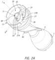
- FIG. 2 Bis a schematic front plan view of the sleeve bearing of FIG. 2 A .
- FIG. 2 Cis a schematic side perspective view of the sleeve bearing of FIG. 2 B .
- FIG. 2 Dis a schematic front plan view of the sleeve bearing and impeller assembly of FIG. 2 A .
- FIG. 2 Eis a schematic side sectional view of the impeller assembly and sleeve bearing of FIG. 2 D .
- FIG. 2 Fis a schematic side sectional view of a non-overlapping sleeve assembly, according to another embodiment.
- FIG. 2 Gis a schematic perspective view of a sleeve bearing having a crenulated pattern.
- FIG. 2 His a schematic plan view of a sinusoidal pattern of the sleeve bearing of FIG. 2 G .
- FIG. 3 Ais a schematic perspective view of a drive bearing according to various embodiments.
- FIG. 3 Bis a front end view of the drive bearing of FIG. 3 A .
- FIG. 3 Cis a side view of the drive bearing of FIG. 3 A .
- FIG. 3 Dis a schematic front end view of a drive bearing according to another embodiment.
- FIG. 3 Eis a schematic front end view of a drive bearing according to another embodiment.
- FIG. 4 Ais a schematic perspective view of an integrated rotor core comprising an impeller shaft with flow tube and a secondary impeller.
- FIG. 4 Bis a schematic perspective view of a proximal portion of the integrated rotor core of FIG. 4 A .
- FIG. 4 Cis a sectional view taken along the longitudinal axis of the rotor core of FIG. 4 B .
- FIG. 4 Dis a schematic proximal end view of the integrated rotor core of FIG. 4 C .
- FIG. 5 Ais a schematic perspective, exploded view of a segmented cone bearing comprising a proximal portion of the integrated rotor core and the drive bearing.
- FIG. 5 Bis a distal end sectional view of the secondary impeller and drive bearing.
- FIG. 6is a schematic, perspective exploded view of a blood flow assist system according to various embodiments.
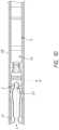
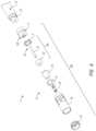
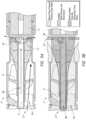
- FIG. 7is a schematic side sectional view of a pump according to various embodiments.
- FIG. 8 Ais a schematic side sectional view of a motor housing according to various embodiments.
- FIG. 8 Bis a schematic perspective view of a motor and a motor mount support.
- FIG. 8 Cis a schematic perspective view of a distal end of a power wire configured to supply power to the motor.
- FIG. 8 Dis a schematic perspective view of a proximal end portion of the power wire.
- FIGS. 9 A and 9 Bare schematic side sectional views of primary and secondary flow pathways through a pump according to various embodiments.
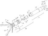
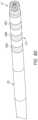
- FIGS. 1 A- 1 DVarious embodiments disclosed herein relate to a blood flow assist system 1 configured to provide circulatory support to a patient, as illustrated in FIGS. 1 A- 1 D .
- the system 1can be sized for intravascular delivery to a treatment location within the circulatory system of the patient, e.g., to a location within the descending aorta of the patient.
- the system 1can have a proximal end 21 with a connector 23 configured to connect to an external control system, e.g., a console (not shown).
- the connector 23can provide electrical communication between the control system and a power wire 20 extending distally along a longitudinal axis L from the connector 23 and the proximal end 21 .
- the power wire 20can comprise an elongate body that electrically and mechanically connects to a pump 2 at or near a distal end 22 of the blood flow assist system 1 , with the distal end 22 spaced apart from the proximal end 21 along the longitudinal axis L.
- the pump 2can comprise a pump head 50 including a pump housing 35 connected to a drive unit 9 that includes a motor housing 29 .
- a retrieval feature 48can be provided at a proximal end portion of the pump 2 .
- the retrieval featurecan be coupled with the distal end of the power wire 20 between the power wire 20 and the motor housing 29 .
- the cliniciancan remove the pump 2 from the patient by engaging a tool (e.g., a snare, clamp, hook, etc.) with the retrieval feature 48 to pull the pump 2 from the patient.
- a toole.g., a snare, clamp, hook, etc.
- the retrieval feature 48can comprise a neck 49 (e.g., a reduced diameter section) at a proximal curved portion 51 c of the motor housing 29 and an enlarged diameter section disposed proximal the neck 49 .
- the enlarged diameter sectioncan comprise a first curved portion 51 a and a second curved portion 51 b , as shown in FIG. 1 E .
- the first and second curved portions 51 a , 51 bcan comprise convex surfaces, e.g., convex ball portions.
- the first and second curved portions 51 a , 51 bcan have different radii of curvature. For example, as shown in FIG.
- the first curved portion 51 acan have a larger radius of curvature than the second curved portion 51 b .
- the first curved portion 51 acan be disposed on opposing sides of the retrieval feature 48 in some embodiments.
- the second curved portion 51 bcan be disposed around the first curved portion 51 a and can have a radially-outward facing surface and a proximally-facing convex surface coupled to the distal end of the power wire 20 .
- the neck 49can have a first depth at a first circumferential position of the retrieval feature 48 and a second depth less than the first depth at a second circumferential position of the retrieval feature 48 spaced apart from the first circumferential position.
- one or more first planes P 1 extending parallel to the longitudinal axis L and intersecting the first curved portion 51 acan have a first angle or taper between the proximal curved portion 51 c of the motor housing 29 and the first curved portion 51 a .
- One or more second planes P 2 extending parallel to the longitudinal axis L and intersecting the second curved portion 51 bcan have a second angle or taper (which is different from the first angle or taper) between the proximal curved portion 51 c of the motor housing 29 and the second curved portion 51 b .
- the first angle or tapercan provide a gradual, continuous (generally monotonically decreasing) geometric transition between the proximal curved portion 51 c of the motor housing 29 and the power wire 20 , which can provide for smooth blood flow and reduce the risk of thrombosis.
- the second curved portion 51 bcan serve as a lobe that extends radially outward, e.g., radially farther out than the first curved portion 51 a .
- the second curved portion 51 bcan be used to engage with a retrieval device or snare to remove the pump 2 from the anatomy.
- Some cross sections through the longitudinal axis of the retrieval feature 48can contain a substantial neck (e.g., a local minimum in the radius of curvature measured along its central axis) while other cross sections through the longitudinal axis of the retrieval feature 48 can contain an insubstantial local minimum or no local minimum.
- the neck 49can be disposed between the curved portions 51 a , 51 b and the proximally-facing convex surface 51 c of the motor housing 29 .
- the retrieval feature 48can be coupled to or integrally formed with the motor housing 29 .
- the retrieval feature 48can be disposed at other locations of the pump 2 .
- the retrieval feature 48can be symmetrical and continuously disposed about the longitudinal axis L.
- the retrieval feature 48can comprise a plurality of discrete surfaces spaced apart circumferentially and/or longitudinally.
- the drive unit 9can be configured to impart rotation to an impeller assembly 4 disposed in the pump housing 35 of the pump head 50 .
- the drive unit 9can include a drive magnet 17 and a motor 30 (see FIGS. 6 - 8 A ) disposed in the motor housing 29 capped by a distal drive unit cover 11 .
- the drive unit cover 11can be formed with or coupled to a drive bearing 18 .
- the drive magnet 17can magnetically couple with a corresponding driven or rotor magnet 12 (see FIG. 7 ) of the impeller assembly 4 that is disposed within the shroud 16 proximal the impeller 6 .
- the power wire 20can extend from the treatment location to outside the body of the patient, and can provide electrical power (e.g., electrical current) and/or control to the motor 30 . Accordingly, no spinning drive shaft extends outside the body of the patient in some embodiments.
- the power wire 20can energize the motor 12 , which can cause the drive magnet 17 to rotate about the longitudinal axis L, which can serve as or be aligned with or correspond to an axis of rotation. Rotation of the drive magnet 17 can impart rotation of the rotor magnet 12 and a primary or first impeller 6 of the impeller assembly 4 about the longitudinal axis L.
- the rotor magnet 12can cause an impeller shaft 5 (which can serve as a flow tube) to rotate which, in turn, can cause the first impeller 6 to rotate to pump blood.
- the drive unit 9can comprise a stator or other stationary magnetic device.
- the stator or other magnetic devicecan be energized, e.g., with alternating current, to impart rotation to the rotor magnet 12 .
- the impeller 6can have one or a plurality of blades 40 extending radially outward along a radial axis R that is radially transverse to the longitudinal axis L.
- the first impeller 6can have a plurality of (e.g., two) axially-aligned blades 40 that extend radially outwardly from a common hub and that have a common length along the longitudinal axis L.
- the curvature and/or overall profilecan be selected so as to improve flow rate and reduce shear stresses. Skilled artisans would appreciate that other designs for the first impeller 5 may be suitable.
- the impeller assembly 4can be disposed in a shroud 16 .
- the impeller shaft 5can be supported at a distal end by a sleeve bearing 15 connected to a distal portion of the shroud 16 .
- a support structuresuch as a localization system can comprise a base portion 36 coupled with the sleeve bearing 15 and/or the shroud 16 .
- the base portion 36 , the sleeve bearing 15 , and/or the shroud 16can be welded together.
- the base portion 36 of the support structure or localization system, the sleeve bearing 15 , and the shroud 16can cooperate to at least partially define the pump housing 35 , as shown in FIGS.
- the localization systemcan comprise a plurality of self-expanding struts 19 having convex contact pads 24 configured to contact a blood vessel wall to maintain spacing of the pump housing 35 from the blood vessel wall in which the pump housing 35 is disposed.
- the struts 19 of the localization systemare illustrated in an expanded, deployed configuration, in which the contact pads 24 extend radially outward to a position in which the contact pads 24 would contact a blood vessel wall within which the pump 2 is disposed to at least partially control position and/or orientation of, e.g., to anchor, the pump 2 during operation of the system 1 .
- a first fluid port 27can be provided distal the impeller assembly 4 at a distal end of the pump housing 35 .
- the shroud 16can comprise a proximal ring 26 coupled with the motor housing 29 and a plurality of second fluid ports 25 formed in a proximal portion of the shroud 16 adjacent (e.g., immediately distal) the proximal ring 26 .
- the second fluid ports 25can comprise openings formed between axially-extending members 60 that extend along the longitudinal axis L between the proximal ring 26 and a cylindrical section 59 of the shroud 16 .
- the axially-extending members 60can be shaped to serve as vanes that can shape or direct the flow of blood through the second fluid ports 25 .
- the axially-extending members 60can be angled or curved to match the profile of the impeller blades 40 . In other embodiments, the axially-extending members 60 may not be angled to match the blades 40 .
- the first fluid port 27can comprise an inlet port into which blood flows. In such embodiments, the impeller assembly 4 can draw blood into the first fluid port 27 and can expel the blood out of the pump 2 through the second fluid ports 25 , which can serve as outlet ports. In other embodiments, however, the direction of blood flow may be reversed, in which case the second fluid ports 25 may serve as fluid inlets and the first fluid port 27 may serve as a fluid outlet.
- FIG. 1 Dshows the pump 2 disposed within an elongate sheath 28 .
- the struts 19are held in a collapsed configuration by the inner wall of the sheath 28 .
- the struts 19can be compressed to a diameter or major lateral dimension at one or more locations that is approximately the same (or slightly smaller than) the diameter of the shroud 16 .
- the patientcan be prepared for the procedure in a catheterization lab in a standard fashion, and the femoral artery can be exposed.
- the sheath 28(or a dilator structure within the sheath 28 ) can be passed over a guidewire and placed into the treatment location, for example, in the descending aorta.
- the pump 2can be advanced into the sheath 28 , with the pump 2 disposed in the mid-thoracic aorta, approximately 4 cm below the take-off of the left subclavian artery.
- the pump 2 and sheath 28can be advanced together to the treatment location. Positioning the pump 2 at this location can beneficially enable sufficient cardiac support as well as increased perfusion of other organs such as the kidneys.
- relative motioncan be provided between the sheath 28 and the pump head (e.g., the sheath 28 can be retracted relative to the pump 2 , or the pump 2 can be advanced out of the sheath 28 ).
- the struts 19 of the localization systemcan self-expand radially outwardly along the radial axis R due to stored strain energy into the deployed and expanded configuration shown in FIGS. 1 A- 1 C .
- the convex contact pads 24can engage the blood vessel wall to stabilize (e.g., anchor) the pump 2 in the patient's vascular system.
- the cliniciancan engage the control system to activate the motor 30 to rotate the impeller assembly 4 to pump blood.
- the pump 2can be inserted into the femoral artery and advanced to the desired treatment location in the descending aorta.
- the pump 2can be positioned such that the distal end 22 is upstream of the impeller 6 , e.g., such that the distally-located first fluid port 27 is upstream of the second fluid port(s) 25 .
- the first fluid port 27can serve as the inlet to the pump 2
- the second ports 25can serve as the outlet(s) of the pump 2 .
- the pump 2can be inserted percutaneously through the left subclavian artery and advanced to the desired treatment location in the descending aorta.
- the pump 2can be positioned such that the distal end 22 of the system 1 is downstream of the impeller 6 , e.g., such that the distally-located first fluid port 27 is downstream of the second fluid port(s) 25 .
- the second fluid port(s) 25can serve as the inlet(s) to the pump 2
- the first port 27can serve as the outlet of the pump 2 .
- the pump 2can be removed from the patient. Relative motion opposite to that used for deploying the pump 2 can be provided between the sheath 28 and the pump 2 (e.g., between the sheath 28 and the impeller assembly 4 and pump housing 35 ) to collapse the struts 19 into the sheath 28 in the collapsed configuration.
- the pump 2can be withdrawn from the sheath 28 with the sheath 28 in the patient's body, and the sheath 28 can subsequently removed.
- the sheath 28 and the pump 2can be removed together from the patient's body.
- the sleeve bearing 15can support a distal end portion 5 A of the impeller shaft 5 , which can support the first impeller 6 and can also serve as a flow tube. Designs may be generally described from a perspective in which the central axis of rotation of the impeller assembly 4 is oriented along the longitudinal axis L of the system 1 , e.g., vertically for purposes of discussion in some instances. As used herein, proximal and distal ends (or end portions) of a component may be axially spaced apart along the longitudinal axis L of the system 1 . Thus, the sleeve bearing 15 may be described interchangeably in terms of an associated length or height, which extend along the longitudinal axis L.
- a rotating memberrotating inside a tubular sleeve or bearing has a bearing surface that is cylindrically shaped as an open right circular cylinder.
- This standard bearing designhas circular proximal and distal edges (e.g., upper and lower interface edges) that are perpendicular to the longitudinal axis L of the rotating member or axis of rotation, and a cylindrical bearing surface between the edges that remains covered and unexposed by the bearing body.
- there is a circular set of points where the rotating member (e.g., the shaft 5 ) and bearing interface with one anotherwhich may be referred to herein as a bearing interface or interface edge.
- any point on this circle on the rotating memberis always perpendicularly aligned with the edge of the sleeve.
- This conditionhas been shown to encourage thrombus formation at the sleeve edge(s).
- This thrombusmay grow to form a complete ring around the sleeve edge, thereby impeding proper operation.
- the designs of the modified sleeve bearing 15 described hereinhave a novel design to reduce or prevent thrombus formation during operation.
- FIGS. 2 A- 2 Eone embodiment of such a sleeve bearing 15 is illustrated.
- the sleeve bearing 15can comprise an inner support structure including an inner sleeve 37 that supports the distal portion 5 A of the impeller shaft 5 .
- the inner sleeve 37can be mechanically coupled to the first impeller 6 in some embodiments, e.g., by way of a thrust ring bearing 14 (see FIG. 6 ).
- the thrust bearing 14can be laser welded to the inner sleeve 37 in one embodiment.
- the sleeve bearing 15can further include an outer support structure comprising an outer annular or cylindrical member, sometimes referred to herein as an outer sleeve or outer bearing carrier 38 connected to the shroud 16 .
- the outer sleeve or bearing carrier 38can comprise a small radially outer portion of the sleeve bearing 15 .
- a connecting structure 39can extend radially between the inner sleeve 37 and the outer bearing carrier 38 to connect the inner sleeve 37 and the outer bearing carrier 38 . In variations the connecting structure 39 can be coupled directly to the shroud 16 .
- the outer bearing carrier 38can be eliminated in one embodiment.
- the outer bearing carrier 38can be integrated into or be part of the shroud 16 , such that the structure is a monolithic construction and not the assembly of multiple parts.
- the connecting structure 39can be indirectly coupled to the shroud 16 through a structure other than the annular member or bearing carrier 38 .
- the pump 2can have a primary or first flow pathway 3 A. Blood can flow along the first flow pathway 3 A between the outer bearing carrier 38 and the inner sleeve 37 and along an exterior surface of the first impeller 6 . A majority of the blood flow (e.g., a majority of the momentum of the total blood flow) through the pump 2 can pass along the primary or first flow pathway 3 A.
- the first flow pathway 3 Acan extend radially between the rotating first impeller 6 and the stationary pump housing 35 . Accordingly, blood can flow over the rotating outermost surface of the first impeller 6 between the first impeller 6 and the stationary inner wall of the pump housing 35 .
- the pump 2can also have a secondary or second flow pathway 3 B along a lumen of the impeller shaft 5 , which as explained herein can serve as a flow tube.
- a minority of the total blood flowcan flow along the secondary flow pathway 3 B.
- the volume flow of blood along the secondary flow pathway 3 Bcan be in a range of 0.5% to 10% of the volume flow of blood along the primary flow pathway 3 A, in a range of 1% to 5% of the volume flow of blood along the primary flow pathway 3 A, or in a range of 2% to 3% of the volume flow of blood along the primary flow pathway 3 A.
- the inner sleeve 37can have a bearing interface surface 41 extending between a proximal edge 37 B (or “lower edge” if viewed vertically) and a distal edge 37 A (or “upper edge” if viewed vertically) spaced apart from the proximal edge 37 B along the longitudinal axis L.
- the sleeve bearing 15can be shaped so that one or more bearing interface surfaces 41 and/or interface edges ( 37 A, 37 B) of the inner sleeve 37 are not perpendicular to the axis of rotation or longitudinal axis L of the sleeve bearing 15 .
- the bearing interface surface 41may comprises edges 37 A, 37 B that form ellipse(s) tilted or tapered with respect to the longitudinal axis L of the sleeve bearing 15 ( FIGS. 2 A- 2 E ).
- the bearing surface(s) 41may vary in a sinusoidal way to create crenulated edge(s) (see FIG. 2 F ).
- the modified sleeve bearings 15expose at least one point on the rotating member or shaft 5 throughout the entire length (or height if the sleeve bearing is viewed as being vertically oriented) of the sleeve bearing 15 so that the rotating member bearing interface surface 41 is only covered by the sleeve bearing for a portion of rotation.
- the interfacing bearing surface(s) 41may have better exchange of the lubricating layer of blood than conventional designs.
- the distal edge 37 Acan comprise a distal boundary of the inner sleeve 37 .
- the distal boundarye.g., the distal edge 37 A
- the distal boundarycan be angled relative to the axis of rotation (which is aligned with the longitudinal axis L) such that, in a cross-section taken perpendicular to the axis of rotation L, only a portion of the distal boundary (e.g., distal edge 37 A) is disposed about the impeller shaft 5 at a selected axial location along the axis of rotation.
- only a portion of a proximal boundarycan be disposed about the impeller shaft 5 at a selected axial location along the axis of rotation. For example, as shown in FIG.
- the bearing interface surface 41can have exposed axial regions 42 A, 42 B comprising axial location(s) at which an exterior surface 5 ′ (see FIG. 2 A ) of the impeller shaft 5 is cyclically exposed to blood that flows along the first flow pathway 3 A.
- the bearing interface surface 41is disposed about only a portion of a perimeter (e.g., circumference) of the impeller shaft 5 .
- an exterior surface of the impeller shaft 5 at a selected axial location within the exposed axial regions 42 A, 42 Bis cyclically exposed to blood flow in the first pathway 3 A during operation of the blood flow assist system 1 .
- the inner sleeve 37may be partially axially overlapping along the longitudinal axis L.
- the bearing surface 41 of the inner sleeve 37may be disposed completely around the exterior surface of the impeller shaft 5 such that the exterior surface 5 ′ of the shaft 5 at that overlapping cross-sectional plane 43 is not exposed to blood flow in the first pathway 3 A.
- the sleeve bearing 15can have a length along the longitudinal axis L.
- the inner sleeve 37may be partially overlapping by an amount in a range of 1% to 50% of the length of the sleeve bearing 15 , in a range of 5% to 50% of the length of the sleeve bearing 15 , in a range of 10% to 50% of the length of the sleeve bearing 15 , in a range of 20% to 40% of the length of the sleeve bearing 15 , or in a range of 25% to 35% of the length of the sleeve bearing 15 (e.g., about 30% of the length of the sleeve bearing 15 in some embodiments).
- a sleeve bearing 15 Acan comprise an inner sleeve 37 which may be non-overlapping such that there are no points on the exterior surface 5 ′ of the impeller shaft 5 that remain covered by the bearing interface surface 41 during rotation of the impeller shaft 37 .
- all axial locations along the length of the inner sleeve 37comprise an exposed axial region 42 , such that the bearing surface 41 of the inner sleeve 37 is disposed only partially about the perimeter of the impeller shaft 5 at all axial locations along the length of the inner sleeve 37 .
- the edge(s) 37 A, 37 Bcan comprise non-circular edge(s) that ensures that there are no points on the rotating member or shaft 5 that remain aligned with the sleeve edge(s) 37 A, 37 B throughout an entire rotation of the rotating member or shaft 5 .
- the sleeve bearing 15 Acan therefore expose at least one point on the rotating member or shaft 5 throughout an entire length (or height) of the sleeve bearing 15 A so that the exterior surface 5 ′ of the shaft 5 is only covered by the inner sleeve 37 for a portion of rotation.
- the bearing edges 37 A, 37 Bare shaped so that maximum length (or height) of the lower or proximal edge 37 B is above minimum length (or height) of the upper or distal edge 37 A in one or more locations around the circumference of the inner sleeve 37 ( FIGS. 2 E & 3 F ).
- the sleeve bearing 15 , 15 Anever covers 360° of the rotating member or shaft 5 throughout the entire length or height of the bearing interface region 41 .
- This interrupted contact of the disclosed embodimentspromotes exchange of a lubricating layer blood over the entire bearing interface 41 and does not allow blood to stagnate or become trapped.
- the tilt or taper of the sleeve edges 37 A, 37 B with respect to the longitudinal axis L (and the axis of rotation)may also generate or enhance fluid dynamic forces that contribute to proper bearing operation and reduce contact and wear of the bearing parts.
- the fluid near the surface of a particular spot on the rotating membere.g., shaft 5
- the rotating membermay experience increases and decreases in pressure as it moves under and out from under the inner sleeve 37 . These pressure changes contribute to lubricating layer formation and dispersal.
- the interface between the sleeve bearing 15 , 15 A and the rotating member (e.g., shaft 5 )is lubricated by blood.
- this lubricationmay be hydrodynamic lubrication, elastohydrodynamic lubrication, boundary lubrication, or mixed lubrication.
- the varying exposure of the rotating member surface and/or varying edge profile of the sleeve bearing edges 37 A, 37 Bmay be designed to help encourage a fluid wedge to improve lubrication.
- viscous drag from a surface patch of the rotating member or shaft 5may increase fluid pressure above that surface patch as it rotates under the sleeve edge(s) 37 A, 37 B.
- the cross-section of the inner bearing surface 41 of the sleeve 37may optionally be made non-circular to aid in wedge pressure generation, for example by varying the wall thickness of the inner sleeve 37 .
- the sleeve edge profile of the edges 37 A, 37 Bmay be beveled or rounded to augment this pressure generation.
- FIGS. 2 G and 2 Hillustrate another example of a sleeve bearing 15 B that has a non-overlapping design.
- the sleeve bearing 15 Bcomprises a crenulated bearing in which the bearing interface surface 41 is disposed about the longitudinal axis L in a repeating, undulating or in some cases a sinusoidal pattern 44 .
- the sinusoidal pattern 44can have alternately exposed gaps about the perimeter of the impeller shaft 5 during rotation such that all axial locations along the length of the sleeve bearing 15 B are cyclically exposed to blood flow during operation of the system 1 .
- the inner sleeve 37 ′can have an undulating pattern that has a plurality of (e.g., two) distal peaks 61 and a plurality of (e.g., two) proximal peaks 62 .
- the peaks 61 , 62can be generally flat with arcuate sections 64 extending between the peaks 61 , 62 .
- a gap 63 between the arcuate sections 64can provide for the cyclical exposure of the shaft 5 to blood flow.
- the shaft 5can transition from covered by the arcuate sections 64 to being uncovered and exposed through the gaps 63 .
- FIG. 2 Hshows an inner sleeve 37 ′′ with another crenulated structure with a sinusoidal patterns, e.g., with curved peaks 61 , 62 .
- the use of curved peaks 61 , 61may beneficially allow for smoother flow profiles.
- the rotating member 5 and the sleeve bearings 15 , 15 A, 15 Bmay each be made of any suitable blood compatible material.
- the rotating membere.g., the impeller shaft 5
- the rotating membermay comprise a flow tube made out a biocompatible polymer, e.g., of PEEK or polyethylene and/or the sleeve bearing 15 , 15 A, 15 B may be made out of a metal, e.g., titanium or stainless steel.
- Making the rotating member or shaft 5 as a plastic tubemay increase the range over which elastohydrodynamic lubrication is present.
- the use of materials that enable elastic deformation of the materials during operationcan provide an improved pressure profile.
- the drive unit 9can comprise a drive magnet 17 and a drive bearing 18 between the drive magnet 17 and the impeller assembly 4 .
- the drive bearing 18can provide a magnetic coupling and a fluid bearing interface between the drive magnet 17 and a rotor assembly 46 that comprises the driven or rotor magnet 12 and an integrated rotor core 8 that includes the impeller shaft 5 and a secondary impeller 7 , as shown in FIG. 6 .
- the drive bearing 18can comprise a segmented cone bearing.
- Cone bearingscan comprise a convex (e.g., generally conical) shaped member 45 seated inside a generally concave (e.g., conical) opening 32 or cavity of the rotor assembly 46 .
- the concave opening 32can serve as a concave bearing surface sized and shaped to mate with the convex member 45 .
- the concave opening 32can comprise an angled concave cavity sized to receive the convex member 45 .
- the drive unit 9can comprise a convex member sized to fit within the angled cavity of the concave opening 32 .
- the bearing interface region of this bearing designcan be formed by the matching surfaces of the conical or convex member 45 and the conical or concave opening 32 and the space between them.
- a cone bearingcan provide both axial and radial confinement. The axial confinement from a single cone bearing can be in one direction only. Cone bearings with steep slopes provide relatively more radial confinement, and cone bearings with shallower slopes provide relatively more axial confinement.
- the conical shaped member 45can be modified to reduce hemolysis and/or clotting.
- the conical member 45can be truncated by a cylinder coaxial to the axis of the cone (or axis of rotation) to remove base portions of the cone.
- the conical member 45can be truncated by a plane perpendicular to the axis of the cone (creating a frustrum or a frustoconical surface). In other embodiments, the conical member 45 can be truncated by both a cylinder and a cone.
- the surface of the conical opening 32may be modified in a similar manner in conjunction with the conical member 45 or instead of the conical member 45 .
- One or the other or both of the surfaces of the conical member 45 and conical opening 32may also be modified by holes, gaps, channels, grooves, bumps, ridges, and/or projections. Each of the surfaces of the conical member 45 and conical opening 32 may also be formed as part of other components of the pump with any overall shape.
- either of their surfacescomprise of a plurality of separate bearing surfaces in the plane of the generally conical shape defining the member 45 or opening 32 .
- the opening 32 and/or the conical member 45 of the bearing pairmay be formed by a plurality of separate surfaces or a segmented surface.
- the plurality of separate surfaces or the segmented surface that make up either the conical member 45 or conical opening 32 of the bearing pairmay extend from the same component or part, or may extend from distinct components or parts.
- Grooves and gaps in either the conical member 45 and/or conical opening 32may be created by removing material from a single generally conical surface or by using a plurality of separate surfaces.
- the conical member 45 of the bearing paircan comprise a convex bearing surface having a segmented frustoconical shape formed from a plurality of distally-extending segments 33 ( FIGS. 3 A- 3 D ).
- the distally-extending segments 33can extend distally from the drive unit cover 11 .
- the segments 33can be spaced apart circumferentially to define at least one channel 34 between adjacent segments 33 .
- Three segments 33are shown in FIGS. 3 A- 3 D , but any suitable number of segments 33 may be utilized.
- the segments 33can be separate components arising from a common part with gaps or channels 34 between them, but the segments 33 may also be separated by shallow or deep grooves.
- the gaps, grooves or channels 34may follow any path.
- the channel(s) 34extend radially outward from a central recess or hollow 31 (also referred to herein as a void) at a location proximal a proximal end portion 5 B of the impeller shaft 5 .
- the width and depth of any groove or channel 34may vary along its path.
- two or more channels 34may join or separate.
- two or more channels 34may join to form the central hollow area 31 coaxial with the axis of the conical surfaces and/or with the longitudinal axis of rotation L.
- the conical opening 32 of the bearing paircan be a continuous (e.g., no gaps, channels, or grooves), generally conical surface.
- the relative angles of the cone bearings (e.g., the segments 33 ) and spacing between segments 33can be selected to provide a desired flow profile through the channel(s) 34 described herein. For example, increased spacing between the segments 33 can provide increased flow through the channels 34 .
- the segmented conical member 45 of the drive bearing 18 with channels 34 between the segments 33 and the continuous conical opening 32can serve as a “segmented cone bearing”.
- the channels 34 between the segments 33allow interrupted contact between bearing surfaces similar to the interrupted contact described above for the modified sleeve bearing 15 , 15 A, 15 B discussed previously.
- This interrupted contactprovides, without limitation, benefits for the segmented cone bearing analogous to those it provides to the modified sleeve bearing 15 , 15 A, 15 B.
- the channels 34 between the segments 33can ensure that at least one point throughout the length or height of the conical opening 32 on the rotating member 5 is intermittently exposed by the conical opening 32 and not continuously covered by the bearing pair. This design promotes exchange of a lubricating layer blood over the entire bearing interface.
- the channels 34also generate pressure changes that contribute to lubricating layer formation and dispersal as described above for the sleeve bearing 15 , 15 A, 15 B.
- additional featuresmay promote blood flow through the central hollow 31 and channels 34 of the segmented cone bearing.
- bloodmay flow in through the channels 34 and exit via the central hollow 31 .
- bloodmay flow into the central hollow 31 (e.g., from the secondary flow pathway 3 B of the impeller shaft 5 ) and exit via the channels 34 .
- This net flow of blood through the central hollow 31 and channels 34may serve to ensure the volume of blood in the channels 34 and central hollow 31 is constantly flowing to provide a source of fresh blood for lubricating layer exchange, to carry away heat, and/or to reduce the time that blood is exposed to conditions within the bearing region that may increase the potential for hemolysis or thrombus formation.
- a concave bearing surface(which can comprise or be defined by the concave opening 32 ) can include a fluid port to deliver blood proximally along the second flow pathway 3 B.
- the convex bearing surface(which can comprise the convex member 45 ) can including a void (e.g., the central hollow 31 ), which can be disposed on the longitudinal axis L.
- the one or more channels 34can extend radially outward from the void or central hollow 31 .
- the voidcan be in fluid communication with the fluid port (e.g., an interface between the flow tube 5 and the conical opening 32 ) so as to direct blood radially outward along at least one channel 34 .
- the segments 33 of the convex member 45can be shaped to fit within the concave bearing surface comprising the concave opening 32 .
- a direct secondary flow pathway 3 B(for example through the flow tube of the impeller shaft 5 shown in FIGS. 4 B- 4 D and 5 B ) may provide proximally-flowing blood into the central hollow 31 .
- a secondary or second impeller 7may be used to drive the secondary flow of blood through the bearing region, e.g., through the second flow pathway 3 B, the central hollow 32 , and radially outwardly through the channel(s) 34 .
- the primary impeller 6 of the pump and/or the additional secondary impeller 7may assist in drawing the blood proximally and directing the blood radially outwardly along the channel(s) 34 .
- FIGS. 4 A- 4 Dshow the secondary impeller 7 that draws blood out through the channels 34 of the segmented cone bearing.
- the secondary impeller 7 and impeller shaft 5can form an integrated rotor core 8 .
- the secondary impeller 7can have a plurality of vanes 10 as explained herein to assist in directing blood radially outward through the channel(s) 34 of the drive bearing 18 .
- the bearing elements 33can be more directly exposed to the blood flow from the flow tube of the impeller shaft 5 along the second flow pathway 3 B. Further, the bearing elements 33 can have a smaller radius where the linear speed of the rotating member is lower. Placing the bearing elements or segments 33 near the axis L of the pump allows the vanes 10 of the secondary impeller 7 to be placed at a greater radius where the linear speed of the rotating member or shaft 5 is higher.
- FIG. 3 Dshows an embodiment in which the channels 34 between the segments 33 follow a curved path from the central hollow 31 .
- the channels 34can be configured to increase flow and reduce shear forces on the blood.
- the depth of the channels 34may be varied to form a central flow diverter 31 a as shown in, e.g., FIG. 3 E .
- the flow diverter 31 amay comprise a distally-extending projection (e.g., a cylindrical projection, a conical projection, a pyramidal projection, etc.) disposed in a central region of the bearing between the segments 33 .
- the flow diverter 31 acan comprise a symmetrical flow diverter.
- the flow diverter 31 amay aid blood coming from the flow tube or lumen of the shaft 5 to transition from axial flow to radial flow to exit through the channels 34 .
- the flow divertermay optionally be manufactured as one or more separate pieces that are then attached in the central hollow 31 and/or channels 34 .
- the flow diverter 31 amay comprise a generally right cylindrical shape extending distally from the bearing 18 .
- the flow diverter 31 acan have a tapered, for example, conical, profile.
- the interface between the segments 33 of the conical member 45 and concave, e.g., conical, opening 32 of the segmented cone bearingcan be lubricated by blood.
- this lubricationmay be hydrodynamic lubrication, elastohydrodynamic lubrication, boundary lubrication, or mixed lubrication.
- the channels 34 between the segments 33 of the conical member 45 of the bearing pairmay promote fluid exchange so that a portion of the blood that makes up the lubricating layer between a region of the conical opening 32 of the bearing pair over one segment 33 of the conical member of the bearing pair is replaced by fresh blood in the lubricating layer that forms between that same region of the conical opening 32 of the bearing pair and the next segment 33 of the conical member of the bearing pair during rotation.
- the width and depth of the channels 34can be altered to encourage this exchange.
- the height and lateral spacing of the segments 33can be selected to provide a desired channel depth and width.
- a width of the channels 34can be in a range of 0.02′′ to 0.06′′, in a range of 0.03′′ to 0.05′′, or in a range of 0.035′′ to 0.045′′ (for example, about 0.04′′ in some embodiments).
- the surfaces of the segments 33 of conical member of the bearing pair along the channels 34form the leading and trailing edges (as seen by a region of the conical opening 32 of the bearing pair) of the segments 33 of the conical member of the bearing pair.
- the distance of the leading and trailing edges from the conical opening 32may also be modified to encourage fluid exchange.
- the edgesmay be beveled or rounded or the distance of the leading and trailing edges may taper away or towards the surface of the conical opening 32 .
- the surfaces of the segments 33 of the conical member 45 of the bearing pairmay also be modified to diverge from a perfect conical surface to promote formation of a lubricating layer.
- one or more surfaces of the segments 33 of the conical member 45 of the bearing pairmay be shaped so the normal distance to the surface of the conical opening 32 of the bearing pair decreases from the leading edge to the trailing edge. Such a surface contour may encourage creation of fluid wedges between the segments 33 of the conical member 45 and the conical opening 32 of the bearing pair for improved lubrication.
- the surfaces of the segments 33 of the conical member 45 and conical opening 32 of the bearing pairmay be smooth and well matched to allow a relatively thin lubricating layer of relatively uniform thickness to form.
- conical member 45 and conical opening 32are described as having a generally conical shape in some embodiments, the member 45 and opening 32 may generally be considered convex member 45 and concave opening 32 .
- the shapes of the convex member and the concave opening 32may be any suitable mating shapes.
- the flow of blood driven by the secondary impeller 7 from the central hollow 31 through the channels 34provides fresh blood for exchange of the lubricating layers and carries away heat in the bearing region. Both functions are important to reducing the potential for thrombus formation in the segmented cone bearing.
- the segments 33 of the conical member 45 of the bearing pair and the conical opening 32 of the bearing pairmay each be made of any suitable blood compatible bearing material.
- the segments 33 of the conical member of the bearing pairmay be made out of titanium or stainless steel and/or the conical opening 32 of the bearing pair may be made out of PEEK or polyethylene.
- the bearing pairmay initially undergo boundary or mixed lubrication where surface asperities are worn to the point where the surfaces of the conical member and conical opening are smooth and well-matched enough for hydrodynamic or elastohydrodynamic lubrication to dominate. Having one side of the bearing pair be relatively softer may increase the range over which elastohydrodynamic lubrication is present.
- the continuous, conical opening 32 of the bearing pairwill be softer and the segmented, conical member of the bearing pair will be harder. This arrangement may help preserve special geometric features of the segments 33 on the conical member of the bearing pair.
- the continuous, conical opening 32 of the bearing pairwill be harder and the segmented, conical member 45 of the bearing pair will be softer. This arrangement may help preserve the surface of the opening 32 as a surface of rotation about the longitudinal axis L.
- the conical opening 32 and the conical member 45can be of similar or even the same hardness which can provide the advantage of dimensional and shape stability throughout the operation of the pump 2 .
- the normal distance between the segments 33 on the conical member of the bearing pair and the conical opening 32 of the bearing pairmay be small enough to exclude red blood cells.
- exchange of the lubricating layermay be less important as long as heat is still transferred away.
- a continuous (e.g., without channels or grooves) conical member 45 of the bearing pairmay still demonstrate low potential for thrombus formation as long as heat can be transferred away quickly enough. In some embodiments, this may be accomplished by eliminating or covering the channels 34 to form a continuous conical surface. Blood flow through the covered channels 34 may transfer sufficient heat from the bearing pair.
- the segmented bearing embodiments described aboveprovide an additional advantage of enhancing the flexibility of the portion of the pump 2 in the vicinity of the pump head 50 .
- the impeller assembly 4can be coupled with the drive unit 9 in a manner that permits some motion between the impeller assembly 4 and the cover 11 .
- the pump 2may be delivered through tortuous or curving vasculature or may be inserted from outside the patient to inside a blood vessel in tight bends.
- the impeller assembly 4can tip toward one or more of the segments 33 and away from one or more segments at the conical opening 32 such that proximal end face of the impeller assembly is at a non-parallel angle to the distal face of the cover 11 .
- the motionmay be significant compared to a mounting of the impeller assembly 4 on a shaft rotatably supported in a drive unit.
- the tipping of the impeller assembly 4can occur with a flexing of the shroud 16 , which may be flexed in high bending stress maneuvers.
- the shroud 16is made of an elastic material, such as nitinol, such that the pump head 50 can flex and elastically return to an undeflected state without elongation.
- FIGS. 4 A- 5 B and 7illustrate how the flow tube of the impeller shaft 5 may be routed through the primary impeller 6 .
- Thisallows for a compact pump rotor assembly 46 in which the primary and secondary flow pathways 3 A, 3 B are separate and flow in the same direction through the system 1 as shown in FIGS. 9 A- 9 B . Having the two flow paths flow pathways 3 A, 3 B in the same direction minimizes or reduces the probability of blood recirculating through the pump.
- the primary impeller 6may also have a thrust ring 14 or thrust surface designed to limit axial motion in the upstream or distal direction by contacting a corresponding thrust ring or thrust surface of the sleeve bearing 15 .
- the primary impeller 6may have the features described in U.S. Pat. Pub. No. 2017/0087288, incorporated by reference herein.
- the secondary impeller 7can be disposed proximal the primary impeller 6 .
- the secondary impeller 7can comprise a flange 47 extending non-parallel (e.g., radially outward along the radial axis R) from the proximal end portion 5 B of the impeller shaft 5 and a plurality of vanes 10 on a proximally-facing surface of the flange 47 .
- the flange 47can extend non-parallel and radially outward from the impeller shaft 5 . In some embodiments, the flange 47 may not extend radially beyond the shroud 16 .
- the flange 47may not extend radially beyond an adjacent portion of the impeller assembly 4 , e.g., may not extend radially beyond an integrated streamlined fairing 13 , discussed below.
- the flange 47can comprise a section of the combined rotor surface that lies in a plane perpendicular to the longitudinal axis L.
- the vanes 10can extend proximally from the flange 47 and can have a curved profile circumferentially about the longitudinal axis L. The vanes 10 can be disposed in the space between the proximal face of the flange 47 and the distal end of the drive unit 9 .
- the concave opening 32can comprise an angled cavity extending inwardly and distally relative to the generally proximally-facing surface of the flange 47 .
- the rotor magnet 12can be disposed adjacent a distally-facing surface of the flange 47 .
- Each of the vanes 10can have an inner end 10 a disposed at or near the concave opening 32 and an outer end 10 b extending radially and circumferentially outward from the inner end 10 a along the flange 47 .
- the flange 47can be coupled to or formed with the proximal end of the impeller shaft 5 . In some embodiments, for example, the flange 47 can be monolithically formed with (e.g., seamlessly formed with) the impeller shaft 5 .
- the flange 47 and impeller shaft 5can be separate components that are mechanically connected to one another (e.g., welded or otherwise coupled).
- the vanes 10can be monolithically formed with the proximally-facing surface of the flange 47 . In other embodiments, the vanes 10 can be mechanically connected to the proximally-facing surface of the flange 47 .
- the vanes 10can extend circumferentially about the longitudinal axis L in a manner such that adjacent vanes 10 circumferentially overlap.
- the radially outer end 10 b of one vanecan circumferentially overlap with, and be disposed radially outward from, the radially inner end 10 a of an adjacent vane.
- the vanes 10can be prevented from contacting the drive unit 9 by the thrust bearing aspect of the segmented cone bearing.
- the vanes 10can pump blood radially out of the channels 34 in the segmented cone bearing and thereby increase net flow through the flow tube of the impeller shaft 5 and segmented cone bearing.
- bloodcan exit the flow tube of the impeller shaft 5 at a location proximal the primary impeller 6 and be driven radially out of the channels 34 by the vanes 10 .
- the vanes 10In the illustrated embodiment, five (5) vanes 10 are used, but it should be appreciated that fewer than five or more than five vanes 10 can be used.
- the secondary impeller 7can have a proximal end 52 at a proximal edge of the vanes 10 .
- the drive unit 9can have a distal end 53 at a distal end of the distally-projecting segments 33 .
- the distally projecting convex segments 33can be received within the concave opening 32 of the rotor assembly 46 .
- the distal end 53 of the drive unit 9is distal the proximal end 52 of the second impeller 7 (e.g., distal the proximal-most end of the rotor assembly 46 ) as shown, for example, in FIG. 7 .
- the flow tube of the impeller shaft 5 , the concave opening 32 of the segmented cone bearing, and the secondary impeller 7can be integrated into one part as an integrated rotor core 8 .
- Advantages of this approachinclude, without limitation, simpler assembly (as described below) and minimization or reduction of joints between parts (particularly on the inner surface of the flow tube of the shaft 5 ).
- the primary impeller 6can be disposed on (e.g., mounted on and secured to (e.g., welded to or adhered to)) the impeller shaft 5 , which can provide a compact design.
- the primary impeller 6 and the impeller shaft 5may be separate components, with the impeller 6 mechanically connected to the impeller shaft 5 .
- the primary impeller 6 and impeller shaft 5can comprise a unitary or monolithic structure (e.g., a molded or cast structure). Such unitary or monolithic structures can be formed without seams or joints between the components of the unitary or monolithic structure.
- the secondary impeller 7can be disposed on (e.g., mechanically secured to) the proximal end of the impeller shaft 5 .
- the secondary impeller 7can be monolithically formed with the impeller shaft 5 so as to form a unitary component (e.g., molded, cast, etc.).
- the secondary impeller 7 and the impeller shaft 5can comprise separate components.
- the primary impeller 6 , the secondary impeller 7 (including the flange 47 ), and the impeller shaft 5can form a unitary or monolithic component or body.
- the primary impeller 6 , the secondary impeller 7 , and the impeller shaft 5can be injection molded over the rotor magnet 12 .
- the surface on which the secondary impeller 6 is disposedcan be considered a flange where the surface extends radially outward from a lumen formed in a central portion of the molded part.
- the integrated rotor core 8can form a compact structure.
- Rotation of the drive magnet 17can impart rotation to the rotor magnet 12 , which is also disposed on (e.g., mechanically connected or mounted on) the impeller shaft 5 .
- Rotation of the rotor magnet 12can impart common rotation to the impeller shaft 5 , the primary impeller 6 , and the secondary impeller 7 .
- FIGS. 7 and 8 A- 8 Dshow an example schematic view various features of the blood flow assist system 1 described herein. The features described above may also be combined in other ways.
- the system 1comprises the drive unit 9 with the motor 30 that can be sealed in the motor housing 29 .
- the drive magnet 17can be rotatable by the motor 30 by way of a motor shaft 51 .
- the motor 30can electrically connect to the power wire 20 .
- the power wire 20can comprise an insulating body having a central lumen 55 and a plurality of (e.g., three) outer lumens 56 A- 56 C extending along a length of the power wire 20 .
- the outer lumens 56 A- 56 Ccan be sized and shaped to receive corresponding electrodes or electrical wire (not shown) to provide electrical power to the motor 30 .
- the lumens 56 A- 56 Ccan receive, respectively, a hot electrode or wire, a neutral electrode or wire, and a ground electrode or wire.
- the electrodescan extend through corresponding openings 57 A- 57 C of a motor mounting support 54 configured to support the motor 30 .
- the central lumen 55can be sized and shaped to receive an elongate stiffening member or guidewire (not shown). The stiffening member or guidewire can be inserted into the central lumen 55 to help guide the pump 2 to the treatment location.
- the connector 23 near the proximal end 21 of the system 1can have electrical contacts 58 A- 58 C electrically connected to the electrodes in the corresponding outer lumens 56 A- 56 C.
- the contacts 58 A- 58 Ccan comprise rings spaced apart by an insulating material and can be configured to electrically connect to corresponding electrical components in the control system or console (not shown).
- the drive magnet 17can be sealed within the drive unit 9 by the drive unit cover 11 that may also have features that act as the bearing components(e.g., the distally-projecting segments 33 ).
- the top distal portion of the cover 11may provide the segments 33 forming the conical member 45 of the segmented cone bearing as described in this disclosure.
- the corresponding conical opening 32 of this bearing paircan be built into a rotatable piece that comprises the secondary impeller 7 and flow tube or impeller shaft 5 (together, the integrated rotor core 8 ).
- the convex member 45matches the contour and fits inside of the concave opening 32 of the rotatable piece.
- the channels 34 in the segmented cone bearingprovide fluid passages for blood entering the bearing region through the flow tube 5 and forced out of the bearing region by the secondary impeller 7 .
- a lubricating layer of blood between the bearing surfaces of the integrated rotor core 8 and the matching surfaces of the cone segments 33provides lubrication, reduces wear, and eases relative motion of the two components. Depending on the geometry, rotational speed, and materials making up the interface, this may be hydrodynamic, elastohydrodynamic, boundary, or mixed lubrication.
- the rotor magnet 12 of the rotor assembly 46can be positioned on the integrated rotor core 8 to be in close proximity to the drive unit 9 , thereby allowing the integrated rotor core 8 to be magnetically coupled to the drive unit 9 and rotated as desired.
- the first or primary impeller 6 with an integrated streamlined fairing 13can be is placed over the rotor magnet 12 and joined to the integrated rotor core 8 to at least partially form the pump rotor assembly 46 .
- the three-piece constructionintegrated rotor core 8 , magnet, and primary impeller 6 with integrated fairing
- the portion of the primary impeller 6 that interfaces with the flow tube 5may be shaped to function as a thrust pad or to be fit with a separate thrust ring 14 to interface with a matching thrust pad on the sleeve bearing 15 that fits around the flow tube 5 .
- the rotor magnet 12 and primary impeller 6 with the fairing 13may be secured to the integrated rotor core 8 so that the components rotate together.
- the pump rotorcould be assembled from more than three pieces.
- the primary impeller 6 and the fairing 13are separate pieces. This can allow the primary impeller 6 and the fairing 13 to be made of different materials.
- the rotor magnet 12may be coated to be suitable for blood contact and may not be covered by the fairing 13 , but rather directly joined to the primary impeller 6 . Such a configuration may allow use of a larger diameter magnet (with corresponding higher torque coupling) in the same pump rotor diameter than would be possible with a magnet inside a fairing.
- a separate ring 14may be added around the flow tube 5 above the primary impeller 6 . This separate ring would then serve as the thrust interface that mates with the thrust surface of the sleeve bearing.
- the separate ringcould be made of a different material than the flow tube 5 or primary impeller 6 .
- the flow tube of the impeller shaft 5 of the pump rotorcan fit inside a fixed (non-rotating) sleeve bearing 15 ( FIG. 7 ).
- the sleeve bearing 15can provide radial confinement of the impeller assembly 4 and the rotor assembly 46 .
- the bearing interfacecomprises the outer surface of the impeller shaft 5 and the inner surface of the sleeve bearing 15 .
- the sleeve bearing 15can have a modified geometry as explained above that reduces or minimizes continuous coverage of the outer surface of the impeller shaft 5 and thereby reduces the potential for thrombosis.
- the sleeve bearing 15may also optionally provide a thrust bearing surface that interfaces with the optional thrust bearing surface of the primary impeller 6 or optional thrust ring 14 .
- the outer bearing carrier 38 of the sleeve bearing 15can attach to the shroud 16 that fits around the impeller assembly 4 and is attached to the drive unit cover 11 of the drive unit 9 .
- the connecting structure 39can include an arm or arms may attach directly to the shroud 16 or may attach to a ring that is then attached to the shroud 16 to provide improved rigidity and circularity of the shroud 16 .
- the shroud 16can comprise a tube with an inlet end and an outlet end.
- the shroud 16can be placed over the various internal components that make up the pump rotor (e.g., the impeller assembly 4 and the rotor assembly 46 ).
- the outlet end of the shroud 16can be secured to the drive unit cover 11 of the drive unit 9 .
- the inlet side of the shroud 16can be open to create an inlet port 27 .
- the front bearingis placed within the inlet port of the shroud 16 as described above.
- the outlet side of the shroud 16has openings 25 in the surface of the shroud (outlet ports) that provide outlets for fluid driven by the primary impeller 6 and secondary impeller 7 .
- the pumpmay include struts or any other securing means for securing the pump in the circulatory system, such as illustrated in U.S. Pat. Nos. 8,012,079 and 9,572,915 and U.S. Pat. Pub. No. 2017/0087288.
- various embodiments of the pump 2provide two flow paths 3 A, 3 B as explained herein.
- the first flow pathway 3 A(red in FIGS. 9 A- 9 B ) is driven by the primary impeller 6 , which draws fluid in through the inlet port 27 of the shroud 16 and directs the fluid out of the outlet ports 25 of the shroud 16 .
- the second flow path 3 B(yellow in FIG. 9 A and blue in FIG. 9 B ) is driven by the secondary impeller 7 , which draws fluid through the internal secondary flow path 3 B, e.g., a lumen or flow tube of the impeller shaft 5 .
- the internal flow pathpasses through the flow tube of the shaft 5 of the integrated rotor core 8 .
- the fluidcan be driven radially outward by the vanes 10 of the secondary impeller 7 .
- flow from both flow pathscan be directed from the inlet 27 to the outlet 25 in the illustrated embodiment. In other embodiments, as described herein, the flow of blood can be reversed.
- fluid flowing through the secondary flow pathacts as a lubricating layer between the rotor assembly 46 and the fixed segments 33 of the segmented cone bearing.
- the matching conical surfaces of the segmented cone bearingcan provide both axial and radial confinement of the pump assembly 46 .
- Embodiments described hereinare included to demonstrate particular aspects of the present disclosure. It should be appreciated by those of ordinary skill in the art that the embodiments described herein merely represent non-limiting embodiments of the disclosure. Those of ordinary skill in the art should, in light of the present disclosure, appreciate that many changes can be made in the specific embodiments described, including various combinations of the different elements, components, steps, features, or the like of the embodiments described, and still obtain a like or similar result without departing from the spirit and scope of the present disclosure. From the foregoing description, one of ordinary skill in the art can easily ascertain the essential characteristics of this disclosure, and without departing from the spirit and scope thereof, can make various changes and modifications to adapt the disclosure to various usages and conditions. The embodiments described hereinabove are meant to be illustrative only and should not be taken as limiting of the scope of the disclosure.
- a phrase referring to “at least one of” a list of itemsrefers to any combination of those items, including single members.
- “at least one of: A, B, or C”is intended to cover: A, B, C, A and B, A and C, B and C, and A, B, and C.
- Conjunctive languagesuch as the phrase “at least one of X, Y and Z,” unless specifically stated otherwise, is otherwise understood with the context as used in general to convey that an item, term, etc. may be at least one of X, Y or Z. Thus, such conjunctive language is not generally intended to imply that certain embodiments require at least one of X, at least one of Y and at least one of Z to each be present.
Landscapes
- Engineering & Computer Science (AREA)
- Health & Medical Sciences (AREA)
- Heart & Thoracic Surgery (AREA)
- Mechanical Engineering (AREA)
- Cardiology (AREA)
- Animal Behavior & Ethology (AREA)
- Public Health (AREA)
- Veterinary Medicine (AREA)
- Anesthesiology (AREA)
- Biomedical Technology (AREA)
- Hematology (AREA)
- Life Sciences & Earth Sciences (AREA)
- General Health & Medical Sciences (AREA)
- General Engineering & Computer Science (AREA)
- Vascular Medicine (AREA)
- Physics & Mathematics (AREA)
- Chemical & Material Sciences (AREA)
- Oil, Petroleum & Natural Gas (AREA)
- Fluid Mechanics (AREA)
- Transplantation (AREA)
- Human Computer Interaction (AREA)
- Urology & Nephrology (AREA)
- Optics & Photonics (AREA)
- External Artificial Organs (AREA)
- Structures Of Non-Positive Displacement Pumps (AREA)
Abstract
Description
- a. Bearing elements (e.g., the
sleeve bearing - b. Secondary flow along the
second pathway 3B may be in the same direction as theprimary flow pathway 3A to reduce or to minimize potential recirculation of blood. - c. The flow tube or
shaft 5,conical opening 32 of segmented cone bearing, and thesecondary impeller 7 can be beneficially integrated in anintegrated rotor core 8. - d. Attractive force of the magnetic coupling utilizes a thrust bearing in only one direction to support the external rotor; no thrust bearing may be used to prevent movement of the
pump rotor 8 away from thedrive unit 9.
- a. Bearing elements (e.g., the
Claims (23)
Priority Applications (1)
| Application Number | Priority Date | Filing Date | Title |
|---|---|---|---|
| US17/535,377US12161854B2 (en) | 2019-12-03 | 2021-11-24 | Blood pumps |
Applications Claiming Priority (4)
| Application Number | Priority Date | Filing Date | Title |
|---|---|---|---|
| US201962943062P | 2019-12-03 | 2019-12-03 | |
| US201962947940P | 2019-12-13 | 2019-12-13 | |
| PCT/US2020/062928WO2021113389A1 (en) | 2019-12-03 | 2020-12-02 | Blood pumps |
| US17/535,377US12161854B2 (en) | 2019-12-03 | 2021-11-24 | Blood pumps |
Related Parent Applications (1)
| Application Number | Title | Priority Date | Filing Date |
|---|---|---|---|
| PCT/US2020/062928ContinuationWO2021113389A1 (en) | 2019-12-03 | 2020-12-02 | Blood pumps |
Publications (2)
| Publication Number | Publication Date |
|---|---|
| US20220080183A1 US20220080183A1 (en) | 2022-03-17 |
| US12161854B2true US12161854B2 (en) | 2024-12-10 |
Family
ID=76221971
Family Applications (8)
| Application Number | Title | Priority Date | Filing Date |
|---|---|---|---|
| US17/535,303ActiveUS11452859B2 (en) | 2019-12-03 | 2021-11-24 | Blood pumps |
| US17/535,377ActiveUS12161854B2 (en) | 2019-12-03 | 2021-11-24 | Blood pumps |
| US17/535,271ActiveUS11324940B2 (en) | 2019-12-03 | 2021-11-24 | Blood pumps |
| US17/739,027ActiveUS11517736B2 (en) | 2019-12-03 | 2022-05-06 | Blood pumps |
| US17/935,036ActiveUS11779751B2 (en) | 2019-12-03 | 2022-09-23 | Blood pumps |
| US18/061,896ActiveUS11857777B2 (en) | 2019-12-03 | 2022-12-05 | Blood pumps |
| US18/467,562PendingUS20240075275A1 (en) | 2019-12-03 | 2023-09-14 | Blood pumps |
| US18/520,086PendingUS20240165394A1 (en) | 2019-12-03 | 2023-11-27 | Blood pumps |
Family Applications Before (1)
| Application Number | Title | Priority Date | Filing Date |
|---|---|---|---|
| US17/535,303ActiveUS11452859B2 (en) | 2019-12-03 | 2021-11-24 | Blood pumps |
Family Applications After (6)
| Application Number | Title | Priority Date | Filing Date |
|---|---|---|---|
| US17/535,271ActiveUS11324940B2 (en) | 2019-12-03 | 2021-11-24 | Blood pumps |
| US17/739,027ActiveUS11517736B2 (en) | 2019-12-03 | 2022-05-06 | Blood pumps |
| US17/935,036ActiveUS11779751B2 (en) | 2019-12-03 | 2022-09-23 | Blood pumps |
| US18/061,896ActiveUS11857777B2 (en) | 2019-12-03 | 2022-12-05 | Blood pumps |
| US18/467,562PendingUS20240075275A1 (en) | 2019-12-03 | 2023-09-14 | Blood pumps |
| US18/520,086PendingUS20240165394A1 (en) | 2019-12-03 | 2023-11-27 | Blood pumps |
Country Status (8)
| Country | Link |
|---|---|
| US (8) | US11452859B2 (en) |
| EP (1) | EP4069347A4 (en) |
| JP (2) | JP7709438B2 (en) |
| CN (1) | CN115279448A (en) |
| AU (1) | AU2020396948A1 (en) |
| CA (1) | CA3160442A1 (en) |
| IL (1) | IL293625A (en) |
| WO (1) | WO2021113389A1 (en) |
Cited By (1)
| Publication number | Priority date | Publication date | Assignee | Title |
|---|---|---|---|---|
| US12383727B2 (en) | 2018-05-30 | 2025-08-12 | Kardion Gmbh | Motor housing module for a heart support system, and heart support system and method for mounting a heart support system |
Families Citing this family (36)
| Publication number | Priority date | Publication date | Assignee | Title |
|---|---|---|---|---|
| EP4290081A3 (en) | 2015-09-25 | 2024-02-21 | Procyrion, Inc. | Non-occluding intravascular blood pump providing reduced hemolysis |
| DE102018201030B4 (en) | 2018-01-24 | 2025-10-16 | Kardion Gmbh | Magnetic dome element with magnetic bearing function |
| US11602627B2 (en) | 2018-03-20 | 2023-03-14 | Second Heart Assist, Inc. | Circulatory assist pump |
| US11690997B2 (en) | 2018-04-06 | 2023-07-04 | Puzzle Medical Devices Inc. | Mammalian body conduit intralumenal device and lumen wall anchor assembly, components thereof and methods of implantation and explanation thereof |
| DE102018207575A1 (en) | 2018-05-16 | 2019-11-21 | Kardion Gmbh | Magnetic face turning coupling for the transmission of torques |
| DE102018207611A1 (en) | 2018-05-16 | 2019-11-21 | Kardion Gmbh | Rotor bearing system |
| DE102018208550A1 (en) | 2018-05-30 | 2019-12-05 | Kardion Gmbh | A lead device for directing blood flow to a cardiac assist system, cardiac assist system, and method of making a lead device |
| DE102018208538A1 (en) | 2018-05-30 | 2019-12-05 | Kardion Gmbh | Intravascular blood pump and process for the production of electrical conductors |
| DE102018208541A1 (en) | 2018-05-30 | 2019-12-05 | Kardion Gmbh | Axial pump for a cardiac assist system and method of making an axial pump for a cardiac assist system |
| DE102018210058A1 (en) | 2018-06-21 | 2019-12-24 | Kardion Gmbh | Stator blade device for guiding the flow of a fluid flowing out of an outlet opening of a heart support system, heart support system with stator blade device, method for operating a stator blade device and manufacturing method |
| DE102018210076A1 (en) | 2018-06-21 | 2019-12-24 | Kardion Gmbh | Method and device for detecting a state of wear of a cardiac support system, method and device for operating a cardiac support system and cardiac support system |
| DE102018211327A1 (en) | 2018-07-10 | 2020-01-16 | Kardion Gmbh | Impeller for an implantable vascular support system |
| DE102018212153A1 (en) | 2018-07-20 | 2020-01-23 | Kardion Gmbh | Inlet line for a pump unit of a cardiac support system, cardiac support system and method for producing an inlet line for a pump unit of a cardiac support system |
| CN112654389A (en) | 2018-08-07 | 2021-04-13 | 开迪恩有限公司 | Bearing device for a cardiac support system and method for flushing an intermediate space in a bearing device for a cardiac support system |
| JP7729779B2 (en) | 2019-03-26 | 2025-08-26 | パズル メディカル デバイシズ インコーポレイテッド | Modular mammalian body implantable fluid flow affecting device and related methods |
| US12171994B2 (en) | 2019-09-11 | 2024-12-24 | Boston Scientific Scimed, Inc. | Reduced thrombosis blood pump with washout bearing |
| US12383723B2 (en) | 2019-10-05 | 2025-08-12 | Puzzle Medical Devices Inc. | Mammalian body implantable fluid flow influencing device |
| IL293625A (en) | 2019-12-03 | 2022-08-01 | Procyrion Inc | blood pumps |
| WO2021119413A1 (en) | 2019-12-13 | 2021-06-17 | Procyrion, Inc. | Support structures for intravascular blood pumps |
| DE102020102474A1 (en) | 2020-01-31 | 2021-08-05 | Kardion Gmbh | Pump for conveying a fluid and method for manufacturing a pump |
| US12076548B2 (en) | 2020-03-03 | 2024-09-03 | Boston Scientific Scimed, Inc. | Blood pump with pivotable housing |
| EP3884969A1 (en)* | 2020-03-27 | 2021-09-29 | Abiomed Europe GmbH | Blood pump |
| EP4291287A1 (en) | 2021-04-14 | 2023-12-20 | Boston Scientific Scimed Inc. | Flexible tip for transvalvular circulatory support device |
| CN115474950A (en)* | 2021-06-15 | 2022-12-16 | 浙江迪远医疗器械有限公司 | Blood pump capable of preventing blood coagulation |
| CN113769260B (en)* | 2021-09-16 | 2024-09-27 | 苏州心岭迈德医疗科技有限公司 | Auxiliary blood pumping system |
| AU2022390146B2 (en) | 2021-11-17 | 2025-04-03 | Boston Scientific Scimed Inc. | Device housing features to facilitate damage free guidewire translations |
| WO2023096892A1 (en)* | 2021-11-23 | 2023-06-01 | Boston Scientific Scimed Inc. | Percutaneous circulatory support device facilitating reduced hemolysis |
| CN114344701A (en)* | 2021-12-27 | 2022-04-15 | 浙江大学滨江研究院 | Ventricular assist device for right heart of child |
| CN114768085A (en)* | 2022-03-21 | 2022-07-22 | 深圳核心医疗科技有限公司 | Blood pump |
| WO2024092349A1 (en) | 2022-11-01 | 2024-05-10 | Puzzle Medical Devices Inc. | Implantable medical devices and related methods thereof |
| EP4630101A2 (en)* | 2022-12-07 | 2025-10-15 | Procyrion, Inc. | Percutaneous mechanical circulatory support device |
| CN116440404B (en)* | 2023-05-18 | 2024-03-08 | 苏州心岭迈德医疗科技有限公司 | Closed micropump based on magnetic force drive |
| CN116650825B (en)* | 2023-06-06 | 2025-09-16 | 深圳核心医疗科技股份有限公司 | Blood pump |
| CN116870356A (en)* | 2023-06-28 | 2023-10-13 | 安徽通灵仿生科技有限公司 | Catheter pump assembly and control system thereof |
| WO2025171909A1 (en) | 2024-02-14 | 2025-08-21 | Christopher Wall | Implantable pump |
| CN120000942B (en)* | 2025-04-18 | 2025-07-11 | 安徽通灵仿生科技有限公司 | Impeller and intervention type blood pump thereof |
Citations (208)
| Publication number | Priority date | Publication date | Assignee | Title |
|---|---|---|---|---|
| US2896926A (en) | 1956-01-10 | 1959-07-28 | Chapman Harold Eric | Device for mixing or treating fluids or free-flowing powders |
| US2935068A (en) | 1955-08-04 | 1960-05-03 | Donaldson John Shearman | Surgical procedure and apparatus for use in carrying out the same |
| US3455540A (en) | 1968-01-04 | 1969-07-15 | Emil G Marcmann | Stirring device |
| US3510229A (en) | 1968-07-23 | 1970-05-05 | Maytag Co | One-way pump |
| US3620584A (en) | 1970-05-25 | 1971-11-16 | Ferrofluidics Corp | Magnetic fluid seals |
| US3812812A (en) | 1973-06-25 | 1974-05-28 | M Hurwitz | Trolling propeller with self adjusting hydrodynamic spoilers |
| US4127384A (en) | 1976-01-26 | 1978-11-28 | Aktiebolaget Electrolux | Autoclave for sterilizing objects |
| US4141603A (en) | 1976-09-03 | 1979-02-27 | U.S. Philips Corporation | Rotation-insensitive spiral groove bearing |
| US4304524A (en) | 1979-09-07 | 1981-12-08 | Woodcoxon Engineering (International) Limited | Marine propellers |
| US4407508A (en) | 1982-12-16 | 1983-10-04 | Ferrofluidics Corporation | Single-pole-piece ferrofluid seal apparatus and exclusion seal system |
| US4613329A (en) | 1983-09-30 | 1986-09-23 | Sherwood Medical Company | Catheter placement device |
| US4625712A (en) | 1983-09-28 | 1986-12-02 | Nimbus, Inc. | High-capacity intravascular blood pump utilizing percutaneous access |
| US4643641A (en) | 1984-09-10 | 1987-02-17 | Mici Limited Partnership Iv | Method and apparatus for sterilization of a centrifugal pump |
| US4753221A (en) | 1986-10-22 | 1988-06-28 | Intravascular Surgical Instruments, Inc. | Blood pumping catheter and method of use |
| US4846152A (en) | 1987-11-24 | 1989-07-11 | Nimbus Medical, Inc. | Single-stage axial flow blood pump |
| US4900227A (en) | 1988-06-14 | 1990-02-13 | Thomson-Brandt-Armements | Wind power of hydraulic power machine with axial feed, radial outflow, and variable geometry vanes, and projectiles fitted with wind power or hydraulic power machines of this type |
| US4919647A (en) | 1988-10-13 | 1990-04-24 | Kensey Nash Corporation | Aortically located blood pumping catheter and method of use |
| US4944722A (en) | 1989-02-23 | 1990-07-31 | Nimbus Medical, Inc. | Percutaneous axial flow blood pump |
| US4969865A (en) | 1989-01-09 | 1990-11-13 | American Biomed, Inc. | Helifoil pump |
| US4994017A (en) | 1988-09-28 | 1991-02-19 | Toyo Boseki Kabushiki Kaisha | Circulation apparatus |
| US5007513A (en) | 1990-04-03 | 1991-04-16 | Lord Corporation | Electroactive fluid torque transmission apparatus with ferrofluid seal |
| US5147388A (en) | 1990-03-08 | 1992-09-15 | Kenji Yamazaki | Auxiliary artificial heart of the embedded-in-body type |
| US5201679A (en) | 1991-12-13 | 1993-04-13 | Attwood Corporation | Marine propeller with breakaway hub |
| US5207695A (en) | 1989-06-19 | 1993-05-04 | Trout Iii Hugh H | Aortic graft, implantation device, and method for repairing aortic aneurysm |
| US5211546A (en) | 1990-05-29 | 1993-05-18 | Nu-Tech Industries, Inc. | Axial flow blood pump with hydrodynamically suspended rotor |
| US5368438A (en) | 1993-06-28 | 1994-11-29 | Baxter International Inc. | Blood pump |
| US5393197A (en) | 1993-11-09 | 1995-02-28 | Lemont Aircraft Corporation | Propulsive thrust ring system |
| US5405383A (en) | 1992-07-14 | 1995-04-11 | Aai Corporation | Articulated heart pump and method of use |
| US5490763A (en) | 1994-09-15 | 1996-02-13 | Abrams; Andrew L. | Pump for shear sensitive fluids |
| US5527159A (en) | 1993-11-10 | 1996-06-18 | The United States Of America As Represented By The Administrator Of The National Aeronautics And Space Administration | Rotary blood pump |
| US5534287A (en) | 1993-04-23 | 1996-07-09 | Schneider (Europe) A.G. | Methods for applying an elastic coating layer on stents |
| US5588812A (en) | 1995-04-19 | 1996-12-31 | Nimbus, Inc. | Implantable electric axial-flow blood pump |
| US5613935A (en) | 1994-12-16 | 1997-03-25 | Jarvik; Robert | High reliability cardiac assist system |
| US5660397A (en) | 1994-09-23 | 1997-08-26 | Holtkamp; William H. | Devices employing a liquid-free medium |
| US5686045A (en) | 1994-02-09 | 1997-11-11 | Carter; Stephen D. | Method for the heat independent sterilization of microbially contaminated instruments |
| WO1998000185A1 (en) | 1996-06-29 | 1998-01-08 | Rau Guenter | Blood pump according to the rotary pump principle |
| US5722930A (en) | 1992-08-06 | 1998-03-03 | Electric Boat Corporation | Reciprocating pump circulatory assist arrangement |
| US5725570A (en) | 1992-03-31 | 1998-03-10 | Boston Scientific Corporation | Tubular medical endoprostheses |
| US5749855A (en) | 1992-09-02 | 1998-05-12 | Reitan; Oyvind | Catheter pump |
| US5824070A (en) | 1995-10-30 | 1998-10-20 | Jarvik; Robert | Hybrid flow blood pump |
| US5827171A (en) | 1996-10-31 | 1998-10-27 | Momentum Medical, Inc. | Intravascular circulatory assist device |
| US5911685A (en) | 1996-04-03 | 1999-06-15 | Guidant Corporation | Method and apparatus for cardiac blood flow assistance |
| US5947703A (en) | 1996-01-31 | 1999-09-07 | Ntn Corporation | Centrifugal blood pump assembly |
| US5951263A (en) | 1995-04-19 | 1999-09-14 | Nimbus, Inc. | Implantable electric axial-flow blood pump with blood-cooled bearing |
| US5964694A (en) | 1997-04-02 | 1999-10-12 | Guidant Corporation | Method and apparatus for cardiac blood flow assistance |
| US6007478A (en) | 1997-11-13 | 1999-12-28 | Impella Cardiotechnik Aktiengesellschaft | Cannula having constant wall thickness with increasing distal flexibility and method of making |
| WO2000033446A1 (en) | 1998-12-02 | 2000-06-08 | Impella Cardiotechnik Ag | Electric motor cooled by a fluid and having high specific power |
| US6136025A (en) | 1999-07-27 | 2000-10-24 | Barbut; Denise R. | Endoscopic arterial pumps for treatment of cardiac insufficiency and venous pumps for right-sided cardiac support |
| WO2001010342A1 (en) | 1999-08-10 | 2001-02-15 | Scimed Life Systems, Inc. | Thrombosis filter having a surface treatment |
| US6227797B1 (en) | 1997-09-05 | 2001-05-08 | Ventrassist Pty Ltd And University Of Technology | Rotary pump with hydrodynamically suspended impeller |
| US6245026B1 (en) | 1996-07-29 | 2001-06-12 | Farallon Medsystems, Inc. | Thermography catheter |
| US6253769B1 (en) | 1997-03-06 | 2001-07-03 | Scimed Life Systems, Inc. | Method for percutaneous coronary artery bypass |
| US6302910B1 (en) | 1992-06-23 | 2001-10-16 | Sun Medical Technology Research Corporation | Auxiliary artificial heart of an embedded type |
| US20020018713A1 (en) | 1997-09-05 | 2002-02-14 | Woodard John C. | Rotary pump with exclusively hydrodynamically suspended impeller |
| WO2002070039A2 (en) | 2001-03-01 | 2002-09-12 | Three Arch Partners | Intravascular device for treatment of hypertension |
| US20020151761A1 (en) | 1997-10-09 | 2002-10-17 | Anthony Viole | Implantable heart assist system and method of applying same |
| US20020169413A1 (en) | 1999-01-11 | 2002-11-14 | Libra Medical Systems, Inc. | Apparatus and methods for treating congestive heart disease |
| US6517315B2 (en) | 2001-05-29 | 2003-02-11 | Hewlett-Packard Company | Enhanced performance fan with the use of winglets |
| US6527699B1 (en)* | 2000-06-02 | 2003-03-04 | Michael P. Goldowsky | Magnetic suspension blood pump |
| US6533716B1 (en) | 1998-03-07 | 2003-03-18 | Thomas Schmitz-Rode | Self-deploying axial-flow pump introduced intravascularly for temporary cardiac support |
| US6547519B2 (en) | 2001-04-13 | 2003-04-15 | Hewlett Packard Development Company, L.P. | Blower impeller apparatus with pivotable blades |
| US6585756B1 (en) | 1999-05-14 | 2003-07-01 | Ernst P. Strecker | Implantable lumen prosthesis |
| US20030144574A1 (en) | 2001-12-19 | 2003-07-31 | Heilman Marlin S. | Method and apparatus for providing limited back-flow in a blood pump during a non-pumping state |
| US6616323B2 (en) | 2000-10-04 | 2003-09-09 | Mcgill Technology Limited | Food blending apparatus |
| US20030176912A1 (en) | 2002-02-26 | 2003-09-18 | Chuter Timothy A.M. | Endovascular graft device and methods for attaching components thereof |
| US6645241B1 (en) | 1992-07-08 | 2003-11-11 | Ernst Peter Strecker | Endoprosthesis that can be percutaneously implanted in the patient's body |
| US6660014B2 (en) | 1999-12-06 | 2003-12-09 | Bacchus Vascular, Inc. | Systems and methods for clot disruption and retrieval |
| US20030233143A1 (en) | 2002-06-17 | 2003-12-18 | Morteza Gharib | Intravascular miniature stent pump |
| WO2003103745A2 (en) | 2002-06-11 | 2003-12-18 | Walid Aboul-Hosn | Expandable blood pump and related methods |
| US20040044266A1 (en) | 2000-12-01 | 2004-03-04 | Thorsten Siess | Intravascular pump |
| US20040046466A1 (en) | 2000-11-25 | 2004-03-11 | Thorsten Siess | Miniature motor |
| US6716189B1 (en) | 1996-10-04 | 2004-04-06 | United States Surgical Corporation | Circulatory support system |
| US6733459B1 (en) | 1999-05-28 | 2004-05-11 | Aisin Seiki Kabushiki Kaisha | Balloon catheter for intra-aortic balloon pump apparatus |
| US6749598B1 (en) | 1999-01-11 | 2004-06-15 | Flowmedica, Inc. | Apparatus and methods for treating congestive heart disease |
| US20040215050A1 (en) | 2002-01-07 | 2004-10-28 | Micromed Technology, Inc. | Blood pump system and method of operation |
| WO2005016416A1 (en) | 2003-08-08 | 2005-02-24 | Impella Cardiosystems Gmbh | Intracardiac pump device |
| US6860713B2 (en) | 2002-11-27 | 2005-03-01 | Nidec Corporation | Fan with collapsible blades, redundant fan system, and related method |
| WO2005020848A2 (en) | 2003-08-28 | 2005-03-10 | Advanced Research And Technology Institute, Inc. | Cavopulmonary assist device and associated method |
| US6866805B2 (en) | 2001-12-27 | 2005-03-15 | Advanced Cardiovascular Systems, Inc. | Hybrid intravascular stent |
| US6887215B2 (en) | 2001-06-01 | 2005-05-03 | Boston Scientific Scimed, Inc. | Compressible ureteral stent for comfort |
| US20050131271A1 (en) | 2002-01-07 | 2005-06-16 | Micromed Technology Inc. | Method and system for physiologic control of an implantable blood pump |
| US20050220636A1 (en) | 2001-12-28 | 2005-10-06 | Michael Henein | Intravascular pump |
| US6972956B2 (en) | 2003-01-16 | 2005-12-06 | Hewlett-Packard Development Company, L.P. | Collapsible fan and system and method incorporating same |
| US20060036127A1 (en) | 2004-08-13 | 2006-02-16 | Delgado Reynolds M Iii | Method and apparatus for long-term assisting a left ventricle to pump blood |
| US7011620B1 (en) | 1999-12-04 | 2006-03-14 | Impella Cardiosystems Ag | Intravascular blood pump |
| US20060062672A1 (en) | 2004-09-17 | 2006-03-23 | Mcbride Mark W | Expandable impeller pump |
| US20060155159A1 (en) | 2003-06-09 | 2006-07-13 | Melvin David B | Power system for a heart actuation device |
| US20070004959A1 (en) | 2003-05-11 | 2007-01-04 | Michel Carrier | Blood pump with frusto-conical bearing structure |
| US7189260B2 (en) | 2000-03-27 | 2007-03-13 | David Horvath | Ventricular assist system secondary impeller |
| US20070156006A1 (en) | 2005-06-06 | 2007-07-05 | The Cleveland Clinic Foundation And Foster-Miller, Inc. | Blood pump |
| US20080103591A1 (en) | 2004-11-12 | 2008-05-01 | Thorsten Siess | Foldable Intravascularly Inserted Blood Pump |
| US7374531B1 (en) | 2003-06-11 | 2008-05-20 | L. Vad Technology, Inc. | Long term ambulatory intra-aortic balloon pump with three dimensional tortuous shape |
| US7381034B2 (en) | 2002-12-26 | 2008-06-03 | Sony Corporation | Hydrodynamic pressure bearing pump with a shaft and a bearing having hydrodynamic pressure generating grooves |
| US7473220B2 (en) | 2003-08-04 | 2009-01-06 | Medcanica, Inc. | Surgical port device |
| US20090093764A1 (en) | 2007-10-08 | 2009-04-09 | Ais Gmbh Aachen Innovative Solutions | Catheter device |
| WO2009046779A1 (en) | 2007-10-05 | 2009-04-16 | Wabco Gmbh | Parking brake modulator and use of a brake modulator as a parking brake modulator |
| US7534258B2 (en) | 2001-06-11 | 2009-05-19 | Advanced Cardiovascular Systems, Inc. | Intravascular stent |
| US20090149950A1 (en)* | 2006-05-31 | 2009-06-11 | Richard Wampler | Heart assist device |
| WO2009091968A1 (en) | 2008-01-18 | 2009-07-23 | Med Institute, Inc. | Intravascular device attachment system having struts |
| US20100041939A1 (en) | 2007-03-24 | 2010-02-18 | Abiomed Europe Gmbh | Blood pump with micromotor |
| US7682673B2 (en) | 1998-12-28 | 2010-03-23 | Tayside Flow Technologies Limited | Blood-flow tubing |
| US20100174131A1 (en)* | 2007-06-14 | 2010-07-08 | Calon Cardio Technology Limited | Reduced Diameter Axial Rotary Pump for Cardiac Assist |
| US7758806B2 (en) | 2005-08-26 | 2010-07-20 | Becton, Dickinson And Company | Methods of sterilizing elastomeric sealing articles |
| US7762941B2 (en) | 2007-04-25 | 2010-07-27 | Robert Jarvik | Blood pump bearings with separated contact surfaces |
| US20100249489A1 (en) | 2009-03-27 | 2010-09-30 | Robert Jarvik | Intraventricular blood pumps anchored by expandable mounting devices |
| US20100256506A1 (en) | 2009-04-03 | 2010-10-07 | Miracor Medical Systems Gmbh | Device for the intermittent occlusion of the coronary sinus |
| US7841976B2 (en) | 2006-03-23 | 2010-11-30 | Thoratec Corporation | Heart assist device with expandable impeller pump |
| US7878967B1 (en) | 2005-10-06 | 2011-02-01 | Sanjaya Khanal | Heart failure/hemodynamic device |
| US7914436B1 (en) | 2006-06-12 | 2011-03-29 | Abiomed, Inc. | Method and apparatus for pumping blood |
| US20110152999A1 (en) | 2009-12-21 | 2011-06-23 | Boston Scientific Scimed, Inc. | Systems and methods for making and using percutaneously-delivered pumping systems for providing hemodynamic support |
| US7993259B2 (en) | 2009-01-23 | 2011-08-09 | Wei-Chang Kang | Percutaneous intra-aortic ventricular assist device |
| US7998054B2 (en) | 1997-10-09 | 2011-08-16 | Thoratec Corporation | Implantable heart assist system and method of applying same |
| US20110238172A1 (en) | 2006-08-06 | 2011-09-29 | Mustafa Akdis | Blood pump |
| EP2388029A1 (en) | 2010-05-17 | 2011-11-23 | ECP Entwicklungsgesellschaft mbH | Pump array |
| US20110303229A1 (en) | 2009-12-05 | 2011-12-15 | Integrated Sensing Systems, Inc. | Delivery system, method, and anchor for medical implant placement |
| US20110318204A1 (en) | 2009-03-09 | 2011-12-29 | Jms Co., Ltd. | Turbo blood pump |
| US20120029265A1 (en) | 2007-02-26 | 2012-02-02 | Heartware, Inc. | Intravascular ventricular assist device |
| US8123669B2 (en) | 2005-04-16 | 2012-02-28 | Abiomed Europe Gmbh | Method for controlling a blood pump |
| US20120134832A1 (en) | 2010-10-18 | 2012-05-31 | World Heart Corporation | Blood pump with splitter impeller blades and splitter stator vanes and related methods |
| US20120172654A1 (en) | 2010-12-30 | 2012-07-05 | Cook Incorporated | Ventricular assist device |
| US20130053623A1 (en) | 2011-08-29 | 2013-02-28 | Don W.E Evans | Expandable vascular pump |
| US8403824B2 (en) | 2008-08-08 | 2013-03-26 | Calon Cardio Technology Limited | Heart assist apparatus |
| US8579858B2 (en) | 2008-06-23 | 2013-11-12 | Cardiobridge Gmbh | Catheter pump for circulatory support |
| US20130303831A1 (en) | 2011-08-29 | 2013-11-14 | Minnetronix, Inc. | Expandable blood pump for cardiac support |
| US8591393B2 (en) | 2011-01-06 | 2013-11-26 | Thoratec Corporation | Catheter pump |
| US8597170B2 (en) | 2011-01-05 | 2013-12-03 | Thoratec Corporation | Catheter pump |
| JP2014501554A (en) | 2010-11-05 | 2014-01-23 | タフツ メディカル センター インコーポレイテッド | Cannula with bifurcated tip for cardiac assist device |
| US20140128659A1 (en)* | 2012-03-26 | 2014-05-08 | Procyrion, Inc. | Systems and methods for fluid flows and/or pressures for circulation and perfusion enhancement |
| US8777832B1 (en) | 2013-03-14 | 2014-07-15 | The University Of Kentucky Research Foundation | Axial-centrifugal flow catheter pump for cavopulmonary assistance |
| US20140200664A1 (en) | 2010-10-07 | 2014-07-17 | Everheart Systems Inc. | High efficiency blood pump |
| US20140275722A1 (en) | 2013-03-14 | 2014-09-18 | Thoratec Corporation | Blood pump rotor bearings |
| US20140275726A1 (en) | 2013-03-15 | 2014-09-18 | Thoratec Corporation | Catheter pump assembly including a stator |
| US20150258260A1 (en) | 2014-03-17 | 2015-09-17 | Daassist As | Percutaneous system, devices and methods |
| US9138518B2 (en) | 2011-01-06 | 2015-09-22 | Thoratec Corporation | Percutaneous heart pump |
| US9138517B2 (en) | 2010-01-28 | 2015-09-22 | Fineheart | Self-contained heart pump, and method implemented in such a pump |
| US20150285258A1 (en) | 2012-10-18 | 2015-10-08 | Calon Cardio Technology Ltd | Centrifugal Pump |
| US9162018B2 (en) | 2011-07-18 | 2015-10-20 | Calon Cardio Technology Limited | Cardiac pump |
| US9199020B2 (en) | 2007-11-01 | 2015-12-01 | Abiomed, Inc. | Purge-free miniature rotary pump |
| US20150364863A1 (en) | 2014-06-12 | 2015-12-17 | Heartware, Inc. | Percutaneous connector and associated methods of use |
| US20160045652A1 (en) | 2013-04-08 | 2016-02-18 | Harobase Innovations Inc. | Left ventricular cardiac assist pump and methods therefor |
| US9265870B2 (en) | 2010-10-13 | 2016-02-23 | Thoratec Corporation | Pumping blood |
| US9433713B2 (en) | 2014-05-13 | 2016-09-06 | Abiomed, Inc. | Blood pump housing component |
| WO2016146663A1 (en) | 2015-03-18 | 2016-09-22 | Abiomed Europe Gmbh | Blood pump |
| US20160303299A1 (en) | 2015-04-16 | 2016-10-20 | Thoratec Corporation | Catheter pump with positioning brace |
| US9533084B2 (en) | 2012-05-09 | 2017-01-03 | Abiomed Europe Gmbh | Intravascular blood pump |
| US20170014562A1 (en) | 2009-05-05 | 2017-01-19 | Ecp Entwicklungsgesellschaft Mbh | Fluid pump changeable in diameter, in particular for medical application |
| US20170087288A1 (en) | 2015-09-25 | 2017-03-30 | Procyrion, Inc. | Non-occluding intravascular blood pump providing reduced hemolysis |
| US9616159B2 (en) | 2014-03-05 | 2017-04-11 | Medtronic Vascular Galway | Modular implantable ventricular assist device |
| US20170188903A1 (en) | 2009-02-26 | 2017-07-06 | Abbott Diabetes Care Inc. | Analyte Monitoring Devices and Methods |
| US20170197019A1 (en) | 2016-01-08 | 2017-07-13 | Nuheart As | Connector for fluid communication between two anatomical compartments |
| WO2017118738A1 (en) | 2016-01-08 | 2017-07-13 | Nuheart As | Connector for coupling anatomical walls |
| US20170216507A1 (en) | 2014-02-25 | 2017-08-03 | Sudhir Kushwaha | Ventricular assist device and method |
| US9744281B2 (en) | 2013-05-02 | 2017-08-29 | Michael Siegenthaler | Catheter-based heart support system and method of implanting thereof |
| WO2017165372A1 (en) | 2016-03-21 | 2017-09-28 | Ramtin Agah | Methods and systems for deployment, charging and retrieval of intracardiac pumps |
| US9777732B2 (en) | 2006-01-13 | 2017-10-03 | Heartware, Inc. | Hydrodynamic thrust bearings for rotary blood pump |
| US20170296720A1 (en)* | 2015-01-06 | 2017-10-19 | Heartware, Inc. | Axial flow rotor with downstream bearing wash flow |
| US20170340789A1 (en) | 2016-05-27 | 2017-11-30 | Yale University | Cavo-arterial pump |
| US20180050140A1 (en) | 2015-03-18 | 2018-02-22 | Abiomed Europe Gmbh | Blood pump |
| US20180050139A1 (en) | 2015-03-18 | 2018-02-22 | Abiomed Europe Gmbh | Blood pump |
| US20180064861A1 (en) | 2015-05-15 | 2018-03-08 | Tc1, Llc | Axial Flow Blood Pump |
| WO2018096531A1 (en) | 2016-11-23 | 2018-05-31 | Magenta Medical Ltd. | Blood pumps |
| US20180169312A1 (en) | 2016-12-19 | 2018-06-21 | Abiomed, Inc. | Heart pump with passive purge system |
| US20180193543A1 (en) | 2017-01-09 | 2018-07-12 | Benjamin Sun | Implantable intravascular ventricular assist device |
| US20180228953A1 (en)* | 2015-08-04 | 2018-08-16 | Abiomed Europe Gmbh | Blood pump |
| US20180236150A1 (en) | 2013-10-31 | 2018-08-23 | Berlin Heart Gmbh | Electrical arrangement comprising an implantable cable element |
| US20180303991A1 (en) | 2015-09-11 | 2018-10-25 | Berlin Heart Gmbh | Blood pump, preferably for assisting a heart |
| US10111994B2 (en) | 2013-05-14 | 2018-10-30 | Heartware, Inc. | Blood pump with separate mixed-flow and axial-flow impeller stages and multi-stage stators |
| US20180311421A1 (en) | 2017-04-28 | 2018-11-01 | Nuheart As | Ventricular assist device and method |
| US20180311425A1 (en) | 2017-04-28 | 2018-11-01 | Nuheart As | Ventricular assist device and method |
| US10195324B2 (en) | 2013-06-07 | 2019-02-05 | Calon Cardio-Technology Ltd. | Bearing for a cardiac pump |
| US20190060543A1 (en) | 2012-02-07 | 2019-02-28 | Hridaya, Inc. | Hemodynamic Assist Device |
| US20190097353A1 (en) | 2016-10-26 | 2019-03-28 | Heartware, Inc. | Grooved connector with land bridge |
| US20190125948A1 (en) | 2016-05-02 | 2019-05-02 | Vadovations, Inc. | Heart assist device |
| US20190133599A1 (en) | 2017-11-03 | 2019-05-09 | Cook Medical Technologies Llc | Endovascular pulsation balloon |
| WO2019094963A1 (en) | 2017-11-13 | 2019-05-16 | Shifamed Holdings, Llc | Intravascular fluid movement devices, systems, and methods of use |
| JP2019523110A (en) | 2016-06-06 | 2019-08-22 | アビオメド インコーポレイテッド | Blood pump assembly having a sensor and a sensor shield |
| WO2019173596A1 (en) | 2018-03-09 | 2019-09-12 | Boston Scientific Scimed, Inc. | Magnetic coupler for hemostatic rotor sealing |
| US20190290816A1 (en) | 2018-03-21 | 2019-09-26 | Tc1 Llc | Driveline Connectors and Methods for Use with Heart Pump Controllers |
| US20190298902A1 (en) | 2016-03-23 | 2019-10-03 | Abiomed Europe Gmbh | Blood pump |
| US10443738B2 (en) | 2016-06-17 | 2019-10-15 | Procyrion, Inc. | Magnetic fluid seal for implantable devices |
| JP2019530501A (en) | 2016-10-07 | 2019-10-24 | ヌハート エーエスNuheart As | Transcatheter device and system for delivery of intracorporeal devices |
| US20190328948A1 (en) | 2018-02-01 | 2019-10-31 | Amr Salahieh | Intravascular blood pumps and methods of use and manufacture |
| WO2019229224A1 (en) | 2018-05-30 | 2019-12-05 | Kardion Gmbh | Apparatus for anchoring a ventricular assist system in a blood vessel, operating method, production method for producing an apparatus and ventricular assist system |
| US20200076271A1 (en) | 2018-08-28 | 2020-03-05 | Boston Scientific Scimed Inc. | Axial flux motor for percutaneous circulatory support device |
| US20200121835A1 (en) | 2018-10-18 | 2020-04-23 | Boston Scientific Scimed Inc. | Blood pump shaft bearing |
| US10722627B1 (en) | 2018-05-24 | 2020-07-28 | RBTS Inc. | Blood pump bearing with integrated fluid diffuser/inducer system |
| US20200306434A1 (en) | 2019-03-25 | 2020-10-01 | Boston Scientific Scimed Inc. | Mechanical circulatory support pump drive with corrosion protection |
| US20210008264A1 (en) | 2019-07-09 | 2021-01-14 | Boston Scientific Scimed Inc. | Circulatory support devic |
| US20210046231A1 (en) | 2019-08-12 | 2021-02-18 | Boston Scientific Scimed Inc. | Flow enhancement for circulatory support device |
| US20210052793A1 (en) | 2019-08-21 | 2021-02-25 | Boston Scientific Scimed Inc. | Circulatory support pump centering anchoring & centering device |
| US20210060223A1 (en) | 2019-08-30 | 2021-03-04 | Boston Scientific Scimed Inc | Glass impeller for a blood pump |
| US20210060224A1 (en) | 2019-08-30 | 2021-03-04 | Boston Scientific Scimed Inc | Hybrid bearing seal for use in blood pump |
| US20210069397A1 (en) | 2019-09-05 | 2021-03-11 | Boston Scientific Scimed Inc | Circulatory support device with integrated cannula |
| US20210069393A1 (en) | 2019-09-11 | 2021-03-11 | Boston Scientific Scimed Inc. | Reduced thrombosis blood pump with washout bearing |
| WO2021062565A2 (en) | 2019-10-04 | 2021-04-08 | Puzzle Medical Devices Inc. | Fluid kinetic energy redistribution system for use as hemodynamic support |
| US20210100940A1 (en)* | 2019-10-03 | 2021-04-08 | Boston Scientific Scimed Inc | Reduced thrombosis blood pump |
| WO2021062566A1 (en) | 2019-10-05 | 2021-04-08 | Puzzle Medical Devices Inc. | Modular impeller system for fluid circulation |
| US20210162196A1 (en) | 2019-03-26 | 2021-06-03 | Puzzle Medical Devices Inc. | Modular mammalian body implantable fluid flow influencing device and related methods |
| WO2021113389A1 (en) | 2019-12-03 | 2021-06-10 | Procyrion, Inc. | Blood pumps |
| WO2021117021A1 (en) | 2019-12-12 | 2021-06-17 | Puzzle Medical Devices Inc. | System and method for assisting flow of a fluid in a vascular system of a mammalian body |
| WO2021119413A1 (en) | 2019-12-13 | 2021-06-17 | Procyrion, Inc. | Support structures for intravascular blood pumps |
| WO2021138673A1 (en) | 2020-01-03 | 2021-07-08 | Puzzle Medical Devices Inc. | Mammalian body conduit intralumenal device and lumen wall anchor assembly, components thereof and methods of implantation and explantation thereof |
| US20210220636A1 (en) | 2020-01-21 | 2021-07-22 | Boston Scientific Scimed, Inc. | Magnetic drives having flux enhancers for blood pumps |
| US20210220637A1 (en) | 2020-01-21 | 2021-07-22 | Boston Scientific Scimed Inc. | Electromagnetically driven blood pump |
| US20210220634A1 (en) | 2018-06-12 | 2021-07-22 | Venstramedical Pty Limited | Intracardiac percutaneous pump for circulatory support and related systems and methods |
| US20210275796A1 (en) | 2020-03-03 | 2021-09-09 | Boston Scientific Scimed Inc | Blood pump with pivotable housing |
| US20210346680A1 (en) | 2018-05-16 | 2021-11-11 | Kardion Gmbh | Rotor bearing system |
| WO2022256333A2 (en) | 2021-06-02 | 2022-12-08 | Procyrion, Inc. | Intravascular blood pump |
Family Cites Families (7)
| Publication number | Priority date | Publication date | Assignee | Title |
|---|---|---|---|---|
| US2704516A (en)* | 1955-03-22 | Rotary pump | ||
| US3031973A (en)* | 1959-11-30 | 1962-05-01 | Kramer Herman | Centrifugal pump with canned motor |
| US3288073A (en)* | 1964-12-01 | 1966-11-29 | Pall Corp | Canned pump having reduced hydraulic thrust |
| US4714405A (en)* | 1983-06-08 | 1987-12-22 | Sundstrand Corporation | Centrifugal pump |
| KR102310675B1 (en) | 2018-08-20 | 2021-10-12 | (주)엘엑스하우시스 | Exhaust gas purifying catalyst |
| KR20210126414A (en) | 2020-04-10 | 2021-10-20 | 에스케이이노베이션 주식회사 | Alkali Metal and/or Alkaline Earth Metal-doped Transition Metal-Hydrogen Active Metal Composite Oxide Catalyst and Process for Preparing Butadiene Using the Same |
| US11325138B2 (en) | 2020-09-10 | 2022-05-10 | Zhangzhou Leyuan Industrial Co., Ltd. | Nozzle for providing a helical spray |
- 2020
- 2020-12-02ILIL293625Apatent/IL293625A/enunknown
- 2020-12-02WOPCT/US2020/062928patent/WO2021113389A1/ennot_activeCeased
- 2020-12-02AUAU2020396948Apatent/AU2020396948A1/enactivePending
- 2020-12-02EPEP20896527.7Apatent/EP4069347A4/enactivePending
- 2020-12-02JPJP2022533385Apatent/JP7709438B2/enactiveActive
- 2020-12-02CACA3160442Apatent/CA3160442A1/enactivePending
- 2020-12-02CNCN202080095443.7Apatent/CN115279448A/enactivePending
- 2021
- 2021-11-24USUS17/535,303patent/US11452859B2/enactiveActive
- 2021-11-24USUS17/535,377patent/US12161854B2/enactiveActive
- 2021-11-24USUS17/535,271patent/US11324940B2/enactiveActive
- 2022
- 2022-05-06USUS17/739,027patent/US11517736B2/enactiveActive
- 2022-09-23USUS17/935,036patent/US11779751B2/enactiveActive
- 2022-12-05USUS18/061,896patent/US11857777B2/enactiveActive
- 2023
- 2023-09-14USUS18/467,562patent/US20240075275A1/enactivePending
- 2023-11-27USUS18/520,086patent/US20240165394A1/enactivePending
- 2025
- 2025-02-10JPJP2025019851Apatent/JP2025069444A/enactivePending
Patent Citations (277)
| Publication number | Priority date | Publication date | Assignee | Title |
|---|---|---|---|---|
| US2935068A (en) | 1955-08-04 | 1960-05-03 | Donaldson John Shearman | Surgical procedure and apparatus for use in carrying out the same |
| US2896926A (en) | 1956-01-10 | 1959-07-28 | Chapman Harold Eric | Device for mixing or treating fluids or free-flowing powders |
| US3455540A (en) | 1968-01-04 | 1969-07-15 | Emil G Marcmann | Stirring device |
| US3510229A (en) | 1968-07-23 | 1970-05-05 | Maytag Co | One-way pump |
| US3620584A (en) | 1970-05-25 | 1971-11-16 | Ferrofluidics Corp | Magnetic fluid seals |
| US3812812A (en) | 1973-06-25 | 1974-05-28 | M Hurwitz | Trolling propeller with self adjusting hydrodynamic spoilers |
| US4127384A (en) | 1976-01-26 | 1978-11-28 | Aktiebolaget Electrolux | Autoclave for sterilizing objects |
| US4141603A (en) | 1976-09-03 | 1979-02-27 | U.S. Philips Corporation | Rotation-insensitive spiral groove bearing |
| US4304524A (en) | 1979-09-07 | 1981-12-08 | Woodcoxon Engineering (International) Limited | Marine propellers |
| US4407508A (en) | 1982-12-16 | 1983-10-04 | Ferrofluidics Corporation | Single-pole-piece ferrofluid seal apparatus and exclusion seal system |
| US4625712A (en) | 1983-09-28 | 1986-12-02 | Nimbus, Inc. | High-capacity intravascular blood pump utilizing percutaneous access |
| US4613329A (en) | 1983-09-30 | 1986-09-23 | Sherwood Medical Company | Catheter placement device |
| US4643641A (en) | 1984-09-10 | 1987-02-17 | Mici Limited Partnership Iv | Method and apparatus for sterilization of a centrifugal pump |
| US4753221A (en) | 1986-10-22 | 1988-06-28 | Intravascular Surgical Instruments, Inc. | Blood pumping catheter and method of use |
| US4846152A (en) | 1987-11-24 | 1989-07-11 | Nimbus Medical, Inc. | Single-stage axial flow blood pump |
| US4900227A (en) | 1988-06-14 | 1990-02-13 | Thomson-Brandt-Armements | Wind power of hydraulic power machine with axial feed, radial outflow, and variable geometry vanes, and projectiles fitted with wind power or hydraulic power machines of this type |
| US4994017A (en) | 1988-09-28 | 1991-02-19 | Toyo Boseki Kabushiki Kaisha | Circulation apparatus |
| US4919647A (en) | 1988-10-13 | 1990-04-24 | Kensey Nash Corporation | Aortically located blood pumping catheter and method of use |
| US4969865A (en) | 1989-01-09 | 1990-11-13 | American Biomed, Inc. | Helifoil pump |
| US4944722A (en) | 1989-02-23 | 1990-07-31 | Nimbus Medical, Inc. | Percutaneous axial flow blood pump |
| US5207695A (en) | 1989-06-19 | 1993-05-04 | Trout Iii Hugh H | Aortic graft, implantation device, and method for repairing aortic aneurysm |
| US5147388A (en) | 1990-03-08 | 1992-09-15 | Kenji Yamazaki | Auxiliary artificial heart of the embedded-in-body type |
| US5007513A (en) | 1990-04-03 | 1991-04-16 | Lord Corporation | Electroactive fluid torque transmission apparatus with ferrofluid seal |
| US5211546A (en) | 1990-05-29 | 1993-05-18 | Nu-Tech Industries, Inc. | Axial flow blood pump with hydrodynamically suspended rotor |
| US5201679A (en) | 1991-12-13 | 1993-04-13 | Attwood Corporation | Marine propeller with breakaway hub |
| US5725570A (en) | 1992-03-31 | 1998-03-10 | Boston Scientific Corporation | Tubular medical endoprostheses |
| US6302910B1 (en) | 1992-06-23 | 2001-10-16 | Sun Medical Technology Research Corporation | Auxiliary artificial heart of an embedded type |
| US6645241B1 (en) | 1992-07-08 | 2003-11-11 | Ernst Peter Strecker | Endoprosthesis that can be percutaneously implanted in the patient's body |
| US5405383A (en) | 1992-07-14 | 1995-04-11 | Aai Corporation | Articulated heart pump and method of use |
| US5722930A (en) | 1992-08-06 | 1998-03-03 | Electric Boat Corporation | Reciprocating pump circulatory assist arrangement |
| US5749855A (en) | 1992-09-02 | 1998-05-12 | Reitan; Oyvind | Catheter pump |
| US5534287A (en) | 1993-04-23 | 1996-07-09 | Schneider (Europe) A.G. | Methods for applying an elastic coating layer on stents |
| US5368438A (en) | 1993-06-28 | 1994-11-29 | Baxter International Inc. | Blood pump |
| US5393197A (en) | 1993-11-09 | 1995-02-28 | Lemont Aircraft Corporation | Propulsive thrust ring system |
| US5527159A (en) | 1993-11-10 | 1996-06-18 | The United States Of America As Represented By The Administrator Of The National Aeronautics And Space Administration | Rotary blood pump |
| US5686045A (en) | 1994-02-09 | 1997-11-11 | Carter; Stephen D. | Method for the heat independent sterilization of microbially contaminated instruments |
| US5490763A (en) | 1994-09-15 | 1996-02-13 | Abrams; Andrew L. | Pump for shear sensitive fluids |
| US5660397A (en) | 1994-09-23 | 1997-08-26 | Holtkamp; William H. | Devices employing a liquid-free medium |
| US5613935A (en) | 1994-12-16 | 1997-03-25 | Jarvik; Robert | High reliability cardiac assist system |
| US5951263A (en) | 1995-04-19 | 1999-09-14 | Nimbus, Inc. | Implantable electric axial-flow blood pump with blood-cooled bearing |
| US5588812A (en) | 1995-04-19 | 1996-12-31 | Nimbus, Inc. | Implantable electric axial-flow blood pump |
| US5824070A (en) | 1995-10-30 | 1998-10-20 | Jarvik; Robert | Hybrid flow blood pump |
| US5947703A (en) | 1996-01-31 | 1999-09-07 | Ntn Corporation | Centrifugal blood pump assembly |
| US5911685A (en) | 1996-04-03 | 1999-06-15 | Guidant Corporation | Method and apparatus for cardiac blood flow assistance |
| US5921913A (en) | 1996-04-03 | 1999-07-13 | Guidant Corporation | Statorless intravascular microaxial flow pump |
| WO1998000185A1 (en) | 1996-06-29 | 1998-01-08 | Rau Guenter | Blood pump according to the rotary pump principle |
| US6245026B1 (en) | 1996-07-29 | 2001-06-12 | Farallon Medsystems, Inc. | Thermography catheter |
| US6716189B1 (en) | 1996-10-04 | 2004-04-06 | United States Surgical Corporation | Circulatory support system |
| US5827171A (en) | 1996-10-31 | 1998-10-27 | Momentum Medical, Inc. | Intravascular circulatory assist device |
| US6253769B1 (en) | 1997-03-06 | 2001-07-03 | Scimed Life Systems, Inc. | Method for percutaneous coronary artery bypass |
| US5964694A (en) | 1997-04-02 | 1999-10-12 | Guidant Corporation | Method and apparatus for cardiac blood flow assistance |
| US6609883B2 (en) | 1997-05-09 | 2003-08-26 | Ventrassist Pty Ltd | Rotary pump with hydrodynamically suspended impeller |
| US6227797B1 (en) | 1997-09-05 | 2001-05-08 | Ventrassist Pty Ltd And University Of Technology | Rotary pump with hydrodynamically suspended impeller |
| US20020018713A1 (en) | 1997-09-05 | 2002-02-14 | Woodard John C. | Rotary pump with exclusively hydrodynamically suspended impeller |
| US6638011B2 (en) | 1997-09-05 | 2003-10-28 | Ventrassist Pty Ltd | Rotary pump with exclusively hydrodynamically suspended impeller |
| US7125376B2 (en) | 1997-10-09 | 2006-10-24 | Orqis Medical Corporation | Implantable heart assist system and method of applying same |
| US7998054B2 (en) | 1997-10-09 | 2011-08-16 | Thoratec Corporation | Implantable heart assist system and method of applying same |
| US20020151761A1 (en) | 1997-10-09 | 2002-10-17 | Anthony Viole | Implantable heart assist system and method of applying same |
| US6007478A (en) | 1997-11-13 | 1999-12-28 | Impella Cardiotechnik Aktiengesellschaft | Cannula having constant wall thickness with increasing distal flexibility and method of making |
| US6533716B1 (en) | 1998-03-07 | 2003-03-18 | Thomas Schmitz-Rode | Self-deploying axial-flow pump introduced intravascularly for temporary cardiac support |
| WO2000033446A1 (en) | 1998-12-02 | 2000-06-08 | Impella Cardiotechnik Ag | Electric motor cooled by a fluid and having high specific power |
| US7682673B2 (en) | 1998-12-28 | 2010-03-23 | Tayside Flow Technologies Limited | Blood-flow tubing |
| US6749598B1 (en) | 1999-01-11 | 2004-06-15 | Flowmedica, Inc. | Apparatus and methods for treating congestive heart disease |
| US20020169413A1 (en) | 1999-01-11 | 2002-11-14 | Libra Medical Systems, Inc. | Apparatus and methods for treating congestive heart disease |
| US6585756B1 (en) | 1999-05-14 | 2003-07-01 | Ernst P. Strecker | Implantable lumen prosthesis |
| US6733459B1 (en) | 1999-05-28 | 2004-05-11 | Aisin Seiki Kabushiki Kaisha | Balloon catheter for intra-aortic balloon pump apparatus |
| US6136025A (en) | 1999-07-27 | 2000-10-24 | Barbut; Denise R. | Endoscopic arterial pumps for treatment of cardiac insufficiency and venous pumps for right-sided cardiac support |
| US20030105383A1 (en) | 1999-07-27 | 2003-06-05 | Barbut Denise R. | Endoscopic arterial pumps for treatment of cardiac insufficiency and venous pumps for right-sided cardiac support |
| WO2001010342A1 (en) | 1999-08-10 | 2001-02-15 | Scimed Life Systems, Inc. | Thrombosis filter having a surface treatment |
| US7011620B1 (en) | 1999-12-04 | 2006-03-14 | Impella Cardiosystems Ag | Intravascular blood pump |
| US6660014B2 (en) | 1999-12-06 | 2003-12-09 | Bacchus Vascular, Inc. | Systems and methods for clot disruption and retrieval |
| US7189260B2 (en) | 2000-03-27 | 2007-03-13 | David Horvath | Ventricular assist system secondary impeller |
| US6527699B1 (en)* | 2000-06-02 | 2003-03-04 | Michael P. Goldowsky | Magnetic suspension blood pump |
| US6616323B2 (en) | 2000-10-04 | 2003-09-09 | Mcgill Technology Limited | Food blending apparatus |
| US20040046466A1 (en) | 2000-11-25 | 2004-03-11 | Thorsten Siess | Miniature motor |
| US20040044266A1 (en) | 2000-12-01 | 2004-03-04 | Thorsten Siess | Intravascular pump |
| WO2002070039A2 (en) | 2001-03-01 | 2002-09-12 | Three Arch Partners | Intravascular device for treatment of hypertension |
| US6547519B2 (en) | 2001-04-13 | 2003-04-15 | Hewlett Packard Development Company, L.P. | Blower impeller apparatus with pivotable blades |
| US6517315B2 (en) | 2001-05-29 | 2003-02-11 | Hewlett-Packard Company | Enhanced performance fan with the use of winglets |
| US6887215B2 (en) | 2001-06-01 | 2005-05-03 | Boston Scientific Scimed, Inc. | Compressible ureteral stent for comfort |
| US7534258B2 (en) | 2001-06-11 | 2009-05-19 | Advanced Cardiovascular Systems, Inc. | Intravascular stent |
| US20030144574A1 (en) | 2001-12-19 | 2003-07-31 | Heilman Marlin S. | Method and apparatus for providing limited back-flow in a blood pump during a non-pumping state |
| US6866805B2 (en) | 2001-12-27 | 2005-03-15 | Advanced Cardiovascular Systems, Inc. | Hybrid intravascular stent |
| US20050220636A1 (en) | 2001-12-28 | 2005-10-06 | Michael Henein | Intravascular pump |
| US20040215050A1 (en) | 2002-01-07 | 2004-10-28 | Micromed Technology, Inc. | Blood pump system and method of operation |
| US20050131271A1 (en) | 2002-01-07 | 2005-06-16 | Micromed Technology Inc. | Method and system for physiologic control of an implantable blood pump |
| US7396327B2 (en) | 2002-01-07 | 2008-07-08 | Micromed Technology, Inc. | Blood pump system and method of operation |
| US20030176912A1 (en) | 2002-02-26 | 2003-09-18 | Chuter Timothy A.M. | Endovascular graft device and methods for attaching components thereof |
| WO2003103745A2 (en) | 2002-06-11 | 2003-12-18 | Walid Aboul-Hosn | Expandable blood pump and related methods |
| US20030233143A1 (en) | 2002-06-17 | 2003-12-18 | Morteza Gharib | Intravascular miniature stent pump |
| US6860713B2 (en) | 2002-11-27 | 2005-03-01 | Nidec Corporation | Fan with collapsible blades, redundant fan system, and related method |
| US7381034B2 (en) | 2002-12-26 | 2008-06-03 | Sony Corporation | Hydrodynamic pressure bearing pump with a shaft and a bearing having hydrodynamic pressure generating grooves |
| US6972956B2 (en) | 2003-01-16 | 2005-12-06 | Hewlett-Packard Development Company, L.P. | Collapsible fan and system and method incorporating same |
| US20070004959A1 (en) | 2003-05-11 | 2007-01-04 | Michel Carrier | Blood pump with frusto-conical bearing structure |
| US20060155159A1 (en) | 2003-06-09 | 2006-07-13 | Melvin David B | Power system for a heart actuation device |
| US7374531B1 (en) | 2003-06-11 | 2008-05-20 | L. Vad Technology, Inc. | Long term ambulatory intra-aortic balloon pump with three dimensional tortuous shape |
| US7473220B2 (en) | 2003-08-04 | 2009-01-06 | Medcanica, Inc. | Surgical port device |
| WO2005016416A1 (en) | 2003-08-08 | 2005-02-24 | Impella Cardiosystems Gmbh | Intracardiac pump device |
| WO2005020848A2 (en) | 2003-08-28 | 2005-03-10 | Advanced Research And Technology Institute, Inc. | Cavopulmonary assist device and associated method |
| US20200316278A1 (en) | 2004-08-13 | 2020-10-08 | Procyrion, Inc. | Method and apparatus for long-term assisting a left ventricle to pump blood |
| US20240017052A1 (en) | 2004-08-13 | 2024-01-18 | Procyrion, Inc. | Method and apparatus for long-term assisting a left ventricle to pump blood |
| US11745005B2 (en) | 2004-08-13 | 2023-09-05 | Procyrion, Inc. | Method and apparatus for long-term assisting a left ventricle to pump blood |
| US11642511B2 (en) | 2004-08-13 | 2023-05-09 | Procyrion, Inc. | Method and apparatus for long-term assisting a left ventricle to pump blood |
| US8012079B2 (en) | 2004-08-13 | 2011-09-06 | Procyrion, Inc. | Method and apparatus for long-term assisting a left ventricle to pump blood |
| US11241569B2 (en) | 2004-08-13 | 2022-02-08 | Procyrion, Inc. | Method and apparatus for long-term assisting a left ventricle to pump blood |
| US20200316277A1 (en) | 2004-08-13 | 2020-10-08 | Procyrion, Inc. | Method and apparatus for long-term assisting a left ventricle to pump blood |
| US10413648B2 (en) | 2004-08-13 | 2019-09-17 | Procyrion, Inc. | Method and apparatus for long-term assisting a left ventricle to pump blood |
| US20060036127A1 (en) | 2004-08-13 | 2006-02-16 | Delgado Reynolds M Iii | Method and apparatus for long-term assisting a left ventricle to pump blood |
| US20190358382A1 (en) | 2004-08-13 | 2019-11-28 | Procyrion, Inc. | Method and apparatus for long-term assisting a left ventricle to pump blood |
| US20060062672A1 (en) | 2004-09-17 | 2006-03-23 | Mcbride Mark W | Expandable impeller pump |
| US7393181B2 (en) | 2004-09-17 | 2008-07-01 | The Penn State Research Foundation | Expandable impeller pump |
| US9364593B2 (en) | 2004-09-17 | 2016-06-14 | The Penn State Research Foundation | Heart assist device with expandable impeller pump |
| US20080103591A1 (en) | 2004-11-12 | 2008-05-01 | Thorsten Siess | Foldable Intravascularly Inserted Blood Pump |
| US8123669B2 (en) | 2005-04-16 | 2012-02-28 | Abiomed Europe Gmbh | Method for controlling a blood pump |
| US8992407B2 (en) | 2005-06-06 | 2015-03-31 | The Cleveland Clinic Foundation | Blood pump |
| US20070156006A1 (en) | 2005-06-06 | 2007-07-05 | The Cleveland Clinic Foundation And Foster-Miller, Inc. | Blood pump |
| US8177703B2 (en) | 2005-06-06 | 2012-05-15 | The Cleveland Clinic Foundation | Blood pump |
| US7758806B2 (en) | 2005-08-26 | 2010-07-20 | Becton, Dickinson And Company | Methods of sterilizing elastomeric sealing articles |
| US7878967B1 (en) | 2005-10-06 | 2011-02-01 | Sanjaya Khanal | Heart failure/hemodynamic device |
| US20180010608A1 (en) | 2006-01-13 | 2018-01-11 | Heartware, Inc. | Hydrodynamic thrust bearings for rotary blood pump |
| US9777732B2 (en) | 2006-01-13 | 2017-10-03 | Heartware, Inc. | Hydrodynamic thrust bearings for rotary blood pump |
| US7841976B2 (en) | 2006-03-23 | 2010-11-30 | Thoratec Corporation | Heart assist device with expandable impeller pump |
| US20090149950A1 (en)* | 2006-05-31 | 2009-06-11 | Richard Wampler | Heart assist device |
| US7914436B1 (en) | 2006-06-12 | 2011-03-29 | Abiomed, Inc. | Method and apparatus for pumping blood |
| US20110238172A1 (en) | 2006-08-06 | 2011-09-29 | Mustafa Akdis | Blood pump |
| US8641594B2 (en) | 2007-02-26 | 2014-02-04 | Heartware, Inc. | Intravascular ventricular assist device |
| US20120029265A1 (en) | 2007-02-26 | 2012-02-02 | Heartware, Inc. | Intravascular ventricular assist device |
| US20100041939A1 (en) | 2007-03-24 | 2010-02-18 | Abiomed Europe Gmbh | Blood pump with micromotor |
| US8088059B2 (en) | 2007-04-25 | 2012-01-03 | Robert Jarvik | Blood pump bearings with separated contact surfaces |
| US7762941B2 (en) | 2007-04-25 | 2010-07-27 | Robert Jarvik | Blood pump bearings with separated contact surfaces |
| US20100174131A1 (en)* | 2007-06-14 | 2010-07-08 | Calon Cardio Technology Limited | Reduced Diameter Axial Rotary Pump for Cardiac Assist |
| US8731664B2 (en) | 2007-06-14 | 2014-05-20 | Calon Cardio Technology Limited | Reduced diameter axial rotary pump for cardiac assist |
| WO2009046779A1 (en) | 2007-10-05 | 2009-04-16 | Wabco Gmbh | Parking brake modulator and use of a brake modulator as a parking brake modulator |
| US20090093764A1 (en) | 2007-10-08 | 2009-04-09 | Ais Gmbh Aachen Innovative Solutions | Catheter device |
| US20170043074A1 (en) | 2007-11-01 | 2017-02-16 | Abiomed, Inc. | Purge-free miniature rotary pump |
| US9486566B2 (en) | 2007-11-01 | 2016-11-08 | Abiomed, Inc. | Purge-free miniature rotary pump |
| US9199020B2 (en) | 2007-11-01 | 2015-12-01 | Abiomed, Inc. | Purge-free miniature rotary pump |
| US20160045653A1 (en) | 2007-11-01 | 2016-02-18 | Abiomed, Inc. | Purge-free miniature rotary pump |
| US20110106115A1 (en) | 2008-01-18 | 2011-05-05 | Med Institute, Inc. | Intravascular device attachment system having struts |
| US20110160844A1 (en) | 2008-01-18 | 2011-06-30 | Med Institute Inc. | Intravascular device attachment system having biological material |
| WO2009091968A1 (en) | 2008-01-18 | 2009-07-23 | Med Institute, Inc. | Intravascular device attachment system having struts |
| US8579858B2 (en) | 2008-06-23 | 2013-11-12 | Cardiobridge Gmbh | Catheter pump for circulatory support |
| US8727959B2 (en) | 2008-06-23 | 2014-05-20 | Cardiobridge Gmbh | Catheter pump for circulatory support |
| US8403824B2 (en) | 2008-08-08 | 2013-03-26 | Calon Cardio Technology Limited | Heart assist apparatus |
| US7993259B2 (en) | 2009-01-23 | 2011-08-09 | Wei-Chang Kang | Percutaneous intra-aortic ventricular assist device |
| US20170188903A1 (en) | 2009-02-26 | 2017-07-06 | Abbott Diabetes Care Inc. | Analyte Monitoring Devices and Methods |
| US20110318204A1 (en) | 2009-03-09 | 2011-12-29 | Jms Co., Ltd. | Turbo blood pump |
| US20100249489A1 (en) | 2009-03-27 | 2010-09-30 | Robert Jarvik | Intraventricular blood pumps anchored by expandable mounting devices |
| US20100256506A1 (en) | 2009-04-03 | 2010-10-07 | Miracor Medical Systems Gmbh | Device for the intermittent occlusion of the coronary sinus |
| US20170014562A1 (en) | 2009-05-05 | 2017-01-19 | Ecp Entwicklungsgesellschaft Mbh | Fluid pump changeable in diameter, in particular for medical application |
| US20110303229A1 (en) | 2009-12-05 | 2011-12-15 | Integrated Sensing Systems, Inc. | Delivery system, method, and anchor for medical implant placement |
| US8734508B2 (en) | 2009-12-21 | 2014-05-27 | Boston Scientific Scimed, Inc. | Systems and methods for making and using percutaneously-delivered pumping systems for providing hemodynamic support |
| US20110152999A1 (en) | 2009-12-21 | 2011-06-23 | Boston Scientific Scimed, Inc. | Systems and methods for making and using percutaneously-delivered pumping systems for providing hemodynamic support |
| US9138517B2 (en) | 2010-01-28 | 2015-09-22 | Fineheart | Self-contained heart pump, and method implemented in such a pump |
| US9919089B2 (en) | 2010-01-28 | 2018-03-20 | Fineheart | Self-contained heart pump, and method implemented in such a pump |
| US20180154057A1 (en) | 2010-01-28 | 2018-06-07 | Fineheart | Self-contained heart pump |
| EP2388029A1 (en) | 2010-05-17 | 2011-11-23 | ECP Entwicklungsgesellschaft mbH | Pump array |
| US20140200664A1 (en) | 2010-10-07 | 2014-07-17 | Everheart Systems Inc. | High efficiency blood pump |
| US20160346450A1 (en) | 2010-10-07 | 2016-12-01 | Everheart Systems Inc. | High efficiency blood pump |
| US9415147B2 (en) | 2010-10-07 | 2016-08-16 | Everheart Systems Inc. | High efficiency blood pump |
| US9265870B2 (en) | 2010-10-13 | 2016-02-23 | Thoratec Corporation | Pumping blood |
| US20120134832A1 (en) | 2010-10-18 | 2012-05-31 | World Heart Corporation | Blood pump with splitter impeller blades and splitter stator vanes and related methods |
| JP2014501554A (en) | 2010-11-05 | 2014-01-23 | タフツ メディカル センター インコーポレイテッド | Cannula with bifurcated tip for cardiac assist device |
| US20120172654A1 (en) | 2010-12-30 | 2012-07-05 | Cook Incorporated | Ventricular assist device |
| US8597170B2 (en) | 2011-01-05 | 2013-12-03 | Thoratec Corporation | Catheter pump |
| US8591393B2 (en) | 2011-01-06 | 2013-11-26 | Thoratec Corporation | Catheter pump |
| US9138518B2 (en) | 2011-01-06 | 2015-09-22 | Thoratec Corporation | Percutaneous heart pump |
| US9162018B2 (en) | 2011-07-18 | 2015-10-20 | Calon Cardio Technology Limited | Cardiac pump |
| US20130303831A1 (en) | 2011-08-29 | 2013-11-14 | Minnetronix, Inc. | Expandable blood pump for cardiac support |
| US20130053623A1 (en) | 2011-08-29 | 2013-02-28 | Don W.E Evans | Expandable vascular pump |
| US20190060543A1 (en) | 2012-02-07 | 2019-02-28 | Hridaya, Inc. | Hemodynamic Assist Device |
| US20140128659A1 (en)* | 2012-03-26 | 2014-05-08 | Procyrion, Inc. | Systems and methods for fluid flows and/or pressures for circulation and perfusion enhancement |
| US9572915B2 (en) | 2012-03-26 | 2017-02-21 | Procyrion, Inc. | Systems and methods for fluid flows and/or pressures for circulation and perfusion enhancement |
| US9533084B2 (en) | 2012-05-09 | 2017-01-03 | Abiomed Europe Gmbh | Intravascular blood pump |
| US20150285258A1 (en) | 2012-10-18 | 2015-10-08 | Calon Cardio Technology Ltd | Centrifugal Pump |
| US20140275722A1 (en) | 2013-03-14 | 2014-09-18 | Thoratec Corporation | Blood pump rotor bearings |
| US9759222B2 (en) | 2013-03-14 | 2017-09-12 | Tc1 Llc | Blood pump rotor bearings |
| US8777832B1 (en) | 2013-03-14 | 2014-07-15 | The University Of Kentucky Research Foundation | Axial-centrifugal flow catheter pump for cavopulmonary assistance |
| US9144638B2 (en) | 2013-03-14 | 2015-09-29 | Thoratec Corporation | Blood pump rotor bearings |
| US20140275726A1 (en) | 2013-03-15 | 2014-09-18 | Thoratec Corporation | Catheter pump assembly including a stator |
| US20160045652A1 (en) | 2013-04-08 | 2016-02-18 | Harobase Innovations Inc. | Left ventricular cardiac assist pump and methods therefor |
| US9744281B2 (en) | 2013-05-02 | 2017-08-29 | Michael Siegenthaler | Catheter-based heart support system and method of implanting thereof |
| US20180296743A1 (en) | 2013-05-02 | 2018-10-18 | Michael Siegenthaler | Catheter-based heart support system and method of implanting thereof |
| US10039873B2 (en) | 2013-05-02 | 2018-08-07 | Michael Siegenthaler | Catheter-based heart support system and method of implanting thereof |
| US10111994B2 (en) | 2013-05-14 | 2018-10-30 | Heartware, Inc. | Blood pump with separate mixed-flow and axial-flow impeller stages and multi-stage stators |
| US10195324B2 (en) | 2013-06-07 | 2019-02-05 | Calon Cardio-Technology Ltd. | Bearing for a cardiac pump |
| US20180236150A1 (en) | 2013-10-31 | 2018-08-23 | Berlin Heart Gmbh | Electrical arrangement comprising an implantable cable element |
| US20170216507A1 (en) | 2014-02-25 | 2017-08-03 | Sudhir Kushwaha | Ventricular assist device and method |
| US9616159B2 (en) | 2014-03-05 | 2017-04-11 | Medtronic Vascular Galway | Modular implantable ventricular assist device |
| US20150258260A1 (en) | 2014-03-17 | 2015-09-17 | Daassist As | Percutaneous system, devices and methods |
| US9433713B2 (en) | 2014-05-13 | 2016-09-06 | Abiomed, Inc. | Blood pump housing component |
| US20150364863A1 (en) | 2014-06-12 | 2015-12-17 | Heartware, Inc. | Percutaneous connector and associated methods of use |
| US20190001034A1 (en)* | 2015-01-06 | 2019-01-03 | Heartware, Inc. | Axial flow rotor with downstream bearing wash flow |
| US20170296720A1 (en)* | 2015-01-06 | 2017-10-19 | Heartware, Inc. | Axial flow rotor with downstream bearing wash flow |
| US20180050139A1 (en) | 2015-03-18 | 2018-02-22 | Abiomed Europe Gmbh | Blood pump |
| US20180050140A1 (en) | 2015-03-18 | 2018-02-22 | Abiomed Europe Gmbh | Blood pump |
| WO2016146663A1 (en) | 2015-03-18 | 2016-09-22 | Abiomed Europe Gmbh | Blood pump |
| US20180050142A1 (en) | 2015-03-18 | 2018-02-22 | Abiomed Europe Gmbh | Blood pump |
| JP2018509224A (en) | 2015-03-18 | 2018-04-05 | アビオメド オイローパ ゲーエムベーハー | Blood pump |
| US10201645B2 (en) | 2015-04-16 | 2019-02-12 | Tc1 Llc | Catheter pump with positioning brace |
| US9907890B2 (en) | 2015-04-16 | 2018-03-06 | Tc1 Llc | Catheter pump with positioning brace |
| US20160303299A1 (en) | 2015-04-16 | 2016-10-20 | Thoratec Corporation | Catheter pump with positioning brace |
| US20180064861A1 (en) | 2015-05-15 | 2018-03-08 | Tc1, Llc | Axial Flow Blood Pump |
| US20180228953A1 (en)* | 2015-08-04 | 2018-08-16 | Abiomed Europe Gmbh | Blood pump |
| US20180303991A1 (en) | 2015-09-11 | 2018-10-25 | Berlin Heart Gmbh | Blood pump, preferably for assisting a heart |
| US20220226634A1 (en) | 2015-09-25 | 2022-07-21 | Procyrion, Inc. | Non-occluding intravascular blood pump providing reduced hemolysis |
| US20170087288A1 (en) | 2015-09-25 | 2017-03-30 | Procyrion, Inc. | Non-occluding intravascular blood pump providing reduced hemolysis |
| US11235138B2 (en) | 2015-09-25 | 2022-02-01 | Procyrion, Inc. | Non-occluding intravascular blood pump providing reduced hemolysis |
| US20170197019A1 (en) | 2016-01-08 | 2017-07-13 | Nuheart As | Connector for fluid communication between two anatomical compartments |
| WO2017118738A1 (en) | 2016-01-08 | 2017-07-13 | Nuheart As | Connector for coupling anatomical walls |
| WO2017165372A1 (en) | 2016-03-21 | 2017-09-28 | Ramtin Agah | Methods and systems for deployment, charging and retrieval of intracardiac pumps |
| US20190298902A1 (en) | 2016-03-23 | 2019-10-03 | Abiomed Europe Gmbh | Blood pump |
| US20190125948A1 (en) | 2016-05-02 | 2019-05-02 | Vadovations, Inc. | Heart assist device |
| US20170340789A1 (en) | 2016-05-27 | 2017-11-30 | Yale University | Cavo-arterial pump |
| JP2019523110A (en) | 2016-06-06 | 2019-08-22 | アビオメド インコーポレイテッド | Blood pump assembly having a sensor and a sensor shield |
| US10443738B2 (en) | 2016-06-17 | 2019-10-15 | Procyrion, Inc. | Magnetic fluid seal for implantable devices |
| JP2019530501A (en) | 2016-10-07 | 2019-10-24 | ヌハート エーエスNuheart As | Transcatheter device and system for delivery of intracorporeal devices |
| US20190097353A1 (en) | 2016-10-26 | 2019-03-28 | Heartware, Inc. | Grooved connector with land bridge |
| WO2018096531A1 (en) | 2016-11-23 | 2018-05-31 | Magenta Medical Ltd. | Blood pumps |
| US20190269840A1 (en) | 2016-11-23 | 2019-09-05 | Magenta Medical Ltd. | Blood pumps |
| US20180169312A1 (en) | 2016-12-19 | 2018-06-21 | Abiomed, Inc. | Heart pump with passive purge system |
| US20180193543A1 (en) | 2017-01-09 | 2018-07-12 | Benjamin Sun | Implantable intravascular ventricular assist device |
| US20180311425A1 (en) | 2017-04-28 | 2018-11-01 | Nuheart As | Ventricular assist device and method |
| US20180311421A1 (en) | 2017-04-28 | 2018-11-01 | Nuheart As | Ventricular assist device and method |
| US20190133599A1 (en) | 2017-11-03 | 2019-05-09 | Cook Medical Technologies Llc | Endovascular pulsation balloon |
| US20190143018A1 (en) | 2017-11-13 | 2019-05-16 | Amr Salahieh | Intravascular fluid movement devices, systems, and methods of use |
| WO2019094963A1 (en) | 2017-11-13 | 2019-05-16 | Shifamed Holdings, Llc | Intravascular fluid movement devices, systems, and methods of use |
| US20190328948A1 (en) | 2018-02-01 | 2019-10-31 | Amr Salahieh | Intravascular blood pumps and methods of use and manufacture |
| WO2019173596A1 (en) | 2018-03-09 | 2019-09-12 | Boston Scientific Scimed, Inc. | Magnetic coupler for hemostatic rotor sealing |
| US20190275224A1 (en) | 2018-03-09 | 2019-09-12 | Boston Scientific Scimed, Inc. | Magnetic coupler for hemostatic rotor sealing |
| US20190290816A1 (en) | 2018-03-21 | 2019-09-26 | Tc1 Llc | Driveline Connectors and Methods for Use with Heart Pump Controllers |
| US20210346680A1 (en) | 2018-05-16 | 2021-11-11 | Kardion Gmbh | Rotor bearing system |
| US10722627B1 (en) | 2018-05-24 | 2020-07-28 | RBTS Inc. | Blood pump bearing with integrated fluid diffuser/inducer system |
| WO2019229224A1 (en) | 2018-05-30 | 2019-12-05 | Kardion Gmbh | Apparatus for anchoring a ventricular assist system in a blood vessel, operating method, production method for producing an apparatus and ventricular assist system |
| US20210220634A1 (en) | 2018-06-12 | 2021-07-22 | Venstramedical Pty Limited | Intracardiac percutaneous pump for circulatory support and related systems and methods |
| US20200076271A1 (en) | 2018-08-28 | 2020-03-05 | Boston Scientific Scimed Inc. | Axial flux motor for percutaneous circulatory support device |
| US20200121835A1 (en) | 2018-10-18 | 2020-04-23 | Boston Scientific Scimed Inc. | Blood pump shaft bearing |
| US20200306434A1 (en) | 2019-03-25 | 2020-10-01 | Boston Scientific Scimed Inc. | Mechanical circulatory support pump drive with corrosion protection |
| US20210162196A1 (en) | 2019-03-26 | 2021-06-03 | Puzzle Medical Devices Inc. | Modular mammalian body implantable fluid flow influencing device and related methods |
| US20210260360A1 (en) | 2019-03-26 | 2021-08-26 | Puzzle Medical Devices Inc. | Modular mammalian body implantable fluid flow influencing device and related methods |
| US20210008264A1 (en) | 2019-07-09 | 2021-01-14 | Boston Scientific Scimed Inc. | Circulatory support devic |
| US20210046231A1 (en) | 2019-08-12 | 2021-02-18 | Boston Scientific Scimed Inc. | Flow enhancement for circulatory support device |
| US20210052793A1 (en) | 2019-08-21 | 2021-02-25 | Boston Scientific Scimed Inc. | Circulatory support pump centering anchoring & centering device |
| US20210060224A1 (en) | 2019-08-30 | 2021-03-04 | Boston Scientific Scimed Inc | Hybrid bearing seal for use in blood pump |
| US20210060223A1 (en) | 2019-08-30 | 2021-03-04 | Boston Scientific Scimed Inc | Glass impeller for a blood pump |
| US20210069397A1 (en) | 2019-09-05 | 2021-03-11 | Boston Scientific Scimed Inc | Circulatory support device with integrated cannula |
| US20210069393A1 (en) | 2019-09-11 | 2021-03-11 | Boston Scientific Scimed Inc. | Reduced thrombosis blood pump with washout bearing |
| US20210100940A1 (en)* | 2019-10-03 | 2021-04-08 | Boston Scientific Scimed Inc | Reduced thrombosis blood pump |
| WO2021062565A2 (en) | 2019-10-04 | 2021-04-08 | Puzzle Medical Devices Inc. | Fluid kinetic energy redistribution system for use as hemodynamic support |
| WO2021062566A1 (en) | 2019-10-05 | 2021-04-08 | Puzzle Medical Devices Inc. | Modular impeller system for fluid circulation |
| US20220257920A1 (en) | 2019-12-03 | 2022-08-18 | Procyrion, Inc. | Blood pumps |
| US11452859B2 (en) | 2019-12-03 | 2022-09-27 | Procyrion, Inc. | Blood pumps |
| WO2021113389A1 (en) | 2019-12-03 | 2021-06-10 | Procyrion, Inc. | Blood pumps |
| US20220080179A1 (en) | 2019-12-03 | 2022-03-17 | Procyrion, Inc. | Blood pumps |
| US20220080182A1 (en) | 2019-12-03 | 2022-03-17 | Procyrion, Inc. | Blood pumps |
| US11857777B2 (en) | 2019-12-03 | 2024-01-02 | Procyrion, Inc. | Blood pumps |
| US11779751B2 (en) | 2019-12-03 | 2023-10-10 | Procyrion, Inc. | Blood pumps |
| US11324940B2 (en)* | 2019-12-03 | 2022-05-10 | Procyrion, Inc. | Blood pumps |
| US20230020104A1 (en) | 2019-12-03 | 2023-01-19 | Procyrion, Inc. | Blood pumps |
| US11517736B2 (en)* | 2019-12-03 | 2022-12-06 | Procyrion, Inc. | Blood pumps |
| WO2021117021A1 (en) | 2019-12-12 | 2021-06-17 | Puzzle Medical Devices Inc. | System and method for assisting flow of a fluid in a vascular system of a mammalian body |
| US20220080184A1 (en) | 2019-12-13 | 2022-03-17 | Procyrion, Inc. | Support structures for intravascular blood pumps |
| US11697017B2 (en) | 2019-12-13 | 2023-07-11 | Procyrion, Inc. | Support structures for intravascular blood pumps |
| US20220080185A1 (en) | 2019-12-13 | 2022-03-17 | Procyrion, Inc. | Support structures for intravascular blood pumps |
| US11471665B2 (en) | 2019-12-13 | 2022-10-18 | Procyrion, Inc. | Support structures for intravascular blood pumps |
| US20220080186A1 (en) | 2019-12-13 | 2022-03-17 | Procyrion, Inc. | Support structures for intravascular blood pumps |
| US20230256233A1 (en) | 2019-12-13 | 2023-08-17 | Procyrion, Inc. | Support structures for intravascular blood pumps |
| US11351359B2 (en) | 2019-12-13 | 2022-06-07 | Procyrion, Inc. | Support structures for intravascular blood pumps |
| US11571559B2 (en) | 2019-12-13 | 2023-02-07 | Procyrion, Inc. | Support structures for intravascular blood pumps |
| US20230060591A1 (en) | 2019-12-13 | 2023-03-02 | Procyrion, Inc. | Support structures for intravascular blood pumps |
| WO2021119413A1 (en) | 2019-12-13 | 2021-06-17 | Procyrion, Inc. | Support structures for intravascular blood pumps |
| US20220296880A1 (en) | 2019-12-13 | 2022-09-22 | Procyrion, Inc. | Support structures for intravascular blood pumps |
| WO2021138673A1 (en) | 2020-01-03 | 2021-07-08 | Puzzle Medical Devices Inc. | Mammalian body conduit intralumenal device and lumen wall anchor assembly, components thereof and methods of implantation and explantation thereof |
| US20210220636A1 (en) | 2020-01-21 | 2021-07-22 | Boston Scientific Scimed, Inc. | Magnetic drives having flux enhancers for blood pumps |
| US20210220637A1 (en) | 2020-01-21 | 2021-07-22 | Boston Scientific Scimed Inc. | Electromagnetically driven blood pump |
| US20210275796A1 (en) | 2020-03-03 | 2021-09-09 | Boston Scientific Scimed Inc | Blood pump with pivotable housing |
| WO2022256333A2 (en) | 2021-06-02 | 2022-12-08 | Procyrion, Inc. | Intravascular blood pump |
Non-Patent Citations (14)
| Title |
|---|
| Demirsoy, Ergun et al., Grafting the restenosed coronary artery after removal of multiple failed stents by endarterectomy, Texas Heart Institute Journal, Endarterectomy of Multiple Stents Before Grafts, 2006, vol. 33, No. 2, pp. 262-263. |
| European Search Report, EP09175307.9, dated Dec. 18, 2009. |
| Extended European Search Report dated Nov. 27, 2023, European Application No. 20896527.7, 6 pages. |
| Greenberg, B., Rationale, Design and Methods for a Pivotal Randomized Clinical Trial of Continuous Aortic Flow Augmentation in Patients with Exacerbation of Heart Failure: The Momentum Trial, Journal of Cardiac Failure, 2007, vol. 13, No. 9, pp. 715-721. |
| Herzum, M. et al., Managing a complication after direct stenting; removal of a maldeployed stent with rotational artherectomy, Heart Jrnl 2005: 91: e46, URL: http://www.heartjnl.com/cgi/content/full/91/6/e46). |
| International Search Report and Written Opinion for PCT/US2013/033894, dated Jun. 17, 2013. |
| International Search Report and Written Opinion for PCT/US2020/062928, dated Apr. 9, 2021, 26 pages. |
| International Search Report and Written Opinion for PCT/US2020/064489, dated Apr. 8, 2021, 25 pages. |
| International Search report of PCT/US2005/028875, dated Dec. 16, 2005. |
| Notice of Allowance mailed Oct. 1, 2021, in U.S. Appl. No. 15/276,590, 14 pages. |
| Siess, T. et al., "From a lab type to a product: A retrospective view on Impella's assist technology," Artificial Organs, Jan. 15, 2002, vol. 25, Issue 5, pp. 414-421. |
| Triantafyllou, K.D. et al., Coronary endarterectomy and stent removal with of-pump coronary artery bypass surgery, Heart Journal, Images in Cardiology, dai: 10.1136/hrt.2005.076687, p. 885. |
| Vazquez, R. et al., Plasma protein denaturation with graded heat exposure, Perfusion, 2013, vol. 28, No. 6, pp. 557-559. |
| Written Opinion of the International Searching Authority, PCT/US2005/028875, Dec. 15, 2005. |
Cited By (1)
| Publication number | Priority date | Publication date | Assignee | Title |
|---|---|---|---|---|
| US12383727B2 (en) | 2018-05-30 | 2025-08-12 | Kardion Gmbh | Motor housing module for a heart support system, and heart support system and method for mounting a heart support system |
Also Published As
| Publication number | Publication date |
|---|---|
| US11517736B2 (en) | 2022-12-06 |
| EP4069347A4 (en) | 2023-12-27 |
| AU2020396948A1 (en) | 2022-06-23 |
| US20230020104A1 (en) | 2023-01-19 |
| US20240075275A1 (en) | 2024-03-07 |
| US11452859B2 (en) | 2022-09-27 |
| JP7709438B2 (en) | 2025-07-16 |
| IL293625A (en) | 2022-08-01 |
| US11779751B2 (en) | 2023-10-10 |
| WO2021113389A1 (en) | 2021-06-10 |
| US20220080182A1 (en) | 2022-03-17 |
| CN115279448A (en) | 2022-11-01 |
| US11324940B2 (en) | 2022-05-10 |
| CA3160442A1 (en) | 2021-06-10 |
| JP2025069444A (en) | 2025-04-30 |
| EP4069347A1 (en) | 2022-10-12 |
| US20230111434A1 (en) | 2023-04-13 |
| JP2023505211A (en) | 2023-02-08 |
| US20220080183A1 (en) | 2022-03-17 |
| US20220080179A1 (en) | 2022-03-17 |
| US20240165394A1 (en) | 2024-05-23 |
| US20220257920A1 (en) | 2022-08-18 |
| US11857777B2 (en) | 2024-01-02 |
Similar Documents
| Publication | Publication Date | Title |
|---|---|---|
| US12161854B2 (en) | Blood pumps | |
| US10765788B2 (en) | Axial flow rotor with downstream bearing wash flow | |
| US12179008B2 (en) | Magnetic coupler for hemostatic rotor sealing | |
| EP3808404B1 (en) | Blood pump with self-flushing bearing | |
| EP3927390A1 (en) | Catheter device with a drive shaft cover | |
| JP2023513034A (en) | intravascular blood pump | |
| US20230071248A1 (en) | Sheath system for catheter pump | |
| WO2011003043A1 (en) | Blood pump with expandable cannula | |
| CN114367034A (en) | Axial-flow type blood pump with integrated impeller structure | |
| CN119055946B (en) | Inlet stent and interventional blood pump | |
| CN114026341A (en) | Heart pump |
Legal Events
| Date | Code | Title | Description |
|---|---|---|---|
| FEPP | Fee payment procedure | Free format text:ENTITY STATUS SET TO UNDISCOUNTED (ORIGINAL EVENT CODE: BIG.); ENTITY STATUS OF PATENT OWNER: SMALL ENTITY | |
| FEPP | Fee payment procedure | Free format text:ENTITY STATUS SET TO SMALL (ORIGINAL EVENT CODE: SMAL); ENTITY STATUS OF PATENT OWNER: SMALL ENTITY | |
| STPP | Information on status: patent application and granting procedure in general | Free format text:SPECIAL NEW | |
| AS | Assignment | Owner name:PROCYRION, INC., TEXAS Free format text:ASSIGNMENT OF ASSIGNORS INTEREST;ASSIGNORS:EARLES, RONALD G.;HEURING, JASON J.;DURST, CHRISTOPHER A.;AND OTHERS;SIGNING DATES FROM 20220313 TO 20220314;REEL/FRAME:059448/0761 | |
| STPP | Information on status: patent application and granting procedure in general | Free format text:NON FINAL ACTION MAILED | |
| STPP | Information on status: patent application and granting procedure in general | Free format text:NON FINAL ACTION MAILED | |
| STPP | Information on status: patent application and granting procedure in general | Free format text:RESPONSE TO NON-FINAL OFFICE ACTION ENTERED AND FORWARDED TO EXAMINER | |
| STPP | Information on status: patent application and granting procedure in general | Free format text:FINAL REJECTION MAILED | |
| STPP | Information on status: patent application and granting procedure in general | Free format text:DOCKETED NEW CASE - READY FOR EXAMINATION | |
| STPP | Information on status: patent application and granting procedure in general | Free format text:FINAL REJECTION MAILED | |
| STPP | Information on status: patent application and granting procedure in general | Free format text:RESPONSE AFTER FINAL ACTION FORWARDED TO EXAMINER | |
| STPP | Information on status: patent application and granting procedure in general | Free format text:NOTICE OF ALLOWANCE MAILED -- APPLICATION RECEIVED IN OFFICE OF PUBLICATIONS | |
| STCF | Information on status: patent grant | Free format text:PATENTED CASE |