US12161262B2 - System, device, and method for baking a food product - Google Patents
System, device, and method for baking a food productDownload PDFInfo
- Publication number
- US12161262B2 US12161262B2US18/213,981US202318213981AUS12161262B2US 12161262 B2US12161262 B2US 12161262B2US 202318213981 AUS202318213981 AUS 202318213981AUS 12161262 B2US12161262 B2US 12161262B2
- Authority
- US
- United States
- Prior art keywords
- main body
- heat
- heat shield
- baking
- wall portion
- Prior art date
- Legal status (The legal status is an assumption and is not a legal conclusion. Google has not performed a legal analysis and makes no representation as to the accuracy of the status listed.)
- Active
Links
Images


Classifications
- A—HUMAN NECESSITIES
- A47—FURNITURE; DOMESTIC ARTICLES OR APPLIANCES; COFFEE MILLS; SPICE MILLS; SUCTION CLEANERS IN GENERAL
- A47J—KITCHEN EQUIPMENT; COFFEE MILLS; SPICE MILLS; APPARATUS FOR MAKING BEVERAGES
- A47J37/00—Baking; Roasting; Grilling; Frying
- A47J37/06—Roasters; Grills; Sandwich grills
- A47J37/07—Roasting devices for outdoor use; Barbecues
- A47J37/0718—Roasting devices for outdoor use; Barbecues with vertical fire box
- A47J37/0727—Roasting devices for outdoor use; Barbecues with vertical fire box with gas burners
- A—HUMAN NECESSITIES
- A21—BAKING; EDIBLE DOUGHS
- A21B—BAKERS' OVENS; MACHINES OR EQUIPMENT FOR BAKING
- A21B1/00—Bakers' ovens
- A21B1/42—Bakers' ovens characterised by the baking surfaces moving during the baking
- A21B1/44—Bakers' ovens characterised by the baking surfaces moving during the baking with surfaces rotating in a horizontal plane
- A—HUMAN NECESSITIES
- A21—BAKING; EDIBLE DOUGHS
- A21D—TREATMENT OF FLOUR OR DOUGH FOR BAKING, e.g. BY ADDITION OF MATERIALS; BAKING; BAKERY PRODUCTS
- A21D8/00—Methods for preparing or baking dough
- A21D8/06—Baking processes
- F—MECHANICAL ENGINEERING; LIGHTING; HEATING; WEAPONS; BLASTING
- F24—HEATING; RANGES; VENTILATING
- F24C—DOMESTIC STOVES OR RANGES ; DETAILS OF DOMESTIC STOVES OR RANGES, OF GENERAL APPLICATION
- F24C15/00—Details
- F24C15/16—Shelves, racks or trays inside ovens; Supports therefor
- F—MECHANICAL ENGINEERING; LIGHTING; HEATING; WEAPONS; BLASTING
- F24—HEATING; RANGES; VENTILATING
- F24C—DOMESTIC STOVES OR RANGES ; DETAILS OF DOMESTIC STOVES OR RANGES, OF GENERAL APPLICATION
- F24C3/00—Stoves or ranges for gaseous fuels
- F24C3/02—Stoves or ranges for gaseous fuels with heat produced solely by flame
- F24C3/027—Ranges
Definitions
- the present inventionrelates generally to ovens and, more specifically, the present invention relates to devices, systems, and methods for baking a food product, such as pizza, in an oven.
- an oven for baking pizzathat is relatively light and readily moveable from one location to another, quickly obtains and maintains the high temperatures that are desirable for baking pizza, and provides the structural characteristics that facilitate baking pizza at high temperatures without burning portions before the pizza is fully baked. It would also be advantageous to provide a pizza oven that is affordable for most households.
- a baking oven for baking a food productincludes a main body, a heat shield, a rotating member, a motor, first and second stones, and a heat element.
- the main bodyincludes an upstanding wall extending along a front side, a rear side, a first side, and a second side of the main body such that the main body includes an opening defined in the front side of the main body.
- the heat shieldincludes a side wall extending inward from a lower end to an upper end. The lower end extends from at least the first side and the second side of the main body and the upper end extends to define a ledge.
- the rotating memberincludes a flat panel and a shaft.
- the shaftextends from an underside surface of the flat panel and defines an axis along a longitudinal length thereof.
- the motorincludes a drive shaft and the motor is coupled to the main body.
- the drive shaftis coupled to the shaft to rotate the rotating member about the axis.
- the first stoneis configured to be positioned on the flat panel and configured to rotate with the flat panel.
- the second stoneis configured to be positioned over the ledge of the heat shield above the first stone.
- the heat elementis coupled to the main body such that the heat element is positioned to emanate heat adjacent the first side of the main body and below the flat panel.
- the heat elementprovides convection heat to move upward from the heat element adjacent the first side and along the heat shield to the second stone, and moves along the second stone and then down the heat shield toward the second side of the main body and down below the flat panel and the first stone.
- the ledge of the heat shieldextends about a periphery of the upper end of the heat shield and defines an opening to expose the second stone to the convection heat.
- the heat elementemanates heat to the underside surface of the flat panel adjacent the first side to conduct heat directly from the flat panel to the first stone as the flat panel rotates.
- the flat panelincludes an upper side surface configured to correspond substantially with an entire underside surface of the first stone so that the upper side surface of the flat panel directly contacts substantially the entire underside surface of the first stone.
- the second stoneis configured to radiate heat downward toward the first stone upon convection heat contacting the second stone.
- the heat elementis coupled to a heat source, the heat source including at least one of propane gas and natural gas.
- the shaft of the rotating memberincludes a notch at a lower end thereof sized and configured to receive the drive shaft of the motor.
- the baking ovenfurther includes a heat cover sized and configured to overlay an upper surface of the second stone.
- the baking ovenfurther includes a main cover sized and configured to cover a top side of the main body.
- the baking ovenincludes a main cover defining a top opening.
- the baking ovenincludes a duct structure defining the top opening.
- the duct structuremay be sized and configured to draw heat from the baking chamber and through the duct structure. The convection heat may heat the baking chamber side-to-side therein and then be channeled around a front periphery of the heat shield and upward toward and through the duct structure.
- the baking ovenincludes a second heat shield sized and configured to minimize heat conduction to exposed portions of the baking oven.
- the second heat shieldmay be positioned between the heat element and the main body of the baking chamber.
- the second heat shieldmay include a gap between the second heat shield and the main body of the baking oven.
- a portable baking oven for baking a food productincludes a main body having a baking chamber therein.
- the main bodyincludes a front side, a rear side, a first side and a second side.
- the first side and the second sideeach extend between the front side and the rear sides.
- the front sidedefines an opening to expose the baking chamber.
- the baking chamberincludes a flat panel configured to rotate, a lower stone supported by the flat panel and configured to rotate with the flat panel, an upper stone suspended above the lower stone, and a heat shield.
- the heat shieldincludes a wall extending inward and upward from at least the first side and the second side of the main body to a stone support portion such that the stone support portion is configured to support the upper stone thereon.
- the portable baking ovenalso includes a heat element.
- the heat elementis coupled to the main body such that the heat element is positioned to emanate heat adjacent the first side of the main body and below the flat panel.
- the heat elementprovides convection heat to move upward from the heat element adjacent the first side and along the heat shield to the upper stone, and moves along the upper stone and then down the heat shield toward the second side of the main body and down below the flat panel and the lower stone.
- the heat elementemanates heat to an underside surface of the flat panel adjacent the first side to conduct heat directly from the flat panel to the lower stone as the flat panel rotates such that the lower stone includes an underside surface substantially entirely in contact with an upper side surface of the flat panel.
- a method of cooking a food product in a portable baking ovenincludes the steps of providing a first stone positioned on a circular flat panel defining a radius with a second stone suspended on a heat shield above the first stone such that the heat shield extends radially inward and upward from an inner surface of an upstanding wall of a main body adjacent the first stone to a ledge suspending the second stone and such that an air-flow gap is defined between the heat shield and a periphery of the flat panel; rotating the flat panel and the first stone positioned on the flat panel with a motor coupled to a shaft extending from a bottom of the flat panel such that the flat panel rotates about an axis defined by the shaft; heating the first stone and the second stone from a heat element coupled to the main body by emanating heat from one side portion of the main body, a portion of the heat element positioned a distance from the axis of the shaft corresponding to about the radius of the flat panel such that convection heat moves upward
- the method step of heatingincludes flowing convection heat through the air-flow gap and upward along the heat shield to the second stone and between the first and second stone, and continues flowing convection heat to move to the opposite side portion of the main body and along the heat shield and downward through the air-flow gap to below the flat panel and the first stone.
- the method step of heatingincludes heating an underside surface of the flat panel for conducting heat directly from the flat panel to the lower stone as the flat panel rotates.
- the method step of heatingincludes heating an underside surface of the flat panel such that the flat panel includes an upper side surface that corresponds with and directly contacts substantially an entire underside surface of the lower stone such that the heating comprises conducting heat directly from the flat panel to the lower stone as the flat panel rotates.
- the method step of heatingincludes radiating heat downward from the upper stone upon the upper stone being heated by convection heat.
- the method step of rotatingincludes rotating the shaft with a drive shaft vertically extending from the motor and coupled to an end of the shaft.
- the method step of heatingincludes heating with a heat source including at least one of propane gas and natural gas.
- the method step of heatingincludes rotating air from side-to-side within the main body, not from rear-to-front of the main body, to limit air-flow from exiting an opening defined in a front side of the main body.
- the method step of rotatingincludes limiting continual direct heat emanating from the heat source to a single location at an underside of the flat panel.
- a baking oven for baking a food productincludes a main body, a baking chamber, a motor, and a heat source.
- the main bodyincludes an upstanding wall extending to a front side portion, a rear side portion, a first side portion, and a second side portion, the first side portion and the second side portion extending between the front side portion and the rear side portion, the front side portion defining an opening to insert and access the food product.
- the baking chamberis within the main body and viewable from the opening defined in the main body.
- the baking chamberincludes a lower stone, an upper stone, and a heat shield.
- the lower stoneis positioned on a flat panel that defines a periphery and the lower stone includes an upper surface configured to receive and bake the food product.
- the flat panelincludes a shaft that defines a longitudinal axis, the shaft being coupled to an underside surface of the flat panel.
- the upper stoneis suspended above the lower stone.
- the heat shieldextends inward and upward from an inner surface of the upstanding wall of at least the first side portion and the second side portion of the main body.
- the heat shieldincludes the upper stone positioned and suspended on the heat shield and above the lower stone.
- the heat shield and the periphery of the flat paneldefine an air flow gap therebetween and adjacent to the first side portion and the second side portion of the main body.
- the motorincludes a drive shaft, the motor being coupled to the main body and the drive shaft being coupled to the shaft extending from the flat panel.
- the motoris configured to rotate the flat panel and the lower stone about the longitudinal axis of the shaft.
- the heat sourceis coupled to the main body and is configured to emanate heat from a location adjacent the first side portion and below the flat panel. Further, the heat source provides convection heat that extends below the flat panel and around the periphery of the flat panel through the air-flow gap so that convection heat moves upward adjacent the first side portion and along the heat shield to the upper stone and along a length of the upper stone, and then down an opposite side adjacent the second side portion and along the heat shield and through the air-flow gap of the opposite side to below the flat panel and the lower stone.
- the heat sourceemanates heat to the underside surface of the flat panel adjacent the first side portion to conduct heat directly from the flat panel to the lower stone as the flat panel rotates.
- the lower stoneincludes an underside surface that is substantially entirely in contact with an upper side surface of the flat panel.
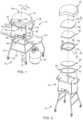
- FIG. 1is a perspective view of a baking oven, according to an embodiment of the present invention.
- FIG. 2is a partially exploded view of the baking oven, according to another embodiment of the present invention.
- FIG. 3is a partial bottom perspective view of the baking oven, depicting a shaft extending through an opening of the baking oven, according to one embodiment of the present invention
- FIG. 4is a partial perspective view of a motor and a shaft of the baking oven, in a non-coupled position, according to another embodiment of the present invention.
- FIG. 5is a perspective view of an end portion of a rotating member, depicting the shaft of the rotating member including an adjustable member, according to another embodiment of the present invention
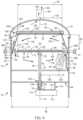
- FIG. 6is a partial cross-sectional side view of the baking oven, taken along section line A of FIG. 1 , according to another embodiment of the present invention.
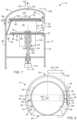
- FIG. 7is a partial cross-sectional side view of the baking oven, taken along section line B of FIG. 1 , according to another embodiment of the present invention.
- FIG. 8is a partial top view of the baking oven without the components positioned above a lower stone, depicting a location of a heat element relative to the lower stone of the baking oven, according to another embodiment of the present invention.
- a baking oven 10sized and configured to bake a food product 8 , such as pizza, or the like, is provided.
- a baking oven 10includes a main body 12 , a lower stone 58 that rotates, an upper stone 60 suspended above the lower stone 58 via a heat shield 56 , and a heat element 44 positioned below and to one side of the rotating lower stone 58 .
- the heat element 44emanates heat upward, the rotating lower stone 58 is heated while convection heat moves along the heat shield 56 and along a length of the upper stone 60 , moving through a baking chamber 34 in a side-to-side manner.
- the convection heatmay then be drawn to move down an opposite side of the heat shield 56 to below the lower stone 58 such that the convection heat may then be drawn to the upward emanating heat provided by the heat element 44 to recirculate the convection heat through the baking oven 10 .
- the location of the heat element 44 below the lower stone 58moves convection heat through the baking chamber 34 in a side-to-side manner and, further, recirculates the heat through the baking oven 10 .
- the baking oven 10 of the present inventionmay quickly achieve and maintain the desired temperatures for baking the food product.
- the baking oven 10may be sized and configured to be portable, meaning that the baking oven 10 may be relatively light-weight, compared to typical ovens, and/or may be readily moveable from one location to another. Further, the baking oven 10 may be sized and configured to be employed similar to a backyard type barbeque grill such that the baking oven 10 may be connected to a typical propane fuel tank or the like and may include a wheel type base. Such structural characteristics enable the baking oven in its portability.
- the baking oven 10may include the main body 12 , legs 14 , handles 16 , a main cover 18 , and side shelves 22 or the like.
- the main body 12may include an upstanding side wall 20 to at least partially define the main body 12 .
- Such upstanding side wall 20may extend over a front side 24 , a rear side 26 , a first side 28 , and a second side 30 of the main body 12 .
- the first side 28 and the second side 30being opposite each other and each extending between the rear side 26 and the front side 24 .
- the first side 28 and the second side 30may include the respective handles 16 as well as the respective side shelves 22 or the like extending therefrom.
- the front side 24may define an opening 32 within the upstanding side wall 20 that exposes a baking chamber 34 .
- the front side 24may also include a lower opening 36 therein to facilitate access or viewability to various components below the baking chamber 34 .
- the front side 24may also include various knobs, such as a fuel knob 38 and an igniter knob 40 .
- the fuel knob 38may be coupled to various valves, tubing, and other structural components, such as a heat source 42 or fuel tank configured to facilitate and control heating of the baking chamber 34 .
- the fuel knob 38may be rotated between an off position and an on position to control release of fuel through a heat element 44 ( FIG. 6 ) and may be turned from the off position to variable open or on positions to regulate the amount of fuel to the heat element 44 therein.
- the igniter knob 40may be, for example, depressed to ignite the fuel at the heat element 44 via a typical electrode spark member (not shown) or by employing any other known method.
- the main body 12 defined by the upstanding side wall 20may be partially tubular with a circular or square/rectangular cross-section.
- the front side 24 of the upstanding side wall 20may be substantially flat or planar and each of the first side 28 , second side and rear side 26 may be a continuous one-piece member having an arcuate configuration to form a partial cylindrical shape or partial circular cross-sectional shape (see FIG. 7 ). With this arrangement, the front side 24 of the upstanding side wall 20 can be fastened to the remaining arcuate portion to form the main body 12 .
- main body 12may include other shapes and configurations as well, as known to one of ordinary skill in the art. Further, each of the sides may also be separate pieces of material fastened together to form the main body 12 .
- the main body 12may also include a bottom side 46 and a top side 48 .
- the bottom side 46may include various braces or be enclosed (or partially enclosed) with a panel 47 ( FIG. 3 ) and the top side 48 may be enclosed with the main cover 18 .
- the main cover 18may be sized and configured to fit over the upstanding side wall 20 of the main body 12 . Further, the main cover 18 may be completely removable from the main body 12 or may be, for example, hingeably coupled to the upstanding side wall 20 . Also, the main cover 18 may partially define the opening 32 that leads to the baking chamber 34 .
- the main cover 18may also include a thermometer 136 configured to provide a temperature reading for the user to gage a suitable temperature of the baking chamber 34 .
- Typical readings from the thermometer 136once reaching a preferred temperature within the baking chamber 34 , may be about 350 degrees Fahrenheit or more, but such reading may not reflect the actual temperatures within the baking chamber 34 due to convection heat only being directed side-to-side within the baking chamber 34 and recirculated within the baking oven 10 , and not out the opening 32 .
- temperatures within the baking chamber 34may range between 600-700 degrees Fahrenheit and even range between 500 to 1000 degrees Fahrenheit.
- the thermometer 136may act as a gage for the user to determine a suitable temperature for baking the food product 8 .
- the bottom side 46 of the main body 12may include the legs 14 , such as four legs or two sets of legs, extending downward from the main body 12 .
- the legs 14may also include one or more lower shelves 50 or panels coupled to the legs 14 to provide additional support to the legs 14 .
- Such legs 14may also include casters 52 or wheels coupled to two or four of the legs to further facilitate the portability of the baking oven 10 .
- the various structural components of the baking ovenmay be formed of various metallic materials, such as steel, stainless steel, or any other suitable material with high temperature ratings and be formed from known structural components, such as sheet metal at various gauges/thicknesses or other known metallic structures, such as tubing or the like, and may be formed and manufactured through various known processes in the art, such as casting, welding, rolling, bending, fastening, etc. Further, structural components of the baking oven that are exposed to high temperatures may be formed from suitable materials with high temperature ratings, as known to one of ordinary skill in the art.
- the main body 12may be sized and configured to support a rotating member 54 and a heat shield 56 .
- the rotating member 54may support a lower stone 58 and the heat shield 56 may support an upper stone 60 .
- the heat shield 56 and upper stonemay support or be covered by a heat cover 62 and the main body 12 may receive or be covered by the main cover 18 .
- the lower stone 58 and the upper stone 60may each be a typical flat pizza stone sized and configured for baking pizza, or other food products, as known by one of ordinary skill in the art.
- the baking chamber 34is accessible through the opening 32 defined in the front side 24 of the main body 12 .
- the baking chamber 34may include the rotating member 54 , the lower stone 58 , the upper stone 60 , the heat shield 56 , and the heat cover 62 .
- Such baking chamber 34may be defined or bordered/surrounded by the heat shield 56 and the lower and upper stones 58 , 60 , the other components employed to enhance the utility or effectiveness of the baking chamber 34 , as discussed herein.
- the baking chamber 34may be heated with the heat element 44 , via the heat source 42 , and configured to emanate heat from below the baking chamber 34 .
- the rotating member 54may include a flat panel 64 and a shaft 66 made of a metallic material, such as steel or any other suitable material that has a high temperature rating.
- the shaft 66extending from an underside surface 68 of the flat panel 64 .
- the flat panel 64may be substantially planar with a lip 70 extending upward from a topside surface 72 and along a periphery 74 of the flat panel 64 .
- Such topside surface 72 of the flat panel 64may be configured to support and position the lower stone 58 thereon.
- the lip 70 of the flat panel 64may be configured to maintain and engage a periphery of the lower stone 58 so as to substantially prevent the lower stone 58 from moving or sliding from the topside surface 72 of the flat panel 64 .
- the lower stone 58may be a disc-like shape with a top surface 100 and bottom surface 102 both being planar such that the bottom surface 102 of the lower stone 58 , in whole or its substantial entirety, is in direct contact with the topside surface 72 of the flat panel 64 .
- the shaft 66 of the rotating member 54may extend from the underside surface 68 of the flat panel 64 and may define an axis 76 along a longitudinal length of the shaft 66 .
- the shaft 66 and the flat panel 64may be configured to rotate, as indicated by arrow 78 , within the main body 12 and about the axis 76 .
- the heat shield 56may be sized and configured to suspend and hold the upper stone 60 above the lower stone 58 at a height 80 .
- Such height 80may be about five inches that may range between about four and six inches and also may range between about four and nine inches.
- the heat shield 56may be configured to funnel and control convection heat within the baking chamber 34 . Further, the heat shield 56 may provide a separation between the baking chamber 34 and the main body 12 to minimize high temperatures to the main body 12 , thereby, limiting potential burn risk to users of the baking oven 10 .
- the heat shield 56may extend upward and inward from a lower end 82 to an upper end 84 , the lower end 82 positioned adjacent or against the upstanding side wall 20 of the main body 12 and the upper end 84 including a ledge 86 to support and hold the upper stone 60 .
- the upper end 84 and ledge 86 of the heat shield 56may extend to define a shield opening 88 therein such that, upon the upper stone 60 being positioned on the heat shield 56 , a bottom surface of the upper stone 60 is substantially exposed in the baking chamber 34 .
- the lower end 82 of the heat shield 56may extend from at least the first side 28 and the second side 30 of the main body 12 .
- the heat shield 56may extend from the first and second sides 28 , 30 and the rear side 26 of the main body 12 such that the lower end 82 of the heat shield 56 corresponds with and abuts against the upstanding sidewall 20 of the main body 12 .
- the heat shield 56may radially extend upward and inward between the lower end 82 and the upper end 84 in a partial cone configuration, extending upward and inward from the first side 28 , second side 30 , and the rear side 26 of the main body 12 .
- the heat shield 56(or upstanding sidewall 20 of the main body 12 ) and the periphery 74 of the flat panel 64 may define an air-flow gap 92 therebetween (see also FIG. 8 ).
- Such air-flow gap 92may be configured to flow convection heat therethrough such that the flat panel 64 includes a diameter 94 that is less than a distance 96 between the upstanding wall 20 of the first side 28 and the second side 30 of the main body 12 to provide the air-flow gap 92 .
- the diameter 94 of the flat panel 64may be less than a distance between opposite sides of the lower end 82 of the heat shield 56 extending from the first and second sides 28 , 30 of the main body 12 .
- the heat shield 56may extend from or be supported by side wall extensions 98 coupled to the upstanding side wall 20 .
- the side wall extensions 98may be positioned on the first and second sides 28 , 30 of the main body 12 such that the lower end 82 of the heat shield 56 may be positioned about level with a plane of the flat panel 64 .
- side wall extensions 98 a(as shown in outline in FIG. 6 ) may be positioned on the first and second sides 28 , 30 of the main body 12 so that the lower end 82 of the heat shield 56 may be positioned below the plane of the flat panel 64 .
- side wall extensions 98 b(as shown in outline in FIG.
- Such side wall extensions 98may also be positioned on the rear side 26 of the main body 12 .
- the main body 28may include a second heat shield 150 sized and configured to shield heat from conducting to the outer portions of the bake oven 10 , such as to the handles 16 ( FIG. 1 ).
- the second heat shield 150may be secured with brackets or the like to the main body 28 adjacent to the heat element 44 and below heat shield 56 and the lower stone 58 .
- the second heat shield 150may be positioned to the main body 28 with a gap 152 defined therebetween such that the second heat shield 150 is substantially separated (but for the securing structure for attaching the second heat shield 150 ) from the main body 28 . In this manner, the second heat shield 150 may be positioned adjacent the heat element 44 to minimize heat from conducting to outer surfaces of the bake oven 10 , such as to the handles 16 of the bake oven 10 .
- the air-flow gap 92may include a distance 93 , measured between the periphery 74 of the flat panel 64 and the lower end 82 of the heat shield 56 on both the first and second sides 28 , 30 of the baking oven 10 , of about one inch and may range between a half inch and up to about three inches.
- a gap distance 95 defined between the heat shield 56 and the periphery 74 of the flat panel 64 on the rear side 26 of the main body 12may be narrower than the air-flow gap 92 with a range between about a quarter inch to a half inch.
- the gap distance 95 on the rear side 26is preferably minimized to promote the convection heat to be directed side-to-side through the air-flow gaps 92 within the baking chamber 34 and to be recirculated within the baking chamber 34 to minimize heat loss and maintain high temperatures within the baking oven 10 , as set forth herein.
- the heat cover 62may be sized and configured to be positioned to lay over the upper stone 60 and a portion of the heat shield 56 . Further, the heat cover 62 may be configured to contain and channel heat relative to the baking chamber so that the upper stone 60 may primarily radiate heat downward from the exposed bottom surface 90 of the upper stone 60 .
- the heat cover 62may include an upper surface 104 and lower surface 106 with a downward extending extension 108 along a periphery of the heat cover 62 . Such periphery of the heat cover 62 may be slightly larger than a periphery of the upper end 84 of the heat shield 56 so that the heat cover maintains its position over the upper stone 60 .
- the heat cover 62may be made from a metallic material, such as aluminum or steel, or any other suitable material, sized and configured to facilitate the upper stone 60 to maintain heat therein and radiate heat downward from the exposed bottom surface 90 .
- the shaft 66 of the rotating member 54may be coupled to a drive shaft 110 of a motor 112 such that the axis 76 of the shaft 66 aligns with a drive shaft axis of the drive shaft 110 .
- the shaft 66may extend through a hole 146 defined in the bottom side 46 of the main body 12 to a motor bracket 114 , the motor bracket 114 being coupled to the main body 12 .
- the bottom sidemay include a bearing portion 148 including a ball bearing arrangement (not shown) sized and configured to limit friction and facilitate smooth rotation of the rotating member.
- the motor bracket 114may include a tongue 116 defining a tongue opening 118 therein.
- the tongue opening 118may be sized and configured to receive the drive shaft 110 and be aligned with the shaft 66 .
- the motor 112may include two rail brackets 120 sized and configured to couple to the tongue 116 such that outer sides of the tongue 116 slide between the rail brackets 120 to position and couple the motor 112 to the motor bracket 114 .
- the drive shaft 110extends upward through the tongue opening 118 and couples to the shaft 66 .
- a bottom end of the shaft 66may include a notch 122 defined therein and sized to receive and correspond with the external surface/structure of the drive shaft 110 .
- the drive shaft 110may include one or more flat surfaces to correspond with the notch 122 defined in the shaft 66 to enable engagement and facilitate driving rotation of the shaft 66 .
- the drive shaft 110may include at least four flat surfaces so as to exhibit a square shape as a cross-section taken along a section line transverse to the drive shaft axis.
- the motor 112can rotate the rotating member 54 about the axis 76 of the shaft 66 .
- the motormay be battery powered or may be connected to a power source, as known in the art.
- the shaft 66 of the rotating member 54may include an adjustable member 138 .
- the adjustable member 138may be sized and configured to adjust a height of the rotating member 54 or, more specifically, adjust the height 80 between the lower stone 58 and to the upper stone 60 .
- the adjustable member 138may include a sleeve 140 with a set screw 142 extending therethrough.
- the set screw 142may be configured to be loosened to adjust a position of the sleeve 140 on the shaft 66 and then tightened to maintain the position of the sleeve 140 on the shaft 66 .
- the adjustable member 138may be located on the shaft 66 at a position that facilitates the shaft 66 to mate with the drive shaft 110 of the motor 112 .
- the adjustable member 138may be located at various positions along the shaft 66 so long as the drive shaft 110 can mate with the shaft 66 of the rotating member 54 .
- the adjustable member 138may be adjusted to a lower position, than that which is depicted, to raise the rotating member 54 and to effectively adjust the height 80 between the lower stone 58 and the upper stone within the baking chamber 34 .
- the baking oven 10may include a cross-member 124 or seat extending between the first side 28 and the second side 30 of the main body 12 below the flat panel 64 of the rotating member 54 such that the cross-member 124 may be centered under the flat panel 64 so that the shaft 66 extends through a hole 126 defined in the cross-member 124 .
- the cross-member 124may extend between the first side 28 and second side 30 of the main body 12 .
- the cross-membermay extend substantially parallel with the front side 24 of the main body 12 .
- Such cross-member 124 or seatmay include the location for the heat element 44 coupled to the heat source 42 ( FIG. 1 ) for emanating heat therefrom.
- the heat element 44may be positioned adjacent the first side 28 (or the second side 30 ) of the main body 12 directly on the cross-member 124 .
- the position of the heat element 44 along the cross-member 124may be a distance 128 from the axis 76 of the shaft 66 to a central axis of the heat element 44 that corresponds to about a radial distance 130 or radius of the flat panel 64 such that the heat element 44 is positioned about directly below the periphery 74 of the flat panel 64 adjacent the first side 28 or the second side 30 of the main body 12 . In this manner heat may emanate upward from the heat element 44 along the first side 28 (or the second side 30 ) of the main body 12 and below the flat panel 64 and move upward through the air-flow gap 92 .
- the location of the heat element 44may extend closer to the first side 28 of the main body, as indicated by dotted line 129 .
- the heat element 44may include an elongated or oval shape such that the effective distance 128 of the heat element 44 may be located relatively closer to the first side 28 of the main body 18 .
- the heat element 44is positioned adjacent one of the first and second sides 28 , 30 of the main body 12 such that the heat element 44 emanates heat upward to a portion of the underside surface 68 of the flat panel 64 and through the air-flow gap 92 .
- the heat element 44may be located and positioned solely adjacent to one of the first side 28 and second side 30 of the main body 12 (specifically excluding being adjacent the rear side 26 and the front side 24 of the main body 12 ).
- the heat element 44may be a burner made from cast iron and may include various configurations, such as circular, oval, u-shaped, or any other suitable configuration to facilitate emanating heat to the flat panel 64 and through the air-flow gap 92 of one of the first and second sides 28 , 30 of the main body 12 .
- the flat panel 64includes the lower stone 58 positioned thereon, the lower stone 58 rotating with the flat panel 64 via the motor 112 coupled to the shaft 66 .
- heat emanating from the heat element 44provides heat directly to the underside surface 68 of the flat panel 64 before moving upward through the air-flow gap 92 .
- conduction heatmoves directly from the flat panel 64 to the lower stone 58 since surfaces of the flat panel and lower stone substantially correspond with each other, e.g., planar surfaces.
- the heating of the lower stone 58is controlled and minimized to substantially prevent “hot spots” so that the food product 8 does not burn on the lower stone 58 .
- the upper stone 60may be primarily heated by convection heat, as depicted by arrow 132 , moving upward from the air-flow gap 92 and along the heat shield 56 and then across a length of the upper stone 60 , the length being similar to the diameter 94 of the lower stone 58 . Further, as depicted by arrow 132 , the convection heat moves downward along the heat shield 56 and through the air flow gap 92 on an opposite side, adjacent the second side 30 , from where the convection heat entered the baking chamber 34 . The convection heat may continue under the flat panel 64 and be drawn toward the heating element 44 and move upward again with the convection heat emanating upward through the original air-flow gap 92 .
- the convection heatmay move through the baking chamber 34 in a side-to-side manner and continue to move under the flat panel 64 such that the convection heat recirculates through the system (essentially moving around the flat panel) in a rotational manner, thereby, minimizing heat loss.
- the upper stone 60upon the upper stone 60 being heated by the convection heat, the upper stone 60 provides radiation heat directed downward to the food product 8 positioned on the lower stone 58 .
- this arrangementminimizes the loss of convection heat through the opening 32 of the baking chamber 34 by re-circulating or rotating through the baking oven 10 in the side-to-side manner (first side 28 to second side 30 , not rear side 26 to front side 24 ) or rotational manner, as indicated by arrows 132 .
- the main cover 18may include a flue or duct structure 160 formed therein to define a top opening 162 to facilitate drawing convection heat through the main cover 18 .
- the flue or duct structure 160may be tubular or the like.
- the duct structure 160may include a swingable flap that may readily be moved between closed, open, and partially open positions.
- the duct structure 160may be a simple opening or vents at the top of the main cover 18 .
- the convection heatmay flow from the heat element 44 into the baking chamber 34 and flow from, for example, one side to the other side (not rear to front) of the baking chamber 34 in a side-to-side manner, similar to that previously set forth.
- the convection heatas shown with dotted arrow 164 , may then flow around a front periphery 166 of the heat shield 56 and upward through a lateral cover gap 168 defined between the heat cover 62 and the main cover 18 .
- Such lateral cover gap 168may be defined around the entire extent of the heat cover 62 and the main cover 18 .
- a front lip of the main cover that defines the opening 32 of the baking chamber 34may extend downward below an elevation of the upper stone 60 .
- Such front lipmay further assist in drawing any convection heat to flow around the front periphery 166 of the heat shield 56 and upward through the lateral cover gap 168 .
- the convection heatmay then flow into a cover space 170 between an upper surface 104 of the heat cover 62 and the main cover 18 and then through the duct structure 160 and out the top opening 162 of the baking oven 10 .
- the convection heatmay be channeled to provide maximum heating within the baking chamber 34 by flowing side-to-side therein (similar to the previous embodiment), and then channeled through the upper regions of the baking oven 10 and out the duct structure 160 .
- the motor 112should be switched on so that the drive shaft 66 can rotate the rotating member 54 , as indicated by rotational arrow 78 .
- the appropriate valve of the fuel source 42should be moved to an open position, after which, the fuel knob 38 may be rotated to an open position.
- the fuel element 44may then be ignited by simply depressing the igniter knob 40 or, otherwise, employing a match or the like adjacent the fuel element 44 .
- flames or emanating heat from the fuel element 44extend upward therefrom and may directly contact the underside surface 68 of the flat panel 64 , as the flat panel 64 rotates, and may also extend upward through the air flow gap 92 adjacent, for example, the first side 28 of the main body 12 .
- the air within the baking chamberwill become heated and, due to the unique arrangement and sizing of the elements within the baking chamber 34 , the convection heat will move within the baking chamber in a side-to-side manner or rotational manner, as indicted by arrows 132 , initially moving upward from the air-flow gap 92 adjacent the first side 28 of the baking chamber 34 and along the heat shield 56 , across a length of the upper stone 60 to an opposite side of the baking chamber 34 , and then downward along the heat shield 56 and through the opposite side of the air-flow gap 92 adjacent the second side 30 of the main body 12 .
- the convection heatmay re-circulate as the convection heat is drawn across the main body 12 under the flat panel 64 toward the upward extending emanating heat from the heating element 44 .
- the convection heatmay heat the baking chamber 34 by flowing side-to-side therein (as shown by arrow 132 within the baking chamber 34 ) and then the convection heat may be channeled toward the upper regions of the baking oven 10 and out the duct structure 160 , as shown by dotted arrow 164 .
- the baking ovenwill be sufficiently heated for baking a food product 8 , such as pizza or the like.
- the usercan view the thermometer to gage a suitable temperature.
- the food product 8may then be placed and positioned directly onto the top surface 100 of the lower stone 58 .
- the emanating heat from the heat element 44heats the underside surface 68 of the flat panel 64 , moving conduction heat directly from the flat panel 64 to the lower stone 58 for heating and baking the food product 8 on the lower stone 58 .
- the emanating heat from the heat element 44flows through the air-flow gap 92 on, for example, the first side 28 to provide convection heat, as indicated by arrow 132 , directly to the upper stone 60 , the convection heat moving through the baking chamber 34 in the side-to-side manner or through the main body 12 in a re-circulating rotational manner, as previously set forth.
- the heated upper stone 60suspended above the food product 8 , provides radiation heat downward from the upper stone 60 to heat and bake the food product 8 .
- the radiation heat from the upper stone 60 and the convection heat moving through the baking chamber 34may cook an upper side of the food product 8 .
- the cook or usermay visually determine when the food product is cooked to his or her liking, typically taking about two to four minutes, dependent upon the level of heat the user may employ on the baking chamber.
- the disclosure hereinhas been directed to cooking a food product, such as pizza or the like
- other food productsmay readily be employed in the baking oven of the present invention.
- the lower stonemay receive a grill like member (not shown) to cook other types of food products, such as steaks or the like.
- the unique structural arrangement of the baking ovenreadily facilitates obtaining and maintaining high temperatures within the baking oven. As such, cooking other types of food products within the baking oven may readily be employed.
Landscapes
- Engineering & Computer Science (AREA)
- Food Science & Technology (AREA)
- Life Sciences & Earth Sciences (AREA)
- Chemical & Material Sciences (AREA)
- Combustion & Propulsion (AREA)
- Mechanical Engineering (AREA)
- General Engineering & Computer Science (AREA)
- Baking, Grill, Roasting (AREA)
Abstract
Description
Claims (23)
Priority Applications (2)
| Application Number | Priority Date | Filing Date | Title |
|---|---|---|---|
| US18/213,981US12161262B2 (en) | 2013-02-20 | 2023-06-26 | System, device, and method for baking a food product |
| US18/944,995US20250064259A1 (en) | 2013-02-20 | 2024-11-12 | System, device, and method for baking a food product |
Applications Claiming Priority (6)
| Application Number | Priority Date | Filing Date | Title |
|---|---|---|---|
| US201361767249P | 2013-02-20 | 2013-02-20 | |
| US14/184,716US9182129B2 (en) | 2013-02-20 | 2014-02-20 | System, device, and method for baking a food product |
| US14/877,899US9848731B2 (en) | 2013-02-20 | 2015-10-07 | System, device, and method for baking a food product |
| US15/853,776US10413123B2 (en) | 2013-02-20 | 2017-12-23 | System, device, and method for baking a food product |
| US16/573,935US11684212B2 (en) | 2013-02-20 | 2019-09-17 | System, device, and method for baking a food product |
| US18/213,981US12161262B2 (en) | 2013-02-20 | 2023-06-26 | System, device, and method for baking a food product |
Related Parent Applications (1)
| Application Number | Title | Priority Date | Filing Date |
|---|---|---|---|
| US16/573,935ContinuationUS11684212B2 (en) | 2013-02-20 | 2019-09-17 | System, device, and method for baking a food product |
Related Child Applications (1)
| Application Number | Title | Priority Date | Filing Date |
|---|---|---|---|
| US18/944,995ContinuationUS20250064259A1 (en) | 2013-02-20 | 2024-11-12 | System, device, and method for baking a food product |
Publications (2)
| Publication Number | Publication Date |
|---|---|
| US20230404324A1 US20230404324A1 (en) | 2023-12-21 |
| US12161262B2true US12161262B2 (en) | 2024-12-10 |
Family
ID=51569324
Family Applications (6)
| Application Number | Title | Priority Date | Filing Date |
|---|---|---|---|
| US14/184,716ActiveUS9182129B2 (en) | 2013-02-20 | 2014-02-20 | System, device, and method for baking a food product |
| US14/877,899ActiveUS9848731B2 (en) | 2013-02-20 | 2015-10-07 | System, device, and method for baking a food product |
| US15/853,776ActiveUS10413123B2 (en) | 2013-02-20 | 2017-12-23 | System, device, and method for baking a food product |
| US16/573,935Active2034-11-14US11684212B2 (en) | 2013-02-20 | 2019-09-17 | System, device, and method for baking a food product |
| US18/213,981ActiveUS12161262B2 (en) | 2013-02-20 | 2023-06-26 | System, device, and method for baking a food product |
| US18/944,995PendingUS20250064259A1 (en) | 2013-02-20 | 2024-11-12 | System, device, and method for baking a food product |
Family Applications Before (4)
| Application Number | Title | Priority Date | Filing Date |
|---|---|---|---|
| US14/184,716ActiveUS9182129B2 (en) | 2013-02-20 | 2014-02-20 | System, device, and method for baking a food product |
| US14/877,899ActiveUS9848731B2 (en) | 2013-02-20 | 2015-10-07 | System, device, and method for baking a food product |
| US15/853,776ActiveUS10413123B2 (en) | 2013-02-20 | 2017-12-23 | System, device, and method for baking a food product |
| US16/573,935Active2034-11-14US11684212B2 (en) | 2013-02-20 | 2019-09-17 | System, device, and method for baking a food product |
Family Applications After (1)
| Application Number | Title | Priority Date | Filing Date |
|---|---|---|---|
| US18/944,995PendingUS20250064259A1 (en) | 2013-02-20 | 2024-11-12 | System, device, and method for baking a food product |
Country Status (1)
| Country | Link |
|---|---|
| US (6) | US9182129B2 (en) |
Families Citing this family (34)
| Publication number | Priority date | Publication date | Assignee | Title |
|---|---|---|---|---|
| CN105143772B (en)* | 2013-04-22 | 2018-11-09 | 坞司冬股份有限公司 | pizza oven |
| US10624353B1 (en) | 2015-03-12 | 2020-04-21 | John Langley | Pizza oven |
| US10238236B2 (en)* | 2015-07-24 | 2019-03-26 | Charcoal Companion Incorporated | Pizza oven conversion apparatus for kettle barbecue |
| US10575680B2 (en)* | 2016-02-22 | 2020-03-03 | William Rowzee Fagg | Brick pizza oven with rotatable and height adjustable turntable and conversion kit for grills |
| US10634362B2 (en) | 2016-06-30 | 2020-04-28 | Midea Group Co., Ltd. | Oven bottom with cooking surface |
| US10827878B2 (en)* | 2016-10-25 | 2020-11-10 | Gmg Products, Llc. | Pizza oven accessory for barbecue grill |
| US10772467B2 (en)* | 2017-05-08 | 2020-09-15 | North Atlantic Imports, Llc | Cooking station and system with removable insert having multiple cooking modes |
| CN109805778B (en)* | 2017-11-22 | 2022-01-18 | 快比萨株式会社 | Oven device |
| JP7048302B2 (en)* | 2017-12-22 | 2022-04-05 | リンナイ株式会社 | Cooker |
| US11076718B2 (en)* | 2018-01-29 | 2021-08-03 | Charcoal Companion Limited | Cooking stone apparatus with rotatable cooking surface |
| US20230031340A1 (en)* | 2018-05-31 | 2023-02-02 | North Atlantic Imports, Llc | Outdoor cooking station with multiple independent cooking modes and method thereof |
| US11452404B2 (en)* | 2018-08-14 | 2022-09-27 | Mark Anderson | Pizza oven |
| KR102651367B1 (en)* | 2018-11-22 | 2024-03-27 | 에스케이하이닉스 주식회사 | Data center |
| US11226107B1 (en) | 2019-01-30 | 2022-01-18 | Wood Stone Corporation | Oven debris collection system |
| US11707158B2 (en)* | 2019-02-01 | 2023-07-25 | Align Machine Works, LLC | Device for conversion of a kamado cooker to a pizza oven |
| JP7352892B2 (en)* | 2019-03-06 | 2023-09-29 | 地方独立行政法人 岩手県工業技術センター | cooking oven equipment |
| US11684210B2 (en)* | 2019-05-03 | 2023-06-27 | Napoli Llc | Oven including gas burner and wood tray |
| IT201900014169A1 (en)* | 2019-08-06 | 2021-02-06 | Edil Ref S R L | Direct cooking oven with smoke evacuation system. |
| US11224228B1 (en) | 2020-06-18 | 2022-01-18 | John Langley | Three sensor oven |
| US20220061588A1 (en)* | 2020-08-31 | 2022-03-03 | Dongguan Haohong Outdoor Products Technology Co., Ltd. | Rotary-pan pizza oven |
| US11344032B1 (en)* | 2021-05-22 | 2022-05-31 | Halo Products Group, Llc | Portable baking oven |
| US20230000284A1 (en)* | 2021-07-03 | 2023-01-05 | North Atlantic Imports, Llc | Oven cooking system, accessory device, and method thereof |
| US12268332B2 (en)* | 2021-09-02 | 2025-04-08 | Jason Huff | Vertical grilling assembly |
| USD1005769S1 (en) | 2021-09-08 | 2023-11-28 | Newage Products Inc. | Oven |
| US12402631B2 (en)* | 2021-09-08 | 2025-09-02 | Newage Products Inc. | Oven |
| US12078359B2 (en) | 2021-09-30 | 2024-09-03 | Solo Brands, Llc | Combustion oven |
| USD1017310S1 (en) | 2021-09-30 | 2024-03-12 | Solo Brands, Llc | Oven |
| EP4487742A1 (en) | 2022-03-03 | 2025-01-08 | Gmg Outdoor Products (Wuhan) Co., Ltd | Grill |
| US12289508B2 (en) | 2022-03-18 | 2025-04-29 | GMG Products, LLC | Detachable camera for a smoker or grill |
| CN217610598U (en)* | 2022-04-19 | 2022-10-21 | 昊鸿电气科技(湖北)有限公司 | Pizza oven |
| US11732895B1 (en) | 2022-05-16 | 2023-08-22 | Sharkninja Operating Llc | Methods and systems for open-loop ignition of a smoke generator fuel source |
| USD1045502S1 (en) | 2022-09-16 | 2024-10-08 | Solo Brands, Llc | Oven |
| US11792895B1 (en) | 2023-06-01 | 2023-10-17 | Sharkninja Operating Llc | Methods and systems for TRIAC set point based control of power delivery |
| US12359808B1 (en) | 2024-04-30 | 2025-07-15 | GMG Products, LLC | Variable fuel cooker |
Citations (61)
| Publication number | Priority date | Publication date | Assignee | Title |
|---|---|---|---|---|
| US3033189A (en) | 1959-11-02 | 1962-05-08 | James L Clark | Rotatable brazier |
| US3033190A (en) | 1960-03-17 | 1962-05-08 | James R Atkinson | Rotary grill for a cooking device |
| US3085497A (en) | 1959-04-10 | 1963-04-16 | Sr Edwin V Statia | Grate-rotating device for portable brazier |
| US3131685A (en) | 1962-01-22 | 1964-05-05 | Lawrence W Bergfield | Grille rotator |
| US3134320A (en) | 1958-03-10 | 1964-05-26 | Kenneth E Battaglia | Portable outdoor barbecue grill |
| US3298301A (en) | 1964-06-08 | 1967-01-17 | Jane U Lowndes | Barbecue stand with rotary gridiron and spit and common drive therefor |
| US3448679A (en) | 1966-07-01 | 1969-06-10 | Thomas Carl Holka | Food cooking apparatus |
| US3511167A (en) | 1968-09-12 | 1970-05-12 | Westinghouse Electric Corp | Cooking oven |
| US3552299A (en) | 1969-05-05 | 1971-01-05 | Tru Broil Corp | Rotary oven |
| US3657996A (en) | 1970-01-29 | 1972-04-25 | Oria Denley Thompson | Barbecue |
| US3848523A (en) | 1973-05-29 | 1974-11-19 | M Vali | Rotary barbecue device |
| US4305329A (en) | 1980-03-10 | 1981-12-15 | Fenoglio Bernard F | Turntable oven |
| US4384513A (en) | 1981-05-07 | 1983-05-24 | Pierick Richard L | Apparatus for preparing pizza in a baking oven |
| US4506652A (en) | 1984-01-06 | 1985-03-26 | Nieco Corporation | Pizza oven |
| US4805587A (en) | 1988-03-18 | 1989-02-21 | Universal Enterprises, Inc. | Gas grill |
| US4938687A (en) | 1988-09-28 | 1990-07-03 | Soremam S.N.C. | Gas cooking apparatus with rotary burner and electrical ignition |
| FR2661236A1 (en) | 1990-04-19 | 1991-10-25 | Ackermann Christian | Wood-fired direct-contact cooker, particularly one which can be built into a piece of kitchen furniture |
| US5378872A (en) | 1991-10-30 | 1995-01-03 | Jovanovic; Dragomir | Infrared apparatus for baking pastries and pizzas |
| US5398666A (en) | 1989-09-22 | 1995-03-21 | Patentsmith Ii, Inc. | Turntable convection heater |
| US5492055A (en) | 1992-11-05 | 1996-02-20 | Bakers Pride Oven Co., Inc. | Pizza oven |
| US5523104A (en) | 1993-11-24 | 1996-06-04 | Kirk; Alan J. E. | Method of cooking pizza |
| US5620624A (en) | 1988-05-19 | 1997-04-15 | Quadlux, Inc. | Cooking method and apparatus controlling cooking cycle |
| US5682873A (en) | 1996-07-01 | 1997-11-04 | Chambers; Harold | Camping stove baking attachment device |
| SE508547C2 (en) | 1992-07-15 | 1998-10-12 | Rune Sundberg | Baking oven |
| US5873300A (en) | 1997-06-10 | 1999-02-23 | Kuhlman; Delmar A. | Apparatus for heating food |
| US6041769A (en) | 1999-07-09 | 2000-03-28 | Llodra, Jr.; Joseph A. | Portable brick oven |
| US6125740A (en) | 1999-03-12 | 2000-10-03 | National Presto Industries, Inc. | Rotatable cooking apparatus |
| US6146677A (en) | 1998-05-01 | 2000-11-14 | Remco Techologies, Inc. | High efficiency infrared oven |
| US6187359B1 (en) | 1999-05-12 | 2001-02-13 | Anthony Mark Zuccarini | Method and apparatus for baking foods in a barbeque grill |
| US6307185B1 (en) | 2000-11-27 | 2001-10-23 | Jerry Loveless | Thermally efficient portable convective oven |
| US20020017290A1 (en)* | 1998-12-18 | 2002-02-14 | Hines Robert S. | Cooking grill with baking oven insert |
| US6425388B1 (en) | 2000-05-22 | 2002-07-30 | The Garland Group | Pizza oven deck |
| US6640695B2 (en) | 2002-02-07 | 2003-11-04 | Steven Stark | Pizza insert for barbeque grill |
| US6708604B1 (en)* | 2003-05-22 | 2004-03-23 | Richard A. Deichler, Jr. | Collapsible smoker and oven device |
| JP2005110895A (en) | 2003-10-07 | 2005-04-28 | Japan Home Supply Kk | Cooker |
| US20060102167A1 (en) | 2004-11-15 | 2006-05-18 | Driscoll James P Jr | Pizza oven for grill |
| US20060191528A1 (en) | 2003-12-19 | 2006-08-31 | Spangrud Bruce D | Gas grill compatible pizza oven |
| US7219663B2 (en) | 2003-09-05 | 2007-05-22 | Islander Innovations Llc | Kit, apparatus and method for use in cooking over an intense heat source |
| USD555419S1 (en) | 2005-03-26 | 2007-11-20 | Clipper Corporation | One handle tray |
| USD580214S1 (en) | 2007-07-02 | 2008-11-11 | Cristel | Pan |
| US20090064985A1 (en)* | 2007-09-12 | 2009-03-12 | Willard Gustavsen | High temperature bake oven |
| USD594271S1 (en) | 2008-07-11 | 2009-06-16 | Pi-Design, Ag | Frying pan |
| US20100124596A1 (en) | 2008-11-17 | 2010-05-20 | Randall Warren Nelson | Insulated cover and method for cooking pizza and similar food items on a home gas or charcoal grill |
| US20100147281A1 (en)* | 2007-09-12 | 2010-06-17 | Willard Gustavsen | High temperature bake oven and method |
| US8093533B2 (en) | 2007-12-17 | 2012-01-10 | Michael French | Modular pizza oven kit, pizza oven finger assembly support, and a method of operating a pizza oven at different speeds and a control arrangement for performing the method |
| USD657992S1 (en) | 2010-06-24 | 2012-04-24 | AGD Holdings Limited | Pan |
| US8181640B2 (en) | 2008-06-09 | 2012-05-22 | Park Jun-Gyu | Portable cooking system |
| JP2012115220A (en) | 2010-12-02 | 2012-06-21 | Homes Coffee Kk | Baking oven |
| US8291896B1 (en) | 2007-07-06 | 2012-10-23 | Dynamic Engineering Designs LLC | Outdoor oven and cooking system |
| USD696057S1 (en) | 2012-05-16 | 2013-12-24 | Duke Manufacturing Co. | Pan |
| US20140014086A1 (en) | 2012-07-14 | 2014-01-16 | Timothy M. Case | Refractory cooking devices |
| USD697751S1 (en) | 2012-10-30 | 2014-01-21 | WS-INVENTION trade GmbH | Rectangular pan |
| US20140026881A1 (en)* | 2012-07-24 | 2014-01-30 | John Luther Abrams | Outdoor Pizza Oven |
| USD732335S1 (en) | 2013-08-06 | 2015-06-23 | Lenox Corporation | Cooking pan |
| US20150323190A1 (en) | 2014-05-09 | 2015-11-12 | Mark Stein | Refractory cooking chambers |
| USD788518S1 (en) | 2016-04-21 | 2017-06-06 | Paul Aggarwal | Cooking container |
| US20170238760A1 (en)* | 2016-02-22 | 2017-08-24 | William Rowzee Fagg | Brick pizza oven with rotatable and height adjustable turntable and conversion kit for grills |
| USD815884S1 (en) | 2016-08-10 | 2018-04-24 | Cambro Manufacturing | Pan with one handled hand grip |
| USD891171S1 (en) | 2018-01-30 | 2020-07-28 | Ooni Limited | Pan with handle |
| US10941945B2 (en) | 2015-12-31 | 2021-03-09 | Ooni Limited | Cooking apparatus |
| US11134690B1 (en)* | 2018-04-19 | 2021-10-05 | Michael French | Pizza oven and a method of using a pizza oven |
- 2014
- 2014-02-20USUS14/184,716patent/US9182129B2/enactiveActive
- 2015
- 2015-10-07USUS14/877,899patent/US9848731B2/enactiveActive
- 2017
- 2017-12-23USUS15/853,776patent/US10413123B2/enactiveActive
- 2019
- 2019-09-17USUS16/573,935patent/US11684212B2/enactiveActive
- 2023
- 2023-06-26USUS18/213,981patent/US12161262B2/enactiveActive
- 2024
- 2024-11-12USUS18/944,995patent/US20250064259A1/enactivePending
Patent Citations (68)
| Publication number | Priority date | Publication date | Assignee | Title |
|---|---|---|---|---|
| US3134320A (en) | 1958-03-10 | 1964-05-26 | Kenneth E Battaglia | Portable outdoor barbecue grill |
| US3085497A (en) | 1959-04-10 | 1963-04-16 | Sr Edwin V Statia | Grate-rotating device for portable brazier |
| US3033189A (en) | 1959-11-02 | 1962-05-08 | James L Clark | Rotatable brazier |
| US3033190A (en) | 1960-03-17 | 1962-05-08 | James R Atkinson | Rotary grill for a cooking device |
| US3131685A (en) | 1962-01-22 | 1964-05-05 | Lawrence W Bergfield | Grille rotator |
| US3298301A (en) | 1964-06-08 | 1967-01-17 | Jane U Lowndes | Barbecue stand with rotary gridiron and spit and common drive therefor |
| US3448679A (en) | 1966-07-01 | 1969-06-10 | Thomas Carl Holka | Food cooking apparatus |
| US3511167A (en) | 1968-09-12 | 1970-05-12 | Westinghouse Electric Corp | Cooking oven |
| US3552299A (en) | 1969-05-05 | 1971-01-05 | Tru Broil Corp | Rotary oven |
| US3657996A (en) | 1970-01-29 | 1972-04-25 | Oria Denley Thompson | Barbecue |
| US3848523A (en) | 1973-05-29 | 1974-11-19 | M Vali | Rotary barbecue device |
| US4305329A (en) | 1980-03-10 | 1981-12-15 | Fenoglio Bernard F | Turntable oven |
| US4384513A (en) | 1981-05-07 | 1983-05-24 | Pierick Richard L | Apparatus for preparing pizza in a baking oven |
| US4506652A (en) | 1984-01-06 | 1985-03-26 | Nieco Corporation | Pizza oven |
| US4805587A (en) | 1988-03-18 | 1989-02-21 | Universal Enterprises, Inc. | Gas grill |
| US5620624A (en) | 1988-05-19 | 1997-04-15 | Quadlux, Inc. | Cooking method and apparatus controlling cooking cycle |
| US4938687A (en) | 1988-09-28 | 1990-07-03 | Soremam S.N.C. | Gas cooking apparatus with rotary burner and electrical ignition |
| US5398666A (en) | 1989-09-22 | 1995-03-21 | Patentsmith Ii, Inc. | Turntable convection heater |
| FR2661236A1 (en) | 1990-04-19 | 1991-10-25 | Ackermann Christian | Wood-fired direct-contact cooker, particularly one which can be built into a piece of kitchen furniture |
| US5378872A (en) | 1991-10-30 | 1995-01-03 | Jovanovic; Dragomir | Infrared apparatus for baking pastries and pizzas |
| SE508547C2 (en) | 1992-07-15 | 1998-10-12 | Rune Sundberg | Baking oven |
| US5492055A (en) | 1992-11-05 | 1996-02-20 | Bakers Pride Oven Co., Inc. | Pizza oven |
| US5523104A (en) | 1993-11-24 | 1996-06-04 | Kirk; Alan J. E. | Method of cooking pizza |
| US5682873A (en) | 1996-07-01 | 1997-11-04 | Chambers; Harold | Camping stove baking attachment device |
| US5873300A (en) | 1997-06-10 | 1999-02-23 | Kuhlman; Delmar A. | Apparatus for heating food |
| US6146677A (en) | 1998-05-01 | 2000-11-14 | Remco Techologies, Inc. | High efficiency infrared oven |
| US6250210B1 (en) | 1998-05-01 | 2001-06-26 | Remco Technologies International Inc. | High efficiency carousel infrared oven |
| US20020017290A1 (en)* | 1998-12-18 | 2002-02-14 | Hines Robert S. | Cooking grill with baking oven insert |
| US6125740A (en) | 1999-03-12 | 2000-10-03 | National Presto Industries, Inc. | Rotatable cooking apparatus |
| US6354194B1 (en) | 1999-03-12 | 2002-03-12 | National Presto Industries, Inc. | Rotatable cooking apparatus |
| US6967036B1 (en) | 1999-03-12 | 2005-11-22 | National Presto Industries, Inc. | Method for cooking a pizza |
| US6187359B1 (en) | 1999-05-12 | 2001-02-13 | Anthony Mark Zuccarini | Method and apparatus for baking foods in a barbeque grill |
| US6041769A (en) | 1999-07-09 | 2000-03-28 | Llodra, Jr.; Joseph A. | Portable brick oven |
| US6425388B1 (en) | 2000-05-22 | 2002-07-30 | The Garland Group | Pizza oven deck |
| US6307185B1 (en) | 2000-11-27 | 2001-10-23 | Jerry Loveless | Thermally efficient portable convective oven |
| US6640695B2 (en) | 2002-02-07 | 2003-11-04 | Steven Stark | Pizza insert for barbeque grill |
| US6708604B1 (en)* | 2003-05-22 | 2004-03-23 | Richard A. Deichler, Jr. | Collapsible smoker and oven device |
| US7219663B2 (en) | 2003-09-05 | 2007-05-22 | Islander Innovations Llc | Kit, apparatus and method for use in cooking over an intense heat source |
| JP2005110895A (en) | 2003-10-07 | 2005-04-28 | Japan Home Supply Kk | Cooker |
| US20060191528A1 (en) | 2003-12-19 | 2006-08-31 | Spangrud Bruce D | Gas grill compatible pizza oven |
| US20060102167A1 (en) | 2004-11-15 | 2006-05-18 | Driscoll James P Jr | Pizza oven for grill |
| USD555419S1 (en) | 2005-03-26 | 2007-11-20 | Clipper Corporation | One handle tray |
| USD580214S1 (en) | 2007-07-02 | 2008-11-11 | Cristel | Pan |
| US8291896B1 (en) | 2007-07-06 | 2012-10-23 | Dynamic Engineering Designs LLC | Outdoor oven and cooking system |
| US20090064985A1 (en)* | 2007-09-12 | 2009-03-12 | Willard Gustavsen | High temperature bake oven |
| US7686010B2 (en) | 2007-09-12 | 2010-03-30 | Willard Gustavsen | High temperature bake oven |
| US8578927B2 (en) | 2007-09-12 | 2013-11-12 | Willard Gustavsen | High temperature bake oven and method |
| US20100147281A1 (en)* | 2007-09-12 | 2010-06-17 | Willard Gustavsen | High temperature bake oven and method |
| US8093533B2 (en) | 2007-12-17 | 2012-01-10 | Michael French | Modular pizza oven kit, pizza oven finger assembly support, and a method of operating a pizza oven at different speeds and a control arrangement for performing the method |
| US8181640B2 (en) | 2008-06-09 | 2012-05-22 | Park Jun-Gyu | Portable cooking system |
| USD594271S1 (en) | 2008-07-11 | 2009-06-16 | Pi-Design, Ag | Frying pan |
| US20100124596A1 (en) | 2008-11-17 | 2010-05-20 | Randall Warren Nelson | Insulated cover and method for cooking pizza and similar food items on a home gas or charcoal grill |
| USD657992S1 (en) | 2010-06-24 | 2012-04-24 | AGD Holdings Limited | Pan |
| JP2012115220A (en) | 2010-12-02 | 2012-06-21 | Homes Coffee Kk | Baking oven |
| USD696057S1 (en) | 2012-05-16 | 2013-12-24 | Duke Manufacturing Co. | Pan |
| US9491951B2 (en) | 2012-07-14 | 2016-11-15 | Timothy M. Case | Refractory cooking devices |
| US20140014086A1 (en) | 2012-07-14 | 2014-01-16 | Timothy M. Case | Refractory cooking devices |
| US20140026881A1 (en)* | 2012-07-24 | 2014-01-30 | John Luther Abrams | Outdoor Pizza Oven |
| USD697751S1 (en) | 2012-10-30 | 2014-01-21 | WS-INVENTION trade GmbH | Rectangular pan |
| USD732335S1 (en) | 2013-08-06 | 2015-06-23 | Lenox Corporation | Cooking pan |
| US20150323190A1 (en) | 2014-05-09 | 2015-11-12 | Mark Stein | Refractory cooking chambers |
| US10941945B2 (en) | 2015-12-31 | 2021-03-09 | Ooni Limited | Cooking apparatus |
| US20170238760A1 (en)* | 2016-02-22 | 2017-08-24 | William Rowzee Fagg | Brick pizza oven with rotatable and height adjustable turntable and conversion kit for grills |
| US10575680B2 (en)* | 2016-02-22 | 2020-03-03 | William Rowzee Fagg | Brick pizza oven with rotatable and height adjustable turntable and conversion kit for grills |
| USD788518S1 (en) | 2016-04-21 | 2017-06-06 | Paul Aggarwal | Cooking container |
| USD815884S1 (en) | 2016-08-10 | 2018-04-24 | Cambro Manufacturing | Pan with one handled hand grip |
| USD891171S1 (en) | 2018-01-30 | 2020-07-28 | Ooni Limited | Pan with handle |
| US11134690B1 (en)* | 2018-04-19 | 2021-10-05 | Michael French | Pizza oven and a method of using a pizza oven |
Non-Patent Citations (17)
| Title |
|---|
| 2010 Outdoor Kitchen Collection by Kalamazoo Gourmet. |
| Alfresco Open Air Culinary Systems: ALF-PZA; Pizza Oven Care and Use Manual; Jul. 2014. |
| Artisan Fire Pizza Oven Document; 2005-2010; Kalamazoo Outdoor Gourmet LLC. |
| Artisan Fire Pizza Oven User and Care Guide by Kalamazoo Outdoor Gourmet (2010); Kalamazoo Outdoor Gourmet, LLC. |
| Homemade Pizza Making Tools from Kalamazoo Outdoor Gourmet (May 5, 2011) https://www.youtube.com/watch?v=jxGEVZ07ffl. |
| Kalamazoo Outdoor Artisan Pizza Oven Article; Trendhunter Inc.; (May 16, 2007). |
| Kalamazoo Outdoor Gourmet – Outdoor Artisan Pizza Oven User Manual (2009). |
| Kalamazoo Outdoor Gourmet Artisan Pizza Oven Operational Manual & Safety InstructionsKalamazoo Safety Instructions (2006). |
| Kalamazoo Outdoor Gourmet Unveils Artisan Fire Pizza Oven; Bakery Online; www.bakeryonline-com-doc-kalamazoo-outdoor-gourmetunveils-artisan-0001.7z. (Mar. 23, 2010). |
| Kalamazoo Outdoor Gourmet—Outdoor Artisan Pizza Oven; Order, p. A (2007). |
| Kalamazoo Outdoor Gourmet—Outdoor Artisan Pizza Oven; Order, Page B; (2006). |
| Kalamazoo Outdoor Pizza Oven Review! (Jul. 14, 2010) https://www.youtube.com/watch?v=q3YWoPwm_bs. |
| Kalamazoo Pizza Oven.mov (Apr. 18, 2010) https://www.youtube.com/watch?v=s8_RfZGTElo. |
| Miyoko Ohtake; "Kalamazoo Outdoor Gourmet Grills" Dwell; (Published Jun. 6, 2011). |
| Nigel F. Maynard; Kalamazoo Outdoor Gourmet Artisan Fire Oven; The Journal of the American Institute of Architects; (Aug. 9, 2010). |
| The Pizza Making Forum Re: Increasing Gas Pizza Oven Temperature—Reply #1 on: Jun. 6, 2011, 05:48:27 AM by Registered User robis, available on https://www.pizzamaking.com/forum/index.php?topic=7333.0, (2011). |
| Victoria Markovitz; "Kalamazoo Outdoor Gourmet's Artisan Fire Pizza Oven" Builder Magazine. (Sep. 29, 2010). |
Also Published As
| Publication number | Publication date |
|---|---|
| US9848731B2 (en) | 2017-12-26 |
| US9182129B2 (en) | 2015-11-10 |
| US20140287119A1 (en) | 2014-09-25 |
| US20160095472A1 (en) | 2016-04-07 |
| US11684212B2 (en) | 2023-06-27 |
| US20180199758A1 (en) | 2018-07-19 |
| US20250064259A1 (en) | 2025-02-27 |
| US20200077839A1 (en) | 2020-03-12 |
| US20230404324A1 (en) | 2023-12-21 |
| US10413123B2 (en) | 2019-09-17 |
Similar Documents
| Publication | Publication Date | Title |
|---|---|---|
| US12161262B2 (en) | System, device, and method for baking a food product | |
| US12011110B2 (en) | Outdoor cooking station with warming chamber and method thereof | |
| US9763540B2 (en) | Smart grill | |
| US20170198917A1 (en) | Kamado style cooker with improved control means | |
| AU2019200027A1 (en) | Refractory cooking devices | |
| US20090000493A1 (en) | Rotisserie oven for a grill | |
| WO2007103524A2 (en) | Outdoor oven | |
| CN105143772A (en) | Pizza oven | |
| US20220279969A1 (en) | Cooking device | |
| US20230309743A1 (en) | Arrangement of components within a cooking device | |
| US20090145421A1 (en) | Portable outdoor gas oven and grill | |
| US20150157173A1 (en) | Oven with rotating cooking surface | |
| US20230000284A1 (en) | Oven cooking system, accessory device, and method thereof | |
| US9383108B2 (en) | Removable oven for grill | |
| US12161264B2 (en) | Drip tray for a cooking device | |
| WO2022192846A1 (en) | Cooking device with temperature sensors | |
| Falciano et al. | Unlocking the secrets of Neapolitan pizza: A concise review of wood‐fired, electric, and gas pizza ovens | |
| US10190781B2 (en) | Removable oven for grill | |
| US20170027382A1 (en) | Vertical Grill Assembly | |
| US20230284830A1 (en) | Outdoor oven with modifiable portability, system and method thereof | |
| US20220279966A1 (en) | Distribution of heat and/or smoke within a cooking device | |
| TWM539893U (en) | Pan-fry and grill stove |
Legal Events
| Date | Code | Title | Description |
|---|---|---|---|
| FEPP | Fee payment procedure | Free format text:ENTITY STATUS SET TO UNDISCOUNTED (ORIGINAL EVENT CODE: BIG.); ENTITY STATUS OF PATENT OWNER: LARGE ENTITY | |
| STPP | Information on status: patent application and granting procedure in general | Free format text:DOCKETED NEW CASE - READY FOR EXAMINATION | |
| STPP | Information on status: patent application and granting procedure in general | Free format text:NON FINAL ACTION MAILED | |
| STPP | Information on status: patent application and granting procedure in general | Free format text:RESPONSE TO NON-FINAL OFFICE ACTION ENTERED AND FORWARDED TO EXAMINER | |
| STPP | Information on status: patent application and granting procedure in general | Free format text:NOTICE OF ALLOWANCE MAILED -- APPLICATION RECEIVED IN OFFICE OF PUBLICATIONS | |
| STPP | Information on status: patent application and granting procedure in general | Free format text:AWAITING TC RESP., ISSUE FEE NOT PAID | |
| STPP | Information on status: patent application and granting procedure in general | Free format text:NOTICE OF ALLOWANCE MAILED -- APPLICATION RECEIVED IN OFFICE OF PUBLICATIONS | |
| AS | Assignment | Owner name:NORTH ATLANTIC IMPORTS, LLC, UTAH Free format text:ASSIGNMENT OF ASSIGNORS INTEREST;ASSIGNOR:GRI CAPITAL, LLC;REEL/FRAME:069057/0868 Effective date:20190926 Owner name:PIZZA CHEF GRILL, INC., UTAH Free format text:ASSIGNMENT OF ASSIGNORS INTEREST;ASSIGNORS:HARDY, WAYNE B.;BLAU, DENO R.;REEL/FRAME:069058/0011 Effective date:20150129 Owner name:NORTH ATLANTIC IMPORTS, LLC, UTAH Free format text:ASSIGNMENT OF ASSIGNORS INTEREST;ASSIGNOR:PIZZA CHEF GRILL, LLC;REEL/FRAME:069058/0119 Effective date:20190909 Owner name:GRI CAPITAL, LLC, UTAH Free format text:ASSIGNMENT OF ASSIGNORS INTEREST;ASSIGNORS:DAHLE, ROGER;LONGSON, DERRICK;REEL/FRAME:069057/0612 Effective date:20150219 | |
| STCF | Information on status: patent grant | Free format text:PATENTED CASE | |
| AS | Assignment | Owner name:BANK OF AMERICA, N.A., AS COLLATERAL AGENT, NORTH CAROLINA Free format text:SECURITY INTEREST;ASSIGNOR:NORTH ATLANTIC IMPORTS, LLC;REEL/FRAME:071247/0315 Effective date:20250508 |