US12161155B2 - Electronic aerosol provision system - Google Patents
Electronic aerosol provision systemDownload PDFInfo
- Publication number
- US12161155B2 US12161155B2US16/758,218US201816758218AUS12161155B2US 12161155 B2US12161155 B2US 12161155B2US 201816758218 AUS201816758218 AUS 201816758218AUS 12161155 B2US12161155 B2US 12161155B2
- Authority
- US
- United States
- Prior art keywords
- section
- aerosol
- forming component
- hatch
- aerosol forming
- Prior art date
- Legal status (The legal status is an assumption and is not a legal conclusion. Google has not performed a legal analysis and makes no representation as to the accuracy of the status listed.)
- Active, expires
Links
Images


Classifications
- A—HUMAN NECESSITIES
- A24—TOBACCO; CIGARS; CIGARETTES; SIMULATED SMOKING DEVICES; SMOKERS' REQUISITES
- A24F—SMOKERS' REQUISITES; MATCH BOXES; SIMULATED SMOKING DEVICES
- A24F40/00—Electrically operated smoking devices; Component parts thereof; Manufacture thereof; Maintenance or testing thereof; Charging means specially adapted therefor
- A24F40/40—Constructional details, e.g. connection of cartridges and battery parts
- A—HUMAN NECESSITIES
- A24—TOBACCO; CIGARS; CIGARETTES; SIMULATED SMOKING DEVICES; SMOKERS' REQUISITES
- A24F—SMOKERS' REQUISITES; MATCH BOXES; SIMULATED SMOKING DEVICES
- A24F40/00—Electrically operated smoking devices; Component parts thereof; Manufacture thereof; Maintenance or testing thereof; Charging means specially adapted therefor
- A24F40/50—Control or monitoring
- A24F40/51—Arrangement of sensors
- A—HUMAN NECESSITIES
- A24—TOBACCO; CIGARS; CIGARETTES; SIMULATED SMOKING DEVICES; SMOKERS' REQUISITES
- A24F—SMOKERS' REQUISITES; MATCH BOXES; SIMULATED SMOKING DEVICES
- A24F40/00—Electrically operated smoking devices; Component parts thereof; Manufacture thereof; Maintenance or testing thereof; Charging means specially adapted therefor
- A24F40/60—Devices with integrated user interfaces
- A—HUMAN NECESSITIES
- A24—TOBACCO; CIGARS; CIGARETTES; SIMULATED SMOKING DEVICES; SMOKERS' REQUISITES
- A24F—SMOKERS' REQUISITES; MATCH BOXES; SIMULATED SMOKING DEVICES
- A24F40/00—Electrically operated smoking devices; Component parts thereof; Manufacture thereof; Maintenance or testing thereof; Charging means specially adapted therefor
- A24F40/70—Manufacture
- A—HUMAN NECESSITIES
- A24—TOBACCO; CIGARS; CIGARETTES; SIMULATED SMOKING DEVICES; SMOKERS' REQUISITES
- A24F—SMOKERS' REQUISITES; MATCH BOXES; SIMULATED SMOKING DEVICES
- A24F40/00—Electrically operated smoking devices; Component parts thereof; Manufacture thereof; Maintenance or testing thereof; Charging means specially adapted therefor
- A24F40/90—Arrangements or methods specially adapted for charging batteries thereof
- A24F40/95—Arrangements or methods specially adapted for charging batteries thereof structurally associated with cases
- A—HUMAN NECESSITIES
- A24—TOBACCO; CIGARS; CIGARETTES; SIMULATED SMOKING DEVICES; SMOKERS' REQUISITES
- A24F—SMOKERS' REQUISITES; MATCH BOXES; SIMULATED SMOKING DEVICES
- A24F47/00—Smokers' requisites not otherwise provided for
- A—HUMAN NECESSITIES
- A61—MEDICAL OR VETERINARY SCIENCE; HYGIENE
- A61M—DEVICES FOR INTRODUCING MEDIA INTO, OR ONTO, THE BODY; DEVICES FOR TRANSDUCING BODY MEDIA OR FOR TAKING MEDIA FROM THE BODY; DEVICES FOR PRODUCING OR ENDING SLEEP OR STUPOR
- A61M15/00—Inhalators
- A61M15/0001—Details of inhalators; Constructional features thereof
- A61M15/0021—Mouthpieces therefor
- A—HUMAN NECESSITIES
- A61—MEDICAL OR VETERINARY SCIENCE; HYGIENE
- A61M—DEVICES FOR INTRODUCING MEDIA INTO, OR ONTO, THE BODY; DEVICES FOR TRANSDUCING BODY MEDIA OR FOR TAKING MEDIA FROM THE BODY; DEVICES FOR PRODUCING OR ENDING SLEEP OR STUPOR
- A61M15/00—Inhalators
- A61M15/0028—Inhalators using prepacked dosages, one for each application, e.g. capsules to be perforated or broken-up
- A—HUMAN NECESSITIES
- A24—TOBACCO; CIGARS; CIGARETTES; SIMULATED SMOKING DEVICES; SMOKERS' REQUISITES
- A24F—SMOKERS' REQUISITES; MATCH BOXES; SIMULATED SMOKING DEVICES
- A24F40/00—Electrically operated smoking devices; Component parts thereof; Manufacture thereof; Maintenance or testing thereof; Charging means specially adapted therefor
- A24F40/10—Devices using liquid inhalable precursors
- A—HUMAN NECESSITIES
- A24—TOBACCO; CIGARS; CIGARETTES; SIMULATED SMOKING DEVICES; SMOKERS' REQUISITES
- A24F—SMOKERS' REQUISITES; MATCH BOXES; SIMULATED SMOKING DEVICES
- A24F40/00—Electrically operated smoking devices; Component parts thereof; Manufacture thereof; Maintenance or testing thereof; Charging means specially adapted therefor
- A24F40/20—Devices using solid inhalable precursors
Definitions
- the present disclosurerelates to electronic aerosol provision systems such as nicotine delivery systems (e.g. electronic cigarettes and the like).
- nicotine delivery systemse.g. electronic cigarettes and the like.
- Electronic aerosol provision systemssuch as electronic cigarettes (e-cigarettes) generally contain a device section containing a power source and possibly electronics for operating the device, and an aerosol provision component which may comprise a reservoir of a source material, such as a liquid, containing a formulation, typically including nicotine, from which an aerosol is generated, e.g. through heat vaporization.
- An aerosol provision component for an aerosol provision systemmay thus comprise a heater having a heating element arranged to receive source material from the reservoir, for example through wicking/capillary action.
- Such systemsare usually provided with one or more air inlet holes located away from a mouthpiece end of the system.
- airis drawn in through the inlet holes and past/through the aerosol provision component.
- There is a flow path connecting between the aerosol provision component and an opening in the mouthpieceso that air drawn past the aerosol provision component continues along the flow path to the mouthpiece opening, carrying some of the aerosol from the aerosol provision component with it.
- Electronic cigaretteswill include a mechanism for activating the heater to vaporize the source material during use.
- a manual activation mechanismsuch as a button, which the user presses to activate the heater.
- the heatermay be activated (i.e. supplied with electrical power) while the user is pressing the button, and deactivated when the user releases the button.
- an automatic activation mechanismsuch as a pressure sensor arranged to detect when a user is drawing air through the system by inhaling on the mouthpiece. In such systems, the heater may be activated when it is detected the user is inhaling through the device and deactivated when it is detected the user has stopped inhaling through the device.
- each of these devicesare arranged in a generally longitudinal format. That is to say, the various component parts, e.g. the aerosol provision component and the device are generally attached in a sequential end-on format. To date, this has been acceptable to some users of such systems since they may resemble conventional combustible products such as cigarettes.
- a further consideration relating to such devicesis the relatively exposed profile of the aerosol provision component. Since it generally extends from the device section, it might be considered as extending the overall profile of the device, which may be undesirable to some consumers.
- a device for an electronic aerosol provision systemcomprising a housing, said housing being formed of a chassis section and a hatch section, wherein the hatch section is connected to the chassis section and moveable between a first position where the chassis section and hatch section together define an enclosed space for an aerosol forming component to be located for aerosol generation, and a second position wherein the chassis section and hatch section are spaced so as to provide access to the space.
- an aerosol delivery systemcomprising: a device for an electronic aerosol provision system, wherein the device comprises a housing, said housing being formed of a chassis section and a hatch section, wherein the hatch section is connected to the chassis section and moveable between a first position where the chassis section and hatch section together define an enclosed space for an aerosol forming component to be located for aerosol generation, and a second position wherein the chassis section and hatch section are spaced so as to provide access to the space, a power supply, an activation means, electronics for operating the device, and an aerosol forming component.
- a process for manufacturing a device for an electronic aerosol provision systemwherein the device comprises a housing, said housing being formed of a chassis section and a hatch section, wherein the hatch section is connected to the chassis section and moveable between a first position where the chassis section and hatch section together define an enclosed space for an aerosol forming component to be located for aerosol generation, and a second position wherein the chassis section and hatch section are spaced so as to provide access to the space, the method comprising: forming the chassis section; forming the hatch section; connecting the chassis section to the hatch section.
- FIG. 1is a schematic diagram of an electronic aerosol provision system such as an e-cigarette in accordance with some examples of the prior art.
- FIG. 2is a diagram of a device in accordance with one embodiment of the present disclosure.
- FIG. 3is a cross sectional diagram of the device of FIG. 2 when the hatch section is in the first position and an aerosol forming component resides within the housing.
- FIG. 4is a diagram of an alternative device in accordance with another embodiment of the present disclosure.
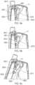
- FIGS. 5 a to 5 cshow one example of a suitable mechanism for transitioning the cover section from the first position to the second position in accordance with the embodiment of FIG. 2 .
- FIG. 6is a perspective view of part of the internal mechanism shown in FIGS. 5 a to 5 c.
- FIG. 7is an exploded diagram showing certain components of the device of the embodiment of FIG. 2 .
- FIG. 8is a perspective view of the hatch section and shows part of the internal mechanism shown in FIGS. 5 a to 5 c.
- FIGS. 9 a to 9 cshow a range of sections taken through the longitudinal axis of the sleeve of the hatch section.
- FIG. 10is a perspective view of a sectional view parallel with a longitudinal axis of the sleeve of the hatch section.
- FIG. 11 ais a perspective view showing the internal space within the housing of the device of FIG. 2 .
- FIG. 11 bis a closed up view of the base of the internal space within the housing of the device of FIG. 2 .
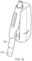
- FIG. 12provides a representational image of an aerosol forming component being inserted into the sleeve of the hatch section of the device of FIG. 2 .
- an aerosol provision systemsuch as an e-cigarette.
- e-cigaretteis sometimes used but this term may be used interchangeably with aerosol (vapor) provision system.
- an aerosol provision systemmay include systems which are intended to generate aerosols from liquid source materials, solid source materials and/or semi-solid source materials, e.g. gels.
- Certain embodiments of the disclosureare described herein in connection with some example e-cigarette configurations (e.g. in terms of a specific overall appearance and underlying vapor generation technology). However, it will be appreciated the same principles can equally be applied for aerosol delivery systems having different overall configurations (e.g. having a different overall appearance, structure and/or vapor generation technology).
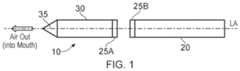
- FIG. 1is a schematic diagram of an aerosol/vapor provision system of the prior art (not to scale).
- the e-cigarette 10 of the prior arthas a generally cylindrical shape, extending along a longitudinal axis indicated by dashed line LA, and comprising two main components, namely a body 20 (device section) and a cartomizer 30 (aerosol provision component).
- the cartomizerincludes an internal chamber containing a reservoir of a source liquid comprising a liquid formulation from which an aerosol is to be generated, a heating element, and a liquid transport element (in this example a wicking element) for transporting source liquid to the vicinity of the heating element.
- the heating elementmay itself provide the liquid transport function.
- the heating element and the element providing the liquid transport functionmay sometimes be collectively referred to as an aerosol generator/aerosol forming member/vaporizer/atomizer/distiller.
- the cartomizer 30further includes a mouthpiece 35 having an opening through which a user may inhale the aerosol from the aerosol generator.
- the source liquidmay be of a conventional kind used in e-cigarettes, for example comprising 0 to 5% nicotine dissolved in a solvent comprising glycerol, water, and/or propylene glycol.
- the source liquidmay also comprise flavorings.
- the reservoir for the source liquidmay comprise a porous matrix or any other structure within a housing for retaining the source liquid until such time that it is required to be delivered to the aerosol generator/vaporizer.
- the reservoirmay comprise a housing defining a chamber containing free liquid (i.e. there may not be a porous matrix).
- the body 20includes a re-chargeable cell or battery to provide power for the e-cigarette 10 and a circuit board including control circuitry for generally controlling the e-cigarette.
- the heating elementIn active use, i.e. when the heating element receives power from the battery, as controlled by the control circuitry, the heating element vaporises source liquid in the vicinity of the heating element to generate an aerosol.
- the aerosolis inhaled by a user through the opening in the mouthpiece. During user inhalation the aerosol is carried from the aerosol source to the mouthpiece opening along an air channel that connects between them.
- the body 20 and cartomizer 30are detachable from one another by separating in a direction parallel to the longitudinal axis LA, as shown in FIG. 1 , but are joined together when the device 10 is in use by a connection, indicated schematically in FIG. 1 as 25 A and 25 B, to provide mechanical and electrical connectivity between the body 20 and the cartomizer 30 .
- the electrical connector on the body 20 that is used to connect to the cartomizeralso serves as a socket for connecting a charging device (not shown) when the body is detached from the cartomizer 30 .
- the other end of the charging devicecan be plugged into an external power supply, for example a USB socket, to charge or to re-charge the cell/battery in the body 20 of the e-cigarette.
- an external power supplyfor example a USB socket
- a cablemay be provided for direct connection between the electrical connector on the body and the external power supply and/or the device may be provided with a separate charging port, for example a port conforming to one of the USB formats.
- the e-cigarette 10is provided with one or more holes (not shown in FIG. 1 ) for air inlet. These holes connect to an air passage (airflow path) running through the e-cigarette 10 to the mouthpiece 35 .
- the air passageincludes a region around the aerosol source and a section comprising an air channel connecting from the aerosol source to the opening in the mouthpiece.
- an airflow sensor 215in this case a pressure sensor, for detecting airflow in electronic cigarette 10 and outputting corresponding airflow detection signals to the control circuitry.
- the airflow sensor 560may operate in accordance with conventional techniques in terms of how it is arranged within the electronic cigarette to generate airflow detection signals indicating when there is a flow of air through the electronic cigarette (e.g. when a user inhales or blows on the mouthpiece).
- the airflowpasses through the air passage (airflow path) through the electronic cigarette and combines/mixes with the vapor in the region around the aerosol source to generate the aerosol.
- the resulting combination of airflow and vaporcontinues along the airflow path connecting from the aerosol source to the mouthpiece for inhalation by a user.
- the cartomizer 30may be detached from the body 20 and disposed of when the supply of source liquid is exhausted (and replaced with another cartomizer if so desired). Alternatively, the cartomizer may be refillable.
- the aerosol provision systemmay function broadly in line with that described above for exemplary prior art devices, e.g. activation of a heater to vaporize a source material so as to entrain an aerosol in a passing airflow which is then inhaled
- the construction of the aerosol provision system of some example embodiments of the present disclosureis different to prior art devices.
- FIG. 2is a diagram of an exemplary device 100 according to one embodiment of the present disclosure. Note that various components and details of the body, e.g. such as wiring and more complex shaping, have been omitted from FIG. 2 for reasons of clarity. Some of these are shown in FIG. 3 .
- Chassis section 210may take the form of a single piece of material, or may be formed from two separate pieces of material 210 a , 210 b joined together along an appropriate seam (not shown). Chassis section 210 and hatch section 220 are connected such that hatch section 220 is moveable relative to the chassis section 210 between a first position where the chassis section 210 and hatch section 220 together define an enclosed space 250 for an aerosol forming component (not shown) to be located for aerosol generation, and a second position wherein the chassis section 210 and hatch section 220 are spaced so as to provide access to the space 250 .
- FIG. 2shows chassis section 210 and hatch section 220 in the second position with space 250 being accessible.
- the hatch section 220may comprise a sleeve 230 mounted on an internal wall of the hatch section 220 such that the sleeve projects towards the space 250 .
- Sleeve 230defines a generally longitudinal recess which is able to accommodate an aerosol forming component (not shown). More specifically, an aerosol forming component can be inserted into sleeve 230 .
- Sleeve 230will be explained in further detail below; however, in the context of the embodiment of FIG.
- the aerosol forming componentis generally more protected than the in the devices of the prior art since it may be located entirely within an enclosed space, thus providing a degree of protection against impact from external objects. This can be particularly important given the presence of source liquid which could leak if the aerosol forming component is damaged.
- the hatch section 220 of the device 100 shown in FIG. 2may also comprise a mouthpiece 260 which defines an outlet.
- the device 100generally includes an inlet 240 which facilitates the inlet of air into the space 250 .
- the inlet 240 , space 250 and outlet 260together form a fluidly connected pathway for air to flow from outside the device, through the space 250 , and out of the outlet of the mouthpiece.
- an aerosol forming componentWhen an aerosol forming component is present in the space 250 , the air flow will be channeled through (or past) the aerosol forming component thereby facilitating the entrainment of aerosol in the airflow path.
- the devicemay include a number of additional features.
- the hatch sectionis an elongate component comprising an externally facing surface and an internally facing surface.
- the hatch sectionincludes a sleeve as part of the internally facing surface, wherein the sleeve is for receiving the aerosol forming component.
- the sleevehas a generally tubular profile.
- moving the hatch section from the first position to the second positionincludes the hatch section undergoing at least one of pivoting, rotating, sliding, swiveling with respect to the chassis housing.
- moving the hatch section from the first position to the second positionincludes the hatch section undergoing more than one of pivoting, sliding, swiveling with respect to the chassis housing.
- moving the hatch section from the first position to the second positionincludes the hatch section undergoing sliding and pivoting with respect to the chassis housing, and in some embodiments, undergoing sliding and then pivoting with respect to the chassis housing.
- the housing of the present devicegenerally comprises one or more inlets for conveying air into the space when the hatch section is in the first position.
- the position of the inlet(s)is not particularly limited.
- at least one inletis present on the hatch section.
- the at least one inletis present on the chassis section. It may be desirable for the one or more inlets to be aligned with an air inlet on the aerosol forming component.
- the device 100 of some example embodiments of the present disclosurecan be activated by any suitable means.
- suitable activation meansinclude button activation, or activation via a sensor (touch sensor, airflow sensor, pressure sensor, thermistor etc.).
- activationit is meant that the aerosol generator of the aerosol forming component can be energized such that vapor is produced from the source material.
- activationcan be considered to be distinct from actuation, whereby the device 100 is brought from an essentially dormant or off state, to a state in which once or more functions can be performed on the device and/or the device can be placed into a mode which can be suitable for activation.
- housing 200generally comprises a power supply/source (not shown in FIG. 2 ) which supplies power to the aerosol generator of the aerosol forming component.
- the connection between the aerosol forming component and the power supplymay be wired or wireless.
- contacts 450 within the housing 200may contact with corresponding electrodes of the aerosol forming component when the hatch section 220 is in the first position and the aerosol forming component thus resides within space 250 . The establishment of such contact will be explained further below.
- connection between the power source and the aerosol forming componentcould be wireless in the sense that a drive coil (not shown) present in the housing 200 and connected to the power source could be energized such that a magnetic field is produced.
- the aerosol forming componentcould then comprise a susceptor which is penetrated by the magnetic field such that eddy currents are induced in the susceptor and it is heated.
- a surface feature 270which facilitates movement of the hatch section 220 from the first position to the second position.
- the surface feature 270will be explained in more detail below.
- the surface feature 270is a recess formed in the outer surface of hatch section 220 .
- the surface featuremay not be a recess, and could inserted be a projection, or area of increased surface roughness.
- the recessed surface feature 270may in this case also define a transparent section 280 of hatch section 220 .
- a transparent sectionallows the user to visualize the aerosol forming component, which could be advantageous in allowing the user to see information displayed on the aerosol forming component (such as flavor, brand, purchase date information etc.) and/or the amount of source material present in the aerosol forming component.
- Such transparent sectionsare generally not required on devices of the prior art since the aerosol forming component is generally fully exposed in a longitudinal type configuration. The transparent section may be located within the recess.
- FIG. 3provides a cross-sectional view of the device 100 of FIG. 2 wherein the hatch section 220 is in the first position and an aerosol forming component 700 is retained within sleeve 230 . It will be appreciated here that enclosed space 250 is formed within the housing and is occupied by an aerosol forming component within sleeve 230 . FIG. 3 will be used to further describe some aspects of various embodiments described herein.
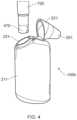
- FIG. 4shows an alternative embodiment of the present disclosure.
- FIG. 4shows device 100 b .
- device 100 bcomprises a housing formed from a chassis section 211 and a hatch section 221 .
- Hatch section 221is connected to chassis section 211 and is moveable between a first position wherein an enclosed space 251 is formed for an aerosol forming component to be located for aerosol generation, and a second position wherein the chassis section 211 and hatch section 221 are spaced so as to provide access to the space 251 .
- hatch section 221is shown in the section position providing access to space 251 .
- space 251may define a sleeve having a generally longitudinal profile.
- the inner surface of the sleevemay be shaped so as to receive an aerosol forming component 700 .
- the hatch sectionis pivotable between the first and second positions.
- said movement between the first and second positionscould also be achieved via sliding, swiveling, etc.
- Hatch section 221also may comprise mouthpiece section 261 .
- mouthpiece section 261may define an outlet which forms a fluid connection with space 251 and an air inlet (not shown) thereby allowing for air to flow through the device 100 b such that aerosol can be entrained when an aerosol forming component is present in space 251 and activated.
- FIG. 7shows an exploded diagram of device 100 .
- chassis sections 210 a and 210 bcan be connected together so as to encase a power supply 290 (such as a battery, which may be rechargeable via wired or wireless means), a printed circuit board (PCB) 291 comprising various control circuitry providing for the functionality of the device, a space for receiving an aerosol forming component via the sleeve 230 of the hatch section, and a mechanism 600 connecting the chassis section 210 and the hatch section 220 and facilitating movement from the first position to the section position.
- a power supply 290such as a battery, which may be rechargeable via wired or wireless means
- PCBprinted circuit board
- mechanism 600can comprise one or more parts which function to connect the chassis and hatch sections, and which facilitates their movement from the respective first to second positions.
- mechanism 600may be comprised of formations on the chassis section 210 , formations on the hatch section 220 and independent (i.e. separately formed) components.
- the control circuitry 550is in the form of a chip, such as an application specific integrated circuit (ASIC) or microcontroller, for controlling the device 100 .
- the circuit board 291 comprising the control circuitrymay be arranged between the power supply and the space 250 .
- the control circuitrymay be provided as a single element or a number of discrete elements.
- the control circuitrymay be connected to a pressure sensor to detect an inhalation on mouthpiece 260 and, as mentioned above, this aspect of detecting when there is airflow in the device and generating corresponding airflow detection signals may be conventional.
- mechanism 600may comprise a dowel (pin) 601 and a carriage spring 602 and respective formations on the chassis section 210 and the hatch section 220 .
- dowel 601may connect carriage spring 602 to both the hatch section 220 and the chassis section 210 , thereby facilitating movement of the hatch section 220 from the first position to the section position.
- the carriage spring 602may be biased against the hatch section 220 so as to urge it towards the second position.
- the hatch sectionmay be retained in the first position via lug 603 being releasably positioned within the longitudinal projection of the L-shaped recess/groove 604 .
- carriage spring 602is able to urge hatch section 220 away from the chassis section 210 and thus into a spaced position (the second position).
- FIGS. 5 a to 5 can exemplary mechanism for facilitating connection and movement between the chassis section 210 and the hatch section 220 is shown in FIGS. 5 a to 5 c .
- Mechanism 650is shown in FIGS. 5 a to 5 c .
- Mechanism 650comprises a first lug 651 and a second lug 652 , both located on the hatch section 220 .
- Lug 651resides within a vertical slot 661 formed within chassis section 210 (it may be that the slot 661 is formed by opposing parts of two chassis section components 210 a and 210 b respectively).
- Slot 661is sized and oriented so as to allow longitudinal movement of lug 651 within the slot.
- Lug 652resides within a generally L-shaped slot 662 formed within chassis section 210 (again, it may be that the slot 662 is formed by opposing parts of two chassis section components 210 a and 210 b respectively).
- Mechanism 650also comprises a biasing cam 670 which is anchored around a pivot P 1 . Biasing cam 670 is urged towards the hatch section 220 by a biasing spring (not shown). Biasing cam includes a retaining shoulder 671 . Retaining shoulder 671 interacts with an anchoring projection 653 of the hatch section 220 .
- the components of mechanism 650provide a simple and robust mechanism for facilitating connection and movement between the chassis section 210 and the hatch section 220 . The operation of the mechanism 650 will now be described in more detail.
- lugs 651 and 652are located in the distal most sections of their respective slots 661 and 662 . Furthermore, in this position, anchoring projection 653 engages retention shoulder 671 . Due to the respective orientations of the upper surface of anchoring projection 653 and the lower surface of retention shoulder 671 , the urging of the biasing cam 670 towards the hatch section provides a proximally acting force on the anchoring projection 653 . Furthermore, slope 663 of slot 552 generally urges the hatch section 220 (and thus the anchoring projection 653 ) towards the biasing cam 670 so that the tip of the anchoring projection 653 resides under the retention shoulder. Such an arrangement generally retains the hatch section 220 in the first position and provides the user with a perceptible engagement of the hatch section in the first position as the anchoring projection 653 rides over and is then retained under the retention shoulder 671 .
- the hatch section 220When the user wants to move hatch section 220 towards the second position, the hatch section 220 is generally moved upwards (proximally with respect to the mouthpiece, as indicated by the arrows in FIG. 5 a ).
- the surface feature 270may make such a movement easier.
- Such a movementresults in lug 652 riding up slope 663 (since it is being biased towards the slope 663 by the biasing cam 670 and biasing spring), and then along the longitudinal projection of slot 663 .
- lug 651travels proximally along slot 661 .
- anchoring projection 653rides over retention shoulder 671 .
- lug 652Upon continued movement of the hatch section 220 , lug 652 becomes positioned at the intersection of the longitudinal and lateral portions of slot 662 .
- FIG. 6provides a cut away view of through the chassis housing 210 such that part of mechanism 650 can be seen more clearly.
- biasing cam 670is mounted on rod 672 which forms pivot P 1 .
- the biasing cam 670can drive the hatch section 220 into the second position provided that lug 652 is in the lateral projection of slot 662 .
- FIG. 8shows a perspective view of hatch section 220 when detached from device 100 .
- hatch sectioncomprises a sleeve 235 upon which lugs 651 and 652 are mounted, as well as anchoring projection 653 .
- FIG. 8also illustrates an alternative position for the inlet 240 .
- the inlet on the devicecan be formed in any component provided that air can enter the space 250 for accommodating the aerosol forming component.
- FIG. 8also shows retention section 300 which, in this embodiment, is a flexible tang 301 which is forced outwards upon insertion of a suitable aerosol forming component in sleeve 235 .
- the material used to form the tang 301Due to the general rigidity of the material used to form the tang 301 , it generally resists outward deflection and as such serves to provide a degree of grip against the aerosol forming component. This then provides a force which helps to resist removal of the aerosol forming component from sleeve 235 .
- a hatch section 220which in some embodiments comprises a sleeve 235 which is suitable for receiving an aerosol forming component. Due to the way in which the present device is used, the aerosol forming component may well be inserted into the sleeve 235 when the sleeve opening 236 is facing downwards. As a result, there is potentially a risk in some implementations that the inserted aerosol forming component may fall out of the sleeve 235 before the hatch section 220 is moved back to the first position. Accordingly, hatch section 235 may be generally provided with a retention section which is configured to resist removal of the aerosol forming component following insertion into the sleeve. This retention section could take different forms.
- the retention sectionis formed from a flexible tang, such as that shown in FIG. 8 .
- Other suitable retention sectionsmay include: a latch 302 (shown in the embodiment of FIG. 3 ) which engages with a corresponding recess 303 on the aerosol forming component; one or more ribs on the inside wall of the sleeve 235 which engage with the outer surface of the aerosol forming component and resist its removal; a magnet positioned at a relevant section of hatch section 220 /sleeve 235 which interacts with a suitable metal component of the aerosol forming component, such as the heater, to resist removal from the sleeve 235 .
- the hatch sectionincludes a sleeve which comprises a flexible tang at an opening of the sleeve.
- FIGS. 9 a to 9 cwhere various cross section cut-aways along the lines A-A, B-B, C-C of FIG. 8 are shown.
- the cross section C-Cis generally taken at the sleeve opening 236 .
- sleeve opening 236has a generally circular cross section.
- the sleeve openingcould take another cross section.
- sleeve 235may have a cross-section profile that varies along its length. For example, whilst the cross-section taken at line C-C may be generally viewed as being circular, the cross section becomes progressively oval long the length of the sleeve 235 .
- the cross-section taken at line B-Bis generally more oval than the cross-section at line C-C.
- the cross-section taken at line A-Ais generally more oval than the cross-section at line B-B.
- the cross section of sleeve 235varies between a first point along its length and a second point along its length.
- the cross-section of sleeve 235progressively varies so as to match the changing longitudinal cross-sectional profile of a corresponding aerosol forming component.
- the cross-section of the sleeveprogressively varies from a generally circular shape at a first position, to a generally oval shape at a second position, wherein the second position is downstream with respect to the direction of insertion of the aerosol forming component into the sleeve.
- the chassis section 210may also include one or more ridges or lugs 460 (or other suitable surface feature), as shown in FIG. 11 b , which correspond to a longitudinal slot 470 on the outer surface of the distal portion of the aerosol forming component. Such a combination of lugs/longitudinal slot can assist in locking the aerosol forming component in the final rotational orientation
- a hatch sectioncomprising a sleeve for receipt of an aerosol forming component, the sleeve defining a longitudinal axis and comprising first and second sections spaced along the longitudinal axis which exert different rotational biases on the aerosol forming component when inserted.
- the aerosol forming componentcomprises electrodes that need to be positioned in a specific rotational orientation for them to engage with corresponding electrodes on the inside of the housing 200 .
- the heater of the aerosol forming componentis required to be orientated in a specific rotational orientation so as to ensure correct alignment with a magnetic field for inductive heating.
- the ability to impart different rotational biases along the length of the sleeveis not limited to the specific cross section of the sleeve.
- a magnetcould be present at a point along the sleeve, wherein said magnet interacts with a corresponding suitable metallic feature on the aerosol forming component. Due to the relative location of the magnet and the corresponding suitable metallic feature on the aerosol forming component, the aerosol forming component can be driven to a different rotational orientation relative to the rotational orientation in which it was in when inserted into the sleeve opening.
- FIG. 10there is shown a cross-sectional view of the hatch section 220 along a longitudinal axis of the hatch section 220 .
- a seal 400such as a sealing ring.
- Seal 400functions to provide a seal between an inner surface 236 of sleeve 235 and an outer surface of the aerosol forming component when inserted into the sleeve 235 . This seal serves to help ensure that when the user inhales on mouthpiece 260 , airflow is drawn through the aerosol forming component, rather than along its outer perimeter.
- the aerosol forming componentis urged into contact with the seal when the aerosol forming component is present in the sleeve and the hatch section is in the first position. In one embodiment, this may be effected by one or more biasing projections located on an inner wall of housing.
- biasing projections 450are spring loaded electrodes (“pogo pins”) which serve to contact the distal most end of the aerosol forming component and urge it into further contact with seal 400 .
- the one or more biasing projectionsneed not be sprung electrodes, but could alternatively be a ridge or other surface feature on the inner wall of housing 100 which serves to urge the aerosol forming component into further contact with seal 400 . It may be desirable to have such biasing projections as they may serve to reduce the manufacturing tolerances within which the housing must be made.
- the aerosol forming component 700includes an aerosol generator arranged (not shown) in an air passage extending along a generally longitudinal axis of the aerosol forming component 700 .
- the aerosol generatormay comprise a resistive heating element adjacent a wicking element (liquid transport element) which is arranged to transport source liquid from a reservoir of source liquid within the aerosol forming component to the vicinity of the heating element for heating.
- the reservoir of source liquid in this exampleis adjacent to the air passage and may be implemented, for example, by providing cotton or foam soaked in source liquid.
- the wicking element and the heating elementmay follow conventional techniques.
- the wicking element and the heating elementmay comprise separate elements, e.g. a metal heating wire wound around/wrapped over a cylindrical wick, the wick, for instance, consisting of a bundle, thread or yarn of glass fibers.
- the functionality of the wicking element and the heating elementmay be provided by a single element. That is to say, the heating element itself may provide the wicking function.
- the heating element/wicking elementmay comprise one or more of: a metal composite structure, such as porous sintered metal fiber media (Bekipor® ST) from Bekaert, a metal foam structure, e.g. of the kind available from Mitsubishi Materials; a multi-layer sintered metal wire mesh, or a folded single-layer metal wire mesh, such as from Bopp; a metal braid; or glass-fiber or carbon-fiber tissue entwined with metal wires.
- the “metal”may be any metallic material having an appropriate electric resistivity to be used in connection/combination with a battery.
- the resultant electric resistance of the heating elementwill typically be in the range 0.5-5 Ohm. Values below 0.5 Ohm could be used but could potentially overstress the battery.
- the “metal”could, for example, be a NiCr alloy (e.g. NiCr8020) or a FeCrAl alloy (e.g. “Kanthal”) or stainless steel (e.g. AISI 304 or AISI 316).
- powermay be delivered from power supply 290 to the aerosol forming member 700 via electrodes 450 .
Landscapes
- Engineering & Computer Science (AREA)
- Health & Medical Sciences (AREA)
- Human Computer Interaction (AREA)
- Animal Behavior & Ethology (AREA)
- Public Health (AREA)
- Anesthesiology (AREA)
- Biomedical Technology (AREA)
- Heart & Thoracic Surgery (AREA)
- Hematology (AREA)
- Life Sciences & Earth Sciences (AREA)
- Bioinformatics & Cheminformatics (AREA)
- General Health & Medical Sciences (AREA)
- Pulmonology (AREA)
- Veterinary Medicine (AREA)
- Containers And Packaging Bodies Having A Special Means To Remove Contents (AREA)
- Casings For Electric Apparatus (AREA)
- Nozzles (AREA)
- Feeding, Discharge, Calcimining, Fusing, And Gas-Generation Devices (AREA)
- Catching Or Destruction (AREA)
- Medicines Containing Plant Substances (AREA)
Abstract
Description
Claims (6)
Applications Claiming Priority (4)
| Application Number | Priority Date | Filing Date | Title |
|---|---|---|---|
| GBGB1717484.8AGB201717484D0 (en) | 2017-10-24 | 2017-10-24 | Electronic aerosol provision device |
| GB1717484 | 2017-10-24 | ||
| GB1717484.8 | 2017-10-24 | ||
| PCT/GB2018/053052WO2019081906A1 (en) | 2017-10-24 | 2018-10-23 | Electronic aerosol provision system |
Related Parent Applications (1)
| Application Number | Title | Priority Date | Filing Date |
|---|---|---|---|
| PCT/GB2018/053052A-371-Of-InternationalWO2019081906A1 (en) | 2017-10-24 | 2018-10-23 | Electronic aerosol provision system |
Related Child Applications (1)
| Application Number | Title | Priority Date | Filing Date |
|---|---|---|---|
| US18/798,091ContinuationUS20240398005A1 (en) | 2017-10-24 | 2024-08-08 | Electronic aerosol provision system |
Publications (2)
| Publication Number | Publication Date |
|---|---|
| US20200288775A1 US20200288775A1 (en) | 2020-09-17 |
| US12161155B2true US12161155B2 (en) | 2024-12-10 |
Family
ID=60481653
Family Applications (3)
| Application Number | Title | Priority Date | Filing Date |
|---|---|---|---|
| US16/758,229Active2038-11-21US11653697B2 (en) | 2017-10-24 | 2018-10-19 | Electronic aerosol provision device having chassis section and movable hatch section |
| US16/758,218Active2040-11-25US12161155B2 (en) | 2017-10-24 | 2018-10-23 | Electronic aerosol provision system |
| US18/798,091PendingUS20240398005A1 (en) | 2017-10-24 | 2024-08-08 | Electronic aerosol provision system |
Family Applications Before (1)
| Application Number | Title | Priority Date | Filing Date |
|---|---|---|---|
| US16/758,229Active2038-11-21US11653697B2 (en) | 2017-10-24 | 2018-10-19 | Electronic aerosol provision device having chassis section and movable hatch section |
Family Applications After (1)
| Application Number | Title | Priority Date | Filing Date |
|---|---|---|---|
| US18/798,091PendingUS20240398005A1 (en) | 2017-10-24 | 2024-08-08 | Electronic aerosol provision system |
Country Status (22)
| Country | Link |
|---|---|
| US (3) | US11653697B2 (en) |
| EP (2) | EP3700370B1 (en) |
| JP (4) | JP7056995B2 (en) |
| KR (3) | KR102498796B1 (en) |
| CN (2) | CN111278306A (en) |
| AU (2) | AU2018356939B2 (en) |
| BR (2) | BR112020008250A2 (en) |
| CA (3) | CA3084453C (en) |
| ES (1) | ES2953555T3 (en) |
| GB (1) | GB201717484D0 (en) |
| HU (1) | HUE062683T2 (en) |
| IL (2) | IL274102B2 (en) |
| LT (1) | LT3700370T (en) |
| MX (2) | MX2020004170A (en) |
| MY (2) | MY203660A (en) |
| NZ (2) | NZ763646A (en) |
| PL (1) | PL3700370T3 (en) |
| PT (1) | PT3700370T (en) |
| RU (2) | RU2751549C1 (en) |
| UA (2) | UA127133C2 (en) |
| WO (2) | WO2019081897A1 (en) |
| ZA (1) | ZA202002233B (en) |
Families Citing this family (15)
| Publication number | Priority date | Publication date | Assignee | Title |
|---|---|---|---|---|
| CN111869939A (en)* | 2017-01-18 | 2020-11-03 | 韩国烟草人参公社 | Charging system |
| GB201717486D0 (en) | 2017-10-24 | 2017-12-06 | Nicoventures Holdings Ltd | Mechanism for hatch of electronic aerosol provision device |
| GB201717479D0 (en) | 2017-10-24 | 2017-12-06 | Nicoventures Holdings Ltd | Hatch section for an electronic aerosol provision device |
| GB201717480D0 (en) | 2017-10-24 | 2017-12-06 | Nicoventures Holdings Ltd | Electronic aerosol provision device with seal |
| GB201717484D0 (en) | 2017-10-24 | 2017-12-06 | Nicoventures Holdings Ltd | Electronic aerosol provision device |
| GB201717497D0 (en) | 2017-10-24 | 2017-12-06 | British American Tobacco Investments Ltd | A mouthpiece assembly |
| GB201717489D0 (en) | 2017-10-24 | 2017-12-06 | Nicoventures Holdings Ltd | Electronic aerosol provision device |
| GB201717498D0 (en) | 2017-10-24 | 2017-12-06 | British American Tobacco Investments Ltd | Aerosol provision device |
| GB201717496D0 (en) | 2017-10-24 | 2017-12-06 | British American Tobacco Investments Ltd | A cartridge for an aerosol provision device |
| TWI728795B (en) | 2019-05-03 | 2021-05-21 | 瑞士商傑太日煙國際股份有限公司(瑞士) | Aerosol generation device with closure and operation method thereof |
| TWI789584B (en) | 2019-05-03 | 2023-01-11 | 瑞士商傑太日煙國際股份有限公司(瑞士) | Aerosol generation device with closure and method of operating aerosol generation device |
| WO2020248103A1 (en)* | 2019-06-10 | 2020-12-17 | Nicoventures Trading Limited | Aerosol provision device |
| US11439185B2 (en)* | 2020-04-29 | 2022-09-13 | R. J. Reynolds Tobacco Company | Aerosol delivery device with sliding and transversely rotating locking mechanism |
| WO2023041450A1 (en)* | 2021-09-15 | 2023-03-23 | Nerudia Limited | Aerosol delivery device/system |
| CN216293015U (en)* | 2021-10-11 | 2022-04-15 | 比亚迪精密制造有限公司 | Rotary switch and heating non-combustion electronic cigarette |
Citations (113)
| Publication number | Priority date | Publication date | Assignee | Title |
|---|---|---|---|---|
| GB354564A (en) | 1930-08-25 | 1931-08-13 | Albert Edward Tinworth | Improvements in or relating to cigarette and like cases |
| US2005557A (en) | 1934-02-06 | 1935-06-18 | Robert L Penney | Pocket cigarette case and lighter |
| US3979228A (en) | 1975-05-01 | 1976-09-07 | Sperry Rand Corporation | Battery operated appliance |
| US4884317A (en) | 1989-02-07 | 1989-12-05 | Liu Ping Hsiung | Hinge units for joining a case and its lid |
| US5048515A (en) | 1988-11-15 | 1991-09-17 | Sanso David W | Respiratory gas supply apparatus and method |
| JPH0879342A (en) | 1994-09-09 | 1996-03-22 | Sony Corp | Cover device |
| WO1997048293A1 (en) | 1996-06-17 | 1997-12-24 | Japan Tobacco Inc. | Flavor producing article |
| EP0845200A1 (en) | 1996-11-22 | 1998-06-03 | Deere & Company | Nylatron support bearing for cage |
| EP0970627A1 (en) | 1997-12-01 | 2000-01-12 | Danming Pu | A healthy cigarette |
| US6065626A (en) | 1998-12-08 | 2000-05-23 | Huang; Chien Jung | Box opening/closing structure |
| US6135106A (en) | 1997-08-22 | 2000-10-24 | Nellcor Puritan-Bennett, Inc. | CPAP pressure and flow transducer |
| JP2001044659A (en) | 1999-05-26 | 2001-02-16 | Sanyo Electric Co Ltd | Electric equipment having cover body |
| US20050016550A1 (en) | 2003-07-17 | 2005-01-27 | Makoto Katase | Electronic cigarette |
| US6942118B2 (en) | 2000-08-14 | 2005-09-13 | The Procter & Gamble Company | Container closure arrangement |
| JP2006032441A (en) | 2004-07-12 | 2006-02-02 | Olympus Corp | Electronic apparatus with two or more opening/closing lids |
| JP2006156322A (en) | 2004-11-05 | 2006-06-15 | Eastman Kodak Co | Structure for housing battery |
| US20070045288A1 (en) | 2005-09-01 | 2007-03-01 | Nelson Stephen G | Inhaler |
| CN1981651A (en) | 2005-12-13 | 2007-06-20 | 菲高合作社 | Cigarette dispenser |
| JP2007165723A (en) | 2005-12-15 | 2007-06-28 | Fujifilm Corp | Lid opening / closing mechanism |
| CN201451347U (en) | 2009-08-19 | 2010-05-12 | 常德金鹏印务有限公司 | Cigarette case provided with cigarette ash box |
| CN101862038A (en) | 2009-04-15 | 2010-10-20 | 中国科学院理化技术研究所 | A heating and atomizing electronic cigarette powered by a capacitor |
| US20110180433A1 (en) | 2010-01-28 | 2011-07-28 | Rennecamp Bryan R | Smoking accessory |
| WO2011095781A1 (en) | 2010-02-05 | 2011-08-11 | Kind Consumer Limited | A simulated smoking device |
| CN102406238A (en) | 2011-11-09 | 2012-04-11 | 刘宝社 | Smokeless suction device |
| JP2012135299A (en) | 2010-03-08 | 2012-07-19 | Kazuhiko Shimizu | Mouthpiece |
| US20120227753A1 (en) | 2010-12-06 | 2012-09-13 | Newton Kyle D | Charger Package for Electronic Cigarette Components |
| US20120255546A1 (en) | 2011-04-11 | 2012-10-11 | Visionary Road | Portable vaporizer |
| JP2012529898A (en) | 2009-06-17 | 2012-11-29 | ブリティッシュ アメリカン タバコ (インヴェストメンツ) リミテッド | Aerosol generator |
| US20120318283A1 (en) | 2010-02-24 | 2012-12-20 | Tomoichi Watanabe | Flavor inhalation pipe |
| CN103202537A (en) | 2013-04-16 | 2013-07-17 | 湖北中烟工业有限责任公司 | Chemical and electronic combined novel smokeless cigarette |
| WO2013156339A1 (en) | 2012-04-20 | 2013-10-24 | Alfred Von Schuckmann | Device for inhaling powdery substances |
| US20140014124A1 (en) | 2012-07-12 | 2014-01-16 | Eco-Cigs, Inc. | Tip charging electronic cigarette and system and method for charging the same |
| CN103689812A (en) | 2013-12-30 | 2014-04-02 | 深圳市合元科技有限公司 | Smoke generator and electronic cigarette with same |
| RU2510711C1 (en) | 2010-02-23 | 2014-04-10 | Хускварна Аб | Flap lid |
| WO2014066730A1 (en) | 2012-10-25 | 2014-05-01 | Lbs Imports, Llc. | Electronic cigarette |
| CN203692551U (en) | 2014-02-12 | 2014-07-09 | 刘秋明 | Electronic cigarette |
| CN203789158U (en) | 2014-04-02 | 2014-08-27 | 林光榕 | Elliptical electronic cigarette |
| CN104095293A (en) | 2014-07-28 | 2014-10-15 | 川渝中烟工业有限责任公司 | Electromagnetic heating type suction device used for heating non-combustible cigarette |
| GB2514893A (en) | 2013-06-04 | 2014-12-10 | Nicoventures Holdings Ltd | Container |
| US20150027459A1 (en) | 2012-09-04 | 2015-01-29 | R.J. Reynolds Tobacco Company | Electronic smoking article comprising one or more microheaters |
| JP2015503335A (en) | 2011-12-30 | 2015-02-02 | フィリップ・モーリス・プロダクツ・ソシエテ・アノニム | Aerosol-generating article for use with an aerosol generator |
| JP2015504668A (en) | 2012-01-03 | 2015-02-16 | フィリップ・モーリス・プロダクツ・ソシエテ・アノニム | Aerosol generator and system |
| CN104582772A (en) | 2012-07-05 | 2015-04-29 | 葛兰素集团有限公司 | inhaler device |
| CN204317504U (en) | 2014-12-03 | 2015-05-13 | 深圳市合元科技有限公司 | Cure hot type electrical smoking device |
| US20150128971A1 (en) | 2013-11-12 | 2015-05-14 | VMR Products, LLC | Vaporizer |
| US20150164138A1 (en) | 2013-04-07 | 2015-06-18 | Kimree Hi-Tech Inc. | Electronic cigarette box and support mechanism |
| CN104770896A (en) | 2015-03-16 | 2015-07-15 | 河南中烟工业有限责任公司 | Electronic atomization device with adjustable tobacco product heating sections |
| US9089166B1 (en) | 2014-05-09 | 2015-07-28 | Njoy, Inc. | Packaging for vaporizing device |
| WO2015117700A1 (en) | 2014-02-10 | 2015-08-13 | Philip Morris Products S.A. | An aerosol-generating system comprising a device and a cartridge, in which the device ensures electrical contact with the cartridge |
| GB2523585A (en) | 2014-02-28 | 2015-09-02 | Beyond Twenty Ltd | Portable charging case for a vapour dispenser |
| US20150245654A1 (en) | 2014-02-28 | 2015-09-03 | Beyond Twenty Ltd. | E-cigarette personal vaporizer |
| JP2015529458A (en) | 2012-08-24 | 2015-10-08 | キミレ ハイテック インクKimree Hi−Tech Inc. | Electronic cigarette equipment |
| WO2015157891A1 (en) | 2014-04-14 | 2015-10-22 | 吉瑞高新科技股份有限公司 | Electronic cigarette and assembly method therefor |
| US20150328415A1 (en) | 2014-05-19 | 2015-11-19 | R.J. Reynolds Tobacco Company | Cartridge vaporizer in a personal vaporizer unit |
| WO2015177046A1 (en) | 2014-05-21 | 2015-11-26 | Philip Morris Products S.A. | An aerosol-generating system comprising a mesh susceptor |
| US20150342258A1 (en) | 2014-05-30 | 2015-12-03 | Shenzhen Smoore Technology Limited | Cartridge for electronic cigarette |
| CN105188429A (en) | 2013-03-15 | 2015-12-23 | R·J·雷诺兹烟草公司 | Cartridge and control body for aerosol delivery device including anti-rotation mechanism and related methods |
| WO2015198051A1 (en) | 2014-06-25 | 2015-12-30 | Kind Consumer Limited | Nicotine dosage regimen |
| WO2016026811A1 (en) | 2014-08-21 | 2016-02-25 | Philip Morris Products Sa | Aerosol-generating device and system |
| US20160050975A1 (en) | 2014-08-21 | 2016-02-25 | R.J. Reynolds Tobacco Company | Aerosol Delivery Device Including a Moveable Cartridge and Related Assembly Method |
| WO2016054580A1 (en) | 2014-10-02 | 2016-04-07 | Digirettes, Inc. | Disposable tank electronic cigarette, method of manufacture and method of use |
| US20160120222A1 (en) | 2013-06-03 | 2016-05-05 | Fontem Holdings 2 B.V. | System with electronic smoking device and capsule |
| US20160120226A1 (en) | 2014-10-29 | 2016-05-05 | Lubby Holdings, LLC | Cartridge cover for personal vaporizer |
| US20160120266A1 (en) | 2013-03-19 | 2016-05-05 | Ying-Chun HUANG | Means of securing shoe studs by using inertia |
| WO2016075028A1 (en) | 2014-11-14 | 2016-05-19 | Jt International Sa | Container for an aerosol generating device |
| WO2016079152A1 (en) | 2014-11-17 | 2016-05-26 | Mcneil Ab | Disposable cartridge for use in an electronic nicotine delivery system |
| CN105658099A (en) | 2013-08-06 | 2016-06-08 | 方特慕控股第二私人有限公司 | Electronic smoking device and manufacturing method thereof |
| CN205337606U (en) | 2015-12-25 | 2016-06-29 | 深圳市合元科技有限公司 | Electron is power supply and electron cigarette for cigarette |
| WO2016111633A1 (en) | 2015-01-09 | 2016-07-14 | Adherium (Nz) Limited | Monitor for a medicament inhaler |
| GB2534209A (en) | 2015-01-19 | 2016-07-20 | Ngip Res Ltd | Aerosol-generating article |
| CN105852225A (en) | 2016-06-16 | 2016-08-17 | 湖南中烟工业有限责任公司 | A drawer-type low-temperature smoke |
| CN105939625A (en) | 2014-02-10 | 2016-09-14 | 菲利普莫里斯生产公司 | Aerosol generating system with heater assembly and cartridge for an aerosol generating system with fluid permeable heater assembly |
| WO2016162446A1 (en) | 2015-04-07 | 2016-10-13 | Philip Morris Products S.A. | Sachet of aerosol-forming substrate, method of manufacturing same, and aerosol-generating device for use with sachet |
| RU2602964C2 (en) | 2012-06-05 | 2016-11-20 | Кимри Хай-Тек Инк. | Suction rod for electronic cigarette and electronic cigarette using said rod |
| CN106170218A (en) | 2014-02-13 | 2016-11-30 | Rai策略控股有限公司 | Method for assembling a cartridge for a smoking article |
| RU2604480C2 (en) | 2012-01-09 | 2016-12-10 | Филип Моррис Продактс С.А. | Smoking article with dual function cap |
| US20160374401A1 (en) | 2014-03-18 | 2016-12-29 | Huizhou Kimree Technology Co., Ltd. Shenzhen Branch | Electronic cigarette oil vaporization method, electronic cigarette control circuit, and electronic cigarette |
| JP2017501805A (en) | 2013-12-23 | 2017-01-19 | パックス ラブズ, インク. | Vaporizer system and method |
| CN106455725A (en) | 2014-06-13 | 2017-02-22 | 尼科创业控股有限公司 | Aerosol provision system |
| EP3132698A1 (en) | 2014-04-16 | 2017-02-22 | Lin, Guangrong | Electronic cigarette and method for assembling same |
| GB2542017A (en) | 2015-09-01 | 2017-03-08 | Beyond Twenty Ltd | Electronic vaporiser system |
| WO2017037457A1 (en) | 2015-09-01 | 2017-03-09 | Beyond Twenty Limited | Electronic vaporiser system |
| US20170064997A1 (en) | 2014-02-28 | 2017-03-09 | Beyond Twenty Ltd. | Electronic vaporiser system |
| JP2017506915A (en) | 2014-02-28 | 2017-03-16 | アルトリア クライアント サービシーズ リミテッド ライアビリティ カンパニー | Electronic cigarette device and its parts |
| CN106509991A (en) | 2016-10-18 | 2017-03-22 | 云南中烟工业有限责任公司 | Sliding cover opening device |
| US20170095623A1 (en) | 2015-10-02 | 2017-04-06 | Michael Trzecieski | Device for Vaporization of Phyto Material |
| US20170099878A1 (en) | 2014-02-28 | 2017-04-13 | Beyond Twenty Ltd. | Electronic vaporiser system |
| CN106572708A (en) | 2014-08-21 | 2017-04-19 | 菲利普莫里斯生产公司 | Aerosol generating device and system |
| CN106686997A (en) | 2016-10-26 | 2017-05-17 | 深圳麦克韦尔股份有限公司 | Electronic cigarette, atomizing core and atomizer thereof |
| EP3167728A1 (en) | 2015-11-12 | 2017-05-17 | Fontem Holdings 1 B.V. | Electronic smoking device with cavity for liquid reservoir |
| US20170156403A1 (en) | 2014-06-27 | 2017-06-08 | Relco Induction Developments Limited | Electronic Vapour Inhalers |
| WO2017093452A1 (en) | 2015-12-03 | 2017-06-08 | Jt International S.A. | Reservoir assembly for a personal vaporizer device |
| US20170172211A1 (en) | 2015-12-22 | 2017-06-22 | Rui Nuno BATISTA | Aerosol-generating system with motor |
| WO2017102633A1 (en) | 2015-12-18 | 2017-06-22 | Jt International Sa | An aerosol generating device |
| CN106880086A (en) | 2017-04-07 | 2017-06-23 | 云南中烟工业有限责任公司 | A kind of mixing cigarette of electronic cigarette and low temperature flue-cured tobacco |
| CN106998815A (en) | 2014-12-15 | 2017-08-01 | 菲利普莫里斯生产公司 | Aerosol including may move cylinder generates system |
| KR20170088106A (en) | 2016-01-22 | 2017-08-01 | 장진혁 | Portable electronic cigarette case |
| EP3199043A1 (en) | 2016-02-01 | 2017-08-02 | Shenzhen Innokin Technology Co., Ltd. | A thread-locking device, a locking safety cover for an electronic cigarette atomizer, an electronic cigarette atomizer with a safety cover and methods for using the same |
| US20170222468A1 (en) | 2014-07-24 | 2017-08-03 | Nicoventures Holdings Limited | Re-charging pack for an e-cigarette |
| US20170273355A1 (en) | 2016-03-25 | 2017-09-28 | Rai Strategic Holdings, Inc. | Aerosol delivery device including connector comprising extension and receptacle |
| WO2017167932A1 (en) | 2016-03-30 | 2017-10-05 | British American Tobacco (Investments) Limited | Apparatus for heating aerosol generating material and a cartridge for the apparatus |
| EP3381305A1 (en) | 2017-03-27 | 2018-10-03 | Shenzhen IVPS Technology Co., Ltd. | Case and battery assembly of electronic cigarette, and electronic cigarette |
| US20190150516A1 (en) | 2017-01-31 | 2019-05-23 | Philter Labs, Inc. | Low emissions electronic smoking device and emissions filtering device |
| US20190254346A1 (en) | 2016-09-14 | 2019-08-22 | British American Tobacco (Investments) Limited | Receptacle section |
| US20190254344A1 (en) | 2016-09-14 | 2019-08-22 | British American Tobacco (Investments) Limited | Receptacle section |
| USD877407S1 (en) | 2017-10-24 | 2020-03-03 | Nicoventures Holdings Limited (A Uk Company) | Electronic cigarette vaporizer |
| USD883568S1 (en) | 2018-10-24 | 2020-05-05 | Nicoventures Holdings Limited | Electronic cigarette vaporizer |
| US20200281267A1 (en) | 2017-10-24 | 2020-09-10 | Nicoventures Trading Limited | Electronic aerosol provision device |
| US20200281264A1 (en) | 2017-10-24 | 2020-09-10 | Nicoventures Trading Limited | Electronic aerosol provision device with seal |
| US20200281268A1 (en) | 2017-10-24 | 2020-09-10 | Nicoventures Trading Limited | Mechanism for hatch of electronic aerosol provision device |
| US20200288775A1 (en) | 2017-10-24 | 2020-09-17 | Nicoventures Trading Limited | Electronic aerosol provision system |
| US20200288776A1 (en) | 2017-10-24 | 2020-09-17 | Nicoventures Trading Limited | Hatch selection for an electronic aerosol provision device |
| US11197504B2 (en) | 2018-06-04 | 2021-12-14 | Kt&G Corporation | Aerosol generator providing easy and quick cleaning |
Family Cites Families (3)
| Publication number | Priority date | Publication date | Assignee | Title |
|---|---|---|---|---|
| CN107529826B (en)* | 2015-04-22 | 2021-02-02 | 奥驰亚客户服务有限责任公司 | Pod assembly, dispensing body and electronic cigarette device including same |
| US10279983B2 (en)* | 2015-08-18 | 2019-05-07 | J.L. Clark, Inc. | Carrying case for hand held objects |
| CN206293498U (en)* | 2016-11-11 | 2017-06-30 | 深圳市艾维普思科技股份有限公司 | Battery box, battery component and electronic cigarette |
- 2017
- 2017-10-24GBGBGB1717484.8Apatent/GB201717484D0/ennot_activeCeased
- 2018
- 2018-10-19ESES18795767Tpatent/ES2953555T3/enactiveActive
- 2018-10-19MYMYPI2020001924Apatent/MY203660A/enunknown
- 2018-10-19UAUAA202002553Apatent/UA127133C2/enunknown
- 2018-10-19MXMX2020004170Apatent/MX2020004170A/enunknown
- 2018-10-19KRKR1020207011676Apatent/KR102498796B1/enactiveActive
- 2018-10-19RURU2020114326Apatent/RU2751549C1/enactive
- 2018-10-19BRBR112020008250-3Apatent/BR112020008250A2/ennot_activeApplication Discontinuation
- 2018-10-19CNCN201880069204.7Apatent/CN111278306A/enactivePending
- 2018-10-19HUHUE18795767Apatent/HUE062683T2/enunknown
- 2018-10-19LTLTEPPCT/GB2018/053026Tpatent/LT3700370T/enunknown
- 2018-10-19PTPT187957675Tpatent/PT3700370T/enunknown
- 2018-10-19WOPCT/GB2018/053026patent/WO2019081897A1/ennot_activeCeased
- 2018-10-19JPJP2020522988Apatent/JP7056995B2/enactiveActive
- 2018-10-19CACA3084453Apatent/CA3084453C/enactiveActive
- 2018-10-19ILIL274102Apatent/IL274102B2/enunknown
- 2018-10-19EPEP18795767.5Apatent/EP3700370B1/enactiveActive
- 2018-10-19NZNZ763646Apatent/NZ763646A/enunknown
- 2018-10-19USUS16/758,229patent/US11653697B2/enactiveActive
- 2018-10-19AUAU2018356939Apatent/AU2018356939B2/enactiveActive
- 2018-10-19PLPL18795767.5Tpatent/PL3700370T3/enunknown
- 2018-10-23MYMYPI2020001896Apatent/MY203662A/enunknown
- 2018-10-23UAUAA202002473Apatent/UA127530C2/enunknown
- 2018-10-23CNCN201880069242.2Apatent/CN111278307B/enactiveActive
- 2018-10-23KRKR1020207011870Apatent/KR102448475B1/enactiveActive
- 2018-10-23RURU2020114244Apatent/RU2764975C2/enactive
- 2018-10-23NZNZ763602Apatent/NZ763602A/enunknown
- 2018-10-23JPJP2020522816Apatent/JP7376012B2/enactiveActive
- 2018-10-23CACA3079779Apatent/CA3079779C/enactiveActive
- 2018-10-23AUAU2018356948Apatent/AU2018356948B2/enactiveActive
- 2018-10-23WOPCT/GB2018/053052patent/WO2019081906A1/ennot_activeCeased
- 2018-10-23EPEP18795788.1Apatent/EP3700375A1/enactivePending
- 2018-10-23CACA3185500Apatent/CA3185500A1/enactivePending
- 2018-10-23ILIL274026Apatent/IL274026B2/enunknown
- 2018-10-23BRBR112020008208-2Apatent/BR112020008208A2/ennot_activeApplication Discontinuation
- 2018-10-23KRKR1020227033037Apatent/KR102589180B1/enactiveActive
- 2018-10-23USUS16/758,218patent/US12161155B2/enactiveActive
- 2018-10-23MXMX2020004165Apatent/MX2020004165A/enunknown
- 2020
- 2020-05-04ZAZA2020/02233Apatent/ZA202002233B/enunknown
- 2022
- 2022-04-14JPJP2022067128Apatent/JP2022087293A/enactivePending
- 2024
- 2024-02-05JPJP2024015842Apatent/JP2024036511A/enactivePending
- 2024-08-08USUS18/798,091patent/US20240398005A1/enactivePending
Patent Citations (143)
| Publication number | Priority date | Publication date | Assignee | Title |
|---|---|---|---|---|
| GB354564A (en) | 1930-08-25 | 1931-08-13 | Albert Edward Tinworth | Improvements in or relating to cigarette and like cases |
| US2005557A (en) | 1934-02-06 | 1935-06-18 | Robert L Penney | Pocket cigarette case and lighter |
| US3979228A (en) | 1975-05-01 | 1976-09-07 | Sperry Rand Corporation | Battery operated appliance |
| JPS51138824A (en) | 1975-05-01 | 1976-11-30 | Sperry Rand Corp | Battery operated device |
| US5048515A (en) | 1988-11-15 | 1991-09-17 | Sanso David W | Respiratory gas supply apparatus and method |
| US4884317A (en) | 1989-02-07 | 1989-12-05 | Liu Ping Hsiung | Hinge units for joining a case and its lid |
| JPH0879342A (en) | 1994-09-09 | 1996-03-22 | Sony Corp | Cover device |
| WO1997048293A1 (en) | 1996-06-17 | 1997-12-24 | Japan Tobacco Inc. | Flavor producing article |
| EP0845200A1 (en) | 1996-11-22 | 1998-06-03 | Deere & Company | Nylatron support bearing for cage |
| US6135106A (en) | 1997-08-22 | 2000-10-24 | Nellcor Puritan-Bennett, Inc. | CPAP pressure and flow transducer |
| EP0970627A1 (en) | 1997-12-01 | 2000-01-12 | Danming Pu | A healthy cigarette |
| RU2183418C2 (en) | 1997-12-01 | 2002-06-20 | Данминг ПУ | Cigarette modification (versions) |
| US6065626A (en) | 1998-12-08 | 2000-05-23 | Huang; Chien Jung | Box opening/closing structure |
| JP2001044659A (en) | 1999-05-26 | 2001-02-16 | Sanyo Electric Co Ltd | Electric equipment having cover body |
| US6942118B2 (en) | 2000-08-14 | 2005-09-13 | The Procter & Gamble Company | Container closure arrangement |
| US20050016550A1 (en) | 2003-07-17 | 2005-01-27 | Makoto Katase | Electronic cigarette |
| JP2006032441A (en) | 2004-07-12 | 2006-02-02 | Olympus Corp | Electronic apparatus with two or more opening/closing lids |
| JP2006156322A (en) | 2004-11-05 | 2006-06-15 | Eastman Kodak Co | Structure for housing battery |
| US20070045288A1 (en) | 2005-09-01 | 2007-03-01 | Nelson Stephen G | Inhaler |
| CN1981651A (en) | 2005-12-13 | 2007-06-20 | 菲高合作社 | Cigarette dispenser |
| JP2007165723A (en) | 2005-12-15 | 2007-06-28 | Fujifilm Corp | Lid opening / closing mechanism |
| CN101862038A (en) | 2009-04-15 | 2010-10-20 | 中国科学院理化技术研究所 | A heating and atomizing electronic cigarette powered by a capacitor |
| JP2012529898A (en) | 2009-06-17 | 2012-11-29 | ブリティッシュ アメリカン タバコ (インヴェストメンツ) リミテッド | Aerosol generator |
| CN201451347U (en) | 2009-08-19 | 2010-05-12 | 常德金鹏印务有限公司 | Cigarette case provided with cigarette ash box |
| US20110180433A1 (en) | 2010-01-28 | 2011-07-28 | Rennecamp Bryan R | Smoking accessory |
| RU2536032C2 (en) | 2010-02-05 | 2014-12-20 | Кайнд Консьюмер Лимитед | Smoking imitation device |
| US9320299B2 (en) | 2010-02-05 | 2016-04-26 | Kind Consumer Limited | Simulated smoking device |
| KR20120114333A (en) | 2010-02-05 | 2012-10-16 | 카인드 컨슈머 리미티드 | A simulated smoking device |
| WO2011095781A1 (en) | 2010-02-05 | 2011-08-11 | Kind Consumer Limited | A simulated smoking device |
| CN102811634A (en) | 2010-02-05 | 2012-12-05 | 亲切消费者有限公司 | A simulated smoking device |
| US20130037042A1 (en) | 2010-02-05 | 2013-02-14 | Alex Hearn | Simulated smoking device |
| JP2013518577A (en) | 2010-02-05 | 2013-05-23 | カインド・コンシューマー・リミテッド | Simulated smoking device |
| RU2510711C1 (en) | 2010-02-23 | 2014-04-10 | Хускварна Аб | Flap lid |
| US20120318283A1 (en) | 2010-02-24 | 2012-12-20 | Tomoichi Watanabe | Flavor inhalation pipe |
| JP2012135299A (en) | 2010-03-08 | 2012-07-19 | Kazuhiko Shimizu | Mouthpiece |
| US20120227753A1 (en) | 2010-12-06 | 2012-09-13 | Newton Kyle D | Charger Package for Electronic Cigarette Components |
| US20120255546A1 (en) | 2011-04-11 | 2012-10-11 | Visionary Road | Portable vaporizer |
| CN102406238A (en) | 2011-11-09 | 2012-04-11 | 刘宝社 | Smokeless suction device |
| JP2015503335A (en) | 2011-12-30 | 2015-02-02 | フィリップ・モーリス・プロダクツ・ソシエテ・アノニム | Aerosol-generating article for use with an aerosol generator |
| JP2015504668A (en) | 2012-01-03 | 2015-02-16 | フィリップ・モーリス・プロダクツ・ソシエテ・アノニム | Aerosol generator and system |
| RU2604480C2 (en) | 2012-01-09 | 2016-12-10 | Филип Моррис Продактс С.А. | Smoking article with dual function cap |
| WO2013156339A1 (en) | 2012-04-20 | 2013-10-24 | Alfred Von Schuckmann | Device for inhaling powdery substances |
| RU2602964C2 (en) | 2012-06-05 | 2016-11-20 | Кимри Хай-Тек Инк. | Suction rod for electronic cigarette and electronic cigarette using said rod |
| CN104582772A (en) | 2012-07-05 | 2015-04-29 | 葛兰素集团有限公司 | inhaler device |
| US20140014124A1 (en) | 2012-07-12 | 2014-01-16 | Eco-Cigs, Inc. | Tip charging electronic cigarette and system and method for charging the same |
| JP2015529458A (en) | 2012-08-24 | 2015-10-08 | キミレ ハイテック インクKimree Hi−Tech Inc. | Electronic cigarette equipment |
| US20150027459A1 (en) | 2012-09-04 | 2015-01-29 | R.J. Reynolds Tobacco Company | Electronic smoking article comprising one or more microheaters |
| WO2014066730A1 (en) | 2012-10-25 | 2014-05-01 | Lbs Imports, Llc. | Electronic cigarette |
| CN105188429A (en) | 2013-03-15 | 2015-12-23 | R·J·雷诺兹烟草公司 | Cartridge and control body for aerosol delivery device including anti-rotation mechanism and related methods |
| US20160120266A1 (en) | 2013-03-19 | 2016-05-05 | Ying-Chun HUANG | Means of securing shoe studs by using inertia |
| US20150164138A1 (en) | 2013-04-07 | 2015-06-18 | Kimree Hi-Tech Inc. | Electronic cigarette box and support mechanism |
| CN103202537A (en) | 2013-04-16 | 2013-07-17 | 湖北中烟工业有限责任公司 | Chemical and electronic combined novel smokeless cigarette |
| US20160120222A1 (en) | 2013-06-03 | 2016-05-05 | Fontem Holdings 2 B.V. | System with electronic smoking device and capsule |
| JP2016521552A (en) | 2013-06-04 | 2016-07-25 | ニコベンチャーズ ホールディングス リミテッド | container |
| GB2514893A (en) | 2013-06-04 | 2014-12-10 | Nicoventures Holdings Ltd | Container |
| CN105658099A (en) | 2013-08-06 | 2016-06-08 | 方特慕控股第二私人有限公司 | Electronic smoking device and manufacturing method thereof |
| EP2875740A2 (en) | 2013-11-12 | 2015-05-27 | VMR Products, LLC | Vaporizer |
| CN204466899U (en) | 2013-11-12 | 2015-07-15 | Vmr产品有限责任公司 | Evaporimeter |
| US20150128971A1 (en) | 2013-11-12 | 2015-05-14 | VMR Products, LLC | Vaporizer |
| JP2017501805A (en) | 2013-12-23 | 2017-01-19 | パックス ラブズ, インク. | Vaporizer system and method |
| CN103689812A (en) | 2013-12-30 | 2014-04-02 | 深圳市合元科技有限公司 | Smoke generator and electronic cigarette with same |
| CN105939625A (en) | 2014-02-10 | 2016-09-14 | 菲利普莫里斯生产公司 | Aerosol generating system with heater assembly and cartridge for an aerosol generating system with fluid permeable heater assembly |
| JP2017506890A (en) | 2014-02-10 | 2017-03-16 | フィリップ・モーリス・プロダクツ・ソシエテ・アノニム | Aerosol generating system with device and cartridge ensuring the device is in electrical contact with the cartridge |
| WO2015117700A1 (en) | 2014-02-10 | 2015-08-13 | Philip Morris Products S.A. | An aerosol-generating system comprising a device and a cartridge, in which the device ensures electrical contact with the cartridge |
| CN203692551U (en) | 2014-02-12 | 2014-07-09 | 刘秋明 | Electronic cigarette |
| CN106170218A (en) | 2014-02-13 | 2016-11-30 | Rai策略控股有限公司 | Method for assembling a cartridge for a smoking article |
| GB2523585A (en) | 2014-02-28 | 2015-09-02 | Beyond Twenty Ltd | Portable charging case for a vapour dispenser |
| US20170064997A1 (en) | 2014-02-28 | 2017-03-09 | Beyond Twenty Ltd. | Electronic vaporiser system |
| JP2017506915A (en) | 2014-02-28 | 2017-03-16 | アルトリア クライアント サービシーズ リミテッド ライアビリティ カンパニー | Electronic cigarette device and its parts |
| US20150245654A1 (en) | 2014-02-28 | 2015-09-03 | Beyond Twenty Ltd. | E-cigarette personal vaporizer |
| US20160150824A1 (en) | 2014-02-28 | 2016-06-02 | Beyond Twenty Ltd. | E-cigarette personal vaporizer |
| US20170099878A1 (en) | 2014-02-28 | 2017-04-13 | Beyond Twenty Ltd. | Electronic vaporiser system |
| JP2017513513A (en) | 2014-02-28 | 2017-06-01 | ビヨンド トゥエンティー リミテッドBeyond Twenty Ltd | Electronic cigarette personal vaporizer |
| US20160374401A1 (en) | 2014-03-18 | 2016-12-29 | Huizhou Kimree Technology Co., Ltd. Shenzhen Branch | Electronic cigarette oil vaporization method, electronic cigarette control circuit, and electronic cigarette |
| CN203789158U (en) | 2014-04-02 | 2014-08-27 | 林光榕 | Elliptical electronic cigarette |
| WO2015157891A1 (en) | 2014-04-14 | 2015-10-22 | 吉瑞高新科技股份有限公司 | Electronic cigarette and assembly method therefor |
| EP3132698A1 (en) | 2014-04-16 | 2017-02-22 | Lin, Guangrong | Electronic cigarette and method for assembling same |
| US9089166B1 (en) | 2014-05-09 | 2015-07-28 | Njoy, Inc. | Packaging for vaporizing device |
| US20150328415A1 (en) | 2014-05-19 | 2015-11-19 | R.J. Reynolds Tobacco Company | Cartridge vaporizer in a personal vaporizer unit |
| WO2015177046A1 (en) | 2014-05-21 | 2015-11-26 | Philip Morris Products S.A. | An aerosol-generating system comprising a mesh susceptor |
| US20150342258A1 (en) | 2014-05-30 | 2015-12-03 | Shenzhen Smoore Technology Limited | Cartridge for electronic cigarette |
| US20170143038A1 (en) | 2014-06-13 | 2017-05-25 | Nicoventures Holdings Limited | Aerosol provision system |
| CN106455725A (en) | 2014-06-13 | 2017-02-22 | 尼科创业控股有限公司 | Aerosol provision system |
| JP2017522293A (en) | 2014-06-25 | 2017-08-10 | カインド・コンシューマー・リミテッドKind Consumer Limited | Nicotine administration plan |
| WO2015198051A1 (en) | 2014-06-25 | 2015-12-30 | Kind Consumer Limited | Nicotine dosage regimen |
| US20170156403A1 (en) | 2014-06-27 | 2017-06-08 | Relco Induction Developments Limited | Electronic Vapour Inhalers |
| US20170222468A1 (en) | 2014-07-24 | 2017-08-03 | Nicoventures Holdings Limited | Re-charging pack for an e-cigarette |
| CN104095293A (en) | 2014-07-28 | 2014-10-15 | 川渝中烟工业有限责任公司 | Electromagnetic heating type suction device used for heating non-combustible cigarette |
| US20160050975A1 (en) | 2014-08-21 | 2016-02-25 | R.J. Reynolds Tobacco Company | Aerosol Delivery Device Including a Moveable Cartridge and Related Assembly Method |
| WO2016026811A1 (en) | 2014-08-21 | 2016-02-25 | Philip Morris Products Sa | Aerosol-generating device and system |
| CN106572708A (en) | 2014-08-21 | 2017-04-19 | 菲利普莫里斯生产公司 | Aerosol generating device and system |
| WO2016054580A1 (en) | 2014-10-02 | 2016-04-07 | Digirettes, Inc. | Disposable tank electronic cigarette, method of manufacture and method of use |
| US20160120226A1 (en) | 2014-10-29 | 2016-05-05 | Lubby Holdings, LLC | Cartridge cover for personal vaporizer |
| WO2016075028A1 (en) | 2014-11-14 | 2016-05-19 | Jt International Sa | Container for an aerosol generating device |
| WO2016079152A1 (en) | 2014-11-17 | 2016-05-26 | Mcneil Ab | Disposable cartridge for use in an electronic nicotine delivery system |
| CN204317504U (en) | 2014-12-03 | 2015-05-13 | 深圳市合元科技有限公司 | Cure hot type electrical smoking device |
| CN106998815A (en) | 2014-12-15 | 2017-08-01 | 菲利普莫里斯生产公司 | Aerosol including may move cylinder generates system |
| WO2016111633A1 (en) | 2015-01-09 | 2016-07-14 | Adherium (Nz) Limited | Monitor for a medicament inhaler |
| GB2534209A (en) | 2015-01-19 | 2016-07-20 | Ngip Res Ltd | Aerosol-generating article |
| CN104770896A (en) | 2015-03-16 | 2015-07-15 | 河南中烟工业有限责任公司 | Electronic atomization device with adjustable tobacco product heating sections |
| WO2016162446A1 (en) | 2015-04-07 | 2016-10-13 | Philip Morris Products S.A. | Sachet of aerosol-forming substrate, method of manufacturing same, and aerosol-generating device for use with sachet |
| WO2017037457A1 (en) | 2015-09-01 | 2017-03-09 | Beyond Twenty Limited | Electronic vaporiser system |
| GB2542017A (en) | 2015-09-01 | 2017-03-08 | Beyond Twenty Ltd | Electronic vaporiser system |
| US20170095623A1 (en) | 2015-10-02 | 2017-04-06 | Michael Trzecieski | Device for Vaporization of Phyto Material |
| EP3167728A1 (en) | 2015-11-12 | 2017-05-17 | Fontem Holdings 1 B.V. | Electronic smoking device with cavity for liquid reservoir |
| US10925317B2 (en) | 2015-11-12 | 2021-02-23 | Fontem Holdings 1 B.V. | Electronic smoking device with cavity for liquid reservoir |
| WO2017093452A1 (en) | 2015-12-03 | 2017-06-08 | Jt International S.A. | Reservoir assembly for a personal vaporizer device |
| JP2019503676A (en) | 2015-12-18 | 2019-02-14 | ジェイティー インターナショナル エス.エイ. | Aerosol generator |
| WO2017102633A1 (en) | 2015-12-18 | 2017-06-22 | Jt International Sa | An aerosol generating device |
| US20170172211A1 (en) | 2015-12-22 | 2017-06-22 | Rui Nuno BATISTA | Aerosol-generating system with motor |
| CN205337606U (en) | 2015-12-25 | 2016-06-29 | 深圳市合元科技有限公司 | Electron is power supply and electron cigarette for cigarette |
| KR20170088106A (en) | 2016-01-22 | 2017-08-01 | 장진혁 | Portable electronic cigarette case |
| EP3199043A1 (en) | 2016-02-01 | 2017-08-02 | Shenzhen Innokin Technology Co., Ltd. | A thread-locking device, a locking safety cover for an electronic cigarette atomizer, an electronic cigarette atomizer with a safety cover and methods for using the same |
| CN109640712A (en) | 2016-03-25 | 2019-04-16 | 莱战略控股公司 | Aerosol delivery device including a connector having an extension and a receptacle |
| US20170273355A1 (en) | 2016-03-25 | 2017-09-28 | Rai Strategic Holdings, Inc. | Aerosol delivery device including connector comprising extension and receptacle |
| JP2019513349A (en) | 2016-03-30 | 2019-05-30 | ブリティッシュ アメリカン タバコ (インヴェストメンツ) リミテッドBritish American Tobacco (Investments) Limited | Device for heating an aerosol generating material and cartridge for the device |
| WO2017167932A1 (en) | 2016-03-30 | 2017-10-05 | British American Tobacco (Investments) Limited | Apparatus for heating aerosol generating material and a cartridge for the apparatus |
| US20190098930A1 (en) | 2016-03-30 | 2019-04-04 | British American Tobacco (Investments) Limited | Apparatus for heating aerosol generating material and a cartridge for the apparatus |
| CN105852225A (en) | 2016-06-16 | 2016-08-17 | 湖南中烟工业有限责任公司 | A drawer-type low-temperature smoke |
| US20190254346A1 (en) | 2016-09-14 | 2019-08-22 | British American Tobacco (Investments) Limited | Receptacle section |
| US20190254344A1 (en) | 2016-09-14 | 2019-08-22 | British American Tobacco (Investments) Limited | Receptacle section |
| CN106509991A (en) | 2016-10-18 | 2017-03-22 | 云南中烟工业有限责任公司 | Sliding cover opening device |
| EP3530128A1 (en) | 2016-10-18 | 2019-08-28 | China Tobacco Yunnan Industrial Co., Ltd | Sliding cover opening device |
| JP2019532638A (en) | 2016-10-18 | 2019-11-14 | チャイナ タバコ ユンナン インダストリアル カンパニー リミテッド | Sliding lid opening device |
| CN106686997A (en) | 2016-10-26 | 2017-05-17 | 深圳麦克韦尔股份有限公司 | Electronic cigarette, atomizing core and atomizer thereof |
| US20190150516A1 (en) | 2017-01-31 | 2019-05-23 | Philter Labs, Inc. | Low emissions electronic smoking device and emissions filtering device |
| EP3381305A1 (en) | 2017-03-27 | 2018-10-03 | Shenzhen IVPS Technology Co., Ltd. | Case and battery assembly of electronic cigarette, and electronic cigarette |
| CN106880086A (en) | 2017-04-07 | 2017-06-23 | 云南中烟工业有限责任公司 | A kind of mixing cigarette of electronic cigarette and low temperature flue-cured tobacco |
| USD881461S1 (en) | 2017-04-24 | 2020-04-14 | Nicoventures Holding Limited | Electronic cigarette vaporizer |
| USD881455S1 (en) | 2017-10-24 | 2020-04-14 | Nicoventures Holdings Limited (A Uk Company) | Electronic cigarette vaporizer |
| US20200281268A1 (en) | 2017-10-24 | 2020-09-10 | Nicoventures Trading Limited | Mechanism for hatch of electronic aerosol provision device |
| USD881462S1 (en) | 2017-10-24 | 2020-04-14 | Nicoventures Holdings Limited | Electronic cigarette vaporizer |
| AU2018356939B2 (en) | 2017-10-24 | 2021-07-01 | Nicoventures Trading Limited | Electronic aerosol provision device |
| USD884265S1 (en) | 2017-10-24 | 2020-05-12 | Nicoventures Holdings Limited | Electronic cigarette vaporizer |
| US20200281267A1 (en) | 2017-10-24 | 2020-09-10 | Nicoventures Trading Limited | Electronic aerosol provision device |
| US20200281264A1 (en) | 2017-10-24 | 2020-09-10 | Nicoventures Trading Limited | Electronic aerosol provision device with seal |
| USD881454S1 (en) | 2017-10-24 | 2020-04-14 | Nicoventures Holdings Limited (A Uk Company) | Electronic cigarette vaporizer |
| US20200288775A1 (en) | 2017-10-24 | 2020-09-17 | Nicoventures Trading Limited | Electronic aerosol provision system |
| US20200288776A1 (en) | 2017-10-24 | 2020-09-17 | Nicoventures Trading Limited | Hatch selection for an electronic aerosol provision device |
| US20200323266A1 (en) | 2017-10-24 | 2020-10-15 | Nicoventures Holdings Limited | Electronic aerosol provision device |
| USD877407S1 (en) | 2017-10-24 | 2020-03-03 | Nicoventures Holdings Limited (A Uk Company) | Electronic cigarette vaporizer |
| US11197504B2 (en) | 2018-06-04 | 2021-12-14 | Kt&G Corporation | Aerosol generator providing easy and quick cleaning |
| USD883568S1 (en) | 2018-10-24 | 2020-05-05 | Nicoventures Holdings Limited | Electronic cigarette vaporizer |
Non-Patent Citations (56)
| Title |
|---|
| "Decision of Dismissal of Amendment received for Japanese Patent Application No. 2022-067128, mailed on Oct. 3, 2023", 8 pages (4 pages of English Translation and 4 pages of Official Copy). |
| "Decision to Grant received for Japanese Patent Application No. 2022-082164, mailed on Oct. 3, 2023", 5 pages (2 pages of English Translation and 3 pages of Official Copy). |
| "Notice of Reasons for Rejection received for Japanese Patent Application No. 2022-067128, mailed on Jun. 6, 2023", 9 pages (4 pages of English Translation and 5 pages of Official Copy). |
| "Office Action received for Chinese Patent Application No. 201880069227.8, mailed on Jun. 1, 2023", 15 pages (6 pages of English Translation and 9 pages of Official Copy). |
| "Office Action received for Chinese Patent Application No. 201880069242.2, mailed on Apr. 25, 2023", 25 pages (10 pages of English Translation and 15 pages of Official Copy). |
| "Polymer filtration media", Bekipor® ST, available at https://www.bekaert.com/en/products/basic-materials/filtration/polymer-filtration-media, 2023, 4 pages. |
| Application and File History for U.S. Appl. No. 16/758,222, filed Apr. 22, 2020, Inventor: Jeremy Wright. |
| Application and File History for U.S. Appl. No. 16/758,225, filed Apr. 22, 2020, Inventor: Jeremy Wright. |
| Application and File History for U.S. Appl. No. 16/758,226, filed Apr. 22, 2020, Inventor: Jeremy Wright. |
| Application and File History for U.S. Appl. No. 16/758,229, filed Apr. 22, 2020, Inventors: Wright et al. |
| Examination Report No. 1 for Australian Patent Application No. 2018356939 dated Feb. 23, 2021, 6 pages. |
| Examination Report No. 1 for Australian Patent Application No. 2018356942 dated Apr. 13, 2021, 5 pages. |
| Great Britain Search Report, Application No. GB1717484.8, dated Apr. 24, 2018, 4 pages. |
| International Preliminary Report on Patentability for Application No. PCT/GB2018/053027, dated May 7, 2020, 11 pages. |
| International Preliminary Report on Patentability for Application No. PCT/GB2018/053028, dated May 7, 2020, 9 pages. |
| International Preliminary Report on Patentability for Application No. PCT/GB2018/053029, dated Jan. 30, 2020, 8 pages. |
| International Preliminary Report on Patentability for Application No. PCT/GB2018/053030, dated May 7, 2020, 10 pages. |
| International Preliminary Report on Patentability for Application No. PCT/GB2018/053052, dated Jan. 29, 2020, 13 pages. |
| International Preliminary Report on Patentability, Application No. PCT/GB2018/053026, dated Jan. 29, 2020, 6 pages. |
| International Preliminary Report on Patentability, Application No. PCT/GB2018/053026, dated Jan. 29, 2020, 7 pages. |
| International Search Report and Written Opinion for Application No. PCT/GB2018/053027, dated Mar. 20, 2019, 20 pages. |
| International Search Report and Written Opinion for Application No. PCT/GB2018/053028, dated Jan. 28, 2019, 15 pages. |
| International Search Report and Written Opinion for Application No. PCT/GB2018/053029, dated Jan. 28, 2019, 13 pages. |
| International Search Report and Written Opinion for Application No. PCT/GB2018/053030, dated Mar. 22, 2019, 19 pages. |
| International Search Report and Written Opinion, Application No. PCT/GB2018/053026, dated Jan. 21, 2019, 9 pages. |
| International Search Report and Written Opinion, Application No. PCT/GB2018/053052, dated Jan. 21, 2019, 9 pages. |
| Invitation to Pay Additional Fees and Partial International Search Report for Application No. PCT/GB2018/053027, dated Jan. 25, 2019, 13 pages. |
| Invitation to Pay Additional Fees/Partial International Search Report for Application No. PCT/GB2018/053030, dated Jan. 30, 2019, 17 pages. |
| Notice Of Reason for Refusal for Japanese Application No. 2020-522816 dated Jun. 22, 2021, 12 pages. |
| Notice of Reason for Refusal for Japanese Application No. 2020-522816 dated Sep. 13, 2022, 35 pages. |
| Notice Of Reason for Refusal for Japanese Application No. 2020-522988 dated Aug. 3, 2021, 10 pages. |
| Office Action dated Apr. 11, 2022 for Russian Application No. 2021106972, 7 pages. |
| Office Action for Canadian Application No. 3,084,454, dated Aug. 30, 2021, 5 pages. |
| Office Action for Chinese Application No. 201880068679.4, dated Jul. 22, 2022, 17 pages. |
| Office Action for Chinese Application No. 201880069204.7, dated Jul. 27, 2022, 17 pages. |
| Office Action For Chinese Application No. 201880069227.8, dated Jul. 15, 2022, 18 pages. |
| Office Action for Chinese Application No. 201880069242.2, dated Jul. 27, 2022, 17 pages. |
| Office action for Japanese Application No. 2020-522854, dated Apr. 19, 2022, 5 pages. |
| Office Action For Japanese Application No. 2020-522893, dated Jul. 6, 2021, 12 pages. |
| Office Action for Korean Application No. 10-2020-7011679, dated Dec. 20, 2021, 23 pages. |
| Office Action For Russian Application No. 2020114426, dated Feb. 3, 2021, 9 pages. |
| Reason for Refusal received for Japanese Patent Application No. 2022-082164, dated Apr. 4, 2023, 8 pages (4 pages of English Translation and 4 pages of Official Copy). |
| Search Report dated Apr. 23, 2018 for Great Britain Application No. GB1717489.7, 3 pages. |
| Search Report dated Apr. 24, 2018 for Great Britain Application No. GB1717480.6, 3 pages. |
| Search Report dated Apr. 25, 2018 for Great Britain Application No. GB1717479.8, 6 pages. |
| Search Report dated Apr. 25, 2018 for Great Britain Application No. GB1717486.3, 4 pages. |
| Search Report for Japanese Application No. 2020-522816, dated Jun. 16, 2021, 19 pages. |
| Search Report for Japanese Application No. 2020-522988, dated Jul. 21, 2021, 19 pages. |
| Search Report for Russian Application No. 2020114244 dated Nov. 17, 2020, 3 pages. |
| Search Report for Russian Application No. 2020114320 dated Dec. 21, 2020, 2 pages. |
| Search Report for Russian Application No. 2020114326 dated Oct. 14, 2020, 2 pages. |
| Search Report for Russian Application No. 2020114395 dated Sep. 11, 2020, 2 pages. |
| Toulas, Bill , "AISI 304 Stainless Steel: Specification and Datasheet", available at https://www.engineeringclicks.com/aisi-304-stainless steel/, Dec. 13, 2018, 11 pages. |
| Toulas, Bill , "AISI 316 Stainless Steel: Specification and Datasheet", available at https://www.engineeringclicks.com/aisi-316-stainless steel/, Nov. 1, 2018, 11 pages. |
| Written Opinion of International Preliminary Authority, Application No. PCT/GB2018/053026, dated Oct. 4, 2019, 6 pages. |
| Written Opinion of the International Preliminary Examining Authority for Application No. PCT/GB2018/053029, dated Oct. 17, 2019, 7 pages. |
Also Published As
Similar Documents
| Publication | Publication Date | Title |
|---|---|---|
| US20240398005A1 (en) | Electronic aerosol provision system | |
| US11925205B2 (en) | Electronic aerosol provision device | |
| US11849767B2 (en) | Electronic aerosol provision device having chassis section and movable hatch section with sealed sleave | |
| US11930851B2 (en) | Electronic aerosol provision device having a chassis section and a movable hatch section with a sealed sleeve | |
| US12075843B2 (en) | Device with a hatch selection and a chassis section for an electronic aerosol provision device |
Legal Events
| Date | Code | Title | Description |
|---|---|---|---|
| FEPP | Fee payment procedure | Free format text:ENTITY STATUS SET TO UNDISCOUNTED (ORIGINAL EVENT CODE: BIG.); ENTITY STATUS OF PATENT OWNER: LARGE ENTITY | |
| STPP | Information on status: patent application and granting procedure in general | Free format text:APPLICATION DISPATCHED FROM PREEXAM, NOT YET DOCKETED | |
| AS | Assignment | Owner name:NICOVENTURES HOLDINGS LIMITED, UNITED KINGDOM Free format text:ASSIGNMENT OF ASSIGNORS INTEREST;ASSIGNORS:WRIGHT, JEREMY;RUCKER, SIMON;SIGNING DATES FROM 20180312 TO 20180404;REEL/FRAME:053267/0771 | |
| STPP | Information on status: patent application and granting procedure in general | Free format text:DOCKETED NEW CASE - READY FOR EXAMINATION | |
| STPP | Information on status: patent application and granting procedure in general | Free format text:NON FINAL ACTION MAILED | |
| STPP | Information on status: patent application and granting procedure in general | Free format text:RESPONSE TO NON-FINAL OFFICE ACTION ENTERED AND FORWARDED TO EXAMINER | |
| STPP | Information on status: patent application and granting procedure in general | Free format text:RESPONSE TO NON-FINAL OFFICE ACTION ENTERED AND FORWARDED TO EXAMINER | |
| STPP | Information on status: patent application and granting procedure in general | Free format text:NOTICE OF ALLOWANCE MAILED -- APPLICATION RECEIVED IN OFFICE OF PUBLICATIONS | |
| STPP | Information on status: patent application and granting procedure in general | Free format text:DOCKETED NEW CASE - READY FOR EXAMINATION | |
| STPP | Information on status: patent application and granting procedure in general | Free format text:NON FINAL ACTION MAILED | |
| AS | Assignment | Owner name:NICOVENTURES TRADING LIMITED, UNITED KINGDOM Free format text:ASSIGNMENT OF ASSIGNORS INTEREST;ASSIGNOR:NICOVENTURES HOLDINGS LIMITED;REEL/FRAME:066948/0021 Effective date:20200305 | |
| STPP | Information on status: patent application and granting procedure in general | Free format text:RESPONSE TO NON-FINAL OFFICE ACTION ENTERED AND FORWARDED TO EXAMINER | |
| STPP | Information on status: patent application and granting procedure in general | Free format text:NOTICE OF ALLOWANCE MAILED -- APPLICATION RECEIVED IN OFFICE OF PUBLICATIONS | |
| STCF | Information on status: patent grant | Free format text:PATENTED CASE |