US12158623B2 - Optical fiber connector - Google Patents
Optical fiber connectorDownload PDFInfo
- Publication number
- US12158623B2 US12158623B2US18/212,721US202318212721AUS12158623B2US 12158623 B2US12158623 B2US 12158623B2US 202318212721 AUS202318212721 AUS 202318212721AUS 12158623 B2US12158623 B2US 12158623B2
- Authority
- US
- United States
- Prior art keywords
- wall portion
- connector
- optical fiber
- fiber connector
- ferrule
- Prior art date
- Legal status (The legal status is an assumption and is not a legal conclusion. Google has not performed a legal analysis and makes no representation as to the accuracy of the status listed.)
- Active
Links
Images


Classifications
- G—PHYSICS
- G02—OPTICS
- G02B—OPTICAL ELEMENTS, SYSTEMS OR APPARATUS
- G02B6/00—Light guides; Structural details of arrangements comprising light guides and other optical elements, e.g. couplings
- G02B6/24—Coupling light guides
- G02B6/36—Mechanical coupling means
- G02B6/38—Mechanical coupling means having fibre to fibre mating means
- G02B6/3807—Dismountable connectors, i.e. comprising plugs
- G02B6/389—Dismountable connectors, i.e. comprising plugs characterised by the method of fastening connecting plugs and sockets, e.g. screw- or nut-lock, snap-in, bayonet type
- G02B6/3893—Push-pull type, e.g. snap-in, push-on
- G—PHYSICS
- G02—OPTICS
- G02B—OPTICAL ELEMENTS, SYSTEMS OR APPARATUS
- G02B6/00—Light guides; Structural details of arrangements comprising light guides and other optical elements, e.g. couplings
- G02B6/24—Coupling light guides
- G02B6/36—Mechanical coupling means
- G02B6/38—Mechanical coupling means having fibre to fibre mating means
- G02B6/3807—Dismountable connectors, i.e. comprising plugs
- G02B6/3869—Mounting ferrules to connector body, i.e. plugs
- G02B6/387—Connector plugs comprising two complementary members, e.g. shells, caps, covers, locked together
- H—ELECTRICITY
- H01—ELECTRIC ELEMENTS
- H01R—ELECTRICALLY-CONDUCTIVE CONNECTIONS; STRUCTURAL ASSOCIATIONS OF A PLURALITY OF MUTUALLY-INSULATED ELECTRICAL CONNECTING ELEMENTS; COUPLING DEVICES; CURRENT COLLECTORS
- H01R13/00—Details of coupling devices of the kinds covered by groups H01R12/70 or H01R24/00 - H01R33/00
- H01R13/46—Bases; Cases
- H01R13/502—Bases; Cases composed of different pieces
- H01R13/506—Bases; Cases composed of different pieces assembled by snap action of the parts
- H—ELECTRICITY
- H01—ELECTRIC ELEMENTS
- H01R—ELECTRICALLY-CONDUCTIVE CONNECTIONS; STRUCTURAL ASSOCIATIONS OF A PLURALITY OF MUTUALLY-INSULATED ELECTRICAL CONNECTING ELEMENTS; COUPLING DEVICES; CURRENT COLLECTORS
- H01R13/00—Details of coupling devices of the kinds covered by groups H01R12/70 or H01R24/00 - H01R33/00
- H01R13/62—Means for facilitating engagement or disengagement of coupling parts or for holding them in engagement
- H01R13/627—Snap or like fastening
- H01R13/6271—Latching means integral with the housing
- H—ELECTRICITY
- H01—ELECTRIC ELEMENTS
- H01R—ELECTRICALLY-CONDUCTIVE CONNECTIONS; STRUCTURAL ASSOCIATIONS OF A PLURALITY OF MUTUALLY-INSULATED ELECTRICAL CONNECTING ELEMENTS; COUPLING DEVICES; CURRENT COLLECTORS
- H01R13/00—Details of coupling devices of the kinds covered by groups H01R12/70 or H01R24/00 - H01R33/00
- H01R13/62—Means for facilitating engagement or disengagement of coupling parts or for holding them in engagement
- H01R13/627—Snap or like fastening
- H01R13/6275—Latching arms not integral with the housing
- H—ELECTRICITY
- H01—ELECTRIC ELEMENTS
- H01R—ELECTRICALLY-CONDUCTIVE CONNECTIONS; STRUCTURAL ASSOCIATIONS OF A PLURALITY OF MUTUALLY-INSULATED ELECTRICAL CONNECTING ELEMENTS; COUPLING DEVICES; CURRENT COLLECTORS
- H01R13/00—Details of coupling devices of the kinds covered by groups H01R12/70 or H01R24/00 - H01R33/00
- H01R13/62—Means for facilitating engagement or disengagement of coupling parts or for holding them in engagement
- H01R13/629—Additional means for facilitating engagement or disengagement of coupling parts, e.g. aligning or guiding means, levers, gas pressure electrical locking indicators, manufacturing tolerances
- H—ELECTRICITY
- H01—ELECTRIC ELEMENTS
- H01R—ELECTRICALLY-CONDUCTIVE CONNECTIONS; STRUCTURAL ASSOCIATIONS OF A PLURALITY OF MUTUALLY-INSULATED ELECTRICAL CONNECTING ELEMENTS; COUPLING DEVICES; CURRENT COLLECTORS
- H01R13/00—Details of coupling devices of the kinds covered by groups H01R12/70 or H01R24/00 - H01R33/00
- H01R13/73—Means for mounting coupling parts to apparatus or structures, e.g. to a wall
- H01R13/74—Means for mounting coupling parts in openings of a panel
- H01R13/741—Means for mounting coupling parts in openings of a panel using snap fastening means
- H01R13/743—Means for mounting coupling parts in openings of a panel using snap fastening means integral with the housing
- G—PHYSICS
- G02—OPTICS
- G02B—OPTICAL ELEMENTS, SYSTEMS OR APPARATUS
- G02B6/00—Light guides; Structural details of arrangements comprising light guides and other optical elements, e.g. couplings
- G02B6/24—Coupling light guides
- G02B6/36—Mechanical coupling means
- G02B6/38—Mechanical coupling means having fibre to fibre mating means
- G02B6/3807—Dismountable connectors, i.e. comprising plugs
- G02B6/381—Dismountable connectors, i.e. comprising plugs of the ferrule type, e.g. fibre ends embedded in ferrules, connecting a pair of fibres
- G02B6/3825—Dismountable connectors, i.e. comprising plugs of the ferrule type, e.g. fibre ends embedded in ferrules, connecting a pair of fibres with an intermediate part, e.g. adapter, receptacle, linking two plugs
- G—PHYSICS
- G02—OPTICS
- G02B—OPTICAL ELEMENTS, SYSTEMS OR APPARATUS
- G02B6/00—Light guides; Structural details of arrangements comprising light guides and other optical elements, e.g. couplings
- G02B6/24—Coupling light guides
- G02B6/36—Mechanical coupling means
- G02B6/38—Mechanical coupling means having fibre to fibre mating means
- G02B6/3807—Dismountable connectors, i.e. comprising plugs
- G02B6/3873—Connectors using guide surfaces for aligning ferrule ends, e.g. tubes, sleeves, V-grooves, rods, pins, balls
- G02B6/3874—Connectors using guide surfaces for aligning ferrule ends, e.g. tubes, sleeves, V-grooves, rods, pins, balls using tubes, sleeves to align ferrules
- G02B6/3878—Connectors using guide surfaces for aligning ferrule ends, e.g. tubes, sleeves, V-grooves, rods, pins, balls using tubes, sleeves to align ferrules comprising a plurality of ferrules, branching and break-out means
- G02B6/3879—Linking of individual connector plugs to an overconnector, e.g. using clamps, clips, common housings comprising several individual connector plugs
- G—PHYSICS
- G02—OPTICS
- G02B—OPTICAL ELEMENTS, SYSTEMS OR APPARATUS
- G02B6/00—Light guides; Structural details of arrangements comprising light guides and other optical elements, e.g. couplings
- G02B6/24—Coupling light guides
- G02B6/36—Mechanical coupling means
- G02B6/38—Mechanical coupling means having fibre to fibre mating means
- G02B6/3807—Dismountable connectors, i.e. comprising plugs
- G02B6/3873—Connectors using guide surfaces for aligning ferrule ends, e.g. tubes, sleeves, V-grooves, rods, pins, balls
- G02B6/3885—Multicore or multichannel optical connectors, i.e. one single ferrule containing more than one fibre, e.g. ribbon type
- H—ELECTRICITY
- H01—ELECTRIC ELEMENTS
- H01R—ELECTRICALLY-CONDUCTIVE CONNECTIONS; STRUCTURAL ASSOCIATIONS OF A PLURALITY OF MUTUALLY-INSULATED ELECTRICAL CONNECTING ELEMENTS; COUPLING DEVICES; CURRENT COLLECTORS
- H01R13/00—Details of coupling devices of the kinds covered by groups H01R12/70 or H01R24/00 - H01R33/00
- H01R13/62—Means for facilitating engagement or disengagement of coupling parts or for holding them in engagement
- H01R13/627—Snap or like fastening
- H01R13/6277—Snap or like fastening comprising annular latching means, e.g. ring snapping in an annular groove
Definitions
- the present disclosurerelates generally to connectors having remote release, and more specifically to narrow width adapters and connectors, such as narrow pitch distance Lucent Connector (LC) duplex adapters and narrow width multi-fiber connectors.
- narrow width adapters and connectorssuch as narrow pitch distance Lucent Connector (LC) duplex adapters and narrow width multi-fiber connectors.
- LCLucent Connector
- High-density interconnect panelsmay be designed to consolidate the increasing volume of interconnections necessary to support the fast-growing networks into a compacted form factor, thereby increasing quality of service and decreasing costs such as floor space and support overhead.
- deployment of high-density interconnect panelshas not been fully realized.
- adjacent connectors and cable assembliesmay obstruct access to individual release mechanisms.
- Such physical obstructionsmay impede the ability of an operator to minimize the stresses applied to the cables and the connectors. For example, these stresses may be applied when a user reaches into a dense group of connectors and pushes aside surrounding optical fibers and connectors to access an individual connector release mechanism with his/her thumb and forefinger. Overstressing the cables and connectors may produce latent defects, compromise the integrity and/or reliability of the terminations, and potentially cause serious disruptions to network performance.
- Small Form Factor Pluggable Transceiversare used presently in telecommunication infrastructures within rack mounted copper-to-fiber media converters, and are also known as Ethernet switches and/or patching hubs. These infrastructure Ethernet and fiber optic connections are evolving quickly to increase connection density due to limited space for such equipment.
- fiber optic connectorshave become smaller over the years, they have not been designed to be any smaller than necessary to plug into commonly sized and readily available SFPs.
- transceiver technologiesdevelop, smaller SFPs will be used to create higher density switches and/or patching hub equipment. Accordingly, there is a need for fiber optic connectors that will meet the needs of future developments in smaller SFPs.
- a connectorcomprising: a front body comprising: a top and a bottom, a recess running lengthwise on the top of the front body, and a rear body detachably connected to the front body forming a housing, wherein a portion of the rear body fits inside the front body when detachably connected; and a push-pull tab comprising a front portion, a rear portion, and one or more side portions, wherein the push-pull tab is detachably connected to the housing using the one or more side portions, wherein the front portion sits in the recess.
- a receiver devicecomprising: one or more ports for receiving a connector having a top and a bottom; the one or more ports comprising at least one cutout on the top; and the one or more ports comprising at least one guide rail on the bottom, wherein the at least one cutout is configured to receive an interchangeable anchor device.
- a further aspectprovides a network system comprising: a connector comprising a housing comprising a groove running widthwise on a surface of the housing; and a push-pull tab comprising a complementary groove, wherein the push-pull tab is detachably connected to the housing; and a receiver device comprising one or more ports for receiving the connector, the one or more ports having an interchangeable anchor device including a first portion and a second portion; wherein the groove is configured to receive the first portion of the interchangeable anchor device when the connector is inserted into the receiving element, and wherein the complimentary groove is configured to receive the second portion of the interchangeable anchor device when the connector is inserted into the receiving element, the push-pull tab being configured to disengage the second portion of the interchangeable anchor device from the complementary groove when the push-pull tab is moved in a direction away from the connector, thereby disengaging the first portion of the interchangeable anchor device from the grove of the connector.
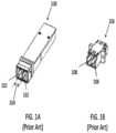
- FIG. 1 Ais a perspective view of a prior art standard 6.25 mm pitch LC connector SFP;
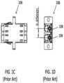
- FIG. 1 Bis a perspective view of a prior art standard 6.25 mm pitch LC adapter
- FIG. 1 Cis a top view of the prior art adapter of FIG. 1 B ;
- FIG. 1 Dis a front view of the prior art adapter of FIG. 1 B , showing the 6.25 mm pitch;
- FIG. 2 Ais a perspective view of a prior art LC duplex connector
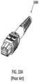
- FIG. 2 Bis a perspective view of a prior art LC duplex connector with a remote release pull tab
- FIG. 2 Cis a top view of a prior art LC connector used in the embodiments shown in FIGS. 2 A and 2 B ;
- FIG. 2 Dis a side view of the prior art LC connector of FIG. 2 C ;
- FIG. 3is a perspective view of a future narrow pitch LC SFP for receiving connectors disclosed herein according to aspects of the present disclosure
- FIG. 4 Ais a perspective view of one embodiment of a narrow pitch LC adapter according to aspects of the present disclosure
- FIG. 4 Bis a top view of the narrow pitch LC adapter of FIG. 4 A ;
- FIG. 4 Cis a front view of the narrow pitch LC adapter of FIG. 4 A , showing a 4.8 mm pitch;
- FIG. 5is a perspective view of one embodiment of a narrow pitch LC duplex connector with remote release according to aspects of the present disclosure
- FIG. 6 Ais a top view of an LC connector used in the embodiment of FIG. 5 according to aspects of the present disclosure
- FIG. 6 Bis a side view of the LC connector of FIG. 6 A according to aspects of the present disclosure
- FIG. 7is a perspective view of narrow pitch LC duplex connector of FIG. 5 , with the release mechanism being removed according to aspects of the present disclosure
- FIG. 8is a perspective disassembled view of the narrow pitch LC duplex connector of FIG. 5 according to aspects of the present disclosure
- FIG. 9is a perspective view of a prior art standard multiple-fiber push-on/pull-off (MPO) SFP;
- FIG. 10 Ais a perspective view of a prior art standard MPO connector
- FIG. 10 Bis a top view of the prior art MPO connector of FIG. 10 A , having a width of 12.4 mm;
- FIG. 10 Cis a front view of the prior art MPO connector of FIG. 10 A ;
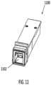
- FIG. 11is a perspective view of a future narrow width multi-fiber SFP for receiving connectors disclosed herein according to aspects of the present disclosure
- FIG. 12 Ais a perspective view of one embodiment of a narrow width multi-fiber connector with remote release according to aspects of the present disclosure
- FIG. 12 Bis a top view of the narrow width multi-fiber connector of FIG. 12 A , having a width of 9.6 mm according to aspects of the present disclosure
- FIG. 12 Cis a front view of the narrow width multi-fiber connector of FIG. 12 A according to aspects of the present disclosure
- FIG. 13 Ais a perspective view of a narrow width multi-fiber connector inserted into a narrow width SFP having an SFP latch according to aspects of the present disclosure
- FIG. 13 Bis a perspective view of a narrow width multi-fiber connector inserted into a narrow width adapter having an adapter latch according to aspects of the present disclosure
- FIG. 14is a side view of a narrow width multi-fiber connector of FIG. 13 A having a recess engaged with an SFP latch in a normal pull tab position according to aspects of the present disclosure.
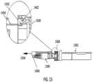
- FIG. 15is a side view of the narrow width multi-fiber connector of FIG. 13 A , being disengaged from the SFP latch by retracting the pull tab according to aspects of the present disclosure.
- FIG. 16 Ais a perspective view of a narrow width multi-fiber connector having an adapter latch according to aspects of the present disclosure
- FIG. 16 Bis a perspective disassembled view of a narrow width multi-fiber connector having an adapter latch according to aspects of the present disclosure
- FIG. 17 Ais a front view of the narrow pitch adapter of FIG. 16 A , showing a 3.80 mm pitch;
- FIG. 17 Bis a side view of the narrow width connector of FIG. 16 A ;
- FIG. 17 Cis a side view of a plug frame fitting inside a SFP according to aspects of the present disclosure.
- FIG. 17 Dis a perspective view of the narrow width connector of FIG. 16 A with the push/pull tab in a normal position in the SFP latching recess according to aspects of the present disclosure
- FIG. 17 Eis a perspective view of the narrow width connector of FIG. 16 A with the push/pull tab in a pulled back position with respect to the SFP latching recess according to aspects of the present disclosure
- FIG. 18 Ais a perspective view of a small form factor transceiver according to aspects of the present disclosure.
- FIG. 18 B and FIG. 18 Care respective side views of the transceiver of FIG. 18 A according to aspects of the present disclosure
- FIG. 19is a perspective view of a SFP having one connector inserted
- FIG. 20 A and FIG. 20 Bare side views of a SFP holding a connector according to aspects of the present disclosure
- FIG. 21is a perspective view of the SFP having one connector inserted and with the push/pull tab retracted according to aspects of the present disclosure
- FIG. 22 A and FIG. 22 Bare side views of the SFP latch in a lifted position to unlatch the connector according to aspects of the disclosure
- FIG. 23 Ais an exploded view of a connector according to aspects of the present disclosure.
- FIG. 23 Bis a perspective view of a connector according to aspects of the present disclosure.
- FIG. 24 Ais an top dimensional view of a connector according to aspects of the present disclosure.
- FIG. 24 Bis an side dimensional view of a connector according to aspects of the present disclosure.
- FIG. 25 Ais a perspective view of a connector with the push-pull tab in the forward position according to aspects of the present disclosure
- FIG. 25 Bis a perspective view of a connector with the push-pull tab in the rearward position according to aspects of the present disclosure
- FIG. 26 Ais a perspective view of a connector with the push-pull tab according to aspects of the present disclosure.
- FIG. 26 Bis a zoomed perspective view of a connector with the push-pull tab according to aspects of the present disclosure
- FIG. 26 Cis another perspective view of a connector with the push-pull tab to aspects of the present disclosure.
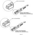
- FIG. 27 Ais a perspective view of a connector with the push-pull tab according to aspects of the present disclosure.
- FIG. 27 Bis a zoomed perspective view of a connector with the push-pull tab according to aspects of the present disclosure
- FIG. 27 Cis another perspective view of a connector with the push-pull tab to aspects of the present disclosure.
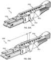
- FIG. 28 Aillustrates an example CS connector according to some embodiments with two separate cross-sectional areas identified
- FIG. 28 Bis a detailed cross section view of a CS connector at the first identified cross-sectional area of the CS connector identified in FIG. 28 A ;
- FIG. 28 Cis a detailed cross sectional view of a CS connector at the second identified cross-sectional area of the CS connector identified in FIG. 28 A ;
- FIG. 29is a perspective view of various connectors with the push-pull tabs of differing lengths according to aspects of the present disclosure.
- FIG. 30 Ais a detailed dimensional front view of a duplex adapter/transceiver according to aspects of the present disclosure
- FIG. 30 Bis a detailed dimensional cross sectional view of a duplex adapter/transceiver according to aspects of the present disclosure
- FIG. 30 Cis another detailed dimensional cross sectional view of a duplex adapter/transceiver according to aspects of the present disclosure.
- FIG. 31 Ais a perspective view of a duplex adapter/transceiver with removable anchors installed
- FIG. 31 Bis a perspective view of a removable anchor device
- FIG. 31 Cis another perspective view of a removable anchor device
- FIG. 32 Ais another a perspective view of a duplex adapter/transceiver with removable anchors installed
- FIG. 32 Bis another perspective view of a removable anchor device
- FIG. 32 Cis another perspective view of a removable anchor device
- FIG. 33 Ais another a perspective view of a duplex adapter/transceiver with removable anchors installed
- FIG. 33 Bis another perspective view of a removable anchor device
- FIG. 33 Cis another perspective view of a removable anchor device
- FIG. 34is a detailed dimensional cross sectional view of a duplex adapter/transceiver with a removable anchor installed according to aspects of the present disclosure
- FIG. 35 Ais another detailed dimensional cross sectional view of a duplex adapter/transceiver with a removable anchor installed according to aspects of the present disclosure
- FIG. 35 Bis a detailed dimensional cross sectional view of a duplex adapter/transceiver with a removable anchor installed according to aspects of the present disclosure
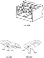
- FIG. 36 Ais a perspective view of a CS connecter being inserted into an adapter/transceiver
- FIG. 36 Bis a perspective view of a CS connecter after being inserted into an adapter/transceiver
- FIG. 37is side cutaway view of a CS connector being inserted into an adapter/transceiver
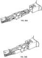
- FIG. 38is a perspective view of a CS connecter with a detailed view of a horizontal groove
- FIG. 39 Ais a side cutaway view of a CS connector inserted into an adapter/receiver
- FIG. 39 Bis another side cutaway view of a CS connector inserted into an adapter/receiver
- FIG. 40shows an illustrative top view of a CS connector inserted into an adapter/receiver and a side cutaway view of a CS connector inserted into an adapter/receiver;
- FIG. 41shows an illustrative top view of CS connector inserted into an adapter/receiver and a side cutaway view of a CS connector inserted into an adapter/receiver;
- FIG. 42shows a dimensional detailed view of the CS connector
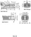
- FIG. 43shows another dimensional detailed view of the CS connector
- FIG. 44 Ashows a fan-out and cassette method for distributing the connection to a slower version of the system.
- FIG. 44 Bshows an alternative for distributing the connection to a slower version of the system without requiring a fan-out and/or a cassette method.
- a connectorrefers to a device and/or component thereof that connects a first module or cable to a second module or cable.
- the connectormay be configured for fiber optic transmission or electrical signal transmission.
- the connectormay be any suitable type now known or later developed, such as, for example, a ferrule connector (FC), a fiber distributed data interface (FDDI) connector, an LC connector, a mechanical transfer (MT) connector, a square connector (SC) connector, an SC duplex connector, or a straight tip (ST) connector.
- FCferrule connector
- FDDIfiber distributed data interface
- LCliquid crystal
- MTmechanical transfer
- SCsquare connector
- SC duplex connectoror a straight tip (ST) connector.
- STstraight tip
- the connectormay generally be defined by a connector housing body. In some embodiments, the housing body may incorporate any or all of the components described herein.
- a “fiber optic cable” or an “optical cable”refers to a cable containing one or more optical fibers for conducting optical signals in beams of light.
- the optical fiberscan be constructed from any suitable transparent material, including glass, fiberglass, and plastic.
- the cablecan include a jacket or sheathing material surrounding the optical fibers.
- the cablecan be connected to a connector on one end or on both ends of the cable.
- Various embodiments described hereingenerally provide a remote release mechanism such that a user can remove cable assembly connectors that are closely spaced together on a high-density panel without damaging surrounding connectors, accidentally disconnecting surrounding connectors, disrupting transmissions through surrounding connectors, and/or the like.
- Various embodimentsalso provide narrow pitch LC duplex connectors and narrow width multi-fiber connectors, for use, for example, with future narrow pitch LC SFPs and future narrow width SFPs.
- the remote release mechanismsallow use of the narrow pitch LC duplex connectors and narrow width multi-fiber connectors in dense arrays of narrow pitch LC SFPs and narrow width multi-fiber SFPs.
- FIG. 1 Ashows a perspective view of a prior art standard 6.25 mm pitch LC connector SFP 100 .
- the SFP 100is configured to receive a duplex connector and provides two receptacles 102 , each for receiving a respective LC connector.
- the pitch 104is defined as the axis-to-axis distance between the central longitudinal axes of each of the two receptacles 102 .
- FIG. 1 Bshows a perspective view of a prior art standard 6.25 mm pitch LC adapter 106 .
- the adapter 106is also configured to receive a duplex connector, and provides two receptacles 108 , each for receiving a respective LC connector.
- FIG. 1 Cis a top view of the adapter 106 of FIG. 1 B .
- the pitch of the adapter 106is defined similarly to that of the SFP 100 , as the axis-to-axis distance between the central longitudinal axes of each of the two receptacles 108 , as illustrated in FIG. 1 D , which shows a front view of the adapter 106 .
- FIG. 2 Ashows a prior art LC duplex connector 200 that may be used with the conventional SFP 100 and the conventional adapter 106 .
- the LC duplex connector 200includes two conventional LC connectors 202 .
- FIG. 2 Bshows another prior art LC duplex connector 204 having a remote release pull tab 206 , and including two conventional LC connectors 208 .
- the remote release pull tabincludes two prongs 210 , each configured to couple to the extending member 212 of a respective LC connector 208 .
- FIGS. 2 C and 2 Dshow top and side views, respectively, of the conventional LC connector 208 , having a width of 5.6 mm, and further showing the extending member 212 .
- Various embodiments disclosed hereinare configured for use with a future SFP, such as the narrow pitch LC SFP 300 shown in FIG. 3 , having a pitch less than that of conventional 6.25 mm and 5.25 mm pitches.
- Various embodimentsutilize LC type fiber optic connectors in duplex arrangements (having transmitted and receiving fibers) but with a connector axis-to-axis distance that is less than the conventional 6.25 mm and 5.25 mm pitches, as described further below.
- FIGS. 4 A to 4 Cshow one embodiment of a narrow pitch adapter 400 .
- the narrow pitch adapter 400has receptacles 402 on opposite ends thereof, configured for mating two narrow pitch LC duplex connectors according to aspects disclosed herein.
- FIG. 4 Bshows a top view of the adapter 400 .
- FIG. 4 Cshows a front view, further illustrating that the adapter 400 has a pitch of 4.8 mm.
- the adapter 400is configured to receive a duplex LC connector, with a pitch of the adapter corresponding to the axis-to-axis distance between the LC connectors of the LC duplex connector.
- the adapter 400has a pitch of 4.8 mm
- various embodiments of narrow pitch adapters disclosed hereinmay have a different pitch that is less than that of the pitch of conventional adapters, for example less than 6.25 mm and less than about 5.25 mm.
- the pitchmay be about 4.8 mm or less.
- the interference between metal edges and burrsmay prevent the fiber optic connector's plastic latch from either becoming fully engaged or easily disengaged, especially with latches that are remotely triggered by pull tabs that project a distance behind the connector so as to keep fingers from disturbing adjacent optical fibers.
- various embodiments disclosed hereinadd a spring force to the remote latching component (pull tab), for example as shown and described in relation to FIGS. 5 , 7 , 8 and 12 below, to ensure that the connector latches are allowed to return to the undisplaced position and thereby become fully engaged inside the SFP's recess.
- FIG. 5shows one embodiment of a narrow pitch connector 500 according to aspects disclosed herein.
- the narrow pitch connector 500is a duplex LC connector including two LC connectors 502 .
- Each of the LC connectors 502includes a respective ferrule 503 and a respective extending member or latching arm 504 .
- the connector 500has a pitch of 4.8 mm, defined as the axis-to-axis distance between the central axes of the LC connectors 502 .
- the connector pitchmay be less than that of the pitch of conventional connectors, for example less than 6.25 mm and less than about 5.25 mm. In some embodiments, the pitch may be about 4.8 mm or less.
- the connector 500further includes a housing 506 having a bottom housing 508 and a top housing 510 .
- the bottom housing 508includes side walls 512 .
- the housing 506 of the connector 500may be a switchable housing.
- the side walls 512may be configured to open so as to facilitate opening of the housing 506 , for example, to change polarity of the connector 500 .
- the side walls 512may be raised towards the rear of the connector 500 , as shown in FIG. 5 .
- One advantage of raising the side walls 512 towards the rear of the connector 500is easier access. In other embodiments, the side walls 512 may be raised at another location.
- the connector 500further includes a pull tab 514 having a distal end 516 and a proximal end 518 .
- the pull tab 514further includes a spring 520 configured to provide a force such that the connector latching arms 504 return to the undisplaced position and thereby become fully engaged inside the SFP's recess.
- the distal end 516 of the pull tab 514may be pulled to remotely release the connector 500 from an SFP or adapter.
- the proximal end 518 of the pull tab 514is uniquely shaped so as to engage with the unique profile of the latching arms 504 of the narrow pitch LC connector 500 .
- the proximal end 518engages both latching arms 504 of the duplex LC connector 500 .
- the proximal end 518includes a single prong configured to engage the latching arms of both connectors 502 .
- the pull tab 514At the proximal end 518 of the pull tab 514 there are outwardly pointing pins 522 configured to rest directly above and slide along the semi-circular surface of latching arms 504 of the duplex LC connectors 502 .
- the horizontal and rearward path direction of the pins 522causes the semi-circular profile of the connector latching arms 504 to flex downward.
- the pull tab 514can also be pushed down at a location directly behind the LC connectors 502 rather than pulling the tab in a rearward motion from a remote distance behind the connectors, such as from the distal end 516 .
- the action of pushing down the connectors' integral levers or latching arms 504unlatches the connector 500 .
- the horizontal motion of the pull tab 514may not be desirable.
- the connector latching arms 504may be pushed down without resulting in a horizontal motion of the pull tab 514 .
- FIGS. 6 A and 6 Bshow top and side views, respectively, of the LC connector 502 of the narrow pitch connector 500 .
- FIG. 6 Afurther shows that the LC connector 502 has a width of 4.6 mm.
- FIG. 6 Bshows the semi-circular profile of the latching arm 504 .
- FIG. 7shows a partially disassembled view of the narrow pitch connector 500 of FIG. 5 .
- the top housing 510is separated from the bottom housing 508 .
- the pull tab 514is coupled to the top housing 510 and configured to slide longitudinally along the length of the connector.
- the top housing 510also includes a restraint 524 configured to receive the pull tab 514 .
- FIG. 8shows a further disassembled view of the narrow pitch connector 500 .
- the pull tab 514is shown to be separated from the top housing 510 , and the spring 520 is removed from the pull tab.
- the pull tab 514includes a longitudinal recess 526 configured to receive the spring 520 , and at least one restraint 528 configured to retain the spring.
- the top housing 510also includes a recess 530 configured to accommodate at least a portion of the pull tab 514 , such as the spring 520 and the proximal end 518 .
- the pull tabmay be removably coupled to the connector via the top housing.
- FIG. 9shows a perspective view of a prior art standard MPO SFP 900 .
- the SFP 900is configured to receive a standard MPO connector and provides a receptacle 902 for receiving an MPO connector having a conventional width, as shown for example in FIGS. 10 A to 10 C .
- FIG. 10 Ashows a perspective view of a conventional MPO connector 1000 .
- the conventional MPO connector 1000has a width of 12.4 mm.
- FIG. 10 Cshows a front view of the MPO connector 1000 .
- FIG. 11shows an embodiment of a future narrow width multi-fiber SFP 1100 according to aspects of the present disclosure.
- Various embodiments disclosed hereinare configured for use with the narrow width multi-fiber SFP 1100 , having a width less than that of conventional MPO connectors, that is less than about 12.4 mm.
- the narrow width multi-fiber SFPhas a receptacle 1102 configured to receive a narrow width multi-fiber connector, such as a narrow width connector having an MT ferrule.
- FIG. 12 Ashows one embodiment of a narrow width connector 1200 according to aspects disclosed herein.
- the narrow width connector 1200is a multi-fiber connector including a multi-fiber MT/MPO ferrule 1202 .
- the connector 1200includes two extending members or latching arms 1204 . In other embodiments, the connector may include at least one latching arm.
- the connector 1200has a width of 9.6 mm, as shown in the top view of the connector 1200 in FIG. 12 B .
- the connector widthmay be less than that of the width of conventional multi-fiber connectors, for example less than the 12.4 mm of the conventional MPO connector shown in FIG. 10 B . In some embodiments, the width may be about 9.6 mm or less.
- the connector 1200further includes a housing 1206 having a bottom housing 1208 and a top housing 1210 .
- the bottom housing 1208includes side walls 1212 .
- the housing 1206 of the connector 1200may be a switchable housing.
- the side walls 1212may be configured to open so as to facilitate opening of the housing 1206 , for example, to change polarity of the connector 1200 .
- the side walls 1212may be raised towards the rear of the connector 1200 .
- One advantage of raising the side walls 1212 towards the rear of the connector 1200is easier access.
- the side walls 1212may also be raised at another location.
- the connector 1200further includes a pull tab 1214 having a distal end 1216 and a proximal end 1218 .
- the pull tab 1214further includes a spring 1220 configured to provide a force such that the connector latching arms 1204 return to the undisplaced position and thereby become fully engaged inside the SFP's recess.
- the distal end 1216 of the pull tab 1214may be pulled to remotely release the connector 1200 from an SFP or adapter.
- the proximal end 1218 of the pull tab 1214is uniquely shaped so as to engage with the unique profile of the latching arms 1204 of the narrow width multi-fiber connector 1200 .
- the proximal end 1218engages both latching arms 1204 of the multi-fiber connector 1200 .
- the proximal end 1218includes a single prong configured to engage the latching arms 1204 .
- the pull tab 1214there are outwardly pointing pins 1222 configured to rest directly above and slide along the semi-circular surface of latching arms 1204 .
- the horizontal and rearward path direction of the pins 1222causes the semi-circular profile of the connector latching arms 1204 to flex downward. Because the pins 1222 are not contained inside ramped grooves of the connector latching arms 1204 , the pull tab 1214 can also be pushed down at a location directly behind the latching arms 1204 rather than pulling the tab in a rearward motion from a remote distance behind the connector, such as from the distal end 1216 .
- the action of pushing down the connector's integral levers or latching arms 1204unlatches the connector 1200 .
- the horizontal motion of the pull tab 1214may not be desirable.
- the connector latching arms 1204may be pushed down without resulting in a horizontal motion of the pull tab 1214 .
- FIGS. 12 B and 12 Cshow top and front views, respectively, of the narrow width multi-fiber connector 1200 .
- FIG. 12 Bfurther shows that the connector 1200 has a width of 9.6 mm.
- the narrow width connectorshave latching arms configured to engage with a fixed or immovable recess within a narrow width SFP or a narrow width adapter.
- the pull tab of the connectordisplaces the flexible latching arm of the connector so as to disengage the latching arm from the recess of the SFP or the adapter.
- the latching armsbend down as the pull tab is pulled back, so as to disengage the connector from the SFP or the adapter.
- the remote latch release pull tabmay be configured to couple with a latch or a hook within the adapter or the SFP.
- the flexible latching arm of the connectoris moved into the main cavity of the SFP or the adapter, and the latch of the SFP or the adapter engages a recess of the connector when the pull tab is in a normal location that is pushed forward by a spring.
- the pull tabmay be configured to have a ramp area such that when the pull tab is pulled back, the latch of the SFP or the adapter is lifted by the retracted pull tab, thereby disengaging the latch of the SFP or the adapter from the connector.
- FIG. 13 Ashows a narrow pitch multi-fiber connector 1300 inserted into a narrow pitch SFP 1302 such that a recess of the connector engages an SFP latch.
- FIG. 13 Bshows the narrow pitch connector 1300 inserted into a narrow pitch adapter 1304 such that a recess of the connector engages a latch of the adapter.
- FIG. 14shows a side view of the narrow width connector 1300 of FIG. 13 A coupled to the narrow width SFP 1302 . Details of the coupling are shown within the circle 1400 .
- the SFP 1302includes an SFP latch 1402 .
- the connector 1300includes a recess 1404 .
- the connector housingmay comprise a recess 1404 .
- the pull tab 1406may be spring-loaded as described in relation to various embodiments. This allows the pull tab 1406 to return to a position that will allow the SFP latch 1402 to engage with the connector recess 1404 .
- the pull tab 1406is in the normal pull tab location, that is pushed forward by a spring, as shown in FIG. 14 , the SFP latch 1402 is engaged with the connector recess 1404 .
- FIG. 15shows a side view of the narrow width connector 1300 of FIG. 13 A as it is disengaged from the narrow width SFP 1302 . Details of the decoupling are shown within the circle 1500 .
- the pull tab 1406includes a taper or a ramp area 1502 . As the pull tab 1406 is pulled back in the direction of the arrow 1504 as shown, the SFP latch 1402 is lifted by the ramp area 1502 of the retracted pull tab, thereby disengaging the SFP latch 1402 from the connector as illustrated within the circle 1500 .
- the same effect described herein in conjunction with FIG. 15also occurs in other embodiments of connectors coupled to a narrow width adapter as shown, for example, in FIG. 13 A .
- FIGS. 14 and 15illustrate coupling of the connector to a narrow width SFP
- the connectormay be coupled to a narrow width adapter having an adapter latch, similar to that of the SFP latch.
- FIGS. 13 A, 13 B, 14 , and 15include a narrow width multi-fiber connector, other embodiments may include narrow pitch LC connectors.
- FIGS. 16 A- 22are various views and details that show a narrow pitch multi-fiber connector, a SFP and the latching mechanisms associated therewith according to various aspects of the invention.
- a CS connectormay be a miniature single-position plug generally characterized by dual cylindrical, spring-loaded butting ferrule(s) of approximately 1.25 mm in diameter, and a push-pull coupling mechanism.
- the optical alignment mechanism of the connectorsis of a rigid hole or a resilient sleeve style.
- the CS connectormay comprise a front body (i.e., plug frame) 2301 , which houses the ferrule(s) and ferrules flange(s) 2302 .
- a rear body (i.e., back post) 2304may connect to the rear of the front body 2301 and contain the ferrule-flange(s) 2302 .
- the ferrule-flange(s) 2302may be held in place using one or more springs 2303 .
- the rear body 2304may include a crimp ring 2305 attached to the rear of the rear body.
- a cable boot 2306may surround the crimp ring 2305 .
- a dust cap 2307may be placed over the front body 2301 in order to protect the ferrules housed in the front body from damage and/or debris.
- a push-pull tab 2310may attach to the CS connector, as discussed in more detail herein.
- the push-pull tab 2310may have a side portion 2312 and a center protrusion (i.e., 2313 ), which serve various functions discussed further herein.
- the push-pull tab 2310may utilize a tab spring 2308 to apply a constant directional force on the push-pull tab to allow for various benefits which are discussed herein.
- FIG. 23 Bone embodiment of an assembled CS connector with a push-pull tab is shown.
- the push-pull tab 2310has a front portion 2314 which resides in a recess 2317 within the front body 2301 . Thus, when the push-pull tab 2310 traverses the connector, as discussed in detail herein, the front portion 2314 moves independently of the front body 2301 .
- a CS connectormay have an overall dimensional width of 7.95 millimeters. Additionally, in further embodiments, the CS connector may have a pitch of 3.8 mm. As discussed herein, the pitch is defined as the axis-to-axis distance between the central axes of the CS connectors 2450 . Moreover, as shown in FIG. 24 B , an embodiment may have an overall dimensional height of 10.46 mm when the push-pull tab 2410 is attached to the front body 2401 and the rear body 2404 .
- a connectore.g., a CS connector
- a connectormay have a push-pull tab to allow for easy insertion and extraction from an adapter.
- the push-pull tab 2510may slide forward and rearward in a lengthwise manner in relation to the connector as indicated by the dashed double-sided arrow 2511 .
- FIG. 25 Ashows an embodiment in which the side portion 2512 of the push-pull tab 2510 contacts the rear body 2504 . This contact between the side portion 2512 and the rear body 2504 stops the forward movement of the push-pull tab 2510 .
- the push-pull tab 2510may be moved away from the rear body by a distance 2513 of about 1 mm to about 3 mm.
- the push-pull tab 2510may have a center protrusion (such as 2314 in FIG. 23 A ) which makes contact with the rear body 2504 . This contact between the center protrusion 2514 and the rear body 2504 may stop the rearward movement of the push-pull tab 2510 .
- the push-pull tabhas a front portion 2614 .
- the front portion 2614may comprise a tip 2630 .
- the tip 2630may comprise a slit or groove (not shown) which may slide over a portion of the front body 2601 in order to securely fasten the front portion 2614 to the front body 2601 .
- the slit or groovemay, in some embodiments, be large enough to accommodate the movement of the push-pull tab as discussed herein. Stated differently, when the push-pull tab is pulled away from the front body (see FIG.
- the push-pull tabmay slide along the front body (i.e., FIG. 26 C ), thus the slit or groove must be large enough to allow for the movement of the push-pull tab while also ensuring a secure attachment in the non-retracted state (i.e., FIG. 26 B ).
- an embodimentmay comprise a spring 2708 (i.e., FIG. 23 A, 2308 ).
- the spring 2708applies a biasing force to the push-pull tab 2710 in the forward direction such that the groove of the front body 2701 and the groove of the push-pull tab 2710 align as discussed herein, and shown in FIG. 42 .
- the hidden linesshow the spring 2708 within the push-pull tab 2710 .
- the push-pull tab 2710may comprise a wedge portion 2731 .
- the wedge portion 2731is configured such that it can snap into the front body 2701 and slide/traverse the recess (see FIG. 23 A at 2317 ) when the push-pull tab is moved along the housing (i.e., front body and rear body).
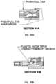
- FIGS. 28 A /B/Ca CS connector is shown including cross-sections of various embodiments.
- FIG. 28 Aillustrates an example CS connector according to some embodiments with two separate cross-sectional areas identified.
- the first cross-sectional areai.e., X-X
- FIG. 28 Bshows how the wedge portion 2831 snaps into, or connects, with the front body 2801 . It should be understood, that this material strength of the wedge portion 2831 ensures a secure connection to the front body 2801 while also allowing for the push-pull tab 2810 to move along the length of the front body 2801 as discussed in further detail herein.
- some embodimentsmay also have a further securing connection device comprising one or more clips 2832 which are formed as part of the push-pull tab.
- the one or more clips 2832connect to and snap into the front body 2801 and positioned adjacent to the rear body 2804 which is inserted into the front body. It should be understood that these are non-limiting examples, and that various connection means may be used to secure the push-pull tab 2810 to the housing.
- the wedge portion 2831 and the one or more clips 2832may be located at various other locations on the push-pull tab 2810 , as well as different location on the front body 2801 and the rear body 2804 .
- the connectorsmay be inserted into an adapter (e.g., a fiber optic port), such as for example in a fiber array or server.
- an adaptere.g., a fiber optic port
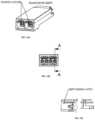
- FIG. 30 AA non-limiting illustrative example of a typical adapter is shown in FIG. 30 A .
- FIG. 30 Aillustrates a dual adapter for accepting two connectors (e.g., a dual ferrule CS connector). It should be understood, that the various dimensions provided herein are only for illustrative purposes, and that various other dimensions may be possible in various implementations.
- FIGS. 30 B and 30 Cshow specific cross-sectional cuts of the adapter shown in FIG. 30 A .
- the various dimensions of FIGS. 30 A, 30 B, and 30 Care listed below in Table 1.
- the receiver/transceivermay allow for the insertion of an anchor device.
- FIG. 29shows the push-pull tab 2910 being constructed with varying lengths.
- FIGS. 30 A, 30 B, and 30 Cillustrate an adapter capable of receiving various modifications.
- a removable adaptor modificatione.g., the hook system of FIGS. 31 B and 31 C
- the removable modification devicesuch as that shown in FIGS. 31 B and 31 C , may comprise a hook tip 3121 and a hook ramp 3122 , or a plurality of either (e.g., as shown, the modification device comprises two hook tips).
- the removable modification devicei.e., interchangeable anchor device
- FIGS. 32 A, 32 B and 32 Cprovide an illustrative non-limiting example of a potential design for the interchangeable anchor device.
- a removable adaptor modificatione.g., the hook system of FIGS. 32 B and 32 C
- the removable modification devicemay comprise a hook tip 3221 and a hook ramp 3222 , or a plurality of either (e.g., as shown, the modification device comprises two hook tips).
- a removable adaptor modification(e.g., the hook system of FIGS. 33 B and 33 C ) may be inserted into the adaptor shown in FIG. 33 A .
- the removable modification devicesuch as that shown in FIGS. 33 B and 33 C , may comprise a hook tip 3321 and a hook ramp 3322 , or a plurality of either (e.g., as shown, the modification device comprises two hook tips).
- FIG. 34illustrates a dual adapter for accepting two connectors (e.g., a dual ferrule CS connector) similar to that shown in FIG. 30 A , however, FIG. 34 includes two removable modification devices 3420 .
- FIGS. 35 A and 35 Bshow specific cross-sectional cuts of the adapter shown in FIG. 34 , and thus, the identified dimensions of FIGS. 34 , 35 A and 35 B are also listed in Table 1.
- FIGS. 36 A and 36 Billustrative examples of a CS connector being inserted into an adapter are shown.
- the adapter shown in the illustrative embodimentcomprises the modification device which engages with portions of the CS connector as discussed below in detail.
- FIG. 37shows a CS connector being inserted into an adapter.
- the modification device 3720impacts and interacts with the CS connector as the connector is inserted into the adapter housing.
- the front of the CS connectorcontacts hook ramp ( FIG. 35 C at 3522 , FIGS. 32 B and 32 C at 3222 , and FIGS. 33 B and 33 C at 3322 ) which lifts the portion of the modification device that is interacting with the CS connector.
- the movement of the modification deviceis shown in zoomed-in detail views 3731 and 3732 .
- the hidden (e.g., dashed) linerepresents the profile hook ramp 3122 , 3222 , and 3322
- the solid linesrepresent the profile of the hook tips 3121 , 3221 , and 3321 .
- the hooks 3121 , 3221 , and 3321rise above the surface of the connector allowing for insertion of the connector into the adapter.
- the hook tips 3121 , 3221 , and 3321interlock with a recess 3709 on the connector. This interlocking action secures the connector within the adapter housing by tab during push-in action.
- the front portion 3814 of the push-pull tab 3810moves independently of the front body 3801 , as discussed herein. Accordingly, the front portion 3814 of the push-pull tab 3810 , which is shown in detail, may align with the recesses 3816 of the front body 3801 . In this configuration, the hook tips 3121 , 3221 , and 3321 are able to securely fasten the connector to the adapter. However, depending on the embodiment, the push-pull tab 3810 may be moved in the forward or rearward direction (see FIGS. 31 , 32 , and 33 ) thus taking the recesses 3816 out of alignment with the push pull tab recess.
- the front portion 3814 of the push-pull tab 3810When the front portion 3814 of the push-pull tab 3810 is moved out of alignment, it interacts with the hook ramp 3122 , 3222 , and 3322 via the ramp 3815 . Accordingly, in some embodiments, moving the push-pull tab 3810 independently of the front body 3801 may allow the ramp area 3815 to apply a force to the hook ramp 3122 , 3222 , and 3322 , thereby raising the hook tips 3121 , 3221 , and 3321 . Once the hook tips 3121 , 3221 , and 3321 are raised, the connector can be safely removed from the adapter and/or transceiver.
- FIGS. 39 - 41show further detail and cross-sectional illustrations of a connector interacting with an adapter and/or transceiver. Additionally, FIGS. 42 and 43 show further detail and possible dimensions of an embodiment, see Table 2.
- a 200 G transceiver module 4401may receive an MPO connector 4402 .
- the MPO connectermay then be split out using an additional tool, such as a fan out 4403 or a cassette 4406 .
- the cablecan be connected to a 100 G module device (e.g., a LC uniboot as shown) 4404 .
- the 100 G module device 4404may then be inserted into a 100 G transceiver 4405 .
- a plurality of CS connectors 4406are inserted into a 200 G transceiver module 4401 .
- Each CS connector 4406may then independently connect to the 100 as shown in FIG. 44 A , a 200 G transceiver module 4401 may receive an MPO connector 4402 .
- the MPO connectermay then be split out using an additional tool, such as a fan out 4403 or a cassette 4406 .
- Once the cable is split out, itcan be connected to a 100 G module device (e.g., a LC uniboot as shown) 4404 .
- the 100 G module device 4404may then be inserted into a 100 G transceiver module 4405 .
- FIG. 14A specific example using multi-strand cables is shown in FIG. 14 for explanatory purposes only, and it should be understood that near endless alternatives and modifications are possible.
- a switche.g., 100 G switch
- a transceivere.g., 100 G transceiver
- the transceiver 1431has an adapter to receive two mini CS duplex connectors 1432 . From each of the two duplex connectors 1432 , a four fiber cable 1433 extends to connect to various other connectors and transceivers.
- one four fiber cable 1433is split in to two fiber cables 1434 , which are then attached to a single CS simplex connector 1435 and placed into a transceiver (e.g., 25 G transceiver) 1436 .
- a transceivere.g. 25 G transceiver
- one of the four fiber cables 1437is connected to a single mini CS duplex connector 1438 , which is then inserted into another transceiver (e.g., 50 G transceiver) 1439 .
- compositions, methods, and devicesare described in terms of “comprising” various components or steps (interpreted as meaning “including, but not limited to”), the compositions, methods, and devices can also “consist essentially of” or “consist of” the various components and steps, and such terminology should be interpreted as defining essentially closed-member groups. It will be further understood by those within the art that if a specific number of an introduced claim recitation is intended, such an intent will be explicitly recited in the claim, and in the absence of such recitation no such intent is present. For example, as an aid to understanding, the following appended claims may contain usage of the introductory phrases “at least one” and “one or more” to introduce claim recitations.
- a rangeincludes each individual member.
- a group having 1-3 cellsrefers to groups having 1, 2, or 3 cells.
- a group having 1-5 cellsrefers to groups having 1, 2, 3, 4, or 5 cells, and so forth.
Landscapes
- Physics & Mathematics (AREA)
- General Physics & Mathematics (AREA)
- Optics & Photonics (AREA)
- Mechanical Coupling Of Light Guides (AREA)
- Details Of Connecting Devices For Male And Female Coupling (AREA)
- Optical Couplings Of Light Guides (AREA)
- Coupling Device And Connection With Printed Circuit (AREA)
Abstract
Description
| TABLE 1 | |||
| Dimensions (mm) | |||
| Reference | Minimum | Maximum | ||
| F1 | 6.5 | 6.7 | |
| F2 | 6.5 | 6.7 |
| G1 | 3.8 | ||
| G2 | 3.8 | ||
| GA1 | 1.90 | ||
| GA2 | 1.90 |
| H1a, b | 2.87 | 2.97 | |
| H2a, b | 2.87 | 2.97 | |
| I1 | 3.7 | 3.8 | |
| I2 | 3.7 | 3.8 | |
| J1 | 5.75 | 5.85 | |
| J2 | 5.75 | 5.85 | |
| K | 6.79 | 6.89 | |
| L | 1.03 | 1.13 |
| M | 1.90 |
| N | 0.05 | — | |
| P | — | 0.8 | |
| Q | — | 1.7 | |
| Ra | — | 1.25 | |
| S | 0.55 | 0.75 | |
| T | 4.0 | 4.1 |
| U | 0.3 |
| V | 1.4 | 1.5 | |
| W | 2.7 | ||
| Y | 0.4 | 0.5 | |
| Z | 3.7 | 3.8 | |
| AA | 1.44 | 1.54 | |
| AB | 4.35 | 4.55 |
| AC1 | 0.5 | ||
| AC2 | 0.5 |
| AD | 2.55 | 2.65 | |
| AF | 9.24 | 9.38 | |
| AG | 14.55 | 14.65 | |
| AI1 | 3.0 | 3.2 | |
| AI2 | 3.0 | 3.2 | |
| AJ | 7.9 | 8.1 | |
| AK1 | 1.43 | 1.53 | |
| AK2 | 1.43 | 1.53 |
| AL | 90 | ||
| AM | 2.24 |
| AN | 2.65 | 2.75 | |
| 0 | 0.2 | ||
| AP | 2.1 | 2.3 |
| AQ1 | 4.0 | ||
| AQ2 | 4.0 | ||
| AR | 15.38 | ||
| AS | 0.5 |
| BA | 8.22 | 8.62 | |
| BB | 0.2 | 0.4 | |
| BC | 1.1 | 1.3 |
| BD | (0.75) |
| BE | 3.5 | 3.7 |
| BF | (1.2) |
| BG | 0.8 | 1.0 | |
| P′ | 0.75 | — | |
| Q′ | — | 1.15 | |
| AD′ | — | 2.3 | |
| CA | 7.29 | 7.39 | |
| CB | 1.65 | 1.75 | |
| CC | 0.3 | — | |
| CD | 2.3 | — |
| CE | (2.2) | ||
| CF | (2.95) |
| CG | 2.6 | 2.8 | ||
| CH | 2.45 | 2.55 | ||
| CI | 1.95 | 2.05 | ||
| F′ | 6.25 | 6.35 | ||
| CJ | 1.75 | 1.85 | ||
| CK | 5.35 | 5.45 | ||
| CL | 0.67 | 0.77 | ||
| CM | 1.95 | 2.05 | ||
| TABLE 2 | |||
| Dimensions (mm) | |||
| Reference | Minimum | Maximum | ||
| BA′a | 8.7 | 8.9 | |
| DA | 8.28 | 8.48 | |
| DB | 7.45 | 7.6 | |
| DC | 5.2 | 5.4 | |
| DD | 5.5 | 5.7 | |
| DE | 5.5 | 5.7 | |
| AG′ | 13.75 | 14.05 | |
| AM′ | 2.08 | 2.18 | |
| AN′ | 2.08 | 2.18 | |
| AC′1b | — | 0.5 | |
| AC′2b | — | 0.5 | |
| Z′b | 3.32 | 3.72 | |
| AR′c | 6.88 | 7.28 | |
| DFc | — | 0.5 |
| G′ | 3.8 |
| DG | 6.86 | 7.06 | |
| J′ | 5.5 | 5.7 | |
| DI | 7.75 | 7.95 |
| DJ | (0.81) | ||
| DK | (3.57) | ||
| DL | (1.3) |
| DMd | 1.45 | — |
| DN | (6.24) |
| AA′ | 1.4 | 1.6 | |
| AB′ | 9.33 | 9.53 |
| DO | (2.92) | ||
| DP | (3.22) |
| DQa | 5.14 | 5.26 | |
| T′ | 3.3 | 3.4 | |
| H′ | 3.0 | 3.2 |
| AF′1 | (2.80) | ||
| AF′2 | (2.80) |
| AK′ | 1.78 | 1.94 | ||
| DR | — | 0.5 | ||
| DS | 1.60 | 1.72 | ||
Claims (25)
Priority Applications (1)
| Application Number | Priority Date | Filing Date | Title |
|---|---|---|---|
| US18/212,721US12158623B2 (en) | 2016-12-05 | 2023-06-22 | Optical fiber connector |
Applications Claiming Priority (10)
| Application Number | Priority Date | Filing Date | Title |
|---|---|---|---|
| US201662430067P | 2016-12-05 | 2016-12-05 | |
| US201662430560P | 2016-12-06 | 2016-12-06 | |
| US201762452147P | 2017-01-30 | 2017-01-30 | |
| US201762457150P | 2017-02-09 | 2017-02-09 | |
| US201762546920P | 2017-08-17 | 2017-08-17 | |
| US15/720,980US10228521B2 (en) | 2016-12-05 | 2017-09-29 | Narrow width adapters and connectors with modular latching arm |
| US16/297,614US10739533B2 (en) | 2016-12-05 | 2019-03-09 | Receiver configured to accept a removable anchor device for securing a fiber optic connector within the receiver |
| US16/988,581US11287583B2 (en) | 2016-12-05 | 2020-08-07 | Narrow width fiber optic connector |
| US17/581,949US11703648B2 (en) | 2016-12-05 | 2022-01-23 | Adapter |
| US18/212,721US12158623B2 (en) | 2016-12-05 | 2023-06-22 | Optical fiber connector |
Related Parent Applications (1)
| Application Number | Title | Priority Date | Filing Date |
|---|---|---|---|
| US17/581,949ContinuationUS11703648B2 (en) | 2016-12-05 | 2022-01-23 | Adapter |
Publications (2)
| Publication Number | Publication Date |
|---|---|
| US20230333330A1 US20230333330A1 (en) | 2023-10-19 |
| US12158623B2true US12158623B2 (en) | 2024-12-03 |
Family
ID=62242966
Family Applications (7)
| Application Number | Title | Priority Date | Filing Date |
|---|---|---|---|
| US15/720,980ActiveUS10228521B2 (en) | 2016-12-05 | 2017-09-29 | Narrow width adapters and connectors with modular latching arm |
| US16/257,672ActiveUS10539748B2 (en) | 2016-12-05 | 2019-01-25 | Network system of narrow width connectors and receiver devices |
| US16/257,619ActiveUS10520689B2 (en) | 2016-12-05 | 2019-01-25 | Receiver device for accepting narrow width connectors |
| US16/297,614ActiveUS10739533B2 (en) | 2016-12-05 | 2019-03-09 | Receiver configured to accept a removable anchor device for securing a fiber optic connector within the receiver |
| US16/988,581ActiveUS11287583B2 (en) | 2016-12-05 | 2020-08-07 | Narrow width fiber optic connector |
| US17/581,949ActiveUS11703648B2 (en) | 2016-12-05 | 2022-01-23 | Adapter |
| US18/212,721ActiveUS12158623B2 (en) | 2016-12-05 | 2023-06-22 | Optical fiber connector |
Family Applications Before (6)
| Application Number | Title | Priority Date | Filing Date |
|---|---|---|---|
| US15/720,980ActiveUS10228521B2 (en) | 2016-12-05 | 2017-09-29 | Narrow width adapters and connectors with modular latching arm |
| US16/257,672ActiveUS10539748B2 (en) | 2016-12-05 | 2019-01-25 | Network system of narrow width connectors and receiver devices |
| US16/257,619ActiveUS10520689B2 (en) | 2016-12-05 | 2019-01-25 | Receiver device for accepting narrow width connectors |
| US16/297,614ActiveUS10739533B2 (en) | 2016-12-05 | 2019-03-09 | Receiver configured to accept a removable anchor device for securing a fiber optic connector within the receiver |
| US16/988,581ActiveUS11287583B2 (en) | 2016-12-05 | 2020-08-07 | Narrow width fiber optic connector |
| US17/581,949ActiveUS11703648B2 (en) | 2016-12-05 | 2022-01-23 | Adapter |
Country Status (10)
| Country | Link |
|---|---|
| US (7) | US10228521B2 (en) |
| EP (1) | EP3548944B1 (en) |
| JP (3) | JP7234111B2 (en) |
| KR (5) | KR102239204B1 (en) |
| CN (3) | CN111596417B (en) |
| AU (3) | AU2017378041B2 (en) |
| BR (1) | BR112019011432A2 (en) |
| CA (1) | CA3049566A1 (en) |
| MX (3) | MX2019006491A (en) |
| WO (1) | WO2018111617A2 (en) |
Families Citing this family (51)
| Publication number | Priority date | Publication date | Assignee | Title |
|---|---|---|---|---|
| US9726830B1 (en) | 2016-06-28 | 2017-08-08 | Senko Advanced Components, Inc. | Connector and adapter system for two-fiber mechanical transfer type ferrule |
| US10078188B1 (en)* | 2016-12-05 | 2018-09-18 | Senko Advanced Components, Inc. | Springless push/pull fiber optic connector |
| CN110031939B (en)* | 2016-12-05 | 2020-06-09 | 扇港元器件股份有限公司 | Narrow Width Adapters and Connectors with Modular Latch Arms |
| US10228521B2 (en) | 2016-12-05 | 2019-03-12 | Senko Advanced Components, Inc. | Narrow width adapters and connectors with modular latching arm |
| US10725248B2 (en) | 2017-01-30 | 2020-07-28 | Senko Advanced Components, Inc. | Fiber optic receptacle with integrated device therein incorporating a behind-the-wall fiber optic receptacle |
| US10871619B2 (en)* | 2017-01-30 | 2020-12-22 | Senko Advanced Components, Inc. | Cassette assembly for a plural of fiber optic receptacles |
| US10185100B2 (en)* | 2017-01-30 | 2019-01-22 | Senko Advanced Components, Inc | Modular connector and adapter assembly using a removable anchor device |
| US10444444B2 (en) | 2017-01-30 | 2019-10-15 | Senko Advanced Components, Inc. | Remote release tab connector assembly |
| CN110249248B (en)* | 2017-01-30 | 2021-07-27 | 扇港元器件股份有限公司 | Optical connectors with reversible polarity |
| US11822133B2 (en) | 2017-07-14 | 2023-11-21 | Senko Advanced Components, Inc. | Ultra-small form factor optical connector and adapter |
| US12001064B2 (en) | 2017-07-14 | 2024-06-04 | Senko Advanced Components, Inc. | Small form factor fiber optic connector with multi-purpose boot |
| US10718911B2 (en) | 2017-08-24 | 2020-07-21 | Senko Advanced Components, Inc. | Ultra-small form factor optical connectors using a push-pull boot receptacle release |
| US10281669B2 (en) | 2017-07-14 | 2019-05-07 | Senko Advance Components, Inc. | Ultra-small form factor optical connectors |
| US11002923B2 (en) | 2017-11-21 | 2021-05-11 | Senko Advanced Components, Inc. | Fiber optic connector with cable boot release having a two-piece clip assembly |
| US10623838B1 (en) | 2017-11-30 | 2020-04-14 | Amazon Technologies, Inc. | Optical transceivers with independently releasable fiber connectors |
| US11016250B2 (en)* | 2017-12-19 | 2021-05-25 | Us Conec, Ltd. | Mini duplex connector with push-pull polarity mechanism, carrier, and rail-receiving crimp body |
| WO2019183070A2 (en) | 2018-03-19 | 2019-09-26 | Senko Advanced Components, Inc. | Removal tool for removing a plural of micro optical connectors from an adapter interface |
| EP3776038B1 (en) | 2018-03-28 | 2024-07-03 | Senko Advanced Components Inc. | Small form factor fiber optic connector with multi-purpose boot |
| USD879039S1 (en)* | 2018-06-07 | 2020-03-24 | Advanced-Connectek Inc. | Optical fiber connector |
| CN112088327A (en) | 2018-07-15 | 2020-12-15 | 扇港元器件股份有限公司 | Subminiature Optical Connectors and Adapters |
| US20200225426A1 (en)* | 2018-08-03 | 2020-07-16 | Ppc Broadband, Inc. | Fiber Optical Connectors |
| US10444441B1 (en)* | 2018-08-10 | 2019-10-15 | Senko Advanced Components, Inc. | Pivotable housing for a fiber optic connector |
| US11073664B2 (en) | 2018-08-13 | 2021-07-27 | Senko Advanced Components, Inc. | Cable boot assembly for releasing fiber optic connector from a receptacle |
| WO2020055440A1 (en) | 2018-09-12 | 2020-03-19 | Senko Advanced Componetns, Inc. | Lc type connector with clip-on push/pull tab for releasing connector from a receptacle using a cable boot |
| WO2020086184A1 (en)* | 2018-09-12 | 2020-04-30 | Senko Advanced Components, Inc | Lc type connector with push/pull assembly for releasing connector from a receptacle using a cable boot |
| US10921531B2 (en) | 2018-09-12 | 2021-02-16 | Senko Advanced Components, Inc. | LC type connector with push/pull assembly for releasing connector from a receptacle using a cable boot |
| US10921530B2 (en) | 2018-09-12 | 2021-02-16 | Senko Advanced Components, Inc. | LC type connector with push/pull assembly for releasing connector from a receptacle using a cable boot |
| US11806831B2 (en) | 2018-11-21 | 2023-11-07 | Senko Advanced Components, Inc. | Fixture and method for polishing fiber optic connector ferrules |
| US11175464B2 (en) | 2018-11-25 | 2021-11-16 | Senko Advanced Components, Inc. | Open ended spring body for use in an optical fiber connector |
| CN113383256B (en) | 2019-01-30 | 2023-02-03 | 美国康涅克有限公司 | Small form factor connector and adapter |
| US11181696B2 (en)* | 2019-02-22 | 2021-11-23 | Senko Advanced Components, Inc. | Adapter assembly having a return spring with a push-pull tab |
| US10996404B2 (en) | 2019-02-25 | 2021-05-04 | Sanwa Electronics USA Corporation | Reversible optical connectors and associated devices, systems, and methods |
| US12038613B2 (en) | 2019-03-28 | 2024-07-16 | Senko Advanced Components, Inc. | Behind-the-wall optical connector and assembly of the same |
| US11579379B2 (en) | 2019-03-28 | 2023-02-14 | Senko Advanced Components, Inc. | Fiber optic adapter assembly |
| US11340406B2 (en) | 2019-04-19 | 2022-05-24 | Senko Advanced Components, Inc. | Small form factor fiber optic connector with resilient latching mechanism for securing within a hook-less receptacle |
| TWI730349B (en)* | 2019-04-24 | 2021-06-11 | 立佳興業股份有限公司 | Optical fiber adapter |
| US11435534B2 (en)* | 2019-06-11 | 2022-09-06 | Clearfield, Inc. | Flexible optical fiber connectors and assemblies |
| WO2020252355A1 (en)* | 2019-06-13 | 2020-12-17 | Senko Advanced Components, Inc | Lever actuated latch arm for releasing a fiber optic connector from a receptacle port and method of use |
| WO2020263678A1 (en)* | 2019-06-25 | 2020-12-30 | The Siemon Compnay | Latch for telecommunications module |
| CN114600018B (en) | 2019-07-23 | 2024-04-09 | 扇港元器件有限公司 | Ultra-small receptacle for receiving a fiber optic connector opposite a ferrule assembly |
| US10809480B1 (en)* | 2019-09-30 | 2020-10-20 | Corning Research & Development Corporation | Dense wavelength division multiplexing fiber optic apparatuses and related equipment |
| US11525963B2 (en)* | 2020-03-03 | 2022-12-13 | Senko Advanced Components, Inc. | Optical connection system, optical connector, and optical adapter for use with optical cable assembly and receptacle |
| JP6812037B1 (en)* | 2020-03-05 | 2021-01-13 | 株式会社精工技研 | Jig for connector plug, connector plug, cable with connector plug |
| US11934017B2 (en) | 2021-03-02 | 2024-03-19 | Corning Research & Development Corporation | Polarity changeable optical connector |
| US12078854B2 (en)* | 2021-04-23 | 2024-09-03 | US Conec, Ltd | Optical assembly |
| IL283017B2 (en)* | 2021-05-06 | 2023-11-01 | Fibernet Ltd | Fiber optic connector |
| WO2022241113A1 (en)* | 2021-05-14 | 2022-11-17 | Senko Advanced Components, Inc. | Optical fiber connector with improved cable retention strength |
| US11543601B1 (en)* | 2021-07-22 | 2023-01-03 | Suncall Technologies (Sz) Co., Ltd | MPO connector with high-density release clip and connector release tool |
| EP4409343A1 (en)* | 2021-09-30 | 2024-08-07 | Senko Advanced Components Inc. | Fiber optic network systems |
| US11740413B1 (en)* | 2022-03-02 | 2023-08-29 | Suncall America Inc. | Duplex optical connector with laterally repositionable connectors and pull boot release |
| US11835774B2 (en)* | 2022-04-20 | 2023-12-05 | Amphenol Corporation | Fiber optic connector plug and associated cable systems, cable assemblies, and method |
Citations (327)
| Publication number | Priority date | Publication date | Assignee | Title |
|---|---|---|---|---|
| US3733576A (en) | 1971-07-28 | 1973-05-15 | J Cooper | Reversible safety ground plug |
| US4150790A (en) | 1975-06-20 | 1979-04-24 | Edward Potter | Reinforced molded lignocellulosic crosstie and railway assembly |
| US4327964A (en) | 1979-12-20 | 1982-05-04 | Texas Instruments Incorporated | Snap-action fiber optic connector |
| GB2111240A (en) | 1981-12-10 | 1983-06-29 | Allied Corp | Connector for an optical fiber |
| US4478473A (en) | 1982-09-30 | 1984-10-23 | The Bendix Corporation | Coupling nut for an electrical connector |
| US4645295A (en) | 1980-02-04 | 1987-02-24 | Allied Corporation | Fiber optic connector |
| US4762388A (en) | 1984-03-19 | 1988-08-09 | E. I. Du Pont De Nemours And Company | Optical connector receptacle and plug |
| US4764129A (en) | 1984-09-27 | 1988-08-16 | British Telecommunications Plc | Electrical connector assemblies |
| US4840451A (en) | 1987-12-08 | 1989-06-20 | Molex Incorporated | Shielded fiber optic connector assembly |
| US4872736A (en) | 1988-04-19 | 1989-10-10 | American Telephone And Telegraph Company, At&T Bell Laboratories | Connector assembly having a latching mechanism |
| US4979792A (en) | 1989-08-21 | 1990-12-25 | Amp Incorporated | Means for keeping keying elements with a connector assembly |
| US5041025A (en) | 1990-01-31 | 1991-08-20 | Thomas & Betts Corporation | Interconnectable components employing a multi-positionable key |
| USD323143S (en) | 1989-06-09 | 1992-01-14 | Sumitomo Wiring Systems, Ltd. | Housing for an electrical connector |
| US5181267A (en) | 1988-02-23 | 1993-01-19 | Amp Incorporated | Sheath connector for an optical cable |
| US5212752A (en) | 1992-05-27 | 1993-05-18 | At&T Bell Laboratories | Optical fiber ferrule connector having enhanced provisions for tuning |
| US5222168A (en) | 1990-12-13 | 1993-06-22 | The Furukawa Electric Co., Ltd. | Method for stacking ferrules of a stacked-type optical connector and a stacked-type optical connector |
| US5265181A (en) | 1992-09-30 | 1993-11-23 | Foxconn International, Inc. | Optical fiber connector with easy changeable verification element |
| US5289554A (en) | 1992-09-29 | 1994-02-22 | Minnesota Mining And Manufacturing Company | Keying element for fiber connector |
| US5317663A (en) | 1993-05-20 | 1994-05-31 | Adc Telecommunications, Inc. | One-piece SC adapter |
| US5335301A (en) | 1993-05-05 | 1994-08-02 | Methode Electronics, Inc. | Fiber optic connector with sliding key |
| US5348487A (en) | 1992-05-20 | 1994-09-20 | Diamond Sa | Plug connector for optical fibers |
| US5390272A (en) | 1993-08-31 | 1995-02-14 | Amphenol Corporation | Fiber optic cable connector with strain relief boot |
| US5444806A (en) | 1993-12-08 | 1995-08-22 | Diamond Sa | Adaptor and plug portion for attainment of an optical plug connection |
| US5481634A (en) | 1994-06-24 | 1996-01-02 | At&T Corp. | Connector for optical fiber |
| US5506922A (en) | 1994-08-01 | 1996-04-09 | Molex Incorporated | Fiber optic component assembly with a movable protective shield |
| US5521997A (en) | 1995-02-28 | 1996-05-28 | The Whitaker Corporation | Rotatably polarizing keying element for a polarized connector |
| US5528712A (en) | 1995-02-06 | 1996-06-18 | Belenkiy; Yuriy | Duplex connector |
| US5570445A (en) | 1994-06-22 | 1996-10-29 | Xintec Corporation | Reusable optical fiber connector adapter with plurality of optical barriers for all fiber delivery laser sources |
| US5588079A (en) | 1995-02-17 | 1996-12-24 | Nec Corporation | Optical connector |
| US5615293A (en) | 1996-01-30 | 1997-03-25 | W. L. Gore & Associates, Inc. | Fiber optic cable assembly for facilitating the installation thereof in a structure |
| US5673346A (en) | 1989-11-24 | 1997-09-30 | Nippon Telegraph And Telephone Corporation | Optical jack for plug-jack optical connector |
| US5684903A (en) | 1994-06-30 | 1997-11-04 | Hamamatsu Photonics K.K. | Receptacle and method of manufacturing the same |
| US5687268A (en) | 1995-11-27 | 1997-11-11 | Lucent Technologies Inc. | Pivotable optical shutter for blocking emission from a lightguide adapter #5 |
| US5719977A (en) | 1996-04-23 | 1998-02-17 | Lucent Technologies Inc. | Optical connector with immovable ferrule |
| JP2573482Y2 (en) | 1992-04-08 | 1998-05-28 | ヒロセ電機株式会社 | 2-core optical connector |
| US5781681A (en) | 1995-11-22 | 1998-07-14 | The Whitaker Corporation | Bend limiting strain relief boot |
| US5845036A (en) | 1996-08-08 | 1998-12-01 | Diamond Sa | Plug portion for an optical fiber connector |
| US5915058A (en) | 1998-01-05 | 1999-06-22 | Molex Incorporated | Fiber optic connector assembly |
| US5937130A (en) | 1998-04-20 | 1999-08-10 | Amberg; Mark F. | Method and apparatus for installing fiber optic jumper cables in an equipment enclosure |
| US5956444A (en) | 1997-02-13 | 1999-09-21 | Amphenol Corporation | Radiation absorbing shield for fiber optic systems |
| US5971626A (en) | 1997-08-29 | 1999-10-26 | Siecor Corporation | Fiber optic connector and connector sleeve assembly |
| US6041155A (en) | 1997-12-10 | 2000-03-21 | Lucent Technologies Inc. | Universal dust cover |
| US6049040A (en) | 1997-09-17 | 2000-04-11 | Biles; Scott Douglas | Universal cable guide |
| US6134370A (en) | 1998-10-30 | 2000-10-17 | Siecor Operations, Llc | Fiber optic cable guide |
| US6146023A (en) | 1997-06-30 | 2000-11-14 | Infineon Technologies Ag | Optical multi-connector |
| US6149313A (en) | 1998-12-31 | 2000-11-21 | Siecor Operations, Llc | Gender selectable fiber optic connector and associated fabrication method |
| US6178283B1 (en) | 1997-08-21 | 2001-01-23 | Infineon Technologies Ag | End piece for a fiber-optic cable |
| EP1074868A1 (en) | 1999-08-05 | 2001-02-07 | Yazaki Corporation | Optical connector |
| US6206581B1 (en) | 1999-10-06 | 2001-03-27 | Lucent Technologies Inc. | Optical connector having a one-piece housing |
| US6206577B1 (en) | 1998-02-05 | 2001-03-27 | Alcoa Fujikura Limited | Fiber optic adapter shutter door assembly |
| US6220762B1 (en) | 1999-02-05 | 2001-04-24 | The Furukawa Electric Co., Ltd. | Collective connection structure of a plurality of optical connectors, optical connector arraying member, and adapter |
| US6224268B1 (en) | 1998-04-23 | 2001-05-01 | The Whitaker Corporation | Plug housing with attached cantilevered latch for a fiber optic connector |
| US6227717B1 (en) | 1997-12-16 | 2001-05-08 | The Siemon Company | Dust caps for use with telecommunications adapters and connectors |
| US6238104B1 (en) | 1998-02-10 | 2001-05-29 | Tyco Electronics Corp | Fiber optic connector, supporting member used therein, and method of connecting the fiber optic connector to a fiber optic cable |
| US6247849B1 (en) | 1997-09-13 | 2001-06-19 | Alliance Fiber Optics Products, Inc. | Protection cap for fiber coupler |
| US6276840B1 (en) | 1995-12-22 | 2001-08-21 | Stratos Lightwave, Inc. | Massive parallel optical interconnect system |
| US6305961B1 (en) | 2000-07-12 | 2001-10-23 | Molex Incorporated | EMI gasket for connector assemblies |
| WO2001079904A2 (en) | 2000-04-18 | 2001-10-25 | Krone Gmbh | Duplex connectors for optical fibre plug connectors |
| JP2001305391A (en) | 2000-04-26 | 2001-10-31 | Fujikura Ltd | Optical connector |
| US6331079B1 (en) | 1999-12-07 | 2001-12-18 | Molex Incorporated | Mounting system for a connector assembly to a substrate |
| US6357931B1 (en) | 1999-11-19 | 2002-03-19 | Yazaki Corporation | Hybrid connector |
| US6364537B1 (en) | 2000-02-08 | 2002-04-02 | The Siemon Company | Dual polarity fiber optic adapter |
| US6364685B1 (en) | 2000-11-03 | 2002-04-02 | Randy Marshall Manning | Connector with articulated latch |
| US6371659B1 (en) | 1997-11-28 | 2002-04-16 | Infineon Technologies Ag | Optical connector system |
| US6386768B1 (en) | 1999-04-29 | 2002-05-14 | Samsung Electronics Co., Ltd. | Slip optical connector module |
| WO2002042818A1 (en) | 2000-11-21 | 2002-05-30 | Euromicron Werkzeuge Gmbh | Connector for optical waveguides comprising a connector housing |
| EP1211537A2 (en) | 2000-10-18 | 2002-06-05 | Lucent Technologies Inc. | Optical/electrical jack receptacle |
| US6419399B1 (en) | 1999-12-01 | 2002-07-16 | 3M Innovative Properties Company | Optical fiber connector system |
| US6450695B1 (en) | 1999-01-28 | 2002-09-17 | Hirose Electric Co., Ltd. | Optical connector |
| EP1245980A2 (en) | 2001-03-28 | 2002-10-02 | Corning Cable Systems LLC | Furcation kit for optical fiber cable |
| US6461054B1 (en) | 1999-10-25 | 2002-10-08 | The Furukawa Electric Co., Ltd. | Adapter having a light-shielding shutter and optical module receptacle having a light-shielding shutter |
| US6471412B1 (en) | 2000-02-04 | 2002-10-29 | Molex Incorporated | Fiber optic connector receptacle |
| US6478472B1 (en) | 2001-01-10 | 2002-11-12 | Fitel Usa Corp. | High-density optical connecting block |
| US6511230B1 (en) | 2000-02-04 | 2003-01-28 | Panduit Corp. | Fiber optic connection system |
| US20030053787A1 (en) | 2001-09-20 | 2003-03-20 | Hung-Cheng Lee | Apparatus for positioning and adjusting a light pipe |
| US20030063862A1 (en) | 2001-10-01 | 2003-04-03 | Woodhead Industries, Inc. | Holder for optical loopback assembly with release mechanism |
| US6551117B2 (en) | 1995-01-13 | 2003-04-22 | Stratos Lightwave, Inc. | Removable transceiver module |
| US6568861B2 (en) | 2001-05-16 | 2003-05-27 | Fci Americas Technology, Inc. | Fiber optic adapter |
| US6579014B2 (en) | 2001-09-28 | 2003-06-17 | Corning Cable Systems Llc | Fiber optic receptacle |
| US20030118293A1 (en) | 2001-12-21 | 2003-06-26 | Tyco Electronics Corporation | Snap together optoelectronic module |
| US20030147230A1 (en) | 2001-12-14 | 2003-08-07 | Antonius Hultermans | EMI shielded adapter for fiber optic connector systems |
| US20030157825A1 (en) | 2002-02-21 | 2003-08-21 | Kane Vincent Michael | Connector position assurance device and latch |
| US6634801B1 (en) | 2000-11-14 | 2003-10-21 | Stratos Lightwave, Inc. | Adjustable strain relief boot |
| US6648520B2 (en) | 2001-09-28 | 2003-11-18 | Corning Cable Systems Llc | Fiber optic plug |
| US6668113B2 (en) | 2001-09-19 | 2003-12-23 | Finisar Corporation | Compact optical assembly for optoelectronic transceivers |
| US6682228B2 (en) | 2002-02-19 | 2004-01-27 | Emcore Corporation | Connector housing for fiber-optic module |
| US6685362B2 (en) | 2000-03-24 | 2004-02-03 | Tyco Electronics Corporation | Shielded adapter assembly |
| US6695486B1 (en) | 1999-10-29 | 2004-02-24 | Cisco Technology, Inc | Angled fiber optic connector |
| US20040043654A1 (en) | 2002-09-03 | 2004-03-04 | Lee Han Ker | Electrical connector having latching mechanism |
| US20040052473A1 (en) | 2002-09-03 | 2004-03-18 | The Furukawa Electric Co., Ltd. | Optical fiber connector part |
| US20040062487A1 (en) | 2002-10-01 | 2004-04-01 | Itt Manufacturing Enterprises, Inc. | Anti-backout latch for fiber optic connector |
| WO2004027485A1 (en) | 2002-09-19 | 2004-04-01 | Fci | Cable guide |
| US6715928B1 (en) | 2003-02-27 | 2004-04-06 | Molex Incorporated | Connector panel mount system |
| CA2495693A1 (en) | 2002-09-27 | 2004-04-08 | Corning Cable Systems Llc | Optical polarity modules and systems |
| US20040078961A1 (en) | 2002-10-24 | 2004-04-29 | Wenzong Chen | System and tool for mounting a connecting device to a substrate |
| US20040136657A1 (en) | 2003-01-15 | 2004-07-15 | Fci Americas Technology, Inc. | Guide boot for a fiber-optic cable |
| US6764222B1 (en) | 2003-01-16 | 2004-07-20 | Molex Incorporated | Fiber optic connector assembly |
| US20040161958A1 (en) | 2001-10-04 | 2004-08-19 | Chris Togami | Electronic modules having integrated lever-activated latching mechanisms |
| US6796715B2 (en) | 2001-04-14 | 2004-09-28 | E20 Communications, Inc. | Fiber optic modules with pull-action de-latching mechanisms |
| US20040234209A1 (en) | 2003-05-22 | 2004-11-25 | Cox Larry R. | Strain relief boot with flexible extension for guiding fiber optic cable |
| US20040247252A1 (en) | 2003-02-28 | 2004-12-09 | John Ehrenreich | Retractable fiber optic connector housing |
| JP2004354693A (en) | 2003-05-29 | 2004-12-16 | Suncall Corp | Optical connector |
| US6848836B2 (en) | 2001-10-09 | 2005-02-01 | Suncall Kabushiki Kaisha | Optical fiber connector with a base end threaded ferrule |
| US6854894B1 (en) | 2001-08-30 | 2005-02-15 | Bryan Yunker | Optical receptacle, transceiver and cage |
| US6872039B2 (en) | 2003-04-23 | 2005-03-29 | Pivot Point, Incorporated | Self-locking pin |
| US20050111796A1 (en) | 2003-11-26 | 2005-05-26 | Matasek Jeffrey A. | Adaptor for reducing EMI |
| US20050135752A1 (en) | 2003-12-23 | 2005-06-23 | Sepehr Kiani | Optical connector assembly |
| US20050135753A1 (en) | 2002-03-14 | 2005-06-23 | Daniel Eigenmann | Fibre-optic plug-in connector system |
| US20050136722A1 (en) | 2003-08-26 | 2005-06-23 | Cairns James L. | Dry mate connector |
| US20050141817A1 (en) | 2003-12-24 | 2005-06-30 | Akihiko Yazaki | Optical connector, optical fiber with connector, optical fiber connecting device, and optical fiber connection method |
| US6918704B2 (en) | 2003-01-30 | 2005-07-19 | Panduit Corp. | Tunable fiber optic connector |
| US6929406B2 (en) | 2002-03-09 | 2005-08-16 | Agilent Technologies, Inc. | Optical device module |
| EP1566674A1 (en) | 2004-02-19 | 2005-08-24 | Reichle & De-Massari AG | Plug housing of an optical plug connector for industrial environment |
| US6935789B2 (en) | 2003-03-11 | 2005-08-30 | Itt Manufacturing Enterprises, Inc. | Fiber optic connector with long terminus movement and moderate length |
| US20050281509A1 (en) | 2004-06-18 | 2005-12-22 | 3M Innovative Properties Company | Optical connector system with EMI shielding |
| US20060062527A1 (en)* | 2004-09-17 | 2006-03-23 | Karl Schrodinger | Optical connector |
| US20060089049A1 (en) | 2004-10-27 | 2006-04-27 | Panduit Corp. | Fiber optic industrial connector |
| US7052186B1 (en) | 2005-06-08 | 2006-05-30 | Itt Manufacturing Enterprises, Inc. | Secondary latch sleeve for connector connections |
| US20060127025A1 (en) | 2004-12-15 | 2006-06-15 | Haberman Thomas W | Cable guide and system for maintaining a desired bend radius |
| US20060140543A1 (en) | 2004-12-29 | 2006-06-29 | Tyco Electronics Corporation | Connector and receptacle containing a physical security feature |
| US20060140453A1 (en) | 2003-01-31 | 2006-06-29 | Geng Z J | Three-dimensional ear biometrics system and method |
| US20060160429A1 (en) | 2004-12-17 | 2006-07-20 | Dawiedczyk Daniel L | Plug connector with mating protection and alignment means |
| US7091421B2 (en) | 2002-01-18 | 2006-08-15 | Ntt Advanced Technology Corporation | Linear object identification tag, and installation instrument and installation method for same, linear object with connector |
| US7090407B2 (en) | 2000-05-26 | 2006-08-15 | Corning Cable Systems Llc | Preconnectorized fiber optic drop cables and assemblies for efficient deployment |
| US7090406B2 (en) | 2000-05-26 | 2006-08-15 | Corning Cable Systems Llc | Preconnectorized fiber optic drop cables and assemblies |
| US7113679B2 (en) | 2000-05-26 | 2006-09-26 | Corning Cable Systems, Llc | Fiber optic drop cables and preconnectorized assemblies having toning portions |
| US7111990B2 (en) | 2000-05-26 | 2006-09-26 | Corning Cable Systems, Llc | Figure-eight preconnectorized fiber optic drop cables and assemblies |
| CN2836038Y (en) | 2005-09-23 | 2006-11-08 | 陈晔 | Optical fiber joint dust-proof cap |
| US20060269194A1 (en) | 2005-05-27 | 2006-11-30 | Luther James P | Fiber optic connector having keyed ferrule holder |
| US20060274411A1 (en) | 2005-06-01 | 2006-12-07 | Naofumi Yamauchi | Directional screen and image projection system |
| USD533504S1 (en) | 2006-03-10 | 2006-12-12 | Cheng Uei Precision Industry Co., Ltd. | Audio jack connector |
| US7153041B2 (en) | 2004-03-12 | 2006-12-26 | Hosiden Corporation | Optical connector with shutter |
| US20070028409A1 (en) | 2004-03-08 | 2007-02-08 | Chiyoe Yamada | Cleaning tool and method of manufacturing cleaning part thereof |
| JP3886610B2 (en) | 1997-08-29 | 2007-02-28 | 株式会社フジクラ | Optical connector |
| DE202006011910U1 (en) | 2005-11-09 | 2007-03-22 | Weidmüller Interface GmbH & Co. KG | Adapter for receiving a plug part |
| US7198409B2 (en) | 2003-06-30 | 2007-04-03 | Adc Telecommunications, Inc. | Fiber optic connector holder and method |
| US20070079854A1 (en) | 2005-10-11 | 2007-04-12 | Ching-Chuan You | Lock mechanism of large umbrella for effecting a multi-sectional length adjustment of telescopic shank |
| US7204644B2 (en) | 2004-03-24 | 2007-04-17 | Corning Cable Systems Llc | Field installable optical fiber connector |
| US7207724B2 (en) | 2000-07-17 | 2007-04-24 | Tyco Electronics Corporation | Connector and receptacle containing a physical security feature |
| US20070098329A1 (en) | 2005-10-27 | 2007-05-03 | The Furukawa Electric Co, Ltd. | Optical connector |
| USD543146S1 (en) | 2006-03-24 | 2007-05-22 | Cheng Uei Precision Industry Co., Ltd. | Receptacle connector |
| USD543124S1 (en) | 2004-10-08 | 2007-05-22 | Nokian Tyres Plc | Tyre inflation pressure monitor |
| US20070149062A1 (en) | 2005-12-28 | 2007-06-28 | Hon Hai Precision Ind. Co., Ltd. | Electrical connector with improved soldering characteristic to be mounted on a printed circuit board |
| US7258493B2 (en) | 2001-03-08 | 2007-08-21 | Belden Cdt (Canada) Inc. | Keyed fibre optic connector |
| US20070230874A1 (en) | 2006-03-20 | 2007-10-04 | Lin Samuel I En | Fiber adapter and shutter member thereof |
| US20070232115A1 (en) | 2006-03-29 | 2007-10-04 | Fluke Corporation | Quick-release connector |
| US7281859B2 (en) | 2004-11-29 | 2007-10-16 | Corning Cable Systems Llc | Optical fiber connector and method of assembly |
| US20070243749A1 (en) | 2005-08-26 | 2007-10-18 | Hon Hai Precision Ind. Co., Ltd. | Plug connector with latching mechanism |
| US7284912B2 (en) | 2005-01-12 | 2007-10-23 | Illum Technologies, Inc. | Multi fiber optical interconnect system, with push—push type insertion/withdrawal mechanism, MT-type connector and shuttered adapter and method for using same |
| DE102006019335A1 (en) | 2006-04-24 | 2007-10-25 | Telegärtner Gerätebau GmbH | Optical connector, has retaining part that is arranged at one end of carrier part for laterally holding and positioning optical connecting unit and is formed in length adjustable manner, where retaining part has U-profile like shape |
| US7297013B2 (en) | 2004-10-22 | 2007-11-20 | Panduit Corp. | Push-pull plugs and tools |
| US7315682B1 (en) | 2006-08-22 | 2008-01-01 | Senko Advanced Components, Inc. | Fiber optic protective shutter |
| USD558675S1 (en) | 2007-01-09 | 2008-01-01 | Advanced Connectek Inc. | Audio jack connector |
| US20080008430A1 (en) | 2006-07-06 | 2008-01-10 | Anthony Stephen Kewitsch | Shape-Retaining Fiber Optic Cables Having Limited Bend Radius |
| US7325980B2 (en) | 2005-08-26 | 2008-02-05 | Tyco Electronics Corporation | Duplex style fiber optic connector interface assembly |
| US7325976B2 (en) | 2000-07-17 | 2008-02-05 | Tyco Electronics Corporation | Connector and receptacle containing a physical security feature |
| US7329137B2 (en) | 2005-10-05 | 2008-02-12 | Tyco Electronics Corporation | Modular plug with slider latch |
| US20080037938A1 (en) | 2003-12-23 | 2008-02-14 | Sepehr Kiani | Modular fiber optic connector system |
| US20080044137A1 (en) | 2006-08-15 | 2008-02-21 | Luther James P | Ruggedized fiber optic connector assembly |
| US20080069501A1 (en) | 2006-09-15 | 2008-03-20 | Mudd Ronald L | Secure fiber optic connector and adapter systems |
| US7347634B2 (en) | 2004-08-06 | 2008-03-25 | Finisar Corporation | Opto-electrical module for optical signals from at least two optical data channels for arranging on a main circuit board of a component assembly and opto-electrical component assembly |
| US7354291B2 (en) | 2006-03-01 | 2008-04-08 | Panduit Corp. | Plug locking assembly |
| US20080101757A1 (en) | 2006-08-22 | 2008-05-01 | Lin Samuel I E | Fiber optic protective shutter |
| US7371082B2 (en) | 2002-01-30 | 2008-05-13 | Adc Telecommunications, Inc. | Fiber optic connector and method |
| TW200821653A (en) | 2006-11-01 | 2008-05-16 | Protai Photonic Co Ltd | SC type simplex one-piece optical adapter |
| US20080144303A1 (en) | 2006-12-19 | 2008-06-19 | Finisar Corporation | Electromagnetic interference shield for an optoelectronic module |
| US7390203B2 (en) | 2006-10-11 | 2008-06-24 | Ortronics, Inc. | Secure fiber optic network keyed connector assembly |
| USD572661S1 (en) | 2006-12-15 | 2008-07-08 | Senko Advanced Components, Inc. | Dust cap for fiber adapter |
| WO2008112986A1 (en) | 2007-03-15 | 2008-09-18 | Senko Advanced Components, Inc. | Single boot for duplex fiber optic connectors |
| US7431604B2 (en) | 2005-10-19 | 2008-10-07 | Tmb | Clamshell style holding part |
| US20080260333A1 (en) | 2007-04-23 | 2008-10-23 | Roth Richard F | Replacement optical connector |
| US20080267566A1 (en) | 2006-03-20 | 2008-10-30 | Senko Advanced Components, Inc. | Fiber adapter and shutter member thereof |
| US7463803B2 (en) | 2005-11-14 | 2008-12-09 | Corning Cable Systems Llc | Drop cable with fiber optic connector and methods for fabricating same |
| US7465180B2 (en) | 2006-06-27 | 2008-12-16 | Fujitsu Limited | Modular plug and plug installation structure |
| US20080310800A1 (en) | 2005-06-28 | 2008-12-18 | Masahiro Shibata | Optical adapter |
| US7472124B2 (en) | 2004-06-17 | 2008-12-30 | International Business Machines Corporation | Method for communicating with multiple data stores |
| US7473124B1 (en) | 2008-02-29 | 2009-01-06 | Tyco Electronics Corporation | Electrical plug assembly with bi-directional push-pull actuator |
| US20090022457A1 (en) | 2007-07-16 | 2009-01-22 | De Jong Michael | Fusion-splice fiber optic connectors and related tools |
| US20090028507A1 (en) | 2007-07-27 | 2009-01-29 | Ashley Wesley Jones | Fiber optic adapter with integrated shutter |
| US7500790B2 (en) | 2003-03-06 | 2009-03-10 | Tyco Electronics Corporation | Connector assembly clip |
| US7510335B1 (en) | 2008-06-09 | 2009-03-31 | Hong Fu Jin Precision Industry (Shenzhen) Co., Ltd. | Optical connector |
| US7513695B1 (en) | 2007-10-09 | 2009-04-07 | Protai Photonic Co., Ltd. | Small form factor, field-installable optical fiber connector |
| US20090196555A1 (en) | 2008-11-12 | 2009-08-06 | Protai Photonic Co. Ltd | Flexibly bended boot for optical fiber connector |
| US20090214162A1 (en) | 2008-02-22 | 2009-08-27 | Senko Advanced Components, Inc. | Apparatus and fiber optic cable retention system including same |
| US20090220197A1 (en) | 2008-02-22 | 2009-09-03 | Jeffrey Gniadek | Apparatus and fiber optic cable retention system including same |
| US7591595B2 (en) | 2007-01-24 | 2009-09-22 | Adc Telelcommunications, Inc. | Hardened fiber optic adapter |
| US7594766B1 (en) | 2002-11-15 | 2009-09-29 | Finisar Corporation | Integrated optical transceiver array |
| JP2009229545A (en) | 2008-03-19 | 2009-10-08 | Sanwa Denki Kogyo Co Ltd | Optical connector plug |
| WO2009135787A1 (en) | 2008-05-07 | 2009-11-12 | Huber+Suhner Ag | Plug connector having unlocking mechanism |
| US20090290938A1 (en) | 2007-02-01 | 2009-11-26 | Hisatoshi Asaoka | Soil pasteurizing apparatus and method using exhaust gas |
| JP2009276493A (en) | 2008-05-14 | 2009-11-26 | Sanwa Denki Kogyo Co Ltd | Optical connector plug |
| US7628545B2 (en) | 2007-06-18 | 2009-12-08 | Corning Cable Systems Llc | Fiber optic plug assembly with boot and crimp band |
| CN201383588Y (en) | 2008-12-24 | 2010-01-13 | 西安西康科技有限责任公司 | Photoelectric mixed contact connector |
| WO2010024851A2 (en) | 2008-08-29 | 2010-03-04 | Corning Cable Systems Llc | Fiber optic furcation assembly having feature(s) for cable management |
| US7677812B2 (en) | 2006-07-31 | 2010-03-16 | Tyco Electronics Corporation | Strain relief boot for cable connector |
| US7695199B2 (en) | 2006-07-20 | 2010-04-13 | Finisar Corporation | Optical subassembly having insertable cylindrical sleeve |
| US7699533B2 (en) | 2003-09-22 | 2010-04-20 | Belden Cdt (Canada) Inc. | Back-to-back receptacle |
| US20100239220A1 (en) | 2008-08-27 | 2010-09-23 | Protai Photonic Co., Ltd | One-piece lc type optical fiber adapter |
| US20100247041A1 (en) | 2007-01-15 | 2010-09-30 | Szilagyi B Daniel | Retrofittable Bend Strain Relief With A Latching Ring |
| US7824113B2 (en) | 2008-03-03 | 2010-11-02 | Avago Technologies Fiber Ip (Singapore) Pte. Ltd. | Small form factor pluggable (SFP) optical transceiver module and method |
| US20100284656A1 (en) | 2009-05-07 | 2010-11-11 | Ofs Fitel, Llc | Short profile optical connector |
| US7837395B2 (en) | 2009-01-21 | 2010-11-23 | Protai Photonic Co., Ltd. | Optical fiber adapter with shutter member |
| US20100322561A1 (en) | 2009-06-18 | 2010-12-23 | Protai Photonic Co. Ltd. | Optical fiber connector and adapter |
| US20110019962A1 (en) | 2008-11-07 | 2011-01-27 | Childers Darrell R | Removable Sleeve for Fiber Optic Connectors for High Density Applications |
| CN201740886U (en) | 2010-08-06 | 2011-02-09 | 华为技术有限公司 | Dual-core optical fiber connector |
| US20110044588A1 (en) | 2008-06-06 | 2011-02-24 | Larson Donald K | Field terminable optical fiber connector with splice element |
| US20110091159A1 (en) | 2009-10-15 | 2011-04-21 | De Jong Michael | Push-Pull Fiber Optic Connectors and Methods for Making the Same |
| US20110131801A1 (en) | 2004-04-19 | 2011-06-09 | Adc Telecommunications, Inc. | Connector removal tool |
| USD641708S1 (en) | 2008-08-27 | 2011-07-19 | Adamant Kogyo, Co., Ltd. | Band for a dust cap of an optical fiber connector |
| US20110177710A1 (en) | 2010-01-15 | 2011-07-21 | Tyco Electronics Corporation | Latch assembly for a connector assembly |
| US8061906B2 (en) | 2007-07-17 | 2011-11-22 | Euromicron Werkzeuge Gmbh | Fibre optic duplex connector |
| US20110299814A1 (en) | 2010-06-04 | 2011-12-08 | Masaya Nakagawa | Duplex optical connector unit |
| US8083450B1 (en) | 2003-11-12 | 2011-12-27 | Termax Corporation | Removable anchor and fastener |
| US20120057824A1 (en) | 2010-09-03 | 2012-03-08 | Fujikura Ltd. | Optical connector and optical communication system |
| US20120057826A1 (en) | 2010-09-06 | 2012-03-08 | Fujikura Ltd. | Optical connector and insertion and removal method of optical connector |
| JP2012053375A (en) | 2010-09-03 | 2012-03-15 | Sanwa Denki Kogyo Co Ltd | Multilink optical connector |
| US20120082416A1 (en) | 2010-09-30 | 2012-04-05 | Fujikura Ltd. | Optical connector, connector adapter, optical fiber line, and optical communication system |
| US20120099822A1 (en) | 2010-10-22 | 2012-04-26 | Panduit Corp. | Optical Communication Connector |
| US8186890B2 (en) | 1997-05-20 | 2012-05-29 | Adc Telecommunications, Inc. | Fiber connector and adapter |
| US8192091B2 (en) | 2009-05-01 | 2012-06-05 | Advanced Connectek Inc. | Optical fiber connector adapter |
| US20120141072A1 (en) | 2009-05-25 | 2012-06-07 | Japan Aviation Electronics Industry, Limited | Optical connector and optical connector system |
| US8202009B2 (en) | 2009-06-05 | 2012-06-19 | Protai Photonic Co. Ltd. | MPO type optical fiber adapter |
| US20120155810A1 (en) | 2010-12-17 | 2012-06-21 | Masaya Nakagawa | Duplex optical connector |
| US20120177326A1 (en) | 2009-08-05 | 2012-07-12 | Huawei Technologies Co., Ltd. | Mini double-core optical fiber connector |
| US20120189260A1 (en) | 2010-12-20 | 2012-07-26 | Adc Telecommunications, Inc. | Fan-Out and Parking Module |
| US8244089B2 (en) | 2009-06-03 | 2012-08-14 | Emerson Network Power, Energy Systems, North America, Inc. | Dust caps for fiber optic connectors |
| US20120213484A1 (en) | 2011-02-22 | 2012-08-23 | Childers Darrell R | Two-Piece Spring Push For Fiber Optic Connectors with Large Diameter Fiber Optic Cables |
| US8251733B2 (en) | 2010-02-08 | 2012-08-28 | Hon Hai Precision Ind. Co., Ltd. | Cable connector assembly |
| US8270796B2 (en) | 2008-03-04 | 2012-09-18 | Adc Telecommunications, Inc. | Multi-port adapter block |
| US20120237177A1 (en) | 2011-03-17 | 2012-09-20 | Yuuji Minota | Locking mechanism of optical module |
| WO2012136702A1 (en) | 2011-04-06 | 2012-10-11 | Fci | Cable guide boot assembly |
| US20120269485A1 (en) | 2011-04-19 | 2012-10-25 | Tyco Electronics Corporation | Fiber optic cable assembly |
| WO2012162385A1 (en) | 2011-05-23 | 2012-11-29 | Senko Advanced Components, Inc. | True one piece housing fiber optic adapter |
| CN202600189U (en) | 2012-05-31 | 2012-12-12 | 泰科电子(上海)有限公司 | Adapter assembly and connector assembly |
| WO2012174227A2 (en) | 2011-06-14 | 2012-12-20 | Molex Incorporated | Ferrule assembly with integral latch |
| US20130071067A1 (en) | 2011-09-21 | 2013-03-21 | Protai Photonic Co., Ltd. | Optical fiber adapter with shutter member |
| US8406597B2 (en) | 2010-02-16 | 2013-03-26 | Commscope, Inc. Of North Carolina | Intelligent fiber optic adapter mounting structures that receive and correctly position multiple types of fiber optic adapters and related adapter collars and bulkheads |
| US20130089995A1 (en) | 2011-10-05 | 2013-04-11 | Senko Advanced Components, Inc. | Latching connector with remote release |
| US20130094816A1 (en) | 2011-10-18 | 2013-04-18 | Senko Advanced Components, Inc. | Flexibly bended boot for optical fiber connector |
| US20130121653A1 (en) | 2011-01-14 | 2013-05-16 | Sumitomo Electric Industries, Ltd. | Optical connector and method for assembling same |
| US20130122745A1 (en) | 2011-11-14 | 2013-05-16 | Emad Soubh | Low-profile right-angle electrical connector assembly |
| WO2013100892A1 (en) | 2011-12-27 | 2013-07-04 | Yazaki Corporation | Optical module |
| US20130183012A1 (en) | 2012-01-13 | 2013-07-18 | Alma Delia Cabanne Lopez | Fan-out kit for a furcation system |
| US20130259429A1 (en) | 2010-03-16 | 2013-10-03 | Ofs Fitel, Llc | Multi-ferrule connector for multicore fiber terminations |
| US8556646B2 (en) | 2010-01-22 | 2013-10-15 | Leoni Kabel Holding Gmbh | Plug element having a locking mechanism |
| US20130308916A1 (en) | 2012-05-16 | 2013-11-21 | Scott Eaker Buff | High-density port tap fiber optic modules, and related systems and methods for monitoring optical networks |
| US20130322825A1 (en) | 2012-06-04 | 2013-12-05 | Terry L. Cooke | Multi-fiber fiber-optic connector with switchable polarity key |
| US20130322826A1 (en) | 2012-06-05 | 2013-12-05 | Charles T. Henke | Ferrule holders with an integral lead-in tube employed in fiber optic connector assemblies, and related components, connectors, and methods |
| US20140016901A1 (en) | 2012-07-11 | 2014-01-16 | Tyco Electronics Uk Ltd. | Rfid-enabled optical adapter for use with a patch panel |
| US20140023322A1 (en) | 2011-05-23 | 2014-01-23 | Senko Advanced Components, Inc. | True one piece housing fiber optic adapter |
| US8641293B2 (en) | 2012-02-20 | 2014-02-04 | Ezontek Technologies Co., Ltd. | Optical fiber connector and apparatus of facilitating to pull out optical fiber connector |
| US8651749B2 (en) | 2010-03-19 | 2014-02-18 | Corning Incorporated | Fiber optic interface with translatable ferrule device |
| WO2014028527A2 (en) | 2012-08-16 | 2014-02-20 | Senko Advanced Components, Inc. | Fiber optic connector |
| US8662760B2 (en) | 2010-10-29 | 2014-03-04 | Corning Cable Systems Llc | Fiber optic connector employing optical fiber guide member |
| WO2014057264A2 (en) | 2012-10-10 | 2014-04-17 | Fibrefab Limited | Fibre optic connector device |
| US20140133808A1 (en) | 2012-11-14 | 2014-05-15 | John P. Hill | Optical fiber connector |
| US8764308B2 (en) | 2011-06-06 | 2014-07-01 | Panduit Corp. | Duplex clip assembly for fiber optic connectors |
| US20140219621A1 (en) | 2013-02-06 | 2014-08-07 | Corning Cable Systems Llc | Fiber optic multiport |
| US20140226946A1 (en) | 2009-06-19 | 2014-08-14 | Corning Optical Communications LLC | High-density fiber optic modules and module housings and related equipment |
| US20140241678A1 (en) | 2005-07-29 | 2014-08-28 | Corning Optical Communications LLC | Fiber optic cable assembly |
| US20140241688A1 (en) | 2013-02-28 | 2014-08-28 | Corning Cable Systems Llc | Fiber optic connector adapter module modules and methods |
| US20140241689A1 (en) | 2013-02-28 | 2014-08-28 | Corning Cable Systems Llc | Ganged fiber optic connector adapter modules and assemblies having reinforcement members and staggered fiber optic connector adapter ports |
| US8834038B2 (en) | 2012-08-24 | 2014-09-16 | Ridgemount Technologies Ltd. | Fiber optic connector |
| US8858089B2 (en) | 2010-03-16 | 2014-10-14 | Ofs Fitel, Llc | Single-fiber connectors for optical fiber cables |
| WO2014182351A1 (en) | 2013-05-10 | 2014-11-13 | Senko Advanced Components, Inc. | Interlockable fiber optic connector adaptors |
| US20140331464A1 (en) | 2013-05-07 | 2014-11-13 | Amphenol Fiber Optics Technology (Shenzhen) | Coupling housing connector pull tab |
| US20140348477A1 (en) | 2013-05-22 | 2014-11-27 | Senko Advanced Components, Inc. | Cable guide for fiber optic cables |
| WO2015027033A1 (en) | 2013-08-21 | 2015-02-26 | Scherer Christopher B | Traceable networking cables with remote-release connectors |
| US20150111417A1 (en) | 2013-10-23 | 2015-04-23 | Facebook, Inc. | Pull tab actuator for connectors |
| US20150301294A1 (en) | 2014-04-18 | 2015-10-22 | Senko Advanced Components, Inc. | Optical fiber connector assembly |
| US20150331201A1 (en) | 2014-05-13 | 2015-11-19 | Senko Advanced Components, Inc. | Optical fiber connector and ferrule |
| US20150355417A1 (en) | 2014-06-09 | 2015-12-10 | Senko Advanced Components, Inc. | Reduced-profile data transmission element connectors, adapters, and connection assemblies thereof |
| WO2015191024A1 (en) | 2014-06-09 | 2015-12-17 | Senko Advanced Components, Inc. | Reduced-profile connectors, adapters, and connection assemblies thereof |
| US20150378113A1 (en) | 2014-06-30 | 2015-12-31 | Nexans | Reversible polarity mpo fiber optic connector |
| US20160116685A1 (en) | 2014-10-22 | 2016-04-28 | Senko Advanced Components, Inc. | Latching connector with remote release |
| US20160131849A1 (en) | 2014-06-17 | 2016-05-12 | Senko Advanced Components, Inc. | Optical fiber adapter |
| US20160161680A1 (en) | 2013-03-15 | 2016-06-09 | Us Conec, Ltd. | Alignment Adapter and Alignment Design for a Connector Therefor |
| US20160172852A1 (en) | 2013-08-29 | 2016-06-16 | Panasonic Intellectual Property Management Co., Ltd. | Energy-harvesting device |
| US20160178850A1 (en) | 2011-03-15 | 2016-06-23 | Adc Telecommunications, Inc. | Fiber optic connector |
| JP2016134234A (en) | 2015-01-16 | 2016-07-25 | 住友電気工業株式会社 | Communication module |
| US9411111B2 (en) | 2014-12-09 | 2016-08-09 | Sae Magnetics (H.K.) Ltd. | Pluggable optical connector, lock and release mechanism therefor |
| US9411110B2 (en) | 2013-02-06 | 2016-08-09 | Corning Optical Communications LLC | Fiber optic connector cover and fiber optic assembly including same |
| US20160231512A1 (en) | 2013-11-08 | 2016-08-11 | Honda Tsushin Kogyo Co., Ltd. | Optical connector plug |
| US20160238796A1 (en) | 2015-02-18 | 2016-08-18 | Us Conec, Ltd. | Spring Push and Push-Pull Tab for Tightly Spaced Fiber Optic Connectors |
| US20160259135A1 (en) | 2015-03-03 | 2016-09-08 | Senko Advanced Components, Inc. | Optical fiber connector with changeable polarity |
| US20160266326A1 (en) | 2015-03-13 | 2016-09-15 | Senko Advanced Components, Inc. | Connector system with interchangeable connector modules for optical fibers, electrical conductors, or both |
| US20160320572A1 (en) | 2015-04-28 | 2016-11-03 | Senko Advanced Components, Inc. | Ingress Protected Optical Fiber Connector Having Small Diameter (Mini-IP Connector) |
| US20160327756A1 (en) | 2015-05-06 | 2016-11-10 | Fibrefab Limited | Fibre optic cable assembly |
| US9494744B2 (en) | 2014-11-10 | 2016-11-15 | Corning Optical Communications LLC | Fiber optic connector having a main connector body and a plurality of removable sub-connectors |
| US20170003458A1 (en) | 2015-07-02 | 2017-01-05 | Senko Advanced Components, Inc. | Bayonet Lock MPO Connector |
| US9548557B2 (en) | 2013-06-26 | 2017-01-17 | Corning Optical Communications LLC | Connector assemblies and methods of manufacture |
| US9551842B2 (en) | 2015-01-15 | 2017-01-24 | Corning Optical Communications LLC | Fiber optic connector with strain relief assembly |
| US9568686B2 (en) | 2012-10-15 | 2017-02-14 | Corning Optical Communications LLC | Optical connector and ferrule adhesion system including adhesive composition, and related methods |
| US9581768B1 (en) | 2015-08-21 | 2017-02-28 | Corning Optical Communications LLC | Fiber optic connector sub-assemblies and related methods |
| US9625658B1 (en) | 2016-04-12 | 2017-04-18 | Jyh Eng Technology Co., Ltd. | Communication connector with alterable polarity |
| US20170153879A1 (en) | 2015-11-30 | 2017-06-01 | International Business Machines Corporation | Tracking an application installation state |
| US9684130B2 (en) | 2011-05-04 | 2017-06-20 | The Siemon Company | Fiber optic connector with polarity change |
| US9684313B2 (en) | 2013-03-15 | 2017-06-20 | Davco Technology, Llc | Automatic drain for fuel processor |
| US9709753B1 (en) | 2016-01-15 | 2017-07-18 | Senko Advanced Components, Inc. | Polarity changeable LC duplex adapter |
| US20170205588A1 (en) | 2016-01-20 | 2017-07-20 | Alliance Fiber Optic Products, Inc. | Fiber optic connector with small profile, and cable assemblies, systems, and methods including the same |
| US20170205590A1 (en) | 2014-11-27 | 2017-07-20 | Suncall Technologies(SZ) Co., Ltd. | Lucent Connector Typed Duplex Connector |
| US20170205587A1 (en) | 2016-01-15 | 2017-07-20 | Senko Advanced Components, Inc. | Fiber optic connector assemblies with adjustable polarity |
| WO2017127208A1 (en) | 2016-01-20 | 2017-07-27 | Alliance Fiber Optic Products, Inc. | Fiber optic connector with small profile, and cable assemblies, systems, and methods including the same |
| US20170227720A1 (en) | 2016-02-09 | 2017-08-10 | Alliance Fiber Optic Products, Inc | Fiber optic connector with dual multi-fiber ferrules, and cable assemblies and systems including the same |
| US20170343740A1 (en) | 2016-05-27 | 2017-11-30 | Finisar Corporation | Duplex mini lc connector |
| US20170351037A1 (en) | 2014-12-25 | 2017-12-07 | Sumitomo Electric Industries, Ltd. | Receptacle connector and optical coupling structure |
| US20170363818A1 (en) | 2016-06-16 | 2017-12-21 | Reichle & De-Massari Ag | Plug connector |
| US20180011258A1 (en) | 2016-07-08 | 2018-01-11 | Senko Advanced Components, Inc. | Polarity changeable conector |
| US20180106972A1 (en) | 2014-02-14 | 2018-04-19 | Adc Telecommunications (Shanghai) Distribution Co., Ltd. | Fiber optic connector and method of assembling the same |
| US20180156988A1 (en) | 2016-12-05 | 2018-06-07 | Senko Advanced Components, Inc. | Narrow Width Adapters and Connectors with Modular Latching Arm |
| US20180217339A1 (en) | 2017-01-30 | 2018-08-02 | Senko Advanced Components, Inc. | Remote release tab connector assembly |
| US20180217340A1 (en) | 2017-01-30 | 2018-08-02 | Senko Advanced Components, Inc. | Optical connectors with reversible polarity |
| US20180224608A1 (en) | 2014-02-14 | 2018-08-09 | Adc Telecommunications (Shanghai) Distribution Co., Ltd. | Fiber optic connector and method of assembling the same |
| US20180252872A1 (en) | 2017-03-03 | 2018-09-06 | Ezconn Corporation | High-density fiber optic connector |
| US10156683B2 (en) | 2016-04-11 | 2018-12-18 | Leviton Manufacturing Co., Inc. | Polarity identification for polarity reversing duplex unibody connectors |
| US20190018209A1 (en) | 2017-07-14 | 2019-01-17 | Senko Advanced Components, Inc. | Ultra-small form factor optical connectors |
| WO2019126337A1 (en) | 2017-12-19 | 2019-06-27 | US Conec, Ltd | Mini duplex connector with push-pull polarity mechanism and carrier |
| US20190204513A1 (en) | 2018-01-03 | 2019-07-04 | Afl Ig Llc | Push-pull boot connector for fiber optic cables |
| US20190243072A1 (en) | 2017-07-14 | 2019-08-08 | Senko Advanced Components Inc | Small form factor fiber optic connector with multi-purpose boot assembly |
| US20200285005A1 (en) | 2016-08-31 | 2020-09-10 | Sumitomo Electric Industries, Ltd. | Optical connection structure |
| US20210099229A1 (en) | 2019-09-30 | 2021-04-01 | Corning Research & Development Corporation | Dense wavelength division multiplexing fiber optic apparatuses and related equipment |
| US11333836B2 (en) | 2017-01-30 | 2022-05-17 | Senko Advanced Components, Inc. | Adapter for optical connectors |
| US11340405B2 (en) | 2019-09-13 | 2022-05-24 | US Conec, Ltd | Multi-ferrule angled polished connector with simplified polarity reversal |
| US11415760B2 (en) | 2016-01-15 | 2022-08-16 | Senko Advanced Components, Inc. | Narrow width adapters and connectors with pull tab release |
| US11428875B2 (en) | 2019-01-25 | 2022-08-30 | Us Conec Ltd. | Single port blindmate for fiber optic connectors |
| US20230213709A1 (en) | 2018-04-06 | 2023-07-06 | Us Conec Ltd. | Flexible Push-Pull Boot |
| US20230393351A1 (en) | 2020-04-15 | 2023-12-07 | Corning Research & Development Corporation | Interconnect system and methods of installing the same |
Family Cites Families (24)
| Publication number | Priority date | Publication date | Assignee | Title |
|---|---|---|---|---|
| GB9307488D0 (en)* | 1993-04-08 | 1993-06-02 | Amp Holland | Optical fibre connector latching mechanism |
| JPH10332987A (en)* | 1997-05-27 | 1998-12-18 | Japan Aviation Electron Ind Ltd | Optical connector receptacle |
| CN1208647C (en)* | 1998-08-04 | 2005-06-29 | 住友电气工业株式会社 | Connectors for optical component plugs, optical component products, and optical component mounting substrate products |
| JP3724703B2 (en)* | 2000-06-05 | 2005-12-07 | 矢崎総業株式会社 | Half-mating prevention connector |
| JP4215577B2 (en)* | 2003-06-25 | 2009-01-28 | 本多通信工業株式会社 | Plug with extraction jig |
| TWD108319S1 (en) | 2004-05-14 | 2005-12-11 | 日本壓著端子製造股份有限公司 | Connector |
| WO2011100634A2 (en)* | 2010-02-12 | 2011-08-18 | Adc Telecommunications, Inc. | Managed fiber connectivity systems |
| TWI464471B (en)* | 2010-03-08 | 2014-12-11 | Protai Photonic Co Ltd | One-piece optical fiber adapter |
| US8814229B2 (en) | 2010-04-30 | 2014-08-26 | Finisar Corporation | Latching mechanism for an electronic module |
| US9075203B2 (en)* | 2012-01-17 | 2015-07-07 | Adc Telecommunications, Inc. | Fiber optic adapter block |
| CA2871500C (en)* | 2012-05-04 | 2020-07-14 | Tyco Electronics Corporation | Cable anchoring system for a fiber optic enclosure |
| JP6006575B2 (en)* | 2012-07-31 | 2016-10-12 | タイコエレクトロニクスジャパン合同会社 | connector |
| CN203376494U (en)* | 2013-06-21 | 2014-01-01 | 余国庆 | Anchoring member of optical fiber connector |
| CN203396983U (en)* | 2013-08-15 | 2014-01-15 | 安费诺光纤技术(深圳)有限公司 | Plugging apparatus suitable for different types of fiber connectors with mobile linkage housings |
| US9207410B2 (en)* | 2013-12-23 | 2015-12-08 | Alliance Fiber Optic Products, Inc. | Optical fiber connector assembly |
| JP6247576B2 (en)* | 2014-03-24 | 2017-12-13 | 日本航空電子工業株式会社 | Connector, plug with built-in connector |
| TWM487444U (en)* | 2014-06-05 | 2014-10-01 | Oe Tek Inc | Multi-core multi-channel pluggable type (Multifiber Push On, MPO) improved fiber adaptor |
| US9423573B2 (en)* | 2014-12-23 | 2016-08-23 | Emit Technology Co., Ltd. | Optical fiber socket |
| CN204595258U (en)* | 2015-04-20 | 2015-08-26 | 连展科技电子(昆山)有限公司 | Can the Optical fiber plug connector of quick release |
| US9739955B2 (en)* | 2015-05-07 | 2017-08-22 | Alliance Fiber Optic Products, Inc. | Push-pull type fiber optic connector assembly |
| CN205104722U (en)* | 2015-10-28 | 2016-03-23 | 烽火通信科技股份有限公司 | A shell fragment formula electric connector that is used for pair LC type optic fibre adapter |
| US9726830B1 (en)* | 2016-06-28 | 2017-08-08 | Senko Advanced Components, Inc. | Connector and adapter system for two-fiber mechanical transfer type ferrule |
| US10416394B2 (en)* | 2017-01-30 | 2019-09-17 | Senko Advanced Components, Inc. | Fiber optic receptacle with integrated device therein |
| TWI628481B (en)* | 2017-02-23 | 2018-07-01 | 楊沐晴 | Optical fiber adapter with shutter members |
- 2017
- 2017-09-29USUS15/720,980patent/US10228521B2/enactiveActive
- 2017-12-05CNCN202010240338.XApatent/CN111596417B/enactiveActive
- 2017-12-05KRKR1020197015761Apatent/KR102239204B1/enactiveActive
- 2017-12-05MXMX2019006491Apatent/MX2019006491A/enunknown
- 2017-12-05CNCN201780024261.9Apatent/CN110557961B/enactiveActive
- 2017-12-05KRKR1020217007658Apatent/KR20210031791A/ennot_activeCeased
- 2017-12-05CACA3049566Apatent/CA3049566A1/enactivePending
- 2017-12-05KRKR1020217007656Apatent/KR20210031789A/ennot_activeCeased
- 2017-12-05CNCN202011334122.6Apatent/CN112799178A/enactivePending
- 2017-12-05WOPCT/US2017/064643patent/WO2018111617A2/ennot_activeCeased
- 2017-12-05BRBR112019011432Apatent/BR112019011432A2/enunknown
- 2017-12-05KRKR1020217007657Apatent/KR102427148B1/enactiveActive
- 2017-12-05AUAU2017378041Apatent/AU2017378041B2/enactiveActive
- 2017-12-05EPEP17881985.0Apatent/EP3548944B1/enactiveActive
- 2017-12-05JPJP2019529922Apatent/JP7234111B2/enactiveActive
- 2017-12-05KRKR1020217007655Apatent/KR20210031788A/ennot_activeAbandoned
- 2019
- 2019-01-25USUS16/257,672patent/US10539748B2/enactiveActive
- 2019-01-25USUS16/257,619patent/US10520689B2/enactiveActive
- 2019-03-09USUS16/297,614patent/US10739533B2/enactiveActive
- 2019-06-03MXMX2021000552Apatent/MX2021000552A/enunknown
- 2019-06-03MXMX2021000551Apatent/MX2021000551A/enunknown
- 2020
- 2020-08-07USUS16/988,581patent/US11287583B2/enactiveActive
- 2020-12-03JPJP2020200988Apatent/JP2021043467A/enactivePending
- 2020-12-03JPJP2020200987Apatent/JP7159268B2/enactiveActive
- 2020-12-23AUAU2020294252Apatent/AU2020294252A1/ennot_activeAbandoned
- 2020-12-23AUAU2020294250Apatent/AU2020294250A1/ennot_activeAbandoned
- 2022
- 2022-01-23USUS17/581,949patent/US11703648B2/enactiveActive
- 2023
- 2023-06-22USUS18/212,721patent/US12158623B2/enactiveActive
Patent Citations (382)
| Publication number | Priority date | Publication date | Assignee | Title |
|---|---|---|---|---|
| US3733576A (en) | 1971-07-28 | 1973-05-15 | J Cooper | Reversible safety ground plug |
| US4150790A (en) | 1975-06-20 | 1979-04-24 | Edward Potter | Reinforced molded lignocellulosic crosstie and railway assembly |
| US4327964A (en) | 1979-12-20 | 1982-05-04 | Texas Instruments Incorporated | Snap-action fiber optic connector |
| US4645295A (en) | 1980-02-04 | 1987-02-24 | Allied Corporation | Fiber optic connector |
| GB2111240A (en) | 1981-12-10 | 1983-06-29 | Allied Corp | Connector for an optical fiber |
| US4478473A (en) | 1982-09-30 | 1984-10-23 | The Bendix Corporation | Coupling nut for an electrical connector |
| US4762388A (en) | 1984-03-19 | 1988-08-09 | E. I. Du Pont De Nemours And Company | Optical connector receptacle and plug |
| US4764129A (en) | 1984-09-27 | 1988-08-16 | British Telecommunications Plc | Electrical connector assemblies |
| US4840451A (en) | 1987-12-08 | 1989-06-20 | Molex Incorporated | Shielded fiber optic connector assembly |
| US5181267A (en) | 1988-02-23 | 1993-01-19 | Amp Incorporated | Sheath connector for an optical cable |
| US4872736A (en) | 1988-04-19 | 1989-10-10 | American Telephone And Telegraph Company, At&T Bell Laboratories | Connector assembly having a latching mechanism |
| USD323143S (en) | 1989-06-09 | 1992-01-14 | Sumitomo Wiring Systems, Ltd. | Housing for an electrical connector |
| US4979792A (en) | 1989-08-21 | 1990-12-25 | Amp Incorporated | Means for keeping keying elements with a connector assembly |
| US5673346A (en) | 1989-11-24 | 1997-09-30 | Nippon Telegraph And Telephone Corporation | Optical jack for plug-jack optical connector |
| US5041025A (en) | 1990-01-31 | 1991-08-20 | Thomas & Betts Corporation | Interconnectable components employing a multi-positionable key |
| US5222168A (en) | 1990-12-13 | 1993-06-22 | The Furukawa Electric Co., Ltd. | Method for stacking ferrules of a stacked-type optical connector and a stacked-type optical connector |
| JP2573482Y2 (en) | 1992-04-08 | 1998-05-28 | ヒロセ電機株式会社 | 2-core optical connector |
| US5348487A (en) | 1992-05-20 | 1994-09-20 | Diamond Sa | Plug connector for optical fibers |
| US5212752A (en) | 1992-05-27 | 1993-05-18 | At&T Bell Laboratories | Optical fiber ferrule connector having enhanced provisions for tuning |
| USRE37080E1 (en) | 1992-05-27 | 2001-03-06 | Lucent Technologies Inc. | Optical fiber ferrule connector having enhanced provisions for tuning |
| US5289554A (en) | 1992-09-29 | 1994-02-22 | Minnesota Mining And Manufacturing Company | Keying element for fiber connector |
| US5265181A (en) | 1992-09-30 | 1993-11-23 | Foxconn International, Inc. | Optical fiber connector with easy changeable verification element |
| US5335301A (en) | 1993-05-05 | 1994-08-02 | Methode Electronics, Inc. | Fiber optic connector with sliding key |
| US5317663A (en) | 1993-05-20 | 1994-05-31 | Adc Telecommunications, Inc. | One-piece SC adapter |
| US5390272A (en) | 1993-08-31 | 1995-02-14 | Amphenol Corporation | Fiber optic cable connector with strain relief boot |
| US5444806A (en) | 1993-12-08 | 1995-08-22 | Diamond Sa | Adaptor and plug portion for attainment of an optical plug connection |
| US5570445A (en) | 1994-06-22 | 1996-10-29 | Xintec Corporation | Reusable optical fiber connector adapter with plurality of optical barriers for all fiber delivery laser sources |
| US5481634A (en) | 1994-06-24 | 1996-01-02 | At&T Corp. | Connector for optical fiber |
| US5684903A (en) | 1994-06-30 | 1997-11-04 | Hamamatsu Photonics K.K. | Receptacle and method of manufacturing the same |
| US5506922A (en) | 1994-08-01 | 1996-04-09 | Molex Incorporated | Fiber optic component assembly with a movable protective shield |
| US6551117B2 (en) | 1995-01-13 | 2003-04-22 | Stratos Lightwave, Inc. | Removable transceiver module |
| US5528712A (en) | 1995-02-06 | 1996-06-18 | Belenkiy; Yuriy | Duplex connector |
| US5588079A (en) | 1995-02-17 | 1996-12-24 | Nec Corporation | Optical connector |
| US5521997A (en) | 1995-02-28 | 1996-05-28 | The Whitaker Corporation | Rotatably polarizing keying element for a polarized connector |
| US5781681A (en) | 1995-11-22 | 1998-07-14 | The Whitaker Corporation | Bend limiting strain relief boot |
| US5687268A (en) | 1995-11-27 | 1997-11-11 | Lucent Technologies Inc. | Pivotable optical shutter for blocking emission from a lightguide adapter #5 |
| US6276840B1 (en) | 1995-12-22 | 2001-08-21 | Stratos Lightwave, Inc. | Massive parallel optical interconnect system |
| US5615293A (en) | 1996-01-30 | 1997-03-25 | W. L. Gore & Associates, Inc. | Fiber optic cable assembly for facilitating the installation thereof in a structure |
| US5719977A (en) | 1996-04-23 | 1998-02-17 | Lucent Technologies Inc. | Optical connector with immovable ferrule |
| US5845036A (en) | 1996-08-08 | 1998-12-01 | Diamond Sa | Plug portion for an optical fiber connector |
| US5956444A (en) | 1997-02-13 | 1999-09-21 | Amphenol Corporation | Radiation absorbing shield for fiber optic systems |
| US8186890B2 (en) | 1997-05-20 | 2012-05-29 | Adc Telecommunications, Inc. | Fiber connector and adapter |
| US6146023A (en) | 1997-06-30 | 2000-11-14 | Infineon Technologies Ag | Optical multi-connector |
| US6178283B1 (en) | 1997-08-21 | 2001-01-23 | Infineon Technologies Ag | End piece for a fiber-optic cable |
| JP3886610B2 (en) | 1997-08-29 | 2007-02-28 | 株式会社フジクラ | Optical connector |
| US5971626A (en) | 1997-08-29 | 1999-10-26 | Siecor Corporation | Fiber optic connector and connector sleeve assembly |
| US6247849B1 (en) | 1997-09-13 | 2001-06-19 | Alliance Fiber Optics Products, Inc. | Protection cap for fiber coupler |
| US6049040A (en) | 1997-09-17 | 2000-04-11 | Biles; Scott Douglas | Universal cable guide |
| US6371659B1 (en) | 1997-11-28 | 2002-04-16 | Infineon Technologies Ag | Optical connector system |
| US6041155A (en) | 1997-12-10 | 2000-03-21 | Lucent Technologies Inc. | Universal dust cover |
| US6227717B1 (en) | 1997-12-16 | 2001-05-08 | The Siemon Company | Dust caps for use with telecommunications adapters and connectors |
| US5915058A (en) | 1998-01-05 | 1999-06-22 | Molex Incorporated | Fiber optic connector assembly |
| US6206577B1 (en) | 1998-02-05 | 2001-03-27 | Alcoa Fujikura Limited | Fiber optic adapter shutter door assembly |
| US6238104B1 (en) | 1998-02-10 | 2001-05-29 | Tyco Electronics Corp | Fiber optic connector, supporting member used therein, and method of connecting the fiber optic connector to a fiber optic cable |
| US5937130A (en) | 1998-04-20 | 1999-08-10 | Amberg; Mark F. | Method and apparatus for installing fiber optic jumper cables in an equipment enclosure |
| US6224268B1 (en) | 1998-04-23 | 2001-05-01 | The Whitaker Corporation | Plug housing with attached cantilevered latch for a fiber optic connector |
| US6134370A (en) | 1998-10-30 | 2000-10-17 | Siecor Operations, Llc | Fiber optic cable guide |
| US6149313A (en) | 1998-12-31 | 2000-11-21 | Siecor Operations, Llc | Gender selectable fiber optic connector and associated fabrication method |
| US6450695B1 (en) | 1999-01-28 | 2002-09-17 | Hirose Electric Co., Ltd. | Optical connector |
| US6220762B1 (en) | 1999-02-05 | 2001-04-24 | The Furukawa Electric Co., Ltd. | Collective connection structure of a plurality of optical connectors, optical connector arraying member, and adapter |
| US6386768B1 (en) | 1999-04-29 | 2002-05-14 | Samsung Electronics Co., Ltd. | Slip optical connector module |
| EP1074868A1 (en) | 1999-08-05 | 2001-02-07 | Yazaki Corporation | Optical connector |
| US6206581B1 (en) | 1999-10-06 | 2001-03-27 | Lucent Technologies Inc. | Optical connector having a one-piece housing |
| US6461054B1 (en) | 1999-10-25 | 2002-10-08 | The Furukawa Electric Co., Ltd. | Adapter having a light-shielding shutter and optical module receptacle having a light-shielding shutter |
| US6695486B1 (en) | 1999-10-29 | 2004-02-24 | Cisco Technology, Inc | Angled fiber optic connector |
| US6357931B1 (en) | 1999-11-19 | 2002-03-19 | Yazaki Corporation | Hybrid connector |
| US6419399B1 (en) | 1999-12-01 | 2002-07-16 | 3M Innovative Properties Company | Optical fiber connector system |
| US6331079B1 (en) | 1999-12-07 | 2001-12-18 | Molex Incorporated | Mounting system for a connector assembly to a substrate |
| US6575640B2 (en) | 2000-02-04 | 2003-06-10 | Panduit Corp. | Fiber optic connection system |
| US6511230B1 (en) | 2000-02-04 | 2003-01-28 | Panduit Corp. | Fiber optic connection system |
| US6471412B1 (en) | 2000-02-04 | 2002-10-29 | Molex Incorporated | Fiber optic connector receptacle |
| US6364537B1 (en) | 2000-02-08 | 2002-04-02 | The Siemon Company | Dual polarity fiber optic adapter |
| US6685362B2 (en) | 2000-03-24 | 2004-02-03 | Tyco Electronics Corporation | Shielded adapter assembly |
| WO2001079904A2 (en) | 2000-04-18 | 2001-10-25 | Krone Gmbh | Duplex connectors for optical fibre plug connectors |
| WO2001079904A3 (en) | 2000-04-18 | 2002-03-21 | Krone Gmbh | Duplex connectors for optical fibre plug connectors |
| JP2001305391A (en) | 2000-04-26 | 2001-10-31 | Fujikura Ltd | Optical connector |
| US7111990B2 (en) | 2000-05-26 | 2006-09-26 | Corning Cable Systems, Llc | Figure-eight preconnectorized fiber optic drop cables and assemblies |
| US7113679B2 (en) | 2000-05-26 | 2006-09-26 | Corning Cable Systems, Llc | Fiber optic drop cables and preconnectorized assemblies having toning portions |
| US7090406B2 (en) | 2000-05-26 | 2006-08-15 | Corning Cable Systems Llc | Preconnectorized fiber optic drop cables and assemblies |
| US7090407B2 (en) | 2000-05-26 | 2006-08-15 | Corning Cable Systems Llc | Preconnectorized fiber optic drop cables and assemblies for efficient deployment |
| US6305961B1 (en) | 2000-07-12 | 2001-10-23 | Molex Incorporated | EMI gasket for connector assemblies |
| US7207724B2 (en) | 2000-07-17 | 2007-04-24 | Tyco Electronics Corporation | Connector and receptacle containing a physical security feature |
| US7325976B2 (en) | 2000-07-17 | 2008-02-05 | Tyco Electronics Corporation | Connector and receptacle containing a physical security feature |
| EP1211537A3 (en) | 2000-10-18 | 2002-06-12 | Lucent Technologies Inc. | Optical/electrical jack receptacle |
| EP1211537A2 (en) | 2000-10-18 | 2002-06-05 | Lucent Technologies Inc. | Optical/electrical jack receptacle |
| US6364685B1 (en) | 2000-11-03 | 2002-04-02 | Randy Marshall Manning | Connector with articulated latch |
| US6634801B1 (en) | 2000-11-14 | 2003-10-21 | Stratos Lightwave, Inc. | Adjustable strain relief boot |
| WO2002042818A1 (en) | 2000-11-21 | 2002-05-30 | Euromicron Werkzeuge Gmbh | Connector for optical waveguides comprising a connector housing |
| US20020172467A1 (en) | 2001-01-10 | 2002-11-21 | Anderson Jerry Max | High-density optical connecting block |
| US6478472B1 (en) | 2001-01-10 | 2002-11-12 | Fitel Usa Corp. | High-density optical connecting block |
| US7258493B2 (en) | 2001-03-08 | 2007-08-21 | Belden Cdt (Canada) Inc. | Keyed fibre optic connector |
| EP1245980A2 (en) | 2001-03-28 | 2002-10-02 | Corning Cable Systems LLC | Furcation kit for optical fiber cable |
| US6796715B2 (en) | 2001-04-14 | 2004-09-28 | E20 Communications, Inc. | Fiber optic modules with pull-action de-latching mechanisms |
| US6568861B2 (en) | 2001-05-16 | 2003-05-27 | Fci Americas Technology, Inc. | Fiber optic adapter |
| US6854894B1 (en) | 2001-08-30 | 2005-02-15 | Bryan Yunker | Optical receptacle, transceiver and cage |
| US6668113B2 (en) | 2001-09-19 | 2003-12-23 | Finisar Corporation | Compact optical assembly for optoelectronic transceivers |
| US20030053787A1 (en) | 2001-09-20 | 2003-03-20 | Hung-Cheng Lee | Apparatus for positioning and adjusting a light pipe |
| US6579014B2 (en) | 2001-09-28 | 2003-06-17 | Corning Cable Systems Llc | Fiber optic receptacle |
| US6648520B2 (en) | 2001-09-28 | 2003-11-18 | Corning Cable Systems Llc | Fiber optic plug |
| US20030063862A1 (en) | 2001-10-01 | 2003-04-03 | Woodhead Industries, Inc. | Holder for optical loopback assembly with release mechanism |
| US20040161958A1 (en) | 2001-10-04 | 2004-08-19 | Chris Togami | Electronic modules having integrated lever-activated latching mechanisms |
| US6848836B2 (en) | 2001-10-09 | 2005-02-01 | Suncall Kabushiki Kaisha | Optical fiber connector with a base end threaded ferrule |
| US20030147230A1 (en) | 2001-12-14 | 2003-08-07 | Antonius Hultermans | EMI shielded adapter for fiber optic connector systems |
| US20030118293A1 (en) | 2001-12-21 | 2003-06-26 | Tyco Electronics Corporation | Snap together optoelectronic module |
| US7091421B2 (en) | 2002-01-18 | 2006-08-15 | Ntt Advanced Technology Corporation | Linear object identification tag, and installation instrument and installation method for same, linear object with connector |
| US7371082B2 (en) | 2002-01-30 | 2008-05-13 | Adc Telecommunications, Inc. | Fiber optic connector and method |
| US6682228B2 (en) | 2002-02-19 | 2004-01-27 | Emcore Corporation | Connector housing for fiber-optic module |
| US20030157825A1 (en) | 2002-02-21 | 2003-08-21 | Kane Vincent Michael | Connector position assurance device and latch |
| US6929406B2 (en) | 2002-03-09 | 2005-08-16 | Agilent Technologies, Inc. | Optical device module |
| US20050135753A1 (en) | 2002-03-14 | 2005-06-23 | Daniel Eigenmann | Fibre-optic plug-in connector system |
| US20040052473A1 (en) | 2002-09-03 | 2004-03-18 | The Furukawa Electric Co., Ltd. | Optical fiber connector part |
| US20040043654A1 (en) | 2002-09-03 | 2004-03-04 | Lee Han Ker | Electrical connector having latching mechanism |
| WO2004027485A1 (en) | 2002-09-19 | 2004-04-01 | Fci | Cable guide |
| CA2495693A1 (en) | 2002-09-27 | 2004-04-08 | Corning Cable Systems Llc | Optical polarity modules and systems |
| US20040062487A1 (en) | 2002-10-01 | 2004-04-01 | Itt Manufacturing Enterprises, Inc. | Anti-backout latch for fiber optic connector |
| US20040078961A1 (en) | 2002-10-24 | 2004-04-29 | Wenzong Chen | System and tool for mounting a connecting device to a substrate |
| US7594766B1 (en) | 2002-11-15 | 2009-09-29 | Finisar Corporation | Integrated optical transceiver array |
| US20040136657A1 (en) | 2003-01-15 | 2004-07-15 | Fci Americas Technology, Inc. | Guide boot for a fiber-optic cable |
| US6764222B1 (en) | 2003-01-16 | 2004-07-20 | Molex Incorporated | Fiber optic connector assembly |
| US20040141693A1 (en) | 2003-01-16 | 2004-07-22 | Szilagyi B. Daniel | Fiber optic connector assembly |
| US6918704B2 (en) | 2003-01-30 | 2005-07-19 | Panduit Corp. | Tunable fiber optic connector |
| US20060140453A1 (en) | 2003-01-31 | 2006-06-29 | Geng Z J | Three-dimensional ear biometrics system and method |
| US6715928B1 (en) | 2003-02-27 | 2004-04-06 | Molex Incorporated | Connector panel mount system |
| US20040247252A1 (en) | 2003-02-28 | 2004-12-09 | John Ehrenreich | Retractable fiber optic connector housing |
| US7500790B2 (en) | 2003-03-06 | 2009-03-10 | Tyco Electronics Corporation | Connector assembly clip |
| US6935789B2 (en) | 2003-03-11 | 2005-08-30 | Itt Manufacturing Enterprises, Inc. | Fiber optic connector with long terminus movement and moderate length |
| US6872039B2 (en) | 2003-04-23 | 2005-03-29 | Pivot Point, Incorporated | Self-locking pin |
| US7001081B2 (en) | 2003-05-22 | 2006-02-21 | 3M Innovative Properties Company | Strain relief boot with flexible extension for guiding fiber optic cable |
| US20040234209A1 (en) | 2003-05-22 | 2004-11-25 | Cox Larry R. | Strain relief boot with flexible extension for guiding fiber optic cable |
| JP2004354693A (en) | 2003-05-29 | 2004-12-16 | Suncall Corp | Optical connector |
| US7407330B2 (en) | 2003-06-30 | 2008-08-05 | Adc Telecommunications, Inc. | Fiber optic connector holder and method |
| US7198409B2 (en) | 2003-06-30 | 2007-04-03 | Adc Telecommunications, Inc. | Fiber optic connector holder and method |
| US20050136722A1 (en) | 2003-08-26 | 2005-06-23 | Cairns James L. | Dry mate connector |
| US7699533B2 (en) | 2003-09-22 | 2010-04-20 | Belden Cdt (Canada) Inc. | Back-to-back receptacle |
| US8083450B1 (en) | 2003-11-12 | 2011-12-27 | Termax Corporation | Removable anchor and fastener |
| US20050111796A1 (en) | 2003-11-26 | 2005-05-26 | Matasek Jeffrey A. | Adaptor for reducing EMI |
| US20050135752A1 (en) | 2003-12-23 | 2005-06-23 | Sepehr Kiani | Optical connector assembly |
| US20080037938A1 (en) | 2003-12-23 | 2008-02-14 | Sepehr Kiani | Modular fiber optic connector system |
| US20050141817A1 (en) | 2003-12-24 | 2005-06-30 | Akihiko Yazaki | Optical connector, optical fiber with connector, optical fiber connecting device, and optical fiber connection method |
| US7331718B2 (en) | 2003-12-24 | 2008-02-19 | 3M Innovative Properties Company | Optical connector, optical fiber with connector, optical fiber connecting device, and optical fiber connection method |
| EP1566674A1 (en) | 2004-02-19 | 2005-08-24 | Reichle & De-Massari AG | Plug housing of an optical plug connector for industrial environment |
| US20070028409A1 (en) | 2004-03-08 | 2007-02-08 | Chiyoe Yamada | Cleaning tool and method of manufacturing cleaning part thereof |
| US7153041B2 (en) | 2004-03-12 | 2006-12-26 | Hosiden Corporation | Optical connector with shutter |
| US7204644B2 (en) | 2004-03-24 | 2007-04-17 | Corning Cable Systems Llc | Field installable optical fiber connector |
| US20110131801A1 (en) | 2004-04-19 | 2011-06-09 | Adc Telecommunications, Inc. | Connector removal tool |
| US7472124B2 (en) | 2004-06-17 | 2008-12-30 | International Business Machines Corporation | Method for communicating with multiple data stores |
| US20050281509A1 (en) | 2004-06-18 | 2005-12-22 | 3M Innovative Properties Company | Optical connector system with EMI shielding |
| US7347634B2 (en) | 2004-08-06 | 2008-03-25 | Finisar Corporation | Opto-electrical module for optical signals from at least two optical data channels for arranging on a main circuit board of a component assembly and opto-electrical component assembly |
| US7234879B2 (en) | 2004-09-17 | 2007-06-26 | Finisar Corporation | Optical connector |
| US20060062527A1 (en)* | 2004-09-17 | 2006-03-23 | Karl Schrodinger | Optical connector |
| USD543124S1 (en) | 2004-10-08 | 2007-05-22 | Nokian Tyres Plc | Tyre inflation pressure monitor |
| US7297013B2 (en) | 2004-10-22 | 2007-11-20 | Panduit Corp. | Push-pull plugs and tools |
| US20060089049A1 (en) | 2004-10-27 | 2006-04-27 | Panduit Corp. | Fiber optic industrial connector |
| US7281859B2 (en) | 2004-11-29 | 2007-10-16 | Corning Cable Systems Llc | Optical fiber connector and method of assembly |
| US20060127025A1 (en) | 2004-12-15 | 2006-06-15 | Haberman Thomas W | Cable guide and system for maintaining a desired bend radius |
| US20060160429A1 (en) | 2004-12-17 | 2006-07-20 | Dawiedczyk Daniel L | Plug connector with mating protection and alignment means |
| US20060140543A1 (en) | 2004-12-29 | 2006-06-29 | Tyco Electronics Corporation | Connector and receptacle containing a physical security feature |
| US7284912B2 (en) | 2005-01-12 | 2007-10-23 | Illum Technologies, Inc. | Multi fiber optical interconnect system, with push—push type insertion/withdrawal mechanism, MT-type connector and shuttered adapter and method for using same |
| US7150567B1 (en) | 2005-05-27 | 2006-12-19 | Corning Cable Systems Llc | Fiber optic connector having keyed ferrule holder |
| US20060269194A1 (en) | 2005-05-27 | 2006-11-30 | Luther James P | Fiber optic connector having keyed ferrule holder |
| US20060274411A1 (en) | 2005-06-01 | 2006-12-07 | Naofumi Yamauchi | Directional screen and image projection system |
| US7052186B1 (en) | 2005-06-08 | 2006-05-30 | Itt Manufacturing Enterprises, Inc. | Secondary latch sleeve for connector connections |
| US20080310800A1 (en) | 2005-06-28 | 2008-12-18 | Masahiro Shibata | Optical adapter |
| US20140241678A1 (en) | 2005-07-29 | 2014-08-28 | Corning Optical Communications LLC | Fiber optic cable assembly |
| US7325980B2 (en) | 2005-08-26 | 2008-02-05 | Tyco Electronics Corporation | Duplex style fiber optic connector interface assembly |
| US20070243749A1 (en) | 2005-08-26 | 2007-10-18 | Hon Hai Precision Ind. Co., Ltd. | Plug connector with latching mechanism |
| CN2836038Y (en) | 2005-09-23 | 2006-11-08 | 陈晔 | Optical fiber joint dust-proof cap |
| US7329137B2 (en) | 2005-10-05 | 2008-02-12 | Tyco Electronics Corporation | Modular plug with slider latch |
| US20070079854A1 (en) | 2005-10-11 | 2007-04-12 | Ching-Chuan You | Lock mechanism of large umbrella for effecting a multi-sectional length adjustment of telescopic shank |
| US7431604B2 (en) | 2005-10-19 | 2008-10-07 | Tmb | Clamshell style holding part |
| US20070098329A1 (en) | 2005-10-27 | 2007-05-03 | The Furukawa Electric Co, Ltd. | Optical connector |
| DE202006011910U1 (en) | 2005-11-09 | 2007-03-22 | Weidmüller Interface GmbH & Co. KG | Adapter for receiving a plug part |
| US7463803B2 (en) | 2005-11-14 | 2008-12-09 | Corning Cable Systems Llc | Drop cable with fiber optic connector and methods for fabricating same |
| US20070149062A1 (en) | 2005-12-28 | 2007-06-28 | Hon Hai Precision Ind. Co., Ltd. | Electrical connector with improved soldering characteristic to be mounted on a printed circuit board |
| US7354291B2 (en) | 2006-03-01 | 2008-04-08 | Panduit Corp. | Plug locking assembly |
| USD533504S1 (en) | 2006-03-10 | 2006-12-12 | Cheng Uei Precision Industry Co., Ltd. | Audio jack connector |
| US20070230874A1 (en) | 2006-03-20 | 2007-10-04 | Lin Samuel I En | Fiber adapter and shutter member thereof |
| US20080267566A1 (en) | 2006-03-20 | 2008-10-30 | Senko Advanced Components, Inc. | Fiber adapter and shutter member thereof |
| USD543146S1 (en) | 2006-03-24 | 2007-05-22 | Cheng Uei Precision Industry Co., Ltd. | Receptacle connector |
| US20070232115A1 (en) | 2006-03-29 | 2007-10-04 | Fluke Corporation | Quick-release connector |
| DE102006019335A1 (en) | 2006-04-24 | 2007-10-25 | Telegärtner Gerätebau GmbH | Optical connector, has retaining part that is arranged at one end of carrier part for laterally holding and positioning optical connecting unit and is formed in length adjustable manner, where retaining part has U-profile like shape |
| US7465180B2 (en) | 2006-06-27 | 2008-12-16 | Fujitsu Limited | Modular plug and plug installation structure |
| US20080008430A1 (en) | 2006-07-06 | 2008-01-10 | Anthony Stephen Kewitsch | Shape-Retaining Fiber Optic Cables Having Limited Bend Radius |
| US7695199B2 (en) | 2006-07-20 | 2010-04-13 | Finisar Corporation | Optical subassembly having insertable cylindrical sleeve |
| US7677812B2 (en) | 2006-07-31 | 2010-03-16 | Tyco Electronics Corporation | Strain relief boot for cable connector |
| US20080044137A1 (en) | 2006-08-15 | 2008-02-21 | Luther James P | Ruggedized fiber optic connector assembly |
| US7315682B1 (en) | 2006-08-22 | 2008-01-01 | Senko Advanced Components, Inc. | Fiber optic protective shutter |
| US7561775B2 (en) | 2006-08-22 | 2009-07-14 | Senko Advanced Components, Inc. | Fiber optic protective shutter |
| US20080101757A1 (en) | 2006-08-22 | 2008-05-01 | Lin Samuel I E | Fiber optic protective shutter |
| US7387447B2 (en) | 2006-09-15 | 2008-06-17 | Corning Cable Systems Llc | Secure fiber optic connector and adapter systems |
| US20080069501A1 (en) | 2006-09-15 | 2008-03-20 | Mudd Ronald L | Secure fiber optic connector and adapter systems |
| US7390203B2 (en) | 2006-10-11 | 2008-06-24 | Ortronics, Inc. | Secure fiber optic network keyed connector assembly |
| TW200821653A (en) | 2006-11-01 | 2008-05-16 | Protai Photonic Co Ltd | SC type simplex one-piece optical adapter |
| USD572661S1 (en) | 2006-12-15 | 2008-07-08 | Senko Advanced Components, Inc. | Dust cap for fiber adapter |
| US20080144303A1 (en) | 2006-12-19 | 2008-06-19 | Finisar Corporation | Electromagnetic interference shield for an optoelectronic module |
| USD558675S1 (en) | 2007-01-09 | 2008-01-01 | Advanced Connectek Inc. | Audio jack connector |
| US20100247041A1 (en) | 2007-01-15 | 2010-09-30 | Szilagyi B Daniel | Retrofittable Bend Strain Relief With A Latching Ring |
| US7591595B2 (en) | 2007-01-24 | 2009-09-22 | Adc Telelcommunications, Inc. | Hardened fiber optic adapter |
| US20100034502A1 (en) | 2007-01-24 | 2010-02-11 | Adc Telecommunications, Inc. | Hardened Fiber Optic Adapter |
| US20090290938A1 (en) | 2007-02-01 | 2009-11-26 | Hisatoshi Asaoka | Soil pasteurizing apparatus and method using exhaust gas |
| WO2008112986A1 (en) | 2007-03-15 | 2008-09-18 | Senko Advanced Components, Inc. | Single boot for duplex fiber optic connectors |
| US7641398B2 (en) | 2007-03-15 | 2010-01-05 | O'riorden Stephen | Single boot for duplex fiber optic connectors |
| US20080226237A1 (en) | 2007-03-15 | 2008-09-18 | O'riorden Stephen | Single boot for duplex fiber optic connectors |
| US20080260333A1 (en) | 2007-04-23 | 2008-10-23 | Roth Richard F | Replacement optical connector |
| US7628545B2 (en) | 2007-06-18 | 2009-12-08 | Corning Cable Systems Llc | Fiber optic plug assembly with boot and crimp band |
| US20090022457A1 (en) | 2007-07-16 | 2009-01-22 | De Jong Michael | Fusion-splice fiber optic connectors and related tools |
| US8061906B2 (en) | 2007-07-17 | 2011-11-22 | Euromicron Werkzeuge Gmbh | Fibre optic duplex connector |
| US20090028507A1 (en) | 2007-07-27 | 2009-01-29 | Ashley Wesley Jones | Fiber optic adapter with integrated shutter |
| US7513695B1 (en) | 2007-10-09 | 2009-04-07 | Protai Photonic Co., Ltd. | Small form factor, field-installable optical fiber connector |
| US20090092360A1 (en) | 2007-10-09 | 2009-04-09 | Protai Photonic Co., Ltd. | Small form factor, field-installable optical fiber connector |
| US20090214162A1 (en) | 2008-02-22 | 2009-08-27 | Senko Advanced Components, Inc. | Apparatus and fiber optic cable retention system including same |
| US20090220197A1 (en) | 2008-02-22 | 2009-09-03 | Jeffrey Gniadek | Apparatus and fiber optic cable retention system including same |
| US7473124B1 (en) | 2008-02-29 | 2009-01-06 | Tyco Electronics Corporation | Electrical plug assembly with bi-directional push-pull actuator |
| US7824113B2 (en) | 2008-03-03 | 2010-11-02 | Avago Technologies Fiber Ip (Singapore) Pte. Ltd. | Small form factor pluggable (SFP) optical transceiver module and method |
| US8270796B2 (en) | 2008-03-04 | 2012-09-18 | Adc Telecommunications, Inc. | Multi-port adapter block |
| JP2009229545A (en) | 2008-03-19 | 2009-10-08 | Sanwa Denki Kogyo Co Ltd | Optical connector plug |
| US20110058773A1 (en) | 2008-05-07 | 2011-03-10 | Adrian Peterhans | Plug connector having unlocking mechanism |
| WO2009135787A1 (en) | 2008-05-07 | 2009-11-12 | Huber+Suhner Ag | Plug connector having unlocking mechanism |
| JP2009276493A (en) | 2008-05-14 | 2009-11-26 | Sanwa Denki Kogyo Co Ltd | Optical connector plug |
| US20110044588A1 (en) | 2008-06-06 | 2011-02-24 | Larson Donald K | Field terminable optical fiber connector with splice element |
| US7510335B1 (en) | 2008-06-09 | 2009-03-31 | Hong Fu Jin Precision Industry (Shenzhen) Co., Ltd. | Optical connector |
| US8267595B2 (en) | 2008-08-27 | 2012-09-18 | Protai Photonic Co., Ltd. | One-piece LC type optical fiber adapter |
| US20100239220A1 (en) | 2008-08-27 | 2010-09-23 | Protai Photonic Co., Ltd | One-piece lc type optical fiber adapter |
| USD641708S1 (en) | 2008-08-27 | 2011-07-19 | Adamant Kogyo, Co., Ltd. | Band for a dust cap of an optical fiber connector |
| WO2010024851A2 (en) | 2008-08-29 | 2010-03-04 | Corning Cable Systems Llc | Fiber optic furcation assembly having feature(s) for cable management |
| US20110019962A1 (en) | 2008-11-07 | 2011-01-27 | Childers Darrell R | Removable Sleeve for Fiber Optic Connectors for High Density Applications |
| US20090196555A1 (en) | 2008-11-12 | 2009-08-06 | Protai Photonic Co. Ltd | Flexibly bended boot for optical fiber connector |
| CN201383588Y (en) | 2008-12-24 | 2010-01-13 | 西安西康科技有限责任公司 | Photoelectric mixed contact connector |
| US7837395B2 (en) | 2009-01-21 | 2010-11-23 | Protai Photonic Co., Ltd. | Optical fiber adapter with shutter member |
| US8192091B2 (en) | 2009-05-01 | 2012-06-05 | Advanced Connectek Inc. | Optical fiber connector adapter |
| US20100284656A1 (en) | 2009-05-07 | 2010-11-11 | Ofs Fitel, Llc | Short profile optical connector |
| US20120141072A1 (en) | 2009-05-25 | 2012-06-07 | Japan Aviation Electronics Industry, Limited | Optical connector and optical connector system |
| US8244089B2 (en) | 2009-06-03 | 2012-08-14 | Emerson Network Power, Energy Systems, North America, Inc. | Dust caps for fiber optic connectors |
| US8202009B2 (en) | 2009-06-05 | 2012-06-19 | Protai Photonic Co. Ltd. | MPO type optical fiber adapter |
| US8408815B2 (en) | 2009-06-18 | 2013-04-02 | Senko Advanced Components, Inc. | Optical fiber connector and adapter |
| US20100322561A1 (en) | 2009-06-18 | 2010-12-23 | Protai Photonic Co. Ltd. | Optical fiber connector and adapter |
| US20140226946A1 (en) | 2009-06-19 | 2014-08-14 | Corning Optical Communications LLC | High-density fiber optic modules and module housings and related equipment |
| US20120177326A1 (en) | 2009-08-05 | 2012-07-12 | Huawei Technologies Co., Ltd. | Mini double-core optical fiber connector |
| US20110091159A1 (en) | 2009-10-15 | 2011-04-21 | De Jong Michael | Push-Pull Fiber Optic Connectors and Methods for Making the Same |
| US20110177710A1 (en) | 2010-01-15 | 2011-07-21 | Tyco Electronics Corporation | Latch assembly for a connector assembly |
| US8556646B2 (en) | 2010-01-22 | 2013-10-15 | Leoni Kabel Holding Gmbh | Plug element having a locking mechanism |
| US8251733B2 (en) | 2010-02-08 | 2012-08-28 | Hon Hai Precision Ind. Co., Ltd. | Cable connector assembly |
| US8406597B2 (en) | 2010-02-16 | 2013-03-26 | Commscope, Inc. Of North Carolina | Intelligent fiber optic adapter mounting structures that receive and correctly position multiple types of fiber optic adapters and related adapter collars and bulkheads |
| US20130259429A1 (en) | 2010-03-16 | 2013-10-03 | Ofs Fitel, Llc | Multi-ferrule connector for multicore fiber terminations |
| US8858089B2 (en) | 2010-03-16 | 2014-10-14 | Ofs Fitel, Llc | Single-fiber connectors for optical fiber cables |
| US8651749B2 (en) | 2010-03-19 | 2014-02-18 | Corning Incorporated | Fiber optic interface with translatable ferrule device |
| US20110299814A1 (en) | 2010-06-04 | 2011-12-08 | Masaya Nakagawa | Duplex optical connector unit |
| CN201740886U (en) | 2010-08-06 | 2011-02-09 | 华为技术有限公司 | Dual-core optical fiber connector |
| JP2012053375A (en) | 2010-09-03 | 2012-03-15 | Sanwa Denki Kogyo Co Ltd | Multilink optical connector |
| US20120057824A1 (en) | 2010-09-03 | 2012-03-08 | Fujikura Ltd. | Optical connector and optical communication system |
| US20120057826A1 (en) | 2010-09-06 | 2012-03-08 | Fujikura Ltd. | Optical connector and insertion and removal method of optical connector |
| US20120082416A1 (en) | 2010-09-30 | 2012-04-05 | Fujikura Ltd. | Optical connector, connector adapter, optical fiber line, and optical communication system |
| US20120099822A1 (en) | 2010-10-22 | 2012-04-26 | Panduit Corp. | Optical Communication Connector |
| US8636424B2 (en) | 2010-10-22 | 2014-01-28 | Panduit Corp. | Optical communication connector |
| US8662760B2 (en) | 2010-10-29 | 2014-03-04 | Corning Cable Systems Llc | Fiber optic connector employing optical fiber guide member |
| US20120155810A1 (en) | 2010-12-17 | 2012-06-21 | Masaya Nakagawa | Duplex optical connector |
| US20120189260A1 (en) | 2010-12-20 | 2012-07-26 | Adc Telecommunications, Inc. | Fan-Out and Parking Module |
| US20130121653A1 (en) | 2011-01-14 | 2013-05-16 | Sumitomo Electric Industries, Ltd. | Optical connector and method for assembling same |
| US20120213484A1 (en) | 2011-02-22 | 2012-08-23 | Childers Darrell R | Two-Piece Spring Push For Fiber Optic Connectors with Large Diameter Fiber Optic Cables |
| US20160178850A1 (en) | 2011-03-15 | 2016-06-23 | Adc Telecommunications, Inc. | Fiber optic connector |
| US20120237177A1 (en) | 2011-03-17 | 2012-09-20 | Yuuji Minota | Locking mechanism of optical module |
| WO2012136702A1 (en) | 2011-04-06 | 2012-10-11 | Fci | Cable guide boot assembly |
| US20120269485A1 (en) | 2011-04-19 | 2012-10-25 | Tyco Electronics Corporation | Fiber optic cable assembly |
| US9684130B2 (en) | 2011-05-04 | 2017-06-20 | The Siemon Company | Fiber optic connector with polarity change |
| US20140023322A1 (en) | 2011-05-23 | 2014-01-23 | Senko Advanced Components, Inc. | True one piece housing fiber optic adapter |
| WO2012162385A1 (en) | 2011-05-23 | 2012-11-29 | Senko Advanced Components, Inc. | True one piece housing fiber optic adapter |
| US20120301080A1 (en) | 2011-05-23 | 2012-11-29 | Senko Advanced Components, Inc. | True one piece housing fiber optic adapter |
| US8764308B2 (en) | 2011-06-06 | 2014-07-01 | Panduit Corp. | Duplex clip assembly for fiber optic connectors |
| WO2012174227A2 (en) | 2011-06-14 | 2012-12-20 | Molex Incorporated | Ferrule assembly with integral latch |
| US20130071067A1 (en) | 2011-09-21 | 2013-03-21 | Protai Photonic Co., Ltd. | Optical fiber adapter with shutter member |
| US8465317B2 (en) | 2011-10-05 | 2013-06-18 | Senko Advanced Components, Inc. | Latching connector with remote release |
| US20130089995A1 (en) | 2011-10-05 | 2013-04-11 | Senko Advanced Components, Inc. | Latching connector with remote release |
| US20130094816A1 (en) | 2011-10-18 | 2013-04-18 | Senko Advanced Components, Inc. | Flexibly bended boot for optical fiber connector |
| US20130122745A1 (en) | 2011-11-14 | 2013-05-16 | Emad Soubh | Low-profile right-angle electrical connector assembly |
| WO2013100892A1 (en) | 2011-12-27 | 2013-07-04 | Yazaki Corporation | Optical module |
| US20130183012A1 (en) | 2012-01-13 | 2013-07-18 | Alma Delia Cabanne Lopez | Fan-out kit for a furcation system |
| US8641293B2 (en) | 2012-02-20 | 2014-02-04 | Ezontek Technologies Co., Ltd. | Optical fiber connector and apparatus of facilitating to pull out optical fiber connector |
| US20130308916A1 (en) | 2012-05-16 | 2013-11-21 | Scott Eaker Buff | High-density port tap fiber optic modules, and related systems and methods for monitoring optical networks |
| CN202600189U (en) | 2012-05-31 | 2012-12-12 | 泰科电子(上海)有限公司 | Adapter assembly and connector assembly |
| US20130322825A1 (en) | 2012-06-04 | 2013-12-05 | Terry L. Cooke | Multi-fiber fiber-optic connector with switchable polarity key |
| US8770863B2 (en) | 2012-06-04 | 2014-07-08 | Corning Cable Systems Llc | Multi-fiber fiber-optic connector with switchable polarity key |
| US20130322826A1 (en) | 2012-06-05 | 2013-12-05 | Charles T. Henke | Ferrule holders with an integral lead-in tube employed in fiber optic connector assemblies, and related components, connectors, and methods |
| US20140016901A1 (en) | 2012-07-11 | 2014-01-16 | Tyco Electronics Uk Ltd. | Rfid-enabled optical adapter for use with a patch panel |
| US20140050446A1 (en) | 2012-08-16 | 2014-02-20 | Jimmy Jun-Fu Chang | Fiber optic connector |
| WO2014028527A2 (en) | 2012-08-16 | 2014-02-20 | Senko Advanced Components, Inc. | Fiber optic connector |
| US8834038B2 (en) | 2012-08-24 | 2014-09-16 | Ridgemount Technologies Ltd. | Fiber optic connector |
| US9557495B2 (en) | 2012-10-10 | 2017-01-31 | Fibrefab Limited | Fibre optic connector device |
| WO2014057264A2 (en) | 2012-10-10 | 2014-04-17 | Fibrefab Limited | Fibre optic connector device |
| US9568686B2 (en) | 2012-10-15 | 2017-02-14 | Corning Optical Communications LLC | Optical connector and ferrule adhesion system including adhesive composition, and related methods |
| US20140133808A1 (en) | 2012-11-14 | 2014-05-15 | John P. Hill | Optical fiber connector |
| US20140219621A1 (en) | 2013-02-06 | 2014-08-07 | Corning Cable Systems Llc | Fiber optic multiport |
| US9411110B2 (en) | 2013-02-06 | 2016-08-09 | Corning Optical Communications LLC | Fiber optic connector cover and fiber optic assembly including same |
| US20140241688A1 (en) | 2013-02-28 | 2014-08-28 | Corning Cable Systems Llc | Fiber optic connector adapter module modules and methods |
| US20140241689A1 (en) | 2013-02-28 | 2014-08-28 | Corning Cable Systems Llc | Ganged fiber optic connector adapter modules and assemblies having reinforcement members and staggered fiber optic connector adapter ports |
| US9684313B2 (en) | 2013-03-15 | 2017-06-20 | Davco Technology, Llc | Automatic drain for fuel processor |
| US11880075B1 (en) | 2013-03-15 | 2024-01-23 | Us Conec Ltd. | Alignment adapter and alignment design for a connector therefor |
| US11385415B2 (en) | 2013-03-15 | 2022-07-12 | Us Conec, Ltd. | Alignment adapter and alignment design for a connector therefor |
| US10890723B2 (en) | 2013-03-15 | 2021-01-12 | Us Conec, Ltd. | Alignment adapter and alignment design for a connector therefor |
| US10156684B2 (en) | 2013-03-15 | 2018-12-18 | US Conec, Ltd | Alignment adapter and alignment design for a connector therefor |
| US20160161680A1 (en) | 2013-03-15 | 2016-06-09 | Us Conec, Ltd. | Alignment Adapter and Alignment Design for a Connector Therefor |
| US20140331464A1 (en) | 2013-05-07 | 2014-11-13 | Amphenol Fiber Optics Technology (Shenzhen) | Coupling housing connector pull tab |
| US20140334780A1 (en) | 2013-05-10 | 2014-11-13 | AMPHENOL Fiber Optic Technology(Shenzhen)Co., Ltd. | Interlockable fiber optic connector adaptors |
| WO2014182351A1 (en) | 2013-05-10 | 2014-11-13 | Senko Advanced Components, Inc. | Interlockable fiber optic connector adaptors |
| US20140348477A1 (en) | 2013-05-22 | 2014-11-27 | Senko Advanced Components, Inc. | Cable guide for fiber optic cables |
| US9548557B2 (en) | 2013-06-26 | 2017-01-17 | Corning Optical Communications LLC | Connector assemblies and methods of manufacture |
| WO2015027033A1 (en) | 2013-08-21 | 2015-02-26 | Scherer Christopher B | Traceable networking cables with remote-release connectors |
| US20160172852A1 (en) | 2013-08-29 | 2016-06-16 | Panasonic Intellectual Property Management Co., Ltd. | Energy-harvesting device |
| US20150111417A1 (en) | 2013-10-23 | 2015-04-23 | Facebook, Inc. | Pull tab actuator for connectors |
| US20160231512A1 (en) | 2013-11-08 | 2016-08-11 | Honda Tsushin Kogyo Co., Ltd. | Optical connector plug |
| US9588305B2 (en) | 2013-11-08 | 2017-03-07 | Honda Tsushin Kogyo Co., Ltd. | Optical connector plug |
| US20180224608A1 (en) | 2014-02-14 | 2018-08-09 | Adc Telecommunications (Shanghai) Distribution Co., Ltd. | Fiber optic connector and method of assembling the same |
| US20180106972A1 (en) | 2014-02-14 | 2018-04-19 | Adc Telecommunications (Shanghai) Distribution Co., Ltd. | Fiber optic connector and method of assembling the same |
| US20160291262A1 (en) | 2014-04-18 | 2016-10-06 | Senko Advanced Components, Inc. | Optical fiber connector assembly |
| US20150301294A1 (en) | 2014-04-18 | 2015-10-22 | Senko Advanced Components, Inc. | Optical fiber connector assembly |
| US20150331201A1 (en) | 2014-05-13 | 2015-11-19 | Senko Advanced Components, Inc. | Optical fiber connector and ferrule |
| WO2015191024A1 (en) | 2014-06-09 | 2015-12-17 | Senko Advanced Components, Inc. | Reduced-profile connectors, adapters, and connection assemblies thereof |
| US20150355417A1 (en) | 2014-06-09 | 2015-12-10 | Senko Advanced Components, Inc. | Reduced-profile data transmission element connectors, adapters, and connection assemblies thereof |
| US9618702B2 (en) | 2014-06-09 | 2017-04-11 | Senko Advanced Components, Inc. | Reduced-profile data transmission element connectors, adapters, and connection assemblies thereof |
| US20160195682A1 (en) | 2014-06-09 | 2016-07-07 | Senko Advanced Components, Inc. | Reduced-Profile Data Transmission Element Connectors, Adapters, and Connection Assemblies Thereof |
| US20160131849A1 (en) | 2014-06-17 | 2016-05-12 | Senko Advanced Components, Inc. | Optical fiber adapter |
| US9557491B2 (en) | 2014-06-17 | 2017-01-31 | Senko Advanced Components, Inc. | Optical fiber adapter |
| US10495823B2 (en) | 2014-06-30 | 2019-12-03 | Us Conec Ltd. | Reversible polarity MPO fiber optic connector |
| US20150378113A1 (en) | 2014-06-30 | 2015-12-31 | Nexans | Reversible polarity mpo fiber optic connector |
| US9599778B2 (en) | 2014-10-22 | 2017-03-21 | Senko Advanced Components, Inc. | Latching connector with remote release |
| US20160116685A1 (en) | 2014-10-22 | 2016-04-28 | Senko Advanced Components, Inc. | Latching connector with remote release |
| US9494744B2 (en) | 2014-11-10 | 2016-11-15 | Corning Optical Communications LLC | Fiber optic connector having a main connector body and a plurality of removable sub-connectors |
| US20170205590A1 (en) | 2014-11-27 | 2017-07-20 | Suncall Technologies(SZ) Co., Ltd. | Lucent Connector Typed Duplex Connector |
| US9411111B2 (en) | 2014-12-09 | 2016-08-09 | Sae Magnetics (H.K.) Ltd. | Pluggable optical connector, lock and release mechanism therefor |
| US20170351037A1 (en) | 2014-12-25 | 2017-12-07 | Sumitomo Electric Industries, Ltd. | Receptacle connector and optical coupling structure |
| US9551842B2 (en) | 2015-01-15 | 2017-01-24 | Corning Optical Communications LLC | Fiber optic connector with strain relief assembly |
| JP2016134234A (en) | 2015-01-16 | 2016-07-25 | 住友電気工業株式会社 | Communication module |
| US9568689B2 (en) | 2015-02-18 | 2017-02-14 | US Conec, Ltd | Spring push and push-pull tab for tightly spaced fiber optic connectors |
| US20160238796A1 (en) | 2015-02-18 | 2016-08-18 | Us Conec, Ltd. | Spring Push and Push-Pull Tab for Tightly Spaced Fiber Optic Connectors |
| US9658409B2 (en) | 2015-03-03 | 2017-05-23 | Senko Advanced Components, Inc. | Optical fiber connector with changeable polarity |
| US20160259135A1 (en) | 2015-03-03 | 2016-09-08 | Senko Advanced Components, Inc. | Optical fiber connector with changeable polarity |
| WO2016148741A1 (en) | 2015-03-13 | 2016-09-22 | Senko Advanced Components, Inc. | Connector system with interchangeable connector modules for optical fibers, electrical conductors, or both |
| US20160266326A1 (en) | 2015-03-13 | 2016-09-15 | Senko Advanced Components, Inc. | Connector system with interchangeable connector modules for optical fibers, electrical conductors, or both |
| US20160320572A1 (en) | 2015-04-28 | 2016-11-03 | Senko Advanced Components, Inc. | Ingress Protected Optical Fiber Connector Having Small Diameter (Mini-IP Connector) |
| US20160327756A1 (en) | 2015-05-06 | 2016-11-10 | Fibrefab Limited | Fibre optic cable assembly |
| US20170003458A1 (en) | 2015-07-02 | 2017-01-05 | Senko Advanced Components, Inc. | Bayonet Lock MPO Connector |
| US9581768B1 (en) | 2015-08-21 | 2017-02-28 | Corning Optical Communications LLC | Fiber optic connector sub-assemblies and related methods |
| US20170153879A1 (en) | 2015-11-30 | 2017-06-01 | International Business Machines Corporation | Tracking an application installation state |
| US20170205587A1 (en) | 2016-01-15 | 2017-07-20 | Senko Advanced Components, Inc. | Fiber optic connector assemblies with adjustable polarity |
| US11415760B2 (en) | 2016-01-15 | 2022-08-16 | Senko Advanced Components, Inc. | Narrow width adapters and connectors with pull tab release |
| US9709753B1 (en) | 2016-01-15 | 2017-07-18 | Senko Advanced Components, Inc. | Polarity changeable LC duplex adapter |
| WO2017127208A1 (en) | 2016-01-20 | 2017-07-27 | Alliance Fiber Optic Products, Inc. | Fiber optic connector with small profile, and cable assemblies, systems, and methods including the same |
| US20170205588A1 (en) | 2016-01-20 | 2017-07-20 | Alliance Fiber Optic Products, Inc. | Fiber optic connector with small profile, and cable assemblies, systems, and methods including the same |
| US20170227720A1 (en) | 2016-02-09 | 2017-08-10 | Alliance Fiber Optic Products, Inc | Fiber optic connector with dual multi-fiber ferrules, and cable assemblies and systems including the same |
| US10156683B2 (en) | 2016-04-11 | 2018-12-18 | Leviton Manufacturing Co., Inc. | Polarity identification for polarity reversing duplex unibody connectors |
| US9625658B1 (en) | 2016-04-12 | 2017-04-18 | Jyh Eng Technology Co., Ltd. | Communication connector with alterable polarity |
| US20170343740A1 (en) | 2016-05-27 | 2017-11-30 | Finisar Corporation | Duplex mini lc connector |
| US20170363818A1 (en) | 2016-06-16 | 2017-12-21 | Reichle & De-Massari Ag | Plug connector |
| US20180011258A1 (en) | 2016-07-08 | 2018-01-11 | Senko Advanced Components, Inc. | Polarity changeable conector |
| US9939589B2 (en) | 2016-07-08 | 2018-04-10 | Senko Advanced Components, Inc. | Polarity changeable connector |
| US20200285005A1 (en) | 2016-08-31 | 2020-09-10 | Sumitomo Electric Industries, Ltd. | Optical connection structure |
| US20180156988A1 (en) | 2016-12-05 | 2018-06-07 | Senko Advanced Components, Inc. | Narrow Width Adapters and Connectors with Modular Latching Arm |
| US10228521B2 (en) | 2016-12-05 | 2019-03-12 | Senko Advanced Components, Inc. | Narrow width adapters and connectors with modular latching arm |
| US20180217340A1 (en) | 2017-01-30 | 2018-08-02 | Senko Advanced Components, Inc. | Optical connectors with reversible polarity |
| US10191230B2 (en) | 2017-01-30 | 2019-01-29 | Senko Advanced Components, Inc. | Optical connectors with reversible polarity |
| US11181701B2 (en) | 2017-01-30 | 2021-11-23 | Senko Advanced Components, Inc. | Optical connectors with reversible polarity and method of use |
| US10444444B2 (en) | 2017-01-30 | 2019-10-15 | Senko Advanced Components, Inc. | Remote release tab connector assembly |
| US11333836B2 (en) | 2017-01-30 | 2022-05-17 | Senko Advanced Components, Inc. | Adapter for optical connectors |
| US20180217339A1 (en) | 2017-01-30 | 2018-08-02 | Senko Advanced Components, Inc. | Remote release tab connector assembly |
| US20180252872A1 (en) | 2017-03-03 | 2018-09-06 | Ezconn Corporation | High-density fiber optic connector |
| US20190018201A1 (en) | 2017-07-14 | 2019-01-17 | Senko Advanced Components, Inc. | Ultra-small form factor optical connectors |
| US11061190B2 (en) | 2017-07-14 | 2021-07-13 | Senko Advanced Components, Inc. | Small form factor fiber optic connector with multi-purpose boot assembly |
| US20190243072A1 (en) | 2017-07-14 | 2019-08-08 | Senko Advanced Components Inc | Small form factor fiber optic connector with multi-purpose boot assembly |
| US11307369B2 (en) | 2017-07-14 | 2022-04-19 | Senko Advanced Components, Inc. | Ultra-small form factor optical connectors used as part of a reconfigurable outer housing |
| US20190018209A1 (en) | 2017-07-14 | 2019-01-17 | Senko Advanced Components, Inc. | Ultra-small form factor optical connectors |
| WO2019126337A1 (en) | 2017-12-19 | 2019-06-27 | US Conec, Ltd | Mini duplex connector with push-pull polarity mechanism and carrier |
| US11525965B2 (en) | 2017-12-19 | 2022-12-13 | Us Conec Ltd. | Mini duplex connector with push-pull polarity mechanism and carrier with latch and rail |
| US11733466B2 (en) | 2017-12-19 | 2023-08-22 | Us Conec Ltd. | Mini duplex connector with push-pull polarity mechanism and carrier |
| US11808994B1 (en) | 2017-12-19 | 2023-11-07 | Us Conec Ltd. | Mini duplex connector with push-pull polarity mechanism and carrier |
| US11846813B2 (en) | 2017-12-19 | 2023-12-19 | Us Conec Ltd. | Mini duplex connector with push-pull polarity mechanism and carrier with latch and rail |
| US20190204513A1 (en) | 2018-01-03 | 2019-07-04 | Afl Ig Llc | Push-pull boot connector for fiber optic cables |
| US20230213709A1 (en) | 2018-04-06 | 2023-07-06 | Us Conec Ltd. | Flexible Push-Pull Boot |
| US11719893B2 (en) | 2018-04-06 | 2023-08-08 | Us Conec Ltd. | Flexible push-pull boot and crimp body for fiber optic connector |
| US11906794B2 (en) | 2018-04-06 | 2024-02-20 | Us Conec Ltd. | Flexible push-pull boot and crimp body for fiber optic connector |
| US11428875B2 (en) | 2019-01-25 | 2022-08-30 | Us Conec Ltd. | Single port blindmate for fiber optic connectors |
| US11340405B2 (en) | 2019-09-13 | 2022-05-24 | US Conec, Ltd | Multi-ferrule angled polished connector with simplified polarity reversal |
| US20210099229A1 (en) | 2019-09-30 | 2021-04-01 | Corning Research & Development Corporation | Dense wavelength division multiplexing fiber optic apparatuses and related equipment |
| US20230393351A1 (en) | 2020-04-15 | 2023-12-07 | Corning Research & Development Corporation | Interconnect system and methods of installing the same |
Non-Patent Citations (148)
| Title |
|---|
| "Fiber Optic adapter/Coupler Tutorial," accessed on the internet at https://community.fs.com/article/fiber-optic-adaptercoupler-tutorial.html, retrieved Dec. 21, 2023, 4pgs. |
| "Fiber Optic Connectors and Assemblies Catalog" 2009, Huber & Suhner Fiver Optics, Herisau, Switzerland, www.hubersuhner.com. |
| "Fiber Optic Interconnect Solutions, Tactical Fiber Optical Connectors, Cables and Termini" 2006, Glenair, Inc., Glendale, California, www.mps-electronics.de. |
| "Fiber Optic Products Catalog" Nov. 2007, Tyco Electronics Corporation, Harrisburg, Pennsylvania, www.ampnetconnect.com. |
| "Fiber Optic Rack Mount Enclosure, 3-Panel 1 RMS," accessed on the internet at https://www.computercablestore.com/fiber-optic-rack-mount-enclosure-3-panel-1-rms, retrieved Dec. 21, 2023, 4pgs. |
| "HDI-45 connector," accessed on the internet at https://en.wikipedia.org/wiki/HDI-45_connector, retrieved Dec. 22, 2023, 4pgs. |
| "Machine Design—An Integrated Approach," 3rd Edition, Pearson College Div, Jan. 1, 2005, 93pgs. |
| "Maelstrom (ride)," Wikipedia, accessed on the internet at https://en.wikipedia.org/wiki/Maelstrom_(ride), retrieved Dec. 27, 2023, 3pgs. |
| "Rack unit," accessed on the internet https://en.wikipedia.org/wiki/Rack_unit, retrieved Oct. 24, 2023, 5pgs. |
| "What Is Optical Fiber Technology, and How Does It Work?," accessed on the internet at https://www.nai-group.com/optical-fiber-technology-how-it-works/, retrieved Dec. 21, 2023, 8pgs. |
| 8961, PH.D. in Support of Petition for Inter Partes Review, US Conec Ltd., Petitioner v. Senko Advanced Components, Inc., Patent Owner, Before the Patent Trial and Appeal Board, Case IPR2024-00117, U.S. Pat. No. 11,333,836, 225pgs. |
| Assignment of U.S. Appl. No. 14/521,414, Takano, Gniadek to Senko Advanced Components, Inc., dated Jan. 15, 2016, 3pgs. |
| Assignment of U.S. Appl. No. 14/521,414, Wong, Ruffner to Senko Advanced Components, Inc., dated Apr. 23, 2015, 8pgs. |
| BSI Standards Publication, Fibre Optic Interconnecting Devices and Components, Part 24, Jan. 2010, 32pgs. |
| Buijs, Marcel, Fiber Optic Center, "Proper Crimping Techniques are Critical When Terminating Fiber Optic Connectors," FOC Blogs, accessed on the internet https://focenter.com/blog/proper-crimping-techniques-are-critical-when-terminating-fiber-optic-connectors, retrieved Feb. 20, 2024, 7pgs. |
| Bulgin, "Terminating and crimping for fiber optics:methods and tips," Nov. 25, 2019, accessed on the internet https://community.element14.com/products/manufacturers/bulgin/b/blog/posts/terminating-and-crimping-for-fiber-optics-methods-and-tips, retrieved Feb. 20, 2024, 4pgs. |
| Cabling, "QSFP-DD MSA Group intros new specs, plus white paper," accessed on the internet at https://www.cablinginstall.com/standards/article/14203903/qsfp-dd-msa-group-intros-new-specs-plus-white-paper, retrieved Dec. 30, 2023, 3pgs. |
| Cambridge English Dictionary, "Meaning of elongate in English," accessed on the internet https://dictionary.cambridge.org/us/dictionary/english/elongate, retrieved Feb. 20, 2024, 8pgs. |
| CS Connector, May 20, 2024, 8 pages. |
| Curran et al. "Basics of Fiber Optics," Amphenol Fiber Systems International, pp. 1-13, dated no later than Jan. 11, 2024. |
| Decision Denying Institution of Inter Partes Review, US Conect Ltd.V. Senko Advanced Components Inc, Before the Patent Trial and Appeal Board, Case IPR2024-00122, U.S. Pat. No. 11,061,190, Jun. 5, 2024, 23 pages. |
| Declaration of Edward Lurie, Senko Advanced Components v. US Conec LTD, Case PGR2024-00032, U.S. Pat. No. 11,733,466, May 19, 2024, 310 pages. |
| Declaration of Edward Lurie, Senko Advanced Components, Inc., Petitioner v. US Conec Ltd., Patent Owner, Before the Patent Trial and Appeal Board, Case IPR2024-00805, U.S. Pat. No. 11,385,415, dated Apr. 11, 2024, 386pgs. |
| Declaration of Edward Lurie, Senko Advanced Components, Inc., Petitioner v. US Conec Ltd., Patent Owner, Before the Patent Trial and Appeal Board, Case PGR2024-00037, U.S. Pat. No. 11,906,794, dated Jun. 14, 2024, 311pgs. |
| Declaration of Edward M. Cady, Jr., Senko Advanced Components, Inc., Petitioner v. US Conec Ltd., Patent Owner, Before the Patent Trial and Appeal Board, Case IPR2024-01074, U.S. Pat. No. 11,880,075, dated Jun. 19, 2024, 258pgs. |
| Declaration of Eric Pearson, US Conec Ltd., Petitioner v. Senko Advanced Components, Inc., Patent Owner, Before the Patent Trial and Appeal Board, Case IPR2024-00119, U.S. Pat. No. 11,415,760, dated Apr. 17, 2024, 35pgs. |
| Declaration of Eric Pearson, US Conec Ltd., Petitioner v. Senko Advanced Components, Inc., Patent Owner, Before the Patent Trial and Appeal Board, Case IPR2024-00122, U.S. Pat. No. 11,061,190, dated Mar. 26, 2024, 115pgs. |
| Declaration of James F. Brennan III, Ph.D. in Support of Petition for Inter Partes Review of Claims 1-22 of U.S. Pat. No. 11,307,369, US Conec Ltd., Petitioner v. Senko Advanced Components, Inc., Patent Owner, Before the Patent Trial and Appeal Board, Case IPR2024-00115, U.S. Pat. No. 11,307,369, dated Jan. 5, 2024, 256pgs. |
| Declaration of James F. Brennan III, Ph.D. in Support of Petition for Inter Partes Review of Claims 23-40 of U.S. Pat. No. 11,307,369, US Conec Ltd., Petitioner v. Senko Advanced Components, Inc., Patent Owner, Before the Patent Trial and Appeal Board, Case IPR2024-00116, U.S. Pat. No. 11,307,369, dated Jan. 5, 2024, 257pgs. |
| Declaration of James F. Brennan III, Ph.D. in Support of Petition for Inter Partes Review of U.S. Pat. No. 11,061,190, US Conec Ltd., Petitioner v. Senko Advanced Components, Inc., Patent Owner, Before the Patent Trial and Appeal Board, U.S. Pat. No. 11,061,190, IPR2024-00122, dated Jan. 4, 2024, 271pgs. |
| Declaration of James F. Brennan III, Ph.D. in Support of Petition for Inter Partes Review of U.S. Pat. No. 11,340,413, US Conec Ltd., Petitioner v. Senko Advanced Components, Inc., Patent Owner, Before the Patent Trial and Appeal Board, Case IPR2024-00118, U.S. Pat. No. 11,340,413, dated Dec. 21, 2023, 294pgs. |
| Declaration of James F. Brennan III, Ph.D. in Support of Petition for Inter Partes Review, US Conec Ltd., Petitioner v. Senko Advanced Components, Inc., Patent Owner, Before the Patent Trial and Appeal Board, Case IPR2024-00119, U.S. Pat. No. 11,415,760, dated Jan. 3, 2024, 281pgs. |
| Declaration of William Singhose, PH.D. in Support of Petition for Inter Partes Review of U.S. Pat. No. 10,191,230, US Conec Ltd., Petitioner v. Senko Advanced Components, Inc., Patent Owner, Before the Patent Trial and Appeal Board, Case IPR2024-00120, U.S. Pat. No. 10,191,230 B2, dated Dec. 19, 2023, 342pgs. |
| Declaration of William Singhose, PH.D. in Support of Petition for Inter Partes Review of U.S. Pat. No. 11,181,701, US Conec Ltd., Petitioner v. Senko Advanced Components, Inc., Patent Owner, Before the Patent Trial and Appeal Board, Case IPR2024-00121, U.S. Pat. No. 11,181,701, dated Dec. 27, 2023, 330pgs. |
| Designerdata Polypropylene, accessed on the internet at https://designerdata.nl/materials/plastics/thermo-plastics/polypropylene-(cop.)?cookie=YES, retrieved Apr. 28, 2024, 2pgs. |
| European Search Report and Written Opinion dated Feb. 19, 2015 for EP 14168005. |
| European Search Report and Written Opinion dated Mar. 3, 2015 for EP 14187661. |
| European Search Report, International Application No. PCT/US2017/064643, dated May 3, 2021, 15 pages. |
| Exhibit A-1—U.S. Pat. No. 11,733,466 Invalidity Claim Chart, Jun. 21, 2024, 55pgs. |
| Exhibit A-2—U.S. Pat. No. 11,733,466 Invalidity Claim Chart, Jun. 21, 2024, 43pgs. |
| Exhibit A-3—U.S. Pat. No. 11,733,466 Invalidity Claim Chart, Jun. 21, 2024, 49pgs. |
| Exhibit A-4—U.S. Pat. No. 11,733,466 Invalidity Claim Chart, Jun. 21, 2024, 37pgs. |
| Exhibit B-1—U.S. Pat. No. 11,808,994 Invalidity Claim Chart, Jun. 21, 2024, 38pgs. |
| Exhibit B-2—U.S. Pat. No. 11,808,994 Invalidity Claim Chart, Jun. 21, 2024, 64pgs. |
| Exhibit B-3—U.S. Pat. No. 11,808,994 Invalidity Claim Chart, Jun. 21, 2024, 68pgs. |
| Exhibit B-4—U.S. Pat. No. 11,808,994 Invalidity Claim Chart, Jun. 21, 2024, 53pgs. |
| Exhibit C-1—U.S. Pat. No. 11,906,794 Invalidity Claim Chart, Jun. 21, 2024, 105pgs. |
| Exhibit C-2—U.S. Pat. No. 11,906,794 Invalidity Claim Chart, Jun. 21, 2024, 98pgs. |
| Exhibit C-3—U.S. Pat. No. 11,906,794 Invalidity Claim Chart, Jun. 21, 2024, 105pgs. |
| Exhibit C-4—U.S. Pat. No. 11,906,794 Invalidity Claim Chart, Jun. 21, 2024, 33pgs. |
| Exhibit C-5—U.S. Pat. No. 11,906,794 Invalidity Claim Chart, Jun. 21, 2024, 39pgs. |
| Exhibit C-6—U.S. Pat. No. 11,906,794 Invalidity Claim Chart, Jun. 21, 2024, 22pgs. |
| Exhibit D-1—U.S. Pat. No. 11,880,075 Invalidity Claim Chart, Jun. 21, 2024, 90pgs. |
| Exhibit D-2—U.S. Pat. No. 11,880,075 Invalidity Claim Chart, Jun. 21, 2024, 91pgs. |
| Exhibit D-3—U.S. Pat. No. 11,880,075 Invalidity Claim Chart, Jun. 21, 2024, 86pgs. |
| Exhibit E-1—U.S. Pat. No. 11,385,415 Invalidity Claim Chart, Jun. 21, 2024, 50pgs. |
| Exhibit E-2—U.S. Pat. No. 11,385,415 Invalidity Claim Chart, Jun. 21, 2024, 25pgs. |
| Exhibit E-3—U.S. Pat. No. 11,385,415 Invalidity Claim Chart, Jun. 21, 2024, 57pgs. |
| Exhibit E-4—U.S. Pat. No. 11,385,415 Invalidity Claim Chart, Jun. 21, 2024, 57pgs. |
| Exhibit E-5—U.S. Pat. No. 11,385,415 Invalidity Claim Chart, Jun. 21, 2024, 8pgs. |
| Exhibit F-1—U.S. Pat. No. 10,495,823 Invalidity Claim Chart, Jun. 21, 2024, 29pgs. |
| Exhibit F-2—U.S. Pat. No. 10,495,823 Invalidity Claim Chart, Jun. 21, 2024, 26pgs. |
| Exhibit G—Other Validity Grounds (Non-Prior Art), Jun. 21, 2024, 54pgs. |
| Exhibit I, US Conec EX1007, IPR2024-00116, U.S. Pat. No. 11,307,369, , dated no later than Apr. 22, 2024; 4pgs. |
| Fibermart, "Fiber Optic Connector Tutorial," accessed on the internet at https://www.fiber-mart.com/news/fiber-optic-connector-tutorial-a-848.html, retrieved Dec. 21, 2023, 5pgs. |
| Fiberoad, " QSFP-DD releases Interface Specification," accessed on the internet at https://fiberroad.com/400g-qsfpdd-dco-standards/, retrieved Dec. 30, 2023, 3pgs. |
| Furukawa Electric, "MT Ferrules," accessed on the internet at https://www.furukawa.eo.jp/telecom/en/product/connector/product/mt.html#:- :text=MT ferrules are key components, wealth of technology and experience., retrieved Nov. 1, 2023, 4pgs. |
| Google Data Centers gallery, accessed on the internet at https://www.google.com/about/datacenters/gallery/, retrieved Dec. 24, 2023, 83pgs. |
| Gurreri et al., " Multi-Fiber, MT Ferrule Endface Fiber Tip Displacement Model for Physical Contact Interconnects," 2006, pp. 1-12. |
| Hendrick, "Interface Specification for MDC Receptacle," Feb. 6, 2020, 7pgs. |
| Huber+Suhner LC-XD Connector, dated no later than Apr. 22, 2024, 2pgs. |
| International Preliminary Report on Patentability dated Aug. 22, 2016 from related International Application No. PCT/US2015/059458, International Filing Date Nov. 6, 2015. |
| International Preliminary Report on Patentability, Application No. PCT/US2018/015733, dated Aug. 8, 2019, pp. 9. |
| International Search Report (ISR) WO2008112986 dated Sep. 15, 2009. |
| International Search Report and Written Opinion dated Apr. 27, 2012 for PCT/US2011/058799. |
| International Search Report and Written Opinion dated Aug. 21, 2008 for PCT/US2008/057023. |
| International Search Report and Written Opinion dated Aug. 27, 2012 for PCT/US2012/039126. |
| International Search Report and Written Opinion dated Jan. 16, 2014 for PCT/US2013/54784. |
| International Search Report and Written Opinion dated May 14, 2014 for PCT/US2014/012137. |
| International Search Report and Written Opinion dated Oct. 9, 2014 for PCT/US2014/041500. |
| International Search Report dated May 19, 2019 for PCT/US2016/028266. |
| International Standard, "Fibre optic interconnecting devices and passive components—Fibre optic connector interfaces—Part 20: Type LC connector family," Ed. 2.0, Apr. 2012, 30pgs. |
| INTL Standard 61754-4 ed1.2b Connector interfaces SC connector, Mar. 2002, 92pgs. |
| ISR WO2012162385ISR Nov. 29, 2012. |
| ISR WO2014028527ISR Feb. 20, 2014. |
| ISR WO2014028527ISR Jul. 16, 2015. |
| ISR WO2015191024ISR Oct. 9, 2014. |
| ISR WO2015US57610ISR Jan. 21, 2016. |
| ISR WO2015US57610ISR Sep. 22, 2016. |
| ISR WO2016148741ISR Sep. 22, 2016. |
| ISR WO2016176083ISR May 19, 2016. |
| Jenkins et al., "Controlling Human Perception of Haptic Profiles Using Contextual Cues," 2023 IEEE World Haptics Conference (WHC), WHC 2023, Delft, Netherlands, Jul. 10-13, 2023, pp. 1-7. |
| Kant, "Data center evolution A tutorial on state of the art, issues, and challenges," Computer Networks, 53:2939-2965, 2009. |
| Kordz, "RJ45 CAT6 Field Termination Connector & & Strain Relief," Technical Data Sheet, kordz.com, 2019, 2pgs. |
| L-com Fiber Coupler, LC Duplex Bronze Sleeve, Low Profile (Sku_ FOA-802), dated no later than Apr. 22, 2024, 1pg. |
| Leviton, "Application Note: Understanding Duplex Polarity," 2020, 3pgs. |
| Lightwave, "QSFP-DD MSA Group offers rev 6.0 specifications for QSFPDDS00, QSFP112," accessed on the internet at https://www.lightwaveonline.com/optical- tech/transmission/article/14204021/qsfp-dd-msa-group-offers-rev-60-specifications-for-qsfp-dd800-qsfp112, retrieved Dec. 30, 2023, 4pgs. |
| Liteon, "19-Inch Rack," accessed on the internet at https://liteon-cips.com/products/racks/19-inch-rack/, retrieved Dec. 21, 2023, 5pgs. |
| Meriam Webster's Collegiate Dictionary, 11th ed., Cover and Bibliographic pages, p. 1172 "sleep—slider," 2012, 4pgs. |
| Molex Incorporated, HBMT Motherboard Adapter, Oct. 31, 2005, 2pgs. |
| Moxel Adaptor, dated no later than Apr. 22, 2024, 1pg. |
| Nishimura et al., "High-Density Multi-Fiber Connectors for Optical Interconnection," Furukawa Review, 34:13-16, Aug. 29, 2008. |
| Nissin Kasei USA Corp., "MPO Connector Kit, Product Specifications," dated no later than Apr. 22, 2024, 9pgs. |
| OCC, "18 Port Rack Mount Fiber Enclosure," accessed on the internet at https://www.computercablestore.com/18-port-rack-mount-fiber-enclosure, retrieved Dec. 18, 2023, 4pgs. |
| Omnexus Plastics & Elastomers, accessed on the internet at https://omnexus.specialchem.com/polymer-property/young-modulus, retrieved Apr. 28, 2024, 14pgs. |
| Order Staying Case, Senko Advanced Components, Inc. vs. US Conec Ltd., In the United States District Court for the District of Delaware, C.A. No. 23-083 (JPM), Jul. 6, 2023, 2pgs. |
| Patent Owner's Preliminary Response to the Petition for Inter Partes Review, US Conec Ltd., Petitioner v. Senko Advanced Components, Inc., Patent Owner, Before the Patent Trial and Appeal Board, Case IPR2024-00119, U.S. Pat. No. 11,415,760, dated Apr. 18, 2024, 42pgs. |
| Patent Owner's Preliminary Response to the Petition for Inter Partes Review, US Conec Ltd., Petitioner v. Senko Advanced Components, Inc., Patent Owner, Before the Patent Trial and Appeal Board, Case IPR2024-00122, U.S. Pat. No. 11,061,190, dated Mar. 27, 2024, 93pgs. |
| Petition [1 of 2] for Inter Partes Review of U.S. Pat. No. 11,307,369 [Claims 1-22], US Conec Ltd., Petitioner v. Senko Advanced Components, Inc., Patent Owner, Before the Patent Trial and Appeal Board, Case IPR2024-00115, U.S. Pat. No. 11,307,369, dated Jan. 6, 2024, 121pgs. |
| Petition [2 of 2] for Inter Partes Review of U.S. Pat. No. 11,307,369 [Claims 23-40], US Conec Ltd., Petitioner v. Senko Advanced Components, Inc., Patent Owner, Before the Patent Trial and Appeal Board, Case IPR2024-00116, U.S. Pat. No. 11,307,369, dated Jan. 6, 2024, 126pgs. |
| Petition for Inter Partes Review of U.S. Pat. No. 10,191,230, US Conec Ltd., Petitioner v. Senko Advanced Components, Inc., Patent Owner, Before the Patent Trial and Appeal Board, Case IPR2024-00120, U.S. Pat. No. 10,191,230 B2, dated Dec. 22, 2023, 177pgs. |
| Petition for Inter Partes Review of U.S. Pat. No. 11,061,190, US Conec Ltd., Petitioner v. Senko Advanced Components, Inc., Patent Owner, Before the Patent Trial and Appeal Board, Case IPR2024-00122, U.S. Pat. No. 11,061,190, dated Jan. 4, 2024, 147pgs. |
| Petition for Inter Partes Review of U.S. Pat. No. 11,181,701, US Conec Ltd., Petitioner v. Senko Advanced Components, Inc., Patent Owner, Before the Patent Trial and Appeal Board, Case IPR2024-00121, U.S. Pat. No. 11,181,701, dated Dec. 28, 2023, 112pgs. |
| Petition for Inter Partes Review of U.S. Pat. No. 11,333,836, US Conec Ltd., Petitioner v. Senko Advanced Components, Inc., Patent Owner, Before the Patent Trial and Appeal Board, Case IPR2024-00117, U.S. Pat. No. 11,333,836, dated Dec. 30, 2023, 131pgs. |
| Petition for Inter Partes Review of U.S. Pat. No. 11,340,413, US Conec Ltd., Petitioner v. Senko Advanced Components, Inc., Patent Owner, Before the Patent Trial and Appeal Board, Case IPR2024-00118, U.S. Pat. No. 11,340,413, dated Dec. 21, 2023, 131pgs. |
| Petition for Inter Partes Review of U.S. Pat. No. 11,385,415, US Conec Ltd., Petitioner v. Senko Advanced Components, Inc., Patent Owner, Before the Patent Trial and Appeal Board, Case IPR2024-00805, U.S. Pat. No. 11,385,415, dated Apr. 12, 2024, 207pgs. |
| Petition for Inter Partes Review of U.S. Pat. No. 11,415,760, US Conec Ltd., Petitioner v. Senko Advanced Components, Inc., Patent Owner, Before the Patent Trial and Appeal Board, Case IPR2024-00119, U.S. Pat. No. 11,415,760, dated Jan. 3, 2024, 126pgs. |
| Petition for Inter Partes Review of U.S. Pat. No. 11,880,075, Senko Advanced Components, Inc., Petitioner v. US Conec Ltd., Patent Owner, Before the Patent Trial and Appeal Board, Case IPR2024-01074, U.S. Pat. No. 11,880,075, dated Jun. 20, 2024, 159pgs. |
| Petition for Post-Grant Review of U.S. Pat. No. 11,733,466, Senko Advanced Components v. US Conec LTD, Case PGR2024-00032, May 21, 2024, 242 pages. |
| Petition for Post-Grant Review of U.S. Pat. No. 11,906,794, Senko Advanced Components, Inc., Petitioner v. US Conec Ltd., Patent Owner, Before the Patent Trial and Appeal Board, Case PGR2024-00037, U.S. Pat. No. 11,906,794, dated Jun. 20, 2024, 270pgs. |
| PolyPhaser Fiber Optic Patch Cord Duplex Uniboot LC to LC Single Mode Fiber, OFNR, Yellow 3.0mm Jacket, 5m (Sku_ FPC2LCLC-USMRY30-05), dated no later than Apr. 22, 2024, 2pgs. |
| Provisional Application 61-789,499, filed Mar. 15, 2013, 32pgs. |
| QSFP-DD Hardware Specification, Sep. 19, 2017, 69 pages. |
| Representative Claim Chart Showing Infringement of U.S. Pat. No. 11,880,075, Mar. 22, 2024, 67pgs. |
| Satake, "The History of the MT and its Variations," accessed on the internet at IEEE Xplore, retrieved Oct. 30, 2023, 2pgs. |
| Scheduling Order, Senko Advanced Components, Inc. vs. US Conec Ltd., In the United States District Court for the District of Delaware, Case No. 1:23-cv-00083-JPM, Mar. 12, 2024, 9pgs. |
| Senko Advanced Components, "The Importance of Proper Cleaving for Fiber Optic Connectors," Application Engineering Note, Feb. 2022, 10pgs. |
| Senko, "The Importance of Proper Crimping in Fiber Optic Assemblies," Application Note, Rev. 01, pp. 1-9, Feb. 2021. |
| The Engineering ToolBox: Polymers, accessed on the internet at https://www.engineeringtoolbox.com/polymer-properties-d_1222.html, retrieved Apr. 28, 2024, 9pgs. |
| The New Oxford American Dictionary, 2nd ed., Cover and Bibliographic pages, p. 1596 "Slickenslide—Slip," 2005, 4pgs. |
| Thorlabs, Guide to Connectorization and Polishing Optical Fibers, FN96A, Apr. 17, 2013, 36pgs. |
| TIA/EI Standard, FOCIS 10 Fiber Optic Connector Intermateability Standard—Type LC, 2002, 38 pages CS Connector, May 20, 2024, 8 pages. |
| Typical Engineering Properties of Polypropylene, INEOS Olefins & Polymers USA, accessed on the internet at www.ineos-op.com, Apr. 2014, 2pgs. |
| U.S. Appl. No. 62/457,150, filed Feb. 9, 2017, 76pgs. |
| U.S. Appl. No. 62/458,042, filed Feb. 13, 2017, 22pgs. |
| U.S. Appl. No. 62/463,898, filed Feb. 27, 2017, 87pgs. |
| U.S. Appl. No. 62/463,901, filed Feb. 27, 2017, 87pgs. |
| U.S. Appl. No. 62/532,710, filed Jul. 14, 2017, 79 pages. |
| U.S. Appl. No. 62/546,920, filed Aug. 17, 2017, 76pgs. |
| U.S. Appl. No. 62/640,914, filed Mar. 9, 2018, 41pgs. |
| U.S. Appl. No. 62/649,539, filed Mar. 28, 2018, 209pgs. |
| U.S. Appl. No. 62/653,706, filed Apr. 6, 2018, 19pgs. |
| U.S. Appl. No. 62/793,198, filed Jan. 16, 2019, 55pgs. |
| Universal LC Fiber Cable—Singlemode 9_125—Plenum 4M with Uniboot LC Connectors (SKU_FODULC- SNG-4m), dated no later than Apr. 22, 2024, 10pgs. |
| Wagner et al., "SC-DC/SC-QC fiber optic connector," Opt. Eng., 37(12) 3129-3133, Dec. 1998. |
| Webster's New International Dictionary of the English Language, 2nd ed., p. 2364, "Slick-Slight," 1947, 4pgs. |
| Wenke, "Report On Fiber Optic Cables," Optical Communication ONT, Hochschule Bremen, City University of Applied Sciences, pp. 1-30, Dec. 18, 2015. |
| White Paper: SC-RJ—Reliability for Every Category, 2008, 14 pages. |
Also Published As
Similar Documents
| Publication | Publication Date | Title |
|---|---|---|
| US12158623B2 (en) | Optical fiber connector | |
| US11675137B2 (en) | Fiber optic system for narrow width fiber optic connectors, adapters and transceivers | |
| US11415760B2 (en) | Narrow width adapters and connectors with pull tab release | |
| US11500164B2 (en) | LC type connector with push/pull assembly for releasing connector from a receptacle using a cable boot | |
| US10921530B2 (en) | LC type connector with push/pull assembly for releasing connector from a receptacle using a cable boot | |
| CN114509847A (en) | Narrow Width Adapters and Connectors with Modular Latch Arms | |
| TWI765555B (en) | Narrow width adapters and connectors with modular latching arm |
Legal Events
| Date | Code | Title | Description |
|---|---|---|---|
| FEPP | Fee payment procedure | Free format text:ENTITY STATUS SET TO UNDISCOUNTED (ORIGINAL EVENT CODE: BIG.); ENTITY STATUS OF PATENT OWNER: LARGE ENTITY | |
| STPP | Information on status: patent application and granting procedure in general | Free format text:APPLICATION UNDERGOING PREEXAM PROCESSING | |
| AS | Assignment | Owner name:SENKO ADVANCED COMPONENTS, INC., MASSACHUSETTS Free format text:ASSIGNMENT OF ASSIGNORS INTEREST;ASSIGNORS:GNIADEK, JEFFREY;WONG, KIMMAN;TAKANO, KAZUYOSHI;AND OTHERS;SIGNING DATES FROM 20171102 TO 20171106;REEL/FRAME:065011/0050 | |
| STPP | Information on status: patent application and granting procedure in general | Free format text:DOCKETED NEW CASE - READY FOR EXAMINATION | |
| STPP | Information on status: patent application and granting procedure in general | Free format text:NON FINAL ACTION MAILED | |
| STPP | Information on status: patent application and granting procedure in general | Free format text:RESPONSE TO NON-FINAL OFFICE ACTION ENTERED AND FORWARDED TO EXAMINER | |
| STPP | Information on status: patent application and granting procedure in general | Free format text:NOTICE OF ALLOWANCE MAILED -- APPLICATION RECEIVED IN OFFICE OF PUBLICATIONS | |
| STPP | Information on status: patent application and granting procedure in general | Free format text:DOCKETED NEW CASE - READY FOR EXAMINATION | |
| STPP | Information on status: patent application and granting procedure in general | Free format text:NOTICE OF ALLOWANCE MAILED -- APPLICATION RECEIVED IN OFFICE OF PUBLICATIONS | |
| STPP | Information on status: patent application and granting procedure in general | Free format text:PUBLICATIONS -- ISSUE FEE PAYMENT VERIFIED | |
| STCF | Information on status: patent grant | Free format text:PATENTED CASE |