US12157223B2 - Systems and methods for disrupting resonance in vacuum cup assemblies used with programmable motion devices - Google Patents
Systems and methods for disrupting resonance in vacuum cup assemblies used with programmable motion devicesDownload PDFInfo
- Publication number
- US12157223B2 US12157223B2US17/167,536US202117167536AUS12157223B2US 12157223 B2US12157223 B2US 12157223B2US 202117167536 AUS202117167536 AUS 202117167536AUS 12157223 B2US12157223 B2US 12157223B2
- Authority
- US
- United States
- Prior art keywords
- effector
- bellows
- intermediate section
- flexible intermediate
- motion device
- Prior art date
- Legal status (The legal status is an assumption and is not a legal conclusion. Google has not performed a legal analysis and makes no representation as to the accuracy of the status listed.)
- Active, expires
Links
Images


Classifications
- B—PERFORMING OPERATIONS; TRANSPORTING
- B25—HAND TOOLS; PORTABLE POWER-DRIVEN TOOLS; MANIPULATORS
- B25J—MANIPULATORS; CHAMBERS PROVIDED WITH MANIPULATION DEVICES
- B25J15/00—Gripping heads and other end effectors
- B25J15/06—Gripping heads and other end effectors with vacuum or magnetic holding means
- B25J15/0616—Gripping heads and other end effectors with vacuum or magnetic holding means with vacuum
- B25J15/0683—Details of suction cup structure, e.g. grooves or ridges
Definitions
- the inventiongenerally relates to programmable motion systems and relates in particular to end-effectors for programmable motion devices (e.g., robotic systems) for use in object processing systems such as object sortation systems.
- programmable motion devicese.g., robotic systems
- object processing systemssuch as object sortation systems.
- End-effectors for robotic systemsmay be employed, for example, in certain applications to select and grasp an object, and then move the acquired object very quickly to a new location.
- End-effectorsshould be designed to quickly and easily select and grasp an object from a jumble of dissimilar objects, and should be designed to securely grasp an object during movement.
- Certain end-effectors, when used on different objects of different physical sizes, weights and materials,may have limitations regarding how securely they may grasp an acquired object, and how securely they may maintain the grasp on the object during rapid movement, particularly rapid acceleration and deceleration (both angular and linear).
- Many end-effectorsemploy vacuum pressure for acquiring and securing objects for transport and/or subsequent operations by articulated arms.
- Other techniques for acquiring and securing objectsinvolve electrostatic attraction, magnetic attraction, needles for penetrating objects such as fabrics, fingers that squeeze an object, hooks that engage and lift a protruding feature of an object, and collets that expand in an opening of an object, among other techniques.
- an end-effector on an articulated armmay include a vacuum cup having a compliant portion, e.g., a bellows portion, that contacts the object to be grasped.
- the compliant portionmay be formed of a polymeric or elastomeric material that is flexible enough to allow it to change its shape to adapt to variations in object surface structures, and to varying physical relationships between the articulated arm and the object, such as for example varying angles of approaches to objects. The flexibility further allows the vacuum cup to conform to the shape of objects or to wrap around corners of objects to create an adequate seal for acquiring and securing the object.
- the inventionprovides an end-effector for a programmable motion device for use with a vacuum source.
- the end-effectorincludes: an end-effector attachment portion for attaching the end-effector to the programmable motion device, the end-effector attachment portion including a vacuum channel coupled to the vacuum source, a contact portion of the end-effector for contacting an object to be acquired by the contact portion of the end-effector, a flexible intermediate section including a contact end of the flexible intermediate portion proximate the contact portion of the end-effector, the flexible intermediate section of the end-effector being intermediate the end-effector attachment portion and the contact portion of the end-effector, the flexible intermediate section including a bellows portion that extends radially outwardly of the vacuum channel, and a bellows insert that extends into the flexible intermediate section a sufficient distance to inhibit a substantial amount of air-flow from entering the bellows portion yet does not significantly inhibit freedom of movement of the flexible intermediate section.
- the inventionprovides a programmable motion device for use with a vacuum source.
- the programmable motion deviceincludes an end-effector including: an end-effector attachment portion for attaching the end-effector to the programmable motion device, said end-effector attachment portion including a vacuum channel coupled to the vacuum source, a contact portion of the end-effector for contacting an object to be acquired by the contact portion of the end-effector, a flexible intermediate section including a contact end of the flexible intermediate portion proximate the contact portion of the end-effector, the flexible intermediate portion being intermediate the end-effector attachment portion and the contact portion of the end-effector, the flexible intermediate section including a bellows portion that extends radially outwardly of the vacuum channel, and a bellows insert that extends into the flexible intermediate section, disturbing any resonance of moving air within the bellows portion.
- the inventionprovides a method of operating a programmable motion device with a vacuum source.
- the methodincludes: providing an end-effector attachment portion for attaching an end-effector to the programmable motion device, said end-effector attachment portion including a vacuum channel coupled to the vacuum source, providing a contact portion of the end-effector for contacting an object to be acquired by the contact portion of the end-effector, providing a flexible intermediate section of the end-effector that is intermediate the end-effector attachment portion and the contact portion of the end-effector, the flexible intermediate section including a bellows portion that extends radially outwardly of the vacuum channel, providing a bellows insert that extends into the flexible intermediate section, and disturbing any resonance of moving air within the bellows portion.
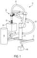
- FIG. 1shows an illustrative diagrammatic view of a programmable motion system with an end-effector in accordance with an aspect of the present invention
- FIG. 2shows an illustrative diagrammatic partial sectional view of an end-effector that may be used in the system of FIG. 1 ;
- FIG. 3shows an illustrative diagrammatic sectional view of a portion of the end-effector of FIG. 2 ;
- FIG. 4shows an illustrative diagrammatic side view of relative component parts of the end-effector of FIG. 2 ;
- FIG. 5shows an illustrative diagrammatic partial sectional view of the end-effector used in the system of FIG. 1 ;
- FIG. 6shows an illustrative diagrammatic partial side view of relative component parts of the end-effector of FIG. 5 ;
- FIG. 7shows an illustrative diagrammatic partial sectional exploded view of the end-effector of FIG. 5 ;
- FIG. 8shows an illustrative diagrammatic partial side view of relative component parts of the end-effector of FIG. 5 showing the attachment unit;
- FIG. 9shows an illustrative diagrammatic center-sectional view of the end-effector of FIG. 5 ;
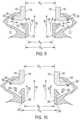
- FIG. 10shows an illustrative diagrammatic center-sectional view similar to that in FIG. 9 of an end-effector in accordance with another aspect of the present invention.
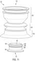
- FIG. 11shows an illustrative diagrammatic exploded view of an end-effector in accordance with a further aspect of the invention that includes a bellows insert that includes a plurality of position securement features;
- FIG. 12shows an illustrative diagrammatic exploded partial section view of the end-effector of FIG. 11 ;
- FIG. 13shows an illustrative diagrammatic partial side sectional view of the end-effector of FIG. 11 .
- FIG. 1shows a programmable motion device 10 that includes a base 12 , a base section 14 , and articulated arm sections 16 and 18 , as well as a vacuum attachment section 20 , and end-effector 22 .
- a high flow vacuumis provided via vacuum hose 24 from a high vacuum source 26 .
- the programmable motion device 10may be used, under the control of one or more computer processing systems 100 , to grasp and move various objects 28 , 30 using the high flow vacuum provided at the end-effector 22 .
- a vacuumIn high air-flow vacuum applications, a vacuum is provided that has a high air-flow, for example, an air-flow of at least about 100 cubic feet per minute, and a vacuum pressure at the end-effector of no more than about 100,000 Pascals below atmospheric, or 85,000 Pascals below atmospheric or 65,000 Pascals below atmospheric. Applicants have discovered that when such a high air-flow vacuum is provided it may cause particularly resonant high air-flow within the end-effector creating a loud (sometimes whistling) noise.
- the high flow vacuummay be provided, for example, by a blower, having a vacuum pressure at the end-effector of no more than about 100,000 Pascals below atmospheric, or 85,000 Pascals below atmospheric or 65,000 Pascals below atmospheric (e.g., about 50,000 Pascals below atmospheric or 7.25 psi).
- a vacuum cup of an end-effectorfor example, may have an internal vacuum passage dimension (e.g., diameter if round) of about 0.5 inches to about 1.5 inches at a most narrow portion of the vacuum passage at the end-effector.
- the components of the end-effectorneed not be circular in cross-sectional shape, and may be polygonal, including square or triangular.
- the internal vacuum passage 32includes several components, each with potentially different inner dimensions.
- the end-effector 22includes an attachment portion 34 for attaching to a programmable motion device 10 that includes an angled large inner dimension portion 36 as well as a vertical large inner dimension section 38 .
- a collar 40is attached to the attachment portion 34 , and includes inner dimension sections 42 , 44 .
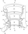
- a flexible bellows 46that is formed, for example, of compliant elastomeric material has a varying inner dimension portion 48 forming the bellows, and a vertical inner dimension portion 50 .
- a vacuum cup 52is attached to the bellows, and has a vertical inner dimension portion 54 and an expanding inner dimension that leads to the cup lip 56 which provides the opening at the underside 58 thereof for the end-effector 22 .
- FIG. 3shows a cut-away portion of one side of the internal vacuum passage 32 (shown in FIG. 2 ), showing portions of the bellows 46 and the collar 40 .
- a fundamental challenge of systems of high flow vacuum systemsis that it is desirable to obtain both high volume air-flow at the contact portion of the end-effector, yet permit flexibility of the end-effector as it contacts and grasps objects without significant attendant noise.
- a dimension of the vacuum channelmay decrease from the contact portion 152 to a flexible intermediate portion 146 as shown at dimension A decreasing to dimension B in FIG. 4 .
- the smaller dimension Bfacilitates creating the high air-flow vacuum at the contact portion 152 .
- the flexible intermediate portion 146e.g., a bellows
- An attachment portion 139(e.g., an attachment collar and/or attachment unit) with a smallest internal dimension C increases in inner dimension to D as also shown in FIG. 4 .
- the flexible intermediate portion 146is positioned between the smaller dimension B of the contact portion 152 , and the smaller dimension C of the attachment portion 139 .
- a narrow inner dimension vacuum channelis maintained at the contact end of the flexible intermediate portion as shown at B in FIG. 4 to provide the high flow vacuum, which widens from dimension A at the contact surface 158 of the contact portion 152 (e.g., vacuum cup).
- the contact portionmay additionally provide some flexibility, but the challenge exists in maintaining the high air-flow vacuum through the flexible intermediate portion without attendant high levels of noise.
- the inventionprovides a bellows insert that extends into the flexible intermediate section a sufficient distance to inhibit a substantial amount of air-flow from entering the bellows portion yet does not significantly inhibit freedom of movement of the flexible intermediate section.
- the bellows insertextends into the flexible intermediate section, disturbing any resonance of moving air within the bellows portion.
- the end-effector attachment portionhas a smallest internal dimension of APi d
- the contact end of the flexible intermediate portionhas a smallest internal dimension of CEi d
- the values AP id and CEi dare within 15% or 10% of each other.
- the end-effector systemmay produce audible noise when the end-effector attachment portion has a smallest internal dimension of APi d , the bellows insert has a smallest internal dimension of BIi d ; and the values AP id and BI id are within 15% or 10% of each other. For example, if BI id is within 15% of AP id , then bellows inserts in accordance with an aspect of the invention may be used. Surprisingly, the use of designs in accordance with various aspects of the invention reduces the noise generated by a compliant vacuum cup when used in such high air-flow application.
- the inventionprovides in accordance with certain aspects, an end-effector 122 as well as the use of the end-effector 122 in the system including the programmable motion device 10 of FIG. 1 in place of the end-effector 22 .
- the end-effector 122provides a vacuum channel 132 that is provided, in part, by attachment unit 134 having inner dimension portions 136 and 138 , collar 146 having inner dimension portions 142 and 144 , bellows 146 having varying inner dimension portions 148 , and vacuum cup 156 .
- the end-effector 122further includes a bellows insert 180 having an inner dimension 182 .
- the presence of the bellowsmay not significantly inhibit movement (e.g., restrict a change in shape of at least 10%, 20%, 50% or 75%) of the flexible bellows in accordance with various aspects of the invention.
- any movement of airmay generally be non-uniform (shown diagrammatically at 172 ).
- the rate of movement of air within the bellowsmay be greatly reduced, and large oscillations of air may be reduced or eliminated, resulting in a substantial decrease in unwanted noise during high flow vacuum use with the programmable motion device 10 of FIG. 1 where the end-effector 122 is substituted for the end-effector 22 .
- FIG. 7shows an exploded view of the combined attachment unit 134 and collar 140 , the flexible intermediate portion 146 including the vacuum cup 152 , and the bellows insert 180 .
- the inner dimension portion 144 of the collar 140 , and the inner dimension portion 150 of the flexible intermediate portion 146may be aligned or closely aligned. Applicants have discovered that in such arrangement, under certain conditions of high flow vacuum use, substantial unwanted noise may result absent a bellows insert 180 . As shown in FIGS.
- the bellows insert 180includes a head portion on a protruding end of the bellows insert that extends into the bellows on a bellows insert extension 186 , yet does not negatively affect substantial movement of the flexible intermediate portion 146 .
- FIG. 9which shows both sides of the attachment collar 140 (that extends from the attachment unit 134 of FIGS. 5 , 7 and 8 ) and the flexible intermediate portion 146 , including the vacuum cup 152 , and the bellows insert 180 .
- the inner dimension portion 144 of the collar 140 , and the inner dimension portion 150 of the flexible intermediate portion 146may be aligned or closely aligned.
- any movement of airwill generally be non-uniform (shown diagrammatically at 172 ). Most significantly, the rate of movement of air within the bellows will be greatly reduced, and large oscillations of air will be reduced or eliminated, resulting in a substantial decrease in unwanted noise during high flow vacuum use as discussed above.
- the protrusion 184(or securement feature) may be provided to facilitate holding the bellow inset in place.
- the attachment portione.g., collar 144
- the contact end of the flexible intermediate portionwill have a smallest internal dimension (CEi d )
- the bellows insertwill have a smallest internal dimension (BI id ) as shown.
- the smallest internal dimension of the attachment portion (AP id ) and the smallest internal dimension (CEi d ) of the contact end of the flexible intermediate portionmay vary no more than 15% of each other in internal dimension, and preferably may vary no more than 10% of each other in internal dimension.
- the end-effector systemmay produce audible noise when the smallest internal dimension of the attachment portion (AP id ) and the smallest internal dimension (BI id ) of the bellows insert may vary no more than 15% of each other in dimension, e.g., diameter, and preferably may vary no more than 10% of each other in dimension, e.g., diameter.
- the use of designs in accordance with an aspect of the inventionmay reduce the noise generated in a compliant end-effector when used in such a high air-flow application.
- the contact end of the flexible intermediate portion 246may be provided that has a smallest internal dimension (CE id ) that is larger than the internal dimension of the attachment portion (AP id ) such that the smallest internal dimension (BI id ) of the bellows insert is aligned or nearly aligned with the smallest internal dimension of the attachment portion (AP id ) (resulting in a whistle absent a bellows insert in accordance with an aspect of the invention).
- the smallest internal dimension of the attachment portion (AP id ) and the smallest internal dimension (CE id ) of the contact end of the flexible intermediate portionmay vary no more than 15% of each other in dimension (e.g., diameter), and preferably may vary no more than 10% of each other in dimension (e.g., diameter).
- the smallest internal dimension of the attachment portion (AP id ) and the smallest internal dimension (BI id ) of the bellows insertmay vary no more than 15% of each other in dimension (e.g., diameter), and preferably may vary no more than 10% of each other in dimension (e.g., diameter).
- any movement of airwill generally be non-uniform. Most significantly, the rate of movement of air within the bellows will be greatly reduced, and large oscillations of air will be reduced or eliminated, resulting in a substantial decrease in unwanted noise during high flow vacuum use as discussed above.
- the inventionprovides an end-effector 322 and a programmable motion device 10 (of FIG. 1 ) including the end-effector 322 (of FIGS. 11 - 13 ).
- the end-effector 322provides a vacuum channel 332 that is provided, in part, by an attachment section 339 that includes an attachment unit 334 having inner dimension portions 336 and 338 , and a collar 340 having inner dimension portions 342 and 344 .
- the end-effector 322also includes a flexible intermediate portion 346 including a bellows having varying inner dimension portions 348 , and a contact section 356 including a vacuum cup.
- the end-effector 322further includes a bellows insert 380 having an inner dimension 382 .
- the bellows insert 380includes a head portion 384 (optionally to facilitate retention) on a protruding end of the bellows insert that extends into the bellows on a bellow insert extension 386 , yet does not negatively affect substantial movement of the flexible intermediate portion 346 . Additionally, the bellows insert includes a shoulder engagement feature 388 that is secured against a shoulder 390 of the flexible intermediate portion 346 as discussed below with reference to FIGS. 12 and 13 .
- FIG. 12shows an exploded view of the combined attachment unit 334 and collar 340 , the flexible intermediate portion 346 including the vacuum cup 352 , and the bellows insert 380 .
- the inner dimension portion 344 of the collar 340 , and the inner dimension portion 350 of the flexible intermediate portion 346may be aligned or closely aligned. Applicants have discovered that in such arrangement, under certain conditions of high flow vacuum use, substantial unwanted noise may result absent a bellows insert 380 .
- the shoulder engagement feature 388is secured against the shoulder 390 of the flexible intermediate portion 346 .
- the shoulder 390 and an outer surface of the bellows insert 380may additionally serve to secure the vacuum cup 352 to the flexible intermediate portion 346 .
Landscapes
- Engineering & Computer Science (AREA)
- Robotics (AREA)
- Mechanical Engineering (AREA)
- Manipulator (AREA)
Abstract
Description
Claims (51)
Priority Applications (2)
| Application Number | Priority Date | Filing Date | Title |
|---|---|---|---|
| US17/167,536US12157223B2 (en) | 2020-02-05 | 2021-02-04 | Systems and methods for disrupting resonance in vacuum cup assemblies used with programmable motion devices |
| US18/919,816US20250144818A1 (en) | 2020-02-05 | 2024-10-18 | Systems and methods for disrupting resonance in vacuum cup assemblies used with programmable motion devices |
Applications Claiming Priority (2)
| Application Number | Priority Date | Filing Date | Title |
|---|---|---|---|
| US202062970208P | 2020-02-05 | 2020-02-05 | |
| US17/167,536US12157223B2 (en) | 2020-02-05 | 2021-02-04 | Systems and methods for disrupting resonance in vacuum cup assemblies used with programmable motion devices |
Related Child Applications (1)
| Application Number | Title | Priority Date | Filing Date |
|---|---|---|---|
| US18/919,816ContinuationUS20250144818A1 (en) | 2020-02-05 | 2024-10-18 | Systems and methods for disrupting resonance in vacuum cup assemblies used with programmable motion devices |
Publications (2)
| Publication Number | Publication Date |
|---|---|
| US20210237285A1 US20210237285A1 (en) | 2021-08-05 |
| US12157223B2true US12157223B2 (en) | 2024-12-03 |
Family
ID=74860389
Family Applications (2)
| Application Number | Title | Priority Date | Filing Date |
|---|---|---|---|
| US17/167,536Active2043-06-13US12157223B2 (en) | 2020-02-05 | 2021-02-04 | Systems and methods for disrupting resonance in vacuum cup assemblies used with programmable motion devices |
| US18/919,816PendingUS20250144818A1 (en) | 2020-02-05 | 2024-10-18 | Systems and methods for disrupting resonance in vacuum cup assemblies used with programmable motion devices |
Family Applications After (1)
| Application Number | Title | Priority Date | Filing Date |
|---|---|---|---|
| US18/919,816PendingUS20250144818A1 (en) | 2020-02-05 | 2024-10-18 | Systems and methods for disrupting resonance in vacuum cup assemblies used with programmable motion devices |
Country Status (6)
| Country | Link |
|---|---|
| US (2) | US12157223B2 (en) |
| EP (1) | EP4100219B1 (en) |
| CN (1) | CN115052720A (en) |
| CA (1) | CA3170700A1 (en) |
| ES (1) | ES3032869T3 (en) |
| WO (1) | WO2021158770A1 (en) |
Families Citing this family (3)
| Publication number | Priority date | Publication date | Assignee | Title |
|---|---|---|---|---|
| EP4010152A1 (en) | 2019-08-08 | 2022-06-15 | Berkshire Grey Operating Company, Inc. | Systems and methods for providing, in programmable motion devices, compliant end effectors with noise mitigation |
| ES3032869T3 (en) | 2020-02-05 | 2025-07-28 | Berkshire Grey Operating Company Inc | End-effector and programmable motion device |
| NL2031663B1 (en)* | 2022-04-22 | 2023-11-07 | Bollegraaf Patents And Brands B V | Suction head for a waste sorting system |
Citations (102)
| Publication number | Priority date | Publication date | Assignee | Title |
|---|---|---|---|---|
| US1610363A (en) | 1925-12-22 | 1926-12-14 | Jay J Davis | Lifting and conveying apparatus |
| US2815919A (en) | 1954-10-20 | 1957-12-10 | Pribil Victor | Suction cups |
| US2853333A (en) | 1955-09-07 | 1958-09-23 | Littell Machine Co F J | Vacuum cup |
| US3005652A (en) | 1960-12-14 | 1961-10-24 | Bemis Bro Bag Co | Vacuum gripping device |
| US3181563A (en) | 1961-12-05 | 1965-05-04 | Corning Glass Works | Valve means for selectively supplying a desired port with positive and negative pressures |
| US3195941A (en) | 1962-08-27 | 1965-07-20 | Whiting Corp | Vacuum gripping pad |
| US3656794A (en) | 1971-01-21 | 1972-04-18 | Diamond Int Corp | Vacuum cup lifter for shell eggs |
| US3743340A (en) | 1971-02-10 | 1973-07-03 | Gis Ag | Vacuum lifting device |
| US3863969A (en) | 1973-11-01 | 1975-02-04 | Aluminum Co Of America | Vacuum lifter |
| US4078671A (en)* | 1974-12-12 | 1978-03-14 | Lundstrom Goran O | Arrangement at industrial robots |
| US4389064A (en) | 1980-12-05 | 1983-06-21 | S.A. Joulin Sema | Gripping device operating by suction |
| FR2527968A1 (en) | 1982-06-08 | 1983-12-09 | Jaz Ind | Supple grip for robot arm - uses two pincers faced with elastically deformable block and has magneto-resistive transducer to measure deformation |
| DE3324441A1 (en) | 1983-04-08 | 1984-10-18 | Reinhard Dipl.-Ing. 3070 Nienburg Göpfert | Automotive device for moving movable heavy concrete parts and goods to be lifted |
| US4557659A (en) | 1982-09-14 | 1985-12-10 | M. Scaglia S.P.A. | Device for supporting and handling loads by means of vacuum operated suction pads |
| US4561687A (en)* | 1984-05-30 | 1985-12-31 | Harris Corporation | Vacuum grip device |
| US4600229A (en) | 1984-08-03 | 1986-07-15 | Oten Peter D | Vacuum cup |
| US4717138A (en)* | 1984-09-04 | 1988-01-05 | Watkiss Automation Limited | Valve mechanism |
| US4787812A (en)* | 1983-02-24 | 1988-11-29 | Goepfert Reinhard | Apparatus for lifting arrays of paving stones and the like |
| US4828304A (en) | 1986-09-09 | 1989-05-09 | Kabushiki Kaisha Yakult Honsha | Vacuum adsorption hand |
| DE3810989A1 (en) | 1988-02-01 | 1989-08-10 | Festo Kg | Apparatus for handling and, in particular, for transporting articles |
| US5190332A (en) | 1990-09-06 | 1993-03-02 | Smc Kabushiki Kaisha | Suction pad for attracting and holding a workpiece |
| US5207465A (en) | 1991-10-24 | 1993-05-04 | Rich Donald S | Self-realigning vacuum pickup arrangement |
| US5253858A (en) | 1991-05-21 | 1993-10-19 | Heidelberger Druckmaschinen Ag | Device for singly separating or singling out stacked printing forms |
| US5752729A (en) | 1993-11-04 | 1998-05-19 | Comalco Aluminium Limited | Vacuum lifting device |
| US5856487A (en) | 1996-02-14 | 1999-01-05 | National Institute Of Immunology | Application of protoberberine alkaloid, berberine, an immunosuppressive agent |
| US5865487A (en) | 1996-05-23 | 1999-02-02 | Motorola, Inc. | Pick-and-place tool for vacuum and magnetic coupling |
| US5890553A (en) | 1996-08-01 | 1999-04-06 | California Institute Of Technology | Multifunction automated crawling system |
| US6131973A (en) | 1998-10-01 | 2000-10-17 | Sikorsky Aircraft Corporation | Vacuum transfer device |
| US6193291B1 (en) | 1999-07-20 | 2001-02-27 | Isi Norgren, Inc. | Vacuum cup apparatus |
| US6213528B1 (en) | 1998-10-20 | 2001-04-10 | U.S. Philips Corporation | Vacuum cup |
| US20010013434A1 (en) | 2000-02-16 | 2001-08-16 | Hopkins Kathleen Garrubba | Adherent Robot |
| US20010045755A1 (en) | 1998-04-18 | 2001-11-29 | Schmalz Gmbh | Gripper system, in particular vacuum gripper system |
| US20020011735A1 (en) | 2000-07-31 | 2002-01-31 | Shigekazu Nagai | Suction pad |
| US6382692B1 (en) | 1999-04-06 | 2002-05-07 | J. Schmalz Gmbh | Vacuum gripper |
| DE10121344A1 (en) | 2001-05-02 | 2002-11-07 | Fft Flexible Fertigungstechnik | Clamping device attached to arm of robot, in particular used for lifting of flat items, comprising suction unit provided with self adjusting stop |
| US20020185575A1 (en) | 2001-06-11 | 2002-12-12 | Kalb James R. | Bellowed suction cup |
| CN1390438A (en) | 1999-11-09 | 2003-01-08 | 西门子公司 | Vacuum pipette for gripping electical components by suction |
| US20030038491A1 (en) | 2001-08-09 | 2003-02-27 | J. Schmalz Gmbh | Under pressure handling device |
| US6607054B1 (en) | 1998-10-31 | 2003-08-19 | Rota Limited | Safety device |
| CN1744970A (en) | 2003-01-29 | 2006-03-08 | 三星钻石工业股份有限公司 | Vacuum suction head |
| US7017961B1 (en) | 2004-08-06 | 2006-03-28 | Bakery Holdings Llc | Compressive end effector |
| US20060242785A1 (en) | 2005-03-15 | 2006-11-02 | Cliff Cawley | Layer picking end effector system, apparatus and method |
| US20070006940A1 (en) | 2005-07-11 | 2007-01-11 | Maurice Perlman | Auto-release vacuum device |
| US7618074B2 (en) | 2004-11-30 | 2009-11-17 | Multitest Elektronische Systeme Gmbh | Handling apparatus for passing electronic components, in particular ICs, to a testing apparatus |
| US20100150743A1 (en) | 2008-12-12 | 2010-06-17 | Norgren Automotive, Inc. | Single Line Venturi Apparatus |
| JP2010201536A (en) | 2009-03-02 | 2010-09-16 | Mitsubishi Materials Techno Corp | Vacuum suction pad |
| CN101925959A (en) | 2008-11-26 | 2010-12-22 | 泰拉丁公司 | Vacuum assisted manipulation of objects |
| US20110255948A1 (en) | 2010-04-19 | 2011-10-20 | Malinowski Mark A | Suction Device |
| US8070203B2 (en) | 2005-09-24 | 2011-12-06 | Franz Schaumberger | Method for controlling vacuum-operated hoists and load protection device for vacuum-operated hoists |
| US20120025053A1 (en) | 2009-03-27 | 2012-02-02 | Xerex Ab | Suction cup having replaceable sealing surfaces |
| DE102011115951A1 (en) | 2011-10-13 | 2013-04-18 | BIBA - Bremer Institut für Produktion und Logistik GmbH | Gripping tool for promotion of irregularly arranged products such as packets, has suction cup that is provided at longitudinal extension of tentacle of support, where tentacle is oriented transversely to the extension |
| US20130129464A1 (en) | 2011-11-18 | 2013-05-23 | Nike, Inc. | Zoned activation manufacturing vacuum tool |
| US20130147101A1 (en) | 2009-09-01 | 2013-06-13 | Ho-Young Cho | Vacuum cup assembly |
| KR20140001186U (en)* | 2012-08-16 | 2014-02-27 | (주) 엔텍인더스트리 | Vacuum adsorber |
| WO2014040843A1 (en) | 2012-09-14 | 2014-03-20 | Knapp Ag | High-speed gripper-changing system |
| CN203529438U (en) | 2013-07-22 | 2014-04-09 | 温州阿尔贝斯气动有限公司 | Vacuum chuck |
| CN203680306U (en) | 2013-12-20 | 2014-07-02 | 君帆工业股份有限公司 | Non-contact porous vacuum floater |
| CN203717601U (en) | 2014-01-23 | 2014-07-16 | 温州阿尔贝斯气动有限公司 | Vacuum sucker |
| WO2014161549A1 (en) | 2013-04-02 | 2014-10-09 | Inva Invest Holding Aps | A flow blocking valve, a vacuum lifting device and a method for operating a vacuum lifting device |
| WO2015162390A1 (en) | 2014-04-25 | 2015-10-29 | Sileane | Method and facility for automatically gripping an object |
| EP2960024A2 (en) | 2014-06-26 | 2015-12-30 | J. Schmalz GmbH | Installation for handling workpieces and method for operating such an assembly |
| CN105668255A (en) | 2016-03-21 | 2016-06-15 | 湖州中辰建设有限公司 | Exterior wall tile stacking and boxing device |
| US20160221187A1 (en) | 2013-03-15 | 2016-08-04 | Industrial Perception, Inc. | Object Pickup Strategies for a Robotic Device |
| US20160258473A1 (en) | 2015-03-05 | 2016-09-08 | Bracketron, Inc. | Suction cup mount |
| US20160271805A1 (en) | 2015-02-12 | 2016-09-22 | J. Schmalz Gmbh | Vacuum generating apparatus and vacuum tube lifter having a vacuum generating apparatus |
| US20170062263A1 (en) | 2015-09-01 | 2017-03-02 | Boris Kesil | Universal Gripping and Suction Chuck |
| WO2017035466A1 (en) | 2015-08-26 | 2017-03-02 | Berkshire Grey Inc. | Systems and methods for providing vacuum valve assemblies for end effectors |
| US20170057091A1 (en) | 2015-08-26 | 2017-03-02 | Berkshire Grey Inc. | Systems and methods for providing contact detection in an articulated arm |
| WO2017044632A1 (en) | 2015-09-08 | 2017-03-16 | Berkshire Grey Inc. | Systems and methods for providing high flow vacuum acquisition in automated systems |
| US20170072572A1 (en) | 2015-09-15 | 2017-03-16 | Berkshire Grey Inc. | Everting end effector for use with an articulated arm in a robotic system |
| US20170080571A1 (en) | 2015-09-01 | 2017-03-23 | Berkshire Grey Inc. | Systems and methods for providing dynamic robotic control systems |
| US20170136632A1 (en) | 2015-11-13 | 2017-05-18 | Berkshire Grey Inc. | Sortation systems and methods for providing sortation of a variety of objects |
| US20170197316A1 (en) | 2016-01-08 | 2017-07-13 | Berkshire Grey Inc. | Systems and methods for acquiring and moving objects |
| US20170225330A1 (en) | 2016-02-08 | 2017-08-10 | Berkshire Grey Inc. | Systems and methods for providing processing of a variety of objects employing motion planning |
| US20180056333A1 (en) | 2015-02-11 | 2018-03-01 | Solystic | Installation for separating and singulating non-uniform postal articles with a vision system having laser sources |
| US20180134501A1 (en) | 2016-11-15 | 2018-05-17 | Amazon Technologies, Inc. | Automated Package Unloading System |
| US20180148272A1 (en) | 2016-11-28 | 2018-05-31 | Berkshire Grey, Inc. | Systems and methods for providing singulation of objects for processing |
| US20180222061A1 (en) | 2015-10-12 | 2018-08-09 | Wisco Lasertechnik Gmbh | Suction frame |
| JP2018130810A (en) | 2017-02-17 | 2018-08-23 | 三菱電機株式会社 | Gripping device, gripping system and control device |
| US20180333749A1 (en) | 2017-04-24 | 2018-11-22 | Berkshire Grey, Inc. | Systems and methods for providing singulation of objects for processing using object movement redistribution |
| WO2019023729A1 (en) | 2017-08-01 | 2019-02-07 | Kuchler, Fritz | Suction head |
| US20190039240A1 (en) | 2017-08-02 | 2019-02-07 | Berkshire Grey, Inc. | Systems and methods for acquiring and moving objects having complex outer surfaces |
| US20190061174A1 (en) | 2017-08-22 | 2019-02-28 | Emerging Acquisitions, Llc | High speed manipulation of non-uniform objects |
| US20190071260A1 (en) | 2014-11-18 | 2019-03-07 | James Laverdiere | Rotary picker with arms |
| US20190134827A1 (en) | 2017-11-07 | 2019-05-09 | Berkshire Grey, Inc. | Systems and methods for providing dynamic vacuum pressure at an end effector using a single vacuum source |
| US20190217471A1 (en) | 2018-01-17 | 2019-07-18 | Berkshire Grey, Inc. | Systems and methods for efficiently moving a variety of objects |
| US20190216644A1 (en) | 2016-08-29 | 2019-07-18 | Craig L. Hershoff | Contact lens manipulator with suction cup and safety release mechanism |
| EP3520973A1 (en) | 2018-02-05 | 2019-08-07 | SMC Corporation | Vacuum pad |
| US20200016746A1 (en) | 2018-07-16 | 2020-01-16 | XYZ Robotics Global Inc. | Robotic system for picking, sorting, and placing a plurality of random and novel objects |
| US20200030994A1 (en) | 2018-07-27 | 2020-01-30 | Berkshire Grey, Inc. | Systems and methods for efficiently exchanging end effector tools |
| US20200130935A1 (en) | 2018-10-25 | 2020-04-30 | Berkshire Grey, Inc. | Systems and methods for learning to extrapolate optimal object routing and handling parameters |
| US10639787B2 (en) | 2017-03-06 | 2020-05-05 | Berkshire Grey, Inc. | Systems and methods for efficiently moving a variety of objects |
| JP2020089936A (en) | 2018-12-05 | 2020-06-11 | 株式会社妙徳 | Suction pad |
| US20200269416A1 (en) | 2019-02-27 | 2020-08-27 | Berkshire Grey, Inc. | Systems and methods for hose routing in programmable motion systems |
| US20200338728A1 (en) | 2019-04-25 | 2020-10-29 | Berkshire Grey, Inc. | Systems and methods for maintaining vacuum hose life in hose routing systems in programmable motion systems |
| WO2021026183A1 (en) | 2019-08-08 | 2021-02-11 | Berkshire Grey, Inc. | Systems and methods for providing, in programmable motion devices, compliant end effectors with noise mitigation |
| US20210129354A1 (en) | 2019-10-31 | 2021-05-06 | Intelligrated Headquarters, Llc | Compliant inner lip on a vacuum gripper |
| US20210237285A1 (en) | 2020-02-05 | 2021-08-05 | Berkshire Grey, Inc. | Systems and methods for disrupting resonance in vacuum cup assemblies used with programmable motion devices |
| US20210308875A1 (en) | 2020-04-01 | 2021-10-07 | Ambidextrous Laboratories, Inc. | End effector device and system for suction-based grasping of bagged objects |
| US20220048717A1 (en) | 2019-01-31 | 2022-02-17 | RightHand Robotics, Inc. | Gripping Device Modalities |
| US20220118629A1 (en) | 2018-10-03 | 2022-04-21 | Nicholas Payton | Hybrid robotic picking device |
| US20230103821A1 (en) | 2021-10-06 | 2023-04-06 | Dexterity, Inc. | Multi-mode robotic end effector |
Family Cites Families (1)
| Publication number | Priority date | Publication date | Assignee | Title |
|---|---|---|---|---|
| KR102049936B1 (en)* | 2017-09-11 | 2019-11-28 | 피스코코리아뉴매틱주식회사 | Vacuum adsorption device |
- 2021
- 2021-02-04ESES21710646Tpatent/ES3032869T3/enactiveActive
- 2021-02-04USUS17/167,536patent/US12157223B2/enactiveActive
- 2021-02-04CNCN202180012206.4Apatent/CN115052720A/enactivePending
- 2021-02-04WOPCT/US2021/016582patent/WO2021158770A1/ennot_activeCeased
- 2021-02-04EPEP21710646.7Apatent/EP4100219B1/enactiveActive
- 2021-02-04CACA3170700Apatent/CA3170700A1/enactivePending
- 2024
- 2024-10-18USUS18/919,816patent/US20250144818A1/enactivePending
Patent Citations (127)
| Publication number | Priority date | Publication date | Assignee | Title |
|---|---|---|---|---|
| US1610363A (en) | 1925-12-22 | 1926-12-14 | Jay J Davis | Lifting and conveying apparatus |
| US2815919A (en) | 1954-10-20 | 1957-12-10 | Pribil Victor | Suction cups |
| US2853333A (en) | 1955-09-07 | 1958-09-23 | Littell Machine Co F J | Vacuum cup |
| US3005652A (en) | 1960-12-14 | 1961-10-24 | Bemis Bro Bag Co | Vacuum gripping device |
| US3181563A (en) | 1961-12-05 | 1965-05-04 | Corning Glass Works | Valve means for selectively supplying a desired port with positive and negative pressures |
| US3195941A (en) | 1962-08-27 | 1965-07-20 | Whiting Corp | Vacuum gripping pad |
| US3656794A (en) | 1971-01-21 | 1972-04-18 | Diamond Int Corp | Vacuum cup lifter for shell eggs |
| US3743340A (en) | 1971-02-10 | 1973-07-03 | Gis Ag | Vacuum lifting device |
| US3863969A (en) | 1973-11-01 | 1975-02-04 | Aluminum Co Of America | Vacuum lifter |
| US4078671A (en)* | 1974-12-12 | 1978-03-14 | Lundstrom Goran O | Arrangement at industrial robots |
| US4389064A (en) | 1980-12-05 | 1983-06-21 | S.A. Joulin Sema | Gripping device operating by suction |
| FR2527968A1 (en) | 1982-06-08 | 1983-12-09 | Jaz Ind | Supple grip for robot arm - uses two pincers faced with elastically deformable block and has magneto-resistive transducer to measure deformation |
| US4557659A (en) | 1982-09-14 | 1985-12-10 | M. Scaglia S.P.A. | Device for supporting and handling loads by means of vacuum operated suction pads |
| US4787812A (en)* | 1983-02-24 | 1988-11-29 | Goepfert Reinhard | Apparatus for lifting arrays of paving stones and the like |
| DE3324441A1 (en) | 1983-04-08 | 1984-10-18 | Reinhard Dipl.-Ing. 3070 Nienburg Göpfert | Automotive device for moving movable heavy concrete parts and goods to be lifted |
| US4561687A (en)* | 1984-05-30 | 1985-12-31 | Harris Corporation | Vacuum grip device |
| US4600229A (en) | 1984-08-03 | 1986-07-15 | Oten Peter D | Vacuum cup |
| US4717138A (en)* | 1984-09-04 | 1988-01-05 | Watkiss Automation Limited | Valve mechanism |
| US4828304A (en) | 1986-09-09 | 1989-05-09 | Kabushiki Kaisha Yakult Honsha | Vacuum adsorption hand |
| DE3810989A1 (en) | 1988-02-01 | 1989-08-10 | Festo Kg | Apparatus for handling and, in particular, for transporting articles |
| US5190332A (en) | 1990-09-06 | 1993-03-02 | Smc Kabushiki Kaisha | Suction pad for attracting and holding a workpiece |
| US5253858A (en) | 1991-05-21 | 1993-10-19 | Heidelberger Druckmaschinen Ag | Device for singly separating or singling out stacked printing forms |
| US5207465A (en) | 1991-10-24 | 1993-05-04 | Rich Donald S | Self-realigning vacuum pickup arrangement |
| US5752729A (en) | 1993-11-04 | 1998-05-19 | Comalco Aluminium Limited | Vacuum lifting device |
| US5856487A (en) | 1996-02-14 | 1999-01-05 | National Institute Of Immunology | Application of protoberberine alkaloid, berberine, an immunosuppressive agent |
| US5865487A (en) | 1996-05-23 | 1999-02-02 | Motorola, Inc. | Pick-and-place tool for vacuum and magnetic coupling |
| US5890553A (en) | 1996-08-01 | 1999-04-06 | California Institute Of Technology | Multifunction automated crawling system |
| US20010045755A1 (en) | 1998-04-18 | 2001-11-29 | Schmalz Gmbh | Gripper system, in particular vacuum gripper system |
| US6131973A (en) | 1998-10-01 | 2000-10-17 | Sikorsky Aircraft Corporation | Vacuum transfer device |
| US6213528B1 (en) | 1998-10-20 | 2001-04-10 | U.S. Philips Corporation | Vacuum cup |
| US6607054B1 (en) | 1998-10-31 | 2003-08-19 | Rota Limited | Safety device |
| US6382692B1 (en) | 1999-04-06 | 2002-05-07 | J. Schmalz Gmbh | Vacuum gripper |
| US6193291B1 (en) | 1999-07-20 | 2001-02-27 | Isi Norgren, Inc. | Vacuum cup apparatus |
| CN1390438A (en) | 1999-11-09 | 2003-01-08 | 西门子公司 | Vacuum pipette for gripping electical components by suction |
| US20010013434A1 (en) | 2000-02-16 | 2001-08-16 | Hopkins Kathleen Garrubba | Adherent Robot |
| US20020011735A1 (en) | 2000-07-31 | 2002-01-31 | Shigekazu Nagai | Suction pad |
| DE10121344A1 (en) | 2001-05-02 | 2002-11-07 | Fft Flexible Fertigungstechnik | Clamping device attached to arm of robot, in particular used for lifting of flat items, comprising suction unit provided with self adjusting stop |
| US20020185575A1 (en) | 2001-06-11 | 2002-12-12 | Kalb James R. | Bellowed suction cup |
| US20030038491A1 (en) | 2001-08-09 | 2003-02-27 | J. Schmalz Gmbh | Under pressure handling device |
| US6817639B2 (en) | 2001-08-09 | 2004-11-16 | J. Schmalz Gmbh | Under pressure handling device |
| CN1744970A (en) | 2003-01-29 | 2006-03-08 | 三星钻石工业股份有限公司 | Vacuum suction head |
| US7017961B1 (en) | 2004-08-06 | 2006-03-28 | Bakery Holdings Llc | Compressive end effector |
| US7618074B2 (en) | 2004-11-30 | 2009-11-17 | Multitest Elektronische Systeme Gmbh | Handling apparatus for passing electronic components, in particular ICs, to a testing apparatus |
| US20060242785A1 (en) | 2005-03-15 | 2006-11-02 | Cliff Cawley | Layer picking end effector system, apparatus and method |
| US20070006940A1 (en) | 2005-07-11 | 2007-01-11 | Maurice Perlman | Auto-release vacuum device |
| US8070203B2 (en) | 2005-09-24 | 2011-12-06 | Franz Schaumberger | Method for controlling vacuum-operated hoists and load protection device for vacuum-operated hoists |
| CN101925959A (en) | 2008-11-26 | 2010-12-22 | 泰拉丁公司 | Vacuum assisted manipulation of objects |
| US20100150743A1 (en) | 2008-12-12 | 2010-06-17 | Norgren Automotive, Inc. | Single Line Venturi Apparatus |
| JP2010201536A (en) | 2009-03-02 | 2010-09-16 | Mitsubishi Materials Techno Corp | Vacuum suction pad |
| US20120025053A1 (en) | 2009-03-27 | 2012-02-02 | Xerex Ab | Suction cup having replaceable sealing surfaces |
| US20130147101A1 (en) | 2009-09-01 | 2013-06-13 | Ho-Young Cho | Vacuum cup assembly |
| US20110255948A1 (en) | 2010-04-19 | 2011-10-20 | Malinowski Mark A | Suction Device |
| DE102011115951A1 (en) | 2011-10-13 | 2013-04-18 | BIBA - Bremer Institut für Produktion und Logistik GmbH | Gripping tool for promotion of irregularly arranged products such as packets, has suction cup that is provided at longitudinal extension of tentacle of support, where tentacle is oriented transversely to the extension |
| US20130129464A1 (en) | 2011-11-18 | 2013-05-23 | Nike, Inc. | Zoned activation manufacturing vacuum tool |
| KR20140001186U (en)* | 2012-08-16 | 2014-02-27 | (주) 엔텍인더스트리 | Vacuum adsorber |
| WO2014040843A1 (en) | 2012-09-14 | 2014-03-20 | Knapp Ag | High-speed gripper-changing system |
| US20160221187A1 (en) | 2013-03-15 | 2016-08-04 | Industrial Perception, Inc. | Object Pickup Strategies for a Robotic Device |
| WO2014161549A1 (en) | 2013-04-02 | 2014-10-09 | Inva Invest Holding Aps | A flow blocking valve, a vacuum lifting device and a method for operating a vacuum lifting device |
| CN203529438U (en) | 2013-07-22 | 2014-04-09 | 温州阿尔贝斯气动有限公司 | Vacuum chuck |
| CN203680306U (en) | 2013-12-20 | 2014-07-02 | 君帆工业股份有限公司 | Non-contact porous vacuum floater |
| CN203717601U (en) | 2014-01-23 | 2014-07-16 | 温州阿尔贝斯气动有限公司 | Vacuum sucker |
| WO2015162390A1 (en) | 2014-04-25 | 2015-10-29 | Sileane | Method and facility for automatically gripping an object |
| US20170050315A1 (en) | 2014-04-25 | 2017-02-23 | Sileane | Method And Facility For Automatically Gripping An Object |
| EP2960024A2 (en) | 2014-06-26 | 2015-12-30 | J. Schmalz GmbH | Installation for handling workpieces and method for operating such an assembly |
| US20190071260A1 (en) | 2014-11-18 | 2019-03-07 | James Laverdiere | Rotary picker with arms |
| US20180056333A1 (en) | 2015-02-11 | 2018-03-01 | Solystic | Installation for separating and singulating non-uniform postal articles with a vision system having laser sources |
| US20160271805A1 (en) | 2015-02-12 | 2016-09-22 | J. Schmalz Gmbh | Vacuum generating apparatus and vacuum tube lifter having a vacuum generating apparatus |
| US20160258473A1 (en) | 2015-03-05 | 2016-09-08 | Bracketron, Inc. | Suction cup mount |
| CN105937541A (en) | 2015-03-05 | 2016-09-14 | 株式会社喜匹喜 | Suction plate |
| US10618177B2 (en) | 2015-08-26 | 2020-04-14 | Berkshire Grey, Inc. | Systems and methods for providing contact detection in an articulated arm |
| WO2017035466A1 (en) | 2015-08-26 | 2017-03-02 | Berkshire Grey Inc. | Systems and methods for providing vacuum valve assemblies for end effectors |
| US10343284B2 (en) | 2015-08-26 | 2019-07-09 | Berkshire Grey, Inc. | Systems and methods for providing contact detection in an articulated arm |
| US9999977B2 (en) | 2015-08-26 | 2018-06-19 | Berkshire Grey, Inc. | Systems and methods for providing vacuum valve assemblies for end effectors |
| US20170080579A1 (en) | 2015-08-26 | 2017-03-23 | Berkshire Grey Inc. | Systems and methods for providing vacuum valve assemblies for end effectors |
| US10913159B2 (en) | 2015-08-26 | 2021-02-09 | Berkshire Grey, Inc. | Systems and methods for providing contact detection in an articulated arm |
| US20170057091A1 (en) | 2015-08-26 | 2017-03-02 | Berkshire Grey Inc. | Systems and methods for providing contact detection in an articulated arm |
| US10875185B2 (en) | 2015-08-26 | 2020-12-29 | Berkshire Grey, Inc. | Systems and methods for providing contact detection in an articulated arm |
| US20170080571A1 (en) | 2015-09-01 | 2017-03-23 | Berkshire Grey Inc. | Systems and methods for providing dynamic robotic control systems |
| US20170062263A1 (en) | 2015-09-01 | 2017-03-02 | Boris Kesil | Universal Gripping and Suction Chuck |
| US10857682B2 (en) | 2015-09-08 | 2020-12-08 | Berkshire Grey, Inc. | Systems and methods for providing high flow vacuum acquisition in automated systems |
| US20170120455A1 (en) | 2015-09-08 | 2017-05-04 | Berkshire Grey Inc. | Systems and methods for providing high flow vacuum acquisition in automated systems |
| US20170087718A1 (en) | 2015-09-08 | 2017-03-30 | Berkshire Grey Inc. | Systems and methods for providing dynamic vacuum pressure in an articulated arm |
| US10596711B2 (en) | 2015-09-08 | 2020-03-24 | Berkshire Grey, Inc. | Systems and methods for providing dynamic vacuum pressure in an articulated arm end effector |
| US10576641B2 (en) | 2015-09-08 | 2020-03-03 | Berkshire Grey, Inc. | Systems and methods for providing high flow vacuum acquisition in automated systems |
| US10118300B2 (en)* | 2015-09-08 | 2018-11-06 | Berkshire Grey, Inc. | Systems and methods for providing high flow vacuum acquisition in automated systems |
| US10399236B2 (en) | 2015-09-08 | 2019-09-03 | Berkshire Grey, Inc. | Systems and methods for providing dynamic vacuum pressure in an articulated arm end effector |
| WO2017044632A1 (en) | 2015-09-08 | 2017-03-16 | Berkshire Grey Inc. | Systems and methods for providing high flow vacuum acquisition in automated systems |
| US20170072572A1 (en) | 2015-09-15 | 2017-03-16 | Berkshire Grey Inc. | Everting end effector for use with an articulated arm in a robotic system |
| US20180222061A1 (en) | 2015-10-12 | 2018-08-09 | Wisco Lasertechnik Gmbh | Suction frame |
| US20170136632A1 (en) | 2015-11-13 | 2017-05-18 | Berkshire Grey Inc. | Sortation systems and methods for providing sortation of a variety of objects |
| WO2017119982A1 (en) | 2016-01-08 | 2017-07-13 | Berkshire Grey Inc. | Systems and methods for acquiring and moving objects |
| US20190001505A1 (en) | 2016-01-08 | 2019-01-03 | Berkshire Grey, Inc. | Systems and methods for acquiring and moving objects |
| US10850402B2 (en) | 2016-01-08 | 2020-12-01 | Berkshire Grey, Inc. | Systems and methods for acquiring and moving objects |
| US20170197316A1 (en) | 2016-01-08 | 2017-07-13 | Berkshire Grey Inc. | Systems and methods for acquiring and moving objects |
| US20170225330A1 (en) | 2016-02-08 | 2017-08-10 | Berkshire Grey Inc. | Systems and methods for providing processing of a variety of objects employing motion planning |
| CN105668255A (en) | 2016-03-21 | 2016-06-15 | 湖州中辰建设有限公司 | Exterior wall tile stacking and boxing device |
| US20190216644A1 (en) | 2016-08-29 | 2019-07-18 | Craig L. Hershoff | Contact lens manipulator with suction cup and safety release mechanism |
| US20180134501A1 (en) | 2016-11-15 | 2018-05-17 | Amazon Technologies, Inc. | Automated Package Unloading System |
| US20180148272A1 (en) | 2016-11-28 | 2018-05-31 | Berkshire Grey, Inc. | Systems and methods for providing singulation of objects for processing |
| JP2018130810A (en) | 2017-02-17 | 2018-08-23 | 三菱電機株式会社 | Gripping device, gripping system and control device |
| US10639787B2 (en) | 2017-03-06 | 2020-05-05 | Berkshire Grey, Inc. | Systems and methods for efficiently moving a variety of objects |
| US20180333749A1 (en) | 2017-04-24 | 2018-11-22 | Berkshire Grey, Inc. | Systems and methods for providing singulation of objects for processing using object movement redistribution |
| WO2019023729A1 (en) | 2017-08-01 | 2019-02-07 | Kuchler, Fritz | Suction head |
| US20190039240A1 (en) | 2017-08-02 | 2019-02-07 | Berkshire Grey, Inc. | Systems and methods for acquiring and moving objects having complex outer surfaces |
| US20190061174A1 (en) | 2017-08-22 | 2019-02-28 | Emerging Acquisitions, Llc | High speed manipulation of non-uniform objects |
| US10668630B2 (en) | 2017-08-22 | 2020-06-02 | Emerging Acquisitions, Llc | High speed manipulation of non-uniform ojects |
| US20190134827A1 (en) | 2017-11-07 | 2019-05-09 | Berkshire Grey, Inc. | Systems and methods for providing dynamic vacuum pressure at an end effector using a single vacuum source |
| US20190217471A1 (en) | 2018-01-17 | 2019-07-18 | Berkshire Grey, Inc. | Systems and methods for efficiently moving a variety of objects |
| EP3520973A1 (en) | 2018-02-05 | 2019-08-07 | SMC Corporation | Vacuum pad |
| US20200017314A1 (en) | 2018-07-16 | 2020-01-16 | XYZ Robotics Global Inc. | Robotic system for picking, sorting, and placing a plurality of random and novel objects |
| US20200016746A1 (en) | 2018-07-16 | 2020-01-16 | XYZ Robotics Global Inc. | Robotic system for picking, sorting, and placing a plurality of random and novel objects |
| US20200030994A1 (en) | 2018-07-27 | 2020-01-30 | Berkshire Grey, Inc. | Systems and methods for efficiently exchanging end effector tools |
| US20220118629A1 (en) | 2018-10-03 | 2022-04-21 | Nicholas Payton | Hybrid robotic picking device |
| US20200130935A1 (en) | 2018-10-25 | 2020-04-30 | Berkshire Grey, Inc. | Systems and methods for learning to extrapolate optimal object routing and handling parameters |
| JP2020089936A (en) | 2018-12-05 | 2020-06-11 | 株式会社妙徳 | Suction pad |
| US20220048717A1 (en) | 2019-01-31 | 2022-02-17 | RightHand Robotics, Inc. | Gripping Device Modalities |
| US20200269416A1 (en) | 2019-02-27 | 2020-08-27 | Berkshire Grey, Inc. | Systems and methods for hose routing in programmable motion systems |
| US20200338728A1 (en) | 2019-04-25 | 2020-10-29 | Berkshire Grey, Inc. | Systems and methods for maintaining vacuum hose life in hose routing systems in programmable motion systems |
| WO2021026183A1 (en) | 2019-08-08 | 2021-02-11 | Berkshire Grey, Inc. | Systems and methods for providing, in programmable motion devices, compliant end effectors with noise mitigation |
| US20210039268A1 (en) | 2019-08-08 | 2021-02-11 | Berkshire Grey, Inc. | Systems and methods for providing, in programmable motion devices, compliant end effectors with noise mitigation |
| US20230091807A1 (en) | 2019-08-08 | 2023-03-23 | Berkshire Grey Operating Company, Inc. | Systems and methods for providing, in programmable motion devices, compliant end effectors with noise mitigation |
| US20210129354A1 (en) | 2019-10-31 | 2021-05-06 | Intelligrated Headquarters, Llc | Compliant inner lip on a vacuum gripper |
| US20210237285A1 (en) | 2020-02-05 | 2021-08-05 | Berkshire Grey, Inc. | Systems and methods for disrupting resonance in vacuum cup assemblies used with programmable motion devices |
| WO2021158770A1 (en) | 2020-02-05 | 2021-08-12 | Berkshire Grey, Inc. | End-effector, programmable motion device and method of operating a programmable motion device |
| US20210308875A1 (en) | 2020-04-01 | 2021-10-07 | Ambidextrous Laboratories, Inc. | End effector device and system for suction-based grasping of bagged objects |
| US20210308874A1 (en) | 2020-04-01 | 2021-10-07 | Ambidextrous Laboratories, Inc. | End effector device and system for suction-based grasping of bagged objects |
| US20230103821A1 (en) | 2021-10-06 | 2023-04-06 | Dexterity, Inc. | Multi-mode robotic end effector |
Non-Patent Citations (17)
| Title |
|---|
| Anver Corporation: Vacuum Tube Lifting Systems, Nov. 22, 2004 (http://www.jrgindustries.com/assets/anver.pdf). |
| Communication pursuant to Article 94(3) EPC issued by the European Patent Office in related European Patent Application No. 20760997.5 on Feb. 20, 2024, 6 pages. |
| Communication pursuant to Rules 161(1) and 162 EPC issued by the European Patent Office in related European Patent Application No. 20760997.5 on Mar. 16, 2022, 3 pages. |
| Communication pursuant to Rules 161(1) and 162 EPC issued by the European Patent Office in related European Patent Application No. 21710646.7 on Sep. 13, 2022, 3 pages. |
| Decision on Rejection, along with its English translation, issued by the China National Intellectual Property Administration in related Chinese Patent Application No. 202080053414.4 on Oct. 25, 2023, 22 pages. |
| Examiner's Report issued by the Innovation, Science and Economic Development Canada (Canadian Intellectual Property Office) in related Canadian Patent Application No. 3,150,291 on Mar. 31, 2023, 4 pages. |
| Examiner's Report issued by the Innovation, Science and Economic Development Canada (Canadian Intellectual Property Office) in related Canadian Patent Application No. 3,170,700 on May 23, 2024, 6 pages. |
| Examiner's Report issued by the Innovation, Science and Economic Development Canada (Canadian Intellectual Property Office) in related Canadian Patent Application No. 3,170,700 on Oct. 24, 2023, 4 pages. |
| Final Office Action issued by the United States Patent and Trademark Office in related U.S. Appl. No. 17/991,073, filed Feb. 13, 2024, 6 pages. |
| International Search Report and Written Opinion issued by the International Searching Authority in related International Application No. PCT/US2020/044923 on Nov. 18, 2020, 10 pages. |
| International Search Report and Written Opinion issued by the International Searching Authority in related International Application No. PCT/US2021/016582 on Jun. 9, 2021, 10 pages. |
| Non-Final Office Action issued by the United States Patent and Trademark Office in related U.S. Appl. No. 16/985,295, filed Apr. 29, 2022, 8 pages. |
| Non-Final Office Action issued by the United States Patent and Trademark Office in related U.S. Appl. No. 17/991,073, filed Sep. 19, 2023, 7 pages. |
| Notice on the First Office Action, along with its English translation, issued by the China National Intellectual Property Administration in related Chinese Patent Application No. 202080053414.4 on Mar. 23, 2023, 32 pages. |
| Notice on the Second Office Action, along with its English translation, issued by the China National Intellectual Property Administration in related Chinese Patent Application No. 202080053414.4 on Aug. 10, 2023, 26 pages. |
| Notification Concerning Transmittal of International Preliminary Report on Patentability and the International Preliminary Report on Patentability issued by the International Bureau of WIPO in related International Application No. PCT/US2020/044923 on Feb. 17, 2022, 8 pages. |
| Notification Concerning Transmittal of International Preliminary Report on Patentability and the International Preliminary Report on Patentability issued by the International Bureau of WIPO in related International Application No. PCT/US2021/016582 on Aug. 18, 2022, 8 pages. |
Also Published As
| Publication number | Publication date |
|---|---|
| EP4100219B1 (en) | 2025-04-09 |
| EP4100219A1 (en) | 2022-12-14 |
| US20250144818A1 (en) | 2025-05-08 |
| CN115052720A (en) | 2022-09-13 |
| ES3032869T3 (en) | 2025-07-28 |
| US20210237285A1 (en) | 2021-08-05 |
| CA3170700A1 (en) | 2021-08-12 |
| WO2021158770A1 (en) | 2021-08-12 |
Similar Documents
| Publication | Publication Date | Title |
|---|---|---|
| US20250144818A1 (en) | Systems and methods for disrupting resonance in vacuum cup assemblies used with programmable motion devices | |
| US11554505B2 (en) | Systems and methods for providing, in programmable motion devices, compliant end effectors with noise mitigation | |
| US10576641B2 (en) | Systems and methods for providing high flow vacuum acquisition in automated systems | |
| CN110116381A (en) | Vacuum chuck | |
| US7452016B2 (en) | Non-contact carrying device | |
| US5882055A (en) | Probe for handling microchips | |
| JP2019193969A (en) | Vacuum power tool | |
| US20040104329A1 (en) | Vibration isolation table | |
| JP7694321B2 (en) | Lifting device | |
| KR20150128595A (en) | Wafer carrier | |
| US6592285B1 (en) | Vibration-damping connection arrangement for two components capable of being moved against one another | |
| CN109192691B (en) | Wafer transfer device and semiconductor processing equipment | |
| US11534765B2 (en) | Test tube vacuum retainer | |
| JPH0475828A (en) | Suction structure for screw | |
| JP2020189341A (en) | Suction carrier device | |
| JPH01242345A (en) | Vacuum suction device | |
| JP3243122B2 (en) | Agricultural product adsorption carrier | |
| KR100767116B1 (en) | Inlet assembly for vacuum cleaner | |
| US11331761B2 (en) | Suction device | |
| JP2524579Y2 (en) | Suction pad | |
| JP2512633Y2 (en) | Adsorption device | |
| JPH08150585A (en) | Vacuum hand | |
| WO2022047787A1 (en) | Apparatus for improving cleanliness of robot and associated robot | |
| JPH07267360A (en) | Transfer device for cathode ray tube on carrier | |
| CN114829091A (en) | Glove assembly for barrier system |
Legal Events
| Date | Code | Title | Description |
|---|---|---|---|
| FEPP | Fee payment procedure | Free format text:ENTITY STATUS SET TO UNDISCOUNTED (ORIGINAL EVENT CODE: BIG.); ENTITY STATUS OF PATENT OWNER: SMALL ENTITY | |
| FEPP | Fee payment procedure | Free format text:ENTITY STATUS SET TO SMALL (ORIGINAL EVENT CODE: SMAL); ENTITY STATUS OF PATENT OWNER: SMALL ENTITY | |
| AS | Assignment | Owner name:BERKSHIRE GREY, INC., MASSACHUSETTS Free format text:ASSIGNMENT OF ASSIGNORS INTEREST;ASSIGNORS:ANDERSON, BRETTON;TOOTHAKER, CALVIN;SIGNING DATES FROM 20210209 TO 20210210;REEL/FRAME:055389/0603 | |
| STPP | Information on status: patent application and granting procedure in general | Free format text:DOCKETED NEW CASE - READY FOR EXAMINATION | |
| AS | Assignment | Owner name:BERKSHIRE GREY OPERATING COMPANY, INC., MASSACHUSETTS Free format text:MERGER AND CHANGE OF NAME;ASSIGNORS:BERKSHIRE GREY, INC.;BERKSHIRE GREY OPERATING COMPANY, INC.;REEL/FRAME:058947/0548 Effective date:20210721 | |
| STPP | Information on status: patent application and granting procedure in general | Free format text:NON FINAL ACTION MAILED | |
| STPP | Information on status: patent application and granting procedure in general | Free format text:RESPONSE TO NON-FINAL OFFICE ACTION ENTERED AND FORWARDED TO EXAMINER | |
| STPP | Information on status: patent application and granting procedure in general | Free format text:FINAL REJECTION MAILED | |
| STPP | Information on status: patent application and granting procedure in general | Free format text:RESPONSE AFTER FINAL ACTION FORWARDED TO EXAMINER | |
| STPP | Information on status: patent application and granting procedure in general | Free format text:NOTICE OF ALLOWANCE MAILED -- APPLICATION RECEIVED IN OFFICE OF PUBLICATIONS | |
| ZAAB | Notice of allowance mailed | Free format text:ORIGINAL CODE: MN/=. | |
| STPP | Information on status: patent application and granting procedure in general | Free format text:NOTICE OF ALLOWANCE MAILED -- APPLICATION RECEIVED IN OFFICE OF PUBLICATIONS | |
| STPP | Information on status: patent application and granting procedure in general | Free format text:PUBLICATIONS -- ISSUE FEE PAYMENT VERIFIED | |
| STCF | Information on status: patent grant | Free format text:PATENTED CASE |