US12157208B2 - Impact tool - Google Patents
Impact toolDownload PDFInfo
- Publication number
- US12157208B2 US12157208B2US17/183,472US202117183472AUS12157208B2US 12157208 B2US12157208 B2US 12157208B2US 202117183472 AUS202117183472 AUS 202117183472AUS 12157208 B2US12157208 B2US 12157208B2
- Authority
- US
- United States
- Prior art keywords
- impact
- handle
- anvil
- motor
- housing portion
- Prior art date
- Legal status (The legal status is an assumption and is not a legal conclusion. Google has not performed a legal analysis and makes no representation as to the accuracy of the status listed.)
- Active, expires
Links
Images


Classifications
- B—PERFORMING OPERATIONS; TRANSPORTING
- B25—HAND TOOLS; PORTABLE POWER-DRIVEN TOOLS; MANIPULATORS
- B25B—TOOLS OR BENCH DEVICES NOT OTHERWISE PROVIDED FOR, FOR FASTENING, CONNECTING, DISENGAGING OR HOLDING
- B25B21/00—Portable power-driven screw or nut setting or loosening tools; Attachments for drilling apparatus serving the same purpose
- B25B21/02—Portable power-driven screw or nut setting or loosening tools; Attachments for drilling apparatus serving the same purpose with means for imparting impact to screwdriver blade or nut socket
- B25B21/023—Portable power-driven screw or nut setting or loosening tools; Attachments for drilling apparatus serving the same purpose with means for imparting impact to screwdriver blade or nut socket for imparting an axial impact, e.g. for self-tapping screws
- B—PERFORMING OPERATIONS; TRANSPORTING
- B25—HAND TOOLS; PORTABLE POWER-DRIVEN TOOLS; MANIPULATORS
- B25B—TOOLS OR BENCH DEVICES NOT OTHERWISE PROVIDED FOR, FOR FASTENING, CONNECTING, DISENGAGING OR HOLDING
- B25B21/00—Portable power-driven screw or nut setting or loosening tools; Attachments for drilling apparatus serving the same purpose
- B25B21/02—Portable power-driven screw or nut setting or loosening tools; Attachments for drilling apparatus serving the same purpose with means for imparting impact to screwdriver blade or nut socket
- B25B21/026—Impact clutches
- B—PERFORMING OPERATIONS; TRANSPORTING
- B25—HAND TOOLS; PORTABLE POWER-DRIVEN TOOLS; MANIPULATORS
- B25F—COMBINATION OR MULTI-PURPOSE TOOLS NOT OTHERWISE PROVIDED FOR; DETAILS OR COMPONENTS OF PORTABLE POWER-DRIVEN TOOLS NOT PARTICULARLY RELATED TO THE OPERATIONS PERFORMED AND NOT OTHERWISE PROVIDED FOR
- B25F5/00—Details or components of portable power-driven tools not particularly related to the operations performed and not otherwise provided for
- B25F5/02—Construction of casings, bodies or handles
- B25F5/025—Construction of casings, bodies or handles with torque reaction bars for rotary tools
- B25F5/026—Construction of casings, bodies or handles with torque reaction bars for rotary tools in the form of an auxiliary handle
- B—PERFORMING OPERATIONS; TRANSPORTING
- B25—HAND TOOLS; PORTABLE POWER-DRIVEN TOOLS; MANIPULATORS
- B25F—COMBINATION OR MULTI-PURPOSE TOOLS NOT OTHERWISE PROVIDED FOR; DETAILS OR COMPONENTS OF PORTABLE POWER-DRIVEN TOOLS NOT PARTICULARLY RELATED TO THE OPERATIONS PERFORMED AND NOT OTHERWISE PROVIDED FOR
- B25F5/00—Details or components of portable power-driven tools not particularly related to the operations performed and not otherwise provided for
- B25F5/001—Gearings, speed selectors, clutches or the like specially adapted for rotary tools
Definitions
- the present inventionrelates to power tools, and more specifically to impact tools.
- Impact tools or wrenchesare typically utilized to provide a striking rotational force, or intermittent applications of torque, to a tool element or workpiece (e.g., a fastener) to either tighten or loosen the fastener.
- a tool element or workpiecee.g., a fastener
- impact wrenchesare typically used to loosen or remove stuck fasteners (e.g., an automobile lug nut on an axle stud) that are otherwise not removable or very difficult to remove using hand tools.
- the present inventionprovides, in one aspect, an impact tool comprising a housing including a motor housing portion and an impact housing portion.
- the impact housing portionhas a front end defining a front end plane.
- the impact toolfurther comprises an electric motor supported in the motor housing, a battery pack supported by the housing for providing power to the motor, and a drive assembly supported by the impact housing portion.
- the drive assemblyis configured to convert a continuous rotational input from the motor to consecutive rotational impacts upon a workpiece.
- the drive assemblyincludes an anvil extending from the front end of the front housing portion.
- the anvilhas an end defining an anvil end plane.
- the drive assemblyalso includes a hammer that is both rotationally and axially movable relative to the anvil for imparting the consecutive rotational impacts upon the anvil, and a spring for biasing the hammer in an axial direction toward the anvil.
- a distance between the front end plane and the anvil end planeis greater than or equal to 6 inches.
- the present inventionprovides, in another aspect, an impact tool comprising a housing including a motor housing portion and an impact housing portion.
- the impact housing portionhas a front end defining a front end plane.
- the impact toolfurther comprises an electric motor supported in the motor housing and defining a motor axis, a battery pack supported by the housing for providing power to the motor, and a drive assembly supported by the impact housing portion.
- the drive assemblyis configured to convert a continuous rotational input from the motor to consecutive rotational impacts upon a workpiece.
- the drive assemblyincludes an anvil, a hammer that is both rotationally and axially movable relative to the anvil for imparting the consecutive rotational impacts upon the anvil, and a spring for biasing the hammer in an axial direction toward the anvil.
- the impact toolfurther includes an auxiliary handle assembly including a collar arranged on the impact housing portion and a handle coupled to the collar.
- the collardefines a handle plane that extends centrally through the collar, orthogonal to the motor axis, and that is parallel to the front end plane. A distance between the front end plane and the handle plane is greater than or equal to 6 inches.
- the present inventionprovides, in yet another aspect, an impact tool comprising a housing including a motor housing portion, an impact housing portion, and a handle portion having a rear surface defining a rear end of the impact tool and defining a rear end plane.
- the impact toolfurther comprises an electric motor supported in the motor housing, a battery pack supported by the housing for providing power to the motor, and a drive assembly supported by the impact housing portion.
- the drive assemblyis configured to convert a continuous rotational input from the motor to consecutive rotational impacts upon a workpiece.
- the drive assemblyincludes an anvil having an end defining an anvil end plane, a hammer that is both rotationally and axially movable relative to the anvil for imparting the consecutive rotational impacts upon the anvil, and a spring for biasing the hammer in an axial direction toward the anvil.
- a distance between the rear end plane and the anvil end planeis less than or equal to 19.5 inches.
- an impact toolcomprising a housing including a motor housing portion, an impact housing portion, and a handle portion having a rear surface defining a rear end of the impact tool and defining a rear end plane.
- the impact toolfurther comprises an electric motor supported in the motor housing and defining a motor axis, a battery pack supported by the housing for providing power to the motor, and a drive assembly supported by the impact housing portion.
- the drive assemblyis configured to convert a continuous rotational input from the motor to consecutive rotational impacts upon a workpiece.
- the drive assemblyincludes an anvil, a hammer that is both rotationally and axially movable relative to the anvil for imparting the consecutive rotational impacts upon the anvil, and a spring for biasing the hammer in an axial direction toward the anvil.
- the impact toolfurther comprises an auxiliary handle assembly including a collar arranged on the impact housing portion and a handle coupled to the collar.
- the collardefines a handle plane that extends centrally through the collar and orthogonal to the motor axis. A distance between the rear end plane and the handle plane is less than or equal to 13.5 inches.
- the present inventionprovides, in yet another aspect, an impact tool comprising a housing including a motor housing portion and an impact housing portion.
- the impact housing portionhas a bore.
- the impact toolfurther comprises an electric motor supported in the motor housing, a battery pack supported by the housing for providing power to the motor, and a drive assembly supported by the impact housing portion.
- the drive assemblyis configured to convert a continuous rotational input from the motor to consecutive rotational impacts upon a workpiece.
- the drive assemblyincludes an anvil, a hammer that is both rotationally and axially movable relative to the anvil for imparting the consecutive rotational impacts upon the anvil, and a spring for biasing the hammer in an axial direction toward the anvil.
- the impact toolfurther comprises an auxiliary handle assembly including a collar and a handle coupled to the collar.
- the collarincludes a collar lock assembly including a detent moveable between a first position, in which the detent is arranged in the bore of the impact housing portion and the collar is rotationally locked with respect to the impact housing portion, and a second position, in which the detent is out of the bore and the collar is rotationally moveable with respect to the impact housing portion.
- the present inventionprovides, in yet another aspect, an impact tool comprising a housing including a motor housing portion and an impact housing portion, an electric motor supported in the motor housing, a battery pack supported by the housing for providing power to the motor, and a drive assembly supported by the impact housing portion.
- the drive assemblyis configured to convert a continuous rotational input from the motor to consecutive rotational impacts upon a workpiece.
- the drive assemblyincludes an anvil, a hammer that is both rotationally and axially movable relative to the anvil for imparting the consecutive rotational impacts upon the anvil, and a spring for biasing the hammer in an axial direction toward the anvil.
- the impact toolfurther comprises an auxiliary handle assembly including a collar arranged on the impact housing portion and a handle coupled to the collar.
- the handleincludes a handle lock assembly switchable between a first state, in which the handle is pivotal with respect to the collar, and a second state, in which the handle is locked with respect to the collar.
- the present inventionprovides, in yet another aspect, an impact tool comprising a housing including a motor housing portion and handle portion having a grip. An aperture is defined between the grip and the motor housing portion.
- the impact toolfurther comprises an electric motor supported in the motor housing, a battery pack supported by the housing for providing power to the motor, and a drive assembly configured to convert a continuous rotational input from the motor to consecutive rotational impacts upon a workpiece.
- the drive assemblyincludes an anvil, a hammer that is both rotationally and axially movable relative to the anvil for imparting the consecutive rotational impacts upon the anvil, and a spring for biasing the hammer in an axial direction toward the anvil.
- the impact toolfurther comprises a trigger on the grip and arranged in the aperture.
- the triggeris configured to activate the motor.
- the impact toolfurther comprises an actuator on a top surface of the handle portion.
- the actuatoris moveable between a first position and a second position. In response to the actuator being in the first position, the motor is configured to rotate in a first direction. In response to the actuator being the second position, the motor is configured to rotate in a second direction that is opposite the first direction.
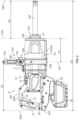
- FIG. 1is a perspective view of an impact wrench according to one embodiment.
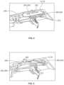
- FIG. 2is a plan view of the impact wrench of FIG. 1 , with a boot removed.
- FIG. 3is an enlarged, cross-sectional view of the impact wrench of FIG. 1 , with portions removed.
- FIG. 4is a perspective view of a forward/reverse actuator of the impact wrench of FIG. 1 , with the forward/reverse actuator in a first position.
- FIG. 5is a perspective view of a forward/reverse actuator of the impact wrench of FIG. 1 , with the forward/reverse actuator in a second position.
- FIG. 6is a graph showing ADC readings based on first, second and third positions of the forward/reverse switch of FIG. 4 .
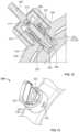
- FIG. 7is a perspective view of an impact housing of the impact wrench of FIG. 1 , with portions removed.
- FIG. 8is a cross-sectional view of an auxiliary handle assembly of the impact wrench of FIG. 1 .
- FIG. 9is an exploded view of a collar lock assembly of the auxiliary handle assembly of FIG. 8 .
- FIG. 10is an enlarged perspective view of a collar of the auxiliary handle assembly of FIG. 8 .
- FIG. 11is an enlarged perspective view of a collar lock assembly of the auxiliary handle assembly of FIG. 8 , with a first actuator knob in a first position.
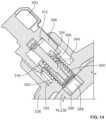
- FIG. 12is a cross-sectional view of a collar lock assembly of the auxiliary handle assembly of FIG. 8 , with a first actuator knob in a first position and a detent in a first position.
- FIG. 13is an enlarged perspective view of a collar lock assembly of the auxiliary handle assembly of FIG. 8 , with a first actuator knob in a second position.
- FIG. 14is a cross-sectional view of a collar lock assembly of the auxiliary handle assembly of FIG. 8 , with a first actuator knob in a second position a detent in a second position.
- FIG. 15is a plan view of the collar lock assembly of FIG. 11 with the first actuator knob in the first position.
- FIG. 16is a plan view of the collar lock assembly of FIG. 11 with the first actuator knob in between the first and second positions.
- FIG. 17is a plan view of the collar lock assembly of FIG. 11 with the first actuator knob in between the first and second positions.
- FIG. 18is a plan view of the collar lock assembly of FIG. 11 with the first actuator knob in the second position.
- FIG. 19is an exploded view of a handle lock assembly of the auxiliary handle assembly of FIG. 8 .
- FIG. 20is a cross-sectional view of a handle lock assembly of the auxiliary handle assembly of FIG. 8 , with a second actuator knob in a first position.
- FIG. 21is a perspective view of a handle of the auxiliary handle assembly of FIG. 8 .
- FIG. 22is an enlarged perspective view of a collar of the auxiliary handle assembly of FIG. 8 .
- FIG. 23is a perspective view of the handle lock assembly of FIG. 20 .
- FIG. 24is a plan view of the handle lock assembly of FIG. 20 , with a second actuator knob in a second position.
- FIG. 25is a plan view of the handle lock assembly of FIG. 20 , with a second actuator knob in a first position.
- FIG. 26is a plan view of the handle lock assembly of FIG. 20 , with a handle receiving an impact force.
- FIG. 27is a plan view of the handle lock assembly of FIG. 20 , with a handle in a deflected position.
- FIG. 28is a plan view of the handle lock assembly of FIG. 20 , with the handle lock assembly illustrating a response to the handle receiving an impact force.
- FIGS. 1 and 2illustrate a power tool in the form of an impact tool or impact wrench 10 .
- the impact wrench 10includes a housing 12 with a motor housing portion 14 , an impact housing portion 16 coupled to the motor housing portion 14 (e.g., by a plurality of fasteners), and a generally D-shaped handle portion 18 disposed rearward of the motor housing portion 14 .
- the handle portion 18includes a grip 19 that can be grasped by a user operating the impact wrench 10 .
- the grip 19is spaced from the motor housing portion 14 such that an aperture 20 is defined between the grip 19 and the motor housing portion 14 .
- a trigger 21extends from the grip 19 into the aperture 20 .
- the handle portion 18 and the motor housing portion 14are defined by cooperating clamshell halves, and the impact housing portion 16 is a unitary body.
- an elastomeric (e.g. rubber) boot 22at least partially covers the impact housing portion 16 for protection.
- the boot 22may be permanently affixed to the impact housing portion 16 or removable and replaceable.
- the impact wrench 10includes a battery pack 25 removably coupled to a battery receptacle 26 on the housing 12 .
- the battery pack 25preferably has a nominal capacity of at least 5 Amp-hours (Ah) (e.g., with two strings of five series-connected battery cells (a “5S2P” pack)). In some embodiments, the battery pack 25 has a nominal capacity of at least 9 Ah (e.g., with three strings of five series-connected battery cells (a “5S3P pack”).
- the illustrated battery pack 25has a nominal output voltage of at least 18 V.
- the battery pack 25is rechargeable, and the cells may have a Lithium-based chemistry (e.g., Lithium, Lithium-ion, etc.) or any other suitable chemistry.
- an electric motor 28supported within the motor housing portion 14 , receives power from the battery pack 25 ( FIG. 1 ) when the battery pack 25 is coupled to the battery receptacle 26 .
- the illustrated motor 28is a brushless direct current (“BLDC”) motor with a rotor or output shaft 30 that is rotatable about a motor axis 32 .
- a fan 34is coupled to the output shaft 30 (e.g., via a splined connection) adjacent a front end of the motor 28 .
- the impact wrench 10may include a power cord for electrically connecting the motor 28 to a source of AC power.
- the impact wrench 10may be configured to operate using a different power source (e.g., a pneumatic power source, etc.).
- the battery pack 25is the preferred means for powering the impact wrench 10 , however, because a cordless impact wrench advantageously requires less maintenance (e.g., no oiling of air lines or compressor motor) and can be used in locations where compressed air or other power sources are unavailable.
- the impact wrench 10further includes a gear assembly 66 coupled to the motor output shaft 30 and a drive assembly 70 coupled to an output of the gear assembly 66 .
- the gear assembly 66is supported within the housing 12 by a support 74 , which is coupled between the motor housing portion 14 and the impact housing portion 16 in the illustrated embodiment.
- the support 74separates the interior of the motor housing portion 14 from the interior of the impact housing portion 16 , and the support 74 and the impact housing portion 16 collectively define a gear case 76 , with the support 74 defining the rear wall of the gear case 76 .
- the gear assembly 66may be configured in any of a number of different ways to provide a speed reduction between the output shaft 30 and an input of the drive assembly 70 .
- the illustrated gear assembly 66includes a helical pinion 82 formed on the motor output shaft 30 , a plurality of helical planet gears 86 , and a helical ring gear 90 .
- the output shaft 30extends through the support 74 such that the pinion 82 is received between and meshed with the planet gears 86 .
- the helical ring gear 90surrounds and is meshed with the planet gears 86 and is rotationally fixed within the gear case 76 (e.g., via projections (not shown) on an exterior of the ring gear 90 cooperating with corresponding grooves (not shown) formed inside impact housing portion 16 ).
- the planet gears 86are mounted on a camshaft 94 of the drive assembly 70 such that the camshaft 94 acts as a planet carrier for the planet gears 86 .
- the gear assembly 66provides a gear ratio from the output shaft 30 to the camshaft 94 between 10:1 and 14:1; however, the gear assembly 66 may be configured to provide other gear ratios.
- the camshaft 94is rotationally supported at its rear end (i.e. the end closest to the motor 28 ) by a radial bearing 102 .
- the camshaft 94includes a bearing seat 106 between the planet gears 86 and the rear end of the camshaft 94 .
- An inner race 110 of the bearing 102is coupled to the bearing seat 106 .
- An outer race 114 of the bearing 102is coupled to a bearing retainer 118 formed in the support 74 .
- the drive assembly 70includes an anvil 200 , extending from the impact housing portion 16 , to which a tool element (e.g., a socket; not shown) can be coupled for performing work on a workpiece (e.g., a fastener).
- the drive assembly 70is configured to convert the continuous rotational force or torque provided by the motor 28 and gear assembly 66 to a striking rotational force or intermittent applications of torque to the anvil 200 when the reaction torque on the anvil 200 (e.g., due to engagement between the tool element and a fastener being worked upon) exceeds a certain threshold.
- the drive assembly 66includes the camshaft 94 , a hammer 204 supported on and axially slidable relative to the camshaft 94 , and the anvil 200 .
- the camshaft 94includes a cylindrical projection 205 adjacent the front end of the camshaft 94 .
- the cylindrical projection 205is smaller in diameter than the remainder of the camshaft 94 and is received within a pilot bore 206 extending through the anvil 200 along the motor axis 32 .
- the engagement between the cylindrical projection 205 and the pilot bore 206rotationally and radially supports the front end of the camshaft 94 .
- a ball bearing 207is seated within the pilot bore 206 .
- the cylindrical projectionabuts the ball bearing 207 , which acts as a thrust bearing to resist axial loads on the camshaft 94 .
- the camshaft 94is rotationally and radially supported at its rear end by the bearing 102 and at its front end by the anvil 200 . Because the radial position of the planet gears 86 on the camshaft 94 is fixed, the position of the camshaft 94 sets the position of the planet gears 86 .
- the ring gear 90is coupled to the impact housing portion 16 such that the ring gear 90 may move radially to a limited extent or “float” relative to the impact housing portion 16 . This facilitates alignment between the planet gears 86 and the ring gear 90 .
- the drive assembly 70further includes a spring 208 biasing the hammer 204 toward the front of the impact wrench 10 (i.e., in the right direction of FIG. 3 ).
- the spring 208biases the hammer 204 in an axial direction toward the anvil 200 , along the motor axis 32 .
- a thrust bearing 212 and a thrust washer 216are positioned between the spring 208 and the hammer 204 .
- the thrust bearing 212 and the thrust washer 216allow for the spring 208 and the camshaft 94 to continue to rotate relative to the hammer 204 after each impact strike when lugs (not shown) on the hammer 204 engage and impact corresponding anvil lugs to transfer kinetic energy from the hammer 204 to the anvil 200 .
- the camshaft 94further includes cam grooves 224 in which corresponding cam balls 228 are received.
- the cam balls 228are in driving engagement with the hammer 204 and movement of the cam balls 228 within the cam grooves 224 allows for relative axial movement of the hammer 204 along the camshaft 94 when the hammer lugs and the anvil lugs are engaged and the camshaft 94 continues to rotate.
- a bushing 222is disposed within the impact housing 16 of the housing to rotationally support the anvil 200 .
- a washer 226which in some embodiments may be an integral flange portion of bushing 222 , is located between the anvil 200 and a front end of the impact housing portion 16 . In some embodiments, multiple washers 226 may be provided as a washer stack.
- an operatoractivates the motor 28 by depressing the trigger 21 , which continuously drives the gear assembly 66 and the camshaft 94 via the output shaft 30 .
- the cam balls 228drive the hammer 204 to co-rotate with the camshaft 94 , and the hammer lugs engage, respectively, driven surfaces of the anvil lugs to provide an impact and to rotatably drive the anvil 200 and the tool element.
- the hammer 204moves or slides rearward along the camshaft 94 , away from the anvil 200 , so that the hammer lugs disengage the anvil lugs 220 .
- the cam balls 228 situated in the respective cam grooves 224 in the camshaft 94move rearward in the cam grooves 224 .
- the spring 208stores some of the rearward energy of the hammer 204 to provide a return mechanism for the hammer 204 .
- the hammer 204continues to rotate and moves or slides forwardly, toward the anvil 200 , as the spring 208 releases its stored energy, until the drive surfaces of the hammer lugs re-engage the driven surfaces of the anvil lugs to cause another impact.
- the impact housing portion 16includes a front portion 228 from which the anvil 200 extends.
- the front portion 228 of the impact housing portion 16includes a front end 229 defining a front end plane FEP.
- the impact housing portion 16also includes a rear portion 230 that is between the front portion 228 and the motor housing portion 14 .
- the front portion 228has a first height H 1 and the rear portion 230 has a second height H 2 that is greater than H 1 .
- H 1is 3.1 inches and H 2 is 5.2 inches.
- a ratio between the second height H 2 and the first height H 1is between 1.5 and 2.0.
- the impact wrench 10also includes an auxiliary handle assembly 232 including a collar 236 coupled to the rear portion 230 of the impact housing portion 16 and a handle 240 pivotally coupled to the collar 236 .
- the collar 236defines a handle plane HP that extends centrally through the collar, orthogonal to the motor axis 32 , and that is parallel to the front end plane FEP.
- a first distance D 1 between the front end plane FEP and the handle plane HPis greater than or equal to six inches, which ensures that the handle 240 is outside a truck wheel rim if the anvil 200 with, for example, a minimum one inch length socket attached, is extended into the rim and used to fasten or loosen a nut in the rim.
- the grip 19includes a rear surface 244 that defines a rearmost point of the impact wrench 10 and a rear end plane REP that is parallel to the front end plane FEP.
- the anvil 200has an end 248 defining an anvil end plane AEP.
- a second distance D 2 between the rear end plane REP and anvil end plane AEPis less than or equal to 19.5 inches.
- a third distance D 3 between the handle plane HP and the rear end plane REPis less than or equal to 13.5 inches.
- a fourth distance D 4 between the front end plane FEP and the anvil end plane AEPis greater than or equal to 6 inches, such that the anvil 200 is able to extend into a truck rim to fasten or loosen a nut in the truck wheel rim.
- the handle portion 18includes top surface 256 on which a forward/reverse actuator 260 is arranged.
- the forward/reverse actuator 260is moveable between a first position, in which the output shaft 30 and thus the anvil 200 rotate about the motor axis 32 in a first (e.g. tightening) direction, and a second position, in which the output shaft 30 and thus the anvil 200 rotate about the motor axis 32 in a second (e.g. loosening) direction.
- the actuator 260is also movable to a third position, for example, between the first and second positions in which the motor 28 is inhibited from being activated in response to the trigger 21 being actuated.
- the impact wrench 10when the actuator 260 is in the third position, the impact wrench 10 is in a “neutral” state, in which the impact wrench 10 may be placed during transport to avoid accidental activation of the motor 28 . Because the forward/reverse actuator 260 is on the top surface 256 , the impact wrench 10 may be operated by a user with one hand. Specifically, the operator may grasp the grip 19 with middle, ring, and pinkie fingers, while operating the trigger 21 with the index finger and the forward/reverse actuator 260 with the thumb.
- the forward/reverse actuator 260is a mechanical shuttle that slides between the first ( FIG. 4 ) and second ( FIG. 5 ) positions.
- the forward/reverse actuator 260has a first magnet 264 and a second magnet 268 , and a sensor, such as an inductive sensor 272 , is arranged underneath the forward/reverse actuator 260 in the handle portion 18 .
- the inductive sensor 272is in electrical communication with a motor control unit (MCU) 276 (shown schematically in FIG. 1 ) that is configured to control the motor 28 .
- the MCU 276is also in electrical communication with the motor 28 and trigger 21 .
- the first magnet 264has a south pole end 280 aligned with the inductive sensor 272 , such that when the forward/reverse actuator 260 is in the first position, the south pole end 280 is arranged proximate the inductive sensor 272 .
- an electromagnetic fieldis created. Based on Faraday's Law of Induction, a voltage will be induced in the first magnet 264 in response to relative movement between the south pole end 280 of the first magnet 264 and the magnetic field of the inductive sensor 272 , which, in turn, produces Eddy currents in the first magnet 264 that oppose the electromagnetic field created by the inductive sensor 272 .
- the MCU 276uses an analog to digital (ADC) reading representative of the change in inductance of the inductive sensor 272 to determine that it is the south pole end 280 of the first magnet 264 that is moved over the inductive sensor 272 , when the ADC reading generates a number between 0 and approximately 310 (see FIG. 6 ), which indicates that the motor 28 and anvil 200 should be rotated in the first (e.g. forward, tightening) direction.
- ADCanalog to digital
- the second magnet 268has a north pole end 284 aligned with the inductive sensor 272 , such that when the forward/reverse actuator 260 is in the second position, the north pole end 284 is arranged proximate the inductive sensor 272 .
- a voltagewill be induced in the second magnet 268 in response to relative movement between the second magnet 268 and the magnetic field of the inductive sensor 272 , which, in turn, produces Eddy currents in the second magnet 268 that oppose the electromagnetic field created by the inductive sensor 272 .
- This changes the inductance of the inductive sensor 272which can be measured and used as an indicator of the presence or physical proximity of the second magnet 268 relative to the inductive sensor 272 .
- the MCU 276uses the ADC reading representative of the change in inductance of the inductive sensor 272 to determine that it was the north pole end 284 of the second magnet 268 that was moved over the inductive sensor 272 , when the ADC reading generates a number between approximately 540 and approximately 625 (based on a hexadecimal system) (see FIG. 6 ), which indicates that the motor 28 and anvil 200 should be rotated in the second (e.g. reverse, loosening) direction.
- the forward/reverse actuator 260is also moveable to a third “neutral” position between the first and second positions, in which the motor 28 will remain deactivated, even if the trigger 21 is pulled.
- the third positionneither the first magnet 264 nor the second magnet 268 are arranged proximate the inductive sensor 272 , such that no magnetic field is generated and the MCU 276 uses the ADC reading to determine that neither of the first or second magnets 264 , 268 are over the inductive sensor 272 , when the ADC reading generates a number between approximately 310 and approximately 540 (see FIG. 6 ), which indicates that the motor 28 and anvil 200 should not be rotated even if the trigger 21 is pulled.
- the rear portion 230 of the impact housing portion 16includes a plurality of radial bores 288 that facilitate mounting of the collar 236 to the rear portion 230 of the impact housing portion 16 .
- the bores 288are formed in steel inserts 290 in the collar 236 .
- the bores 288arranged at angles ⁇ with respect to one another.
- ais 45 degrees but in other embodiments, a can be greater or less than 45 degrees.
- the rubber boot 22has a plurality of indicia 292 to indicate the various potential rotational positions of the collar 236 with respect to the impact housing 16 .
- the collar 236is arranged about and axially aligned with the plurality of radial bores 288 along the handle plane HP.
- the collar 236also includes a collar lock assembly 296 .
- the collar lock assembly 296includes a first actuator knob 300 that is coupled to a detent 304 via a threaded member 308 , with the threaded member 308 being coupled to the first actuator knob 300 via a transverse pin 312 that passes through bores 313 , 314 respectively arranged in the threaded member 308 and the first actuator knob 300 .
- the collar lock assembly 296also includes a spring seat member 316 that is threaded into a threaded bore 320 of the collar 236 .
- a collar lock assembly spring 324is arranged inside and seated against the spring seat member 316 , such that the spring 324 biases the detent 304 , and thus the threaded member 308 and first actuator knob 300 , radially inward and toward the motor axis 32 .
- the detent 304is biased toward a first position in which the detent 304 is received in one of the bores 288 , as shown in FIG. 12 .
- the threaded member 308extends centrally through the spring seat member 316 and the spring 324 .
- the collar 236includes a well 328 in which the threaded bore 320 of the collar 236 is arranged.
- the well 328includes a pair of bottom surfaces 332 , a pair of top recesses 336 (only one shown), and a pair of identical cam surfaces 340 (only one shown) that are respectively arranged between the bottom surfaces 332 and top recesses 336 .
- the first actuator knob 300includes a pair of cam surfaces 344 (only one shown) and a pair of projections or detents 348 .
- the operatorTo switch the rotational orientation of the collar 236 with respect to the rear portion 230 of the impact housing portion 16 , the operator must first disengage the detent 304 from the bore 288 in which it is arranged. Thus, the operator rotates the first actuator knob 300 counterclockwise, as viewed chronologically in FIGS. 15 - 18 . As the operator rotates the first actuator knob 300 , the detents 348 of the first actuator knob 300 move along the cam surfaces 340 of the well 238 , until the detents reach a position shown in FIG. 18 , at which point the spring 324 biases the detents 348 into the top recesses 336 .
- the detent 304has been moved to a second position, in which the detent 304 is out of the bore 288 in which it was arranged, as shown in FIGS. 14 and 18 .
- a plurality of red indicators 352 ( FIG. 13 ) on the first actuator knob 300are exposed from the well 328 to alert the operator that the collar lock assembly 296 is in an unlocked state, such that the collar 296 is rotationally moveable with respect to the impact housing portion 16 .
- the operatormay then rotate the collar 236 with respect to the impact housing portion 16 to a new rotational position in which the detent 304 is aligned with a new bore 288 .
- the operatorrotates the first actuator knob 300 clockwise as viewed in order of FIG. 18 , FIG. 17 , FIG. 16 , and FIG. 15 , until the detents 348 of the first actuator knob 260 reach the bottom surfaces 332 of the well 328 and the detent 304 is arranged in the first position in the new bore 288 (see FIGS. 11 , 12 , and 15 ), such that the collar 236 is once again rotationally locked with respect to the impact housing portion 16 in the new rotational position.
- the cam surfaces 344 of the first actuator knob 260are respectively mated against the cam surfaces 340 of the well 328 , as shown in FIG. 15 .
- the auxiliary handle assembly 232includes a handle lock assembly 356 to selectively lock the handle 240 with respect to the collar 236 .
- the handle lock assembly 356includes a second actuator knob 360 that is coupled to a threaded fastener 362 via a nut 363 .
- the threaded fastener 362defines a pivot axis PA and has an end 362 a arranged in a first outer jaw 364 that is arranged in the handle 240 .
- the threaded fastener 362extends through a second outer jaw 372 , as well as first and second inner jaws 376 , 380 .
- the first outer jaw 364has a first plurality of outer teeth 384 that mesh with a first plurality of inner teeth 388 on the first inner jaw 376 .
- the second outer jaw 372has a second plurality of outer teeth 392 that mesh with a second plurality of inner teeth 396 on the second inner jaw 380 .
- a first spring 400is arranged between the first outer jaw 364 and first inner jaw 376 , such that the first inner jaw 376 is biased away from the first outer jaw 364 .
- a second spring 404is arranged between the second outer jaw 372 and the second inner jaw 380 , such that the second outer jaw 372 is biased away from the second inner jaw 380 .
- a central spring 408is arranged between the first and second inner jaws 376 , 380 , such that the first and second inner jaws 376 , 380 are biased away from one another.
- An end cap 412is arranged adjacent the first outer jaw 364 within the handle 240 and secured to the handle 240 via a pin 416 , such that when the handle 240 is being adjusted with respect to the collar 236 as described in further detail below, the handle lock assembly 356 does not move back and forth along the pivot axis PA.
- the end cap 412has ribs 420 and the first outer jaw 364 has ribs 424 that are arranged in corresponding recesses 428 of the handle 240 , such that the end cap 412 and first outer jaw 364 are coupled for rotation with the handle 240 about the pivot axis PA.
- the second outer jaw 372has ribs 432 that are arranged in corresponding recesses 436 of the handle 240 , such that the second outer jaw 372 is coupled for rotation with the handle 240 when arranged inside of the handle 240 .
- the first and second inner jaws 376 , 380respectively have ribs 440 , 444 that are arranged in a recess 448 of a loop 452 on the collar 236 , such that the first and second inner jaws 376 , 380 are inhibited from rotation about the pivot axis PA.
- the operatorWhen the operator desires to adjust the position of the handle 240 with respect to the collar 236 , the operator first rotates the second actuator knob 360 about the pivot axis PA, such that the nut 363 and second actuator knob 360 move away from the second outer jaw 372 along the threaded fastener 362 .
- the first spring 400is able to bias the first inner jaw 376 from the first outer jaw 364 , such that first plurality of outer teeth 384 are no longer engaged with the first plurality of inner teeth 388 . Also, once the second actuator knob 360 has been moved to the first position shown in FIG.
- the second spring 404is able to bias the second outer jaw 372 from the second inner jaw 380 , such that the second plurality of outer teeth 392 are no longer engaged with the second plurality of inner teeth 396 .
- the central spring 408is inhibited from biasing the second inner jaw 380 into contact with the second outer jaw 372 because the second inner jaw 380 is blocked by a second inner rim 456 ( FIG. 21 ) of the handle 240 .
- the operatormay now pivot the handle 240 about the pivot axis PA to a new position with respect to the collar 236 .
- the first outer jaw 364 and end cap 412pivot therewith.
- the second outer jaw 372does not pivot with the handle 240 , because in the first position of the second actuator knob 360 , the second outer jaw 372 has been biased by the second spring 404 to a position in which the ribs 432 are no longer arranged in the corresponding recesses 436 of the handle 240 .
- the operatorrotates the second actuator knob 360 until it is moved to a second, locked, position shown in FIG. 25 .
- Movement of the second actuator knob 360 to the second positionmoves the second outer jaw 372 back toward the second inner jaw 380 , such that the second plurality of outer teeth 312 are engaged with the second plurality of inner teeth 396 .
- the second inner jaw 380moves, via the central spring 408 , the first inner jaw 376 , into abutting contact with a first inner rim 460 ( FIG.
- a force Fis applied to the handle 240 (as shown in FIG. 26 ) while the second actuator knob 260 is in the second, locked position, thereby causing the first and second outer jaws 364 , 372 to rotate with the handle 240 .
- the sudden rotation of the first and second outer jaws 364 , 372respectively move the first and second inner jaws 376 , 380 toward each other, causing the central spring 408 to compress, such that the first and second inner jaws 376 , 380 momentarily disengage the first and second outer jaws 364 , 372 , thereby preventing damage to the handle lock assembly 356 , handle 240 , and collar 236 .
Landscapes
- Engineering & Computer Science (AREA)
- Mechanical Engineering (AREA)
- Percussive Tools And Related Accessories (AREA)
- Details Of Spanners, Wrenches, And Screw Drivers And Accessories (AREA)
- Portable Power Tools In General (AREA)
Abstract
Description
Claims (20)
Priority Applications (2)
| Application Number | Priority Date | Filing Date | Title |
|---|---|---|---|
| US17/183,472US12157208B2 (en) | 2020-02-24 | 2021-02-24 | Impact tool |
| US18/965,760US20250091181A1 (en) | 2020-02-24 | 2024-12-02 | Impact tool |
Applications Claiming Priority (2)
| Application Number | Priority Date | Filing Date | Title |
|---|---|---|---|
| US202062980706P | 2020-02-24 | 2020-02-24 | |
| US17/183,472US12157208B2 (en) | 2020-02-24 | 2021-02-24 | Impact tool |
Related Child Applications (1)
| Application Number | Title | Priority Date | Filing Date |
|---|---|---|---|
| US18/965,760ContinuationUS20250091181A1 (en) | 2020-02-24 | 2024-12-02 | Impact tool |
Publications (2)
| Publication Number | Publication Date |
|---|---|
| US20210260734A1 US20210260734A1 (en) | 2021-08-26 |
| US12157208B2true US12157208B2 (en) | 2024-12-03 |
Family
ID=77365742
Family Applications (2)
| Application Number | Title | Priority Date | Filing Date |
|---|---|---|---|
| US17/183,472Active2042-02-25US12157208B2 (en) | 2020-02-24 | 2021-02-24 | Impact tool |
| US18/965,760PendingUS20250091181A1 (en) | 2020-02-24 | 2024-12-02 | Impact tool |
Family Applications After (1)
| Application Number | Title | Priority Date | Filing Date |
|---|---|---|---|
| US18/965,760PendingUS20250091181A1 (en) | 2020-02-24 | 2024-12-02 | Impact tool |
Country Status (4)
| Country | Link |
|---|---|
| US (2) | US12157208B2 (en) |
| EP (1) | EP4110554B1 (en) |
| CN (1) | CN218658760U (en) |
| WO (1) | WO2021173602A1 (en) |
Families Citing this family (12)
| Publication number | Priority date | Publication date | Assignee | Title |
|---|---|---|---|---|
| EP3894136A4 (en)* | 2018-12-10 | 2023-01-11 | Milwaukee Electric Tool Corporation | HIGH TORQUE IMPACT TOOL |
| JP7320419B2 (en) | 2019-09-27 | 2023-08-03 | 株式会社マキタ | rotary impact tool |
| JP7386027B2 (en)* | 2019-09-27 | 2023-11-24 | 株式会社マキタ | rotary impact tool |
| USD948978S1 (en)* | 2020-03-17 | 2022-04-19 | Milwaukee Electric Tool Corporation | Rotary impact wrench |
| USD999037S1 (en)* | 2020-10-21 | 2023-09-19 | Ingersoll-Rand Industrial U.S., Inc. | Impact tool |
| JP7691303B2 (en)* | 2021-08-06 | 2025-06-11 | 株式会社マキタ | Impact Tools |
| USD1015103S1 (en)* | 2022-03-09 | 2024-02-20 | Mobiletron Electronics Co., Ltd. | Impact wrench |
| JP2024033183A (en)* | 2022-08-30 | 2024-03-13 | 株式会社マキタ | Auxiliary grip for impact tools |
| TWI852080B (en)* | 2022-09-12 | 2024-08-11 | 車王電子股份有限公司 | Power Tool Batteries |
| USD1044452S1 (en)* | 2023-01-06 | 2024-10-01 | Mobiletron Electronics Co., Ltd | Part of case of power tool |
| US20240335933A1 (en)* | 2023-04-07 | 2024-10-10 | Ingersoll-Rand Industrial U.S., Inc. | Multiple position non-contact trigger system for a power tool |
| US20250205858A1 (en)* | 2023-12-21 | 2025-06-26 | Milwaukee Electric Tool Corporation | Mechanical clutch in an impact tool |
Citations (217)
| Publication number | Priority date | Publication date | Assignee | Title |
|---|---|---|---|---|
| US2373664A (en) | 1941-12-17 | 1945-04-17 | Rotor Tool Company | Impact clutch |
| US2373667A (en) | 1943-02-11 | 1945-04-17 | Rotor Tool Company | Impact clutch |
| US2564224A (en) | 1946-04-08 | 1951-08-14 | Independent Pneumatic Tool Co | Impact tool |
| US2825436A (en) | 1953-07-03 | 1958-03-04 | Chicago Pneumatic Tool Co | Impact clutch |
| US2881884A (en) | 1955-01-12 | 1959-04-14 | Chicago Pneumatic Tool Co | Impact clutch |
| US2973071A (en) | 1956-10-31 | 1961-02-28 | Master Power Corp | Impact tool |
| US3068973A (en) | 1960-07-29 | 1962-12-18 | Gardner Denver Co | Rotary impact tool |
| US3070201A (en) | 1960-03-02 | 1962-12-25 | Ingersoli Rand Company | Impact tool |
| US3156334A (en) | 1961-05-16 | 1964-11-10 | Reed Roller Bit Co | Impact tool with hammer rotatable and axially movable within the motor |
| US3250153A (en) | 1964-01-27 | 1966-05-10 | Everett W Purkey | Portable drill press |
| US3352368A (en) | 1965-08-30 | 1967-11-14 | Black & Decker Mfg Co | Pivoted trigger means for power-operated reversible tool |
| US3362486A (en) | 1964-06-18 | 1968-01-09 | Meudon Forges Atel | Impact wrenches |
| US3369615A (en) | 1966-05-27 | 1968-02-20 | Black & Decker Mfg Co | Impact wrench |
| US3606931A (en) | 1969-06-19 | 1971-09-21 | Atlas Copco Ab | Rotary impact motor |
| US3648784A (en) | 1969-09-26 | 1972-03-14 | Atlas Copco Ab | Rotary impact motor |
| US3804180A (en) | 1972-07-07 | 1974-04-16 | M Gelfand | Impact wrench |
| US4002212A (en) | 1974-10-02 | 1977-01-11 | Atlas Copco Aktiebolag | Rotary impact mechanism |
| US4276675A (en) | 1980-02-07 | 1981-07-07 | Black & Decker Inc. | Auxiliary handle for a power tool |
| US4314782A (en) | 1979-08-06 | 1982-02-09 | Black & Decker Inc. | Tool guide |
| US4505170A (en) | 1982-09-30 | 1985-03-19 | Laere Christiaan G M | Hand-holdable electric power tool apparatus |
| US4619162A (en) | 1982-09-30 | 1986-10-28 | Laere Christiaan G M | Hand-holdable electric power tool apparatus |
| US4719976A (en) | 1985-02-26 | 1988-01-19 | Robert Bosch Gmbh | Hammer drill |
| US4790218A (en) | 1987-11-19 | 1988-12-13 | Cabrera Leonel M | Rotary socket wrench |
| US4905423A (en) | 1982-09-30 | 1990-03-06 | Laere Christiaan G M | Electric rotary power tool apparatus holdable by hand during operation, kit comprising the same, and novel switch means therefor |
| US4977966A (en) | 1990-03-30 | 1990-12-18 | The United States Of America As Represented By The Secretary Of The Navy | Seawater hydraulic rotary impact tool |
| US5049012A (en) | 1991-03-11 | 1991-09-17 | Ryobi Motor Products Corp. | Auxiliary handle for hand-held drill |
| US5092410A (en) | 1990-03-29 | 1992-03-03 | Chicago Pneumatic Tool Company | Adjustable pressure dual piston impulse clutch |
| USD343345S (en) | 1992-03-25 | 1994-01-18 | Hitachi Koki Company Limited | Portable electric hammer |
| US5836403A (en) | 1996-10-31 | 1998-11-17 | Snap-On Technologies, Inc. | Reversible high impact mechanism |
| DE19738092C1 (en) | 1997-09-01 | 1998-12-17 | Bosch Gmbh Robert | Electric tool, e.g. an electric drill, with control device for externally influencing operating parameters |
| US5888031A (en) | 1996-05-10 | 1999-03-30 | Robert Bosch Gmbh | Drilling device |
| US6104114A (en) | 1997-07-10 | 2000-08-15 | Nidec Corporation | Brushless motor |
| US6158526A (en) | 1999-03-09 | 2000-12-12 | Snap-On Tools Company | Reversible impact mechanism with structure limiting hammer travel |
| US20010004939A1 (en) | 1999-12-22 | 2001-06-28 | Gerard Durmeyer | Electromagnetic hammer having a moving ferromagnetic mass |
| US20020035876A1 (en) | 2000-03-08 | 2002-03-28 | Donaldson Robert D. | Torque process control method and apparatus for fluid powered tools |
| US6546815B2 (en) | 1999-03-16 | 2003-04-15 | Kuken Co., Ltd. | Reading method of screw rotation angle of hand-held impact wrench, hand-vibration detection method, tightening evaluation method and control method of hand-held power screw loosening tool |
| US6553627B1 (en) | 2000-09-28 | 2003-04-29 | Clifford J. Horler | Handle assembly for a tool |
| US6786683B2 (en) | 2001-04-10 | 2004-09-07 | Hilti Aktiengesellschaft | Hand tool with electronic depth stop |
| US20050121209A1 (en) | 2003-11-11 | 2005-06-09 | Matsushita Electric Works, Ltd. | Transportable power tool |
| US6935437B2 (en) | 2002-09-12 | 2005-08-30 | Kabushiki Kaisha Shinano Seisakusho | Air drill |
| US7032685B2 (en) | 2003-08-01 | 2006-04-25 | Toku Pneumatic Tool Mfg. Co., Ltd. | Fastening tool |
| US20070000676A1 (en) | 2005-06-30 | 2007-01-04 | Matsushita Electric Works, Ltd. | Rotary impact power tool |
| US7259486B2 (en) | 2005-04-21 | 2007-08-21 | Nidec Corporation | Axial fan |
| US20070209162A1 (en) | 2006-03-09 | 2007-09-13 | Mcroberts Jason | Auxiliary handle for reciprocating saw |
| US20070267206A1 (en) | 2006-05-19 | 2007-11-22 | Tranmax Machinery Co., Ltd. | Single-hand operable structure for controlling forward/backward intake of a straight pneumatic wrench |
| US20080078067A1 (en) | 2006-09-01 | 2008-04-03 | Nicolantonio Aldo D | Handle |
| US20080099217A1 (en) | 2006-10-26 | 2008-05-01 | Ingersoll-Rand Company | Electric motor impact tool |
| CN101186034A (en) | 2006-11-24 | 2008-05-28 | 罗伯特·博世有限公司 | Auxiliary handle for a hand held machine tool with rapid adjustment by means of two threads |
| DE102007039245A1 (en) | 2006-11-24 | 2008-05-29 | Robert Bosch Gmbh | Additional handle with quick adjustment and wear-resistant anti-rotation elements |
| US7401663B2 (en) | 2002-11-14 | 2008-07-22 | Black & Decker Inc. | Electric motor driven hand-held tool |
| JP2008183691A (en) | 2007-01-31 | 2008-08-14 | Makita Corp | Power tool |
| US20090000434A1 (en) | 2007-03-29 | 2009-01-01 | Makita Corporation | Handles for hand-held tools |
| USD590681S1 (en) | 2006-04-18 | 2009-04-21 | Ingersoll-Rand Company | Air tool |
| USD591130S1 (en) | 2006-04-18 | 2009-04-28 | Ingersoll-Rand Company | Air tool |
| US20090133894A1 (en) | 2005-09-07 | 2009-05-28 | Yokota Industrial Co., Ltd. | Electric impact tightening tool |
| US20090178520A1 (en) | 2006-11-22 | 2009-07-16 | Uwe Engelfried | Auxiliary handle with eccentric clamping lever for a hand-held power tool |
| US7628220B2 (en) | 2004-05-20 | 2009-12-08 | Cembre S.P.A. | Impact motorized wrench |
| USD606377S1 (en) | 2008-01-03 | 2009-12-22 | Yueh-Chi Enterprise Co., Ltd. | Air hammer |
| US20100005629A1 (en) | 2006-09-01 | 2010-01-14 | Aldo Di Nicolantonio | Auxiliary handle device |
| US7673702B2 (en) | 2007-08-09 | 2010-03-09 | Ingersoll-Rand Company | Impact wrench |
| US20100064481A1 (en) | 2008-09-15 | 2010-03-18 | Hilti Aktiengesellschaft | Auxiliary handle for hand-held power tool |
| US20100064482A1 (en) | 2008-09-15 | 2010-03-18 | Hilti Aktiengesellschaft | Auxiliary handle for hand-held power tool |
| US20100064480A1 (en) | 2008-09-15 | 2010-03-18 | Hilti Aktiengesellschaft | Auxiliary handle for hand-held power tool |
| US20100096155A1 (en) | 2007-09-21 | 2010-04-22 | Hitachi Koki Co., Ltd. | Impact Tool |
| US20100149790A1 (en)* | 2008-12-16 | 2010-06-17 | Chi Hoe Leong | Hand-held power tool |
| US20110011609A1 (en) | 2008-03-05 | 2011-01-20 | Robert Simm | Auxiliary handle and handheld power tool |
| US7905377B2 (en) | 2008-08-14 | 2011-03-15 | Robert Bosch Gmbh | Flywheel driven nailer with safety mechanism |
| US20110073334A1 (en) | 2009-09-30 | 2011-03-31 | Hitachi Koki Co., Ltd. | Rotary striking tool |
| US7918286B2 (en) | 2008-03-25 | 2011-04-05 | Makita Corporation | Impact tool |
| US20110079407A1 (en) | 2009-10-01 | 2011-04-07 | Hitachi Koki Co., Ltd. | Rotary striking tool |
| US7934566B2 (en) | 2008-08-14 | 2011-05-03 | Robert Bosch Gmbh | Cordless nailer drive mechanism sensor |
| US20110120741A1 (en) | 2008-05-09 | 2011-05-26 | Kurt Limberg | Auxiliary handle for use with a power tool |
| US20110188232A1 (en) | 2009-02-25 | 2011-08-04 | Friedman Brian E | Power tool with a light for illuminating a workpiece |
| US8069929B2 (en) | 2008-03-10 | 2011-12-06 | Makita Corporation | Impact tool |
| US20110315417A1 (en) | 2009-03-10 | 2011-12-29 | Makita Corporation | Rotary impact tool |
| US8127974B2 (en) | 2009-02-25 | 2012-03-06 | Huading Zhang | Electrical motor driven nail gun |
| US20120073846A1 (en) | 2010-09-29 | 2012-03-29 | Hitachi Koki Co., Ltd., | Power tool |
| US8230607B2 (en) | 2008-05-09 | 2012-07-31 | Milwaukee Electric Tool Corporation | Keyless blade clamp for a power tool |
| US20120199372A1 (en) | 2009-07-29 | 2012-08-09 | Hitachi Koki Co., Ltd., | Impact tool |
| US20120234566A1 (en) | 2010-11-30 | 2012-09-20 | Hitachi Koki Co., Ltd., | Impact tool |
| US8272452B2 (en) | 2007-06-05 | 2012-09-25 | Max Co., Ltd. | Hammering tool |
| US20120279736A1 (en) | 2009-07-29 | 2012-11-08 | Hitachi Koki Co., Ltd. | Impact tool |
| US20120292070A1 (en) | 2011-05-19 | 2012-11-22 | Hitachi Koki Co., Ltd. | Electric tool and communication plug for electric tool |
| US20120292065A1 (en) | 2010-02-11 | 2012-11-22 | Hitachi Koki Co. Ltd | Impact Tool |
| US20120312572A1 (en)* | 2011-06-07 | 2012-12-13 | Black & Decker Inc. | Handle assembly for power tool |
| US20120318550A1 (en) | 2010-03-11 | 2012-12-20 | Hitachi Koki Co., Ltd. | Impact tool |
| US20120319508A1 (en) | 2011-06-15 | 2012-12-20 | Hitachi Koki Co., Ltd. | Electric tool |
| US20120318549A1 (en) | 2011-06-15 | 2012-12-20 | Makita Corporation | Impact tool |
| US20130000934A1 (en) | 2010-12-28 | 2013-01-03 | Hitachi Koki Co., Ltd. | Power Tool Provided With Circuit Board |
| US20130008679A1 (en) | 2010-03-31 | 2013-01-10 | Hitachi Koki Co., Ltd. | Power Tool |
| US20130014967A1 (en) | 2010-03-31 | 2013-01-17 | Hitachi Koki Co., Ltd. | Power Tool |
| CN202684816U (en) | 2012-07-23 | 2013-01-23 | 陆永兴 | Anti-explosion energy accumulation type impact pneumatic wrench |
| US20130025892A1 (en) | 2010-03-31 | 2013-01-31 | Hitachi Koki Co., Ltd. | Power Tool |
| US8371708B2 (en) | 2008-03-26 | 2013-02-12 | Makita Corporation | Electric power tool |
| US8371394B2 (en) | 2008-04-22 | 2013-02-12 | Gerard Grand | Impact mechanism |
| US20130062008A1 (en) | 2011-04-15 | 2013-03-14 | Violent Lips, LLC | Lip Substrate Applicator Kit and Method |
| US20130062086A1 (en) | 2010-05-31 | 2013-03-14 | Hitachi Koki Co., Ltd. | Power tool |
| US20130075121A1 (en) | 2010-03-08 | 2013-03-28 | Hitachi Koki Co., Ltd. | Impact tool |
| US8407860B2 (en) | 2009-07-09 | 2013-04-02 | Robert Bosch Gmbh | Apparatus for fastening a handle on a power tool |
| US20130087355A1 (en) | 2010-06-30 | 2013-04-11 | Hitachi Koki Co., Ltd. | Impact Tool |
| US20130126202A1 (en) | 2010-07-30 | 2013-05-23 | Hitachi Koki Co., Ltd. | Screw Tightening Tool |
| US20130133911A1 (en) | 2011-11-30 | 2013-05-30 | Goshi Ishikawa | Rotary impact tool |
| US20130139614A1 (en) | 2011-12-05 | 2013-06-06 | David C. Johnson | Portable torque work station and associated torquing method |
| US8460153B2 (en) | 2009-12-23 | 2013-06-11 | Black & Decker Inc. | Hybrid impact tool with two-speed transmission |
| US20130233584A1 (en) | 2012-03-09 | 2013-09-12 | Hitachi Koki Co., Ltd. | Power Tool and Power Tool System |
| US20130270934A1 (en) | 2010-06-14 | 2013-10-17 | Black & Decker Inc. | Stator assembly for a brushless motor in a power tool |
| US20130270932A1 (en) | 2010-06-14 | 2013-10-17 | Black & Decker Inc. | Rotor assembly for brushless motor for a power tool |
| US20130284480A1 (en) | 2012-04-30 | 2013-10-31 | Hitachi Koki Co., Ltd. | Power tool |
| US8584770B2 (en) | 2010-03-23 | 2013-11-19 | Black & Decker Inc. | Spindle bearing arrangement for a power tool |
| US20130333910A1 (en) | 2009-07-29 | 2013-12-19 | Hitachi Koki Co., Ltd., | Impact tool |
| US20140014385A1 (en) | 2012-07-14 | 2014-01-16 | Hitachi Koki Co., Ltd. | Power tool |
| US20140069672A1 (en) | 2011-05-20 | 2014-03-13 | Hitachi Koki Co., Ltd. | Power Tool |
| US20140124229A1 (en) | 2011-10-31 | 2014-05-08 | Hitachi Koki Co., Ltd. | Impact tool |
| US20140131059A1 (en) | 2012-11-13 | 2014-05-15 | Milwaukee Electric Tool Corporation | High-power cordless, hand-held power tool including a brushless direct current motor |
| US20140138114A1 (en) | 2012-11-19 | 2014-05-22 | Makita Corporation | Dust collecting device and power tool having the same |
| US20140144658A1 (en) | 2011-07-05 | 2014-05-29 | Robert Bosch Gmbh | Percussion mechanism apparatus |
| US20140145524A1 (en) | 2012-11-28 | 2014-05-29 | Hitachi Koki Co., Ltd. | Electric power tool |
| US20140158388A1 (en) | 2012-12-12 | 2014-06-12 | Ingersoll-Rand Company | Torque-Limited Impact Tool |
| US20140158390A1 (en) | 2011-07-21 | 2014-06-12 | Hitachi Koki Co., Ltd. | Electric tool |
| US20140182869A1 (en) | 2012-12-27 | 2014-07-03 | Makita Corporation | Impact tool |
| US20140223695A1 (en) | 2011-06-30 | 2014-08-14 | Robert Bosch Gmbh | Handle device, in particular for hand tools |
| US20140224075A1 (en) | 2013-02-14 | 2014-08-14 | ToolTech, LLC | Flip socket nut removal tool |
| US20140231113A1 (en) | 2013-02-21 | 2014-08-21 | Robert Bosch Gmbh | Hand-held power tool and method for operating the hand-held power tool |
| US8827003B2 (en) | 2010-07-05 | 2014-09-09 | Makita Corporation | Impact tool |
| US20140251649A1 (en) | 2013-03-11 | 2014-09-11 | Makita Corporation | Power tool assembly, power tool, and auxiliary handle member |
| CN203843800U (en) | 2013-03-14 | 2014-09-24 | 株式会社牧田 | Electric tool |
| US20140318821A1 (en)* | 2012-02-03 | 2014-10-30 | Milwaukee Electric Tool Corporation | Rotary hammer |
| US20140371018A1 (en) | 2013-06-12 | 2014-12-18 | Makita Corporation | Power rotary tool and impact power tool |
| US20140374130A1 (en) | 2012-03-13 | 2014-12-25 | Hitachi Koki Co., Ltd. | Impact Tool |
| US20150000946A1 (en) | 2013-07-01 | 2015-01-01 | Ingersoll-Rand Company | Rotary Impact Tool |
| US8925646B2 (en) | 2011-02-23 | 2015-01-06 | Ingersoll-Rand Company | Right angle impact tool |
| US8925645B2 (en) | 2008-05-08 | 2015-01-06 | Hitachi Koki Co., Ltd. | Oil pulse tool |
| US20150022125A1 (en) | 2012-03-14 | 2015-01-22 | Hitachi Koki Co., Ltd. | Electric tool |
| US20150041169A1 (en) | 2013-08-08 | 2015-02-12 | Makita Corporation | Impact tool |
| US20150041170A1 (en) | 2012-01-26 | 2015-02-12 | Makita Corporation | Impact Tool |
| US20150047866A1 (en) | 2012-03-29 | 2015-02-19 | Hitachi Koki Co., Ltd. | Electric tool and fastening method using the same |
| US8961358B2 (en) | 2011-06-17 | 2015-02-24 | Makita Corporation | Electric power tool |
| US20150083451A1 (en) | 2012-03-30 | 2015-03-26 | Hitachi Koki Co., Ltd. | Power tool |
| US20150083448A1 (en) | 2013-09-26 | 2015-03-26 | Chervon Intellectual Property Limited | Electric tool and method for fastening a threaded member by using it |
| US20150144368A1 (en) | 2013-11-26 | 2015-05-28 | Makita Corporation | Power tool |
| US20150144366A1 (en) | 2013-11-26 | 2015-05-28 | Makita Corporation | Power tool |
| US20150144365A1 (en) | 2012-06-05 | 2015-05-28 | Makita Corporation | Rotary Impact Tool |
| US20150174753A1 (en) | 2013-12-25 | 2015-06-25 | Makita Corporation | Auxiliary handle and power tool having the same |
| US20150209952A1 (en) | 2014-01-30 | 2015-07-30 | Panasonic Intellectual Property Management Co., Ltd. | Auxiliary handle and electric power tool provided with the auxiliary handle |
| US20150231770A1 (en) | 2014-02-18 | 2015-08-20 | Makita Corporation | Rotary impact tool |
| US20150231771A1 (en) | 2012-09-28 | 2015-08-20 | Hitachi Koki Co., Ltd. | Power Tool |
| US9114521B2 (en) | 2009-06-04 | 2015-08-25 | Makita Corporation | Electric power tool |
| US20150266176A1 (en) | 2014-03-24 | 2015-09-24 | Makita Corporation | Impact tool |
| US20150303842A1 (en) | 2012-11-29 | 2015-10-22 | Hitachi Koki Co., Ltd. | Impact tool |
| US20150333664A1 (en) | 2014-05-16 | 2015-11-19 | Robert Bosch Gmbh | Hand-Held Power Tool |
| US20150336249A1 (en) | 2012-12-22 | 2015-11-26 | Hitachi Koki Co., Ltd. | Impact tool and method of controlling impact tool |
| US20150343617A1 (en)* | 2014-05-27 | 2015-12-03 | Makita Corporation | Power tool and rotary impact tool |
| US20150352699A1 (en) | 2013-01-24 | 2015-12-10 | Hitachi Koki Co., Ltd. | Power Tool |
| US20160008961A1 (en) | 2013-03-30 | 2016-01-14 | Hitachi Koki Co., Ltd. | Power tool |
| US20160079887A1 (en) | 2013-04-26 | 2016-03-17 | Hitachi Koki Co., Ltd. | Electric tool |
| US20160075007A1 (en) | 2013-04-17 | 2016-03-17 | Makita Corporation | Handle and power tool comprising same handle |
| US9308638B2 (en) | 2013-01-17 | 2016-04-12 | Seiko Epson Corporation | Power tool and auxiliary handle member |
| US20160107297A1 (en) | 2014-10-20 | 2016-04-21 | Makita Corporation | Electric power tool |
| US9321159B2 (en) | 2011-06-17 | 2016-04-26 | Dino Paoli S.R.L. | Impact tool |
| US20160129568A1 (en) | 2013-07-26 | 2016-05-12 | Hitachi Koki Co., Ltd. | Impact tool |
| US20160136801A1 (en) | 2014-11-14 | 2016-05-19 | Makita Corporation | Power tool |
| JP2016097498A (en) | 2014-11-26 | 2016-05-30 | 株式会社マキタ | Impact tool |
| US9393711B2 (en) | 2011-04-11 | 2016-07-19 | Milwaukee Electric Tool Corporation | Hand-held knockout punch driver |
| US9415497B2 (en) | 2009-07-03 | 2016-08-16 | Robert Bosch Gmbh | Hand-held power tool |
| US20160250743A1 (en) | 2013-11-26 | 2016-09-01 | Hitachi Koki Co., Ltd. | Electrical power tool |
| US20160279782A1 (en) | 2015-03-23 | 2016-09-29 | Robert Bosch Gmbh | Power Tool, in Particular Portable Power Tool, Having a Motorized Drive Unit and Having At Least One Sensor Device |
| US20160288308A1 (en) | 2015-03-30 | 2016-10-06 | Robert Bosch Gmbh | Protective Device at least for Protecting a User in the Event of an Uncontrolled Blockage of a Portable Power Tool |
| US9463566B2 (en) | 2013-05-29 | 2016-10-11 | Makita Corporation | Auxiliary handle and reciprocating power tool having the same |
| US20160311102A1 (en)* | 2015-04-22 | 2016-10-27 | Milwaukee Electric Tool Corporation | Rotary hammer |
| US20160325415A1 (en) | 2015-05-04 | 2016-11-10 | Milwaukee Electric Tool Corporation | Adaptive impact blow detection |
| US20160354905A1 (en) | 2015-06-05 | 2016-12-08 | Ingersoll-Rand Company | Power tools with user-selectable operational modes |
| US20170021478A1 (en) | 2013-12-17 | 2017-01-26 | HYTORC Division Unex Corporation | Apparatus for tightening threaded fasteners |
| US20170028537A1 (en) | 2011-04-05 | 2017-02-02 | Ingersoll-Rand Company | Impact wrench having dynamically tuned drive components and method thereof |
| US20170036327A1 (en) | 2015-08-07 | 2017-02-09 | Hitachi Koki Co., Ltd. | Electric tool |
| US9566692B2 (en) | 2011-04-05 | 2017-02-14 | Ingersoll-Rand Company | Rotary impact device |
| US20170057064A1 (en) | 2015-08-24 | 2017-03-02 | Makita Corporation | Rotary impact tool and method for controlling the same |
| US20170106517A1 (en)* | 2014-06-12 | 2017-04-20 | Makita Corporation | Impact tool |
| US20170106525A1 (en)* | 2015-10-16 | 2017-04-20 | Kenneth J. Brauer | Rotating handle and related methods |
| CN206122746U (en) | 2016-10-13 | 2017-04-26 | 天津智目科技发展有限公司 | Decorations are dedicated prevents that motor burns out and electric drill of measurable degree of depth |
| JP2017080853A (en) | 2015-10-30 | 2017-05-18 | 日立工機株式会社 | Power tool |
| US20170144278A1 (en) | 2014-06-30 | 2017-05-25 | Hitachi Koki Co., Ltd. | Impact tool |
| US20170151657A1 (en) | 2015-11-26 | 2017-06-01 | Makita Corporation | Power tool |
| US20170173768A1 (en) | 2015-12-17 | 2017-06-22 | Milwaukee Electric Tool Corporation | System and method for configuring a power tool with an impact mechanism |
| US20170190032A1 (en) | 2014-06-20 | 2017-07-06 | Robert Bosch Gmbh | Method for controlling an electric motor of a power tool |
| US20170190028A1 (en) | 2016-01-05 | 2017-07-06 | Milwaukee Electric Tool Corporation | Impact tool |
| US20170190027A1 (en) | 2014-05-30 | 2017-07-06 | Hitachi Koki Co., Ltd. | Electric tool |
| US20170239801A1 (en) | 2016-02-22 | 2017-08-24 | Makita Corporation | Angle tool |
| US20170246732A1 (en) | 2016-02-25 | 2017-08-31 | Milwaukee Electric Tool Corporation | Power tool including an output position sensor |
| US20170312902A1 (en)* | 2014-10-29 | 2017-11-02 | Hitachi Koki Co., Ltd. | Powered working machine |
| US20170326720A1 (en) | 2016-05-13 | 2017-11-16 | Makita Corporation | Power tool |
| US20170326712A1 (en) | 2016-05-10 | 2017-11-16 | Johnson Electric S.A. | Driving Device And Power Tool Comprising Same |
| CN206702908U (en) | 2017-05-05 | 2017-12-05 | 河钢股份有限公司邯郸分公司 | A kind of overhead traveling crane wheel quick replacement device |
| US20170348835A1 (en) | 2016-06-01 | 2017-12-07 | Actuant Corporation | Electric torque tool with ramping effect |
| US20180001444A1 (en) | 2015-01-30 | 2018-01-04 | Hitachi Koki Co., Ltd. | Work machine |
| US20180117745A1 (en) | 2015-01-30 | 2018-05-03 | Hitachi Koki Co., Ltd. | Impact tool |
| US20180200872A1 (en) | 2014-06-20 | 2018-07-19 | Robert Bosch Gmbh | Method for operating a power tool |
| US20180222022A1 (en) | 2017-02-09 | 2018-08-09 | Makita Corporation | Power tool |
| USD835959S1 (en) | 2017-12-08 | 2018-12-18 | Ingersoll-Rand Company | Pistol grip impact tool |
| US20190030696A1 (en) | 2017-07-31 | 2019-01-31 | Ingersoll-Rand Company | Impact Tool Angular Velocity Measurement System |
| US20190030692A1 (en) | 2016-01-14 | 2019-01-31 | Koki Holdings Co., Ltd. | Rotary Impact Tool |
| CN109500432A (en) | 2018-12-06 | 2019-03-22 | 重庆电子工程职业学院 | A kind of house wiring hand held drilling device |
| US10286529B2 (en) | 2013-06-27 | 2019-05-14 | Makita Corporation | Screw-tightening power tool |
| US10295990B2 (en) | 2015-05-18 | 2019-05-21 | Milwaukee Electric Tool Corporation | User interface for tool configuration and data capture |
| USD853815S1 (en) | 2017-11-06 | 2019-07-16 | Ingersoll-Rand Company | D-handle impact tool |
| CN209139897U (en) | 2018-12-14 | 2019-07-23 | 海南大凯消防安全工程有限公司 | A kind of dedicated drilling equipment through walls of fire engineering installation |
| US20190255687A1 (en)* | 2018-02-19 | 2019-08-22 | Milwaukee Electric Tool Corporation | Impact tool |
| CN209812185U (en)* | 2019-04-04 | 2019-12-20 | 熊望辉 | A inflation nail mounting tool for construction |
| US20200009709A1 (en) | 2017-03-07 | 2020-01-09 | Makita Corporation | Tool holding apparatus and power tool, and impact tool |
| US20200122281A1 (en) | 2016-07-06 | 2020-04-23 | Hilti Aktiengesellschaft | Handheld power tool |
| US20200180124A1 (en) | 2018-12-10 | 2020-06-11 | Milwaukee Electric Tool Corporation | High torque impact tool |
| US20200198100A1 (en) | 2018-12-21 | 2020-06-25 | Milwaukee Electric Tool Corporation | High torque impact tool |
| US20200262037A1 (en) | 2019-02-18 | 2020-08-20 | Milwaukee Electric Tool Corporation | Impact tool |
| EP3706960A1 (en) | 2017-11-07 | 2020-09-16 | Milwaukee Electric Tool Corporation | Non-contact speed selector swtich in rotary power tool |
| US20210100170A1 (en) | 2019-10-07 | 2021-04-08 | Makita Corporation | Hedge trimmer |
| US20210237249A1 (en) | 2020-02-04 | 2021-08-05 | Milwaukee Electric Tool Corporation | Impact tool |
| US20210260733A1 (en) | 2020-02-24 | 2021-08-26 | Milwaukee Electric Tool Corporation | Impact tool |
| US11858109B2 (en) | 2019-06-26 | 2024-01-02 | Hilti Aktiengesellschaft | Side handle for an electric hand-held power tool |
- 2021
- 2021-02-24USUS17/183,472patent/US12157208B2/enactiveActive
- 2021-02-24WOPCT/US2021/019316patent/WO2021173602A1/ennot_activeCeased
- 2021-02-24CNCN202190000346.5Upatent/CN218658760U/enactiveActive
- 2021-02-24EPEP21760776.1Apatent/EP4110554B1/enactiveActive
- 2024
- 2024-12-02USUS18/965,760patent/US20250091181A1/enactivePending
Patent Citations (225)
| Publication number | Priority date | Publication date | Assignee | Title |
|---|---|---|---|---|
| US2373664A (en) | 1941-12-17 | 1945-04-17 | Rotor Tool Company | Impact clutch |
| US2373667A (en) | 1943-02-11 | 1945-04-17 | Rotor Tool Company | Impact clutch |
| US2564224A (en) | 1946-04-08 | 1951-08-14 | Independent Pneumatic Tool Co | Impact tool |
| US2825436A (en) | 1953-07-03 | 1958-03-04 | Chicago Pneumatic Tool Co | Impact clutch |
| US2881884A (en) | 1955-01-12 | 1959-04-14 | Chicago Pneumatic Tool Co | Impact clutch |
| US2973071A (en) | 1956-10-31 | 1961-02-28 | Master Power Corp | Impact tool |
| US3070201A (en) | 1960-03-02 | 1962-12-25 | Ingersoli Rand Company | Impact tool |
| US3068973A (en) | 1960-07-29 | 1962-12-18 | Gardner Denver Co | Rotary impact tool |
| US3156334A (en) | 1961-05-16 | 1964-11-10 | Reed Roller Bit Co | Impact tool with hammer rotatable and axially movable within the motor |
| US3250153A (en) | 1964-01-27 | 1966-05-10 | Everett W Purkey | Portable drill press |
| US3362486A (en) | 1964-06-18 | 1968-01-09 | Meudon Forges Atel | Impact wrenches |
| US3352368A (en) | 1965-08-30 | 1967-11-14 | Black & Decker Mfg Co | Pivoted trigger means for power-operated reversible tool |
| US3369615A (en) | 1966-05-27 | 1968-02-20 | Black & Decker Mfg Co | Impact wrench |
| US3606931A (en) | 1969-06-19 | 1971-09-21 | Atlas Copco Ab | Rotary impact motor |
| US3648784A (en) | 1969-09-26 | 1972-03-14 | Atlas Copco Ab | Rotary impact motor |
| US3804180A (en) | 1972-07-07 | 1974-04-16 | M Gelfand | Impact wrench |
| US4002212A (en) | 1974-10-02 | 1977-01-11 | Atlas Copco Aktiebolag | Rotary impact mechanism |
| US4314782A (en) | 1979-08-06 | 1982-02-09 | Black & Decker Inc. | Tool guide |
| US4276675A (en) | 1980-02-07 | 1981-07-07 | Black & Decker Inc. | Auxiliary handle for a power tool |
| US4505170A (en) | 1982-09-30 | 1985-03-19 | Laere Christiaan G M | Hand-holdable electric power tool apparatus |
| US4619162A (en) | 1982-09-30 | 1986-10-28 | Laere Christiaan G M | Hand-holdable electric power tool apparatus |
| US4905423A (en) | 1982-09-30 | 1990-03-06 | Laere Christiaan G M | Electric rotary power tool apparatus holdable by hand during operation, kit comprising the same, and novel switch means therefor |
| US4719976A (en) | 1985-02-26 | 1988-01-19 | Robert Bosch Gmbh | Hammer drill |
| US4790218A (en) | 1987-11-19 | 1988-12-13 | Cabrera Leonel M | Rotary socket wrench |
| US5092410A (en) | 1990-03-29 | 1992-03-03 | Chicago Pneumatic Tool Company | Adjustable pressure dual piston impulse clutch |
| US4977966A (en) | 1990-03-30 | 1990-12-18 | The United States Of America As Represented By The Secretary Of The Navy | Seawater hydraulic rotary impact tool |
| US5049012A (en) | 1991-03-11 | 1991-09-17 | Ryobi Motor Products Corp. | Auxiliary handle for hand-held drill |
| USD343345S (en) | 1992-03-25 | 1994-01-18 | Hitachi Koki Company Limited | Portable electric hammer |
| US5888031A (en) | 1996-05-10 | 1999-03-30 | Robert Bosch Gmbh | Drilling device |
| US5836403A (en) | 1996-10-31 | 1998-11-17 | Snap-On Technologies, Inc. | Reversible high impact mechanism |
| US6104114A (en) | 1997-07-10 | 2000-08-15 | Nidec Corporation | Brushless motor |
| DE19738092C1 (en) | 1997-09-01 | 1998-12-17 | Bosch Gmbh Robert | Electric tool, e.g. an electric drill, with control device for externally influencing operating parameters |
| US6158526A (en) | 1999-03-09 | 2000-12-12 | Snap-On Tools Company | Reversible impact mechanism with structure limiting hammer travel |
| US6546815B2 (en) | 1999-03-16 | 2003-04-15 | Kuken Co., Ltd. | Reading method of screw rotation angle of hand-held impact wrench, hand-vibration detection method, tightening evaluation method and control method of hand-held power screw loosening tool |
| US20010004939A1 (en) | 1999-12-22 | 2001-06-28 | Gerard Durmeyer | Electromagnetic hammer having a moving ferromagnetic mass |
| US20020035876A1 (en) | 2000-03-08 | 2002-03-28 | Donaldson Robert D. | Torque process control method and apparatus for fluid powered tools |
| US6553627B1 (en) | 2000-09-28 | 2003-04-29 | Clifford J. Horler | Handle assembly for a tool |
| US6786683B2 (en) | 2001-04-10 | 2004-09-07 | Hilti Aktiengesellschaft | Hand tool with electronic depth stop |
| US6935437B2 (en) | 2002-09-12 | 2005-08-30 | Kabushiki Kaisha Shinano Seisakusho | Air drill |
| US7401663B2 (en) | 2002-11-14 | 2008-07-22 | Black & Decker Inc. | Electric motor driven hand-held tool |
| US7032685B2 (en) | 2003-08-01 | 2006-04-25 | Toku Pneumatic Tool Mfg. Co., Ltd. | Fastening tool |
| US20050121209A1 (en) | 2003-11-11 | 2005-06-09 | Matsushita Electric Works, Ltd. | Transportable power tool |
| US7628220B2 (en) | 2004-05-20 | 2009-12-08 | Cembre S.P.A. | Impact motorized wrench |
| US7259486B2 (en) | 2005-04-21 | 2007-08-21 | Nidec Corporation | Axial fan |
| US20070000676A1 (en) | 2005-06-30 | 2007-01-04 | Matsushita Electric Works, Ltd. | Rotary impact power tool |
| US20090133894A1 (en) | 2005-09-07 | 2009-05-28 | Yokota Industrial Co., Ltd. | Electric impact tightening tool |
| US20070209162A1 (en) | 2006-03-09 | 2007-09-13 | Mcroberts Jason | Auxiliary handle for reciprocating saw |
| USD591130S1 (en) | 2006-04-18 | 2009-04-28 | Ingersoll-Rand Company | Air tool |
| USD590681S1 (en) | 2006-04-18 | 2009-04-21 | Ingersoll-Rand Company | Air tool |
| US20070267206A1 (en) | 2006-05-19 | 2007-11-22 | Tranmax Machinery Co., Ltd. | Single-hand operable structure for controlling forward/backward intake of a straight pneumatic wrench |
| US20080078067A1 (en) | 2006-09-01 | 2008-04-03 | Nicolantonio Aldo D | Handle |
| US20100005629A1 (en) | 2006-09-01 | 2010-01-14 | Aldo Di Nicolantonio | Auxiliary handle device |
| US20080099217A1 (en) | 2006-10-26 | 2008-05-01 | Ingersoll-Rand Company | Electric motor impact tool |
| US20090178520A1 (en) | 2006-11-22 | 2009-07-16 | Uwe Engelfried | Auxiliary handle with eccentric clamping lever for a hand-held power tool |
| US7823256B2 (en) | 2006-11-22 | 2010-11-02 | Robert Bosch Gmbh | Auxiliary handle with eccentric clamping lever for a hand-held power tool |
| DE102007039245A1 (en) | 2006-11-24 | 2008-05-29 | Robert Bosch Gmbh | Additional handle with quick adjustment and wear-resistant anti-rotation elements |
| CN101186034A (en) | 2006-11-24 | 2008-05-28 | 罗伯特·博世有限公司 | Auxiliary handle for a hand held machine tool with rapid adjustment by means of two threads |
| JP2008183691A (en) | 2007-01-31 | 2008-08-14 | Makita Corp | Power tool |
| US8032990B2 (en) | 2007-03-29 | 2011-10-11 | Makita Corporation | Handles for hand-held tools |
| US20090000434A1 (en) | 2007-03-29 | 2009-01-01 | Makita Corporation | Handles for hand-held tools |
| US8272452B2 (en) | 2007-06-05 | 2012-09-25 | Max Co., Ltd. | Hammering tool |
| US7673702B2 (en) | 2007-08-09 | 2010-03-09 | Ingersoll-Rand Company | Impact wrench |
| US20100096155A1 (en) | 2007-09-21 | 2010-04-22 | Hitachi Koki Co., Ltd. | Impact Tool |
| USD606377S1 (en) | 2008-01-03 | 2009-12-22 | Yueh-Chi Enterprise Co., Ltd. | Air hammer |
| US20110011609A1 (en) | 2008-03-05 | 2011-01-20 | Robert Simm | Auxiliary handle and handheld power tool |
| US8069929B2 (en) | 2008-03-10 | 2011-12-06 | Makita Corporation | Impact tool |
| US7918286B2 (en) | 2008-03-25 | 2011-04-05 | Makita Corporation | Impact tool |
| US8371708B2 (en) | 2008-03-26 | 2013-02-12 | Makita Corporation | Electric power tool |
| US8371394B2 (en) | 2008-04-22 | 2013-02-12 | Gerard Grand | Impact mechanism |
| US8925645B2 (en) | 2008-05-08 | 2015-01-06 | Hitachi Koki Co., Ltd. | Oil pulse tool |
| US20110120741A1 (en) | 2008-05-09 | 2011-05-26 | Kurt Limberg | Auxiliary handle for use with a power tool |
| US8230607B2 (en) | 2008-05-09 | 2012-07-31 | Milwaukee Electric Tool Corporation | Keyless blade clamp for a power tool |
| US7905377B2 (en) | 2008-08-14 | 2011-03-15 | Robert Bosch Gmbh | Flywheel driven nailer with safety mechanism |
| US7934566B2 (en) | 2008-08-14 | 2011-05-03 | Robert Bosch Gmbh | Cordless nailer drive mechanism sensor |
| US20100064481A1 (en) | 2008-09-15 | 2010-03-18 | Hilti Aktiengesellschaft | Auxiliary handle for hand-held power tool |
| US20100064482A1 (en) | 2008-09-15 | 2010-03-18 | Hilti Aktiengesellschaft | Auxiliary handle for hand-held power tool |
| US20100064480A1 (en) | 2008-09-15 | 2010-03-18 | Hilti Aktiengesellschaft | Auxiliary handle for hand-held power tool |
| US20100149790A1 (en)* | 2008-12-16 | 2010-06-17 | Chi Hoe Leong | Hand-held power tool |
| US8127974B2 (en) | 2009-02-25 | 2012-03-06 | Huading Zhang | Electrical motor driven nail gun |
| US20110188232A1 (en) | 2009-02-25 | 2011-08-04 | Friedman Brian E | Power tool with a light for illuminating a workpiece |
| US20110315417A1 (en) | 2009-03-10 | 2011-12-29 | Makita Corporation | Rotary impact tool |
| US9114521B2 (en) | 2009-06-04 | 2015-08-25 | Makita Corporation | Electric power tool |
| US9415497B2 (en) | 2009-07-03 | 2016-08-16 | Robert Bosch Gmbh | Hand-held power tool |
| US8407860B2 (en) | 2009-07-09 | 2013-04-02 | Robert Bosch Gmbh | Apparatus for fastening a handle on a power tool |
| US20120279736A1 (en) | 2009-07-29 | 2012-11-08 | Hitachi Koki Co., Ltd. | Impact tool |
| US20120199372A1 (en) | 2009-07-29 | 2012-08-09 | Hitachi Koki Co., Ltd., | Impact tool |
| US20130333910A1 (en) | 2009-07-29 | 2013-12-19 | Hitachi Koki Co., Ltd., | Impact tool |
| US20110073334A1 (en) | 2009-09-30 | 2011-03-31 | Hitachi Koki Co., Ltd. | Rotary striking tool |
| US20110079407A1 (en) | 2009-10-01 | 2011-04-07 | Hitachi Koki Co., Ltd. | Rotary striking tool |
| US8460153B2 (en) | 2009-12-23 | 2013-06-11 | Black & Decker Inc. | Hybrid impact tool with two-speed transmission |
| US20120292065A1 (en) | 2010-02-11 | 2012-11-22 | Hitachi Koki Co. Ltd | Impact Tool |
| US20130075121A1 (en) | 2010-03-08 | 2013-03-28 | Hitachi Koki Co., Ltd. | Impact tool |
| US20120318550A1 (en) | 2010-03-11 | 2012-12-20 | Hitachi Koki Co., Ltd. | Impact tool |
| US8584770B2 (en) | 2010-03-23 | 2013-11-19 | Black & Decker Inc. | Spindle bearing arrangement for a power tool |
| US20130014967A1 (en) | 2010-03-31 | 2013-01-17 | Hitachi Koki Co., Ltd. | Power Tool |
| US20130025892A1 (en) | 2010-03-31 | 2013-01-31 | Hitachi Koki Co., Ltd. | Power Tool |
| US20130008679A1 (en) | 2010-03-31 | 2013-01-10 | Hitachi Koki Co., Ltd. | Power Tool |
| US20130062086A1 (en) | 2010-05-31 | 2013-03-14 | Hitachi Koki Co., Ltd. | Power tool |
| US20130270932A1 (en) | 2010-06-14 | 2013-10-17 | Black & Decker Inc. | Rotor assembly for brushless motor for a power tool |
| US20130270934A1 (en) | 2010-06-14 | 2013-10-17 | Black & Decker Inc. | Stator assembly for a brushless motor in a power tool |
| US20130087355A1 (en) | 2010-06-30 | 2013-04-11 | Hitachi Koki Co., Ltd. | Impact Tool |
| US8827003B2 (en) | 2010-07-05 | 2014-09-09 | Makita Corporation | Impact tool |
| US20130126202A1 (en) | 2010-07-30 | 2013-05-23 | Hitachi Koki Co., Ltd. | Screw Tightening Tool |
| US20120073846A1 (en) | 2010-09-29 | 2012-03-29 | Hitachi Koki Co., Ltd., | Power tool |
| US20120234566A1 (en) | 2010-11-30 | 2012-09-20 | Hitachi Koki Co., Ltd., | Impact tool |
| US20130000934A1 (en) | 2010-12-28 | 2013-01-03 | Hitachi Koki Co., Ltd. | Power Tool Provided With Circuit Board |
| US20150075829A1 (en) | 2011-02-23 | 2015-03-19 | Ingersoll-Rand Company | Angle Impact Tool |
| US8925646B2 (en) | 2011-02-23 | 2015-01-06 | Ingersoll-Rand Company | Right angle impact tool |
| US20170028537A1 (en) | 2011-04-05 | 2017-02-02 | Ingersoll-Rand Company | Impact wrench having dynamically tuned drive components and method thereof |
| US9566692B2 (en) | 2011-04-05 | 2017-02-14 | Ingersoll-Rand Company | Rotary impact device |
| US9393711B2 (en) | 2011-04-11 | 2016-07-19 | Milwaukee Electric Tool Corporation | Hand-held knockout punch driver |
| US20130062008A1 (en) | 2011-04-15 | 2013-03-14 | Violent Lips, LLC | Lip Substrate Applicator Kit and Method |
| US20120292070A1 (en) | 2011-05-19 | 2012-11-22 | Hitachi Koki Co., Ltd. | Electric tool and communication plug for electric tool |
| US20140069672A1 (en) | 2011-05-20 | 2014-03-13 | Hitachi Koki Co., Ltd. | Power Tool |
| US20120312572A1 (en)* | 2011-06-07 | 2012-12-13 | Black & Decker Inc. | Handle assembly for power tool |
| US20120318549A1 (en) | 2011-06-15 | 2012-12-20 | Makita Corporation | Impact tool |
| US20120319508A1 (en) | 2011-06-15 | 2012-12-20 | Hitachi Koki Co., Ltd. | Electric tool |
| US8961358B2 (en) | 2011-06-17 | 2015-02-24 | Makita Corporation | Electric power tool |
| US9321159B2 (en) | 2011-06-17 | 2016-04-26 | Dino Paoli S.R.L. | Impact tool |
| US20140223695A1 (en) | 2011-06-30 | 2014-08-14 | Robert Bosch Gmbh | Handle device, in particular for hand tools |
| US20140144658A1 (en) | 2011-07-05 | 2014-05-29 | Robert Bosch Gmbh | Percussion mechanism apparatus |
| US20140158390A1 (en) | 2011-07-21 | 2014-06-12 | Hitachi Koki Co., Ltd. | Electric tool |
| US20140124229A1 (en) | 2011-10-31 | 2014-05-08 | Hitachi Koki Co., Ltd. | Impact tool |
| US20130133911A1 (en) | 2011-11-30 | 2013-05-30 | Goshi Ishikawa | Rotary impact tool |
| US20130139614A1 (en) | 2011-12-05 | 2013-06-06 | David C. Johnson | Portable torque work station and associated torquing method |
| US20150041170A1 (en) | 2012-01-26 | 2015-02-12 | Makita Corporation | Impact Tool |
| US9849577B2 (en) | 2012-02-03 | 2017-12-26 | Milwaukee Electric Tool Corporation | Rotary hammer |
| US20140318821A1 (en)* | 2012-02-03 | 2014-10-30 | Milwaukee Electric Tool Corporation | Rotary hammer |
| US20130233584A1 (en) | 2012-03-09 | 2013-09-12 | Hitachi Koki Co., Ltd. | Power Tool and Power Tool System |
| US20140374130A1 (en) | 2012-03-13 | 2014-12-25 | Hitachi Koki Co., Ltd. | Impact Tool |
| US20150022125A1 (en) | 2012-03-14 | 2015-01-22 | Hitachi Koki Co., Ltd. | Electric tool |
| US20150047866A1 (en) | 2012-03-29 | 2015-02-19 | Hitachi Koki Co., Ltd. | Electric tool and fastening method using the same |
| US20150083451A1 (en) | 2012-03-30 | 2015-03-26 | Hitachi Koki Co., Ltd. | Power tool |
| US20130284480A1 (en) | 2012-04-30 | 2013-10-31 | Hitachi Koki Co., Ltd. | Power tool |
| US20150144365A1 (en) | 2012-06-05 | 2015-05-28 | Makita Corporation | Rotary Impact Tool |
| US20140014385A1 (en) | 2012-07-14 | 2014-01-16 | Hitachi Koki Co., Ltd. | Power tool |
| CN202684816U (en) | 2012-07-23 | 2013-01-23 | 陆永兴 | Anti-explosion energy accumulation type impact pneumatic wrench |
| US20150231771A1 (en) | 2012-09-28 | 2015-08-20 | Hitachi Koki Co., Ltd. | Power Tool |
| US20140131059A1 (en) | 2012-11-13 | 2014-05-15 | Milwaukee Electric Tool Corporation | High-power cordless, hand-held power tool including a brushless direct current motor |
| US20140138114A1 (en) | 2012-11-19 | 2014-05-22 | Makita Corporation | Dust collecting device and power tool having the same |
| US20140145524A1 (en) | 2012-11-28 | 2014-05-29 | Hitachi Koki Co., Ltd. | Electric power tool |
| US20150303842A1 (en) | 2012-11-29 | 2015-10-22 | Hitachi Koki Co., Ltd. | Impact tool |
| US20140158388A1 (en) | 2012-12-12 | 2014-06-12 | Ingersoll-Rand Company | Torque-Limited Impact Tool |
| US20150336249A1 (en) | 2012-12-22 | 2015-11-26 | Hitachi Koki Co., Ltd. | Impact tool and method of controlling impact tool |
| US9643300B2 (en) | 2012-12-27 | 2017-05-09 | Makita Corporation | Impact tool |
| US20140182869A1 (en) | 2012-12-27 | 2014-07-03 | Makita Corporation | Impact tool |
| US9308638B2 (en) | 2013-01-17 | 2016-04-12 | Seiko Epson Corporation | Power tool and auxiliary handle member |
| US20150352699A1 (en) | 2013-01-24 | 2015-12-10 | Hitachi Koki Co., Ltd. | Power Tool |
| US20140224075A1 (en) | 2013-02-14 | 2014-08-14 | ToolTech, LLC | Flip socket nut removal tool |
| US20140231113A1 (en) | 2013-02-21 | 2014-08-21 | Robert Bosch Gmbh | Hand-held power tool and method for operating the hand-held power tool |
| US20140251649A1 (en) | 2013-03-11 | 2014-09-11 | Makita Corporation | Power tool assembly, power tool, and auxiliary handle member |
| CN203843800U (en) | 2013-03-14 | 2014-09-24 | 株式会社牧田 | Electric tool |
| US20160008961A1 (en) | 2013-03-30 | 2016-01-14 | Hitachi Koki Co., Ltd. | Power tool |
| US20160075007A1 (en) | 2013-04-17 | 2016-03-17 | Makita Corporation | Handle and power tool comprising same handle |
| US20160079887A1 (en) | 2013-04-26 | 2016-03-17 | Hitachi Koki Co., Ltd. | Electric tool |
| US9463566B2 (en) | 2013-05-29 | 2016-10-11 | Makita Corporation | Auxiliary handle and reciprocating power tool having the same |
| US20140371018A1 (en) | 2013-06-12 | 2014-12-18 | Makita Corporation | Power rotary tool and impact power tool |
| US20190224819A1 (en) | 2013-06-27 | 2019-07-25 | Makita Corporation | Screw-tightening power tool |
| US10286529B2 (en) | 2013-06-27 | 2019-05-14 | Makita Corporation | Screw-tightening power tool |
| US20150000946A1 (en) | 2013-07-01 | 2015-01-01 | Ingersoll-Rand Company | Rotary Impact Tool |
| US20160129568A1 (en) | 2013-07-26 | 2016-05-12 | Hitachi Koki Co., Ltd. | Impact tool |
| US20150041169A1 (en) | 2013-08-08 | 2015-02-12 | Makita Corporation | Impact tool |
| US20150083448A1 (en) | 2013-09-26 | 2015-03-26 | Chervon Intellectual Property Limited | Electric tool and method for fastening a threaded member by using it |
| US20160250743A1 (en) | 2013-11-26 | 2016-09-01 | Hitachi Koki Co., Ltd. | Electrical power tool |
| US20150144368A1 (en) | 2013-11-26 | 2015-05-28 | Makita Corporation | Power tool |
| US20150144366A1 (en) | 2013-11-26 | 2015-05-28 | Makita Corporation | Power tool |
| US20170021478A1 (en) | 2013-12-17 | 2017-01-26 | HYTORC Division Unex Corporation | Apparatus for tightening threaded fasteners |
| US20150174753A1 (en) | 2013-12-25 | 2015-06-25 | Makita Corporation | Auxiliary handle and power tool having the same |
| US20150209952A1 (en) | 2014-01-30 | 2015-07-30 | Panasonic Intellectual Property Management Co., Ltd. | Auxiliary handle and electric power tool provided with the auxiliary handle |
| US20150231770A1 (en) | 2014-02-18 | 2015-08-20 | Makita Corporation | Rotary impact tool |
| US20150266176A1 (en) | 2014-03-24 | 2015-09-24 | Makita Corporation | Impact tool |
| US20150333664A1 (en) | 2014-05-16 | 2015-11-19 | Robert Bosch Gmbh | Hand-Held Power Tool |
| EP2944433B1 (en) | 2014-05-16 | 2017-06-14 | Robert Bosch Gmbh | Manual machine tool |
| US20150343617A1 (en)* | 2014-05-27 | 2015-12-03 | Makita Corporation | Power tool and rotary impact tool |
| US20170190027A1 (en) | 2014-05-30 | 2017-07-06 | Hitachi Koki Co., Ltd. | Electric tool |
| US20170106517A1 (en)* | 2014-06-12 | 2017-04-20 | Makita Corporation | Impact tool |
| US20180200872A1 (en) | 2014-06-20 | 2018-07-19 | Robert Bosch Gmbh | Method for operating a power tool |
| US20170190032A1 (en) | 2014-06-20 | 2017-07-06 | Robert Bosch Gmbh | Method for controlling an electric motor of a power tool |
| US20170144278A1 (en) | 2014-06-30 | 2017-05-25 | Hitachi Koki Co., Ltd. | Impact tool |
| US20160107297A1 (en) | 2014-10-20 | 2016-04-21 | Makita Corporation | Electric power tool |
| US20170312902A1 (en)* | 2014-10-29 | 2017-11-02 | Hitachi Koki Co., Ltd. | Powered working machine |
| US20160136801A1 (en) | 2014-11-14 | 2016-05-19 | Makita Corporation | Power tool |
| JP2016097498A (en) | 2014-11-26 | 2016-05-30 | 株式会社マキタ | Impact tool |
| US20180117745A1 (en) | 2015-01-30 | 2018-05-03 | Hitachi Koki Co., Ltd. | Impact tool |
| US20180001444A1 (en) | 2015-01-30 | 2018-01-04 | Hitachi Koki Co., Ltd. | Work machine |
| US10654153B2 (en) | 2015-01-30 | 2020-05-19 | Koki Holdings Co., Ltd. | Impact tool |
| US20160279782A1 (en) | 2015-03-23 | 2016-09-29 | Robert Bosch Gmbh | Power Tool, in Particular Portable Power Tool, Having a Motorized Drive Unit and Having At Least One Sensor Device |
| US20160288308A1 (en) | 2015-03-30 | 2016-10-06 | Robert Bosch Gmbh | Protective Device at least for Protecting a User in the Event of an Uncontrolled Blockage of a Portable Power Tool |
| US20160311102A1 (en)* | 2015-04-22 | 2016-10-27 | Milwaukee Electric Tool Corporation | Rotary hammer |
| US20160325415A1 (en) | 2015-05-04 | 2016-11-10 | Milwaukee Electric Tool Corporation | Adaptive impact blow detection |
| US10295990B2 (en) | 2015-05-18 | 2019-05-21 | Milwaukee Electric Tool Corporation | User interface for tool configuration and data capture |
| US20160354905A1 (en) | 2015-06-05 | 2016-12-08 | Ingersoll-Rand Company | Power tools with user-selectable operational modes |
| US20170036327A1 (en) | 2015-08-07 | 2017-02-09 | Hitachi Koki Co., Ltd. | Electric tool |
| US20170057064A1 (en) | 2015-08-24 | 2017-03-02 | Makita Corporation | Rotary impact tool and method for controlling the same |
| US20170106525A1 (en)* | 2015-10-16 | 2017-04-20 | Kenneth J. Brauer | Rotating handle and related methods |
| JP2017080853A (en) | 2015-10-30 | 2017-05-18 | 日立工機株式会社 | Power tool |
| US20170151657A1 (en) | 2015-11-26 | 2017-06-01 | Makita Corporation | Power tool |
| US20170173768A1 (en) | 2015-12-17 | 2017-06-22 | Milwaukee Electric Tool Corporation | System and method for configuring a power tool with an impact mechanism |
| US20170190028A1 (en) | 2016-01-05 | 2017-07-06 | Milwaukee Electric Tool Corporation | Impact tool |
| US20190030692A1 (en) | 2016-01-14 | 2019-01-31 | Koki Holdings Co., Ltd. | Rotary Impact Tool |
| US20170239801A1 (en) | 2016-02-22 | 2017-08-24 | Makita Corporation | Angle tool |
| US20170246732A1 (en) | 2016-02-25 | 2017-08-31 | Milwaukee Electric Tool Corporation | Power tool including an output position sensor |
| US20170326712A1 (en) | 2016-05-10 | 2017-11-16 | Johnson Electric S.A. | Driving Device And Power Tool Comprising Same |
| US20170326720A1 (en) | 2016-05-13 | 2017-11-16 | Makita Corporation | Power tool |
| US20170348835A1 (en) | 2016-06-01 | 2017-12-07 | Actuant Corporation | Electric torque tool with ramping effect |
| US20200122281A1 (en) | 2016-07-06 | 2020-04-23 | Hilti Aktiengesellschaft | Handheld power tool |
| CN206122746U (en) | 2016-10-13 | 2017-04-26 | 天津智目科技发展有限公司 | Decorations are dedicated prevents that motor burns out and electric drill of measurable degree of depth |
| US20180222022A1 (en) | 2017-02-09 | 2018-08-09 | Makita Corporation | Power tool |
| US20200009709A1 (en) | 2017-03-07 | 2020-01-09 | Makita Corporation | Tool holding apparatus and power tool, and impact tool |
| CN206702908U (en) | 2017-05-05 | 2017-12-05 | 河钢股份有限公司邯郸分公司 | A kind of overhead traveling crane wheel quick replacement device |
| US20190030696A1 (en) | 2017-07-31 | 2019-01-31 | Ingersoll-Rand Company | Impact Tool Angular Velocity Measurement System |
| USD853815S1 (en) | 2017-11-06 | 2019-07-16 | Ingersoll-Rand Company | D-handle impact tool |
| EP3706960A1 (en) | 2017-11-07 | 2020-09-16 | Milwaukee Electric Tool Corporation | Non-contact speed selector swtich in rotary power tool |
| USD835959S1 (en) | 2017-12-08 | 2018-12-18 | Ingersoll-Rand Company | Pistol grip impact tool |
| US20190255687A1 (en)* | 2018-02-19 | 2019-08-22 | Milwaukee Electric Tool Corporation | Impact tool |
| CN109500432A (en) | 2018-12-06 | 2019-03-22 | 重庆电子工程职业学院 | A kind of house wiring hand held drilling device |
| US20200180124A1 (en) | 2018-12-10 | 2020-06-11 | Milwaukee Electric Tool Corporation | High torque impact tool |
| CN209139897U (en) | 2018-12-14 | 2019-07-23 | 海南大凯消防安全工程有限公司 | A kind of dedicated drilling equipment through walls of fire engineering installation |
| US20200198100A1 (en) | 2018-12-21 | 2020-06-25 | Milwaukee Electric Tool Corporation | High torque impact tool |
| US20200262037A1 (en) | 2019-02-18 | 2020-08-20 | Milwaukee Electric Tool Corporation | Impact tool |
| CN209812185U (en)* | 2019-04-04 | 2019-12-20 | 熊望辉 | A inflation nail mounting tool for construction |
| US11858109B2 (en) | 2019-06-26 | 2024-01-02 | Hilti Aktiengesellschaft | Side handle for an electric hand-held power tool |
| US20210100170A1 (en) | 2019-10-07 | 2021-04-08 | Makita Corporation | Hedge trimmer |
| US20210237249A1 (en) | 2020-02-04 | 2021-08-05 | Milwaukee Electric Tool Corporation | Impact tool |
| US20210260733A1 (en) | 2020-02-24 | 2021-08-26 | Milwaukee Electric Tool Corporation | Impact tool |
Non-Patent Citations (10)
| Title |
|---|
| Beacham, "Best Rotary Hammers," available at <https://bestreviews.com/tools/hammers/best-rotary-hammers> dated Oct. 1, 2021 (2 pages). |
| Extended European Search Report for Application No. 21760776.1 dated Feb. 27, 2024 (9 pages). |
| Ingersoll Rand, "1″ D-Handle Impact Wrench 2850MAX and 2850MAX-6", Informational Flyer, 2018, 2 pages. |
| Ingersoll Rand, "2850MAX Series Air Impactools™—Exploded View", Edition 3, Feb. 2018, 2 pages. |
| Ingersoll Rand, "285B Series Air Impact Wrench—Exploded View", Edition 7, Jan. 2014, 2 pages. |
| Ingersoll Rand, "Air Impact Wrench 2850MAX and 2850MAX-6" Product Information, Edition 3, Feb. 2018, 32 pages. |
| Ingersoll Rand, "Air Impact Wrench Series 285B and 295A" Product Information, Edition 5, Jan. 2014, 36 pages. |
| International Search Report and Written Opinio for Application No. PCT/US2019/064583 dated Apr. 10, 2020 (12 pages). |
| International Search Report and Written Opinion for Application No. PCT/US2021/019316 dated Jun. 18, 2021 (14 pages). |
| Musyoka et al., "Best Rotary Hammers: Drill and Chisel More Efficiently," available at <https://www.thedrive.com/reviews/31029/best-rotary-hamer-drill> dated Aug. 20, 2021 (9 pages). |
Also Published As
| Publication number | Publication date |
|---|---|
| EP4110554A4 (en) | 2024-03-27 |
| EP4110554A1 (en) | 2023-01-04 |
| US20210260734A1 (en) | 2021-08-26 |
| WO2021173602A1 (en) | 2021-09-02 |
| CN218658760U (en) | 2023-03-21 |
| US20250091181A1 (en) | 2025-03-20 |
| EP4110554B1 (en) | 2025-09-17 |
Similar Documents
| Publication | Publication Date | Title |
|---|---|---|
| US12157208B2 (en) | Impact tool | |
| US20240033883A1 (en) | Impact tool | |
| US11964368B2 (en) | Impact tool | |
| EP2388107B1 (en) | Multi-function tool system | |
| US9016395B2 (en) | Impact tool | |
| US11772245B2 (en) | Impact tool | |
| US20210316424A1 (en) | Wigo | |
| AU2022206770B2 (en) | Gearing and crankshaft assembly for power tools | |
| CN218556911U (en) | Power tool and deformable retaining ring for power tool | |
| HK40080541A (en) | Gearing and crankshaft assembly for power tools | |
| HK40082355A (en) | Gearing and crankshaft assembly for power tools |
Legal Events
| Date | Code | Title | Description |
|---|---|---|---|
| FEPP | Fee payment procedure | Free format text:ENTITY STATUS SET TO UNDISCOUNTED (ORIGINAL EVENT CODE: BIG.); ENTITY STATUS OF PATENT OWNER: LARGE ENTITY | |
| AS | Assignment | Owner name:MILWAUKEE ELECTRIC TOOL CORPORATION, WISCONSIN Free format text:ASSIGNMENT OF ASSIGNORS INTEREST;ASSIGNORS:KUBALE, MARK A.;BROWN, EVAN;WEBER, ANDREW J.;SIGNING DATES FROM 20210603 TO 20210622;REEL/FRAME:057108/0630 | |
| STPP | Information on status: patent application and granting procedure in general | Free format text:DOCKETED NEW CASE - READY FOR EXAMINATION | |
| AS | Assignment | Owner name:MILWAUKEE ELECTRIC TOOL CORPORATION, WISCONSIN Free format text:ASSIGNMENT OF ASSIGNORS INTEREST;ASSIGNOR:SCHNEIDER, JACOB P.;REEL/FRAME:058162/0598 Effective date:20211102 | |
| STPP | Information on status: patent application and granting procedure in general | Free format text:NON FINAL ACTION MAILED | |
| STPP | Information on status: patent application and granting procedure in general | Free format text:RESPONSE TO NON-FINAL OFFICE ACTION ENTERED AND FORWARDED TO EXAMINER | |
| STPP | Information on status: patent application and granting procedure in general | Free format text:FINAL REJECTION MAILED | |
| STPP | Information on status: patent application and granting procedure in general | Free format text:RESPONSE AFTER FINAL ACTION FORWARDED TO EXAMINER | |
| STPP | Information on status: patent application and granting procedure in general | Free format text:NOTICE OF ALLOWANCE MAILED -- APPLICATION RECEIVED IN OFFICE OF PUBLICATIONS | |
| STCF | Information on status: patent grant | Free format text:PATENTED CASE |