US12157044B2 - Ball bats with reduced durability regions for deterring alteration - Google Patents
Ball bats with reduced durability regions for deterring alterationDownload PDFInfo
- Publication number
- US12157044B2 US12157044B2US17/246,418US202117246418AUS12157044B2US 12157044 B2US12157044 B2US 12157044B2US 202117246418 AUS202117246418 AUS 202117246418AUS 12157044 B2US12157044 B2US 12157044B2
- Authority
- US
- United States
- Prior art keywords
- bat
- ring element
- barrel
- plies
- composite
- Prior art date
- Legal status (The legal status is an assumption and is not a legal conclusion. Google has not performed a legal analysis and makes no representation as to the accuracy of the status listed.)
- Active, expires
Links
- 241000288673ChiropteraSpecies0.000titledescription13
- 230000004075alterationEffects0.000titledescription3
- 239000002131composite materialSubstances0.000claimsabstractdescription106
- 239000000463materialSubstances0.000claimsdescription54
- 239000011159matrix materialSubstances0.000claimsdescription27
- 238000000926separation methodMethods0.000claimsdescription24
- 229920003023plasticPolymers0.000claimsdescription4
- 239000004033plasticSubstances0.000claimsdescription4
- 239000000853adhesiveSubstances0.000abstractdescription9
- 230000001070adhesive effectEffects0.000abstractdescription9
- 238000005516engineering processMethods0.000description52
- 238000000034methodMethods0.000description19
- 239000000835fiberSubstances0.000description13
- 230000008569processEffects0.000description13
- 230000032798delaminationEffects0.000description12
- 239000011347resinSubstances0.000description10
- 229920005989resinPolymers0.000description10
- 229920000049Carbon (fiber)Polymers0.000description8
- 239000004917carbon fiberSubstances0.000description8
- VNWKTOKETHGBQD-UHFFFAOYSA-NmethaneChemical compoundCVNWKTOKETHGBQD-UHFFFAOYSA-N0.000description7
- -1Kevlar®)Chemical compound0.000description6
- 229920001343polytetrafluoroethylenePolymers0.000description4
- 239000004810polytetrafluoroethyleneSubstances0.000description4
- 239000004677NylonSubstances0.000description3
- 239000004676acrylonitrile butadiene styreneSubstances0.000description3
- 239000004760aramidSubstances0.000description3
- 239000002657fibrous materialSubstances0.000description3
- 239000002648laminated materialSubstances0.000description3
- 229910052751metalInorganic materials0.000description3
- 239000002184metalSubstances0.000description3
- 229920001778nylonPolymers0.000description3
- 229920006324polyoxymethylenePolymers0.000description3
- 230000001105regulatory effectEffects0.000description3
- OKTJSMMVPCPJKN-UHFFFAOYSA-NCarbonChemical compound[C]OKTJSMMVPCPJKN-UHFFFAOYSA-N0.000description2
- 229930040373ParaformaldehydeNatural products0.000description2
- VYPSYNLAJGMNEJ-UHFFFAOYSA-NSilicium dioxideChemical compoundO=[Si]=OVYPSYNLAJGMNEJ-UHFFFAOYSA-N0.000description2
- 229920006362Teflon®Polymers0.000description2
- XECAHXYUAAWDEL-UHFFFAOYSA-Nacrylonitrile butadiene styreneChemical compoundC=CC=C.C=CC#N.C=CC1=CC=CC=C1XECAHXYUAAWDEL-UHFFFAOYSA-N0.000description2
- 229920000122acrylonitrile butadiene styrenePolymers0.000description2
- 229920006231aramid fiberPolymers0.000description2
- 230000004323axial lengthEffects0.000description2
- 239000000805composite resinSubstances0.000description2
- 230000000694effectsEffects0.000description2
- 239000006261foam materialSubstances0.000description2
- 239000003365glass fiberSubstances0.000description2
- 230000004048modificationEffects0.000description2
- 238000012986modificationMethods0.000description2
- 238000009527percussionMethods0.000description2
- 229920000647polyepoxidePolymers0.000description2
- 229920000139polyethylene terephthalatePolymers0.000description2
- 239000005020polyethylene terephthalateSubstances0.000description2
- 230000035755proliferationEffects0.000description2
- 230000007480spreadingEffects0.000description2
- 238000003892spreadingMethods0.000description2
- 238000012360testing methodMethods0.000description2
- 238000001721transfer mouldingMethods0.000description2
- 238000011282treatmentMethods0.000description2
- 239000002023woodSubstances0.000description2
- 2380000101463D printingMethods0.000description1
- ZOXJGFHDIHLPTG-UHFFFAOYSA-NBoronChemical compound[B]ZOXJGFHDIHLPTG-UHFFFAOYSA-N0.000description1
- 239000004412Bulk moulding compoundSubstances0.000description1
- 229920000742CottonPolymers0.000description1
- 229920001651CyanoacrylatePolymers0.000description1
- 229920004943Delrin®Polymers0.000description1
- 239000004593EpoxySubstances0.000description1
- 229920000271Kevlar®Polymers0.000description1
- MWCLLHOVUTZFKS-UHFFFAOYSA-NMethyl cyanoacrylateChemical compoundCOC(=O)C(=C)C#NMWCLLHOVUTZFKS-UHFFFAOYSA-N0.000description1
- 239000004952PolyamideSubstances0.000description1
- 239000003677Sheet moulding compoundSubstances0.000description1
- 229910000831SteelInorganic materials0.000description1
- 239000004809TeflonSubstances0.000description1
- RTAQQCXQSZGOHL-UHFFFAOYSA-NTitaniumChemical compound[Ti]RTAQQCXQSZGOHL-UHFFFAOYSA-N0.000description1
- 229910052782aluminiumInorganic materials0.000description1
- XAGFODPZIPBFFR-UHFFFAOYSA-NaluminiumChemical compound[Al]XAGFODPZIPBFFR-UHFFFAOYSA-N0.000description1
- 229920003235aromatic polyamidePolymers0.000description1
- 230000004888barrier functionEffects0.000description1
- 230000009286beneficial effectEffects0.000description1
- 229910052796boronInorganic materials0.000description1
- 229910052799carbonInorganic materials0.000description1
- 239000000919ceramicSubstances0.000description1
- 239000011248coating agentSubstances0.000description1
- 238000000576coating methodMethods0.000description1
- 239000012141concentrateSubstances0.000description1
- 229920001971elastomerPolymers0.000description1
- 239000000806elastomerSubstances0.000description1
- 239000003822epoxy resinSubstances0.000description1
- 239000011152fibreglassSubstances0.000description1
- 239000011521glassSubstances0.000description1
- 229910002804graphiteInorganic materials0.000description1
- 239000010439graphiteSubstances0.000description1
- 238000004519manufacturing processMethods0.000description1
- 239000007769metal materialSubstances0.000description1
- 150000002739metalsChemical class0.000description1
- 238000000465mouldingMethods0.000description1
- 230000008520organizationEffects0.000description1
- 229920002647polyamidePolymers0.000description1
- 239000004417polycarbonateSubstances0.000description1
- 229920000515polycarbonatePolymers0.000description1
- 239000002861polymer materialSubstances0.000description1
- 239000004814polyurethaneSubstances0.000description1
- 229920005749polyurethane resinPolymers0.000description1
- 239000004800polyvinyl chlorideSubstances0.000description1
- 238000005096rolling processMethods0.000description1
- 239000000377silicon dioxideSubstances0.000description1
- 239000010959steelSubstances0.000description1
- BFKJFAAPBSQJPD-UHFFFAOYSA-NtetrafluoroetheneChemical compoundFC(F)=C(F)FBFKJFAAPBSQJPD-UHFFFAOYSA-N0.000description1
- 239000010936titaniumSubstances0.000description1
- 229910052719titaniumInorganic materials0.000description1
- 230000007704transitionEffects0.000description1
- 230000000007visual effectEffects0.000description1
- 239000011800void materialSubstances0.000description1
Images


Classifications
- A—HUMAN NECESSITIES
- A63—SPORTS; GAMES; AMUSEMENTS
- A63B—APPARATUS FOR PHYSICAL TRAINING, GYMNASTICS, SWIMMING, CLIMBING, OR FENCING; BALL GAMES; TRAINING EQUIPMENT
- A63B59/00—Bats, rackets, or the like, not covered by groups A63B49/00 - A63B57/00
- A63B59/50—Substantially rod-shaped bats for hitting a ball in the air, e.g. for baseball
- A63B59/54—Substantially rod-shaped bats for hitting a ball in the air, e.g. for baseball made of plastic
- A—HUMAN NECESSITIES
- A63—SPORTS; GAMES; AMUSEMENTS
- A63B—APPARATUS FOR PHYSICAL TRAINING, GYMNASTICS, SWIMMING, CLIMBING, OR FENCING; BALL GAMES; TRAINING EQUIPMENT
- A63B59/00—Bats, rackets, or the like, not covered by groups A63B49/00 - A63B57/00
- A63B59/50—Substantially rod-shaped bats for hitting a ball in the air, e.g. for baseball
- A63B59/56—Substantially rod-shaped bats for hitting a ball in the air, e.g. for baseball characterised by the head
- A—HUMAN NECESSITIES
- A63—SPORTS; GAMES; AMUSEMENTS
- A63B—APPARATUS FOR PHYSICAL TRAINING, GYMNASTICS, SWIMMING, CLIMBING, OR FENCING; BALL GAMES; TRAINING EQUIPMENT
- A63B2102/00—Application of clubs, bats, rackets or the like to the sporting activity ; particular sports involving the use of balls and clubs, bats, rackets, or the like
- A63B2102/18—Baseball, rounders or similar games
- A63B2102/182—Softball
- A—HUMAN NECESSITIES
- A63—SPORTS; GAMES; AMUSEMENTS
- A63B—APPARATUS FOR PHYSICAL TRAINING, GYMNASTICS, SWIMMING, CLIMBING, OR FENCING; BALL GAMES; TRAINING EQUIPMENT
- A63B2209/00—Characteristics of used materials
- A—HUMAN NECESSITIES
- A63—SPORTS; GAMES; AMUSEMENTS
- A63B—APPARATUS FOR PHYSICAL TRAINING, GYMNASTICS, SWIMMING, CLIMBING, OR FENCING; BALL GAMES; TRAINING EQUIPMENT
- A63B2209/00—Characteristics of used materials
- A63B2209/02—Characteristics of used materials with reinforcing fibres, e.g. carbon, polyamide fibres
- A63B2209/023—Long, oriented fibres, e.g. wound filaments, woven fabrics, mats
Definitions
- the matrix or resin of the composite materialtends to crack and the fibers tend to stretch or break.
- the composite materialdevelops interlaminar failures, which involve plies or layers of composite materials in a composite bat separating or delaminating from each other along a failure plane between the layers. This break-in tends to reduce stiffness and increase the elasticity or trampoline effect of a bat against a ball, which tends to temporarily increase bat performance.
- a batbreaks in, and before it fully fails (for example, before the bat wall experiences a through-thickness failure), it may exceed performance limitations specified by a governing body, such as limitations related to batted ball speed. Some such limitations are specifically aimed at regulating the performance of a bat that has been broken in from normal use (such as BBCOR, or “Bat-Ball Coefficient of Restitution”).
- ABSIaccelerated break-in
- ABIaccelerated break-in
- Representative embodiments of the present technologyinclude a ball bat with a handle, a barrel attached to or continuous with the handle along a longitudinal axis of the bat, and a reduced-durability region positioned in the barrel.
- the reduced-durability regionmay include two adjacent stacks of composite laminate plies, wherein the stacks are spaced apart from each other along the longitudinal axis to form a first gap therebetween.
- a separation plymay be positioned in the first gap between the stacks.
- the separation plymay include a composite fiber mat.
- the separation plymay include a release ply.
- the separation plyincludes a non-woven fiber mat material.
- At least one cap ply elementmay be positioned around an end of one of the stacks.
- an axis of the first gapis oriented at an oblique angle relative to the longitudinal axis of the bat.
- at least one of the stacksincludes one or more fibrous bundles, the one or more fibrous bundles being oriented transverse to the at least one of the stacks and extending at least partially circumferentially about the barrel.
- the barrelmay further include an outwardly facing skin facing away from the barrel and an inwardly facing skin facing an interior hollow region of the barrel. At least one of the outwardly facing skin or the inwardly facing skin may include a discontinuity forming a second gap in the at least one of the outwardly facing skin or the inwardly facing skin along the longitudinal axis, the first gap and the second gap being connected to each other.
- a cover layermay be positioned over the second gap.
- the cover layermay include carbon fiber composite.
- a ring elementmay be positioned in a gap between the stacks.
- the ring elementmay include a rigid or semi-rigid material.
- a first bond between the ring element and adjacent composite matrix materialmay be weaker than a second bond between the composite laminate plies in each of the stacks.
- the ring elementmay have a rectangular or otherwise elongated cross-section that is oriented perpendicular to the longitudinal axis of the ball bat.
- the ring elementmay have a cross-section that is oriented at an oblique angle relative to the longitudinal axis.
- the ring elementmay have a triangular cross-section, a square cross-section, or other cross-sectional shapes.
- the reduced-durability regionmay include one or more composite laminate plies positioned between the ring element and at least one of an outwardly facing skin or an inwardly facing skin of the ball bat.
- the reduced-durability regionmay further include a second ring element, which may be spaced apart from the first ring element, with a composite laminate ply therebetween, or the second ring element may be attached to the first ring element.
- the second ring elementmay be attached to the first ring element with a bond or other connection that is configured to fail under a stress that is less than a stress that would cause failure of a bond between composite laminate plies in the stacks.
- FIG. 1illustrates a ball bat according to an embodiment of the present technology.
- FIG. 2illustrates a partial cross-sectional view of a portion of a barrel wall having a reduced-durability region according to an embodiment of the present technology.
- FIG. 3illustrates a partial cross-sectional view of a portion of a barrel wall having a reduced-durability region according to another embodiment of the present technology.
- FIG. 4illustrates a partial cross-sectional view of a portion of a barrel wall having a reduced-durability region according to another embodiment of the present technology.
- FIG. 5illustrates a partial cross-sectional view of a portion of a barrel wall having a reduced-durability region according to another embodiment of the present technology.
- FIG. 6illustrates a partial cross-sectional view of a portion of a barrel wall having a reduced-durability region according to another embodiment of the present technology.
- FIG. 7illustrates a partial cross-sectional view of a portion of a barrel wall having a reduced-durability region according to another embodiment of the present technology.
- FIGS. 8 , 10 - 16 , 18 , and 20illustrate partial cross-sectional views of portions of barrel walls having reduced-durability regions according to other embodiments of the present technology.
- FIGS. 9 and 19illustrate isometric views of appliances in the form of ring elements according to embodiments of the present technology.
- FIG. 17illustrates a cross-sectional view of an appliance in the form of a ring element according to another embodiment of the present technology.
- the present technologyis directed to ball bats with reduced-durability regions for deterring alteration, and associated systems and methods.
- Various embodiments of the technologywill now be described. The following description provides specific details for a thorough understanding and enabling description of these embodiments. One skilled in the art will understand, however, that the invention may be practiced without many of these details. Additionally, some well-known structures or functions, such as structures or functions common to ball bats and composite materials, may not be shown or described in detail so as to avoid unnecessarily obscuring the relevant description of the various embodiments. Accordingly, embodiments of the present technology may include additional elements or exclude some of the elements described below with reference to FIGS. 1 - 19 , which illustrate examples of the technology.
- FIG. 1illustrates a ball bat 100 having a barrel portion 110 and a handle portion 120 .
- the handle portion 120may include an end knob 140 and the barrel portion 110 may optionally be closed with an end cap 150 .
- the barrel portion 110may include a non-tapered or straight section 160 extending between the end cap 150 and an end location 170 .
- the bat 100may have any suitable dimensions.
- the bat 100may have an overall length of 20 to 40 inches, or 26 to 34 inches.
- the overall barrel diametermay be 2.0 to 3.0 inches, or 2.25 to 2.75 inches.
- Typical ball batshave diameters of 2.25, 2.625, or 2.75 inches. Bats having various combinations of these overall lengths and barrel diameters, or any other suitable dimensions, are contemplated herein.
- the specific preferred combination of bat dimensionsis generally dictated by the user of the bat 100 , and may vary greatly among users.
- the barrel portion 110may be constructed with one or more composite materials.
- suitable composite materialsinclude plies reinforced with fibers of carbon, glass, graphite, boron, aramid (such as Kevlar®), ceramic, or silica (such as Astroquartz®).
- the handle portion 120may be constructed from the same materials as, or different materials than, the barrel portion 110 .
- the handle portion 120may be constructed from a composite material (the same or a different material than that used to construct the barrel portion 110 ), a metal material, or any other material suitable for use in a striking implement such as the bat 100 .
- FIGS. 2 - 8 , 10 - 16 , and 18illustrate partial cross-sectional views of a portion of the straight section 160 of the bat barrel 110 according to embodiments of the present technology.
- Each of FIGS. 2 - 8 , 10 - 16 , and 18illustrates a two-dimensional projection of a cross-section of a wall of the barrel between an interior portion of the bat and the exterior of the bat.
- FIGS. 2 - 8 , 10 - 16 , and 18may illustrate a part of the bat 100 in section A indicated in FIG. 1 , or they may illustrate other sections.
- FIG. 2illustrates a partial cross-sectional view of a portion of a composite barrel wall 200 in the straight section 160 of the bat 100 according to an embodiment of the present technology.
- the wall 200defines an outer structure of the bat 100 , which may be hollow in some embodiments.
- the wall 200may have an inwardly facing skin 210 positioned to face toward an interior area of the bat 100 , and an outwardly facing skin 220 positioned to face outwardly from the bat 100 .
- the bat 100may include interior structural elements within the composite wall 200 or elsewhere in the bat 100 .
- the composite barrel wall 200may be formed from a variety of materials such as the composite materials described herein.
- the inwardly facing skin 210 or the outwardly facing skin 220may be formed with a composite material including carbon fibers oriented at approximately 60 degrees relative to the longitudinal axis of the bat 100 . Any other suitable fibrous materials and fiber angles may be used.
- a reduced-durability region 230may include two or more stacks 240 of plies 250 of laminate materials positioned on each side of a discontinuity or gap region 260 inside the wall 200 .
- the gap region 260is described as being located between two or more stacks 240 , the gap region 260 may also be considered a discontinuity in what would otherwise be a continuous single stack 240 of plies 250 .
- five plies 250are illustrated in each stack 240 , any suitable number of plies 250 may form each stack 240 , and the stacks 240 may have different quantities of plies 250 from each other.
- the plies 250 forming the stacks 240may be formed from any material or materials suitable for use in ball bats, striking implements, or other equipment, including, for example, carbon fiber in a matrix, glass fiber in a matrix, aramid fibers in a matrix, or other composite materials or combinations of matrices, resins, fibers, or meshes forming composite laminate layers, including other composite materials described herein.
- the plies 250 , the outwardly facing skin 220 , and the inwardly facing skin 210may be formed from pre-impregnated material cured in a mold. In some embodiments, resin transfer molding processes may be used to form the various layers of embodiments of the technology.
- a gap region 260In a conventional bat that does not include a gap region 260 (in other words, in a bat with a continuous stack of plies), stresses in the bat wall would generally be distributed along the length of the plies (generally along a longitudinal axis of the bat). In such a conventional bat, forces from impact or other stresses would generally cause the plies to delaminate from each other.
- the gap region 260focuses or directs the stress concentration between the stacks 240 , thereby creating a new failure plane in addition to existing failure modes, such as delamination.
- the wall 200may break through and along the gap region 260 , such as along the Z-axis (labeled “z”) of the bat wall 200 or otherwise along a path between the inwardly facing skin 210 and the outwardly facing skin 220 .
- zthe Z-axis
- the gap region 260weakens the strength of the wall 200 along the Z-axis such that it is weaker than the axial (along the longitudinal axis of the bat) interlaminar strength.
- the gapmay be too strong or too narrow to reliably provide such a break after overuse or abuse.
- delaminationmay occur to a significant (or undesirable) degree before a break in the gap region causes total failure of the wall.
- pliessuch as the plies 250
- pliesmay move, narrowing or even closing the gap, which may delay or disrupt the failure along the gap.
- an appliancesuch as a separation ply 270 may be positioned in the gap region 260 .
- the appliancesuch as the separation ply 270 , also reduces or prevents interweaving, nesting, or bonding of the stacks 240 across the gap region 260 , thereby resisting or preventing an undesirable increase in strength at the gap region 260 relative to a gap without such a separation ply 270 .
- the separation ply 270allows some bonding between the stacks 240 , the gap region 260 may be stronger. If the separation ply 270 is a barrier, it may allow only minimal bonding or no bonding at all across the gap region 260 , resulting in a weaker gap region 260 .
- the level of energy at which failure of the wall 200 occurs at the gap region 260can be tailored to be lower than the energy required to delaminate the stacks 240 in a particular bat configuration.
- the separation ply 270may be formed from any suitable material, depending on the level of bonding desired between the stacks 240 .
- a strong materialmay be used, such as one or more carbon fiber or glass fiber composite mats or other fiber composite mats.
- the separation ply 270may be rigid or semi-rigid, while in other embodiments it may be flexible.
- a release ply materialsuch as polytetrafluoroethylene (PTFE, commercially available as TEFLON), nylon sheet, or other release plies may be used.
- PTFEpolytetrafluoroethylene
- the release ply materialmay be perforated or porous, which may increase the strength of the gap region 260 by allowing limited bonding between the stacks 240 .
- the separation ply 270may be formed from a non-woven mat material having a fiber aerial weight of approximately 30 grams per square meter.
- a non-woven mat materialhaving a fiber aerial weight of approximately 30 grams per square meter.
- Such a materialmay include a variety of types of fibers and treatments and may function as an inexpensive and reliable material for providing a desired strength in the gap region 260 .
- the reduced-durability region 230(centered around the middle of the gap region 260 ) may be located along the straight section 160 of the bat barrel 110 (see FIG. 1 ).
- the reduced-durability region 230may be located within section A, or it may be located anywhere between approximately one inch from the distal end of the bat 100 having end cap 150 and approximately one inch from the end location 170 of the straight section 160 .
- the reduced-durability region 230may be located in other portions of the bat 100 .
- the reduced-durability region 230may be positioned anywhere a bat may be rolled or tampered with by a user, or anywhere a regulatory body wishes to test the bat 100 .
- the reduced-durability region 230may be positioned at or near the center of percussion of the bat 100 , as measured by the ASTM F2398-11 Standard. In some embodiments, the reduced-durability region 230 may be positioned somewhere between the center of percussion and the end location 170 of the straight section 160 .
- FIG. 3illustrates a partial cross-sectional view of a portion of a composite barrel wall 300 in the straight section 160 of the bat 100 having a reduced-durability region 330 according to another embodiment of the present technology.
- the wall 300 illustrated in FIG. 3may be generally similar to the wall 200 illustrated and described above with regard to FIG. 2 , but it may further include one or more cap ply elements 310 , which are described in additional detail below.
- the barrel wall 300may include an inwardly facing skin 210 , an outwardly facing skin 220 , stacks 240 of plies 250 on either side of a gap region 260 , and a separation ply 270 to reduce or prevent bonding across the gap region 260 .
- the cap ply elements 310prevent (or at least resist) proliferation of the crack to the stacks 240 of plies 250 .
- the cap ply elements 310prevent or resist delamination of the stacks 240 of plies 250 by preventing or resisting spreading of the crack along the axial length of the bat (i.e., along the longitudinal or x-axis of the bat, marked with “x” in FIG. 3 ).
- the cap ply elements 310prevent or resist delamination of the stacks 240 of plies 250 by preventing or resisting spreading of the crack along the axial length of the bat (i.e., along the longitudinal or x-axis of the bat, marked with “x” in FIG. 3 ).
- the cap ply elements 310may be formed from a foam material, a plastic material, or another material suitable for being folded, molded, or otherwise shaped around an edge of each of the stacks 240 .
- the cap ply elements 310may be formed from similar materials as the separation ply 260 .
- the cap ply elements 310may be rigid.
- the cap ply elements 310may be flexible (for example, they may be formed with an elastomer material to make the cap ply elements 310 resilient). Because FIG. 3 illustrates a cross-section, it is understood that each cap ply element 310 may be in the form of a ring positioned along the circumference of an assembled bat.
- FIG. 4illustrates a partial cross-sectional view of a portion of a composite barrel wall 400 in the straight section 160 of the bat 100 having a reduced-durability region 430 according to another embodiment of the present technology.
- the wall 400 illustrated in FIG. 4may be generally similar to the wall 300 illustrated and described above with regard to FIG. 3 .
- the stacks 240 of plies 250may also include one or more circumferential fibers or fibrous bundles 410 positioned at the end of the stacks 240 between the stacks 240 and the cap ply elements 310 .
- the fibrous bundles 410may be oriented to be generally transverse (such as perpendicular) to the plies 250 , for example, they may be positioned circumferentially through the interior of the barrel wall 400 around at least a portion of the bat.
- the fibrous bundles 410increase local stiffness in the vicinity of the gap region 260 to help guide the failure of the wall 400 through the gap region 260 .
- the fibrous bundles 410are illustrated as being adjacent to the cap ply elements 310 in FIG. 4 , in some embodiments, they may be positioned in other locations.
- FIG. 5illustrates a partial cross-sectional view of a portion of a composite barrel wall 500 in the straight section 160 of the bat 100 having a reduced-durability region 530 according to another embodiment of the present technology.
- the wall 500 illustrated in FIG. 5may be generally similar to the wall 300 illustrated and described above with regard to FIG. 3 .
- the stacks 240 of plies 250may also include one or more circumferential fibers 510 positioned between plies 250 in the stacks 240 .
- the fibrous bundles 510may be oriented transverse (such as perpendicular) to the plies 250 , for example, they may be positioned circumferentially through the interior of the wall 500 around at least a portion of the bat.
- the fibrous bundles 510increase local stiffness of the barrel at a distance from the gap region 260 to further customize the strength of the gap region 260 or to further concentrate stresses in the gap region 260 .
- one or more of the fibrous bundles 510may be positioned at a distance of approximately 1 to 2 inches from the reduced-durability region 530 .
- FIG. 6illustrates a partial cross-sectional view of a portion of a composite barrel wall 600 in the straight section 160 of the bat 100 having a reduced-durability region 630 according to another embodiment of the present technology.
- the wall 600 illustrated in FIG. 6may be generally similar to the wall 300 illustrated and described above with regard to FIG. 3 , but the gap region 260 extends through at least one of the inwardly facing skin 610 and the outwardly facing skin 620 .
- one or both of the inwardly facing skin 610 or the outwardly facing skin 620may have a gap or discontinuity 640 that extends the gap region 260 through one or both of the inwardly facing skin 610 or the outwardly facing skin 620 .
- the discontinuity 640 in the inwardly facing skin 610 or the outwardly facing skin 620may be aligned with the gap region 260 .
- a cover layer 650may be positioned to cover the gap region 260 and the discontinuity 640 .
- cover layers 650may be formed with intermediate modulus carbon fiber composite (which may have a Young's Modulus or elastic modulus between approximately 42 million pounds per square inch and 55 million pounds per square inch) or another composite or non-composite material suitable for allowing through-failure of the bat wall 600 before significant delamination occurs in the stacks 240 of plies 250 .
- Intermediate modulus carbon fiber materialsmay be beneficial because they generally provide more stiffness per unit weight than standard carbon fiber materials (which may have elastic modulus values around 33 million pounds per square inch).
- Intermediate modulus materialsprovide more stiffness than standard fiber materials while generally being less costly and less brittle than higher modulus fiber materials (which have elastic modulus values greater than 55 million pounds per square inch).
- the embodiment of the wall 600 and the reduced-durability region 630 illustrated and described with regard to FIG. 6allows for further customization of the strength of the reduced-durability region 630 and the gap region 260 .
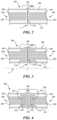
- FIG. 7illustrates a partial cross-sectional view of a portion of a composite barrel wall 700 in the straight section 160 of the bat 100 having a reduced-durability region 730 in accordance with another embodiment of the present technology.
- the wall 700 illustrated in FIG. 7may be generally similar to the wall 300 illustrated and described above with regard to FIG. 3 , but the gap region 260 is oriented at an oblique angle.
- an axis 710 of the gap region 260(parallel to the transverse portions 720 of the cap ply elements 750 abutting the stacks 740 ) may be oriented at an angle 760 relative to the longitudinal or X-axis (labeled “x”) of the bat.
- the angle 760may have a value of between 1 and 89 degrees, for example, it may be between 30 and 65 degrees, or 60 degrees in a particular embodiment.
- the stacks 740having plies 250 , may be staggered or angled to correspond to the angle 760 of the gap region 260 .
- the separation ply 270may also be angled to correspond to the angle 760 of the gap region 260 .
- the cap ply elements 750which may be similar to the cap ply elements 310 described above, may have transverse portions 720 that are also oriented along the angle 760 .
- the wall 700 and the reduced-durability region 730when the angle 760 is relatively small, the wall 700 and the reduced-durability region 730 increase in strength. For example, the wall 700 and the reduced-durability region 730 may withstand more forces before experiencing a through-failure in the gap region 260 .
- the separation ply 270may cause failure to propagate through the wall of a bat (e.g., through the stacks 240 ) along the Z-axis within or along the gap regions 260 faster than failure occurring in bats without reduced durability regions (such as those without gap regions 260 ).
- other appliancesmay provide similar effects.
- FIGS. 8 - 19illustrate embodiments with other appliances to control failure along the Z-axis through the bat wall.
- rigid or semi-rigid appliancessuch as those described below, may reduce the risk that interlaminar failures (which can cause undesirable increases in performance) occur before a bat fails through its wall along the Z-axis. Such rigid or semi-rigid appliances may improve control and consistency of the strength properties of a bat wall.
- FIG. 8illustrates a partial cross-sectional view of a portion of a composite barrel wall 800 in the straight section 160 of the bat 100 having a reduced-durability region 830 according to another embodiment of the present technology.
- the wall 800 illustrated in FIG. 8may be generally similar to the wall 200 illustrated and described above with regard to FIG. 2 , but instead of using a separation ply 270 to guide failure through the bat wall, the appliance positioned in the gap region 260 may be a ring element 810 (see FIG. 9 ).
- the ring element 810functions similarly to the separation ply 270 in that it reduces or prevents bonding across the gap region 260 and guides failure through the bat wall along the Z-axis.
- the ring element 810facilitates a more predictable fracture location and a more predictable level of strain at which failure may occur.
- the ring element 810may be formed as a single piece or as multiple pieces connected together, with or without discontinuities along its circumference.
- the ring element 810may have a rectangular or otherwise elongated cross-section 815 that is oriented along the Z-axis, perpendicular to the longitudinal axis of the bat (the X-axis), such that the ring element 810 traverses across the stacks 240 in a direction perpendicular to the plies 250 .
- the ring element 810need not be oriented perpendicular to the longitudinal axis of the bat, and it may have other orientations (for example, see below with regard to FIG. 10 ).
- the cross-section 815may be square-shaped, or it may have other suitable shapes.
- the ring element 810prevents (or at least resists) proliferation of the crack to the stacks 240 of plies 250 .
- the ring element 810prevents or resists delamination of the stacks 240 of plies 250 by preventing or resisting spreading of the crack along the axial length of the bat (i.e., along the longitudinal or X-axis of the bat, marked with “x” in FIG. 8 ).
- the ring element 810prevents or resists delamination of the stacks 240 of plies 250 by preventing or resisting spreading of the crack along the axial length of the bat (i.e., along the longitudinal or X-axis of the bat, marked with “x” in FIG. 8 ).
- Appliancesmay have a variety of shapes.
- the size, shape, and dimensions of the ring element 810 and other appliances described belowmay be adjusted to meet the desired overall strength of the bat in normal use and during ABI processes, the bond strength between the composite resin or matrix and the appliance (such as the ring element 810 ), and the strength of the appliance itself (such as the ring element 810 ).
- rigid or semi-rigid appliancesmay be formed with a high-surface-energy material such as acetal polymer (for example, Delrin®), polytetrafluoroethylene (PTFE, for example, Teflon®), polyoxymethylene (POM), polyamides (Nylon), polyethylene terephthalate (PET), or other suitable plastic or polymer materials.
- a high-surface-energy materialsuch as acetal polymer (for example, Delrin®), polytetrafluoroethylene (PTFE, for example, Teflon®), polyoxymethylene (POM), polyamides (Nylon), polyethylene terephthalate (PET), or other suitable plastic or polymer materials.
- acetal polymerfor example, Delrin®
- PTFEpolytetrafluoroethylene
- POMpolyoxymethylene
- nylonpolyamides
- PETpolyethylene terephthalate
- the inwardly facing skin 210 and the outwardly facing skin 220may be constructed to be sufficiently strong to handle the stress of normal use, but sufficiently weak to fail during ABI processes.
- one or more plies 250may not include a discontinuity or gap and may further strengthen the reduced-durability region (as described below, for example, with regard to FIG. 11 ).
- an appliancemay traverse approximately 25% of the wall thickness t, or other fractions thereof.
- appliancesmay be formed with materials having moderate to strong bond strength with the surrounding composite matrix material in the bat wall. Such materials may provide further control of how much strain is required to cause the bat wall to fracture.
- Materials that may provide moderate to strong bond strength with the composite matrix materialinclude acrylonitrile butadiene styrene (ABS), polyvinyl chloride (PVC), polycarbonate (PC), polyurethane (PU).
- ABSacrylonitrile butadiene styrene
- PVCpolyvinyl chloride
- PCpolycarbonate
- PUpolyurethane
- Other materialsmay provide moderate to strong bond strength with the composite matrix material.
- appliances described hereinmay be formed from a breakable material such that the appliances themselves fracture before delamination occurs.
- some appliancesmay be scored or etched to force a failure or breaking point.
- appliancesmay be made by a method that provides inherent flaws, such as a 3D printing process.
- ABS materialprovides a balance between the strength of the bond with the composite matrix material and the strength of the appliance itself.
- an appliance made with ABS materialmay be weaker than the interlaminar bond between the composite plies 250 .
- appliancesmay be formed with metal, such as aluminum, steel, or titanium, or other metals, foam materials, or wood, or any other suitable rigid or semi-rigid material.
- metalsuch as aluminum, steel, or titanium, or other metals, foam materials, or wood, or any other suitable rigid or semi-rigid material.
- a designermay select the appropriate material for the appliance based on the strength of a bond between the material and the composite matrix, or based on the strength of the material itself.
- appliancesmay be formed with composite material (such as composite laminate material, bulk molding compound, or sheet molding compound).
- a composite appliancemay be pre-formed with composite material and pre-cured, then installed in a ball bat composite layup during manufacturing.
- the strength or stiffness of the appliancesmay be selected or designed to match or exceed the strength or stiffness of the composite material located next to the appliance in the gap.
- the appliancesmay be pre-cured, they may have a reduced bond strength with neighboring composite material in the bat wall relative to composites that are cured simultaneously. Accordingly, the bond strength of a pre-cured composite appliance may be lower than the interlaminar strength between composite laminate plies 250 .
- the bond strength of a pre-cured composite appliancemay be only approximately 75 to 80 percent of the bond strength of plies 250 , which facilitates failure along the sides or within the appliance at lower stress levels than those that may cause interlaminar failure.
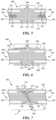
- FIG. 10illustrates a partial cross-sectional view of a portion of a composite barrel wall 1000 in the straight section 160 of the bat 100 having a reduced-durability region 1030 according to another embodiment of the present technology.
- the wall 1000 illustrated in FIG. 10may be generally similar to the wall 800 illustrated and described above with regard to FIG. 8 , but the appliance may be in the form of a beveled ring element 1010 .
- the beveled ring element 1010may resemble the ring element 810 , but it may have a cross-section that traverses an angled gap region 260 , or is otherwise oriented at an oblique angle relative to the stacks 240 of plies 250 .
- a cross-section of the beveled ring element 1010may have an axis 1040 that is oriented at an angle 1020 (such as an oblique angle) relative to the longitudinal or X-axis of the bat, or to the plies 250 .
- the angle 1020may have a value between 30 degrees and 90 degrees (for example, 45 degrees).
- the stacks 240having plies 250 , may be staggered or angled to correspond to the angle 1020 of the beveled ring element 1010 .
- the beveled ring element 1010functions generally similarly to the flat ring element 810 described above with regard to FIG. 8 , but the angle 1020 facilitates additional modification of the fracture properties of the wall 1000 .
- the wall 1000 and the reduced-durability region 1030increase in strength.
- the wall 1000 and the reduced-durability region 1030may withstand more forces before experiencing a through-failure in the gap region 260 than would a flat ring element 810 ( FIG. 8 ), depending on the materials forming the appliance and the bond strength between the appliance and the composite matrix in the wall.
- the beveled ring element 1010may be formed as a single piece or as multiple pieces connected together, with or without discontinuities along its circumference.
- FIG. 11illustrates a partial cross-sectional view of a portion of a composite barrel wall 1100 in the straight section 160 of the bat 100 having a reduced-durability region 1130 according to another embodiment of the present technology.
- the reduced-durability region 1130 in FIG. 11is generally similar to the reduced-durability region 1030 described and illustrated above with regard to FIG. 10 , except that the appliance may be in the form of a beveled ring element 1110 that extends through only a portion of the stacks 240 of plies 250 .
- the gap region 260 between the stacks 240may not extend through all the plies 250 , such that one or more plies 250 are continuous in the reduced-durability region 1130 .
- the beveled ring element 1110may occupy between 25 percent and 50 percent of the overall thickness t of the barrel wall 1100 .
- the plies 250 that are continuous (not interrupted by a gap or an appliance)may be referred to as through-plies. Any suitable number of through-plies may be positioned in the wall 1100 , toward the outwardly facing skin 220 (such as one or more through-plies between the ring element 1110 and the outwardly facing skin 220 ) or toward the inwardly facing skin 210 (such as one or more through-plies between the ring element 1110 and the inwardly facing skin 210 ).
- FIG. 12illustrates a partial cross-sectional view of a portion of a composite barrel wall 1200 in the straight section 160 of the bat 100 having a reduced-durability region 1230 according to another embodiment of the present technology.
- the reduced-durability region 1230 in FIG. 12is generally similar to the other reduced-durability regions described herein, except that the appliance may be in the form of a ring element 1210 with a triangular cross-section 1215 .
- the triangular cross-section 1215may have any suitable dimensions. For example, it may be sized to fully or almost fully extend between the inwardly facing skin 210 and the outwardly facing skin 220 .
- the ring element 1210may be sized to allow plies 250 (such as through-plies) to pass between the ring element 1210 and the inwardly facing skin 210 or the outwardly facing skin 220 .
- the triangular cross-section 1215may have equilateral proportions, isosceles proportions, scalene proportions, or other proportions.
- the triangular cross-section 1215may include any suitable angles, such as a right angle. Although the triangular cross-section 1215 is illustrated as having one side that is parallel with the X-axis of the bat, in various embodiments, the triangular cross-section 1215 may have other orientations.
- FIG. 13illustrates a partial cross-sectional view of a portion of a composite barrel wall 1300 in the straight section 160 of the bat 100 having a reduced-durability region 1330 according to another embodiment of the present technology.
- the reduced-durability region 1330 in FIG. 13is generally similar to the other reduced-durability regions described herein, including the reduced-durability region 1230 illustrated in FIG. 12 and described above.
- the appliancemay be in the form of a ring element 1310 that is similar to the ring element 1210 illustrated and described above with regard to FIG. 12 , but with a triangular cross-section 1315 that is smaller than the cross-section 1215 illustrated in FIG. 12 .
- the triangular cross-section 1315may span approximately 25% of the overall wall thickness t of the barrel wall 1300 .
- the triangular cross-section 1315may be positioned adjacent to one of the skins 210 , 220 , or there may be one or more through-plies 250 between the inwardly facing skin 210 and the triangular cross-section 1315 or between the outwardly facing skin 220 and the triangular cross-section 1315 .
- the triangular cross-section 1315may be positioned in a gap region 260 that includes gaps between any suitable number of composite laminate plies 250 (for example, as shown in the illustration in FIG. 13 , two plies 250 may have gaps within which the ring element 1310 is situated).
- FIG. 14illustrates a partial cross-sectional view of a portion of a composite barrel wall 1400 in the straight section 160 of the bat 100 having a reduced-durability region 1430 according to another embodiment of the present technology.
- the reduced-durability region 1430 in FIG. 14is generally similar to the other reduced-durability regions described herein, including the reduced-durability region 1330 illustrated in FIG. 13 and described above.
- there may be two appliances positioned in the gap region 260(the gap region 260 may have multiple longitudinal gaps between plies 250 ).
- the appliancesmay be similar to other appliances described herein.
- the appliancesmay be in the form of ring elements 1410 that may be generally similar to the ring elements 1310 described above with regard to FIG. 13 .
- the ring elements 1410may have triangular cross-sections 1415 and they may be positioned anywhere in the gap region 260 , within a discontinuity or break between composite laminate plies 250 .
- one or more plies(such as the through-ply 1417 ) may be positioned between the ring elements 1410 , or a space between the ring elements 1410 may be filled with composite matrix material, or the space between the ring elements 1410 may be a void.
- the quantity, shape, and arrangement of ring elements 1410 functioning as appliancesmay be selected to tailor the force required to break through the bat wall 1400 in the reduced-durability region 1430 before the composite laminate plies delaminate.
- a bond strength between an appliance and the composite matrix or resinmay be designed to be close to or greater than the interlaminar strength of nearby plies 250 .
- a designermay provide through-plies in the reduced-durability region, and the designer may provide a weaker bond between the through-plies and other plies or appliances.
- FIG. 15illustrates a partial cross-sectional view of a portion of a composite barrel wall 1500 in the straight section 160 of the bat 100 having a reduced-durability region 1530 according to another embodiment of the present technology.
- the reduced-durability region 1530 in FIG. 15is generally similar to the other reduced-durability regions described herein, including the reduced-durability region 1330 illustrated in FIG. 13 and described above.
- the appliancemay be in the form of a plurality of ring elements 1510 (such as two or more) having cross-sections 1515 that provide an interface 1517 between the ring elements 1510 .
- two ring elements 1510may each have a triangular cross-section 1515 with a base edge 1516 , and the base edges 1516 may be positioned adjacent to each other to form the interface 1517 between corresponding faces of the ring elements 1510 .
- the base edges 1516may be joined together with an adhesive or matrix material, or they may not be joined together at all.
- the triangular cross-sections 1515may be sized to generally occupy the entirety of the wall 1500 between the skins 210 , 220 , or they may be sized to occupy only a portion of the wall 1500 , such as 25% of the wall thickness t.
- the gap region 260may include some plies 250 with discontinuities and some plies 250 that do not have discontinuities in the gap region 260 (through-plies).
- Embodiments with interfaces between a plurality of rings (such as the ring elements 1510 ) or between other portions of appliances, such as the interface 1517 illustrated in FIG. 15may include a bond between the base edges 1516 at the interface 1517 that is weaker than a bond between the ring elements 1510 and the surrounding composite matrix or resin material.
- the faces of the rings or other appliances in contact with each other at the interface 1517may be partially or completely coated with, treated with, or otherwise include a release material or a bond-resistant material to resist bonding with the composite matrix in the wall and to control the strength of the bond at the interface 1517 .
- the faces of the rings or other appliancesmay be bonded to each other using a full or partial coating or treatment of adhesive having a selected bond strength, so that the interface 1517 includes a bond of adhesive, release material, or a combination of adhesive and release material distributed in portions of the interface.
- a bat designermay select the amount and position of adhesive and release material to tailor the bond strength at the interface 1517 , such as making the bond strength at the interface 1517 lower than the strength of the surrounding matrix bond with the appliances.
- a cyanoacrylate or other epoxy resinmay be selected to provide lower bond strength in the interface 1517 than the bond strength between the appliances and the surrounding composite matrix material in the wall.
- FIG. 15illustrates an interface 1517 that is oriented at a non-parallel angle relative to the Z-axis
- the interface 1517may be oriented at any suitable angle.
- the interface 1517may be parallel to the Z-axis, in which case the ring elements 1510 may have square or rectangular cross-sections.
- FIG. 16illustrates a partial cross-sectional view of a portion of a composite barrel wall 1600 in the straight section 160 of the bat 100 having a reduced-durability region 1630 according to another embodiment of the present technology.
- the reduced-durability region 1630 in FIG. 16is generally similar to the other reduced-durability regions described herein, but with an alternative arrangement of appliances.
- a pair of ring elements 1610may be positioned inside the wall 1600 between the skins 210 , 220 and facing each other, such as abutting each other at an interface 1617 .
- the interface 1617may be similar to the interface 1517 described above with regard to FIG. 16 , such that it may be fully or partially coated with adhesive or release material depending on the bond strength desired by a designer.
- the interface 1617may include a plurality of connecting elements 1620 distributed around the circumference of the barrel wall 1600 .
- the connecting elements 1620may include thread positioned and configured to hold the ring elements 1610 together along the X-axis but configured to fail in shear (along the Z-axis) under stresses associated with ABI protocol.
- the connecting elements 1620may include pins formed from a rigid or semi-rigid material.
- the connecting elements 1620may be formed with metal, plastic, composite resin matrix, thread (such as cotton, nylon, or other thread material), wood, or other materials suitable for providing a connection between the ring elements 1610 in the interface 1617 .
- connecting elementsmay be integral with the rings or appliances.
- FIG. 17illustrates a cross-sectional view of an embodiment of a ring element 1700 that may be used as an appliance in a reduced-durability region, such as the reduced-durability region 1630 in FIG. 16 .
- the ring element 1700may include connecting elements in the form of a groove 1710 and a protrusion 1720 , so that a plurality of rings 1700 (such as two or more) may be stacked or nested.
- the protrusion 1720 in a first ring element 1700may be positioned in a groove 1710 of a second ring.
- the protrusion 1720 in the groove 1710provides a shear interface that functions similarly to the connecting element 1620 described and illustrated above with regard to FIG. 16 .
- the protrusion 1720may be configured to break or shear off when stresses in an ABI procedure are applied to a bat wall, at a lower stress than stresses that cause adjacent composite laminate plies to delaminate.
- a thin ring of material with selected strengthmay be attached to each ring element 1700 .
- such a thin ring of material, or the protrusion 1720may be, but need not be, continuous around a circumference of the ball bat.
- the thin ring of material or the protrusion 1720may be segmented to further tailor the shear strength between the rings 1700 in a reduced-durability region.
- FIG. 18illustrates a partial cross-sectional view of a portion of a composite barrel wall 1800 in the straight section 160 of the bat 100 having a reduced-durability region 1830 according to another embodiment of the present technology.
- the reduced-durability regionincludes a gap region 260 between the stacks 240 of plies 250 .
- any number of through-plies 1810may be positioned in the barrel wall 1800 .
- the through-ply or through-plies 1810further facilitate tailoring the strength of the reduced-durability region 1830 .
- a through-plymay strengthen the gap to delay delamination during an ABI process.
- the through-plies 1810may be formed from any suitable composite material, including those described above.
- FIG. 19illustrates an appliance in the form of a ring element 1900 having a t-shaped cross-section, according to an embodiment of the present technology.
- the ring element 1900may otherwise be similar to other ring elements illustrated and described herein.
- the t-shaped ring element 1900provides a different surface area and different bond characteristics with the surrounding composite matrix material to facilitate a further option for tailoring the strength of a reduced-durability region.
- the ring elementsmay be positioned in the bat wall during the composite laminate layup process.
- an inwardly facing skin 210may be wrapped around a mandrel, followed by one or more composite laminate plies 240 .
- a ring elementmay be slid onto the assembly or otherwise positioned around the mandrel within the composite layup.
- other layerssuch as composite laminate plies 240 , may be positioned adjacent to or on top of the ring element, followed by the outwardly facing skin 220 , after which the structure may be cured.
- pre-preg composite laminate materialmay be used.
- resin transfer molding (RTM) processesmay be used, in which laminate plies 240 are impregnated with resin after being laid up around the mandrel.
- RTMresin transfer molding
- Other assembly processesmay be used in accordance with embodiments of the present technology.
- the inwardly facing skin 210 , the outwardly facing skin 220 , or both skins,may be omitted.
- FIGS. 2 - 8 , 10 - 16 , and 18illustrate space between various layers and appliances, in some embodiments the layers and components of embodiments of the present technology may be in generally intimate contact (via any resin or adhesive employed in the various embodiments).
- Embodiments of the present technologyprovide reduced-durability regions to deter or discourage bat alteration. For example, if a user attempts to roll or perform other ABI processes, stresses in the bat wall will be focused along the gap between composite stacks rather than between the plies in the stacks, which will cause the wall of the bat to fail (destroying the bat) before significant delamination occurs that would otherwise improve performance.
- the present technologymay provide a visual or tactile indicator of a failure of the bat wall prior to delamination (if any) between plies. Accordingly, the present technology allows for improved testing, improved indication of bat failure, and it may deter players from attempting to alter a bat.
- inwardly facing skinsfor example, inwardly facing skins 210 , 610 described above
- outwardly facing skinsfor example, outwardly facing skins 220 , 620
- both inwardly and outwardly facing skinswhich may cover the appliances (such as separation plies 270 , cap ply elements 310 or 750 , appliances in the form of ring elements, or other appliances).
- inwardly facing skins, outwardly facing skins, or both inwardly and outwardly facing skinsmay be omitted, such that the appliances form part of an outermost layer of a barrel wall or are exposed to the hollow interior of a bat, the outside environment of a bat, or both (see FIG. 20 ).
- one or both of the cover layers 650 covering the gap region 260 in FIG. 6may be omitted.
Landscapes
- Health & Medical Sciences (AREA)
- General Health & Medical Sciences (AREA)
- Physical Education & Sports Medicine (AREA)
- Moulding By Coating Moulds (AREA)
- Laminated Bodies (AREA)
- Wind Motors (AREA)
Abstract
Description
Claims (20)
Priority Applications (2)
| Application Number | Priority Date | Filing Date | Title |
|---|---|---|---|
| US17/246,418US12157044B2 (en) | 2017-07-19 | 2021-04-30 | Ball bats with reduced durability regions for deterring alteration |
| US18/942,293US20250065200A1 (en) | 2017-07-19 | 2024-11-08 | Ball bats with reduced durability regions for deterring alteration |
Applications Claiming Priority (3)
| Application Number | Priority Date | Filing Date | Title |
|---|---|---|---|
| US15/654,513US11167190B2 (en) | 2017-07-19 | 2017-07-19 | Ball bats with reduced durability regions for deterring alteration |
| US16/132,199US11013967B2 (en) | 2017-07-19 | 2018-09-14 | Ball bats with reduced durability regions for deterring alteration |
| US17/246,418US12157044B2 (en) | 2017-07-19 | 2021-04-30 | Ball bats with reduced durability regions for deterring alteration |
Related Parent Applications (1)
| Application Number | Title | Priority Date | Filing Date |
|---|---|---|---|
| US16/132,199ContinuationUS11013967B2 (en) | 2017-07-19 | 2018-09-14 | Ball bats with reduced durability regions for deterring alteration |
Related Child Applications (1)
| Application Number | Title | Priority Date | Filing Date |
|---|---|---|---|
| US18/942,293ContinuationUS20250065200A1 (en) | 2017-07-19 | 2024-11-08 | Ball bats with reduced durability regions for deterring alteration |
Publications (2)
| Publication Number | Publication Date |
|---|---|
| US20210252358A1 US20210252358A1 (en) | 2021-08-19 |
| US12157044B2true US12157044B2 (en) | 2024-12-03 |
Family
ID=65014649
Family Applications (3)
| Application Number | Title | Priority Date | Filing Date |
|---|---|---|---|
| US16/132,199ActiveUS11013967B2 (en) | 2017-07-19 | 2018-09-14 | Ball bats with reduced durability regions for deterring alteration |
| US17/246,418Active2038-05-02US12157044B2 (en) | 2017-07-19 | 2021-04-30 | Ball bats with reduced durability regions for deterring alteration |
| US18/942,293PendingUS20250065200A1 (en) | 2017-07-19 | 2024-11-08 | Ball bats with reduced durability regions for deterring alteration |
Family Applications Before (1)
| Application Number | Title | Priority Date | Filing Date |
|---|---|---|---|
| US16/132,199ActiveUS11013967B2 (en) | 2017-07-19 | 2018-09-14 | Ball bats with reduced durability regions for deterring alteration |
Family Applications After (1)
| Application Number | Title | Priority Date | Filing Date |
|---|---|---|---|
| US18/942,293PendingUS20250065200A1 (en) | 2017-07-19 | 2024-11-08 | Ball bats with reduced durability regions for deterring alteration |
Country Status (1)
| Country | Link |
|---|---|
| US (3) | US11013967B2 (en) |
Families Citing this family (3)
| Publication number | Priority date | Publication date | Assignee | Title |
|---|---|---|---|---|
| US11167190B2 (en) | 2017-07-19 | 2021-11-09 | Easton Diamond Sports, Llc | Ball bats with reduced durability regions for deterring alteration |
| US10940377B2 (en) | 2018-06-19 | 2021-03-09 | Easton Diamond Sports, Llc | Composite ball bats with transverse fibers |
| US12246230B2 (en) | 2021-08-20 | 2025-03-11 | Easton Diamond Sports, Llc | Composite ball bats with transverse interlaminar interfaces |
Citations (136)
| Publication number | Priority date | Publication date | Assignee | Title |
|---|---|---|---|---|
| US1611858A (en) | 1923-12-31 | 1926-12-21 | Union Hardware Company | Baseball bat |
| US4014542A (en) | 1973-03-22 | 1977-03-29 | Yukio Tanikawa | Bat used in baseball |
| US4025377A (en) | 1974-03-14 | 1977-05-24 | Yukio Tanikawa | Method of producing a baseball bat |
| US4132130A (en) | 1977-01-17 | 1979-01-02 | Nasa | Safety flywheel |
| US4150291A (en) | 1977-12-23 | 1979-04-17 | The United States Of America As Represented By The Secretary Of The Air Force | Nondestructive tester for fiberglass-aluminum honeycomb structures |
| US4505479A (en) | 1982-12-28 | 1985-03-19 | Souders Roger B | Weighted bat with weight securing means |
| US4604319A (en) | 1984-06-01 | 1986-08-05 | American Cyanamid Company | Thermoplastic interleafed resin matrix composites with improved impact strength and toughness |
| US4780346A (en) | 1986-03-28 | 1988-10-25 | Societe Eruopeene De Propulsion | Tubular laminated structure for reinforcing a piece in composite material |
| US4804315A (en) | 1987-07-30 | 1989-02-14 | United Technologies Corporation | Composite helicopter swashplate |
| US4818584A (en) | 1987-12-03 | 1989-04-04 | General Dynamics Corp. | Arresting delamination in composite laminate |
| US4848745A (en) | 1986-06-04 | 1989-07-18 | Phillips Petroleum Company | Fiber reinforced article |
| US4867399A (en) | 1987-03-20 | 1989-09-19 | Manufacture D'appareillage Electrique De Cahors | Insulating equipment for an electric line pole and method for making it |
| US4931247A (en) | 1988-12-19 | 1990-06-05 | Yeh Chien Hwa | Fabrication method of a hollow racket made of carbon fiber |
| US4963408A (en) | 1988-06-13 | 1990-10-16 | Mono-Lite Corporation | Structural unitary composite laminate structure and method for making same |
| US5048441A (en) | 1989-06-15 | 1991-09-17 | Fiberspar, Inc. | Composite sail mast with high bending strength |
| US5057353A (en) | 1989-05-17 | 1991-10-15 | American Cyanamid Company | Advance composites with thermoplastic particles at the interface between layers |
| US5131651A (en) | 1991-05-13 | 1992-07-21 | You Chin San | Ball bat |
| CN1067388A (en) | 1991-05-31 | 1992-12-30 | 尤景三 | sports bat |
| EP0585965A1 (en) | 1989-07-12 | 1994-03-09 | Teijin Limited | Process for the production of composite molded articles |
| US5301940A (en) | 1990-11-15 | 1994-04-12 | Mizuno Corporation | Baseball bat and production thereof |
| US5303917A (en) | 1992-04-13 | 1994-04-19 | Uke Alan K | Bat for baseball or softball |
| US5362046A (en) | 1993-05-17 | 1994-11-08 | Steven C. Sims, Inc. | Vibration damping |
| US5364095A (en) | 1989-03-08 | 1994-11-15 | Easton Aluminum, Inc. | Tubular metal ball bat internally reinforced with fiber composite |
| US5380003A (en) | 1993-01-15 | 1995-01-10 | Lanctot; Paul A. | Baseball bat |
| US5395108A (en) | 1994-01-19 | 1995-03-07 | Easton Aluminum, Inc. | Simulated wood composite ball bat |
| US5415398A (en) | 1993-05-14 | 1995-05-16 | Eggiman; Michael D. | Softball bat |
| USRE35081E (en) | 1989-06-15 | 1995-11-07 | Fiberspar, Inc. | Composite structural member with high bending strength |
| US5490669A (en) | 1992-10-13 | 1996-02-13 | Smart; Merlin L. | Laminated ball bat |
| US5511777A (en) | 1994-02-03 | 1996-04-30 | Grover Products Co. | Ball bat with rebound core |
| US5516097A (en) | 1995-04-13 | 1996-05-14 | Huddleston; Allen D. | Flexible section baseball bat |
| US5556695A (en) | 1988-03-24 | 1996-09-17 | Ara, Inc. | Delaminating armor |
| US5593158A (en) | 1995-12-21 | 1997-01-14 | Jas D. Easton, Inc. | Shock attenuating ball bat |
| US5624115A (en) | 1990-05-04 | 1997-04-29 | The Baum Research & Development Co., Inc. | Composite baseball bat with cavitied core |
| US5641366A (en) | 1988-01-20 | 1997-06-24 | Loral Vought Systems Corporation | Method for forming fiber-reinforced composite |
| US5676610A (en) | 1996-12-23 | 1997-10-14 | Hillerich & Bradsby Co. | Bat having a rolled sheet inserted into the barrel |
| US5711728A (en) | 1996-10-25 | 1998-01-27 | Marcelo; Severino V. | Shock and vibration absorbing ball bat |
| US5759113A (en) | 1996-06-21 | 1998-06-02 | Minnesota Mining And Manufacturing Company | Vibration damped golf clubs and ball bats |
| US5772541A (en) | 1997-05-01 | 1998-06-30 | Jas D. Easton, Inc. | Vibration dampened hand-held implements |
| US5833561A (en) | 1997-01-27 | 1998-11-10 | Lisco, Inc. | Ball bat with tailored flexibility |
| US5899823A (en) | 1997-08-27 | 1999-05-04 | Demarini Sports, Inc. | Ball bat with insert |
| US5964673A (en) | 1997-01-27 | 1999-10-12 | Hellerich & Brasby Co. | Hollow metal bat with stiffened transition zone and method of making same |
| US6007439A (en) | 1997-04-14 | 1999-12-28 | Hillerich & Bradsby Co. | Vibration dampener for metal ball bats and similar impact implements |
| US6010417A (en) | 1998-05-15 | 2000-01-04 | Young Bat Co., Inc. | Baseball bat |
| US6033758A (en) | 1995-06-06 | 2000-03-07 | Cryovac, Inc. | Laminate having a coextruded, multilayer film which delaminates and package made therefrom |
| US6042493A (en) | 1998-05-14 | 2000-03-28 | Jas. D. Easton, Inc. | Tubular metal bat internally reinforced with fiber and metallic composite |
| US6053828A (en) | 1997-10-28 | 2000-04-25 | Worth, Inc. | Softball bat with exterior shell |
| US6265333B1 (en) | 1998-06-02 | 2001-07-24 | Board Of Regents, University Of Nebraska-Lincoln | Delamination resistant composites prepared by small diameter fiber reinforcement at ply interfaces |
| US20010014634A1 (en) | 1998-10-20 | 2001-08-16 | Jack W. Mackay | Metal baseball bat with wood bat performance characteristics |
| US6344007B1 (en) | 1996-02-02 | 2002-02-05 | Spalding Sports Worldwide, Inc. | Bat with high moment of inertia to weight ratio and method of fabrication |
| US20020016230A1 (en) | 2000-06-28 | 2002-02-07 | Masaaki Okuyama | Baseball or softball bat |
| US6352485B1 (en) | 1994-08-12 | 2002-03-05 | Advanced Composites, Inc. | Fiber reinforced molded products and processes |
| US6383101B2 (en) | 1998-07-01 | 2002-05-07 | Wilson Sporting Goods Co. | Ball bat |
| US6398675B1 (en) | 2000-07-03 | 2002-06-04 | Wilson Sporting Goods Co. | Bat with elastomeric interface |
| US20020091022A1 (en) | 1999-09-15 | 2002-07-11 | Fritzke Mark A. | Insert for a bat having an improved seam orientation |
| US20020098924A1 (en) | 2001-01-23 | 2002-07-25 | Houser Russell A. | Athletic devices and other devices with superelastic components |
| US6425836B1 (en) | 1998-10-19 | 2002-07-30 | Mizuno Corporation | Baseball or softball bat |
| US6440017B1 (en) | 1999-10-28 | 2002-08-27 | Steven L. Anderson | Metal bat having improved barrel structure |
| US6461260B1 (en) | 2000-05-15 | 2002-10-08 | Worth, Inc. | Composite wrap bat |
| US20020151392A1 (en) | 2000-05-31 | 2002-10-17 | John Buiatti | Rigid shell layered softball bat with elastomer layer |
| US20020198071A1 (en) | 1998-07-22 | 2002-12-26 | Michael L. Snow | Ball bat |
| US6508731B1 (en) | 1996-02-02 | 2003-01-21 | Spalding Sports Worldwide, Inc. | Composite bat with metal barrel area and method of fabrication |
| US20030153416A1 (en) | 2002-02-11 | 2003-08-14 | Anderson Steven L. | Multiple wall metal bat having independent outer wall and textured inner wall |
| US20030186763A1 (en) | 2002-04-02 | 2003-10-02 | Wilson Sporting Goods Co. | Bat with composite handle |
| US6634969B2 (en) | 1999-07-07 | 2003-10-21 | Composites Design Services, Llc | Method of tuning a bat and a tuned bat |
| US6723012B1 (en) | 2002-02-21 | 2004-04-20 | Ce Composites Baseball, Inc. | Polymer composite bat |
| US6723127B2 (en) | 2001-07-16 | 2004-04-20 | Spine Core, Inc. | Artificial intervertebral disc having a wave washer force restoring element |
| US6729983B1 (en) | 1999-11-22 | 2004-05-04 | Worth, Inc. | Tubular sports implement with internal structural bridge |
| US6755757B2 (en) | 1998-03-18 | 2004-06-29 | Ce Composites Baseball Inc. | Composite over-wrapped lightweight core and method |
| US20040132563A1 (en) | 2003-01-03 | 2004-07-08 | Giannetti William B. | Ball bat with a strain energy optimized barrel |
| US6761653B1 (en) | 2000-05-15 | 2004-07-13 | Worth, Llc | Composite wrap bat with alternative designs |
| WO2004062734A2 (en) | 2003-01-03 | 2004-07-29 | Jas D. Easton, Inc. | Ball bat with a strain energy optimized barrel |
| US6776735B1 (en) | 1998-12-14 | 2004-08-17 | Reichhold, Inc. | Baseball bat |
| US20040176197A1 (en) | 2003-03-07 | 2004-09-09 | Sutherland Willian Terrance | Composite baseball bat |
| US20040209716A1 (en) | 2001-01-19 | 2004-10-21 | Miken Composites, Llc. | Composite softball bat with inner sleeve |
| US6808464B1 (en) | 1999-12-03 | 2004-10-26 | Thu Van Nguyen | Reinforced-layer metal composite bat |
| US6863628B1 (en) | 2000-03-20 | 2005-03-08 | Richard A. Brandt | Vibration damping striking implement |
| CN2684892Y (en) | 2004-02-09 | 2005-03-16 | 叶辅渝 | Baseball bat with intermediate layer of elastomeric material |
| US6872156B2 (en) | 2001-05-02 | 2005-03-29 | Mizuno Corporation | Baseball or softball bat, bat base member and elastic sleeve |
| US20050070387A1 (en) | 2003-09-26 | 2005-03-31 | Bando Chemical Industries, Ltd. | Drive belt pulley and belt drive system |
| US20050070384A1 (en) | 2003-09-29 | 2005-03-31 | Stephen Fitzgerald | Tubular baseball bats with variable stiffened barrels |
| US20050143203A1 (en) | 2003-11-25 | 2005-06-30 | Honor Life, Inc. | Ball bats and methods of making same |
| US20050227795A1 (en) | 1999-09-15 | 2005-10-13 | Wilson Sporting Goods Co. | Ball bat having a hitting portion with variable wall thickness |
| US20060025253A1 (en)* | 2004-07-29 | 2006-02-02 | Giannetti William B | Composite ball bat with constrained layer dampening |
| US20060025251A1 (en) | 2004-07-29 | 2006-02-02 | Jas. D. Easton, Inc. | Ball bat including an integral shock attenuation region |
| WO2006015160A1 (en) | 2004-07-29 | 2006-02-09 | Easton Sports, Inc. | Optimized ball bat |
| US7006947B2 (en) | 2001-01-08 | 2006-02-28 | Vextec Corporation | Method and apparatus for predicting failure in a system |
| US7087296B2 (en) | 2001-11-29 | 2006-08-08 | Saint-Gobain Technical Fabrics Canada, Ltd. | Energy absorbent laminate |
| US20060247079A1 (en) | 2002-02-21 | 2006-11-02 | Sutherland Terrance W | Polymer composite bat |
| US20070202974A1 (en) | 2006-11-16 | 2007-08-30 | Giannetti William B | Single wall ball bat including quartz structural fiber |
| US20070205201A1 (en) | 2002-04-12 | 2007-09-06 | Microcosm, Inc. | Composite pressure tank and process for its manufacture |
| US20070219027A1 (en) | 2006-03-17 | 2007-09-20 | Chong Huang B | Baseball bat |
| US20070254752A1 (en)* | 2003-09-29 | 2007-11-01 | Sutherland Terrance W | Multi-walled tubular baseball bats with barrel inserts of variable geometry |
| US20080039241A1 (en) | 2006-08-08 | 2008-02-14 | Kenneth Eugene Pope | Bunt master |
| US7344461B2 (en) | 2006-02-27 | 2008-03-18 | Thu Van Nguyen | Composite bat with metal sleeve |
| US20080070726A1 (en) | 2006-07-28 | 2008-03-20 | Nippon Shaft Co., Ltd. | Bat used for baseball or softball |
| US7431655B2 (en) | 1994-09-29 | 2008-10-07 | Clawson Custom Cues, Inc. | Billiard cue |
| US20090065299A1 (en) | 2004-05-28 | 2009-03-12 | Sting Free Technologies Company | Sound dissipating material |
| US20090085299A1 (en) | 2005-05-19 | 2009-04-02 | Uchiyama Manufacturing Corp. | Sealing Device |
| US20090130425A1 (en) | 2005-08-12 | 2009-05-21 | Modumetal, Llc. | Compositionally modulated composite materials and methods for making the same |
| US20090181813A1 (en) | 2008-01-10 | 2009-07-16 | Giannetti William B | Ball bat with exposed region for revealing delamination |
| US20090215560A1 (en) | 2008-02-26 | 2009-08-27 | Nike, Inc. | Composite Bat |
| US7585235B2 (en) | 2006-10-31 | 2009-09-08 | Mizuno Corporation | Baseball or softball bat |
| US20090280935A1 (en) | 2008-05-09 | 2009-11-12 | Nhk Spring Co., Ltd. | Bat for baseball or softball |
| US7699725B2 (en) | 2008-02-26 | 2010-04-20 | Nike, Inc. | Layered composite material bat |
| US20100160095A1 (en) | 2008-12-23 | 2010-06-24 | Dewey Chauvin | Ball bat with governed performance |
| US7749115B1 (en) | 2008-04-02 | 2010-07-06 | Rawlings Sporting Goods Company, Inc. | Bat with circumferentially aligned and axially segmented barrel section |
| US7874946B2 (en) | 2008-10-07 | 2011-01-25 | Mattingly Hitting Products, Inc. | Baseball bat with multiple reinforcing beams |
| US7914404B2 (en) | 2008-10-27 | 2011-03-29 | Easton Sports, Inc. | Ball bat including visual indication of whether internal structural tampering with the ball bat has occurred |
| US20110165976A1 (en) | 2010-01-05 | 2011-07-07 | Chuang H Y | Ball bat including multiple failure planes |
| US7985149B2 (en) | 2008-11-17 | 2011-07-26 | Nippon Shaft Co., Ltd. | Bat for baseball or softball |
| US20110195808A1 (en) | 2010-02-11 | 2011-08-11 | Dewey Chauvin | Ball bat having a segmented barrel |
| US20110287875A1 (en) | 2010-05-21 | 2011-11-24 | Wilson Sporting Goods Co. | Ball bat having performance adjusting annular member |
| US20120142461A1 (en) | 2010-01-05 | 2012-06-07 | Chuang H Y | Ball bat including multiple failure planes |
| US8197366B2 (en) | 2009-11-23 | 2012-06-12 | Easton Sports, Inc. | Ball bat including integral barrel features for reducing BBCOR |
| US8282516B2 (en) | 2008-10-27 | 2012-10-09 | Easton Sports, Inc. | Ball bat including a tamper-resistant cap |
| US8409038B2 (en) | 2009-07-17 | 2013-04-02 | Macdougall & Sons Bat Company, Llc | Baseball bat |
| US20130116070A1 (en) | 2011-11-04 | 2013-05-09 | Warrior Sports, Inc. | I-beam construction in a hockey blade core |
| US20130165279A1 (en) | 2011-12-21 | 2013-06-27 | H. Y. Chuang | Ball bat including a reinforced, low-durability region for deterring barrel alteration |
| US20130184108A1 (en) | 2012-01-13 | 2013-07-18 | Sean S. Epling | Ball bat having improved structure to allow for detection of rolling |
| US8512174B2 (en) | 2010-11-02 | 2013-08-20 | Wilson Sporting Goods Co. | Ball bat including a barrel portion having separate proximal and distal members |
| US20130316859A1 (en) | 2012-04-11 | 2013-11-28 | George Burger | Tamper-resistant ball bat |
| US8602924B2 (en) | 2009-05-15 | 2013-12-10 | Mizuno Corporation | Baseball or softball bat |
| US20140080642A1 (en) | 2012-09-14 | 2014-03-20 | Wilson Sporting Goods Co. | Ball bat with optimized barrel wall spacing and improved end cap |
| US8814733B2 (en) | 2011-01-06 | 2014-08-26 | Mizuno Usa, Inc. | Baseball or softball bat with modified restitution characteristics |
| US20150018139A1 (en) | 2013-07-10 | 2015-01-15 | Wilson Sporting Goods Co. | Ball bat including a fiber composite component having high angle discontinuous fibers |
| US9211460B2 (en) | 2013-07-10 | 2015-12-15 | Wilson Sporting Goods Co. | Ball bat including a fiber composite component having high angle discontinuous fibers |
| US9242155B1 (en)* | 2012-01-13 | 2016-01-26 | Vyatek Sports, Inc. | Barrel for a bat assembly and ball bat |
| US20160158617A1 (en)* | 2014-12-06 | 2016-06-09 | Baden Sports, Inc. | Bat with multiple hitting profiles |
| US9427640B2 (en) | 2014-04-11 | 2016-08-30 | Easton Baseball/Softball Inc. | Ball bat including a stiffening element in the barrel |
| US20170056736A1 (en) | 2015-08-27 | 2017-03-02 | Bps Diamond Sports Corp. | Composite ball bat including a barrel with structural regions separated by a porous non-adhesion layer |
| US20170252617A1 (en) | 2016-03-04 | 2017-09-07 | Bauer Hockey Inc. | 3D Weaving Material and Method of 3D Weaving for Sporting Implements |
| US20180174495A1 (en) | 2016-12-20 | 2018-06-21 | Easton Baseball / Softball Inc. | Tamper-evident bat barrels |
| US20190022483A1 (en) | 2017-07-19 | 2019-01-24 | Easton Diamond Sports, Llc | Ball bats with reduced durability regions for deterring alteration |
| US20190054357A1 (en) | 2017-08-15 | 2019-02-21 | Wilson Sporting Goods Co. | Ball bat including a fiber composite barrel having an accelerated break-in fuse region |
| US20190054356A1 (en)* | 2017-08-15 | 2019-02-21 | Wilson Sporting Goods Co. | Ball bat including a fiber composite barrel having an accelerated break-in fuse region |
| US20190381377A1 (en) | 2018-06-19 | 2019-12-19 | Easton Diamond Sports, Llc | Composite ball bats with transverse fibers |
- 2018
- 2018-09-14USUS16/132,199patent/US11013967B2/enactiveActive
- 2021
- 2021-04-30USUS17/246,418patent/US12157044B2/enactiveActive
- 2024
- 2024-11-08USUS18/942,293patent/US20250065200A1/enactivePending
Patent Citations (167)
| Publication number | Priority date | Publication date | Assignee | Title |
|---|---|---|---|---|
| US1611858A (en) | 1923-12-31 | 1926-12-21 | Union Hardware Company | Baseball bat |
| US4014542A (en) | 1973-03-22 | 1977-03-29 | Yukio Tanikawa | Bat used in baseball |
| US4025377A (en) | 1974-03-14 | 1977-05-24 | Yukio Tanikawa | Method of producing a baseball bat |
| US4132130A (en) | 1977-01-17 | 1979-01-02 | Nasa | Safety flywheel |
| US4150291A (en) | 1977-12-23 | 1979-04-17 | The United States Of America As Represented By The Secretary Of The Air Force | Nondestructive tester for fiberglass-aluminum honeycomb structures |
| US4505479A (en) | 1982-12-28 | 1985-03-19 | Souders Roger B | Weighted bat with weight securing means |
| US4604319B1 (en) | 1984-06-01 | 1995-07-04 | American Cyanamid Co | Thermoplastic interleafed resin matrix composites with improved impact strength and toughness |
| US4604319A (en) | 1984-06-01 | 1986-08-05 | American Cyanamid Company | Thermoplastic interleafed resin matrix composites with improved impact strength and toughness |
| US4780346A (en) | 1986-03-28 | 1988-10-25 | Societe Eruopeene De Propulsion | Tubular laminated structure for reinforcing a piece in composite material |
| US4848745A (en) | 1986-06-04 | 1989-07-18 | Phillips Petroleum Company | Fiber reinforced article |
| US4867399A (en) | 1987-03-20 | 1989-09-19 | Manufacture D'appareillage Electrique De Cahors | Insulating equipment for an electric line pole and method for making it |
| US4804315A (en) | 1987-07-30 | 1989-02-14 | United Technologies Corporation | Composite helicopter swashplate |
| US4818584A (en) | 1987-12-03 | 1989-04-04 | General Dynamics Corp. | Arresting delamination in composite laminate |
| US5641366A (en) | 1988-01-20 | 1997-06-24 | Loral Vought Systems Corporation | Method for forming fiber-reinforced composite |
| US5556695A (en) | 1988-03-24 | 1996-09-17 | Ara, Inc. | Delaminating armor |
| US4963408A (en) | 1988-06-13 | 1990-10-16 | Mono-Lite Corporation | Structural unitary composite laminate structure and method for making same |
| US4931247A (en) | 1988-12-19 | 1990-06-05 | Yeh Chien Hwa | Fabrication method of a hollow racket made of carbon fiber |
| US5364095A (en) | 1989-03-08 | 1994-11-15 | Easton Aluminum, Inc. | Tubular metal ball bat internally reinforced with fiber composite |
| US5057353A (en) | 1989-05-17 | 1991-10-15 | American Cyanamid Company | Advance composites with thermoplastic particles at the interface between layers |
| US5048441A (en) | 1989-06-15 | 1991-09-17 | Fiberspar, Inc. | Composite sail mast with high bending strength |
| USRE35081E (en) | 1989-06-15 | 1995-11-07 | Fiberspar, Inc. | Composite structural member with high bending strength |
| EP0585965A1 (en) | 1989-07-12 | 1994-03-09 | Teijin Limited | Process for the production of composite molded articles |
| US5624115A (en) | 1990-05-04 | 1997-04-29 | The Baum Research & Development Co., Inc. | Composite baseball bat with cavitied core |
| US5301940A (en) | 1990-11-15 | 1994-04-12 | Mizuno Corporation | Baseball bat and production thereof |
| US5131651A (en) | 1991-05-13 | 1992-07-21 | You Chin San | Ball bat |
| CN1067388A (en) | 1991-05-31 | 1992-12-30 | 尤景三 | sports bat |
| US5303917A (en) | 1992-04-13 | 1994-04-19 | Uke Alan K | Bat for baseball or softball |
| US5490669A (en) | 1992-10-13 | 1996-02-13 | Smart; Merlin L. | Laminated ball bat |
| US5380003A (en) | 1993-01-15 | 1995-01-10 | Lanctot; Paul A. | Baseball bat |
| US5415398A (en) | 1993-05-14 | 1995-05-16 | Eggiman; Michael D. | Softball bat |
| US5362046A (en) | 1993-05-17 | 1994-11-08 | Steven C. Sims, Inc. | Vibration damping |
| US5395108A (en) | 1994-01-19 | 1995-03-07 | Easton Aluminum, Inc. | Simulated wood composite ball bat |
| US5511777A (en) | 1994-02-03 | 1996-04-30 | Grover Products Co. | Ball bat with rebound core |
| US6352485B1 (en) | 1994-08-12 | 2002-03-05 | Advanced Composites, Inc. | Fiber reinforced molded products and processes |
| US7431655B2 (en) | 1994-09-29 | 2008-10-07 | Clawson Custom Cues, Inc. | Billiard cue |
| US5516097A (en) | 1995-04-13 | 1996-05-14 | Huddleston; Allen D. | Flexible section baseball bat |
| US6033758A (en) | 1995-06-06 | 2000-03-07 | Cryovac, Inc. | Laminate having a coextruded, multilayer film which delaminates and package made therefrom |
| US5593158A (en) | 1995-12-21 | 1997-01-14 | Jas D. Easton, Inc. | Shock attenuating ball bat |
| US6344007B1 (en) | 1996-02-02 | 2002-02-05 | Spalding Sports Worldwide, Inc. | Bat with high moment of inertia to weight ratio and method of fabrication |
| US6508731B1 (en) | 1996-02-02 | 2003-01-21 | Spalding Sports Worldwide, Inc. | Composite bat with metal barrel area and method of fabrication |
| US5759113A (en) | 1996-06-21 | 1998-06-02 | Minnesota Mining And Manufacturing Company | Vibration damped golf clubs and ball bats |
| US5711728A (en) | 1996-10-25 | 1998-01-27 | Marcelo; Severino V. | Shock and vibration absorbing ball bat |
| US5676610A (en) | 1996-12-23 | 1997-10-14 | Hillerich & Bradsby Co. | Bat having a rolled sheet inserted into the barrel |
| US5964673A (en) | 1997-01-27 | 1999-10-12 | Hellerich & Brasby Co. | Hollow metal bat with stiffened transition zone and method of making same |
| US5833561A (en) | 1997-01-27 | 1998-11-10 | Lisco, Inc. | Ball bat with tailored flexibility |
| US6007439A (en) | 1997-04-14 | 1999-12-28 | Hillerich & Bradsby Co. | Vibration dampener for metal ball bats and similar impact implements |
| US5772541A (en) | 1997-05-01 | 1998-06-30 | Jas D. Easton, Inc. | Vibration dampened hand-held implements |
| US5899823A (en) | 1997-08-27 | 1999-05-04 | Demarini Sports, Inc. | Ball bat with insert |
| US6053828A (en) | 1997-10-28 | 2000-04-25 | Worth, Inc. | Softball bat with exterior shell |
| US6287222B1 (en) | 1997-10-28 | 2001-09-11 | Worth, Inc. | Metal bat with exterior shell |
| US6755757B2 (en) | 1998-03-18 | 2004-06-29 | Ce Composites Baseball Inc. | Composite over-wrapped lightweight core and method |
| US6042493A (en) | 1998-05-14 | 2000-03-28 | Jas. D. Easton, Inc. | Tubular metal bat internally reinforced with fiber and metallic composite |
| US6010417A (en) | 1998-05-15 | 2000-01-04 | Young Bat Co., Inc. | Baseball bat |
| US6265333B1 (en) | 1998-06-02 | 2001-07-24 | Board Of Regents, University Of Nebraska-Lincoln | Delamination resistant composites prepared by small diameter fiber reinforcement at ply interfaces |
| US6383101B2 (en) | 1998-07-01 | 2002-05-07 | Wilson Sporting Goods Co. | Ball bat |
| US20020198071A1 (en) | 1998-07-22 | 2002-12-26 | Michael L. Snow | Ball bat |
| US6425836B1 (en) | 1998-10-19 | 2002-07-30 | Mizuno Corporation | Baseball or softball bat |
| US20010014634A1 (en) | 1998-10-20 | 2001-08-16 | Jack W. Mackay | Metal baseball bat with wood bat performance characteristics |
| US6776735B1 (en) | 1998-12-14 | 2004-08-17 | Reichhold, Inc. | Baseball bat |
| US6634969B2 (en) | 1999-07-07 | 2003-10-21 | Composites Design Services, Llc | Method of tuning a bat and a tuned bat |
| US6497631B1 (en) | 1999-09-15 | 2002-12-24 | Wilson Sporting Goods Co. | Ball bat |
| US20020091022A1 (en) | 1999-09-15 | 2002-07-11 | Fritzke Mark A. | Insert for a bat having an improved seam orientation |
| US20050227795A1 (en) | 1999-09-15 | 2005-10-13 | Wilson Sporting Goods Co. | Ball bat having a hitting portion with variable wall thickness |
| US6440017B1 (en) | 1999-10-28 | 2002-08-27 | Steven L. Anderson | Metal bat having improved barrel structure |
| US6729983B1 (en) | 1999-11-22 | 2004-05-04 | Worth, Inc. | Tubular sports implement with internal structural bridge |
| US6808464B1 (en) | 1999-12-03 | 2004-10-26 | Thu Van Nguyen | Reinforced-layer metal composite bat |
| US6863628B1 (en) | 2000-03-20 | 2005-03-08 | Richard A. Brandt | Vibration damping striking implement |
| US6761653B1 (en) | 2000-05-15 | 2004-07-13 | Worth, Llc | Composite wrap bat with alternative designs |
| US6461260B1 (en) | 2000-05-15 | 2002-10-08 | Worth, Inc. | Composite wrap bat |
| US6663517B2 (en) | 2000-05-31 | 2003-12-16 | Jas. D. Easton, Inc. | Rigid shell layered softball bat with elastomer layer |
| US20020151392A1 (en) | 2000-05-31 | 2002-10-17 | John Buiatti | Rigid shell layered softball bat with elastomer layer |
| US20020016230A1 (en) | 2000-06-28 | 2002-02-07 | Masaaki Okuyama | Baseball or softball bat |
| US6398675B1 (en) | 2000-07-03 | 2002-06-04 | Wilson Sporting Goods Co. | Bat with elastomeric interface |
| US7006947B2 (en) | 2001-01-08 | 2006-02-28 | Vextec Corporation | Method and apparatus for predicting failure in a system |
| US20040209716A1 (en) | 2001-01-19 | 2004-10-21 | Miken Composites, Llc. | Composite softball bat with inner sleeve |
| US20020098924A1 (en) | 2001-01-23 | 2002-07-25 | Houser Russell A. | Athletic devices and other devices with superelastic components |
| US6872156B2 (en) | 2001-05-02 | 2005-03-29 | Mizuno Corporation | Baseball or softball bat, bat base member and elastic sleeve |
| US6723127B2 (en) | 2001-07-16 | 2004-04-20 | Spine Core, Inc. | Artificial intervertebral disc having a wave washer force restoring element |
| US7087296B2 (en) | 2001-11-29 | 2006-08-08 | Saint-Gobain Technical Fabrics Canada, Ltd. | Energy absorbent laminate |
| US20030153416A1 (en) | 2002-02-11 | 2003-08-14 | Anderson Steven L. | Multiple wall metal bat having independent outer wall and textured inner wall |
| US6723012B1 (en) | 2002-02-21 | 2004-04-20 | Ce Composites Baseball, Inc. | Polymer composite bat |
| US20060247079A1 (en) | 2002-02-21 | 2006-11-02 | Sutherland Terrance W | Polymer composite bat |
| US20030195066A1 (en) | 2002-04-02 | 2003-10-16 | Wilson Sporting Goods Co. | Bat with composite handle |
| US20040077439A1 (en) | 2002-04-02 | 2004-04-22 | Wilson Sporting Goods Co. | Bat with composite handle |
| US20030186763A1 (en) | 2002-04-02 | 2003-10-02 | Wilson Sporting Goods Co. | Bat with composite handle |
| US20070205201A1 (en) | 2002-04-12 | 2007-09-06 | Microcosm, Inc. | Composite pressure tank and process for its manufacture |
| US20040132564A1 (en) | 2003-01-03 | 2004-07-08 | Giannetti William B. | Composite baseball bat having an interface section in the bat barrel |
| US6866598B2 (en) | 2003-01-03 | 2005-03-15 | Jas. D. Easton, Inc. | Ball bat with a strain energy optimized barrel |
| US20050202909A1 (en)* | 2003-01-03 | 2005-09-15 | Giannetti William B. | Ball bat with a strain energy optimized barrel |
| US20040132563A1 (en) | 2003-01-03 | 2004-07-08 | Giannetti William B. | Ball bat with a strain energy optimized barrel |
| WO2004062734A2 (en) | 2003-01-03 | 2004-07-29 | Jas D. Easton, Inc. | Ball bat with a strain energy optimized barrel |
| US6764419B1 (en) | 2003-01-03 | 2004-07-20 | Jas D. Easton, Inc. | Composite baseball bat having an interface section in the bat barrel |
| US6997826B2 (en) | 2003-03-07 | 2006-02-14 | Ce Composites Baseball Inc. | Composite baseball bat |
| US20040176197A1 (en) | 2003-03-07 | 2004-09-09 | Sutherland Willian Terrance | Composite baseball bat |
| US20050070387A1 (en) | 2003-09-26 | 2005-03-31 | Bando Chemical Industries, Ltd. | Drive belt pulley and belt drive system |
| US20050070384A1 (en) | 2003-09-29 | 2005-03-31 | Stephen Fitzgerald | Tubular baseball bats with variable stiffened barrels |
| US7867114B2 (en) | 2003-09-29 | 2011-01-11 | Ce Composites Baseball Inc. | Multi-walled tubular baseball bats with barrel inserts of variable geometry |
| US20070254752A1 (en)* | 2003-09-29 | 2007-11-01 | Sutherland Terrance W | Multi-walled tubular baseball bats with barrel inserts of variable geometry |
| US20050143203A1 (en) | 2003-11-25 | 2005-06-30 | Honor Life, Inc. | Ball bats and methods of making same |
| CN2684892Y (en) | 2004-02-09 | 2005-03-16 | 叶辅渝 | Baseball bat with intermediate layer of elastomeric material |
| US20090065299A1 (en) | 2004-05-28 | 2009-03-12 | Sting Free Technologies Company | Sound dissipating material |
| US20060025251A1 (en) | 2004-07-29 | 2006-02-02 | Jas. D. Easton, Inc. | Ball bat including an integral shock attenuation region |
| CA2577184C (en) | 2004-07-29 | 2014-04-01 | Easton Sports, Inc. | Optimized ball bat |
| US7163475B2 (en) | 2004-07-29 | 2007-01-16 | Easton Sports, Inc. | Ball bat exhibiting optimized performance via discrete lamina tailoring |
| US20060247078A1 (en) | 2004-07-29 | 2006-11-02 | Giannetti William B | Ball bat exhibiting optimized performance via selective placement of interlaminar shear control zones |
| US20060025253A1 (en)* | 2004-07-29 | 2006-02-02 | Giannetti William B | Composite ball bat with constrained layer dampening |
| US7115054B2 (en) | 2004-07-29 | 2006-10-03 | Jas. D. Easton, Inc. | Ball bat exhibiting optimized performance via selective placement of interlaminar shear control zones |
| US7442134B2 (en) | 2004-07-29 | 2008-10-28 | Easton Sports, Inc. | Ball bat including an integral shock attenuation region |
| WO2006015160A1 (en) | 2004-07-29 | 2006-02-09 | Easton Sports, Inc. | Optimized ball bat |
| US20090085299A1 (en) | 2005-05-19 | 2009-04-02 | Uchiyama Manufacturing Corp. | Sealing Device |
| US20090130425A1 (en) | 2005-08-12 | 2009-05-21 | Modumetal, Llc. | Compositionally modulated composite materials and methods for making the same |
| US7344461B2 (en) | 2006-02-27 | 2008-03-18 | Thu Van Nguyen | Composite bat with metal sleeve |
| US20070219027A1 (en) | 2006-03-17 | 2007-09-20 | Chong Huang B | Baseball bat |
| US20080070726A1 (en) | 2006-07-28 | 2008-03-20 | Nippon Shaft Co., Ltd. | Bat used for baseball or softball |
| US20080039241A1 (en) | 2006-08-08 | 2008-02-14 | Kenneth Eugene Pope | Bunt master |
| US7585235B2 (en) | 2006-10-31 | 2009-09-08 | Mizuno Corporation | Baseball or softball bat |
| US20070202974A1 (en) | 2006-11-16 | 2007-08-30 | Giannetti William B | Single wall ball bat including quartz structural fiber |
| US20090181813A1 (en) | 2008-01-10 | 2009-07-16 | Giannetti William B | Ball bat with exposed region for revealing delamination |
| US7857719B2 (en) | 2008-01-10 | 2010-12-28 | Easton Sports, Inc. | Ball bat with exposed region for revealing delamination |
| US7699725B2 (en) | 2008-02-26 | 2010-04-20 | Nike, Inc. | Layered composite material bat |
| US20090215560A1 (en) | 2008-02-26 | 2009-08-27 | Nike, Inc. | Composite Bat |
| US8029391B2 (en) | 2008-02-26 | 2011-10-04 | Nike, Inc. | Composite bat |
| US7749115B1 (en) | 2008-04-02 | 2010-07-06 | Rawlings Sporting Goods Company, Inc. | Bat with circumferentially aligned and axially segmented barrel section |
| US7980970B2 (en) | 2008-05-09 | 2011-07-19 | Nippon Shaft Co., Ltd | Bat for baseball or softball |
| US20090280935A1 (en) | 2008-05-09 | 2009-11-12 | Nhk Spring Co., Ltd. | Bat for baseball or softball |
| US7874946B2 (en) | 2008-10-07 | 2011-01-25 | Mattingly Hitting Products, Inc. | Baseball bat with multiple reinforcing beams |
| US8282516B2 (en) | 2008-10-27 | 2012-10-09 | Easton Sports, Inc. | Ball bat including a tamper-resistant cap |
| US7914404B2 (en) | 2008-10-27 | 2011-03-29 | Easton Sports, Inc. | Ball bat including visual indication of whether internal structural tampering with the ball bat has occurred |
| US7985149B2 (en) | 2008-11-17 | 2011-07-26 | Nippon Shaft Co., Ltd. | Bat for baseball or softball |
| US20100160095A1 (en) | 2008-12-23 | 2010-06-24 | Dewey Chauvin | Ball bat with governed performance |
| US8602924B2 (en) | 2009-05-15 | 2013-12-10 | Mizuno Corporation | Baseball or softball bat |
| US8409038B2 (en) | 2009-07-17 | 2013-04-02 | Macdougall & Sons Bat Company, Llc | Baseball bat |
| US8197366B2 (en) | 2009-11-23 | 2012-06-12 | Easton Sports, Inc. | Ball bat including integral barrel features for reducing BBCOR |
| US20140213395A1 (en) | 2010-01-05 | 2014-07-31 | Easton Sports, Inc. | Ball bat including multiple failure planes |
| US20120142461A1 (en) | 2010-01-05 | 2012-06-07 | Chuang H Y | Ball bat including multiple failure planes |
| US8182377B2 (en) | 2010-01-05 | 2012-05-22 | Easton Sports, Inc. | Ball bat including multiple failure planes |
| US8376881B2 (en) | 2010-01-05 | 2013-02-19 | Easton Sports, Inc. | Ball bat including multiple failure planes |
| US9744416B2 (en) | 2010-01-05 | 2017-08-29 | Easton Diamond Sports, Llc | Ball bat including multiple failure planes |
| WO2011084847A1 (en) | 2010-01-05 | 2011-07-14 | Easton Sports, Inc. | Ball bat including multiple failure planes |
| US8708845B2 (en) | 2010-01-05 | 2014-04-29 | Easton Sports, Inc. | Ball bat including multiple failure planes |
| US20110165976A1 (en) | 2010-01-05 | 2011-07-07 | Chuang H Y | Ball bat including multiple failure planes |
| US20110195808A1 (en) | 2010-02-11 | 2011-08-11 | Dewey Chauvin | Ball bat having a segmented barrel |
| US20110287875A1 (en) | 2010-05-21 | 2011-11-24 | Wilson Sporting Goods Co. | Ball bat having performance adjusting annular member |
| US8512174B2 (en) | 2010-11-02 | 2013-08-20 | Wilson Sporting Goods Co. | Ball bat including a barrel portion having separate proximal and distal members |
| US8814733B2 (en) | 2011-01-06 | 2014-08-26 | Mizuno Usa, Inc. | Baseball or softball bat with modified restitution characteristics |
| US20130116070A1 (en) | 2011-11-04 | 2013-05-09 | Warrior Sports, Inc. | I-beam construction in a hockey blade core |
| US20130165279A1 (en) | 2011-12-21 | 2013-06-27 | H. Y. Chuang | Ball bat including a reinforced, low-durability region for deterring barrel alteration |
| US8979682B2 (en) | 2011-12-21 | 2015-03-17 | Easton Baseball/Softball Inc. | Ball bat including a reinforced, low-durability region for deterring barrel alteration |
| WO2013101465A1 (en) | 2011-12-27 | 2013-07-04 | Easton Sports, Inc. | Ball bat including multiple failure planes |
| US9242155B1 (en)* | 2012-01-13 | 2016-01-26 | Vyatek Sports, Inc. | Barrel for a bat assembly and ball bat |
| US20130184108A1 (en) | 2012-01-13 | 2013-07-18 | Sean S. Epling | Ball bat having improved structure to allow for detection of rolling |
| US20130316859A1 (en) | 2012-04-11 | 2013-11-28 | George Burger | Tamper-resistant ball bat |
| US20140080642A1 (en) | 2012-09-14 | 2014-03-20 | Wilson Sporting Goods Co. | Ball bat with optimized barrel wall spacing and improved end cap |
| US9067109B2 (en) | 2012-09-14 | 2015-06-30 | Wilson Sporting Goods Co. | Ball bat with optimized barrel wall spacing and improved end cap |
| US9149697B2 (en) | 2012-09-14 | 2015-10-06 | Wilson Sporting Goods Co. | Ball bat with optimized barrel wall spacing and improved end cap |
| US9211460B2 (en) | 2013-07-10 | 2015-12-15 | Wilson Sporting Goods Co. | Ball bat including a fiber composite component having high angle discontinuous fibers |
| US9238163B2 (en) | 2013-07-10 | 2016-01-19 | Wilson Sporting Goods Co. | Ball bat including a fiber composite component having high angle discontinuous fibers |
| US20150018139A1 (en) | 2013-07-10 | 2015-01-15 | Wilson Sporting Goods Co. | Ball bat including a fiber composite component having high angle discontinuous fibers |
| US9427640B2 (en) | 2014-04-11 | 2016-08-30 | Easton Baseball/Softball Inc. | Ball bat including a stiffening element in the barrel |
| US20160158617A1 (en)* | 2014-12-06 | 2016-06-09 | Baden Sports, Inc. | Bat with multiple hitting profiles |
| US20170056736A1 (en) | 2015-08-27 | 2017-03-02 | Bps Diamond Sports Corp. | Composite ball bat including a barrel with structural regions separated by a porous non-adhesion layer |
| US20170252617A1 (en) | 2016-03-04 | 2017-09-07 | Bauer Hockey Inc. | 3D Weaving Material and Method of 3D Weaving for Sporting Implements |
| US20180174495A1 (en) | 2016-12-20 | 2018-06-21 | Easton Baseball / Softball Inc. | Tamper-evident bat barrels |
| US20190022483A1 (en) | 2017-07-19 | 2019-01-24 | Easton Diamond Sports, Llc | Ball bats with reduced durability regions for deterring alteration |
| US20190054357A1 (en) | 2017-08-15 | 2019-02-21 | Wilson Sporting Goods Co. | Ball bat including a fiber composite barrel having an accelerated break-in fuse region |
| US20190054356A1 (en)* | 2017-08-15 | 2019-02-21 | Wilson Sporting Goods Co. | Ball bat including a fiber composite barrel having an accelerated break-in fuse region |
| US20190381377A1 (en) | 2018-06-19 | 2019-12-19 | Easton Diamond Sports, Llc | Composite ball bats with transverse fibers |
Non-Patent Citations (27)
| Title |
|---|
| ASTM International, F2219—14 Standard Test Methods for Measuring High-Speed Bat Performance, USA Baseball ABI Protocol, May 2016. |
| Fibre Reinforced Plastic, "Sandwich Composite and Core Material Web Page", available at http://www.fibre-reinforced-plastic.com/2010/12/sandwich-composite-and-core-material.html, dated Dec. 12, 2010, website visited Jun. 18, 2018. |
| Global Plastic Sheeting, "GPS Diamond Scrim", available at https://www.globalplasticsheeting.com/gps-diamond-scrim-30-36-45-lldpe, exact publication date unknown, website visited Dec. 27, 2017. |
| Global Plastic Sheeting, "Poly Scrim Crawl Space Vapor Barriers", available at https://www.globalplasticsheeting.com/ultra-scrim-crawl-space-vapor-barriers, exact publication date unknown, website visited Dec. 27, 2017, 3 pgs. |
| IP Office Australia, "Patent Examination Report No. 1", for AU2012362912, Nov. 18, 2016. |
| IP Office Canada, "International Search Report and Written Opinion", for PCT/CA2016/051007, Nov. 3, 2016. |
| IP Office Canada, Office Action for Application No. 2,852,513, Oct. 19, 2018. |
| IP Office China PRC, "First Office Action", for CN201280064601.8 with English Translation, Aug. 18, 2015. |
| IP Office Japan, "Office Action", for JP2014-550320, with English translation Oct. 25, 2016. |
| IP Office Taiwan, Official Letter and Search Report for TW101148678, with English Translation, Jul. 12, 2016. |
| Mustone, et al., "Using LS-DYNA to Develop a Baseball Bat Performance and Design Tool", 6th International LS-DYNA Users Conference, Apr. 9-10, 2000, Detroit, MI. |
| U.S. Appl. No. 13/337,630, Non-Final Office Action dated Jul. 30, 2013. |
| U.S. Appl. No. 14/244,566, "Final Office Action" dated Dec. 14, 2015. |
| U.S. Appl. No. 14/244,566, Final Office Action dated Nov. 23, 2016. |
| U.S. Appl. No. 14/244,566, Non-Final Office Action dated Jun. 18, 2015. |
| U.S. Appl. No. 14/244,566, Non-Final Office Action dated May 31, 2016. |
| U.S. Appl. No. 15/385,268, "Non-Final Office Action" dated Jun. 29, 2018. |
| U.S. Appl. No. 15/385,268, "Non-Final Office Action", dated Jul. 5, 2019. |
| U.S. Appl. No. 15/385,268, Final Office Action dated Feb. 1, 2019. |
| U.S. Appl. No. 15/654,513, "Non-Final Office Action" dated Sep. 28, 2018. |
| U.S. Appl. No. 15/654,513, "Non-Final Office Action", dated Aug. 20, 2019. |
| U.S. Appl. No. 15/654,513, Final Office Action dated Apr. 25, 2019. |
| U.S. Appl. No. 16/012,085, "Final Office Action" dated Sep. 27, 2019. |
| U.S. Appl. No. 16/012,085, Non-Final Office Action dated Apr. 2, 2019. |
| USPTO, "International Search Report and Written Opinion", for PCT/US2005/026872, Dec. 5, 2005. |
| USPTO, "International Search Report and Written Opinion", for PCT/US2010/062083, Apr. 6, 2011. |
| USPTO, "International Search Report and Written Opinion", for PCT/US2012/069268, Apr. 15, 2013. |
Also Published As
| Publication number | Publication date |
|---|---|
| US20190022484A1 (en) | 2019-01-24 |
| US20250065200A1 (en) | 2025-02-27 |
| US20210252358A1 (en) | 2021-08-19 |
| US11013967B2 (en) | 2021-05-25 |
Similar Documents
| Publication | Publication Date | Title |
|---|---|---|
| US12239892B2 (en) | Ball bats with reduced durability regions for deterring alteration | |
| US20250065200A1 (en) | Ball bats with reduced durability regions for deterring alteration | |
| CN102869413B (en) | bat with multiple failure surfaces | |
| CA2852513C (en) | Ball bat including multiple failure planes | |
| US10773138B2 (en) | Ball bat including a fiber composite barrel having an accelerated break-in fuse region | |
| US7699725B2 (en) | Layered composite material bat | |
| US10940377B2 (en) | Composite ball bats with transverse fibers | |
| US8858373B2 (en) | Ball bat having improved structure to allow for detection of rolling | |
| JP6151271B2 (en) | Ball bat with reinforced low durability area to prevent torso remodeling | |
| US20120108368A1 (en) | Ball bat including a barrel portion having separate proximal and distal members | |
| US9211460B2 (en) | Ball bat including a fiber composite component having high angle discontinuous fibers | |
| US9238163B2 (en) | Ball bat including a fiber composite component having high angle discontinuous fibers | |
| US10709946B2 (en) | Ball bat with decoupled barrel | |
| US20170056736A1 (en) | Composite ball bat including a barrel with structural regions separated by a porous non-adhesion layer | |
| US20190054356A1 (en) | Ball bat including a fiber composite barrel having an accelerated break-in fuse region | |
| JP2007185253A (en) | Golf club shaft | |
| CA3053266A1 (en) | Ball bats with reduced durability regions for deterring alteration | |
| US10702753B2 (en) | Strengthening ball bats and other composite structures with nano-additives | |
| US11364425B1 (en) | Ball bat having asymmetrical barrel composition or construction | |
| US10905931B2 (en) | Ball bat with stitched composite layers | |
| US11389703B2 (en) | Bat | |
| US12246230B2 (en) | Composite ball bats with transverse interlaminar interfaces | |
| HK1180628B (en) | Ball bat including multiple failure planes | |
| JP2780010B2 (en) | FRP bat |
Legal Events
| Date | Code | Title | Description |
|---|---|---|---|
| FEPP | Fee payment procedure | Free format text:ENTITY STATUS SET TO UNDISCOUNTED (ORIGINAL EVENT CODE: BIG.); ENTITY STATUS OF PATENT OWNER: LARGE ENTITY | |
| AS | Assignment | Owner name:EASTON DIAMOND SPORTS, LLC, CALIFORNIA Free format text:ASSIGNMENT OF ASSIGNORS INTEREST;ASSIGNORS:CHAUVIN, DEWEY;ST-LAURENT, FREDERIC;KAPLAN, MICK;AND OTHERS;SIGNING DATES FROM 20190110 TO 20190410;REEL/FRAME:056113/0793 | |
| STPP | Information on status: patent application and granting procedure in general | Free format text:APPLICATION DISPATCHED FROM PREEXAM, NOT YET DOCKETED | |
| STPP | Information on status: patent application and granting procedure in general | Free format text:DOCKETED NEW CASE - READY FOR EXAMINATION | |
| STPP | Information on status: patent application and granting procedure in general | Free format text:NON FINAL ACTION MAILED | |
| STPP | Information on status: patent application and granting procedure in general | Free format text:RESPONSE TO NON-FINAL OFFICE ACTION ENTERED AND FORWARDED TO EXAMINER | |
| STCV | Information on status: appeal procedure | Free format text:NOTICE OF APPEAL FILED | |
| STCV | Information on status: appeal procedure | Free format text:APPEAL BRIEF (OR SUPPLEMENTAL BRIEF) ENTERED AND FORWARDED TO EXAMINER | |
| STCV | Information on status: appeal procedure | Free format text:EXAMINER'S ANSWER TO APPEAL BRIEF MAILED | |
| STCV | Information on status: appeal procedure | Free format text:APPEAL READY FOR REVIEW | |
| STCV | Information on status: appeal procedure | Free format text:ON APPEAL -- AWAITING DECISION BY THE BOARD OF APPEALS | |
| FEPP | Fee payment procedure | Free format text:PETITION RELATED TO MAINTENANCE FEES GRANTED (ORIGINAL EVENT CODE: PTGR); ENTITY STATUS OF PATENT OWNER: LARGE ENTITY | |
| STCV | Information on status: appeal procedure | Free format text:BOARD OF APPEALS DECISION RENDERED | |
| STPP | Information on status: patent application and granting procedure in general | Free format text:NOTICE OF ALLOWANCE MAILED -- APPLICATION RECEIVED IN OFFICE OF PUBLICATIONS | |
| STCF | Information on status: patent grant | Free format text:PATENTED CASE |