US12156825B2 - Orthopedic walker - Google Patents
Orthopedic walkerDownload PDFInfo
- Publication number
- US12156825B2 US12156825B2US16/266,925US201916266925AUS12156825B2US 12156825 B2US12156825 B2US 12156825B2US 201916266925 AUS201916266925 AUS 201916266925AUS 12156825 B2US12156825 B2US 12156825B2
- Authority
- US
- United States
- Prior art keywords
- portions
- receiving section
- walker
- upper receiving
- anterior
- Prior art date
- Legal status (The legal status is an assumption and is not a legal conclusion. Google has not performed a legal analysis and makes no representation as to the accuracy of the status listed.)
- Active, expires
Links
Images


Classifications
- A—HUMAN NECESSITIES
- A61—MEDICAL OR VETERINARY SCIENCE; HYGIENE
- A61F—FILTERS IMPLANTABLE INTO BLOOD VESSELS; PROSTHESES; DEVICES PROVIDING PATENCY TO, OR PREVENTING COLLAPSING OF, TUBULAR STRUCTURES OF THE BODY, e.g. STENTS; ORTHOPAEDIC, NURSING OR CONTRACEPTIVE DEVICES; FOMENTATION; TREATMENT OR PROTECTION OF EYES OR EARS; BANDAGES, DRESSINGS OR ABSORBENT PADS; FIRST-AID KITS
- A61F5/00—Orthopaedic methods or devices for non-surgical treatment of bones or joints; Nursing devices ; Anti-rape devices
- A61F5/01—Orthopaedic devices, e.g. long-term immobilising or pressure directing devices for treating broken or deformed bones such as splints, casts or braces
- A61F5/0195—Shoe-like orthopaedic devices for protecting the feet against injuries after operations
- A—HUMAN NECESSITIES
- A61—MEDICAL OR VETERINARY SCIENCE; HYGIENE
- A61F—FILTERS IMPLANTABLE INTO BLOOD VESSELS; PROSTHESES; DEVICES PROVIDING PATENCY TO, OR PREVENTING COLLAPSING OF, TUBULAR STRUCTURES OF THE BODY, e.g. STENTS; ORTHOPAEDIC, NURSING OR CONTRACEPTIVE DEVICES; FOMENTATION; TREATMENT OR PROTECTION OF EYES OR EARS; BANDAGES, DRESSINGS OR ABSORBENT PADS; FIRST-AID KITS
- A61F5/00—Orthopaedic methods or devices for non-surgical treatment of bones or joints; Nursing devices ; Anti-rape devices
- A61F5/01—Orthopaedic devices, e.g. long-term immobilising or pressure directing devices for treating broken or deformed bones such as splints, casts or braces
- A61F5/0102—Orthopaedic devices, e.g. long-term immobilising or pressure directing devices for treating broken or deformed bones such as splints, casts or braces specially adapted for correcting deformities of the limbs or for supporting them; Ortheses, e.g. with articulations
- A61F5/0104—Orthopaedic devices, e.g. long-term immobilising or pressure directing devices for treating broken or deformed bones such as splints, casts or braces specially adapted for correcting deformities of the limbs or for supporting them; Ortheses, e.g. with articulations without articulation
- A61F5/0111—Orthopaedic devices, e.g. long-term immobilising or pressure directing devices for treating broken or deformed bones such as splints, casts or braces specially adapted for correcting deformities of the limbs or for supporting them; Ortheses, e.g. with articulations without articulation for the feet or ankles
- B—PERFORMING OPERATIONS; TRANSPORTING
- B29—WORKING OF PLASTICS; WORKING OF SUBSTANCES IN A PLASTIC STATE IN GENERAL
- B29C—SHAPING OR JOINING OF PLASTICS; SHAPING OF MATERIAL IN A PLASTIC STATE, NOT OTHERWISE PROVIDED FOR; AFTER-TREATMENT OF THE SHAPED PRODUCTS, e.g. REPAIRING
- B29C45/00—Injection moulding, i.e. forcing the required volume of moulding material through a nozzle into a closed mould; Apparatus therefor
- B29C45/14—Injection moulding, i.e. forcing the required volume of moulding material through a nozzle into a closed mould; Apparatus therefor incorporating preformed parts or layers, e.g. injection moulding around inserts or for coating articles
- B29C45/14008—Inserting articles into the mould
- B—PERFORMING OPERATIONS; TRANSPORTING
- B29—WORKING OF PLASTICS; WORKING OF SUBSTANCES IN A PLASTIC STATE IN GENERAL
- B29C—SHAPING OR JOINING OF PLASTICS; SHAPING OF MATERIAL IN A PLASTIC STATE, NOT OTHERWISE PROVIDED FOR; AFTER-TREATMENT OF THE SHAPED PRODUCTS, e.g. REPAIRING
- B29C45/00—Injection moulding, i.e. forcing the required volume of moulding material through a nozzle into a closed mould; Apparatus therefor
- B29C45/14—Injection moulding, i.e. forcing the required volume of moulding material through a nozzle into a closed mould; Apparatus therefor incorporating preformed parts or layers, e.g. injection moulding around inserts or for coating articles
- B29C45/14467—Joining articles or parts of a single article
Definitions
- Sprains, fractures, and soft tissue injuries involving the lower leg and footcommonly result from household accidents, workplace incidents, and sports related trauma. Other wounds or sensitive areas in the lower limbs may result from surgical intervention or the effect of certain medical conditions. These injuries affect a broad range of individuals and, while not life threatening, can increase in severity without treatment, stabilization, and/or protection.
- Prior art solutions for treating, stabilizing, and/or protecting the lower limb after injury or surgerycan be categorized into two approaches: casting systems and orthopedic braces. Each approach can provide the required rigid support to a user's limb, with distinct disadvantages and drawbacks.
- casting systemsare typically fabricated directly on the limb of a user and can conform directly to the unique anatomy of a user.
- the casting systemscomprise an interior padding and an exterior layer of materials moldable in a first state before transitioning into a rigid material state, e.g. molded plasters or resins applied to a limb and then hardened in place.
- the casting systemsare often difficult and messy to create, are not adjustable once hardened, are not easily removed without being destroyed, are not reusable, are not breathable or hygienic, and must be worn for long, uninterrupted periods.
- Orthopedic bracesinclude a wide range of splints, braces, and walking boots.
- the bracescan be mass-produced and are formed of complex multicomponent systems that allow adjustment or tightening to the limb of a user.
- Such multicomponent systemsoften include several straps or other securing means, with rigid plastic shells or splints for securing a padded structure around a limb, enclosing or wrapping the limb in both a soft or padded internal covering, with a harder frame or external shell.
- the complexity of the multicomponent systems and the cost of the required materialsrender orthopedic braces uneconomical for personalized construction conforming to the anatomy or treatment needs of a user.
- both the unadaptable casting systems and the complex orthopedic bracesare bulky and heavy.
- the exterior surface of a castmay be rough, while the surface profile of an orthopedic brace is uneven, and each can frequently disrupt the use of clothing, furniture, and/or bedding, or cause uncomfortable contact against another limb of the user.
- the orthopedic walker or walking boot of the disclosurebridges the gap between the two prior art solutions, providing the advantages of a solution adjustably conforming to the individual anatomy of a user, and without the related drawbacks of added weight, complexity, and cost.
- An orthopedic walker or walking bootis arranged with a construction for facilitating donning and doffing and which provides a limb with reliable protection and support is described.
- the walkermay be configured as having a semi-rigid body material to reduce the complexity, cost, and weight of the walker.
- the semi-rigid nature of the body materialprovides rigid support to the limb and allows the walker to resiliently hold or return to its original shape, while having flexibility or resiliency to facilitate regular and comfortable donning and doffing. While a semi-rigid body material is preferable, other types of materials are envisioned.
- the walkercombines the strength, support, and customized fit of a casting system with the adjustability and other functional and structural advantages of an orthopedic brace. Due to the use of a semi-rigid body material, the walker may be advantageously manufactured with a unitary form construction or of a single-part construction or of multiple components.
- the semi-rigid body materialmay preferably constitute a unitary construction to provide a comfortable and readily adjustable fit about a limb with no additional splints, supports, padding, or other components as required in prior art devices.
- the semi-rigid body materialfurther reduces the cost and weight of the walker relative to casting systems and conventional orthopedic braces.
- Material properties of a body of the walkercan be adjusted to accommodate the desired fit and hold of the walker. Increased elasticity can urge the walker body towards a closed position over a limb, helping to secure the walker on the limb of a user during periods of activity. Increased rigidity can be used for injuries where protection from external forces is most important and/or provided in regions requiring greater immobilization or support.
- the walker bodycan be advantageously configured with a smooth, streamlined, and soft surface both on an interior and exterior surface of the walker, while retaining enough strength to stabilize the limb.
- the smooth surfaceprevents the walker from catching on clothing or other objects such as knee scooters or crutches, or from causing discomfort during sleep or other activities.
- the material used in the walker bodymay be selected based on the needs of individual users and/or activity levels. A thicker or higher density material may be used for more active users, while a thinner or lower density material may be used for less active users.
- the variation of material properties of the walker bodymay be adjusted based on the injury of a user and the user's activity level and can treat many injuries and users.
- embodiments describedmay herein use varying material properties, including different thicknesses, densities, or hardnesses of body material, to adjust the flexibility and resiliency of different portions of the walker about a limb. Injured areas may receive greater support, compression, immobilization, or protection while other areas are provided with increased mobility and comfort.
- the thickness and/or density of the body material of the walker bodymay increase from a proximal end to a distal end of the walker body, providing increased support to an injured foot or ankle region while retaining a comfortable fit about a lower leg region particularly for users having differently sized legs.
- the thickness and/or density of the body material of the walker bodymay be greater at medial and/or lateral portions, or at anterior and/or posterior portions, to form a support having properties like the effect of a splint or frame but without the added complexity, cost, or weight.
- the increased thickness and/or densitycan create increased support against medial and lateral rotation and/or against anterior and posterior rotation.
- a walker bodymay be customized to treat an injury, such as a sprain, or to accommodate the needs of a user without adding complex splints, padding, or other components.
- An exemplary body materialmay be an expanded plastic.
- expanded plasticit is understood that the plastic may be porous or foam-like, such as closed-cell.
- the expanded plasticmay be selected due to its stiffness, either in the material composition or structurally, such as by thickness, or according to both.
- An example of an expanded plasticis ethylene-vinyl acetate (EVA), which may be an expanded rubber or foam rubber, and is an elastomeric polymer that produces materials having rubber-like softness and flexibility.
- EVAethylene-vinyl acetate
- the EVAmay have different proportions of vinyl-acetate which structurally may modify the toughness and stiffness of the EVA.
- Other polymeric materialsmay form the body and may be selected from the non-limiting group comprising polyurethane, polyethylene, and polypropylene.
- the expanded plasticoffers a stiff but lighter body than in conventional orthopedic walkers.
- the expanded plasticalso allows for flexibility that facilitates donning of the walker. Donning and doffing of the unitary form walker may be facilitated by at least one opening provided in the walker body, which may be in the form of an elongate opening or another form.
- the at least one openingmay be configured to partially divide the walker body into a first side and a second side along a limb-receiving region of the walker.
- the at least one openingmay extend along the length of the limb-receiving region to allow a user to fold back the first and second sides of the walker to insert a limb into the limb-receiving region without excessive bending of an injured limb or joint. This may advantageously provide for easier donning from a supine position, e.g. post-surgery.
- the at least one openingmay also be configured to allow access to the limb while the walker body is secured to a limb.
- the walker bodymay secure an ankle of a user, while also having an elongate opening exposing a proximal side of a foot and toes.
- Such a configurationallows a clinician to access bandaging about the foot, allows additional space for injured toes, and/or provides increased ventilation of the proximal side of the foot without sacrificing needed stability, immobilization, or support.
- a bottom surface of the walkermay retain increased structural integrity and provide increased protection and comfort for a user.
- the at least one openingmay be arranged such that the first side and the second side of the walker body are configured as lateral and medial portions, or as anterior and posterior portions.
- the at least one openingmay extend in a longitudinal and a transverse direction such that the at least one opening wraps or spirals around the limb receiving region of the orthopedic walker.
- the at least one opening in the walker bodymay define at least two elongate openings, which partially divide the body of the walker into the first side and the second side along the limb receiving region of the walker.
- the at least two elongate openingscan be arranged such that the first side and the second side are configured as lateral and medial portions, or as anterior and posterior portions.
- one or both of the at least two elongate openingscan extend in both the longitudinal and transverse direction.
- the bottom surface of the walker bodymay be provided with a recessed portion to facilitate donning and doffing of the walker.
- the recessed portionmay be configured to allow the first side and the second side of the walker body to expand apart, providing a larger opening for insertion or removal of the limb of the user.
- the recessed portionmay be configured to extend from a posterior end to an anterior end of the bottom surface, and to provide a joint or vertex for the separation of lateral and medial sides of the walker.
- the walker bodymay be advantageously opened and applied to the limb of the user without requiring the user to move or manipulate the limb, such as when the user is lying supinely in a hospital bed.
- the at least one opening of the walker bodyis defined by a first edge of the walker body opposite a second edge.
- the first edgehas a receiving recess along at least a portion of its length and the second edge has a protruding part along at least a portion of its length corresponding to the receiving recess of the first edge.
- the receiving recessis arranged to receive the protruding part and facilitate the closure of the at least one opening of the walker body, improving the fit and closure of the walker about the limb of a user.
- One or both of the receiving recess and the protruding partmay be arranged with friction-enhancing elements to improve the connection between the first and second edges.
- the combination of the protruding part and the receiving recessenables the walker body to better resist external forces by locking the first and second sides of the walker body together. Further, the combination of the protruding part and the receiving recess advantageously avoids overlap in the edges of the walker body, which in prior art devices causes uneven closure and sliding at the overlapping edges, reducing comfort and compliant and/or effective use.
- the protruding part and the receiving recessmay be configured with complementary shapes or surfaces for improving a locking of the first and second sides of the walker body.
- the protruding partmay have a J-hook or other suitable shape arranged to engage a corresponding notch or shape within the receiving recess.
- the protruding part and the receiving recessmay be provided with a friction-enhancing surface texture.
- first edge and the second edgemay each include at least one receiving recess and at least one protruding part.
- the at least one receiving recess and the at least one protruding part of each of the first and second edgesmay be arranged with corresponding shapes to create a zipper-like fastening of the first and second sides of the walker body.
- the locking or coupling of the first edge and the second edge or of the at least one protruding part and the at least one receiving recess to each othermay be affected through the resiliency of the walker body, and/or a force exerted by a user, to bring the first edge and the second edge together in alignment.
- a closing meansmay also be provided to secure the walker about the limb of the user.
- the walker bodymay further be provided with at least one securing element to secure and/or tighten the walker body about the limb of the user.
- the at least one securing elementmay include a hook and loop fastener, straps, buckles, or other means of closing or securing provided on the walker body, wrapped around the walker, etc.
- the walker bodymay be advantageously configured with at least one receiving element for receiving the at least one securing element with no additional components.
- the at least one receiving elementmay comprise at least one channel, hole, slot, slit, or opening in the walker body.
- the at least one receiving elementis configured as at least one channel, hole, slot, slit or opening, the at least one receiving element may extend a distance into and/or through the semi-rigid material of the walker body into the limb-receiving region of the walker body.
- the at least one securing elementcan be threaded through the at least one receiving element, such that the at least one securing element is integrated into the walker body and provides a tight fit against the limb of the user.
- the walker bodymay be provided with channels in or holes through an exterior surface of the walker body at locations corresponding to the anatomical shape of the limb, such as at a calf, for securing to users of different anatomical sizes/shapes.
- the at least one receiving elementmay include a receiving element in the bottom surface of the walker body. Such a configuration can be advantageous in securing the walker to the foot of a user.
- this disclosureenables one of ordinary skill in the art to arrange the at least one securing element and the at least one receiving element according to the anatomy and/or needs of the user.
- the walker bodymay be provided with a plurality of openings arranged to provide ventilation between the exterior and interior of the walker.
- the walker bodymay be provided with channels for conducting moisture away from a limb and towards the plurality of openings. This arrangement makes it possible to increase ventilation for cooling and drying a limb within the walker body over prior art devices and methods.
- the walker bodymay be made in different sizes and/or may be modifiable to fit a user or limb.
- the walker bodymay be provided with cutting indicia for adjusting the length or size of the walker. Cutting indicia may also be provided along other portions of the walker for selectively removing one or more portions of the walker body to reduce weight of the walker body, relieve pressure points over an affected area, or to facilitate medical treatment of a particular area.
- the at least one protruding partmay be configured to have an excess length, such that the at least one protruding part may be trimmed to adjust the size of the limb receiving portion of the walker body.
- the unitary walkereliminates the additional weight and complexity of multicomponent systems.
- the bottom surface of the walkermay be configured as a sole, and arranged with a rocker-type shape, a friction enhancing surface pattern, and/or with a variable thickness or rigidity to allow a user to more comfortably ambulate.
- a separate outsoleor similarly a slipper sole, can be attached to the bottom surface of the walker body for providing additional support.
- the outsolemay secure to the walker body through any suitable means, and can provide increased protection and support including a rocker-type shape, a friction enhancing surface pattern, and/or variable thickness or rigidity to allow a user to more comfortably ambulate, etc.
- the outsolemay be configured to have a configuration allowing for an improved connection to the walker body.
- the exterior surface of the walker bodymay be provided with at least one receiving recess corresponding to at least one protruding part in the outsole.
- the outsolemay be easily and simply secured to the walker body without significant effort or expense. Similarly, the outsole may be removed for a subsequent doffing or adjustment of the walker about the limb of the user.
- the receiving recess and the protruding partmay be positioned to avoid sensitive or injured areas of a limb, and/or to provide an improved attachment.
- a shield portionmay be attached to the walker body for providing increased protection to certain portions of the limb of the user.
- the shield portionmay comprise the same or similar material as the walker body and may similarly include at least one receiving element for receiving the at least one securing element of the walker body.
- a shield portionmay comprise a covering for an open-toe walker body. Such a configuration provides the advantages of an open-toe walker body with the added protection of a closed toe configuration.
- An interior surface of the walker bodymay be provided with a friction-enhancing surface texture, or with a plurality of protrusions, along an entirety of the interior of the walker or at certain locations requiring greater friction or cushioning.
- a stronger and more resilient fit between the limb and the walkermay be established.
- the surface texture or the plurality of protrusionsmay be configured with a variable extension length, to increase the comfort or fit for a user, or to cushion a pressure point.
- the interior surface of the walkermay be provided with a padding for increasing user comfort.
- Memory foam or similar materialmay be secured to a malleolus portion of the walker to soften contact with the walker body and to provide improved engagement between the walker body and limbs of users of different dimensions.
- the limb-receiving regionitself has both an upper receiving section and a lower receiving section.
- the upper receiving sectionhaving either a cylindrical or a conical basic form, e.g. a tubular basic form, such that the upper receiving section conforms to the shape of a limb.
- the lower receiving areamay have a shape conforming to a foot or other limb and may be provided with an open or a closed toe.
- the semi-rigid body materialmay comprise EVA, a rubber foam, a closed cell foam, a foam-like material, or any other suitable material having the requisite material properties described previously. Materials are preferred that reduce the weight of the walker body, provide enough strength and support to the limb, and provide enough flexibility to facilitate easy and regular donning and doffing.
- the semi-rigid body materialmay have further advantageous properties, e.g. increased durability and comfort. A more durable material lasts longer and is easier to clean.
- a material that is resistant to solvents and high temperatures, as is the case with EVA,is advantageous as it may be easily cleaned with solvents and/or autoclaved. All these features improve the user's experience while reducing complexity, cost, and bulk.
- Embodiments of an orthopedic walker according to the disclosuremay be manufactured in many sizes and configurations. Some embodiments may advantageously be configured to be stackable, to be easier to store and ship.
- the walker bodymay be configured to open into a flat state, and a second walker body, a third walker body, and son on may be inserted thereon for stacking and storing the walker bodies.
- the orthopedic walkerhas a body formed from at least one polymeric material, and the body defines an upper receiving section, a lower receiving section, and a footbed.
- the upper receiving sectionincludes first and second portions divided by a median plane of the orthopedic walker.
- the first and second portionsare arranged to individually articulate about or from the median plane to expand or retract a variable distance between the first and second portions of the upper receiving section along one of anterior or posterior sides of the body.
- the embodimentprovides the advantage that the walker can be donned on a user when the user is in a supine position, with the first and second portions securing to the leg without the necessity of lifting the leg or knee, which may have recently undergone operation.
- the walker bodymay define at least one opening that separates the first and second portions.
- the at least one openingis may be at least one elongate opening spacing the first and second portions apart from one another.
- the at least one openingcan taper in width from a proximal end to a distal end of the upper limb receiving portion.
- the at least one openingmay widen from the proximal end to the distal end of the lower limb-receiving portion.
- the first opening of the at least openingmay extend along an entirety of the body on the anterior side of the body from the upper receiving section to the lower receiving section.
- the walker bodymay form at least two openings.
- the at least two openingsmay partially separate the upper receiving section of the body into the first and second portions.
- the at least two openingsmay be opposite one another generally along the median plane.
- the walker bodymay consist of the upper receiving section, the lower receiving section, and the footbed, and may be formed as a continuous and unitary structure formed from the at least one polymeric material.
- the at least one polymeric materialmay be an expanded thermoplastic.
- the first and second portions of the upper receiving sectionmay have generally a same or symmetric profile such that the upper receiving section is arranged for both right and left legs of a user.
- Each of the first and second portionsmay have a curvilinear profile extending between and among proximal and distal portions of the upper receiving section.
- the first and second portionsmay have a convex profile along an inner surface thereof generally corresponding to the concavity of the inner surface.
- the upper receiving sectionmay have a varying wall thickness.
- the lower receiving sectioncan include first and second portions defined by the median plane.
- the first and second sides of the walker bodymay have a generally same profile such that the lower receiving section is arranged for both right and left feet of a user.
- the footbedincludes at least one elongate groove extending along or generally parallel to the median plane of the orthopedic walker.
- the at least one elongate groovemay extend along either an inner surface or an outer surface of the footbed and extending a thickness into the footbed.
- the bodymay be arranged to exhibit an increasing rigidity from a proximal end to a distal end.
- the bodycan define a curvilinear reinforcement feature generally dividing the upper receiving section from the lower receiving section.
- the reinforcement featuredefines greater rigidity of the body than areas of the body adjacent thereto.
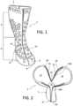
- FIG. 1is a perspective view of an embodiment of an orthopedic walker in a closed configuration.
- FIG. 2is a perspective view of the orthopedic walker of FIG. 1 in an open configuration.
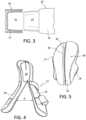
- FIG. 3is a schematic view of connecting edges in the orthopedic walker of FIG. 1 .
- FIG. 4is a schematic view of another embodiment of an orthopedic walker in an open state.
- FIG. 5is a perspective view of a bottom surface of the orthopedic walker in FIG. 4 .
- FIG. 6 Ais a side elevational view of another embodiment of an orthopedic walker.
- FIG. 6 Bis a front elevational view of the embodiment of FIG. 6 A .
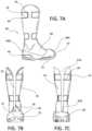
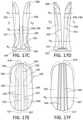
- FIG. 7 Ais a side elevational view of another embodiment of an orthopedic walker.
- FIG. 7 Bis a front elevational view of the embodiment of FIG. 7 A .
- FIG. 7 Cis a rear elevational view of the embodiment of FIG. 7 A .
- FIG. 8 Ais a perspective view of another embodiment of an orthopedic walker.
- FIG. 8 Bis a perspective view of a dorsal/anterior component of the embodiment of FIG. 8 A .
- FIG. 9is a perspective view of another embodiment of an orthopedic walker.
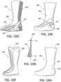
- FIG. 10 Ais a side elevational view of another embodiment of an orthopedic walker.
- FIG. 10 Bis a rear perspective view of the embodiment of FIG. 10 A .
- FIG. 10 Cis a side elevational view of another embodiment of an orthopedic walker.
- FIG. 10 Dis a side elevational view of another embodiment of an orthopedic walker.
- FIG. 10 Eis a side elevational view of another embodiment of an orthopedic walker.
- FIG. 10 Fis a perspective view of another embodiment of an orthopedic walker.
- FIG. 10 Gis a detail view taken from FIG. 10 F .
- FIG. 10 His a side elevational view of another embodiment of an orthopedic walker.
- FIG. 11 Ais a side elevational view of another embodiment of an orthopedic walker.
- FIG. 11 Bis a front perspective view of a reinforcement component of the embodiment of FIG. 11 A .
- FIG. 11 Cis a schematic view exemplifying placing a sole component to an orthopedic walker.
- FIG. 11 Dis a perspective view of the orthopedic walker of FIG. 11 C with the sole component installed.
- FIG. 12 Ais a side elevational view of another embodiment of an orthopedic walker.
- FIG. 12 Bis a schematic front perspective view of the embodiment of FIG. 12 A being adjusted.
- FIG. 13is a side elevational view of another embodiment of an orthopedic walker.
- FIG. 14 Ais a side elevational view of another embodiment of an orthopedic walker.
- FIG. 14 Bis a detail view taken from detail XIV in the orthopedic walker of FIG. 14 A .
- FIG. 15 Ais a side elevational view of another embodiment of an orthopedic walker in a closed configuration.
- FIG. 15 Bis a rear perspective view of the embodiment of FIG. 15 A in an open configuration.
- FIG. 16 Ais a schematic perspective view of another embodiment of an orthopedic walker in first and second configurations (I, II).
- FIG. 16 Bis a side elevational view of another embodiment of an orthopedic walker having a hinge feature.
- FIG. 17 Ais a perspective view of an orthopedic walker arranged for universal use.
- FIG. 17 Bis a side elevational view of the orthopedic walker of FIG. 17 A .
- FIG. 17 Cis a front elevational view of the orthopedic walker of FIG. 17 A .
- FIG. 17 Dis a rear elevational view of the orthopedic walker of FIG. 17 A .
- FIG. 17 Eis a top plan view of the orthopedic walker of FIG. 17 A .
- FIG. 17 Fis a bottom plan view of the orthopedic walker of FIG. 17 A .
- FIG. 17 Gis a schematic view showing the orthopedic walker of FIG. 17 A having first and second portion articulating individually relative to one another.
- FIG. 17 His a schematic view exemplifying donning the orthopedic walker of FIG. 17 A when a user is in a supine position.
- FIG. 18 Ais a schematic view showing an anterior side of an orthopedic walker according to a variation and arranged for universal use.
- FIG. 18 Bis a schematic view showing the posterior side of the orthopedic walker of FIG. 18 A .
- Embodiments of an orthopedic walkerare used for donning and doffing on a user and are provided for stabilizing and supporting anatomical portions of a user, for example, the lower leg, ankle, and foot of a user.
- the walkerhas a semi-rigid or rigid body material to reduce the complexity, cost, and weight of the walker.
- the semi-rigid nature of the body materialprovides rigid support when worn on the limb and allows the walker to resiliently hold or return to its original shape, while having some degree of flexibility or resiliency to facilitate regular donning and doffing.
- a preferred embodiment of the walker bodyis constructed from a single material and obviates the necessity of providing different structural materials.
- the walkereliminates the need for securing different materials together with adhesives and fasteners and has enough strength and resiliency to withstand normal ground reaction forces incurred on the foot, ankle, and leg, while stabilizing the limb and offering an intimate fit.
- the orthopedic walkerneed not be solely limited to the unitary construction.
- the walkercombines the strength and support of a casting system with the adjustability of an orthopedic walker.
- the walkermay be advantageously manufactured with a unitary form construction or of a single part construction.
- the simplified constructionenhances ease and comfort of use and offers a more lightweight structure.
- the embodiments of the disclosureare suitable for supporting and stabilizing anatomical portions of many users having various anatomical shapes and sizes, the embodiments of the disclosure may also be dimensioned to accommodate different types, shapes, and sizes of anatomical portions.
- the walkermay be an off-the-shelf product accommodating general sizes and shapes of the lower limb and feet or may be readily custom fabricated.
- the anterior and posterior portionsare defined by a frontal or coronal plane, F p , as depicted in FIG. 17 A .
- the anterior and posterior portions of the orthopedic walkerfunction together to form a supporting and stabilizing boot that encompasses the anatomical portions of the user.
- the lateral and medial portions of the orthopedic walkerare described independently.
- the lateral and medial portionsare defined by a median or sagittal plane, M p , as depicted in FIG. 17 A .
- the lateral and medial portions of the orthopedic walkerfunction together to form a supporting and stabilizing boot that encompasses the anatomical portions of the user.
- the sides of the orthopedic walker S I , S IIare simply divided by the median plane, as shown in at least FIG. 17 A .
- anterioralso has its ordinary meaning and refers to a location that is behind or to the rear of another location.
- anteriorhas its ordinary meaning and refers to a location ahead of or to the front of another location.
- medialhas its ordinary meaning and refers to a location near the median plane of a body, such as the inside of a foot.
- lateralhas its ordinary meaning and refers to a location farther from the median plane of a body, such as the outside of a foot.
- distalhas its ordinary meaning and refers to a location farther from the point of attachment of a limb.
- proximalhas its ordinary meaning and refers to a location closer to the point of attachment of a limb.
- a structurecan be proximal or distal in relation to another point of reference.
- a kneeis distal to an upper leg but proximal to the lower leg, however in the context of the orthopedic walker the knee is used as a frame of reference such that proximal P r is closer to the knee and whereas distal D i is farther from the knee.
- rigidmay distinguish characteristics of portions of certain features of the orthopedic walker.
- compressiblemay distinguish characteristics of portions of certain features of the orthopedic walker.
- rigidshould denote that an element of the device is devoid of flexibility. Within the context of support members or shells that are “rigid,” it should indicate that they do not lose their overall shape when force is applied, and they may break if bent with enough force.
- the term “compressible”may generally qualify such structural features as being capable of being reduced in size or volume due to the exertion of force applied to the structural feature.
- the “expanded” plasticmay have a lightweight cellular structure, such as a closed-cell foam, however the expanded plastic may cover a porous material or other generally lightweight or low-density material.
- unitarymay generally denote that an element of the walker is continuous in its construction, as opposed to comprising an assemblage of separate and spatially adjustable components.
- elongatemay generally denote that an element of the walker is longer than it is wide.
- FIG. 1shows an anterior view of an orthopedic walker 1 in a closed configuration.
- the orthopedic walker 1has a unitary form construction in that the structure is continuous and formed from a same material and arranged to extend about the user without interruption.
- a body 2 of the orthopedic walker 1consists a single material part.
- the body 2has a shape corresponding to a limb and having a unitary form construction to intimately fit against the user.
- the body 2is configured to receive a limb of a user in an open configuration, as illustrated in FIG. 2 , and to close about the limb of the user in a closed configuration, as illustrated in FIG. 1 .
- the body 2may have the general shape of a boot, conforming to the shape of a user's foot and a portion of a user's lower leg, inclusive of the ankle. While in the general shape of a boot, the footprint and bulk of the walker 1 is significantly streamlined as it is contoured to the general shape of a lower leg and foot. Unlike in conventional walkers, both the inner and outer peripheries of the body 2 are substantially form-fitting to the anatomical shape of a lower leg and foot.
- the body 2may be configured to an intended treatment purpose for the user.
- the height of the body 2may vary depending on a condition to be treated.
- the body 2may have a high top extending up the user's lower leg or may be manufactured or trimmed to have a low top.
- the walker 1may be configured in different heights to accommodate the pathologies and indications used for treatment.
- the body 2may have an open or closed toe portion 9 .
- a closed toe portionmay be advantageous over prior art embodiments of a cast, where a closed toe is only possible by tightly wrapping the toe area, and an orthopedic brace, where the toe is left open due to the constraints of a multi-component system.
- the walker 1may be configured with a closed toe portion 9 that surrounds and protects but does not tightly wrap the toes of a user, resulting in increased comfort over existing walkers.
- the closed toe portion 9offers a protective barrier to the environment without adding significant bulk.
- the closed toe portion 9is preferably contoured anatomically to toes and improves gait while the walker 1 is worn compared to conventional walkers, making it easier for the user to walk with the walker 1 donned.
- an open toe configurationmay be advantageous for providing increased access, space, and/or ventilation to the limb of the user.
- the body 2may be configured to the needs of the user, and/or may be cut or otherwise altered to adapt to the needs of the user.
- the body 2may be formed as a single part from a semi-rigid body material.
- the semi-rigid body materialreduces the complexity, cost, and weight of the walker 1 .
- the semi-rigid nature of the body materialprovides rigid support to the limb and allows the walker 1 to resiliently hold or return to its original shape, while having some degree of flexibility or resiliency to facilitate regular donning and doffing.
- Preferred materials for forming the bodyinclude an expanded polymer such as: EVA, rubber foam, or a closed-cell foam. Alternate polymeric materials may be employed having enough rigidity to intimately support and hold the lower limb and foot, while offering a protective barrier to elements and enabling the body 2 to likewise serve as the sole being subjected to repeated ground strike.
- the materials for forming the bodymay also advantageously reduce a body weight of the walker without sacrificing needed robustness.
- the semi-rigid body materialmay be configured to have distinct material properties, including material thickness, densities, etc., according to a preferred treatment and/or stabilization.
- the semi-rigid body materialmay be configured to substantially retain a shape of a closed configuration of the body 2 .
- the semi-rigid body materialmay be configured such that the body 2 provides compression for securing the body 2 about the limb when no force or pressure is applied to the body 2 .
- a shape of the body 2may be configured to support a particular area, or to prevent a particular motion of the limb.
- the interior of the walker 1 and the body 2may be defined by two portions, namely an upper receiving section 4 defining an upper or proximal part of the orthopedic walker or boot 1 corresponding to the lower leg, and a lower receiving section 6 defining a lower or distal part of the boot 1 corresponding to the foot of a user.
- an upper receiving section 4defining an upper or proximal part of the orthopedic walker or boot 1 corresponding to the lower leg
- a lower receiving section 6defining a lower or distal part of the boot 1 corresponding to the foot of a user.
- the body 2may be directly secured against the limb while offering both rigidity and compressive support without discomfort.
- a bottom surface 8 of the body 2may be configured with increased thickness as a sole or may be provided with an outsole.
- the sole 8may comprise a region with material properties, such as increased thickness or a non-slip surface, or may comprise an attached outsole. If the sole 8 is formed from the body 2 , it may be provided with treads to assist the user when walking or may be substantially smooth to reduce the overall shape and footprint, or a combination of the two. Wedges may be inserted into the walker 1 to provide Achilles tendon support and/or protection.
- the form-fitting nature of the walker 1as it is generally formed as a unitary body, has a more streamlined shape, and is much more contoured to the shape of a human foot than in conventional walkers.
- the rounded edges 13 extending about the foot portion of the walker 1exemplify how the walker 1 can be configured more as a structural stocking contoured as or to a human foot, rather than a generic shape.
- the shape of the walker 1derives from it being moulded to a shape of a human foot, and has a unitary, circumferential design.
- the body 2defines at least one opening 10 to facilitate donning and doffing of the orthopedic walker 1 .
- the at least one opening 10is shown in FIG. 1 as an elongate opening, extending from a proximal portion at an end of the body 2 to a distal portion at a second end of the body 2 .
- the walker 1defines an opening at the upper receiving section 4 and the lower receiving section 6 , enabling a limb such as a foot to be slipped into the walker 1 like a boot.
- the at least one elongate opening 10separates the body 2 into first and second sides 12 , 14 which join to seal or enclose the lower leg and foot of the user.
- the at least one elongate opening 10may only open the upper receiving section 4 , increasing the strength and support provided by the lower receiving section 6 .
- FIG. 2illustrates that the at least one elongate opening 10 comprises posterior and anterior elongate openings 10 A, 10 B separating the first and second sides 12 , 14 .
- the elongate openings 10 A, 10 Bmay be separately formed and closable relative to one another, such that the posterior opening 10 A can be closed independently from the anterior opening 10 B.
- Both elongate openings 10 A, 10 Bmay be closed in a clamshell configuration, being biased by posterior and anterior end portions 25 , 27 located at the distal end. In this manner, the distal end of the walker 1 provides the base by which the elongate openings 10 A, 10 B open to receive the user's lower leg and foot.
- the elongate openings 10 A, 10 Bmay be biased from the distal end, allowing the proximal end of the first and second sides 12 , 14 to be articulated to significantly open the limb-receiving portion 15 of the walker 1 in variable sizes to accommodate different sized lower limbs and feet.
- the material forming the walker 1is sufficiently resilient to undergo repeated biasing of the first and second sides 12 , 14 from the end portions 25 , 27 .
- the first side 12corresponds to a lateral side and the second side 14 corresponds to a medial side, and the first and second sides 12 , 14 provide support against lateral or medial movement of the limb.
- the at least one opening 10does not extend into or along the bottom surface 8 of the body 2 (when the bottom surface 8 is arranged to be used as a contact surface), so as not to interfere with any surface contour of the bottom surface 8 .
- the at least one elongate opening 10may be arranged to extend both in longitudinal and transverse directions, to provide increased support in preferred portions of the body 2 .
- At least one opening 10may be generally defined along the frontal plane of the walker 1 (corresponding to the leg), permitting side entry of the lower leg.
- the userneed only pull the first side 12 and the second side 14 apart, to expand the limb-receiving region 15 into an opened state for introduction of a limb of the user.
- the first side 12 and the second side 14can return to the closed state and enclose the limb.
- suitable fastenersmay maintain the walker 1 in a closed configuration, which may be defined as the at least one opening 10 being closed or generally closed.
- Buckles, straps, snaps, hooks, and other meansmay be located on the walker body 2 in predetermined locations to maintain the first and second sides 12 , 14 as being directly or generally adjacent to one another despite being donned by the user.
- the walker 1forms or is located circumferentially about the user to fully arrest movement of the lower limb during rehabilitation by the user. This may be achieved by intimately securing the walker 1 about the user's injured area and maintaining the limb in a fixed position by at least the fasteners securing the walker body 2 against the user.
- the semi-rigid body materialmay be configured to have a predetermined thickness, density and/or rigidity, such that the body 2 may compress tightly against a limb or against preferred regions of a limb.
- the semi-rigid body 2is preferably configured to have a thickness, density, and/or rigidity that remains flexible enough for a user to open the body 2 when introducing a limb.
- the body 2may have different thicknesses over its entirety. Side portions corresponding to a frontal plane of the first and second sides 12 , 14 may have increased thickness, to provide additional support over other areas of the body 2 that require more restriction of movement.
- the body 2may have an increasing thickness from a proximal end to a distal end, such that the lower receiving section 6 is more rigid than the upper receiving section 4 .
- the body 2may be configured with increased thickness around affected areas, or in a configuration forming a thicker and more rigid “frame” within the body 2 .
- the orthopedic walker 1may have a low top configuration, such that a user may insert a limb with or without the at least one opening 10 of the embodiments according to FIG. 1 .
- a low top configurationis understood here to correspond to the understanding of a low top shoe.
- the length of the body 2may be made to any necessary length to provide appropriate support to the user.
- the material properties of the body 2may vary to facilitate donning and doffing.
- a heel-supporting areamay be configured with increased elasticity to allow a heel of a user to compress the heel-supporting area during donning. The heel-supporting area could then be pulled up around the heel, or elastically return to its original shape about the heel.
- the material propertiesmay be modified depending on the location of the material in view of the walker 1 or the structural properties, such as thickness, may likewise be adapted depending on the location in view of the walker 1 .
- the exterior surface of the body 2is provided with a plurality of openings 16 configured to ventilate the limb, reduce pressure on a region, and/or reduce the weight of the body 2 .
- the benefit of ventilation, reduced pressure and reduced weightmust be considered against the potential loss of support or strength provided by the body 2 , as understood by one skilled in the art in view of the teachings of this disclosure.
- the arrangement of the openings 16may thus be optimized for reducing the weight of the walker 1 without sacrificing support, for example.
- the body 2may be provided with cutting indicia, such that a user or clinician may cut-out or remove portions of the body 2 according to the needs of a user or to adjust the size or weight of the orthopedic walker 1 .
- the body 2may be simply configured to tightly conform to a limb without contacting a swollen or injured portion that is sensitive to contact.
- cutting indiciamay be provided on the upper receiving section 4 to adjust the height of the body 1 to a user.
- cut linesmay be provided along the body 2 , such as with indents or recesses.
- the at least one elongate opening 10 or the elongate openings 10 A, 10 Bmay be defined by a first edge 20 on the first side 12 and a second edge 22 on the second side 14 .
- the first edge 20may be provided with a receiving recess 21 arranged to receive a protruding part 23 from the second edge 22 .
- a shape of the receiving recess 21is configured to correspond to a shape of the protruding part 23 .
- the receiving recess 21 and the protruding part 23may have any suitable shape for connecting the first edge 20 and the second edge 22 , such as a J-hook shape.
- the surface of the receiving recess 21 and the protruding part 23may further be provided with a friction enhancing texture to strengthen a locking of the first edge 20 and the second edge 22 .
- the first edge 20 and the second edge 22may each be provided with at least one receiving recess 21 and at least one protruding part 23 to lock in an alternating, zipper-like method.
- an interior surface of the limb receiving region 15may be provided with a textured surface or a plurality of protrusions.
- the textured surface or the plurality of protrusionsmay be arranged to allow for an increased friction against a movement of a limb, or to provide a lower density cushion for the limb.
- FIGS. 4 and 5show another embodiment of a walker 17 having a bottom surface 28 provided with a recessed portion 30 to facilitate donning and doffing of the walker 17 .
- the recessed portion 30may be configured to increase a variable distance d between the first and second sides 18 , 19 of the walker 17 along at least one opening, to provide a larger opening for insertion of the limb of the user.
- the recessed portion 30is shown extending from a posterior end 32 to an anterior end 34 of the bottom surface 28 .
- the recessed portion 30acts as a joint or vertex for the separation of lateral and medial sides of the walker. In this way the walker body may be advantageously opened and applied to the limb of the user without requiring the user to move or manipulate the limb, for example when the user is lying in a hospital bed.
- FIGS. 6 A and 6 Brepresent exemplary embodiments of a walker 31 having integrated strap retainers 36 A, 36 B for supporting circumferential straps 39 A, 39 B.
- the strap retainers 36 A, 36 Bmay comprise at least one channel, hole, slot, slit, or opening formed by the walker body for permitting insertion of the straps 39 A, 39 B to close the walker 31 and/or be firmly secured about the walker 31 .
- the walker 31also represents a configuration that can easily accommodate different sized feet and lower legs, while offering access to the toe by forming a toe section 37 that is open.
- a dorsal portion 35 of the walker 31may likewise be open with the toe section 37 , to offer relief at the dorsal portion 35 .
- the walker 31preferably forms a continuous opening between the proximal and distal ends 38 A, 38 B, and is closed on the anterior side by the straps 39 A, 39 B.
- the posterior side of the walker 31may be closed without an opening, or may include a posterior opening, much as in the other embodiments.
- the material of the walker 31is sufficiently resilient to adjust to opening about the anterior side of the walker 31 to accommodate the lower leg and foot, but when the straps 39 A, 39 B are tensioned, the walker 31 firmly and rigidly inhibits movement of the ankle and foot.
- FIGS. 7 A- 7 Cexemplify another walker 40 having differently formed sections, preferably from a unitary construction, that may be considered to have been moulded simultaneously, or post-fabricated with differently formed sections.
- the differently formed sectionsmay be structurally arranged differently, or may be formed with different properties, or both.
- the walker 40comprises a body 44 that defines a recess portion 41 for receiving a strap (not shown).
- the recess 41extends generally circumferentially about the walker 40 to accommodate a strap that is likewise preferably secured circumferentially about the walker 40 to close anterior and posterior openings 53 , 59 .
- the walker 40forms strap retainers 43 , as in the preceding embodiment, to maintain the straps within the recess 41 .
- the strap retainer 43defines a slot 45 through which the strap may extend.
- the walker 40defines bolsters 46 A, 46 B at the distal end proximate to the sole 47 .
- the bolsters 46 A, 46 Bmay be thickened regions of the walker 40 , exhibiting a thickness greater than neighbouring section 48 , which may exhibit greater flexibility.
- the bolsters 46 A, 46 Bmay be formed from a different material composition, may exhibit surface roughness, or may possess other features to enhance its toughness compared to the neighbouring section 48 since the bolsters 46 A, 46 B may be subjected to more wear and tear.
- the sole 47may be formed from a tougher material than other portions of the walker 40 and can have tread features 51 to improve traction while the user is walking. Upper portions 49 of the sole 47 may also have features to enhance durability and increase the structure of the sole 47 to provide enough to the user's foot. In certain embodiments, the sole 47 may be formed of a material that provides shock-absorbing effects and/or energy return to the user.
- the anterior and posterior openings 53 , 59may be formed differently from one another to facilitate donning.
- the anterior opening 53has a dorsal opening 55 with a larger opening section than in other parts of the anterior opening 53 , which aids in placing the foot within the walker 40 .
- the posterior opening 59flares at a proximal end 61 A to reflect the normal anatomy of a lower leg, such as at the calf.
- the posterior opening 59tapers by decreasing width toward a distal end 61 B, which likewise reflects the normally anatomy of an Achilles tendon.
- FIGS. 8 A and 8 Bshow another embodiment of a walker 50 having multiple components, as in posterior and anterior components 52 , 54 separable from one another.
- Each of the components 52 , 54are preferably unitary in structure, and corresponding fit with one another.
- the posterior component 52comprises leg and ankle portions 56 , 58 corresponding to the posterior of the leg, and defines a foot portion 60 .
- the leg portion 56defines proximal wings 57 A, 57 B arranged to extend anteriorly.
- the foot portion 60may have a sole portion 59 defined similarly to any of the other embodiments described herein.
- the foot portion 60forms a foot bed 84 for receiving the user's foot.
- the anterior component 54is arranged extend over the posterior component 52 , and has leg, ankle and dorsal portions 62 , 64 , 66 that overlap the leg, ankle and foot portions 56 , 58 , 60 of the posterior component 52 , to generally completely enclose the lower leg and foot.
- a peripheral edge 79 of the posterior component 54extends and overlaps the proximal wings 57 A, 57 B.
- the anterior component 54preferably defines a closed toe portion 68 which encases a toe portion of the foot portion 60 .
- a configuration of straps 70 , 72 , 74is secured to the posterior and anterior components 52 , 54 to draw the posterior and anterior components 52 , 54 toward one another.
- the anterior component 54may form a slot 76 about which the strap 70 is secured along the peripheral edge 79 on one side of the anterior component 54 , and couples or loops about a corresponding slot or bracket 78 integrated with the anterior component 54 whereby the bracket 78 is formed from a different material from the anterior component 54 , or formed by the anterior component 54 , such as a bracket 78 molded unitarily from the same material as the anterior component 54 .
- the foot portion 60 of the posterior component 52may form a slot 82 in the thickness thereof, through which the strap 74 feeds to pull the anterior component 54 toward the foot portion 60 of the posterior component 52 .
- the configuration of straps 70 , 72 , 74is not limited to those illustrated and described, and other forms applying or adopting these configurations are envisioned by the disclosure.
- FIG. 9exemplifies how any of the embodiments of a walker may be provided with reinforcement elements.
- a walker 100includes a body 102 forming an opening 104 along at least a posterior side of the walker 100 , separating first and second proximal portions 106 , 108 of the body 102 .
- the first and second proximal portions 106 , 108may be drawn together by a strapping configuration as depicted in FIGS. 6 A- 7 C .
- the posterior side of the walker 100includes an elongate reinforcement element 114 disposed from the proximal end 110 to the distal end 112 of the body 102 .
- the reinforcement element 114may extend below the opening 104 to just above a heel notch 128 .
- the heel notch 128may be provided as a pressure relief feature to accommodate heel strike of the walker 100 .
- the reinforcement element 114is arranged for being selectively inserted through retainers 120 formed by the walker body 102 , with a distal end 124 of the reinforcement element 114 being received at a distal seat 126 formed by the body 102 .
- the proximal end 122 of the reinforcement element 114may extend freely or be otherwise accessible so the reinforcement element 114 may be removed.
- the walker 100may have lateral/medial reinforcement elements 116 on opposed sides of the body 102 to increase walker strength, particularly about an ankle portion of the body 102 .
- Retainers 130may be formed by the body 102 or otherwise attached to the body 102 to permit the lateral/medial supports 116 to be selectively added to the walker 100 .
- fore/aft reinforcement elements 118may be selectively added to lateral and medial sides of the walker 100 and retained by retainers 132 , and/or received by end holders 134 .
- the reinforcement elements 114 , 116 , 118may be selected among a plurality of different types of reinforcement elements having different stiffnesses and other useful properties. Some reinforcement elements may be more rigid than other reinforcement elements.
- An exampleincludes reinforcement elements constructed from malleable aluminum that can be adapted to the anatomy of a specific user.
- the length of the reinforcement elements 114 , 116 , 118may be modified as considered necessary to a user's requirements.
- the walker 100may advantageously comprise a body 102 that is lighter in weight and bulk compared to existing devices without sacrificing needed strength and support.
- a reinforcement element 114 , 116 , 132may include range-of-motion control, energy return, and/or improved stability in particular directions or regions.
- a reinforcement elementmay be provided proximate a malleolus of a user and on an indicate side of the user's leg to immobilize and support the user.
- FIGS. 10 A and 10 Billustrate another walker 150 having a removable and contourable reinforcement element 154 .
- the reinforcement elements 114 , 116 , 118are generally rods or bars
- the reinforcement element 154may define a specific, complex shape received by a corresponding walker recess 156 formed by the walker body 152 .
- the reinforcement element 154may press fit into the recess 156 or adhere thereto by other known fasteners such as an adhesive or removable fastener such as hook and loop.
- the reinforcement element 154may be secured to the body 152 by a circumferential strap 170 .
- the posterior portion 158 of the walker 150receives the reinforcement element 154 comprising proximal wings 162 and distal wings 164 that provide lateral and medial support to the walker 150 in addition to posterior support provided between the proximal and distal wings 164 by a posterior portion 161 of the reinforcement element 154 .
- the reinforcement element 154may be selectively added to the body 152 depending on the user's requirements for support.
- FIG. 10 Aalso exemplifies how the walker 150 may have a dorsal shell 160 with edge contours corresponding to edge contours of the body 152 .
- the dorsal shell 160may have one side connected to the body 152 by a living hinge or may be completely separable from the body 152 .
- the dorsal shell 160may be formed from the same material as the body 152 .
- a strap 168may be provided which extends over the dorsal shell 160 and is connected to the body 152 , which retains the dorsal shell 160 relative to the body 152 .
- FIG. 10 Cshows how an orthopedic walker 172 may have a footbed 174 (or other locations and sections) reinforced with a reinforcing footplate 176 or other suitable inserts.
- the reinforcing footplate 176may be constructed from many structural materials, having greater strength or resiliency than the material forming the body of the orthopedic walker 172 .
- FIG. 10 Dshows how an orthopedic walker 178 may have a body 180 reinforced by material thickness or other structural features, such as supplementary material sections 181 , 182 , 183 , 184 formed from material having different properties from the body, 180 and provided in anatomically distinguishable sections.
- the reinforcement feature 181may correspond to the foot, whereas reinforcement feature 182 may correspond to the malleolus or ankle.
- the reinforcement feature 183may extend posteriorly along the body to inhibit flexibility, and the reinforcement feature 184 may underlie the foot.
- the malleolus-corresponding reinforcement feature 182may be provided with increased thickness and/or decreased elasticity relative to the body 180 to provide improved stability and/or immobilization to the user's ankle.
- the reinforcement feature 183may provide a different elasticity than the body 180 for controlling a range of motion of the foot. It will be understood that alternative arrangements are contemplated.
- FIG. 10 Eexemplifies an orthopedic walker 185 having a reinforcement feature 186 intended to be contoured about or along a periphery of at least part of an ankle.
- An indicator or indicia 187may denote a region for modification of the orthopedic walker 185 , such as a cut-out area 188 for removing material for wound safety, treatment, pressure relief, ventilation, weight reduction, or other purposes.
- the indicia 187may be formed from the body 180 and can comprise protruding or recessed portions of the body 180 .
- the indicia 187 and/or cut-out area 188may be provided on an interior surface of the orthopedic walker 185 .
- FIGS. 10 F- 10 Gshow an orthopedic walker 189 wherein the edge portions 190 have a thickness the relative to a thickness t b of the body 180 .
- the edge portions 190may have a taper 191 either formed along an inner side (as depicted) or an outer side of the body 180 .
- the thinned edge portions 190offer a more flexible edge to the orthopedic walker 189 to reduce pressure portions or points, and/or permit the clinician to trim the body 180 according to the anatomy of the user.
- FIG. 10 Hexemplifies how the orthopedic walker 192 can have a cut-out 193 for modification of the body 180 .
- the cut-out 193is provided for removing material about an Achilles region 194 of the body 180 to offer relief.
- the cut-out 193may be formed as reduced material portions that can remain intact as part of the body 180 if it is not desired for removal.
- FIGS. 11 A and 11 Bshow a walker 200 comprising another example of a reinforcement element 204 that may be added to a walker body 202 , to define and provide support for a sole of the walker 200 .
- the reinforcement element 204may be substantially stiffer and tougher than the material forming the body 202 .
- the reinforcement element 204may extend from a dorsal portion 206 underneath the body 202 to a posterior portion 207 .
- This example of a reinforcement element 204includes a dorsal portion 208 , a toe portion 210 , a sole portion 212 , a heel portion 214 , and a posterior portion 216 .
- the reinforcement element 204may also have wings 218 that wrap about the heel, for example about medial and lateral sides, and posterior portions 214 , 216 .
- the reinforcement element 204may be modified according to areas of the walker 200 whereat reinforcement is needed and is not limited to having all the portions.
- the reinforcement element 204may have hinged sections 220 , such as a living hinge, for example between the toe portion 210 and the dorsal portion 208 to facilitate bending, while maintaining a continuously formed reinforcement element 204 .
- the reinforcement element 204is not limited to being continuously formed but may comprise a plurality of parts selectively placed at desired portions of the body 202 .
- the sections/portions of the reinforcement element 204may have different materials or properties at different locations.
- FIGS. 11 C and 11 Dexemplify how a sole component 228 can be added to a footbed 226 of an orthopedic walker 222 having a body 223 .
- the footbed 226defines an outer surface 227 extending at least into part of the lower receiving portion 236 .
- the footbed 226may define an open anterior region 235 generally corresponding to where toes of a foot may extend.
- the sole component 228may have a closed anterior region 230 arranged to fittingly engage the anterior side of the footbed 226 to close the open anterior region 235 .
- the sole componenthas a cavity 229 wherein the footbed 226 may be inserted, and a closed posterior region 231 that extends about a posterior region 237 of the footbed 226 and may additionally extend to the lower receiving section 236 .
- the sole component 228may have elasticity so the closed anterior and posterior regions 230 , 231 can elasticity extend to fittingly and snugly engage the body 223 , as shown in FIG. 11 D .
- the sole component 228may form a tread or other suitable surface to provide traction to the orthopedic walker 222 .
- the sole component 228can serve as a strap to retain a user's foot in the body 223 at the footbed 226 and lower receiving section 236 .
- FIGS. 11 C and 11 Dalso show how the body 223 can form recesses 224 , 225 for retaining straps 232 , 233 at a predetermined location to prevent migration of the straps 232 , 233 over the surface of the body 223 .
- the body 223may form retainers 239 having slots 240 through which the straps 232 , 233 extend to offer yet further retention means for the straps 232 , 233 .
- the sole component 228may attach to the walker body 223 by any suitable means, including but not limited to magnets, zippers, hooks and corresponding loops, hook-and-loop fastener, straps, click-on components, or otherwise.
- the sole component 228 and the outer surface 227 of the footbed 226may comprise corresponding structures (not shown) that provide engagement and support between the sole component 228 and the walker body 223 in an engagement configuration.
- the corresponding structuresmay comprise mating ribs that provide structural support but are arranged to mate such that the profile of the combined walker body 223 and sole component 228 may have a minimal profile.
- the sole component 228may have a wider configuration than the footbed 226 for pressure distribution and optimized traction over a walking surface.
- the sole component 228may comprise pull loops for ease of donning and doffing the sole component 228 .
- a single size or version of the walker 222may be provided (as the walker 222 may accommodate differently sized users), different sizes of sole component 228 may be provided and interchanged with the walker 222 .
- the walker 222 and the sole component 228may be arranged in thickness or construction to minimize heel-height discrepancy between the walker 222 and the user's unaffected foot.
- the sole component 228may be arranged to have a height or thickness like a shoe worn outdoors, whereas the footbed 226 may have a reduced thickness such that heel height is minimized indoors (such as if the user is not wearing a shoe on the unaffected foot).
- FIGS. 12 A and 12 Bexemplify a walker 250 having different regions of breathability.
- a walker body 252forms a frame to the walker 250 , particularly along the posterior, and medial and lateral sides, and along the sole or foot bed.
- a textile, foam or other flexible and breathable material 254may be provided in the areas outside of the walker body 252 .
- the body 252may have strap segments 258 placeable over the breathable material 254 to tighten the walker 250 about the user.
- Frame elements or additional straps 260 of the walker body 252may overlap the breathable material 254 , thereby providing improved structure to the body 252 .
- FIG. 12 Bspecifically illustrates how the strap segments 258 , 260 may be trimmable to an appropriate length for the user.
- These strap segments 258 , 260may be formed from the same material and directly from the body 252 .
- FIG. 13shows another embodiment including a walker 300 having a body 302 , which a breathable material 304 bridging areas within the body 302 .
- the walker 300has a toe portion 306 either formed from the body 302 or formed from a separate material secured to the body 302 .
- the body 302defines a strap 308 unitary and continuous with the body 302 .
- the strap 308forms a plurality of slots 312 arranged to receive a fastener 310 for securing to at least one of a plurality of slots 314 formed by the body 302 .
- the fastener 310includes a base portion 316 retained by at least one of the slots 312 of the strap 308 .
- the fastener 310rests within at least one of the slots 312 by a groove 322 , and a head portion 320 of the fastener 310 protrudes from the strap 308 to engage the at least one slot 314 of the body 302 .
- the fastener 310preferably is formed from a harder material than the material forming the body 302 , so that as the head portion 320 is pressed into the at least one slot 314 , the material about the at least one slot 314 may slightly yield to accommodate the fastener 310 .
- the fastener 310 structuremay be formed from the material forming the strap 308 and body 302 .
- FIGS. 14 A and 14 Bshow another embodiment of a walker 350 wherein at least one strap 358 is separately connected to a body 352 of the walker 350 .
- the body 352defines an edge 354 that defines a slot 356 through which a strap 358 secures.
- the strap 358may form a boss 360 with a size larger than the slot 356 to retain the strap 358 with the body 352 .
- FIGS. 15 A and 15 Bexemplify another walker embodiment 400 having a body 402 from which a posterior portion 406 pivots away relative to an anterior portion 404 .
- the walker 400provides a rear entry opening by the posterior portion 406 opening for ease of donning and doffing.
- the body 402may be unitary with the anterior and posterior portions 404 , 406 , such that a living hinge 412 permits articulation by the posterior portion 406 .
- the posterior portion 406may overlap with a proximal anterior portion 410 and can fasten with a fastener 416 .
- a strap 414may be provided to circumferentially extend about the anterior and posterior portions 404 , 406 , and extend through a slot 418 formed by the posterior portion 406 .
- the posterior portion 406may comprise medial/lateral wings 408 that may extend around and overlap a portion of the anterior portion 410 , such that as the strap 414 extends around the wings 408 and the anterior portion 410 , an
- FIG. 16 Aillustrates an embodiment of a walker 450 with a body 452 having first and second portions 454 , 456 forming struts to the walker 450 , yet arranged to open by biasing about living hinges 458 formed from the body 452 .
- the first and second portions 454 , 456may be trimmable to accommodate the specific dimensions of a user.
- the first and second portions 454 , 456may comprise individual sections 159 that are arranged to be discretized and separated from adjacent sections of the first and second portions 454 , 456 to form struts of a user-tailored length.
- Recesses or relief areas 464may be defined on opposed sides, for example anterior and posterior sides, of a flex portion 460 , to reduce material and facilitate outward and inward biasing of the first and second portions 454 , 456 .
- a footbed 464may comprise any suitable material for supporting a user, including added components such as Achilles tendon wedges, memory foam, shock absorbing material, heat-formable materials, or any other suitable material.
- FIG. 16 Bshows another embodiment of an orthopedic walker 470 having a hinge feature 474 about an articulating portion 478 of the walker 470 to facilitate first and second portions 471 , 472 to open and close for donning generally along a median plane of the orthopedic walker 470 .
- the first and second sides corresponding to the first and second portions 471 , 472may have similar structure to enable each to articulate.
- Relief areas 475 , 476may be provided on anterior and posterior sides of the first and second portions 471 , 472 to reduce material at or about the articulating portion 478 .
- At least one material relief segment 477may be provided within the articulating portion 478 to better enable each of the first and second portions 471 , 472 to articulate relative to one another.
- FIGS. 17 A- 17 H and FIGS. 18 A-Billustrate another embodiment of an orthopedic walker 500 arranged for universal use for both right and left legs and feet.
- the walker 500has generally symmetrical first and second sides S I , S II , divided by the median plane M p .
- FIG. 18 Ashows how first and second portions 502 , 504 are symmetrical relative to one another so they can accommodate both right and left legs and feet, although they each have a curvilinear profile 548 from proximal to distal ends.
- the curvilinear profile 548is defined to more naturally fit a leg, ankle and foot, as compared to conventional walkers.
- the spacing of the first and second portions 502 , 504taper through the upper receiving section 503 , and are contoured to accommodate the malleolus of an ankle in at least the lower receiving section 505 .
- the curvilinear profile 548may define an expanded portion 550 proximate the malleolus for accommodating and comfortably immobilizing a user's leg, while defining a different width along the leg at tapering profile 549 .
- the walker 500may accommodate leg profiles L L corresponding to a left leg and L R corresponding to a right leg, thus simplifying the process of providing an appropriate support to a user.
- the footbed 522may be contoured accordingly to accommodate both right and leg feet.
- the first and second sides S I , S IImay define a same profile by being symmetrical such that the fit for right and left legs is the same.
- FIG. 18 Billustrates how the walker 500 has improved frontal plane control along the frontal plane Fp, particularly in view of conventional double strut walkers.
- the improved frontal plane Fp controlis achieved by the first and second portions of at least the upper and lower receiving sections 503 , 505 having extending regions 551 , 552 wrapping about the anterior and posterior sides of a user's leg, such that when straps 553 , 554 are provided about the first and second portions 502 , 504 , the walker 500 is better able arrest or immobilize the leg.
- the extending regions 551 , 553are provided without adversely increasing the weight of the walker 500 since when an expanded thermoplastic is used to form the walker body 501 , significant weight savings are achieved.
- a profile defined on a medial and a lateral side of the walker 500may not be symmetrical but may rather be side-specific; that is, portions may be fitted to the dimensions common in a left or a right leg. Portions proximate the calf and the malleolus, for example, may be adjusted to accommodate a side-specific dimension, with the malleolus portion on a medial side arranged to be higher and more anterior, for example, or to be more profile if less space is needed to make the walker 500 universal, as a universal walker requires more space to accommodate either malleolus.
- a side-specific walker 500may have a narrower and asymmetrically shaped footbed 507 , with a narrower toe portion to improve rollover/gait dynamics late in the stance phase.
- the walker 500defines a body 501 formed from at least one polymeric material.
- the body 501defines an upper receiving section 503 , a lower receiving section 505 , and a footbed 507 .
- the upper receiving section 503includes first and second portions 502 , 504 divided by a median plane of the orthopedic walker M p .
- the first and second portions 502 , 504are arranged to individually articulate or pivot (from generally at the lower receiving portion and/or footbed) about or from the median plane M p to expand or retract a variable distance d between the first and second portions 502 , 504 .
- the variable distance dmay increase as the first and second portions 502 , 504 pivot or articulate by being able to extend from an upright predetermined configuration to at least pivoting 90 degrees or at least perpendicularly to an open configuration.
- the upright predetermined configurationis a default position in which the first and second portions 502 , 504 rest or return to if a load to pivot the first and second portions is outwardly released.
- the upright predetermined configurationis achieved by at least resiliency of the polymeric material forming the first and second portions 502 , 504 , and/or or the structural shape and configuration of the first and second portions 502 , 504 relative to the lower receiving section 505 and/or footbed 507 .
- the upright predetermined configurationgenerally is oriented so the first and second portions 502 , 504 extend in the proximal P r and distal D r directions and is a default configuration.
- first and second portions 502 , 504can pivot outwardly at least perpendicularly away from each other to open the walker 500 for donning, the first and second portions 502 , 504 may pivot inwardly toward one another upon application of a load, such as using a strap to tension at least in a circumferential or partially circumferential orientation about the walker 500 .
- each of the first and second portions 502 , 504can be pivoted or articulated distally from a predetermined configuration without necessarily moving the other one of the first and second portions 502 , 504 .
- the first and second portions 502 , 504can be arranged so they both open simultaneously opening or tilting toward the distal end of the body 501 to enable quick and simple donning.
- FIG. 17 Hshows how the walker 500 can be donned when the user is in a supine position.
- the protocolis to maintain the user in a supine position after surgery, and the arrangement of opening the walker 500 enables the walker 500 to be donned without lifting the leg and foot.
- the userneed not be in a supine position to don the walker 500 and may be donned by the user opening and/or stepping into the walker 500 .
- FIGS. 17 E and 17 Fexemplify how the walker 500 need not merely rely on the resiliency of material forming the body 501 to permit articulation.
- the footbed 507may include at least one channel or groove 540 , 542 located along and into a thickness of the inner surface 522 between anterior and posterior ends 517 , 518 .
- a central groove 542extends generally along the median plane M p to allow the articulation of the walker 500 to occur at the footbed 507 rather than merely pivoting the first and second portions 502 , 504 , either by resiliency of the material forming the walker 500 and/or with a hinge.
- Additional grooves 542may be provided alongside the central groove 542 to allow the footbed 507 to fan or bend to achieve the supine donning of the walker 500 , as depicted in FIG. 17 G .
- the footbed 507may have a special shape or configuration to address and minimize rollover.
- the footbed 507may advantageously attain a same comfort level as existing devices yet have a reduced build height relative to existing devices as special insole material may be omitted without sacrificing comfort.
- hard plasticsare used to create immobilization of the limb, with a certain thickness for optimal immobilization.
- Thick foam solesare added to provide cushioning against the hard-plastic body to improve comfort in gait. Because of the improved rollover-prevention profile and the EVA, the thick foam soles in combination with the hard-plastic layer of conventional devices may be reduced and/or removed.
- the outer surface 534 of the footbed 507may likewise form at least one groove 546 generally along or alongside the median plane M p .
- Either of the grooves of the inner surface 522 or outer surface 534may have grooves with a uniform width or a variable width according to a location relative to the anterior and posterior ends 517 , 518 .
- the groovesare shown as extending a length of the footplate between the anterior and posterior ends 517 , 518 , they may extend only partially and/or in different directions, patterns, and/or spacings.
- the body 501defines at least two openings 536 , 538 at least partially separating the upper receiving section 503 of the body 501 into the first and second portions 502 , 504 .
- the at least two openings 536 , 538are preferably opposite one another generally along the median plane M p , and generally extending elongate in the proximal P r and distal D r directions.
- the at least two openings 536 , 538can articulate relative to one another, the first and second portions 502 , 504 may be variably spaced relative to one another in a predetermined configuration, without intentionally varying the distance of the first and second portions 502 , 504 relative to one another.
- first and second anterior edges 537 , 539may be spaced at a width w 1 at a proximal end of the body 501 , whereas at a middle location the width w 2 may be less than at width w1.
- the first and second anterior edges 537 , 539 at the footbed or distal endmay be spaced wider with a width w 3 than the width w2.
- first and second posterior edges 541 , 543 of the first and second portions 502 , 504may be spaced variably relative to one another, whereby a proximal portion may have a width w 4 and a distal portion may have width w 5 .
- the spacing of the at least two elongate openings 536 , 538may be different relative to one another, and may vary in the proximal P r and distal D r directions differently according to the unique anatomy of a leg, ankle and foot generally on the anterior and posterior sides, and lateral and medial sides.
- the body 501consists the upper receiving section 503 , the lower receiving section 505 , and the footbed 507 as a continuous structure formed unitarily from the at least one polymeric material.
- the at least one polymeric materialmay be an expanded thermoplastic, which offers weight savings while offering a rigid structure.
- the expanded thermoplasticmay be selected from the group consisting of polyurethane, polyethylene, polypropylene and ethylene-vinyl acetate.
- the first and second portions 502 , 504are symmetrical relative to one another, such that the first and second portions have a curvilinear profile extending between and among the proximal P r and distal D r directions of the upper receiving section 504 .
- the first and second portions 502 , 504have a convex profile 560 , 561 along an inner surface 558 thereof.
- the first and second portions 502 , 504have convex profiles 562 , 563 along an outer surface 559 thereof generally corresponding to the concavity of the inner surface 558 , as it is intended that the convex profile 560 , 561 closely contours to the leg and ankle in the walker 500 , particularly if the first and second portions 502 , 504 pivot to accommodate a user's leg once or as the walker 500 is donned.
- the upper receiving section 503may have a varying wall thickness, or a substantially uniform wall thickness, as explained in relation to foregoing embodiments.
- the upper receiving section 503may have an increased thickness at least proximate a periphery 508 thereof relative to areas outside the periphery 506 .
- the increased thicknessmay have a tapering width 510 in sections and may connect with regions having curvilinear thickness differences 512 according to areas requiring additional support, than at areas such as areas 506 , 514 , 516 outside of the increased thickness.
- the areas requiring additional supportmay be at the ankle to better immobilize movement in the frontal plane, or at an anterior toe area 518 .
- the reinforcing area 512extends above the malleolus 545 with anterior and posterior sections 524 , 528 gradually extending to a crest 526 to form a transitional support more proximate to a user's anatomy and regions by which the user may require enhanced frontal plane control.
- the reinforcing area 512may only protrude outwardly without interfering with the inner side of the 558 body, which interfaces with the user's leg, ankle and foot.
- the footbed 507may have a substantially decreased thickness t over conventional walkers, as shown with the anterior lip 530 .
- a problemoften occurs with a mismatch of height of the walker compared to the unaffected foot, ankle and leg.
- the footbed 507has an inner surface 522 upon which the foot is placed and extends a length 520 of the distal end portion of the walker.
- the improved support by the upper and lower receiving portions 503 , 505enables a thinner footbed 507 , coupled with the unitary construction of the body 501 of the walker 500 .
- An outer surface 534 of the footbed 534may have a curvilinear profile 535 with a tread (not shown) to enable foot rollover and traction for walking.
- the footbed 507may include the lip 530 and a posterior groove 532 for at least interlocking with a sole component.
- an orthopedic walkermay combine the benefits of existing casting devices and existing orthopedic braces in a walker that is both lightweight compared to existing devices and nevertheless comprises necessary strength and rigidity for immobilization and support of a limb of a user.
- Orthopedic walkersmay comprise additional features for supporting a limb of a user without adding significant weight, such as stays or inserts, ventilation openings, longitudinal openings facilitating supine donning and doffing, removable outer soles, and others.
Landscapes
- Health & Medical Sciences (AREA)
- Nursing (AREA)
- Orthopedic Medicine & Surgery (AREA)
- Engineering & Computer Science (AREA)
- Biomedical Technology (AREA)
- Heart & Thoracic Surgery (AREA)
- Vascular Medicine (AREA)
- Life Sciences & Earth Sciences (AREA)
- Animal Behavior & Ethology (AREA)
- General Health & Medical Sciences (AREA)
- Public Health (AREA)
- Veterinary Medicine (AREA)
- Orthopedics, Nursing, And Contraception (AREA)
- Rehabilitation Tools (AREA)
- Prostheses (AREA)
Abstract
Description
Claims (20)
Priority Applications (2)
| Application Number | Priority Date | Filing Date | Title |
|---|---|---|---|
| US16/266,925US12156825B2 (en) | 2018-02-02 | 2019-02-04 | Orthopedic walker |
| US18/905,752US20250025327A1 (en) | 2018-02-02 | 2024-10-03 | Orthopedic walker |
Applications Claiming Priority (2)
| Application Number | Priority Date | Filing Date | Title |
|---|---|---|---|
| US201862625527P | 2018-02-02 | 2018-02-02 | |
| US16/266,925US12156825B2 (en) | 2018-02-02 | 2019-02-04 | Orthopedic walker |
Related Child Applications (1)
| Application Number | Title | Priority Date | Filing Date |
|---|---|---|---|
| US18/905,752ContinuationUS20250025327A1 (en) | 2018-02-02 | 2024-10-03 | Orthopedic walker |
Publications (2)
| Publication Number | Publication Date |
|---|---|
| US20190240057A1 US20190240057A1 (en) | 2019-08-08 |
| US12156825B2true US12156825B2 (en) | 2024-12-03 |
Family
ID=65441137
Family Applications (2)
| Application Number | Title | Priority Date | Filing Date |
|---|---|---|---|
| US16/266,925Active2039-05-03US12156825B2 (en) | 2018-02-02 | 2019-02-04 | Orthopedic walker |
| US18/905,752PendingUS20250025327A1 (en) | 2018-02-02 | 2024-10-03 | Orthopedic walker |
Family Applications After (1)
| Application Number | Title | Priority Date | Filing Date |
|---|---|---|---|
| US18/905,752PendingUS20250025327A1 (en) | 2018-02-02 | 2024-10-03 | Orthopedic walker |
Country Status (4)
| Country | Link |
|---|---|
| US (2) | US12156825B2 (en) |
| EP (1) | EP3746008B1 (en) |
| CN (1) | CN111801071B (en) |
| WO (1) | WO2019152906A1 (en) |
Cited By (1)
| Publication number | Priority date | Publication date | Assignee | Title |
|---|---|---|---|---|
| US20230000655A1 (en)* | 2021-06-30 | 2023-01-05 | Thorwear Inc. | Ankle foot orthoses and method of manufacturing |
Families Citing this family (10)
| Publication number | Priority date | Publication date | Assignee | Title |
|---|---|---|---|---|
| US12156825B2 (en) | 2018-02-02 | 2024-12-03 | Ossur Iceland Ehf | Orthopedic walker |
| US11253402B2 (en)* | 2018-03-03 | 2022-02-22 | Fastform Research Ltd. | Orthosis apparatus and method of use |
| US20200253772A1 (en)* | 2019-02-07 | 2020-08-13 | Mary-Kate Reid | Waterproof Ankle-Foot Orthosis |
| US11865027B1 (en)* | 2019-10-18 | 2024-01-09 | Matthew Danzel Milton | Hamstring support system and method of use |
| US11369163B1 (en)* | 2019-12-03 | 2022-06-28 | Jesse Offutt | Athletic shoe having integral ankle support |
| US12357488B2 (en) | 2020-10-14 | 2025-07-15 | Darco International, Inc. | Rear entry walker |
| US20220151812A1 (en)* | 2020-11-19 | 2022-05-19 | Ossur Iceland Ehf | Orthopedic walker |
| US12295894B2 (en)* | 2021-11-09 | 2025-05-13 | Allen Medical Systems, Inc. | Surgical traction boot having resilient heel pad and medial and lateral straps |
| WO2024086686A1 (en) | 2022-10-21 | 2024-04-25 | Ossur Iceland Ehf | Pump assembly for an orthopedic device |
| US11931281B1 (en) | 2022-12-30 | 2024-03-19 | Protect3D, Inc. | Adjustable brace and processes for making and using same |
Citations (379)
| Publication number | Priority date | Publication date | Assignee | Title |
|---|---|---|---|---|
| US346606A (en)* | 1886-08-03 | John g | ||
| US975576A (en) | 1908-09-14 | 1910-11-15 | Daniel Sexton | Innersole. |
| US1012017A (en) | 1911-05-20 | 1911-12-19 | Edward William Salt | Device or appliance for treating or curing deformations of the foot. |
| US2200849A (en) | 1939-12-18 | 1940-05-14 | Morris N Margolin | Inner sole |
| US2236367A (en) | 1939-04-04 | 1941-03-25 | Gruber John | Shoe |
| US2292297A (en) | 1941-08-02 | 1942-08-04 | Edward B Sherlock | Toe protecting shield for shoes |
| US2444640A (en) | 1946-10-19 | 1948-07-06 | William H Epstein | Blucher type shoe with removable plug |
| US2868191A (en) | 1957-07-05 | 1959-01-13 | Juhasz Steve | Foot massaging device |
| US2885797A (en) | 1957-08-16 | 1959-05-12 | Edward W Chrencik | Shoe construction with resilient heel and arch support |
| US2888016A (en) | 1956-04-04 | 1959-05-26 | Lamater Georgia K De | Therapeutic boot |
| US2909854A (en) | 1957-08-14 | 1959-10-27 | Edelstein Marie | Pressure relieving insoles |
| US2913837A (en) | 1958-04-11 | 1959-11-24 | Holland Racine Shoes Inc | Shoe heel construction |
| US2917844A (en) | 1956-09-12 | 1959-12-22 | William M Scholl | Laminated foot cushioning device with pocketed lift |
| US2928193A (en) | 1958-02-06 | 1960-03-15 | Kristan Philip | Shoe insole |
| US2979835A (en) | 1958-04-28 | 1961-04-18 | William M Scholl | Foot cushioning device |
| US2979836A (en) | 1959-01-07 | 1961-04-18 | Scholl Mfg Co Inc | Foot cushioning devices for use in articles of footwear |
| US3270358A (en) | 1962-09-25 | 1966-09-06 | Rosearch Inc | Method of manufacturing a safety shoe |
| US3464126A (en) | 1967-10-30 | 1969-09-02 | Vahe B Sarkissian | Shoe with a hinged mechanically adjustable heel |
| US3548420A (en) | 1967-03-06 | 1970-12-22 | Stryker Corp | Cushion structure |
| US3580248A (en) | 1968-12-02 | 1971-05-25 | Leighton W Larson | Bivalved cast |
| US3681860A (en) | 1970-05-22 | 1972-08-08 | Bidegain Sa | Shoes,especially for children |
| US3685176A (en) | 1970-07-02 | 1972-08-22 | Marion F Rudy | Inflatable article of footwear |
| US3730169A (en) | 1971-03-08 | 1973-05-01 | T Fiber | Shoe inner sole and orthopedic support |
| US3735758A (en) | 1971-06-07 | 1973-05-29 | M Novotney | Foot and ankle cast enclosure |
| US3760056A (en) | 1970-09-23 | 1973-09-18 | Bogert R | Method for custom fitting an inflatable bladder to a wearer{3 s foot |
| US3786805A (en) | 1970-10-06 | 1974-01-22 | Inst Europ De Rech Et D Applic | Splint having inflatable detachable cushions |
| US3792537A (en) | 1971-02-24 | 1974-02-19 | Rieker & Co Justus | Ski boot |
| DE2341658A1 (en) | 1972-08-23 | 1974-03-07 | Polyair Maschb Gmbh | SKI BOOT |
| US3814088A (en) | 1972-01-12 | 1974-06-04 | E Raymond | Orthopedic boot |
| US3834377A (en) | 1973-09-19 | 1974-09-10 | S Lebold | Easily removable orthopedic shoe platform |
| US3859740A (en) | 1974-01-23 | 1975-01-14 | James A Kemp | Cushion heel pad for spur heels |
| US3922800A (en) | 1974-07-01 | 1975-12-02 | K 2 Corp | Size adjustable ski boot |
| US3955565A (en) | 1973-12-05 | 1976-05-11 | Johnson Jr Glenn W | Orthopedic apparatus |
| US4045888A (en) | 1976-10-26 | 1977-09-06 | Bruce Oxenberg | Athletic shoe |
| US4057056A (en) | 1976-06-01 | 1977-11-08 | Payton Hugh W | Walking cast |
| US4095353A (en) | 1977-05-05 | 1978-06-20 | Oggs Manufacturing Corp. | Massage sandal |
| US4100686A (en) | 1977-09-06 | 1978-07-18 | Sgarlato Thomas E | Shoe sole construction |
| US4142307A (en) | 1977-01-07 | 1979-03-06 | Hans Martin | Ski and skating boot |
| FR2399811A1 (en) | 1977-08-08 | 1979-03-09 | Delery Marc | Sports shoe, especially skating boot - has outer thermoplastic shell with protuberances used for guiding flexible cables, tightened by ratchet wheel |
| US4177583A (en) | 1978-04-13 | 1979-12-11 | Chapman Andrew W | Orthopedic shoe with forefoot protective guard |
| US4184273A (en) | 1977-09-06 | 1980-01-22 | Scott Usa, Inc. | Boot with hinged upper |
| US4217893A (en) | 1977-08-01 | 1980-08-19 | Payton Hugh W | Above-the-knee cast |
| US4217706A (en) | 1979-07-18 | 1980-08-19 | Vartanian Vincent A | Boot for walking cast |
| US4232459A (en) | 1977-11-02 | 1980-11-11 | Franco Vaccari | Ski boots |
| US4237626A (en) | 1979-02-26 | 1980-12-09 | Brown Dennis N | Deformable foot wedge |
| US4267649A (en) | 1979-05-07 | 1981-05-19 | Smith Gardner M | Interchangeable shoe |
| US4300294A (en) | 1979-10-09 | 1981-11-17 | Riecken George C | Article of footwear |
| US4333248A (en) | 1980-07-23 | 1982-06-08 | Samuel Samuels | Protective shoe |
| US4370818A (en) | 1980-12-15 | 1983-02-01 | Arthur Simoglou | Protective footwear |
| US4408402A (en) | 1982-08-05 | 1983-10-11 | Looney Judy A | Supportive shoe and insert |
| US4414965A (en) | 1981-05-26 | 1983-11-15 | Mauldin Donald M | Brace for tibial fractures |
| EP0095396A1 (en) | 1982-05-21 | 1983-11-30 | Guy Salort | External upright position and walking apparatus for the lower-limbs motorically handicapped |
| USD272281S (en) | 1981-09-28 | 1984-01-17 | Ballert Orthopedic Corp. | Contracture control orthosis |
| DE3228753A1 (en) | 1982-07-31 | 1984-02-02 | Helmut 3000 Hannover John | Foot-supporting splint |
| GB2124473A (en) | 1982-06-26 | 1984-02-22 | Mizuno Kk | Shoe insole |
| US4446856A (en) | 1981-12-18 | 1984-05-08 | The Langer Biomechanics Group, Inc. | Orthotic device |
| US4494536A (en) | 1982-12-01 | 1985-01-22 | Latenser John F | Foam boot |
| US4505269A (en) | 1983-07-21 | 1985-03-19 | Davies John R | Ankle splint |
| US4550721A (en) | 1983-07-01 | 1985-11-05 | Michel Lorraine M | Foot support |
| US4565017A (en) | 1984-09-28 | 1986-01-21 | Ottieri Enterprises | Ski boot |
| US4571853A (en) | 1984-06-04 | 1986-02-25 | Medrano Walter A | Shoe insert |
| US4572169A (en) | 1984-04-03 | 1986-02-25 | Kenneth D. Driver | Removable lower leg brace |
| US4587962A (en) | 1984-02-08 | 1986-05-13 | United States Manufacturing Company | Tibia/ankle orthosis |
| US4598484A (en) | 1984-08-29 | 1986-07-08 | Ma Sung S | Footwear |
| US4599811A (en) | 1982-12-06 | 1986-07-15 | Boussac Saint-Freres B.S.F. | Easy to put on wrap-around shoe which is adaptable to the shape of the foot |
| US4608768A (en) | 1983-10-24 | 1986-09-02 | Puma-Sportschuhfabriken Rudolf Dassler Kg | Athletic shoe having a shock-absorbing running sole and a process for manufacturing said athletic shoe |
| US4620378A (en) | 1984-05-30 | 1986-11-04 | Nordica S.P.A. | Ski boot incorporating a foot securing device |
| EP0201051A1 (en) | 1985-05-06 | 1986-11-12 | NORDICA S.p.A | Ski boot |
| US4633599A (en) | 1984-08-17 | 1987-01-06 | Salomon S. A. | Ski boot |
| US4633598A (en) | 1983-09-30 | 1987-01-06 | Nippon Rubber Co., Ltd. | Insole for shoe |
| US4633877A (en) | 1984-08-07 | 1987-01-06 | Duramet Systems, Inc. | Dynamic foot support and kit therefor |
| US4638794A (en)* | 1984-02-23 | 1987-01-27 | Gunter Grisar | Joint cuff |
| GB2178940A (en) | 1985-08-15 | 1987-02-25 | Alan Robert Peate | Article of footwear |
| US4660300A (en) | 1984-09-14 | 1987-04-28 | Salomon S.A. | Traction device for ski boot |
| US4669202A (en) | 1984-09-28 | 1987-06-02 | Ottieri Enterprises | Ski boot |
| US4674205A (en) | 1983-02-24 | 1987-06-23 | Nitex Gmbh | Stamped cushioning piece in the form of an insole or of an insert piece for shoes |
| US4674204A (en) | 1983-02-28 | 1987-06-23 | Sullivan James B | Shock absorbing innersole and method for preparing same |
| US4677767A (en) | 1984-08-13 | 1987-07-07 | Darby H Darrell | Shock absorbing surgical shoe |
| US4689898A (en) | 1985-09-11 | 1987-09-01 | Fahey Brian W | Running shoe |
| US4719710A (en) | 1985-09-04 | 1988-01-19 | Nordica S.P.A. | Operating device for foot locking elements, particularly for ski boots |
| US4727661A (en) | 1985-12-05 | 1988-03-01 | Margrit Kuhn | Footwear with removable insole |
| US4741115A (en) | 1985-12-02 | 1988-05-03 | Nordica S.P.A. | Ski boot with an operating assembly for the closing and adjustment devices |
| US4748726A (en) | 1986-08-08 | 1988-06-07 | Motorrad-Teilefabrik Weinmann GmbH & Co. KG. Fahrrad-und Motorrad-Teilefabrik | Ski boot fastener |
| US4760653A (en) | 1985-12-24 | 1988-08-02 | Nordica Spa | Device for closing the quarters of ski boots |
| US4771768A (en) | 1986-12-16 | 1988-09-20 | United States Manufacturing Company | Controlled motion ankle fracture walker |
| US4773170A (en) | 1987-05-18 | 1988-09-27 | Orthopedic Systems, Inc. | Cushioned heel inset for post-operative shoe |
| US4793078A (en) | 1986-04-24 | 1988-12-27 | Andrews Anthony C | Insoles for footwear |
| USD299787S (en) | 1986-03-28 | 1989-02-14 | Bates Norman R | Sole for cast shoe |
| US4805321A (en) | 1987-10-14 | 1989-02-21 | Kangapoos U.S.A., Inc. | Reversible shoe tongue |
| US4805601A (en) | 1985-03-15 | 1989-02-21 | Eischen Sr Clement G | Device for lower limb extremity having weight-response pressure chambers |
| US4811504A (en) | 1988-01-28 | 1989-03-14 | Bunke Clinton R | Walk ease ski boot soles |
| US4869001A (en) | 1986-03-07 | 1989-09-26 | Superfeet In-Shoe Systems, Inc. | Foot and ankle orthotic for a skate boot or the like, and method |
| US4872273A (en) | 1987-12-14 | 1989-10-10 | Smeed Clifford G | Spike shoe slip |
| US4879822A (en) | 1986-06-02 | 1989-11-14 | Hayes Jaye B | Ski boot and sport shoe assembly |
| US4893418A (en) | 1988-01-11 | 1990-01-16 | Ogden Inc. | Shoe insole and method of manufacture |
| FR2634988A1 (en) | 1988-08-04 | 1990-02-09 | Rada Christophe | Podal device for treating painful areas on the sole of the foot |
| US4934355A (en) | 1988-09-28 | 1990-06-19 | Porcelli Timothy W | Foot brace |
| US4947838A (en) | 1989-02-27 | 1990-08-14 | Donato Giannetti | Shell-like orthopedic brace |
| US4974583A (en) | 1990-04-10 | 1990-12-04 | Excell Medical Systems, Inc. | Leg and ankle brace |
| US5056509A (en) | 1991-01-11 | 1991-10-15 | Swearington Derritt R | Ankle brace |
| US5065481A (en) | 1989-09-26 | 1991-11-19 | Raichle Sportschuh Ag | Clamping device for a ski boot |
| US5065531A (en) | 1990-08-20 | 1991-11-19 | Prestridge Patrick L | Attachment device for providing detachable uppers in footwear and the like |
| US5078128A (en) | 1990-06-27 | 1992-01-07 | Royce Medical Company | Removable leg walker |
| US5123180A (en) | 1991-04-12 | 1992-06-23 | Urban R. Nannig | Composite insole |
| US5125400A (en) | 1985-12-16 | 1992-06-30 | Aircast Incorporated | Ankle brace having multiple inflatable aircells |
| US5143058A (en) | 1990-11-06 | 1992-09-01 | Care Co. Medical Products, Inc. | Foot and leg splint |
| USD329527S (en) | 1990-12-17 | 1992-09-22 | Jack Cohen | Surgical shoe |
| US5152038A (en) | 1989-04-20 | 1992-10-06 | Weinmann Gmbh & Co. Kg | Rotary closure for a sports shoe |
| USD330109S (en) | 1991-12-13 | 1992-10-13 | Nike, Inc. | Shoe upper |
| US5154682A (en) | 1989-09-14 | 1992-10-13 | David Kellerman | Low friction adjustable shoe insert |
| US5154695A (en) | 1988-09-20 | 1992-10-13 | L'nard Associates, Inc. | Foot splint |
| US5157813A (en) | 1991-10-31 | 1992-10-27 | William Carroll | Shoelace tensioning device |
| US5176623A (en) | 1991-10-15 | 1993-01-05 | Professional Care Products Incorporated | Multiple fixed angle orthopaedic appliance |
| US5176624A (en) | 1990-07-21 | 1993-01-05 | Kuehnreich Heinz Peter | Shoe bandage |
| US5183036A (en) | 1989-09-18 | 1993-02-02 | Spademan Richard George | Walker brace |
| FR2681516A1 (en) | 1991-09-24 | 1993-03-26 | Philippe Christian | Inner insole (insole for cleanliness, sock) for articles of footwear |
| US5197942A (en) | 1992-01-13 | 1993-03-30 | Harold Brady | Customized foot orthosis |
| USD334646S (en) | 1990-12-04 | 1993-04-13 | Richland Shoe Company, a division of H. H. Brown Shoe Company, Inc. | Ribbed boot collar |
| WO1993013685A1 (en) | 1992-01-09 | 1993-07-22 | Bauerfeind Gmbh & Co. | Insole |
| USD337876S (en) | 1991-02-11 | 1993-08-03 | Professional Products, Inc. | Orthopedic sole |
| US5233767A (en) | 1990-02-09 | 1993-08-10 | Hy Kramer | Article of footwear having improved midsole |
| US5242379A (en) | 1990-07-02 | 1993-09-07 | Exoflex, Inc. | Ankle brace with floating pivot hinge |
| US5257470A (en) | 1989-03-17 | 1993-11-02 | Nike, Inc. | Shoe bladder system |
| WO1993024081A1 (en) | 1992-05-22 | 1993-12-09 | Peter Habermeyer | External fixing device for extremities of bodies |
| US5277695A (en) | 1991-11-08 | 1994-01-11 | Aircast, Inc. | Adjustable ankle compress |
| USD344589S (en) | 1991-05-10 | 1994-02-22 | Professional Products, Inc. | Lower leg brace with orthopedic sole |
| US5288286A (en) | 1992-02-25 | 1994-02-22 | Davis Albert D | Adjustable pressure cast for orthopedic injuries |
| DE9314920U1 (en) | 1993-10-01 | 1994-03-03 | Ott, Gerhard, Prof. Dr., 53177 Bonn | Foot relief rail |
| US5325613A (en) | 1992-01-28 | 1994-07-05 | Tretorn Ab | Shoe with a central closure |
| US5329705A (en) | 1993-02-16 | 1994-07-19 | Royce Medical Company | Footgear with pressure relief zones |
| US5352189A (en) | 1992-02-19 | 1994-10-04 | Tecnol Medical Products, Inc. | Ankle brace walker |
| US5359791A (en) | 1991-01-12 | 1994-11-01 | Ipos Gmbh & Co. Kg | Arch support for bedding load-sensitive feet |
| USD352191S (en) | 1993-01-28 | 1994-11-08 | Zorian Gale M | Flag case |
| USD352784S (en) | 1993-06-18 | 1994-11-22 | Comed Inc. | Surgical boot |
| US5368551A (en) | 1992-11-19 | 1994-11-29 | Saranda Corporation | Ankle brace walker |
| US5368549A (en) | 1991-03-06 | 1994-11-29 | Aircast, Inc. | Method for injection-molding an orthopedic device and product of the method |
| US5370133A (en) | 1994-02-22 | 1994-12-06 | Darco International, Inc. | Lower leg, ankle and foot immobilization brace with uniform, adjustable compression |
| US5378223A (en) | 1992-10-23 | 1995-01-03 | Royce Medical Company | Orthopedic support pad and method for providing semi-permanent relief zones |
| US5399152A (en) | 1990-09-13 | 1995-03-21 | Habermeyer; Peter | Apparatus for treating fractures in extremities |
| US5407421A (en) | 1994-05-18 | 1995-04-18 | Goldsmith; Seth | Compressive brace |
| US5425701A (en) | 1994-01-21 | 1995-06-20 | Minnesota Mining And Manufacturing Company | Orthopedic brace having width adjusting vamp |
| US5426872A (en) | 1993-02-16 | 1995-06-27 | Tetra Sports Corporation | Ski boot closure system |
| US5429588A (en) | 1993-02-17 | 1995-07-04 | Innovative Care Ltd. | Ankle foot orthoses known as lower leg walkers |
| US5429377A (en) | 1993-04-15 | 1995-07-04 | Duer; Sandra D. | Sanitary protective covers for shopping cart use |
| US5433695A (en) | 1994-05-06 | 1995-07-18 | Dm Systems, Inc. | Foot piece for walking cast |
| US5435009A (en) | 1992-10-01 | 1995-07-25 | Huntleigh Technology Plc | Inflatable compression garment |
| US5441015A (en) | 1991-08-20 | 1995-08-15 | Farley; Michael D. | Compression boot and method for treatment of injured limb |
| USD363780S (en) | 1994-02-22 | 1995-10-31 | Darco International Corporation | Immobilization brace |
| US5464385A (en) | 1990-06-27 | 1995-11-07 | Royce Medical Company | Walker with open heel |
| US5477593A (en) | 1993-06-21 | 1995-12-26 | Salomon S.A. | Lace locking device |
| USD365919S (en) | 1994-08-31 | 1996-01-09 | Far Great Plastics Industrial Co., Ltd. | Skate boot |
| US5483757A (en) | 1994-02-03 | 1996-01-16 | Frykberg; Robert G. | Healing sandal |
| US5496263A (en)* | 1991-10-11 | 1996-03-05 | Ascent Technologies Group, Inc. | Ankle stabilization system |
| US5548848A (en) | 1992-12-18 | 1996-08-27 | Robert Huybrechts | Mouldable composition and method of making it |
| USD373548S (en) | 1994-07-05 | 1996-09-10 | Varifex, Inc. | Skate boot |
| US5558627A (en) | 1991-03-01 | 1996-09-24 | Singer; Samuel | Orthopaedic brace with an inflatable air bag |
| USD375191S (en) | 1994-09-30 | 1996-11-05 | Reebok International Ltd. | Surface ornamentation for a portion of a shoe sole |
| US5573501A (en) | 1993-09-07 | 1996-11-12 | Ruscito; Joseph L. | Orthotic with indicia bearing layer |
| US5577998A (en) | 1995-02-03 | 1996-11-26 | Aircast, Incorporated | Walking brace |
| USD376429S (en) | 1995-05-25 | 1996-12-10 | Comed Inc. | Surgical shoe |
| US5617650A (en) | 1992-10-23 | 1997-04-08 | Grim; Tracy E. | Vacuum formed conformable shoe |
| EP0770368A1 (en) | 1995-10-27 | 1997-05-02 | JOHNSON & JOHNSON PROFESSIONAL Inc. | Walker brace |
| USD379258S (en) | 1996-01-18 | 1997-05-20 | Ching-Hwo Cheng | In-line skate boot casing |
| US5641322A (en) | 1995-01-03 | 1997-06-24 | S. R. Orthopedic Laboratories Inc. | Orthopedic knee brace suspension system which includes non-slippage inflatable air pillows and a pump |
| US5647104A (en) | 1995-12-01 | 1997-07-15 | Laurence H. James | Cable fastener |
| US5656226A (en) | 1991-03-06 | 1997-08-12 | Aircast, Inc. | Method and apparatus for injection-molding a thermoplastic device |
| USD383250S (en) | 1995-05-08 | 1997-09-02 | Amico Angelo P | Combined leg and ankle guard |
| USD384746S (en) | 1995-01-04 | 1997-10-07 | Restorative Care Of America Incorporated | Sole plate for a foot orthosis |
| WO1997036507A1 (en) | 1996-04-01 | 1997-10-09 | Johnson & Johnson Professional, Inc. | Orthopedic cast walker boot |
| USD390345S (en) | 1996-11-22 | 1998-02-10 | Sport Maska, Inc. | Sole for a boot |
| US5717996A (en) | 1996-04-18 | 1998-02-17 | Feldmann; Dov | Shin and ankle protection device |
| USD391748S (en) | 1997-01-31 | 1998-03-10 | Nine West Group, Inc. | Sport shoe sole |
| US5778565A (en) | 1995-11-28 | 1998-07-14 | Royce Medical Company | Versatile orthopaedic or post-operative footgear having removable toe piece |
| US5778563A (en) | 1994-02-16 | 1998-07-14 | Ahlbaeumer; Georg | Shoe, in particular sport shoe or orthopaedic stocking with ankle stabilization |
| US5797862A (en) | 1994-11-21 | 1998-08-25 | Lamont; William D. | Medical boot for patient with diabetic foot |
| USD398142S (en) | 1997-03-19 | 1998-09-15 | Richard Benoit | Boot protector |
| USD398439S (en) | 1996-01-08 | 1998-09-22 | The Burton Corporation | Snowboarding boot sole |
| US5819378A (en) | 1997-11-03 | 1998-10-13 | Doyle; Michael A. | Buckle device with enhanced tension adjustment |
| US5827211A (en) | 1996-12-18 | 1998-10-27 | Sellinger; Daniel J. | Ankle-foot-heel protective orthotic boot |
| US5836902A (en) | 1996-12-03 | 1998-11-17 | Gray; James C. | Splint |
| USD401042S (en) | 1997-01-08 | 1998-11-17 | Howard Davis | Shoe sole |
| US5846063A (en) | 1987-05-26 | 1998-12-08 | Nikola Lakic | Miniature universal pump and valve for inflatable liners |
| US5853380A (en) | 1994-02-02 | 1998-12-29 | Boston Brace International Inc. | Soft ankle/foot orthosis |
| US5857987A (en) | 1993-05-21 | 1999-01-12 | Habermeyer; Peter | Device for the ensheathing fixation of extremities and extremity regions |
| USD404895S (en) | 1997-06-20 | 1999-02-02 | La Rocca Di Rosato L. & C. Snc | Protection element for roller skates |
| US5868690A (en) | 1997-04-30 | 1999-02-09 | Eischen, Sr.; Clement G. | Inflatable boot and method for its manufacture |
| US5913841A (en) | 1994-11-21 | 1999-06-22 | Lamont; William D. | Medical boot with detachable sole for wound care application |
| US5934599A (en) | 1997-08-22 | 1999-08-10 | Hammerslag; Gary R. | Footwear lacing system |
| US5951504A (en) | 1993-07-29 | 1999-09-14 | Royce Medical Products | Ankle brace with adjustable heel strap |
| US5961477A (en) | 1998-05-08 | 1999-10-05 | Turtzo; Craig H. | Ankle/foot orthosis |
| US5993404A (en) | 1998-06-16 | 1999-11-30 | Mc Niel; Frank T. | Walking brace |
| US6000148A (en) | 1997-06-27 | 1999-12-14 | Salomon S.A. | Multi-layered sole coupled to a reinforcement of the upper of the boot |
| USD418967S (en) | 1997-07-18 | 2000-01-18 | Ed Stengel | Plastic tongue protector |
| US6021780A (en) | 1998-07-09 | 2000-02-08 | Darco International, Inc. | Immobilization brace with overlapping ventilation ports within semi-flexible boot and foam sheet material liner |
| US6027468A (en) | 1998-03-18 | 2000-02-22 | Aircast, Inc. | Walking brace with enhanced shock absorbency |
| US6044578A (en) | 1998-12-31 | 2000-04-04 | Kelz; William K. | Ski boot walking attachment |
| US6098315A (en) | 1995-05-31 | 2000-08-08 | Comfort Technologies, Inc. | Self molding insole insert |
| US6131195A (en) | 1999-07-29 | 2000-10-17 | Parker Athletic Products, Llc | Custom-fitted batter's lower leg protector |
| US6205685B1 (en) | 1989-09-14 | 2001-03-27 | Kellerman Company Llc | Adjustable orthotic |
| USD440754S1 (en) | 2000-10-17 | 2001-04-24 | Bite, Llc | Toe guard |
| US6228044B1 (en) | 1999-01-05 | 2001-05-08 | Rose Biomedical Research | Methods and apparatus for treating plantar ulcerations |
| US6267742B1 (en) | 1998-09-29 | 2001-07-31 | Brown Medical Industries | Biplanar foot dorsiflexion collapsible posterior splint |
| US6283932B1 (en) | 1998-05-08 | 2001-09-04 | Thomas Münch | Orthopedic device |
| US6289558B1 (en) | 1997-08-22 | 2001-09-18 | Boa Technology, Inc. | Footwear lacing system |
| US6334854B1 (en)* | 1999-09-27 | 2002-01-01 | Locke Henderson Davis | Dynamic response ankle-foot orthosis |
| US6338768B1 (en) | 2000-07-07 | 2002-01-15 | Cheng-Te Chi | Method for manufacturing a shoe insole |
| US6361514B1 (en) | 2001-02-23 | 2002-03-26 | Brown Medical Industries | Universal ankle splint |
| US6377178B1 (en) | 2000-06-20 | 2002-04-23 | William DeToro | Therapeutic ankle & foot apparatus having a contact sensor mechanism |
| US6409691B1 (en) | 1999-08-02 | 2002-06-25 | Daos Limited | Liquid brace |
| US20020095750A1 (en) | 1997-08-22 | 2002-07-25 | Hammerslag Gary R. | Footwear lacing system |
| US6432073B2 (en) | 1999-12-23 | 2002-08-13 | Deroyal Industries, Inc. | Foot orthosis |
| USD461936S1 (en) | 2001-09-05 | 2002-08-20 | Mizuno Corporation | Athletic leg guard |
| EP1238640A1 (en) | 2001-03-09 | 2002-09-11 | Darco International | Walker brace |
| USD467708S1 (en) | 2002-07-09 | 2002-12-31 | Nike, Inc. | Portion of a shoe upper |
| US6517505B1 (en)* | 1999-10-26 | 2003-02-11 | Bernie T. Veldman | Pliable orthotic device |
| USD473654S1 (en) | 2002-07-23 | 2003-04-22 | Royce Medical Company | Orthopaedic walker |
| USD473704S1 (en) | 2000-08-23 | 2003-04-29 | Skechers U.S.A., Inc. Ii | Portion of a shoe upper |
| US20030093882A1 (en) | 2001-11-20 | 2003-05-22 | Benetton Group S.P.A. | Tightening device, particularly for a sports shoe |
| US6572571B2 (en) | 2000-08-31 | 2003-06-03 | Richard Dean Lowe | Limb stabilizer |
| US6589194B1 (en) | 2000-06-23 | 2003-07-08 | C-Boot Ltd | Self-powered compression devices and methods for promoting circulation and therapeutic compression |
| USD476799S1 (en) | 2002-06-19 | 2003-07-08 | Rory W. Fuerst | Hiking boot sole |
| US20030171703A1 (en) | 1996-08-29 | 2003-09-11 | Royce Medical Products | Self-equalizing resilient orthopaedic support |
| US20030204938A1 (en) | 1997-08-22 | 2003-11-06 | Hammerslag Gary R. | Footwear lacing system |
| US20040010212A1 (en) | 2002-04-01 | 2004-01-15 | Kuiper Hendrik Klaas | Therapeutic limb covering using hydrostatic pressure |
| US20040019307A1 (en) | 2002-07-23 | 2004-01-29 | Royce Medical Company | Versatile orthopaedic leg mounted walkers |
| WO2004021817A1 (en) | 2002-09-09 | 2004-03-18 | Royce Medical Company | Low shear customized footgear |
| US6755798B2 (en) | 2002-02-13 | 2004-06-29 | Aircast, Inc. | Pneumatic achilles sleeve |
| US20040167453A1 (en) | 1999-02-18 | 2004-08-26 | Ultra Athlete Llc | Ankle brace with cuff and strap |
| USD500855S1 (en) | 2004-01-30 | 2005-01-11 | Aircast, Inc. | Low profile pneumatic walking brace |
| US6866043B1 (en) | 2002-04-26 | 2005-03-15 | William Davis | Ambulatory therapeutic footwear |
| US20050060914A1 (en)* | 2003-07-22 | 2005-03-24 | Fuerst Rory W. | Footwear having an enclosed and articulated toe |
| USD504005S1 (en) | 2004-06-01 | 2005-04-19 | Wolverine World Wide, Inc. | Footwear sole |
| USD505727S1 (en) | 2003-08-29 | 2005-05-31 | Dj Orthopedics, Llc | Thermal therapy pad |
| US20050131324A1 (en) | 2003-12-15 | 2005-06-16 | Bledsoe Gary R. | Boot for treatment of plantar fasciitis |
| US20050145256A1 (en) | 2003-12-24 | 2005-07-07 | Howard Mark E. | Orthopedic walker having a soft boot with a deformable insert |
| US20050165338A1 (en) | 1995-12-28 | 2005-07-28 | Iglesias Joseph M. | Molded orthopaedic devices |
| US20050171461A1 (en)* | 2004-01-30 | 2005-08-04 | Erez Pick | Walking brace |
| JP2005211626A (en) | 2004-01-28 | 2005-08-11 | Shigeru Koyakata | Air pump for removing moisture in boots |
| US20050172517A1 (en) | 2000-12-21 | 2005-08-11 | Bledsoe Gary R. | Walking boot for diabetic and other patients |
| US20050187505A1 (en) | 2004-02-24 | 2005-08-25 | Tamarack Habilitation Technologies, Inc. | Spherical joint orthosis |
| US20050274046A1 (en) | 2004-05-27 | 2005-12-15 | Schwartz Richard B | Fracture walker with horseshoe heel pad beneath insole |
| US6976972B2 (en) | 2003-09-09 | 2005-12-20 | Scott Orthotic Labs, Inc. | Suspension walker |
| US6991613B2 (en) | 2003-07-07 | 2006-01-31 | Restorative Care Of America Incorporated | Ankle fracture brace with break-away arm |
| US20060048344A1 (en) | 2004-09-03 | 2006-03-09 | Cavanagh Peter R | Locking therapeutic device |
| US7010823B2 (en) | 2000-01-14 | 2006-03-14 | Dc Shoes, Inc. | Removable liner and inflatable bladder for snowboard boots and method of manufacture |
| USD517306S1 (en) | 2004-09-30 | 2006-03-21 | Columbia Insurance Company | Toe cap for a shoe |
| US7018351B1 (en) | 1996-08-29 | 2006-03-28 | Royce Medical Company | Comfortable orthopaedic support and the method of making the same |
| WO2006035469A2 (en) | 2004-09-27 | 2006-04-06 | Riccardo Diomedi | Decomposable insole |
| US20060084899A1 (en) | 2004-10-04 | 2006-04-20 | Verkade Drew R | Hinged ankle brace |
| WO2006045079A1 (en) | 2004-10-19 | 2006-04-27 | Aircast Llc | Devices and methods for adjustable foot correction |
| USD523217S1 (en) | 2004-11-12 | 2006-06-20 | Wolverine World Wide, Inc. | Footwear upper |
| US20060135899A1 (en) | 2004-12-21 | 2006-06-22 | Jerome Matthew D | Diabetic walker |
| US20060135902A1 (en) | 2004-12-22 | 2006-06-22 | Ossur Hf | Knee brace and method for securing the same |
| US20060156517A1 (en) | 1997-08-22 | 2006-07-20 | Hammerslag Gary R | Reel based closure system |
| US20060189907A1 (en) | 2005-01-21 | 2006-08-24 | Aircast Llc | Brace having inflatable support |
| USD528214S1 (en) | 2004-03-02 | 2006-09-12 | Skimeter Sarl | Splint |
| US20060217649A1 (en) | 2003-10-16 | 2006-09-28 | David Rabe | Ankle brace |
| US20060229541A1 (en) | 2003-01-28 | 2006-10-12 | Andreas Hassler | Orthopedic inlay |
| US20070011914A1 (en)* | 2005-07-15 | 2007-01-18 | The Timberland Company | Shoe with anatomical protection |
| US20070055188A1 (en) | 2003-11-30 | 2007-03-08 | Flowmedic Limited | Supportive structure and circulation enhancing apparatus |
| US7198610B2 (en) | 2004-12-22 | 2007-04-03 | Ossur Hf | Knee brace and method for securing the same |
| WO2007078845A2 (en) | 2005-12-15 | 2007-07-12 | Djo, Llc | Systems and methods applying reversed sequence pressure to control edema flow |
| US20070167884A1 (en) | 2006-01-17 | 2007-07-19 | Theranova, Llc | Method and apparatus for negative pressure therapy |
| US20070169378A1 (en) | 2006-01-06 | 2007-07-26 | Mark Sodeberg | Rough and fine adjustment closure system |
| US20070185425A1 (en) | 2004-12-22 | 2007-08-09 | Palmi Einarsson | Spacer element for prosthetic and orthotic devices |
| US20070191749A1 (en)* | 2006-02-14 | 2007-08-16 | Barberio Alessandro A | Orthopedic braces and casts with aerating arrangements |
| US7281341B2 (en) | 2003-12-10 | 2007-10-16 | The Burton Corporation | Lace system for footwear |
| USD554835S1 (en) | 2006-01-09 | 2007-11-13 | Establishment Amra | Support plate for sporting footwear with an attached spring system |
| USD555291S1 (en) | 2005-11-09 | 2007-11-13 | Downunder Distribution Group Pty Ltd | Foot guard |
| USD555343S1 (en) | 2006-12-01 | 2007-11-20 | Ariat International, Inc. | Portion of a footwear upper |
| US20070293798A1 (en)* | 2002-07-23 | 2007-12-20 | Irving Hu | Versatile orthopaedic leg mounted walker |
| USD559988S1 (en)* | 2006-02-17 | 2008-01-15 | Cascade Dafo, Inc. | Orthosis |
| US20080060167A1 (en) | 1997-08-22 | 2008-03-13 | Hammerslag Gary R | Reel based closure system |
| US20080066272A1 (en) | 2006-09-12 | 2008-03-20 | Hammerslag Gary R | Closure System For Braces, Protective Wear And Similar Articles |
| US7354411B2 (en) | 2004-02-23 | 2008-04-08 | Tyco Healthcare Group Lp | Garment detection method and system for delivering compression treatment |
| USD575039S1 (en) | 2005-03-22 | 2008-08-19 | Aerogroup International Holdings, Inc. | Shoe sole |
| USD576781S1 (en) | 2007-07-03 | 2008-09-16 | Ossur Hf | Orthotic device |
| US7455651B2 (en)* | 2006-06-14 | 2008-11-25 | Natalia Mollica | Anti-gravity decompressant for lower extremities |
| US20080294082A1 (en) | 2007-05-21 | 2008-11-27 | Julia Chang | Orthopedic device |
| US20080319362A1 (en)* | 2007-06-20 | 2008-12-25 | Mark Joseph | Orthopedic System for Immobilizing and Supporting Body Parts |
| USD583544S1 (en) | 2002-12-20 | 2008-12-30 | Keen Llc | Outsole toe piece |
| USD583956S1 (en) | 2007-12-11 | 2008-12-30 | Ossur, Hf | Orthotic device |
| US20090012482A1 (en) | 2007-03-14 | 2009-01-08 | Pinto Moshe | Devices and methods for application of reduced pressure therapy |
| US7493706B2 (en) | 2005-11-02 | 2009-02-24 | Jong Soo Cho | Shoe with cushion and ventilation device |
| US20090099495A1 (en) | 2007-10-15 | 2009-04-16 | Michael Campos | Orthopedic device having a patient compliance system |
| US7524295B1 (en) | 2007-06-25 | 2009-04-28 | Ultra Athlete Llc | Convertible ankle brace |
| USD594368S1 (en) | 2007-07-16 | 2009-06-16 | Swarovski Aktiengesellschaft | Object made of glass, artificial gemstone, natural gemstone |
| USD596301S1 (en) | 2008-04-25 | 2009-07-14 | Ossur Hf | Orthopedic device |
| USD596386S1 (en) | 2008-11-03 | 2009-07-21 | Wolverine World Wide, Inc. | Footwear sole |
| US20090227927A1 (en)* | 2008-03-10 | 2009-09-10 | Frazer Michael J | Orthopedic walking brace |
| US20090234260A1 (en) | 2008-03-13 | 2009-09-17 | Chris Coward | System and method for reduced pressure charging |
| US20090270820A1 (en) | 1999-04-02 | 2009-10-29 | Johnson Royce W | System and method for use of agent in combination with subatmospheric pressure tissue treatment |
| USD603155S1 (en) | 2008-02-27 | 2009-11-03 | Tod's S.P.A. | Curved triangular decoration |
| US20090287128A1 (en) | 2008-05-15 | 2009-11-19 | Arni Thor Ingimundarson | Orthopedic devices utilizing rotary tensioning |
| US20090287127A1 (en) | 2008-05-15 | 2009-11-19 | Irving Hu | Circumferential walker |
| EP2147664A1 (en) | 2008-07-22 | 2010-01-27 | Orthomerica Products, Inc. | Foot and ankle positioning orthosis |
| US20100069808A1 (en) | 2008-09-16 | 2010-03-18 | Mitchell John R | Foot abduction bracing apparatus |
| US20100100020A1 (en) | 2008-10-20 | 2010-04-22 | Breg, Inc. | Orthopedic walker boot having a removable heel plate |
| USD614775S1 (en) | 2009-07-17 | 2010-04-27 | Melissa Snively | Decorative covering for medical boot |
| USD615285S1 (en) | 2008-10-16 | 2010-05-11 | Trek Bicycle Corporation | Bicycle shoe strap |
| US7717869B2 (en) | 2005-02-18 | 2010-05-18 | Eischco, Inc. | Pressure maintained inflatable boot |
| USD616556S1 (en) | 2009-09-22 | 2010-05-25 | Ossur Hf | Orthopedic device |
| USD622494S1 (en) | 2009-10-26 | 2010-08-31 | Skechers U.S.A., Inc. Ii | Flap on shoe tongue |
| WO2010104824A1 (en) | 2009-03-09 | 2010-09-16 | Aetrex Worldwide, Inc. | Shoe sole inserts for pressure distribution |
| US20100287793A1 (en)* | 2009-05-13 | 2010-11-18 | K-2 Corporation | Sports boot construction |
| US7838717B2 (en) | 2005-09-07 | 2010-11-23 | Tyco Healthcare Group Lp | Self contained wound dressing with micropump |
| US20100324461A1 (en) | 2009-06-17 | 2010-12-23 | Darco International, Inc. | Adjustable splinting device |
| US20110009791A1 (en) | 2008-03-10 | 2011-01-13 | Gero Hopmann | Support shell arrangement for arrangement at a lower leg |
| US20110015555A1 (en) | 2009-07-14 | 2011-01-20 | Anderson Gregory S | Piezoelectric, micro-exercise apparatus and method |
| USD634438S1 (en) | 2010-06-14 | 2011-03-15 | Ossur Hf | Orthopedic walker |
| USD634852S1 (en) | 2009-09-22 | 2011-03-22 | Ossur Hf | Sole for orthopedic device |
| USD636159S1 (en) | 2011-01-24 | 2011-04-19 | Nike, Inc. | Shoe outsole |
| USD636157S1 (en) | 2009-09-21 | 2011-04-19 | Columbia Sportswear North America, Inc. | Shoe outsole |
| US7964766B2 (en) | 2003-10-28 | 2011-06-21 | Smith & Nephew Plc | Wound cleansing apparatus in-situ |
| USD642363S1 (en) | 2010-11-08 | 2011-08-02 | Mohindar Kaur Rajmohan | Shoe insert |
| USD642775S1 (en) | 2011-03-14 | 2011-08-09 | Skechers U.S.A., Inc. Ii | Periphery of an outsole |
| US8021347B2 (en) | 2008-07-21 | 2011-09-20 | Tyco Healthcare Group Lp | Thin film wound dressing |
| USD648113S1 (en) | 2011-08-15 | 2011-11-08 | Nike, Inc. | Shoe upper |
| USD651381S1 (en) | 2009-12-04 | 2012-01-03 | Simms Suzanne M | Overshoe for athletic shoes |
| USRE43063E1 (en) | 2003-10-15 | 2012-01-03 | Samsung Sdi Co., Ltd. | Integrated cap assembly of a secondary battery and fabricating method thereof |
| US20120010534A1 (en) | 2010-07-09 | 2012-01-12 | The University Of Utah | Systems, devices, and methods for monitoring an under foot load profile of a tibial fracture patient during a period of partial weight bearing |
| US20120035560A1 (en) | 2008-04-01 | 2012-02-09 | Eddy Patrick E | Wound treatment system |
| US8158844B2 (en) | 2008-10-08 | 2012-04-17 | Kci Licensing, Inc. | Limited-access, reduced-pressure systems and methods |
| US20120130292A1 (en)* | 2009-08-14 | 2012-05-24 | David Benjoar | Massage device |
| USD661887S1 (en) | 2012-02-29 | 2012-06-19 | Nike, Inc. | Shoe upper |
| US20120220960A1 (en) | 2011-02-28 | 2012-08-30 | Ruland Robert T | Self-contained cryothetrapy and suction system |
| US20120238924A1 (en) | 2009-10-11 | 2012-09-20 | Vascuactive Ltd. | Devices for functional revascularization by alternating pressure |
| US8308705B2 (en) | 2008-12-19 | 2012-11-13 | Industrial Technology Research Institute | Apparatus for fluid collection |
| US8313449B2 (en) | 2008-03-13 | 2012-11-20 | Kci Licensing, Inc. | Foot manifolds, apparatuses, systems, and methods for applying reduced pressure to a tissue site on a foot |
| US20130018294A1 (en) | 2011-01-18 | 2013-01-17 | Jones James W | Systems and methods for limb support |
| USD675421S1 (en) | 2012-08-31 | 2013-02-05 | Nike, Inc. | Shoe upper |
| US20130066247A1 (en) | 2011-09-13 | 2013-03-14 | Velocity Sales, LLC | Ankle walker |
| USD677866S1 (en) | 2010-09-24 | 2013-03-19 | Reebok International Limited | Shoe |
| KR101243558B1 (en) | 2012-06-20 | 2013-03-19 | 김종훈 | Protective cover of gips-shoe |
| USD680728S1 (en) | 2011-06-22 | 2013-04-30 | Salomon S.A.S. | Portion of an upper of a footwear article |
| USD682517S1 (en) | 2013-02-13 | 2013-05-21 | Nike, Inc. | Shoe outsole |
| USD683214S1 (en) | 2012-09-28 | 2013-05-28 | Leo Paper Bags Manufacturing (1982) Limited | Folding rigid box |
| WO2013084213A1 (en) | 2011-12-08 | 2013-06-13 | Apos - Medical And Sports Technologies Ltd. | Methods for treating spine pathologies |
| USD684760S1 (en) | 2013-02-28 | 2013-06-25 | Nike, Inc. | Shoe upper |
| USD689677S1 (en) | 2011-03-24 | 2013-09-17 | Crocs, Inc. | Footwear sole |
| USD696499S1 (en) | 2012-08-20 | 2013-12-31 | Impacto Protective Products Inc. | Shoe guard |
| USD696785S1 (en) | 2013-05-30 | 2013-12-31 | 3M Innovative Properties Company | Brace |
| USD698074S1 (en) | 2012-04-17 | 2014-01-21 | Ip Holdings, Llc | External ballast frame |
| USD698338S1 (en) | 2013-03-14 | 2014-01-28 | Select Comfort Corporation | Remote control |
| US20140039368A1 (en)* | 2012-01-25 | 2014-02-06 | Dale Perkins | Ankle-foot orthotic device |
| USD700404S1 (en) | 2013-01-22 | 2014-02-25 | Evoshield | Leg and foot shield |
| WO2014032029A1 (en) | 2012-08-23 | 2014-02-27 | Djo, Llc | Inflation control valve |
| USD703335S1 (en) | 2012-08-03 | 2014-04-22 | Velocity Medical, Llc | Ankle walker shell |
| US20140128789A1 (en) | 2012-11-08 | 2014-05-08 | Tung-Cheng Chen | Ventilative Orthopedic Boot with an Air Cushion |
| US20140171837A1 (en) | 2012-12-18 | 2014-06-19 | Karen Aiko Harcourt | Vacuum cast ("vac-cast") and methods for treatment of plantar wounds |
| USD709277S1 (en) | 2012-04-20 | 2014-07-22 | Realizeworks Inc. | Shoe |
| USD712639S1 (en) | 2013-10-18 | 2014-09-09 | Sorel Corporation | Footwear |
| US20140276310A1 (en) | 2013-03-15 | 2014-09-18 | Ovation Medical | Overmolding for an orthopedic walking boot |
| USD714042S1 (en) | 2014-05-30 | 2014-09-30 | Nike, Inc. | Shoe upper |
| US20140350446A1 (en) | 2010-07-01 | 2014-11-27 | Ossur Hf | Achilles Tendon Stretching Device |
| WO2015006766A1 (en) | 2013-07-12 | 2015-01-15 | Usarthro, Llc | Systems and methods for providing a total contact and offloading cast |
| KR20150019768A (en) | 2013-08-16 | 2015-02-25 | 김도현 | A gips shoes for height adjustment |
| US20150075030A1 (en) | 2013-09-18 | 2015-03-19 | Ossur Hf | Insole for an orthopedic device |
| US20150088046A1 (en) | 2013-09-25 | 2015-03-26 | Ossur Hf | Orthopedic device |
| US9003677B2 (en) | 2010-04-20 | 2015-04-14 | Crocs, Inc. | System and method for toning footwear |
| USD729393S1 (en) | 2014-03-27 | 2015-05-12 | Ossur Hf | Outsole for an orthopedic device |
| US20150164179A1 (en) | 2013-12-12 | 2015-06-18 | Ossur Hf | Outsole for orthopedic device |
| USD740896S1 (en) | 2014-05-07 | 2015-10-13 | George E. Halper, Jr. | Slidable exercise device for the foot |
| USD742017S1 (en) | 2014-03-27 | 2015-10-27 | Ossur Hf | Shell for an orthopedic device |
| USD744111S1 (en) | 2014-03-27 | 2015-11-24 | Ossur Hf | Orthopedic device |
| US9220622B2 (en) | 2004-12-22 | 2015-12-29 | Ossur Hf | Orthopedic device |
| US20160000174A1 (en)* | 2014-07-01 | 2016-01-07 | Ovation Medical | Adjustable walking apparatus |
| US9248042B2 (en) | 2012-09-12 | 2016-02-02 | Yessenia Lopez | Dorsal foot splint |
| US20160213823A1 (en) | 2015-01-26 | 2016-07-28 | Ossur Iceland Ehf | Negative pressure wound therapy orthopedic device |
| US9474334B2 (en) | 2012-11-13 | 2016-10-25 | Ossur Hf | Fastener member for affixation to a structure in an orthopedic device and method for securing the same |
| KR101694805B1 (en) | 2016-05-31 | 2017-01-10 | 김충환 | Leg Protector |
| KR101694792B1 (en) | 2016-03-16 | 2017-01-10 | 김충환 | Leg Protector and sole of shoes for the same |
| US9668907B2 (en) | 2013-09-25 | 2017-06-06 | Ossur Iceland Ehf | Orthopedic device |
| US20170216078A1 (en)* | 2016-01-28 | 2017-08-03 | Dimension Orthotics, LLC | 3d printed splint and cast |
| WO2017160064A1 (en)* | 2016-03-15 | 2017-09-21 | 김충환 | Leg protector and shoe sole for same |
| US20170296373A1 (en)* | 2015-03-20 | 2017-10-19 | TayCo Brace, LLC | External ankle brace |
| US9839548B2 (en) | 2013-09-25 | 2017-12-12 | Ossur Iceland Ehf | Orthopedic device |
| US9839549B2 (en) | 2013-09-25 | 2017-12-12 | Ossur Iceland Ehf | Orthopedic device |
| US20190240057A1 (en) | 2018-02-02 | 2019-08-08 | Ossur Iceland Ehf | Orthopedic walker |
Family Cites Families (4)
| Publication number | Priority date | Publication date | Assignee | Title |
|---|---|---|---|---|
| JPH09220245A (en)* | 1995-10-27 | 1997-08-26 | Johnson & Johnson Professional Inc | Ankle fixture |
| US7727173B2 (en)* | 2002-05-17 | 2010-06-01 | Rooney John E | Method and apparatus for the treatment of plantar ulcers and foot deformities |
| US9603736B1 (en)* | 2013-10-02 | 2017-03-28 | David C. Buck | Enhanced forefoot protection for orthopedic rehabilitation devices |
| CN203591362U (en)* | 2013-12-02 | 2014-05-14 | 庄汝杰 | Supporting device for rear half portion of foot |
- 2019
- 2019-02-04USUS16/266,925patent/US12156825B2/enactiveActive
- 2019-02-04WOPCT/US2019/016462patent/WO2019152906A1/ennot_activeCeased
- 2019-02-04EPEP19705694.8Apatent/EP3746008B1/enactiveActive
- 2019-02-04CNCN201980011136.3Apatent/CN111801071B/enactiveActive
- 2024
- 2024-10-03USUS18/905,752patent/US20250025327A1/enactivePending
Patent Citations (436)
| Publication number | Priority date | Publication date | Assignee | Title |
|---|---|---|---|---|
| US346606A (en)* | 1886-08-03 | John g | ||
| US975576A (en) | 1908-09-14 | 1910-11-15 | Daniel Sexton | Innersole. |
| US1012017A (en) | 1911-05-20 | 1911-12-19 | Edward William Salt | Device or appliance for treating or curing deformations of the foot. |
| US2236367A (en) | 1939-04-04 | 1941-03-25 | Gruber John | Shoe |
| US2200849A (en) | 1939-12-18 | 1940-05-14 | Morris N Margolin | Inner sole |
| US2292297A (en) | 1941-08-02 | 1942-08-04 | Edward B Sherlock | Toe protecting shield for shoes |
| US2444640A (en) | 1946-10-19 | 1948-07-06 | William H Epstein | Blucher type shoe with removable plug |
| US2888016A (en) | 1956-04-04 | 1959-05-26 | Lamater Georgia K De | Therapeutic boot |
| US2917844A (en) | 1956-09-12 | 1959-12-22 | William M Scholl | Laminated foot cushioning device with pocketed lift |
| US2868191A (en) | 1957-07-05 | 1959-01-13 | Juhasz Steve | Foot massaging device |
| US2909854A (en) | 1957-08-14 | 1959-10-27 | Edelstein Marie | Pressure relieving insoles |
| US2885797A (en) | 1957-08-16 | 1959-05-12 | Edward W Chrencik | Shoe construction with resilient heel and arch support |
| US2928193A (en) | 1958-02-06 | 1960-03-15 | Kristan Philip | Shoe insole |
| US2913837A (en) | 1958-04-11 | 1959-11-24 | Holland Racine Shoes Inc | Shoe heel construction |
| US2979835A (en) | 1958-04-28 | 1961-04-18 | William M Scholl | Foot cushioning device |
| US2979836A (en) | 1959-01-07 | 1961-04-18 | Scholl Mfg Co Inc | Foot cushioning devices for use in articles of footwear |
| US3270358A (en) | 1962-09-25 | 1966-09-06 | Rosearch Inc | Method of manufacturing a safety shoe |
| US3548420A (en) | 1967-03-06 | 1970-12-22 | Stryker Corp | Cushion structure |
| US3464126A (en) | 1967-10-30 | 1969-09-02 | Vahe B Sarkissian | Shoe with a hinged mechanically adjustable heel |
| US3580248A (en) | 1968-12-02 | 1971-05-25 | Leighton W Larson | Bivalved cast |
| US3681860A (en) | 1970-05-22 | 1972-08-08 | Bidegain Sa | Shoes,especially for children |
| US3685176A (en) | 1970-07-02 | 1972-08-22 | Marion F Rudy | Inflatable article of footwear |
| US3760056A (en) | 1970-09-23 | 1973-09-18 | Bogert R | Method for custom fitting an inflatable bladder to a wearer{3 s foot |
| US3786805A (en) | 1970-10-06 | 1974-01-22 | Inst Europ De Rech Et D Applic | Splint having inflatable detachable cushions |
| US3792537A (en) | 1971-02-24 | 1974-02-19 | Rieker & Co Justus | Ski boot |
| US3730169A (en) | 1971-03-08 | 1973-05-01 | T Fiber | Shoe inner sole and orthopedic support |
| US3735758A (en) | 1971-06-07 | 1973-05-29 | M Novotney | Foot and ankle cast enclosure |
| US3814088A (en) | 1972-01-12 | 1974-06-04 | E Raymond | Orthopedic boot |
| DE2341658A1 (en) | 1972-08-23 | 1974-03-07 | Polyair Maschb Gmbh | SKI BOOT |
| US3834377A (en) | 1973-09-19 | 1974-09-10 | S Lebold | Easily removable orthopedic shoe platform |
| US3955565A (en) | 1973-12-05 | 1976-05-11 | Johnson Jr Glenn W | Orthopedic apparatus |
| US3859740A (en) | 1974-01-23 | 1975-01-14 | James A Kemp | Cushion heel pad for spur heels |
| US3922800A (en) | 1974-07-01 | 1975-12-02 | K 2 Corp | Size adjustable ski boot |
| US4057056A (en) | 1976-06-01 | 1977-11-08 | Payton Hugh W | Walking cast |
| US4045888A (en) | 1976-10-26 | 1977-09-06 | Bruce Oxenberg | Athletic shoe |
| US4142307A (en) | 1977-01-07 | 1979-03-06 | Hans Martin | Ski and skating boot |
| US4095353A (en) | 1977-05-05 | 1978-06-20 | Oggs Manufacturing Corp. | Massage sandal |
| US4217893A (en) | 1977-08-01 | 1980-08-19 | Payton Hugh W | Above-the-knee cast |
| FR2399811A1 (en) | 1977-08-08 | 1979-03-09 | Delery Marc | Sports shoe, especially skating boot - has outer thermoplastic shell with protuberances used for guiding flexible cables, tightened by ratchet wheel |
| US4184273A (en) | 1977-09-06 | 1980-01-22 | Scott Usa, Inc. | Boot with hinged upper |
| US4100686A (en) | 1977-09-06 | 1978-07-18 | Sgarlato Thomas E | Shoe sole construction |
| US4232459A (en) | 1977-11-02 | 1980-11-11 | Franco Vaccari | Ski boots |
| US4177583A (en) | 1978-04-13 | 1979-12-11 | Chapman Andrew W | Orthopedic shoe with forefoot protective guard |
| US4237626A (en) | 1979-02-26 | 1980-12-09 | Brown Dennis N | Deformable foot wedge |
| US4267649A (en) | 1979-05-07 | 1981-05-19 | Smith Gardner M | Interchangeable shoe |
| US4217706A (en) | 1979-07-18 | 1980-08-19 | Vartanian Vincent A | Boot for walking cast |
| US4300294A (en) | 1979-10-09 | 1981-11-17 | Riecken George C | Article of footwear |
| US4333248A (en) | 1980-07-23 | 1982-06-08 | Samuel Samuels | Protective shoe |
| US4370818A (en) | 1980-12-15 | 1983-02-01 | Arthur Simoglou | Protective footwear |
| US4414965A (en) | 1981-05-26 | 1983-11-15 | Mauldin Donald M | Brace for tibial fractures |
| USD272281S (en) | 1981-09-28 | 1984-01-17 | Ballert Orthopedic Corp. | Contracture control orthosis |
| US4446856A (en) | 1981-12-18 | 1984-05-08 | The Langer Biomechanics Group, Inc. | Orthotic device |
| EP0095396A1 (en) | 1982-05-21 | 1983-11-30 | Guy Salort | External upright position and walking apparatus for the lower-limbs motorically handicapped |
| GB2124473A (en) | 1982-06-26 | 1984-02-22 | Mizuno Kk | Shoe insole |
| DE3228753A1 (en) | 1982-07-31 | 1984-02-02 | Helmut 3000 Hannover John | Foot-supporting splint |
| US4408402A (en) | 1982-08-05 | 1983-10-11 | Looney Judy A | Supportive shoe and insert |
| US4494536A (en) | 1982-12-01 | 1985-01-22 | Latenser John F | Foam boot |
| US4599811A (en) | 1982-12-06 | 1986-07-15 | Boussac Saint-Freres B.S.F. | Easy to put on wrap-around shoe which is adaptable to the shape of the foot |
| US4674205A (en) | 1983-02-24 | 1987-06-23 | Nitex Gmbh | Stamped cushioning piece in the form of an insole or of an insert piece for shoes |
| US4674204A (en) | 1983-02-28 | 1987-06-23 | Sullivan James B | Shock absorbing innersole and method for preparing same |
| US4550721A (en) | 1983-07-01 | 1985-11-05 | Michel Lorraine M | Foot support |
| US4505269A (en) | 1983-07-21 | 1985-03-19 | Davies John R | Ankle splint |
| US4633598A (en) | 1983-09-30 | 1987-01-06 | Nippon Rubber Co., Ltd. | Insole for shoe |
| US4608768A (en) | 1983-10-24 | 1986-09-02 | Puma-Sportschuhfabriken Rudolf Dassler Kg | Athletic shoe having a shock-absorbing running sole and a process for manufacturing said athletic shoe |
| US4587962A (en) | 1984-02-08 | 1986-05-13 | United States Manufacturing Company | Tibia/ankle orthosis |
| US4638794A (en)* | 1984-02-23 | 1987-01-27 | Gunter Grisar | Joint cuff |
| US4572169A (en) | 1984-04-03 | 1986-02-25 | Kenneth D. Driver | Removable lower leg brace |
| US4620378A (en) | 1984-05-30 | 1986-11-04 | Nordica S.P.A. | Ski boot incorporating a foot securing device |
| US4571853A (en) | 1984-06-04 | 1986-02-25 | Medrano Walter A | Shoe insert |
| US4633877A (en) | 1984-08-07 | 1987-01-06 | Duramet Systems, Inc. | Dynamic foot support and kit therefor |
| US4677767A (en) | 1984-08-13 | 1987-07-07 | Darby H Darrell | Shock absorbing surgical shoe |
| US4633599A (en) | 1984-08-17 | 1987-01-06 | Salomon S. A. | Ski boot |
| US4598484A (en) | 1984-08-29 | 1986-07-08 | Ma Sung S | Footwear |
| US4660300A (en) | 1984-09-14 | 1987-04-28 | Salomon S.A. | Traction device for ski boot |
| US4669202A (en) | 1984-09-28 | 1987-06-02 | Ottieri Enterprises | Ski boot |
| US4565017A (en) | 1984-09-28 | 1986-01-21 | Ottieri Enterprises | Ski boot |
| US4805601A (en) | 1985-03-15 | 1989-02-21 | Eischen Sr Clement G | Device for lower limb extremity having weight-response pressure chambers |
| EP0201051A1 (en) | 1985-05-06 | 1986-11-12 | NORDICA S.p.A | Ski boot |
| US4680878A (en) | 1985-05-06 | 1987-07-21 | Nordica S.P.A. | Ski boot |
| GB2178940A (en) | 1985-08-15 | 1987-02-25 | Alan Robert Peate | Article of footwear |
| US4719710A (en) | 1985-09-04 | 1988-01-19 | Nordica S.P.A. | Operating device for foot locking elements, particularly for ski boots |
| US4689898A (en) | 1985-09-11 | 1987-09-01 | Fahey Brian W | Running shoe |
| US4741115A (en) | 1985-12-02 | 1988-05-03 | Nordica S.P.A. | Ski boot with an operating assembly for the closing and adjustment devices |
| US4727661A (en) | 1985-12-05 | 1988-03-01 | Margrit Kuhn | Footwear with removable insole |
| US5125400A (en) | 1985-12-16 | 1992-06-30 | Aircast Incorporated | Ankle brace having multiple inflatable aircells |
| US4760653A (en) | 1985-12-24 | 1988-08-02 | Nordica Spa | Device for closing the quarters of ski boots |
| US4869001A (en) | 1986-03-07 | 1989-09-26 | Superfeet In-Shoe Systems, Inc. | Foot and ankle orthotic for a skate boot or the like, and method |
| USD299787S (en) | 1986-03-28 | 1989-02-14 | Bates Norman R | Sole for cast shoe |
| US4793078A (en) | 1986-04-24 | 1988-12-27 | Andrews Anthony C | Insoles for footwear |
| US4879822A (en) | 1986-06-02 | 1989-11-14 | Hayes Jaye B | Ski boot and sport shoe assembly |
| US4748726A (en) | 1986-08-08 | 1988-06-07 | Motorrad-Teilefabrik Weinmann GmbH & Co. KG. Fahrrad-und Motorrad-Teilefabrik | Ski boot fastener |
| US4771768A (en) | 1986-12-16 | 1988-09-20 | United States Manufacturing Company | Controlled motion ankle fracture walker |
| US4773170A (en) | 1987-05-18 | 1988-09-27 | Orthopedic Systems, Inc. | Cushioned heel inset for post-operative shoe |
| US5846063A (en) | 1987-05-26 | 1998-12-08 | Nikola Lakic | Miniature universal pump and valve for inflatable liners |
| US4805321A (en) | 1987-10-14 | 1989-02-21 | Kangapoos U.S.A., Inc. | Reversible shoe tongue |
| US4872273A (en) | 1987-12-14 | 1989-10-10 | Smeed Clifford G | Spike shoe slip |
| US4893418A (en) | 1988-01-11 | 1990-01-16 | Ogden Inc. | Shoe insole and method of manufacture |
| US4811504A (en) | 1988-01-28 | 1989-03-14 | Bunke Clinton R | Walk ease ski boot soles |
| FR2634988A1 (en) | 1988-08-04 | 1990-02-09 | Rada Christophe | Podal device for treating painful areas on the sole of the foot |
| US5154695A (en) | 1988-09-20 | 1992-10-13 | L'nard Associates, Inc. | Foot splint |
| US4934355A (en) | 1988-09-28 | 1990-06-19 | Porcelli Timothy W | Foot brace |
| US4947838A (en) | 1989-02-27 | 1990-08-14 | Donato Giannetti | Shell-like orthopedic brace |
| US5257470A (en) | 1989-03-17 | 1993-11-02 | Nike, Inc. | Shoe bladder system |
| US5152038A (en) | 1989-04-20 | 1992-10-06 | Weinmann Gmbh & Co. Kg | Rotary closure for a sports shoe |
| US6205685B1 (en) | 1989-09-14 | 2001-03-27 | Kellerman Company Llc | Adjustable orthotic |
| US5154682A (en) | 1989-09-14 | 1992-10-13 | David Kellerman | Low friction adjustable shoe insert |
| US5183036A (en) | 1989-09-18 | 1993-02-02 | Spademan Richard George | Walker brace |
| US5065481A (en) | 1989-09-26 | 1991-11-19 | Raichle Sportschuh Ag | Clamping device for a ski boot |
| US5233767A (en) | 1990-02-09 | 1993-08-10 | Hy Kramer | Article of footwear having improved midsole |
| US4974583A (en) | 1990-04-10 | 1990-12-04 | Excell Medical Systems, Inc. | Leg and ankle brace |
| US5078128A (en) | 1990-06-27 | 1992-01-07 | Royce Medical Company | Removable leg walker |
| US5464385A (en) | 1990-06-27 | 1995-11-07 | Royce Medical Company | Walker with open heel |
| US5242379A (en) | 1990-07-02 | 1993-09-07 | Exoflex, Inc. | Ankle brace with floating pivot hinge |
| US5176624A (en) | 1990-07-21 | 1993-01-05 | Kuehnreich Heinz Peter | Shoe bandage |
| US5065531A (en) | 1990-08-20 | 1991-11-19 | Prestridge Patrick L | Attachment device for providing detachable uppers in footwear and the like |
| US5399152A (en) | 1990-09-13 | 1995-03-21 | Habermeyer; Peter | Apparatus for treating fractures in extremities |
| US5143058A (en) | 1990-11-06 | 1992-09-01 | Care Co. Medical Products, Inc. | Foot and leg splint |
| USD334646S (en) | 1990-12-04 | 1993-04-13 | Richland Shoe Company, a division of H. H. Brown Shoe Company, Inc. | Ribbed boot collar |
| USD329527S (en) | 1990-12-17 | 1992-09-22 | Jack Cohen | Surgical shoe |
| US5056509A (en) | 1991-01-11 | 1991-10-15 | Swearington Derritt R | Ankle brace |
| US5359791A (en) | 1991-01-12 | 1994-11-01 | Ipos Gmbh & Co. Kg | Arch support for bedding load-sensitive feet |
| USD337876S (en) | 1991-02-11 | 1993-08-03 | Professional Products, Inc. | Orthopedic sole |
| US5558627A (en) | 1991-03-01 | 1996-09-24 | Singer; Samuel | Orthopaedic brace with an inflatable air bag |
| US5656226A (en) | 1991-03-06 | 1997-08-12 | Aircast, Inc. | Method and apparatus for injection-molding a thermoplastic device |
| USRE37338E1 (en) | 1991-03-06 | 2001-08-21 | Aircast, Inc. | Method for injection-molding an orthopedic device and product of the method |
| US5368549A (en) | 1991-03-06 | 1994-11-29 | Aircast, Inc. | Method for injection-molding an orthopedic device and product of the method |
| US5123180A (en) | 1991-04-12 | 1992-06-23 | Urban R. Nannig | Composite insole |
| USD344589S (en) | 1991-05-10 | 1994-02-22 | Professional Products, Inc. | Lower leg brace with orthopedic sole |
| US5441015A (en) | 1991-08-20 | 1995-08-15 | Farley; Michael D. | Compression boot and method for treatment of injured limb |
| FR2681516A1 (en) | 1991-09-24 | 1993-03-26 | Philippe Christian | Inner insole (insole for cleanliness, sock) for articles of footwear |
| US5496263A (en)* | 1991-10-11 | 1996-03-05 | Ascent Technologies Group, Inc. | Ankle stabilization system |
| US5176623A (en) | 1991-10-15 | 1993-01-05 | Professional Care Products Incorporated | Multiple fixed angle orthopaedic appliance |
| US5157813A (en) | 1991-10-31 | 1992-10-27 | William Carroll | Shoelace tensioning device |
| US5277695A (en) | 1991-11-08 | 1994-01-11 | Aircast, Inc. | Adjustable ankle compress |
| USD330109S (en) | 1991-12-13 | 1992-10-13 | Nike, Inc. | Shoe upper |
| US5438768A (en) | 1992-01-09 | 1995-08-08 | Bauerfeind Gmbh & Co. | Sole insert |
| WO1993013685A1 (en) | 1992-01-09 | 1993-07-22 | Bauerfeind Gmbh & Co. | Insole |
| US5197942A (en) | 1992-01-13 | 1993-03-30 | Harold Brady | Customized foot orthosis |
| US5325613A (en) | 1992-01-28 | 1994-07-05 | Tretorn Ab | Shoe with a central closure |
| US5352189A (en) | 1992-02-19 | 1994-10-04 | Tecnol Medical Products, Inc. | Ankle brace walker |
| US5288286A (en) | 1992-02-25 | 1994-02-22 | Davis Albert D | Adjustable pressure cast for orthopedic injuries |
| WO1993024081A1 (en) | 1992-05-22 | 1993-12-09 | Peter Habermeyer | External fixing device for extremities of bodies |
| US5435009A (en) | 1992-10-01 | 1995-07-25 | Huntleigh Technology Plc | Inflatable compression garment |
| US5617650A (en) | 1992-10-23 | 1997-04-08 | Grim; Tracy E. | Vacuum formed conformable shoe |
| US5378223A (en) | 1992-10-23 | 1995-01-03 | Royce Medical Company | Orthopedic support pad and method for providing semi-permanent relief zones |
| US5368551A (en) | 1992-11-19 | 1994-11-29 | Saranda Corporation | Ankle brace walker |
| US5548848A (en) | 1992-12-18 | 1996-08-27 | Robert Huybrechts | Mouldable composition and method of making it |
| USD352191S (en) | 1993-01-28 | 1994-11-08 | Zorian Gale M | Flag case |
| US5329705A (en) | 1993-02-16 | 1994-07-19 | Royce Medical Company | Footgear with pressure relief zones |
| USRE40363E1 (en) | 1993-02-16 | 2008-06-10 | Ossur Hf | Footgear with pressure relief zones |
| US5426872A (en) | 1993-02-16 | 1995-06-27 | Tetra Sports Corporation | Ski boot closure system |
| US5761834A (en) | 1993-02-16 | 1998-06-09 | Royce Medical Company | Footgear with pressure relief zones |
| WO1994018863A1 (en) | 1993-02-16 | 1994-09-01 | Royce Medical Company | Footgear with pressure relief zones |
| US5429588A (en) | 1993-02-17 | 1995-07-04 | Innovative Care Ltd. | Ankle foot orthoses known as lower leg walkers |
| US5429377A (en) | 1993-04-15 | 1995-07-04 | Duer; Sandra D. | Sanitary protective covers for shopping cart use |
| US5857987A (en) | 1993-05-21 | 1999-01-12 | Habermeyer; Peter | Device for the ensheathing fixation of extremities and extremity regions |
| USD352784S (en) | 1993-06-18 | 1994-11-22 | Comed Inc. | Surgical boot |
| US5477593A (en) | 1993-06-21 | 1995-12-26 | Salomon S.A. | Lace locking device |
| US5951504A (en) | 1993-07-29 | 1999-09-14 | Royce Medical Products | Ankle brace with adjustable heel strap |
| US5573501A (en) | 1993-09-07 | 1996-11-12 | Ruscito; Joseph L. | Orthotic with indicia bearing layer |
| DE9314920U1 (en) | 1993-10-01 | 1994-03-03 | Ott, Gerhard, Prof. Dr., 53177 Bonn | Foot relief rail |
| US5425701A (en) | 1994-01-21 | 1995-06-20 | Minnesota Mining And Manufacturing Company | Orthopedic brace having width adjusting vamp |
| US5853380A (en) | 1994-02-02 | 1998-12-29 | Boston Brace International Inc. | Soft ankle/foot orthosis |
| US5483757A (en) | 1994-02-03 | 1996-01-16 | Frykberg; Robert G. | Healing sandal |
| US5778563A (en) | 1994-02-16 | 1998-07-14 | Ahlbaeumer; Georg | Shoe, in particular sport shoe or orthopaedic stocking with ankle stabilization |
| USD363780S (en) | 1994-02-22 | 1995-10-31 | Darco International Corporation | Immobilization brace |
| US5370133A (en) | 1994-02-22 | 1994-12-06 | Darco International, Inc. | Lower leg, ankle and foot immobilization brace with uniform, adjustable compression |
| US5433695A (en) | 1994-05-06 | 1995-07-18 | Dm Systems, Inc. | Foot piece for walking cast |
| US5407421A (en) | 1994-05-18 | 1995-04-18 | Goldsmith; Seth | Compressive brace |
| USD373548S (en) | 1994-07-05 | 1996-09-10 | Varifex, Inc. | Skate boot |
| USD365919S (en) | 1994-08-31 | 1996-01-09 | Far Great Plastics Industrial Co., Ltd. | Skate boot |
| USD375191S (en) | 1994-09-30 | 1996-11-05 | Reebok International Ltd. | Surface ornamentation for a portion of a shoe sole |
| US5797862A (en) | 1994-11-21 | 1998-08-25 | Lamont; William D. | Medical boot for patient with diabetic foot |
| US5913841A (en) | 1994-11-21 | 1999-06-22 | Lamont; William D. | Medical boot with detachable sole for wound care application |
| US5641322A (en) | 1995-01-03 | 1997-06-24 | S. R. Orthopedic Laboratories Inc. | Orthopedic knee brace suspension system which includes non-slippage inflatable air pillows and a pump |
| USD384746S (en) | 1995-01-04 | 1997-10-07 | Restorative Care Of America Incorporated | Sole plate for a foot orthosis |
| US5577998A (en) | 1995-02-03 | 1996-11-26 | Aircast, Incorporated | Walking brace |
| USD383250S (en) | 1995-05-08 | 1997-09-02 | Amico Angelo P | Combined leg and ankle guard |
| USD376429S (en) | 1995-05-25 | 1996-12-10 | Comed Inc. | Surgical shoe |
| US6098315A (en) | 1995-05-31 | 2000-08-08 | Comfort Technologies, Inc. | Self molding insole insert |
| EP0770368A1 (en) | 1995-10-27 | 1997-05-02 | JOHNSON & JOHNSON PROFESSIONAL Inc. | Walker brace |
| US5833639A (en) | 1995-10-27 | 1998-11-10 | Johnson & Johnson Professional, Inc. | Short leg walker |
| US5778565A (en) | 1995-11-28 | 1998-07-14 | Royce Medical Company | Versatile orthopaedic or post-operative footgear having removable toe piece |
| US5647104A (en) | 1995-12-01 | 1997-07-15 | Laurence H. James | Cable fastener |
| US20050165338A1 (en) | 1995-12-28 | 2005-07-28 | Iglesias Joseph M. | Molded orthopaedic devices |
| US7311686B1 (en) | 1995-12-28 | 2007-12-25 | Ossur Hf | Molded orthopaedic devices |
| USD398439S (en) | 1996-01-08 | 1998-09-22 | The Burton Corporation | Snowboarding boot sole |
| USD379258S (en) | 1996-01-18 | 1997-05-20 | Ching-Hwo Cheng | In-line skate boot casing |
| US5827210A (en) | 1996-04-01 | 1998-10-27 | Comed Inc. | Orthopedic cast walker boot |
| WO1997036507A1 (en) | 1996-04-01 | 1997-10-09 | Johnson & Johnson Professional, Inc. | Orthopedic cast walker boot |
| US5717996A (en) | 1996-04-18 | 1998-02-17 | Feldmann; Dov | Shin and ankle protection device |
| US7018351B1 (en) | 1996-08-29 | 2006-03-28 | Royce Medical Company | Comfortable orthopaedic support and the method of making the same |
| US7288076B2 (en) | 1996-08-29 | 2007-10-30 | Ossur Hf | Self-equalizing resilient orthopaedic support |
| US20030171703A1 (en) | 1996-08-29 | 2003-09-11 | Royce Medical Products | Self-equalizing resilient orthopaedic support |
| USD390345S (en) | 1996-11-22 | 1998-02-10 | Sport Maska, Inc. | Sole for a boot |
| US5836902A (en) | 1996-12-03 | 1998-11-17 | Gray; James C. | Splint |
| US5827211A (en) | 1996-12-18 | 1998-10-27 | Sellinger; Daniel J. | Ankle-foot-heel protective orthotic boot |
| USD401042S (en) | 1997-01-08 | 1998-11-17 | Howard Davis | Shoe sole |
| USD391748S (en) | 1997-01-31 | 1998-03-10 | Nine West Group, Inc. | Sport shoe sole |
| USD398142S (en) | 1997-03-19 | 1998-09-15 | Richard Benoit | Boot protector |
| US5868690A (en) | 1997-04-30 | 1999-02-09 | Eischen, Sr.; Clement G. | Inflatable boot and method for its manufacture |
| USD404895S (en) | 1997-06-20 | 1999-02-02 | La Rocca Di Rosato L. & C. Snc | Protection element for roller skates |
| US6000148A (en) | 1997-06-27 | 1999-12-14 | Salomon S.A. | Multi-layered sole coupled to a reinforcement of the upper of the boot |
| USD418967S (en) | 1997-07-18 | 2000-01-18 | Ed Stengel | Plastic tongue protector |
| US5934599A (en) | 1997-08-22 | 1999-08-10 | Hammerslag; Gary R. | Footwear lacing system |
| US7591050B2 (en) | 1997-08-22 | 2009-09-22 | Boa Technology, Inc. | Footwear lacing system |
| US20030204938A1 (en) | 1997-08-22 | 2003-11-06 | Hammerslag Gary R. | Footwear lacing system |
| US20080083135A1 (en) | 1997-08-22 | 2008-04-10 | Hammerslag Gary R | Reel based closure system |
| US6202953B1 (en) | 1997-08-22 | 2001-03-20 | Gary R. Hammerslag | Footwear lacing system |
| US20020095750A1 (en) | 1997-08-22 | 2002-07-25 | Hammerslag Gary R. | Footwear lacing system |
| US6289558B1 (en) | 1997-08-22 | 2001-09-18 | Boa Technology, Inc. | Footwear lacing system |
| US20080066346A1 (en) | 1997-08-22 | 2008-03-20 | Hammerslag Gary R | Reel based closure system |
| US20080066345A1 (en) | 1997-08-22 | 2008-03-20 | Hammerslag Gary R | Reel based closure system |
| US20080060167A1 (en) | 1997-08-22 | 2008-03-13 | Hammerslag Gary R | Reel based closure system |
| US20080060168A1 (en) | 1997-08-22 | 2008-03-13 | Hammerslag Gary R | Reel based closure system |
| US20060156517A1 (en) | 1997-08-22 | 2006-07-20 | Hammerslag Gary R | Reel based closure system |
| US5819378A (en) | 1997-11-03 | 1998-10-13 | Doyle; Michael A. | Buckle device with enhanced tension adjustment |
| US6027468A (en) | 1998-03-18 | 2000-02-22 | Aircast, Inc. | Walking brace with enhanced shock absorbency |
| US5961477A (en) | 1998-05-08 | 1999-10-05 | Turtzo; Craig H. | Ankle/foot orthosis |
| US6283932B1 (en) | 1998-05-08 | 2001-09-04 | Thomas Münch | Orthopedic device |
| US5993404A (en) | 1998-06-16 | 1999-11-30 | Mc Niel; Frank T. | Walking brace |
| US6021780A (en) | 1998-07-09 | 2000-02-08 | Darco International, Inc. | Immobilization brace with overlapping ventilation ports within semi-flexible boot and foam sheet material liner |
| US6267742B1 (en) | 1998-09-29 | 2001-07-31 | Brown Medical Industries | Biplanar foot dorsiflexion collapsible posterior splint |
| US6044578A (en) | 1998-12-31 | 2000-04-04 | Kelz; William K. | Ski boot walking attachment |
| US20020095105A1 (en) | 1999-01-05 | 2002-07-18 | Jensen | Methods and apparatus for treating plantar ulcerations |
| US6228044B1 (en) | 1999-01-05 | 2001-05-08 | Rose Biomedical Research | Methods and apparatus for treating plantar ulcerations |
| US6682497B2 (en) | 1999-01-05 | 2004-01-27 | Jeffrey L. Jensen | Methods and apparatus for treating plantar ulcerations |
| US20040167453A1 (en) | 1999-02-18 | 2004-08-26 | Ultra Athlete Llc | Ankle brace with cuff and strap |
| US20090270820A1 (en) | 1999-04-02 | 2009-10-29 | Johnson Royce W | System and method for use of agent in combination with subatmospheric pressure tissue treatment |
| US6131195A (en) | 1999-07-29 | 2000-10-17 | Parker Athletic Products, Llc | Custom-fitted batter's lower leg protector |
| US6409691B1 (en) | 1999-08-02 | 2002-06-25 | Daos Limited | Liquid brace |
| US6334854B1 (en)* | 1999-09-27 | 2002-01-01 | Locke Henderson Davis | Dynamic response ankle-foot orthosis |
| US6517505B1 (en)* | 1999-10-26 | 2003-02-11 | Bernie T. Veldman | Pliable orthotic device |
| US6432073B2 (en) | 1999-12-23 | 2002-08-13 | Deroyal Industries, Inc. | Foot orthosis |
| US7010823B2 (en) | 2000-01-14 | 2006-03-14 | Dc Shoes, Inc. | Removable liner and inflatable bladder for snowboard boots and method of manufacture |
| US6377178B1 (en) | 2000-06-20 | 2002-04-23 | William DeToro | Therapeutic ankle & foot apparatus having a contact sensor mechanism |
| US6589194B1 (en) | 2000-06-23 | 2003-07-08 | C-Boot Ltd | Self-powered compression devices and methods for promoting circulation and therapeutic compression |
| US6338768B1 (en) | 2000-07-07 | 2002-01-15 | Cheng-Te Chi | Method for manufacturing a shoe insole |
| USD473704S1 (en) | 2000-08-23 | 2003-04-29 | Skechers U.S.A., Inc. Ii | Portion of a shoe upper |
| US6572571B2 (en) | 2000-08-31 | 2003-06-03 | Richard Dean Lowe | Limb stabilizer |
| USD440754S1 (en) | 2000-10-17 | 2001-04-24 | Bite, Llc | Toe guard |
| US7418755B2 (en) | 2000-12-21 | 2008-09-02 | Medical Technology, Inc. | Walking boot for diabetic and other patients |
| US20050172517A1 (en) | 2000-12-21 | 2005-08-11 | Bledsoe Gary R. | Walking boot for diabetic and other patients |
| US6361514B1 (en) | 2001-02-23 | 2002-03-26 | Brown Medical Industries | Universal ankle splint |
| US20020128574A1 (en) | 2001-03-09 | 2002-09-12 | Darco International, Inc. | Below knee cast replacement walker |
| EP1238640A1 (en) | 2001-03-09 | 2002-09-11 | Darco International | Walker brace |
| USD461936S1 (en) | 2001-09-05 | 2002-08-20 | Mizuno Corporation | Athletic leg guard |
| US20030093882A1 (en) | 2001-11-20 | 2003-05-22 | Benetton Group S.P.A. | Tightening device, particularly for a sports shoe |
| US6755798B2 (en) | 2002-02-13 | 2004-06-29 | Aircast, Inc. | Pneumatic achilles sleeve |
| US6945944B2 (en) | 2002-04-01 | 2005-09-20 | Incappe, Llc | Therapeutic limb covering using hydrostatic pressure |
| US20040010212A1 (en) | 2002-04-01 | 2004-01-15 | Kuiper Hendrik Klaas | Therapeutic limb covering using hydrostatic pressure |
| US6866043B1 (en) | 2002-04-26 | 2005-03-15 | William Davis | Ambulatory therapeutic footwear |
| USD476799S1 (en) | 2002-06-19 | 2003-07-08 | Rory W. Fuerst | Hiking boot sole |
| USD467708S1 (en) | 2002-07-09 | 2002-12-31 | Nike, Inc. | Portion of a shoe upper |
| US7303538B2 (en) | 2002-07-23 | 2007-12-04 | Ossur Hf | Versatile orthopaedic leg mounted walkers |
| USD473654S1 (en) | 2002-07-23 | 2003-04-22 | Royce Medical Company | Orthopaedic walker |
| US20040019307A1 (en) | 2002-07-23 | 2004-01-29 | Royce Medical Company | Versatile orthopaedic leg mounted walkers |
| US20070293798A1 (en)* | 2002-07-23 | 2007-12-20 | Irving Hu | Versatile orthopaedic leg mounted walker |
| US6792699B2 (en) | 2002-09-09 | 2004-09-21 | Royce Medical Company | Low shear customized footgear |
| WO2004021817A1 (en) | 2002-09-09 | 2004-03-18 | Royce Medical Company | Low shear customized footgear |
| USD583544S1 (en) | 2002-12-20 | 2008-12-30 | Keen Llc | Outsole toe piece |
| US20060229541A1 (en) | 2003-01-28 | 2006-10-12 | Andreas Hassler | Orthopedic inlay |
| US6991613B2 (en) | 2003-07-07 | 2006-01-31 | Restorative Care Of America Incorporated | Ankle fracture brace with break-away arm |
| US20050060914A1 (en)* | 2003-07-22 | 2005-03-24 | Fuerst Rory W. | Footwear having an enclosed and articulated toe |
| USD505727S1 (en) | 2003-08-29 | 2005-05-31 | Dj Orthopedics, Llc | Thermal therapy pad |
| US6976972B2 (en) | 2003-09-09 | 2005-12-20 | Scott Orthotic Labs, Inc. | Suspension walker |
| USRE43063E1 (en) | 2003-10-15 | 2012-01-03 | Samsung Sdi Co., Ltd. | Integrated cap assembly of a secondary battery and fabricating method thereof |
| US20060217649A1 (en) | 2003-10-16 | 2006-09-28 | David Rabe | Ankle brace |
| US7964766B2 (en) | 2003-10-28 | 2011-06-21 | Smith & Nephew Plc | Wound cleansing apparatus in-situ |
| US20070055188A1 (en) | 2003-11-30 | 2007-03-08 | Flowmedic Limited | Supportive structure and circulation enhancing apparatus |
| US7281341B2 (en) | 2003-12-10 | 2007-10-16 | The Burton Corporation | Lace system for footwear |
| US20050131324A1 (en) | 2003-12-15 | 2005-06-16 | Bledsoe Gary R. | Boot for treatment of plantar fasciitis |
| US20050145256A1 (en) | 2003-12-24 | 2005-07-07 | Howard Mark E. | Orthopedic walker having a soft boot with a deformable insert |
| JP2005211626A (en) | 2004-01-28 | 2005-08-11 | Shigeru Koyakata | Air pump for removing moisture in boots |
| USD500855S1 (en) | 2004-01-30 | 2005-01-11 | Aircast, Inc. | Low profile pneumatic walking brace |
| US20050171461A1 (en)* | 2004-01-30 | 2005-08-04 | Erez Pick | Walking brace |
| US7354411B2 (en) | 2004-02-23 | 2008-04-08 | Tyco Healthcare Group Lp | Garment detection method and system for delivering compression treatment |
| US20050187505A1 (en) | 2004-02-24 | 2005-08-25 | Tamarack Habilitation Technologies, Inc. | Spherical joint orthosis |
| USD528214S1 (en) | 2004-03-02 | 2006-09-12 | Skimeter Sarl | Splint |
| US20050274046A1 (en) | 2004-05-27 | 2005-12-15 | Schwartz Richard B | Fracture walker with horseshoe heel pad beneath insole |
| USD504005S1 (en) | 2004-06-01 | 2005-04-19 | Wolverine World Wide, Inc. | Footwear sole |
| US20060048344A1 (en) | 2004-09-03 | 2006-03-09 | Cavanagh Peter R | Locking therapeutic device |
| WO2006035469A2 (en) | 2004-09-27 | 2006-04-06 | Riccardo Diomedi | Decomposable insole |
| USD517306S1 (en) | 2004-09-30 | 2006-03-21 | Columbia Insurance Company | Toe cap for a shoe |
| US20060084899A1 (en) | 2004-10-04 | 2006-04-20 | Verkade Drew R | Hinged ankle brace |
| WO2006045079A1 (en) | 2004-10-19 | 2006-04-27 | Aircast Llc | Devices and methods for adjustable foot correction |
| USD523217S1 (en) | 2004-11-12 | 2006-06-20 | Wolverine World Wide, Inc. | Footwear upper |
| US20060135899A1 (en) | 2004-12-21 | 2006-06-22 | Jerome Matthew D | Diabetic walker |
| US7384584B2 (en) | 2004-12-21 | 2008-06-10 | Orthomerica Products, Inc. | Diabetic walker |
| US20060135902A1 (en) | 2004-12-22 | 2006-06-22 | Ossur Hf | Knee brace and method for securing the same |
| US9220622B2 (en) | 2004-12-22 | 2015-12-29 | Ossur Hf | Orthopedic device |
| US20070185425A1 (en) | 2004-12-22 | 2007-08-09 | Palmi Einarsson | Spacer element for prosthetic and orthotic devices |
| US7198610B2 (en) | 2004-12-22 | 2007-04-03 | Ossur Hf | Knee brace and method for securing the same |
| US20060189907A1 (en) | 2005-01-21 | 2006-08-24 | Aircast Llc | Brace having inflatable support |
| US7717869B2 (en) | 2005-02-18 | 2010-05-18 | Eischco, Inc. | Pressure maintained inflatable boot |
| USD575039S1 (en) | 2005-03-22 | 2008-08-19 | Aerogroup International Holdings, Inc. | Shoe sole |
| US20070011914A1 (en)* | 2005-07-15 | 2007-01-18 | The Timberland Company | Shoe with anatomical protection |
| US7838717B2 (en) | 2005-09-07 | 2010-11-23 | Tyco Healthcare Group Lp | Self contained wound dressing with micropump |
| US7493706B2 (en) | 2005-11-02 | 2009-02-24 | Jong Soo Cho | Shoe with cushion and ventilation device |
| USD555291S1 (en) | 2005-11-09 | 2007-11-13 | Downunder Distribution Group Pty Ltd | Foot guard |
| US20070282230A1 (en) | 2005-12-15 | 2007-12-06 | Djo, Llc | Systems and methods for applying reversed sequence pressure to control edema flow |
| WO2007078845A2 (en) | 2005-12-15 | 2007-07-12 | Djo, Llc | Systems and methods applying reversed sequence pressure to control edema flow |
| US20070169378A1 (en) | 2006-01-06 | 2007-07-26 | Mark Sodeberg | Rough and fine adjustment closure system |
| USD554835S1 (en) | 2006-01-09 | 2007-11-13 | Establishment Amra | Support plate for sporting footwear with an attached spring system |
| US20070167884A1 (en) | 2006-01-17 | 2007-07-19 | Theranova, Llc | Method and apparatus for negative pressure therapy |
| US8012112B2 (en) | 2006-02-14 | 2011-09-06 | Alessandro Aldo Barberio | Orthopedic braces and casts with aerating arrangements |
| US20070191749A1 (en)* | 2006-02-14 | 2007-08-16 | Barberio Alessandro A | Orthopedic braces and casts with aerating arrangements |
| USD559988S1 (en)* | 2006-02-17 | 2008-01-15 | Cascade Dafo, Inc. | Orthosis |
| US7455651B2 (en)* | 2006-06-14 | 2008-11-25 | Natalia Mollica | Anti-gravity decompressant for lower extremities |
| US20080066272A1 (en) | 2006-09-12 | 2008-03-20 | Hammerslag Gary R | Closure System For Braces, Protective Wear And Similar Articles |
| USD555343S1 (en) | 2006-12-01 | 2007-11-20 | Ariat International, Inc. | Portion of a footwear upper |
| US20090012482A1 (en) | 2007-03-14 | 2009-01-08 | Pinto Moshe | Devices and methods for application of reduced pressure therapy |
| CN101711141A (en) | 2007-05-21 | 2010-05-19 | 奥索集团公司 | Orthopedic device |
| US20080294083A1 (en) | 2007-05-21 | 2008-11-27 | Julia Chang | Orthopedic device |
| US7727174B2 (en) | 2007-05-21 | 2010-06-01 | Ossur Hf | Orthopedic device |
| US20080294082A1 (en) | 2007-05-21 | 2008-11-27 | Julia Chang | Orthopedic device |
| US20110196275A1 (en) | 2007-05-21 | 2011-08-11 | Julia Chang | Orthopedic device |
| US20080319362A1 (en)* | 2007-06-20 | 2008-12-25 | Mark Joseph | Orthopedic System for Immobilizing and Supporting Body Parts |
| US7524295B1 (en) | 2007-06-25 | 2009-04-28 | Ultra Athlete Llc | Convertible ankle brace |
| USD576781S1 (en) | 2007-07-03 | 2008-09-16 | Ossur Hf | Orthotic device |
| USD594368S1 (en) | 2007-07-16 | 2009-06-16 | Swarovski Aktiengesellschaft | Object made of glass, artificial gemstone, natural gemstone |
| US20090099495A1 (en) | 2007-10-15 | 2009-04-16 | Michael Campos | Orthopedic device having a patient compliance system |
| USD592755S1 (en) | 2007-12-11 | 2009-05-19 | Ossur Hf | Orthotic device |
| USD583956S1 (en) | 2007-12-11 | 2008-12-30 | Ossur, Hf | Orthotic device |
| USD592756S1 (en) | 2007-12-11 | 2009-05-19 | Ossur Hf | Orthotic device |
| USD603155S1 (en) | 2008-02-27 | 2009-11-03 | Tod's S.P.A. | Curved triangular decoration |
| US20090227927A1 (en)* | 2008-03-10 | 2009-09-10 | Frazer Michael J | Orthopedic walking brace |
| US20110009791A1 (en) | 2008-03-10 | 2011-01-13 | Gero Hopmann | Support shell arrangement for arrangement at a lower leg |
| US8313449B2 (en) | 2008-03-13 | 2012-11-20 | Kci Licensing, Inc. | Foot manifolds, apparatuses, systems, and methods for applying reduced pressure to a tissue site on a foot |
| EP2468323A1 (en) | 2008-03-13 | 2012-06-27 | KCI Licensing, Inc. | System for reduced pressure treatment |
| US20090234260A1 (en) | 2008-03-13 | 2009-09-17 | Chris Coward | System and method for reduced pressure charging |
| US20120035560A1 (en) | 2008-04-01 | 2012-02-09 | Eddy Patrick E | Wound treatment system |
| USD596301S1 (en) | 2008-04-25 | 2009-07-14 | Ossur Hf | Orthopedic device |
| US20100234782A1 (en) | 2008-05-15 | 2010-09-16 | Irving Hu | Circumferential walker |
| US9492301B2 (en) | 2008-05-15 | 2016-11-15 | Ossur Hf | Circumferential walker |
| US8506510B2 (en) | 2008-05-15 | 2013-08-13 | Ossur Hf | Circumferential walker |
| US9333106B2 (en) | 2008-05-15 | 2016-05-10 | Ossur Hf | Circumferential walker |
| US9468553B2 (en) | 2008-05-15 | 2016-10-18 | Ossur Hf | Circumferential walker |
| US9220621B2 (en) | 2008-05-15 | 2015-12-29 | Ossur Hf | Circumferential walker |
| US20120078148A1 (en) | 2008-05-15 | 2012-03-29 | Irving Hu | Circumferential walker |
| US20090287127A1 (en) | 2008-05-15 | 2009-11-19 | Irving Hu | Circumferential walker |
| US20090287128A1 (en) | 2008-05-15 | 2009-11-19 | Arni Thor Ingimundarson | Orthopedic devices utilizing rotary tensioning |
| US8002724B2 (en) | 2008-05-15 | 2011-08-23 | Ossur Hf | Circumferential walker |
| US20130310721A1 (en) | 2008-05-15 | 2013-11-21 | Ossur Hf | Circumferential Walker |
| CN102026592A (en) | 2008-05-15 | 2011-04-20 | 奥苏尔公司 | Ring Walker |
| US8021347B2 (en) | 2008-07-21 | 2011-09-20 | Tyco Healthcare Group Lp | Thin film wound dressing |
| EP2147664A1 (en) | 2008-07-22 | 2010-01-27 | Orthomerica Products, Inc. | Foot and ankle positioning orthosis |
| US20100069808A1 (en) | 2008-09-16 | 2010-03-18 | Mitchell John R | Foot abduction bracing apparatus |
| US8158844B2 (en) | 2008-10-08 | 2012-04-17 | Kci Licensing, Inc. | Limited-access, reduced-pressure systems and methods |
| USD615285S1 (en) | 2008-10-16 | 2010-05-11 | Trek Bicycle Corporation | Bicycle shoe strap |
| US20100100020A1 (en) | 2008-10-20 | 2010-04-22 | Breg, Inc. | Orthopedic walker boot having a removable heel plate |
| USD596386S1 (en) | 2008-11-03 | 2009-07-21 | Wolverine World Wide, Inc. | Footwear sole |
| US8308705B2 (en) | 2008-12-19 | 2012-11-13 | Industrial Technology Research Institute | Apparatus for fluid collection |
| WO2010104824A1 (en) | 2009-03-09 | 2010-09-16 | Aetrex Worldwide, Inc. | Shoe sole inserts for pressure distribution |
| US20100287793A1 (en)* | 2009-05-13 | 2010-11-18 | K-2 Corporation | Sports boot construction |
| US20100324461A1 (en) | 2009-06-17 | 2010-12-23 | Darco International, Inc. | Adjustable splinting device |
| US20110015555A1 (en) | 2009-07-14 | 2011-01-20 | Anderson Gregory S | Piezoelectric, micro-exercise apparatus and method |
| USD614775S1 (en) | 2009-07-17 | 2010-04-27 | Melissa Snively | Decorative covering for medical boot |
| US20120130292A1 (en)* | 2009-08-14 | 2012-05-24 | David Benjoar | Massage device |
| USD636157S1 (en) | 2009-09-21 | 2011-04-19 | Columbia Sportswear North America, Inc. | Shoe outsole |
| USD616556S1 (en) | 2009-09-22 | 2010-05-25 | Ossur Hf | Orthopedic device |
| USD634852S1 (en) | 2009-09-22 | 2011-03-22 | Ossur Hf | Sole for orthopedic device |
| US20120238924A1 (en) | 2009-10-11 | 2012-09-20 | Vascuactive Ltd. | Devices for functional revascularization by alternating pressure |
| USD622494S1 (en) | 2009-10-26 | 2010-08-31 | Skechers U.S.A., Inc. Ii | Flap on shoe tongue |
| USD651381S1 (en) | 2009-12-04 | 2012-01-03 | Simms Suzanne M | Overshoe for athletic shoes |
| US9003677B2 (en) | 2010-04-20 | 2015-04-14 | Crocs, Inc. | System and method for toning footwear |
| USD634438S1 (en) | 2010-06-14 | 2011-03-15 | Ossur Hf | Orthopedic walker |
| US20140350446A1 (en) | 2010-07-01 | 2014-11-27 | Ossur Hf | Achilles Tendon Stretching Device |
| US20120010534A1 (en) | 2010-07-09 | 2012-01-12 | The University Of Utah | Systems, devices, and methods for monitoring an under foot load profile of a tibial fracture patient during a period of partial weight bearing |
| USD677866S1 (en) | 2010-09-24 | 2013-03-19 | Reebok International Limited | Shoe |
| USD642363S1 (en) | 2010-11-08 | 2011-08-02 | Mohindar Kaur Rajmohan | Shoe insert |
| US20130018294A1 (en) | 2011-01-18 | 2013-01-17 | Jones James W | Systems and methods for limb support |
| USD636159S1 (en) | 2011-01-24 | 2011-04-19 | Nike, Inc. | Shoe outsole |
| US20120220960A1 (en) | 2011-02-28 | 2012-08-30 | Ruland Robert T | Self-contained cryothetrapy and suction system |
| USD642775S1 (en) | 2011-03-14 | 2011-08-09 | Skechers U.S.A., Inc. Ii | Periphery of an outsole |
| USD689677S1 (en) | 2011-03-24 | 2013-09-17 | Crocs, Inc. | Footwear sole |
| USD701032S1 (en) | 2011-06-22 | 2014-03-18 | Salomon S.A.S. | Quarter of a footwear article |
| USD701033S1 (en) | 2011-06-22 | 2014-03-18 | Salomon S.A.S. | Portion of an upper of a footwear article |
| USD680728S1 (en) | 2011-06-22 | 2013-04-30 | Salomon S.A.S. | Portion of an upper of a footwear article |
| USD648113S1 (en) | 2011-08-15 | 2011-11-08 | Nike, Inc. | Shoe upper |
| US20130066247A1 (en) | 2011-09-13 | 2013-03-14 | Velocity Sales, LLC | Ankle walker |
| US8574181B2 (en) | 2011-09-13 | 2013-11-05 | Velocity Medical, Llc | Ankle walker |
| WO2013084213A1 (en) | 2011-12-08 | 2013-06-13 | Apos - Medical And Sports Technologies Ltd. | Methods for treating spine pathologies |
| US20140039368A1 (en)* | 2012-01-25 | 2014-02-06 | Dale Perkins | Ankle-foot orthotic device |
| USD661887S1 (en) | 2012-02-29 | 2012-06-19 | Nike, Inc. | Shoe upper |
| USD698074S1 (en) | 2012-04-17 | 2014-01-21 | Ip Holdings, Llc | External ballast frame |
| USD709277S1 (en) | 2012-04-20 | 2014-07-22 | Realizeworks Inc. | Shoe |
| KR101243558B1 (en) | 2012-06-20 | 2013-03-19 | 김종훈 | Protective cover of gips-shoe |
| USD703335S1 (en) | 2012-08-03 | 2014-04-22 | Velocity Medical, Llc | Ankle walker shell |
| USD696499S1 (en) | 2012-08-20 | 2013-12-31 | Impacto Protective Products Inc. | Shoe guard |
| WO2014032029A1 (en) | 2012-08-23 | 2014-02-27 | Djo, Llc | Inflation control valve |
| USD675421S1 (en) | 2012-08-31 | 2013-02-05 | Nike, Inc. | Shoe upper |
| US9248042B2 (en) | 2012-09-12 | 2016-02-02 | Yessenia Lopez | Dorsal foot splint |
| USD683214S1 (en) | 2012-09-28 | 2013-05-28 | Leo Paper Bags Manufacturing (1982) Limited | Folding rigid box |
| US20140128789A1 (en) | 2012-11-08 | 2014-05-08 | Tung-Cheng Chen | Ventilative Orthopedic Boot with an Air Cushion |
| US9474334B2 (en) | 2012-11-13 | 2016-10-25 | Ossur Hf | Fastener member for affixation to a structure in an orthopedic device and method for securing the same |
| US20140171837A1 (en) | 2012-12-18 | 2014-06-19 | Karen Aiko Harcourt | Vacuum cast ("vac-cast") and methods for treatment of plantar wounds |
| USD700404S1 (en) | 2013-01-22 | 2014-02-25 | Evoshield | Leg and foot shield |
| USD682517S1 (en) | 2013-02-13 | 2013-05-21 | Nike, Inc. | Shoe outsole |
| USD684760S1 (en) | 2013-02-28 | 2013-06-25 | Nike, Inc. | Shoe upper |
| USD698338S1 (en) | 2013-03-14 | 2014-01-28 | Select Comfort Corporation | Remote control |
| US20140276310A1 (en) | 2013-03-15 | 2014-09-18 | Ovation Medical | Overmolding for an orthopedic walking boot |
| US20140265018A1 (en) | 2013-03-15 | 2014-09-18 | Ovation Medical | Overmolding for an orthopedic walking boot |
| USD696785S1 (en) | 2013-05-30 | 2013-12-31 | 3M Innovative Properties Company | Brace |
| WO2015006766A1 (en) | 2013-07-12 | 2015-01-15 | Usarthro, Llc | Systems and methods for providing a total contact and offloading cast |
| KR20150019768A (en) | 2013-08-16 | 2015-02-25 | 김도현 | A gips shoes for height adjustment |
| US20150075030A1 (en) | 2013-09-18 | 2015-03-19 | Ossur Hf | Insole for an orthopedic device |
| US9744065B2 (en) | 2013-09-25 | 2017-08-29 | Ossur Hf | Orthopedic device |
| US9668907B2 (en) | 2013-09-25 | 2017-06-06 | Ossur Iceland Ehf | Orthopedic device |
| US9839550B2 (en) | 2013-09-25 | 2017-12-12 | Ossur Hf | Orthopedic device |
| US9839549B2 (en) | 2013-09-25 | 2017-12-12 | Ossur Iceland Ehf | Orthopedic device |
| US9839548B2 (en) | 2013-09-25 | 2017-12-12 | Ossur Iceland Ehf | Orthopedic device |
| US20150088046A1 (en) | 2013-09-25 | 2015-03-26 | Ossur Hf | Orthopedic device |
| USD712639S1 (en) | 2013-10-18 | 2014-09-09 | Sorel Corporation | Footwear |
| US20150164179A1 (en) | 2013-12-12 | 2015-06-18 | Ossur Hf | Outsole for orthopedic device |
| USD729393S1 (en) | 2014-03-27 | 2015-05-12 | Ossur Hf | Outsole for an orthopedic device |
| USD772418S1 (en) | 2014-03-27 | 2016-11-22 | Ossur Hf | Shell for an orthopedic device |
| USD776288S1 (en) | 2014-03-27 | 2017-01-10 | Ossur Hf | Shell for an orthopedic device |
| USD742017S1 (en) | 2014-03-27 | 2015-10-27 | Ossur Hf | Shell for an orthopedic device |
| USD776289S1 (en) | 2014-03-27 | 2017-01-10 | Ossur Hf | Shell for an orthopedic device |
| USD744111S1 (en) | 2014-03-27 | 2015-11-24 | Ossur Hf | Orthopedic device |
| USD740896S1 (en) | 2014-05-07 | 2015-10-13 | George E. Halper, Jr. | Slidable exercise device for the foot |
| USD714042S1 (en) | 2014-05-30 | 2014-09-30 | Nike, Inc. | Shoe upper |
| US20160000174A1 (en)* | 2014-07-01 | 2016-01-07 | Ovation Medical | Adjustable walking apparatus |
| US20160213823A1 (en) | 2015-01-26 | 2016-07-28 | Ossur Iceland Ehf | Negative pressure wound therapy orthopedic device |
| US20170296373A1 (en)* | 2015-03-20 | 2017-10-19 | TayCo Brace, LLC | External ankle brace |
| US20170216078A1 (en)* | 2016-01-28 | 2017-08-03 | Dimension Orthotics, LLC | 3d printed splint and cast |
| WO2017160064A1 (en)* | 2016-03-15 | 2017-09-21 | 김충환 | Leg protector and shoe sole for same |
| EP3431056A1 (en) | 2016-03-15 | 2019-01-23 | Kim, Choonghwan | Leg protector and shoe sole for same |
| US20190076286A1 (en) | 2016-03-15 | 2019-03-14 | Choonghwan KIM | Leg protector and shoe sole for same |
| US20190142622A1 (en) | 2016-03-15 | 2019-05-16 | Choonghwan KIM | Leg protector and shoe sole for same |
| US10667939B2 (en) | 2016-03-15 | 2020-06-02 | Choonghwan KIM | Leg protector and shoe sole for same |
| US10702413B2 (en) | 2016-03-15 | 2020-07-07 | Choonghwan KIM | Leg protector and shoe sole for same |
| KR101694792B1 (en) | 2016-03-16 | 2017-01-10 | 김충환 | Leg Protector and sole of shoes for the same |
| KR101694805B1 (en) | 2016-05-31 | 2017-01-10 | 김충환 | Leg Protector |
| US20190240057A1 (en) | 2018-02-02 | 2019-08-08 | Ossur Iceland Ehf | Orthopedic walker |
Non-Patent Citations (23)
| Title |
|---|
| "Aircast AirSelect Standard Patient Information," DJO Global, 2013, 1 Page. |
| "Airselect Standard," DJO, Downloaded from https://www.djoglobal.com/products/aircast/airselect-standard, 2019, 4 Pages. |
| "Eva Explained, What Is It?," Monmouth Rubber & Plastics, 2019, 4 Pages. |
| "FP Walker (Foam Pneumatic)," DJO, Downloaded from https://www.djoglobal.com/products/aircast/fp-walker-foam-pneumatic, 2019, 4 Pages. |
| "FP Walker Foam Pneumatic," Aircast, 2 Pages, Downloaded on Feb. 4, 2019. |
| "Genesis Walker The lightest Full Shell Walker Boot on the Market," Breg Inc, 2015, 6 Pages. |
| "Rebound Air Walker the Standard in Foot and Ankle Care," Ossur, Mar. 2016, 4 Pages. |
| "Townsend XLR8 Pneumatic Walker," Townsend AThuasne Company, downloaded from www.townsenddesign.com on Feb. 4, 2019, 4 Pages. |
| FoamFactory, Polyethylene Foam: Its Uses, Characteristics, and Varieties, Nov. 9, 2011, https://www.foambymail.com/blog/polyethylene-foam-its-uses-characteristics-and-varieties/#:˜:text=Polyethylene%20is%20closed%2Dcell%20foam,present%20in%20open%2Dcell%20foams (Year: 2011).* |
| FoamSealant, What is an EVA foam and its common uses, May 25, 2015, https://foamsealant.com.au/what-is-an-eva-foam-and-its-common-uses/ (Year: 2015).* |
| Hanhi et al., "Elastomeric Materials," Tampere University of Technology, The Laboratory of Plastics and Elastomer Technology, 2007, 84 Pages. |
| International Search Report and Written Opinion from PCT Application No. PCT/US2021/059657, Apr. 7, 2022. |
| International Search Report from PCT Application No. PCT/US2019/016462, May 17, 2019. |
| Office Action from corresponding Chinese Application No. 201980011136.3, Dec. 2, 2021. |
| Office Action from corresponding Chinese Application No. 201980011136.3, Jul. 21, 2022. |
| Partial International Search Report from PCT Application No. PCT/US2021/059657, Feb. 16, 2022. |
| Product Information Sheet: FP Walker (foam pneumatic), Aircast, Jan. 1, 2008, 4 pages. Retrieved from the internet, http://www.aircast.com/index.asp/fuseaction/products.detail/cat/2/id/75. |
| Product Information Sheet: Nextep Contour w/Air Walker, Procare, DJ Orthopedics, Jan. 1, 2008, 1 page. Retrieved from internet, www.djortho.com. |
| Product Information Sheet: Nextep Contour Walker, Procare, DJ Orthopedics, Jan. 1, 2008, 1 page. Retrieved from the internet, www.djortho.com. |
| Product Information Sheet: SP Walker (short pneumatic), Aircast, Jan. 1, 2008, 4 pages. Retrieved from the internet, http://www.aircast.com/index.asp/fuseaction/products.detail/cat/2/id/14. |
| Product Information Sheet: XP Achilles Walker (EU only), Aircast, Jan. 1, 2008, 4 pages. Retrieved from the internet, http://www.aircast.com/index.asp/fuseaction/products.detail/cat/2/id/104. |
| Product Information Sheet: XP Diabetic Walker System, Aircast, Jan. 1, 2008, 4 pages. Retrieved from the internet, http://www.aircast.com/index.asp/fuseaction/products.detail/cat/2/id/15. |
| Product Information Sheet: XP Walker (extra pneumatic), Aircast, Jan. 1, 2008, 4 pages. Retrieved from the internet, http://www.aircast.com/index.asp/fuseaction/products.detail/cat/2/id/76. |
Cited By (2)
| Publication number | Priority date | Publication date | Assignee | Title |
|---|---|---|---|---|
| US20230000655A1 (en)* | 2021-06-30 | 2023-01-05 | Thorwear Inc. | Ankle foot orthoses and method of manufacturing |
| US12279984B2 (en)* | 2021-06-30 | 2025-04-22 | Thorwear Inc. | Ankle foot orthosis |
Also Published As
| Publication number | Publication date |
|---|---|
| CN111801071A (en) | 2020-10-20 |
| EP3746008A1 (en) | 2020-12-09 |
| EP3746008B1 (en) | 2024-03-27 |
| US20190240057A1 (en) | 2019-08-08 |
| US20250025327A1 (en) | 2025-01-23 |
| WO2019152906A1 (en) | 2019-08-08 |
| CN111801071B (en) | 2023-02-28 |
Similar Documents
| Publication | Publication Date | Title |
|---|---|---|
| US20250025327A1 (en) | Orthopedic walker | |
| US9907687B2 (en) | Ankle brace | |
| US8226589B2 (en) | Night splint with digital dorsiflexion | |
| EP2150214B1 (en) | Orthopedic device | |
| US7727173B2 (en) | Method and apparatus for the treatment of plantar ulcers and foot deformities | |
| US9220621B2 (en) | Circumferential walker | |
| US20020128574A1 (en) | Below knee cast replacement walker | |
| US20220151812A1 (en) | Orthopedic walker | |
| AU2001217945A1 (en) | Orthopedic ankle brace | |
| US20080302371A1 (en) | Boot for Ulcer Treatment | |
| JPS6130580B2 (en) | ||
| CN116157099A (en) | Orthopedic support system and method of use | |
| CN116963698A (en) | Orthopedic walking aid | |
| WO2024145500A1 (en) | Ambulatory protective device |
Legal Events
| Date | Code | Title | Description |
|---|---|---|---|
| AS | Assignment | Owner name:OSSUR ICELAND EHF, ICELAND Free format text:ASSIGNMENT OF ASSIGNORS INTEREST;ASSIGNORS:GUNNSTEINSSON, LARUS;INGIMARSSON, GUDNI;OMARSSON, BJORN;AND OTHERS;SIGNING DATES FROM 20190128 TO 20190204;REEL/FRAME:048246/0853 | |
| FEPP | Fee payment procedure | Free format text:ENTITY STATUS SET TO UNDISCOUNTED (ORIGINAL EVENT CODE: BIG.); ENTITY STATUS OF PATENT OWNER: LARGE ENTITY | |
| STPP | Information on status: patent application and granting procedure in general | Free format text:NON FINAL ACTION MAILED | |
| STPP | Information on status: patent application and granting procedure in general | Free format text:RESPONSE TO NON-FINAL OFFICE ACTION ENTERED AND FORWARDED TO EXAMINER | |
| STPP | Information on status: patent application and granting procedure in general | Free format text:FINAL REJECTION MAILED | |
| STPP | Information on status: patent application and granting procedure in general | Free format text:RESPONSE AFTER FINAL ACTION FORWARDED TO EXAMINER | |
| STPP | Information on status: patent application and granting procedure in general | Free format text:ADVISORY ACTION MAILED | |
| STPP | Information on status: patent application and granting procedure in general | Free format text:DOCKETED NEW CASE - READY FOR EXAMINATION | |
| STPP | Information on status: patent application and granting procedure in general | Free format text:NON FINAL ACTION MAILED | |
| STPP | Information on status: patent application and granting procedure in general | Free format text:RESPONSE TO NON-FINAL OFFICE ACTION ENTERED AND FORWARDED TO EXAMINER | |
| STPP | Information on status: patent application and granting procedure in general | Free format text:FINAL REJECTION MAILED | |
| STCV | Information on status: appeal procedure | Free format text:NOTICE OF APPEAL FILED | |
| STPP | Information on status: patent application and granting procedure in general | Free format text:NON FINAL ACTION MAILED | |
| STPP | Information on status: patent application and granting procedure in general | Free format text:RESPONSE TO NON-FINAL OFFICE ACTION ENTERED AND FORWARDED TO EXAMINER | |
| STPP | Information on status: patent application and granting procedure in general | Free format text:NOTICE OF ALLOWANCE MAILED -- APPLICATION RECEIVED IN OFFICE OF PUBLICATIONS | |
| ZAAB | Notice of allowance mailed | Free format text:ORIGINAL CODE: MN/=. | |
| STPP | Information on status: patent application and granting procedure in general | Free format text:PUBLICATIONS -- ISSUE FEE PAYMENT VERIFIED | |
| STPP | Information on status: patent application and granting procedure in general | Free format text:AWAITING TC RESP, ISSUE FEE PAYMENT VERIFIED | |
| STCF | Information on status: patent grant | Free format text:PATENTED CASE |