US12156709B2 - Highly articulated laparoscopic joint including electrical signal transmission therethrough - Google Patents
Highly articulated laparoscopic joint including electrical signal transmission therethroughDownload PDFInfo
- Publication number
- US12156709B2 US12156709B2US17/276,511US201917276511AUS12156709B2US 12156709 B2US12156709 B2US 12156709B2US 201917276511 AUS201917276511 AUS 201917276511AUS 12156709 B2US12156709 B2US 12156709B2
- Authority
- US
- United States
- Prior art keywords
- arcuate surface
- distal
- electrical cable
- proximal
- joint
- Prior art date
- Legal status (The legal status is an assumption and is not a legal conclusion. Google has not performed a legal analysis and makes no representation as to the accuracy of the status listed.)
- Active, expires
Links
- 230000008054signal transmissionEffects0.000title1
- 210000000707wristAnatomy0.000claimsabstractdescription106
- 239000012636effectorSubstances0.000claimsabstractdescription55
- 230000008878couplingEffects0.000claimsdescription6
- 238000010168coupling processMethods0.000claimsdescription6
- 238000005859coupling reactionMethods0.000claimsdescription6
- 238000010304firingMethods0.000description28
- 230000009977dual effectEffects0.000description25
- 230000007704transitionEffects0.000description4
- 230000008901benefitEffects0.000description3
- 238000005299abrasionMethods0.000description2
- 238000005452bendingMethods0.000description2
- 230000008030eliminationEffects0.000description2
- 238000003379elimination reactionMethods0.000description2
- 230000007246mechanismEffects0.000description2
- 238000000034methodMethods0.000description2
- 238000012986modificationMethods0.000description2
- 230000004048modificationEffects0.000description2
- 238000012958reprocessingMethods0.000description2
- 238000005096rolling processMethods0.000description2
- 210000003484anatomyAnatomy0.000description1
- 230000000712assemblyEffects0.000description1
- 238000000429assemblyMethods0.000description1
- 230000005540biological transmissionEffects0.000description1
- 230000000295complement effectEffects0.000description1
- 238000004590computer programMethods0.000description1
- 238000010276constructionMethods0.000description1
- 230000000694effectsEffects0.000description1
- 238000012978minimally invasive surgical procedureMethods0.000description1
- 230000004044responseEffects0.000description1
- 238000000926separation methodMethods0.000description1
- 238000001356surgical procedureMethods0.000description1
Images


Classifications
- A—HUMAN NECESSITIES
- A61—MEDICAL OR VETERINARY SCIENCE; HYGIENE
- A61B—DIAGNOSIS; SURGERY; IDENTIFICATION
- A61B17/00—Surgical instruments, devices or methods
- A61B17/068—Surgical staplers, e.g. containing multiple staples or clamps
- A61B17/072—Surgical staplers, e.g. containing multiple staples or clamps for applying a row of staples in a single action, e.g. the staples being applied simultaneously
- A61B17/07207—Surgical staplers, e.g. containing multiple staples or clamps for applying a row of staples in a single action, e.g. the staples being applied simultaneously the staples being applied sequentially
- A—HUMAN NECESSITIES
- A61—MEDICAL OR VETERINARY SCIENCE; HYGIENE
- A61B—DIAGNOSIS; SURGERY; IDENTIFICATION
- A61B18/00—Surgical instruments, devices or methods for transferring non-mechanical forms of energy to or from the body
- A61B18/04—Surgical instruments, devices or methods for transferring non-mechanical forms of energy to or from the body by heating
- A61B18/12—Surgical instruments, devices or methods for transferring non-mechanical forms of energy to or from the body by heating by passing a current through the tissue to be heated, e.g. high-frequency current
- A61B18/14—Probes or electrodes therefor
- A—HUMAN NECESSITIES
- A61—MEDICAL OR VETERINARY SCIENCE; HYGIENE
- A61B—DIAGNOSIS; SURGERY; IDENTIFICATION
- A61B34/00—Computer-aided surgery; Manipulators or robots specially adapted for use in surgery
- A61B34/30—Surgical robots
- A—HUMAN NECESSITIES
- A61—MEDICAL OR VETERINARY SCIENCE; HYGIENE
- A61B—DIAGNOSIS; SURGERY; IDENTIFICATION
- A61B34/00—Computer-aided surgery; Manipulators or robots specially adapted for use in surgery
- A61B34/30—Surgical robots
- A61B34/37—Leader-follower robots
- A—HUMAN NECESSITIES
- A61—MEDICAL OR VETERINARY SCIENCE; HYGIENE
- A61B—DIAGNOSIS; SURGERY; IDENTIFICATION
- A61B34/00—Computer-aided surgery; Manipulators or robots specially adapted for use in surgery
- A61B34/70—Manipulators specially adapted for use in surgery
- A—HUMAN NECESSITIES
- A61—MEDICAL OR VETERINARY SCIENCE; HYGIENE
- A61B—DIAGNOSIS; SURGERY; IDENTIFICATION
- A61B34/00—Computer-aided surgery; Manipulators or robots specially adapted for use in surgery
- A61B34/70—Manipulators specially adapted for use in surgery
- A61B34/71—Manipulators operated by drive cable mechanisms
- A—HUMAN NECESSITIES
- A61—MEDICAL OR VETERINARY SCIENCE; HYGIENE
- A61B—DIAGNOSIS; SURGERY; IDENTIFICATION
- A61B17/00—Surgical instruments, devices or methods
- A61B2017/00017—Electrical control of surgical instruments
- A61B2017/00022—Sensing or detecting at the treatment site
- A—HUMAN NECESSITIES
- A61—MEDICAL OR VETERINARY SCIENCE; HYGIENE
- A61B—DIAGNOSIS; SURGERY; IDENTIFICATION
- A61B17/00—Surgical instruments, devices or methods
- A61B17/00234—Surgical instruments, devices or methods for minimally invasive surgery
- A61B2017/00292—Surgical instruments, devices or methods for minimally invasive surgery mounted on or guided by flexible, e.g. catheter-like, means
- A61B2017/003—Steerable
- A61B2017/00305—Constructional details of the flexible means
- A61B2017/00314—Separate linked members
- A—HUMAN NECESSITIES
- A61—MEDICAL OR VETERINARY SCIENCE; HYGIENE
- A61B—DIAGNOSIS; SURGERY; IDENTIFICATION
- A61B17/00—Surgical instruments, devices or methods
- A61B17/00234—Surgical instruments, devices or methods for minimally invasive surgery
- A61B2017/00292—Surgical instruments, devices or methods for minimally invasive surgery mounted on or guided by flexible, e.g. catheter-like, means
- A61B2017/003—Steerable
- A61B2017/00318—Steering mechanisms
- A61B2017/00323—Cables or rods
- A61B2017/00327—Cables or rods with actuating members moving in opposite directions
- A—HUMAN NECESSITIES
- A61—MEDICAL OR VETERINARY SCIENCE; HYGIENE
- A61B—DIAGNOSIS; SURGERY; IDENTIFICATION
- A61B17/00—Surgical instruments, devices or methods
- A61B17/068—Surgical staplers, e.g. containing multiple staples or clamps
- A61B17/072—Surgical staplers, e.g. containing multiple staples or clamps for applying a row of staples in a single action, e.g. the staples being applied simultaneously
- A61B2017/07214—Stapler heads
- A61B2017/07257—Stapler heads characterised by its anvil
- A—HUMAN NECESSITIES
- A61—MEDICAL OR VETERINARY SCIENCE; HYGIENE
- A61B—DIAGNOSIS; SURGERY; IDENTIFICATION
- A61B17/00—Surgical instruments, devices or methods
- A61B17/068—Surgical staplers, e.g. containing multiple staples or clamps
- A61B17/072—Surgical staplers, e.g. containing multiple staples or clamps for applying a row of staples in a single action, e.g. the staples being applied simultaneously
- A61B2017/07214—Stapler heads
- A61B2017/07271—Stapler heads characterised by its cartridge
- A—HUMAN NECESSITIES
- A61—MEDICAL OR VETERINARY SCIENCE; HYGIENE
- A61B—DIAGNOSIS; SURGERY; IDENTIFICATION
- A61B17/00—Surgical instruments, devices or methods
- A61B17/28—Surgical forceps
- A61B17/29—Forceps for use in minimally invasive surgery
- A61B2017/2926—Details of heads or jaws
- A61B2017/2927—Details of heads or jaws the angular position of the head being adjustable with respect to the shaft
- A—HUMAN NECESSITIES
- A61—MEDICAL OR VETERINARY SCIENCE; HYGIENE
- A61B—DIAGNOSIS; SURGERY; IDENTIFICATION
- A61B34/00—Computer-aided surgery; Manipulators or robots specially adapted for use in surgery
- A61B34/30—Surgical robots
- A61B2034/302—Surgical robots specifically adapted for manipulations within body cavities, e.g. within abdominal or thoracic cavities
- A—HUMAN NECESSITIES
- A61—MEDICAL OR VETERINARY SCIENCE; HYGIENE
- A61B—DIAGNOSIS; SURGERY; IDENTIFICATION
- A61B34/00—Computer-aided surgery; Manipulators or robots specially adapted for use in surgery
- A61B34/30—Surgical robots
- A61B2034/305—Details of wrist mechanisms at distal ends of robotic arms
- A—HUMAN NECESSITIES
- A61—MEDICAL OR VETERINARY SCIENCE; HYGIENE
- A61B—DIAGNOSIS; SURGERY; IDENTIFICATION
- A61B90/00—Instruments, implements or accessories specially adapted for surgery or diagnosis and not covered by any of the groups A61B1/00 - A61B50/00, e.g. for luxation treatment or for protecting wound edges
- A61B90/36—Image-producing devices or illumination devices not otherwise provided for
- A61B90/37—Surgical systems with images on a monitor during operation
Definitions
- Robotic surgical systemshave been used in minimally invasive medical procedures.
- Some robotic surgical systemsinclude a console supporting a surgical robotic arm and a surgical instrument having at least one end effector (e.g., a forceps or a stapling device) mounted to the robotic arm.
- the robotic armprovides mechanical power to the surgical instrument for its operation and movement.
- Each robotic armmay include an instrument drive unit that is operatively connected to the surgical instrument.
- the surgical instrumentsmay include cables that are motor driven to operate end effectors of the surgical instruments.
- the present disclosurerelates to surgical instruments for use in surgical procedures. More specifically, the present disclosure relates to articulable robotic surgical instruments for robotic surgical systems used to conduct minimally invasive surgical procedures. The present disclosure provides for small surgical instruments for robotic surgical systems that provide increased articulation, torque transmission, and mechanical manipulation.
- a robotic electromechanical surgical instrumentincludes a housing, an elongated shaft that extends distally from the housing, a wrist assembly supported on the elongated shaft, an end effector coupled to the wrist assembly, cables coupled to the wrist assembly, and an electrical cable coupled to the end effector.
- the elongated shaftdefines a longitudinal axis.
- the wrist assemblyincludes a first joint coupled to a second joint.
- the cablesare movable to manipulate the first and second joints to enable the wrist assembly to articulate relative to the longitudinal axis.
- the first jointincludes a proximal segment defining an arcuate surface and a distal segment defining an arcuate surface.
- the electrical cableis positioned relative to the proximal arcuate surface and the distal arcuate surface such that, during articulation of the wrist assembly, the electrical cable rolls off of the distal arcuate surface as the electrical cable rolls on to the proximal arcuate surface, and the electrical cable rolls off of the proximal arcuate surface as the electrical cable rolls on to the distal arcuate surface.
- the proximal and distal segments of the first jointare supported for movement relative to one another to facilitate articulation of the wrist assembly relative to the longitudinal axis of the elongated shaft.
- a linkmay be coupling the proximal segment of the first joint to the distal segment of the first joint.
- the proximal segment of the first jointdefines a proximal aperture and the distal segment of the first joint defines a distal aperture which is misaligned with the proximal aperture.
- the electrical cablemay be disposed through the proximal aperture and the distal aperture.
- the electrical cableis positioned between the proximal segment and the distal segment of the first joint such that, as the distal segment articulates relative to the proximal segment, the electrical wire rolls onto the distal arcuate surface at a rate and the electrical wire rolls off of the proximal arcuate surface at the same rate.
- the electrical cableis configured to transmit electrosurgical treatment energy to a portion of the end effector. Additionally, or alternatively, the electrical cable is configured to transmit a sensor signal from the end effector.
- the second jointincludes a proximal segment defining a proximal arcuate surface and a distal segment defining a distal arcuate surface.
- the electrical cablemay be positioned relative to the proximal arcuate surface of the second joint and the distal arcuate surface of the second joint such that, during articulation of the wrist assembly, the electrical cable rolls off of the distal arcuate surface of the second joint as the electrical cable rolls on to the proximal arcuate surface of the second joint, and the electrical cable rolls off of the proximal arcuate surface of the second joint as the electrical cable rolls on to the distal arcuate surface of the second joint.
- the electromechanical surgical instrumentmay include a second electrical cable.
- the proximal segment of the first jointmay define a second proximal arcuate surface
- the distal segment of the first jointmay define a second distal arcuate surface
- the second electrical cableis positioned such that, during articulation of the wrist assembly, the second electrical cable rolls off of the second distal arcuate surface as the electrical cable rolls on to the second proximal arcuate surface, and the second electrical cable rolls off of the second proximal arcuate surface as the second electrical cable rolls on to the second distal arcuate surface.
- the housingincludes an electrical contact disposed thereon and the electrical cable is coupled to the electrical contact.
- a wrist assemblyfor use with an electromechanical surgical instrument.
- the wrist assemblyincludes a first joint and a second joint operably coupled to the first joint and a plurality of cables coupled to at least one of the first joint or the second joint.
- the plurality of cablesare movable to manipulate the first and second joints to enable the wrist assembly to articulate relative to a longitudinal axis defined by the wrist assembly in an unarticulated position.
- the first jointincludes a proximal segment defining a proximal arcuate surface and a distal segment defining a distal arcuate surface.
- An electrical cableis positioned relative to the proximal arcuate surface and the distal arcuate surface such that, during articulation of the wrist assembly, the electrical cable rolls off of the distal arcuate surface as the electrical cable rolls on to the proximal arcuate surface, and the electrical cable rolls off of the proximal arcuate surface as the electrical cable rolls on to the distal arcuate surface.
- the proximal segment of the first jointdefines a proximal aperture and the distal segment of the first joint defines a distal aperture which is misaligned with the proximal aperture.
- the electrical cablemay be disposed through the proximal aperture and the distal aperture.
- a linkmay be coupling the proximal segment of the first joint to the distal segment of the first joint.
- the electrical cableis positioned between the proximal segment and the distal segment of the first joint such that, as the distal segment articulates relative to the proximal segment, the electrical wire rolls onto the distal arcuate surface at a rate and the electrical wire rolls off of the proximal arcuate surface at the same rate.
- the electrical cableis configured to transmit electrosurgical treatment energy to a portion of the end effector. Additionally, or alternatively, the electrical cable is configured to transmit a sensor signal from the end effector.
- the second jointincludes a proximal segment defining a proximal arcuate surface and a distal segment defining a distal arcuate surface.
- the electrical cablemay be positioned relative to the proximal arcuate surface of the second joint and the distal arcuate surface of the second joint such that, during articulation of the wrist assembly, the electrical cable rolls off of the distal arcuate surface of the second joint as the electrical cable rolls on to the proximal arcuate surface of the second joint, and the electrical cable rolls off of the proximal arcuate surface of the second joint as the electrical cable rolls on to the distal arcuate surface of the second joint.
- the wrist assemblymay include a second electrical cable.
- the proximal segment of the first jointmay define a second proximal arcuate surface
- the distal segment of the first jointmay define a second distal arcuate surface
- the second electrical cableis positioned such that, during articulation of the wrist assembly, the second electrical cable rolls off of the second distal arcuate surface as the electrical cable rolls on to the second proximal arcuate surface, and the second electrical cable rolls off of the second proximal arcuate surface as the second electrical cable rolls on to the second distal arcuate surface.
- the presently disclosed surgical instrumentsprovide deterministic end effector position while resisting external loading (e.g., from the patient anatomy) from affecting the drive system.
- the presently disclosed surgical instrumentsinclude knuckle gearing (or coupling) with interlocking geometry that maintains rolling contact between gears to prevent ‘S’ condition in the joint where the end effector location would be non-deterministic.
- the presently disclosed surgical instrumentsalso provide high articulation (e.g., +/ ⁇ 70 degrees) in two directions while maintaining minimal bend radius.
- additional cablescan be routed to provide additional mechanical functionality at the end effector (e.g., a dedicated grasp function).
- the presently disclosed surgical instruments and wrist assembliesinclude structural features that facilitate passage of electrical cables therethrough with minimal resistance and minimal stress imparted on electrical cables during articulation of wrist assembly.
- the electrical cablesdo not translate longitudinally through any of the joints or components of the wrist assembly. This eliminates the need for tensioning or payout mechanisms that would otherwise be required to drive any cables or wires during articulation. Elimination of longitudinal translation of electrical cables also reduces the possibility of failures due to wear and abrasion of electrical cables and any components in contact with electrical cables.
- the electrical cablesbend through only a single axis during articulation of the wrist assembly, as opposed to being bend in multiple directions, which significantly extends the lifetime of the electrical cables and even the components the electrical cables are in contact with.
- the electrical cablesare positioned within the wrist assembly, beneath drive cabling and shielding structures throughout the full articulation range, which reduces chances of damage to the electrical wires from incidental contact and reprocessing.
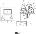
- FIG. 1is a schematic illustration of a robotic surgical system in accordance with the present disclosure
- FIG. 2is a perspective view of a surgical instrument of the robotic surgical system of FIG. 1 in an unarticulated position
- FIG. 3is an enlarged, perspective view of the indicated area of detail shown in FIG. 2 ;
- FIG. 4is a perspective view of an end effector of the surgical instrument of FIG. 2 shown separated from a wrist assembly of an elongated shaft assembly of the surgical instrument;
- FIGS. 5 and 6are perspective views of the wrist assembly of FIG. 4 ;
- FIG. 7is a perspective view, with parts separated, of the elongated shaft assembly of FIG. 4 ;
- FIG. 8is an enlarged, cross-sectional view of the wrist assembly of FIG. 5 as taken along section line 8 - 8 of FIG. 5
- FIG. 9is an enlarged view of the wrist assembly of FIG. 5 with portions thereof shown in phantom for clarity;
- FIG. 10is an enlarged, longitudinal, cross-sectional view of the indicated area of detail shown in FIG. 2 ;
- FIG. 11is a cross-sectional view of the wrist assembly of FIG. 5 as taken along the section line 11 - 11 of FIG. 10 ;
- FIG. 12is a top view of a distal portion of the surgical instrument of FIG. 2 with the wrist assembly thereof shown in an articulated position;
- FIG. 13is an enlarged view of the indicated area of detail shown in FIG. 12 ;
- FIG. 14is a longitudinal, cross-sectional view of FIG. 13 ;
- FIG. 15is a perspective view of the surgical instrument of FIG. 2 shown in an exemplary articulated position
- FIG. 16is an enlarged view of the indicated area of detail shown in FIG. 15 with portions thereof removed for clarity;
- FIG. 17is a perspective view of an alternative embodiment of a surgical instrument shown in an exemplary articulated position
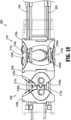
- FIG. 18is a perspective view of a wrist assembly of the surgical instrument of FIG. 17 ;
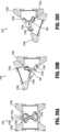
- FIG. 19 Ais a cross-sectional view of a first joint of the wrist assembly of FIG. 18 in an unarticulated position
- FIG. 19 Bis a cross-sectional view of the first joint of the wrist assembly of FIG. 18 in an articulated position
- FIG. 19 Cis a cross-sectional view of the first joint of the wrist assembly of FIG. 18 in another articulated position
- FIG. 20 Ais a cross-sectional view of a second joint of the wrist assembly of FIG. 18 in an unarticulated position
- FIG. 20 Bis a cross-sectional view of the second joint of the wrist assembly of FIG. 18 in an articulated position
- FIG. 20 Cis a cross-sectional view of the second joint of the wrist assembly of FIG. 18 in another articulated position.
- distalrefers to structure that is closer to a patient
- proximalrefers to structure farther from the patient
- the term “clinician”refers to a doctor, nurse, or other care provider and may include support personnel.
- well-known functions or constructionsare not described in detail to avoid obscuring the present disclosure in unnecessary detail.
- a surgical systemsuch as, for example, a robotic surgical system 1 , generally includes one or more surgical robotic arms 2 , 3 , a control device 4 , and an operating console 5 coupled with control device 4 .
- Any of the surgical robotic arms 2 , 3may have a robotic surgical assembly 100 and an electromechanical surgical instrument 200 coupled thereto.
- Electromechanical surgical instrument 200includes an end effector 300 disposed at a distal portion thereof.
- robotic surgical assembly 100may be removably attached to a slide rail 40 of one or more of surgical robotic arms 2 , 3 .
- robotic surgical assembly 100may be fixedly attached to slide rail 40 of one or more of surgical robotic arms 2 , 3 .
- Operating console 5 of robotic surgical system 1includes a display device 6 , which is set up to display three-dimensional images; and manual input devices 7 , 8 , by means of which a clinician (not shown), is able to telemanipulate the robotic arms 2 , 3 of robotic surgical system 1 in a first operating mode, as known in principle to a person skilled in the art.
- Each robotic arm of robotic arms 2 , 3may be composed of any number of members, which may be connected through any number of joints.
- Robotic arms 2 , 3may be driven by electric drives (not shown) that are connected to control device 4 .
- Control device 4e.g., a computer of robotic surgical system 1 is set up to activate the drives, for example, by means of a computer program, in such a way that robotic arms 2 , 3 , the attached robotic surgical assembly 100 , and thus electromechanical surgical instrument 200 (including end effector 300 ) of robotic surgical system 1 execute a desired movement according to a movement defined by means of manual input devices 7 , 8 .
- Control device 4may be set up in such a way that it regulates movement of robotic arms 2 , 3 and/or of the drives.
- Robotic surgical system 1is configured for use on a patient “P” positioned (e.g., lying) on a surgical table “ST” to be treated in a minimally invasive manner by means of a surgical instrument, e.g., electromechanical surgical instrument 200 and, more specifically, end effector 300 of electromechanical surgical instrument 200 .
- Robotic surgical system 1may include more than two robotic arms 2 , 3 , the additional robotic arms are likewise connected to control device 4 and telemanipulatable by means of operating console 5 .
- a surgical instrument, for example, electromechanical surgical instrument 200 (including end effector 300 thereof),may also be attached to any additional robotic arm(s).
- Control device 4 of robotic surgical system 1may control one or more motors (not shown), each motor configured to drive movement of robotic arms 2 , 3 in any number of directions.
- Control device 4may control an instrument drive unit 110 including one or more motors 50 (or motor packs).
- Motors 50drive various operations of end effector 300 of electromechanical surgical instrument 200 .
- Motors 50may include a rotation motor, such as, for example, a canister motor.
- One or more of motors 50(or a different motor, not shown) may be configured to drive a rotation of electromechanical surgical instrument 200 , or components thereof, relative to a longitudinal axis “L-L” thereof.
- the one or more motorscan be configured to effect operation and/or movement of electromechanical end effector 300 of electromechanical surgical instrument 200 .
- electromechanical surgical instrument 200 of robotic surgical system 1includes a housing 202 at a proximal end portion thereof and an elongated shaft 204 that extends distally from housing 202 .
- Elongated shaft 204includes a wrist assembly 206 supported on a distal end portion of elongated shaft 204 that couples end effector 300 to elongated shaft 204 .
- Housing 202 of electromechanical surgical instrument 200is configured to selectively couple to instrument drive unit 110 of robotic surgical assembly 100 , for example, via side loading on a sterile interface module 112 of robotic surgical assembly 100 , to enable motors 50 of instrument drive unit 110 of robotic surgical assembly 100 to operate end effector 300 of electromechanical surgical instrument 200 .
- Housing 202 of electromechanical surgical instrument 200supports a drive assembly 203 that mechanically and/or electrically cooperates with motors 50 of instrument drive unit 110 of robotic surgical assembly 100 .
- Drive assembly 203 of electromechanical surgical instrument 200can include any suitable electrical and/or mechanical component to effectuate driving force/movement, and which components may be similar to components of the drive assembly described in commonly owned International Application Publication No. WO2017053358, filed Sep. 21, 2016, the entire disclosure of which is incorporated by reference herein.
- drive assembly 203 of electromechanical surgical instrument 200includes a cable drive assembly 203 a and a firing assembly 203 b .
- the cable drive assembly 203 ais similar to that described in commonly owned U.S. Patent Application Publication No. 2015/0297199, filed Oct. 22, 2015 and entitled “Adapter Assembly with Gimbal for Interconnecting Electromechanical Surgical Devices and Surgical Loading Units, and Surgical Systems Thereof,” the entire disclosure of which is incorporated by reference herein.
- cable drive assembly 203 a of electromechanical surgical instrument 200includes one or more driven members 209 , such as driven members 209 a , 209 b , 209 c , 209 d ( FIG. 15 ), to enable robotic surgical assembly 100 to transfer power and actuation forces from motors 50 of robotic surgical assembly 100 to ultimately drive movement of components of end effector 300 of electromechanical surgical instrument 200 .
- driven members 209such as driven members 209 a , 209 b , 209 c , 209 d ( FIG. 15 )
- cable drive assembly 203 a of electromechanical surgical instrument 200includes cables 205 , such as cables 205 a , 205 b , 205 c , and 205 d , which are coupled to a respective driven member 209 a , 209 b , 209 c , 209 d ( FIG. 15 ) of electromechanical surgical instrument 200 at a proximal end portion thereof.
- Cables 205 of cable drive assembly 203 aextend distally to distal end portions thereof, and may include ferrules 205 x ( FIG.
- Cable drive assembly 203 acan include one or more pulleys, friction wheels, gears, couplers, rack and pinion arrangements, etc. coupled directly or indirectly to driven members 209 and/or cables 205 to facilitate driving movement imparted through driven members 209 and/or cables 205 .
- the cables 205can be arranged such that diagonal cables (e.g. cables 205 d , 205 b or cables 205 a , 205 c ; see FIG. 4 ) can be positioned to be driven in opposite directions in order to provide articulation in multiple axes (e.g. two). Although only four cables are shown, cable drive assembly 203 a can include any number of cables, for example, to provide additional functionally at the end effector 300 .
- diagonal cablese.g. cables 205 d , 205 b or cables 205 a , 205 c ; see FIG. 4
- cable drive assembly 203 acan include any number of cables, for example, to provide additional functionally at the end effector 300 .
- wrist assembly 206 of elongated shaft 204 of electromechanical surgical instrument 200includes, from proximal to distal, a first interface 208 coupled to a distal portion of an outer tube 204 a of elongated shaft 204 , a first joint 210 coupled to a distal portion of first interface 208 , a second joint 212 coupled to a distal portion of first joint 210 and angularly displaced therefrom (e.g., offset 90 degrees), and a second interface 214 coupled to a distal portion of second joint 212 .
- first interface 208 of wrist assembly 206is in the form of a tubular interface and includes a proximal housing 208 a and a distal housing 208 b that extends distally from proximal housing 208 a , and a central aperture 208 c that is defined therethrough to receive firing assembly 203 b of drive assembly 203 .
- Proximal housing 208 a of first interface 208defines a pair of side slots 208 d (only one side slot 208 d shown with the other identically disposed on the opposite side of proximal housing 208 a ) that receive distally extending tabs 204 b of outer tube 204 a .
- Proximal housing 208 afurther defines a plurality of cable channels 208 f (e.g., four) disposed at circumferentially spaced apart locations about proximal housing 208 a (only one cable channel 208 f is explicitly shown).
- Distal housing 208 bdefines a first ledge 208 g and a second ledge 208 h that define a transverse channel 208 i between the first and second ledges 208 g , 208 h .
- First and second ledges 208 g , 208 hdefine cable apertures 208 j (e.g., two each) that align with cable channels 208 f to receive cables 205 of cable drive assembly 203 a of drive assembly 203 therethrough.
- First and second ledges 208 g , 208 hfurther include distal tabs 208 k , 208 L that extend distally therefrom.
- First joint 210 of wrist assembly 206includes a proximal segment 210 a and a distal segment 210 b that are pivotally coupled together by links or caps 210 c , 210 d that help resist axial loading (created by tensile forces from cables 205 ) and misalignment in a transverse direction.
- links 210 c , 210 dhelp maintain clearance of, for instance, enmeshed gear teeth (see, e.g., FIG. 9 illustrating link 210 d maintaining sufficient distance or axial separation between gear teeth 210 j and 210 q so that gear teeth 210 j and 210 q do not bind).
- Proximal segment 210 a of first joint 210includes proximal tabs 210 e (only one shown with an identical tab 210 e shown on an opposite side of proximal segment 210 a ) that are received within transverse channel 208 i of first interface 208 .
- Proximal segment 210 adefines a transverse recess 210 f that is angularly displaced from proximal tabs 210 e (e.g., 90 degrees) and positioned to receive distal tabs 208 k , 208 L of first interface 208 to prevent proximal segment 210 a of first joint 210 from rotating relative to first interface 208 about longitudinal axis “L-L” ( FIG.
- Proximal segment 210 aincludes a first coupler or gear 210 g and a second coupler or gear 210 h that extend distally from proximal segment 210 on opposed sides of proximal segment 210 a .
- First and second gears 210 g , 210 hhave a plurality of spaced apart teeth 210 j .
- First and second gears 210 g , 210 hinclude pins 210 k that extend laterally (e.g., perpendicularly) therefrom for engagement with links 210 d , 210 c of first joint 210 . Any of the presently disclosed pins may include rivets or the like.
- Gears 210 h , 210 gare recessed from side surfaces of proximal segment 210 a of first joint 210 to facilitate movement of links 210 c , 210 d of first joint 210 and distal segment 210 b of first joint 210 relative to proximal segment 210 a , as distal segment 210 b articulates relative to proximal segment 210 a .
- Proximal segment 210 a of first joint 210further defines a central opening 210 m for receiving firing assembly 203 b of drive assembly 203 therethrough, and a plurality of cable apertures 210 n (e.g., four) for receiving the cables 205 of cable drive assembly 203 a of drive assembly 203 therethrough.
- Distal segment 210 b of first joint 210includes a coupler with knuckles or gears 210 p (only one shown with a second identical coupler or gear 210 p shown on an opposite side of distal segment 210 b ) that extend proximally from distal segment 210 b and are positioned to enmesh or geometrically interlock (e.g., teeth 210 q thereof) with first and second gears 210 g , 210 h of proximal segment 210 a of first joint 210 to maintain rolling contact between respective interlocked gears (e.g., 210 p , 210 h ; see FIGS.
- respective interlocked gearse.g., 210 p , 210 h ; see FIGS.
- Distal segment 210 bfurther includes pins or bosses 210 r (only one shown with a second identical pin 210 r shown on an opposite side of distal segment 210 b ) that extend laterally from (e.g., perpendicularly from) gears 210 p .
- Distal segment 210 bfurther defines recesses 210 t and includes distally extending tabs 210 u that are alternately interspersed and disposed at angularly displaced locations (e.g., 90 degrees apart) about a distal end portion of distal end segment 210 b .
- Distal segment 210 bdefines a central aperture 210 v for receiving firing assembly 203 b therethrough and a plurality of cable apertures 210 w (e.g., four) for receiving cables 205 of cable drive assembly 203 a therethrough.
- Each of proximal and distal segments 210 a , 210 b of first joint 210include a pair of tapered surfaces 210 x that provide space between the distal and proximal segments 210 a , 210 b of first joint 210 to enable distal segment 210 b to articulate relative to proximal segment 210 a as teeth 210 j , 210 q of proximal and distal segments 210 a , 210 b enmesh with one another.
- Tapered surfaces 210 x of proximal segment 210 aare configured to contact tapered surfaces of distal segment 210 b to limit articulation (e.g., define maximum articulation in a given direction) of distal segment 210 b relative to proximal segment 210 a.
- Links 210 c , 210 d of first joint 210define proximal and distal pin apertures 210 y , 210 z that receive pins 210 k , 210 r of proximal and distal segments 210 a , 210 b , respectively, to secure proximal and distal segments 210 a , 210 b of first joint 210 together and enable distal segment 210 b to articulate relative to proximal segment 210 a.
- Second joint 212 of wrist assembly 206is identical to first joint 210 of wrist assembly 206 but is angularly displaced (e.g., 90 degrees) relative to first joint 210 so that first and second joints 210 , 212 can interconnect and articulate/pivot relative to one another.
- second joint 212includes a proximal segment 212 a and a distal segment 212 b that are pivotally coupled together by links 212 c , 212 d such that proximal segment 212 a , distal segment 212 b , and links 212 c , 212 d of second joint 212 are identical to proximal segment 210 a , distal segment 210 b , and links 210 c , 210 d of first joint 210 , respectively.
- Proximal segment 212 a of second joint 212is coupled to distal segment 210 b of first joint 210 such that proximal segment 212 a of second joint 212 is rotationally locked to distal segment 210 b of first joint 210 (e.g., tongue and groove type interconnection).
- proximal and distal segments 212 a , 212 b of second joint 212can articulate/pivot relative to one another while distal segment 210 b of first joint 210 articulates/pivots relative to proximal segment 210 a of first joint 210 .
- Second interface 214 of wrist assembly 206is in the form of a tubular interface and defines proximal and distal recesses 214 a , 214 b that correspond to, and/or are aligned with, one another, respectively.
- Second interface 214includes proximal and distal tabs 214 c , 214 d that correspond to, and/or are aligned with, one another, respectively.
- Proximal recesses 214 a and proximal tabs 214 c of second interface 214are configured to engage distally extending tabs 210 u and recesses 210 t of second joint 212 (e.g., tongue and groove type connection) to rotationally lock second interface 214 to distal segment 210 b of second joint 212 .
- Second interface 214further defines cable slots 214 e at circumferentially spaced apart locations about second interface 214 that are positioned to receive ferrules 205 x and cables 205 therein to secure cables 205 to second interface 214 .
- Second interface 214further defines a central aperture 214 f that is configured to receive firing assembly 203 b of drive assembly 203 therethrough.
- Second interface 214also defines alignment holes 214 g to facilitate alignment and securement of wrist assembly 206 to end effector 300 of electromechanical surgical instrument 200 .
- firing assembly 203 b of drive assembly 203 of electromechanical surgical instrument 200which is in the form of a multi-stage universal joint assembly, includes a drive shaft 220 , a ball shaft 222 that extends distally from drive shaft 220 , a first bearing 224 supported on ball shaft 222 to rotatably support ball shaft 222 , a first ball housing 226 coupled to a distal portion of ball shaft 222 , a first dual ball shaft 228 coupled to first ball housing 226 and supporting a second bearing 230 that rotatably supports first dual ball shaft 228 , a second ball housing 232 coupled to a distal portion of first dual ball shaft 228 , a second dual ball shaft 234 coupled to a distal portion of second ball housing 232 and supporting a third bearing 236 that rotatably supports second dual ball shaft 234 , and a drive coupler 238 supported on a distal portion of second dual ball shaft 234 .
- Drive shaft 220 of firing assembly 203 b of drive assembly 203has a proximal end portion coupled to a driven member 211 ( FIG. 15 ) of drive assembly 203 that operably couples to one or more of motors 50 of robotic surgical assembly 100 (see FIGS. 1 and 15 ) to enable drive shaft 220 to rotate about longitudinal axis “L-L,” as indicated by arrows “A” ( FIG. 7 ).
- Drive shaft 220extends to a keyed distal portion 220 a configured to be received by a proximal portion of ball shaft 222 .
- Keyed distal portion 220 ais shown with a rectangular configuration, but may have any suitable non-circular configuration such as a triangle, square, star, etc.
- Keyed distal portion 220 adefines a pin hole 220 c configured to receive a pin 220 d therein.
- Ball shaft 222 of firing assembly 203 bhas proximal portion 222 a defining a keyed bore 222 b ( FIG. 10 ) that is configured to receive keyed distal portion 220 a of drive shaft 220 therein to enable ball shaft 222 to rotate with drive shaft 220 .
- Keyed bore 222 bcan have any suitable non-circular configuration and may be configured to complement keyed distal portion 220 a of drive shaft 220 to facilitate a rotatably locked connection between ball shaft 222 and drive shaft 220 such that ball shaft 222 and drive shaft 220 rotate together.
- Ball shaft 222further defines a pin hole 222 c that receives pin 220 d therein to rotatably couple drive shaft 220 to ball shaft 222 (see FIGS.
- Ball shaft 222defines an annular clip channel 222 e in an outer surface thereof. Annular clip channel 222 e is configured to receive a clip 222 f (e.g., an E-clip) to obstruct axial movement of first bearing 224 to enable first bearing 224 of firing assembly 203 b to be maintained axially fixed on a bearing surface 222 g of ball shaft 222 .
- Ball shaft 222further includes a ball member 222 h supported on a distal end portion of ball shaft 222 .
- Ball member 222 h of ball shaft 222defines a transverse opening 222 i therethrough configured to receive a ball pin 222 j defining a pin hole 222 k therein.
- Ball member 222 hfurther defines an elongated slot 222 m that is configured to align with pin hole 222 k of ball pin 222 j.
- First ball housing 226 of firing assembly 203 b of drive assembly 203has a proximal shell 226 a defining a proximal bore 226 b therein that rotatably receives ball member 222 h of ball shaft 222 therein.
- Proximal shell 226 afurther defines a pin passage 226 c that receives a pin 226 d therethrough.
- Pin 226 dis receivable within elongated slot 222 m of ball member 222 h of ball shaft 222 while received through proximal shell 226 a of first ball housing 226 to rotatably couple ball member 222 h of ball shaft 222 to proximal shell 226 a of first ball housing 226 (see FIGS.
- First ball housing 226 of firing assembly 203 balso includes a distal shell 226 i configured to couple to first dual ball shaft 228 .
- Distal shell 226 idefines a distal bore 226 j and a pin passage 226 k therethrough that receives a pin 226 m therein to rotatably/articulatably couple first dual ball shaft 228 to distal shell 226 i (e.g., to define another universal joint).
- First dual ball shaft 228 of firing assembly 203 bincludes a proximal ball member 228 a that extends proximally from a bearing support surface 228 b , and a distal ball member 228 c that extends distally from bearing support surface 228 b that rotatably supports second bearing 230 .
- Proximal and distal ball members 228 a , 228 cdefine transverse openings 228 d , 228 e therethrough, respectively, and elongated slots 228 n , 228 p therethrough, respectively.
- Transverse openings 228 d , 228 e of proximal and distal ball members 228 a , 228 care configured to receive ball pins 228 j , 228 k therein, respectively.
- Each ball pin 228 j , 228 kdefines a pin hole 228 m therein.
- Pin hole 228 m of ball pin 228 k and elongated slot 228 n of ball member 228 aare configured to receive pin 226 m of first ball housing 226 to rotatably/articulatably couple first dual ball shaft 228 to distal shell 226 i of first ball housing 226 (e.g., to define universal joints).
- Second ball housing 232 of firing assembly 203 b of drive assembly 203is identical to first ball housing 226 of firing assembly 203 b and includes a proximal shell 232 a , a distal shell 232 b that extends distally from proximal shell 232 a , and pins 232 c , 232 d that are received within proximal and distal shells 232 a , 232 b , respectively.
- Pins 232 c , 232 d of second ball housing 232rotatably couple second ball housing 232 to ball members 228 c , 234 a of first dual ball shaft 228 and second dual ball shaft 234 , respectively, (e.g., to define universal joints) similar to the rotatable/articulatable coupling described above with respect to first ball housing 226 and ball members 222 h , 228 a of ball shaft 222 and first dual ball shaft 228 , respectively.
- Second dual ball shaft 234 of firing assembly 203 b of drive assembly 203is similar to first dual ball shaft 228 of firing assembly 203 b and includes a proximal ball member 234 a that extends proximally from a bearing support surface 234 b that supports third bearing 236 , and a distal ball member 234 c that extends distally from bearing support surface 234 b .
- Bearing support surface 234 bfurther defines an annular clip channel 234 d that is configured to receive a clip 234 e (e.g., an E-clip) to obstruct axial movement of third bearing 236 and axially support third bearing 236 on bearing support surface 234 b of second dual ball shaft 234 .
- a clip 234 ee.g., an E-clip
- Second dual ball shaft 234further includes ball pins 234 f , 234 g .
- Proximal ball member 234 a of second dual ball shaft 234is rotatably coupled to distal shell 232 b of second ball housing 232 (e.g., a universal joint) and distal ball member 234 c of second dual ball shaft 234 rotatably supports drive coupler 238 thereon.
- Drive coupler 238 of firing assembly 203 bdefines a proximal bore 238 a ( FIG. 8 ) that rotatably receives distal ball member 234 c of second dual ball shaft 234 , and a distal bore 238 b that is configured to couple to end effector 300 of electromechanical surgical instrument 200 .
- distal bore 238 b of drive coupler 238is shown including a non-circular configuration, such as a D-shaped configuration, distal bore 238 b can have any non-circular configuration (e.g., triangular, rectangular, pentagonal, etc.) to facilitate a rotatably locked connection between firing assembly 203 b and end effector 300 so that end effector 300 , or components thereof, can rotate with firing assembly 203 b of drive assembly 203 .
- Drive coupler 238further defines a pin hole 238 c that receives a pin 238 d to rotatably couple drive coupler 238 to distal ball member 234 c of second dual ball shaft 234 .
- end effector 300 of electromechanical surgical instrument 200includes a mounting portion 302 on a proximal end portion thereof, and a first jaw member 304 (e.g., an anvil) and a second jaw member 306 (e.g., a cartridge assembly) that are coupled to mounting portion 302 .
- First and second jaw members 304 , 306are positioned for pivotal movement between open ( FIG. 3 ) and closed (not shown) positions.
- First and second jaw members 304 , 306support a drive assembly 308 that is configured to fire a fastener cartridge 310 supported in second jaw member 306 .
- mounting portion 302 of end effector 300includes mounting tabs 302 a and defines mounting recesses 302 b that engage respective distal recesses 214 b and distal tabs 214 d of second interface 214 of wrist assembly 206 .
- Mounting portion 302further includes alignment pins 302 that are received within alignment holes 214 g of second interface 214 of wrist assembly 206 .
- Mounting portion 302further defines a central opening 302 d that is configured to receive drive coupler 238 of firing assembly 203 b to couple drive coupler 238 to drive assembly 308 of end effector 300 .
- drive assembly 308 of end effector 300includes a driven coupler 308 a that is received in distal bore 238 b of drive coupler 238 of firing assembly 203 b of drive assembly 203 .
- Driven coupler 308 a of drive assembly 308includes a non-circular configuration (e.g., D-shape) that is keyed to distal bore 238 b of drive coupler 238 of firing assembly 203 b so that driven coupler 308 a and drive coupler 238 are rotatably locked with respect to one another such that driven coupler 308 a and drive coupler 238 rotate together as drive coupler 238 rotates.
- Driven coupler 308 ais pinned to a lead screw 308 b that supports a drive beam 308 c such that rotation of driven coupler 308 a causes lead screw 308 b to rotate and axially advance drive beam 308 c along lead screw 308 b .
- driven coupler 308 ais pinned to a lead screw 308 b that supports a drive beam 308 c such that rotation of driven coupler 308 a causes lead screw 308 b to rotate and axially advance drive beam 308 c along lead screw 308 b .
- one or more motors 50 of instrument drive unit 110can be actuated to rotate one or more of driven members 209 of electrosurgical instrument 200 to push and/or pull one or more cables 205 of cable drive assembly 203 a of drive assembly 203 of electromechanical surgical instrument 200 .
- cables 205 of cable drive assembly 203 aaxially translate, as indicated by arrows “B” ( FIG.
- first and second joints 210 , 212 of wrist assembly 206rotate and/or articulate with one or more of first ball housing 226 , first dual ball shaft 228 , second ball housing 232 , and/or second dual ball shaft 234 of firing assembly 203 b of drive assembly 203 , relative to longitudinal axis “L-L,” as indicated by arrows “C” and “D” (see FIGS. 12 - 16 ).
- Each of first and second joints 210 , 212can be configured to articulate through an articulation angle of up to 70 degrees such that first joint 210 can be articulated through an articulation angle “ ⁇ ” up to 70 degrees while second joint 212 is articulated through an articulation angle “ ⁇ ” up to 70 degrees, as seen in FIG.
- firing assembly 203 bpivot, rotate, and/or articulate as first and second joint 210 , 212 pivot, rotate, and/or articulate.
- firing assembly 203 bcan be rotated about longitudinal axis “L-L,” as indicated by arrows “A,” (see FIGS. 2 and 7 ) in response to rotation of driven member 211 ( FIG. 15 ) by one or more of motors 50 of instrument drive unit 110 ( FIG. 1 ).
- Rotation of firing assembly 203 b of drive assembly 203causes drive coupler 238 of firing assembly 203 b to rotate lead screw 308 b of end effector 300 about its axis, e.g., axis “Z-Z,” as indicated by arrows “F” ( FIG.
- Rotation of lead screw 308 b of end effector 300causes drive beam 308 c of end effector 300 to advance distally along lead screw 308 b , as indicated by arrow “G,” so that first and second jaw members 304 , 306 of end effector 300 move from the open or unapproximated position ( FIG. 3 ) thereof to the closed or approximated position (not shown) thereof.
- drive beam 308 c of end effector 300continues to advance distally along first and second jaw members 304 , 306
- drive beam 308 cfires fastener cartridge 310 ( FIG. 3 ) to fasten and/or sever tissue captured between first and second jaw members 304 , 306 similar to that described in U.S. Patent Application Publication No. 2015/0297199 referenced above.
- Electromechanical surgical instrument 2000is similar to electromechanical surgical instrument 200 , described above, includes all of the same features and components as electromechanical surgical instrument 200 , and is usable with (and interfaces with) surgical system 1 ( FIG. 1 ) in the same manner as electromechanical surgical instrument 200 .
- electromechanical surgical instrument 2000additionally includes electrical cables 1000 , 2000 , and wrist assembly 2600 and housing 2020 for supporting electrical cables 1000 , 2000 . Accordingly, for brevity, only the basic components of electromechanical surgical instrument 2000 , and the differences between electromechanical surgical instrument 2000 and electromechanical surgical instrument 200 , will be described.
- wrist assembly 2600includes structural features that facilitate passage of electrical cables 1000 , 2000 therethrough with minimal resistance and minimal stress imparted on electrical cables 1000 , 2000 during articulation of wrist assembly 2600 .
- electrical cables 1000 , 2000do not translate longitudinally through any of joints 2100 , 2120 . This eliminates the need for tensioning or payout mechanisms that would otherwise be required to drive any cables or wires during articulation. Elimination of longitudinal translation of electrical cables 1000 , 2000 also reduces the possibility of failures due to wear and abrasion of electrical cables 1000 , 2000 and any components in contact with electrical cables 1000 , 2000 .
- electrical cables 1000 , 2000bend through only a single axis during articulation of the wrist assembly 2600 , as opposed to being bent in multiple directions, which significantly extends the lifetime of the electrical cables 1000 , 2000 and even the components the electrical cables 1000 , 2000 are in contact with. Additionally, the electrical cables 1000 , 2000 are positioned within the wrist assembly 2600 , beneath drive cabling and shielding structures throughout the full articulation range, which reduces chances of damage to the electrical cables 1000 , 2000 from incidental contact and reprocessing.
- Electromechanical surgical instrument 2000 of robotic surgical system 1( FIG. 1 ) includes a housing 2020 at a proximal end portion thereof and an elongated shaft 2040 that extends distally from housing 2020 .
- a wrist assembly 2600is supported on a distal end portion of elongated shaft 2040 that couples end effector 300 to elongated shaft 2040 .
- Housing 2020 of electromechanical surgical instrument 2000is configured to selectively couple to instrument drive unit 110 of robotic surgical assembly 100 ( FIG. 1 ), for example, via side loading on a sterile interface module 112 of robotic surgical assembly 100 , to enable motors 50 of instrument drive unit 110 of robotic surgical assembly 100 to operate end effector 300 of electromechanical surgical instrument 2000 .
- Housing 2020 of electromechanical surgical instrument 2000supports a drive assembly 2030 (including cable drive assembly 2030 a and firing assembly 2030 b ) that mechanically and/or electrically cooperates with motors 50 of instrument drive unit 110 of robotic surgical assembly 100 .
- housing 2020includes a first electrical contact 2091 on a proximal portion thereof which interfaces with a corresponding electrical contact (not shown) of instrument drive unit 110 to create an electrical connection between electrical cable 1000 and the other components of robotic surgical system 1 (e.g., an electrosurgical generator, controller, sensor, etc.). Housing 2020 similarly includes a second electrical contact 2092 on a proximal portion thereof which interfaces with a corresponding electrical contact (not shown) of instrument drive unit 110 to create an electrical connection between electrical cable 2000 and the other components of robotic surgical system 1 (e.g., an electrosurgical generator, controller, sensor, etc.). It is contemplated that electromechanical surgical instrument 2000 may additionally include a printed circuit board (not shown) to which electrical cable 1000 and/or electrical cable 2000 are coupled.
- Electrical cables 1000 , 2000may be utilized to create an electrical connection between any portion of electromechanical surgical instrument 2000 (e.g., end effector 300 ) and any component(s) of robotic surgical system 1 (e.g., robotic arms 2 , 3 , control device 4 , and/or operating console 5 ).
- at least one of electrical cables 1000 , 2000is used to transmit electrosurgical treatment energy from an electrosurgical generator “G” (see FIG. 1 ) to a portion of end effector 300 , such as an energy delivery portion or device (not shown) coupled to end effector 300 .
- one or both of electrical cables 1000 , 2000may be utilized to transmit sensor signals between end effector 300 (or sensors coupled thereto) and any other component(s) of robotic surgical system 1 .
- Wrist assembly 2600is supported on elongated shaft 2040 and includes a first joint 2100 coupled to a second joint 2120 .
- First joint 2100includes a proximal segment 2100 a defining a proximal arcuate surface 2104 a and a distal segment 2100 b defining a distal arcuate surface 2104 b on each side thereof.
- Proximal segment 2100 ais coupled to distal segment 2100 b via a pair of links 2110 a , 2110 b .
- second joint 2120includes a proximal segment 2120 a defining a proximal arcuate surface 2124 a and a distal segment 2120 b defining a distal arcuate surface 2124 b on each side thereof.
- Proximal segment 2120 ais coupled to distal segment 2120 b via a pair of links 2112 a , 2112 b.
- an end effector 300is coupled to wrist assembly 2600 and a plurality of cables are coupled to the wrist assembly 2600 to manipulate first joint 2100 and second joint 2120 to enable wrist assembly 2600 to articulate relative to the longitudinal axis “L” ( FIG. 2 ) defined by elongated shaft 2040 .
- proximal segment 2100 a of first joint 2100defines a proximal aperture 2102 a and distal segment 2100 b of first joint 2100 defines a distal aperture 2102 b , which is misaligned with the proximal aperture 2102 a .
- proximal segment 2120 a of second joint 2120defines a proximal aperture 2122 a and distal segment 2120 b of second joint 2120 defines a distal aperture 2122 b , which is misaligned with the proximal aperture 2122 a .
- Electrical cable 1000passes through proximal aperture 2102 a defined by the proximal segment 2100 a of first joint 2100 , distal aperture 2102 b defined by distal segment 2100 b of first joint 2100 , proximal aperture 2122 a defined by proximal segment 2120 a of second joint 2120 , and distal aperture 2122 b defined by distal segment 2120 b of second joint 2120 .
- electrical cable 2000passes through respective apertures defined on the other side of first joint 2100 and second joint 2120 , respectively.
- proximal arcuate surface 2104 a , proximal aperture 2102 a , distal arcuate surface 2104 b , and distal aperture 2102 bare positioned and dimensioned such that, during articulation of wrist assembly 2600 , electrical cable 1000 rolls off of distal arcuate surface 2104 b when electrical cable 1000 rolls on to proximal arcuate surface 2104 a , and electrical cable 1000 rolls off of proximal arcuate surface 2104 a when electrical cable 1000 rolls on to distal arcuate surface 2104 b .
- Electrical cable 2000is similarly arranged with similar arcuate surfaces present on the other side of proximal segment 2100 a and distal segment 2100 b of first joint 2100 .
- the proximal segment 2100 a of first joint 2100defines a second proximal arcuate surface 2104 aa ( FIG. 18 ) on the other side thereof
- distal segment 2100 b of first joint 2100defines a second distal arcuate surface 2104 bb on the other side thereof.
- Second electrical cable 2000is positioned such that, during articulation of wrist assembly 2600 , second electrical cable 2000 rolls off of second distal arcuate surface 2104 bb as electrical cable 2000 rolls on to second proximal arcuate surface 2104 aa , and second electrical cable 2000 rolls off of second proximal arcuate surface 2104 aa as second electrical cable 2000 rolls on to second distal arcuate surface 2104 bb.
- proximal arcuate surface 2124 a , proximal aperture 2122 a , distal arcuate surface 2124 b , and distal aperture 2122 bare positioned and dimensioned such that, during articulation of wrist assembly 2600 , electrical cable 1000 rolls off of distal arcuate surface 2124 b when electrical cable 1000 rolls on to proximal arcuate surface 2124 a , and electrical cable 1000 rolls off of proximal arcuate surface 2124 a when electrical cable 1000 rolls on to distal arcuate surface 2124 b .
- Electrical cable 2000is similarly arranged with similar arcuate surfaces present on the other side of proximal segment 2120 a and distal segment 2120 b of second joint 2120 .
- proximal segment 2120 a of second joint 2120defines a second proximal arcuate surface 2124 aa ( FIG. 18 ) on the other side thereof
- distal segment 2120 b of second joint 2120defines a second distal arcuate surface 2124 bb on the other side thereof.
- Second electrical cable 2000is positioned such that during articulation of wrist assembly 2600 second electrical cable 2000 rolls off of second distal arcuate surface 2124 bb , as electrical cable 2000 rolls on to second proximal arcuate surface 2124 aa and second electrical cable 2000 rolls off of second proximal arcuate surface 2124 aa as second electrical cable 2000 rolls on to second distal arcuate surface 2124 bb.
- FIG. 19 Aillustrates first joint 2100 of wrist assembly 2600 in an unarticulated position.
- electrical wire 1000is in contact with both arcuate surface 2104 a of proximal segment 2100 a and arcuate surface 2104 b of distal segment 2100 b .
- electrical cable 1000contacts a larger area of arcuate surface 2014 a and is no longer in contact with arcuate surface 2104 b .
- first joint 2100is transitioned from an unarticulated position ( FIG. 19 A ) to another fully articulated position ( FIG.
- electrical cable 1000is no longer in contact with arcuate surface 2104 a and contacts a larger area of arcuate surface 2104 b .
- electrical cable 1000bends through only one axis, as opposed to bending in multiple directions, which extends its lifetime.
- electrical cable 2000similarly interacts with arcuate surfaces on the other side of first joint 2100 as first joint 2100 transitions between the unarticulated position and the multiple articulated positions.
- FIG. 20 Aillustrates second joint 2120 of wrist assembly 2600 in an unarticulated position.
- electrical wire 1000is in contact with both arcuate surface 2124 a of proximal segment 2120 a and arcuate surface 2124 b of distal segment 2120 b .
- electrical cable 1000contacts a larger area of arcuate surface 2024 a and is no longer in contact with arcuate surface 2124 b .
- second joint 2120is transitioned from an unarticulated position ( FIG. 20 A ) to another fully articulated position ( FIG.
- electrical cable 1000is no longer in contact with arcuate surface 2124 a and contacts a larger area of arcuate surface 2124 b .
- electrical cable 1000bends through only one axis, as opposed to bending in multiple directions, which extends its lifetime.
- electrical cable 2000similarly interacts with arcuate surfaces on the other side of second joint 2120 as the second joint 2120 transitions between the unarticulated position and the multiple articulated positions.
- electromechanical surgical instrument 200 , 2000is described herein in connection with robotic surgical system 1
- the presently disclosed electromechanical surgical instruments 200 , 2000can be provided in the form of a hand held electromechanical instrument, which may be manually driven and/or powered.
- a hand held electromechanical instrumentwhich may be manually driven and/or powered.
- U.S. Patent Application Publication No. 2015/0297199describes one example of a powered hand held electromechanical instrument, one or more of the components of which (e.g., the surgical device or handle thereof) can be utilized in connection with the presently disclosed surgical instrument 200 , 2000 .
Landscapes
- Health & Medical Sciences (AREA)
- Surgery (AREA)
- Life Sciences & Earth Sciences (AREA)
- Engineering & Computer Science (AREA)
- Medical Informatics (AREA)
- General Health & Medical Sciences (AREA)
- Biomedical Technology (AREA)
- Heart & Thoracic Surgery (AREA)
- Nuclear Medicine, Radiotherapy & Molecular Imaging (AREA)
- Molecular Biology (AREA)
- Animal Behavior & Ethology (AREA)
- Veterinary Medicine (AREA)
- Public Health (AREA)
- Robotics (AREA)
- Physics & Mathematics (AREA)
- Plasma & Fusion (AREA)
- Otolaryngology (AREA)
- Surgical Instruments (AREA)
- Manipulator (AREA)
Abstract
Description
Claims (20)
Priority Applications (1)
| Application Number | Priority Date | Filing Date | Title |
|---|---|---|---|
| US17/276,511US12156709B2 (en) | 2018-09-17 | 2019-09-10 | Highly articulated laparoscopic joint including electrical signal transmission therethrough |
Applications Claiming Priority (3)
| Application Number | Priority Date | Filing Date | Title |
|---|---|---|---|
| US201862732108P | 2018-09-17 | 2018-09-17 | |
| PCT/US2019/050272WO2020060792A1 (en) | 2018-09-17 | 2019-09-10 | Highly articulated laparoscopic joint including electrical signal transmission therethrough |
| US17/276,511US12156709B2 (en) | 2018-09-17 | 2019-09-10 | Highly articulated laparoscopic joint including electrical signal transmission therethrough |
Publications (2)
| Publication Number | Publication Date |
|---|---|
| US20210290322A1 US20210290322A1 (en) | 2021-09-23 |
| US12156709B2true US12156709B2 (en) | 2024-12-03 |
Family
ID=69887918
Family Applications (1)
| Application Number | Title | Priority Date | Filing Date |
|---|---|---|---|
| US17/276,511Active2041-09-03US12156709B2 (en) | 2018-09-17 | 2019-09-10 | Highly articulated laparoscopic joint including electrical signal transmission therethrough |
Country Status (7)
| Country | Link |
|---|---|
| US (1) | US12156709B2 (en) |
| EP (2) | EP3852668B1 (en) |
| JP (1) | JP2022501110A (en) |
| CN (1) | CN112702970B (en) |
| AU (1) | AU2019344528B2 (en) |
| CA (1) | CA3110703A1 (en) |
| WO (1) | WO2020060792A1 (en) |
Families Citing this family (260)
| Publication number | Priority date | Publication date | Assignee | Title |
|---|---|---|---|---|
| US20070084897A1 (en) | 2003-05-20 | 2007-04-19 | Shelton Frederick E Iv | Articulating surgical stapling instrument incorporating a two-piece e-beam firing mechanism |
| US9060770B2 (en) | 2003-05-20 | 2015-06-23 | Ethicon Endo-Surgery, Inc. | Robotically-driven surgical instrument with E-beam driver |
| US9072535B2 (en) | 2011-05-27 | 2015-07-07 | Ethicon Endo-Surgery, Inc. | Surgical stapling instruments with rotatable staple deployment arrangements |
| US11890012B2 (en) | 2004-07-28 | 2024-02-06 | Cilag Gmbh International | Staple cartridge comprising cartridge body and attached support |
| US11998198B2 (en) | 2004-07-28 | 2024-06-04 | Cilag Gmbh International | Surgical stapling instrument incorporating a two-piece E-beam firing mechanism |
| US7934630B2 (en) | 2005-08-31 | 2011-05-03 | Ethicon Endo-Surgery, Inc. | Staple cartridges for forming staples having differing formed staple heights |
| US11484312B2 (en) | 2005-08-31 | 2022-11-01 | Cilag Gmbh International | Staple cartridge comprising a staple driver arrangement |
| US11246590B2 (en) | 2005-08-31 | 2022-02-15 | Cilag Gmbh International | Staple cartridge including staple drivers having different unfired heights |
| US7669746B2 (en) | 2005-08-31 | 2010-03-02 | Ethicon Endo-Surgery, Inc. | Staple cartridges for forming staples having differing formed staple heights |
| US10159482B2 (en) | 2005-08-31 | 2018-12-25 | Ethicon Llc | Fastener cartridge assembly comprising a fixed anvil and different staple heights |
| US20070106317A1 (en) | 2005-11-09 | 2007-05-10 | Shelton Frederick E Iv | Hydraulically and electrically actuated articulation joints for surgical instruments |
| US11793518B2 (en) | 2006-01-31 | 2023-10-24 | Cilag Gmbh International | Powered surgical instruments with firing system lockout arrangements |
| US8708213B2 (en) | 2006-01-31 | 2014-04-29 | Ethicon Endo-Surgery, Inc. | Surgical instrument having a feedback system |
| US8820603B2 (en) | 2006-01-31 | 2014-09-02 | Ethicon Endo-Surgery, Inc. | Accessing data stored in a memory of a surgical instrument |
| US20120292367A1 (en) | 2006-01-31 | 2012-11-22 | Ethicon Endo-Surgery, Inc. | Robotically-controlled end effector |
| US7845537B2 (en) | 2006-01-31 | 2010-12-07 | Ethicon Endo-Surgery, Inc. | Surgical instrument having recording capabilities |
| US8186555B2 (en) | 2006-01-31 | 2012-05-29 | Ethicon Endo-Surgery, Inc. | Motor-driven surgical cutting and fastening instrument with mechanical closure system |
| US20110295295A1 (en) | 2006-01-31 | 2011-12-01 | Ethicon Endo-Surgery, Inc. | Robotically-controlled surgical instrument having recording capabilities |
| US8992422B2 (en) | 2006-03-23 | 2015-03-31 | Ethicon Endo-Surgery, Inc. | Robotically-controlled endoscopic accessory channel |
| US10568652B2 (en) | 2006-09-29 | 2020-02-25 | Ethicon Llc | Surgical staples having attached drivers of different heights and stapling instruments for deploying the same |
| US11980366B2 (en) | 2006-10-03 | 2024-05-14 | Cilag Gmbh International | Surgical instrument |
| US8684253B2 (en) | 2007-01-10 | 2014-04-01 | Ethicon Endo-Surgery, Inc. | Surgical instrument with wireless communication between a control unit of a robotic system and remote sensor |
| US8632535B2 (en) | 2007-01-10 | 2014-01-21 | Ethicon Endo-Surgery, Inc. | Interlock and surgical instrument including same |
| US20080169333A1 (en) | 2007-01-11 | 2008-07-17 | Shelton Frederick E | Surgical stapler end effector with tapered distal end |
| US11564682B2 (en) | 2007-06-04 | 2023-01-31 | Cilag Gmbh International | Surgical stapler device |
| US8931682B2 (en) | 2007-06-04 | 2015-01-13 | Ethicon Endo-Surgery, Inc. | Robotically-controlled shaft based rotary drive systems for surgical instruments |
| US7753245B2 (en) | 2007-06-22 | 2010-07-13 | Ethicon Endo-Surgery, Inc. | Surgical stapling instruments |
| US11849941B2 (en) | 2007-06-29 | 2023-12-26 | Cilag Gmbh International | Staple cartridge having staple cavities extending at a transverse angle relative to a longitudinal cartridge axis |
| US7866527B2 (en) | 2008-02-14 | 2011-01-11 | Ethicon Endo-Surgery, Inc. | Surgical stapling apparatus with interlockable firing system |
| US8636736B2 (en) | 2008-02-14 | 2014-01-28 | Ethicon Endo-Surgery, Inc. | Motorized surgical cutting and fastening instrument |
| JP5410110B2 (en) | 2008-02-14 | 2014-02-05 | エシコン・エンド−サージェリィ・インコーポレイテッド | Surgical cutting / fixing instrument with RF electrode |
| US11986183B2 (en) | 2008-02-14 | 2024-05-21 | Cilag Gmbh International | Surgical cutting and fastening instrument comprising a plurality of sensors to measure an electrical parameter |
| US7819298B2 (en) | 2008-02-14 | 2010-10-26 | Ethicon Endo-Surgery, Inc. | Surgical stapling apparatus with control features operable with one hand |
| US9179912B2 (en) | 2008-02-14 | 2015-11-10 | Ethicon Endo-Surgery, Inc. | Robotically-controlled motorized surgical cutting and fastening instrument |
| US8573465B2 (en) | 2008-02-14 | 2013-11-05 | Ethicon Endo-Surgery, Inc. | Robotically-controlled surgical end effector system with rotary actuated closure systems |
| US9585657B2 (en) | 2008-02-15 | 2017-03-07 | Ethicon Endo-Surgery, Llc | Actuator for releasing a layer of material from a surgical end effector |
| US9204923B2 (en) | 2008-07-16 | 2015-12-08 | Intuitive Surgical Operations, Inc. | Medical instrument electronically energized using drive cables |
| US9386983B2 (en) | 2008-09-23 | 2016-07-12 | Ethicon Endo-Surgery, Llc | Robotically-controlled motorized surgical instrument |
| US9005230B2 (en) | 2008-09-23 | 2015-04-14 | Ethicon Endo-Surgery, Inc. | Motorized surgical instrument |
| US11648005B2 (en) | 2008-09-23 | 2023-05-16 | Cilag Gmbh International | Robotically-controlled motorized surgical instrument with an end effector |
| US8210411B2 (en) | 2008-09-23 | 2012-07-03 | Ethicon Endo-Surgery, Inc. | Motor-driven surgical cutting instrument |
| US8608045B2 (en) | 2008-10-10 | 2013-12-17 | Ethicon Endo-Sugery, Inc. | Powered surgical cutting and stapling apparatus with manually retractable firing system |
| US8220688B2 (en) | 2009-12-24 | 2012-07-17 | Ethicon Endo-Surgery, Inc. | Motor-driven surgical cutting instrument with electric actuator directional control assembly |
| US11925354B2 (en) | 2010-09-30 | 2024-03-12 | Cilag Gmbh International | Staple cartridge comprising staples positioned within a compressible portion thereof |
| US11812965B2 (en) | 2010-09-30 | 2023-11-14 | Cilag Gmbh International | Layer of material for a surgical end effector |
| US9351730B2 (en) | 2011-04-29 | 2016-05-31 | Ethicon Endo-Surgery, Llc | Tissue thickness compensator comprising channels |
| US9016542B2 (en) | 2010-09-30 | 2015-04-28 | Ethicon Endo-Surgery, Inc. | Staple cartridge comprising compressible distortion resistant components |
| US9788834B2 (en) | 2010-09-30 | 2017-10-17 | Ethicon Llc | Layer comprising deployable attachment members |
| US9386988B2 (en) | 2010-09-30 | 2016-07-12 | Ethicon End-Surgery, LLC | Retainer assembly including a tissue thickness compensator |
| US12213666B2 (en) | 2010-09-30 | 2025-02-04 | Cilag Gmbh International | Tissue thickness compensator comprising layers |
| US10945731B2 (en) | 2010-09-30 | 2021-03-16 | Ethicon Llc | Tissue thickness compensator comprising controlled release and expansion |
| US9629814B2 (en) | 2010-09-30 | 2017-04-25 | Ethicon Endo-Surgery, Llc | Tissue thickness compensator configured to redistribute compressive forces |
| US8695866B2 (en) | 2010-10-01 | 2014-04-15 | Ethicon Endo-Surgery, Inc. | Surgical instrument having a power control circuit |
| AU2012250197B2 (en) | 2011-04-29 | 2017-08-10 | Ethicon Endo-Surgery, Inc. | Staple cartridge comprising staples positioned within a compressible portion thereof |
| US11207064B2 (en) | 2011-05-27 | 2021-12-28 | Cilag Gmbh International | Automated end effector component reloading system for use with a robotic system |
| BR112014024098B1 (en) | 2012-03-28 | 2021-05-25 | Ethicon Endo-Surgery, Inc. | staple cartridge |
| MX358135B (en) | 2012-03-28 | 2018-08-06 | Ethicon Endo Surgery Inc | Tissue thickness compensator comprising a plurality of layers. |
| US9101358B2 (en) | 2012-06-15 | 2015-08-11 | Ethicon Endo-Surgery, Inc. | Articulatable surgical instrument comprising a firing drive |
| US9282974B2 (en) | 2012-06-28 | 2016-03-15 | Ethicon Endo-Surgery, Llc | Empty clip cartridge lockout |
| US12383267B2 (en) | 2012-06-28 | 2025-08-12 | Cilag Gmbh International | Robotically powered surgical device with manually-actuatable reversing system |
| US9408606B2 (en) | 2012-06-28 | 2016-08-09 | Ethicon Endo-Surgery, Llc | Robotically powered surgical device with manually-actuatable reversing system |
| US20140001231A1 (en) | 2012-06-28 | 2014-01-02 | Ethicon Endo-Surgery, Inc. | Firing system lockout arrangements for surgical instruments |
| US9289256B2 (en) | 2012-06-28 | 2016-03-22 | Ethicon Endo-Surgery, Llc | Surgical end effectors having angled tissue-contacting surfaces |
| BR112015021082B1 (en) | 2013-03-01 | 2022-05-10 | Ethicon Endo-Surgery, Inc | surgical instrument |
| RU2672520C2 (en) | 2013-03-01 | 2018-11-15 | Этикон Эндо-Серджери, Инк. | Hingedly turnable surgical instruments with conducting ways for signal transfer |
| US9629629B2 (en) | 2013-03-14 | 2017-04-25 | Ethicon Endo-Surgey, LLC | Control systems for surgical instruments |
| US9826976B2 (en) | 2013-04-16 | 2017-11-28 | Ethicon Llc | Motor driven surgical instruments with lockable dual drive shafts |
| BR112015026109B1 (en) | 2013-04-16 | 2022-02-22 | Ethicon Endo-Surgery, Inc | surgical instrument |
| US9775609B2 (en) | 2013-08-23 | 2017-10-03 | Ethicon Llc | Tamper proof circuit for surgical instrument battery pack |
| BR112016021943B1 (en) | 2014-03-26 | 2022-06-14 | Ethicon Endo-Surgery, Llc | SURGICAL INSTRUMENT FOR USE BY AN OPERATOR IN A SURGICAL PROCEDURE |
| US20150272580A1 (en) | 2014-03-26 | 2015-10-01 | Ethicon Endo-Surgery, Inc. | Verification of number of battery exchanges/procedure count |
| US10013049B2 (en) | 2014-03-26 | 2018-07-03 | Ethicon Llc | Power management through sleep options of segmented circuit and wake up control |
| US12232723B2 (en) | 2014-03-26 | 2025-02-25 | Cilag Gmbh International | Systems and methods for controlling a segmented circuit |
| CN106456159B (en) | 2014-04-16 | 2019-03-08 | 伊西康内外科有限责任公司 | Fastener Cartridge Assembly and Nail Retainer Cover Arrangement |
| BR112016023825B1 (en) | 2014-04-16 | 2022-08-02 | Ethicon Endo-Surgery, Llc | STAPLE CARTRIDGE FOR USE WITH A SURGICAL STAPLER AND STAPLE CARTRIDGE FOR USE WITH A SURGICAL INSTRUMENT |
| US20150297225A1 (en) | 2014-04-16 | 2015-10-22 | Ethicon Endo-Surgery, Inc. | Fastener cartridges including extensions having different configurations |
| CN106456176B (en) | 2014-04-16 | 2019-06-28 | 伊西康内外科有限责任公司 | Fastener Cartridge Including Extensions With Different Configurations |
| US10327764B2 (en) | 2014-09-26 | 2019-06-25 | Ethicon Llc | Method for creating a flexible staple line |
| BR112017004361B1 (en) | 2014-09-05 | 2023-04-11 | Ethicon Llc | ELECTRONIC SYSTEM FOR A SURGICAL INSTRUMENT |
| US11311294B2 (en) | 2014-09-05 | 2022-04-26 | Cilag Gmbh International | Powered medical device including measurement of closure state of jaws |
| US10135242B2 (en) | 2014-09-05 | 2018-11-20 | Ethicon Llc | Smart cartridge wake up operation and data retention |
| US10105142B2 (en) | 2014-09-18 | 2018-10-23 | Ethicon Llc | Surgical stapler with plurality of cutting elements |
| US11523821B2 (en) | 2014-09-26 | 2022-12-13 | Cilag Gmbh International | Method for creating a flexible staple line |
| US9924944B2 (en) | 2014-10-16 | 2018-03-27 | Ethicon Llc | Staple cartridge comprising an adjunct material |
| US11141153B2 (en) | 2014-10-29 | 2021-10-12 | Cilag Gmbh International | Staple cartridges comprising driver arrangements |
| US10517594B2 (en) | 2014-10-29 | 2019-12-31 | Ethicon Llc | Cartridge assemblies for surgical staplers |
| US10736636B2 (en) | 2014-12-10 | 2020-08-11 | Ethicon Llc | Articulatable surgical instrument system |
| MX389118B (en) | 2014-12-18 | 2025-03-20 | Ethicon Llc | SURGICAL INSTRUMENT WITH AN ANVIL THAT CAN BE SELECTIVELY MOVED ON A DISCRETE, NON-MOBILE AXIS RELATIVE TO A STAPLE CARTRIDGE. |
| US9844375B2 (en) | 2014-12-18 | 2017-12-19 | Ethicon Llc | Drive arrangements for articulatable surgical instruments |
| US9943309B2 (en) | 2014-12-18 | 2018-04-17 | Ethicon Llc | Surgical instruments with articulatable end effectors and movable firing beam support arrangements |
| US10085748B2 (en) | 2014-12-18 | 2018-10-02 | Ethicon Llc | Locking arrangements for detachable shaft assemblies with articulatable surgical end effectors |
| US9987000B2 (en) | 2014-12-18 | 2018-06-05 | Ethicon Llc | Surgical instrument assembly comprising a flexible articulation system |
| US9844374B2 (en) | 2014-12-18 | 2017-12-19 | Ethicon Llc | Surgical instrument systems comprising an articulatable end effector and means for adjusting the firing stroke of a firing member |
| US11154301B2 (en) | 2015-02-27 | 2021-10-26 | Cilag Gmbh International | Modular stapling assembly |
| JP2020121162A (en) | 2015-03-06 | 2020-08-13 | エシコン エルエルシーEthicon LLC | Time dependent evaluation of sensor data to determine stability element, creep element and viscoelastic element of measurement |
| US9993248B2 (en) | 2015-03-06 | 2018-06-12 | Ethicon Endo-Surgery, Llc | Smart sensors with local signal processing |
| US10441279B2 (en) | 2015-03-06 | 2019-10-15 | Ethicon Llc | Multiple level thresholds to modify operation of powered surgical instruments |
| US10433844B2 (en) | 2015-03-31 | 2019-10-08 | Ethicon Llc | Surgical instrument with selectively disengageable threaded drive systems |
| US10105139B2 (en) | 2015-09-23 | 2018-10-23 | Ethicon Llc | Surgical stapler having downstream current-based motor control |
| US10238386B2 (en) | 2015-09-23 | 2019-03-26 | Ethicon Llc | Surgical stapler having motor control based on an electrical parameter related to a motor current |
| US10299878B2 (en) | 2015-09-25 | 2019-05-28 | Ethicon Llc | Implantable adjunct systems for determining adjunct skew |
| US11890015B2 (en) | 2015-09-30 | 2024-02-06 | Cilag Gmbh International | Compressible adjunct with crossing spacer fibers |
| US10478188B2 (en) | 2015-09-30 | 2019-11-19 | Ethicon Llc | Implantable layer comprising a constricted configuration |
| US10433846B2 (en) | 2015-09-30 | 2019-10-08 | Ethicon Llc | Compressible adjunct with crossing spacer fibers |
| ITUB20155057A1 (en) | 2015-10-16 | 2017-04-16 | Medical Microinstruments S R L | Robotic surgery set |
| US10265068B2 (en) | 2015-12-30 | 2019-04-23 | Ethicon Llc | Surgical instruments with separable motors and motor control circuits |
| US10292704B2 (en) | 2015-12-30 | 2019-05-21 | Ethicon Llc | Mechanisms for compensating for battery pack failure in powered surgical instruments |
| BR112018016098B1 (en) | 2016-02-09 | 2023-02-23 | Ethicon Llc | SURGICAL INSTRUMENT |
| US11213293B2 (en) | 2016-02-09 | 2022-01-04 | Cilag Gmbh International | Articulatable surgical instruments with single articulation link arrangements |
| US10448948B2 (en) | 2016-02-12 | 2019-10-22 | Ethicon Llc | Mechanisms for compensating for drivetrain failure in powered surgical instruments |
| US10828028B2 (en) | 2016-04-15 | 2020-11-10 | Ethicon Llc | Surgical instrument with multiple program responses during a firing motion |
| US11607239B2 (en) | 2016-04-15 | 2023-03-21 | Cilag Gmbh International | Systems and methods for controlling a surgical stapling and cutting instrument |
| US10426467B2 (en) | 2016-04-15 | 2019-10-01 | Ethicon Llc | Surgical instrument with detection sensors |
| US10357247B2 (en) | 2016-04-15 | 2019-07-23 | Ethicon Llc | Surgical instrument with multiple program responses during a firing motion |
| US20170296173A1 (en) | 2016-04-18 | 2017-10-19 | Ethicon Endo-Surgery, Llc | Method for operating a surgical instrument |
| US10363037B2 (en) | 2016-04-18 | 2019-07-30 | Ethicon Llc | Surgical instrument system comprising a magnetic lockout |
| US10500000B2 (en) | 2016-08-16 | 2019-12-10 | Ethicon Llc | Surgical tool with manual control of end effector jaws |
| US10973516B2 (en) | 2016-12-21 | 2021-04-13 | Ethicon Llc | Surgical end effectors and adaptable firing members therefor |
| JP2020501815A (en) | 2016-12-21 | 2020-01-23 | エシコン エルエルシーEthicon LLC | Surgical stapling system |
| US11090048B2 (en) | 2016-12-21 | 2021-08-17 | Cilag Gmbh International | Method for resetting a fuse of a surgical instrument shaft |
| MX2019007295A (en) | 2016-12-21 | 2019-10-15 | Ethicon Llc | Surgical instrument system comprising an end effector lockout and a firing assembly lockout. |
| JP7010957B2 (en) | 2016-12-21 | 2022-01-26 | エシコン エルエルシー | Shaft assembly with lockout |
| US10582928B2 (en) | 2016-12-21 | 2020-03-10 | Ethicon Llc | Articulation lock arrangements for locking an end effector in an articulated position in response to actuation of a jaw closure system |
| US10813638B2 (en) | 2016-12-21 | 2020-10-27 | Ethicon Llc | Surgical end effectors with expandable tissue stop arrangements |
| US20180168615A1 (en) | 2016-12-21 | 2018-06-21 | Ethicon Endo-Surgery, Llc | Method of deforming staples from two different types of staple cartridges with the same surgical stapling instrument |
| US11419606B2 (en) | 2016-12-21 | 2022-08-23 | Cilag Gmbh International | Shaft assembly comprising a clutch configured to adapt the output of a rotary firing member to two different systems |
| US20180168625A1 (en) | 2016-12-21 | 2018-06-21 | Ethicon Endo-Surgery, Llc | Surgical stapling instruments with smart staple cartridges |
| US10542982B2 (en) | 2016-12-21 | 2020-01-28 | Ethicon Llc | Shaft assembly comprising first and second articulation lockouts |
| JP7010956B2 (en) | 2016-12-21 | 2022-01-26 | エシコン エルエルシー | How to staple tissue |
| US11517325B2 (en) | 2017-06-20 | 2022-12-06 | Cilag Gmbh International | Closed loop feedback control of motor velocity of a surgical stapling and cutting instrument based on measured displacement distance traveled over a specified time interval |
| US10307170B2 (en) | 2017-06-20 | 2019-06-04 | Ethicon Llc | Method for closed loop control of motor velocity of a surgical stapling and cutting instrument |
| US11653914B2 (en) | 2017-06-20 | 2023-05-23 | Cilag Gmbh International | Systems and methods for controlling motor velocity of a surgical stapling and cutting instrument according to articulation angle of end effector |
| US10881399B2 (en) | 2017-06-20 | 2021-01-05 | Ethicon Llc | Techniques for adaptive control of motor velocity of a surgical stapling and cutting instrument |
| US10779820B2 (en) | 2017-06-20 | 2020-09-22 | Ethicon Llc | Systems and methods for controlling motor speed according to user input for a surgical instrument |
| US11266405B2 (en) | 2017-06-27 | 2022-03-08 | Cilag Gmbh International | Surgical anvil manufacturing methods |
| US10993716B2 (en) | 2017-06-27 | 2021-05-04 | Ethicon Llc | Surgical anvil arrangements |
| US10765427B2 (en) | 2017-06-28 | 2020-09-08 | Ethicon Llc | Method for articulating a surgical instrument |
| US10758232B2 (en) | 2017-06-28 | 2020-09-01 | Ethicon Llc | Surgical instrument with positive jaw opening features |
| USD906355S1 (en) | 2017-06-28 | 2020-12-29 | Ethicon Llc | Display screen or portion thereof with a graphical user interface for a surgical instrument |
| EP3420947B1 (en) | 2017-06-28 | 2022-05-25 | Cilag GmbH International | Surgical instrument comprising selectively actuatable rotatable couplers |
| US11564686B2 (en) | 2017-06-28 | 2023-01-31 | Cilag Gmbh International | Surgical shaft assemblies with flexible interfaces |
| US11484310B2 (en) | 2017-06-28 | 2022-11-01 | Cilag Gmbh International | Surgical instrument comprising a shaft including a closure tube profile |
| US10932772B2 (en) | 2017-06-29 | 2021-03-02 | Ethicon Llc | Methods for closed loop velocity control for robotic surgical instrument |
| US11974742B2 (en) | 2017-08-03 | 2024-05-07 | Cilag Gmbh International | Surgical system comprising an articulation bailout |
| US11471155B2 (en) | 2017-08-03 | 2022-10-18 | Cilag Gmbh International | Surgical system bailout |
| US11944300B2 (en) | 2017-08-03 | 2024-04-02 | Cilag Gmbh International | Method for operating a surgical system bailout |
| US11134944B2 (en) | 2017-10-30 | 2021-10-05 | Cilag Gmbh International | Surgical stapler knife motion controls |
| US10842490B2 (en) | 2017-10-31 | 2020-11-24 | Ethicon Llc | Cartridge body design with force reduction based on firing completion |
| US10779826B2 (en) | 2017-12-15 | 2020-09-22 | Ethicon Llc | Methods of operating surgical end effectors |
| US10835330B2 (en) | 2017-12-19 | 2020-11-17 | Ethicon Llc | Method for determining the position of a rotatable jaw of a surgical instrument attachment assembly |
| US11179151B2 (en) | 2017-12-21 | 2021-11-23 | Cilag Gmbh International | Surgical instrument comprising a display |
| US12336705B2 (en) | 2017-12-21 | 2025-06-24 | Cilag Gmbh International | Continuous use self-propelled stapling instrument |
| EP3761897A4 (en) | 2018-03-07 | 2021-11-24 | Intuitive Surgical Operations, Inc. | LOW-FRICTION MEDICAL TOOLS WITH SMALL PROFILE AND ASSEMBLY-FRIENDLY COMPONENTS |
| US11992286B2 (en) | 2018-03-07 | 2024-05-28 | Intuitive Surgical Operations, Inc. | Low-friction medical tools having roller-assisted tension members |
| US11207065B2 (en) | 2018-08-20 | 2021-12-28 | Cilag Gmbh International | Method for fabricating surgical stapler anvils |
| US20200054321A1 (en) | 2018-08-20 | 2020-02-20 | Ethicon Llc | Surgical instruments with progressive jaw closure arrangements |
| US11291440B2 (en) | 2018-08-20 | 2022-04-05 | Cilag Gmbh International | Method for operating a powered articulatable surgical instrument |
| WO2020131529A1 (en)* | 2018-12-20 | 2020-06-25 | Auris Health, Inc. | Shielding for wristed instruments |
| US11696761B2 (en) | 2019-03-25 | 2023-07-11 | Cilag Gmbh International | Firing drive arrangements for surgical systems |
| US11903581B2 (en) | 2019-04-30 | 2024-02-20 | Cilag Gmbh International | Methods for stapling tissue using a surgical instrument |
| US20200345359A1 (en) | 2019-04-30 | 2020-11-05 | Ethicon Llc | Tissue stop for a surgical instrument |
| US11648009B2 (en) | 2019-04-30 | 2023-05-16 | Cilag Gmbh International | Rotatable jaw tip for a surgical instrument |
| US11464601B2 (en) | 2019-06-28 | 2022-10-11 | Cilag Gmbh International | Surgical instrument comprising an RFID system for tracking a movable component |
| US11553971B2 (en) | 2019-06-28 | 2023-01-17 | Cilag Gmbh International | Surgical RFID assemblies for display and communication |
| US11771419B2 (en) | 2019-06-28 | 2023-10-03 | Cilag Gmbh International | Packaging for a replaceable component of a surgical stapling system |
| US11478241B2 (en) | 2019-06-28 | 2022-10-25 | Cilag Gmbh International | Staple cartridge including projections |
| US12004740B2 (en) | 2019-06-28 | 2024-06-11 | Cilag Gmbh International | Surgical stapling system having an information decryption protocol |
| US11684434B2 (en) | 2019-06-28 | 2023-06-27 | Cilag Gmbh International | Surgical RFID assemblies for instrument operational setting control |
| US11660163B2 (en) | 2019-06-28 | 2023-05-30 | Cilag Gmbh International | Surgical system with RFID tags for updating motor assembly parameters |
| US11241235B2 (en) | 2019-06-28 | 2022-02-08 | Cilag Gmbh International | Method of using multiple RFID chips with a surgical assembly |
| US11426167B2 (en) | 2019-06-28 | 2022-08-30 | Cilag Gmbh International | Mechanisms for proper anvil attachment surgical stapling head assembly |
| US11523822B2 (en) | 2019-06-28 | 2022-12-13 | Cilag Gmbh International | Battery pack including a circuit interrupter |
| US11497492B2 (en) | 2019-06-28 | 2022-11-15 | Cilag Gmbh International | Surgical instrument including an articulation lock |
| US11638587B2 (en) | 2019-06-28 | 2023-05-02 | Cilag Gmbh International | RFID identification systems for surgical instruments |
| US11627959B2 (en) | 2019-06-28 | 2023-04-18 | Cilag Gmbh International | Surgical instruments including manual and powered system lockouts |
| US11504122B2 (en) | 2019-12-19 | 2022-11-22 | Cilag Gmbh International | Surgical instrument comprising a nested firing member |
| US11529139B2 (en) | 2019-12-19 | 2022-12-20 | Cilag Gmbh International | Motor driven surgical instrument |
| US11529137B2 (en) | 2019-12-19 | 2022-12-20 | Cilag Gmbh International | Staple cartridge comprising driver retention members |
| US12035913B2 (en) | 2019-12-19 | 2024-07-16 | Cilag Gmbh International | Staple cartridge comprising a deployable knife |
| US11576672B2 (en) | 2019-12-19 | 2023-02-14 | Cilag Gmbh International | Surgical instrument comprising a closure system including a closure member and an opening member driven by a drive screw |
| US11844520B2 (en) | 2019-12-19 | 2023-12-19 | Cilag Gmbh International | Staple cartridge comprising driver retention members |
| US11464512B2 (en) | 2019-12-19 | 2022-10-11 | Cilag Gmbh International | Staple cartridge comprising a curved deck surface |
| US11911032B2 (en) | 2019-12-19 | 2024-02-27 | Cilag Gmbh International | Staple cartridge comprising a seating cam |
| US11607219B2 (en) | 2019-12-19 | 2023-03-21 | Cilag Gmbh International | Staple cartridge comprising a detachable tissue cutting knife |
| US11701111B2 (en) | 2019-12-19 | 2023-07-18 | Cilag Gmbh International | Method for operating a surgical stapling instrument |
| US11559304B2 (en) | 2019-12-19 | 2023-01-24 | Cilag Gmbh International | Surgical instrument comprising a rapid closure mechanism |
| US11446029B2 (en) | 2019-12-19 | 2022-09-20 | Cilag Gmbh International | Staple cartridge comprising projections extending from a curved deck surface |
| USD1039141S1 (en)* | 2020-04-27 | 2024-08-13 | Acclarent, Inc. | Flex section in shaft for ENT instrument |
| USD975278S1 (en) | 2020-06-02 | 2023-01-10 | Cilag Gmbh International | Staple cartridge |
| USD974560S1 (en) | 2020-06-02 | 2023-01-03 | Cilag Gmbh International | Staple cartridge |
| USD975851S1 (en) | 2020-06-02 | 2023-01-17 | Cilag Gmbh International | Staple cartridge |
| USD976401S1 (en) | 2020-06-02 | 2023-01-24 | Cilag Gmbh International | Staple cartridge |
| USD975850S1 (en) | 2020-06-02 | 2023-01-17 | Cilag Gmbh International | Staple cartridge |
| US11871925B2 (en) | 2020-07-28 | 2024-01-16 | Cilag Gmbh International | Surgical instruments with dual spherical articulation joint arrangements |
| US11896217B2 (en) | 2020-10-29 | 2024-02-13 | Cilag Gmbh International | Surgical instrument comprising an articulation lock |
| US11534259B2 (en) | 2020-10-29 | 2022-12-27 | Cilag Gmbh International | Surgical instrument comprising an articulation indicator |
| US11779330B2 (en) | 2020-10-29 | 2023-10-10 | Cilag Gmbh International | Surgical instrument comprising a jaw alignment system |
| US11931025B2 (en) | 2020-10-29 | 2024-03-19 | Cilag Gmbh International | Surgical instrument comprising a releasable closure drive lock |
| USD1013170S1 (en) | 2020-10-29 | 2024-01-30 | Cilag Gmbh International | Surgical instrument assembly |
| US12053175B2 (en) | 2020-10-29 | 2024-08-06 | Cilag Gmbh International | Surgical instrument comprising a stowed closure actuator stop |
| US11617577B2 (en) | 2020-10-29 | 2023-04-04 | Cilag Gmbh International | Surgical instrument comprising a sensor configured to sense whether an articulation drive of the surgical instrument is actuatable |
| US11517390B2 (en) | 2020-10-29 | 2022-12-06 | Cilag Gmbh International | Surgical instrument comprising a limited travel switch |
| US11844518B2 (en) | 2020-10-29 | 2023-12-19 | Cilag Gmbh International | Method for operating a surgical instrument |
| USD980425S1 (en) | 2020-10-29 | 2023-03-07 | Cilag Gmbh International | Surgical instrument assembly |
| US11717289B2 (en) | 2020-10-29 | 2023-08-08 | Cilag Gmbh International | Surgical instrument comprising an indicator which indicates that an articulation drive is actuatable |
| US11452526B2 (en) | 2020-10-29 | 2022-09-27 | Cilag Gmbh International | Surgical instrument comprising a staged voltage regulation start-up system |
| US11944296B2 (en) | 2020-12-02 | 2024-04-02 | Cilag Gmbh International | Powered surgical instruments with external connectors |
| US11653915B2 (en) | 2020-12-02 | 2023-05-23 | Cilag Gmbh International | Surgical instruments with sled location detection and adjustment features |
| US11653920B2 (en) | 2020-12-02 | 2023-05-23 | Cilag Gmbh International | Powered surgical instruments with communication interfaces through sterile barrier |
| US11744581B2 (en) | 2020-12-02 | 2023-09-05 | Cilag Gmbh International | Powered surgical instruments with multi-phase tissue treatment |
| US11849943B2 (en) | 2020-12-02 | 2023-12-26 | Cilag Gmbh International | Surgical instrument with cartridge release mechanisms |
| US11627960B2 (en) | 2020-12-02 | 2023-04-18 | Cilag Gmbh International | Powered surgical instruments with smart reload with separately attachable exteriorly mounted wiring connections |
| US11890010B2 (en) | 2020-12-02 | 2024-02-06 | Cllag GmbH International | Dual-sided reinforced reload for surgical instruments |
| US11678882B2 (en) | 2020-12-02 | 2023-06-20 | Cilag Gmbh International | Surgical instruments with interactive features to remedy incidental sled movements |
| US11737751B2 (en) | 2020-12-02 | 2023-08-29 | Cilag Gmbh International | Devices and methods of managing energy dissipated within sterile barriers of surgical instrument housings |
| US11980362B2 (en) | 2021-02-26 | 2024-05-14 | Cilag Gmbh International | Surgical instrument system comprising a power transfer coil |
| US11696757B2 (en) | 2021-02-26 | 2023-07-11 | Cilag Gmbh International | Monitoring of internal systems to detect and track cartridge motion status |
| US11730473B2 (en) | 2021-02-26 | 2023-08-22 | Cilag Gmbh International | Monitoring of manufacturing life-cycle |
| US12108951B2 (en) | 2021-02-26 | 2024-10-08 | Cilag Gmbh International | Staple cartridge comprising a sensing array and a temperature control system |
| US11950777B2 (en) | 2021-02-26 | 2024-04-09 | Cilag Gmbh International | Staple cartridge comprising an information access control system |
| US11812964B2 (en) | 2021-02-26 | 2023-11-14 | Cilag Gmbh International | Staple cartridge comprising a power management circuit |
| US12324580B2 (en) | 2021-02-26 | 2025-06-10 | Cilag Gmbh International | Method of powering and communicating with a staple cartridge |
| US11723657B2 (en) | 2021-02-26 | 2023-08-15 | Cilag Gmbh International | Adjustable communication based on available bandwidth and power capacity |
| US11701113B2 (en) | 2021-02-26 | 2023-07-18 | Cilag Gmbh International | Stapling instrument comprising a separate power antenna and a data transfer antenna |
| US11925349B2 (en) | 2021-02-26 | 2024-03-12 | Cilag Gmbh International | Adjustment to transfer parameters to improve available power |
| US11751869B2 (en) | 2021-02-26 | 2023-09-12 | Cilag Gmbh International | Monitoring of multiple sensors over time to detect moving characteristics of tissue |
| US11749877B2 (en) | 2021-02-26 | 2023-09-05 | Cilag Gmbh International | Stapling instrument comprising a signal antenna |
| US11950779B2 (en) | 2021-02-26 | 2024-04-09 | Cilag Gmbh International | Method of powering and communicating with a staple cartridge |
| US11793514B2 (en) | 2021-02-26 | 2023-10-24 | Cilag Gmbh International | Staple cartridge comprising sensor array which may be embedded in cartridge body |
| US11744583B2 (en) | 2021-02-26 | 2023-09-05 | Cilag Gmbh International | Distal communication array to tune frequency of RF systems |
| US11717291B2 (en) | 2021-03-22 | 2023-08-08 | Cilag Gmbh International | Staple cartridge comprising staples configured to apply different tissue compression |
| US11737749B2 (en) | 2021-03-22 | 2023-08-29 | Cilag Gmbh International | Surgical stapling instrument comprising a retraction system |
| US11826012B2 (en) | 2021-03-22 | 2023-11-28 | Cilag Gmbh International | Stapling instrument comprising a pulsed motor-driven firing rack |
| US11723658B2 (en) | 2021-03-22 | 2023-08-15 | Cilag Gmbh International | Staple cartridge comprising a firing lockout |
| US11759202B2 (en) | 2021-03-22 | 2023-09-19 | Cilag Gmbh International | Staple cartridge comprising an implantable layer |
| US11806011B2 (en) | 2021-03-22 | 2023-11-07 | Cilag Gmbh International | Stapling instrument comprising tissue compression systems |
| US11826042B2 (en) | 2021-03-22 | 2023-11-28 | Cilag Gmbh International | Surgical instrument comprising a firing drive including a selectable leverage mechanism |
| US11944336B2 (en) | 2021-03-24 | 2024-04-02 | Cilag Gmbh International | Joint arrangements for multi-planar alignment and support of operational drive shafts in articulatable surgical instruments |
| US11896219B2 (en) | 2021-03-24 | 2024-02-13 | Cilag Gmbh International | Mating features between drivers and underside of a cartridge deck |
| US11744603B2 (en) | 2021-03-24 | 2023-09-05 | Cilag Gmbh International | Multi-axis pivot joints for surgical instruments and methods for manufacturing same |
| US11857183B2 (en) | 2021-03-24 | 2024-01-02 | Cilag Gmbh International | Stapling assembly components having metal substrates and plastic bodies |
| US11786239B2 (en) | 2021-03-24 | 2023-10-17 | Cilag Gmbh International | Surgical instrument articulation joint arrangements comprising multiple moving linkage features |
| US11849945B2 (en) | 2021-03-24 | 2023-12-26 | Cilag Gmbh International | Rotary-driven surgical stapling assembly comprising eccentrically driven firing member |
| US11903582B2 (en) | 2021-03-24 | 2024-02-20 | Cilag Gmbh International | Leveraging surfaces for cartridge installation |
| US11849944B2 (en) | 2021-03-24 | 2023-12-26 | Cilag Gmbh International | Drivers for fastener cartridge assemblies having rotary drive screws |
| US11832816B2 (en) | 2021-03-24 | 2023-12-05 | Cilag Gmbh International | Surgical stapling assembly comprising nonplanar staples and planar staples |
| US11786243B2 (en) | 2021-03-24 | 2023-10-17 | Cilag Gmbh International | Firing members having flexible portions for adapting to a load during a surgical firing stroke |
| US12102323B2 (en) | 2021-03-24 | 2024-10-01 | Cilag Gmbh International | Rotary-driven surgical stapling assembly comprising a floatable component |
| US11793516B2 (en) | 2021-03-24 | 2023-10-24 | Cilag Gmbh International | Surgical staple cartridge comprising longitudinal support beam |
| US11896218B2 (en) | 2021-03-24 | 2024-02-13 | Cilag Gmbh International | Method of using a powered stapling device |
| CN113171178B (en)* | 2021-04-23 | 2023-09-22 | 上海微创医疗机器人(集团)股份有限公司 | Snake-shaped joint, surgical instrument and endoscope |
| US11826047B2 (en) | 2021-05-28 | 2023-11-28 | Cilag Gmbh International | Stapling instrument comprising jaw mounts |
| GB2611346B (en)* | 2021-10-01 | 2024-08-07 | Cmr Surgical Ltd | A robotic surgical instrument |
| US11980363B2 (en) | 2021-10-18 | 2024-05-14 | Cilag Gmbh International | Row-to-row staple array variations |
| US12089841B2 (en) | 2021-10-28 | 2024-09-17 | Cilag CmbH International | Staple cartridge identification systems |
| US11937816B2 (en)* | 2021-10-28 | 2024-03-26 | Cilag Gmbh International | Electrical lead arrangements for surgical instruments |
| US12432790B2 (en) | 2021-10-28 | 2025-09-30 | Cilag Gmbh International | Method and device for transmitting UART communications over a security short range wireless communication |
| WO2024220525A1 (en)* | 2023-04-19 | 2024-10-24 | Intuitive Surgical Operations, Inc. | Medical instrument wrist with cable routing |
| WO2025133897A1 (en)* | 2023-12-22 | 2025-06-26 | Valuebiotech S.R.L. | Mechanical joint for an articulated arm of a surgical robot |
| CN119385689A (en)* | 2025-01-02 | 2025-02-07 | 以诺康医疗科技(苏州)有限公司 | Snake joint for surgical robot, operating arm and surgical robot |
Citations (22)
| Publication number | Priority date | Publication date | Assignee | Title |
|---|---|---|---|---|
| US5710870A (en) | 1995-09-07 | 1998-01-20 | California Institute Of Technology | Decoupled six degree-of-freedom robot manipulator |
| US5797900A (en) | 1996-05-20 | 1998-08-25 | Intuitive Surgical, Inc. | Wrist mechanism for surgical instrument for performing minimally invasive surgery with enhanced dexterity and sensitivity |
| US20040199147A1 (en) | 2002-10-02 | 2004-10-07 | Kouji Nishizawa | Manipulator |
| US20050040664A1 (en) | 2002-10-07 | 2005-02-24 | Harmonic Drive Systems Inc. | Finger unit for robot hand |
| US20080119870A1 (en)* | 2006-11-16 | 2008-05-22 | Williams Matthew R | Two-piece end-effectors for robotic surgical tools |
| JP2009136684A (en) | 2001-06-29 | 2009-06-25 | Intuitive Surgical Inc | Surgical implement having tendon driving multi-disk wrist joint allowing positive location |
| US20100016852A1 (en) | 2008-07-16 | 2010-01-21 | Intuitive Surgical, Inc. | Medical instrument electronically energized using drive cables |
| JP2011072574A (en) | 2009-09-30 | 2011-04-14 | Terumo Corp | Medical manipulator |
| US8523900B2 (en)* | 2009-02-03 | 2013-09-03 | Terumo Kabushiki Kaisha | Medical manipulator |
| JP2014513570A (en) | 2011-02-18 | 2014-06-05 | インテュイティブ サージカル オペレーションズ, インコーポレイテッド | Fusion and cutting surgical instruments and related methods |
| EP2240095B1 (en) | 2008-02-06 | 2015-09-30 | Aesculap AG | Apparatus for articulating the wrist of a laparoscopic grasping instrument |
| US20160166347A1 (en) | 2013-08-26 | 2016-06-16 | Olympus Corporation | Medical manipulator |
| WO2016148463A1 (en) | 2015-03-17 | 2016-09-22 | 한국기술교육대학교 산학협력단 | Robot arm |
| US20170252096A1 (en) | 2016-03-07 | 2017-09-07 | Ethicon Llc | Robotic Bi-Polar Instruments |
| WO2018049211A1 (en)* | 2016-09-09 | 2018-03-15 | Intuitive Surgical Operations, Inc. | Wrist architecture |
| US20180206904A1 (en) | 2017-01-20 | 2018-07-26 | Ethicon Llc | Articulating electrosurgical tools |
| US20180304389A1 (en)* | 2015-10-16 | 2018-10-25 | Medical Microinstruments S.p.A. | Method of manufacturing for a medical instrument |
| US20190117247A1 (en)* | 2016-02-05 | 2019-04-25 | Board Of Regents Of The University Of Texas System | Surgical apparatus |
| CN109937013A (en)* | 2016-09-14 | 2019-06-25 | 直观外科手术操作公司 | Joint assembly with intersecting axis flexural pivot |
| US20190328467A1 (en)* | 2016-11-21 | 2019-10-31 | Intuitive Surgical Operations, Inc. | Cable length conserving medical instrument |
| US20210169597A1 (en)* | 2017-12-14 | 2021-06-10 | Intuitive Surgical Operations, Inc. | Medical tools having tension bands |
| US11109925B2 (en)* | 2014-02-21 | 2021-09-07 | Intuitive Surgical Operations, Inc. | Articulatable members having constrained motion and related devices and methods |
Family Cites Families (4)
| Publication number | Priority date | Publication date | Assignee | Title |
|---|---|---|---|---|
| US9295522B2 (en)* | 2013-11-08 | 2016-03-29 | Covidien Lp | Medical device adapter with wrist mechanism |
| US10080552B2 (en) | 2014-04-21 | 2018-09-25 | Covidien Lp | Adapter assembly with gimbal for interconnecting electromechanical surgical devices and surgical loading units, and surgical systems thereof |
| US10111665B2 (en) | 2015-02-19 | 2018-10-30 | Covidien Lp | Electromechanical surgical systems |
| US10639111B2 (en) | 2015-09-25 | 2020-05-05 | Covidien Lp | Surgical robotic assemblies and instrument adapters thereof |
- 2019
- 2019-09-10EPEP19863144.2Apatent/EP3852668B1/enactiveActive
- 2019-09-10CACA3110703Apatent/CA3110703A1/enactivePending
- 2019-09-10EPEP23163383.5Apatent/EP4218651A1/enactivePending
- 2019-09-10CNCN201980060198.3Apatent/CN112702970B/enactiveActive
- 2019-09-10JPJP2021514564Apatent/JP2022501110A/enactivePending
- 2019-09-10AUAU2019344528Apatent/AU2019344528B2/ennot_activeCeased
- 2019-09-10WOPCT/US2019/050272patent/WO2020060792A1/ennot_activeCeased
- 2019-09-10USUS17/276,511patent/US12156709B2/enactiveActive
Patent Citations (23)
| Publication number | Priority date | Publication date | Assignee | Title |
|---|---|---|---|---|
| US5710870A (en) | 1995-09-07 | 1998-01-20 | California Institute Of Technology | Decoupled six degree-of-freedom robot manipulator |
| US5797900A (en) | 1996-05-20 | 1998-08-25 | Intuitive Surgical, Inc. | Wrist mechanism for surgical instrument for performing minimally invasive surgery with enhanced dexterity and sensitivity |
| JP2009136684A (en) | 2001-06-29 | 2009-06-25 | Intuitive Surgical Inc | Surgical implement having tendon driving multi-disk wrist joint allowing positive location |
| EP2659854A2 (en) | 2001-06-29 | 2013-11-06 | Intuitive Surgical Operations, Inc. | Surgical tool having positively positionable tendon-actuated multi-disk wrist joint |
| US20040199147A1 (en) | 2002-10-02 | 2004-10-07 | Kouji Nishizawa | Manipulator |
| US20050040664A1 (en) | 2002-10-07 | 2005-02-24 | Harmonic Drive Systems Inc. | Finger unit for robot hand |
| US20080119870A1 (en)* | 2006-11-16 | 2008-05-22 | Williams Matthew R | Two-piece end-effectors for robotic surgical tools |
| EP2240095B1 (en) | 2008-02-06 | 2015-09-30 | Aesculap AG | Apparatus for articulating the wrist of a laparoscopic grasping instrument |
| US20100016852A1 (en) | 2008-07-16 | 2010-01-21 | Intuitive Surgical, Inc. | Medical instrument electronically energized using drive cables |
| US8523900B2 (en)* | 2009-02-03 | 2013-09-03 | Terumo Kabushiki Kaisha | Medical manipulator |
| JP2011072574A (en) | 2009-09-30 | 2011-04-14 | Terumo Corp | Medical manipulator |
| JP2014513570A (en) | 2011-02-18 | 2014-06-05 | インテュイティブ サージカル オペレーションズ, インコーポレイテッド | Fusion and cutting surgical instruments and related methods |
| US20160166347A1 (en) | 2013-08-26 | 2016-06-16 | Olympus Corporation | Medical manipulator |
| US11109925B2 (en)* | 2014-02-21 | 2021-09-07 | Intuitive Surgical Operations, Inc. | Articulatable members having constrained motion and related devices and methods |
| WO2016148463A1 (en) | 2015-03-17 | 2016-09-22 | 한국기술교육대학교 산학협력단 | Robot arm |
| US20180304389A1 (en)* | 2015-10-16 | 2018-10-25 | Medical Microinstruments S.p.A. | Method of manufacturing for a medical instrument |
| US20190117247A1 (en)* | 2016-02-05 | 2019-04-25 | Board Of Regents Of The University Of Texas System | Surgical apparatus |
| US20170252096A1 (en) | 2016-03-07 | 2017-09-07 | Ethicon Llc | Robotic Bi-Polar Instruments |
| WO2018049211A1 (en)* | 2016-09-09 | 2018-03-15 | Intuitive Surgical Operations, Inc. | Wrist architecture |
| CN109937013A (en)* | 2016-09-14 | 2019-06-25 | 直观外科手术操作公司 | Joint assembly with intersecting axis flexural pivot |
| US20190328467A1 (en)* | 2016-11-21 | 2019-10-31 | Intuitive Surgical Operations, Inc. | Cable length conserving medical instrument |
| US20180206904A1 (en) | 2017-01-20 | 2018-07-26 | Ethicon Llc | Articulating electrosurgical tools |
| US20210169597A1 (en)* | 2017-12-14 | 2021-06-10 | Intuitive Surgical Operations, Inc. | Medical tools having tension bands |
Non-Patent Citations (6)
| Title |
|---|
| Canadian Office Action dated Jan. 21, 2023, issued in corresponding Canadian Appln. No. 3,110,703, 5 pages. |
| Examination Report No. 1 issued in corresponding Australian Appl. No. 2019344528 dated Aug. 12, 2021 (3 pages). |
| Extended European Search Report issued in corresponding application EP 19863144.2 dated Sep. 6, 2022 (12 pages). |
| Extended European Search Report issued in European Patent Application No. 23163383.5 dated Jul. 5, 2023 (10 pages). |
| International Search Report and Written Opinion of the International Searching Authority issued in corresponding Int'l Appl. No. PCT/US2019/050272 dated Dec. 27, 2019 (12 pages). |
| Office Action issued in corresponding Japanese Appliation No. 2021-514564 mailed May 19, 2022, together with English language translation (10 pages). |
Also Published As
| Publication number | Publication date |
|---|---|
| AU2019344528B2 (en) | 2021-09-23 |
| EP3852668A1 (en) | 2021-07-28 |
| AU2019344528A1 (en) | 2021-03-18 |
| CN112702970B (en) | 2024-01-02 |
| CN112702970A (en) | 2021-04-23 |
| WO2020060792A1 (en) | 2020-03-26 |
| CA3110703A1 (en) | 2020-03-26 |
| EP3852668A4 (en) | 2022-10-05 |
| EP4218651A1 (en) | 2023-08-02 |
| EP3852668B1 (en) | 2023-12-13 |
| US20210290322A1 (en) | 2021-09-23 |
| JP2022501110A (en) | 2022-01-06 |
Similar Documents
| Publication | Publication Date | Title |
|---|---|---|
| US12156709B2 (en) | Highly articulated laparoscopic joint including electrical signal transmission therethrough | |
| US12433705B2 (en) | Robotic surgical instrument including high articulation wrist assembly with torque transmission and mechanical manipulation | |
| US12114941B2 (en) | Wrist articulation by linked tension members | |
| US11357572B2 (en) | Double universal joint | |
| US20220125540A1 (en) | Robotic surgical instrument including high articulation wrist assembly |
Legal Events
| Date | Code | Title | Description |
|---|---|---|---|
| AS | Assignment | Owner name:COVIDIEN LP, MASSACHUSETTS Free format text:ASSIGNMENT OF ASSIGNORS INTEREST;ASSIGNOR:TRAINA, ZACHARY;REEL/FRAME:055602/0333 Effective date:20210221 | |
| FEPP | Fee payment procedure | Free format text:ENTITY STATUS SET TO UNDISCOUNTED (ORIGINAL EVENT CODE: BIG.); ENTITY STATUS OF PATENT OWNER: LARGE ENTITY | |
| STPP | Information on status: patent application and granting procedure in general | Free format text:DOCKETED NEW CASE - READY FOR EXAMINATION | |
| STPP | Information on status: patent application and granting procedure in general | Free format text:NON FINAL ACTION MAILED | |
| STPP | Information on status: patent application and granting procedure in general | Free format text:RESPONSE TO NON-FINAL OFFICE ACTION ENTERED AND FORWARDED TO EXAMINER | |
| STPP | Information on status: patent application and granting procedure in general | Free format text:FINAL REJECTION MAILED | |
| STPP | Information on status: patent application and granting procedure in general | Free format text:RESPONSE AFTER FINAL ACTION FORWARDED TO EXAMINER | |
| STPP | Information on status: patent application and granting procedure in general | Free format text:ADVISORY ACTION MAILED | |
| STPP | Information on status: patent application and granting procedure in general | Free format text:DOCKETED NEW CASE - READY FOR EXAMINATION | |
| STPP | Information on status: patent application and granting procedure in general | Free format text:NOTICE OF ALLOWANCE MAILED -- APPLICATION RECEIVED IN OFFICE OF PUBLICATIONS | |
| ZAAB | Notice of allowance mailed | Free format text:ORIGINAL CODE: MN/=. | |
| STPP | Information on status: patent application and granting procedure in general | Free format text:PUBLICATIONS -- ISSUE FEE PAYMENT VERIFIED | |
| STCF | Information on status: patent grant | Free format text:PATENTED CASE |