US12151798B2 - System and method for positioning an aquatic vessel - Google Patents
System and method for positioning an aquatic vesselDownload PDFInfo
- Publication number
- US12151798B2 US12151798B2US17/033,805US202017033805AUS12151798B2US 12151798 B2US12151798 B2US 12151798B2US 202017033805 AUS202017033805 AUS 202017033805AUS 12151798 B2US12151798 B2US 12151798B2
- Authority
- US
- United States
- Prior art keywords
- boat
- pontoon
- pontoon boat
- mooring
- docking location
- Prior art date
- Legal status (The legal status is an assumption and is not a legal conclusion. Google has not performed a legal analysis and makes no representation as to the accuracy of the status listed.)
- Active, expires
Links
Images


Classifications
- B—PERFORMING OPERATIONS; TRANSPORTING
- B63—SHIPS OR OTHER WATERBORNE VESSELS; RELATED EQUIPMENT
- B63H—MARINE PROPULSION OR STEERING
- B63H25/00—Steering; Slowing-down otherwise than by use of propulsive elements; Dynamic anchoring, i.e. positioning vessels by means of main or auxiliary propulsive elements
- B63H25/02—Initiating means for steering, for slowing down, otherwise than by use of propulsive elements, or for dynamic anchoring
- B63H25/04—Initiating means for steering, for slowing down, otherwise than by use of propulsive elements, or for dynamic anchoring automatic, e.g. reacting to compass
- B—PERFORMING OPERATIONS; TRANSPORTING
- B63—SHIPS OR OTHER WATERBORNE VESSELS; RELATED EQUIPMENT
- B63B—SHIPS OR OTHER WATERBORNE VESSELS; EQUIPMENT FOR SHIPPING
- B63B1/00—Hydrodynamic or hydrostatic features of hulls or of hydrofoils
- B63B1/02—Hydrodynamic or hydrostatic features of hulls or of hydrofoils deriving lift mainly from water displacement
- B63B1/10—Hydrodynamic or hydrostatic features of hulls or of hydrofoils deriving lift mainly from water displacement with multiple hulls
- B63B1/12—Hydrodynamic or hydrostatic features of hulls or of hydrofoils deriving lift mainly from water displacement with multiple hulls the hulls being interconnected rigidly
- B63B1/125—Hydrodynamic or hydrostatic features of hulls or of hydrofoils deriving lift mainly from water displacement with multiple hulls the hulls being interconnected rigidly comprising more than two hulls
- B—PERFORMING OPERATIONS; TRANSPORTING
- B63—SHIPS OR OTHER WATERBORNE VESSELS; RELATED EQUIPMENT
- B63B—SHIPS OR OTHER WATERBORNE VESSELS; EQUIPMENT FOR SHIPPING
- B63B29/00—Accommodation for crew or passengers not otherwise provided for
- B63B29/02—Cabins or other living spaces; Construction or arrangement thereof
- B—PERFORMING OPERATIONS; TRANSPORTING
- B63—SHIPS OR OTHER WATERBORNE VESSELS; RELATED EQUIPMENT
- B63B—SHIPS OR OTHER WATERBORNE VESSELS; EQUIPMENT FOR SHIPPING
- B63B35/00—Vessels or similar floating structures specially adapted for specific purposes and not otherwise provided for
- B63B35/34—Pontoons
- B—PERFORMING OPERATIONS; TRANSPORTING
- B63—SHIPS OR OTHER WATERBORNE VESSELS; RELATED EQUIPMENT
- B63B—SHIPS OR OTHER WATERBORNE VESSELS; EQUIPMENT FOR SHIPPING
- B63B49/00—Arrangements of nautical instruments or navigational aids
- B—PERFORMING OPERATIONS; TRANSPORTING
- B63—SHIPS OR OTHER WATERBORNE VESSELS; RELATED EQUIPMENT
- B63H—MARINE PROPULSION OR STEERING
- B63H11/00—Marine propulsion by water jets
- B63H11/02—Marine propulsion by water jets the propulsive medium being ambient water
- B63H11/04—Marine propulsion by water jets the propulsive medium being ambient water by means of pumps
- B—PERFORMING OPERATIONS; TRANSPORTING
- B63—SHIPS OR OTHER WATERBORNE VESSELS; RELATED EQUIPMENT
- B63H—MARINE PROPULSION OR STEERING
- B63H25/00—Steering; Slowing-down otherwise than by use of propulsive elements; Dynamic anchoring, i.e. positioning vessels by means of main or auxiliary propulsive elements
- B63H25/46—Steering or dynamic anchoring by jets or by rudders carrying jets
- B—PERFORMING OPERATIONS; TRANSPORTING
- B63—SHIPS OR OTHER WATERBORNE VESSELS; RELATED EQUIPMENT
- B63H—MARINE PROPULSION OR STEERING
- B63H25/00—Steering; Slowing-down otherwise than by use of propulsive elements; Dynamic anchoring, i.e. positioning vessels by means of main or auxiliary propulsive elements
- B63H25/02—Initiating means for steering, for slowing down, otherwise than by use of propulsive elements, or for dynamic anchoring
- B63H2025/028—Initiating means for steering, for slowing down, otherwise than by use of propulsive elements, or for dynamic anchoring using remote control means, e.g. wireless control; Equipment or accessories therefor
Definitions
- the present disclosurerelates to systems and methods to change position of an aquatic vessel and in particular an automatic system for changing a position of a pontoon boat including a thruster system to position the pontoon boat.
- Pontoon and other types of multi-hull boatsare known. It is known to include at least one outboard engine positioned at the stern of the boat to propel the boat through the water.
- a pontoon boatwhich is positionable relative to a mooring implement.
- the pontoon boatcomprising a plurality of pontoons; a deck supported by the plurality of pontoons, the deck having an outer perimeter; a thruster system including at least one water inlet in the plurality of pontoons and a plurality of water outlets in the plurality of pontoons; a plurality of sensors supported by the plurality of pontoons; and at least one controller operatively coupled to the plurality of sensors and the thruster system.
- the at least one controllerconfigured to automatically position the pontoon boat relative to the mooring implement with the thruster system based on input from the plurality of sensors.
- the plurality of water outletsincludes a port-bow outlet. In a variation thereof, the plurality of water outlets includes a port-stern outlet. In a further variation thereof, the plurality of water outlets includes a starboard-bow outlet. In a still further variation thereof, the plurality of water outlets includes a starboard-stern outlet.
- the thruster systemfurther includes at least one fluid pump which pumps fluid from the at least one inlet towards at least one of the plurality of outlets.
- the pontoon boatfurther comprises an outboard motor positioned at a stern of the pontoon board.
- the mooring implementis a dock. In another example thereof, the mooring implement is a lift. In still another example thereof, the mooring implement is a slip.
- the plurality of sensorsincludes a plurality of stereo cameras.
- a first stereo camera of the plurality of stereo camerasis oriented to enhance detection of horizontal features.
- the plurality of sensorsincludes a LIDAR system.
- a method of automatically docking a pontoon boat relative to a mooring implementcomprising receiving sensor data regarding a target docking location proximate the mooring implement; activating a thruster system provided in at least one pontoon of the pontoon boat; automatically controlling a movement of the pontoon boat to the target docking location; and providing an indication when the pontoon boat is in the target docking location.
- the step of activating the thruster systemfollows the further steps of presenting a representation of the target docking location to an operator; and receiving confirmation from the operator of a selection of the target docking location.
- the step of presenting the representation of the target docking location to the operatorincludes the step of displaying the representation on a handheld operator device which communicates with the pontoon boat over a network.
- the methodfurther comprises the step of maintaining a position of the pontoon boat in the target docking location with the thruster system.
- the step of receiving sensor data regarding the target docking location proximate the mooring implementincludes the step of receiving position information from a sensor associated with the mooring implement.
- the step of receiving sensor data regarding the target docking location proximate the mooring implementincludes the step of receiving information regarding a fiducial associated with the mooring implement.
- a method of automatically docking an aquatic vessel having an outboard motor relative to a mooring implementcomprising receiving sensor data regarding a target docking location proximate the mooring implement; activating a thruster system of the aquatic vessel to propel the aquatic vessel; determining the outboard motor of the aquatic vessel is in a raised position; in response to determining the outboard motor is in the raised position, automatically controlling a movement of the aquatic vessel to the target docking location; and providing an indication when the aquatic vessel is in the target docking location.
- the step of activating the thruster systemfollows the further steps of presenting a representation of the target docking location to an operator; and receiving confirmation from the operator of a selection of the target docking location.
- the step of presenting the representation of the target docking location to the operatorincludes the step of displaying the representation on a handheld operator device which communicates with the aquatic vessel over a network.
- the methodfurther comprising the step of maintaining a position of the aquatic vessel in the target docking location with the thruster system.
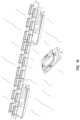
- FIG. 1illustrates a front view of a pontoon boat having a deck supported by a plurality of pontoons
- FIG. 2illustrates a top view of a pontoon boat having a deck and seating
- FIG. 3illustrates a representative top view of the pontoon boat of FIG. 1 including a thruster system having a first group of thruster outlets positioned in a bow portion of the pontoon boat and directed towards the bow of the pontoon boat with a first one directed towards port and a second one directed towards starboard and a second group of thruster outlets positioned in a stern portion of the pontoon boat and directed towards the stern of the pontoon boat with a first one directed towards port and a second one directed towards starboard;
- FIG. 4illustrates a representative view of the systems of the pontoon boat of FIG. 1 and an auto-positioning control device
- FIG. 5illustrates a representative view of a portion of one of the plurality of pontoons of FIG. 1 including a thruster system
- FIG. 5 Aillustrates a representative view of a portion of one of the plurality of pontoons of FIG. 1 including another exemplary thruster system
- FIG. 6illustrates a representative view of exemplary sensor systems
- FIG. 7illustrates an image of a LIDAR system output of an exemplary LIDAR system
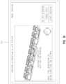
- FIG. 8illustrates exemplary positioning of bow stereo camera systems on an exemplary pontoon boat
- FIG. 9illustrates exemplary positioning of stern stereo camera systems on an exemplary pontoon boat
- FIG. 10illustrates an exemplary coverage area of a stereo camera system including a pair of bow stereo cameras and a pair of stern stereo cameras;
- FIG. 11illustrates an exemplary processing sequence of a controller associated with the pontoon boat
- FIG. 12illustrates a timing diagram a controller associated with the pontoon boat
- FIGS. 13 and 13 Aillustrates another exemplary processing sequence of a controller associated with the pontoon boat
- FIG. 13 Billustrates yet a further exemplary processing sequence of a controller associated with the pontoon boat
- FIG. 14illustrates a pontoon boat approaching an open docking position
- FIG. 15illustrates a selection screen of a docking interface presented on a display of the auto-docking control device
- FIG. 16illustrates a commencement screen of the docking interface presented on the display of the auto-docking control device
- FIG. 17illustrates a progression screen of the docking interface presented on the display of the auto-docking control device
- FIG. 18illustrates a completion screen of the docking interface presented on the display of the auto-docking control device
- FIG. 19illustrates a processing sequence for estimating disturbances on the boat due to environmental conditions.
- FIG. 20illustrates a processing sequence for including weight distribution in the determination of command velocity.
- Coupledmeans that the two or more components are in direct physical contact and arrangements wherein the two or more components are not in direct contact with each other (e.g., the components are “coupled” via at least a third component), but yet still cooperate or interact with each other.
- numeric terminologysuch as first, second, third, and fourth, is used in reference to various components or features. Such use is not intended to denote an ordering of the components or features. Rather, numeric terminology is used to assist the reader in identifying the component or features being referenced and should not be narrowly interpreted as providing a specific order of components or features.
- the embodiments disclosed hereinmay be used with any type of aquatic vessel, including pontoon boats, single hull boats, and other types of aquatic vessels.
- An exemplary aquatic vessel, a pontoon boat 100is provided as an example.
- an exemplary pontoon boat 100is floating in a body of water 10 having a top surface 12 .
- Pontoon boat 100includes a deck 104 supported by a plurality of pontoons 106 .
- the decksupports a railing 108 including a gate 110 positioned in a bow portion 112 (see FIG. 2 ) of pontoon boat 100 .
- Pontoon boat 100may further include a plurality of seats 114 , a canopy (see FIG. 10 for an example), and other components supported by deck 104 .
- pontoon boat 100further includes an operator console 190 having a plurality of operator controls including a steering input, illustratively steering wheel 192 , and a throttle control, illustratively a throttle lever 194 , and other exemplary controls.
- operator console 190having a plurality of operator controls including a steering input, illustratively steering wheel 192 , and a throttle control, illustratively a throttle lever 194 , and other exemplary controls.
- the plurality of pontoons 106include a starboard pontoon 120 , a port pontoon 122 , and a central pontoon 124 .
- Each of starboard pontoon 120 , port pontoon 122 , and central pontoon 124support deck 104 through respective brackets 126 .
- Each of starboard pontoon 120 , port pontoon 122 , and central pontoon 124support deck 104 above top surface 12 of water 10 .
- the plurality of pontoons 106may be limited to two pontoons or have four or more pontoons.
- the thruster systems described hereinmay be used with a single hull vessel.
- pontoon boat 100has a longitudinal centerline 140 and a lateral centerline 142 .
- Longitudinal centerline 140divides pontoon boat 100 into a port side 144 of pontoon boat 100 and a starboard side 146 of pontoon boat 100 .
- Lateral centerline 142divides pontoon boat 100 into a bow portion 148 of pontoon boat 100 and a stern portion 150 of pontoon boat 100 .
- Deck 104 of pontoon boat 100includes an outer perimeter 149 including a bow perimeter portion 152 , a starboard perimeter portion 154 , a stern perimeter portion 158 , and a port perimeter portion 156 .
- the plurality of pontoons 106define a port extreme extent 160 corresponding to an outer extent of port pontoon 122 and a starboard extreme extent 162 corresponding to an outer extent of starboard pontoon 120 .
- Pontoon boat 100includes an outboard motor 170 which extends beyond stern perimeter portion 158 of deck 104 .
- outboard motor 170is an internal combustion engine which power rotation of a propeller (see FIG. 14 ). The propeller may be rotated in a first direction to propel pontoon boat 100 forward in a direction 172 or in a second direction to propel pontoon boat 100 rearward in a direction 174 .
- outboard motor 170is rotatably mounted relative to deck 104 such that an orientation of the propeller may be adjusted to turn pontoon boat 100 in one of direction 176 and direction 178 .
- multiple outboard motors 170may be provided.
- the multiple outboard motors 170may be positioned adjacent the stern perimeter portion 158 of pontoon boat 100 .
- motor 170may also be an inboard motor positioned at least partially within perimeter 149 of pontoon boat 100 .
- pontoon boat 100further includes a thruster system 200 .
- Thruster system 200provides additional control over a position and/or orientation of pontoon boat 100 .
- Thruster system 200may carried by one or more of the plurality of pontoons 106 .
- thruster system 200is carried by central pontoon 124 or a combination of any one or more of starboard pontoon 120 , port pontoon 122 , and central pontoon 124 .
- Thruster system 200may be internal to one or more of the plurality of pontoons 106 , external to the one or more plurality of pontoons, or a combination thereof.
- At least one of the plurality of pontoons 106includes at least one water inlet, illustratively water inlet 202 of fluid conduit 204 is shown, and at least one water outlet, illustratively water outlet 206 and water outlet 210 both of fluid conduit 208 , are shown.
- Fluid conduit 208is fluidly coupled to fluid conduit 204 .
- each of water inlet 202 , water outlet 206 , and water outlet 210are positioned below top surface 12 of water 10 .
- Thruster system 200includes a fluid pump 220 positioned in fluid conduit 204 to move water from proximate water inlet 202 of fluid conduit 204 towards water outlet 206 and water outlet 210 of fluid conduit 208 .
- Exemplary fluid pumpsinclude the JT-30, JT-50, JT-70, and JT-90 series pumps available from Holland Marine Parts B.V. located at Donker Duyvisweg 297 , 3316 BL Dordrecht (NL).
- Fluid pump 220is powered by a power source 222 .
- Illustratively power source 222includes an electric motor 224 and a battery bank 226 which power electric motor 224 .
- An exemplary battery bank 226is a 24 volt lead acid battery.
- controller 230is an electronic controller including processing circuits and memory.
- controller 230is microprocessor-based and memory is a non-transitory computer readable medium which includes processing instructions stored therein that are executable by the microprocessor of controller to control operation of fluid pump 220 .
- Exemplary non-transitory computer-readable mediumsinclude random access memory (RAM), read-only memory (ROM), erasable programmable read-only memory (e.g., EPROM, EEPROM, or Flash memory), or any other tangible medium capable of storing information.
- controller 230is one of wired or wirelessly coupled to a user interface 240 , such as operator console 190 (see FIG. 2 ), positioned above deck 104 .
- User interface 240includes one or more input devices. Exemplary input devices include switches, dials, joysticks, touch screens, cameras (to capture visual cues), microphones (to capture audio cues), and other suitable input devices for receiving a user input.
- the user interfaceis provided on a personal mobile device, such as a smart phone or tablet (see for example remote operator device 300 in FIG. 4 ), and the personal mobile device includes processing instructions which provide input to controller 230 over a wireless connection.
- controller 230is also operatively coupled to a first valve 250 and a second valve 252 .
- Controller 230controls whether fluid from fluid pump 220 reaches water outlet 206 based on whether first valve 250 is open or closed by controller 230 .
- Controller 230controls whether fluid from fluid pump 220 reaches water outlet 210 based on whether second valve 252 is open or closed by controller 230 .
- controller 230may control additional valves to control fluid flow to additional water outlets.
- controller 230controls a respective valve associated with each of the respective water outlets 260 , 262 , 264 , and 266 .
- the respective valvesmay be sequenced in a manner that permits the thruster system 200 to independently control the flow to each of water outlets 260 , 262 , 264 , and 266 .
- Controller 230includes processing sequences which control the opening and closing of each of the respective valves to ensure that the valves are not closed in a manner that results in the water pressure in the thruster system spiking to exceed a threshold.
- controller 230monitors a temperature of at least one of water in the thruster system and the fluid pump along with the states of the respective valves to minimize the chance of overheating of the thruster system and/or unwanted water pressure spikes.
- thruster system 200does not include valves 250 and 252 . Rather, in one embodiment, fluid pump 220 is fluidly coupled to only water inlet 202 and water outlet 206 and a separate fluid pump 220 is provided to fluidly couple water inlet 202 and water outlet 210 .
- thruster systemincludes a single valve 280 (see FIG. 5 A ).
- Valve 580is a three-way valve and is positionable in an off configuration wherein water is not communicated to either of outlets 206 and 210 , a first on configuration wherein water is communicated to only outlet 206 , and a second on configuration wherein water is communicated to only outlet 210 .
- outlet 206is a starboard facing outlet and outlet 210 is a port facing outlet.
- outlet 206is a starboard and stern facing outlet and outlet 210 is a port and stern facing outlet.
- a boat including thruster system 200could be moved forward by pulsing between the first on configuration and the second on configuration.
- outlet 206is a starboard and bow facing outlet and outlet 210 is a port and bow facing outlet.
- a boat including thruster system 200could be moved backward by pulsing between the first on configuration and the second on configuration.
- thruster system 200includes four water outlets, a bow-port outlet 260 , a bow-starboard outlet 262 , a stern-port outlet 264 , and a stern-starboard outlet 266 .
- Bow-port outlet 260has a corresponding fluid conduit 270 which causes water to exit bow-port outlet 260 in a direction, indicated by the arrow, towards both port side 144 of pontoon boat 100 and bow portion 148 of pontoon boat 100 .
- Bow-starboard outlet 262has a corresponding fluid conduit 272 which causes water to exit bow-starboard outlet 262 in a direction, indicated by the arrow, towards both starboard side 146 of pontoon boat 100 and bow portion 148 of pontoon boat 100 .
- Stern-port outlet 264has a corresponding fluid conduit 274 which causes water to exit stern-port outlet 264 in a direction, indicated by the arrow, towards both port side 144 of pontoon boat 100 and stern portion 150 of pontoon boat 100 .
- Stern-starboard outlet 266has a corresponding fluid conduit 276 which causes water to exit stern-starboard outlet 266 in a direction, indicated by the arrow, towards both starboard side 146 of pontoon boat 100 and stern portion 150 of pontoon boat 100 .
- the direction of outlet 260is straight towards port side 144 to cause water to exit in a direction towards port side 144 of pontoon boat 100 or angled to cause water to exit in a direction towards both port side 144 of pontoon boat 100 and stern portion 150 of pontoon boat 100
- the direction of outlet 262is straight towards starboard side 146 to cause water to exit in a direction towards starboard side 146 of pontoon boat 100 or angled to cause water to exit in a direction towards both starboard side 146 of pontoon boat 100 and stern portion 150 of pontoon boat 100
- the direction of outlet 264is straight towards port side 144 to cause water to exit in a direction towards port side 144 of pontoon boat 100 or angled to cause water to exit in a direction towards both port side 144 of pontoon boat 100 and bow portion 148 of pontoon boat 100
- the direction of outlet 266is straight towards starboard side 146 to cause water to exit in a direction towards starboard side 146 of pontoon boat 100
- each of fluid conduits 270 - 276are angled downward (see FIG. 1 ) so that water exiting the respective outlets 260 - 266 is directed downward, as opposed to straight horizontally.
- An advantage, among others, of angling the outlets 260 - 266 of fluid conduits 270 - 276 downwardis increased stability of pontoon boat 100 in water 10 .
- the outlets 260 - 266 of fluid conduits 270 - 276 of the depicted thrusters, and/or the outlets of fluid conduits of additional thrustersmay be oriented horizontally, angled upward, angled downward or combinations thereof.
- the outlet direction of fluid conduits 270 - 276 and/or of additional fluid conduitsis adjustable in at least one of vertically (e.g. upward, straight horizontally, and downward) and fore-aft (e.g. more towards bow portion 148 , straight laterally towards one of port portion 144 and starboard portion 146 , and more towards stern portion 150 ).
- each of fluid conduit 270 , fluid conduit 272 , fluid conduit 274 , and fluid conduit 276are fed by a respective fluid pump 220 from one or more water inlets 202 in central pontoon 124 .
- the respective fluid pumps 220may be independently or jointly controlled by controller 230 .
- a plurality of fluid conduit 270 , fluid conduit 272 , fluid conduit 274 , and fluid conduit 276are fed by a common fluid pump 220 and one or more valves are included to control which of the plurality of fluid conduit 270 , fluid conduit 272 , fluid conduit 274 , and fluid conduit 276 are in fluid communication with the common fluid pump 220 .
- thruster system 200may include any combination of water jet thruster fluid pumps 220 , propellers, or other suitable thrust system.
- Pontoon boat 100includes a boat controller 302 having at least one associated memory 304 .
- Memory 304is one or more non-transitory computer readable mediums. Memory 304 may be representative of multiple memories which are provided locally with boat controller 302 or otherwise available to boat controller 302 over a network. The information recorded or determined by boat controller 302 may be stored on memory 304 . In embodiments, memory 304 is distributed.
- Boat controller 302provides the electronic control of the various components of pontoon boat 100 . Further, boat controller 302 is operatively coupled to a plurality of sensors 306 which monitor various parameters of pontoon boat 100 or the environment surrounding pontoon boat 100 . Exemplary sensed parameters include, but are not limited to, location (e.g. GPS location), relative location to surrounding environmental objects, water current, wind speed, angular orientation of boat 100 (e.g. pitch, roll, yaw), wave height, water temperature, water depth, water clarity, presence of environmental objects (e.g. other aquatic vessels, docks, buoys, fallen trees, sandbars). One or more sensors 306 may be integrated into the hull structure of boat 100 .
- locatione.g. GPS location
- relative location to surrounding environmental objectse.g. water current, wind speed, angular orientation of boat 100 (e.g. pitch, roll, yaw), wave height, water temperature, water depth, water clarity, presence of environmental objects (e.g. other aquatic vessels, docks,
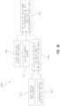
- Boat controller 302performs certain operations to control one or more subsystems of other boat components, such as one or more of sensor systems 306 , an outboard prime mover system 308 , thruster system 200 , a steering system 312 , a network system 314 , and other systems.
- boat controller 302is represented as including several controllers, illustratively outboard prime mover controller 320 , thruster controller 230 , steering controller 322 , sensing controller 324 , network controller 326 , and auto-dock controller 330 .
- controllersmay each be single devices or distributed devices or one or more of these controllers may together be part of a single device or distributed device.
- the functions of these controllersmay be performed by hardware and/or as computer instructions on a non-transient computer readable storage medium, such as memory 304 .
- outboard prime mover controller 320 , thruster controller 230 , steering controller 322 , sensing controller 324 , network controller 326 , and auto-dock controller 330are illustrated as discrete controllers, in embodiments, one or more of outboard prime mover controller 320 , thruster controller 230 , steering controller 322 , sensing controller 324 , network controller 326 , and auto-dock controller 330 may be part of the same controller.
- boat controller 302includes at least two separate controllers which communicate over a network.
- the networkis a CAN network.
- the CAN networkis implemented in accord with the J1939 protocol. Details regarding an exemplary CAN network are disclosed in U.S. patent application Ser. No. 11/218,163, filed Sep. 1, 2005, the disclosure of which is expressly incorporated by reference herein. Of course, any suitable type of network or data bus may be used in place of the CAN network. In one embodiment, two wire serial communication is used.
- Outboard prime mover system 308includes a prime mover, illustratively outboard motor 170 in FIG. 2 .
- Exemplary prime moversinclude outboard style motors, inboard style motors, internal combustion engines, two stroke internal combustion engines, four stroke internal combustion engines, diesel engines, electric motors, hybrid engines, jet powered engines, and other suitable sources of motive force.
- Outboard prime mover system 308further includes a power supply system (not shown). The type of power supply system depends on the type of prime mover used. In embodiments, the prime mover is an internal combustion engine and the power supply system is one of a pull start system and an electric start system.
- Outboard prime mover system 308in the case of an internal combustion engine, would further include a fuel system and air intake system which provide fuel and air to the internal combustion engine.
- the prime moveris an electric motor and power supply system is a switch system which electrically couples one or more batteries to the electric motor.
- the prime moveris a jet-based engine which requires an auxiliary pump and/or water intake system.
- Thruster system 200includes one or more thruster fluid pumps, valves, and other components.
- Steering system 312includes one or more devices which are controlled to alter a direction of travel of pontoon boat 100 .
- steering system 312includes a hydraulic system (not shown) which orients outboard motor 170 relative to deck 104 . By turning outboard motor 170 relative to deck 104 a direction of travel of pontoon boat 100 may be altered.
- outboard motor 170is stationary and pontoon boat 100 includes a separate rudder which is oriented by steering system 312 relative to deck 104 to steer pontoon boat 100 .
- steering system 312provides input to thruster system 200 to control operation of thruster system 200 to move and orient pontoon boat 100 .
- Sensor system 306includes one or more sensing systems which provide input to boat controller 302 for operation of boat controller 302 and other sub-systems.
- Exemplary sensor systems for guiding the position of pontoon boat 100include camera systems, stereo camera systems, location determiners such as GPS systems, accelerometers, magnetometers, gyroscopes, LIDAR systems, radar systems, ultrasound systems, piezo tubes, echo sounder, sonic pulse, acoustic Doppler, sonar, Inertial Measurement Units (IMUs), millimeter wave systems, and other suitable sensor systems to identify environmental objects such as docks, boats, buoys, and other objects.
- location determinerssuch as GPS systems, accelerometers, magnetometers, gyroscopes, LIDAR systems, radar systems, ultrasound systems, piezo tubes, echo sounder, sonic pulse, acoustic Doppler, sonar, Inertial Measurement Units (IMUs), millimeter wave systems, and other suitable sensor systems to identify environmental objects such as
- sensor systems 306may determine the location of objects surrounding pontoon boat 100 and, in embodiments, sensor systems 306 may utilize one or more fiducials affixed to an object, such as a mooring implement, to determine a location of pontoon boat 100 relative to the mooring implement.
- Boat controller 302also interacts with an operator interface 362 which includes at least one input device and at least one output device.
- Exemplary input devicesinclude levers, buttons, switches, soft keys, joysticks, and other suitable input devices.
- Exemplary output devicesinclude lights, displays, audio devices, tactile devices, and other suitable output devices.
- the output devicesinclude a display and boat controller 302 formats information to be displayed on the display and operator interface 360 displays the information.
- input devices and output devicesinclude a touch display and boat controller 302 formats information to be displayed on the touch display, operator interface 360 displays the information, and operator interface 360 monitors the touch display for operator input.
- Exemplary operator inputsinclude a touch, a drag, a swipe, a pinch, a spread, and other known types of gesturing.
- the output devicesprovide feedback on the position of pontoon boat 100 relative to a dock, a lift, a slip, or a goal location via one or more of audio, visual, and tactile queues.
- Boat controller 302may further receive input from or send output to remote operator device 300 .
- Remote operator device 300includes an operator device controller 370 with associated memory 372 , an operator interface 374 , and a network system 376 .
- Exemplary remote operator device 300include cellular phones, tablets, and other remote interfaces which may be handheld or mounted to pontoon boat 100 .
- Exemplary cellular phonesinclude the IPHONE brand cellular phone sold by Apple Inc., located at 1 Infinite Loop, Cupertino, CA 95014 and the GALAXY brand cellular phone sold by Samsung Electronics Co., Ltd.
- Operator device controller 370includes a network controller 380 which controls communications between remote operator device 300 and other devices, such as pontoon boat 100 , through one or more network systems 314 .
- network controller 380 of remote operator device 300communicates with remote devices over a wireless network.
- An exemplary wireless networkis a radio frequency network utilizing a BLUETOOTH protocol or other wireless protocol.
- network system 376includes a radio frequency antenna.
- remote operator device 300may be connected with pontoon boat 100 through a wired network.
- Operator interface 374includes at least one input device and at least one output device.
- Exemplary input devicesinclude levers, buttons, switches, soft keys, and other suitable input devices.
- Exemplary output devicesinclude lights, displays, audio devices, tactile devices, and other suitable output devices.
- the output devicesinclude a display and operator device controller 370 formats information to be displayed on the display and operator interface 374 displays the information.
- input devices and output devicesinclude a touch display and operator device controller 370 formats information to be displayed on the touch display, operator interface 374 displays the information, and operator interface 374 monitors the touch display for operator input.
- Exemplary operator inputsinclude a touch, a drag, a swipe, a pinch, a spread, and other known types of gesturing.
- Operator device controller 370includes an auto-dock I/O controller 382 .
- Auto-dock I/O controller 382interacts with auto-dock controller 330 of pontoon boat 100 to, as explained in more detail herein, operate the systems of pontoon boat 100 to position pontoon boat 100 relative to a mooring implement, such as a dock, a boat slip, a lift, or other suitable mooring implement. Further, the systems of pontoon boat 100 may be used to position boat 100 relative to a sandbar/beach or buoy.
- operator device controller 370is represented as including several controllers, illustratively network controller 380 and auto-dock I/O controller 382 .
- controllersmay each be single devices or distributed devices or one or more of these controllers may together be part of a single device or distributed device.
- the functions of these controllersmay be performed by hardware and/or as computer instructions on a non-transient computer readable storage medium, such as memory 372 and/or memory 304 .
- network controller 380 and auto-dock I/O controller 382are illustrated as discrete controllers, in embodiments, network controller 380 and auto-dock I/O controller 382 may be part of the same controller.
- Auto-dock I/O controller 382is illustrated as part of operator device controller 370 .
- pontoon boat 100includes a display as part of operator interface 360 and the functionality of auto-dock I/O controller 382 is provided as part of boat controller 302 .
- Sensors 306may include a GPS/Magnetometer 400 .
- the GPS (Global Positioning System) of GPS/magnetometer 400determines a location of pontoon boat 100 on the Earth.
- the magnetometer of GPS/magnetometer 400determines an orientation of pontoon boat 100 relative to the magnetic field of the Earth. Although illustrated as a single device separate GPS and magnetometer devices may be used. Further, other suitable devices for determining a location of pontoon boat 100 and an orientation of pontoon boat 100 may be used.
- Sensors 306may include a LIDAR (Light Detection and Ranging) system 402 .
- LIDAR system 402uses pulsed lasers to determine distance to surrounding objects.
- LIDAR system 402provides three-dimensional geometry of the surroundings of pontoon boat 100 in the range of 20-100 meters from the LIDAR system 402 .
- An advantage, among others, of LIDAR system 402is that it is able to function day and night with a low dependence on lighting conditions.
- the data from LIDAR system 402may be used to provide a reflectivity map, an example of which is shown as map 404 in FIG. 7 .
- a representation of the location and orientation of pontoon boat 100is also displayed on operator interface 374 .
- the location and orientation of pontoon boat 100 relative to surrounding objectsmay be determined by boat controller 302 based the output of LIDAR system 402 .
- Sensors 306may include a radar system 414 .
- Radar system 414provides distance to surrounding objects. The location and orientation of pontoon boat 100 relative to surrounding objects may be determined by boat controller 302 based the output of radar system 414 .
- Sensors 306may include an IMU (Inertial Measurement Unit) system 410 .
- IMU 410provides an angular position of pontoon boat 100 including one or more of a pitch angle, a roll angle, and a yaw angle and accelerations of pontoon boat 100 in each of the x, y, and z axes. This output may be used to determine an orientation of pontoon boat 100 and to determine whether auto-dock controller 330 of boat controller 302 may be activated.
- auto-dock controller 330may include a threshold that a pitch and/or roll of pontoon boat 100 must be less than, such as 10 degrees, 5 degrees, or 3 degrees, for auto-dock controller 330 to continue.
- sensors 306may further include a wind sensor (not shown) and auto-dock controller 330 may include a threshold that wind speed must be less than, such as 20 miles per hour, for auto-dock controller 330 to continue.
- Sensors 306may include one or more stereo cameras 412 .
- Stereo cameras 412provide a three-dimensional geometry of the surroundings of pontoon boat 100 in the range of 10-15 meters from the stereo cameras 412 .
- An advantage, among others, of stereo cameras 412is that they are able to provide visible light video to operator interface 374 of remote operator device 300 for display.
- stereo cameras 412provide grayscale information.
- stereo cameras 412provide color information which may be used to classify objects or other operations.
- exemplary placement of four stereo cameras 412are illustrated.
- the stereo cameras 412are positioned proximate the bow-starboard corner of pontoon boat 100 , the bow-port corner of pontoon boat 100 , the stern-starboard corner of pontoon boat 100 , and the stern-port corner of pontoon boat 100 .
- FIG. 10a representation of a coverage area of the four stereo cameras 412 is illustrated. Additional stereo cameras or other imaging sensors may be positioned at various locations on pontoon boat 100 .
- At least some stereo camerasare oriented such that a line connecting the respective cameras of a stereo camera is angled relative to horizontal, such as vertical, to enhance the ability of the system to recognize horizontal features (dock, boats, and other objects).
- at least some stereo camerasare oriented such that a lone connecting the respective cameras of a stereo camera is horizontal to enhance the ability of the system to recognize vertical features such as on boat lifts or posts.
- Exemplary locationsinclude on or affixed to a top rail or portion of barrier 108 , on or affixed to deck 104 , on or affixed to gate 110 , on or affixed to canopy or roof structure, or other suitable locations.
- pontoon boat 100includes a bow camera 412 and a stern camera 412 , each centered on or positioned near longitudinal centerline 140 of pontoon boat 100 .
- stereo camerasare moveable between a stored position and a use position when the auto-dock feature is in use.
- the stereo cameras 412may be supported by deck 104 on telescoping mounts. The stereo cameras 412 are positioned proximate the deck 104 when the auto-dock feature is not in use (“stored position”) and raised relative to the stored position, either automatically or manually, to a raised use position when the auto-dock feature is in use.
- Auto-dock controller 330includes a localization component 430 , a perception component 432 , a mission planner component 434 , and a navigation component 436 .
- Localization component 430receives the inputs from sensors 306 , such as from GPS/magnetometer 400 , IMU system 410 , stereo cameras 412 , LIDAR system 402 , and radar system 414 . Based on those inputs, localization component 430 locates pontoon boat 100 and, in embodiments, corresponding objects in the environment surrounding pontoon boat 100 .
- Obstacles, reference points, goal points, other water vessels, people, docks, buoys, and/or reference objectsmay be sensed by one or more sensing systems including visual sensors (e.g. cameras), range sensors (e.g. LIDAR, radar, sonar), stereo sensing, projected light visual sensing, beacon detection, sonar, and proximity sensors.
- localization component 430includes a sensor fusion algorithm to estimate a three-dimensional pose of pontoon boat 100 .
- the pose of pontoon boat 100may be determined by one or more of GPS information, IMU information, visual odometry, visual SLAM, visual feature matching, point cloud matching, triangulation with one or more beacons in the environment, INS, and stereo data matching. Based on this information, the local pose estimate of pontoon boat 100 and potential location of obstacles, are provided to perception component 432 .
- Perception component 432detects, such as with stereo cameras 412 and LIDAR system 402 , and tracks the objects in the environment surrounding pontoon boat 100 (e.g. other boats or swimmers) and a target docking location, such as location 440 (see FIG. 10 ), with respect to pontoon boat 100 .
- perception component 432determines a representation of the environmental around boat 100 and semantically labels objects in the representation of the environment like boats and docks based comparisons to learned objects accessible by the logic that have been classified as docks or boats. Based on the location of the objects an audible warning may be sounded with a speaker or horn.
- Perception component 432outputs to mission planner component 434 the locations of the obstacles in the surrounding environment and the target docking location with respect to the frame of reference of pontoon boat 100 .
- the target docking locationmay correspond to a location proximate a dock, a location proximate a boat slip, a location of a boat lift, a portion of a sandbar/beach, or other suitable locations.
- a good docking locationis determined by based on the dimensions of boat 100 to ensure there is ample room to maneuver and dock boat 100 , a planar nature of the environmental object identified as a dock, and an openness of the dock area to allow for docking and disembarking from boat 100 .
- Mission planner component 434identifies a navigation plan to navigate pontoon boat 100 to the target docking location 440 while avoiding the objects in the environment surrounding pontoon boat 100 .
- mission planner component 434uses a dynamic graph based on the information from perception component 432 to estimate path and trajectory for pontoon boat 100 .
- Mission planner component 434outputs navigation waypoints to navigation component 436 .
- Navigation component 436controls one or more of outboard prime mover system 308 , thruster system 200 , and steering system 312 to navigate pontoon boat 100 to location 440 .
- navigation component 436determines the control of outboard prime mover system 308 , thruster system 200 , and steering system 312 to navigate pontoon boat 100 along the navigation waypoints output by mission planner component 434 .
- navigation component 436utilizes a PID algorithm to provide a smooth movement along the navigation waypoints.
- navigation component 436utilizes one or more of predictive control, PI, PID, PD, sliding mode control, and/or other suitable control schemes.
- navigation component 436adjusts the control of outboard prime mover system 308 , thruster system 200 , and steering system 312 based on at least one of a sensed weight distribution on boat 100 , a wind characteristic, and a current of water 12 .
- an exemplary processing sequence 600 for navigation component 436is shown.
- the GPS sensor 400a measurement is received of a location of boat 100 .
- the current commanded control velocity of boat 100is received, as represented by block 602 .
- a deviation in the motion of boat 100 from an expected location of the boatis determined, as represented by block 604 .
- inputsare received from a wind speed and direction sensor 340 and a water current sensor 342 .
- an estimate of additional disturbances on boat 100 due to environmental conditionsmay be determined, as represented by block 606 .
- Navigation component 436receives an input from IMU 410 which provides an indication of how boat 100 is sitting in water 12 . If the weight supported by boat 100 is not evenly distributed, boat 100 will not sit level in water 12 . Further, changes in the weight distribution of the boat 100 , such as due to people moving around, results in a change in the center of mass and moment of inertia of boat 100 , as represented by blocks 672 and 674 . This change perturbs the angle of boat 100 in water 12 , as represented by block 676 , which is measured by IMU 410 , as represented by block 678 .
- Navigation component 436includes this change in weight distribution into account when determining the next control velocity command for outboard prime mover system 308 , thruster system 200 , and steering system 312 to move to a target position.
- a timing diagram 450 of an exemplary operation of auto-dock controller 330is shown.
- the auto-dock processing sequenceis started, as represented by block 452 .
- an operator of pontoon boat 100moves pontoon boat 100 within range of a dock or other mooring location, as represented by block 454 , and auto-dock controller 330 localizes the position of pontoon boat 100 , as represented by block 456 , with localization component 430 .
- auto-dock controller 330senses the environment around pontoon boat 100 , as represented by block 458 , and rectifies and processes sensor data from sensors 306 , as represented by block 460 , with perception component 432 .
- the auto-dock processing sequenceis begun in response to the selection of an input 462 provided on an input screen 464 on operator interface 374 (see FIG. 15 ).
- Input screen 464illustrates a target docking location 466 determined by auto-dock controller 330 based on the size of pontoon boat 100 and a corresponding sized area proximate the dock. The operator confirms the displayed target docking location by selecting it, as represented by block 470 in FIG. 12 and illustrated in FIG. 16 .
- auto-dock controller 330begins determining the path and trajectory of pontoon boat 100 , as represented by blocks 472 and 474 , and controlling one or more of outboard prime mover system 308 , thruster system 200 , and steering system 312 to move pontoon boat 100 to the docking location, as represented by block 476 .
- the path and trajectory of pontoon boat 100is updated multiple times during the movement of pontoon boat 100 to the docking location 466 as represented by loop 478 .
- block 472is a global path and trajectory to move pontoon boat 100 from its current position to the docking location and block 474 is a local path and trajectory to move pontoon boat 100 to the next waypoint along the global path and trajectory.
- the auto-dock controller 330may receive an input from a sensor monitoring an area in front of a control panel of boat 100 . In embodiments, the auto-dock controller 330 may fail to initiate or stop an ongoing auto-dock procedure if an operator is not sensed being in front of the control panel of the boat 100 .
- a switchis provided as part of the control panel or at another location on pontoon boat 100 and the auto-dock controller 330 may fail to initiate or stop an ongoing auto-dock procedure based on the status of the switch.
- the switchis a deadman switch which requires the user to apply active force to keep the switch closed. If the user stops applying force, the switch opens and the auto-dock procedure is stopped.
- the switchis a liveman switch which requires a user to apply active force to keep the switch closed, but if force over a threshold amount is applied, the switch opens. Similar to the deadman switch, if the user does not apply active force, the switch opens. If the user stops applying force or applies excessive force, the auto-dock procedure is stopped.
- remote operator device 300presents feedback to the operator of the position of pontoon boat 100 .
- screen 464 presented on operator interface 374includes a cancel docking input region which if selected would cancel the auto-docking process.
- screen 464provides a message to the operator that docking is complete and pontoon boat 100 should be moored to the dock or other mooring location.
- one or both of remote operator device 300 and operator interface 374provide one or more of audio, visual, and tactile feedback to the user of when pontoon boat 100 is in the docking position, when an obstacle is near, or other specified scenarios.
- block 480represents when pontoon boat 100 is positioned in the confirmed target docking location 466 .
- auto-dock controller 330operates to maintain pontoon boat 100 in a mooring configuration at the docking location 466 until the auto-docking process is ended, as represented by blocks 482 and 484 .
- the pontoon boat 100remains essentially stationary to allow an operator to tie up, or moor the vessel to the docking structure.
- the systemmay maintain a position of the boat 100 relative to the dock or slip sides.
- the systemmay maintain a center of mass of boat 100 between the lifts.
- remote operator device 300is monitoring the weight of pontoon boat 100 and the current of the water pontoon boat 100 is positioned in, as represented by block 486 .
- This datais processed to update requirements of thruster system 200 to maintain the position of pontoon boat 100 relative to the dock as represented by block 488 .
- This processis repeated until the auto-dock process ends, as represented by loop 490 .
- the mooring configuration processends automatically after a certain amount of time has passed, or it may be controlled via an operator device 300 input, by the operator, once the pontoon boat 100 has been successfully moored.
- the logic of the mooring configuration processcould be utilized outside of a docking process, in which an operator could configure a pontoon boat 100 to simply stay in a stationary position for a period of time in open water to, for example, allow another aquatic vessel to tie up to it, or allow a swimmer to board the pontoon boat 100 .
- a mooring configuration process utilized in open waterprovides a type of virtual anchor (“station keeping”).
- the systemmaintains the position and orientation of pontoon boat 100 in the water (minimize translational and rotational movement). The system compensates for wind, water current, momentum, and water disturbances (such waves caused by passing aquatic vessels).
- the systemwhen an operator through remote operator interface 374 or operator interface 360 manipulates an input to direct motion of the pontoon boat 100 , the system responds accordingly and instead of maintaining a zero velocity or position, it attempts to match the user's desired input (like turn, translate, etc) while compensating for disturbances. When the user stops directing motion through remote operator interface 374 or operator interface 360 , the system reverts to the station keeping (zero velocity/zero movement).
- the systems disclosed hereinprovide alerts to an operator moving the boat 100 manually of proximate objects.
- Exemplary alertsinclude audio, visual, and tactile alerts.
- the systems disclosed hereinmodify a movement of boat 100 to prevent a collision with a sensed object.
- an exemplary processing sequence 500is shown.
- the auto-docking processis started with auto-dock I/O controller 382 on remote operator device 300 by initiating an auto-dock software application with operator interface 374 of remote operator device 300 , as represented by block 502 .
- Thisalso results in auto-dock controller 330 of pontoon boat 100 beginning to execute, as represented by block 504 .
- remote operator device 300On operator interface 374 of remote operator device 300 , the output of various sensors 306 are displayed and updated, as represented by block 506 .
- An operator of remote operator device 300confirms a presented target docking region or type, as represented by block 508 . These inputs are sent to auto-dock controller 330 of pontoon boat 100 and a global planner determines proposed movements of pontoon boat 100 to the selected location, as represented by block 512 .
- the planis output to the operator on operator interface 374 , as represented by block 514 .
- the operatorcan accept the proposed plan or change the proposed plan, as represented by block 516 . If the operator is making a change of region, control returns to block 512 , as represented by block 518 .
- the local planner of mission planner component 434 of auto-dock controller 330determines and updates the movement of pontoon boat 100 towards the selected location and the waypoints there between, as represented by block 522 .
- the local planner of mission planner component 434 of auto-dock controller 330receives inputs from a pose estimator of localization component 430 of auto-dock controller 330 which determines and updates the location and orientation of pontoon boat 100 , as represented by block 524 , and from perception component 432 of auto-dock controller 330 which determines and provides updates on the environment surrounding pontoon boat 100 , as represented by block 526 .
- the local planner of mission planner component 434 of auto-dock controller 330outputs instructions to navigation component 436 of auto-dock controller 330 , as represented by block 530 . Further, auto-dock controller 330 determines if pontoon boat 100 is at the desired location and if so controls pontoon boat 100 to maintain the desired location, as represented by blocks 532 and 534 . The local planner of mission planner component 434 of auto-dock controller 330 also provides updates to auto-dock I/O controller 382 of remote operator device 300 which are displayed on operator interface 374 , as represented by block 534 .
- the local planner of mission planner component 434 of auto-dock controller 330also monitors for user input to stop movement of pontoon boat 100 , as represented by block 536 .
- Exemplary inputsinclude a selection through operator interface 374 to pause or end the docking, the pressing of an estop input, and manual input to move pontoon boat 100 through operator console 190 of pontoon boat 100 .
- the auto-dock controller 330first confirms that outboard motor 170 is in a raised trim-up position. In one example, this confirmation is received as an operator input on operator interface 374 of remote operator device 300 . In another example, this confirmation is received by checking a trim sensor that monitors a trim position of outboard motor 170 . In yet another example a controller of outboard motor provides a signal to remote operator device of a trim position of outboard motor 170 .
- Auto-dock controller 330verifies the trim position of the outboard motor, as represented by block 552 .
- the auto-dock controller 330determines whether the outboard motor is in the raised trim-up position, as represented by block 554 . If the outboard motor is in the raised trim-up position then auto-dock controller executes the auto-dock procedure, as represented by block 556 . If the outboard motor is not in the raised trim-up position then auto-dock controller provides a notification to the operator to raise the outboard motor, as represented by block 556 .
- Exemplary notificationsinclude a visual cue on operator device 300 , an audible cue such as a horn or alarm, and/or a tactile cue.
- the disclosed embodimentsare capable detecting or determining various conditions including (a) weather conditions: no wind, slight wind, moderate wind, heavy wind, no water current, slight current, moderate current, heavy current, no rain, light rain, heavy rain, fog, overcast, sunshine at morning, noon, and night, and night-time; (b) surrounding conditions: shallow water, shoreline, people in the water, people out of the water, stationary boats at a dock, stationary boats, similar boats moving at a dock, similar boats moving, small watercraft, large watercraft, foreign objects (hazards) in water, and foreign objects (hazards) along dock; (c) detection of mooring implement features: tie-down feature, modified boat lift, unmodified boat lift; (d) dock types: shorter than boat, longer than boat; perpendicular slip; angled slip; and (e) boat conditions: list amount (due to wind, water, and/or people), list rate (due to wind, water, and/or people), approach speed, approach angle, approach distance.
- weather conditionsno wind, slight wind, moderate
- a pure assist (ADAS like) controlis provided by the disclosed systems.
- an operator of the boat 100provides input of a desired movement of boat 100 , such as through a joystick input.
- Sensorsprovide information related to the location of boat 100 relative to surrounding objects and the system alerts the operator when boat 100 is getting close to a detected obstacle.
- the systemmay provide feedback to the operator of the distance to the mooring implement, such as the dock.
- the feedbackmay be audio, visual, and/or tactile.
- the feedbackmay provide a numeric measurement or a qualitative indication of the distance.
- the systemwill execute a station keeping procedure to compensate for wind and current.
- the station keepingwill maintain the position of boat 100 while it is being secured to the mooring implement.
- the systemwill prevent collisions with other objects. Collisions may be prevented by altering a course of travel of boat 100 or station keeping.
- an assistive docking controlis provided by the disclosed systems.
- an operatorclicks/touches area on a screen of the user interface to indicate where boat should dock.
- the operatoralso specifies how boat should dock (head-on, parallel, boat lift, etc).
- the operatormust touch/hold some kind of deadman switch and minimum environmental conditions must be satisfied for the system to continue.
- the systemnotifies and kicks out if the deadman switch is released, or system unable to achieve desired motion (due to unseen obstruction, high wind, high current, poor visibility, etc.).
- the operatormay be the only person looking for obstacles and hazards.
- the systemmoves boat 100 to target location in motion selected by operator.
- the operatorspecifies intended action (parallel, head-on, boat lift, etc) and is presented with viable options detected by system.
- the operatorconfirms/selects option for target location.
- the systemdetects obstacles and differentiates dock from obstacles. Further, the system can determine if boat 100 will fit in the target location. The system waits for detected dynamic obstacles if they present hazard.
- the operatoris given options for action along with providing target confirmation (system can automatically detect boat lift, parallel, head-on, etc).
- the operatormay step away from deadman switch for a predetermined amount of time, such as a few seconds.
- the operatormay provide a voice command to the system to disengage assist.
- the described embodimentsare not limited to this orientation of the boat, but rather may be used to position the boat in an desired orientation relative to an environmental object, such as docks, piers, mooring points and other objects, such that the boat may be positioned in a desired orientation relative to a dock, may be pulled into a slip, may be positioned on a lift, may be located relative to a mooring point, and other positions relative to an environmental object.
- an environmental objectsuch as docks, piers, mooring points and other objects
Landscapes
- Engineering & Computer Science (AREA)
- Chemical & Material Sciences (AREA)
- Combustion & Propulsion (AREA)
- Mechanical Engineering (AREA)
- Ocean & Marine Engineering (AREA)
- Radar, Positioning & Navigation (AREA)
- Remote Sensing (AREA)
- Physics & Mathematics (AREA)
- Fluid Mechanics (AREA)
- Traffic Control Systems (AREA)
- Control Of Position, Course, Altitude, Or Attitude Of Moving Bodies (AREA)
- Position Fixing By Use Of Radio Waves (AREA)
Abstract
Description
Claims (25)
Priority Applications (2)
| Application Number | Priority Date | Filing Date | Title |
|---|---|---|---|
| US17/033,805US12151798B2 (en) | 2019-09-27 | 2020-09-27 | System and method for positioning an aquatic vessel |
| US18/954,612US20250187713A1 (en) | 2019-09-27 | 2024-11-21 | System and method for positioning an aquatic vessel |
Applications Claiming Priority (3)
| Application Number | Priority Date | Filing Date | Title |
|---|---|---|---|
| US201962907250P | 2019-09-27 | 2019-09-27 | |
| US202063012992P | 2020-04-21 | 2020-04-21 | |
| US17/033,805US12151798B2 (en) | 2019-09-27 | 2020-09-27 | System and method for positioning an aquatic vessel |
Related Child Applications (1)
| Application Number | Title | Priority Date | Filing Date |
|---|---|---|---|
| US18/954,612ContinuationUS20250187713A1 (en) | 2019-09-27 | 2024-11-21 | System and method for positioning an aquatic vessel |
Publications (2)
| Publication Number | Publication Date |
|---|---|
| US20210094665A1 US20210094665A1 (en) | 2021-04-01 |
| US12151798B2true US12151798B2 (en) | 2024-11-26 |
Family
ID=75162886
Family Applications (2)
| Application Number | Title | Priority Date | Filing Date |
|---|---|---|---|
| US17/033,805Active2043-02-16US12151798B2 (en) | 2019-09-27 | 2020-09-27 | System and method for positioning an aquatic vessel |
| US18/954,612PendingUS20250187713A1 (en) | 2019-09-27 | 2024-11-21 | System and method for positioning an aquatic vessel |
Family Applications After (1)
| Application Number | Title | Priority Date | Filing Date |
|---|---|---|---|
| US18/954,612PendingUS20250187713A1 (en) | 2019-09-27 | 2024-11-21 | System and method for positioning an aquatic vessel |
Country Status (5)
| Country | Link |
|---|---|
| US (2) | US12151798B2 (en) |
| EP (1) | EP4034957A4 (en) |
| CN (1) | CN115151881A (en) |
| CA (1) | CA3152109A1 (en) |
| WO (1) | WO2021062339A1 (en) |
Families Citing this family (16)
| Publication number | Priority date | Publication date | Assignee | Title |
|---|---|---|---|---|
| US11208188B2 (en) | 2019-06-10 | 2021-12-28 | Polaris Industries Inc. | Thruster arrangement for a boat |
| US11220318B2 (en) | 2020-04-09 | 2022-01-11 | The Yacht Group Llc | Bracket for mounting a thruster to a boat |
| US12006015B2 (en)* | 2020-05-13 | 2024-06-11 | Liquid Propulsion, Llc | Thrust system for steering marine vessels |
| US12179889B2 (en) | 2020-07-06 | 2024-12-31 | Polaris Industries Inc. | Boat maneuverability and stability control systems and methods |
| JP7554105B2 (en)* | 2020-12-02 | 2024-09-19 | ヤマハ発動機株式会社 | Distance recognition system and control method thereof, ship |
| JP2022134608A (en)* | 2021-03-03 | 2022-09-15 | ヤマハ発動機株式会社 | Ship steering system and ship |
| US20230049367A1 (en)* | 2021-08-10 | 2023-02-16 | Polaris Industries Inc. | Thruster control for a boat |
| CN113628208B (en)* | 2021-08-30 | 2024-02-06 | 北京中星天视科技有限公司 | Ship detection method, device, electronic equipment and computer readable medium |
| US20250052023A1 (en)* | 2021-12-15 | 2025-02-13 | The Hydbeam Company Limited | A canal docking system |
| US12235646B2 (en) | 2022-01-10 | 2025-02-25 | Ford Global Technologies, Llc | System and method for assisting a docking operation |
| JP2023112442A (en)* | 2022-02-01 | 2023-08-14 | 日本発條株式会社 | system |
| CN114595776B (en)* | 2022-03-14 | 2024-09-10 | 集美大学 | Ship collision risk assessment method, device and storage medium |
| US12188766B2 (en)* | 2022-04-07 | 2025-01-07 | Navico, Inc. | Guide system for assistance in mounting a sonar transducer assembly or housing |
| JP7641337B1 (en)* | 2023-09-13 | 2025-03-06 | ヤマハ発動機株式会社 | Ferry control system, ferry control method, and ferry |
| US12429336B1 (en)* | 2023-09-19 | 2025-09-30 | The United States Of America As Represented By The Secretary Of The Navy | Magnetic positioning for vehicle groups |
| US20250128798A1 (en)* | 2023-10-23 | 2025-04-24 | Honda Motor Co., Ltd. | Sensor calibration system for watercraft and watercraft |
Citations (200)
| Publication number | Priority date | Publication date | Assignee | Title |
|---|---|---|---|---|
| US4056073A (en) | 1974-07-25 | 1977-11-01 | Omnithruster Inc. | Boat thruster |
| JPS5973387A (en) | 1982-10-18 | 1984-04-25 | Yamaha Motor Co Ltd | Motorboat |
| JPS61282193A (en) | 1985-06-10 | 1986-12-12 | Kawasaki Heavy Ind Ltd | Flap device for small personal watercraft |
| US5172324A (en) | 1990-06-14 | 1992-12-15 | Johnson Fishing Inc. | Electronic steering system |
| JPH0565098A (en) | 1991-09-06 | 1993-03-19 | Yamaha Motor Co Ltd | Ship attitude control device |
| US5259331A (en) | 1992-06-11 | 1993-11-09 | Outboard Marine Corporation | Motor pod for pontoon boat |
| ES2046117A2 (en) | 1992-05-27 | 1994-01-16 | Creaciones E Investigaciones E | Control systems for recreation water vehicles |
| JPH06227478A (en) | 1993-02-01 | 1994-08-16 | Kawasaki Heavy Ind Ltd | Small-sized high speed vessel |
| JPH0747992A (en) | 1993-08-05 | 1995-02-21 | Mitsubishi Heavy Ind Ltd | Grounding alarm device |
| JPH0829745A (en) | 1994-07-18 | 1996-02-02 | Fujitsu Ltd | Optical waveguide device |
| JPH0832528A (en) | 1994-07-12 | 1996-02-02 | Nec Corp | Reception eb/no detection circuit |
| JPH0832525A (en) | 1994-07-19 | 1996-02-02 | Hitachi Ltd | Optical receiver circuit |
| JPH0832524A (en) | 1994-07-18 | 1996-02-02 | Oki Electric Ind Co Ltd | Optical circuit module constituting fiber optical amplifier |
| JPH0832523A (en) | 1994-06-30 | 1996-02-02 | At & T Corp | Interterminal communication provision system of communication network |
| JPH08284726A (en) | 1995-04-18 | 1996-10-29 | Yamaha Motor Co Ltd | Cylinder pause control method and device of internal combustion engine, and internal combustion engine thereof |
| JPH08284705A (en) | 1995-04-12 | 1996-10-29 | Yamaha Motor Co Ltd | Internal combustion engine cylinder pause controlling method, device and its internal combustion engine |
| JPH08284725A (en) | 1995-04-17 | 1996-10-29 | Yamaha Motor Co Ltd | Cylinder pause control method and device of internal combustion engine, thereof and internal combustion engine thereof |
| JPH0953500A (en) | 1995-08-15 | 1997-02-25 | Yamaha Motor Co Ltd | Signal fail time control method and device of electronic controlled internal combustion engine |
| JPH09301279A (en) | 1996-05-20 | 1997-11-25 | Yamaha Motor Co Ltd | Proplusion unit for small boat |
| JPH10218084A (en) | 1997-02-05 | 1998-08-18 | Yamaha Motor Co Ltd | Automatic control device for sail of yacht |
| JP2836738B2 (en) | 1996-03-22 | 1998-12-14 | 川崎重工業株式会社 | High speed ship trim tub device |
| JP2898502B2 (en) | 1993-02-04 | 1999-06-02 | 川崎重工業株式会社 | Small high-speed boat |
| JP2000038195A (en) | 1998-07-23 | 2000-02-08 | Yamaha Motor Co Ltd | Small planing boat |
| US6142841A (en) | 1998-05-14 | 2000-11-07 | Brunswick Corporation | Waterjet docking control system for a marine vessel |
| US6249241B1 (en)* | 1995-09-21 | 2001-06-19 | The United States Of America As Represented By The Secretary Of The Navy | Marine vessel traffic system |
| JP2001287693A (en) | 2000-04-10 | 2001-10-16 | Yamaha Motor Co Ltd | Planing boat |
| US6325683B1 (en) | 1992-02-28 | 2001-12-04 | Yocum-Keene Concepts, Inc. | Trolling system for water crafts |
| JP3305522B2 (en) | 1994-12-05 | 2002-07-22 | ヤマハ発動機株式会社 | Operation device for jet propulsion boat |
| US6434512B1 (en)* | 1998-04-02 | 2002-08-13 | Reliance Electric Technologies, Llc | Modular data collection and analysis system |
| US6439941B2 (en) | 1999-11-15 | 2002-08-27 | Mcclure Richard J. | Automated fail-safe sea rescue flotation system |
| US20020129410P1 (en) | 2001-10-12 | 2002-09-12 | Amorao Amado Q. | Strawberry plant named La Conchita |
| US6469664B1 (en) | 1999-10-05 | 2002-10-22 | Honeywell International Inc. | Method, apparatus, and computer program products for alerting surface vessels to hazardous conditions |
| JP3410867B2 (en) | 1995-07-26 | 2003-05-26 | ヤマハ発動機株式会社 | Control method and apparatus for internal combustion engine |
| US6581537B2 (en) | 2001-06-04 | 2003-06-24 | The Penn State Research Foundation | Propulsion of underwater vehicles using differential and vectored thrust |
| US20030137445A1 (en) | 2002-01-22 | 2003-07-24 | Van Rees H. Barteld | Auto-docking system |
| CA2396479A1 (en) | 2002-04-26 | 2003-10-26 | Bombardier Inc. | Personal watercraft having off-power steering system |
| JP3523711B2 (en) | 1995-04-06 | 2004-04-26 | ヤマハ発動機株式会社 | Misfire control method and apparatus for internal combustion engine and internal combustion engine |
| US6734808B1 (en) | 1999-10-05 | 2004-05-11 | Honeywell International Inc. | Method, apparatus and computer program products for alerting submersible vessels to hazardous conditions |
| JP2004178574A (en) | 2002-11-11 | 2004-06-24 | Yamaha Motor Co Ltd | Control parameter optimization method, control parameter optimization device, and control apparatus optimization program |
| US20040222902A1 (en) | 2003-05-06 | 2004-11-11 | Wortsmith Joe W. | Vehicle positioning apparatus |
| WO2005030574A1 (en) | 2003-09-29 | 2005-04-07 | Yamaha Hatsudoki Kabushiki Kaisha | Outboard motor |
| JP3672133B2 (en) | 1996-07-12 | 2005-07-13 | ヤマハマリン株式会社 | Electronic component mounting structure for outboard motor |
| US20050181687A1 (en) | 2004-02-17 | 2005-08-18 | Takashi Okumura | Steering system for small boat |
| US20050272322A1 (en)* | 2004-06-03 | 2005-12-08 | Honda Motor Co., Ltd. | Outboard motor steering angle and tilt/trim angle regulating system |
| JP2006036008A (en) | 2004-07-27 | 2006-02-09 | Yamaha Marine Co Ltd | Small-sized planing boat |
| JP3745406B2 (en) | 1995-04-19 | 2006-02-15 | ヤマハ発動機株式会社 | Cylinder deactivation control method and apparatus for internal combustion engine and internal combustion engine |
| JP3744961B2 (en) | 1995-04-19 | 2006-02-15 | ヤマハ発動機株式会社 | Cylinder deactivation control method and apparatus for internal combustion engine and internal combustion engine |
| JP2006160214A (en) | 2004-12-10 | 2006-06-22 | Honda Motor Co Ltd | Outboard motor steering system |
| JP2006219002A (en) | 2005-02-10 | 2006-08-24 | Honda Motor Co Ltd | Outboard motor steering system |
| US20060228959A1 (en) | 2005-04-11 | 2006-10-12 | Ruiz Leonard P | Pontoon boat with jet propulsion drive |
| US7182033B1 (en) | 2006-01-10 | 2007-02-27 | Brunswick Corporation | Self-contained marine propulsion system for a pontoon boat |
| US7185599B1 (en) | 2006-01-10 | 2007-03-06 | Brunswick Corporation | Jet drive propulsion system for a pontoon boat |
| JP3939777B2 (en) | 1996-01-12 | 2007-07-04 | ヤマハ発動機株式会社 | Learning control method and apparatus for electronically controlled fuel injection device |
| US20070227429A1 (en) | 2006-03-28 | 2007-10-04 | Takashi Okuyama | Boat having prioritized controls |
| US20070249244A1 (en) | 2006-04-19 | 2007-10-25 | Eifu Watanabe | Remote control unit for a boat |
| US20070276563A1 (en) | 2005-12-20 | 2007-11-29 | Yamaha Hatsudoki Kabushiki Kaisha | Marine vessel running controlling apparatus, and marine vessel employing the same |
| US7315779B1 (en) | 2006-12-22 | 2008-01-01 | Bombardier Recreational Products Inc. | Vehicle speed limiter |
| US20080038967A1 (en) | 2006-04-28 | 2008-02-14 | Honda Motor Co., Ltd. | Tiller handle for outboard motors |
| US20080119094A1 (en) | 2006-11-17 | 2008-05-22 | Yamaha Marine Kabushiki Kaisha | Watercraft steering system, and watercraft |
| US7380538B1 (en) | 2006-12-22 | 2008-06-03 | Bombardier Recreational Products Inc. | Reverse operation of a vehicle |
| US7416458B2 (en) | 2004-05-11 | 2008-08-26 | Yamaha Motor Co., Ltd. | Controller for propulsion unit, control program for propulsion unit controller, method of controlling propulsion unit controller, and controller for watercraft |
| US20080254689A1 (en) | 2006-10-06 | 2008-10-16 | Yamaha Hatsudoki Kabushiki Kaisha | Control apparatus for marine vessel propulsion system, and marine vessel running supporting system and marine vessel using the same |
| US20090101056A1 (en) | 2007-10-18 | 2009-04-23 | Waldo Tim R | Bow thruster for watercraft |
| US20090107380A1 (en) | 2007-10-31 | 2009-04-30 | Bombardier Recreational Products Inc. | Personal watercraft having an adjustable suspension |
| US20090107379A1 (en) | 2007-10-31 | 2009-04-30 | Bombardier Recreational Products Inc. | Personal watercraft having a suspension system |
| US20090107377A1 (en) | 2007-10-31 | 2009-04-30 | Bombardier Recreational Products Inc. | Personal watercraft |
| US7530345B1 (en) | 2006-12-22 | 2009-05-12 | Bombardier Recreational Products Inc. | Vehicle cruise control |
| US20090139437A1 (en) | 2007-11-30 | 2009-06-04 | Bombardier Recreational Products Inc. | Rear platform geometry |
| US20090176418A1 (en) | 2008-01-08 | 2009-07-09 | Yamaha Marine Kabushiki Kaisha | Boat |
| US20090224132A1 (en) | 2008-03-05 | 2009-09-10 | Yamaha Hatsudoki Kabushiki Kaisha | Boat body and boat including the same |
| US20090227157A1 (en) | 2008-03-05 | 2009-09-10 | Yamaha Hatsudoki Kabushiki Kaisha | Boat |
| US20090264029A1 (en) | 2006-12-22 | 2009-10-22 | Bombardier Recreational Products Inc. | Watercraft with steer-responsive reverse gate |
| US20100041286A1 (en) | 2007-12-21 | 2010-02-18 | Bombardier Recreational Products Inc. | Jet propulsion trim and reverse system |
| US20100114412A1 (en) | 2007-12-18 | 2010-05-06 | Yamaha Hatsudoki Kabushiki Kaisha | Boat |
| US20100178815A1 (en) | 2009-01-15 | 2010-07-15 | Bombardier Recreational Products Inc. | Method of controlling a personal watercraft |
| US20100240266A1 (en) | 2007-06-25 | 2010-09-23 | Yamaha Marine Kabushiki Kaisha | Vessel speed control system for small planing boat and small planing boat utilizing the same |
| US20100256845A1 (en) | 2009-04-03 | 2010-10-07 | Yamaha Hatsudoki Kabushiki Kaisha | Boat propelling system |
| US20100267296A1 (en) | 2009-04-17 | 2010-10-21 | Honda Motor Co., Ltd. | Outboard motor control apparatus |
| US7836787B2 (en) | 2004-04-12 | 2010-11-23 | Yamaha Hatsudoki Kabushiki Kaisha | Shift system for boat propulsion unit |
| US7900510B1 (en)* | 2007-06-13 | 2011-03-08 | O'brien Edwin | Marine trolling sensor |
| US7950340B1 (en) | 2005-08-19 | 2011-05-31 | Triton Industries, Inc. | Pontoon boat |
| US20110217888A1 (en) | 2010-03-05 | 2011-09-08 | Honda Motor Co., Ltd. | Outboard motor control apparatus |
| US20110217886A1 (en) | 2010-03-05 | 2011-09-08 | Honda Motor Co., Ltd. | Outboard motor control apparatus |
| US20110223815A1 (en) | 2010-03-15 | 2011-09-15 | Yamaha Hatsudoki Kabushiki Kaisha | Marine vessel |
| JP4791340B2 (en) | 2006-12-22 | 2011-10-12 | ヤマハ発動機株式会社 | Ship propulsion device control device, cruise support system using the same, and vessel |
| US8066538B1 (en)* | 2009-11-12 | 2011-11-29 | Kostrzewski Krzysztof A | Jet boat with engine-balance system |
| US20110294370A1 (en) | 2010-05-28 | 2011-12-01 | Honda Motor Co., Ltd. | Outboard motor control apparatus |
| US20120021659A1 (en) | 2010-07-22 | 2012-01-26 | Yamaha Hatsudoki Kabushiki Kaisha | Marine vessel propulsion device and marine vessel including the same |
| US20120025965A1 (en) | 2010-07-28 | 2012-02-02 | Honda Mortor Co., Ltd. | Method of Controlling a Collision Warning System Using Right of Way |
| US8146524B1 (en) | 2009-10-30 | 2012-04-03 | Bombardier Recreational Products Inc. | Seating arrangement for a vehicle |
| US8177594B2 (en) | 2008-07-24 | 2012-05-15 | Bombardier Recreational Products Inc. | Watercraft reverse gate operation |
| US20120129410A1 (en) | 2010-11-19 | 2012-05-24 | Maxwell Tyers | Automatic docking system |
| JP2012096774A (en) | 2010-10-04 | 2012-05-24 | Honda Motor Co Ltd | Trimaran ship with roll-reducing function |
| US8441956B2 (en) | 2010-01-29 | 2013-05-14 | Honda Motor Co., Ltd. | Marine wireless communication system |
| US8589004B1 (en) | 2012-10-02 | 2013-11-19 | Yamaha Hatsudoki Kabushiki Kaisha | Boat propulsion system and method for controlling boat propulsion system |
| US20130316603A1 (en) | 2012-05-23 | 2013-11-28 | Yamaha Hatsudoki Kabushiki Kaisha | Outboard motor |
| US8622778B2 (en) | 2010-11-19 | 2014-01-07 | Maxwell Tyers | Programmable automatic docking system |
| US8645012B2 (en) | 2010-08-20 | 2014-02-04 | Johnson Outdoors Inc. | System and method for automatically navigating a depth contour |
| US8725312B2 (en) | 2011-08-12 | 2014-05-13 | Kawasaki Jukogyo Kabushiki Kaisha | System for obtaining information in vehicle |
| US20140158037A1 (en) | 2012-12-10 | 2014-06-12 | Ronald A. George | Trimaran having outriggers with propulsors |
| US8753154B2 (en) | 2011-10-19 | 2014-06-17 | Yamaha Hatsudoki Kabushiki Kaisha | Watercraft |
| US20140220837A1 (en) | 2013-02-01 | 2014-08-07 | Honda Motor Co., Ltd. | Outboard motor control apparatus |
| US8818587B1 (en) | 2013-01-10 | 2014-08-26 | Brunswick Corporation | Systems and methods for controlling movement of propulsion units on a marine vessel |
| US20140295717A1 (en) | 2013-03-29 | 2014-10-02 | Honda Motor Co., Ltd. | Outboard motor control apparatus |
| US20140349530A1 (en) | 2009-03-30 | 2014-11-27 | Yamaha Hatsudoki Kabushiki Kaisha | Marine vessel |
| US20140364019A1 (en) | 2012-02-10 | 2014-12-11 | Yamaha Hatsudoki Kabushiki Kaisha | Outboard motor control system |
| US8924054B1 (en) | 2013-03-14 | 2014-12-30 | Brunswick Corporation | Systems and methods for positioning a marine vessel |
| CN104276265A (en) | 2013-07-10 | 2015-01-14 | B·泰尔斯 | Programmable automatic docking system |
| US8965606B2 (en) | 2007-09-14 | 2015-02-24 | Yamaha Hatsudoki Kabushiki Kaisha | Watercraft including operating devices to adjust an amount and a direction of a propulsive force of the watercraft |
| US20150086373A1 (en) | 2013-09-20 | 2015-03-26 | Yamaha Hatsudoki Kabushiki Kaisha | Jet propulsion watercraft |
| US20150089427A1 (en) | 2013-09-26 | 2015-03-26 | Yamaha Hatsudoki Kabushiki Kaisha | Vessel display system and small vessel including the same |
| JP2015069656A (en) | 2013-09-30 | 2015-04-13 | 本田技研工業株式会社 | Three-dimensional (3d) navigation |
| JP2015068831A (en) | 2013-09-30 | 2015-04-13 | 本田技研工業株式会社 | Function-extended three-dimensional (3d) navigation |
| US9108710B1 (en) | 2013-01-31 | 2015-08-18 | Brp Us Inc. | Pontoon boat |
| US20160003636A1 (en) | 2013-03-15 | 2016-01-07 | Honda Motor Co., Ltd. | Multi-level navigation monitoring and control |
| US20160011000A1 (en) | 2014-07-08 | 2016-01-14 | Honda Motor Co., Ltd. | Method and apparatus for presenting a travel metric |
| KR20160006943A (en) | 2014-07-10 | 2016-01-20 | 대우조선해양 주식회사 | Dynamic positioning system and dynamic positioning method the same |
| US9248895B1 (en) | 2013-08-30 | 2016-02-02 | Bombardier Recreational Products Inc. | Actuator for a gate of a watercraft jet propulsion system |
| US20160059855A1 (en) | 2014-09-01 | 2016-03-03 | Honda Research Institute Europe Gmbh | Method and system for post-collision manoeuvre planning and vehicle equipped with such system |
| US20160176409A1 (en) | 2014-12-17 | 2016-06-23 | Honda Motor Co., Ltd. | System and method for dynamic vehicle control affecting sleep states of vehicle occupants |
| US9376189B1 (en) | 2012-05-24 | 2016-06-28 | Bombardier Recreational Products Inc. | Trim and reverse system for a watercraft jet propulsion system |
| WO2016166620A1 (en) | 2015-03-13 | 2016-10-20 | Fryjewicz Piotr | A vessel drive and a drive control method |
| US20160318445A1 (en) | 2015-04-30 | 2016-11-03 | Honda Motor Co., Ltd. | System and method for vehicle collision mitigation with vulnerable road user context sensing |
| US9517826B1 (en) | 2014-01-31 | 2016-12-13 | Bombardier Recreational Products Inc. | Method of decelerating a watercraft |
| US20160375974A1 (en) | 2015-06-26 | 2016-12-29 | Honda Motor Co., Ltd. | Outboard motor for a watercraft and methods of use and manufacture thereof |
| US20170137103A1 (en) | 2015-11-17 | 2017-05-18 | Yamaha Hatsudoki Kabushiki Kaisha | Boat maneuvering control method for boat and boat maneuvering control system for boat |
| US20170152012A1 (en) | 2015-11-30 | 2017-06-01 | Bombardier Recreational Products Inc. | Method for decelerating a watercraft |
| US9682757B1 (en) | 2016-01-29 | 2017-06-20 | Brp Us Inc. | Method for reversing a jet propelled watercraft |
| US20170205829A1 (en)* | 2010-11-19 | 2017-07-20 | Bradley Tyers | Automatic Location Placement System |
| US9738364B2 (en) | 2016-01-15 | 2017-08-22 | Kenneth Abney | Hull-mountable retractable thruster apparatus and method |
| US20170268896A1 (en) | 2016-03-17 | 2017-09-21 | Honda Motor Co., Ltd. | Vehicular communications network and methods of use and manufacture thereof |
| US20170277192A1 (en) | 2016-03-24 | 2017-09-28 | Honda Motor Co., Ltd. | System and method for trajectory planning for unexpected pedestrians |
| US20170369055A1 (en) | 2016-06-23 | 2017-12-28 | Honda Motor Co., Ltd. | Vehicular communications network and methods of use and manufacture thereof |
| US20180004209A1 (en) | 2016-06-30 | 2018-01-04 | Yamaha Hatsudoki Kabushiki Kaisha | Marine vessel |
| US20180037227A1 (en) | 2016-06-23 | 2018-02-08 | Honda Motor Co., Ltd. | System and method for vehicle control in tailgating situations |
| US20180134354A1 (en) | 2016-11-14 | 2018-05-17 | Yamaha Hatsudoki Kabushiki Kaisha | Vessel propulsion system and vessel including the same |
| US20180151009A1 (en) | 2016-11-28 | 2018-05-31 | Honda Motor Co., Ltd. | System and method for providing hands free operation of at least one vehicle door |
| US10065721B1 (en) | 2016-01-29 | 2018-09-04 | Bombardier Recreational Products Inc. | Personal watercraft footrests |
| US20180286251A1 (en) | 2017-03-29 | 2018-10-04 | Honda Motor Co., Ltd. | Small boat navigation assist system |
| US20180288821A1 (en) | 2017-03-29 | 2018-10-04 | Honda Motor Co., Ltd. | Marine telecommunications network building system and telecommunications terminal for small boats |
| US20180283874A1 (en) | 2017-03-29 | 2018-10-04 | Honda Motor Co., Ltd. | Boat navigation assist system, and navigation assist apparatus and server of the system |
| US20180345994A1 (en) | 2017-06-01 | 2018-12-06 | Honda Research Institute Europe Gmbh | System and method for automated execution of a maneuver or behavior of a system |
| WO2018232376A1 (en) | 2017-06-16 | 2018-12-20 | FLIR Belgium BVBA | Autonomous and assisted docking systems and methods |
| US20190019352A1 (en) | 2017-07-12 | 2019-01-17 | Siren Marine LLC | Boat monitoring and tracking |
| CN109285389A (en) | 2018-09-18 | 2019-01-29 | 广州中国科学院沈阳自动化研究所分所 | An automatic berthing system and method for an unmanned ship |
| US20190048639A1 (en) | 2017-08-08 | 2019-02-14 | Honda Motor Co., Ltd. | System and method for inhibiting automatic movement of a barrier |
| US20190071160A1 (en) | 2017-09-01 | 2019-03-07 | Brp Us Inc. | Method for controlling a trim-tilt angle of a marine propulsion unit |
| US10272977B2 (en) | 2017-03-29 | 2019-04-30 | Honda Motor Co., Ltd. | Boat navigation assist system, and navigation assist apparatus and server of the system |
| WO2019081019A1 (en) | 2017-10-26 | 2019-05-02 | Cpac Systems Ab | A system for controlling the movement of a marine vessel |
| US20190233074A1 (en) | 2018-01-31 | 2019-08-01 | Brp Us Inc. | Bracket assembly for a marine outboard motor |
| US10377458B1 (en) | 2016-01-29 | 2019-08-13 | Brp Us Inc. | Joystick system for a watercraft |
| US20200001953A1 (en) | 2018-06-29 | 2020-01-02 | Bombardier Recreational Products Inc. | Trim system for a watercraft and method for controlling a trim of a watercraft |
| US20200026293A1 (en) | 2017-03-31 | 2020-01-23 | Honda Motor Co., Ltd. | Control device for propelling system |
| US20200042013A1 (en) | 2018-07-31 | 2020-02-06 | Honda Motor Co., Ltd. | System and method for shared autonomy through cooperative sensing |
| US10556642B1 (en) | 2015-10-30 | 2020-02-11 | Bombardier Recreational Products Inc. | Watercraft |
| US20200064466A1 (en) | 2018-08-21 | 2020-02-27 | Siren Marine LLC | Marine machine type communication device |
| US20200086879A1 (en) | 2018-09-14 | 2020-03-19 | Honda Motor Co., Ltd. | Scene classification prediction |
| US20200089969A1 (en) | 2018-09-14 | 2020-03-19 | Honda Motor Co., Ltd. | Scene classification |
| US20200156751A1 (en) | 2018-11-16 | 2020-05-21 | Brp Us Inc. | Tiller system for a marine outboard engine |
| US10723429B1 (en) | 2018-01-30 | 2020-07-28 | Brp Us Inc. | Power steering system for marine outboard motor |
| US20200252775A1 (en) | 2018-08-21 | 2020-08-06 | Siren Marine LLC | Marine machine type communication device |
| US20200301437A1 (en) | 2019-03-20 | 2020-09-24 | Honda Motor Co., Ltd. | System and method for outputting vehicle dynamic controls using deep neural networks |
| US20200312155A1 (en) | 2018-07-31 | 2020-10-01 | Honda Motor Co., Ltd. | Systems and methods for swarm action |
| US20200385097A1 (en) | 2019-06-10 | 2020-12-10 | Polaris Industries Inc. | Thruster arrangement for a boat |
| US20210065224A1 (en) | 2019-08-29 | 2021-03-04 | Honda Motor Co., Ltd. | System and method for completing trend mapping using similarity scoring |
| US20210061431A1 (en) | 2019-08-30 | 2021-03-04 | Brp Us Inc. | Power steering system for an outdrive engine and method for controlling same |
| US20210086875A1 (en) | 2019-09-24 | 2021-03-25 | Yamaha Hatsudoki Kabushiki Kaisha | Posture control system for hull, posture control method for the hull, and marine vessel |
| US20210094661A1 (en) | 2019-09-27 | 2021-04-01 | Polaris Industries Inc. | System and method for positioning an aquatic vessel |
| WO2021075319A1 (en) | 2019-10-17 | 2021-04-22 | 川崎重工業株式会社 | Ship maneuvering assistance system and method |
| US20210129954A1 (en) | 2019-11-06 | 2021-05-06 | Yamaha Hatsudoki Kabushiki Kaisha | Posture control system for hull and marine vessel |
| US20210141396A1 (en) | 2019-11-07 | 2021-05-13 | Yamaha Hatsudoki Kabushiki Kaisha | Boat and trim angle control method for boat |
| US20210155333A1 (en) | 2018-10-25 | 2021-05-27 | Yamaha Hatsudoki Kabushiki Kaisha | Outboard motor and outboard motor movement mechanism |
| US20210188406A1 (en) | 2019-12-19 | 2021-06-24 | Yamaha Hatsudoki Kabushiki Kaisha | Posture control system for hull, control method therefor, and marine vessel |
| US11046406B1 (en) | 2019-01-30 | 2021-06-29 | Bombardier Recreational Products Inc. | Watercraft and venturi unit |
| US20210229791A1 (en) | 2020-01-29 | 2021-07-29 | Yamaha Hatsudoki Kabushiki Kaisha | Course control system for marine vessel, and marine vessel |
| US20210250737A1 (en) | 2020-02-12 | 2021-08-12 | Honda Motor Co., Ltd. | System and method for providing marine connectivity |
| US20210263513A1 (en) | 2020-02-26 | 2021-08-26 | Polaris Industries Inc. | Environment monitoring system and method for a towed recreational vehicle |
| US20210293545A1 (en) | 2019-05-31 | 2021-09-23 | Honda Motor Co., Ltd. | System and method for providing point of interest related notifications |
| US20210335060A1 (en) | 2020-04-24 | 2021-10-28 | Honda Motor Co., Ltd. | System and method for processing a reliability report associated with a vehicle |
| US20220001962A1 (en) | 2020-07-06 | 2022-01-06 | Polaris Industries Inc. | Boat maneuverability and stability control systems and methods |
| US20220048513A1 (en) | 2020-08-12 | 2022-02-17 | Honda Motor Co., Ltd. | Probabilistic-based lane-change decision making and motion planning system and method thereof |
| US11348191B2 (en) | 2020-03-31 | 2022-05-31 | Honda Motor Co., Ltd. | System and method for vehicle reporting electrical infrastructure and vegetation twining |
| US20220169339A1 (en) | 2020-11-30 | 2022-06-02 | Bombardier Recreational Products Inc. | Multihull watercraft |
| US20220177088A1 (en) | 2020-12-08 | 2022-06-09 | Yamaha Hatsudoki Kabushiki Kaisha | Watercraft |
| US20220177087A1 (en) | 2020-12-08 | 2022-06-09 | Yamaha Hatsudoki Kabushiki Kaisha | Watercraft |
| US11390262B2 (en) | 2016-12-15 | 2022-07-19 | Polaris Industries Inc. | Device and method for supervising and modifying vehicle operation |
| US20220234701A1 (en) | 2021-01-25 | 2022-07-28 | Honda Motor Co., Ltd. | Rescue system |
| US11427284B1 (en) | 2019-04-30 | 2022-08-30 | Bombardier Recreational Products Inc. | Personal watercraft hull |
| US20220308576A1 (en) | 2021-03-23 | 2022-09-29 | Polaris Industries Inc. | Multi-vehicle communication and control systems and methods |
| US20220306256A1 (en) | 2021-03-26 | 2022-09-29 | Honda Motor Co., Ltd. | Boat |
| US20220306257A1 (en) | 2021-03-23 | 2022-09-29 | Yamaha Motor Co., Ltd. | System for and method of controlling watercraft |
| US20220317857A1 (en) | 2021-03-30 | 2022-10-06 | Honda Motor Co., Ltd. | Method and System for Managing Contextual Views within a User Interface |
| US20220332303A1 (en) | 2021-04-20 | 2022-10-20 | Taiga Motors Inc. | Electric vehicle and control method therefor |
| US20220371715A1 (en) | 2021-05-18 | 2022-11-24 | Yamaha Hatsudoki Kabushiki Kaisha | Marine vessel propulsion control system and marine vessel |
| US20220371700A1 (en) | 2021-05-18 | 2022-11-24 | Taiga Motors Inc. | Control console for personal watercraft |
| US20220383646A1 (en) | 2021-05-27 | 2022-12-01 | Honda Motor Co., Ltd. | Mobile object control device, mobile object control method, and storage medium |
| US20230008091A1 (en) | 2021-07-09 | 2023-01-12 | Kawasaki Motors, Ltd. | Calling system and method for personal watercraft |
| US20230012090A1 (en) | 2021-07-09 | 2023-01-12 | Kawasaki Motors, Ltd. | Periphery recognition support system and method for personal watercraft |
| US20230049367A1 (en) | 2021-08-10 | 2023-02-16 | Polaris Industries Inc. | Thruster control for a boat |
| US20230168678A1 (en) | 2021-11-30 | 2023-06-01 | Honda Motor Co., Ltd. | Travel route control of autonomous work vehicle using global navigation satellite system |
- 2020
- 2020-09-27EPEP20870163.1Apatent/EP4034957A4/enactivePending
- 2020-09-27CNCN202080067969.4Apatent/CN115151881A/enactivePending
- 2020-09-27WOPCT/US2020/052973patent/WO2021062339A1/ennot_activeCeased
- 2020-09-27CACA3152109Apatent/CA3152109A1/enactivePending
- 2020-09-27USUS17/033,805patent/US12151798B2/enactiveActive
- 2024
- 2024-11-21USUS18/954,612patent/US20250187713A1/enactivePending
Patent Citations (213)
| Publication number | Priority date | Publication date | Assignee | Title |
|---|---|---|---|---|
| US4056073A (en) | 1974-07-25 | 1977-11-01 | Omnithruster Inc. | Boat thruster |
| JPS5973387A (en) | 1982-10-18 | 1984-04-25 | Yamaha Motor Co Ltd | Motorboat |
| JPS61282193A (en) | 1985-06-10 | 1986-12-12 | Kawasaki Heavy Ind Ltd | Flap device for small personal watercraft |
| US5172324A (en) | 1990-06-14 | 1992-12-15 | Johnson Fishing Inc. | Electronic steering system |
| JPH0565098A (en) | 1991-09-06 | 1993-03-19 | Yamaha Motor Co Ltd | Ship attitude control device |
| US6325683B1 (en) | 1992-02-28 | 2001-12-04 | Yocum-Keene Concepts, Inc. | Trolling system for water crafts |
| ES2046117A2 (en) | 1992-05-27 | 1994-01-16 | Creaciones E Investigaciones E | Control systems for recreation water vehicles |
| US5259331A (en) | 1992-06-11 | 1993-11-09 | Outboard Marine Corporation | Motor pod for pontoon boat |
| JPH06227478A (en) | 1993-02-01 | 1994-08-16 | Kawasaki Heavy Ind Ltd | Small-sized high speed vessel |
| JP2898502B2 (en) | 1993-02-04 | 1999-06-02 | 川崎重工業株式会社 | Small high-speed boat |
| JPH0747992A (en) | 1993-08-05 | 1995-02-21 | Mitsubishi Heavy Ind Ltd | Grounding alarm device |
| JPH0832523A (en) | 1994-06-30 | 1996-02-02 | At & T Corp | Interterminal communication provision system of communication network |
| US5502587A (en) | 1994-06-30 | 1996-03-26 | At&T Corp. | Network comprising a space division photonic switch and a terminal which forms an output signal from an input signal |
| JPH0832528A (en) | 1994-07-12 | 1996-02-02 | Nec Corp | Reception eb/no detection circuit |
| JPH0832524A (en) | 1994-07-18 | 1996-02-02 | Oki Electric Ind Co Ltd | Optical circuit module constituting fiber optical amplifier |
| JPH0829745A (en) | 1994-07-18 | 1996-02-02 | Fujitsu Ltd | Optical waveguide device |
| JPH0832525A (en) | 1994-07-19 | 1996-02-02 | Hitachi Ltd | Optical receiver circuit |
| JP3305522B2 (en) | 1994-12-05 | 2002-07-22 | ヤマハ発動機株式会社 | Operation device for jet propulsion boat |
| JP3523711B2 (en) | 1995-04-06 | 2004-04-26 | ヤマハ発動機株式会社 | Misfire control method and apparatus for internal combustion engine and internal combustion engine |
| JPH08284705A (en) | 1995-04-12 | 1996-10-29 | Yamaha Motor Co Ltd | Internal combustion engine cylinder pause controlling method, device and its internal combustion engine |
| JPH08284725A (en) | 1995-04-17 | 1996-10-29 | Yamaha Motor Co Ltd | Cylinder pause control method and device of internal combustion engine, thereof and internal combustion engine thereof |
| JPH08284726A (en) | 1995-04-18 | 1996-10-29 | Yamaha Motor Co Ltd | Cylinder pause control method and device of internal combustion engine, and internal combustion engine thereof |
| JP3744961B2 (en) | 1995-04-19 | 2006-02-15 | ヤマハ発動機株式会社 | Cylinder deactivation control method and apparatus for internal combustion engine and internal combustion engine |
| JP3745406B2 (en) | 1995-04-19 | 2006-02-15 | ヤマハ発動機株式会社 | Cylinder deactivation control method and apparatus for internal combustion engine and internal combustion engine |
| JP3410867B2 (en) | 1995-07-26 | 2003-05-26 | ヤマハ発動機株式会社 | Control method and apparatus for internal combustion engine |
| JPH0953500A (en) | 1995-08-15 | 1997-02-25 | Yamaha Motor Co Ltd | Signal fail time control method and device of electronic controlled internal combustion engine |
| US6249241B1 (en)* | 1995-09-21 | 2001-06-19 | The United States Of America As Represented By The Secretary Of The Navy | Marine vessel traffic system |
| JP3939777B2 (en) | 1996-01-12 | 2007-07-04 | ヤマハ発動機株式会社 | Learning control method and apparatus for electronically controlled fuel injection device |
| JP2836738B2 (en) | 1996-03-22 | 1998-12-14 | 川崎重工業株式会社 | High speed ship trim tub device |
| JPH09301279A (en) | 1996-05-20 | 1997-11-25 | Yamaha Motor Co Ltd | Proplusion unit for small boat |
| JP3672133B2 (en) | 1996-07-12 | 2005-07-13 | ヤマハマリン株式会社 | Electronic component mounting structure for outboard motor |
| JPH10218084A (en) | 1997-02-05 | 1998-08-18 | Yamaha Motor Co Ltd | Automatic control device for sail of yacht |
| US6434512B1 (en)* | 1998-04-02 | 2002-08-13 | Reliance Electric Technologies, Llc | Modular data collection and analysis system |
| US6142841A (en) | 1998-05-14 | 2000-11-07 | Brunswick Corporation | Waterjet docking control system for a marine vessel |
| JP2000038195A (en) | 1998-07-23 | 2000-02-08 | Yamaha Motor Co Ltd | Small planing boat |
| US6469664B1 (en) | 1999-10-05 | 2002-10-22 | Honeywell International Inc. | Method, apparatus, and computer program products for alerting surface vessels to hazardous conditions |
| US6734808B1 (en) | 1999-10-05 | 2004-05-11 | Honeywell International Inc. | Method, apparatus and computer program products for alerting submersible vessels to hazardous conditions |
| US6439941B2 (en) | 1999-11-15 | 2002-08-27 | Mcclure Richard J. | Automated fail-safe sea rescue flotation system |
| JP2001287693A (en) | 2000-04-10 | 2001-10-16 | Yamaha Motor Co Ltd | Planing boat |
| US6581537B2 (en) | 2001-06-04 | 2003-06-24 | The Penn State Research Foundation | Propulsion of underwater vehicles using differential and vectored thrust |
| US20020129410P1 (en) | 2001-10-12 | 2002-09-12 | Amorao Amado Q. | Strawberry plant named La Conchita |
| US20030137445A1 (en) | 2002-01-22 | 2003-07-24 | Van Rees H. Barteld | Auto-docking system |
| CA2396479A1 (en) | 2002-04-26 | 2003-10-26 | Bombardier Inc. | Personal watercraft having off-power steering system |
| JP2004178574A (en) | 2002-11-11 | 2004-06-24 | Yamaha Motor Co Ltd | Control parameter optimization method, control parameter optimization device, and control apparatus optimization program |
| US20040222902A1 (en) | 2003-05-06 | 2004-11-11 | Wortsmith Joe W. | Vehicle positioning apparatus |
| WO2005030574A1 (en) | 2003-09-29 | 2005-04-07 | Yamaha Hatsudoki Kabushiki Kaisha | Outboard motor |
| US20050181687A1 (en) | 2004-02-17 | 2005-08-18 | Takashi Okumura | Steering system for small boat |
| US7836787B2 (en) | 2004-04-12 | 2010-11-23 | Yamaha Hatsudoki Kabushiki Kaisha | Shift system for boat propulsion unit |
| US7416458B2 (en) | 2004-05-11 | 2008-08-26 | Yamaha Motor Co., Ltd. | Controller for propulsion unit, control program for propulsion unit controller, method of controlling propulsion unit controller, and controller for watercraft |
| US20050272322A1 (en)* | 2004-06-03 | 2005-12-08 | Honda Motor Co., Ltd. | Outboard motor steering angle and tilt/trim angle regulating system |
| JP2006036008A (en) | 2004-07-27 | 2006-02-09 | Yamaha Marine Co Ltd | Small-sized planing boat |
| JP2006160214A (en) | 2004-12-10 | 2006-06-22 | Honda Motor Co Ltd | Outboard motor steering system |
| JP2006219002A (en) | 2005-02-10 | 2006-08-24 | Honda Motor Co Ltd | Outboard motor steering system |
| US20060228959A1 (en) | 2005-04-11 | 2006-10-12 | Ruiz Leonard P | Pontoon boat with jet propulsion drive |
| US7950340B1 (en) | 2005-08-19 | 2011-05-31 | Triton Industries, Inc. | Pontoon boat |
| US20070276563A1 (en) | 2005-12-20 | 2007-11-29 | Yamaha Hatsudoki Kabushiki Kaisha | Marine vessel running controlling apparatus, and marine vessel employing the same |
| US7182033B1 (en) | 2006-01-10 | 2007-02-27 | Brunswick Corporation | Self-contained marine propulsion system for a pontoon boat |
| US7185599B1 (en) | 2006-01-10 | 2007-03-06 | Brunswick Corporation | Jet drive propulsion system for a pontoon boat |
| US20070227429A1 (en) | 2006-03-28 | 2007-10-04 | Takashi Okuyama | Boat having prioritized controls |
| US20070249244A1 (en) | 2006-04-19 | 2007-10-25 | Eifu Watanabe | Remote control unit for a boat |
| US20080038967A1 (en) | 2006-04-28 | 2008-02-14 | Honda Motor Co., Ltd. | Tiller handle for outboard motors |
| US20080254689A1 (en) | 2006-10-06 | 2008-10-16 | Yamaha Hatsudoki Kabushiki Kaisha | Control apparatus for marine vessel propulsion system, and marine vessel running supporting system and marine vessel using the same |
| US20080119094A1 (en) | 2006-11-17 | 2008-05-22 | Yamaha Marine Kabushiki Kaisha | Watercraft steering system, and watercraft |
| US20090264029A1 (en) | 2006-12-22 | 2009-10-22 | Bombardier Recreational Products Inc. | Watercraft with steer-responsive reverse gate |
| US7380538B1 (en) | 2006-12-22 | 2008-06-03 | Bombardier Recreational Products Inc. | Reverse operation of a vehicle |
| JP4791340B2 (en) | 2006-12-22 | 2011-10-12 | ヤマハ発動機株式会社 | Ship propulsion device control device, cruise support system using the same, and vessel |
| US8202136B2 (en) | 2006-12-22 | 2012-06-19 | Bombardier Recreational Products Inc. | Watercraft with steer-responsive reverse gate |
| US7315779B1 (en) | 2006-12-22 | 2008-01-01 | Bombardier Recreational Products Inc. | Vehicle speed limiter |
| US7530345B1 (en) | 2006-12-22 | 2009-05-12 | Bombardier Recreational Products Inc. | Vehicle cruise control |
| US7900510B1 (en)* | 2007-06-13 | 2011-03-08 | O'brien Edwin | Marine trolling sensor |
| US20100240266A1 (en) | 2007-06-25 | 2010-09-23 | Yamaha Marine Kabushiki Kaisha | Vessel speed control system for small planing boat and small planing boat utilizing the same |
| US8965606B2 (en) | 2007-09-14 | 2015-02-24 | Yamaha Hatsudoki Kabushiki Kaisha | Watercraft including operating devices to adjust an amount and a direction of a propulsive force of the watercraft |
| US20090101056A1 (en) | 2007-10-18 | 2009-04-23 | Waldo Tim R | Bow thruster for watercraft |
| US20090107380A1 (en) | 2007-10-31 | 2009-04-30 | Bombardier Recreational Products Inc. | Personal watercraft having an adjustable suspension |
| US20090107379A1 (en) | 2007-10-31 | 2009-04-30 | Bombardier Recreational Products Inc. | Personal watercraft having a suspension system |
| US20090107377A1 (en) | 2007-10-31 | 2009-04-30 | Bombardier Recreational Products Inc. | Personal watercraft |
| US20090139437A1 (en) | 2007-11-30 | 2009-06-04 | Bombardier Recreational Products Inc. | Rear platform geometry |
| US20100114412A1 (en) | 2007-12-18 | 2010-05-06 | Yamaha Hatsudoki Kabushiki Kaisha | Boat |
| US7841915B2 (en) | 2007-12-21 | 2010-11-30 | Bombardier Recreational Products, Inc. | Jet propulsion trim and reverse system |
| US20100041286A1 (en) | 2007-12-21 | 2010-02-18 | Bombardier Recreational Products Inc. | Jet propulsion trim and reverse system |
| US20090176418A1 (en) | 2008-01-08 | 2009-07-09 | Yamaha Marine Kabushiki Kaisha | Boat |
| US20090224132A1 (en) | 2008-03-05 | 2009-09-10 | Yamaha Hatsudoki Kabushiki Kaisha | Boat body and boat including the same |
| US20090227157A1 (en) | 2008-03-05 | 2009-09-10 | Yamaha Hatsudoki Kabushiki Kaisha | Boat |
| US8177594B2 (en) | 2008-07-24 | 2012-05-15 | Bombardier Recreational Products Inc. | Watercraft reverse gate operation |
| US20100178815A1 (en) | 2009-01-15 | 2010-07-15 | Bombardier Recreational Products Inc. | Method of controlling a personal watercraft |
| US20140349530A1 (en) | 2009-03-30 | 2014-11-27 | Yamaha Hatsudoki Kabushiki Kaisha | Marine vessel |
| US20100256845A1 (en) | 2009-04-03 | 2010-10-07 | Yamaha Hatsudoki Kabushiki Kaisha | Boat propelling system |
| US20100267296A1 (en) | 2009-04-17 | 2010-10-21 | Honda Motor Co., Ltd. | Outboard motor control apparatus |
| US8146524B1 (en) | 2009-10-30 | 2012-04-03 | Bombardier Recreational Products Inc. | Seating arrangement for a vehicle |
| US8066538B1 (en)* | 2009-11-12 | 2011-11-29 | Kostrzewski Krzysztof A | Jet boat with engine-balance system |
| US8441956B2 (en) | 2010-01-29 | 2013-05-14 | Honda Motor Co., Ltd. | Marine wireless communication system |
| US20110217888A1 (en) | 2010-03-05 | 2011-09-08 | Honda Motor Co., Ltd. | Outboard motor control apparatus |
| US20110217886A1 (en) | 2010-03-05 | 2011-09-08 | Honda Motor Co., Ltd. | Outboard motor control apparatus |
| US20110223815A1 (en) | 2010-03-15 | 2011-09-15 | Yamaha Hatsudoki Kabushiki Kaisha | Marine vessel |
| US20110294370A1 (en) | 2010-05-28 | 2011-12-01 | Honda Motor Co., Ltd. | Outboard motor control apparatus |
| US20120021659A1 (en) | 2010-07-22 | 2012-01-26 | Yamaha Hatsudoki Kabushiki Kaisha | Marine vessel propulsion device and marine vessel including the same |
| US20120025965A1 (en) | 2010-07-28 | 2012-02-02 | Honda Mortor Co., Ltd. | Method of Controlling a Collision Warning System Using Right of Way |
| US8645012B2 (en) | 2010-08-20 | 2014-02-04 | Johnson Outdoors Inc. | System and method for automatically navigating a depth contour |
| JP2012096774A (en) | 2010-10-04 | 2012-05-24 | Honda Motor Co Ltd | Trimaran ship with roll-reducing function |
| US10281917B2 (en) | 2010-11-19 | 2019-05-07 | Bradley Tyers | Automatic location placement system |
| US20180017974A1 (en)* | 2010-11-19 | 2018-01-18 | Bradley Tyers | Automatic Location Placement System |
| US8622778B2 (en) | 2010-11-19 | 2014-01-07 | Maxwell Tyers | Programmable automatic docking system |
| US9778657B2 (en)* | 2010-11-19 | 2017-10-03 | Bradley Tyers | Automatic location placement system |
| US20170205829A1 (en)* | 2010-11-19 | 2017-07-20 | Bradley Tyers | Automatic Location Placement System |
| US20120129410A1 (en) | 2010-11-19 | 2012-05-24 | Maxwell Tyers | Automatic docking system |
| US8725312B2 (en) | 2011-08-12 | 2014-05-13 | Kawasaki Jukogyo Kabushiki Kaisha | System for obtaining information in vehicle |
| US8753154B2 (en) | 2011-10-19 | 2014-06-17 | Yamaha Hatsudoki Kabushiki Kaisha | Watercraft |
| US20140364019A1 (en) | 2012-02-10 | 2014-12-11 | Yamaha Hatsudoki Kabushiki Kaisha | Outboard motor control system |
| US20130316603A1 (en) | 2012-05-23 | 2013-11-28 | Yamaha Hatsudoki Kabushiki Kaisha | Outboard motor |
| US9376189B1 (en) | 2012-05-24 | 2016-06-28 | Bombardier Recreational Products Inc. | Trim and reverse system for a watercraft jet propulsion system |
| US8589004B1 (en) | 2012-10-02 | 2013-11-19 | Yamaha Hatsudoki Kabushiki Kaisha | Boat propulsion system and method for controlling boat propulsion system |
| US20140158037A1 (en) | 2012-12-10 | 2014-06-12 | Ronald A. George | Trimaran having outriggers with propulsors |
| US8818587B1 (en) | 2013-01-10 | 2014-08-26 | Brunswick Corporation | Systems and methods for controlling movement of propulsion units on a marine vessel |
| US9108710B1 (en) | 2013-01-31 | 2015-08-18 | Brp Us Inc. | Pontoon boat |
| US20140220837A1 (en) | 2013-02-01 | 2014-08-07 | Honda Motor Co., Ltd. | Outboard motor control apparatus |
| US8924054B1 (en) | 2013-03-14 | 2014-12-30 | Brunswick Corporation | Systems and methods for positioning a marine vessel |
| US20160003636A1 (en) | 2013-03-15 | 2016-01-07 | Honda Motor Co., Ltd. | Multi-level navigation monitoring and control |
| US20140295717A1 (en) | 2013-03-29 | 2014-10-02 | Honda Motor Co., Ltd. | Outboard motor control apparatus |
| CN104276265A (en) | 2013-07-10 | 2015-01-14 | B·泰尔斯 | Programmable automatic docking system |
| US20160187883A1 (en) | 2013-07-10 | 2016-06-30 | Maxwell Tyers | A Programmable Automatic Docking System |
| US9248895B1 (en) | 2013-08-30 | 2016-02-02 | Bombardier Recreational Products Inc. | Actuator for a gate of a watercraft jet propulsion system |
| US20150086373A1 (en) | 2013-09-20 | 2015-03-26 | Yamaha Hatsudoki Kabushiki Kaisha | Jet propulsion watercraft |
| US20150089427A1 (en) | 2013-09-26 | 2015-03-26 | Yamaha Hatsudoki Kabushiki Kaisha | Vessel display system and small vessel including the same |
| JP2015069656A (en) | 2013-09-30 | 2015-04-13 | 本田技研工業株式会社 | Three-dimensional (3d) navigation |
| JP2015068831A (en) | 2013-09-30 | 2015-04-13 | 本田技研工業株式会社 | Function-extended three-dimensional (3d) navigation |
| US9517826B1 (en) | 2014-01-31 | 2016-12-13 | Bombardier Recreational Products Inc. | Method of decelerating a watercraft |
| US20160011000A1 (en) | 2014-07-08 | 2016-01-14 | Honda Motor Co., Ltd. | Method and apparatus for presenting a travel metric |
| KR20160006943A (en) | 2014-07-10 | 2016-01-20 | 대우조선해양 주식회사 | Dynamic positioning system and dynamic positioning method the same |
| US20160059855A1 (en) | 2014-09-01 | 2016-03-03 | Honda Research Institute Europe Gmbh | Method and system for post-collision manoeuvre planning and vehicle equipped with such system |
| US20160176409A1 (en) | 2014-12-17 | 2016-06-23 | Honda Motor Co., Ltd. | System and method for dynamic vehicle control affecting sleep states of vehicle occupants |
| WO2016166620A1 (en) | 2015-03-13 | 2016-10-20 | Fryjewicz Piotr | A vessel drive and a drive control method |
| US20160318445A1 (en) | 2015-04-30 | 2016-11-03 | Honda Motor Co., Ltd. | System and method for vehicle collision mitigation with vulnerable road user context sensing |
| US20160375974A1 (en) | 2015-06-26 | 2016-12-29 | Honda Motor Co., Ltd. | Outboard motor for a watercraft and methods of use and manufacture thereof |
| US10556642B1 (en) | 2015-10-30 | 2020-02-11 | Bombardier Recreational Products Inc. | Watercraft |
| US20170137103A1 (en) | 2015-11-17 | 2017-05-18 | Yamaha Hatsudoki Kabushiki Kaisha | Boat maneuvering control method for boat and boat maneuvering control system for boat |
| US20170152012A1 (en) | 2015-11-30 | 2017-06-01 | Bombardier Recreational Products Inc. | Method for decelerating a watercraft |
| US9738364B2 (en) | 2016-01-15 | 2017-08-22 | Kenneth Abney | Hull-mountable retractable thruster apparatus and method |
| US9682757B1 (en) | 2016-01-29 | 2017-06-20 | Brp Us Inc. | Method for reversing a jet propelled watercraft |
| US10377458B1 (en) | 2016-01-29 | 2019-08-13 | Brp Us Inc. | Joystick system for a watercraft |
| US10065721B1 (en) | 2016-01-29 | 2018-09-04 | Bombardier Recreational Products Inc. | Personal watercraft footrests |
| US20170268896A1 (en) | 2016-03-17 | 2017-09-21 | Honda Motor Co., Ltd. | Vehicular communications network and methods of use and manufacture thereof |
| US20170277192A1 (en) | 2016-03-24 | 2017-09-28 | Honda Motor Co., Ltd. | System and method for trajectory planning for unexpected pedestrians |
| US20180037227A1 (en) | 2016-06-23 | 2018-02-08 | Honda Motor Co., Ltd. | System and method for vehicle control in tailgating situations |
| US20170369055A1 (en) | 2016-06-23 | 2017-12-28 | Honda Motor Co., Ltd. | Vehicular communications network and methods of use and manufacture thereof |
| US20180004209A1 (en) | 2016-06-30 | 2018-01-04 | Yamaha Hatsudoki Kabushiki Kaisha | Marine vessel |
| US20180134354A1 (en) | 2016-11-14 | 2018-05-17 | Yamaha Hatsudoki Kabushiki Kaisha | Vessel propulsion system and vessel including the same |
| US20180151009A1 (en) | 2016-11-28 | 2018-05-31 | Honda Motor Co., Ltd. | System and method for providing hands free operation of at least one vehicle door |
| US11390262B2 (en) | 2016-12-15 | 2022-07-19 | Polaris Industries Inc. | Device and method for supervising and modifying vehicle operation |
| US10272977B2 (en) | 2017-03-29 | 2019-04-30 | Honda Motor Co., Ltd. | Boat navigation assist system, and navigation assist apparatus and server of the system |
| US20180286251A1 (en) | 2017-03-29 | 2018-10-04 | Honda Motor Co., Ltd. | Small boat navigation assist system |
| US20180283874A1 (en) | 2017-03-29 | 2018-10-04 | Honda Motor Co., Ltd. | Boat navigation assist system, and navigation assist apparatus and server of the system |
| US20180288821A1 (en) | 2017-03-29 | 2018-10-04 | Honda Motor Co., Ltd. | Marine telecommunications network building system and telecommunications terminal for small boats |
| US20200026293A1 (en) | 2017-03-31 | 2020-01-23 | Honda Motor Co., Ltd. | Control device for propelling system |
| US10871775B2 (en) | 2017-03-31 | 2020-12-22 | Honda Motor Co., Ltd. | Control device for propelling system |
| US20180345994A1 (en) | 2017-06-01 | 2018-12-06 | Honda Research Institute Europe Gmbh | System and method for automated execution of a maneuver or behavior of a system |
| WO2018232376A1 (en) | 2017-06-16 | 2018-12-20 | FLIR Belgium BVBA | Autonomous and assisted docking systems and methods |
| US20190019352A1 (en) | 2017-07-12 | 2019-01-17 | Siren Marine LLC | Boat monitoring and tracking |
| US20190048639A1 (en) | 2017-08-08 | 2019-02-14 | Honda Motor Co., Ltd. | System and method for inhibiting automatic movement of a barrier |
| US20190071160A1 (en) | 2017-09-01 | 2019-03-07 | Brp Us Inc. | Method for controlling a trim-tilt angle of a marine propulsion unit |
| WO2019081019A1 (en) | 2017-10-26 | 2019-05-02 | Cpac Systems Ab | A system for controlling the movement of a marine vessel |
| US10723429B1 (en) | 2018-01-30 | 2020-07-28 | Brp Us Inc. | Power steering system for marine outboard motor |
| US20190233074A1 (en) | 2018-01-31 | 2019-08-01 | Brp Us Inc. | Bracket assembly for a marine outboard motor |
| US20200001953A1 (en) | 2018-06-29 | 2020-01-02 | Bombardier Recreational Products Inc. | Trim system for a watercraft and method for controlling a trim of a watercraft |
| US20200042013A1 (en) | 2018-07-31 | 2020-02-06 | Honda Motor Co., Ltd. | System and method for shared autonomy through cooperative sensing |
| US20200312155A1 (en) | 2018-07-31 | 2020-10-01 | Honda Motor Co., Ltd. | Systems and methods for swarm action |
| US20200064466A1 (en) | 2018-08-21 | 2020-02-27 | Siren Marine LLC | Marine machine type communication device |
| US20200252775A1 (en) | 2018-08-21 | 2020-08-06 | Siren Marine LLC | Marine machine type communication device |
| US20200086879A1 (en) | 2018-09-14 | 2020-03-19 | Honda Motor Co., Ltd. | Scene classification prediction |
| US20200089969A1 (en) | 2018-09-14 | 2020-03-19 | Honda Motor Co., Ltd. | Scene classification |
| CN109285389A (en) | 2018-09-18 | 2019-01-29 | 广州中国科学院沈阳自动化研究所分所 | An automatic berthing system and method for an unmanned ship |
| US20210155333A1 (en) | 2018-10-25 | 2021-05-27 | Yamaha Hatsudoki Kabushiki Kaisha | Outboard motor and outboard motor movement mechanism |
| US20200156751A1 (en) | 2018-11-16 | 2020-05-21 | Brp Us Inc. | Tiller system for a marine outboard engine |
| US11046406B1 (en) | 2019-01-30 | 2021-06-29 | Bombardier Recreational Products Inc. | Watercraft and venturi unit |
| US20200301437A1 (en) | 2019-03-20 | 2020-09-24 | Honda Motor Co., Ltd. | System and method for outputting vehicle dynamic controls using deep neural networks |
| US11427284B1 (en) | 2019-04-30 | 2022-08-30 | Bombardier Recreational Products Inc. | Personal watercraft hull |
| US20210293545A1 (en) | 2019-05-31 | 2021-09-23 | Honda Motor Co., Ltd. | System and method for providing point of interest related notifications |
| US20230373606A1 (en) | 2019-06-10 | 2023-11-23 | Polaris Industries Inc. | Thruster arrangement for a boat |
| US11738841B2 (en) | 2019-06-10 | 2023-08-29 | Polaris Industries Inc. | Thruster arrangement for a boat |
| US20210380210A1 (en) | 2019-06-10 | 2021-12-09 | Polaris Industries Inc. | Thruster arrangement for a boat |
| US11208188B2 (en) | 2019-06-10 | 2021-12-28 | Polaris Industries Inc. | Thruster arrangement for a boat |
| US20200385097A1 (en) | 2019-06-10 | 2020-12-10 | Polaris Industries Inc. | Thruster arrangement for a boat |
| US20210065224A1 (en) | 2019-08-29 | 2021-03-04 | Honda Motor Co., Ltd. | System and method for completing trend mapping using similarity scoring |
| US20210061431A1 (en) | 2019-08-30 | 2021-03-04 | Brp Us Inc. | Power steering system for an outdrive engine and method for controlling same |
| US20210086875A1 (en) | 2019-09-24 | 2021-03-25 | Yamaha Hatsudoki Kabushiki Kaisha | Posture control system for hull, posture control method for the hull, and marine vessel |
| US11618537B2 (en) | 2019-09-27 | 2023-04-04 | Polaris Industries Inc. | System and method for positioning an aquatic vessel |
| US20210094661A1 (en) | 2019-09-27 | 2021-04-01 | Polaris Industries Inc. | System and method for positioning an aquatic vessel |
| WO2021075319A1 (en) | 2019-10-17 | 2021-04-22 | 川崎重工業株式会社 | Ship maneuvering assistance system and method |
| US20210129954A1 (en) | 2019-11-06 | 2021-05-06 | Yamaha Hatsudoki Kabushiki Kaisha | Posture control system for hull and marine vessel |
| US20210141396A1 (en) | 2019-11-07 | 2021-05-13 | Yamaha Hatsudoki Kabushiki Kaisha | Boat and trim angle control method for boat |
| US20210188406A1 (en) | 2019-12-19 | 2021-06-24 | Yamaha Hatsudoki Kabushiki Kaisha | Posture control system for hull, control method therefor, and marine vessel |
| US20210229791A1 (en) | 2020-01-29 | 2021-07-29 | Yamaha Hatsudoki Kabushiki Kaisha | Course control system for marine vessel, and marine vessel |
| US20210250737A1 (en) | 2020-02-12 | 2021-08-12 | Honda Motor Co., Ltd. | System and method for providing marine connectivity |
| US20210263513A1 (en) | 2020-02-26 | 2021-08-26 | Polaris Industries Inc. | Environment monitoring system and method for a towed recreational vehicle |
| US11348191B2 (en) | 2020-03-31 | 2022-05-31 | Honda Motor Co., Ltd. | System and method for vehicle reporting electrical infrastructure and vegetation twining |
| US20210335060A1 (en) | 2020-04-24 | 2021-10-28 | Honda Motor Co., Ltd. | System and method for processing a reliability report associated with a vehicle |
| US20220001962A1 (en) | 2020-07-06 | 2022-01-06 | Polaris Industries Inc. | Boat maneuverability and stability control systems and methods |
| US20220048513A1 (en) | 2020-08-12 | 2022-02-17 | Honda Motor Co., Ltd. | Probabilistic-based lane-change decision making and motion planning system and method thereof |
| US20220169339A1 (en) | 2020-11-30 | 2022-06-02 | Bombardier Recreational Products Inc. | Multihull watercraft |
| US20220177087A1 (en) | 2020-12-08 | 2022-06-09 | Yamaha Hatsudoki Kabushiki Kaisha | Watercraft |
| US20220177088A1 (en) | 2020-12-08 | 2022-06-09 | Yamaha Hatsudoki Kabushiki Kaisha | Watercraft |
| US20220234701A1 (en) | 2021-01-25 | 2022-07-28 | Honda Motor Co., Ltd. | Rescue system |
| US20220308576A1 (en) | 2021-03-23 | 2022-09-29 | Polaris Industries Inc. | Multi-vehicle communication and control systems and methods |
| US20220306257A1 (en) | 2021-03-23 | 2022-09-29 | Yamaha Motor Co., Ltd. | System for and method of controlling watercraft |
| US20220306256A1 (en) | 2021-03-26 | 2022-09-29 | Honda Motor Co., Ltd. | Boat |
| US20220317857A1 (en) | 2021-03-30 | 2022-10-06 | Honda Motor Co., Ltd. | Method and System for Managing Contextual Views within a User Interface |
| US20220332303A1 (en) | 2021-04-20 | 2022-10-20 | Taiga Motors Inc. | Electric vehicle and control method therefor |
| US20220371700A1 (en) | 2021-05-18 | 2022-11-24 | Taiga Motors Inc. | Control console for personal watercraft |
| US20220371715A1 (en) | 2021-05-18 | 2022-11-24 | Yamaha Hatsudoki Kabushiki Kaisha | Marine vessel propulsion control system and marine vessel |
| US20220383646A1 (en) | 2021-05-27 | 2022-12-01 | Honda Motor Co., Ltd. | Mobile object control device, mobile object control method, and storage medium |
| US20230008091A1 (en) | 2021-07-09 | 2023-01-12 | Kawasaki Motors, Ltd. | Calling system and method for personal watercraft |
| US20230012090A1 (en) | 2021-07-09 | 2023-01-12 | Kawasaki Motors, Ltd. | Periphery recognition support system and method for personal watercraft |
| US20230049367A1 (en) | 2021-08-10 | 2023-02-16 | Polaris Industries Inc. | Thruster control for a boat |
| US20230168678A1 (en) | 2021-11-30 | 2023-06-01 | Honda Motor Co., Ltd. | Travel route control of autonomous work vehicle using global navigation satellite system |
Non-Patent Citations (8)
| Title |
|---|
| "Evinrude unveils $5,999 iDock joystick piloting system", Jul. 10, 2017; 4 pages. |
| Evinrude unveils $5,999 iDock joystick piloting system, Boating Industry, dated Jul. 10, 2017; 4 pages. |
| Faria Marine Instruments Owner's Manual; 4 pages. |
| Hummingbird.com, 2019 Hummingbird Products brochure; 40 pages. |
| International Preliminary Report on Patentability received for PCT Patent Application No. PCT/US2020/052973, mailed on Apr. 7, 2022, 8 pages. |
| International Search Report and Written Opinion issued by the International Searching Authority, dated Dec. 21, 2020, for International Patent Application No. PCT/US2020/052973; 17 pages. |
| International Search Report and Written Opinion, issued by the International Searching Authority, dated Dec. 21, 2020, for International Patent Application No. 3; 9 pages. |
| Office Action issued by the Canadian Intellectual Property Office, dated Aug. 10, 2021, for Canadian Patent Application No. 3,082,689; 6 pages. |
Also Published As
| Publication number | Publication date |
|---|---|
| WO2021062339A1 (en) | 2021-04-01 |
| EP4034957A1 (en) | 2022-08-03 |
| CN115151881A (en) | 2022-10-04 |
| US20250187713A1 (en) | 2025-06-12 |
| CA3152109A1 (en) | 2021-04-01 |
| US20210094665A1 (en) | 2021-04-01 |
| EP4034957A4 (en) | 2023-12-27 |
Similar Documents
| Publication | Publication Date | Title |
|---|---|---|
| US12151798B2 (en) | System and method for positioning an aquatic vessel | |
| US20250172948A1 (en) | Autonomous and assisted docking systems and methods | |
| EP3639104B1 (en) | Perimeter ranging sensor systems and methods | |
| US11505292B2 (en) | Perimeter ranging sensor systems and methods | |
| US11618537B2 (en) | System and method for positioning an aquatic vessel | |
| JP7336565B2 (en) | Automatic docking device | |
| US10191490B2 (en) | Marine vessel | |
| US8622778B2 (en) | Programmable automatic docking system | |
| US11971478B2 (en) | Steering assemblies and associated methods | |
| JP5000244B2 (en) | Docking support device and ship equipped with the same | |
| US20160187883A1 (en) | A Programmable Automatic Docking System | |
| CN109739238A (en) | Automatic ship berthing and departing system and working method thereof | |
| CA3170005A1 (en) | Thruster control for a boat | |
| CN114167854A (en) | Condition avoidance system for marine vessels | |
| JP2021501724A (en) | System for maneuvering a boat | |
| JP2003341592A (en) | Ship control parameter select device and sailing control system having the device | |
| US12263915B1 (en) | Anchoring system for a marine vessel | |
| US20190138015A1 (en) | System for manoeuvring a boat | |
| US20240319746A1 (en) | Autonomous and assisted docking systems and methods | |
| US12298769B1 (en) | Navigation control system and method for a marine vessel | |
| KR102576728B1 (en) | Autonomous Boat And Method Of Automatically Mooring Autonomous Boat | |
| US20230294813A1 (en) | Manoeuvring system for a vessel | |
| US20190138014A1 (en) | System for manoeuvring a boat |
Legal Events
| Date | Code | Title | Description |
|---|---|---|---|
| FEPP | Fee payment procedure | Free format text:ENTITY STATUS SET TO UNDISCOUNTED (ORIGINAL EVENT CODE: BIG.); ENTITY STATUS OF PATENT OWNER: LARGE ENTITY | |
| STPP | Information on status: patent application and granting procedure in general | Free format text:APPLICATION DISPATCHED FROM PREEXAM, NOT YET DOCKETED | |
| AS | Assignment | Owner name:POLARIS INDUSTRIES INC., MINNESOTA Free format text:ASSIGNMENT OF ASSIGNORS INTEREST;ASSIGNORS:SCHMID, ANDREW C.;DONAT, BLAIR A.;FUCHS, MICHAEL J.;AND OTHERS;SIGNING DATES FROM 20200928 TO 20201224;REEL/FRAME:055831/0082 Owner name:CARNEGIE MELLON UNIVERSITY, PENNSYLVANIA Free format text:ASSIGNMENT OF ASSIGNORS INTEREST;ASSIGNORS:HERMAN, HERMAN;KANNAPPAN, PRASANNA;GLISSON, MATTHEW;AND OTHERS;SIGNING DATES FROM 20200930 TO 20210325;REEL/FRAME:055830/0962 | |
| STPP | Information on status: patent application and granting procedure in general | Free format text:DOCKETED NEW CASE - READY FOR EXAMINATION | |
| STPP | Information on status: patent application and granting procedure in general | Free format text:NON FINAL ACTION MAILED | |
| STPP | Information on status: patent application and granting procedure in general | Free format text:RESPONSE TO NON-FINAL OFFICE ACTION ENTERED AND FORWARDED TO EXAMINER | |
| STPP | Information on status: patent application and granting procedure in general | Free format text:FINAL REJECTION MAILED | |
| STPP | Information on status: patent application and granting procedure in general | Free format text:ADVISORY ACTION MAILED | |
| STPP | Information on status: patent application and granting procedure in general | Free format text:DOCKETED NEW CASE - READY FOR EXAMINATION | |
| STPP | Information on status: patent application and granting procedure in general | Free format text:NOTICE OF ALLOWANCE MAILED -- APPLICATION RECEIVED IN OFFICE OF PUBLICATIONS | |
| STPP | Information on status: patent application and granting procedure in general | Free format text:NOTICE OF ALLOWANCE MAILED -- APPLICATION RECEIVED IN OFFICE OF PUBLICATIONS | |
| STCF | Information on status: patent grant | Free format text:PATENTED CASE |