US12145507B2 - Interior rearview mirror assembly with actuator - Google Patents
Interior rearview mirror assembly with actuatorDownload PDFInfo
- Publication number
- US12145507B2 US12145507B2US17/301,898US202117301898AUS12145507B2US 12145507 B2US12145507 B2US 12145507B2US 202117301898 AUS202117301898 AUS 202117301898AUS 12145507 B2US12145507 B2US 12145507B2
- Authority
- US
- United States
- Prior art keywords
- mirror
- actuator
- body portion
- memory
- arcuate gear
- Prior art date
- Legal status (The legal status is an assumption and is not a legal conclusion. Google has not performed a legal analysis and makes no representation as to the accuracy of the status listed.)
- Active, expires
Links
- 230000006870functionEffects0.000claimsdescription21
- 238000000034methodMethods0.000claimsdescription8
- OKTJSMMVPCPJKN-UHFFFAOYSA-NCarbonChemical compound[C]OKTJSMMVPCPJKN-UHFFFAOYSA-N0.000description8
- 229910052799carbonInorganic materials0.000description8
- 230000005484gravityEffects0.000description4
- 210000003128headAnatomy0.000description3
- 238000012544monitoring processMethods0.000description3
- 230000000712assemblyEffects0.000description2
- 238000000429assemblyMethods0.000description2
- 230000006386memory functionEffects0.000description2
- 238000012545processingMethods0.000description2
- 230000001154acute effectEffects0.000description1
- 230000010354integrationEffects0.000description1
- 238000005259measurementMethods0.000description1
- 239000002184metalSubstances0.000description1
- 238000012986modificationMethods0.000description1
- 230000004048modificationEffects0.000description1
- 238000012552reviewMethods0.000description1
Images


Classifications
- B—PERFORMING OPERATIONS; TRANSPORTING
- B60—VEHICLES IN GENERAL
- B60R—VEHICLES, VEHICLE FITTINGS, OR VEHICLE PARTS, NOT OTHERWISE PROVIDED FOR
- B60R1/00—Optical viewing arrangements; Real-time viewing arrangements for drivers or passengers using optical image capturing systems, e.g. cameras or video systems specially adapted for use in or on vehicles
- B60R1/12—Mirror assemblies combined with other articles, e.g. clocks
- B—PERFORMING OPERATIONS; TRANSPORTING
- B60—VEHICLES IN GENERAL
- B60R—VEHICLES, VEHICLE FITTINGS, OR VEHICLE PARTS, NOT OTHERWISE PROVIDED FOR
- B60R1/00—Optical viewing arrangements; Real-time viewing arrangements for drivers or passengers using optical image capturing systems, e.g. cameras or video systems specially adapted for use in or on vehicles
- B60R1/02—Rear-view mirror arrangements
- B60R1/04—Rear-view mirror arrangements mounted inside vehicle
- B—PERFORMING OPERATIONS; TRANSPORTING
- B60—VEHICLES IN GENERAL
- B60R—VEHICLES, VEHICLE FITTINGS, OR VEHICLE PARTS, NOT OTHERWISE PROVIDED FOR
- B60R1/00—Optical viewing arrangements; Real-time viewing arrangements for drivers or passengers using optical image capturing systems, e.g. cameras or video systems specially adapted for use in or on vehicles
- B60R1/02—Rear-view mirror arrangements
- B60R1/06—Rear-view mirror arrangements mounted on vehicle exterior
- B60R1/062—Rear-view mirror arrangements mounted on vehicle exterior with remote control for adjusting position
- B60R1/07—Rear-view mirror arrangements mounted on vehicle exterior with remote control for adjusting position by electrically powered actuators
- B60R1/072—Rear-view mirror arrangements mounted on vehicle exterior with remote control for adjusting position by electrically powered actuators for adjusting the mirror relative to its housing
- B—PERFORMING OPERATIONS; TRANSPORTING
- B60—VEHICLES IN GENERAL
- B60R—VEHICLES, VEHICLE FITTINGS, OR VEHICLE PARTS, NOT OTHERWISE PROVIDED FOR
- B60R1/00—Optical viewing arrangements; Real-time viewing arrangements for drivers or passengers using optical image capturing systems, e.g. cameras or video systems specially adapted for use in or on vehicles
- B60R1/12—Mirror assemblies combined with other articles, e.g. clocks
- B60R2001/1253—Mirror assemblies combined with other articles, e.g. clocks with cameras, video cameras or video screens
Definitions
- the present inventionrelates to interior rearview mirror systems and, more particularly, to an interior rearview mirror system having a display at the interior rearview mirror for viewing by the driver of the vehicle.
- a mirror assemblythat is adjustably mounted to an interior portion of a vehicle, such as via a double ball pivot or joint mounting configuration where the mirror casing and reflective element are adjusted relative to the interior portion of a vehicle by pivotal movement about the double ball pivot configuration.
- the mirror casing and reflective elementare pivotable about either or both of the ball pivot joints by a user that is adjusting a rearward field of view of the reflective element.
- a display screenat the mirror assembly.
- a variety of interior and exterior mirror assemblies with indicators and/or displaysare known in the art, such as U.S. Pat. Nos.
- a vehicular interior rearview mirror assemblycomprises (i) a mirror head having a reflective element and (ii) a mirror mount that attaches at an interior portion of the vehicle.
- the mirror headpivotally attaches at the mirror mount.
- a back platehas a front side and a rear side separated by a thickness of the back plate.
- the reflective elementis attached at the front side of the back plate.
- the mirror headcomprises an actuator attached at the rear side of the back plate.
- the actuatorcomprises a body portion attached at the back plate and an adapter plate that is pivotable relative to the body portion.
- the adapter plateattaches at the mirror mount.
- the actuatorcomprises a pair of arcuate gear elements that attach at one end to the adapter plate and that are movably received at the body portion.
- the actuatorcomprises a pair of motors operable to rotatably drive respective gears that engage the respective arcuate gear elements.
- the gearsmove the respective arcuate gear elements to impart pivotal movement of the body portion and the mirror head relative to the adapter plate and the mirror mount.
- the actuatorWith the mirror mount attached at the interior portion of the vehicle, the actuator, when actuated, pivots the body portion and the mirror head in tandem relative to the mirror mount to adjust the mirror head to provide a rearward view for a driver of the vehicle.
- the actuatoralso provides a memory position or orientation function so that the mirror assembly may store in memory a selected or preferred orientation of the mirror head and operate the actuator to pivot the mirror head to that orientation, such as responsive to a user actuatable input.
- the actuatoralso includes a clutch subassembly that allows for movement of the respective arcuate gear elements independent of actuation of the respective motors.
- FIG. 1is a perspective view of an interior rearview mirror assembly
- FIG. 2is a side elevation of an actuator operable to pivot the mirror head of the interior rearview mirror assembly, shown disposed at an adapter plate and mirror stay that is configured to attach at an interior portion of the vehicle;
- FIGS. 3 and 4are plan views of the actuator, adapter plate and mirror stay of FIG. 2 ;
- FIGS. 5 and 6are sectional views of the actuator, adapter plate and mirror stay of FIG. 2 ;
- FIG. 7is a plan view of the actuator, adapter plate and mirror stay of FIG. 2 , with a housing or cover portion removed from the actuator;
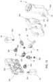
- FIGS. 8 and 9are perspective views of the actuator, adapter plate and mirror stay of FIG. 7 ;
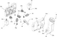
- FIG. 10is an exploded perspective view of the actuator, adapter plate and mirror stay
- FIG. 11is an exploded perspective view of a clutch gear subassembly of the actuator.
- FIG. 12is a sectional view of the clutch gear subassembly of FIG. 11 ;
- FIG. 13is a perspective view of the adapter plate attached to the actuator attached at a mounting plate of a mirror reflective element, shown with the mirror casing removed and the actuator not attached at the mirror stay;
- FIG. 14is an exploded view of the mirror stay and adapter plate of FIG. 13 ;
- FIG. 15is a perspective view of the actuator, adapter plate, mirror stay and mirror reflective element of FIG. 13 , with the actuator attached to the adapter plate and mirror stay and detached from the mounting plate of the mirror reflective element;
- FIG. 16is a plan view of the mirror stay, adapter plate, actuator and mirror reflective element of FIG. 15 , with the actuator attached at the mirror reflective element;
- FIGS. 17 and 18are perspective views of another mirror actuator, shown without a housing or cover portion and with a memory circuit feature;
- FIG. 19is a side elevation of the mirror actuator of FIGS. 17 and 18 ;
- FIG. 20is a perspective view of the mirror actuator of FIGS. 17 and 18 , showing additional details of the memory circuit;
- FIG. 20 Ais an enlarged view of the area A in FIG. 20 ;
- FIG. 21is an enlarged view similar to FIG. 20 A , showing a nominal position of the wiping element at the circuit pad;
- FIG. 22is another enlarged view, showing the wiping element when the mirror head is at a nominal position and at plus and minus 11 degrees from the nominal position.
- an interior rearview mirror assembly 10 for a vehicleincludes a casing 12 that houses a reflective element 14 ( FIG. 1 ).
- the mirror reflective element 14 and mirror casing or housing 12form the mirror head 16 .
- the mirror head 16is adjustably mounted to an interior portion of a vehicle (such as to an interior or in-cabin surface of a vehicle windshield or a headliner of a vehicle or the like) via a mounting structure or mounting configuration or assembly or stay 18 .
- the mirror head 16is adjustable relative to the mirror mount or stay 18 via an electrically powered actuator 20 , which is operable to adjust the mirror head to provide a desired or selected rearward view to the driver of the vehicle.
- the actuator 20comprises a body 22 that houses two motors 24 , 26 and gear elements that are rotatably driven by the motors, with the body 22 configured to attach at a mounting plate or back plate 30 ( FIGS. 13 , 15 and 16 ) at the rear of the mirror reflective element.
- the body 22 of the actuatorattaches to the mounting plate 30 such as via screws that engage screw holes 30 a of the mounting plate 30 .
- the mounting plate 30may comprise the backing plate of the mirror reflective element 14 or may comprise a separate mounting plate of the actuator, such that the mounting plate is attachable at the mirror head or backing plate to mount the actuator 20 and mounting plate 30 as a unit in the mirror head.
- the actuator 20comprises an attachment plate or element or adapter plate 32 for attaching at the lower part of the mirror stay 18 .
- the adapter plate 32pivotally attaches at a rear side or portion of the body 22 relative to the side or portion of the body 22 attached at the back plate 30 .
- the adapter plate 32pivotally attaches at the body 22 of the actuator and pivots relative to the body 22 .
- the adapter plate 32pivots relative to the body.
- the systemmay also be manually adjusted (i.e., the adapter plate can pivot relative to the body without use of one or both motors).
- the motors 24 , 26are housed within the housing or body 22 , which comprises a front housing portion 22 a and a rear housing portion 22 b that are attached together to encase the motors.
- the front housing portion 22 aprovides a front or forward wall of the housing (forward with respect to the forward direction of travel of the vehicle when the mirror assembly is mounted in the vehicle) and the rear housing portion 22 b provides a rear wall of the housing (rearward of the front housing portion with respect to the forward direction of travel of the vehicle when the mirror assembly is mounted in the vehicle) substantially parallel to the front wall of the housing.
- the motorswhen powered, rotatably drive respective output gears or worm gears 24 a , 26 a , which engage and rotatably drive a respective main gear 24 b , 26 b , which in turn engage and rotatably drive a respective clutch subassembly 34 , 36 .
- the worm gears 24 a , 26 a of the motors 24 , 26rotate about an axis parallel to the front and rear walls of the housing 22 .
- the main gears 24 b , 26 brotate about an axis perpendicular to the rotational axis of the worm gears and substantially perpendicular to the front and rear walls of the housing 22 .
- the clutch subassemblies 34 , 36rotate about different axes, where clutch subassembly 34 rotates about a vertical axis parallel to the front and rear walls of the housing and clutch subassembly 36 rotates about a horizontal axis parallel to the front and rear walls of the housing.
- the clutch subassemblies 34 , 36rotate about axes that are orthogonal to one another.
- the clutch subassemblies 34 , 36engage respective output arc gear elements 38 , 40 and, when one or both clutch subassemblies is rotatably driven (such as via rotation of the respective motor), the respective clutch subassembly imparts movement of the respective arc gear element 38 , 40 to pivot the mirror head relative to the mirror stay 18 .
- the arc gear elements 38 , 40protrude through respective apertures 23 a in the front housing portion 22 a and attach (such as via snap-attachment) at one end to the adapter plate 32 at the adapter plate attachment elements 32 a .
- the other ends of the arc gear elementsare received at arcuate receiving portions 23 b of the rear housing portion 22 b , whereby movement of the arc gear elements relative to the housing 22 pivots the adapter plate relative to the housing.
- the adapter plate 32comprises a pivot element 32 c (such as a socket element) that pivotally receives a pivot element 23 c to form part of a pivot joint at which the plate 32 is pivotally attached at the front housing portion 22 a .
- the arc gear elements 38 , 40protrude through respective apertures 23 a in the front housing portion 22 a and snap attach at the adapter plate 32 .
- movement of the arc gear elements 38 , 40 relative to the housing 22imparts pivotal movement of the actuator body or housing 22 relative to the adapter plate 32 , and thus pivots the mirror head 16 relative to the adapter plate 32 and the mirror stay 18 .
- Each arc gear element 38 , 40functions to pivot the mirror head about a respective axis at the pivot joint via the mirror head's connection to the housing 22 .
- movement of arc gear element 38 ( FIG. 6 ) relative to the actuatorpivots the mirror head about a generally vertical axis (with the mirror stay mounted at the vehicle) and movement of arc gear element 40 ( FIG. 5 ) pivots the mirror head about a generally horizontal axis.
- the mirror stay 18when the (mirror assembly) is mounted at the vehicle (e.g., via the mirror stay mounted at the windshield), the mirror stay 18 is oriented substantially vertical and movement of the actuator relative to the arc gear element 38 pivots the mirror head left and right (about a generally vertical axis) and movement of the actuator relative to the arc gear element 40 pivots or tilts the mirror head up and down.
- the arc gear element 40is biased toward the respective receiving portion 23 b , such as via a spring element 42 or other suitable biasing element.
- the spring counterbalanceassists the actuator in movement of the mirror head in the vertical direction of travel (about the horizontal axis), in order to decrease the required actuator torque.
- the actuatorWhen pivoting the mirror head in the vertical direction, the actuator must overcome the force of gravity, and the spring counterbalance reduces that external force. Conversely, when the actuator pivots the mirror head downward (and thus works against the biasing force of the spring element), the spring counter balance again reduces the external force of gravity (which could otherwise cause the mirror head to drop or pivot faster or a greater distance than intended). Because the actuator is not overworked (to overcome the force of gravity) when pivoting the mirror head upwards and is not over-driven (via the additional force of gravity) when pivoting the mirror head downward, movement of the actuator aided by the spring counter balance 42 is smoother, which serves to improve sound quality during operation of the actuator.
- the clutch subassembly 34 , 36comprises a drive shaft 35 a having a drive gear 35 b thereat, and a helical gear 35 c disposed on the drive shaft 35 a .
- a spring 35 d and crimp washer 35 eare disposed at the drive shaft and the spring 35 d urges or biases the helical gear 35 c toward and into engagement with a clutch interface surface 35 f at the drive shaft 35 a .
- the gear train(comprising the gears 24 a , 24 b and 26 a , 26 b ) engages and rotatably drives helical gear 35 c of the respective clutch subassembly, which in turn rotates drive gear 35 b engaging respective arc gear elements 38 , 40 to pivot the mirror head.
- torqueis provided to the drive shaft to a certain or sufficient degree or in a certain manner (such as when the driver of the vehicle manually adjusts the mirror head), the drive shaft 35 a will rotate relative to the helical gear 35 c along the primary axis.
- a drivermay manually adjust the mirror head, thereby causing movement of one or more arc gear elements as the driver manipulates the mirror head.
- the moving arc gear elementprovides torque at the respective drive gear 35 b , which in turn provides torque via the drive shaft to the helical gear 35 c . If the helical gear 35 c is resisted via the respective main gear 24 a , 24 b and motor 24 , 26 , the torque is felt at the drive shaft which, as described above, may rotate relative to the helical gear 35 c . Thus, if a user provides a force to manually adjust the mirror head (and thereby cause movement of one or more arc gear elements), the clutch subassembly may allow (via rotation of the drive shaft relative to the helical gear) movement of the arc gear and corresponding rotation of the drive gear with reduced or nonexistent movement of the motor.
- the spring 35 dprovides pressure between the helical gear 35 c and the drive shaft 35 a at the clutch interface surface 35 f .
- the clutch interface surface 35 fcomprises an angled surface (at an acute angle relative to the longitudinal axis of the drive shaft, such as an angle greater than about 30 degrees and less than about 60 degrees).
- the clutch interface surface 35 fis at a 45 degree angle relative to the longitudinal axis of the drive shaft.
- the 45 degree clutch interfaceprovides more surface area than a traditional flat plate clutch, thereby increasing the torque required to promote relative motion between the drive shaft 35 a and the helical gear 35 c over the torque that may be required if the clutch interface were not angled.
- the clutch assembly 34 , 36may also include a beveled gear 35 g non-rotatably attached or keyed to the drive shaft for engaging a corresponding beveled gear of a memory pod 44 that tracks the position of the mirror head.
- the memory pod or element 44 of the actuator 20is disposed at the rear housing portion 22 b and engages the beveled gear 35 g at the end of each of the clutch subassemblies.
- the memory podcomprises beveled gear elements 44 a that engage the respective clutch subassemblies 34 , 36 and that rotate when the drive shaft 35 a and beveled gear 35 g of the clutch assembly rotates.
- the X-Y axis memory podscan be made into a 1-piece system for direct connection to the gear train.
- the memory pod 44may comprise a single element that engages both the gear train of motor 24 moving arc gear element 38 and the gear train of motor 26 moving arc gear element 40 via respective beveled gear elements 44 a .
- the clutch subassemblymeshes with the respective arc gear element via the respective drive gear 35 b and is connected to the memory pod 44 via respective beveled gears 35 g . Because the memory pod 44 is rotated when the drive shaft 35 a of the clutch subassembly 34 is rotated, the memory pod will be engaged both when the motors of the actuator affect the mirror head and when the mirror head is adjusted manually relative to the mirror stay. This allows for manual driving of the mirror head (i.e., manual adjustment of the mirror head by the driver) relative to the mirror stay, while staying tied to the memory system.
- That position of the mirror headis electronically tracked via the memory pod and the driver may store that position in memory.
- the mirror headmay be moved manually or via actuation of the actuator to a different position or orientation.
- the actuatoris operable (such as automatically upon startup of the vehicle or via actuation of a user actuatable input in the vehicle) to adjust the mirror head to return the mirror head to the position stored in memory by operating one or both motors until the memory pod gears are at the position they were when the mirror head was previously in the stored position or orientation.
- the adapter plate 32is configured for attachment to the lower end of the mirror stay 18 and for receiving respective ends of the arc gear elements 38 , 40 at the adapter plate attachment elements 32 a .
- the adapter plate 32may snap attach at the mirror stay 18 via a snap attach element 32 b at the adapter plate 32 that corresponds to a snap attach element at the mirror stay 18 .
- the adapter platemay also be integrally formed with the mirror stay, but maintaining separate components for the mirror stay and the adapter plate allows for easier integration of the actuator to many mirror systems and vehicles (i.e., the adapter plate may be received at various different embodiments of mirror stays).
- the staymay be used to bias mirror default angle depending on the country of use resulting in the actuator being required to accommodate less horizontal angular travel.
- the actuatorcan be placed into many mirror combinations by using a common mounting pattern, such as the snap attach element 32 b at the adapter plate and a corresponding snap attach element at the given mirror stay.
- the adapter platemay be adapted to correspond to a given mirror stay while maintaining the configuration to the actuator 20 .
- the common or universal actuatorthus may be mounted to the selected mirror attachment plate/reflective element and the adapter plate may be mounted to the selected mirror stay via common attachment points or elements.
- the stay/mirror footcan be produced as a one-piece element in conjunction with actuator adapter plate, which serves to require fewer components.
- an actuator 120includes a circuit element 146 (such as a flexible circuit element or the like) that is disposed at the rear housing portion 122 b and that electrically connects to the motors 124 , 126 via connecting portions 146 a and that has a connecting end 146 b for electrical connection to a circuit board of the mirror head.
- the circuit board of the mirror headincludes control circuitry for controlling the motors 124 , 126 and for determining the position or orientation of the mirror head via the memory feature.
- the memory featureis provided via a memory wiper element 148 disposed at a side of each of the arc gear elements 138 , 140 engaging and moving along (as the arc gear elements move) respective carbon traces 150 at the contact pads or circuits 146 c , 146 d of the circuit element 146 .
- the contact pad 146 cis disposed along a side of the arc gear element 138 and the contact pad 146 d is disposed along a side of the arc gear element 140 .
- the wiper element 148is disposed at the side of the respective arc gear element and slidably engages the carbon traces 150 at the respective contact pad 146 c , 146 d of the circuit element as the respective arc gear element is moved via manual adjustment of the mirror head or electrical adjustment via actuation of the actuator.
- the wiper element 148may be positioned at a generally central region of the carbon traces 150 when the mirror head is at a nominal position, and, such as shown in FIG. 22 , the wiper element 148 may move upward or downward along the carbon traces to positions that are plus or minus about 11 degrees from the nominal position for that pivot axis (e.g., horizontal pivot axis or vertical pivot axis).
- the horizontal and vertical travel motors 124 , 126are connected to the memory system using the semi-flex PCB routing provided by the flexible circuit element 146 , and the electrical output from the circuit is provided to outside of the actuator via the connecting end 146 b .
- the memory systemcomprises “memory wipers,” which may comprise sheet metal spring fingers that are attached to the arc gear elements or output gears and that touch against carbon traces 150 on the memory boards 146 c , 146 d , changing their resistance values as they move along the carbon traces.
- the wipersslide along the arc shaped carbon pads on the circuit element and change the resistance through the circuit (and the resistance is determined or measured via a potentiometer).
- a given resistance measured through the circuitmay correspond to a given location or rotation of the respective arc gear elements and the system may be able to determine the orientation of the mirror head.
- the memory systemincluding the wipers and conductive traces, may utilize aspects of the memory functions described in U.S. provisional applications, Ser. No. 63/201,112, filed Apr. 13, 2021, and/or Ser. No. 63/198,589, filed Oct. 29, 2020, which are hereby incorporated herein by reference in their entireties.
- the wiper elements 148will slide along the respective carbon traces 150 and that movement is electronically tracked so that the system knows the position of the respective arc gear element 138 , 140 relative to the actuator housing at any time.
- the drivermay store that position in memory. After the memory position is stored, the mirror head may be moved manually or via actuation of the actuator to a different position or orientation.
- the actuatoris operable (such as automatically upon initial ignition on or vehicle startup or via actuation of a user actuatable input in the vehicle or responsive to a signal from or associated with a passive entry system of the vehicle that is indicative of the vehicle user approaching the vehicle or unlocking the vehicle door or opening the vehicle door to enter the vehicle) to adjust the mirror head to return the mirror head to the position stored in memory by operating one or both motors until the wiper elements are at the position they were when the mirror head was previously in the stored position or orientation.
- the memory function of the actuatormay position the mirror head at a preselected orientation responsive to determination of a particular driver of the vehicle (or responsive to a user input, such as similar to a memory seat setting and feature).
- the mirror assemblymay include an in-cabin viewing camera that views and captures image data of a driver's head region, such as for or as part of a driver monitoring system of the vehicle. The system may recognize the identity of the driver and operate the actuator to position the mirror head at the preselected orientation saved in memory for that driver.
- the actuator or systemmay physically calibrate or optimize or adjust the mirror head position (and thus the mirror reflection that the driver would see at the mirror reflective element) relative to the driver's specific eye points and/or other identified features of the driver and/or interior of the vehicle within the field of view of the in-cabin viewing camera.
- the driver monitoring camera's field of viewwould also be optimized by such positioning of the driver's face/head in a common zone within the camera's imager.
- the camerawould be fixed to the mirror head (thus when the mirror angle is adjusted, so is the camera), and the algorithm would detect the position of the driver's face in the image data captured by the camera and then, based on that position information, the controller or ECU could drive the memory actuator to a new position with feedback from the memory system in the actuator.
- the drivermay manually position the mirror head to a position that provides an optimized mirror reflection for the driver's rearward view, at which point the camera detects the position of the driver's face and/or eye points relative to the camera's field of view and stores that information in the memory system.
- the mirror headmay also be pivoted automatically based on a preset algorithm that, via processing of image data captured by the in-cabin viewing camera, determines a relationship between the mirror head and the driver and/or interior feature of the vehicle and operates the actuator to provide a position of the mirror head that corresponds to a preset relationship based on the algorithm (for example, a preset angle and distance of the mirror head relative to the driver of the vehicle or a preset orientation that positions the driver's head or an interior feature at a preset or previously saved position in the camera's field of view).
- a preset algorithmfor example, a preset angle and distance of the mirror head relative to the driver of the vehicle or a preset orientation that positions the driver's head or an interior feature at a preset or previously saved position in the camera's field of view.
- the systemmay determine an identity of the driver and store the manually selected or automatically calibrated or adjusted position of the mirror head for the determined identity of the driver. Then, to later reposition the mirror head at a position specific to the driver of the vehicle, the actuator may pivot the mirror head to match the relative face position and/or eye points relative to the camera field of view that is stored in memory.
- the actuatormay also be programmed to pivot the mirror head to provide an optimized point of view for the driver based on preset measurement points (such as distance and angle of the mirror reflective element from the driver's eyes).
- the systemis capable of providing a memory position function that, via processing of image data captured by the driver viewing camera, matches the driver of the vehicle to an identity stored in memory and actuates the motors of the actuator to pivot the mirror head to a particular orientation for setting the desired rearward view of the identified driver.
- the particular orientation of the mirror head for setting the rearward view for the identified drivermay be manually selected and preset by the particular driver of the vehicle (such as during an initial drive of the vehicle), so that later the memory position function can adjust the actuator and mirror head until a particular feature is at a preselected location within the image data captured by the camera.
- the memory position functionmay determine when a particular feature is at the preselected location, such as based on eye points or the position of the drivers face within the captured image data, or such as based on location of a fixed element in the vehicle (e.g., such as a seat headrest or rear window or rear door of the vehicle) within the captured image data.
- the actuatorcan be electrically controlled by integrating with the vehicle Local Interconnect Network (LIN) bus system. This allows a simple three wire connection to the mirror head or to the circuit board in the mirror head. All of the motor driving electronics and the memory functionality can be located directly in the mirror head, instead of requiring it to be controlled by the vehicle.
- LINvehicle Local Interconnect Network
- the mirror headmay be electrically connected to the vehicle wire harness via various suitable means.
- the main vehicle wire harnessmay plug into a connector at the mirror printed circuit board (PCB), and a jumper wire harness may electrically connect the mirror PCB to the actuator.
- the main vehicle wire harnessmay plug into a connector at the mirror PCB, and the actuator may have direct connection to the mirror PCB, with the actuator being electrically connected to the mirror PCB when the actuator is assembled to the mirror back plate.
- the main vehicle wire harnessmay split into two connections, with one connector electrically connecting to the actuator and the other connector electrically connecting to the mirror PCB.
- the interior mirror assemblymay comprise a dual-mode interior rearview video mirror that can switch from a traditional reflection mode to a live-video display mode, such as is by utilizing aspects of the mirror assemblies and systems described in U.S. Pat. Nos. 10,442,360; 10,421,404; 10,166,924; 10,046,706 and/or 10,029,614, and/or U.S. Publication Nos. US-2020-0377022; US-2019-0258131; US-2019-0146297; US-2019-0118717; US-2019-0047475 and/or US-2017-0355312, and/or U.S. patent application Ser. No. 17/301,853, filed Apr. 16, 2021, now U.S. Pat. No.
- the mirror headmay be tiltable or pivotable between a mirror mode orientation, where the reflective element is positioned to provide the desired driver's rearward field of view, and a display mode orientation, where the mirror head is tilted upward or downward relative to the mirror mode orientation, such that the display is viewable by the driver while the reflective element reflects light from rearward of the vehicle and incident thereon upward or downward away from the driver's eyes.
- the mirror headmay be tiltable or pivotable between the mirror mode orientation and the display mode orientation via the actuator that is electrically powered to impart the pivotal movement, or via manually flipping of the mirror head about a generally horizontal pivot axis.
- the mirror assemblythus may provide a display system that can display video images across the entire reflective surface of an interior rearview mirror assembly.
- the display systemmay include a display device disposed at an upper region of the vehicle's interior cabin (or other location), such that, when the mirror head is tilted or angled or otherwise mechanically adjusted, the mirror reflective element reflects the displayed image across the entire reflective surface for viewing by the driver of the vehicle.
- the display systemmay include a video display screen disposed in the mirror head and viewable (when activated) through the reflective element.
- the drivercan view the rearward field of view provided by the reflective element, but when the mirror head is tilted or adjusted (to the “display mode”), the displayed video images (such as derived from image data captured by a rearward viewing camera) are viewable by the driver of the vehicle, with the tilting of the mirror head causing the primary reflection off of the reflective element to be out of the driver's eyes (since it would be aimed up toward the headliner or down into the cabin area instead of out the rear window).
- the displayed video imagessuch as derived from image data captured by a rearward viewing camera
- the mirror systemincludes the electronically operable actuator that is operable to adjust or pivot the mirror head between the mirror mode orientation and the display mode orientation.
- the mirror actuatormay move the mirror head to the display mode orientation responsive to a user input or responsive to the driver shifting the vehicle into a reverse gear, whereby a rear backup camera is actuated and the display displays video images derived from image data captured by the rear backup camera.
- the actuatormay comprise a micro gearhead motor so as to provide a reduced profile or smaller package size of the actuator, such as by utilizing aspects of the reduced profile actuator described in U.S. Publication No. US-2018-0251069, which is hereby incorporated herein by reference in its entirety.
- the display screenpreferably displays the captured video images at the entire viewable portion of the display screen, in order to provide relatively large displayed images for viewing by the driver of the vehicle while the driver is normally operating the vehicle.
- the user inputsare touch or proximity sensors disposed at a portion of the display screen.
- the video display screenwhen normally operating to display video images captured by the camera, may display the video images over the entire display portion or active portion of the display screen and, responsive to a user input (such as a user or driver touching a portion of the display screen or touch screen), may display icons or indicia at a portion of the display screen to indicate where the user can touch to actuate or control the display settings or the like.
- the user inputs or touch sensorsmay comprise any suitable sensors or inputs, and may utilize aspects of the inputs and sensors described in U.S. Pat. Nos. 9,827,913; 9,598,016; 9,346,403; 8,730,553; 8,508,831; 8,154,418; 7,255,451; 7,253,723 and/or 7,224,324, which are hereby incorporated herein by reference in their entireties.
- the displaymay utilize aspects of the displays of the types disclosed in U.S. Pat. Nos. 5,530,240 and/or 6,329,925, which are hereby incorporated herein by reference in their entireties, and/or of display-on-demand or transflective type displays, such as the types disclosed in U.S. Pat. Nos. 7,855,755; 7,777,611; 7,626,749; 7,581,859; 7,446,924; 7,446,650; 7,370,983; 7,338,177; 7,274,501; 7,255,451; 7,195,381; 7,184,190; 6,690,268; 5,668,663 and/or 5,724,187, and/or in U.S. Publication No. US-2006-0050018, which are all hereby incorporated herein by reference in their entireties.
- the displaymay be viewable through the reflective element when the display is activated to display information.
Landscapes
- Engineering & Computer Science (AREA)
- Multimedia (AREA)
- Mechanical Engineering (AREA)
- Rear-View Mirror Devices That Are Mounted On The Exterior Of The Vehicle (AREA)
Abstract
Description
Claims (25)
Priority Applications (2)
| Application Number | Priority Date | Filing Date | Title |
|---|---|---|---|
| US17/301,898US12145507B2 (en) | 2020-04-20 | 2021-04-19 | Interior rearview mirror assembly with actuator |
| US18/950,393US20250074310A1 (en) | 2020-04-20 | 2024-11-18 | Interior rearview mirror assembly with actuator |
Applications Claiming Priority (3)
| Application Number | Priority Date | Filing Date | Title |
|---|---|---|---|
| US202063012448P | 2020-04-20 | 2020-04-20 | |
| US202063198589P | 2020-10-29 | 2020-10-29 | |
| US17/301,898US12145507B2 (en) | 2020-04-20 | 2021-04-19 | Interior rearview mirror assembly with actuator |
Related Child Applications (1)
| Application Number | Title | Priority Date | Filing Date |
|---|---|---|---|
| US18/950,393ContinuationUS20250074310A1 (en) | 2020-04-20 | 2024-11-18 | Interior rearview mirror assembly with actuator |
Publications (2)
| Publication Number | Publication Date |
|---|---|
| US20210323477A1 US20210323477A1 (en) | 2021-10-21 |
| US12145507B2true US12145507B2 (en) | 2024-11-19 |
Family
ID=78082536
Family Applications (2)
| Application Number | Title | Priority Date | Filing Date |
|---|---|---|---|
| US17/301,898Active2043-01-11US12145507B2 (en) | 2020-04-20 | 2021-04-19 | Interior rearview mirror assembly with actuator |
| US18/950,393PendingUS20250074310A1 (en) | 2020-04-20 | 2024-11-18 | Interior rearview mirror assembly with actuator |
Family Applications After (1)
| Application Number | Title | Priority Date | Filing Date |
|---|---|---|---|
| US18/950,393PendingUS20250074310A1 (en) | 2020-04-20 | 2024-11-18 | Interior rearview mirror assembly with actuator |
Country Status (1)
| Country | Link |
|---|---|
| US (2) | US12145507B2 (en) |
Families Citing this family (6)
| Publication number | Priority date | Publication date | Assignee | Title |
|---|---|---|---|---|
| NL2018400B1 (en)* | 2017-02-21 | 2018-09-17 | Mci Mirror Controls Int Netherlands B V | Adjustment instrument and method |
| US11845383B2 (en) | 2021-04-13 | 2023-12-19 | Magna Mirrors Of America, Inc. | Exterior rearview mirror with power extending mechanism |
| EP4354897A1 (en)* | 2022-10-14 | 2024-04-17 | Harman International Industries, Inc. | Microphone arrangement |
| US12393089B2 (en) | 2022-11-17 | 2025-08-19 | Magna Mirrors Of America, Inc. | Vehicular driver monitoring system with camera and light emitter in interior rearview mirror |
| US12342106B2 (en) | 2023-01-01 | 2025-06-24 | Magna Mirrors Of America, Inc. | Vehicular driver monitoring system |
| US12386148B1 (en)* | 2023-09-20 | 2025-08-12 | Lg Electronics Inc. | Mirror assembly |
Citations (93)
| Publication number | Priority date | Publication date | Assignee | Title |
|---|---|---|---|---|
| US2263382A (en) | 1939-06-19 | 1941-11-18 | Gotzinger George | Mirror signal |
| US2580014A (en) | 1949-09-13 | 1951-12-25 | Gazda Antoine | Combined rearview mirror and direction indicating device |
| US3266016A (en) | 1964-08-06 | 1966-08-09 | Maru Sho | Outside signal for automobiles |
| US4499451A (en) | 1981-04-07 | 1985-02-12 | Nippondenso Co., Ltd. | Mirror |
| US4588267A (en) | 1984-01-18 | 1986-05-13 | Ronald Pastore | Combination rear view mirror and digital clock |
| US4623222A (en) | 1983-11-14 | 1986-11-18 | Nippondenso Co., Ltd. | Liquid crystal type dazzle-free transmissive-reflective mirror |
| US4630904A (en) | 1985-01-22 | 1986-12-23 | Ronald Pastore | Combination rear view mirror and digital displays |
| JPS6275619A (en) | 1985-09-30 | 1987-04-07 | Nifco Inc | Glare-proof mirror |
| US4721364A (en) | 1983-12-29 | 1988-01-26 | Nippondenso Co., Ltd. | Dazzle-free mirror with photocell in a non-dazzle-free portion |
| EP0356099A2 (en) | 1988-08-17 | 1990-02-28 | Nikon Corporation | Electrochromic device |
| US4906085A (en) | 1986-06-30 | 1990-03-06 | Kabushiki Kaisha Tokai Rika Denki Seisakusho | Sideview mirror assembly with regulating filter using sunlight for automobiles |
| US5313335A (en) | 1992-06-05 | 1994-05-17 | Delco Electronics Corporation | Blindzone signal indicator |
| US5355284A (en) | 1990-02-20 | 1994-10-11 | K. W. Muth Company, Inc. | Mirror assembly |
| US5436741A (en) | 1993-12-28 | 1995-07-25 | Harman Automotive, Inc. | Holographic signaling mirror |
| US5477390A (en)* | 1993-08-16 | 1995-12-19 | Lowell Engineering Corp. | Mirror assembly powered into rearwardly folded position against reversing spring bias |
| US5481409A (en) | 1990-02-20 | 1996-01-02 | K. W. Muth Company, Inc. | Mirror assembly |
| US5530240A (en) | 1992-12-15 | 1996-06-25 | Donnelly Corporation | Display for automatic rearview mirror |
| US5575552A (en) | 1994-12-09 | 1996-11-19 | United Technologies Automotive Systems, Inc. | Lighted mirror apparatus |
| US5587699A (en) | 1994-11-03 | 1996-12-24 | United Technologies Automotive Systems Inc. | Exterior mirror with information display |
| US5668663A (en) | 1994-05-05 | 1997-09-16 | Donnelly Corporation | Electrochromic mirrors and devices |
| US5786772A (en) | 1996-03-22 | 1998-07-28 | Donnelly Corporation | Vehicle blind spot detection display system |
| US5788357A (en) | 1996-08-28 | 1998-08-04 | K. W. Muth Company, Inc. | Mirror assembly |
| US5938166A (en) | 1996-10-29 | 1999-08-17 | Lang-Mekra North America, Inc. | Vehicle rear view mirror coupling assembly |
| US5938320A (en) | 1997-03-19 | 1999-08-17 | Harman Automotive, Inc. | Enhanced illuminated polymeric indicator employed in a mirror housing of an automotive vehicle |
| US5956181A (en) | 1997-07-18 | 1999-09-21 | Lin; William | Two way mirror with dual functions of rear view mirror and video displayer |
| US6005724A (en) | 1998-10-05 | 1999-12-21 | K. W. Muth Company, Inc. | Mirror coating, mirror utilizing same, and a mirror assembly |
| US6045243A (en) | 1996-08-28 | 2000-04-04 | K.W. Muth Company, Inc. | Mirror assembly |
| US6111683A (en) | 1997-04-02 | 2000-08-29 | Gentex Corporation | Electrochromic mirrors having a signal light |
| US6257746B1 (en) | 1998-11-03 | 2001-07-10 | K. W. Muth Company, Inc. | Signalling assembly |
| US6264353B1 (en) | 1998-11-23 | 2001-07-24 | Lear Automotive Dearborn, Inc. | Exterior mirror with supplement turn signal |
| US6329925B1 (en) | 1999-11-24 | 2001-12-11 | Donnelly Corporation | Rearview mirror assembly with added feature modular display |
| EP1176056A2 (en) | 2000-07-28 | 2002-01-30 | MEKRA Lang GmbH & Co. KG | Rear view mirror, in particular for utility vehicles, with camera and monitor |
| US6356376B1 (en) | 1997-04-02 | 2002-03-12 | Gentex Corporation | Electrochromic rearview mirror incorporating a third surface metal reflector and a display/signal light |
| JP2002120649A (en) | 2000-08-07 | 2002-04-23 | Ichikoh Ind Ltd | Room mirror with built-in monitor |
| US6428172B1 (en) | 1999-11-24 | 2002-08-06 | Donnelly Corporation | Rearview mirror assembly with utility functions |
| WO2003084780A2 (en) | 2002-04-03 | 2003-10-16 | Gentex Corporation | Electrochromic rearview mirror assembly incorporating a display/signal light |
| US6690268B2 (en) | 2000-03-02 | 2004-02-10 | Donnelly Corporation | Video mirror systems incorporating an accessory module |
| WO2004012963A1 (en) | 2002-08-06 | 2004-02-12 | Meihua Mediaview Technologies (Shenzhen) Co.Ltd. | Two-purpose mirror for transmission and reflection |
| WO2004098953A2 (en) | 2003-05-06 | 2004-11-18 | Gentex Corporation | Vehicular rearview mirror elements and assemblies incorporating these elements |
| US20060050018A1 (en) | 2002-12-20 | 2006-03-09 | Hutzel Barry W | Accessory system for vehicle |
| US7184190B2 (en) | 2002-09-20 | 2007-02-27 | Donnelly Corporation | Electro-optic reflective element assembly |
| US7195381B2 (en) | 2001-01-23 | 2007-03-27 | Donnelly Corporation | Vehicle interior LED lighting system |
| US7224324B2 (en) | 2000-03-27 | 2007-05-29 | Donnelly Corporation | Interactive automotive rearvision system |
| US7253723B2 (en) | 2003-05-19 | 2007-08-07 | Donnelly Corporation | Mirror assembly |
| US7255451B2 (en) | 2002-09-20 | 2007-08-14 | Donnelly Corporation | Electro-optic mirror cell |
| US7274501B2 (en) | 2002-09-20 | 2007-09-25 | Donnelly Corporation | Mirror reflective element assembly |
| US20080049344A1 (en)* | 2006-08-23 | 2008-02-28 | Donnelly Corporation | Vehicle interior rearview mirror assembly with actuator |
| US7338177B2 (en) | 2003-11-26 | 2008-03-04 | Donnelly Corporation | Mirror reflective element for a vehicle |
| US20080073477A1 (en) | 2001-12-21 | 2008-03-27 | Heinrich Lang | Linkage arrangement for the adjustment of rearview mirrors |
| US7370983B2 (en) | 2000-03-02 | 2008-05-13 | Donnelly Corporation | Interior mirror assembly with display |
| US7446924B2 (en) | 2003-10-02 | 2008-11-04 | Donnelly Corporation | Mirror reflective element assembly including electronic component |
| US7581859B2 (en) | 2005-09-14 | 2009-09-01 | Donnelly Corp. | Display device for exterior rearview mirror |
| US7626749B2 (en) | 2005-05-16 | 2009-12-01 | Donnelly Corporation | Vehicle mirror assembly with indicia at reflective element |
| JP2010143250A (en) | 2008-12-16 | 2010-07-01 | Nissan Motor Co Ltd | Rear view recognizing apparatus |
| JP2010163104A (en) | 2009-01-16 | 2010-07-29 | Denso Corp | Vehicular display apparatus and vehicular peripheral visual field display system having the same |
| US7777611B2 (en) | 2006-11-06 | 2010-08-17 | Donnelly Corporation | Display device for exterior rearview mirror |
| US7855755B2 (en) | 2005-11-01 | 2010-12-21 | Donnelly Corporation | Interior rearview mirror assembly with display |
| US20120038964A1 (en) | 2009-04-23 | 2012-02-16 | Magna Mirrors Of America, Inc. | Mirror assembly for vehicle |
| US8154418B2 (en) | 2008-03-31 | 2012-04-10 | Magna Mirrors Of America, Inc. | Interior rearview mirror system |
| US20120236388A1 (en) | 2009-04-23 | 2012-09-20 | Magna Mirrors Of America, Inc. | Frameless interior rearview mirror assembly |
| US20140022390A1 (en) | 2010-10-15 | 2014-01-23 | Magna Mirrors Of America, Inc. | Interior rearview mirror assembly |
| US20140097320A1 (en) | 2012-10-04 | 2014-04-10 | Gentex Corporation | Rearview mounting device |
| US20140268355A1 (en) | 2013-03-15 | 2014-09-18 | Gentex Corporation | Display mirror assembly |
| US20140285666A1 (en) | 2011-11-01 | 2014-09-25 | Magna Mirrors Of America, Inc. | Vision system with door mounted exterior mirror and display |
| US20140293169A1 (en) | 2009-10-07 | 2014-10-02 | Magna Mirrors Of America, Inc. | Rearview mirror assembly |
| EP2789505A1 (en) | 2011-12-09 | 2014-10-15 | Nissan Motor Company, Limited | Video display mirror and video display mirror system |
| US20150085337A1 (en) | 2013-09-24 | 2015-03-26 | Gentex Corporation | Display mirror assembly |
| US20150097955A1 (en) | 2010-02-10 | 2015-04-09 | Magna Mirrors Of America, Inc. | Exterior rearview mirror assembly |
| US20160082890A1 (en) | 2010-02-04 | 2016-03-24 | Magna Mirrors Of America, Inc. | Interior rearview mirror system for vehicle |
| US20160129842A1 (en) | 2014-11-07 | 2016-05-12 | Gentex Corporation | Full display mirror actuator |
| US20160250972A1 (en) | 2015-02-27 | 2016-09-01 | Gentex Corporation | Full display mirror with rack-and-pinion actuator |
| US20160250974A1 (en) | 2015-02-27 | 2016-09-01 | Gentex Corporation | Full display mirror with worm gear driven toggle mechanism |
| US20160250970A1 (en) | 2015-02-27 | 2016-09-01 | Gentex Corporation | Full display mirror actuator with linkage arm |
| US20160275833A1 (en) | 2015-03-18 | 2016-09-22 | John Bruce Forbes | Dynamic content analysis and engagement system for shared displays |
| US20160341963A1 (en) | 2015-05-18 | 2016-11-24 | Gentex Corporation | Full display rearview device |
| US20170088055A1 (en) | 2015-09-30 | 2017-03-30 | Gentex Corporation | Full display mirror |
| US20170297498A1 (en) | 2015-06-26 | 2017-10-19 | Magna Mirrors Of America, Inc. | Interior rearview mirror assembly with full screen video display |
| WO2017191558A1 (en) | 2016-05-02 | 2017-11-09 | Magna Mirrors Of America, Inc. | Caseless rearview mirror assembly |
| US20170327044A1 (en) | 2016-05-11 | 2017-11-16 | Magna Mirrors Of America, Inc. | Vehicle vision system with display by a mirror |
| US20170355312A1 (en) | 2016-06-08 | 2017-12-14 | Magna Mirrors Of America, Inc. | Interior rearview mirror assembly with full screen video display |
| US20180134217A1 (en) | 2015-05-06 | 2018-05-17 | Magna Mirrors Of America, Inc. | Vehicle vision system with blind zone display and alert system |
| US10029614B2 (en) | 2015-11-17 | 2018-07-24 | Magna Mirrors Of America, Inc. | Interior rearview mirror assembly |
| US10046706B2 (en) | 2015-06-26 | 2018-08-14 | Magna Mirrors Of America, Inc. | Interior rearview mirror assembly with full screen video display |
| US20180244204A1 (en) | 2017-02-28 | 2018-08-30 | Gentex Corporation | Auto switching of display mirror assembly |
| US20180251069A1 (en)* | 2017-03-02 | 2018-09-06 | Magna Mirrors Of America, Inc. | Interior rearview mirror assembly with display and tilt mechanism |
| US20190047475A1 (en) | 2014-05-15 | 2019-02-14 | Magna Mirrors Of America, Inc. | Interior rearview mirror assembly with low profile mirror |
| US20190118717A1 (en) | 2017-10-25 | 2019-04-25 | Magna Mirrors Of America, Inc. | Full mirror display utilizing a trailer camera |
| US20190381938A1 (en)* | 2018-06-18 | 2019-12-19 | Gentex Corporation | Rearview mirror assembly having automatic adjustment responsive to eye-tracking |
| US11214199B2 (en) | 2019-06-03 | 2022-01-04 | Magna Mirrors Of America, Inc. | Interior rearview mirror assembly with display and tilt mechanism |
| US11465561B2 (en) | 2020-04-17 | 2022-10-11 | Magna Mirrors Of America, Inc. | Interior rearview mirror assembly with driver monitoring system |
| US20220324384A1 (en) | 2021-04-13 | 2022-10-13 | Magna Mirrors of America,Inc. | Exterior rearview mirror with power extending mechanism |
| US11498494B2 (en) | 2019-11-27 | 2022-11-15 | Magna Electronics Inc. | Vehicular camera monitoring system |
| US11505123B2 (en) | 2019-12-02 | 2022-11-22 | Magna Electronics Inc. | Vehicular camera monitoring system with stereographic display |
- 2021
- 2021-04-19USUS17/301,898patent/US12145507B2/enactiveActive
- 2024
- 2024-11-18USUS18/950,393patent/US20250074310A1/enactivePending
Patent Citations (114)
| Publication number | Priority date | Publication date | Assignee | Title |
|---|---|---|---|---|
| US2263382A (en) | 1939-06-19 | 1941-11-18 | Gotzinger George | Mirror signal |
| US2580014A (en) | 1949-09-13 | 1951-12-25 | Gazda Antoine | Combined rearview mirror and direction indicating device |
| US3266016A (en) | 1964-08-06 | 1966-08-09 | Maru Sho | Outside signal for automobiles |
| US4499451A (en) | 1981-04-07 | 1985-02-12 | Nippondenso Co., Ltd. | Mirror |
| US4623222A (en) | 1983-11-14 | 1986-11-18 | Nippondenso Co., Ltd. | Liquid crystal type dazzle-free transmissive-reflective mirror |
| US4721364A (en) | 1983-12-29 | 1988-01-26 | Nippondenso Co., Ltd. | Dazzle-free mirror with photocell in a non-dazzle-free portion |
| US4588267A (en) | 1984-01-18 | 1986-05-13 | Ronald Pastore | Combination rear view mirror and digital clock |
| US4630904A (en) | 1985-01-22 | 1986-12-23 | Ronald Pastore | Combination rear view mirror and digital displays |
| JPS6275619A (en) | 1985-09-30 | 1987-04-07 | Nifco Inc | Glare-proof mirror |
| US4906085A (en) | 1986-06-30 | 1990-03-06 | Kabushiki Kaisha Tokai Rika Denki Seisakusho | Sideview mirror assembly with regulating filter using sunlight for automobiles |
| EP0356099A2 (en) | 1988-08-17 | 1990-02-28 | Nikon Corporation | Electrochromic device |
| US5355284A (en) | 1990-02-20 | 1994-10-11 | K. W. Muth Company, Inc. | Mirror assembly |
| US5481409A (en) | 1990-02-20 | 1996-01-02 | K. W. Muth Company, Inc. | Mirror assembly |
| US5313335A (en) | 1992-06-05 | 1994-05-17 | Delco Electronics Corporation | Blindzone signal indicator |
| US5530240A (en) | 1992-12-15 | 1996-06-25 | Donnelly Corporation | Display for automatic rearview mirror |
| US5477390A (en)* | 1993-08-16 | 1995-12-19 | Lowell Engineering Corp. | Mirror assembly powered into rearwardly folded position against reversing spring bias |
| US5436741A (en) | 1993-12-28 | 1995-07-25 | Harman Automotive, Inc. | Holographic signaling mirror |
| US5668663A (en) | 1994-05-05 | 1997-09-16 | Donnelly Corporation | Electrochromic mirrors and devices |
| US5724187A (en) | 1994-05-05 | 1998-03-03 | Donnelly Corporation | Electrochromic mirrors and devices |
| US5587699A (en) | 1994-11-03 | 1996-12-24 | United Technologies Automotive Systems Inc. | Exterior mirror with information display |
| US5575552A (en) | 1994-12-09 | 1996-11-19 | United Technologies Automotive Systems, Inc. | Lighted mirror apparatus |
| US5786772A (en) | 1996-03-22 | 1998-07-28 | Donnelly Corporation | Vehicle blind spot detection display system |
| US6045243A (en) | 1996-08-28 | 2000-04-04 | K.W. Muth Company, Inc. | Mirror assembly |
| US5788357A (en) | 1996-08-28 | 1998-08-04 | K. W. Muth Company, Inc. | Mirror assembly |
| US5938166A (en) | 1996-10-29 | 1999-08-17 | Lang-Mekra North America, Inc. | Vehicle rear view mirror coupling assembly |
| US5938320A (en) | 1997-03-19 | 1999-08-17 | Harman Automotive, Inc. | Enhanced illuminated polymeric indicator employed in a mirror housing of an automotive vehicle |
| US6111683A (en) | 1997-04-02 | 2000-08-29 | Gentex Corporation | Electrochromic mirrors having a signal light |
| US6700692B2 (en) | 1997-04-02 | 2004-03-02 | Gentex Corporation | Electrochromic rearview mirror assembly incorporating a display/signal light |
| US6356376B1 (en) | 1997-04-02 | 2002-03-12 | Gentex Corporation | Electrochromic rearview mirror incorporating a third surface metal reflector and a display/signal light |
| US6512624B2 (en) | 1997-04-02 | 2003-01-28 | Gentex Corporation | Electrochromic rearview mirror incorporating a third surface partially transmissive reflector |
| US5956181A (en) | 1997-07-18 | 1999-09-21 | Lin; William | Two way mirror with dual functions of rear view mirror and video displayer |
| US7446650B2 (en) | 1998-01-07 | 2008-11-04 | Donnelly Corporation | Accessory system suitable for use in a vehicle |
| US6005724A (en) | 1998-10-05 | 1999-12-21 | K. W. Muth Company, Inc. | Mirror coating, mirror utilizing same, and a mirror assembly |
| US6257746B1 (en) | 1998-11-03 | 2001-07-10 | K. W. Muth Company, Inc. | Signalling assembly |
| US6264353B1 (en) | 1998-11-23 | 2001-07-24 | Lear Automotive Dearborn, Inc. | Exterior mirror with supplement turn signal |
| US6329925B1 (en) | 1999-11-24 | 2001-12-11 | Donnelly Corporation | Rearview mirror assembly with added feature modular display |
| US7488080B2 (en) | 1999-11-24 | 2009-02-10 | Donnelly Corporation | Information display system for a vehicle |
| US6428172B1 (en) | 1999-11-24 | 2002-08-06 | Donnelly Corporation | Rearview mirror assembly with utility functions |
| US7370983B2 (en) | 2000-03-02 | 2008-05-13 | Donnelly Corporation | Interior mirror assembly with display |
| US6690268B2 (en) | 2000-03-02 | 2004-02-10 | Donnelly Corporation | Video mirror systems incorporating an accessory module |
| US7224324B2 (en) | 2000-03-27 | 2007-05-29 | Donnelly Corporation | Interactive automotive rearvision system |
| EP1176056A2 (en) | 2000-07-28 | 2002-01-30 | MEKRA Lang GmbH & Co. KG | Rear view mirror, in particular for utility vehicles, with camera and monitor |
| US6642840B2 (en) | 2000-07-28 | 2003-11-04 | Lang-Mekra North Amicica, Llc | Rearview mirror assembly with monitor |
| JP2002120649A (en) | 2000-08-07 | 2002-04-23 | Ichikoh Ind Ltd | Room mirror with built-in monitor |
| US7195381B2 (en) | 2001-01-23 | 2007-03-27 | Donnelly Corporation | Vehicle interior LED lighting system |
| US20080073477A1 (en) | 2001-12-21 | 2008-03-27 | Heinrich Lang | Linkage arrangement for the adjustment of rearview mirrors |
| WO2003084780A2 (en) | 2002-04-03 | 2003-10-16 | Gentex Corporation | Electrochromic rearview mirror assembly incorporating a display/signal light |
| US20040027694A1 (en) | 2002-08-06 | 2004-02-12 | Mediaview Technologies Corporation | Adjustable segmented dual function mirror with video display |
| US20040027695A1 (en) | 2002-08-06 | 2004-02-12 | William Lin | Adjustable dual function mirror with video display |
| WO2004012963A1 (en) | 2002-08-06 | 2004-02-12 | Meihua Mediaview Technologies (Shenzhen) Co.Ltd. | Two-purpose mirror for transmission and reflection |
| US7184190B2 (en) | 2002-09-20 | 2007-02-27 | Donnelly Corporation | Electro-optic reflective element assembly |
| US7255451B2 (en) | 2002-09-20 | 2007-08-14 | Donnelly Corporation | Electro-optic mirror cell |
| US7274501B2 (en) | 2002-09-20 | 2007-09-25 | Donnelly Corporation | Mirror reflective element assembly |
| US20060050018A1 (en) | 2002-12-20 | 2006-03-09 | Hutzel Barry W | Accessory system for vehicle |
| WO2004098953A2 (en) | 2003-05-06 | 2004-11-18 | Gentex Corporation | Vehicular rearview mirror elements and assemblies incorporating these elements |
| US7253723B2 (en) | 2003-05-19 | 2007-08-07 | Donnelly Corporation | Mirror assembly |
| US7446924B2 (en) | 2003-10-02 | 2008-11-04 | Donnelly Corporation | Mirror reflective element assembly including electronic component |
| US7338177B2 (en) | 2003-11-26 | 2008-03-04 | Donnelly Corporation | Mirror reflective element for a vehicle |
| US7626749B2 (en) | 2005-05-16 | 2009-12-01 | Donnelly Corporation | Vehicle mirror assembly with indicia at reflective element |
| US7581859B2 (en) | 2005-09-14 | 2009-09-01 | Donnelly Corp. | Display device for exterior rearview mirror |
| US7855755B2 (en) | 2005-11-01 | 2010-12-21 | Donnelly Corporation | Interior rearview mirror assembly with display |
| US20080049344A1 (en)* | 2006-08-23 | 2008-02-28 | Donnelly Corporation | Vehicle interior rearview mirror assembly with actuator |
| US7777611B2 (en) | 2006-11-06 | 2010-08-17 | Donnelly Corporation | Display device for exterior rearview mirror |
| US8154418B2 (en) | 2008-03-31 | 2012-04-10 | Magna Mirrors Of America, Inc. | Interior rearview mirror system |
| JP2010143250A (en) | 2008-12-16 | 2010-07-01 | Nissan Motor Co Ltd | Rear view recognizing apparatus |
| JP2010163104A (en) | 2009-01-16 | 2010-07-29 | Denso Corp | Vehicular display apparatus and vehicular peripheral visual field display system having the same |
| US20120236388A1 (en) | 2009-04-23 | 2012-09-20 | Magna Mirrors Of America, Inc. | Frameless interior rearview mirror assembly |
| US8508831B2 (en) | 2009-04-23 | 2013-08-13 | Magna Mirrors Of America, Inc. | Mirror assembly for vehicle |
| US8730553B2 (en) | 2009-04-23 | 2014-05-20 | Magna Mirrors Of America, Inc. | Frameless interior rearview mirror assembly |
| US20120038964A1 (en) | 2009-04-23 | 2012-02-16 | Magna Mirrors Of America, Inc. | Mirror assembly for vehicle |
| US20140293169A1 (en) | 2009-10-07 | 2014-10-02 | Magna Mirrors Of America, Inc. | Rearview mirror assembly |
| US9346403B2 (en) | 2009-10-07 | 2016-05-24 | Magna Mirrors Of America, Inc. | Rearview mirror assembly |
| US20160082890A1 (en) | 2010-02-04 | 2016-03-24 | Magna Mirrors Of America, Inc. | Interior rearview mirror system for vehicle |
| US20150097955A1 (en) | 2010-02-10 | 2015-04-09 | Magna Mirrors Of America, Inc. | Exterior rearview mirror assembly |
| US9827913B2 (en) | 2010-02-10 | 2017-11-28 | Magna Mirrors Of America, Inc. | Exterior rearview mirror assembly |
| US20140022390A1 (en) | 2010-10-15 | 2014-01-23 | Magna Mirrors Of America, Inc. | Interior rearview mirror assembly |
| US9598016B2 (en) | 2010-10-15 | 2017-03-21 | Magna Mirrors Of America, Inc. | Interior rearview mirror assembly |
| US20140285666A1 (en) | 2011-11-01 | 2014-09-25 | Magna Mirrors Of America, Inc. | Vision system with door mounted exterior mirror and display |
| EP2789505A1 (en) | 2011-12-09 | 2014-10-15 | Nissan Motor Company, Limited | Video display mirror and video display mirror system |
| US20140097320A1 (en) | 2012-10-04 | 2014-04-10 | Gentex Corporation | Rearview mounting device |
| US8960629B2 (en) | 2012-10-04 | 2015-02-24 | Gentex Corporation | Rearview mounting device |
| US20140268355A1 (en) | 2013-03-15 | 2014-09-18 | Gentex Corporation | Display mirror assembly |
| US20180329210A1 (en) | 2013-09-24 | 2018-11-15 | Gentex Corporation | Display mirror assembly |
| US20170248787A1 (en) | 2013-09-24 | 2017-08-31 | Gentex Corporation | Display mirror assembly |
| US20150085337A1 (en) | 2013-09-24 | 2015-03-26 | Gentex Corporation | Display mirror assembly |
| US20190047475A1 (en) | 2014-05-15 | 2019-02-14 | Magna Mirrors Of America, Inc. | Interior rearview mirror assembly with low profile mirror |
| US20160129842A1 (en) | 2014-11-07 | 2016-05-12 | Gentex Corporation | Full display mirror actuator |
| US20160250972A1 (en) | 2015-02-27 | 2016-09-01 | Gentex Corporation | Full display mirror with rack-and-pinion actuator |
| US20160250974A1 (en) | 2015-02-27 | 2016-09-01 | Gentex Corporation | Full display mirror with worm gear driven toggle mechanism |
| US20160250970A1 (en) | 2015-02-27 | 2016-09-01 | Gentex Corporation | Full display mirror actuator with linkage arm |
| US20160275833A1 (en) | 2015-03-18 | 2016-09-22 | John Bruce Forbes | Dynamic content analysis and engagement system for shared displays |
| US20180134217A1 (en) | 2015-05-06 | 2018-05-17 | Magna Mirrors Of America, Inc. | Vehicle vision system with blind zone display and alert system |
| US20160341963A1 (en) | 2015-05-18 | 2016-11-24 | Gentex Corporation | Full display rearview device |
| US10046706B2 (en) | 2015-06-26 | 2018-08-14 | Magna Mirrors Of America, Inc. | Interior rearview mirror assembly with full screen video display |
| US10421404B2 (en) | 2015-06-26 | 2019-09-24 | Magna Mirrors Of America, Inc. | Interior rearview mirror assembly with full screen video display |
| US20170297498A1 (en) | 2015-06-26 | 2017-10-19 | Magna Mirrors Of America, Inc. | Interior rearview mirror assembly with full screen video display |
| US20170088055A1 (en) | 2015-09-30 | 2017-03-30 | Gentex Corporation | Full display mirror |
| US10029614B2 (en) | 2015-11-17 | 2018-07-24 | Magna Mirrors Of America, Inc. | Interior rearview mirror assembly |
| US20190258131A9 (en) | 2016-05-02 | 2019-08-22 | Magna Mirrors Of America, Inc. | Caseless rearview mirror assembly |
| WO2017191558A1 (en) | 2016-05-02 | 2017-11-09 | Magna Mirrors Of America, Inc. | Caseless rearview mirror assembly |
| US20190146297A1 (en) | 2016-05-02 | 2019-05-16 | Magna Mirrors Of America, Inc. | Caseless rearview mirror assembly |
| US20170327044A1 (en) | 2016-05-11 | 2017-11-16 | Magna Mirrors Of America, Inc. | Vehicle vision system with display by a mirror |
| US10166924B2 (en) | 2016-05-11 | 2019-01-01 | Magna Mirrors Of America, Inc. | Vehicle vision system with display by a mirror |
| US20170355312A1 (en) | 2016-06-08 | 2017-12-14 | Magna Mirrors Of America, Inc. | Interior rearview mirror assembly with full screen video display |
| US20180244204A1 (en) | 2017-02-28 | 2018-08-30 | Gentex Corporation | Auto switching of display mirror assembly |
| US20180251069A1 (en)* | 2017-03-02 | 2018-09-06 | Magna Mirrors Of America, Inc. | Interior rearview mirror assembly with display and tilt mechanism |
| US10442360B2 (en) | 2017-03-02 | 2019-10-15 | Magna Mirrors Of America, Inc. | Interior rearview mirror assembly with display and tilt mechanism |
| US20190118717A1 (en) | 2017-10-25 | 2019-04-25 | Magna Mirrors Of America, Inc. | Full mirror display utilizing a trailer camera |
| US20190381938A1 (en)* | 2018-06-18 | 2019-12-19 | Gentex Corporation | Rearview mirror assembly having automatic adjustment responsive to eye-tracking |
| US11214199B2 (en) | 2019-06-03 | 2022-01-04 | Magna Mirrors Of America, Inc. | Interior rearview mirror assembly with display and tilt mechanism |
| US11498494B2 (en) | 2019-11-27 | 2022-11-15 | Magna Electronics Inc. | Vehicular camera monitoring system |
| US11505123B2 (en) | 2019-12-02 | 2022-11-22 | Magna Electronics Inc. | Vehicular camera monitoring system with stereographic display |
| US11465561B2 (en) | 2020-04-17 | 2022-10-11 | Magna Mirrors Of America, Inc. | Interior rearview mirror assembly with driver monitoring system |
| US20220324384A1 (en) | 2021-04-13 | 2022-10-13 | Magna Mirrors of America,Inc. | Exterior rearview mirror with power extending mechanism |
Non-Patent Citations (1)
| Title |
|---|
| Hicks et al., "Panoramic Electronic Rear Vision for Automotive Applications" SAE Technical Paper Series 1999-01-0655, Detroit, MI Mar. 1-4, 1999. |
Also Published As
| Publication number | Publication date |
|---|---|
| US20210323477A1 (en) | 2021-10-21 |
| US20250074310A1 (en) | 2025-03-06 |
Similar Documents
| Publication | Publication Date | Title |
|---|---|---|
| US12145507B2 (en) | Interior rearview mirror assembly with actuator | |
| US11465561B2 (en) | Interior rearview mirror assembly with driver monitoring system | |
| US11794648B2 (en) | Exterior rearview mirror assembly | |
| US12240380B2 (en) | Vehicle interior rearview mirror assembly with actuator | |
| US9827913B2 (en) | Exterior rearview mirror assembly | |
| EP2817172B1 (en) | Exterior rearview mirror assembly | |
| US20170355312A1 (en) | Interior rearview mirror assembly with full screen video display | |
| US20070047115A1 (en) | Flip-up convex mirror attachment | |
| CN104302516A (en) | Interior rearview mirror system for vehicle and vehicle equipped with the interior rearview mirror system for vehicle | |
| US20230078512A1 (en) | Overhead console accessory system with shared controls, cameras, and lighting | |
| US12342106B2 (en) | Vehicular driver monitoring system | |
| US20230286441A1 (en) | Vehicular overhead console integrated with interior mirror and electronic content | |
| US20250026267A1 (en) | Vehicular exterior rearview mirror system | |
| CN110316078B (en) | Vehicle, and control system and control method based on vehicle-mounted display terminal | |
| JP2002504038A (en) | Vehicle interior rearview mirror and actuator for the vehicle interior rearview mirror | |
| CN213007866U (en) | Vehicle camera device, outside rear-view mirror assembly, panoramic image system and vehicle | |
| JP2004503436A (en) | Vehicle mirror control circuit device | |
| JP2010254209A (en) | Automatic angle adjusting device of vehicular mirror | |
| JP6984974B2 (en) | Vehicle door mirror device | |
| US20250178532A1 (en) | Vehicular interior rearview mirror assembly with full mirror display | |
| US20240190351A1 (en) | Vehicular driver monitoring system | |
| KR100493467B1 (en) | Rear-view device for an automobile | |
| US20180281685A1 (en) | Rear view manual adjustment perspective change system and method | |
| JP2006123834A (en) | Vehicle rear imaging device | |
| KR20050018106A (en) | Side mirror for a vehicle |
Legal Events
| Date | Code | Title | Description |
|---|---|---|---|
| AS | Assignment | Owner name:MAGNA MIRRORS OF AMERICA, INC., MICHIGAN Free format text:ASSIGNMENT OF ASSIGNORS INTEREST;ASSIGNORS:LACROSS, ANTHONY J.;ESSER, ROBERT L.;HUIZEN, GREGORY A.;SIGNING DATES FROM 20200420 TO 20200421;REEL/FRAME:055956/0131 | |
| FEPP | Fee payment procedure | Free format text:ENTITY STATUS SET TO UNDISCOUNTED (ORIGINAL EVENT CODE: BIG.); ENTITY STATUS OF PATENT OWNER: LARGE ENTITY | |
| STPP | Information on status: patent application and granting procedure in general | Free format text:DOCKETED NEW CASE - READY FOR EXAMINATION | |
| STPP | Information on status: patent application and granting procedure in general | Free format text:NON FINAL ACTION MAILED | |
| STPP | Information on status: patent application and granting procedure in general | Free format text:RESPONSE TO NON-FINAL OFFICE ACTION ENTERED AND FORWARDED TO EXAMINER | |
| STPP | Information on status: patent application and granting procedure in general | Free format text:FINAL REJECTION MAILED | |
| STPP | Information on status: patent application and granting procedure in general | Free format text:RESPONSE AFTER FINAL ACTION FORWARDED TO EXAMINER | |
| STPP | Information on status: patent application and granting procedure in general | Free format text:NOTICE OF ALLOWANCE MAILED -- APPLICATION RECEIVED IN OFFICE OF PUBLICATIONS | |
| ZAAB | Notice of allowance mailed | Free format text:ORIGINAL CODE: MN/=. | |
| STPP | Information on status: patent application and granting procedure in general | Free format text:AWAITING TC RESP., ISSUE FEE NOT PAID | |
| STPP | Information on status: patent application and granting procedure in general | Free format text:NOTICE OF ALLOWANCE MAILED -- APPLICATION RECEIVED IN OFFICE OF PUBLICATIONS | |
| STPP | Information on status: patent application and granting procedure in general | Free format text:PUBLICATIONS -- ISSUE FEE PAYMENT VERIFIED | |
| STCF | Information on status: patent grant | Free format text:PATENTED CASE |