US12145415B2 - Suspension with hydraulic preload adjust - Google Patents
Suspension with hydraulic preload adjustDownload PDFInfo
- Publication number
- US12145415B2 US12145415B2US17/316,520US202117316520AUS12145415B2US 12145415 B2US12145415 B2US 12145415B2US 202117316520 AUS202117316520 AUS 202117316520AUS 12145415 B2US12145415 B2US 12145415B2
- Authority
- US
- United States
- Prior art keywords
- spring
- vehicle
- preload
- suspension damper
- shock absorber
- Prior art date
- Legal status (The legal status is an assumption and is not a legal conclusion. Google has not performed a legal analysis and makes no representation as to the accuracy of the status listed.)
- Active
Links
- 230000036316preloadEffects0.000titleclaimsabstractdescription50
- 239000000725suspensionSubstances0.000titleclaimsdescription26
- 230000035939shockEffects0.000claimsabstractdescription28
- 239000006096absorbing agentSubstances0.000claimsabstractdescription20
- 230000006835compressionEffects0.000claimsabstractdescription13
- 238000007906compressionMethods0.000claimsabstractdescription13
- 230000007246mechanismEffects0.000abstractdescription4
- 239000012530fluidSubstances0.000description21
- 238000010586diagramMethods0.000description4
- 238000013016dampingMethods0.000description3
- 230000000694effectsEffects0.000description3
- 230000001133accelerationEffects0.000description2
- 238000004891communicationMethods0.000description2
- 230000003247decreasing effectEffects0.000description2
- JJLJMEJHUUYSSY-UHFFFAOYSA-LCopper hydroxideChemical compound[OH-].[OH-].[Cu+2]JJLJMEJHUUYSSY-UHFFFAOYSA-L0.000description1
- 230000008859changeEffects0.000description1
- 239000002131composite materialSubstances0.000description1
- 230000008602contractionEffects0.000description1
- 235000012489doughnutsNutrition0.000description1
- 230000001939inductive effectEffects0.000description1
- 230000003993interactionEffects0.000description1
- 238000000034methodMethods0.000description1
- 230000037361pathwayEffects0.000description1
- 230000035699permeabilityEffects0.000description1
- 230000004044responseEffects0.000description1
- 230000000087stabilizing effectEffects0.000description1
Images


Classifications
- B—PERFORMING OPERATIONS; TRANSPORTING
- B60—VEHICLES IN GENERAL
- B60G—VEHICLE SUSPENSION ARRANGEMENTS
- B60G17/00—Resilient suspensions having means for adjusting the spring or vibration-damper characteristics, for regulating the distance between a supporting surface and a sprung part of vehicle or for locking suspension during use to meet varying vehicular or surface conditions, e.g. due to speed or load
- B60G17/02—Spring characteristics, e.g. mechanical springs and mechanical adjusting means
- B60G17/027—Mechanical springs regulated by fluid means
- B60G17/0272—Mechanical springs regulated by fluid means the mechanical spring being a coil spring
- B—PERFORMING OPERATIONS; TRANSPORTING
- B60—VEHICLES IN GENERAL
- B60G—VEHICLE SUSPENSION ARRANGEMENTS
- B60G15/00—Resilient suspensions characterised by arrangement, location or type of combined spring and vibration damper, e.g. telescopic type
- B60G15/02—Resilient suspensions characterised by arrangement, location or type of combined spring and vibration damper, e.g. telescopic type having mechanical spring
- B60G15/06—Resilient suspensions characterised by arrangement, location or type of combined spring and vibration damper, e.g. telescopic type having mechanical spring and fluid damper
- B60G15/062—Resilient suspensions characterised by arrangement, location or type of combined spring and vibration damper, e.g. telescopic type having mechanical spring and fluid damper the spring being arranged around the damper
- B60G15/065—Resilient suspensions characterised by arrangement, location or type of combined spring and vibration damper, e.g. telescopic type having mechanical spring and fluid damper the spring being arranged around the damper characterised by the use of a combination of springs
- B—PERFORMING OPERATIONS; TRANSPORTING
- B60—VEHICLES IN GENERAL
- B60G—VEHICLE SUSPENSION ARRANGEMENTS
- B60G17/00—Resilient suspensions having means for adjusting the spring or vibration-damper characteristics, for regulating the distance between a supporting surface and a sprung part of vehicle or for locking suspension during use to meet varying vehicular or surface conditions, e.g. due to speed or load
- B60G17/015—Resilient suspensions having means for adjusting the spring or vibration-damper characteristics, for regulating the distance between a supporting surface and a sprung part of vehicle or for locking suspension during use to meet varying vehicular or surface conditions, e.g. due to speed or load the regulating means comprising electric or electronic elements
- B60G17/0152—Resilient suspensions having means for adjusting the spring or vibration-damper characteristics, for regulating the distance between a supporting surface and a sprung part of vehicle or for locking suspension during use to meet varying vehicular or surface conditions, e.g. due to speed or load the regulating means comprising electric or electronic elements characterised by the action on a particular type of suspension unit
- F—MECHANICAL ENGINEERING; LIGHTING; HEATING; WEAPONS; BLASTING
- F16—ENGINEERING ELEMENTS AND UNITS; GENERAL MEASURES FOR PRODUCING AND MAINTAINING EFFECTIVE FUNCTIONING OF MACHINES OR INSTALLATIONS; THERMAL INSULATION IN GENERAL
- F16F—SPRINGS; SHOCK-ABSORBERS; MEANS FOR DAMPING VIBRATION
- F16F1/00—Springs
- F16F1/02—Springs made of steel or other material having low internal friction; Wound, torsion, leaf, cup, ring or the like springs, the material of the spring not being relevant
- F16F1/04—Wound springs
- F16F1/12—Attachments or mountings
- F16F1/121—Attachments or mountings adjustable, e.g. to modify spring characteristics
- F—MECHANICAL ENGINEERING; LIGHTING; HEATING; WEAPONS; BLASTING
- F16—ENGINEERING ELEMENTS AND UNITS; GENERAL MEASURES FOR PRODUCING AND MAINTAINING EFFECTIVE FUNCTIONING OF MACHINES OR INSTALLATIONS; THERMAL INSULATION IN GENERAL
- F16F—SPRINGS; SHOCK-ABSORBERS; MEANS FOR DAMPING VIBRATION
- F16F13/00—Units comprising springs of the non-fluid type as well as vibration-dampers, shock-absorbers, or fluid springs
- F16F13/005—Units comprising springs of the non-fluid type as well as vibration-dampers, shock-absorbers, or fluid springs comprising both a wound spring and a damper, e.g. a friction damper
- F16F13/007—Units comprising springs of the non-fluid type as well as vibration-dampers, shock-absorbers, or fluid springs comprising both a wound spring and a damper, e.g. a friction damper the damper being a fluid damper
- B—PERFORMING OPERATIONS; TRANSPORTING
- B60—VEHICLES IN GENERAL
- B60G—VEHICLE SUSPENSION ARRANGEMENTS
- B60G17/00—Resilient suspensions having means for adjusting the spring or vibration-damper characteristics, for regulating the distance between a supporting surface and a sprung part of vehicle or for locking suspension during use to meet varying vehicular or surface conditions, e.g. due to speed or load
- B60G17/015—Resilient suspensions having means for adjusting the spring or vibration-damper characteristics, for regulating the distance between a supporting surface and a sprung part of vehicle or for locking suspension during use to meet varying vehicular or surface conditions, e.g. due to speed or load the regulating means comprising electric or electronic elements
- B60G17/016—Resilient suspensions having means for adjusting the spring or vibration-damper characteristics, for regulating the distance between a supporting surface and a sprung part of vehicle or for locking suspension during use to meet varying vehicular or surface conditions, e.g. due to speed or load the regulating means comprising electric or electronic elements characterised by their responsiveness, when the vehicle is travelling, to specific motion, a specific condition, or driver input
- B—PERFORMING OPERATIONS; TRANSPORTING
- B60—VEHICLES IN GENERAL
- B60G—VEHICLE SUSPENSION ARRANGEMENTS
- B60G2202/00—Indexing codes relating to the type of spring, damper or actuator
- B60G2202/30—Spring/Damper and/or actuator Units
- B60G2202/31—Spring/Damper and/or actuator Units with the spring arranged around the damper, e.g. MacPherson strut
- B60G2202/312—The spring being a wound spring
- B—PERFORMING OPERATIONS; TRANSPORTING
- B60—VEHICLES IN GENERAL
- B60G—VEHICLE SUSPENSION ARRANGEMENTS
- B60G2400/00—Indexing codes relating to detected, measured or calculated conditions or factors
- B60G2400/10—Acceleration; Deceleration
- B—PERFORMING OPERATIONS; TRANSPORTING
- B60—VEHICLES IN GENERAL
- B60G—VEHICLE SUSPENSION ARRANGEMENTS
- B60G2400/00—Indexing codes relating to detected, measured or calculated conditions or factors
- B60G2400/20—Speed
- B—PERFORMING OPERATIONS; TRANSPORTING
- B60—VEHICLES IN GENERAL
- B60G—VEHICLE SUSPENSION ARRANGEMENTS
- B60G2400/00—Indexing codes relating to detected, measured or calculated conditions or factors
- B60G2400/25—Stroke; Height; Displacement
- B—PERFORMING OPERATIONS; TRANSPORTING
- B60—VEHICLES IN GENERAL
- B60G—VEHICLE SUSPENSION ARRANGEMENTS
- B60G2401/00—Indexing codes relating to the type of sensors based on the principle of their operation
- B60G2401/11—Electrostrictive transducers
- B—PERFORMING OPERATIONS; TRANSPORTING
- B60—VEHICLES IN GENERAL
- B60G—VEHICLE SUSPENSION ARRANGEMENTS
- B60G2401/00—Indexing codes relating to the type of sensors based on the principle of their operation
- B60G2401/17—Magnetic/Electromagnetic
- B—PERFORMING OPERATIONS; TRANSPORTING
- B60—VEHICLES IN GENERAL
- B60G—VEHICLE SUSPENSION ARRANGEMENTS
- B60G2500/00—Indexing codes relating to the regulated action or device
- B60G2500/20—Spring action or springs
- B60G2500/22—Spring constant
- B—PERFORMING OPERATIONS; TRANSPORTING
- B60—VEHICLES IN GENERAL
- B60G—VEHICLE SUSPENSION ARRANGEMENTS
- B60G2600/00—Indexing codes relating to particular elements, systems or processes used on suspension systems or suspension control systems
- B60G2600/22—Magnetic elements
Definitions
- Embodiments of the inventiongenerally relate to a damper assembly for a vehicle. More specifically, certain embodiments relate to spring preload adjustment used in conjunction with a vehicle suspension.
- Vehicle suspension systemstypically include a spring component or components and a damping component or components.
- mechanical springslike helical springs, are used with some type of viscous fluid-based damping mechanism and the two are mounted functionally in parallel.
- features of the damper or springare user-adjustable. What is needed is an improved method and apparatus for varying spring preload characteristics.
- the present inventiongenerally includes a shock absorber for a vehicle having a damper and a first and second springs mounted coaxially around the damper and a preload adjuster for partially compressing at least one of the springs independently of the compression stroke.
- the preload adjusteris remotely controllable.
- the shock absorberincludes an additional mechanism for preloading at least one of the springs.
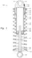
- FIG. 1is a section view of a shock absorber having two coaxial springs, both of which are pre-loadable.
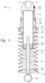
- FIG. 2is a section view of the shock absorber of FIG. 1 in which the spring members are pre-loaded.
- FIG. 3is a section view of the shock absorber illustrating an independent way of pre-loading one of the springs relative to the other spring.
- FIG. 4is a schematic diagram showing a control arrangement for a remotely operated bypass.
- FIG. 5is a schematic diagram showing another control arrangement for a remotely operated bypass.
- FIGS. 1 - 3illustrate a shock absorber 100 having damper and spring functions.
- the damper 100includes a cylinder 102 with a rod 107 and a piston 105 which is sealed in the cylinder with a seal 108 .
- fluidmeters from one side of the piston 105 to the other side by passing through flow paths (not shown) formed in the piston 105 .
- shimsare used to partially obstruct flow paths through the piston 105 in each direction. By selecting shims having certain desired stiffness characteristics, the dampening effects caused by the piston 105 as it travels through the fluid can be increased or decreased, and dampening rates can be different between the compression and rebound strokes of the piston 105 .
- a reservoir(not shown) is typically in fluid communication with the damper cylinder 102 for receiving and supplying damping fluid as the piston rod 107 moves in and out of the cylinder.
- the reservoirincludes a cylinder portion in fluid communication with the damper cylinder 102 .
- Certain features of reservoir type dampersare shown and described in U.S. Pat. No. 7,374,028, which is incorporated herein, in its entirety, by reference.
- One end of the piston rod 107is supplied with an eyelet 109 for connecting to a portion of a vehicle wheel suspension linkage.
- An opposite end(opposite the piston), is supplied with an eyelet 111 to be mounted to another portion of the vehicle, such as the frame, that moves independently of the first part.
- a closure 110is constructed and arranged to thread onto an end of cylinder 102 and engage telescopically with a preload piston 120 .
- the preload pistonis slidable relative to and sealed against (by seal 131 ) an exterior surface of cylinder 102 and is also slidably sealed against an exterior of the closure 110 by seal 132 .
- the preload pistonincludes two separate spring axial abutment structures. Shown are large diameter abutment 115 and a small diameter abutment 130 . A spring abutment 125 is attached at an opposite end of rod 107 , adjacent a lower connecting eye. As shown in the figures, abutment 125 may be stepped with two surfaces 126 , 127 and of sufficient diameter to support either the lower end of a large diameter spring 150 or a small diameter spring 155 or both simultaneously (as shown).
- a preload adjuster assemblyincludes a hydraulic fluid flow path comprising fill fitting 160 , flow path 161 , 162 and piston chamber 163 (visible in FIG. 2 ).
- one or more springsare mounted to abut surfaces 125 and one or both of 115 and 130 .
- FIG. 1shows the shock absorber in the “minimum extension” position (no hydraulic fluid in chamber 163 ) as it is shown in FIG. 1 .
- the springs 150 , 155 so mountedwill be in their most compliant state due to minimum preload (i.e. pre-compression).
- fluidis introduced manually or via onboard hydraulic reservoir and pump, into port 160 .
- both springs 150 , 155are acted upon by the preload piston 120 causing both to become more or less compressed as the preload piston 120 moves in relation to the fluid in chamber 163 .
- either of the springscould be independently mounted wherein it is not affected at all by the expansion and contraction of the chamber 163 .
- chamber 163 of the preload adjusteris operated with relatively non-compressible fluid
- compressible fluidsuch as gas may be used in the chamber to create a composite spring rate comprising compressible gas and mechanical spring.
- large diameter abutment 115 holding larger diameter spring 150 at one endis independently adjustable relative to the other spring 155 and the chamber. Independent adjustment is provided by a threaded relationship 156 between the abutment 115 and the outer diameter of the chamber.
- abutmentis located near an end of the chamber wall.
- abutment 115has been threadedly moved axially along the cylinder to a location closer to an opposite end of the chamber. In this manner, additional preload is placed upon the larger diameter spring 150 separate and apart from preload supplied by the preload piston 120 .
- the preload adjustermay be automated such that onboard load sensing associated with a vehicle adjusts the spring rate based on sensed operational conditions and microprocessor-controlled fluid introduction into one or more preload adjusters on the vehicle (e.g. 4 on a 4 wheeler),
- FIG. 4is a schematic diagram illustrating a sample circuit 400 used to provide remote control of a preload adjuster using a vehicle's power steering fluid (although any suitable fluid pressure source may be substituted for reservoir 410 as could an electrical current source in the case of an electrically actuated valve member 175 ).
- a fluid pathway 405 having a switch-operated valve 402 thereinruns from a fluid (or current) reservoir 410 that is kept pressurized by, in one embodiment, a power steering pump (not shown) to a preload adjuster that is operable, for example, by a user selectable dash board switch 415 .
- the valve 402permits fluid to travel to the adjuster, thereby urging it to an expanded position.
- a remotely operable preload adjuster like the one described aboveis particularly useful with on/off road vehicles. These vehicles can have as much as 20′′ of shock absorber travel to permit them to negotiate rough, uneven terrain at speed with usable shock absorbing function. In off-road applications, compliant shock absorbing is necessary as the vehicle relies on its long travel suspension when encountering off-road obstacles. However, operating a vehicle with very compliant, long travel suspension on a smooth road at higher speeds can be problematic due to the springiness/sponginess of the suspension. Such compliance can cause reduced handling characteristics and even loss of control. Such control issues can be pronounced when cornering at high speed as a compliant, long travel vehicle may tend to roll excessively. Similarly, such a vehicle may pitch and yaw excessively during braking and acceleration. With the remotely operated preload adjuster described herein, spring characteristics of a shock absorber can be completely changed from a compliantly dampened “springy” arrangement to a “stiffer” system ideal for higher speeds on a smooth road.
- FIG. 5shows a schematic diagram of a remote control system 500 based upon any or all of vehicle speed, damper rod speed, and damper rod position.
- One embodiment of FIG. 5is designed to automatically increase spring compression in a shock absorber in the event a damper rod reaches a certain velocity in its travel towards the bottom end of travel at a predetermined speed of the vehicle.
- the systemadds stiffness (and control) in the event of rapid operation (e.g.
- the systemadds stiffness (e.g. expands the chamber 163 ) in the event that the rod velocity in compression is relatively low, but the rod progresses past a certain point in the travel.
- stiffnesse.g. expands the chamber 163
- Such configurationaids in stabilizing the vehicle against excessive low rare suspension movement events such as cornering roll, braking and acceleration yaw and pitch and “g-out.”
- FIG. 5illustrates, for example, a system including three variables: rod speed, rod position and vehicle speed. Any or all of the variables shown may be considered by processor 502 in controlling the valve 175 . Any other suitable vehicle operation variable may be used in addition to or in lieu of the variables 515 , 505 , 510 such as, for example, piston rod compression strain, eyelet strain, vehicle mounted accelerometer data or any other suitable vehicle or component performance data.
- a suitable proximity sensor or linear coil transducer or other electro-magnetic transduceris incorporated in the dampening cylinder to provide a sensor to monitor the position and or speed of the piston (and suitable magnetic tag) with respect to the cylinder.
- the magnetic transducerincludes a waveguide and a magnet, such as a doughnut (toroidal) magnet that is joined to the cylinder and oriented such that the magnetic field generated by the magnet passes through the piston rod and the waveguide.
- Electric pulsesare applied to the waveguide from a pulse generator that provides a stream of electric pulses, each of which is also provided to a signal processing circuit for timing purposes.
- a pulse generatorthat provides a stream of electric pulses, each of which is also provided to a signal processing circuit for timing purposes.
- a magnetic fieldis formed surrounding the waveguide. Interaction of this field with the magnetic field from the magnet causes a torsional strain wave pulse to be launched in the waveguide in both directions away from the magnet.
- a coil assembly and sensing tapeis joined to the waveguide.
- the strain wavecauses a dynamic effect in the permeability of the sensing tape which is biased with a permanent magnetic field by the magnet.
- the dynamic effect in the magnetic field of the coil assembly due to the strain wave pulseresults in an output signal from the coil assembly that is provided to the signal processing circuit along signal lines.
- the signal processing circuitcan calculate a distance of the magnet from the coil assembly or the relative velocity between the waveguide and the magnet.
- the signal processing circuitprovides an output signal, digital or analog, proportional to the calculated distance and I or velocity.
- a separate wheel speed transducer for sensing the rotational speed of a wheel about an axleincludes housing fixed to the axle and containing therein, for example, two permanent magnets.
- the magnetsare arranged such that an elongated pole piece commonly abuts first surfaces of each of the magnets, such surfaces being of like polarity.
- Two inductive cons having flux-conductive cores axially passing therethroughabut each of the magnets on second surfaces thereof, the second surfaces of the magnets again being of like polarity with respect to each other and of opposite polarity with respect to the first surfaces.
- Wheel speed transducersare described in U.S. Pat. No. 3,986,118 which is incorporated herein by reference in its entirety.
- a logic unit 502 with user-definable settingsreceives inputs from the rod speed 510 and location 505 transducers as well as the wheel speed transducer 515 .
- the logic unitis user-programmable and depending on the needs of the operator, the unit records the variables, and then if certain criteria are met, the logic circuit sends its own signal to the preload adjuster to either expand or contract. Thereafter, the condition of the preload adjuster 175 is relayed back to the logic unit 502 .
- the logic shown in FIG. 5assumes a single shock absorber but the logic circuit is usable with any number of shocks or groups of shocks. For instance, the shock absorbers on one side of the vehicle can be acted upon while the vehicle's other shocks remain unaffected.
- the remotely operated preload adjustercan be used in a variety of ways with many different driving and road variables.
- the preload adjusteris controlled based upon vehicle speed in conjunction with the angular location of the vehicle's steering wheel. In this manner, by sensing the steering wheel turn severity (angle of rotation), additional stiffness can be applied to one shock or one set of shocks on one side of the vehicle (suitable, for example, to mitigate cornering roll) in the event of a sharp turn at a relatively high speed.
- a transducersuch as an accelerometer measures other aspects of the vehicle's suspension system, like axle force and/or moments applied to various parts of the vehicle, like steering tie rods, and directs change to the preload adjuster positioning in response thereto.
- the preload adjustercan be controlled at least in part by a pressure transducer measuring pressure in a vehicle tire and adding or subtracting stiffness characteristics to some or all of the wheels in the event of, for example, an increased or decreased pressure reading.
- a parametermight include a gyroscopic mechanism that monitors vehicle trajectory and identifies a “spin-out” or other loss of control condition and adds and/or reduces spring stiffness to some or all of the vehicle's shock absorbers in the event of a loss of control to help the operator of the vehicle to regain control.
Landscapes
- Engineering & Computer Science (AREA)
- Mechanical Engineering (AREA)
- General Engineering & Computer Science (AREA)
- Vehicle Body Suspensions (AREA)
Abstract
Description
Claims (3)
Priority Applications (1)
| Application Number | Priority Date | Filing Date | Title |
|---|---|---|---|
| US17/316,520US12145415B2 (en) | 2012-02-03 | 2021-05-10 | Suspension with hydraulic preload adjust |
Applications Claiming Priority (8)
| Application Number | Priority Date | Filing Date | Title |
|---|---|---|---|
| US201261594886P | 2012-02-03 | 2012-02-03 | |
| US13/758,330US8770592B2 (en) | 2012-02-03 | 2013-02-04 | Suspension with hydraulic preload adjust |
| US14/293,927US9248717B2 (en) | 2012-02-03 | 2014-06-02 | Suspension with hydraulic preload adjust |
| US14/995,098US9623716B2 (en) | 2012-02-03 | 2016-01-13 | Suspension with hydraulic preload adjust |
| US15/471,986US9969236B2 (en) | 2012-02-03 | 2017-03-28 | Suspension with hydraulic preload adjust |
| US15/948,634US10336151B2 (en) | 2012-02-03 | 2018-04-09 | Suspension with hydraulic preload adjust |
| US16/442,186US11001120B2 (en) | 2012-02-03 | 2019-06-14 | Suspension with hydraulic preload adjust |
| US17/316,520US12145415B2 (en) | 2012-02-03 | 2021-05-10 | Suspension with hydraulic preload adjust |
Related Parent Applications (1)
| Application Number | Title | Priority Date | Filing Date |
|---|---|---|---|
| US16/442,186ContinuationUS11001120B2 (en) | 2012-02-03 | 2019-06-14 | Suspension with hydraulic preload adjust |
Publications (2)
| Publication Number | Publication Date |
|---|---|
| US20210260951A1 US20210260951A1 (en) | 2021-08-26 |
| US12145415B2true US12145415B2 (en) | 2024-11-19 |
Family
ID=48902237
Family Applications (7)
| Application Number | Title | Priority Date | Filing Date |
|---|---|---|---|
| US13/758,330ActiveUS8770592B2 (en) | 2012-02-03 | 2013-02-04 | Suspension with hydraulic preload adjust |
| US14/293,927ActiveUS9248717B2 (en) | 2012-02-03 | 2014-06-02 | Suspension with hydraulic preload adjust |
| US14/995,098ActiveUS9623716B2 (en) | 2012-02-03 | 2016-01-13 | Suspension with hydraulic preload adjust |
| US15/471,986ActiveUS9969236B2 (en) | 2012-02-03 | 2017-03-28 | Suspension with hydraulic preload adjust |
| US15/948,634ActiveUS10336151B2 (en) | 2012-02-03 | 2018-04-09 | Suspension with hydraulic preload adjust |
| US16/442,186ActiveUS11001120B2 (en) | 2012-02-03 | 2019-06-14 | Suspension with hydraulic preload adjust |
| US17/316,520ActiveUS12145415B2 (en) | 2012-02-03 | 2021-05-10 | Suspension with hydraulic preload adjust |
Family Applications Before (6)
| Application Number | Title | Priority Date | Filing Date |
|---|---|---|---|
| US13/758,330ActiveUS8770592B2 (en) | 2012-02-03 | 2013-02-04 | Suspension with hydraulic preload adjust |
| US14/293,927ActiveUS9248717B2 (en) | 2012-02-03 | 2014-06-02 | Suspension with hydraulic preload adjust |
| US14/995,098ActiveUS9623716B2 (en) | 2012-02-03 | 2016-01-13 | Suspension with hydraulic preload adjust |
| US15/471,986ActiveUS9969236B2 (en) | 2012-02-03 | 2017-03-28 | Suspension with hydraulic preload adjust |
| US15/948,634ActiveUS10336151B2 (en) | 2012-02-03 | 2018-04-09 | Suspension with hydraulic preload adjust |
| US16/442,186ActiveUS11001120B2 (en) | 2012-02-03 | 2019-06-14 | Suspension with hydraulic preload adjust |
Country Status (1)
| Country | Link |
|---|---|
| US (7) | US8770592B2 (en) |
Families Citing this family (50)
| Publication number | Priority date | Publication date | Assignee | Title |
|---|---|---|---|---|
| US9162573B2 (en) | 2010-06-03 | 2015-10-20 | Polaris Industries Inc. | Electronic throttle control |
| US8770592B2 (en) | 2012-02-03 | 2014-07-08 | Fox Factory, Inc. | Suspension with hydraulic preload adjust |
| US9205717B2 (en) | 2012-11-07 | 2015-12-08 | Polaris Industries Inc. | Vehicle having suspension with continuous damping control |
| US10648554B2 (en) | 2014-09-02 | 2020-05-12 | Polaris Industries Inc. | Continuously variable transmission |
| CN107406094B (en) | 2014-10-31 | 2020-04-14 | 北极星工业有限公司 | System and method for controlling a vehicle |
| CN110121438B (en) | 2016-11-18 | 2023-01-31 | 北极星工业有限公司 | vehicles with adjustable suspension |
| US10406884B2 (en) | 2017-06-09 | 2019-09-10 | Polaris Industries Inc. | Adjustable vehicle suspension system |
| DE102017212882A1 (en)* | 2017-07-26 | 2019-01-31 | Bayerische Motoren Werke Aktiengesellschaft | Suspension Spring Damper System of a Vehicle Wheel |
| CN107487140B (en)* | 2017-08-17 | 2019-08-02 | 西华大学 | High-precision electric automobile suspension rigidity measuring sensor |
| CN107487139B (en)* | 2017-08-17 | 2019-08-02 | 西华大学 | Electric automobile suspension rigidity measurement sensor |
| US20200325509A1 (en) | 2017-09-08 | 2020-10-15 | Intrexon Corporation | Microorganisms and Methods in the Fermentation of Benzylisoquinoline Alkaloids |
| US10981429B2 (en) | 2017-09-29 | 2021-04-20 | Fox Factory, Inc. | Electronically controlled sway bar damping link |
| US20190101178A1 (en)* | 2017-09-29 | 2019-04-04 | Fox Factory, Inc. | Damper with hydraulically-adjustable preload and/or cross-over |
| WO2019183051A1 (en) | 2018-03-19 | 2019-09-26 | Polaris Industries Inc. | Continuously variable transmission |
| JP2021126906A (en)* | 2018-05-02 | 2021-09-02 | 日立Astemo株式会社 | Suspension device |
| KR102635917B1 (en)* | 2018-08-29 | 2024-02-08 | 현대자동차주식회사 | Apparatus of adjusting vehicle height for suspension |
| CN109050193B (en)* | 2018-08-30 | 2021-08-31 | 安徽工程大学 | car suspension system |
| US10987987B2 (en) | 2018-11-21 | 2021-04-27 | Polaris Industries Inc. | Vehicle having adjustable compression and rebound damping |
| US20220041029A1 (en)* | 2020-02-27 | 2022-02-10 | Fox Factory, Inc. | Hydraulically-adjustable preload and/or cross-over |
| US11840120B2 (en) | 2020-02-27 | 2023-12-12 | Fox Factory, Inc. | IFP shock with automatically adjustable ride height |
| US11718137B2 (en) | 2020-02-27 | 2023-08-08 | Fox Factory, Inc. | Shock assembly with automatically adjustable ride height |
| US12077028B2 (en)* | 2020-03-03 | 2024-09-03 | Shock Therapy Suspension, Inc. | Coilover shock with adjustable crossover |
| US12397878B2 (en) | 2020-05-20 | 2025-08-26 | Polaris Industries Inc. | Systems and methods of adjustable suspensions for off-road recreational vehicles |
| CN111731062A (en)* | 2020-06-28 | 2020-10-02 | 阜阳常阳汽车部件有限公司 | Truck axle suspension assembly |
| MX2022015902A (en) | 2020-07-17 | 2023-01-24 | Polaris Inc | Adjustable suspensions and vehicle operation for off-road recreational vehicles. |
| US11639081B2 (en)* | 2020-07-29 | 2023-05-02 | Ferrari S.P.A. | Device and apparatus for the height adjustment of a road vehicle and relative road vehicle |
| US12070981B2 (en) | 2020-10-27 | 2024-08-27 | Fox Factory, Inc. | Internal stroke sensor for an IFP shock assembly |
| US12138977B2 (en) | 2020-11-19 | 2024-11-12 | Fox Factory, Inc. | Energy harvesting switch |
| US12168379B2 (en) | 2020-11-19 | 2024-12-17 | Fox Factory, Inc. | Shock absorber with a bearing housing bypass assembly |
| US11932340B2 (en)* | 2020-12-04 | 2024-03-19 | Robert Bosch Llc | Suspension pre-load management system |
| US11634003B2 (en) | 2020-12-17 | 2023-04-25 | Fox Factory, Inc. | Automated control system for an electronically controlled sway bar link |
| US20220210650A1 (en) | 2020-12-28 | 2022-06-30 | Fox Factory, Inc. | Wireless switch for an active component |
| US12065214B2 (en) | 2020-12-28 | 2024-08-20 | Fox Factory, Inc. | Wireless active suspension system |
| EP4271579B1 (en)* | 2020-12-30 | 2024-09-18 | Marelli Suspension Systems Italy S.p.A. | Device for adjusting the bumper clearance in a vehicle suspension, vehicle suspension comprising such device and method for adjusting such a suspension |
| US20220234679A1 (en) | 2021-01-28 | 2022-07-28 | Fox Factory, Inc. | Damper with an annular base valve flow system |
| US12330459B2 (en) | 2021-02-01 | 2025-06-17 | Fox Factory, Inc. | Three-port adjuster |
| US20220266939A1 (en) | 2021-02-23 | 2022-08-25 | Fox Factory, Inc. | Orientationally flexible bump sensor |
| US12429106B2 (en) | 2021-09-14 | 2025-09-30 | Fox Factory, Inc. | Wireless active suspension system with at least one wireless sensor coupled with at least one unsprung mass |
| US20230082373A1 (en) | 2021-09-14 | 2023-03-16 | Fox Factory, Inc. | Bypass port piston |
| US12083850B2 (en) | 2021-12-20 | 2024-09-10 | Fox Factory, Inc. | Electronically controlled sway bar damping link |
| EP4253106A1 (en) | 2022-02-23 | 2023-10-04 | Fox Factory, Inc. | Hydraulic cross-linked suspension |
| US12311720B2 (en) | 2022-02-23 | 2025-05-27 | Fox Factory, Inc. | Hydraulic cross-linked suspension |
| US12291182B2 (en) | 2022-05-02 | 2025-05-06 | Robert Bosch Gmbh | Road surface detection using anti-lock braking system pressure sensor |
| EP4272983A1 (en) | 2022-05-06 | 2023-11-08 | Fox Factory, Inc. | Spring preload system |
| US20230400080A1 (en) | 2022-06-10 | 2023-12-14 | Fox Factory, Inc. | Integrated bearing hardware for shock assembly |
| KR102696060B1 (en)* | 2022-06-30 | 2024-08-19 | 현대모비스 주식회사 | Vehicle height adjusting device |
| US12269310B2 (en)* | 2023-05-05 | 2025-04-08 | GM Global Technology Operations LLC | Variable suspension spring rates using magnetorheological fluid |
| DE102023118270A1 (en)* | 2023-07-11 | 2025-01-16 | Thyssenkrupp Ag | Height level adjustment system for a chassis of a motor vehicle |
| US12384213B2 (en) | 2023-08-25 | 2025-08-12 | Fox Factory, Inc. | Hot-start suspension tune |
| USD1053284S1 (en) | 2024-06-05 | 2024-12-03 | Yonghua Liu | Leg muscle exerciser |
Citations (33)
| Publication number | Priority date | Publication date | Assignee | Title |
|---|---|---|---|---|
| US2902274A (en) | 1957-06-11 | 1959-09-01 | Monroe Auto Equipment Co | Vehicle suspension system |
| US3986118A (en) | 1975-05-02 | 1976-10-12 | Goodyear Aerospace Corporation | Simplified wheel speed transducer |
| US4050684A (en) | 1976-07-19 | 1977-09-27 | Sanders Franklin C | Velocity sensitive dual rate shock strut |
| US4310149A (en) | 1979-03-29 | 1982-01-12 | Sycam Advanced Technology Corp. | Shock absorber |
| US4854554A (en) | 1986-12-19 | 1989-08-08 | Maremont Corporation | Pneumatic spring structure with dual output force and pressure decay compensation and method of operation |
| US5007659A (en) | 1990-03-07 | 1991-04-16 | Monroe Auto Equipment Company | Internal damping force sensor |
| US5372531A (en) | 1991-09-27 | 1994-12-13 | Sofec, Inc. | Disconnectable mooring system |
| US5952823A (en) | 1996-03-22 | 1999-09-14 | Mts Systems Corporation | Magnetostrictive linear displacement transducer for a shock absorber |
| US6073536A (en) | 1998-03-02 | 2000-06-13 | Campbell; A. Keith | Automotive hydraulic system and method for driving a hydraulic accessory in parallel with a power steering unit |
| US6450304B1 (en)* | 2001-02-12 | 2002-09-17 | Delphi Technologies, Inc. | Piston and rod assembly for air-actuated variable damping |
| US20030051956A1 (en) | 2001-09-17 | 2003-03-20 | Alexander Serkh | Frictional damping strut |
| US6640941B2 (en)* | 2001-10-23 | 2003-11-04 | Tayco Developments, Inc. | Shock-isolation structure |
| US20040256778A1 (en) | 2003-06-17 | 2004-12-23 | Frank Verriet | ATV coil spring preload equalizing adjuster |
| US20050189685A1 (en) | 2004-03-01 | 2005-09-01 | Frank Verriet | Dual spring rate preload module with air adjustment |
| US7360776B2 (en) | 2002-03-16 | 2008-04-22 | Amtech Corporation | Method and apparatus for rebound control |
| US7374028B2 (en) | 2003-07-08 | 2008-05-20 | Fox Factory, Inc. | Damper with pressure-sensitive compression damping |
| US20090072460A1 (en) | 2007-03-14 | 2009-03-19 | Audi Ag | Wheel suspension for motor vehicles |
| US20090108546A1 (en) | 2007-10-31 | 2009-04-30 | Audi Ag | Adjustment device for suspension means |
| US20090236807A1 (en) | 2008-03-19 | 2009-09-24 | Wootten Dennis K | Methods and apparatus for suspending vehicles |
| US20100044975A1 (en) | 2008-07-24 | 2010-02-25 | Joshua Benjamin Yablon | Vehicle suspension damper |
| US20100170760A1 (en) | 2009-01-07 | 2010-07-08 | John Marking | Remotely Operated Bypass for a Suspension Damper |
| US20100181709A1 (en) | 2009-01-09 | 2010-07-22 | Andrew Laird | Adjustable blow-off suspension |
| US20100219572A1 (en) | 2009-03-02 | 2010-09-02 | Gary Back | Independent Spring Cartridge |
| US20100308518A1 (en) | 2007-12-14 | 2010-12-09 | Audi Ag | Spring Strut Arrangement for Wheel Suspension of Motor Vehicles |
| US20110291338A1 (en) | 2010-05-27 | 2011-12-01 | Pepka Charles F | Preloaded dual-spring assembly |
| US20110315494A1 (en) | 2009-01-07 | 2011-12-29 | John Marking | Bypass for a suspension damper |
| US8104591B2 (en) | 2005-08-11 | 2012-01-31 | Eko Sport, Inc. | Magnetic valve for shock absorbers |
| US20130144489A1 (en) | 2011-09-12 | 2013-06-06 | Fox Factory, Inc. | Methods and apparatus for suspension set up |
| US8770592B2 (en)* | 2012-02-03 | 2014-07-08 | Fox Factory, Inc. | Suspension with hydraulic preload adjust |
| US8807259B2 (en) | 2012-09-28 | 2014-08-19 | Yamaha Hatsudoki Kabushiki Kaisha | Motorcycle |
| US8857580B2 (en)* | 2009-01-07 | 2014-10-14 | Fox Factory, Inc. | Remotely operated bypass for a suspension damper |
| US9239090B2 (en)* | 2009-01-07 | 2016-01-19 | Fox Factory, Inc. | Suspension damper with remotely-operable valve |
| US11448283B2 (en)* | 2019-04-29 | 2022-09-20 | Fox Factory, Inc. | Main piston boost valve in a vehicle damper |
Family Cites Families (5)
| Publication number | Priority date | Publication date | Assignee | Title |
|---|---|---|---|---|
| JPS5557537U (en)* | 1978-10-14 | 1980-04-18 | ||
| US4958706A (en)* | 1988-11-14 | 1990-09-25 | Richardson Donald G | Adjustable shock absorbers |
| DE19723347C1 (en)* | 1997-06-04 | 1998-12-17 | Mannesmann Sachs Ag | Sprung suspension strut for motor vehicle |
| US6374966B1 (en)* | 1998-12-04 | 2002-04-23 | Lillbacka Jetair Oy | Shock absorber assembly |
| US6915885B2 (en)* | 2001-08-09 | 2005-07-12 | Zf Sachs Ag | Oscillation damper with adjustable damping force |
- 2013
- 2013-02-04USUS13/758,330patent/US8770592B2/enactiveActive
- 2014
- 2014-06-02USUS14/293,927patent/US9248717B2/enactiveActive
- 2016
- 2016-01-13USUS14/995,098patent/US9623716B2/enactiveActive
- 2017
- 2017-03-28USUS15/471,986patent/US9969236B2/enactiveActive
- 2018
- 2018-04-09USUS15/948,634patent/US10336151B2/enactiveActive
- 2019
- 2019-06-14USUS16/442,186patent/US11001120B2/enactiveActive
- 2021
- 2021-05-10USUS17/316,520patent/US12145415B2/enactiveActive
Patent Citations (44)
| Publication number | Priority date | Publication date | Assignee | Title |
|---|---|---|---|---|
| US2902274A (en) | 1957-06-11 | 1959-09-01 | Monroe Auto Equipment Co | Vehicle suspension system |
| US3986118A (en) | 1975-05-02 | 1976-10-12 | Goodyear Aerospace Corporation | Simplified wheel speed transducer |
| US4050684A (en) | 1976-07-19 | 1977-09-27 | Sanders Franklin C | Velocity sensitive dual rate shock strut |
| US4310149A (en) | 1979-03-29 | 1982-01-12 | Sycam Advanced Technology Corp. | Shock absorber |
| US4854554A (en) | 1986-12-19 | 1989-08-08 | Maremont Corporation | Pneumatic spring structure with dual output force and pressure decay compensation and method of operation |
| US5007659A (en) | 1990-03-07 | 1991-04-16 | Monroe Auto Equipment Company | Internal damping force sensor |
| US5372531A (en) | 1991-09-27 | 1994-12-13 | Sofec, Inc. | Disconnectable mooring system |
| US5952823A (en) | 1996-03-22 | 1999-09-14 | Mts Systems Corporation | Magnetostrictive linear displacement transducer for a shock absorber |
| US6073536A (en) | 1998-03-02 | 2000-06-13 | Campbell; A. Keith | Automotive hydraulic system and method for driving a hydraulic accessory in parallel with a power steering unit |
| US6450304B1 (en)* | 2001-02-12 | 2002-09-17 | Delphi Technologies, Inc. | Piston and rod assembly for air-actuated variable damping |
| US20030051956A1 (en) | 2001-09-17 | 2003-03-20 | Alexander Serkh | Frictional damping strut |
| US6640941B2 (en)* | 2001-10-23 | 2003-11-04 | Tayco Developments, Inc. | Shock-isolation structure |
| US7360776B2 (en) | 2002-03-16 | 2008-04-22 | Amtech Corporation | Method and apparatus for rebound control |
| US20040256778A1 (en) | 2003-06-17 | 2004-12-23 | Frank Verriet | ATV coil spring preload equalizing adjuster |
| US7374028B2 (en) | 2003-07-08 | 2008-05-20 | Fox Factory, Inc. | Damper with pressure-sensitive compression damping |
| US20050189685A1 (en) | 2004-03-01 | 2005-09-01 | Frank Verriet | Dual spring rate preload module with air adjustment |
| US8104591B2 (en) | 2005-08-11 | 2012-01-31 | Eko Sport, Inc. | Magnetic valve for shock absorbers |
| US20090072460A1 (en) | 2007-03-14 | 2009-03-19 | Audi Ag | Wheel suspension for motor vehicles |
| US20090108546A1 (en) | 2007-10-31 | 2009-04-30 | Audi Ag | Adjustment device for suspension means |
| US7926822B2 (en) | 2007-10-31 | 2011-04-19 | Audi, Ag | Adjustment device for suspension means |
| US20100308518A1 (en) | 2007-12-14 | 2010-12-09 | Audi Ag | Spring Strut Arrangement for Wheel Suspension of Motor Vehicles |
| US20090236807A1 (en) | 2008-03-19 | 2009-09-24 | Wootten Dennis K | Methods and apparatus for suspending vehicles |
| US20100044975A1 (en) | 2008-07-24 | 2010-02-25 | Joshua Benjamin Yablon | Vehicle suspension damper |
| US9120362B2 (en)* | 2009-01-07 | 2015-09-01 | Fox Factory, Inc. | Bypass for a suspension damper |
| US20100170760A1 (en) | 2009-01-07 | 2010-07-08 | John Marking | Remotely Operated Bypass for a Suspension Damper |
| US20110315494A1 (en) | 2009-01-07 | 2011-12-29 | John Marking | Bypass for a suspension damper |
| US9239090B2 (en)* | 2009-01-07 | 2016-01-19 | Fox Factory, Inc. | Suspension damper with remotely-operable valve |
| US8857580B2 (en)* | 2009-01-07 | 2014-10-14 | Fox Factory, Inc. | Remotely operated bypass for a suspension damper |
| US20100181709A1 (en) | 2009-01-09 | 2010-07-22 | Andrew Laird | Adjustable blow-off suspension |
| US20100219572A1 (en) | 2009-03-02 | 2010-09-02 | Gary Back | Independent Spring Cartridge |
| US20110291338A1 (en) | 2010-05-27 | 2011-12-01 | Pepka Charles F | Preloaded dual-spring assembly |
| US20130144489A1 (en) | 2011-09-12 | 2013-06-06 | Fox Factory, Inc. | Methods and apparatus for suspension set up |
| US8838335B2 (en) | 2011-09-12 | 2014-09-16 | Fox Factory, Inc. | Methods and apparatus for suspension set up |
| US8770592B2 (en)* | 2012-02-03 | 2014-07-08 | Fox Factory, Inc. | Suspension with hydraulic preload adjust |
| US9248717B2 (en) | 2012-02-03 | 2016-02-02 | Fox Factory, Inc. | Suspension with hydraulic preload adjust |
| US20160129750A1 (en) | 2012-02-03 | 2016-05-12 | Fox Factory, Inc. | Suspension with hydraulic preload adjust |
| US9623716B2 (en) | 2012-02-03 | 2017-04-18 | Fox Factory, Inc. | Suspension with hydraulic preload adjust |
| US20170197486A1 (en) | 2012-02-03 | 2017-07-13 | Fox Factory, Inc. | Suspension with hydraulic preload adjust |
| US9969236B2 (en) | 2012-02-03 | 2018-05-15 | Fox Factory, Inc. | Suspension with hydraulic preload adjust |
| US20180222273A1 (en) | 2012-02-03 | 2018-08-09 | Fox Factory, Inc. | Suspension with hydraulic preload adjust |
| US10336151B2 (en) | 2012-02-03 | 2019-07-02 | Fox Factory, Inc. | Suspension with hydraulic preload adjust |
| US11001120B2 (en)* | 2012-02-03 | 2021-05-11 | Fox Factory, Inc. | Suspension with hydraulic preload adjust |
| US8807259B2 (en) | 2012-09-28 | 2014-08-19 | Yamaha Hatsudoki Kabushiki Kaisha | Motorcycle |
| US11448283B2 (en)* | 2019-04-29 | 2022-09-20 | Fox Factory, Inc. | Main piston boost valve in a vehicle damper |
Also Published As
| Publication number | Publication date |
|---|---|
| US9969236B2 (en) | 2018-05-15 |
| US9623716B2 (en) | 2017-04-18 |
| US20160129750A1 (en) | 2016-05-12 |
| US20210260951A1 (en) | 2021-08-26 |
| US20170197486A1 (en) | 2017-07-13 |
| US10336151B2 (en) | 2019-07-02 |
| US20130200589A1 (en) | 2013-08-08 |
| US11001120B2 (en) | 2021-05-11 |
| US20190291529A1 (en) | 2019-09-26 |
| US20140265080A1 (en) | 2014-09-18 |
| US20180222273A1 (en) | 2018-08-09 |
| US8770592B2 (en) | 2014-07-08 |
| US9248717B2 (en) | 2016-02-02 |
Similar Documents
| Publication | Publication Date | Title |
|---|---|---|
| US12145415B2 (en) | Suspension with hydraulic preload adjust | |
| US20220389983A1 (en) | Position sensitive suspension damping with an active valve | |
| US11976706B2 (en) | Remotely operated bypass for a suspension damper | |
| US12122205B2 (en) | Active valve for an internal bypass | |
| US11796030B2 (en) | Main piston boost valve in a vehicle damper | |
| US20210079973A1 (en) | Bypass for a suspension damper | |
| US20210025472A1 (en) | Remotely operated bypass for a suspension damper | |
| US9239090B2 (en) | Suspension damper with remotely-operable valve | |
| EP2410203B1 (en) | Suspension Damper with Remotely-Operable Valve | |
| US20140027219A1 (en) | Remotely operated bypass for a suspension damper | |
| EP3290738B1 (en) | Remotely operated bypass for a suspension damper | |
| US20180216692A1 (en) | Twin tube shock with adjustable pressure regulation | |
| EP3663605B1 (en) | Position sensitive suspension damping with an active valve | |
| EP3660349A1 (en) | Active valve for an internal bypass |
Legal Events
| Date | Code | Title | Description |
|---|---|---|---|
| FEPP | Fee payment procedure | Free format text:ENTITY STATUS SET TO UNDISCOUNTED (ORIGINAL EVENT CODE: BIG.); ENTITY STATUS OF PATENT OWNER: LARGE ENTITY | |
| STPP | Information on status: patent application and granting procedure in general | Free format text:DOCKETED NEW CASE - READY FOR EXAMINATION | |
| AS | Assignment | Owner name:WELLS FARGO BANK, NATIONAL ASSOCIATION, NORTH CAROLINA Free format text:SECURITY INTEREST;ASSIGNOR:FOX FACTORY, INC.;REEL/FRAME:059616/0435 Effective date:20220405 | |
| STPP | Information on status: patent application and granting procedure in general | Free format text:NON FINAL ACTION MAILED | |
| STPP | Information on status: patent application and granting procedure in general | Free format text:RESPONSE TO NON-FINAL OFFICE ACTION ENTERED AND FORWARDED TO EXAMINER | |
| STPP | Information on status: patent application and granting procedure in general | Free format text:FINAL REJECTION MAILED | |
| STPP | Information on status: patent application and granting procedure in general | Free format text:DOCKETED NEW CASE - READY FOR EXAMINATION | |
| STPP | Information on status: patent application and granting procedure in general | Free format text:NON FINAL ACTION MAILED | |
| STPP | Information on status: patent application and granting procedure in general | Free format text:NOTICE OF ALLOWANCE MAILED -- APPLICATION RECEIVED IN OFFICE OF PUBLICATIONS | |
| ZAAB | Notice of allowance mailed | Free format text:ORIGINAL CODE: MN/=. | |
| STPP | Information on status: patent application and granting procedure in general | Free format text:PUBLICATIONS -- ISSUE FEE PAYMENT VERIFIED | |
| STCF | Information on status: patent grant | Free format text:PATENTED CASE |