US12145288B2 - Apparatuses and methods for cutting porous substrates - Google Patents
Apparatuses and methods for cutting porous substratesDownload PDFInfo
- Publication number
- US12145288B2 US12145288B2US17/342,431US202117342431AUS12145288B2US 12145288 B2US12145288 B2US 12145288B2US 202117342431 AUS202117342431 AUS 202117342431AUS 12145288 B2US12145288 B2US 12145288B2
- Authority
- US
- United States
- Prior art keywords
- die
- stripping sleeve
- diameter
- puncher
- sleeve
- Prior art date
- Legal status (The legal status is an assumption and is not a legal conclusion. Google has not performed a legal analysis and makes no representation as to the accuracy of the status listed.)
- Active
Links
- 239000000758substrateSubstances0.000titleclaimsabstractdescription54
- 238000000034methodMethods0.000titleabstractdescription23
- 238000005520cutting processMethods0.000titleabstractdescription15
- 230000033001locomotionEffects0.000claimsdescription11
- 239000012472biological sampleSubstances0.000claimsdescription9
- 230000036316preloadEffects0.000claimsdescription5
- 230000000284resting effectEffects0.000claimsdescription5
- XAGFODPZIPBFFR-UHFFFAOYSA-NaluminiumChemical compound[Al]XAGFODPZIPBFFR-UHFFFAOYSA-N0.000claimsdescription3
- 229910052782aluminiumInorganic materials0.000claimsdescription3
- 239000000523sampleSubstances0.000description22
- 238000004080punchingMethods0.000description12
- 239000000463materialSubstances0.000description7
- 230000008569processEffects0.000description7
- 239000008280bloodSubstances0.000description5
- 210000004369bloodAnatomy0.000description5
- 238000013461designMethods0.000description5
- 229920002678cellulosePolymers0.000description3
- 239000001913celluloseSubstances0.000description3
- 238000000605extractionMethods0.000description3
- 238000012545processingMethods0.000description3
- 230000003068static effectEffects0.000description3
- 229910000831SteelInorganic materials0.000description2
- 230000009471actionEffects0.000description2
- 238000013459approachMethods0.000description2
- 230000005611electricityEffects0.000description2
- 239000012530fluidSubstances0.000description2
- 238000004811liquid chromatographyMethods0.000description2
- 230000007246mechanismEffects0.000description2
- 238000012986modificationMethods0.000description2
- 230000004048modificationEffects0.000description2
- 238000003752polymerase chain reactionMethods0.000description2
- 239000010959steelSubstances0.000description2
- 238000003860storageMethods0.000description2
- 238000004458analytical methodMethods0.000description1
- 238000012864cross contaminationMethods0.000description1
- 239000003814drugSubstances0.000description1
- 229940079593drugDrugs0.000description1
- 239000002359drug metaboliteSubstances0.000description1
- 239000012636effectorSubstances0.000description1
- 230000000694effectsEffects0.000description1
- 238000003018immunoassayMethods0.000description1
- 230000010354integrationEffects0.000description1
- 239000007788liquidSubstances0.000description1
- 238000004895liquid chromatography mass spectrometryMethods0.000description1
- 238000004949mass spectrometryMethods0.000description1
- 229920005597polymer membranePolymers0.000description1
- 238000002360preparation methodMethods0.000description1
- 238000003825pressingMethods0.000description1
- 230000000750progressive effectEffects0.000description1
- 238000010008shearingMethods0.000description1
- 238000012360testing methodMethods0.000description1
- 231100000607toxicokineticsToxicity0.000description1
- 238000000825ultraviolet detectionMethods0.000description1
Images


Classifications
- B—PERFORMING OPERATIONS; TRANSPORTING
- B26—HAND CUTTING TOOLS; CUTTING; SEVERING
- B26F—PERFORATING; PUNCHING; CUTTING-OUT; STAMPING-OUT; SEVERING BY MEANS OTHER THAN CUTTING
- B26F1/00—Perforating; Punching; Cutting-out; Stamping-out; Apparatus therefor
- B26F1/02—Perforating by punching, e.g. with relatively-reciprocating punch and bed
- B26F1/14—Punching tools; Punching dies
- B—PERFORMING OPERATIONS; TRANSPORTING
- B21—MECHANICAL METAL-WORKING WITHOUT ESSENTIALLY REMOVING MATERIAL; PUNCHING METAL
- B21D—WORKING OR PROCESSING OF SHEET METAL OR METAL TUBES, RODS OR PROFILES WITHOUT ESSENTIALLY REMOVING MATERIAL; PUNCHING METAL
- B21D45/00—Ejecting or stripping-off devices arranged in machines or tools dealt with in this subclass
- B21D45/003—Ejecting or stripping-off devices arranged in machines or tools dealt with in this subclass in punching machines or punching tools
- B21D45/006—Stripping-off devices
- B—PERFORMING OPERATIONS; TRANSPORTING
- B21—MECHANICAL METAL-WORKING WITHOUT ESSENTIALLY REMOVING MATERIAL; PUNCHING METAL
- B21D—WORKING OR PROCESSING OF SHEET METAL OR METAL TUBES, RODS OR PROFILES WITHOUT ESSENTIALLY REMOVING MATERIAL; PUNCHING METAL
- B21D45/00—Ejecting or stripping-off devices arranged in machines or tools dealt with in this subclass
- B21D45/06—Stripping-off devices
- B21D45/08—Stripping-off devices interrelated with motion of tool
- B—PERFORMING OPERATIONS; TRANSPORTING
- B26—HAND CUTTING TOOLS; CUTTING; SEVERING
- B26D—CUTTING; DETAILS COMMON TO MACHINES FOR PERFORATING, PUNCHING, CUTTING-OUT, STAMPING-OUT OR SEVERING
- B26D7/00—Details of apparatus for cutting, cutting-out, stamping-out, punching, perforating, or severing by means other than cutting
- B26D7/01—Means for holding or positioning work
- B26D7/02—Means for holding or positioning work with clamping means
- B—PERFORMING OPERATIONS; TRANSPORTING
- B26—HAND CUTTING TOOLS; CUTTING; SEVERING
- B26D—CUTTING; DETAILS COMMON TO MACHINES FOR PERFORATING, PUNCHING, CUTTING-OUT, STAMPING-OUT OR SEVERING
- B26D7/00—Details of apparatus for cutting, cutting-out, stamping-out, punching, perforating, or severing by means other than cutting
- B26D7/18—Means for removing cut-out material or waste
- B—PERFORMING OPERATIONS; TRANSPORTING
- B26—HAND CUTTING TOOLS; CUTTING; SEVERING
- B26F—PERFORATING; PUNCHING; CUTTING-OUT; STAMPING-OUT; SEVERING BY MEANS OTHER THAN CUTTING
- B26F1/00—Perforating; Punching; Cutting-out; Stamping-out; Apparatus therefor
- B26F1/02—Perforating by punching, e.g. with relatively-reciprocating punch and bed
- G—PHYSICS
- G01—MEASURING; TESTING
- G01N—INVESTIGATING OR ANALYSING MATERIALS BY DETERMINING THEIR CHEMICAL OR PHYSICAL PROPERTIES
- G01N1/00—Sampling; Preparing specimens for investigation
- G01N1/02—Devices for withdrawing samples
- G01N1/04—Devices for withdrawing samples in the solid state, e.g. by cutting
- G—PHYSICS
- G01—MEASURING; TESTING
- G01N—INVESTIGATING OR ANALYSING MATERIALS BY DETERMINING THEIR CHEMICAL OR PHYSICAL PROPERTIES
- G01N1/00—Sampling; Preparing specimens for investigation
- G01N1/28—Preparing specimens for investigation including physical details of (bio-)chemical methods covered elsewhere, e.g. G01N33/50, C12Q
- G01N1/286—Preparing specimens for investigation including physical details of (bio-)chemical methods covered elsewhere, e.g. G01N33/50, C12Q involving mechanical work, e.g. chopping, disintegrating, compacting, homogenising
- G01N2001/2873—Cutting or cleaving
- G01N2001/288—Filter punches
- Y—GENERAL TAGGING OF NEW TECHNOLOGICAL DEVELOPMENTS; GENERAL TAGGING OF CROSS-SECTIONAL TECHNOLOGIES SPANNING OVER SEVERAL SECTIONS OF THE IPC; TECHNICAL SUBJECTS COVERED BY FORMER USPC CROSS-REFERENCE ART COLLECTIONS [XRACs] AND DIGESTS
- Y10—TECHNICAL SUBJECTS COVERED BY FORMER USPC
- Y10T—TECHNICAL SUBJECTS COVERED BY FORMER US CLASSIFICATION
- Y10T83/00—Cutting
- Y10T83/04—Processes
- Y—GENERAL TAGGING OF NEW TECHNOLOGICAL DEVELOPMENTS; GENERAL TAGGING OF CROSS-SECTIONAL TECHNOLOGIES SPANNING OVER SEVERAL SECTIONS OF THE IPC; TECHNICAL SUBJECTS COVERED BY FORMER USPC CROSS-REFERENCE ART COLLECTIONS [XRACs] AND DIGESTS
- Y10—TECHNICAL SUBJECTS COVERED BY FORMER USPC
- Y10T—TECHNICAL SUBJECTS COVERED BY FORMER US CLASSIFICATION
- Y10T83/00—Cutting
- Y10T83/202—With product handling means
- Y10T83/2092—Means to move, guide, or permit free fall or flight of product
- Y10T83/2096—Means to move product out of contact with tool
- Y10T83/2122—By ejector within a hollow cutter
- Y10T83/2133—By resiliently biased ejector
- Y—GENERAL TAGGING OF NEW TECHNOLOGICAL DEVELOPMENTS; GENERAL TAGGING OF CROSS-SECTIONAL TECHNOLOGIES SPANNING OVER SEVERAL SECTIONS OF THE IPC; TECHNICAL SUBJECTS COVERED BY FORMER USPC CROSS-REFERENCE ART COLLECTIONS [XRACs] AND DIGESTS
- Y10—TECHNICAL SUBJECTS COVERED BY FORMER USPC
- Y10T—TECHNICAL SUBJECTS COVERED BY FORMER US CLASSIFICATION
- Y10T83/00—Cutting
- Y10T83/202—With product handling means
- Y10T83/2092—Means to move, guide, or permit free fall or flight of product
- Y10T83/2096—Means to move product out of contact with tool
- Y10T83/2135—Moving stripper timed with tool stroke
- Y10T83/215—Carried by moving tool element or its support
- Y10T83/2155—Stripper biased against product
- Y10T83/2159—By spring means
Definitions
- the inventionrelates generally to apparatuses and methods for cutting porous substrates.
- Porous substratessuch as cellulose matrices (e.g. 31 ETF, FTA and FTA elute cards available from Whatman) are often used to store biological samples, such as blood.
- a new application area for these cardsis in the pharmaceutical industry, which is using them to store dried blood samples from pharmacokinetic and toxicokinetic studies.
- the current methodsrequire the user to cut the sample out of the card, usually a 1-6 mm diameter circle, place the cut disc in a vial or well with extraction fluid, and then shake/vortex for a set period of time. The extraction fluid is then removed and analyzed using a method such as LC-MS.
- the pharmaceutical industryis expecting to process a large number of samples per day and is therefore looking for ways to automate the process.
- the stock material used in such processesis not fed from a roll-to-roll system.
- the FTA cardstypically contain 1-4 samples locations and thus must be handled individually, even when high-throughput processing is required.
- the desired punch locationcan vary from card to card.
- the cardsare typically manipulated and positioned by a robotic end effector or mechanism to move the cards to the correct location with respect to the punch.
- the card gripper fingersshould be as thin as possible. However, very thin gripper fingers are unlikely able to prevent the punch retraction forces from moving or pulling the card from the gripping system.
- the integration of a stripping sleeve with the punchprevents motion of the paper. Additionally, as a variety of card types exist, the stripping sleeve is essentially independent of the desired card type to be punched.
- One approach to preventing card motion during punching or retractionis to create a stiff gripper that substantially encompasses the perimeter of the FTA card and prevent the card from being pulled up/out during the retraction process.
- the designlimits the storage density of the cards and must be custom designed for each new card shape.
- the apparatuses and methods of the inventiongenerally comprise an integrated stripping sleeve, which greatly simplifies the design of the card gripping system and eliminates the need for additional actuators to hold the card in place during the blanking operation. Additionally, the components of the apparatuses that are most prone to wear are easily replaced making the apparatuses field serviceable and user friendly.
- the apparatusalso does not require an ejector pin, unlike current punching devices, to push a disc through the die and into the sample receptacle such as a well plate.
- the apparatusescomprise various features that alone, or in combination, also work to ensure that a sample piece is cut cleanly out of the porous substrate and is not drawn back up into the apparatus when the puncher is retracted or otherwise misplaced during the cutting operation.
- An embodiment of an apparatus of the inventionfor cutting a sample piece, having a shape and an outer dimension, out of a porous substrate, generally comprises: a puncher having an outermost dimension at a punch head; a stripping sleeve; a die having an innermost dimension that is larger than the outermost dimension of the punch head; and a fixture that holds the die in a fixed position relative to the puncher and stripping sleeve.
- the stripping sleeve in one or more of the embodimentsis spring loaded.
- the apparatusmay also comprise one or more guides, wherein a pillar comprises a seat for the guides and the stripping sleeve comprises one or more slots or channels that engage the guides.
- the pillarcomprises the channels and the stripping sleeve comprises the seat for the guides
- the fixturemay comprise the pillar, in which the puncher is seated.
- the components of the apparatussuch as but not limited to, the pillar and puncher are removable from the fixture by disengaging the engaging components.
- the apparatusmay further comprise a ball bearing cage through which the pillar can move and may comprise a roller sleeve that supports the cage.
- the fixtureis a c-frame having an upper arm that supports the roller sleeve and a lower arm that supports the die.
- the apparatusmay comprise sleeve guides and one or more channels that engage the guides.
- the pillarcomprises a seat for the guide
- the stripping sleevecomprises one or more channels that engage the guides.
- the sleevecomprises a seat for the guide and the pillar comprises the channels that engage the guides.
- the punch headhas a length and the channels have a length that corresponds to the punch head length, or is substantially the same length as the die length.
- the diemay have an upper end and a lower end and an inner diameter that is larger on the lower end than an inner diameter on the upper end. In some embodiments, the inner diameter of the die increases gradually from the upper end to the lower end.
- the puncheris coaxially located within the sleeve and the puncher has a path axis along which the punch moves within the sleeve.
- the sleevemay be spring-loaded and has a shoulder against which the spring presses.
- the springmay be coaxially located between an inner surface of the sleeve and an outer surface of the puncher.
- the fixturemay comprise a pillar, in which the puncher is seated, and may further comprise a ball bearing cage through which the pillar can move and a roller sleeve that supports the cage.
- An example of a method of the invention, for punching out pieces of a porous substrategenerally comprises: loading the porous substrate onto a support comprising a die; actuating a puncher, having a punch head, and a stripping sleeve so that the sleeve holds the porous substrate against the support as the punch head passes through the die to cut a piece from the porous substrate and push the piece through the die into a receptacle; and the sleeve holds the porous substrate against the support as the punch head is retracted through the die and substrate; and retracting the punch head and then the stripping sleeve.
- the punched piececomprises a biological sample.
- the receptaclemay comprise a well on a multi-well plate.
- the receptaclesmay also comprise one or more vials seated, for example, on a handling system.
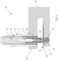
- FIG. 1is a cross-sectional side view of an embodiment of the apparatus of the invention.
- FIG. 2 Ais a front view of an embodiment of the apparatus of the invention and FIG. 2 B is a cross-section view of the apparatus of FIG. 2 A through line A-A;
- FIG. 3 Ais side view of the apparatus shown in FIG. 2 A and FIG. 3 B is a cross-sectional view of the apparatus shown in FIG. 3 A through line B-B;
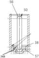
- FIG. 4 Ais a side view of an embodiment of the stripping sleeve with the inner wall shown in phantom and FIG. 4 B is a cross-sectional view of the stripping sleeve shown in FIG. 4 A through line A-A;
- FIG. 5 Ais a side view of another embodiment of the stripping sleeve with the inner wall shown in phantom and FIG. 5 B is a cross-sectional view of the stripping sleeve shown in FIG. 5 A through line A-A;
- FIG. 6is a side view of an embodiment of the slot guide for a stripping sleeve
- FIG. 7is an embodiment of the punch bushing
- FIG. 8is another embodiment of a punch bushing
- FIG. 9 Ais a side view of an embodiment of the pillar and FIG. 9 B is a cross-sectional view of the embodiment shown in FIG. 9 A through line A-A; and
- FIGS. 10 A- 10 Cshow an embodiment of the apparatus in progressive stages of action.
- FIG. 10 Ais a cross-sectional view of an embodiment of the apparatus with a porous substrate on the support
- FIG. 10 Bis the apparatus with the stripper sleeve and puncher deployed and in contact with the card
- FIG. 10 Cshows the puncher fully extended after cutting a piece from the card and pushing it through the die of the punching bushing.
- the methods and apparatuses of the inventionare in part adapted to prevent the loss of samples located on porous substrates, such as FTA paper, when processing the samples, such as dried blood spots. These methods and apparatuses may be incorporated into systems designed, for example, to automate the cutting of discs from dried samples on carrier substrates such as cellulose matrices or polymer membranes.
- a small punche.g. 1-6 mm in diameter
- One or more of the embodiments of the methods and apparatusescomprises a spring-loaded stripping sleeve that holds the porous substrate against a support while a puncher punches a piece out of the porous substrate, through a die and into a receptacle and while the puncher is retracted from the subsequent hole in the porous substrate.
- Apparatus 10comprises punch 12 having a punch head 34 , stripping sleeve 14 , pillar 20 in which punch 12 is seated, a hard-liner support 22 which is fixed to C-frame support 18 , and die 16 which is seated in the lower arm of C-frame support 18 .
- Stripping sleeve 14is spring loaded by load spring 26 which surrounds punch 12 and is also seated in pillar 20 and actuates stripping sleeve 14 by pressing against shoulder 38 of stripping sleeve 14 when the punch 12 is driven downward toward die 16 during a punching operation.
- load spring 26which surrounds punch 12 and is also seated in pillar 20 and actuates stripping sleeve 14 by pressing against shoulder 38 of stripping sleeve 14 when the punch 12 is driven downward toward die 16 during a punching operation.
- the C-frame design of support 18minimizes the size and footprint of the apparatus and minimizes vibration as well.
- the integrated stripping sleeve 14prevents motion of the porous substrate as punch 12 punches through substrate 28 and die 16 , and then as punch 12 is retracted back through die 16 and substrate 28 after a piece is cut out of the substrate.
- the continuous punch control of apparatus 10 with a full stroke all the way through die 16reduces the complexity of the apparatus and obviates the need for an ejector pin associated with previous punching systems.
- the moving parts of apparatus 10may be removed from apparatus 10 as a unit, by removing the pillar assembly from the c-frame support 18 along the punch axis.
- An embodiment of pillar 20is shown in FIGS. 9 A and 9 B generally show the location set screw 32 and pin guide 35 of this example embodiment.
- any of the subcomponents of the unitmay be replaced or interchanged.
- the stripping sleeve 14may be removed and replaced by removing pins 52 from pin holes 35 and sliding the sleeve and spring 26 from counter bore 37 in pillar 20 .
- the punch 12may be removed and replaced by removing the engagement components, such as set screw 32 which passes through the pillar 20 into the punch.
- the common support design of apparatus 10allows the various components of the apparatus to be readily interchanged in the field.
- the punchermay be interchanged, for example, to accommodate different punch sizes or when the punch head becomes worn.
- Sample pieces of porous substrates used to in biological sample testing systemsare typically between 1 and 6 mm in diameter, which determine the size of die 16 , punch head 34 and stripping sleeve head 36 .
- the apparatusis not limited to such shapes or sizes and may be adapted for any suitably sized pieces to be cut out of the sample substrate.
- Apparatus 10is adapted to cut a sample piece, having a predetermined shape and an outer dimension, out of a porous substrate, such as FTA card 28 .
- Punch 12has a defined outer dimension at the head or distal end 34 of the punch that contacts the FTA card.
- the defined outer diameter of the punch head 34substantially corresponds to the predetermined shape and outer dimension of the sample piece to be cut out of the card.
- the outer dimensionis the largest dimension of the piece that will determine the size of the punch head and, in turn, the size of the die through which the punch head cuts and pushes the cut piece through and into a receptacle.
- the outer dimension of the sample piecewould be the diameter if the sample piece to be cut is a round disc.
- Stripping sleeve 14has a stripping head 36 that also substantially corresponds to the shape and outer dimension of the sample piece, although the stripping head is larger than both the punch head and the sample piece, to hold the porous substrate against a surface of die 16 of apparatus 10 as the die cuts out a piece of the substrate.
- Die 16has an innermost dimension, such as an inner diameter, that is larger than the outermost dimension of the punch head.
- a fixture, such as C-frame support 18holds the die in a fixed position relative to the puncher and stripping sleeve.
- the die or punch bushingmay also be interchangeable by removing a setscrew 33 , shown in FIG. 3 B .
- Stripping sleeve 14comprises elongated slots or channels 50 through which guides, such as stripping sleeve pins 52 extend. Pins 52 are seated in the lower portion of pillar 20 . A retaining ring or clip engages with pin 52 in the notch area 53 to hold the pins in place against the pillar 20 .
- FIG. 6shows an embodiment of stripping sleeve pin 52 having a head 54 that engages slot 50 .
- Slots 50are necessarily limited to an opening that completely perforates the wall of the stripping sleeve. For example, depending on the material the sleeve and the thickness of the wall of the sleeve, the slot could also be a channel or groove that does not perforate the inner surface of the sleeve.
- the pillarcomprises a seat for the guide
- the stripping sleevecomprises one or more channels that engage the guides.
- the sleevecomprises the seat for the guide and the pillar comprises the channels which engage the guides.
- pins 52When in a resting mode, pins 52 are located at the upper end of slot 50 . As stripping sleeve 14 is actuated by loaded spring 26 , slots 50 together with pins 52 allow sleeve 14 to move in a vertical direction to an extent that is determined by the length of slot 50 .
- the upper end 56 of slot 50serves as a stop for pin 52 when at the punch is at rest.
- the lower end 57serves as a hard stop for pin 52 but the pin should never limit the motion in the direction of the lower end 57 under normal operating conditions.
- the sleeve 14When the sleeve 14 reaches the desired point at which sleeve head 36 is providing just enough pressure on FTA card 28 to hold it in place on support 18 without making an imprint in, or otherwise damaging, the FTA card 28 or a biological sample on the card.
- the end of the sleeve 36should extend beyond the punch 12 such that the punch is recessed within the sleeve in the resting mode; in this way, the sleeve will maintain contact prior, during, and after the punch contacts the card 28 .]
- the length of slot 50will generally be determined by the length of die 16 together with the thickness of card 28 .
- Sleeve 14as shown in FIGS.
- FIGS. 4 A and 4 Bhas a sleeve head 36 that is substantially smaller that the upper inner diameter of sleeve 14 , to accommodate punches for cutting relatively small pieces of porous substrates.
- the embodiment of the sleeve head shown in FIGS. 4 A and 4 Bgraduates from a larger diameter to a smaller diameter sleeve head in part by a series of stepped shoulders including the shoulder 38 and a second shoulder 38 B and a gradual tapered head.
- the loaded spring 26 of apparatus 10is seated, and presses against, shoulder 38 during a punching operation.
- FIGS. 5 A and 5 BAnother embodiment of a stripping sleeve is shown in FIGS. 5 A and 5 B .
- Stripping sleeve 60has a sleeve head 64 having a diameter than is larger, than sleeve head 36 relative to the upper inner diameter of the sleeve, to accommodate punches for cutting relatively larger piece of porous substrates.
- Sleeve 60also has shoulder 62 that similarly serves in part as a stop for a loaded spring.
- the components of apparatus 10should be made of materials that are suited to withstand a reasonable amount of use so as to reduce the amount of wear on the parts and the frequency of changing the components.
- Sleeve 14may be made from a variety of materials such as aluminum, plastic and steel. Generally though, materials that are lighter in weight but which are still able to withstand repeated use, such as aluminum, may be more suitable that heavier materials, such as steel, to reduce the overall weight of the apparatus.
- Die 16may be a punching bushing as shown in FIGS. 1 , 2 and 8 .
- Punch bushing 16has an inner bore 74 that is only slightly larger than the outer diameter of punch head 34 .
- Bushing 16has a tapered head 70 to accommodate small punch heads for cutting relatively small pieces of the porous substrate.
- Bushing 16also has a shoulder 72 on which the bushing rests when seated on a corresponding shoulder of lower arm 42 of C-frame support 18 .
- the bore of the diemay gradually increase in diameter from the top entrance of the die to the bottom exit of the die.
- bushing 80which has a head 82 and inner bore 84 that are larger relative to the outside diameter of the bushing to accommodate larger punch heads for cutting relatively larger pieces of a porous substrate.
- the punching methodis illustrated in the example shown by the cross-sectionals views of FIGS. 10 A- 10 C .
- the punchperforms the blanking process by shearing the FTA substrate using a traditional punch and die approach.
- the punch headgenerally moves at high speed (e.g. 500 mm/sec) and pushes the substrate through the bottom die, creating a blank (sample disc) in the shape of the die.
- the clearance between the cylindrical punch and the cylindrical opening in the dieis very tight (e.g. about 0.0002′′ or 5 ⁇ m) to ensure a high quality blank with little or no fraying.
- the stripping sleevethat holds the FTA substrate in place during the punch and retraction motions.
- the stripping sleeveis a spring-loaded component that engages stripping sleeve pin and moves with the punch head.
- the stripping sleeve in this examplehas a pre-load of about 13N and is slotted to allow for relative motion with sleeve pin and punch.
- the loaded springpushes against a shoulder of the sleeve. This action forces the sleeve downward until the sleeve head contacts the FTA substrate just before the punch, because, in this example, the punch is slightly recessed within the sleeve.
- the pre-load of the stripping sleeveis transferred to the FTA substrate.
- a blankcut disc
- the stripping sleevecontinues to push and hold the FTA substrate against a portion of the bottom die.
- the holding forcereaches a peak at the max stroke of the punch head (e.g. approximately 22N).
- the punchis retracted through the die, the edges of the substrate are in contact with the body of the punch and the friction applies an upward force on the substrate.
- the stripping sleeveapplies a downward force on the substrate to prevent any motion of the substrate, so long as the force (ranging from peak force to preload force) is less than the upward force created by punch retraction. Because the punch is normally, in this example, slightly recessed in the stripping sleeve, the sleeve continues to apply a downward force until the punch is fully retracted from the substrate.
- the component design and configurationalso serves to provide positive sample control.
- the punch mechanismis configured so that the punched sample disc is unlikely to become stuck in an undesirable location. Lost samples increase the risk of cross contamination and may result in requiring a large number of samples being retaken.
- the positive sample controlis implemented by ensuring that the stroke of the punch continues all the way through the die. If a receptacle is positioned directly under and in contact with the immediate underside of the bottom die, the location of the cut sample disc will be ensured after the punching operation.
- the methods and systems of the inventionmay be used in conjunction (e.g. in-line) with analytical systems that analyze the samples and materials extracted from the samples on the porous substrates for many different purposes such as, but not limited to, immunoassays (e.g. to identify the presence or absence of a component), liquid chromatography with UV detection (e.g. to characterize and quantify components), liquid chromatography with mass spectrometry (e.g. to identify and/or quantify components), and polymerase chain reaction (PCR) for DNA analysis.
- immunoassayse.g. to identify the presence or absence of a component
- liquid chromatography with UV detectione.g. to characterize and quantify components
- liquid chromatography with mass spectrometrye.g. to identify and/or quantify components
- PCRpolymerase chain reaction
Landscapes
- Life Sciences & Earth Sciences (AREA)
- Engineering & Computer Science (AREA)
- Mechanical Engineering (AREA)
- Forests & Forestry (AREA)
- Chemical & Material Sciences (AREA)
- Health & Medical Sciences (AREA)
- Physics & Mathematics (AREA)
- Analytical Chemistry (AREA)
- Biochemistry (AREA)
- General Health & Medical Sciences (AREA)
- General Physics & Mathematics (AREA)
- Immunology (AREA)
- Pathology (AREA)
- Perforating, Stamping-Out Or Severing By Means Other Than Cutting (AREA)
- Sampling And Sample Adjustment (AREA)
Abstract
Description
Claims (15)
Priority Applications (1)
| Application Number | Priority Date | Filing Date | Title |
|---|---|---|---|
| US17/342,431US12145288B2 (en) | 2010-06-30 | 2021-06-08 | Apparatuses and methods for cutting porous substrates |
Applications Claiming Priority (3)
| Application Number | Priority Date | Filing Date | Title |
|---|---|---|---|
| US12/826,877US9321095B2 (en) | 2010-06-30 | 2010-06-30 | Apparatuses and methods for cutting porous substrates |
| US15/090,255US20160214269A1 (en) | 2010-06-30 | 2016-04-04 | Apparatuses and methods for cutting porous substrates |
| US17/342,431US12145288B2 (en) | 2010-06-30 | 2021-06-08 | Apparatuses and methods for cutting porous substrates |
Related Parent Applications (1)
| Application Number | Title | Priority Date | Filing Date |
|---|---|---|---|
| US15/090,255ContinuationUS20160214269A1 (en) | 2010-06-30 | 2016-04-04 | Apparatuses and methods for cutting porous substrates |
Publications (2)
| Publication Number | Publication Date |
|---|---|
| US20210291397A1 US20210291397A1 (en) | 2021-09-23 |
| US12145288B2true US12145288B2 (en) | 2024-11-19 |
Family
ID=44487127
Family Applications (3)
| Application Number | Title | Priority Date | Filing Date |
|---|---|---|---|
| US12/826,877Active2031-01-14US9321095B2 (en) | 2010-06-30 | 2010-06-30 | Apparatuses and methods for cutting porous substrates |
| US15/090,255AbandonedUS20160214269A1 (en) | 2010-06-30 | 2016-04-04 | Apparatuses and methods for cutting porous substrates |
| US17/342,431ActiveUS12145288B2 (en) | 2010-06-30 | 2021-06-08 | Apparatuses and methods for cutting porous substrates |
Family Applications Before (2)
| Application Number | Title | Priority Date | Filing Date |
|---|---|---|---|
| US12/826,877Active2031-01-14US9321095B2 (en) | 2010-06-30 | 2010-06-30 | Apparatuses and methods for cutting porous substrates |
| US15/090,255AbandonedUS20160214269A1 (en) | 2010-06-30 | 2016-04-04 | Apparatuses and methods for cutting porous substrates |
Country Status (5)
| Country | Link |
|---|---|
| US (3) | US9321095B2 (en) |
| EP (1) | EP2588844B1 (en) |
| CN (1) | CN103119418B (en) |
| GB (1) | GB2493893B (en) |
| WO (1) | WO2012001013A1 (en) |
Families Citing this family (16)
| Publication number | Priority date | Publication date | Assignee | Title |
|---|---|---|---|---|
| CA3124804C (en) | 2012-09-18 | 2023-08-22 | Auspex Pharmaceuticals, Inc. | Formulations pharmacokinetics of deuterated benzoquinoline inhibitors of vesicular monoamine transporter 2 |
| CN102990710A (en)* | 2012-10-29 | 2013-03-27 | 茅惠杰 | Improved punching structure |
| CN104316371B (en)* | 2014-10-15 | 2016-08-17 | 东北大学 | The sample separating apparatus of a kind of metallographic specimen and using method thereof |
| PT3265085T (en) | 2015-03-06 | 2022-09-05 | Auspex Pharmaceuticals Inc | Methods for the treatment of abnormal involuntary movement disorders |
| JP6576851B2 (en)* | 2016-02-17 | 2019-09-18 | 学校法人大同学園 | Half blanking test method |
| CN105818207B (en)* | 2016-05-25 | 2018-06-08 | 浙江三棱塑胶有限公司 | A kind of intermediate supports plastic cylinder body three-point positioning mechanism |
| CN205950870U (en)* | 2016-08-17 | 2017-02-15 | 广州蓝勃生物科技有限公司 | Sheet perforating device |
| CN106272682B (en)* | 2016-09-23 | 2018-07-27 | 陕西理工大学 | One kind can positional punch device |
| DE102017100957A1 (en)* | 2017-01-18 | 2018-07-19 | Boxplan Gmbh & Co. Kg | Device for changing the insertion of a first ram or a second ram |
| CN107263594B (en)* | 2017-06-26 | 2018-10-26 | 朱建国 | An automatic blanking and cutting raw betel nut device |
| CN107297765B (en)* | 2017-06-26 | 2018-10-26 | 朱建国 | A kneading device for cutting raw betel nuts |
| CN107322682B (en)* | 2017-08-07 | 2019-07-12 | 北京工业大学 | A punching device for microfluidic chip PDMS material |
| JP6931943B2 (en) | 2017-08-30 | 2021-09-08 | イムプリメド インコーポレイティッドImprimed,Inc. | Products for high-volume sorting of chemical and biochemical compounds |
| CN109540631B (en)* | 2019-01-10 | 2022-07-26 | 韩华新能源(启东)有限公司 | Sample preparation tool and sample preparation method for photovoltaic material DSC |
| PL240069B1 (en)* | 2019-11-22 | 2022-02-14 | Politechnika Poznanska | Perforating head with two cutting edges with a movable punch for a device for perforation of transport belts |
| CN112326297B (en)* | 2020-10-30 | 2023-12-22 | 河南省中医院(河南中医药大学第二附属医院) | Lymph node screening device for tumor examination |
Citations (57)
| Publication number | Priority date | Publication date | Assignee | Title |
|---|---|---|---|---|
| US2217393A (en) | 1938-04-27 | 1940-10-08 | Webb George Henry | Machine for nibbling or punching metal and other sheets |
| US2225342A (en) | 1939-03-18 | 1940-12-17 | Allied Steel & Conveyors Inc | Punch stripping device |
| US2364011A (en) | 1943-02-25 | 1944-11-28 | George F Wales | Punching machine |
| FR1053907A (en) | 1951-07-24 | 1954-02-05 | Pari Mutuel Soc D Expl Du | Punch tool |
| US2953051A (en) | 1956-09-20 | 1960-09-20 | George F Wales | Perforating implement with stripper sleeve retaining means |
| US3079824A (en)* | 1960-08-09 | 1963-03-05 | Houdaille Industries Inc | Punching device having a spring biased stripper |
| US3114280A (en) | 1960-12-14 | 1963-12-17 | Houdaille Industries Inc | Punching device |
| US3205742A (en)* | 1963-07-11 | 1965-09-14 | Dro Engineering Company Di | Adjustable pierce unit |
| US3357755A (en) | 1965-10-23 | 1967-12-12 | Danly Mach Specialties Inc | Ball bearing die set |
| US3628407A (en) | 1969-12-22 | 1971-12-21 | Hobart S Adams | Precision long reach hole punch |
| US3722337A (en) | 1970-12-31 | 1973-03-27 | Whitney Corp W | Fluid-actuated punch press with workpiece stripper |
| US3779113A (en)* | 1971-03-04 | 1973-12-18 | P Jestin | Punching unit |
| US3863341A (en) | 1973-08-27 | 1975-02-04 | James L Ramer | Explosive actuated punch |
| US3935772A (en) | 1975-03-21 | 1976-02-03 | Houdaille Industries, Inc. | Punching device having selectable pinch point clearance |
| US4012975A (en)* | 1975-07-31 | 1977-03-22 | Lalone Barry Grant | High speed punching apparatus and tool therefor |
| US4341735A (en) | 1980-03-28 | 1982-07-27 | American Cyanamid Company | Sample carrier material handling apparatus |
| US4457196A (en) | 1980-12-17 | 1984-07-03 | Houdaille Industries, Inc. | Punch press assembly including a preloaded encapsulted spring |
| US4489053A (en) | 1981-12-03 | 1984-12-18 | Nihon Medi-Physics Co., Ltd. | Stable radioactive diagnostic agent and a non-radioactive carrier therefor |
| US4696211A (en)* | 1984-10-18 | 1987-09-29 | Trumpf Gmbh & Co. | Method and apparatus for nibbling cutouts with rectilinear and curvilinear contours by rotation of tooling with cutting surfaces of rectilinear and curvilinear contours and novel tooling therefor |
| US4993295A (en) | 1988-12-08 | 1991-02-19 | Utica Enterprises, Inc. | Punch stripper |
| US5045302A (en) | 1988-04-11 | 1991-09-03 | Amersham International Plc | Ligands and cationic complexes thereof with technetium-99m |
| US5081891A (en) | 1988-08-19 | 1992-01-21 | Mate Punch & Die Co. | Punch assembly |
| US5176057A (en) | 1991-10-11 | 1993-01-05 | Murata Machinery Limited | Punch holder with stripper arrangement |
| US5300280A (en) | 1992-02-14 | 1994-04-05 | Mallinckrodt Medical, Inc. | Stabilized radiopharmaceutical kits |
| US5460057A (en) | 1992-07-14 | 1995-10-24 | Wallac Oy | Method and apparatus for handling samples and sample collection system |
| US5598635A (en)* | 1993-04-28 | 1997-02-04 | Nitto Kohki Co., Ltd. | Hydraulic puncher |
| US5638170A (en) | 1994-06-07 | 1997-06-10 | Hudson Control Group, Inc. | Punched carrier specimen sample processor |
| US5848563A (en)* | 1992-07-21 | 1998-12-15 | Amada Metrecs Company Limited | Multiple tool for punch press |
| US6142052A (en)* | 1997-10-06 | 2000-11-07 | Amada Metrecs Company, Limited | Punching tool |
| DE10048643A1 (en) | 1999-09-22 | 2001-05-31 | Biopsytec Gmbh | Automatic sampling unit for filling microtitration plates with plant matter, comprises a stripper designed for virtually friction-free motion along a cutting stamp axis |
| DE20022666U1 (en) | 2000-09-22 | 2002-01-03 | Biopsytec GmbH, 10435 Berlin | Device for automated sampling and filling of microtiter plates with plant material |
| CN1331081A (en) | 2000-06-28 | 2002-01-16 | 北京师范大学 | Tetraphosphine quatorphosphonium salt, its preparing process, and two-step tetraphosphine medicine kit and its application |
| US6342143B1 (en) | 2000-01-06 | 2002-01-29 | Carnegie Mellon University | Cutting tool for multiple sample retrieval from gelatinous material |
| US6372504B1 (en) | 1998-12-16 | 2002-04-16 | Labsystems Oy | Method and apparatus for conveying a sample to a sample vessel |
| US6713042B2 (en) | 2001-02-26 | 2004-03-30 | Bristol-Myers Squibb Pharma Company | Ascorbic acid analogs for metalloradiopharmaceuticals |
| US20050129579A1 (en) | 2003-11-05 | 2005-06-16 | Bizpac (Australia) Pty Ltd. | System and method for analysing laboratory samples |
| US20060060046A1 (en)* | 2004-09-22 | 2006-03-23 | Fumitaka Sugizaki | Biasing assembly for a punching device |
| US7029653B1 (en) | 1999-06-21 | 2006-04-18 | Nihon Medi-Physics Co., Ltd. | Method of the administration of drugs having binding affinity with plasma protein and preparation to be used in the method |
| US7052672B2 (en) | 2000-12-28 | 2006-05-30 | Ge Healthcare Limited | Stabilized radiopharmaceutical compositions |
| WO2006094388A1 (en) | 2005-03-07 | 2006-09-14 | Novx Systems Inc. | Automated analyzer |
| US20060216781A1 (en) | 2005-03-23 | 2006-09-28 | Gebing Ronald A | Microarrayer with coaxial multiple punches |
| US20060246419A1 (en) | 2005-04-07 | 2006-11-02 | Bio-Rad Laboratories, Inc. | Layered support sheet for high-yield spot cutting from gels or membranes |
| US7156009B2 (en)* | 2000-10-26 | 2007-01-02 | Amada Company, Limited | Die device |
| US7159426B1 (en)* | 2005-09-27 | 2007-01-09 | Gm Global Technology Operations, Inc. | Quick change assembly for hydroforming punches |
| US7168356B2 (en)* | 2001-06-19 | 2007-01-30 | Wilson Tool International Inc. | Adjustable length punch assembly |
| US20080105095A1 (en) | 2006-11-06 | 2008-05-08 | Stromsholmen Ab | Punch stripper and press tool |
| WO2009115852A2 (en) | 2008-03-20 | 2009-09-24 | 3Dhistech Kft. | Sampling unit |
| CN101614628A (en) | 2009-07-16 | 2009-12-30 | 上海交通大学 | Composite Die for Stretching, Punching and Reaming Used to Test Hole Reaming Properties of Plates |
| WO2010043668A1 (en) | 2008-10-17 | 2010-04-22 | Zentech S.A. | Dried blood spots for blood analysis |
| US7954404B2 (en) | 2008-04-29 | 2011-06-07 | Mate Precision Tooling, Inc. | Punch device with adjustment subassembly as retrofit insert or as original equipment |
| US20110132111A1 (en) | 2009-12-04 | 2011-06-09 | General Electric Company | Methods and systems to prevent punch loss during automated sample processing |
| US8408111B2 (en)* | 2008-11-06 | 2013-04-02 | Wilson Tool International Inc. | Adjustable punch assemblies and associated adjustment methods |
| US20140109742A1 (en)* | 2012-10-19 | 2014-04-24 | Mate Precision Tooling, Inc. | Punch Assembly With Separate Adjustable Punch Guiding Shim Block |
| US8714065B2 (en)* | 2004-11-19 | 2014-05-06 | Amada Company, Limited | Punching die |
| US20160228936A1 (en)* | 2015-02-09 | 2016-08-11 | Mate Precision Tooling, Inc. | Punch assembly with replaceable punch tip |
| US11034046B2 (en)* | 2017-04-04 | 2021-06-15 | Amada Tool America, Inc. | Adjustable punch head assembly |
| US20210354188A1 (en)* | 2020-05-14 | 2021-11-18 | BTM Company, LLC | Metal fastening die assembly |
- 2010
- 2010-06-30USUS12/826,877patent/US9321095B2/enactiveActive
- 2011
- 2011-06-28GBGB1222224.6Apatent/GB2493893B/enactiveActive
- 2011-06-28WOPCT/EP2011/060853patent/WO2012001013A1/enactiveApplication Filing
- 2011-06-28EPEP11743785.5Apatent/EP2588844B1/enactiveActive
- 2011-06-28CNCN201180032550.6Apatent/CN103119418B/enactiveActive
- 2016
- 2016-04-04USUS15/090,255patent/US20160214269A1/ennot_activeAbandoned
- 2021
- 2021-06-08USUS17/342,431patent/US12145288B2/enactiveActive
Patent Citations (59)
| Publication number | Priority date | Publication date | Assignee | Title |
|---|---|---|---|---|
| US2217393A (en) | 1938-04-27 | 1940-10-08 | Webb George Henry | Machine for nibbling or punching metal and other sheets |
| US2225342A (en) | 1939-03-18 | 1940-12-17 | Allied Steel & Conveyors Inc | Punch stripping device |
| US2364011A (en) | 1943-02-25 | 1944-11-28 | George F Wales | Punching machine |
| FR1053907A (en) | 1951-07-24 | 1954-02-05 | Pari Mutuel Soc D Expl Du | Punch tool |
| US2953051A (en) | 1956-09-20 | 1960-09-20 | George F Wales | Perforating implement with stripper sleeve retaining means |
| US3079824A (en)* | 1960-08-09 | 1963-03-05 | Houdaille Industries Inc | Punching device having a spring biased stripper |
| US3114280A (en) | 1960-12-14 | 1963-12-17 | Houdaille Industries Inc | Punching device |
| US3205742A (en)* | 1963-07-11 | 1965-09-14 | Dro Engineering Company Di | Adjustable pierce unit |
| US3357755A (en) | 1965-10-23 | 1967-12-12 | Danly Mach Specialties Inc | Ball bearing die set |
| US3628407A (en) | 1969-12-22 | 1971-12-21 | Hobart S Adams | Precision long reach hole punch |
| US3722337A (en) | 1970-12-31 | 1973-03-27 | Whitney Corp W | Fluid-actuated punch press with workpiece stripper |
| US3779113A (en)* | 1971-03-04 | 1973-12-18 | P Jestin | Punching unit |
| US3863341A (en) | 1973-08-27 | 1975-02-04 | James L Ramer | Explosive actuated punch |
| US3935772A (en) | 1975-03-21 | 1976-02-03 | Houdaille Industries, Inc. | Punching device having selectable pinch point clearance |
| US4012975A (en)* | 1975-07-31 | 1977-03-22 | Lalone Barry Grant | High speed punching apparatus and tool therefor |
| US4341735A (en) | 1980-03-28 | 1982-07-27 | American Cyanamid Company | Sample carrier material handling apparatus |
| US4457196A (en) | 1980-12-17 | 1984-07-03 | Houdaille Industries, Inc. | Punch press assembly including a preloaded encapsulted spring |
| US4489053A (en) | 1981-12-03 | 1984-12-18 | Nihon Medi-Physics Co., Ltd. | Stable radioactive diagnostic agent and a non-radioactive carrier therefor |
| US4696211A (en)* | 1984-10-18 | 1987-09-29 | Trumpf Gmbh & Co. | Method and apparatus for nibbling cutouts with rectilinear and curvilinear contours by rotation of tooling with cutting surfaces of rectilinear and curvilinear contours and novel tooling therefor |
| US5045302A (en) | 1988-04-11 | 1991-09-03 | Amersham International Plc | Ligands and cationic complexes thereof with technetium-99m |
| US5081891A (en) | 1988-08-19 | 1992-01-21 | Mate Punch & Die Co. | Punch assembly |
| US4993295A (en) | 1988-12-08 | 1991-02-19 | Utica Enterprises, Inc. | Punch stripper |
| US5176057A (en) | 1991-10-11 | 1993-01-05 | Murata Machinery Limited | Punch holder with stripper arrangement |
| US5300280A (en) | 1992-02-14 | 1994-04-05 | Mallinckrodt Medical, Inc. | Stabilized radiopharmaceutical kits |
| US5460057A (en) | 1992-07-14 | 1995-10-24 | Wallac Oy | Method and apparatus for handling samples and sample collection system |
| US5848563A (en)* | 1992-07-21 | 1998-12-15 | Amada Metrecs Company Limited | Multiple tool for punch press |
| US5598635A (en)* | 1993-04-28 | 1997-02-04 | Nitto Kohki Co., Ltd. | Hydraulic puncher |
| US5638170A (en) | 1994-06-07 | 1997-06-10 | Hudson Control Group, Inc. | Punched carrier specimen sample processor |
| US6142052A (en)* | 1997-10-06 | 2000-11-07 | Amada Metrecs Company, Limited | Punching tool |
| US6372504B1 (en) | 1998-12-16 | 2002-04-16 | Labsystems Oy | Method and apparatus for conveying a sample to a sample vessel |
| US7029653B1 (en) | 1999-06-21 | 2006-04-18 | Nihon Medi-Physics Co., Ltd. | Method of the administration of drugs having binding affinity with plasma protein and preparation to be used in the method |
| DE10048643A1 (en) | 1999-09-22 | 2001-05-31 | Biopsytec Gmbh | Automatic sampling unit for filling microtitration plates with plant matter, comprises a stripper designed for virtually friction-free motion along a cutting stamp axis |
| US6342143B1 (en) | 2000-01-06 | 2002-01-29 | Carnegie Mellon University | Cutting tool for multiple sample retrieval from gelatinous material |
| CN1331081A (en) | 2000-06-28 | 2002-01-16 | 北京师范大学 | Tetraphosphine quatorphosphonium salt, its preparing process, and two-step tetraphosphine medicine kit and its application |
| DE20022666U1 (en) | 2000-09-22 | 2002-01-03 | Biopsytec GmbH, 10435 Berlin | Device for automated sampling and filling of microtiter plates with plant material |
| US7156009B2 (en)* | 2000-10-26 | 2007-01-02 | Amada Company, Limited | Die device |
| US7052672B2 (en) | 2000-12-28 | 2006-05-30 | Ge Healthcare Limited | Stabilized radiopharmaceutical compositions |
| US6713042B2 (en) | 2001-02-26 | 2004-03-30 | Bristol-Myers Squibb Pharma Company | Ascorbic acid analogs for metalloradiopharmaceuticals |
| US7168356B2 (en)* | 2001-06-19 | 2007-01-30 | Wilson Tool International Inc. | Adjustable length punch assembly |
| US20050129579A1 (en) | 2003-11-05 | 2005-06-16 | Bizpac (Australia) Pty Ltd. | System and method for analysing laboratory samples |
| US20060060046A1 (en)* | 2004-09-22 | 2006-03-23 | Fumitaka Sugizaki | Biasing assembly for a punching device |
| US8714065B2 (en)* | 2004-11-19 | 2014-05-06 | Amada Company, Limited | Punching die |
| WO2006094388A1 (en) | 2005-03-07 | 2006-09-14 | Novx Systems Inc. | Automated analyzer |
| US7666355B2 (en) | 2005-03-07 | 2010-02-23 | Tino Alavie | Automated analyzer |
| US20060216781A1 (en) | 2005-03-23 | 2006-09-28 | Gebing Ronald A | Microarrayer with coaxial multiple punches |
| US20060246419A1 (en) | 2005-04-07 | 2006-11-02 | Bio-Rad Laboratories, Inc. | Layered support sheet for high-yield spot cutting from gels or membranes |
| US7159426B1 (en)* | 2005-09-27 | 2007-01-09 | Gm Global Technology Operations, Inc. | Quick change assembly for hydroforming punches |
| US20080105095A1 (en) | 2006-11-06 | 2008-05-08 | Stromsholmen Ab | Punch stripper and press tool |
| WO2009115852A2 (en) | 2008-03-20 | 2009-09-24 | 3Dhistech Kft. | Sampling unit |
| US7954404B2 (en) | 2008-04-29 | 2011-06-07 | Mate Precision Tooling, Inc. | Punch device with adjustment subassembly as retrofit insert or as original equipment |
| WO2010043668A1 (en) | 2008-10-17 | 2010-04-22 | Zentech S.A. | Dried blood spots for blood analysis |
| US8408111B2 (en)* | 2008-11-06 | 2013-04-02 | Wilson Tool International Inc. | Adjustable punch assemblies and associated adjustment methods |
| CN101614628A (en) | 2009-07-16 | 2009-12-30 | 上海交通大学 | Composite Die for Stretching, Punching and Reaming Used to Test Hole Reaming Properties of Plates |
| US20110132111A1 (en) | 2009-12-04 | 2011-06-09 | General Electric Company | Methods and systems to prevent punch loss during automated sample processing |
| US20140109742A1 (en)* | 2012-10-19 | 2014-04-24 | Mate Precision Tooling, Inc. | Punch Assembly With Separate Adjustable Punch Guiding Shim Block |
| US20160228936A1 (en)* | 2015-02-09 | 2016-08-11 | Mate Precision Tooling, Inc. | Punch assembly with replaceable punch tip |
| US10328479B2 (en)* | 2015-02-09 | 2019-06-25 | Mate Precision Tooling, Inc. | Punch assembly with replaceable punch tip secured by coupling pin |
| US11034046B2 (en)* | 2017-04-04 | 2021-06-15 | Amada Tool America, Inc. | Adjustable punch head assembly |
| US20210354188A1 (en)* | 2020-05-14 | 2021-11-18 | BTM Company, LLC | Metal fastening die assembly |
Non-Patent Citations (6)
| Title |
|---|
| Chinese Office Action issued in connection with corresponding CN Application No. 201180032550.6 on Aug. 29, 2014. |
| EP Office Action from corresponding EP Application No. 11743785.5 dated Nov. 27, 2013. |
| European Office Action issued in connection with corresponding EP Application No. 11743785.5 on Oct. 8, 2015. |
| GB Office Action from corresponding GB Application No. 1222224.6 dated Mar. 31, 2014. |
| PCT Search Report and Written Opinion from corresponding PCT Application No. PCT/EP2011/060853 dated Sep. 23, 2011. |
| Tanno et al., "Radiopharmaceuticals", Medicine and Drug, 30:268 (1994). |
Also Published As
| Publication number | Publication date |
|---|---|
| US20160214269A1 (en) | 2016-07-28 |
| GB2493893B (en) | 2015-04-15 |
| EP2588844A1 (en) | 2013-05-08 |
| US20210291397A1 (en) | 2021-09-23 |
| GB2493893A (en) | 2013-02-20 |
| US20120000330A1 (en) | 2012-01-05 |
| WO2012001013A1 (en) | 2012-01-05 |
| CN103119418A (en) | 2013-05-22 |
| US9321095B2 (en) | 2016-04-26 |
| CN103119418B (en) | 2016-03-02 |
| GB201222224D0 (en) | 2013-01-23 |
| EP2588844B1 (en) | 2019-08-07 |
Similar Documents
| Publication | Publication Date | Title |
|---|---|---|
| US12145288B2 (en) | Apparatuses and methods for cutting porous substrates | |
| CA2780523C (en) | Sample processing system and method thereof with a punching head and an ejector pin | |
| JP6026572B2 (en) | Transfer device, sample distribution system and laboratory automation system | |
| JP5671051B2 (en) | Method and system for processing a sample on a porous substrate | |
| US6943035B1 (en) | Liquid dispensing apparatus and method | |
| CA2304731A1 (en) | Apparatus for removing a sample from an array of samples and a cutting tool for use with that apparatus | |
| EP3435091A1 (en) | Automatic analysis device | |
| US20060213258A1 (en) | System useful for holding a sample and in subjecting the sample to chromatographic analysis | |
| JP2006091006A (en) | Manufacturing system and method of chip equipment | |
| EP0332944A2 (en) | Filter punch and filter collection system | |
| US20210033635A1 (en) | Sampling mechanism and sampling method | |
| US5062308A (en) | Filter punch and filter collection system | |
| Finehout et al. | Document Title: Automated Processing of FTA Samples |
Legal Events
| Date | Code | Title | Description |
|---|---|---|---|
| FEPP | Fee payment procedure | Free format text:ENTITY STATUS SET TO UNDISCOUNTED (ORIGINAL EVENT CODE: BIG.); ENTITY STATUS OF PATENT OWNER: LARGE ENTITY | |
| STPP | Information on status: patent application and granting procedure in general | Free format text:DOCKETED NEW CASE - READY FOR EXAMINATION | |
| STPP | Information on status: patent application and granting procedure in general | Free format text:NON FINAL ACTION MAILED | |
| STPP | Information on status: patent application and granting procedure in general | Free format text:RESPONSE TO NON-FINAL OFFICE ACTION ENTERED AND FORWARDED TO EXAMINER | |
| STPP | Information on status: patent application and granting procedure in general | Free format text:NON FINAL ACTION MAILED | |
| STPP | Information on status: patent application and granting procedure in general | Free format text:FINAL REJECTION MAILED | |
| AS | Assignment | Owner name:QIAGEN HEALTHCARE BIOTECHNOLOGIES SYSTEMS GMBH, GERMANY Free format text:CHANGE OF NAME;ASSIGNOR:QIAGEN HEALTHCARE BIOTECHNOLOGIES SYSTEMS LIMITED;REEL/FRAME:064521/0560 Effective date:20200831 Owner name:GE HEALTHCARE BIOTECHNOLOGIES SYSTEMS LIMITED, UNITED KINGDOM Free format text:CHANGE OF NAME;ASSIGNOR:GENERAL ELECTRIC COMPANY;REEL/FRAME:064521/0543 Effective date:20190612 Owner name:GENERAL ELECTRIC COMPANY, NEW YORK Free format text:ASSIGNMENT OF ASSIGNORS INTEREST;ASSIGNOR:GRIFFIN, WESTON BLAINE;REEL/FRAME:064521/0540 Effective date:20100629 Owner name:QIAGEN HEALTHCARE BIOTECHNOLOGIES SYSTEMS LIMITED, UNITED KINGDOM Free format text:CHANGE OF NAME;ASSIGNOR:GE HEALTHCARE BIOTECHNOLOGIES SYSTEMS LIMITED;REEL/FRAME:064522/0143 Effective date:20190906 | |
| STPP | Information on status: patent application and granting procedure in general | Free format text:ADVISORY ACTION MAILED | |
| STPP | Information on status: patent application and granting procedure in general | Free format text:DOCKETED NEW CASE - READY FOR EXAMINATION | |
| STPP | Information on status: patent application and granting procedure in general | Free format text:NON FINAL ACTION MAILED | |
| STPP | Information on status: patent application and granting procedure in general | Free format text:RESPONSE TO NON-FINAL OFFICE ACTION ENTERED AND FORWARDED TO EXAMINER | |
| STPP | Information on status: patent application and granting procedure in general | Free format text:NOTICE OF ALLOWANCE MAILED -- APPLICATION RECEIVED IN OFFICE OF PUBLICATIONS | |
| STPP | Information on status: patent application and granting procedure in general | Free format text:PUBLICATIONS -- ISSUE FEE PAYMENT VERIFIED | |
| STCF | Information on status: patent grant | Free format text:PATENTED CASE |