US12144922B2 - Wound dressing with multiple treatment zones - Google Patents
Wound dressing with multiple treatment zonesDownload PDFInfo
- Publication number
- US12144922B2 US12144922B2US17/624,958US202017624958AUS12144922B2US 12144922 B2US12144922 B2US 12144922B2US 202017624958 AUS202017624958 AUS 202017624958AUS 12144922 B2US12144922 B2US 12144922B2
- Authority
- US
- United States
- Prior art keywords
- wound
- zone
- foam layer
- negative pressure
- drape
- Prior art date
- Legal status (The legal status is an assumption and is not a legal conclusion. Google has not performed a legal analysis and makes no representation as to the accuracy of the status listed.)
- Active, expires
Links
- 238000011282treatmentMethods0.000titleabstractdescription38
- 206010052428WoundDiseases0.000claimsabstractdescription325
- 208000027418Wounds and injuryDiseases0.000claimsabstractdescription325
- 239000006260foamSubstances0.000claimsabstractdescription148
- 239000012530fluidSubstances0.000claimsabstractdescription42
- 238000002560therapeutic procedureMethods0.000claimsdescription104
- 125000004122cyclic groupChemical group0.000claimsdescription18
- 238000000926separation methodMethods0.000description50
- 239000000463materialSubstances0.000description23
- 239000006261foam materialSubstances0.000description22
- 230000005540biological transmissionEffects0.000description8
- 238000000034methodMethods0.000description6
- 208000004221Multiple TraumaDiseases0.000description5
- 230000008878couplingEffects0.000description5
- 238000010168coupling processMethods0.000description5
- 238000005859coupling reactionMethods0.000description5
- 210000000416exudates and transudateAnatomy0.000description5
- 238000012986modificationMethods0.000description4
- 230000004048modificationEffects0.000description4
- 239000000853adhesiveSubstances0.000description3
- 230000001070adhesive effectEffects0.000description3
- 230000008901benefitEffects0.000description2
- 230000008859changeEffects0.000description2
- 208000034693LacerationDiseases0.000description1
- 230000004075alterationEffects0.000description1
- 230000015556catabolic processEffects0.000description1
- 239000003086colorantSubstances0.000description1
- 238000010276constructionMethods0.000description1
- 238000001804debridementMethods0.000description1
- 238000013461designMethods0.000description1
- 238000002955isolationMethods0.000description1
- 230000005012migrationEffects0.000description1
- 238000013508migrationMethods0.000description1
- 239000002245particleSubstances0.000description1
- 230000008569processEffects0.000description1
- 238000012552reviewMethods0.000description1
- 231100000241scarToxicity0.000description1
- 238000006467substitution reactionMethods0.000description1
- 230000007704transitionEffects0.000description1
- 230000029663wound healingEffects0.000description1
Images


Classifications
- A—HUMAN NECESSITIES
- A61—MEDICAL OR VETERINARY SCIENCE; HYGIENE
- A61M—DEVICES FOR INTRODUCING MEDIA INTO, OR ONTO, THE BODY; DEVICES FOR TRANSDUCING BODY MEDIA OR FOR TAKING MEDIA FROM THE BODY; DEVICES FOR PRODUCING OR ENDING SLEEP OR STUPOR
- A61M1/00—Suction or pumping devices for medical purposes; Devices for carrying-off, for treatment of, or for carrying-over, body-liquids; Drainage systems
- A61M1/90—Negative pressure wound therapy devices, i.e. devices for applying suction to a wound to promote healing, e.g. including a vacuum dressing
- A61M1/91—Suction aspects of the dressing
- A61M1/912—Connectors between dressing and drainage tube
- A—HUMAN NECESSITIES
- A61—MEDICAL OR VETERINARY SCIENCE; HYGIENE
- A61F—FILTERS IMPLANTABLE INTO BLOOD VESSELS; PROSTHESES; DEVICES PROVIDING PATENCY TO, OR PREVENTING COLLAPSING OF, TUBULAR STRUCTURES OF THE BODY, e.g. STENTS; ORTHOPAEDIC, NURSING OR CONTRACEPTIVE DEVICES; FOMENTATION; TREATMENT OR PROTECTION OF EYES OR EARS; BANDAGES, DRESSINGS OR ABSORBENT PADS; FIRST-AID KITS
- A61F13/00—Bandages or dressings; Absorbent pads
- A61F13/02—Adhesive bandages or dressings
- A61F13/0203—Adhesive bandages or dressings with fluid retention members
- A61F13/022—Adhesive bandages or dressings with fluid retention members having more than one layer with different fluid retention characteristics
- A—HUMAN NECESSITIES
- A61—MEDICAL OR VETERINARY SCIENCE; HYGIENE
- A61F—FILTERS IMPLANTABLE INTO BLOOD VESSELS; PROSTHESES; DEVICES PROVIDING PATENCY TO, OR PREVENTING COLLAPSING OF, TUBULAR STRUCTURES OF THE BODY, e.g. STENTS; ORTHOPAEDIC, NURSING OR CONTRACEPTIVE DEVICES; FOMENTATION; TREATMENT OR PROTECTION OF EYES OR EARS; BANDAGES, DRESSINGS OR ABSORBENT PADS; FIRST-AID KITS
- A61F13/00—Bandages or dressings; Absorbent pads
- A61F13/05—Bandages or dressings; Absorbent pads specially adapted for use with sub-pressure or over-pressure therapy, wound drainage or wound irrigation, e.g. for use with negative-pressure wound therapy [NPWT]
Definitions
- the present disclosurerelates generally to the field of treating wounds.
- the present disclosurerelates more specifically to dressings capable of applying different wound treatment therapies to different zones of a wound.
- Existing dressings for applying wound treatment therapiespose numerous disadvantages, including: inability to apply different instillation therapies to different wound zones; inability to apply different negative pressure cycles across different wound zones; inability to fluidly isolate different wound zones; etc. Given the limitations of existing dressings for applying wound treatment therapies, it may be desirable to provide a means of isolation between the different zones of a wound such that different wound treatment therapies may be applied to the different zones of the wound.
- the customizable wound treatment systemincludes a dressing configured for use with a first zone and a second zone of the wound that includes a first foam layer configured for placement over the first zone, a second foam layer configured for placement over the second zone, a first drape layer disposed over the first foam layer and beneath the second foam layer, and a second drape layer disposed over the second foam layer.
- the customizable wound treatment systemalso includes a negative pressure source pneumatically coupled to the first foam layer and the second foam layer and operable to create a negative pressure at the first zone and the second zone and a fluid instillation pump fluidly coupled to the first foam layer and configured to instill a treatment fluid to the first zone.
- the first zonecan include a wound bed of the wound and the second zone can include a periwound of the wound.
- the first drape layer and the second drape layerpneumatically and fluidly isolate the first foam layer and the second foam layer from each other.
- the negative pressure sourceis operable to provide a common negative pressure regimen to both the first zone and the second zone.
- the negative pressure sourceis also operable to simultaneously provide a first negative pressure regimen to the first zone and a second negative pressure regimen to the second zone such that the first negative pressure regimen is different from the second negative pressure regimen.
- the first foam layeris disposed above the first zone and the second foam layer is disposed above the second zone in a concentric pattern.
- the second foam layermay extend beyond a perimeter of the first foam layer.
- the first foam layeris formed of a first foam material and the second foam layer is formed of a second foam material.
- the first foam materialmay comprise a first density and the second foam material may comprise a second density that is greater than the first density.
- the second foam layercomprises holes extending therethrough.
- the systemincludes a first foam layer configured for placement over a first wound zone, a second foam layer configured for placement over a second wound zone, a first drape layer disposed over the first foam layer and beneath the second foam layer and configured to isolate the first wound zone from the second wound zone, a second drape layer disposed over the second foam layer and the first drape layer and configured to isolate the first wound zone and the second wound zone from an external environment, an instillation pump that provides an instillation fluid to the first foam layer, a negative pressure pump configured to remove air from the first wound zone and the second wound zone, and a control circuit communicably coupled to the instillation pump and the negative pressure pump.
- control circuitcontrols the instillation pump to provide an amount of instillation fluid to the first foam layer, provide a soak period.
- the control circuitcontrols the negative pressure pump to provide at least one cyclic variation of negative pressure at the first wound zone and the second wound zone.
- the systemincludes a manifold that fluidly communicates the negative pressure pump with the first wound zone and the second wound zone.
- the manifoldis configured to fluidly communicate the first foam layer with the instillation pump via a first tube.
- the manifoldincludes a first and second aperture and fluidly communicates the first foam layer and the second foam layer with the negative pressure pump via a first tube and a second tube.
- the manifoldincludes a single aperture and to fluidly communicate the first foam layer and the second foam layer with the negative pressure pump via a first tube.
- the manifoldis configured to isolate a first cyclic variation of negative pressure applied to the first wound zone from a second cyclic variation of negative pressure applied to the second wound zone.
- the manifoldfluidly couples the instillation pump with the second foam layer.
- the negative pressure pumpapplies a first cyclic variation of negative pressure to the first foam layer and a second cyclic variation of negative pressure to the second foam layer.
- the first drape layerincludes a first drape aperture configured to receive a first tube and the second drape layer includes a second drape aperture configured to align with the first drape aperture and receive the first tube.
- the second drape layercan include a third drape aperture configured to receive a second tube.
- the manifoldcan include a first aperture and a second aperture configured to align with a second drape aperture and a third drape aperture.
- control circuitis configured to simultaneously control the negative pressure pump to provide at least one cyclic variation of negative pressure at the first foam layer and the second foam layer and control the instillation pump to provide the instillation fluid to the first foam layer.
- control circuitis configured to apply a first cyclic variation of negative pressure to the first wound zone and a second cyclic variation of negative pressure to the second wound zone.
- control circuitis configured to apply a first constant negative pressure to the first wound zone and a second constant negative pressure to the second wound zone.
- control circuitis configured to control the negative pressure pump to simultaneously provide a constant negative pressure to the first wound zone and a cyclic variation of negative pressure to the second wound zone.
- the different wound therapiesinclude a first wound therapy applied to the first wound zone including a first application of negative pressure and a first application of instillation and a second wound therapy applied to the second wound zone including a second application of negative pressure and a second application of instillation.
- the different wound therapiescan include a user selection of the different wound therapies.
- Another implementation of the present disclosureis a method for applying different wound therapies to wound zones.
- the methodincludes placing a first foam layer over a first wound zone, placing a second foam layer over a second wound zone, placing a first drape layer over the first foam layer and beneath the second foam layer, covering the second foam layer with a second drape layer, providing a manifold that bridges between and fluidly communicates with the first foam layer and the second foam layer and with an instillation pump and a negative pressure pump, applying a first wound therapy to the first wound zone, and applying a second would therapy to the second wound zone.
- placing the first foam layer over the first wound zoneinvolves fitting the first foam layer to the first wound zone and placing the second foam layer over the second wound zone involves fitting the second foam layer to the second wound zone.
- applying the first wound therapy to the first wound zoneinvolves applying a first application of negative pressure to the first wound zone and applying a first application of instillation to the first wound zone.
- applying the first application of negative pressure to the first wound zoneinvolves applying a first constant negative pressure to the first wound zone.
- applying the first application of negative pressure to the first wound zoneinvolves applying a first cyclic variation of negative pressure to the first wound zone.
- applying a second wound therapy to the second wound zoneinvolves applying a second application of negative pressure to the second wound zone and applying a second application of instillation to the second wound zone. Applying the second application of negative pressure to the second wound zone can involve applying a second constant negative pressure to the second wound zone.
- applying the second application of negative pressure to the second wound zoneinvolves applying a second cyclic variation of negative pressure to the second wound zone.
- the wound dressingincludes a first foam layer configured for placement over the first wound zone, a first film cover disposed over the first foam layer and including a first aperture, a fenestrated film layer disposed over the first film cover and overlapping the second wound zone and including a second aperture, a second foam layer disposed over the fenestrated film layer and including a third aperture, a drape layer disposed over the second foam layer and including a fourth aperture formed therein, and a fitting including a tubular portion and a flange portion.
- the tubular portionis configured to extend through the first aperture, the second aperture, the third aperture, and the fourth aperture, fluidly communicate with the first foam layer and the fenestrated film layer, and draw a negative pressure through the first foam layer and the second foam layer.
- the fittingpneumatically communicates the first foam layer and the second foam layer with a negative pressure pump.
- the fittingcan pneumatically communicate the first foam layer with an instillation pump.
- the negative pressure pumpis operable to provide a common negative pressure to both the first wound zone and the second wound zone.
- the negative pressure pumpcan be operable to simultaneously provide a first negative pressure regimen to the first wound zone and a second negative pressure regimen to the second wound zone.
- the first negative pressure regimenis different than the second negative pressure regimen.
- the customizable wound treatment systemincludes a dressing configured for use with a first zone and a second zone of the wound that includes a first foam layer configured for placement over the first zone, a second foam layer configured for placement over the second zone, a first drape layer disposed over the first foam layer, and a second drape layer disposed over the second foam layer.
- the customizable wound treatment systemalso includes a negative pressure source pneumatically coupled to the first foam layer and the second foam layer and operable to create a negative pressure at the first zone and the second zone and a fluid instillation pump fluidly coupled to the first foam layer and configured to instill a treatment fluid to the first zone.
- the first zonecan include a wound bed of the wound and the second zone can include a periwound of the wound.
- the first drape layer and the second drape layerpneumatically and fluidly isolate the first foam layer and the second foam layer from each other.
- the negative pressure sourceis operable to provide a common negative pressure regimen to both the first zone and the second zone.
- the negative pressure sourceis also operable to simultaneously provide a first negative pressure regimen to the first zone and a second negative pressure regimen to the second zone such that the first negative pressure regimen is different from the second negative pressure regimen.
- the first foam layeris disposed above the first zone and the second foam layer is disposed above the second zone in a concentric pattern.
- the second foam layermay extend beyond a perimeter of the first foam layer.
- the first foam layeris formed of a first foam material and the second foam layer is formed of a second foam material.
- the first foam materialmay comprise a first density and the second foam material may comprise a second density that is greater than the first density.
- the second foam layercomprises holes extending therethrough.
- FIG. 1 Ais a first wound zone separation system, according to an exemplary embodiment.
- FIG. 1 Bis a second wound zone separation system, according to an exemplary embodiment.
- FIG. 2 Ais an exploded view illustrating the first wound zone separation system of FIG. 1 A , according to an exemplary embodiment.
- FIG. 2 Bis an exploded view illustrating the second wound zone separation system of FIG. 1 B , according to an exemplary embodiment.
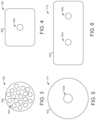
- FIG. 3is an illustration of a first foam layer used with the first wound zone separation system of FIG. 1 A , according to an exemplary embodiment.
- FIG. 4is an illustration of a first drape layer used with the first wound zone separation system of FIG. 1 A , according to an exemplary embodiment.
- FIG. 5is an illustration of a second foam layer used with the first wound zone separation system of FIG. 1 A , according to an exemplary embodiment.
- FIG. 6is an illustration of a second drape layer used with the first wound zone separation system of FIG. 1 A , according to an exemplary embodiment.
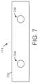
- FIG. 7is an illustration of a manifold used with the first wound zone separation system of FIG. 1 A , according to an exemplary embodiment.
- FIG. 8is an illustration of a fitting used with the second wound zone separation system of FIG. 1 B , according to an exemplary embodiment.
- FIG. 9 Ais an illustration of a first application of multiple wound treatment therapies, according to an exemplary embodiment.
- FIG. 9 Bis an illustration of a second application of multiple wound treatment therapies, according to an exemplary embodiment.
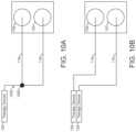
- FIG. 10 Ais an illustration of a first tubing configuration used with the first wound zone separation system of FIG. 1 A , according to an exemplary embodiment.
- FIG. 10 Bis an illustration of a second tubing configuration used with the first wound zone separation system of FIG. 1 A , according to an exemplary embodiment.
- FIG. 10 Cis an illustration of a third tubing configuration used with the first wound zone separation system of FIG. 1 A , according to an exemplary embodiment.
- FIG. 10 Dis an illustration of a fourth tubing configuration used with the first wound zone separation system of FIG. 1 A , according to an exemplary embodiment.
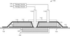
- wound zone separation system 100may be configured to isolate (e.g., fluidly, physically, etc.) various zones of a wound. Additionally, wound zone separation system 100 may be configured to apply different wound therapy treatments to different wound zones. For example, wound zone separation system 100 may be able to apply a negative differential pressure treatment and/or a fluid instillation treatment to a first wound zone 102 (shown as a wound bed) via a first tube 116 and a second wound zone shown 104 (shown as a periwound) via a second tube 118 .
- the examples described hereinare not intended to be limiting.
- Wound zone separation system 100may include any additional features, components, or modules to allow for customization of applying multiple wound treatment therapies to multiple wound zones.
- Wound zone separation system 100is shown as a single dressing for use at a wound site having two or more wound zones. As shown in FIGS. 1 A & 2 A , the dressing is applied to first wound zone 102 and second wound zone 104 , according to an exemplary embodiment.
- First wound zone 102illustrated as a wound bed in the exemplary embodiment, may be the immediate location of a wound (e.g., sore, laceration, burn, etc.).
- First tube 116may be configured to communicate (e.g., fluidly, pneumatically, etc.) with first wound zone 102 and apply a first wound treatment therapy (e.g., instillation therapy, negative pressure therapy, etc.) from a therapy device 126 .
- a first wound treatment therapye.g., instillation therapy, negative pressure therapy, etc.
- Second wound zone 104illustrated as a periwound in the exemplary embodiment, may be the area substantially surrounding the area of first wound zone 102 .
- Second tube 118may be configured to communicate (e.g., fluidly, pneumatically, etc.) with second wound zone 104 and apply a second wound treatment from a therapy device 128 .
- wound zone separation system 100may include features configured to couple (e.g., fluidly, physically, etc.) and/or isolate (e.g., fluidly, physically, etc.) first wound zone 102 and second wound zone 104 with the components of wound zone separation system 100 .
- wound zone separation system 100is shown to include a first foam layer 106 configured for placement over the first wound zone 102 .
- first foam layer 106may be customized (e.g., fitted, selected) for placement on or within a volume defined by first wound zone 102 .
- First foam layer 106may couple (e.g., pneumatically, fluidly, etc.) first tube 116 with first wound zone 102 .
- first foam layer 106may be formed of a material configured to allow the flow of air, fluid, debris, etc. to flow therethrough, i.e., to flow from first wound zone 102 to first tube 116 .
- Wound zone separation system 100is shown to include a first drape layer 108 configured for placement over first foam layer 106 and at least partially over second wound zone 104 .
- first drape layer 108may be customized (e.g., fitted, selected) for placement over an area larger than an area covered by first foam layer 106 .
- first drape layer 108may be sealable over first wound zone 102 and at least a portion of second wound zone 104 in a substantially airtight manner to allow a pressure differential to be maintained across the first drape layer 108 .
- wound zone separation system 100is shown to include a second foam layer 110 which may be configured for placement over second wound zone 104 .
- second foam layer 110may also be configured for placement over at least a portion of first wound zone 102 .
- second foam layer 110may be customized (e.g., fitted, selected) for placement over an area defined by second wound zone 104 and may provide a central cutout configured for placement around first wound zone 102 .
- second foam layer 110may couple (e.g., pneumatically, fluidly, etc.) second tube 118 with second wound zone 104 .
- second foam layer 110may be formed of a material configured to allow the flow of air, fluid, debris, etc. to flow therethrough, i.e., to flow from second wound zone 104 to second tube 118 .
- Wound zone separation system 100is also shown to include a second drape layer 112 configured for placement over second foam layer 110 and first drape layer 108 .
- second drape layer 112may be customized (e.g., fitted, selected) for placement over an area larger than an area covered by first drape layer 108 .
- second drape layer 112may be sealable over second wound zone 104 in a substantially airtight manner to allow a pressure differential to be maintained across the second drape layer 112 .
- second drape layer 112may be configured to isolate (e.g., pneumatically, fluidly, physically, etc.) first wound zone 102 and second wound zone 104 from an external environment.
- wound zone separation system 100is shown to include a manifold 114 configured for placement over second drape layer 112 .
- wound zone separation system 100may not include manifold 114 .
- manifold 114may be customized to couple (e.g., fluidly, pneumatically, etc.) first wound zone 102 with a negative pressure pump and/or an instillation pump via first foam layer 106 and first tube 116 .
- manifold 114may be customized to couple (e.g., fluidly, pneumatically, etc.) second wound zone 104 with a negative pressure pump and/or an instillation pump via second foam layer 110 and second tube 118 .
- Wound zone separation system 100is also shown to include first tube 116 and second tube 118 .
- wound zone separation system 100may include any number of tubes.
- First tube 116 and second tube 118may be defined according to any number of, and combination of desired dimensions, shapes, sizes, features, configurations, and other characteristics, and may be formed of any number of, or combination of, different materials.
- First tube 116 and second tube 118may include any additional features and/or components (e.g., y-connectors, couplers, threaded surfaces, etc.) to facilitate the application of one or more wound treatment therapies.
- first tube 116 and second tube 118may be configured to couple the various components of wound zone separation system 100 , first wound zone 102 , and second wound zone 104 with therapy device 126 and/or therapy device 128 .
- therapy device 126 and therapy device 128are shown to be provided as individual devices, according to an exemplary embodiment.
- therapy device 126 and therapy device 128may be provided as individual devices operating with a single use.
- therapy device 126may operate as a negative pressure pump while therapy device 128 may operate as a fluid instillation pump.
- therapy device 126 and therapy device 128may be included as one unit with multiple uses.
- therapy device 126 and therapy device 128may operate as a unitary device providing both a fluid instillation source as well as a negative pressure source.
- therapy device 126 and therapy device 128may each be capable of multiple uses (e.g., a negative pressure pump and a fluid instillation pump) that may or may not be controller independently of the other.
- wound zone separation system 100may be configured to isolate (e.g., fluidly, physically, pneumatically, etc.) various zones of a wound. Additionally, wound zone separation system 100 may be configured to apply different wound treatment therapies to various wound zones via a tube 120 and a fitting 122 . Referring specifically to FIG. 1 B , the second embodiment of wound zone separation system 100 is shown to apply a wound therapy treatment to first wound zone 102 and second wound zone 104 from therapy device 126 via tube 120 .
- the second embodiment of wound zone separation system 100may include any additional features, components, or modules to allow for customization of applying wound treatment therapies to multiple wound zones.
- first foam layer 106configured for placement over the first wound zone 102 .
- first foam layer 106may be customized (e.g., fitted, selected) for placement within a volume defined by first wound zone 102 .
- first foam layer 106may couple (e.g., pneumatically, fluidly, etc.) tube 120 with first wound zone 102 .
- the second embodiment of wound zone separation system 100is also shown to include first drape layer 108 , according to exemplary embodiments.
- First drape layer 108may be configured for placement over first foam layer 106 and at least partially over second wound zone 104 .
- first drape layer 108may be customized (e.g., fitted, selected) for placement over an area larger than an area covered by first foam layer 106 .
- first drape layer 108may be sealable over first wound zone 102 and at least a portion of second wound zone 104 in a substantially airtight manner to allow a pressure differential to be maintained across the first drape layer 108 .
- the second embodiment of wound zone separation system 100is shown to include a fenestrated film layer 124 configured for placement over first drape layer 108 and substantially over second wound zone 104 .
- fenestrated film layer 124may be customized (e.g., fitted, selected, etc.) for placement over an area larger than an area covered by first drape layer 108 .
- Fenestrated film layer 124may be formed of a material configured to allow the flow of air, fluid, debris, etc. to flow therethrough, i.e., to flow from a surface of fenestrated film layer 124 nearest the second wound zone 104 to a surface of fenestrated film layer 12 furthest the second wound zone 104 .
- the second embodiment of wound zone separation system 100is shown to include second foam layer 110 configured for placement over fenestrated film layer 124 .
- second foam layer 110may be configured for placement over at least a portion of first wound zone 102 .
- Second foam layer 110may couple (e.g., pneumatically, fluidly, etc.) fitting 122 with fenestrated film layer 124 .
- second foam layer 110may be formed of a material configured to allow the flow of air, fluid, debris, etc. to flow therethrough, i.e., to flow from fenestrated film layer 124 to fitting 122 .
- the second embodiment of wound zone separation system 100is shown to include second drape layer 112 configured for placement over second foam layer 110 .
- second drape layer 112may be customized (e.g., fitted, selected) for placement over an area larger than an area covered by second foam layer 110 .
- second drape layer 112may be sealable over second wound zone 104 in a substantially airtight manner to allow a pressure differential to be maintained across the second drape layer 112 .
- second drape layer 112may be configured to isolate the first wound zone 102 and second wound zone 104 from an external environment.
- the second embodiment of wound zone separation system 100is also shown to include a fitting 122 configured to couple the various components of wound zone separation system 100 , first wound zone 102 , and second wound zone 104 with a tube 120 .
- fitting 122may include features configured to apply different wound treatment therapies to first wound zone 102 and second wound zone 104 via tube 120 .
- the second embodiment of wound zone separation system 100is shown to include tube 120 .
- Tube 120may be defined according to any number of, and combination of desired dimensions, shapes, sizes, features, configurations, and other characteristics, and may be formed of any number of, or combination of, different materials.
- tube 120may be configured to couple the various components of wound zone separation system 100 , first wound zone 102 , and second wound zone 104 with therapy device 126 . Further, as will be described, tube 120 may be configured to simultaneously apply a negative pressure therapy along with an instillation therapy administered by therapy device 126 .
- first foam layer 106may be defined according to any number of, and combination of, desired dimensions, shapes, sizes, features, configurations, and other characteristics, and may be formed of any number of, or combination of, different materials.
- first foam layer 106is defined by a first foam material 302 (e.g., GRANUFOAMTM Dressing, V.A.C. VERAFLO CLEANSE CHOICETM Dressing/Dressing Kit, etc.) having a first density and providing multiple holes 304 extending therethrough.
- various numbers of the holes 304are arranged in various positions on the first foam material 302 .
- First foam layer 106may be configured to allow for a first wound treatment therapy to be applied to first wound zone 102 (shown as a wound bed).
- first foam layer 106may be the coupling medium between a negative pressure pump and a fluid instillation pump configured to apply a cyclical application of negative pressure and fluid instillation to first wound zone 102 via first tube 116 .
- the first wound zone 102may be caused to deform into the holes 304 by the negative pressure. Deformation of the first wound zone 102 into the multiple holes 304 may contribute to the breakdown of thick exudate, fibrinous slough, or other unwanted tissue or debris at the wound bed.
- first foam material 302 and holes 304may thereby facilitate debridement and/or cleansing of the wound bed to promote wound healing.
- first foam layer 106may allow for the removal of air, fluid, wound exudate, etc. from the first wound zone 102 and the addition of instillation fluid to the first wound zone 102 via first tube 116 .
- first foam layer 106may be provided without holes 304 .
- first drape layer 108is shown, according to an exemplary embodiment.
- First drape layer 108may be defined according to any number of, and combination of, desired dimensions, shapes, sizes, features, configurations, and other characteristics, and may be formed of any number of, or combination of, different materials.
- first drape layer 108is shown to be defined by a first drape material 402 having a first drape hole 404 extending therethrough.
- First drape hole 404may be defined according to any number of desired dimensions, shapes, sizes, and configurations, and may be customized to fit a diameter defined by an exterior surface of first tube 116 .
- first drape layer 108may provide any number of first drape holes 404 .
- first drape layer 108may provide an additional number of first drape holes 404 to couple (e.g., fluidly, pneumatically, etc.) additional tubes with first foam layer 106 .
- First drape hole 404may include any number or combination of coupling features (e.g., flanged low-profile pads, fittings, snap-fit connectors, adhesive material, etc.) configured to couple first tube 116 about the first drape hole 404 .
- first drape layer 108is sealable over first wound zone 102 and at least a portion of second wound zone 104 in a substantially airtight manner to allow a pressure differential to be maintained across the first drape layer 108 .
- a negative pressure treatmentmay be applied to first wound zone 102 by establishing a pressure differential between a surface of first drape layer 108 nearest the first wound zone 102 and a surface of first drape layer 108 furthest the first wound zone 102 .
- first drape layer 108is sealable over first wound zone 102 and at least a portion of second wound zone 104 in a substantially fluid-tight manner to prevent the transmission or migration of fluid from first wound zone 102 to second wound zone 104 .
- an instillation treatmentmay be applied to first wound zone 102 that is not intended to be applied to second wound zone 104 .
- the placement of first drape layer 108 over first wound zone 102 and at least a portion of second wound zone 104may prevent the transmission of instillation fluid to second wound zone 104 .
- the placement of first drape layer 108 over first wound zone 102may be configured to prevent the transmission of wound exudate (e.g., wound fluid, wound exudate, etc.) between first wound zone 102 and second wound zone 104 .
- wound exudatee.g., wound fluid, wound exudate, etc.
- Second foam layer 110may be defined according to any number of, and combination of, desired dimensions, shapes, sizes, features, configurations, and other characteristics, and may be formed of any number of, or combination of, different materials.
- second foam layer 110is defined by a second foam material 502 (e.g., GRANUFOAMTM Dressing, V.A.C. VERAFLO CLEANSE CHOICETM Dressing/Dressing Kit, etc.) having a second density and providing multiple holes 504 extending therethrough.
- the second density of the second foam material 502is less than the first density of the first foam material 302 .
- the second foam material 502may be formed of a material that is significantly different than a material that forms the first foam material 302 .
- the second foam material 502is a felted foam material.
- second foam layer 110is shown to provide a central cutout 504 configured for placement about a circumference defined by first wound zone 102 .
- second foam material 502may be the same or similar to first foam material 302 .
- the central cutout 504is shown to be provided on second foam material 502 extending therethrough, according to an exemplary embodiment.
- Central cutout 504may be defined according to any number of desired dimensions, shapes, sizes, and configurations appropriate for customization to first wound zone 102 and/or second wound zone 104 .
- central cutout 504may be customized to fit a diameter defined by an exterior surface of first tube 116 .
- central cutoutmay be formed of equal or similar dimensions, shapes, and sizes to first drape hole 404 . Referring to FIGS. 1 A & 2 A , central cutout 504 may be configured to align with first drape hole 404 such that a continuous, hollow aperture is formed therethrough.
- the continuous, hollow aperture formed by first drape hole 404 and central cutout 504may allow for the transmission of first tube 116 through second foam layer 110 and first drape layer 108 .
- Second foam layer 110may be configured to allow for a second wound treatment therapy to be applied to second wound zone 104 .
- second foam layer 110may be the coupling medium between an instillation pump configured to apply an application of fluid instillation to second wound zone 104 via second tube 118 .
- the dimensions, shapes, size, and configuration of second foam layer 110 and the material forming the second foam material 502may be configured to allow for substantial saturation of fluid instillation.
- second drape layer 112is shown, according to an exemplary embodiment.
- Second drape layer 112may be defined according to any number of, and combination of, desired dimensions, shapes, sizes, features, configurations, and other characteristics, and may be formed of any number of, or combination of, different materials.
- second drape layer 112is shown to be defined by a single material 602 .
- Second drape layer 112is shown to provide a second drape hole 604 and a third drape hole 606 extending therethrough.
- Second drape hole 604 and third drape hole 606may be defined according to any number of desired dimensions, shapes, sizes, and configurations. In some embodiments, second drape hole 604 and third drape hole 606 may define by equal or similar sizes and shapes. In some embodiments, second drape hole 604 may be customized to fit a diameter defined by first tube 116 . In some embodiments, second drape hole 604 may be formed of equal or similar dimensions, shapes, and sizes to first drape hole 404 and/or first tube passage 506 . Referring to FIGS. 1 A & 2 A , second drape hole 604 may be configured to align with first drape hole 404 and first tube passage 506 such that a continuous, hollow aperture is formed therethrough. The continuous, hollow aperture formed by second drape hole 604 , first drape hole 404 , and first tube passage 506 may allow for the transmission of first tube 116 through second drape layer 112 , second foam layer 110 , and first drape layer 108 .
- third drape hole 606may be customized to fit a diameter defined by second tube 118 .
- second drape layer 112may provide any number of second drape holes 604 and/or third drape holes 606 .
- second drape layer 112may provide an additional number of second drape holes 604 to couple (e.g., fluidly, pneumatically, etc.) additional tubes with first foam layer 106 .
- Second drape hole 604 and third drape hole 606may provide any number or combination of coupling features (e.g., flanged low-profile pads, fittings, snap-fit connectors, adhesive material, etc.) configured to couple first tube 116 with second drape hole 604 and second tube 118 with third drape hole 606 .
- second drape layer 112is sealable over second wound zone 104 in a substantially airtight manner to allow a pressure differential to be maintained across the second drape layer 112 .
- a negative pressure treatmentmay be applied to second wound zone 104 by establishing a pressure differential between a surface of second drape layer 112 nearest the second wound zone 104 and a surface of second drape layer 112 furthest the second wound zone 104 .
- second drape layer 112is sealable over second wound zone 104 and in a substantially fluid-tight manner to prevent the transmission of fluid from second wound zone 104 to an external environment.
- manifold 114is shown, according to an exemplary embodiment.
- manifold 114may be configured to couple a common negative pressure pump (e.g., supplied by therapy device 128 or therapy device 126 ) with first wound zone 102 and second wound zone 104 to allow suction be drawn from both first wound zone 102 and second wound zone 104 .
- a common negative pressure pumpe.g., supplied by therapy device 128 or therapy device 126
- manifold 114is shown to be defined by a rectangular plate formed of a single material 702 .
- Manifold 114is shown to provide a first manifold hole 704 and a second manifold hole 706 extending therethrough.
- First manifold hole 704 and second manifold hole 706may be defined according to any number of desired dimensions, shapes, sizes, and configurations. In some embodiments, first manifold hole 704 and second manifold hole 706 may define equal or similar sizes and shapes. First manifold hole 704 may be customized to fit a diameter defined by first tube 116 . In some embodiments, first manifold hole 704 may be formed of equal or similar dimensions, shapes, and/or sizes to first drape hole 404 , first tube passage 506 , and/or second drape hole 604 . In some embodiments, first manifold hole 704 may be configured to align with first drape hole 404 , first tube passage 506 , and second drape hole 604 such that a continuous, hollow aperture is formed therethrough.
- first manifold hole 704may allow for the transmission of first tube 116 through manifold 114 , second drape layer 112 , second foam layer 110 , and first drape layer 108 .
- second manifold hole 706may be customized to fit a diameter defined by second tube 118 .
- second manifold hole 706may be configured to align with third drape hole 606 such that a continuous, hollow aperture is formed therethrough.
- the continuous, hollow aperture formed by second manifold hole 706 and third drape hole 606may allow for the transmission of second tube 118 through manifold 114 and second drape layer 112 .
- Fitting 122is shown, according to an exemplary embodiment.
- Fitting 122is shown to include a top portion 802 and a bottom portion 804 .
- Top portion 802is shown to couple (e.g., physically, fluidly, etc.) tube 120 with bottom portion 804 .
- Fitting 122 and tube 120may be defined according to any number of, and combination of, desired dimensions, shapes, sizes, features, configurations, and other characteristics, and may be formed of any number of, or combination of, different materials.
- tube 120is configured to simultaneously apply an instillation therapy via a first passage 806 and a negative pressure therapy via a second passage 808 .
- First passage 806 and second passage 808may be defined as continuous hollow channels extending through an entirety of the length of tube 120 .
- first passage 806 and second 808are independent channels that are not fluidly coupled.
- First passage 806may be configured to couple with an instillation pump (not shown).
- second passage 808may be configured to couple with a negative pressure source (not shown).
- tube 120may feature any number of channels configured to apply various wound treatment therapies.
- top portion 802 and bottom portion 804may be formed of the same material forming a unitary, monolithic structure. In other embodiments, top portion 802 and bottom portion 804 may be formed of the same or different materials and configured to couple (e.g., snap-fit, screw in, adhere in, etc.) to each other.
- top portion 802may provide a protruding threaded system while bottom portion 804 may feature an indented threaded structure in order to receive and install the protruding threaded system of top portion 802 .
- Top portion 802is shown to include a tube aperture 810 .
- Tube aperture 810may be configured to receive tube 120 and couple (e.g., fluidly, pneumatically, etc.) tube 120 with the various components of fitting 122 and the features of wound zone separation system 100 .
- tube aperture 810may include features (e.g., adhesive material, hook and loop structure, etc.) configured to retain the coupling of tube 120 with top portion 802 .
- Top portion 802is also shown to include a first instillation channel 812 .
- First instillation channel 812may be configured to direct an instillation treatment to an intended location in wound zone separation system 100 (e.g., first wound zone 102 via first foam layer 106 ).
- top portion 802is shown to define a hollow volume configured to apply a negative pressure regimen.
- the hollow volume defined by top portion 802may apply a negative pressure regimen via second passage 808 .
- Bottom portion 804is shown include second instillation channel 814 , according to an exemplary embodiment.
- Second instillation channel 814may be defined as a continuous, hollow channel configured to extend through the entirety of bottom portion 804 .
- second instillation channel 814is shown to fluidly couple with first instillation channel 812 to form one continuous hollow channel extending through the entirety of fitting 122 .
- an instillation therapymay be applied to first wound zone 102 via first passage 806 .
- Bottom portion 804is shown include multiple holes 816 , according to an exemplary embodiment. Holes 816 may be configured to fluidly couple the various components of wound zone separation system 100 with a negative pressure pump (not shown). In some embodiments, holes 816 may be configured to receive particles from first wound zone 102 and second wound zone 104 . In various embodiments, various numbers of the holes 816 are arranged in various positions on the bottom portion 804 .
- Bottom portion 804is shown to define an aperture 818 , according to an exemplary embodiment.
- Aperture 818may be configured to pneumatically couple and apply a negative pressure treatment to first wound zone 102 . Additionally, aperture 818 may be configured to receive wound excrement (e.g., scar tissue, skin, fluid) from first wound zone 102 .
- wound excremente.g., scar tissue, skin, fluid
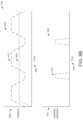
- FIGS. 9 A & 9 Bvarious graphical representations of applying different wound therapies are shown, according to exemplary embodiments.
- the graphs illustrated in FIGS. 9 A & 9 Bprovide examples of simultaneously applying negative pressure therapies with instillation therapies.
- a first graphical representation of applying different wound therapies 900is shown.
- a first graph 902illustrates the cyclic application of negative pressure therapies while a second graph 904 illustrates the cyclic application of instillation therapy.
- the graph 902shows pressure on the vertical axis 906 and time on the horizontal axis 908 .
- the graph 904shows instillation application on the vertical axis 910 and time on a similar horizontal axis 908 .
- a third graph 952illustrates a cyclic application of negative pressure 912 with an application of constant negative pressure 954 .
- Second graph 904is shown illustrating the application of instillation therapy 612 .
- the third graph 952shows pressure on the vertical axis 906 and time on the horizontal axis 908 .
- a first application of negative pressure 912is applied across first drape layer 108 of the first wound zone.
- a second application of negative pressure 914is applied across second drape layer 112 of the second wound zone.
- the negative pressuremay cycle many times between a high value and a low value.
- the low pressure value and the high pressure valuemay be user selectable.
- the first application of negative pressure 912may be varied between a value of approximately 25 mmHg and a value of approximately 200 mmHg and the second application of negative pressure may be varied between a value of approximately 10 mmHg and a value of approximately 150 mmHg.
- Other rangesmay be used to suit pneumatic treatment therapies.
- a first application of negative pressure 912may be applied across first drape layer 108 of the first wound zone.
- An application of substantially constant negative pressure 954may be applied across second drape layer 112 of the second wound zone.
- the application of constant negative pressure 954may be maintained once the desired constant pressure value is achieved. Similar to the first application of negative pressure 912 , the value of constant negative pressure may be user selectable.
- a control circuit within therapy device 126 and/or therapy device 128may be used to control one or more negative pressure pumps to control the pressure of the various wound zones (e.g., first wound zone 102 and second wound zone 104 ) from atmospheric pressure to a target negative pressure as illustrated by graph 902 .
- the negative pressuremay be maintained for a predetermined or user-selected amount of time once the target negative pressure has been achieved.
- a first application of fluid instillation 916may be applied to first foam layer 106 .
- First application of fluid instillation 916may correspond to the low pressure values of graphs 902 and 952 .
- the application of fluid instillation 916may occur after the first high-pressure application of negative pressure 912 .
- the graphs illustrated in FIGS. 9 A & 9 Bshow linear transitions (e.g., constant slopes) between pressure values and between instillation values, it should be understood that various other pressure trajectories may be provided by various embodiments.
- the first application of negative pressure 912may take a sinusoidal form in alternative embodiments of graph 902 .
- the example of graph 902shows substantially equivalent rise times (e.g., the time for pressure to change from the low pressure value to the high pressure value) and fall times (e.g., the time for pressure to change from the high pressure value to the low pressure value), it should be understood that various relative rise times and fall times may be used. For example, a rise time and/or fall time may be selected by a user.
- FIGS. 10 A- 10 Dvarious embodiments of tubing configurations are shown schematically, according to exemplary embodiments.
- the examples provided in FIGS. 10 A- 10 Dare shown to be used with the wound zones of wound zone separation system 100 .
- a first configuration of tubingis shown to use first tube 116 with first wound zone 102 and second tube 118 with second wound zone 104 .
- first tube 116 and second tube 118are shown to couple at a connector 1000 for use with a common therapy device (e.g., therapy device 126 ).
- Connector 1000may be any type of device configured to couple two tubes (e.g., first tube 116 and second tube 118 ) and lead into a singular tube 1002 .
- Singular tube 1002may be coupled (e.g., pneumatically, fluidly, etc.) to therapy device 126 .
- therapy device 126may provide a negative pressure source and/or an instillation pump.
- singular tube 1002may be configured to transport instillation fluid from therapy device 126 to first tube 116 and/or second tube 118 .
- singular tube 1002may be configured to transport wound exudate (e.g. wound debris, fluid, etc.) from first wound zone 102 and/or second wound zone 104 to a disposal bin (not shown).
- wound exudatee.g. wound debris, fluid, etc.
- connector 1000may be configured to direct flow in a predetermined direction.
- connector 1000may be configured to function as a check valve that only allows for instillation fluid to flow through first tube 116 into first wound zone 102 .
- connector 1000may be configured to allow instillation fluid to flow through second tube 118 .
- connector 1000may be configured to allow instillation fluid through both first tube 116 and second tube 118 .
- FIG. 10 Ba second configuration of tubing is shown for use with therapy device 126 and therapy device 128 (provided as separate devices), or a common therapy device (e.g., therapy device 126 or therapy device 128 ) with separate pump capabilities, according to an exemplary embodiment.
- the embodiment of FIG. 10 Bincludes first tube 116 and second tube 118 function as independent tubes that are not connected (e.g., by connector 1000 ).
- first tube 116 and second tube 118may be coupled (e.g., fluidly, pneumatically) to separate negative pressure sources and/or different instillation pumps provided by therapy device 126 and therapy device 128 .
- FIG. 10 Ca third configuration of tubing is shown, according to an exemplary embodiment.
- the embodiment illustrated in FIG. 10 Cshows first tube 116 and second tube 118 coupled using connector 1000 to singular tube 1002 .
- first wound zone 102is also shown to be coupled (e.g., fluidly, pneumatically, etc.) with a third tube 1004 .
- Third tube 1004may be configured to apply a negative pressure provided by therapy device 128 to first wound zone 102 and/or transport instillation fluid to first wound zone 102 .
- first tube 116 , second tube 118 , connector 1000 , and singular tube 1002may be coupled to a negative pressure pump provided by therapy device 126 and configured to apply a negative pressure therapy to first wound zone 102 and second wound zone 104 .
- Third tube 1004may be connected to an instillation pump provided by therapy device 128 and configured to apply an instillation therapy to first wound zone 102 .
- the application of a negative pressure therapy provided by therapy device 126 via the tubing system including first tube 116 , second tube 118 , connector 1000 , and singular tube 1002is separated from an instillation therapy provided by therapy device 128 applied by third tube 1004 .
- FIG. 10 Da fourth configuration of tubing is shown, according to an exemplary embodiment.
- the embodiment illustrated in FIG. 10 Dincludes therapy device 128 coupled to first wound zone 102 via first tube 116 , therapy device 126 coupled to second wound zone 104 via second tube 118 , and a therapy device 1006 coupled to first wound zone 102 via third tube 1004 .
- the therapy device 1006may provide substantially similar features and operational abilities as therapy device 126 and/or therapy device 128 .
- first tube 116 and second tube 118may be coupled to different negative pressure sources provided by therapy device 126 and therapy device 128 and third tube 1004 may be coupled to instillation pump provided by therapy device 1006 .
- Coupledmeans the joining of two members directly or indirectly to one another. Such joining may be stationary (e.g., permanent, etc.) or moveable (e.g., removable, releasable, etc.). Such joining may be achieved with the two members or the two members and any additional intermediate members being integrally formed as a single unitary body with one another or with the two members or the two members and any additional intermediate members being attached to one another.
Landscapes
- Health & Medical Sciences (AREA)
- Heart & Thoracic Surgery (AREA)
- General Health & Medical Sciences (AREA)
- Engineering & Computer Science (AREA)
- Biomedical Technology (AREA)
- Life Sciences & Earth Sciences (AREA)
- Animal Behavior & Ethology (AREA)
- Vascular Medicine (AREA)
- Public Health (AREA)
- Veterinary Medicine (AREA)
- Anesthesiology (AREA)
- Hematology (AREA)
- Media Introduction/Drainage Providing Device (AREA)
Abstract
Description
Claims (11)
Priority Applications (1)
| Application Number | Priority Date | Filing Date | Title |
|---|---|---|---|
| US17/624,958US12144922B2 (en) | 2019-07-17 | 2020-07-16 | Wound dressing with multiple treatment zones |
Applications Claiming Priority (3)
| Application Number | Priority Date | Filing Date | Title |
|---|---|---|---|
| US201962875352P | 2019-07-17 | 2019-07-17 | |
| US17/624,958US12144922B2 (en) | 2019-07-17 | 2020-07-16 | Wound dressing with multiple treatment zones |
| PCT/IB2020/056709WO2021009712A1 (en) | 2019-07-17 | 2020-07-16 | Wound dressing with multiple treatment zones |
Publications (2)
| Publication Number | Publication Date |
|---|---|
| US20220288297A1 US20220288297A1 (en) | 2022-09-15 |
| US12144922B2true US12144922B2 (en) | 2024-11-19 |
Family
ID=71784346
Family Applications (1)
| Application Number | Title | Priority Date | Filing Date |
|---|---|---|---|
| US17/624,958Active2040-08-28US12144922B2 (en) | 2019-07-17 | 2020-07-16 | Wound dressing with multiple treatment zones |
Country Status (3)
| Country | Link |
|---|---|
| US (1) | US12144922B2 (en) |
| EP (1) | EP3999006A1 (en) |
| WO (1) | WO2021009712A1 (en) |
Families Citing this family (4)
| Publication number | Priority date | Publication date | Assignee | Title |
|---|---|---|---|---|
| EP4295869A3 (en) | 2019-06-03 | 2024-03-20 | Convatec Limited | Methods and devices to disrupt and contain pathogens |
| GB201914706D0 (en) | 2019-10-11 | 2019-11-27 | Smith & Nephew | Apparatuses and methods for negative pressure wound therapy with switcheable fluid management |
| GB202006305D0 (en) | 2020-04-29 | 2020-06-10 | Smith & Nephew | Apparatures and methods for negative pressure wound therapy |
| US11806222B2 (en)* | 2021-08-06 | 2023-11-07 | John Baeke | Apparatus for cutting a material and a method for cutting a negative pressure wound therapy dressing |
Citations (140)
| Publication number | Priority date | Publication date | Assignee | Title |
|---|---|---|---|---|
| US1355846A (en) | 1920-02-06 | 1920-10-19 | David A Rannells | Medical appliance |
| US2547758A (en) | 1949-01-05 | 1951-04-03 | Wilmer B Keeling | Instrument for treating the male urethra |
| US2632443A (en) | 1949-04-18 | 1953-03-24 | Eleanor P Lesher | Surgical dressing |
| GB692578A (en) | 1949-09-13 | 1953-06-10 | Minnesota Mining & Mfg | Improvements in or relating to drape sheets for surgical use |
| US2682873A (en) | 1952-07-30 | 1954-07-06 | Johnson & Johnson | General purpose protective dressing |
| US2910763A (en) | 1955-08-17 | 1959-11-03 | Du Pont | Felt-like products |
| US2969057A (en) | 1957-11-04 | 1961-01-24 | Brady Co W H | Nematodic swab |
| US3066672A (en) | 1960-09-27 | 1962-12-04 | Jr William H Crosby | Method and apparatus for serial sampling of intestinal juice |
| US3367332A (en) | 1965-08-27 | 1968-02-06 | Gen Electric | Product and process for establishing a sterile area of skin |
| US3520300A (en) | 1967-03-15 | 1970-07-14 | Amp Inc | Surgical sponge and suction device |
| US3568675A (en) | 1968-08-30 | 1971-03-09 | Clyde B Harvey | Fistula and penetrating wound dressing |
| US3648692A (en) | 1970-12-07 | 1972-03-14 | Parke Davis & Co | Medical-surgical dressing for burns and the like |
| US3682180A (en) | 1970-06-08 | 1972-08-08 | Coilform Co Inc | Drain clip for surgical drain |
| US3826254A (en) | 1973-02-26 | 1974-07-30 | Verco Ind | Needle or catheter retaining appliance |
| DE2640413A1 (en) | 1976-09-08 | 1978-03-09 | Wolf Gmbh Richard | CATHETER MONITORING DEVICE |
| US4080970A (en) | 1976-11-17 | 1978-03-28 | Miller Thomas J | Post-operative combination dressing and internal drain tube with external shield and tube connector |
| US4096853A (en) | 1975-06-21 | 1978-06-27 | Hoechst Aktiengesellschaft | Device for the introduction of contrast medium into an anus praeter |
| US4139004A (en) | 1977-02-17 | 1979-02-13 | Gonzalez Jr Harry | Bandage apparatus for treating burns |
| US4165748A (en) | 1977-11-07 | 1979-08-28 | Johnson Melissa C | Catheter tube holder |
| US4184510A (en) | 1977-03-15 | 1980-01-22 | Fibra-Sonics, Inc. | Valued device for controlling vacuum in surgery |
| WO1980002182A1 (en) | 1979-04-06 | 1980-10-16 | J Moss | Portable suction device for collecting fluids from a closed wound |
| US4233969A (en) | 1976-11-11 | 1980-11-18 | Lock Peter M | Wound dressing materials |
| US4245630A (en) | 1976-10-08 | 1981-01-20 | T. J. Smith & Nephew, Ltd. | Tearable composite strip of materials |
| US4256109A (en) | 1978-07-10 | 1981-03-17 | Nichols Robert L | Shut off valve for medical suction apparatus |
| US4261363A (en) | 1979-11-09 | 1981-04-14 | C. R. Bard, Inc. | Retention clips for body fluid drains |
| US4275721A (en) | 1978-11-28 | 1981-06-30 | Landstingens Inkopscentral Lic, Ekonomisk Forening | Vein catheter bandage |
| US4284079A (en) | 1979-06-28 | 1981-08-18 | Adair Edwin Lloyd | Method for applying a male incontinence device |
| US4297995A (en) | 1980-06-03 | 1981-11-03 | Key Pharmaceuticals, Inc. | Bandage containing attachment post |
| US4333468A (en) | 1980-08-18 | 1982-06-08 | Geist Robert W | Mesentery tube holder apparatus |
| US4373519A (en) | 1981-06-26 | 1983-02-15 | Minnesota Mining And Manufacturing Company | Composite wound dressing |
| US4382441A (en) | 1978-12-06 | 1983-05-10 | Svedman Paul | Device for treating tissues, for example skin |
| US4392858A (en) | 1981-07-16 | 1983-07-12 | Sherwood Medical Company | Wound drainage device |
| US4392853A (en) | 1981-03-16 | 1983-07-12 | Rudolph Muto | Sterile assembly for protecting and fastening an indwelling device |
| US4419097A (en) | 1981-07-31 | 1983-12-06 | Rexar Industries, Inc. | Attachment for catheter tube |
| EP0100148A1 (en) | 1982-07-06 | 1984-02-08 | Dow Corning Limited | Medical-surgical dressing and a process for the production thereof |
| US4465485A (en) | 1981-03-06 | 1984-08-14 | Becton, Dickinson And Company | Suction canister with unitary shut-off valve and filter features |
| EP0117632A2 (en) | 1983-01-27 | 1984-09-05 | Johnson & Johnson Products Inc. | Adhesive film dressing |
| US4475909A (en) | 1982-05-06 | 1984-10-09 | Eisenberg Melvin I | Male urinary device and method for applying the device |
| US4480638A (en) | 1980-03-11 | 1984-11-06 | Eduard Schmid | Cushion for holding an element of grafted skin |
| US4525374A (en) | 1984-02-27 | 1985-06-25 | Manresa, Inc. | Treating hydrophobic filters to render them hydrophilic |
| US4525166A (en) | 1981-11-21 | 1985-06-25 | Intermedicat Gmbh | Rolled flexible medical suction drainage device |
| US4540412A (en) | 1983-07-14 | 1985-09-10 | The Kendall Company | Device for moist heat therapy |
| US4543100A (en) | 1983-11-01 | 1985-09-24 | Brodsky Stuart A | Catheter and drain tube retainer |
| US4548202A (en) | 1983-06-20 | 1985-10-22 | Ethicon, Inc. | Mesh tissue fasteners |
| US4551139A (en) | 1982-02-08 | 1985-11-05 | Marion Laboratories, Inc. | Method and apparatus for burn wound treatment |
| EP0161865A2 (en) | 1984-05-03 | 1985-11-21 | Smith and Nephew Associated Companies p.l.c. | Adhesive wound dressing |
| US4569348A (en) | 1980-02-22 | 1986-02-11 | Velcro Usa Inc. | Catheter tube holder strap |
| AU550575B2 (en) | 1981-08-07 | 1986-03-27 | Richard Christian Wright | Wound drainage device |
| US4605399A (en) | 1984-12-04 | 1986-08-12 | Complex, Inc. | Transdermal infusion device |
| US4608041A (en) | 1981-10-14 | 1986-08-26 | Frese Nielsen | Device for treatment of wounds in body tissue of patients by exposure to jets of gas |
| US4640688A (en) | 1985-08-23 | 1987-02-03 | Mentor Corporation | Urine collection catheter |
| US4655754A (en) | 1984-11-09 | 1987-04-07 | Stryker Corporation | Vacuum wound drainage system and lipids baffle therefor |
| US4664662A (en) | 1984-08-02 | 1987-05-12 | Smith And Nephew Associated Companies Plc | Wound dressing |
| WO1987004626A1 (en) | 1986-01-31 | 1987-08-13 | Osmond, Roger, L., W. | Suction system for wound and gastro-intestinal drainage |
| US4710165A (en) | 1985-09-16 | 1987-12-01 | Mcneil Charles B | Wearable, variable rate suction/collection device |
| US4733659A (en) | 1986-01-17 | 1988-03-29 | Seton Company | Foam bandage |
| GB2195255A (en) | 1986-09-30 | 1988-04-07 | Vacutec Uk Limited | Method and apparatus for vacuum treatment of an epidermal surface |
| US4743232A (en) | 1986-10-06 | 1988-05-10 | The Clinipad Corporation | Package assembly for plastic film bandage |
| GB2197789A (en) | 1986-11-28 | 1988-06-02 | Smiths Industries Plc | Anti-foaming disinfectants used in surgical suction apparatus |
| US4758220A (en) | 1985-09-26 | 1988-07-19 | Alcon Laboratories, Inc. | Surgical cassette proximity sensing and latching apparatus |
| US4787888A (en) | 1987-06-01 | 1988-11-29 | University Of Connecticut | Disposable piezoelectric polymer bandage for percutaneous delivery of drugs and method for such percutaneous delivery (a) |
| US4826494A (en) | 1984-11-09 | 1989-05-02 | Stryker Corporation | Vacuum wound drainage system |
| US4838883A (en) | 1986-03-07 | 1989-06-13 | Nissho Corporation | Urine-collecting device |
| US4840187A (en) | 1986-09-11 | 1989-06-20 | Bard Limited | Sheath applicator |
| US4863449A (en) | 1987-07-06 | 1989-09-05 | Hollister Incorporated | Adhesive-lined elastic condom cathether |
| US4872450A (en) | 1984-08-17 | 1989-10-10 | Austad Eric D | Wound dressing and method of forming same |
| US4878901A (en) | 1986-10-10 | 1989-11-07 | Sachse Hans Ernst | Condom catheter, a urethral catheter for the prevention of ascending infections |
| GB2220357A (en) | 1988-05-28 | 1990-01-10 | Smiths Industries Plc | Medico-surgical containers |
| US4897081A (en) | 1984-05-25 | 1990-01-30 | Thermedics Inc. | Percutaneous access device |
| US4906240A (en) | 1988-02-01 | 1990-03-06 | Matrix Medica, Inc. | Adhesive-faced porous absorbent sheet and method of making same |
| US4906233A (en) | 1986-05-29 | 1990-03-06 | Terumo Kabushiki Kaisha | Method of securing a catheter body to a human skin surface |
| US4919654A (en) | 1988-08-03 | 1990-04-24 | Kalt Medical Corporation | IV clamp with membrane |
| CA2005436A1 (en) | 1988-12-13 | 1990-06-13 | Glenda G. Kalt | Transparent tracheostomy tube dressing |
| US4941882A (en) | 1987-03-14 | 1990-07-17 | Smith And Nephew Associated Companies, P.L.C. | Adhesive dressing for retaining a cannula on the skin |
| US4953565A (en) | 1986-11-26 | 1990-09-04 | Shunro Tachibana | Endermic application kits for external medicines |
| WO1990010424A1 (en) | 1989-03-16 | 1990-09-20 | Smith & Nephew Plc | Absorbent devices and precursors therefor |
| US4969880A (en) | 1989-04-03 | 1990-11-13 | Zamierowski David S | Wound dressing and treatment method |
| US4985019A (en) | 1988-03-11 | 1991-01-15 | Michelson Gary K | X-ray marker |
| GB2235877A (en) | 1989-09-18 | 1991-03-20 | Antonio Talluri | Closed wound suction apparatus |
| US5037397A (en) | 1985-05-03 | 1991-08-06 | Medical Distributors, Inc. | Universal clamp |
| US5086170A (en) | 1989-01-16 | 1992-02-04 | Roussel Uclaf | Process for the preparation of azabicyclo compounds |
| US5092858A (en) | 1990-03-20 | 1992-03-03 | Becton, Dickinson And Company | Liquid gelling agent distributor device |
| US5100396A (en) | 1989-04-03 | 1992-03-31 | Zamierowski David S | Fluidic connection system and method |
| US5134994A (en) | 1990-02-12 | 1992-08-04 | Say Sam L | Field aspirator in a soft pack with externally mounted container |
| US5149331A (en) | 1991-05-03 | 1992-09-22 | Ariel Ferdman | Method and device for wound closure |
| US5167613A (en) | 1992-03-23 | 1992-12-01 | The Kendall Company | Composite vented wound dressing |
| US5176663A (en) | 1987-12-02 | 1993-01-05 | Pal Svedman | Dressing having pad with compressibility limiting elements |
| WO1993009727A1 (en) | 1991-11-14 | 1993-05-27 | Wake Forest University | Method and apparatus for treating tissue damage |
| US5215522A (en) | 1984-07-23 | 1993-06-01 | Ballard Medical Products | Single use medical aspirating device and method |
| US5232453A (en) | 1989-07-14 | 1993-08-03 | E. R. Squibb & Sons, Inc. | Catheter holder |
| US5261893A (en) | 1989-04-03 | 1993-11-16 | Zamierowski David S | Fastening system and method |
| US5278100A (en) | 1991-11-08 | 1994-01-11 | Micron Technology, Inc. | Chemical vapor deposition technique for depositing titanium silicide on semiconductor wafers |
| US5279550A (en) | 1991-12-19 | 1994-01-18 | Gish Biomedical, Inc. | Orthopedic autotransfusion system |
| US5298015A (en) | 1989-07-11 | 1994-03-29 | Nippon Zeon Co., Ltd. | Wound dressing having a porous structure |
| US5342376A (en) | 1993-05-03 | 1994-08-30 | Dermagraphics, Inc. | Inserting device for a barbed tissue connector |
| US5344415A (en) | 1993-06-15 | 1994-09-06 | Deroyal Industries, Inc. | Sterile system for dressing vascular access site |
| DE4306478A1 (en) | 1993-03-02 | 1994-09-08 | Wolfgang Dr Wagner | Drainage device, in particular pleural drainage device, and drainage method |
| WO1994020041A1 (en) | 1993-03-09 | 1994-09-15 | Wake Forest University | Wound treatment employing reduced pressure |
| US5358494A (en) | 1989-07-11 | 1994-10-25 | Svedman Paul | Irrigation dressing |
| US5437651A (en) | 1993-09-01 | 1995-08-01 | Research Medical, Inc. | Medical suction apparatus |
| US5437622A (en) | 1992-04-29 | 1995-08-01 | Laboratoire Hydrex (Sa) | Transparent adhesive dressing with reinforced starter cuts |
| DE29504378U1 (en) | 1995-03-15 | 1995-09-14 | MTG Medizinisch, technische Gerätebau GmbH, 66299 Friedrichsthal | Electronically controlled low-vacuum pump for chest and wound drainage |
| WO1996005873A1 (en) | 1994-08-22 | 1996-02-29 | Kinetic Concepts Inc. | Wound drainage equipment |
| US5527293A (en) | 1989-04-03 | 1996-06-18 | Kinetic Concepts, Inc. | Fastening system and method |
| US5549584A (en) | 1994-02-14 | 1996-08-27 | The Kendall Company | Apparatus for removing fluid from a wound |
| US5556375A (en) | 1994-06-16 | 1996-09-17 | Hercules Incorporated | Wound dressing having a fenestrated base layer |
| US5607388A (en) | 1994-06-16 | 1997-03-04 | Hercules Incorporated | Multi-purpose wound dressing |
| WO1997018007A1 (en) | 1995-11-14 | 1997-05-22 | Kci Medical Limited | Portable wound treatment apparatus |
| GB2329127A (en) | 1997-09-12 | 1999-03-17 | Kci Medical Ltd | Suction head and drape wound treatment assembly |
| US6071267A (en) | 1998-02-06 | 2000-06-06 | Kinetic Concepts, Inc. | Medical patient fluid management interface system and method |
| US6135116A (en) | 1997-07-28 | 2000-10-24 | Kci Licensing, Inc. | Therapeutic method for treating ulcers |
| US6241747B1 (en) | 1993-05-03 | 2001-06-05 | Quill Medical, Inc. | Barbed Bodily tissue connector |
| US6287316B1 (en) | 1999-03-26 | 2001-09-11 | Ethicon, Inc. | Knitted surgical mesh |
| US20020077661A1 (en) | 2000-12-20 | 2002-06-20 | Vahid Saadat | Multi-barbed device for retaining tissue in apposition and methods of use |
| US20020115951A1 (en) | 2001-02-22 | 2002-08-22 | Core Products International, Inc. | Ankle brace providing upper and lower ankle adjustment |
| US20020120185A1 (en) | 2000-05-26 | 2002-08-29 | Kci Licensing, Inc. | System for combined transcutaneous blood gas monitoring and vacuum assisted wound closure |
| US20020143286A1 (en) | 2001-03-05 | 2002-10-03 | Kci Licensing, Inc. | Vacuum assisted wound treatment apparatus and infection identification system and method |
| US6488643B1 (en) | 1998-10-08 | 2002-12-03 | Kci Licensing, Inc. | Wound healing foot wrap |
| US6493568B1 (en) | 1994-07-19 | 2002-12-10 | Kci Licensing, Inc. | Patient interface system |
| AU755496B2 (en) | 1997-09-12 | 2002-12-12 | Kci Licensing, Inc. | Surgical drape and suction head for wound treatment |
| US20030050594A1 (en)* | 2001-04-30 | 2003-03-13 | Kci Licensing, Inc. | Wound therapy and tissue management system and method with fluid differentiation |
| JP4129536B2 (en) | 2000-02-24 | 2008-08-06 | ヴェネテック インターナショナル,インコーポレイテッド | Highly compatible catheter anchoring system |
| US20090227969A1 (en) | 2008-03-05 | 2009-09-10 | Jonathan Paul Jaeb | Dressing and method for applying reduced pressure to and collecting and storing fluid from a tissue site |
| US7846141B2 (en) | 2002-09-03 | 2010-12-07 | Bluesky Medical Group Incorporated | Reduced pressure treatment system |
| US20110257573A1 (en) | 2010-04-13 | 2011-10-20 | Kci Licensing, Inc. | Compositions with reactive ingredients, and wound dressings, apparatuses, and methods |
| US8216198B2 (en) | 2009-01-09 | 2012-07-10 | Tyco Healthcare Group Lp | Canister for receiving wound exudate in a negative pressure therapy system |
| US8251979B2 (en) | 2009-05-11 | 2012-08-28 | Tyco Healthcare Group Lp | Orientation independent canister for a negative pressure wound therapy device |
| US8257327B2 (en) | 2003-10-28 | 2012-09-04 | Smith & Nephew Plc | Wound cleansing apparatus with actives |
| US8398614B2 (en) | 2002-10-28 | 2013-03-19 | Smith & Nephew Plc | Apparatus for aspirating, irrigating and cleansing wounds |
| US8449509B2 (en) | 2004-04-05 | 2013-05-28 | Bluesky Medical Group Incorporated | Flexible reduced pressure treatment appliance |
| US8529548B2 (en) | 2004-04-27 | 2013-09-10 | Smith & Nephew Plc | Wound treatment apparatus and method |
| US8551060B2 (en) | 2008-07-17 | 2013-10-08 | Smith & Nephew, Inc. | Subatmospheric pressure mechanism for wound therapy system and related methods therefor |
| US8926592B2 (en) | 2003-10-28 | 2015-01-06 | Smith & Nephew Plc | Wound cleansing apparatus with heat |
| US9017302B2 (en) | 2008-07-21 | 2015-04-28 | Smith & Nephew, Inc. | Thin film wound dressing |
| US20170182230A1 (en)* | 2015-12-29 | 2017-06-29 | Kci Licensing, Inc. | System and Methods for Treatment of Wounds With Negative Pressure and Peroxy Pyruvic Acid |
| US20180214315A1 (en) | 2017-01-27 | 2018-08-02 | Kci Licensing, Inc. | Multi-Layer Abdominal Closure Dressing With Instillation Capabilities |
| US20180243463A1 (en)* | 2015-08-31 | 2018-08-30 | 3M Innovative Properties Company | Negative pressure wound therapy dressings comprising (meth)acrylate pressure-sensitive adhesive with enhanced adhesion to wet surfaces |
| US20190099293A1 (en)* | 2007-12-06 | 2019-04-04 | Smith & Nephew Plc | Wound filling apparatuses and methods |
| US20190231944A1 (en)* | 2013-03-13 | 2019-08-01 | Smith & Nephew, Inc. | Negative pressure wound closure device and systems and methods of use in treating wounds with negative pressure |
| US20200069850A1 (en)* | 2017-02-28 | 2020-03-05 | T.J.Smith And Nephew,Limited | Multiple dressing negative pressure wound therapy system |
- 2020
- 2020-07-16USUS17/624,958patent/US12144922B2/enactiveActive
- 2020-07-16EPEP20745302.8Apatent/EP3999006A1/enactivePending
- 2020-07-16WOPCT/IB2020/056709patent/WO2021009712A1/ennot_activeCeased
Patent Citations (160)
| Publication number | Priority date | Publication date | Assignee | Title |
|---|---|---|---|---|
| US1355846A (en) | 1920-02-06 | 1920-10-19 | David A Rannells | Medical appliance |
| US2547758A (en) | 1949-01-05 | 1951-04-03 | Wilmer B Keeling | Instrument for treating the male urethra |
| US2632443A (en) | 1949-04-18 | 1953-03-24 | Eleanor P Lesher | Surgical dressing |
| GB692578A (en) | 1949-09-13 | 1953-06-10 | Minnesota Mining & Mfg | Improvements in or relating to drape sheets for surgical use |
| US2682873A (en) | 1952-07-30 | 1954-07-06 | Johnson & Johnson | General purpose protective dressing |
| US2910763A (en) | 1955-08-17 | 1959-11-03 | Du Pont | Felt-like products |
| US2969057A (en) | 1957-11-04 | 1961-01-24 | Brady Co W H | Nematodic swab |
| US3066672A (en) | 1960-09-27 | 1962-12-04 | Jr William H Crosby | Method and apparatus for serial sampling of intestinal juice |
| US3367332A (en) | 1965-08-27 | 1968-02-06 | Gen Electric | Product and process for establishing a sterile area of skin |
| US3520300A (en) | 1967-03-15 | 1970-07-14 | Amp Inc | Surgical sponge and suction device |
| US3568675A (en) | 1968-08-30 | 1971-03-09 | Clyde B Harvey | Fistula and penetrating wound dressing |
| US3682180A (en) | 1970-06-08 | 1972-08-08 | Coilform Co Inc | Drain clip for surgical drain |
| US3648692A (en) | 1970-12-07 | 1972-03-14 | Parke Davis & Co | Medical-surgical dressing for burns and the like |
| US3826254A (en) | 1973-02-26 | 1974-07-30 | Verco Ind | Needle or catheter retaining appliance |
| US4096853A (en) | 1975-06-21 | 1978-06-27 | Hoechst Aktiengesellschaft | Device for the introduction of contrast medium into an anus praeter |
| DE2640413A1 (en) | 1976-09-08 | 1978-03-09 | Wolf Gmbh Richard | CATHETER MONITORING DEVICE |
| US4245630A (en) | 1976-10-08 | 1981-01-20 | T. J. Smith & Nephew, Ltd. | Tearable composite strip of materials |
| US4233969A (en) | 1976-11-11 | 1980-11-18 | Lock Peter M | Wound dressing materials |
| US4080970A (en) | 1976-11-17 | 1978-03-28 | Miller Thomas J | Post-operative combination dressing and internal drain tube with external shield and tube connector |
| US4139004A (en) | 1977-02-17 | 1979-02-13 | Gonzalez Jr Harry | Bandage apparatus for treating burns |
| US4184510A (en) | 1977-03-15 | 1980-01-22 | Fibra-Sonics, Inc. | Valued device for controlling vacuum in surgery |
| US4165748A (en) | 1977-11-07 | 1979-08-28 | Johnson Melissa C | Catheter tube holder |
| US4256109A (en) | 1978-07-10 | 1981-03-17 | Nichols Robert L | Shut off valve for medical suction apparatus |
| US4275721A (en) | 1978-11-28 | 1981-06-30 | Landstingens Inkopscentral Lic, Ekonomisk Forening | Vein catheter bandage |
| US4382441A (en) | 1978-12-06 | 1983-05-10 | Svedman Paul | Device for treating tissues, for example skin |
| WO1980002182A1 (en) | 1979-04-06 | 1980-10-16 | J Moss | Portable suction device for collecting fluids from a closed wound |
| US4284079A (en) | 1979-06-28 | 1981-08-18 | Adair Edwin Lloyd | Method for applying a male incontinence device |
| US4261363A (en) | 1979-11-09 | 1981-04-14 | C. R. Bard, Inc. | Retention clips for body fluid drains |
| US4569348A (en) | 1980-02-22 | 1986-02-11 | Velcro Usa Inc. | Catheter tube holder strap |
| US4480638A (en) | 1980-03-11 | 1984-11-06 | Eduard Schmid | Cushion for holding an element of grafted skin |
| US4297995A (en) | 1980-06-03 | 1981-11-03 | Key Pharmaceuticals, Inc. | Bandage containing attachment post |
| US4333468A (en) | 1980-08-18 | 1982-06-08 | Geist Robert W | Mesentery tube holder apparatus |
| US4465485A (en) | 1981-03-06 | 1984-08-14 | Becton, Dickinson And Company | Suction canister with unitary shut-off valve and filter features |
| US4392853A (en) | 1981-03-16 | 1983-07-12 | Rudolph Muto | Sterile assembly for protecting and fastening an indwelling device |
| US4373519A (en) | 1981-06-26 | 1983-02-15 | Minnesota Mining And Manufacturing Company | Composite wound dressing |
| US4392858A (en) | 1981-07-16 | 1983-07-12 | Sherwood Medical Company | Wound drainage device |
| US4419097A (en) | 1981-07-31 | 1983-12-06 | Rexar Industries, Inc. | Attachment for catheter tube |
| AU550575B2 (en) | 1981-08-07 | 1986-03-27 | Richard Christian Wright | Wound drainage device |
| US4608041A (en) | 1981-10-14 | 1986-08-26 | Frese Nielsen | Device for treatment of wounds in body tissue of patients by exposure to jets of gas |
| US4525166A (en) | 1981-11-21 | 1985-06-25 | Intermedicat Gmbh | Rolled flexible medical suction drainage device |
| US4551139A (en) | 1982-02-08 | 1985-11-05 | Marion Laboratories, Inc. | Method and apparatus for burn wound treatment |
| US4475909A (en) | 1982-05-06 | 1984-10-09 | Eisenberg Melvin I | Male urinary device and method for applying the device |
| EP0100148A1 (en) | 1982-07-06 | 1984-02-08 | Dow Corning Limited | Medical-surgical dressing and a process for the production thereof |
| EP0117632A2 (en) | 1983-01-27 | 1984-09-05 | Johnson & Johnson Products Inc. | Adhesive film dressing |
| US4548202A (en) | 1983-06-20 | 1985-10-22 | Ethicon, Inc. | Mesh tissue fasteners |
| US4540412A (en) | 1983-07-14 | 1985-09-10 | The Kendall Company | Device for moist heat therapy |
| US4543100A (en) | 1983-11-01 | 1985-09-24 | Brodsky Stuart A | Catheter and drain tube retainer |
| US4525374A (en) | 1984-02-27 | 1985-06-25 | Manresa, Inc. | Treating hydrophobic filters to render them hydrophilic |
| EP0161865A2 (en) | 1984-05-03 | 1985-11-21 | Smith and Nephew Associated Companies p.l.c. | Adhesive wound dressing |
| US4897081A (en) | 1984-05-25 | 1990-01-30 | Thermedics Inc. | Percutaneous access device |
| US5215522A (en) | 1984-07-23 | 1993-06-01 | Ballard Medical Products | Single use medical aspirating device and method |
| US4664662A (en) | 1984-08-02 | 1987-05-12 | Smith And Nephew Associated Companies Plc | Wound dressing |
| US4872450A (en) | 1984-08-17 | 1989-10-10 | Austad Eric D | Wound dressing and method of forming same |
| US4655754A (en) | 1984-11-09 | 1987-04-07 | Stryker Corporation | Vacuum wound drainage system and lipids baffle therefor |
| US4826494A (en) | 1984-11-09 | 1989-05-02 | Stryker Corporation | Vacuum wound drainage system |
| US4605399A (en) | 1984-12-04 | 1986-08-12 | Complex, Inc. | Transdermal infusion device |
| US5037397A (en) | 1985-05-03 | 1991-08-06 | Medical Distributors, Inc. | Universal clamp |
| US4640688A (en) | 1985-08-23 | 1987-02-03 | Mentor Corporation | Urine collection catheter |
| US4710165A (en) | 1985-09-16 | 1987-12-01 | Mcneil Charles B | Wearable, variable rate suction/collection device |
| US4758220A (en) | 1985-09-26 | 1988-07-19 | Alcon Laboratories, Inc. | Surgical cassette proximity sensing and latching apparatus |
| US4733659A (en) | 1986-01-17 | 1988-03-29 | Seton Company | Foam bandage |
| WO1987004626A1 (en) | 1986-01-31 | 1987-08-13 | Osmond, Roger, L., W. | Suction system for wound and gastro-intestinal drainage |
| US4838883A (en) | 1986-03-07 | 1989-06-13 | Nissho Corporation | Urine-collecting device |
| US4906233A (en) | 1986-05-29 | 1990-03-06 | Terumo Kabushiki Kaisha | Method of securing a catheter body to a human skin surface |
| US4840187A (en) | 1986-09-11 | 1989-06-20 | Bard Limited | Sheath applicator |
| GB2195255A (en) | 1986-09-30 | 1988-04-07 | Vacutec Uk Limited | Method and apparatus for vacuum treatment of an epidermal surface |
| US4743232A (en) | 1986-10-06 | 1988-05-10 | The Clinipad Corporation | Package assembly for plastic film bandage |
| US4878901A (en) | 1986-10-10 | 1989-11-07 | Sachse Hans Ernst | Condom catheter, a urethral catheter for the prevention of ascending infections |
| US4953565A (en) | 1986-11-26 | 1990-09-04 | Shunro Tachibana | Endermic application kits for external medicines |
| GB2197789A (en) | 1986-11-28 | 1988-06-02 | Smiths Industries Plc | Anti-foaming disinfectants used in surgical suction apparatus |
| US4941882A (en) | 1987-03-14 | 1990-07-17 | Smith And Nephew Associated Companies, P.L.C. | Adhesive dressing for retaining a cannula on the skin |
| US4787888A (en) | 1987-06-01 | 1988-11-29 | University Of Connecticut | Disposable piezoelectric polymer bandage for percutaneous delivery of drugs and method for such percutaneous delivery (a) |
| US4863449A (en) | 1987-07-06 | 1989-09-05 | Hollister Incorporated | Adhesive-lined elastic condom cathether |
| US5176663A (en) | 1987-12-02 | 1993-01-05 | Pal Svedman | Dressing having pad with compressibility limiting elements |
| US4906240A (en) | 1988-02-01 | 1990-03-06 | Matrix Medica, Inc. | Adhesive-faced porous absorbent sheet and method of making same |
| US4985019A (en) | 1988-03-11 | 1991-01-15 | Michelson Gary K | X-ray marker |
| GB2220357A (en) | 1988-05-28 | 1990-01-10 | Smiths Industries Plc | Medico-surgical containers |
| EP0358302A2 (en) | 1988-05-28 | 1990-03-14 | Smiths Industries Public Limited Company | Medico-surgical suction container |
| US4919654A (en) | 1988-08-03 | 1990-04-24 | Kalt Medical Corporation | IV clamp with membrane |
| CA2005436A1 (en) | 1988-12-13 | 1990-06-13 | Glenda G. Kalt | Transparent tracheostomy tube dressing |
| US5086170A (en) | 1989-01-16 | 1992-02-04 | Roussel Uclaf | Process for the preparation of azabicyclo compounds |
| WO1990010424A1 (en) | 1989-03-16 | 1990-09-20 | Smith & Nephew Plc | Absorbent devices and precursors therefor |
| US5100396A (en) | 1989-04-03 | 1992-03-31 | Zamierowski David S | Fluidic connection system and method |
| US5527293A (en) | 1989-04-03 | 1996-06-18 | Kinetic Concepts, Inc. | Fastening system and method |
| US4969880A (en) | 1989-04-03 | 1990-11-13 | Zamierowski David S | Wound dressing and treatment method |
| US5261893A (en) | 1989-04-03 | 1993-11-16 | Zamierowski David S | Fastening system and method |
| US5298015A (en) | 1989-07-11 | 1994-03-29 | Nippon Zeon Co., Ltd. | Wound dressing having a porous structure |
| US5358494A (en) | 1989-07-11 | 1994-10-25 | Svedman Paul | Irrigation dressing |
| US5232453A (en) | 1989-07-14 | 1993-08-03 | E. R. Squibb & Sons, Inc. | Catheter holder |
| GB2235877A (en) | 1989-09-18 | 1991-03-20 | Antonio Talluri | Closed wound suction apparatus |
| US5134994A (en) | 1990-02-12 | 1992-08-04 | Say Sam L | Field aspirator in a soft pack with externally mounted container |
| US5092858A (en) | 1990-03-20 | 1992-03-03 | Becton, Dickinson And Company | Liquid gelling agent distributor device |
| US5149331A (en) | 1991-05-03 | 1992-09-22 | Ariel Ferdman | Method and device for wound closure |
| US5278100A (en) | 1991-11-08 | 1994-01-11 | Micron Technology, Inc. | Chemical vapor deposition technique for depositing titanium silicide on semiconductor wafers |
| WO1993009727A1 (en) | 1991-11-14 | 1993-05-27 | Wake Forest University | Method and apparatus for treating tissue damage |
| US5645081A (en) | 1991-11-14 | 1997-07-08 | Wake Forest University | Method of treating tissue damage and apparatus for same |
| US5636643A (en) | 1991-11-14 | 1997-06-10 | Wake Forest University | Wound treatment employing reduced pressure |
| US5279550A (en) | 1991-12-19 | 1994-01-18 | Gish Biomedical, Inc. | Orthopedic autotransfusion system |
| US5167613A (en) | 1992-03-23 | 1992-12-01 | The Kendall Company | Composite vented wound dressing |
| US5437622A (en) | 1992-04-29 | 1995-08-01 | Laboratoire Hydrex (Sa) | Transparent adhesive dressing with reinforced starter cuts |
| DE4306478A1 (en) | 1993-03-02 | 1994-09-08 | Wolfgang Dr Wagner | Drainage device, in particular pleural drainage device, and drainage method |
| WO1994020041A1 (en) | 1993-03-09 | 1994-09-15 | Wake Forest University | Wound treatment employing reduced pressure |
| US6241747B1 (en) | 1993-05-03 | 2001-06-05 | Quill Medical, Inc. | Barbed Bodily tissue connector |
| US5342376A (en) | 1993-05-03 | 1994-08-30 | Dermagraphics, Inc. | Inserting device for a barbed tissue connector |
| US5344415A (en) | 1993-06-15 | 1994-09-06 | Deroyal Industries, Inc. | Sterile system for dressing vascular access site |
| US5437651A (en) | 1993-09-01 | 1995-08-01 | Research Medical, Inc. | Medical suction apparatus |
| US5549584A (en) | 1994-02-14 | 1996-08-27 | The Kendall Company | Apparatus for removing fluid from a wound |
| US5556375A (en) | 1994-06-16 | 1996-09-17 | Hercules Incorporated | Wound dressing having a fenestrated base layer |
| US5607388A (en) | 1994-06-16 | 1997-03-04 | Hercules Incorporated | Multi-purpose wound dressing |
| US6493568B1 (en) | 1994-07-19 | 2002-12-10 | Kci Licensing, Inc. | Patient interface system |
| WO1996005873A1 (en) | 1994-08-22 | 1996-02-29 | Kinetic Concepts Inc. | Wound drainage equipment |
| DE29504378U1 (en) | 1995-03-15 | 1995-09-14 | MTG Medizinisch, technische Gerätebau GmbH, 66299 Friedrichsthal | Electronically controlled low-vacuum pump for chest and wound drainage |
| WO1997018007A1 (en) | 1995-11-14 | 1997-05-22 | Kci Medical Limited | Portable wound treatment apparatus |
| US6135116A (en) | 1997-07-28 | 2000-10-24 | Kci Licensing, Inc. | Therapeutic method for treating ulcers |
| AU745271B2 (en) | 1997-09-12 | 2002-03-14 | Kci Licensing, Inc. | Surgical drape and suction head for wound treatment |
| US6814079B2 (en) | 1997-09-12 | 2004-11-09 | Kci Licensing, Inc. | Surgical drape and suction head for wound treatment |
| EP1018967A1 (en) | 1997-09-12 | 2000-07-19 | KCI Medical Ltd. | Surgical drape and suction head for wound treatment |
| GB2333965A (en) | 1997-09-12 | 1999-08-11 | Kci Medical Ltd | Surgical drape |
| US6553998B2 (en) | 1997-09-12 | 2003-04-29 | Kci Licensing, Inc. | Surgical drape and suction head for wound treatment |
| US6345623B1 (en) | 1997-09-12 | 2002-02-12 | Keith Patrick Heaton | Surgical drape and suction head for wound treatment |
| WO1999013793A1 (en) | 1997-09-12 | 1999-03-25 | Kci Medical Limited | Surgical drape and suction head for wound treatment |
| AU755496B2 (en) | 1997-09-12 | 2002-12-12 | Kci Licensing, Inc. | Surgical drape and suction head for wound treatment |
| GB2329127A (en) | 1997-09-12 | 1999-03-17 | Kci Medical Ltd | Suction head and drape wound treatment assembly |
| US6071267A (en) | 1998-02-06 | 2000-06-06 | Kinetic Concepts, Inc. | Medical patient fluid management interface system and method |
| US6488643B1 (en) | 1998-10-08 | 2002-12-03 | Kci Licensing, Inc. | Wound healing foot wrap |
| US6287316B1 (en) | 1999-03-26 | 2001-09-11 | Ethicon, Inc. | Knitted surgical mesh |
| JP4129536B2 (en) | 2000-02-24 | 2008-08-06 | ヴェネテック インターナショナル,インコーポレイテッド | Highly compatible catheter anchoring system |
| US20020120185A1 (en) | 2000-05-26 | 2002-08-29 | Kci Licensing, Inc. | System for combined transcutaneous blood gas monitoring and vacuum assisted wound closure |
| US20020077661A1 (en) | 2000-12-20 | 2002-06-20 | Vahid Saadat | Multi-barbed device for retaining tissue in apposition and methods of use |
| US20020115951A1 (en) | 2001-02-22 | 2002-08-22 | Core Products International, Inc. | Ankle brace providing upper and lower ankle adjustment |
| US20020143286A1 (en) | 2001-03-05 | 2002-10-03 | Kci Licensing, Inc. | Vacuum assisted wound treatment apparatus and infection identification system and method |
| US20030050594A1 (en)* | 2001-04-30 | 2003-03-13 | Kci Licensing, Inc. | Wound therapy and tissue management system and method with fluid differentiation |
| US9211365B2 (en) | 2002-09-03 | 2015-12-15 | Bluesky Medical Group, Inc. | Reduced pressure treatment system |
| US7846141B2 (en) | 2002-09-03 | 2010-12-07 | Bluesky Medical Group Incorporated | Reduced pressure treatment system |
| US8062273B2 (en) | 2002-09-03 | 2011-11-22 | Bluesky Medical Group Incorporated | Reduced pressure treatment system |
| US8398614B2 (en) | 2002-10-28 | 2013-03-19 | Smith & Nephew Plc | Apparatus for aspirating, irrigating and cleansing wounds |
| US8834451B2 (en) | 2002-10-28 | 2014-09-16 | Smith & Nephew Plc | In-situ wound cleansing apparatus |
| US8535296B2 (en) | 2002-10-28 | 2013-09-17 | Smith & Nephew Plc | Apparatus for aspirating, irrigating and cleansing wounds |
| US8926592B2 (en) | 2003-10-28 | 2015-01-06 | Smith & Nephew Plc | Wound cleansing apparatus with heat |
| US9289542B2 (en) | 2003-10-28 | 2016-03-22 | Smith & Nephew Plc | Wound cleansing apparatus |
| US8257327B2 (en) | 2003-10-28 | 2012-09-04 | Smith & Nephew Plc | Wound cleansing apparatus with actives |
| US8449509B2 (en) | 2004-04-05 | 2013-05-28 | Bluesky Medical Group Incorporated | Flexible reduced pressure treatment appliance |
| US9198801B2 (en) | 2004-04-05 | 2015-12-01 | Bluesky Medical Group, Inc. | Flexible reduced pressure treatment appliance |
| US8529548B2 (en) | 2004-04-27 | 2013-09-10 | Smith & Nephew Plc | Wound treatment apparatus and method |
| US20150080788A1 (en) | 2004-04-27 | 2015-03-19 | Smith & Nephew Plc | Wound treatment apparatus and method |
| US20190099293A1 (en)* | 2007-12-06 | 2019-04-04 | Smith & Nephew Plc | Wound filling apparatuses and methods |
| US20090227969A1 (en) | 2008-03-05 | 2009-09-10 | Jonathan Paul Jaeb | Dressing and method for applying reduced pressure to and collecting and storing fluid from a tissue site |
| US20140163491A1 (en) | 2008-07-17 | 2014-06-12 | Smith & Nephew, Inc. | Subatmospheric pressure mechanism for wound therapy system and related methods therefor |
| US8551060B2 (en) | 2008-07-17 | 2013-10-08 | Smith & Nephew, Inc. | Subatmospheric pressure mechanism for wound therapy system and related methods therefor |
| US9017302B2 (en) | 2008-07-21 | 2015-04-28 | Smith & Nephew, Inc. | Thin film wound dressing |
| US8216198B2 (en) | 2009-01-09 | 2012-07-10 | Tyco Healthcare Group Lp | Canister for receiving wound exudate in a negative pressure therapy system |
| US8679081B2 (en) | 2009-01-09 | 2014-03-25 | Smith & Nephew, Inc. | Canister for receiving wound exudate in a negative pressure therapy system |
| US8568386B2 (en) | 2009-05-11 | 2013-10-29 | Smith & Nephew, Inc. | Orientation independent canister for a negative pressure wound therapy device |
| US8251979B2 (en) | 2009-05-11 | 2012-08-28 | Tyco Healthcare Group Lp | Orientation independent canister for a negative pressure wound therapy device |
| US20110257573A1 (en) | 2010-04-13 | 2011-10-20 | Kci Licensing, Inc. | Compositions with reactive ingredients, and wound dressings, apparatuses, and methods |
| US20190231944A1 (en)* | 2013-03-13 | 2019-08-01 | Smith & Nephew, Inc. | Negative pressure wound closure device and systems and methods of use in treating wounds with negative pressure |
| US20180243463A1 (en)* | 2015-08-31 | 2018-08-30 | 3M Innovative Properties Company | Negative pressure wound therapy dressings comprising (meth)acrylate pressure-sensitive adhesive with enhanced adhesion to wet surfaces |
| US20170182230A1 (en)* | 2015-12-29 | 2017-06-29 | Kci Licensing, Inc. | System and Methods for Treatment of Wounds With Negative Pressure and Peroxy Pyruvic Acid |
| US20180214315A1 (en) | 2017-01-27 | 2018-08-02 | Kci Licensing, Inc. | Multi-Layer Abdominal Closure Dressing With Instillation Capabilities |
| US20200069850A1 (en)* | 2017-02-28 | 2020-03-05 | T.J.Smith And Nephew,Limited | Multiple dressing negative pressure wound therapy system |
Non-Patent Citations (41)
| Title |
|---|
| A.A. Safronov, Dissertation Abstract, Vacuum Therapy of Trophic Ulcers of the Lower Leg with Simultaneous Autoplasty of the Skin (Central Scientific Research Institute of Traumatology and Orthopedics, Moscow, U.S.S.R. 1967) (copy and certified translation). |
| Arnljots, Bjom et al.: "Irrigation Treatment in Split-Thickness Skin Grafting of Intractable Leg Ulcers", Scand J. Plast Reconstr. Surg., No. 19, 1985, pp. 211-213. |
| C.E. Tennants, "The Use of Hypermia in the Postoperative Treatment of Lesions of the Extremities and Thorax," Journal of the American Medical Association 64 (1915), pp. 1548-1549. |
| Chariker, Mark E., M.D., et al.; "Effective Management of incisional and cutaneous fistulae with closed suction wound drainage"; Contemporary Surgery, vol. 34, Jun. 1989, pp. 59-63. |
| Chinn, Steven D. et al.: "Closed Wound Suction Drainage", The Journal of Foot Surgery, vol. 24, No. 1, 1985, pp. 76-81. |
| D.E. Tribble, An Improved Sump Drain-Irrigation Device of Simple Construction, Archives of Surgery 105 (1972) pp. 511-513. |
| Dattilo, Philip P., Jr., et al.; "Medical Textiles: Application of an Absorbable Barbed Bi-directional Surgical Suture"; Journal of Textile and Apparel, Technology and Management, vol. 2, Issue 2, Spring 2002, pp. 1-5. |
| Davydov, Yu. A., et al.; "Vacuum Therapy in the Treatment of Purulent Lactation Mastitis"; Vestnik Khirurgi, May 14, 1986, pp. 66-70, and 9 page English translation thereof. |
| Davydov, Yu.A., et al.; "Bacteriological and Cytological Assessment of Vacuum Therapy for Purulent Wounds"; Vestnik Khirugi, Oct. 1988, pp. 48-52, and 8 page English translation thereof. |
| Davydov, Yu.A., et al.; "Concepts for the Clinical-Biological Management of the Wound Process in the Treatment of Purulent Wounds by Means of Vacuum Therapy"; Vestnik Khirurgi, Jul. 7, 1980, pp. 132-136, and 8 page English translation thereof. |
| Egnell Minor, Instruction Book, First Edition, 300 7502, Feb. 1975, pp. 24. |
| Egnell Minor: Addition to the Users Manual Concerning Overflow Protection—Concerns all Egnell Pumps, Feb. 3, 1983, pp. 2. |
| F.E. Johnson, "An Improved Technique for Skin Graft Placement Using a Suction Drain," Surgery, Gynecology, and Obstetrics 159 (1984), pp. 584-585. |
| G. Živadinovi?, V. ?uki?, Ž. Maksimovi?, ?. Radak, and P. Peška, "Vacuum Therapy in the Treatment of Peripheral Blood Vessels," Timok Medical Journal 11 (1986), pp. 161-164 (copy and certified translation). |
| George V. Letsou, MD., et al.; "Stimulation of Adenylate Cyclase Activity in Cultured Endothelial Cells Subjected to Cyclic Stretch"; Journal of Cardiovascular Surgery, 31, 1990, pp. 634-639. |
| International Search Report and Written Opinion for Corresponding Application No. PCT/IB2020/056709, mailed Sep. 9, 2020. |
| International Search Report for PCT International Application PCT/GB95/01983; Nov. 23, 1995. |
| James H. Blackburn II, MD et al.: Negative-Pressure Dressings as a Bolster for Skin Grafts; Annals of Plastic Surgery, vol. 40, No. 5, May 1998, pp. 453-457; Lippincott Williams & Wilkins, Inc., Philidelphia, PA, USA. |
| John Masters; "Reliable, Inexpensive and Simple Suction Dressings"; Letter to the Editor, British Journal of Plastic Surgery, 1998, vol. 51 (3), p. 267; Elsevier Science/The British Association of Plastic Surgeons, UK. |
| K.F. Jeter, T.E. Tintle, and M. Chariker, "Managing Draining Wounds and Fistulae: New and Established Methods," Chronic Wound Care, edited by D. Krasner (Health Management Publications, Inc., King of Prussia, PA 1990), pp. 240-246. |
| Kostyuchenok, B.M., et al.; "Vacuum Treatment in the Surgical Management of Purulent Wounds"; Vestnik Khirurgi, Sep. 1986, pp. 18-21 and 6 page English translation thereof. |
| Louis C. Argenta, MD and Michael J. Morykwas, PHD; Vacuum-Assisted Closure: A New Method for Wound Control and Treatment: Clinical Experience; Annals of Plastic Surgery; vol. 38, No. 6, Jun. 1997; pp. 563-576. |
| M. Schein, R. Saadia, J.R. Jamieson, and G.A.G. Decker, "The ‘Sandwich Technique’ in the Management of the Open Abdomen," British Journal of Surgery 73 (1986), pp. 369-370. |
| M.J. Morykwas, L.C. Argenta, E.I. Shelton-Brown, and W. McGuirt, "Vacuum-Assisted Closure: A New Method for Wound Control and Treatment: Animal Studies and Basic Foundation," Annals of Plastic Surgery 38 (1997), pp. 553-562 (Morykwas I). |
| N.A. Bagautdinov, "Variant of External Vacuum Aspiration in the Treatment of Purulent Diseases of Soft Tissues," Current Problems in Modern Clinical Surgery: Interdepartmental Collection, edited by V. Ye Volkov et al. (Chuvashia State University, Cheboksary, U.S.S.R. 1986); pp. 94-96 (copy and certified translation). |
| Orringer, Jay, et al.; "Management of Wounds in Patients with Complex Enterocutaneous Fistulas"; Surgery, Gynecology & Obstetrics, Jul. 1987, vol. 165, pp. 79-80. |
| PCT International Examination and Search Report, PCT International Application PCT/GB96/02802; Jan. 15, 1998 & Apr. 29, 1997. |
| PCT International Search Report for PCT International Application PCT/GB98/02713; Jan. 8, 1999. |
| PCT Written Opinion, PCT International Application PCT/GB96/02802; Sept. 3, 1997. |
| PCT Written Opinion; PCT International Application PCT/GB98/02713; Jun. 8, 1999. |
| S.E. Greer, et al. "The Use of Subatmospheric Pressure Dressing Therapy to Close Lymphocutaneous Fistulas of the Groin" British Journal of Plastic Surgery (2000), 53, pp. 484-487. |
| Selections from W. Meyer and V. Schmieden, Bier's Hyperemic Treatment in Surgery, Medicine, and the Specialties: A Manual of Its Practical Application, (W.B. Saunders Co., Philadelphia, PA 1909), pp. 17-25, 44-64, 90-96, 167-170, and 210-211. |
| Susan Mendez-Eatmen, RN; "When wounds Won't Heal" RN Jan. 1998, vol. 61 (1); Medical Economics Company, Inc., Montvale, NJ, USA; pp. 20-24. |
| Svedman, P. et al: "A Dressing System Providing Fluid Supply and Suction Drainage Used for Continuous of Intermittent Irrigation", Annals of Plastic Surgery, vol. 17, No. 2, Aug. 1986, pp. 125-133. |
| Svedman, P.: "A Dressing Allowing Continuous Treatment of a Biosurface", IRCS Medical Science: Biomedical Technology, Clinical Medicine, Surgery and Transplantation, vol. 7, 1979, p. 221. |
| Svedman, P.: "Irrigation Treatment of Leg Ulcers", The Lancet, Sep. 3, 1983, pp. 532-534. |
| V.A. Kuznetsov & N.a. Bagautdinov, "Vacuum and Vacuum-Sorption Treatment of Open Septic Wounds," in II All-Union Conference on Wounds and Wound Infections: Presentation Abstracts, edited by B.M. Kostyuchenok et al. (Moscow, U.S.S.R. Oct. 28-29, 1986) pp. 91-92 ("Bagautdinov II"). |
| V.A. Solovev et al., Guidelines, The Method of Treatment of Immature External Fistulas in the Upper Gastrointestinal Tract, editor-in-chief Prov. V.I. Parahonyak (S.M. Kirov Gorky State Medical Institute, Gorky, U.S.S.R. 1987) ("Solovev Guidelines"). |
| V.A. Solovev, Dissertation Abstract, Treatment and Prevention of Suture Failures after Gastric Resection (S.M. Kirov Gorky State Medical Institute, Gorky, U.S.S.R. 1988) ("Solovev Abstract"). |
| V.A.C. @ Therapy Clinical Guidelines: A Reference Source for Clinicians; Jul. 2007. |
| Yusupov. Yu.N., et al.; "Active Wound Drainage", Vestnki Khirurgi, vol. 138, Issue 4, 1987, and 7 page English translation thereof. |
Also Published As
| Publication number | Publication date |
|---|---|
| EP3999006A1 (en) | 2022-05-25 |
| US20220288297A1 (en) | 2022-09-15 |
| WO2021009712A1 (en) | 2021-01-21 |
Similar Documents
| Publication | Publication Date | Title |
|---|---|---|
| US12144922B2 (en) | Wound dressing with multiple treatment zones | |
| US20210128802A1 (en) | Leak-resistant bandage systems and methods with hydrophilic foam wound insert for fluid-instillation and/or negative-pressure wound therapies | |
| US10932953B2 (en) | Reduced-pressure dressings, systems, and methods with evaporative devices | |
| US12409076B2 (en) | Dressing providing apertures with multiple orifice sizes for negative-pressure therapy | |
| US11241338B2 (en) | Apparatus and methods for regulating negative pressure in a negative pressure wound therapy system | |
| US10350338B2 (en) | Apparatuses, systems, and methods for managing liquid flow associated with a tissue site using the presence of reduced pressure | |
| US10702649B2 (en) | Combination fluid instillation and negative pressure dressing | |
| EP3171839B1 (en) | Foam laminate dressing | |
| US9956328B2 (en) | Multi-conduit connectors and methods for negative pressure wound therapy | |
| JP2021521912A (en) | Dressings that provide apertures with multiple orifice sizes for negative pressure therapy | |
| WO2021070048A1 (en) | Compression-resistant wound dressing |
Legal Events
| Date | Code | Title | Description |
|---|---|---|---|
| FEPP | Fee payment procedure | Free format text:ENTITY STATUS SET TO UNDISCOUNTED (ORIGINAL EVENT CODE: BIG.); ENTITY STATUS OF PATENT OWNER: LARGE ENTITY | |
| STPP | Information on status: patent application and granting procedure in general | Free format text:APPLICATION UNDERGOING PREEXAM PROCESSING | |
| STPP | Information on status: patent application and granting procedure in general | Free format text:DOCKETED NEW CASE - READY FOR EXAMINATION | |
| STPP | Information on status: patent application and granting procedure in general | Free format text:NON FINAL ACTION MAILED | |
| STPP | Information on status: patent application and granting procedure in general | Free format text:NON FINAL ACTION MAILED | |
| AS | Assignment | Owner name:KCI LICENSING, INC., TEXAS Free format text:ASSIGNMENT OF ASSIGNORS INTEREST;ASSIGNORS:CARROLL, CHRISTOPHER A.;LOCKE, CHRISTOPHER BRIAN;INGRAM, SHANNON C.;AND OTHERS;SIGNING DATES FROM 20230709 TO 20230819;REEL/FRAME:064644/0465 | |
| AS | Assignment | Owner name:3M INNOVATIVE PROPERTIES COMPANY, MINNESOTA Free format text:ASSIGNMENT OF ASSIGNORS INTEREST;ASSIGNOR:KCI LICENSING, INC.;REEL/FRAME:064788/0823 Effective date:20230830 | |
| AS | Assignment | Owner name:3M INNOVATIVE PROPERTIES COMPANY, MINNESOTA Free format text:CORRECTIVE ASSIGNMENT TO CORRECT THE APPLICATION LISTED ON SCHEDULE OF IP RIGHTS ATTACHED TO ASSIGNMENT AT LINES 55: 71; 89; 116-129; AND 131 NEED TO BE DELETED PREVIOUSLY RECORDED AT REEL: 064788 FRAME: 0823. ASSIGNOR(S) HEREBY CONFIRMS THE ASSIGNMENT;ASSIGNOR:KCI LICENSING, INC.;REEL/FRAME:064886/0479 Effective date:20230830 | |
| STPP | Information on status: patent application and granting procedure in general | Free format text:RESPONSE TO NON-FINAL OFFICE ACTION ENTERED AND FORWARDED TO EXAMINER | |
| AS | Assignment | Owner name:SOLVENTUM INTELLECTUAL PROPERTIES COMPANY, MINNESOTA Free format text:ASSIGNMENT OF ASSIGNORS INTEREST;ASSIGNOR:3M INNOVATIVE PROPERTIES COMPANY;REEL/FRAME:066431/0915 Effective date:20240201 | |
| STPP | Information on status: patent application and granting procedure in general | Free format text:FINAL REJECTION MAILED | |
| STPP | Information on status: patent application and granting procedure in general | Free format text:RESPONSE AFTER FINAL ACTION FORWARDED TO EXAMINER | |
| STPP | Information on status: patent application and granting procedure in general | Free format text:DOCKETED NEW CASE - READY FOR EXAMINATION | |
| STPP | Information on status: patent application and granting procedure in general | Free format text:NOTICE OF ALLOWANCE MAILED -- APPLICATION RECEIVED IN OFFICE OF PUBLICATIONS | |
| STPP | Information on status: patent application and granting procedure in general | Free format text:PUBLICATIONS -- ISSUE FEE PAYMENT VERIFIED | |
| STCF | Information on status: patent grant | Free format text:PATENTED CASE |