US12144672B2 - System and method for autonomous identification of heterogeneous phantom regions - Google Patents
System and method for autonomous identification of heterogeneous phantom regionsDownload PDFInfo
- Publication number
- US12144672B2 US12144672B2US17/536,323US202117536323AUS12144672B2US 12144672 B2US12144672 B2US 12144672B2US 202117536323 AUS202117536323 AUS 202117536323AUS 12144672 B2US12144672 B2US 12144672B2
- Authority
- US
- United States
- Prior art keywords
- regions
- interest
- image
- processor
- computer
- Prior art date
- Legal status (The legal status is an assumption and is not a legal conclusion. Google has not performed a legal analysis and makes no representation as to the accuracy of the status listed.)
- Active, expires
Links
Images


Classifications
- G—PHYSICS
- G06—COMPUTING OR CALCULATING; COUNTING
- G06T—IMAGE DATA PROCESSING OR GENERATION, IN GENERAL
- G06T7/00—Image analysis
- G06T7/0002—Inspection of images, e.g. flaw detection
- G06T7/0012—Biomedical image inspection
- G—PHYSICS
- G06—COMPUTING OR CALCULATING; COUNTING
- G06V—IMAGE OR VIDEO RECOGNITION OR UNDERSTANDING
- G06V10/00—Arrangements for image or video recognition or understanding
- G06V10/20—Image preprocessing
- G06V10/24—Aligning, centring, orientation detection or correction of the image
- G06V10/242—Aligning, centring, orientation detection or correction of the image by image rotation, e.g. by 90 degrees
- A—HUMAN NECESSITIES
- A61—MEDICAL OR VETERINARY SCIENCE; HYGIENE
- A61B—DIAGNOSIS; SURGERY; IDENTIFICATION
- A61B6/00—Apparatus or devices for radiation diagnosis; Apparatus or devices for radiation diagnosis combined with radiation therapy equipment
- A61B6/58—Testing, adjusting or calibrating thereof
- A61B6/582—Calibration
- A61B6/583—Calibration using calibration phantoms
- A61B6/584—Calibration using calibration phantoms determining position of components of the apparatus or device using images of the phantom
- G—PHYSICS
- G06—COMPUTING OR CALCULATING; COUNTING
- G06T—IMAGE DATA PROCESSING OR GENERATION, IN GENERAL
- G06T7/00—Image analysis
- G06T7/10—Segmentation; Edge detection
- G06T7/11—Region-based segmentation
- G—PHYSICS
- G06—COMPUTING OR CALCULATING; COUNTING
- G06V—IMAGE OR VIDEO RECOGNITION OR UNDERSTANDING
- G06V10/00—Arrangements for image or video recognition or understanding
- G06V10/20—Image preprocessing
- G06V10/25—Determination of region of interest [ROI] or a volume of interest [VOI]
- G—PHYSICS
- G06—COMPUTING OR CALCULATING; COUNTING
- G06V—IMAGE OR VIDEO RECOGNITION OR UNDERSTANDING
- G06V10/00—Arrangements for image or video recognition or understanding
- G06V10/20—Image preprocessing
- G06V10/26—Segmentation of patterns in the image field; Cutting or merging of image elements to establish the pattern region, e.g. clustering-based techniques; Detection of occlusion
- G—PHYSICS
- G06—COMPUTING OR CALCULATING; COUNTING
- G06V—IMAGE OR VIDEO RECOGNITION OR UNDERSTANDING
- G06V10/00—Arrangements for image or video recognition or understanding
- G06V10/70—Arrangements for image or video recognition or understanding using pattern recognition or machine learning
- G06V10/82—Arrangements for image or video recognition or understanding using pattern recognition or machine learning using neural networks
- G—PHYSICS
- G06—COMPUTING OR CALCULATING; COUNTING
- G06T—IMAGE DATA PROCESSING OR GENERATION, IN GENERAL
- G06T2207/00—Indexing scheme for image analysis or image enhancement
- G06T2207/10—Image acquisition modality
- G06T2207/10072—Tomographic images
- G06T2207/10081—Computed x-ray tomography [CT]
- G—PHYSICS
- G06—COMPUTING OR CALCULATING; COUNTING
- G06T—IMAGE DATA PROCESSING OR GENERATION, IN GENERAL
- G06T2207/00—Indexing scheme for image analysis or image enhancement
- G06T2207/10—Image acquisition modality
- G06T2207/10116—X-ray image
- G—PHYSICS
- G06—COMPUTING OR CALCULATING; COUNTING
- G06T—IMAGE DATA PROCESSING OR GENERATION, IN GENERAL
- G06T2207/00—Indexing scheme for image analysis or image enhancement
- G06T2207/20—Special algorithmic details
- G06T2207/20081—Training; Learning
- G—PHYSICS
- G06—COMPUTING OR CALCULATING; COUNTING
- G06T—IMAGE DATA PROCESSING OR GENERATION, IN GENERAL
- G06T2207/00—Indexing scheme for image analysis or image enhancement
- G06T2207/20—Special algorithmic details
- G06T2207/20084—Artificial neural networks [ANN]
- G—PHYSICS
- G06—COMPUTING OR CALCULATING; COUNTING
- G06T—IMAGE DATA PROCESSING OR GENERATION, IN GENERAL
- G06T2207/00—Indexing scheme for image analysis or image enhancement
- G06T2207/30—Subject of image; Context of image processing
- G06T2207/30004—Biomedical image processing
Definitions
- the subject matter disclosed hereinrelates to systems and methods for deep-learning based autonomous identification of heterogeneous phantom regions.
- CTcomputed tomography
- a computeris able to reconstruct images of the portions of a patient's body responsible for the radiation attenuation.
- these imagesare based upon separate examination of a series of angularly displaced measurements.
- a CT systemproduces data that represent the distribution of linear attenuation coefficients of the scanned object. The data are then reconstructed to produce an image that is typically displayed on a screen, and may be printed or reproduced on film.
- Phantomsare commonly utilized in the CT system during the calibration process and for quality assurance (QA) testing.
- QAquality assurance
- a homogeneous phantome.g., constructed using a single material where the attenuation coefficient doesn't change within the phantom cross section
- a heterogeneous phantome.g., constructed using multiple materials where the attenuation coefficient changes within a phantom image depending on the material
- ROIsregions of interest
- a heterogeneous phantomcan be advantageous for calibration purposes in multi-energy photon counting CT scanners. Thus, correct and autonomous identification of a heterogeneous phantom ROIs is needed to execute such tasks.
- a computer-implemented methodincludes obtaining, at a processor, a tomographic image of a phantom, wherein the phantom includes heterogeneous regions having a plurality of materials with varying attenuation coefficients.
- the methodalso includes automatically segmenting, via the processor, the heterogeneous regions from the tomographic image to generate a segmented image.
- the methodfurther includes automatically identifying, via the processor, a plurality of regions of interest having varying attenuation coefficients within the tomographic image based on the segmented image.
- the methodstill further includes automatically labeling, via the processor, each region of interest of the plurality of regions of interest as representing a particular material of the plurality of materials.
- the methodeven further includes outputting, via the processor, a labeled image of the tomographic image.
- a computer-implemented methodincludes beginning, via a processor, a calibration of a tomographic imaging system.
- the methodalso includes obtaining, via the processor, a tomographic image of a phantom utilizing the tomographic imaging system, wherein the phantom includes heterogeneous regions having a plurality of materials with varying attenuation coefficients.
- the methodalso includes automatically segmenting, via the processor, the heterogeneous regions from the tomographic image to generate a segmented image.
- the methodfurther includes automatically identifying, via the processor, a plurality of regions of interest having varying attenuation coefficients within the tomographic image based on the segmented image.
- the methodstill further includes automatically labeling, via the processor, each region of interest of the plurality of regions of interest as representing a particular material of the plurality of materials.
- the methodfurther includes calculating, via the processor, a respective calibration vector for one or more regions of interest of the plurality of regions of interest based on the labeling of each region of interest.
- a computer-implemented methodincludes beginning, via a processor, quality assurance testing of a tomographic imaging system.
- the methodincludes obtaining, via the processor, a tomographic image of a phantom utilizing the tomographic imaging system, wherein the phantom includes heterogeneous regions having a plurality of materials with varying attenuation coefficients.
- the methodalso includes automatically segmenting, via the processor, the heterogeneous regions from the tomographic image to generate a segmented image.
- the methodfurther includes automatically identifying, via the processor, a plurality of regions of interest having varying attenuation coefficients within the tomographic image based on the segmented image.
- the methodstill further includes automatically labeling, via the processor, each region of interest of the plurality of regions of interest as representing a particular material of the plurality of materials.
- the methodeven further includes calculating, via the processor, image quality metrics based on the labeling of each region of interest.
- FIG. 1is a schematic illustration of an embodiment of a computed tomography (CT) system configured to acquire CT images of a patient and process the images, in accordance with aspects of the present disclosure
- CTcomputed tomography
- FIG. 2is a schematic view of an X-ray source and a multi-row X-ray detector (e.g., as viewed in an X-Y plane) imaging a heterogeneous phantom, in accordance with aspects of the present disclosure;
- FIG. 3is a flow chart of a method for identifying regions within a heterogeneous phantom, in accordance with aspects of the present disclosure
- FIG. 4is an example of a static lookup table and labeled or annotated tomographic image, in accordance with aspects of the present disclosure
- FIG. 5is an example of a dynamic lookup table and labeled or annotated tomographic image, in accordance with aspects of the present disclosure
- FIG. 6is example of a chart including coordinates, index, and material description, in accordance with aspects of the present disclosure
- FIG. 7is schematic diagram of the method in FIG. 3 , in accordance with aspects of the present disclosure.
- FIG. 8is a flow chart of a method for training a deep neural network for identifying regions within a heterogeneous phantom, in accordance with aspects of the present disclosure
- FIG. 9is schematic diagram for generating training data from an unaugmented image, in accordance with aspects of the present disclosure.
- FIG. 10is a schematic diagram for generating further training data, in accordance with aspects of the present disclosure.
- FIG. 11are examples of training data of image-label pairs generated from an unaugmented image, in accordance with aspects of the present disclosure.
- FIG. 12is a flow chart of a method for performing a calibration process that utilizes a ROI location algorithm, in accordance with aspects of the present disclosure.
- FIG. 13is a flow chart of a method for performing a QA testing process that utilizes a ROI location algorithm, in accordance with aspects of the present disclosure.
- Deep-learning (DL) approaches discussed hereinmay be based on artificial neural networks, and may therefore encompass one or more of deep neural networks, fully connected networks, convolutional neural networks (CNNs), perceptrons, encoders-decoders, recurrent networks, wavelet filter banks, u-nets, generative adversarial networks (GANs), or other neural network architectures.
- the neural networksmay include shortcuts, activations, batch-normalization layers, and/or other features. These techniques are referred to herein as deep-learning techniques, though this terminology may also be used specifically in reference to the use of deep neural networks, which is a neural network having a plurality of layers.
- deep-learning techniques(which may also be known as deep machine learning, hierarchical learning, or deep structured learning) are a branch of machine learning techniques that employ mathematical representations of data and artificial neural networks for learning and processing such representations.
- deep-learning approachesmay be characterized by their use of one or more algorithms to extract or model high level abstractions of a type of data-of-interest. This may be accomplished using one or more processing layers, with each layer typically corresponding to a different level of abstraction and, therefore potentially employing or utilizing different aspects of the initial data or outputs of a preceding layer (i.e., a hierarchy or cascade of layers) as the target of the processes or algorithms of a given layer.
- thismay be characterized as different layers corresponding to the different feature levels or resolution in the data.
- the processing from one representation space to the next-level representation spacecan be considered as one ‘stage’ of the process.
- Each stage of the processcan be performed by separate neural networks or by different parts of one larger neural network.
- the present disclosureprovides systems and methods for deep-learning based autonomous identification of heterogeneous phantom regions (e.g., via region of interest location algorithm).
- the disclosed embodimentsinclude obtaining or acquiring (e.g., via a CT scanner) a tomographic image of a phantom.
- the phantomincludes heterogeneous regions having a plurality of materials (e.g., within rods) with varying or different attenuation coefficients.
- the disclosed embodimentsalso include automatically segmenting (e.g., via a trained deep neural network) the heterogeneous regions from the tomographic image to generate a segmented image (e.g., segmentation mask).
- the disclosed embodimentsfurther include automatically identifying a plurality of regions of interest having varying attenuation coefficients within the tomographic image based on the segmented image.
- the disclosed embodimentsinclude automatically determining an angle of rotation of the phantom relative to a properly positioned phantom (via comparison of the segmentation mask to a reference image (e.g., reference or template segmentation mask serving as a ground truth) for a properly positioned phantom).
- the disclosed embodimentsyet further include automatically labeling each region of interest of the plurality of regions of interest as representing a particular material of the plurality of materials.
- the disclosed embodimentsstill further include outputting a labeled or annotated image of the tomographic image with the labeled regions of interest.
- a rotational angle of the phantom within the tomographic image and/or a chart having both at least a label and the particular material for each region of interestenable the use of a multi-structure in the calibration and QA process without modifying any phantom hardware (e.g., adding a tracer/marker to identify regions).
- the deep neural networkcan be trained with any phantom at any scanning protocols. The ability to automatically identify the regions of interest within the heterogeneous phantom eliminates the need for manual intervention while ensuring the efficacy of the region identification.
- FIG. 1illustrates an embodiment of an imaging system 10 for acquiring and processing image data in accordance with aspects of the present disclosure.
- CTcomputed tomography
- system 10is a CT system designed to acquire X-ray projection data, to reconstruct the projection data into a tomographic image, and to process the image data for display and analysis.
- the CT imaging system 10includes an X-ray source 12 .
- the source 12may include one or more X-ray sources, such as an X-ray tube or solid-state emission structures.
- the X-ray source 12in accordance with present embodiments, is configured to emit an X-ray beam 20 at one or more energies.
- the source 12may be positioned proximate to a collimator 22 used to define the size and shape of the one or more X-ray beams 20 that pass into a region in which a subject 24 (e.g., a patient) or object of interest is positioned.
- the subject 24attenuates at least a portion of the X-rays.
- Resulting attenuated X-rays 26impact a detector array 28 formed by a plurality of detector elements. Each detector element produces an electrical signal that represents the intensity of the X-ray beam incident at the position of the detector element when the beam strikes the detector 28 . Electrical signals are acquired and processed to generate one or more scan datasets or reconstructed images.
- a system controller 30commands operation of the imaging system 10 to execute examination and/or calibration protocols and to process the acquired data.
- the system controller 30furnishes power, focal spot location, control signals and so forth, for the X-ray examination sequences.
- the detector 28is coupled to the system controller 30 , which commands acquisition of the signals generated by the detector 28 .
- the system controller 30via a motor controller 36 , may control operation of a linear positioning subsystem 32 and/or a rotational subsystem 34 used to move components of the imaging system 10 and/or the subject 24 .
- the system controller 30may include signal processing circuitry and associated memory circuitry.
- the memory circuitrymay store programs, routines, and/or encoded algorithms executed by the system controller 30 to operate the imaging system 10 , including the X-ray source 12 , and to process the data acquired by the detector 28 in accordance with the steps and processes discussed herein.
- the system controller 30may be implemented as all or part of a processor-based system such as a general purpose or application-specific computer system.
- the source 12may be controlled by an X-ray controller 38 contained within the system controller 30 .
- the X-ray controller 38may be configured to provide power and timing signals to the source 12 .
- the system controller 30may include a data acquisition system (DAS) 40 .
- DAS 40receives data collected by readout electronics of the detector 28 , such as sampled analog signals from the detector 28 .
- the DAS 40may then convert the data to digital signals for subsequent processing by a processor-based system, such as a computer 42 .
- the detector 28may convert the sampled analog signals to digital signals prior to transmission to the data acquisition system 40 .
- the computermay include processing circuitry 44 (e.g., image processing circuitry).
- the computer 42may include or communicate with one or more non-transitory memory devices 46 that can store data processed by the computer 42 , data to be processed by the computer 42 , or instructions to be executed by a processor (e.g., processing circuitry 44 ) of the computer 42 .
- the processing circuitry 44 of the computer 42may execute one or more sets of instructions stored on the memory 46 , which may be a memory of the computer 42 , a memory of the processor, firmware, or a similar instantiation.
- the memory 46stores sets of instructions that, when executed by the processor, perform image processing methods as discussed herein.
- the memory 46also stores one or more algorithms and/or neural networks 47 that may be utilized in autonomous identification of heterogeneous phantom regions as described in greater detail below.
- the computer 42may also be adapted to control features enabled by the system controller 30 (i.e., scanning operations and data acquisition), such as in response to commands and scanning parameters provided by an operator via an operator workstation 48 .
- the system 10may also include a display 50 coupled to the operator workstation 48 that allows the operator to view relevant system data, to observe reconstructed images, to control imaging, and so forth.
- the system 10may include a printer 52 coupled to the operator workstation 48 and configured to print images.
- the display 50 and the printer 52may also be connected to the computer 42 directly or via the operator workstation 48 .
- the operator workstation 48may include or be coupled to a picture archiving and communications system (PACS) 54 .
- PACS 54may be coupled to a remote system 56 , radiology department information system (RIS), hospital information system (HIS) or to an internal or external network, so that others at different locations can gain access to the image data.
- RISradiology department information system
- HIShospital information system
- the computer 42 and operator workstation 48may be coupled to other output devices, which may include standard or special purpose computer monitors and associated processing circuitry.
- One or more operator workstations 40may be further linked in the system for outputting system parameters, requesting examinations, viewing images, and so forth.
- displays, printers, workstations, and similar devices supplied within the systemmay be local to the data acquisition components, or may be remote from these components, such as elsewhere within an institution or hospital, or in an entirely different location, linked to the image acquisition system via one or more configurable networks, such as the Internet, virtual private networks, and so forth.
- the computer 30 , memory 38 , and operator workstation 40may be provided collectively as a general or special purpose computer or workstation configured to operate in accordance with the aspects of the present disclosure.
- the general or special purpose computermay be provided as a separate component with respect to the data acquisition components of the system 10 or may be provided in a common platform with such components.
- the system controller 30may be provided as part of such a computer or workstation or as part of a separate system dedicated to image acquisition.
- an example of the X-ray source 12 and the detector 28are illustrated in an X-Y plane.
- the collimator 22is disposed between the X-ray source 12 and the detector 28 and determines the shape of the X-ray beam 20 .
- a heterogeneous phantom 60is disposed between the X-ray source 12 and the detector 28 and may be utilized in a calibration process as well as QA testing of a CT imaging system (e.g., system 10 in FIG. 1 ) as described below.
- the heterogeneous phantom 60includes heterogeneous regions 62 having a plurality of materials with varying or different attenuation coefficients.
- each heterogeneous region 62may be a rod 64 made of a different material with a different attenuation coefficient.
- Some of the rodsmay have the same material.
- Some of the rodsmay have the same material but at different concentrations. Examples of the material may be calcium, iodine, adipose tissue, water, iron, tissue mimicking materials (e.g., brain, adipose tissue, etc.), and blood mimicking materials
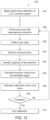
- FIG. 3is a flow chart of a method 66 for identifying regions within a heterogeneous phantom.
- One or more steps of the method 66may be performed by one or more components (e.g., processing circuitry) of the CT imaging system in FIG. 1 or a device separate or remote from the CT imaging system.
- the method 66includes obtaining or acquiring a tomographic image of a heterogeneous phantom (block 68 ).
- the tomographic imagemay be obtained utilizing a predefined protocol (e.g., kV, mA, bowtie, rotation speed, aperture, etc.).
- the method 66also includes automatically segmenting heterogeneous regions (e.g., having a plurality of materials with varying or different attenuation coefficients) from the tomographic image to generate a segmented image (e.g., segmentation mask) (block 70 ).
- a trained deep neural networkmay be utilized for performing segmentation of the heterogeneous regions.
- alternative techniquese.g., if, then statements may be utilized in performing the segmentation of the heterogeneous regions.
- the method 66further includes automatically determining an angle of rotation (e.g., angular rotation) of the heterogeneous phantom relative to a properly positioned heterogeneous phantom (or the heterogeneous phantom at a predefined position) (block 72 ).
- Determining the angle of rotationincludes comparing the segmentation image derived from the tomographic image to a reference image of a properly positioned heterogeneous phantom.
- the reference imagemay be a segmentation image or segmentation mask derived from a tomographic image of the properly positioned heterogeneous phantom.
- a similarity indexmay be utilized to determine the angle of rotation based on the comparison between the segmentation image and the reference image. There is no limit on the angle of rotation of the phantom that can be determined.
- the method 66still further includes automatically identifying a plurality of ROIs having varying attenuation coefficients within the tomographic image based on the segmented image (i.e., based on the determined angle of rotation) (block 74 ).
- the plurality of ROIscorrespond to the heterogeneous regions within the heterogeneous phantom. Identifying the ROIs includes identifying multi-connectivity (e.g., 8) pixel regions within the tomographic image. Identifying the ROIs also includes identifying pixels regions greater than a predefined number (e.g., 100) of connected pixels.
- the method 66yet further includes automatically labeling each ROI of the plurality of ROIs as representing a particular material of the materials with the varying or different attenuation coefficients (block 76 ).
- labeling the ROIsincludes generating a label matrix for the plurality of ROIs and comparing the label matrix to a static lookup table to label/identify each ROI as representing a particular material.
- FIG. 4is an example of a static lookup table 78 and labeled or annotated tomographic image 80 .
- each ROI 82is associated with a label 84 (e.g., R1, R2, R3, etc.) of the label matrix.
- each label 84corresponds to a specific material.
- labeling the ROIsincludes calculating a mean CT number (e.g., in Hounsfield units (HU)) for each ROI and comparing the respective CT number to a dynamic lookup table to determine the material.
- the dynamic lookup tableassociates specific CT number ranges with specific materials.
- FIG. 5is an example of a dynamic lookup table 78 and labeled or annotated tomographic image 88 .
- a mean CT numberis determined for each ROI 90 .
- each materialis associated within a particular CT number range (e.g., HU range).
- the method 66even further includes outputting a labeled or annotated image of the tomographic image (e.g., labeled tomographic images 80 , 88 in FIGS. 4 , 5 ) (block 92 ).
- the angle of rotation of the heterogeneous phantomis also outputted.
- a chartis also outputted that includes at least a label and a particular material (or concentration or density of the material) for each ROI in the labeled image.
- the chartmay also in include coordinates for each ROI.
- An example of a chart 94 that may be outputtedis provided in FIG. 6 .
- FIG. 7is schematic diagram of the method 66 (e.g., ROI location algorithm) in FIG. 3 .
- an image 96e.g., unlabeled tomographic image
- a trained deep neural network 98e.g., trained convolutional neural network
- the trained deep neural network 98generates a segmented image 100 (e.g., segmentation mask) from the image 96 having heterogeneous regions 102 having a plurality of materials with varying or different attenuation coefficients.
- the segmented image 100is compared to a reference or template image from which a similarity index 104 may be used to determine an angle of rotation for the heterogeneous phantom in the image 96 relative to a properly positioned heterogeneous phantom (or heterogeneous phantom at a predefined position).
- Regions of interestare identified in the image 96 by identifying connectivity regions (as indicated by reference numeral 106 ) and pixel regions of greater than 100 pixels (as indicated by reference numeral 108 ).
- a label matrixis created for the regions of interest in the image 96 (as indicated by reference numeral 110 ).
- the regions of interest in the image 96may be identified/labeled by comparing the label matrix and a lookup table (as indicated by reference numeral 112 ). A labeled or annotated image 114 of the image 96 is outputted. All of the steps of the depicted method may be automated.
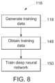
- FIG. 8is a flow chart of a method 116 for training a deep neural network (e.g., deep neural network 98 in FIG. 7 ) for identifying regions within a heterogeneous phantom.
- a deep neural networke.g., deep neural network 98 in FIG. 7
- One or more steps of the method 116may be performed by one or more components (e.g., processing circuitry) of the CT imaging system in FIG. 1 or a device separate or remote from the CT imaging system.
- the method 116includes generating training data for the deep neural network (e.g., convolutional neural network) (block 118 ).
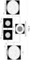
- the initial training datamay be generated by taking an unaugmented image 120 (e.g., tomographic image) of a heterogeneous phantom and randomly rotating a central portion 122 of the image 120 (as indicated in images 123 , 124 ) while keeping a peripheral part 126 of the image 120 (as indicated in image 128 ) intact to generate an augmented image or data 130 that includes central portion 122 rotated relative to the image 120 .
- a number of augmented images 130may be generated from the image 120 with different degrees of rotation of the central portion 122 .
- augmented imagesmay be manually processed to generate a label (e.g., segmentation image or segmentation mask) for the heterogeneous regions in each augmented image.
- image-label pairsincluding the augmented image and the segmentation image may be generated from the augmented images.
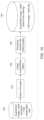
- further training datamay be generated while the deep neural network (e.g., convolutional neural network) is being trained.
- the deep neural networke.g., convolutional neural network
- in-place data augmentation or on-the-fly data augmentatione.g. utilizing ImageDataGenerator class of Keras deep learning network library
- data augmentationis performed (as indicated by reference numeral 136 ) to generate randomly transformed batch images 138 which are provided to form a larger training dataset 140 (augmented image-label pairs) for training the deep neural network.
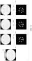
- FIG. 11provides different examples of augmented image-label pairs 142 obtained from an unaugmented image 143 .
- Each augmented image-label pair 142 in FIG. 11includes an augmented image 144 and a segmentation image 146 (e.g., segmentation mask for the heterogeneous regions).
- the method 116also includes obtaining the training data (e.g., image-label pairs) (block 148 ).
- the method 116further includes training the deep neural network to generate a trained deep neural network (block 150 ) that can segment the heterogeneous regions from an inputted image of a heterogeneous phantom. It should be noted that may be trained for any scanning protocol.
- FIG. 12is a flow chart of a method 152 for performing a calibration process that utilizes the ROI location algorithm.
- One or more steps of the method 152may be performed by one or more components (e.g., processing circuitry) of the CT imaging system in FIG. 1 or a device separate or remote from the CT imaging system.
- the method 152includes beginning performing calibration of a CT scanner system (CT imaging system in FIG. 1 ) (block 154 ).
- the method 152also includes performing a scan of a heterogeneous phantom as described above (block 156 ).
- the method 152further includes collecting or obtaining the scan data (block 158 ) and performing reconstruction on the scan data to generate a tomographic image of the heterogeneous phantom (block 160 ).
- the method 152still further includes identifying one or more heterogeneous regions within tomographic image of the heterogeneous phantom (block 162 ). The identification of heterogeneous regions occurs utilizing the ROI location algorithm as described above.
- the method 152even further includes calculating the required values (e.g., CT numbers) from the one or more identified heterogeneous regions (block 164 ).
- the method 152yet further includes calculating and storing respective calibration vectors for the one or more heterogeneous regions (block 166 ).
- the method 152includes deciding whether the calibration process is complete (block 168 ). If not complete, the method 152 returns to block 156 . If complete, the method 152 includes ending the calibration process (block 170 ).
- FIG. 13is a flow chart of a method 172 for performing a QA testing process that utilizes the ROI location algorithm.
- One or more steps of the method 172may be performed by one or more components (e.g., processing circuitry) of the CT imaging system in FIG. 1 or a device separate or remote from the CT imaging system.
- the method 172includes beginning performing QA testing of a CT scanner system (CT imaging system in FIG. 1 ) (block 174 ).
- the method 172also includes manually positioning a heterogeneous phantom between the radiation source and the detector of the CT scanner (block 176 ).
- the method 172also includes performing a scan of the heterogeneous phantom (block 178 ).
- the method 172further includes collecting or obtaining the scan data (block 180 ) and performing reconstruction on the scan data to generate a tomographic image of the heterogeneous phantom (block 182 ).
- the method 172includes identifying a center region of the heterogeneous phantom (block 184 ). The method 172 also includes determining if the heterogeneous phantom is grossly misaligned based on the identification of the center region (block 186 ). If the heterogeneous phantom is grossly misaligned, the method 172 includes determining if the misalignment can be corrected for automatically (block 188 ). If the misalignment cannot be correctly for automatically, the method 172 returns to block 176 . If the misalignment can be corrected for automatically, the method 172 includes automatically adjusting table position (block 190 ) in axial plane and/or automatically adjusting table location in z-direction (block 192 ).
- the method 172includes passing the identified center region as input to an image analysis for autonomous ROI placement (e.g., utilizing the ROI location algorithm as described above) (block 194 ).
- ROI location algorithmmay correct for any minor misalignments (i.e., provide fine tuning).
- the method 172also includes calculating image quality (IQ) metrics (block 196 ).
- the method 172further includes ending the QA testing process (block 198 ).
- inventionsinclude providing for deep-learning based autonomous identification of heterogeneous phantom regions (e.g., via region of interest location algorithm).
- the disclosed embodimentsenable the use of a multi-structure in the calibration and QA process without modifying any phantom hardware (e.g., adding a tracer/marker to identify regions).
- the deep neural networkcan be trained with any phantom at any scanning protocols. The ability to automatically identify the regions of interest within the heterogeneous phantom eliminates the need for manual intervention while ensuring the efficacy of the region identification.
Landscapes
- Engineering & Computer Science (AREA)
- Theoretical Computer Science (AREA)
- Physics & Mathematics (AREA)
- General Physics & Mathematics (AREA)
- Health & Medical Sciences (AREA)
- Medical Informatics (AREA)
- Multimedia (AREA)
- General Health & Medical Sciences (AREA)
- Computer Vision & Pattern Recognition (AREA)
- Life Sciences & Earth Sciences (AREA)
- Evolutionary Computation (AREA)
- Radiology & Medical Imaging (AREA)
- Nuclear Medicine, Radiotherapy & Molecular Imaging (AREA)
- Software Systems (AREA)
- Computing Systems (AREA)
- Artificial Intelligence (AREA)
- Databases & Information Systems (AREA)
- Biomedical Technology (AREA)
- Animal Behavior & Ethology (AREA)
- Surgery (AREA)
- Public Health (AREA)
- Veterinary Medicine (AREA)
- Molecular Biology (AREA)
- Heart & Thoracic Surgery (AREA)
- Pathology (AREA)
- Optics & Photonics (AREA)
- High Energy & Nuclear Physics (AREA)
- Biophysics (AREA)
- Quality & Reliability (AREA)
- Apparatus For Radiation Diagnosis (AREA)
Abstract
Description
Claims (20)
Priority Applications (4)
| Application Number | Priority Date | Filing Date | Title |
|---|---|---|---|
| US17/536,323US12144672B2 (en) | 2021-11-29 | 2021-11-29 | System and method for autonomous identification of heterogeneous phantom regions |
| JP2022175193AJP7585275B2 (en) | 2021-11-29 | 2022-11-01 | System and method for autonomous identification of inhomogeneous phantom regions - Patents.com |
| EP22207648.1AEP4187496A1 (en) | 2021-11-29 | 2022-11-15 | System and method for autonomous identification of heterogeneous phantom regions |
| CN202211425441.7ACN116188360A (en) | 2021-11-29 | 2022-11-15 | System and method for autonomous identification of heteroplasmic regions |
Applications Claiming Priority (1)
| Application Number | Priority Date | Filing Date | Title |
|---|---|---|---|
| US17/536,323US12144672B2 (en) | 2021-11-29 | 2021-11-29 | System and method for autonomous identification of heterogeneous phantom regions |
Publications (2)
| Publication Number | Publication Date |
|---|---|
| US20230165557A1 US20230165557A1 (en) | 2023-06-01 |
| US12144672B2true US12144672B2 (en) | 2024-11-19 |
Family
ID=84358849
Family Applications (1)
| Application Number | Title | Priority Date | Filing Date |
|---|---|---|---|
| US17/536,323Active2042-07-21US12144672B2 (en) | 2021-11-29 | 2021-11-29 | System and method for autonomous identification of heterogeneous phantom regions |
Country Status (4)
| Country | Link |
|---|---|
| US (1) | US12144672B2 (en) |
| EP (1) | EP4187496A1 (en) |
| JP (1) | JP7585275B2 (en) |
| CN (1) | CN116188360A (en) |
Families Citing this family (1)
| Publication number | Priority date | Publication date | Assignee | Title |
|---|---|---|---|---|
| EP4215116A1 (en)* | 2022-01-20 | 2023-07-26 | Ecential Robotics | Device for an x-ray imaging system |
Citations (87)
| Publication number | Priority date | Publication date | Assignee | Title |
|---|---|---|---|---|
| US6256367B1 (en)* | 1997-06-14 | 2001-07-03 | General Electric Company | Monte Carlo scatter correction method for computed tomography of general object geometries |
| US6345112B1 (en)* | 1997-08-19 | 2002-02-05 | The United States Of America As Represented By The Department Of Health And Human Services | Method for segmenting medical images and detecting surface anomalies in anatomical structures |
| US6404853B1 (en)* | 2001-11-02 | 2002-06-11 | Ge Medical Systems Global Technology Company, Llc | Method for identifying and correcting pixels with excess pixel lag in a solid state x-ray detector |
| US20030043967A1 (en)* | 2001-08-28 | 2003-03-06 | Richard Aufrichtig | Method and apparatus for identifying and correcting line artifacts in a solid state X-ray detector |
| US20030233039A1 (en)* | 2002-06-12 | 2003-12-18 | Lingxiong Shao | Physiological model based non-rigid image registration |
| US20040058951A1 (en)* | 2002-01-24 | 2004-03-25 | Lanza Gregory M. | Integrin targeted imaging agents |
| US20040264627A1 (en)* | 2003-06-25 | 2004-12-30 | Besson Guy M. | Dynamic multi-spectral X-ray projection imaging |
| US20060098856A1 (en)* | 2003-01-30 | 2006-05-11 | Koninklijke Philips Electronics N.V. | Reconstruction of local patient doses in computed tomography |
| US20070244395A1 (en)* | 2006-01-03 | 2007-10-18 | Ge Wang | Systems and methods for multi-spectral bioluminescence tomography |
| US20080159469A1 (en)* | 2006-09-28 | 2008-07-03 | Ernst-Peter Ruhrnschopf | Method for combined bone hardening and scattered radiation correction in X-ray computed tomography |
| US7627079B2 (en)* | 2005-11-21 | 2009-12-01 | The Regents Of The University Of California | Method for computing patient radiation dose in computed tomography |
| US20100210931A1 (en)* | 2008-04-04 | 2010-08-19 | Modulate Imaging Inc. | Method for performing qualitative and quantitative analysis of wounds using spatially structured illumination |
| US7792249B2 (en)* | 2007-12-23 | 2010-09-07 | Oraya Therapeutics, Inc. | Methods and devices for detecting, controlling, and predicting radiation delivery |
| US20100272339A1 (en)* | 2009-04-24 | 2010-10-28 | Siemens Medical Solutions Usa, Inc. | Calibration of a Multi-Pinhole SPECT System Without Pre-Knowledge of Point Source Markers 3D Coordinates |
| US20110026791A1 (en)* | 2009-07-29 | 2011-02-03 | Icad, Inc. | Systems, computer-readable media, and methods for classifying and displaying breast density |
| US20110049384A1 (en)* | 2007-10-19 | 2011-03-03 | Yared Wael I | Imaging Systems Featuring Waveguiding Compensation |
| US7933782B2 (en)* | 2007-01-29 | 2011-04-26 | Bruce Reiner | Quality assurance scorecard for diagnostic medical agent administration |
| US20110123088A1 (en)* | 2009-11-25 | 2011-05-26 | David Sebok | Extracting patient motion vectors from marker positions in x-ray images |
| US8018487B2 (en)* | 2005-04-28 | 2011-09-13 | Qami | Method and apparatus for automated quality assurance in medical imaging |
| US20120076371A1 (en)* | 2010-09-23 | 2012-03-29 | Siemens Aktiengesellschaft | Phantom Identification |
| US20120106817A1 (en)* | 2010-04-30 | 2012-05-03 | Cornell University, The Trustees of Columbia University in the City of New York | System and method for radiation dose reporting |
| US20120148131A1 (en)* | 2010-12-08 | 2012-06-14 | Radimetrics, Inc. | Generating a suitable model for estimating patient radiation dose resulting from medical imaging scans |
| US20130156163A1 (en)* | 2011-12-19 | 2013-06-20 | General Electric Company | Method and apparatus for reconstructing an image of an object |
| US20130170723A1 (en)* | 2011-12-07 | 2013-07-04 | Telesecurity Sciences, Inc. | Extraction of objects from ct images by sequential segmentation and carving |
| US20130235969A1 (en)* | 2012-03-01 | 2013-09-12 | Imris Inc. | Patient Alignment in MRI Guided Radiation Therapy |
| US20130272595A1 (en)* | 2010-12-15 | 2013-10-17 | H. Lee Moffitt Cancer Center And Research Institute, Inc. | Method for assessing breast density |
| US20140180082A1 (en)* | 2012-12-21 | 2014-06-26 | Caperay Medical (Pty) Ltd | Dual-modality mammography |
| US20140355856A1 (en)* | 2013-05-31 | 2014-12-04 | General Photonics Corporation | Reconstruction of optical coherent tomography (oct) images of morphological features |
| US20150005635A1 (en)* | 2007-05-04 | 2015-01-01 | Delphinus Medical Technologies, Inc. | Patient interface system |
| US20150085979A1 (en)* | 2012-05-01 | 2015-03-26 | Universitat Bern | Image distortion correction and robust phantom detection |
| US20150216498A1 (en)* | 2012-08-20 | 2015-08-06 | Orangedental Gmbh & Co. Kg | Geometric Characterization and Calibration of a Cone-Beam Computer Tomography Apparatus |
| US20150262387A1 (en)* | 2009-09-11 | 2015-09-17 | Straxcorp Pty Ltd | Method and system for image analysis |
| US9198633B2 (en)* | 2011-07-29 | 2015-12-01 | Gammex, Inc. | Computed tomography perfusion phantom and method use thereof |
| US20160015356A1 (en)* | 2014-07-18 | 2016-01-21 | Gammex, Inc. | Brain Tissue Equivalent Material And Phantom Device Comprising The Same |
| US20160113612A1 (en)* | 2014-10-28 | 2016-04-28 | Siemens Aktiengesellschaft | Method for the fully automatic detection and assessment of damaged vertebrae |
| US20160278715A1 (en)* | 2015-03-23 | 2016-09-29 | University Of Kentucky Research Foundation | Noncontact Three-dimensional Diffuse Optical Imaging of Deep Tissue Blood Flow Distribution |
| US20160287906A1 (en)* | 2015-04-02 | 2016-10-06 | Varian Medical Systems International Ag | Portal dosimetry systems, devices, and methods |
| US20160310762A1 (en)* | 2015-04-23 | 2016-10-27 | Sun Nuclear Corporation | Radiation Detector Calibration |
| US20160370285A1 (en)* | 2015-06-19 | 2016-12-22 | The United States Of America, As Represented By The Secretary, Department Of Health And Human Serv | Solid hemoglobin-polymer biophotonic phantoms and their use |
| US20170112457A1 (en)* | 2014-06-09 | 2017-04-27 | University Of Lincoln | Assembly, Apparatus, System and Method |
| US20170164835A1 (en)* | 2014-06-10 | 2017-06-15 | Ithera Medical Gmbh | Device and method for hybrid optoacoustic tomography and ultrasonography |
| US20170245825A1 (en)* | 2016-02-29 | 2017-08-31 | Varian Medical Systems, Inc. | Automatic organ-dose-estimation for patient-specific computed tomography scans |
| WO2017223560A1 (en) | 2016-06-24 | 2017-12-28 | Rensselaer Polytechnic Institute | Tomographic image reconstruction via machine learning |
| US20180014806A1 (en)* | 2016-07-14 | 2018-01-18 | Toshiba Medical Systems Corporation | Scatter simulation with a radiative transfer equation using direct integral spherical harmonics method for computed tomography |
| US20180028133A1 (en)* | 2016-07-29 | 2018-02-01 | The Regents Of The University Of Colorado, A Body Corporate | Automated tracking of fiducial marker clusters in x-ray images |
| US20180061058A1 (en)* | 2016-08-26 | 2018-03-01 | Elekta, Inc. | Image segmentation using neural network method |
| US20180116620A1 (en)* | 2016-10-31 | 2018-05-03 | Siemens Healthcare Gmbh | Deep Learning Based Bone Removal in Computed Tomography Angiography |
| US20180140272A1 (en)* | 2016-11-23 | 2018-05-24 | Gammex, Inc. | Automated detection and identification of phantoms |
| US10022098B2 (en)* | 2014-07-09 | 2018-07-17 | Siemens Aktiengesellschaft | Method and device for generating a low-dose X-ray image preview, imaging system and computer program product |
| US20180224592A1 (en)* | 2017-02-09 | 2018-08-09 | David Wayne Holdsworth | Method and apparatus for calibrating low-light level optical imaging systems |
| US20180247450A1 (en)* | 2015-09-03 | 2018-08-30 | Schlumberger Technology Corporation | A computer-implemented method and a system for creating a three-dimensional mineral model of a sample of a heterogenous medium |
| US20180289336A1 (en) | 2017-04-10 | 2018-10-11 | Fujifilm Corporation | Medical image display device, method, and program |
| US20180330233A1 (en)* | 2017-05-11 | 2018-11-15 | General Electric Company | Machine learning based scatter correction |
| US20190046813A1 (en)* | 2016-02-02 | 2019-02-14 | Suzhou Evidance Medical Technologies Inc. | Systems and Methods for Radiation Treatment Planning |
| US20190054194A1 (en)* | 2017-08-17 | 2019-02-21 | Case Western Reserve University | System and Method For Evaluation of Subjects Using Magnetic Resonance Imaging and Oxygen-17 |
| US20190108441A1 (en)* | 2017-10-11 | 2019-04-11 | General Electric Company | Image generation using machine learning |
| US10349912B2 (en)* | 2017-04-05 | 2019-07-16 | Siemens Healthcare Gmbh | Determining a reference dose parameter of a computed tomography imaging |
| US10360344B2 (en)* | 2009-12-10 | 2019-07-23 | Koninklijke Philips N.V. | Diagnostic techniques for continuous storage and joint analysis of both image and non-image medical data |
| US10363011B2 (en)* | 2014-03-05 | 2019-07-30 | Siemens Healthcare Gmbh | Automatic dose control for imaging medical devices |
| US10376713B2 (en)* | 2014-09-24 | 2019-08-13 | Hitachi, Ltd. | Radiation therapy planning system, radiation therapy planning method, and radiation therapy system |
| US20190251694A1 (en) | 2018-02-14 | 2019-08-15 | Elekta, Inc. | Atlas-based segmentation using deep-learning |
| US20190266436A1 (en)* | 2018-02-26 | 2019-08-29 | General Electric Company | Machine learning in an imaging modality service context |
| US20190388054A1 (en)* | 2016-12-09 | 2019-12-26 | Taishan Medical University | Bimodal three-dimensional mammary gland imaging quality detecting phantom and method |
| US20200065969A1 (en)* | 2018-08-27 | 2020-02-27 | Siemens Healthcare Gmbh | Medical image segmentation from raw data using a deep attention neural network |
| US20200085404A1 (en)* | 2017-03-16 | 2020-03-19 | The Johns Hopkins University | Geometric calibration for cone beam ct using line fiducials |
| US20200170612A1 (en)* | 2017-08-17 | 2020-06-04 | Technological University Dublin | Tissue Mimicking Materials |
| US20200211710A1 (en)* | 2017-09-08 | 2020-07-02 | The General Hospital Corporation | Patient risk stratification based on body composition derived from computed tomography images using machine learning |
| US20200234471A1 (en)* | 2019-01-18 | 2020-07-23 | Canon Medical Systems Corporation | Deep-learning-based scatter estimation and correction for x-ray projection data and computer tomography (ct) |
| US20200237319A1 (en)* | 2019-01-25 | 2020-07-30 | Samsung Electronics Co., Ltd. | X-ray image processing method and x-ray image processing apparatus |
| US20200359911A1 (en)* | 2019-05-17 | 2020-11-19 | Massachusetts Institute Of Technology | Arterial wall characterization in optical coherence tomography imaging |
| US11000255B2 (en)* | 2017-02-24 | 2021-05-11 | Bayer Healthcare Llc | Systems and methods for generating simulated computed tomography (CT) images |
| US11051782B1 (en)* | 2018-02-23 | 2021-07-06 | Robert Edwin Douglas | Image quality by incorporating data unit assurance markers |
| US20210236080A1 (en) | 2020-01-30 | 2021-08-05 | GE Precision Healthcare LLC | Cta large vessel occlusion model |
| US20210239862A1 (en)* | 2019-11-22 | 2021-08-05 | Hellma Materials Gmbh | Imaging detector system for gamma radiation using unidirectional and bidirectional compton scattering processes |
| US20210239775A1 (en)* | 2020-01-15 | 2021-08-05 | The University Of North Carolina At Chapel Hill | Methods, systems, and computer-readable media for nondestructively measuring physical properties of a material by observing induced displacements using different focal configurations |
| CN113423342A (en) | 2019-02-14 | 2021-09-21 | 棱镜传感器公司 | Calibration of x-ray imaging systems |
| US11354832B2 (en)* | 2017-05-01 | 2022-06-07 | Koninklijke Philips N.V. | Generation of accurate hybrid datasets for quantitative molecular imaging |
| US20220245928A1 (en)* | 2021-02-04 | 2022-08-04 | Google Llc | Systems and methods for progressive learning for machine-learned models to optimize training speed |
| US20220322940A1 (en)* | 2019-08-09 | 2022-10-13 | EMvision Medical Devices Ltd | Apparatus and process for electromagnetic imaging |
| US20220342098A1 (en)* | 2021-04-23 | 2022-10-27 | Canon Medical Systems Corporation | Bad detector calibration methods and workflow for a small pixelated photon counting ct system |
| US11532390B2 (en)* | 2017-12-21 | 2022-12-20 | Siemens Healthcare Gmbh | Method and system for validating parameters in a medical study |
| US11688044B2 (en)* | 2021-02-05 | 2023-06-27 | GE Precision Healthcare LLC | Systems and methods of validating motion correction of medical images for quantitative parametric maps |
| US11694373B2 (en)* | 2017-04-07 | 2023-07-04 | Regents Of The University Of Minnesota | Methods for scan-specific k-space interpolation reconstruction in magnetic resonance imaging using machine learning |
| US20230320688A1 (en)* | 2022-04-12 | 2023-10-12 | GE Precision Healthcare LLC | Systems and methods for image artifact mitigation with targeted modular calibration |
| US11794037B2 (en)* | 2017-02-28 | 2023-10-24 | Sun Nuclear Corporation | Radiation therapy treatment verification with electronic portal imaging device transit images |
| US11813103B2 (en)* | 2018-06-29 | 2023-11-14 | Shanghai United Imaging Healthcare Co., Ltd. | Methods and systems for modulating radiation dose |
| US11826585B2 (en)* | 2017-11-28 | 2023-11-28 | Regents Of The University Of Minnesota | Adaptive refocusing of ultrasound transducer arrays using image data |
Family Cites Families (3)
| Publication number | Priority date | Publication date | Assignee | Title |
|---|---|---|---|---|
| US6694047B1 (en)* | 1999-07-15 | 2004-02-17 | General Electric Company | Method and apparatus for automated image quality evaluation of X-ray systems using any of multiple phantoms |
| DE102005049602B3 (en)* | 2005-10-17 | 2007-04-19 | Siemens Ag | Segmenting at least one substance in an x-ray image involves determining number of image points in classification range as assessment value and deriving segmented image with threshold comparison based on assessment value |
| CN104463828B (en)* | 2013-09-18 | 2018-04-10 | 株式会社日立制作所 | CT image evaluation apparatus and CT image evaluation methods |
- 2021
- 2021-11-29USUS17/536,323patent/US12144672B2/enactiveActive
- 2022
- 2022-11-01JPJP2022175193Apatent/JP7585275B2/enactiveActive
- 2022-11-15EPEP22207648.1Apatent/EP4187496A1/enactivePending
- 2022-11-15CNCN202211425441.7Apatent/CN116188360A/enactivePending
Patent Citations (112)
| Publication number | Priority date | Publication date | Assignee | Title |
|---|---|---|---|---|
| US6256367B1 (en)* | 1997-06-14 | 2001-07-03 | General Electric Company | Monte Carlo scatter correction method for computed tomography of general object geometries |
| US6345112B1 (en)* | 1997-08-19 | 2002-02-05 | The United States Of America As Represented By The Department Of Health And Human Services | Method for segmenting medical images and detecting surface anomalies in anatomical structures |
| US20030043967A1 (en)* | 2001-08-28 | 2003-03-06 | Richard Aufrichtig | Method and apparatus for identifying and correcting line artifacts in a solid state X-ray detector |
| US6404853B1 (en)* | 2001-11-02 | 2002-06-11 | Ge Medical Systems Global Technology Company, Llc | Method for identifying and correcting pixels with excess pixel lag in a solid state x-ray detector |
| US20040058951A1 (en)* | 2002-01-24 | 2004-03-25 | Lanza Gregory M. | Integrin targeted imaging agents |
| US20030233039A1 (en)* | 2002-06-12 | 2003-12-18 | Lingxiong Shao | Physiological model based non-rigid image registration |
| US20060098856A1 (en)* | 2003-01-30 | 2006-05-11 | Koninklijke Philips Electronics N.V. | Reconstruction of local patient doses in computed tomography |
| US20040264627A1 (en)* | 2003-06-25 | 2004-12-30 | Besson Guy M. | Dynamic multi-spectral X-ray projection imaging |
| US8957955B2 (en)* | 2005-04-28 | 2015-02-17 | Bruce Reiner | Method and apparatus for automated quality assurance in medical imaging |
| US8018487B2 (en)* | 2005-04-28 | 2011-09-13 | Qami | Method and apparatus for automated quality assurance in medical imaging |
| US7627079B2 (en)* | 2005-11-21 | 2009-12-01 | The Regents Of The University Of California | Method for computing patient radiation dose in computed tomography |
| US20070244395A1 (en)* | 2006-01-03 | 2007-10-18 | Ge Wang | Systems and methods for multi-spectral bioluminescence tomography |
| US8676302B2 (en)* | 2006-01-03 | 2014-03-18 | University Of Iowa Research Foundation | Systems and methods for multi-spectral bioluminescence tomography |
| US20080159469A1 (en)* | 2006-09-28 | 2008-07-03 | Ernst-Peter Ruhrnschopf | Method for combined bone hardening and scattered radiation correction in X-ray computed tomography |
| US7933782B2 (en)* | 2007-01-29 | 2011-04-26 | Bruce Reiner | Quality assurance scorecard for diagnostic medical agent administration |
| US20150005635A1 (en)* | 2007-05-04 | 2015-01-01 | Delphinus Medical Technologies, Inc. | Patient interface system |
| US20140243661A1 (en)* | 2007-10-19 | 2014-08-28 | Visen Medical, Inc. | Imaging Systems Featuring Waveguiding Compensation |
| US20140003692A1 (en)* | 2007-10-19 | 2014-01-02 | Visen Medical, Inc. | Imaging systems featuring waveguiding compensation |
| US20110049384A1 (en)* | 2007-10-19 | 2011-03-03 | Yared Wael I | Imaging Systems Featuring Waveguiding Compensation |
| US9311722B2 (en)* | 2007-10-19 | 2016-04-12 | Visen Medical, Inc. | Imaging systems featuring waveguiding compensation |
| US8653480B2 (en)* | 2007-10-19 | 2014-02-18 | Visen Medical, Inc. | Imaging systems featuring waveguiding compensation |
| US8492734B2 (en)* | 2007-10-19 | 2013-07-23 | Visen Medical, Inc. | Imaging systems featuring waveguiding compensation |
| US7792249B2 (en)* | 2007-12-23 | 2010-09-07 | Oraya Therapeutics, Inc. | Methods and devices for detecting, controlling, and predicting radiation delivery |
| US20100210931A1 (en)* | 2008-04-04 | 2010-08-19 | Modulate Imaging Inc. | Method for performing qualitative and quantitative analysis of wounds using spatially structured illumination |
| US20100272339A1 (en)* | 2009-04-24 | 2010-10-28 | Siemens Medical Solutions Usa, Inc. | Calibration of a Multi-Pinhole SPECT System Without Pre-Knowledge of Point Source Markers 3D Coordinates |
| US20110026791A1 (en)* | 2009-07-29 | 2011-02-03 | Icad, Inc. | Systems, computer-readable media, and methods for classifying and displaying breast density |
| US9877691B2 (en)* | 2009-09-11 | 2018-01-30 | Straxcorp Pty Ltd | Method and system for image analysis |
| US20160296188A1 (en)* | 2009-09-11 | 2016-10-13 | Straxcorp Pty Ltd | Method and system for image analysis |
| US9566038B2 (en)* | 2009-09-11 | 2017-02-14 | Straxcorp Pty Ltd | Method and system for image analysis |
| US20170119333A1 (en)* | 2009-09-11 | 2017-05-04 | Straxcorp Pty Ltd | Method and system for image analysis |
| US20150262387A1 (en)* | 2009-09-11 | 2015-09-17 | Straxcorp Pty Ltd | Method and system for image analysis |
| US9378566B2 (en)* | 2009-09-11 | 2016-06-28 | Straxcorp Pty Ltd | Method and system for image analysis |
| US9082182B2 (en)* | 2009-11-25 | 2015-07-14 | Dental Imaging Technologies Corporation | Extracting patient motion vectors from marker positions in x-ray images |
| US20110123088A1 (en)* | 2009-11-25 | 2011-05-26 | David Sebok | Extracting patient motion vectors from marker positions in x-ray images |
| US10360344B2 (en)* | 2009-12-10 | 2019-07-23 | Koninklijke Philips N.V. | Diagnostic techniques for continuous storage and joint analysis of both image and non-image medical data |
| US20120106817A1 (en)* | 2010-04-30 | 2012-05-03 | Cornell University, The Trustees of Columbia University in the City of New York | System and method for radiation dose reporting |
| US20120076371A1 (en)* | 2010-09-23 | 2012-03-29 | Siemens Aktiengesellschaft | Phantom Identification |
| US20120148131A1 (en)* | 2010-12-08 | 2012-06-14 | Radimetrics, Inc. | Generating a suitable model for estimating patient radiation dose resulting from medical imaging scans |
| US10546376B2 (en)* | 2010-12-08 | 2020-01-28 | Bayer Healthcare Llc | Dose estimation service system configured to support multiple computerized medical imaging scan providers |
| US10546375B2 (en)* | 2010-12-08 | 2020-01-28 | Bayer Healthcare Llc | Generating a suitable model for estimating patient radiation dose from medical imaging scans |
| US9547893B2 (en)* | 2010-12-08 | 2017-01-17 | Bayer Healthcare Llc | Generating a suitable model for estimating patient radiation dose resulting from medical imaging scans |
| US20130272595A1 (en)* | 2010-12-15 | 2013-10-17 | H. Lee Moffitt Cancer Center And Research Institute, Inc. | Method for assessing breast density |
| US9198633B2 (en)* | 2011-07-29 | 2015-12-01 | Gammex, Inc. | Computed tomography perfusion phantom and method use thereof |
| US20130170723A1 (en)* | 2011-12-07 | 2013-07-04 | Telesecurity Sciences, Inc. | Extraction of objects from ct images by sequential segmentation and carving |
| US20130156163A1 (en)* | 2011-12-19 | 2013-06-20 | General Electric Company | Method and apparatus for reconstructing an image of an object |
| US20130235969A1 (en)* | 2012-03-01 | 2013-09-12 | Imris Inc. | Patient Alignment in MRI Guided Radiation Therapy |
| US20150085979A1 (en)* | 2012-05-01 | 2015-03-26 | Universitat Bern | Image distortion correction and robust phantom detection |
| US20150216498A1 (en)* | 2012-08-20 | 2015-08-06 | Orangedental Gmbh & Co. Kg | Geometric Characterization and Calibration of a Cone-Beam Computer Tomography Apparatus |
| US20140180082A1 (en)* | 2012-12-21 | 2014-06-26 | Caperay Medical (Pty) Ltd | Dual-modality mammography |
| US20140355856A1 (en)* | 2013-05-31 | 2014-12-04 | General Photonics Corporation | Reconstruction of optical coherent tomography (oct) images of morphological features |
| US10363011B2 (en)* | 2014-03-05 | 2019-07-30 | Siemens Healthcare Gmbh | Automatic dose control for imaging medical devices |
| US20170112457A1 (en)* | 2014-06-09 | 2017-04-27 | University Of Lincoln | Assembly, Apparatus, System and Method |
| US20170164835A1 (en)* | 2014-06-10 | 2017-06-15 | Ithera Medical Gmbh | Device and method for hybrid optoacoustic tomography and ultrasonography |
| US10022098B2 (en)* | 2014-07-09 | 2018-07-17 | Siemens Aktiengesellschaft | Method and device for generating a low-dose X-ray image preview, imaging system and computer program product |
| US20160015356A1 (en)* | 2014-07-18 | 2016-01-21 | Gammex, Inc. | Brain Tissue Equivalent Material And Phantom Device Comprising The Same |
| US10376713B2 (en)* | 2014-09-24 | 2019-08-13 | Hitachi, Ltd. | Radiation therapy planning system, radiation therapy planning method, and radiation therapy system |
| US20160113612A1 (en)* | 2014-10-28 | 2016-04-28 | Siemens Aktiengesellschaft | Method for the fully automatic detection and assessment of damaged vertebrae |
| US9861319B2 (en)* | 2015-03-23 | 2018-01-09 | University Of Kentucky Research Foundation | Noncontact three-dimensional diffuse optical imaging of deep tissue blood flow distribution |
| US20160278715A1 (en)* | 2015-03-23 | 2016-09-29 | University Of Kentucky Research Foundation | Noncontact Three-dimensional Diffuse Optical Imaging of Deep Tissue Blood Flow Distribution |
| US20160287906A1 (en)* | 2015-04-02 | 2016-10-06 | Varian Medical Systems International Ag | Portal dosimetry systems, devices, and methods |
| US20160310762A1 (en)* | 2015-04-23 | 2016-10-27 | Sun Nuclear Corporation | Radiation Detector Calibration |
| US20160370285A1 (en)* | 2015-06-19 | 2016-12-22 | The United States Of America, As Represented By The Secretary, Department Of Health And Human Serv | Solid hemoglobin-polymer biophotonic phantoms and their use |
| US20180247450A1 (en)* | 2015-09-03 | 2018-08-30 | Schlumberger Technology Corporation | A computer-implemented method and a system for creating a three-dimensional mineral model of a sample of a heterogenous medium |
| US20190046813A1 (en)* | 2016-02-02 | 2019-02-14 | Suzhou Evidance Medical Technologies Inc. | Systems and Methods for Radiation Treatment Planning |
| US20170245825A1 (en)* | 2016-02-29 | 2017-08-31 | Varian Medical Systems, Inc. | Automatic organ-dose-estimation for patient-specific computed tomography scans |
| WO2017223560A1 (en) | 2016-06-24 | 2017-12-28 | Rensselaer Polytechnic Institute | Tomographic image reconstruction via machine learning |
| US20190325621A1 (en)* | 2016-06-24 | 2019-10-24 | Rensselaer Polytechnic Institute | Tomographic image reconstruction via machine learning |
| US20180014806A1 (en)* | 2016-07-14 | 2018-01-18 | Toshiba Medical Systems Corporation | Scatter simulation with a radiative transfer equation using direct integral spherical harmonics method for computed tomography |
| US11253210B2 (en)* | 2016-07-29 | 2022-02-22 | The Regents Of The University Of Colorado, A Body Corporate | Automated tracking of fiducial marker clusters in x-ray images |
| US20180028133A1 (en)* | 2016-07-29 | 2018-02-01 | The Regents Of The University Of Colorado, A Body Corporate | Automated tracking of fiducial marker clusters in x-ray images |
| US20180061058A1 (en)* | 2016-08-26 | 2018-03-01 | Elekta, Inc. | Image segmentation using neural network method |
| US20180116620A1 (en)* | 2016-10-31 | 2018-05-03 | Siemens Healthcare Gmbh | Deep Learning Based Bone Removal in Computed Tomography Angiography |
| US10939891B2 (en)* | 2016-11-23 | 2021-03-09 | Gammex, Inc. | Automated detection and identification of phantoms |
| US20180140272A1 (en)* | 2016-11-23 | 2018-05-24 | Gammex, Inc. | Automated detection and identification of phantoms |
| US20190388054A1 (en)* | 2016-12-09 | 2019-12-26 | Taishan Medical University | Bimodal three-dimensional mammary gland imaging quality detecting phantom and method |
| US20180224592A1 (en)* | 2017-02-09 | 2018-08-09 | David Wayne Holdsworth | Method and apparatus for calibrating low-light level optical imaging systems |
| US11000255B2 (en)* | 2017-02-24 | 2021-05-11 | Bayer Healthcare Llc | Systems and methods for generating simulated computed tomography (CT) images |
| US11794037B2 (en)* | 2017-02-28 | 2023-10-24 | Sun Nuclear Corporation | Radiation therapy treatment verification with electronic portal imaging device transit images |
| US20200085404A1 (en)* | 2017-03-16 | 2020-03-19 | The Johns Hopkins University | Geometric calibration for cone beam ct using line fiducials |
| US10349912B2 (en)* | 2017-04-05 | 2019-07-16 | Siemens Healthcare Gmbh | Determining a reference dose parameter of a computed tomography imaging |
| US11694373B2 (en)* | 2017-04-07 | 2023-07-04 | Regents Of The University Of Minnesota | Methods for scan-specific k-space interpolation reconstruction in magnetic resonance imaging using machine learning |
| US20180289336A1 (en) | 2017-04-10 | 2018-10-11 | Fujifilm Corporation | Medical image display device, method, and program |
| US11354832B2 (en)* | 2017-05-01 | 2022-06-07 | Koninklijke Philips N.V. | Generation of accurate hybrid datasets for quantitative molecular imaging |
| US20180330233A1 (en)* | 2017-05-11 | 2018-11-15 | General Electric Company | Machine learning based scatter correction |
| US20200170612A1 (en)* | 2017-08-17 | 2020-06-04 | Technological University Dublin | Tissue Mimicking Materials |
| US20190054194A1 (en)* | 2017-08-17 | 2019-02-21 | Case Western Reserve University | System and Method For Evaluation of Subjects Using Magnetic Resonance Imaging and Oxygen-17 |
| US20200211710A1 (en)* | 2017-09-08 | 2020-07-02 | The General Hospital Corporation | Patient risk stratification based on body composition derived from computed tomography images using machine learning |
| US20190108441A1 (en)* | 2017-10-11 | 2019-04-11 | General Electric Company | Image generation using machine learning |
| US11826585B2 (en)* | 2017-11-28 | 2023-11-28 | Regents Of The University Of Minnesota | Adaptive refocusing of ultrasound transducer arrays using image data |
| US11532390B2 (en)* | 2017-12-21 | 2022-12-20 | Siemens Healthcare Gmbh | Method and system for validating parameters in a medical study |
| US20190251694A1 (en) | 2018-02-14 | 2019-08-15 | Elekta, Inc. | Atlas-based segmentation using deep-learning |
| US11051782B1 (en)* | 2018-02-23 | 2021-07-06 | Robert Edwin Douglas | Image quality by incorporating data unit assurance markers |
| US20190266436A1 (en)* | 2018-02-26 | 2019-08-29 | General Electric Company | Machine learning in an imaging modality service context |
| US11813103B2 (en)* | 2018-06-29 | 2023-11-14 | Shanghai United Imaging Healthcare Co., Ltd. | Methods and systems for modulating radiation dose |
| US10922816B2 (en)* | 2018-08-27 | 2021-02-16 | Siemens Healthcare Gmbh | Medical image segmentation from raw data using a deep attention neural network |
| US20200065969A1 (en)* | 2018-08-27 | 2020-02-27 | Siemens Healthcare Gmbh | Medical image segmentation from raw data using a deep attention neural network |
| EP3683771B1 (en) | 2019-01-18 | 2022-07-06 | Canon Medical Systems Corporation | Medical processing apparatus |
| US20200234471A1 (en)* | 2019-01-18 | 2020-07-23 | Canon Medical Systems Corporation | Deep-learning-based scatter estimation and correction for x-ray projection data and computer tomography (ct) |
| US10937206B2 (en)* | 2019-01-18 | 2021-03-02 | Canon Medical Systems Corporation | Deep-learning-based scatter estimation and correction for X-ray projection data and computer tomography (CT) |
| US20200237319A1 (en)* | 2019-01-25 | 2020-07-30 | Samsung Electronics Co., Ltd. | X-ray image processing method and x-ray image processing apparatus |
| CN113423342A (en) | 2019-02-14 | 2021-09-21 | 棱镜传感器公司 | Calibration of x-ray imaging systems |
| US20200359911A1 (en)* | 2019-05-17 | 2020-11-19 | Massachusetts Institute Of Technology | Arterial wall characterization in optical coherence tomography imaging |
| US20220322940A1 (en)* | 2019-08-09 | 2022-10-13 | EMvision Medical Devices Ltd | Apparatus and process for electromagnetic imaging |
| US20210239862A1 (en)* | 2019-11-22 | 2021-08-05 | Hellma Materials Gmbh | Imaging detector system for gamma radiation using unidirectional and bidirectional compton scattering processes |
| US20210239775A1 (en)* | 2020-01-15 | 2021-08-05 | The University Of North Carolina At Chapel Hill | Methods, systems, and computer-readable media for nondestructively measuring physical properties of a material by observing induced displacements using different focal configurations |
| US20210236080A1 (en) | 2020-01-30 | 2021-08-05 | GE Precision Healthcare LLC | Cta large vessel occlusion model |
| US11450096B2 (en)* | 2021-02-04 | 2022-09-20 | Google Llc | Systems and methods for progressive learning for machine-learned models to optimize training speed |
| US20220245928A1 (en)* | 2021-02-04 | 2022-08-04 | Google Llc | Systems and methods for progressive learning for machine-learned models to optimize training speed |
| US11688044B2 (en)* | 2021-02-05 | 2023-06-27 | GE Precision Healthcare LLC | Systems and methods of validating motion correction of medical images for quantitative parametric maps |
| US20220342098A1 (en)* | 2021-04-23 | 2022-10-27 | Canon Medical Systems Corporation | Bad detector calibration methods and workflow for a small pixelated photon counting ct system |
| US11782176B2 (en)* | 2021-04-23 | 2023-10-10 | Canon Medical Systems Corporation | Bad detector calibration methods and workflow for a small pixelated photon counting CT system |
| US20230320688A1 (en)* | 2022-04-12 | 2023-10-12 | GE Precision Healthcare LLC | Systems and methods for image artifact mitigation with targeted modular calibration |
Non-Patent Citations (3)
| Title |
|---|
| CN113423342—English Abstract, Espacenet search results Feb. 19, 2024; 1 page. |
| EP application 22207648.1 filed Nov. 15, 2022—extended Search Report issued Apr. 21, 2023; 8 pages. |
| JP application 2022-175193 filed Nov. 1, 2022—Office Action issued Nov. 22, 2023; Machine Translation, 8 pages. |
Also Published As
| Publication number | Publication date |
|---|---|
| CN116188360A (en) | 2023-05-30 |
| JP2023080021A (en) | 2023-06-08 |
| US20230165557A1 (en) | 2023-06-01 |
| JP7585275B2 (en) | 2024-11-18 |
| EP4187496A1 (en) | 2023-05-31 |
Similar Documents
| Publication | Publication Date | Title |
|---|---|---|
| JP7234064B2 (en) | Iterative image reconstruction framework | |
| US7813783B2 (en) | Methods and systems for attenuation correction in medical imaging | |
| US8699768B2 (en) | Scan plan field of view adjustor, determiner, and/or quality assessor | |
| US12182970B2 (en) | X-ray imaging restoration using deep learning algorithms | |
| JPH0714022A (en) | Method and apparatus for reconstitution of three-dimensional image from incomplete conical beam projection data | |
| US20170042494A1 (en) | Computed tomography apparatus and method of reconstructing a computed tomography image by the computed tomography apparatus | |
| US11823354B2 (en) | System and method for utilizing a deep learning network to correct for a bad pixel in a computed tomography detector | |
| US20220375038A1 (en) | Systems and methods for computed tomography image denoising with a bias-reducing loss function | |
| JP6526428B2 (en) | Medical image processing apparatus, medical image processing method and medical image diagnostic apparatus | |
| US20080118130A1 (en) | method and system for grouping images in a tomosynthesis imaging system | |
| US7978886B2 (en) | System and method for anatomy based reconstruction | |
| EP4187496A1 (en) | System and method for autonomous identification of heterogeneous phantom regions | |
| US12156752B2 (en) | Method and systems for aliasing artifact reduction in computed tomography imaging | |
| US8854355B2 (en) | System and method of visualizing features in an image | |
| US20230320688A1 (en) | Systems and methods for image artifact mitigation with targeted modular calibration | |
| Huang et al. | Learning Perspective Distortion Correction in Cone-Beam X-Ray Transmission Imaging | |
| US11701067B2 (en) | Attenuation correction-based weighting for tomographic inconsistency detection | |
| US20230237638A1 (en) | Apparatus and methods for unsupervised image denoising using double over-parameterization | |
| US20250095239A1 (en) | Methods and systems for generating dual-energy images from a single-energy imaging system | |
| US20250037241A1 (en) | Methods and systems for dual-energy subtraction images | |
| US20240108302A1 (en) | Method for identifying interventional object, imaging system, and non-transitory computer-readable medium | |
| US20250095143A1 (en) | Methods and systems for generating dual-energy images from a single-energy imaging system based on anatomical segmentation | |
| CN119497875A (en) | Cone beam artifact reduction | |
| JP6951169B2 (en) | Nuclear medicine diagnostic equipment | |
| JP2023183108A (en) | Interior CT image reconstruction method, image reconstruction device, and program |
Legal Events
| Date | Code | Title | Description |
|---|---|---|---|
| AS | Assignment | Owner name:GE PRECISION HEALTHCARE, LLC, WISCONSIN Free format text:ASSIGNMENT OF ASSIGNORS INTEREST;ASSIGNORS:DATTA, ARKA;MCCLURE, KRISTA MAE;BOUDRY, JOHN MOORE;SIGNING DATES FROM 20211116 TO 20211118;REEL/FRAME:058224/0891 | |
| FEPP | Fee payment procedure | Free format text:ENTITY STATUS SET TO UNDISCOUNTED (ORIGINAL EVENT CODE: BIG.); ENTITY STATUS OF PATENT OWNER: LARGE ENTITY | |
| STPP | Information on status: patent application and granting procedure in general | Free format text:DOCKETED NEW CASE - READY FOR EXAMINATION | |
| STPP | Information on status: patent application and granting procedure in general | Free format text:NON FINAL ACTION MAILED | |
| STPP | Information on status: patent application and granting procedure in general | Free format text:RESPONSE TO NON-FINAL OFFICE ACTION ENTERED AND FORWARDED TO EXAMINER | |
| STPP | Information on status: patent application and granting procedure in general | Free format text:FINAL REJECTION MAILED | |
| STPP | Information on status: patent application and granting procedure in general | Free format text:RESPONSE AFTER FINAL ACTION FORWARDED TO EXAMINER | |
| STPP | Information on status: patent application and granting procedure in general | Free format text:ADVISORY ACTION MAILED | |
| STPP | Information on status: patent application and granting procedure in general | Free format text:DOCKETED NEW CASE - READY FOR EXAMINATION | |
| STPP | Information on status: patent application and granting procedure in general | Free format text:NOTICE OF ALLOWANCE MAILED -- APPLICATION RECEIVED IN OFFICE OF PUBLICATIONS | |
| ZAAB | Notice of allowance mailed | Free format text:ORIGINAL CODE: MN/=. | |
| STPP | Information on status: patent application and granting procedure in general | Free format text:AWAITING TC RESP., ISSUE FEE NOT PAID | |
| STPP | Information on status: patent application and granting procedure in general | Free format text:NOTICE OF ALLOWANCE MAILED -- APPLICATION RECEIVED IN OFFICE OF PUBLICATIONS | |
| STPP | Information on status: patent application and granting procedure in general | Free format text:AWAITING TC RESP., ISSUE FEE NOT PAID | |
| STPP | Information on status: patent application and granting procedure in general | Free format text:PUBLICATIONS -- ISSUE FEE PAYMENT VERIFIED | |
| STCF | Information on status: patent grant | Free format text:PATENTED CASE |