US12144513B2 - Vertebral joint access and decortication devices and methods of using - Google Patents
Vertebral joint access and decortication devices and methods of usingDownload PDFInfo
- Publication number
- US12144513B2 US12144513B2US17/278,422US201917278422AUS12144513B2US 12144513 B2US12144513 B2US 12144513B2US 201917278422 AUS201917278422 AUS 201917278422AUS 12144513 B2US12144513 B2US 12144513B2
- Authority
- US
- United States
- Prior art keywords
- guide tube
- burr
- decortication
- chisel
- facet joint
- Prior art date
- Legal status (The legal status is an assumption and is not a legal conclusion. Google has not performed a legal analysis and makes no representation as to the accuracy of the status listed.)
- Active, expires
Links
Images


Classifications
- A—HUMAN NECESSITIES
- A61—MEDICAL OR VETERINARY SCIENCE; HYGIENE
- A61B—DIAGNOSIS; SURGERY; IDENTIFICATION
- A61B17/00—Surgical instruments, devices or methods
- A61B17/16—Instruments for performing osteoclasis; Drills or chisels for bones; Trepans
- A61B17/1662—Instruments for performing osteoclasis; Drills or chisels for bones; Trepans for particular parts of the body
- A61B17/1671—Instruments for performing osteoclasis; Drills or chisels for bones; Trepans for particular parts of the body for the spine
- A—HUMAN NECESSITIES
- A61—MEDICAL OR VETERINARY SCIENCE; HYGIENE
- A61B—DIAGNOSIS; SURGERY; IDENTIFICATION
- A61B17/00—Surgical instruments, devices or methods
- A61B17/16—Instruments for performing osteoclasis; Drills or chisels for bones; Trepans
- A61B17/1637—Hollow drills or saws producing a curved cut, e.g. cylindrical
- A—HUMAN NECESSITIES
- A61—MEDICAL OR VETERINARY SCIENCE; HYGIENE
- A61B—DIAGNOSIS; SURGERY; IDENTIFICATION
- A61B17/00—Surgical instruments, devices or methods
- A61B17/16—Instruments for performing osteoclasis; Drills or chisels for bones; Trepans
- A61B17/1659—Surgical rasps, files, planes, or scrapers
- A—HUMAN NECESSITIES
- A61—MEDICAL OR VETERINARY SCIENCE; HYGIENE
- A61B—DIAGNOSIS; SURGERY; IDENTIFICATION
- A61B17/00—Surgical instruments, devices or methods
- A61B17/16—Instruments for performing osteoclasis; Drills or chisels for bones; Trepans
- A61B17/17—Guides or aligning means for drills, mills, pins or wires
- A61B17/1739—Guides or aligning means for drills, mills, pins or wires specially adapted for particular parts of the body
- A61B17/1757—Guides or aligning means for drills, mills, pins or wires specially adapted for particular parts of the body for the spine
- A—HUMAN NECESSITIES
- A61—MEDICAL OR VETERINARY SCIENCE; HYGIENE
- A61B—DIAGNOSIS; SURGERY; IDENTIFICATION
- A61B17/00—Surgical instruments, devices or methods
- A61B17/56—Surgical instruments or methods for treatment of bones or joints; Devices specially adapted therefor
- A61B17/58—Surgical instruments or methods for treatment of bones or joints; Devices specially adapted therefor for osteosynthesis, e.g. bone plates, screws or setting implements
- A61B17/68—Internal fixation devices, including fasteners and spinal fixators, even if a part thereof projects from the skin
- A61B17/70—Spinal positioners or stabilisers, e.g. stabilisers comprising fluid filler in an implant
- A61B17/7062—Devices acting on, attached to, or simulating the effect of, vertebral processes, vertebral facets or ribs ; Tools for such devices
- A61B17/7064—Devices acting on, attached to, or simulating the effect of, vertebral facets; Tools therefor
- A—HUMAN NECESSITIES
- A61—MEDICAL OR VETERINARY SCIENCE; HYGIENE
- A61B—DIAGNOSIS; SURGERY; IDENTIFICATION
- A61B90/00—Instruments, implements or accessories specially adapted for surgery or diagnosis and not covered by any of the groups A61B1/00 - A61B50/00, e.g. for luxation treatment or for protecting wound edges
- A61B90/08—Accessories or related features not otherwise provided for
- A—HUMAN NECESSITIES
- A61—MEDICAL OR VETERINARY SCIENCE; HYGIENE
- A61B—DIAGNOSIS; SURGERY; IDENTIFICATION
- A61B90/00—Instruments, implements or accessories specially adapted for surgery or diagnosis and not covered by any of the groups A61B1/00 - A61B50/00, e.g. for luxation treatment or for protecting wound edges
- A61B90/39—Markers, e.g. radio-opaque or breast lesions markers
- A—HUMAN NECESSITIES
- A61—MEDICAL OR VETERINARY SCIENCE; HYGIENE
- A61B—DIAGNOSIS; SURGERY; IDENTIFICATION
- A61B17/00—Surgical instruments, devices or methods
- A61B2017/0042—Surgical instruments, devices or methods with special provisions for gripping
- A—HUMAN NECESSITIES
- A61—MEDICAL OR VETERINARY SCIENCE; HYGIENE
- A61B—DIAGNOSIS; SURGERY; IDENTIFICATION
- A61B90/00—Instruments, implements or accessories specially adapted for surgery or diagnosis and not covered by any of the groups A61B1/00 - A61B50/00, e.g. for luxation treatment or for protecting wound edges
- A61B90/08—Accessories or related features not otherwise provided for
- A61B2090/0807—Indication means
- A61B2090/0811—Indication means for the position of a particular part of an instrument with respect to the rest of the instrument, e.g. position of the anvil of a stapling instrument
Definitions
- This present disclosurerelates generally to spinal distraction, and more specifically to devices and methods related to accessing a spinal facet joint and decorticating bone of a spinal facet joint.
- Adverse spinal conditionsmay be characteristic of age. Conditions such as Degenerative Disc Disease (DDD) and spinal stenosis can result in a reduction of foraminal area (i.e. the available space for the passage of nerves and blood vessels), which may compress cervical nerve roots and cause radicular pain. Both neck extension and ipsilateral rotation, in contrast to neck flexion, may further reduce the foraminal area and contribute to pain, nerve root compression, and neural injury.
- DDDDegenerative Disc Disease
- spinal stenosiscan result in a reduction of foraminal area (i.e. the available space for the passage of nerves and blood vessels), which may compress cervical nerve roots and cause radicular pain.
- Both neck extension and ipsilateral rotationin contrast to neck flexion, may further reduce the foraminal area and contribute to pain, nerve root compression, and neural injury.
- spinal fusion surgeryis often very invasive is that, due to the position of the spinal cord in back of (posterior to) the central vertebral bodies of the spine, many of the procedures require entering the patient through the front of the body (an “anterior approach”) and dissecting through various tissues to gain access to the spine. Fusion procedures are often performed on the cervical spine, which requires dissecting through the neck, or the lumbar spine, which requires dissecting through the abdomen. In either case, cutting through the anterior tissues of the patient to reach the spine is not without risk.
- a spinal facet joint apparatusmay include a guide tube for insertion into a spinal facet joint; and a decortication tool slidably and rotatably received within the guide tube to decorticate bone of the spinal facet joint.
- a decortication toolslidably and rotatably received within the guide tube to decorticate bone of the spinal facet joint.
- one or more of the components of the apparatusmay be included as part of a kit.
- the guide tubemay include a cutout or scallop feature formed on a bottom or lower portion of the distal end of the guide tube.
- the cutout or scallop featuremay be configured to further expose the decortication tool to decorticate areas outside of or adjacent to the spinal facet joint.
- the guide tubemay include a hard stop feature adjacent a distal end. The hard stop feature may be configured to prevent a distal end of the guide tube from being inserted into the spinal canal.
- the guide tubemay include a curve feature positioned proximal to the hard stop.
- the curve featuremay be configured to provide a visualization landmark to aid in positioning the distal end of the guide tube.
- the guide tubemay define a working cannula that includes a shape with at least one of a center hole, a concentric hole, or a four corner cutout.
- the working cannulamay be configured to allow a variety of instruments to be used in conjunction with the guide tube.
- the guide tubemay include forks having teeth formed on the distal end of the guide tube.
- a distal end of the guide tubemay include a visualization hole configured to provide a visualization landmark to aid in positioning the distal end of the guide tube.
- the decortication toolmay include a decorticator rasp.
- the decortication toolmay include a decorticator burr having a first burr and a second burr, each burr including unidirectional cutting flutes.
- the decorticator burrmay have a first burr and a second burr, each burr including bi-directional cutting flutes.
- the decortication toolmay include an intra facet decorticator burr having a tip formed of at least one of a bullet, snub-nosed, pointed, or blunt shape.
- the decorticator burrmay have an intra facet burr and an outer facet burr, wherein a vertical face connecting the intra facet burr and the outer facet burr is fluted.
- the decortication toolmay include a decorticator burr having an intra facet burr and an outer facet burr that form a step drill.
- the decortication toolmay include an intra facet decorticator burr comprising a tip formed as a tapered oval.
- the decortication toolmay include an intra facet decorticator burr having a tip shaped as a prolate spheroid.
- the apparatusmay include an access chisel having a distal portion and a proximal portion connected by a tubular shaft.
- the distal portionmay have a control feature to prevent the access chisel from advancing further into the facet joint, and provide stabilization for medial/lateral movement for improved controlled and targeted decortication.
- the apparatusmay include a multi-use instrument.
- the instrumentmay include a body including opposing first and second sides, and opposing first and second surfaces.
- the instrumentmay include a cavity defined in the body, the cavity being open to the second surface.
- the instrumentmay include a bar attached to the second side of the body, wherein a portion of the bar extends beyond the second surface of the body.
- a portion of the access chiselmay be received within the cavity defined in the body of the instrument.
- the second surface of the bodymay engage the guide tube to advance the guide tube along the access chisel and into the spinal facet joint.
- one or more of the components of the apparatusmay be included as part of a kit.
- the apparatusmay include an outer decorticator configured to decorticate at least one of a superior and inferior vertebrae lateral mass of the spinal facet joint.
- the outer decorticatormay include a distal end formed with a plurality of bi-directional or uni-directional teeth.
- one or more of the components of the apparatusmay be included as part of a kit.
- a vertebral facet joint access chisel apparatusmay include an access chisel configured to provide access to a target location in a vertebral facet joint.
- the access chiselmay include a distal portion and a proximal portion connected by a tubular shaft.
- the distal portionmay have a control feature to prevent the access chisel from advancing further into the facet joint, and provide stabilization for medial/lateral movement for improved controlled and targeted decortication.
- control featuremay include a scalloped feature or hard stop feature configured to prevent the access chisel from advancing into a spinal canal.
- the control featuremay include a blade positioned on an upper surface of a tongue, the blade configured to provide stability and minimize unwanted medial/lateral movement.
- the control featuremay include an anti-backout feature on an underside of a tongue. The anti-backout feature may be configured to prevent the unintentional backout of the access chisel from the facet joint.
- the control featuremay include a notch feature at the distal tip, the notch configured to provide stability when the chisel is positioned at or near an entry point of the facet joint.
- a decortication tool for decorticating bonemay include a shaft with proximal and distal end portions, a handle connected to the proximal end portion of the shaft, and a decortication head coupled to the distal end portion of the shaft.
- the decortication toolmay include a sheath slidably connected to the shaft.
- the sheathmay include a plurality of cannulas defined therethrough.
- the shaftmay be slidably received within one of the plurality of cannulas.
- a cutoutmay be defined through the handle. The cutout may be C-shaped and radially spaced from a centerline of the shaft.
- the decortication headmay include a burr.
- the burrmay include a plurality of geometries.
- the burrmay include a first round geometry and a second tapering geometry extending from the first round geometry.
- the burrmay include a single round burr.
- the decortication headmay include a rasp.
- the decortication headmay articulate relative to the shaft.
- the decortication headmay pivot between a first position in which the decortication head is aligned with a centerline of the shaft, and a second position in which the decortication head is pivoted towards the shaft.
- the decortication headmay rotate relative to the shaft.
- the decortication headmay oscillate back and forth to decorticate bone.
- the decortication headmay rotate about an axis perpendicular to the shaft.
- the raspmay define at least a portion of a terminal end surface of the decortication head.
- the decortication toolmay be part of a spinal system for implanting a spinal implant within a spinal facet joint.
- the systemmay include a guide tube for insertion into a spinal facet joint.
- the decortication toolmay be slidably and rotatably received within the guide tube to decorticate bone of the spinal facet joint.
- the systemmay include an access chisel for insertion into a spinal facet joint.
- the decortication toolmay include a cannula through which the access chisel is slidably received.
- the decortication toolmay be movable along and about the access chisel to decorticate bone of the spinal facet joint.
- the decortication toolmay be rotated about the access chisel to decorticate bone of the spinal facet joint.
- a multi-use instrumentfor use in or with a spinal system.
- the multi-use instrumentmay include a body including opposing first and second sides and opposing first and second surfaces.
- the instrumentmay include a cavity defined in the body. The cavity may be open to the second surface of the body.
- the instrumentmay include a bar attached to the second side of the body. A portion of the bar may extend beyond the second surface of the body.
- the cavitymay be open to the first side of the body.
- the instrumentmay include a slot defined in the first side along a length of the body, the slot being in communication with the cavity.
- the instrumentmay include an alignment window defined in the first side of the body, the alignment window being in communication with the cavity.
- the instrumentmay include a channel defined in the first side of the body.
- the channelmay be sized to match a profile of a fastener or knob.
- the channelmay be shaped such that a fastener or knob is positionable in a plurality of positions along the length of the channel.
- the barmay include a convexly-shaped terminal edge.
- the barmay taper in width from adjacent to the body to the terminal edge.
- the instrumentmay be part of a spinal system for implanting a spinal implant within a spinal facet joint.
- the systemmay include an access chisel for insertion into a spinal facet joint.
- the systemmay include a guide tube slidably coupled to the access chisel. A portion of the access chisel may be received within the cavity defined in the body of the instrument.
- the second surface of the bodymay engage the guide tube to advance the guide tube along the access chisel and into the spinal facet joint.
- the access chiselmay include an alignment mark. The instrument may advance the guide tube along the access chisel and into the spinal facet joint until the alignment mark of the access chisel aligns with the alignment window defined in the body of the instrument.
- a vertebral facet joint access and decortication apparatusincludes an access chisel configured to provide access to a target location in a vertebral facet joint, an outer decorticator configured to decorticate at least one of a superior and inferior vertebrae lateral mass of the target location, a guide tube configured to further distract the target location, and a decorticating tool configured to decorticate an articular surface of at least one of the superior or inferior vertebrae of the target location.
- one or more of the components of the apparatusmay be included as part of a kit.
- the access chiselincludes a scalloped feature or hard stop feature configured to prevent the access chisel from advancing into the spinal canal.
- the access chiselincludes a blade positioned on an upper surface of a tongue, the blade configured to provide stability and minimize unwanted medial/lateral movement.
- the access chiselincludes an anti-backout feature on an underside of a tongue, the anti-backout feature configured to prevent the unintentional backout of the access chisel from the facet joint.
- the access chiselincludes a notch feature at the distal tip, the notch configured to provide stability when the chisel is docked to the entry of the facet joint.
- the outer decorticatorincludes a distal end formed by a plurality of bi-directional or uni-directional teeth.
- the guide tubeincludes a hard stop feature adjacent a distal end, the hard stop feature configured to prevent a distal end of the guide tube from being inserted into the spinal canal.
- the guide tubeincludes a curve feature positioned proximal to the hard stop, the curve feature configured to provide a visualization landmark to aid in positioning the distal end of the guide tube.
- the guide tubedefines a working cannula that includes a shape with at least one of a center hole, a concentric hole, or a four corner cutout, the working cannula shape configured to allow a variety of instruments to be used in conjunction with the guide tube.
- the guide tubeincludes forks having teeth formed on the distal end of the guide tube.
- the guide tubeincludes a cutout or scallop feature formed on a bottom or lower portion of the distal end of the guide tube, the cutout or scallop feature configured to further expose the decorticator tool to decorticate areas outside of or adjacent the target location.
- a distal end of the guide tubeincludes a visualization hole configured to provide a visualization landmark to aid in positioning the distal end of the guide tube.
- the decorticating toolcomprises a decorticator rasp. In some aspects, the decorticating tool comprises a decorticator burr comprising a first burr and a second burr, each burr including unidirectional cutting flutes. In some aspects, the decorticating tool comprises a decorticator burr comprising a first burr and a second burr, each burr including bi-directional cutting flutes. In some aspects, the decorticating tool comprises an intra facet decorticator burr comprising a tip formed of at least one of a bullet, snub-nosed, pointed, or blunt shape.
- the decorticating toolcomprises a decorticator burr comprising an intra facet burr and an outer facet burr, wherein a vertical face connecting the intra facet burr and the outer facet burr is fluted.
- the decorticating toolcomprises a decorticator burr comprising an intra facet burr and an outer facet burr that form a step drill.
- the decorticating toolcomprises an intra facet decorticator burr comprising a tip formed as a tapered oval.
- one or more of the components of the apparatusmay be included as part of a kit.
- a decorticating toolcomprising an intra facet decorticator burr comprising a tip shaped as a prolate spheroid is described.
- a method of decorticating a facet jointincludes inserting a tip of an access chisel into a target facet joint location.
- the methodmay include advancing an outer decorticator over the access chisel.
- the methodmay include decorticating superior and/or inferior lateral masses of the target location.
- the methodmay include removing the outer decorticator while leaving the chisel tip positioned in the target location.
- the methodmay include advancing a guide tube over the access chisel.
- the methodmay include positioning forks of the guide tube adjacent an outside of the chisel tip and further distracting the target location.
- the methodmay include removing the access chisel through a shaft of the guide tube. In some aspects, the method may include advancing a decorticator rasp through the guide tube. In some aspects, the method may include decorticating an articular surface of the target location using the decorticator rasp. In some aspects, the method may include removing the decorticator rasp through the guide tube. In some aspects, the method may include advancing a decorticator burr through the guide tube. In some aspects, the method may include further decorticating the articular surfaces of the target location using the decorticator burr. In some aspects, the method may include removing the decorticator burr through the guide tube. In some aspects, the target facet joint location is a cervical facet joint.
- a method of accessing and decorticating a facet joint in preparation for a facet joint implantincludes making an incision and exposing targeted bony elements at a target location in the facet joint.
- the methodincludes inserting an access chisel tip of an access chisel into the target location.
- the methodincludes slidably inserting an outer decorticator over the access chisel.
- the methodincludes decorticating superior and/or inferior lateral masses of the target location.
- the methodoptionally includes slidably removing the outer decorticator while leaving the chisel tip positioned in the target location.
- the methodincludes slidably inserting a guide tube over the access chisel. In some aspects, the method includes positioning forks of the guide tube adjacent an outside of the chisel tip and further distracting the target location. In some aspects, the method optionally includes slidably removing the access chisel through a shaft of the guide tube. In some aspects, the method includes slidably inserting a decorticator rasp through the guide tube. In some aspects, the method includes decorticating an articular surface of the target location using the decorticator rasp. In some aspects, the method optionally includes slidably removing the decorticator rasp through the guide tube. In some aspects, the method includes slidably inserting a decorticator burr through the guide tube.
- the methodoptionally includes further decorticating the articular surfaces of the target location using the decorticator burr. In some aspects, the method optionally includes slidably removing the decorticator burr through the guide tube.
- the methodmay also include providing or applying spinal instrumentation as appropriate.
- the spinal instrumentationis a facet joint implant. In some aspects, the target location is a cervical facet joint.
- FIG. 1is a perspective view of a decortication tool according to some examples of the present disclosure.
- FIG. 2is an enlarged detail view of a decortication head of the decortication tool of FIG. 1 .
- FIG. 3is an enlarged, fragmentary view of the decortication tool of FIG. 1 in a first position according to some examples of the present disclosure.
- FIG. 4is an enlarged, fragmentary view of the decortication tool of FIG. 1 in a second position according to some examples of the present disclosure.
- FIG. 5is a front elevation view of the decortication tool of FIG. 1 in the second position and showing a first movement of the decortication tool to decorticate bone.
- FIG. 6is a side elevation view of the decortication tool of FIG. 1 in the second position and showing a second movement of the decortication tool to decorticate bone.
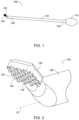
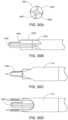
- FIG. 7is a perspective view of an additional decortication tool according to some examples of the present disclosure.
- FIG. 8is an enlarged, fragmentary elevation view of the decortication tool of FIG. 7 .
- FIG. 9is an enlarged, fragmentary plan view of the decortication tool of FIG. 7 .
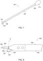
- FIG. 10is a perspective view of an additional decortication tool according to some examples of the present disclosure.
- FIG. 11is an enlarged, fragmentary view of the decortication tool of FIG. 10 .
- FIG. 12is an enlarged, fragmentary elevation view of the decortication tool of FIG. 10 .
- FIG. 13is another enlarged, fragmentary elevation view of the decortication tool of FIG. 10 .
- FIG. 14is a perspective view of an additional decortication tool according to some examples of the present disclosure.
- FIG. 15is an elevation view of the decortication tool of FIG. 14 .
- FIG. 16is another elevation view of the decortication tool of FIG. 14 .
- FIG. 17is an elevation view of a sheath of the decortication tool of FIG. 14 according to some examples of the present disclosure.
- FIG. 18is an elevation view of an additional sheath of the decortication tool of FIG. 14 according to some examples of the present disclosure.
- FIG. 19is an elevation view of an access chisel anchored in a spinal facet joint according to some examples of the present disclosure.
- FIG. 20is an elevation view of the sheath of the decortication tool of FIG. 14 slid along the access chisel of FIG. 19 .
- FIG. 21is an elevation view of the decortication tool of FIG. 14 slid within the sheath.
- FIG. 22is an elevation view of the decortication tool of FIG. 14 and showing a first movement of the decortication tool to decorticate bone.
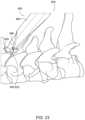
- FIG. 23is an enlarged, detail view of FIG. 22 .
- FIG. 24is a fragmentary view of the decortication tool of FIG. 14 and showing a second movement of the decortication tool to decorticate bone.
- FIG. 25is a perspective view of an additional decortication tool according to some examples of the present disclosure.
- FIG. 26is an elevation view of the decortication tool of FIG. 25 .
- FIG. 27is an elevation view of an access chisel anchored in a spinal facet joint according to some examples of the present disclosure.
- FIG. 28is an elevation view of the decortication tool of FIG. 25 slid along the access chisel of FIG. 26 .
- FIG. 29is an enlarged view of the configuration of FIG. 28 and showing a first movement of the decortication tool to decorticate bone.
- FIG. 30is a perspective view of a multi-use instrument according to some examples of the present disclosure.
- FIG. 31is another perspective view of the multi-use instrument of FIG. 30 .
- FIG. 32is an exploded view of the multi-use instrument of FIG. 30 .
- FIG. 33is a perspective view of the multi-use instrument of FIG. 30 positioned adjacent to an access chisel and a guide tube according to some examples of the present disclosure.
- FIG. 34is a perspective view of the multi-use instrument of FIG. 30 engaged with the access chisel and the guide tube.
- FIG. 35is an enlarged view of FIG. 33 and showing the multi-use instrument of FIG. 30 aligned with the access chisel.
- FIG. 36is a perspective view of the multi-use instrument of FIG. 30 positioned adjacent to a spinal instrument according to some examples of the present disclosure.
- FIG. 37is a perspective view of the multi-use instrument of FIG. 30 positioned to separate first and second components of the spinal instrument of FIG. 36 according to a first method.
- FIG. 38is a perspective view of the multi-use instrument of FIG. 30 positioned to separate first and second components of the spinal instrument of FIG. 36 according to a second method.
- FIG. 39is a perspective view of the multi-use instrument of FIG. 30 engaged with a spinal instrument according to some examples of the present disclosure.
- FIG. 40is a perspective view of the multi-use instrument of FIG. 30 and showing movement of the multi-use instrument to loosen a knob of the spinal instrument of FIG. 39 .
- FIG. 41 Ais a perspective view of an embodiment of an access chisel instrument.
- FIG. 41 Bis an exploded view of the access chisel instrument of FIG. 41 A .
- FIG. 42is a side view of an embodiment of an outer decorticator instrument.
- FIG. 43is a perspective view of an embodiment of a guide tube instrument.
- FIG. 44is a side view of a decorticator burr instrument.
- FIG. 45 Ais a side view of an access chisel introduced into a surgical site and docked near one of two vertebra forming a facet joint.
- FIG. 45 Bis a side view of the access chisel of FIG. 45 A as it is introduced into the facet space.
- FIGS. 46 - 51are top views of the nose portion of various embodiments of an access chisel.
- FIG. 52 Ais a side view of an embodiment of an access chisel.
- FIG. 52 Bis a side view of the access chisel of FIG. 52 A positioned within the facet space or joint.
- FIG. 53 Ais a side view of an embodiment of an access chisel.
- FIG. 53 Bis a side view of the access chisel of FIG. 53 A positioned within the facet space or joint.
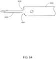
- FIG. 54is a perspective view of an embodiment of an access chisel.
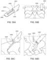
- FIG. 55 Ais a perspective view of an embodiment of an access chisel.
- FIGS. 55 B- 55 Dare rear, side, and perspective views of the access chisel of FIG. 55 A positioned within the facet space.
- FIG. 56is a perspective view of an embodiment of an access chisel.
- FIGS. 57 A and 57 Bare a perspective and side view of an embodiment of an access chisel.
- FIGS. 58 A and 58 Bare a perspective and side view of an embodiment of an access chisel.
- FIGS. 59 A and 59 Bare a perspective and side view of an embodiment of an access chisel.
- FIG. 60is a perspective view of an embodiment of an access chisel.
- FIG. 61is a perspective view of an embodiment of an access chisel positioned within the facet space.
- FIGS. 62 - 65are perspective views of various embodiments of an access chisel.
- FIG. 66is a perspective view of the nose portion of an embodiment of an access chisel.
- FIG. 67is a perspective view of an embodiment of an access chisel.
- FIGS. 68 A- 68 Bare a side and perspective view of an embodiment of an outer decorticator.
- FIGS. 69 A- 69 Bare a side and perspective view of an embodiment of an outer decorticator.
- FIGS. 70 A- 70 Care various views of an embodiment of an outer decorticator.
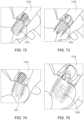
- FIG. 71 Ais a side view of a delivery tool assembly including an embodiment of an access chisel introduced into a facet space.
- FIG. 71 Bis a side view the delivery tool assembly of FIG. 71 A including an embodiment of a guide tube and the access chisel being introduced into the facet space.
- FIG. 71 Cis a side view of the delivery tool assembly of FIG. 71 B with the access chisel received in the guide tube and positioned within the facet space.
- FIG. 71 Dis a perspective view of the delivery tool assembly of FIG. 71 C positioned within the facet space.
- FIG. 71 Eis a perspective view of the delivery tool assembly of FIG. 71 D with the access chisel removed.
- FIG. 71 Fis a side view of the delivery tool assembly of FIG. 71 E .
- FIG. 72is a perspective view of a guide tube with a decortication rasp received within the guide tube.
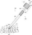
- FIG. 73is a perspective view of a guide tube with a decortication burr received within the guide tube.
- FIG. 74is a perspective view of a guide tube with an interior facet decorticator sleeved within the guide tube.
- FIG. 75is a perspective view of a guide tube with an intervertebral cage implant being delivered through the guide tube into the facet joint.
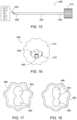
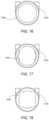
- FIGS. 76 - 78are proximal end views of various embodiments of a guide tube.
- FIGS. 79 - 80are side views of the distal ends of embodiments of a guide tube.
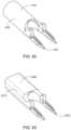
- FIGS. 81 A- 81 Care various views of the distal ends of embodiments of a guide tube and a decorticating burr.
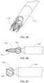
- FIGS. 82 - 84are perspective views of the distal ends of embodiments of a guide tube.
- FIG. 85is a perspective view of an embodiment of a delivery tool assembly including a guide tube and a decorticating burr.
- FIGS. 86 - 87are side views of the proximal ends of embodiments of decorticating burrs.
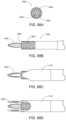
- FIGS. 88 A- 88 Dare various views of an embodiment of a delivery tool assembly including a decorticating burr and guide tube.
- FIGS. 89 A- 89 Dare various views of an embodiment of a delivery tool assembly including a decorticating burr and guide tube.
- FIGS. 90 A- 90 Dare various views of an embodiment of a delivery tool assembly including a decorticating burr and guide tube.
- FIGS. 91 A- 91 Dare various views of an embodiment of a delivery tool assembly including a decorticating burr and guide tube.
- FIGS. 92 A- 92 Dare various views of an embodiment of a delivery tool assembly including a decorticating burr and guide tube.
- FIG. 93illustrates a method for delivering a vertebral joint implant.
- FIG. 94illustrates a spinal instrumentation kit, which may include various tools or devices disclosed herein.
- aspects of the present disclosuregenerally involve devices and methods for treating spinal stenosis, or the narrowing of one or more areas of the intervertebral joint space between two adjacent vertebrae (i.e., a facet joint). This narrowing can put pressure on the spinal cord or the nerves that branch out from the narrowed area, thus causing pain, tingling, numbness and/or weakness.
- the present disclosureincludes discussion of a spinal system for distracting a facet joint of the spine to remedy this condition.
- the systemmay include one or more tools and an implant for distracting and maintaining the distracted position of the facet joint.
- the facet jointmay be distracted and prepped (e.g., decorticated) for receipt of an implant, thereby forcibly maintaining the distraction of the facet joint to relieve symptoms associated with spinal stenosis.
- the surfaces of the facet joint to receive the implantmay be decorticated prior to insertion of the implant.
- Some of the devices, systems, and methods described hereinmay include or be performed using one or more components of the DTRAX® Spinal System or the CORUSTM Spinal System, from Buffalo Medical Technology, Inc. (www.providencemt.com).
- FIGS. 1 - 6illustrate a first example of a decortication tool 100 for decorticating bone of a spinal facet joint.
- the decortication tool 100includes a shaft 102 with a proximal end portion 104 , a distal end portion 106 , and a centerline CL extending between the proximal and distal end portions 104 , 106 .
- a handle 114is connected to the proximal end portion 104 of the shaft 102 .
- a decortication head 120which may be referred to as a decorticator, is coupled to the distal end portion 106 of the shaft 102 .
- a usermay manipulate the decortication tool 100 , such as via the handle 114 , to decorticate bone using the decortication head 120 .
- the decortication toolis manipulated via the shaft.
- the decortication tool 100may be positioned adjacent to or at least partially within a spinal facet joint to engage the decortication head 120 of the decortication tool 100 with bone mass or tissue of one or more adjacent vertebrae.
- the decortication head 120may be moved (e.g., rotated, slid, rocked back and forth, or otherwise maneuvered) to decorticate the surface of the bone, as explained in detail below.
- the decortication head 120may include or be defined by a rasp 130 .
- the rasp 130is positioned within or near the facet space, whereupon the decortication tool 100 is moved to decorticate one or more bony surfaces via the rasp 130 .
- the rasp 130may include many configurations.
- the rasp 130may include a rough surface 132 defined by a plurality of teeth or projections 134 designed to decorticate bone when moved linearly along or rotated against a bony surface.
- the decortication head 120 or rasp 130may articulate relative to the shaft 102 .
- the decortication head 120may pivot between a plurality of positions, such as between a first position (see FIG. 3 ) and a second position (see FIGS. 4 - 6 ).
- the first positionwhich may be referred to as a closed position
- the decortication head 120may be aligned with the centerline CL of the shaft 102 .
- the decortication head 120may extend parallel to or coextensive with the centerline CL of the shaft 102 when positioned in the first position.
- the first positionmay allow the decortication tool 100 to be positioned in or adjacent to the facet space.
- the first position of the decortication head 120may allow the decortication tool 100 to be guided to the facet space using a guide apparatus (e.g., a guide tube or access chisel).
- a guide apparatuse.g., a guide tube or access chisel
- the decortication head 120may be pivoted towards the shaft 102 .
- the decortication head 120may pivot upwards from the first position and towards the second position.
- the decortication head 120may pivot downwards from the second position and towards the first position.
- the second positionmay allow the decortication tool 100 to decorticate bone surfaces within the facet space.
- the decortication head 120may be articulated to the second position such that the decortication head 120 may decorticate bone by movement of the decortication head 120 .
- the decortication head 120may be rotated medial and lateral ( FIG. 5 ) or moved back and forth ( FIG. 6 ) to decorticate bone.
- the decortication head 120may be articulated between positions in many manners.
- the decortication head 120may be articulated by placing downward pressure on the shaft 102 , which may be pliable. Additionally or alternatively, the decortication head 120 may be articulated by mechanical features incorporated into the design of the decortication tool 100 .
- the decortication tool 100may include one or more gear trains, lever systems, or the like, such as within the shaft 102 , to cause the decortication head 120 to move between positions.
- the handle 114may be manipulated, such as pushed, pulled, or rotated, among others, to move the decortication head 120 between the first and second positions.
- the decortication head 120may be articulated between positions in many configurations.
- FIGS. 7 - 9illustrate an additional decortication tool 200 for decorticating bone of a spinal facet joint. Except as otherwise noted below, the decortication tool 200 is similar to the decortication tool 100 of FIGS. 1 - 6 described above. Thus, like features may not be described when they would be apparent to those of skill in the art in light of the description above and in view of FIGS. 7 - 9 . For ease of reference, like features include appropriately incremented reference numbers.
- the decortication tool 200includes a shaft 202 , a handle 214 connected to a proximal end portion 204 of the shaft 202 , and a decortication head 220 coupled to a distal end portion 206 of the shaft 202 .
- the decortication head 220includes or is defined by a rasp 230 .
- the rasp 230may be configured similar to or different from the rasp 130 described above.
- the decortication head 220 or rasp 230may rotate relative to the shaft 202 . Depending on the particular application, the decortication head 220 may rotate in one direction or in two directions.
- the decortication head 220may rotate in only a first direction 240 (e.g., a clockwise rotation), in only a second direction 242 (e.g., a counter-clockwise rotation), or in both the first and second directions 240 , 242 .
- the decortication head 220may oscillate back and forth in the first and second directions 240 , 242 to decorticate bone.
- the decortication head 220may rotate about a rotational axis R.
- the rotational axis Rmay extend in many angles relative to the shaft 202 .
- the rotational axis Rmay extend substantially perpendicular to the shaft 202 .
- perpendicularmay include angles between about 80 degrees and about 100 degrees relative to the centerline CL of the shaft 202 .
- the decortication head 220may be fixed relative to the shaft 202 .
- the decortication head 220may be pivoted to a desired angle relative to the shaft 202 .
- the decortication head 220may be pivoted such that the rotational axis R extends between about 0 degrees and about 180 degrees relative to the centerline CL of the shaft 202 .
- the decortication head 220may be rotated relative to the shaft 202 in many manners.
- the decortication tool 200may include mechanical features incorporated into its design, such as one or more gear trains, lever systems, or the like.
- the mechanical featuresmay couple the handle 214 to the decortication head 220 such that manipulation of the handle 214 causes the decortication head 220 to rotate.
- the handle 214may be rotated, pushed, pulled, twisted, or the like to cause the decortication head 220 to rotate.
- Such examplesare illustrative only, and the decortication head 220 may be rotated relative to the shaft 202 in many configurations.
- FIGS. 10 - 13illustrate an additional decortication tool 300 for decorticating bone of a spinal facet joint. Except as otherwise noted below, the decortication tool 300 is similar to the decortication tools 100 and 200 of FIGS. 1 - 9 described above. Thus, like features may not be described when they would be apparent to those of skill in the art in light of the description above and in view of FIGS. 10 - 13 . For ease of reference, like features include appropriately incremented reference numbers.
- the decortication tool 300includes a shaft 302 , a handle 314 connected to a proximal end portion 304 of the shaft 302 , and a decortication head 320 coupled to a distal end portion 306 of the shaft 302 .
- the decortication head 320includes or is defined by a burr 346 .
- the burr 346is positioned within or near the facet space, whereupon the decortication tool 300 is rotated to decorticate one or more bony surfaces via the burr 346 .
- the burr 346may include many configurations.
- the burr 346may be defined by one or more cutting edges 348 designed to decorticate bone when the burr 346 is rotated against or moved linearly along a bony surface.
- the burr 346may include many configurations. For instance, as shown in FIG. 12 , the burr 346 may include a complex shape with a plurality of geometries. As one example, the burr 346 may include a first geometry or burr 350 and a second geometry or burr 352 extending from the first geometry 350 . Depending on the particular application, the first geometry 350 may be substantially round in two-dimensional space, or substantially spherical in three-dimensional space. The second geometry 352 may be different than the first geometry 350 . In one example, the second geometry 352 includes a tapering geometry extending from the first geometry 350 to a point-like tip 354 . For instance, the second geometry 352 may include a shape similar to a missile or bullet shape.
- the second geometry 352may be sized and shaped to position a portion of the burr 346 into the facet joint to decorticate one or more bony surfaces inside the facet space.
- the first geometry 350may be designed such that a portion of the burr 346 sits outside the facet joint to decorticate one or more bony surfaces outside the facet space. In this manner, the burr 346 may be arranged to decorticate bony surfaces both inside and outside the facet space in a simultaneous manner.
- FIGS. 14 - 24illustrate an additional decortication tool 400 for decorticating bone of a spinal facet joint. Except as otherwise noted below, the decortication tool 400 is similar to the decortication tools 100 , 200 , and 300 of FIGS. 1 - 13 described above. Thus, like features may not be described when they would be apparent to those of skill in the art in light of the description above and in view of FIGS. 14 - 24 . For ease of reference, like features include appropriately incremented reference numbers.
- the decortication tool 400includes a shaft 402 , a handle 414 connected to a proximal end portion 404 of the shaft 402 , and a decortication head 420 coupled to a distal end portion 406 of the shaft 402 .
- the decortication tool 400may include a sheath 460 through which the shaft 402 is slidably received.
- the sheath 460may include a plurality of cannulas defined therethrough.
- the sheath 460may include a first cannula 462 and a second cannula 464 above the first cannula 462 .
- the sheath 460may include additional cannulas, such as a third cannula 466 above the second cannula 464 .
- the shaft 402may be slidably received within one of the cannulas.
- the shaft 402may be slidably received within the second cannula 464 , or the third cannula 466 (if equipped).
- the sheath 460may include a tip 468 .
- the handle 414may include a cutout 470 defined therethrough. As shown, the cutout 470 may be C-shaped and radially spaced from the centerline CL of the shaft 402 . In this manner, the handle 414 may accommodate another tool associated with the sheath 460 . For instance, as detailed more fully below, a guide element or fixation device, such as an access chisel or the like, may be inserted within the first cannula 462 of the shaft 402 . In such examples, the shaft 402 may be inserted within the second cannula 464 of the sheath 460 .
- a guide element or fixation devicesuch as an access chisel or the like
- the guide elementmay be received within the cutout 470 of the handle 414 as the decortication head 420 is moved towards the facet joint.
- the cutout 470may allow user manipulation of the handle 414 to move the decortication head 420 without interfering with or dislodging the guide element or fixation device.
- the shape of the cutout 470may allow rotation of the handle 414 (and decortication head 420 ) without moving the guide element or fixation device.
- the shaft 402may be inserted within the third cannula 466 . Additional cannulas may be incorporated into the sheath 460 if additional reach for the decortication head 420 is needed.
- FIGS. 25 - 29illustrate an additional decortication tool 500 for decorticating bone of a spinal facet joint.
- the decortication tool 500is similar to the decortication tools 100 , 200 , 300 , and 400 of FIGS. 1 - 24 described above.
- like featuresmay not be described when they would be apparent to those of skill in the art in light of the description above and in view of FIGS. 25 - 29 .
- like featuresinclude appropriately incremented reference numbers.
- the decortication tool 500includes a shaft 502 , a handle 514 connected to a proximal end portion 504 of the shaft 502 , and a decortication head 520 coupled to a distal end portion 506 of the shaft 502 .
- the shaft 502may be hollow defining a bore 576 extending through the handle 514 , shaft 502 , and decortication head 520 .
- the decortication head 520may be formed integrally with or fixed to the distal end portion 506 of the shaft 502 .
- the decortication head 520may include first and second portions 580 , 582 .
- the first portion 580may be connected to the distal end portion 506 of the shaft 502 .
- the second portion 582may extend from the first portion 580 and parallel to the centerline CL of the shaft 502 .
- the second portion 582is radially spaced from the centerline CL of the shaft 502 .
- the second portion 582may include a substantially C-shaped profile with inner and outer surfaces 584 , 586 defining respective arc segments or lengths spaced radially from the centerline CL of the shaft 502 .
- the arc lengths of the inner and outer surfaces 584 , 586may be less than a full circumference around the centerline CL of the shaft 502 , less than one-half the circumference around the centerline CL of the shaft 502 , or less than one-quarter the circumference around the centerline CL of the shaft 502 . In this manner, the second portion 582 may not extend completely around the centerline CL of the shaft 502 .
- the decortication head 520may include or be defined as a rasp 530 .
- the rasp 530may define at least a portion of a terminal end surface 588 of the second portion 582 of the decortication head 520 .
- the second portion 582 of the decortication head 520is positioned within or near the facet space, whereupon the decortication tool 500 is rotated to decorticate one or more bony surfaces via the rasp 530 .
- the decortication tools 100 , 200 , 300 , 400 , 500may be utilized as part of a spinal system 600 and provided in a spinal system kit 4000 as shown in FIG. 94 .
- the spinal system 600may include any combination of the following elements: an access chisel 602 , a guide tube 604 , and one or more of the decortication tools 100 , 200 , 300 , 400 , or 500 described above.
- the components of the spinal system 600may allow a user (e.g., surgeon) to decorticate bone of a spinal facet joint in preparation for a spinal implant.
- the spinal system 600may include additional components for implanting the spinal implant within the facet space of a spinal facet joint.
- the spinal system 600may include a delivery device 610 , a driver assembly, a malleting tool, or other instruments, as explained more fully below.
- the spinal system 600may be included in a kit 4000 , as shown in FIG. 94 .
- the kitincludes some or all of an access chisel 602 , a guide tube 604 , a decortication tool 4002 , 4004 which may be similar to the decortication tools 100 , 200 , 300 , 400 , or 500 described above, a rasp 1219 as described in FIG. 72 , a tamp 4008 to tamp bone graft material, and a multi-use instrument 800 as described in FIGS. 30 and 31 .
- the kit 4000may also include some or all of a delivery device 610 and/or a driver assembly to deliver/drive a spinal implant, a malleting tool (in addition to or instead of the multi-use tool), or other instruments.
- the access chisel 602can include many configurations allowing at least partial insertion of the access chisel 602 into a spinal facet joint.
- the access chisel 602may include a shaft portion 620 , a tip portion 622 , and a head portion 624 .
- the shaft portion 620may have a generally cylindrical cross-section, such as tubular or otherwise.
- the tip portion 622may by chamfered such that the access chisel 602 may be driven into and/or otherwise anchored in the spinal facet joint.
- the tip portion 622may have one or more chamfers, such as a single chamfer, a double chamfer, or more than two chamfers.
- the tip portion 622may be coped to define a tip or point.
- the head portion 624may be arranged to facilitate user manipulation of the access chisel 602 .
- the head portion 624may be generally solid with an end surface 630 for malleting the access chisel 602 into position.
- the head portion 624may include an alignment mark 640 .
- a groove 642may be defined on the head portion 624 at a distance away from the end surface 630 .
- the groove 642may extend circumferentially around the head portion 624 .
- the alignment mark 640(groove 642 ) may align with a corresponding alignment feature of another tool or instrument to define a seated position of the access chisel 602 and/or the other tool or instrument.
- the guide tube 604can include many configurations allowing at least partial insertion of the guide tube 604 into a spinal facet joint.
- the guide tube 604includes a tubular shaft 660 , an anchoring mechanism 662 at a distal end 664 of the tubular shaft 660 , and a handle 668 at a proximal end 670 of the tubular shaft 660 .
- the tubular shaft 660may have an annularly-shaped cross section with an inner radius defining an internal bore 680 . The inner radius may allow insertion of other spinal instruments and tools within the guide tube 604 .
- the internal bore 680may be sized and shaped to allow insertion of the access chisel 602 therein.
- the guide tube 604may be movably and/or slidably coupled to the access chisel 602 .
- the guide tube 604may slide along and/or rotate about the shaft portion 620 of the access chisel 602 .
- the anchoring mechanism 662 of the guide tube 604allows the guide tube 604 to be driven into and/or otherwise anchored in a spinal facet joint.
- the anchoring mechanism 662may include one or more anchoring forks 690 arranged to fix the guide tube 604 in a desired position within the spinal facet joint.
- the anchoring forks 690may be arranged such that the decortication head 320 is positioned and moves between two or more forks 690 .
- the forks 690may have a general V-shape to facilitate insertion and/or anchoring of the forks 690 within the spinal facet joint.
- the forks 690may include a plurality of serrations 692 to facilitate anchoring of the guide tube 604 within the spinal facet joint.
- the decortication tool 100may be utilized with the guide tube 604 .
- the guide tube 604is inserted posteriorly into a spinal facet joint.
- the anchoring mechanism 662fixes the guide tube 604 in position relative to (e.g., at least partially within) the facet joint.
- the decortication tool 100is inserted through the internal bore 680 of the guide tube 604 .
- the decortication head 120may be positioned in its first position to allow slidable insertion of the decortication tool 100 within the guide tube 604 .
- the decortication head 120may be moved to its second position to begin decortication of one or more bony surfaces of the facet joint. For example, as shown in FIGS. 5 and 6 , respectively, the decortication head 120 may be rotated left to right (medial, lateral) or moved back and forth to decorticate bone via the rasp 130 . As noted above, movement of the decortication head 120 may be accomplished by user manipulation of the handle 114 and/or shaft 102 of the decortication tool 100 . With the anchoring mechanism 662 anchored to the facet joint, the decortication head 120 may move relative to the guide tube 604 in decorticating bone.
- the decortication tool 200may also be utilized with the guide tube 604 .
- the guide tube 604is inserted posteriorly into a spinal facet joint.
- the anchoring mechanism 662fixes the guide tube 604 in position relative to (e.g., at least partially within) the facet joint.
- the decortication tool 200is inserted through the guide tube 604 .
- the decortication head 220may be rotated, such as back and forth, to decorticate bone tissue.
- the decortication head 220may be rotated to decorticate the space below the facet joint, though the decortication head 220 may be positioned to decorticate other locations of the facet joint.
- the decortication tool 300may also be utilized with the guide tube 604 .
- the guide tube 604is inserted posteriorly into a spinal facet joint.
- the anchoring mechanism 662fixes the guide tube 604 in position relative to (e.g., at least partially within) the facet joint.
- the decortication tool 300is inserted through the guide tube 604 until the decortication head 320 reaches the facet space. Once in position, the decortication head 320 may be rotated such that the one or more burrs decorticate desired bone tissue.
- the first geometry 350may be positioned within the facet joint to decorticate inside the facet space.
- the second geometry 352may be positioned outside the facet joint to decorticate the space outside the facet joint simultaneously with the first geometry 350 .
- the decortication tool 400may be utilized with the access chisel 602 .
- the access chisel 602is inserted posteriorly into a spinal facet joint.
- the tip portion 622 of the access chisel 602may fix the access chisel 602 in position relative to (e.g., at least partially within) the facet joint.
- the sheath 460 of the decortication tool 400is inserted over the access chisel 602 . For instance, as shown in FIG.
- the access chisel 602may be slidably received within the first cannula 462 of the sheath 460 . Once the access chisel 602 is slidably received within the first cannula 462 , the sheath 460 may be moved along the access chisel 602 until the tip 468 of the sheath 460 is positioned at, within, or near the facet space.
- the shaft 402 of the decortication tool 400may inserted within the second cannula 464 of the sheath 460 .
- the shaft 402may be slid down the second cannula 464 of the sheath 460 until the decortication head 420 reaches the facet joint.
- a portion of the access chisel 602e.g., the head portion 624 ) may be received within the cutout 470 of the handle 414 .
- the decortication tool 400may be moved such that the decortication head 420 decorticates bony tissue of the facet joint.
- the handle 414may be moved to rotate the decortication head 420 .
- the shape of the cutout 470 within the handle 414may allow movement (e.g., rotation) of the handle 414 without dislodging the access chisel 602 from the facet joint.
- the sheath 460may be rotated medial to lateral to decorticate bone to the left or right. If additional reach or decortication is needed, the shaft 402 of the decortication tool 400 may be inserted within another cannula of the sheath 460 , such as within the third cannula 466 .
- the decortication tool 500may also be utilized with the access chisel 602 .
- the access chisel 602is inserted posteriorly into a spinal facet joint.
- the tip portion 622 of the access chisel 602may fix the access chisel 602 in position relative to (e.g., at least partially within) the facet joint.
- the decortication tool 500is positioned about the access chisel 602 and moved along the access chisel 602 until the decortication head 520 reaches the facet space.
- the access chisel 602may be slidably and rotatably received within the bore 576 of the decortication tool 500 .
- the decortication tool 500may be moved to decorticate bone.
- the decortication tool 500may be rotated back and forth via the handle 514 such that the rasp 530 defined on the terminal end surface 588 of the decortication head 520 decorticates bone above the facet joint, though the decortication head 520 may be positioned to decorticate other locations of the facet joint.
- the decortication tool 500may be rotated medial or lateral with the access chisel 602 to decorticate bone to the left or right.
- a spinal implantmay be inserted within the facet space to fuse the two adjacent vertebrae together.
- the decortication of bone tissuemay promote healing and bone growth around the spinal implant.
- the spinal implantmay be fused with bony tissue of the two adjacent vertebrae to fixedly secure the vertebrae together.
- the spinal implantmay include many configurations.
- the spinal implantmay be similar to the spinal implant disclosed in U.S. patent application Ser. No. 15/489,163, the disclosure of which is hereby incorporated by reference in its entirety.
- the spinal implantmay be inserted within the facet space in many configurations.
- the spinal system 600may include a delivery device 610 .
- the spinal implantmay be coupled to the delivery device 610 and inserted within the facet space, such as via the guide tube 604 .
- the delivery device 610may be similar to the device disclosed in U.S. patent application Ser. No. 15/489,163, the disclosure of which is hereby incorporated by reference in its entirety.
- FIGS. 30 - 40illustrate various views of a multi-use instrument 800 for use in a spinal system, such as spinal system 600 .
- the multi-use instrument 800which may be referred to as a multi-assist instrument or simply an instrument, may include a body 802 with opposing first and second sides 804 , 806 and opposing first and second surfaces 808 , 810 .
- the first and second sides 804 , 806may define front and rear sides of the body 802 , though other configurations are contemplated.
- the first and second surfaces 808 , 810may define top and bottom surfaces of the body 802 , though other configurations are contemplated.
- the body 802may be referred to as a handle, and as such, includes a form factor designed to fit comfortably in a user's hand.
- the body 802may include many configurations.
- the body 802may be at least partially hollow with a cavity 820 defined therein.
- the cavity 820may be open to the second surface 810 of the body 802 .
- the cavity 820may also be open to the first side 804 of the body 802 .
- the body 802may include a slot 822 defined in the first side 804 along a length of the body 802 between the first and second surfaces 808 , 810 .
- the slot 822may be in communication with the cavity 820 .
- the body 802includes an alignment window 824 defined in the first side 804 of the body 802 . Similar to the slot 822 , the alignment window 824 may be in communication with the cavity 820 . As shown, the alignment window 824 may extend generally perpendicular to the slot 822 .
- the body 802may include a channel 830 defined in its first side 804 to define an indented space along the body.
- the channel 830may be defined in the first side 804 from adjacent to the first surface 808 to adjacent to the second surface 810 .
- the slot 822 and alignment window 824may be defined along the bottom of the channel 830 .
- the channel 830may be sized to match a profile of a fastener or knob, similar to a socket of a socket wrench assembly.
- the head of a fastener or knobmay be at least partially inserted within the channel 830 and the body 802 used to tighten and/or loosen the fastener or knob through rotation of the body 802 .
- the channel 830may be shaped such that a fastener or knob is positionable in a plurality of positions along the length of the channel 830 between the first and second surfaces 808 , 810 .
- the fastener or knobmay be positioned within the channel 830 adjacent to the first surface 808 , adjacent to the second surface 810 , or anywhere in between the first and second surfaces 808 , 810 .
- the instrument 800may include a bar 840 attached to the second side 806 of the body 802 .
- a first portion 842 of the bar 840extends beyond the second surface 810 of the body 802 .
- a second portion 844 of the bar 840is attached to the body 802 .
- the bar 840may be attached to the body 802 in many configurations.
- the bar 840may be attached to the body 802 using one or more fasteners 850 , though other configurations are contemplated, including adhesive, heat or sonic welding, or corresponding retention features, among others.
- the bar 840may be formed integrally with the body 802 .
- the bar 840may include many configurations.
- the bar 840may be formed from flat stock.
- the bar 840may include a convexly-shaped terminal edge 860 .
- the bar 840may taper in width from adjacent to the body 802 to the terminal edge 860 .
- the instrument 800may be utilized as part of the spinal system 600 .
- the instrument 800may be used to manipulate various components of the spinal system 600 .
- the instrument 800may be used to advance the guide tube 604 over the access chisel 602 and into the spinal facet joint.
- the second surface 810 of the body 802may engage the handle 668 of the guide tube 604 to push the guide tube 604 along the access chisel 602 .
- the first portion 842 of the bar 840 extending beyond the body 802may engage a lateral side surface of the handle 668 to stabilize the instrument 800 relative to the guide tube 604 , or vice versa.
- forcemay be applied to the first surface 808 of the instrument 800 , such as using a surgical mallet, to advance the guide tube 604 along the access chisel 602 .
- the head portion 624 of the access chisel 602may be received within the cavity 820 of the body 802 .
- the head portion 624 of the access chisel 602may be visible through at least the slot 822 and alignment window 824 of the body 802 .
- the guide tube 604may be advanced along the access chisel 602 until the guide tube 604 is in a desired position relative to the access chisel 602 as determined by a visible position of the access chisel 602 within the cavity 820 .
- the guide tube 604may be fully deployed when the alignment mark 640 of the access chisel 602 aligns with the alignment window 824 defined in the body 802 of the instrument 800 (see FIG. 35 ).
- the instrument 800may be used in other manners.
- the bar 840 of the instrument 800may be inserted between the handle 668 of the guide tube 604 and the handle 114 , 214 , 314 , 414 , or 514 of the decortication tool 100 , 200 , 300 , 400 , or 500 to separate the components.
- a bending momentFIG. 37
- a rotational forceFIG.
- the bar 840may be used to separate other components of the spinal system 600 .
- the bar 840may be used to separate the guide tube 604 from a chisel rasp or other instrument of the spinal system 600 .
- the instrument 800may be used to reposition the components as desired. For instance, once the components are separated, the instrument 800 may be used to tap the guide tube 604 back into place, if needed.
- the instrument 800may be used to loosen a fastener or knob of a spinal system tool.
- the delivery device 610may include a knob 870 .
- Rotation of the knob 870may perform a function of the spinal system 600 , such as selectively delivering a spinal implant within the facet joint.
- the knob 870may be positioned within the channel 830 of the instrument 800 , such as anywhere along the length of the channel 830 between the first and second surfaces 808 , 810 .
- the instrument 800may be rotated to loosen the knob 870 to deliver the spinal implant within the facet joint. In this manner, the instrument 800 may act like a socket or wrench in loosening the knob 870 .
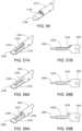
- FIGS. 41 A- 44include various views of tools that may be included in vertebral joint access, preparation, and delivery, including a chisel, outer decorticator, guide tube, and decorticator burr, the tools including features for improved controlled and targeted decortication and some or all of which may be included as part of spinal system 600 .
- FIG. 41 Ais a perspective view of an embodiment of an access chisel 1102 instrument.
- FIG. 41 Bis an exploded view of the access chisel 1102 instrument of FIG. 41 A .
- FIG. 42is a side view of an embodiment of an outer decorticator 1110 instrument.
- FIG. 43is a perspective view of an embodiment of a guide tube 1118 instrument.
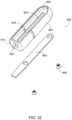
- FIG. 44is a side view of a decorticator burr 1126 instrument.
- the chisel 1102may include a proximal portion 1104 that includes a handle, a distal portion that includes a chisel tip 1106 , such as a chamfered tip forming a nose of the chisel 1102 , and a tongue 1134 .
- the distal portion and the proximal portion 1104may be connected by a tubular shaft 1108 .
- the outer decorticator 1110may include a proximal portion 1112 formed to engage a handle or otherwise allow a practitioner to directly or indirectly (such as through a robotic arm) grasp the proximal portion 1112 to rotate the outer decorticator 1110 to operate the outer decorticator 1110 .
- a tubular shaft 1116connects the proximal portion 1112 to a distal portion 1114 .
- the distal portion 1114may be shaped with a decorticator or rough surface that may be used to roughen or abrade the surface of a target deployment area.
- the shaft 1116 of the outer decorticator 1110is hollow, with a larger inner diameter than an outer diameter of the shaft 1108 of the chisel 1102 .
- the shaft 1116 of the outer decorticator 1110may be slid over the shaft 1108 of the chisel 1102 .
- the distal portion 1114 of the outer decorticator 1110may be larger than the outside diameter of the shaft 1116 . This aspect may provide more stability when engaging the outer decorticator 1110 to the targeted area for improved controlled and targeted decortication.
- the guide tube 1118may include a tubular shaft 1124 connecting a proximal portion 1120 that is connected to forks 1122 formed at the distal end of the guide tube 1118 .
- the shaft 1124may be hollow, with an inner diameter that is larger than the outer diameter of the chisel shaft 1108 .
- the guide tube 1118may be slid over the chisel 1102 to position the forks 1122 within the target facet joint space. Once the forks 1122 are positioned, the chisel 1102 may be removed by sliding the chisel tip 1106 and shaft 1108 of the chisel 1102 through the hollow shaft 1124 of the guide tube 1118 .
- the decorticator burr 1126may include a proximal portion 1128 , a burred end 1130 formed at a distal portion opposite the proximal end 1128 , and a tubular shaft 1132 connecting the proximal portion 1128 and burred end 1130 .
- the outer diameter of the shaft 1132may be smaller than the inner diameter of the guide tube shaft 1124 .
- the burred end 1130 of the decorticator burr 1126may be inserted into the proximal portion 1120 of the guide tube 1118 , and slid through the shaft 1124 until it extends between and/or past the forks 1122 of the guide tube 1118 .
- the vertebral joint access and preparation devices described in FIGS. 41 A- 44may be utilized to deliver a vertebral joint implant. It can be appreciated that the practitioner may use a robotic arm or other robotic surgical instrument to perform any, some or all of these steps as described here and elsewhere in the application.
- a practitionermay make an incision in a patient and expose targeted bony elements. The practitioner may then insert the access chisel 1102 , inserting the chisel tip 1106 into the target location. The practitioner may then slidably insert the outer decorticator 1110 (may also be referred to as the trephine) over the access chisel to decorticate superior and inferior lateral masses of the target location. After the superior and inferior lateral masses are decorticated, the outer decorticator 1110 may be slidably removed, leaving the chisel 1102 with its chisel tip 1106 positioned in the target location.
- the outer decorticator 1110may also be referred to as the trephine
- the guide tube 1118is inserted over the access chisel 1102 , positioning the forks 1122 adjacent the outside of the chisel tip 1106 .
- the access chisel 1102is then slidably removed, sliding within the shaft 1124 of the guide tube 1118 .
- a decorticator raspmay then be slidably inserted inside the guide tube 1118 to decorticate the articular surfaces of the target location using the rasp.
- the decorticator raspmay then be slidably removed from within the guide tube 1118 , and the decorticator burr 1126 may then be slidably inserted through the guide tube, with the burred end 1130 extending between and/or past the distal end with forks 1122 to further decorticate the articular surfaces of the target location.
- the decorticator burr 1126may then be removed from within the guide tube 1118 .
- Other spinal instrumentationmay then be used, including but not limited to applying bone graft, inserting an implant, or various combinations thereof.
- the insertion of the implantmay further distract the joint or target delivery location.
- the toolmay be removed, and the implant remains in the joint or target delivery location.
- FIG. 45 Ais a side view of an access chisel introduced into a surgical site and docked onto an entry space of a facet joint (i.e. at a superior or inferior vertebra, the vertebrae together forming the facet joint).
- FIG. 45 Bis a side view of the access chisel of FIG. 45 A docked onto the facet entrance and introduced into the facet joint space. As shown in FIGS. 45 A- 45 B , the chisel 1102 is introduced into the surgical site and is positioned at the facet joint or “docks” onto the entry space of the facet joint.
- the nose of the chisel tip 1106is used to break the facet capsule.
- the tongue 1134 of the chisel 1102is then introduced into the facet joint space, as shown in FIG. 45 B .
- the chiselmay include a single or doubly chamfered nose at a distal end or may have a coped distal end or a combination of coping and chamfering.
- the tip or nosemay include a roughened surface on one or more sides to aid in anchoring or docking the chisel in the facet joint. Additionally, this roughened surface may allow for roughening or decorticating the inner surfaces of the facet joint.
- the tip or nosemay have a length adapted to extend substantially across the facet joint.
- the tip or nosemay include a notch feature, such as notch 3107 of FIG. 66 , to provide stability when the chisel is docked to the entry of the facet joint.
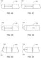
- FIGS. 46 - 51 , and 66show top views of the tip or nose portion of the distal end of various embodiments of access chisels that may be similar to or different than, and used in similar or different methods as previously described access chisels.
- FIG. 46shows a chisel 1202 with a nose 1206 that is narrow.
- FIG. 47shows a chisel 1302 with a nose 1306 that is wide.
- FIG. 48includes a chisel 1402 with a nose 1406 that is tapered.
- FIG. 49shows a chisel 1502 with a nose 1506 that is pointed.
- FIG. 50shows a chisel 1602 with a nose 1606 that includes teeth 1607 .
- FIG. 51shows a chisel 1702 with a nose 1706 that includes a pin point 1707 .
- FIG. 66shows a chisel 3102 with a nose 3106 that includes a notch or cutout feature 3107 .
- the notch 3107may be u-shaped, rectangular shaped, hemispherical, or oblong. In some examples, the notch 3107 may help to provide stability when the instrument is docked onto the entry of the facet joint, such as shown in FIG. 45 A .
- FIG. 52 Ais a side view of an embodiment of an access chisel 1802 .
- FIG. 52 Bis a side view of the access chisel 1802 of FIG. 52 A , shown positioned within the facet space.
- the access chisel 1802may include similar or different features, and be used in similar or different methods, than as previously described access chisels.
- the access chisel 1802may include a scalloped feature 1836 on the upper side of the proximal end of the access chisel tongue 1834 . In use, the scalloped feature 1836 may prevent the access chisel 1802 from advancing further into the facet joint, and provide stabilization for medial/lateral movement for improved controlled and targeted decortication.
- FIG. 53 Ais a side view of an embodiment of an access chisel 1902 .
- FIG. 53 Bis a side view of the access chisel 1902 of FIG. 53 A , shown positioned within the facet joint space.
- the access chisel 1902may include a hard stop feature 1936 on the proximal end of the tongue 1934 .
- the hard stop 1936may be a flat ridge that is generally perpendicular to the tongue 1934 . Similar to the scalloped feature 1836 , the hard stop 1936 may be used to prevent the access chisel 1902 from advancing further into the facet joint and provide stabilization for medial/lateral movement for controlled and targeted decortication.
- the access chisel 1902may include a scalloped feature 1937 on the underside of the tongue.
- the scalloped featuremay also act as a hard stop to help prevent the access chisel 1902 from advancing further into the facet joint and provide stabilization for medial/lateral movement for controlled and targeted decortication.
- the scalloped feature 1937may extend past the hard stop 1936 in the direction of a proximal end of the access chisel 1902 such that a length of the side of the tongue with the scalloped features 1937 is longer than a length of the tongue with the hard stop 1936 .
- FIG. 54is a side view of an embodiment of an access chisel 4002 .
- the access chisel 4002includes a hard stop feature 4036 on a proximal end of the tongue 4004 .
- the hard stop 4036may be a flat ridge that is generally perpendicular to the tongue 4034 .
- the access chisel 4002may also include a scalloped feature 4037 on the proximal end of the tongue 4004 on the underside of the tongue a side opposite that with the hard stop 4036 .
- the overall length of the tongue of the side of the tongue with the scalloped feature 4307may be generally the same as a length of the tongue with the hard stop 4036 .
- a length of the radius of the scalloped feature 1937may larger than that of a length of the radius of the scalloped feature 4037 , in some examples, to better match the geometry of the cervical spine.
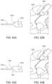
- FIG. 55 Ais a perspective view of an embodiment of an access chisel 2002 .
- FIGS. 55 B- 55 Dare rear, side, and perspective views of the access chisel 1002 of FIG. 55 A positioned within the facet joint space.
- the access chisel of FIGS. 55 A- 55 Dmay include similar or different features, and be used in similar or different methods, than as previously described access chisels.
- the access chisel 2002may include a blade 2038 that extends along the tongue 2034 and away from the upper surface of the tongue, between the hard stop feature 2036 and the chisel tip 2006 .
- the blade 2038may extend along the center or near the side of the tongue, being a raised feature that may dig into the underside of the superior facet when in use, providing greater stability and minimizing or preventing unwanted medial/lateral movement for improved controlled and targeted decortication.
- the distal end 2006 of the access chisel 2002is shaped to have a wide nose, similar to access chisel 1702 of FIG. 47 , but other shapes or types of noses may be used.
- the access chisel 2002includes a vertical blade 2040 at the distal end of the chisel tip 2006 , such as adjacent the hard stop 2036 , that may dig into the superior facet entrance to provide additional stabilization for controlled and targeted decortication.
- the area adjacent the hard stopmay include a rasp texture 2138 instead of a vertical blade.
- the chisel 2102includes a chisel tip 2106 with a pointed nose, other nose shapes may be used.
- FIGS. 57 A and 57 Bare top perspective and side views of an embodiment of an access chisel 2202 , with the center blade 2238 extending along the length of the tongue 2234 , between and including the scalloped feature 2236 to the chisel tip 2206 .
- FIGS. 58 A and 58 Bare a perspective and side view of an embodiment of an access chisel 2302 , with the center blade 2338 extending along the tongue 2334 between the scalloped feature 2336 and the chisel tip 2306 . As shown in FIGS.
- FIGS. 59 A and 59 Bare a perspective and side view of an embodiment of an access chisel 2402 , where the center blade 2438 extends along the tongue 2434 between and includes the hard stop feature 2436 to the chisel tip 2406 .
- the hard stop feature 2436may be similar to the hard stop feature 1936 of FIGS. 53 A- 53 B , but may also include a tapered or angle face 2437 on the center blade at the hard stop.
- the access chisels of FIGS. 57 A- 57 Bmay be similar to or different than, and used in similar or different manners, as previously described access chisels. While the chisel tips 2206 , 2306 , and 2406 of FIGS. 57 A- 59 B are shown in a wide nose shape, other shapes and combinations of features may be used.
- FIG. 60is a perspective view of an embodiment of an access chisel 3502 , with the center blade 3538 extending along the length of the tongue 3534 .
- the hard stop feature 3536may include the center blade that extends upwards with a blunt or flat face 3537 , as opposed to the tapered or pointed face of the stop 2436 of FIGS. 59 A- 59 B .
- the underside of the access chisel tonguemay include an anti-backout feature, such as raised or indented chevron profile, teeth, or another textured feature that may help prevent the access chisel from unintentional backout.
- FIG. 61is a bottom perspective view of an embodiment of an access chisel 2502 positioned within the facet space, with the underside 2542 including a raised chevron pattern.
- FIGS. 62 - 65are bottom perspective views of embodiments of access chisels 2602 , 2702 , 2802 , 2902 .
- the access chisels 2502 , 2602 , 2702 , 2802may include similar or different features, and be used in similar or different methods, than as previously described access chisels.
- FIG. 62shows the bottom surface 2642 of access chisel 2602 that includes a raised chevron pattern.
- FIG. 63shows the bottom surface 1742 of the tongue of access chisel 1702 that includes an indented or concave chevron pattern.
- FIG. 64shows the bottom surface 2842 of the tongue of the access chisel 2802 that includes raised teeth positioned on either side edge of the tongue.
- the teeth of access chisel 2802may have flatted areas at the top of each tooth, with two rows of teeth.
- FIG. 65shows the bottom surface 2942 of the access chisel 1902 including teeth extending the length of the tongue in 3 rows.
- FIG. 67is a perspective view of an embodiment of an access chisel 3602 , with the bottom surface 3642 that includes raised teeth on either side edge of the tongue.
- the teeth of access chisel 3602have pointed ends at the top of each tooth.
- each row of teethmay include one, two, three, four, five, size, seven, eight, nine and/or ten teeth.
- the access chiselmay include one, two, three, four, five, size, seven, eight, nine and/or ten rows of teeth.
- the rows of teethinclude the same or similar numbers of teeth, or different numbers of teeth.
- a first rowmay include more or less teeth than that of a second, third, fourth, fifth, sixth, seventh, eighth, ninth or tenth row of teeth.
- the underside surface featuresmay also act as a stabilization feature to provide further stabilization in the medial/lateral movement and/or in conjunction with the center blade feature for improved controlled and targeted decortication.
- the access chisels of FIGS. 61 - 65 and 67may be similar to or different than, and used in similar or different manners, as previously described access chisels.
- FIGS. 68 A- 68 Bare side and perspective views of an embodiment of an outer decorticator 1210 .
- FIGS. 69 A- 69 Bare side and perspective views of an embodiment of an outer decorticator 1310 .
- FIGS. 70 A- 70 Care perspective and distal views of an embodiment of an outer decorticator 1410 .
- the outer decorticator 1210 , 1310 , 1410may include similar or different features, and be used in similar or different methods, than as previously described outer decorticators.
- Outer decorticator 1210 , 1310may include a chamfered distal end 1214 , 1314 with a plurality of serrated teeth 1244 , 1344 positioned at the distal tip of the chamfered distal end 1214 , 1314 and a beveled edge 1246 , 1346 extending along the periphery of the chamfered distal end.
- the teeth 1244are bidirectional, and the teeth 1344 are unidirectional.
- the width of the teeth at the base of each toothmay be in a range between and including 1-3 mm.
- the outer decorticatoris advanced over the access chisel to dissect fascia and muscle off the lateral lamina and lateral mass under visual guidance.
- the larger size of the distal end 1214 , 1314may allow a larger area to be dissected.
- the outer decorticator 1410may include a chamfered distal end 1414 , with a plurality of serrated teeth 1444 and a beveled edge 1446 extending along the periphery of the chamfered distal end 1414 .
- the chamfered portion of the distal endis offset away from the portion of decorticator 1410 formed by the teeth.
- the lumen forming the internal portion of the distal end 1414may have a generally constant diameter 1450 .
- the outer surface of the decorticator 1410may have a cam lobe type shape, with a bump or raised portion in one section.
- the cam shapemay be attributed to a varying height 1448 of each tooth 1444 , with the tooth at a center of the toothed section having a taller height 1448 a than the height 1448 b of the teeth at the edges of the toothed section.
- the overall shape of the decorticator 1410may be optimized to increase the reach of the decorticator teeth 1444 while optimizing insertion through a small incision 1452 , such as a vertical incision, made using a scalpel.
- a small incision 1452such as a vertical incision, made using a scalpel.
- the outer decorticator tipmay be rotated back and forth in the direction of the arrow, allowing the tooth with the tallest height 1448 a to reach and decorticate bone while maintaining ease of insertion through the vertical incision.
- the height 1448 a of the tallest toothmay be approximately 2 mm, but a smaller or larger height tooth may also be used.
- guide tubessimilar to or different than guide tube 118 are now described.
- the following guide tubesmay include similar or different features, and be used in similar or different methods, than as previously described guide tubes.
- FIGS. 71 A- 71 Eshow views of a delivery tool assembly including a guide tube being docked to or positioned within a facet joint.
- FIG. 71 Ais a side view of a delivery tool assembly including an embodiment of an access chisel 1102 introduced into a facet joint space. In use, the access chisel is first introduced to the surgical site and inserted into the articular capsule of the facet joint.
- FIG. 71 Bis a side view the delivery tool assembly of FIG. 71 A including an embodiment of a guide tube 1218 sleeved over the access chisel and being introduced into the facet joint space.
- the guide tube 1218slides over the access chisel 1102 as a guide and is positioned at the entry point of the facet joint with the hard stop 1250 of the guide tube 1218 facing posteriorly.
- FIG. 71 Cis a side view of the delivery tool assembly of FIG. 71 B with the guide tube 1218 sleeved over the access chisel 1102 and positioned within the facet joint space, with the forks 1222 of the guide tube 1218 extending on either side of the access chisel 1102 .
- the guide tube 1218may be malleted to insert the forks 1222 into the articular capsule.
- the physical hard stop 1250may help to prevent the tip and forks 1222 from being inserted too anteriorly.
- FIG. 71 Dis a perspective view of the delivery tool assembly of FIG. 71 C positioned within the facet joint space.
- FIG. 71 Eis a perspective view of the delivery tool assembly of FIG. 71 D with the access chisel removed.
- the tip and forks 1222 of the guide tube 1218further distracts the joint which may allow the access chisel 1102 to be removed from the joint.
- FIG. 71 Fis a side view of the delivery tool assembly of FIG. 71 E , showing the curve feature 1252 and visualization hole 1254 positioned on the distal end 1214 of the guide tube 1218 .
- the curve or arcuate shaped cut-out or feature 1252located proximal to the hard stop 1250 , and the visualization hole 1254 may provide a visualization landmark for the user to position the tip or distal end of the guide tube properly in the facet joint.
- the curve featuremay be a rounded, scalloped, arcuate or concave shaped cutout.
- the docked guide tube 1218can be used as a working cannula for various decortication instruments to prepare the articular surfaces for implant insertion.
- FIG. 72is a perspective view of docked guide tube 1218 with a decortication rasp 1219 sleeved within the guide tube.
- FIG. 73is a perspective view of docked guide tube 1218 with a decortication burr 1126 sleeved or positioned within the guide tube.
- FIG. 74is a perspective view of docked guide tube 1218 with an inferior facet decorticator 1121 sleeved within the guide tube 1218 .
- FIG. 75is a perspective view of docked guide tube 1218 with an intervertebral cage implant 1123 sleeved or positioned within the guide tube.
- the intervertebral cage implant 1123can be inserted through the guide tube and fixated into the facet joint.
- FIGS. 76 - 78are proximal end views of embodiments of a guide tube.
- the guide tubes 1318 , 1418 , 1518 of FIGS. 76 - 78may be similar to or different than, and used in similar or different manners, as previously described guide tubes.
- the working cannula formed through the body the guide tube tipmay have various profiles to accommodate multiple instruments of the system.
- FIG. 76shows a guide tube 1318 with a tip having a working cannula 1356 with a center hole.
- FIG. 77shows a guide tube 1418 with a tip having a working cannula 1456 with a concentric holes.
- FIG. 78shows a guide tube 1518 with a tip having a working cannula 1556 with a four corner cutout.
- the various working cannula shapes 1356 , 1456 , 1556may allow a variety of instruments to be used in conjunction with the guide tube.
- FIGS. 79 - 80are side views of the distal ends of guide tube embodiments.
- FIGS. 82 - 84are perspective views of the distal ends of guide tube embodiments.
- guide tube 1618may have a guide tube tip 1622 with teeth formed with a “V” profile ( FIG. 79 ) or guide tube 1718 may have a guide tube tip 1722 with teeth formed with a “U” profile ( FIG. 80 ).
- the various shapes of the teeth on the tip 1622 , 1722may help to anchor the tip into the articular surfaces of the joint to prevent instrument back-out.
- FIG. 81 A- 81 Cshow the tip 1822 of guide tube 1818 and a decorticator burr 1726 having a first or intra facet burr 1762 and a second or outer facet burr 1764 .
- the inner decorticator or decorticator burris used in combination with the guide tube.
- the underside of the guide tube tip 1822may include a large lower cutout or scallop feature 1858 to help expose a decorticator tool, such as a decorticator burr 1726 , to be able to decorticate areas outside of or adjacent the facet joint.
- the length of the lower radius of the cutout 1858is increased to, in some examples, better match the geometry of the cervical spine and to help expose more of the inner decorticator cutting surface.
- the guide tube tipmay also include a guide tube tip bump or hard stop 850 to help maintain or control the position of the distal end of the guide tube.
- the guide tubemay act as a portal to allow the inner decorticator to insert through it and reach the desired space (See FIG. 81 C , with the distal ends of the tools positioned within the facet space).
- the guide tube 1818is inserted posteriorly into a facet joint into the cervical spine (C1-C7/T1).
- the decorticator burrsuch as decorticator 1726 , is inserted through the guide tube. Once it reaches the facet space, it is rotated to decorticate the bone.
- the guide tubemay act as a hard stop for the inner decorticator, preventing it from being inserted too deeply. When fully inserted, the tip of the intra facet burr 1762 aligns with the front tip 1822 of the guide tube 1818 .
- the front edge of the outer facet burr 1764can be offset behind the front edge of the guide tube tip bumps or hard stop 1850 to prevent over decortication when rotating the decorticator.
- the front edge of the outer facet burr 1764may line up with or be parallel to the front edge of the guide tube tip bumps or hard stop 1850 , allowing the front face to the facet to be decorticated.
- the outer profile of the guide tipmay have a different shape in order to adjust the thickness and geometry of the hard stops and forks of the guide tube.
- FIG. 82shows the tip 1922 of guide tube 1918 which includes an outer profile 1960 that is circular.
- FIG. 83shows the tip 2022 of guide tube 2018 which includes a rectangular outer profile 2060 .
- FIG. 84shows the tip 2122 of guide tube 2118 which includes an outer profile 2160 with a central portion 2160 a that is circular and an outer portion 2160 b that is rectangular.
- FIG. 85is a perspective view of an embodiment of a delivery tool assembly including a guide tube and a decorticating burr.
- the guide tube 1118is inserted posteriorly into a facet joint in the cervical spine, such as at C1-C7/T1, preferably at C5-C7/T1.
- the decorticating burr 1126 or similar toolis inserted through the lumen of the guide tube 1118 . Once the distal end 130 reaches the facet space, the decorticator burr 1126 may be rotated within the guide tube 1118 to decorticate the bony surface of the vertebrae that form the facet joint.
- Embodiments of decorticator burr toolsmay include multiple geometry shapes, including a combination of two burr geometries.
- FIGS. 86 - 87are side views of the proximal ends of embodiments of decorticating burrs.
- the burred end 1230 of the decorticator burr 1226may include a front, smaller outer diameter burr 1262 that may be inserted into the facet joint to decorticate inside the facet space.
- the burr 1262may be pointed or oval shaped, with a longer length than overall diameter, or a prolate spheroid, or a tapered oval shaped burr.
- An additional, larger diameter burr 1264may be located proximal to the burr 1262 , having a larger overall diameter than the diameter of the burr 1262 .
- the burr 1264may sit outside the facet joint to decorticate the space outside the facet.
- the decorticator burr 1326 in FIG. 87may include a single burr 1364 at the distal end 1330 , the burr 1364 having a generally round or spherical shape. In use, the burr 1364 decorticates the space outside the facet joint.
- FIGS. 88 A- 88 Dare views of an embodiment of a delivery tool assembly including a decorticating burr 1426 and guide tube 1118 .
- FIGS. 88 A and 88 Bshow a distal end view and side view of the decorticator burr 1426 .
- FIGS. 88 C and 88 Dshow a side view and a top view of the delivery tool assembly including the decorticator burr 1426 and guide tube 1118 , with the decorticator burr 1426 positioned within the guide tube 1118 .
- the decorticator burr 1426includes a distal end formed by a prolate spheroid or a tapered oval shaped burr 1462 with a pointed end with angled cutting flutes.
- the burr 1462may have a bullet, snub-nosed, blunt, or flat end.
- the burr 1462may be cylindrical, or have a consistent cross-sectional area along the length of the burr.
- the decorticator burr 1426may also include a burr 1464 positioned proximal to the burr 1462 .
- the burr 1464may be cylindrical shaped, with an angled, cross-hatched, bi-directional cutting flutes, or combinations thereof.
- a forward face 1466 of the burr 1464located on a distal end of the burr 1464 , may also include a cutting flute. In some examples, the forward face does not include a cutting burr.
- FIGS. 89 A- 89 Dare views of an embodiment of a delivery tool assembly including a decorticating burr 1526 and guide tube 1118 .
- FIGS. 89 A and 89 Bshow a distal end view and side view of the decorticator burr 1526 .
- FIGS. 89 C and 89 Dshow a side view and a top view of the delivery tool assembly including the decorticator burr 1526 and guide tube 1118 , with the decorticator burr 1526 positioned within the guide tube 1118 .
- the decorticator burr 1526includes a distal end formed by a prolate spheroid or a tapered oval shaped burr 1562 with a pointed end.
- the burr 1562may have a bullet, snub-nosed, blunt, or flat end.
- the burrmay be cylindrical, or have a consistent cross-sectional area along the length of the burr 1562 .
- the angled, unidirectional flutes of burr 1562may extend at least partially along the length of the burr 1562 , but in some examples, may extend the full length of the burr (See FIG. 88 B ).
- the burr 1562may be an intra facet decorticator that is used to decorticate inside the facet space.
- the decorticator burr 1526may also include a burr 1564 positioned proximal to the burr 1562 .
- the burr 1564may be cylindrical shaped, with angled, uni-directional cutting flutes.
- a forward face 1566 of the burr 1564located at a distal end of the burr 1564 , may also include a uni-directional cutting flutes. In some examples, the forward face 1566 does not include a cutting burr.
- the burr 1564includes a fluted design with six, or more or less, cutting flutes designed to decorticate bone. The flutes are helical and may help to drive the device into the bony space as it is rotated.
- FIGS. 90 A- 90 Dare views of an embodiment of a delivery tool assembly including a decorticating burr 1626 and guide tube 1118 .
- FIGS. 90 A and 90 Bshow a distal end view and side view of the decorticator burr 1626 .
- FIGS. 90 C and 90 Dshow a side view and a top view of the delivery tool assembly including the decorticator burr 1626 and guide tube 1118 , with the decorticator burr 1626 positioned within the guide tube 1118 .
- the decorticator burr 1626includes a distal end formed by a snub nosed or bull nosed burr 1662 .
- the burr 1626is cylindrical, or has a consistent cross-sectional area along the length of the burr 1662 except for the distal end.
- the unidirectional flutes of burr 1662may extend the length of the burr 1662 .
- the unidirectional flutes on the burr 1662may be used to decorticate the bony surface when rotated in a clockwise direction.
- the decorticator burr 1626may also include a burr 1664 positioned proximal to the burr 1662 , so that the combination of burr 1662 and burr 1664 form a step drill.
- the burr 1664may be cylindrical shaped, with a uni-directional cutting flutes similar to those of burr 1662 .
- the cutting flutes on the burr 1664may be angled at a proximal end of the burr 1664 .
- the angle of the flutes or cutting surfacesmay be in between and including 10 and 25 degrees.
- a forward face 1666 of the burr 1664may also include a uni-directional cutting flutes.
- FIGS. 91 A- 91 Dare views of an embodiment of a delivery tool assembly including a decorticating burr 1726 and guide tube.
- FIGS. 91 A and 91 Bshow a distal end view and side view of the decorticator burr 1726 .
- FIGS. 91 C and 91 Dshow a side view and a top view of the delivery tool assembly including the decorticator burr 1726 and guide tube 1118 , with the decorticator burr 1726 positioned within the guide tube 118 .
- the decorticator burr 1726includes a distal end formed by a pointed or tapered burr 1762 .
- the burr 1726may be cylindrical, or has a consistent cross-sectional area along the length of the burr 1762 aside from the pointed end.
- the unidirectional flutes of burr 1762may extend the length of the burr 1762 .
- the unidirectional flutes on the burr 1762may be used to decorticate the bony surface when rotated in a clockwise direction.
- the leading, slim portion of the bur 1762may be used to insert into the facet joint and decorticate inside the facet space.
- the burr 1762may be referred to as the intra facet burr.
- the decorticator burr 1726may also include a burr 1764 positioned proximal to the intra facet burr 1762 .
- the burr 1764may be larger in diameter and be used to sit outside the facet joint and decorticate the space outside or below the facet, and may also be referred to as an outer facet burr.
- the combination of burr 1762 and burr 1764may form a step drill.
- the burr 1764may be cylindrical shaped, with uni-directional cutting flutes similar to those of burr 1762 .
- the decorticator burr 1726includes straight cutting flutes that may be offset from the center and present a cutting edge when rotated.
- the cutting flutes on the burr 1764may be angled at a proximal end of the burr 1764 .
- the angle of the flutes or cutting surfacesmay be in between and including 10 and 25 degrees.
- a forward face 1766 of the burr 1764may also include a uni-directional cutting flutes.
- the decorticator burr 1726includes chip breakers 1768 on the cutting burr 1762 and 1764 that may be used to break the chips formed from cutting from the bone into smaller chips to allow the decorticator burr 1726 to rotate more easily.
- the chip breakersare placed along the cutting edge to prevent the device from snagging during rotation. The chip breakers may be staggered to each adjacent cross arm.
- FIGS. 92 A- 92 Dare views of an embodiment of a delivery tool assembly including a decorticating burr 1826 and guide tube.
- FIGS. 92 A and 92 Bshow a distal end view and side view of the decorticator burr 1826 .
- FIGS. 92 C and 92 Dshow a side view and a top view of the delivery tool assembly including the decorticator burr 1826 and guide tube 1118 , with the decorticator burr 1826 positioned within the guide tube 1118 .
- the decorticator burr 1826includes a distal end formed by a cylindrical shaped burr 1862 with a pointed end, having a consistent cross-sectional area the length of the burr 1862 up to the pointed end.
- the burr 1862may have a bullet, snub-nosed, or flat end.
- the angled, unidirectional flutes of burr 1862may extend at least partially along the length of the burr 1562 , but in some examples, may extend the full length of the burr 1862 .
- the unidirectional flutesmay be implemented so that the burr is rotated counter clockwise to decorticate the bone.
- the decorticator burr 1826may also include a burr 1864 positioned proximal to the burr 1862 .
- the burr 1864may be cylindrical shaped, with angled, uni-directional cutting flutes, and the combination of the burr 1862 and burr 1864 form a step drill-like instrument.
- a forward face 1866 of the burr 1864may also include uni-directional cutting flutes. In some examples, the forward face 1866 does not include a cutting burr.
- a method 3000 for delivering a vertebral joint implantis described in FIG. 93 .
- the methodmay include making an incision.
- the methodmay include exposing targeted bony elements at a target location.
- the methodmay include inserting an access chisel tip of an access chisel into the target location and distracting the target location.
- the access chisel of block 3006may be similar to the previously described access chisels.
- the methodmay include slidably inserting an outer decorticator over the access chisel.
- the outer decorticator of block 3008may be similar to previously described outer decorticators.
- the methodmay include decorticating superior and/or inferior lateral masses of the target location.
- the methodmay include slidably removing the outer decorticator while leaving the chisel tip positioned in the target location.
- the methodmay include slidably inserting a guide tube over the access chisel.
- the guide tube of block 3014may be similar to the previously described guide tubes.
- the methodmay include positioning the forks of the guide tube adjacent an outside of the chisel tip and further distracting the target location.
- the methodmay include slidably removing the access chisel through a shaft of the guide tube.
- the methodmay include slidably inserting a decorticator rasp through the guide tube.
- the decorticator rasp of block 3020may be similar to previously described decorticator rasps.
- the methodmay include decorticating the articular surfaces of the target location using the decorticator rasp.
- methodmay include slidably removing the decorticator rasp through the guide tube.
- the methodmay include slidably inserting a decorticator burr through the guide tube.
- the decorticator burr of block 3026may be similar to previously described decorticator burrs.
- the methodmay include further decorticating the articular surfaces of the target location using the decorticator burr.
- the methodmay include slidably removing the decorticator burr through the guide tube.
- the methodmay include applying spinal instrumentation as appropriate.
- the spinal instrumentation of block 3032may include, but is not limited to applying bone graft, inserting an implant, or various combinations thereof.
- the delivery system or apparatus disclosed hereinis advantageous for at least the following reasons.
- the systemfacilitates delivery of an implant to a facet joint via a minimally invasive or percutaneous procedure, reducing the risk, surgical time and recovery time associated with the implantation of the implant in the facet joint.
- many of the dimensional characteristics associated with the delivery system, its components, and the implantare advantageous in that they facilitate or make possible the minimally invasive or percutaneous procedures described herein.
- the systemmay facilitate the implant being delivered while the patient is capable of providing verbal feedback as to the impact of the implant relative to symptoms being felt by the patient.
Landscapes
- Health & Medical Sciences (AREA)
- Surgery (AREA)
- Life Sciences & Earth Sciences (AREA)
- Orthopedic Medicine & Surgery (AREA)
- Medical Informatics (AREA)
- Molecular Biology (AREA)
- Veterinary Medicine (AREA)
- Engineering & Computer Science (AREA)
- Biomedical Technology (AREA)
- Heart & Thoracic Surgery (AREA)
- Public Health (AREA)
- Nuclear Medicine, Radiotherapy & Molecular Imaging (AREA)
- Animal Behavior & Ethology (AREA)
- General Health & Medical Sciences (AREA)
- Oral & Maxillofacial Surgery (AREA)
- Dentistry (AREA)
- Neurology (AREA)
- Pathology (AREA)
- Prostheses (AREA)
- Surgical Instruments (AREA)
Abstract
Description
Claims (19)
Priority Applications (1)
| Application Number | Priority Date | Filing Date | Title |
|---|---|---|---|
| US17/278,422US12144513B2 (en) | 2018-09-21 | 2019-09-20 | Vertebral joint access and decortication devices and methods of using |
Applications Claiming Priority (4)
| Application Number | Priority Date | Filing Date | Title |
|---|---|---|---|
| US201862734512P | 2018-09-21 | 2018-09-21 | |
| US201962864103P | 2019-06-20 | 2019-06-20 | |
| US17/278,422US12144513B2 (en) | 2018-09-21 | 2019-09-20 | Vertebral joint access and decortication devices and methods of using |
| PCT/US2019/052172WO2020061464A1 (en) | 2018-09-21 | 2019-09-20 | Vertebral joint access and decortication devices and methods of using |
Related Parent Applications (1)
| Application Number | Title | Priority Date | Filing Date |
|---|---|---|---|
| PCT/US2019/052172A-371-Of-InternationalWO2020061464A1 (en) | 2018-09-21 | 2019-09-20 | Vertebral joint access and decortication devices and methods of using |
Related Child Applications (1)
| Application Number | Title | Priority Date | Filing Date |
|---|---|---|---|
| US18/950,286ContinuationUS20250072908A1 (en) | 2018-09-21 | 2024-11-18 | Vertebral joint access and decortication devices and methods of using |
Publications (2)
| Publication Number | Publication Date |
|---|---|
| US20210386434A1 US20210386434A1 (en) | 2021-12-16 |
| US12144513B2true US12144513B2 (en) | 2024-11-19 |
Family
ID=69887905
Family Applications (2)
| Application Number | Title | Priority Date | Filing Date |
|---|---|---|---|
| US17/278,422Active2040-04-24US12144513B2 (en) | 2018-09-21 | 2019-09-20 | Vertebral joint access and decortication devices and methods of using |
| US18/950,286PendingUS20250072908A1 (en) | 2018-09-21 | 2024-11-18 | Vertebral joint access and decortication devices and methods of using |
Family Applications After (1)
| Application Number | Title | Priority Date | Filing Date |
|---|---|---|---|
| US18/950,286PendingUS20250072908A1 (en) | 2018-09-21 | 2024-11-18 | Vertebral joint access and decortication devices and methods of using |
Country Status (2)
| Country | Link |
|---|---|
| US (2) | US12144513B2 (en) |
| WO (1) | WO2020061464A1 (en) |
Families Citing this family (13)
| Publication number | Priority date | Publication date | Assignee | Title |
|---|---|---|---|---|
| WO2009089367A2 (en) | 2008-01-09 | 2009-07-16 | Providence Medical Technology, Inc. | Methods and apparatus for accessing and treating the facet joint |
| US11224521B2 (en) | 2008-06-06 | 2022-01-18 | Providence Medical Technology, Inc. | Cervical distraction/implant delivery device |
| CA2725811A1 (en) | 2008-06-06 | 2009-12-10 | Providence Medical Technology, Inc. | Facet joint implants and delivery tools |
| AU2015267055B2 (en) | 2014-05-27 | 2020-04-02 | Christopher U. Phan | Lateral mass fixation implant |
| EP4368128A3 (en) | 2016-09-07 | 2024-07-17 | Vertos Medical, Inc. | Percutaneous lateral recess resection methods and instruments |
| US11648128B2 (en) | 2018-01-04 | 2023-05-16 | Providence Medical Technology, Inc. | Facet screw and delivery device |
| US12178721B1 (en) | 2021-04-12 | 2024-12-31 | Seaspine, Inc. | Bone joint inserter device and methods of use thereof |
| WO2022232339A1 (en)* | 2021-04-29 | 2022-11-03 | Providence Medical Technology, Inc. | System and method for lumbar fusion |
| US11998221B2 (en) | 2021-11-23 | 2024-06-04 | Life Spine, Inc. | Articulating curette for decorticating a vertebral endplate via a cannula |
| US20230404561A1 (en) | 2022-06-16 | 2023-12-21 | Vertos Medical, Inc. | Integrated instrument assembly |
| US11931053B2 (en) | 2022-08-04 | 2024-03-19 | PTL Opco, LLC | Single-use joint decorticator apparatus |
| AU2023361396A1 (en)* | 2022-10-11 | 2025-05-22 | Providence Medical Technology, Inc. | Spinal decortication and grafting |
| US12201309B2 (en)* | 2023-02-03 | 2025-01-21 | Travis Greenhalgh | Decompression system and methods of use |
Citations (490)
| Publication number | Priority date | Publication date | Assignee | Title |
|---|---|---|---|---|
| US1934962A (en) | 1932-03-23 | 1933-11-14 | White S Dental Mfg Co | Surgical chisel holding and driving implement |
| US2708376A (en) | 1949-11-07 | 1955-05-17 | Firth Brown Toois Ltd | Cutting and abrading tools |
| US2984241A (en) | 1958-11-06 | 1961-05-16 | Esar R Wren | Powered osteotome |
| US3486505A (en) | 1967-05-22 | 1969-12-30 | Gordon M Morrison | Orthopedic surgical instrument |
| US4463753A (en) | 1980-01-04 | 1984-08-07 | Gustilo Ramon B | Compression bone screw |
| US4479491A (en) | 1982-07-26 | 1984-10-30 | Martin Felix M | Intervertebral stabilization implant |
| US4530355A (en) | 1982-01-18 | 1985-07-23 | Richards Manufacturing Co., Inc. | Compression screw assembly |
| US4604995A (en) | 1984-03-30 | 1986-08-12 | Stephens David C | Spinal stabilizer |
| US4736738A (en) | 1984-07-09 | 1988-04-12 | Matej Lipovsek | Instrument kit and procedure for performing posterior lumbar interbody fusion |
| US4759769A (en) | 1987-02-12 | 1988-07-26 | Health & Research Services Inc. | Artificial spinal disc |
| US4772287A (en) | 1987-08-20 | 1988-09-20 | Cedar Surgical, Inc. | Prosthetic disc and method of implanting |
| US4877020A (en) | 1984-11-30 | 1989-10-31 | Vich Jose M O | Apparatus for bone graft |
| US4878915A (en) | 1987-01-22 | 1989-11-07 | Brantigan John W | Surgical prosthetic implant facilitating vertebral interbody fusion |
| US5015247A (en) | 1988-06-13 | 1991-05-14 | Michelson Gary K | Threaded spinal implant |
| US5026373A (en) | 1988-10-17 | 1991-06-25 | Surgical Dynamics, Inc. | Surgical method and apparatus for fusing adjacent bone structures |
| US5100405A (en) | 1990-09-07 | 1992-03-31 | Mclaren Alexander C | Locking cap for medical implants |
| US5135528A (en) | 1991-06-04 | 1992-08-04 | Frederick Winston | Hockey stick chisel |
| US5192327A (en) | 1991-03-22 | 1993-03-09 | Brantigan John W | Surgical prosthetic implant for vertebrae |
| DE9304368U1 (en) | 1993-03-18 | 1993-05-13 | AAP GmbH & Co. Betriebs KG, 1000 Berlin | Spinal implant |
| US5236460A (en) | 1990-02-12 | 1993-08-17 | Midas Rex Pneumatic Tools, Inc. | Vertebral body prosthesis |
| US5443514A (en) | 1993-10-01 | 1995-08-22 | Acromed Corporation | Method for using spinal implants |
| US5484437A (en) | 1988-06-13 | 1996-01-16 | Michelson; Gary K. | Apparatus and method of inserting spinal implants |
| FR2722980A1 (en) | 1994-07-26 | 1996-02-02 | Samani Jacques | Spinal implant for securing adjacent pair of vertebrae |
| US5489307A (en) | 1993-02-10 | 1996-02-06 | Spine-Tech, Inc. | Spinal stabilization surgical method |
| US5527312A (en) | 1994-08-19 | 1996-06-18 | Salut, Ltd. | Facet screw anchor |
| US5549679A (en) | 1994-05-20 | 1996-08-27 | Kuslich; Stephen D. | Expandable fabric implant for stabilizing the spinal motion segment |
| US5554191A (en) | 1994-01-26 | 1996-09-10 | Biomat | Intersomatic vertebral cage |
| US5571109A (en) | 1993-08-26 | 1996-11-05 | Man Ceramics Gmbh | System for the immobilization of vertebrae |
| US5571191A (en) | 1995-03-16 | 1996-11-05 | Fitz; William R. | Artificial facet joint |
| US5584832A (en) | 1993-03-15 | 1996-12-17 | Synthes (U.S.A.) | Hook with screw for treatment of vertebral column deformities |
| WO1996041582A1 (en) | 1995-06-13 | 1996-12-27 | Societe De Fabrication De Materiel Orthopedique En Abrege - Sofamor | Implant for surgically treating a vertebral isthmic fracture |
| US5593409A (en) | 1988-06-13 | 1997-01-14 | Sofamor Danek Group, Inc. | Interbody spinal fusion implants |
| US5632747A (en) | 1995-03-15 | 1997-05-27 | Osteotech, Inc. | Bone dowel cutter |
| US5649945A (en) | 1994-10-17 | 1997-07-22 | Raymedica, Inc. | Spinal anulus cutter |
| US5653763A (en) | 1996-03-29 | 1997-08-05 | Fastenetix, L.L.C. | Intervertebral space shape conforming cage device |
| US5665122A (en) | 1995-01-31 | 1997-09-09 | Kambin; Parviz | Expandable intervertebral cage and surgical method |
| US5674295A (en) | 1994-10-17 | 1997-10-07 | Raymedica, Inc. | Prosthetic spinal disc nucleus |
| US5702443A (en) | 1993-04-27 | 1997-12-30 | Medevelop Ab | Anchoring element for implantation in tissue, for holding prostheses, artificial joint components or the like |
| US5772661A (en) | 1988-06-13 | 1998-06-30 | Michelson; Gary Karlin | Methods and instrumentation for the surgical correction of human thoracic and lumbar spinal disease from the antero-lateral aspect of the spine |
| US5792044A (en) | 1996-03-22 | 1998-08-11 | Danek Medical, Inc. | Devices and methods for percutaneous surgery |
| US5797909A (en) | 1988-06-13 | 1998-08-25 | Michelson; Gary Karlin | Apparatus for inserting spinal implants |
| US5836948A (en) | 1997-01-02 | 1998-11-17 | Saint Francis Medical Technologies, Llc | Spine distraction implant and method |
| US5879353A (en) | 1995-01-17 | 1999-03-09 | Gore Enterprise Holdings, Inc. | Guided bone rasp |
| US5885299A (en) | 1994-09-15 | 1999-03-23 | Surgical Dynamics, Inc. | Apparatus and method for implant insertion |
| US5891147A (en) | 1996-06-25 | 1999-04-06 | Sdgi Holdings, Inc. | Minimally invasive spinal surgical methods & instruments |
| US5895426A (en) | 1996-09-06 | 1999-04-20 | Osteotech, Inc. | Fusion implant device and method of use |
| US5906616A (en) | 1994-09-15 | 1999-05-25 | Surgical Dynamics, Inc. | Conically shaped anterior fusion cage and method of implantation |
| JPH11508781A (en) | 1995-06-07 | 1999-08-03 | エスディージーアイ・ホールディングス・インコーポレーテッド | Anterior spinal instrument placement and method for endograft and revision |
| US5953820A (en) | 1996-11-12 | 1999-09-21 | Maxtech, Inc. | Chisels and scrapers with replaceable blades |
| US5961522A (en) | 1997-11-10 | 1999-10-05 | Mehdizadeh; Hamid M. | Laminectomy chisel and guide apparatus |
| WO1999049818A1 (en) | 1998-03-30 | 1999-10-07 | Marchosky J Alexander | Prosthetic system |
| US5976146A (en) | 1997-07-11 | 1999-11-02 | Olympus Optical Co., Ltd. | Surgical operation system and method of securing working space for surgical operation in body |
| US5989291A (en) | 1998-02-26 | 1999-11-23 | Third Millennium Engineering, Llc | Intervertebral spacer device |
| US6008433A (en) | 1998-04-23 | 1999-12-28 | Stone; Kevin R. | Osteotomy wedge device, kit and methods for realignment of a varus angulated knee |
| US6033405A (en) | 1994-09-15 | 2000-03-07 | Surgical Dynamics, Inc. | Apparatus and method for implant insertion |
| US6063088A (en) | 1997-03-24 | 2000-05-16 | United States Surgical Corporation | Method and instrumentation for implant insertion |
| WO2000035388A1 (en) | 1998-12-14 | 2000-06-22 | Phoenix Biomedical Corp. | System for stabilizing the vertebral column including deployment instruments and variable expansion inserts therefor |
| US6090143A (en) | 1998-09-21 | 2000-07-18 | Meriwether; Michael W. | Box cage for intervertebral body fusion |
| US6099531A (en) | 1998-08-20 | 2000-08-08 | Bonutti; Peter M. | Changing relationship between bones |
| US6102950A (en) | 1999-01-19 | 2000-08-15 | Vaccaro; Alex | Intervertebral body fusion device |
| US6113602A (en)* | 1999-03-26 | 2000-09-05 | Sulzer Spine-Tech Inc. | Posterior spinal instrument guide and method |
| US6113637A (en) | 1998-10-22 | 2000-09-05 | Sofamor Danek Holdings, Inc. | Artificial intervertebral joint permitting translational and rotational motion |
| WO2000053126A1 (en) | 1999-03-10 | 2000-09-14 | Aesculap Ag & Co. Kg | Implant for fixing an articulated joint |
| US6149650A (en) | 1988-06-13 | 2000-11-21 | Michelson; Gary Karlin | Threaded spinal implant |
| WO2001001895A1 (en) | 1999-07-02 | 2001-01-11 | Petrus Besselink | Reinforced expandable cage |
| US6174311B1 (en) | 1998-10-28 | 2001-01-16 | Sdgi Holdings, Inc. | Interbody fusion grafts and instrumentation |
| US6176882B1 (en) | 1998-02-20 | 2001-01-23 | Biedermann Motech Gmbh | Intervertebral implant |
| US6179873B1 (en) | 1995-08-11 | 2001-01-30 | Bernhard Zientek | Intervertebral implant, process for widening and instruments for implanting an intervertebral implant |
| US6190414B1 (en) | 1996-10-31 | 2001-02-20 | Surgical Dynamics Inc. | Apparatus for fusion of adjacent bone structures |
| US6193757B1 (en) | 1998-10-29 | 2001-02-27 | Sdgi Holdings, Inc. | Expandable intervertebral spacers |
| US6200322B1 (en) | 1999-08-13 | 2001-03-13 | Sdgi Holdings, Inc. | Minimal exposure posterior spinal interbody instrumentation and technique |
| US6210412B1 (en) | 1988-06-13 | 2001-04-03 | Gary Karlin Michelson | Method for inserting frusto-conical interbody spinal fusion implants |
| US6224630B1 (en) | 1998-05-29 | 2001-05-01 | Advanced Bio Surfaces, Inc. | Implantable tissue repair device |
| US6224607B1 (en) | 1999-01-25 | 2001-05-01 | Gary K. Michelson | Instrumentation and method for creating an intervertebral space for receiving an implant |
| US6245108B1 (en) | 1999-02-25 | 2001-06-12 | Spineco | Spinal fusion implant |
| US6248110B1 (en) | 1994-01-26 | 2001-06-19 | Kyphon, Inc. | Systems and methods for treating fractured or diseased bone using expandable bodies |
| US6248345B1 (en) | 1997-07-02 | 2001-06-19 | Euro-Celtique, S.A. | Prolonged anesthesia in joints and body spaces |
| US20010004710A1 (en) | 1994-05-06 | 2001-06-21 | Jeffrey C. Felt | Mold apparatus and kit for in situ tissue repair |
| US20010007074A1 (en) | 1999-12-23 | 2001-07-05 | Michael Strobel | Screw for medical purposes and a driving tool |
| USD444878S1 (en) | 1999-08-05 | 2001-07-10 | Gore Enterprise Holdings, Inc. | Implantable surgical membrane |
| USD445188S1 (en) | 1999-08-05 | 2001-07-17 | Gore Enterprise Holdings, Inc. | Implantable surgical membrane |
| US6267763B1 (en) | 1999-03-31 | 2001-07-31 | Surgical Dynamics, Inc. | Method and apparatus for spinal implant insertion |
| US6283966B1 (en) | 1999-07-07 | 2001-09-04 | Sulzer Spine-Tech Inc. | Spinal surgery tools and positioning method |
| US20010047208A1 (en) | 1999-12-08 | 2001-11-29 | Michelson Gary K. | Spinal implant surface configuration |
| US6325827B1 (en) | 1999-02-01 | 2001-12-04 | Blacksheep Technologies, Inc. | Intervertebral implant |
| US20010053914A1 (en) | 2000-01-06 | 2001-12-20 | Landry Michael E. | Instrument and method for implanting an interbody fusion device |
| US20020026195A1 (en) | 2000-04-07 | 2002-02-28 | Kyphon Inc. | Insertion devices and method of use |
| US6371984B1 (en) | 1999-09-13 | 2002-04-16 | Keraplast Technologies, Ltd. | Implantable prosthetic or tissue expanding device |
| US6371988B1 (en) | 1996-10-23 | 2002-04-16 | Sdgi Holdings, Inc. | Bone grafts |
| WO2002034120A2 (en) | 2000-10-27 | 2002-05-02 | Blackstone Medical, Inc. | Facet fixation devices |
| WO2002038062A2 (en) | 2000-11-13 | 2002-05-16 | Boehm Frank H Jr | Device and method for lumbar interbody fusion |
| US20020068941A1 (en)* | 2000-07-06 | 2002-06-06 | Hanson David A. | Bone preparation instruments and methods |
| US6402784B1 (en) | 1997-07-10 | 2002-06-11 | Aberdeen Orthopaedic Developments Limited | Intervertebral disc nucleus prosthesis |
| US20020077641A1 (en) | 1988-06-13 | 2002-06-20 | Michelson Gary Karlin | Apparatus and method of inserting spinal implants |
| US6423083B2 (en) | 1994-01-26 | 2002-07-23 | Kyphon Inc. | Inflatable device for use in surgical protocol relating to fixation of bone |
| US6425919B1 (en) | 1999-08-18 | 2002-07-30 | Intrinsic Orthopedics, Inc. | Devices and methods of vertebral disc augmentation |
| US20020107519A1 (en) | 2001-02-05 | 2002-08-08 | Dixon Robert A. | Dual spreader flange-tube vertebral stabilizer |
| US6436098B1 (en) | 1993-06-10 | 2002-08-20 | Sofamor Danek Holdings, Inc. | Method for inserting spinal implants and for securing a guard to the spine |
| US6451023B1 (en) | 2001-01-25 | 2002-09-17 | Linvatec Corporation | Guide bushing for coring reamer, storage package for reamer assembly, and method of use |
| US6454807B1 (en) | 2000-11-30 | 2002-09-24 | Roger P. Jackson | Articulated expandable spinal fusion cage system |
| WO2002076335A2 (en) | 2001-03-27 | 2002-10-03 | Michelson Gary K | Radially expanding interbody spinal fusion implants and instrumentation for insertion thereof |
| US20020143343A1 (en) | 2001-03-27 | 2002-10-03 | Surgical Dynamics, Inc. | Method and apparatus for spinal implant insertion |
| US20020147497A1 (en) | 2001-04-06 | 2002-10-10 | Integrated Vascular Systems, Inc. | Methods for treating spinal discs |
| US20020165612A1 (en) | 2001-05-03 | 2002-11-07 | David Gerber | Intervertebral implant for transforaminal posterior lumbar interbody fusion procedure |
| US20020169471A1 (en) | 2001-04-16 | 2002-11-14 | Kyphon Inc. | Insertion devices and method of use |
| US6485518B1 (en) | 1999-12-10 | 2002-11-26 | Nuvasive | Facet screw and bone allograft intervertebral support and fusion system |
| US20020177866A1 (en) | 2001-04-19 | 2002-11-28 | Stuart Weikel | Inflatable device and method for reducing fractures in bone and in treating the spine |
| US6500206B1 (en) | 2000-09-15 | 2002-12-31 | Donald W. Bryan | Instruments for inserting spinal vertebral implant |
| US20030023312A1 (en) | 2000-08-15 | 2003-01-30 | Thalgott John S. | Disc prosthesis |
| US6514256B2 (en) | 1997-01-02 | 2003-02-04 | St. Francis Medical Technologies, Inc. | Spine distraction implant and method |
| US20030028251A1 (en) | 2001-07-30 | 2003-02-06 | Mathews Hallett H. | Methods and devices for interbody spinal stabilization |
| US20030033017A1 (en) | 2001-06-29 | 2003-02-13 | The Regents Of The University Of California | Biodegradable/bioactive nucleus pulposus implant and method for treating degenerated intervertebral discs |
| US20030032962A1 (en) | 2000-02-22 | 2003-02-13 | Mcgahan Thomas V. | Instruments and techniques for disc space preparation |
| US20030040801A1 (en) | 2001-07-16 | 2003-02-27 | Ralph James D. | Intervertebral spacer device having a wave washer force restoring element |
| US6530955B2 (en) | 1999-06-08 | 2003-03-11 | Osteotech, Inc. | Ramp-shaped intervertebral implant |
| US6537279B1 (en) | 1998-06-09 | 2003-03-25 | Gary K. Michelson | Device and method for preparing a space between adjacent vertebrae to receive an insert |
| US20030060887A1 (en) | 2000-05-01 | 2003-03-27 | Ek Steven W. | System and method for joint resurface repair |
| US6540747B1 (en) | 1999-04-16 | 2003-04-01 | Nuvasive, Inc. | System for securing joints together |
| US20030077134A1 (en)* | 2001-10-12 | 2003-04-24 | Bernhard Moser | Drilling tool |
| US20030083668A1 (en) | 2001-10-30 | 2003-05-01 | Christopher Rogers | Slaphammer tool |
| US20030083688A1 (en) | 2001-10-30 | 2003-05-01 | Simonson Robert E. | Configured and sized cannula |
| US6558390B2 (en) | 2000-02-16 | 2003-05-06 | Axiamed, Inc. | Methods and apparatus for performing therapeutic procedures in the spine |
| US6565605B2 (en) | 2000-12-13 | 2003-05-20 | Medicinelodge, Inc. | Multiple facet joint replacement |
| US6569186B1 (en) | 2000-10-05 | 2003-05-27 | Biomet, Inc. | Soft tissue screw and fixation device |
| US20030105526A1 (en) | 2001-11-30 | 2003-06-05 | Amei Technologies Inc. | High tibial osteotomy (HTO) wedge |
| US6575919B1 (en) | 1999-10-19 | 2003-06-10 | Kyphon Inc. | Hand-held instruments that access interior body regions |
| US6575979B1 (en) | 2000-02-16 | 2003-06-10 | Axiamed, Inc. | Method and apparatus for providing posterior or anterior trans-sacral access to spinal vertebrae |
| US6575899B1 (en) | 1999-10-20 | 2003-06-10 | Sdgi Holdings, Inc. | Methods and instruments for endoscopic interbody surgical techniques |
| US20030109928A1 (en) | 2000-07-12 | 2003-06-12 | Denis Pasquet | Intersomatic implant |
| US6579319B2 (en) | 2000-11-29 | 2003-06-17 | Medicinelodge, Inc. | Facet joint replacement |
| US6582467B1 (en) | 2000-10-31 | 2003-06-24 | Vertelink Corporation | Expandable fusion cage |
| US6582468B1 (en) | 1998-12-11 | 2003-06-24 | Spryker Spine | Intervertebral disc prosthesis with compressible body |
| US20030120276A1 (en) | 2000-05-01 | 2003-06-26 | Tallarida Steven J. | System and method for joint resurface repair |
| US20030144737A1 (en) | 2002-01-29 | 2003-07-31 | Sherman Michael C. | System and method for spine spacing |
| US20030149438A1 (en) | 2001-04-30 | 2003-08-07 | Howmedica Osteonics Corp. | Insertion instrument |
| US6607530B1 (en) | 1999-05-10 | 2003-08-19 | Highgate Orthopedics, Inc. | Systems and methods for spinal fixation |
| US20030158553A1 (en) | 1988-06-13 | 2003-08-21 | Michelson Gary Karlin | Instrumentation for the surgical correction of spinal disease |
| US6610091B1 (en) | 1999-10-22 | 2003-08-26 | Archus Orthopedics Inc. | Facet arthroplasty devices and methods |
| US6626905B1 (en) | 2000-08-02 | 2003-09-30 | Sulzer Spine-Tech Inc. | Posterior oblique lumbar arthrodesis |
| US6648893B2 (en) | 2000-10-27 | 2003-11-18 | Blackstone Medical, Inc. | Facet fixation devices |
| US6652584B2 (en) | 2000-02-04 | 2003-11-25 | Gary K. Michelson | Expandable threaded arcuate interbody spinal fusion implant with lordotic configuration during insertion |
| US20030225416A1 (en) | 2002-05-21 | 2003-12-04 | Bonvallet Todd C. | Instruments and techniques for separating bony structures |
| US6666866B2 (en) | 2000-11-07 | 2003-12-23 | Osteotech, Inc. | Spinal intervertebral implant insertion tool |
| US20040010259A1 (en) | 2002-03-12 | 2004-01-15 | Waldemar Link Gmbh & Co. | Cervical prosthesis and instrumentation therefor |
| US6679886B2 (en) | 2000-09-01 | 2004-01-20 | Synthes (Usa) | Tools and methods for creating cavities in bone |
| US6682535B2 (en) | 1999-06-16 | 2004-01-27 | Thomas Hoogland | Apparatus for decompressing herniated intervertebral discs |
| US6682562B2 (en) | 2000-03-10 | 2004-01-27 | Eurosurgical Sa | Intervertebral disc prosthesis |
| US6685742B1 (en) | 2002-11-12 | 2004-02-03 | Roger P. Jackson | Articulated anterior expandable spinal fusion cage system |
| US6709458B2 (en) | 2000-02-04 | 2004-03-23 | Gary Karlin Michelson | Expandable push-in arcuate interbody spinal fusion implant with tapered configuration during insertion |
| US20040059337A1 (en) | 2000-07-06 | 2004-03-25 | Sulzer Spine-Tech Inc. | Bone preparation instruments and methods |
| US6712853B2 (en) | 2000-12-15 | 2004-03-30 | Spineology, Inc. | Annulus-reinforcing band |
| US6719773B1 (en) | 1998-06-01 | 2004-04-13 | Kyphon Inc. | Expandable structures for deployment in interior body regions |
| US6723095B2 (en) | 2001-12-28 | 2004-04-20 | Hemodynamics, Inc. | Method of spinal fixation using adhesive media |
| US20040087948A1 (en) | 2002-08-29 | 2004-05-06 | Loubert Suddaby | Spinal facet fixation device |
| US6740093B2 (en) | 2000-02-28 | 2004-05-25 | Stephen Hochschuler | Method and apparatus for treating a vertebral body |
| US20040111155A1 (en) | 2002-05-10 | 2004-06-10 | Ferree Bret A. | Artificial disc replacement (ADR) using elastic tether member |
| US6751875B2 (en) | 2001-09-13 | 2004-06-22 | William Randolph Jones | High-speed, hand-held reciprocating method for cutting, carving, sawing, chiseling, filing, sanding, and engraving |
| US20040133280A1 (en) | 2002-11-21 | 2004-07-08 | Trieu Hai H. | Systems and techniques for interbody spinal stabilization with expandable devices |
| JP2004523288A (en) | 2001-02-06 | 2004-08-05 | エスディージーアイ・ホールディングス・インコーポレーテッド | Spinal implant having an attached band member |
| US20040162562A1 (en) | 2003-02-13 | 2004-08-19 | Osteotech, Inc. | Instrumentation system for treating end plates of adjacent vertebrae |
| US6805715B2 (en) | 2001-10-09 | 2004-10-19 | Pmt Corporation | Method and device for treating intervertebral disc herniations |
| US6808537B2 (en) | 2000-07-07 | 2004-10-26 | Gary Karlin Michelson | Expandable implant with interlocking walls |
| US6814738B2 (en) | 2001-01-23 | 2004-11-09 | Depuy Acromed, Inc. | Medical impacting device and system |
| US20040225292A1 (en) | 2003-05-05 | 2004-11-11 | Sasso Ricardo C. | Bone anchor and methods of using the same |
| US6823871B2 (en) | 2000-06-01 | 2004-11-30 | Arthrex, Inc. | Allograft bone or synthetic wedges for osteotomy |
| US20040254575A1 (en) | 2003-06-13 | 2004-12-16 | Obenchain Theodore G. | Method and apparatus for stabilization of facet joint |
| US6840941B2 (en) | 2001-10-31 | 2005-01-11 | Depuy Acromed, Inc. | Vertebral endplate chisel |
| US20050010234A1 (en) | 2001-07-16 | 2005-01-13 | Ralph James D. | Method of distracting vertebral bones |
| US20050010294A1 (en) | 2001-02-04 | 2005-01-13 | Michelson Gary K. | Instrumentation for inserting and deploying an expandable interbody spinal fusion implant |
| US20050015097A1 (en) | 2003-04-10 | 2005-01-20 | Mujwid James R. | Variable-axis surgical driver |
| US20050021042A1 (en) | 2003-07-21 | 2005-01-27 | Theirry Marnay | Instruments and method for inserting an intervertebral implant |
| US20050027358A1 (en) | 2003-07-29 | 2005-02-03 | Loubert Suddaby | Inflatable nuclear prosthesis |
| US6851430B2 (en) | 2000-05-01 | 2005-02-08 | Paul M. Tsou | Method and apparatus for endoscopic spinal surgery |
| US20050033432A1 (en) | 2003-08-05 | 2005-02-10 | Charles Gordon | Artificial spinal unit assemblies |
| US20050038515A1 (en) | 2003-06-20 | 2005-02-17 | Sdgi Holdings, Inc. | Lumbar composite nucleus |
| US20050038511A1 (en) | 2003-08-15 | 2005-02-17 | Martz Erik O. | Transforaminal lumbar interbody fusion (TLIF) implant, surgical procedure and instruments for insertion of spinal implant in a spinal disc space |
| US20050049623A1 (en) | 2003-09-02 | 2005-03-03 | Moore Jeffrey D. | Devices and techniques for a minimally invasive disc space preparation and implant insertion |
| US20050049705A1 (en) | 2003-08-29 | 2005-03-03 | Hale Horace Winston | Facet implant |
| US20050055096A1 (en) | 2002-12-31 | 2005-03-10 | Depuy Spine, Inc. | Functional spinal unit prosthetic |
| US20050065609A1 (en) | 2001-11-19 | 2005-03-24 | Douglas Wardlaw | Intervertebral disc prosthesis |
| WO2005032358A2 (en) | 2003-10-02 | 2005-04-14 | Endius, Inc. | Methods, systems and apparatuses for performing minimally invasive spinal procedures |
| US20050080422A1 (en) | 2003-10-14 | 2005-04-14 | Centerpulse Spine-Tech, Inc. | Instruments for use with implants, and methods |
| US20050085912A1 (en) | 2003-10-20 | 2005-04-21 | Uri Arnin | Facet prosthesis |
| US20050090901A1 (en) | 2001-12-05 | 2005-04-28 | Armin Studer | Intervertebral disk prosthesis or nucleus replacement prosthesis |
| US20050090829A1 (en) | 2003-10-23 | 2005-04-28 | Osteotech, Inc. | Spinal bone chisels |
| US20050113842A1 (en) | 2002-05-06 | 2005-05-26 | Rudolf Bertagnoli | Instrumentation and methods for preparation of an intervertebral space |
| US20050119680A1 (en) | 2001-12-07 | 2005-06-02 | Diamatrix Limited, Inc. | Surgical device with a moveable instrument protector |
| US20050124993A1 (en) | 2002-12-02 | 2005-06-09 | Chappuis James L. | Facet fusion system |
| US20050143818A1 (en) | 2003-05-14 | 2005-06-30 | Hansen Yuan | Prostheses, tools and methods for replacement of natural facet joints with artifical facet joint surfaces |
| US20050149192A1 (en) | 2003-11-20 | 2005-07-07 | St. Francis Medical Technologies, Inc. | Intervertebral body fusion cage with keels and implantation method |
| US20050159746A1 (en) | 2004-01-21 | 2005-07-21 | Dieter Grob | Cervical facet resurfacing implant |
| US20050159650A1 (en) | 2003-12-18 | 2005-07-21 | Depuy Spine, Inc. | Surgical methods and surgical kits |
| US6921403B2 (en) | 2000-02-16 | 2005-07-26 | Trans1 Inc. | Method and apparatus for spinal distraction and fusion |
| US6923813B2 (en) | 2003-09-03 | 2005-08-02 | Kyphon Inc. | Devices for creating voids in interior body regions and related methods |
| US20050177240A1 (en) | 2004-02-06 | 2005-08-11 | Jason Blain | Vertebral facet joint prosthesis and method of fixation |
| US20050182417A1 (en) | 2004-02-12 | 2005-08-18 | Pagano Paul J. | Surgical instrumentation and method for treatment of a spinal structure |
| US20050209698A1 (en) | 2003-08-05 | 2005-09-22 | Gordon Charles R | Expandable intervertebral implant |
| US20050216018A1 (en) | 2004-03-29 | 2005-09-29 | Sennett Andrew R | Orthopedic surgery access devices |
| US20050234455A1 (en) | 2004-04-19 | 2005-10-20 | Lawrence Binder | Bone fixation plate |
| US20050240188A1 (en) | 2001-12-27 | 2005-10-27 | Osteotech, Inc. | Bone fasteners and method for stabilizing vertebral bone facets using the bone fasteners |
| US6962606B2 (en) | 2000-02-04 | 2005-11-08 | Gary Karlin Michelson | Expandable push-in interbody spinal fusion implant |
| US20050251146A1 (en) | 2002-07-19 | 2005-11-10 | Martz Erik O | Chisels and procedure for insertion of spinal implant in a spinal disc space |
| US20050251260A1 (en) | 2002-08-15 | 2005-11-10 | David Gerber | Controlled artificial intervertebral disc implant |
| US20050251257A1 (en) | 2004-05-04 | 2005-11-10 | Mitchell Margaret E | Spinal implants with body and insert |
| US6964686B2 (en) | 1999-05-17 | 2005-11-15 | Vanderbilt University | Intervertebral disc replacement prosthesis |
| US6972035B2 (en) | 2000-04-19 | 2005-12-06 | Michelson Gary K | Expandable threaded arcuate interbody spinal fusion implant with cylindrical configuration during insertion |
| US6974478B2 (en) | 1999-10-22 | 2005-12-13 | Archus Orthopedics, Inc. | Prostheses, systems and methods for replacement of natural facet joints with artificial facet joint surfaces |
| US20060004367A1 (en) | 2004-06-17 | 2006-01-05 | Alamin Todd F | Facet joint fusion devices and methods |
| US20060004448A1 (en) | 2004-06-30 | 2006-01-05 | Depuy Spine, Inc. | Multi-joint implant |
| US6986772B2 (en) | 2001-03-01 | 2006-01-17 | Michelson Gary K | Dynamic lordotic guard with movable extensions for creating an implantation space posteriorly in the lumbar spine |
| US20060015184A1 (en) | 2004-01-30 | 2006-01-19 | John Winterbottom | Stacking implants for spinal fusion |
| US20060036323A1 (en) | 2004-08-03 | 2006-02-16 | Carl Alan L | Facet device and method |
| US20060036243A1 (en) | 2004-08-13 | 2006-02-16 | Ricardo Sasso | Replacement facet joint and method |
| US20060041311A1 (en) | 2004-08-18 | 2006-02-23 | Mcleer Thomas J | Devices and methods for treating facet joints |
| US20060058790A1 (en) | 2004-08-03 | 2006-03-16 | Carl Allen L | Spinous process reinforcement device and method |
| US20060079905A1 (en) | 2003-06-17 | 2006-04-13 | Disc-O-Tech Medical Technologies Ltd. | Methods, materials and apparatus for treating bone and other tissue |
| US20060085074A1 (en) | 2004-10-18 | 2006-04-20 | Kamshad Raiszadeh | Medical device systems for the spine |
| US20060085068A1 (en) | 2004-10-18 | 2006-04-20 | Barry Richard J | Spine microsurgery techniques, training aids and implants |
| US7033394B2 (en) | 1999-05-05 | 2006-04-25 | Sdgi Holdings, Inc. | Interbody spinal fusion implants with end cap for locking vertebral body penetrating members |
| US20060095028A1 (en) | 2004-10-15 | 2006-05-04 | Baxano, Inc. | Devices and methods for tissue access |
| US20060111780A1 (en) | 2004-11-22 | 2006-05-25 | Orthopedic Development Corporation | Minimally invasive facet joint hemi-arthroplasty |
| US20060111779A1 (en) | 2004-11-22 | 2006-05-25 | Orthopedic Development Corporation, A Florida Corporation | Minimally invasive facet joint fusion |
| WO2006058221A2 (en) | 2004-11-24 | 2006-06-01 | Abdou Samy M | Devices and methods for inter-vertebral orthopedic device placement |
| US7066961B2 (en) | 1988-06-28 | 2006-06-27 | Gary Karlin Michelson | Spinal implant |
| USD524443S1 (en) | 2005-11-04 | 2006-07-04 | Quantum Orthopedics, Inc. | Interbody fusion device |
| US20060149289A1 (en) | 2004-12-13 | 2006-07-06 | St. Francis Medical Technologies, Inc. | Inter-cervical facet implant and method |
| US7083623B2 (en) | 1996-07-31 | 2006-08-01 | Sdgi Holdings, Inc. | Milling instrumentation and method for preparing a space between adjacent vertebral bodies |
| US7090698B2 (en) | 2001-03-02 | 2006-08-15 | Facet Solutions | Method and apparatus for spine joint replacement |
| US20060189991A1 (en) | 2005-01-11 | 2006-08-24 | Bickley Barry T | Graft anchor |
| US20060190081A1 (en) | 2005-02-09 | 2006-08-24 | Gary Kraus | Facet stabilization schemes |
| US7096972B2 (en) | 2002-09-17 | 2006-08-29 | Orozco Jr Efrem | Hammer drill attachment |
| US7101398B2 (en) | 2002-12-31 | 2006-09-05 | Depuy Acromed, Inc. | Prosthetic facet joint ligament |
| US20060200137A1 (en) | 2001-02-16 | 2006-09-07 | St. Francis Medical Technologies, Inc. | Method and device for treating ailments of the spine |
| US20060206118A1 (en) | 2005-03-11 | 2006-09-14 | Kim Daniel H | Percutaneous endoscopic access tools for the spinal epidural space and related methods of treatment |
| US20060217812A1 (en) | 1999-08-18 | 2006-09-28 | Lambrecht Greg H | Method of anchoring an implant in an intervertebral disc |
| US20060229627A1 (en) | 2004-10-29 | 2006-10-12 | Hunt Margaret M | Variable angle spinal surgery instrument |
| US20060235414A1 (en) | 2005-04-14 | 2006-10-19 | Sdgi Holdings, Inc. | Intervertebral joint |
| US20060235306A1 (en)* | 2005-04-15 | 2006-10-19 | Integra Lifesciences (Ireland) | Ultrasonic horn for removal of hard tissue |
| US20060235391A1 (en) | 2005-03-08 | 2006-10-19 | Sutterlin Chester Iii | Facet joint stabilization |
| US20060241758A1 (en) | 2005-04-20 | 2006-10-26 | Sdgi Holdings, Inc. | Facet spacers |
| US20060241597A1 (en) | 2004-12-13 | 2006-10-26 | St. Francis Medical Technologies, Inc. | Inter-cervical facet joint implant with locking screw system |
| US20060247633A1 (en) | 2004-12-13 | 2006-11-02 | St. Francis Medical Technologies, Inc. | Inter-cervical facet implant with surface enhancements |
| US20060271195A1 (en) | 2005-05-24 | 2006-11-30 | Jeffery Thramann | Facet replacement |
| US20060276801A1 (en) | 2005-04-04 | 2006-12-07 | Yerby Scott A | Inter-cervical facet implant distraction tool |
| US20060276897A1 (en) | 2004-12-13 | 2006-12-07 | St. Francis Medical Technologies, Inc. | Implant for stabilizing a bone graft during spinal fusion |
| WO2006130791A2 (en) | 2005-06-02 | 2006-12-07 | Zimmer Spine, Inc. | Minimally invasive facet joint repair |
| US20060293663A1 (en) | 2005-04-21 | 2006-12-28 | Spine Wave, Inc. | Dynamic stabilization system for the spine |
| US20070016196A1 (en) | 2005-05-10 | 2007-01-18 | Winslow Charles J | Inter-cervical facet implant with implantation tool |
| US20070016195A1 (en) | 2005-05-10 | 2007-01-18 | Winslow Charles J | Inter-cervical facet implant with implantation tool |
| US7166110B2 (en) | 2004-01-09 | 2007-01-23 | Yundt Kent D | Method, system and apparatus for interbody fusion |
| US7175023B2 (en) | 2000-12-04 | 2007-02-13 | Irwin Industrial Tool Company | Chisel scabbard with removable insert |
| US7179263B2 (en) | 2000-03-15 | 2007-02-20 | Sdgi Holdings, Inc. | Methods and instruments for laparoscopic spinal surgery |
| US20070043362A1 (en) | 2005-02-17 | 2007-02-22 | Malandain Hugues F | Percutaneous spinal implants and methods |
| US20070050031A1 (en) | 2005-08-23 | 2007-03-01 | Hamid Khosrowshahi | Spinal implant and implant inserter |
| US20070055263A1 (en) | 2005-07-29 | 2007-03-08 | X-Sten Corp. | Tools for Percutaneous Spinal Ligament Decompression and Device for Supporting Same |
| US20070055245A1 (en) | 2004-08-13 | 2007-03-08 | Sasso Ricardo C | Replacement facet joint and method |
| US20070073402A1 (en) | 2005-08-26 | 2007-03-29 | Edward Vresilovic | Hydrogel balloon prosthesis for nucleus pulposus |
| US20070083265A1 (en) | 2000-12-14 | 2007-04-12 | Malone David G | Devices and methods for facilitating controlled bone growth or repair |
| US7220280B2 (en) | 2002-10-16 | 2007-05-22 | Advanced Medical Technologies Ag | Spreader implant for placement between vertebrae |
| US20070123888A1 (en) | 2004-10-15 | 2007-05-31 | Baxano, Inc. | Flexible tissue rasp |
| US20070123863A1 (en) | 2004-12-13 | 2007-05-31 | St. Francis Medical Technologies, Inc. | Inter-cervical facet implant with multiple direction articulation joint and method for implanting |
| US20070135921A1 (en) | 2005-12-09 | 2007-06-14 | Park Kee B | Surgical implant |
| US20070135814A1 (en) | 2005-12-12 | 2007-06-14 | Sdgi Holdings, Inc. | Facet spacer |
| US20070149983A1 (en) | 2005-12-13 | 2007-06-28 | Deru Gmbh | Facet joint prosthesis |
| US20070150061A1 (en) | 2005-12-27 | 2007-06-28 | Sdgi Holdings, Inc. | Intervertebral disc augmentation and rehydration with superabsorbent polymers |
| US20070161991A1 (en) | 2004-10-20 | 2007-07-12 | Moti Altarac | Systems and methods for posterior dynamic stabilization of the spine |
| US20070162138A1 (en) | 2005-12-12 | 2007-07-12 | Sdgi Holdings, Inc. | Vertebral implant and insertion tool |
| US20070179617A1 (en) | 2006-01-25 | 2007-08-02 | Spinemedica Corporation | Prosthetic wide range motion facets and methods of fabricating same |
| US20070191861A1 (en) | 2006-01-30 | 2007-08-16 | Sdgi Holdings, Inc. | Instruments and methods for implanting nucleus replacement material in an intervertebral disc nucleus space |
| US7261739B2 (en) | 2001-10-18 | 2007-08-28 | Spinecore, Inc. | Intervertebral spacer device having arch shaped spring element |
| US7273373B2 (en) | 2002-10-31 | 2007-09-25 | K. K. Hollyx | Artificial root of a tooth |
| US7273498B2 (en) | 1997-06-03 | 2007-09-25 | Warsaw Orthopedic, Inc. | Open intervertebral spacer |
| US20070225812A1 (en) | 2003-10-30 | 2007-09-27 | Gill Steven S | Intervertebral Prosthesis |
| US20070225721A1 (en) | 2000-03-07 | 2007-09-27 | Zimmer Technology, Inc. | Method and apparatus for reducing femoral fractures |
| WO2007120903A2 (en) | 2006-04-14 | 2007-10-25 | Blackstone Medical, Inc. | Percutaneous facet fusion system and method |
| US20070250167A1 (en) | 2003-04-21 | 2007-10-25 | Rsb Spine Llc | Spine implants |
| US7291149B1 (en) | 1995-06-07 | 2007-11-06 | Warsaw Orthopedic, Inc. | Method for inserting interbody spinal fusion implants |
| US7300440B2 (en) | 1995-03-27 | 2007-11-27 | Warsaw Orthopedic, Inc. | Methods and instruments for interbody fusion |
| US20070276491A1 (en) | 2006-05-24 | 2007-11-29 | Disc Dynamics, Inc. | Mold assembly for intervertebral prosthesis |
| US20070282441A1 (en) | 2006-05-19 | 2007-12-06 | Katie Stream | Spinal Stabilization Device and Methods |
| US20070288014A1 (en) | 2006-06-06 | 2007-12-13 | Shadduck John H | Spine treatment devices and methods |
| US20070293949A1 (en) | 2004-10-08 | 2007-12-20 | Salerni Anthony A | Interior connecting interbody cage insertional tools, methods and devices |
| US20070299451A1 (en) | 2006-06-08 | 2007-12-27 | Howmedica Osteonics Corp. | Offset tool guide for femoral head preparation |
| US20080015581A1 (en) | 2006-04-28 | 2008-01-17 | Concept Matrix, Llc | Cervical fixation device |
| US20080021457A1 (en) | 2006-07-05 | 2008-01-24 | Warsaw Orthopedic Inc. | Zygapophysial joint repair system |
| US20080021464A1 (en) | 2006-07-19 | 2008-01-24 | Joshua Morin | System and method for a spinal implant locking assembly |
| US7326211B2 (en) | 2001-08-23 | 2008-02-05 | Interventional Spine, Inc. | Deployment tool for distal bone anchors with secondary compression |
| US20080058954A1 (en) | 2006-08-22 | 2008-03-06 | Hai Trieu | Methods of treating spinal injuries using injectable flowable compositions comprising organic materials |
| US20080065219A1 (en) | 2006-09-08 | 2008-03-13 | Justin Dye | Offset radius lordosis |
| US20080071375A1 (en) | 2005-10-10 | 2008-03-20 | Carver Donna J | Artificial spinal disc replacement system and method |
| US20080077245A1 (en) | 2006-04-20 | 2008-03-27 | Lee Casey K | Intervertebral disc and facet joint prosthesis |
| US20080091269A1 (en) | 2005-06-03 | 2008-04-17 | Zipnick Richard I | Minimally invasive apparatus to manipulate and revitalize spinal column disc |
| US20080097436A1 (en) | 2006-04-21 | 2008-04-24 | Culbert Brad S | Method and apparatus for spinal fixation |
| US20080140207A1 (en) | 2006-12-07 | 2008-06-12 | Interventional Spine, Inc. | Intervertebral implant |
| US20080154377A1 (en) | 2006-12-22 | 2008-06-26 | Voellmicke John C | Composite vertebral spacers and instrument |
| US20080161810A1 (en) | 2006-10-18 | 2008-07-03 | Warsaw Orthopedic, Inc. | Guide and Cutter for Contouring Facet Joints and Methods of Use |
| US20080161929A1 (en) | 2006-12-29 | 2008-07-03 | Mccormack Bruce | Cervical distraction device |
| JP2008522787A (en) | 2004-12-13 | 2008-07-03 | セント フランシス メディカル テクノロジーズ インコーポレイテッド | Intervertebral implant |
| US20080167657A1 (en) | 2006-12-31 | 2008-07-10 | Stout Medical Group, L.P. | Expandable support device and method of use |
| US20080177311A1 (en) | 2006-10-30 | 2008-07-24 | St. Francis Medical Technologies, Inc. | Facet joint implant sizing tool |
| US20080183209A1 (en) | 2005-09-23 | 2008-07-31 | Spinal Kinetics, Inc. | Spinal Stabilization Device |
| US20080195206A1 (en) | 2007-02-14 | 2008-08-14 | Spinal Kinetics, Inc. | Prosthetic intervertebral discs assemblies having compressible core elements with enhanced torque transmission |
| US20080216846A1 (en) | 2005-08-10 | 2008-09-11 | Bruce Levin | Spinal intervention techniques and instruments for post-laminectomy syndrome and other spinal disorders |
| US20080234677A1 (en) | 2007-03-21 | 2008-09-25 | The University Of North Carolina At Chapel Hill Anglefix Tech, Llc | Anti-unscrewing and multi-angular fastening apparatuses and methods for surgical bone screw/plate systems |
| US20080234758A1 (en) | 2007-02-26 | 2008-09-25 | Depuy Spine, Inc. | Intra-facet fixation device and method of use |
| US7431722B1 (en) | 1995-02-27 | 2008-10-07 | Warsaw Orthopedic, Inc. | Apparatus including a guard member having a passage with a non-circular cross section for providing protected access to the spine |
| US20080255622A1 (en) | 2007-04-13 | 2008-10-16 | Depuy Spine, Inc. | Facet fixation and fusion screw and washer assembly and method of use |
| US20080255618A1 (en) | 2007-04-13 | 2008-10-16 | Depuy Spine, Inc. | Articulating facet fusion screw |
| US20080255666A1 (en) | 2007-04-13 | 2008-10-16 | Depuy Spine, Inc. | Facet fixation and fusion wedge and method of use |
| US20080255667A1 (en) | 2007-04-13 | 2008-10-16 | Horton Kenneth L | Allograft spinal facet fusion system |
| US20080275455A1 (en) | 2006-08-16 | 2008-11-06 | Amicus, Llc | Apparatus and Methods for Inserting an Implant |
| US20080300685A1 (en) | 2007-06-20 | 2008-12-04 | Warsaw Orthopedic, Inc. | Posterior Total Joint Replacement |
| US20080306537A1 (en) | 2007-06-08 | 2008-12-11 | Interventional Spine, Inc. | Method and apparatus for spinal stabilization |
| US7465304B1 (en) | 2003-04-14 | 2008-12-16 | Spine Design, Inc. | Anterior cervical facet discectomy surgery kit and method for its use |
| WO2008153732A1 (en) | 2007-05-22 | 2008-12-18 | Vg Innovations, Llc | Method and apparatus for spinal facet fusion |
| US20080312744A1 (en) | 2004-07-27 | 2008-12-18 | Edward Vresilovic | Supplementation or replacement of a nucleus pulposus of an intervertebral disc |
| US7476251B2 (en) | 2002-10-29 | 2009-01-13 | Kyphon Sarl | Interspinous process apparatus and method with a selectably expandable spacer |
| US7500992B2 (en) | 2004-10-05 | 2009-03-10 | Kung-Chia Li | Distractable body augmenter capable of being planted through a pedicle for vertebral body reconstruction |
| US20090131986A1 (en) | 2007-11-19 | 2009-05-21 | David Lee | Method and apparatus for spinal facet joint fusion using irregularly shaped cortical bone implants |
| US20090138053A1 (en) | 2007-09-25 | 2009-05-28 | Zyga Technology, Inc. | Method and apparatus for facet joint stabilization |
| US20090177215A1 (en) | 2003-01-16 | 2009-07-09 | Stack Richard S | Satiation pouches and methods of use |
| US20090177205A1 (en) | 2008-01-09 | 2009-07-09 | Providence Medical Technology, Inc. | Methods and apparatus for accessing and treating the facet joint |
| US20090177237A1 (en) | 2008-01-04 | 2009-07-09 | Spartek Medical, Inc. | Cervical spine implant system and method |
| US20090182429A1 (en) | 2008-01-16 | 2009-07-16 | Warsaw Orthopedic, Inc. | Total joint Replacement |
| US7569057B2 (en) | 2003-09-11 | 2009-08-04 | Warsaw Orthopedic, Inc. | Impulsive percussion instruments for endplate preparation |
| US7580743B2 (en) | 2002-02-11 | 2009-08-25 | Spineguard | Device for monitoring penetration into anatomical members |
| US20090234397A1 (en) | 2004-11-22 | 2009-09-17 | Petersen David A | Methods and Surgical Kits for Minimally-Invasive Facet Joint Fusion |
| US20090248076A1 (en) | 2008-03-26 | 2009-10-01 | Reynolds Martin A | Interspinous Process Spacer Having Tight Access Offset Hooks |
| US20090263461A1 (en) | 2008-04-18 | 2009-10-22 | Warsaw Orthopedic, Inc. | Alpha adrenergic receptor agonists for treatment of degenerative disc disease |
| US7608077B2 (en) | 2000-02-16 | 2009-10-27 | Trans1 Inc. | Method and apparatus for spinal distraction and fusion |
| US20090270929A1 (en) | 2008-04-24 | 2009-10-29 | Loubert Suddaby | Facet joint fixation device |
| US20090275994A1 (en) | 2008-04-30 | 2009-11-05 | Phan Christopher U | Apparatus and methods for inserting facet screws |
| US7615079B2 (en) | 2006-04-20 | 2009-11-10 | Meditech Advisors, Llc | Monorail system |
| US7618451B2 (en) | 2001-05-25 | 2009-11-17 | Conformis, Inc. | Patient selectable joint arthroplasty devices and surgical tools facilitating increased accuracy, speed and simplicity in performing total and partial joint arthroplasty |
| US20090292363A1 (en) | 2008-05-23 | 2009-11-26 | Vanderbilt University | Intervertebral prosthesis |
| US20090297603A1 (en) | 2008-05-29 | 2009-12-03 | Abhijeet Joshi | Interspinous dynamic stabilization system with anisotropic hydrogels |
| US20090306671A1 (en) | 2008-06-06 | 2009-12-10 | Providence Medical Technology, Inc. | Facet joint implants and delivery tools |
| WO2009148619A2 (en) | 2008-06-06 | 2009-12-10 | Providence Medical Technology, Inc. | Facet joint implants and delivery tools |
| US7632291B2 (en) | 2003-06-13 | 2009-12-15 | Trivascular2, Inc. | Inflatable implant |
| US20090312763A1 (en) | 2008-06-06 | 2009-12-17 | Mccormack Bruce M | Facet joint implants and delivery tools |
| US7648509B2 (en) | 2003-03-10 | 2010-01-19 | Ilion Medical Llc | Sacroiliac joint immobilization |
| US7648523B2 (en) | 2004-12-08 | 2010-01-19 | Interventional Spine, Inc. | Method and apparatus for spinal stabilization |
| US20100016970A1 (en) | 2008-07-17 | 2010-01-21 | John Kapitan | Spinal interbody spacers |
| US7655043B2 (en) | 2005-04-29 | 2010-02-02 | Warsaw Orthopedic, Inc. | Expandable spinal implant and associated instrumentation |
| US20100036418A1 (en) | 2008-08-05 | 2010-02-11 | The Cleveland Clinic Foundation | Facet augmentation |
| US7662173B2 (en) | 2000-02-16 | 2010-02-16 | Transl, Inc. | Spinal mobility preservation apparatus |
| USD611147S1 (en) | 2007-02-27 | 2010-03-02 | Zimmer Spine, Inc. | Spinal implant |
| WO2010030994A2 (en) | 2008-06-06 | 2010-03-18 | Providence Medical Technology, Inc. | Cervical distraction/implant delivery device |
| US7682378B2 (en) | 2004-11-10 | 2010-03-23 | Dfine, Inc. | Bone treatment systems and methods for introducing an abrading structure to abrade bone |
| US7686807B2 (en) | 2001-03-22 | 2010-03-30 | Interventional Spine, Inc. | Tool for bone fixation device |
| US20100082065A1 (en) | 2008-10-01 | 2010-04-01 | Butler Michael S | Spinal Facet Fastener |
| US20100086185A1 (en) | 2004-03-11 | 2010-04-08 | Weiss Kenneth L | Image creation, analysis, presentation and localization technology |
| US20100093829A1 (en) | 2006-07-07 | 2010-04-15 | Gorman James R | Methods for preventing, postponing or improving the outcome of spinal device and fusion procedures |
| US7699878B2 (en) | 2002-11-13 | 2010-04-20 | Synthes Usa, Llc | Method for locking an artificial facet between two vertebral bodies |
| US7708766B2 (en) | 2003-08-11 | 2010-05-04 | Depuy Spine, Inc. | Distraction screw |
| US20100111829A1 (en) | 2008-10-31 | 2010-05-06 | Warsaw Orthopedic, Inc. | Flowable composition that hardens on delivery to a target tissue site beneath the skin |
| US20100114318A1 (en) | 2005-09-01 | 2010-05-06 | Spinal Kinetics, Inc. | Prosthetic Intervertebral Discs |
| USD615653S1 (en) | 2009-06-05 | 2010-05-11 | Horton Kenneth L | Spinal implant |
| US20100145459A1 (en) | 2008-11-07 | 2010-06-10 | Mcdonough William P | Zero-profile interbody spacer and coupled plate assembly |
| US20100145391A1 (en) | 2008-12-05 | 2010-06-10 | Kleiner Jeffrey | Apparatus and method of spinal implant and fusion |
| US20100161057A1 (en) | 2008-12-19 | 2010-06-24 | Amicus, Llc | Interbody Vertebral Prosthetic Device With Self-Deploying Screws |
| USD619719S1 (en) | 2009-06-26 | 2010-07-13 | Pannu Yashdip S | Spinal insert |
| USD620113S1 (en) | 2008-12-02 | 2010-07-20 | Eminent Spine Llc | Interbody fusion device implant |
| US7763024B2 (en) | 2004-09-23 | 2010-07-27 | Spine Solutions, Inc. | Adjustable cutting of cutout in vertebral bone |
| US7763050B2 (en) | 2004-12-13 | 2010-07-27 | Warsaw Orthopedic, Inc. | Inter-cervical facet implant with locking screw and method |
| US20100211104A1 (en) | 2009-02-13 | 2010-08-19 | Missoum Moumene | Dual Spring Posterior Dynamic Stabilization Device With Elongation Limiting Elastomers |
| US7789898B2 (en) | 2005-04-15 | 2010-09-07 | Warsaw Orthopedic, Inc. | Transverse process/laminar spacer |
| USD623749S1 (en) | 2009-10-23 | 2010-09-14 | Horton Kenneth L | Cervical spinal implant |
| USD623748S1 (en) | 2009-09-24 | 2010-09-14 | Horton Kenneth L | Cervical spinal implant with lock |
| WO2010107692A1 (en) | 2009-03-16 | 2010-09-23 | Synthes Usa, Llc | System and method for stabilizing vertebrae in spine surgery through a lateral access channel |
| US20100286783A1 (en) | 2008-01-17 | 2010-11-11 | Synthes Usa, Llc | Expandable intervertebral implant and associated method of manufacturing the same |
| USD627468S1 (en) | 2008-07-26 | 2010-11-16 | Ulrich Gmbh & Co. Kg | Spinal implant |
| US7850733B2 (en) | 2004-02-10 | 2010-12-14 | Atlas Spine, Inc. | PLIF opposing wedge ramp |
| US20110004247A1 (en) | 2008-03-06 | 2011-01-06 | Beat Lechmann | Facet interference screw |
| US7867277B1 (en) | 2005-07-15 | 2011-01-11 | Nuvasive Inc. | Spinal fusion implant and related methods |
| US20110022089A1 (en) | 2009-07-24 | 2011-01-27 | Zyga Technology, Inc | Systems and methods for facet joint treatment |
| US7879098B1 (en) | 2005-10-19 | 2011-02-01 | Simmons Jr James W | Expandable lordosis stabilizing cage |
| US7883336B2 (en) | 1998-07-17 | 2011-02-08 | Astra Tech Ab | Implant having circumferentially oriented roughness |
| US7896803B2 (en) | 2005-02-14 | 2011-03-01 | Karl Storz Imaging, Inc. | Variable direction of view instrument with on-board actuators |
| US20110054613A1 (en) | 2009-08-26 | 2011-03-03 | Murren, Llc | Spinal implant and method |
| US20110077686A1 (en) | 2009-09-29 | 2011-03-31 | Kyphon Sarl | Interspinous process implant having a compliant spacer |
| US7918891B1 (en) | 2004-03-29 | 2011-04-05 | Nuvasive Inc. | Systems and methods for spinal fusion |
| US20110082548A1 (en) | 2009-10-07 | 2011-04-07 | Zyga Technology, Inc. | Low friction resurfacing implant |
| WO2011050140A1 (en) | 2009-10-22 | 2011-04-28 | Blue Fury Consulting, L.L.C. | Posterior cervical fusion system and techniques |
| US20110098756A1 (en) | 2009-02-11 | 2011-04-28 | Brannon James K | Pedicle screw |
| US7938857B2 (en) | 2001-11-09 | 2011-05-10 | Zimmer Spine, Inc. | Spinal implant |
| US20110112644A1 (en) | 2009-11-12 | 2011-05-12 | Zilberstein Boris | Disc prosthetic implant device |
| US7942903B2 (en) | 2005-04-12 | 2011-05-17 | Moskowitz Ahmnon D | Bi-directional fixating transvertebral body screws and posterior cervical and lumbar interarticulating joint calibrated stapling devices for spinal fusion |
| US20110144755A1 (en) | 2004-02-10 | 2011-06-16 | Baynham Bret O | PLIF opposing wedge ramp |
| US20110184470A1 (en) | 2008-08-07 | 2011-07-28 | K2M, Inc. | Bone screw assembly |
| US7988714B2 (en) | 2004-10-08 | 2011-08-02 | Aesculap Ag | Bone screw |
| US20110190821A1 (en) | 2010-02-04 | 2011-08-04 | Spinefrontier, Inc | Spinal screw assembly |
| US20110245930A1 (en) | 2008-10-29 | 2011-10-06 | Smith & Nephew, Inc. | Porous surface layers with increased surface roughness and implants incorporating the same |
| US8052728B2 (en) | 2007-07-31 | 2011-11-08 | Zimmer Spine, Inc. | Method for stabilizing a facet joint |
| USD650481S1 (en) | 2011-06-02 | 2011-12-13 | Jamie Gottlieb | Intervertebral body fusion implant device |
| US20110307061A1 (en) | 2010-06-15 | 2011-12-15 | Zyga Technology, Inc. | Systems and methods for facet joint treatment |
| US20120010659A1 (en) | 2010-07-09 | 2012-01-12 | Nicholas Angert | Facet fusion implant |
| US20120010662A1 (en) | 2010-07-12 | 2012-01-12 | Depuy Spine, Inc. | Pedicular facet fusion screw with plate |
| JP2012501234A (en) | 2008-09-02 | 2012-01-19 | ジンテス ゲゼルシャフト ミット ベシュレンクテル ハフツング | Intervertebral implant having blades for connection to adjacent vertebral bodies |
| US20120029545A1 (en) | 2009-09-24 | 2012-02-02 | Medicinelodge, Inc Dba Imds Co-Innovation | Reciprocating surgical instrument |
| USD653757S1 (en) | 2010-03-09 | 2012-02-07 | Binder Biomedical, Inc. | Intervertebral spinal stabilization device |
| US8114158B2 (en) | 2004-08-03 | 2012-02-14 | Kspine, Inc. | Facet device and method |
| US20120065613A1 (en) | 2010-08-27 | 2012-03-15 | Pepper John R | Methods and Systems for Interbody Implant and Bone Graft Delivery |
| US20120130496A1 (en) | 2008-09-02 | 2012-05-24 | Duffield William E | Intervertebral Fusion Implant |
| US20120143334A1 (en) | 1999-02-23 | 2012-06-07 | Warsaw Orthopedic, Inc. | Shaped load-bearing osteoimplant and methods of making the same |
| US8206418B2 (en) | 2007-01-10 | 2012-06-26 | Gmedelaware 2 Llc | System and method for facet joint replacement with detachable coupler |
| US20120179259A1 (en) | 2010-12-21 | 2012-07-12 | Mcdonough William P | Intervertebral implants, systems, and methods of use |
| US20120245689A1 (en) | 2011-03-25 | 2012-09-27 | Gimbel Jonathan A | Interbody device insertion systems and methods |
| US20120265250A1 (en) | 2011-03-18 | 2012-10-18 | Raed M. Ali, M.D., Inc. | Transpedicular access to intervertebral spaces and related spinal fusion systems and methods |
| US20120277801A1 (en) | 2011-04-29 | 2012-11-01 | Warsaw Orthopedic, Inc. | Methods and Instruments for Use in Vertebral Treatment |
| US20120283776A1 (en) | 2011-05-04 | 2012-11-08 | Kyphon Sarl | Methods and instruments for use in vertebral treatment |
| US20120296431A1 (en) | 2003-08-01 | 2012-11-22 | Spinal Kinetics, Inc. | Prosthetic Intervertebral Disc Implants |
| US8333804B1 (en) | 2008-03-27 | 2012-12-18 | Spinelogik, Inc. | Intervertebral fusion device and method of use |
| US20120323242A1 (en) | 2011-06-16 | 2012-12-20 | Industrial Technology Research Institute | Surgical awl and method of using the same |
| USD674900S1 (en) | 2012-03-01 | 2013-01-22 | David Janice | Intervertebral body fusion implant device |
| US20130023889A1 (en) | 2007-07-19 | 2013-01-24 | Spinal Elements, Inc. | Attachable instrument guide with detachable handle |
| US8366747B2 (en) | 2004-10-20 | 2013-02-05 | Zimmer Spine, Inc. | Apparatus for connecting a longitudinal member to a bone portion |
| US8382767B2 (en) | 2008-10-31 | 2013-02-26 | K2M, Inc. | Implant insertion tool |
| US8394107B2 (en) | 2003-04-09 | 2013-03-12 | Depuy Spine, Inc. | Guide for spinal tools, implants, and devices |
| US8394129B2 (en) | 2011-03-10 | 2013-03-12 | Interventional Spine, Inc. | Method and apparatus for minimally invasive insertion of intervertebral implants |
| USD677791S1 (en) | 2012-02-03 | 2013-03-12 | Zimmer Spine, Inc. | Intervertebral implant |
| WO2013043584A2 (en) | 2010-01-13 | 2013-03-28 | Jcbd, Llc | Systems for and methods of fusing a sacroiliac joint |
| USD681205S1 (en) | 2012-04-23 | 2013-04-30 | Nanovis, LLC | Intervertebral body spacer implant |
| US20130110243A1 (en) | 2011-11-01 | 2013-05-02 | Titan Spine Llc | Microstructured implant surfaces |
| US8439922B1 (en) | 2008-02-06 | 2013-05-14 | NiVasive, Inc. | Systems and methods for holding and implanting bone anchors |
| US20130123923A1 (en) | 2011-05-10 | 2013-05-16 | Paul Pavlov | Facet interference cage |
| US8518090B2 (en) | 2010-10-05 | 2013-08-27 | Acumed Llc | Fastener with serrated thread for attachment to a bone plate at a selectable angle |
| US20130226239A1 (en) | 2012-02-23 | 2013-08-29 | Moti Altarac | Facet screw and method for spinal stabilization |
| US8529609B2 (en) | 2009-12-01 | 2013-09-10 | Osteomed Llc | Polyaxial facet fixation screw system |
| US20130238095A1 (en) | 2012-03-06 | 2013-09-12 | Nicholas Pavento | Nubbed Plate |
| US20130253649A1 (en) | 2012-02-17 | 2013-09-26 | Timothy T. DAVIS | Implantable facet fusion devices |
| US20130274763A1 (en) | 2012-04-13 | 2013-10-17 | Warsaw Orthopedic, Inc. | Methods and devices for facet joint preparation and implant delivery |
| US20140012318A1 (en) | 2011-09-06 | 2014-01-09 | Atul Goel | Devices and method for treatment of spondylotic disease |
| US20140025113A1 (en) | 2008-06-06 | 2014-01-23 | Providence Medical Technology, Inc. | Composite spinal facet implant with textured surfaces |
| US20140066758A1 (en) | 2012-08-28 | 2014-03-06 | Warsaw Orthopedic, Inc. | Spinal implant system and methods of use |
| US20140100657A1 (en) | 2008-06-06 | 2014-04-10 | Providence Medical Technology, Inc. | Spinal facet cage implant |
| US20140114415A1 (en) | 2012-10-19 | 2014-04-24 | Jeffrey Tyber | Orthopedic Systems for Spine and Tracking Control |
| US20140135930A1 (en) | 2012-11-09 | 2014-05-15 | Bacem Georges | Interbody Device With Opening to Allow Packing Graft and Other Biologies |
| US20140172103A1 (en) | 2012-12-17 | 2014-06-19 | Michael J. O'Neil | Polyaxial Intervertebral Cage |
| US8764755B2 (en) | 2001-03-01 | 2014-07-01 | Warsaw Orthopedic, Inc. | Method for using a guard for creating a socket posteriorly in the lumbar spine |
| JP2014516268A (en) | 2011-03-22 | 2014-07-10 | デピュイ・スパイン・インコーポレイテッド | Novel implant inserter with laterally extending dovetail engagement mechanism |
| US20140228959A1 (en) | 2013-02-14 | 2014-08-14 | Globus Medical, Inc | Devices and Methods for Correcting Vertebral Misalignment |
| US8845727B2 (en) | 2011-05-04 | 2014-09-30 | Omni Acquisitions, Inc. | Intervertebral body fusion implant device |
| WO2014188280A2 (en) | 2013-01-16 | 2014-11-27 | Retrospine Pty Ltd | Spinal plate selection and positioning system |
| US20150025635A1 (en) | 2013-07-17 | 2015-01-22 | Aesculap Implant Systems, Llc | Spinal interbody device, system and method |
| USD723691S1 (en) | 2012-10-23 | 2015-03-03 | Providence Medical Technology, Inc. | Cervical cage |
| USD723690S1 (en) | 2012-10-23 | 2015-03-03 | Providence Medical Technology, Inc. | Spinal implant |
| US20150088200A1 (en) | 2009-09-03 | 2015-03-26 | Minsurg International, Inc. | Surgical implant device and surgical implant insertion assembly for the translation and fusion of a facet joint of the spine |
| US20150100129A1 (en) | 2013-10-07 | 2015-04-09 | Warsaw Orthopedic, Inc. | Spinal implant system and method |
| US9039766B1 (en) | 2011-06-30 | 2015-05-26 | Mx Orthopedics, Corp. | Wave spring for a spinal implant |
| USD732667S1 (en) | 2012-10-23 | 2015-06-23 | Providence Medical Technology, Inc. | Cage spinal implant |
| US20150230834A1 (en) | 2009-10-22 | 2015-08-20 | Nuvasive, Inc. | System and Method for Posterior Cervical Fusion |
| US9186193B2 (en) | 2009-09-18 | 2015-11-17 | Spinal Surgical Strategies, Llc | Fusion cage with combined biological delivery system |
| US20150328005A1 (en) | 2014-05-15 | 2015-11-19 | Globus Medical, Inc | Standalone Interbody Implants |
| US20150328010A1 (en) | 2014-05-15 | 2015-11-19 | Globus Medical, Inc. | Standalone interbody implants |
| US20150342617A1 (en)* | 2013-01-11 | 2015-12-03 | Nobel Biocare Services Ag | Dental drill bit |
| US20150342648A1 (en) | 2014-05-27 | 2015-12-03 | Bruce M. McCormack | Lateral mass fixation implant |
| US20150342649A1 (en) | 2014-05-28 | 2015-12-03 | Bruce M. McCormack | Lateral mass fixation system |
| USD745156S1 (en) | 2012-10-23 | 2015-12-08 | Providence Medical Technology, Inc. | Spinal implant |
| US9220608B2 (en) | 2012-04-24 | 2015-12-29 | Warsaw Orthopedic, Inc. | Facet joint implant device |
| USD750249S1 (en) | 2014-10-20 | 2016-02-23 | Spinal Surgical Strategies, Llc | Expandable fusion cage |
| US9271765B2 (en) | 2011-02-24 | 2016-03-01 | Spinal Elements, Inc. | Vertebral facet joint fusion implant and method for fusion |
| WO2016049784A1 (en) | 2014-09-29 | 2016-04-07 | Startech Engineering Ag | Expandable spinal implant |
| US9339263B2 (en) | 2014-01-03 | 2016-05-17 | DePuy Synthes Products, Inc. | Dilation system and method |
| US20160250035A1 (en) | 2003-05-27 | 2016-09-01 | Simplify Medical Ptd, Ltd. | Prosthetic disc for intervertebral insertion |
| US20160331553A1 (en) | 2015-05-11 | 2016-11-17 | Providence Medical Technology, Inc. | Bone screw and implant delivery device |
| US9504583B2 (en) | 2004-06-10 | 2016-11-29 | Spinal Elements, Inc. | Implant and method for facet immobilization |
| WO2017066475A1 (en) | 2015-10-13 | 2017-04-20 | Providence Medical Technology, Inc. | Spinal joint implant delivery device and system |
| US20170135733A1 (en) | 2013-03-15 | 2017-05-18 | Jcbd, Llc | Systems and methods for fusing a sacroiliac joint and anchoring an orthopedic appliance |
| US9707650B2 (en)* | 2013-09-27 | 2017-07-18 | Ev Group E. Thallner Gmbh | System and method for machining a workpiece |
| US9717403B2 (en) | 2008-12-05 | 2017-08-01 | Jeffrey B. Kleiner | Method and apparatus for performing retro peritoneal dissection |
| US20170281360A1 (en) | 2011-11-09 | 2017-10-05 | Globus Medical, Inc. | Intervertebral spinal implant |
| US20170360571A1 (en) | 2012-03-30 | 2017-12-21 | Ali H. MESIWALA | Spinal Fusion Implant and Related Methods |
| US9937053B2 (en) | 2014-11-04 | 2018-04-10 | Warsaw Orthopedic, Inc. | Expandable interbody implant |
| US20180168772A1 (en)* | 2015-06-23 | 2018-06-21 | The Research Foundation For The State University Of New York | Multi-diameter drill bit |
| US20180303623A1 (en) | 2017-04-19 | 2018-10-25 | Life Spine, Inc. | Stand-Alone ALIF Spine Implants |
| USD841167S1 (en) | 2017-08-16 | 2019-02-19 | American Medical Ortho Systems LLC | Lumbar interbody implant |
| USD841165S1 (en) | 2015-10-13 | 2019-02-19 | Providence Medical Technology, Inc. | Cervical cage |
| US20190083271A1 (en) | 2017-09-15 | 2019-03-21 | Jcbd, Llc | Systems for and methods of preparing and fusing a sacroiliac joint |
| US10327913B2 (en) | 2011-10-28 | 2019-06-25 | Warsaw Orthopedic, Inc. | Pivotable interbody implant system |
| US20190239932A1 (en) | 2016-06-28 | 2019-08-08 | Providence Medical Technology, Inc. | Spinal implant and methods of using the same |
| US20190307572A1 (en) | 2008-06-06 | 2019-10-10 | Providence Medical Technology, Inc. | Cervical distraction/implant delivery device |
| US20200155205A1 (en) | 2017-05-19 | 2020-05-21 | Providence Medical Technology, Inc. | Spinal fixation access and delivery system |
| USD887552S1 (en) | 2016-07-01 | 2020-06-16 | Providence Medical Technology, Inc. | Cervical cage |
| US20200289285A1 (en) | 2017-11-16 | 2020-09-17 | Providence Medical Technology, Inc. | Arthroplasty implant for a facet joint |
| US20200405502A1 (en) | 2019-06-27 | 2020-12-31 | Pioneer Surgical Technology, Inc. | Intervertebral implant inserter tool |
| US10907417B2 (en)* | 2008-01-22 | 2021-02-02 | William J Brady | Polycrystalline diamond chisel type insert for use in percussion drill bits even for use in large hole percussion drilling of oil wells |
| USD911525S1 (en) | 2019-06-21 | 2021-02-23 | Providence Medical Technology, Inc. | Spinal cage |
| US20210059833A1 (en) | 2018-01-04 | 2021-03-04 | Providence Medical Technology, Inc. | Facet screw and delivery device |
| US20220323117A1 (en) | 2019-06-21 | 2022-10-13 | Providence Medical Technology, Inc. | Spinal facet implant and delivery tools |
- 2019
- 2019-09-20WOPCT/US2019/052172patent/WO2020061464A1/ennot_activeCeased
- 2019-09-20USUS17/278,422patent/US12144513B2/enactiveActive
- 2024
- 2024-11-18USUS18/950,286patent/US20250072908A1/enactivePending
Patent Citations (746)
| Publication number | Priority date | Publication date | Assignee | Title |
|---|---|---|---|---|
| US1934962A (en) | 1932-03-23 | 1933-11-14 | White S Dental Mfg Co | Surgical chisel holding and driving implement |
| US2708376A (en) | 1949-11-07 | 1955-05-17 | Firth Brown Toois Ltd | Cutting and abrading tools |
| US2984241A (en) | 1958-11-06 | 1961-05-16 | Esar R Wren | Powered osteotome |
| US3486505A (en) | 1967-05-22 | 1969-12-30 | Gordon M Morrison | Orthopedic surgical instrument |
| US4463753A (en) | 1980-01-04 | 1984-08-07 | Gustilo Ramon B | Compression bone screw |
| US4530355A (en) | 1982-01-18 | 1985-07-23 | Richards Manufacturing Co., Inc. | Compression screw assembly |
| US4479491A (en) | 1982-07-26 | 1984-10-30 | Martin Felix M | Intervertebral stabilization implant |
| US4604995A (en) | 1984-03-30 | 1986-08-12 | Stephens David C | Spinal stabilizer |
| US4736738A (en) | 1984-07-09 | 1988-04-12 | Matej Lipovsek | Instrument kit and procedure for performing posterior lumbar interbody fusion |
| US4877020A (en) | 1984-11-30 | 1989-10-31 | Vich Jose M O | Apparatus for bone graft |
| US4878915A (en) | 1987-01-22 | 1989-11-07 | Brantigan John W | Surgical prosthetic implant facilitating vertebral interbody fusion |
| US4759769A (en) | 1987-02-12 | 1988-07-26 | Health & Research Services Inc. | Artificial spinal disc |
| US4772287A (en) | 1987-08-20 | 1988-09-20 | Cedar Surgical, Inc. | Prosthetic disc and method of implanting |
| US20020077641A1 (en) | 1988-06-13 | 2002-06-20 | Michelson Gary Karlin | Apparatus and method of inserting spinal implants |
| US5593409A (en) | 1988-06-13 | 1997-01-14 | Sofamor Danek Group, Inc. | Interbody spinal fusion implants |
| US7722619B2 (en) | 1988-06-13 | 2010-05-25 | Warsaw Orthopedic, Inc. | Method of maintaining distraction of a spinal disc space |
| US20030158553A1 (en) | 1988-06-13 | 2003-08-21 | Michelson Gary Karlin | Instrumentation for the surgical correction of spinal disease |
| US20050065518A1 (en) | 1988-06-13 | 2005-03-24 | Karlin Technology, Inc. | Spinal fusion system including spinal fusion device and additional orthopedic hardware |
| US20060200139A1 (en) | 1988-06-13 | 2006-09-07 | Sdgi Holdings, Inc. | Tissue dilator and method for performing a spinal procedure |
| US8066705B2 (en) | 1988-06-13 | 2011-11-29 | Warsaw Orthopedic, Inc. | Instrumentation for the endoscopic correction of spinal disease |
| US6264656B1 (en) | 1988-06-13 | 2001-07-24 | Gary Karlin Michelson | Threaded spinal implant |
| US5484437A (en) | 1988-06-13 | 1996-01-16 | Michelson; Gary K. | Apparatus and method of inserting spinal implants |
| US20060200138A1 (en) | 1988-06-13 | 2006-09-07 | Sdgi Holdings, Inc. | Surgical instrument for distracting a spinal disc space |
| US6270498B1 (en) | 1988-06-13 | 2001-08-07 | Gary Karlin Michelson | Apparatus for inserting spinal implants |
| US5505732A (en) | 1988-06-13 | 1996-04-09 | Michelson; Gary K. | Apparatus and method of inserting spinal implants |
| US7115128B2 (en) | 1988-06-13 | 2006-10-03 | Sdgi Holdings, Inc. | Method for forming through a guard an implantation space in the human spine |
| US7914530B2 (en) | 1988-06-13 | 2011-03-29 | Warsaw Orthopedic, Inc. | Tissue dilator and method for performing a spinal procedure |
| US20060184172A1 (en) | 1988-06-13 | 2006-08-17 | Karlin Technology Inc. | Fusion device formed of a porous biocompatible material |
| US6210412B1 (en) | 1988-06-13 | 2001-04-03 | Gary Karlin Michelson | Method for inserting frusto-conical interbody spinal fusion implants |
| US6770074B2 (en)* | 1988-06-13 | 2004-08-03 | Gary Karlin Michelson | Apparatus for use in inserting spinal implants |
| US7288093B2 (en) | 1988-06-13 | 2007-10-30 | Warsaw Orthopedic, Inc. | Spinal fusion implant having a curved end |
| US6149650A (en) | 1988-06-13 | 2000-11-21 | Michelson; Gary Karlin | Threaded spinal implant |
| US20050065519A1 (en) | 1988-06-13 | 2005-03-24 | Karlin Technology, Inc. | Threaded spinal device for insertion between vertebral bodies |
| US7452359B1 (en) | 1988-06-13 | 2008-11-18 | Warsaw Orthopedic, Inc. | Apparatus for inserting spinal implants |
| US7491205B1 (en) | 1988-06-13 | 2009-02-17 | Warsaw Orthopedic, Inc. | Instrumentation for the surgical correction of human thoracic and lumbar spinal disease from the lateral aspect of the spine |
| US5015247A (en) | 1988-06-13 | 1991-05-14 | Michelson Gary K | Threaded spinal implant |
| US7569054B2 (en) | 1988-06-13 | 2009-08-04 | Warsaw Orthopedic, Inc. | Tubular member having a passage and opposed bone contacting extensions |
| US6096038A (en) | 1988-06-13 | 2000-08-01 | Michelson; Gary Karlin | Apparatus for inserting spinal implants |
| US6080155A (en) | 1988-06-13 | 2000-06-27 | Michelson; Gary Karlin | Method of inserting and preloading spinal implants |
| US7686805B2 (en) | 1988-06-13 | 2010-03-30 | Warsaw Orthopedic, Inc. | Methods for distraction of a disc space |
| US5741253A (en) | 1988-06-13 | 1998-04-21 | Michelson; Gary Karlin | Method for inserting spinal implants |
| US5772661A (en) | 1988-06-13 | 1998-06-30 | Michelson; Gary Karlin | Methods and instrumentation for the surgical correction of human thoracic and lumbar spinal disease from the antero-lateral aspect of the spine |
| US20040133277A1 (en) | 1988-06-13 | 2004-07-08 | Michelson Gary Karlin | Spinal implant for insertion between vertebral bodies |
| US5797909A (en) | 1988-06-13 | 1998-08-25 | Michelson; Gary Karlin | Apparatus for inserting spinal implants |
| US6582432B1 (en) | 1988-06-13 | 2003-06-24 | Karlin Technology Inc. | Cap for use with artificial spinal fusion implant |
| US20030139816A1 (en) | 1988-06-13 | 2003-07-24 | Karlin Technology, Inc. | Threaded spinal implant for insertion between vertebral bodies |
| US7066961B2 (en) | 1988-06-28 | 2006-06-27 | Gary Karlin Michelson | Spinal implant |
| US5026373A (en) | 1988-10-17 | 1991-06-25 | Surgical Dynamics, Inc. | Surgical method and apparatus for fusing adjacent bone structures |
| US5236460A (en) | 1990-02-12 | 1993-08-17 | Midas Rex Pneumatic Tools, Inc. | Vertebral body prosthesis |
| US5100405A (en) | 1990-09-07 | 1992-03-31 | Mclaren Alexander C | Locking cap for medical implants |
| US5192327A (en) | 1991-03-22 | 1993-03-09 | Brantigan John W | Surgical prosthetic implant for vertebrae |
| US5135528A (en) | 1991-06-04 | 1992-08-04 | Frederick Winston | Hockey stick chisel |
| US5489307A (en) | 1993-02-10 | 1996-02-06 | Spine-Tech, Inc. | Spinal stabilization surgical method |
| US5720748A (en) | 1993-02-10 | 1998-02-24 | Spine-Tech, Inc. | Spinal stabilization surgical apparatus |
| US5899908A (en) | 1993-02-10 | 1999-05-04 | Sulzer Spine-Tech Inc. | Spinal drill tube guide |
| US5584832A (en) | 1993-03-15 | 1996-12-17 | Synthes (U.S.A.) | Hook with screw for treatment of vertebral column deformities |
| DE9304368U1 (en) | 1993-03-18 | 1993-05-13 | AAP GmbH & Co. Betriebs KG, 1000 Berlin | Spinal implant |
| US5702443A (en) | 1993-04-27 | 1997-12-30 | Medevelop Ab | Anchoring element for implantation in tissue, for holding prostheses, artificial joint components or the like |
| US20080255564A1 (en) | 1993-06-10 | 2008-10-16 | Karlin Technology, Inc. | Bone cutting device |
| US7399303B2 (en) | 1993-06-10 | 2008-07-15 | Warsaw Orthopedic, Inc. | Bone cutting device and method for use thereof |
| US6875213B2 (en) | 1993-06-10 | 2005-04-05 | Sdgi Holdings, Inc. | Method of inserting spinal implants with the use of imaging |
| US20060058793A1 (en) | 1993-06-10 | 2006-03-16 | Karlin Technology, Inc. | Distractor for use in spinal surgery |
| US7264622B2 (en) | 1993-06-10 | 2007-09-04 | Warsaw Orthopedic, Inc. | System for radial bone displacement |
| US6436098B1 (en) | 1993-06-10 | 2002-08-20 | Sofamor Danek Holdings, Inc. | Method for inserting spinal implants and for securing a guard to the spine |
| US20060036247A1 (en) | 1993-06-10 | 2006-02-16 | Karlin Technology, Inc. | Distractor for use in spinal surgery |
| US7326214B2 (en) | 1993-06-10 | 2008-02-05 | Warsaw Orthopedic, Inc. | Bone cutting device having a cutting edge with a non-extending center |
| US7887565B2 (en) | 1993-06-10 | 2011-02-15 | Warsaw Orthopedic, Inc. | Apparatus and method for sequential distraction |
| US20040073217A1 (en) | 1993-06-10 | 2004-04-15 | Karlin Technology, Inc. | Osteogenic packing device and method |
| US20060142762A1 (en) | 1993-06-10 | 2006-06-29 | Michelson Gary K | Apparatus and method for sequential distraction |
| US20080287955A1 (en) | 1993-06-10 | 2008-11-20 | Karlin Technology, Inc. | Distractor for use in spinal surgery and method of use thereof |
| US5571109A (en) | 1993-08-26 | 1996-11-05 | Man Ceramics Gmbh | System for the immobilization of vertebrae |
| US5443514A (en) | 1993-10-01 | 1995-08-22 | Acromed Corporation | Method for using spinal implants |
| US6248110B1 (en) | 1994-01-26 | 2001-06-19 | Kyphon, Inc. | Systems and methods for treating fractured or diseased bone using expandable bodies |
| US6899719B2 (en) | 1994-01-26 | 2005-05-31 | Kyphon Inc. | Systems and methods for treating fractured or diseased bone using expandable bodies |
| US6423083B2 (en) | 1994-01-26 | 2002-07-23 | Kyphon Inc. | Inflatable device for use in surgical protocol relating to fixation of bone |
| US5554191A (en) | 1994-01-26 | 1996-09-10 | Biomat | Intersomatic vertebral cage |
| US6663647B2 (en) | 1994-01-26 | 2003-12-16 | Kyphon Inc. | Inflatable device for use in surgical protocol relating to fixation of bone |
| US6443988B2 (en) | 1994-05-06 | 2002-09-03 | Disc Dynamics, Inc. | Mold apparatus and kit for in situ tissue repair |
| US20010004710A1 (en) | 1994-05-06 | 2001-06-21 | Jeffrey C. Felt | Mold apparatus and kit for in situ tissue repair |
| US5549679A (en) | 1994-05-20 | 1996-08-27 | Kuslich; Stephen D. | Expandable fabric implant for stabilizing the spinal motion segment |
| FR2722980A1 (en) | 1994-07-26 | 1996-02-02 | Samani Jacques | Spinal implant for securing adjacent pair of vertebrae |
| US5527312A (en) | 1994-08-19 | 1996-06-18 | Salut, Ltd. | Facet screw anchor |
| US5906616A (en) | 1994-09-15 | 1999-05-25 | Surgical Dynamics, Inc. | Conically shaped anterior fusion cage and method of implantation |
| US6033405A (en) | 1994-09-15 | 2000-03-07 | Surgical Dynamics, Inc. | Apparatus and method for implant insertion |
| US5885299A (en) | 1994-09-15 | 1999-03-23 | Surgical Dynamics, Inc. | Apparatus and method for implant insertion |
| US5649945A (en) | 1994-10-17 | 1997-07-22 | Raymedica, Inc. | Spinal anulus cutter |
| US5674295A (en) | 1994-10-17 | 1997-10-07 | Raymedica, Inc. | Prosthetic spinal disc nucleus |
| US5879353A (en) | 1995-01-17 | 1999-03-09 | Gore Enterprise Holdings, Inc. | Guided bone rasp |
| US5665122A (en) | 1995-01-31 | 1997-09-09 | Kambin; Parviz | Expandable intervertebral cage and surgical method |
| US6224595B1 (en) | 1995-02-17 | 2001-05-01 | Sofamor Danek Holdings, Inc. | Method for inserting a spinal implant |
| US7207991B2 (en) | 1995-02-27 | 2007-04-24 | Warsaw Orthopedic, Inc. | Method for the endoscopic correction of spinal disease |
| US7431722B1 (en) | 1995-02-27 | 2008-10-07 | Warsaw Orthopedic, Inc. | Apparatus including a guard member having a passage with a non-circular cross section for providing protected access to the spine |
| US5632747A (en) | 1995-03-15 | 1997-05-27 | Osteotech, Inc. | Bone dowel cutter |
| US5928238A (en) | 1995-03-15 | 1999-07-27 | Osteotech, Inc. | Bone dowel cutter |
| US5571191A (en) | 1995-03-16 | 1996-11-05 | Fitz; William R. | Artificial facet joint |
| USRE36758E (en) | 1995-03-16 | 2000-06-27 | Fitz; William R. | Artificial facet joint |
| US7300440B2 (en) | 1995-03-27 | 2007-11-27 | Warsaw Orthopedic, Inc. | Methods and instruments for interbody fusion |
| US7291149B1 (en) | 1995-06-07 | 2007-11-06 | Warsaw Orthopedic, Inc. | Method for inserting interbody spinal fusion implants |
| JPH11508781A (en) | 1995-06-07 | 1999-08-03 | エスディージーアイ・ホールディングス・インコーポレーテッド | Anterior spinal instrument placement and method for endograft and revision |
| USRE37161E1 (en) | 1995-06-07 | 2001-05-01 | Gary Karlin Michelson | Anterior spinal instrumentation and method for implantation and revision |
| USRE37005E (en) | 1995-06-07 | 2000-12-26 | Sdgi Holdings, Inc. | Anterior spinal instrumentation and method for implantation and revision |
| US6190388B1 (en) | 1995-06-07 | 2001-02-20 | Gary K. Michelson | Anterior spinal instrumentation and method for implantation and revision |
| WO1996041582A1 (en) | 1995-06-13 | 1996-12-27 | Societe De Fabrication De Materiel Orthopedique En Abrege - Sofamor | Implant for surgically treating a vertebral isthmic fracture |
| US6179873B1 (en) | 1995-08-11 | 2001-01-30 | Bernhard Zientek | Intervertebral implant, process for widening and instruments for implanting an intervertebral implant |
| US5792044A (en) | 1996-03-22 | 1998-08-11 | Danek Medical, Inc. | Devices and methods for percutaneous surgery |
| US5653763A (en) | 1996-03-29 | 1997-08-05 | Fastenetix, L.L.C. | Intervertebral space shape conforming cage device |
| US5891147A (en) | 1996-06-25 | 1999-04-06 | Sdgi Holdings, Inc. | Minimally invasive spinal surgical methods & instruments |
| US7083623B2 (en) | 1996-07-31 | 2006-08-01 | Sdgi Holdings, Inc. | Milling instrumentation and method for preparing a space between adjacent vertebral bodies |
| US5895426A (en) | 1996-09-06 | 1999-04-20 | Osteotech, Inc. | Fusion implant device and method of use |
| US6315795B1 (en) | 1996-09-06 | 2001-11-13 | Osteotech, Inc. | Fusion implant device and method of use |
| US6045580A (en) | 1996-09-06 | 2000-04-04 | Osteotech, Inc. | Fusion implant device and method of use |
| US6371988B1 (en) | 1996-10-23 | 2002-04-16 | Sdgi Holdings, Inc. | Bone grafts |
| US6190414B1 (en) | 1996-10-31 | 2001-02-20 | Surgical Dynamics Inc. | Apparatus for fusion of adjacent bone structures |
| US5953820A (en) | 1996-11-12 | 1999-09-21 | Maxtech, Inc. | Chisels and scrapers with replaceable blades |
| US6514256B2 (en) | 1997-01-02 | 2003-02-04 | St. Francis Medical Technologies, Inc. | Spine distraction implant and method |
| US6478796B2 (en) | 1997-01-02 | 2002-11-12 | St. Francis Medical Technologies, Inc. | Spin distraction implant and method |
| US5836948A (en) | 1997-01-02 | 1998-11-17 | Saint Francis Medical Technologies, Llc | Spine distraction implant and method |
| US6063088A (en) | 1997-03-24 | 2000-05-16 | United States Surgical Corporation | Method and instrumentation for implant insertion |
| US7273498B2 (en) | 1997-06-03 | 2007-09-25 | Warsaw Orthopedic, Inc. | Open intervertebral spacer |
| US6248345B1 (en) | 1997-07-02 | 2001-06-19 | Euro-Celtique, S.A. | Prolonged anesthesia in joints and body spaces |
| US6402784B1 (en) | 1997-07-10 | 2002-06-11 | Aberdeen Orthopaedic Developments Limited | Intervertebral disc nucleus prosthesis |
| US5976146A (en) | 1997-07-11 | 1999-11-02 | Olympus Optical Co., Ltd. | Surgical operation system and method of securing working space for surgical operation in body |
| US5961522A (en) | 1997-11-10 | 1999-10-05 | Mehdizadeh; Hamid M. | Laminectomy chisel and guide apparatus |
| US6176882B1 (en) | 1998-02-20 | 2001-01-23 | Biedermann Motech Gmbh | Intervertebral implant |
| US5989291A (en) | 1998-02-26 | 1999-11-23 | Third Millennium Engineering, Llc | Intervertebral spacer device |
| WO1999049818A1 (en) | 1998-03-30 | 1999-10-07 | Marchosky J Alexander | Prosthetic system |
| US6008433A (en) | 1998-04-23 | 1999-12-28 | Stone; Kevin R. | Osteotomy wedge device, kit and methods for realignment of a varus angulated knee |
| US6224630B1 (en) | 1998-05-29 | 2001-05-01 | Advanced Bio Surfaces, Inc. | Implantable tissue repair device |
| US6719773B1 (en) | 1998-06-01 | 2004-04-13 | Kyphon Inc. | Expandable structures for deployment in interior body regions |
| US6537279B1 (en) | 1998-06-09 | 2003-03-25 | Gary K. Michelson | Device and method for preparing a space between adjacent vertebrae to receive an insert |
| US7883336B2 (en) | 1998-07-17 | 2011-02-08 | Astra Tech Ab | Implant having circumferentially oriented roughness |
| US6423063B1 (en) | 1998-08-20 | 2002-07-23 | Peter M. Bonutti | Changing relationship between bones |
| US6099531A (en) | 1998-08-20 | 2000-08-08 | Bonutti; Peter M. | Changing relationship between bones |
| US20130144389A1 (en) | 1998-08-20 | 2013-06-06 | Bonutti Skeletal Innovations, LLC | Joint spacer |
| US7892261B2 (en) | 1998-08-20 | 2011-02-22 | P Tech, Llc | Spinal implant and methods for changing spatial relationships between vertebrae |
| US7001385B2 (en) | 1998-08-20 | 2006-02-21 | Bonutti Ip, Llc | Joint spacer with compartment for orthobiologic material |
| US6159245A (en) | 1998-09-21 | 2000-12-12 | Meriwether; Michael W. | Box cage for intervertebral body fusion |
| US6090143A (en) | 1998-09-21 | 2000-07-18 | Meriwether; Michael W. | Box cage for intervertebral body fusion |
| US6113637A (en) | 1998-10-22 | 2000-09-05 | Sofamor Danek Holdings, Inc. | Artificial intervertebral joint permitting translational and rotational motion |
| US6174311B1 (en) | 1998-10-28 | 2001-01-16 | Sdgi Holdings, Inc. | Interbody fusion grafts and instrumentation |
| US7479160B2 (en) | 1998-10-28 | 2009-01-20 | Warsaw Orthopedic, Inc. | Interbody fusion grafts and instrumentation |
| US6193757B1 (en) | 1998-10-29 | 2001-02-27 | Sdgi Holdings, Inc. | Expandable intervertebral spacers |
| US6582468B1 (en) | 1998-12-11 | 2003-06-24 | Spryker Spine | Intervertebral disc prosthesis with compressible body |
| US6436142B1 (en) | 1998-12-14 | 2002-08-20 | Phoenix Biomedical Corp. | System for stabilizing the vertebral column including deployment instruments and variable expansion inserts therefor |
| WO2000035388A1 (en) | 1998-12-14 | 2000-06-22 | Phoenix Biomedical Corp. | System for stabilizing the vertebral column including deployment instruments and variable expansion inserts therefor |
| US6102950A (en) | 1999-01-19 | 2000-08-15 | Vaccaro; Alex | Intervertebral body fusion device |
| US6224607B1 (en) | 1999-01-25 | 2001-05-01 | Gary K. Michelson | Instrumentation and method for creating an intervertebral space for receiving an implant |
| US6565574B2 (en) | 1999-01-25 | 2003-05-20 | Gary K. Michelson | Distractor for use in spinal surgery |
| US6325827B1 (en) | 1999-02-01 | 2001-12-04 | Blacksheep Technologies, Inc. | Intervertebral implant |
| US20120143334A1 (en) | 1999-02-23 | 2012-06-07 | Warsaw Orthopedic, Inc. | Shaped load-bearing osteoimplant and methods of making the same |
| US6245108B1 (en) | 1999-02-25 | 2001-06-12 | Spineco | Spinal fusion implant |
| WO2000053126A1 (en) | 1999-03-10 | 2000-09-14 | Aesculap Ag & Co. Kg | Implant for fixing an articulated joint |
| US6113602A (en)* | 1999-03-26 | 2000-09-05 | Sulzer Spine-Tech Inc. | Posterior spinal instrument guide and method |
| US6267763B1 (en) | 1999-03-31 | 2001-07-31 | Surgical Dynamics, Inc. | Method and apparatus for spinal implant insertion |
| US6540747B1 (en) | 1999-04-16 | 2003-04-01 | Nuvasive, Inc. | System for securing joints together |
| US7033394B2 (en) | 1999-05-05 | 2006-04-25 | Sdgi Holdings, Inc. | Interbody spinal fusion implants with end cap for locking vertebral body penetrating members |
| US6607530B1 (en) | 1999-05-10 | 2003-08-19 | Highgate Orthopedics, Inc. | Systems and methods for spinal fixation |
| US6964686B2 (en) | 1999-05-17 | 2005-11-15 | Vanderbilt University | Intervertebral disc replacement prosthesis |
| US6530955B2 (en) | 1999-06-08 | 2003-03-11 | Osteotech, Inc. | Ramp-shaped intervertebral implant |
| US6682535B2 (en) | 1999-06-16 | 2004-01-27 | Thomas Hoogland | Apparatus for decompressing herniated intervertebral discs |
| WO2001001895A1 (en) | 1999-07-02 | 2001-01-11 | Petrus Besselink | Reinforced expandable cage |
| US6283966B1 (en) | 1999-07-07 | 2001-09-04 | Sulzer Spine-Tech Inc. | Spinal surgery tools and positioning method |
| USD445188S1 (en) | 1999-08-05 | 2001-07-17 | Gore Enterprise Holdings, Inc. | Implantable surgical membrane |
| USD444878S1 (en) | 1999-08-05 | 2001-07-10 | Gore Enterprise Holdings, Inc. | Implantable surgical membrane |
| US6200322B1 (en) | 1999-08-13 | 2001-03-13 | Sdgi Holdings, Inc. | Minimal exposure posterior spinal interbody instrumentation and technique |
| US7524333B2 (en) | 1999-08-18 | 2009-04-28 | Intrinsic Therapeutics, Inc. | Method of anchoring an implant in an intervertebral disc |
| US20060217812A1 (en) | 1999-08-18 | 2006-09-28 | Lambrecht Greg H | Method of anchoring an implant in an intervertebral disc |
| US6425919B1 (en) | 1999-08-18 | 2002-07-30 | Intrinsic Orthopedics, Inc. | Devices and methods of vertebral disc augmentation |
| US6371984B1 (en) | 1999-09-13 | 2002-04-16 | Keraplast Technologies, Ltd. | Implantable prosthetic or tissue expanding device |
| US6575919B1 (en) | 1999-10-19 | 2003-06-10 | Kyphon Inc. | Hand-held instruments that access interior body regions |
| US6575899B1 (en) | 1999-10-20 | 2003-06-10 | Sdgi Holdings, Inc. | Methods and instruments for endoscopic interbody surgical techniques |
| US6610091B1 (en) | 1999-10-22 | 2003-08-26 | Archus Orthopedics Inc. | Facet arthroplasty devices and methods |
| US6974478B2 (en) | 1999-10-22 | 2005-12-13 | Archus Orthopedics, Inc. | Prostheses, systems and methods for replacement of natural facet joints with artificial facet joint surfaces |
| US20010047208A1 (en) | 1999-12-08 | 2001-11-29 | Michelson Gary K. | Spinal implant surface configuration |
| US6485518B1 (en) | 1999-12-10 | 2002-11-26 | Nuvasive | Facet screw and bone allograft intervertebral support and fusion system |
| US20010007074A1 (en) | 1999-12-23 | 2001-07-05 | Michael Strobel | Screw for medical purposes and a driving tool |
| US20010053914A1 (en) | 2000-01-06 | 2001-12-20 | Landry Michael E. | Instrument and method for implanting an interbody fusion device |
| US6524312B2 (en) | 2000-01-06 | 2003-02-25 | Spinal Concepts, Inc. | Instrument and method for implanting an interbody fusion device |
| US20050065608A1 (en) | 2000-02-04 | 2005-03-24 | Michelson Gary K. | Expandable threaded arcuate interbody spinal fusion implant with lordotic configuration during insertion |
| US7008453B1 (en) | 2000-02-04 | 2006-03-07 | Sdgi Holdings, Inc. | Expandable push-in arcuate interbody spinal fusion implant with cylindrical configuration during insertion |
| US6962606B2 (en) | 2000-02-04 | 2005-11-08 | Gary Karlin Michelson | Expandable push-in interbody spinal fusion implant |
| US6652584B2 (en) | 2000-02-04 | 2003-11-25 | Gary K. Michelson | Expandable threaded arcuate interbody spinal fusion implant with lordotic configuration during insertion |
| US6709458B2 (en) | 2000-02-04 | 2004-03-23 | Gary Karlin Michelson | Expandable push-in arcuate interbody spinal fusion implant with tapered configuration during insertion |
| US7892286B2 (en) | 2000-02-04 | 2011-02-22 | Warsaw Orthopedic, Inc. | Expandable push-in orthopedic implant |
| US7118598B2 (en) | 2000-02-04 | 2006-10-10 | Sdgi Holdings, Inc. | Expandable push-in arcuate interbody spinal fusion implant with cylindrical configuration during insertion |
| US6793679B2 (en) | 2000-02-04 | 2004-09-21 | Gary Karlin Michelson | Expandable push-in arcuate interbody spinal fusion implant with tapered configuration during insertion |
| US8097034B2 (en) | 2000-02-04 | 2012-01-17 | Warsaw Orthopedic, Inc. | Expandable arcuate interbody spinal fusion implant with two expanders |
| US20060069442A1 (en) | 2000-02-04 | 2006-03-30 | Michelson Gary K | Expandable push-in orthopedic implant |
| US20070032871A1 (en) | 2000-02-04 | 2007-02-08 | Michelson Gary K | Expandable push-in arcuate orthopedic implant |
| US7662173B2 (en) | 2000-02-16 | 2010-02-16 | Transl, Inc. | Spinal mobility preservation apparatus |
| US6921403B2 (en) | 2000-02-16 | 2005-07-26 | Trans1 Inc. | Method and apparatus for spinal distraction and fusion |
| US6558390B2 (en) | 2000-02-16 | 2003-05-06 | Axiamed, Inc. | Methods and apparatus for performing therapeutic procedures in the spine |
| US6575979B1 (en) | 2000-02-16 | 2003-06-10 | Axiamed, Inc. | Method and apparatus for providing posterior or anterior trans-sacral access to spinal vertebrae |
| US7608077B2 (en) | 2000-02-16 | 2009-10-27 | Trans1 Inc. | Method and apparatus for spinal distraction and fusion |
| US20060195109A1 (en) | 2000-02-22 | 2006-08-31 | Mcgahan Thomas V | Instruments and techniques for disc space preparation |
| US7033362B2 (en) | 2000-02-22 | 2006-04-25 | Sdgi Holdings, Inc. | Instruments and techniques for disc space preparation |
| US20030032962A1 (en) | 2000-02-22 | 2003-02-13 | Mcgahan Thomas V. | Instruments and techniques for disc space preparation |
| US20060241626A1 (en) | 2000-02-22 | 2006-10-26 | Mcgahan Thomas V | Instruments and techniques for disc space preparation |
| US8062299B2 (en) | 2000-02-22 | 2011-11-22 | Warsaw Orthopedic, Inc. | Instruments and techniques for disc space preparation |
| US6740093B2 (en) | 2000-02-28 | 2004-05-25 | Stephen Hochschuler | Method and apparatus for treating a vertebral body |
| US20040215344A1 (en) | 2000-02-28 | 2004-10-28 | Stephen Hochschuler | Method and apparatus for treating a vertebral body |
| US20070225721A1 (en) | 2000-03-07 | 2007-09-27 | Zimmer Technology, Inc. | Method and apparatus for reducing femoral fractures |
| US6682562B2 (en) | 2000-03-10 | 2004-01-27 | Eurosurgical Sa | Intervertebral disc prosthesis |
| US7179263B2 (en) | 2000-03-15 | 2007-02-20 | Sdgi Holdings, Inc. | Methods and instruments for laparoscopic spinal surgery |
| US20020026195A1 (en) | 2000-04-07 | 2002-02-28 | Kyphon Inc. | Insertion devices and method of use |
| US6972035B2 (en) | 2000-04-19 | 2005-12-06 | Michelson Gary K | Expandable threaded arcuate interbody spinal fusion implant with cylindrical configuration during insertion |
| US20060079962A1 (en) | 2000-04-19 | 2006-04-13 | Michelson Gary K | Expandable implant with expander |
| US8007534B2 (en) | 2000-04-19 | 2011-08-30 | Warsaw Orthopedic, Inc. | Expandable implant with expander |
| US6851430B2 (en) | 2000-05-01 | 2005-02-08 | Paul M. Tsou | Method and apparatus for endoscopic spinal surgery |
| US7029479B2 (en) | 2000-05-01 | 2006-04-18 | Arthrosurface, Inc. | System and method for joint resurface repair |
| US20030060887A1 (en) | 2000-05-01 | 2003-03-27 | Ek Steven W. | System and method for joint resurface repair |
| US20030120276A1 (en) | 2000-05-01 | 2003-06-26 | Tallarida Steven J. | System and method for joint resurface repair |
| US6823871B2 (en) | 2000-06-01 | 2004-11-30 | Arthrex, Inc. | Allograft bone or synthetic wedges for osteotomy |
| US20020068941A1 (en)* | 2000-07-06 | 2002-06-06 | Hanson David A. | Bone preparation instruments and methods |
| US6641582B1 (en)* | 2000-07-06 | 2003-11-04 | Sulzer Spine-Tech Inc. | Bone preparation instruments and methods |
| US6635060B2 (en) | 2000-07-06 | 2003-10-21 | Sulzer Spine-Tech Inc. | Bone preparation instruments and methods |
| US20040059337A1 (en) | 2000-07-06 | 2004-03-25 | Sulzer Spine-Tech Inc. | Bone preparation instruments and methods |
| US7608107B2 (en) | 2000-07-07 | 2009-10-27 | Warsaw Orthopedic, Inc. | Expandable implant with interlocking walls and method for use thereof |
| US6808537B2 (en) | 2000-07-07 | 2004-10-26 | Gary Karlin Michelson | Expandable implant with interlocking walls |
| US20030109928A1 (en) | 2000-07-12 | 2003-06-12 | Denis Pasquet | Intersomatic implant |
| US7033392B2 (en) | 2000-08-02 | 2006-04-25 | Zimmer Spine, Inc. | Posterior oblique lumbar arthrodesis |
| US6626905B1 (en) | 2000-08-02 | 2003-09-30 | Sulzer Spine-Tech Inc. | Posterior oblique lumbar arthrodesis |
| US20030023312A1 (en) | 2000-08-15 | 2003-01-30 | Thalgott John S. | Disc prosthesis |
| US6679886B2 (en) | 2000-09-01 | 2004-01-20 | Synthes (Usa) | Tools and methods for creating cavities in bone |
| US7476226B2 (en) | 2000-09-01 | 2009-01-13 | Synthes (U.S.A.) | Tools and methods for creating cavities in bone |
| US20040087956A1 (en) | 2000-09-01 | 2004-05-06 | Synthes (U.S.A) | Tools and methods for creating cavities in bone |
| US6500206B1 (en) | 2000-09-15 | 2002-12-31 | Donald W. Bryan | Instruments for inserting spinal vertebral implant |
| US6569186B1 (en) | 2000-10-05 | 2003-05-27 | Biomet, Inc. | Soft tissue screw and fixation device |
| US6648893B2 (en) | 2000-10-27 | 2003-11-18 | Blackstone Medical, Inc. | Facet fixation devices |
| WO2002034120A2 (en) | 2000-10-27 | 2002-05-02 | Blackstone Medical, Inc. | Facet fixation devices |
| US6582467B1 (en) | 2000-10-31 | 2003-06-24 | Vertelink Corporation | Expandable fusion cage |
| US6666866B2 (en) | 2000-11-07 | 2003-12-23 | Osteotech, Inc. | Spinal intervertebral implant insertion tool |
| WO2002038062A2 (en) | 2000-11-13 | 2002-05-16 | Boehm Frank H Jr | Device and method for lumbar interbody fusion |
| US6579319B2 (en) | 2000-11-29 | 2003-06-17 | Medicinelodge, Inc. | Facet joint replacement |
| US6454807B1 (en) | 2000-11-30 | 2002-09-24 | Roger P. Jackson | Articulated expandable spinal fusion cage system |
| US7175023B2 (en) | 2000-12-04 | 2007-02-13 | Irwin Industrial Tool Company | Chisel scabbard with removable insert |
| US6565605B2 (en) | 2000-12-13 | 2003-05-20 | Medicinelodge, Inc. | Multiple facet joint replacement |
| US20130317548A1 (en) | 2000-12-14 | 2013-11-28 | Depuy Synthes Products Llc | Devices and methods for facilitating controlled bone growth or repair |
| US20070083265A1 (en) | 2000-12-14 | 2007-04-12 | Malone David G | Devices and methods for facilitating controlled bone growth or repair |
| US8142503B2 (en) | 2000-12-14 | 2012-03-27 | Depuy Spine, Inc. | Devices and methods for facilitating controlled bone growth or repair |
| US8523908B2 (en) | 2000-12-14 | 2013-09-03 | Depuy Synthes Products Llc | Devices and methods for facilitating controlled bone growth or repair |
| US6712853B2 (en) | 2000-12-15 | 2004-03-30 | Spineology, Inc. | Annulus-reinforcing band |
| US6814738B2 (en) | 2001-01-23 | 2004-11-09 | Depuy Acromed, Inc. | Medical impacting device and system |
| US6451023B1 (en) | 2001-01-25 | 2002-09-17 | Linvatec Corporation | Guide bushing for coring reamer, storage package for reamer assembly, and method of use |
| US20050010294A1 (en) | 2001-02-04 | 2005-01-13 | Michelson Gary K. | Instrumentation for inserting and deploying an expandable interbody spinal fusion implant |
| US20050015149A1 (en) | 2001-02-04 | 2005-01-20 | Michelson Gary K. | Instrumentation with inwardly moveable extensions for inserting an expandable interbody spinal fusion implant |
| US7655027B2 (en) | 2001-02-04 | 2010-02-02 | Warsaw Orthopedic, Inc. | Method for inserting and deploying an expandable interbody spinal fusion implant |
| US7922729B2 (en) | 2001-02-04 | 2011-04-12 | Warsaw Orthopedic, Inc. | Instrumentation for inserting and deploying an expandable interbody spinal fusion implant |
| US20020107519A1 (en) | 2001-02-05 | 2002-08-08 | Dixon Robert A. | Dual spreader flange-tube vertebral stabilizer |
| JP2004523288A (en) | 2001-02-06 | 2004-08-05 | エスディージーアイ・ホールディングス・インコーポレーテッド | Spinal implant having an attached band member |
| US7371238B2 (en) | 2001-02-16 | 2008-05-13 | Queen's University At Kingston | Method and device for treating scoliosis |
| US20060200137A1 (en) | 2001-02-16 | 2006-09-07 | St. Francis Medical Technologies, Inc. | Method and device for treating ailments of the spine |
| US9211198B2 (en) | 2001-03-01 | 2015-12-15 | Warsaw Orthopedic, Inc. | Method for using a guard for creating a socket posteriorly in the lumbar spine |
| US8764755B2 (en) | 2001-03-01 | 2014-07-01 | Warsaw Orthopedic, Inc. | Method for using a guard for creating a socket posteriorly in the lumbar spine |
| US6986772B2 (en) | 2001-03-01 | 2006-01-17 | Michelson Gary K | Dynamic lordotic guard with movable extensions for creating an implantation space posteriorly in the lumbar spine |
| US7090698B2 (en) | 2001-03-02 | 2006-08-15 | Facet Solutions | Method and apparatus for spine joint replacement |
| US7686807B2 (en) | 2001-03-22 | 2010-03-30 | Interventional Spine, Inc. | Tool for bone fixation device |
| US20060058878A1 (en) | 2001-03-27 | 2006-03-16 | Michelson Gary K | Radially expanding implants |
| WO2002076335A2 (en) | 2001-03-27 | 2002-10-03 | Michelson Gary K | Radially expanding interbody spinal fusion implants and instrumentation for insertion thereof |
| US7445636B2 (en) | 2001-03-27 | 2008-11-04 | Warsaw Orthopedic, Inc. | Instrumentation for use with radially expanding interbody spinal fusion implant |
| US20020143343A1 (en) | 2001-03-27 | 2002-10-03 | Surgical Dynamics, Inc. | Method and apparatus for spinal implant insertion |
| US7128760B2 (en) | 2001-03-27 | 2006-10-31 | Warsaw Orthopedic, Inc. | Radially expanding interbody spinal fusion implants, instrumentation, and methods of insertion |
| US7410501B2 (en) | 2001-03-27 | 2008-08-12 | Warsaw Orthopedic, Inc. | Radially expanding interbody spinal fusion implants, instrumentation, and method of insertion |
| US20020147496A1 (en) | 2001-04-06 | 2002-10-10 | Integrated Vascular Systems, Inc. | Apparatus for treating spinal discs |
| US20020147497A1 (en) | 2001-04-06 | 2002-10-10 | Integrated Vascular Systems, Inc. | Methods for treating spinal discs |
| US20020169471A1 (en) | 2001-04-16 | 2002-11-14 | Kyphon Inc. | Insertion devices and method of use |
| US20020177866A1 (en) | 2001-04-19 | 2002-11-28 | Stuart Weikel | Inflatable device and method for reducing fractures in bone and in treating the spine |
| US6632235B2 (en) | 2001-04-19 | 2003-10-14 | Synthes (U.S.A.) | Inflatable device and method for reducing fractures in bone and in treating the spine |
| US20030149438A1 (en) | 2001-04-30 | 2003-08-07 | Howmedica Osteonics Corp. | Insertion instrument |
| US20020165612A1 (en) | 2001-05-03 | 2002-11-07 | David Gerber | Intervertebral implant for transforaminal posterior lumbar interbody fusion procedure |
| US6719794B2 (en) | 2001-05-03 | 2004-04-13 | Synthes (U.S.A.) | Intervertebral implant for transforaminal posterior lumbar interbody fusion procedure |
| US7618451B2 (en) | 2001-05-25 | 2009-11-17 | Conformis, Inc. | Patient selectable joint arthroplasty devices and surgical tools facilitating increased accuracy, speed and simplicity in performing total and partial joint arthroplasty |
| US20030033017A1 (en) | 2001-06-29 | 2003-02-13 | The Regents Of The University Of California | Biodegradable/bioactive nucleus pulposus implant and method for treating degenerated intervertebral discs |
| US7156877B2 (en) | 2001-06-29 | 2007-01-02 | The Regents Of The University Of California | Biodegradable/bioactive nucleus pulposus implant and method for treating degenerated intervertebral discs |
| US20050010234A1 (en) | 2001-07-16 | 2005-01-13 | Ralph James D. | Method of distracting vertebral bones |
| US20030040801A1 (en) | 2001-07-16 | 2003-02-27 | Ralph James D. | Intervertebral spacer device having a wave washer force restoring element |
| US20040106999A1 (en) | 2001-07-30 | 2004-06-03 | Mathews Hallett H. | Methods and devices for interbody spinal stabilization |
| US20030028251A1 (en) | 2001-07-30 | 2003-02-06 | Mathews Hallett H. | Methods and devices for interbody spinal stabilization |
| US20060149279A1 (en) | 2001-07-30 | 2006-07-06 | Mathews Hallett H | Methods and devices for interbody spinal stabilization |
| US20080108996A1 (en) | 2001-08-23 | 2008-05-08 | Interventional Spine, Inc. | Deployment tool for distal bone anchors with secondary compression |
| US7326211B2 (en) | 2001-08-23 | 2008-02-05 | Interventional Spine, Inc. | Deployment tool for distal bone anchors with secondary compression |
| US6751875B2 (en) | 2001-09-13 | 2004-06-22 | William Randolph Jones | High-speed, hand-held reciprocating method for cutting, carving, sawing, chiseling, filing, sanding, and engraving |
| US6805715B2 (en) | 2001-10-09 | 2004-10-19 | Pmt Corporation | Method and device for treating intervertebral disc herniations |
| US20030077134A1 (en)* | 2001-10-12 | 2003-04-24 | Bernhard Moser | Drilling tool |
| US7261739B2 (en) | 2001-10-18 | 2007-08-28 | Spinecore, Inc. | Intervertebral spacer device having arch shaped spring element |
| US20030083688A1 (en) | 2001-10-30 | 2003-05-01 | Simonson Robert E. | Configured and sized cannula |
| US20030083668A1 (en) | 2001-10-30 | 2003-05-01 | Christopher Rogers | Slaphammer tool |
| US6840941B2 (en) | 2001-10-31 | 2005-01-11 | Depuy Acromed, Inc. | Vertebral endplate chisel |
| US7938857B2 (en) | 2001-11-09 | 2011-05-10 | Zimmer Spine, Inc. | Spinal implant |
| US20050065609A1 (en) | 2001-11-19 | 2005-03-24 | Douglas Wardlaw | Intervertebral disc prosthesis |
| US20030105526A1 (en) | 2001-11-30 | 2003-06-05 | Amei Technologies Inc. | High tibial osteotomy (HTO) wedge |
| US20050090901A1 (en) | 2001-12-05 | 2005-04-28 | Armin Studer | Intervertebral disk prosthesis or nucleus replacement prosthesis |
| US20050119680A1 (en) | 2001-12-07 | 2005-06-02 | Diamatrix Limited, Inc. | Surgical device with a moveable instrument protector |
| US20050240188A1 (en) | 2001-12-27 | 2005-10-27 | Osteotech, Inc. | Bone fasteners and method for stabilizing vertebral bone facets using the bone fasteners |
| US6979333B2 (en) | 2001-12-28 | 2005-12-27 | Hemodynamics, Inc. | Method of spinal fixation using adhesive media |
| US20060095036A1 (en) | 2001-12-28 | 2006-05-04 | Hammerslag Julius G | Method of spinal fixation using adhesive media |
| US6723095B2 (en) | 2001-12-28 | 2004-04-20 | Hemodynamics, Inc. | Method of spinal fixation using adhesive media |
| US6733534B2 (en) | 2002-01-29 | 2004-05-11 | Sdgi Holdings, Inc. | System and method for spine spacing |
| US20030144737A1 (en) | 2002-01-29 | 2003-07-31 | Sherman Michael C. | System and method for spine spacing |
| US7580743B2 (en) | 2002-02-11 | 2009-08-25 | Spineguard | Device for monitoring penetration into anatomical members |
| US20040010259A1 (en) | 2002-03-12 | 2004-01-15 | Waldemar Link Gmbh & Co. | Cervical prosthesis and instrumentation therefor |
| US20050113842A1 (en) | 2002-05-06 | 2005-05-26 | Rudolf Bertagnoli | Instrumentation and methods for preparation of an intervertebral space |
| US20040111155A1 (en) | 2002-05-10 | 2004-06-10 | Ferree Bret A. | Artificial disc replacement (ADR) using elastic tether member |
| US20030225416A1 (en) | 2002-05-21 | 2003-12-04 | Bonvallet Todd C. | Instruments and techniques for separating bony structures |
| US20050251146A1 (en) | 2002-07-19 | 2005-11-10 | Martz Erik O | Chisels and procedure for insertion of spinal implant in a spinal disc space |
| US20050251260A1 (en) | 2002-08-15 | 2005-11-10 | David Gerber | Controlled artificial intervertebral disc implant |
| US20050267480A1 (en) | 2002-08-29 | 2005-12-01 | Loubert Suddaby | Spinal facet fixation device |
| US20040087948A1 (en) | 2002-08-29 | 2004-05-06 | Loubert Suddaby | Spinal facet fixation device |
| US7096972B2 (en) | 2002-09-17 | 2006-08-29 | Orozco Jr Efrem | Hammer drill attachment |
| US7220280B2 (en) | 2002-10-16 | 2007-05-22 | Advanced Medical Technologies Ag | Spreader implant for placement between vertebrae |
| US7476251B2 (en) | 2002-10-29 | 2009-01-13 | Kyphon Sarl | Interspinous process apparatus and method with a selectably expandable spacer |
| US7273373B2 (en) | 2002-10-31 | 2007-09-25 | K. K. Hollyx | Artificial root of a tooth |
| US6685742B1 (en) | 2002-11-12 | 2004-02-03 | Roger P. Jackson | Articulated anterior expandable spinal fusion cage system |
| US7699878B2 (en) | 2002-11-13 | 2010-04-20 | Synthes Usa, Llc | Method for locking an artificial facet between two vertebral bodies |
| US8668722B2 (en) | 2002-11-13 | 2014-03-11 | DePuy Synthes Products, LLC | Method for locking an artificial facet between two vertebral bodies |
| US20040133280A1 (en) | 2002-11-21 | 2004-07-08 | Trieu Hai H. | Systems and techniques for interbody spinal stabilization with expandable devices |
| US20050124993A1 (en) | 2002-12-02 | 2005-06-09 | Chappuis James L. | Facet fusion system |
| US7101398B2 (en) | 2002-12-31 | 2006-09-05 | Depuy Acromed, Inc. | Prosthetic facet joint ligament |
| US20060259142A1 (en) | 2002-12-31 | 2006-11-16 | Andrew Dooris | Prosthetic Facet Joint Ligament |
| US20050055096A1 (en) | 2002-12-31 | 2005-03-10 | Depuy Spine, Inc. | Functional spinal unit prosthetic |
| US20090177215A1 (en) | 2003-01-16 | 2009-07-09 | Stack Richard S | Satiation pouches and methods of use |
| US20040162562A1 (en) | 2003-02-13 | 2004-08-19 | Osteotech, Inc. | Instrumentation system for treating end plates of adjacent vertebrae |
| US7648509B2 (en) | 2003-03-10 | 2010-01-19 | Ilion Medical Llc | Sacroiliac joint immobilization |
| US8394107B2 (en) | 2003-04-09 | 2013-03-12 | Depuy Spine, Inc. | Guide for spinal tools, implants, and devices |
| US7255703B2 (en) | 2003-04-10 | 2007-08-14 | Zimmer Spine, Inc. | Variable-axis surgical driver |
| US20050015097A1 (en) | 2003-04-10 | 2005-01-20 | Mujwid James R. | Variable-axis surgical driver |
| US7465304B1 (en) | 2003-04-14 | 2008-12-16 | Spine Design, Inc. | Anterior cervical facet discectomy surgery kit and method for its use |
| US20070250167A1 (en) | 2003-04-21 | 2007-10-25 | Rsb Spine Llc | Spine implants |
| US20040225292A1 (en) | 2003-05-05 | 2004-11-11 | Sasso Ricardo C. | Bone anchor and methods of using the same |
| US20050143818A1 (en) | 2003-05-14 | 2005-06-30 | Hansen Yuan | Prostheses, tools and methods for replacement of natural facet joints with artifical facet joint surfaces |
| US20160250035A1 (en) | 2003-05-27 | 2016-09-01 | Simplify Medical Ptd, Ltd. | Prosthetic disc for intervertebral insertion |
| US7632291B2 (en) | 2003-06-13 | 2009-12-15 | Trivascular2, Inc. | Inflatable implant |
| US20040254575A1 (en) | 2003-06-13 | 2004-12-16 | Obenchain Theodore G. | Method and apparatus for stabilization of facet joint |
| US20060079905A1 (en) | 2003-06-17 | 2006-04-13 | Disc-O-Tech Medical Technologies Ltd. | Methods, materials and apparatus for treating bone and other tissue |
| US20050038515A1 (en) | 2003-06-20 | 2005-02-17 | Sdgi Holdings, Inc. | Lumbar composite nucleus |
| US20050021042A1 (en) | 2003-07-21 | 2005-01-27 | Theirry Marnay | Instruments and method for inserting an intervertebral implant |
| US20050027358A1 (en) | 2003-07-29 | 2005-02-03 | Loubert Suddaby | Inflatable nuclear prosthesis |
| US6958077B2 (en) | 2003-07-29 | 2005-10-25 | Loubert Suddaby | Inflatable nuclear prosthesis |
| US20120296431A1 (en) | 2003-08-01 | 2012-11-22 | Spinal Kinetics, Inc. | Prosthetic Intervertebral Disc Implants |
| US20050209698A1 (en) | 2003-08-05 | 2005-09-22 | Gordon Charles R | Expandable intervertebral implant |
| US20050033432A1 (en) | 2003-08-05 | 2005-02-10 | Charles Gordon | Artificial spinal unit assemblies |
| US7708766B2 (en) | 2003-08-11 | 2010-05-04 | Depuy Spine, Inc. | Distraction screw |
| US20050038511A1 (en) | 2003-08-15 | 2005-02-17 | Martz Erik O. | Transforaminal lumbar interbody fusion (TLIF) implant, surgical procedure and instruments for insertion of spinal implant in a spinal disc space |
| US7988712B2 (en) | 2003-08-29 | 2011-08-02 | Gerraspine A.G. | Method for resurfacing a lumbar articular facet |
| US20070149976A1 (en) | 2003-08-29 | 2007-06-28 | Gerraspine A.G. | Method for resurfacing a lumbar articular facet |
| US20050049705A1 (en) | 2003-08-29 | 2005-03-03 | Hale Horace Winston | Facet implant |
| US20050049623A1 (en) | 2003-09-02 | 2005-03-03 | Moore Jeffrey D. | Devices and techniques for a minimally invasive disc space preparation and implant insertion |
| US6923813B2 (en) | 2003-09-03 | 2005-08-02 | Kyphon Inc. | Devices for creating voids in interior body regions and related methods |
| US7569057B2 (en) | 2003-09-11 | 2009-08-04 | Warsaw Orthopedic, Inc. | Impulsive percussion instruments for endplate preparation |
| WO2005032358A2 (en) | 2003-10-02 | 2005-04-14 | Endius, Inc. | Methods, systems and apparatuses for performing minimally invasive spinal procedures |
| US20050080422A1 (en) | 2003-10-14 | 2005-04-14 | Centerpulse Spine-Tech, Inc. | Instruments for use with implants, and methods |
| US20050085912A1 (en) | 2003-10-20 | 2005-04-21 | Uri Arnin | Facet prosthesis |
| US6966930B2 (en) | 2003-10-20 | 2005-11-22 | Impliant Ltd. | Facet prosthesis |
| US20050090829A1 (en) | 2003-10-23 | 2005-04-28 | Osteotech, Inc. | Spinal bone chisels |
| US20070225812A1 (en) | 2003-10-30 | 2007-09-27 | Gill Steven S | Intervertebral Prosthesis |
| US20050149192A1 (en) | 2003-11-20 | 2005-07-07 | St. Francis Medical Technologies, Inc. | Intervertebral body fusion cage with keels and implantation method |
| US20050159650A1 (en) | 2003-12-18 | 2005-07-21 | Depuy Spine, Inc. | Surgical methods and surgical kits |
| US7166110B2 (en) | 2004-01-09 | 2007-01-23 | Yundt Kent D | Method, system and apparatus for interbody fusion |
| US7922766B2 (en) | 2004-01-21 | 2011-04-12 | Gerraspine A.G. | Method for resurfacing a cervical articular facet |
| US20070179619A1 (en) | 2004-01-21 | 2007-08-02 | Gerraspine A.G. | Method for resurfacing a cervical articular facet |
| US20050159746A1 (en) | 2004-01-21 | 2005-07-21 | Dieter Grob | Cervical facet resurfacing implant |
| US20060015184A1 (en) | 2004-01-30 | 2006-01-19 | John Winterbottom | Stacking implants for spinal fusion |
| US7846183B2 (en) | 2004-02-06 | 2010-12-07 | Spinal Elements, Inc. | Vertebral facet joint prosthesis and method of fixation |
| US20050177240A1 (en) | 2004-02-06 | 2005-08-11 | Jason Blain | Vertebral facet joint prosthesis and method of fixation |
| US7850733B2 (en) | 2004-02-10 | 2010-12-14 | Atlas Spine, Inc. | PLIF opposing wedge ramp |
| US20110144755A1 (en) | 2004-02-10 | 2011-06-16 | Baynham Bret O | PLIF opposing wedge ramp |
| US20050182417A1 (en) | 2004-02-12 | 2005-08-18 | Pagano Paul J. | Surgical instrumentation and method for treatment of a spinal structure |
| US7641664B2 (en) | 2004-02-12 | 2010-01-05 | Warsaw Orthopedic, Inc. | Surgical instrumentation and method for treatment of a spinal structure |
| US20100086185A1 (en) | 2004-03-11 | 2010-04-08 | Weiss Kenneth L | Image creation, analysis, presentation and localization technology |
| US20050216018A1 (en) | 2004-03-29 | 2005-09-29 | Sennett Andrew R | Orthopedic surgery access devices |
| US7918891B1 (en) | 2004-03-29 | 2011-04-05 | Nuvasive Inc. | Systems and methods for spinal fusion |
| US20050234455A1 (en) | 2004-04-19 | 2005-10-20 | Lawrence Binder | Bone fixation plate |
| US20050251257A1 (en) | 2004-05-04 | 2005-11-10 | Mitchell Margaret E | Spinal implants with body and insert |
| US9504583B2 (en) | 2004-06-10 | 2016-11-29 | Spinal Elements, Inc. | Implant and method for facet immobilization |
| US7935136B2 (en) | 2004-06-17 | 2011-05-03 | Alamin Todd F | Facet joint fusion devices and methods |
| US20060004367A1 (en) | 2004-06-17 | 2006-01-05 | Alamin Todd F | Facet joint fusion devices and methods |
| US20060004448A1 (en) | 2004-06-30 | 2006-01-05 | Depuy Spine, Inc. | Multi-joint implant |
| US20080312744A1 (en) | 2004-07-27 | 2008-12-18 | Edward Vresilovic | Supplementation or replacement of a nucleus pulposus of an intervertebral disc |
| US8147553B2 (en) | 2004-07-27 | 2012-04-03 | Synthes Usa, Llc | Supplementation or replacement of a nucleus pulposus of an intervertebral disc |
| US20060036323A1 (en) | 2004-08-03 | 2006-02-16 | Carl Alan L | Facet device and method |
| US8114158B2 (en) | 2004-08-03 | 2012-02-14 | Kspine, Inc. | Facet device and method |
| US20060058790A1 (en) | 2004-08-03 | 2006-03-16 | Carl Allen L | Spinous process reinforcement device and method |
| US7846184B2 (en) | 2004-08-13 | 2010-12-07 | Sasso Ricardo C | Replacement facet joint and method |
| JP2008509735A (en) | 2004-08-13 | 2008-04-03 | リカルド・サッソ | Small joint surface joint for replacement and method therefor |
| US20060036243A1 (en) | 2004-08-13 | 2006-02-16 | Ricardo Sasso | Replacement facet joint and method |
| US20070055245A1 (en) | 2004-08-13 | 2007-03-08 | Sasso Ricardo C | Replacement facet joint and method |
| US20080249571A1 (en) | 2004-08-13 | 2008-10-09 | Sasso Ricardo C | Replacement facet joint and method |
| US20060041311A1 (en) | 2004-08-18 | 2006-02-23 | Mcleer Thomas J | Devices and methods for treating facet joints |
| US7763024B2 (en) | 2004-09-23 | 2010-07-27 | Spine Solutions, Inc. | Adjustable cutting of cutout in vertebral bone |
| US7500992B2 (en) | 2004-10-05 | 2009-03-10 | Kung-Chia Li | Distractable body augmenter capable of being planted through a pedicle for vertebral body reconstruction |
| US20070293949A1 (en) | 2004-10-08 | 2007-12-20 | Salerni Anthony A | Interior connecting interbody cage insertional tools, methods and devices |
| US7988714B2 (en) | 2004-10-08 | 2011-08-02 | Aesculap Ag | Bone screw |
| US20070123888A1 (en) | 2004-10-15 | 2007-05-31 | Baxano, Inc. | Flexible tissue rasp |
| US20060095028A1 (en) | 2004-10-15 | 2006-05-04 | Baxano, Inc. | Devices and methods for tissue access |
| US20060085074A1 (en) | 2004-10-18 | 2006-04-20 | Kamshad Raiszadeh | Medical device systems for the spine |
| US7452369B2 (en) | 2004-10-18 | 2008-11-18 | Barry Richard J | Spine microsurgery techniques, training aids and implants |
| US20060085068A1 (en) | 2004-10-18 | 2006-04-20 | Barry Richard J | Spine microsurgery techniques, training aids and implants |
| US20070161991A1 (en) | 2004-10-20 | 2007-07-12 | Moti Altarac | Systems and methods for posterior dynamic stabilization of the spine |
| US8366747B2 (en) | 2004-10-20 | 2013-02-05 | Zimmer Spine, Inc. | Apparatus for connecting a longitudinal member to a bone portion |
| US20060229627A1 (en) | 2004-10-29 | 2006-10-12 | Hunt Margaret M | Variable angle spinal surgery instrument |
| US7682378B2 (en) | 2004-11-10 | 2010-03-23 | Dfine, Inc. | Bone treatment systems and methods for introducing an abrading structure to abrade bone |
| US20060111779A1 (en) | 2004-11-22 | 2006-05-25 | Orthopedic Development Corporation, A Florida Corporation | Minimally invasive facet joint fusion |
| US7708761B2 (en) | 2004-11-22 | 2010-05-04 | Minsurg International, Inc. | Spinal plug for a minimally invasive facet joint fusion system |
| US7517358B2 (en) | 2004-11-22 | 2009-04-14 | Orthopedic Development Corporation | Implant device used in minimally invasive facet joint hemi-arthroplasty |
| US20060111781A1 (en) | 2004-11-22 | 2006-05-25 | Orthopedic Development Corporation | Implant device used in minimally invasive facet joint hemi-arthroplasty |
| US7837713B2 (en) | 2004-11-22 | 2010-11-23 | Minsurg International, Inc. | Methods and surgical kits for minimally-invasive facet joint fusion |
| US20090234397A1 (en) | 2004-11-22 | 2009-09-17 | Petersen David A | Methods and Surgical Kits for Minimally-Invasive Facet Joint Fusion |
| US20060111780A1 (en) | 2004-11-22 | 2006-05-25 | Orthopedic Development Corporation | Minimally invasive facet joint hemi-arthroplasty |
| WO2006058221A2 (en) | 2004-11-24 | 2006-06-01 | Abdou Samy M | Devices and methods for inter-vertebral orthopedic device placement |
| US7648523B2 (en) | 2004-12-08 | 2010-01-19 | Interventional Spine, Inc. | Method and apparatus for spinal stabilization |
| US8128660B2 (en) | 2004-12-13 | 2012-03-06 | Kyphon Sarl | Inter-cervical facet joint implant with locking screw system |
| US7763050B2 (en) | 2004-12-13 | 2010-07-27 | Warsaw Orthopedic, Inc. | Inter-cervical facet implant with locking screw and method |
| US20070123863A1 (en) | 2004-12-13 | 2007-05-31 | St. Francis Medical Technologies, Inc. | Inter-cervical facet implant with multiple direction articulation joint and method for implanting |
| US20060149289A1 (en) | 2004-12-13 | 2006-07-06 | St. Francis Medical Technologies, Inc. | Inter-cervical facet implant and method |
| US7776090B2 (en) | 2004-12-13 | 2010-08-17 | Warsaw Orthopedic, Inc. | Inter-cervical facet implant and method |
| US20060276897A1 (en) | 2004-12-13 | 2006-12-07 | St. Francis Medical Technologies, Inc. | Implant for stabilizing a bone graft during spinal fusion |
| US20060247632A1 (en) | 2004-12-13 | 2006-11-02 | St. Francis Medical Technologies, Inc. | Inter-cervical facet implant with surface enhancements |
| US20060247650A1 (en) | 2004-12-13 | 2006-11-02 | St. Francis Medical Technologies, Inc. | Inter-cervical facet joint fusion implant |
| JP2008522787A (en) | 2004-12-13 | 2008-07-03 | セント フランシス メディカル テクノロジーズ インコーポレイテッド | Intervertebral implant |
| US7601170B2 (en) | 2004-12-13 | 2009-10-13 | Kyphon Sarl | Inter-cervical facet implant and method |
| US7591851B2 (en) | 2004-12-13 | 2009-09-22 | Kyphon Sarl | Inter-cervical facet implant and method |
| US20060241597A1 (en) | 2004-12-13 | 2006-10-26 | St. Francis Medical Technologies, Inc. | Inter-cervical facet joint implant with locking screw system |
| US8172877B2 (en) | 2004-12-13 | 2012-05-08 | Kyphon Sarl | Inter-cervical facet implant with surface enhancements |
| US8118838B2 (en) | 2004-12-13 | 2012-02-21 | Kyphon Sarl | Inter-cervical facet implant with multiple direction articulation joint and method for implanting |
| US20060247633A1 (en) | 2004-12-13 | 2006-11-02 | St. Francis Medical Technologies, Inc. | Inter-cervical facet implant with surface enhancements |
| US8100944B2 (en) | 2004-12-13 | 2012-01-24 | Kyphon Sarl | Inter-cervical facet implant and method for preserving the tissues surrounding the facet joint |
| US20060189991A1 (en) | 2005-01-11 | 2006-08-24 | Bickley Barry T | Graft anchor |
| US20120245637A1 (en) | 2005-02-09 | 2012-09-27 | Gary Kraus | Facet stabilization schemes |
| US20060190081A1 (en) | 2005-02-09 | 2006-08-24 | Gary Kraus | Facet stabilization schemes |
| US7896803B2 (en) | 2005-02-14 | 2011-03-01 | Karl Storz Imaging, Inc. | Variable direction of view instrument with on-board actuators |
| US20070043362A1 (en) | 2005-02-17 | 2007-02-22 | Malandain Hugues F | Percutaneous spinal implants and methods |
| US7998174B2 (en) | 2005-02-17 | 2011-08-16 | Kyphon Sarl | Percutaneous spinal implants and methods |
| US20060235391A1 (en) | 2005-03-08 | 2006-10-19 | Sutterlin Chester Iii | Facet joint stabilization |
| US20060206118A1 (en) | 2005-03-11 | 2006-09-14 | Kim Daniel H | Percutaneous endoscopic access tools for the spinal epidural space and related methods of treatment |
| US20060276801A1 (en) | 2005-04-04 | 2006-12-07 | Yerby Scott A | Inter-cervical facet implant distraction tool |
| US20110295327A1 (en) | 2005-04-12 | 2011-12-01 | Moskowitz Ahmnon D | Bi-directional fixating transvertebral body screws and posterior cervical and lumbar interarticulating joint calibrated stapling devices for spinal fusion |
| US7942903B2 (en) | 2005-04-12 | 2011-05-17 | Moskowitz Ahmnon D | Bi-directional fixating transvertebral body screws and posterior cervical and lumbar interarticulating joint calibrated stapling devices for spinal fusion |
| US20060235414A1 (en) | 2005-04-14 | 2006-10-19 | Sdgi Holdings, Inc. | Intervertebral joint |
| US7789898B2 (en) | 2005-04-15 | 2010-09-07 | Warsaw Orthopedic, Inc. | Transverse process/laminar spacer |
| US20060235306A1 (en)* | 2005-04-15 | 2006-10-19 | Integra Lifesciences (Ireland) | Ultrasonic horn for removal of hard tissue |
| US8092475B2 (en)* | 2005-04-15 | 2012-01-10 | Integra Lifesciences (Ireland) Ltd. | Ultrasonic horn for removal of hard tissue |
| US20060241758A1 (en) | 2005-04-20 | 2006-10-26 | Sdgi Holdings, Inc. | Facet spacers |
| US20060293663A1 (en) | 2005-04-21 | 2006-12-28 | Spine Wave, Inc. | Dynamic stabilization system for the spine |
| US7655043B2 (en) | 2005-04-29 | 2010-02-02 | Warsaw Orthopedic, Inc. | Expandable spinal implant and associated instrumentation |
| US8029540B2 (en) | 2005-05-10 | 2011-10-04 | Kyphon Sarl | Inter-cervical facet implant with implantation tool |
| US20070244483A9 (en) | 2005-05-10 | 2007-10-18 | Winslow Charles J | Inter-cervical facet implant with implantation tool |
| US20070016218A1 (en) | 2005-05-10 | 2007-01-18 | Winslow Charles J | Inter-cervical facet implant with implantation tool |
| US20070016195A1 (en) | 2005-05-10 | 2007-01-18 | Winslow Charles J | Inter-cervical facet implant with implantation tool |
| US20070016196A1 (en) | 2005-05-10 | 2007-01-18 | Winslow Charles J | Inter-cervical facet implant with implantation tool |
| US7862589B2 (en) | 2005-05-24 | 2011-01-04 | Lanx, Inc. | Facet replacement |
| US20060271195A1 (en) | 2005-05-24 | 2006-11-30 | Jeffery Thramann | Facet replacement |
| US20060276790A1 (en) | 2005-06-02 | 2006-12-07 | Zimmer Spine, Inc. | Minimally invasive facet joint repair |
| WO2006130791A2 (en) | 2005-06-02 | 2006-12-07 | Zimmer Spine, Inc. | Minimally invasive facet joint repair |
| US20080091269A1 (en) | 2005-06-03 | 2008-04-17 | Zipnick Richard I | Minimally invasive apparatus to manipulate and revitalize spinal column disc |
| US7867277B1 (en) | 2005-07-15 | 2011-01-11 | Nuvasive Inc. | Spinal fusion implant and related methods |
| US20070055263A1 (en) | 2005-07-29 | 2007-03-08 | X-Sten Corp. | Tools for Percutaneous Spinal Ligament Decompression and Device for Supporting Same |
| US20080216846A1 (en) | 2005-08-10 | 2008-09-11 | Bruce Levin | Spinal intervention techniques and instruments for post-laminectomy syndrome and other spinal disorders |
| US20070050031A1 (en) | 2005-08-23 | 2007-03-01 | Hamid Khosrowshahi | Spinal implant and implant inserter |
| US20070073402A1 (en) | 2005-08-26 | 2007-03-29 | Edward Vresilovic | Hydrogel balloon prosthesis for nucleus pulposus |
| US20100114318A1 (en) | 2005-09-01 | 2010-05-06 | Spinal Kinetics, Inc. | Prosthetic Intervertebral Discs |
| US20080183209A1 (en) | 2005-09-23 | 2008-07-31 | Spinal Kinetics, Inc. | Spinal Stabilization Device |
| US7491240B1 (en) | 2005-10-10 | 2009-02-17 | Donna Jean Carver | Artificial spinal disc replacement system and method |
| US20080071375A1 (en) | 2005-10-10 | 2008-03-20 | Carver Donna J | Artificial spinal disc replacement system and method |
| US7879098B1 (en) | 2005-10-19 | 2011-02-01 | Simmons Jr James W | Expandable lordosis stabilizing cage |
| USD541940S1 (en) | 2005-11-04 | 2007-05-01 | Spinal Elements, Inc. | Interbody fusion device |
| USD524443S1 (en) | 2005-11-04 | 2006-07-04 | Quantum Orthopedics, Inc. | Interbody fusion device |
| US20070135921A1 (en) | 2005-12-09 | 2007-06-14 | Park Kee B | Surgical implant |
| US20070162138A1 (en) | 2005-12-12 | 2007-07-12 | Sdgi Holdings, Inc. | Vertebral implant and insertion tool |
| US20070135814A1 (en) | 2005-12-12 | 2007-06-14 | Sdgi Holdings, Inc. | Facet spacer |
| US20070149983A1 (en) | 2005-12-13 | 2007-06-28 | Deru Gmbh | Facet joint prosthesis |
| US7896903B2 (en) | 2005-12-13 | 2011-03-01 | Deru Gmbh | Facet joint prosthesis |
| US20070150061A1 (en) | 2005-12-27 | 2007-06-28 | Sdgi Holdings, Inc. | Intervertebral disc augmentation and rehydration with superabsorbent polymers |
| US20070179617A1 (en) | 2006-01-25 | 2007-08-02 | Spinemedica Corporation | Prosthetic wide range motion facets and methods of fabricating same |
| US20070191861A1 (en) | 2006-01-30 | 2007-08-16 | Sdgi Holdings, Inc. | Instruments and methods for implanting nucleus replacement material in an intervertebral disc nucleus space |
| WO2007120903A2 (en) | 2006-04-14 | 2007-10-25 | Blackstone Medical, Inc. | Percutaneous facet fusion system and method |
| US20080077245A1 (en) | 2006-04-20 | 2008-03-27 | Lee Casey K | Intervertebral disc and facet joint prosthesis |
| US7615079B2 (en) | 2006-04-20 | 2009-11-10 | Meditech Advisors, Llc | Monorail system |
| US20080097436A1 (en) | 2006-04-21 | 2008-04-24 | Culbert Brad S | Method and apparatus for spinal fixation |
| US20080015581A1 (en) | 2006-04-28 | 2008-01-17 | Concept Matrix, Llc | Cervical fixation device |
| US20070282441A1 (en) | 2006-05-19 | 2007-12-06 | Katie Stream | Spinal Stabilization Device and Methods |
| US20070276491A1 (en) | 2006-05-24 | 2007-11-29 | Disc Dynamics, Inc. | Mold assembly for intervertebral prosthesis |
| US20070288014A1 (en) | 2006-06-06 | 2007-12-13 | Shadduck John H | Spine treatment devices and methods |
| US20070299451A1 (en) | 2006-06-08 | 2007-12-27 | Howmedica Osteonics Corp. | Offset tool guide for femoral head preparation |
| US20080021457A1 (en) | 2006-07-05 | 2008-01-24 | Warsaw Orthopedic Inc. | Zygapophysial joint repair system |
| US20100093829A1 (en) | 2006-07-07 | 2010-04-15 | Gorman James R | Methods for preventing, postponing or improving the outcome of spinal device and fusion procedures |
| US20080021464A1 (en) | 2006-07-19 | 2008-01-24 | Joshua Morin | System and method for a spinal implant locking assembly |
| US20080275455A1 (en) | 2006-08-16 | 2008-11-06 | Amicus, Llc | Apparatus and Methods for Inserting an Implant |
| US8062303B2 (en) | 2006-08-16 | 2011-11-22 | K2M, Inc. | Apparatus and methods for inserting an implant |
| US20080058954A1 (en) | 2006-08-22 | 2008-03-06 | Hai Trieu | Methods of treating spinal injuries using injectable flowable compositions comprising organic materials |
| US20080065219A1 (en) | 2006-09-08 | 2008-03-13 | Justin Dye | Offset radius lordosis |
| US20080161810A1 (en) | 2006-10-18 | 2008-07-03 | Warsaw Orthopedic, Inc. | Guide and Cutter for Contouring Facet Joints and Methods of Use |
| US20080177311A1 (en) | 2006-10-30 | 2008-07-24 | St. Francis Medical Technologies, Inc. | Facet joint implant sizing tool |
| US20080140207A1 (en) | 2006-12-07 | 2008-06-12 | Interventional Spine, Inc. | Intervertebral implant |
| US20080154377A1 (en) | 2006-12-22 | 2008-06-26 | Voellmicke John C | Composite vertebral spacers and instrument |
| US10206787B2 (en) | 2006-12-22 | 2019-02-19 | Medos International Sarl | Composite vertebral spacers and instrument |
| WO2008083349A2 (en) | 2006-12-29 | 2008-07-10 | Providence Medical Technology Inc. | Cervical distraction device |
| US10219910B2 (en) | 2006-12-29 | 2019-03-05 | Providence Medical Technology, Inc. | Cervical distraction method |
| US8348979B2 (en) | 2006-12-29 | 2013-01-08 | Providence Medical Technology, Inc. | Cervical distraction method |
| US9622873B2 (en) | 2006-12-29 | 2017-04-18 | Providence Medical Technology, Inc. | Cervical distraction method |
| US20130123922A1 (en) | 2006-12-29 | 2013-05-16 | Providence Medical Technology, Inc. | Cervical distraction method |
| US20080208341A1 (en) | 2006-12-29 | 2008-08-28 | Providence Medical Technology, Inc. | Cervical distraction method |
| US20190307571A1 (en) | 2006-12-29 | 2019-10-10 | Providence Medical Technology, Inc. | Cervical distraction method |
| US11285010B2 (en) | 2006-12-29 | 2022-03-29 | Providence Medical Technology, Inc. | Cervical distraction method |
| US20080161929A1 (en) | 2006-12-29 | 2008-07-03 | Mccormack Bruce | Cervical distraction device |
| US20220313448A1 (en) | 2006-12-29 | 2022-10-06 | Providence Medical Technology, Inc. | Cervical distraction method |
| US20140379087A1 (en) | 2006-12-29 | 2014-12-25 | Providence Medical Technology, Inc. | Cervical distraction method |
| US8834530B2 (en) | 2006-12-29 | 2014-09-16 | Providence Medical Technology, Inc. | Cervical distraction method |
| US7824431B2 (en) | 2006-12-29 | 2010-11-02 | Providence Medical Technology, Inc. | Cervical distraction method |
| US20170216044A1 (en) | 2006-12-29 | 2017-08-03 | Providence Medical Technology, Inc. | Cervical distraction method |
| US20080167657A1 (en) | 2006-12-31 | 2008-07-10 | Stout Medical Group, L.P. | Expandable support device and method of use |
| US8206418B2 (en) | 2007-01-10 | 2012-06-26 | Gmedelaware 2 Llc | System and method for facet joint replacement with detachable coupler |
| US20080195206A1 (en) | 2007-02-14 | 2008-08-14 | Spinal Kinetics, Inc. | Prosthetic intervertebral discs assemblies having compressible core elements with enhanced torque transmission |
| US20080234758A1 (en) | 2007-02-26 | 2008-09-25 | Depuy Spine, Inc. | Intra-facet fixation device and method of use |
| US8133261B2 (en) | 2007-02-26 | 2012-03-13 | Depuy Spine, Inc. | Intra-facet fixation device and method of use |
| USD611147S1 (en) | 2007-02-27 | 2010-03-02 | Zimmer Spine, Inc. | Spinal implant |
| US20080234677A1 (en) | 2007-03-21 | 2008-09-25 | The University Of North Carolina At Chapel Hill Anglefix Tech, Llc | Anti-unscrewing and multi-angular fastening apparatuses and methods for surgical bone screw/plate systems |
| WO2008127978A2 (en) | 2007-04-13 | 2008-10-23 | Depuy Spine, Inc. | Facet fixation and fusion screw and washer assembly and method of use |
| US7901439B2 (en) | 2007-04-13 | 2011-03-08 | Horton Kenneth L | Allograft spinal facet fusion system |
| US20080255622A1 (en) | 2007-04-13 | 2008-10-16 | Depuy Spine, Inc. | Facet fixation and fusion screw and washer assembly and method of use |
| US20080255618A1 (en) | 2007-04-13 | 2008-10-16 | Depuy Spine, Inc. | Articulating facet fusion screw |
| US20080255666A1 (en) | 2007-04-13 | 2008-10-16 | Depuy Spine, Inc. | Facet fixation and fusion wedge and method of use |
| US20080255667A1 (en) | 2007-04-13 | 2008-10-16 | Horton Kenneth L | Allograft spinal facet fusion system |
| US8197513B2 (en) | 2007-04-13 | 2012-06-12 | Depuy Spine, Inc. | Facet fixation and fusion wedge and method of use |
| US8043334B2 (en) | 2007-04-13 | 2011-10-25 | Depuy Spine, Inc. | Articulating facet fusion screw |
| WO2008153732A1 (en) | 2007-05-22 | 2008-12-18 | Vg Innovations, Llc | Method and apparatus for spinal facet fusion |
| US20090036927A1 (en) | 2007-05-22 | 2009-02-05 | Tov Vestgaarden | Method and apparatus for spinal facet fusion |
| US8162981B2 (en) | 2007-05-22 | 2012-04-24 | Vg Innovations, Llc | Method and apparatus for spinal facet fusion |
| US20080306537A1 (en) | 2007-06-08 | 2008-12-11 | Interventional Spine, Inc. | Method and apparatus for spinal stabilization |
| US20080300685A1 (en) | 2007-06-20 | 2008-12-04 | Warsaw Orthopedic, Inc. | Posterior Total Joint Replacement |
| US20130023889A1 (en) | 2007-07-19 | 2013-01-24 | Spinal Elements, Inc. | Attachable instrument guide with detachable handle |
| US8052728B2 (en) | 2007-07-31 | 2011-11-08 | Zimmer Spine, Inc. | Method for stabilizing a facet joint |
| US20090138053A1 (en) | 2007-09-25 | 2009-05-28 | Zyga Technology, Inc. | Method and apparatus for facet joint stabilization |
| US20090131986A1 (en) | 2007-11-19 | 2009-05-21 | David Lee | Method and apparatus for spinal facet joint fusion using irregularly shaped cortical bone implants |
| US20090177237A1 (en) | 2008-01-04 | 2009-07-09 | Spartek Medical, Inc. | Cervical spine implant system and method |
| WO2009089367A2 (en) | 2008-01-09 | 2009-07-16 | Providence Medical Technology, Inc. | Methods and apparatus for accessing and treating the facet joint |
| US20230149179A1 (en) | 2008-01-09 | 2023-05-18 | Providence Medical Technology, Inc. | Methods and apparatus for accessing and treating the facet joint |
| US9005288B2 (en) | 2008-01-09 | 2015-04-14 | Providence Medical Techonlogy, Inc. | Methods and apparatus for accessing and treating the facet joint |
| US20090177205A1 (en) | 2008-01-09 | 2009-07-09 | Providence Medical Technology, Inc. | Methods and apparatus for accessing and treating the facet joint |
| US20170189199A1 (en) | 2008-01-09 | 2017-07-06 | Providence Medical Technology, Inc. | Methods and apparatus for accessing and treating the facet joint |
| US20150201977A1 (en) | 2008-01-09 | 2015-07-23 | Providence Medical Technology, Inc. | Methods and apparatus for accessing and treating the facet joint |
| US20210022881A1 (en) | 2008-01-09 | 2021-01-28 | Providence Medical Technology, Inc. | Methods and apparatus for accessing and treating the facet joint |
| US20090182429A1 (en) | 2008-01-16 | 2009-07-16 | Warsaw Orthopedic, Inc. | Total joint Replacement |
| US20100286783A1 (en) | 2008-01-17 | 2010-11-11 | Synthes Usa, Llc | Expandable intervertebral implant and associated method of manufacturing the same |
| US10907417B2 (en)* | 2008-01-22 | 2021-02-02 | William J Brady | Polycrystalline diamond chisel type insert for use in percussion drill bits even for use in large hole percussion drilling of oil wells |
| US8439922B1 (en) | 2008-02-06 | 2013-05-14 | NiVasive, Inc. | Systems and methods for holding and implanting bone anchors |
| US20110004247A1 (en) | 2008-03-06 | 2011-01-06 | Beat Lechmann | Facet interference screw |
| US20090248076A1 (en) | 2008-03-26 | 2009-10-01 | Reynolds Martin A | Interspinous Process Spacer Having Tight Access Offset Hooks |
| US8333804B1 (en) | 2008-03-27 | 2012-12-18 | Spinelogik, Inc. | Intervertebral fusion device and method of use |
| US20090263461A1 (en) | 2008-04-18 | 2009-10-22 | Warsaw Orthopedic, Inc. | Alpha adrenergic receptor agonists for treatment of degenerative disc disease |
| US20090270929A1 (en) | 2008-04-24 | 2009-10-29 | Loubert Suddaby | Facet joint fixation device |
| US20090275994A1 (en) | 2008-04-30 | 2009-11-05 | Phan Christopher U | Apparatus and methods for inserting facet screws |
| US20090275993A1 (en) | 2008-04-30 | 2009-11-05 | Phan Christopher U | Apparatus and methods for inserting facet screws |
| US20090292363A1 (en) | 2008-05-23 | 2009-11-26 | Vanderbilt University | Intervertebral prosthesis |
| US20090297603A1 (en) | 2008-05-29 | 2009-12-03 | Abhijeet Joshi | Interspinous dynamic stabilization system with anisotropic hydrogels |
| US9622874B2 (en) | 2008-06-06 | 2017-04-18 | Providence Medical Technology, Inc. | Cervical distraction/implant delivery device |
| US20090312763A1 (en) | 2008-06-06 | 2009-12-17 | Mccormack Bruce M | Facet joint implants and delivery tools |
| US20240122629A1 (en) | 2008-06-06 | 2024-04-18 | Providence Medical Technology, Inc. | Vertebral joint implants and delivery tools |
| US20160008040A1 (en) | 2008-06-06 | 2016-01-14 | Providence Medical Technology, Inc. | Facet joint implants and delivery tools |
| US9333086B2 (en) | 2008-06-06 | 2016-05-10 | Providence Medical Technology, Inc. | Spinal facet cage implant |
| US20240099746A1 (en) | 2008-06-06 | 2024-03-28 | Providence Medical Technology, Inc. | Vertebral joint implants and delivery tools |
| WO2010030994A2 (en) | 2008-06-06 | 2010-03-18 | Providence Medical Technology, Inc. | Cervical distraction/implant delivery device |
| US20100191241A1 (en) | 2008-06-06 | 2010-07-29 | Mccormack Bruce M | Vertebral joint implants and delivery tools |
| US9381049B2 (en) | 2008-06-06 | 2016-07-05 | Providence Medical Technology, Inc. | Composite spinal facet implant with textured surfaces |
| US20220287742A1 (en) | 2008-06-06 | 2022-09-15 | Providence Medical Technology, Inc. | Vertebral joint implants and delivery tools |
| US20220211513A1 (en) | 2008-06-06 | 2022-07-07 | Providence Medical Technology, Inc. | Cervical distraction/implant delivery device |
| US20220151663A1 (en) | 2008-06-06 | 2022-05-19 | Providence Medical Technology, Inc. | Vertebral joint implants and delivery tools |
| US9011492B2 (en) | 2008-06-06 | 2015-04-21 | Providence Medical Technology, Inc. | Facet joint implants and delivery tools |
| US8267966B2 (en) | 2008-06-06 | 2012-09-18 | Providence Medical Technology, Inc. | Facet joint implants and delivery tools |
| US11272964B2 (en) | 2008-06-06 | 2022-03-15 | Providence Medical Technology, Inc. | Vertebral joint implants and delivery tools |
| US20090306671A1 (en) | 2008-06-06 | 2009-12-10 | Providence Medical Technology, Inc. | Facet joint implants and delivery tools |
| US20220031297A1 (en) | 2008-06-06 | 2022-02-03 | Providence Medical Technology, Inc. | Facet joint implants and delivery tools |
| US20160242754A1 (en) | 2008-06-06 | 2016-08-25 | Providence Medical Technology, Inc. | Cervical distraction/implant delivery device |
| US20160317316A1 (en) | 2008-06-06 | 2016-11-03 | Providence Medical Technology, Inc. | Spinal facet cage implant |
| US20200085475A1 (en) | 2008-06-06 | 2020-03-19 | Providence Medical Technology, Inc. | Vertebral joint implants and delivery tools |
| US20140296916A1 (en) | 2008-06-06 | 2014-10-02 | Providence Medical Technology, Inc. | Vertebral joint implants and delivery tools |
| US10588672B2 (en) | 2008-06-06 | 2020-03-17 | Providence Medical Technology, Inc. | Vertebral joint implants and delivery tools |
| US20130006364A1 (en) | 2008-06-06 | 2013-01-03 | Providence Medical Technology, Inc. | Facet joint implants and delivery tools |
| US10568666B2 (en) | 2008-06-06 | 2020-02-25 | Providence Medical Technology, Inc. | Vertebral joint implants and delivery tools |
| US20130012994A1 (en) | 2008-06-06 | 2013-01-10 | Providence Medical Technology, Inc. | Vertebral joint implants and delivery tools |
| US20130013070A1 (en) | 2008-06-06 | 2013-01-10 | Providence Medical Technology, Inc. | Vertebral joint implants and delivery tools |
| US20130018474A1 (en) | 2008-06-06 | 2013-01-17 | Providence Medical Technology, Inc. | Vertebral joint implants and delivery tools |
| US20190350626A1 (en) | 2008-06-06 | 2019-11-21 | Providence Medical Technology, Inc. | Facet joint implants and delivery tools |
| US20130023995A1 (en) | 2008-06-06 | 2013-01-24 | Providence Medical Technology, Inc. | Vertebral joint implants and delivery tools |
| US9622791B2 (en) | 2008-06-06 | 2017-04-18 | Providence Medical Technology, Inc. | Vertebral joint implants and delivery tools |
| US20130023996A1 (en) | 2008-06-06 | 2013-01-24 | Providence Medical Technology, Inc. | Vertebral joint implants and delivery tools |
| US8361152B2 (en) | 2008-06-06 | 2013-01-29 | Providence Medical Technology, Inc. | Facet joint implants and delivery tools |
| US20130030440A1 (en) | 2008-06-06 | 2013-01-31 | Providence Medical Technology, Inc. | Vertebral joint implants and delivery tools |
| US20130030532A1 (en) | 2008-06-06 | 2013-01-31 | Providence Medical Technology, Inc. | Vertebral joint implants and delivery tools |
| US10456175B2 (en) | 2008-06-06 | 2019-10-29 | Providence Medical Technology, Inc. | Vertebral joint implants and delivery tools |
| US8828062B2 (en) | 2008-06-06 | 2014-09-09 | Providence Medical Technology, Inc. | Vertebral joint implants and delivery tools |
| US20100069912A1 (en) | 2008-06-06 | 2010-03-18 | Mccormack Bruce M | Cervical distraction/implant delivery device |
| US9629665B2 (en) | 2008-06-06 | 2017-04-25 | Providence Medical Technology, Inc. | Vertebral joint implants and delivery tools |
| US20190307572A1 (en) | 2008-06-06 | 2019-10-10 | Providence Medical Technology, Inc. | Cervical distraction/implant delivery device |
| US8753347B2 (en) | 2008-06-06 | 2014-06-17 | Providence Medical Technology, Inc. | Vertebral joint implants and delivery tools |
| US20190240041A1 (en) | 2008-06-06 | 2019-08-08 | Providence Medical Technology, Inc. | Spinal facet cage implant |
| US8425558B2 (en) | 2008-06-06 | 2013-04-23 | Providence Medical Technology, Inc. | Vertebral joint implants and delivery tools |
| US20190209151A1 (en) | 2008-06-06 | 2019-07-11 | Providence Medical Technology, Inc. | Facet joint implants and delivery tools |
| US20130110168A1 (en) | 2008-06-06 | 2013-05-02 | Providence Medical Technology, Inc. | Facet joint implants and delivery tools |
| US10238501B2 (en) | 2008-06-06 | 2019-03-26 | Providence Medical Technology, Inc. | Cervical distraction/implant delivery device |
| US8753345B2 (en)* | 2008-06-06 | 2014-06-17 | Providence Medical Technology, Inc. | Vertebral joint implants and delivery tools |
| US10226285B2 (en) | 2008-06-06 | 2019-03-12 | Providence Medical Technology, Inc. | Vertebral joint implants and delivery tools |
| US20140100657A1 (en) | 2008-06-06 | 2014-04-10 | Providence Medical Technology, Inc. | Spinal facet cage implant |
| US20170348027A1 (en) | 2008-06-06 | 2017-12-07 | Providence Medical Technology, Inc. | Vertebral joint implants and delivery tools |
| US8512347B2 (en) | 2008-06-06 | 2013-08-20 | Providence Medical Technology, Inc. | Cervical distraction/implant delivery device |
| WO2009148619A2 (en) | 2008-06-06 | 2009-12-10 | Providence Medical Technology, Inc. | Facet joint implants and delivery tools |
| US20140025113A1 (en) | 2008-06-06 | 2014-01-23 | Providence Medical Technology, Inc. | Composite spinal facet implant with textured surfaces |
| US20170354444A1 (en) | 2008-06-06 | 2017-12-14 | Providence Medical Technology, Inc. | Vertebral joint implants and delivery tools |
| US10172721B2 (en) | 2008-06-06 | 2019-01-08 | Providence Technology, Inc. | Spinal facet cage implant |
| US10149673B2 (en) | 2008-06-06 | 2018-12-11 | Providence Medical Technology, Inc. | Facet joint implants and delivery tools |
| US10039649B2 (en) | 2008-06-06 | 2018-08-07 | Providence Medical Technology, Inc. | Composite spinal facet implant with textured surfaces |
| US20180161077A1 (en) | 2008-06-06 | 2018-06-14 | Providence Medical Technology, Inc. | Vertebral joint implants and delivery tools |
| US20130310878A1 (en) | 2008-06-06 | 2013-11-21 | Providence Medical Technology, Inc. | Cervical distraction/implant delivery device |
| US20130310839A1 (en) | 2008-06-06 | 2013-11-21 | Providence Medical Technology, Inc. | Cervical distraction/implant delivery device |
| US20130310943A1 (en) | 2008-06-06 | 2013-11-21 | Providence Medical Technology, Inc. | Cervical distraction/implant delivery device |
| US8623054B2 (en)* | 2008-06-06 | 2014-01-07 | Providence Medical Technology, Inc. | Vertebral joint implants and delivery tools |
| US20100016970A1 (en) | 2008-07-17 | 2010-01-21 | John Kapitan | Spinal interbody spacers |
| USD627468S1 (en) | 2008-07-26 | 2010-11-16 | Ulrich Gmbh & Co. Kg | Spinal implant |
| US20100036418A1 (en) | 2008-08-05 | 2010-02-11 | The Cleveland Clinic Foundation | Facet augmentation |
| US20110184470A1 (en) | 2008-08-07 | 2011-07-28 | K2M, Inc. | Bone screw assembly |
| JP2012501234A (en) | 2008-09-02 | 2012-01-19 | ジンテス ゲゼルシャフト ミット ベシュレンクテル ハフツング | Intervertebral implant having blades for connection to adjacent vertebral bodies |
| US20120130496A1 (en) | 2008-09-02 | 2012-05-24 | Duffield William E | Intervertebral Fusion Implant |
| US9358127B2 (en) | 2008-09-02 | 2016-06-07 | Globus Medical, Inc. | Intervertebral fusion implant |
| US20100082065A1 (en) | 2008-10-01 | 2010-04-01 | Butler Michael S | Spinal Facet Fastener |
| US20110245930A1 (en) | 2008-10-29 | 2011-10-06 | Smith & Nephew, Inc. | Porous surface layers with increased surface roughness and implants incorporating the same |
| US8382767B2 (en) | 2008-10-31 | 2013-02-26 | K2M, Inc. | Implant insertion tool |
| US20100111829A1 (en) | 2008-10-31 | 2010-05-06 | Warsaw Orthopedic, Inc. | Flowable composition that hardens on delivery to a target tissue site beneath the skin |
| US20100145459A1 (en) | 2008-11-07 | 2010-06-10 | Mcdonough William P | Zero-profile interbody spacer and coupled plate assembly |
| USD620113S1 (en) | 2008-12-02 | 2010-07-20 | Eminent Spine Llc | Interbody fusion device implant |
| US20170027713A1 (en) | 2008-12-05 | 2017-02-02 | Jeffrey B. Kleiner | Apparatus and Method of Spinal Implant and Fusion |
| US9427264B2 (en) | 2008-12-05 | 2016-08-30 | Jeffrey KLEINER | Apparatus and method of spinal implant and fusion |
| US8366748B2 (en) | 2008-12-05 | 2013-02-05 | Kleiner Jeffrey | Apparatus and method of spinal implant and fusion |
| US20130338720A1 (en) | 2008-12-05 | 2013-12-19 | Jeffrey KLEINER | Apparatus and method of spinal implant and fusion |
| US8870882B2 (en) | 2008-12-05 | 2014-10-28 | Jeffrey KLEINER | Apparatus and method of spinal implant and fusion |
| US20100145391A1 (en) | 2008-12-05 | 2010-06-10 | Kleiner Jeffrey | Apparatus and method of spinal implant and fusion |
| US9717403B2 (en) | 2008-12-05 | 2017-08-01 | Jeffrey B. Kleiner | Method and apparatus for performing retro peritoneal dissection |
| US20100161057A1 (en) | 2008-12-19 | 2010-06-24 | Amicus, Llc | Interbody Vertebral Prosthetic Device With Self-Deploying Screws |
| WO2010074714A2 (en) | 2008-12-23 | 2010-07-01 | Providence Medical Technology, Inc. | Vertebral joint implants and delivery tools |
| US20110098756A1 (en) | 2009-02-11 | 2011-04-28 | Brannon James K | Pedicle screw |
| US20100211104A1 (en) | 2009-02-13 | 2010-08-19 | Missoum Moumene | Dual Spring Posterior Dynamic Stabilization Device With Elongation Limiting Elastomers |
| WO2010107692A1 (en) | 2009-03-16 | 2010-09-23 | Synthes Usa, Llc | System and method for stabilizing vertebrae in spine surgery through a lateral access channel |
| USD631967S1 (en) | 2009-06-05 | 2011-02-01 | Horton Kenneth L | Spinal implant |
| USD615653S1 (en) | 2009-06-05 | 2010-05-11 | Horton Kenneth L | Spinal implant |
| USD619719S1 (en) | 2009-06-26 | 2010-07-13 | Pannu Yashdip S | Spinal insert |
| US20110022089A1 (en) | 2009-07-24 | 2011-01-27 | Zyga Technology, Inc | Systems and methods for facet joint treatment |
| US20110054613A1 (en) | 2009-08-26 | 2011-03-03 | Murren, Llc | Spinal implant and method |
| US20150088200A1 (en) | 2009-09-03 | 2015-03-26 | Minsurg International, Inc. | Surgical implant device and surgical implant insertion assembly for the translation and fusion of a facet joint of the spine |
| US9186193B2 (en) | 2009-09-18 | 2015-11-17 | Spinal Surgical Strategies, Llc | Fusion cage with combined biological delivery system |
| USD623748S1 (en) | 2009-09-24 | 2010-09-14 | Horton Kenneth L | Cervical spinal implant with lock |
| US20120029545A1 (en) | 2009-09-24 | 2012-02-02 | Medicinelodge, Inc Dba Imds Co-Innovation | Reciprocating surgical instrument |
| US20110077686A1 (en) | 2009-09-29 | 2011-03-31 | Kyphon Sarl | Interspinous process implant having a compliant spacer |
| US20110082548A1 (en) | 2009-10-07 | 2011-04-07 | Zyga Technology, Inc. | Low friction resurfacing implant |
| US20150230834A1 (en) | 2009-10-22 | 2015-08-20 | Nuvasive, Inc. | System and Method for Posterior Cervical Fusion |
| WO2011050140A1 (en) | 2009-10-22 | 2011-04-28 | Blue Fury Consulting, L.L.C. | Posterior cervical fusion system and techniques |
| US20120215259A1 (en) | 2009-10-22 | 2012-08-23 | Blue Fury Consulting, Llc | Posterior cervical fusion system and techniques |
| USD623749S1 (en) | 2009-10-23 | 2010-09-14 | Horton Kenneth L | Cervical spinal implant |
| US20110112644A1 (en) | 2009-11-12 | 2011-05-12 | Zilberstein Boris | Disc prosthetic implant device |
| US8529609B2 (en) | 2009-12-01 | 2013-09-10 | Osteomed Llc | Polyaxial facet fixation screw system |
| WO2013043584A2 (en) | 2010-01-13 | 2013-03-28 | Jcbd, Llc | Systems for and methods of fusing a sacroiliac joint |
| US20110190821A1 (en) | 2010-02-04 | 2011-08-04 | Spinefrontier, Inc | Spinal screw assembly |
| USD653757S1 (en) | 2010-03-09 | 2012-02-07 | Binder Biomedical, Inc. | Intervertebral spinal stabilization device |
| US20110307061A1 (en) | 2010-06-15 | 2011-12-15 | Zyga Technology, Inc. | Systems and methods for facet joint treatment |
| US20120010659A1 (en) | 2010-07-09 | 2012-01-12 | Nicholas Angert | Facet fusion implant |
| US20120010662A1 (en) | 2010-07-12 | 2012-01-12 | Depuy Spine, Inc. | Pedicular facet fusion screw with plate |
| US20120010669A1 (en) | 2010-07-12 | 2012-01-12 | Depuy Spine, Inc. | Pedicular facet fusion screw with plate |
| US20120065613A1 (en) | 2010-08-27 | 2012-03-15 | Pepper John R | Methods and Systems for Interbody Implant and Bone Graft Delivery |
| US8518090B2 (en) | 2010-10-05 | 2013-08-27 | Acumed Llc | Fastener with serrated thread for attachment to a bone plate at a selectable angle |
| US20120179259A1 (en) | 2010-12-21 | 2012-07-12 | Mcdonough William P | Intervertebral implants, systems, and methods of use |
| US9271765B2 (en) | 2011-02-24 | 2016-03-01 | Spinal Elements, Inc. | Vertebral facet joint fusion implant and method for fusion |
| US8394129B2 (en) | 2011-03-10 | 2013-03-12 | Interventional Spine, Inc. | Method and apparatus for minimally invasive insertion of intervertebral implants |
| US20120265250A1 (en) | 2011-03-18 | 2012-10-18 | Raed M. Ali, M.D., Inc. | Transpedicular access to intervertebral spaces and related spinal fusion systems and methods |
| JP2014516268A (en) | 2011-03-22 | 2014-07-10 | デピュイ・スパイン・インコーポレイテッド | Novel implant inserter with laterally extending dovetail engagement mechanism |
| US20120245689A1 (en) | 2011-03-25 | 2012-09-27 | Gimbel Jonathan A | Interbody device insertion systems and methods |
| US8998905B2 (en) | 2011-04-29 | 2015-04-07 | Warsaw Orthopedic, Inc. | Methods and instruments for use in vertebral treatment |
| US20120277801A1 (en) | 2011-04-29 | 2012-11-01 | Warsaw Orthopedic, Inc. | Methods and Instruments for Use in Vertebral Treatment |
| US20120283776A1 (en) | 2011-05-04 | 2012-11-08 | Kyphon Sarl | Methods and instruments for use in vertebral treatment |
| US8845727B2 (en) | 2011-05-04 | 2014-09-30 | Omni Acquisitions, Inc. | Intervertebral body fusion implant device |
| US20130123923A1 (en) | 2011-05-10 | 2013-05-16 | Paul Pavlov | Facet interference cage |
| USD650481S1 (en) | 2011-06-02 | 2011-12-13 | Jamie Gottlieb | Intervertebral body fusion implant device |
| US20120323242A1 (en) | 2011-06-16 | 2012-12-20 | Industrial Technology Research Institute | Surgical awl and method of using the same |
| US9039766B1 (en) | 2011-06-30 | 2015-05-26 | Mx Orthopedics, Corp. | Wave spring for a spinal implant |
| US20140012318A1 (en) | 2011-09-06 | 2014-01-09 | Atul Goel | Devices and method for treatment of spondylotic disease |
| US10327913B2 (en) | 2011-10-28 | 2019-06-25 | Warsaw Orthopedic, Inc. | Pivotable interbody implant system |
| US20130110243A1 (en) | 2011-11-01 | 2013-05-02 | Titan Spine Llc | Microstructured implant surfaces |
| US20170281360A1 (en) | 2011-11-09 | 2017-10-05 | Globus Medical, Inc. | Intervertebral spinal implant |
| USD677791S1 (en) | 2012-02-03 | 2013-03-12 | Zimmer Spine, Inc. | Intervertebral implant |
| US20130253649A1 (en) | 2012-02-17 | 2013-09-26 | Timothy T. DAVIS | Implantable facet fusion devices |
| US20130226239A1 (en) | 2012-02-23 | 2013-08-29 | Moti Altarac | Facet screw and method for spinal stabilization |
| USD674900S1 (en) | 2012-03-01 | 2013-01-22 | David Janice | Intervertebral body fusion implant device |
| US20130238095A1 (en) | 2012-03-06 | 2013-09-12 | Nicholas Pavento | Nubbed Plate |
| US20170360571A1 (en) | 2012-03-30 | 2017-12-21 | Ali H. MESIWALA | Spinal Fusion Implant and Related Methods |
| US20130274763A1 (en) | 2012-04-13 | 2013-10-17 | Warsaw Orthopedic, Inc. | Methods and devices for facet joint preparation and implant delivery |
| USD681205S1 (en) | 2012-04-23 | 2013-04-30 | Nanovis, LLC | Intervertebral body spacer implant |
| US9220608B2 (en) | 2012-04-24 | 2015-12-29 | Warsaw Orthopedic, Inc. | Facet joint implant device |
| US20140066758A1 (en) | 2012-08-28 | 2014-03-06 | Warsaw Orthopedic, Inc. | Spinal implant system and methods of use |
| US20140114415A1 (en) | 2012-10-19 | 2014-04-24 | Jeffrey Tyber | Orthopedic Systems for Spine and Tracking Control |
| USD723691S1 (en) | 2012-10-23 | 2015-03-03 | Providence Medical Technology, Inc. | Cervical cage |
| USD723690S1 (en) | 2012-10-23 | 2015-03-03 | Providence Medical Technology, Inc. | Spinal implant |
| USRE48501E1 (en) | 2012-10-23 | 2021-04-06 | Providence Medical Technology, Inc. | Cage spinal implant |
| USD732667S1 (en) | 2012-10-23 | 2015-06-23 | Providence Medical Technology, Inc. | Cage spinal implant |
| USD745156S1 (en) | 2012-10-23 | 2015-12-08 | Providence Medical Technology, Inc. | Spinal implant |
| US20140135930A1 (en) | 2012-11-09 | 2014-05-15 | Bacem Georges | Interbody Device With Opening to Allow Packing Graft and Other Biologies |
| US20140172103A1 (en) | 2012-12-17 | 2014-06-19 | Michael J. O'Neil | Polyaxial Intervertebral Cage |
| US20150342617A1 (en)* | 2013-01-11 | 2015-12-03 | Nobel Biocare Services Ag | Dental drill bit |
| WO2014188280A2 (en) | 2013-01-16 | 2014-11-27 | Retrospine Pty Ltd | Spinal plate selection and positioning system |
| US20140228959A1 (en) | 2013-02-14 | 2014-08-14 | Globus Medical, Inc | Devices and Methods for Correcting Vertebral Misalignment |
| US20170135733A1 (en) | 2013-03-15 | 2017-05-18 | Jcbd, Llc | Systems and methods for fusing a sacroiliac joint and anchoring an orthopedic appliance |
| US20150025635A1 (en) | 2013-07-17 | 2015-01-22 | Aesculap Implant Systems, Llc | Spinal interbody device, system and method |
| US9707650B2 (en)* | 2013-09-27 | 2017-07-18 | Ev Group E. Thallner Gmbh | System and method for machining a workpiece |
| US20150100129A1 (en) | 2013-10-07 | 2015-04-09 | Warsaw Orthopedic, Inc. | Spinal implant system and method |
| US9339263B2 (en) | 2014-01-03 | 2016-05-17 | DePuy Synthes Products, Inc. | Dilation system and method |
| US20150328005A1 (en) | 2014-05-15 | 2015-11-19 | Globus Medical, Inc | Standalone Interbody Implants |
| US20150328010A1 (en) | 2014-05-15 | 2015-11-19 | Globus Medical, Inc. | Standalone interbody implants |
| US20200375633A1 (en) | 2014-05-27 | 2020-12-03 | Providence Medical Technology, Inc. | Lateral mass fixation implant |
| US20150342648A1 (en) | 2014-05-27 | 2015-12-03 | Bruce M. McCormack | Lateral mass fixation implant |
| US12004781B2 (en) | 2014-05-27 | 2024-06-11 | Providence Medical Technology, Inc. | Lateral mass fixation implant |
| US20150342649A1 (en) | 2014-05-28 | 2015-12-03 | Bruce M. McCormack | Lateral mass fixation system |
| US10201375B2 (en) | 2014-05-28 | 2019-02-12 | Providence Medical Technology, Inc. | Lateral mass fixation system |
| US11058466B2 (en) | 2014-05-28 | 2021-07-13 | Providence Medical Technology, Inc. | Lateral mass fixation system |
| US20230139017A1 (en) | 2014-05-28 | 2023-05-04 | Providence Medical Technology, Inc. | Lateral mass fixation system |
| US20190247099A1 (en) | 2014-05-28 | 2019-08-15 | Providence Medical Technology, Inc. | Lateral mass fixation system |
| US20210378720A1 (en) | 2014-05-28 | 2021-12-09 | Providence Medical Technology, Inc. | Lateral mass fixation system |
| WO2016049784A1 (en) | 2014-09-29 | 2016-04-07 | Startech Engineering Ag | Expandable spinal implant |
| USD750249S1 (en) | 2014-10-20 | 2016-02-23 | Spinal Surgical Strategies, Llc | Expandable fusion cage |
| US9937053B2 (en) | 2014-11-04 | 2018-04-10 | Warsaw Orthopedic, Inc. | Expandable interbody implant |
| US20160331553A1 (en) | 2015-05-11 | 2016-11-17 | Providence Medical Technology, Inc. | Bone screw and implant delivery device |
| US20180168772A1 (en)* | 2015-06-23 | 2018-06-21 | The Research Foundation For The State University Of New York | Multi-diameter drill bit |
| USD884895S1 (en) | 2015-10-13 | 2020-05-19 | Providence Medical Technology, Inc. | Cervical cage |
| USD841165S1 (en) | 2015-10-13 | 2019-02-19 | Providence Medical Technology, Inc. | Cervical cage |
| US10682243B2 (en) | 2015-10-13 | 2020-06-16 | Providence Medical Technology, Inc. | Spinal joint implant delivery device and system |
| WO2017066475A1 (en) | 2015-10-13 | 2017-04-20 | Providence Medical Technology, Inc. | Spinal joint implant delivery device and system |
| US20180303631A1 (en) | 2015-10-13 | 2018-10-25 | Providence Medical Technology, Inc. | Spinal joint implant delivery device and system |
| US20190239932A1 (en) | 2016-06-28 | 2019-08-08 | Providence Medical Technology, Inc. | Spinal implant and methods of using the same |
| USD887552S1 (en) | 2016-07-01 | 2020-06-16 | Providence Medical Technology, Inc. | Cervical cage |
| US20180303623A1 (en) | 2017-04-19 | 2018-10-25 | Life Spine, Inc. | Stand-Alone ALIF Spine Implants |
| US20240032974A1 (en) | 2017-05-19 | 2024-02-01 | Providence Medical Technology, Inc. | Spinal fixation access and delivery system |
| US20200155205A1 (en) | 2017-05-19 | 2020-05-21 | Providence Medical Technology, Inc. | Spinal fixation access and delivery system |
| USD841167S1 (en) | 2017-08-16 | 2019-02-19 | American Medical Ortho Systems LLC | Lumbar interbody implant |
| US20190083271A1 (en) | 2017-09-15 | 2019-03-21 | Jcbd, Llc | Systems for and methods of preparing and fusing a sacroiliac joint |
| US20200289285A1 (en) | 2017-11-16 | 2020-09-17 | Providence Medical Technology, Inc. | Arthroplasty implant for a facet joint |
| US11648128B2 (en) | 2018-01-04 | 2023-05-16 | Providence Medical Technology, Inc. | Facet screw and delivery device |
| US20230181327A1 (en) | 2018-01-04 | 2023-06-15 | Providence Medical Technology, Inc. | Facet screw and delivery device |
| US20240024121A1 (en) | 2018-01-04 | 2024-01-25 | Providence Medical Technology, Inc. | Facet screw and delivery device |
| US20210059833A1 (en) | 2018-01-04 | 2021-03-04 | Providence Medical Technology, Inc. | Facet screw and delivery device |
| US20220323117A1 (en) | 2019-06-21 | 2022-10-13 | Providence Medical Technology, Inc. | Spinal facet implant and delivery tools |
| USD911525S1 (en) | 2019-06-21 | 2021-02-23 | Providence Medical Technology, Inc. | Spinal cage |
| US20200405502A1 (en) | 2019-06-27 | 2020-12-31 | Pioneer Surgical Technology, Inc. | Intervertebral implant inserter tool |
Non-Patent Citations (10)
| Title |
|---|
| Atul Goel, Facetal distraction as treatment for single- and multilevel cervical spondylotic radiculopathy and myelopathy: a preliminary report, J Neurosurg Spine, Jun. 2011, pp. 689-696. |
| Press Release, Interventional Spine, Inc., FDA Grants Conditional Approval to Interventional Spine's PercuDyn System IDE Application, Jul. 1, 2008, 1 Page. |
| Press Release, Interventional Spine, Inc., Interventional Spine, Inc. Introduces the PERPOS Fusion Facet Prep Kit, Oct. 14, 2008, 1 Page. |
| Press Release, minSURG Corp., Orthopedic Development Corporation's TruFUSE Procedure Tops 1,750 Patients in First Year, Sep. 24, 2007, 1 Page. |
| Providence Medical Technology, "Cavux Cervical Cages", first available Oct. 5, 2016. (hllps://web.archive.org/web/20161005063842/https:/providencemt.com/cavux-cervical-cages/). |
| Providence Medical Technology, "Posterior Cervical Stabilization System (PCSS)", first available Jun. 21, 2020. (hllps://web.archive.org/web/20200621181620/hllps:/providencemt.com/pcss/). |
| Research Gate, "DTRAX Posterior Cervical Cage", first available Jul. 2016. (hllps://www.researchgate.net/figure/DTRAX-Posterior-Cervical-Cage-Note-The-cervical-cages-are-manufactured-from-implant_fig3_305314436). |
| Spinal News International, "FDA clears Renovis Surgical 3D-printed titanium standalone cervical cage", first available Apr. 11, 2016. https://spinalnewsinternational.com/fda-clears-renovis-surgical-3d-printed-titanium-standalone-cervical-cage/. |
| Stein, et al., "Percutaneous Facet Joint Fusion: Preliminary Experience," Journal of Vascular and Interventional Radiology, Jan.-Feb. 1993, pp. 69-74, vol. 4, No. 1. |
| US 7,063,700 B2, 06/2006, Michelson (withdrawn) |
Also Published As
| Publication number | Publication date |
|---|---|
| US20210386434A1 (en) | 2021-12-16 |
| US20250072908A1 (en) | 2025-03-06 |
| WO2020061464A1 (en) | 2020-03-26 |
Similar Documents
| Publication | Publication Date | Title |
|---|---|---|
| US20250072908A1 (en) | Vertebral joint access and decortication devices and methods of using | |
| US11559408B2 (en) | Methods and apparatus for accessing and treating the facet joint | |
| US11083511B2 (en) | Method and implant system for sacroiliac joint fixation and fusion | |
| US11058553B2 (en) | Spinal facet cage implant | |
| US10653535B2 (en) | Apparatus and method for bone screw deployment | |
| US10245087B2 (en) | Systems and methods for fusing a sacroiliac joint and anchoring an orthopedic appliance | |
| US9895179B2 (en) | Intramedullary fixation devices | |
| US10433880B2 (en) | Systems and methods for fusing a sacroiliac joint and anchoring an orthopedic appliance | |
| US7837713B2 (en) | Methods and surgical kits for minimally-invasive facet joint fusion | |
| US8986355B2 (en) | Facet fusion implant | |
| US8394107B2 (en) | Guide for spinal tools, implants, and devices | |
| ES2989555T3 (en) | Vertebral joint implants and delivery tools | |
| US8623053B2 (en) | Method and apparatus for spinal facet fusion | |
| KR20090106466A (en) | Instruments and Methods for Providing Surgical Access to the Spine | |
| WO2024254613A1 (en) | Apparatus and method for fusing a sacroiliac joint |
Legal Events
| Date | Code | Title | Description |
|---|---|---|---|
| FEPP | Fee payment procedure | Free format text:ENTITY STATUS SET TO UNDISCOUNTED (ORIGINAL EVENT CODE: BIG.); ENTITY STATUS OF PATENT OWNER: SMALL ENTITY | |
| FEPP | Fee payment procedure | Free format text:ENTITY STATUS SET TO SMALL (ORIGINAL EVENT CODE: SMAL); ENTITY STATUS OF PATENT OWNER: SMALL ENTITY | |
| AS | Assignment | Owner name:PROVIDENCE MEDICAL TECHNOLOGY, INC., CALIFORNIA Free format text:ASSIGNMENT OF ASSIGNORS INTEREST;ASSIGNOR:DOMEK, NICHOLAS;REEL/FRAME:057399/0604 Effective date:20210719 Owner name:PROVIDENCE MEDICAL TECHNOLOGY, INC., CALIFORNIA Free format text:ASSIGNMENT OF ASSIGNORS INTEREST;ASSIGNORS:TANAKA, SHIGERU;PHAN, CHRISTOPHER U;DOMEK, NICHOLAS;AND OTHERS;SIGNING DATES FROM 20210715 TO 20210727;REEL/FRAME:057399/0574 | |
| STPP | Information on status: patent application and granting procedure in general | Free format text:DOCKETED NEW CASE - READY FOR EXAMINATION | |
| STPP | Information on status: patent application and granting procedure in general | Free format text:NON FINAL ACTION MAILED | |
| STPP | Information on status: patent application and granting procedure in general | Free format text:RESPONSE TO NON-FINAL OFFICE ACTION ENTERED AND FORWARDED TO EXAMINER | |
| STPP | Information on status: patent application and granting procedure in general | Free format text:RESPONSE TO NON-FINAL OFFICE ACTION ENTERED AND FORWARDED TO EXAMINER | |
| STPP | Information on status: patent application and granting procedure in general | Free format text:EX PARTE QUAYLE ACTION MAILED | |
| STPP | Information on status: patent application and granting procedure in general | Free format text:RESPONSE TO EX PARTE QUAYLE ACTION ENTERED AND FORWARDED TO EXAMINER | |
| STPP | Information on status: patent application and granting procedure in general | Free format text:FINAL REJECTION MAILED | |
| STPP | Information on status: patent application and granting procedure in general | Free format text:DOCKETED NEW CASE - READY FOR EXAMINATION | |
| STPP | Information on status: patent application and granting procedure in general | Free format text:NOTICE OF ALLOWANCE MAILED -- APPLICATION RECEIVED IN OFFICE OF PUBLICATIONS | |
| STPP | Information on status: patent application and granting procedure in general | Free format text:PUBLICATIONS -- ISSUE FEE PAYMENT VERIFIED | |
| STCF | Information on status: patent grant | Free format text:PATENTED CASE |