US12143065B2 - Systems and methods for an enhanced watchdog in solar module installations - Google Patents
Systems and methods for an enhanced watchdog in solar module installationsDownload PDFInfo
- Publication number
- US12143065B2 US12143065B2US17/526,793US202117526793AUS12143065B2US 12143065 B2US12143065 B2US 12143065B2US 202117526793 AUS202117526793 AUS 202117526793AUS 12143065 B2US12143065 B2US 12143065B2
- Authority
- US
- United States
- Prior art keywords
- solar module
- power bus
- line communication
- power
- power line
- Prior art date
- Legal status (The legal status is an assumption and is not a legal conclusion. Google has not performed a legal analysis and makes no representation as to the accuracy of the status listed.)
- Active
Links
- 238000000034methodMethods0.000titleabstractdescription71
- 238000009434installationMethods0.000titledescription6
- 238000004891communicationMethods0.000claimsdescription99
- 230000000737periodic effectEffects0.000claimsdescription4
- 230000004044responseEffects0.000claimsdescription4
- 238000012423maintenanceMethods0.000abstractdescription10
- 230000001788irregularEffects0.000abstractdescription6
- 238000012544monitoring processMethods0.000abstractdescription6
- 238000009877renderingMethods0.000abstract1
- 239000003990capacitorSubstances0.000description4
- 238000003491arrayMethods0.000description3
- 238000004519manufacturing processMethods0.000description3
- 230000001960triggered effectEffects0.000description3
- 206010014405ElectrocutionDiseases0.000description2
- 230000007257malfunctionEffects0.000description2
- 238000012986modificationMethods0.000description2
- 230000004048modificationEffects0.000description2
- 230000035939shockEffects0.000description2
- 230000002159abnormal effectEffects0.000description1
- 238000013459approachMethods0.000description1
- 230000006399behaviorEffects0.000description1
- 230000008901benefitEffects0.000description1
- 238000005516engineering processMethods0.000description1
- 230000005669field effectEffects0.000description1
- 230000006870functionEffects0.000description1
- 230000000977initiatory effectEffects0.000description1
- 231100000518lethalToxicity0.000description1
- 230000001665lethal effectEffects0.000description1
- 230000002265preventionEffects0.000description1
- 230000000246remedial effectEffects0.000description1
- 239000004065semiconductorSubstances0.000description1
Images


Classifications
- H—ELECTRICITY
- H02—GENERATION; CONVERSION OR DISTRIBUTION OF ELECTRIC POWER
- H02S—GENERATION OF ELECTRIC POWER BY CONVERSION OF INFRARED RADIATION, VISIBLE LIGHT OR ULTRAVIOLET LIGHT, e.g. USING PHOTOVOLTAIC [PV] MODULES
- H02S50/00—Monitoring or testing of PV systems, e.g. load balancing or fault identification
- H02S50/10—Testing of PV devices, e.g. of PV modules or single PV cells
- H01L31/02021—
- H01L31/052—
- H—ELECTRICITY
- H02—GENERATION; CONVERSION OR DISTRIBUTION OF ELECTRIC POWER
- H02S—GENERATION OF ELECTRIC POWER BY CONVERSION OF INFRARED RADIATION, VISIBLE LIGHT OR ULTRAVIOLET LIGHT, e.g. USING PHOTOVOLTAIC [PV] MODULES
- H02S40/00—Components or accessories in combination with PV modules, not provided for in groups H02S10/00 - H02S30/00
- H02S40/30—Electrical components
- H02S40/32—Electrical components comprising DC/AC inverter means associated with the PV module itself, e.g. AC modules
- H—ELECTRICITY
- H02—GENERATION; CONVERSION OR DISTRIBUTION OF ELECTRIC POWER
- H02S—GENERATION OF ELECTRIC POWER BY CONVERSION OF INFRARED RADIATION, VISIBLE LIGHT OR ULTRAVIOLET LIGHT, e.g. USING PHOTOVOLTAIC [PV] MODULES
- H02S40/00—Components or accessories in combination with PV modules, not provided for in groups H02S10/00 - H02S30/00
- H02S40/30—Electrical components
- H02S40/34—Electrical components comprising specially adapted electrical connection means to be structurally associated with the PV module, e.g. junction boxes
- H—ELECTRICITY
- H10—SEMICONDUCTOR DEVICES; ELECTRIC SOLID-STATE DEVICES NOT OTHERWISE PROVIDED FOR
- H10F—INORGANIC SEMICONDUCTOR DEVICES SENSITIVE TO INFRARED RADIATION, LIGHT, ELECTROMAGNETIC RADIATION OF SHORTER WAVELENGTH OR CORPUSCULAR RADIATION
- H10F77/00—Constructional details of devices covered by this subclass
- H10F77/60—Arrangements for cooling, heating, ventilating or compensating for temperature fluctuations
- H10F77/63—Arrangements for cooling directly associated or integrated with photovoltaic cells, e.g. heat sinks directly associated with the photovoltaic cells or integrated Peltier elements for active cooling
- H—ELECTRICITY
- H10—SEMICONDUCTOR DEVICES; ELECTRIC SOLID-STATE DEVICES NOT OTHERWISE PROVIDED FOR
- H10F—INORGANIC SEMICONDUCTOR DEVICES SENSITIVE TO INFRARED RADIATION, LIGHT, ELECTROMAGNETIC RADIATION OF SHORTER WAVELENGTH OR CORPUSCULAR RADIATION
- H10F77/00—Constructional details of devices covered by this subclass
- H10F77/95—Circuit arrangements
- H10F77/953—Circuit arrangements for devices having potential barriers
- H10F77/955—Circuit arrangements for devices having potential barriers for photovoltaic devices
- H—ELECTRICITY
- H02—GENERATION; CONVERSION OR DISTRIBUTION OF ELECTRIC POWER
- H02S—GENERATION OF ELECTRIC POWER BY CONVERSION OF INFRARED RADIATION, VISIBLE LIGHT OR ULTRAVIOLET LIGHT, e.g. USING PHOTOVOLTAIC [PV] MODULES
- H02S50/00—Monitoring or testing of PV systems, e.g. load balancing or fault identification
- H02S50/10—Testing of PV devices, e.g. of PV modules or single PV cells
- H02S50/15—Testing of PV devices, e.g. of PV modules or single PV cells using optical means, e.g. using electroluminescence
- Y—GENERAL TAGGING OF NEW TECHNOLOGICAL DEVELOPMENTS; GENERAL TAGGING OF CROSS-SECTIONAL TECHNOLOGIES SPANNING OVER SEVERAL SECTIONS OF THE IPC; TECHNICAL SUBJECTS COVERED BY FORMER USPC CROSS-REFERENCE ART COLLECTIONS [XRACs] AND DIGESTS
- Y02—TECHNOLOGIES OR APPLICATIONS FOR MITIGATION OR ADAPTATION AGAINST CLIMATE CHANGE
- Y02E—REDUCTION OF GREENHOUSE GAS [GHG] EMISSIONS, RELATED TO ENERGY GENERATION, TRANSMISSION OR DISTRIBUTION
- Y02E10/00—Energy generation through renewable energy sources
- Y02E10/50—Photovoltaic [PV] energy
Definitions
- the present applicationrelates to U.S. Pat. No. 7,807,919, issued Oct. 5, 2010 and entitled “Apparatuses and Methods to Reduce Safety Risks Associated with Photovoltaic Systems,” which has a continuation application published as U.S. Pat. App. Pub. No. 2011/0061713 with a title of “Apparatuses and Methods to Reduce Safety Risks Associated with Photovoltaic Systems,” and U.S. Pat. No. 7,602,080, issued Oct. 13, 2009 and entitled “Systems and Methods to Balance Solar Panels in a Multi-Panel System,” the entire disclosures of which applications are hereby incorporated herein by reference.
- the present applicationfurther relates to U.S. Pat. No. 8,823,218, issued Sep.
- At least some embodiments of the disclosurerelate to photovoltaic systems in general, and more particularly but not limited to, improving the safety of photovoltaic systems.
- First responders, solar array installers, and maintenance personnel operating near solar arrayscan be exposed to dangerous or lethal voltages. The danger can be even higher if certain wires are disconnected through theft, vandalism, accident, natural forces, or other causes.
- solar arrayscan be turned off in an emergency. However, the systems used to turn off a solar array in an emergency can also be disabled by the emergency (e.g., fire).
- a solar arraymay include a watchdog unit able to disconnect a solar module from a power bus, or lower the solar module voltage to a safe level, when communication from the central controller is interrupted. Disconnecting the solar module, or lowering the solar module voltage, may be performed by opening a switchable connection or lowering a duty cycle of the switchable connection. Either of these operations can be controlled by a controller within the watchdog unit.
- the watchdog unitmay lose power or not have access to its primary energy source (e.g., due to fire, vandalism, or malfunction, to name a few). In such an instance the watchdog unit may turn to a backup energy source (e.g., battery or capacitor).
- a backup energy sourcee.g., battery or capacitor
- One aspect of the disclosureis a system comprising a watchdog unit coupled between a solar module and a power bus.
- the watchdog unitmay be configured to monitor communication from a central controller.
- the watchdog unitmay also be configured to determine that the communication is interrupted.
- the watchdog unitmay also be configured to disconnect the solar module from the power bus when the communication is interrupted.
- Another aspect of the disclosureis a system comprising a watchdog device coupled between a solar module and a power bus.
- the watchdog devicemay be configured to verify communication with a central controller.
- the watchdog devicemay also be configured to shut down the solar module if communication with the central controller cannot be verified.
- the methodincludes monitoring, via a computing device, a signal from a central controller.
- the methodincludes determining, via the computing device, if the signal has been lost.
- the methodincludes disconnecting, via the computing device, one or more solar modules from a power bus if the signal has been lost.
- the methodincludes determining, via the computing device, if the signal includes a shutdown command.
- the methodincludes disconnecting, via the computing device, the one or more solar modules from the power bus if the signal includes a shutdown command.
- the methodincludes waiting, via the computing device, for a restart signal.
- the methodincludes connecting, via the computing device, the one or more solar modules to the power bus when the restart signal is received.
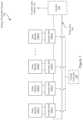
- FIG. 1illustrates an embodiment of an energy production system including a plurality of junction boxes each coupled between a solar module and a power bus.
- FIG. 2illustrates a solar module and a detail view of an embodiment of a junction box.
- FIG. 3illustrates an embodiment of a junction box.
- FIG. 4illustrates an embodiment of a method of controlling the output of a solar module.
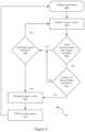
- FIG. 5illustrates another embodiment of a method of controlling the output of a solar module.
- Solar arrayscan be shut down during an emergency, maintenance, or installation in order to protect first responders, solar array installers, and maintenance personnel from shock or electrocution.
- systems used to shut down a solar arraycan also be damaged in an emergency.
- the systems and methods herein disclosedcan shut down a solar array or lower the voltages to safe levels even when the solar array is damaged or when an active shutdown signal is sent to the solar array.
- a watchdog unitis disclosed that monitors communication from a central controller, and upon interruption of that communication, disconnects a solar module from a power bus. Alternatively, when communication is interrupted, the watchdog unit can lower the solar module voltage to a safe level.
- the systems and methodsalso describe a watchdog unit able to receive a shutdown signal, which would allow first responders, solar array installers, and maintenance personnel to remotely render the solar array safe before approaching the solar array. In the event that the watchdog unit loses power, backup sources of power are also described.
- FIG. 1illustrates an embodiment of an energy production system 100 including a plurality of junction boxes 104 each coupled between a solar module 102 and a power bus 108 .
- the solar modules 102generate power from absorbed photons and provide this power to the power bus 108 .
- the junction boxes 104control the voltage provided by the solar modules 102 to the power bus 108 . In an embodiment, this is done via control of one or more switchable connections within the junction boxes 104 .
- Junction boxes 104can disconnect the solar modules 102 from the power bus 108 or lower the voltage provided to the power bus 108 .
- the junction boxes 104may each comprise a watchdog unit. Each watchdog unit can monitor a communication (or signal) from a central controller 106 via wireless or wired connection. When the communication is interrupted, each watchdog unit can render its associated solar module 102 safe by disconnecting the solar module 102 from the power bus 108 or by lowering the solar module 202 voltage to a safe level.
- Power from the solar modules 102can be converted to alternating current (AC) power via an optional inverter 140 , and then provided to the power grid, a battery, or other load. Given a direct current (DC) load, the inverter may be left out.
- the power bus 108may be connected in parallel or series with other power buses in a combiner box (not illustrated) before the combined power is provided to the inverter 140 or a (DC) load.
- Watchdog unitsmay also be configured to respond to a shutdown signal. Upon receiving a shutdown signal from the central controller 106 , the watchdog units may disconnect the solar modules 102 from the power bus 108 , or they may lower the solar module 102 voltages to a safe level.
- the shutdown signalcan be automatically generated within the central controller 106 or some other controller in communication with the central controller 106 . Alternatively, the shutdown signal can be manually generated. For instance, a solar array maintenance worker may push a button connected to the central controller initiating shutdown of all solar modules so that the worker can do maintenance on the solar array without worrying about shock or electrocution.
- the location of the central controller 106is non-limiting.
- the central controller 106may be remote.
- the central controller 106may be a part of a combiner box or inverter 140 .
- the central controller 106may be a part of one of the junction boxes 104 .
- FIG. 1illustrates a junction box 104 for each solar module 102
- other embodimentsmay have solar modules 102 that are coupled directly to the power bus without a junction box 104 .
- theremay not be a watchdog unit in every junction box 104 .
- a “solar cell”is a photovoltaic device configured to absorb photons and convert them into electrical energy.
- a “solar module”is a device that includes at least one or more solar cells, wherein the solar cells are connected in series or in parallel. The solar cells absorb photons and convert the photons into electrical energy.
- a “power bus”is a conductive path connecting one or more solar modules 102 in series.
- a “watchdog unit”is a device or software implemented in hardware configured to monitor a communication from a central controller 106 and shut down, or disconnect from the power bus 108 , a solar module 102 when the communication from the central controller 106 is interrupted or when a shutdown signal is received.
- a “signal”is an electric quantity (voltage or current or field strength) whose modulation represents coded information.
- FIG. 2illustrates a solar module 202 and a detail view of an embodiment of a junction box 204 .
- the junction box 204may be coupled between a solar module 202 and a power bus 208 .
- the junction box 204may include a controller 212 and may include a switchable connection 216 (or two or more switchable connections 216 ).
- the junction box 204optionally includes a converter/adaptor 218 and/or optionally includes a diode 220 .
- the junction box 204may include a watchdog unit 210 .
- the watchdog unit 210may be configured to monitor a communication from the central controller 106 , determine that the communication has been interrupted, and disconnect the solar module 202 from the power bus 208 or lower the solar module 202 voltage to a safe level.
- the watchdog unit 210may be configured to monitor a communication from the central controller 106 via a connection 214 .
- the connection 214can be wired or wireless.
- the watchdog unit 210may be implemented in software.
- the watchdog 210 for monitoring the wired communicationmay also be implemented in software or in a hardware-software combination.
- the watchdog unit 210 for monitoring the wireless communicationmay also be implemented in hardware or in a hardware-software combination.
- the communicationcan take any form that can be recognized by the watchdog unit 210 . For instance, the communication can be continuous or pulsed, or periodic or non-periodic.
- the central controller 106may fail to send a communication or the connection 214 (wired or wireless) between the central controller 106 and the watchdog unit 210 may be severed by fire, accident, or malfunction, to name a few.
- the watchdog unit 210can determine that the communication has been interrupted.
- the watchdog unit 210can render its associated solar module 202 safe by disconnecting the solar module 202 from the power bus 208 or by lowering the solar module 202 voltage to a safe level. Disconnecting the solar module 202 can be performed by, for instance, forcing the switchable connection 216 to operate in an open state. Lowering the solar module 202 voltage to a safe level can be performed by, for example, lowering the duty cycle of the switchable connection 216 .
- the watchdog unit 210may look for loss of the pulses.
- the watchdog unit 210may also look for an irregular periodicity to the pulses.
- the watchdog unit 210may look for a decrease in the amplitude of the pulses. Whichever one or more of these the watchdog unit 210 looks for, it will also look to see that the irregular behavior has surpassed a threshold. For example, irregularity in the periodicity of the pulses may be identified when less than a threshold number of pulses are received that have an abnormal period. As another example, an interrupted communication may be one that has dropped below a certain threshold amplitude.
- an interrupted communicationmay be one that has been irregular for longer than a threshold period of time.
- the watchdog unit 210may look for a threshold of irregularity to be surpassed. These limited examples merely scratch the surface of the numerous qualities or parameters that can be monitored in order to determine that a communication has been interrupted.
- While the watchdog unit 210can be triggered by an interrupted communication, it can also be triggered by an instruction or other affirmative signal. For instance, the same communication that the watchdog unit 210 monitors for interruption, could also carry an indication (or instructions) to limit the voltage or disconnect (or shutdown) the solar module 202 from the power bus 208 .
- the central controller 106can be configured to transmit a repeated or continuous communication, but it can also be configured to transmit a limited-duration shutdown signal.
- the watchdog unit 210can monitor the communication for an interruption or for a shutdown signal.
- the shutdown signalcan be initiated by an automatic control in or of the central controller 106 .
- the shutdown signalcan also be manually initiated.
- the manually-initiated shutdown signalmay be used by first responders, solar array installers, and maintenance personnel to remotely render the solar array safe.
- the manual inputcan be connected to the central controller 106 or can be remotely transmitted to the central controller 106 .
- the watchdog unit 210can also be triggered by detecting a fault in: the power bus 208 wiring, wiring internal to the watchdog unit 210 , or wiring internal to the junction box 204 .
- a faultcan be detected by comparing relevant voltages, or the absence of voltages between any one or more of the following: solar modules 202 , power buses 208 , or ground, to name a few.
- a faultcan be detected by comparing relevant voltages, or the absence thereof, between the solar module 202 and the power bus 208 .
- the relevant voltages, or absence thereofcould be compared between the solar module 202 and the ground.
- the watchdog unit 210is a part of the junction box 204 .
- the watchdog unit 210can be located outside the junction box 204 .
- the watchdog unit 210can be a part of the combiner box, the inverter 140 , or any other location downstream from the junction box 204 .
- the watchdog unit 210can include any one or more of the following: the controller 212 ; one or more switchable connections 216 ; the converter/adaptor 218 ; and the diode 220 .
- the watchdog unit 210may lose power. For instance, the watchdog unit 210 may become disconnected from a primary power source (e.g., via fire).
- the primary power sourcemay include, for example, one or more of the following: the solar module 202 , the power bus 206 , a battery (not illustrated), or a capacitor (not illustrated).
- the watchdog unit 210may be wired to draw power from either or both of the solar module 202 and the power bus 206 .
- a backup power sourcecan therefore provide the watchdog unit 210 with power when the watchdog unit's 210 primary power source is not available. In other words, the watchdog unit 210 can draw energy from a backup energy source when a primary energy source is not available.
- the junction box 204may include the controller 212 .
- the controller 212may monitor a communication from the central controller 106 via the wired/wireless connection 214 .
- the wired/wireless connection 214can also be seen in FIG. 1 as the dashed line leading from the central controller 106 to the solar modules 102 . If the communication is interrupted, then the controller 204 may render the solar module 202 safe by either limiting the solar module 202 voltage or by disconnecting the solar module 202 from the power bus 208 .
- the controller 204can control the switchable connection 216 via a wired or wireless connection (not illustrated).
- the controller 204can control the duty cycle of the switchable connection 216 .
- the controller 204can control the voltage that the solar module 202 provides to the power bus 208 .
- the controller 204can also disconnect the solar module 202 from the power bus 208 by leaving the switchable connection 216 in an open state.
- the controller 204can be implemented in hardware, software, or a hardware-software combination.
- the controller 204may derive instructions from a storage medium such as a non-volatile storage medium (e.g., electrically erasable programmable read-only memory (EEPROM), read-only memory (ROM), flash, to name a few). This allows the controller 204 to obtain instructions even when power has been lost.
- EEPROMelectrically erasable programmable read-only memory
- ROMread-only memory
- the junction box 204may include the switchable connection 216 .
- the switchable connection 216may connect and disconnect the solar module 202 to/from the power bus 208 .
- the switchable connection 216may be normally closed. When the switchable connection 216 is closed, the solar module 202 is connected to the power bus 208 , and the entire voltage of the solar module 202 can be provided to the power bus 208 . However, when the switchable connection 216 is opened, the solar module 202 may be disconnected from the power bus 208 and cannot provide voltage to the power bus 208 .
- By opening and closing the switchable connection 216 at a particular duty cyclea portion of the solar module's 202 voltage can be provided to the power bus 208 , in essence lowering the solar module 202 voltage to a safe level.
- the switchable connection 216can be mechanical or electrical (e.g., transistors).
- electrical switchesinclude field-effect transistors (FET), metal-oxide-semiconductor FETs (MOSFET), and insulated gate bipolar-type transistors (IGBT).
- FETfield-effect transistors
- MOSFETmetal-oxide-semiconductor FETs
- IGBTinsulated gate bipolar-type transistors
- the function of the switchable connection 216may be carried out elsewhere (e.g., by the inverter 140 ).
- the junction box 204may include a converter/adaptor 218 .
- the converter/adapter 218acts as a local management unit (“LMU”).
- the LMUsmay be configured to balance voltages and currents between solar modules 202 and between power buses 208 .
- the converter/adaptercan be implemented serially (as illustrated) or in parallel (not illustrated).
- the junction box 204may include an optional diode 220 .
- the diode 220can be coupled in series with the power bus 208 and coupled in parallel with the solar module 202 .
- the diode 220may be forward biased in the direction of the flow of current. As such, the diode 220 can reverse bias the solar module 202 , should the solar module 202 stop producing power.
- the diode 220can prevent reversal of the solar module 202 if there are one or more weak solar modules 202 on the power bus 208 .
- Weak solar modules 202are those that provide a lower current than other solar modules 202 .
- the diode 220may not be desired for an AC configuration since the diode 220 can rectify an AC power signal and thus reduce the power generated by the solar module 202 .
- FIG. 3illustrates an embodiment of a junction box 304 .
- This embodiment of a junction box 304is similar to the junction box 204 illustrated in FIG. 2 , but with the addition of optional switchable connections 322 , 324 and optional lines 326 , 328 , 330 .
- the junction box 304may include a bypass circuit such as the one formed by switchable connection 322 . Since current may have to pass through the solar module 302 in order to pass downstream on the power bus 308 , current may stop flowing in the power bus 308 if the watchdog unit 310 disconnects one of the solar modules 302 from the power bus 308 .
- a bypass circuitusing the switchable connection 322 , shorts the power bus 308 through the junction box 304 such that current in the power bus 308 can bypass the solar module 302 .
- the switchable connection 322may normally be open, but may close when the solar module 302 is disconnected from the power bus 308 .
- the bypass circuitcan be used in combination with a diode 320 .
- the bypass circuitalso allows current to pass through the junction box 304 without having to pass through the diode 320 or the solar module 302 .
- the switchable connection 322can be a mechanical or electronic switch. Non-limiting examples of electronic switches include FETs, MOSFETs, and IGBTs. The switchable connection 322 may not be desired in a high voltage system.
- the junction box 304may include a switchable connection 324 , which can be used to increase the longevity of the solar module 302 .
- the switchable connection 324may be normally open. When closed, the switchable connection 324 can short the solar module 302 to itself. This may be done when the solar module 302 is disconnected from the power bus 308 . In doing so, the solar module 302 can produce current, which may increase the solar module's 302 longevity. Shorting the solar module 302 is described in more detail in related U.S. Pat. No. 8,039,730, entitled “Systems and Methods for Prevention of Open Loop Damage during or Immediately after Manufacturing,” which is incorporated herein by reference.
- the junction box 304may include a feed line 326 connecting the solar module 302 and the controller 312 .
- the feed line 326may be configured to provide the controller 312 with power when power is lost (e.g., when the controller 312 cannot obtain power from its primary power source).
- the junction box 304may include a line 328 configured to provide power to the controller 312 from the solar module 302 .
- the junction box 304may include a line 330 configured provide power to the controller 312 from the power bus 308 .
- the controller 312may also be powered by a batter or capacitor (not illustrated).
- FIG. 4illustrates an embodiment of a method of controlling the output of a solar module.
- the method 400may be computer-implemented, and each of the operations discussed below can be carried out via a computing device.
- the method 400begins by initializing parameters in an initialize parameters operation 402 .
- System checksare then performed in a perform system checks operation 404 .
- the method 400then verifies communication with a central controller via a verify communication decision 406 . If communications with the central controller are verified, then the method 400 looks for a shutdown signal in a shutdown signal received decision 408 . If a shutdown signal is not received, then the method returns to the perform system checks operation 404 . If a shutdown signal is received, then the method 400 shuts down the solar module in shutdown operation 410 .
- the method 400then waits for a restart signal from the central controller in the wait for restart signal operation 412 . Once the restart signal is received, the method returns to the initialize parameters operation 402 .
- the method 400waits to verify communication. If communication is verified in less than an allowed number of “skips,” as determined by a number of allowed skips exceeded decision 414 , then the method 400 looks for a shutdown signal in the shutdown decision 408 . The method 400 then continues from the shutdown decision 408 as previously described. However, if communication is not verified by the time the number of skips is exceeded, as determined by the number of allowed skips exceeded decision 414 , then the method 400 turns to the shutdown operation 410 and shuts the solar module down (disconnects one or more solar modules from the power bus or lowers one or more solar module voltages to safe levels). The method 400 then continues from the shutdown operation 410 as previously described.
- the method 400begins with the initialize parameters operation 402 .
- Parametersare used in the perform system checks operation 404 , as reference points for the system checks. Parameters can thus include values describing any of the systems or devices that the perform system checks operation 404 may look at. For instance, the types of wiring, proper voltages in the wires, proper currents in transistors, expected signals from the central controller, number of allowed skips, what the shutdown signal looks like, and how much time can elapse before an irregular signal is considered interrupted are just some of the parameters that can be used. Parameters can be stored in a storage medium, preferably a non-volatile storage medium such as electrically erasable programmable read-only memory (EEPROM), read-only memory (ROM), and flash.
- EEPROMelectrically erasable programmable read-only memory
- ROMread-only memory
- the method 400then performs system checks in the perform operation 404 .
- System checkscompare the parameters to measured values.
- Some non-limiting examples of things that can be measuredinclude, types of wiring, voltages in the wires, currents in transistors, signals from the central controller, number of skips, the shutdown signal, and elapsed time of interrupted signals, to name a few.
- a parameter initialized in the initialize operation 402may indicate that the voltage produced by the panel should be around 30V plus or minus 5V. If the system check finds the voltage to be 29V, then everything is acceptable. However, if the voltage were 24V or any other value below 25V, then the system check might provide a warning to the central controller or take some other remedial action.
- Verifying communicationincludes monitoring a communication from the central controller and ensuring that there are no problems with the communication. For instance, ensuring that the voltage of the communication is above a certain threshold (e.g., within 10% of maximum power), ensuring that a certain number of pulses are received within a certain period of time (e.g., at least one hundred pulses per second), or ensuring that communication is not lost for longer than a threshold period of time (e.g., communication is not verified if lost for more than three seconds), to name a few.
- verifying communicationcan include receiving a communication within a set time from when a last communication was received.
- the method 400may determine that communication has not been verified.
- the signal or communication from the central controllercan be transmitted via wireless or wired means.
- verifying communicationcan be an active rather than passive operation. For example, a signal such as a challenge can be sent to the central controller, and the communication is not verified until a response is received.
- a shutdown signalcan replace the signal that is being monitored.
- the shutdown signalcan be overlaid or multiplexed onto the signal being monitored.
- the shutdown signalcan be initiated by automatic means, such as a fire alarm.
- the shutdown signalcan be initiated by manual means, such as a fireman pushing an emergency shutdown button at the breaker box on a house that is burning.
- the method 400can loop back to the perform system checks operation 402 as illustrated. Alternatively, the method 400 can continue to verify communication with the central controller via the verify decision 406 . If the shutdown signal is received, then the method 400 shuts the solar module down in the shutdown operation 410 . Shutdown may include using a watchdog and/or switchable connection to disconnect the solar module from the power bus. Shutdown may include using a watchdog and/or switchable connection to lower the solar module voltage to a safe level.
- the method 400waits for a restart signal.
- the restart signalis a signal from the central controller that is transmitted via the same wireless or wired means that communicates the originally monitored signal.
- the restart signalmay be automatically transmitted when certain conditions are met or may be manually initiated. For instance, at the end of a fire or after a home has been fixed after a fire, maintenance personnel may flip a manual switch near the fuse box to initiate the restart signal.
- the backup power sourcemay run down while the method 400 waits for the restart signal.
- the method 400can initiate a full shutdown. The full shutdown may include turning off all systems which are still operational.
- the method 400can loop back to the initialize parameters operation 402 .
- the method 400may continue trying to verify communication until a threshold is surpassed. This continued attempt to verify takes place via the number of skips allowed decision 414 .
- Skipsrefers to the event of missing a communication or pulse. If a communication or pulse should be received every second, but one pulse is not received, then a skip has occurred. For example, if a communication or pulse is not received for five seconds, then four skips have occurred.
- the thresholdcan take many forms. For instance, the threshold can be a number of skips. The threshold can be a time period in which communication cannot be verified. The threshold can be a number of missed pulses or a number of pulses having less-than-expected amplitude.
- the threshold valuescan be extracted from or read from a storage medium.
- the storage mediumcan be the same one that stores parameters, or it can be a separate storage medium. In either case, non-volatile memory can be used so that the threshold values can still be accessed even after power is lost.
- the method 400moves to the shutdown and wait operations 410 , 412 .
- the thresholdis not surpassed (e.g., communication with the central controller is lost, but resumes before the threshold is surpassed)
- the method 400determines if the communication (or signal) includes a shutdown signal via the shutdown decision 408 .
- the method 400requires the verify communication decision 406 along with the shutdown operation 410 .
- the method 400is about monitoring communication from the central controller, verifying the communication, and shutting the solar module down when the communication cannot be verified. Any one or more of the other operations and decisions can be added to this basic set of decision 406 and operation 410 .
- the method 400can look for the shutdown signal via the shutdown decision 408 concurrently with the verify decision 406 or before the verify decision 406 .
- the number of allowed skips exceeded decision 414may also operate before, after, or concurrently with the shutdown decision 408 .
- the method 400may loop back to the verify decision 406 rather than the initialize and perform operations 402 , 404 .
- FIG. 5illustrates another embodiment of a method of controlling the output of a solar module.
- the method 500may be computer-implemented, and each of the operations discussed below can be carried out via a computing device.
- the method 500monitors a signal from a central controller in a monitor operation 502 .
- the method 500determines if the signal has been lost via a signal lost decision 504 . If the signal is lost, then one or more solar modules are disconnected from a power bus via a disconnect operation 508 .
- Disconnectmeans that a switchable connection has a reduced duty cycle such that the voltage provided to the power bus by the solar module is reduced.
- the switchable connectioncan have a duty cycle of 0%, always open, such that no voltage is provided to the power bus.
- the method 500may also determine if the signal includes a shutdown signal via a shutdown signal received decision 506 . If the signal includes a shutdown signal, then the method 500 disconnects one or more solar modules from the power bus via the disconnect operation 508 . If a shutdown signal is not received, then the method 500 continues to monitor the signal from the central controller via the monitor operation 502 . When the one or more solar modules are disconnected from the power bus, the method 500 may optionally enable a bypass circuit via an enable bypass circuit operation 510 . The bypass circuit allows current to continue to flow in the power bus when the one or more solar modules are disconnected from the power bus. The method 500 may then wait for a restart signal via a wait operation 512 .
- the method 500continues to wait for the restart signal until the restart signal is received or until a backup power source (e.g., battery or capacitor) runs out, assuming the primary power source is not available. If the backup power source runs out, then the method 500 initiates a full shutdown. If the restart signal is received, then the method 500 can connect the one or more solar modules to the power bus via a connect operation 516 .
- a backup power sourcee.g., battery or capacitor
- lost signalit is meant that the signal amplitude is not great enough to surpass an amplitude threshold or that the signal has become so irregular as to surpass an irregularity threshold. For instance, if only ten out of a hundred pulses have been received (assuming a pulsed signal), then the signal may be considered lost.
- watchdog unitscan be coupled between each solar module and the power bus.
- the watchdog unitscan be configured to monitor a signal from a central controller and disconnect the solar modules from the power bus if the signal is lost or if the signal includes a shutdown signal.
- Disconnecting one solar module from the power busmay include a complete disconnection, as for example performed via the opening of a mechanical or electronic switch. However, disconnecting can also include lowering the voltage (e.g., lowering a duty cycle of a switch).
- lowering the voltagee.g., lowering a duty cycle of a switch.
- the watchdog unitscan be a part of local management units (LMU's) that are also responsible for balancing the currents between solar modules in a power bus and are responsible for balancing the voltages between power buses in a solar array.
- LMU'slocal management units
Landscapes
- Photovoltaic Devices (AREA)
- Life Sciences & Earth Sciences (AREA)
- Engineering & Computer Science (AREA)
- Sustainable Development (AREA)
- Sustainable Energy (AREA)
- Safety Devices In Control Systems (AREA)
Abstract
Description
Claims (21)
Priority Applications (2)
| Application Number | Priority Date | Filing Date | Title |
|---|---|---|---|
| US17/526,793US12143065B2 (en) | 2009-09-03 | 2021-11-15 | Systems and methods for an enhanced watchdog in solar module installations |
| US18/941,741US20250070713A1 (en) | 2009-09-03 | 2024-11-08 | Systems and methods for an enhanced watchdog in solar module installations |
Applications Claiming Priority (6)
| Application Number | Priority Date | Filing Date | Title |
|---|---|---|---|
| US27597709P | 2009-09-03 | 2009-09-03 | |
| US27675309P | 2009-09-16 | 2009-09-16 | |
| US12/628,977US8933321B2 (en) | 2009-02-05 | 2009-12-01 | Systems and methods for an enhanced watchdog in solar module installations |
| US14/572,458US10312857B2 (en) | 2009-09-03 | 2014-12-16 | Systems and methods for an enhanced watchdog in solar module installations |
| US16/389,775US11967930B2 (en) | 2009-09-03 | 2019-04-19 | Systems and methods for an enhanced watchdog in solar module installations |
| US17/526,793US12143065B2 (en) | 2009-09-03 | 2021-11-15 | Systems and methods for an enhanced watchdog in solar module installations |
Related Parent Applications (1)
| Application Number | Title | Priority Date | Filing Date |
|---|---|---|---|
| US16/389,775ContinuationUS11967930B2 (en) | 2009-09-03 | 2019-04-19 | Systems and methods for an enhanced watchdog in solar module installations |
Related Child Applications (1)
| Application Number | Title | Priority Date | Filing Date |
|---|---|---|---|
| US18/941,741ContinuationUS20250070713A1 (en) | 2009-09-03 | 2024-11-08 | Systems and methods for an enhanced watchdog in solar module installations |
Publications (2)
| Publication Number | Publication Date |
|---|---|
| US20220077819A1 US20220077819A1 (en) | 2022-03-10 |
| US12143065B2true US12143065B2 (en) | 2024-11-12 |
Family
ID=42229712
Family Applications (6)
| Application Number | Title | Priority Date | Filing Date |
|---|---|---|---|
| US12/628,977Active2031-10-08US8933321B2 (en) | 2007-11-02 | 2009-12-01 | Systems and methods for an enhanced watchdog in solar module installations |
| US14/572,458Active2031-10-20US10312857B2 (en) | 2009-09-03 | 2014-12-16 | Systems and methods for an enhanced watchdog in solar module installations |
| US16/389,775Active2030-03-25US11967930B2 (en) | 2009-09-03 | 2019-04-19 | Systems and methods for an enhanced watchdog in solar module installations |
| US17/526,793ActiveUS12143065B2 (en) | 2009-09-03 | 2021-11-15 | Systems and methods for an enhanced watchdog in solar module installations |
| US18/642,041PendingUS20240348205A1 (en) | 2009-09-03 | 2024-04-22 | Systems and methods for an enhanced watchdog in solar module installations |
| US18/941,741PendingUS20250070713A1 (en) | 2009-09-03 | 2024-11-08 | Systems and methods for an enhanced watchdog in solar module installations |
Family Applications Before (3)
| Application Number | Title | Priority Date | Filing Date |
|---|---|---|---|
| US12/628,977Active2031-10-08US8933321B2 (en) | 2007-11-02 | 2009-12-01 | Systems and methods for an enhanced watchdog in solar module installations |
| US14/572,458Active2031-10-20US10312857B2 (en) | 2009-09-03 | 2014-12-16 | Systems and methods for an enhanced watchdog in solar module installations |
| US16/389,775Active2030-03-25US11967930B2 (en) | 2009-09-03 | 2019-04-19 | Systems and methods for an enhanced watchdog in solar module installations |
Family Applications After (2)
| Application Number | Title | Priority Date | Filing Date |
|---|---|---|---|
| US18/642,041PendingUS20240348205A1 (en) | 2009-09-03 | 2024-04-22 | Systems and methods for an enhanced watchdog in solar module installations |
| US18/941,741PendingUS20250070713A1 (en) | 2009-09-03 | 2024-11-08 | Systems and methods for an enhanced watchdog in solar module installations |
Country Status (2)
| Country | Link |
|---|---|
| US (6) | US8933321B2 (en) |
| WO (1) | WO2011028457A2 (en) |
Families Citing this family (191)
| Publication number | Priority date | Publication date | Assignee | Title |
|---|---|---|---|---|
| US10693415B2 (en) | 2007-12-05 | 2020-06-23 | Solaredge Technologies Ltd. | Testing of a photovoltaic panel |
| US11881814B2 (en) | 2005-12-05 | 2024-01-23 | Solaredge Technologies Ltd. | Testing of a photovoltaic panel |
| US9088178B2 (en) | 2006-12-06 | 2015-07-21 | Solaredge Technologies Ltd | Distributed power harvesting systems using DC power sources |
| US8816535B2 (en) | 2007-10-10 | 2014-08-26 | Solaredge Technologies, Ltd. | System and method for protection during inverter shutdown in distributed power installations |
| US8319471B2 (en) | 2006-12-06 | 2012-11-27 | Solaredge, Ltd. | Battery power delivery module |
| US11687112B2 (en) | 2006-12-06 | 2023-06-27 | Solaredge Technologies Ltd. | Distributed power harvesting systems using DC power sources |
| US11888387B2 (en) | 2006-12-06 | 2024-01-30 | Solaredge Technologies Ltd. | Safety mechanisms, wake up and shutdown methods in distributed power installations |
| US11296650B2 (en) | 2006-12-06 | 2022-04-05 | Solaredge Technologies Ltd. | System and method for protection during inverter shutdown in distributed power installations |
| US8319483B2 (en) | 2007-08-06 | 2012-11-27 | Solaredge Technologies Ltd. | Digital average input current control in power converter |
| US8947194B2 (en) | 2009-05-26 | 2015-02-03 | Solaredge Technologies Ltd. | Theft detection and prevention in a power generation system |
| US8013472B2 (en) | 2006-12-06 | 2011-09-06 | Solaredge, Ltd. | Method for distributed power harvesting using DC power sources |
| US11735910B2 (en) | 2006-12-06 | 2023-08-22 | Solaredge Technologies Ltd. | Distributed power system using direct current power sources |
| US8963369B2 (en) | 2007-12-04 | 2015-02-24 | Solaredge Technologies Ltd. | Distributed power harvesting systems using DC power sources |
| US11855231B2 (en) | 2006-12-06 | 2023-12-26 | Solaredge Technologies Ltd. | Distributed power harvesting systems using DC power sources |
| US9112379B2 (en) | 2006-12-06 | 2015-08-18 | Solaredge Technologies Ltd. | Pairing of components in a direct current distributed power generation system |
| US8384243B2 (en) | 2007-12-04 | 2013-02-26 | Solaredge Technologies Ltd. | Distributed power harvesting systems using DC power sources |
| US8473250B2 (en) | 2006-12-06 | 2013-06-25 | Solaredge, Ltd. | Monitoring of distributed power harvesting systems using DC power sources |
| US11569659B2 (en) | 2006-12-06 | 2023-01-31 | Solaredge Technologies Ltd. | Distributed power harvesting systems using DC power sources |
| US12316274B2 (en) | 2006-12-06 | 2025-05-27 | Solaredge Technologies Ltd. | Pairing of components in a direct current distributed power generation system |
| US9130401B2 (en) | 2006-12-06 | 2015-09-08 | Solaredge Technologies Ltd. | Distributed power harvesting systems using DC power sources |
| US11309832B2 (en) | 2006-12-06 | 2022-04-19 | Solaredge Technologies Ltd. | Distributed power harvesting systems using DC power sources |
| US8618692B2 (en) | 2007-12-04 | 2013-12-31 | Solaredge Technologies Ltd. | Distributed power system using direct current power sources |
| WO2009055474A1 (en) | 2007-10-23 | 2009-04-30 | And, Llc | High reliability power systems and solar power converters |
| CA2737134C (en) | 2007-10-15 | 2017-10-10 | Ampt, Llc | Systems for highly efficient solar power |
| US7884278B2 (en)* | 2007-11-02 | 2011-02-08 | Tigo Energy, Inc. | Apparatuses and methods to reduce safety risks associated with photovoltaic systems |
| US11228278B2 (en) | 2007-11-02 | 2022-01-18 | Tigo Energy, Inc. | System and method for enhanced watch dog in solar panel installations |
| US8933321B2 (en) | 2009-02-05 | 2015-01-13 | Tigo Energy, Inc. | Systems and methods for an enhanced watchdog in solar module installations |
| US8823218B2 (en) | 2007-11-02 | 2014-09-02 | Tigo Energy, Inc. | System and method for enhanced watch dog in solar panel installations |
| CN105244905B (en) | 2007-12-05 | 2019-05-21 | 太阳能安吉有限公司 | Release mechanism in distributed power device is waken up and method for closing |
| WO2009073867A1 (en) | 2007-12-05 | 2009-06-11 | Solaredge, Ltd. | Parallel connected inverters |
| WO2009072076A2 (en) | 2007-12-05 | 2009-06-11 | Solaredge Technologies Ltd. | Current sensing on a mosfet |
| US9291696B2 (en) | 2007-12-05 | 2016-03-22 | Solaredge Technologies Ltd. | Photovoltaic system power tracking method |
| US11264947B2 (en) | 2007-12-05 | 2022-03-01 | Solaredge Technologies Ltd. | Testing of a photovoltaic panel |
| US8111052B2 (en) | 2008-03-24 | 2012-02-07 | Solaredge Technologies Ltd. | Zero voltage switching |
| EP2294669B8 (en) | 2008-05-05 | 2016-12-07 | Solaredge Technologies Ltd. | Direct current power combiner |
| US20090315336A1 (en)* | 2008-06-23 | 2009-12-24 | Hudson Worthington Harr | Renewable energy generation system |
| SG175717A1 (en) | 2009-04-17 | 2011-12-29 | Ampt Llc | Methods and apparatus for adaptive operation of solar power systems |
| CA2767867C (en) | 2009-07-16 | 2018-11-13 | General Cybernation Group, Inc. | Smart and scalable power inverters |
| US10121913B2 (en)* | 2009-10-19 | 2018-11-06 | Helios Focus Llc | Solar photovoltaic module safety shutdown system |
| US9466737B2 (en) | 2009-10-19 | 2016-10-11 | Ampt, Llc | Solar panel string converter topology |
| US12418177B2 (en) | 2009-10-24 | 2025-09-16 | Solaredge Technologies Ltd. | Distributed power system using direct current power sources |
| US8854193B2 (en) | 2009-12-29 | 2014-10-07 | Tigo Energy, Inc. | Systems and methods for remote or local shut-off of a photovoltaic system |
| US8773236B2 (en)* | 2009-12-29 | 2014-07-08 | Tigo Energy, Inc. | Systems and methods for a communication protocol between a local controller and a master controller |
| US8271599B2 (en) | 2010-01-08 | 2012-09-18 | Tigo Energy, Inc. | Systems and methods for an identification protocol between a local controller and a master controller in a photovoltaic power generation system |
| US9007210B2 (en)* | 2010-04-22 | 2015-04-14 | Tigo Energy, Inc. | Enhanced system and method for theft prevention in a solar power array during nonoperative periods |
| DE102010029813B4 (en)* | 2010-06-08 | 2023-02-23 | Sma Solar Technology Ag | Method for controlling electrical power generation of a sub-module in a photovoltaic system |
| WO2012031662A1 (en)* | 2010-09-10 | 2012-03-15 | Sew-Eurodrive Gmbh & Co. Kg Abt. Ecg | System, in particular a local energy distribution system, having an intermediate circuit, method for controlling the energy flow in a system, and use of converters of a system that are arranged in various housings |
| EP2432026A1 (en)* | 2010-09-21 | 2012-03-21 | MS ENERGIES Société privée à responsabilité limitée | Photovoltaic plant with protection against the risks of electrocution in the event of a fire and safety box for such a plant |
| US10673222B2 (en) | 2010-11-09 | 2020-06-02 | Solaredge Technologies Ltd. | Arc detection and prevention in a power generation system |
| US10230310B2 (en) | 2016-04-05 | 2019-03-12 | Solaredge Technologies Ltd | Safety switch for photovoltaic systems |
| US10673229B2 (en) | 2010-11-09 | 2020-06-02 | Solaredge Technologies Ltd. | Arc detection and prevention in a power generation system |
| GB2485527B (en) | 2010-11-09 | 2012-12-19 | Solaredge Technologies Ltd | Arc detection and prevention in a power generation system |
| DE102010052009A1 (en)* | 2010-11-19 | 2012-05-24 | Kostal Industrie Elektrik Gmbh | Photovoltaic system and photovoltaic module |
| DE102010053500A1 (en)* | 2010-11-23 | 2012-05-24 | Trimos Gmbh | Photovoltaic generator with protective circuit for photovoltaic modules |
| ITVR20100227A1 (en)* | 2010-11-29 | 2012-05-30 | Metech Italia S R L | SAFETY DEVICE FOR PHOTOVOLTAIC SYSTEMS |
| TWI530043B (en)* | 2010-12-07 | 2016-04-11 | 創惟科技股份有限公司 | Junction box, power system and control method thereof |
| GB2486408A (en) | 2010-12-09 | 2012-06-20 | Solaredge Technologies Ltd | Disconnection of a string carrying direct current |
| FR2970375B1 (en)* | 2011-01-11 | 2013-10-04 | Philippe Dumas | ELECTRICAL SAFETY OF PHOTOVOLTAIC ENERGY PRODUCTION FACILITIES |
| GB2483317B (en) | 2011-01-12 | 2012-08-22 | Solaredge Technologies Ltd | Serially connected inverters |
| DE102011010172A1 (en)* | 2011-02-02 | 2013-06-13 | Sma Solar Technology Ag | Signal generating inverter and operating method for an inverter |
| EP2495766A1 (en)* | 2011-02-13 | 2012-09-05 | Fabio Brucchi | Safety system to reduce risk of electrocution at photovoltaic panels level |
| US9093902B2 (en)* | 2011-02-15 | 2015-07-28 | Cyboenergy, Inc. | Scalable and redundant mini-inverters |
| TWI435233B (en)* | 2011-03-14 | 2014-04-21 | Powertech Technology Inc | Device and method for managing abnormality prediction of semiconductor process equipments |
| US20140032009A1 (en)* | 2011-04-15 | 2014-01-30 | Siemens Aktiengesellschaft | Power distribution system and method for operation thereof |
| ITVI20110112A1 (en) | 2011-04-29 | 2012-10-30 | Itaco S R L | PHOTOVOLTAIC PLANT FOR THE PRODUCTION OF ELECTRIC POWER OF HIGH POWER |
| US20120298166A1 (en)* | 2011-05-24 | 2012-11-29 | Rfmarq, Inc. | Solar Panel with Energy Efficient Bypass Diode System |
| ITMI20111024A1 (en)* | 2011-06-07 | 2012-12-08 | Voltalink Srl | INTEGRATED SYSTEM FOR THE REMOTE MANAGEMENT OF PHOTOVOLTAIC SYSTEMS |
| US9331488B2 (en) | 2011-06-30 | 2016-05-03 | Cyboenergy, Inc. | Enclosure and message system of smart and scalable power inverters |
| US8780592B1 (en) | 2011-07-11 | 2014-07-15 | Chilicon Power, LLC | Systems and methods for increasing output current quality, output power, and reliability of grid-interactive inverters |
| DE102011110682A1 (en) | 2011-08-19 | 2013-02-21 | Phoenix Contact Gmbh & Co. Kg | Junction box for a solar panel with a protection circuit |
| US8723370B2 (en)* | 2011-08-30 | 2014-05-13 | Renewable Power Conversion, Inc. | Photovoltaic string sub-combiner |
| DE102011082160A1 (en)* | 2011-09-06 | 2013-03-07 | Robert Bosch Gmbh | Protective switching device, photovoltaic system and method for operating such |
| US8570005B2 (en) | 2011-09-12 | 2013-10-29 | Solaredge Technologies Ltd. | Direct current link circuit |
| FR2982435B1 (en)* | 2011-11-03 | 2014-06-13 | Augier | PHOTOVOLTAIC PANEL SECURITY DEVICE |
| TWI451658B (en)* | 2011-11-16 | 2014-09-01 | Genesys Logic Inc | Junction box, power system and control method thereof |
| GB2498365A (en) | 2012-01-11 | 2013-07-17 | Solaredge Technologies Ltd | Photovoltaic module |
| GB2498790A (en) | 2012-01-30 | 2013-07-31 | Solaredge Technologies Ltd | Maximising power in a photovoltaic distributed power system |
| GB2498791A (en) | 2012-01-30 | 2013-07-31 | Solaredge Technologies Ltd | Photovoltaic panel circuitry |
| US9853565B2 (en) | 2012-01-30 | 2017-12-26 | Solaredge Technologies Ltd. | Maximized power in a photovoltaic distributed power system |
| US9735777B2 (en) | 2012-02-17 | 2017-08-15 | Multi-Holding Ag | Disconnection of solar modules |
| TW201338348A (en)* | 2012-03-01 | 2013-09-16 | Hon Hai Prec Ind Co Ltd | Uninterruptible power supply system |
| GB2499991A (en) | 2012-03-05 | 2013-09-11 | Solaredge Technologies Ltd | DC link circuit for photovoltaic array |
| CN103457303A (en)* | 2012-05-30 | 2013-12-18 | 台达电子工业股份有限公司 | Solar power generation system with power generation module and its output electric energy control method |
| TW201349731A (en)* | 2012-05-30 | 2013-12-01 | Delta Electronics Inc | Solar power generation system with power generation module and output power control method thereof |
| US10115841B2 (en)* | 2012-06-04 | 2018-10-30 | Solaredge Technologies Ltd. | Integrated photovoltaic panel circuitry |
| US10090430B2 (en) | 2014-05-27 | 2018-10-02 | Sunpower Corporation | System for manufacturing a shingled solar cell module |
| US9780253B2 (en) | 2014-05-27 | 2017-10-03 | Sunpower Corporation | Shingled solar cell module |
| US9947820B2 (en) | 2014-05-27 | 2018-04-17 | Sunpower Corporation | Shingled solar cell panel employing hidden taps |
| USD1009775S1 (en) | 2014-10-15 | 2024-01-02 | Maxeon Solar Pte. Ltd. | Solar panel |
| USD933584S1 (en) | 2012-11-08 | 2021-10-19 | Sunpower Corporation | Solar panel |
| DE102013101314A1 (en) | 2013-02-11 | 2014-08-14 | Phoenix Contact Gmbh & Co. Kg | Safe photovoltaic system |
| US9791835B2 (en) | 2013-03-12 | 2017-10-17 | Chuck McCune | PV stop potential voltage and hazard stop system |
| US10143101B2 (en) | 2013-03-12 | 2018-11-27 | Chuck McCune | PV stax—multi-function junction MF/J system |
| US9941813B2 (en) | 2013-03-14 | 2018-04-10 | Solaredge Technologies Ltd. | High frequency multi-level inverter |
| US9548619B2 (en) | 2013-03-14 | 2017-01-17 | Solaredge Technologies Ltd. | Method and apparatus for storing and depleting energy |
| US9397497B2 (en) | 2013-03-15 | 2016-07-19 | Ampt, Llc | High efficiency interleaved solar power supply system |
| EP3506370B1 (en) | 2013-03-15 | 2023-12-20 | Solaredge Technologies Ltd. | Bypass mechanism |
| US20150236638A1 (en)* | 2013-04-13 | 2015-08-20 | Solexel, Inc. | Solar photovoltaic module power control and status monitoring system utilizing laminateembedded remote access module switch |
| US10784815B2 (en) | 2013-04-13 | 2020-09-22 | Sigmagen, Inc. | Solar photovoltaic module remote access module switch and real-time temperature monitoring |
| US9571032B2 (en)* | 2013-06-10 | 2017-02-14 | Leto Solar Corporation | Junction box for solar cell module and method for driving same |
| AT515047B1 (en)* | 2013-10-21 | 2019-08-15 | Es Esolutions Gmbh Elektrotechnik Und Photovoltaik | Arrangement for switching photovoltaic systems |
| JP3189106U (en) | 2013-12-12 | 2014-02-20 | ティー・エス・ビー株式会社 | Solar power system |
| US9318974B2 (en) | 2014-03-26 | 2016-04-19 | Solaredge Technologies Ltd. | Multi-level inverter with flying capacitor topology |
| US11949026B2 (en) | 2014-05-27 | 2024-04-02 | Maxeon Solar Pte. Ltd. | Shingled solar cell module |
| US11482639B2 (en) | 2014-05-27 | 2022-10-25 | Sunpower Corporation | Shingled solar cell module |
| US9843193B2 (en) | 2014-07-30 | 2017-12-12 | Robert Getsla | Safety shutdown system for photovoltaic power generators |
| US20160036234A1 (en)* | 2014-07-31 | 2016-02-04 | Fraunhofer Usa, Inc. | Photovoltaic systems and related techniques |
| US10038317B1 (en)* | 2014-08-18 | 2018-07-31 | Bentek Corporation | Rapid disconnect safety system for photovoltaic (PV) systems |
| USD913210S1 (en) | 2014-10-15 | 2021-03-16 | Sunpower Corporation | Solar panel |
| USD933585S1 (en) | 2014-10-15 | 2021-10-19 | Sunpower Corporation | Solar panel |
| USD999723S1 (en) | 2014-10-15 | 2023-09-26 | Sunpower Corporation | Solar panel |
| USD896747S1 (en) | 2014-10-15 | 2020-09-22 | Sunpower Corporation | Solar panel |
| AU2015364718B2 (en) | 2014-12-16 | 2019-11-28 | Marici Holdings The Netherlands B.V. | Energy panel arrangement power dissipation |
| WO2016123305A1 (en)* | 2015-01-28 | 2016-08-04 | Abb Technology Ag | Energy panel arrangement shutdown |
| WO2016134356A1 (en) | 2015-02-22 | 2016-08-25 | Abb Technology Ag | Photovoltaic string reverse polarity detection |
| US10861999B2 (en) | 2015-04-21 | 2020-12-08 | Sunpower Corporation | Shingled solar cell module comprising hidden tap interconnects |
| US10388802B2 (en) | 2015-07-06 | 2019-08-20 | SolarOff Systems, LLC | System and method for synchronized rapid shutdown of electrical devices |
| DE102015114755A1 (en) | 2015-09-03 | 2017-03-09 | Phoenix Contact Gmbh & Co. Kg | Safe photovoltaic system |
| FR3041823A1 (en)* | 2015-09-25 | 2017-03-31 | Commissariat Energie Atomique | CONNECTOR FOR PHOTOVOLTAIC MODULE |
| TWM517913U (en)* | 2015-10-22 | 2016-02-21 | 豪客能源科技股份有限公司 | Integrated apparatus with multiple solar panel modules |
| US10566798B2 (en) | 2016-03-31 | 2020-02-18 | Texas Instruments Incorporated | Solar panel disconnect and reactivation system |
| US11177663B2 (en) | 2016-04-05 | 2021-11-16 | Solaredge Technologies Ltd. | Chain of power devices |
| US11018623B2 (en) | 2016-04-05 | 2021-05-25 | Solaredge Technologies Ltd. | Safety switch for photovoltaic systems |
| US12057807B2 (en) | 2016-04-05 | 2024-08-06 | Solaredge Technologies Ltd. | Chain of power devices |
| US10673379B2 (en) | 2016-06-08 | 2020-06-02 | Sunpower Corporation | Systems and methods for reworking shingled solar cell modules |
| CN106602504B (en)* | 2017-02-28 | 2018-11-06 | 阳光电源股份有限公司 | A kind of photovoltaic Quick shut-off device and photovoltaic system |
| ES2823590T3 (en)* | 2018-01-18 | 2021-05-07 | Soltec Energias Renovables Sl | Photovoltaic system to generate electricity with an auxiliary charging module |
| EP3540938B1 (en)* | 2018-03-13 | 2021-06-23 | FIMER S.p.A. | A shut-down apparatus for a string of photovoltaic panels |
| CN110417348A (en)* | 2018-04-28 | 2019-11-05 | 北京汉能光伏投资有限公司 | Solar module junction box, solar system and solar module control method |
| CN109067353B (en) | 2018-08-24 | 2020-03-24 | 阳光电源股份有限公司 | Active bypass control device and method for photovoltaic module |
| CN110875716B (en)* | 2018-08-31 | 2024-12-10 | 苏州阿特斯阳光电力科技有限公司 | A photovoltaic module |
| CN110875715B (en)* | 2018-08-31 | 2025-04-15 | 苏州阿特斯阳光电力科技有限公司 | A photovoltaic module |
| CN110875719B (en)* | 2018-08-31 | 2025-04-15 | 苏州阿特斯阳光电力科技有限公司 | A photovoltaic module |
| CN110875717B (en)* | 2018-08-31 | 2025-04-15 | 苏州阿特斯阳光电力科技有限公司 | A photovoltaic module |
| CN109149777B (en)* | 2018-09-28 | 2020-07-07 | 阳光电源股份有限公司 | Shutdown control system and method |
| CN109193610B (en)* | 2018-09-28 | 2021-01-08 | 阳光电源股份有限公司 | Shutdown control system and method |
| GB2585173A (en)* | 2018-11-12 | 2021-01-06 | Eaton Intelligent Power Ltd | Photovoltaic string combiner box with protection functions |
| US11190022B2 (en) | 2019-01-09 | 2021-11-30 | Texas Instruments Incorporated | Controller circuit for photovoltaic sub-module |
| US10797921B2 (en) | 2019-02-12 | 2020-10-06 | Texas Instruments Incorporated | Threshold computation circuit for S-FSK receiver, integrated circuit, and method associated therewith |
| US10778482B2 (en) | 2019-02-12 | 2020-09-15 | Texas Instruments Incorporated | Bit slicer circuit for S-FSK receiver, integrated circuit, and method associated therewith |
| US11342787B2 (en) | 2019-03-20 | 2022-05-24 | Texas Instruments Incorporated | Controller circuit for photovoltaic module |
| US11350186B2 (en) | 2019-03-20 | 2022-05-31 | Texas Instruments Incorporated | Monitoring circuit for photovoltaic module |
| WO2021003728A1 (en)* | 2019-07-11 | 2021-01-14 | 华为技术有限公司 | Converter, method and system applied to photovoltaic power generation system |
| US11398795B2 (en) | 2019-12-20 | 2022-07-26 | GAF Energy LLC | Roof integrated photovoltaic system |
| MX2022009069A (en) | 2020-01-22 | 2023-01-05 | GAF Energy LLC | INTEGRATED PHOTOVOLTAIC ROOF TILES, METHODS, SYSTEMS AND KITS THEREOF. |
| US11251744B1 (en) | 2020-06-04 | 2022-02-15 | GAF Energy LLC | Photovoltaic shingles and methods of installing same |
| US11843067B2 (en) | 2020-07-22 | 2023-12-12 | GAF Energy LLC | Photovoltaic modules |
| WO2022035473A1 (en) | 2020-08-11 | 2022-02-17 | GAF Energy LLC | Roof mounted photovoltaic system and method for wireless transfer of electrical energy |
| CA3191420A1 (en) | 2020-09-03 | 2022-03-10 | Gabriela Bunea | Building integrated photovoltaic system |
| KR102520478B1 (en)* | 2020-09-18 | 2023-04-10 | 한화솔루션 주식회사 | Photovoltaic system, device and method for monitoring thereof |
| US11545928B2 (en) | 2020-10-13 | 2023-01-03 | GAF Energy LLC | Solar roofing system |
| WO2022081853A1 (en) | 2020-10-14 | 2022-04-21 | GAF Energy LLC | Mounting apparatus for photovoltaic modules |
| CA3196900A1 (en) | 2020-10-29 | 2022-05-05 | Michael David KUIPER | System of roofing and photovoltaic shingles and methods of installing same |
| MX2023008498A (en)* | 2021-01-19 | 2023-09-29 | GAF Energy LLC | Watershedding features for roofing shingles. |
| MX2023009726A (en) | 2021-02-19 | 2023-11-09 | GAF Energy LLC | PHOTOVOLTAIC MODULE FOR A ROOF WITH CONTINUOUS FIBER TAPE. |
| US11670727B2 (en) | 2021-02-26 | 2023-06-06 | Sri Satya Acquisitions Llc | Solar electricity generation system and method |
| CA3210838A1 (en) | 2021-03-29 | 2022-10-06 | GAF Energy LLC | Electrical components for photovoltaic systems |
| MX2023013029A (en) | 2021-05-06 | 2023-11-16 | GAF Energy LLC | PHOTOVOLTAIC MODULE WITH TRANSPARENT PERIMETER EDGES. |
| WO2022256430A1 (en) | 2021-06-02 | 2022-12-08 | GAF Energy LLC | Photovoltaic module with light-scattering encapsulant providing shingle-mimicking appearance |
| US12009781B2 (en) | 2021-07-06 | 2024-06-11 | GAF Energy LLC | Jumper module for photovoltaic systems |
| WO2023034432A1 (en) | 2021-09-01 | 2023-03-09 | GAF Energy LLC | Photovoltaic modules for commercial roofing |
| DE102021123679A1 (en)* | 2021-09-14 | 2023-03-16 | E.ON Group Innovation GmbH | Technology for protecting electrical networks in the event of a communication link failure |
| CA3242693A1 (en) | 2022-01-20 | 2023-07-27 | Thierry Nguyen | Roofing shingles for mimicking the appearance of photovoltaic modules |
| US12013153B2 (en) | 2022-02-08 | 2024-06-18 | GAF Energy LLC | Building integrated photovoltaic system |
| WO2023164494A1 (en) | 2022-02-23 | 2023-08-31 | GAF Energy LLC | Roofing shingle and method of manufacturing same |
| US11670945B1 (en) | 2022-02-28 | 2023-06-06 | Lunar Energy, Inc. | Power optimizers in series with voltage sensors and a common reference signal |
| US12015265B2 (en) | 2022-02-28 | 2024-06-18 | Lunar Energy, Inc. | Autonomous detection of rapid shutdown condition |
| US11984521B2 (en) | 2022-03-10 | 2024-05-14 | GAF Energy LLC | Combined encapsulant and backsheet for photovoltaic modules |
| WO2023197010A1 (en) | 2022-04-08 | 2023-10-12 | GAF Energy LLC | Low profile connector for solar roofing systems |
| WO2023240005A1 (en)* | 2022-06-06 | 2023-12-14 | GAF Energy LLC | Active component indicators for photovoltaic systems |
| WO2024015996A1 (en) | 2022-07-15 | 2024-01-18 | GAF Energy LLC | Solar roofing system with fiber composite roofing shingles |
| CN115065321B (en)* | 2022-08-15 | 2022-11-11 | 深圳市中旭新能源有限公司 | Optimization device for automatically controlling voltage safety in non-watchdog mode and photovoltaic system |
| WO2024044685A1 (en) | 2022-08-24 | 2024-02-29 | GAF Energy LLC | System for forming a roofing membrane, and associated method |
| US12414385B2 (en) | 2022-08-29 | 2025-09-09 | GAF Energy LLC | Photovoltaic modules with offset layers |
| US12034089B2 (en) | 2022-09-01 | 2024-07-09 | GAF Energy LLC | Anti-reflective photovoltaic shingles and related methods |
| WO2024059462A1 (en) | 2022-09-13 | 2024-03-21 | GAF Energy LLC | Sensing roofing system and method thereof |
| WO2024073288A1 (en) | 2022-09-26 | 2024-04-04 | GAF Energy LLC | Photovoltaic modules integrated with building siding and fencing |
| WO2024073498A1 (en) | 2022-09-29 | 2024-04-04 | GAF Energy LLC | Jumper module with sleeve |
| CN117856824A (en) | 2022-10-07 | 2024-04-09 | 迭戈能源有限公司 | Solar panel transmitter and signal synchronization |
| WO2024091828A1 (en) | 2022-10-25 | 2024-05-02 | GAF Energy LLC | Roofing materials and related methods |
| US12231075B2 (en) | 2022-10-27 | 2025-02-18 | GAF Energy LLC | Building integrated photovoltaic systems |
| US12413183B2 (en) | 2022-11-15 | 2025-09-09 | GAF Energy LLC | Electrical cable passthrough for photovoltaic systems |
| US11811361B1 (en) | 2022-12-14 | 2023-11-07 | GAF Energy LLC | Rapid shutdown device for photovoltaic modules |
| US12355390B1 (en) | 2023-02-03 | 2025-07-08 | GAF Energy LLC | Solar shingle and associated roofing system and method |
| US12413174B2 (en) | 2023-02-21 | 2025-09-09 | GAF Energy LLC | Roofing system including photovoltaic module wireway cover, and associated method |
| US12176849B2 (en) | 2023-02-23 | 2024-12-24 | GAF Energy LLC | Photovoltaic shingles with multi-module power electronics |
| KR20240147000A (en)* | 2023-03-30 | 2024-10-08 | 엘지이노텍 주식회사 | Power converting apparatus |
| US12009782B1 (en) | 2023-04-04 | 2024-06-11 | GAF Energy LLC | Photovoltaic systems with wireways |
| US12413177B2 (en) | 2023-08-31 | 2025-09-09 | GAF Energy LLC | Photovoltaic modules and roofing shingles with nail zones |
| US12316268B2 (en) | 2023-10-26 | 2025-05-27 | GAF Energy LLC | Roofing systems with water ingress protection |
| US12438495B2 (en) | 2023-12-05 | 2025-10-07 | GAF Energy LLC | Roofing system for prevention of roofing shingle deformation |
Citations (142)
| Publication number | Priority date | Publication date | Assignee | Title |
|---|---|---|---|---|
| DE3010371A1 (en) | 1980-03-15 | 1981-09-24 | Licentia Gmbh | Control output circuit for solar cells - has sensing circuit which switches cells through to converter when power output exceeds threshold |
| JPS6125104U (en) | 1984-07-19 | 1986-02-14 | 株式会社 ユ−エム工業 | hand saw |
| US4580090A (en) | 1983-09-16 | 1986-04-01 | Motorola, Inc. | Maximum power tracker |
| EP0178757A2 (en) | 1984-10-15 | 1986-04-23 | Trw Inc. | Solar array regulator |
| US4604567A (en) | 1983-10-11 | 1986-08-05 | Sundstrand Corporation | Maximum power transfer system for a solar cell array |
| US4873480A (en) | 1988-08-03 | 1989-10-10 | Lafferty Donald L | Coupling network for improving conversion efficiency of photovoltaic power source |
| US5027051A (en) | 1990-02-20 | 1991-06-25 | Donald Lafferty | Photovoltaic source switching regulator with maximum power transfer efficiency without voltage change |
| US5054023A (en) | 1989-05-12 | 1991-10-01 | Kronberg James W | "Smart" watchdog safety switch |
| US5143556A (en) | 1989-03-13 | 1992-09-01 | Matlin Ronald W | Support for photovoltaic arrays |
| US5235266A (en) | 1990-06-02 | 1993-08-10 | Schottel-Werft Josef Becker Gmbh & Co. Kg | Energy-generating plant, particularly propeller-type ship's propulsion plant, including a solar generator |
| US5268832A (en) | 1991-08-20 | 1993-12-07 | Kabushiki Kaisha Toshiba | DC/AC inverter controller for solar cell, including maximum power point tracking function |
| US5280133A (en) | 1991-12-13 | 1994-01-18 | United Solar Systems Corporation | Junction box for a solar panel |
| DE4232356A1 (en) | 1992-09-26 | 1994-03-31 | Inst Solare Energieversorgungstechnik Iset | Power supply system with at least two rectifier-inverter pairs - has voltage from one pair phase-shifted with respect to other pair thus eliminating unwanted harmonics |
| US5472614A (en) | 1991-12-30 | 1995-12-05 | Hospal Ltd. | Dialysis machine with safety monitoring and a corresponding method for monitoring safety |
| US5504418A (en) | 1993-11-26 | 1996-04-02 | Hughes Aircraft Company | Full shunt boost switching voltage limiter for solar panel array |
| US5604430A (en) | 1994-10-11 | 1997-02-18 | Trw Inc. | Solar array maximum power tracker with arcjet load |
| US5648731A (en) | 1993-05-11 | 1997-07-15 | Trw Inc. | Method of checking solar panel characteristics in an operating solar electrical system |
| US5747967A (en) | 1996-02-22 | 1998-05-05 | Midwest Research Institute | Apparatus and method for maximizing power delivered by a photovoltaic array |
| US5801519A (en) | 1996-06-21 | 1998-09-01 | The Board Of Trustees Of The University Of Illinois | Self-excited power minimizer/maximizer for switching power converters and switching motor drive applications |
| JPH11103538A (en) | 1997-09-27 | 1999-04-13 | My Way Giken Kk | Optical power generating system |
| US5923158A (en) | 1996-08-30 | 1999-07-13 | Canon Kabushiki Kaisha | Power control apparatus for solar power generation system |
| US5932994A (en) | 1996-05-15 | 1999-08-03 | Samsung Electronics, Co., Ltd. | Solar cell power source device |
| US6031736A (en) | 1995-07-26 | 2000-02-29 | Canon Kabushiki Kaisha | Control apparatus of inverter and power generation system using such control apparatus |
| US6093885A (en) | 1998-03-03 | 2000-07-25 | Canon Kabushiki Kaisha | Photovoltaic power generating system |
| US6101073A (en) | 1997-06-13 | 2000-08-08 | Canon Kabushiki Kaisha | Ground fault protecting apparatus and method for solar power generation and solar power generation apparatus using the apparatus and method |
| JP2000358330A (en) | 1999-06-14 | 2000-12-26 | Nissin Electric Co Ltd | Photovoltaic power generating apparatus |
| DE19961705A1 (en) | 1999-12-21 | 2001-07-05 | Sma Regelsysteme Gmbh | Arrangement for decentralized supply of regenerative energy performs voltage regulation at combination point for controlled improvement of quality of electrical supply |
| US6275016B1 (en) | 2001-02-15 | 2001-08-14 | Texas Instruments Incorporated | Buck-boost switching regulator |
| US20010023703A1 (en) | 2000-02-29 | 2001-09-27 | Hiroshi Kondo | Solar power generation apparatus and control method therefor |
| US6350944B1 (en) | 2000-05-30 | 2002-02-26 | Hughes Electronics Corporation | Solar module array with reconfigurable tile |
| US6396239B1 (en) | 2001-04-06 | 2002-05-28 | William M. Benn | Portable solar generator |
| US6448489B2 (en) | 2000-04-28 | 2002-09-10 | Sharp Kabushiki Kaisha | Solar generation system |
| US6515215B1 (en) | 1998-03-13 | 2003-02-04 | Canon Kabushiki Kaisha | Photovoltaic module, photovoltaic module array, photovoltaic system, and method of detecting failure of photovoltaic module |
| WO2003012569A1 (en) | 2001-07-29 | 2003-02-13 | Stichting Energieonderzoek Centrum Nederland | Maximum powerpoint tracker |
| US6545211B1 (en) | 1999-01-14 | 2003-04-08 | Canon Kabushiki Kaisha | Solar cell module, building material with solar cell module, solar cell module framing structure, and solar power generation apparatus |
| JP2003134661A (en) | 2001-10-17 | 2003-05-09 | Mitsubishi Heavy Ind Ltd | Load interruption detecting device and photovoltaic power generator |
| US6650031B1 (en) | 1998-09-30 | 2003-11-18 | Siemens And Shell Solar Gmbh | Protective system for a solar module |
| US6653549B2 (en) | 2000-07-10 | 2003-11-25 | Canon Kabushiki Kaisha | Photovoltaic power generation systems and methods of controlling photovoltaic power generation systems |
| EP1388774A1 (en) | 2002-08-09 | 2004-02-11 | Alcatel | Source conditioning circuit at a maximum power point |
| US6713890B2 (en) | 2001-05-29 | 2004-03-30 | Canon Kabushiki Kaisha | Power generation apparatus and its control method |
| US6763226B1 (en) | 2002-07-31 | 2004-07-13 | Computer Science Central, Inc. | Multifunctional world wide walkie talkie, a tri-frequency cellular-satellite wireless instant messenger computer and network for establishing global wireless volp quality of service (qos) communications, unified messaging, and video conferencing via the internet |
| US6819011B2 (en) | 2002-11-14 | 2004-11-16 | Fyre Storm, Inc. | Switching power converter controller with watchdog timer |
| US6837739B2 (en) | 2003-01-31 | 2005-01-04 | Hewlett-Packard Development Company, L.P. | Battery connection interrupter |
| US6844739B2 (en) | 2001-03-09 | 2005-01-18 | National Institute Of Advanced Industrial Science And Technology | Maximum power point tracking method and device |
| US20050021189A1 (en) | 2003-07-25 | 2005-01-27 | Timm Miguel A. | Self-contained electronic pressure monitoring and shutdown device |
| US20050057215A1 (en) | 2003-09-15 | 2005-03-17 | Stefan Matan | Systems and methods for charging a battery |
| US20050057214A1 (en) | 2003-09-15 | 2005-03-17 | Stefan Matan | Systems and methods for generating renewable energy |
| US20050063422A1 (en) | 2003-09-19 | 2005-03-24 | Sashi Lazar | Communication protocol over power line communication networks |
| US6894911B2 (en) | 2000-06-02 | 2005-05-17 | Iwatt, Inc. | Method of driving a power converter by using a power pulse and a sense pulse |
| US20050121067A1 (en) | 2002-07-09 | 2005-06-09 | Canon Kabushiki Kaisha | Solar power generation apparatus, solar power generation system, and method of manufacturing solar power generation apparatus |
| WO2005069096A1 (en) | 2004-01-12 | 2005-07-28 | Koninklijke Philips Electronics, N.V. | Solar power source with maximum power-point tracking |
| US20050172995A1 (en) | 2002-05-17 | 2005-08-11 | Rudiger Rohrig | Circuit arrangement for a photovoltaic system |
| US6946753B2 (en) | 2002-11-14 | 2005-09-20 | Fyre Storm, Inc. | Switching power converter controller with watchdog timer |
| KR200402282Y1 (en) | 2005-09-13 | 2005-11-28 | 주식회사 에스에너지 | Monitering apparatus of solar photo condensing array |
| WO2005112551A2 (en) | 2004-05-21 | 2005-12-01 | Hansung Engineering Co. Ltd | Method for compensating for partial shade in photovoltaic power system |
| US20060001406A1 (en) | 2004-07-01 | 2006-01-05 | Stefan Matan | Power extractor circuit |
| US6984970B2 (en) | 2002-09-19 | 2006-01-10 | Alcatel | Conditioning circuit for a power supply at the maximum power point, a solar generator, and a conditioning method |
| AU2005262278A1 (en) | 2004-07-13 | 2006-01-19 | Tigo Energy, Inc. | A device for distributed maximum power tracking for solar arrays |
| ES2249147A1 (en) | 2004-07-01 | 2006-03-16 | Fundacion Robotiker | Intelligent photovoltaic module, has inverter that supplies alternating current to tracking algorithm point maximum power unit, and direct current to direct current converter controlled by maximum power unit |
| US7061214B2 (en) | 2003-11-25 | 2006-06-13 | Texas Instruments Incorporated | Single inductor dual output buck converter with frequency and time varying offset control |
| DE102005012213A1 (en) | 2005-01-26 | 2006-08-03 | G. Spelsberg Gmbh & Co. Kg | Connection circuit for electrically connecting solar cells of solar cell module, has electronically controlled switching arrangement as protective device, and switching device controlled by control switch of switching device |
| US20060174939A1 (en) | 2004-12-29 | 2006-08-10 | Isg Technologies Llc | Efficiency booster circuit and technique for maximizing power point tracking |
| US20060185727A1 (en) | 2004-12-29 | 2006-08-24 | Isg Technologies Llc | Converter circuit and technique for increasing the output efficiency of a variable power source |
| US20060231132A1 (en) | 2005-04-18 | 2006-10-19 | Thomas Neussner | Photovoltaic generator with thermo switch element |
| DE102005018173A1 (en) | 2005-04-19 | 2006-10-26 | Aixcon Elektrotechnik Gmbh | Photovoltaic device safe interruption method, involves attaching switching device in direct proximity to generator field within or outside structure, where device switches field on demand into low-energy operating point by control line |
| US7150938B2 (en) | 2001-03-30 | 2006-12-19 | Lithium Power Technologies, Inc. | Structurally embedded intelligent power unit |
| US20070019613A1 (en) | 2003-03-31 | 2007-01-25 | Aleandro Frezzolini | Packet communication between a collecting unit and a plurality of control devices and over the power supply line |
| WO2007048421A2 (en) | 2005-10-24 | 2007-05-03 | Conergy Ag | Switch-fuse with control management for solar cells |
| KR100725755B1 (en) | 2006-11-17 | 2007-06-08 | 주식회사 텐코리아 | Solar power unit |
| FR2894401A1 (en) | 2005-12-07 | 2007-06-08 | Transenergie Sa | Electrical energy generating installation controlling device for e.g. arid zone, has transmitter periodically sending alternating current signal, captured by receiver controlling interrupter, for inducing opening or closing of interrupter |
| US7248946B2 (en) | 2004-05-11 | 2007-07-24 | Advanced Energy Conversion, Llc | Inverter control methodology for distributed generation sources connected to a utility grid |
| US7256566B2 (en) | 2003-05-02 | 2007-08-14 | Ballard Power Systems Corporation | Method and apparatus for determining a maximum power point of photovoltaic cells |
| US7259474B2 (en) | 2003-04-09 | 2007-08-21 | Utstarcom, Inc. | Method and apparatus for aggregating power from multiple sources |
| US7276886B2 (en) | 2005-10-03 | 2007-10-02 | Texas Instruments Incorporated | Dual buck-boost converter with single inductor |
| US20070229237A1 (en) | 2005-09-20 | 2007-10-04 | Lawrence Kates | Programmed wireless sensor system |
| US20070273351A1 (en) | 2004-07-01 | 2007-11-29 | Atira Technologies Llc | Dynamic switch power converter |
| US20080036440A1 (en) | 2004-06-24 | 2008-02-14 | Ambient Control Systems, Inc. | Systems and Methods for Providing Maximum Photovoltaic Peak Power Tracking |
| US7336004B2 (en) | 2002-11-22 | 2008-02-26 | Siemens Vdo Automotive Corporation | Topologies for using multiple energy sources for power conversions |
| US20080122518A1 (en) | 2006-11-27 | 2008-05-29 | Besser David A | Multi-Source, Multi-Load Systems with a Power Extractor |
| US20080122449A1 (en) | 2006-11-27 | 2008-05-29 | Besser David A | Power extractor for impedance matching |
| US20080121272A1 (en) | 2006-11-27 | 2008-05-29 | Besser David A | System and apparatuses with multiple power extractors coupled to different power sources |
| US20080143188A1 (en) | 2006-12-06 | 2008-06-19 | Meir Adest | Distributed power harvesting systems using dc power sources |
| US20080147335A1 (en) | 2006-12-06 | 2008-06-19 | Meir Adest | Monitoring of distributed power harvesting systems using dc power sources |
| US20080142071A1 (en) | 2006-12-15 | 2008-06-19 | Miasole | Protovoltaic module utilizing a flex circuit for reconfiguration |
| US7394237B2 (en) | 2006-06-16 | 2008-07-01 | Uis Abler Electronics Co., Ltd. | Maxium power point tracking method and tracking device thereof for a solar power system |
| WO2008077473A2 (en) | 2006-12-21 | 2008-07-03 | Sp Solarprojekt Gmbh | Solar power generation plant |
| US20080164766A1 (en) | 2006-12-06 | 2008-07-10 | Meir Adest | Current bypass for distributed power harvesting systems using dc power sources |
| US20080179949A1 (en) | 2006-11-27 | 2008-07-31 | Besser David A | Power extractor detecting a power change |
| US20080236648A1 (en) | 2007-03-30 | 2008-10-02 | Klein David L | Localized power point optimizer for solar cell installations |
| US20080238195A1 (en) | 2007-03-27 | 2008-10-02 | Shaver Argil E | Distributed maximum power point tracking system, structure and process |
| US20080265185A1 (en) | 2007-04-24 | 2008-10-30 | Kabushiki Kaisha Toshiba | Light emitting apparatus and method for inspecting same |
| US7462955B2 (en) | 2004-09-27 | 2008-12-09 | Northern Power Systems, Inc. | Electrical power distribution system and method thereof |
| US20080303503A1 (en) | 2004-07-13 | 2008-12-11 | Central Queensland University | Device For Distributed Maximum Power Tracking For Solar Arrays |
| WO2009006879A2 (en) | 2007-07-11 | 2009-01-15 | Robert Maier | Photovoltaic system |
| US20090066357A1 (en) | 2007-09-06 | 2009-03-12 | Enphase Energy, Inc. | Method and apparatus for detecting impairment of a solar array |
| US7516106B2 (en) | 2002-03-28 | 2009-04-07 | Robert Shaw Controls Company | System and method for controlling usage of a commodity |
| US7518346B2 (en) | 2006-03-03 | 2009-04-14 | Texas Instruments Deutschland Gmbh | Buck-boost DC/DC converter with overlap control using ramp shift signal |
| US7518266B2 (en) | 2006-11-01 | 2009-04-14 | Electric Power Research Institute, Inc. | Method and apparatus for improving AC transmission system dispatchability, system stability, and power flow controllability using DC transmission systems |
| DE102007050031B3 (en) | 2007-10-17 | 2009-04-16 | Hanning Elektro-Werke Gmbh & Co. Kg | Control system for solar systems |
| US20090114263A1 (en) | 2007-11-02 | 2009-05-07 | Tigo Energy, Inc. | Apparatuses and Methods to Reduce Safety Risks Associated with Photovoltaic Systems |
| US7538451B2 (en) | 2004-06-15 | 2009-05-26 | Sony Corporation | Power supply system and electronic device |
| US20090141522A1 (en) | 2007-10-10 | 2009-06-04 | Solaredge, Ltd. | System and method for protection during inverter shutdown in distributed power installations |
| US7545053B2 (en) | 2002-09-04 | 2009-06-09 | Hitachi, Ltd. | Power supply and power supply method upon interruption of electric service |
| US20090179662A1 (en) | 2008-01-10 | 2009-07-16 | Moulton Thomas A | System for Monitoring Individual Photovoltaic Modules |
| US20090182532A1 (en)* | 2008-01-05 | 2009-07-16 | Stoeber Joachim | Monitoring unit for photovoltaic modules |
| US20090183763A1 (en) | 2008-01-18 | 2009-07-23 | Tenksolar, Inc | Flat-Plate Photovoltaic Module |
| US20090183760A1 (en) | 2008-01-18 | 2009-07-23 | Tenksolar Inc | Redundant electrical architecture for photovoltaic modules |
| US20090207543A1 (en) | 2008-02-14 | 2009-08-20 | Independent Power Systems, Inc. | System and method for fault detection and hazard prevention in photovoltaic source and output circuits |
| KR100912892B1 (en) | 2008-04-21 | 2009-08-20 | 서울마린 (주) | Remote self-diagnosis monitoring and remote control system for photovoltaic devices |
| US7595616B2 (en) | 2004-05-28 | 2009-09-29 | Texas Instruments Deutschland Gmbh | Control circuit for a polarity inverting buck-boost DC-DC converter |
| US20090242011A1 (en) | 2008-02-19 | 2009-10-01 | Photowatt International | Installation of telecontrolled photovoltaic modules |
| US7602080B1 (en) | 2008-11-26 | 2009-10-13 | Tigo Energy, Inc. | Systems and methods to balance solar panels in a multi-panel system |
| US7605498B2 (en) | 2007-10-15 | 2009-10-20 | Ampt, Llc | Systems for highly efficient solar power conversion |
| US20100028362A1 (en) | 2006-04-27 | 2010-02-04 | Northern Sydney and Central Coast Area Health Serv | Modulation of t helper cell-mediated immune responses |
| US20100057267A1 (en) | 2008-08-27 | 2010-03-04 | General Electric Company | System and method for controlling ramp rate of solar photovoltaic system |
| US20100071274A1 (en) | 2008-09-23 | 2010-03-25 | Joe Brescia | Unitized Curtain Wall Module Adapted for Integrated Photovoltaic Conversion Module |
| US20100085670A1 (en) | 2008-10-07 | 2010-04-08 | Krishnan Palaniswami | Photovoltaic module monitoring system |
| WO2010037393A1 (en) | 2008-10-01 | 2010-04-08 | Sunsil A/S | Power generation system and method of operating a power generation system |
| US20100131108A1 (en) | 2008-01-18 | 2010-05-27 | Tenksolar, Inc | Thin-film photovoltaic module |
| US20100132758A1 (en) | 2008-12-02 | 2010-06-03 | Advanced Energy Industries, Inc. | Device, system, and method for managing an application of power from photovoltaic arrays |
| US20100139734A1 (en) | 2009-02-05 | 2010-06-10 | Tigo Energy | Systems and Methods for an Enhanced Watchdog in Solar Module Installations |
| US20100269889A1 (en) | 2009-04-27 | 2010-10-28 | MHLEED Inc. | Photoelectric Solar Panel Electrical Safety System Permitting Access for Fire Suppression |
| US20100282293A1 (en) | 2009-01-21 | 2010-11-11 | Tenksolar | Illumination agnostic solar panel |
| US20100283612A1 (en) | 2009-05-08 | 2010-11-11 | Centerpointe Technologies, Inc. | Method and apparatus for implementing enhanced signature checking security measures for solar energy systems |
| US20100321148A1 (en) | 2009-06-18 | 2010-12-23 | Peter Gevorkian | Wireless intelligent solar power reader (wispr) structure and process |
| US20100326809A1 (en) | 2009-05-25 | 2010-12-30 | Eaton Industries Gmbh | Safety switchgear for solar plants |
| US20110068702A1 (en) | 2009-09-24 | 2011-03-24 | Cree Led Lighting Solutions, Inc. | Solid state lighting apparatus with controllable bypass circuits and methods of operation thereof |
| US20110092094A1 (en) | 2008-06-14 | 2011-04-21 | Kostal Industrie Elektrik Gmbh | Electric Connection Receptable for a Solar Cell Module |
| US20110172842A1 (en) | 2009-12-29 | 2011-07-14 | Tigo Energy | Systems and Methods for Remote or Local Shut-Off of a Photovoltaic System |
| US8013472B2 (en) | 2006-12-06 | 2011-09-06 | Solaredge, Ltd. | Method for distributed power harvesting using DC power sources |
| US20110218687A1 (en) | 2007-11-02 | 2011-09-08 | Tigo Energy | System and Method for Enhanced Watch Dog in Solar Panel Installations |
| EP2495766A1 (en) | 2011-02-13 | 2012-09-05 | Fabio Brucchi | Safety system to reduce risk of electrocution at photovoltaic panels level |
| US8531055B2 (en)* | 2006-12-06 | 2013-09-10 | Solaredge Ltd. | Safety mechanisms, wake up and shutdown methods in distributed power installations |
| US8669675B2 (en) | 2003-05-28 | 2014-03-11 | Beacon Power, Llc | Power converter for a solar panel |
| US8773236B2 (en) | 2009-12-29 | 2014-07-08 | Tigo Energy, Inc. | Systems and methods for a communication protocol between a local controller and a master controller |
| US8830649B2 (en) | 2009-09-29 | 2014-09-09 | Siemens Aktiengesellschaft | Free-wheeling circuit |
| US8947194B2 (en) | 2009-05-26 | 2015-02-03 | Solaredge Technologies Ltd. | Theft detection and prevention in a power generation system |
| US9112379B2 (en) | 2006-12-06 | 2015-08-18 | Solaredge Technologies Ltd. | Pairing of components in a direct current distributed power generation system |
| US9401599B2 (en) | 2010-12-09 | 2016-07-26 | Solaredge Technologies Ltd. | Disconnection of a string carrying direct current power |
| JP6125104B2 (en) | 2014-07-16 | 2017-05-10 | 三菱電機株式会社 | Air conditioning control device, air conditioning control method, and program |
| US20200304065A1 (en) | 2007-11-02 | 2020-09-24 | Tigo Energy, Inc. | System and method for enhanced watch dog in solar panel installations |
| US20220352393A1 (en) | 2014-05-27 | 2022-11-03 | Sunpower Corporation | Shingled solar cell module |
Family Cites Families (7)
| Publication number | Priority date | Publication date | Assignee | Title |
|---|---|---|---|---|
| JPH04219982A (en) | 1990-12-20 | 1992-08-11 | Sanyo Electric Co Ltd | Solar battery panel and its connection |
| JPH0897460A (en) | 1994-09-22 | 1996-04-12 | Nissin Electric Co Ltd | Solar cell power generator |
| JPH08116628A (en) | 1994-10-14 | 1996-05-07 | Nitto Kogyo Kk | Solar disconnecting switch |
| JP3316336B2 (en) | 1995-05-17 | 2002-08-19 | 三洋電機株式会社 | Solar cell device |
| JPH09148611A (en) | 1995-11-24 | 1997-06-06 | Sanyo Electric Co Ltd | Solar battery device |
| DE19611561A1 (en) | 1996-03-23 | 1997-09-25 | Koenig & Bauer Albert Ag | Method and device for transporting sheets |
| US20090018376A1 (en)* | 2007-07-09 | 2009-01-15 | Belter Randolph K | Catalytic process for the preparation of fluorinated halocarbons |
- 2009
- 2009-12-01USUS12/628,977patent/US8933321B2/enactiveActive
- 2010
- 2010-08-23WOPCT/US2010/046274patent/WO2011028457A2/enactiveApplication Filing
- 2014
- 2014-12-16USUS14/572,458patent/US10312857B2/enactiveActive
- 2019
- 2019-04-19USUS16/389,775patent/US11967930B2/enactiveActive
- 2021
- 2021-11-15USUS17/526,793patent/US12143065B2/enactiveActive
- 2024
- 2024-04-22USUS18/642,041patent/US20240348205A1/enactivePending
- 2024-11-08USUS18/941,741patent/US20250070713A1/enactivePending
Patent Citations (198)
| Publication number | Priority date | Publication date | Assignee | Title |
|---|---|---|---|---|
| DE3010371A1 (en) | 1980-03-15 | 1981-09-24 | Licentia Gmbh | Control output circuit for solar cells - has sensing circuit which switches cells through to converter when power output exceeds threshold |
| US4580090A (en) | 1983-09-16 | 1986-04-01 | Motorola, Inc. | Maximum power tracker |
| US4604567A (en) | 1983-10-11 | 1986-08-05 | Sundstrand Corporation | Maximum power transfer system for a solar cell array |
| JPS6125104U (en) | 1984-07-19 | 1986-02-14 | 株式会社 ユ−エム工業 | hand saw |
| EP0178757A2 (en) | 1984-10-15 | 1986-04-23 | Trw Inc. | Solar array regulator |
| US4873480A (en) | 1988-08-03 | 1989-10-10 | Lafferty Donald L | Coupling network for improving conversion efficiency of photovoltaic power source |
| US5143556A (en) | 1989-03-13 | 1992-09-01 | Matlin Ronald W | Support for photovoltaic arrays |
| US5054023A (en) | 1989-05-12 | 1991-10-01 | Kronberg James W | "Smart" watchdog safety switch |
| US5027051A (en) | 1990-02-20 | 1991-06-25 | Donald Lafferty | Photovoltaic source switching regulator with maximum power transfer efficiency without voltage change |
| US5235266A (en) | 1990-06-02 | 1993-08-10 | Schottel-Werft Josef Becker Gmbh & Co. Kg | Energy-generating plant, particularly propeller-type ship's propulsion plant, including a solar generator |
| US5268832A (en) | 1991-08-20 | 1993-12-07 | Kabushiki Kaisha Toshiba | DC/AC inverter controller for solar cell, including maximum power point tracking function |
| US5280133A (en) | 1991-12-13 | 1994-01-18 | United Solar Systems Corporation | Junction box for a solar panel |
| US5472614A (en) | 1991-12-30 | 1995-12-05 | Hospal Ltd. | Dialysis machine with safety monitoring and a corresponding method for monitoring safety |
| DE4232356A1 (en) | 1992-09-26 | 1994-03-31 | Inst Solare Energieversorgungstechnik Iset | Power supply system with at least two rectifier-inverter pairs - has voltage from one pair phase-shifted with respect to other pair thus eliminating unwanted harmonics |
| US5648731A (en) | 1993-05-11 | 1997-07-15 | Trw Inc. | Method of checking solar panel characteristics in an operating solar electrical system |
| US5504418A (en) | 1993-11-26 | 1996-04-02 | Hughes Aircraft Company | Full shunt boost switching voltage limiter for solar panel array |
| US5604430A (en) | 1994-10-11 | 1997-02-18 | Trw Inc. | Solar array maximum power tracker with arcjet load |
| US6031736A (en) | 1995-07-26 | 2000-02-29 | Canon Kabushiki Kaisha | Control apparatus of inverter and power generation system using such control apparatus |
| US5747967A (en) | 1996-02-22 | 1998-05-05 | Midwest Research Institute | Apparatus and method for maximizing power delivered by a photovoltaic array |
| US5932994A (en) | 1996-05-15 | 1999-08-03 | Samsung Electronics, Co., Ltd. | Solar cell power source device |
| US5801519A (en) | 1996-06-21 | 1998-09-01 | The Board Of Trustees Of The University Of Illinois | Self-excited power minimizer/maximizer for switching power converters and switching motor drive applications |
| US5923158A (en) | 1996-08-30 | 1999-07-13 | Canon Kabushiki Kaisha | Power control apparatus for solar power generation system |
| US6101073A (en) | 1997-06-13 | 2000-08-08 | Canon Kabushiki Kaisha | Ground fault protecting apparatus and method for solar power generation and solar power generation apparatus using the apparatus and method |
| JPH11103538A (en) | 1997-09-27 | 1999-04-13 | My Way Giken Kk | Optical power generating system |
| US6093885A (en) | 1998-03-03 | 2000-07-25 | Canon Kabushiki Kaisha | Photovoltaic power generating system |
| US6515215B1 (en) | 1998-03-13 | 2003-02-04 | Canon Kabushiki Kaisha | Photovoltaic module, photovoltaic module array, photovoltaic system, and method of detecting failure of photovoltaic module |
| US6650031B1 (en) | 1998-09-30 | 2003-11-18 | Siemens And Shell Solar Gmbh | Protective system for a solar module |
| US6545211B1 (en) | 1999-01-14 | 2003-04-08 | Canon Kabushiki Kaisha | Solar cell module, building material with solar cell module, solar cell module framing structure, and solar power generation apparatus |
| JP2000358330A (en) | 1999-06-14 | 2000-12-26 | Nissin Electric Co Ltd | Photovoltaic power generating apparatus |
| DE19961705A1 (en) | 1999-12-21 | 2001-07-05 | Sma Regelsysteme Gmbh | Arrangement for decentralized supply of regenerative energy performs voltage regulation at combination point for controlled improvement of quality of electrical supply |
| US20010023703A1 (en) | 2000-02-29 | 2001-09-27 | Hiroshi Kondo | Solar power generation apparatus and control method therefor |
| US6593520B2 (en) | 2000-02-29 | 2003-07-15 | Canon Kabushiki Kaisha | Solar power generation apparatus and control method therefor |
| US6448489B2 (en) | 2000-04-28 | 2002-09-10 | Sharp Kabushiki Kaisha | Solar generation system |
| US6350944B1 (en) | 2000-05-30 | 2002-02-26 | Hughes Electronics Corporation | Solar module array with reconfigurable tile |
| US6894911B2 (en) | 2000-06-02 | 2005-05-17 | Iwatt, Inc. | Method of driving a power converter by using a power pulse and a sense pulse |
| US6653549B2 (en) | 2000-07-10 | 2003-11-25 | Canon Kabushiki Kaisha | Photovoltaic power generation systems and methods of controlling photovoltaic power generation systems |
| US20040056768A1 (en) | 2000-07-10 | 2004-03-25 | Canon Kabushiki Kaisha | Photovoltaic power generation systems and methods of controlling photovoltaic power generation systems |
| US6275016B1 (en) | 2001-02-15 | 2001-08-14 | Texas Instruments Incorporated | Buck-boost switching regulator |
| US6844739B2 (en) | 2001-03-09 | 2005-01-18 | National Institute Of Advanced Industrial Science And Technology | Maximum power point tracking method and device |
| US7150938B2 (en) | 2001-03-30 | 2006-12-19 | Lithium Power Technologies, Inc. | Structurally embedded intelligent power unit |
| US6396239B1 (en) | 2001-04-06 | 2002-05-28 | William M. Benn | Portable solar generator |
| US6713890B2 (en) | 2001-05-29 | 2004-03-30 | Canon Kabushiki Kaisha | Power generation apparatus and its control method |
| US6897370B2 (en) | 2001-05-29 | 2005-05-24 | Canon Kabushiki Kaisha | Power generation apparatus and its control method |
| WO2003012569A1 (en) | 2001-07-29 | 2003-02-13 | Stichting Energieonderzoek Centrum Nederland | Maximum powerpoint tracker |
| JP2003134661A (en) | 2001-10-17 | 2003-05-09 | Mitsubishi Heavy Ind Ltd | Load interruption detecting device and photovoltaic power generator |
| US7516106B2 (en) | 2002-03-28 | 2009-04-07 | Robert Shaw Controls Company | System and method for controlling usage of a commodity |
| US20050172995A1 (en) | 2002-05-17 | 2005-08-11 | Rudiger Rohrig | Circuit arrangement for a photovoltaic system |
| US20050121067A1 (en) | 2002-07-09 | 2005-06-09 | Canon Kabushiki Kaisha | Solar power generation apparatus, solar power generation system, and method of manufacturing solar power generation apparatus |
| US6763226B1 (en) | 2002-07-31 | 2004-07-13 | Computer Science Central, Inc. | Multifunctional world wide walkie talkie, a tri-frequency cellular-satellite wireless instant messenger computer and network for establishing global wireless volp quality of service (qos) communications, unified messaging, and video conferencing via the internet |
| EP1388774A1 (en) | 2002-08-09 | 2004-02-11 | Alcatel | Source conditioning circuit at a maximum power point |
| US7545053B2 (en) | 2002-09-04 | 2009-06-09 | Hitachi, Ltd. | Power supply and power supply method upon interruption of electric service |
| US6984970B2 (en) | 2002-09-19 | 2006-01-10 | Alcatel | Conditioning circuit for a power supply at the maximum power point, a solar generator, and a conditioning method |
| US6946753B2 (en) | 2002-11-14 | 2005-09-20 | Fyre Storm, Inc. | Switching power converter controller with watchdog timer |
| US6819011B2 (en) | 2002-11-14 | 2004-11-16 | Fyre Storm, Inc. | Switching power converter controller with watchdog timer |
| US7336004B2 (en) | 2002-11-22 | 2008-02-26 | Siemens Vdo Automotive Corporation | Topologies for using multiple energy sources for power conversions |
| US6837739B2 (en) | 2003-01-31 | 2005-01-04 | Hewlett-Packard Development Company, L.P. | Battery connection interrupter |
| US20070019613A1 (en) | 2003-03-31 | 2007-01-25 | Aleandro Frezzolini | Packet communication between a collecting unit and a plurality of control devices and over the power supply line |
| US7259474B2 (en) | 2003-04-09 | 2007-08-21 | Utstarcom, Inc. | Method and apparatus for aggregating power from multiple sources |
| US7256566B2 (en) | 2003-05-02 | 2007-08-14 | Ballard Power Systems Corporation | Method and apparatus for determining a maximum power point of photovoltaic cells |
| US9438035B2 (en) | 2003-05-28 | 2016-09-06 | Solaredge Technologies Ltd. | Power converter for a solar panel |
| US8669675B2 (en) | 2003-05-28 | 2014-03-11 | Beacon Power, Llc | Power converter for a solar panel |
| US20050021189A1 (en) | 2003-07-25 | 2005-01-27 | Timm Miguel A. | Self-contained electronic pressure monitoring and shutdown device |
| US20050057214A1 (en) | 2003-09-15 | 2005-03-17 | Stefan Matan | Systems and methods for generating renewable energy |
| US20050057215A1 (en) | 2003-09-15 | 2005-03-17 | Stefan Matan | Systems and methods for charging a battery |
| US20050063422A1 (en) | 2003-09-19 | 2005-03-24 | Sashi Lazar | Communication protocol over power line communication networks |
| US7061214B2 (en) | 2003-11-25 | 2006-06-13 | Texas Instruments Incorporated | Single inductor dual output buck converter with frequency and time varying offset control |
| WO2005069096A1 (en) | 2004-01-12 | 2005-07-28 | Koninklijke Philips Electronics, N.V. | Solar power source with maximum power-point tracking |
| US7248946B2 (en) | 2004-05-11 | 2007-07-24 | Advanced Energy Conversion, Llc | Inverter control methodology for distributed generation sources connected to a utility grid |
| WO2005112551A2 (en) | 2004-05-21 | 2005-12-01 | Hansung Engineering Co. Ltd | Method for compensating for partial shade in photovoltaic power system |
| US7595616B2 (en) | 2004-05-28 | 2009-09-29 | Texas Instruments Deutschland Gmbh | Control circuit for a polarity inverting buck-boost DC-DC converter |
| US7538451B2 (en) | 2004-06-15 | 2009-05-26 | Sony Corporation | Power supply system and electronic device |
| US20080036440A1 (en) | 2004-06-24 | 2008-02-14 | Ambient Control Systems, Inc. | Systems and Methods for Providing Maximum Photovoltaic Peak Power Tracking |
| ES2249147A1 (en) | 2004-07-01 | 2006-03-16 | Fundacion Robotiker | Intelligent photovoltaic module, has inverter that supplies alternating current to tracking algorithm point maximum power unit, and direct current to direct current converter controlled by maximum power unit |
| US20070273351A1 (en) | 2004-07-01 | 2007-11-29 | Atira Technologies Llc | Dynamic switch power converter |
| US20060001406A1 (en) | 2004-07-01 | 2006-01-05 | Stefan Matan | Power extractor circuit |
| AU2005262278A1 (en) | 2004-07-13 | 2006-01-19 | Tigo Energy, Inc. | A device for distributed maximum power tracking for solar arrays |
| US20080303503A1 (en) | 2004-07-13 | 2008-12-11 | Central Queensland University | Device For Distributed Maximum Power Tracking For Solar Arrays |
| US7462955B2 (en) | 2004-09-27 | 2008-12-09 | Northern Power Systems, Inc. | Electrical power distribution system and method thereof |
| US20060185727A1 (en) | 2004-12-29 | 2006-08-24 | Isg Technologies Llc | Converter circuit and technique for increasing the output efficiency of a variable power source |
| US20060174939A1 (en) | 2004-12-29 | 2006-08-10 | Isg Technologies Llc | Efficiency booster circuit and technique for maximizing power point tracking |
| DE102005012213A1 (en) | 2005-01-26 | 2006-08-03 | G. Spelsberg Gmbh & Co. Kg | Connection circuit for electrically connecting solar cells of solar cell module, has electronically controlled switching arrangement as protective device, and switching device controlled by control switch of switching device |
| US20060231132A1 (en) | 2005-04-18 | 2006-10-19 | Thomas Neussner | Photovoltaic generator with thermo switch element |
| DE102005018173A1 (en) | 2005-04-19 | 2006-10-26 | Aixcon Elektrotechnik Gmbh | Photovoltaic device safe interruption method, involves attaching switching device in direct proximity to generator field within or outside structure, where device switches field on demand into low-energy operating point by control line |
| KR200402282Y1 (en) | 2005-09-13 | 2005-11-28 | 주식회사 에스에너지 | Monitering apparatus of solar photo condensing array |
| US20070229237A1 (en) | 2005-09-20 | 2007-10-04 | Lawrence Kates | Programmed wireless sensor system |
| US7276886B2 (en) | 2005-10-03 | 2007-10-02 | Texas Instruments Incorporated | Dual buck-boost converter with single inductor |
| WO2007048421A2 (en) | 2005-10-24 | 2007-05-03 | Conergy Ag | Switch-fuse with control management for solar cells |
| FR2894401A1 (en) | 2005-12-07 | 2007-06-08 | Transenergie Sa | Electrical energy generating installation controlling device for e.g. arid zone, has transmitter periodically sending alternating current signal, captured by receiver controlling interrupter, for inducing opening or closing of interrupter |
| US7518346B2 (en) | 2006-03-03 | 2009-04-14 | Texas Instruments Deutschland Gmbh | Buck-boost DC/DC converter with overlap control using ramp shift signal |
| US20100028362A1 (en) | 2006-04-27 | 2010-02-04 | Northern Sydney and Central Coast Area Health Serv | Modulation of t helper cell-mediated immune responses |
| US7394237B2 (en) | 2006-06-16 | 2008-07-01 | Uis Abler Electronics Co., Ltd. | Maxium power point tracking method and tracking device thereof for a solar power system |
| US7518266B2 (en) | 2006-11-01 | 2009-04-14 | Electric Power Research Institute, Inc. | Method and apparatus for improving AC transmission system dispatchability, system stability, and power flow controllability using DC transmission systems |
| KR100725755B1 (en) | 2006-11-17 | 2007-06-08 | 주식회사 텐코리아 | Solar power unit |
| US20080122518A1 (en) | 2006-11-27 | 2008-05-29 | Besser David A | Multi-Source, Multi-Load Systems with a Power Extractor |
| US20080179949A1 (en) | 2006-11-27 | 2008-07-31 | Besser David A | Power extractor detecting a power change |
| US20080121272A1 (en) | 2006-11-27 | 2008-05-29 | Besser David A | System and apparatuses with multiple power extractors coupled to different power sources |
| US20080122449A1 (en) | 2006-11-27 | 2008-05-29 | Besser David A | Power extractor for impedance matching |
| US20080191675A1 (en) | 2006-11-27 | 2008-08-14 | Besser David A | Power extractor detecting power and voltage changes |
| US20080191560A1 (en) | 2006-11-27 | 2008-08-14 | Besser David A | Power extractor with control loop |
| US8587151B2 (en) | 2006-12-06 | 2013-11-19 | Solaredge, Ltd. | Method for distributed power harvesting using DC power sources |
| US9590526B2 (en) | 2006-12-06 | 2017-03-07 | Solaredge Technologies Ltd. | Safety mechanisms, wake up and shutdown methods in distributed power installations |
| US20080164766A1 (en) | 2006-12-06 | 2008-07-10 | Meir Adest | Current bypass for distributed power harvesting systems using dc power sources |
| US8531055B2 (en)* | 2006-12-06 | 2013-09-10 | Solaredge Ltd. | Safety mechanisms, wake up and shutdown methods in distributed power installations |
| US20080147335A1 (en) | 2006-12-06 | 2008-06-19 | Meir Adest | Monitoring of distributed power harvesting systems using dc power sources |
| US8013472B2 (en) | 2006-12-06 | 2011-09-06 | Solaredge, Ltd. | Method for distributed power harvesting using DC power sources |
| US20080143188A1 (en) | 2006-12-06 | 2008-06-19 | Meir Adest | Distributed power harvesting systems using dc power sources |
| US9112379B2 (en) | 2006-12-06 | 2015-08-18 | Solaredge Technologies Ltd. | Pairing of components in a direct current distributed power generation system |
| US20080142071A1 (en) | 2006-12-15 | 2008-06-19 | Miasole | Protovoltaic module utilizing a flex circuit for reconfiguration |
| WO2008077473A2 (en) | 2006-12-21 | 2008-07-03 | Sp Solarprojekt Gmbh | Solar power generation plant |
| US8427009B2 (en) | 2007-03-27 | 2013-04-23 | Newdoll Enterprises Llc | Distributed maximum power point tracking system, structure and process |
| US8035249B2 (en) | 2007-03-27 | 2011-10-11 | Newdoll Enterprises Llc | Distributed maximum power point tracking system, structure and process |
| US20080238195A1 (en) | 2007-03-27 | 2008-10-02 | Shaver Argil E | Distributed maximum power point tracking system, structure and process |
| US20080236648A1 (en) | 2007-03-30 | 2008-10-02 | Klein David L | Localized power point optimizer for solar cell installations |
| US20080265185A1 (en) | 2007-04-24 | 2008-10-30 | Kabushiki Kaisha Toshiba | Light emitting apparatus and method for inspecting same |
| WO2009006879A2 (en) | 2007-07-11 | 2009-01-15 | Robert Maier | Photovoltaic system |
| US20100300508A1 (en)* | 2007-07-11 | 2010-12-02 | Robert Maier | Photovoltaic system |
| US20090066357A1 (en) | 2007-09-06 | 2009-03-12 | Enphase Energy, Inc. | Method and apparatus for detecting impairment of a solar array |
| US8816535B2 (en) | 2007-10-10 | 2014-08-26 | Solaredge Technologies, Ltd. | System and method for protection during inverter shutdown in distributed power installations |
| US20090141522A1 (en) | 2007-10-10 | 2009-06-04 | Solaredge, Ltd. | System and method for protection during inverter shutdown in distributed power installations |
| US7719140B2 (en) | 2007-10-15 | 2010-05-18 | Ampt, Llc | Systems for boundary controlled solar power conversion |
| US7605498B2 (en) | 2007-10-15 | 2009-10-20 | Ampt, Llc | Systems for highly efficient solar power conversion |
| DE102007050031B3 (en) | 2007-10-17 | 2009-04-16 | Hanning Elektro-Werke Gmbh & Co. Kg | Control system for solar systems |
| US20150053250A1 (en) | 2007-11-02 | 2015-02-26 | Tigo Energy, Inc. | System and method for enhanced watch dog in solar panel installations |
| US11228278B2 (en) | 2007-11-02 | 2022-01-18 | Tigo Energy, Inc. | System and method for enhanced watch dog in solar panel installations |
| US10256770B2 (en) | 2007-11-02 | 2019-04-09 | Tigo Energy, Inc. | System and method for enhanced watch dog in solar panel installations |
| US9813021B2 (en) | 2007-11-02 | 2017-11-07 | Tigo Energy, Inc. | System and method for enhanced watch dog in solar panel installations |
| US20230283232A1 (en) | 2007-11-02 | 2023-09-07 | Tigo Energy, Inc. | System and method for enhanced watch dog in solar panel installations |
| US20190207556A1 (en) | 2007-11-02 | 2019-07-04 | Tigo Energy, Inc. | System and Method for Enhanced Watch Dog in Solar Panel Installations |
| US7807919B2 (en) | 2007-11-02 | 2010-10-05 | Tigo Energy, Inc. | Apparatuses and methods to reduce safety risks associated with photovoltaic systems |
| US20160315585A1 (en) | 2007-11-02 | 2016-10-27 | Tigo Energy, Inc. | System and method for enhanced watch dog in solar panel installations |
| US10686403B2 (en) | 2007-11-02 | 2020-06-16 | Tigo Energy, Inc. | System and method for enhanced watch dog in solar panel installations |
| US9397612B2 (en) | 2007-11-02 | 2016-07-19 | Tigo Energy, Inc. | System and method for enhanced watch dog in solar panel installations |
| US20200304065A1 (en) | 2007-11-02 | 2020-09-24 | Tigo Energy, Inc. | System and method for enhanced watch dog in solar panel installations |
| US20180019705A1 (en) | 2007-11-02 | 2018-01-18 | Tigo Energy, Inc. | System and method for enhanced watch dog in solar panel installations |
| US20090114263A1 (en) | 2007-11-02 | 2009-05-07 | Tigo Energy, Inc. | Apparatuses and Methods to Reduce Safety Risks Associated with Photovoltaic Systems |
| US7884278B2 (en) | 2007-11-02 | 2011-02-08 | Tigo Energy, Inc. | Apparatuses and methods to reduce safety risks associated with photovoltaic systems |
| US20110061713A1 (en) | 2007-11-02 | 2011-03-17 | Tigo Energy | Apparatuses and Methods to Reduce Safety Risks Associated with Photovoltaic Systems |
| US8823218B2 (en) | 2007-11-02 | 2014-09-02 | Tigo Energy, Inc. | System and method for enhanced watch dog in solar panel installations |
| US11646695B2 (en) | 2007-11-02 | 2023-05-09 | Tigo Energy, Inc. | System and method for enhanced watch dog in solar panel installations |
| US20220140784A1 (en) | 2007-11-02 | 2022-05-05 | Tigo Energy, Inc. | System and method for enhanced watch dog in solar panel installations |
| US20090133736A1 (en) | 2007-11-02 | 2009-05-28 | Tigo Energy, Inc. | Apparatuses and Methods to Reduce Safety Risks Associated with Photovoltaic Systems |
| US20110218687A1 (en) | 2007-11-02 | 2011-09-08 | Tigo Energy | System and Method for Enhanced Watch Dog in Solar Panel Installations |
| US20220271711A1 (en) | 2007-11-02 | 2022-08-25 | Tigo Energy, Inc. | System and method for enhanced watch dog in solar panel installations |
| US20090182532A1 (en)* | 2008-01-05 | 2009-07-16 | Stoeber Joachim | Monitoring unit for photovoltaic modules |
| US20090179662A1 (en) | 2008-01-10 | 2009-07-16 | Moulton Thomas A | System for Monitoring Individual Photovoltaic Modules |
| US9768725B2 (en) | 2008-01-18 | 2017-09-19 | Tenksolar, Inc. | Redundant electrical architecture for photovoltaic modules |
| US8828778B2 (en) | 2008-01-18 | 2014-09-09 | Tenksolar, Inc. | Thin-film photovoltaic module |
| US20090183763A1 (en) | 2008-01-18 | 2009-07-23 | Tenksolar, Inc | Flat-Plate Photovoltaic Module |
| US20120234374A1 (en) | 2008-01-18 | 2012-09-20 | Tenksolar | Thin-film photovoltaic module |
| US8212139B2 (en) | 2008-01-18 | 2012-07-03 | Tenksolar, Inc. | Thin-film photovoltaic module |
| US20100131108A1 (en) | 2008-01-18 | 2010-05-27 | Tenksolar, Inc | Thin-film photovoltaic module |
| US20090183760A1 (en) | 2008-01-18 | 2009-07-23 | Tenksolar Inc | Redundant electrical architecture for photovoltaic modules |
| US20150047689A1 (en) | 2008-01-18 | 2015-02-19 | Tenksolar, Inc. | Redundant electrical architecture for photovoltaic modules |
| US8933320B2 (en) | 2008-01-18 | 2015-01-13 | Tenksolar, Inc. | Redundant electrical architecture for photovoltaic modules |
| US20090207543A1 (en) | 2008-02-14 | 2009-08-20 | Independent Power Systems, Inc. | System and method for fault detection and hazard prevention in photovoltaic source and output circuits |
| US20090242011A1 (en) | 2008-02-19 | 2009-10-01 | Photowatt International | Installation of telecontrolled photovoltaic modules |
| KR100912892B1 (en) | 2008-04-21 | 2009-08-20 | 서울마린 (주) | Remote self-diagnosis monitoring and remote control system for photovoltaic devices |
| US20110092094A1 (en) | 2008-06-14 | 2011-04-21 | Kostal Industrie Elektrik Gmbh | Electric Connection Receptable for a Solar Cell Module |
| US20100057267A1 (en) | 2008-08-27 | 2010-03-04 | General Electric Company | System and method for controlling ramp rate of solar photovoltaic system |
| US20100071274A1 (en) | 2008-09-23 | 2010-03-25 | Joe Brescia | Unitized Curtain Wall Module Adapted for Integrated Photovoltaic Conversion Module |
| WO2010037393A1 (en) | 2008-10-01 | 2010-04-08 | Sunsil A/S | Power generation system and method of operating a power generation system |
| US20100085670A1 (en) | 2008-10-07 | 2010-04-08 | Krishnan Palaniswami | Photovoltaic module monitoring system |
| US7602080B1 (en) | 2008-11-26 | 2009-10-13 | Tigo Energy, Inc. | Systems and methods to balance solar panels in a multi-panel system |
| US20100132758A1 (en) | 2008-12-02 | 2010-06-03 | Advanced Energy Industries, Inc. | Device, system, and method for managing an application of power from photovoltaic arrays |
| US20100282293A1 (en) | 2009-01-21 | 2010-11-11 | Tenksolar | Illumination agnostic solar panel |
| US20140035373A1 (en) | 2009-01-21 | 2014-02-06 | Tenksolar, Inc. | Illumination agnostic solar panel |
| US20170085094A1 (en) | 2009-01-21 | 2017-03-23 | Tenksolar, Inc. | Illumination agnostic solar panel |
| US8563847B2 (en) | 2009-01-21 | 2013-10-22 | Tenksolar, Inc | Illumination agnostic solar panel |
| US9543890B2 (en) | 2009-01-21 | 2017-01-10 | Tenksolar, Inc. | Illumination agnostic solar panel |
| US20100139734A1 (en) | 2009-02-05 | 2010-06-10 | Tigo Energy | Systems and Methods for an Enhanced Watchdog in Solar Module Installations |
| US8933321B2 (en) | 2009-02-05 | 2015-01-13 | Tigo Energy, Inc. | Systems and methods for an enhanced watchdog in solar module installations |
| US20100269889A1 (en) | 2009-04-27 | 2010-10-28 | MHLEED Inc. | Photoelectric Solar Panel Electrical Safety System Permitting Access for Fire Suppression |
| US20100283612A1 (en) | 2009-05-08 | 2010-11-11 | Centerpointe Technologies, Inc. | Method and apparatus for implementing enhanced signature checking security measures for solar energy systems |
| US20100326809A1 (en) | 2009-05-25 | 2010-12-30 | Eaton Industries Gmbh | Safety switchgear for solar plants |
| US8947194B2 (en) | 2009-05-26 | 2015-02-03 | Solaredge Technologies Ltd. | Theft detection and prevention in a power generation system |
| US20100321148A1 (en) | 2009-06-18 | 2010-12-23 | Peter Gevorkian | Wireless intelligent solar power reader (wispr) structure and process |
| US20190253022A1 (en) | 2009-09-03 | 2019-08-15 | Tigo Energy, Inc. | Systems and Methods for an Enhanced Watchdog in Solar Module Installations |
| US10312857B2 (en) | 2009-09-03 | 2019-06-04 | Tigo Energy, Inc. | Systems and methods for an enhanced watchdog in solar module installations |
| US20150101651A1 (en) | 2009-09-03 | 2015-04-16 | Tigo Energy, Inc. | Systems and methods for an enhanced watchdog in solar module installations |
| US20110068702A1 (en) | 2009-09-24 | 2011-03-24 | Cree Led Lighting Solutions, Inc. | Solid state lighting apparatus with controllable bypass circuits and methods of operation thereof |
| US8830649B2 (en) | 2009-09-29 | 2014-09-09 | Siemens Aktiengesellschaft | Free-wheeling circuit |
| US8854193B2 (en) | 2009-12-29 | 2014-10-07 | Tigo Energy, Inc. | Systems and methods for remote or local shut-off of a photovoltaic system |
| US20210313807A1 (en) | 2009-12-29 | 2021-10-07 | Tigo Energy, Inc. | Systems and Methods for Remote or Local Shut-off of a Photovoltaic System |
| US20150028692A1 (en) | 2009-12-29 | 2015-01-29 | Tigo Energy, Inc. | Systems and methods for remote or local shut-off of a photovoltaic system |
| US20160301214A1 (en) | 2009-12-29 | 2016-10-13 | Tigo Energy, Inc. | Systems and methods for remote or local shut-off of a photovoltaic system |
| US10523013B2 (en) | 2009-12-29 | 2019-12-31 | Tigo Energy, Inc. | Systems and methods for remote or local shut-off of a photovoltaic system |
| US20200136391A1 (en) | 2009-12-29 | 2020-04-30 | Tigo Energy, Inc. | Systems and Methods for Remote or Local Shut-off of a Photovoltaic System |
| US11728443B2 (en) | 2009-12-29 | 2023-08-15 | Tigo Energy, Inc. | Systems and methods for remote or local shut-off of a photovoltaic system |
| US20180351365A1 (en) | 2009-12-29 | 2018-12-06 | Tigo Energy, Inc. | Systems and Methods for Remote or Local Shut-off of a Photovoltaic System |
| US10063056B2 (en) | 2009-12-29 | 2018-08-28 | Tigo Energy, Inc. | Systems and methods for remote or local shut-off of a photovoltaic system |
| US9377765B2 (en) | 2009-12-29 | 2016-06-28 | Tigo Energy, Inc. | Systems and methods for remote or local shut-off of a photovoltaic system |
| US11081889B2 (en) | 2009-12-29 | 2021-08-03 | Tigo Energy, Inc. | Systems and methods for remote or local shut-off of a photovoltaic system |
| US20110172842A1 (en) | 2009-12-29 | 2011-07-14 | Tigo Energy | Systems and Methods for Remote or Local Shut-Off of a Photovoltaic System |
| US8773236B2 (en) | 2009-12-29 | 2014-07-08 | Tigo Energy, Inc. | Systems and methods for a communication protocol between a local controller and a master controller |
| US9401599B2 (en) | 2010-12-09 | 2016-07-26 | Solaredge Technologies Ltd. | Disconnection of a string carrying direct current power |
| EP2495766A1 (en) | 2011-02-13 | 2012-09-05 | Fabio Brucchi | Safety system to reduce risk of electrocution at photovoltaic panels level |
| US20220352393A1 (en) | 2014-05-27 | 2022-11-03 | Sunpower Corporation | Shingled solar cell module |
| JP6125104B2 (en) | 2014-07-16 | 2017-05-10 | 三菱電機株式会社 | Air conditioning control device, air conditioning control method, and program |
Non-Patent Citations (46)
| Title |
|---|
| Advanced Energy Group, "The Basics of Solar Power Systems," located at http://web.archive.org/web/20010331044156/http://www.solar4power.com/solar-power-basics.html, Mar. 31, 2001. |
| Alonso, R. et al., "A New Distributed Converter Interface for PV Panels," 20th European Photovoltaic Solar Energy Conference, Barcelona, Spain, pp. 2288-2291, Jun. 6-10, 2005. |
| Alonso, R. et al., "Experimental Results of Intelligent PV Module for Grid-Connected PV Systems," 21st European Photovoltaic Solar Energy Conference, Dresden, Germany, pp. 2297-2300, Sep. 4-8, 2006. |
| Apparatuses and Methods to Reduce Safety Risks Associated With Photovoltaic Systems, U.S. Appl. No. 12/254,780, filed Oct. 20, 2008 Earl Powell et al. Patented Case May 28, 2010. |
| Apparatuses and Methods to Reduce Safety Risks Associated With Photovoltaic Systems, U.S. Appl. No. 12/366,597, filed Feb. 5, 2009 Earl Powell et al. Patented Case Jul. 20, 2010. |
| Apparatuses and Methods to Reduce Safety Risks Associated With Photovoltaic Systems, U.S. Appl. No. 12/948,614, filed Nov. 17, 2010 Earl Powell et al. Abandoned—Failure to Respond to an Office Action Jul. 9, 2020. |
| Basso, Tim, "IEEE Standard for Interconnecting Distributed Resources With the Electric Power System," IEEE PES Meeting, Jun. 9, 2004. |
| Boostbuck.com, "The Four Boostbuck Topologies," located at http://www.boostbuck.com/TheFourTopologies.html, 2003. |
| Definition of "removable" from Webster's Third New International Dictionary, Unabridged, 1993. |
| Definition of "remove" from Webster's Third New International Dictionary, Unabridged, 1993. |
| English machine translation of Moine (FR 2,894,401 A1 ) provided by the EPO website, All Pages, 2023. (Year: 2023).* |
| English machine translation of Moine (FR-2894401-A1) provided by the EPO website, 2023, All Pages. (Year: 2023).* |
| Enslin, Johan H.R., et al., "Integrated Photovoltaic Maximum Power Point Tracking Converter," IEEE Transactions on Industrial Electronics, vol. 44, No. 6, pp. 769-773, Dec. 1997. |
| European Patent Application No. 08845104.2, Extended Search Report, Jul. 31, 2014. |
| European Patent Application No. 11772811.3, Extended Search Report, Dec. 15, 2014. |
| Extended European Search Report, EP23183948.1, mailed on Aug. 31, 2023. |
| Gautam, Nalin K. et al., "An Efficient Algorithm to Simulate the Electrical Performance of Solar Photovoltaic Arrays," Energy, vol. 27, No. 4, pp. 347-361, 2002. |
| Hewes, J. "Relays," located at http://web.archive.org/web/20030816010159/www.kpsec.freeuk.com/components/relay.htm, Aug. 16, 2003. |
| International Patent Application No. PCT/US2008/081827, International Search Report and Written Opinion, Jun. 24, 2009. |
| International Patent Application No. PCT/US2010/046274, International Search Report and Written Opinion, Apr. 22, 2011. |
| International Patent Application No. PCT/US2011/033658, International Search Report and Written Opinion, Jan. 13, 2012. |
| Linares, Leonor et al., "Improved Energy Capture in Series String Photovoltaics via Smart Distributed Power Electronics," 24th Annual IEEE Applied Power Electronics Conference and Exposition, pp. 904-910, Feb. 15, 2009. |
| Nordmann, T. et al., "Performance of PV Systems Under Real Conditions," European Workshop on Life Cycle Analysis and Recycling of Solar Modules, The "Waste" Challenge, Brussels, Belgium, Mar. 18-19, 2004. |
| Palma, L. et al., "A Modular Fuel Cell, Modular DC-DC Converter Concept for High Performance and Enhanced Reliability," 38th IEEE Power Electronics Specialists Conference (PESC'07), pp. 2633-2638, Jun. 17, 2007. |
| Quaschning, V. et al., "Cost Effectiveness of Shadow Tolerant Photovoltaic Systems," Euronsun 96, pp. 819-824, Sep. 16, 1996. |
| Roman, Eduardo, et al., "Intelligent PV Module for Grid-Connected PV Systems," IEEE Transactions on Industrial Electronics, vol. 53, No. 4, pp. 1066-1073, Aug. 2006. |
| System and Method for Enhanced Watch Dog in Solar Panel Installations, U.S. Appl. No. 13/092,783, filed Apr. 22, 2011 Ron Hadar et al. Patented Case Nov. 7, 2013. |
| System and Method for Enhanced Watch Dog in Solar Panel Installations, U.S. Appl. No. 14/473,659, filed Aug. 29, 2014 Ron Hadar et al. Patented Case Oct. 7, 2015. |
| System and Method for Enhanced Watch Dog in Solar Panel Installations, U.S. Appl. No. 15/203,713, filed Jul. 6, 2016 Ron Hadar et al. Patented Case Mar. 8, 2017. |
| System and Method for Enhanced Watch Dog in Solar Panel Installations, U.S. Appl. No. 15/717,244, filed Sep. 27, 2017 Ron Hadar et al. Patented Case Mar. 20, 2019. |
| System and Method for Enhanced Watch Dog in Solar Panel Installations, U.S. Appl. No. 16/293,514, filed Mar. 5, 2019 Ron Hadar et al. Patented Case May 27, 2020. |
| System and Method for Enhanced Watch Dog in Solar Panel Installations, U.S. Appl. No. 16/899,351, filed Jun. 11, 2020 Ron Hadar et al. Publications—Issue Fee Payment Verified May 21, 2021. |
| System and Method for Enhanced Watch Dog in Solar Panel Installations, U.S. Appl. No. 17,721,206, filed Apr. 14, 2022, Ron Hadar et al. Application Undergoing Preexam Processing Apr. 14, 2022. |
| Systems and Methods for an Enhanced Watchdog in Solar Module Installations, U.S. Appl. No. 12/628,977, filed Dec. 1, 2009 Ron Hadar et al. Patented Case Jul. 12, 2011. |
| Systems and Methods for an Enhanced Watchdog in Solar Module Installations, U.S. Appl. No. 14/572,458, filed Dec. 16, 2014 Ron Hadar et al. Patented Case Aug. 29, 2018. |
| Systems and Methods for an Enhanced Watchdog in Solar Module Installations, U.S. Appl. No. 16/389,775, filed Apr. 19, 2019 Ron Hadar et al. Final Rejection Mailed Oct. 13, 2021. |
| Systems and Methods for Remote or Local Shut-Off of a Photovoltaic System, U.S. Appl. No. 13/073,915, filed Mar. 28, 2011 Maxym Makhota et al. Patented Case Dec. 3, 2013. |
| Systems and Methods for Remote or Local Shut-Off of a Photovoltaic System, U.S. Appl. No. 14/503,723, filed Oct. 1, 2014 Maxym Makhota et al. Patented Case Jun. 8, 2016. |
| Systems and Methods for Remote or Local Shut-Off of a Photovoltaic System, U.S. Appl. No. 15/186,330, filed Jun. 17, 2016 Maxym Makhota et al. Patented Case Oct. 18, 2017. |
| Systems and Methods for Remote or Local Shut-Off of a Photovoltaic System, U.S. Appl. No. 16/055,789, filed Aug. 6, 2018 Maxym Makhota et al. Patented Case May 9, 2019. |
| Systems and Methods for Remote or Local Shut-Off of a Photovoltaic System, U.S. Appl. No. 16/729,100, filed Dec. 27, 2019 Maxym Makhota et al. Patented Case Dec. 14, 2020. |
| Systems and Methods for Remote or Local Shut-Off of a Photovoltaic System, U.S. Appl. No. 17/351,071, filed Jun. 17, 2021 Maxym Makhota et al. Docketed New Case—Ready for Examination Jul. 13, 2021. |
| Uriarte, S. et al., "Energy Integrated Management System for PV Applications," 20th European Photovoltaic Solar Energy Conference, Jun. 6, 2005. |
| Walker, G. R. et al., "Cascaded DC-DC Converter Connection of Photovoltaic Modules," 33rd IEEE Power Electronics Specialists Conference (PESC'02), vol. 1, pp. 24-29, 2002. |
| Walker, Geoffrey R. et al., "Cascaded DC-DC Converter Connection of Photovoltaic Modules," IEEE Transactions on Power Electronics, vol. 19, No. 4, pp. 1130-1139, Jul. 2004. |
| Wiles, John, "Photovoltaic Power Systems and the National Electrical Code: Suggested Practices," Sandia National Laboratories, document No. SAND2001-0674, Mar. 2001. |
Also Published As
| Publication number | Publication date |
|---|---|
| US20190253022A1 (en) | 2019-08-15 |
| WO2011028457A3 (en) | 2011-06-16 |
| US11967930B2 (en) | 2024-04-23 |
| US20250070713A1 (en) | 2025-02-27 |
| US20240348205A1 (en) | 2024-10-17 |
| WO2011028457A2 (en) | 2011-03-10 |
| US20220077819A1 (en) | 2022-03-10 |
| US20150101651A1 (en) | 2015-04-16 |
| US8933321B2 (en) | 2015-01-13 |
| US10312857B2 (en) | 2019-06-04 |
| US20100139734A1 (en) | 2010-06-10 |
Similar Documents
| Publication | Publication Date | Title |
|---|---|---|
| US12143065B2 (en) | Systems and methods for an enhanced watchdog in solar module installations | |
| US9812869B2 (en) | Rapid shutdown and safety disconnect for hybrid PV systems | |
| US8837098B2 (en) | Method for limiting the generator voltage of a photovoltaic installation in case of danger and photovoltaic installation | |
| US8823218B2 (en) | System and method for enhanced watch dog in solar panel installations | |
| US10411459B2 (en) | Photovoltaic power generation system and method for shutting down the same | |
| US9525286B2 (en) | Shutdown system and method for photovoltaic system | |
| US9356553B2 (en) | String continuity monitoring | |
| WO2015087638A1 (en) | Solar photovoltaic system | |
| WO2010078303A2 (en) | Electrical safety shutoff system and devices for photovoltaic modules | |
| CN102810893A (en) | Connection Control for Generator Modules | |
| US20160018456A1 (en) | Discharge ratio string continuity monitoring | |
| CN109818567B (en) | Parallel or series connection type turn-off system for photovoltaic module | |
| US11855578B2 (en) | System and method for enhanced watch dog in solar panel installations | |
| US9735777B2 (en) | Disconnection of solar modules | |
| CN115663769A (en) | Photovoltaic power generation system direct-current parallel arc protection and positioning system and method | |
| WO2021024339A1 (en) | Solar power generation system | |
| JP7176611B2 (en) | Solar power system | |
| CN109818569B (en) | Parallel type turn-off system for photovoltaic module and method for restarting after turn-off | |
| CN109818568B (en) | Series connection type turn-off system for photovoltaic module and method for restarting after turn-off | |
| EP3534477B1 (en) | A safety shutoff system for photovoltaic modules |
Legal Events
| Date | Code | Title | Description |
|---|---|---|---|
| AS | Assignment | Owner name:TIGO ENERGY, INC., CALIFORNIA Free format text:ASSIGNMENT OF ASSIGNORS INTEREST;ASSIGNORS:HADAR, RON;ARDITI, SHMUEL;REEL/FRAME:058117/0195 Effective date:20091130 | |
| FEPP | Fee payment procedure | Free format text:ENTITY STATUS SET TO UNDISCOUNTED (ORIGINAL EVENT CODE: BIG.); ENTITY STATUS OF PATENT OWNER: LARGE ENTITY | |
| FEPP | Fee payment procedure | Free format text:ENTITY STATUS SET TO SMALL (ORIGINAL EVENT CODE: SMAL); ENTITY STATUS OF PATENT OWNER: LARGE ENTITY | |
| STPP | Information on status: patent application and granting procedure in general | Free format text:DOCKETED NEW CASE - READY FOR EXAMINATION | |
| AS | Assignment | Owner name:NEWLIGHT CAPITAL LLC, CALIFORNIA Free format text:ASSIGNMENT OF ASSIGNORS INTEREST;ASSIGNOR:TIGO ENERGY, INC.;REEL/FRAME:058755/0516 Effective date:20220118 | |
| AS | Assignment | Owner name:TIGO ENERGY, INC., CALIFORNIA Free format text:RELEASE BY SECURED PARTY;ASSIGNORS:NEWLIGHT CAPITAL LLC;UMB BANK, NATIONAL ASSOCIATION, AS TRUSTEE;REEL/FRAME:062821/0250 Effective date:20230210 | |
| STPP | Information on status: patent application and granting procedure in general | Free format text:NON FINAL ACTION MAILED | |
| STPP | Information on status: patent application and granting procedure in general | Free format text:RESPONSE TO NON-FINAL OFFICE ACTION ENTERED AND FORWARDED TO EXAMINER | |
| STPP | Information on status: patent application and granting procedure in general | Free format text:FINAL REJECTION MAILED | |
| STPP | Information on status: patent application and granting procedure in general | Free format text:DOCKETED NEW CASE - READY FOR EXAMINATION | |
| STPP | Information on status: patent application and granting procedure in general | Free format text:NON FINAL ACTION MAILED | |
| STPP | Information on status: patent application and granting procedure in general | Free format text:RESPONSE TO NON-FINAL OFFICE ACTION ENTERED AND FORWARDED TO EXAMINER | |
| STPP | Information on status: patent application and granting procedure in general | Free format text:NOTICE OF ALLOWANCE MAILED -- APPLICATION RECEIVED IN OFFICE OF PUBLICATIONS | |
| ZAAB | Notice of allowance mailed | Free format text:ORIGINAL CODE: MN/=. | |
| FEPP | Fee payment procedure | Free format text:ENTITY STATUS SET TO UNDISCOUNTED (ORIGINAL EVENT CODE: BIG.); ENTITY STATUS OF PATENT OWNER: LARGE ENTITY | |
| STPP | Information on status: patent application and granting procedure in general | Free format text:PUBLICATIONS -- ISSUE FEE PAYMENT RECEIVED | |
| STPP | Information on status: patent application and granting procedure in general | Free format text:PUBLICATIONS -- ISSUE FEE PAYMENT VERIFIED | |
| STCF | Information on status: patent grant | Free format text:PATENTED CASE |