US12142939B2 - Integrated wireless-power-transmission platform designed to operate in multiple bands, and multi-band antennas for use therewith - Google Patents
Integrated wireless-power-transmission platform designed to operate in multiple bands, and multi-band antennas for use therewithDownload PDFInfo
- Publication number
- US12142939B2 US12142939B2US18/314,742US202318314742AUS12142939B2US 12142939 B2US12142939 B2US 12142939B2US 202318314742 AUS202318314742 AUS 202318314742AUS 12142939 B2US12142939 B2US 12142939B2
- Authority
- US
- United States
- Prior art keywords
- power
- wireless
- receiver
- signal
- receivers
- Prior art date
- Legal status (The legal status is an assumption and is not a legal conclusion. Google has not performed a legal analysis and makes no representation as to the accuracy of the status listed.)
- Active
Links
- 230000005540biological transmissionEffects0.000claimsabstractdescription178
- 238000004891communicationMethods0.000claimsabstractdescription149
- 238000000034methodMethods0.000claimsabstractdescription91
- 230000010287polarizationEffects0.000claimsdescription47
- 230000015654memoryEffects0.000claimsdescription38
- 238000003306harvestingMethods0.000claimsdescription25
- 238000003860storageMethods0.000claimsdescription23
- 230000001105regulatory effectEffects0.000claimsdescription7
- 238000001514detection methodMethods0.000description30
- 230000004044responseEffects0.000description27
- 230000010363phase shiftEffects0.000description23
- 230000005855radiationEffects0.000description22
- 238000010586diagramMethods0.000description21
- 230000006870functionEffects0.000description14
- 230000035945sensitivityEffects0.000description13
- QVFWZNCVPCJQOP-UHFFFAOYSA-NchloralodolChemical compoundCC(O)(C)CC(C)OC(O)C(Cl)(Cl)ClQVFWZNCVPCJQOP-UHFFFAOYSA-N0.000description10
- 230000008878couplingEffects0.000description10
- 238000010168coupling processMethods0.000description10
- 238000005859coupling reactionMethods0.000description10
- 230000007704transitionEffects0.000description10
- 238000002955isolationMethods0.000description9
- 238000012546transferMethods0.000description9
- 230000000875corresponding effectEffects0.000description8
- 238000005457optimizationMethods0.000description8
- 230000000737periodic effectEffects0.000description8
- 230000003044adaptive effectEffects0.000description7
- 238000001914filtrationMethods0.000description7
- 238000012544monitoring processMethods0.000description7
- 230000009977dual effectEffects0.000description6
- 230000035611feedingEffects0.000description6
- 239000011159matrix materialSubstances0.000description6
- 238000012545processingMethods0.000description6
- 238000004458analytical methodMethods0.000description5
- 230000008859changeEffects0.000description5
- 230000003750conditioning effectEffects0.000description5
- 238000001228spectrumMethods0.000description5
- 230000003068static effectEffects0.000description5
- 230000009471actionEffects0.000description4
- 230000003190augmentative effectEffects0.000description4
- 239000003989dielectric materialSubstances0.000description4
- 230000005684electric fieldEffects0.000description4
- 230000033001locomotionEffects0.000description4
- 230000004048modificationEffects0.000description4
- 238000012986modificationMethods0.000description4
- 230000006855networkingEffects0.000description4
- 238000005070samplingMethods0.000description4
- 101100408383Mus musculus Piwil1 geneProteins0.000description3
- 239000008186active pharmaceutical agentSubstances0.000description3
- 230000002776aggregationEffects0.000description3
- 238000004220aggregationMethods0.000description3
- 230000008901benefitEffects0.000description3
- 239000003990capacitorSubstances0.000description3
- 238000006243chemical reactionMethods0.000description3
- 230000001276controlling effectEffects0.000description3
- 230000007423decreaseEffects0.000description3
- 238000004146energy storageMethods0.000description3
- 230000002452interceptive effectEffects0.000description3
- 230000000670limiting effectEffects0.000description3
- 238000004519manufacturing processMethods0.000description3
- 238000005259measurementMethods0.000description3
- 230000011664signalingEffects0.000description3
- 230000001360synchronised effectEffects0.000description3
- 238000012360testing methodMethods0.000description3
- 230000003321amplificationEffects0.000description2
- 230000033228biological regulationEffects0.000description2
- 230000000694effectsEffects0.000description2
- 239000000463materialSubstances0.000description2
- 238000003199nucleic acid amplification methodMethods0.000description2
- 230000003287optical effectEffects0.000description2
- 230000008569processEffects0.000description2
- 239000007787solidSubstances0.000description2
- 230000001960triggered effectEffects0.000description2
- JMASRVWKEDWRBT-UHFFFAOYSA-NGallium nitrideChemical compound[Ga]#NJMASRVWKEDWRBT-UHFFFAOYSA-N0.000description1
- 235000008694Humulus lupulusNutrition0.000description1
- 238000010521absorption reactionMethods0.000description1
- 230000004913activationEffects0.000description1
- 230000006399behaviorEffects0.000description1
- 230000002457bidirectional effectEffects0.000description1
- 230000000295complement effectEffects0.000description1
- 238000004590computer programMethods0.000description1
- 238000012790confirmationMethods0.000description1
- 238000007796conventional methodMethods0.000description1
- 230000002596correlated effectEffects0.000description1
- 230000001186cumulative effectEffects0.000description1
- 230000003247decreasing effectEffects0.000description1
- 230000001419dependent effectEffects0.000description1
- 238000013461designMethods0.000description1
- 238000009826distributionMethods0.000description1
- 230000005611electricityEffects0.000description1
- 230000007613environmental effectEffects0.000description1
- 239000004744fabricSubstances0.000description1
- 239000011521glassSubstances0.000description1
- 229920001903high density polyethylenePolymers0.000description1
- 239000004700high-density polyethyleneSubstances0.000description1
- 238000002847impedance measurementMethods0.000description1
- 230000006872improvementEffects0.000description1
- 230000001939inductive effectEffects0.000description1
- 238000003780insertionMethods0.000description1
- 230000037431insertionEffects0.000description1
- 230000004807localizationEffects0.000description1
- 238000007726management methodMethods0.000description1
- 238000013507mappingMethods0.000description1
- 239000003550markerSubstances0.000description1
- 230000007246mechanismEffects0.000description1
- 229910052751metalInorganic materials0.000description1
- 239000002184metalSubstances0.000description1
- 230000000116mitigating effectEffects0.000description1
- 238000002156mixingMethods0.000description1
- 230000008520organizationEffects0.000description1
- 238000013021overheatingMethods0.000description1
- 230000002829reductive effectEffects0.000description1
- 238000005204segregationMethods0.000description1
- 238000000926separation methodMethods0.000description1
- 238000004088simulationMethods0.000description1
- 239000004984smart glassSubstances0.000description1
Images


Classifications
- H—ELECTRICITY
- H02—GENERATION; CONVERSION OR DISTRIBUTION OF ELECTRIC POWER
- H02J—CIRCUIT ARRANGEMENTS OR SYSTEMS FOR SUPPLYING OR DISTRIBUTING ELECTRIC POWER; SYSTEMS FOR STORING ELECTRIC ENERGY
- H02J50/00—Circuit arrangements or systems for wireless supply or distribution of electric power
- H02J50/20—Circuit arrangements or systems for wireless supply or distribution of electric power using microwaves or radio frequency waves
- H—ELECTRICITY
- H02—GENERATION; CONVERSION OR DISTRIBUTION OF ELECTRIC POWER
- H02J—CIRCUIT ARRANGEMENTS OR SYSTEMS FOR SUPPLYING OR DISTRIBUTING ELECTRIC POWER; SYSTEMS FOR STORING ELECTRIC ENERGY
- H02J50/00—Circuit arrangements or systems for wireless supply or distribution of electric power
- H02J50/40—Circuit arrangements or systems for wireless supply or distribution of electric power using two or more transmitting or receiving devices
- H—ELECTRICITY
- H02—GENERATION; CONVERSION OR DISTRIBUTION OF ELECTRIC POWER
- H02J—CIRCUIT ARRANGEMENTS OR SYSTEMS FOR SUPPLYING OR DISTRIBUTING ELECTRIC POWER; SYSTEMS FOR STORING ELECTRIC ENERGY
- H02J50/00—Circuit arrangements or systems for wireless supply or distribution of electric power
- H02J50/80—Circuit arrangements or systems for wireless supply or distribution of electric power involving the exchange of data, concerning supply or distribution of electric power, between transmitting devices and receiving devices
- H—ELECTRICITY
- H02—GENERATION; CONVERSION OR DISTRIBUTION OF ELECTRIC POWER
- H02J—CIRCUIT ARRANGEMENTS OR SYSTEMS FOR SUPPLYING OR DISTRIBUTING ELECTRIC POWER; SYSTEMS FOR STORING ELECTRIC ENERGY
- H02J50/00—Circuit arrangements or systems for wireless supply or distribution of electric power
- H02J50/001—Energy harvesting or scavenging
Definitions
- the present disclosurerelates generally to wireless-power transmission, and to wireless-power-transmission platforms operable in multiple bands, and multi-band antennas for use therewith.
- Wireless charging systems for consumer devicestypically require users to place devices at a specific position or orientation around the wireless power transmitter to be charged.
- These types of systemsare poorly suited for environments in which multiple receiving devices need to be charged simultaneously (e.g., in a large room, manufacturing center, warehouse, etc.). Environments in which multiple receiving devices need to be powered simultaneously often include batteryless devices or devices that might be unable to communicate with a wireless-power transmitter (e.g., because the receiving device does not include a communication radio or is unable to provide sufficient power to a communication radio due to various reasons).
- these types of environments, which can include multiple receiving devices needing to be powered simultaneouslyneed infrastructure to allow wireless power transmitters to identify receiving devices that are initially active and/or inactive to allow for a comprehensive and efficiently-designed solution.
- many of these types of environmentscan include receiving devices (the inactive and/or active receiving devices) that operate at different frequency bands for receipt of wireless power.
- appropriately designed infrastructurealso needs to be developed to support multiple frequency bands.
- the infrastructureneeds to comply with regulatory requirements in various jurisdictions, which can limit the flexibility and adoption of such systems as they need to be defined for each specific application in different jurisdictions without being able to be dynamically changed after production and/or manufacture of the sets.
- wireless charging systemsmay need to operate in areas with other types of active wireless communication, such as WiFi, Bluetooth, or radio-frequency identification (RFID).
- RFIDradio-frequency identification
- the wireless charging systemsmay cause interference with other types of wireless communication, leading to errors and/or failures.
- these types of environmentsneed wireless charging systems that are able to coexist with the other wireless communication systems to allow for a comprehensive and efficiently designed solution.
- wireless charging systemmay be deployed in areas with other wireless communication systems such as RFID, LoRa, and/or IEEE 802.11 that utilize the same frequency bands as the wireless power signals.
- Some of the embodiments described hereininclude wireless power bridges with programmable wireless power transmission (WPT) transmit (TX) physical layers, and which can also include a plurality of data communication transceivers or receivers.
- WPTwireless power transmission
- TXprogrammable wireless power transmission
- subsystemsmay be used in a wireless power device to enable in-band signal detection, classification, and interference mitigation.
- the WPT transmittermay be used to augment the performance of the other wireless communication system(s).
- Some embodiments described hereininclude a method of providing wireless power and wireless synchronization.
- the methodincludes detecting a RFID signal and causing transmission of one or more radio-frequency (RF) signals to energize one or more power receivers, where the one or more RF signals are configured to boost the RF identification signal.
- RFradio-frequency
- Some embodiments described hereininclude a method of operating a transmitter device.
- the methodincludes (i) operating the transmitter device in a first mode, including: (a) detecting an RF identification signal; and (b) augmenting the RF identification signal using a transmitter of the transmitter device; and (ii) operating the transmitter device in a second mode, including (1) detecting one or more power receivers; and (2) causing transmission of one or more RF signals, via the transmitter, to energize the one or more power receivers.
- Some embodiments described hereininclude a method of providing wireless power and wireless synchronization.
- the methodincludes, at a device configured to provide wireless power transmission (WPT) signals, (i) scanning an area for wireless communications; (ii) identifying presence of a communications network based on the scan; (iii) in accordance with a determination that transmission of the WPT signals would not interfere with the communications network, providing the WPT signals in a first configuration; and (iv) in accordance with a determination that the transmission of the WPT signals would interfere with the communications network, providing the WPT signals in a second configuration, the second configuration configured to reduce interference with the communications network.
- WPTwireless power transmission
- the repeater deviceincludes (i) a receiver configured to detect an incoming RF identification signal; (ii) circuitry coupled to the receiver and a transmitter, the circuitry configured to (a) detect a power envelope of the incoming RF identification signal; and (b) modulate an output signal in accordance with the power envelope to generate a modulated output signal; and (iii) the transmitter configured to transmit the modulated output signal.
- the wireless power transmission systems and methods described hereinenable a wireless power transmitter to discover and provide power for active and inactive power receivers within a wireless-power coverage area.
- Internet-of-things (IOT) systemscan benefit from dedicated wireless power transmitters and bridges that augment existing networks and increase the capability of batteryless and battery-light applications.
- Batteryless IOT devicestend to have low power and functionality with limited networking capabilities.
- wireless power receiversmay operate at different frequencies and protocols.
- Gateway and bridging functionalitycan aid in localization and filtering of battery-less devices. This functionality can include network traffic management functionality and site survey and device location capabilities.
- ambient harvesting systemsmay have: (i) lower maximum energy available, (ii) limited range with WiFi-only harvesting (e.g., 2.4 and 5.8 GHz), and (iii) a non-deterministic WPT duty cycle due to networking traffic that can result in an unreliable power source.
- Many applicationsrequire networking (e.g., Bluetooth Low Energy (BLE)) and sensor data that is periodic and/or event-based.
- BLEBluetooth Low Energy
- Ambient harvesting systemsmay not be able to provide enough energy, and therefore the networking devices need a reliable power source.
- Some embodiments described hereininclude a method of surveying for active and inactive power receivers within a wireless-power coverage area.
- the methodincludes (i) causing performance of a survey looking for active power receivers of a plurality of power receivers within a wireless-power coverage area using one or more communication radios; (ii) receiving information from an active power receiver of the plurality of power receivers; (iii) causing transmission of RF signals to energize inactive power receivers of the plurality of power receivers using a power-transmission antenna, where (a) a first RF signal of the RF signals is transmitted using a first value for a transmission characteristic, and (b) a second RF signal of the RF signals is transmitted using a second value for the transmission characteristic, the first and second values being distinct; (iv) receiving additional information from a first energized power receiver and further information from a second energized power receiver, where: (a) the first energized power receiver was one of the inactive power receivers until it received energy from the first
- Some embodiments described hereininclude a wireless-power transmitting device that includes (i) a polarization-switching component configured to switch between a left-hand circular polarization setting, a right-hand circular polarization setting, a horizontal polarization setting, and a vertical polarization setting; (ii) a plurality of antennas coupled to a plurality of outputs of the polarization-switching component; and (iii) a programmable-splitter component coupled to the polarization-switching component and configured to be switchable between a linear polarization setting and a circular polarization setting.
- methods, systems, and devicesare disclosed for surveying for active and inactive power receivers within a wireless-power coverage area and providing wireless power transmission. Such methods may complement or replace conventional methods for surveying and power transfer.
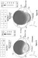
- FIGS. 1 A- 1 Dillustrate example operations of a wireless-power transmission system in accordance with some embodiments.
- FIGS. 2 A- 2 Cillustrate other example operations of the wireless-power transmission system in accordance with some embodiments.
- FIGS. 3 A- 3 Cillustrate example operations of a wireless-power network in accordance with some embodiments.
- FIGS. 4 A- 4 Billustrate example circuits for wireless-power transmission in accordance with some embodiments.
- FIGS. 5 A- 5 Dillustrate example circuits for wireless-power transmission in accordance with some embodiments.
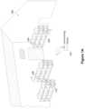
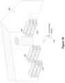
- FIG. 6 Aillustrates an example antenna arrangement for wireless-power transmission in accordance with some embodiments.
- FIG. 6 Billustrates an example operating state for the antenna arrangement of FIG. 6 A in accordance with some embodiments.
- FIG. 6 Cillustrates an example transmitter for wireless-power transmission in accordance with some embodiments.
- FIGS. 7 A- 7 Dillustrate additional example operating states for the antenna arrangement of FIG. 6 A in accordance with some embodiments.
- FIGS. 8 A and 8 Billustrate example timing waveforms for a wireless-power transmission system in accordance with some embodiments.
- FIGS. 9 A- 9 Eare flow diagrams showing a method of surveying for active and inactive power receivers within a wireless-power coverage area in accordance with some embodiments.
- FIGS. 10 A and 10 Bare block diagrams of a wireless-power transmitter in accordance with some embodiments.
- FIG. 11is a block diagram illustrating a wireless power receiver in accordance with some embodiments.
- FIG. 12illustrates example operation of a wireless repeater in accordance with some embodiments.
- FIGS. 13 A- 13 Billustrate example operation of a wireless-power network in accordance with some embodiments.
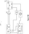
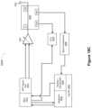
- FIG. 14illustrates an example circuit for wireless-power transmission in accordance with some embodiments.
- FIGS. 15 A- 15 Fillustrate example operation of wireless repeaters in accordance with some embodiments.
- FIGS. 16 A- 16 Eillustrate example timing waveforms for a wireless-power transmission system in accordance with some embodiments.
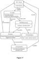
- FIG. 17is a state diagram for wireless-power transmission in accordance with some embodiments.
- FIGS. 18 A- 18 Fillustrate example circuits for wireless-power transmission in accordance with some embodiments.
- FIGS. 19 A- 19 Billustrate an example antenna diversity solution in accordance with some embodiments.
- FIGS. 20 A- 20 Dillustrate example circuits for wireless-power transmission in accordance with some embodiments.
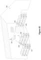
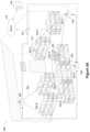
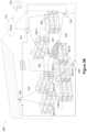
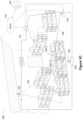
- FIGS. 21 A- 21 Bare flow diagrams showing example methods of wireless-power transmission in accordance with some embodiments.
- FIGS. 22 A- 22 Fillustrate an example antenna with example outputs in accordance with some embodiments.
- a transmitting devicecan be an electronic device that includes, or is otherwise associated with, various components and circuits responsible for generating and transmitting electromagnetic energy, forming transmission energy within a radiation profile at locations in a transmission field, monitoring the conditions of the transmission field (e.g., by monitoring receiver communications), and/or adjusting the radiation profile as needed.
- a radiation profilerefers to a distribution of energy field within the transmission range of a transmitting device or an individual antenna (also referred to as a “transmitter”).
- a receiver(which may also be referred to as a wireless-power receiver or tag) can be an electronic device that comprises at least one antenna, at least one rectifying circuit, and at least one power converter, which may utilize energy transmitted in the transmission field from a transmitter for powering or charging the electronic device (e.g., for purposes of communication and/or advertising).
- FIGS. 1 A- 1 Dillustrate example operation of a wireless-power transmission system in accordance with some embodiments.
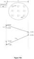
- FIG. 1 Ashows a site (e.g., a warehouse) with a transmitting device 102 (e.g., the wireless-power transmitter 1000 of FIG. 10 A ) transmitting a signal at a first frequency, f 1 , (e.g., 2.4 GHz) and receiving a response from a receiver 104 and a receiver 108 .
- the receivers shown in FIGS. 1 A- 1 De.g., the receivers 104 , 106 , 108 , and 110
- the receivers shown in FIGS. 1 A- 1 Dare instances of the wireless-power receiver 1100 of FIG. 11 .
- the receivers 106 and 110do not respond to the first frequency.
- FIG. 1 Bshows the transmitting device 102 transmitting a signal at a second frequency, f 2 , (e.g., 865 MHz) and receiving no response from the receivers 104 , 106 , 108 , and 110 .
- f 2a second frequency
- the receivers 104 , 106 , 108 , and 110are not responsive to the signals transmitted at the second frequency, e.g., due to an operating bandwidth of the receivers and/or a determination that the receivers are not authorized to communicate with the transmitting device via the signals transmitted at the second frequency.
- FIG. 1 Cshows the transmitting device 102 transmitting a signal at a third frequency, f 3 , (e.g., 915 MHz) and receiving a response from the receiver 106 and the receiver 110 (not from the receivers 104 and 108 ).
- f 3a third frequency
- FIG. 1 Dshows the transmitting device 102 generating an energizing pattern 112 (including the first and third frequencies) based on the responses received (and not received) in FIGS. 1 A- 1 C .
- the energizing patternis sometimes referred to as a wireless power zone, wireless power cell, or wireless operating area.
- the energizing pattern 112is adapted to reach each of the receivers.
- the transmitting device 102generates a first energizing pattern for the first frequency (adapted to reach the receivers 104 and 108 ) and a second energizing pattern for the second frequency (adapted to reach the receivers 106 and 110 ).
- the receiverscommunicate with the transmitting device 102 via the frequencies used for wireless-power transfer (e.g., frequencies f 1 and f 3 ). In some embodiments, the receivers communicate with the transmitting device 102 via one or more communication channels that are distinct from the frequencies used for wireless-power transfer.
- the frequencies used for wireless-power transfere.g., frequencies f 1 and f 3 .
- the receiverscommunicate with the transmitting device 102 via one or more communication channels that are distinct from the frequencies used for wireless-power transfer.
- a first receivercommunicates with the transmitting device 102 via Bluetooth low energy (BLE) protocol to inform the transmitting device 102 that the first receiver is configured to receive WPT at a first frequency (e.g., 915 MHz) and a second receiver communicates with the transmitting device 102 via BLE protocol to inform the transmitting device 102 that the second receiver is configured to receive WPT at a second frequency (e.g., 865 MHz).
- BLEBluetooth low energy
- a third receivercommunicates with the transmitting device 102 at one of the first frequency and the second frequency.
- the third receivercommunicates with the transmitting device 102 at a third frequency.
- FIGS. 2 A- 2 Cillustrate another example operation of the wireless-power transmission system in accordance with some embodiments.
- FIG. 2 Ashows the transmitting device 102 mounted on a wall of a building (e.g., a warehouse). In some embodiments, the transmitting device 102 is mountable on a wall, ceiling, crossbar, fixture, or the like.
- the transmitting device 102 in FIG. 2 Ais generating an energizing pattern 202 .
- the energizing pattern 202includes the first and third frequencies and is adapted to cover the receivers 104 , 106 , 108 , and 110 . In some embodiments, the energizing pattern 202 is determined and/or selected based on prior communication(s) between the transmitting device 102 and the receivers 104 , 106 , 108 , and 110 .
- FIG. 2 Bshows the receiver 104 having left the wireless-power coverage area of the transmitting device 102 .
- the transmitting device 102has determined that the receiver 104 is not in the wireless-power coverage area and accordingly has generated an energizing pattern 204 having a different shape (coverage area) than the energizing pattern 202 .
- the energizing pattern 204is configured to cover an area that includes the receivers 106 , 108 , and 110 , but not the prior location of the receiver 104 .
- the transmitting device 102detects movement of the receiver 104 leaving the wireless-power coverage area and generates the energizing pattern 202 based on the locations of the remaining receivers (e.g., the receivers 106 , 108 , and 110 ). In some embodiments, the transmitting device 102 sends a transmission intended for the receiver 104 and determines that the receiver 104 has left the wireless-power coverage area in accordance with not receiving a response from the receiver 104 to the transmission within a preset amount of time.
- the transmitting device 102performs a frequency scan and determines that the receiver 104 has left the wireless-power coverage area based on the frequency scan (e.g., the transmitting device 102 performs the scan in response to not receiving a response from the receiver within the preset amount of time). In some embodiments, in accordance with a determination that the receiver 104 has not left the wireless-power coverage area based on the frequency scan, the transmitting device re-scans the wireless-power coverage area (e.g., by transmitting signals at a different frequency, and/or waiting for more than the preset amount of time (e.g., a second preset amount of time)).
- the preset amount of timee.g., a second preset amount of time
- FIG. 2 Cshows a receiver 208 within the wireless-power coverage area of the transmitting device 102 while the transmitting device 102 is generating an energizing pattern 206 .
- the energizing pattern 206includes different frequencies than the energizing pattern 202 (e.g., the second frequency, f 2 ).
- the receiver 208communicates with the transmitting device 102 via the second frequency (e.g., to inform the transmitting device of its presence in the wireless-power coverage area (and its frequency for wireless power transmission)).
- the transmitting device 102periodically surveys for receivers (e.g., performs one or more operations of the method 900 ) while generating an energizing pattern.
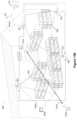
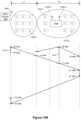
- FIGS. 3 A- 3 Cillustrate a wireless-power network 300 in accordance with some embodiments.
- FIG. 3 Ashows the wireless-power network 300 at a first time providing WPT to a plurality of receivers 303 with respective wireless power zones based on the locations of the receivers 303 .
- the wireless-power network 300 in FIG. 3 Aincludes wireless power transmitting devices 302 , 306 , and 310 (also sometimes referred to as “wireless power bridge” or “wireless power transmitter”) located at different locations within the area associated with the wireless-power network 300 (e.g., at a plurality of locations are selected to maximize a cumulative operating area of the wireless-power network 300 ).
- each of the wireless power transmitting device 302 , 306 , and 310is an instance of the wireless-power transmitter 1000 of FIG. 10 A .
- Each transmitter within the wireless-power networkprovides WPT to a respective wireless power zone (e.g., the wireless power zones 304 , 308 , and 312 ) providing power to a plurality of receivers, e.g., the receivers 303 - 1 through 303 - 8 .
- the receiversinclude batteryless and small-battery devices.
- the wireless power transmitterscommunicate a network status and/or device status to the cloud 316 , the gateway 314 , and each other.
- an operating area defined by the wireless-power networkis adjustable via transmit power control based on feedback from the receivers and/or the other transmitting devices.
- the gateway 314governs the operating state and/or operating area of each transmitting device (e.g., to reduce or minimize operating area overlap between two or more of the wireless power transmitting device).
- the operating state and/or operating area of each transmitting deviceis stored at a database 318 (e.g., a network storage location).
- the wireless power zonesoverlap (e.g., the overlap region 320 ), and the network 300 assigns a receiver to a particular transmitting device or power zone. For example, the receiver 303 - 4 in FIG. 3 A could be assigned to the transmitting device 310 or the transmitting device 306 .
- the assigned transmitting deviceaccounts for the receiver position and requirements when generating energizing patterns and the unassigned transmitting device does not.
- the transmitting devicesprovide multi-radio bridging, as well as an artificial-reality (AI) offload (e.g., to the AI engine 478 ), which can provide technical improvements (e.g., reducing network traffic).
- AIartificial-reality
- the device communicationis connection-mode or connectionless and bidirectional or unidirectional.
- a wireless power transmitting deviceidentifies, locates, and energizes receiver devices. In some embodiments, a transmitting device filters and/or aggregates data from a collection of receiver devices in the wireless power operating area. In some embodiments, a transmitting device has a dynamically programmable energizing power zone area (e.g., based on feedback from energized receiver devices and/or a site map). In some embodiments, a transmitting device has programmable bridging and gateway functionality. In some embodiments, a transmitting device has programmable BLE scanning timing (e.g., for optimizing receiver (e.g., the receiver 303 ) reception).
- a transmitting deviceaggregates, filters, and retransmits receiver information (e.g., on BLE via advertisement and/or mesh connections). In some embodiments, a transmitting device aggregates, filters, and retransmits receiver information on a backhaul network (e.g., WiFi or ethernet networks). In some embodiments, a transmitting device has cloud-control API for dynamic re-programmability via the cloud 316 . In some embodiments, a transmitting device has a (self-organizing) array of transmitters.
- the network 300has knowledge (e.g., in the network storage 318 ) of all the transmitting devices, gateways, and receiver metrics (e.g., per unit time).
- adaptive time-series datais aggregated up to the network 300 .
- the aggregated data(e.g., a full dataset) is stored in a database (e.g., in memory of a transmitting device, the gateway 314 , or network storage 318 ).
- FIG. 3 Bshows the wireless-power network 300 at a second time.
- some of the receivers 303 from FIG. 3 Ae.g., the receivers 303 - 1 , 303 - 3 , 303 - 5 , 303 - 6 , 303 - 7 , and 303 - 8
- the transmitting devices 302 , 306 and 310have adjusted their respective wireless power zones in accordance with the updated positions of the receivers in the coverage area.
- FIG. 3 Bsome of the receivers 303 from FIG. 3 A (e.g., the receivers 303 - 1 , 303 - 3 , 303 - 5 , 303 - 6 , 303 - 7 , and 303 - 8 ) have left the area and some receivers (e.g., the receivers 303 - 10 through 303 - 14 ) have entered the area.
- the transmitting devices 302 , 306 and 310have adjusted their respective wireless power zones in accordance with the updated positions of
- the transmitting device 302is producing the wireless power zone 332
- the transmitting device 306is producing the wireless power zone 334
- the transmitting device 310is producing the wireless power zone 336 .
- Based on wireless power zones produced by the wireless power transmitters 306 and 310there is an overlap region 329 that includes both of the wireless power zones 334 and 336 .
- FIG. 3 Cshows the wireless-power network 300 with the wireless power zones adjusted (as compared to FIG. 3 B ) to reduce (eliminate) overlap between the wireless power zones (e.g., eliminate the overlap region 329 ).
- the transmitting device 306is producing the wireless power zone 352 , which does not cover the receiver 303 - 4 or the receiver 303 - 13
- the transmitting device 302is producing the wireless power zone 354 , which is enlarged (as compared to the wireless power zone 332 in FIG. 3 B ) to cover the receiver 303 - 13 .
- an optimization of the wireless power zonesis performed at the gateway 314 or the cloud 316 based on information from the transmitting devices 302 , 306 , and 310 .
- the optimizationincludes reducing an area of overlap regions between the power zones.
- the transmitting devices 302 , 306 , and 310relay receiver locations and coverage areas to one another to coordinate optimization of the wireless power zones.
- the network 300performs concentration and segregation by adjusting the wireless power zone for each transmitting device.
- the network 300performs smart gateway filtering (e.g., via stream analysis).
- the network 300reduces/minimizes the amount of additional traffic in the case of very large numbers of receivers that may be visible from multiple transmitters (e.g., via optimization techniques described above, such as smart gateway filtering).
- the network 300minimizes the zone overlap by programming the receiver BLE transmit power.
- the network 300prioritizes based on role, performance, schedule, and/or event type. Examples of event types can include glass break detection, a mass receiver drop event, and the like.
- Performance metrics examplesinclude a receiver advertising frequency, a frequency of sensor information updates or timed parameter change, received signal strength indicator (RSSI) and angle of arrival (AoA), filtered MAC address, physical location information, and the like.
- the systemhas an onboard AI system (e.g., the AI engine 478 ) configured to evaluate performance metrics and govern the operation of the transmitting devices accordingly.
- the network 300includes multiple gateways in communication with subsets of the transmitting devices (and one another).
- the gatewayscommunicate with each other and/or the cloud to upload and/or bridge preferred receivers.
- the gateway communicationsinclude proprietary and standards-based communications (e.g., BLE mesh option).
- the gateway communicationis used to reinforce the location of the receivers based on gateway location.
- FIGS. 4 A- 4 Billustrate example circuits for wireless-power transmission in accordance with some embodiments.
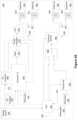
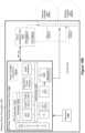
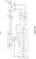
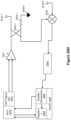
- FIG. 4 Aillustrates an integrated transmitter platform 400 with dual band energizing and BLE bridge in accordance with some embodiments.
- the integrated transmitter platform 400is a component of the transmitting device 102 .
- the integrated transmitter platform 400includes a voltage source 402 (e.g., a 5-volt USB voltage source), a DC converter 404 (e.g., a 5-volt to 3.3-volt converter), a DC converter 406 (e.g., a 5-volt to 1.5-volt converter), a resonator 410 (e.g., a 50M resonator), and a controller integrated circuit (IC) 408 (e.g., a sub-GHz WPT controller with programmable frequencies 864-867 MHz and 902-928 MHz).
- the programmable frequenciesare in a range between 860-960 MHz, which can be consistent with local regulations in certain jurisdictions.
- the integrated transmitter platform 400further includes a filter 412 (e.g., a band-pass filter for 915 MHz), a low-pass filter (LPF) 416 , a power amplifier 414 , a phase splitter 418 , balancing units (baluns) 420 and 422 , and antennas 424 and 426 (e.g., sub-GHz antennas).
- the power amplifier 414is a power amplifier integrated circuit (IC) (e.g., 30 dBm) with programmable power scaling via internal settings or external supply.
- ICpower amplifier integrated circuit
- the power amplifier 414has one or more of: continuous wave programmable frequency-hopping spread spectrum (FHSS), pulse-width modulation (PWM), amplitude modification (AM), and on-off keying (OOK).
- FHSScontinuous wave programmable frequency-hopping spread spectrum
- PWMpulse-width modulation
- AMamplitude modification
- OLKon-off keying
- the phase splitter 418 , balancing units 420 and 422 , and antennas 424 and 426comprise an integrated balanced dual-dipole antenna feed.
- the integrated transmitter platform 400further includes an antenna 428 , one or more resonators (e.g., including a resonator 432 , which can be a 16M resonator, a resonator 436 , which can be a 26M resonator, and/or a third resonator, which can be a 50M resonator), a system-on-chip (SoC) 430 , a transceiver 438 , a switching component 440 , and a frontend module 442 .
- the SoC 430is, or includes a 2.4 GHz WPT and BLE circuit with time division multiplexing (TDM) BLE and WPT functionality.
- the frontend module 442includes a programmable 2.4 GHz 20 dBm power amplifier.
- the transceiver 438is and WPT transmitter IC with individually-programmable output power, modulation, bandwidth, and/or transmission length.
- the integrated transmitter platform 400further includes a phase splitter 444 (e.g., a 90-degree hybrid phase splitter), balancing units 446 and 448 , and antennas 450 and 452 (e.g., 2.4 GHz antennas).
- a phase splitter 444e.g., a 90-degree hybrid phase splitter
- balancing units 446 and 448e.g., balancing units 446 and 448
- antennas 450 and 452e.g., 2.4 GHz antennas.
- the phase splitter 444 , balancing units 446 and 448 , and antennas 450 and 452comprise an integrated balanced dual-dipole antenna feed.
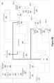
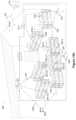
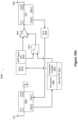
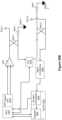
- FIG. 4 Billustrates an integrated transmitter platform 458 , in accordance with some embodiments.
- the integrated transmitter platform 458includes a microcontroller (MCU) 476 (e.g., configured for data aggregation and filtering), an AI engine 478 coupled to one or more sensors 474 (e.g., a local sensor array to augment system AI capability), and an uplink communications module 472 with data backhaul options including USB 460 , Ethernet 462 , WiFi 468 , and LTE 470 .
- MCUmicrocontroller
- Some example AI capabilities for the AI engine 478include: (i) a temperature comparison between device and gateway, (ii) acoustic event detection comparison between device and gateway, (iii) correlation of vibration event from devices versus temperature at the gateway, (iv) temperature, humidity, IMU, microphone, and IR sensing and monitoring, and (v) AI offloading of optimization operations performed by one or more wireless power transmitters and/or one or more wireless power receivers.
- the embedded AI engine 478is used to enhance receiver location and/or provide data filtering.
- the uplink communications module 472further includes power supply options including power-over-ethernet (PoE) 466 and USB voltage source 464 .
- PoEpower-over-ethernet
- the integrated transmitter platform 458further includes DC converters 482 and 486 (e.g., 5 volt to 3.3 volt or 1.5 volt converters), a transmitter IC 488 (e.g., configured for WPT), a resonator 484 (e.g., a 50M resonator), a power amplifier 490 (e.g., an instance of the power amplifier 414 ), a low-pass filter 492 , a front end module 494 (e.g., configured to manage the antenna 481 - 1 and 915 MHz, RFID, and/or WiFi transmissions), and antennas 481 .
- DC converters 482 and 486e.g., 5 volt to 3.3 volt or 1.5 volt converters
- a transmitter IC 488e.g., configured for WPT
- a resonator 484e.g., a 50M resonator
- a power amplifier 490e.g., an instance of the power amplifier 414
- the integrated transmitter platform 458further includes an SoC 480 (e.g., configured to manage BLE, WPT, WiFi, ultra-wide band (UWB), and global positioning satellite (GPS) transmissions), a frontend module 491 (e.g., configured to manage antennas 481 - 3 , 481 - 4 , and 481 - 5 ), a low pass filter 497 , a BLE scanner 499 , and multiple radios for different device communication protocols, including WiFi (e.g., 802.11ah) 496 , RFID 498 , GPS 495 , and UWB 493 .
- SoC 480e.g., configured to manage BLE, WPT, WiFi, ultra-wide band (UWB), and global positioning satellite (GPS) transmissions
- a frontend module 491e.g., configured to manage antennas 481 - 3 , 481 - 4 , and 481 - 5
- a low pass filter 497e.g., a B
- FIGS. 5 A- 5 Dillustrate example circuits for wireless-power transmission, in accordance with some embodiments.
- the circuits in FIGS. 5 A- 5 Dare components of a transmitting device 1000 or a transmitting device 1050 .
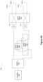
- FIG. 5 Aillustrates an antenna tuning circuit 500 in accordance with some embodiments.
- the antenna tuning circuit 500has dynamically switchable polarization between linear or circular (e.g., right-hand circular polarization (RHCP) or left-hand circular polarization (LHCP)).
- RHCPright-hand circular polarization
- LHCPleft-hand circular polarization
- the tuning circuit 500includes an amplifier 502 (e.g., a variable gain amplifier), a splitter 504 (e.g., a programmable splitter), a phase shifter 508 (e.g., a 90-degree phase shifter), a switch matrix 506 , balancing units 510 and 512 , a switch matrix 514 (e.g., a 4 ⁇ 4 or dual double-port double-throw switch matrix), and antennas 516 .
- the programmable splitter 504is programmable between a splitter-only mode for linear polarization and a splitter and 90-degree phase shift mode for circular polarization.
- the switch matrix 514has the following settings: A through and B through for LHCP, A cross and B cross for RCHP, A through and B open for horizontal polarization, and A open and B through for vertical polarization.
- a transmitting devicee.g., transmitting device 1000 or a transmitting device 1050
- includes a tuning circuit for tuning the frequency bande.g., specifically for tuning for frequencies within a range between 860 MHz to 960 MHz (e.g., which can be 915 MHz in one example).
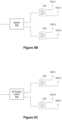
- FIG. 5 Billustrates a linear polarization scheme for an antenna arrangement in accordance with some embodiments.
- the linear polarization schemeincludes an output of a splitter 520 coupled to balancing units 522 and 524 .
- the balancing unit 522is coupled to antennas 526 - 1 and 526 - 2 .
- the balancing unit 524is coupled to the antennas 526 - 3 and 526 - 4 .
- FIG. 5 Cillustrates a circular polarization scheme for the antenna arrangement in accordance with some embodiments. As shown in FIG. 5 C , the circular polarization scheme includes an output of a 90-degree hybrid splitter 530 coupled to the balancing units 522 and 524 .
- the antenna 526 - 1 in FIGS. 5 B and 5 Cis used as a phase reference (e.g., 0 degrees).
- the phaseis controlled by inductive and/or capacitive (L/C) values and positions for each balancing unit 522 and 524 .
- FIG. 5 Dillustrates an antenna tuning circuit 550 in accordance with some embodiments.
- the tuning circuit 550has dynamically switchable polarization between linear or circular (e.g., RHCP or LHCP).
- the tuning circuit 550includes the amplifier 502 (e.g., a variable gain amplifier), the splitter 504 (e.g., a programmable splitter), a phase shifter 552 (e.g., a 90-degree phase shifter), a phase shifter 554 (e.g., a 180-degree phase shifter), the balancing units 510 and 512 , and the antennas 516 .
- the amplifier 502e.g., a variable gain amplifier
- the splitter 504e.g., a programmable splitter
- a phase shifter 552e.g., a 90-degree phase shifter
- a phase shifter 554e.g., a 180-degree phase shifter
- the tuning circuit 550also includes switching controls 560 (e.g., switching control 560 - 1 for the phase shifter 552 and switching control 560 - 2 for the phase shifter 554 ).
- the switching controls 560are operable to switch polarization for antennas 516 .
- switching control 560 - 1 in position 1 and switching control 560 - 2 in position 1corresponds to an RHCP setting
- switching control 560 - 1 in position 1 and switching control 560 - 2 in position 2corresponds to an LHCP setting
- switching control 560 - 1 in position 2e.g., bypassing the phase shifter 552
- switching control 560 - 2 in position 1corresponds to a horizontal linear polarization setting
- switching control 560 - 1 in position 2 and switching control 560 - 2 in position 2corresponds to a vertical linear polarization setting.
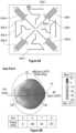
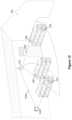
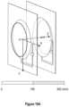
- FIG. 6 Aillustrates an example antenna arrangement for wireless-power transmission in accordance with some embodiments.
- FIG. 6 Ashows a multiband dual-polarized antenna circuit 602 in accordance with some embodiments.
- the antenna circuit 602includes antennas 604 (e.g., 604 - 1 through 604 - 4 ) for transmissions (e.g., wireless-power transmissions) in a first frequency range (e.g., a sub-GHz range), antennas 606 (e.g., 606 - 1 through 606 - 4 ) for transmissions (e.g., wireless-power transmissions) in a second frequency range (e.g., a 2.4 GHz range), and a plurality of mechanical coupling points 608 (e.g., 608 - 1 and 608 - 2 ).
- antennas 604e.g., 604 - 1 through 604 - 4
- transmissionse.g., wireless-power transmissions
- a second frequency rangee.g.
- the antenna circuit 602is a low-cost, low-mass, and lightweight printed circuit board (PCB) antenna circuit.
- the antenna circuit 602includes additional antennas for transmitting signals at other frequencies distinct from the first and second frequencies (e.g., a third frequency, a fourth frequency, etc.).
- the antenna circuit 602is configured for coplanar, collocated dual-band operation (e.g., a same phase-center for both bands). In some embodiments, the antenna circuit 602 is circular-polarized for two or more bands. In some embodiments, the antenna circuit 602 is bill of materials (BOM)-programmable between RHCP and LHCP. In some embodiments, the antenna circuit 602 has high isolation (e.g., at least 15 dB or between 5 to 25 dB) between ports and frequency bands. In some embodiments, the antenna circuit 602 low band is BOM-programmable in a frequency range of 860-960 MHz (e.g., including 865 MHz to 918 MHz).
- the antenna circuit 602has a reflector integrated into the housing.
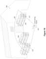
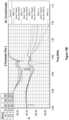
- FIG. 6 Billustrates an example operating state (e.g., a radiation field pattern on top and a port configuration on bottom) for the antenna arrangement of FIG. 6 A in accordance with some embodiments.
- an example gain plotis shown corresponding to the antennas 604 being active with antenna 604 - 4 having a 0-degree phase shift, antenna 604 - 2 having a 180-degree phase shift, antenna 604 - 3 having a 90-degree phase shift, and antenna 604 - 1 having a 270-degree phase shift.
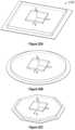
- FIG. 6 Cshows views of a transmitter 650 for wireless-power transmission at different angles in accordance with some embodiments.
- the transmitter 650includes the antenna circuit 602 mounted to a support structure 652 and enclosed in a housing 654 .
- the transmitter 650is a programmable wireless power transmitter.
- the programmable wireless power transmittere.g., the transmitting device 102
- the programmable wireless power transmitterincludes a multiband WPT energizing source with configurable transmission patterns in multiple frequency bands.
- a programmable wireless power transmitterincludes one or more flexible radios for system calibration, device energizing, and communication functions.
- a programmable wireless power transmitterincludes a programmable physical layer (e.g., for frequency-hopping, PWM/OOK signaling, and modulation). In some embodiments, a programmable wireless power transmitter includes programmable and/or dynamic TDM between WPT and communications. In some embodiments, a programmable wireless power transmitter has a compact housing with an integrated antenna and reflector. In some embodiments, the integrated antenna (e.g., the antenna circuit 602 ) has a coplanar, collocated (e.g., same phase center) multiband dual linear-polarized or circular-polarized antenna structure. In some embodiments, the integrated antenna can be operated as circular-polarized antenna or cross-polarized.
- the wireless power transmitterincludes at least one antenna with dynamic polarization-switching. In some embodiments, the wireless power transmitter includes at least one antenna integrated with a feeding structure on the PCB. In some embodiments, the wireless power transmitter 650 has at least one antenna that is BOM-programmable or has dynamic switched frequency tuning (for embodiments in which dynamic switched frequency tuning is utilized, the skilled artisan will understand upon reading this disclosure that updates would be made to the switching networks for use with this type of tuning).
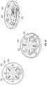
- FIGS. 7 A- 7 Dillustrate additional example operating states for the antenna arrangement of FIG. 6 A in accordance with some embodiments.
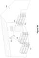
- FIG. 7 Aillustrates a horizontal linear polarization (e.g., an X-polarization) setting and radiation field pattern (e.g., gain plot) in accordance with some embodiments.
- radiation field patterne.g., gain plot
- an example radiation field patternis shown corresponding to the antennas 606 being active with antenna 606 - 4 having a 0-degree phase shift, antenna 606 - 2 having a 0-degree phase shift, antenna 606 - 3 having a 180-degree phase shift, and antenna 606 - 1 having a 180-degree phase shift.
- FIG. 7 Billustrates a vertical linear polarization (e.g., a Y-polarization) setting and radiation field pattern in accordance with some embodiments.
- a vertical linear polarizatione.g., a Y-polarization
- an example radiation field patternis shown corresponding to the antennas 606 being active with antenna 606 - 4 having a 0-degree phase shift, antenna 606 - 2 having a 180-degree phase shift, antenna 606 - 3 having a 180-degree phase shift, and antenna 606 - 1 having a 0-degree phase shift.
- FIG. 7 Cillustrates an LHCP setting and radiation field pattern in accordance with some embodiments.
- an example radiation field patternis shown corresponding to the antennas 606 being active with antenna 606 - 4 having a 0-degree phase shift, antenna 606 - 2 having a 90-degree phase shift, antenna 606 - 3 having a 180-degree phase shift, and antenna 606 - 1 having a 270-degree phase shift.
- FIG. 7 Dillustrates an RHCP setting and radiation field pattern in accordance with some embodiments.
- an example radiation field patternis shown corresponding to the antennas 606 being active with antenna 606 - 4 having a 0-degree phase shift, antenna 606 - 2 having a 270-degree phase shift, antenna 606 - 3 having a 180-degree phase shift, and antenna 606 - 1 having a 90-degree phase shift.
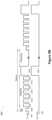
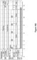
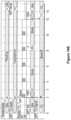
- FIGS. 8 A and 8 Billustrate example timing waveforms for a wireless-power transmission system in accordance with some embodiments.
- FIG. 8 Ashows a timing waveform 800 that includes a sub-GHz signal 802 and a 2.4 GHz signal 804 .
- each signalhas an active time 806 (e.g., between 30 ms and 50 ms).
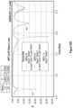
- FIG. 8 Bshows a frequency hopping spread spectrum (FHSS) timing waveform 850 illustrating dual-band synchronized energizing, BLE advertisement, and BLE scanning period.
- the timing waveform 850includes a sub-GHz signal 852 and a 2.4 GHz signal 854 .
- the 2.4 GHz signal 854hops from 2426 MHz (e.g., a BLE transmission) to 2402 MHz to 2428 MHz to 2480 MHz to 2454 MHz to 2467 MHz to 2415 MHz to 2441 MHz to 2450 MHz.
- the periodis 45 milliseconds (ms), and the hopping occurs at 4.5 ms intervals.
- the wireless-power transmitting device(e.g., the transmitting device 102 ) is configured for a plurality of energizing and communication transmissions.
- the plurality of transmissionsincludes a 918 MHz programmable WPT waveform with a PWM frequency and duty cycle, AM/OOK, Baud rate, frequency, CW, fixed frequency and FHSS, and/or programmable output power up to 30 dBm (or even up to 45 dBm).
- the plurality of transmissionsincludes a 2.4 GHz WPT waveform with programmable frequency, modulation, bandwidth, data rate, programmable duty-cycle and timing to other radios, and/or programmable output power up to 20 dBm.
- the plurality of transmissionsincludes a BLE transmission with programmable advertising period and scan windows, timing to energizing waveforms, programmable output power up to 20 dBm, and/or programmable repeater/bridge functionality.
- the plurality of transmissionsincludes a gateway operation transmission with receiver hub for various protocol (e.g., BLE, UWB, RFID, WiFi, etc.) receivers where data is filtered and retransmitted via BLE or dedicated backhaul (e.g., PoE, WiFi, or LTE).
- the gateway operation transmissionhas programmable and/or adaptive filtering for high volumes of receivers, e.g., dynamically tracking receiver information and load-balance to the uplink.
- the gateway operation transmissionlocalizes each receiver to a gateway for location and uplink bandwidth conservation.
- the gateway operation transmissionhas a control API channel, e.g., a remote-control API for scheduled or dynamic transmitting.
- the wireless-power transmitting device(e.g., the transmitting device 102 ) is programmable for regulatory compliance.
- the transmitter programmabilitycan be used to achieve regulatory compliance for dedicated WPT devices.
- the transmitting device 102can be configured as follows:
- the transmitting device 102can be configured as follows:
- FIGS. 9 A- 9 Eare a flow diagram showing a method 900 of surveying for active and inactive power receivers within a wireless-power coverage area (e.g., as illustrated in FIGS. 1 A- 1 D ) in accordance with some embodiments.
- the method 900may be performed by a transmitting device 102 , or a transmitting device 1000 or 1050 , or one or more integrated circuits of a transmitting device such as the integrated transmitter platform 400 ( FIG. 4 A ), the integrated transmitter platform 458 ( FIG. 4 B ), the RF power transmitter integrated circuit (RFIC) 1060 ( FIG. 10 A ), and/or the power amplifier integrated circuit (PAIC) 1061 A ( FIG. 10 B ).
- RFICRF power transmitter integrated circuit
- PAICpower amplifier integrated circuit
- 9 A- 9 Ecorrespond to instructions stored in a computer memory or a computer-readable storage medium (e.g., memory 1072 and 1074 of the wireless-power transmitter 1050 , FIG. 10 B ).
- a computer memory or a computer-readable storage mediume.g., memory 1072 and 1074 of the wireless-power transmitter 1050 , FIG. 10 B .
- the operations beloware described as being performed by a transmitting device.
- FIGS. 9 A- 9 Esome, but not all, of the operations illustrated in FIGS. 9 A- 9 E are performed. Similarly, one or more operations illustrated in FIGS. 9 A- 9 E may be optional or performed in a different sequence. Furthermore, two or more operations of FIG. 9 A- 9 E consistent with the present disclosure may be overlapping in time, concurrent, or simultaneous.
- the transmitting devicecauses ( 902 ) performance of a survey looking for active power receivers of a plurality of power receivers (e.g., wireless-power receivers 303 ) within a wireless-power coverage area using one or more communication radios. For example, the transmitting device sends one or more transmissions at different frequency bands as illustrated in FIGS. 1 A- 1 C .
- the one or more communication radiosare configured for ( 904 ) system calibration transmissions, energizing transmissions, and communications transmissions (e.g., the radios described above with reference to FIGS. 4 A- 4 B ).
- the transmitting deviceperforms a power zone calibration.
- the transmitting devicetests each band for optimum duty cycle and power.
- the optimum settingsare based on calibration results of other gateways or programmed from the cloud.
- the transmitting devicereceives ( 906 ) information from an active power receiver of the plurality of power receivers (e.g., as illustrated in FIG. 1 A ).
- the active power receivertransmits to the transmitting device at the same frequency at which the transmitting device transmitted (e.g., shown in FIG. 1 A ).
- the active power receivertransmits on a communication frequency or band that is different from the frequency/band used by the transmitting device for the survey.
- the information from the active power receiverincludes ( 908 ) an indication of harvesting capability for the active power receiver.
- the transmitting deviceperforms a site survey of devices in range, where the site survey does not include any WPT (e.g., communication radios only). In some situations, some devices are active already (e.g., battery-powered devices).
- Receiverse.g., the receivers 104 , 106 , 108 , and 110 ) can advertise their harvesting capability or the system may have a look-up table (LUT) based on device type.
- the information from the active power receiverincludes ( 910 ) an indication of a receiver type for the active power receiver, and a harvesting capability for the active power receiver is identified based on the receiver type (e.g., using a LUT).
- LUTmay be local or in the cloud and may be dynamically updated.
- the transmitting deviceidentifies which bands are needed based on the data from the receivers.
- the LUTis a three-dimensional lookup table (e.g., a 3DLUT) configured to map to a three-dimensional area (e.g., the warehouse shown in FIGS. 1 A- 1 D ).
- the transmitting devicecauses ( 912 ) transmission of radio-frequency (RF) signals to energize inactive power receivers of the plurality of power receivers using a power-transmission antenna.
- a first RF signal of the RF signalsis transmitted ( 914 ) using a first value for a transmission characteristic (e.g., a first frequency value).
- a second RF signal of the RF signalsis transmitted ( 916 ) using a second value for the transmission characteristic (e.g., a second frequency value), the first and second values being distinct.
- the transmitting deviceperforms a site survey of devices in range, where the site survey includes WPT. For example, the transmitting device 102 transmits a signal at a first frequency in FIG. 1 A , and transmits a signal at a second frequency in FIG. 1 B .
- the transmitting devicecauses ( 918 ) transmission of the first RF signal and the second RF signal in sequence.
- the transmitting deviceenergizes multiple bands in sequence or concurrently to identify sleeping or batteryless receivers. Energizing the multiple bands may include a 918 MHz max duty cycle and a 2.4 GHz energizing duty cycle with fixed preset balance between WPT and scan/communication.
- FIG. 8 Aillustrates an example of energizing multiple bands (e.g., 2.4 GHz and sub-1 GHz) concurrently.
- the transmitting devicemodulates ( 920 ) the RF signals in accordance with one or more wake-up patterns.
- the site survey of devices in rangeincludes known wake-up patterns required to turn on sleeping receivers (e.g., clock calibrations and OOK patterns).
- the power transmitter 414 in FIGS. 4 A and 4 Bis configured to transmit OOK signals.
- the inactive power receivers of the plurality of power receiversinclude ( 922 ) a batteryless device.
- a tag on retail merchandisemay include a receiver circuit, but not a battery.
- the power-transmission antennais ( 924 ) distinct from the one or more communication radios.
- the antenna 481 - 1 in FIG. 4 Bmay be used for WPT while the antenna 481 - 2 in FIG. 4 B is used for communication.
- the transmission of the RF signalsis caused ( 926 ) using a plurality of power-transmission antennas, including the power-transmission antenna (e.g., the antenna 481 - 1 ).
- the antennas 424 and 426 in FIG. 4 Amay be used for power transmission, such as power transmission shown in FIGS. 1 A- 4 B ).
- the plurality of power-transmission antennasare ( 928 ) coplanar to one another and collocated within a same housing.
- the antennas 604 and 606 in FIG. 6 Aare coplanar and collocated.
- the power-transmission antennasare arranged on a same circuit board.
- the plurality of power-transmission antennashave ( 930 ) a multiband dual linear-polarized or circular-polarized structure.
- the antennas in FIG. 6 Amay be controlled by the antenna tuning circuit 500 shown in FIG. 5 A to generate the gain plots shown in FIGS. 7 A- 7 D .
- the plurality of power-transmission antennasare ( 932 ) configured for dynamic polarization-switching (e.g., via the antenna tuning circuit 500 shown in FIG. 5 A ).
- the transmitting devicereceives ( 934 ) additional information from a first energized power receiver and further information from a second energized power receiver.
- the first energized power receiveris ( 936 ) one of the inactive power receivers before receiving energy from the first RF signal.
- the second energized power receiveris ( 938 ) one of the inactive power receivers before receiving energy from the second RF signal.
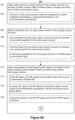
- the transmitting deviceidentifies ( 940 ) two or more frequency bands for RF wireless-power transmissions by a wireless-power transmitting device within the wireless-power coverage area based on the information, the additional information, and the further information. For example, the transmitting device 102 in FIG. 1 D identifies the first and third frequencies for WPT based on the receiver responses shown in FIGS. 1 A- 1 C . In some embodiments, the transmitting device identifies which bands are needed and how many receivers are present in each band. Different transmitters may have different energizing patterns and may use different combinations of frequencies. In some embodiments, the transmitting device registers receiver information to the system (local/cloud).
- the two or more frequency bands for RF radio-frequency wireless-power transmissionsare identified ( 942 ) based on the harvesting capability for the active power receiver.
- the transmitting devicegenerates ( 944 ) an energizing pattern for RF wireless-power transmissions based on the identified two or more frequency bands.
- generating the energizing patternincludes ( 946 ) setting a power level for the power-transmission antenna.
- generating the energizing patternincludes ( 948 ) setting a duty cycle for each frequency band of the two or more frequency bands.
- generating the energizing patternincludes ( 950 ) selecting a polarization setting and a phase setting.
- FIG. 5 Dshows an antenna tuning circuit with switching controls 560 - 1 and 560 - 2 for switching the antennas 516 to different polarization settings.
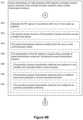
- the energizing patternis ( 952 ) further based on a site map of the wireless-power coverage area. In some embodiments, generating the energizing pattern includes ( 954 ) scheduling energizing time periods and device scanning time periods. In some embodiments, the transmitting device performs a site survey then a WPT optimization, then a site activation and network organization/optimization. In some embodiments, the transmitting device adds battery-less or sleeping receivers without electronic system level capability onboarding.
- the transmitting devicedetermines ( 956 ) that the energizing pattern complies with one or more regulatory standards (e.g., the FCC Part 15 and/or EN302-208 standards described previously).
- one or more regulatory standardse.g., the FCC Part 15 and/or EN302-208 standards described previously.
- the transmitting deviceregisters ( 958 ) the energizing pattern with a server system.
- the transmitting device 302 in FIG. 3 Amay register the wireless power zone 304 (e.g., an energizing pattern) with the gateway 314 , or with a remote server system in the cloud 316 .
- the transmitting deviceregisters the energizing pattern and receiver information to the system (e.g., a local, mesh, or cloud system) and updates the information over time (e.g., periodically).
- the server systemis configured ( 960 ) to assist with generating respective energizing patterns for each of multiple wireless-power transmitting devices, including the wireless-power transmitting device, that are within the wireless-power coverage area.
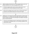
- a periodic site surveyis used to identify (or reidentify) receivers in the corresponding wireless power zone (wireless-power coverage area).
- the transmitting devicedetermines ( 962 ) that at least one of the active power receiver, the first energized power receiver, and the second energized power receiver is no longer within the wireless-power coverage area; and modifies the energizing pattern based on remaining receivers in the wireless-power coverage area in accordance with the determination. For example, in FIG. 2 B the receiver 104 is no longer in the wireless-power coverage area, and the transmitting device 102 adjusts the wireless power zone accordingly, in accordance with determining that the receiver 104 is no longer in the coverage area (e.g., adjusting from the energizing pattern 202 to the energizing pattern 204 ).
- the transmitting devicedetermines ( 964 ) that at least one additional power receiver is within the wireless-power coverage area; and modifies the energizing pattern based on the at least one additional power receiver in accordance with the determination. For example, in FIG. 2 C the receiver 208 is in the wireless-power coverage area, and the transmitting device 102 adjusts the wireless power zone accordingly (e.g., adjusting from the energizing pattern 204 to the energizing pattern 206 ).
- FIG. 10 Ais a block diagram of a wireless-power transmitter in accordance with some embodiments.
- the block diagram of a wireless-power transmitter 1000corresponds to an example of the components that can be included within the transmitting device 102 described above in reference to FIGS. 1 - 9 .
- the wireless-power transmitter 1000can be referred to herein as a near-field power transmitter device, transmitter, power transmitter, or wireless-power transmitter device.
- the wireless-power transmitter 1000includes one or more of: one or more communications components 1010 , one or more power amplifier units 1020 - 1 , . . .
- one or more power-transfer elementse.g., such as antennas 1030 - 1 to 1030 - n (which can be instances of the antenna elements shown in FIGS. 4 - 6 )
- an RFIC 1060e.g., analogous to controllers in FIGS. 4 A- 4 B
- sensors 1065e.g., the sensors 474 .
- the communication component(s) 1010enable communication between the wireless-power transmitter 1000 and one or more communication networks.
- the communication component(s) 1010are capable of data communications using any of a variety of custom or standard wireless protocols (e.g., IEEE 802.15.4, Wi-Fi, Zigbee, 6LoWPAN, Thread, Z-Wave, Bluetooth Smart, ISA100.11a, WirelessHART, MiWi, etc.) custom or standard wired protocols (e.g., Ethernet, HomePlug, etc.), and/or any other suitable communication protocol, including communication protocols not yet developed as of the filing date of this document.
- custom or standard wireless protocolse.g., IEEE 802.15.4, Wi-Fi, Zigbee, 6LoWPAN, Thread, Z-Wave, Bluetooth Smart, ISA100.11a, WirelessHART, MiWi, etc.
- custom or standard wired protocolse.g., Ethernet, HomePlug, etc.
- the communication component(s) 1010receives charging information from a wireless-power receiver (or from an electronic device configured to be charged by the wireless-power receiver; e.g., the receiver 104 , FIG. 1 A ).
- the charging informationis received in a packet of information that is received in conjunction with an indication that the wireless-power receiver is located within one meter of the wireless-power transmitter 1000 .
- the charging informationincludes the location of the wireless-power receiver within the transmission field of the wireless-power transmitter 1000 (or the surrounding area within the communications component(s) range).
- communication components 1010such as BLE communications paths operating at 2.4 GHz, to enable the wireless-power transmitter 1000 to monitor and track the location of the wireless-power receiver. The location of the wireless-power receiver can be monitored and tracked based on the charging information received from the wireless-power receiver via the communications component(s) 1010 .
- the charging informationindicates that a wireless-power receiver is configured or equipped to receive wirelessly-delivered power from the wireless-power transmitter 1000 . More specifically, the wireless-power receiver can use a wireless communication protocol (such as BLE) to transmit the charging information as well as authentication information to the one or more integrated circuits (e.g., RFIC 1060 ) of the wireless-power transmitter 1000 .
- the charging informationalso includes general information such as charge requests from the receiver, the current battery level, charging rate (e.g., effectively transmitted power or electromagnetic energy successfully converted to usable energy), device specific information (e.g., temperature, sensor data, receiver requirements or specifications, and/or other receiver specific information), etc.
- the communication component(s) 1010are not able to communicate with wireless-power receivers for various reasons, e.g., because there is no power available for the communication component(s) 1010 to use for the transmission of data signals or because the wireless-power receiver itself does not actually include any communication component of its own.
- the wireless-power transmitters 1000 described hereinare still able to uniquely identify different types of devices and, when a wireless-power receiver is detected, figure out if that the wireless-power receiver is authorized to receive wireless-power (e.g., by measuring impedances, reflected power, and/or other techniques).
- the one or more power amplifiers 1020are configured to amplify an electromagnetic signal that is provided to the one or more antennas 1030 .
- the power amplifier 1020 used in the power transmission systemcontrols both the efficiency and gains of the output of the power amplifier.
- the power amplifier used in the power transmission systemis a class E power amplifier 1020 .
- the power amplifier 1020 used in the power transmission systemis a Gallium Nitride (GaN) power amplifier.
- the wireless-power transmitters 1000is configured to control operation of the one or more power amplifiers 1020 when they drive one or more antennas 1030 .
- one or more of the power amplifiers 1020are a variable power amplifier including at least two power levels.
- a variable power amplifierincludes one or more of a low-power level, median-power level, and high-power level.
- the wireless-power transmitters 1000is configured to select power levels of the one or more power amplifiers.
- the powere.g., electromagnetic power
- the wireless-power transmitters 1000is controlled and modulated at the wireless-power transmitters 1000 via switch circuitry as to enable the wireless-power transmitters to send electromagnetic energy to one or more wireless receiving devices (e.g., wireless-power receivers) via the one or more antennas 1030 .
- the output power of the single power amplifier 1020is equal or greater than 2 W. In some embodiments, the output power of the single power amplifier 1020 is equal or less than 15 W. In some embodiments, the output power of the single power amplifier 1020 is greater than 2 W and less than 15 W. In some embodiments, the output power of the single power amplifier 1020 is equal or greater than 4 W. In some embodiments, the output power of the single power amplifier 1020 is equal or less than 8 W. In some embodiments, the output power of the single power amplifier 1020 is greater than 4 W and less than 8 W. In some embodiments, the output power of the single power amplifier 1020 is greater than 8 W and up to 50 W.
- the electric field within the power transmission range of the antenna 1030 controlled by the single power amplifier 1020is at or below a specific absorption rate (SAR) value of 1.6 W/kg, which is in compliance with the FCC SAR requirement in the United States.
- SARspecific absorption rate
- the electric field within the power transmission range of the antenna 1030 controlled by the single power amplifier 1020is at or below a SAR value of 2 W/kg, which is in compliance with the International Electrotechnical Commission SAR requirement in the European Union.
- the electric field within the power transmission range of the antenna 1030 controlled by the single power amplifier 1020is at or below a SAR value of 0.8 W/kg. In some embodiments, by using a single power amplifier 1020 with a power range from 2 W to 15 W, the electric field within the power transmission range of the antenna 1030 controlled by the single power amplifier 1020 is at or below any level that is regulated by relevant rules or regulations. In some embodiments, the SAR value in a location of the radiation profile of the antenna decreases as the range of the radiation profile increases.
- the radiation profile generated by the antenna controlled by a single power amplifieris defined based on how much usable power is available to a wireless-power receiver when it receives electromagnetic energy from the radiation profile (e.g., rectifies and converts the electromagnetic energy into a usable DC current), and the amount of usable power available to such a wireless-power receiver can be referred to as the effective transmitted power of an electromagnetic signal.
- the effective transmitted power of the electromagnetic signal in a predefined radiation profileis at least 0.5 W.
- the effective transmitted power of the signal in a predefined radiation profileis greater than 1 W.
- the effective transmitted power of the signal in a predefined radiation profileis greater than 2 W.
- the effective transmitted power of the signal in a predefined radiation profileis greater than 5 W. In some embodiments, the effective transmitted power of the signal in a predefined radiation profile is less than or equal to 4 W. In some embodiments, there are a range of values that fall within the effective transmitted power (e.g., 2-4 W).
- the transmitting device 1000is coupled to or integrated with an electronic device, such as a pen, a marker, a phone, a tablet, a laptop, a hearing aid, smart glasses, headphones, computer accessories (e.g., mouse, keyboard, remote speakers), and/or other electrical devices.
- the wireless-power transmitter 1000is coupled to or integrated with a small consumer device, such as a fitness band, a smart watch, and/or other wearable product.
- the wireless-power transmitter 1000is an electronic device.
- FIG. 10 Bis a block diagram of another wireless-power transmitter 1050 (e.g., an instance of the transmitting device 102 ) including an RFIC 1060 , one or more sensors 1065 , one or more antennas 1030 , and/or a power amplifier 1020 in accordance with some embodiments.
- the wireless-power transmitter 1050can be an instance of the wireless-power transmitter devices described above in reference to FIGS. 1 - 9 , and includes one or more additional and/or distinct components, or omits one or more components.
- the RFIC 1060includes a CPU subsystem 1070 , an external device control interface, a subsection for DC to power conversion, and analog and digital control interfaces interconnected via an interconnection component, such as a bus or interconnection fabric block 1071 .
- the CPU subsystem 1070includes a microprocessor unit (CPU) 1073 with related read-only memory (ROM) 1072 for device program booting via a digital control interface, e.g., an I2C port, to an external flash containing the CPU executable code to be loaded into the CPU subsystem random-access memory (RAM) 1074 or executed directly from flash.
- CPUmicroprocessor unit
- ROMread-only memory
- the CPU subsystem 1070also includes an encryption module or block 1076 to authenticate and secure communication exchanges with external devices, such as wireless-power receivers that attempt to receive wirelessly delivered power from the Wireless-power transmitters.
- the wireless-power transmittersmay also include a temperature monitoring circuit (not shown) that is in communication with the CPU subsystem 1070 to ensure that the wireless-power transmitters remains within an acceptable temperature range. For example, if a determination is made that the wireless-power transmitters has reached a threshold temperature, then operation of the wireless-power transmitters may be temporarily suspended until the wireless-power transmitters falls below the threshold temperature.
- the RFIC 1060also includes (or is in communication with) a PAIC 1061 A that is responsible for controlling and managing operations of a power amplifier, including, but not limited to, reading measurements of impedance at various measurement points within the power amplifier, instructing the power amplifier to amplify the electromagnetic signal, synchronizing the turn on and/or shutdown of the power amplifier, optimizing performance of the power amplifier, protecting the power amplifier, and other functions discussed herein.
- a PAIC 1061 Athat is responsible for controlling and managing operations of a power amplifier, including, but not limited to, reading measurements of impedance at various measurement points within the power amplifier, instructing the power amplifier to amplify the electromagnetic signal, synchronizing the turn on and/or shutdown of the power amplifier, optimizing performance of the power amplifier, protecting the power amplifier, and other functions discussed herein.
- the impedance measurementare used to allow the wireless-power transmitters (via the RFIC 1060 and/or PAIC 1061 A) to detect of one or more foreign objects, optimize operation of the one or more power amplifiers, assess one or more safety thresholds, detect changes in the impedance at the one or more power amplifiers, detect movement of the receiver within the wireless transmission field, protect the power amplifier from damage (e.g., by shutting down the power amplifier, changing a selected power level of the power amplifier, and/or changing other configurations of the wireless-power transmitters), classify a receiver (e.g., authorized receivers, unauthorized receivers, and/or receiver with an object), compensate for the power amplifier (e.g., by making hardware, software, and/or firmware adjustments), tune the wireless-power transmitters, and/or other functions.
- a receivere.g., authorized receivers, unauthorized receivers, and/or receiver with an object
- compensate for the power amplifiere.g., by making hardware, software, and/or firmware adjustments
- the PAIC 1061 Amay be on the same integrated circuit as the RFIC 1060 . Alternatively, in some embodiments, the PAIC 1061 A may be on its own integrated circuit that is separate from (but still in communication with) the RFIC 1060 . In some embodiments, the PAIC 1061 A is on the same chip with one or more of the power amplifiers 1020 . In some other embodiments, the PAIC 1061 A is on its own chip that is a separate chip from the power amplifiers 1020 . In some embodiments, the PAIC 1061 A may be on its own integrated circuit that is separate from (but still in communication with) the RFIC 1060 enables older systems to be retrofitted.
- the PAIC 1061 A as a standalone chip communicatively coupled to the RFIC 1060can reduce the processing load and potential damage from over-heating. Alternatively or additionally, in some embodiments, it is more efficient to design and use two different ICs (e.g., the RFIC 1060 and the PAIC 1061 A).
- executable instructions running on the CPUare used to manage operation of the wireless-power transmitters and to control external devices through a control interface, e.g., SPI control interface 1075 , and the other analog and digital interfaces included in the RFIC 1060 .
- the CPU subsystem 1070also manages operation of the subsection of the RFIC 1060 , which includes a local oscillator (LO) 1077 and a transmitter (TX) 1078 .
- the LO 1077is adjusted based on instructions from the CPU subsystem 1070 and is thereby set to different desired frequencies of operation, while the TX converts, amplifies, modulates the output as desired to generate a viable power level.
- the RFIC 1060 and/or PAIC 1061 Aprovide the viable power level (e.g., via the TX 1078 ) directly to the one or more power amplifiers 1020 and does not use any beam-forming capabilities (e.g., bypasses/disables a beam-forming IC and/or any associated algorithms if phase-shifting is not required, such as when only a single antenna 1030 is used to transmit power transmission signals to a wireless-power receiver).
- the relative phases of the power signals from different antennasare unaltered after transmission.
- the phases of the power signalsare not controlled and remain in a fixed or initial phase.
- the RFIC 1060 and/or PAIC 1061 Aregulate the functionality of the power amplifiers 1020 including adjusting the viable power level to the power amplifiers 1020 , enabling the power amplifiers 1020 , disabling the power amplifiers 1020 , and/or other functions.
- antenna coverage areas 1090which can be instance of the plurality of power-transfer points of a transmitter antenna element
- the wireless-power receiverto sequentially or selectively activate different antenna coverage areas 1090 (e.g., power transfer points) in order to determine the most efficient and safest (if any) antenna coverage area 1090 to use for transmitting wireless-power to a wireless-power receiver.
- the one or more power amplifiers 1020are also controlled by the CPU subsystem 1070 to allow the CPU 1073 to measure output power provided by the power amplifiers 1020 to the antenna coverage areas (e.g., plurality of power-transfer points) of the wireless-power transmitter.
- the one or more power amplifiers 1020are controlled by the CPU subsystem 1070 via the PAIC 1061 A.
- the power amplifiers 1020may include various measurement points that allow for at least measuring impedance values that are used to enable the foreign object detection techniques, receiver and/or foreign object movement detection techniques, power amplifier optimization techniques, power amplifier protection techniques, receiver classification techniques, power amplifier impedance detection techniques, and/or other safety techniques described in commonly-owned U.S. Pat. No. 10,985,617.
- the near-field power transmitters disclosed hereinmay use adaptive loading techniques to optimize power transfer. Such techniques are described in detail in commonly-owned PCT Application No. PCT/US2017/065886 (Published PCT Application WO 2018/111921) and, in particular, in reference to FIGS. 5-8 and 12-15 of PCT Application No. PCT/US2017/065886.
- FIG. 11is a block diagram illustrating a representative wireless-power receiver 1100 (also sometimes interchangeably referred to herein as a receiver, or power receiver), in accordance with some embodiments.
- the receivers described previously with respect to FIGS. 1 - 10are instances of the wireless-power receiver 1100 .
- the wireless-power receiver 1100includes one or more processing units (e.g., CPUs, ASICs, FPGAs, microprocessors, and the like) 1152 , one or more communication components 1154 , memory 1156 , antenna(s) 1160 (which can be instances receiver antenna elements), power harvesting circuitry 1159 (e.g., power conversion circuitry), and one or more communication buses 1158 for interconnecting these components (sometimes called a chipset).
- the wireless-power receiver 1100includes one or more optional sensors 1162 , similar to the one or sensors.
- the wireless-power receiver 1100includes an energy storage device 1161 for storing energy harvested via the power harvesting circuitry 1159 .
- the energy storage device 1161includes one or more batteries, one or more capacitors, one or more inductors, and the like.
- power harvesting circuitrycaptures and converts ambient energy from the environment, such as light, heat, vibration, or radio waves, into electrical energy that can be used to power electronic devices.
- the power harvesting circuitry 1159includes one or more rectifying circuits and/or one or more power converters.
- the power harvesting circuitry 1159includes one or more components (e.g., a power converter) configured to convert energy from power waves and/or concentrated areas of RF energy to electrical energy (e.g., electricity).
- the power harvesting circuitry 1159is further configured to supply power to a coupled electronic device, such as a laptop or phone.
- supplying power to a coupled electronic deviceinclude translating electrical energy from an AC form to a DC form (e.g., usable by the electronic device).
- the optional signature-signal generating circuit 1110includes one or more components as discussed with reference to FIGS. 3A-3D of commonly-owned U.S. Pat. No. 10,615,647.
- the antenna(s) 1160include one or more helical antennas, such as those described in detail in commonly-owned U.S. Pat. No. 10,734,717 (e.g., with particular reference to FIGS. 2-4B, and elsewhere).
- the wireless-power receiver 1100includes one or more output devices such as one or more indicator lights, a sound card, a speaker, a small display for displaying textual information and error codes, etc.
- the wireless-power receiver 1100includes a location detection device, such as a GPS or other geo-location receiver, for determining the location of the wireless-power receiver 1100 .
- the one or more sensors 1162include one or more thermal radiation sensors, ambient temperature sensors, humidity sensors, IR sensors, occupancy sensors (e.g., RFID sensors), ambient light sensors, motion detectors, accelerometers, and/or gyroscopes. It is noted that the foreign object detection techniques can operate without relying on the one or more sensor(s) 1162 .
- the communication component(s) 1154enable communication between the wireless-power receiver 1100 and one or more communication networks.
- the communication component(s) 1154are capable of data communications using any of a variety of custom or standard wireless protocols (e.g., IEEE 802.15.4, Wi-Fi, Zigbee, 6LoWPAN, Thread, Z-Wave, Bluetooth Smart, ISA100.11a, WirelessHART, MiWi, etc.) custom or standard wired protocols (e.g., Ethernet, HomePlug, etc.), and/or any other suitable communication protocol, including communication protocols not yet developed as of the filing date of this document. It is noted that the foreign object detection techniques can operate without relying on the communication component(s) 1154 .
- the communication component(s) 1154include, for example, hardware capable of data communications using any of a variety of custom or standard wireless protocols (e.g., IEEE 802.15.4, Wi-Fi, Zigbee, 6LoWPAN, Thread, Z-Wave, Bluetooth Smart, ISA100.11a, WirelessHART, MiWi, etc.) and/or any of a variety of custom or standard wired protocols (e.g., Ethernet, HomePlug, etc.), or any other suitable communication protocol, including communication protocols not yet developed as of the filing date of this document.
- custom or standard wireless protocolse.g., IEEE 802.15.4, Wi-Fi, Zigbee, 6LoWPAN, Thread, Z-Wave, Bluetooth Smart, ISA100.11a, WirelessHART, MiWi, etc.
- any of a variety of custom or standard wired protocolse.g., Ethernet, HomePlug, etc.
- the memory 1156includes high-speed random-access memory, such as DRAM, SRAM, DDR SRAM, or other random-access solid-state memory devices; and, optionally, includes non-volatile memory, such as one or more magnetic disk storage devices, one or more optical disk storage devices, one or more flash memory devices, or one or more other non-volatile solid state storage devices.
- the memory 1156or alternatively the non-volatile memory within memory 1156 , includes a non-transitory computer-readable storage medium.
- the memory 1156 , or the non-transitory computer-readable storage medium of the memory 1156stores the following programs, modules, and data structures, or a subset or superset thereof:
- Each of the above-identified elementsis optionally stored in one or more of the previously mentioned memory devices, and corresponds to a set of instructions for performing the function(s) described above.
- the above-identified modules or programse.g., sets of instructions
- the memory 1156optionally, stores a subset of the modules and data structures identified above.
- the memory 1156optionally, stores additional modules and data structures not described above, such as an identifying module for identifying a device type of a connected device (e.g., a device type for an electronic device that is coupled with the wireless-power receiver 1100 ).
- the memory 1156stores a secure element module for providing identification information to the wireless-power transmitter (e.g., the wireless-power transmitter uses the identification information to determine if the wireless-power receiver 1100 is authorized to receive wirelessly delivered power).
- the memory 1156stores a signature-signal generating module used to control various components to cause impedance changes at the antenna(s) 1160 and/or power harvesting circuitry 1159 to then cause changes in reflected power as received by a signature-signal receiving circuit.
- FIG. 12illustrates an example operation of a wireless repeater in accordance with some embodiments.
- the transmitting device 102 in FIG. 12is generating an energizing pattern 1201 that covers the receivers 104 , 106 , 108 , and 110 .
- FIG. 12also shows an RF device 1202 (e.g., an RFID reader device) with a communication range of 1204 that covers the receivers 108 and 110 .
- the transmitting device 102receives a signal (e.g., an RFID signal) from the RF device 1202 and repeats the signal to the receivers in the energizing pattern 1201 , including the receivers 104 and 106 .
- a signale.g., an RFID signal
- the transmitting device 102receives a response to the signal from the receivers 104 and 106 and relays the response to the RF device 1202 . In this way, the transmitting device 102 extends the effective range of the RF device 1202 .
- FIGS. 13 A- 13 Billustrate example operation of a wireless-power network in accordance with some embodiments.
- FIG. 13 Ashows the wireless-power network 300 from FIGS. 3 A- 3 C with the addition of an RF device 1302 (e.g., an RFID reader device).
- the RF device 1302 in FIG. 13 Ahas a communication range 1304 that covers the receivers 303 - 11 and 303 - 12 .
- the transmitting device 302receives a signal (e.g., an RFID signal) from the RF device 1302 and repeats the signal to the receivers in the energizing pattern 354 , including the receiver 303 - 13 .
- a signale.g., an RFID signal
- the transmitting device 302receives a response to the signal from the receivers 303 - 13 and relays the response to the RF device 1302 . In some embodiments, the transmitting device 302 relays the signal to the transmitting devices 306 and 310 and relays responses corresponding to the receivers 303 - 2 , 338 , 1306 , 303 - 9 , and 303 - 10 to the RF device 1302 . In this way, the wireless-power network 300 extends the effective range of the RF device 1302 .
- a WPT TXmay operate in an area with multiple networks in the same frequency band. In some cases, the WPT TX may interfere with other networks. In those cases, it is desirable to detect and classify signals in the area and configure the WPT TX into an appropriate non-interfering state.
- FIG. 13 Bshows the wireless-power network 300 , the RF device 1302 , and wireless communication devices 1314 and 1318 .
- the wireless communication devices 1314 and 1318utilize the same frequency bands as the wireless-power network 300 .
- the transmitting devices 302 , 306 , and 310are configured to detect communications between the devices 1314 and 1318 and adjust the transmission of wireless power to reduce/minimize interference with the communications.
- the transmittersscan and identify communication network(s) that are in-band and likely to be harmed by the WPT.
- the transmittersare set to a non-interfering configuration in response to a determination that the communication network(s) are likely to be harmed.
- wireless power networksare deployed in areas with legacy tracking and communications systems.
- an ultra high frequency (UHF) RFID read zonemay overlap with a wireless power network (WPN) zone.
- WPNwireless power network
- a WPNmay interfere with RFID reading (e.g., tags located in a WPN cell could be jammed).
- a WPN TXis used to augment a forward link-limited RFID system by repeating the reader-to-tag signal and optionally the tag-to-reader phase.
- tags located in the wireless power zone 354may have higher response rates and higher probability of successful reading.
- tags located in the wireless power zones 352 and 336are visible to the RF device 1302 .
- FIG. 14illustrates an integrated transmitter platform 1400 for wireless-power transmission in accordance with some embodiments.
- the integrated transmitter platform 1400is similar to the integrated transmitter platform 458 illustrated in FIG. 4 B , except the frontend module 494 and various radio components are replaced with an antenna interface 1402 .
- the antenna interface 1402includes one or more antenna modules and one or more receiver modules, including one or more of: an RFID module, an RFID tag receiver, a software-defined receiver, a protocol-specific receiver, a WiFi module, and a WPT module.
- the integrated transmitter platform 1400includes separate antennas for WPT and RFID/WiFi communications.
- An integrated transmitter platform with synchronization capabilitymay operate in several different modes defined by hardware capability and/or software programmability.
- the modesmay include an RFID reader mode, an RFID repeater mode, a WPT mode, a listen-before-talk mode, and a data classification and aggregation mode.
- the transmitterin the RFID reader mode, includes an RFID reader unit.
- the transmitterin the RFID repeater mode the transmitter is nominally off until an RFID signal is detected, an RFID reader envelope is followed by the repeater, and functionality may be enabled or disabled via firmware.
- the transmitterin an RFID repeater and WPT mode, the transmitter is nominally running WPT functionality and, if an RFID reader pattern is received, the transmitter automatically transitions into RFID repeating mode.
- the RFID repeating modecontinues until no RFID read pattern is detected for some amount of time (e.g., a programmable timeout).
- the RFID frequencyis programmable. For example, an existing WPT frequency plan may be followed in some cases, and in other cases (e.g., using a software-defined radio (SDR) receiver), the RFID frequency may be detected and the repeater frequency plan adjusted for best performance.
- SDRsoftware-defined radio
- the repeaterworks as above with WPT in RFID-compatible always-on mode (non-reader). If an in-band signal is detected above a programmable detection threshold, WPT is temporarily disabled (e.g., using programmable thresholds).
- the repeaterworks as above with WPT in RFID-compatible always-on mode (non-reader). If an in-band signal is detected above a programmable detection threshold, a radio communication receiver samples and classifies the signal (e.g., as RFID read, backscatter, LoRA, or 802.11h). The signal may constitute a packet or frame of data. If the WPN TX is also a gateway, the data packet/frame may be forwarded to the cloud based on some criteria.
- the functionality described aboveis implemented in hardware. In some embodiments, the functionality described above is software programmable.
- FIGS. 15 A- 15 Fillustrate an example operation of wireless repeaters in accordance with some embodiments.
- FIG. 15 Ashows an RFID reader device 1502 with an antenna 1504 and an associated range of L1 (e.g., 9 meters).
- FIG. 15 Afurther shows multiple RF devices 1508 (e.g., 1508 - 1 through 1508 - n ) within the range L1 (e.g., a link budget) of the RFID reader device 1502 .
- the RF devices 1508include one or more RFID tags.
- FIG. 15 Aalso shows example transmission strengths for the RFID reader 1502 .
- the RFID reader 1502transmits a signal 1512 with a transmit power of 30 dBm.
- the antenna 1504has a gain of 6 dBm resulting in an effective isotropic radiated power (EIRP) of 36 dBm.
- EIRPeffective isotropic radiated power
- the signal strengthdecreases across the range L1 to a value of ⁇ 15 dBm (e.g., has a path loss of 51 dB).
- an RF device antennahas a gain of 0 db and a conversion efficiency of ⁇ 5 dB, resulting in a signal of ⁇ 20 dBm.
- the return signal 1518also decreases across the range L1 to a value of ⁇ 71 dBm.
- the received signalis boosted at the antenna 1504 to a value of ⁇ 65 dBm. In some embodiments, the receive signal is boosted at the antenna 1504 to a value of between ⁇ 100 to ⁇ 40 dBm.
- the RF devices 1508have a sensitivity of ⁇ 20 dBm. In some embodiments, the RF devices have a sensitivity of between ⁇ 10 dBm and ⁇ 100 dBm. Table 1 below shows example power for the system shown in FIG. 15 A .
- FIG. 15 Bshows the RFID reader device 1502 and an RF repeater device 1536 (e.g., working together to boost the RFID reading range).
- the RF repeater device 1536includes a receive antenna 1538 - 1 and a transmit antenna 1538 - 2 .
- the RF repeater device 1536includes a single antenna for receive and transmit.
- the RF repeater device 1536has an associated range of L2 (e.g., 12 meters, 20 meters, 50 meters).
- FIG. 15 Bfurther shows the RF devices 1508 with the range L1 and RF devices 1532 within the range L2. As shown in FIG.
- the signal 1512 from the RFID reader 1502has a strength of ⁇ 79 dBm if it travels the range of L1 and L2 without any assistance from the RF repeater device 1536 .
- the RF repeater device 1536repeats the signal 1512 with a signal 1539 that has an EIRP of 36 dBm (e.g., ⁇ 17 dBm plus an amplifier gain, a receive antenna gain, and a transmit antenna gain).
- the RF repeater device 1536extends the range of the RFID reader 1502 by increasing the signal strength from ⁇ 17 dBm to an EIRP of 36 dBm.
- the system link budgetthere are at least two factors that affect the system link budget, such as the RFID reader's sensitivity and the RFID tag's sensitivity. In some embodiments, other factors are considered, such as any obstructions between communicating devices.
- the system coverageis determined by the RFID reader's sensitivity.
- a carrier cancellation amplifiercan be placed in the middle of the tag group to increase the coverage and it has the capability to help the RFID reader to reach the potential coverage.
- the WPT repeateris installed at a place 12 meters from the RFID reader where it picks up the RFID reader's signal and amplifies it and broadcast at an EIRP of 36 dBm. In this example, the WPT repeater powers up all the tags around it in an 8-meter radius.
- FIG. 15 Cillustrates the RFID reader device 1502 and a repeater device 1571 .
- the repeater device 1571includes a receive antenna 1576 - 1 and a transmit antenna 1576 - 2 and has an associated range L3 that covers a group of RF devices 1578 .
- the repeater device 1571includes a receiver module 1572 and an amplifier module 1574 .
- the operation of the repeater device 1571increases the effective range of the RFID reader device 1502 by the amount of L3 (e.g., 8 meters, 10 meters, or 12 meters).
- FIG. 15 Dillustrates the RFID reader device 1502 and a repeater device 1579 .
- the repeater device 1579includes the antenna 1576 - 1 (e.g., a shared antenna for receiving and transmitting signals).
- the repeater device 1579also includes a circulator 1580 , a receiver module 1582 , and an amplifier module 1584 .
- the repeater device 1579 in FIG. 15 Dhas the associated range L3 that covers the RF devices 1578 .
- FIG. 15 Eillustrates the RFID reader device 1502 with the RF repeater device 1571 arranged to boost performance (e.g., receiving and repeating the signal with amplification) within the associated range L1 (rather than extend the range).
- the repeater devices 1536 , 1571 , and 1579are WPT devices configured to repeat RFID signals.
- the WPT devicelistens for RFID reader transmissions and modulates its transmissions to follow the reader amplitude shift keying (ASK)/OOK envelope to repeat the reader signal. In this way, passive tags can be visible (e.g., detectable) closer to the reader sensitivity distance.
- the repeater devices 1536 , 1571 , and 1579are configured to boost read range of the RFID reader device 1502 and/or increase read performance within the RFID reader device range (e.g., range L1).
- the repeater deviceis configured to operate in a RFID-only mode and/or a hybrid RFID and WPT mode.
- the WPT devicecan be disabled completely when RFID is detected.
- the location of the reader, un-boosted area, and boosted areaare known, and separate antennas can be used to receive the RFID and transmit the repeated signal.
- the repeater devicecan be implemented with a shared antenna for TX and receiver (RX), e.g., for lower cost and/or better control of isolation.
- FIG. 15 Fillustrates the RFID reader device 1502 and the repeater device 1579 arranged in a similar manner as in FIG. 15 D .
- devices 1598e.g., Bluetooth communication devices
- devices 1590e.g., WiFi communication devices
- the repeater device 1579is configured to detect transmissions between the devices 1598 and/or the devices 1590 and modulates its transmissions (e.g., WPT transmissions) to reduce/minimize interference with the transmissions between the devices 1598 and/or the devices 1590 .
- the WPT devicelistens for other transmissions and modulates its TX.
- the RFID receiveridentifies the RFID signals so the TX can follow the reader envelope.
- a programmable SDR receiverexamines data properties and determines what action to take, via parametric analysis and preamble/data demodulation.
- the WPT deviceis used to energize BLE tags and sensors in the presence of RFID, and is collocated with LoRa, 802.11 ah, and/or other networks.
- there is a protocol-specific and/or software-programmable receiver in the WPT devicesuch that the receiver can be programmed to detect and classify nearby signals as likely to be impacted or not.
- the WPT transmittercan use an RFID hybrid mode or other coexistence mode depending on the signals present in the area.
- a SDR solutionis used with a hardware receiver and modulator to minimize repeater latency.
- FIGS. 16 A- 16 Eillustrate example timing waveforms for a wireless-power transmission system in accordance with some embodiments.
- FIG. 16 Ashows a timing diagram for RFID repeating functions.
- the WPT TX signalis used to repeat the reader TX signal.
- the WPT TXis enabled to follow the envelope of the received signal.
- the WPT TXresponds (with minimum delay) and returns to idle state when RFID reader cycle is complete.
- the receiveris a physical layer solution only, e.g., an envelope follower.
- FIG. 16 Bshows a timing diagram for WPT and RFID repeat functions.
- the WPT repeater stateswitches between a WPT mode and an RFID mode in accordance with detecting a reader TX signal. For example, when the reader TX signal is detected at the WPT repeater, the WPT repeater changes into an RFID hybrid mode, and follows the envelope of the received signal while RFID reader is active. In this example, the WPT repeater responds and then returns to previous WPT mode when the RFID reader becomes inactive.
- the receiveris a physical layer solution only, e.g., an envelope follower.
- switching between the hybrid mode and the WPT modeis achieved in hardware or hardware and software. In some embodiments, this mode switching is used to implement an LBT functionality, where WPT turns off when a signal is detected and/or the WPT goes to a pre-programmed transmit (e.g., power/frequency) setting when a signal is detected.
- a pre-programmed transmite.g., power/frequency
- FIG. 16 Cshows another timing diagram for WP and RFID repeat functions.
- the WPT repeater stateswitches between the WPT mode and the RFID mode. For example, when the Reader TX signal is detected at the WPT repeater, the WPT repeater changes into RFID hybrid mode, and follows the envelope of the received signal while RFID reader is active. In this example, the WPT repeater responds and the returns to previous WPT mode when the RFID reader becomes inactive.
- the deviceis in an energy/power detection phase (e.g., envelope detection is occurring).
- the deviceis in an RFID classification phase.
- the WPT RXdemodulates/decodes the RFID reader signal, software reads the data, and classifies the data as RFID or not RFID.
- the classificationmay be periodic, and/or there may be a time limit or other programmable limit for a coexistence mode. In various embodiments, the detection and classification are performed at a single chip, multiple chips, or logical blocks. In some embodiments, in accordance with a determination that the signal is RFID, the software configures the hardware into a RFID hybrid mode until one or more conditions are met to go back to normal WPT mode (e.g., based on timeout, number of reads, and/or other parameter received from the network). In some embodiments, in accordance with a determination that the signal is not RFID, the software maintains the system in normal WPT mode.
- FIG. 16 Dshows another timing diagram for WP and coexistence functions.
- the WPT repeater stateswitches between the WPT mode and a coexistence mode.
- the deviceis in a signal detection phase (e.g., a trigger starts an RX classification process and/or energy detection).
- the deviceis in a coexistence RX classification phase.
- the WPT RXdemodulates and/or decodes the signal or part of it, such as the preamble, software reads the data, and classifies the data as a known or unknown radio standard.
- the classificationis periodic, and/or based on a time-limit or some other programmable limit for the coexistence mode.
- the deviceswitches into RFID hybrid mode.
- the devicechecks for other in-band signals.
- the classificationis based on frequency, spectrum, bandwidth, shape, and/or packet power profile.
- the softwareconfigures the TX appropriately. For example, if the signal is WiFi or WiFi-like the device takes action A, if the signal is LoRa or LoRa-like the devices takes action B, and if the signal is GSM or GSM-like the device takes action C.
- the datais classified locally or offloaded to a local ML system or to the cloud (e.g., via backhaul radios).
- the devices described with reference to FIGS. 16 C and 16 Dimplement an LBT feature.
- FIG. 16 Eshows another timing diagram for wireless power and coexistence functions.
- the reader stateswitches between idle and reading, and the WPT transmit state switches between the WPT mode and a coexistence mode accordingly.
- the reader transmitterswitches between off (in the idle reader state) to on (in the reading state).
- the reader transmittermay transmit or repeat an incoming RF signal (e.g., operate as an RFID repeater).
- RFID performanceis enhanced by adding an uncorrelated in-band signal (e.g., WPT) in a certain amplitude window. In some cases, the uncorrelated signal may be 6-20 dB below the reader signal.
- the WPT TXis programmed to operate in a non-envelope-following mode, e.g., that can enhance the performance of certain tags.
- the non-envelope-following modeis lower power at a high duty cycle and/or a non-correlated PWM signal.
- the envelope detection and signal classificationare combined into a single function, e.g., with a single indication of (RFID) activity presented to the local processor.
- RFIDindication of
- a period of the periodic monitoringis based on one or more properties of the detected signal and/or one or more properties of the WPT transmitter.
- the WPT TXis switched into RFID hybrid mode in response to the RFID being present (e.g., as described previously with respect to FIGS. 16 C- 16 D ).
- the hybrid modeis (i) static or dynamic CW power, or (ii) a PWM at one or several frequencies in sequence.
- the backoff mode in FIG. 16 Eindicates a programmable backoff power level.
- the systemdetects an RF signal (e.g., an RFID signal) and then moves to a static CW or hopping (non-envelope-following) transmission pattern.
- an RF signale.g., an RFID signal
- the static CW or hopping (non-envelope-following) transmission patternis transmitted at a lower power as compared to when the RF signal is not detected.
- FIG. 17is a state diagram for wireless-power transmission in accordance with some embodiments.
- the deviceis initially in a WPT_normal state that includes transmitting with listening.
- the devicetransitions to a TX_inhibit state where the transmitter is disabled (e.g., transmission ceases) and detected energy is sampled and/or uploaded for analysis. In this way, when energy is detected at the receiver, the transmitter is temporarily backed off or disabled to begin classification.
- the devicetransitions to an RFIDPatternCheck state and an envelope and/or preamble for the sample data is checked.
- sample datais read from the receiver.
- the devicetransitions to an RFIDHybridMode that includes a timer, counter, and/or periodic checking. If the sample data is not RFID (or the device uses a full analysis path), the device transitions to an MLSystem state. For example, if an RFID pattern checker determines the signal is not RFID, the ML system is triggered to start additional classification. In the MLSystem state, the frequency, spectrum, and/or preamble of the sample data is analyzed to classify the sample data. If the sample data is determined to be a wireless communication, the device transitions to a Communications state that includes backing off and/or disabling the transmitter and/or performing a coexistence test.
- the devicetransitions back to the WPT_normal state. In this way, if the classification system determines that radio communications are present, the transmitter will stay in backoff/disable mode or go into coexistence mode until radio communications are not present.
- the state diagramincludes only a subset of the states shown in FIG. 17 .
- the MLSystem state and/or Communications stateare not included.
- the state diagram for WPT TXincludes RFID detection and a programmable algorithm for RFID coexistence and/or enhancement.
- the WPTis in a normal WPT mode, e.g., while listening for signals.
- the envelope detection and signal classificationmay be combined into a single function, e.g., with a single indication to the local processor.
- a hybrid mode algorithmstarts.
- the algorithmanalyzes the signal amplitude and, optionally, the frequency or other properties of the nearby reader.
- the algorithmadjusts the WPT output to a RFID-enhancing state.
- the RFID-enhancing stateincludes an envelope follower mode (e.g., as described previously).
- the RFID-enhancing stateincludes static or varying power level (e.g., set for edge tag enhancement).
- a power-setting algorithmis a fixed value from memory and/or a lookup table (LUT).
- the transmitterstays in the programmed RFID hybrid/enhancement mode.
- the RFIDHybridModeincludes fixed or programmable backoff (e.g., with lower power and/or adjusted duty cycle).
- FIGS. 18 A- 18 Fillustrate example circuits for wireless-power transmission in accordance with some embodiments.
- FIG. 18 Ashows a circuit 1800 for a repeater device that includes a receiver antenna 1804 and receiver coupler 1802 .
- the repeater device in FIG. 18 Aalso includes a transmit antenna 1822 and a transmit coupler 1820 .
- the receiver coupler 1802is coupled to a discrete RX module 1810 that includes an AM demodulator 1806 and a comparator and/or amplifier 1808 .
- the discrete RX module 1810is coupled to a microcontroller (MCU) 1812 (e.g., sends a trigger to the MCU).
- MCUmicrocontroller
- the MCU 1812is coupled to, or includes, a WPT signal generator 1814 that is coupled to an amplifier component 1824 (e.g., sends an RF out signal to the amplifier component) and a switching component 1816 (e.g., controlling amplification of the amplifier component 1824 ).
- the MCU 1812 and the transmit coupler 1820are coupled to a carrier cancellation circuit (CCC) 1818 .
- the AM demodulator 1806 and the amplifier component 1824are configured to detect an incoming power envelope and modulate the TX signal to follow.
- the TX envelopeis generated by the MCU 1812 based on the received signal from the receiver.
- deviceis configured to provide the TX envelope directly from the receiver output.
- FIG. 18 Billustrates a circuit 1823 that is similar to the circuit 1800 , except that a signal antenna 1822 is used as both a transmitter and receiver.
- the discrete RX module 1810includes the AM demodulator 1806 and a comparator and/or slicer module 1828 .
- the AM demodulator 1806 in FIG. 18 Bis coupled to a transceiver coupler 1825 for the antenna 1822 via a signal conditioning component 1826 .
- the circuits 1800 and 1823include one or more isolation components (e.g., the CCC 1818 ) configured to isolate the received and transmitted signals from one another (e.g., isolate the receiver from the transmitter).
- FIG. 18 Cillustrates a circuit 1830 that is similar to the circuit 1823 , except that the discrete RX module 1810 is replaced with a tag RX module 1832 .
- the tag RX module 1832includes a rectifier and/or demodulator 1834 and registers 1836 .
- the tag RX module 1832is a RFID tag integrated circuit (IC) used as the receiver, which contains power rectification, envelope detection, and/or RFID signal decoding/demodulation.
- the decoded datacan be used by the transmitter system to monitor RFID status before switching into RFID hybrid mode.
- the TX envelope in RFID hybrid modeis provided by the tag IC envelope after confirmation by the MCU that the signal is actually RFID.
- the carrier cancellation circuitmay be adaptive, using feedback from the receive coupler port via the tag IC.
- calibration of the carrier-cancellation circuitimproves/optimizes system performance.
- the devicemay disable TX and apply test signal to the antenna port at minimum level to verify trigger condition sensitivity, enable TX at max power, and if trigger condition is affected, sweep the CCC filter and attenuation settings until trigger condition is visible.
- the calibrationis triggerable at runtime for fine-tuning due to temperature/component drift or other detected change in conditions (e.g., antenna load change or obstruction, other sensor inputs).
- FIG. 18 Dillustrates a circuit 1840 that is similar to the circuit 1823 , except that the discrete RX module 1810 is replaced with a software-defined radio (SDR) RX module 1842 .
- the MCU module 1812includes, or is coupled to, a classification engine 1841 in FIG. 18 D .
- the SDR RX module 1842includes an environmental detection module 1844 , a tuner 1846 , an analog-to-digital converter (ADC) 1848 , a digital down converter (DDC) 1850 , and a digital signal processor (DSP) 1852 .
- ADCanalog-to-digital converter
- DDCdigital down converter
- DSPdigital signal processor
- Signal conditioninge.g., gain, attenuation, and/or filtering
- the carrier-cancellation circuit 1818is controlled by the MCU 1812 .
- the MCU 1812improves/optimizes the filter setting to reduce/minimize the carrier signal present in the received signal.
- the carrier cancellation functionmay be implemented in the DSP or may be implemented in hardware.
- the tuner 1846may be configured to convert the incoming signal to an intermediate frequency (IF).
- the ADC 1848 , DDC 1850 , and/or DSP 1852may represent a decoder that decodes the data. For example, the decoder allows the transmitter system to monitor the received signal and switch into a preset or adaptive hybrid mode.
- additional specialized hardware and/or software in the systemis included to aid in classification with preprogrammed or learned pattern detection for different communication standards.
- the circuit 1840may be configured to include different programmable behaviors if RFID is detected versus WiFi, GSM, or Lora. For example, depending on input power received, the transmitter may back off power, or completely turn off until the channel is clear.
- FIG. 18 Eshows example components of the AM demodulator 1806 in accordance with some embodiments.
- the AM demodulator 1806includes a diode 1860 coupled with an electrical ground 1864 via a capacitor 1862 .
- FIG. 18 Fshows example components of the CCC 1818 in accordance with some embodiments.
- the CCC 1818includes a phase tuner portion that includes variable capacitors 1868 - 1 and 1868 - 2 and an inductor 1870 .
- the CCC 1818includes an amplifier tuner portion that includes resistors 1874 - 1 and 1874 - 2 and a variable resistor 1872 (e.g., a potentiometer).
- the CCC 1818operates in series between the TX and RX path couplers, or as shunt in the case of a shared antenna.
- the CCC 1818includes a variable phase shifter and an attenuator.
- Table 2 belowshows example power for a UHF RFID system without a repeater/boost.
- Reader to Reader to Tag(5 m) Tag (10 m) TX Power 30 30 dBm Antenna Gain 6 6 dBi EIRP 36 36 dBm Frequency 0.918 0.918 GHz Distance 5 10 m PathLoss 45.68 51.70 dB Pin from Reader ⁇ 9.678 ⁇ 15.698 dBm RX Gain 1 1 dBi RX Net Input ⁇ 8.678 ⁇ 14.698 dBm RX Efficiency 30% 30% RX Net of Efficiency 0.041 0.01 mW RX Sensitivity ⁇ 20 ⁇ 20 dBm RX Overhead 0.01 0.01 mW RX Surplus 0.031 0.000 mW dB Margin 6.09 0.07 dB
- Table 3shows example power for a UHF RFID system with a repeater/boost.
- Table 4 belowshows example power for a reader to a WPT transmit with antenna isolation.
- Table 5 belowshows example power for a reader to a WPT transmit with carrier cancellation.
- FIGS. 19 A- 19 Billustrate an example antenna diversity solution in accordance with some embodiments.
- FIG. 19 Ashows an example with two patch antennas placed back-to-back with one another.
- the two patch antennasare left-hand and right-hand circularly polarized and placed back-to-back with 100 mm separation.
- the antennasrepresent an electromagnetic solution that allows for simultaneous monitoring for RFID read signals while transmitting in WPT or RFID hybrid mode.
- FIG. 19 Bshows example simulation results for the antenna arrangement shown in FIG. 19 A .
- the simulated couplingis from ⁇ 48 dB to ⁇ 55 dB depending on the size of the antenna back plane.
- FIGS. 20 A- 20 Dillustrate example circuits for wireless-power transmission in accordance with some embodiments.
- FIG. 20 Ashows an example circuit for a repeater with an antenna 1822 , a circulator 2006 , and directional couplers 2002 - 1 and 2002 - 2 .
- FIG. 20 Bshows an example circuit for a repeater with antennas 2010 - 1 and 2010 - 2 (e.g., the antenna 2010 - 2 for receiving and the antenna 2010 - 1 for transmitting).
- the circulator 2006the loss is minimized to the insertion loss of the circulator only. In this way, a circulator improves the RX sensitivity.
- FIGS. 20 A and 20 Bshow RX circuits with carrier cancellation achieved by two directional couplers.
- FIG. 20 Cshows an example circuit for a repeater with the antenna 1822 , the circulator 2006 , the directional coupler 2002 - 1 , a directional coupler 2040 , and conditioning component 2042 (e.g., a low pass filter).
- the low pass filteris configured to pass signals in the range of 0-30 MHz.
- FIG. 20 Dshows an example circuit for a repeater with the antennas 2010 - 1 and 2010 - 2 , the directional coupler 2040 , and the conditioning component 2042 .
- the WPT transmitting RF frequencyis different from the RFID reader frequency
- the WPT signal received on the RX pathcan be cancelled effectively by mixing with the carrier frequency.
- Table 6 belowshows example power for a reader to a WPT transmit with carrier cancellation via isolator.
- FIGS. 21 A- 21 Bare flow diagrams showing example methods of wireless-power transmission in accordance with some embodiments.
- FIG. 21 Ais a flow diagram showing a method 2100 of providing wireless power and wireless synchronization (e.g., as illustrated in FIGS. 15 A- 15 F ) in accordance with some embodiments.
- the method 2100may be performed by a transmitting device 102 or 302 , or one or more integrated circuits of a transmitting device such as the integrated transmitter platform 1400 ( FIG. 14 ), the RFIC 1060 ( FIG. 10 A ), and/or the PAIC 1061 A ( FIG. 10 B ). At least some of the operations shown in FIG.
- 21 Acorrespond to instructions stored in a computer memory or a computer-readable storage medium (e.g., memory 1072 and 1074 of the wireless-power transmitter 1050 , FIG. 10 B ).
- a computer memory or a computer-readable storage mediume.g., memory 1072 and 1074 of the wireless-power transmitter 1050 , FIG. 10 B .
- the operations beloware described as being performed by a transmitting device.
- the transmitting devicedetects ( 2102 ) an RFID signal.
- the RFID signalcomprises an RFID interrogation signal.
- the RFID signalcomprises an RFID transmission signal.
- the RFID signalis detected using a signal-detecting receiver.
- the transmitting devicecauses ( 2104 ) transmission of one or more RF signals to energize one or more power receivers, where the one or more RF signals are configured to boost the RFID signal.
- the one or more RF signalsare synchronized with the RFID signal.
- configuring the one or more RF signals to boost the RFID signalincludes increasing a range and/or performance of the RFID signal.
- the transmitting devicedetermines timing information of the RFID signal; and configures the transmission of the one or more RF signals.
- the timing informationcomprises a time period and/or frequency of the RFID signal.
- the transmitting devicedetermines an envelope of the RFID signal; and configures the one or more RF signals to conform to the envelope of the RFID signal.
- the one or more RF signalsare transmitted concurrently with detecting the RFID signal.
- the RFID signalhas a first frequency, and the one or more RF signals are configured to have the first frequency.
- the RFID signalis detected using a first antenna and the one or more RF signals are transmitted using a second antenna.
- the transmitting deviceprior to detecting the RFID signal, causes transmission of the one or more RF signals; and, in response to detecting the RFID signal, the transmitting device ceases to cause transmission of the one or more RF signals; and configures the one or more RF signals to boost the RFID signal, where the one or more RF signals are caused to be transmitted after the configuring.
- FIG. 21 Bis a flow diagram showing a method 2150 of operating a transmitter device in accordance with some embodiments.
- the method 2150may be performed by a transmitting device 102 or 302 , or one or more integrated circuits of a transmitting device such as the integrated transmitter platform 1400 ( FIG. 14 ), the RFIC 1060 ( FIG. 10 A ), and/or the PAIC 1061 A ( FIG. 10 B ).
- At least some of the operations shown in FIG. 21 Bcorrespond to instructions stored in a computer memory or a computer-readable storage medium (e.g., memory 1072 and 1074 of the wireless-power transmitter 1050 , FIG. 10 B ).
- a transmitting devicee.g., memory 1072 and 1074 of the wireless-power transmitter 1050 , FIG. 10 B .
- the transmitting devicescans ( 2152 ) an area for wireless communications. For example, the transmitting device detects energy as described previously with respect to FIG. 17 .
- the transmitting deviceidentifies ( 2154 ) the presence of a communications network based on the scan. For example, the transmitting device performs an RFID pattern check and/or analyzes properties of the detected signal/energy to identify the presence of the communications network, as described previously with respect to FIG. 17 .
- the transmitting deviceprovides ( 2156 ) the WPT signals in a first configuration.
- the scanning and the determiningare performed at a same chip (e.g., a single integrated circuit).
- determining whether the transmission of the WPT signals would interfere with the communications networkincludes determining that the WPT signals share at least a portion of a frequency band with the communications network.
- determining whether the transmission of the WPT signals would interfere with the communications networkincludes classifying a protocol type of the communications network.
- the transmitting deviceprovides ( 2158 ) the WPT signals in a second configuration, the second configuration configured to reduce interference with the communications network. In some embodiments, the transmitting device determines whether the transmission of the WPT signals would interfere with the communications network. In some embodiments, the transmitting device transitions from the second configuration to the first configuration in accordance with one or more predefined criteria. In some embodiments, the transmitting device receives a packet from the communications network; and transmits the packet to a remote device.
- FIGS. 22 A- 22 Fillustrate example antennas with example outputs in accordance with some embodiments.
- FIG. 22 Ashows an antenna 2100 .
- the antenna 2100is a stacked patch antenna for 918 MHz WPT and 2.4 GHz frequency band.
- the antennaincludes three layers of metal.
- the bottom layeris the antenna ground
- the second layeris the patch antenna for 918 MHz WPT band
- the top layeris the patch antenna for 2.4 GHz.
- a dielectricis positioned between the ground and the second layer.
- the dielectric between ground and the 918 Mhz patchmay be a 1 ⁇ 4-inch-thick dielectric material (such as HDPE or any other low-loss dielectric materials, including air).
- a dielectricis positioned between the second layer and the top layer.
- the dielectric material between 918 MHz WPT and the 2.4 GHz patchis 1 ⁇ 8-inch-thick dielectric material.
- the size of the antennais about 120 mm ⁇ 120 mm.
- the antenna 2100has a non-rectangular shape.
- FIG. 22 Bshows an oval-shaped antenna and FIG. 22 C shows a hexagonal-shaped antenna.
- the stacked patch antenna arrangementimproves gain and/or efficiency of the WPT and 2.4 GHz (e.g., Bluetooth) transmissions.
- the WPT bandis an 865 MHz ISM band.
- the two feedings for each frequency bandexcite two orthogonal polarization modes.
- FIG. 22 Dshows a plot of the return loss for the WPT mode and the 2.4 GHz mode.
- the antenna gain for the WPTis between 6-9 dB depending on the ground size. In some circumstances, the larger ground plate yields a higher WPT antenna gain. In some embodiments, the 2.4 GHz antenna gain is about 8 dB (e.g., regardless of the ground size).
- FIGS. 22 E and 22 Fshow gain plots for the WPT band and 2.4 GHz band transmissions.
- a method of surveying for active and inactive power receivers within a wireless-power coverage areais performed (e.g., the method 900 ).
- the methodincludes: (i) causing performance of a survey looking for active power receivers of a plurality of power receivers within a wireless-power coverage area using one or more communication radios (e.g., the frontend module 442 and coupled antennas 450 and 452 in FIG. 4 A ); (ii) receiving information from an active power receiver of the plurality of power receivers (e.g., the response from the receiver 104 in FIG.
- a first RF signal of the RF signalsis transmitted using a first value for a transmission characteristic (e.g., 918 MHz), and (b) a second RF signal of the RF signals is transmitted using a second value for the transmission characteristic (e.g., 2.4 GHz), the first and second values being distinct; (iv) receiving additional information from a first energized power receiver (e.g., the receiver 106 in FIG.
- a first energized power receivere.g., the receiver 106 in FIG.
- the signalsfurther include mmW bands.
- a goalis to wake as many of the inactive devices as possible so various different RF signals are sent out with different values for different transmission characteristics to achieve this goal.
- the information from the active power receiverincludes an indication of harvesting capability for the active power receiver (e.g., whether the active power receiver is configured for 918 MHz or 865 MHz WPT).
- the two or more frequency bands for radio-frequency wireless-power transmissionsare identified based on the harvesting capability for the active power receiver (e.g., the active power receiver is configured for 865 MHz WPT and one of the identified bands is 865 MHz).
- the information from the active power receiverincludes an indication of a receiver type (e.g., a device identifier or a device type identifier) for the active power receiver; and (ii) the method further includes identifying a harvesting capability for the active power receiver based on the receiver type.
- identifying the harvesting capability for the active power receivercomprises using an LUT stored in the memory of the wireless-power transmitting device.
- identifying the harvesting capability for the active power receivercomprises sending the indication of the receiver type to a remote system (e.g., a server system in the cloud 316 , as shown in FIG. 3 A ) and receiving a response from the remote system that indicates the harvesting capability.
- causing transmission of RF signals to energize the inactive power receiverscomprises causing transmission of the first RF signal and the second RF signal in sequence.
- the first RF signal and the second RF signalare transmitted concurrently or simultaneously (e.g., as illustrated in FIGS. 8 A- 8 B ).
- causing transmission of RF signals to energize the inactive power receiverscomprises modulating the RF signals in accordance with one or more wake-up patterns.
- the wake-up patternsinclude clock calibrations and OOK patterns.
- the inactive power receivers of the plurality of power receiversinclude a batteryless device.
- the plurality of power receiversare located within a warehouse environment and there can be numerous (e.g., hundreds or thousands) of such power receivers in the warehouse environment, each of which is used to help track inventory.
- Other examplesinclude grocery store pricing tags that can be power receivers.
- the methodfurther includes generating an energizing pattern (e.g., the energizing pattern 112 in FIG. 1 D ) for RF wireless-power transmissions based on the identified two or more frequency bands.
- an energizing patterndefines how a respective wireless-power transmitting device is to transmit RF signals into a wireless-power coverage area, which can include information concerning frequency bands, power levels, polarization, duty cycle, and the like.
- the energizing patternalso is based on which receivers have been assigned to the transmitting device and that the energizing patterns change as the assigned receivers change.
- generating the energizing patternincludes setting a power level for the power-transmission antenna. In some embodiments, generating the energizing pattern includes setting a respective power level for each of the one or more communication radios (e.g., a power level at which to amplify a power transmission signal using a power amplifier).
- generating the energizing patternincludes setting a duty cycle for each frequency band of the two or more frequency bands.
- generating the energizing patternincludes selecting a polarization setting and a phase setting. (e.g., linear polarization and/or circular polarization feeding schemes). In some embodiments, generating the energizing pattern further includes selecting a frequency-hopping setting (e.g., via a programmable splitter component).
- the energizing patternis further based on a site map of the wireless-power coverage area.
- the site mapincludes relative locations of walls and impediments to wireless-power transmission.
- the site mapincludes relative locations of other transmitters in the coverage area.
- generating the energizing patternincludes scheduling energizing time periods and device scanning time periods (e.g., BLE advertisement and scanning).
- the methodfurther includes, prior to generating the energizing pattern, determining that the energizing pattern complies with one or more regulatory standards (e.g., based on duty cycle, intensity, and modulation scheme).
- one or more regulatory standardse.g., based on duty cycle, intensity, and modulation scheme.
- the methodfurther includes, after generating an energizing pattern, (i) determining that at least one of the active power receiver, the first energized power receiver, and the second energized power receiver is no longer within the wireless-power coverage area; and (ii) in accordance with the determination, modifying the energizing pattern based on remaining receivers in the wireless-power coverage area (e.g., as illustrated in FIG. 2 B ).
- modifying the energizing patterncomprises identifying a frequency band of the two or more frequency bands and excluding the frequency band from the modified energizing pattern.
- the methodfurther includes, after generating an energizing pattern, (i) determining that at least one additional power receiver is within the wireless-power coverage area; and (ii) in accordance with the determination, modifying the energizing pattern based on the at least one additional power receiver (e.g., as illustrated in FIG. 2 C ).
- modifying the energizing patterncomprises identifying an additional frequency band and modifying the energizing pattern to include the additional frequency band.
- the methodfurther includes registering the energizing pattern with a server system (e.g., the gateway device 314 or a device in the cloud 316 in FIG. 3 A ).
- the wireless-power transmitting devicefurther registers the power receiver information with the server system.
- the server systemis configured to assist with generating respective energizing patterns for each of multiple wireless-power transmitting devices, including the wireless-power transmitting device, that are within the wireless-power coverage area.
- the server systemprovides an optimized energizing pattern to the wireless-power transmitting device (or information for optimizing the energizing pattern at the wireless-power transmitting device) so as to minimize overlap of power transfer between the multiple wireless-power transmitting devices.
- the information from the active and energized receiversis used to identify a frequency band for another wireless-power transmitting device.
- multiple power bridgesmay be configured with frequency and coverage area settings (e.g., concurrently).
- serverdetermines which receivers are going to be powered by which wireless-power transmitting devices, so the coverage areas for each of the transmitting devices can be configured dynamically and be something that is server-defined and then pushed down to the transmitting devices (or the transmitting devices can coordinate among one another to refine and/or do some of the coverage designations/modifications locally).
- the different wireless-power transmitting devicesreceive the information from different power-receivers and all of the various received information is used in the aggregate to generate the energizing patterns for the various wireless-power transmitting devices (e.g., the wireless-power transmitting device does not need to receive the information from the power receivers, it can be another transmitting device, or a collection of transmitting devices, that receives that information that is then used to generate an energizing pattern for the wireless-power transmitting device).
- the one or more communication radiosare configured for system calibration transmissions, energizing transmissions, and communications transmissions.
- the power-transmission antennais distinct from the one or more communication radios.
- the one or more communication radiosinclude one or more antennas that are distinct from the power-transmission antenna.
- the transmission of the RF signalsis caused using a plurality of power-transmission antennas, including the power-transmission antenna (e.g., the antennas shown in FIG. 6 A ).
- the plurality of power-transmission antennasare coplanar to one another and collocated within a same housing (e.g., have the same phase center and are integrated with feeding structure on main PCB).
- the plurality of power-transmission antennashave a multiband dual linear-polarized or circular-polarized structure (e.g., can be operated as circular-polarized or cross-polarized).
- the plurality of power-transmission antennasare configured for dynamic polarization-switching (e.g., have BOM-programmable or dynamic switched frequency tuning).
- a computing systemincludes one or more processors; memory; and one or more programs stored in the memory and configured for execution by the one or more processors, the one or more programs comprising instructions for performing any of the methods of A1-A24.
- the computing systemis a server system.
- the computing systemis the wireless-power transmitting device.
- a non-transitory computer-readable storage mediumstoring one or more programs configured for execution by a computing system having one or more processors and memory, the one or more programs comprising instructions for performing any of the methods of A1-A24.
- the computing systemis a server system (e.g., A17-A18).
- the computing systemis the wireless-power transmitting device (e.g., A1).
- a wireless-power transmitting device(e.g., the transmitting device 102 ) includes (i) a polarization-switching component configured to switch between a left-hand circular polarization setting, a right-hand circular polarization setting, a horizontal polarization setting, and a vertical polarization setting; (ii) a plurality of antennas coupled to a plurality of outputs of the polarization-switching component; and (iii) a programmable-splitter component coupled to the polarization-switching component and configured to be switchable between a linear polarization setting and a circular polarization setting (e.g., as illustrated in FIGS. 5 A- 5 C ).
- the devicefurther includes one or more balancing units (e.g., the balancing units 420 , 422 , 446 , and 448 in FIG. 4 A ) coupled to one or more inputs of the switching component, the one or more balancing units configured to interface unbalanced input lines with balanced output lines for the polarization-switching component.
- the balancing unitsinclude isolation transformers.
- the programmable-splitter componentincludes a 90-degree phase shift element (e.g., the phase shifter 508 ) coupled with a switching element (e.g., the switch matrix 506 ). in some embodiments, the programmable-splitter component includes a phase shift element in the range of 0 degrees to 180 degrees.
- the devicefurther includes a variable-gain component (e.g., the amplifier 502 ) coupled to an input of at least one of the polarization-switching components (e.g., the switch matrix 506 ) and the programmable-splitter component (e.g., the splitter 504 ), the variable-gain component configured to vary a voltage of an output signal supplied to the at least one of the polarization-switching component and the programmable-splitter component (e.g., based on a control voltage supplied to the variable gain component).
- a variable-gain componente.g., the amplifier 502
- the polarization-switching componentse.g., the switch matrix 506
- the programmable-splitter componente.g., the splitter 504
- the plurality of antennasare adapted to transmit at a sub-1 gigahertz frequency (e.g., 918 MHz) and a 2.4 gigahertz frequency (e.g., same phase center for both bands).
- a sub-1 gigahertz frequencye.g., 918 MHz
- a 2.4 gigahertz frequencye.g., same phase center for both bands.
- the plurality of power-transmission antennasare coplanar to one another and collocated within the same housing (e.g., as illustrated in FIG. 6 C ).
- the plurality of antennashave a multiband dual linear-polarized or circular-polarized structure (e.g., as illustrated in FIG. 6 A ).
- switching between the left-hand circular polarization setting, the right-hand circular polarization setting, the horizontal polarization setting, and the vertical polarization settingcomprising adjusting respective phases for the plurality of antennas (e.g., as illustrated in FIGS. 7 A- 7 D ).
- the plurality of antennascomprise a first subset of antennas (e.g., the antennas 604 ) adapted for a first frequency band and a second subset of antennas (e.g., the antennas 606 ) adapted for a second frequency band.
- the first and second subsets of antennasare positioned in a coplanar, alternating arrangement (e.g., two groups of four symmetrically shaped antennas).
- the first and second subsets of antennasare arranged to maintain high isolation between antenna ports (e.g., at least 15 dB).
- the plurality of antennasare mounted to an antenna board, and the wireless-power transmitting device further includes a reflective housing (e.g., the housing 654 ) enclosing at least a portion of the antenna board.
- a reflective housinge.g., the housing 654
- the polarization-switching componentis configured to select one of the left-hand circular polarization setting, the right-hand circular polarization setting, the horizontal polarization setting, and the vertical polarization setting in accordance with an energizing pattern selected for the wireless-power transmitting device.
- the programmable-splitter componentis configured to select one of the linear polarization setting and the circular polarization setting in accordance with the energizing pattern selected for the wireless-power transmitting device.
- the energizing patternis selected based on a plurality of power receivers identified within a wireless-power coverage area of the wireless-power transmitting device (e.g., as illustrated in FIGS. 1 - 3 ).
- a method of forming the wireless-power transmitting device of any of A1-A24comprises providing and coupling each of the components of the wireless-power transmitting device recited in any of B1-B15.
- a method of using the wireless-power transmitting device of any of B1-B15comprises transmitting RF signals to a power receiver to wirelessly deliver power to the power receiver.
- the wireless-power transmitting device of any of B1-B15is used as a component of the wireless-power transmitting device of any of A1-A24.
- a method of providing wireless power and wireless synchronizationincludes (i) detecting an RF identification signal; and (ii) causing transmission of one or more RF signals to energize one or more power receivers, wherein the one or more RF signals are configured to boost the RFID signal.
- the methodis performed at any one of the transmitting devices described herein.
- the methodis performed at a wireless power bridge.
- the wireless power bridgeis configured to operate as an RF repeater (e.g., for RFID signals).
- the one or more RF signalsare synchronized with the RFID signal.
- configuring the one or more RF signals to boost the RFID signalincludes increasing a range and/or performance of the RFID signal. In some embodiments, configuring the RF signals to boost the RFID signal includes adjusting one or more frequencies of the RF signals based on a frequency of the RFID signal.
- the methodfurther includes determining timing information of the RFID signal; and configuring the transmission of the one or more RF signals.
- the timing informationcomprises a time period and/or frequency of the RFID signal.
- the RFID signalcomprises an RFID interrogation signal (e.g., from an RFID reader).
- the RFID signalcomprises an RFID transmission signal (e.g., from an RFID tag).
- the RFID signalis detected using a signal-detecting receiver (e.g., an RFID receiver with read interrupt signaling and data demodulation).
- the receiveris a data communication receiver.
- the receiveris a sampling receiver with detection and demodulation hardware (e.g., for LoRa, WiFi, and/or RFID).
- the receiveris a sampling receiver with software-defined demodulation for various types of networks (e.g., power, preamble, and classification).
- the methodfurther includes determining an envelope of the RFID signal; and configuring the one or more RF signals to conform to the envelope of the RFID signal.
- the one or more RF signalsare modulated to follow the reader ASK/OOK envelope to repeat the reader signal.
- the one or more RF signalsare transmitted concurrently with detecting the RFID signal. For example, using antenna spatial multiplexing, non-reciprocity, and/or carrier cancellation.
- the RFID signalhas a first frequency
- the one or more RF signalsare configured to have the first frequency.
- the RFID frequencyis detected, and the repeater frequency plan is adjusted for best performance.
- the RFID signalis detected using a first antenna and the one or more RF signals are transmitted using a second antenna.
- the methodfurther including, prior to detecting the RFID signal, causing transmission of the one or more RF signals; and, in response to detecting the RFID signal (a) ceasing to cause transmission of the one or more RF signals; and (b) configuring the one or more RF signals to boost the RFID signal, where the one or more RF signals are caused to be transmitted after the configuring.
- a method of operating a transmitter deviceincludes (i) operating the transmitter device in a first mode, including: (a) detecting an RF identification signal; and (b) augmenting the RFID signal using a transmitter of the transmitter device (e.g., repeating the RFID signal); and (ii) operating the transmitter device in a second mode, including (a) detecting one or more power receivers; and (b) causing transmission of one or more RF signals, via the transmitter, to energize the one or more power receivers.
- the transmitterwhile in the first mode, the transmitter is off (powered-down) until an RFID signal is received.
- the second modeis disabled in response to detecting the RFID signal (e.g., to avoid interference).
- the methodis performed at any one of the transmitting devices described herein. In some embodiments, the method is performed at a wireless power bridge. In some embodiments, the wireless power bridge is configured to operate as an RF repeater (e.g., for RFID signals).
- operating the transmitter device in the second modefurther includes detecting the RFID signal and configuring the one or more RF signals to augment the RFID signal.
- the RFID signalis detected using a first antenna and the RFID signal is augmented using a second antenna.
- the RFID signalis detected and augmented using a same antenna.
- the one or more RF signalsare transmitted using the same antenna.
- the transmitter deviceis configured to operate in the second mode in accordance with a determination that at least one power receiver is detected; and the transmitter device is configured to operate in the first mode in accordance with a determination that the at least one power receiver is not detected.
- the transmitter deviceis configured to transition from the first mode to the second mode in accordance with detection of at least one power receiver.
- the transmitter deviceis further configured to operate in a third mode, including (i) detecting the one or more power receivers; and (ii) causing transmission of one or more second RF signals, via the transmitter, to energize the one or more power receivers, the one or more second RF signals configured to reduce interference with a communication signal.
- the transmitter deviceis configured to operate in the second mode in accordance with a determination that no communication signal is detected; and the transmitter device is configured to operate in the third mode in accordance with a determination that at least one communication signal is detected.
- the transmitter devicewhile operating in the third mode, is configured to transition to the second mode in accordance with the communication signal no longer being detected (e.g., a preset time out).
- operating in the third modefurther includes (i) determining whether transmission of the one or more RF signals would interfere with the communication signal; (ii) in accordance with a determination that the transmission of the one or more RF signals would not interfere with the communication signal, causing transmission of the one or more RF signals; and (iii) in accordance with a determination that the transmission of the one or more RF signals would interfere with the communication signal, causing transmission of the one or more second RF signals.
- available modes of the transmitter deviceare enabled or disabled in firmware, the available modes including the first mode and the second mode.
- a method of providing wireless power and wireless synchronizationincludes, at a device configured to provide wireless power transmission (WPT) signals: (i) scanning an area for wireless communications; (ii) identifying the presence of a communications network based on the scan; (iii) in accordance with a determination that transmission of the WPT signals would not interfere with the communications network, providing the WPT signals in a first configuration; and (iv) in accordance with a determination that the transmission of the WPT signals would interfere with the communications network, providing the WPT signals in a second configuration, the second configuration configured to reduce interference with the communications network.
- WPTwireless power transmission
- the methodis performed at a network device (e.g., a bridge or gateway device). In some embodiments, the method is performed at any one of the transmitting devices described herein.
- a software-defined radio(SDR) is used to determine/set the configurations based on properties of detected communication signals. In some embodiments, the configuration selection is based on a power level and/or classification of the communications network. For example, a first configuration is used for the presence of WiFi, a second configuration is used for the presence of LoRa, and a third configuration is used for the presence of GSM.
- the communications networkis an RFID, WiFi, LoRa, or GSM network.
- the second configurationincludes transmission of WPT signals in an envelope-follower mode. In some embodiments, the second configuration includes transmission of WPT signals in a non-envelope-follower mode. In some embodiments, the second configuration includes transmission of WPT signals in a static CW or hopping transmission pattern.
- the methodfurther includes determining whether the transmission of the WPT signals would interfere with the communications network.
- the determinationoccurs at the device, in some embodiments the determination occurs at a remote system (e.g., presence data is sent to the remote system for analysis and instructions).
- E3In some embodiments of E2, the scanning and the determining are performed at a same chip. In some embodiments, the scanning and the determining at different chips.
- determining whether the transmission of the WPT signals would interfere with the communications networkcomprises determining that the WPT signals share at least a portion of a frequency band with the communications network.
- determining whether the transmission of the WPT signals would interfere with the communications networkcomprises classifying a protocol type of the communications network. For example, an RFID protocol, an 802.11 protocol, or a LoRA protocol.
- the receiverdemodulates/decodes the incoming signal (e.g., the preamble), software reads the data, and classifies the incoming signal as RFID or not RFID.
- the RFID signalsare considered to interfere, and the non-RFID signals are considered not to interfere.
- the classificationcan be periodic, and/or there can be a time limit or some other programmable limit for coexistence mode. In some embodiments, the classification is based on a frequency, a spectrum, a bandwidth, a shape, and/or a packet power profile.
- the methodfurther includes transitioning from the second configuration to the first configuration in accordance with one or more predefined criteria.
- the one or more predefined criteriainclude a timeout criterion, a number of reads criterion, and/or other parameters received from the communications network.
- the methodfurther includes receiving a packet from the communications network; and transmitting the packet to a remote device.
- communication packetsare forwarded to a network (cloud) server.
- a computing systemincludes one or more processors, memory, and one or more programs stored in the memory and configured for execution by the one or more processors, the one or more programs comprising instructions for performing any of the methods described herein (e.g., the methods 900 , 2100 , 2150 , A1-A24, C1-13, D1-D11, and E1-E7).
- a non-transitory computer-readable storage mediumstores one or more programs configured for execution by a computing system having one or more processors and memory, the one or more programs comprising instructions for performing any of the methods described herein (e.g., the methods 900 , 2100 , 2150 , A1-A24, C1-13, D1-D11, and E1-E7).
- a repeater deviceincludes: (i) a receiver configured to detect an incoming radio-frequency (RF) identification signal; (ii) circuitry coupled to the receiver and a transmitter, the circuitry configured to: (a) detect a power envelope of the incoming RFID signal; and (b) modulate an output signal in accordance with the power envelope to generate a modulated output signal; and (iii) the transmitter configured to transmit the modulated output signal.
- the receivercomprises an RFID tag IC.
- the receivercomprises a power rectifier component, an envelope detection component, and an RFID signal decoder component.
- the repeater deviceis configured to monitor decoded data and switch to a hybrid operation mode in accordance with the decoded data meeting one or more criteria (e.g., as described previously with respect to FIG. 17 ).
- the repeater devicefurther includes control circuitry configured to generate a power envelope for the output signal based on the power envelope of the incoming RFID signal.
- control circuitrymay be a controller or microcontroller.
- the circuitrycomprises an amplitude demodulator for detecting the power envelope, and an amplitude modulator for modulating the output signal.
- the circuitryincludes a coupling component configured to provide the power envelope to the amplitude modulator.
- the circuitryincludes a classification component configured to detect patterns corresponding to different communication standards.
- the receiver and the transmitterare components of a same antenna.
- the circuitrycomprises a directional coupler configured to sample the incoming RFID signal.
- the circuitrycomprises a signal conditioning component configured to apply a gain, attenuation, and/or filer to the RFID signal.
- the receiver and the transmitterare components of a different antennas.
- the receivercomprises one or more of: a tuner configured to convert the incoming RFID signal to an intermediate frequency; an analog-to-digital converter; a digital downconverter; and a digital signal processor (DSP).
- the DSPis programmable.
- the DSPis configured to decode the data.
- the repeater devicefurther includes a cancellation circuit configured to isolate the receiver from the transmitter.
- the cancellation circuitis arranged in series between the receiver and the transmitter.
- the cancellation circuitcomprises a variable phase shifter and/or an attenuator.
- the cancellation circuitis adaptive (e.g., uses feedback from the receiver to adjust one or more outputs).
- a carrier cancellation functionis implemented in a processor (e.g., a DSP).
- the cancellation circuitcomprises a circulator.
- the repeater deviceis configured to perform any of the methods of C1-13, D1-D11, and E1-E7.
- the repeater deviceincludes one or more components from any of the transmitting devices described herein (e.g., the repeater device is an instance of one of the transmitting devices described herein).
- the repeater deviceis configured for RFID detection and enhancement.
- the repeater devicedetects an RFID interrogation over-the-air, and synchronizes a WPT transmission to interrogators in time and/or frequency.
- the transmitting deviceis configured to boost range of an RFID response signal, e.g., amplify the backscatter signal by applying power during the tag to reader phase of RFID.
- the transmitting deviceis configured to detect, synchronize, and boost the reader signal to improve the range of an existing RFID reader.
- the transmitting deviceincludes an algorithm to switch between a pure WPT mode and an RFID hybrid mode (e.g., as described previously with respect to FIG. 17 ).
- the repeater deviceis configured for programmable listen-before-talk and classification. For example, the repeater device scans and identifies communication networks in-band and classifies the networks as likely or unlikely victims based on a combination of factors. In this example, the repeater device sets the transmitter to a non-interfering configuration if needed.
- the repeater deviceis a wireless power bridge.
- the repeater deviceincludes dedicated WPT band(s) with programmable PHY optimized for wireless power transmission, e.g., with or without data communication in the WPT band(s).
- the wireless power bridgeoperates in one of several modes which may have different hardware configurations and/or may be software-programmable.
- the modesmay include RFID repeater only; RFID repeater and WPT; RFID repeater, WPT, and listen-before-talk; or RFID repeater, WPT, and LBT with data classification.
- the repeater deviceincludes a signal-detecting receiver inside a WPN transmitter. In some embodiments, the repeater device includes a power and/or envelope detector to enable TX to match RFID activity. In some embodiments, the repeater device includes a RFID receiver with read interrupt signaling and data demodulation. In some embodiments, the repeater device includes a data communication receiver inside a WPN transmitter. In some embodiments, the repeater device includes a sampling receiver with LoRa, WiFi, and RFID detection/demodulation in hardware. In some embodiments, the repeater device includes a sampling receiver with software-defined demodulation for various victim networks (e.g., power, preamble, and/or classification).
- various victim networkse.g., power, preamble, and/or classification
- the repeater deviceincludes an electromagnetic and/or electronic solution to enable simultaneous receive and transmit for RFID boosting, including one or more of: antenna spatial multiplexing (diversity), electromagnetic or electronic non-reciprocity, and fixed and/or adaptive carrier cancellation.
- electromagnetic and/or electronic solutionto enable simultaneous receive and transmit for RFID boosting, including one or more of: antenna spatial multiplexing (diversity), electromagnetic or electronic non-reciprocity, and fixed and/or adaptive carrier cancellation.
- the storage mediumcan include, but is not limited to, high-speed random-access memory, such as DRAM, SRAM, DDR RAM, or other random-access solid-state memory devices, and may include non-volatile memory, such as one or more magnetic disk storage devices, optical disk storage devices, flash memory devices, or other non-volatile solid state storage devices.
- Memoryoptionally includes one or more storage devices remotely located from the CPU(s) (e.g., processor(s)).
- Memoryor alternatively the non-volatile memory device(s) within the memory, comprises a non-transitory computer readable storage medium.
- features of the present inventioncan be incorporated in software and/or firmware for controlling the hardware of a processing system (such as the components associated with the wireless-power transmitter 1300 and/or wireless-power receivers 1100 ), and for enabling a processing system to interact with other mechanisms utilizing the results of the present invention.
- software or firmwaremay include, but is not limited to, application code, device drivers, operating systems, and execution environments/containers.
- the term “if”may be construed to mean “when” or “upon” or “in response to determining” or “in accordance with a determination” or “in response to detecting,” that a stated condition precedent is true, depending on the context.
- the phrase “if it is determined [that a stated condition precedent is true]” or “if [a stated condition precedent is true]” or “when [a stated condition precedent is true]”may be construed to mean “upon determining” or “in response to determining” or “in accordance with a determination” or “upon detecting” or “in response to detecting” that the stated condition precedent is true, depending on the context.
Landscapes
- Engineering & Computer Science (AREA)
- Computer Networks & Wireless Communication (AREA)
- Power Engineering (AREA)
- Mobile Radio Communication Systems (AREA)
Abstract
Description
- WPT1 (FHSS+AM+PWM): 917.210-918.778 MHz, 50 channels, on
time 40 ms, Period 45 ms, up to 90% duty cycle, 30 dBm OP. - WPT2 (DTS+PWM): 2402-2475 MHz 19.8 dBm OP, 2476-2480 MHz 7.55 dBm OP, up to 100% duty cycle. Max power up to 2475 MHz, limited power>2475 due to restricted band emissions. This power level can be programmable by channel.
- BLE: 2402-2440 MHz 18.8 dBm OP, 2441-2480 MHz 15.84 dBm OP
- In this example, the WPT2 and BLE are time-sequenced (e.g., not concurrent).
- WPT1 (FHSS+AM+PWM): 917.210-918.778 MHz, 50 channels, on
- WPT1 (CW+PWM): 865.7 MHz, 1 channel, up to 90% duty cycle, 30 dBm OP.
- WPT2a (DTS+PWM): 2450 MHz, 20 dBm OP, up to 100% duty cycle (EN300-440-4)
- WPT2b (FHSS): 7 channel pseudo-random hopping in 2402-2480 MHz with even spacing and programmable timing such that TX duty-cycle<10%
- BLE: 2402-2480 MHz, OP 7.5 dBm no duty-cycle restriction.
- In this example, the WPT2a, WPT2b, and BLE are time sequenced (e.g., not concurrent).
Operating logic 1166 including procedures for handling various basic system services and for performing hardware dependent tasks;Communication module 1168 for coupling to and/or communicating with remote devices (e.g., remote sensors, transmitters, receivers, servers, mapping memories) in conjunction with communication component(s)1154;Optional sensor module 1170 for obtaining and processing sensor data (e.g., in conjunction with sensor(s)1162) to, for example, determine the presence, velocity, and/or positioning of the wireless-power receiver 1100, a transmittingdevice 102, or an object in the vicinity of the transmittingdevice 102;- Wireless power-receiving
module 1172 for receiving (e.g., in conjunction with antenna(s)1160 and/or power harvesting circuitry1159) energy from capacitively-conveyed electrical signals, power waves, and/or energy pockets; optionally converting (e.g., in conjunction with power harvesting circuitry1159) the energy (e.g., to direct current); transferring the energy to a coupled electronic device; and optionally storing the energy (e.g., in conjunction with energy storage device1161); and Database 1174, including but not limited to:Sensor information 1176 for storing and managing data received, detected, and/or transmitted by one or more sensors (e.g.,sensors 1162 and/or one or more remote sensors);Device settings 1178 for storing operational settings for the wireless-power receiver 1100, a coupled electronic device, and/or one or more remote devices; andCommunication protocol information 1180 for storing and managing protocol information for one or more protocols (e.g., custom or standard wireless protocols, such as Zigbee, Z-Wave, and/or custom or standard wired protocols, such as Ethernet);
| UHF RFID reader to tag |
| Reader TXP | 30 | ||||
| Antenna Gain | |||||
| 6 | dBi | ||||
| 36 | dBm | ||||
| Freq | 0.915 | GHz | |||
| Path Loss | Distance | 9 | m | ||
| PathLoss | 50.76 | dB | |||
| Tag | Coupling Efficiency | −5 | dB | ||
| RXNet | −19.76 | dBm | |||
| Tag IC sensitivity | −20 | dBm | |||
| Net Margin | 0.24 | dB |
| UHF RFID tag to reader |
| Tag | Reflected Power | −19.76 | |||
| Gain | |||||
| 0 | dBi | ||||
| EIRP | −19.755 | dBm | |||
| Freq | 0.915 | GHz | |||
| Path Loss | Distance | 9 | m | ||
| PathLoss | 50.76 | dB | |||
| Reader Sensitivity | 1 | −64.5 | |||
| Reader Sensitivity | |||||
| 2 | −75 | dB | |||
| Net Margin | 10.49 | dB | |||
| Reader to | Reader to | |||
| Tag (5 m) | Tag (10 m) | |||
| 30 | 30 | ||||
| Antenna Gain | |||||
| 6 | 6 | dBi | |||
| 36 | 36 | dBm | |||
| Frequency | 0.918 | 0.918 | |||
| Distance | |||||
| 5 | 10 | m | |||
| PathLoss | 45.68 | 51.70 | dB | ||
| Pin from Reader | −9.678 | −15.698 | dBm | ||
| 1 | 1 | dBi | |||
| RX Net Input | −8.678 | −14.698 | |||
| RX Efficiency | |||||
| 30% | 30% | ||||
| RX Net of Efficiency | 0.041 | 0.01 | mW | ||
| RX Sensitivity | −20 | −20 | dBm | ||
| RX Overhead | 0.01 | 0.01 | mW | ||
| RX Surplus | 0.031 | 0.000 | mW | ||
| dB Margin | 6.09 | 0.07 | dB | ||
| Reader to Tag (with Booster) |
| 30 | ||||
| Antenna Gain | ||||
| 6 | dBi | |||
| 36 | dBm | |||
| Frequency | 0.918 | GHz | ||
| Distance | 10 | m | ||
| PathLoss | 51.70 | dB | ||
| Pin from Reader | −15.698 | dBm | ||
| 1 | dBi | |||
| RX Net Input from Reader | −14.698 | |||
| WPT TXP | ||||
| 30 | ||||
| Antenna Gain | ||||
| 6 | dBi | |||
| 36 | dBm | |||
| Frequency | 0.918 | GHz | ||
| Distance | 5 | m | ||
| PathLoss | 45.68 | dB | ||
| Pin from Reader | −9.678 | dBm | ||
| 1 | dBi | |||
| RX Net Input from Reader | −8.678 | dBm | ||
| Total from Reader + WPT | −7.709 | |||
| RX Efficiency | ||||
| 30% | ||||
| RX Net of Efficiency | 0.051 | mW | ||
| RX Sensitivity | −20 | dBm | ||
| RX Overhead | 0.01 | mW | ||
| RX Surplus | 0.041 | mW | ||
| dB Margin | 7.06 | dB | ||
| Reader to WPT RX with antenna |
| TX Power |
| 30 | |||
| Antenna Gain | |||
| 6 | dBi | ||
| 36 | dBm | ||
| Frequency | 0.918 | GHz | |
| Distance | 5 | m | |
| PathLoss | 45.68 | dB | |
| Pin from Reader | −9.678 | ||
| WPT TX | |||
| 30 | |||
| Antenna Gain | |||
| 6 | dBm | ||
| 36 | |||
| Coupler Directivity | |||
| 1 | |||
| Coupling Factor | |||
| 10 | dB | ||
| TX at RX path | 29 | dBm | |
| WPT | 6 | dBi | |
| Reader at RX | −3.678 | ||
| Antenna Isolation | |||
| 60 | dB | ||
| TX at RX | −18 | dBm | |
| Reader to WPT RX with carrier |
| TX Power |
| 30 | |||
| Antenna Gain | |||
| 6 | dBi | ||
| 36 | dBm | ||
| Frequency | 0.918 | GHz | |
| Distance | 5 | m | |
| PathLoss | 45.68 | dB | |
| Pin from Reader | −9.678 | ||
| WPT TX | |||
| 30 | |||
| Antenna Gain | |||
| 6 | dBm | ||
| 36 | |||
| Coupler Directivity | |||
| 1 | |||
| Coupling Factor | |||
| 10 | dB | ||
| TX at RX path | 29 | ||
| Carrier Cancellation | |||
| 60 | dB | ||
| TX at RX Net | −41 | dBm | |
| Reader at RX Net | −13.678 | dBm | |
| Reader to WPT RX with carrier cancellation via |
| TX Power |
| 30 | ||
| Antenna Gain | ||
| 6 | dBi | |
| 36 | dBm | |
| Frequency | 0.918 | GHz |
| Distance | 5 | m |
| PathLoss | 45.68 | dB |
| Pin from Reader | −9.678 | |
| WPT TX | ||
| 30 | ||
| Antenna Gain | ||
| 6 | dBm | |
| 36 | ||
| Coupler Directivity | ||
| 1 | ||
| Coupling Factor | ||
| 10 | ||
| Isolation | ||
| 15 | ||
| Isolator Loss | ||
| 1 | dB | |
| TX at RX (conducted power at repeater) | 13 | |
| Carrier Cancellation | ||
| 40 | dB | |
| TX at RX (carrier after the carrier cancellation) | −37 | dBm |
| Reader at RX Net | −3.678 | dBm |
Claims (20)
Priority Applications (3)
| Application Number | Priority Date | Filing Date | Title |
|---|---|---|---|
| US18/314,742US12142939B2 (en) | 2022-05-13 | 2023-05-09 | Integrated wireless-power-transmission platform designed to operate in multiple bands, and multi-band antennas for use therewith |
| PCT/US2023/022138WO2023220436A1 (en) | 2022-05-13 | 2023-05-12 | Integrated wireless-power-transmission platform designed to operate in multiple bands, and multi-band antennas for use therewith |
| US18/639,430US20240266884A1 (en) | 2022-05-13 | 2024-04-18 | Integrated wireless-power-transmission platform with support for dynamic tuning, and method and systems of use thereof |
Applications Claiming Priority (5)
| Application Number | Priority Date | Filing Date | Title |
|---|---|---|---|
| US202263342000P | 2022-05-13 | 2022-05-13 | |
| US202263411060P | 2022-09-28 | 2022-09-28 | |
| US202363490441P | 2023-03-15 | 2023-03-15 | |
| US202363496663P | 2023-04-17 | 2023-04-17 | |
| US18/314,742US12142939B2 (en) | 2022-05-13 | 2023-05-09 | Integrated wireless-power-transmission platform designed to operate in multiple bands, and multi-band antennas for use therewith |
Related Child Applications (1)
| Application Number | Title | Priority Date | Filing Date |
|---|---|---|---|
| US18/639,430Continuation-In-PartUS20240266884A1 (en) | 2022-05-13 | 2024-04-18 | Integrated wireless-power-transmission platform with support for dynamic tuning, and method and systems of use thereof |
Publications (2)
| Publication Number | Publication Date |
|---|---|
| US20230369899A1 US20230369899A1 (en) | 2023-11-16 |
| US12142939B2true US12142939B2 (en) | 2024-11-12 |
Family
ID=88698495
Family Applications (1)
| Application Number | Title | Priority Date | Filing Date |
|---|---|---|---|
| US18/314,742ActiveUS12142939B2 (en) | 2022-05-13 | 2023-05-09 | Integrated wireless-power-transmission platform designed to operate in multiple bands, and multi-band antennas for use therewith |
Country Status (2)
| Country | Link |
|---|---|
| US (1) | US12142939B2 (en) |
| WO (1) | WO2023220436A1 (en) |
Families Citing this family (2)
| Publication number | Priority date | Publication date | Assignee | Title |
|---|---|---|---|---|
| WO2025144554A1 (en)* | 2023-12-27 | 2025-07-03 | Cisco Technology, Inc. | Trigger-based energy requirement polling |
| CN119209964A (en)* | 2024-09-30 | 2024-12-27 | 广东菲利斯新能源有限公司 | Single-source dual-frequency excitation source system and control method for wireless power transmission |
Citations (1147)
| Publication number | Priority date | Publication date | Assignee | Title |
|---|---|---|---|---|
| US787412A (en) | 1900-05-16 | 1905-04-18 | Nikola Tesla | Art of transmitting electrical energy through the natural mediums. |
| US2811624A (en) | 1954-01-07 | 1957-10-29 | Raytheon Mfg Co | Radiation systems |
| US2863148A (en) | 1954-06-17 | 1958-12-02 | Emi Ltd | Helical antenna enclosed in a dielectric |
| US3167775A (en) | 1959-10-07 | 1965-01-26 | Rudolf Guertler | Multi-band antenna formed of closely spaced folded dipoles of increasing length |
| US3434678A (en) | 1965-05-05 | 1969-03-25 | Raytheon Co | Microwave to dc converter |
| US3696384A (en) | 1971-07-08 | 1972-10-03 | Recognition Devices | Ultrasonic tracking and locating system |
| US3754269A (en) | 1972-03-07 | 1973-08-21 | Vorta Systems Inc | Omni-directional antenna mounted in circular radome |
| US4101895A (en) | 1977-02-14 | 1978-07-18 | The United States Of America As Represented By The Secretary Of The Army | Multifrequency antenna system integrated into a radome |
| US4360741A (en) | 1980-10-06 | 1982-11-23 | The Boeing Company | Combined antenna-rectifier arrays for power distribution systems |
| US4944036A (en) | 1970-12-28 | 1990-07-24 | Hyatt Gilbert P | Signature filter system |
| US4995010A (en) | 1989-07-21 | 1991-02-19 | Johnson Fishing, Inc. | Depth finding-trolling system |
| US5142292A (en) | 1991-08-05 | 1992-08-25 | Checkpoint Systems, Inc. | Coplanar multiple loop antenna for electronic article surveillance systems |
| US5200759A (en) | 1991-06-03 | 1993-04-06 | Mcginnis Henry J | Telecommunications tower equipment housing |
| US5211471A (en) | 1990-12-28 | 1993-05-18 | The Brinkmann Corporation | Flashlight with tailcap switch boot |
| US5276455A (en) | 1991-05-24 | 1994-01-04 | The Boeing Company | Packaging architecture for phased arrays |
| WO1995008125A1 (en) | 1993-09-17 | 1995-03-23 | Teradyne, Inc. | Printed circuit board tester |
| US5548292A (en) | 1993-05-07 | 1996-08-20 | Space Systems/Loral | Mobile communication satellite payload |
| US5556749A (en) | 1992-11-12 | 1996-09-17 | Hitachi Chemical Research Center, Inc. | Oligoprobe designstation: a computerized method for designing optimal DNA probes |
| US5568088A (en) | 1994-01-11 | 1996-10-22 | Ericsson Ge Mobile Communications Inc. | Waste energy control and management in power amplifier |
| US5646633A (en) | 1995-04-05 | 1997-07-08 | Mcdonnell Douglas Corporation | Microstrip antenna having a plurality of broken loops |
| US5697063A (en) | 1995-05-30 | 1997-12-09 | Matsushita Electric Industrial Co., Ltd. | Indoor radio communication system |
| US5712642A (en) | 1994-09-27 | 1998-01-27 | Hughes Missile Systems Company | Spatial power combiner using subharmonic beam position control |
| WO1998031070A1 (en) | 1997-01-14 | 1998-07-16 | Checkpoint Systems, Inc. | Multiple loop antenna |
| US5936527A (en) | 1998-02-10 | 1999-08-10 | E-Tag Systems, Inc. | Method and apparatus for locating and tracking documents and other objects |
| WO1999052173A2 (en) | 1998-03-16 | 1999-10-14 | Raytheon Company | Phased array antenna calibration system and method |
| US5982139A (en) | 1997-05-09 | 1999-11-09 | Parise; Ronald J. | Remote charging system for a vehicle |
| US6046708A (en) | 1998-02-03 | 2000-04-04 | Telefonaktiebolaget Lm Ericsson | Termination contact for an antenna with a nickel-titanium radiating element |
| US6061025A (en) | 1995-12-07 | 2000-05-09 | Atlantic Aerospace Electronics Corporation | Tunable microstrip patch antenna and control system therefor |
| EP1028482A2 (en) | 1999-02-11 | 2000-08-16 | Patria Vehicles Oy | Telescopic mast system |
| US6127942A (en) | 1998-10-27 | 2000-10-03 | The Aerospace Corporation | Ultrasonic power sensory system |
| US6127799A (en) | 1999-05-14 | 2000-10-03 | Gte Internetworking Incorporated | Method and apparatus for wireless powering and recharging |
| JP2000323916A (en) | 1999-05-10 | 2000-11-24 | Mitsubishi Electric Corp | Loop antenna |
| US6163296A (en) | 1999-07-12 | 2000-12-19 | Lockheed Martin Corp. | Calibration and integrated beam control/conditioning system for phased-array antennas |
| US6176433B1 (en) | 1997-05-15 | 2001-01-23 | Hitachi, Ltd. | Reader/writer having coil arrangements to restrain electromagnetic field intensity at a distance |
| EP1081506A1 (en) | 1999-08-10 | 2001-03-07 | Armstrong World Industries, Inc. | Ceiling tile transmitter and receiver system |
| US6271799B1 (en) | 2000-02-15 | 2001-08-07 | Harris Corporation | Antenna horn and associated methods |
| US6289237B1 (en) | 1998-12-22 | 2001-09-11 | University Of Pittsburgh Of The Commonwealth System Of Higher Education | Apparatus for energizing a remote station and related method |
| US6329908B1 (en) | 2000-06-23 | 2001-12-11 | Armstrong World Industries, Inc. | Addressable speaker system |
| DE20016655U1 (en) | 2000-09-25 | 2002-02-14 | iC-Haus GmbH, 55294 Bodenheim | System for wireless energy and data transmission |
| US20020065052A1 (en) | 2000-02-01 | 2002-05-30 | Krishna Pande | Complete outdoor radio unit for LMDS |
| US6400586B2 (en) | 1993-03-29 | 2002-06-04 | Powerware Corporation | Power factor corrected UPS with improved connection of battery to neutral |
| US6421235B2 (en) | 1997-04-04 | 2002-07-16 | Richarad J. Ditzik | Portable electronic units including notebook computers, PDAs and battery operated units |
| US20020103447A1 (en) | 2000-09-12 | 2002-08-01 | Koninklijke Philips Electronic N.V. | Data transmission system |
| US6437685B2 (en) | 2000-06-30 | 2002-08-20 | Mitsubishi Denki Kabushiki Kaisha | Cordless power transmission system, power transmission terminal and electrical appliance |
| US6456253B1 (en) | 1999-11-02 | 2002-09-24 | RR Elektronische Geräte GmbH & Co. KG | Reflector antenna and method of producing a sub-reflector |
| JP2002319816A (en) | 2001-04-24 | 2002-10-31 | Ee C Ii Tec Kk | Antenna device |
| US6476795B1 (en) | 2000-01-20 | 2002-11-05 | Hewlett-Packard Company | Mouse recharging module |
| US20020171594A1 (en) | 2001-05-17 | 2002-11-21 | Wistron Neweb Corporation | Dual band slot antenna |
| US6501414B2 (en) | 2001-04-02 | 2002-12-31 | The United States Of America As Represented By The United States National Aeronautics And Space Administration | Method for locating a concealed object |
| US20030038750A1 (en) | 2001-08-24 | 2003-02-27 | Gemtek Technology Co., Ltd. | Indented planar inverted F-type antenna |
| US20030058187A1 (en) | 2001-09-24 | 2003-03-27 | Billiet Romain Louis | Ceramic-embedded micro-electromagnetic device and method of fabrication thereof |
| US6583723B2 (en) | 2001-02-23 | 2003-06-24 | Fujitsu Limited | Human interface system using a plurality of sensors |
| US6597897B2 (en) | 1998-12-14 | 2003-07-22 | Lear Automotive Dearborn, Inc. | Low power radio frequency transmitter with controllable gain |
| US6615074B2 (en) | 1998-12-22 | 2003-09-02 | University Of Pittsburgh Of The Commonwealth System Of Higher Education | Apparatus for energizing a remote station and related method |
| WO2003091943A1 (en) | 2002-04-24 | 2003-11-06 | Marconi Intellectual Property (Us) Inc | Energy source recharging device and method |
| US6650376B1 (en) | 1998-02-17 | 2003-11-18 | Fujitsu Limited | Controller of tuner apparatus and method for controlling power supply to tuner of tuner apparatus |
| US6664920B1 (en) | 1993-11-18 | 2003-12-16 | Raytheon Company | Near-range microwave detection for frequency-modulation continuous-wave and stepped frequency radar systems |
| US6680700B2 (en) | 2000-10-09 | 2004-01-20 | Koninklijke Philips Electronics N.V. | Miniaturized microwave antenna |
| US20040020100A1 (en) | 2002-08-05 | 2004-02-05 | O'brien Denis Michael | Apparatus for a wireless animal trap detection system |
| US20040130425A1 (en) | 2002-08-12 | 2004-07-08 | Tal Dayan | Enhanced RF wireless adaptive power provisioning system for small devices |
| US20040130442A1 (en) | 1995-06-07 | 2004-07-08 | Breed David S. | Wireless and powerless sensor and interrogator |
| US20040145342A1 (en) | 2003-01-28 | 2004-07-29 | Lyon Geoff M. | Adaptive charger system and method |
| US20040155832A1 (en) | 2002-12-16 | 2004-08-12 | Alps Electric Co., Ltd. | Compact and low-profile antenna device having wide range of resonance frequencies |
| WO2004077550A1 (en) | 2003-02-28 | 2004-09-10 | Innotron Co., Ltd. | Wireless battery charging system using rectenna |
| US6798716B1 (en) | 2003-06-19 | 2004-09-28 | Bc Systems, Inc. | System and method for wireless electrical power transmission |
| US6803744B1 (en) | 1999-11-01 | 2004-10-12 | Anthony Sabo | Alignment independent and self aligning inductive power transfer system |
| US20040207559A1 (en) | 2003-04-15 | 2004-10-21 | Filtronic Lk Oy | Adjustable multi-band antenna |
| US20040259604A1 (en) | 2003-05-20 | 2004-12-23 | Mickle Marlin H. | Recharging method and associated apparatus |
| US20050007276A1 (en) | 2003-07-10 | 2005-01-13 | Barrick Donald E. | Circular superdirective receive antenna arrays |
| GB2404497A (en) | 2003-07-30 | 2005-02-02 | Peter Bryan Webster | PCB mounted antenna |
| US6853197B1 (en) | 2001-12-03 | 2005-02-08 | Atheros Communications, Inc. | Method and apparatus for insuring integrity of a connectorized antenna |
| US6856291B2 (en) | 2002-08-15 | 2005-02-15 | University Of Pittsburgh- Of The Commonwealth System Of Higher Education | Energy harvesting circuits and associated methods |
| US20050116683A1 (en) | 2002-05-13 | 2005-06-02 | Splashpower Limited | Contact-less power transfer |
| US20050117660A1 (en) | 2002-04-30 | 2005-06-02 | Sandrine Vialle | Wireless transmission using an adaptive transmit antenna array |
| US20050134517A1 (en) | 2003-12-18 | 2005-06-23 | Kathrein-Werke Kg | Antenna having at least one dipole or an antenna element arrangement similar to a dipole |
| US6911945B2 (en) | 2003-02-27 | 2005-06-28 | Filtronic Lk Oy | Multi-band planar antenna |
| US20050227619A1 (en) | 2002-02-21 | 2005-10-13 | Lee Jong H | Broadband wireless repeater for mobile communication system |
| US20050237258A1 (en) | 2002-03-27 | 2005-10-27 | Abramov Oleg Y | Switched multi-beam antenna |
| US6960968B2 (en) | 2002-06-26 | 2005-11-01 | Koninklijke Philips Electronics N.V. | Planar resonator for wireless power transfer |
| US6967462B1 (en) | 2003-06-05 | 2005-11-22 | Nasa Glenn Research Center | Charging of devices by microwave power beaming |
| US20060013335A1 (en) | 2004-07-19 | 2006-01-19 | Michael Leabman | Multi-connection, non-simultaneous frequency diversity in radio communication systems |
| US20060019712A1 (en) | 2001-11-14 | 2006-01-26 | Seung-Won Choi | Calibration apparatus for smart antenna and method thereof |
| US20060030279A1 (en) | 2004-07-19 | 2006-02-09 | Michael Leabman | Non-simultaneous frequency diversity in radio communication systems |
| US7003350B2 (en) | 2003-11-03 | 2006-02-21 | Kenergy, Inc. | Intravenous cardiac pacing system with wireless power supply |
| US7012572B1 (en) | 2004-07-16 | 2006-03-14 | Hrl Laboratories, Llc | Integrated ultra wideband element card for array antennas |
| US7027311B2 (en) | 2003-10-17 | 2006-04-11 | Firefly Power Technologies, Inc. | Method and apparatus for a wireless power supply |
| US20060092079A1 (en) | 2004-10-01 | 2006-05-04 | De Rochemont L P | Ceramic antenna module and methods of manufacture thereof |
| US20060094425A1 (en) | 2004-10-28 | 2006-05-04 | Mickle Marlin H | Recharging apparatus |
| US20060113955A1 (en) | 2004-11-29 | 2006-06-01 | Patrick Nunally | Remote power charging of electronic devices |
| US20060119532A1 (en) | 2004-12-07 | 2006-06-08 | Jae-Seung Yun | Circular polarized helical radiation element and its array antenna operable in TX/RX band |
| KR20060061776A (en) | 2006-05-12 | 2006-06-08 | 순천대학교 산학협력단 | Receiver integrated antenna power supply IC chip for power energy wireless transmission using radio waves |
| JP2006157586A (en) | 2004-11-30 | 2006-06-15 | Keakomu:Kk | Portable radio equipment |
| US7068234B2 (en) | 2003-05-12 | 2006-06-27 | Hrl Laboratories, Llc | Meta-element antenna and array |
| US7068991B2 (en) | 1997-05-09 | 2006-06-27 | Parise Ronald J | Remote power recharge for electronic equipment |
| US7079079B2 (en) | 2004-06-30 | 2006-07-18 | Skycross, Inc. | Low profile compact multi-band meanderline loaded antenna |
| US20060160517A1 (en) | 2005-01-19 | 2006-07-20 | Samsung Electronics Co., Ltd. | Apparatus and method for using ambient RF power in a portable terminal |
| US20060184705A1 (en) | 2005-02-17 | 2006-08-17 | Yukio Nakajima | Communication system, digital camera and docking apparatus |
| US20060199620A1 (en) | 2005-02-24 | 2006-09-07 | Firefly Power Technologies, Inc. | Method, apparatus and system for power transmission |
| US20060238365A1 (en) | 2005-04-24 | 2006-10-26 | Elio Vecchione | Short-range wireless power transmission and reception |
| US20060252370A1 (en) | 2003-08-08 | 2006-11-09 | Goossens Hendrikus M W | Unidirectional power and bi-directional data transfer over a single inductive coupling |
| WO2006122783A2 (en) | 2005-05-18 | 2006-11-23 | Electrolux Home Products Corporation N.V. | Food temperature setting using rfid technology |
| US20060266917A1 (en) | 2005-05-23 | 2006-11-30 | Baldis Sisinio F | Wireless Power Transmission System |
| US20060266564A1 (en) | 2005-05-24 | 2006-11-30 | Perlman Stephen G | System and method for powering a vehicle using radio frequency generators |
| US20060284593A1 (en) | 2005-06-21 | 2006-12-21 | Nagy Louis L | Wireless battery charging system and method |
| US20070007821A1 (en) | 2005-07-06 | 2007-01-11 | Nazzareno Rossetti | Untethered power supply of electronic devices |
| US20070021140A1 (en) | 2005-07-22 | 2007-01-25 | Keyes Marion A Iv | Wireless power transmission systems and methods |
| US20070019693A1 (en) | 2005-03-07 | 2007-01-25 | Graham David S | Wireless power beaming to common electronic devices |
| JP2007043432A (en) | 2005-08-02 | 2007-02-15 | Mitsubishi Materials Corp | Surface-mounted antenna |
| US7183748B1 (en) | 2000-02-07 | 2007-02-27 | Fujitsu Limited | Electric charger and power supply device for portable terminal |
| US7191013B1 (en) | 2004-11-08 | 2007-03-13 | The United States Of America As Represented By The Administrator Of The National Aeronautics And Space Administration | Hand held device for wireless powering and interrogation of biomems sensors and actuators |
| US20070060185A1 (en) | 2003-09-25 | 2007-03-15 | Gwendal Simon | Method for adjusting a transmitting power in a wireless communications network |
| US7193644B2 (en) | 2002-10-15 | 2007-03-20 | Revolutionary Concepts, Inc. | Automated audio video messaging and answering system |
| US7196663B2 (en) | 2002-09-09 | 2007-03-27 | Thomson Licensing | Dielectric resonator type antennas |
| US7205749B2 (en) | 2005-02-28 | 2007-04-17 | Texas Instruments Incorporated | Power line communication using power factor correction circuits |
| US20070093269A1 (en) | 2005-08-03 | 2007-04-26 | Michael Leabman | Beamforming using subset of antenna array |
| US20070090997A1 (en) | 2005-10-20 | 2007-04-26 | Raytheon Company | Reflect array antennas having monolithic sub-arrays with improved DC bias current paths |
| KR20070044302A (en) | 2005-10-24 | 2007-04-27 | 삼성전자주식회사 | Apparatus and method for sharing power wirelessly by induction |
| US20070097653A1 (en) | 2005-11-03 | 2007-05-03 | International Business Machines Corporation | Method and apparatus for grounding a heat sink in thermal contact with an electronic component using a grounding spring having multiple-jointed spring fingers |
| US20070106894A1 (en) | 2004-04-15 | 2007-05-10 | Yibo Zhang | Communication device, communication system and authentication method |
| US20070109121A1 (en) | 2005-08-04 | 2007-05-17 | Cohen Marc H | Harvesting ambient radio frequency electromagnetic energy for powering wireless electronic devices, sensors and sensor networks and applications thereof |
| US7222356B1 (en) | 1999-01-14 | 2007-05-22 | Canon Kabushiki Kaisha | Communication apparatus, storage medium, camera and processing method |
| WO2007070571A2 (en) | 2005-12-14 | 2007-06-21 | The University Of Kansas | Microstrip antenna for rfid device |
| US20070139000A1 (en) | 2005-03-03 | 2007-06-21 | Yosuke Kozuma | System, apparatus and method for supplying electric power, apparatus and method for receiving electric power, storage medium and program |
| US20070149162A1 (en) | 2005-02-24 | 2007-06-28 | Powercast, Llc | Pulse transmission method |
| US20070173214A1 (en) | 2006-01-05 | 2007-07-26 | University Of Pittsburgh-Of The Commonwealth System Of Higher Education | Wireless autonomous device system |
| US20070178857A1 (en) | 2005-10-24 | 2007-08-02 | Firefly Power Technologies, Inc. | Method and apparatus for high efficiency rectification for various loads |
| US20070178945A1 (en) | 2006-01-18 | 2007-08-02 | Cook Nigel P | Method and system for powering an electronic device via a wireless link |
| US20070182367A1 (en) | 2006-01-31 | 2007-08-09 | Afshin Partovi | Inductive power source and charging system |
| US20070191074A1 (en) | 2005-05-24 | 2007-08-16 | Powercast, Llc | Power transmission network and method |
| US20070191075A1 (en) | 2006-02-13 | 2007-08-16 | Powercast, Llc | Implementation of an RF power transmitter and network |
| KR100755144B1 (en) | 2006-06-02 | 2007-09-04 | 엘지전자 주식회사 | Refrigerator to communicate data wirelessly with sensors for detecting food storage conditions |
| US20070210960A1 (en) | 2006-03-10 | 2007-09-13 | Ahmadreza Rofougaran | Beamforming RF circuit and applications thereof |
| US7274336B2 (en) | 2002-01-25 | 2007-09-25 | The Boeing Company | Aircraft phased array antenna structure including adjacently supported equipment |
| US7274334B2 (en) | 2005-03-24 | 2007-09-25 | Tdk Corporation | Stacked multi-resonator antenna |
| US20070222681A1 (en) | 2006-03-22 | 2007-09-27 | Firefly Power Technologies, Inc. | Method and apparatus for implementation of a wireless power supply |
| US20070229261A1 (en) | 2006-04-03 | 2007-10-04 | Intermec Ip Corp. | Automatic data collection device, method and article |
| US20070228833A1 (en) | 2004-05-11 | 2007-10-04 | Stevens Michael C | Controlling Inductive Power Transfer Systems |
| US20070240297A1 (en) | 2003-11-19 | 2007-10-18 | Chang-Fa Yang | Chip Antenna |
| US20070273486A1 (en) | 2005-01-13 | 2007-11-29 | Fujitsu Limited | Information access system for accessing information in contactless information storage device, and method therefor |
| US20070298846A1 (en) | 2006-06-14 | 2007-12-27 | Powercast, Llc | Wireless power transmission |
| US20070296639A1 (en) | 2004-08-18 | 2007-12-27 | Anders Hook | Wave-Guide-Notch Antenna |
| US20080014897A1 (en) | 2006-01-18 | 2008-01-17 | Cook Nigel P | Method and apparatus for delivering energy to an electrical or electronic device via a wireless link |
| US20080024376A1 (en) | 2006-07-28 | 2008-01-31 | Iti Scotland Limited | Antenna arrangement |
| US20080048917A1 (en) | 2006-08-25 | 2008-02-28 | Rayspan Corporation | Antennas Based on Metamaterial Structures |
| US20080067874A1 (en) | 2006-09-14 | 2008-03-20 | Ryan Tseng | Method and apparatus for wireless power transmission |
| US20080074324A1 (en) | 2006-09-21 | 2008-03-27 | Puzella Angelo M | Tile sub-array and related circuits and techniques |
| US7351975B2 (en) | 2005-03-29 | 2008-04-01 | Duke University | Sensor system for identifying and tracking movements of multiple sources |
| KR100819604B1 (en) | 2005-07-27 | 2008-04-03 | 엘에스전선 주식회사 | Wireless Charger Decreased in Variation of Charging Efficiency |
| US7359730B2 (en) | 2005-04-29 | 2008-04-15 | Telecordia Technologies, Inc. | Method and apparatus for reducing interference associated with wireless communication |
| US20080089277A1 (en) | 2006-10-16 | 2008-04-17 | Assa Abloy Hospitality, Inc. | Centralized wireless network for multi-room large properties |
| US7372408B2 (en) | 2006-01-13 | 2008-05-13 | International Business Machines Corporation | Apparatus and methods for packaging integrated circuit chips with antenna modules providing closed electromagnetic environment for integrated antennas |
| US20080110263A1 (en) | 2006-11-10 | 2008-05-15 | Penrith Corporation | Transducer array imaging system |
| US20080122297A1 (en) | 2006-11-24 | 2008-05-29 | Semiconductor Energy Laboratory Co., Ltd. | Wireless Power Supply System and Wireless Power Supply Method |
| US20080123383A1 (en) | 2006-11-29 | 2008-05-29 | Semiconductor Energy Laboratory Co., Ltd. | Rectifier circuit, power supply circuit, and semiconductor device |
| US7392068B2 (en) | 2002-03-01 | 2008-06-24 | Mobilewise | Alternative wirefree mobile device power supply method and system with free positioning |
| JP2008167017A (en) | 2006-12-27 | 2008-07-17 | Renesas Technology Corp | Power amplification and detection circuit, and transmitter and transceiver each using the same, |
| US20080169910A1 (en) | 2007-01-05 | 2008-07-17 | Powercast Corporation | Implementation of a wireless power transmitter and method |
| US20080197802A1 (en) | 2007-02-16 | 2008-08-21 | Seiko Epson Corporation | Power transmission control device, power reception control device, non-contact power transmission system, power transmission device, power reception device, and electronic instrument |
| US20080204350A1 (en) | 2007-02-23 | 2008-08-28 | Northrop Grumman Systems Corporation | Modular active phased array |
| US20080211458A1 (en) | 2007-03-01 | 2008-09-04 | Lawther Joel S | Charging display system |
| US20080210762A1 (en) | 2006-08-31 | 2008-09-04 | Semiconductor Energy Laboratory Co., Ltd. | Semiconductor device and power receiving device |
| US20080233890A1 (en) | 2007-03-19 | 2008-09-25 | Thomas Baker | Method and system for auto detecting and auto switching antennas in a multi-antenna fm transmit/receive system |
| US20080258993A1 (en) | 2007-03-16 | 2008-10-23 | Rayspan Corporation | Metamaterial Antenna Arrays with Radiation Pattern Shaping and Beam Switching |
| US20080266191A1 (en) | 2005-11-10 | 2008-10-30 | Nxp B.V. | Broadband Antenna For a Transponder of a Radio Frequency Identification System |
| US20080278378A1 (en) | 2007-05-07 | 2008-11-13 | National Taiwan University | Wideband dielectric resonator antenna |
| US7463201B2 (en) | 2002-02-01 | 2008-12-09 | Interdigital Corporation | Aperiodic array antenna |
| US20080309452A1 (en) | 2007-06-14 | 2008-12-18 | Hatem Zeine | Wireless power transmission system |
| US7471247B2 (en) | 2006-06-13 | 2008-12-30 | Nokia Siemens Networks, Oy | Antenna array and unit cell using an artificial magnetic layer |
| US20090002493A1 (en) | 2005-03-22 | 2009-01-01 | Lawrence Kates | System and method for pest detection |
| US20090010316A1 (en) | 2006-12-29 | 2009-01-08 | Broadcom Corporation | Reconfigurable mimo transceiver and method for use therewith |
| US20090019183A1 (en) | 2007-07-10 | 2009-01-15 | Qualcomm Incorporated | Methods and apparatus for data exchange in peer to peer communications |
| US20090036065A1 (en) | 2007-08-01 | 2009-02-05 | Crystalmedia Technology, Inc. | Transmit/receive switch |
| US20090039828A1 (en) | 2007-08-08 | 2009-02-12 | Daniel Benjamin Jakubowski | Wireless charging of electronic devices |
| US20090047998A1 (en) | 2007-08-16 | 2009-02-19 | Motorola, Inc. | Method and apparatus for controlling power transmission levels for a mobile station having transmit diversity |
| US20090058731A1 (en) | 2007-08-30 | 2009-03-05 | Gm Global Technology Operations, Inc. | Dual Band Stacked Patch Antenna |
| US20090060012A1 (en) | 2007-09-02 | 2009-03-05 | Mitsubishi Electric Corporation | System for transmitting information data from a transmitter to a receiver over a nested block channel |
| US20090058361A1 (en) | 2007-06-01 | 2009-03-05 | Michael Sasha John | Systems and Methods for Wireless Power |
| US20090067198A1 (en) | 2007-08-29 | 2009-03-12 | David Jeffrey Graham | Contactless power supply |
| US20090067208A1 (en) | 2007-09-11 | 2009-03-12 | Donald Corey Martin | Method and apparatus for providing power |
| US20090073066A1 (en) | 2007-09-14 | 2009-03-19 | M/A-Com, Inc. | Grid Antenna |
| US20090096412A1 (en) | 2007-10-10 | 2009-04-16 | Chuan-Pan Huang | Inductive charging device |
| US20090096413A1 (en) | 2006-01-31 | 2009-04-16 | Mojo Mobility, Inc. | System and method for inductive charging of portable devices |
| US20090102296A1 (en) | 2007-01-05 | 2009-04-23 | Powercast Corporation | Powering cell phones and similar devices using RF energy harvesting |
| US20090102292A1 (en) | 2007-09-19 | 2009-04-23 | Nigel Power, Llc | Biological Effects of Magnetic Power Transfer |
| US20090108679A1 (en) | 2007-10-30 | 2009-04-30 | Ati Technologies Ulc | Wireless energy transfer |
| US20090122847A1 (en) | 2007-09-04 | 2009-05-14 | Sierra Wireless, Inc. | Antenna Configurations for Compact Device Wireless Communication |
| US7535195B1 (en) | 2005-08-25 | 2009-05-19 | National Semiconductor Corporation | Battery charger that employs current sharing to simultaneously power an application and charge a battery |
| US20090128262A1 (en) | 2007-11-15 | 2009-05-21 | Samsung Electronics Co., Ltd. | Apparatus and system for transmitting power wirelessly |
| JP2009525715A (en) | 2006-01-31 | 2009-07-09 | エルエス ケーブル リミテッド | Non-contact charging device provided with coil array, non-contact charging system and charging method |
| US20090174604A1 (en) | 2005-06-28 | 2009-07-09 | Pasi Keskitalo | Internal Multiband Antenna and Methods |
| CN201278367Y (en) | 2008-04-21 | 2009-07-22 | 江苏华灿电讯股份有限公司 | 3500MHz 65DEG bi-polarized plate type antenna |
| US20090200985A1 (en) | 2005-10-21 | 2009-08-13 | Regan Zane | Systems and Methods for Receiving and Managing Power in Wireless Devices |
| US20090207092A1 (en) | 2008-02-15 | 2009-08-20 | Paul Nysen | Compact diversity antenna system |
| US20090206791A1 (en) | 2008-02-20 | 2009-08-20 | Chun-Kil Jung | Non-Contact Power Charging System and Control Method Thereof |
| US20090218884A1 (en) | 2005-06-28 | 2009-09-03 | Soar Roger J | Contactless Battery Charging Apparel |
| JP2009201328A (en) | 2008-02-25 | 2009-09-03 | Toshiba Corp | Charger and charging system |
| US20090218891A1 (en) | 2008-02-29 | 2009-09-03 | Mccollough Jr Norman D | Method and apparatus for rfid based smart sensors |
| US20090243397A1 (en) | 2008-03-05 | 2009-10-01 | Nigel Power, Llc | Packaging and Details of a Wireless Power device |
| US20090256752A1 (en) | 2008-04-14 | 2009-10-15 | International Business Machines Corporation | Radio frequency (rf) integrated circuit (ic) packages with integrated aperture-coupled patch antenna(s) in ring and/or offset cavities |
| US20090264069A1 (en) | 2008-04-17 | 2009-10-22 | Hiroyuki Yamasuge | Wireless communication apparatus, power supply method, program, and wireless communication system |
| US20090271048A1 (en) | 2008-04-28 | 2009-10-29 | Masataka Wakamatsu | Power Transmitting Apparatus, Power Transmission Method, Program, and Power Transmission System |
| US7614556B2 (en) | 2004-11-05 | 2009-11-10 | Goliath Solutions, Llc | Distributed RFID antenna array utilizing circular polarized helical antennas |
| US20090281678A1 (en) | 2008-05-12 | 2009-11-12 | Masataka Wakamatsu | Power Transmission Device, Power Transmission Method, Program, Power Receiving Device and Power Transfer System |
| US20090284227A1 (en) | 2008-05-13 | 2009-11-19 | Qualcomm Incorporated | Receive antenna for wireless power transfer |
| US20090291634A1 (en) | 2006-04-24 | 2009-11-26 | Mikko Saarisalo | System and method for manage and control near field communication for a mobile multifunctional device when the device is uncharged or only partially charged |
| US20090312046A1 (en) | 2008-06-11 | 2009-12-17 | International Business Machines Corporation | Intelligent wireless power charging system |
| US7639994B2 (en) | 2006-07-29 | 2009-12-29 | Powercast Corporation | RF power transmission network and method |
| US20090322281A1 (en) | 2008-06-25 | 2009-12-31 | Seiko Epson Corporation | Power transmission control device, power transmission device, power receiving control device, power receiving device, electronic apparatus, method for controlling power transmission, and method for controlling power receiving |
| US20100001683A1 (en) | 2008-07-03 | 2010-01-07 | Chi Mei Communication Systems, Inc. | Charging apparatus, portable electronic device using the apparatus, and charging method thereof |
| US20100007307A1 (en) | 2008-07-09 | 2010-01-14 | Access Business Group International Llc | Wireless charging system |
| US20100007569A1 (en) | 2006-12-04 | 2010-01-14 | Dong-Uk Sim | Dipole tag antenna structure mountable on metallic objects using artificial magnetic conductor for wireless identification and wireless identification system using the dipole tag antenna structure |
| US7652577B1 (en) | 2006-02-04 | 2010-01-26 | Checkpoint Systems, Inc. | Systems and methods of beamforming in radio frequency identification applications |
| US20100019908A1 (en) | 2008-07-24 | 2010-01-28 | International Business Machines Corporation | Circuit structure and method of fabrication for facilitating radio frequency identification (rfid) |
| US20100033021A1 (en) | 2008-08-05 | 2010-02-11 | Broadcom Corporation | Phased array wireless resonant power delivery system |
| US20100034238A1 (en) | 2008-08-05 | 2010-02-11 | Broadcom Corporation | Spread spectrum wireless resonant power delivery |
| US20100044123A1 (en) | 2005-05-24 | 2010-02-25 | Rearden, Llc | System and method for powering vehicle using radio frequency signals and feedback |
| WO2010022181A1 (en) | 2008-08-19 | 2010-02-25 | Qualcomm Incorporated | Wireless power transmission for portable wireless power charging |
| US20100060534A1 (en) | 2008-09-09 | 2010-03-11 | Kabushiki Kaisha Toshiba | Antenna device |
| US7679576B2 (en) | 2006-08-10 | 2010-03-16 | Kathrein-Werke Kg | Antenna arrangement, in particular for a mobile radio base station |
| US20100066631A1 (en) | 2006-09-21 | 2010-03-18 | Raytheon Company | Panel Array |
| US20100075607A1 (en) | 2008-09-19 | 2010-03-25 | Kenichi Hosoya | Method of controlling wireless communication system and wireless communication system |
| US20100079005A1 (en) | 2008-09-30 | 2010-04-01 | Searete Llc, A Limited Liability Corporation Of The State Of Delaware | Beam power with multiple power zones |
| US20100079011A1 (en) | 2008-09-30 | 2010-04-01 | Searete Llc, A Limited Liability Corporation Of The State Of Delaware | Beam power with beam redirection |
| WO2010039246A1 (en) | 2008-09-30 | 2010-04-08 | Searete, Llc | Beam power for local receivers |
| US20100087227A1 (en) | 2008-10-02 | 2010-04-08 | Alvarion Ltd. | Wireless base station design |
| US20100090656A1 (en) | 2005-06-08 | 2010-04-15 | Shearer John G | Powering devices using rf energy harvesting |
| US7702771B2 (en) | 1996-07-23 | 2010-04-20 | Server Technology, Inc. | Electrical power distribution device having a current display |
| US20100109443A1 (en) | 2008-07-28 | 2010-05-06 | Qualcomm Incorporated | Wireless power transmission for electronic devices |
| US20100117926A1 (en) | 2008-11-13 | 2010-05-13 | Microsoft Corporation | Wireless antenna for emitting conical radiation |
| US20100123624A1 (en) | 2008-11-19 | 2010-05-20 | Harris Corporation | Systems and methods for determining element phase center locations for an array of antenna elements |
| US20100123618A1 (en) | 2008-11-19 | 2010-05-20 | Harris Corporation | Closed loop phase control between distant points |
| US20100142418A1 (en) | 2008-06-02 | 2010-06-10 | Shinichiro Nishioka | Data communication system, data communication request device, and data communication response device |
| US20100142509A1 (en) | 2008-12-08 | 2010-06-10 | Samsung Electronics Co., Ltd. | Method and system for integrated wireless power and data communication |
| US20100148723A1 (en) | 2008-09-02 | 2010-06-17 | Qualcomm Incorporated | Bidirectional wireless power transmission |
| US20100151808A1 (en) | 2008-11-21 | 2010-06-17 | Qualcomm Incorporated | Reduced jamming between receivers and wireless power transmitters |
| US20100156741A1 (en) | 2008-12-19 | 2010-06-24 | Enrique Ayala Vazquez | Electronic device with isolated antennas |
| US20100164433A1 (en) | 2008-12-30 | 2010-07-01 | Motorola, Inc. | Wireless Battery Charging Systems, Battery Systems and Charging Apparatus |
| US20100164296A1 (en) | 2008-09-27 | 2010-07-01 | Kurs Andre B | Wireless energy transfer using variable size resonators and system monitoring |
| US20100167664A1 (en) | 2008-12-31 | 2010-07-01 | Motorola, Inc. | Apparatus and Method for Providing Antenna Beamforming |
| US20100171676A1 (en) | 2007-09-06 | 2010-07-08 | Panasonic Corporation | Antenna element |
| US20100171461A1 (en) | 2009-01-06 | 2010-07-08 | Access Business Group International Llc | Wireless charging system with device power compliance |
| US20100174629A1 (en) | 2009-01-06 | 2010-07-08 | Taylor Joshua B | Metered Delivery of Wireless Power |
| US20100176934A1 (en) | 2009-01-14 | 2010-07-15 | Mstar Semiconductor, Inc. | Radio frequency charging system |
| US20100181961A1 (en) | 2009-01-22 | 2010-07-22 | Qualcomm Incorporated | Adaptive power control for wireless charging |
| US20100181964A1 (en) | 2009-01-22 | 2010-07-22 | Mark Huggins | Wireless power distribution system and method for power tools |
| US20100194206A1 (en) | 2009-02-05 | 2010-08-05 | Qualcomm Incorporated | Wireless power for charging devices |
| US20100201189A1 (en) | 2008-05-13 | 2010-08-12 | Qualcomm Incorporated | Wireless power transfer for vehicles |
| US20100201314A1 (en) | 2009-02-12 | 2010-08-12 | Qualcomm Incorporated | Wireless power transfer for low power devices |
| US20100201201A1 (en) | 2009-02-10 | 2010-08-12 | Qualcomm Incorporated | Wireless power transfer in public places |
| US20100210233A1 (en) | 2008-09-08 | 2010-08-19 | Qualcomm Incorporated | Receive antenna arrangement for wireless power |
| US20100207572A1 (en) | 2009-02-13 | 2010-08-19 | Qualcomm Incorporated | Wireless power from renewable energy |
| US20100213895A1 (en) | 2009-02-24 | 2010-08-26 | Qualcomm Incorporated | Wireless power charging timing and charging control |
| US20100214177A1 (en) | 2009-02-26 | 2010-08-26 | Harris Corporation, Corporation of the State of Delawre | Wireless communications including an antenna for wireless power transmission and data communication and associated methods |
| US20100222010A1 (en) | 2009-02-13 | 2010-09-02 | Qualcomm Incorporated | Antenna sharing for wirelessly powered devices |
| US20100225270A1 (en) | 2009-03-08 | 2010-09-09 | Qualcomm Incorporated | Wireless power transfer for chargeable devices |
| US20100227570A1 (en) | 2009-03-09 | 2010-09-09 | Palm, Inc. | Isolation techniques for multiple co-located radio modules |
| US20100244576A1 (en) | 2009-03-25 | 2010-09-30 | Qualcomm Incorporated | Optimization of wireless power devices |
| US20100256831A1 (en) | 2009-04-03 | 2010-10-07 | Keith Abramo | Wireless power infrastructure |
| US20100253281A1 (en) | 2009-04-07 | 2010-10-07 | Qualcomm Incorporated | Wireless power transmission scheduling |
| US20100259447A1 (en) | 2009-04-10 | 2010-10-14 | Raytheon Company | Wireless power transmission system and method |
| US20100264747A1 (en) | 2008-09-27 | 2010-10-21 | Hall Katherine L | Wireless energy transfer converters |
| US20100279606A1 (en) | 2009-02-13 | 2010-11-04 | Qualcomm Incorporated | Wireless power and wireless communication for electronic devices |
| US20100277003A1 (en) | 2009-03-20 | 2010-11-04 | Qualcomm Incorporated | Adaptive impedance tuning in wireless power transmission |
| US7830312B2 (en) | 2008-03-11 | 2010-11-09 | Intel Corporation | Wireless antenna array system architecture and methods to achieve 3D beam coverage |
| US20100289341A1 (en) | 2009-02-10 | 2010-11-18 | Qualcomm Incorporated | Systems and methods relating to multi-dimensional wireless charging |
| US20100295372A1 (en) | 2008-09-15 | 2010-11-25 | Searete Llc | Methods, devices and systems for transmission between an implanted device and an external device |
| US7844306B2 (en) | 2005-05-24 | 2010-11-30 | Powercast Corporation | Power transmission network |
| WO2010138994A1 (en) | 2009-06-02 | 2010-12-09 | Commonwealth Scientific Industrial Research Organisation | Power transmission to mobile devices on animals |
| US20100309088A1 (en) | 2009-06-05 | 2010-12-09 | Nokia Corporation | Near Field Communication |
| US20100315045A1 (en) | 2007-06-14 | 2010-12-16 | Omnilectric, Inc. | Wireless power transmission system |
| US20100328044A1 (en) | 2006-10-26 | 2010-12-30 | Koninklijke Philips Electronics N.V. | Inductive power system and method of operation |
| US20110009057A1 (en) | 2009-07-07 | 2011-01-13 | Nokia Corporation | Wireless charging coil filtering |
| US20110013198A1 (en) | 2008-03-22 | 2011-01-20 | Shirley Lyle G | Dimensional probe and methods of use |
| US20110018360A1 (en) | 2009-07-24 | 2011-01-27 | Access Business Group International Llc | Power supply |
| US20110028114A1 (en) | 2008-03-21 | 2011-02-03 | Nxp B.V. | Apparatus comprising a broadcast receiver circuit and provided with an antenna |
| US20110032866A1 (en) | 2009-08-06 | 2011-02-10 | Leabman Michael A | System and Methods for Scalable Processing of Received Radio Frequency Beamform Signal |
| US20110043047A1 (en) | 2008-09-27 | 2011-02-24 | Aristeidis Karalis | Wireless energy transfer using field shaping to reduce loss |
| US20110043163A1 (en) | 2009-08-24 | 2011-02-24 | Access Business Group International Llc | Wireless power distribution and control system |
| US7898105B2 (en) | 2006-09-01 | 2011-03-01 | Powercast Corporation | RF powered specialty lighting, motion, sound |
| US7904117B2 (en) | 2005-08-12 | 2011-03-08 | Sibeam | Wireless communication device using adaptive beamforming |
| US20110057853A1 (en) | 2009-09-08 | 2011-03-10 | Electronics And Telecommunications Research Institute | Patch antenna with wide bandwidth at millimeter wave band |
| US20110057607A1 (en) | 2009-09-10 | 2011-03-10 | Qualcomm Incorporated | Variable wireless power transmission |
| US20110062788A1 (en) | 2009-09-17 | 2011-03-17 | Yung-Hsiang Chen | Wirless power supply device |
| US7911386B1 (en) | 2006-05-23 | 2011-03-22 | The Regents Of The University Of California | Multi-band radiating elements with composite right/left-handed meta-material transmission line |
| US20110074342A1 (en) | 2009-09-30 | 2011-03-31 | Nellcor Puritan Bennett Llc | Wireless electricity for electronic devices |
| US20110074349A1 (en) | 2008-05-28 | 2011-03-31 | Georgia Tech Research Corporation | Systems and methods for providing wireless power to a portable unit |
| US7925308B2 (en) | 2005-11-21 | 2011-04-12 | Powercast Corporation | Radio-frequency (RF) power portal |
| US20110092161A1 (en) | 2009-10-19 | 2011-04-21 | Simon Dotan | Wireless communication apparatus for monitoring proximity of a subject |
| US20110109167A1 (en) | 2009-11-09 | 2011-05-12 | Samsung Electronics Co., Ltd. | Load impedance decision device, wireless power transmission device, and wireless power transmission method |
| US20110115605A1 (en) | 2009-11-17 | 2011-05-19 | Strattec Security Corporation | Energy harvesting system |
| US20110115303A1 (en) | 2009-11-19 | 2011-05-19 | Access Business Group International Llc | Multiple use wireless power systems |
| US20110115432A1 (en) | 2009-11-17 | 2011-05-19 | Qualcomm Incorporated | Power management for electronic devices |
| US7948208B2 (en) | 2006-06-01 | 2011-05-24 | Mojo Mobility, Inc. | Power source, charging system, and inductive receiver for mobile devices |
| US20110122018A1 (en) | 2009-11-24 | 2011-05-26 | Industrial Technology Research Institute | Electromagnetic conductor reflecting plate and antenna array thereof and radar thereof and communication apparatus thereof |
| US20110122026A1 (en) | 2009-11-24 | 2011-05-26 | Delaquil Matthew P | Scalable and/or reconfigurable beamformer systems |
| US20110121660A1 (en) | 2008-06-02 | 2011-05-26 | Powermat Ltd. | Appliance mounted power outlets |
| US20110127845A1 (en) | 2009-11-30 | 2011-06-02 | Broadcom Corporation | Wireless power circuit board and assembly |
| US20110127952A1 (en) | 2009-11-30 | 2011-06-02 | Broadcom Corporation | Ic controlled wireless power operation and applications thereof |
| US20110133691A1 (en) | 2007-11-20 | 2011-06-09 | Nokia Corporation | Wireless Galvanic Charging Device,Method of Operation Thereof and Mobile Electric Device to be Charged |
| US20110151789A1 (en) | 2009-12-23 | 2011-06-23 | Louis Viglione | Wireless power transmission using phased array antennae |
| US20110154429A1 (en) | 2009-12-17 | 2011-06-23 | Winegard Company | Internal television antenna and method for a portable entertainment module |
| US20110156640A1 (en) | 2009-12-25 | 2011-06-30 | Mehran Moshfeghi | Method and apparatus for wirelessly transferring power and communicating with one or more slave devices |
| US20110156494A1 (en) | 2008-08-25 | 2011-06-30 | Governing Dynamics Llc | Wireless Energy Transfer System |
| EP2346136A1 (en) | 2010-01-13 | 2011-07-20 | Universität Duisburg-Essen | Apparatus for generating an alternating magnetic field and apparatus for providing an effective power from an alternating magnetic field |
| US20110175455A1 (en) | 2010-01-15 | 2011-07-21 | Sony Corporation | Wireless power supplying system |
| US20110175461A1 (en) | 2010-01-07 | 2011-07-21 | Audiovox Corporation | Method and apparatus for harvesting energy |
| US20110184842A1 (en) | 2010-01-28 | 2011-07-28 | Roger D Melen | Energy transfer systems and methods for mobile vehicles |
| US20110182245A1 (en) | 2008-03-20 | 2011-07-28 | Nokia Corporation | Data indicator for persistently allocated packets in a communications system |
| US20110181120A1 (en) | 2010-01-27 | 2011-07-28 | Honeywell International Inc. | Wireless energy transfer |
| US20110195722A1 (en) | 2010-02-09 | 2011-08-11 | Jerold Michael Walter | Method and system for tracking, monitoring and/or charging tracking devices including wireless energy transfer features |
| US20110194543A1 (en) | 2010-02-11 | 2011-08-11 | Yang Zhao | Routing device and signal transmitting method for wireless local area network |
| US20110199046A1 (en) | 2010-02-12 | 2011-08-18 | Fu Da Tong Technology Co., Ltd. | Frequency modulation type wirelss power supply and charger system |
| US20110202289A1 (en) | 2010-02-16 | 2011-08-18 | Mehdi Kalantari Khandani | System and method for remote sensing and wireless energy transfer on conductive body |
| US20110215086A1 (en) | 2010-03-02 | 2011-09-08 | Winharbor Technology Co., Ltd. | Wirelessly-chargeable stretch-resistant light-emitting or heat-emitting structure |
| US20110217923A1 (en) | 2010-03-05 | 2011-09-08 | Tyco Healthcare Group Lp | System and method for transferring power to intrabody instruments |
| US20110221391A1 (en) | 2010-03-12 | 2011-09-15 | Samsung Electronics Co., Ltd. | Method for wireless charging using communication network |
| US20110220634A1 (en) | 2010-03-12 | 2011-09-15 | Winharbor Technology Co., Ltd. | Wirelessly-chargeable heating pad |
| WO2011112022A2 (en) | 2010-03-12 | 2011-09-15 | Samsung Electronics Co., Ltd. | Wireless power charging method and apparatus for electronic device |
| US20110222272A1 (en) | 2010-03-09 | 2011-09-15 | Winharbor Technology Co., Ltd. | Removable wirelessly-chargeable light-emitting device |
| US20110222154A1 (en) | 2010-03-11 | 2011-09-15 | Samsung Electronics Co., Ltd. | 3d eyeglasses, charging cradle, 3d display apparatus and system for charging 3d eyeglasses wirelessly |
| US20110227725A1 (en) | 2000-01-24 | 2011-09-22 | Muirhead Scott A W | Pallet with wireless transceiver for communicating pallet manifest, condition and location information |
| US20110243040A1 (en) | 2010-04-06 | 2011-10-06 | Samsung Electronics Co. Ltd. | Apparatus and method for spatial division duplex (sdd) for millimeter wave communication system |
| US20110243050A1 (en) | 2004-10-14 | 2011-10-06 | Alvarion Ltd. | Method and apparatus for power saving in wireless systems |
| US20110244913A1 (en) | 2010-04-02 | 2011-10-06 | Samsung Electronics Co., Ltd. | Method and apparatus for controlling wireless power transmission |
| US20110249678A1 (en) | 2010-04-08 | 2011-10-13 | Hunt Technologies, Llc | Dynamic modulation selection |
| US20110248575A1 (en) | 2010-04-08 | 2011-10-13 | Samsung Electronics Co., Ltd. | Television system with wireless power transmission function, television set, and set-top box |
| US20110248573A1 (en) | 2010-04-07 | 2011-10-13 | Panasonic Corporation | Wireless power transmission system |
| US20110254503A1 (en) | 2010-04-08 | 2011-10-20 | Qualcomm Incorporated | Wireless power antenna alignment adjustment system for vehicles |
| US20110254377A1 (en) | 2010-04-08 | 2011-10-20 | Qualcomm Incorporated | Wireless power transmission in electric vehicles |
| US20110259953A1 (en) | 2010-04-08 | 2011-10-27 | Access Business Group International Llc | Point of sale inductive systems and methods |
| US8049676B2 (en) | 2006-06-12 | 2011-11-01 | Broadcom Corporation | Planer antenna structure |
| US8055003B2 (en) | 2008-04-01 | 2011-11-08 | Apple Inc. | Acoustic systems for electronic devices |
| US20110273977A1 (en) | 2010-05-04 | 2011-11-10 | Nir Shapira | System and method for channel state related feedback in multi-user multiple-input-multiple-output systems |
| US20110282415A1 (en) | 2010-05-11 | 2011-11-17 | Searete Llc, A Limited Liability Corporation Of The State Of Delaware | Wearable wireless power transmitter |
| US20110281535A1 (en) | 2010-05-14 | 2011-11-17 | Qualcomm Incorporated | Controlling field distribution of a wireless power transmitter |
| US20110279226A1 (en) | 2010-05-14 | 2011-11-17 | Topco Scientific Co.,Ltd. | Charging system and charging method thereof |
| US20110278941A1 (en) | 2010-05-12 | 2011-11-17 | General Electric Company | Dielectric materials for power transfer system |
| US20110285213A1 (en) | 2009-02-04 | 2011-11-24 | Intel Mobile Communications Technology GmbH | Determining device, method for determining of transmitting parameter, energy transmitting device and method for wirelessly transmitting energy |
| US20110286374A1 (en) | 2010-05-20 | 2011-11-24 | Samsung Electronics Co., Ltd. | Method and system for wireless charging using radio wave |
| US20110291489A1 (en) | 2010-05-31 | 2011-12-01 | Tsai Ming-Chiu | Power transmission method of high-power wireless induction power supply system |
| US8070595B2 (en) | 2009-02-10 | 2011-12-06 | Cfph, Llc | Amusement devices and games including means for processing electronic data where ultimate outcome of the game is dependent on relative odds of a card combination and/or where chance is a factor: the monty hall paradox |
| KR20110132059A (en) | 2010-06-01 | 2011-12-07 | 심현섭 | LED lighting using contactless power supply |
| US20110302078A1 (en) | 2010-06-02 | 2011-12-08 | Bryan Marc Failing | Managing an energy transfer between a vehicle and an energy transfer system |
| US20110304437A1 (en) | 2010-06-09 | 2011-12-15 | Plus Location Systems USA LLC | Antenna and Sensor System for Sharply Defined Active Sensing Zones |
| US20110304216A1 (en) | 2010-06-10 | 2011-12-15 | Access Business Group International Llc | Coil configurations for inductive power transer |
| US20110304521A1 (en) | 2009-03-06 | 2011-12-15 | Nec Corporation | Resonator antenna and communication apparatus |
| KR20110135540A (en) | 2010-06-11 | 2011-12-19 | 삼성전자주식회사 | Receiver for wireless power reception and method of receiving wireless power thereof |
| EP2397973A1 (en) | 2010-06-18 | 2011-12-21 | Research In Motion Limited | Shared coil for inductive charging and hearing-aid-compliance requirements in mobile phones |
| US8092301B2 (en) | 2008-07-14 | 2012-01-10 | Cfph, Llc | Information aggregation games |
| JP2012016171A (en) | 2010-06-30 | 2012-01-19 | Toshiba Corp | Power transmission system and power transmission device |
| US20120013198A1 (en) | 2010-07-15 | 2012-01-19 | Sony Corporation | Power relaying apparatus, power transmission system and method for manufacturing power relaying apparatus |
| US20120013296A1 (en) | 2010-07-15 | 2012-01-19 | Soudeh Heydari | Method and system for harvesting rf signals and wirelessly charging a device |
| US20120013196A1 (en) | 2010-07-16 | 2012-01-19 | Young-Jae Kim | Fuel cell system and power managing method of the same |
| US20120019419A1 (en) | 2009-01-07 | 2012-01-26 | Christophe Prat | Flat Screen With Integrated Antenna |
| US20120025622A1 (en) | 2010-07-29 | 2012-02-02 | Electronics And Telecommunication Research Institute | Wireless power transmitter, wireless power receiver, and method for wireless power transfer using them |
| KR20120009843A (en) | 2010-07-21 | 2012-02-02 | 엘지전자 주식회사 | Mobile terminal and its application sharing method |
| US20120043887A1 (en) | 2010-08-18 | 2012-02-23 | Steven Mesibov | Wireless power transmission system and associated devices |
| US20120051294A1 (en) | 2007-12-21 | 2012-03-01 | Thomson Licensing | Method of transmission of at least a data packet by several antennas and corresponding reception method |
| US20120051109A1 (en) | 2010-08-27 | 2012-03-01 | Dong Zo Kim | Active rectifier with delay locked loop, wireless power receiving apparatus including active rectifier |
| US20120056741A1 (en) | 2010-09-07 | 2012-03-08 | Liping Julia Zhu | System to track one or more indoor persons, outdoor persons and vehicles |
| US20120056486A1 (en) | 2010-09-02 | 2012-03-08 | Advantest Corporation | Wireless power receiving apparatus |
| US20120068906A1 (en) | 2009-04-05 | 2012-03-22 | Elta Systems Ltd. | Phased array antenna and method for producing thereof |
| US20120074891A1 (en) | 2010-09-27 | 2012-03-29 | Noel Wayne Anderson | Robot power source charging station |
| US20120075072A1 (en) | 2010-09-29 | 2012-03-29 | Ravikanth Pappu | Co-located radio-frequency identification fields |
| US20120080944A1 (en) | 2006-03-28 | 2012-04-05 | Wireless Environment, Llc. | Grid Shifting System for a Lighting Circuit |
| US20120080957A1 (en) | 2008-08-20 | 2012-04-05 | Cooper Emily B | Wireless power transfer apparatus and method thereof |
| US20120086284A1 (en) | 2008-09-27 | 2012-04-12 | Capanella Andrew J | Wireless transmission of solar generated power |
| US20120086615A1 (en) | 2010-10-12 | 2012-04-12 | John Peter Norair | Method and Apparatus for an Integrated Antenna |
| US8159090B2 (en) | 2006-09-01 | 2012-04-17 | Powercast Corporation | Hybrid power harvesting and method |
| US20120095617A1 (en) | 2011-10-06 | 2012-04-19 | Ford Global Technologies, Llc | Vehicle guidance system |
| US20120098485A1 (en) | 2010-10-21 | 2012-04-26 | Samsung Electronics Co., Ltd. | Wireless charging method and apparatus |
| US20120099675A1 (en) | 2009-07-02 | 2012-04-26 | Panasonic Corporation | Transmission circuit and communication device |
| US20120098350A1 (en) | 2008-09-27 | 2012-04-26 | Campanella Andrew J | Wireless energy transfer for photovoltaic panels |
| US20120105252A1 (en) | 2010-10-28 | 2012-05-03 | Tongqing Wang | Wireless traffic sensor system |
| US20120104849A1 (en) | 2010-02-17 | 2012-05-03 | Stewart John Robert Jackson | Electrical Supply Apparatus |
| US20120103562A1 (en) | 2010-11-02 | 2012-05-03 | Clayton Alexander | Heated or cooled dishwasher safe dishware and drinkware |
| US20120112532A1 (en) | 2008-09-27 | 2012-05-10 | Kesler Morris P | Tunable wireless energy transfer for in-vehicle applications |
| JP2012095226A (en) | 2010-10-28 | 2012-05-17 | Toppan Printing Co Ltd | Cross dipole antenna and non-contact communication medium equipped with the same |
| US20120119914A1 (en) | 2009-07-23 | 2012-05-17 | Fujitsu Limited | Power transmission device, wireless power supply system, and wireless power supply device |
| US8184454B2 (en) | 2008-06-09 | 2012-05-22 | National Taipei University Of Technology | Wireless power transmitting apparatus |
| US20120126743A1 (en) | 2011-10-21 | 2012-05-24 | Rivers Jr Cecil | System, charging device, and method of charging a power storage device |
| US20120133214A1 (en) | 2010-11-26 | 2012-05-31 | Electronics And Telecommunications Research Institute | Direct feeding apparatus for impedance matching of wireless power transmission device, and transmitter and receiver using the same |
| US20120132647A1 (en) | 2010-11-30 | 2012-05-31 | Bose Corporation | Induction Cooking |
| US20120142291A1 (en) | 2010-11-26 | 2012-06-07 | Broadcom Corporation | Distribution of Transmit Signal to Multiple Transmit Antennas for Reduction of Measured Specific Absorption Rate |
| US20120146577A1 (en) | 2010-12-10 | 2012-06-14 | Canon Kabushiki Kaisha | Power supply apparatus, battery pack, method, and storage medium |
| US20120149307A1 (en) | 2010-12-10 | 2012-06-14 | Hitachi, Ltd | Wireless Power Transmission System, Transmitter, and Receiver |
| US20120150670A1 (en) | 2009-01-06 | 2012-06-14 | Access Business Group International Llc | Wireless power delivery during payment |
| US20120147802A1 (en) | 2010-06-18 | 2012-06-14 | Yosuke Ukita | Communication apparatus and communication method |
| US20120146576A1 (en) | 2010-06-11 | 2012-06-14 | Mojo Mobility, Inc. | System for wireless power transfer that supports interoperability, and multi-pole magnets for use therewith |
| US20120146426A1 (en) | 1999-11-01 | 2012-06-14 | Anthony Sabo | Alignment independent and self-aligning inductive power transfer system |
| US20120153894A1 (en) | 2010-12-16 | 2012-06-21 | Qualcomm Incorporated | Wireless energy transfer and continuous radio station signal coexistence |
| US20120157019A1 (en) | 2010-12-16 | 2012-06-21 | Pai-Chi Li | Wireless power transmission system, wireless power transmitting apparatus and wireless power receiving apparatus |
| US20120161531A1 (en) | 2010-12-23 | 2012-06-28 | Sang Joon Kim | Wireless power and data transmission and reception system |
| US20120161544A1 (en) | 2009-12-25 | 2012-06-28 | Kabushiki Kaisha Toshiba | Wireless power transmission device and power receiving device |
| US20120169276A1 (en) | 2011-01-04 | 2012-07-05 | Primax Electronics Ltd. | Wireless charging transmitter for portable electronic device |
| US20120173418A1 (en) | 2010-12-30 | 2012-07-05 | International Business Machines Corporation | Managing power distribution |
| US20120169278A1 (en) | 2011-01-03 | 2012-07-05 | Samsung Electronics Co., Ltd. | Wireless power transmission apparatus and system for wireless power transmission thereof |
| US20120179004A1 (en) | 2009-01-14 | 2012-07-12 | Bernd Roesicke | Medical monitoring network |
| US20120181973A1 (en) | 2003-08-29 | 2012-07-19 | Robert Lyden | Solar array resembling natural foliage including means for wireless transmission of electric power |
| US20120182427A1 (en) | 2011-06-06 | 2012-07-19 | Aaron Marshall | System and method for providing thermal gender recognition |
| US20120188142A1 (en) | 2009-08-06 | 2012-07-26 | Indian Space Research Organisation Of Isro | Printed quasi-tapered tape helical array antenna |
| US20120187851A1 (en) | 2009-01-22 | 2012-07-26 | Mark Huggins | Wireless power distribution system and method |
| US8234509B2 (en) | 2008-09-26 | 2012-07-31 | Hewlett-Packard Development Company, L.P. | Portable power supply device for mobile computing devices |
| US20120201153A1 (en) | 2011-02-03 | 2012-08-09 | Dinesh Bharadia | Adaptive techniques for full duplex communications |
| US20120200399A1 (en) | 2009-09-02 | 2012-08-09 | Kwang Muk Chae | Transmission apparatus for remotely indicating position and reception apparatus |
| JP2012157167A (en) | 2011-01-26 | 2012-08-16 | Denso Corp | Onboard power supply unit, power supply unit on roadside, and power transmission system between road and vehicle |
| US20120206299A1 (en) | 2011-02-10 | 2012-08-16 | International Business Machines Corporation | Millimeter-wave communications using a reflector |
| US20120214536A1 (en) | 2009-08-27 | 2012-08-23 | Lg Electronics Inc. | Cooperative wireless power signal transmission method and device |
| US20120211214A1 (en) | 2010-12-09 | 2012-08-23 | Panasonic Avionics Corporation | Heatsink Device and Method |
| US20120212072A1 (en) | 2011-02-21 | 2012-08-23 | Sony Corporation | Power transmission device, power transmission method, and power transmission system |
| US20120212071A1 (en) | 2011-02-21 | 2012-08-23 | Sony Corporation | Power transmission device, power transmission method, and power transmission system |
| US20120214462A1 (en) | 2011-02-18 | 2012-08-23 | Chu Inchang | Wireless charging method and apparatus |
| US8264291B2 (en) | 2009-06-19 | 2012-09-11 | Sony Corporation | Resonator and a method of manufacturing the same, and oscillator and electronic apparatus including the same |
| US20120228392A1 (en) | 2011-03-11 | 2012-09-13 | Apple Inc. | Systems, methods, and computer-readable media for thermally managing electronic devices using dynamic optical components |
| US20120231856A1 (en) | 2011-03-08 | 2012-09-13 | Jae-Cheol Lee | Mobile terminal, method of controlling wireless charging thereof, and wireless charging system thereof |
| US20120228956A1 (en) | 2011-03-10 | 2012-09-13 | Semiconductor Energy Laboratory Co., Ltd. | Power-receiving device, wireless power-feeding system including power-receiving device, and wireless communication system including power-receiving device |
| US20120235636A1 (en) | 2011-01-18 | 2012-09-20 | Afshin Partovi | Systems and methods for providing positioning freedom, and support of different voltages, protocols, and power levels in a wireless power system |
| US20120242283A1 (en) | 2011-03-25 | 2012-09-27 | Nam Yun Kim | Portable device and wireless power charging system for portable device |
| US8276325B2 (en) | 2009-12-31 | 2012-10-02 | The United States Of America As Represented By The Secretary Of The Navy | Vehicle and mast mounting assembly therefor |
| US20120248891A1 (en) | 2011-03-31 | 2012-10-04 | Qualcomm Incorporated | Systems and methods for detecting and protecting a wireless power communication device in a wireless power system |
| US20120248886A1 (en) | 2008-09-27 | 2012-10-04 | Kesler Morris P | Multi-resonator wireless energy transfer to mobile devices |
| US20120248888A1 (en) | 2008-09-27 | 2012-10-04 | Kesler Morris P | Wireless energy transfer with resonator arrays for medical applications |
| US20120249051A1 (en) | 2011-03-30 | 2012-10-04 | Samsung Electronics Co., Ltd. | Method and system for wireless charging in a portable terminal |
| US8284101B2 (en) | 2008-05-02 | 2012-10-09 | The Queen's University Of Belfast | Retrodirective antenna systems |
| US20120262002A1 (en) | 2011-04-13 | 2012-10-18 | Qualcomm Incorporated | Antenna alignment and vehicle guidance for wireless charging of electric vehicles |
| US20120265272A1 (en) | 2011-04-13 | 2012-10-18 | Spinal Modulation, Inc. | Telemetry antennas for medical devices and medical devices including telemetry antennas |
| US20120267900A1 (en) | 2011-04-19 | 2012-10-25 | Huffman James D | Energy harvesting device including mems composite transducer |
| US20120268238A1 (en) | 2011-04-25 | 2012-10-25 | Park Jinmoo | Apparatus and system for providing wireless charging service |
| US20120270592A1 (en) | 2011-03-04 | 2012-10-25 | Qualcomm Incorporated | Systems and methods for dynamic transmission power limit back-off for specific absorption rate compliance |
| US20120274154A1 (en) | 2011-04-27 | 2012-11-01 | Research In Motion Limited | Methods and apparatuses for wireless power transfer |
| US20120280650A1 (en) | 2011-05-05 | 2012-11-08 | Samsung Electro-Mechanics Company, Ltd. | Wireless Power Transfer System and Methods |
| US8310201B1 (en) | 2003-05-06 | 2012-11-13 | Cypress Semiconductor Corporation | Battery with electronic compartment |
| US20120286582A1 (en) | 2011-05-11 | 2012-11-15 | Samsung Electronics Co., Ltd. | Wireless power transmission system, and method of controlling resonance impedance and resonance frequency of wireless power transmission system |
| US20120293021A1 (en) | 2011-03-22 | 2012-11-22 | Triune Ip Llc | Variable Power Energy Harvesting System |
| US20120293119A1 (en) | 2011-05-17 | 2012-11-22 | Samsung Electronics Co., Ltd. | Wireless charging apparatus and method |
| US20120292993A1 (en) | 2011-05-20 | 2012-11-22 | American Science And Technology Corporation | Energy Scavenging Power Supply |
| US20120299389A1 (en) | 2011-05-27 | 2012-11-29 | Jaesung Lee | Establishing data communication connection using wireless power transmission |
| US20120299542A1 (en) | 2011-05-27 | 2012-11-29 | uBeam Inc. | Receiver controller for wireless power transfer |
| US20120306284A1 (en) | 2011-05-13 | 2012-12-06 | Samsung Electronics Co., Ltd. | Wireless power system comprising power transmitter and power receiver and method for receiving and transmitting power of the apparatuses |
| US20120306720A1 (en) | 2011-06-06 | 2012-12-06 | Kabushiki Kaisha Toshiba | Antenna unit and panel array antenna device |
| US20120306707A1 (en) | 2011-06-01 | 2012-12-06 | Guangli Yang | Low-Profile Multiband Antenna For a Wireless Communication Device |
| US20120306433A1 (en) | 2011-05-31 | 2012-12-06 | Nam Yun Kim | Wireless power transmission and charging system, and power control method of wireless power transmission and charging system |
| US20120307873A1 (en) | 2011-05-31 | 2012-12-06 | Nam Yun Kim | Apparatus and method for data communication using wireless power |
| US20120306705A1 (en) | 2010-03-31 | 2012-12-06 | Nec Corporation | Radio communication apparatus and current reducing method |
| US20120306572A1 (en) | 2011-06-01 | 2012-12-06 | Rf Micro Devices, Inc. | Method of power amplifier calibration for an envelope tracking system |
| US20120309332A1 (en) | 2011-05-30 | 2012-12-06 | Shen-Yi Liao | RF Processing Circuit and Wireless Communication Device Using the Same |
| US20120309308A1 (en) | 2011-06-01 | 2012-12-06 | Samsung Electronics Co., Ltd. | Wireless power transmission system, and method and apparatus for allocating communication channel and transmitting power in wireless power transmission system |
| US20120309295A1 (en) | 2011-05-31 | 2012-12-06 | Yael Maguire | Passively powering a wireless communications device |
| US20120313446A1 (en) | 2011-06-07 | 2012-12-13 | Samsung Electronics Co., Ltd. | Method and apparatus for controlling wireless power of a receiver in a wireless power transmission/reception system |
| US20120313835A1 (en) | 2009-12-22 | 2012-12-13 | Saab Ab | Radiation element retainer device |
| US20120313449A1 (en) | 2008-09-27 | 2012-12-13 | Witricity Corporation | Resonator optimizations for wireless energy transfer |
| US20120326660A1 (en) | 2011-06-27 | 2012-12-27 | Board Of Regents, The University Of Texas System | Wireless Power Transmission |
| WO2012177283A1 (en) | 2011-06-21 | 2012-12-27 | Intel Corporation | Apparatus, systems and methods for wireless charging for pc platforms and peripherals |
| US20130002550A1 (en) | 2008-05-30 | 2013-01-03 | Sony Computer Entertainment America Llc. | Determination of controller three-dimensional location using image analysis and ultrasonic communication |
| US20130005252A1 (en) | 2011-06-29 | 2013-01-03 | Jaesung Lee | Wireless power transmission and communication between devices |
| US20130018439A1 (en) | 2011-07-14 | 2013-01-17 | Cyberonics, Inc. | Implantable nerve wrap for nerve stimulation configured for far field radiative powering |
| US20130024059A1 (en) | 2011-07-21 | 2013-01-24 | Ut-Battelle, Llc | Wireless power transfer electric vehicle supply equipment installation and validation tool |
| US20130026981A1 (en) | 2011-07-28 | 2013-01-31 | Broadcom Corporation | Dual mode wireless power |
| US20130026982A1 (en) | 2011-07-29 | 2013-01-31 | Perry Rothenbaum | Wireless battery charging device, method and system |
| US20130032589A1 (en) | 2010-04-26 | 2013-02-07 | Korea Institute Of Industrial Technology | Contactlessly chargeable heater |
| US20130033571A1 (en) | 2011-08-03 | 2013-02-07 | General Electric Company | Method and system for cropping a 3-dimensional medical dataset |
| US20130038402A1 (en) | 2011-07-21 | 2013-02-14 | Witricity Corporation | Wireless power component selection |
| US20130038124A1 (en) | 2007-03-27 | 2013-02-14 | Ronald M. Newdoll | Pole-mounted power generation systems, structures and processes |
| US20130044035A1 (en) | 2010-09-07 | 2013-02-21 | Kunjie Zhuang | Dual-Polarized Microstrip Antenna |
| US20130043738A1 (en) | 2011-08-18 | 2013-02-21 | Samsung Electronics Co., Ltd. | Apparatus and method for sharing energy in wireless device |
| US8384600B2 (en) | 2009-03-11 | 2013-02-26 | Tyco Electronics Services Gmbh | High gain metamaterial antenna device |
| US20130049475A1 (en) | 2011-08-31 | 2013-02-28 | Samsung Electronics Co., Ltd. | Wireless power transmission system using solar cell module |
| US20130049484A1 (en) | 2010-04-30 | 2013-02-28 | Powermat Technologies Ltd. | System and method for transferring power inductively over an extended region |
| US20130049471A1 (en) | 2011-08-24 | 2013-02-28 | Vladislav Oleynik | Multipurpose, universal Converter with battery control and real-time Power Factor Correction. |
| US20130058379A1 (en) | 2011-09-05 | 2013-03-07 | Samsung Electronics Co., Ltd. | Communication apparatus and communication method in wireless power transmission system |
| US20130057210A1 (en) | 2011-09-02 | 2013-03-07 | Tesla Motors, Inc. | Method of Operating a Multiport Vehicle Charging System |
| US20130057205A1 (en) | 2011-09-05 | 2013-03-07 | Ls Cable & System Ltd. | Apparatus for wireless power transmission using multi antenna and method for controlling the same |
| US20130057078A1 (en) | 2011-06-29 | 2013-03-07 | Jaesung Lee | Wireless power transmitter and wireless power transfer method thereof in many-to-one communication |
| US20130057364A1 (en) | 2008-09-27 | 2013-03-07 | Witricity Corporation | Resonator enclosure |
| WO2013031988A1 (en) | 2011-09-02 | 2013-03-07 | 富士通株式会社 | Power relay |
| WO2013035190A1 (en) | 2011-09-09 | 2013-03-14 | 中国電力株式会社 | Non-contact power supply system and non-contact power supply method |
| US20130063266A1 (en) | 2011-08-13 | 2013-03-14 | Geoff Yunker | Retail security display system |
| KR20130026977A (en) | 2011-09-06 | 2013-03-14 | 삼성전자주식회사 | Communication method and apparatus in wireless charge system |
| US20130063143A1 (en) | 2011-09-01 | 2013-03-14 | Siemens Aktiengesellschaft | Local SAR Constrained Parallel Transmission RF Pulse in Magnetic Resonance Imaging |
| US20130062959A1 (en) | 2011-09-09 | 2013-03-14 | Qualcomm Incorporated | Systems and methods for detecting and identifying a wireless power device |
| US20130063082A1 (en) | 2011-09-08 | 2013-03-14 | Samsung Electronics Co., Ltd. | Wireless power receiver and control method thereof |
| WO2013038074A2 (en) | 2011-09-12 | 2013-03-21 | Valeo Systemes Thermiques | Inductive power transmission device |
| US20130069444A1 (en) | 2010-05-28 | 2013-03-21 | Koninklijke Philips Electronics N.V. | Transmitter module for use in a modular power transmitting system |
| US20130077650A1 (en) | 2010-04-08 | 2013-03-28 | Gerhard Traxler | Thermographic Test Method and Testing Device for Carrying Out the Test Method |
| WO2013042399A1 (en) | 2011-09-21 | 2013-03-28 | パナソニック 株式会社 | Non-contact power supply system |
| US20130076308A1 (en) | 2010-06-03 | 2013-03-28 | Powerkiss Oy | Arrangement for a charger |
| US20130078918A1 (en) | 1996-02-20 | 2013-03-28 | Robert J. Crowley | Mobile wifi arrangement |
| US8411963B2 (en) | 2008-08-08 | 2013-04-02 | The Nielsen Company (U.S.), Llc | Methods and apparatus to count persons in a monitored environment |
| US20130083774A1 (en) | 2011-09-29 | 2013-04-04 | Samsung Electronics Co., Ltd | Method and apparatus for short handover latency in wireless communication system using beam forming |
| US20130082653A1 (en) | 2011-10-04 | 2013-04-04 | Samsung Electronics Co., Ltd. | Wireless power multi-charging method and power transmitter |
| US20130082651A1 (en) | 2011-09-30 | 2013-04-04 | Samsung Electronics Co., Ltd. | Apparatus and method for wireless charging |
| US20130088082A1 (en) | 2011-10-11 | 2013-04-11 | Electronics And Telecommunications Research Institute | Wireless power transferring device, wireless power receiving device and wireless power transferring and receiving device |
| WO2013052950A1 (en) | 2011-10-06 | 2013-04-11 | Rolls-Royce Corporation | Wireless battery charging system |
| US20130088090A1 (en) | 2011-10-07 | 2013-04-11 | Utah State University Research Foundation | Wireless power transfer magnetic couplers |
| US20130088192A1 (en) | 2011-10-05 | 2013-04-11 | Research In Motion Limited | Wireless charging and communication with power source devices and power charge devices in a communication system |
| US20130088331A1 (en) | 2011-10-10 | 2013-04-11 | Electronics And Telecommunications Reasearch Institute | Apparatus and method for recognizing location of object in location recognition system |
| US20130093388A1 (en) | 2008-05-07 | 2013-04-18 | Mojo Mobility, Inc. | Inductive charging including use of after-market accessories |
| US20130099586A1 (en) | 2011-10-19 | 2013-04-25 | Toshiba Tec Kabushiki Kaisha | Power transmission apparatus, power transmission device, power reception device, and power transmission method |
| US20130099389A1 (en) | 2011-10-19 | 2013-04-25 | Samsung Electronics Co., Ltd. | Multilayered circuit type antenna package |
| US8432071B2 (en) | 2010-08-05 | 2013-04-30 | Taiwan Semiconductor Manufacturing Company, Ltd. | Method and apparatus for energy harvest from ambient sources |
| US20130106197A1 (en) | 2011-11-02 | 2013-05-02 | Lg Innotek Co., Ltd. | Wireless power transmitter and power transmission method thereof |
| US20130107023A1 (en) | 2011-10-28 | 2013-05-02 | Mayuko Tanaka | Contact-less Power Transmitter and Contact-less Power Transmission System |
| US20130120217A1 (en) | 2010-07-28 | 2013-05-16 | Tetsuya Ueda | Microwave resonator configured by composite right/left-handed meta-material and antenna apparatus provided with the microwave resonator |
| US20130119778A1 (en) | 2011-11-10 | 2013-05-16 | Lg Innotek Co., Ltd. | Wireless power transmitter, wireless power receiver, wireless power transmission method and wireless power reception method |
| US20130120206A1 (en) | 2011-11-16 | 2013-05-16 | Andrew Llc | Modular Feed Network |
| US20130120052A1 (en) | 2011-11-14 | 2013-05-16 | Andrew Siska | Conductive Shield for Shaping an Electric Field of a Conductive Wire |
| US20130119777A1 (en) | 2011-11-03 | 2013-05-16 | Shaw Industries Group | Wireless energy transfer systems |
| US20130120205A1 (en) | 2011-11-16 | 2013-05-16 | Andrew Llc | Flat panel array antenna |
| US20130130621A1 (en) | 2011-11-17 | 2013-05-23 | Samsung Electronics Co., Ltd. | Method and apparatus for data communication in wireless power transmission |
| US20130132010A1 (en) | 2011-11-21 | 2013-05-23 | Research In Motion Limited | Method and apparatus for battery charge level estimation |
| US8451189B1 (en) | 2009-04-15 | 2013-05-28 | Herbert U. Fluhler | Ultra-wide band (UWB) artificial magnetic conductor (AMC) metamaterials for electrically thin antennas and arrays |
| US8452235B2 (en) | 2009-03-28 | 2013-05-28 | Qualcomm, Incorporated | Tracking receiver devices with wireless power systems, apparatuses, and methods |
| US20130134923A1 (en) | 2011-11-25 | 2013-05-30 | Research In Motion Limited | Apparatus, and associated method, for providing charging energy to recharge a portable power supply |
| US20130137455A1 (en) | 2011-11-28 | 2013-05-30 | Sony Corporation | Wireless energy transfer system |
| US8457656B2 (en) | 2010-09-27 | 2013-06-04 | Awarepoint Corporation | Wireless tracking system and method utilizing multiple location algorithms |
| US20130141037A1 (en) | 2011-12-05 | 2013-06-06 | Jatupum Jenwatanavet | Apparatus for wireless device charging using radio frequency (rf) energy and device to be wirelessly charged |
| US20130149975A1 (en) | 2011-12-08 | 2013-06-13 | Apple Inc. | System and methods for performing antenna transmit diversity |
| US20130148341A1 (en) | 2010-08-23 | 2013-06-13 | Litonics Limited | Heatsink for lighting device |
| US20130157729A1 (en) | 2011-12-16 | 2013-06-20 | Joseph Akwo Tabe | Energy harvesting computer device in association with a communication device configured with apparatus for boosting signal reception |
| US20130155748A1 (en) | 2010-06-15 | 2013-06-20 | Telefonaktiebolaget L M Ericsson (Publ) | Conversion Circuit |
| US20130154387A1 (en) | 2011-12-15 | 2013-06-20 | Samsung Electronics Co., Ltd. | Apparatus and method for transmitting wireless power |
| US20130162335A1 (en) | 2011-12-26 | 2013-06-27 | Korea University Research And Business Foundation | Charge pumping apparatus using optimum power point tracking and method thereof |
| US20130171939A1 (en) | 2011-12-30 | 2013-07-04 | Robert Bosch Gmbh | Low cost proximity pairing mechanism in wireless personal area networks |
| US20130169061A1 (en) | 2010-09-02 | 2013-07-04 | Vladimir Vitalievich Miroshnichenko | Appliance with a wireless electrical energy transmission device |
| US20130169219A1 (en) | 2011-12-29 | 2013-07-04 | Research In Motion Corporation | Power supply management for portable electronic devices |
| US20130169348A1 (en) | 2012-01-04 | 2013-07-04 | Futurewei Technologies, Inc. | SAR Control Using Capacitive Sensor and Transmission Duty Cycle Control in a Wireless Device |
| US20130178253A1 (en) | 2002-09-12 | 2013-07-11 | Broadcom Corporation | Using location information to control transmission signal levels of wireless devices |
| US20130175877A1 (en) | 2011-01-28 | 2013-07-11 | Panasonic Corporation | Power supplying module for contactless power supplying device, method for using power supplying module of contactless power supplying device, and method for manufacturing power supplying module of contactless power supplying device |
| US20130181881A1 (en) | 2012-01-13 | 2013-07-18 | Sarantel Limited | Antenna assembly |
| WO2013105920A2 (en) | 2011-12-09 | 2013-07-18 | Intel Corporation | Implementing wireless power transfer with 60 ghz mmwave communication |
| US20130190031A1 (en) | 2010-10-04 | 2013-07-25 | Håkan Persson | Minimizing drive test logged data reporting |
| US20130187475A1 (en) | 2012-01-10 | 2013-07-25 | Samsung Electronics Co., Ltd. | Reasonant apparatus for wireless power transfer |
| US20130193769A1 (en) | 2012-01-27 | 2013-08-01 | Vinay Mehta | Solar Roof Shingles and Underlayment with Wireless Power Transfer |
| US20130197320A1 (en) | 2012-01-26 | 2013-08-01 | David E. Albert | Ultrasonic digital communication of biological parameters |
| US20130210357A1 (en) | 2012-02-10 | 2013-08-15 | Huawei Device Co., Ltd. | Method, device and system for radio frequency device pairing |
| US20130207477A1 (en) | 2012-02-15 | 2013-08-15 | Snu R&Db Foundation | Method, system and computer-readable recording medium for transferring wireless power by using antennas with high orders of spherical modes |
| US20130207893A1 (en) | 2009-04-29 | 2013-08-15 | Kye Systems Corp. | Positioning input system with wireless charging function, and device |
| US20130207879A1 (en) | 2010-04-26 | 2013-08-15 | Tyco Electronics Services Gmbh | Pcb antenna layout |
| JP2013162624A (en) | 2012-02-03 | 2013-08-19 | Sharp Corp | Power supply system |
| US20130221757A1 (en) | 2012-02-29 | 2013-08-29 | Electronics And Telecommunications Research Institute | Wireless power transmission apparatus |
| US20130222201A1 (en) | 2012-02-24 | 2013-08-29 | Futurewei Technologies, Inc. | Active Antenna System (AAS) Radio Frequency (RF) Module with Heat Sink Integrated Antenna Reflector |
| US20130234530A1 (en) | 2012-03-07 | 2013-09-12 | Hitachi Maxell, Ltd. | Wireless power transfer system and wireless power transfer method |
| US20130234658A1 (en) | 2012-03-12 | 2013-09-12 | Renesas Electronics Corporation | Wireless charging circuit, wireless charging system and semiconductor device |
| US20130234536A1 (en) | 2012-03-08 | 2013-09-12 | Sergey Chemishkian | Method and system to control ambient rf energy for wireless devices |
| US20130241474A1 (en) | 2012-03-15 | 2013-09-19 | Mehran Moshfeghi | Method and system for a battery charging station utilizing multiple types of power transmitters for wireless battery charging |
| US20130241306A1 (en) | 2010-12-10 | 2013-09-19 | Everheart Systems Inc. | Mobile wireless power system |
| US20130241468A1 (en) | 2010-12-27 | 2013-09-19 | Mehran Moshfeghi | Method and system for wireless battery charging utilizing ultrasonic transducer array based beamforming |
| US20130250102A1 (en) | 2011-06-10 | 2013-09-26 | Flir Systems, Inc. | Electrical cabinet infrared monitor |
| US20130249478A1 (en) | 2012-03-21 | 2013-09-26 | Kabushiki Kaisha Tokai Rika Denki Seisakusho | In-vehicle wireless charging system |
| US20130249479A1 (en) | 2011-01-18 | 2013-09-26 | Mojo Mobility, Inc. | Systems and methods for wireless power transfer |
| US20130254578A1 (en) | 2012-03-23 | 2013-09-26 | Hon Hai Precision Industry Co., Ltd. | Computing device and method for managing servers in data center |
| US20130249682A1 (en) | 2011-10-27 | 2013-09-26 | Ford Global Technologies, Llc | Vehicle wireless charger safety system |
| US8552597B2 (en) | 2006-03-31 | 2013-10-08 | Siemens Corporation | Passive RF energy harvesting scheme for wireless sensor |
| CN103348563A (en) | 2011-02-17 | 2013-10-09 | 松下电器产业株式会社 | Power transmitting apparatus, power receiving apparatus, and power transmitting method |
| US20130264997A1 (en) | 2012-04-09 | 2013-10-10 | Samsung Electronics Co., Ltd. | Wireless charging apparatus and method |
| US20130268782A1 (en) | 2012-04-06 | 2013-10-10 | Broadcom Corporation | System and Method for Power Control in a Physical Layer Device |
| US8560026B2 (en) | 2010-11-23 | 2013-10-15 | Motorola Mobility Llc | Methods and devices for power-aware data synchronization in wireless devices |
| US20130270923A1 (en) | 2008-04-21 | 2013-10-17 | Qualcomm Incorporated | System and method for efficient wireless power transfer to devices located on and outside a charging base |
| US8564485B2 (en) | 2005-07-25 | 2013-10-22 | Pulse Finland Oy | Adjustable multiband antenna and methods |
| US20130278076A1 (en) | 2013-03-04 | 2013-10-24 | Hello Inc. | Telemetry system with wireless power receiver and monitoring devices |
| US20130288617A1 (en) | 2012-04-26 | 2013-10-31 | Samsung Electro-Mechanics Co., Ltd. | Circuit for Controlling Switching Time of Transmitting and Receiving Signal in Wireless Communication System |
| US20130288600A1 (en) | 2012-04-25 | 2013-10-31 | Nokia Corporation | Method, apparatus, and computer program product for wireless charging detection |
| US20130285477A1 (en) | 2010-11-09 | 2013-10-31 | The Regents Of The University Of California | Wireless power mechanisms for lab-on-a-chip devices |
| US20130285464A1 (en) | 2012-04-26 | 2013-10-31 | Semiconductor Energy Laboratory., Ltd. | Power feeding system and power feeding method |
| US20130285606A1 (en) | 2011-01-10 | 2013-10-31 | Powermat Technologies Ltd. | System for transferring power inductively to items within a container |
| US20130293423A1 (en) | 2008-03-31 | 2013-11-07 | Golba Llc | Method and system for determining the location of an electronic device using multi-tone frequeny signals |
| US20130300356A1 (en) | 2012-05-14 | 2013-11-14 | Lg Electronics Inc. | Charging area displayable wireless charger and controlling method thereof |
| US20130311798A1 (en) | 2012-05-18 | 2013-11-21 | Dell Products, Lp | System and Method for Providing Wireless Power Feedback in a Wireless Power Delivery System |
| US20130307751A1 (en) | 2012-05-18 | 2013-11-21 | Research In Motion Limited | Compact Multi-Band Antenna for Worldwide Mobile Handset Applications |
| US20130310020A1 (en) | 2010-10-25 | 2013-11-21 | Yamamoto Kazuhiro | Communication device |
| WO2013175596A1 (en) | 2012-05-23 | 2013-11-28 | パイオニア株式会社 | Power transmitting system, power transmitting method, power transmitting apparatus and power receiving apparatus |
| US8604746B2 (en) | 2010-05-31 | 2013-12-10 | Samsung Sdi Co., Ltd. | Contactless power charging system and energy storage system including the same |
| US20130339108A1 (en) | 2012-06-14 | 2013-12-19 | Sap Ag | Managing demand charge tariffs for electric power |
| US20130334883A1 (en) | 2012-06-19 | 2013-12-19 | Samsung Electronics Co., Ltd. | Battery charging method and electronic device |
| US20130343251A1 (en) | 2012-06-25 | 2013-12-26 | Huawei Device Co., Ltd. | Method and wi-fi device for setting communications mode |
| US20130343585A1 (en) | 2012-06-20 | 2013-12-26 | Broadcom Corporation | Multisensor hearing assist device for health |
| US20130343208A1 (en) | 2012-06-22 | 2013-12-26 | Research In Motion Limited | Apparatus and associated method for providing communication bandwidth in communication system |
| US20140006017A1 (en) | 2012-06-29 | 2014-01-02 | Qualcomm Incorporated | Systems, methods, apparatus, and computer-readable media for generating obfuscated speech signal |
| US20140001876A1 (en) | 2012-06-29 | 2014-01-02 | Ihi Aerospace Co., Ltd. | Rectenna |
| US20140001875A1 (en) | 2012-06-29 | 2014-01-02 | Broadcom Corporation | Portable device capable of wireless power reception and transmission |
| US20140001846A1 (en) | 2011-12-28 | 2014-01-02 | Lutron Electronics Co., Inc. | Load Control System Having A Broadcast Controller With A Diverse Wireless Communication System |
| US8626249B2 (en) | 2008-08-12 | 2014-01-07 | T-Mobile Usa, Inc. | Charging station that operates as an intermediary device between mobile devices and other devices |
| US20140009110A1 (en) | 2012-07-09 | 2014-01-09 | Samsung Electronics Co., Ltd. | Method and apparatus for providing wireless charging power to a wireless power receiver |
| US20140011531A1 (en) | 2011-03-22 | 2014-01-09 | Telefonaktiebolaget L M Ericsson (Publ) | Performing Coordinated Multipoint Transmission and Reception (CoMP) in a Wireless Communication Network |
| US20140008993A1 (en) | 2012-07-06 | 2014-01-09 | DvineWave Inc. | Methodology for pocket-forming |
| US8629576B2 (en) | 2008-03-28 | 2014-01-14 | Qualcomm Incorporated | Tuning and gain control in electro-magnetic power systems |
| US20140015336A1 (en) | 2012-07-15 | 2014-01-16 | Access Business Group International Llc | Variable mode wireless power supply systems |
| US20140015344A1 (en) | 2012-07-10 | 2014-01-16 | Farrokh Mohamadi | Flat panel, stationary or mobile, spatially beam-formed wireless energy delivery system |
| US20140024325A1 (en) | 2012-07-20 | 2014-01-23 | Telefonaktiebolaget L M Ericsson (Publ) | Method and system for providing wireless base station radio with non-disruptive service power class switching |
| US20140021907A1 (en) | 2011-10-03 | 2014-01-23 | The Board Of Trustees Of The Leland Stanford Junior University | Wireless energy transfer |
| US20140021908A1 (en) | 2012-03-23 | 2014-01-23 | Hevo Inc. | Systems and mobile application for electric wireless charging stations |
| US20140035526A1 (en) | 2012-07-31 | 2014-02-06 | Qualcomm Incorporated | Selective communication based on distance from a plurality of electric vehicle wireless charging stations in a facility |
| US20140035786A1 (en) | 2012-07-31 | 2014-02-06 | Cambium Networks Limited | Patch antenna |
| US20140043248A1 (en) | 2012-08-13 | 2014-02-13 | Chih-Shan Yeh | Touch panel structure, touch and display panel structure, and integrated touch display panel structure having antenna pattern and method of forming touch panel having antenna pattern |
| US8653966B2 (en) | 2007-05-23 | 2014-02-18 | Ip Holdings, Inc. | System for seamless and secure networking of implantable medical devices, electronic patch devices and wearable devices |
| US20140049422A1 (en) | 2012-08-17 | 2014-02-20 | Qualcomm Incorporated | Wireless power system with capacitive proximity sensing |
| KR20140023410A (en) | 2012-03-23 | 2014-02-26 | 주식회사 엘지화학 | Substrate for organic electronic device |
| KR20140023409A (en) | 2014-01-06 | 2014-02-26 | 엘지이노텍 주식회사 | Wireless charging system and method of cotnrolligng the same |
| US20140054971A1 (en) | 2012-08-24 | 2014-02-27 | Qualcomm Incorporated | Power supply control in wireless power transfer systems |
| US20140055098A1 (en) | 2012-08-23 | 2014-02-27 | Samsung Electronics Co., Ltd. | Method and apparatus for wireless charging an electronic device |
| US20140057618A1 (en) | 2011-02-24 | 2014-02-27 | Nokia Siemens Networks Oy | Configuring Power Distribution Within Cooperation Areas of Cellular Communication Networks |
| US20140062395A1 (en) | 2012-09-05 | 2014-03-06 | Samsung Electronics Co., Ltd. | Wireless power transmitter for excluding cross-connected wireless power receiver and method for controlling the same |
| US8674551B2 (en) | 2008-06-06 | 2014-03-18 | University Of Florida Research Foundation, Inc. | Method and apparatus for contactless power transfer |
| US20140082435A1 (en) | 2012-09-19 | 2014-03-20 | Anritsu Coporation | Test system, test method, and test device |
| US20140086125A1 (en) | 2012-09-24 | 2014-03-27 | Broadcom Corporation | Enhanced rate physical layer for bluetooth™ low energy |
| US20140086592A1 (en) | 2012-09-26 | 2014-03-27 | Rohm Co., Ltd. | Wireless power supply receiver-transmitter device, wireless power supply receiver and wireless power supply transmitter |
| US8686905B2 (en) | 2007-01-08 | 2014-04-01 | Ruckus Wireless, Inc. | Pattern shaping of RF emission patterns |
| US20140091756A1 (en) | 2012-10-02 | 2014-04-03 | Witricity Corporation | Wireless power transfer |
| US20140091968A1 (en) | 2009-09-08 | 2014-04-03 | Google Inc. | System and method for adaptive beamforming for specific absorption rate control |
| US20140091974A1 (en) | 2008-03-05 | 2014-04-03 | Ethertronics, Inc. | Modal antenna-integrated battery assembly |
| US20140104157A1 (en) | 2012-10-15 | 2014-04-17 | Qualcomm Mems Technologies, Inc. | Transparent antennas on a display device |
| US20140103869A1 (en) | 2012-09-07 | 2014-04-17 | Qualcomm Incorporated | Protection device and method for power transmitter |
| US20140111153A1 (en) | 2012-10-19 | 2014-04-24 | Samsung Electronics Co., Ltd. | Wireless power transmitters and receivers, and method for permitting a wireless power receiver by a wireless power transmitter |
| US20140113689A1 (en) | 2012-10-19 | 2014-04-24 | Samsung Electronics Co., Ltd. | Wireless power receiver and method for setting sleep mode in wireless power receiver |
| US20140111147A1 (en) | 2007-12-21 | 2014-04-24 | Cynetic Designs Ltd. | Modular pocket with inductive power and data |
| JP2014075927A (en) | 2012-10-04 | 2014-04-24 | Sanyo Electric Co Ltd | Non-contact power supply system, power reception apparatus, power supply stand, and non-contact power supply method |
| US8712485B2 (en) | 2010-11-19 | 2014-04-29 | Apple Inc. | Proximity sensor arrangement in a mobile device |
| US8712355B2 (en) | 2011-08-30 | 2014-04-29 | Motorola Mobility Llc | Antenna tuning on an impedance trajectory |
| US20140117946A1 (en) | 2012-10-31 | 2014-05-01 | GM Global Technology Operations LLC | Method and system for charging a plug-in electric vehicle |
| US20140118140A1 (en) | 2012-10-25 | 2014-05-01 | David Amis | Methods and systems for requesting the aid of security volunteers using a security network |
| US8718773B2 (en) | 2007-05-23 | 2014-05-06 | Ebr Systems, Inc. | Optimizing energy transmission in a leadless tissue stimulation system |
| WO2014068992A1 (en) | 2012-11-02 | 2014-05-08 | パナソニック株式会社 | Wireless power transmission system |
| US20140128107A1 (en) | 2012-11-08 | 2014-05-08 | Samsung Electronics Co., Ltd. | Apparatus and method for outputting location of wireless charging device in portable terminal |
| WO2014075103A1 (en) | 2012-11-09 | 2014-05-15 | California Institute Of Technology | Smart rf lensing: efficient, dynamic and mobile wireless power transfer |
| US20140132210A1 (en) | 2012-03-21 | 2014-05-15 | Mojo Mobility, Inc. | System and method for charging or powering devices, such as robots, electric vehicles, or other mobile devices or equipment |
| US20140133279A1 (en) | 2012-11-13 | 2014-05-15 | The Board Of Trustees Of The Leland Stanford Junior University | Energy Harvesting |
| US8729737B2 (en) | 2008-09-27 | 2014-05-20 | Witricity Corporation | Wireless energy transfer using repeater resonators |
| US20140141838A1 (en) | 2012-11-16 | 2014-05-22 | UNU Electronics Inc. | Mobile device case with interchangeable display |
| US20140139180A1 (en) | 2012-11-20 | 2014-05-22 | Samsung Electronics Co., Ltd. | Wireless power receiver for increased charging efficiency |
| US20140139034A1 (en) | 2012-09-07 | 2014-05-22 | Ganapathy Sankar | Multi-mode Multi-coupling Multi-protocol Ubiquitous Wireless Power Transmitter |
| US20140142876A1 (en) | 2012-11-16 | 2014-05-22 | Witricity Corporation | Systems And Methods For Wireless Power System With Improved Performance and/or Ease of Use |
| US8736228B1 (en) | 2010-12-20 | 2014-05-27 | Amazon Technologies, Inc. | Charging an electronic device including traversing at least a portion of a path with an apparatus |
| US20140145884A1 (en) | 2012-11-27 | 2014-05-29 | International Business Machines Corporation | Package structures to improve on-chip antenna performance |
| US20140143933A1 (en) | 2012-11-27 | 2014-05-29 | Qualcomm Incorporated | Wireless charging systems and methods |
| US20140145879A1 (en) | 2011-03-15 | 2014-05-29 | Helen K. Pan | Mm-wave phased array antenna with beam tilting radiation pattern |
| US20140152117A1 (en) | 2012-12-03 | 2014-06-05 | WIPQTUS Inc. | Wireless Power System With A Self-regulating Wireless Power Receiver |
| US20140159662A1 (en) | 2011-07-24 | 2014-06-12 | Makita Corporation | Portable battery pack charging system, method for recharging a battery pack, and adapter therefor |
| US20140159651A1 (en) | 2012-12-12 | 2014-06-12 | Qualcomm Incorporated | Resolving communcations in a wireless power system with co-located transmitters |
| US20140159667A1 (en) | 2012-12-10 | 2014-06-12 | Electronics & Telecommunications Research Institute | Energy conversion apparatus |
| US20140169385A1 (en) | 2011-05-26 | 2014-06-19 | Cohere Technologies, Inc. | Modulation and equalization in an orthonormal time-frequency shifting communications system |
| JP2014112063A (en) | 2012-10-31 | 2014-06-19 | Nissan Motor Co Ltd | Non-contact power supply device |
| EP2747195A1 (en) | 2012-12-21 | 2014-06-25 | Stichting IMEC Nederland | Antenna arrangement for wireless powering |
| US20140176061A1 (en) | 2012-12-26 | 2014-06-26 | Elwha Llc | Ad-hoc Wireless Sensor Package |
| US20140177399A1 (en) | 2012-12-24 | 2014-06-26 | Hon Hai Precision Industry Co., Ltd. | Electronic wrist watch having wireless charging function |
| US20140176054A1 (en) | 2012-12-20 | 2014-06-26 | Shahar Porat | Wireless charging optimization |
| US20140184148A1 (en) | 2012-12-28 | 2014-07-03 | Broadcom Corporation | Power Transfer Architecture With Charging History |
| US20140183964A1 (en) | 2012-12-28 | 2014-07-03 | Broadcom Corporation | Power Transmitting Device Having Power Theft Detection and Prevention |
| US20140184155A1 (en) | 2012-12-27 | 2014-07-03 | Korea Electronics Technology Institute | Transmitting antenna and transmitter for wireless power charging |
| US20140184170A1 (en) | 2013-01-02 | 2014-07-03 | Kt Corporation | Management of electric power demand in electric vehicle charging stations |
| US20140184163A1 (en) | 2012-12-28 | 2014-07-03 | Ripan Das | Battery charge management for electronic device |
| KR20140085200A (en) | 2012-12-27 | 2014-07-07 | 전자부품연구원 | In-band communication for wireless power transfer |
| US8772960B2 (en) | 2011-05-23 | 2014-07-08 | Denso Corporation | Power transmitting and receiving system for vehicle |
| US8770482B2 (en) | 2006-04-26 | 2014-07-08 | Roche Diagnostics Operations, Inc. | Apparatus and method to administer and manage an intelligent base unit for a handheld medical device |
| US20140194092A1 (en) | 2011-08-25 | 2014-07-10 | Telefonaktiebolaget L M Ericsson (Publ) | Charging of Battery-Operated Devices Over Wireless Connections |
| US20140194095A1 (en) | 2013-01-06 | 2014-07-10 | Wavemarket, Inc. | System and method for message identification and notification |
| US20140191818A1 (en) | 2011-08-16 | 2014-07-10 | Koninklijke Philips N.V. | Dynamic resonant matching circuit for wireless power receivers |
| US20140191568A1 (en) | 2013-01-04 | 2014-07-10 | Mojo Mobility, Inc. | System and method for powering or charging multiple receivers wirelessly with a power transmitter |
| US20140197691A1 (en) | 2013-01-14 | 2014-07-17 | Mitsubishi Electric Research Laboratories, Inc | Wireless Energy Transfer for Misaligned Resonators |
| WO2014113093A1 (en) | 2013-01-18 | 2014-07-24 | Delphi Technologies, Inc. | Object detection system for source resonator |
| US20140206384A1 (en) | 2013-01-24 | 2014-07-24 | Electronics And Telecommunications Research Institute | Wireless power charging apparatus and method of charging the apparatus |
| US20140210281A1 (en) | 2013-01-29 | 2014-07-31 | Canon Kabushiki Kaisha | Power supply system, power transmission device, power receiving device, method for controlling power transmission device, method for controlling power receiving device, and program |
| US20140217967A1 (en) | 2013-02-04 | 2014-08-07 | Ossia, Inc. | Systems and methods for optimally delivering pulsed wireless power |
| US20140217955A1 (en) | 2010-07-09 | 2014-08-07 | Industrial Technology Research Institute | Charge apparatus |
| US20140232610A1 (en) | 2011-02-02 | 2014-08-21 | Mitsubishi Steel Mfg. Co., Ltd. | Antenna device |
| US20140232320A1 (en) | 2013-02-18 | 2014-08-21 | Maurice Ento July | Unit |
| US20140239733A1 (en) | 2012-01-08 | 2014-08-28 | Powermat Technologies, Ltd. | System and method for providing and controlling inductive power charging |
| US20140241231A1 (en) | 2013-02-22 | 2014-08-28 | Ossia, Inc. | Method and apparatus for focused data communications |
| US20140245036A1 (en) | 2011-11-18 | 2014-08-28 | Sony Corporation | Electronic apparatus, charging control method, charging system, and data transmission system |
| WO2014132258A1 (en) | 2013-02-28 | 2014-09-04 | Powermat Technologies Ltd. | Systems and methods for managing a distributed wireless power transfer network for electrical devices |
| US20140246416A1 (en) | 2013-03-04 | 2014-09-04 | Black & Decker Inc. | Electrically heated garment |
| US20140247152A1 (en) | 2013-03-04 | 2014-09-04 | Hello Inc. | Telemetry system with tracking receiver devices |
| US8832646B1 (en) | 2005-01-18 | 2014-09-09 | The Mathworks, Inc. | Obfuscation of automatically generated code |
| CN203826555U (en) | 2014-05-15 | 2014-09-10 | 重庆大学 | Dual-band micro strip antenna based on split resonance ring |
| US20140252813A1 (en) | 2013-03-11 | 2014-09-11 | Robert Bosch Gmbh | Contactless Power Transfer System |
| US20140252866A1 (en) | 2011-11-03 | 2014-09-11 | Jim Walsh | Presence and range detection of wireless power receiving devices and method thereof |
| WO2014134996A1 (en) | 2013-11-07 | 2014-09-12 | 中兴通讯股份有限公司 | Transmitting power control method and apparatus |
| US20140265725A1 (en) | 2013-03-15 | 2014-09-18 | uBeam Inc. | Ultrasonic Driver |
| US20140266025A1 (en) | 2013-03-15 | 2014-09-18 | Daniel B. Jakubowski | Wireless interrogation and wireless charging of electronic devices |
| US20140273892A1 (en) | 2013-03-14 | 2014-09-18 | Farhad Nourbakhsh | Integrated networking equipment and diversity antenna in light bulb |
| US20140265943A1 (en) | 2013-03-15 | 2014-09-18 | uBeam Inc. | Ultrasonic Transducer Control |
| US20140281655A1 (en) | 2013-03-15 | 2014-09-18 | uBeam Inc. | Transducer Clock Signal Distribution |
| US20140265727A1 (en) | 2013-03-15 | 2014-09-18 | uBeam Inc. | Ultrasonic Transducer |
| US20140266946A1 (en) | 2013-03-15 | 2014-09-18 | Searete Llc | Surface scattering antenna improvements |
| US20140273819A1 (en) | 2013-03-13 | 2014-09-18 | Qualcomm Incorporated | Near-field equivalent source representation for sar estimation |
| JP2014176131A (en) | 2013-03-06 | 2014-09-22 | Toshiba Corp | Coil, power reception apparatus, and power transmission apparatus |
| US20140292451A1 (en) | 2011-12-22 | 2014-10-02 | Andrew Llc | Capacitive blind-mate module interconnection |
| CN104090265A (en) | 2014-07-04 | 2014-10-08 | 北京智谷睿拓技术服务有限公司 | Positioning method and device |
| US20140300452A1 (en) | 2013-04-05 | 2014-10-09 | Powermat Technologies, Ltd. | System and method for determining proximity |
| US8860364B2 (en) | 2010-04-23 | 2014-10-14 | Qualcomm Incorporated | Wireless power distribution among a plurality of receivers |
| US20140312706A1 (en) | 2008-09-27 | 2014-10-23 | Witricity Corporation | Temperature compensation in a wireless transfer system |
| US20140325218A1 (en) | 2013-04-26 | 2014-10-30 | Toyota Jidosha Kabushiki Kaisha | Wireless Charging System Using Secure Wireless Charging Protocols |
| US20140327320A1 (en) | 2013-05-01 | 2014-11-06 | Witricity Corporation | Wireless energy transfer |
| US20140327390A1 (en) | 2013-05-02 | 2014-11-06 | Electronics And Telecommunications Research Institute | Apparatus and method for wireless charging |
| US20140333142A1 (en) | 2013-05-08 | 2014-11-13 | Broadcom Corporation | Limiting wireless power receiver voltage |
| US8897770B1 (en) | 2014-08-18 | 2014-11-25 | Sunlight Photonics Inc. | Apparatus for distributed airborne wireless communications |
| CN104167773A (en) | 2013-05-15 | 2014-11-26 | 福特全球技术公司 | Vehicle wireless charger safety system |
| US20140354063A1 (en) | 2013-05-10 | 2014-12-04 | DvineWave Inc. | Tracking surface for determining optimal charging position |
| US20140355718A1 (en) | 2011-09-12 | 2014-12-04 | Rwth Aachen | Device for modifying trajectories |
| US20140354221A1 (en) | 2013-05-10 | 2014-12-04 | DvineWave Inc. | Antenna arrangement for pocket-forming |
| US20140368405A1 (en) | 2013-06-18 | 2014-12-18 | Telefonaktiebolaget L M Ericsson (Publ) | Inverted F-Antennas at a Wireless Communication Node |
| US20140368048A1 (en) | 2013-05-10 | 2014-12-18 | DvineWave Inc. | Wireless charging with reflectors |
| US20140368161A1 (en) | 2013-06-17 | 2014-12-18 | DvineWave Inc. | Battery life of portable electronic devices |
| US8917057B2 (en) | 2002-06-10 | 2014-12-23 | City University Of Hong Kong | Battery charging system |
| US20140375261A1 (en) | 2012-02-05 | 2014-12-25 | Humavox Ltd. | Remote charging system |
| US20140375258A1 (en) | 2013-06-19 | 2014-12-25 | Samsung Electronics Co., Ltd. | Wireless charger for electronic device |
| US20140375139A1 (en) | 2012-10-05 | 2014-12-25 | Canon Kabushiki Kaisha | Power supply apparatus, power supply method, and computer program |
| US20140375253A1 (en) | 2013-06-24 | 2014-12-25 | DvineWave Inc. | Methodology for multiple pocket-forming |
| KR20140148270A (en) | 2013-06-21 | 2014-12-31 | 삼성전자주식회사 | A method and apparatus for energy efficient signal transmission in massive multi-antenna wireless communication systems |
| US20150002080A1 (en) | 2013-06-26 | 2015-01-01 | Robert Bosch Gmbh | Wireless Charging System |
| US20150003207A1 (en) | 2013-06-27 | 2015-01-01 | Electronics And Telecommunications Research Institute | Wireless power transmission apparatus using ultrasound |
| US20150001949A1 (en) | 2013-07-01 | 2015-01-01 | DvineWave Inc. | Hybrid charging method for wireless power transmission based on pocket-forming |
| US8928544B2 (en) | 2011-02-21 | 2015-01-06 | Her Majesty The Queen In Right Of Canada As Represented By The Minister Of National Defence | Wideband circularly polarized hybrid dielectric resonator antenna |
| US20150011160A1 (en) | 2013-07-08 | 2015-01-08 | Research In Motion Limited | Docking station connectivity monitor/controller |
| US20150008980A1 (en) | 2013-07-05 | 2015-01-08 | Samsung Electronics Co., Ltd. | Apparatus and method for matching harmonics |
| US20150015192A1 (en) | 2013-07-11 | 2015-01-15 | DvineWave Inc. | Wireless tracking pocket-forming |
| US20150015182A1 (en) | 2012-02-07 | 2015-01-15 | Puck Charger Systems Pty Ltd | System and method for charging mobile devices at a venue |
| US20150015180A1 (en) | 2013-03-20 | 2015-01-15 | Garold C. Miller | Portable Power Charger with Wireless and Direct Charging Connectivity |
| US8937408B2 (en) | 2008-09-27 | 2015-01-20 | Witricity Corporation | Wireless energy transfer for medical applications |
| US20150021990A1 (en) | 2007-02-02 | 2015-01-22 | Inovus Solar, Inc. | Energy-efficient solar-powered outdoor lighting |
| US20150022008A1 (en) | 2013-05-10 | 2015-01-22 | DvineWave Inc. | Home base station for multiple room coverage with multiple transmitters |
| US20150023204A1 (en) | 2013-07-19 | 2015-01-22 | General Electric Company | Systems and methods for combined wireless power charging and network pairing |
| US20150022194A1 (en) | 2013-07-18 | 2015-01-22 | Blackberry Limited | Magnetometer for aligning a portable device on a planar charging surface of an inductive charging unit |
| US20150022010A1 (en) | 2013-05-10 | 2015-01-22 | DvineWave Inc. | Wireless charging and powering of electronic sensors in a vehicle |
| US20150028875A1 (en) | 2012-03-09 | 2015-01-29 | Panasonic Corporation | Metal detection method, metal detection device, metal detection method for wireless power supply device, and wireless power supply device |
| US20150028697A1 (en) | 2013-07-29 | 2015-01-29 | Kabushiki Kaisha Yaskawa Denki | Linear motor |
| US20150028688A1 (en) | 2012-02-29 | 2015-01-29 | The Chugoku Electric Power Co., Inc. | Wireless power transfer system, power transmission device, power receiving device, and control method of wireless power transfer system |
| US20150028694A1 (en) | 2013-07-25 | 2015-01-29 | DvineWave Inc. | Power couplings in transmitters for wireless power transmission |
| US8946940B2 (en) | 2011-03-23 | 2015-02-03 | Samsung Electronics Co., Ltd. | Wireless power transmission system, and method for controlling wireless power transmission and wireless power reception |
| US20150035378A1 (en) | 2012-02-17 | 2015-02-05 | University Of Virginia Patent Foundation | Energy harvesting and control for sensor node |
| US20150039482A1 (en) | 2013-07-31 | 2015-02-05 | Canon Kabushiki Kaisha | Control apparatus, method and computer-readable storage medium |
| US20150035709A1 (en) | 2013-07-31 | 2015-02-05 | Samsung Electronics Co., Ltd. | Antenna device and electronic device with the same |
| US20150035715A1 (en) | 2013-08-01 | 2015-02-05 | Samsung Electronics Co., Ltd. | Antenna device and electronic apparatus having the same |
| CN104347915A (en) | 2013-07-31 | 2015-02-11 | 深圳光启创新技术有限公司 | Space angle filtering device and antenna |
| US20150041459A1 (en) | 2013-08-06 | 2015-02-12 | DvineWave Inc. | Wireless electrical temperature regulator for food and beverages |
| US20150046526A1 (en) | 2013-08-01 | 2015-02-12 | Google Inc. | Magnetic Induction Network Device |
| JP2015027345A (en) | 2013-07-30 | 2015-02-12 | 佐古 曜一郎 | Vacuum cleaning device |
| US20150042265A1 (en) | 2013-05-10 | 2015-02-12 | DvineWave Inc. | Wireless powering of electronic devices |
| US20150044977A1 (en) | 2013-08-06 | 2015-02-12 | Motorola Mobility Llc | Method and wireless communication device for using an antenna as a sensor device in guiding selection of optimized tuning networks |
| DE102013216953A1 (en) | 2013-08-26 | 2015-02-26 | Robert Bosch Gmbh | Inductive energy transfer device and method for operating an inductive energy transfer device |
| US8970070B2 (en) | 2010-07-02 | 2015-03-03 | Panasonic Intellectual Property Management Co., Ltd. | Wireless power transmission system |
| US20150061404A1 (en) | 2010-08-31 | 2015-03-05 | Witricity Corporation | Communication in wireless energy transfer systems |
| US20150076917A1 (en) | 2013-05-10 | 2015-03-19 | DvineWave Inc. | Wireless power supply for logistic services |
| US20150077037A1 (en) | 2013-05-10 | 2015-03-19 | DvineWave Inc. | Wireless power transmission utilizing alternate energy sources |
| US20150076927A1 (en) | 2013-05-10 | 2015-03-19 | DvineWave Inc. | Wireless power supply for rescue devices |
| US20150077036A1 (en) | 2013-05-10 | 2015-03-19 | DvineWave Inc. | Wireless power distribution system for military applications |
| US8989053B1 (en) | 2013-11-29 | 2015-03-24 | Fedex Corporate Services, Inc. | Association management in a wireless node network |
| US20150091520A1 (en) | 2013-09-27 | 2015-04-02 | Siemens Aktiengesellschaft | Electrically powered vehicle and method of charging an electrical energy storage device of an electrically powered vehicle |
| US20150091706A1 (en) | 2013-09-30 | 2015-04-02 | Sergey Chemishkian | Real-time wireless power transfer control for passive backscattering devices |
| US20150097442A1 (en) | 2013-10-08 | 2015-04-09 | Nokia Corporation | Method and apparatus for wireless power transfer |
| US20150097663A1 (en) | 2013-10-07 | 2015-04-09 | Google Inc. | Smart-home multi-functional hazard detector providing location-specific feature configuration |
| US9006934B2 (en) | 2010-04-09 | 2015-04-14 | Sony Corporation | Power feeding apparatus, power receiving apparatus, wireless power feeding system and method for wireless transfer of power |
| US20150102769A1 (en) | 2013-05-10 | 2015-04-16 | DvineWave Inc. | Wireless charging of tools using a toolbox transmitter |
| US20150102973A1 (en) | 2013-10-15 | 2015-04-16 | Northrop Grumman Systems Corporation | Reflectarray antenna system |
| US20150102942A1 (en) | 2013-10-11 | 2015-04-16 | Northrop Grumman Systems Corporation | System and method for providing a distributed directional aperture |
| US20150102764A1 (en) | 2013-05-10 | 2015-04-16 | DvineWave Inc. | Wireless charging methods and systems for game controllers, based on pocket-forming |
| US20150109181A1 (en) | 2013-10-21 | 2015-04-23 | Elwha LLC, a limited liability company of the State of Delaware | Antenna system facilitating reduction of interfering signals |
| US20150108848A1 (en) | 2013-10-22 | 2015-04-23 | Nxp B.V. | Antenna resonance frequency control driver |
| US20150115878A1 (en) | 2013-10-31 | 2015-04-30 | Samsung Electro-Mechanics Co., Ltd. | Wireless charging device and control method thereof |
| US20150115877A1 (en) | 2013-10-31 | 2015-04-30 | Honda Motor Co., Ltd. | Method and system to mount a portable electronic device to wirelessly charge |
| US20150116153A1 (en) | 2013-10-28 | 2015-04-30 | Skycross, Inc. | Antenna structures and methods thereof for selecting antenna configurations |
| US20150130285A1 (en) | 2013-05-10 | 2015-05-14 | DvineWave Inc. | Portable transmitter for wireless power transmission |
| US20150128733A1 (en) | 2013-11-12 | 2015-05-14 | Qualcomm Incorporated | Methods, devices and systems for self charging sensors |
| US20150137612A1 (en) | 2012-05-17 | 2015-05-21 | Equos Research Co., Ltd. | Antenna coil |
| US20150148664A1 (en) | 2013-11-27 | 2015-05-28 | Clear Guide Medical | Ultrasound system with stereo image guidance or tracking |
| US20150155737A1 (en) | 2013-12-02 | 2015-06-04 | Qualcomm Incorporated | Wireless power orthogonal polarization antenna array |
| US20150155738A1 (en) | 2013-05-10 | 2015-06-04 | DvineWave Inc. | Wireless power distribution system for law enforcement equipment |
| US20150162779A1 (en) | 2011-12-15 | 2015-06-11 | Samsung Electronics Co., Ltd. | Method and apparatus for transmitting wireless power |
| US20150162751A1 (en) | 2013-05-10 | 2015-06-11 | DvineWave Inc. | Wireless charging of clothing and smart fabrics |
| US20150162662A1 (en) | 2012-02-17 | 2015-06-11 | Skycross, Inc. | Method and apparatus for controlling an antenna |
| US20150162129A1 (en) | 2012-07-04 | 2015-06-11 | Pioneer Corporation | Wireless power transmission antenna apparatus |
| US9059599B2 (en) | 2012-04-20 | 2015-06-16 | Korea Electronics Technology Institute | Method and system for multi wireless charging |
| US20150171513A1 (en) | 2013-12-17 | 2015-06-18 | Elwha Llc | System wirelessly transferring power to a target device over a tested transmission pathway |
| US20150171656A1 (en) | 2013-05-10 | 2015-06-18 | DvineWave Inc. | Laptop computer as a transmitter for wireless charging |
| US20150171931A1 (en) | 2012-07-31 | 2015-06-18 | Intellectual Discovery Co., Ltd. | Wireless power transmission network and wireless power transmission method |
| US20150171658A1 (en) | 2012-05-29 | 2015-06-18 | Humavox Ltd. | Wireless charging device |
| US20150180284A1 (en) | 2013-12-20 | 2015-06-25 | Samsung Electro-Mechanics Co., Ltd. | Apparatus for transmitting and receiving wireless power |
| US20150180133A1 (en) | 2008-08-22 | 2015-06-25 | Duke University | Metamaterial waveguide lens |
| US20150181117A1 (en) | 2013-12-20 | 2015-06-25 | Qualcomm Incorporated | Thermal and power management |
| US20150180249A1 (en) | 2013-12-19 | 2015-06-25 | Byung-chul Jeon | Charging circuits, charging systems, and wireless power reception devices including the same |
| US20150177326A1 (en) | 2013-12-20 | 2015-06-25 | Texas Instruments Deutschland Gmbh | Waveform Calibration Using Built In Self Test Mechanism |
| US20150187491A1 (en) | 2013-12-27 | 2015-07-02 | Canon Kabushiki Kaisha | Wireless power supply system |
| US20150188352A1 (en) | 2013-12-28 | 2015-07-02 | Gregory A. Peek | Wireless charging device for wearable electronic device |
| WO2015097809A1 (en) | 2013-12-26 | 2015-07-02 | 三菱電機エンジニアリング株式会社 | Resonant transmitting power-supply device and resonant transmitting power-supply system |
| KR20150077678A (en) | 2013-12-30 | 2015-07-08 | 전자부품연구원 | Wireless power transmitting method and wireless power transmitter performing the same |
| JP2015128370A (en) | 2013-11-28 | 2015-07-09 | Tdk株式会社 | Wireless power transmission system |
| US9083595B2 (en) | 2010-05-28 | 2015-07-14 | Cohere Technologies, Inc. | Signal modulation method resistant to echo reflections and frequency offsets |
| US20150199665A1 (en) | 2014-01-10 | 2015-07-16 | Htc Corporation | Method of Payment for Wireless Charging Service |
| US20150201385A1 (en) | 2014-01-10 | 2015-07-16 | Microsoft Corporation | Antenna coupling for sensing and dynamic transmission |
| US9088216B2 (en) | 2009-01-19 | 2015-07-21 | Power Systems Technologies, Ltd. | Controller for a synchronous rectifier switch |
| US20150207542A1 (en) | 2014-01-21 | 2015-07-23 | Ossia, Inc. | Systems and methods for wireless power and communication |
| US20150207333A1 (en) | 2012-09-11 | 2015-07-23 | Access Business Group International Llc | Wireless power control |
| US20150222126A1 (en) | 2013-05-10 | 2015-08-06 | Energous | External or internal receiver for smart mobile devices |
| US20150233987A1 (en) | 2014-02-14 | 2015-08-20 | Qualcomm Incorporated | Device detection through dynamic impedance change measurement |
| US20150236515A1 (en) | 2012-09-14 | 2015-08-20 | Denso Corporation | Wireless power supply system |
| US20150236877A1 (en) | 2014-02-14 | 2015-08-20 | Mediatek Inc. | Methods and apparatus for envelope tracking system |
| US20150244201A1 (en) | 2014-02-26 | 2015-08-27 | Htc Corporation | Method of Handling Wireless Charging Authentication |
| US20150244341A1 (en) | 2014-02-23 | 2015-08-27 | Apple Inc. | Impedance Matching for Inductive Power Transfer Systems |
| US20150244187A1 (en) | 2014-02-26 | 2015-08-27 | Kabushiki Kaisha Toshiba | Electronic device |
| US20150244080A1 (en) | 2011-04-07 | 2015-08-27 | Hrl Laboratories, Llc. | Polarization independent active artificial magentic conductor |
| US20150244070A1 (en) | 2013-04-27 | 2015-08-27 | Commsky Technologies, Inc. | Switchable Antennas for Wireless Applications |
| US9124125B2 (en) | 2013-05-10 | 2015-09-01 | Energous Corporation | Wireless power transmission with selective range |
| US20150249484A1 (en) | 2012-10-11 | 2015-09-03 | Powermat Technologies, Ltd. | Inductive power transmission system and method for concurrently transmitting digital messages |
| WO2015130902A1 (en) | 2014-02-28 | 2015-09-03 | L'oreal | Charge current monitoring or control in a resonance-tuned inductive charger |
| US9130397B2 (en) | 2013-05-10 | 2015-09-08 | Energous Corporation | Wireless charging and powering of electronic devices in a vehicle |
| US20150255989A1 (en) | 2014-03-04 | 2015-09-10 | Broadcom Corporation | Resonant Tuning Through Rectifier Time Shifting |
| US20150256097A1 (en) | 2014-03-05 | 2015-09-10 | Ken Gudan | System for ambient energy harvesting |
| US20150262465A1 (en) | 2014-03-14 | 2015-09-17 | Wilbert Pritchett | Child Proximity Alarm Assembly |
| US20150263534A1 (en) | 2014-03-14 | 2015-09-17 | Research & Business Foundation Sungkyunkwan University | Active rectifier and wireless power receiving apparatus using the same that can reduce reverse current leakage |
| US20150263548A1 (en) | 2014-03-14 | 2015-09-17 | Emily Cooper | Systems and methods for wireless power distribution allocation |
| US20150260835A1 (en) | 2014-03-17 | 2015-09-17 | Qualcomm Incorporated | Systems, methods, and apparatus for radar-based detection of objects in a predetermined space |
| US9143010B2 (en) | 2010-12-28 | 2015-09-22 | Tdk Corporation | Wireless power transmission system for selectively powering one or more of a plurality of receivers |
| US9143000B2 (en) | 2012-07-06 | 2015-09-22 | Energous Corporation | Portable wireless charging pad |
| US20150270618A1 (en) | 2014-03-20 | 2015-09-24 | Apple Inc. | Electronic Device With Indirectly Fed Slot Antennas |
| US20150270622A1 (en) | 2014-03-20 | 2015-09-24 | Canon Kabushiki Kaisha | Antenna device |
| US20150280429A1 (en) | 2013-05-20 | 2015-10-01 | Nec Tokin Corporation | Communication apparatus and electronic device |
| US20150278558A1 (en) | 2014-03-28 | 2015-10-01 | Avi Priev | Methods, Systems and Apparatus to Secure Devices Via Physical and/or Virtual Locking |
| US20150280484A1 (en) | 2014-03-27 | 2015-10-01 | Piezo Energy Technologies, LLC | Electro-Acoustic Device Charging and Power Supply |
| US9153074B2 (en) | 2011-07-18 | 2015-10-06 | Dylan T X Zhou | Wearable augmented reality eyeglass communication device including mobile phone and mobile computing via virtual touch screen gesture control and neuron command |
| US20150288067A1 (en) | 2014-04-02 | 2015-10-08 | Lg Electronics Inc. | Reradiation antenna and wireless charger |
| US20150288438A1 (en) | 2012-12-10 | 2015-10-08 | Intel Corporation | Modular antenna array with rf and baseband beamforming |
| US20150288074A1 (en) | 2012-10-24 | 2015-10-08 | Microsoft Corporation | Sar reduction in radio transmitting devices |
| WO2015161323A1 (en) | 2014-04-18 | 2015-10-22 | Transsip, Inc. | Metamaterial substrate for circuit design |
| US20150311585A1 (en) | 2012-06-12 | 2015-10-29 | United States Government As Represented By The Secretary Of The Navy | Near Field Tunable Parasitic Antenna |
| US20150312721A1 (en) | 2014-04-25 | 2015-10-29 | Aruba Networks, Inc. | Determining location based on both a detected location and a predicted location |
| US9178389B2 (en) | 2011-08-29 | 2015-11-03 | Samsung Electro-Mechanics Co., Ltd. | Wireless power transmission system and method of controlling the same |
| US20150318729A1 (en) | 2013-05-10 | 2015-11-05 | Energous Corporation | Wireless sound tracking pocket-forming |
| US20150326143A1 (en) | 2014-05-07 | 2015-11-12 | Energous Corporation | Synchronous Rectifier Design for Wireless Power Receiver |
| US20150326070A1 (en) | 2014-05-07 | 2015-11-12 | Energous Corporation | Methods and Systems for Maximum Power Point Transfer in Receivers |
| US20150326072A1 (en) | 2014-05-07 | 2015-11-12 | Energous Corporation | Boost-Charger-Boost System for Enhanced Power Delivery |
| US20150326024A1 (en) | 2014-05-07 | 2015-11-12 | Energous Corporation | Systems and Methods for Device and Power Receiver Pairing |
| US20150327085A1 (en) | 2010-05-28 | 2015-11-12 | Cohere Technologies, Inc. | Otfs methods of data channel characterization and uses thereof |
| US20150333528A1 (en) | 2013-06-12 | 2015-11-19 | Energous Corporation | Wireless sound powered house |
| US20150333573A1 (en) | 2013-05-10 | 2015-11-19 | Energous Corporation | Wireless sound power distribution system for law enforcement equipment |
| US20150333800A1 (en) | 2011-05-27 | 2015-11-19 | uBeam Inc. | Motion prediction for wireless power transfer |
| US20150339497A1 (en) | 2014-05-23 | 2015-11-26 | Bank Of America Corporation | Secure media container |
| US20150340759A1 (en) | 2014-05-20 | 2015-11-26 | University Of North Dakota | Conformal antennas for unmanned and piloted vehicles and method of antenna operation |
| US20150341087A1 (en) | 2011-01-20 | 2015-11-26 | Triune Ip, Llc | Multi-use wireless power and data system |
| US20150340903A1 (en) | 2014-05-23 | 2015-11-26 | Energous Corporation | Systems and Methods for Power Payment Based on Proximity |
| US20150358222A1 (en) | 2012-05-01 | 2015-12-10 | Time Warner Cable Enterprises Llc | Power fluctuation detection and analysis |
| US20150365137A1 (en) | 2014-06-11 | 2015-12-17 | Enovate Medical, Llc | Variable wireless transfer |
| US9225196B2 (en) | 2013-05-14 | 2015-12-29 | Richtek Technology Corp. | Rectifying-and-modulating circuit and wireless power receiver incorporating the same |
| US20160005068A1 (en) | 2014-07-02 | 2016-01-07 | Sk Planet Co., Ltd. | Service providing device, terminal, wireless charging system comprising the same, control method thereof and computer readable medium having computer program recorded therefor |
| US20160013855A1 (en) | 2013-02-16 | 2016-01-14 | Cable Television Laboratories, Inc. | Multiple-input multiple-output (mimo) communication system |
| US20160013560A1 (en) | 2014-07-10 | 2016-01-14 | Google Inc. | Robust Antenna Configurations for Wireless Connectivity of Smart Home Devices |
| US20160013661A1 (en) | 2014-07-08 | 2016-01-14 | Witricity Corporation | Resonators for wireless power transfer systems |
| US20160013677A1 (en) | 2014-07-14 | 2016-01-14 | Energous Corporation | System and Method for Enabling Automatic Charging Schedules in a Wireless Power Network to One or More Devices |
| US20160012695A1 (en) | 2014-07-14 | 2016-01-14 | Energous Corporation | Off-Premises Alert System and Method for Wireless Power Receivers in a Wireless Power Network |
| US9240469B2 (en) | 2012-11-07 | 2016-01-19 | Southeast University | Transverse ultra-thin insulated gate bipolar transistor having high current density |
| US20160020636A1 (en) | 2014-07-15 | 2016-01-21 | Rf Micro Devices, Inc. | Radio frequency (rf) power harvesting circuit |
| US9244500B2 (en) | 2011-05-23 | 2016-01-26 | Intel Corporation | System integration supporting completely wireless peripheral applications |
| US9242411B2 (en) | 2009-01-06 | 2016-01-26 | Stratasys Ltd. | Method and apparatus for monitoring electro-magnetic radiation power in solid freeform fabrication systems |
| WO2016013944A1 (en) | 2014-07-24 | 2016-01-28 | Intel Corporation | Secure wireless charging |
| US20160028403A1 (en) | 2013-03-11 | 2016-01-28 | Massachusetts Institute Of Technology | Superconducting three-terminal device and logic gates |
| US20160033254A1 (en) | 2014-07-31 | 2016-02-04 | Ossia, Inc. | Techniques for determining distance between radiating objects in multipath wireless power delivery environments |
| US20160043572A1 (en) | 2010-12-21 | 2016-02-11 | Intel Corporation | Range adaptation mechanism for wireless power transfer |
| US20160043571A1 (en) | 2008-09-27 | 2016-02-11 | Witricity Corporation | Resonator enclosure |
| US20160042206A1 (en) | 2013-03-14 | 2016-02-11 | Alberto Pesavento | Powering rfid tags using multiple synthesized-beam rfid readers |
| WO2016024869A1 (en) | 2014-08-12 | 2016-02-18 | Powerbyproxi Limited | System and method for power transfer |
| US9270344B2 (en) | 2013-02-01 | 2016-02-23 | Creating Revolutions, LLC | Combination process interaction |
| US20160056635A1 (en) | 2014-08-21 | 2016-02-25 | Energous Corporation | Systems and Methods for Tracking the Status and Usage Information of a Wireless Power Transmission System |
| US20160054440A1 (en) | 2014-08-25 | 2016-02-25 | Younis Technologies, Inc. | Indoor position location using delayed scanned directional reflectors |
| US20160056640A1 (en) | 2014-08-25 | 2016-02-25 | NuVolta Technologies | Zero Voltage Switching Half-Bridge Converters |
| US9276329B2 (en) | 2012-11-22 | 2016-03-01 | Commscope Technologies Llc | Ultra-wideband dual-band cellular basestation antenna |
| US20160065005A1 (en) | 2013-04-17 | 2016-03-03 | Intellectual Discovery Co., Ltd. | Wireless power transmission apparatus and method therefor |
| US9282582B1 (en) | 2014-10-31 | 2016-03-08 | Aruba Networks, Inc. | Sleep control for network of bluetooth low energy devices |
| US20160079799A1 (en) | 2014-09-16 | 2016-03-17 | Rf Micro Devices, Inc. | Method for wireless charging power control |
| US9294840B1 (en) | 2010-12-17 | 2016-03-22 | Logitech Europe S. A. | Ease-of-use wireless speakers |
| US20160087486A1 (en) | 2014-09-24 | 2016-03-24 | Oleg POGORELIK | Methods and systems for optimizing location-based wireless charging |
| US20160087483A1 (en) | 2014-09-19 | 2016-03-24 | Rf Micro Devices, Inc. | Antenna array calibration for wireless charging |
| US9297896B1 (en) | 2011-05-24 | 2016-03-29 | Garmin International, Inc. | Electronically steered weather radar |
| US20160094092A1 (en) | 2014-09-25 | 2016-03-31 | Supply, Inc. | Wireless Power Transmission |
| US20160094091A1 (en) | 2014-09-25 | 2016-03-31 | Agency For Defense Development | Wideband rectenna and rectifying apparatus for rectenna |
| US20160099614A1 (en) | 2014-02-06 | 2016-04-07 | Energous Corporation | External or Internal Receiver for Smart Mobile Devices |
| US20160099755A1 (en) | 2012-07-06 | 2016-04-07 | Energous Corporation | Methodology for multiple pocket-forming |
| US20160099757A1 (en) | 2012-07-06 | 2016-04-07 | Energous Corporation | Systems and methods for wireless power transmission |
| US20160099601A1 (en) | 2012-07-06 | 2016-04-07 | Energous Corporation | Receivers for Wireless Power Transmission |
| WO2016057115A1 (en) | 2014-10-09 | 2016-04-14 | Utc Fire & Security Corporation | Device for providing wireless energy transfer |
| US20160112787A1 (en) | 2014-10-17 | 2016-04-21 | Apple Inc. | Audio class-compliant charging accessories for wireless headphones and headsets |
| US20160126752A1 (en) | 2013-06-17 | 2016-05-05 | Nokia Technologies Oy | Method and apparatus for wireless power transfer |
| US20160126775A1 (en) | 2014-04-08 | 2016-05-05 | Sk Planet Co., Ltd. | Wireless charging equipment, terminal, wireless charging system comprising the same, control method thereof and non-transitory computer readable storage medium having computer program recorded thereon |
| US20160126749A1 (en) | 2013-07-29 | 2016-05-05 | Canon Kabushiki Kaisha | Power transfer system, and power receiving apparatus, power transmitting apparatus, and control method thereof |
| US20160126776A1 (en) | 2014-01-29 | 2016-05-05 | Sk Planet Co., Ltd. | Wireless charging equipment, terminal, wireless charging system comprising the same, control method thereof and non-transitory computer readable storage medium having computer program recorded thereon |
| US20160141908A1 (en) | 2014-11-14 | 2016-05-19 | Motorola Solutions, Inc | Method and apparatus for efficiency compliance in wireless charging systems |
| US20160164563A1 (en) | 2014-12-05 | 2016-06-09 | Microsoft Technology Licensing, Llc | Selective specific absorption rate adjustment |
| WO2016088261A1 (en) | 2014-12-05 | 2016-06-09 | 三菱電機エンジニアリング株式会社 | Resonance-type power transmission system, transmission device, and power feed position control system |
| US9368020B1 (en) | 2013-05-10 | 2016-06-14 | Energous Corporation | Off-premises alert system and method for wireless power receivers in a wireless power network |
| US20160174162A1 (en) | 2014-12-16 | 2016-06-16 | Qualcomm Incorporated | Determining transmit power limits using a combined specific absorption measurement for multiple transmitters |
| US20160172890A1 (en) | 2014-12-12 | 2016-06-16 | Qualcomm Incorporated | Wearable devices for wireless power transfer and communication |
| US20160181849A1 (en) | 2014-12-22 | 2016-06-23 | Qualcomm Incorporated | System and method for thermal management in wireless charging devices |
| US20160181873A1 (en) | 2013-08-09 | 2016-06-23 | Drayson Wireless Limited | RF Energy Harvester |
| US20160181867A1 (en) | 2014-12-23 | 2016-06-23 | Palo Alto Research Center Incorporated | Rectifying Circuit For Multiband Radio Frequency (RF) Energy Harvesting |
| US20160197522A1 (en) | 2015-01-05 | 2016-07-07 | Ossia Inc. | Techniques for reducing human exposure to wireless energy in wireless power delivery environments |
| CN105765821A (en) | 2013-11-22 | 2016-07-13 | 加州理工学院 | Generator unit for wireless power transfer |
| US20160202343A1 (en) | 2015-01-09 | 2016-07-14 | Fujitsu Limited | Location information determination system |
| US20160204643A1 (en) | 2013-08-15 | 2016-07-14 | Humavox Ltd. | Wireless Charging Device |
| US20160204642A1 (en) | 2013-08-13 | 2016-07-14 | Samsung Electronics Co., Ltd. | Wireless charging control method and apparatus in wireless power transmission system |
| KR20160087671A (en) | 2015-01-14 | 2016-07-22 | 엘지전자 주식회사 | Wireless charging device |
| US9401977B1 (en) | 2013-10-28 | 2016-07-26 | David Curtis Gaw | Remote sensing device, system, and method utilizing smartphone hardware components |
| US20160218545A1 (en) | 2015-01-22 | 2016-07-28 | Jeffrey Mark Schroeder | Integrating a wireless charging device with a human machine interface (hmi) |
| US9409490B2 (en) | 2013-09-27 | 2016-08-09 | Qualcomm Incorporated | Device alignment in inductive power transfer systems |
| US20160233582A1 (en) | 2015-02-11 | 2016-08-11 | Google Inc. | Multi-Band Antenna with a Battery Resonator |
| US9419335B2 (en) | 2013-05-31 | 2016-08-16 | Commissariat A L'energie Atomique Et Aux Energies Alternatives | Electromagnetic wave propagation disruption device and method for producing same |
| US9419443B2 (en) | 2013-05-10 | 2016-08-16 | Energous Corporation | Transducer sound arrangement for pocket-forming |
| US20160238365A1 (en) | 2015-01-14 | 2016-08-18 | Barry Douglas Wixey | Crown Molding Protractor |
| US20160240908A1 (en) | 2015-02-13 | 2016-08-18 | Cambium Networks Limited | Radio frequency connection arrangement |
| US20160248276A1 (en) | 2015-02-23 | 2016-08-25 | Electronics And Telecommunications Research Institute | Wireless power transmission apparatus, wireless power transmission system including the same and wireless power transmission method thereof |
| US9438046B1 (en) | 2013-05-10 | 2016-09-06 | Energous Corporation | Methods and systems for maximum power point transfer in receivers |
| US9444283B2 (en) | 2012-02-28 | 2016-09-13 | Samsung Electronics Co., Ltd | Method and apparatus for wirelessly charging multiple wireless power receivers |
| EP3067983A1 (en) | 2015-03-09 | 2016-09-14 | Trimble Navigation Limited | Polarization diversity in array antennas |
| US9450449B1 (en) | 2012-07-06 | 2016-09-20 | Energous Corporation | Antenna arrangement for pocket-forming |
| US9461502B2 (en) | 2013-05-03 | 2016-10-04 | Samsung Electronics Co., Ltd | Control method for wireless charging |
| US20160294225A1 (en) | 2014-12-15 | 2016-10-06 | PogoTec, Inc. | Wireless power systems and methods suitable for charging wearable electronic devices |
| US20160301240A1 (en) | 2015-04-10 | 2016-10-13 | Ossia Inc. | Wirelessly chargeable battery apparatus |
| US20160299210A1 (en) | 2015-04-10 | 2016-10-13 | Ossia Inc. | Techniques for imaging wireless power delivery environments and tracking objects therein |
| US20160322868A1 (en) | 2013-12-26 | 2016-11-03 | Mitsubishi Electric Engineering Company, Limited | Resonant type transmission power supply device and resonant type transmission power supply system |
| US20160323000A1 (en) | 2013-12-16 | 2016-11-03 | The Regents Of The University Of California | Wireless wearable big data brain machine interface |
| US20160336804A1 (en) | 2014-01-03 | 2016-11-17 | Wilus Institute Of Standards And Technology Inc. | Wireless power transmission apparatus and wireless power transmission method |
| US20160344098A1 (en) | 2014-12-12 | 2016-11-24 | The Boeing Company | Switchable transmit and receive phased array antenna |
| WO2016187357A1 (en) | 2015-05-18 | 2016-11-24 | Lasermotive, Inc. | Locating power receivers |
| US20160339258A1 (en) | 2014-05-12 | 2016-11-24 | Micron Devices Llc | Remote rf power system with low profile transmitting antenna |
| US20160359367A1 (en) | 2011-09-03 | 2016-12-08 | Ariel Inventions, Llc | Transferring power to a mobile device |
| US9520748B2 (en) | 2013-04-17 | 2016-12-13 | El Wha Llc | Systems and methods for providing wireless power to a power-receiving device, and related power-receiving devices |
| US9520725B2 (en) | 2011-12-27 | 2016-12-13 | The Chugoku Electric Power Co., Inc. | Wireless power transfer system, transmission device, and controlling method of wireless power transfer system |
| US9522270B2 (en) | 2014-07-10 | 2016-12-20 | Micron Devices, LLC | Circuit for an implantable device |
| US20160380466A1 (en) | 2015-02-03 | 2016-12-29 | Intel Corporation | Device dependent maximum coil current |
| US20160380464A1 (en) | 2015-06-24 | 2016-12-29 | Verizon Patent And Licensing Inc. | Contextual assistance for wireless charging |
| US9537357B2 (en) | 2013-05-10 | 2017-01-03 | Energous Corporation | Wireless sound charging methods and systems for game controllers, based on pocket-forming |
| US9532748B2 (en) | 2013-04-22 | 2017-01-03 | Personal Neuro Devices Inc. | Methods and devices for brain activity monitoring supporting mental state development and training |
| US9538382B2 (en) | 2013-05-10 | 2017-01-03 | Energous Corporation | System and method for smart registration of wireless power receivers in a wireless power network |
| US20170005530A1 (en) | 2015-06-30 | 2017-01-05 | Ossia Inc. | Energy delivery modulation in wireless power delivery environments |
| US20170005481A1 (en) | 2015-07-02 | 2017-01-05 | Qualcomm Incorporated | Controlling field distribution of a wireless power transmitter |
| US20170005516A9 (en) | 2012-07-06 | 2017-01-05 | Energous Corporation | Method for 3 dimensional pocket-forming |
| US9544640B2 (en) | 2010-03-02 | 2017-01-10 | Harman International Industries, Incorporated | Wireless theater system |
| CN106329116A (en) | 2016-08-31 | 2017-01-11 | 武汉虹信通信技术有限责任公司 | Small-scale LTE multi-array antenna |
| US20170012448A1 (en) | 2014-09-09 | 2017-01-12 | Halo International SEZC Ltd. | Multi-functional portable power charger |
| US20170025903A1 (en) | 2014-02-20 | 2017-01-26 | Samsung Electronics Co., Ltd. | Wireless power transmitter and method for controlling wireless power transmitter |
| US20170026087A1 (en) | 2015-07-22 | 2017-01-26 | Canon Kabushiki Kaisha | Electronic device capable of performing wireless communication, method of controlling the electronic device, and program |
| US20170025887A1 (en) | 2015-07-23 | 2017-01-26 | Samsung Electronics Co., Ltd. | Operating method of an electronic device and electronic device supporting the same |
| US9559553B2 (en) | 2015-02-16 | 2017-01-31 | Lg Innotek Co., Ltd. | Wireless power transmission apparatus and wireless power transmission method |
| US20170040700A1 (en) | 2015-08-03 | 2017-02-09 | City University Of Hong Kong | Antenna |
| US9571974B2 (en) | 2014-10-20 | 2017-02-14 | Samsung Electronics Co., Ltd. | Device searching method and electronic device supporting the same |
| US20170043675A1 (en) | 2015-08-14 | 2017-02-16 | Jaguar Land Rover Limited | System and method for charging portable electronic devices within a vehicle |
| US20170047784A1 (en) | 2015-08-12 | 2017-02-16 | Samsung Electronics Co., Ltd. | Electronic device and method for controlling fan of electronic device |
| US20170063168A1 (en) | 2014-05-20 | 2017-03-02 | Fujitsu Limited | Wireless power transfer control method and wireless power transfer system |
| US9590444B2 (en) | 2009-11-30 | 2017-03-07 | Broadcom Corporation | Device with integrated wireless power receiver configured to make a charging determination based on a level of battery life and charging efficiency |
| US9590317B2 (en) | 2009-08-31 | 2017-03-07 | Commscope Technologies Llc | Modular type cellular antenna assembly |
| US20170077979A1 (en) | 2015-09-11 | 2017-03-16 | Parallel Wireless, Inc. | Antenna-integrated radio with wireless fronthaul |
| US20170077765A1 (en) | 2015-09-16 | 2017-03-16 | Energous Corporation | Systems and methods of object detection in wireless power charging systems |
| US20170077733A1 (en) | 2015-09-10 | 2017-03-16 | Qualcomm Incorporated | Wireless power transmitting unit using metal plates |
| US20170077734A1 (en) | 2015-09-15 | 2017-03-16 | Intel Corporation | Power transmission with wireless transceiver |
| EP3145052A1 (en) | 2015-09-15 | 2017-03-22 | Energous Corporation | Identifying receivers in a wireless charging transmission field |
| US20170085437A1 (en) | 2015-09-22 | 2017-03-23 | Veniam, Inc. | Systems and methods for monitoring a network of moving things |
| US9620996B2 (en) | 2015-04-10 | 2017-04-11 | Ossia Inc. | Wireless charging with multiple power receiving facilities on a wireless device |
| US20170110886A1 (en) | 2015-10-16 | 2017-04-20 | uBeam Inc. | Performance adjustment for wireless power transfer devices |
| US20170110910A1 (en) | 2015-10-19 | 2017-04-20 | Ossia Inc. | Techniques for authenticating devices in wireless power delivery environments |
| US20170127196A1 (en) | 2015-10-29 | 2017-05-04 | PogoTec, Inc. | Hearing aid adapted for wireless power reception |
| US9647328B2 (en) | 2011-11-04 | 2017-05-09 | Kathrein-Werke Kg | Patch radiator |
| US20170134686A9 (en) | 2013-05-10 | 2017-05-11 | Energous Corporation | Tv system with wireless power transmitter |
| US20170141583A1 (en) | 2015-11-13 | 2017-05-18 | Google Inc. | Wireless Power Delivery Over Medium Range Distances Using Magnetic, and Common and Differential Mode-Electric, Near-Field Coupling |
| US20170141582A1 (en) | 2015-11-13 | 2017-05-18 | Google Inc. | Wireless Power Near-Field Repeater System That Includes Metamaterial Arrays to Suppress Far-Field Radiation and Power Loss |
| US20170163076A1 (en) | 2015-12-03 | 2017-06-08 | Samsung Electronics Co. Ltd. | Device for performing wireless charging and method thereof |
| US20170168595A1 (en) | 2015-12-11 | 2017-06-15 | SomniQ, Inc. | Apparatus, system, and methods for interfacing with a user and/or external apparatus by stationary state detection |
| US20170179763A9 (en) | 2012-07-06 | 2017-06-22 | Energous Corporation | Methodology for pocket-forming |
| WO2017112942A1 (en) | 2015-12-24 | 2017-06-29 | Energous Corporation | Systems and methods of object detection in wireless power charging systems |
| US20170214422A1 (en) | 2016-01-27 | 2017-07-27 | Lg Electronics Inc. | Watch-type mobile terminal including antenna |
| US9723635B2 (en) | 2014-02-21 | 2017-08-01 | Sony Corporation | NFC collision avoidance with controllable NFC transmission delay timing |
| US20170274787A1 (en) | 2016-03-24 | 2017-09-28 | Ford Global Technologies, Llc | Inductive charger alignment systems for vehicles |
| US9793758B2 (en) | 2014-05-23 | 2017-10-17 | Energous Corporation | Enhanced transmitter using frequency control for wireless power transmission |
| US9800172B1 (en) | 2014-05-07 | 2017-10-24 | Energous Corporation | Integrated rectifier and boost converter for boosting voltage received from wireless power transmission waves |
| US9806564B2 (en) | 2014-05-07 | 2017-10-31 | Energous Corporation | Integrated rectifier and boost converter for wireless power transmission |
| US9819230B2 (en) | 2014-05-07 | 2017-11-14 | Energous Corporation | Enhanced receiver for wireless power transmission |
| US9824815B2 (en) | 2013-05-10 | 2017-11-21 | Energous Corporation | Wireless charging and powering of healthcare gadgets and sensors |
| US9825674B1 (en) | 2014-05-23 | 2017-11-21 | Energous Corporation | Enhanced transmitter that selects configurations of antenna elements for performing wireless power transmission and receiving functions |
| US20170338695A1 (en) | 2014-11-05 | 2017-11-23 | Powerbyproxi Limited | Received wireless power regulation |
| US9831718B2 (en) | 2013-07-25 | 2017-11-28 | Energous Corporation | TV with integrated wireless power transmitter |
| US9838083B2 (en) | 2014-07-21 | 2017-12-05 | Energous Corporation | Systems and methods for communication with remote management systems |
| US9843201B1 (en) | 2012-07-06 | 2017-12-12 | Energous Corporation | Wireless power transmitter that selects antenna sets for transmitting wireless power to a receiver based on location of the receiver, and methods of use thereof |
| US9843213B2 (en) | 2013-08-06 | 2017-12-12 | Energous Corporation | Social power sharing for mobile devices based on pocket-forming |
| US9847679B2 (en) | 2014-05-07 | 2017-12-19 | Energous Corporation | System and method for controlling communication between wireless power transmitter managers |
| US9847677B1 (en) | 2013-10-10 | 2017-12-19 | Energous Corporation | Wireless charging and powering of healthcare gadgets and sensors |
| US9853692B1 (en) | 2014-05-23 | 2017-12-26 | Energous Corporation | Systems and methods for wireless power transmission |
| US9853361B2 (en) | 2014-05-02 | 2017-12-26 | The Invention Science Fund I Llc | Surface scattering antennas with lumped elements |
| US9859756B2 (en) | 2012-07-06 | 2018-01-02 | Energous Corporation | Transmittersand methods for adjusting wireless power transmission based on information from receivers |
| US9859797B1 (en) | 2014-05-07 | 2018-01-02 | Energous Corporation | Synchronous rectifier design for wireless power receiver |
| US20180006611A1 (en) | 2016-06-30 | 2018-01-04 | Nxp B.V. | Doherty amplifier circuits |
| US9867062B1 (en) | 2014-07-21 | 2018-01-09 | Energous Corporation | System and methods for using a remote server to authorize a receiving device that has requested wireless power and to determine whether another receiving device should request wireless power in a wireless power transmission system |
| US9866279B2 (en) | 2013-05-10 | 2018-01-09 | Energous Corporation | Systems and methods for selecting which power transmitter should deliver wireless power to a receiving device in a wireless power delivery network |
| US9867032B2 (en) | 2011-01-14 | 2018-01-09 | Samsung Electronics Co., Ltd. | Method and apparatus for transmitting user input from a sink device to a source device in a Wi-Fi direct communication system |
| US9871301B2 (en) | 2014-07-21 | 2018-01-16 | Energous Corporation | Integrated miniature PIFA with artificial magnetic conductor metamaterials |
| US9876379B1 (en) | 2013-07-11 | 2018-01-23 | Energous Corporation | Wireless charging and powering of electronic devices in a vehicle |
| US9876536B1 (en) | 2014-05-23 | 2018-01-23 | Energous Corporation | Systems and methods for assigning groups of antennas to transmit wireless power to different wireless power receivers |
| US9876648B2 (en) | 2014-08-21 | 2018-01-23 | Energous Corporation | System and method to control a wireless power transmission system by configuration of wireless power transmission control parameters |
| US9876380B1 (en) | 2013-09-13 | 2018-01-23 | Energous Corporation | Secured wireless power distribution system |
| US9876394B1 (en) | 2014-05-07 | 2018-01-23 | Energous Corporation | Boost-charger-boost system for enhanced power delivery |
| US9882427B2 (en) | 2013-05-10 | 2018-01-30 | Energous Corporation | Wireless power delivery using a base station to control operations of a plurality of wireless power transmitters |
| US9887584B1 (en) | 2014-08-21 | 2018-02-06 | Energous Corporation | Systems and methods for a configuration web service to provide configuration of a wireless power transmitter within a wireless power transmission system |
| US9887739B2 (en) | 2012-07-06 | 2018-02-06 | Energous Corporation | Systems and methods for wireless power transmission by comparing voltage levels associated with power waves transmitted by antennas of a plurality of antennas of a transmitter to determine appropriate phase adjustments for the power waves |
| US20180040929A1 (en) | 2014-05-30 | 2018-02-08 | Duracell U.S. Operations, Inc. | Indicator circuit decoupled from a ground plane |
| US9893554B2 (en) | 2014-07-14 | 2018-02-13 | Energous Corporation | System and method for providing health safety in a wireless power transmission system |
| US9893564B2 (en) | 2009-06-17 | 2018-02-13 | L. Pierre de Rochemont | R.F. energy collection circuit for wireless devices |
| US9891669B2 (en) | 2014-08-21 | 2018-02-13 | Energous Corporation | Systems and methods for a configuration web service to provide configuration of a wireless power transmitter within a wireless power transmission system |
| US9893555B1 (en) | 2013-10-10 | 2018-02-13 | Energous Corporation | Wireless charging of tools using a toolbox transmitter |
| US20180048178A1 (en) | 2013-06-25 | 2018-02-15 | Energous Corporation | System and methods of using electromagnetic waves to wirelessly deliver power to electronic devices |
| US9899861B1 (en) | 2013-10-10 | 2018-02-20 | Energous Corporation | Wireless charging methods and systems for game controllers, based on pocket-forming |
| US9899744B1 (en) | 2015-10-28 | 2018-02-20 | Energous Corporation | Antenna for wireless charging systems |
| US9899873B2 (en) | 2014-05-23 | 2018-02-20 | Energous Corporation | System and method for generating a power receiver identifier in a wireless power network |
| US9912199B2 (en) | 2012-07-06 | 2018-03-06 | Energous Corporation | Receivers for wireless power transmission |
| US9917477B1 (en) | 2014-08-21 | 2018-03-13 | Energous Corporation | Systems and methods for automatically testing the communication between power transmitter and wireless receiver |
| US9916485B1 (en) | 2015-09-09 | 2018-03-13 | Cpg Technologies, Llc | Method of managing objects using an electromagnetic guided surface waves over a terrestrial medium |
| US9923386B1 (en) | 2012-07-06 | 2018-03-20 | Energous Corporation | Systems and methods for wireless power transmission by modifying a number of antenna elements used to transmit power waves to a receiver |
| US20180090992A1 (en) | 2009-12-22 | 2018-03-29 | View, Inc. | Window antennas for emitting radio frequency signals |
| US9941754B2 (en) | 2012-07-06 | 2018-04-10 | Energous Corporation | Wireless power transmission with selective range |
| US9941747B2 (en) | 2014-07-14 | 2018-04-10 | Energous Corporation | System and method for manually selecting and deselecting devices to charge in a wireless power network |
| US9939864B1 (en) | 2014-08-21 | 2018-04-10 | Energous Corporation | System and method to control a wireless power transmission system by configuration of wireless power transmission control parameters |
| US9948135B2 (en) | 2015-09-22 | 2018-04-17 | Energous Corporation | Systems and methods for identifying sensitive objects in a wireless charging transmission field |
| US20180109146A1 (en) | 2016-10-18 | 2018-04-19 | Powersphyr Inc. | Intelligent multi-mode wireless power transmitter system |
| US9954374B1 (en) | 2014-05-23 | 2018-04-24 | Energous Corporation | System and method for self-system analysis for detecting a fault in a wireless power transmission Network |
| US9965009B1 (en) | 2014-08-21 | 2018-05-08 | Energous Corporation | Systems and methods for assigning a power receiver to individual power transmitters based on location of the power receiver |
| US9966784B2 (en) | 2014-06-03 | 2018-05-08 | Energous Corporation | Systems and methods for extending battery life of portable electronic devices charged by sound |
| US9966765B1 (en) | 2013-06-25 | 2018-05-08 | Energous Corporation | Multi-mode transmitter |
| US9973008B1 (en) | 2014-05-07 | 2018-05-15 | Energous Corporation | Wireless power receiver with boost converters directly coupled to a storage element |
| GB2556620A (en) | 2016-09-27 | 2018-06-06 | Zoneart Networks Ltd | Antenna array |
| US10003211B1 (en) | 2013-06-17 | 2018-06-19 | Energous Corporation | Battery life of portable electronic devices |
| RU2658332C1 (en) | 2017-08-04 | 2018-06-20 | Самсунг Электроникс Ко., Лтд. | Wireless power transmission system for a multi-path environment |
| US10008875B1 (en) | 2015-09-16 | 2018-06-26 | Energous Corporation | Wireless power transmitter configured to transmit power waves to a predicted location of a moving wireless power receiver |
| US10008777B1 (en) | 2017-04-13 | 2018-06-26 | Tekcem | Method for automatically adjusting a tunable passive antenna and a tuning unit, and apparatus for radio communication using this method |
| US10008889B2 (en) | 2014-08-21 | 2018-06-26 | Energous Corporation | Method for automatically testing the operational status of a wireless power receiver in a wireless power transmission system |
| US10027159B2 (en) | 2015-12-24 | 2018-07-17 | Energous Corporation | Antenna for transmitting wireless power signals |
| US10038337B1 (en) | 2013-09-16 | 2018-07-31 | Energous Corporation | Wireless power supply for rescue devices |
| US20180227018A1 (en) | 2015-08-13 | 2018-08-09 | Golba Llc | Master Unit for Wirelessly Charging Slave Devices Using Different Charging Modes |
| US10050462B1 (en) | 2013-08-06 | 2018-08-14 | Energous Corporation | Social power sharing for mobile devices based on pocket-forming |
| US10063105B2 (en) | 2013-07-11 | 2018-08-28 | Energous Corporation | Proximity transmitters for wireless power charging systems |
| US10063064B1 (en) | 2014-05-23 | 2018-08-28 | Energous Corporation | System and method for generating a power receiver identifier in a wireless power network |
| US10063106B2 (en) | 2014-05-23 | 2018-08-28 | Energous Corporation | System and method for a self-system analysis in a wireless power transmission network |
| US10068703B1 (en) | 2014-07-21 | 2018-09-04 | Energous Corporation | Integrated miniature PIFA with artificial magnetic conductor metamaterials |
| US10075008B1 (en) | 2014-07-14 | 2018-09-11 | Energous Corporation | Systems and methods for manually adjusting when receiving electronic devices are scheduled to receive wirelessly delivered power from a wireless power transmitter in a wireless power network |
| US20180262050A1 (en) | 2015-09-11 | 2018-09-13 | Yank Technologies, Inc. | Wireless charging platforms via three-dimensional phased coil arrays |
| US10079515B2 (en) | 2016-12-12 | 2018-09-18 | Energous Corporation | Near-field RF charging pad with multi-band antenna element with adaptive loading to efficiently charge an electronic device at any position on the pad |
| US20180269715A1 (en) | 2017-03-16 | 2018-09-20 | Searete Llc | Wireless power transfer management |
| US10090699B1 (en) | 2013-11-01 | 2018-10-02 | Energous Corporation | Wireless powered house |
| US10090886B1 (en) | 2014-07-14 | 2018-10-02 | Energous Corporation | System and method for enabling automatic charging schedules in a wireless power network to one or more devices |
| US10090714B2 (en) | 2013-11-12 | 2018-10-02 | California Institute Of Technology | Wireless power transfer |
| KR20180108317A (en) | 2017-03-24 | 2018-10-04 | 삼성전자주식회사 | Wireless power transmitter and method for transmitting wireless power according to an aspect of a cradle in a wireless power transmitter |
| US10103552B1 (en) | 2013-06-03 | 2018-10-16 | Energous Corporation | Protocols for authenticated wireless power transmission |
| US10103582B2 (en) | 2012-07-06 | 2018-10-16 | Energous Corporation | Transmitters for wireless power transmission |
| US20180301934A1 (en) | 2017-04-18 | 2018-10-18 | Infineon Technologies Austria Ag | Flexible bridge amplifier for wireless power |
| KR20180114721A (en) | 2017-04-11 | 2018-10-19 | 엘지이노텍 주식회사 | A wireless power module |
| US10110046B1 (en) | 2015-06-25 | 2018-10-23 | Marvell International Ltd. | Mobile to mobile wireless charging |
| US20180309314A1 (en) | 2017-04-24 | 2018-10-25 | Qualcomm Incorporated | Wireless power transfer protection |
| US20180316391A1 (en) | 2017-04-26 | 2018-11-01 | Minebea Mitsumi Inc. | Wireless power transmission system, and communication and protection methods for the same |
| US10122219B1 (en) | 2017-10-10 | 2018-11-06 | Energous Corporation | Systems, methods, and devices for using a battery as a antenna for receiving wirelessly delivered power from radio frequency power waves |
| US10122415B2 (en) | 2014-12-27 | 2018-11-06 | Energous Corporation | Systems and methods for assigning a set of antennas of a wireless power transmitter to a wireless power receiver based on a location of the wireless power receiver |
| US10128693B2 (en) | 2014-07-14 | 2018-11-13 | Energous Corporation | System and method for providing health safety in a wireless power transmission system |
| US10124754B1 (en) | 2013-07-19 | 2018-11-13 | Energous Corporation | Wireless charging and powering of electronic sensors in a vehicle |
| US10128699B2 (en) | 2014-07-14 | 2018-11-13 | Energous Corporation | Systems and methods of providing wireless power using receiver device sensor inputs |
| US10128686B1 (en) | 2015-09-22 | 2018-11-13 | Energous Corporation | Systems and methods for identifying receiver locations using sensor technologies |
| US10135112B1 (en) | 2015-11-02 | 2018-11-20 | Energous Corporation | 3D antenna mount |
| US10135286B2 (en) | 2015-12-24 | 2018-11-20 | Energous Corporation | Near field transmitters for wireless power charging of an electronic device by leaking RF energy through an aperture offset from a patch antenna |
| US10135295B2 (en) | 2015-09-22 | 2018-11-20 | Energous Corporation | Systems and methods for nullifying energy levels for wireless power transmission waves |
| US10135294B1 (en) | 2015-09-22 | 2018-11-20 | Energous Corporation | Systems and methods for preconfiguring transmission devices for power wave transmissions based on location data of one or more receivers |
| US10141791B2 (en) | 2014-05-07 | 2018-11-27 | Energous Corporation | Systems and methods for controlling communications during wireless transmission of power using application programming interfaces |
| US10141768B2 (en) | 2013-06-03 | 2018-11-27 | Energous Corporation | Systems and methods for maximizing wireless power transfer efficiency by instructing a user to change a receiver device's position |
| US20180343040A1 (en) | 2017-05-26 | 2018-11-29 | Nucurrent, Inc. | Wireless electrical energy transmission system for flexible device orientation |
| US10148097B1 (en) | 2013-11-08 | 2018-12-04 | Energous Corporation | Systems and methods for using a predetermined number of communication channels of a wireless power transmitter to communicate with different wireless power receivers |
| US10153645B1 (en) | 2014-05-07 | 2018-12-11 | Energous Corporation | Systems and methods for designating a master power transmitter in a cluster of wireless power transmitters |
| US10153660B1 (en) | 2015-09-22 | 2018-12-11 | Energous Corporation | Systems and methods for preconfiguring sensor data for wireless charging systems |
| US10153653B1 (en) | 2014-05-07 | 2018-12-11 | Energous Corporation | Systems and methods for using application programming interfaces to control communications between a transmitter and a receiver |
| US10158257B2 (en) | 2014-05-01 | 2018-12-18 | Energous Corporation | System and methods for using sound waves to wirelessly deliver power to electronic devices |
| US10158259B1 (en) | 2015-09-16 | 2018-12-18 | Energous Corporation | Systems and methods for identifying receivers in a transmission field by transmitting exploratory power waves towards different segments of a transmission field |
| US10164478B2 (en) | 2015-12-29 | 2018-12-25 | Energous Corporation | Modular antenna boards in wireless power transmission systems |
| US20180375368A1 (en) | 2015-12-24 | 2018-12-27 | Energous Corporation | Unit cell of a wireless power transmitter for wireless power charging |
| US10170917B1 (en) | 2014-05-07 | 2019-01-01 | Energous Corporation | Systems and methods for managing and controlling a wireless power network by establishing time intervals during which receivers communicate with a transmitter |
| US10177594B2 (en) | 2015-10-28 | 2019-01-08 | Energous Corporation | Radiating metamaterial antenna for wireless charging |
| US10186893B2 (en) | 2015-09-16 | 2019-01-22 | Energous Corporation | Systems and methods for real time or near real time wireless communications between a wireless power transmitter and a wireless power receiver |
| US10193396B1 (en) | 2014-05-07 | 2019-01-29 | Energous Corporation | Cluster management of transmitters in a wireless power transmission system |
| US10199849B1 (en) | 2014-08-21 | 2019-02-05 | Energous Corporation | Method for automatically testing the operational status of a wireless power receiver in a wireless power transmission system |
| US10199850B2 (en) | 2015-09-16 | 2019-02-05 | Energous Corporation | Systems and methods for wirelessly transmitting power from a transmitter to a receiver by determining refined locations of the receiver in a segmented transmission field associated with the transmitter |
| US10199835B2 (en) | 2015-12-29 | 2019-02-05 | Energous Corporation | Radar motion detection using stepped frequency in wireless power transmission system |
| US10206185B2 (en) | 2013-05-10 | 2019-02-12 | Energous Corporation | System and methods for wireless power transmission to an electronic device in accordance with user-defined restrictions |
| US10205239B1 (en) | 2014-05-07 | 2019-02-12 | Energous Corporation | Compact PIFA antenna |
| US20190052979A1 (en) | 2017-01-05 | 2019-02-14 | Ohio State Innovation Foundation | Systems and methods for wirelessly charging a hearing device |
| US10211674B1 (en) | 2013-06-12 | 2019-02-19 | Energous Corporation | Wireless charging using selected reflectors |
| US10211680B2 (en) | 2013-07-19 | 2019-02-19 | Energous Corporation | Method for 3 dimensional pocket-forming |
| US10211682B2 (en) | 2014-05-07 | 2019-02-19 | Energous Corporation | Systems and methods for controlling operation of a transmitter of a wireless power network based on user instructions received from an authenticated computing device powered or charged by a receiver of the wireless power network |
| US10211685B2 (en) | 2015-09-16 | 2019-02-19 | Energous Corporation | Systems and methods for real or near real time wireless communications between a wireless power transmitter and a wireless power receiver |
| US10218227B2 (en) | 2014-05-07 | 2019-02-26 | Energous Corporation | Compact PIFA antenna |
| US10224758B2 (en) | 2013-05-10 | 2019-03-05 | Energous Corporation | Wireless powering of electronic devices with selective delivery range |
| US10223717B1 (en) | 2014-05-23 | 2019-03-05 | Energous Corporation | Systems and methods for payment-based authorization of wireless power transmission service |
| US10224982B1 (en) | 2013-07-11 | 2019-03-05 | Energous Corporation | Wireless power transmitters for transmitting wireless power and tracking whether wireless power receivers are within authorized locations |
| US20190074862A1 (en) | 2017-09-01 | 2019-03-07 | Qualcomm Incorporated | High selectivity tdd rf front end |
| US10230266B1 (en) | 2014-02-06 | 2019-03-12 | Energous Corporation | Wireless power receivers that communicate status data indicating wireless power transmission effectiveness with a transmitter using a built-in communications component of a mobile device, and methods of use thereof |
| US10243414B1 (en) | 2014-05-07 | 2019-03-26 | Energous Corporation | Wearable device with wireless power and payload receiver |
| US10256657B2 (en) | 2015-12-24 | 2019-04-09 | Energous Corporation | Antenna having coaxial structure for near field wireless power charging |
| US10256677B2 (en) | 2016-12-12 | 2019-04-09 | Energous Corporation | Near-field RF charging pad with adaptive loading to efficiently charge an electronic device at any position on the pad |
| US10263432B1 (en) | 2013-06-25 | 2019-04-16 | Energous Corporation | Multi-mode transmitter with an antenna array for delivering wireless power and providing Wi-Fi access |
| US10270261B2 (en) | 2015-09-16 | 2019-04-23 | Energous Corporation | Systems and methods of object detection in wireless power charging systems |
| WO2019078660A1 (en) | 2017-10-20 | 2019-04-25 | 삼성전자 주식회사 | Wireless power transmission apparatus and control method thereof |
| US10291066B1 (en) | 2014-05-07 | 2019-05-14 | Energous Corporation | Power transmission control systems and methods |
| US10291056B2 (en) | 2015-09-16 | 2019-05-14 | Energous Corporation | Systems and methods of controlling transmission of wireless power based on object indentification using a video camera |
| US10291055B1 (en) | 2014-12-29 | 2019-05-14 | Energous Corporation | Systems and methods for controlling far-field wireless power transmission based on battery power levels of a receiving device |
| US10305315B2 (en) | 2013-07-11 | 2019-05-28 | Energous Corporation | Systems and methods for wireless charging using a cordless transceiver |
| US10320446B2 (en) | 2015-12-24 | 2019-06-11 | Energous Corporation | Miniaturized highly-efficient designs for near-field power transfer system |
| US10333332B1 (en) | 2015-10-13 | 2019-06-25 | Energous Corporation | Cross-polarized dipole antenna |
| US10381880B2 (en) | 2014-07-21 | 2019-08-13 | Energous Corporation | Integrated antenna structure arrays for wireless power transmission |
| US10389161B2 (en) | 2017-03-15 | 2019-08-20 | Energous Corporation | Surface mount dielectric antennas for wireless power transmitters |
| US10396588B2 (en) | 2013-07-01 | 2019-08-27 | Energous Corporation | Receiver for wireless power reception having a backup battery |
| US10396604B2 (en) | 2014-05-07 | 2019-08-27 | Energous Corporation | Systems and methods for operating a plurality of antennas of a wireless power transmitter |
| US10439442B2 (en) | 2017-01-24 | 2019-10-08 | Energous Corporation | Microstrip antennas for wireless power transmitters |
| US10439448B2 (en) | 2014-08-21 | 2019-10-08 | Energous Corporation | Systems and methods for automatically testing the communication between wireless power transmitter and wireless power receiver |
| US20190326782A1 (en) | 2018-04-24 | 2019-10-24 | Apple Inc. | Wireless Charging System With Metallic Object Detection |
| US10483768B2 (en) | 2015-09-16 | 2019-11-19 | Energous Corporation | Systems and methods of object detection using one or more sensors in wireless power charging systems |
| US10498144B2 (en) | 2013-08-06 | 2019-12-03 | Energous Corporation | Systems and methods for wirelessly delivering power to electronic devices in response to commands received at a wireless power transmitter |
| US10511097B2 (en) | 2017-05-12 | 2019-12-17 | Energous Corporation | Near-field antennas for accumulating energy at a near-field distance with minimal far-field gain |
| US10511196B2 (en) | 2015-11-02 | 2019-12-17 | Energous Corporation | Slot antenna with orthogonally positioned slot segments for receiving electromagnetic waves having different polarizations |
| US20190386522A1 (en) | 2018-06-15 | 2019-12-19 | Lg Innotek Co., Ltd. | Method and apparatus for controlling wireless power transmission |
| US10523033B2 (en) | 2015-09-15 | 2019-12-31 | Energous Corporation | Receiver devices configured to determine location within a transmission field |
| US10594165B2 (en) | 2015-11-02 | 2020-03-17 | Energous Corporation | Stamped three-dimensional antenna |
| US20200091608A1 (en) | 2016-12-21 | 2020-03-19 | Intel Corporation | Wireless communication technology, apparatuses, and methods |
| US10615647B2 (en) | 2018-02-02 | 2020-04-07 | Energous Corporation | Systems and methods for detecting wireless power receivers and other objects at a near-field charging pad |
| US10680319B2 (en) | 2017-01-06 | 2020-06-09 | Energous Corporation | Devices and methods for reducing mutual coupling effects in wireless power transmission systems |
| US20200204009A1 (en)* | 2017-09-04 | 2020-06-25 | Lg Innotek Co., Ltd. | Wireless power transfer method and device therefor |
| US20200235614A1 (en) | 2019-01-18 | 2020-07-23 | Ossia Inc. | Optimizing pairing of a wireless power transmission system with a wireless power receiver client |
| US10734717B2 (en) | 2015-10-13 | 2020-08-04 | Energous Corporation | 3D ceramic mold antenna |
| US20200274397A1 (en) | 2016-06-13 | 2020-08-27 | Maps, Inc. | Wireless power transmitter capable of automatic adjustment according to impedance change |
| US10778041B2 (en) | 2015-09-16 | 2020-09-15 | Energous Corporation | Systems and methods for generating power waves in a wireless power transmission system |
| US20200295599A1 (en) | 2019-03-15 | 2020-09-17 | Balluff Gmbh | Device for inductively transferring electrical energy and/or data, and method for producing such a device |
| US10848853B2 (en) | 2017-06-23 | 2020-11-24 | Energous Corporation | Systems, methods, and devices for utilizing a wire of a sound-producing device as an antenna for receipt of wirelessly delivered power |
| US20210044152A1 (en)* | 2018-03-12 | 2021-02-11 | Lg Electronics Inc. | Device and method for supporting improved communication speed in wireless power transmission system |
| US10923954B2 (en) | 2016-11-03 | 2021-02-16 | Energous Corporation | Wireless power receiver with a synchronous rectifier |
| US10965164B2 (en) | 2012-07-06 | 2021-03-30 | Energous Corporation | Systems and methods of wirelessly delivering power to a receiver device |
| US10985617B1 (en) | 2019-12-31 | 2021-04-20 | Energous Corporation | System for wirelessly transmitting energy at a near-field distance without using beam-forming control |
| US10992185B2 (en) | 2012-07-06 | 2021-04-27 | Energous Corporation | Systems and methods of using electromagnetic waves to wirelessly deliver power to game controllers |
| US10992187B2 (en) | 2012-07-06 | 2021-04-27 | Energous Corporation | System and methods of using electromagnetic waves to wirelessly deliver power to electronic devices |
| US11011942B2 (en) | 2017-03-30 | 2021-05-18 | Energous Corporation | Flat antennas having two or more resonant frequencies for use in wireless power transmission systems |
| US11018779B2 (en) | 2019-02-06 | 2021-05-25 | Energous Corporation | Systems and methods of estimating optimal phases to use for individual antennas in an antenna array |
| US20210273684A1 (en) | 2019-03-07 | 2021-09-02 | Universal City Studios Llc | Systems and methods for a wirelessly powered interactive guest device |
| US11159057B2 (en) | 2018-03-14 | 2021-10-26 | Energous Corporation | Loop antennas with selectively-activated feeds to control propagation patterns of wireless power signals |
| US11245289B2 (en) | 2016-12-12 | 2022-02-08 | Energous Corporation | Circuit for managing wireless power transmitting devices |
| US11342798B2 (en) | 2017-10-30 | 2022-05-24 | Energous Corporation | Systems and methods for managing coexistence of wireless-power signals and data signals operating in a same frequency band |
| US11355966B2 (en) | 2019-12-13 | 2022-06-07 | Energous Corporation | Charging pad with guiding contours to align an electronic device on the charging pad and efficiently transfer near-field radio-frequency energy to the electronic device |
| US11437735B2 (en) | 2018-11-14 | 2022-09-06 | Energous Corporation | Systems for receiving electromagnetic energy using antennas that are minimally affected by the presence of the human body |
| US11469629B2 (en) | 2020-08-12 | 2022-10-11 | Energous Corporation | Systems and methods for secure wireless transmission of power using unidirectional communication signals from a wireless-power-receiving device |
| US11502551B2 (en) | 2012-07-06 | 2022-11-15 | Energous Corporation | Wirelessly charging multiple wireless-power receivers using different subsets of an antenna array to focus energy at different locations |
| US11515732B2 (en) | 2018-06-25 | 2022-11-29 | Energous Corporation | Power wave transmission techniques to focus wirelessly delivered power at a receiving device |
| US11539243B2 (en) | 2019-01-28 | 2022-12-27 | Energous Corporation | Systems and methods for miniaturized antenna for wireless power transmissions |
| US20230085960A1 (en)* | 2021-09-23 | 2023-03-23 | Ossia Inc. | Retrodirective Wireless Power Transfer Via Backscattering |
| US20240178703A1 (en)* | 2021-03-23 | 2024-05-30 | Lg Electronics Inc. | Method and device for improving communication quality on basis of pwm in wireless power transmission system |
- 2023
- 2023-05-09USUS18/314,742patent/US12142939B2/enactiveActive
- 2023-05-12WOPCT/US2023/022138patent/WO2023220436A1/ennot_activeCeased
Patent Citations (1329)
| Publication number | Priority date | Publication date | Assignee | Title |
|---|---|---|---|---|
| US787412A (en) | 1900-05-16 | 1905-04-18 | Nikola Tesla | Art of transmitting electrical energy through the natural mediums. |
| US2811624A (en) | 1954-01-07 | 1957-10-29 | Raytheon Mfg Co | Radiation systems |
| US2863148A (en) | 1954-06-17 | 1958-12-02 | Emi Ltd | Helical antenna enclosed in a dielectric |
| US3167775A (en) | 1959-10-07 | 1965-01-26 | Rudolf Guertler | Multi-band antenna formed of closely spaced folded dipoles of increasing length |
| US3434678A (en) | 1965-05-05 | 1969-03-25 | Raytheon Co | Microwave to dc converter |
| US4944036A (en) | 1970-12-28 | 1990-07-24 | Hyatt Gilbert P | Signature filter system |
| US3696384A (en) | 1971-07-08 | 1972-10-03 | Recognition Devices | Ultrasonic tracking and locating system |
| US3754269A (en) | 1972-03-07 | 1973-08-21 | Vorta Systems Inc | Omni-directional antenna mounted in circular radome |
| US4101895A (en) | 1977-02-14 | 1978-07-18 | The United States Of America As Represented By The Secretary Of The Army | Multifrequency antenna system integrated into a radome |
| US4360741A (en) | 1980-10-06 | 1982-11-23 | The Boeing Company | Combined antenna-rectifier arrays for power distribution systems |
| US4995010A (en) | 1989-07-21 | 1991-02-19 | Johnson Fishing, Inc. | Depth finding-trolling system |
| US5211471A (en) | 1990-12-28 | 1993-05-18 | The Brinkmann Corporation | Flashlight with tailcap switch boot |
| US5276455A (en) | 1991-05-24 | 1994-01-04 | The Boeing Company | Packaging architecture for phased arrays |
| US5200759A (en) | 1991-06-03 | 1993-04-06 | Mcginnis Henry J | Telecommunications tower equipment housing |
| US5142292A (en) | 1991-08-05 | 1992-08-25 | Checkpoint Systems, Inc. | Coplanar multiple loop antenna for electronic article surveillance systems |
| US5556749A (en) | 1992-11-12 | 1996-09-17 | Hitachi Chemical Research Center, Inc. | Oligoprobe designstation: a computerized method for designing optimal DNA probes |
| US6400586B2 (en) | 1993-03-29 | 2002-06-04 | Powerware Corporation | Power factor corrected UPS with improved connection of battery to neutral |
| US5548292A (en) | 1993-05-07 | 1996-08-20 | Space Systems/Loral | Mobile communication satellite payload |
| US5631572A (en) | 1993-09-17 | 1997-05-20 | Teradyne, Inc. | Printed circuit board tester using magnetic induction |
| WO1995008125A1 (en) | 1993-09-17 | 1995-03-23 | Teradyne, Inc. | Printed circuit board tester |
| US6664920B1 (en) | 1993-11-18 | 2003-12-16 | Raytheon Company | Near-range microwave detection for frequency-modulation continuous-wave and stepped frequency radar systems |
| US5568088A (en) | 1994-01-11 | 1996-10-22 | Ericsson Ge Mobile Communications Inc. | Waste energy control and management in power amplifier |
| US5712642A (en) | 1994-09-27 | 1998-01-27 | Hughes Missile Systems Company | Spatial power combiner using subharmonic beam position control |
| US5646633A (en) | 1995-04-05 | 1997-07-08 | Mcdonnell Douglas Corporation | Microstrip antenna having a plurality of broken loops |
| US5697063A (en) | 1995-05-30 | 1997-12-09 | Matsushita Electric Industrial Co., Ltd. | Indoor radio communication system |
| US6988026B2 (en) | 1995-06-07 | 2006-01-17 | Automotive Technologies International Inc. | Wireless and powerless sensor and interrogator |
| US20040130442A1 (en) | 1995-06-07 | 2004-07-08 | Breed David S. | Wireless and powerless sensor and interrogator |
| US6061025A (en) | 1995-12-07 | 2000-05-09 | Atlantic Aerospace Electronics Corporation | Tunable microstrip patch antenna and control system therefor |
| US20130078918A1 (en) | 1996-02-20 | 2013-03-28 | Robert J. Crowley | Mobile wifi arrangement |
| US7702771B2 (en) | 1996-07-23 | 2010-04-20 | Server Technology, Inc. | Electrical power distribution device having a current display |
| WO1998031070A1 (en) | 1997-01-14 | 1998-07-16 | Checkpoint Systems, Inc. | Multiple loop antenna |
| US6421235B2 (en) | 1997-04-04 | 2002-07-16 | Richarad J. Ditzik | Portable electronic units including notebook computers, PDAs and battery operated units |
| US5982139A (en) | 1997-05-09 | 1999-11-09 | Parise; Ronald J. | Remote charging system for a vehicle |
| US7068991B2 (en) | 1997-05-09 | 2006-06-27 | Parise Ronald J | Remote power recharge for electronic equipment |
| US6176433B1 (en) | 1997-05-15 | 2001-01-23 | Hitachi, Ltd. | Reader/writer having coil arrangements to restrain electromagnetic field intensity at a distance |
| US6046708A (en) | 1998-02-03 | 2000-04-04 | Telefonaktiebolaget Lm Ericsson | Termination contact for an antenna with a nickel-titanium radiating element |
| US5936527A (en) | 1998-02-10 | 1999-08-10 | E-Tag Systems, Inc. | Method and apparatus for locating and tracking documents and other objects |
| US6650376B1 (en) | 1998-02-17 | 2003-11-18 | Fujitsu Limited | Controller of tuner apparatus and method for controlling power supply to tuner of tuner apparatus |
| WO1999052173A2 (en) | 1998-03-16 | 1999-10-14 | Raytheon Company | Phased array antenna calibration system and method |
| US6127942A (en) | 1998-10-27 | 2000-10-03 | The Aerospace Corporation | Ultrasonic power sensory system |
| US6597897B2 (en) | 1998-12-14 | 2003-07-22 | Lear Automotive Dearborn, Inc. | Low power radio frequency transmitter with controllable gain |
| US6289237B1 (en) | 1998-12-22 | 2001-09-11 | University Of Pittsburgh Of The Commonwealth System Of Higher Education | Apparatus for energizing a remote station and related method |
| US6615074B2 (en) | 1998-12-22 | 2003-09-02 | University Of Pittsburgh Of The Commonwealth System Of Higher Education | Apparatus for energizing a remote station and related method |
| US7222356B1 (en) | 1999-01-14 | 2007-05-22 | Canon Kabushiki Kaisha | Communication apparatus, storage medium, camera and processing method |
| EP1028482A2 (en) | 1999-02-11 | 2000-08-16 | Patria Vehicles Oy | Telescopic mast system |
| JP2000323916A (en) | 1999-05-10 | 2000-11-24 | Mitsubishi Electric Corp | Loop antenna |
| US6127799A (en) | 1999-05-14 | 2000-10-03 | Gte Internetworking Incorporated | Method and apparatus for wireless powering and recharging |
| US6163296A (en) | 1999-07-12 | 2000-12-19 | Lockheed Martin Corp. | Calibration and integrated beam control/conditioning system for phased-array antennas |
| EP1081506A1 (en) | 1999-08-10 | 2001-03-07 | Armstrong World Industries, Inc. | Ceiling tile transmitter and receiver system |
| US6803744B1 (en) | 1999-11-01 | 2004-10-12 | Anthony Sabo | Alignment independent and self aligning inductive power transfer system |
| US20120146426A1 (en) | 1999-11-01 | 2012-06-14 | Anthony Sabo | Alignment independent and self-aligning inductive power transfer system |
| US6456253B1 (en) | 1999-11-02 | 2002-09-24 | RR Elektronische Geräte GmbH & Co. KG | Reflector antenna and method of producing a sub-reflector |
| US6476795B1 (en) | 2000-01-20 | 2002-11-05 | Hewlett-Packard Company | Mouse recharging module |
| US20110227725A1 (en) | 2000-01-24 | 2011-09-22 | Muirhead Scott A W | Pallet with wireless transceiver for communicating pallet manifest, condition and location information |
| US20020065052A1 (en) | 2000-02-01 | 2002-05-30 | Krishna Pande | Complete outdoor radio unit for LMDS |
| US7183748B1 (en) | 2000-02-07 | 2007-02-27 | Fujitsu Limited | Electric charger and power supply device for portable terminal |
| US6271799B1 (en) | 2000-02-15 | 2001-08-07 | Harris Corporation | Antenna horn and associated methods |
| US6329908B1 (en) | 2000-06-23 | 2001-12-11 | Armstrong World Industries, Inc. | Addressable speaker system |
| US6437685B2 (en) | 2000-06-30 | 2002-08-20 | Mitsubishi Denki Kabushiki Kaisha | Cordless power transmission system, power transmission terminal and electrical appliance |
| US20020103447A1 (en) | 2000-09-12 | 2002-08-01 | Koninklijke Philips Electronic N.V. | Data transmission system |
| DE20016655U1 (en) | 2000-09-25 | 2002-02-14 | iC-Haus GmbH, 55294 Bodenheim | System for wireless energy and data transmission |
| US6680700B2 (en) | 2000-10-09 | 2004-01-20 | Koninklijke Philips Electronics N.V. | Miniaturized microwave antenna |
| US6583723B2 (en) | 2001-02-23 | 2003-06-24 | Fujitsu Limited | Human interface system using a plurality of sensors |
| US6501414B2 (en) | 2001-04-02 | 2002-12-31 | The United States Of America As Represented By The United States National Aeronautics And Space Administration | Method for locating a concealed object |
| JP2002319816A (en) | 2001-04-24 | 2002-10-31 | Ee C Ii Tec Kk | Antenna device |
| US20020171594A1 (en) | 2001-05-17 | 2002-11-21 | Wistron Neweb Corporation | Dual band slot antenna |
| US20030038750A1 (en) | 2001-08-24 | 2003-02-27 | Gemtek Technology Co., Ltd. | Indented planar inverted F-type antenna |
| US20030058187A1 (en) | 2001-09-24 | 2003-03-27 | Billiet Romain Louis | Ceramic-embedded micro-electromagnetic device and method of fabrication thereof |
| US20060019712A1 (en) | 2001-11-14 | 2006-01-26 | Seung-Won Choi | Calibration apparatus for smart antenna and method thereof |
| US6853197B1 (en) | 2001-12-03 | 2005-02-08 | Atheros Communications, Inc. | Method and apparatus for insuring integrity of a connectorized antenna |
| US7274336B2 (en) | 2002-01-25 | 2007-09-25 | The Boeing Company | Aircraft phased array antenna structure including adjacently supported equipment |
| US7463201B2 (en) | 2002-02-01 | 2008-12-09 | Interdigital Corporation | Aperiodic array antenna |
| US20050227619A1 (en) | 2002-02-21 | 2005-10-13 | Lee Jong H | Broadband wireless repeater for mobile communication system |
| US7392068B2 (en) | 2002-03-01 | 2008-06-24 | Mobilewise | Alternative wirefree mobile device power supply method and system with free positioning |
| US20050237258A1 (en) | 2002-03-27 | 2005-10-27 | Abramov Oleg Y | Switched multi-beam antenna |
| US7215296B2 (en) | 2002-03-27 | 2007-05-08 | Airgain, Inc. | Switched multi-beam antenna |
| WO2003091943A1 (en) | 2002-04-24 | 2003-11-06 | Marconi Intellectual Property (Us) Inc | Energy source recharging device and method |
| US20050117660A1 (en) | 2002-04-30 | 2005-06-02 | Sandrine Vialle | Wireless transmission using an adaptive transmit antenna array |
| US20050116683A1 (en) | 2002-05-13 | 2005-06-02 | Splashpower Limited | Contact-less power transfer |
| US8917057B2 (en) | 2002-06-10 | 2014-12-23 | City University Of Hong Kong | Battery charging system |
| US6960968B2 (en) | 2002-06-26 | 2005-11-01 | Koninklijke Philips Electronics N.V. | Planar resonator for wireless power transfer |
| US20040020100A1 (en) | 2002-08-05 | 2004-02-05 | O'brien Denis Michael | Apparatus for a wireless animal trap detection system |
| US20040130425A1 (en) | 2002-08-12 | 2004-07-08 | Tal Dayan | Enhanced RF wireless adaptive power provisioning system for small devices |
| US6856291B2 (en) | 2002-08-15 | 2005-02-15 | University Of Pittsburgh- Of The Commonwealth System Of Higher Education | Energy harvesting circuits and associated methods |
| US7196663B2 (en) | 2002-09-09 | 2007-03-27 | Thomson Licensing | Dielectric resonator type antennas |
| US20130178253A1 (en) | 2002-09-12 | 2013-07-11 | Broadcom Corporation | Using location information to control transmission signal levels of wireless devices |
| US7193644B2 (en) | 2002-10-15 | 2007-03-20 | Revolutionary Concepts, Inc. | Automated audio video messaging and answering system |
| US20040155832A1 (en) | 2002-12-16 | 2004-08-12 | Alps Electric Co., Ltd. | Compact and low-profile antenna device having wide range of resonance frequencies |
| US20040145342A1 (en) | 2003-01-28 | 2004-07-29 | Lyon Geoff M. | Adaptive charger system and method |
| US6911945B2 (en) | 2003-02-27 | 2005-06-28 | Filtronic Lk Oy | Multi-band planar antenna |
| WO2004077550A1 (en) | 2003-02-28 | 2004-09-10 | Innotron Co., Ltd. | Wireless battery charging system using rectenna |
| US20040207559A1 (en) | 2003-04-15 | 2004-10-21 | Filtronic Lk Oy | Adjustable multi-band antenna |
| US8310201B1 (en) | 2003-05-06 | 2012-11-13 | Cypress Semiconductor Corporation | Battery with electronic compartment |
| US7068234B2 (en) | 2003-05-12 | 2006-06-27 | Hrl Laboratories, Llc | Meta-element antenna and array |
| US7403803B2 (en) | 2003-05-20 | 2008-07-22 | University Of Pittsburgh - Of The Commonwealth System Of Higher Education | Recharging method and associated apparatus |
| US20040259604A1 (en) | 2003-05-20 | 2004-12-23 | Mickle Marlin H. | Recharging method and associated apparatus |
| US6967462B1 (en) | 2003-06-05 | 2005-11-22 | Nasa Glenn Research Center | Charging of devices by microwave power beaming |
| US6798716B1 (en) | 2003-06-19 | 2004-09-28 | Bc Systems, Inc. | System and method for wireless electrical power transmission |
| US20050007276A1 (en) | 2003-07-10 | 2005-01-13 | Barrick Donald E. | Circular superdirective receive antenna arrays |
| GB2404497A (en) | 2003-07-30 | 2005-02-02 | Peter Bryan Webster | PCB mounted antenna |
| US20060252370A1 (en) | 2003-08-08 | 2006-11-09 | Goossens Hendrikus M W | Unidirectional power and bi-directional data transfer over a single inductive coupling |
| US20120181973A1 (en) | 2003-08-29 | 2012-07-19 | Robert Lyden | Solar array resembling natural foliage including means for wireless transmission of electric power |
| US20070060185A1 (en) | 2003-09-25 | 2007-03-15 | Gwendal Simon | Method for adjusting a transmitting power in a wireless communications network |
| US7643312B2 (en) | 2003-10-17 | 2010-01-05 | Powercast Corporation | Method and apparatus for a wireless power supply |
| US7027311B2 (en) | 2003-10-17 | 2006-04-11 | Firefly Power Technologies, Inc. | Method and apparatus for a wireless power supply |
| US7003350B2 (en) | 2003-11-03 | 2006-02-21 | Kenergy, Inc. | Intravenous cardiac pacing system with wireless power supply |
| US20070240297A1 (en) | 2003-11-19 | 2007-10-18 | Chang-Fa Yang | Chip Antenna |
| US20050134517A1 (en) | 2003-12-18 | 2005-06-23 | Kathrein-Werke Kg | Antenna having at least one dipole or an antenna element arrangement similar to a dipole |
| US20070106894A1 (en) | 2004-04-15 | 2007-05-10 | Yibo Zhang | Communication device, communication system and authentication method |
| US20070228833A1 (en) | 2004-05-11 | 2007-10-04 | Stevens Michael C | Controlling Inductive Power Transfer Systems |
| US7079079B2 (en) | 2004-06-30 | 2006-07-18 | Skycross, Inc. | Low profile compact multi-band meanderline loaded antenna |
| US7012572B1 (en) | 2004-07-16 | 2006-03-14 | Hrl Laboratories, Llc | Integrated ultra wideband element card for array antennas |
| US20060013335A1 (en) | 2004-07-19 | 2006-01-19 | Michael Leabman | Multi-connection, non-simultaneous frequency diversity in radio communication systems |
| US20060030279A1 (en) | 2004-07-19 | 2006-02-09 | Michael Leabman | Non-simultaneous frequency diversity in radio communication systems |
| US20070296639A1 (en) | 2004-08-18 | 2007-12-27 | Anders Hook | Wave-Guide-Notch Antenna |
| US20060092079A1 (en) | 2004-10-01 | 2006-05-04 | De Rochemont L P | Ceramic antenna module and methods of manufacture thereof |
| US20110243050A1 (en) | 2004-10-14 | 2011-10-06 | Alvarion Ltd. | Method and apparatus for power saving in wireless systems |
| US8228194B2 (en) | 2004-10-28 | 2012-07-24 | University Of Pittsburgh - Of The Commonwealth System Of Higher Education | Recharging apparatus |
| US20060094425A1 (en) | 2004-10-28 | 2006-05-04 | Mickle Marlin H | Recharging apparatus |
| US7614556B2 (en) | 2004-11-05 | 2009-11-10 | Goliath Solutions, Llc | Distributed RFID antenna array utilizing circular polarized helical antennas |
| US7191013B1 (en) | 2004-11-08 | 2007-03-13 | The United States Of America As Represented By The Administrator Of The National Aeronautics And Space Administration | Hand held device for wireless powering and interrogation of biomems sensors and actuators |
| US20060113955A1 (en) | 2004-11-29 | 2006-06-01 | Patrick Nunally | Remote power charging of electronic devices |
| US7443057B2 (en) | 2004-11-29 | 2008-10-28 | Patrick Nunally | Remote power charging of electronic devices |
| JP2006157586A (en) | 2004-11-30 | 2006-06-15 | Keakomu:Kk | Portable radio equipment |
| US20060119532A1 (en) | 2004-12-07 | 2006-06-08 | Jae-Seung Yun | Circular polarized helical radiation element and its array antenna operable in TX/RX band |
| US20070273486A1 (en) | 2005-01-13 | 2007-11-29 | Fujitsu Limited | Information access system for accessing information in contactless information storage device, and method therefor |
| US8832646B1 (en) | 2005-01-18 | 2014-09-09 | The Mathworks, Inc. | Obfuscation of automatically generated code |
| US20060160517A1 (en) | 2005-01-19 | 2006-07-20 | Samsung Electronics Co., Ltd. | Apparatus and method for using ambient RF power in a portable terminal |
| US20060184705A1 (en) | 2005-02-17 | 2006-08-17 | Yukio Nakajima | Communication system, digital camera and docking apparatus |
| US20070149162A1 (en) | 2005-02-24 | 2007-06-28 | Powercast, Llc | Pulse transmission method |
| US20060199620A1 (en) | 2005-02-24 | 2006-09-07 | Firefly Power Technologies, Inc. | Method, apparatus and system for power transmission |
| US7205749B2 (en) | 2005-02-28 | 2007-04-17 | Texas Instruments Incorporated | Power line communication using power factor correction circuits |
| US20070139000A1 (en) | 2005-03-03 | 2007-06-21 | Yosuke Kozuma | System, apparatus and method for supplying electric power, apparatus and method for receiving electric power, storage medium and program |
| US20070019693A1 (en) | 2005-03-07 | 2007-01-25 | Graham David S | Wireless power beaming to common electronic devices |
| US20090002493A1 (en) | 2005-03-22 | 2009-01-01 | Lawrence Kates | System and method for pest detection |
| US7274334B2 (en) | 2005-03-24 | 2007-09-25 | Tdk Corporation | Stacked multi-resonator antenna |
| US7351975B2 (en) | 2005-03-29 | 2008-04-01 | Duke University | Sensor system for identifying and tracking movements of multiple sources |
| US20060238365A1 (en) | 2005-04-24 | 2006-10-26 | Elio Vecchione | Short-range wireless power transmission and reception |
| US7359730B2 (en) | 2005-04-29 | 2008-04-15 | Telecordia Technologies, Inc. | Method and apparatus for reducing interference associated with wireless communication |
| WO2006122783A2 (en) | 2005-05-18 | 2006-11-23 | Electrolux Home Products Corporation N.V. | Food temperature setting using rfid technology |
| US20060266917A1 (en) | 2005-05-23 | 2006-11-30 | Baldis Sisinio F | Wireless Power Transmission System |
| US7844306B2 (en) | 2005-05-24 | 2010-11-30 | Powercast Corporation | Power transmission network |
| US20070191074A1 (en) | 2005-05-24 | 2007-08-16 | Powercast, Llc | Power transmission network and method |
| US20060266564A1 (en) | 2005-05-24 | 2006-11-30 | Perlman Stephen G | System and method for powering a vehicle using radio frequency generators |
| US20100044123A1 (en) | 2005-05-24 | 2010-02-25 | Rearden, Llc | System and method for powering vehicle using radio frequency signals and feedback |
| US8380255B2 (en) | 2005-05-24 | 2013-02-19 | Powercast Corporation | Power transmission network |
| US7451839B2 (en) | 2005-05-24 | 2008-11-18 | Rearden, Llc | System and method for powering a vehicle using radio frequency generators |
| US8621245B2 (en) | 2005-06-08 | 2013-12-31 | Powercast Corporation | Powering devices using RF energy harvesting |
| US9021277B2 (en) | 2005-06-08 | 2015-04-28 | Powercast Corporation | Powering devices using RF energy harvesting |
| US20100090656A1 (en) | 2005-06-08 | 2010-04-15 | Shearer John G | Powering devices using rf energy harvesting |
| US20060284593A1 (en) | 2005-06-21 | 2006-12-21 | Nagy Louis L | Wireless battery charging system and method |
| US20090174604A1 (en) | 2005-06-28 | 2009-07-09 | Pasi Keskitalo | Internal Multiband Antenna and Methods |
| US20090218884A1 (en) | 2005-06-28 | 2009-09-03 | Soar Roger J | Contactless Battery Charging Apparel |
| US20070007821A1 (en) | 2005-07-06 | 2007-01-11 | Nazzareno Rossetti | Untethered power supply of electronic devices |
| US20070021140A1 (en) | 2005-07-22 | 2007-01-25 | Keyes Marion A Iv | Wireless power transmission systems and methods |
| US8564485B2 (en) | 2005-07-25 | 2013-10-22 | Pulse Finland Oy | Adjustable multiband antenna and methods |
| KR100819604B1 (en) | 2005-07-27 | 2008-04-03 | 엘에스전선 주식회사 | Wireless Charger Decreased in Variation of Charging Efficiency |
| JP2007043432A (en) | 2005-08-02 | 2007-02-15 | Mitsubishi Materials Corp | Surface-mounted antenna |
| US20070093269A1 (en) | 2005-08-03 | 2007-04-26 | Michael Leabman | Beamforming using subset of antenna array |
| US20070109121A1 (en) | 2005-08-04 | 2007-05-17 | Cohen Marc H | Harvesting ambient radio frequency electromagnetic energy for powering wireless electronic devices, sensors and sensor networks and applications thereof |
| US7904117B2 (en) | 2005-08-12 | 2011-03-08 | Sibeam | Wireless communication device using adaptive beamforming |
| US7535195B1 (en) | 2005-08-25 | 2009-05-19 | National Semiconductor Corporation | Battery charger that employs current sharing to simultaneously power an application and charge a battery |
| US20070090997A1 (en) | 2005-10-20 | 2007-04-26 | Raytheon Company | Reflect array antennas having monolithic sub-arrays with improved DC bias current paths |
| US20090200985A1 (en) | 2005-10-21 | 2009-08-13 | Regan Zane | Systems and Methods for Receiving and Managing Power in Wireless Devices |
| US20070103110A1 (en) | 2005-10-24 | 2007-05-10 | Samsung Electronics Co., Ltd. | Apparatus and method of wirelessly sharing power by inductive method |
| US20070178857A1 (en) | 2005-10-24 | 2007-08-02 | Firefly Power Technologies, Inc. | Method and apparatus for high efficiency rectification for various loads |
| KR20070044302A (en) | 2005-10-24 | 2007-04-27 | 삼성전자주식회사 | Apparatus and method for sharing power wirelessly by induction |
| US9000616B2 (en) | 2005-10-24 | 2015-04-07 | Powercast Corporation | Method and apparatus for high efficiency rectification for various loads |
| US7868482B2 (en) | 2005-10-24 | 2011-01-11 | Powercast Corporation | Method and apparatus for high efficiency rectification for various loads |
| US20070097653A1 (en) | 2005-11-03 | 2007-05-03 | International Business Machines Corporation | Method and apparatus for grounding a heat sink in thermal contact with an electronic component using a grounding spring having multiple-jointed spring fingers |
| US20080266191A1 (en) | 2005-11-10 | 2008-10-30 | Nxp B.V. | Broadband Antenna For a Transponder of a Radio Frequency Identification System |
| US7925308B2 (en) | 2005-11-21 | 2011-04-12 | Powercast Corporation | Radio-frequency (RF) power portal |
| WO2007070571A2 (en) | 2005-12-14 | 2007-06-21 | The University Of Kansas | Microstrip antenna for rfid device |
| US20070164868A1 (en) | 2005-12-14 | 2007-07-19 | Deavours Daniel D | Microstrip antenna for rfid device |
| US20070173214A1 (en) | 2006-01-05 | 2007-07-26 | University Of Pittsburgh-Of The Commonwealth System Of Higher Education | Wireless autonomous device system |
| US7372408B2 (en) | 2006-01-13 | 2008-05-13 | International Business Machines Corporation | Apparatus and methods for packaging integrated circuit chips with antenna modules providing closed electromagnetic environment for integrated antennas |
| US20070178945A1 (en) | 2006-01-18 | 2007-08-02 | Cook Nigel P | Method and system for powering an electronic device via a wireless link |
| US8447234B2 (en) | 2006-01-18 | 2013-05-21 | Qualcomm Incorporated | Method and system for powering an electronic device via a wireless link |
| US20110050166A1 (en) | 2006-01-18 | 2011-03-03 | Qualcomm Incorporated | Method and system for powering an electronic device via a wireless link |
| US20080014897A1 (en) | 2006-01-18 | 2008-01-17 | Cook Nigel P | Method and apparatus for delivering energy to an electrical or electronic device via a wireless link |
| US9130602B2 (en) | 2006-01-18 | 2015-09-08 | Qualcomm Incorporated | Method and apparatus for delivering energy to an electrical or electronic device via a wireless link |
| JP2009525715A (en) | 2006-01-31 | 2009-07-09 | エルエス ケーブル リミテッド | Non-contact charging device provided with coil array, non-contact charging system and charging method |
| US20070182367A1 (en) | 2006-01-31 | 2007-08-09 | Afshin Partovi | Inductive power source and charging system |
| US20090096413A1 (en) | 2006-01-31 | 2009-04-16 | Mojo Mobility, Inc. | System and method for inductive charging of portable devices |
| US7652577B1 (en) | 2006-02-04 | 2010-01-26 | Checkpoint Systems, Inc. | Systems and methods of beamforming in radio frequency identification applications |
| US20070191075A1 (en) | 2006-02-13 | 2007-08-16 | Powercast, Llc | Implementation of an RF power transmitter and network |
| US20070210960A1 (en) | 2006-03-10 | 2007-09-13 | Ahmadreza Rofougaran | Beamforming RF circuit and applications thereof |
| US7812771B2 (en) | 2006-03-22 | 2010-10-12 | Powercast, Llc | Method and apparatus for implementation of a wireless power supply |
| US20070222681A1 (en) | 2006-03-22 | 2007-09-27 | Firefly Power Technologies, Inc. | Method and apparatus for implementation of a wireless power supply |
| US20120080944A1 (en) | 2006-03-28 | 2012-04-05 | Wireless Environment, Llc. | Grid Shifting System for a Lighting Circuit |
| US8552597B2 (en) | 2006-03-31 | 2013-10-08 | Siemens Corporation | Passive RF energy harvesting scheme for wireless sensor |
| US20070229261A1 (en) | 2006-04-03 | 2007-10-04 | Intermec Ip Corp. | Automatic data collection device, method and article |
| US20090291634A1 (en) | 2006-04-24 | 2009-11-26 | Mikko Saarisalo | System and method for manage and control near field communication for a mobile multifunctional device when the device is uncharged or only partially charged |
| US8770482B2 (en) | 2006-04-26 | 2014-07-08 | Roche Diagnostics Operations, Inc. | Apparatus and method to administer and manage an intelligent base unit for a handheld medical device |
| KR20060061776A (en) | 2006-05-12 | 2006-06-08 | 순천대학교 산학협력단 | Receiver integrated antenna power supply IC chip for power energy wireless transmission using radio waves |
| US7911386B1 (en) | 2006-05-23 | 2011-03-22 | The Regents Of The University Of California | Multi-band radiating elements with composite right/left-handed meta-material transmission line |
| US7948208B2 (en) | 2006-06-01 | 2011-05-24 | Mojo Mobility, Inc. | Power source, charging system, and inductive receiver for mobile devices |
| KR100755144B1 (en) | 2006-06-02 | 2007-09-04 | 엘지전자 주식회사 | Refrigerator to communicate data wirelessly with sensors for detecting food storage conditions |
| US8049676B2 (en) | 2006-06-12 | 2011-11-01 | Broadcom Corporation | Planer antenna structure |
| US7471247B2 (en) | 2006-06-13 | 2008-12-30 | Nokia Siemens Networks, Oy | Antenna array and unit cell using an artificial magnetic layer |
| US20070298846A1 (en) | 2006-06-14 | 2007-12-27 | Powercast, Llc | Wireless power transmission |
| US20080024376A1 (en) | 2006-07-28 | 2008-01-31 | Iti Scotland Limited | Antenna arrangement |
| US7639994B2 (en) | 2006-07-29 | 2009-12-29 | Powercast Corporation | RF power transmission network and method |
| US7679576B2 (en) | 2006-08-10 | 2010-03-16 | Kathrein-Werke Kg | Antenna arrangement, in particular for a mobile radio base station |
| US20080048917A1 (en) | 2006-08-25 | 2008-02-28 | Rayspan Corporation | Antennas Based on Metamaterial Structures |
| WO2008024993A2 (en) | 2006-08-25 | 2008-02-28 | Rayspan Corporation | Antennas based on metamaterial structures |
| US20080210762A1 (en) | 2006-08-31 | 2008-09-04 | Semiconductor Energy Laboratory Co., Ltd. | Semiconductor device and power receiving device |
| US7898105B2 (en) | 2006-09-01 | 2011-03-01 | Powercast Corporation | RF powered specialty lighting, motion, sound |
| US8159090B2 (en) | 2006-09-01 | 2012-04-17 | Powercast Corporation | Hybrid power harvesting and method |
| US8432062B2 (en) | 2006-09-01 | 2013-04-30 | Powercast Corporation | RF powered specialty lighting, motion, sound |
| US20080067874A1 (en) | 2006-09-14 | 2008-03-20 | Ryan Tseng | Method and apparatus for wireless power transmission |
| US20080074324A1 (en) | 2006-09-21 | 2008-03-27 | Puzella Angelo M | Tile sub-array and related circuits and techniques |
| US20100066631A1 (en) | 2006-09-21 | 2010-03-18 | Raytheon Company | Panel Array |
| US20080089277A1 (en) | 2006-10-16 | 2008-04-17 | Assa Abloy Hospitality, Inc. | Centralized wireless network for multi-room large properties |
| US20100328044A1 (en) | 2006-10-26 | 2010-12-30 | Koninklijke Philips Electronics N.V. | Inductive power system and method of operation |
| US20080110263A1 (en) | 2006-11-10 | 2008-05-15 | Penrith Corporation | Transducer array imaging system |
| US20080122297A1 (en) | 2006-11-24 | 2008-05-29 | Semiconductor Energy Laboratory Co., Ltd. | Wireless Power Supply System and Wireless Power Supply Method |
| US8099140B2 (en) | 2006-11-24 | 2012-01-17 | Semiconductor Energy Laboratory Co., Ltd. | Wireless power supply system and wireless power supply method |
| US20080123383A1 (en) | 2006-11-29 | 2008-05-29 | Semiconductor Energy Laboratory Co., Ltd. | Rectifier circuit, power supply circuit, and semiconductor device |
| US20100007569A1 (en) | 2006-12-04 | 2010-01-14 | Dong-Uk Sim | Dipole tag antenna structure mountable on metallic objects using artificial magnetic conductor for wireless identification and wireless identification system using the dipole tag antenna structure |
| JP2008167017A (en) | 2006-12-27 | 2008-07-17 | Renesas Technology Corp | Power amplification and detection circuit, and transmitter and transceiver each using the same, |
| US20090010316A1 (en) | 2006-12-29 | 2009-01-08 | Broadcom Corporation | Reconfigurable mimo transceiver and method for use therewith |
| US20080169910A1 (en) | 2007-01-05 | 2008-07-17 | Powercast Corporation | Implementation of a wireless power transmitter and method |
| US20090102296A1 (en) | 2007-01-05 | 2009-04-23 | Powercast Corporation | Powering cell phones and similar devices using RF energy harvesting |
| US8686905B2 (en) | 2007-01-08 | 2014-04-01 | Ruckus Wireless, Inc. | Pattern shaping of RF emission patterns |
| US20150021990A1 (en) | 2007-02-02 | 2015-01-22 | Inovus Solar, Inc. | Energy-efficient solar-powered outdoor lighting |
| US20080197802A1 (en) | 2007-02-16 | 2008-08-21 | Seiko Epson Corporation | Power transmission control device, power reception control device, non-contact power transmission system, power transmission device, power reception device, and electronic instrument |
| US20080204350A1 (en) | 2007-02-23 | 2008-08-28 | Northrop Grumman Systems Corporation | Modular active phased array |
| US20080211458A1 (en) | 2007-03-01 | 2008-09-04 | Lawther Joel S | Charging display system |
| US20080258993A1 (en) | 2007-03-16 | 2008-10-23 | Rayspan Corporation | Metamaterial Antenna Arrays with Radiation Pattern Shaping and Beam Switching |
| US20080233890A1 (en) | 2007-03-19 | 2008-09-25 | Thomas Baker | Method and system for auto detecting and auto switching antennas in a multi-antenna fm transmit/receive system |
| US20130038124A1 (en) | 2007-03-27 | 2013-02-14 | Ronald M. Newdoll | Pole-mounted power generation systems, structures and processes |
| US20080278378A1 (en) | 2007-05-07 | 2008-11-13 | National Taiwan University | Wideband dielectric resonator antenna |
| US8653966B2 (en) | 2007-05-23 | 2014-02-18 | Ip Holdings, Inc. | System for seamless and secure networking of implantable medical devices, electronic patch devices and wearable devices |
| US8718773B2 (en) | 2007-05-23 | 2014-05-06 | Ebr Systems, Inc. | Optimizing energy transmission in a leadless tissue stimulation system |
| US9318898B2 (en) | 2007-06-01 | 2016-04-19 | Witricity Corporation | Wireless power harvesting and transmission with heterogeneous signals |
| US8115448B2 (en) | 2007-06-01 | 2012-02-14 | Michael Sasha John | Systems and methods for wireless power |
| US20090058361A1 (en) | 2007-06-01 | 2009-03-05 | Michael Sasha John | Systems and Methods for Wireless Power |
| US20120007441A1 (en) | 2007-06-01 | 2012-01-12 | Michael Sasha John | Wireless Power Harvesting and Transmission with Heterogeneous Signals. |
| US8854176B2 (en) | 2007-06-14 | 2014-10-07 | Ossia, Inc. | Wireless power transmission system |
| US8159364B2 (en) | 2007-06-14 | 2012-04-17 | Omnilectric, Inc. | Wireless power transmission system |
| US20120193999A1 (en) | 2007-06-14 | 2012-08-02 | Omnilectric, Inc. | Wireless power transmission system |
| US8558661B2 (en) | 2007-06-14 | 2013-10-15 | Omnilectric, Inc. | Wireless power transmission system |
| US20080309452A1 (en) | 2007-06-14 | 2008-12-18 | Hatem Zeine | Wireless power transmission system |
| US20140035524A1 (en) | 2007-06-14 | 2014-02-06 | Omnilectric, Inc. | Wireless power transmission system |
| US8410953B2 (en) | 2007-06-14 | 2013-04-02 | Omnilectric, Inc. | Wireless power transmission system |
| US20130207604A1 (en) | 2007-06-14 | 2013-08-15 | Omnilectric, Inc. | Wireless power transmission system |
| US20100315045A1 (en) | 2007-06-14 | 2010-12-16 | Omnilectric, Inc. | Wireless power transmission system |
| WO2008156571A2 (en) | 2007-06-14 | 2008-12-24 | Hatem Zeine | Wireless power transmission system |
| US8446248B2 (en) | 2007-06-14 | 2013-05-21 | Omnilectric, Inc. | Wireless power transmission system |
| US20090019183A1 (en) | 2007-07-10 | 2009-01-15 | Qualcomm Incorporated | Methods and apparatus for data exchange in peer to peer communications |
| US20090036065A1 (en) | 2007-08-01 | 2009-02-05 | Crystalmedia Technology, Inc. | Transmit/receive switch |
| US20090039828A1 (en) | 2007-08-08 | 2009-02-12 | Daniel Benjamin Jakubowski | Wireless charging of electronic devices |
| US20090047998A1 (en) | 2007-08-16 | 2009-02-19 | Motorola, Inc. | Method and apparatus for controlling power transmission levels for a mobile station having transmit diversity |
| US20090067198A1 (en) | 2007-08-29 | 2009-03-12 | David Jeffrey Graham | Contactless power supply |
| US20090058731A1 (en) | 2007-08-30 | 2009-03-05 | Gm Global Technology Operations, Inc. | Dual Band Stacked Patch Antenna |
| US20090060012A1 (en) | 2007-09-02 | 2009-03-05 | Mitsubishi Electric Corporation | System for transmitting information data from a transmitter to a receiver over a nested block channel |
| US20090122847A1 (en) | 2007-09-04 | 2009-05-14 | Sierra Wireless, Inc. | Antenna Configurations for Compact Device Wireless Communication |
| US20100171676A1 (en) | 2007-09-06 | 2010-07-08 | Panasonic Corporation | Antenna element |
| US8461817B2 (en) | 2007-09-11 | 2013-06-11 | Powercast Corporation | Method and apparatus for providing wireless power to a load device |
| US20090067208A1 (en) | 2007-09-11 | 2009-03-12 | Donald Corey Martin | Method and apparatus for providing power |
| US20090073066A1 (en) | 2007-09-14 | 2009-03-19 | M/A-Com, Inc. | Grid Antenna |
| US20090102292A1 (en) | 2007-09-19 | 2009-04-23 | Nigel Power, Llc | Biological Effects of Magnetic Power Transfer |
| US20090096412A1 (en) | 2007-10-10 | 2009-04-16 | Chuan-Pan Huang | Inductive charging device |
| US20090108679A1 (en) | 2007-10-30 | 2009-04-30 | Ati Technologies Ulc | Wireless energy transfer |
| US20090128262A1 (en) | 2007-11-15 | 2009-05-21 | Samsung Electronics Co., Ltd. | Apparatus and system for transmitting power wirelessly |
| US20110133691A1 (en) | 2007-11-20 | 2011-06-09 | Nokia Corporation | Wireless Galvanic Charging Device,Method of Operation Thereof and Mobile Electric Device to be Charged |
| US20140111147A1 (en) | 2007-12-21 | 2014-04-24 | Cynetic Designs Ltd. | Modular pocket with inductive power and data |
| US20120051294A1 (en) | 2007-12-21 | 2012-03-01 | Thomson Licensing | Method of transmission of at least a data packet by several antennas and corresponding reception method |
| US20090207092A1 (en) | 2008-02-15 | 2009-08-20 | Paul Nysen | Compact diversity antenna system |
| US20090206791A1 (en) | 2008-02-20 | 2009-08-20 | Chun-Kil Jung | Non-Contact Power Charging System and Control Method Thereof |
| JP2009201328A (en) | 2008-02-25 | 2009-09-03 | Toshiba Corp | Charger and charging system |
| US20090218891A1 (en) | 2008-02-29 | 2009-09-03 | Mccollough Jr Norman D | Method and apparatus for rfid based smart sensors |
| US20090243397A1 (en) | 2008-03-05 | 2009-10-01 | Nigel Power, Llc | Packaging and Details of a Wireless Power device |
| US20140091974A1 (en) | 2008-03-05 | 2014-04-03 | Ethertronics, Inc. | Modal antenna-integrated battery assembly |
| US7830312B2 (en) | 2008-03-11 | 2010-11-09 | Intel Corporation | Wireless antenna array system architecture and methods to achieve 3D beam coverage |
| US20110182245A1 (en) | 2008-03-20 | 2011-07-28 | Nokia Corporation | Data indicator for persistently allocated packets in a communications system |
| US20110028114A1 (en) | 2008-03-21 | 2011-02-03 | Nxp B.V. | Apparatus comprising a broadcast receiver circuit and provided with an antenna |
| US20110013198A1 (en) | 2008-03-22 | 2011-01-20 | Shirley Lyle G | Dimensional probe and methods of use |
| US8629576B2 (en) | 2008-03-28 | 2014-01-14 | Qualcomm Incorporated | Tuning and gain control in electro-magnetic power systems |
| US20130293423A1 (en) | 2008-03-31 | 2013-11-07 | Golba Llc | Method and system for determining the location of an electronic device using multi-tone frequeny signals |
| US8055003B2 (en) | 2008-04-01 | 2011-11-08 | Apple Inc. | Acoustic systems for electronic devices |
| US20090256752A1 (en) | 2008-04-14 | 2009-10-15 | International Business Machines Corporation | Radio frequency (rf) integrated circuit (ic) packages with integrated aperture-coupled patch antenna(s) in ring and/or offset cavities |
| US20090264069A1 (en) | 2008-04-17 | 2009-10-22 | Hiroyuki Yamasuge | Wireless communication apparatus, power supply method, program, and wireless communication system |
| US8180286B2 (en) | 2008-04-17 | 2012-05-15 | Sony Corporation | Wireless power and communication system |
| US20130270923A1 (en) | 2008-04-21 | 2013-10-17 | Qualcomm Incorporated | System and method for efficient wireless power transfer to devices located on and outside a charging base |
| CN201278367Y (en) | 2008-04-21 | 2009-07-22 | 江苏华灿电讯股份有限公司 | 3500MHz 65DEG bi-polarized plate type antenna |
| US20140139039A1 (en) | 2008-04-21 | 2014-05-22 | Qualcomm Incorporated | Short range efficient wireless power transfer |
| US20090271048A1 (en) | 2008-04-28 | 2009-10-29 | Masataka Wakamatsu | Power Transmitting Apparatus, Power Transmission Method, Program, and Power Transmission System |
| US8284101B2 (en) | 2008-05-02 | 2012-10-09 | The Queen's University Of Belfast | Retrodirective antenna systems |
| US20130093388A1 (en) | 2008-05-07 | 2013-04-18 | Mojo Mobility, Inc. | Inductive charging including use of after-market accessories |
| US20090281678A1 (en) | 2008-05-12 | 2009-11-12 | Masataka Wakamatsu | Power Transmission Device, Power Transmission Method, Program, Power Receiving Device and Power Transfer System |
| US20090284082A1 (en) | 2008-05-13 | 2009-11-19 | Qualcomm Incorporated | Method and apparatus with negative resistance in wireless power transfers |
| US20090284227A1 (en) | 2008-05-13 | 2009-11-19 | Qualcomm Incorporated | Receive antenna for wireless power transfer |
| US20090286475A1 (en) | 2008-05-13 | 2009-11-19 | Qualcomm Incorporated | Signaling charging in wireless power environment |
| US20090284220A1 (en) | 2008-05-13 | 2009-11-19 | Qualcomm Incorporated | Method and apparatus for adaptive tuning of wireless power transfer |
| US20090286476A1 (en) | 2008-05-13 | 2009-11-19 | Qualcomm Incorporated | Reverse link signaling via receive antenna impedance modulation |
| US20100201189A1 (en) | 2008-05-13 | 2010-08-12 | Qualcomm Incorporated | Wireless power transfer for vehicles |
| US20110074349A1 (en) | 2008-05-28 | 2011-03-31 | Georgia Tech Research Corporation | Systems and methods for providing wireless power to a portable unit |
| US20130002550A1 (en) | 2008-05-30 | 2013-01-03 | Sony Computer Entertainment America Llc. | Determination of controller three-dimensional location using image analysis and ultrasonic communication |
| US20100142418A1 (en) | 2008-06-02 | 2010-06-10 | Shinichiro Nishioka | Data communication system, data communication request device, and data communication response device |
| US20110121660A1 (en) | 2008-06-02 | 2011-05-26 | Powermat Ltd. | Appliance mounted power outlets |
| US8674551B2 (en) | 2008-06-06 | 2014-03-18 | University Of Florida Research Foundation, Inc. | Method and apparatus for contactless power transfer |
| US8184454B2 (en) | 2008-06-09 | 2012-05-22 | National Taipei University Of Technology | Wireless power transmitting apparatus |
| US20090312046A1 (en) | 2008-06-11 | 2009-12-17 | International Business Machines Corporation | Intelligent wireless power charging system |
| US20090322281A1 (en) | 2008-06-25 | 2009-12-31 | Seiko Epson Corporation | Power transmission control device, power transmission device, power receiving control device, power receiving device, electronic apparatus, method for controlling power transmission, and method for controlling power receiving |
| US20100001683A1 (en) | 2008-07-03 | 2010-01-07 | Chi Mei Communication Systems, Inc. | Charging apparatus, portable electronic device using the apparatus, and charging method thereof |
| US20100007307A1 (en) | 2008-07-09 | 2010-01-14 | Access Business Group International Llc | Wireless charging system |
| US8092301B2 (en) | 2008-07-14 | 2012-01-10 | Cfph, Llc | Information aggregation games |
| US20100019908A1 (en) | 2008-07-24 | 2010-01-28 | International Business Machines Corporation | Circuit structure and method of fabrication for facilitating radio frequency identification (rfid) |
| US20100109443A1 (en) | 2008-07-28 | 2010-05-06 | Qualcomm Incorporated | Wireless power transmission for electronic devices |
| US8278784B2 (en) | 2008-07-28 | 2012-10-02 | Qualcomm Incorporated | Wireless power transmission for electronic devices |
| US20110156493A1 (en) | 2008-08-05 | 2011-06-30 | Broadcom Corporation | Phased array wireless resonant power delivery system |
| US20100034238A1 (en) | 2008-08-05 | 2010-02-11 | Broadcom Corporation | Spread spectrum wireless resonant power delivery |
| US20100033021A1 (en) | 2008-08-05 | 2010-02-11 | Broadcom Corporation | Phased array wireless resonant power delivery system |
| US8411963B2 (en) | 2008-08-08 | 2013-04-02 | The Nielsen Company (U.S.), Llc | Methods and apparatus to count persons in a monitored environment |
| US8626249B2 (en) | 2008-08-12 | 2014-01-07 | T-Mobile Usa, Inc. | Charging station that operates as an intermediary device between mobile devices and other devices |
| US20100127660A1 (en) | 2008-08-19 | 2010-05-27 | Qualcomm Incorporated | Wireless power transmission for portable wireless power charging |
| WO2010022181A1 (en) | 2008-08-19 | 2010-02-25 | Qualcomm Incorporated | Wireless power transmission for portable wireless power charging |
| US20120080957A1 (en) | 2008-08-20 | 2012-04-05 | Cooper Emily B | Wireless power transfer apparatus and method thereof |
| US20150180133A1 (en) | 2008-08-22 | 2015-06-25 | Duke University | Metamaterial waveguide lens |
| US20110156494A1 (en) | 2008-08-25 | 2011-06-30 | Governing Dynamics Llc | Wireless Energy Transfer System |
| US20100148723A1 (en) | 2008-09-02 | 2010-06-17 | Qualcomm Incorporated | Bidirectional wireless power transmission |
| US20100210233A1 (en) | 2008-09-08 | 2010-08-19 | Qualcomm Incorporated | Receive antenna arrangement for wireless power |
| US20100060534A1 (en) | 2008-09-09 | 2010-03-11 | Kabushiki Kaisha Toshiba | Antenna device |
| US20100295372A1 (en) | 2008-09-15 | 2010-11-25 | Searete Llc | Methods, devices and systems for transmission between an implanted device and an external device |
| US20100075607A1 (en) | 2008-09-19 | 2010-03-25 | Kenichi Hosoya | Method of controlling wireless communication system and wireless communication system |
| US8234509B2 (en) | 2008-09-26 | 2012-07-31 | Hewlett-Packard Development Company, L.P. | Portable power supply device for mobile computing devices |
| US20160043571A1 (en) | 2008-09-27 | 2016-02-11 | Witricity Corporation | Resonator enclosure |
| US20110043047A1 (en) | 2008-09-27 | 2011-02-24 | Aristeidis Karalis | Wireless energy transfer using field shaping to reduce loss |
| US20120098350A1 (en) | 2008-09-27 | 2012-04-26 | Campanella Andrew J | Wireless energy transfer for photovoltaic panels |
| US8497601B2 (en) | 2008-09-27 | 2013-07-30 | Witricity Corporation | Wireless energy transfer converters |
| US8937408B2 (en) | 2008-09-27 | 2015-01-20 | Witricity Corporation | Wireless energy transfer for medical applications |
| US20120112532A1 (en) | 2008-09-27 | 2012-05-10 | Kesler Morris P | Tunable wireless energy transfer for in-vehicle applications |
| US8729737B2 (en) | 2008-09-27 | 2014-05-20 | Witricity Corporation | Wireless energy transfer using repeater resonators |
| US20120313449A1 (en) | 2008-09-27 | 2012-12-13 | Witricity Corporation | Resonator optimizations for wireless energy transfer |
| US20140312706A1 (en) | 2008-09-27 | 2014-10-23 | Witricity Corporation | Temperature compensation in a wireless transfer system |
| US20130057364A1 (en) | 2008-09-27 | 2013-03-07 | Witricity Corporation | Resonator enclosure |
| US20120248886A1 (en) | 2008-09-27 | 2012-10-04 | Kesler Morris P | Multi-resonator wireless energy transfer to mobile devices |
| US20120248888A1 (en) | 2008-09-27 | 2012-10-04 | Kesler Morris P | Wireless energy transfer with resonator arrays for medical applications |
| US20100264747A1 (en) | 2008-09-27 | 2010-10-21 | Hall Katherine L | Wireless energy transfer converters |
| US20120086284A1 (en) | 2008-09-27 | 2012-04-12 | Capanella Andrew J | Wireless transmission of solar generated power |
| US20100164296A1 (en) | 2008-09-27 | 2010-07-01 | Kurs Andre B | Wireless energy transfer using variable size resonators and system monitoring |
| US20140159652A1 (en) | 2008-09-27 | 2014-06-12 | Witricity Corporation | Wireless energy transfer converters |
| US20100079011A1 (en) | 2008-09-30 | 2010-04-01 | Searete Llc, A Limited Liability Corporation Of The State Of Delaware | Beam power with beam redirection |
| US7786419B2 (en) | 2008-09-30 | 2010-08-31 | The Invention Science Fund I, Llc | Beam power with beam redirection |
| US8264101B2 (en) | 2008-09-30 | 2012-09-11 | The Invention Science Fund I, Llc | Beam power with multiple power zones |
| CN102227884A (en) | 2008-09-30 | 2011-10-26 | 希尔莱特有限责任公司 | Power transmission for local receivers |
| WO2010039246A1 (en) | 2008-09-30 | 2010-04-08 | Searete, Llc | Beam power for local receivers |
| US20100079005A1 (en) | 2008-09-30 | 2010-04-01 | Searete Llc, A Limited Liability Corporation Of The State Of Delaware | Beam power with multiple power zones |
| US20100087227A1 (en) | 2008-10-02 | 2010-04-08 | Alvarion Ltd. | Wireless base station design |
| US20100117926A1 (en) | 2008-11-13 | 2010-05-13 | Microsoft Corporation | Wireless antenna for emitting conical radiation |
| US20100123618A1 (en) | 2008-11-19 | 2010-05-20 | Harris Corporation | Closed loop phase control between distant points |
| US20100123624A1 (en) | 2008-11-19 | 2010-05-20 | Harris Corporation | Systems and methods for determining element phase center locations for an array of antenna elements |
| US20100151808A1 (en) | 2008-11-21 | 2010-06-17 | Qualcomm Incorporated | Reduced jamming between receivers and wireless power transmitters |
| US20100142509A1 (en) | 2008-12-08 | 2010-06-10 | Samsung Electronics Co., Ltd. | Method and system for integrated wireless power and data communication |
| US20100156741A1 (en) | 2008-12-19 | 2010-06-24 | Enrique Ayala Vazquez | Electronic device with isolated antennas |
| US20100164433A1 (en) | 2008-12-30 | 2010-07-01 | Motorola, Inc. | Wireless Battery Charging Systems, Battery Systems and Charging Apparatus |
| US20100167664A1 (en) | 2008-12-31 | 2010-07-01 | Motorola, Inc. | Apparatus and Method for Providing Antenna Beamforming |
| US9242411B2 (en) | 2009-01-06 | 2016-01-26 | Stratasys Ltd. | Method and apparatus for monitoring electro-magnetic radiation power in solid freeform fabrication systems |
| US20100171461A1 (en) | 2009-01-06 | 2010-07-08 | Access Business Group International Llc | Wireless charging system with device power compliance |
| US20100174629A1 (en) | 2009-01-06 | 2010-07-08 | Taylor Joshua B | Metered Delivery of Wireless Power |
| US20120150670A1 (en) | 2009-01-06 | 2012-06-14 | Access Business Group International Llc | Wireless power delivery during payment |
| US20120019419A1 (en) | 2009-01-07 | 2012-01-26 | Christophe Prat | Flat Screen With Integrated Antenna |
| US20100176934A1 (en) | 2009-01-14 | 2010-07-15 | Mstar Semiconductor, Inc. | Radio frequency charging system |
| US20120179004A1 (en) | 2009-01-14 | 2012-07-12 | Bernd Roesicke | Medical monitoring network |
| US9088216B2 (en) | 2009-01-19 | 2015-07-21 | Power Systems Technologies, Ltd. | Controller for a synchronous rectifier switch |
| US20100181961A1 (en) | 2009-01-22 | 2010-07-22 | Qualcomm Incorporated | Adaptive power control for wireless charging |
| US20100181964A1 (en) | 2009-01-22 | 2010-07-22 | Mark Huggins | Wireless power distribution system and method for power tools |
| US20120187851A1 (en) | 2009-01-22 | 2012-07-26 | Mark Huggins | Wireless power distribution system and method |
| US8823319B2 (en) | 2009-01-22 | 2014-09-02 | Qualcomm Incorporated | Adaptive power control for wireless charging of devices |
| CN102292896A (en) | 2009-01-22 | 2011-12-21 | 高通股份有限公司 | Adaptive power control for wireless charging |
| US20130278209A1 (en) | 2009-01-22 | 2013-10-24 | Qualcomm Incorporated | Adaptive power control for wireless charging of devices |
| US8497658B2 (en) | 2009-01-22 | 2013-07-30 | Qualcomm Incorporated | Adaptive power control for wireless charging of devices |
| US20110285213A1 (en) | 2009-02-04 | 2011-11-24 | Intel Mobile Communications Technology GmbH | Determining device, method for determining of transmitting parameter, energy transmitting device and method for wirelessly transmitting energy |
| US20100194206A1 (en) | 2009-02-05 | 2010-08-05 | Qualcomm Incorporated | Wireless power for charging devices |
| US20100201201A1 (en) | 2009-02-10 | 2010-08-12 | Qualcomm Incorporated | Wireless power transfer in public places |
| US8070595B2 (en) | 2009-02-10 | 2011-12-06 | Cfph, Llc | Amusement devices and games including means for processing electronic data where ultimate outcome of the game is dependent on relative odds of a card combination and/or where chance is a factor: the monty hall paradox |
| US20100289341A1 (en) | 2009-02-10 | 2010-11-18 | Qualcomm Incorporated | Systems and methods relating to multi-dimensional wireless charging |
| US20100201314A1 (en) | 2009-02-12 | 2010-08-12 | Qualcomm Incorporated | Wireless power transfer for low power devices |
| US20100279606A1 (en) | 2009-02-13 | 2010-11-04 | Qualcomm Incorporated | Wireless power and wireless communication for electronic devices |
| US20100207572A1 (en) | 2009-02-13 | 2010-08-19 | Qualcomm Incorporated | Wireless power from renewable energy |
| US20100222010A1 (en) | 2009-02-13 | 2010-09-02 | Qualcomm Incorporated | Antenna sharing for wirelessly powered devices |
| US8963486B2 (en) | 2009-02-13 | 2015-02-24 | Qualcomm Incorporated | Wireless power from renewable energy |
| EP3118970A1 (en) | 2009-02-24 | 2017-01-18 | QUALCOMM Incorporated | Wireless power charging timing and charging control |
| US20100213895A1 (en) | 2009-02-24 | 2010-08-26 | Qualcomm Incorporated | Wireless power charging timing and charging control |
| US8760113B2 (en) | 2009-02-24 | 2014-06-24 | Qualcomm Incorporated | Wireless power charging timing and charging control |
| US20100214177A1 (en) | 2009-02-26 | 2010-08-26 | Harris Corporation, Corporation of the State of Delawre | Wireless communications including an antenna for wireless power transmission and data communication and associated methods |
| US20110304521A1 (en) | 2009-03-06 | 2011-12-15 | Nec Corporation | Resonator antenna and communication apparatus |
| US20100225270A1 (en) | 2009-03-08 | 2010-09-09 | Qualcomm Incorporated | Wireless power transfer for chargeable devices |
| US20100227570A1 (en) | 2009-03-09 | 2010-09-09 | Palm, Inc. | Isolation techniques for multiple co-located radio modules |
| US8384600B2 (en) | 2009-03-11 | 2013-02-26 | Tyco Electronics Services Gmbh | High gain metamaterial antenna device |
| US8338991B2 (en) | 2009-03-20 | 2012-12-25 | Qualcomm Incorporated | Adaptive impedance tuning in wireless power transmission |
| US20100277003A1 (en) | 2009-03-20 | 2010-11-04 | Qualcomm Incorporated | Adaptive impedance tuning in wireless power transmission |
| US20100244576A1 (en) | 2009-03-25 | 2010-09-30 | Qualcomm Incorporated | Optimization of wireless power devices |
| US8452235B2 (en) | 2009-03-28 | 2013-05-28 | Qualcomm, Incorporated | Tracking receiver devices with wireless power systems, apparatuses, and methods |
| US20100256831A1 (en) | 2009-04-03 | 2010-10-07 | Keith Abramo | Wireless power infrastructure |
| US20120068906A1 (en) | 2009-04-05 | 2012-03-22 | Elta Systems Ltd. | Phased array antenna and method for producing thereof |
| US20100253281A1 (en) | 2009-04-07 | 2010-10-07 | Qualcomm Incorporated | Wireless power transmission scheduling |
| US8072380B2 (en) | 2009-04-10 | 2011-12-06 | Raytheon Company | Wireless power transmission system and method |
| US20100259447A1 (en) | 2009-04-10 | 2010-10-14 | Raytheon Company | Wireless power transmission system and method |
| US8451189B1 (en) | 2009-04-15 | 2013-05-28 | Herbert U. Fluhler | Ultra-wide band (UWB) artificial magnetic conductor (AMC) metamaterials for electrically thin antennas and arrays |
| US20130207893A1 (en) | 2009-04-29 | 2013-08-15 | Kye Systems Corp. | Positioning input system with wireless charging function, and device |
| WO2010138994A1 (en) | 2009-06-02 | 2010-12-09 | Commonwealth Scientific Industrial Research Organisation | Power transmission to mobile devices on animals |
| US20100309088A1 (en) | 2009-06-05 | 2010-12-09 | Nokia Corporation | Near Field Communication |
| US9893564B2 (en) | 2009-06-17 | 2018-02-13 | L. Pierre de Rochemont | R.F. energy collection circuit for wireless devices |
| US8264291B2 (en) | 2009-06-19 | 2012-09-11 | Sony Corporation | Resonator and a method of manufacturing the same, and oscillator and electronic apparatus including the same |
| US20120099675A1 (en) | 2009-07-02 | 2012-04-26 | Panasonic Corporation | Transmission circuit and communication device |
| US8655272B2 (en) | 2009-07-07 | 2014-02-18 | Nokia Corporation | Wireless charging coil filtering |
| US20110009057A1 (en) | 2009-07-07 | 2011-01-13 | Nokia Corporation | Wireless charging coil filtering |
| US20120119914A1 (en) | 2009-07-23 | 2012-05-17 | Fujitsu Limited | Power transmission device, wireless power supply system, and wireless power supply device |
| US20110018360A1 (en) | 2009-07-24 | 2011-01-27 | Access Business Group International Llc | Power supply |
| US20110032866A1 (en) | 2009-08-06 | 2011-02-10 | Leabman Michael A | System and Methods for Scalable Processing of Received Radio Frequency Beamform Signal |
| US8614643B2 (en) | 2009-08-06 | 2013-12-24 | Truepath Holdings Llc | System and methods for antenna optimization for wireless broadband communication |
| US8467733B2 (en) | 2009-08-06 | 2013-06-18 | Truepath Holdings Llc | System and methods for wireless broadband delivery of data |
| US20110034191A1 (en) | 2009-08-06 | 2011-02-10 | Leabman Michael A | System and Methods for Wireless Broadband Delivery of Data |
| US20120188142A1 (en) | 2009-08-06 | 2012-07-26 | Indian Space Research Organisation Of Isro | Printed quasi-tapered tape helical array antenna |
| US8923189B2 (en) | 2009-08-06 | 2014-12-30 | Truepath Technologies, Llc | System and methods for scalable processing of received radio frequency beamform signal |
| US20110032149A1 (en) | 2009-08-06 | 2011-02-10 | Leabman Michael A | System and Methods for Antenna Optimization for Wireless Broadband Communication |
| US20110034190A1 (en) | 2009-08-06 | 2011-02-10 | Leabman Michael A | System and Methods for Simultaneous Wireless Broadband Communication Between Multiple Base Stations |
| US20110043163A1 (en) | 2009-08-24 | 2011-02-24 | Access Business Group International Llc | Wireless power distribution and control system |
| US20110043327A1 (en) | 2009-08-24 | 2011-02-24 | Baarman David W | Physical and virtual identification in a wireless power network |
| US20120214536A1 (en) | 2009-08-27 | 2012-08-23 | Lg Electronics Inc. | Cooperative wireless power signal transmission method and device |
| US9590317B2 (en) | 2009-08-31 | 2017-03-07 | Commscope Technologies Llc | Modular type cellular antenna assembly |
| US20120200399A1 (en) | 2009-09-02 | 2012-08-09 | Kwang Muk Chae | Transmission apparatus for remotely indicating position and reception apparatus |
| CN102860037A (en) | 2009-09-02 | 2013-01-02 | 蔡光默 | Transmission apparatus for remotely indicating position and reception apparatus |
| US20110057853A1 (en) | 2009-09-08 | 2011-03-10 | Electronics And Telecommunications Research Institute | Patch antenna with wide bandwidth at millimeter wave band |
| US20140091968A1 (en) | 2009-09-08 | 2014-04-03 | Google Inc. | System and method for adaptive beamforming for specific absorption rate control |
| US20110057607A1 (en) | 2009-09-10 | 2011-03-10 | Qualcomm Incorporated | Variable wireless power transmission |
| US20110062788A1 (en) | 2009-09-17 | 2011-03-17 | Yung-Hsiang Chen | Wirless power supply device |
| US20110074342A1 (en) | 2009-09-30 | 2011-03-31 | Nellcor Puritan Bennett Llc | Wireless electricity for electronic devices |
| US20110092161A1 (en) | 2009-10-19 | 2011-04-21 | Simon Dotan | Wireless communication apparatus for monitoring proximity of a subject |
| US20110109167A1 (en) | 2009-11-09 | 2011-05-12 | Samsung Electronics Co., Ltd. | Load impedance decision device, wireless power transmission device, and wireless power transmission method |
| US20110115432A1 (en) | 2009-11-17 | 2011-05-19 | Qualcomm Incorporated | Power management for electronic devices |
| US20110115605A1 (en) | 2009-11-17 | 2011-05-19 | Strattec Security Corporation | Energy harvesting system |
| US20110115303A1 (en) | 2009-11-19 | 2011-05-19 | Access Business Group International Llc | Multiple use wireless power systems |
| US20110122026A1 (en) | 2009-11-24 | 2011-05-26 | Delaquil Matthew P | Scalable and/or reconfigurable beamformer systems |
| US20110122018A1 (en) | 2009-11-24 | 2011-05-26 | Industrial Technology Research Institute | Electromagnetic conductor reflecting plate and antenna array thereof and radar thereof and communication apparatus thereof |
| US9590444B2 (en) | 2009-11-30 | 2017-03-07 | Broadcom Corporation | Device with integrated wireless power receiver configured to make a charging determination based on a level of battery life and charging efficiency |
| US20110127952A1 (en) | 2009-11-30 | 2011-06-02 | Broadcom Corporation | Ic controlled wireless power operation and applications thereof |
| US20110127845A1 (en) | 2009-11-30 | 2011-06-02 | Broadcom Corporation | Wireless power circuit board and assembly |
| US20110154429A1 (en) | 2009-12-17 | 2011-06-23 | Winegard Company | Internal television antenna and method for a portable entertainment module |
| US20180090992A1 (en) | 2009-12-22 | 2018-03-29 | View, Inc. | Window antennas for emitting radio frequency signals |
| US20120313835A1 (en) | 2009-12-22 | 2012-12-13 | Saab Ab | Radiation element retainer device |
| US20110151789A1 (en) | 2009-12-23 | 2011-06-23 | Louis Viglione | Wireless power transmission using phased array antennae |
| US20190296586A1 (en) | 2009-12-25 | 2019-09-26 | Golba Llc | Portable Pad for Wireless Charging |
| US20110156640A1 (en) | 2009-12-25 | 2011-06-30 | Mehran Moshfeghi | Method and apparatus for wirelessly transferring power and communicating with one or more slave devices |
| US20120161544A1 (en) | 2009-12-25 | 2012-06-28 | Kabushiki Kaisha Toshiba | Wireless power transmission device and power receiving device |
| US8686685B2 (en) | 2009-12-25 | 2014-04-01 | Golba, Llc | Secure apparatus for wirelessly transferring power and communicating with one or more slave devices |
| US8276325B2 (en) | 2009-12-31 | 2012-10-02 | The United States Of America As Represented By The Secretary Of The Navy | Vehicle and mast mounting assembly therefor |
| US20110175461A1 (en) | 2010-01-07 | 2011-07-21 | Audiovox Corporation | Method and apparatus for harvesting energy |
| US8362745B2 (en) | 2010-01-07 | 2013-01-29 | Audiovox Corporation | Method and apparatus for harvesting energy |
| EP2346136A1 (en) | 2010-01-13 | 2011-07-20 | Universität Duisburg-Essen | Apparatus for generating an alternating magnetic field and apparatus for providing an effective power from an alternating magnetic field |
| US20110175455A1 (en) | 2010-01-15 | 2011-07-21 | Sony Corporation | Wireless power supplying system |
| US20110181120A1 (en) | 2010-01-27 | 2011-07-28 | Honeywell International Inc. | Wireless energy transfer |
| US20110184842A1 (en) | 2010-01-28 | 2011-07-28 | Roger D Melen | Energy transfer systems and methods for mobile vehicles |
| US20110195722A1 (en) | 2010-02-09 | 2011-08-11 | Jerold Michael Walter | Method and system for tracking, monitoring and/or charging tracking devices including wireless energy transfer features |
| US20110194543A1 (en) | 2010-02-11 | 2011-08-11 | Yang Zhao | Routing device and signal transmitting method for wireless local area network |
| US20110199046A1 (en) | 2010-02-12 | 2011-08-18 | Fu Da Tong Technology Co., Ltd. | Frequency modulation type wirelss power supply and charger system |
| US20110202289A1 (en) | 2010-02-16 | 2011-08-18 | Mehdi Kalantari Khandani | System and method for remote sensing and wireless energy transfer on conductive body |
| US20120104849A1 (en) | 2010-02-17 | 2012-05-03 | Stewart John Robert Jackson | Electrical Supply Apparatus |
| US9544640B2 (en) | 2010-03-02 | 2017-01-10 | Harman International Industries, Incorporated | Wireless theater system |
| US20110215086A1 (en) | 2010-03-02 | 2011-09-08 | Winharbor Technology Co., Ltd. | Wirelessly-chargeable stretch-resistant light-emitting or heat-emitting structure |
| US20110217923A1 (en) | 2010-03-05 | 2011-09-08 | Tyco Healthcare Group Lp | System and method for transferring power to intrabody instruments |
| US20110222272A1 (en) | 2010-03-09 | 2011-09-15 | Winharbor Technology Co., Ltd. | Removable wirelessly-chargeable light-emitting device |
| US20110222154A1 (en) | 2010-03-11 | 2011-09-15 | Samsung Electronics Co., Ltd. | 3d eyeglasses, charging cradle, 3d display apparatus and system for charging 3d eyeglasses wirelessly |
| WO2011112022A2 (en) | 2010-03-12 | 2011-09-15 | Samsung Electronics Co., Ltd. | Wireless power charging method and apparatus for electronic device |
| EP2545635A2 (en) | 2010-03-12 | 2013-01-16 | Samsung Electronics Co., Ltd. | Wireless power charging method and apparatus for electronic device |
| US20110221389A1 (en) | 2010-03-12 | 2011-09-15 | Samsung Electronics Co., Ltd. | Wireless power charging method and apparatus for electronic device |
| US20110220634A1 (en) | 2010-03-12 | 2011-09-15 | Winharbor Technology Co., Ltd. | Wirelessly-chargeable heating pad |
| US20110221391A1 (en) | 2010-03-12 | 2011-09-15 | Samsung Electronics Co., Ltd. | Method for wireless charging using communication network |
| US20120306705A1 (en) | 2010-03-31 | 2012-12-06 | Nec Corporation | Radio communication apparatus and current reducing method |
| US20110244913A1 (en) | 2010-04-02 | 2011-10-06 | Samsung Electronics Co., Ltd. | Method and apparatus for controlling wireless power transmission |
| US20110243040A1 (en) | 2010-04-06 | 2011-10-06 | Samsung Electronics Co. Ltd. | Apparatus and method for spatial division duplex (sdd) for millimeter wave communication system |
| US20110248573A1 (en) | 2010-04-07 | 2011-10-13 | Panasonic Corporation | Wireless power transmission system |
| US20130077650A1 (en) | 2010-04-08 | 2013-03-28 | Gerhard Traxler | Thermographic Test Method and Testing Device for Carrying Out the Test Method |
| US20110249678A1 (en) | 2010-04-08 | 2011-10-13 | Hunt Technologies, Llc | Dynamic modulation selection |
| US20110259953A1 (en) | 2010-04-08 | 2011-10-27 | Access Business Group International Llc | Point of sale inductive systems and methods |
| US20110248575A1 (en) | 2010-04-08 | 2011-10-13 | Samsung Electronics Co., Ltd. | Television system with wireless power transmission function, television set, and set-top box |
| US20110254503A1 (en) | 2010-04-08 | 2011-10-20 | Qualcomm Incorporated | Wireless power antenna alignment adjustment system for vehicles |
| US20110254377A1 (en) | 2010-04-08 | 2011-10-20 | Qualcomm Incorporated | Wireless power transmission in electric vehicles |
| US9006934B2 (en) | 2010-04-09 | 2015-04-14 | Sony Corporation | Power feeding apparatus, power receiving apparatus, wireless power feeding system and method for wireless transfer of power |
| US8860364B2 (en) | 2010-04-23 | 2014-10-14 | Qualcomm Incorporated | Wireless power distribution among a plurality of receivers |
| US20130207879A1 (en) | 2010-04-26 | 2013-08-15 | Tyco Electronics Services Gmbh | Pcb antenna layout |
| US20130032589A1 (en) | 2010-04-26 | 2013-02-07 | Korea Institute Of Industrial Technology | Contactlessly chargeable heater |
| US20130049484A1 (en) | 2010-04-30 | 2013-02-28 | Powermat Technologies Ltd. | System and method for transferring power inductively over an extended region |
| US20110273977A1 (en) | 2010-05-04 | 2011-11-10 | Nir Shapira | System and method for channel state related feedback in multi-user multiple-input-multiple-output systems |
| US20110282415A1 (en) | 2010-05-11 | 2011-11-17 | Searete Llc, A Limited Liability Corporation Of The State Of Delaware | Wearable wireless power transmitter |
| US20110278941A1 (en) | 2010-05-12 | 2011-11-17 | General Electric Company | Dielectric materials for power transfer system |
| US20110279226A1 (en) | 2010-05-14 | 2011-11-17 | Topco Scientific Co.,Ltd. | Charging system and charging method thereof |
| US20110281535A1 (en) | 2010-05-14 | 2011-11-17 | Qualcomm Incorporated | Controlling field distribution of a wireless power transmitter |
| US20110286374A1 (en) | 2010-05-20 | 2011-11-24 | Samsung Electronics Co., Ltd. | Method and system for wireless charging using radio wave |
| US20130069444A1 (en) | 2010-05-28 | 2013-03-21 | Koninklijke Philips Electronics N.V. | Transmitter module for use in a modular power transmitting system |
| US20150327085A1 (en) | 2010-05-28 | 2015-11-12 | Cohere Technologies, Inc. | Otfs methods of data channel characterization and uses thereof |
| US9083595B2 (en) | 2010-05-28 | 2015-07-14 | Cohere Technologies, Inc. | Signal modulation method resistant to echo reflections and frequency offsets |
| US8604746B2 (en) | 2010-05-31 | 2013-12-10 | Samsung Sdi Co., Ltd. | Contactless power charging system and energy storage system including the same |
| US20110291489A1 (en) | 2010-05-31 | 2011-12-01 | Tsai Ming-Chiu | Power transmission method of high-power wireless induction power supply system |
| KR20110132059A (en) | 2010-06-01 | 2011-12-07 | 심현섭 | LED lighting using contactless power supply |
| US20110302078A1 (en) | 2010-06-02 | 2011-12-08 | Bryan Marc Failing | Managing an energy transfer between a vehicle and an energy transfer system |
| US20130076308A1 (en) | 2010-06-03 | 2013-03-28 | Powerkiss Oy | Arrangement for a charger |
| US20110304437A1 (en) | 2010-06-09 | 2011-12-15 | Plus Location Systems USA LLC | Antenna and Sensor System for Sharply Defined Active Sensing Zones |
| US20110304216A1 (en) | 2010-06-10 | 2011-12-15 | Access Business Group International Llc | Coil configurations for inductive power transer |
| US20150236520A1 (en) | 2010-06-10 | 2015-08-20 | Access Business Group International Llc | Coil configurations for inductive power transfer |
| US20120146576A1 (en) | 2010-06-11 | 2012-06-14 | Mojo Mobility, Inc. | System for wireless power transfer that supports interoperability, and multi-pole magnets for use therewith |
| KR20110135540A (en) | 2010-06-11 | 2011-12-19 | 삼성전자주식회사 | Receiver for wireless power reception and method of receiving wireless power thereof |
| US20130155748A1 (en) | 2010-06-15 | 2013-06-20 | Telefonaktiebolaget L M Ericsson (Publ) | Conversion Circuit |
| EP2397973A1 (en) | 2010-06-18 | 2011-12-21 | Research In Motion Limited | Shared coil for inductive charging and hearing-aid-compliance requirements in mobile phones |
| US20120147802A1 (en) | 2010-06-18 | 2012-06-14 | Yosuke Ukita | Communication apparatus and communication method |
| JP2012016171A (en) | 2010-06-30 | 2012-01-19 | Toshiba Corp | Power transmission system and power transmission device |
| US8970070B2 (en) | 2010-07-02 | 2015-03-03 | Panasonic Intellectual Property Management Co., Ltd. | Wireless power transmission system |
| US20140217955A1 (en) | 2010-07-09 | 2014-08-07 | Industrial Technology Research Institute | Charge apparatus |
| US20120013198A1 (en) | 2010-07-15 | 2012-01-19 | Sony Corporation | Power relaying apparatus, power transmission system and method for manufacturing power relaying apparatus |
| US20120013296A1 (en) | 2010-07-15 | 2012-01-19 | Soudeh Heydari | Method and system for harvesting rf signals and wirelessly charging a device |
| US20120013196A1 (en) | 2010-07-16 | 2012-01-19 | Young-Jae Kim | Fuel cell system and power managing method of the same |
| KR20120009843A (en) | 2010-07-21 | 2012-02-02 | 엘지전자 주식회사 | Mobile terminal and its application sharing method |
| US20130120217A1 (en) | 2010-07-28 | 2013-05-16 | Tetsuya Ueda | Microwave resonator configured by composite right/left-handed meta-material and antenna apparatus provided with the microwave resonator |
| US20120025622A1 (en) | 2010-07-29 | 2012-02-02 | Electronics And Telecommunication Research Institute | Wireless power transmitter, wireless power receiver, and method for wireless power transfer using them |
| US8432071B2 (en) | 2010-08-05 | 2013-04-30 | Taiwan Semiconductor Manufacturing Company, Ltd. | Method and apparatus for energy harvest from ambient sources |
| US20120043887A1 (en) | 2010-08-18 | 2012-02-23 | Steven Mesibov | Wireless power transmission system and associated devices |
| US20130148341A1 (en) | 2010-08-23 | 2013-06-13 | Litonics Limited | Heatsink for lighting device |
| US20120051109A1 (en) | 2010-08-27 | 2012-03-01 | Dong Zo Kim | Active rectifier with delay locked loop, wireless power receiving apparatus including active rectifier |
| US20150061404A1 (en) | 2010-08-31 | 2015-03-05 | Witricity Corporation | Communication in wireless energy transfer systems |
| US20130169061A1 (en) | 2010-09-02 | 2013-07-04 | Vladimir Vitalievich Miroshnichenko | Appliance with a wireless electrical energy transmission device |
| US20120056486A1 (en) | 2010-09-02 | 2012-03-08 | Advantest Corporation | Wireless power receiving apparatus |
| US20130044035A1 (en) | 2010-09-07 | 2013-02-21 | Kunjie Zhuang | Dual-Polarized Microstrip Antenna |
| US20120056741A1 (en) | 2010-09-07 | 2012-03-08 | Liping Julia Zhu | System to track one or more indoor persons, outdoor persons and vehicles |
| US20120074891A1 (en) | 2010-09-27 | 2012-03-29 | Noel Wayne Anderson | Robot power source charging station |
| US8457656B2 (en) | 2010-09-27 | 2013-06-04 | Awarepoint Corporation | Wireless tracking system and method utilizing multiple location algorithms |
| US20120075072A1 (en) | 2010-09-29 | 2012-03-29 | Ravikanth Pappu | Co-located radio-frequency identification fields |
| CN103380561B (en) | 2010-09-30 | 2017-09-12 | 英特尔公司 | Wireless power transfer device and method thereof |
| US20130190031A1 (en) | 2010-10-04 | 2013-07-25 | Håkan Persson | Minimizing drive test logged data reporting |
| US20120086615A1 (en) | 2010-10-12 | 2012-04-12 | John Peter Norair | Method and Apparatus for an Integrated Antenna |
| US9059598B2 (en) | 2010-10-21 | 2015-06-16 | Samsung Electronics Co., Ltd | Wireless charging method and apparatus |
| US20120098485A1 (en) | 2010-10-21 | 2012-04-26 | Samsung Electronics Co., Ltd. | Wireless charging method and apparatus |
| US20130310020A1 (en) | 2010-10-25 | 2013-11-21 | Yamamoto Kazuhiro | Communication device |
| JP2012095226A (en) | 2010-10-28 | 2012-05-17 | Toppan Printing Co Ltd | Cross dipole antenna and non-contact communication medium equipped with the same |
| US20120105252A1 (en) | 2010-10-28 | 2012-05-03 | Tongqing Wang | Wireless traffic sensor system |
| US20120103562A1 (en) | 2010-11-02 | 2012-05-03 | Clayton Alexander | Heated or cooled dishwasher safe dishware and drinkware |
| US20130200064A1 (en) | 2010-11-02 | 2013-08-08 | Piatto Technologies, Inc. | Heated or cooled dishwasher safe dishware and drinkware |
| US20130285477A1 (en) | 2010-11-09 | 2013-10-31 | The Regents Of The University Of California | Wireless power mechanisms for lab-on-a-chip devices |
| US8712485B2 (en) | 2010-11-19 | 2014-04-29 | Apple Inc. | Proximity sensor arrangement in a mobile device |
| US8560026B2 (en) | 2010-11-23 | 2013-10-15 | Motorola Mobility Llc | Methods and devices for power-aware data synchronization in wireless devices |
| US20120133214A1 (en) | 2010-11-26 | 2012-05-31 | Electronics And Telecommunications Research Institute | Direct feeding apparatus for impedance matching of wireless power transmission device, and transmitter and receiver using the same |
| US20120142291A1 (en) | 2010-11-26 | 2012-06-07 | Broadcom Corporation | Distribution of Transmit Signal to Multiple Transmit Antennas for Reduction of Measured Specific Absorption Rate |
| US20120132647A1 (en) | 2010-11-30 | 2012-05-31 | Bose Corporation | Induction Cooking |
| US20120211214A1 (en) | 2010-12-09 | 2012-08-23 | Panasonic Avionics Corporation | Heatsink Device and Method |
| US20120146577A1 (en) | 2010-12-10 | 2012-06-14 | Canon Kabushiki Kaisha | Power supply apparatus, battery pack, method, and storage medium |
| US20130241306A1 (en) | 2010-12-10 | 2013-09-19 | Everheart Systems Inc. | Mobile wireless power system |
| US20120149307A1 (en) | 2010-12-10 | 2012-06-14 | Hitachi, Ltd | Wireless Power Transmission System, Transmitter, and Receiver |
| US20120153894A1 (en) | 2010-12-16 | 2012-06-21 | Qualcomm Incorporated | Wireless energy transfer and continuous radio station signal coexistence |
| US20120157019A1 (en) | 2010-12-16 | 2012-06-21 | Pai-Chi Li | Wireless power transmission system, wireless power transmitting apparatus and wireless power receiving apparatus |
| US9294840B1 (en) | 2010-12-17 | 2016-03-22 | Logitech Europe S. A. | Ease-of-use wireless speakers |
| US8736228B1 (en) | 2010-12-20 | 2014-05-27 | Amazon Technologies, Inc. | Charging an electronic device including traversing at least a portion of a path with an apparatus |
| US20160043572A1 (en) | 2010-12-21 | 2016-02-11 | Intel Corporation | Range adaptation mechanism for wireless power transfer |
| US20120161531A1 (en) | 2010-12-23 | 2012-06-28 | Sang Joon Kim | Wireless power and data transmission and reception system |
| US20130241468A1 (en) | 2010-12-27 | 2013-09-19 | Mehran Moshfeghi | Method and system for wireless battery charging utilizing ultrasonic transducer array based beamforming |
| US9143010B2 (en) | 2010-12-28 | 2015-09-22 | Tdk Corporation | Wireless power transmission system for selectively powering one or more of a plurality of receivers |
| US20120173418A1 (en) | 2010-12-30 | 2012-07-05 | International Business Machines Corporation | Managing power distribution |
| US20120169278A1 (en) | 2011-01-03 | 2012-07-05 | Samsung Electronics Co., Ltd. | Wireless power transmission apparatus and system for wireless power transmission thereof |
| US20120169276A1 (en) | 2011-01-04 | 2012-07-05 | Primax Electronics Ltd. | Wireless charging transmitter for portable electronic device |
| US20130285606A1 (en) | 2011-01-10 | 2013-10-31 | Powermat Technologies Ltd. | System for transferring power inductively to items within a container |
| US9867032B2 (en) | 2011-01-14 | 2018-01-09 | Samsung Electronics Co., Ltd. | Method and apparatus for transmitting user input from a sink device to a source device in a Wi-Fi direct communication system |
| US20130119929A1 (en) | 2011-01-18 | 2013-05-16 | Mojo Mobility, Inc. | Multi-dimensional inductive charger and applications thereof |
| US20130249479A1 (en) | 2011-01-18 | 2013-09-26 | Mojo Mobility, Inc. | Systems and methods for wireless power transfer |
| US20120235636A1 (en) | 2011-01-18 | 2012-09-20 | Afshin Partovi | Systems and methods for providing positioning freedom, and support of different voltages, protocols, and power levels in a wireless power system |
| US20150341087A1 (en) | 2011-01-20 | 2015-11-26 | Triune Ip, Llc | Multi-use wireless power and data system |
| JP2012157167A (en) | 2011-01-26 | 2012-08-16 | Denso Corp | Onboard power supply unit, power supply unit on roadside, and power transmission system between road and vehicle |
| US20130175877A1 (en) | 2011-01-28 | 2013-07-11 | Panasonic Corporation | Power supplying module for contactless power supplying device, method for using power supplying module of contactless power supplying device, and method for manufacturing power supplying module of contactless power supplying device |
| US20140232610A1 (en) | 2011-02-02 | 2014-08-21 | Mitsubishi Steel Mfg. Co., Ltd. | Antenna device |
| US20120201173A1 (en) | 2011-02-03 | 2012-08-09 | Mayank Jain | Single channel full duplex wireless communications |
| US20120201153A1 (en) | 2011-02-03 | 2012-08-09 | Dinesh Bharadia | Adaptive techniques for full duplex communications |
| US20120206299A1 (en) | 2011-02-10 | 2012-08-16 | International Business Machines Corporation | Millimeter-wave communications using a reflector |
| US20130328417A1 (en) | 2011-02-17 | 2013-12-12 | Panasonic Corporation | Power transmitting apparatus, power receiving apparatus, and power transmitting method |
| CN103348563A (en) | 2011-02-17 | 2013-10-09 | 松下电器产业株式会社 | Power transmitting apparatus, power receiving apparatus, and power transmitting method |
| US20120214462A1 (en) | 2011-02-18 | 2012-08-23 | Chu Inchang | Wireless charging method and apparatus |
| US8903456B2 (en) | 2011-02-18 | 2014-12-02 | Lg Electronics Inc. | Wireless charging method and apparatus |
| US8928544B2 (en) | 2011-02-21 | 2015-01-06 | Her Majesty The Queen In Right Of Canada As Represented By The Minister Of National Defence | Wideband circularly polarized hybrid dielectric resonator antenna |
| US20120212071A1 (en) | 2011-02-21 | 2012-08-23 | Sony Corporation | Power transmission device, power transmission method, and power transmission system |
| US20120212072A1 (en) | 2011-02-21 | 2012-08-23 | Sony Corporation | Power transmission device, power transmission method, and power transmission system |
| US20140057618A1 (en) | 2011-02-24 | 2014-02-27 | Nokia Siemens Networks Oy | Configuring Power Distribution Within Cooperation Areas of Cellular Communication Networks |
| US20120270592A1 (en) | 2011-03-04 | 2012-10-25 | Qualcomm Incorporated | Systems and methods for dynamic transmission power limit back-off for specific absorption rate compliance |
| US20120231856A1 (en) | 2011-03-08 | 2012-09-13 | Jae-Cheol Lee | Mobile terminal, method of controlling wireless charging thereof, and wireless charging system thereof |
| US20120228956A1 (en) | 2011-03-10 | 2012-09-13 | Semiconductor Energy Laboratory Co., Ltd. | Power-receiving device, wireless power-feeding system including power-receiving device, and wireless communication system including power-receiving device |
| US20150234144A1 (en) | 2011-03-11 | 2015-08-20 | Apple Inc. | Systems, methods, and computer-readable media for thermally managing electronic devices using dynamic optical components |
| US20120228392A1 (en) | 2011-03-11 | 2012-09-13 | Apple Inc. | Systems, methods, and computer-readable media for thermally managing electronic devices using dynamic optical components |
| US20140225805A1 (en) | 2011-03-15 | 2014-08-14 | Helen K. Pan | Conformal phased array antenna with integrated transceiver |
| US20140145879A1 (en) | 2011-03-15 | 2014-05-29 | Helen K. Pan | Mm-wave phased array antenna with beam tilting radiation pattern |
| US20140011531A1 (en) | 2011-03-22 | 2014-01-09 | Telefonaktiebolaget L M Ericsson (Publ) | Performing Coordinated Multipoint Transmission and Reception (CoMP) in a Wireless Communication Network |
| US20120293021A1 (en) | 2011-03-22 | 2012-11-22 | Triune Ip Llc | Variable Power Energy Harvesting System |
| US8946940B2 (en) | 2011-03-23 | 2015-02-03 | Samsung Electronics Co., Ltd. | Wireless power transmission system, and method for controlling wireless power transmission and wireless power reception |
| KR20120108759A (en) | 2011-03-25 | 2012-10-05 | 삼성전자주식회사 | Portable device and wireless power charging system |
| US20120242283A1 (en) | 2011-03-25 | 2012-09-27 | Nam Yun Kim | Portable device and wireless power charging system for portable device |
| US20120249051A1 (en) | 2011-03-30 | 2012-10-04 | Samsung Electronics Co., Ltd. | Method and system for wireless charging in a portable terminal |
| US20120248891A1 (en) | 2011-03-31 | 2012-10-04 | Qualcomm Incorporated | Systems and methods for detecting and protecting a wireless power communication device in a wireless power system |
| US20150244080A1 (en) | 2011-04-07 | 2015-08-27 | Hrl Laboratories, Llc. | Polarization independent active artificial magentic conductor |
| US20120262002A1 (en) | 2011-04-13 | 2012-10-18 | Qualcomm Incorporated | Antenna alignment and vehicle guidance for wireless charging of electric vehicles |
| US20120265272A1 (en) | 2011-04-13 | 2012-10-18 | Spinal Modulation, Inc. | Telemetry antennas for medical devices and medical devices including telemetry antennas |
| US20120267900A1 (en) | 2011-04-19 | 2012-10-25 | Huffman James D | Energy harvesting device including mems composite transducer |
| US20120268238A1 (en) | 2011-04-25 | 2012-10-25 | Park Jinmoo | Apparatus and system for providing wireless charging service |
| US20120274154A1 (en) | 2011-04-27 | 2012-11-01 | Research In Motion Limited | Methods and apparatuses for wireless power transfer |
| US20120280650A1 (en) | 2011-05-05 | 2012-11-08 | Samsung Electro-Mechanics Company, Ltd. | Wireless Power Transfer System and Methods |
| US20120286582A1 (en) | 2011-05-11 | 2012-11-15 | Samsung Electronics Co., Ltd. | Wireless power transmission system, and method of controlling resonance impedance and resonance frequency of wireless power transmission system |
| US20120306284A1 (en) | 2011-05-13 | 2012-12-06 | Samsung Electronics Co., Ltd. | Wireless power system comprising power transmitter and power receiver and method for receiving and transmitting power of the apparatuses |
| US20120293119A1 (en) | 2011-05-17 | 2012-11-22 | Samsung Electronics Co., Ltd. | Wireless charging apparatus and method |
| US20120292993A1 (en) | 2011-05-20 | 2012-11-22 | American Science And Technology Corporation | Energy Scavenging Power Supply |
| US9244500B2 (en) | 2011-05-23 | 2016-01-26 | Intel Corporation | System integration supporting completely wireless peripheral applications |
| US8772960B2 (en) | 2011-05-23 | 2014-07-08 | Denso Corporation | Power transmitting and receiving system for vehicle |
| US9297896B1 (en) | 2011-05-24 | 2016-03-29 | Garmin International, Inc. | Electronically steered weather radar |
| US20140169385A1 (en) | 2011-05-26 | 2014-06-19 | Cohere Technologies, Inc. | Modulation and equalization in an orthonormal time-frequency shifting communications system |
| US9793764B2 (en) | 2011-05-27 | 2017-10-17 | uBeam Inc. | Sender transducer for wireless power transfer |
| US20120299540A1 (en) | 2011-05-27 | 2012-11-29 | uBeam Inc. | Sender communications for wireless power transfer |
| US20120299541A1 (en) | 2011-05-27 | 2012-11-29 | uBeam Inc. | Sender controller for wireless power transfer |
| US20120300593A1 (en) | 2011-05-27 | 2012-11-29 | uBeam Inc. | Receiver transducer for wireless power transfer |
| US20150333800A1 (en) | 2011-05-27 | 2015-11-19 | uBeam Inc. | Motion prediction for wireless power transfer |
| US20120300592A1 (en) | 2011-05-27 | 2012-11-29 | uBeam Inc. | Sender transducer for wireless power transfer |
| US20120299542A1 (en) | 2011-05-27 | 2012-11-29 | uBeam Inc. | Receiver controller for wireless power transfer |
| US20120300588A1 (en) | 2011-05-27 | 2012-11-29 | uBeam Inc. | Receiver communications for wireless power transfer |
| US20120299389A1 (en) | 2011-05-27 | 2012-11-29 | Jaesung Lee | Establishing data communication connection using wireless power transmission |
| US9001622B2 (en) | 2011-05-27 | 2015-04-07 | uBeam Inc. | Receiver communications for wireless power transfer |
| US20120309332A1 (en) | 2011-05-30 | 2012-12-06 | Shen-Yi Liao | RF Processing Circuit and Wireless Communication Device Using the Same |
| US20120306433A1 (en) | 2011-05-31 | 2012-12-06 | Nam Yun Kim | Wireless power transmission and charging system, and power control method of wireless power transmission and charging system |
| US20120307873A1 (en) | 2011-05-31 | 2012-12-06 | Nam Yun Kim | Apparatus and method for data communication using wireless power |
| US20120309295A1 (en) | 2011-05-31 | 2012-12-06 | Yael Maguire | Passively powering a wireless communications device |
| US20120306707A1 (en) | 2011-06-01 | 2012-12-06 | Guangli Yang | Low-Profile Multiband Antenna For a Wireless Communication Device |
| US20120306572A1 (en) | 2011-06-01 | 2012-12-06 | Rf Micro Devices, Inc. | Method of power amplifier calibration for an envelope tracking system |
| US20120309308A1 (en) | 2011-06-01 | 2012-12-06 | Samsung Electronics Co., Ltd. | Wireless power transmission system, and method and apparatus for allocating communication channel and transmitting power in wireless power transmission system |
| US20120182427A1 (en) | 2011-06-06 | 2012-07-19 | Aaron Marshall | System and method for providing thermal gender recognition |
| US20120306720A1 (en) | 2011-06-06 | 2012-12-06 | Kabushiki Kaisha Toshiba | Antenna unit and panel array antenna device |
| US20120313446A1 (en) | 2011-06-07 | 2012-12-13 | Samsung Electronics Co., Ltd. | Method and apparatus for controlling wireless power of a receiver in a wireless power transmission/reception system |
| US20130250102A1 (en) | 2011-06-10 | 2013-09-26 | Flir Systems, Inc. | Electrical cabinet infrared monitor |
| US9706137B2 (en) | 2011-06-10 | 2017-07-11 | Flir Systems, Inc. | Electrical cabinet infrared monitor |
| WO2012177283A1 (en) | 2011-06-21 | 2012-12-27 | Intel Corporation | Apparatus, systems and methods for wireless charging for pc platforms and peripherals |
| US20150002086A1 (en) | 2011-06-21 | 2015-01-01 | Gary N. Matos | Apparatus, systems and methods for wireless charging for pc platforms and peripherals |
| US20120326660A1 (en) | 2011-06-27 | 2012-12-27 | Board Of Regents, The University Of Texas System | Wireless Power Transmission |
| US9030161B2 (en) | 2011-06-27 | 2015-05-12 | Board Of Regents, The University Of Texas System | Wireless power transmission |
| US20130057078A1 (en) | 2011-06-29 | 2013-03-07 | Jaesung Lee | Wireless power transmitter and wireless power transfer method thereof in many-to-one communication |
| US20130005252A1 (en) | 2011-06-29 | 2013-01-03 | Jaesung Lee | Wireless power transmission and communication between devices |
| US20130018439A1 (en) | 2011-07-14 | 2013-01-17 | Cyberonics, Inc. | Implantable nerve wrap for nerve stimulation configured for far field radiative powering |
| US9153074B2 (en) | 2011-07-18 | 2015-10-06 | Dylan T X Zhou | Wearable augmented reality eyeglass communication device including mobile phone and mobile computing via virtual touch screen gesture control and neuron command |
| US20130024059A1 (en) | 2011-07-21 | 2013-01-24 | Ut-Battelle, Llc | Wireless power transfer electric vehicle supply equipment installation and validation tool |
| US20130038402A1 (en) | 2011-07-21 | 2013-02-14 | Witricity Corporation | Wireless power component selection |
| US20140159662A1 (en) | 2011-07-24 | 2014-06-12 | Makita Corporation | Portable battery pack charging system, method for recharging a battery pack, and adapter therefor |
| US20130026981A1 (en) | 2011-07-28 | 2013-01-31 | Broadcom Corporation | Dual mode wireless power |
| US20130026982A1 (en) | 2011-07-29 | 2013-01-31 | Perry Rothenbaum | Wireless battery charging device, method and system |
| US20130033571A1 (en) | 2011-08-03 | 2013-02-07 | General Electric Company | Method and system for cropping a 3-dimensional medical dataset |
| US20130063266A1 (en) | 2011-08-13 | 2013-03-14 | Geoff Yunker | Retail security display system |
| US20140191818A1 (en) | 2011-08-16 | 2014-07-10 | Koninklijke Philips N.V. | Dynamic resonant matching circuit for wireless power receivers |
| US20130043738A1 (en) | 2011-08-18 | 2013-02-21 | Samsung Electronics Co., Ltd. | Apparatus and method for sharing energy in wireless device |
| US20130049471A1 (en) | 2011-08-24 | 2013-02-28 | Vladislav Oleynik | Multipurpose, universal Converter with battery control and real-time Power Factor Correction. |
| US20140194092A1 (en) | 2011-08-25 | 2014-07-10 | Telefonaktiebolaget L M Ericsson (Publ) | Charging of Battery-Operated Devices Over Wireless Connections |
| US9178389B2 (en) | 2011-08-29 | 2015-11-03 | Samsung Electro-Mechanics Co., Ltd. | Wireless power transmission system and method of controlling the same |
| US8712355B2 (en) | 2011-08-30 | 2014-04-29 | Motorola Mobility Llc | Antenna tuning on an impedance trajectory |
| US20130049475A1 (en) | 2011-08-31 | 2013-02-28 | Samsung Electronics Co., Ltd. | Wireless power transmission system using solar cell module |
| US20130063143A1 (en) | 2011-09-01 | 2013-03-14 | Siemens Aktiengesellschaft | Local SAR Constrained Parallel Transmission RF Pulse in Magnetic Resonance Imaging |
| WO2013031988A1 (en) | 2011-09-02 | 2013-03-07 | 富士通株式会社 | Power relay |
| US20130057210A1 (en) | 2011-09-02 | 2013-03-07 | Tesla Motors, Inc. | Method of Operating a Multiport Vehicle Charging System |
| US20160359367A1 (en) | 2011-09-03 | 2016-12-08 | Ariel Inventions, Llc | Transferring power to a mobile device |
| US20130058379A1 (en) | 2011-09-05 | 2013-03-07 | Samsung Electronics Co., Ltd. | Communication apparatus and communication method in wireless power transmission system |
| US20130057205A1 (en) | 2011-09-05 | 2013-03-07 | Ls Cable & System Ltd. | Apparatus for wireless power transmission using multi antenna and method for controlling the same |
| KR20130026977A (en) | 2011-09-06 | 2013-03-14 | 삼성전자주식회사 | Communication method and apparatus in wireless charge system |
| US20130063082A1 (en) | 2011-09-08 | 2013-03-14 | Samsung Electronics Co., Ltd. | Wireless power receiver and control method thereof |
| US20130062959A1 (en) | 2011-09-09 | 2013-03-14 | Qualcomm Incorporated | Systems and methods for detecting and identifying a wireless power device |
| WO2013035190A1 (en) | 2011-09-09 | 2013-03-14 | 中国電力株式会社 | Non-contact power supply system and non-contact power supply method |
| US20140355718A1 (en) | 2011-09-12 | 2014-12-04 | Rwth Aachen | Device for modifying trajectories |
| US20140346860A1 (en) | 2011-09-12 | 2014-11-27 | Valeo Systemes Thermiques | Inductive power transmission device |
| WO2013038074A2 (en) | 2011-09-12 | 2013-03-21 | Valeo Systemes Thermiques | Inductive power transmission device |
| WO2013042399A1 (en) | 2011-09-21 | 2013-03-28 | パナソニック 株式会社 | Non-contact power supply system |
| US20130083774A1 (en) | 2011-09-29 | 2013-04-04 | Samsung Electronics Co., Ltd | Method and apparatus for short handover latency in wireless communication system using beam forming |
| US20130082651A1 (en) | 2011-09-30 | 2013-04-04 | Samsung Electronics Co., Ltd. | Apparatus and method for wireless charging |
| US20140021907A1 (en) | 2011-10-03 | 2014-01-23 | The Board Of Trustees Of The Leland Stanford Junior University | Wireless energy transfer |
| US9142998B2 (en) | 2011-10-03 | 2015-09-22 | The Board Of Trustees Of The Leland Stanford Junior University | Wireless energy transfer |
| US20130082653A1 (en) | 2011-10-04 | 2013-04-04 | Samsung Electronics Co., Ltd. | Wireless power multi-charging method and power transmitter |
| US20130088192A1 (en) | 2011-10-05 | 2013-04-11 | Research In Motion Limited | Wireless charging and communication with power source devices and power charge devices in a communication system |
| WO2013052950A1 (en) | 2011-10-06 | 2013-04-11 | Rolls-Royce Corporation | Wireless battery charging system |
| US20120095617A1 (en) | 2011-10-06 | 2012-04-19 | Ford Global Technologies, Llc | Vehicle guidance system |
| US20130088090A1 (en) | 2011-10-07 | 2013-04-11 | Utah State University Research Foundation | Wireless power transfer magnetic couplers |
| US20130088331A1 (en) | 2011-10-10 | 2013-04-11 | Electronics And Telecommunications Reasearch Institute | Apparatus and method for recognizing location of object in location recognition system |
| US20130088082A1 (en) | 2011-10-11 | 2013-04-11 | Electronics And Telecommunications Research Institute | Wireless power transferring device, wireless power receiving device and wireless power transferring and receiving device |
| US20130099586A1 (en) | 2011-10-19 | 2013-04-25 | Toshiba Tec Kabushiki Kaisha | Power transmission apparatus, power transmission device, power reception device, and power transmission method |
| US20130099389A1 (en) | 2011-10-19 | 2013-04-25 | Samsung Electronics Co., Ltd. | Multilayered circuit type antenna package |
| US20120126743A1 (en) | 2011-10-21 | 2012-05-24 | Rivers Jr Cecil | System, charging device, and method of charging a power storage device |
| US20130249682A1 (en) | 2011-10-27 | 2013-09-26 | Ford Global Technologies, Llc | Vehicle wireless charger safety system |
| US20130107023A1 (en) | 2011-10-28 | 2013-05-02 | Mayuko Tanaka | Contact-less Power Transmitter and Contact-less Power Transmission System |
| US20130106197A1 (en) | 2011-11-02 | 2013-05-02 | Lg Innotek Co., Ltd. | Wireless power transmitter and power transmission method thereof |
| JP2013099249A (en) | 2011-11-02 | 2013-05-20 | Lg Innotek Co Ltd | Radio power transmission device and its power transmission method |
| US10181756B2 (en) | 2011-11-02 | 2019-01-15 | Lg Innotek Co., Ltd. | Wireless power transmitter and power transmission method thereof |
| US20130119777A1 (en) | 2011-11-03 | 2013-05-16 | Shaw Industries Group | Wireless energy transfer systems |
| US20140252866A1 (en) | 2011-11-03 | 2014-09-11 | Jim Walsh | Presence and range detection of wireless power receiving devices and method thereof |
| US9647328B2 (en) | 2011-11-04 | 2017-05-09 | Kathrein-Werke Kg | Patch radiator |
| US20130119778A1 (en) | 2011-11-10 | 2013-05-16 | Lg Innotek Co., Ltd. | Wireless power transmitter, wireless power receiver, wireless power transmission method and wireless power reception method |
| US20130120052A1 (en) | 2011-11-14 | 2013-05-16 | Andrew Siska | Conductive Shield for Shaping an Electric Field of a Conductive Wire |
| US20130120205A1 (en) | 2011-11-16 | 2013-05-16 | Andrew Llc | Flat panel array antenna |
| US20130120206A1 (en) | 2011-11-16 | 2013-05-16 | Andrew Llc | Modular Feed Network |
| US20130130621A1 (en) | 2011-11-17 | 2013-05-23 | Samsung Electronics Co., Ltd. | Method and apparatus for data communication in wireless power transmission |
| US20140245036A1 (en) | 2011-11-18 | 2014-08-28 | Sony Corporation | Electronic apparatus, charging control method, charging system, and data transmission system |
| US20130132010A1 (en) | 2011-11-21 | 2013-05-23 | Research In Motion Limited | Method and apparatus for battery charge level estimation |
| US20130134923A1 (en) | 2011-11-25 | 2013-05-30 | Research In Motion Limited | Apparatus, and associated method, for providing charging energy to recharge a portable power supply |
| US20130137455A1 (en) | 2011-11-28 | 2013-05-30 | Sony Corporation | Wireless energy transfer system |
| CN103151848A (en) | 2011-11-28 | 2013-06-12 | 索尼公司 | Wireless energy transfer system |
| US20130141037A1 (en) | 2011-12-05 | 2013-06-06 | Jatupum Jenwatanavet | Apparatus for wireless device charging using radio frequency (rf) energy and device to be wirelessly charged |
| US20130149975A1 (en) | 2011-12-08 | 2013-06-13 | Apple Inc. | System and methods for performing antenna transmit diversity |
| WO2013105920A2 (en) | 2011-12-09 | 2013-07-18 | Intel Corporation | Implementing wireless power transfer with 60 ghz mmwave communication |
| US20140292090A1 (en) | 2011-12-09 | 2014-10-02 | Carlos Cordeiro | Implementing wireless power transfer with 60 ghz mmwave communication |
| US20130154387A1 (en) | 2011-12-15 | 2013-06-20 | Samsung Electronics Co., Ltd. | Apparatus and method for transmitting wireless power |
| US20150162779A1 (en) | 2011-12-15 | 2015-06-11 | Samsung Electronics Co., Ltd. | Method and apparatus for transmitting wireless power |
| US20130157729A1 (en) | 2011-12-16 | 2013-06-20 | Joseph Akwo Tabe | Energy harvesting computer device in association with a communication device configured with apparatus for boosting signal reception |
| US20140292451A1 (en) | 2011-12-22 | 2014-10-02 | Andrew Llc | Capacitive blind-mate module interconnection |
| US20130162335A1 (en) | 2011-12-26 | 2013-06-27 | Korea University Research And Business Foundation | Charge pumping apparatus using optimum power point tracking and method thereof |
| US9520725B2 (en) | 2011-12-27 | 2016-12-13 | The Chugoku Electric Power Co., Inc. | Wireless power transfer system, transmission device, and controlling method of wireless power transfer system |
| US20140001846A1 (en) | 2011-12-28 | 2014-01-02 | Lutron Electronics Co., Inc. | Load Control System Having A Broadcast Controller With A Diverse Wireless Communication System |
| US20130169219A1 (en) | 2011-12-29 | 2013-07-04 | Research In Motion Corporation | Power supply management for portable electronic devices |
| US20130171939A1 (en) | 2011-12-30 | 2013-07-04 | Robert Bosch Gmbh | Low cost proximity pairing mechanism in wireless personal area networks |
| US20130169348A1 (en) | 2012-01-04 | 2013-07-04 | Futurewei Technologies, Inc. | SAR Control Using Capacitive Sensor and Transmission Duty Cycle Control in a Wireless Device |
| US20140239733A1 (en) | 2012-01-08 | 2014-08-28 | Powermat Technologies, Ltd. | System and method for providing and controlling inductive power charging |
| US20130187475A1 (en) | 2012-01-10 | 2013-07-25 | Samsung Electronics Co., Ltd. | Reasonant apparatus for wireless power transfer |
| US20130181881A1 (en) | 2012-01-13 | 2013-07-18 | Sarantel Limited | Antenna assembly |
| US20130197320A1 (en) | 2012-01-26 | 2013-08-01 | David E. Albert | Ultrasonic digital communication of biological parameters |
| US20130193769A1 (en) | 2012-01-27 | 2013-08-01 | Vinay Mehta | Solar Roof Shingles and Underlayment with Wireless Power Transfer |
| JP2013162624A (en) | 2012-02-03 | 2013-08-19 | Sharp Corp | Power supply system |
| US20140375261A1 (en) | 2012-02-05 | 2014-12-25 | Humavox Ltd. | Remote charging system |
| US20150015182A1 (en) | 2012-02-07 | 2015-01-15 | Puck Charger Systems Pty Ltd | System and method for charging mobile devices at a venue |
| US20130210357A1 (en) | 2012-02-10 | 2013-08-15 | Huawei Device Co., Ltd. | Method, device and system for radio frequency device pairing |
| US20130207477A1 (en) | 2012-02-15 | 2013-08-15 | Snu R&Db Foundation | Method, system and computer-readable recording medium for transferring wireless power by using antennas with high orders of spherical modes |
| US20150035378A1 (en) | 2012-02-17 | 2015-02-05 | University Of Virginia Patent Foundation | Energy harvesting and control for sensor node |
| US20150162662A1 (en) | 2012-02-17 | 2015-06-11 | Skycross, Inc. | Method and apparatus for controlling an antenna |
| US20130222201A1 (en) | 2012-02-24 | 2013-08-29 | Futurewei Technologies, Inc. | Active Antenna System (AAS) Radio Frequency (RF) Module with Heat Sink Integrated Antenna Reflector |
| US9444283B2 (en) | 2012-02-28 | 2016-09-13 | Samsung Electronics Co., Ltd | Method and apparatus for wirelessly charging multiple wireless power receivers |
| US20150028688A1 (en) | 2012-02-29 | 2015-01-29 | The Chugoku Electric Power Co., Inc. | Wireless power transfer system, power transmission device, power receiving device, and control method of wireless power transfer system |
| US20130221757A1 (en) | 2012-02-29 | 2013-08-29 | Electronics And Telecommunications Research Institute | Wireless power transmission apparatus |
| US20130234530A1 (en) | 2012-03-07 | 2013-09-12 | Hitachi Maxell, Ltd. | Wireless power transfer system and wireless power transfer method |
| US20130234536A1 (en) | 2012-03-08 | 2013-09-12 | Sergey Chemishkian | Method and system to control ambient rf energy for wireless devices |
| US20150028875A1 (en) | 2012-03-09 | 2015-01-29 | Panasonic Corporation | Metal detection method, metal detection device, metal detection method for wireless power supply device, and wireless power supply device |
| US20130234658A1 (en) | 2012-03-12 | 2013-09-12 | Renesas Electronics Corporation | Wireless charging circuit, wireless charging system and semiconductor device |
| US20130241474A1 (en) | 2012-03-15 | 2013-09-19 | Mehran Moshfeghi | Method and system for a battery charging station utilizing multiple types of power transmitters for wireless battery charging |
| US9077188B2 (en) | 2012-03-15 | 2015-07-07 | Golba Llc | Method and system for a battery charging station utilizing multiple types of power transmitters for wireless battery charging |
| US20140132210A1 (en) | 2012-03-21 | 2014-05-15 | Mojo Mobility, Inc. | System and method for charging or powering devices, such as robots, electric vehicles, or other mobile devices or equipment |
| US20130249478A1 (en) | 2012-03-21 | 2013-09-26 | Kabushiki Kaisha Tokai Rika Denki Seisakusho | In-vehicle wireless charging system |
| KR20140023410A (en) | 2012-03-23 | 2014-02-26 | 주식회사 엘지화학 | Substrate for organic electronic device |
| US20140021908A1 (en) | 2012-03-23 | 2014-01-23 | Hevo Inc. | Systems and mobile application for electric wireless charging stations |
| US20130254578A1 (en) | 2012-03-23 | 2013-09-26 | Hon Hai Precision Industry Co., Ltd. | Computing device and method for managing servers in data center |
| US20130268782A1 (en) | 2012-04-06 | 2013-10-10 | Broadcom Corporation | System and Method for Power Control in a Physical Layer Device |
| US20130264997A1 (en) | 2012-04-09 | 2013-10-10 | Samsung Electronics Co., Ltd. | Wireless charging apparatus and method |
| US9059599B2 (en) | 2012-04-20 | 2015-06-16 | Korea Electronics Technology Institute | Method and system for multi wireless charging |
| US20130288600A1 (en) | 2012-04-25 | 2013-10-31 | Nokia Corporation | Method, apparatus, and computer program product for wireless charging detection |
| US20130285464A1 (en) | 2012-04-26 | 2013-10-31 | Semiconductor Energy Laboratory., Ltd. | Power feeding system and power feeding method |
| US20130288617A1 (en) | 2012-04-26 | 2013-10-31 | Samsung Electro-Mechanics Co., Ltd. | Circuit for Controlling Switching Time of Transmitting and Receiving Signal in Wireless Communication System |
| US20150358222A1 (en) | 2012-05-01 | 2015-12-10 | Time Warner Cable Enterprises Llc | Power fluctuation detection and analysis |
| US20130300356A1 (en) | 2012-05-14 | 2013-11-14 | Lg Electronics Inc. | Charging area displayable wireless charger and controlling method thereof |
| US20150137612A1 (en) | 2012-05-17 | 2015-05-21 | Equos Research Co., Ltd. | Antenna coil |
| US20130307751A1 (en) | 2012-05-18 | 2013-11-21 | Research In Motion Limited | Compact Multi-Band Antenna for Worldwide Mobile Handset Applications |
| US20130311798A1 (en) | 2012-05-18 | 2013-11-21 | Dell Products, Lp | System and Method for Providing Wireless Power Feedback in a Wireless Power Delivery System |
| WO2013175596A1 (en) | 2012-05-23 | 2013-11-28 | パイオニア株式会社 | Power transmitting system, power transmitting method, power transmitting apparatus and power receiving apparatus |
| US20150171658A1 (en) | 2012-05-29 | 2015-06-18 | Humavox Ltd. | Wireless charging device |
| US20150311585A1 (en) | 2012-06-12 | 2015-10-29 | United States Government As Represented By The Secretary Of The Navy | Near Field Tunable Parasitic Antenna |
| US20130339108A1 (en) | 2012-06-14 | 2013-12-19 | Sap Ag | Managing demand charge tariffs for electric power |
| US20130334883A1 (en) | 2012-06-19 | 2013-12-19 | Samsung Electronics Co., Ltd. | Battery charging method and electronic device |
| US20130343585A1 (en) | 2012-06-20 | 2013-12-26 | Broadcom Corporation | Multisensor hearing assist device for health |
| US20130343208A1 (en) | 2012-06-22 | 2013-12-26 | Research In Motion Limited | Apparatus and associated method for providing communication bandwidth in communication system |
| US20130343251A1 (en) | 2012-06-25 | 2013-12-26 | Huawei Device Co., Ltd. | Method and wi-fi device for setting communications mode |
| US20140001875A1 (en) | 2012-06-29 | 2014-01-02 | Broadcom Corporation | Portable device capable of wireless power reception and transmission |
| US20140001876A1 (en) | 2012-06-29 | 2014-01-02 | Ihi Aerospace Co., Ltd. | Rectenna |
| US20140006017A1 (en) | 2012-06-29 | 2014-01-02 | Qualcomm Incorporated | Systems, methods, apparatus, and computer-readable media for generating obfuscated speech signal |
| US20150162129A1 (en) | 2012-07-04 | 2015-06-11 | Pioneer Corporation | Wireless power transmission antenna apparatus |
| US10965164B2 (en) | 2012-07-06 | 2021-03-30 | Energous Corporation | Systems and methods of wirelessly delivering power to a receiver device |
| US9843201B1 (en) | 2012-07-06 | 2017-12-12 | Energous Corporation | Wireless power transmitter that selects antenna sets for transmitting wireless power to a receiver based on location of the receiver, and methods of use thereof |
| US20160099755A1 (en) | 2012-07-06 | 2016-04-07 | Energous Corporation | Methodology for multiple pocket-forming |
| US20160099757A1 (en) | 2012-07-06 | 2016-04-07 | Energous Corporation | Systems and methods for wireless power transmission |
| US10992185B2 (en) | 2012-07-06 | 2021-04-27 | Energous Corporation | Systems and methods of using electromagnetic waves to wirelessly deliver power to game controllers |
| US20140008993A1 (en) | 2012-07-06 | 2014-01-09 | DvineWave Inc. | Methodology for pocket-forming |
| US20160099601A1 (en) | 2012-07-06 | 2016-04-07 | Energous Corporation | Receivers for Wireless Power Transmission |
| US9450449B1 (en) | 2012-07-06 | 2016-09-20 | Energous Corporation | Antenna arrangement for pocket-forming |
| US20170005516A9 (en) | 2012-07-06 | 2017-01-05 | Energous Corporation | Method for 3 dimensional pocket-forming |
| US20170179763A9 (en) | 2012-07-06 | 2017-06-22 | Energous Corporation | Methodology for pocket-forming |
| US9859756B2 (en) | 2012-07-06 | 2018-01-02 | Energous Corporation | Transmittersand methods for adjusting wireless power transmission based on information from receivers |
| US9887739B2 (en) | 2012-07-06 | 2018-02-06 | Energous Corporation | Systems and methods for wireless power transmission by comparing voltage levels associated with power waves transmitted by antennas of a plurality of antennas of a transmitter to determine appropriate phase adjustments for the power waves |
| US9906065B2 (en) | 2012-07-06 | 2018-02-27 | Energous Corporation | Systems and methods of transmitting power transmission waves based on signals received at first and second subsets of a transmitter's antenna array |
| US9912199B2 (en) | 2012-07-06 | 2018-03-06 | Energous Corporation | Receivers for wireless power transmission |
| US9923386B1 (en) | 2012-07-06 | 2018-03-20 | Energous Corporation | Systems and methods for wireless power transmission by modifying a number of antenna elements used to transmit power waves to a receiver |
| US10298024B2 (en) | 2012-07-06 | 2019-05-21 | Energous Corporation | Wireless power transmitters for selecting antenna sets for transmitting wireless power based on a receiver's location, and methods of use thereof |
| US11502551B2 (en) | 2012-07-06 | 2022-11-15 | Energous Corporation | Wirelessly charging multiple wireless-power receivers using different subsets of an antenna array to focus energy at different locations |
| US9143000B2 (en) | 2012-07-06 | 2015-09-22 | Energous Corporation | Portable wireless charging pad |
| US10186913B2 (en) | 2012-07-06 | 2019-01-22 | Energous Corporation | System and methods for pocket-forming based on constructive and destructive interferences to power one or more wireless power receivers using a wireless power transmitter including a plurality of antennas |
| US10992187B2 (en) | 2012-07-06 | 2021-04-27 | Energous Corporation | System and methods of using electromagnetic waves to wirelessly deliver power to electronic devices |
| US11652369B2 (en) | 2012-07-06 | 2023-05-16 | Energous Corporation | Systems and methods of determining a location of a receiver device and wirelessly delivering power to a focus region associated with the receiver device |
| US10103582B2 (en) | 2012-07-06 | 2018-10-16 | Energous Corporation | Transmitters for wireless power transmission |
| US9941754B2 (en) | 2012-07-06 | 2018-04-10 | Energous Corporation | Wireless power transmission with selective range |
| US20140009110A1 (en) | 2012-07-09 | 2014-01-09 | Samsung Electronics Co., Ltd. | Method and apparatus for providing wireless charging power to a wireless power receiver |
| US20140015344A1 (en) | 2012-07-10 | 2014-01-16 | Farrokh Mohamadi | Flat panel, stationary or mobile, spatially beam-formed wireless energy delivery system |
| US20140015336A1 (en) | 2012-07-15 | 2014-01-16 | Access Business Group International Llc | Variable mode wireless power supply systems |
| US20140024325A1 (en) | 2012-07-20 | 2014-01-23 | Telefonaktiebolaget L M Ericsson (Publ) | Method and system for providing wireless base station radio with non-disruptive service power class switching |
| US20140035526A1 (en) | 2012-07-31 | 2014-02-06 | Qualcomm Incorporated | Selective communication based on distance from a plurality of electric vehicle wireless charging stations in a facility |
| US20150171931A1 (en) | 2012-07-31 | 2015-06-18 | Intellectual Discovery Co., Ltd. | Wireless power transmission network and wireless power transmission method |
| US20140035786A1 (en) | 2012-07-31 | 2014-02-06 | Cambium Networks Limited | Patch antenna |
| US20140043248A1 (en) | 2012-08-13 | 2014-02-13 | Chih-Shan Yeh | Touch panel structure, touch and display panel structure, and integrated touch display panel structure having antenna pattern and method of forming touch panel having antenna pattern |
| US20140049422A1 (en) | 2012-08-17 | 2014-02-20 | Qualcomm Incorporated | Wireless power system with capacitive proximity sensing |
| US20140055098A1 (en) | 2012-08-23 | 2014-02-27 | Samsung Electronics Co., Ltd. | Method and apparatus for wireless charging an electronic device |
| US20140054971A1 (en) | 2012-08-24 | 2014-02-27 | Qualcomm Incorporated | Power supply control in wireless power transfer systems |
| US20140062395A1 (en) | 2012-09-05 | 2014-03-06 | Samsung Electronics Co., Ltd. | Wireless power transmitter for excluding cross-connected wireless power receiver and method for controlling the same |
| US20140139034A1 (en) | 2012-09-07 | 2014-05-22 | Ganapathy Sankar | Multi-mode Multi-coupling Multi-protocol Ubiquitous Wireless Power Transmitter |
| US20140103869A1 (en) | 2012-09-07 | 2014-04-17 | Qualcomm Incorporated | Protection device and method for power transmitter |
| US20150207333A1 (en) | 2012-09-11 | 2015-07-23 | Access Business Group International Llc | Wireless power control |
| US20150236515A1 (en) | 2012-09-14 | 2015-08-20 | Denso Corporation | Wireless power supply system |
| US20140082435A1 (en) | 2012-09-19 | 2014-03-20 | Anritsu Coporation | Test system, test method, and test device |
| US20140086125A1 (en) | 2012-09-24 | 2014-03-27 | Broadcom Corporation | Enhanced rate physical layer for bluetooth™ low energy |
| US20140086592A1 (en) | 2012-09-26 | 2014-03-27 | Rohm Co., Ltd. | Wireless power supply receiver-transmitter device, wireless power supply receiver and wireless power supply transmitter |
| US20140091756A1 (en) | 2012-10-02 | 2014-04-03 | Witricity Corporation | Wireless power transfer |
| JP2014075927A (en) | 2012-10-04 | 2014-04-24 | Sanyo Electric Co Ltd | Non-contact power supply system, power reception apparatus, power supply stand, and non-contact power supply method |
| US20140375139A1 (en) | 2012-10-05 | 2014-12-25 | Canon Kabushiki Kaisha | Power supply apparatus, power supply method, and computer program |
| US20150249484A1 (en) | 2012-10-11 | 2015-09-03 | Powermat Technologies, Ltd. | Inductive power transmission system and method for concurrently transmitting digital messages |
| US20140104157A1 (en) | 2012-10-15 | 2014-04-17 | Qualcomm Mems Technologies, Inc. | Transparent antennas on a display device |
| US20140111153A1 (en) | 2012-10-19 | 2014-04-24 | Samsung Electronics Co., Ltd. | Wireless power transmitters and receivers, and method for permitting a wireless power receiver by a wireless power transmitter |
| US20140113689A1 (en) | 2012-10-19 | 2014-04-24 | Samsung Electronics Co., Ltd. | Wireless power receiver and method for setting sleep mode in wireless power receiver |
| US20150288074A1 (en) | 2012-10-24 | 2015-10-08 | Microsoft Corporation | Sar reduction in radio transmitting devices |
| US20140118140A1 (en) | 2012-10-25 | 2014-05-01 | David Amis | Methods and systems for requesting the aid of security volunteers using a security network |
| US20140117946A1 (en) | 2012-10-31 | 2014-05-01 | GM Global Technology Operations LLC | Method and system for charging a plug-in electric vehicle |
| JP2014112063A (en) | 2012-10-31 | 2014-06-19 | Nissan Motor Co Ltd | Non-contact power supply device |
| WO2014068992A1 (en) | 2012-11-02 | 2014-05-08 | パナソニック株式会社 | Wireless power transmission system |
| US9240469B2 (en) | 2012-11-07 | 2016-01-19 | Southeast University | Transverse ultra-thin insulated gate bipolar transistor having high current density |
| US20140128107A1 (en) | 2012-11-08 | 2014-05-08 | Samsung Electronics Co., Ltd. | Apparatus and method for outputting location of wireless charging device in portable terminal |
| WO2014075103A1 (en) | 2012-11-09 | 2014-05-15 | California Institute Of Technology | Smart rf lensing: efficient, dynamic and mobile wireless power transfer |
| US20140175893A1 (en) | 2012-11-09 | 2014-06-26 | California Institute Of Technology | Smart rf lensing: efficient, dynamic and mobile wireless power transfer |
| US20150130293A1 (en) | 2012-11-09 | 2015-05-14 | California Institute Of Technology | Generator unit for wireless power transfer |
| US20140133279A1 (en) | 2012-11-13 | 2014-05-15 | The Board Of Trustees Of The Leland Stanford Junior University | Energy Harvesting |
| US20140142876A1 (en) | 2012-11-16 | 2014-05-22 | Witricity Corporation | Systems And Methods For Wireless Power System With Improved Performance and/or Ease of Use |
| US20140141838A1 (en) | 2012-11-16 | 2014-05-22 | UNU Electronics Inc. | Mobile device case with interchangeable display |
| US20140139180A1 (en) | 2012-11-20 | 2014-05-22 | Samsung Electronics Co., Ltd. | Wireless power receiver for increased charging efficiency |
| US9276329B2 (en) | 2012-11-22 | 2016-03-01 | Commscope Technologies Llc | Ultra-wideband dual-band cellular basestation antenna |
| US20140145884A1 (en) | 2012-11-27 | 2014-05-29 | International Business Machines Corporation | Package structures to improve on-chip antenna performance |
| US20140143933A1 (en) | 2012-11-27 | 2014-05-29 | Qualcomm Incorporated | Wireless charging systems and methods |
| US20140152117A1 (en) | 2012-12-03 | 2014-06-05 | WIPQTUS Inc. | Wireless Power System With A Self-regulating Wireless Power Receiver |
| US20140159667A1 (en) | 2012-12-10 | 2014-06-12 | Electronics & Telecommunications Research Institute | Energy conversion apparatus |
| US20150288438A1 (en) | 2012-12-10 | 2015-10-08 | Intel Corporation | Modular antenna array with rf and baseband beamforming |
| US20140159651A1 (en) | 2012-12-12 | 2014-06-12 | Qualcomm Incorporated | Resolving communcations in a wireless power system with co-located transmitters |
| US20140176054A1 (en) | 2012-12-20 | 2014-06-26 | Shahar Porat | Wireless charging optimization |
| EP2747195A1 (en) | 2012-12-21 | 2014-06-25 | Stichting IMEC Nederland | Antenna arrangement for wireless powering |
| US20140176082A1 (en) | 2012-12-21 | 2014-06-26 | Stichting Imec Nederland | Antenna Arrangement for Wireless Powering |
| US20140177399A1 (en) | 2012-12-24 | 2014-06-26 | Hon Hai Precision Industry Co., Ltd. | Electronic wrist watch having wireless charging function |
| US20140176061A1 (en) | 2012-12-26 | 2014-06-26 | Elwha Llc | Ad-hoc Wireless Sensor Package |
| US20140184155A1 (en) | 2012-12-27 | 2014-07-03 | Korea Electronics Technology Institute | Transmitting antenna and transmitter for wireless power charging |
| KR20140085200A (en) | 2012-12-27 | 2014-07-07 | 전자부품연구원 | In-band communication for wireless power transfer |
| US20140183964A1 (en) | 2012-12-28 | 2014-07-03 | Broadcom Corporation | Power Transmitting Device Having Power Theft Detection and Prevention |
| US20140184148A1 (en) | 2012-12-28 | 2014-07-03 | Broadcom Corporation | Power Transfer Architecture With Charging History |
| US20140184163A1 (en) | 2012-12-28 | 2014-07-03 | Ripan Das | Battery charge management for electronic device |
| US20140184170A1 (en) | 2013-01-02 | 2014-07-03 | Kt Corporation | Management of electric power demand in electric vehicle charging stations |
| US20140191568A1 (en) | 2013-01-04 | 2014-07-10 | Mojo Mobility, Inc. | System and method for powering or charging multiple receivers wirelessly with a power transmitter |
| US20140194095A1 (en) | 2013-01-06 | 2014-07-10 | Wavemarket, Inc. | System and method for message identification and notification |
| US20140197691A1 (en) | 2013-01-14 | 2014-07-17 | Mitsubishi Electric Research Laboratories, Inc | Wireless Energy Transfer for Misaligned Resonators |
| WO2014113093A1 (en) | 2013-01-18 | 2014-07-24 | Delphi Technologies, Inc. | Object detection system for source resonator |
| US20140203629A1 (en) | 2013-01-18 | 2014-07-24 | Delphi Technologies, Inc. | Foreign object detection system and method suitable for source resonator of wireless energy transfer system |
| US20140206384A1 (en) | 2013-01-24 | 2014-07-24 | Electronics And Telecommunications Research Institute | Wireless power charging apparatus and method of charging the apparatus |
| US20140210281A1 (en) | 2013-01-29 | 2014-07-31 | Canon Kabushiki Kaisha | Power supply system, power transmission device, power receiving device, method for controlling power transmission device, method for controlling power receiving device, and program |
| US9270344B2 (en) | 2013-02-01 | 2016-02-23 | Creating Revolutions, LLC | Combination process interaction |
| US20140217967A1 (en) | 2013-02-04 | 2014-08-07 | Ossia, Inc. | Systems and methods for optimally delivering pulsed wireless power |
| US20160013855A1 (en) | 2013-02-16 | 2016-01-14 | Cable Television Laboratories, Inc. | Multiple-input multiple-output (mimo) communication system |
| US20140232320A1 (en) | 2013-02-18 | 2014-08-21 | Maurice Ento July | Unit |
| US20140241231A1 (en) | 2013-02-22 | 2014-08-28 | Ossia, Inc. | Method and apparatus for focused data communications |
| WO2014132258A1 (en) | 2013-02-28 | 2014-09-04 | Powermat Technologies Ltd. | Systems and methods for managing a distributed wireless power transfer network for electrical devices |
| US20130278076A1 (en) | 2013-03-04 | 2013-10-24 | Hello Inc. | Telemetry system with wireless power receiver and monitoring devices |
| US20140247152A1 (en) | 2013-03-04 | 2014-09-04 | Hello Inc. | Telemetry system with tracking receiver devices |
| US20140246416A1 (en) | 2013-03-04 | 2014-09-04 | Black & Decker Inc. | Electrically heated garment |
| JP2014176131A (en) | 2013-03-06 | 2014-09-22 | Toshiba Corp | Coil, power reception apparatus, and power transmission apparatus |
| US20140252813A1 (en) | 2013-03-11 | 2014-09-11 | Robert Bosch Gmbh | Contactless Power Transfer System |
| US20160028403A1 (en) | 2013-03-11 | 2016-01-28 | Massachusetts Institute Of Technology | Superconducting three-terminal device and logic gates |
| US20140273819A1 (en) | 2013-03-13 | 2014-09-18 | Qualcomm Incorporated | Near-field equivalent source representation for sar estimation |
| US20160042206A1 (en) | 2013-03-14 | 2016-02-11 | Alberto Pesavento | Powering rfid tags using multiple synthesized-beam rfid readers |
| US20140273892A1 (en) | 2013-03-14 | 2014-09-18 | Farhad Nourbakhsh | Integrated networking equipment and diversity antenna in light bulb |
| US20140266025A1 (en) | 2013-03-15 | 2014-09-18 | Daniel B. Jakubowski | Wireless interrogation and wireless charging of electronic devices |
| US20140265725A1 (en) | 2013-03-15 | 2014-09-18 | uBeam Inc. | Ultrasonic Driver |
| US20140281655A1 (en) | 2013-03-15 | 2014-09-18 | uBeam Inc. | Transducer Clock Signal Distribution |
| US20140265943A1 (en) | 2013-03-15 | 2014-09-18 | uBeam Inc. | Ultrasonic Transducer Control |
| US20140266946A1 (en) | 2013-03-15 | 2014-09-18 | Searete Llc | Surface scattering antenna improvements |
| US20140265727A1 (en) | 2013-03-15 | 2014-09-18 | uBeam Inc. | Ultrasonic Transducer |
| US20150015180A1 (en) | 2013-03-20 | 2015-01-15 | Garold C. Miller | Portable Power Charger with Wireless and Direct Charging Connectivity |
| US20140300452A1 (en) | 2013-04-05 | 2014-10-09 | Powermat Technologies, Ltd. | System and method for determining proximity |
| US9520748B2 (en) | 2013-04-17 | 2016-12-13 | El Wha Llc | Systems and methods for providing wireless power to a power-receiving device, and related power-receiving devices |
| US20160065005A1 (en) | 2013-04-17 | 2016-03-03 | Intellectual Discovery Co., Ltd. | Wireless power transmission apparatus and method therefor |
| US9532748B2 (en) | 2013-04-22 | 2017-01-03 | Personal Neuro Devices Inc. | Methods and devices for brain activity monitoring supporting mental state development and training |
| JP2014217044A (en) | 2013-04-26 | 2014-11-17 | トヨタ自動車株式会社 | Wireless charging system using secure charging protocol |
| US20140325218A1 (en) | 2013-04-26 | 2014-10-30 | Toyota Jidosha Kabushiki Kaisha | Wireless Charging System Using Secure Wireless Charging Protocols |
| US20150244070A1 (en) | 2013-04-27 | 2015-08-27 | Commsky Technologies, Inc. | Switchable Antennas for Wireless Applications |
| US20140327320A1 (en) | 2013-05-01 | 2014-11-06 | Witricity Corporation | Wireless energy transfer |
| US20140327390A1 (en) | 2013-05-02 | 2014-11-06 | Electronics And Telecommunications Research Institute | Apparatus and method for wireless charging |
| US9461502B2 (en) | 2013-05-03 | 2016-10-04 | Samsung Electronics Co., Ltd | Control method for wireless charging |
| US20140333142A1 (en) | 2013-05-08 | 2014-11-13 | Broadcom Corporation | Limiting wireless power receiver voltage |
| US20150222126A1 (en) | 2013-05-10 | 2015-08-06 | Energous | External or internal receiver for smart mobile devices |
| US9537354B2 (en) | 2013-05-10 | 2017-01-03 | Energous Corporation | System and method for smart registration of wireless power receivers in a wireless power network |
| WO2014182788A2 (en) | 2013-05-10 | 2014-11-13 | Energous Corporation | Methodology for pocket-forming |
| US9368020B1 (en) | 2013-05-10 | 2016-06-14 | Energous Corporation | Off-premises alert system and method for wireless power receivers in a wireless power network |
| US9419443B2 (en) | 2013-05-10 | 2016-08-16 | Energous Corporation | Transducer sound arrangement for pocket-forming |
| US10056782B1 (en) | 2013-05-10 | 2018-08-21 | Energous Corporation | Methods and systems for maximum power point transfer in receivers |
| US9438046B1 (en) | 2013-05-10 | 2016-09-06 | Energous Corporation | Methods and systems for maximum power point transfer in receivers |
| US9438045B1 (en) | 2013-05-10 | 2016-09-06 | Energous Corporation | Methods and systems for maximum power point transfer in receivers |
| US20150042265A1 (en) | 2013-05-10 | 2015-02-12 | DvineWave Inc. | Wireless powering of electronic devices |
| US10128695B2 (en) | 2013-05-10 | 2018-11-13 | Energous Corporation | Hybrid Wi-Fi and power router transmitter |
| US20150076917A1 (en) | 2013-05-10 | 2015-03-19 | DvineWave Inc. | Wireless power supply for logistic services |
| US10134260B1 (en) | 2013-05-10 | 2018-11-20 | Energous Corporation | Off-premises alert system and method for wireless power receivers in a wireless power network |
| US20150077037A1 (en) | 2013-05-10 | 2015-03-19 | DvineWave Inc. | Wireless power transmission utilizing alternate energy sources |
| US9967743B1 (en) | 2013-05-10 | 2018-05-08 | Energous Corporation | Systems and methods for using a transmitter access policy at a network service to determine whether to provide power to wireless power receivers in a wireless power network |
| US9537357B2 (en) | 2013-05-10 | 2017-01-03 | Energous Corporation | Wireless sound charging methods and systems for game controllers, based on pocket-forming |
| US20150076927A1 (en) | 2013-05-10 | 2015-03-19 | DvineWave Inc. | Wireless power supply for rescue devices |
| US20140368048A1 (en) | 2013-05-10 | 2014-12-18 | DvineWave Inc. | Wireless charging with reflectors |
| US9538382B2 (en) | 2013-05-10 | 2017-01-03 | Energous Corporation | System and method for smart registration of wireless power receivers in a wireless power network |
| US9124125B2 (en) | 2013-05-10 | 2015-09-01 | Energous Corporation | Wireless power transmission with selective range |
| US20150077036A1 (en) | 2013-05-10 | 2015-03-19 | DvineWave Inc. | Wireless power distribution system for military applications |
| US9537358B2 (en) | 2013-05-10 | 2017-01-03 | Energous Corporation | Laptop computer as a transmitter for wireless sound charging |
| US20150171656A1 (en) | 2013-05-10 | 2015-06-18 | DvineWave Inc. | Laptop computer as a transmitter for wireless charging |
| US9130397B2 (en) | 2013-05-10 | 2015-09-08 | Energous Corporation | Wireless charging and powering of electronic devices in a vehicle |
| US9252628B2 (en) | 2013-05-10 | 2016-02-02 | Energous Corporation | Laptop computer as a transmitter for wireless charging |
| US20150102769A1 (en) | 2013-05-10 | 2015-04-16 | DvineWave Inc. | Wireless charging of tools using a toolbox transmitter |
| US20150102764A1 (en) | 2013-05-10 | 2015-04-16 | DvineWave Inc. | Wireless charging methods and systems for game controllers, based on pocket-forming |
| US20150022010A1 (en) | 2013-05-10 | 2015-01-22 | DvineWave Inc. | Wireless charging and powering of electronic sensors in a vehicle |
| US10224758B2 (en) | 2013-05-10 | 2019-03-05 | Energous Corporation | Wireless powering of electronic devices with selective delivery range |
| US9882427B2 (en) | 2013-05-10 | 2018-01-30 | Energous Corporation | Wireless power delivery using a base station to control operations of a plurality of wireless power transmitters |
| US20170134686A9 (en) | 2013-05-10 | 2017-05-11 | Energous Corporation | Tv system with wireless power transmitter |
| US10206185B2 (en) | 2013-05-10 | 2019-02-12 | Energous Corporation | System and methods for wireless power transmission to an electronic device in accordance with user-defined restrictions |
| US20150162751A1 (en) | 2013-05-10 | 2015-06-11 | DvineWave Inc. | Wireless charging of clothing and smart fabrics |
| US20150022008A1 (en) | 2013-05-10 | 2015-01-22 | DvineWave Inc. | Home base station for multiple room coverage with multiple transmitters |
| US20150270741A1 (en) | 2013-05-10 | 2015-09-24 | Energous Corporation | Wireless charging and powering of electronic devices in a vehicle |
| US9866279B2 (en) | 2013-05-10 | 2018-01-09 | Energous Corporation | Systems and methods for selecting which power transmitter should deliver wireless power to a receiving device in a wireless power delivery network |
| US20140354063A1 (en) | 2013-05-10 | 2014-12-04 | DvineWave Inc. | Tracking surface for determining optimal charging position |
| US20150333573A1 (en) | 2013-05-10 | 2015-11-19 | Energous Corporation | Wireless sound power distribution system for law enforcement equipment |
| US20140354221A1 (en) | 2013-05-10 | 2014-12-04 | DvineWave Inc. | Antenna arrangement for pocket-forming |
| US20150155738A1 (en) | 2013-05-10 | 2015-06-04 | DvineWave Inc. | Wireless power distribution system for law enforcement equipment |
| US9847669B2 (en) | 2013-05-10 | 2017-12-19 | Energous Corporation | Laptop computer as a transmitter for wireless charging |
| US9843763B2 (en) | 2013-05-10 | 2017-12-12 | Energous Corporation | TV system with wireless power transmitter |
| US9843229B2 (en) | 2013-05-10 | 2017-12-12 | Energous Corporation | Wireless sound charging and powering of healthcare gadgets and sensors |
| US9800080B2 (en) | 2013-05-10 | 2017-10-24 | Energous Corporation | Portable wireless charging pad |
| US9824815B2 (en) | 2013-05-10 | 2017-11-21 | Energous Corporation | Wireless charging and powering of healthcare gadgets and sensors |
| US20150318729A1 (en) | 2013-05-10 | 2015-11-05 | Energous Corporation | Wireless sound tracking pocket-forming |
| US20150130285A1 (en) | 2013-05-10 | 2015-05-14 | DvineWave Inc. | Portable transmitter for wireless power transmission |
| US9225196B2 (en) | 2013-05-14 | 2015-12-29 | Richtek Technology Corp. | Rectifying-and-modulating circuit and wireless power receiver incorporating the same |
| CN104167773A (en) | 2013-05-15 | 2014-11-26 | 福特全球技术公司 | Vehicle wireless charger safety system |
| US20150280429A1 (en) | 2013-05-20 | 2015-10-01 | Nec Tokin Corporation | Communication apparatus and electronic device |
| US9419335B2 (en) | 2013-05-31 | 2016-08-16 | Commissariat A L'energie Atomique Et Aux Energies Alternatives | Electromagnetic wave propagation disruption device and method for producing same |
| US10103552B1 (en) | 2013-06-03 | 2018-10-16 | Energous Corporation | Protocols for authenticated wireless power transmission |
| WO2014197472A1 (en) | 2013-06-03 | 2014-12-11 | Energous Corporation | Tracking surface for determining optimal charging position |
| US10291294B2 (en) | 2013-06-03 | 2019-05-14 | Energous Corporation | Wireless power transmitter that selectively activates antenna elements for performing wireless power transmission |
| US20190393928A1 (en) | 2013-06-03 | 2019-12-26 | Energous Corporation | Wireless power receivers that are externally attachable to electronic devices |
| US10141768B2 (en) | 2013-06-03 | 2018-11-27 | Energous Corporation | Systems and methods for maximizing wireless power transfer efficiency by instructing a user to change a receiver device's position |
| US10211674B1 (en) | 2013-06-12 | 2019-02-19 | Energous Corporation | Wireless charging using selected reflectors |
| US20150333528A1 (en) | 2013-06-12 | 2015-11-19 | Energous Corporation | Wireless sound powered house |
| US20160126752A1 (en) | 2013-06-17 | 2016-05-05 | Nokia Technologies Oy | Method and apparatus for wireless power transfer |
| US20140368161A1 (en) | 2013-06-17 | 2014-12-18 | DvineWave Inc. | Battery life of portable electronic devices |
| US10003211B1 (en) | 2013-06-17 | 2018-06-19 | Energous Corporation | Battery life of portable electronic devices |
| US20140368405A1 (en) | 2013-06-18 | 2014-12-18 | Telefonaktiebolaget L M Ericsson (Publ) | Inverted F-Antennas at a Wireless Communication Node |
| US20140375258A1 (en) | 2013-06-19 | 2014-12-25 | Samsung Electronics Co., Ltd. | Wireless charger for electronic device |
| KR20140148270A (en) | 2013-06-21 | 2014-12-31 | 삼성전자주식회사 | A method and apparatus for energy efficient signal transmission in massive multi-antenna wireless communication systems |
| US20140375253A1 (en) | 2013-06-24 | 2014-12-25 | DvineWave Inc. | Methodology for multiple pocket-forming |
| WO2014209587A1 (en) | 2013-06-24 | 2014-12-31 | Energous Corporation | Methodology for multiple pocket-forming |
| US9966765B1 (en) | 2013-06-25 | 2018-05-08 | Energous Corporation | Multi-mode transmitter |
| US20180048178A1 (en) | 2013-06-25 | 2018-02-15 | Energous Corporation | System and methods of using electromagnetic waves to wirelessly deliver power to electronic devices |
| US10263432B1 (en) | 2013-06-25 | 2019-04-16 | Energous Corporation | Multi-mode transmitter with an antenna array for delivering wireless power and providing Wi-Fi access |
| US20150002080A1 (en) | 2013-06-26 | 2015-01-01 | Robert Bosch Gmbh | Wireless Charging System |
| US20150003207A1 (en) | 2013-06-27 | 2015-01-01 | Electronics And Telecommunications Research Institute | Wireless power transmission apparatus using ultrasound |
| US20150001949A1 (en) | 2013-07-01 | 2015-01-01 | DvineWave Inc. | Hybrid charging method for wireless power transmission based on pocket-forming |
| US10396588B2 (en) | 2013-07-01 | 2019-08-27 | Energous Corporation | Receiver for wireless power reception having a backup battery |
| US20150008980A1 (en) | 2013-07-05 | 2015-01-08 | Samsung Electronics Co., Ltd. | Apparatus and method for matching harmonics |
| US20150011160A1 (en) | 2013-07-08 | 2015-01-08 | Research In Motion Limited | Docking station connectivity monitor/controller |
| US9876379B1 (en) | 2013-07-11 | 2018-01-23 | Energous Corporation | Wireless charging and powering of electronic devices in a vehicle |
| US20150015192A1 (en) | 2013-07-11 | 2015-01-15 | DvineWave Inc. | Wireless tracking pocket-forming |
| US10224982B1 (en) | 2013-07-11 | 2019-03-05 | Energous Corporation | Wireless power transmitters for transmitting wireless power and tracking whether wireless power receivers are within authorized locations |
| US10063105B2 (en) | 2013-07-11 | 2018-08-28 | Energous Corporation | Proximity transmitters for wireless power charging systems |
| US10305315B2 (en) | 2013-07-11 | 2019-05-28 | Energous Corporation | Systems and methods for wireless charging using a cordless transceiver |
| US10523058B2 (en) | 2013-07-11 | 2019-12-31 | Energous Corporation | Wireless charging transmitters that use sensor data to adjust transmission of power waves |
| US20150022194A1 (en) | 2013-07-18 | 2015-01-22 | Blackberry Limited | Magnetometer for aligning a portable device on a planar charging surface of an inductive charging unit |
| US10211680B2 (en) | 2013-07-19 | 2019-02-19 | Energous Corporation | Method for 3 dimensional pocket-forming |
| US20150023204A1 (en) | 2013-07-19 | 2015-01-22 | General Electric Company | Systems and methods for combined wireless power charging and network pairing |
| US10124754B1 (en) | 2013-07-19 | 2018-11-13 | Energous Corporation | Wireless charging and powering of electronic sensors in a vehicle |
| US20150028694A1 (en) | 2013-07-25 | 2015-01-29 | DvineWave Inc. | Power couplings in transmitters for wireless power transmission |
| US9831718B2 (en) | 2013-07-25 | 2017-11-28 | Energous Corporation | TV with integrated wireless power transmitter |
| US20160126749A1 (en) | 2013-07-29 | 2016-05-05 | Canon Kabushiki Kaisha | Power transfer system, and power receiving apparatus, power transmitting apparatus, and control method thereof |
| US20150028697A1 (en) | 2013-07-29 | 2015-01-29 | Kabushiki Kaisha Yaskawa Denki | Linear motor |
| JP2015027345A (en) | 2013-07-30 | 2015-02-12 | 佐古 曜一郎 | Vacuum cleaning device |
| US20150039482A1 (en) | 2013-07-31 | 2015-02-05 | Canon Kabushiki Kaisha | Control apparatus, method and computer-readable storage medium |
| US20150035709A1 (en) | 2013-07-31 | 2015-02-05 | Samsung Electronics Co., Ltd. | Antenna device and electronic device with the same |
| CN104347915A (en) | 2013-07-31 | 2015-02-11 | 深圳光启创新技术有限公司 | Space angle filtering device and antenna |
| US20150046526A1 (en) | 2013-08-01 | 2015-02-12 | Google Inc. | Magnetic Induction Network Device |
| US20150035715A1 (en) | 2013-08-01 | 2015-02-05 | Samsung Electronics Co., Ltd. | Antenna device and electronic apparatus having the same |
| US20150044977A1 (en) | 2013-08-06 | 2015-02-12 | Motorola Mobility Llc | Method and wireless communication device for using an antenna as a sensor device in guiding selection of optimized tuning networks |
| US20150041459A1 (en) | 2013-08-06 | 2015-02-12 | DvineWave Inc. | Wireless electrical temperature regulator for food and beverages |
| US10050462B1 (en) | 2013-08-06 | 2018-08-14 | Energous Corporation | Social power sharing for mobile devices based on pocket-forming |
| US9843213B2 (en) | 2013-08-06 | 2017-12-12 | Energous Corporation | Social power sharing for mobile devices based on pocket-forming |
| US10498144B2 (en) | 2013-08-06 | 2019-12-03 | Energous Corporation | Systems and methods for wirelessly delivering power to electronic devices in response to commands received at a wireless power transmitter |
| US20160181873A1 (en) | 2013-08-09 | 2016-06-23 | Drayson Wireless Limited | RF Energy Harvester |
| US20160204642A1 (en) | 2013-08-13 | 2016-07-14 | Samsung Electronics Co., Ltd. | Wireless charging control method and apparatus in wireless power transmission system |
| US20160204643A1 (en) | 2013-08-15 | 2016-07-14 | Humavox Ltd. | Wireless Charging Device |
| DE102013216953A1 (en) | 2013-08-26 | 2015-02-26 | Robert Bosch Gmbh | Inductive energy transfer device and method for operating an inductive energy transfer device |
| US9876380B1 (en) | 2013-09-13 | 2018-01-23 | Energous Corporation | Secured wireless power distribution system |
| US10038337B1 (en) | 2013-09-16 | 2018-07-31 | Energous Corporation | Wireless power supply for rescue devices |
| WO2015038773A1 (en) | 2013-09-16 | 2015-03-19 | Energous Corporation | Wireless power supply for logistic services |
| US20150091520A1 (en) | 2013-09-27 | 2015-04-02 | Siemens Aktiengesellschaft | Electrically powered vehicle and method of charging an electrical energy storage device of an electrically powered vehicle |
| US9409490B2 (en) | 2013-09-27 | 2016-08-09 | Qualcomm Incorporated | Device alignment in inductive power transfer systems |
| US20150091706A1 (en) | 2013-09-30 | 2015-04-02 | Sergey Chemishkian | Real-time wireless power transfer control for passive backscattering devices |
| US20150097663A1 (en) | 2013-10-07 | 2015-04-09 | Google Inc. | Smart-home multi-functional hazard detector providing location-specific feature configuration |
| US20170092115A1 (en) | 2013-10-07 | 2017-03-30 | Google Inc. | Smart-home multi-functional device with guided installation |
| US20150097442A1 (en) | 2013-10-08 | 2015-04-09 | Nokia Corporation | Method and apparatus for wireless power transfer |
| US9899861B1 (en) | 2013-10-10 | 2018-02-20 | Energous Corporation | Wireless charging methods and systems for game controllers, based on pocket-forming |
| US9893555B1 (en) | 2013-10-10 | 2018-02-13 | Energous Corporation | Wireless charging of tools using a toolbox transmitter |
| US9847677B1 (en) | 2013-10-10 | 2017-12-19 | Energous Corporation | Wireless charging and powering of healthcare gadgets and sensors |
| US20150102942A1 (en) | 2013-10-11 | 2015-04-16 | Northrop Grumman Systems Corporation | System and method for providing a distributed directional aperture |
| US20150102973A1 (en) | 2013-10-15 | 2015-04-16 | Northrop Grumman Systems Corporation | Reflectarray antenna system |
| US20150109181A1 (en) | 2013-10-21 | 2015-04-23 | Elwha LLC, a limited liability company of the State of Delaware | Antenna system facilitating reduction of interfering signals |
| US20150108848A1 (en) | 2013-10-22 | 2015-04-23 | Nxp B.V. | Antenna resonance frequency control driver |
| US20150116153A1 (en) | 2013-10-28 | 2015-04-30 | Skycross, Inc. | Antenna structures and methods thereof for selecting antenna configurations |
| US9401977B1 (en) | 2013-10-28 | 2016-07-26 | David Curtis Gaw | Remote sensing device, system, and method utilizing smartphone hardware components |
| US20150115878A1 (en) | 2013-10-31 | 2015-04-30 | Samsung Electro-Mechanics Co., Ltd. | Wireless charging device and control method thereof |
| US20150115877A1 (en) | 2013-10-31 | 2015-04-30 | Honda Motor Co., Ltd. | Method and system to mount a portable electronic device to wirelessly charge |
| US10090699B1 (en) | 2013-11-01 | 2018-10-02 | Energous Corporation | Wireless powered house |
| WO2014134996A1 (en) | 2013-11-07 | 2014-09-12 | 中兴通讯股份有限公司 | Transmitting power control method and apparatus |
| US10148097B1 (en) | 2013-11-08 | 2018-12-04 | Energous Corporation | Systems and methods for using a predetermined number of communication channels of a wireless power transmitter to communicate with different wireless power receivers |
| US20150128733A1 (en) | 2013-11-12 | 2015-05-14 | Qualcomm Incorporated | Methods, devices and systems for self charging sensors |
| US10090714B2 (en) | 2013-11-12 | 2018-10-02 | California Institute Of Technology | Wireless power transfer |
| CN105765821A (en) | 2013-11-22 | 2016-07-13 | 加州理工学院 | Generator unit for wireless power transfer |
| US20150148664A1 (en) | 2013-11-27 | 2015-05-28 | Clear Guide Medical | Ultrasound system with stereo image guidance or tracking |
| JP2015128370A (en) | 2013-11-28 | 2015-07-09 | Tdk株式会社 | Wireless power transmission system |
| US8989053B1 (en) | 2013-11-29 | 2015-03-24 | Fedex Corporate Services, Inc. | Association management in a wireless node network |
| US20150155737A1 (en) | 2013-12-02 | 2015-06-04 | Qualcomm Incorporated | Wireless power orthogonal polarization antenna array |
| US20160323000A1 (en) | 2013-12-16 | 2016-11-03 | The Regents Of The University Of California | Wireless wearable big data brain machine interface |
| US20150171512A1 (en) | 2013-12-17 | 2015-06-18 | Elwha Llc | Sub-nyquist holographic aperture antenna configured to define selectable, arbitrary complex electromagnetic fields |
| US20150171513A1 (en) | 2013-12-17 | 2015-06-18 | Elwha Llc | System wirelessly transferring power to a target device over a tested transmission pathway |
| US20150180249A1 (en) | 2013-12-19 | 2015-06-25 | Byung-chul Jeon | Charging circuits, charging systems, and wireless power reception devices including the same |
| US20150181117A1 (en) | 2013-12-20 | 2015-06-25 | Qualcomm Incorporated | Thermal and power management |
| US20150177326A1 (en) | 2013-12-20 | 2015-06-25 | Texas Instruments Deutschland Gmbh | Waveform Calibration Using Built In Self Test Mechanism |
| US20150180284A1 (en) | 2013-12-20 | 2015-06-25 | Samsung Electro-Mechanics Co., Ltd. | Apparatus for transmitting and receiving wireless power |
| WO2015097809A1 (en) | 2013-12-26 | 2015-07-02 | 三菱電機エンジニアリング株式会社 | Resonant transmitting power-supply device and resonant transmitting power-supply system |
| US20160322868A1 (en) | 2013-12-26 | 2016-11-03 | Mitsubishi Electric Engineering Company, Limited | Resonant type transmission power supply device and resonant type transmission power supply system |
| US20170005524A1 (en) | 2013-12-26 | 2017-01-05 | Mitsubishi Electric Engineering Company, Limited | Resonant type transmission power supply device and resonant type transmission power supply system |
| US20150187491A1 (en) | 2013-12-27 | 2015-07-02 | Canon Kabushiki Kaisha | Wireless power supply system |
| JP2015128349A (en) | 2013-12-27 | 2015-07-09 | キヤノン株式会社 | Power transmission device, radio power supply system, control method and program |
| US20150188352A1 (en) | 2013-12-28 | 2015-07-02 | Gregory A. Peek | Wireless charging device for wearable electronic device |
| KR20150077678A (en) | 2013-12-30 | 2015-07-08 | 전자부품연구원 | Wireless power transmitting method and wireless power transmitter performing the same |
| US20160336804A1 (en) | 2014-01-03 | 2016-11-17 | Wilus Institute Of Standards And Technology Inc. | Wireless power transmission apparatus and wireless power transmission method |
| KR20140023409A (en) | 2014-01-06 | 2014-02-26 | 엘지이노텍 주식회사 | Wireless charging system and method of cotnrolligng the same |
| US20150199665A1 (en) | 2014-01-10 | 2015-07-16 | Htc Corporation | Method of Payment for Wireless Charging Service |
| US20150201385A1 (en) | 2014-01-10 | 2015-07-16 | Microsoft Corporation | Antenna coupling for sensing and dynamic transmission |
| US20150207542A1 (en) | 2014-01-21 | 2015-07-23 | Ossia, Inc. | Systems and methods for wireless power and communication |
| US20160126776A1 (en) | 2014-01-29 | 2016-05-05 | Sk Planet Co., Ltd. | Wireless charging equipment, terminal, wireless charging system comprising the same, control method thereof and non-transitory computer readable storage medium having computer program recorded thereon |
| US10230266B1 (en) | 2014-02-06 | 2019-03-12 | Energous Corporation | Wireless power receivers that communicate status data indicating wireless power transmission effectiveness with a transmitter using a built-in communications component of a mobile device, and methods of use thereof |
| US20160099614A1 (en) | 2014-02-06 | 2016-04-07 | Energous Corporation | External or Internal Receiver for Smart Mobile Devices |
| US20150233987A1 (en) | 2014-02-14 | 2015-08-20 | Qualcomm Incorporated | Device detection through dynamic impedance change measurement |
| US20150236877A1 (en) | 2014-02-14 | 2015-08-20 | Mediatek Inc. | Methods and apparatus for envelope tracking system |
| US20170025903A1 (en) | 2014-02-20 | 2017-01-26 | Samsung Electronics Co., Ltd. | Wireless power transmitter and method for controlling wireless power transmitter |
| US9723635B2 (en) | 2014-02-21 | 2017-08-01 | Sony Corporation | NFC collision avoidance with controllable NFC transmission delay timing |
| US20150244341A1 (en) | 2014-02-23 | 2015-08-27 | Apple Inc. | Impedance Matching for Inductive Power Transfer Systems |
| US20150244201A1 (en) | 2014-02-26 | 2015-08-27 | Htc Corporation | Method of Handling Wireless Charging Authentication |
| US20150244187A1 (en) | 2014-02-26 | 2015-08-27 | Kabushiki Kaisha Toshiba | Electronic device |
| WO2015130902A1 (en) | 2014-02-28 | 2015-09-03 | L'oreal | Charge current monitoring or control in a resonance-tuned inductive charger |
| US20150255989A1 (en) | 2014-03-04 | 2015-09-10 | Broadcom Corporation | Resonant Tuning Through Rectifier Time Shifting |
| US20150256097A1 (en) | 2014-03-05 | 2015-09-10 | Ken Gudan | System for ambient energy harvesting |
| US20150263548A1 (en) | 2014-03-14 | 2015-09-17 | Emily Cooper | Systems and methods for wireless power distribution allocation |
| US20150262465A1 (en) | 2014-03-14 | 2015-09-17 | Wilbert Pritchett | Child Proximity Alarm Assembly |
| US20150263534A1 (en) | 2014-03-14 | 2015-09-17 | Research & Business Foundation Sungkyunkwan University | Active rectifier and wireless power receiving apparatus using the same that can reduce reverse current leakage |
| US20150260835A1 (en) | 2014-03-17 | 2015-09-17 | Qualcomm Incorporated | Systems, methods, and apparatus for radar-based detection of objects in a predetermined space |
| US20150270618A1 (en) | 2014-03-20 | 2015-09-24 | Apple Inc. | Electronic Device With Indirectly Fed Slot Antennas |
| US20150270622A1 (en) | 2014-03-20 | 2015-09-24 | Canon Kabushiki Kaisha | Antenna device |
| US20150280484A1 (en) | 2014-03-27 | 2015-10-01 | Piezo Energy Technologies, LLC | Electro-Acoustic Device Charging and Power Supply |
| US20150278558A1 (en) | 2014-03-28 | 2015-10-01 | Avi Priev | Methods, Systems and Apparatus to Secure Devices Via Physical and/or Virtual Locking |
| US20150288067A1 (en) | 2014-04-02 | 2015-10-08 | Lg Electronics Inc. | Reradiation antenna and wireless charger |
| US20160126775A1 (en) | 2014-04-08 | 2016-05-05 | Sk Planet Co., Ltd. | Wireless charging equipment, terminal, wireless charging system comprising the same, control method thereof and non-transitory computer readable storage medium having computer program recorded thereon |
| WO2015161323A1 (en) | 2014-04-18 | 2015-10-22 | Transsip, Inc. | Metamaterial substrate for circuit design |
| US20150312721A1 (en) | 2014-04-25 | 2015-10-29 | Aruba Networks, Inc. | Determining location based on both a detected location and a predicted location |
| US10516301B2 (en) | 2014-05-01 | 2019-12-24 | Energous Corporation | System and methods for using sound waves to wirelessly deliver power to electronic devices |
| US10158257B2 (en) | 2014-05-01 | 2018-12-18 | Energous Corporation | System and methods for using sound waves to wirelessly deliver power to electronic devices |
| US9853361B2 (en) | 2014-05-02 | 2017-12-26 | The Invention Science Fund I Llc | Surface scattering antennas with lumped elements |
| US20150326072A1 (en) | 2014-05-07 | 2015-11-12 | Energous Corporation | Boost-Charger-Boost System for Enhanced Power Delivery |
| US9876394B1 (en) | 2014-05-07 | 2018-01-23 | Energous Corporation | Boost-charger-boost system for enhanced power delivery |
| US10218227B2 (en) | 2014-05-07 | 2019-02-26 | Energous Corporation | Compact PIFA antenna |
| US11233425B2 (en) | 2014-05-07 | 2022-01-25 | Energous Corporation | Wireless power receiver having an antenna assembly and charger for enhanced power delivery |
| US10211682B2 (en) | 2014-05-07 | 2019-02-19 | Energous Corporation | Systems and methods for controlling operation of a transmitter of a wireless power network based on user instructions received from an authenticated computing device powered or charged by a receiver of the wireless power network |
| US10116170B1 (en) | 2014-05-07 | 2018-10-30 | Energous Corporation | Methods and systems for maximum power point transfer in receivers |
| US10014728B1 (en) | 2014-05-07 | 2018-07-03 | Energous Corporation | Wireless power receiver having a charger system for enhanced power delivery |
| US9973008B1 (en) | 2014-05-07 | 2018-05-15 | Energous Corporation | Wireless power receiver with boost converters directly coupled to a storage element |
| US10205239B1 (en) | 2014-05-07 | 2019-02-12 | Energous Corporation | Compact PIFA antenna |
| US10141791B2 (en) | 2014-05-07 | 2018-11-27 | Energous Corporation | Systems and methods for controlling communications during wireless transmission of power using application programming interfaces |
| US10153645B1 (en) | 2014-05-07 | 2018-12-11 | Energous Corporation | Systems and methods for designating a master power transmitter in a cluster of wireless power transmitters |
| US10243414B1 (en) | 2014-05-07 | 2019-03-26 | Energous Corporation | Wearable device with wireless power and payload receiver |
| US10153653B1 (en) | 2014-05-07 | 2018-12-11 | Energous Corporation | Systems and methods for using application programming interfaces to control communications between a transmitter and a receiver |
| US10193396B1 (en) | 2014-05-07 | 2019-01-29 | Energous Corporation | Cluster management of transmitters in a wireless power transmission system |
| US10186911B2 (en) | 2014-05-07 | 2019-01-22 | Energous Corporation | Boost converter and controller for increasing voltage received from wireless power transmission waves |
| US10396604B2 (en) | 2014-05-07 | 2019-08-27 | Energous Corporation | Systems and methods for operating a plurality of antennas of a wireless power transmitter |
| US9859797B1 (en) | 2014-05-07 | 2018-01-02 | Energous Corporation | Synchronous rectifier design for wireless power receiver |
| US9847679B2 (en) | 2014-05-07 | 2017-12-19 | Energous Corporation | System and method for controlling communication between wireless power transmitter managers |
| US10298133B2 (en) | 2014-05-07 | 2019-05-21 | Energous Corporation | Synchronous rectifier design for wireless power receiver |
| US10291066B1 (en) | 2014-05-07 | 2019-05-14 | Energous Corporation | Power transmission control systems and methods |
| US20150326143A1 (en) | 2014-05-07 | 2015-11-12 | Energous Corporation | Synchronous Rectifier Design for Wireless Power Receiver |
| US20150326024A1 (en) | 2014-05-07 | 2015-11-12 | Energous Corporation | Systems and Methods for Device and Power Receiver Pairing |
| US10170917B1 (en) | 2014-05-07 | 2019-01-01 | Energous Corporation | Systems and methods for managing and controlling a wireless power network by establishing time intervals during which receivers communicate with a transmitter |
| US9819230B2 (en) | 2014-05-07 | 2017-11-14 | Energous Corporation | Enhanced receiver for wireless power transmission |
| US9806564B2 (en) | 2014-05-07 | 2017-10-31 | Energous Corporation | Integrated rectifier and boost converter for wireless power transmission |
| US9800172B1 (en) | 2014-05-07 | 2017-10-24 | Energous Corporation | Integrated rectifier and boost converter for boosting voltage received from wireless power transmission waves |
| US20150326070A1 (en) | 2014-05-07 | 2015-11-12 | Energous Corporation | Methods and Systems for Maximum Power Point Transfer in Receivers |
| US20160339258A1 (en) | 2014-05-12 | 2016-11-24 | Micron Devices Llc | Remote rf power system with low profile transmitting antenna |
| US9859758B1 (en) | 2014-05-14 | 2018-01-02 | Energous Corporation | Transducer sound arrangement for pocket-forming |
| CN203826555U (en) | 2014-05-15 | 2014-09-10 | 重庆大学 | Dual-band micro strip antenna based on split resonance ring |
| US20170063168A1 (en) | 2014-05-20 | 2017-03-02 | Fujitsu Limited | Wireless power transfer control method and wireless power transfer system |
| US20150340759A1 (en) | 2014-05-20 | 2015-11-26 | University Of North Dakota | Conformal antennas for unmanned and piloted vehicles and method of antenna operation |
| JPWO2015177859A1 (en) | 2014-05-20 | 2017-04-20 | 富士通株式会社 | Wireless power transmission control method and wireless power transmission system |
| US20150340903A1 (en) | 2014-05-23 | 2015-11-26 | Energous Corporation | Systems and Methods for Power Payment Based on Proximity |
| US9954374B1 (en) | 2014-05-23 | 2018-04-24 | Energous Corporation | System and method for self-system analysis for detecting a fault in a wireless power transmission Network |
| US9899873B2 (en) | 2014-05-23 | 2018-02-20 | Energous Corporation | System and method for generating a power receiver identifier in a wireless power network |
| US20150339497A1 (en) | 2014-05-23 | 2015-11-26 | Bank Of America Corporation | Secure media container |
| US10223717B1 (en) | 2014-05-23 | 2019-03-05 | Energous Corporation | Systems and methods for payment-based authorization of wireless power transmission service |
| US9825674B1 (en) | 2014-05-23 | 2017-11-21 | Energous Corporation | Enhanced transmitter that selects configurations of antenna elements for performing wireless power transmission and receiving functions |
| US9876536B1 (en) | 2014-05-23 | 2018-01-23 | Energous Corporation | Systems and methods for assigning groups of antennas to transmit wireless power to different wireless power receivers |
| US10063064B1 (en) | 2014-05-23 | 2018-08-28 | Energous Corporation | System and method for generating a power receiver identifier in a wireless power network |
| US9853692B1 (en) | 2014-05-23 | 2017-12-26 | Energous Corporation | Systems and methods for wireless power transmission |
| US10063106B2 (en) | 2014-05-23 | 2018-08-28 | Energous Corporation | System and method for a self-system analysis in a wireless power transmission network |
| US9793758B2 (en) | 2014-05-23 | 2017-10-17 | Energous Corporation | Enhanced transmitter using frequency control for wireless power transmission |
| US20180040929A1 (en) | 2014-05-30 | 2018-02-08 | Duracell U.S. Operations, Inc. | Indicator circuit decoupled from a ground plane |
| US9966784B2 (en) | 2014-06-03 | 2018-05-08 | Energous Corporation | Systems and methods for extending battery life of portable electronic devices charged by sound |
| US20150365138A1 (en) | 2014-06-11 | 2015-12-17 | Enovate Medical, Llc | Interference Detection for a Wireless Transfer Station |
| US20150365137A1 (en) | 2014-06-11 | 2015-12-17 | Enovate Medical, Llc | Variable wireless transfer |
| US20160005068A1 (en) | 2014-07-02 | 2016-01-07 | Sk Planet Co., Ltd. | Service providing device, terminal, wireless charging system comprising the same, control method thereof and computer readable medium having computer program recorded therefor |
| CN104090265A (en) | 2014-07-04 | 2014-10-08 | 北京智谷睿拓技术服务有限公司 | Positioning method and device |
| US20160013661A1 (en) | 2014-07-08 | 2016-01-14 | Witricity Corporation | Resonators for wireless power transfer systems |
| US9522270B2 (en) | 2014-07-10 | 2016-12-20 | Micron Devices, LLC | Circuit for an implantable device |
| US20160013560A1 (en) | 2014-07-10 | 2016-01-14 | Google Inc. | Robust Antenna Configurations for Wireless Connectivity of Smart Home Devices |
| US10090886B1 (en) | 2014-07-14 | 2018-10-02 | Energous Corporation | System and method for enabling automatic charging schedules in a wireless power network to one or more devices |
| US10128699B2 (en) | 2014-07-14 | 2018-11-13 | Energous Corporation | Systems and methods of providing wireless power using receiver device sensor inputs |
| US10075008B1 (en) | 2014-07-14 | 2018-09-11 | Energous Corporation | Systems and methods for manually adjusting when receiving electronic devices are scheduled to receive wirelessly delivered power from a wireless power transmitter in a wireless power network |
| US10554052B2 (en) | 2014-07-14 | 2020-02-04 | Energous Corporation | Systems and methods for determining when to transmit power waves to a wireless power receiver |
| US20160013677A1 (en) | 2014-07-14 | 2016-01-14 | Energous Corporation | System and Method for Enabling Automatic Charging Schedules in a Wireless Power Network to One or More Devices |
| US10128693B2 (en) | 2014-07-14 | 2018-11-13 | Energous Corporation | System and method for providing health safety in a wireless power transmission system |
| US20160012695A1 (en) | 2014-07-14 | 2016-01-14 | Energous Corporation | Off-Premises Alert System and Method for Wireless Power Receivers in a Wireless Power Network |
| US9941747B2 (en) | 2014-07-14 | 2018-04-10 | Energous Corporation | System and method for manually selecting and deselecting devices to charge in a wireless power network |
| US9893554B2 (en) | 2014-07-14 | 2018-02-13 | Energous Corporation | System and method for providing health safety in a wireless power transmission system |
| US20160020636A1 (en) | 2014-07-15 | 2016-01-21 | Rf Micro Devices, Inc. | Radio frequency (rf) power harvesting circuit |
| US9867062B1 (en) | 2014-07-21 | 2018-01-09 | Energous Corporation | System and methods for using a remote server to authorize a receiving device that has requested wireless power and to determine whether another receiving device should request wireless power in a wireless power transmission system |
| US9871301B2 (en) | 2014-07-21 | 2018-01-16 | Energous Corporation | Integrated miniature PIFA with artificial magnetic conductor metamaterials |
| US10490346B2 (en) | 2014-07-21 | 2019-11-26 | Energous Corporation | Antenna structures having planar inverted F-antenna that surrounds an artificial magnetic conductor cell |
| US9838083B2 (en) | 2014-07-21 | 2017-12-05 | Energous Corporation | Systems and methods for communication with remote management systems |
| US10068703B1 (en) | 2014-07-21 | 2018-09-04 | Energous Corporation | Integrated miniature PIFA with artificial magnetic conductor metamaterials |
| US10381880B2 (en) | 2014-07-21 | 2019-08-13 | Energous Corporation | Integrated antenna structure arrays for wireless power transmission |
| US9882394B1 (en) | 2014-07-21 | 2018-01-30 | Energous Corporation | Systems and methods for using servers to generate charging schedules for wireless power transmission systems |
| WO2016013944A1 (en) | 2014-07-24 | 2016-01-28 | Intel Corporation | Secure wireless charging |
| US20160033254A1 (en) | 2014-07-31 | 2016-02-04 | Ossia, Inc. | Techniques for determining distance between radiating objects in multipath wireless power delivery environments |
| WO2016024869A1 (en) | 2014-08-12 | 2016-02-18 | Powerbyproxi Limited | System and method for power transfer |
| US8897770B1 (en) | 2014-08-18 | 2014-11-25 | Sunlight Photonics Inc. | Apparatus for distributed airborne wireless communications |
| US10439448B2 (en) | 2014-08-21 | 2019-10-08 | Energous Corporation | Systems and methods for automatically testing the communication between wireless power transmitter and wireless power receiver |
| US10199849B1 (en) | 2014-08-21 | 2019-02-05 | Energous Corporation | Method for automatically testing the operational status of a wireless power receiver in a wireless power transmission system |
| US9887584B1 (en) | 2014-08-21 | 2018-02-06 | Energous Corporation | Systems and methods for a configuration web service to provide configuration of a wireless power transmitter within a wireless power transmission system |
| US9917477B1 (en) | 2014-08-21 | 2018-03-13 | Energous Corporation | Systems and methods for automatically testing the communication between power transmitter and wireless receiver |
| US20160056635A1 (en) | 2014-08-21 | 2016-02-25 | Energous Corporation | Systems and Methods for Tracking the Status and Usage Information of a Wireless Power Transmission System |
| US9939864B1 (en) | 2014-08-21 | 2018-04-10 | Energous Corporation | System and method to control a wireless power transmission system by configuration of wireless power transmission control parameters |
| US9891669B2 (en) | 2014-08-21 | 2018-02-13 | Energous Corporation | Systems and methods for a configuration web service to provide configuration of a wireless power transmitter within a wireless power transmission system |
| US10008889B2 (en) | 2014-08-21 | 2018-06-26 | Energous Corporation | Method for automatically testing the operational status of a wireless power receiver in a wireless power transmission system |
| US9899844B1 (en) | 2014-08-21 | 2018-02-20 | Energous Corporation | Systems and methods for configuring operational conditions for a plurality of wireless power transmitters at a system configuration interface |
| US9965009B1 (en) | 2014-08-21 | 2018-05-08 | Energous Corporation | Systems and methods for assigning a power receiver to individual power transmitters based on location of the power receiver |
| US10790674B2 (en) | 2014-08-21 | 2020-09-29 | Energous Corporation | User-configured operational parameters for wireless power transmission control |
| US9876648B2 (en) | 2014-08-21 | 2018-01-23 | Energous Corporation | System and method to control a wireless power transmission system by configuration of wireless power transmission control parameters |
| US20200153286A1 (en) | 2014-08-25 | 2020-05-14 | NuVolta Technologies | Wireless Power Transfer System and Method |
| US20160054440A1 (en) | 2014-08-25 | 2016-02-25 | Younis Technologies, Inc. | Indoor position location using delayed scanned directional reflectors |
| US20160056640A1 (en) | 2014-08-25 | 2016-02-25 | NuVolta Technologies | Zero Voltage Switching Half-Bridge Converters |
| US20170012448A1 (en) | 2014-09-09 | 2017-01-12 | Halo International SEZC Ltd. | Multi-functional portable power charger |
| US20160079799A1 (en) | 2014-09-16 | 2016-03-17 | Rf Micro Devices, Inc. | Method for wireless charging power control |
| US9711999B2 (en) | 2014-09-19 | 2017-07-18 | Qorvo Us, Inc. | Antenna array calibration for wireless charging |
| US20160087483A1 (en) | 2014-09-19 | 2016-03-24 | Rf Micro Devices, Inc. | Antenna array calibration for wireless charging |
| US9564773B2 (en) | 2014-09-24 | 2017-02-07 | Intel IP Corportation | Methods and systems for optimizing location-based wireless charging |
| WO2016048512A1 (en) | 2014-09-24 | 2016-03-31 | Intel IP Corporation | Methods and systems for optimizing location-based wireless charging |
| US20160087486A1 (en) | 2014-09-24 | 2016-03-24 | Oleg POGORELIK | Methods and systems for optimizing location-based wireless charging |
| US20160094091A1 (en) | 2014-09-25 | 2016-03-31 | Agency For Defense Development | Wideband rectenna and rectifying apparatus for rectenna |
| US20160094092A1 (en) | 2014-09-25 | 2016-03-31 | Supply, Inc. | Wireless Power Transmission |
| WO2016057115A1 (en) | 2014-10-09 | 2016-04-14 | Utc Fire & Security Corporation | Device for providing wireless energy transfer |
| US20160112787A1 (en) | 2014-10-17 | 2016-04-21 | Apple Inc. | Audio class-compliant charging accessories for wireless headphones and headsets |
| US9571974B2 (en) | 2014-10-20 | 2017-02-14 | Samsung Electronics Co., Ltd. | Device searching method and electronic device supporting the same |
| US9282582B1 (en) | 2014-10-31 | 2016-03-08 | Aruba Networks, Inc. | Sleep control for network of bluetooth low energy devices |
| US20170338695A1 (en) | 2014-11-05 | 2017-11-23 | Powerbyproxi Limited | Received wireless power regulation |
| US20160141908A1 (en) | 2014-11-14 | 2016-05-19 | Motorola Solutions, Inc | Method and apparatus for efficiency compliance in wireless charging systems |
| WO2016088261A1 (en) | 2014-12-05 | 2016-06-09 | 三菱電機エンジニアリング株式会社 | Resonance-type power transmission system, transmission device, and power feed position control system |
| US20160164563A1 (en) | 2014-12-05 | 2016-06-09 | Microsoft Technology Licensing, Llc | Selective specific absorption rate adjustment |
| US20160344098A1 (en) | 2014-12-12 | 2016-11-24 | The Boeing Company | Switchable transmit and receive phased array antenna |
| US20160172890A1 (en) | 2014-12-12 | 2016-06-16 | Qualcomm Incorporated | Wearable devices for wireless power transfer and communication |
| US20160294225A1 (en) | 2014-12-15 | 2016-10-06 | PogoTec, Inc. | Wireless power systems and methods suitable for charging wearable electronic devices |
| US20160174162A1 (en) | 2014-12-16 | 2016-06-16 | Qualcomm Incorporated | Determining transmit power limits using a combined specific absorption measurement for multiple transmitters |
| US20160181849A1 (en) | 2014-12-22 | 2016-06-23 | Qualcomm Incorporated | System and method for thermal management in wireless charging devices |
| US20160181867A1 (en) | 2014-12-23 | 2016-06-23 | Palo Alto Research Center Incorporated | Rectifying Circuit For Multiband Radio Frequency (RF) Energy Harvesting |
| US10122415B2 (en) | 2014-12-27 | 2018-11-06 | Energous Corporation | Systems and methods for assigning a set of antennas of a wireless power transmitter to a wireless power receiver based on a location of the wireless power receiver |
| US10291055B1 (en) | 2014-12-29 | 2019-05-14 | Energous Corporation | Systems and methods for controlling far-field wireless power transmission based on battery power levels of a receiving device |
| US20160197522A1 (en) | 2015-01-05 | 2016-07-07 | Ossia Inc. | Techniques for reducing human exposure to wireless energy in wireless power delivery environments |
| US20160202343A1 (en) | 2015-01-09 | 2016-07-14 | Fujitsu Limited | Location information determination system |
| KR20160087671A (en) | 2015-01-14 | 2016-07-22 | 엘지전자 주식회사 | Wireless charging device |
| US20160238365A1 (en) | 2015-01-14 | 2016-08-18 | Barry Douglas Wixey | Crown Molding Protractor |
| US20160218545A1 (en) | 2015-01-22 | 2016-07-28 | Jeffrey Mark Schroeder | Integrating a wireless charging device with a human machine interface (hmi) |
| US20160380466A1 (en) | 2015-02-03 | 2016-12-29 | Intel Corporation | Device dependent maximum coil current |
| US20160233582A1 (en) | 2015-02-11 | 2016-08-11 | Google Inc. | Multi-Band Antenna with a Battery Resonator |
| US20160240908A1 (en) | 2015-02-13 | 2016-08-18 | Cambium Networks Limited | Radio frequency connection arrangement |
| US9559553B2 (en) | 2015-02-16 | 2017-01-31 | Lg Innotek Co., Ltd. | Wireless power transmission apparatus and wireless power transmission method |
| US20160248276A1 (en) | 2015-02-23 | 2016-08-25 | Electronics And Telecommunications Research Institute | Wireless power transmission apparatus, wireless power transmission system including the same and wireless power transmission method thereof |
| EP3067983A1 (en) | 2015-03-09 | 2016-09-14 | Trimble Navigation Limited | Polarization diversity in array antennas |
| US20160301240A1 (en) | 2015-04-10 | 2016-10-13 | Ossia Inc. | Wirelessly chargeable battery apparatus |
| US20160299210A1 (en) | 2015-04-10 | 2016-10-13 | Ossia Inc. | Techniques for imaging wireless power delivery environments and tracking objects therein |
| US9620996B2 (en) | 2015-04-10 | 2017-04-11 | Ossia Inc. | Wireless charging with multiple power receiving facilities on a wireless device |
| WO2016187357A1 (en) | 2015-05-18 | 2016-11-24 | Lasermotive, Inc. | Locating power receivers |
| US20160380464A1 (en) | 2015-06-24 | 2016-12-29 | Verizon Patent And Licensing Inc. | Contextual assistance for wireless charging |
| US10110046B1 (en) | 2015-06-25 | 2018-10-23 | Marvell International Ltd. | Mobile to mobile wireless charging |
| US20170005530A1 (en) | 2015-06-30 | 2017-01-05 | Ossia Inc. | Energy delivery modulation in wireless power delivery environments |
| US20170005481A1 (en) | 2015-07-02 | 2017-01-05 | Qualcomm Incorporated | Controlling field distribution of a wireless power transmitter |
| US20170026087A1 (en) | 2015-07-22 | 2017-01-26 | Canon Kabushiki Kaisha | Electronic device capable of performing wireless communication, method of controlling the electronic device, and program |
| US20170025887A1 (en) | 2015-07-23 | 2017-01-26 | Samsung Electronics Co., Ltd. | Operating method of an electronic device and electronic device supporting the same |
| US20170040700A1 (en) | 2015-08-03 | 2017-02-09 | City University Of Hong Kong | Antenna |
| US20170047784A1 (en) | 2015-08-12 | 2017-02-16 | Samsung Electronics Co., Ltd. | Electronic device and method for controlling fan of electronic device |
| US20180227018A1 (en) | 2015-08-13 | 2018-08-09 | Golba Llc | Master Unit for Wirelessly Charging Slave Devices Using Different Charging Modes |
| US20170043675A1 (en) | 2015-08-14 | 2017-02-16 | Jaguar Land Rover Limited | System and method for charging portable electronic devices within a vehicle |
| US9916485B1 (en) | 2015-09-09 | 2018-03-13 | Cpg Technologies, Llc | Method of managing objects using an electromagnetic guided surface waves over a terrestrial medium |
| US20170077733A1 (en) | 2015-09-10 | 2017-03-16 | Qualcomm Incorporated | Wireless power transmitting unit using metal plates |
| US20170077979A1 (en) | 2015-09-11 | 2017-03-16 | Parallel Wireless, Inc. | Antenna-integrated radio with wireless fronthaul |
| US20180262050A1 (en) | 2015-09-11 | 2018-09-13 | Yank Technologies, Inc. | Wireless charging platforms via three-dimensional phased coil arrays |
| US9906275B2 (en) | 2015-09-15 | 2018-02-27 | Energous Corporation | Identifying receivers in a wireless charging transmission field |
| US11670970B2 (en) | 2015-09-15 | 2023-06-06 | Energous Corporation | Detection of object location and displacement to cause wireless-power transmission adjustments within a transmission field |
| US20170077734A1 (en) | 2015-09-15 | 2017-03-16 | Intel Corporation | Power transmission with wireless transceiver |
| US10523033B2 (en) | 2015-09-15 | 2019-12-31 | Energous Corporation | Receiver devices configured to determine location within a transmission field |
| EP3145052A1 (en) | 2015-09-15 | 2017-03-22 | Energous Corporation | Identifying receivers in a wireless charging transmission field |
| US10291056B2 (en) | 2015-09-16 | 2019-05-14 | Energous Corporation | Systems and methods of controlling transmission of wireless power based on object indentification using a video camera |
| US10211685B2 (en) | 2015-09-16 | 2019-02-19 | Energous Corporation | Systems and methods for real or near real time wireless communications between a wireless power transmitter and a wireless power receiver |
| US10270261B2 (en) | 2015-09-16 | 2019-04-23 | Energous Corporation | Systems and methods of object detection in wireless power charging systems |
| US10483768B2 (en) | 2015-09-16 | 2019-11-19 | Energous Corporation | Systems and methods of object detection using one or more sensors in wireless power charging systems |
| US10186893B2 (en) | 2015-09-16 | 2019-01-22 | Energous Corporation | Systems and methods for real time or near real time wireless communications between a wireless power transmitter and a wireless power receiver |
| US10199850B2 (en) | 2015-09-16 | 2019-02-05 | Energous Corporation | Systems and methods for wirelessly transmitting power from a transmitter to a receiver by determining refined locations of the receiver in a segmented transmission field associated with the transmitter |
| US10158259B1 (en) | 2015-09-16 | 2018-12-18 | Energous Corporation | Systems and methods for identifying receivers in a transmission field by transmitting exploratory power waves towards different segments of a transmission field |
| US10778041B2 (en) | 2015-09-16 | 2020-09-15 | Energous Corporation | Systems and methods for generating power waves in a wireless power transmission system |
| US10312715B2 (en) | 2015-09-16 | 2019-06-04 | Energous Corporation | Systems and methods for wireless power charging |
| US11056929B2 (en) | 2015-09-16 | 2021-07-06 | Energous Corporation | Systems and methods of object detection in wireless power charging systems |
| US10008875B1 (en) | 2015-09-16 | 2018-06-26 | Energous Corporation | Wireless power transmitter configured to transmit power waves to a predicted location of a moving wireless power receiver |
| US20170077765A1 (en) | 2015-09-16 | 2017-03-16 | Energous Corporation | Systems and methods of object detection in wireless power charging systems |
| US10128686B1 (en) | 2015-09-22 | 2018-11-13 | Energous Corporation | Systems and methods for identifying receiver locations using sensor technologies |
| US10135295B2 (en) | 2015-09-22 | 2018-11-20 | Energous Corporation | Systems and methods for nullifying energy levels for wireless power transmission waves |
| US20170085437A1 (en) | 2015-09-22 | 2017-03-23 | Veniam, Inc. | Systems and methods for monitoring a network of moving things |
| US10135294B1 (en) | 2015-09-22 | 2018-11-20 | Energous Corporation | Systems and methods for preconfiguring transmission devices for power wave transmissions based on location data of one or more receivers |
| US10153660B1 (en) | 2015-09-22 | 2018-12-11 | Energous Corporation | Systems and methods for preconfiguring sensor data for wireless charging systems |
| US9948135B2 (en) | 2015-09-22 | 2018-04-17 | Energous Corporation | Systems and methods for identifying sensitive objects in a wireless charging transmission field |
| US10734717B2 (en) | 2015-10-13 | 2020-08-04 | Energous Corporation | 3D ceramic mold antenna |
| US10333332B1 (en) | 2015-10-13 | 2019-06-25 | Energous Corporation | Cross-polarized dipole antenna |
| US20170110886A1 (en) | 2015-10-16 | 2017-04-20 | uBeam Inc. | Performance adjustment for wireless power transfer devices |
| US20170110910A1 (en) | 2015-10-19 | 2017-04-20 | Ossia Inc. | Techniques for authenticating devices in wireless power delivery environments |
| US10177594B2 (en) | 2015-10-28 | 2019-01-08 | Energous Corporation | Radiating metamaterial antenna for wireless charging |
| US9899744B1 (en) | 2015-10-28 | 2018-02-20 | Energous Corporation | Antenna for wireless charging systems |
| US20170127196A1 (en) | 2015-10-29 | 2017-05-04 | PogoTec, Inc. | Hearing aid adapted for wireless power reception |
| US10511196B2 (en) | 2015-11-02 | 2019-12-17 | Energous Corporation | Slot antenna with orthogonally positioned slot segments for receiving electromagnetic waves having different polarizations |
| US10594165B2 (en) | 2015-11-02 | 2020-03-17 | Energous Corporation | Stamped three-dimensional antenna |
| US10135112B1 (en) | 2015-11-02 | 2018-11-20 | Energous Corporation | 3D antenna mount |
| US20170141583A1 (en) | 2015-11-13 | 2017-05-18 | Google Inc. | Wireless Power Delivery Over Medium Range Distances Using Magnetic, and Common and Differential Mode-Electric, Near-Field Coupling |
| US20170141582A1 (en) | 2015-11-13 | 2017-05-18 | Google Inc. | Wireless Power Near-Field Repeater System That Includes Metamaterial Arrays to Suppress Far-Field Radiation and Power Loss |
| US20170163076A1 (en) | 2015-12-03 | 2017-06-08 | Samsung Electronics Co. Ltd. | Device for performing wireless charging and method thereof |
| US20170168595A1 (en) | 2015-12-11 | 2017-06-15 | SomniQ, Inc. | Apparatus, system, and methods for interfacing with a user and/or external apparatus by stationary state detection |
| US10218207B2 (en) | 2015-12-24 | 2019-02-26 | Energous Corporation | Receiver chip for routing a wireless signal for wireless power charging or data reception |
| US10958095B2 (en) | 2015-12-24 | 2021-03-23 | Energous Corporation | Near-field wireless power transmission techniques for a wireless-power receiver |
| US20180375368A1 (en) | 2015-12-24 | 2018-12-27 | Energous Corporation | Unit cell of a wireless power transmitter for wireless power charging |
| US11451096B2 (en) | 2015-12-24 | 2022-09-20 | Energous Corporation | Near-field wireless-power-transmission system that includes first and second dipole antenna elements that are switchably coupled to a power amplifier and an impedance-adjusting component |
| US10256657B2 (en) | 2015-12-24 | 2019-04-09 | Energous Corporation | Antenna having coaxial structure for near field wireless power charging |
| US10320446B2 (en) | 2015-12-24 | 2019-06-11 | Energous Corporation | Miniaturized highly-efficient designs for near-field power transfer system |
| US11114885B2 (en) | 2015-12-24 | 2021-09-07 | Energous Corporation | Transmitter and receiver structures for near-field wireless power charging |
| US10491029B2 (en) | 2015-12-24 | 2019-11-26 | Energous Corporation | Antenna with electromagnetic band gap ground plane and dipole antennas for wireless power transfer |
| US10277054B2 (en) | 2015-12-24 | 2019-04-30 | Energous Corporation | Near-field charging pad for wireless power charging of a receiver device that is temporarily unable to communicate |
| US10879740B2 (en) | 2015-12-24 | 2020-12-29 | Energous Corporation | Electronic device with antenna elements that follow meandering patterns for receiving wireless power from a near-field antenna |
| US11689045B2 (en) | 2015-12-24 | 2023-06-27 | Energous Corporation | Near-held wireless power transmission techniques |
| WO2017112942A1 (en) | 2015-12-24 | 2017-06-29 | Energous Corporation | Systems and methods of object detection in wireless power charging systems |
| US10027159B2 (en) | 2015-12-24 | 2018-07-17 | Energous Corporation | Antenna for transmitting wireless power signals |
| US10135286B2 (en) | 2015-12-24 | 2018-11-20 | Energous Corporation | Near field transmitters for wireless power charging of an electronic device by leaking RF energy through an aperture offset from a patch antenna |
| US10186892B2 (en) | 2015-12-24 | 2019-01-22 | Energous Corporation | Receiver device with antennas positioned in gaps |
| US10447093B2 (en) | 2015-12-24 | 2019-10-15 | Energous Corporation | Near-field antenna for wireless power transmission with four coplanar antenna elements that each follows a respective meandering pattern |
| US10141771B1 (en) | 2015-12-24 | 2018-11-27 | Energous Corporation | Near field transmitters with contact points for wireless power charging |
| US10516289B2 (en) | 2015-12-24 | 2019-12-24 | Energous Corportion | Unit cell of a wireless power transmitter for wireless power charging |
| US10164478B2 (en) | 2015-12-29 | 2018-12-25 | Energous Corporation | Modular antenna boards in wireless power transmission systems |
| US10199835B2 (en) | 2015-12-29 | 2019-02-05 | Energous Corporation | Radar motion detection using stepped frequency in wireless power transmission system |
| US10263476B2 (en) | 2015-12-29 | 2019-04-16 | Energous Corporation | Transmitter board allowing for modular antenna configurations in wireless power transmission systems |
| US20170214422A1 (en) | 2016-01-27 | 2017-07-27 | Lg Electronics Inc. | Watch-type mobile terminal including antenna |
| US20170274787A1 (en) | 2016-03-24 | 2017-09-28 | Ford Global Technologies, Llc | Inductive charger alignment systems for vehicles |
| US20200274397A1 (en) | 2016-06-13 | 2020-08-27 | Maps, Inc. | Wireless power transmitter capable of automatic adjustment according to impedance change |
| US20180006611A1 (en) | 2016-06-30 | 2018-01-04 | Nxp B.V. | Doherty amplifier circuits |
| CN106329116A (en) | 2016-08-31 | 2017-01-11 | 武汉虹信通信技术有限责任公司 | Small-scale LTE multi-array antenna |
| GB2556620A (en) | 2016-09-27 | 2018-06-06 | Zoneart Networks Ltd | Antenna array |
| US20180109146A1 (en) | 2016-10-18 | 2018-04-19 | Powersphyr Inc. | Intelligent multi-mode wireless power transmitter system |
| US10923954B2 (en) | 2016-11-03 | 2021-02-16 | Energous Corporation | Wireless power receiver with a synchronous rectifier |
| US10355534B2 (en) | 2016-12-12 | 2019-07-16 | Energous Corporation | Integrated circuit for managing wireless power transmitting devices |
| US10476312B2 (en) | 2016-12-12 | 2019-11-12 | Energous Corporation | Methods of selectively activating antenna zones of a near-field charging pad to maximize wireless power delivered to a receiver |
| US10256677B2 (en) | 2016-12-12 | 2019-04-09 | Energous Corporation | Near-field RF charging pad with adaptive loading to efficiently charge an electronic device at any position on the pad |
| US10079515B2 (en) | 2016-12-12 | 2018-09-18 | Energous Corporation | Near-field RF charging pad with multi-band antenna element with adaptive loading to efficiently charge an electronic device at any position on the pad |
| US10840743B2 (en) | 2016-12-12 | 2020-11-17 | Energous Corporation | Circuit for managing wireless power transmitting devices |
| US11245289B2 (en) | 2016-12-12 | 2022-02-08 | Energous Corporation | Circuit for managing wireless power transmitting devices |
| US11594902B2 (en) | 2016-12-12 | 2023-02-28 | Energous Corporation | Circuit for managing multi-band operations of a wireless power transmitting device |
| US20200091608A1 (en) | 2016-12-21 | 2020-03-19 | Intel Corporation | Wireless communication technology, apparatuses, and methods |
| US20190052979A1 (en) | 2017-01-05 | 2019-02-14 | Ohio State Innovation Foundation | Systems and methods for wirelessly charging a hearing device |
| US10680319B2 (en) | 2017-01-06 | 2020-06-09 | Energous Corporation | Devices and methods for reducing mutual coupling effects in wireless power transmission systems |
| US10439442B2 (en) | 2017-01-24 | 2019-10-08 | Energous Corporation | Microstrip antennas for wireless power transmitters |
| US20200112204A1 (en) | 2017-01-24 | 2020-04-09 | Energous Corporation | Microstrip antennas for wireless power transmitters |
| US10389161B2 (en) | 2017-03-15 | 2019-08-20 | Energous Corporation | Surface mount dielectric antennas for wireless power transmitters |
| US20180269715A1 (en) | 2017-03-16 | 2018-09-20 | Searete Llc | Wireless power transfer management |
| KR20180108317A (en) | 2017-03-24 | 2018-10-04 | 삼성전자주식회사 | Wireless power transmitter and method for transmitting wireless power according to an aspect of a cradle in a wireless power transmitter |
| US11011942B2 (en) | 2017-03-30 | 2021-05-18 | Energous Corporation | Flat antennas having two or more resonant frequencies for use in wireless power transmission systems |
| KR20180114721A (en) | 2017-04-11 | 2018-10-19 | 엘지이노텍 주식회사 | A wireless power module |
| US10008777B1 (en) | 2017-04-13 | 2018-06-26 | Tekcem | Method for automatically adjusting a tunable passive antenna and a tuning unit, and apparatus for radio communication using this method |
| US20180301934A1 (en) | 2017-04-18 | 2018-10-18 | Infineon Technologies Austria Ag | Flexible bridge amplifier for wireless power |
| US20180309314A1 (en) | 2017-04-24 | 2018-10-25 | Qualcomm Incorporated | Wireless power transfer protection |
| US20180316391A1 (en) | 2017-04-26 | 2018-11-01 | Minebea Mitsumi Inc. | Wireless power transmission system, and communication and protection methods for the same |
| US11637456B2 (en) | 2017-05-12 | 2023-04-25 | Energous Corporation | Near-field antennas for accumulating radio frequency energy at different respective segments included in one or more channels of a conductive plate |
| US11245191B2 (en) | 2017-05-12 | 2022-02-08 | Energous Corporation | Fabrication of near-field antennas for accumulating energy at a near-field distance with minimal far-field gain |
| US10511097B2 (en) | 2017-05-12 | 2019-12-17 | Energous Corporation | Near-field antennas for accumulating energy at a near-field distance with minimal far-field gain |
| US20180343040A1 (en) | 2017-05-26 | 2018-11-29 | Nucurrent, Inc. | Wireless electrical energy transmission system for flexible device orientation |
| US10848853B2 (en) | 2017-06-23 | 2020-11-24 | Energous Corporation | Systems, methods, and devices for utilizing a wire of a sound-producing device as an antenna for receipt of wirelessly delivered power |
| US11218795B2 (en) | 2017-06-23 | 2022-01-04 | Energous Corporation | Systems, methods, and devices for utilizing a wire of a sound-producing device as an antenna for receipt of wirelessly delivered power |
| RU2658332C1 (en) | 2017-08-04 | 2018-06-20 | Самсунг Электроникс Ко., Лтд. | Wireless power transmission system for a multi-path environment |
| US20190074862A1 (en) | 2017-09-01 | 2019-03-07 | Qualcomm Incorporated | High selectivity tdd rf front end |
| US20200204009A1 (en)* | 2017-09-04 | 2020-06-25 | Lg Innotek Co., Ltd. | Wireless power transfer method and device therefor |
| US10122219B1 (en) | 2017-10-10 | 2018-11-06 | Energous Corporation | Systems, methods, and devices for using a battery as a antenna for receiving wirelessly delivered power from radio frequency power waves |
| US10714984B2 (en) | 2017-10-10 | 2020-07-14 | Energous Corporation | Systems, methods, and devices for using a battery as an antenna for receiving wirelessly delivered power from radio frequency power waves |
| WO2019078660A1 (en) | 2017-10-20 | 2019-04-25 | 삼성전자 주식회사 | Wireless power transmission apparatus and control method thereof |
| US11342798B2 (en) | 2017-10-30 | 2022-05-24 | Energous Corporation | Systems and methods for managing coexistence of wireless-power signals and data signals operating in a same frequency band |
| US20200244111A1 (en) | 2018-02-02 | 2020-07-30 | Energous Corporation | Systems and Methods for Detecting Wireless Power Receivers and Other Objects at a Near-Field Charging Pad |
| US11710987B2 (en) | 2018-02-02 | 2023-07-25 | Energous Corporation | Systems and methods for detecting wireless power receivers and other objects at a near-field charging pad |
| US10615647B2 (en) | 2018-02-02 | 2020-04-07 | Energous Corporation | Systems and methods for detecting wireless power receivers and other objects at a near-field charging pad |
| US20210044152A1 (en)* | 2018-03-12 | 2021-02-11 | Lg Electronics Inc. | Device and method for supporting improved communication speed in wireless power transmission system |
| US11159057B2 (en) | 2018-03-14 | 2021-10-26 | Energous Corporation | Loop antennas with selectively-activated feeds to control propagation patterns of wireless power signals |
| US20190326782A1 (en) | 2018-04-24 | 2019-10-24 | Apple Inc. | Wireless Charging System With Metallic Object Detection |
| US20190386522A1 (en) | 2018-06-15 | 2019-12-19 | Lg Innotek Co., Ltd. | Method and apparatus for controlling wireless power transmission |
| US11699847B2 (en) | 2018-06-25 | 2023-07-11 | Energous Corporation | Power wave transmission techniques to focus wirelessly delivered power at a receiving device |
| US11515732B2 (en) | 2018-06-25 | 2022-11-29 | Energous Corporation | Power wave transmission techniques to focus wirelessly delivered power at a receiving device |
| US11437735B2 (en) | 2018-11-14 | 2022-09-06 | Energous Corporation | Systems for receiving electromagnetic energy using antennas that are minimally affected by the presence of the human body |
| US20200235614A1 (en) | 2019-01-18 | 2020-07-23 | Ossia Inc. | Optimizing pairing of a wireless power transmission system with a wireless power receiver client |
| US11539243B2 (en) | 2019-01-28 | 2022-12-27 | Energous Corporation | Systems and methods for miniaturized antenna for wireless power transmissions |
| US11463179B2 (en) | 2019-02-06 | 2022-10-04 | Energous Corporation | Systems and methods of estimating optimal phases to use for individual antennas in an antenna array |
| US11018779B2 (en) | 2019-02-06 | 2021-05-25 | Energous Corporation | Systems and methods of estimating optimal phases to use for individual antennas in an antenna array |
| US20210273684A1 (en) | 2019-03-07 | 2021-09-02 | Universal City Studios Llc | Systems and methods for a wirelessly powered interactive guest device |
| US20200295599A1 (en) | 2019-03-15 | 2020-09-17 | Balluff Gmbh | Device for inductively transferring electrical energy and/or data, and method for producing such a device |
| US11355966B2 (en) | 2019-12-13 | 2022-06-07 | Energous Corporation | Charging pad with guiding contours to align an electronic device on the charging pad and efficiently transfer near-field radio-frequency energy to the electronic device |
| US10985617B1 (en) | 2019-12-31 | 2021-04-20 | Energous Corporation | System for wirelessly transmitting energy at a near-field distance without using beam-forming control |
| US11411437B2 (en) | 2019-12-31 | 2022-08-09 | Energous Corporation | System for wirelessly transmitting energy without using beam-forming control |
| US11469629B2 (en) | 2020-08-12 | 2022-10-11 | Energous Corporation | Systems and methods for secure wireless transmission of power using unidirectional communication signals from a wireless-power-receiving device |
| US20240178703A1 (en)* | 2021-03-23 | 2024-05-30 | Lg Electronics Inc. | Method and device for improving communication quality on basis of pwm in wireless power transmission system |
| US20230085960A1 (en)* | 2021-09-23 | 2023-03-23 | Ossia Inc. | Retrodirective Wireless Power Transfer Via Backscattering |
Non-Patent Citations (157)
| Title |
|---|
| Adamiuk et al., "Compact, Dual-Polarized UWB-Antanna, Embedded in a Dielectric," IEEE Transactions on Antenna and Propagation, IEEE Service Center, Piscataway, NJ, US vol. 56, No. 2, Feb. 1, 2010, 8 pgs. |
| Energous Corp., IPRP, PCT/US2014/040697, Dec. 8, 2015, 9 pgs. |
| Energous Corp., IPRP, PCT/US2014/040705, Dec. 8, 2015, 6 pgs. |
| Energous Corp., IPRP, PCT/US2014/045119, Jan. 12, 2016, 9 pgs. |
| Energous Corp., IPRP, PCT/US2014/048002, Feb. 12, 2015 8 pgs. |
| Energous Corp., IPRP, PCT/US2014/049669, Feb. 9, 2016, 8 pgs. |
| Energous Corp., IPRP, PCT/US2014/059317, Apr. 12, 2016, 10 pgs. |
| Energous Corp., IPRP, PCT/US2014/059340, Apr, 12, 2016, 11 pgs. |
| Energous Corp., IPRP, PCT/US2014/059871, Apr. 12, 2016, 9 pgs. |
| Energous Corp., IPRP, PCT/US2014/062661, May 3, 2016, 10 pgs. |
| Energous Corp., IPRP, PCT/US2014/068282, Jun. 7, 2016, 10 pgs. |
| Energous Corp., IPRP, PCT/US2014/068586, Jun. 14, 2016, 8 pgs. |
| Energous Corp., IPRP, PCT/US2015/067242, Jun. 27, 2017, 7 pgs. |
| Energous Corp., IPRP, PCT/US2015/067243, Jun. 27, 2017, 7 pgs. |
| Energous Corp., IPRP, PCT/US2015/067245, Jun. 27, 2017, 7 pgs. |
| Energous Corp., IPRP, PCT/US2015/067246, Jun. 27, 2017, 9 pgs. |
| Energous Corp., IPRP, PCT/US2015/067249, Jun. 27, 2017, 7 pgs. |
| Energous Corp., IPRP, PCT/US2015/067250, Mar. 30, 2016, 10 pgs. |
| Energous Corp., IPRP, PCT/US2015/067271, Jul. 4, 2017, 5 pgs. |
| Energous Corp., IPRP, PCT/US2015/067275, Jul. 4, 2017, 7 pgs. |
| Energous Corp., IPRP, PCT/US2015/067279, Jul. 4, 2017, 7 pgs. |
| Energous Corp., IPRP, PCT/US2015/067282, Jul. 4, 2017, 6 pgs. |
| Energous Corp., IPRP, PCT/US2015/067287, Jul. 4, 2017, 6 pgs. |
| Energous Corp., IPRP, PCT/US2015/067291, Jul. 4, 2017, 4 pgs. |
| Energous Corp., IPRP, PCT/US2015/067294, Jul. 4, 2017, 6 pgs. |
| Energous Corp., IPRP, PCT/US2015/067325, Jul. 4, 2017, 8 pgs. |
| Energous Corp., IPRP, PCT/US2015/067334, Jul. 4, 2017, 5 pgs. |
| Energous Corp., IPRP, PCT/US2016/068495, Jun. 26, 2018, 7 pgs. |
| Energous Corp., IPRP, PCT/US2016/068551, Jun. 26, 2018, 6 pgs. |
| Energous Corp., IPRP, PCT/US2016/068987, Jul. 3, 2018, 7 pgs. |
| Energous Corp., IPRP, PCT/US2016/068993, Jul. 3, 2018, 10 pgs. |
| Energous Corp., IPRP, PCT/US2017/046800, Feb. 12, 2019, 10 pgs. |
| Energous Corp., IPRP, PCT/US2017/065886, Jun. 18, 2019, 10 pgs. |
| Energous Corp., IPRP, PCT/US2018/012806, Jul. 9, 2019, 6 pgs. |
| Energous Corp., IPRP, PCT/US2018/025465, Oct. 1, 2019, 8 pgs. |
| Energous Corp., IPRP, PCT/US2018/031768, Nov. 12, 2019, 8 pgs. |
| Energous Corp., IPRP, PCT/US2018/031786, Apr. 14, 2020, 7 pgs. |
| Energous Corp., IPRP, PCT/US2018/039334, Dec. 24, 2019, 8 pgs. |
| Energous Corp., IPRP, PCT/US2018/051082, Mar. 17, 2020, 9 pgs. |
| Energous Corp., IPRP, PCT/US2018/058178, May 5, 2020, 7 pgs. |
| Energous Corp., IPRP, PCT/US2019/015820, Aug. 4, 2020, 7 pgs. |
| Energous Corp., IPRP, PCT/US2019/021817, Sep. 15, 2020, 7 pgs. |
| Energous Corp., IPRP, PCT/US2020/027409, Sep. 28, 2021, 7 pgs. |
| Energous Corp., IPRP, PCT/US2020/064592, May 17, 2022, 7 pgs. |
| Energous Corp., IPRP, PCT/US2020/067566, Jul. 5, 2022, 8 pgs. |
| Energous Corp., IPRP, PCT/US2021/027140, Oct. 13, 2022, 5 pgs. |
| Energous Corp., IPRP, PCT/US2021/045269, Feb. 7, 2023, 7 pgs. |
| Energous Corp., IPRP, PCT/US2021/061430, May 30, 2023, 7 pgs. |
| Energous Corp., IPRP, PCT/US2021/062452, Jun. 13, 2023, 7 pgs. |
| Energous Corp., ISRWO, PCT/US2014/037072, Sep. 12, 2014, 8 pgs. |
| Energous Corp., ISRWO, PCT/US2014/037109, Apr. 8, 2016, 12 pgs. |
| Energous Corp., ISRWO, PCT/US2014/037170, Sep. 15, 2014, 11 pgs. |
| Energous Corp., ISRWO, PCT/US2014/040648, Oct. 10, 2014, 11 pgs. |
| Energous Corp., ISRWO, PCT/US2014/040697, Oct. 1, 2014, 12 pgs. |
| Energous Corp., ISRWO, PCT/US2014/040705, Sep. 23, 2014, 8 pgs. |
| Energous Corp., ISRWO, PCT/US2014/041323, Oct. 1, 2014, 10 pgs. |
| Energous Corp., ISRWO, PCT/US2014/041342, Jan. 27, 2015, 10 pgs. |
| Energous Corp., ISRWO, PCT/US2014/041534, Oct. 13, 2014, 10 pgs. |
| Energous Corp., ISRWO, PCT/US2014/041546, Oct. 16, 2014, 12 pgs. |
| Energous Corp., ISRWO, PCT/US2014/041558, Oct. 10, 2014, 8 pgs. |
| Energous Corp., ISRWO, PCT/US2014/044810 Oct. 21, 2014, 12 pgs. |
| Energous Corp., ISRWO, PCT/US2014/045102, Oct. 28, 2014, 14 pgs. |
| Energous Corp., ISRWO, PCT/US2014/045119, Oct. 13, 2014, 11 pgs. |
| Energous Corp., ISRWO, PCT/US2014/045237, Oct. 13, 2014, 16 pgs. |
| Energous Corp., ISRWO, PCT/US2014/046941, Nov. 6, 2014, 11 pgs. |
| Energous Corp., ISRWO, PCT/US2014/046956, Nov. 12, 2014, 10 pgs. |
| Energous Corp., ISRWO, PCT/US2014/046961, Nov. 24, 2014, 16 pgs. |
| Energous Corp., ISRWO, PCT/US2014/047963, Nov. 7, 2014, 13 pgs. |
| Energous Corp., ISRWO, PCT/US2014/048002, Nov. 13, 2014, 11 pgs. |
| Energous Corp., ISRWO, PCT/US2014/049666, Nov. 10, 2014, 7 pgs. |
| Energous Corp., ISRWO, PCT/US2014/049669, Nov. 13, 2014, 10 pgs. |
| Energous Corp., ISRWO, PCT/US2014/049673, Nov. 18, 2014, 10 pgs. |
| Energous Corp., ISRWO, PCT/US2014/054891, Dec. 18, 2014, 12 pgs. |
| Energous Corp., ISRWO, PCT/US2014/054897, Feb. 17, 2015, 10 pgs. |
| Energous Corp., ISRWO, PCT/US2014/054953, Dec. 4, 2014, 7 pgs. |
| Energous Corp., ISRWO, PCT/US2014/055195, Dec. 22, 2014, 11 pgs. |
| Energous Corp., ISRWO, PCT/US2014/059317, Feb. 24, 2015, 13 pgs. |
| Energous Corp., ISRWO, PCT/US2014/059340, Jan. 15, 2015, 13 pgs. |
| Energous Corp., ISRWO, PCT/US2014/059871, Jan. 23, 2015, 12 pgs. |
| Energous Corp., ISRWO, PCT/US2014/062661, Jan. 27, 2015, 12 pgs. |
| Energous Corp., ISRWO, PCT/US2014/062672, Jan. 26, 2015, 11 pgs. |
| Energous Corp., ISRWO, PCT/US2014/062682, Feb. 12, 2015, 10 pgs. |
| Energous Corp., ISRWO, PCT/US2014/068282, Mar. 19, 2015, 13 pgs. |
| Energous Corp., ISRWO, PCT/US2014/068568, Mar. 20, 2015, 10 pgs. |
| Energous Corp., ISRWO, PCT/US2014/068586, Mar. 20, 2015, 11 pgs. |
| Energous Corp., ISRWO, PCT/US2015/067242, Mar. 16, 2016, 9 pgs. |
| Energous Corp., ISRWO, PCT/US2015/067243, Mar. 10, 2016, 11 pgs. |
| Energous Corp., ISRWO, PCT/US2015/067245, Mar. 17, 2016, 8 pgs. |
| Energous Corp., ISRWO, PCT/US2015/067246, May 11, 2016, 18 pgs. |
| Energous Corp., ISRWO, PCT/US2015/067249, Mar. 29, 2016, 8 pgs. |
| Energous Corp., ISRWO, PCT/US2015/067250, Mar. 30, 2016, 11 pgs. |
| Energous Corp., ISRWO, PCT/US2015/067271, Mar. 11, 2016, 6 pgs. |
| Energous Corp., ISRWO, PCT/US2015/067275, Mar. 3, 2016, 8 pgs. |
| Energous Corp., ISRWO, PCT/US2015/067279, Mar. 11, 2015, 13 pgs. |
| Energous Corp., ISRWO, PCT/US2015/067282, Jul. 5, 2016, 7 pgs. |
| Energous Corp., ISRWO, PCT/US2015/067287, Feb. 2, 2016, 8 pgs. |
| Energous Corp., ISRWO, PCT/US2015/067291, Mar. 4, 2016, 10 pgs. |
| Energous Corp., ISRWO, PCT/US2015/067294, Mar. 29, 2016, 7 pgs. |
| Energous Corp., ISRWO, PCT/US2015/067325, Mar. 10, 2016, 9 pgs. |
| Energous Corp., ISRWO, PCT/US2015/067334, Mar. 3, 2016, 6 pgs. |
| Energous Corp., ISRWO, PCT/US2016/068495, Mar. 30, 2017, 9 pgs. |
| Energous Corp., ISRWO, PCT/US2016/068498, May 17, 2017, 8 pgs. |
| Energous Corp., ISRWO, PCT/US2016/068504, Mar. 30, 2017, 8 pgs. |
| Energous Corp., ISRWO, PCT/US2016/068551, Mar. 17, 2017, 8 pgs. |
| Energous Corp., ISRWO, PCT/US2016/068565, Mar. 8, 2017, 11 pgs. |
| Energous Corp., ISRWO, PCT/US2016/068987, May 8, 2017, 10 pgs. |
| Energous Corp., ISRWO, PCT/US2016/068993, Mar. 13, 2017, 12 pgs. |
| Energous Corp., ISRWO, PCT/US2016/069313, Nov. 13, 2017, 10 pgs. |
| Energous Corp., ISRWO, PCT/US2016/069316, Mar. 16, 2017, 15 pgs. |
| Energous Corp., ISRWO, PCT/US2017/046800, Sep. 11, 2017, 13 pgs. |
| Energous Corp., ISRWO, PCT/US2017/065886, Apr. 6, 2018, 13 pgs. |
| Energous Corp., ISRWO, PCT/US2018/012806, Mar. 23, 2018, 9 pgs. |
| Energous Corp., ISRWO, PCT/US2018/025465, Jun. 22, 2018, 9 pgs. |
| Energous Corp., ISRWO, PCT/US2018/031768, Jul. 3, 2018, 9 pgs. |
| Energous Corp., ISRWO, PCT/US2018/031786, Aug. 8, 2018, 9 pgs. |
| Energous Corp., ISRWO, PCT/US2018/039334, Sep. 11, 2018, 9 pgs. |
| Energous Corp., ISRWO, PCT/US2018/051082, Dec. 12, 2018, 9 pgs. |
| Energous Corp., ISRWO, PCT/US2018/058178, Mar. 13, 2019, 10 pgs. |
| Energous Corp., ISRWO, PCT/US2018/064289, Apr. 25, 2019, 12 pgs. |
| Energous Corp., ISRWO, PCT/US2019/015820, May 14, 2019, 9 pgs. |
| Energous Corp., ISRWO, PCT/US2019/021817, Apr. 6, 2019, 11 pgs. |
| Energous Corp., ISRWO, PCT/US2019/039014, Oct. 4, 2019, 15 pgs. |
| Energous Corp., ISRWO, PCT/US2019/061445, Jan. 7, 2020, 19 pgs. |
| Energous Corp., ISRWO, PCT/US2020/027409, Jul. 24, 2020, 11 pgs. |
| Energous Corp., ISRWO, PCT/US2020/064592, Mar. 24, 2021, 10 pgs. |
| Energous Corp., ISRWO, PCT/US2020/067566, Apr. 27, 2021, 12 pgs. |
| Energous Corp., ISRWO, PCT/US2021/027140, Jul. 21, 2021, 9 pgs. |
| Energous Corp., ISRWO, PCT/US2021/045269, Dec. 7, 2021, 7 pgs. |
| Energous Corp., ISRWO, PCT/US2021/061430, Apr. 6, 2022, 10 pgs. |
| Energous Corp., ISRWO, PCT/US2021/062452, Mar. 29, 2022, 11 pgs. |
| Energous Corp., ISRWO, PCT/US2022/054108, May 4, 2023, 11 pgs. |
| Gill et al., "A System for Change Detection and Human Recognition in Voxel Space using the Microsoft Kinect Sensor," 2011 IEEE Applied Imagery Pattern Recognition Workshop. 8 pgs. |
| Han et al., Enhanced Computer Vision with Microsoft Kinect Sensor: A Review, IEEE Transactions on Cybernetics vol. 43, No. 5., pp. 1318-1334, Oct. 3, 2013. |
| Hsieh et al., "Development of a Retrodirective Wireless Microwave Power Transmission System", IEEE, 2003, pp. 393-396. |
| Leabman, "Adaptive Band-partitioning for Interference Cancellation in Communication System," Thesis Massachusetts Institute of Technology, Feb. 1997, pp. 1-70. |
| Li et al., "High-Efficiency Switching-Mode Charger System Design Considerations with Dynamic Power Path Management," Mar./Apr. 2012 Issue, 8 pgs. |
| Mao et al., "BeamStar: An Edge-Based Approach to Routing in Wireless Sensors Networks", IEEE Transactions on Mobile Computing, IEEE Service Center, Los Alamitos, CA, vol. 6, No. 11, Nov. 1, 2007, 13 pgs. |
| Mascarenas et al., "Experimental Studies of Using Wireless Energy Transmission for Powering Embedded Sensor Nodes," Nov. 28, 2009, Journal of Sound and Vibration, 13 pgs. |
| Mishra et al., "SIW-based Slot Array Antenna and Power Management Circuit for Wireless Energy Harvesting Applications", IEEE APSURSI, Jul. 2012, 2 pgs. |
| Nenzi et al., "U-Helix: On-Chip Short Conical Antenna", 7th European Conference on Antennas and Propagation (EUCAP), ISBN: 978-1-4673-2187-7, IEEE, Apr. 8, 2013, 5 pgs. |
| Notice of Intent to Issue Reexam Certificate: U.S. Appl. No. 90/013,793 Feb. 2, 2017, 8 pgs. |
| Order Granting Reexamination Request, U.S. Appl. No. 90/013,793 Aug. 31, 2016, 23 pgs. |
| Ossia Inc. vs Energous Corp., Declaration of Stephen B. Heppe in Support of Petition for Post-Grant Review of U.S. Pat. No. 9,124,125, PGR2016-00023, May 31, 2016, 144 pgs. |
| Ossia Inc. vs Energous Corp., Declaration of Stephen B. Heppe in Support of Petition for Post-Grant Review of U.S. Pat. No. 9,124,125, PGR2016-00024, May 31, 2016, 122 pgs. |
| Ossia Inc. vs Energous Corp., Patent Owner Preliminary Response, Sep. 8, 2016, 95 pgs. |
| Ossia Inc. vs Energous Corp., Petition for Post Grant Review of U.S. Pat. No. 9,124,125, May 31, 2016, 86 pgs. |
| Ossia Inc. vs Energous Corp., Petition for Post-Grant Review of U.S. Pat. No. 9,124,125, May 31, 2016, 92 pgs. |
| Ossia Inc. vs Energous Corp., PGR2016-00023-Institution Decision, Nov. 29, 2016, 29 pgs. |
| Ossia Inc. vs Energous Corp., PGR2016-00024-Institution Decision, Nov. 29, 2016, 50 pgs. |
| Ossia Inc. vs Energous Corp., PGR2016-00024-Judgement-Adverse, Jan. 20, 2017, 3 pgs. |
| Qing et al., "UHF Near-Field Segmented Loop Antennas with Enlarged Interrogation Zone," 2012 IEEE International Workshop on Antenna Technology (iWAT), Mar. 1, 2012, pp. 132-135, XP055572059, ISBN: 978-1-4673-0035-3. |
| Singh, "Wireless Power Transfer Using Metamaterial Bonded Microstrip Antenna for Smart Grid WSN", 4th International Conference on Advances in Computing and Communications (ICACC), Aug. 27-29, 2014, 1 pg. |
| Smolders, "Broadband Microstrip Array Antennas", Institute of Electrical and Electronics Engineers, Digest of the Antennas and Propagation Society International Symposium, Seattle, WA, Jun. 19-24, 1994, 3 pgs. |
| Van Veen et al., "Beamforming: A Versatile Approach to Spatial Filtering", IEEE, ASSP Magazine, Apr. 1988, pp. 4-24. |
| Wei et al., "Design of a Wideband Horizontally Polarized Omnidirectional Printed Loop Antenna," IEEE Antennas and Wireless Propagation Letters, vol. 11, Jan. 3, 2012, 4 pgs. |
| Zeng et al., "A Compact Fractal Loop Rectenna for RF Energy Harvesting," IEEE Antennas and Wireless Propagation Letters, vol. 16, Jun. 26, 2017, 4 pgs. |
| Zhai et al., "A Practical Wireless Charging System Based on Ultra-Wideband Retro-Reflective Beamforming", 2010 IEEE Antennas and Propagation Society International Symposium, Toronto, ON, 2010, 4 pgs. |
Also Published As
| Publication number | Publication date |
|---|---|
| US20230369899A1 (en) | 2023-11-16 |
| WO2023220436A1 (en) | 2023-11-16 |
Similar Documents
| Publication | Publication Date | Title |
|---|---|---|
| US12142939B2 (en) | Integrated wireless-power-transmission platform designed to operate in multiple bands, and multi-band antennas for use therewith | |
| US11011942B2 (en) | Flat antennas having two or more resonant frequencies for use in wireless power transmission systems | |
| EP3747109B1 (en) | Systems and methods detecting wireless power receivers and other objects at a near-field charging pad | |
| JP4934050B2 (en) | Radio frequency tag and reader with asymmetric communication bandwidth | |
| US10389161B2 (en) | Surface mount dielectric antennas for wireless power transmitters | |
| US9246351B2 (en) | Antenna sharing for wirelessly powered devices | |
| US11843450B2 (en) | Duplex long range backscatter wireless communication systems and methods | |
| An et al. | Cross-frequency communication: Near-field identification of UHF RFIDs with WiFi! | |
| US12306285B2 (en) | Systems and methods for using one or more sensors to detect and classify objects in a keep-out zone of a wireless-power transmission field, and antennas with integrated sensor arrangements | |
| JP2018513584A (en) | System and method for far-field communication using a re-used antenna | |
| US9826364B2 (en) | Systems and methods for location-based tuning | |
| US20220181916A1 (en) | Wireless-Power Transmitters With Antenna Elements Having Multiple Power-Transfer Points That Each Only Transfer Electromagnetic Energy Upon Coupling With A Wireless-Power Receiver, And Methods Of Use Thereof | |
| US20240266884A1 (en) | Integrated wireless-power-transmission platform with support for dynamic tuning, and method and systems of use thereof | |
| JP2002015288A (en) | RFID multi-purpose interrogator | |
| WO2015143731A1 (en) | Mobile reader | |
| WO2006055431A2 (en) | Radio frequency tag and reader with asymmetric communication bandwidth | |
| WO2015125442A1 (en) | Communication device and communication system using same | |
| US12155231B2 (en) | Asymmetric spiral antennas for wireless power transmission and reception | |
| US20090109001A1 (en) | Wireless IC tag, wireless IC tag system and operation method for wireless IC tag | |
| Ahmed et al. | Towards Ubiquitous IoT through Long Range Wireless Energy Harvesting | |
| JP2012227849A (en) | Wireless lan communication apparatus |
Legal Events
| Date | Code | Title | Description |
|---|---|---|---|
| FEPP | Fee payment procedure | Free format text:ENTITY STATUS SET TO UNDISCOUNTED (ORIGINAL EVENT CODE: BIG.); ENTITY STATUS OF PATENT OWNER: SMALL ENTITY | |
| AS | Assignment | Owner name:ENERGOUS CORPORATION, CALIFORNIA Free format text:ASSIGNMENT OF ASSIGNORS INTEREST;ASSIGNORS:JOHNSTON, CESAR A.;JAIN, DEEPAK;LIU, YUNHONG;AND OTHERS;SIGNING DATES FROM 20230510 TO 20230511;REEL/FRAME:063617/0845 | |
| STPP | Information on status: patent application and granting procedure in general | Free format text:DOCKETED NEW CASE - READY FOR EXAMINATION | |
| STPP | Information on status: patent application and granting procedure in general | Free format text:AWAITING TC RESP., ISSUE FEE NOT PAID | |
| STPP | Information on status: patent application and granting procedure in general | Free format text:NOTICE OF ALLOWANCE MAILED -- APPLICATION RECEIVED IN OFFICE OF PUBLICATIONS | |
| FEPP | Fee payment procedure | Free format text:ENTITY STATUS SET TO SMALL (ORIGINAL EVENT CODE: SMAL); ENTITY STATUS OF PATENT OWNER: SMALL ENTITY | |
| STPP | Information on status: patent application and granting procedure in general | Free format text:PUBLICATIONS -- ISSUE FEE PAYMENT VERIFIED | |
| STCF | Information on status: patent grant | Free format text:PATENTED CASE |