US12141743B2 - System for inventory management - Google Patents
System for inventory managementDownload PDFInfo
- Publication number
- US12141743B2 US12141743B2US16/671,894US201916671894AUS12141743B2US 12141743 B2US12141743 B2US 12141743B2US 201916671894 AUS201916671894 AUS 201916671894AUS 12141743 B2US12141743 B2US 12141743B2
- Authority
- US
- United States
- Prior art keywords
- sensor
- product
- pusher
- management system
- flip window
- Prior art date
- Legal status (The legal status is an assumption and is not a legal conclusion. Google has not performed a legal analysis and makes no representation as to the accuracy of the status listed.)
- Active, expires
Links
Images


Classifications
- G—PHYSICS
- G06—COMPUTING OR CALCULATING; COUNTING
- G06Q—INFORMATION AND COMMUNICATION TECHNOLOGY [ICT] SPECIALLY ADAPTED FOR ADMINISTRATIVE, COMMERCIAL, FINANCIAL, MANAGERIAL OR SUPERVISORY PURPOSES; SYSTEMS OR METHODS SPECIALLY ADAPTED FOR ADMINISTRATIVE, COMMERCIAL, FINANCIAL, MANAGERIAL OR SUPERVISORY PURPOSES, NOT OTHERWISE PROVIDED FOR
- G06Q10/00—Administration; Management
- G06Q10/08—Logistics, e.g. warehousing, loading or distribution; Inventory or stock management
- G06Q10/087—Inventory or stock management, e.g. order filling, procurement or balancing against orders
- A—HUMAN NECESSITIES
- A47—FURNITURE; DOMESTIC ARTICLES OR APPLIANCES; COFFEE MILLS; SPICE MILLS; SUCTION CLEANERS IN GENERAL
- A47F—SPECIAL FURNITURE, FITTINGS, OR ACCESSORIES FOR SHOPS, STOREHOUSES, BARS, RESTAURANTS OR THE LIKE; PAYING COUNTERS
- A47F1/00—Racks for dispensing merchandise; Containers for dispensing merchandise
- A47F1/04—Racks or containers with arrangements for dispensing articles, e.g. by means of gravity or springs
- A47F1/12—Racks or containers with arrangements for dispensing articles, e.g. by means of gravity or springs dispensing from the side of an approximately horizontal stack
- A47F1/125—Racks or containers with arrangements for dispensing articles, e.g. by means of gravity or springs dispensing from the side of an approximately horizontal stack with an article-pushing device
- A47F1/126—Racks or containers with arrangements for dispensing articles, e.g. by means of gravity or springs dispensing from the side of an approximately horizontal stack with an article-pushing device the pushing device being urged by spring means
- A—HUMAN NECESSITIES
- A47—FURNITURE; DOMESTIC ARTICLES OR APPLIANCES; COFFEE MILLS; SPICE MILLS; SUCTION CLEANERS IN GENERAL
- A47F—SPECIAL FURNITURE, FITTINGS, OR ACCESSORIES FOR SHOPS, STOREHOUSES, BARS, RESTAURANTS OR THE LIKE; PAYING COUNTERS
- A47F5/00—Show stands, hangers, or shelves characterised by their constructional features
- A47F5/08—Show stands, hangers, or shelves characterised by their constructional features secured to the wall, ceiling, or the like; Wall-bracket display devices
- A47F5/0807—Display panels, grids or rods used for suspending merchandise or cards supporting articles; Movable brackets therefor
- A47F5/0861—Anti-theft means therefor
- G—PHYSICS
- G08—SIGNALLING
- G08B—SIGNALLING OR CALLING SYSTEMS; ORDER TELEGRAPHS; ALARM SYSTEMS
- G08B13/00—Burglar, theft or intruder alarms
- G08B13/02—Mechanical actuation
- G08B13/14—Mechanical actuation by lifting or attempted removal of hand-portable articles
- G08B13/1436—Mechanical actuation by lifting or attempted removal of hand-portable articles with motion detection
- G—PHYSICS
- G08—SIGNALLING
- G08B—SIGNALLING OR CALLING SYSTEMS; ORDER TELEGRAPHS; ALARM SYSTEMS
- G08B13/00—Burglar, theft or intruder alarms
- G08B13/02—Mechanical actuation
- G08B13/14—Mechanical actuation by lifting or attempted removal of hand-portable articles
- G08B13/1481—Mechanical actuation by lifting or attempted removal of hand-portable articles with optical detection
- G—PHYSICS
- G08—SIGNALLING
- G08B—SIGNALLING OR CALLING SYSTEMS; ORDER TELEGRAPHS; ALARM SYSTEMS
- G08B13/00—Burglar, theft or intruder alarms
- G08B13/02—Mechanical actuation
- G08B13/14—Mechanical actuation by lifting or attempted removal of hand-portable articles
- G08B13/149—Mechanical actuation by lifting or attempted removal of hand-portable articles with electric, magnetic, capacitive switch actuation
- G—PHYSICS
- G09—EDUCATION; CRYPTOGRAPHY; DISPLAY; ADVERTISING; SEALS
- G09F—DISPLAYING; ADVERTISING; SIGNS; LABELS OR NAME-PLATES; SEALS
- G09F3/00—Labels, tag tickets, or similar identification or indication means; Seals; Postage or like stamps
- G09F3/08—Fastening or securing by means not forming part of the material of the label itself
- G09F3/18—Casings, frames or enclosures for labels
- G09F3/20—Casings, frames or enclosures for labels for adjustable, removable, or interchangeable labels
- G09F3/204—Casings, frames or enclosures for labels for adjustable, removable, or interchangeable labels specially adapted to be attached to a shelf or the like
- G—PHYSICS
- G09—EDUCATION; CRYPTOGRAPHY; DISPLAY; ADVERTISING; SEALS
- G09F—DISPLAYING; ADVERTISING; SIGNS; LABELS OR NAME-PLATES; SEALS
- G09F3/00—Labels, tag tickets, or similar identification or indication means; Seals; Postage or like stamps
- G09F3/08—Fastening or securing by means not forming part of the material of the label itself
- G09F3/18—Casings, frames or enclosures for labels
- G09F3/20—Casings, frames or enclosures for labels for adjustable, removable, or interchangeable labels
- G09F3/208—Electronic labels, Labels integrating electronic displays
- H—ELECTRICITY
- H04—ELECTRIC COMMUNICATION TECHNIQUE
- H04W—WIRELESS COMMUNICATION NETWORKS
- H04W4/00—Services specially adapted for wireless communication networks; Facilities therefor
- H04W4/30—Services specially adapted for particular environments, situations or purposes
- H04W4/35—Services specially adapted for particular environments, situations or purposes for the management of goods or merchandise
- A—HUMAN NECESSITIES
- A47—FURNITURE; DOMESTIC ARTICLES OR APPLIANCES; COFFEE MILLS; SPICE MILLS; SUCTION CLEANERS IN GENERAL
- A47F—SPECIAL FURNITURE, FITTINGS, OR ACCESSORIES FOR SHOPS, STOREHOUSES, BARS, RESTAURANTS OR THE LIKE; PAYING COUNTERS
- A47F1/00—Racks for dispensing merchandise; Containers for dispensing merchandise
- A47F1/04—Racks or containers with arrangements for dispensing articles, e.g. by means of gravity or springs
- A47F1/12—Racks or containers with arrangements for dispensing articles, e.g. by means of gravity or springs dispensing from the side of an approximately horizontal stack
- A47F1/121—Racks or containers with arrangements for dispensing articles, e.g. by means of gravity or springs dispensing from the side of an approximately horizontal stack made of tubes or wire
- A—HUMAN NECESSITIES
- A47—FURNITURE; DOMESTIC ARTICLES OR APPLIANCES; COFFEE MILLS; SPICE MILLS; SUCTION CLEANERS IN GENERAL
- A47F—SPECIAL FURNITURE, FITTINGS, OR ACCESSORIES FOR SHOPS, STOREHOUSES, BARS, RESTAURANTS OR THE LIKE; PAYING COUNTERS
- A47F10/00—Furniture or installations specially adapted to particular types of service systems, not otherwise provided for
- A47F10/02—Furniture or installations specially adapted to particular types of service systems, not otherwise provided for for self-service type systems, e.g. supermarkets
- A47F2010/025—Furniture or installations specially adapted to particular types of service systems, not otherwise provided for for self-service type systems, e.g. supermarkets using stock management systems
- A—HUMAN NECESSITIES
- A47—FURNITURE; DOMESTIC ARTICLES OR APPLIANCES; COFFEE MILLS; SPICE MILLS; SUCTION CLEANERS IN GENERAL
- A47F—SPECIAL FURNITURE, FITTINGS, OR ACCESSORIES FOR SHOPS, STOREHOUSES, BARS, RESTAURANTS OR THE LIKE; PAYING COUNTERS
- A47F5/00—Show stands, hangers, or shelves characterised by their constructional features
- A47F5/0043—Show shelves
- A47F5/005—Partitions therefore
- A—HUMAN NECESSITIES
- A47—FURNITURE; DOMESTIC ARTICLES OR APPLIANCES; COFFEE MILLS; SPICE MILLS; SUCTION CLEANERS IN GENERAL
- A47F—SPECIAL FURNITURE, FITTINGS, OR ACCESSORIES FOR SHOPS, STOREHOUSES, BARS, RESTAURANTS OR THE LIKE; PAYING COUNTERS
- A47F5/00—Show stands, hangers, or shelves characterised by their constructional features
- A47F5/08—Show stands, hangers, or shelves characterised by their constructional features secured to the wall, ceiling, or the like; Wall-bracket display devices
- A47F5/0807—Display panels, grids or rods used for suspending merchandise or cards supporting articles; Movable brackets therefor
- A47F5/0869—Accessories for article-supporting brackets, e.g. price- indicating means, not covered by a single one of groups A47F5/08
Definitions
- the present disclosurerelates to shelving and product display and a system for aiding in determining the inventory on the shelf in a retail store.
- a major cost in the operation of retail storesrelates to inventory management, which includes the tracking and storing of inventory.
- a significant portion of this costrelates to product inventory management in the selling area of the store.
- a considerable portion of inventory management costis the periodic counting of product on the store shelves. This counting is necessary to determine the amount of product on the shelf and to help ensure the shelves are fully stocked.
- Theftcan be the result of both customers' and employees' actions and has been difficult to eliminate. Attempts to deter and prevent theft have proven to be only partially effective. For instance, in-store cameras often do not observe the theft clearly enough to catch or prosecute the thief. In addition, in-store security personnel are rarely in the correct position to actually observe a thief in action. As a result, theft continues to be a significant problem and cost in the management of inventory. It would be beneficial to provide aid in monitoring for theft.
- a second inherent disadvantagerelates to store-run product promotions.
- a typical promotionwill have a product located at the end of an aisle or in some type of promotional location that increase customer awareness of the product.
- the productis also placed on the shelf in its traditional location so that customers familiar with the product placement of the store can find the product without undue searching. Therefore, customers can obtain the product being promoted in multiple places, and it can be difficult to determine the effectiveness of a particular promotional display, i.e., the effect of a promotional discount offered for the product versus the normal purchasing of the product. It would be beneficial to more accurately determine the effectiveness of in-store promotions.
- this disclosureincludes a display management system having a mechanism that may be configured to move in response to a product being removed from the display management system. This movement may be used to generate electronic data that may be detected. Further, this electronic data may be used to detect a security event, such as an attempted theft.
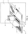
- FIG. 1 aillustrates an isometric view of an embodiment of the present invention including a pusher assembly and a sensor assembly.
- FIG. 1 billustrates another isometric view of an embodiment of the present invention including a pusher assembly and a sensor assembly
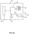
- FIG. 2 aillustrates a schematic view of an embodiment of the sensor assembly used with the present invention.
- FIG. 2 billustrates a schematic view of an alternative embodiment of a sensor assembly used with the present invention.
- FIG. 2 cillustrates a schematic view of another alternative embodiment of a sensor assembly used with the present invention.
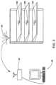
- FIG. 3illustrates a schematic view of an embodiment of the present invention, including an antenna, an access point and a store computer.
- FIG. 4illustrates a schematic view of an embodiment of the present invention, including an access point, a store computer and a security camera.
- FIG. 5illustrates a flow chart demonstrating a method of providing data from the indicia strip to a store computer.
- FIG. 6illustrates a flow chart demonstrating a method of determining the amount of product on the shelf via a query from store computer.
- FIG. 7illustrates a flow chart demonstrating a method of updating the association of particular product with a particular shelf location.
- FIG. 8illustrates a flow chart demonstrating an alternative method of updating the association of a particular product with a particular shelf location.
- FIG. 9illustrates an isometric view of an alternative embodiment of the present invention.
- FIG. 10illustrates a partially exploded view of an alternative embodiment of the present invention.
- FIG. 11illustrate an isometric view of an alternative embodiment of the present invention.
- FIG. 12illustrates an isometric view of another alternative embodiment of the present invention.
- FIG. 13illustrates an isometric view of yet another alternative embodiment of the present invention.
- FIG. 14illustrates an isometric view of yet another alternative embodiment of the present invention.
- FIG. 15 aillustrates an isometric view of yet another alternative embodiment of the present invention.
- FIG. 15 billustrates a schematic of a beam, a fixed mirror, and a pusher assembly in accordance with the embodiment illustrated in FIG. 15 a.
- FIG. 16 aillustrates an isometric view of yet another alternative embodiment of the present invention.
- FIG. 16 billustrates a schematic of a beam, a fixed mirror, and a pusher assembly in accordance with the embodiment illustrated in FIG. 16 a.
- FIG. 17 aillustrates an isometric view of yet another alternative embodiment of the present invention.
- FIG. 17 billustrates a schematic of a beam, a fixed mirror, and a pusher assembly in accordance with the embodiment illustrated in FIG. 17 a.
- FIGS. 18 A- 18 Cdepict an alternative implementation of a display management system, according to one or more aspects described herein.
- FIGS. 19 A and 19 Bschematically depict plan views of an alternative implementation of a display management system, according to one or more aspects described herein.
- FIG. 20 Aschematically depicts a capacitive sensor, according to one or more aspects described herein.
- FIG. 20 Bschematically depicts a control circuit, according to one or more aspects described herein.
- FIGS. 21 A and 21 Bdepict an alternative implementation of a display management system, according to one or more aspects described herein.
- FIG. 22 Aschematically depicts an integrated accelerometer device, according to one or more aspects described herein.
- FIG. 22 Bschematically depicts an integrated accelerometer device in communication with a control circuit, according to one or more aspects described herein.
- FIG. 23depicts an alternative implementation of a display management system, according to one or more aspects described herein.
- FIG. 24schematically depicts a sensor network configured to implement one or more inventory management, security, and/or recognition functions in combination with one or more display management systems, according to one or more aspects described herein.
- FIG. 25schematically depicts a flowchart diagram of a process that may be executed by a display management system controller device to determine a number of products removed from a sensor-equipped display management system, according to one or more aspects described herein.
- FIG. 26is a flowchart diagram of a process for calculation of a number of products removed from a display management system, according to one or more aspects described herein.
- FIG. 27depicts another implementation of a display management system, according to one or more aspects described herein, according to one or more aspects described herein.
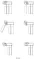
- FIGS. 28 A- 28 Fdepict a sequence of movements of a label holder as a product is removed from the display management system of FIG. 27 , according to one or more aspects described herein.
- FIG. 29schematically depicts the display management system of FIG. 27 , including a label holder rotation sensor device, according to one or more aspects described herein.
- FIG. 30schematically depicts another implementation of a display management system, according to one or more aspects described herein.
- FIG. 31schematically depicts another implementation of a display management system, according to one or more aspects described herein.
- FIG. 32schematically depicts another implementation of a display management system, according to one or more aspects described herein.
- FIGS. 32 A- 32 Cschematically depict a product-removal event, a non-removal event, and a product-stocking event, according to one or more aspects described herein.
- FIG. 33schematically depicts another view of the display management system of FIG. 27 , according to one or more aspects described herein.
- FIG. 34depicts another implementation of a display management system, according to one or more aspects described herein.
- FIG. 35depicts the display management system of FIG. 34 following the repositioning, and associated pairing of a peg hook structure into a different product section, according to one or more aspects described herein.
- FIG. 36depicts a flowchart diagram of a process that may be executed by the display management system of FIG. 34 , according to one or more aspects described herein.
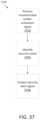
- FIG. 37is a flowchart diagram of a security operational mode of a control module, according to one or more aspects described herein.
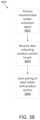
- FIG. 38is a flowchart diagram of a pairing operational mode of a control module, according to one or more aspects described herein.
- FIG. 39is a flowchart diagram of a restocking operational mode of a control module, according to one or more aspects described herein.
- FIG. 40is a flowchart diagram of a status operational mode of a control module, according to one or more aspects described herein.
- FIG. 41depicts a flowchart diagram of another process that may be executed by the display management system of FIG. 34 , according to one or more aspects described herein.
- FIG. 42depicts an implementation of a display management system, according to one or more aspects described herein.
- FIG. 43depicts an example annunciator device, according to one or more aspects described herein.
- FIG. 44depicts a retrofitted annunciator device, according to one or more aspects described herein.
- the present disclosuremay be used with the shelf and pusher assembly system described in either U.S. Pat. No. 6,041,720 to Hardy or U.S. Pat. No. 4,830,201 to Breslow.
- the present disclosuremay also be used with other pusher assemblies and shelf configurations known in the art.
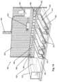
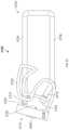
- FIG. 1 aillustrates an embodiment of the present disclosure.
- a shelf wall 1is configured to support a shelf 5 .
- the shelf 5has a front side 6 , the front side 6 typically facing the aisle where customers walk when shopping, and a rear side 7 .
- Mounted on the shelfis a pusher assembly 15 .
- the pusher assembly 15includes a biasing mechanism such as a sheet coil spring 20 containing an indicia strip 21 .
- the pusher assembly 15further includes an integral divider wall 22 and a floor section 23 on one side of the divider wall 22 and a floor section 24 on the other side of the divider wall 22 .
- the sheet coil spring 20is operatively connected to a pusher 25 and can be used to urge the pusher 25 , and the associated product, toward the front side 6 of the shelf 5 .
- the pusher assembly 15may be modular and can include a divider wall or an additional floor section that fit or mate in place.
- a sensor assembly 30can be mounted to the underside of the floor 24 over which the pusher 25 travels or to the shelf 5 and is configured to read the indicia strip 21 .
- the sensor assembly 30can be located at any position along the floor 24 and preferably near the coil spring 20 .
- the indicia strip 21is configured to provide a pattern that includes a representation associated with the position of the pusher 25 .
- the sensor assembly 30can scan a representation on the indicia strip 21 that reflects the pusher 25 being in that position.
- the indicia strip 21is depicted in FIG. 1 a as a strip mounted on the sheet coil spring 20 .
- the indicia strip 21can be printed on a paper that can be attached to the coil spring 20 , and can be black on white, white on black, or some other colors in a known manner.
- the indicia strip 21can be printed or acid etched or laser etched, depending on the sensor assembly 30 used to read the indicia strip 21 , in a known manner.
- the indicia strip 21can be separate from the coil spring 20 . In this embodiment, the indicia strip 21 can be mounted alongside or adjacent to the coil spring 20 .
- the representations in the pattern contained on the indicia strip 21can be optically readable or can be read based on other methods, including but not limited to passive variable capacitance, inductance, resistance, or magnetic, or active signal detection.
- FIG. 1 bdepicts an alternative embodiment of the invention with the sensor assembly 30 mounted on the front side of the pusher 25 , the sensor assembly 30 configured to read the indicia strip 21 .
- the sensor assembly 30could be mounted behind the pusher 25 .
- the sensor assembly 30can be mounted in different places.
- the sensor assembly 30will be mounted in such a manner so as to avoid direct contact with the product on the shelf so as to minimize damage to the sensor assembly 30 .
- the sensor assembly 30may be mounted within or on the pusher 25 and configured to read the indicia strip 21 .
- the indicia strip 21is not mounted to or part of the coil spring; rather, the indicia strip 21 may be positioned along the top of the floor 24 or along the underside of the floor 24 and is read by the sensor assembly 30 .
- the indicia strip 21is of the type that may have variable magnetic or capacitive characteristics.
- the sensor assembly 30may incorporate an analog oscillator whose frequency is determined by the magnetism or capacitance of the indicia strip 21 at the particular position of the pusher 25 .
- the oscillatorcan directly modulate the radio frequency signal and send that signal to a central access point, as discussed below.
- the central access pointcan then demodulate the signal and use the signal to determine the position of the pusher 25 .
- an optical infrared or visible light LED retro-reflective sensor arraycan be used for a black/white printed indicia strip 21 .
- the indicia strip 21 pattern containing the various representationscould be 6 bits wide. In an alternative embodiment, depending on the width of the shelf and the desired precision, the pattern on the indicia strip could be more than 6 bits wide.
- the indicia strip 21could be less than 6 bits wide. Reducing the number of bits on the indicia strip 21 reduces the precision regarding the position of the pusher 25 but has the advantage of potentially avoiding the need to determine the dimension of the product. An embodiment with a reduced number of bits will be discussed below.
- the indicia stripwill preferably include at least two representations so that the two representations can be used to reflect at least two positions of the pusher.
- the number of measurable positions of the pusher 25can be varied.
- a configuration of a 6 bit wide pattern on an indicia strip 21 with a sensor assembly 30 that can scan 6 bitscould scan at least 64 representations associated with 64 positions of the pusher 25 .
- the representations in the pattern on the indicia strip 21can be in many symbologies but a Gray Code provides that only one bit will change in each increment of movement, reducing potential errors.
- the sensor assembly 30 and the indicia strip 21can be configured depending on the distance of travel of the pusher 25 and the expected size of the product.
- the coil spring 20has a width of about 1 inch and the indicia strip 21 covers approximately 80% of the width of the coil spring 20 .
- the indicia strip 21covers approximately 80% of the width of the coil spring 20 .
- One skilled in the artwill understand that other widths of the coil spring 20 , and other dimensions of the indicia strip 21 are possible with the invention.
- the number of products on the shelfcould be measured by the number of measurable positions of pusher 25 .
- the position of the pusher 25could be used to determine the amount of product on the shelf without the need to manually count the product.
- the number of measurable positionscould exceed the number of products that can be placed in a facing.
- a configuration of the sensor assembly 30 and indicia strip 21might be desired with an increased number of measurable positions.
- a configuration where 256 positions of the pusher 25 are measuredmight be desirable.
- Such a configurationcould be used to determine the actual number of product on the shelf for a wide variety of product dimensions.
- the sensor assembly 30 and indicia strip 21can be configured to provide a decreased number of measurable positions.
- four positions of the pusher 25are measurable.
- the shelfwould provide information regarding how full the shelf was but would not provide the actual quantity of items on the shelf (assuming that 4 products would not fill the facing). This configuration could be useful in providing an automatic notification that a shelf was running out of product and needed to be restocked without the need to determine the product dimensions.
- FIG. 2 adepicts a schematic of an embodiment of the sensor assembly 30 .
- a printed circuit board (“PCB”) 35is configured to support a sensor 50 , the sensor 50 being compatible with the chosen type of indicia strip 21 .
- a controller 55is mounted to the PCB 35 and is configured to control the sensor 50 and transmit signals regarding the position of the pusher 25 via an antenna 65 .
- the controller 55can be configured to actuate the sensor 50 based on an input from the timing device 70 .
- the timing device 70can include, but is not limited to, a low power interval timer or a real time clock and is configured to provide information relating to the passage of time.
- the senor 50can include, but is not limited to, an optical infrared or visible light LED retro-reflective sensor.
- an optical infrared or visible light LED retro-reflective sensorPreferably, for a 6 bit wide pattern, a linear array of 6 emitters/sensors will be used where one emitter/sensor is aligned with each bit position printed on the indicia strip 21 .
- the sensor 50is positioned approximately 0.1 inches from the surface of the printed strip mounted on the indicia strip 21 .
- a binary codecan be assembled by the controller 55 that corresponds to the representation on the indicia strip 21 , the representation associated with a position of the pusher 25 .
- the controller 55Regardless of how the position of the pusher 25 is determined, the controller 55 generates a pusher code that represents the position of the pusher 25 .
- the pusher codecan be in digital or analog form and reflects the position of the pusher 25 .
- the pusher codecan be processed data or unprocessed data.
- the pusher codecan be, but is not limited to, the scanned representation or a controller processed representation.
- the pusher codecan be some other data that reflects the relative position of the pusher 25 .
- the controller 55is powered by a power source 75 .
- the power source 75can be, but is not limited to, a long life battery, a wired power supply, or a solar panel. As can be appreciated, the type of power supply will have an impact on the functionality of the sensor assembly 30 . If the power source 75 is a long life battery, a system configuration designed to utilize less energy will be preferable to avoid the need to change the battery on a frequent basis. If the power source 75 is a wired power source, the sensor 50 can be used more frequently without the need to replenish the power supply and the sensor assembly 30 can even be configured to provide real time information.
- the controller 55can be manufactured with a unique serial number.
- each pusher 25would be associated with a unique serial number or identity code.
- each indicia strip 21can include a unique identity code along with the representation associated with the position of the pusher 25 . Encoding the indicia strip 21 with a unique identity code can reduce the complexity of the controller 55 but typically will result in increased complexity of the sensor 50 .
- the informationwhen the information is transmitted from the sensor assembly 30 , the information may include an identity code and the pusher code representative of the pusher 25 position.
- informationsuch as time of sending and the status of the circuitry or the status of the power source may also be transmitted.
- FIG. 2 billustrates a schematic of an alternative embodiment of a sensor assembly 130 .
- a PCB 135has a power management circuit 148 configured to minimize use of power.
- the power management circuit 148provides power to a sensor 150 , a controller 155 and associated memory 156 .
- the memory 156can be volatile type memory, such as dynamic random access memory, but preferably the memory is non-volatile type memory, such as flash memory, so as to minimize power consumption.
- the power management circuit 148also provides power to a communication control 157 .
- the power management circuit 148can also provide power to a timing device 170 . As depicted, the power management circuit 148 is powered by a power source 175 .
- an input signalis provided to the controller 155 .
- the input signalcan be a signal generated by the timing device 170 or can be from some other source.
- the controller 155in response, activates the sensor 150 by sending a signal to the power management circuit 148 .
- the controller 155receives data from the sensor 150 which is used to form the pusher code representative of the position of the pusher 25 .
- the controller 155compares the data scanned by the sensor 150 with the previous data scanned by the sensor 150 , which is data residing in the memory 156 . Depending on the configuration of the system, if the data scanned by the sensor 150 is the same as the previous scanned data, the controller 155 can be configured to wait until the end of the next interval of the timer.
- the controller 155can then activate the communication control 157 and provide the pusher code to the communication control 157 for transmission.
- the communication control 157can then transmit the pusher code for further processing.
- the terms “transmit” and “transmission,” unless otherwise specified,include sending of information over a wire or via a wireless system and can be direct or indirect (i.e. through a network). If the power source 175 is not a wired power supply, however, it is preferable to use a method of communication that consumes relatively little power.
- FIG. 2 cillustrates a schematic of an alternative embodiment of a sensor assembly 230 .
- a PCB 235is configured to support a sensor 250 and a controller 255 .
- the controller 255is powered by a power source 275 and is configured to control the sensor 250 and has integrated functionality, including but not limited to, time keeping, power management, and communication control.
- the controller 255transmits the data scanned by the sensor 250 without any processing of the data.
- the pusher codeis the data scanned by the sensor 250 .
- the sensor and controllercan be integrated together.
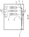
- FIG. 3illustrates a possible configuration for providing data regarding the position of the pusher 25 to a processing device, such as a store computer 90 .
- an access point 80is configured to transmit information to a central access point 85 .
- the central access point 85is connected to the store computer 90 and provides the data received from the access point 80 to the store computer 90 .
- the data sent from the access point 80is received from antenna 165 , antenna 265 and antenna 365 .
- the antenna 165is associated with a particular pusher 25 and sensor assembly 30 , typically via the use of a unique serial number that can be associated with a controller.
- the antenna 265 and the antenna 365are also associated with different pushers 25 and sensor assemblies 30 , each with a unique serial number. Alternatively, one or more antennas could be associated with more than one pushers 25 .
- the power required to transmit wireless signalsincreases as the transmission distance increases.
- the preferred wireless communication configurationwill transmit low powered signals over a short distance.
- the various antennas 165 , 265 and 365transmit a wireless signal to the access point 80 , located nearby, thus a low powered transmission is suitable.
- the access point 80then re-transmits the signal to the central access point 85 using higher power during the secondary transmission.
- the power source for the various controllers connected to the antenna 165 , 265 and 365can more readily utilize a power source 75 consisting of a long life battery. While the transmission method between access point 80 and central access point 85 is depicted as wireless, the access point 80 and central access point 85 can also communicate over wires.
- the controller 55 corresponding to each pusher 25can be hard-wired to an access point 80 so that the controller 55 transmits the data to access point 80 over one or more wires.
- the access point 80can then transmit the data to the store computer 90 .
- the datais transmitted directly from the sensor assembly 30 to the store computer 90 .
- the transmissioncan be either wireless, such as an infrared, ultrasonic or electromagnetic wave transmission, or can be hard-wired.
- the controller 55can be configured to provide a real time update on the level of product on the shelf or in the store so that more accurate decisions regarding the need to order additional product can be made. This configuration also makes it possible to recognize and send alerts regarding potential theft situations based on the real-time movement of the pusher 25 .
- the real time product informationmay make it possible to provide a more responsive inventory system so as to lower the amount of inventory in the store and therefore reduce the cost of inventory.
- Wireless systemsprovide increased flexibility in installation and can be readily installed in existing shelves without the need to install wires for either power or communication.
- the use of a wireless systemallows for the gradual installation of an inventory system. For example, items of high value (and therefore suffering from an increased likelihood of being stolen) or items that tend to have significant variations in customer demand can be monitored first.
- the sensor assemblies 30may be networked together via a series of wireless access points 80 where each access point 80 accepts transmissions from any sensor assembly 30 in the vicinity of the access point 80 .
- each access point 80accepts transmissions from any sensor assembly 30 in the vicinity of the access point 80 .
- there exist a number of wireless access points 80 and the access points 80are connected via a network, where the network transmits the data to the store computer 90 .
- each wireless access point 80transmits the data directly to the store computer 90 .
- a battery powered sensor assembly 30could communicate via a low powered wireless transmission to an access point 80 , the access point 80 being powered by a wired power supply.
- the access pointwould transmit a wireless signal to a central access point 85 that was powered by a wired power supply.
- the central access point 85could be connected via a wire to the store computer 90 .
- a timing device 70comprises a low powered timer
- the controller 55can rest dormant until a signal from the timing device 70 indicates it is time to send an update regarding the position of the pusher 25 .
- An example of a low powered timerincludes a low powered, low cost interval timer.
- Low powered, low cost interval timersmay not be highly accurate and therefore multiple pusher devices in a store will likely randomize their transmission times so as to reduce transmission collisions.
- the period of data transmissiontypically will be on the order of a few milliseconds, and therefore, it is unlikely that signals from different controllers will be sent at the same time. This likelihood can be further decreased if the controllers are not all started at the same time. If the transmissions only occur a few times per day (i.e. to provide periodic updates on the amount of product on the shelf), the likelihood of communication collisions is further reduced.
- the decreased frequency of transmission and the short transmission periodhelps reduce the amount of power consumed.
- the senor 50continuously monitors the indicia strip 21 .
- the pusher 25will move and the sensor 50 can scan a new representation on the indicia strip 21 corresponding to the new position of the pusher 25 .
- the controller 55can then send a transmission including the new position of the pusher 25 to the store computer 90 (i.e. the controller 55 can send a new pusher code).
- the store computer 90can monitor the amount of product on the shelf in real time.
- the transmission of signals, from the antenna 165 to the store computer 90 for example,is a one-way transmission.
- the systemmay be set up to handle two-way transmission of signals between the sensor assembly 30 and the store computer 90 .
- additional hardwaresuch as a receiver is included in the sensor assembly 30 .
- the two-way systemallows for bi-directional transfer of information.
- the store computer 90could query a particular controller 55 about the position of the associated pusher 25 .
- the controller 55could activate the sensor 50 in response to the query and determine a pusher code reflecting the position of the pusher 25 .
- the controller 55could then transmit the pusher code along with the identity code of the controller 55 to the store computer 90 .
- the store computer 90could determine the inventory level of a product.
- the store computer 90could include the identifying code in the transmission.
- the store computer 90may store, access, and perform functions with the identifying codes of all or a subset of the controllers or pusher systems in the store.
- all the controllers 55 associated with products purchased from the same vendorcould be queried just before the order to the respective vendor was placed. The order to that vendor could then be updated with the latest product inventory information. In this manner, the order placed to the vendor could be made more accurate without the need for laborious counting of products on the shelf.
- Some vendorsare responsible for stocking the shelves in a retail store instead of the store personnel.
- an embodiment of the present inventioncould provide the vendor with updates in response to queries from the vendor's computer.
- the vendorcould track the amount of product available on the shelves as frequently as desired, even in real time.
- a vendorcould send a query to a controller 55 via a wide area network (“WAN”).
- the controller 55could determine the position of the pusher 25 and transmit a signal back to the vendor via the WAN.
- the vendorcould communicate with the store computer 90 to obtain information regarding the inventory level of products on the shelf.
- the vendorcould control the manufacturing process of the product in response to inventory levels on the shelves.
- the vendorwould have an increasingly effective inventory system if multiple stores were networked to the vendor's computer so that the aggregate amount of product on all the store shelves could be determined. If the vendor was only connected to a single store, the information, while less indicative of the total inventory, could provide valuable details regarding patterns of behavior of the consumers.
- FIG. 4illustrates an embodiment of the present invention that includes the use of a security camera 195 .
- an access point 180receives a signal from a controller 155 indicating that pusher 25 , not shown, has moved.
- the access point 180transmits the signal to a central access point 185 that is connected to a store computer 190 .
- the store computer 190determines that the rate of change in product level of the product associated with the controller 155 is indicative of a potential theft.
- the store computer 190then transmits a signal, either wired, or wirelessly, to an antenna 196 , which is mounted to the security camera 195 .
- the signalinstructs the security camera 195 to monitor a position associated with the location of the controller 155 .
- the store computer 190can also notify security personnel to monitor the area by displaying a warning on the store computer screen or by transmitting a signal to a security computer or by activating an audible tone or flashing light in the vicinity of the potential theft or by other known methods of notification such as a signal to the pager or beeper carried by the security personnel.
- Information from the security cameracould be sent to a television or other visual display device that is located near the location where the potential theft is occurring.
- the visual display devicecould display an image of the potential thief such that the potential thief could appreciate the fact that the thief was being watched.
- the controller 155preferably monitors the position of pusher 25 on a frequent or even real time basis so as to provide a more timely response. If a power source 75 consisting of a long life battery is utilized, it may be beneficial to utilize a controller that can determine a potential theft situation without the need to transmit data to the store computer 190 . In such an embodiment, the controller can be configured to transmit data to provide inventory level updates and also to provide security notifications.
- the position of the potential theft relative to the security camera 195would be beneficial to provide an instruction to the security camera 195 to focus on a particular position.
- This positional informationcould be generated by a number of methods, including providing the store computer 190 with the security camera coordinate system for the security camera 195 .
- the position of the controller 155 relative to the security camera 195could be determined during setup and during a potential theft situation; the position of the controller 155 could be used to direct the focus of the security camera 195 .
- the security camera 195could be configured to focus in several positions, such as three points along an aisle, and the store computer 190 could indicate which position was the most appropriate for the particular situation.
- the described methodsare illustrative because of the numerous methods of controlling the security camera 195 that exist.
- the store computer 190could signal to the controller 155 to activate a device capable of providing an audible warning tone.
- the controller 155could determine that a potential theft had occurred and could provide a notification, including the sounding of an audible warning tone. In addition, the controller 155 could transmit a signal to the store computer 190 .
- the sensor assembly 30would preferably include a timing device 70 so as to allow the controller 155 to more readily determine whether the rate of movement of pusher 25 exceeds a preset level.
- a two-tiered responsecould be implemented. If the change in position of the pusher 25 was greater than normal, a signal could be transmitted to the security camera 195 . In addition, an inaudible notification could be provided directly to security personnel. If the positional change of the pusher 25 more clearly indicated a potential theft, an audible alarm and flashing lights could also be activated. Thus, the response could be configured to more carefully match the situation.
- FIG. 5illustrates an embodiment of a method for determining the amount of a particular product available in a facing on a shelf.
- the sensor assembly 30uses a timing device 70 consisting of a low powered interval timer.
- the controller 55is initially in a dormant state and only the timing device 70 is running.
- the timing device 70provides a signal to the controller 55 that the time interval is complete.
- the controller 55in response to the signal from the timing device 70 , becomes activated and the controller 55 then activates the sensor 50 .
- step 410the sensor 50 scans the representation contained in the pattern on the indicia strip 21 so that the controller 55 can generate the pusher code representative of the position of the pusher 25 .
- step 415the controller 55 generates the pusher code in response to the pattern scanned by the sensor 50 .
- step 420the controller 55 transmits a signal that can include the unique serial number of the controller 55 and the pusher code, to the store computer 90 .
- the store computer 90receives the data from the controller 55 .
- the transfer of data from the controller 55 to the store computer 90is direct.
- the controller 55transmits data to the store computer 90 indirectly through an access point or a network.
- the store computer 90calculates the amount of product on the shelf based on the position of the pusher 25 .
- the store computer 90also updates the inventory list at this point.
- the total amount of product on all of the facings that have that productcan be calculated.
- the calculation of product in a facingcan be accomplished through the use of a database of products and the relevant dimensions of a product, and the position of the pusher.
- the number of products placed in the facingcan be provided during setup of the controller 55 for that product.
- the position of the pusher 25 and the number of products corresponding to that position of the pusher 25can be used to calculate the quantity of remaining products based on a later position of the pusher 25 through the use of well known extrapolation techniques.
- the position of the pusher 25can be one of four positions representing X>3 ⁇ 4, 3 ⁇ 4 ⁇ X>1 ⁇ 2, 1 ⁇ 2 ⁇ X>1 ⁇ 4, and X ⁇ 1 ⁇ 4.
- This latter embodimentprovides less precise information but also requires less computation effort to provide the approximate inventory level.
- this embodimentcan be used to manage inventory without the need to determine and track the dimension of the product.
- the amount product on the shelfcan be roughly determined based the number of facings containing the product and whether the pusher 25 for each facing is in a position representative of a full, mostly full, low or almost empty facing.
- the store computer 90determines whether any action is required.
- a potential thefta decrease in the inventory below a pre-set level or the emptying of a facing of product while ample product still remains on the shelf in other facings would indicate that some action was required.
- the store computer 90could determine that, based on historical usage and the average delivery time and the cost per delivery, the current level of inventory was low.
- the minimum inventory levelcould be preset and once the inventory level drops below a preset level, the store computer 90 could determine that the product level was low.
- the store computer 90would determine if a potential theft was taking place.
- the store computer 90could compare the current level of inventory, based on the position of the pusher 25 , to the previous level of inventory. If the rate of change in inventory level exceeded a preset level, the store computer 90 would determine that a potential theft was taking place.
- the store computer 90would notify security. The notification could include a page to security or a signal to a security camera 195 to focus in a particular direction.
- step 470the store computer 90 would determine if the existing order needed to be modified.
- the store computer 90could compare the current product requirement to the current order. If the store computer 90 determined that an amount of product ordered was insufficient, the store computer 90 would proceed to step 475 .
- step 475the store computer 90 would update the current inventory order so that the inventory order matched the current product requirements.
- step 480the store computer 90 would determine if a facing on a shelf was empty. If there was an empty facing, the store computer 90 would then notify the store management that there was an undesirable empty facing in step 485 . The store management could then decide the appropriate action to take depending on the type of product and the availability of substitute goods. If the facing was not empty, the store computer 90 would wait until the next product update.
- FIG. 6depicts an embodiment of a method for determining the amount of inventory on the shelf in a two-way system.
- the store computer 90sends a query to a sensor assembly 30 .
- the sensor assembly 30contains a controller 55 that is identified by a unique serial number or identifying code.
- step 520the sensor assembly 30 receives the query from the store computer 90 .
- the controller 55activates the sensor 50 and prepares to receive data reflecting the position of the pusher 25 .
- step 530the sensor 50 scans the indicia strip 21 and the controller 55 generates a pusher code representative of the position of the pusher 25 .
- step 540the sensor assembly 30 transmits the pusher code representative of the position of the pusher 25 along with the unique serial number of the controller 55 to the store computer 90 .
- the store computer 90receives this transmission in step 550 .
- This transmissioncan be sent directly from the sensor assembly 30 to the store computer 90 or, preferably, it can be indirectly through a network.
- the transmissioncan be sent in a wireless manner, over wires, or some combination of a wireless and wired transmission.
- the store computer 90determines the level of inventory on the shelf.
- the determinationcan be based on the product dimension and the position of the pusher 25 .
- the determinationcan be based solely on the position of the pusher 25 .
- FIG. 7depicts an embodiment of a method for setting up a controller for a particular product.
- the productcan be placed on the shelf in the appropriate facing.
- step 610can be skipped and the set-up can start with step 620 .
- a set-up button on a hand-held deviceis pressed.
- the hand-held deviceis configured to transmit a signal to a store computer 90 indicating that the user of the hand-held device is about to associate a product with a serial number or identifying code of a controller 55 .
- the transmission of signals between the hand-held device and the store computer 90is done in a wireless manner.
- the store computer 90provides feedback to the user indicating that the store computer 90 is ready to proceed. In an alternative embodiment, no feedback is provided.
- step 630the UPC code of the product is scanned and transmitted to the store computer 90 .
- step 640the store computer 90 looks up the product dimension based on the UPC code. If the UPC code does not have a listed dimension, the store computer 90 checks if the user can input the needed dimension in step 642 . If the user cannot, the setup is terminated and the user can try to setup a new product. If the user can determine the dimension, the user enters the dimension in step 644 .
- step 646a dimension is associated with the UPC code. Then, in step 650 the store computer 90 sends a signal to the hand-held device to indicate that the user should proceed with the setup.
- step 660the user activates the controller 55 with the hand-held device.
- an optical setup sensoris mounted on the pusher assembly and is connected to the controller 55 .
- the setup sensoris recessed in the pusher 25 but could be mounted in other locations such as on the top or the side of the pusher 25 .
- the hand-held devicewill be configured to transmit a signal to the setup sensor. The act of transmitting the setup signal to the setup sensor will cause the controller 55 to awake from a dormant state.
- the controller 55in response to the setup signal, will send data indicating that the controller 55 is being setup to the store computer 90 .
- the datawill include the unique serial number of the controller 55 .
- the datamay also include a generic setup code or a setup code corresponding to the hand-held scanner and can include a pusher code representative of the position of the pusher 25 . In the event that multiple hand-held devices are being utilized at the same time, it may be beneficial to provide a setup code associated with a particular hand-held device.
- the store computer 90will receive the data from the controller 55 . If the data includes the pusher code, the store computer 90 can calculate the amount of product in the facing at this time. In step 685 , the store computer 90 sends a signal to the hand-held device indicating that the controller 55 has been setup and associated with the UPC code of a particular product. In addition, if the position of the pusher 25 was originally included, the store computer 90 can also provide a calculation of the current quantity of product in the facing that was just set up. In addition, the store computer 90 requests that the user verify that the setup information is correct.
- step 690the user indicates the information is correct.
- the setup for the controller 55is complete. To change the product associated with the controller 55 , the process can be repeated.
- FIG. 8illustrates an alternative method of associating a controller with a product.
- a hand-held deviceis activated to indicate that the user is about to setup controller 55 .
- the activationincludes the transmission of a signal to a store computer 90 .
- step 720the hand-held device is used to scan the UPC code of the product and transmit the information to the store computer 90 .
- step 730the store computer 90 looks to see if a product dimension is listed for that scanned UPC code. In the event that no dimension is associated with the UPC code, the computer, in step 732 , transmits a signal to the hand-held device requesting the user to input the appropriate product dimension.
- the usercan cancel the setup and start over with a new product in step 734 .
- the userIf the user does know the dimension or is able to measure the dimension, the user then enters the dimension and transmits the information to the store computer 90 in step 736 . After the product dimension is determined, in step 740 , the store computer 90 sends a signal to the hand held device indicating that the user should proceed.
- step 750the user scans the serial number of the controller 55 .
- the serial number of the controller 55is printed in a black/white code on a sticker mounted to the sensor assembly 30 .
- the hand held deviceAfter scanning the serial number, the hand held device transmits the serial number to the store computer 90 .
- step 760the store computer 90 associates the UPC code of the product with the serial number of the controller 55 .
- the store computer 90then signals the hand held device that the setup for the device is complete.
- all communications between the hand-held device and the store computer 90can include a code representing the hand-held device.
- the method of associating a product with a controller 55could be done without sending a signal to the store computer 90 .
- the datawould be uploaded from the hand-held device once the user had associated the various controllers with the various products.
- a system for determining the location of the pusher with an indicia strip and sensorhas been described. Numerous additional methods exist for measuring the distance between the front or rear of a shelf and the pusher or the final product in a facing of products. Based on this distance, and understanding the dimension of the products in the facing, a simple calculation can be performed to determine the number of products in the facing. This calculation can be performed by a microprocessor, store computer, controller or some other processing device which has received the information regarding the distance between the shelf front and the last product in a facing.
- the pusher assemblyhas been described to include a spring. However, some other biasing method, such as gravity or magnetism, would also work to move the pusher and the product forward.
- the use of transmitted light or other signalsuch as a radio frequency signal, that is passed between a position near the back of the facing of products and a stationary position can be used to measure the distance between the front of the shelf and the pusher.
- a transmitter 700 or 702is incorporated into a pusher 725 .
- the transmittergenerates a light or other signal that can be transmitted on command, periodically or continuously.
- a light emitting diode (LED), radio frequency or ultrasonic generator or other signal generation devicecan be used to generate the light or signal.
- a corresponding receiveris incorporated into a location that is stationary in relation to the pusher 725 .
- the receiver 712can be incorporated into a front rail or another location at or near the front of the shelf, a receiver 730 can be incorporated into a rear rail or other location at or near the rear of the shelf, it also can be incorporated into the floor of the shelf, the track of the pusher, the roof of the shelf or the divider wall.
- the receiverdetects the signal that is sent from the transmitter. For example, a LED may radiate light having a particular intensity.
- a phototransistor acting as a receiverdetects the light signals being emitted from the LED.
- the sensitivity of the phototransistor and the intensity of the LEDmay be adjusted by the microprocessor in order to adjust the overall sensitivity of the optical components.
- the adjustmentcan be done remotely.
- the transmittercan communicate in a wireless fashion with the receiver through RF, IR or other known means such as magnetic fields, electrical fields, sound waves and the like.
- the transmitter and receivermay be in communication with a controller that tracks the time of sending and receiving.
- This datacan be provided to a processing device such as a microprocessor or a store computer, thus in this embodiment the pusher code would include the time interval between sending and receiving.
- Information regarding the time at which the signal was sent and the time at which it was receivedmay be utilized by a processing device to determine the time between the transmission and the receipt of the signal. Based on this length of time, the processing device can calculate the distance between the transmitter and the receiver. Knowing the dimensions of the shelf, the pusher system and the components thereof, this distance can then be translated into the distance between the front side 6 of the shelf and the face of the pusher 25 that is biased against the back of the facing of products. Such a translation is well known and within the knowledge of one of ordinary skill. If the relevant dimension of the products in the facing is known, the processing device can then calculate the number of products in the facing based on the known dimension of the products.
- the transmitter and the receiverswitch locations.
- the transmittercan be placed at or near the front or the rear of the shelf or other relatively stationary position and the receiver can be placed on or near the pusher.
- the transmitter and the receivercan be incorporated into the same device which merely bounces a signal off a stationary position.
- a reflectorcan be placed on the pusher and a transmitter/receiver using a laser, or some other light source, can determine the distance between the reflector and the transmitter/receiver based on the time of travel.
- Examples of possible transmitter/receiversinclude, but are not limited to, optical displacement measurement sensors and reflective laser sensors.
- the location of either the part that is stationarybe located near the front side or the rear side of the shelf so as to make the distance calculation simpler and to avoid problems with symmetric distances on both sides of the stationary unit mounted to the shelf. For example, mounting a transmitter halfway between the front and rear of the shelf would make determining the location of the pusher more complicated because there would be two possible locations for a given distance.
- a transmitter( 700 , 702 ) is incorporated into a pusher 725 .
- the transmitteris a light emitting diode and is located at any location on the pusher 725 that allows the transmitter to function.
- the transmittercan be located at the top of the pusher 725 at 700 or at the base of the pusher 725 at 702 or at other locations on the pusher 725 .
- a receiveris located at a position that is fixed in relation to the movement of the pusher 725 .
- the receivermay be a phototransistor and can be located on the front of the shelf 705 , such as receiver 710 or on a front rail 708 connected to the front of the shelf, such as receiver 712 .
- the receivercan further be located on the floor of the shelf at any number of positions as represented by 714 , on the floor of the pusher track at 716 or at a location above the shelf 705 such as on another shelf (not shown) mounted above the shelf 705 .
- the receivercan be located on the divider wall at 720 or 722 or other location on the divider wall.
- the receiveralso can be located near the rear side 707 at 730 or at 732 . Preferably, the receiver will be mounted near the either front side 706 or the rear side 707 so as to make distance calculation simpler.
- the receiver and the transmittercan also switch locations.
- the pushercan incorporate a receiver, and a transmitter can be incorporated at any of the locations 710 - 732 as well as in any other location that is fixed in relation to the movement of the pusher.
- the location of the transmitterwill be near either the front side 706 or the rear side 707 so as to make calculation of distance simpler.
- the transmitteris located at 700 and the receiver is located at 710 .
- the transmitter 700mounted on the pusher 725 , moves with the pusher 725 .
- a signalwill take a certain amount of time to travel from the transmitter 700 to the receiver 710 .
- a signalwill take less time to travel from the transmitter 700 to the receiver 710 .
- Data regarding the transmission and receipt of the signali.e. the pusher code
- the processing devicedetermines the amount of time it takes the signal to travel from the transmitter to the receiver. Knowing the signal travel speed, the processing device determines the distance between the transmitter and the receiver.
- the processing deviceWith an understanding of the location of the transmitter in relation to the products and an understanding of the location of the receiver in relation to the front or back of the shelf, the processing device will be able to determine the distance between the pusher and the front of the shelf. Using the dimension of the products, the processing device can then determine the number of products in the facing.
- the light emitting diode or other transmittercan be set to function periodically, continuously or on command from a remote location.
- the processing devicemay control both the LED and phototransistor.
- the processing devicemay record a time T 1 in which the microprocessor issues a command to generate a pulse from the LED and a time T 2 in which the light signal is detected by the phototransistor. Both of these times T 1 and T 2 may be stored in memory and used to determine the number of product in the facing, using the above described relationships.
- a capacitive proximity sensormay be utilized to measure the distance between the front of the shelf and the pusher or the final product in a facing of products.
- the capacitive proximity sensordetects the pusher which acts as a target for the capacitive proximity sensor.
- the capacitive proximity sensorgenerates an electrostatic field which is directed at the target.
- the capacitive proximity sensorreacts to the changes in capacitance caused by the movement of the pusher in relation to the sensor.
- Additional sensing environmentsmay also include the use of magnetic proximity sensor or an inductive proximity sensor.
- the proximity sensorsmay be utilized to measure the distance between the front of the shelf and the pusher or the final product in a facing of product.
- An inductive proximity sensoris useful in detection of metal targets as the inductive proximity sensor uses an induced field to sense the target object.
- the proximity of a pusher in relation to the inductive proximity sensorcan be detected as the distance of the pusher changes with respect to the location of the inductive proximity sensor.
- a magnetic proximity sensor based on the Hall Effect principlemay also be utilized to sense the location of the pusher.
- a proximity sensorcould be mounted near the rear side 707 , the proximity sensor configured to sense the distance to the pusher 25 .
- a processing devicesuch as the store computer or microprocessor, could determine the distance between the pusher 725 and the front side 706 and use that distance to determine how much product was left on the shelf.
- a Radio Frequency Identifying Transponder (“RFIT”) having a unique identity codeis mounted to the pusher 725 .
- a sensor assembly including a transmitter/receivercan be mounted on the rear side 707 of the shelf 705 .
- the transmitter/receiverwhen activated, transmits an activation signal that activates the RFIT.
- the RFITupon activation, transmits a responsive signal that includes the unique identifying code.
- the transmitter/receiverreceives the responsive signal from the RFIT.
- the sensor assemblyis equipped with a timing device and measures the time between the initial transmission of the signal from the transmitter/receiver until the receipt of the responsive signal from the RFIT.
- a controllercan initiate the transmission of the signal and record the receipt of the responsive signal into memory.
- the controlleris also equipped with a timing device to measure the delay. The delay in time can be used to calculate the distance between the transmitter/receiver and the RFIT.
- the controllercan calculate the distance and provide a pusher code that includes the distance. Alternatively, the pusher code will include data regarding the delay and the pusher code will be forwarded to a processing device for distance calculation. As discussed above, the distance between the pusher 25 and the transmitter/receiver can be used to calculate the amount of product remaining in the shelf.
- An advantage of using an RFIT in combination with a transmitter/receiveris that it can be easily retro-fitted to existing systems.
- the RFITdoes not require internal power, this embodiment eliminates the need to provide a powered device on the pusher 725 .
- the transmitter/receiveris powered.
- the transmitter/receivertransmits a focused or low powered signal so that only the RFIT associated with the transmitter/receiver is activated.
- the transmitter/receiverignores responsive signals from RFIT's that do not include the proper unique identifying code.
- a low powered, one-chip radar sensormay be used to determine the distance between the radar sensor and the pusher 725 .
- the radar sensormay be mounted near the rear side 707 so as to make distance determinations less complex.
- a device for measuring the tension of the spring used for pushing the productscan be used.
- the tension on the springwill, at least in part, be dependent upon the number of products in front of the pusher. As more products are placed in front of the pusher, the spring either further compresses or expands. In the case of a coil spring, as more products are placed in front of the pusher, the two ends of the spring move further apart and the spring further uncoils. As the spring uncoils, the amount of tension or pressure within the remaining coil of the spring increases. By measuring the tension of the spring, the length of the spring that is uncoiled can be determined.
- the spring tension measuring devicecan incorporate a processing device or can transmit the information it measures to a microprocessor or other processing device.
- a spring tension measuring devicemay include a force measuring unit that includes, but is not limited to, strain gauges, tensiometers, torque transducers or some other force measuring device to determine the tension exerted on the coil spring.
- the force measuring unitis preferably connected to a controller, where the controller is configured to convert the data from the force measuring unit into a force value. The controller could then transmit the force value to a processing device.
- the pusher codewould include a force value. Numerous other methods of measuring spring tension will be apparent to one of skill in the art and are within the scope of the invention.
- the number of products remaining in a particular facingis determined in part through the use of one or more transmitter(s) and receiver(s) placed on opposite lateral sides of the products.
- the transmitters or receiversmay be placed on divider walls that separate facings of products.
- a series of transmittersis incorporated into or onto the base of a divider wall.
- a series of receiversin incorporated into or onto the other side of the divider wall. In this manner, when products are on a shelf, those products that are being pushed are between the transmitters on one divider wall and the receivers on another divider wall.
- the transmitterPeriodically, when prompted, or continuously, the transmitter sends a signal. If there is no product between the transmitter and the receiver, the receiver will receive the signal. If there is a product between the transmitter and the receiver, the product will block the signal, and the signal will not be received by the receiver.
- a microprocessorreceives the information regarding whether or not the various receivers received a signal. Based on this information, the microprocessor can determine the approximate distance between the front of the facing and the last product in the facing. With an understanding of the dimension of the products, the information regarding receipt and non-receipt of signals can be translated into an understanding of the approximate number of products in the particular facing.
- one transmitter and one receiveris used to indicate that a particular shelf is running low on the associated product.
- the location of the transmitter/receiveris preferably closer to the front side 706 then the rear side 707 .
- a controller with a unique identifying codeis associated with the transmitter and receiver so that the unique identifying code can be associated with the product.
- the transmitter and the receivercan be incorporated into the same device which attempts to bounce a signal off a predetermined target affixed to a particular location. If the signal bounces as expected, it indicates that there is no product between the transmitter and the target location. If the signal does not bounce as expected, a product exists between the transmitter and the target location.
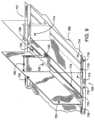
- FIG. 10depicts a partially exploded view of an alternative embodiment of a shelf and pusher assembly, the shelf having divider walls.
- several transmitters 750are placed on the left side of the divider wall toward the bottom.
- the transmittersalso can be placed higher on the divider wall as shown at 752 .
- Corresponding receivers 760are placed on the right side of the divider wall toward the bottom. These receivers also can be placed higher on the divider wall as shown at 762 .
- the receivers and the transmittersare positioned such that an unobstructed signal can be sent from a transmitter and received by a corresponding receiver.
- productsuch as product P
- itcan obstruct the signal sent from the transmitter.
- product P(shown in dashed lines) will prevent the signal from reaching the receiver 760 nearest the front side 6 of the shelf.
- the receivers that are positioned further back than product Pwill receive the signals sent to them.
- a microprocessorreceives the information regarding whether each of the receivers 760 received signals. Based on this information, the microprocessor can determine the distance between the front of the shelf and the last product in a particular facing. With an understanding of the width of each product, the microprocessor can determine the number of products in a particular facing.
- the pushercontacts a variety of sensing devices as it moves backward or forward on a shelf.
- Sensing devicesare placed on a surface below, above, or on the sides of a pusher.
- These sensing devicesinclude devices that are mechanical, electrical and electromechanical, optical and magnetic, and can include spring loaded latches, electrical contacts, light emitting diodes or metal wires or other sensors such as linear position sensors.
- the pusherAs the pusher moves backward or forward on a shelf, it interacts with the sensing devices.
- the pushermay interact with the devices through the mechanical contact of the pusher and the devices.
- the pushermay also be equipped with a separate sensing device that interacts with the stationary sensing devices as the pusher moves backward or forward.
- Information regarding the interaction between the pusher and the sensing devicesi.e. the pusher code
- the processing deviceBased on the determination of the devices with which the pusher interacted, the processing device can determine the approximate position of the pusher in relation to the front of the shelf. With an understanding of product data, such as the dimension of the product, a processing device can then determine the approximate number of products that are in the particular facing related to the pusher and the sensing devices.
- sensing devices 810 , 811 and 812are incorporated into the base of the track on which the products rest. When products are resting directly over the switches, the sensing devices are closed. As products are removed and the pusher 825 travels forward, the sensing devices that are to the rear of the pusher 825 are released and open. A controller determines which sensing devices are open or closed. Based on this information, a processing device can determine the approximate distance between the pusher 825 and the front side 806 of the shelf. Knowing the dimension of the products, the processing device can determine the number of products in a particular facing.
- sensing devices 814 , 815 , 816 , 817 , and 818are placed on the pusher track 802 .
- a separate contact(not shown) is placed on the bottom of the pusher 825 .
- the contact on the pusher 825is configured such that when the contact on the pusher 825 is adjacent to a sensing device mounted on the pusher track 802 , the sensing device on the pusher track 802 is activated.
- a signalis sent to a processing device, the signal providing information as to which sensing devices has been activated. Based on this information, the processing devise can determine the approximate distance of the pusher from the front of the shelf. Knowing additional data about the products, such as the product dimensions, the processing device can determine the number of products in a particular facing.
- the processing devicecan determine that the amount product is equal to the amount of product that can fit in the space between the contact 816 and the front side 806 of the shelf 801 .
- the processing devicecan determine that the pusher 825 is between contacts 815 and 817 . This, therefore, provides an approximate position of the pusher 825 and the approximate position can be used to determine the approximate quantity of product remaining on the shelf.
- the contactscan be spaced closer together near the front side 806 of the shelf 801 so that more accurate measurements can be taken as the amount of product on the shelf decreases. Alternatively, enough contacts can be used to provide a relatively precise location of the pusher 825 .
- the contacts 819 , 820 , 821 and 822can be mounted to the divider wall 803 .
- the activation of one of the contacts 819 - 822indicates the location or the approximate location of the pusher 825 . Locating the contacts along the divider wall 803 can help prevent problems with accidental activation of the contacts by product on the shelf.
- the distance between contacts 819 - 822can be non-uniform so that greater precision is provided as the shelf becomes less full.
- a shelf management system 900 for detecting and communicating the position of a pusher assembly on a shelfis depicted in FIG. 14 .
- the shelf management system 900may include a pusher assembly 915 , a light assembly, and a control module 940 .
- the pusher assembly 915 , light assembly, and control module 940may all be secured to a gondola wall 905 or similar structure that holds a product 910 .
- the product 910may be aligned or arranged along the pusher assembly 915 . Additionally, the product 910 may be contained in separate product container box 912 as illustrated in FIG. 14 .
- the pusher assembly 915may include a biasing mechanism such as a coil spring.
- the pusher assembly 915may include an integral divider wall 922 and a floor section 920 on one or both sides of the divider wall 922 .
- the coil springmay be operatively connected or associated with a pusher 925 and can be used to urge the pusher 925 , and the associated product 910 , toward the front side of the shelf.
- the pusher assembly 915may be modular and can include a divider wall or an additional floor section that fits or mates in place. Additionally, since the present invention has no connection to the pusher assembly 915 , the present invention may work with any product shelving system.
- the light assemblymay include a light channel 930 and a light transceiver 932 .
- the light transceiver 932may be one of many light transceivers located on the light channel 930 .
- the light transceiver 932may be located behind the product 910 to be measured on a shelf.
- the light transceiver 932may consist of a light transmitter 934 and a light sensor 936 .
- the light transmitter 934is configured to send a light signal 935 towards the pusher 925
- the light sensor 936is configured to receive the light signal 935 from the pusher 925 .
- the light transmitter 934 and the light sensor 936may be the same component as part of the light transceiver 932 .
- the spacing of the light transmitters 934 and the light sensors 936 on the light channel 930may ensure that at least one light transmitter 934 and one light sensor 936 is focused on or sees every pusher 925 .
- the light channel 930may include an electronic connection 938 .
- the light assemblymay utilize one of many different types of light, with one type of light being utilized is in the “infrared spectrum.”
- the light assemblycould include an infrared (IR) transceiver, wherein the IR transceiver may consist of an IR transmitter and an IR sensor.
- IRinfrared
- the shelf management system 900may also include a control module 940 .
- the control module 940may align with the electronic connection 938 on the light channel 930 and lock into place.
- the control module 940may include a microcomputer. Additionally, the control module 930 may have internal wireless capability without departing from the invention.
- the product 910may be pushed forward by the spring-urged pusher 925 or pusher paddle in the shelf management system 900 .
- a light signal 935is transmitted from the light transmitter 934 found on the light channel 930 .
- the light signal 935may then reflect off the back of the pusher paddle 925 or the product 910 and then back to the light sensors 936 .
- This informationmay then be relayed to the control module 940 , thereby measuring the distance to the pusher 925 or the product 910 .
- the light transceiver 932may be controlled by the control module 940 and microcomputer connected to the light transceiver 932 .
- the process of sending the light signal 935 to and from the pusher paddle 925 or the product 910may be taken on a continuous or near continuous basis, such as a fraction of a second, or may be taken on a periodic basis such as a second, or 5 seconds.
- the microcomputer in the control module 940may compare the most current position of the pusher 925 with a previous position of the pusher. The difference in positions of the pusher 925 may result in the microcomputer determining a condition of the shelf management system 900 .
- the microcomputermay determine that no activity has occurred since the last reading.
- the microcomputermay determine that a normal shopping instance has occurred, and if so how many product packages are still being urged by the pusher 925 .
- Another condition that may be communicatedis a low product condition. For example, the microcomputer may determine a low product condition if any pusher location is empty of product packages or less than a predetermined number of product packages are still being urged by the pusher 925 .
- the shelf management systemmay include a local audio box 950 . Any of the conditions described above may be communicated by the microcomputer to the local audio box 950 remotely via wired or wireless communication devices to a remote computer, a store public announcement system, a cell phone, a pager, or a remote annunciator. Additionally, without departing from the present invention, the shelf management system may include a light annunciator 960 . Any of the conditions described above may be communicated by the microcomputer to the light annunciator 960 remotely via wired or wireless means to a remote computer, a store public announcement system, a cell phone, a pager, or a remote annunciator. An internal wireless capability of the control module 940 may wirelessly transmit signals to/from a remote location to indicate the condition of the shelf management system.
- the number of products aligned on the shelfcould be measured.
- the position of the pusher 925could be used to determine the amount of product 910 on the shelf without the need to manually count the product.
- the light transceiver 932transmits the light signal 935 to the pusher 925 or the product 910 .
- the light signal 935may then be reflected back to the light transceiver 932 to determine the location of the pusher 925 by measuring and calculating the time to receive the light signal 935 at the light transceiver 932 .
- the time to receive the light signal 935 back at the light transceiver 932increases a particular amount.
- the control modulecan calculate how many products have been removed from the shelf by an algorithm of how fast the light signal is traveling back to the light transceiver 932 .
- the control modulealso can calculate the number of products that remain on the shelf in front of the pusher using in part information regarding the shelf dimensions, including the shelf depth.
- the systemcan be used in an inventory management mode to help the retailer determine the number of products for inventory purposes and restocking in low-stock or no-stock situations.
- a usermay input the thickness of the product 910 as a setting into the control module 940 during the set-up or loading of the product 910 on the shelf.
- the thickness of the product 910may be determined by the control module 940 after taking a number of different readings from the system, such as a smart or learning system for determining the thickness of the product 910 .
- the thickness of the productalso may be determined by the system when products are initially stocked in the system.
- the light transceiver 932transmits the light signal 935 to the pusher 925 when no product is on the shelf.
- the light signal 935may then be reflected back to the light transceiver 932 to determine the location of the pusher 925 by measuring and calculating the time to receive the light signal 935 at the light transceiver 932 .
- the control modulecan calculate the thickness of the product.
- FIGS. 15 a and 15 billustrate another shelf management system 1000 for detecting and communicating the position of a pusher assembly on a shelf similar to the shelf management system 900 described above and illustrated in FIG. 14 .
- the shelf management system 1000may include a pusher assembly 1015 , a laser assembly, and a control module 1040 .
- the pusher assembly 1015 , laser assembly, and control module 1040may all be secured to a gondola wall 1005 or similar structure that holds a product 1010 .
- the product 1010may be aligned or arranged along the pusher assembly 1015 . Additionally, the product 1010 may be contained in separate product container box 1012 as illustrated in FIG. 15 a.
- the pusher assembly 1015may include a biasing mechanism such as a sheet coil spring.
- the pusher assembly 1015may include an integral divider wall 1022 and a floor section 1020 on one or both sides of the divider wall 1022 .
- the sheet coil springmay be operatively connected to a pusher 1025 and can be used to urge the pusher 1025 , and the associated product 1010 , toward the front side of the shelf.
- the pusher assembly 1015may be modular and can include a divider wall or an additional floor section that fits or mates in place.
- the laser assemblymay include a rear reflector strip 1030 and a single light transceiver or laser scanner 1032 .
- the laser scanner 1032may emit or transmit a laser light or output beam 1035 .
- the laser scanner 1032may include a moving mirror or rotating mirror (not shown) located within or associated with the laser scanner 1032 .
- the laser scanner 1032may include an integrated circuit mirror technology, such as microelectromechanical systems (MEMS) mirrors used in the Digital Light Projector (DLP) field, wherein an array of tiny microscopic mirrors are used to direct and alter the output beam 1035 .
- MEMSmicroelectromechanical systems
- DLPDigital Light Projector
- the moving mirrormay rotate within the laser scanner to alter the output beam 1035 being emitted from the laser scanner 1032 .
- the transmission and angles of the output beam 1035may also be altered by other various ways.
- the moving mirrormay be controlled by a microcomputer within the control module 1040 .
- the moving mirrormay direct the output beam 1035 from the laser scanner 1032 at various angles, thereby creating a swept beam 1037 .
- the swept beam 1037may be directed along the rear reflector strip. An example of a portion of the swept beam 1037 is illustrated in FIG. 15 b .
- the process of transmitting the swept beam 1037 from the laser scanner 1032 to and from the pusher paddle 1025 or the product 1010may be taken on a continuous or near continuous basis, such as a fraction of a second, a second, or 5 seconds.
- the rear reflector strip 1030may include piece-wise linear or smooth fixed mirrors 1034 .
- the fixed mirrors 1034may be positioned along the rear reflector strip 1030 .
- the fixed mirrors 1034may be along, parallel or near-parallel to the path of the swept beam 1037 such that each individual fixed mirror 1034 intercepts the output beam 1035 along its swept path (as shown in FIG. 15 b ).
- the fixed mirrors 1034may also be located along the rear reflector strip 1034 and located behind and essentially perpendicular to the direction of travel of the pushers 1025 in the shelf management system 1000 .
- the rear reflector strip 1030may include an electronic connection 1038 .
- the shelf management system 1000may also include a control module 1040 .
- the control module 1040may align with the electronic connection 1038 on the rear reflector strip 1030 and lock into place.
- the control module 1040may include a microcomputer. Additionally, the control module 1040 may have internal wireless capability without departing from the invention.
- the product 1010may be pushed forward by the spring-urged pusher 1025 or pusher paddle in the shelf management system 1000 .
- the laser scanner 1032directs the swept beam 1037 along the rear reflector strip 1030 at one of the fixed mirrors 1034 .
- the fixed mirror 1034may then redirect the output beam 1035 at a preferred angle (such as a right angle) to the altered path of the output beam 1035 such that the fixed mirror 1034 essentially directs the output beam 1035 to the back of the pusher 1025 .
- the output beam 1035may then reflect off the back of the pusher 1025 wherein the output beam 1035 then returns back to the laser scanner 1032 for analysis. This information may then be relayed to the control module 1040 .
- the laser scanner 1032may be configured to measure the distance to the pusher 1025 .
- the laser scanner 1032may be controlled by the control module 1040 and the microcomputer.
- the microcomputer in the control module 1040may compare the most current position of the pusher 1025 with a previous position. The difference in positions of the pusher 1025 may result in the microcomputer determining a condition of the shelf management system 1000 .
- the microcomputermay determine that no activity has occurred since the last reading.
- the microcomputermay determine that a normal shopping instance has occurred, and if so how many product packages are still being urged by the pusher 1025 .
- the microcomputermay determine that a potential theft situation is in progress.
- Another condition that may be communicatedis a low product condition. For example, the microcomputer may determine a low product condition if any pusher location is empty of product packages or less than a predetermined number of product packages are still being urged by the pusher 1025 .
- the shelf management system 1000may include a local audio annunciator 1050 . Any of the conditions described above may be communicated by the microcomputer via wired or wireless means to various communication modules, such as: a local or remote audio annunciator 1050 , a local or remote light annunciator 1060 , a remote computer, a store public announcement system, a cell phone, a pager, or an other remote annunciator.
- An internal wireless capability of the control module 1040may wirelessly transmit signals to/from a remote location to indicate the condition of the shelf management system.
- a shelf management system 1100may include one fixed mirror 1134 located along the length of the rear reflector strip 1130 .
- the shape of the fixed mirror 1134may be curved and may be approximately a parabola shape. Since the laser scanner 1132 , the moving mirror, and ultimately the swept beam 1137 , are controlled by the microcomputer or control module 1140 , the microcomputer is capable of determining the position of each pusher 1125 on the shelf by knowing and using the position of the moving mirror at any point in time during the sweeping motion and analyzing the output beam 1135 .
- the process of transmitting the swept beam 1137 from the laser scanner 1132 to and from the pusher paddle 1125may be taken on a continuous or near continuous basis, such as a fraction of a second, or on a periodic bases such as a second, or every 5 seconds.
- the microcomputermay execute an algorithm which determines that multiple readings represent only one wide pusher 1125 . This might be the case if readings are taken every 1 inch along the length of an example 48 inch-long shelf. A product position 1110 in front of a pusher 1125 on the shelf may be six inches wide. Therefore, in this example, five or six readings may be taken across the back of the pusher 1125 and product as the mirror sweeps and directs the swept beam 1137 . If one of the six-inch wide products is removed from the pusher 1125 , the microcomputer detects that at least five or six sensing positions essentially simultaneously changed an equal amount. The microcomputer may then be able to determine that all five or six readings represent one product width. This can be a learned aspect of the shelf management system 1100 which can change as different products are merchandised on the shelf over time.
- a parabolic piece-wise linear mirror 1234 with a piece-wise linear approximation of a parabolamay be utilized.
- a shelf management system 1200may include a piece-wise parabolic mirror 1234 that may be positioned along the rear reflector strip 1230 .
- This piece-wise parabolic mirror 1234may include multiple linear sections 1233 with multiple leading edges 1236 .
- the linear sections 1233may be wide enough to be easily manufacturable.
- the linear sections 1233may be narrow enough so that a shelf filled with the narrowest pushers 1225 will have at least one linear mirror section 1233 reflecting the output beam 1235 to/from it.
- the leading edge 1236 of each linear mirror section 1233may include a small flat section 1239 and an angled leading edge 1236 .
- the small flat section 1239may retro-reflect the swept beam 1237 directly back to the laser scanner 1232 , without first allowing it to reflect from the back of a pusher 1225 .
- the process of transmitting the swept beam 1137 from the laser scanner 1132 to and from the pusher paddle 1125may be taken on a continuous or near continuous basis, such as a fraction of a second, or a periodic basis such as a second, or 5 seconds.
- the laser scanner 1232will see a series of short bright bursts directed back to the laser scanner 1232 , followed by a reflection from the angled leading edge 1236 .
- the reflection from the angled leading edge 1236indicates the position of a pusher 1225 .
- the mirrorwill again encounter a small flat section 1239 preceding the second angled leading edge 1236 .
- These small flat sections 1239may represent cue points on the piece-wise parabolic mirror 1234 .
- These cue points 1239may be interpreted by the microcomputer as ‘cue’ signals 1242 .
- these small flat sections 1239may divide the shelf up into designated sections that can be analyzed by the microcomputer for movement. Based on the distance and location of the small flat sections 1239 , the laser scanner 1232 may alert the control module 1240 that an angled leading edge 1236 is about to be encountered and a reading should be taken. In this way, the control module 1240 does not need to have a fine level of measurement of the moving mirror position. Additionally, the length of the piece-wise parabolic mirror 1234 can be any length. The control module 1240 may determine the number of pusher positions to read based on the number of cueing signals 1244 it receives between the ‘home’ and ‘end’ positions of the swept beam 1237 .
- the number of products aligned on the shelfcould be measured.
- the position of the pushercould be used to determine the amount of product on the shelf without the need to manually count the product.
- the laser scannersends the output beam to the pusher or the product.
- the output beammay then be reflected back to the laser scanner to determine the location of the pusher by measuring and calculating the time to receive the output beam at the laser scanner.
- the time to receive the output beam back at the laser scannermay increase a set amount.
- the control modulecan calculate how many products have been removed from the shelf by an algorithm of how fast the output beam is traveling back to the laser scanner.
- the thickness of the productmay be a setting or input that can be input into the control module during the set-up of the product on the shelf. Additionally, without departing from this invention, the thickness of the product may be determined by the control module after taking a number of different readings from the system, such as a smart or learning system for determining the thickness of the product.
- the present inventionhas no connection to the spring-urged pusher system and hence can work with almost any system currently in use.
- the present inventionhas no physical moving connection to the pusher system or the product which precludes the system from wearing out or getting dirty and reducing its effectiveness over time or with the number of products sold.
- the present inventioncan operate from batteries for an extended period of time. RFID inventory systems require relatively high power radio-frequency transmitters to scan the product on the shelf and cannot operate from batteries.
- the cost of the systemmay be amortized over the number of products sold from the shelf over a number of years.
- This cost of the systemis as opposed to having to justify the cost of an individual RFID tag on each product package as well as amortizing an expensive reader system and infrastructure in each product's price.
- the present inventioncan be programmed to ignore the replacement of product back onto the shelf as is the case when the shelf is being restocked.
- the sensors of the various sensing configurations discussed in the above embodimentsmay output a signal representing the sensed parameter in either analog or digital format.
- the analog outputmay in the form of a voltage or current signal.
- an analog-to-digital convertermay be utilized to transform the analog signal to a digital signal for use by a controller or processing device.
- FIGS. 18 A- 18 Cdepict an alternative implementation of a display management system 1800 .
- the display management system 1800comprises a front rail 1802 , configured to be removably-coupled to a display surface (not shown).
- a display surfacemay comprise a shelf structure, and the like.
- the front rail 1802may be configured to be removably-coupled at a front edge of a display surface (not shown).
- the front rail 1802may be removably-coupled to a display surface at a position other than an edge of the display surface, such as at a central portion of a surface, and the like.
- the front rail 1802has a front rail length 1808 .
- Front rail 1802may be configured such that the front rail length 1808 is parallel to a front edge of a display surface (not shown). Accordingly, the front rail length 1808 may be embodied with any dimensions, without departing from the scope of the disclosures described herein. As such, the front rail length 1808 may be configured to fit one or more physical dimensions of a given display surface (not shown).
- the display management system 1800may comprise a pusher 1804 .
- pusher 1804may be generally referred to as a movable mechanism of a display management system, such as display management system 1800 .
- the pusher 1804may be configured to urge one or more display products (not shown) along a floor structure 1810 towards a first end 1812 of the floor structure from a second end 1814 of the floor structure.
- the display management system 1800may comprise one or more dividers 1806 .
- a divider 1806may be configured to separate a first group of display products (not shown) associated with a first pusher 1804 from a second group of display products (not shown) associated with a second pusher on a display surface (not shown).
- the divider 1806including the divider wall 1803 , the floor structure 1810 , and/or the barrier 1818 , may have a divider length 1816 .
- the divider 1806may be configured to be removably-coupled to the front rail 1802 such that the front rail length 1808 is substantially perpendicular to the divider length 1816 .
- the display management system 1800may be implemented such that the front rail length 1808 may be configured to be positioned at any angle relative to the divider length 1816 , and such that an angle between the front rail length 1808 and the divider length 1816 may not be substantially 90°, and without departing from the scope of the disclosures described herein.
- the pusher 1804may be urged towards the first end of the floor structure 1812 by a coiled spring 1820 .
- a barrier 1818may be configured to retain one or more display products (not pictured in FIG. 18 A- 18 C ) within the display management system 1800 as the pusher 1804 , urged by the coiled spring 1820 , exerts a force on the one or more display products to slide them towards the barrier 1818 .
- the pusher 1804may be configured to slide along the floor structure 1810 without being guided by one or more rail structures.
- One or more elements of the display management system 1800may provide functionality similar to the front rail 580, the pusher 520, the divider 550, the divider wall 552, the floor 554, the coiled spring 534, and the barrier 556, respectively, as described in FIG. 58, FIG. 62, and FIG. 72 of U.S. patent application Ser. No. 14/444,357, filed 28 Jul. 2014, the entire contents of which are incorporated herein by reference for any and all non-limiting purposes.
- the display management system 1800may comprise a capacitive sensor 1822 .
- the capacitive sensor 1822may be configured to output a signal that may be processed to determine a position of one or more elements of the display management system 1800 .
- the capacitive sensor 1822may be configured to output a signal that may be processed to determine a position of the pusher 1804 .
- the capacitive sensor 1822may be utilized to determine a number of display products retained within the display management system 1800 .
- the capacitive sensor 1822may be utilized to determine a position of the pusher 1804 within the display management system 1800 , independently of specific geometrical features of the display management system 1800 . As such, the systems and methods described herein related to the capacitive sensor 1822 may be practiced with alternative display management systems described throughout this paper, as well as U.S. patent application Ser. No. 14/444,357, which has been incorporated herein by reference.
- the capacitive sensor 1822may be configured to be positioned along the divider length 1816 on the floor structure 1810 , and such that an uncoiled length 1823 of the coiled spring 1820 makes contact with a portion of the capacitive sensor 1822 extending along the divider length 1816 . Accordingly, the capacitive sensor 1822 is described in further detail in relation to FIG. 20 .
- FIGS. 19 A and 19 Bschematically depict plan views of the display management system 1800 .
- FIG. 19 Aschematically depicts the display management system 1800 in a first configuration having a first plurality of display products 1902 a - 1902 f sandwiched between the barrier 1818 and the pusher 1804 .
- the coiled spring 1820has a first uncoiled length 1904 .
- FIG. 19 Bthe display management system 1800 is depicted in a second configuration having a reduced number of display products 1902 a - 1902 c contained within the system 1800 . Consequently, the coiled spring 1820 has a reduced, or a second, uncoiled length 1906 .
- a conductive materialin one example, a metal or alloy
- the extent to which the coiled spring 1820 makes contact with the capacitive sensor 1822is proportional to an uncoiled length, such as, in one example, uncoiled length 1904 or 1906 .
- an output signal from the capacitive sensor 1822may vary based upon a length of the coiled spring 1820 in contact with the capacitive sensor 1822 .
- a position of the pusher 1804may be detected based on a point of contact of a portion of the coiled spring 1820 with the capacitive sensor 1822 . Accordingly, an output signal from the capacitive sensor 1822 may vary based upon a position of the pusher 1804 , and correspondingly, a number of display products ( 1902 a - 1902 f ) retained within the display management system 1800 .
- FIG. 20 Aschematically depicts a detailed view of a capacitive sensor 1822 .
- the capacitive sensor 1822comprises a circuit board 2002 , the circuit board 2002 having a longitudinal length 2016 .
- the capacitive sensor 1822may be coupled to a floor structure 1812 of a divider 1806 , and such that the longitudinal length 2016 of the capacitive sensor 1822 is substantially parallel to the divider length 1816 .
- the capacitive sensor 1822may be configured to be retrofitted into a display management system 1800 , such that all electronic components associated with capacitive sensor 1822 may be self-contained on the circuit board 2002 .
- the capacitive sensor 1822may comprise a plurality of capacitive sensor elements 2004 a - 2004 f As such, those of ordinary skill in the art will recognize that the capacitive sensor elements 2004 a - 2004 f depicted in FIG. 20 A merely represent one example implementation of the capacitive sensor 1822 , and various alternative implementations of capacitive sensor 1822 may be realized, having a different number of capacitive sensor elements to those capacitive sensor elements 2004 a - 2004 f depicted in FIG. 20 A .
- the capacitive sensor 1822may be configured to output a signal proportional to a capacitance value, and such that the capacitance value may be based upon an uncoiled length (e.g. uncoiled lengths 1904 and 1906 ) of the coiled spring 1820 .
- the control circuit 2006comprises electronic elements configured to calculate one or more capacitance values associated with the capacitive sensor elements 2004 a - 2004 f
- the control circuit 2006may be referred to as a transmitter circuit, and configured to transmit one or more data points received from the capacitive sensor elements 2004 a - 2004 f to a remote processor, such as the display management system controller device 2400 from FIG. 24 .
- one or more calculated capacitance valuesmay vary based upon a length of a conductor in contact with the circuit board 2002 .
- the one or more calculated capacitance valuesmay vary based upon an uncoiled length of the coiled spring 1820 , such as those uncoiled lengths 1904 and 1906 depicted as examples in FIGS. 19 A and 19 B .
- a capacitance valuemay vary based on a point of contact of a portion of the coiled spring 1820 with the circuit board 2002 .
- the control circuit 2006may be configured to calculate a value of capacitance between one or more successive pairs of capacitive sensor elements, selected from the capacitive sensor elements 2004 a - 2004 f .
- a value of capacitance calculated between a pair of capacitive sensor elements, selected from the capacitive sensor elements 2004 a - 2004 fmay change if one or more of the pair of capacitive sensor elements comes into contact with a portion of an uncoiled length of the coiled spring 1820 .
- a change in capacitance between successive pairs of the capacitive sensor elements 2004 a - 2004 fmay be utilized to indicate a position of the pusher 1804 .
- one or more of the capacitive sensor elements 2004 a - 2004 fmay comprise an exposed electrically-conducting structure configured to contact a portion of the electrically-conducting uncoiled length of coiled spring 1820 .
- the capacitive sensor elements 2004 a - 2004 fmay comprise one or more insulating materials, but still allow for a capacitance between successive pairs of the capacitive sensor elements 2004 a - 2004 f to be detected.
- the circuit board 2002may comprise a substantially insulating material configured to electrically insulate the capacitive sensor elements 2004 a - 2004 f from one another. Further, the capacitive sensor elements 2004 a - 2004 f may be connected to the control circuit 2006 by electrical conductors (not depicted in FIG. 20 A ). In one example, a pair of capacitive sensor elements, selected from the capacitive sensor elements 2004 a - 2004 f , may be separated by a separation distance 2018 .
- the separation distance 2018may be uniform between each pair of capacitive sensor elements, selected from the capacitive sensor elements 2004 a - 2004 f , or may be non-uniform, such that a first separation distance 2018 may be different from a second separation distance 2020 .
- separation distances 2018 and 2020may be embodied with any dimensions, without departing from the scope of the disclosures described herein.
- the separation distances 2018 and 2020may range from a millimeter or less to several hundred millimeters or more, and the like.
- a separation distancesuch as separation distance 2018 and/or 2020 , between a pair of capacitive sensor elements, selected from capacitive sensor elements 2004 a - 2004 f , may determine a resolution of the capacitive sensor 1822 .
- a resolution of the capacitive sensor 1822may be proportional to a precision with which the capacitive sensor 1822 can determine a location of a pusher, such as pusher 1804 .
- the precision with which the capacitive sensor 1822 can determine the location of a pusher on the floor structure 1810may also increase.
- the capacitive sensor 1822may be utilized to calculate an absolute location of the pusher 1804 on the floor structure 1810 . As such, the location of the pusher 1804 may not be calibrated based upon a zeroed position on the floor structure 1810 . Accordingly, a location of pusher 1804 may not be determined relative to another location on the capacitive sensor 1822 , and the like.
- control circuit 2006may be utilized to calculate a position of the pusher 1804 on the capacitive sensor 1822 using interpolation methodology.
- the control circuit 2006may receive signals (otherwise referred to as sensor data) from multiple capacitive sensor elements, from the capacitive sensor elements 2004 a - 2004 f , and by processing the received signals, determine that the location of the pusher 1804 lies between a pair of the capacitive sensor elements, selected from capacitive sensor elements 2004 a - 2004 f
- the control circuit 2006may be utilized to interpolate a closeness of a pusher 1804 to a first capacitive sensor element versus a second, adjacent, capacitive sensor element.
- the capacitive sensor 1822may be implemented, in one example, using a single pair of capacitive sensor elements 2004 spaced apart between the first end 1812 and the second end 1814 of the floor structure 1810 .
- FIG. 20 Bschematically depicts a more detailed view of the control circuit 2006 .
- the control circuit 2006comprises a power supply 2008 , a memory 2010 , an interface 2012 , and a processor 2014 .
- the memory 2010 , interface 2012 , and processor 2014may be embodied as a single microcontroller circuit, or may be implemented as discrete electronic elements.
- the power supply 2008may represent a source of electrical energy provided by one or more electrochemical cells, otherwise referred to simply as a cell or as a battery.
- power supply 2008may be implemented as a single “button cell” or “coin cell.”
- power supply 2008may be a rechargeable or a non-rechargeable battery.
- power supply 2008may represent electronic hardware configured to receive, and potentially to condition (rectify AC to DC, and/or step-up/step-down a voltage, smoothen, among others) a wired electrical supply.
- power supply 2008may represent electronic hardware configured to receive, and potentially to condition, a power supply received from an external source wirelessly, such as by electromagnetic induction (electrodynamic induction, electrostatic induction, and the like).
- power supply 2008may comprise one or more photovoltaic (solar cells).
- power supply 2008may represent any technology, or combination of technologies, configured to provide electrical power to the control circuit 2006 , without departing from the scope of the disclosures described herein.
- power supply 2008may be configured to store any amount of energy (J), and/or to provide an electrical potential (voltage (V)), or an electrical current (A) of any value, without departing from the scope of the disclosures described herein.
- Memory 2010may be a form of persistent memory, or a form of volatile memory, or a combination thereof. As such, memory 2010 may comprise a form of random access memory (RAM) that is cleared by a power cycle or other reboot operation of the control circuit 2006 . In other embodiments, memory 2010 may be non-volatile, such that it does not require power from power supply 2008 to maintain information. As such, memory 2010 may comprise a form of read only memory (ROM), or flash memory. Generally, memory 2010 may be referred to as a form of a non-transitory, computer-readable medium and utilized to store instructions that may be executed by processor 2014 .
- RAMrandom access memory
- ROMread only memory
- Interface 2012may comprise hardware and/or firmware configured to facilitate communication between the control circuit 2006 and one or more external devices.
- interface 2012may be utilized to facilitate communication between processor 2014 and an external computer device across a network.
- interface 2012may be configured to communicate via one or more of a wired connection, such as utilizing an Ethernet connection, or a wireless connection, such as utilizing a Bluetooth connection, a Wi-Fi connection, or the industrial, scientific, and medical (ISM) radio bands.
- Interface 2012may be configured to facilitate communication between the control circuit 2006 and any wired or wireless link or network, and using any communication protocol.
- processor 2014comprises a microprocessor having one or more processing cores. As such, processor 2014 may be configured to execute instructions stored within memory 2010 . Further, one or more processes executed by processor 2014 may be utilized to drive one or more electrical circuits associated with the circuit board 2002 and the plurality of capacitive sensor elements 2004 a - 2004 f . Additionally, processor 2014 may be configured to receive and process, via interface 2012 , one or more sensor readings from the plurality of capacitive sensor elements 2004 a - 2004 f In one specific example, a capacitive sensor element, from the plurality of capacitive sensor elements 2004 a - 2004 f may be configured to output an analog signal (voltage, current, and the like) or a digital signal (for example, a binary signal, among others).
- one or more signals communicated from the plurality of capacitive sensor elements 2004 a - 2004 fmay be received by processor 2014 .
- the processor 2014may execute one or more processes on the received signals before communicating, via the interface 2012 , the received signals to a remote processor, such as that processor 2404 associated with the display management system controller device 2400 described in FIG. 24 .
- These one or more processesmay include determining that a received signal is above a threshold value, compressing the received signals for communication, or filtering the received signals, among others.
- the processor 2404 of the display management system controller device 2400may calculate one or more capacitance values as previously described in relation to FIG.
- one or more signals communicated from the plurality of capacitive sensor elements 2004 a - 2004 fmay be processed by processor 2014 to calculate the one or more capacitance values as previously described in relation to FIG. 20 A .
- the calculated capacitance valuesmay be utilized to calculate the location of the pusher 1804 on the display management system 1800 .
- a combination of processor 2014 and processor 2404may be utilized to determine a location of a pusher 1804 , and the like.
- control circuit 2006may be configured to communicate directly with a mobile device.
- control circuit 2006may be configured to establish a Bluetooth connection with a smart phone or tablet of a shopper in a store in order to receive one or more pieces of biographic information associated with the shopper.
- the control circuit 2006may be configured to query a mobile device of a user removing the one or more display products to receive one or more pieces of biographic information associated with the user.
- the biography informationmay include, among others, a name, a gender, a preferred spoken language, an age, or an approximate age range.
- control circuit 2006may be configured to communicate with the display management system controller device 2400 .
- the display management system controller device 2400may attempt to establish a connection (via Bluetooth, and the like) to a mobile device associated with a user removing said one or more display products.
- the capacitive sensor 1822may be configured to operate within a low power mode until the pusher 1804 is moved as a result of one or more display products, such as display products 1902 a - 1902 f , or removed from the display management system 1800 .
- this low power modemay include processor 2014 operating in a low power configuration that continuously monitors the sensor outputs from the capacitive sensor elements 2004 a - 2004 f Accordingly, in this example, the processor 2014 may execute one or more processes to enter a high power configuration upon receiving one or more sensor signals indicative of movement of the pusher 1804 .
- the high power configurationmay include executing one or more processes to deliver additional electrical power to memory 2010 , interface 2012 , and/or processor 2014 in order to execute additional processes on the received sensor data and/or communicate the received sensor data to a remote processor.
- the capacitive sensor 1822may be configured to consume a reduced amount of electrical energy while the pusher 1804 remains stationary.
- this low power configurationmay be utilized to prolong a battery life associated with power supply 2008 .
- the capacitive sensor 1822may be configured to operate within a low power configuration while the pusher 1804 remains stationary, and such that the low power configuration delivers electrical energy to one or more of the plurality of capacitive sensor elements 2004 a - 2004 f Accordingly, in response to motion of the pusher 1804 , one or more of the capacitive sensor elements 2004 a - 2004 f may be configured to communicate a wake signal to the control circuit 2006 in order to enter a high power configuration. As such, the wake signal may be received by the control circuit 2006 , and in response, additional power may be delivered to one or more of the memory 2010 , interface 2012 , and/or processor 2014 .
- maintaining the capacitive sensor 1822 , and in particular, the control circuit 2006 , within a low power configuration for a period of time during which the pusher 1804 is stationarymay allow for decreased overall energy consumption, and in one example, increased battery life of the capacitive sensor 1822 .
- FIGS. 21 A and 21 Bdepict an alternative implementation of a display management system 2100 .
- FIG. 21 Adepicts an isometric view of a display management system 2100 configured as a box-shelf.
- the box-shelf display management system 2100comprises a top 2102 and two sides 2104 that can be connected together to form part of a housing 2106 .
- a recessed portion 2108is provided so that in the event that the box-shelf display management system 2100 is mounted under a shelf (not shown), the recessed portion 2108 will aid in ensuring that there is no interference with the brackets that support the shelf or other structure that may extend downward (not shown).
- One or more shelf supports 2110are mounted to the box-shelf display management system 2100 to facilitate the box-shelf display management system 2100 to be mounted to a vertical support (not shown) in a traditional manner.
- a slidable shelf 2112is mounted to one or more tracks 2114 , which may be supported at least in part by the sides 2104 .
- the slidable shelf 2112may include a support surface 2116 that supports a divider 2118 .
- the support surface 2116may support one or more display management systems, such as systems 1800 described previously.
- the support surface 2116includes a rail 2120 mounted to the front of the shelf 2112 .
- the railsupports a retainer 2122 .
- a door 2124 with one or more handles 2126may be mounted to the top 2102 via a hinge system 2128 .
- the door 2124may be referred to as a flip window 2124 , and such that the flip window 2124 may be partially or wholly transparent to visible light.
- flip window 2124may facilitate viewing of one or more display products within the box-shelf display management system 2100 .
- the box-shelf display management system 2100may be similar to the box-shelf 3405 described in U.S. application Ser. No. 14/046,385 filed 4 Oct. 2013, now U.S. Pat. No. 9,167,913, the entire contents of which are incorporated herein by reference for any and all non-limiting purposes.
- the display management system 3400described in relation to FIG. 34 , may be used in combination with any of the systems described in U.S. Pat. No. 9,167,913, or with a system that includes door 2124 or window 2124 , or combinations thereof.
- the box-shelf display management system 2100may be configured to retain one or more display products, such as display products 1902 a - 1902 f schematically depicted in FIG. 19 A . Accordingly, in one configuration, the box-shelf display management system 2100 positions the slidable shelf 2112 within the housing 2106 . As such, in order to remove one or more display products (not shown in FIG. 21 A ) from the box-shelf display management system 2100 , a user may rotate the flip window 2124 from a substantially vertical position (depicted in FIG. 21 B to a substantially horizontal position depicted in FIG. 21 A ).
- the box-shelf display management system 2100may be configured with a sensor 2130 .
- sensor 2130may be an accelerometer.
- the accelerometer sensor 2130may be sensitive to accelerations (due to gravity or otherwise) along a single axis (one-axis accelerometer), along two mutually-perpendicular axes (a 2-axis accelerometer), or along three mutually-perpendicular axes (a 3-axis accelerometer).
- an accelerometer sensor 2130may be utilized to determine an orientation of a structure to which it is affixed. As such, accelerometer sensor 2130 from FIG. 21 A may be utilized to determine an orientation of the flip window 2124 .
- the accelerometer sensor 2130may offer improved accuracy in determining an orientation of the flip window 2124 when compared to one or more alternative sensor technologies positioned as hinge 2128 , wherein a range of motion of hinge 2128 may be comparatively more limited.
- an accelerometer sensorsuch as accelerometer sensor 2130
- the accelerometer sensor 2130may be utilized to determine an orientation of the flip window 2124 .
- the accelerometer sensor 2130may be located on the flip window 2124 at any location configured to move in conjunction with the movement of the flip window 2124 , without departing from the scope of the disclosures described herein.
- the accelerometer sensor 2130may be generally utilized to determine an orientation of a flip window, similar to flip window 2124 , as part of any display management system.
- display management system 2100having flip window 2124 , is merely one example of a display management system with which an accelerometer sensor 2130 may be utilized.
- the accelerometer sensor 2130may be coupled to a movable feature of the various additional or alternative implementations of display management structures that may be envisioned by those of ordinary skill in the art.
- accelerometer sensor 2130may be implemented as part of an integrated accelerometer device, as schematically depicted in FIG. 22 A .
- the integrated accelerometer device 2130may comprise an accelerometer circuit board 2200 , a power supply 2202 , and an interface 2203 .
- power supply 2202may be configured to provide electrical energy to the accelerometer circuit board 2200 and the interface 2203 .
- the power supply 2202may be similar to power supply 2008 , and may be embodied as a wired electrical supply, one or more batteries, hardware configured to accommodate wireless transmission of electrical energy, or combinations thereof.
- interface 2203may be similar to interface 2012 , and such that interface 2203 may be configured to communicate one or more acceleration signals from the accelerometer sensor 2130 via a wired or wireless network.
- the integrated accelerometer device 2130may be configured to output one or more sensor signals (otherwise referred to as motion data) indicative of an orientation of the flip window 2124 .
- the one or more sensor signalsmay comprise an analog or a digital signal indicative of an acceleration along one or more of the axes to which the integrated accelerometer device 2130 is sensitive.
- the sensor signal output from the integrated accelerometer device 2130may be as a result of an acceleration due to gravity resolved along one, two, or three mutually perpendicular axes (x-, y-, and/or z-axis) to which the integrated accelerometer device 2330 is sensitive.
- the integrated accelerometer device 2130is configured to communicate a sensor signal (otherwise referred to as motion data) via the interface 2203 to a control circuit, such as control circuit 2006 depicted in FIG. 22 B .
- a control circuitsuch as control circuit 2006 depicted in FIG. 22 B .
- communication between the control circuit 2006 and the integrated accelerometer device 2130may be via a hardware (wired) connection.
- communication between the control circuit 2006 and the integrated accelerometer device 2130may be, additionally or alternatively, via a wireless connection.
- an output signal from the integrated accelerometer device 2130may be processed and utilized in a similar manner to a sensor output from the capacitive sensor 1822 previously described.
- a sensor output from the integrated accelerometer device 2130may be communicated directly to a display management system controller device 2400 , described in further detail in relation to FIG. 24 .
- accelerometer sensor 2130may be configured to operate in a low power configuration while a movable structure to which the accelerometer sensor 2130 is coupled remains stationary. As such, the accelerometer sensor 2130 may be configured to operate in this low power configuration while an output from the accelerometer circuit board 2200 is unchanging (indicative of, in one example, the flip window 2124 remaining at a fixed orientation). Accordingly, upon detection of motion of the flip window 2124 , one or more of the accelerometer circuit board 2200 , the control circuit 2006 , and/or the display management system controller device 2400 may be configured to implement a high power configuration.
- this high power configurationmay be configured to execute one or more processes in response to movement of the flip window 2124 , wherein movement of the flip window 2124 may be indicative of one or more display products, such as display products 1902 a - 1902 f , being removed from a display management system, such as system 2100 , 1800 , and/or 2300 .
- FIG. 23depicts an alternative implementation of a display management system 2300 .
- FIG. 23depicts a spiral peg hook security device 2301 .
- the spiral peg hook security device 2301may comprise a front structure 2314 , rigidly-coupled to a back structure 2306 by a support rail 2308 .
- the back structure 2306may comprise one or more coupling elements (not shown) configured to removably-couple the spiral peg hook security device 2301 to a surface 2312 .
- surface 2312may be similar to the gondola wall 905 described in relation to FIG. 14 .
- surface 2312may comprise any support structure configured to receive one or more coupling elements (not shown) of the spiral peg hook security device 2301 .
- the spiral peg hook security device 2301comprises a knob 2304 , rotatably-coupled to the front structure 2314 , and configured to rotate about the center axis of bearing 2316 .
- the front structure 2314may be configured to receive one or more labels associated with one or more display products supported by the spiral peg hook security device 2301 .
- spiral rail 2302may be configured to rotate about the center axis of bearing 2316 .
- one or more display products supported by (hanging from) support rail 2310may be urged by the spiral rail 2302 towards the front structure 2314 .
- spiral rail 2302may be configured to urge one or more display products hanging from support rail 2310 towards the back structure 2306 .
- the spiral peg hook security device 2301may be configured to display one or more products within a store. As such, in one embodiment, the spiral peg hook security device 2301 may be utilized to prevent multiple products that are supported by support rail 2310 from being quickly removed from the spiral peg hook security device 2301 . In this way, the spiral peg hook security device 2301 may be utilized to deter theft of one or more products hanging from support rail 2310 , due to the extended time needed to rotate knob 2304 and spiral rail 2302 in order to remove the one or more products from the device 2301 .
- an accelerometer sensor 2130may be utilized with the display management system 2300 in order to detect motion of the knob 2304 and/or spiral rail 2302 .
- the spiral rail 2302may be rotated in order to insert and/or remove one or more display products from the display management system 2300 .
- the accelerometer sensor 2130may be coupled to a structure that is configured to rotate upon application of a manual force to knob 2304 .
- the accelerometer sensor 2130may be coupled within a structure of the knob 2304 , as schematically depicted in FIG. 23 .
- FIG. 23those of ordinary skill in the art will recognize additional or alternative placement options for the accelerometer sensor 2130 that may be utilized without departing from the scope of the disclosures described herein.
- a change in a sensor output from the accelerometer sensor 2130 as the spiral rail 2302 is being rotatedmay be utilized by one or more of the accelerometer circuit board 2200 , the control circuit 2006 , and/or the display management system controller device 2400 , to track the rotation of the spiral rail 2302 , and thus, determine a number of display products inserted onto/removed from the display management system 2300 .
- display management system 2300may utilize the accelerometer sensor 2130 to detect motion, and in response, execute one or more processes.
- a motion of the spiral rail 2302may execute one or more processes to transition the accelerometer sensor 2130 from a low power configuration into a high power configuration, as described previously.
- FIG. 24schematically depicts a sensor network 2401 configured to implement one or more inventory management, security, and/or recognition functions in combination with one or more display management systems, such as systems 1800 , 2100 , and 2300 , among others.
- the sensor network 2401comprises a display management system controller device 2400 .
- the display management system controller device 2400may comprise a memory 2402 .
- memory 2402may be a form of persistent or volatile memory, or combinations thereof.
- memory 2402may comprise a form of random access memory (RAM) that is cleared by a power cycle or other reboot operation of the device 2400 .
- RAMrandom access memory
- memory 2402may be non-volatile, such that it does not require power to maintain information.
- memory 2402may comprise a form of read only memory (ROM), or flash memory, among others.
- memory 2402may be referred to as a form of a non-transitory, computer-readable medium and utilized to store instructions that may be executed by processor 2404 .
- device 2400may comprise an interface 2406 , wherein interface 2406 is configured with hardware and supporting firmware that allow device 2400 to connect to network 2408 .
- device 2400may comprise a processor 2404 , wherein processor 2404 may comprise a microprocessor having one or more processing cores. As such, processor 2404 may be configured to execute instructions stored within memory 2402 .
- the display management system controller device 2400may be configured to execute one or more processes in response to receiving sensor information from one or more of a capacitive sensor 1822 (via control circuit 2006 ), or from an accelerometer sensor 2130 (directly, or via control circuit 2006 ).
- communication between one or more of the control circuit 2006 , the accelerometer sensor 2130 , and the display management system controller device 2400may be unidirectional, or may be bi-directional.
- the display management system controller device 2400may be referred to as a remote processor, and may be positioned remotely from one or more display management systems ( 1800 , 2100 and/or 2300 ) to which one or more sensors ( 1822 , 2130 ) are attached for detection of motion indicative of one or more display products being removed.
- a distance between the display management system controller device 2400 and one or more sensors with which it may be in communicationmay be any given distance, without departing from the scope of the disclosures described herein.
- the display management system controller device 2400may be positioned within a same geographic location (in one example, a same store) as the one or more sensor devices with which the display management system controller device 2400 is in communication.
- the display management system controller device 2400may be positioned at a different geographic location to one or more display management systems (e.g. 1800 , 2100 , and/or 2300 ) with which the device 2400 in communication via network 2408 .
- the display management system controller device 2400may be configured to calculate a position of a pusher 1804 , a flip window 2124 , and/or a spiral rail 2302 . Accordingly, the display management system controller device 2400 may be configured to calculate a number of display products removed from one or more display management systems (e.g. 1800 , 2100 , and/or 2300 ) based upon detected motion of one or more pushers 1804 , flip windows 2124 , and/or spiral rails 2302 .
- display management systemse.g. 1800 , 2100 , and/or 2300
- the display management system controller device 2400may be configured to determine a number of display products removed from the display management system 1800 based upon comparison of a first position of a pusher 1804 with a second position of said pusher 1804 .
- processor 2404may calculate a distance moved by pusher 1804 , and execute one or more processes to consult a lookup table (stored, for example, in memory 2402 ) for a depth dimension associated with a plurality of products held within the display management system 1800 .
- processor 2404may determine a product type held within display management system 1800 based upon information input by a user, or information sensed by one or more sensors 2410 (e.g.
- the processor 2404may determine a number of products removed from the display management system 1800 . Similarly, the processor 2404 may be utilized to determine a number of products inserted into a display management system 1800 (e.g. during a restocking process, and the like).
- the display management system controller device 2400may infer a depth dimension of a product type stored within a display management system 1800 .
- processor 2404may determine a depth dimension of a product based upon one or more discrete motions of the pusher 1804 .
- processor 2404may execute one or more processes to recognize a consistent distance moved by pusher 1804 , and from this recognized distance, infer a depth dimension of a product to be utilized in determining a number of products removed from the display management system 1800 in response to future movements of pusher 1804 .
- the display management system controller device 2400may be configured to execute one or more processes based upon information received from one or more control circuits, such as control circuit 2006 , or accelerometer sensors, such as accelerometer sensor 2130 .
- the display management system controller device 2400may be configured to communicate with device 2410 .
- device 2410may comprise a camera, a speaker, a microphone, a proximity sensor, a motion sensor, an ambient light sensor, or an electronic display, among many others.
- the display management system controller device 2400may be configured to display, on an electronic display device 2410 , a message associated with one or more products stored within a display management system (e.g. system 1800 , 2100 , or 2300 ).
- the display management system controller device 2400may be configured to communicate with one or more mobile devices, such as mobile device 2412 .
- communication between the display management system controller device 2400 and one or more of a control circuit 2006 , an accelerometer sensor 2130 , device 2410 , and/or mobile device 2412may be via a network 2408 .
- network 2408may be a wired or wireless network that may utilize any communication protocol.
- network 2408may be the Internet, a wide area network (WAN), a local area network (LAN), or a Bluetooth connection, among many others.
- network 2408may utilize one or more bands of the industrial, scientific and medical (ISM) radio bands.
- ISMindustrial, scientific and medical
- the display management system controller device 2400may execute one or more processes to receive and store one or more pieces of biographic information associated with a user, such as a user removing one or more display products from one or more display management systems (e.g. 1800 , 2100 , and/or 2300 ) in communication with the device 2400 .
- the display management system controller device 2400may receive one or more pieces of biographic information associated with the user, and received from a mobile device 2412 carried by the user.
- the mobile device 2412may comprise a smart phone or tablet carried by a user, and configured to communicate with the display management system controller device 2400 via one or more of a Bluetooth connection, an NFC connection, or a Wi-Fi connection, among others.
- the display management system controller device 2400may execute one or more processes to receive data from an additional sensor 2410 , in response to receiving motion data from one or more sensors (e.g. one or more sensors 1822 and/or 2130 ) associated with one or more display management systems (e.g. 1800 , 2100 , and/or 2300 ).
- the display management system controller device 2400may communicate with a camera device 2410 , and execute one or more facial recognition processes to determine, in one example, an identity of a customer from a database of customers who are members of a store loyalty program.
- the display management system controller device 2400may communicate with the camera device 2410 , and execute one or more facial recognition processes to determine one or more points of information associated with a user removing the one or more products from the display management systems from which motion data is received. This information may include a gender and/or an approximate age range of the user removing the one or more products from the display management systems from which motion data is received. In this way, the display management system controller device 2400 may be utilized to collect shopper behavior information that may be utilized to plan product displays within a store, to determine a popularity of a given product for a given age range, and/or gender, and the like.
- the display management system controller device 2400may execute one or more processes to recognize one or more patterns from the data received from sensors associated with motion of one or more display management systems (e.g. systems 1800 , 2100 , and/or 2300 ).
- processor 2404may receive motion data from a plurality of sensors (e.g. one or more sensors 1822 and/or 2130 ), and based upon the received motion data, determine whether the sensor data represents a recognized pattern (stored in memory 2402 ) resulting from products being removed from the one or more display management systems (e.g. systems 1800 , 2100 , and/or 2300 ).
- the display management system controller device 2400may receive motion data from a single display management system (e.g. system 1800 , 2100 , or 2300 ) and determine that the received motion data represents removal of a plurality of a same product from the display management system. Further, the display management system controller device 2400 may calculate a rate at which products are being removed from this display management system. In one example, if a rate at which the products are being removed from this display management system is above a threshold level, the display management system controller device 2400 may determine that the removal of products may represent an attempted theft. In response, the display management system controller device 2400 may execute one or more processes to communicate a warning message to security personnel. In one example, this warning message may be communicated as an electronic message delivered via network 2408 .
- a single display management systeme.g. system 1800 , 2100 , or 2300
- the display management system controller device 2400may calculate a rate at which products are being removed from this display management system. In one example, if a rate at which the products are being removed
- the display management system controller device 2400may, in response to determining that motion data represents a pattern associated with an attempted theft, communicate with a camera device 2410 to capture one or more images of a user of the display management system from which the motion data has been received. In this way, one or more images of a suspected thief may be recorded. Further, the display management system controller device 2400 may, in response to determining that received motion data may represents an attempted theft, execute one or more processes to sound an audible message and/or siren.
- the display management system controller device 2400may receive sensor data, otherwise referred to as motion data, from a plurality of sensors (e.g. one or more sensors 1822 and/or 2130 , among others) associated with a plurality of display management systems (e.g. 1800 , 2100 , and/or 2300 ). Accordingly, the display management system controller device 2400 may execute one or more processes to recognize one or more patterns from the data received from the sensors. In this way, the display management system controller device 2400 may determine, in response to a rate at which products are being removed from the display management systems in close proximity to one another within a store being above a threshold rate level, that the received sensor data may represent an attempted theft. In response, the display management system controller device 2400 may communicate with a camera 2410 , or communicate a message to security personnel, among others.
- sensor dataotherwise referred to as motion data
- the display management system controller device 2400may receive sensor data from an accelerometer sensor 2130 coupled to a flip window 2124 . As such, data received from the accelerometer sensor 2130 may represent an orientation of the flip window 2124 . In one embodiment, the display management system controller device 2400 may be configured to recalibrate a rest position (otherwise referred to as a zeroed position) associated with the accelerometer sensor 2130 . In particular, the processor 2404 may execute one or more processes to recognize that the flip window 2124 is positioned at a specific angle when the flip window 2124 is not being moved. As such, this specific angle may not be equal to a 0° angle from a vertical orientation. In response, the processor 2404 may determine that the specific angle represents a rest position from which motion of the accelerometer sensor 2130 is to be calculated.
- a rest positionotherwise referred to as a zeroed position
- the display management system controller device 2400may be configured to postpone one or more processes associated with recognition of an attempted theft.
- processor 2404may execute one or more processes to allow for restocking of one or more display management systems in communication with the display management system controller device 2400 , and the like.
- a physical keymay be utilized to disarm communication between a display management system ( 1800 , 2100 and/or 2300 ) and the display management system controller device 2400 .
- electronic communication device(not shown) may be carried by a user restocking one or more of the display management systems in communication with the display management system controller device 2400 .
- the electronic medication devicemay communicate across network 2408 to identify the user as a person engaged in restocking a display management system.
- one or more security features associated with the display management system controller device 2400 configured to identify potential attempted theftsmay be temporarily suspended based upon instructions received by the display management system controller device 2400 from a user.
- this usermay be a store manager, and the like.
- a temporary suspensionmay be applied to a subset of display management systems (e.g. one or more of the display management systems 1800 , 2100 and/or 2300 ) in communication with the display management system controller device 2400 .
- display management system controller device 2400may be connected to an inventory control system (not shown). As such, information gathered by the display management system controller device 2400 related to a number of products removed from one or more display management systems (e.g. one or more of the display management systems 1800 , 2100 and/or 2300 ) may be communicated to an inventory control system such that information related to an inventory held within a store may be updated in real-time, and the like.
- an inventory control systemnot shown
- the display management system controller device 2400may communicate with one or more devices configured to provide data associated with one or more display management systems (e.g. one or more of the display management systems 1800 , 2100 and/or 2300 ), one or more individuals within a store (e.g. customers removing one or more products from the display management systems), and/or one or more communication devices (e.g. cameras, electronic display screens, microphones, ambient light sensors, motion sensors, mobile devices, and the like), among others.
- the display management system controller device 2400may communicate with one or more of devices 2006 , 2330 , 2410 , and/or 2412 .
- communication between one or more of the devices 2006 , 2130 , 2410 , and/or 2412may not be using a direct network connection.
- communication between one or more of the depicted devices 2006 , 2130 , 2410 , and/or 2412may utilize mesh networking methodologies, without departing from the scope of the disclosures described herein.
- FIG. 25schematically depicts a flowchart diagram of a process 2500 that may be executed by a display management system controller device 2400 , and in particular, processor 2404 .
- processor 2404may receive sensor data from one or more sensors (e.g. one or more sensors 1822 and/or 2130 , among others). In one example, the sensor data may be received at block 2502 .
- processor 2404may execute one or more processes to determine a source of the received sensor data.
- processor 2404may determine a source of the sensor data at block 2504 of process 2500 . As such, the processor 2404 may determine a display management system source of the received sensor data, such as one or more of display management systems 1800 , 2100 , and/or 2300 .
- processor 2404may execute one or more processes to calculate a motion of a mechanism of a display management system.
- the processor 2404may calculate a position of one or more of a pusher 1804 , a flip window 2124 , and/or a spiral rail 2302 . From this position information, processor 2404 may calculate a distance moved by one or more of the respective mechanisms ( 1804 , 2124 , and/or 2302 ).
- these one or more processes to calculate a motion of a mechanism of a display management systemmay be executed at block 2506 in accordance with motion calculation methods previously described in this document.
- process 2500may calculate a number of products removed from the display management system.
- processor 2404may execute one or more processes to infer, or lookup, from a lookup table stored within memory 2402 , a depth of a product. Using this information, processor 2404 may compare a depth of a product to a distance moved by, in one example, a pusher 1804 . In turn, processor 2404 may calculate the number of products removed from a display management system 1800 . Similarly, processor 2404 may utilize substantially similar processes to determine a number of products inserted into a display management system 1800 . Accordingly, this determination of a number of products removed from a display management system may be executed at block 2508 of process 2500 .
- processor 2404may execute one or more processes to attempt to identify a pattern from the received sensor data. As such, processor 2404 may execute one or more processes to attempt to identify a product removal pattern from one or more display management systems, such as systems 1800 , 2100 , and/or 2300 . In particular, processor 2404 may identify one or more product removal pattern indicative of a potential attempted theft based upon one or more product removal rates being above one or more threshold rate levels, and/or products being removed from a same display management system and/or multiple display management systems within a predetermined physical radius of one another. In one example, processor 2404 may attempt to identify one or more patterns from received sensor data at block 2510 .
- decision block 2512represents one or more processes executed by processor 2404 two check whether one or more one or more product removal patterns have been found from received sensor data.
- process 2500may proceed to block 2516 , wherein processor 2404 may communicate an alert message.
- this alert messagemay be an audible message and/or siren emitted by a local audio box, such as local audio box 950 .
- this alert messagemay be an electronic message communicated to security personnel within a store, among others.
- process 2500may proceed to block 2514 , and such that display management system controller device 2400 may communicate with an external device, such as device 2410 and/or 2412 .
- FIG. 26is a flowchart diagram of a process 2600 for calculation of a number of products removed from a display management system.
- process 2600is described based upon sensor data received from a sensor (e.g. sensors 1822 , and/or 2130 ) configured to output signals responsive to a motion of a movable mechanism (pusher 1804 , flip window 2124 , and/or spiral rail 2302 , among others) within a display management system, such as display management system 1800 , 2100 , and/or 2300 .
- this sensor datamay be received at block 2602 of process 2600 by processor 2014 .
- one or more processesmay be executed by processor 2014 to determine a change in the received output data.
- processor 2014may execute one or more processes to query memory 2010 for a stored sensor value indicative of a previous output from a same sensor from which the data was received at block 2602 . Accordingly, the processor 2014 may compare the stored sensor value to the new sensor value received from a display management system, and calculate a change in an output from the sensor
- the processor 2014may compare the calculated change in the output signal from the sensor to one or more predetermined threshold values.
- the one or more predetermined threshold valuesmay represent motion thresholds below which processor 2014 may discard the sensor data received at block 2602 .
- the received sensor datais below the one or more predetermined threshold values, it may not be as a result of a product removal from a display management system, and may be due to random motion/vibration of a store shelf, among others.
- block 2606may have the behavior of an electronic filter, among others.
- the processor 2014may execute those processes associated with blocks 2602 and 2604 while operating in a low power configuration. In this way, assessment of received sensor data may be carried out while consuming a reduced amount of electrical energy, and thereby prolonging, in one example, the battery life of a sensor 1822 , and/or 2130 . Accordingly, if, at decision block 2606 , it is determined that the received sensor data does not represent motion of a mechanism of a display management system above one or more threshold values, process 2600 proceeds to block 2608 , and the processor 2014 remains in a low power configuration.
- process 2600proceeds to block 2610 , and the processor 2014 may enter a high power configuration.
- the high power configurationmay include communication of the sensor data to a remote processor, such as processor 2404 .
- the high power configurationmay include execution of one or more additional processes by the same processor 2014 , wherein these additional processes may consume electrical energy at a higher rate than the processor 2014 consumers in a low power configuration.
- process 2600includes calculation of a position of a movable mechanism (e.g. pusher 1804 , flip window 2124 , and/or spiral rail 2302 , among others) of a display management system.
- this calculation of a position of a movable mechanism of the display management systemmay be executed at block 2612 .
- calculation of a position of a movable mechanism of a display management systemmay include execution of one or more sub-processes to convert received sensor data into an indication of a position of the movable mechanism.
- block 2612may include execution of one or more processes to convert a value proportional to a capacitance of sensor 1822 into a position of pusher 1804 .
- block 2612may include execution of one or more processes to convert a value proportional to an acceleration sensed by accelerometer 2130 into a position of flip window 2124 or spiral rail 2302 .
- processor 2014 and/or processor 2404may query a lookup table, stored in memory 2010 and/or 2402 for information associated with one or more products stored within the display management system. This information may include a depth dimension of the product stored within the display management system. Accordingly, using this information, the processor 2014 and/or 2404 may calculate a number of products removed from the display management system. In particular, processor 2014 and/or 2404 may compare a distance moved by a movable mechanism of the display management system with the specific product dimensions. In one specific example, a distance moved by pusher 1804 may be divided by a depth dimension of a product stored within the display management system 1800 . In one example, this calculation of a number of products removed from the display management system may be executed at block 2616 .
- FIG. 27depicts another implementation of a display management system 2700 .
- the display management system 2700may be referred to as a peg hook system, and comprise a support structure 2702 that has an upper rail 2704 coupled to a lower rail 2706 at a first end 2708 .
- the lower rail 2706may be configured to support one or more hanging products (not shown in FIG. 27 ) that are added to, and removed from, the lower rail 2706 at a second end 2710 .
- a label holder 2712may be pivotably-coupled to a second end 2714 of the upper rail 2704 .
- the display management system 2700may be configured to be removably-coupled to a surface (not shown) at the first end 2708 , such that the support structure 2702 may, in one example, be cantilevered out from a vertical peg hook surface, similar to surface 2312 as depicted in FIG. 23 , for example. Accordingly, any coupling mechanism and geometry (peg hooks, and the like) may be utilized to removably-couple the display management system 2700 to a surface.
- the upper rail 2704 and the lower rail 2706may comprise an electrically-conductive structure formed from a metal or alloy, and such that an electrical current may be passed from the second end 2714 of the upper rail 2704 to the second end 2710 of the lower rail 2706 .
- the label holder 2712may comprise a display plate 2716 that has a front surface 2718 and a back surface 2720 .
- the front surface 2718 of the display plate 2716may be configured to receive a display label (not shown in FIG. 27 ). Accordingly, in one example, this display label may be configured to communicate product information (e.g. a product name, price, and the like) to a customer in a store, and the like.
- the label holder 2712may also comprise an arm structure 2722 that is coupled to the back surface 2720 of the display plate 2718 .
- the arm structure 2722may comprise a geometry that prevents more than one product from being removed from the lower rail 2706 as the label holder 2712 is pivoted from a closed position, as depicted in FIG. 27 , to an open position, as depicted in FIG. 28 C .
- the arm structure 2722may comprise a lower bumper surface 2730 spaced apart from an upper bumper surface 2732 to form a channel 2806 therebetween.
- the label holder 2712may be formed from one or more injection molding processes of one or more polymer materials. Additionally or alternatively, the label holder 2712 may be wholly or partially formed from one or more metals or alloys.
- FIGS. 28 A- 28 Fdepict a sequence of movements of the label holder 2712 as a product 2804 a is removed from the display management system 2700 .
- the label holder 2712may be configured to pivot between a closed position, as depicted in FIG. 28 A , and an open position, as depicted in FIG. 28 C .
- the arm structure 2722may be configured to prevent more than one product (e.g. more than one of products 2804 a - c ) hanging from the lower rail 2706 from being removed from the display management system 2700 each time the label holder 2712 is pivoted from the closed position depicted in FIG. 28 A to the open position depicted in FIG. 28 C . Taking each step in turn, FIG.
- FIG. 28 Adepicts the label holder 2712 in a closed position
- FIG. 28 Bdepicts the label holder 2712 is a partially-pivoted position with product 2804 a within channel 2806 of the arm structure 2722 . Accordingly, the geometry of the arm structure 2722 is such that only one of the products, from products 2804 a - 2804 c , will fit into the channel 2806 .
- FIG. 28 Cdepicts the label holder 2712 in a fully-pivoted position.
- FIG. 28 Ddepicts the label holder 2712 in the fully-pivoted position after the product 2804 a is removed from the lower rail 2706 .
- FIG. 28 Edepicts the label holder 2712 in the partially-pivoted position as it is returned to the closed position, as depicted in FIG. 28 E .
- the display management system 2700may comprise a sensor device configured to output data responsive to a motion of the label holder 2712 .
- FIG. 29schematically depicts the display management system 2700 that includes a label holder rotation sensor device 2902 .
- the label holder rotation sensor device 2902may comprise an accelerometer sensor, and may be substantially similar to sensor 2130 , as previously described.
- the label holder rotation sensor device 2902may be similar to the control circuit 2006 , as previously described.
- the label holder rotation sensor device 2902may comprise a power supply similar to power supply 2008 , a memory similar to memory 2010 , an interface similar to interface 2012 , and a processor similar to processor 2014 .
- the label holder rotation sensor device 2902may be configured to receive and process sensor data received from one or more sensor types, including, among others, accelerometers, force sensors, capacitance sensors, current sensors (ammeters/galvanometers), and voltage sensors (voltmeters). Accordingly, the label holder rotation sensor device 2902 may be configured to receive sensor data and detect a movement of the label holder 2712 .
- the label holder rotation sensor device 2902can be configured to measure the angular movement of the label holder 2712 .
- the label holder rotation sensor device 2902may be configured to measure a change in angle with a resolution of 10°, 5°, 1°, 0.1° or less.
- the angular movement of the label holder 2712may also measure an absolute angle of inclination of the label holder 2712 relative to a vertical plane (e.g. relative to gravity), and with a resolution of 10°, 5°, 1°, 0.1° or less.
- an output from the label holder rotation sensor device 2902may comprise a signal (e.g. an electronic analog or digital signal), that may be processed to receive an angular value that may correspond to a change in angular rotation of the label holder 2712 , or an absolute value of inclination/rotation of the label holder 2712 (e.g.
- the label holder rotation sensor device 2902may, in one example, be positioned within a display plate 2716 of the label holder 2712 .
- the label holder rotation sensor device 2902may comprise a circuit board, or a circuit shielded with a protective covering (e.g. a casing configured to receive the device 2902 ).
- the label holder rotation sensor device 2902may be received into a recess (not depicted) on the front surface 2718 or back surface 2720 of the display plate 2716 .
- the label holder rotation sensor device 2902may be covered within the recess by a covering such that it is not externally visible.
- a display label, received by the label holder 2712may, in one example, cover a recess configured to receive the label holder rotation sensor device 2902 .
- the label holder rotation sensor device 2902be may be overmolded within the label holder 2712 .
- the label holder rotation sensor device 2902may, in another example, be externally visible on or within the label holder 2712 .
- the label holder rotation sensor device 2902may be removably-coupled to the label holder 2712 , or may be rigidly coupled to the label holder 2712 .
- the label holder rotation sensor device 2902may be coupled to a portion of the label holder 2712 other than the display plate 2716 .
- the label holder rotation sensor device 2902may be coupled to the arm structure 2722 .
- the label holder rotation sensor device 2902and can predict certain conditions of the label holder 2712 .
- the label holder rotation sensor device 2902may execute one or more processes to detect a pattern from the received sensor data which may be indicative of an attempted theft of one or more products from the display management system 2700 .
- the label holder rotation sensor device 2902may detect high-frequency movement of the label holder 2712 above a threshold frequency (it will be understood that any special frequency may be utilized without departing from the scope of these disclosures), which may be indicative of an attempted theft.
- the label holder rotation sensor device 2902may detect that the whole display management system 2700 has been removed from a surface to which it was coupled (not depicted in FIG. 29 ).
- this detection of a removal of the display management system 2700may be interpreted as an attempt to steal one or more products from the display management system 2700 .
- the label holder rotation sensor device 2902may utilize multiple sensors of different types in combination with one another in order to interpret a movement of the label holder 2712 .
- the label holder rotation sensor device 2902may be utilized for product inventory tracking on the display management system 2700 .
- the arm structure 2722which only allows one product to be removed from the display management system 2700 at a time, the label holder rotation sensor device 2902 may recognize each transition of the label holder 2712 from a closed position (e.g.
- the label holder rotation sensor device 2902may be utilized to track product inventory on the display management system 2700 utilizing one or more optical sensors to detect one or more products being inserted onto, or removed from, the display management system 2700 . Additionally or alternatively, the label holder rotation sensor device 2902 may utilize an RFID sensor to track a number of products being inserted onto or removed from the display management system 2700 .
- the label holder rotation sensor device 2902may include one or more sensors on an integrated circuit. In another example, the label holder rotation sensor device 2902 may receive sensor data from a sensor element positioned elsewhere on the display management system 2700 .
- FIG. 30schematically depicts a display management system 3000 similar to display management system 2700 , and including the label holder 2712 comprising the label holder rotation sensor device 2902 .
- display management system 3000may also include an additional label holder contact sensor 3002 , label holder contact sensor 3002 , which may be configured to make contact with the second end 2710 of the lower rail 2706 when the label holder 2712 is in the closed position depicted FIG. 30 .
- Label holder contact sensor 3002may be configured to communicate data to label holder rotation sensor device 2902 . Further, label holder contact sensor 3002 may comprise one or more of a force sensor, a capacitance sensor, a voltage sensor, or a current sensor configured to detect contact between label holder contact sensor 3002 and the second end 2710 of the lower rail 2706 . Accordingly, the label holder contact sensor 3002 may be removably or rigidly coupled to a support arm 3003 of the arm structure 2722 .
- the label holder contact sensor 3002may be coupled to the support arm 3003 by overmolding a portion or all of the label holder contact sensor 3002 , by a fastener (such as a one or more screws, rivets, or bolts, or any other fastener known in the art), by an adhesive, by a weld process (including a polymer or a metallic weld), among others.
- a fastenersuch as a one or more screws, rivets, or bolts, or any other fastener known in the art
- an adhesiveby a weld process (including a polymer or a metallic weld), among others.
- the label holder contact sensor 3002can detect the bending of the lower rail 2706 to predict a potential theft. Also in certain examples, it is contemplated that the label holder contact sensor 3002 can be implemented in conjunction with the label holder rotation sensor device 2902 or alone as a lower cost option for predicting potential theft situations. As such, in one example, the label holder contact sensor 3002 may generate an electrical (analog or digital) signal that may be communicated by a wired or wireless pathway to the label holder rotation sensor device 2902 .
- the label holder rotation sensor device 2902may receive the electrical signal from the label holder contact sensor 2002 , and interpret the received signal as indicating that, among others, there is contact, partial contact, or no contact between the label holder contact sensor 3002 and the second end 2710 of the lower rail 2706 .
- the label holder rotation sensor device 2902may receive periodic data from the label holder contact sensor 3002 with a frequency (any frequency may be utilized without departing from these disclosures e.g. 0.1 Hz, 1 Hz, 60 Hz).
- the label holder contact sensor 3002may generate a non-periodic, or a continuous output signal.
- the label holder rotation sensor device 2902may query the label holder contact sensor 3002 with a periodicity (any frequency may be utilized without departing from the scope of these disclosures), or with a non-periodic frequency. As such, the label holder contact sensor 3002 may only generate an output signal upon receipt of a query from the label holder rotation sensor device 2902 .
- FIG. 31schematically depicts another display management system 3100 similar display management system 2700 , having the label holder 2712 comprising the label holder rotation sensor device 2902 .
- display management system 3100may also include an upper label holder contact sensor 3104 and a lower label holder contact sensor 3102 .
- the lower label holder contact sensor 3102may be similar to the label holder contact sensor 3002 with regard to one or more of the functionality and location on the label holder 2712 described in relation to the label holder contact sensor 3002 .
- the upper label holder contact sensor 3104may have functionality similar to the label holder contact sensor 2002 described in relation to FIG.
- the upper label holder contact sensor 3104 and the lower label holder contact sensor 3102may be configured to make contact with the second end 2714 of the upper rail 2704 and the second end 2710 of the lower rail 2706 , respectively, when the label holder 2712 is in the closed position depicted in FIG. 31 .
- sensors 3102 and 3104may be configured to communicate data to label holder rotation sensor device 2902 or other devices as discussed herein.
- upper label holder contact sensor 3104 and the lower label holder contact sensor 3102may comprise one or more of a force sensor, a capacitance sensor, a voltage sensor, or a current sensor.
- contact between the lower label holder contact sensor 3102 and the second end 2710 of the lower rail 2706 , and contact between the upper label holder contact sensor 3104 and the second end 2714 of the upper rail 2704completes an electrical circuit such that an electrical current may be passed through the support structure 2702 between sensors 3102 and 3104 .
- detection of an electrical current at one or more of sensors 3102 and/or 3104may be communicated to label holder rotation sensor device 2902 in order to determine that the label holder 2712 is in a closed position.
- FIG. 32schematically depicts another display management system 3200 , similar to display management system 2700 .
- the display management system 3200may include the label holder 2712 comprising the label holder rotation sensor device 2902 , and the support structure 2702 .
- the display management system 3200may include an upper product contact sensor 3204 and a lower product contact sensor 3202 .
- the upper product contact sensor 3204 and the lower product contact sensor 3202may be configured to make contact with a product (e.g. a product similar to products 2804 a - c as schematically depicted in FIG. 28 A ) as it is inserted onto and/or removed from the lower rail 2706 .
- the sensors 3202 and 3204may comprise force sensors.
- the sensors 3202 and 3204may utilize piezoelectric elements configured to generate an output signal responsive to one or more of the upper product contact sensor 3204 and the lower product contact sensor 3202 making contact with another object, such a product hanging on lower rail 2706 (not depicted in FIG. 32 ).
- sensors 3202 and 3204may be coupled to surfaces 2730 and 2732 of the arm structure 2722 within the channel 2806 such that it is likely that a product being removed from, or inserted onto, the lower rail 2706 will make contact with one or more of the sensors 3202 and/or 3204 .
- the coupling of the upper product contact sensor 3204 and the lower product contact sensor 3202 to surfaces 2730 and 2732may be by partial overmolding, by a welding process, or using a fastener, among others.
- one or more of sensors 3202 and 3204may comprise a capacitive sensor, an electrical resistance sensor, a voltage sensor, a current sensor, or a proximity sensor, among others.
- the upper product contact sensor 3204 and the lower product contact sensor 3202may comprise infra-red sensors. Accordingly, a product may be detected within the channel 2806 upon breaking an infra-red beam between the sensors 3204 and 3202 .
- sensors 3202 and 3204can detect a product-removal event ( FIG. 32 A ), a non-removal event ( FIG. 32 B ), or a product-stocking event ( FIG. 32 C ).
- the combination of the sensors 3202 and 3204 with the label holder rotation sensor device 2902can help predict these events.
- FIG. 32 Awhich shows a product removal event
- the sensors 3202 and 3204can sense product therebetween as the label holder 2712 is rotated from the closed position to the opened position. Additionally, as shown in FIG.
- the systemcan log this event as a non-removal or false alarm event.
- the combination of the label holder rotation sensor device 2902 and the sensors 3202 and 3204can predict a product restocking event where product is added to the display management system 2700 .
- FIG. 33schematically depicts another view of the display management system 2700 of FIG. 27 .
- FIG. 33depicts the display management system 2700 with the lower rail 2706 bent such that one or more products 3304 a - c may be removed from the display management system 2700 without the label holder 2712 pivoting from a closed position to an open position for each product being removed.
- the label holder 2712may comprise an opening 3302 configured to receive the second end 2710 of the lower rail 2706 when the label holder 2712 is in a closed position, as schematically depicted FIG. 33 . Accordingly, the opening 3302 may prevent the lower rail 2706 from being bent into the position schematically depicted in FIG. 33 without moving the label holder 2712 .
- the label holder rotation sensor device 2902may execute one or more processes to identify a potential attempted theft of products from the display management system 2700 .
- FIG. 33illustrates another potential theft situation.
- the bending of the lower rail 2706may also cause the label holder 2712 to rotate upwardly.
- the label holder rotation sensor device 2902can detect the rotation of the label holder 2712 , which may also trigger one or more processes to indicate that a potential attempted theft of products is occurring.
- FIG. 34depicts another implementation of a display management system 2130 , according to one or more aspects described herein.
- FIG. 34schematically depicts two product sections 3402 and 3404 .
- a product sectionmay correspond to a grouping of products in a same or related product category, and/or products displayed together in a same display area.
- product section 3402is a cosmetics section
- product section 3404is a shaving section.
- the display management system 3400may be used to track and manage multiple product sections in addition to those two product sections 3402 and 3404 (e.g. 10 product sections, 50 product sections, 100 product sections, 500 product sections, 1000 product sections or more), and associate each product section with a different geographic area and/or product type within a store.
- the display management system 3400may be used in combination with a peg board 3406 .
- additional or alternative display hardwaremay be used, such as a wire grid, grid wall panels, a slat wall, or shelf surface, among others.
- the example productsare displayed to a user (e.g. a shopper or store employee) while hanging below peg hook structures 3408 a - 3408 h .
- each of the peg hook structures 3408 a - 3408 hmay be similar to one or more of display management system 2700 , display management system 3000 , display management system 3100 , and/or display management system 3200 .
- each of the peg hook structures 3408 a - 3408 hmay include a label holder rotation sensor device similar to device 2902 .
- the display management system 3400may include a control module 3410 , which may otherwise be referred to as a router 3410 .
- the control module 3410may be similar to control module 940 , control module 1040 , control module 1140 , and/or control module 1240 .
- the control module 3410may include a wired power supply and a processor that executes instructions received from a remote computer device, or stored in on-board memory.
- the control module 3410may be configured to communicate with the peg hook structures 3408 a - 3408 h , an annunciator device 3412 , and a user interface controller 3414 As such, the peg hook structures 3408 a - 3408 h , the annunciator device 3412 , and the user interface controller 3414 may each communicate with the control module 3410 using one or more wireless, digital or analog communication protocols or methodologies, such as Bluetooth, Bluetooth Low Energy (BLE), Wi-Fi, a cellular network, ZigBee, Z-Wave, 6LoWPAN, Thread, WiFi-ah, NFC, NB-IoT, EnOcean, Dash7, WireslessHART, infra-red, and RFID, among others.
- BLEBluetooth Low Energy
- Wi-FiWireless Fidelity
- control module 3410may be used to receive sensor information and determine if a security event, such as an attempted theft of products from a display system, is taking place within a store. In one example, the control module 3410 may determine if a security event, such as an attempted theft, is occurring based on a frequency at which one or more products are being removed from a display, such as display management system 3400 .
- the control module 3400may be configured to communicate with and receive sensor data from a label holder rotation sensor device 2902 that is coupled to one or more of the peg hook structures 3408 a - 3408 h .
- control module 3410may be configured to wirelessly communicate, or communicate using a wired channel with and receive sensor data from sensor 2130 that may be coupled to a spiral peg hook security device 2301 , or door or flip window 2124 .
- control module 1040may be configured to receive data, by wireless or wired communication channels, from any of the sensors described throughout these disclosures, such as sensors 30 , 50 , 130 , 150 , 230 , 250 , 936 , 1822 , 2004 , 2130 , 2902 , 3002 , 3102 , 3104 , 3202 , and/or 3204 .
- each of the label holder rotation sensor devices(e.g., device 2902 ) associated with each of the peg hook structures 3408 a - 3408 h may be configured to function in a low-energy state when stationary for a predetermined timeout duration.
- a label holder rotation sensor deviceis configured to transition from a low-energy state to a high-energy state when motion is detected.
- a label holder rotation sensor devicemay consume a comparatively reduced amount of energy from an integrated battery, and when in the high-energy state, the label holder rotation sensor device is configured to process the data generated by a sensor as a result of motion of the label holder rotation sensor device, and communicate a signal to the control module 3410 .
- the annunciator device 3412may include a light output device 3416 and/or a speaker device 3418 .
- the light output device 3416may be configured to generate and output a visible alert. It is contemplated that this visible alert may include one or more different colors and a persistent or intermittent illumination of a light source. It is further contemplated that the intermittent illumination of the light source may include any pattern of illumination, and the light source may include any light source technology, including one or more LEDs, among others. Further, it is contemplated that the speaker device 3418 may output an audible signal of any type (e.g.
- the audible signal from the speaker device 3418may be outputted at any volume, and the volume may be adjusted during or between audible signal outputs.
- the annunciator device 3412may be configured to transition between a low-energy state when not in use, to a high-energy state upon receipt of a specific data type from the control module 3410 .
- the annunciator device 3412may be powered by an integrated battery.
- the user interface controller 3414may include a remote control device for receiving user input control commands. It is contemplated that the controller 3414 may have any number of user interface controls, and use any interface technology, including one or more buttons, touch screens, or switches, among others. In one example, the user interface controller 3414 may include a smartphone device, a tablet device, a laptop, or a personal computer, among others. Additionally or alternatively, control module 3410 of the display management system 3400 maybe configured to receive voice control commands from a user, among others.
- each peg hook structure, from the peg hook structures 3408 a - 3408 hmay be saved into memory of the control module 3410 , or another computer device that is wired or wirelessly connected to the control module 3410 . Further, each peg hook structure may be associated in memory with a product section in a store. The association of the peg hook structure with a product section may be detected by a sensor within a label holder rotation sensor device (e.g. detected by a location sensor, an RFID sensor, among others). Additionally or alternatively, the association of peg hook structure with a product section may be user-inputted using the user interface controller 3414 .
- 35depicts the display management system 3400 following the repositioning, and associated pairing of peg hook structure 3408 d into product section 3404 .
- the repositioning and pairing of the peg hook structure 3408 dcorresponds to peg hook structure 3408 d being moved from product section 3402 to product section 3404 .
- This pairing functionalityis described in further detail in the following sections of this disclosure.
- FIG. 36depicts a flowchart diagram of a process 3600 that may be executed by the display management system 3400 , according to one or more aspects described herein.
- the elements depicted within region 3603may be executed by a processor of a peg hook structure, such as peg hook structures 3408 a - 3408 h .
- the elements depicted within region 3605may be executed by a processor of the control module 3410 .
- the data communication described in the followingmay use any combination of data communication protocols, hardware and/or firmware.
- motion sensor datamay be received from a sensor of a peg hook structure, such as a label holder rotation sensor 2902 .
- the received motion datamay be indicative of a motion of a label holder 2712 .
- the one or more processes executed to receive motion sensor datamay be executed at block 3602 of flowchart 3600 .
- the motion data received at block 3602may be processed to determine if it is a motion that corresponds to a product being removed from (or added to) a lower rail 2706 of a display management system 2700 , 3000 , 3100 , and/or 3200 . Accordingly, one or more processes may be executed at block 3604 in order to analyze the received motion sensor data. This analysis may include comparing the received motion sensor data to one or more threshold values (e.g., orientation angle, duration of motion, speed of motion threshold values, among others) above which the motion data is determined to correspond to a product being removed from (or added to) a lower rail 2706 .
- threshold valuese.g., orientation angle, duration of motion, speed of motion threshold values, among others
- one or more processesmay be executed to output a label holder activation signal.
- This label holder activation signalmay include an indication that a motion sensor has been activated, and a unique identifier associated with the sensor and a given display management system (e.g., display management system 2700 , 3000 , 3100 , and/or 3200 ).
- These one or more processes to output a label holder activation signalmay be executed at block 3606 .
- the control module 3410may, in turn, execute one or more processes to receive the label holder activation signal at block 3612 .
- control datamay be received from a user interface.
- the user interfacemay include the user interface controller 3414 , which may be a handheld remote or smart phone device, a tablet, a laptop, or a personal computer, among others.
- One or more processes to receive the control datamay be executed at block 3608 .
- the received control datamay include instructions to activate a control module operational mode. From the received control data, one or more instructions to activate a control module operational mode may be identified. One or more processes executed to identify the control module operational mode may be executed at block 3610 .
- the control module operational modesmay include: a security operational mode, which may be activated at block 3614 , a pairing operational mode, which may be activated at block 3616 , a restocking operational mode, which may be activated at block 3618 , and a status operational mode, which may be activated at 3620 .
- FIG. 37is a flowchart diagram 3700 of a security operational mode of the control module 3410 , according to one or more aspects described herein.
- a label holder activation signalmay be received and processed by the control module 3410 while operating within a security operational mode. These one or more processes may be executed at block 3702 of flowchart 3700 .
- the control module 3410may determine a number of discrete label holder activations that have been received within a timeout period, and from a same product section. It is contemplated that any timeout period may be used.
- the control module 3410may combine label holder activation signals from multiple different product sections within a store. These one or more processes may be executed at block 3702 .
- the control module 3410may identify a security event from the received label holder activation signal.
- the security eventmay be identified based upon a threshold number of label holder activations received within a timeout period, or an anomalous signal received from a label holder, which may correspond to a label holder 2712 being held in an open position for a prolonged, and predetermined period of time, among others.
- One or more processes to identify the security eventmay be executed at block 3704 .
- the control module 3410may output a security alert signal. This security alert signal may be, in one example, communicated to the annunciator device 3402 and/or a remote computer device, such as the user interface controller 3414 .
- FIG. 38depicts a flowchart diagram 3800 of a pairing operational mode of the display management system 3400 , according to one or more aspects described herein.
- a label holder activation signalmay be received and processed by the control module 3410 while operating within a pairing operational mode.
- This label holder activation signalmay be used to identify a specific peg hook structure (e.g., from peg hook structures 3408 a - 3408 h ) to be paired.
- These one or more processesmay be executed at block 3802 of flowchart 3800 .
- Additional datamay be received from a user interface controller 3414 .
- This additional datamay include an indication of a product section with which to pair the identified specific peg hook structure (e.g., the identified specific peg hook structure is to be paired with a cosmetics product section).
- One or more processesmay be executed to receive this data indicating a product section to pair at block 3804 .
- the control module 3410may, in response to receipt of an indication of a specific peg hook structure to be paired with a specific product section, save into memory an association of the specific peg hook structure with the specific product section at block 3806 .
- FIG. 39depicts a flowchart diagram 3900 of a restocking operational mode of the display management system 3400 , according to one or more aspects described herein.
- restocking datamay be received from a user.
- this restocking datamay be received from the user interface controller 3414 and/or a remote computer device.
- the restocking datamay include an identification of a product section, or one or more specific peg hook structures to be restocked. Additionally, the restocking data may identify a timeout period during which the identified product section and/or specific peg hook structures may be restocked without triggering a security alert signal.
- One or more processesmay be executed by the control module 3410 to receive the restocking data at block 3902 .
- the control module 3410may deactivate a security mode for the identified timeout period at block 3904 .
- FIG. 40depicts a flowchart diagram 4000 of a status operational mode of the display management system 3400 , according to one or more aspects described herein.
- a request for status information of a product section, or one or more specific peg hook structuresmay be received by the control module 3410 from the user interface controller 3414 and/or a remote computer device.
- the control module 3410may identify the product section, and/or the one or more specific peg hook structures based upon the sensor activation signal received at block 3612 .
- the control module 3410may receive the status request at block 4002 , and output status information for the identified product section and/or the one or more specific peg hook structures at block 4004 .
- the status informationmay include one or more battery charge levels of one or more label holder rotation sensor devices associated with the peg hook structures, and/or a number of activations of label holder rotation sensor devices within a product section, or of a single peg hook structure, among others.
- FIG. 41depicts a flowchart diagram of a process 4100 that may be executed by the display management system 3400 , according to one or more aspects described herein.
- the control module 3410may include a non-transitory computer-readable medium that stores computer-executable instructions that may be executed by a processor to receive a rotation sensor electronic signal.
- This rotation sensor electronic signalmay be generated by a label holder rotation sensor device of one or more peghook structures 3408 a - 3408 h . Further, the rotation sensor electronic signal may be generated in response to a motion of a label holder, such as label holder 2712 .
- the process 4100may be executed by display management system 3400 using data received by the control module 3410 from additional sensors, such as sensor 2130 that may be coupled to a spiral peg hook security device 2301 , or door or flip window 2124 .
- the control module 3410may be configured to execute process 4100 using data, received by wireless or wired communication channels, from any of the sensors described throughout these disclosures, such as sensors 30 , 50 , 130 , 150 , 230 , 250 , 936 , 1822 , 2004 , 2130 , 2902 , 3002 , 3102 , 3104 , 3202 , and/or 3204 .
- a rotation sensor electronic signalmay be generated in response to a threshold amount of motion of a label holder, and it is contemplated that any threshold amount of motion of the label holder may be used, without departing from the scope of these disclosures.
- the rotation sensor electronic signalmay be communicated from a wireless or wired communication interface of the label holder rotation sensor device, and received by a wireless or wired communication interface of the control module 3410 .
- one or more processes executed by the control module 3410 to receive the rotation sensor electronic signalmay be executed at block 4102 .
- the control module 3410may increment a counter stored in memory.
- This countermay be implemented using any known methodology, and may include a software, a firmware, and/or a hardware counter, or combinations thereof.
- the countermay be configured to reset to a null or zero count upon expiration of a threshold timeout period. It is contemplated that this threshold timeout period may be configured with any value, and may be adjustable by a user in software, firmware or hardware, or a combination thereof.
- one or more processesmay be executed by the control module 3410 to increment the counter upon receipt of the rotation sensor electronic signal at block 4104 of flowchart 4100 .
- the control module 3410may, upon receipt of the rotation sensor electronic signal, determine if the counter has reached a threshold value corresponding to a threshold number of rotations signals received within the timeout period.
- the threshold valuemay be determined to correspond to, among others, an attempted theft of one or more products from a display management system within a store.
- the threshold valuemay be determined to correspond to a user who is having difficulties removing one or more products from a display management system, and who may be in need of assistance from an employee within a store.
- control module 3410may execute one or more processes to output an annunciator device electronic signal.
- This annunciator device electronic signalmay include one or more instructions that are received by the annunciator device 3412 .
- the annunciator device 3412may output one or more audible or visible signals that may include, among others, a siren, a tone, a sequence of musical notes, a sequence of flashing lights, a spoken language security announcement, or a spoken language announcement that assistance is needed for a customer at a specific location within a store, or combinations thereof.
- the one or more processes executed by the control module 3410 to output the annunciator device electronic signalmay be executed at block 4108 . Additionally or alternatively, if the control module 3410 determines that a threshold number of rotation signals have been received within a timeout period, the control module 3410 may communicate a signal to a remote device without indicating to a user who has caused the label holder to move that a threshold number of rotation signals have been received.
- the remote devicemay be associated with, among others, security personnel and/or management of a store.
- FIG. 42depicts an implementation of a display management system 4200 , according to one or more aspects described herein.
- the display management system 4200may include a sensor device 4202 that is coupled to a flip window 4204 .
- the sensor devicemay otherwise be referred to as a window sensor device.
- the flip window 4204which may otherwise be referred to as a security window 4204 , may be partially or wholly transparent, and used to display one or more products within the display management system 4200 .
- the flip window 4202may form a portion of one or more of the display management systems described throughout this disclosure.
- the sensor device 4202may be similar to device 2130 depicted in FIG. 21 A as being coupled to the flip window 2124 .
- the sensor device 4202may be configured to detect motion of the flip window 4204 .
- the sensor device 4202may detect when a user rotates the flip window 4204 about the hinge 4208 .
- the sensor device 4202may output a sensor activation signal or motion signal for any motion of an element to which it is coupled.
- the sensor device 4202may output a sensor activation signal or motion signal when motion of an element to which it is coupled is above one or more fixed of user-definable motion thresholds.
- the sensor device 4202may be configured to communicate information to a remote device using one or more wireless communication channels.
- the sensor device 4202may be configured to communicate with the control module 3410 , as previously described. As such, the sensor device 4202 may be used in combination with the display management system 3400 , as previously described. Accordingly, the sensor device 4202 may be utilized in one or more of the processes described in relation to FIGS. 36 - 41 .
- the sensor device 4202may comprise a circuit board that integrates an accelerometer (single axis, two axis, or three axis accelerometer), a gyroscope, a light sensor (including an infra-red sensor and/or a sensor of light in the visible spectrum), a capacitive sensor, and/or a mechanical switch. Additionally, the sensor device 4202 may include any analog and/or digital circuitry used to facilitate the functionality of the one or more integrated sensors.
- the sensor device 4202may include a power source. This power source may be in the form of a cell or battery 4206 .
- the sensor device 4202may include an energy harvesting device configured to convert kinetic energy from the motion of the flip window 4204 into electrical energy that may be stored in the battery 4206 and/or used to power the one or more electronic elements of the sensor device 4202 .
- This energy harvesting devicemay be in the form of a dynamo that is implemented with any known electromechanical design, without departing from the scope of these disclosures.
- the sensor device 4202may include one or more photovoltaic cells configured to convert light energy into electrical energy may be stored within the battery 4206 and/or used to power the one or more electronic elements of the sensor device 4202 .
- the sensor device 4202may additionally include a transmitter or transceiver, hereinafter referred to as a transceiver, configured to facilitate one-way or two-way communication from, or from and to, the sensor device 4202 .
- the transceivermay include any adapter hardware, firmware and/or software for communication using any wireless communication protocol, such as BLUETOOTH, BLUETOOTH LOW ENERGY (BLE), WI-FI, A CELLULAR NETWORK, ZIGBEE, Z-WAVE, 6LOWPAN, THREAD, WIFI-AH, NFC, NB-IOT, ENOCEAN, DASH7, WIRESLESSHART, INFRA-RED, AND RFID.
- the sensor device 4202may be coupled to the flip window 4204 by any mechanical coupling element, which may include, among others, an adhesive, a screw, a bolt, a rivet, a staple, a hook and loop fastener. Additionally or alternatively, the sensor device 4202 may be positioned within a slot or cutout of the flip window 4204 and may be loosely held within said slot or cutout, or held by way of an interference fit.
- any mechanical coupling elementmay include, among others, an adhesive, a screw, a bolt, a rivet, a staple, a hook and loop fastener.
- the sensor device 4202may be positioned within a slot or cutout of the flip window 4204 and may be loosely held within said slot or cutout, or held by way of an interference fit.
- the sensor device 4202may be coupled to a stationary portion of the display management system 4200 , and the sensor device may detect products removed from or added to the display management system 4200 as a result of vibrations being propagated through one or more mechanical elements of the display management system 4200 to the sensor device 4202 .
- the sensor device 4202may include firmware and/or processes stored within a non-transitory computer-readable medium (that may be any form of volatile memory, or any persistent form of memory). This firmware and/or processes may facilitate functionality to: filter, compress, interpolate or otherwise process data outputted from a sensor of the sensor device 4202 , and/or identify patterns within sensor data received from the sensor of sensor device 4202 . Additionally, the firmware and/or processes stored with in a non-transitory computer-readable medium may be used to communicate with a remote device through the transceiver.
- firmware and/or processes stored within a non-transitory computer-readable mediummay be used to communicate with a remote device through the transceiver.
- the sensor device 4202may be used in combination with any of the security systems, and attached to any of the movable window or other elements described in U.S. application Ser. No. 14/046,385, filed 4 Oct. 2013, now U.S. Pat. No. 9,167,913, the entire contents of which are incorporated herein by reference for any and all non-limiting purposes.
- FIG. 43depicts an example annunciator device 4300 , according to one or more aspects described herein.
- the annunciator device 4300may be similar to device 1060 described in relation to FIG. 15 A .
- the annunciator device 4300may include circuit board 4302 that includes one or more sub-components configured to receive and process sensor information received through the terminals, or docketing contacts 4304 .
- the docking contacts 4304may be configured to communicate with one or more external devices, such as one or more mechanical switches. These mechanical switches, in turn, may be positioned on one or more of the inventory or display management systems described throughout this disclosure, whereby a switch may be activated as a user removes or adds one or more products from or to a display system.
- the circuit board 4302may include one or more user interfaces, such as push buttons, switches, and/or a screen. Additionally, the circuit board 4302 may include one or more logic chips and/or microprocessors configured to output one or more audible signals to the speaker device 4306 .
- the audible signalsmay include one or more tones, alarms, or spoken language messages. Further, the conditions under which the one or more audible signals may be outputted may be adjustable, by using an external device to program one or more logic elements of the circuit board 4302 .
- the circuit board 4302 and speaker device 4306may be powered by one or more batteries, which may be held within battery retainer 4308 .
- the circuit board 4302 , speaker device 4306 and battery retainer 4308may be encased within a protective shell 4310 , which may include one or more removable covering elements that are not depicted in FIG. 43 .
- FIG. 44depicts a retrofitted annunciator device 4400 , according to one or more aspects described herein.
- FIG. 44depicts an implementation of a communication device 4402 that may be retrofitted into the protective shell 4310 such that activation signals from external sensors (e.g. one or more wired mechanical switches or motion sensing devices) may be received through existing connection hardware terminals 4304 , and communicated wirelessly to a remote device.
- the retrofitted annunciator device 4400may receive sensor signals from one or more mechanical/electromechanical switches and/or other types of sensors described throughout this disclosure and connected to a flip window of a display management system, similar to display window/flip window 2124 , and display window/flip window 4204 .
- the retrofitted annunciator device 4400may receive sensor signals from one or more mechanical/electromechanical switches and/or other types of sensors described throughout this disclosure and coupled to alternative structures of a display management system.
- the communication device 4402may be used in combination with the display management system 3400 , as previously described. Accordingly, the communication device 4402 may be utilized in one or more of the processes described in relation to FIGS. 36 - 41 .
- the communication device 4402may include elements similar to control sensor 2130 , system controller device 2400 , and/or communication device 4402 , as previously described.
- the communication device 4402may include a power source, such as a battery, an energy harvesting device, and/or one or more photovoltaic cells.
- the communication device 4402may additionally include one or more logic circuits and/or microprocessors configured to receive, process and/or interpret sensor data received through terminals 4304 . It is contemplated that any sensor data processes may be implemented by the communication device 4402 , including, among others, filtering, interpolating, compressing, identifying one or more patterns within sensor data, and/or storage of multiple sensor activations.
- the communication device 4402may additionally include a wireless transmitter or transceiver, which is hereinafter referred to as a transceiver.
- This wireless transceivermay include hardware, such as one or more antennae, and supporting firmware and software configured to communicate using any wireless communication channel and/or protocol.
- the communication device 4402may communicate using one or more of BLUETOOTH, BLUETOOTH LOW ENERGY (BLE), WI-FI, A CELLULAR NETWORK, ZIGBEE, Z-WAVE, 6LOWPAN, THREAD, WIFI-AH, NFC, NB-IOT, ENOCEAN, DASH7, WIRESLESSHART, INFRA-RED, AND RFID.
- the communication devicemay be configured to connect to a control module, similar to control module 3410 , such that sensor hardware already installed within a display management system using a wired connection to terminals 4304 may be upgraded to having a wireless connection to control module 3410 .
- a display management systemmay include a support structure with an upper rail connected to a lower rail at a first, or proximal end.
- the support structuremay be configured to be removably coupled to a surface at the first end, and the lower rail may be configured to support a hanging product that is added to and removed from the lower rail at a second, or distal end.
- the display management systemmay have a label holder that is pivotably coupled to a second, or distal end of the upper rail, with the label holder pivoting between a closed position and an open position.
- the label holdermay further have a display plate that has a front surface for receiving a display label, and a back surface.
- the label holdermay have an arm structure extending from the back surface of the display plate, with the arm structure having a geometry that prevents more than one product from being removed from, or added to, the lower rail each time the label holder is pivoted from the closed position to the open position.
- the label holder of the display management systemmay additionally include a label holder rotation sensor device that is configured to output a rotation sensor electronic signal when the label holder is moved from a closed position to an open position.
- the display management systemmay additionally include an annunciator device, and a control module that is connected to the label holder rotation sensor device and the annunciator device.
- the control modulemay have a non-transitory computer-readable medium that has computer-executable instructions that are executed by a processor to receive the rotation sensor electronic signal from the label holder rotation sensor device. Further, the control module may be configured to output an annunciator device electronic signal upon receipt of a threshold number of rotation holder electronic signals from the label holder rotation sensor device within a threshold time period. The annunciator device, in turn, may be configured to receive the annunciator device electronic signal, and output an audible or visible signal.
- the control modulemay communicate with the label holder rotation sensor device and the annunciator device using one or more wireless communication channels.
- control modulemay include a router device.
- the label holder rotation sensor devicemay include an accelerometer sensor.
- this disclosureincludes a display management system having a mechanism that may be configured to move in response to a product being removed from the display management system.
- the display management systemmay additionally have a sensor that outputs motion data in response to movement of the mechanism.
- the display management systemmay have a control circuit that receives the motion data and communicates the motion data to a remote processor if it exceeds a threshold value.
- the display management systemmay have a non-transitory computer-readable medium comprising computer-executable instructions that may be executed by the remote processor to calculate the current position of the mechanism from the motion data, and calculate the number of products removed from the display management system based on the position of the mechanism.
- this disclosureincludes a display management system that may have a mechanism configured to move in response to a product being removed from the display management system.
- the display management systemmay further have a sensor that outputs motion data in response to movement of the mechanism.
- the display management systemmay have a transmitter circuit that transmits the motion data to a remote processor, and a non-transitory computer readable medium comprising computer-executable instructions that may be executed by the remote processor to calculate the current position of the mechanism and calculate a product removal pattern.
- this disclosureincludes a non-transitory computer-readable medium comprising computer-executable instructions that when executed by a processor may be configured to receive sensor data from sensors associated with one or more display management systems. Additionally, the sensor data may be used to calculate a number of products removed from the one or more display management system, and may be used to detect product removal pattern based on the number of products removed from the display management systems.
- this disclosureincludes a display management system that has a support structure with an upper rail connected to a lower rail, the lower rail configured to support a hanging product.
- the display management systemmay have a label holder that is pivotably coupled to one end of the upper rail, with the label holder pivoting between a closed position and an open position.
- the label holdermay further have a display plate that has a front surface for receiving a display label, and a back surface.
- the label holdermay have an arm structure extending from the back surface of the display plate, with the arm structure having a geometry that prevents more than one product from being removed from, or added to, the lower rail each time the label holder is pivoted from the closed position to the open position.
- this disclosurerelates to a display management system that has a support structure with an upper rail coupled to a lower rail, with the lower rail configured to support a hanging product.
- the display management systemmay have a label holder that is pivotably coupled to one end of the upper rail, with the label holder pivoting between a closed position and an open position.
- the label holdermay also include a display plate that has a front surface configured to receive a display label, and a back surface.
- the label holdermay have a sensor device and a non-transitory computer-readable medium that has computer-executable instructions. When executed by a processor, the computer-executable instructions may receive data from the sensor device, and calculate a product removal pattern from the display management system.
- a display management systemmay include a support structure with an upper rail connected to a lower rail at a first, or proximal end.
- the support structuremay be configured to be removably coupled to a surface at the first end, and the lower rail may be configured to support a hanging product that is added to and removed from the lower rail at a second, or distal end.
- the display management systemmay have a label holder that is pivotably coupled to a second, or distal end of the upper rail, with the label holder pivoting between a closed position and an open position.
- the label holdermay further have a display plate that has a front surface for receiving a display label, and a back surface.
- the label holdermay have an arm structure extending from the back surface of the display plate, with the arm structure having a geometry that prevents more than one product from being removed from, or added to, the lower rail each time the label holder is pivoted from the closed position to the open position.
- the display management systemmay also include a label holder rotation sensor device in operative communication with a sensor.
- the label holder rotation sensor devicemay have a first non-transitory computer-readable medium with computer-executable instructions that are executed by a processor to receive motion data from the sensor, detect from the received motion data, a motion of the label holder, and output a label holder activation signal indicating that the label holder has been moved.
- the display management systemmay include a control module that has a second non-transitory computer-readable medium with computer-executable instructions that are executed by a processor to receive control data from a user interface controller, and identify from the received control data and instruction to activate a control module operational mode.
- the control data received from the user interface controllermay include an instruction to operate the control module in a security operational mode.
- the second non-transitory computer-readable mediummay include computer-executable instructions that are executed by a processor to activate the security mode of the display management system.
- the instructionsmay receive the label holder activation signal from the label holder rotation sensor device may identify, based on the received label holder activation signal, a security event, and output, based on the identified security event, a security alert signal.
- the identification of the security eventmay further include identifying, based on the received label holder activation signal, a threshold number of activation signals received within a predetermined period of time from the label holder rotation sensor device, or from multiple label holder rotation sensor devices within a same product section.
- the display management systemmay additionally include an annunciator device that has at least one of a speaker output device and a light output device.
- the annunciator devicemay also include a third non-transitory computer-readable medium that stores computer-executable instructions that are executed by a processor to receive a security alert signal, and output at least one of an audible or visible alert indication.
- the control data received from the user interface controllermay include an instruction to operate the control module in a pairing operational mode.
- the second non-transitory computer-readable mediummay include computer-executable instructions that are executed by a processor to activate a pairing mode of the display management system, receive a label holder activation signal, receive data from the user interface controller indicating a product section with which to associate the label holder rotation sensor device, and save into memory a record associating the product section and the label holder rotation sensor device.
- the control data received from the user interface controllermay include an instruction to operate the control module in a restocking operational mode.
- the second non-transitory computer-readable mediummay include computer-executable instructions that are executed by a processor to receive data from a user interface controller indicating a product section and a time delay during which the product section is to be restocked. Additionally, the processor may execute instructions to deactivate a security mode for the product section for a duration of the time delay and ignore the received the label holder activation signal for the duration of the time delay.
- the control data received from the user interface controllermay include an instruction to operate the control module in a status operational mode.
- the second non-transitory computer-readable mediummay include computer-executable instructions that are executed by a processor to output status data associated with the label holder rotation sensor device.
- the status datamay include a battery charge level and a number of activations of the label holder rotations sensor device.
- the sensor of the display management systemmay be an accelerometer or a product contact sensor coupled to the arm structure.
- the various embodiments described hereinmay be implemented by general-purpose or specialized computer hardware.
- the computer hardwaremay comprise one or more processors, otherwise referred to as microprocessors, having one or more processing cores configured to allow for parallel processing/execution of instructions.
- the various disclosures described hereinmay be implemented as software coding, wherein those of skill in the art will recognize various coding languages that may be employed with the disclosures described herein.
- the disclosures described hereinmay be utilized in the implementation of application-specific integrated circuits (ASICs), or in the implementation of various electronic components comprising conventional electronic circuits (otherwise referred to as off-the-shelf components).
- ASICsapplication-specific integrated circuits
- One or more of the disclosures described hereinmay comprise a computer program product having computer-readable medium/media with instructions stored thereon/therein that, when executed by a processor, are configured to perform one or more methods, techniques, systems, or embodiments described herein.
- the instructions stored on the computer-readable mediamay comprise actions to be executed for performing various steps of the methods, techniques, systems, or embodiments described herein.
- the computer-readable medium/mediamay comprise a storage medium with instructions configured to be processed by a computing device, and specifically a processor associated with a computing device.
- the computer-readable mediummay include a form of persistent or volatile memory such as a hard disk drive (HDD), a solid state drive (SSD), an optical disk (CD-ROMs, DVDs), tape drives, floppy disk, ROM, RAM, EPROM, EEPROM, DRAM, VRAM, flash memory, RAID devices, remote data storage (cloud storage, and the like), or any other media type or storage device suitable for storing data thereon/therein.
- a first storage mediummay be prioritized over a second storage medium, such that different workloads may be implemented by storage media of different priorities.
- the computer-readable mediamay store software code/instructions configured to control one or more of a general-purpose, or a specialized computer. Said software may be utilized to facilitate interface between a human user and a computing device, and wherein said software may include device drivers, operating systems, and applications. As such, the computer-readable media may store software code/instructions configured to perform one or more implementations described herein.
- the one or more implementations described throughout this disclosuremay utilize logical blocks, modules, and circuits that may be implemented or performed with a general-purpose processor, a digital signal processor (DSP), an application-specific integrated circuit (ASIC), a field programmable gate array (FPGA) or other programmable logic device, discrete gate or transistor logic, discrete hardware components, or any combination thereof designed to perform the functions described herein.
- DSPdigital signal processor
- ASICapplication-specific integrated circuit
- FPGAfield programmable gate array
- a general-purpose processormay be a microprocessor, or any conventional processor, controller, microcontroller, or state machine.
- a processormay also be implemented as a combination of computing devices, e.g., a combination of a DSP and a microprocessor, a plurality of microprocessors, one or more microprocessors in conjunction with a DSP core, or any other such configuration.
- any software module, software layer, or thread described hereinmay comprise an engine comprising firmware or software and hardware configured to perform embodiments described herein.
- Functions of a software module or software layer described hereinmay be embodied directly in hardware, or embodied as software executed by a processor, or embodied as a combination of the two.
- a software modulemay reside in RAM memory, flash memory, ROM memory, EPROM memory, EEPROM memory, registers, hard disk, a removable disk, a CD-ROM, or any other form of storage medium known in the art.
- An example storage mediumis coupled to the processor such that the processor can read data from, and write data to, the storage medium.
- the storage mediummay be integral to the processor.
- the processor and the storage mediummay reside in an ASIC.
- the ASICmay reside in a user device.
- the processor and the storage mediummay reside as discrete components in a user device.
Landscapes
- General Physics & Mathematics (AREA)
- Physics & Mathematics (AREA)
- Business, Economics & Management (AREA)
- Engineering & Computer Science (AREA)
- Theoretical Computer Science (AREA)
- Economics (AREA)
- Marketing (AREA)
- Strategic Management (AREA)
- Entrepreneurship & Innovation (AREA)
- Human Resources & Organizations (AREA)
- Finance (AREA)
- Operations Research (AREA)
- Quality & Reliability (AREA)
- Development Economics (AREA)
- Tourism & Hospitality (AREA)
- General Business, Economics & Management (AREA)
- Accounting & Taxation (AREA)
- Computer Networks & Wireless Communication (AREA)
- Signal Processing (AREA)
- Burglar Alarm Systems (AREA)
Abstract
Description
Claims (22)
Priority Applications (1)
| Application Number | Priority Date | Filing Date | Title |
|---|---|---|---|
| US16/671,894US12141743B2 (en) | 2014-11-12 | 2019-11-01 | System for inventory management |
Applications Claiming Priority (6)
| Application Number | Priority Date | Filing Date | Title |
|---|---|---|---|
| US201462078809P | 2014-11-12 | 2014-11-12 | |
| US14/939,220US10339495B2 (en) | 2004-02-03 | 2015-11-12 | System for inventory management |
| US201762560498P | 2017-09-19 | 2017-09-19 | |
| US201862622560P | 2018-01-26 | 2018-01-26 | |
| US16/135,151US11182738B2 (en) | 2014-11-12 | 2018-09-19 | System for inventory management |
| US16/671,894US12141743B2 (en) | 2014-11-12 | 2019-11-01 | System for inventory management |
Related Parent Applications (1)
| Application Number | Title | Priority Date | Filing Date |
|---|---|---|---|
| US16/135,151ContinuationUS11182738B2 (en) | 2014-11-12 | 2018-09-19 | System for inventory management |
Publications (2)
| Publication Number | Publication Date |
|---|---|
| US20200065755A1 US20200065755A1 (en) | 2020-02-27 |
| US12141743B2true US12141743B2 (en) | 2024-11-12 |
Family
ID=65000145
Family Applications (9)
| Application Number | Title | Priority Date | Filing Date |
|---|---|---|---|
| US16/135,151Active2035-12-05US11182738B2 (en) | 2014-11-12 | 2018-09-19 | System for inventory management |
| US16/671,894Active2036-10-28US12141743B2 (en) | 2014-11-12 | 2019-11-01 | System for inventory management |
| US16/671,792AbandonedUS20200065754A1 (en) | 2014-11-12 | 2019-11-01 | System for Inventory Management |
| US16/671,740Active2035-12-17US11468401B2 (en) | 2014-11-12 | 2019-11-01 | Application system for inventory management |
| US17/197,613AbandonedUS20210192439A1 (en) | 2014-11-12 | 2021-03-10 | Display Management Systems |
| US17/197,506AbandonedUS20210201254A1 (en) | 2014-11-12 | 2021-03-10 | Display Management Systems |
| US17/201,890AbandonedUS20210224730A1 (en) | 2014-11-12 | 2021-03-15 | System for Inventory Management |
| US17/520,408AbandonedUS20220058572A1 (en) | 2014-11-12 | 2021-11-05 | System for Inventory Management |
| US19/029,981PendingUS20250238755A1 (en) | 2014-11-12 | 2025-01-17 | Display management systems |
Family Applications Before (1)
| Application Number | Title | Priority Date | Filing Date |
|---|---|---|---|
| US16/135,151Active2035-12-05US11182738B2 (en) | 2014-11-12 | 2018-09-19 | System for inventory management |
Family Applications After (7)
| Application Number | Title | Priority Date | Filing Date |
|---|---|---|---|
| US16/671,792AbandonedUS20200065754A1 (en) | 2014-11-12 | 2019-11-01 | System for Inventory Management |
| US16/671,740Active2035-12-17US11468401B2 (en) | 2014-11-12 | 2019-11-01 | Application system for inventory management |
| US17/197,613AbandonedUS20210192439A1 (en) | 2014-11-12 | 2021-03-10 | Display Management Systems |
| US17/197,506AbandonedUS20210201254A1 (en) | 2014-11-12 | 2021-03-10 | Display Management Systems |
| US17/201,890AbandonedUS20210224730A1 (en) | 2014-11-12 | 2021-03-15 | System for Inventory Management |
| US17/520,408AbandonedUS20220058572A1 (en) | 2014-11-12 | 2021-11-05 | System for Inventory Management |
| US19/029,981PendingUS20250238755A1 (en) | 2014-11-12 | 2025-01-17 | Display management systems |
Country Status (1)
| Country | Link |
|---|---|
| US (9) | US11182738B2 (en) |
Families Citing this family (19)
| Publication number | Priority date | Publication date | Assignee | Title |
|---|---|---|---|---|
| US8047385B2 (en) | 2004-02-03 | 2011-11-01 | Rtc Industries, Inc. | Product securement and management system |
| US11375826B2 (en)* | 2004-02-03 | 2022-07-05 | Rtc Industries, Inc. | Product securement and management system |
| US20150096998A1 (en)* | 2013-10-08 | 2015-04-09 | Fasteners For Retail, Inc. | Sensor and lockout for anti-sweep hook |
| WO2018045038A1 (en) | 2016-08-31 | 2018-03-08 | Invue Security Products Inc. | Modular shelf sweep detector |
| US20180285808A1 (en)* | 2017-04-03 | 2018-10-04 | Amazon Technologies, Inc. | Using proximity sensors for bin association and detection |
| US10885753B2 (en) | 2018-03-21 | 2021-01-05 | Fasteners For Retail, Inc. | Anti-theft device with remote alarm feature |
| US10993550B2 (en) | 2018-03-21 | 2021-05-04 | Fasteners For Retail, Inc. | Anti-theft retail merchandise pusher with remote alarm feature |
| US12033601B2 (en)* | 2018-10-26 | 2024-07-09 | Vusiongroup Gmbh | Radio base station for combined radio communication |
| EP3945949B1 (en)* | 2019-04-05 | 2025-01-22 | Fasteners for Retail, Inc. | Anti-theft pusher with incremental distance detection |
| US11030575B2 (en)* | 2019-07-15 | 2021-06-08 | Steve Gu | Smart item monitoring system |
| US11154143B2 (en)* | 2019-09-30 | 2021-10-26 | Fasteners For Retail, Inc. | Anti-theft hook with integrated loss prevention functionality |
| USD965355S1 (en)* | 2020-03-18 | 2022-10-04 | Walgreen Co. | Cover for cosmetic products |
| US11688157B2 (en)* | 2020-04-23 | 2023-06-27 | International Business Machines Corporation | Shopper analysis using an acceleration sensor and imaging |
| KR20210144156A (en) | 2020-05-21 | 2021-11-30 | 주식회사 라인어스 | Electronic shelf label controlling method |
| KR20220004367A (en)* | 2020-07-03 | 2022-01-11 | 주식회사 라인어스 | Electronic shelf label and controlling method thereof |
| US20220084000A1 (en)* | 2020-09-14 | 2022-03-17 | MicroEdge Technologies | Vending machine sensors |
| US12433428B2 (en) | 2021-08-23 | 2025-10-07 | Fasteners For Retail, Inc. | Anti-sweeping hook with integrated inventory monitoring and/or loss prevention functionality |
| US12437262B2 (en) | 2021-08-23 | 2025-10-07 | Fasteners For Retail, Inc. | Anti-sweeping hook with integrated inventory monitoring and/or loss prevention functionality |
| EP4434015A1 (en)* | 2021-11-30 | 2024-09-25 | InVue Security Products, Inc. | Merchandise display security systems and methods |
Citations (609)
| Publication number | Priority date | Publication date | Assignee | Title |
|---|---|---|---|---|
| US154940A (en) | 1874-09-15 | Improvement in adjustable partitions for book-cases | ||
| US355511A (en) | 1887-01-04 | Book-support | ||
| US632231A (en) | 1898-02-11 | 1899-09-05 | Nat Ticket Case Company | Ticket-case. |
| US808067A (en) | 1904-04-18 | 1905-12-26 | William Cyrus Briggs | Mechanism for feeding cigars to banding mechanisms. |
| US847863A (en) | 1906-04-19 | 1907-03-19 | Thomas A Watts | Vending-machine. |
| US1156140A (en) | 1914-02-19 | 1915-10-12 | Benjamin M Hair | Vending device. |
| US1682580A (en) | 1923-07-18 | 1928-08-28 | Edwin D Pratt | Method and apparatus for dispensing napkins |
| US1703987A (en) | 1926-10-25 | 1929-03-05 | Willard A Sloper | Store delivery apparatus |
| US1712080A (en) | 1924-05-21 | 1929-05-07 | Kelly William Willard | Display sales rack |
| US1714266A (en) | 1927-09-15 | 1929-05-21 | Johnson Charles Ernest | Adjustable cabinet dish tray |
| US1734031A (en) | 1928-04-02 | 1929-11-05 | Milwaukee Paper Box Company | Dispensing device |
| US1786392A (en) | 1928-12-10 | 1930-12-23 | Edward F Kemp | Holder for confectionery |
| US1964597A (en) | 1931-10-09 | 1934-06-26 | Rapellin Rene | Cigarette dispensing device |
| US1971749A (en) | 1931-12-11 | 1934-08-28 | Hamilton Mfg Co | Type case |
| US1991102A (en) | 1934-07-09 | 1935-02-12 | William J Kernaghan | Metal display rack |
| US2057627A (en) | 1935-04-01 | 1936-10-13 | Starline | Ventilation system for cattle barns and the like |
| US2079754A (en) | 1935-07-17 | 1937-05-11 | William V Waxgiser | Article projection apparatus for shelves |
| US2085479A (en) | 1933-04-06 | 1937-06-29 | Fort Howard Paper Co | Dispenser cabinet |
| US2110299A (en) | 1936-11-23 | 1938-03-08 | Hinkle Cecil Edward | Bottle rack |
| US2111496A (en) | 1936-11-27 | 1938-03-15 | Midland Wire & Metal Products | Display and dispensing rack |
| US2129122A (en) | 1936-07-10 | 1938-09-06 | Beech Nut Packing Co | Display stand |
| US2185605A (en) | 1938-04-25 | 1940-01-02 | John M Murphy | Package accessory |
| US2218444A (en) | 1938-04-11 | 1940-10-15 | George S Vineyard | Merchandise dispenser |
| CH223095A (en) | 1939-06-02 | 1942-08-31 | Toller Johann | Control apparatus. |
| US2499088A (en) | 1947-03-29 | 1950-02-28 | Brill | Refrigerated display case |
| US2516122A (en) | 1945-09-20 | 1950-07-25 | Hope Metal Products Co | Metal bin |
| US2538165A (en) | 1949-01-06 | 1951-01-16 | Richard F Randtke | Filing box and follower member |
| US2555102A (en) | 1948-10-05 | 1951-05-29 | Miner S Anderson | Combined bottle carrier and rack |
| US2563570A (en) | 1951-08-07 | Space apportioning divider for beds | ||
| US2652154A (en) | 1949-12-27 | 1953-09-15 | John F Mccarthy | Display rack |
| GB697994A (en) | 1950-04-13 | 1953-10-07 | Gino Michel | An improved display and storage holder for containers arranged in a row on a platform |
| US2670853A (en) | 1950-04-29 | 1954-03-02 | Schneider Eugenic Barbe | Display stand for stacked containers |
| US2678045A (en) | 1952-04-15 | 1954-05-11 | Frances C Erhard | Card sorting device |
| GB740311A (en) | 1954-01-22 | 1955-11-09 | Albert Weber | A shelf support |
| US2732952A (en) | 1956-01-31 | skelton | ||
| US2738881A (en) | 1950-04-13 | 1956-03-20 | Michel Gino | Display and storage holder for containers |
| US2750049A (en) | 1954-08-16 | 1956-06-12 | Vendo Co | Vending machine shelf having bottle feeding mechanism |
| US2775365A (en) | 1953-03-06 | 1956-12-25 | Percy W Mestman | Bag dispenser |
| DE969003C (en) | 1952-03-14 | 1958-04-17 | Ver Werkstaetten Wittenau G M | Adjustable shaft for self-sellers |
| US2893596A (en) | 1953-03-04 | 1959-07-07 | Rowe Mfg Co Inc | Sandwich merchandising machine |
| US2918295A (en) | 1957-03-27 | 1959-12-22 | American Mfg Co | Mobile knock-down display rack |
| US2934212A (en) | 1957-12-16 | 1960-04-26 | James J Jacobson | Display and dispensing racks |
| US2948403A (en) | 1958-07-15 | 1960-08-09 | Independent Lock Co | Lock display device |
| DE1819158U (en) | 1960-07-04 | 1960-10-06 | Werner Millhan | GOODS CONTAINER WITH AUTOMATIC FEED DEVICE. |
| US2964154A (en) | 1958-02-28 | 1960-12-13 | C E Erickson Co Inc | Tray unit for display stand |
| GB881700A (en) | 1959-09-08 | 1961-11-08 | Wilmot Breeden Ltd | Means for dispensing packets or wrapped goods of uniform shape |
| US3083067A (en) | 1960-05-05 | 1963-03-26 | Coopers Inc | Merchandise display and dispensing device |
| US3103396A (en) | 1963-09-10 | portnoy | ||
| US3151576A (en) | 1961-10-27 | 1964-10-06 | Vita Pakt Citrus Products Co | Display stands |
| US3161295A (en) | 1963-01-24 | 1964-12-15 | Chesley Ind Inc | Display device for merchandise |
| US3166195A (en) | 1963-06-25 | 1965-01-19 | Russell E Taber | Display device |
| CH412251A (en) | 1964-01-06 | 1966-04-30 | Gemperle Albert | Display and sales shelf with dividing and feeding device |
| US3285429A (en) | 1964-05-25 | 1966-11-15 | Miller Herman Inc | Shelf organizer |
| US3308964A (en) | 1964-12-17 | 1967-03-14 | Alfred T Pistone | Bin divider |
| US3308961A (en) | 1965-03-03 | 1967-03-14 | Chesley Ind Inc | Package display-dispenser |
| GB1082150A (en) | 1963-12-07 | 1967-09-06 | Acker Norbert Karl | Conveyor of multi-selection vending machines |
| US3348732A (en) | 1966-09-02 | 1967-10-24 | Schwarz Heinz Walter | Article dispensing device |
| GB1088654A (en) | 1965-05-07 | 1967-10-25 | Stephen Arthur Jones | Disposable tongs |
| US3405716A (en) | 1967-07-03 | 1968-10-15 | Knoll Associates | Guide rod latch for card file drawer |
| US3452899A (en) | 1967-10-24 | 1969-07-01 | Albert C Libberton | Follower advanced commodity dispenser |
| US3481482A (en) | 1967-08-11 | 1969-12-02 | August P Wilkens | Pilfer-proof merchandising card holder |
| US3497081A (en) | 1968-02-26 | 1970-02-24 | Field Mfg Corp | Shelf divider mechanisms |
| US3501020A (en) | 1967-12-27 | 1970-03-17 | George Krikorian | Bin construction |
| US3550979A (en) | 1968-06-20 | 1970-12-29 | Miller Herman Inc | Molded card drawers and cabinets therefor |
| DE2002720A1 (en) | 1970-01-22 | 1971-07-29 | Matthias Scherer | Compartment, especially for pharmacies |
| US3598246A (en) | 1968-01-22 | 1971-08-10 | Ferrero Gmbh | Sales display stands for packaged goods, especially packaged chocolates |
| US3652154A (en) | 1970-08-07 | 1972-03-28 | Us Air Force | Light control system for use in very low light intensities |
| US3667826A (en) | 1970-11-20 | 1972-06-06 | Hallmark Cards | Merchandise display unit |
| US3698568A (en) | 1970-12-18 | 1972-10-17 | Armstrong Store Fixture Corp | Partition structure with adjustable end member |
| US3709371A (en) | 1971-03-19 | 1973-01-09 | Kraftco Corp | Display container |
| US3724715A (en) | 1970-09-24 | 1973-04-03 | Universal Oil Prod Co | Dispenser with metering system |
| US3751129A (en) | 1971-10-20 | 1973-08-07 | Wright Barry Corp | Card tray |
| DE7311113U (en) | 1973-03-24 | 1973-08-16 | Unternehmensberatung Koch A | Display rack |
| US3767083A (en) | 1969-01-28 | 1973-10-23 | Wilkinson Sword Ltd | Dispenser for shaving units |
| DE2232398A1 (en) | 1972-07-01 | 1974-01-10 | Kurt Baumann | SHOP FACILITIES FOR PACKAGES OF GOODS |
| US3814490A (en) | 1972-10-12 | 1974-06-04 | Wright Barry Corp | File drawer follower block |
| US3815519A (en) | 1973-03-15 | 1974-06-11 | A Meyer | Snap-on adjustable sliding clip for shelf partitions |
| US3830169A (en) | 1972-08-21 | 1974-08-20 | Poster Products | Display table |
| US3848745A (en) | 1973-08-08 | 1974-11-19 | J Smith | Tray unit |
| US3868021A (en) | 1973-10-09 | 1975-02-25 | Wilhelm Heinrich | Separator panel holder for display shelves |
| US3870156A (en) | 1973-08-20 | 1975-03-11 | Brown Jug Inc | Modular wine bottle rack |
| US4007841A (en) | 1973-02-12 | 1977-02-15 | Oscar Mayer & Co. Inc. | Article display rack |
| SE394537B (en) | 1973-08-06 | 1977-06-27 | Siemens Ag | DEVICE FOR FASTENING AN ANCHOR AT A CONTACT BREWING HALLER EQUIPPED WITH ANCHOR OPENING |
| US4042096A (en) | 1976-03-15 | 1977-08-16 | Smith Daniel F | Shelf aid |
| US4106668A (en) | 1977-02-14 | 1978-08-15 | Kayser-Roth Corporation | Device for displaying and storing articles |
| FR2385365A1 (en) | 1977-03-30 | 1978-10-27 | Corjon Jean Louis | Self service display sales unit for cigarettes - has packets pressure pushed forward towards opening by channel guided L-shaped packet sized weights |
| EP0004921A1 (en) | 1978-04-17 | 1979-10-31 | Firma Franz Delbrouck | Dispenser, particularly for a refrigerator |
| JPS54168195U (en) | 1978-05-18 | 1979-11-27 | ||
| DE2825724A1 (en) | 1978-06-12 | 1979-12-13 | Kurt Baumann | Merchandise display unit for upright packages - contains support elements formed from single length of wire |
| EP0018003A2 (en) | 1979-04-19 | 1980-10-29 | DISPLAY-DESIGN GMBH für moderne Verkaufsförderungs- mittel und Raumausstattung | Partitioning system for shelvings |
| US4300693A (en) | 1979-11-15 | 1981-11-17 | The Mead Corporation | Automatic feed device for merchandise display |
| US4303162A (en) | 1979-08-13 | 1981-12-01 | The Mead Corporation | Forward feed merchandising device for soft drink bottles |
| US4314700A (en) | 1980-10-03 | 1982-02-09 | Dylag Kenneth C | Card counting prevention apparatus for blackjack |
| EP0048479A1 (en) | 1980-09-22 | 1982-03-31 | VM Technologies, Inc. | Package dispenser mechanism |
| US4331243A (en) | 1979-12-03 | 1982-05-25 | Market Innovators, Inc. | Gravity flow rack |
| GB2027339B (en) | 1978-07-14 | 1982-08-18 | Corjon J L | Racks for dispensing articles |
| US4351439A (en) | 1980-03-11 | 1982-09-28 | Leggett & Platt, Incorporated | Merchandise display device |
| DE3116145A1 (en) | 1981-04-23 | 1982-11-11 | Hairmatic AG, 6331 Hünenberg | Merchandise holding and display device |
| US4378872A (en) | 1977-03-28 | 1983-04-05 | Si Handling Systems, Inc. | Article handling apparatus |
| DE8308485U1 (en) | 1983-03-22 | 1983-09-08 | The Howard Marlboro Group, 10018 New York, N.Y. | SPECIAL CONSTRUCTION TO RECEIVE EXHIBITIONS GOODS TO BE OFFERED |
| DE3211880A1 (en) | 1982-03-31 | 1983-10-06 | Hans Helmut Valkieser | Shelf unit for accommodating rows of packages |
| FR2526338A1 (en) | 1982-05-06 | 1983-11-10 | Corjon Jean Louis | Frame for display and distribution of cigarette packets - has frame with longitudinally sliding rod to dispense packets |
| US4448653A (en) | 1980-10-14 | 1984-05-15 | Balzers Aktiengesellschaft | Cathode arrangement for sputtering material from a target in a cathode sputtering unit |
| US4454948A (en) | 1981-11-23 | 1984-06-19 | The Mead Corporation | Gravity feed display unit |
| US4460096A (en) | 1980-10-20 | 1984-07-17 | Bristol-Myers Company | Shelf organizer |
| US4463854A (en) | 1983-01-17 | 1984-08-07 | Mackenzie David D | Book support assembly |
| US4467927A (en) | 1982-08-12 | 1984-08-28 | Walter Nathan | Molded tray for display stands |
| US4476985A (en) | 1981-05-18 | 1984-10-16 | Rockford Products Corporation | Screw and bolt tray displayer |
| US4482066A (en) | 1982-09-24 | 1984-11-13 | Dykstra Donald P | Storage rack with an extendible shelf structure |
| JPS59218113A (en) | 1983-05-26 | 1984-12-08 | トーイン株式会社 | Commodity display case |
| US4488653A (en) | 1984-03-12 | 1984-12-18 | Paul Belokin | Magnetically mounted shelf divider |
| DE8426651U1 (en) | 1984-02-10 | 1985-02-07 | Krieger, Horst, 3500 Kassel | Tray for the presentation of goods packages arranged one behind the other within easy reach |
| US4504100A (en) | 1981-06-26 | 1985-03-12 | Yvette Chaumard | Apparatus for storing and dispensing parallelepipedic objects and packets, particularly packets of cigarettes, boxes and other articles |
| JPS6056224U (en) | 1984-06-29 | 1985-04-19 | グラフテツク株式会社 | Recording paper |
| DE8520125U1 (en) | 1985-07-12 | 1986-01-30 | Formtechnik GmbH Spritzguss und Werkzeugbau, 6149 Fürth | Shelf insert |
| EP0176209A2 (en) | 1984-08-17 | 1986-04-02 | Haworth, Inc. | Slidable work surface |
| US4588093A (en) | 1982-12-20 | 1986-05-13 | Field Frank P | Merchandise display device |
| US4589349A (en) | 1982-05-14 | 1986-05-20 | The Mead Corporation | Extendible shelf |
| US4602560A (en) | 1983-02-03 | 1986-07-29 | Electromeca S.A. | Control process and device for the movements of a part, and their use in a hay gathering machine |
| US4615276A (en) | 1985-09-16 | 1986-10-07 | Garabedian Aram G | Shelf divider assembly |
| US4620489A (en) | 1982-09-07 | 1986-11-04 | The Kent Corporation | Extendible merchandise shelving display |
| US4629072A (en) | 1984-12-17 | 1986-12-16 | P.O.P. Displays, Inc. | Apparatus for storing and dispensing stacked articles |
| JPS629945U (en) | 1985-07-03 | 1987-01-21 | ||
| JPS6260521A (en) | 1985-09-09 | 1987-03-17 | 株式会社シノベ製作所 | Display shelf of commodity contained in regular shape container |
| US4651883A (en) | 1985-07-29 | 1987-03-24 | Leggett & Platt, Incorporated | Gravity feed pusher merchandiser |
| GB2180527A (en) | 1985-09-12 | 1987-04-01 | Tm Group Limited | Control and monitoring of dispenser, e.g. for cigarettes |
| BE906083A (en) | 1986-12-30 | 1987-04-16 | Promo Ct Nv | Item-presentation equipment in succession - has spring component thrusting along track and against stop |
| EP0224107A2 (en) | 1985-11-16 | 1987-06-03 | Henkel Kommanditgesellschaft auf Aktien | Device for displaying articles for sale |
| US4685574A (en) | 1984-01-10 | 1987-08-11 | Visual Marketing Inc. | Shelf-supported expandable gravity feed system |
| US4705175A (en) | 1987-02-17 | 1987-11-10 | Sara Lee Corporation | Display and pull-out tray assemblies for integrated modular store fixture system |
| US4706821A (en) | 1986-07-17 | 1987-11-17 | Jockey International, Inc. | Merchandise display and dispensing device |
| DE3628609A1 (en) | 1986-08-22 | 1988-02-25 | Dieter Surmann | Rack for displaying goods |
| JPS6329463U (en) | 1986-08-13 | 1988-02-26 | ||
| US4729481A (en) | 1986-01-10 | 1988-03-08 | Pcr Company | Apparatus for advancing shelved goods |
| US4730741A (en) | 1986-10-16 | 1988-03-15 | The Niven Marketing Group | Pressure-feed tray system |
| US4742936A (en) | 1986-01-15 | 1988-05-10 | The Display Equation, Inc. | Dispensing device with numerical indicator for inventory control |
| EP0270016A2 (en) | 1986-11-29 | 1988-06-08 | Werner Schenk | Construction kit for a goods display box |
| US4762235A (en) | 1986-07-09 | 1988-08-09 | Sara Lee Corporation | Integrated modular store fixture system and a tray and header therefor |
| US4762236A (en) | 1986-10-16 | 1988-08-09 | The Niven Marketing Group | Adjustable tray dispensing apparatus |
| US4768661A (en) | 1985-11-21 | 1988-09-06 | Armstrong Store Fixture Corporation | Binning and banding structure and clips therefor |
| US4775058A (en) | 1986-12-15 | 1988-10-04 | Jameson Pharmaceutical Corp. | Display shelf organizer |
| US4776472A (en) | 1987-10-09 | 1988-10-11 | Brand Manufacturing Corp. | Bakery display shelves |
| US4790037A (en) | 1987-05-13 | 1988-12-13 | Air-Lok Pool Covers, Inc. | Swimming pool cover assembly |
| FR2617385A1 (en) | 1987-07-02 | 1989-01-06 | Normandie Conditionnement | Modular device for displaying and automatically dispensing articles |
| EP0298500A2 (en) | 1987-07-10 | 1989-01-11 | Minolta Camera Kabushiki Kaisha | Flash device |
| US4809856A (en) | 1988-06-23 | 1989-03-07 | Spacesaver Corporation | Shelf divider |
| US4828144A (en) | 1988-04-18 | 1989-05-09 | Garrick Clayton G | Dispenser for permanent wave rods and end papers |
| US4830201A (en) | 1988-04-11 | 1989-05-16 | Rtc Industries, Inc. | Spring-urged shelf divider system |
| US4836390A (en) | 1987-10-15 | 1989-06-06 | Polvere Dennis J | Rack for dispensing articles |
| US4846367A (en) | 1986-07-01 | 1989-07-11 | Jean Guigan | Device for storing and dispensing objects |
| US4883169A (en) | 1988-12-19 | 1989-11-28 | Flanagan Jr Richard E | Portable receptacle for returnable beverage containers |
| US4899668A (en) | 1988-12-15 | 1990-02-13 | Southern Imperial, Inc. | Shelf divider |
| US4901853A (en) | 1989-05-26 | 1990-02-20 | Avantek, Inc. | Substrate transport box |
| US4901869A (en) | 1988-08-26 | 1990-02-20 | Hawkinson Rodney B | Merchandise display rack of variable size |
| US4907707A (en) | 1988-04-04 | 1990-03-13 | Oscar Mayer Foods Corporation | Merchandiser assembly |
| US4934645A (en) | 1989-03-20 | 1990-06-19 | Rtc Industries, Inc. | Shelving assembly |
| US4954697A (en) | 1985-10-05 | 1990-09-04 | Sanden Corporation | Vending apparatus for self-service store |
| GB2232398A (en) | 1989-05-16 | 1990-12-12 | Int Partners Glass Res | Transfer jaw mechanism for a glassware forming machine |
| EP0408400A1 (en) | 1989-07-14 | 1991-01-16 | P.M. Crafts Ltd. | Shelving systems |
| US5009334A (en) | 1989-09-19 | 1991-04-23 | The Gillette Company | Anti-pilferage fixture |
| US5012936A (en) | 1988-04-04 | 1991-05-07 | Oscar Meyer Foods Corporation | Merchandiser assembly |
| US5025936A (en) | 1989-10-30 | 1991-06-25 | David Lamoureaux | Rack for storing and displaying bottles |
| US5027957A (en) | 1989-11-14 | 1991-07-02 | Thomas A. Schultz Company, Inc. | Display device |
| WO1991015141A1 (en) | 1990-04-06 | 1991-10-17 | Gerald Yablans | Multi-package adjustable shelf display dispenser |
| EP0454586A1 (en) | 1990-04-25 | 1991-10-30 | DIDIER BERNARDIN s.a.r.l. | Display device for a row of objects |
| US5082125A (en) | 1991-03-27 | 1992-01-21 | Wright Tool Company | Partitioning device |
| US5088607A (en) | 1990-03-12 | 1992-02-18 | Sara Lee Corporation | Pull-out tray assembly for an integrated modular store fixture system |
| US5110192A (en) | 1988-10-17 | 1992-05-05 | Jacques Lauterbach | Apparatus for storing and dispensing objects, such as in particular packets of cigarettes, boxes and other like articles, of parallelepipedic or cylindrical shape |
| US5123546A (en) | 1988-04-04 | 1992-06-23 | Oscar Mayer Foods Corporation | Merchandiser assembly |
| US5148927A (en) | 1991-08-07 | 1992-09-22 | Fast Industries Inc. | Pin mount shelf divider |
| US5161702A (en) | 1989-11-14 | 1992-11-10 | Thomas A. Schutz Company | Display device |
| US5172314A (en) | 1991-05-03 | 1992-12-15 | Electronic Retailing Systems International | Apparatus for communicating price changes including printer and display devices |
| US5178258A (en) | 1990-01-25 | 1993-01-12 | Smalley Alfred E | Inertial conveyor system |
| US5183166A (en) | 1991-01-07 | 1993-02-02 | Belokin Jr Paul | Foldable shelf display |
| US5190186A (en) | 1990-04-06 | 1993-03-02 | P.O.P. Displays, Inc. | Multi-package adjustable shelf display dispenser |
| US5203463A (en) | 1991-12-09 | 1993-04-20 | Gold Steven K | Adjustable product display and dispensing unit |
| US5215199A (en) | 1992-01-16 | 1993-06-01 | Pedro Bejarano | Rack for supporting items such as bottles |
| WO1993011449A1 (en) | 1991-11-27 | 1993-06-10 | United Technologies Corporation | Laser diode liquid-level/distance measurement |
| US5240126A (en) | 1992-05-29 | 1993-08-31 | The Gillette Company | Dispensing rack apparatus |
| US5255802A (en) | 1991-03-22 | 1993-10-26 | Padco, Incorporated | Merchandise display system |
| US5265738A (en) | 1992-05-14 | 1993-11-30 | P.O.P. Displays, Inc. | Shelf display dispenser for packaged merchandise |
| EP0572119A2 (en) | 1992-04-28 | 1993-12-01 | Keyosk Corporation | Automatic vending machine |
| EP0587059A2 (en) | 1992-09-05 | 1994-03-16 | Scintilla Ag | Goods presentation system |
| US5316154A (en) | 1992-11-04 | 1994-05-31 | Hajec Jr John W | Rack for storing and dispensing plastic oil containers |
| US5341945A (en) | 1993-08-31 | 1994-08-30 | Burke Gibson, Inc. | Shelf divider system |
| DE4307082A1 (en) | 1993-03-06 | 1994-09-08 | Guetermann & Co | Method and apparatus for the electronic recording of quantities on vending machines |
| US5351839A (en) | 1992-09-28 | 1994-10-04 | Decision Point Marketing, Inc. | Vertically adjustable pusher point of purchase display |
| US5366099A (en) | 1994-02-02 | 1994-11-22 | Consumer Promotions, Inc. | Adjustable display unit |
| US5381908A (en) | 1993-09-20 | 1995-01-17 | All Stock Displays Inc. | Organizer for grocery shelves |
| JPH0717608A (en) | 1993-05-06 | 1995-01-20 | Hitachi Ltd | Electronic shelf label system |
| US5390802A (en) | 1993-02-12 | 1995-02-21 | Hmg Worldwide In-Store Marketing, Inc. | Shelf assembly for gondola display structure |
| GB2281289A (en) | 1993-08-26 | 1995-03-01 | Ppe Ltd | A display shelf/case divider system |
| US5413229A (en) | 1993-02-03 | 1995-05-09 | Zuberbuhler; H. Richard | Shelf allocation and management system |
| US5415297A (en) | 1993-10-26 | 1995-05-16 | Lynk, Inc. | Storage rack for optical disc storage cases |
| US5448226A (en) | 1994-02-24 | 1995-09-05 | Electronic Retailing Systems International, Inc. | Shelf talker management system |
| US5450969A (en) | 1993-11-08 | 1995-09-19 | Gamon International, Inc. | Shelving display |
| US5458248A (en) | 1992-12-23 | 1995-10-17 | George S.A. | Display rack for shelves |
| US5464105A (en) | 1993-08-25 | 1995-11-07 | Deluxe Craft Manufacturing Co. | Multiple item shelving display system |
| US5469975A (en) | 1993-12-27 | 1995-11-28 | Fajnsztajn; Aleksander | Mount for use with a postal sorting tray |
| US5469976A (en) | 1993-04-30 | 1995-11-28 | Burchell; James R. | Shelf allocation and management system |
| GB2290077A (en) | 1994-06-10 | 1995-12-13 | Ppe Ltd | Latch for pusher on a merchandising shelf |
| BE1008382A3 (en) | 1994-05-17 | 1996-04-02 | Mes Philippe Gomarus Marie | Distribution device for rows of objects |
| US5537312A (en) | 1993-05-06 | 1996-07-16 | Hitachi, Ltd. | Electronic rack labeling system |
| GB2297241A (en) | 1995-01-12 | 1996-07-31 | Artform Int Ltd | Pressure feed device for shelves |
| US5542552A (en) | 1994-04-04 | 1996-08-06 | P.O.P. Displays, Inc. | Adjustable display and dispenser rack |
| US5548282A (en) | 1993-05-05 | 1996-08-20 | Pricer Ab | Electronic shelf edge price display system |
| US5562217A (en) | 1994-10-31 | 1996-10-08 | The Mead Corporation | Pusher unit for dispensing merchandise |
| US5613621A (en) | 1995-04-24 | 1997-03-25 | Gervasi; Paul | Inventory control shelf aid dispensing device |
| US5615780A (en) | 1995-10-31 | 1997-04-01 | Nimetz; Steven A. | Full-access, non-gravity dependent, jar storage rack |
| USD378888S (en) | 1995-03-27 | 1997-04-22 | Sunwood AB | Wine-rack |
| US5634564A (en) | 1995-06-13 | 1997-06-03 | The Mead Corporation | Pusher device for dispensing articles |
| US5638963A (en) | 1995-03-29 | 1997-06-17 | Laurel Graphics & Fabrication Company | Product management apparatus and method |
| US5665304A (en) | 1995-12-12 | 1997-09-09 | Warner-Lambert Company | Display unit |
| US5671362A (en) | 1995-04-04 | 1997-09-23 | Cowe; Alan B. | Materials monitoring systems, materials management systems and related methods |
| US5671851A (en) | 1996-05-02 | 1997-09-30 | Gamon International, Inc. | Product display apparatus |
| US5673801A (en) | 1996-03-25 | 1997-10-07 | Markson Rosenthal & Company | Shelf organizer display |
| GB2283407B (en) | 1993-11-01 | 1997-10-29 | Ppe Ltd | Adjustable shelf assembly for merchandising display stand |
| EP0806749A1 (en) | 1995-08-25 | 1997-11-12 | Matsushita Refrigeration Company | Storage device in vending machine |
| USD386363S (en) | 1996-09-09 | 1997-11-18 | Shahriar Dardashti | Wine bottle rack |
| US5702008A (en) | 1996-07-22 | 1997-12-30 | Trion Industries Inc. | Merchandise display hook with positioning support for pivoting label holder |
| US5711432A (en) | 1996-03-15 | 1998-01-27 | Display Technologies, Inc. | Pilfer-resistant peg hook assembly |
| US5730320A (en) | 1996-02-09 | 1998-03-24 | Melco Wire Products Co. | Product dispensing apparatus |
| US5737504A (en) | 1994-12-21 | 1998-04-07 | Kabushiki Kaisha Sato | Label printer |
| US5738019A (en) | 1993-11-01 | 1998-04-14 | Ppe Limited | Adjustable shelf assembly for merchandising display stand |
| US5740944A (en) | 1996-04-01 | 1998-04-21 | Crawford; Arthur D. | Sock storage and dispenser |
| US5743428A (en) | 1995-06-28 | 1998-04-28 | Vulcan Spring & Mfg. Co. | Printed springs and method of manufacture |
| US5746328A (en) | 1996-08-23 | 1998-05-05 | Decision Point Marketing, Inc. | Pegboard-mountable adjustable merchandising rack |
| US5788090A (en) | 1995-04-28 | 1998-08-04 | Amix Co., Ltd. | Commodity display unit |
| US5803276A (en) | 1997-05-27 | 1998-09-08 | Vogler; Michael N. | Adjustable shelf divider |
| US5826731A (en) | 1996-03-11 | 1998-10-27 | Dardashti; Shahriar | Knock-down bottle rack |
| US5839588A (en) | 1996-12-26 | 1998-11-24 | Hawkinson; Terry B. | Track system for feeding of product at points of sale |
| US5855283A (en) | 1997-07-31 | 1999-01-05 | Dci Marketing, Inc. | Product display |
| US5859414A (en) | 1995-12-29 | 1999-01-12 | Aironet Wireless Communications, Inc. | Interactive customer information terminal |
| US5873473A (en) | 1997-09-16 | 1999-02-23 | Konstant Products, Inc. | Release mechanism for carts, pallets or unit load storage systems |
| US5878895A (en) | 1997-06-30 | 1999-03-09 | Newell Operating Company | Front loading package display system |
| US5880449A (en) | 1995-08-17 | 1999-03-09 | Eldat Communication Ltd. | System and method for providing a store customer with personally associated prices for selected items |
| DE19745813A1 (en) | 1997-10-16 | 1999-04-22 | Capton Handelsgesellschaft Mbh | Device for determining fill levels, especially in chute of automatic vending machine |
| US5906283A (en) | 1996-10-30 | 1999-05-25 | Fasteners For Retail, Inc. | Product pusher |
| DE29902688U1 (en) | 1999-02-16 | 1999-07-08 | Voßhenrich, Udo, 32108 Bad Salzuflen | Product presentation system |
| US5933813A (en) | 1995-04-13 | 1999-08-03 | Eldat Communication Ltd. | Sales promotion data processor system and interactive changeable display particularly useful therein |
| US5963134A (en) | 1997-07-24 | 1999-10-05 | Checkpoint Systems, Inc. | Inventory system using articles with RFID tags |
| US5971204A (en) | 1997-10-17 | 1999-10-26 | Rehrig Pacific Company | Bottle dispenser |
| US5992652A (en) | 1997-07-30 | 1999-11-30 | Newell Operating Company | Refill indicator for product display and dispensing system |
| US5992653A (en) | 1997-12-18 | 1999-11-30 | J & J Snack Foods Corp. | Display and dispensing pack |
| JPH11342054A (en) | 1998-06-03 | 1999-12-14 | Kawajun Kk | Marchandise display unit |
| US6006678A (en) | 1995-11-13 | 1999-12-28 | Merit; William | Method and apparatus for selective engagement of shelf separation structures conformed to provide visual display surfaces |
| EP0986980A1 (en) | 1998-09-15 | 2000-03-22 | Driver | Pushing device for displaying articles on a shelf |
| US6041720A (en) | 1997-11-13 | 2000-03-28 | Rtc Industries, Inc. | Product management display system |
| EP0779047B1 (en) | 1995-12-14 | 2000-04-19 | Van Geel Systems B.V. | A mobile filing cabinet provided with a moving device as well as such a moving device |
| US6076670A (en) | 1997-07-10 | 2000-06-20 | P.O.P. Displays, Inc. | Tooth brush tray with canopy |
| US6082557A (en) | 1995-10-17 | 2000-07-04 | Checkmate International Pty. Ltd. | Shelving system |
| US6082558A (en) | 1997-08-28 | 2000-07-04 | L&P Property Management Company | Shelf assembly with pusher having memory characteristic and method of use |
| US6089385A (en) | 1998-05-08 | 2000-07-18 | Enukanto Kabushiki Kaisha | Roller type commodity stand |
| US6105004A (en) | 1996-04-18 | 2000-08-15 | Eldat Communication, Ltd. | Product monitoring system particularly useful in merchandising and inventory control |
| US6105791A (en) | 1999-04-26 | 2000-08-22 | Display Technologies, Llc | Inventory counting article pusher display tray system |
| US6124851A (en) | 1995-07-20 | 2000-09-26 | E Ink Corporation | Electronic book with multiple page displays |
| US6129218A (en) | 1998-05-11 | 2000-10-10 | Target Brands, Inc. | Merchandise display system |
| WO2000061438A1 (en) | 1999-04-13 | 2000-10-19 | Touch Controls, Inc. | Product container inventory control system and method of using same |
| US6142317A (en) | 1997-11-12 | 2000-11-07 | Merl; Milton J. | Gravity feed shelving system with track and pusher |
| WO2000071004A1 (en) | 1999-05-24 | 2000-11-30 | Rtc Industries, Inc. | Storage and display rack and shelf therefor |
| EP1057164A1 (en) | 1998-02-20 | 2000-12-06 | Display Edge Technology, Ltd. | Shelf-edge display system |
| US6158598A (en) | 1996-07-04 | 2000-12-12 | Hl Display Ab | Biased pusher mountable on a display hook |
| US6164491A (en) | 1995-03-15 | 2000-12-26 | L&P Property Management Company | Pneumatic product vending system and product loader therefor |
| US6173845B1 (en) | 1999-06-14 | 2001-01-16 | Display Industries, Llc. | Beverage display rack with head locking keyway |
| US6227385B1 (en) | 1999-12-03 | 2001-05-08 | Dci Marketing, Inc. | Shelf tray system |
| US6234328B1 (en) | 1999-09-24 | 2001-05-22 | Ndr Corporation | Adjustable shelf system |
| US6253190B1 (en) | 1995-04-28 | 2001-06-26 | Telxon Corporation | Programmable shelf tag and method for changing and updating shelf tag information |
| US6253954B1 (en) | 1998-02-26 | 2001-07-03 | Sanyo Electric Co., Ltd. | Article storage/dispensing device for vending machine |
| US6269285B1 (en) | 1997-11-14 | 2001-07-31 | Daniel R. Mignault | Self-service freezer chest with inventory monitoring means |
| USD445615S1 (en) | 1999-02-23 | 2001-07-31 | Burke Display Systems, Inc. | Slide member |
| US20010017284A1 (en) | 2000-02-29 | 2001-08-30 | Mikio Watanabe | Showcase assembly unit for showcase structure |
| US6289326B1 (en) | 1997-06-04 | 2001-09-11 | Lafleur Bernard B. | Portable interactive kiosk |
| US20010051901A1 (en) | 2000-01-27 | 2001-12-13 | Hager Jonathan M. | Consumer shopping tool to augment retail sales |
| US6357606B1 (en) | 1999-02-02 | 2002-03-19 | Hmg Worldwide In-Store Marketing, Inc. | Modular self-adjusting merchandise display system |
| US20020036178A1 (en) | 2000-09-22 | 2002-03-28 | Nicolas Tombu | Rack for supporting circularly symmetrical containers |
| US6378727B1 (en) | 1998-04-30 | 2002-04-30 | Bourjois | Device for displaying and dispensing a plurality of products |
| US6382431B1 (en) | 2000-03-03 | 2002-05-07 | Burke Display Systems, Inc. | Shelf management system |
| US6389991B1 (en) | 2000-07-19 | 2002-05-21 | ALBUMS DF LTéE | Display device |
| US6401942B1 (en) | 2000-03-06 | 2002-06-11 | Michael P. Eckert | Transformable display and holding device |
| US6405880B1 (en) | 2001-07-02 | 2002-06-18 | Rtc Industries, Inc. | Rack merchandising system |
| US6409027B1 (en) | 2001-03-09 | 2002-06-25 | Oneida Ltd. | Dispensing tray for display console |
| US6464089B1 (en) | 2001-05-11 | 2002-10-15 | Vulcan Spring & Manufacturing Company | Adjustable spring-driven pusher device for a merchandise dispenser |
| EP1249804A2 (en) | 2001-04-02 | 2002-10-16 | Ncr International Inc. | System and method of displaying information about an item by an electronic display |
| US20020148794A1 (en) | 2001-04-11 | 2002-10-17 | Marihugh Daniel W. | Merchandise display tray with spring-loaded pusher plate |
| US20020158133A1 (en) | 2001-04-26 | 2002-10-31 | International Business Machines Corporation | Providing a location and item identification data to visually impaired shoppers in a site having barcode labels |
| US20020170866A1 (en) | 2001-04-26 | 2002-11-21 | Dci Marketing, Inc. | Merchandising system |
| WO2002091885A1 (en) | 2001-05-17 | 2002-11-21 | Rtc Industries, Inc. | Product management display system |
| US6484891B2 (en) | 2000-03-24 | 2002-11-26 | Burke Display Systems, Inc. | Adjustable track system for modular display systems |
| US20020178013A1 (en) | 2001-05-22 | 2002-11-28 | International Business Machines Corporation | Customer guidance system for retail store |
| US6497326B1 (en) | 1997-11-28 | 2002-12-24 | Kawajun Co., Ltd. | Goods display unit |
| US20030000956A1 (en) | 2000-05-22 | 2003-01-02 | Alexandre Maldonado | Adjustable push forward dispensing mechanism |
| US6507352B1 (en) | 1998-12-23 | 2003-01-14 | Ncr Corporation | Apparatus and method for displaying a menu with an interactive retail terminal |
| US20030010732A1 (en) | 1999-08-24 | 2003-01-16 | Robert P. Burke | Adjustable forward feeding display system |
| US6523664B2 (en) | 2001-07-25 | 2003-02-25 | B-O-F Corporation | Rollers and track for gravity fed shelving apparatus |
| US6523703B1 (en) | 2001-09-26 | 2003-02-25 | Display Industries, Llc. | Pusher mechanism for a merchandising display shelf |
| WO2003016938A2 (en) | 2001-08-17 | 2003-02-27 | David James Brown | Distributed communications system |
| US6527127B2 (en) | 2001-08-06 | 2003-03-04 | Tablex Inc. | Universal shelving |
| US6533131B2 (en) | 1999-12-02 | 2003-03-18 | Plasti-Rapid | System for displaying products for sale |
| US20030055727A1 (en) | 2001-09-18 | 2003-03-20 | Walker Jay S. | Method and apparatus for facilitating the provision of a benefit to a customer of a retailer |
| US20030053014A1 (en) | 2001-09-19 | 2003-03-20 | Optrex Corporation | Electronic shelf label |
| US6536658B1 (en) | 1999-12-28 | 2003-03-25 | Ncr Corporation | Method and apparatus for operating a retail terminal having a proximity detector that is operable to ascertain movement and distance of a consumer relative to the retail terminal |
| US20030057167A1 (en) | 2001-09-19 | 2003-03-27 | Dci Marketing, Inc. | Merchandising system |
| US20030061973A1 (en) | 2001-09-25 | 2003-04-03 | L&P Property Management Company | Product display and fronting assembly |
| US6550674B1 (en) | 2002-08-23 | 2003-04-22 | Yoram Neumark | System for cataloging an inventory and method of use |
| WO2003032775A2 (en) | 2003-02-26 | 2003-04-24 | Rtc Industries, Inc. | Merchandise self-facing system with interlocking pushers |
| US20030078691A1 (en) | 2001-10-19 | 2003-04-24 | Kimberly-Clark Worldwide, Inc. | Spindle system, apparatus, and methods for applying spindle apparatus |
| US20030085187A1 (en) | 2001-10-15 | 2003-05-08 | Dci Marketing, Inc. | Merchandising system |
| WO2003039301A1 (en) | 2001-10-30 | 2003-05-15 | Wanzl Metallwarenfabrik Gmbh | Holder for cigarettes |
| US20030106867A1 (en) | 2001-12-10 | 2003-06-12 | John Caterinacci | Merchandizing display |
| US6598754B2 (en) | 2000-04-20 | 2003-07-29 | Standrite Bookends, Llc | Adjustable bookend |
| US20030141265A1 (en) | 2002-01-31 | 2003-07-31 | Merit Jo | Merchandise display device |
| US20030150829A1 (en) | 2000-07-07 | 2003-08-14 | Henrik Linden | Arrangement in a supporting device for goods |
| US6622874B1 (en) | 2001-11-13 | 2003-09-23 | Terry Hawkinson | Apparatus and method for holding and feeding product |
| US20030193481A1 (en) | 2002-04-12 | 2003-10-16 | Alexander Sokolsky | Touch-sensitive input overlay for graphical user interface |
| EP1356425A1 (en) | 2001-01-19 | 2003-10-29 | PSC Scanning, Inc. | Self-checkout system and method including item buffer for item security verification |
| US20030217980A1 (en) | 2002-03-13 | 2003-11-27 | Johnson Allen E. | Merchandising system |
| US20030233288A1 (en) | 2002-06-17 | 2003-12-18 | Sweeney William R. | System for coupling package displays to remote power source |
| US6666533B1 (en) | 2002-03-26 | 2003-12-23 | Roseanne Stavros | Drawer organizer |
| USD485699S1 (en) | 2002-11-18 | 2004-01-27 | Fasteners For Retail, Inc. | Paddle for a shelf system |
| GB2392667A (en) | 2002-09-07 | 2004-03-10 | Nigel Francis Gamble | Pusher apparatus for merchandise |
| US6717516B2 (en) | 2001-03-08 | 2004-04-06 | Symbol Technologies, Inc. | Hybrid bluetooth/RFID based real time location tracking |
| US6738628B1 (en) | 1999-09-03 | 2004-05-18 | International Business Machines Corporation | Electronic physical asset tracking |
| US20040104239A1 (en) | 2002-10-04 | 2004-06-03 | Black Talbert James | Vending machine dispensing system |
| US20040118795A1 (en) | 2002-12-23 | 2004-06-24 | Burke Robert P. | Modular display rack having horizontally separable front barrier |
| US20040119681A1 (en) | 1998-11-02 | 2004-06-24 | E Ink Corporation | Broadcast system for electronic ink signs |
| US20040140278A1 (en) | 2002-11-18 | 2004-07-22 | Fasteners For Retail, Inc. | Shelving system |
| US20040140279A1 (en) | 2003-01-21 | 2004-07-22 | Fasteners For Retail, Inc. | Shelving system |
| US20040145451A1 (en) | 2003-01-27 | 2004-07-29 | Bruce Failing | Price display system and methods for use therewith |
| US20040178156A1 (en) | 2003-02-12 | 2004-09-16 | Knorring Edward I. | Method and apparatus for converting gondola shelf to gravity feed shelf |
| KR20040089123A (en) | 2002-01-23 | 2004-10-20 | 미드웨스트바코 코포레이션 | Inventory management system |
| WO2004104951A1 (en) | 2003-05-26 | 2004-12-02 | Inperspective Research Consultancy (Proprietary) Limited | Trolley tracker |
| US20040245197A1 (en) | 2001-07-09 | 2004-12-09 | Mcelvaney Oliver | Shelf management systems |
| US6830157B2 (en) | 2002-11-27 | 2004-12-14 | Display Industries, Llc. | Pie pusher merchandising display device |
| US20040260572A1 (en) | 2003-02-21 | 2004-12-23 | Kevin George | Digital photofinishing system and method offering operator-defined packages of prints |
| US20050033645A1 (en) | 2000-10-31 | 2005-02-10 | Duphily Michele R. | Virtual cashier |
| US20050040123A1 (en) | 2003-08-22 | 2005-02-24 | Ala Ali | Inventory control system |
| FR2859364A1 (en) | 2003-09-08 | 2005-03-11 | Joalpe Ind De Expositores Sa | Display unit e.g. for foodstuffs in flat packages has support that slides along rail and is fastened in position by meshing toothed components |
| US6866156B2 (en) | 2001-12-17 | 2005-03-15 | Trion Industries, Inc. | Adjustable width product display system |
| US20050077259A1 (en) | 2003-10-13 | 2005-04-14 | Albert Menz | Weighted pusher |
| WO2005033645A1 (en) | 2003-09-30 | 2005-04-14 | Intrinsic Marks International Llc | Item monitoring system and methods |
| US20050086133A1 (en) | 2003-01-08 | 2005-04-21 | Scherer William H. | System and method for sensing and analyzing inventory levels and consumer buying habits |
| US20050092702A1 (en) | 2003-10-31 | 2005-05-05 | Trion Industries, Inc. | Product display rack with front barrier panel |
| US6889854B2 (en) | 1999-08-24 | 2005-05-10 | Burke Display Systems, Inc. | Snap-fit adjustable display system |
| US20050108098A1 (en) | 2003-11-13 | 2005-05-19 | Majid Syed | Network controlled retail shelf display receiver system and method |
| US6897763B2 (en) | 2003-08-07 | 2005-05-24 | Eastman Kodak Company | Retail signage management system |
| WO2005057444A1 (en) | 2003-12-05 | 2005-06-23 | Ebrahim Ghiwala | Improvements in and relating to self-service checkouts |
| KR20050066397A (en) | 2003-12-26 | 2005-06-30 | 강용준 | Device for advertizing goods by sensing approach of shopper and display stand equipped with the device |
| US20050165649A1 (en) | 2004-01-22 | 2005-07-28 | International Business Machines Corporation | Accessible shopping guide for retail business |
| US20050168345A1 (en) | 2004-02-03 | 2005-08-04 | Rtc Industries, Inc. | System for inventory management |
| US20050190072A1 (en) | 2004-02-26 | 2005-09-01 | Brown Katherine A. | Item monitoring system and methods of using an item monitoring system |
| US20050195081A1 (en) | 2004-03-08 | 2005-09-08 | Studnicki Adam A. | Asset tag with event detection capabilities |
| US6948900B1 (en) | 2004-09-10 | 2005-09-27 | Life Time Systems, Llc | Flow rack |
| US20050228718A1 (en) | 2004-04-13 | 2005-10-13 | Pop Insights Inc. | Point of purchase research device |
| US20050279722A1 (en) | 2003-08-22 | 2005-12-22 | Ala Ali | Multiple station inventory control system |
| US7002451B2 (en) | 2000-01-11 | 2006-02-21 | Freeman Jeffrey R | Package location system |
| DE102004037365A1 (en) | 2004-07-30 | 2006-03-23 | Deutsche Post Ag | Containers with electronic labels; Use of an electronic label for labeling containers |
| US20060071774A1 (en) | 2004-02-26 | 2006-04-06 | Brown Katherine A | Item monitoring system and methods using an item monitoring system |
| US20060102718A1 (en) | 2004-10-29 | 2006-05-18 | Yoshiyuki Kajino | Filing security system and article security system |
| CN1787003A (en) | 2004-12-09 | 2006-06-14 | 国际商业机器公司 | Virtual shopping environment and method for enabling shopper to purchase items |
| US20060157431A1 (en) | 2005-01-14 | 2006-07-20 | Alpha Security Products, Inc. | Display rod lock mechanism |
| US20060163349A1 (en) | 2004-09-30 | 2006-07-27 | W5 Networks, Inc. | Wireless systems suitable for retail automation and promotion |
| US7084769B2 (en) | 2002-01-09 | 2006-08-01 | Vue Technology, Inc. | Intelligent station using multiple RF antennae and inventory control system and method incorporating same |
| US7090125B2 (en) | 2003-12-18 | 2006-08-15 | Altierre Corporation | Low power wireless display tag systems and methods |
| US20060186064A1 (en) | 2005-02-18 | 2006-08-24 | William Merit & Associates, Inc. | Method and apparatus for selective engagement of shelf divider structures within a shelf management system |
| US7114606B2 (en) | 2002-05-08 | 2006-10-03 | B-O-F Corporation | Selectable width track apparatus and method for a gravity fed shelving system |
| US20060237381A1 (en) | 2005-04-25 | 2006-10-26 | Lockwood Thomas A | Time delay product pushing system |
| KR20060123497A (en) | 2003-12-16 | 2006-12-01 | 유-마케이팅 인터렉추얼 프로퍼티즈 피티이 엘티디 | Display system |
| US20060279527A1 (en) | 1999-05-03 | 2006-12-14 | E Ink Corporation | Machine-readable displays |
| US7152040B1 (en) | 2003-05-27 | 2006-12-19 | Microsoft Corporation | Electronic shelf label |
| WO2006133487A1 (en) | 2005-06-14 | 2006-12-21 | Adina Resources Pty Ltd | Method and means for tracking people and objects with active tags |
| US7152791B2 (en) | 2004-03-30 | 2006-12-26 | Honeywell International, Inc. | Identifying the location of an asset |
| US7155238B2 (en) | 2004-07-06 | 2006-12-26 | Katz Daniel A | Wireless location determining device |
| US20060289637A1 (en) | 2005-06-28 | 2006-12-28 | Media Cart Holdings, Inc. | Media enabled shopping cart system with basket inventory |
| US20070016494A1 (en) | 2005-06-27 | 2007-01-18 | 3M Innovative Properties Company | Methods of adjusting sales plans |
| CN1906644A (en) | 2003-10-30 | 2007-01-31 | 摩德数据有限公司 | Method and system for storing, retrieving and managing data for labeling |
| US20070024551A1 (en) | 1998-09-11 | 2007-02-01 | Alexander Gelbman | Smart electronic label employing electronic ink |
| US20070034581A1 (en) | 2005-08-11 | 2007-02-15 | David Weck | Point-of-purchase-display system and device including a video |
| US20070095903A1 (en) | 2005-10-27 | 2007-05-03 | Asuman Suenbuel | Personalized transaction assistance with sensor networks |
| US7216770B2 (en) | 2003-10-14 | 2007-05-15 | Fasteners For Retail, Inc. | Adjustable shelving system |
| WO2007073334A1 (en) | 2005-12-23 | 2007-06-28 | Pier Ab | Display of an electronic shelf label |
| US20070159298A1 (en) | 2006-01-03 | 2007-07-12 | Symbol Technologies, Inc. | System and method for interrogating and updating electronic shelf labels |
| US7252230B1 (en) | 2005-05-09 | 2007-08-07 | Cisco Technology, Inc. | Method and apparatus for real-time tracking of inventory using active RFID technology |
| US20070194037A1 (en) | 2006-01-13 | 2007-08-23 | Close James G | Spring driven method and apparatus for in-carton display and fronting of merchandise items |
| AU2007233199A1 (en) | 2006-03-31 | 2007-10-11 | Checkpoint Systems, Inc. | System and method for securing and displaying items for merchandising |
| JP2007284238A (en) | 2006-04-20 | 2007-11-01 | Ishida Co Ltd | Sorting system |
| US20070278164A1 (en) | 2006-05-31 | 2007-12-06 | Thomas Lang | Dispensing system |
| WO2007140800A1 (en) | 2006-06-06 | 2007-12-13 | Aida Centre, S.L. | Metallic shelf |
| US20070283615A1 (en) | 2006-06-12 | 2007-12-13 | Rock-Tenn Shared Services, Llc | Theft deterrent system hook |
| US20070289344A1 (en) | 2006-06-16 | 2007-12-20 | Alpha Security Products, Inc. | Lock mechanism for display rod |
| WO2007149967A2 (en) | 2006-06-21 | 2007-12-27 | Resta Frank V | Inventory rack with measuring means |
| US7319397B2 (en) | 2004-08-26 | 2008-01-15 | Avante International Technology, Inc. | RFID device for object monitoring, locating, and tracking |
| US20080074264A1 (en) | 2006-09-19 | 2008-03-27 | Teletech Holdings, Inc. | Product information associated with customer location |
| US20080136647A1 (en) | 2006-12-11 | 2008-06-12 | Symbol Technologies, Inc. | Personal rfid detector |
| US20080142458A1 (en) | 2006-12-15 | 2008-06-19 | Excell Products, Inc. | Pusher assembly |
| DE102006061135A1 (en) | 2006-12-22 | 2008-06-26 | Siemens Ag | Apparatus and method for labeling a transport container with a destination address |
| US20080164310A1 (en) | 2007-01-09 | 2008-07-10 | Dupuy Charles G | Labeling system |
| US7400251B2 (en) | 2005-05-23 | 2008-07-15 | International Business Machines Corporation | Methods for managing electronic asset tags for asset devices |
| US20080208695A1 (en) | 2007-02-12 | 2008-08-28 | James Condron | System and method for improved retail sales |
| US20080228346A1 (en) | 2000-03-07 | 2008-09-18 | Michael Lucas | Apparatus, systems and methods for managing vehicle assets |
| EP1973034A2 (en) | 1998-09-11 | 2008-09-24 | Alexander Gelbman | Remotely-alterable electronic-ink based display device employing an electronic-ink layer integrated within a stacked architecture |
| US20080249658A1 (en) | 2004-06-16 | 2008-10-09 | Walker Jay S | Products and Processes for Addressing a Customer Service Issue |
| US20080250464A1 (en) | 2007-01-12 | 2008-10-09 | Pixads, Llc | System for Providing Multimedia Content to Customers and Method Thereof |
| US20080255894A1 (en) | 1995-07-31 | 2008-10-16 | Information Planning & Management Service, Inc. | Electronic product information display system |
| US7458473B1 (en) | 2005-12-06 | 2008-12-02 | New Dimensions Research Corporation | Display shelf |
| US20080303637A1 (en) | 2003-09-03 | 2008-12-11 | Metrologic Instruments, Inc. | Updateable electronic-ink based display label device |
| US20090020548A1 (en) | 2007-07-18 | 2009-01-22 | Rapid Displays, Inc. | Pusher and merchandise display system |
| US7493336B2 (en) | 2003-07-22 | 2009-02-17 | International Business Machines Corporation | System and method of updating planogram information using RFID tags and personal shopping device |
| US20090084812A1 (en) | 2007-09-28 | 2009-04-02 | The Coca-Cola Company | Package Advancement System |
| US20090095695A1 (en) | 2007-10-15 | 2009-04-16 | Invue Security Products, Inc. | Merchandise display hook having interlocking time delay arms |
| US7520429B2 (en) | 2004-03-31 | 2009-04-21 | United Parcel Service Of America, Inc. | Systems and methods for an electronic programmable merchandise tag |
| US20090101606A1 (en) | 2006-05-04 | 2009-04-23 | Carl Olson | Product shelf divider system and method |
| US7526762B1 (en) | 2000-06-30 | 2009-04-28 | Nokia Corporation | Network with mobile terminals as browsers having wireless access to the internet and method for using same |
| US20090134103A1 (en) | 2007-11-26 | 2009-05-28 | Altierre Corporation | Impact resistant, easy attachment shelf-edge rails for shelf edge mounted electronic displays |
| US20090133301A1 (en) | 2007-11-26 | 2009-05-28 | Altierre Corporation | Differentiated far-field and near-field attention garnering device and system |
| KR20090054501A (en) | 2007-11-27 | 2009-06-01 | 엘지이노텍 주식회사 | Store Management System Using Near Field Communication |
| US7542283B1 (en) | 2004-09-10 | 2009-06-02 | Micro Industries Corporation | Integrated display computer with telephone switch cradle peripheral |
| US20090139945A1 (en) | 2007-10-05 | 2009-06-04 | Jacobson Kenneth B | Hanger retainer device, system, and methods for retaining hangers on a rod |
| US20090157515A1 (en) | 2006-02-07 | 2009-06-18 | Lafauci Michael | System and method for monitoring sales, purchases and distribution of products |
| CN101472509A (en) | 2005-09-12 | 2009-07-01 | Rtc工业股份有限公司 | Product management display system with trackless pusher mechanism |
| US20090179825A1 (en) | 2005-02-17 | 2009-07-16 | Jukka Enarvi | Arrangement for presenting and updating information |
| US7565108B2 (en) | 2002-03-26 | 2009-07-21 | Nokia Corporation | Radio frequency identification (RF-ID) based discovery for short range radio communication with reader device having transponder functionality |
| CN101507380A (en) | 2006-08-18 | 2009-08-12 | 德尔菲技术公司 | Lightweight audio system and method for vehicle applications |
| US7580845B2 (en) | 2004-04-13 | 2009-08-25 | United Parcel Services Of America, Inc. | Electronic shipping label with updateable visual display |
| US20090248198A1 (en) | 2008-03-25 | 2009-10-01 | Siegel Norman L | Retail shelf supply monitoring system |
| US7614065B2 (en) | 2001-12-17 | 2009-11-03 | Automated Media Services, Inc. | System and method for verifying content displayed on an electronic visual display |
| US20090287992A1 (en) | 2008-05-16 | 2009-11-19 | Parata Systems, Llc | Methods, systems and computer program products for creating and modifying labels used by pharmaceutical dispensing systems |
| US20090313365A1 (en) | 2006-07-07 | 2009-12-17 | Stephen Whitehead | Data processing |
| US7641057B2 (en) | 2003-10-14 | 2010-01-05 | Fasteners For Retail, Inc. | Adjustable shelving system |
| US20100017025A1 (en) | 2003-10-17 | 2010-01-21 | Rock-Tenn Shared Services, Llc | Time delay product pushing system |
| KR20100022890A (en) | 2008-08-20 | 2010-03-03 | 숭실대학교산학협력단 | Apparatus and system for supporting purchase |
| US7675422B2 (en) | 2003-04-09 | 2010-03-09 | Visible Assets, Inc. | Networked RF Tag for tracking people by means of loyalty cards |
| US20100072152A1 (en) | 2007-12-12 | 2010-03-25 | Seidae Industrial Co., Ltd. | Shelf for showcase |
| US7686185B2 (en) | 2005-06-02 | 2010-03-30 | Coin Acceptors, Inc. | Dispenser tray for a vending machine |
| US20100100460A1 (en) | 2005-05-17 | 2010-04-22 | Avrille Friedman Aronson | Diamond Retailer, Wholesaler and Consumer Finder, Tracker and Sales System |
| KR20100041969A (en) | 2008-10-15 | 2010-04-23 | 경북대학교 산학협력단 | Electronic shelf label tag control method and system thereof |
| US20100106588A1 (en) | 2008-07-11 | 2010-04-29 | Zbd Displays Ltd. | Display system |
| US20100106662A1 (en) | 2008-10-29 | 2010-04-29 | Satyanarayanan Ramaswamy | Method and apparatus for in-store directions using visual or audio cues for current location determination |
| US20100108624A1 (en) | 2008-10-09 | 2010-05-06 | Sparkowski Robert P | Spring feed shelf display with lateral adjustment |
| US20100138304A1 (en) | 2008-12-01 | 2010-06-03 | Library Automation Technologies, Inc. | Item assessment system |
| US20100133214A1 (en) | 2008-02-08 | 2010-06-03 | Hamlon Pty Ltd | Display unit with roller assembly shelving |
| US7743984B2 (en) | 2004-10-29 | 2010-06-29 | United Parcel Service Of America, Inc. | Systems and methods for tracking items using wirelessly-enabled devices |
| US20100169190A1 (en) | 2008-12-31 | 2010-07-01 | Frito-Lay North America, Inc. | Method and Apparatus for Monitoring Inventory |
| US20100169189A1 (en) | 2008-12-31 | 2010-07-01 | Frito-Lay North America, Inc. | Method and Apparatus for Monitoring Inventory |
| US20100176075A1 (en) | 2009-01-15 | 2010-07-15 | Nagel Thomas O | Product display with improved pull-through frame arrangements |
| US20100175438A1 (en) | 2009-01-13 | 2010-07-15 | Invue Security Products Inc. | Combination non-programmable and programmable key for security device |
| WO2010082835A1 (en) | 2009-01-19 | 2010-07-22 | Realtime Norway As | System and method for displaying and updating price and product related information |
| US7768399B2 (en) | 2004-12-07 | 2010-08-03 | Inventory Systems Gmbh | Holder for at least one object |
| US20100200526A1 (en) | 2009-02-11 | 2010-08-12 | Southern Imperial, Inc. | Self Contained Retail Pusher |
| US20100205045A1 (en) | 2009-02-06 | 2010-08-12 | Yinying Zhang | System and method for improving retail store customer loyalty |
| US7775130B2 (en) | 2006-10-26 | 2010-08-17 | Load Star Sensors, Inc | Capacitive sensor based inventory control |
| US7775430B2 (en) | 2005-06-23 | 2010-08-17 | Xerox Corporation | Smart and easy shopping using portable RF transceiver-enabled devices and fixed in-store RF transceivers |
| US20100206829A1 (en) | 2009-02-13 | 2010-08-19 | L&P Property Management Company | Product display |
| US20100262554A1 (en) | 2009-04-13 | 2010-10-14 | Nintendo Of America Inc. | In-store wireless shopping network using hand-held devices |
| US20100258513A1 (en) | 2009-04-08 | 2010-10-14 | Target Brands, Inc. | Product display system |
| US7815060B2 (en) | 2007-01-04 | 2010-10-19 | Frazier Industrial Company | Case flow system with adjustable lane dividers |
| US7823734B2 (en) | 2005-09-12 | 2010-11-02 | Rtc Industries, Inc. | Product management display system with trackless pusher mechanism |
| US20100276383A1 (en) | 2005-10-25 | 2010-11-04 | Rtc Industries, Inc. | Product Management Display System |
| US7837106B2 (en) | 2002-12-13 | 2010-11-23 | Neopost Technologies | System for collecting and automatically checking ordered articles |
| WO2010137883A2 (en) | 2009-05-29 | 2010-12-02 | Lg Innotek Co., Ltd. | Terminal, system and method for electronic shelf label using radio-frequency identification |
| US7853477B2 (en) | 2003-12-30 | 2010-12-14 | O'shea Michael D | RF-based electronic system and method for automatic cross-marketing promotional offers and check-outs |
| US7864041B2 (en) | 2007-11-28 | 2011-01-04 | Carefusion 303, Inc. | Active-tag based dispensing |
| WO2011001024A1 (en) | 2009-06-30 | 2011-01-06 | Maricap Oy | System for guiding directing and warning |
| US20110010271A1 (en) | 2009-07-07 | 2011-01-13 | Ncr Corporation | Methods and Apparatus for Self Service Transactions From Multiple Vendors |
| US20110022980A1 (en) | 2009-07-23 | 2011-01-27 | Utique, Inc. | Virtual visual selection merchandising interface |
| US20110018685A1 (en) | 2008-03-31 | 2011-01-27 | Masataka Tanaka | Franchise add-on system, user operation terminal and store front stock shelf and backyard stock shelf used therefor, and computer program used therefor |
| US20110017532A1 (en) | 2007-10-15 | 2011-01-27 | Langford Performance Engineering Limited | A hybrid powertrain |
| US7896172B1 (en) | 2006-01-31 | 2011-03-01 | Hester Thomas F | Compactable product pusher system and display |
| US7904333B1 (en) | 1996-10-25 | 2011-03-08 | Ipf, Inc. | Web-based electronic commerce (EC) enabled shopping network configured to allow members of a consumer product management team and authorized parties to communicate directly with consumers shopping at EC-enabled websites along the world wide web (WWW), using multi-mode virtual kiosks (MMVKS) driven by server-side components and managed by product team members |
| EP2309377A1 (en) | 2004-03-05 | 2011-04-13 | Pricer AB | Electronic shelf label and electronic labelling system |
| US20110106624A1 (en) | 2007-07-13 | 2011-05-05 | Sunrise R&D Holdings, Llc | Systems of influencing shopper's product selection at the first moment of truth based upon a shopper's location in a retail establishment |
| US20110106653A1 (en) | 2009-08-03 | 2011-05-05 | Fantasy Diamond Corporation | Merchandise display system, apparatus and method |
| US20110128378A1 (en) | 2005-03-16 | 2011-06-02 | Reza Raji | Modular Electronic Display Platform |
| US20110161146A1 (en) | 2003-05-28 | 2011-06-30 | Walker Digital, Llc | Method and apparatus for managing vending machine offers |
| CA2693874A1 (en) | 2010-01-15 | 2011-07-15 | Job Site Resources, Llc | Portable asset dispensing device |
| US7982622B2 (en) | 2004-04-27 | 2011-07-19 | Infratab, Inc. | Apparatus and method for monitoring and communicating data associated with a product |
| US20110178863A1 (en) | 2010-01-19 | 2011-07-21 | Daigle Mark R | Location based consumer interface for retail environment |
| WO2011089452A1 (en) | 2010-01-20 | 2011-07-28 | Ivana Marsic | Multimedia system for shopping process management |
| US20110215060A1 (en) | 2010-03-04 | 2011-09-08 | Southern Imperial, Inc. | Alarm Sounding Retail Display System |
| US20110234514A1 (en) | 2010-02-02 | 2011-09-29 | David Gothard | Interactive Media Display |
| US20110251920A1 (en) | 2010-04-08 | 2011-10-13 | Douglas Watson | Item finder system for finding items stored in storage regions |
| US8047385B2 (en) | 2004-02-03 | 2011-11-01 | Rtc Industries, Inc. | Product securement and management system |
| GB2480462A (en) | 2010-05-19 | 2011-11-23 | Store Display Developments Ltd | Electronic display module, in particular, electronic shelf label |
| US20110304316A1 (en) | 2009-02-19 | 2011-12-15 | Inventory Systems Gmbh | Feed device for the automatic shifting of objects and method for detecting a movement of a feed unit in a feed device |
| US20120004769A1 (en) | 2008-10-22 | 2012-01-05 | Newzoom, Inc. | Automated retail shelf units and systems |
| US20120044056A1 (en) | 2010-08-18 | 2012-02-23 | Byun Gi Young | Electronic shelf label system and communicating method using the same |
| US8135482B2 (en) | 2001-11-20 | 2012-03-13 | Touchsensor Technologies, Llc | Intelligent shelving system |
| JP2012058854A (en) | 2010-09-06 | 2012-03-22 | Nippon Telegr & Teleph Corp <Ntt> | Gesture recognition device and method |
| US8144245B2 (en) | 2007-02-28 | 2012-03-27 | Caterpillar Inc. | Method of determining a machine operation using virtual imaging |
| US8171142B2 (en) | 2010-06-30 | 2012-05-01 | Vmware, Inc. | Data center inventory management using smart racks |
| JP2012089140A (en) | 2005-02-10 | 2012-05-10 | Fujitsu Ltd | Information provision apparatus and information provision system |
| US20120120327A1 (en) | 2010-11-12 | 2012-05-17 | Marx David L | Electronic Retail Shelf Pricing and Promotional Display Modular System |
| US8184005B2 (en) | 2006-12-29 | 2012-05-22 | Bce Inc. | Method and apparatus for wireless management of articles |
| US20120147055A1 (en) | 2010-09-16 | 2012-06-14 | Matt Pallakoff | System and method for organizing and presenting content on an electronic device |
| US8207819B2 (en) | 2008-03-12 | 2012-06-26 | Sunrise R&D Holdings, Llc | System and method of using rewritable paper for displaying product information on product displays |
| US8219558B1 (en) | 2008-04-25 | 2012-07-10 | David Scott Trandal | Methods and systems for inventory management |
| WO2012095825A2 (en) | 2011-01-14 | 2012-07-19 | Hemi Pajączek Spółka Jawna | Managing system, in particular for goods labels in place of storage or exposition of goods and method of controlling of such system |
| US8231017B2 (en) | 2006-12-08 | 2012-07-31 | Madix, Inc. | Display of video and other content in retail stores |
| US20120204458A1 (en) | 2007-09-27 | 2012-08-16 | Goehring William R | Space saving manual shelf management system |
| US8255500B2 (en) | 2009-01-09 | 2012-08-28 | Ganart Technologies, Inc. | Remotely configurable user device with physical user resources and interface |
| US20120223943A1 (en) | 2011-03-01 | 2012-09-06 | Joshua Allen Williams | Displaying data for a physical retail environment on a virtual illustration of the physical retail environment |
| US20120228240A1 (en) | 2011-03-08 | 2012-09-13 | T-Ink, Llc | Intelligent Display And Fixture System |
| US20120246023A1 (en) | 2005-12-15 | 2012-09-27 | At&T Intellectual Property I, L.P. | User Access to Item Information |
| US20120245969A1 (en) | 2011-03-17 | 2012-09-27 | Patrick Campbell | On-Shelf Tracking System |
| US8280784B2 (en) | 2006-10-19 | 2012-10-02 | International Business Machines Corporation | automatic inventory variance identification |
| US8284061B1 (en) | 2010-04-12 | 2012-10-09 | Diegane Dione | System and method for exchanging information bi-directionally |
| US8284059B2 (en) | 2009-09-21 | 2012-10-09 | Carefusion 303, Inc. | Inventory monitoring and verification system |
| US20120284085A1 (en) | 2000-06-12 | 2012-11-08 | Walker Jay S | Methods and Systems for Facilitating the Provision of Opinions to a Shopper from a Panel of Peers |
| US20120284132A1 (en) | 2011-05-03 | 2012-11-08 | Uniyoung Kim | Display device attachable to shopping carts, shopping cart, and digital signage display |
| US20120280810A1 (en) | 2011-05-05 | 2012-11-08 | Merchandising Technologies, Inc. | Retail security system |
| US20120286937A1 (en) | 2011-05-10 | 2012-11-15 | Omni-Id Limited | Visual RFID Tags and Interactive Visual RFID Networks |
| US8312999B2 (en) | 2005-09-12 | 2012-11-20 | Rtc Industries, Inc. | Product management display system with trackless pusher mechanism |
| US8321302B2 (en) | 2002-01-23 | 2012-11-27 | Sensormatic Electronics, LLC | Inventory management system |
| US8322544B2 (en) | 2005-09-12 | 2012-12-04 | Rtc Industries, Inc. | Product management display system with trackless pusher mechanism |
| WO2012166613A1 (en) | 2011-05-27 | 2012-12-06 | Qualcomm Incorporated | Secure input via a touchscreen |
| US20120330781A1 (en) | 2011-06-21 | 2012-12-27 | Simon Borrero | System and Method for Shopping Goods, Virtualizing a Personalized Storefront |
| US8342340B2 (en) | 2006-02-16 | 2013-01-01 | Fasteners For Retail, Inc. | Merchandising system |
| US20130002422A1 (en) | 2011-06-10 | 2013-01-03 | Checkpoint Systems, Inc | Wireless shelf pusher activity detection system and associated methods |
| US20130041752A1 (en) | 2011-04-04 | 2013-02-14 | Shopper's Club, Llc | Shopping Apparatus and Methods |
| US20130037562A1 (en) | 2006-01-13 | 2013-02-14 | James Garth Close | Spring driven method and apparatus for in-carton display and fronting of merchandise items |
| US8376154B2 (en) | 2008-11-26 | 2013-02-19 | Sungal Corporation | Modular gravity actuated rolling shelving assembly |
| US20130057404A1 (en) | 2011-09-01 | 2013-03-07 | Ecolink Intelligent Technology, Inc. | Security Apparatus and Method |
| US8410931B2 (en) | 1998-06-22 | 2013-04-02 | Sipco, Llc | Mobile inventory unit monitoring systems and methods |
| US20130109323A1 (en) | 2011-10-31 | 2013-05-02 | Nokia Corporation | Wirelessly Transferring Data To A Packaged Electronic Device |
| US20130132216A1 (en) | 2011-11-18 | 2013-05-23 | International Business Machines Corporation | Pos interface (if) emulator |
| US20130141240A1 (en) | 2011-12-06 | 2013-06-06 | Southern Imperial, Inc. | Signal Emitting Retail Device |
| US8463431B2 (en) | 2009-04-13 | 2013-06-11 | Utique, Inc. | Customer retention system and process in a vending unit, retail display or automated retail store |
| US20130157569A1 (en) | 2011-12-19 | 2013-06-20 | Texas Instruments Norway | Systems and Methods of Distributed Tag Tracking |
| US8489452B1 (en) | 2003-09-10 | 2013-07-16 | Target Brands, Inc. | Systems and methods for providing a user incentive program using smart card technology |
| US20130210360A1 (en) | 2012-02-13 | 2013-08-15 | Sony Corporation | Methods of communicating identification information and a responsive command via short-range communications, and related devices |
| US20130214909A1 (en) | 2012-02-22 | 2013-08-22 | Qualcomm Incorporated | Airplane mode for wireless transmitter device and system using short-range wireless broadcasts |
| US20130226742A1 (en) | 2004-02-03 | 2013-08-29 | Rtc Industries, Inc. | Continuous Display Shelf Edge Label Device |
| US20130235206A1 (en) | 2012-03-12 | 2013-09-12 | Numerex Corp. | System and Method of On-Shelf Inventory Management |
| US8534469B2 (en) | 2011-11-01 | 2013-09-17 | Southern Imperial, Inc. | Inventory display lock |
| US20130275261A1 (en) | 2012-04-17 | 2013-10-17 | Yehuda Yoked | Smart price tag system including remote display |
| US20130317903A1 (en) | 2011-01-28 | 2013-11-28 | Pop Channel S.R.L. | Integrated system for displaying items and for measurable promotional communication |
| US8602224B2 (en) | 2009-09-15 | 2013-12-10 | Michael Casey | Timed locking anti-sweep mechanism and display device |
| US20130332271A1 (en) | 2012-06-08 | 2013-12-12 | Ronny Hay | Computer-controlled, unattended, automated checkout store outlet system and related method |
| US20140006229A1 (en) | 2012-04-05 | 2014-01-02 | Thomas A. Birch | Method and Apparatus for Managing Product Placement on Store Shelf |
| US20140006225A1 (en) | 2012-06-28 | 2014-01-02 | Adobe Systems Incorporated | Automatic device inventory management for different types of devices |
| US20140043162A1 (en) | 2012-08-13 | 2014-02-13 | Michael Siciliano | Inventory system for the prevention of tobacco product theft |
| CA2822926A1 (en) | 2012-08-15 | 2014-02-15 | Trion Industries, Inc. | Back-loading product dispensing hook |
| US8655795B1 (en)* | 2013-07-30 | 2014-02-18 | ZiK, Inc. | System and method for establishing geographical communication and predicting mail delivery using mailbox-mounted devices |
| US20140055243A1 (en) | 2012-08-23 | 2014-02-27 | Nokia Corporation | Method and apparatus for secure asset tracking |
| US8662325B2 (en) | 2008-10-01 | 2014-03-04 | ADCO Industries—Technologies, L.P. | Shelving glide |
| CN103703476A (en) | 2011-02-07 | 2014-04-02 | 因特梅特罗工业公司 | Inventory management system |
| US20140100769A1 (en) | 2012-10-08 | 2014-04-10 | Amazon Technologies, Inc. | Replenishing a retail facility |
| US20140100999A1 (en) | 2012-10-04 | 2014-04-10 | Amazon Technologies, Inc. | Filling an order at an inventory pier |
| US8698606B2 (en) | 2009-10-28 | 2014-04-15 | Lg Innotek Co., Ltd. | Digital price displayer and ESL system comprising the same |
| US20140113560A1 (en) | 2012-10-22 | 2014-04-24 | Cambridge Silicon Radio Limited | Dynamic interactive zone driven proximity awareness system |
| US20140110584A1 (en) | 2011-03-17 | 2014-04-24 | Triangle Strategy Group, LLC | Methods, systems, and computer readable media for tracking consumer interactions with products using electromagnetic beam sensors |
| US20140139548A1 (en) | 2012-11-16 | 2014-05-22 | Cisco Technology, Inc. | Retail digital signage |
| US20140145828A1 (en) | 2012-11-25 | 2014-05-29 | Amir Bassan-Eskenazi | Managing a sphere of wireless tags |
| WO2014080252A1 (en) | 2012-11-26 | 2014-05-30 | Nokia Corporation | Handling bluetooth low energy advertisement messages |
| US8739984B2 (en) | 2005-09-12 | 2014-06-03 | Rtc Industries, Inc. | Product management display system with trackless pusher mechanism |
| US8751318B2 (en) | 2011-05-30 | 2014-06-10 | Lg Electronics Inc. | Method for managing and/or controlling store and system for the same |
| US8781622B2 (en) | 2010-06-02 | 2014-07-15 | Utique, Inc. | Mobile device assisted retail system and process in a vending unit, retail display or automated retail store |
| US20140201042A1 (en) | 2013-01-11 | 2014-07-17 | Tagnetics, Inc. | Inventory control system |
| US20140197953A1 (en)* | 2011-12-06 | 2014-07-17 | Southern Imperial, Inc. | Signal Emitting Retail Device |
| US20140210692A1 (en) | 2013-01-25 | 2014-07-31 | Opticon, Inc. | System for remote management of electronic shelf display modules |
| US20140214195A1 (en) | 2013-01-28 | 2014-07-31 | Amazon Technologies, Inc. | Inventory System with Connectable Inventory Holders |
| US20140220883A1 (en) | 2013-02-04 | 2014-08-07 | Shopkick, Inc. | Presence detection using bluetooth and hybrid-mode transmitters |
| US8810392B1 (en) | 2010-02-04 | 2014-08-19 | Google Inc. | Device and method for monitoring the presence of items and issuing an alert if an item is not detected |
| US20140239061A1 (en) | 2013-02-25 | 2014-08-28 | Ideal Innovations Incorporated | System and Method for Tracking Items by Means of Longwave, Magnetic Signal Tagging |
| US8823521B2 (en)* | 2010-10-18 | 2014-09-02 | Osa Acquisition, Llc | Computer-implemented systems and methods for providing an out of stock/low stock alert |
| US20140247116A1 (en) | 2011-11-11 | 2014-09-04 | Bar Code Specialties, Inc. (Dba Bcs Solutions) | Robotic inventory systems |
| US20140258028A1 (en) | 2013-03-05 | 2014-09-11 | Rtc Industries, Inc. | In-Store Item Alert Architecture |
| US20140268949A1 (en) | 2013-03-15 | 2014-09-18 | Tagnetics, Inc. | Apparatus and system of power conversion |
| WO2014144631A2 (en) | 2013-03-15 | 2014-09-18 | Rtc Industries, Inc. | Continuous display shelf edge label device |
| US8844431B2 (en) | 2012-06-08 | 2014-09-30 | ADCO Industries—Technologies, L.P. | Roller Grill divider |
| US20140291405A1 (en) | 2011-05-06 | 2014-10-02 | EC Solution Group B.V. a corporation | Reusable electronic bag tag |
| US20140299620A1 (en) | 2004-02-03 | 2014-10-09 | Rtc Industries Inc. | System for inventory management |
| US20140299663A1 (en) | 2013-04-05 | 2014-10-09 | Trimble Navigation Limited | Smart storage system |
| US20140305891A1 (en) | 2013-04-12 | 2014-10-16 | Marketing Impact Limited | Adjustable depth merchandising crossbar systems and methods for dividing, pushing and/or dispensing one or more retail products |
| US20140316561A1 (en) | 2013-03-13 | 2014-10-23 | Pantry | Vending kit and method |
| US20140316916A1 (en) | 2012-06-08 | 2014-10-23 | Ronny Hay | Computer-controlled, unattended, automated checkout store outlet and related method |
| US20140352372A1 (en) | 2013-06-04 | 2014-12-04 | Invue Security Products Inc. | Merchandise display hook with alarm |
| US20140360953A1 (en) | 2013-06-11 | 2014-12-11 | Display Technologies | Merchandising system with pusher assembly |
| US20150039477A1 (en) | 2013-07-31 | 2015-02-05 | Encompass Technologies, LLP | Inventory Control System |
| US8978904B2 (en) | 2005-09-12 | 2015-03-17 | Rtc Industries, Inc. | Product management display system with trackless pusher mechanism |
| US20150088306A1 (en) | 2013-09-26 | 2015-03-26 | Sonia Varrasso | Inventory monitoring system |
| US20150091729A1 (en) | 2013-09-29 | 2015-04-02 | Invue Security Products Inc. | Systems and methods for protecting retail display merchandise from theft |
| US20150090675A1 (en) | 2009-08-14 | 2015-04-02 | Pos Tuning Udo Vosshenrich Gmbh & Co. Kg | Goods feeding device |
| KR101507380B1 (en) | 2014-06-16 | 2015-04-07 | 주식회사 바우드 | Showcase to display the box on which the light emitting elements are arranged |
| US20150112827A1 (en) | 2013-10-17 | 2015-04-23 | At&T Intellectual Property I, L.P. | Devices, Methods, and Computer Readable Storage Devices for Providing Offers Based onAqqreqate Need |
| US20150186982A1 (en) | 2013-12-30 | 2015-07-02 | Ebay Inc. | Systems and methods for managing shopping lists and shopping routes |
| US20150356657A1 (en) | 2014-06-10 | 2015-12-10 | Hussmann Corporation | System and method for interaction with a retail environment |
| US20150356666A1 (en) | 2014-06-10 | 2015-12-10 | Hussmann Corporation | System and method for generating a virtual representation of a retail environment |
| US20150382150A1 (en) | 2014-06-30 | 2015-12-31 | Polar Electro Oy | Bluetooth beacon transmission |
| US20160048798A1 (en) | 2013-01-11 | 2016-02-18 | Tagnetics, Inc. | Inventory sensor |
| US20160132822A1 (en) | 2013-03-05 | 2016-05-12 | Rtc Industries, Inc. | System for Inventory Management |
| US20160132823A1 (en) | 2004-02-03 | 2016-05-12 | Rtc Industries, Inc. | System for Inventory Management |
| US20160132949A1 (en) | 2014-11-12 | 2016-05-12 | International Business Machines Corporation | Sales assistance based on purchasing prediction |
| US9468315B2 (en) | 2011-01-07 | 2016-10-18 | Mechtronics Corporation | Theft deterrent device for product display systems |
| JP6056224B2 (en) | 2012-07-06 | 2017-01-11 | 株式会社ニコン | Vibration wave motor |
| US20170024756A1 (en) | 2014-04-11 | 2017-01-26 | Pricer Ab | Electronic shelf label positioning method and system |
| US9576417B2 (en)* | 2012-07-09 | 2017-02-21 | Checkpoint Systems, Inc. | Item pusher apparatus with channel-based shuttle displacement detection and associated methods |
| US20170061525A1 (en) | 2015-09-02 | 2017-03-02 | Kohl's Department Stores, Inc. | Proximity-based object identification with live feedback |
| US9697709B2 (en) | 2014-09-18 | 2017-07-04 | Indyme Solutions, Inc. | Merchandise activity sensor system and methods of using same |
| US9706857B2 (en) | 2004-02-03 | 2017-07-18 | Rtc Industries, Inc. | Product securement and management system |
| CN107105905A (en) | 2014-11-12 | 2017-08-29 | Rtc工业股份有限公司 | System for inventory management |
| JP6209945B2 (en) | 2013-11-05 | 2017-10-11 | マツダ株式会社 | Vehicle shift device |
| US9820587B1 (en) | 2016-07-15 | 2017-11-21 | Guangzhou Hybon Electronic Technology Co., Limited | Merchandise security hook |
| JP6329463B2 (en) | 2014-08-26 | 2018-05-23 | 株式会社Subaru | Vehicle control device |
| US10007892B1 (en) | 2016-03-28 | 2018-06-26 | Amazon Technologies, Inc. | Capacitive sensor system |
| US10262293B1 (en) | 2015-06-23 | 2019-04-16 | Amazon Technologies, Inc | Item management system using multiple scales |
| US10271666B2 (en) | 2016-04-22 | 2019-04-30 | Walmart Apollo, Llc | Product count tracking device |
| US10334964B2 (en) | 2017-08-03 | 2019-07-02 | Inventory Systems Gmbh | Holder assembly |
| US10420427B2 (en) | 2014-12-05 | 2019-09-24 | Inventory Systems Gmbh | Goods holder having two signal-producing means |
| US20200351474A1 (en)* | 2018-08-21 | 2020-11-05 | SafeDeliv, LLC | System and apparatus for mailbox security |
Family Cites Families (37)
| Publication number | Priority date | Publication date | Assignee | Title |
|---|---|---|---|---|
| DE369003C (en) | 1923-02-13 | Emil Boehme | Shirt with four chest parts | |
| JPS6056224B2 (en) | 1979-07-10 | 1985-12-09 | 株式会社日立製作所 | Metal vapor deposition method on the inner surface of a vacuum vessel for a torus-shaped fusion device |
| JPS5632855A (en) | 1979-08-27 | 1981-04-02 | Fujitsu Ltd | Control circuit for right of transmission |
| JPS5928287A (en) | 1982-08-03 | 1984-02-14 | Nec Corp | Cache buffer controller |
| DE3308485A1 (en) | 1983-03-10 | 1984-09-20 | Cremer, Heinrich, 4050 Mönchengladbach | Raker-type chain conveyor, especially for conveying chips |
| JP3172743B2 (en) | 1992-08-03 | 2001-06-04 | 栗田工業株式会社 | Article management shelf and article management device |
| JP3698736B2 (en) | 1993-01-18 | 2005-09-21 | オリンパス株式会社 | Multi-degree-of-freedom flexible tube device |
| JP2880044B2 (en) | 1993-05-26 | 1999-04-05 | 日立金属株式会社 | Non-magnetic substrate material for magnetic head |
| JP3446290B2 (en) | 1994-03-24 | 2003-09-16 | 栗田工業株式会社 | Goods storage shelves |
| US5804810A (en) | 1996-06-26 | 1998-09-08 | Par Government Systems Corporation | Communicating with electronic tags |
| US6230930B1 (en) | 1997-10-14 | 2001-05-15 | Cross-Given Manufacturing Company | Apparatus and method for vending products |
| US6513677B1 (en) | 1997-10-14 | 2003-02-04 | Gross-Given Manufacturing Company | Apparatus and method for vending products |
| US6844821B2 (en) | 2001-02-15 | 2005-01-18 | Illinois Tool Works Inc. | Electronic display system tag, related interface protocal and display methods |
| WO2003072471A1 (en) | 2001-11-23 | 2003-09-04 | Munroe Chirnomas | Machine and methods for vending articles |
| US20050149414A1 (en) | 2003-12-30 | 2005-07-07 | Kimberly-Clark Worldwide, Inc. | RFID system and method for managing out-of-stock items |
| US9375100B2 (en) | 2004-02-03 | 2016-06-28 | Rtc Industries, Inc. | Product securement and management system |
| US20100072221A1 (en) | 2004-05-21 | 2010-03-25 | Munroe Chirnomas | Machine and methods for vending articles |
| US7722521B2 (en) | 2004-12-20 | 2010-05-25 | Varian Medical Systems Uk Limited | Method and apparatus for automatic tracking and identification of device components |
| US8571941B2 (en) | 2005-04-29 | 2013-10-29 | Mercatus Technologies Inc. | Systems and methods for managing user information over a network |
| US7392948B2 (en) | 2005-07-28 | 2008-07-01 | Industrial Technology Research Institute | Electronic product identifier system |
| US7168905B1 (en) | 2005-08-01 | 2007-01-30 | Worthwhile Products | Storage and retrieval system |
| US20080255960A1 (en) | 2006-07-05 | 2008-10-16 | Martin Khang Nguyen | Managing retail transactions |
| US7783527B2 (en) | 2007-09-21 | 2010-08-24 | Sunrise R&D Holdings, Llc | Systems of influencing shoppers at the first moment of truth in a retail establishment |
| US8092251B2 (en) | 2007-12-29 | 2012-01-10 | Apple Inc. | Active electronic media device packaging |
| US8271322B2 (en) | 2008-07-22 | 2012-09-18 | Distinctive Technologies Llc | Customer experience management system |
| US8140187B2 (en) | 2008-10-23 | 2012-03-20 | Automated Merchandising Systems, Inc. | Multiple drawer and compartment vending |
| US8332240B1 (en)* | 2008-11-11 | 2012-12-11 | VEMR, Inc. | Method and system for tracking and monitoring vaccine and pharmaceutical information |
| US20110017768A1 (en)* | 2009-07-20 | 2011-01-27 | Antonio Vardaro | Vertical small packet dispenser |
| WO2011094676A1 (en)* | 2010-01-29 | 2011-08-04 | Mechtronics Corporation | Theft deterrent system for product display device |
| US20110218889A1 (en)* | 2010-03-05 | 2011-09-08 | Southern Imperial, Inc. | Retail Display System With Integrated Security and Inventory Management |
| US8803687B2 (en) | 2011-12-06 | 2014-08-12 | Southern Imperial, Inc. | Retail system signal receiver unit for recognizing a preset audible alarm tone |
| WO2014028975A1 (en) | 2012-08-24 | 2014-02-27 | Ivan Pongrac | Scanning clip |
| US9240090B2 (en)* | 2012-08-29 | 2016-01-19 | Marketing Impact Limited | Security shelving apparatus and method for securely storing and/or dispensing retail articles |
| KR102206044B1 (en) | 2012-12-10 | 2021-01-21 | 삼성전자주식회사 | Mobile device of bangle type, and methods for controlling and diplaying ui thereof |
| US9129494B2 (en)* | 2012-12-13 | 2015-09-08 | Southern Imperial, Inc. | Alarming pusher system |
| US20150146018A1 (en) | 2013-11-25 | 2015-05-28 | Tagnetics, Inc. | Camera system with inductive powering of wireless camera tags |
| GB2576531B (en)* | 2018-08-22 | 2020-08-19 | The Marmon Group Ltd | Merchandise display system and display unit |
- 2018
- 2018-09-19USUS16/135,151patent/US11182738B2/enactiveActive
- 2019
- 2019-11-01USUS16/671,894patent/US12141743B2/enactiveActive
- 2019-11-01USUS16/671,792patent/US20200065754A1/ennot_activeAbandoned
- 2019-11-01USUS16/671,740patent/US11468401B2/enactiveActive
- 2021
- 2021-03-10USUS17/197,613patent/US20210192439A1/ennot_activeAbandoned
- 2021-03-10USUS17/197,506patent/US20210201254A1/ennot_activeAbandoned
- 2021-03-15USUS17/201,890patent/US20210224730A1/ennot_activeAbandoned
- 2021-11-05USUS17/520,408patent/US20220058572A1/ennot_activeAbandoned
- 2025
- 2025-01-17USUS19/029,981patent/US20250238755A1/enactivePending
Patent Citations (662)
| Publication number | Priority date | Publication date | Assignee | Title |
|---|---|---|---|---|
| US3103396A (en) | 1963-09-10 | portnoy | ||
| US2563570A (en) | 1951-08-07 | Space apportioning divider for beds | ||
| US2732952A (en) | 1956-01-31 | skelton | ||
| US154940A (en) | 1874-09-15 | Improvement in adjustable partitions for book-cases | ||
| US355511A (en) | 1887-01-04 | Book-support | ||
| US632231A (en) | 1898-02-11 | 1899-09-05 | Nat Ticket Case Company | Ticket-case. |
| US808067A (en) | 1904-04-18 | 1905-12-26 | William Cyrus Briggs | Mechanism for feeding cigars to banding mechanisms. |
| US847863A (en) | 1906-04-19 | 1907-03-19 | Thomas A Watts | Vending-machine. |
| US1156140A (en) | 1914-02-19 | 1915-10-12 | Benjamin M Hair | Vending device. |
| US1682580A (en) | 1923-07-18 | 1928-08-28 | Edwin D Pratt | Method and apparatus for dispensing napkins |
| US1712080A (en) | 1924-05-21 | 1929-05-07 | Kelly William Willard | Display sales rack |
| US1703987A (en) | 1926-10-25 | 1929-03-05 | Willard A Sloper | Store delivery apparatus |
| US1714266A (en) | 1927-09-15 | 1929-05-21 | Johnson Charles Ernest | Adjustable cabinet dish tray |
| US1734031A (en) | 1928-04-02 | 1929-11-05 | Milwaukee Paper Box Company | Dispensing device |
| US1786392A (en) | 1928-12-10 | 1930-12-23 | Edward F Kemp | Holder for confectionery |
| US1964597A (en) | 1931-10-09 | 1934-06-26 | Rapellin Rene | Cigarette dispensing device |
| US1971749A (en) | 1931-12-11 | 1934-08-28 | Hamilton Mfg Co | Type case |
| US2085479A (en) | 1933-04-06 | 1937-06-29 | Fort Howard Paper Co | Dispenser cabinet |
| US1991102A (en) | 1934-07-09 | 1935-02-12 | William J Kernaghan | Metal display rack |
| US2057627A (en) | 1935-04-01 | 1936-10-13 | Starline | Ventilation system for cattle barns and the like |
| US2079754A (en) | 1935-07-17 | 1937-05-11 | William V Waxgiser | Article projection apparatus for shelves |
| US2129122A (en) | 1936-07-10 | 1938-09-06 | Beech Nut Packing Co | Display stand |
| US2110299A (en) | 1936-11-23 | 1938-03-08 | Hinkle Cecil Edward | Bottle rack |
| US2111496A (en) | 1936-11-27 | 1938-03-15 | Midland Wire & Metal Products | Display and dispensing rack |
| US2218444A (en) | 1938-04-11 | 1940-10-15 | George S Vineyard | Merchandise dispenser |
| US2185605A (en) | 1938-04-25 | 1940-01-02 | John M Murphy | Package accessory |
| CH223095A (en) | 1939-06-02 | 1942-08-31 | Toller Johann | Control apparatus. |
| US2516122A (en) | 1945-09-20 | 1950-07-25 | Hope Metal Products Co | Metal bin |
| US2499088A (en) | 1947-03-29 | 1950-02-28 | Brill | Refrigerated display case |
| US2555102A (en) | 1948-10-05 | 1951-05-29 | Miner S Anderson | Combined bottle carrier and rack |
| US2538165A (en) | 1949-01-06 | 1951-01-16 | Richard F Randtke | Filing box and follower member |
| US2652154A (en) | 1949-12-27 | 1953-09-15 | John F Mccarthy | Display rack |
| GB697994A (en) | 1950-04-13 | 1953-10-07 | Gino Michel | An improved display and storage holder for containers arranged in a row on a platform |
| US2738881A (en) | 1950-04-13 | 1956-03-20 | Michel Gino | Display and storage holder for containers |
| US2670853A (en) | 1950-04-29 | 1954-03-02 | Schneider Eugenic Barbe | Display stand for stacked containers |
| DE969003C (en) | 1952-03-14 | 1958-04-17 | Ver Werkstaetten Wittenau G M | Adjustable shaft for self-sellers |
| US2678045A (en) | 1952-04-15 | 1954-05-11 | Frances C Erhard | Card sorting device |
| US2893596A (en) | 1953-03-04 | 1959-07-07 | Rowe Mfg Co Inc | Sandwich merchandising machine |
| US2775365A (en) | 1953-03-06 | 1956-12-25 | Percy W Mestman | Bag dispenser |
| GB740311A (en) | 1954-01-22 | 1955-11-09 | Albert Weber | A shelf support |
| US2750049A (en) | 1954-08-16 | 1956-06-12 | Vendo Co | Vending machine shelf having bottle feeding mechanism |
| US2918295A (en) | 1957-03-27 | 1959-12-22 | American Mfg Co | Mobile knock-down display rack |
| US2934212A (en) | 1957-12-16 | 1960-04-26 | James J Jacobson | Display and dispensing racks |
| US2964154A (en) | 1958-02-28 | 1960-12-13 | C E Erickson Co Inc | Tray unit for display stand |
| US2948403A (en) | 1958-07-15 | 1960-08-09 | Independent Lock Co | Lock display device |
| GB881700A (en) | 1959-09-08 | 1961-11-08 | Wilmot Breeden Ltd | Means for dispensing packets or wrapped goods of uniform shape |
| US3083067A (en) | 1960-05-05 | 1963-03-26 | Coopers Inc | Merchandise display and dispensing device |
| DE1819158U (en) | 1960-07-04 | 1960-10-06 | Werner Millhan | GOODS CONTAINER WITH AUTOMATIC FEED DEVICE. |
| US3151576A (en) | 1961-10-27 | 1964-10-06 | Vita Pakt Citrus Products Co | Display stands |
| US3161295A (en) | 1963-01-24 | 1964-12-15 | Chesley Ind Inc | Display device for merchandise |
| US3166195A (en) | 1963-06-25 | 1965-01-19 | Russell E Taber | Display device |
| GB1082150A (en) | 1963-12-07 | 1967-09-06 | Acker Norbert Karl | Conveyor of multi-selection vending machines |
| CH412251A (en) | 1964-01-06 | 1966-04-30 | Gemperle Albert | Display and sales shelf with dividing and feeding device |
| US3285429A (en) | 1964-05-25 | 1966-11-15 | Miller Herman Inc | Shelf organizer |
| US3308964A (en) | 1964-12-17 | 1967-03-14 | Alfred T Pistone | Bin divider |
| US3308961A (en) | 1965-03-03 | 1967-03-14 | Chesley Ind Inc | Package display-dispenser |
| GB1088654A (en) | 1965-05-07 | 1967-10-25 | Stephen Arthur Jones | Disposable tongs |
| US3348732A (en) | 1966-09-02 | 1967-10-24 | Schwarz Heinz Walter | Article dispensing device |
| US3405716A (en) | 1967-07-03 | 1968-10-15 | Knoll Associates | Guide rod latch for card file drawer |
| US3481482A (en) | 1967-08-11 | 1969-12-02 | August P Wilkens | Pilfer-proof merchandising card holder |
| US3452899A (en) | 1967-10-24 | 1969-07-01 | Albert C Libberton | Follower advanced commodity dispenser |
| US3501020A (en) | 1967-12-27 | 1970-03-17 | George Krikorian | Bin construction |
| US3598246A (en) | 1968-01-22 | 1971-08-10 | Ferrero Gmbh | Sales display stands for packaged goods, especially packaged chocolates |
| US3497081A (en) | 1968-02-26 | 1970-02-24 | Field Mfg Corp | Shelf divider mechanisms |
| US3550979A (en) | 1968-06-20 | 1970-12-29 | Miller Herman Inc | Molded card drawers and cabinets therefor |
| US3767083A (en) | 1969-01-28 | 1973-10-23 | Wilkinson Sword Ltd | Dispenser for shaving units |
| DE2002720A1 (en) | 1970-01-22 | 1971-07-29 | Matthias Scherer | Compartment, especially for pharmacies |
| US3652154A (en) | 1970-08-07 | 1972-03-28 | Us Air Force | Light control system for use in very low light intensities |
| US3724715A (en) | 1970-09-24 | 1973-04-03 | Universal Oil Prod Co | Dispenser with metering system |
| US3667826A (en) | 1970-11-20 | 1972-06-06 | Hallmark Cards | Merchandise display unit |
| US3698568A (en) | 1970-12-18 | 1972-10-17 | Armstrong Store Fixture Corp | Partition structure with adjustable end member |
| US3709371A (en) | 1971-03-19 | 1973-01-09 | Kraftco Corp | Display container |
| US3751129A (en) | 1971-10-20 | 1973-08-07 | Wright Barry Corp | Card tray |
| DE2232398A1 (en) | 1972-07-01 | 1974-01-10 | Kurt Baumann | SHOP FACILITIES FOR PACKAGES OF GOODS |
| US3830169A (en) | 1972-08-21 | 1974-08-20 | Poster Products | Display table |
| US3814490A (en) | 1972-10-12 | 1974-06-04 | Wright Barry Corp | File drawer follower block |
| US4007841A (en) | 1973-02-12 | 1977-02-15 | Oscar Mayer & Co. Inc. | Article display rack |
| US3815519A (en) | 1973-03-15 | 1974-06-11 | A Meyer | Snap-on adjustable sliding clip for shelf partitions |
| DE7311113U (en) | 1973-03-24 | 1973-08-16 | Unternehmensberatung Koch A | Display rack |
| SE394537B (en) | 1973-08-06 | 1977-06-27 | Siemens Ag | DEVICE FOR FASTENING AN ANCHOR AT A CONTACT BREWING HALLER EQUIPPED WITH ANCHOR OPENING |
| US3848745A (en) | 1973-08-08 | 1974-11-19 | J Smith | Tray unit |
| US3870156A (en) | 1973-08-20 | 1975-03-11 | Brown Jug Inc | Modular wine bottle rack |
| US3868021A (en) | 1973-10-09 | 1975-02-25 | Wilhelm Heinrich | Separator panel holder for display shelves |
| US4042096A (en) | 1976-03-15 | 1977-08-16 | Smith Daniel F | Shelf aid |
| US4106668A (en) | 1977-02-14 | 1978-08-15 | Kayser-Roth Corporation | Device for displaying and storing articles |
| US4378872A (en) | 1977-03-28 | 1983-04-05 | Si Handling Systems, Inc. | Article handling apparatus |
| FR2385365A1 (en) | 1977-03-30 | 1978-10-27 | Corjon Jean Louis | Self service display sales unit for cigarettes - has packets pressure pushed forward towards opening by channel guided L-shaped packet sized weights |
| US4269326A (en) | 1978-04-17 | 1981-05-26 | Klaus Delbrouck | Dispensing compartment, in particular for refrigerating units |
| EP0004921A1 (en) | 1978-04-17 | 1979-10-31 | Firma Franz Delbrouck | Dispenser, particularly for a refrigerator |
| JPS54168195U (en) | 1978-05-18 | 1979-11-27 | ||
| DE2825724A1 (en) | 1978-06-12 | 1979-12-13 | Kurt Baumann | Merchandise display unit for upright packages - contains support elements formed from single length of wire |
| GB2027339B (en) | 1978-07-14 | 1982-08-18 | Corjon J L | Racks for dispensing articles |
| EP0018003A2 (en) | 1979-04-19 | 1980-10-29 | DISPLAY-DESIGN GMBH für moderne Verkaufsförderungs- mittel und Raumausstattung | Partitioning system for shelvings |
| US4303162A (en) | 1979-08-13 | 1981-12-01 | The Mead Corporation | Forward feed merchandising device for soft drink bottles |
| US4300693A (en) | 1979-11-15 | 1981-11-17 | The Mead Corporation | Automatic feed device for merchandise display |
| US4331243A (en) | 1979-12-03 | 1982-05-25 | Market Innovators, Inc. | Gravity flow rack |
| US4351439A (en) | 1980-03-11 | 1982-09-28 | Leggett & Platt, Incorporated | Merchandise display device |
| EP0048479A1 (en) | 1980-09-22 | 1982-03-31 | VM Technologies, Inc. | Package dispenser mechanism |
| US4314700A (en) | 1980-10-03 | 1982-02-09 | Dylag Kenneth C | Card counting prevention apparatus for blackjack |
| US4448653A (en) | 1980-10-14 | 1984-05-15 | Balzers Aktiengesellschaft | Cathode arrangement for sputtering material from a target in a cathode sputtering unit |
| US4460096A (en) | 1980-10-20 | 1984-07-17 | Bristol-Myers Company | Shelf organizer |
| DE3116145A1 (en) | 1981-04-23 | 1982-11-11 | Hairmatic AG, 6331 Hünenberg | Merchandise holding and display device |
| US4476985A (en) | 1981-05-18 | 1984-10-16 | Rockford Products Corporation | Screw and bolt tray displayer |
| US4504100A (en) | 1981-06-26 | 1985-03-12 | Yvette Chaumard | Apparatus for storing and dispensing parallelepipedic objects and packets, particularly packets of cigarettes, boxes and other articles |
| US4454948A (en) | 1981-11-23 | 1984-06-19 | The Mead Corporation | Gravity feed display unit |
| DE3211880A1 (en) | 1982-03-31 | 1983-10-06 | Hans Helmut Valkieser | Shelf unit for accommodating rows of packages |
| FR2526338A1 (en) | 1982-05-06 | 1983-11-10 | Corjon Jean Louis | Frame for display and distribution of cigarette packets - has frame with longitudinally sliding rod to dispense packets |
| US4589349A (en) | 1982-05-14 | 1986-05-20 | The Mead Corporation | Extendible shelf |
| US4467927A (en) | 1982-08-12 | 1984-08-28 | Walter Nathan | Molded tray for display stands |
| US4620489A (en) | 1982-09-07 | 1986-11-04 | The Kent Corporation | Extendible merchandise shelving display |
| US4482066A (en) | 1982-09-24 | 1984-11-13 | Dykstra Donald P | Storage rack with an extendible shelf structure |
| US4588093A (en) | 1982-12-20 | 1986-05-13 | Field Frank P | Merchandise display device |
| US4463854A (en) | 1983-01-17 | 1984-08-07 | Mackenzie David D | Book support assembly |
| US4602560A (en) | 1983-02-03 | 1986-07-29 | Electromeca S.A. | Control process and device for the movements of a part, and their use in a hay gathering machine |
| DE8308485U1 (en) | 1983-03-22 | 1983-09-08 | The Howard Marlboro Group, 10018 New York, N.Y. | SPECIAL CONSTRUCTION TO RECEIVE EXHIBITIONS GOODS TO BE OFFERED |
| JPS59218113A (en) | 1983-05-26 | 1984-12-08 | トーイン株式会社 | Commodity display case |
| US4685574A (en) | 1984-01-10 | 1987-08-11 | Visual Marketing Inc. | Shelf-supported expandable gravity feed system |
| DE8426651U1 (en) | 1984-02-10 | 1985-02-07 | Krieger, Horst, 3500 Kassel | Tray for the presentation of goods packages arranged one behind the other within easy reach |
| US4488653A (en) | 1984-03-12 | 1984-12-18 | Paul Belokin | Magnetically mounted shelf divider |
| JPS6056224U (en) | 1984-06-29 | 1985-04-19 | グラフテツク株式会社 | Recording paper |
| EP0176209A2 (en) | 1984-08-17 | 1986-04-02 | Haworth, Inc. | Slidable work surface |
| US4629072A (en) | 1984-12-17 | 1986-12-16 | P.O.P. Displays, Inc. | Apparatus for storing and dispensing stacked articles |
| JPS629945U (en) | 1985-07-03 | 1987-01-21 | ||
| DE8520125U1 (en) | 1985-07-12 | 1986-01-30 | Formtechnik GmbH Spritzguss und Werkzeugbau, 6149 Fürth | Shelf insert |
| US4651883A (en) | 1985-07-29 | 1987-03-24 | Leggett & Platt, Incorporated | Gravity feed pusher merchandiser |
| JPS6260521A (en) | 1985-09-09 | 1987-03-17 | 株式会社シノベ製作所 | Display shelf of commodity contained in regular shape container |
| GB2180527A (en) | 1985-09-12 | 1987-04-01 | Tm Group Limited | Control and monitoring of dispenser, e.g. for cigarettes |
| US4615276A (en) | 1985-09-16 | 1986-10-07 | Garabedian Aram G | Shelf divider assembly |
| US4954697A (en) | 1985-10-05 | 1990-09-04 | Sanden Corporation | Vending apparatus for self-service store |
| EP0224107A2 (en) | 1985-11-16 | 1987-06-03 | Henkel Kommanditgesellschaft auf Aktien | Device for displaying articles for sale |
| US4724968A (en) | 1985-11-16 | 1988-02-16 | Henkel Kommanditgesellschaft Auf Aktien | Device for the presentation of retail articles |
| US4768661A (en) | 1985-11-21 | 1988-09-06 | Armstrong Store Fixture Corporation | Binning and banding structure and clips therefor |
| US4729481A (en) | 1986-01-10 | 1988-03-08 | Pcr Company | Apparatus for advancing shelved goods |
| US4742936A (en) | 1986-01-15 | 1988-05-10 | The Display Equation, Inc. | Dispensing device with numerical indicator for inventory control |
| US4846367A (en) | 1986-07-01 | 1989-07-11 | Jean Guigan | Device for storing and dispensing objects |
| SU1600615A3 (en) | 1986-07-01 | 1990-10-15 | Жан Гиган и Франк Гиган (FR) | Device for storing and dispensing articles |
| US4762235A (en) | 1986-07-09 | 1988-08-09 | Sara Lee Corporation | Integrated modular store fixture system and a tray and header therefor |
| US4706821A (en) | 1986-07-17 | 1987-11-17 | Jockey International, Inc. | Merchandise display and dispensing device |
| JPS6329463U (en) | 1986-08-13 | 1988-02-26 | ||
| DE3628609A1 (en) | 1986-08-22 | 1988-02-25 | Dieter Surmann | Rack for displaying goods |
| US4730741A (en) | 1986-10-16 | 1988-03-15 | The Niven Marketing Group | Pressure-feed tray system |
| US4762236A (en) | 1986-10-16 | 1988-08-09 | The Niven Marketing Group | Adjustable tray dispensing apparatus |
| EP0270016A2 (en) | 1986-11-29 | 1988-06-08 | Werner Schenk | Construction kit for a goods display box |
| US4775058A (en) | 1986-12-15 | 1988-10-04 | Jameson Pharmaceutical Corp. | Display shelf organizer |
| BE906083A (en) | 1986-12-30 | 1987-04-16 | Promo Ct Nv | Item-presentation equipment in succession - has spring component thrusting along track and against stop |
| US4705175A (en) | 1987-02-17 | 1987-11-10 | Sara Lee Corporation | Display and pull-out tray assemblies for integrated modular store fixture system |
| US4790037A (en) | 1987-05-13 | 1988-12-13 | Air-Lok Pool Covers, Inc. | Swimming pool cover assembly |
| FR2617385A1 (en) | 1987-07-02 | 1989-01-06 | Normandie Conditionnement | Modular device for displaying and automatically dispensing articles |
| EP0298500A2 (en) | 1987-07-10 | 1989-01-11 | Minolta Camera Kabushiki Kaisha | Flash device |
| US4776472A (en) | 1987-10-09 | 1988-10-11 | Brand Manufacturing Corp. | Bakery display shelves |
| US4836390A (en) | 1987-10-15 | 1989-06-06 | Polvere Dennis J | Rack for dispensing articles |
| US4907707A (en) | 1988-04-04 | 1990-03-13 | Oscar Mayer Foods Corporation | Merchandiser assembly |
| US5123546A (en) | 1988-04-04 | 1992-06-23 | Oscar Mayer Foods Corporation | Merchandiser assembly |
| US5012936A (en) | 1988-04-04 | 1991-05-07 | Oscar Meyer Foods Corporation | Merchandiser assembly |
| EP0337340A2 (en) | 1988-04-11 | 1989-10-18 | Rtc Industries, Inc. | Spring-urged shelf divider system |
| US4830201A (en) | 1988-04-11 | 1989-05-16 | Rtc Industries, Inc. | Spring-urged shelf divider system |
| US4828144A (en) | 1988-04-18 | 1989-05-09 | Garrick Clayton G | Dispenser for permanent wave rods and end papers |
| US4809856A (en) | 1988-06-23 | 1989-03-07 | Spacesaver Corporation | Shelf divider |
| US4901869A (en) | 1988-08-26 | 1990-02-20 | Hawkinson Rodney B | Merchandise display rack of variable size |
| US5110192A (en) | 1988-10-17 | 1992-05-05 | Jacques Lauterbach | Apparatus for storing and dispensing objects, such as in particular packets of cigarettes, boxes and other like articles, of parallelepipedic or cylindrical shape |
| US4899668A (en) | 1988-12-15 | 1990-02-13 | Southern Imperial, Inc. | Shelf divider |
| US4883169A (en) | 1988-12-19 | 1989-11-28 | Flanagan Jr Richard E | Portable receptacle for returnable beverage containers |
| US4934645A (en) | 1989-03-20 | 1990-06-19 | Rtc Industries, Inc. | Shelving assembly |
| GB2232398A (en) | 1989-05-16 | 1990-12-12 | Int Partners Glass Res | Transfer jaw mechanism for a glassware forming machine |
| US4901853A (en) | 1989-05-26 | 1990-02-20 | Avantek, Inc. | Substrate transport box |
| EP0408400A1 (en) | 1989-07-14 | 1991-01-16 | P.M. Crafts Ltd. | Shelving systems |
| US5009334A (en) | 1989-09-19 | 1991-04-23 | The Gillette Company | Anti-pilferage fixture |
| US5025936A (en) | 1989-10-30 | 1991-06-25 | David Lamoureaux | Rack for storing and displaying bottles |
| US5161702A (en) | 1989-11-14 | 1992-11-10 | Thomas A. Schutz Company | Display device |
| US5027957A (en) | 1989-11-14 | 1991-07-02 | Thomas A. Schultz Company, Inc. | Display device |
| US5178258A (en) | 1990-01-25 | 1993-01-12 | Smalley Alfred E | Inertial conveyor system |
| US5088607A (en) | 1990-03-12 | 1992-02-18 | Sara Lee Corporation | Pull-out tray assembly for an integrated modular store fixture system |
| US5190186A (en) | 1990-04-06 | 1993-03-02 | P.O.P. Displays, Inc. | Multi-package adjustable shelf display dispenser |
| WO1991015141A1 (en) | 1990-04-06 | 1991-10-17 | Gerald Yablans | Multi-package adjustable shelf display dispenser |
| EP0454586A1 (en) | 1990-04-25 | 1991-10-30 | DIDIER BERNARDIN s.a.r.l. | Display device for a row of objects |
| US5111942A (en) | 1990-04-25 | 1992-05-12 | Didier Bernardin | Display tray for aligned articles |
| US5183166A (en) | 1991-01-07 | 1993-02-02 | Belokin Jr Paul | Foldable shelf display |
| US5255802A (en) | 1991-03-22 | 1993-10-26 | Padco, Incorporated | Merchandise display system |
| US5082125A (en) | 1991-03-27 | 1992-01-21 | Wright Tool Company | Partitioning device |
| US5172314A (en) | 1991-05-03 | 1992-12-15 | Electronic Retailing Systems International | Apparatus for communicating price changes including printer and display devices |
| US5148927A (en) | 1991-08-07 | 1992-09-22 | Fast Industries Inc. | Pin mount shelf divider |
| RU2101731C1 (en) | 1991-11-27 | 1998-01-10 | Юнайтед Текнолоджиз Корпорейшн | Device built around laser for metering distance to compound target and/or liquid level |
| WO1993011449A1 (en) | 1991-11-27 | 1993-06-10 | United Technologies Corporation | Laser diode liquid-level/distance measurement |
| US5257090A (en) | 1991-11-27 | 1993-10-26 | United Technologies Corporation | Laser diode liquid-level/distance measurement |
| US5203463A (en) | 1991-12-09 | 1993-04-20 | Gold Steven K | Adjustable product display and dispensing unit |
| US5215199A (en) | 1992-01-16 | 1993-06-01 | Pedro Bejarano | Rack for supporting items such as bottles |
| EP0572119A2 (en) | 1992-04-28 | 1993-12-01 | Keyosk Corporation | Automatic vending machine |
| US5265738A (en) | 1992-05-14 | 1993-11-30 | P.O.P. Displays, Inc. | Shelf display dispenser for packaged merchandise |
| US5240126A (en) | 1992-05-29 | 1993-08-31 | The Gillette Company | Dispensing rack apparatus |
| EP0587059A2 (en) | 1992-09-05 | 1994-03-16 | Scintilla Ag | Goods presentation system |
| US5351839A (en) | 1992-09-28 | 1994-10-04 | Decision Point Marketing, Inc. | Vertically adjustable pusher point of purchase display |
| US5316154A (en) | 1992-11-04 | 1994-05-31 | Hajec Jr John W | Rack for storing and dispensing plastic oil containers |
| US5458248A (en) | 1992-12-23 | 1995-10-17 | George S.A. | Display rack for shelves |
| US5413229A (en) | 1993-02-03 | 1995-05-09 | Zuberbuhler; H. Richard | Shelf allocation and management system |
| US5390802A (en) | 1993-02-12 | 1995-02-21 | Hmg Worldwide In-Store Marketing, Inc. | Shelf assembly for gondola display structure |
| DE4307082A1 (en) | 1993-03-06 | 1994-09-08 | Guetermann & Co | Method and apparatus for the electronic recording of quantities on vending machines |
| US5469976A (en) | 1993-04-30 | 1995-11-28 | Burchell; James R. | Shelf allocation and management system |
| US5548282A (en) | 1993-05-05 | 1996-08-20 | Pricer Ab | Electronic shelf edge price display system |
| JPH0717608A (en) | 1993-05-06 | 1995-01-20 | Hitachi Ltd | Electronic shelf label system |
| US5537312A (en) | 1993-05-06 | 1996-07-16 | Hitachi, Ltd. | Electronic rack labeling system |
| US5464105A (en) | 1993-08-25 | 1995-11-07 | Deluxe Craft Manufacturing Co. | Multiple item shelving display system |
| GB2281289A (en) | 1993-08-26 | 1995-03-01 | Ppe Ltd | A display shelf/case divider system |
| US5341945A (en) | 1993-08-31 | 1994-08-30 | Burke Gibson, Inc. | Shelf divider system |
| US5381908A (en) | 1993-09-20 | 1995-01-17 | All Stock Displays Inc. | Organizer for grocery shelves |
| US5415297A (en) | 1993-10-26 | 1995-05-16 | Lynk, Inc. | Storage rack for optical disc storage cases |
| GB2283407B (en) | 1993-11-01 | 1997-10-29 | Ppe Ltd | Adjustable shelf assembly for merchandising display stand |
| US5738019A (en) | 1993-11-01 | 1998-04-14 | Ppe Limited | Adjustable shelf assembly for merchandising display stand |
| US5450969A (en) | 1993-11-08 | 1995-09-19 | Gamon International, Inc. | Shelving display |
| US5469975A (en) | 1993-12-27 | 1995-11-28 | Fajnsztajn; Aleksander | Mount for use with a postal sorting tray |
| US5366099A (en) | 1994-02-02 | 1994-11-22 | Consumer Promotions, Inc. | Adjustable display unit |
| US5448226A (en) | 1994-02-24 | 1995-09-05 | Electronic Retailing Systems International, Inc. | Shelf talker management system |
| US5542552A (en) | 1994-04-04 | 1996-08-06 | P.O.P. Displays, Inc. | Adjustable display and dispenser rack |
| BE1008382A3 (en) | 1994-05-17 | 1996-04-02 | Mes Philippe Gomarus Marie | Distribution device for rows of objects |
| GB2290077A (en) | 1994-06-10 | 1995-12-13 | Ppe Ltd | Latch for pusher on a merchandising shelf |
| US5562217A (en) | 1994-10-31 | 1996-10-08 | The Mead Corporation | Pusher unit for dispensing merchandise |
| US5737504A (en) | 1994-12-21 | 1998-04-07 | Kabushiki Kaisha Sato | Label printer |
| GB2297241A (en) | 1995-01-12 | 1996-07-31 | Artform Int Ltd | Pressure feed device for shelves |
| US6164491A (en) | 1995-03-15 | 2000-12-26 | L&P Property Management Company | Pneumatic product vending system and product loader therefor |
| USD378888S (en) | 1995-03-27 | 1997-04-22 | Sunwood AB | Wine-rack |
| US5638963A (en) | 1995-03-29 | 1997-06-17 | Laurel Graphics & Fabrication Company | Product management apparatus and method |
| US5671362A (en) | 1995-04-04 | 1997-09-23 | Cowe; Alan B. | Materials monitoring systems, materials management systems and related methods |
| US5933813A (en) | 1995-04-13 | 1999-08-03 | Eldat Communication Ltd. | Sales promotion data processor system and interactive changeable display particularly useful therein |
| US5613621A (en) | 1995-04-24 | 1997-03-25 | Gervasi; Paul | Inventory control shelf aid dispensing device |
| US5788090A (en) | 1995-04-28 | 1998-08-04 | Amix Co., Ltd. | Commodity display unit |
| US6253190B1 (en) | 1995-04-28 | 2001-06-26 | Telxon Corporation | Programmable shelf tag and method for changing and updating shelf tag information |
| US5634564A (en) | 1995-06-13 | 1997-06-03 | The Mead Corporation | Pusher device for dispensing articles |
| US5685664A (en) | 1995-06-13 | 1997-11-11 | The Mead Corporation | Arrangement for interconnecting two objects |
| US5743428A (en) | 1995-06-28 | 1998-04-28 | Vulcan Spring & Mfg. Co. | Printed springs and method of manufacture |
| US6124851A (en) | 1995-07-20 | 2000-09-26 | E Ink Corporation | Electronic book with multiple page displays |
| US20080255894A1 (en) | 1995-07-31 | 2008-10-16 | Information Planning & Management Service, Inc. | Electronic product information display system |
| US5880449A (en) | 1995-08-17 | 1999-03-09 | Eldat Communication Ltd. | System and method for providing a store customer with personally associated prices for selected items |
| EP0806749A1 (en) | 1995-08-25 | 1997-11-12 | Matsushita Refrigeration Company | Storage device in vending machine |
| US6082557A (en) | 1995-10-17 | 2000-07-04 | Checkmate International Pty. Ltd. | Shelving system |
| US5615780A (en) | 1995-10-31 | 1997-04-01 | Nimetz; Steven A. | Full-access, non-gravity dependent, jar storage rack |
| US6006678A (en) | 1995-11-13 | 1999-12-28 | Merit; William | Method and apparatus for selective engagement of shelf separation structures conformed to provide visual display surfaces |
| US5665304A (en) | 1995-12-12 | 1997-09-09 | Warner-Lambert Company | Display unit |
| EP0779047B1 (en) | 1995-12-14 | 2000-04-19 | Van Geel Systems B.V. | A mobile filing cabinet provided with a moving device as well as such a moving device |
| US5859414A (en) | 1995-12-29 | 1999-01-12 | Aironet Wireless Communications, Inc. | Interactive customer information terminal |
| US5730320A (en) | 1996-02-09 | 1998-03-24 | Melco Wire Products Co. | Product dispensing apparatus |
| US5826731A (en) | 1996-03-11 | 1998-10-27 | Dardashti; Shahriar | Knock-down bottle rack |
| US5711432A (en) | 1996-03-15 | 1998-01-27 | Display Technologies, Inc. | Pilfer-resistant peg hook assembly |
| US5673801A (en) | 1996-03-25 | 1997-10-07 | Markson Rosenthal & Company | Shelf organizer display |
| US5740944A (en) | 1996-04-01 | 1998-04-21 | Crawford; Arthur D. | Sock storage and dispenser |
| US6105004A (en) | 1996-04-18 | 2000-08-15 | Eldat Communication, Ltd. | Product monitoring system particularly useful in merchandising and inventory control |
| US5671851A (en) | 1996-05-02 | 1997-09-30 | Gamon International, Inc. | Product display apparatus |
| US6158598A (en) | 1996-07-04 | 2000-12-12 | Hl Display Ab | Biased pusher mountable on a display hook |
| US5702008A (en) | 1996-07-22 | 1997-12-30 | Trion Industries Inc. | Merchandise display hook with positioning support for pivoting label holder |
| US5746328A (en) | 1996-08-23 | 1998-05-05 | Decision Point Marketing, Inc. | Pegboard-mountable adjustable merchandising rack |
| USD386363S (en) | 1996-09-09 | 1997-11-18 | Shahriar Dardashti | Wine bottle rack |
| US7904333B1 (en) | 1996-10-25 | 2011-03-08 | Ipf, Inc. | Web-based electronic commerce (EC) enabled shopping network configured to allow members of a consumer product management team and authorized parties to communicate directly with consumers shopping at EC-enabled websites along the world wide web (WWW), using multi-mode virtual kiosks (MMVKS) driven by server-side components and managed by product team members |
| US5906283A (en) | 1996-10-30 | 1999-05-25 | Fasteners For Retail, Inc. | Product pusher |
| US5839588A (en) | 1996-12-26 | 1998-11-24 | Hawkinson; Terry B. | Track system for feeding of product at points of sale |
| US5803276A (en) | 1997-05-27 | 1998-09-08 | Vogler; Michael N. | Adjustable shelf divider |
| US6289326B1 (en) | 1997-06-04 | 2001-09-11 | Lafleur Bernard B. | Portable interactive kiosk |
| US5878895A (en) | 1997-06-30 | 1999-03-09 | Newell Operating Company | Front loading package display system |
| US6076670A (en) | 1997-07-10 | 2000-06-20 | P.O.P. Displays, Inc. | Tooth brush tray with canopy |
| US5963134A (en) | 1997-07-24 | 1999-10-05 | Checkpoint Systems, Inc. | Inventory system using articles with RFID tags |
| US5992652A (en) | 1997-07-30 | 1999-11-30 | Newell Operating Company | Refill indicator for product display and dispensing system |
| US5855283A (en) | 1997-07-31 | 1999-01-05 | Dci Marketing, Inc. | Product display |
| US6082558A (en) | 1997-08-28 | 2000-07-04 | L&P Property Management Company | Shelf assembly with pusher having memory characteristic and method of use |
| US5873473A (en) | 1997-09-16 | 1999-02-23 | Konstant Products, Inc. | Release mechanism for carts, pallets or unit load storage systems |
| DE19745813A1 (en) | 1997-10-16 | 1999-04-22 | Capton Handelsgesellschaft Mbh | Device for determining fill levels, especially in chute of automatic vending machine |
| US6112938A (en) | 1997-10-17 | 2000-09-05 | Rehrig Pacific Company | Bottle dispenser |
| US5971204A (en) | 1997-10-17 | 1999-10-26 | Rehrig Pacific Company | Bottle dispenser |
| US6142317A (en) | 1997-11-12 | 2000-11-07 | Merl; Milton J. | Gravity feed shelving system with track and pusher |
| US6041720A (en) | 1997-11-13 | 2000-03-28 | Rtc Industries, Inc. | Product management display system |
| US6269285B1 (en) | 1997-11-14 | 2001-07-31 | Daniel R. Mignault | Self-service freezer chest with inventory monitoring means |
| US6497326B1 (en) | 1997-11-28 | 2002-12-24 | Kawajun Co., Ltd. | Goods display unit |
| US5992653A (en) | 1997-12-18 | 1999-11-30 | J & J Snack Foods Corp. | Display and dispensing pack |
| EP1057164A1 (en) | 1998-02-20 | 2000-12-06 | Display Edge Technology, Ltd. | Shelf-edge display system |
| US6253954B1 (en) | 1998-02-26 | 2001-07-03 | Sanyo Electric Co., Ltd. | Article storage/dispensing device for vending machine |
| US6378727B1 (en) | 1998-04-30 | 2002-04-30 | Bourjois | Device for displaying and dispensing a plurality of products |
| US6089385A (en) | 1998-05-08 | 2000-07-18 | Enukanto Kabushiki Kaisha | Roller type commodity stand |
| US6129218A (en) | 1998-05-11 | 2000-10-10 | Target Brands, Inc. | Merchandise display system |
| JPH11342054A (en) | 1998-06-03 | 1999-12-14 | Kawajun Kk | Marchandise display unit |
| US8410931B2 (en) | 1998-06-22 | 2013-04-02 | Sipco, Llc | Mobile inventory unit monitoring systems and methods |
| EP1973034A2 (en) | 1998-09-11 | 2008-09-24 | Alexander Gelbman | Remotely-alterable electronic-ink based display device employing an electronic-ink layer integrated within a stacked architecture |
| US20070024551A1 (en) | 1998-09-11 | 2007-02-01 | Alexander Gelbman | Smart electronic label employing electronic ink |
| EP0986980A1 (en) | 1998-09-15 | 2000-03-22 | Driver | Pushing device for displaying articles on a shelf |
| US20040119681A1 (en) | 1998-11-02 | 2004-06-24 | E Ink Corporation | Broadcast system for electronic ink signs |
| US6507352B1 (en) | 1998-12-23 | 2003-01-14 | Ncr Corporation | Apparatus and method for displaying a menu with an interactive retail terminal |
| US6357606B1 (en) | 1999-02-02 | 2002-03-19 | Hmg Worldwide In-Store Marketing, Inc. | Modular self-adjusting merchandise display system |
| DE29902688U1 (en) | 1999-02-16 | 1999-07-08 | Voßhenrich, Udo, 32108 Bad Salzuflen | Product presentation system |
| USD445615S1 (en) | 1999-02-23 | 2001-07-31 | Burke Display Systems, Inc. | Slide member |
| USD472411S1 (en) | 1999-02-23 | 2003-04-01 | Burke Display Systems, Inc. | Slide member |
| WO2000061438A1 (en) | 1999-04-13 | 2000-10-19 | Touch Controls, Inc. | Product container inventory control system and method of using same |
| US6105791A (en) | 1999-04-26 | 2000-08-22 | Display Technologies, Llc | Inventory counting article pusher display tray system |
| US20060279527A1 (en) | 1999-05-03 | 2006-12-14 | E Ink Corporation | Machine-readable displays |
| WO2000071004A1 (en) | 1999-05-24 | 2000-11-30 | Rtc Industries, Inc. | Storage and display rack and shelf therefor |
| US6209733B1 (en) | 1999-06-14 | 2001-04-03 | Display Industries, Llc. | Beverage display rack with head locking keyway |
| US6173845B1 (en) | 1999-06-14 | 2001-01-16 | Display Industries, Llc. | Beverage display rack with head locking keyway |
| US6234325B1 (en) | 1999-06-14 | 2001-05-22 | Display Industries, Llc. | Beverage display rack with head locking keyway |
| US6234326B1 (en) | 1999-06-14 | 2001-05-22 | Display Industries, Llc. | Beverage display rack with head locking keyway |
| US20030010732A1 (en) | 1999-08-24 | 2003-01-16 | Robert P. Burke | Adjustable forward feeding display system |
| US6889854B2 (en) | 1999-08-24 | 2005-05-10 | Burke Display Systems, Inc. | Snap-fit adjustable display system |
| US6772888B2 (en) | 1999-08-24 | 2004-08-10 | Burke Display Systems, Inc. | Adjustable forward feeding display system |
| US6738628B1 (en) | 1999-09-03 | 2004-05-18 | International Business Machines Corporation | Electronic physical asset tracking |
| US6234328B1 (en) | 1999-09-24 | 2001-05-22 | Ndr Corporation | Adjustable shelf system |
| US6533131B2 (en) | 1999-12-02 | 2003-03-18 | Plasti-Rapid | System for displaying products for sale |
| US6409028B2 (en) | 1999-12-03 | 2002-06-25 | Dci Marketing, Inc. | Shelf tray system |
| US20010010302A1 (en) | 1999-12-03 | 2001-08-02 | Dci Marketing, Inc. | Shelf tray system |
| US6227385B1 (en) | 1999-12-03 | 2001-05-08 | Dci Marketing, Inc. | Shelf tray system |
| US20020108916A1 (en) | 1999-12-03 | 2002-08-15 | Dci Marketing, Inc. | Shelf tray system |
| US6536658B1 (en) | 1999-12-28 | 2003-03-25 | Ncr Corporation | Method and apparatus for operating a retail terminal having a proximity detector that is operable to ascertain movement and distance of a consumer relative to the retail terminal |
| US7002451B2 (en) | 2000-01-11 | 2006-02-21 | Freeman Jeffrey R | Package location system |
| US20010051901A1 (en) | 2000-01-27 | 2001-12-13 | Hager Jonathan M. | Consumer shopping tool to augment retail sales |
| US6409026B2 (en) | 2000-02-29 | 2002-06-25 | Kid Co., Ltd. | Showcase assembly unit for showcase structure |
| US20010017284A1 (en) | 2000-02-29 | 2001-08-30 | Mikio Watanabe | Showcase assembly unit for showcase structure |
| US6382431B1 (en) | 2000-03-03 | 2002-05-07 | Burke Display Systems, Inc. | Shelf management system |
| US6401942B1 (en) | 2000-03-06 | 2002-06-11 | Michael P. Eckert | Transformable display and holding device |
| US20080228346A1 (en) | 2000-03-07 | 2008-09-18 | Michael Lucas | Apparatus, systems and methods for managing vehicle assets |
| US6484891B2 (en) | 2000-03-24 | 2002-11-26 | Burke Display Systems, Inc. | Adjustable track system for modular display systems |
| US6598754B2 (en) | 2000-04-20 | 2003-07-29 | Standrite Bookends, Llc | Adjustable bookend |
| US20030000956A1 (en) | 2000-05-22 | 2003-01-02 | Alexandre Maldonado | Adjustable push forward dispensing mechanism |
| US20120284085A1 (en) | 2000-06-12 | 2012-11-08 | Walker Jay S | Methods and Systems for Facilitating the Provision of Opinions to a Shopper from a Panel of Peers |
| US7526762B1 (en) | 2000-06-30 | 2009-04-28 | Nokia Corporation | Network with mobile terminals as browsers having wireless access to the internet and method for using same |
| US20030150829A1 (en) | 2000-07-07 | 2003-08-14 | Henrik Linden | Arrangement in a supporting device for goods |
| US6389991B1 (en) | 2000-07-19 | 2002-05-21 | ALBUMS DF LTéE | Display device |
| US20020036178A1 (en) | 2000-09-22 | 2002-03-28 | Nicolas Tombu | Rack for supporting circularly symmetrical containers |
| US20050033645A1 (en) | 2000-10-31 | 2005-02-10 | Duphily Michele R. | Virtual cashier |
| EP1356425A1 (en) | 2001-01-19 | 2003-10-29 | PSC Scanning, Inc. | Self-checkout system and method including item buffer for item security verification |
| US6717516B2 (en) | 2001-03-08 | 2004-04-06 | Symbol Technologies, Inc. | Hybrid bluetooth/RFID based real time location tracking |
| US6409027B1 (en) | 2001-03-09 | 2002-06-25 | Oneida Ltd. | Dispensing tray for display console |
| EP1249804A2 (en) | 2001-04-02 | 2002-10-16 | Ncr International Inc. | System and method of displaying information about an item by an electronic display |
| US20020148794A1 (en) | 2001-04-11 | 2002-10-17 | Marihugh Daniel W. | Merchandise display tray with spring-loaded pusher plate |
| US20020158133A1 (en) | 2001-04-26 | 2002-10-31 | International Business Machines Corporation | Providing a location and item identification data to visually impaired shoppers in a site having barcode labels |
| US6497367B2 (en) | 2001-04-26 | 2002-12-24 | International Business Machines Corporation | Providing a location and item identification data to visually impaired shoppers in a site having barcode labels |
| US20020170866A1 (en) | 2001-04-26 | 2002-11-21 | Dci Marketing, Inc. | Merchandising system |
| US6464089B1 (en) | 2001-05-11 | 2002-10-15 | Vulcan Spring & Manufacturing Company | Adjustable spring-driven pusher device for a merchandise dispenser |
| EP1395152A1 (en) | 2001-05-17 | 2004-03-10 | Rtc Industries, Inc. | Product management display system |
| WO2002091885A1 (en) | 2001-05-17 | 2002-11-21 | Rtc Industries, Inc. | Product management display system |
| US7093546B2 (en) | 2001-05-17 | 2006-08-22 | Rtc Industries, Inc. | Product management display system |
| US6964235B2 (en) | 2001-05-17 | 2005-11-15 | Rtc Industries, Inc. | Product management display system |
| US20020178013A1 (en) | 2001-05-22 | 2002-11-28 | International Business Machines Corporation | Customer guidance system for retail store |
| US6405880B1 (en) | 2001-07-02 | 2002-06-18 | Rtc Industries, Inc. | Rack merchandising system |
| US20040245197A1 (en) | 2001-07-09 | 2004-12-09 | Mcelvaney Oliver | Shelf management systems |
| US6523664B2 (en) | 2001-07-25 | 2003-02-25 | B-O-F Corporation | Rollers and track for gravity fed shelving apparatus |
| US6527127B2 (en) | 2001-08-06 | 2003-03-04 | Tablex Inc. | Universal shelving |
| WO2003016938A2 (en) | 2001-08-17 | 2003-02-27 | David James Brown | Distributed communications system |
| US20030055727A1 (en) | 2001-09-18 | 2003-03-20 | Walker Jay S. | Method and apparatus for facilitating the provision of a benefit to a customer of a retailer |
| US20030057167A1 (en) | 2001-09-19 | 2003-03-27 | Dci Marketing, Inc. | Merchandising system |
| US6914648B2 (en) | 2001-09-19 | 2005-07-05 | Optrex Corporation | Electronic shelf label |
| US20030053014A1 (en) | 2001-09-19 | 2003-03-20 | Optrex Corporation | Electronic shelf label |
| US20030061973A1 (en) | 2001-09-25 | 2003-04-03 | L&P Property Management Company | Product display and fronting assembly |
| US6523703B1 (en) | 2001-09-26 | 2003-02-25 | Display Industries, Llc. | Pusher mechanism for a merchandising display shelf |
| US20030085187A1 (en) | 2001-10-15 | 2003-05-08 | Dci Marketing, Inc. | Merchandising system |
| US6886699B2 (en) | 2001-10-15 | 2005-05-03 | Dci Marketing, Inc. | Merchandising system |
| US20030078691A1 (en) | 2001-10-19 | 2003-04-24 | Kimberly-Clark Worldwide, Inc. | Spindle system, apparatus, and methods for applying spindle apparatus |
| WO2003039301A1 (en) | 2001-10-30 | 2003-05-15 | Wanzl Metallwarenfabrik Gmbh | Holder for cigarettes |
| US6622874B1 (en) | 2001-11-13 | 2003-09-23 | Terry Hawkinson | Apparatus and method for holding and feeding product |
| US8135482B2 (en) | 2001-11-20 | 2012-03-13 | Touchsensor Technologies, Llc | Intelligent shelving system |
| US20030106867A1 (en) | 2001-12-10 | 2003-06-12 | John Caterinacci | Merchandizing display |
| US7614065B2 (en) | 2001-12-17 | 2009-11-03 | Automated Media Services, Inc. | System and method for verifying content displayed on an electronic visual display |
| US6866156B2 (en) | 2001-12-17 | 2005-03-15 | Trion Industries, Inc. | Adjustable width product display system |
| US7084769B2 (en) | 2002-01-09 | 2006-08-01 | Vue Technology, Inc. | Intelligent station using multiple RF antennae and inventory control system and method incorporating same |
| KR20040089123A (en) | 2002-01-23 | 2004-10-20 | 미드웨스트바코 코포레이션 | Inventory management system |
| US8321302B2 (en) | 2002-01-23 | 2012-11-27 | Sensormatic Electronics, LLC | Inventory management system |
| US20030141265A1 (en) | 2002-01-31 | 2003-07-31 | Merit Jo | Merchandise display device |
| US6655536B2 (en) | 2002-01-31 | 2003-12-02 | Merit Jo | Merchandise display device |
| US20030217980A1 (en) | 2002-03-13 | 2003-11-27 | Johnson Allen E. | Merchandising system |
| US6666533B1 (en) | 2002-03-26 | 2003-12-23 | Roseanne Stavros | Drawer organizer |
| US7565108B2 (en) | 2002-03-26 | 2009-07-21 | Nokia Corporation | Radio frequency identification (RF-ID) based discovery for short range radio communication with reader device having transponder functionality |
| US20030193481A1 (en) | 2002-04-12 | 2003-10-16 | Alexander Sokolsky | Touch-sensitive input overlay for graphical user interface |
| US7114606B2 (en) | 2002-05-08 | 2006-10-03 | B-O-F Corporation | Selectable width track apparatus and method for a gravity fed shelving system |
| US20030233288A1 (en) | 2002-06-17 | 2003-12-18 | Sweeney William R. | System for coupling package displays to remote power source |
| US6550674B1 (en) | 2002-08-23 | 2003-04-22 | Yoram Neumark | System for cataloging an inventory and method of use |
| US20060163272A1 (en) | 2002-09-07 | 2006-07-27 | Gamble Nigel F | Pusher apparatus for merchandise |
| GB2392667A (en) | 2002-09-07 | 2004-03-10 | Nigel Francis Gamble | Pusher apparatus for merchandise |
| US20040104239A1 (en) | 2002-10-04 | 2004-06-03 | Black Talbert James | Vending machine dispensing system |
| USD485699S1 (en) | 2002-11-18 | 2004-01-27 | Fasteners For Retail, Inc. | Paddle for a shelf system |
| US20040140278A1 (en) | 2002-11-18 | 2004-07-22 | Fasteners For Retail, Inc. | Shelving system |
| US6830157B2 (en) | 2002-11-27 | 2004-12-14 | Display Industries, Llc. | Pie pusher merchandising display device |
| US7837106B2 (en) | 2002-12-13 | 2010-11-23 | Neopost Technologies | System for collecting and automatically checking ordered articles |
| US20040118795A1 (en) | 2002-12-23 | 2004-06-24 | Burke Robert P. | Modular display rack having horizontally separable front barrier |
| US20050086133A1 (en) | 2003-01-08 | 2005-04-21 | Scherer William H. | System and method for sensing and analyzing inventory levels and consumer buying habits |
| US20040140279A1 (en) | 2003-01-21 | 2004-07-22 | Fasteners For Retail, Inc. | Shelving system |
| US20060049122A1 (en) | 2003-01-21 | 2006-03-09 | Fasteners For Retail, Inc. | Shelving system |
| US20040145451A1 (en) | 2003-01-27 | 2004-07-29 | Bruce Failing | Price display system and methods for use therewith |
| US20040178156A1 (en) | 2003-02-12 | 2004-09-16 | Knorring Edward I. | Method and apparatus for converting gondola shelf to gravity feed shelf |
| US20040260572A1 (en) | 2003-02-21 | 2004-12-23 | Kevin George | Digital photofinishing system and method offering operator-defined packages of prints |
| WO2003032775A2 (en) | 2003-02-26 | 2003-04-24 | Rtc Industries, Inc. | Merchandise self-facing system with interlocking pushers |
| US7675422B2 (en) | 2003-04-09 | 2010-03-09 | Visible Assets, Inc. | Networked RF Tag for tracking people by means of loyalty cards |
| WO2004104951A1 (en) | 2003-05-26 | 2004-12-02 | Inperspective Research Consultancy (Proprietary) Limited | Trolley tracker |
| US7152040B1 (en) | 2003-05-27 | 2006-12-19 | Microsoft Corporation | Electronic shelf label |
| US20110161146A1 (en) | 2003-05-28 | 2011-06-30 | Walker Digital, Llc | Method and apparatus for managing vending machine offers |
| US7493336B2 (en) | 2003-07-22 | 2009-02-17 | International Business Machines Corporation | System and method of updating planogram information using RFID tags and personal shopping device |
| US6897763B2 (en) | 2003-08-07 | 2005-05-24 | Eastman Kodak Company | Retail signage management system |
| US20050040123A1 (en) | 2003-08-22 | 2005-02-24 | Ala Ali | Inventory control system |
| US20050279722A1 (en) | 2003-08-22 | 2005-12-22 | Ala Ali | Multiple station inventory control system |
| US20080303637A1 (en) | 2003-09-03 | 2008-12-11 | Metrologic Instruments, Inc. | Updateable electronic-ink based display label device |
| FR2859364A1 (en) | 2003-09-08 | 2005-03-11 | Joalpe Ind De Expositores Sa | Display unit e.g. for foodstuffs in flat packages has support that slides along rail and is fastened in position by meshing toothed components |
| US8489452B1 (en) | 2003-09-10 | 2013-07-16 | Target Brands, Inc. | Systems and methods for providing a user incentive program using smart card technology |
| WO2005033645A1 (en) | 2003-09-30 | 2005-04-14 | Intrinsic Marks International Llc | Item monitoring system and methods |
| US20050131578A1 (en) | 2003-09-30 | 2005-06-16 | Intrinsic Marks International Llc | Item monitoring system and methods |
| US20050077259A1 (en) | 2003-10-13 | 2005-04-14 | Albert Menz | Weighted pusher |
| US7216770B2 (en) | 2003-10-14 | 2007-05-15 | Fasteners For Retail, Inc. | Adjustable shelving system |
| US7641057B2 (en) | 2003-10-14 | 2010-01-05 | Fasteners For Retail, Inc. | Adjustable shelving system |
| US20100017025A1 (en) | 2003-10-17 | 2010-01-21 | Rock-Tenn Shared Services, Llc | Time delay product pushing system |
| CN1906644A (en) | 2003-10-30 | 2007-01-31 | 摩德数据有限公司 | Method and system for storing, retrieving and managing data for labeling |
| US20050092702A1 (en) | 2003-10-31 | 2005-05-05 | Trion Industries, Inc. | Product display rack with front barrier panel |
| US20050108098A1 (en) | 2003-11-13 | 2005-05-19 | Majid Syed | Network controlled retail shelf display receiver system and method |
| WO2005057444A1 (en) | 2003-12-05 | 2005-06-23 | Ebrahim Ghiwala | Improvements in and relating to self-service checkouts |
| KR20060123497A (en) | 2003-12-16 | 2006-12-01 | 유-마케이팅 인터렉추얼 프로퍼티즈 피티이 엘티디 | Display system |
| US7090125B2 (en) | 2003-12-18 | 2006-08-15 | Altierre Corporation | Low power wireless display tag systems and methods |
| KR20050066397A (en) | 2003-12-26 | 2005-06-30 | 강용준 | Device for advertizing goods by sensing approach of shopper and display stand equipped with the device |
| US7853477B2 (en) | 2003-12-30 | 2010-12-14 | O'shea Michael D | RF-based electronic system and method for automatic cross-marketing promotional offers and check-outs |
| US20050165649A1 (en) | 2004-01-22 | 2005-07-28 | International Business Machines Corporation | Accessible shopping guide for retail business |
| US20130226742A1 (en) | 2004-02-03 | 2013-08-29 | Rtc Industries, Inc. | Continuous Display Shelf Edge Label Device |
| US20050168345A1 (en) | 2004-02-03 | 2005-08-04 | Rtc Industries, Inc. | System for inventory management |
| US20120273442A1 (en) | 2004-02-03 | 2012-11-01 | Rtc | Product Securement and Management System |
| US8047385B2 (en) | 2004-02-03 | 2011-11-01 | Rtc Industries, Inc. | Product securement and management system |
| US20160132823A1 (en) | 2004-02-03 | 2016-05-12 | Rtc Industries, Inc. | System for Inventory Management |
| US7792711B2 (en) | 2004-02-03 | 2010-09-07 | Rtc Industries, Inc. | System for inventory management |
| US9167913B2 (en)* | 2004-02-03 | 2015-10-27 | Rtc Industries, Inc. | Product securement and management system |
| US9706857B2 (en) | 2004-02-03 | 2017-07-18 | Rtc Industries, Inc. | Product securement and management system |
| US9898712B2 (en) | 2004-02-03 | 2018-02-20 | Rtc Industries, Inc. | Continuous display shelf edge label device |
| US20120000869A1 (en) | 2004-02-03 | 2012-01-05 | Rtc Industries, Inc. | Product securement and management system |
| US10210478B2 (en) | 2004-02-03 | 2019-02-19 | Rtc Industries, Inc. | Continuous display shelf edge label device |
| US20140299620A1 (en) | 2004-02-03 | 2014-10-09 | Rtc Industries Inc. | System for inventory management |
| US20050190072A1 (en) | 2004-02-26 | 2005-09-01 | Brown Katherine A. | Item monitoring system and methods of using an item monitoring system |
| JP2007525393A (en) | 2004-02-26 | 2007-09-06 | スリーエム イノベイティブ プロパティズ カンパニー | Item monitoring system and method of using the item monitoring system |
| US20060071774A1 (en) | 2004-02-26 | 2006-04-06 | Brown Katherine A | Item monitoring system and methods using an item monitoring system |
| EP2309377A1 (en) | 2004-03-05 | 2011-04-13 | Pricer AB | Electronic shelf label and electronic labelling system |
| US20050195081A1 (en) | 2004-03-08 | 2005-09-08 | Studnicki Adam A. | Asset tag with event detection capabilities |
| US7152791B2 (en) | 2004-03-30 | 2006-12-26 | Honeywell International, Inc. | Identifying the location of an asset |
| US7520429B2 (en) | 2004-03-31 | 2009-04-21 | United Parcel Service Of America, Inc. | Systems and methods for an electronic programmable merchandise tag |
| US7580845B2 (en) | 2004-04-13 | 2009-08-25 | United Parcel Services Of America, Inc. | Electronic shipping label with updateable visual display |
| US20050228718A1 (en) | 2004-04-13 | 2005-10-13 | Pop Insights Inc. | Point of purchase research device |
| US7982622B2 (en) | 2004-04-27 | 2011-07-19 | Infratab, Inc. | Apparatus and method for monitoring and communicating data associated with a product |
| US20080249658A1 (en) | 2004-06-16 | 2008-10-09 | Walker Jay S | Products and Processes for Addressing a Customer Service Issue |
| US7155238B2 (en) | 2004-07-06 | 2006-12-26 | Katz Daniel A | Wireless location determining device |
| DE102004037365A1 (en) | 2004-07-30 | 2006-03-23 | Deutsche Post Ag | Containers with electronic labels; Use of an electronic label for labeling containers |
| WO2006023954A2 (en) | 2004-08-23 | 2006-03-02 | Ala Ali | Multiple station inventory control system |
| US7319397B2 (en) | 2004-08-26 | 2008-01-15 | Avante International Technology, Inc. | RFID device for object monitoring, locating, and tracking |
| US7542283B1 (en) | 2004-09-10 | 2009-06-02 | Micro Industries Corporation | Integrated display computer with telephone switch cradle peripheral |
| US6948900B1 (en) | 2004-09-10 | 2005-09-27 | Life Time Systems, Llc | Flow rack |
| US20060163349A1 (en) | 2004-09-30 | 2006-07-27 | W5 Networks, Inc. | Wireless systems suitable for retail automation and promotion |
| US20060102718A1 (en) | 2004-10-29 | 2006-05-18 | Yoshiyuki Kajino | Filing security system and article security system |
| US7743984B2 (en) | 2004-10-29 | 2010-06-29 | United Parcel Service Of America, Inc. | Systems and methods for tracking items using wirelessly-enabled devices |
| US7768399B2 (en) | 2004-12-07 | 2010-08-03 | Inventory Systems Gmbh | Holder for at least one object |
| CN1787003A (en) | 2004-12-09 | 2006-06-14 | 国际商业机器公司 | Virtual shopping environment and method for enabling shopper to purchase items |
| US20060131401A1 (en) | 2004-12-09 | 2006-06-22 | Do Phuc K | Virtual shopping environment |
| US20060157431A1 (en) | 2005-01-14 | 2006-07-20 | Alpha Security Products, Inc. | Display rod lock mechanism |
| JP2012089140A (en) | 2005-02-10 | 2012-05-10 | Fujitsu Ltd | Information provision apparatus and information provision system |
| US20090179825A1 (en) | 2005-02-17 | 2009-07-16 | Jukka Enarvi | Arrangement for presenting and updating information |
| US20060186064A1 (en) | 2005-02-18 | 2006-08-24 | William Merit & Associates, Inc. | Method and apparatus for selective engagement of shelf divider structures within a shelf management system |
| US20110128378A1 (en) | 2005-03-16 | 2011-06-02 | Reza Raji | Modular Electronic Display Platform |
| US20060237381A1 (en) | 2005-04-25 | 2006-10-26 | Lockwood Thomas A | Time delay product pushing system |
| US7252230B1 (en) | 2005-05-09 | 2007-08-07 | Cisco Technology, Inc. | Method and apparatus for real-time tracking of inventory using active RFID technology |
| US20100100460A1 (en) | 2005-05-17 | 2010-04-22 | Avrille Friedman Aronson | Diamond Retailer, Wholesaler and Consumer Finder, Tracker and Sales System |
| US7400251B2 (en) | 2005-05-23 | 2008-07-15 | International Business Machines Corporation | Methods for managing electronic asset tags for asset devices |
| US7686185B2 (en) | 2005-06-02 | 2010-03-30 | Coin Acceptors, Inc. | Dispenser tray for a vending machine |
| WO2006133487A1 (en) | 2005-06-14 | 2006-12-21 | Adina Resources Pty Ltd | Method and means for tracking people and objects with active tags |
| US7775430B2 (en) | 2005-06-23 | 2010-08-17 | Xerox Corporation | Smart and easy shopping using portable RF transceiver-enabled devices and fixed in-store RF transceivers |
| CN101208718A (en) | 2005-06-27 | 2008-06-25 | 3M创新有限公司 | Methods of adjusting sales plans |
| US20070016494A1 (en) | 2005-06-27 | 2007-01-18 | 3M Innovative Properties Company | Methods of adjusting sales plans |
| US20060289637A1 (en) | 2005-06-28 | 2006-12-28 | Media Cart Holdings, Inc. | Media enabled shopping cart system with basket inventory |
| US20070034581A1 (en) | 2005-08-11 | 2007-02-15 | David Weck | Point-of-purchase-display system and device including a video |
| WO2007024639A2 (en) | 2005-08-22 | 2007-03-01 | 3M Innovative Properties Company | An item monitoring system and methods of using an item monitoring system |
| US8312999B2 (en) | 2005-09-12 | 2012-11-20 | Rtc Industries, Inc. | Product management display system with trackless pusher mechanism |
| US8322544B2 (en) | 2005-09-12 | 2012-12-04 | Rtc Industries, Inc. | Product management display system with trackless pusher mechanism |
| US8739984B2 (en) | 2005-09-12 | 2014-06-03 | Rtc Industries, Inc. | Product management display system with trackless pusher mechanism |
| CN101472509A (en) | 2005-09-12 | 2009-07-01 | Rtc工业股份有限公司 | Product management display system with trackless pusher mechanism |
| US9072394B2 (en)* | 2005-09-12 | 2015-07-07 | Rtc Industries, Inc. | Product management display system with trackless pusher mechanism |
| US7823734B2 (en) | 2005-09-12 | 2010-11-02 | Rtc Industries, Inc. | Product management display system with trackless pusher mechanism |
| US8978904B2 (en) | 2005-09-12 | 2015-03-17 | Rtc Industries, Inc. | Product management display system with trackless pusher mechanism |
| US20100276383A1 (en) | 2005-10-25 | 2010-11-04 | Rtc Industries, Inc. | Product Management Display System |
| US20070095903A1 (en) | 2005-10-27 | 2007-05-03 | Asuman Suenbuel | Personalized transaction assistance with sensor networks |
| CN1972228A (en) | 2005-10-27 | 2007-05-30 | Sap股份公司 | Personalized transaction assistance with sensor networks |
| US7458473B1 (en) | 2005-12-06 | 2008-12-02 | New Dimensions Research Corporation | Display shelf |
| US20120246023A1 (en) | 2005-12-15 | 2012-09-27 | At&T Intellectual Property I, L.P. | User Access to Item Information |
| WO2007073334A1 (en) | 2005-12-23 | 2007-06-28 | Pier Ab | Display of an electronic shelf label |
| EP2367101A1 (en) | 2005-12-23 | 2011-09-21 | Pier AB | Display of an electronic shelf label |
| US20070159298A1 (en) | 2006-01-03 | 2007-07-12 | Symbol Technologies, Inc. | System and method for interrogating and updating electronic shelf labels |
| US20130037562A1 (en) | 2006-01-13 | 2013-02-14 | James Garth Close | Spring driven method and apparatus for in-carton display and fronting of merchandise items |
| US20070194037A1 (en) | 2006-01-13 | 2007-08-23 | Close James G | Spring driven method and apparatus for in-carton display and fronting of merchandise items |
| US7896172B1 (en) | 2006-01-31 | 2011-03-01 | Hester Thomas F | Compactable product pusher system and display |
| US20090157515A1 (en) | 2006-02-07 | 2009-06-18 | Lafauci Michael | System and method for monitoring sales, purchases and distribution of products |
| US8342340B2 (en) | 2006-02-16 | 2013-01-01 | Fasteners For Retail, Inc. | Merchandising system |
| AU2007233199A1 (en) | 2006-03-31 | 2007-10-11 | Checkpoint Systems, Inc. | System and method for securing and displaying items for merchandising |
| US8089357B2 (en) | 2006-03-31 | 2012-01-03 | Checkpoint Systems, Inc. | System and method for securing and displaying items for merchandising |
| JP2007284238A (en) | 2006-04-20 | 2007-11-01 | Ishida Co Ltd | Sorting system |
| US20090101606A1 (en) | 2006-05-04 | 2009-04-23 | Carl Olson | Product shelf divider system and method |
| US20070278164A1 (en) | 2006-05-31 | 2007-12-06 | Thomas Lang | Dispensing system |
| WO2007140800A1 (en) | 2006-06-06 | 2007-12-13 | Aida Centre, S.L. | Metallic shelf |
| US20070283615A1 (en) | 2006-06-12 | 2007-12-13 | Rock-Tenn Shared Services, Llc | Theft deterrent system hook |
| US20070289344A1 (en) | 2006-06-16 | 2007-12-20 | Alpha Security Products, Inc. | Lock mechanism for display rod |
| US20090319399A1 (en) | 2006-06-21 | 2009-12-24 | Resta Frank V | Inventory rack with measuring means |
| WO2007149967A2 (en) | 2006-06-21 | 2007-12-27 | Resta Frank V | Inventory rack with measuring means |
| US20090313365A1 (en) | 2006-07-07 | 2009-12-17 | Stephen Whitehead | Data processing |
| CN101507380A (en) | 2006-08-18 | 2009-08-12 | 德尔菲技术公司 | Lightweight audio system and method for vehicle applications |
| US20080074264A1 (en) | 2006-09-19 | 2008-03-27 | Teletech Holdings, Inc. | Product information associated with customer location |
| US8280784B2 (en) | 2006-10-19 | 2012-10-02 | International Business Machines Corporation | automatic inventory variance identification |
| US7775130B2 (en) | 2006-10-26 | 2010-08-17 | Load Star Sensors, Inc | Capacitive sensor based inventory control |
| US8231017B2 (en) | 2006-12-08 | 2012-07-31 | Madix, Inc. | Display of video and other content in retail stores |
| US20080136647A1 (en) | 2006-12-11 | 2008-06-12 | Symbol Technologies, Inc. | Personal rfid detector |
| US20080142458A1 (en) | 2006-12-15 | 2008-06-19 | Excell Products, Inc. | Pusher assembly |
| DE102006061135A1 (en) | 2006-12-22 | 2008-06-26 | Siemens Ag | Apparatus and method for labeling a transport container with a destination address |
| US8184005B2 (en) | 2006-12-29 | 2012-05-22 | Bce Inc. | Method and apparatus for wireless management of articles |
| US7815060B2 (en) | 2007-01-04 | 2010-10-19 | Frazier Industrial Company | Case flow system with adjustable lane dividers |
| US20080164310A1 (en) | 2007-01-09 | 2008-07-10 | Dupuy Charles G | Labeling system |
| US20080250464A1 (en) | 2007-01-12 | 2008-10-09 | Pixads, Llc | System for Providing Multimedia Content to Customers and Method Thereof |
| US20080208695A1 (en) | 2007-02-12 | 2008-08-28 | James Condron | System and method for improved retail sales |
| US8144245B2 (en) | 2007-02-28 | 2012-03-27 | Caterpillar Inc. | Method of determining a machine operation using virtual imaging |
| US20110106624A1 (en) | 2007-07-13 | 2011-05-05 | Sunrise R&D Holdings, Llc | Systems of influencing shopper's product selection at the first moment of truth based upon a shopper's location in a retail establishment |
| US20090020548A1 (en) | 2007-07-18 | 2009-01-22 | Rapid Displays, Inc. | Pusher and merchandise display system |
| US20120204458A1 (en) | 2007-09-27 | 2012-08-16 | Goehring William R | Space saving manual shelf management system |
| US20090084812A1 (en) | 2007-09-28 | 2009-04-02 | The Coca-Cola Company | Package Advancement System |
| US20090139945A1 (en) | 2007-10-05 | 2009-06-04 | Jacobson Kenneth B | Hanger retainer device, system, and methods for retaining hangers on a rod |
| US20090095695A1 (en) | 2007-10-15 | 2009-04-16 | Invue Security Products, Inc. | Merchandise display hook having interlocking time delay arms |
| US20110017532A1 (en) | 2007-10-15 | 2011-01-27 | Langford Performance Engineering Limited | A hybrid powertrain |
| US20090133301A1 (en) | 2007-11-26 | 2009-05-28 | Altierre Corporation | Differentiated far-field and near-field attention garnering device and system |
| US20090134103A1 (en) | 2007-11-26 | 2009-05-28 | Altierre Corporation | Impact resistant, easy attachment shelf-edge rails for shelf edge mounted electronic displays |
| KR20090054501A (en) | 2007-11-27 | 2009-06-01 | 엘지이노텍 주식회사 | Store Management System Using Near Field Communication |
| US7864041B2 (en) | 2007-11-28 | 2011-01-04 | Carefusion 303, Inc. | Active-tag based dispensing |
| US20100072152A1 (en) | 2007-12-12 | 2010-03-25 | Seidae Industrial Co., Ltd. | Shelf for showcase |
| US20100133214A1 (en) | 2008-02-08 | 2010-06-03 | Hamlon Pty Ltd | Display unit with roller assembly shelving |
| US8207819B2 (en) | 2008-03-12 | 2012-06-26 | Sunrise R&D Holdings, Llc | System and method of using rewritable paper for displaying product information on product displays |
| US20090248198A1 (en) | 2008-03-25 | 2009-10-01 | Siegel Norman L | Retail shelf supply monitoring system |
| US20130024023A1 (en) | 2008-03-25 | 2013-01-24 | Fasteners For Retail, Inc. | Retail shelf supply monitoring system |
| US20110018685A1 (en) | 2008-03-31 | 2011-01-27 | Masataka Tanaka | Franchise add-on system, user operation terminal and store front stock shelf and backyard stock shelf used therefor, and computer program used therefor |
| US8219558B1 (en) | 2008-04-25 | 2012-07-10 | David Scott Trandal | Methods and systems for inventory management |
| US20090287992A1 (en) | 2008-05-16 | 2009-11-19 | Parata Systems, Llc | Methods, systems and computer program products for creating and modifying labels used by pharmaceutical dispensing systems |
| US20100106588A1 (en) | 2008-07-11 | 2010-04-29 | Zbd Displays Ltd. | Display system |
| KR20100022890A (en) | 2008-08-20 | 2010-03-03 | 숭실대학교산학협력단 | Apparatus and system for supporting purchase |
| US8662325B2 (en) | 2008-10-01 | 2014-03-04 | ADCO Industries—Technologies, L.P. | Shelving glide |
| US20100108624A1 (en) | 2008-10-09 | 2010-05-06 | Sparkowski Robert P | Spring feed shelf display with lateral adjustment |
| KR20100041969A (en) | 2008-10-15 | 2010-04-23 | 경북대학교 산학협력단 | Electronic shelf label tag control method and system thereof |
| US20120004769A1 (en) | 2008-10-22 | 2012-01-05 | Newzoom, Inc. | Automated retail shelf units and systems |
| US20100106662A1 (en) | 2008-10-29 | 2010-04-29 | Satyanarayanan Ramaswamy | Method and apparatus for in-store directions using visual or audio cues for current location determination |
| US8376154B2 (en) | 2008-11-26 | 2013-02-19 | Sungal Corporation | Modular gravity actuated rolling shelving assembly |
| US20100138304A1 (en) | 2008-12-01 | 2010-06-03 | Library Automation Technologies, Inc. | Item assessment system |
| US20100169190A1 (en) | 2008-12-31 | 2010-07-01 | Frito-Lay North America, Inc. | Method and Apparatus for Monitoring Inventory |
| US20100169189A1 (en) | 2008-12-31 | 2010-07-01 | Frito-Lay North America, Inc. | Method and Apparatus for Monitoring Inventory |
| US8255500B2 (en) | 2009-01-09 | 2012-08-28 | Ganart Technologies, Inc. | Remotely configurable user device with physical user resources and interface |
| US20100175438A1 (en) | 2009-01-13 | 2010-07-15 | Invue Security Products Inc. | Combination non-programmable and programmable key for security device |
| US20100176075A1 (en) | 2009-01-15 | 2010-07-15 | Nagel Thomas O | Product display with improved pull-through frame arrangements |
| WO2010082835A1 (en) | 2009-01-19 | 2010-07-22 | Realtime Norway As | System and method for displaying and updating price and product related information |
| US20100205045A1 (en) | 2009-02-06 | 2010-08-12 | Yinying Zhang | System and method for improving retail store customer loyalty |
| US20100200526A1 (en) | 2009-02-11 | 2010-08-12 | Southern Imperial, Inc. | Self Contained Retail Pusher |
| US20100206829A1 (en) | 2009-02-13 | 2010-08-19 | L&P Property Management Company | Product display |
| US20110304316A1 (en) | 2009-02-19 | 2011-12-15 | Inventory Systems Gmbh | Feed device for the automatic shifting of objects and method for detecting a movement of a feed unit in a feed device |
| US20100258513A1 (en) | 2009-04-08 | 2010-10-14 | Target Brands, Inc. | Product display system |
| US8463431B2 (en) | 2009-04-13 | 2013-06-11 | Utique, Inc. | Customer retention system and process in a vending unit, retail display or automated retail store |
| US20100262554A1 (en) | 2009-04-13 | 2010-10-14 | Nintendo Of America Inc. | In-store wireless shopping network using hand-held devices |
| WO2010137883A2 (en) | 2009-05-29 | 2010-12-02 | Lg Innotek Co., Ltd. | Terminal, system and method for electronic shelf label using radio-frequency identification |
| WO2011001024A1 (en) | 2009-06-30 | 2011-01-06 | Maricap Oy | System for guiding directing and warning |
| US20110010271A1 (en) | 2009-07-07 | 2011-01-13 | Ncr Corporation | Methods and Apparatus for Self Service Transactions From Multiple Vendors |
| US20110022980A1 (en) | 2009-07-23 | 2011-01-27 | Utique, Inc. | Virtual visual selection merchandising interface |
| US20110106653A1 (en) | 2009-08-03 | 2011-05-05 | Fantasy Diamond Corporation | Merchandise display system, apparatus and method |
| US20150090675A1 (en) | 2009-08-14 | 2015-04-02 | Pos Tuning Udo Vosshenrich Gmbh & Co. Kg | Goods feeding device |
| US8602224B2 (en) | 2009-09-15 | 2013-12-10 | Michael Casey | Timed locking anti-sweep mechanism and display device |
| US8284059B2 (en) | 2009-09-21 | 2012-10-09 | Carefusion 303, Inc. | Inventory monitoring and verification system |
| US8698606B2 (en) | 2009-10-28 | 2014-04-15 | Lg Innotek Co., Ltd. | Digital price displayer and ESL system comprising the same |
| CA2693874A1 (en) | 2010-01-15 | 2011-07-15 | Job Site Resources, Llc | Portable asset dispensing device |
| US20110178863A1 (en) | 2010-01-19 | 2011-07-21 | Daigle Mark R | Location based consumer interface for retail environment |
| US20130030953A1 (en) | 2010-01-20 | 2013-01-31 | Ivana Marsic | Multimedia System for Shopping Process Management |
| WO2011089452A1 (en) | 2010-01-20 | 2011-07-28 | Ivana Marsic | Multimedia system for shopping process management |
| US20110234514A1 (en) | 2010-02-02 | 2011-09-29 | David Gothard | Interactive Media Display |
| US8810392B1 (en) | 2010-02-04 | 2014-08-19 | Google Inc. | Device and method for monitoring the presence of items and issuing an alert if an item is not detected |
| US20110215060A1 (en) | 2010-03-04 | 2011-09-08 | Southern Imperial, Inc. | Alarm Sounding Retail Display System |
| US20110251920A1 (en) | 2010-04-08 | 2011-10-13 | Douglas Watson | Item finder system for finding items stored in storage regions |
| US8284061B1 (en) | 2010-04-12 | 2012-10-09 | Diegane Dione | System and method for exchanging information bi-directionally |
| GB2480462A (en) | 2010-05-19 | 2011-11-23 | Store Display Developments Ltd | Electronic display module, in particular, electronic shelf label |
| US8781622B2 (en) | 2010-06-02 | 2014-07-15 | Utique, Inc. | Mobile device assisted retail system and process in a vending unit, retail display or automated retail store |
| US8171142B2 (en) | 2010-06-30 | 2012-05-01 | Vmware, Inc. | Data center inventory management using smart racks |
| US20120044056A1 (en) | 2010-08-18 | 2012-02-23 | Byun Gi Young | Electronic shelf label system and communicating method using the same |
| JP2012058854A (en) | 2010-09-06 | 2012-03-22 | Nippon Telegr & Teleph Corp <Ntt> | Gesture recognition device and method |
| US20120147055A1 (en) | 2010-09-16 | 2012-06-14 | Matt Pallakoff | System and method for organizing and presenting content on an electronic device |
| US8823521B2 (en)* | 2010-10-18 | 2014-09-02 | Osa Acquisition, Llc | Computer-implemented systems and methods for providing an out of stock/low stock alert |
| US20120120327A1 (en) | 2010-11-12 | 2012-05-17 | Marx David L | Electronic Retail Shelf Pricing and Promotional Display Modular System |
| US9468315B2 (en) | 2011-01-07 | 2016-10-18 | Mechtronics Corporation | Theft deterrent device for product display systems |
| WO2012095825A2 (en) | 2011-01-14 | 2012-07-19 | Hemi Pajączek Spółka Jawna | Managing system, in particular for goods labels in place of storage or exposition of goods and method of controlling of such system |
| US20130317903A1 (en) | 2011-01-28 | 2013-11-28 | Pop Channel S.R.L. | Integrated system for displaying items and for measurable promotional communication |
| CN103703476A (en) | 2011-02-07 | 2014-04-02 | 因特梅特罗工业公司 | Inventory management system |
| US20120223943A1 (en) | 2011-03-01 | 2012-09-06 | Joshua Allen Williams | Displaying data for a physical retail environment on a virtual illustration of the physical retail environment |
| US20120228240A1 (en) | 2011-03-08 | 2012-09-13 | T-Ink, Llc | Intelligent Display And Fixture System |
| US20140110584A1 (en) | 2011-03-17 | 2014-04-24 | Triangle Strategy Group, LLC | Methods, systems, and computer readable media for tracking consumer interactions with products using electromagnetic beam sensors |
| US20120245969A1 (en) | 2011-03-17 | 2012-09-27 | Patrick Campbell | On-Shelf Tracking System |
| US20130041752A1 (en) | 2011-04-04 | 2013-02-14 | Shopper's Club, Llc | Shopping Apparatus and Methods |
| US20120284132A1 (en) | 2011-05-03 | 2012-11-08 | Uniyoung Kim | Display device attachable to shopping carts, shopping cart, and digital signage display |
| US20120280810A1 (en) | 2011-05-05 | 2012-11-08 | Merchandising Technologies, Inc. | Retail security system |
| US20140291405A1 (en) | 2011-05-06 | 2014-10-02 | EC Solution Group B.V. a corporation | Reusable electronic bag tag |
| US20120286937A1 (en) | 2011-05-10 | 2012-11-15 | Omni-Id Limited | Visual RFID Tags and Interactive Visual RFID Networks |
| WO2012166613A1 (en) | 2011-05-27 | 2012-12-06 | Qualcomm Incorporated | Secure input via a touchscreen |
| US8751318B2 (en) | 2011-05-30 | 2014-06-10 | Lg Electronics Inc. | Method for managing and/or controlling store and system for the same |
| US20130002422A1 (en) | 2011-06-10 | 2013-01-03 | Checkpoint Systems, Inc | Wireless shelf pusher activity detection system and associated methods |
| US20120330781A1 (en) | 2011-06-21 | 2012-12-27 | Simon Borrero | System and Method for Shopping Goods, Virtualizing a Personalized Storefront |
| US20130057404A1 (en) | 2011-09-01 | 2013-03-07 | Ecolink Intelligent Technology, Inc. | Security Apparatus and Method |
| US20130109323A1 (en) | 2011-10-31 | 2013-05-02 | Nokia Corporation | Wirelessly Transferring Data To A Packaged Electronic Device |
| US8534469B2 (en) | 2011-11-01 | 2013-09-17 | Southern Imperial, Inc. | Inventory display lock |
| US20140247116A1 (en) | 2011-11-11 | 2014-09-04 | Bar Code Specialties, Inc. (Dba Bcs Solutions) | Robotic inventory systems |
| US20130132216A1 (en) | 2011-11-18 | 2013-05-23 | International Business Machines Corporation | Pos interface (if) emulator |
| US9318007B2 (en) | 2011-12-06 | 2016-04-19 | Southern Imperial, Inc. | Signal emitting retail device |
| US8629772B2 (en) | 2011-12-06 | 2014-01-14 | Southern Imperial, Inc. | Signal emitting retail device |
| US9318008B2 (en) | 2011-12-06 | 2016-04-19 | Southern Imperial, Inc. | Signal emitting retail device |
| US20140197953A1 (en)* | 2011-12-06 | 2014-07-17 | Southern Imperial, Inc. | Signal Emitting Retail Device |
| US20130141240A1 (en) | 2011-12-06 | 2013-06-06 | Southern Imperial, Inc. | Signal Emitting Retail Device |
| US20130157569A1 (en) | 2011-12-19 | 2013-06-20 | Texas Instruments Norway | Systems and Methods of Distributed Tag Tracking |
| US20130210360A1 (en) | 2012-02-13 | 2013-08-15 | Sony Corporation | Methods of communicating identification information and a responsive command via short-range communications, and related devices |
| US20130214909A1 (en) | 2012-02-22 | 2013-08-22 | Qualcomm Incorporated | Airplane mode for wireless transmitter device and system using short-range wireless broadcasts |
| US20130235206A1 (en) | 2012-03-12 | 2013-09-12 | Numerex Corp. | System and Method of On-Shelf Inventory Management |
| US20140006229A1 (en) | 2012-04-05 | 2014-01-02 | Thomas A. Birch | Method and Apparatus for Managing Product Placement on Store Shelf |
| US20130275261A1 (en) | 2012-04-17 | 2013-10-17 | Yehuda Yoked | Smart price tag system including remote display |
| US8844431B2 (en) | 2012-06-08 | 2014-09-30 | ADCO Industries—Technologies, L.P. | Roller Grill divider |
| US20130332271A1 (en) | 2012-06-08 | 2013-12-12 | Ronny Hay | Computer-controlled, unattended, automated checkout store outlet system and related method |
| US20140316916A1 (en) | 2012-06-08 | 2014-10-23 | Ronny Hay | Computer-controlled, unattended, automated checkout store outlet and related method |
| US20140006225A1 (en) | 2012-06-28 | 2014-01-02 | Adobe Systems Incorporated | Automatic device inventory management for different types of devices |
| JP6056224B2 (en) | 2012-07-06 | 2017-01-11 | 株式会社ニコン | Vibration wave motor |
| US9576417B2 (en)* | 2012-07-09 | 2017-02-21 | Checkpoint Systems, Inc. | Item pusher apparatus with channel-based shuttle displacement detection and associated methods |
| US20140043162A1 (en) | 2012-08-13 | 2014-02-13 | Michael Siciliano | Inventory system for the prevention of tobacco product theft |
| CA2822926A1 (en) | 2012-08-15 | 2014-02-15 | Trion Industries, Inc. | Back-loading product dispensing hook |
| CA2822926C (en) | 2012-08-15 | 2018-03-06 | Trion Industries, Inc. | Back-loading product dispensing hook |
| US20140055243A1 (en) | 2012-08-23 | 2014-02-27 | Nokia Corporation | Method and apparatus for secure asset tracking |
| US20140100999A1 (en) | 2012-10-04 | 2014-04-10 | Amazon Technologies, Inc. | Filling an order at an inventory pier |
| US20140100769A1 (en) | 2012-10-08 | 2014-04-10 | Amazon Technologies, Inc. | Replenishing a retail facility |
| US20140113560A1 (en) | 2012-10-22 | 2014-04-24 | Cambridge Silicon Radio Limited | Dynamic interactive zone driven proximity awareness system |
| US20140139548A1 (en) | 2012-11-16 | 2014-05-22 | Cisco Technology, Inc. | Retail digital signage |
| US20140145828A1 (en) | 2012-11-25 | 2014-05-29 | Amir Bassan-Eskenazi | Managing a sphere of wireless tags |
| WO2014080252A1 (en) | 2012-11-26 | 2014-05-30 | Nokia Corporation | Handling bluetooth low energy advertisement messages |
| US9275361B2 (en) | 2013-01-11 | 2016-03-01 | Tagnetics, Inc. | Out of stock sensor |
| US20160048798A1 (en) | 2013-01-11 | 2016-02-18 | Tagnetics, Inc. | Inventory sensor |
| US20140201042A1 (en) | 2013-01-11 | 2014-07-17 | Tagnetics, Inc. | Inventory control system |
| US20140210692A1 (en) | 2013-01-25 | 2014-07-31 | Opticon, Inc. | System for remote management of electronic shelf display modules |
| US20140214195A1 (en) | 2013-01-28 | 2014-07-31 | Amazon Technologies, Inc. | Inventory System with Connectable Inventory Holders |
| US20140220883A1 (en) | 2013-02-04 | 2014-08-07 | Shopkick, Inc. | Presence detection using bluetooth and hybrid-mode transmitters |
| US20140239061A1 (en) | 2013-02-25 | 2014-08-28 | Ideal Innovations Incorporated | System and Method for Tracking Items by Means of Longwave, Magnetic Signal Tagging |
| US20140258028A1 (en) | 2013-03-05 | 2014-09-11 | Rtc Industries, Inc. | In-Store Item Alert Architecture |
| US20160132822A1 (en) | 2013-03-05 | 2016-05-12 | Rtc Industries, Inc. | System for Inventory Management |
| US10410277B2 (en) | 2013-03-05 | 2019-09-10 | Rtc Industries, Inc. | In-store item alert architecture |
| US20140316561A1 (en) | 2013-03-13 | 2014-10-23 | Pantry | Vending kit and method |
| WO2014144631A2 (en) | 2013-03-15 | 2014-09-18 | Rtc Industries, Inc. | Continuous display shelf edge label device |
| US20140268949A1 (en) | 2013-03-15 | 2014-09-18 | Tagnetics, Inc. | Apparatus and system of power conversion |
| US20140299663A1 (en) | 2013-04-05 | 2014-10-09 | Trimble Navigation Limited | Smart storage system |
| US20140305891A1 (en) | 2013-04-12 | 2014-10-16 | Marketing Impact Limited | Adjustable depth merchandising crossbar systems and methods for dividing, pushing and/or dispensing one or more retail products |
| US20140352372A1 (en) | 2013-06-04 | 2014-12-04 | Invue Security Products Inc. | Merchandise display hook with alarm |
| US9167916B2 (en) | 2013-06-04 | 2015-10-27 | Invue Security Products Inc. | Merchandise display hook with alarm |
| US20140360953A1 (en) | 2013-06-11 | 2014-12-11 | Display Technologies | Merchandising system with pusher assembly |
| US8655795B1 (en)* | 2013-07-30 | 2014-02-18 | ZiK, Inc. | System and method for establishing geographical communication and predicting mail delivery using mailbox-mounted devices |
| US20150039477A1 (en) | 2013-07-31 | 2015-02-05 | Encompass Technologies, LLP | Inventory Control System |
| US20150088306A1 (en) | 2013-09-26 | 2015-03-26 | Sonia Varrasso | Inventory monitoring system |
| US20150091729A1 (en) | 2013-09-29 | 2015-04-02 | Invue Security Products Inc. | Systems and methods for protecting retail display merchandise from theft |
| US20150112827A1 (en) | 2013-10-17 | 2015-04-23 | At&T Intellectual Property I, L.P. | Devices, Methods, and Computer Readable Storage Devices for Providing Offers Based onAqqreqate Need |
| JP6209945B2 (en) | 2013-11-05 | 2017-10-11 | マツダ株式会社 | Vehicle shift device |
| US20150186982A1 (en) | 2013-12-30 | 2015-07-02 | Ebay Inc. | Systems and methods for managing shopping lists and shopping routes |
| US20170024756A1 (en) | 2014-04-11 | 2017-01-26 | Pricer Ab | Electronic shelf label positioning method and system |
| US20150356666A1 (en) | 2014-06-10 | 2015-12-10 | Hussmann Corporation | System and method for generating a virtual representation of a retail environment |
| US20150356657A1 (en) | 2014-06-10 | 2015-12-10 | Hussmann Corporation | System and method for interaction with a retail environment |
| KR101507380B1 (en) | 2014-06-16 | 2015-04-07 | 주식회사 바우드 | Showcase to display the box on which the light emitting elements are arranged |
| US20150382150A1 (en) | 2014-06-30 | 2015-12-31 | Polar Electro Oy | Bluetooth beacon transmission |
| JP6329463B2 (en) | 2014-08-26 | 2018-05-23 | 株式会社Subaru | Vehicle control device |
| US9697709B2 (en) | 2014-09-18 | 2017-07-04 | Indyme Solutions, Inc. | Merchandise activity sensor system and methods of using same |
| CN107105905A (en) | 2014-11-12 | 2017-08-29 | Rtc工业股份有限公司 | System for inventory management |
| US20160132949A1 (en) | 2014-11-12 | 2016-05-12 | International Business Machines Corporation | Sales assistance based on purchasing prediction |
| US10420427B2 (en) | 2014-12-05 | 2019-09-24 | Inventory Systems Gmbh | Goods holder having two signal-producing means |
| US10262293B1 (en) | 2015-06-23 | 2019-04-16 | Amazon Technologies, Inc | Item management system using multiple scales |
| US20170061525A1 (en) | 2015-09-02 | 2017-03-02 | Kohl's Department Stores, Inc. | Proximity-based object identification with live feedback |
| US10007892B1 (en) | 2016-03-28 | 2018-06-26 | Amazon Technologies, Inc. | Capacitive sensor system |
| US10271666B2 (en) | 2016-04-22 | 2019-04-30 | Walmart Apollo, Llc | Product count tracking device |
| US9820587B1 (en) | 2016-07-15 | 2017-11-21 | Guangzhou Hybon Electronic Technology Co., Limited | Merchandise security hook |
| US10334964B2 (en) | 2017-08-03 | 2019-07-02 | Inventory Systems Gmbh | Holder assembly |
| US20200351474A1 (en)* | 2018-08-21 | 2020-11-05 | SafeDeliv, LLC | System and apparatus for mailbox security |
Non-Patent Citations (122)
| Title |
|---|
| "Electronic Shelf Label controlling various information in real lime (ESL)," hllp:l/cesl.co.kr/eng/product-introduction/cest-esl.hlml, CEST—Center for Embedded Software Technology, printed on Mar. 5, 2013, dale of website unknown out prior to the filing of the present matter. |
| "How physics drives the supermarket industry," IOP Institute of Physics, Physicsworks. 4 pages. |
| "Product Range :: I LID—The next generation in electronic shelf labels," : http://www.ilid.com.au/product-range.php, printed on Mar. 5, 2013, dale of website unknown but prior to the filing of the present matter. |
| Altierre Digital Retail, Altierre Corp., "Altierre Unveils E-Paper Product Family For Digital Signs and Price Tags." 2 pages, http://www.altierre.com/pr_e-paper.html (printed Jan. 31, 2013). |
| Apr. 19, 2016—(KR) Office Action—App 10-2015-7027591. |
| Apr. 2, 2014—(RU) Office Action—App. No. 2013109955. |
| Apr. 2, 2014—(RU)—Office Action—App 2013109955. |
| Apr. 2, 2018—(CN) First Office Action—App 201480024831.0. |
| Apr. 22, 2016 (PCT) ISR and Written Opinion—App PCT/US2015/060404. |
| Apr. 22, 2016—(PCT)—International Search Report—App PCT/US2015/060404. |
| Apr. 22, 2019—(KR) Office Action—App. No. 10-2018-7015060. |
| Apr. 6, 2015—(PCT) International Search Report—App PCT/US14/29124. |
| Apr. 6, 2015—(WO) ISR—App. No. PCT/US2014/29124. |
| Apr. 6, 2015—(WO) Written Opinion—App. No. PCT/US2014/29124. |
| Apr. 6, 2018—(KR) Office Action—App 10-2017-7015819. |
| Aug. 16, 2019—(CN) Third Office Action—App 201480024831.0. |
| Aug. 18, 2016—(EP) Office Action—App 14716461.0. |
| Aug. 19, 2009—(US) Final Office Action—U.S. Appl. No. 10/772,010. |
| Aug. 19, 2016—(EP) Extended ESR—App. No. 14723571.7-1903. |
| Aug. 28, 2019—(AU) First Examination Report—App 2018241074. |
| Brazilian Patent Office Action for Application No. BR112021004525-2 dated Jun. 20, 2023 (5 pages). |
| Chinese Patent Office First Office Action for application 201980074582.9, dated Feb. 7, 2023 (31 pages with translation). |
| Dec. 10, 2020—(KR) Office Action—App. No. 10-2020-7002962. |
| Dec. 14, 2015—(EP) Exam Report—App 11745636.8. |
| Dec. 14, 2015—(EP) Examination Report—U.S. Appl. No. 11/745,636. |
| Dec. 15, 2016—(US) Final Office Action—U.S. Appl. No. 13/836,680. |
| Dec. 17, 2018—(US) Final Office Action—U.S. Appl. No. 14/591,421. |
| Dec. 2, 2020—(CN) First Office Action—CN 2018800734745. |
| Dec. 26, 2018—(KR) Notice of Allowance—App 10-2017-7015819. |
| Dec. 6, 2011—(EP) Office Action—App. No. 05712322.6-2221. |
| Document entitled "Relevant Prior Art for U.S. Appl. No. 10/772,010". |
| Electronic Shelf-Edge Labels ("Realprice system") http://www.hitech-LCD.com/ESL.html. |
| Electronic Shelf-Edge Labels http://www.fujitsu.com/downloads/EU/uk/pdf/industries/retail/retail-solutions-electronic-self-edge-labels.pdf. |
| ESignage http://www.episys.com/page/25/esignage.htm. |
| Feb. 10, 2021—(AU) First Examination Report—App 2020203256. |
| Feb. 11, 2019—(KR) Office Action—App 10-2017-736152. |
| Feb. 2, 2010—(US) Non-Final Office Action—U.S. Appl. No. 10/772,010. |
| Feb. 21, 2013—(WO) IPR and Written Opinion—App. No. PCT/US2011/046209. |
| Feb. 23, 2018—(CN) Second Office Action—App. No. 201480026575.9. |
| FFr Yello pp. 02003 Product Catalog, "Merchandising Ideas Made Easy for Every Retail Environment!", Cover p. 9-11, 48-49, 52-58, Back Cover. |
| FFrR Yellow pp. 02003 Product Catalog, "Merchandising Ideas Made Easy for Every Retail Environment!", Cover p. 9-11, 48-49, 52-58, Back Cover. |
| George Coulouris et al., "Distributed Systems: Concepts and Design (5th Edition)", Addison-Wesley, US, XP055261658, ISBN: 978-0-13-214301-1 pp. Ch01-Ch06, Ch09-Ch10, ch13,, Chapters 1, 3 and 19, dated May 7, 2011. |
| https://smartshelf.com/retail_solutions.html#led. |
| https://www.youtube.com/watch?v=ULucc1ZVBnM&feature=youtu.be. |
| Iddo Genuth, "The Future of Electronic Paper," Oct. 15, 2007, XP002513292, Down oaded from http://thefutureofthings.com/articles/1000/the-future-of-electornic-paper.html, 7 pages. |
| Jan. 10, 2019—(WO) International Search Report and Written Opinion—App. No. PCT/US2018/051775. |
| Jan. 11, 2019—(KR) Notice of Allowance—App 10-2015-7027591. |
| Jan. 14, 2021—(CN) Notice of Re-examination—App 201480024831.0. |
| Jan. 15, 2014—(US) Final Office Action—U.S. Appl. No. 13/194,649. |
| Jan. 18, 2018—(AU) Examination Report—App 2015346254. |
| Jan. 27, 2021—(EP) Office Action—EP18783266.2. |
| Jan. 28, 2011—(EP) Supplementary Search Report—App. No. 05712322.6-2221. |
| Jan. 28, 2021—(AU) Office Action—AU 2018336797. |
| Jan. 3, 2014—(US) Final Office Action—U.S. Appl. No. 12/876,919. |
| Jan. 31, 2019—(CN)—Second Office Action—App 201480024831.0. |
| Jan. 5, 2021—(AU) Examination Report—App 2019271906. |
| Jan. 7, 2020—(CN) Rejection Decision—App 201480024831.0. |
| John Ross, "Retail technology and the evolving shopper," Shopper Sciences. 11 pages. |
| Jul. 10, 2013—(US) Non-Final Office Action—U.S. Appl. No. 13/194,649. |
| Jul. 14, 2020—(EP) Office Action—App. No. 17177125.6. |
| Jul. 18, 2017—(KR) Office Action—App. 10-2015-7029832. |
| Jul. 26, 2018 (US)—Non-Final Office Action—U.S. Appl. No. 14/939,220. |
| Jul. 30, 2019—(EP) Examination Report—App 16744914.9. |
| Jul. 5, 2019—(CN) Office Action—App. No. 201580072899.0. |
| Jul. 6, 2018—(CN) Third Office Action—App 201480026575.9. |
| Jun. 10, 2014—(PCT) ISR & Written Opinion—App PCT/US2014/020797. |
| Jun. 14, 2019—(EP) Partial European Search Report—App 19158063.8. |
| Jun. 19, 2017—(CN) First Office Action and ISR—App. No. 201480026575.9. |
| Jun. 2, 2010—(US) Final Office Office Action—U.S. Appl. No. 10/772,010. |
| Jun. 2, 2016—(US) Non-Final Office Action—U.S. Appl. No. 13/836,680. |
| Jun. 2, 2020—(KR) Office Action—App. No. 10-2020-7002962. |
| Jun. 22, 2016—(AU) Search Report—App 2014225837. |
| Jun. 24, 2014—(MX)—Office Action—App MX/a/2013/001455—Eng Tran. |
| Jun. 28, 2016—(AU) Examination Report—App 2014228923. |
| Jun. 29, 2020—(CN) Third Office Action (w/translation)—App 201580072899.0. |
| Jun. 7, 2017—(CN) ISR—App. No. 201480026575.9. |
| Letter from Maria Comninou of Harness Dickey to Stephanie Knapp dated Nov. 11, 2009. |
| Mar. 1, 2017—(AU) Second Office Action—App. No. 2014228923. |
| Mar. 14, 2018—(EP) Communication Pursuant to Article 94(3) EPC—App 15798644.9. |
| Mar. 15, 2019—(EP) Extended Europen Search Report and European Search Opinion—App 19153057.5. |
| Mar. 20, 2008—(WO) ISR and Written Opinion—App. No. PCT/US05/02836. |
| Mar. 23, 2021—(WO) IPRP and Written Opinion—App. No. PCT/US2019/051724. |
| Mar. 24, 2015—(US) Non-Final Office Action—U.S. Appl. No. 13/836,680. |
| Mar. 26, 2021—(EP) Second Office Action—App. No. 17177125.6. |
| Mar. 3, 2015—(AU) Office Action—App 2011285929. |
| Mar. 3, 2015—(AU) Office Action—App 2013205058. |
| Mar. 4, 2008—(US) Non-Final Office Action—U.S. Appl. No. 10/772,010. |
| Mar. 9, 2009—(US) Non-Final Office Action—U.S. Appl. No. 10/772,010. |
| May 20, 2021—(AU) Examination Report—App 2020203256. |
| May 25, 2011—(EP) Office Action—App. No. 05712322.6-2221. |
| May 30, 2018—(AU) Examination Report—App 2015346254. |
| May 4, 2016—(US) Non-Final Office Action—U.S. Appl. No. 14/308,989. |
| McAndrew, Sean T., et al., "Potential use of real-time data capture and job-tracking technology in the field," Facilities 2005, 23, pp. 31-46. |
| Nov. 15, 2019—(WO) International Search Report and Written Opinion—PCT/US2019/051724. |
| Nov. 18, 2016—(US) Final Office Action—U.S. Appl. No. 14/308,989. |
| Nov. 24, 2011—(WO) ISR and Written Opinion—App. No. PCT/US2011/046209. |
| Nov. 27, 2019—(KR) Office Action—App 10-2017-7036152. |
| Nov. 28, 2017 (US)—Non-Final Office Action—U.S. Appl. No. 14/713,809. |
| Nov. 5, 2019—(AU) Second Examination Report—App 2018241074. |
| Nov. 7, 2017—(EP) Extended Search Report—App. No. 17177125.6. |
| Nov. 7, 2017—(EP)—Communication 94(3) EPC—App 14716461.0. |
| Oct. 15, 2020—(EP) Office Action—App 16744914.9. |
| Oct. 27, 2016—(KR) Final Rejection—App 10-2015-7027591. |
| Oct. 28, 2018—(KR) Final Rejection—App 10-2017-7015819. |
| Oct. 7, 2015—(US) Non-Final Office Action—U.S. Appl. No. 14/308,989. |
| Retailer introduces electronic shelf-edge labelling http://www.conveniencestore.co.uk/news/retailer-introduces-electronic-shelf-edge-labelling/231511.article. |
| Revolutionary Shelf Edge Displays from in the UK http://crystal-display.com/digital-signage/shelf-edge-displays/. |
| Robertson, "Food Packaging: Principles and Practice, Second Edition", CRC Press, XP055301114, ISBN: 978-0-8493-3775-8, vol. 0, p. 308, dated Sep. 22, 2005. |
| Scott D. Walkins & Megan E. Henriksen of Anderson Economic Group, LLC, "Michigan's Item Pricing Law: The Price Tag for Retailers and Consumers," Dec. 11, 2010 (http://www.AndersonElectronicGroup.com) 39 pages. |
| Segmented Dot Matrix Electronic Shelf Label â€"SM Model and Segmented Dot Matrix Electronic Narrow Facing Label â€" MM http://www.ilid.com.au/product-range.php#sm. |
| Sep. 19, 2016—(PCT) International Search Report—App PCT/US2016/032328. |
| Sep. 23, 2014—(US) Non-Final Office Action—U.S. Appl. No. 13/836,680. |
| Sep. 24, 2015—(WO) IPRP and Written Opinion—App. No. PCT/US2014/29124. |
| Sep. 3, 2008—(US) Final Office Action—U.S. Appl. No. 10/772,010. |
| Sep. 5, 2013—(US)—Office Action—U.S. Appl. No. 12/876,919. |
| Sep. 7, 2017—(US)—Final Office Action—U.S. Appl. No. 14/591,421. |
| Shelf-edge digital price tags invade the South of France http://www.digitalsignagetoday.com/article/196299/Shelf-edge-digital-price-tags-invade-the-South-of-France. |
| Suzanne Vita Palazzo, "New life for ESLs?, Advanced capabilities being buill into electronic shelf labels may help overcome retailers' concerns about ROI.", Grocery Headquarters (www.groceryheadquarters.com), Mar. 2007, pp. 97-100. |
| The NZ ESL range from pricer http://www.electronicshelflabelling.co.nz/products/. |
| Vectron, Speedy POS Solutions to make ezi-profits. 15 pages. |
| XDS-1068: 10-inch All-in-One Multi-touch Signboard with Power-over-Ethernet http://www.iadea.com/product/xds-1068. |
| ZBD Solutions, Shelf Edge Labelling http://www.zbdsolutions.com/solutions/index.html (printed Jan. 29, 2013). |
Also Published As
| Publication number | Publication date |
|---|---|
| US11468401B2 (en) | 2022-10-11 |
| US20210224730A1 (en) | 2021-07-22 |
| US20200065754A1 (en) | 2020-02-27 |
| US20200065755A1 (en) | 2020-02-27 |
| US20220058572A1 (en) | 2022-02-24 |
| US20200065753A1 (en) | 2020-02-27 |
| US20190019140A1 (en) | 2019-01-17 |
| US20210192439A1 (en) | 2021-06-24 |
| US11182738B2 (en) | 2021-11-23 |
| US20250238755A1 (en) | 2025-07-24 |
| US20210201254A1 (en) | 2021-07-01 |
Similar Documents
| Publication | Publication Date | Title |
|---|---|---|
| US20250238755A1 (en) | Display management systems | |
| US20250182046A1 (en) | System for inventory management | |
| US10339495B2 (en) | System for inventory management | |
| AU2021261930A1 (en) | System for inventory management | |
| WO2020061187A9 (en) | System for inventory management |
Legal Events
| Date | Code | Title | Description |
|---|---|---|---|
| FEPP | Fee payment procedure | Free format text:ENTITY STATUS SET TO UNDISCOUNTED (ORIGINAL EVENT CODE: BIG.); ENTITY STATUS OF PATENT OWNER: LARGE ENTITY | |
| STPP | Information on status: patent application and granting procedure in general | Free format text:DOCKETED NEW CASE - READY FOR EXAMINATION | |
| AS | Assignment | Owner name:RTC INDUSTRIES, INC., ILLINOIS Free format text:ASSIGNMENT OF ASSIGNORS INTEREST;ASSIGNORS:COSTELLO, PATRICK;HARDY, STEPHEN N.;DIPAOLO, TONY;SIGNING DATES FROM 20200608 TO 20200914;REEL/FRAME:054515/0450 | |
| STPP | Information on status: patent application and granting procedure in general | Free format text:NON FINAL ACTION MAILED | |
| STPP | Information on status: patent application and granting procedure in general | Free format text:RESPONSE TO NON-FINAL OFFICE ACTION ENTERED AND FORWARDED TO EXAMINER | |
| STPP | Information on status: patent application and granting procedure in general | Free format text:FINAL REJECTION MAILED | |
| STPP | Information on status: patent application and granting procedure in general | Free format text:NON FINAL ACTION MAILED | |
| STPP | Information on status: patent application and granting procedure in general | Free format text:RESPONSE TO NON-FINAL OFFICE ACTION ENTERED AND FORWARDED TO EXAMINER | |
| STPP | Information on status: patent application and granting procedure in general | Free format text:NOTICE OF ALLOWANCE MAILED -- APPLICATION RECEIVED IN OFFICE OF PUBLICATIONS | |
| ZAAB | Notice of allowance mailed | Free format text:ORIGINAL CODE: MN/=. | |
| STPP | Information on status: patent application and granting procedure in general | Free format text:AWAITING TC RESP., ISSUE FEE NOT PAID | |
| STPP | Information on status: patent application and granting procedure in general | Free format text:NOTICE OF ALLOWANCE MAILED -- APPLICATION RECEIVED IN OFFICE OF PUBLICATIONS | |
| STPP | Information on status: patent application and granting procedure in general | Free format text:PUBLICATIONS -- ISSUE FEE PAYMENT VERIFIED | |
| STCF | Information on status: patent grant | Free format text:PATENTED CASE |