US12141624B2 - Stabilizing performance of processing devices - Google Patents
Stabilizing performance of processing devicesDownload PDFInfo
- Publication number
- US12141624B2 US12141624B2US17/059,579US201917059579AUS12141624B2US 12141624 B2US12141624 B2US 12141624B2US 201917059579 AUS201917059579 AUS 201917059579AUS 12141624 B2US12141624 B2US 12141624B2
- Authority
- US
- United States
- Prior art keywords
- cpu
- processing device
- maximum power
- power limit
- maximum
- Prior art date
- Legal status (The legal status is an assumption and is not a legal conclusion. Google has not performed a legal analysis and makes no representation as to the accuracy of the status listed.)
- Active, expires
Links
Images


Classifications
- G—PHYSICS
- G06—COMPUTING OR CALCULATING; COUNTING
- G06F—ELECTRIC DIGITAL DATA PROCESSING
- G06F9/00—Arrangements for program control, e.g. control units
- G06F9/06—Arrangements for program control, e.g. control units using stored programs, i.e. using an internal store of processing equipment to receive or retain programs
- G06F9/46—Multiprogramming arrangements
- G06F9/50—Allocation of resources, e.g. of the central processing unit [CPU]
- G06F9/5094—Allocation of resources, e.g. of the central processing unit [CPU] where the allocation takes into account power or heat criteria
- G—PHYSICS
- G06—COMPUTING OR CALCULATING; COUNTING
- G06F—ELECTRIC DIGITAL DATA PROCESSING
- G06F1/00—Details not covered by groups G06F3/00 - G06F13/00 and G06F21/00
- G06F1/16—Constructional details or arrangements
- G06F1/20—Cooling means
- G06F1/206—Cooling means comprising thermal management
- G—PHYSICS
- G06—COMPUTING OR CALCULATING; COUNTING
- G06F—ELECTRIC DIGITAL DATA PROCESSING
- G06F1/00—Details not covered by groups G06F3/00 - G06F13/00 and G06F21/00
- G06F1/26—Power supply means, e.g. regulation thereof
- G06F1/32—Means for saving power
- G06F1/3203—Power management, i.e. event-based initiation of a power-saving mode
- G06F1/3234—Power saving characterised by the action undertaken
- G06F1/3237—Power saving characterised by the action undertaken by disabling clock generation or distribution
- G—PHYSICS
- G06—COMPUTING OR CALCULATING; COUNTING
- G06F—ELECTRIC DIGITAL DATA PROCESSING
- G06F1/00—Details not covered by groups G06F3/00 - G06F13/00 and G06F21/00
- G06F1/26—Power supply means, e.g. regulation thereof
- G06F1/32—Means for saving power
- G06F1/3203—Power management, i.e. event-based initiation of a power-saving mode
- G06F1/3234—Power saving characterised by the action undertaken
- G06F1/324—Power saving characterised by the action undertaken by lowering clock frequency
- G—PHYSICS
- G06—COMPUTING OR CALCULATING; COUNTING
- G06F—ELECTRIC DIGITAL DATA PROCESSING
- G06F1/00—Details not covered by groups G06F3/00 - G06F13/00 and G06F21/00
- G06F1/26—Power supply means, e.g. regulation thereof
- G06F1/32—Means for saving power
- G06F1/3203—Power management, i.e. event-based initiation of a power-saving mode
- G06F1/3234—Power saving characterised by the action undertaken
- G06F1/3243—Power saving in microcontroller unit
- G—PHYSICS
- G06—COMPUTING OR CALCULATING; COUNTING
- G06F—ELECTRIC DIGITAL DATA PROCESSING
- G06F1/00—Details not covered by groups G06F3/00 - G06F13/00 and G06F21/00
- G06F1/26—Power supply means, e.g. regulation thereof
- G06F1/32—Means for saving power
- G06F1/3203—Power management, i.e. event-based initiation of a power-saving mode
- G06F1/3234—Power saving characterised by the action undertaken
- G06F1/3296—Power saving characterised by the action undertaken by lowering the supply or operating voltage
- Y—GENERAL TAGGING OF NEW TECHNOLOGICAL DEVELOPMENTS; GENERAL TAGGING OF CROSS-SECTIONAL TECHNOLOGIES SPANNING OVER SEVERAL SECTIONS OF THE IPC; TECHNICAL SUBJECTS COVERED BY FORMER USPC CROSS-REFERENCE ART COLLECTIONS [XRACs] AND DIGESTS
- Y02—TECHNOLOGIES OR APPLICATIONS FOR MITIGATION OR ADAPTATION AGAINST CLIMATE CHANGE
- Y02D—CLIMATE CHANGE MITIGATION TECHNOLOGIES IN INFORMATION AND COMMUNICATION TECHNOLOGIES [ICT], I.E. INFORMATION AND COMMUNICATION TECHNOLOGIES AIMING AT THE REDUCTION OF THEIR OWN ENERGY USE
- Y02D10/00—Energy efficient computing, e.g. low power processors, power management or thermal management
Definitions
- Processorsperform operations on an external data source in order to execute computer readable program code.
- Example processorsinclude central processing units, graphics, video, tensor, neural, physics, and digital processing units, among others. Each of these may implement certain circuitry that employs a clock signal to pace operations executed by the processor.
- FIG. 1is a flowchart depicting a method of stabilizing performance of a processing device according to an example of the principles described herein.
- FIG. 2is a graph showing the different possible states under different thermal capacity states according to an example of the principles described herein.
- FIG. 3is a flowchart depicting a method of operating a central processing unit (CPU) according to an example of the principles described herein.
- CPUcentral processing unit
- FIG. 4is a block diagram of a central processing unit (CPU) adaptive power controller according to an example of the principles described herein.
- CPUcentral processing unit
- Processing devicereceive and execute computer readable program code.
- the computer readable program codemay be received from a data storage device external to the processing device.
- the processing devicemay also cause data to be cached in a cache or other storage device.
- the energy provided to the processing deviceincreases the heat produced by the processing device. If the heat exceeds a certain threshold, the processing device, itself, may be destroyed. Heat may be increased under a number of circumstances include lack of proper heat dissipation, overclocking, and buildup of dust on or near the processing device.
- the processing deviceitself may include a thermal monitor that reads, in real-time, the temperature of the processing device and takes action so that the heat of the processing device does not exceed a threshold temperature.
- the thermal monitormay monitor a single or a plurality of cores within the processing device.
- the thermal monitormay be set to monitor for a threshold temperature that meets and/or exceeds a maximum thermal capacity set by a manufacturer of the processing device.
- the maximum thermal capacitymay be set based on a predicted ambient temperature resulting from the capabilities of an associated heat dump on the processing device and may also be a function of the clock rate the processing device is or is requested to operate.
- the threshold temperature representing a maximum thermal capacity set by a manufacturer of the processing devicemay be set to a conservative temperature. This conservative temperature may be set at a lower temperature that the processing device can withstand so that the maximum temperature the processing device is capable of withstanding (i.e., a failure temperature) will not be reached. As a result, a temperature gap may be formed between the threshold temperature representing the maximum thermal capacity set by a manufacturer of the processing device and the actual maximum temperature the processing device may be capable of withstanding. Additionally, the threshold temperature representing the maximum thermal capacity set by a manufacturer of the processing device may leave room for the clock rate to be increased without damaging the processing device. Still further, the actual ambient temperature may be lower thereby allowing the heat sink associated with the processing device to be able to dissipate additional heat.
- the present methods and systems described hereinallow for additional processing output from the processing device that operates under manufacturer's temperature limits and/or clock rates while also preventing damage to the processing device.
- the present methods and systems described hereinalso provide for a processing device that has a relatively better performance for an end user as compared with other manufacturer's temperature and throttling methods.
- the present specificationdescribes a method of stabilizing performance of a processing device that includes determining a maximum operational temperature of any number of cores of a processing device from a thermal control circuit of the processing device; setting a maximum power based on a maximum thermal capacity of the processing device to a power lower than the maximum operational temperature; increasing the power provided to the processing device when the maximum thermal capacity is below a set temperature; and placing the power provided to the processing device to an intermediate power level relative to the operational temperature and the maximum thermal capacity when operations of the processing device are to exceed the operational temperature of any of the cores of the processing device.
- the present specificationalso describes a method of operating a central processing unit that includes setting a maximum power provided to a central processing unit (CPU) lower than a maximum operational temperature based on a maximum thermal capacity of the CPU; increasing the power provided to the CPU when the maximum thermal capacity is below a set temperature and at a throttling state; and placing the power provided to the CPU to an intermediate power level relative to the operational temperature and the maximum thermal capacity when operations of the CPU are to exceed the operational temperature; and when the power provided to the CPU is increased, a throttling maximum thermal capacity is engaged to, for a boost period, overclock the CPU.
- CPUcentral processing unit
- the present specificationalso describes a central processing unit (CPU) adaptive power controller that includes a CPU having a plurality of cores; a thermal capacity monitor to: determine a maximum operational temperature of any number of the plurality of cores of the CPU from a thermal control circuit of the CPU; and set a maximum power based on a maximum thermal capacity of the CPU to a power lower than the maximum operational temperature; and increase the power provided to the CPU when the maximum thermal capacity is below a set temperature; wherein, when the power provided to the CPU is increased, a throttling maximum thermal capacity is engaged to, for a boost period, overclock any of the number of plurality of cores.
- CPUcentral processing unit
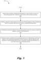
- FIG. 1is a flowchart depicting a method ( 100 ) of stabilizing performance of a processing device according to an example of the principles described herein.
- the processing devicemay be any type of processing device that may receive any type of data from a data storage device as input and provide output.
- the processing devicemay include any combination of electronic circuits to facilitate the processing that data.
- the processing devicemay form part of a computing device such as a server, a desktop computer, a laptop computer, a personal digital assistant (PDA), a mobile device, a smartphone, a gaming system, and a tablet, among other types of computing devices.
- the computing devicemay include various hardware components.
- these hardware componentsmay be the processing device described herein, a number of data storage devices, a number of peripheral device adapters, and a number of network adapters. These hardware components may be interconnected through the use of a number of busses and/or network connections.
- the processing device, data storage device, peripheral device adapters, and a network adaptermay be communicatively coupled via a bus.
- the processing devicemay be thermally and/or mechanically coupled to a heat dump.
- the heat dumpmay be used to transfer heat from the processing device to ambient so as to cool down the processing device.
- the rate at which the heat is transferred from the processing device to ambientmay be determined at the time or manufacturing of the computing device.
- Such informationin an example, may be provided to the processing device for reference as to execute the functionality of the methods described herein.
- the processing devicemay include the hardware architecture to retrieve executable code from the data storage device and execute the executable code.
- the executable codemay, when executed by the processor, cause the processor to implement the functionality described in connection with the methods of the present specification described herein.
- the processing devicemay receive input from and provide output to a number of the remaining hardware units.
- datamay be received and sent to a thermal control circuit to control the clock rate/temperature of the processing device.
- the thermal control circuitmay be in the form of computer executable program code that is executed by the processing device itself or a separate processing device.
- the thermal control circuitmay be in the form of an application specific integrated circuit (ASIC).
- ASICapplication specific integrated circuit
- This ASICmay be accessed by the processing device or be formed as part of the processing device such that, during operation of the processing device, the processing device may have access to information regarding, among other data, the heat transfer characteristics of the heat sink, data descriptive of an expected heat output of the processing device relative to the power consumption, and data descriptive of an expected heat output of the processing device relative to the clock rate of the processing device, among other types of data described herein.
- the data storage device associated with the processing devicemay store data such as executable program code that is executed by the processing device.
- the data storage devicemay specifically store computer code representing a number of applications that the processing device executes to implement the functionality described herein.
- the data storage devicemay include various types of memory modules, including volatile and nonvolatile memory.
- the data storage device of the present exampleincludes Random Access Memory (RAM), Read Only Memory (ROM), and Hard Disk Drive (HDD) memory.
- RAMRandom Access Memory
- ROMRead Only Memory
- HDDHard Disk Drive
- Many other types of memorymay also be utilized, and the present specification contemplates the use of many varying type(s) of memory in the data storage device as may suit a particular application of the principles described herein.
- the method ( 100 )may include determining ( 105 ) a maximum operational temperature of any number of cores of a processing device from a thermal control circuit of the processing device.
- the maximum operational temperature associated with any of the given coresmay be stored on a data storage device and/or maintained by the thermal control circuit as described herein.
- the maximum operational temperaturemay be a maximum operating temperature the processing device may withstand before it fails (i.e., failure temperature) due to overheating.
- the maximum operational temperaturemay be some operating temperature that is less than the failure temperature of the processing device but larger than a manufacturer's operating temperature limit.
- a temperature gaptherefore, is created between the determined ( 105 ) maximum operational temperature and the manufacturer's operating temperature limit.
- the present specificationdescribes operation of the processing device within the temperature gap despite the manufacturer's operating temperature limit.
- the processing device and/or the thermal control circuitmay determine ( 105 ) the maximum operational temperature of any given core.
- the thermal control circuitmay, in real-time, monitor the heat of the processing device and may be used to determine if and when the operating temperature meets or is predicted to meet the maximum operational temperature.
- the maximum operational temperaturemay be a temperature set by the manufacturer of the processing device and may be dependent on a number of factors including the hardware structure of the circuitry of the processing device and the types of materials used to form the processing device, among other factors. Regardless of the factors, however, the maximum operational temperature may be provided at the time of manufacture of the processing device and stored on a data storage device associated with the processing device.
- the method ( 100 )may include setting ( 110 ) a maximum power based on a maximum thermal capacity of the processing device to a power lower than the maximum operational temperature.
- the power provided to the processing devicemay be related to the frequency in Hertz of the clock rate of the processing device.
- the maximum thermal capacitymay be determined by, for example, referring to a look-up table.
- the look-up tablemay include any number of relationships descriptive of the heat produced by the processing device under corresponding power consumption and, accordingly, clock rates.
- the method ( 100 )may continue with increasing ( 115 ) the power provided to the processing device when the maximum thermal capacity is below a set temperature. Because the processing device has accessed data associated with the thermal capacity of the processing device under certain circumstances (i.e., clock rates and heat dissipation capabilities of the heat sink), the power may be increased when a calculated thermal capacity has not reached the maximum operation temperature defined at manufacturing time of the processing device. In an example, the maximum thermal capacity of the processing device may be set to 35 degrees Celsius. In this example the clock rate may set to 4.6 Ghz without increasing the operating temperature of the processing device. Additionally, this results in a power consumption of 150 Watts of power. However, where the current operating temperature is below the maximum thermal capacity, the processor may be overclocked or additional power may be used by the processor to increase the speed of processing. This results in an increase in temperature, but this increase is not excessive to the point of reaching the maximum operational temperature.
- the methodmay continue with placing ( 120 ) the power provided to the processing device to an intermediate power level relative to the operational temperature and the maximum thermal capacity when operations of the processing device are to exceed the operational temperature of any of the cores of the processing device.
- the processormay operate at a higher clock rate while not being throttled.
- normal throttling of the processing devicemay be implemented.
- the performance of the processing devicemay be stabilized resulting in better overall performance.
- the processing devicemay be set to have a maximum power set to be at 150 Watts. This may correspond to the processing device operating at 4.7 Ghz at a set temperature of 35 degrees Celsius. If the actual temperature or predicted temperature of the processing device is lower than 35 degrees Celsius, the processing device may have the capability to run at a relatively higher clock rate such as 4.9 Ghz. However, during a heavy loading process, the power to the processing device may be limited to the 150 Watts based on the set temperature. Where this is the case, the processing device's clock rate would usually drop back from 4.9 Ghz to 4.7 Ghz. With the method ( 100 ) described herein, the power to the processing device may be increased from 150 Watts to 170 Watts and keep the clock rate at 4.9 Ghz.
- the thermal capacitymay be set to a lower power such as 130 Watts thereby preventing any throttling of the clock rate so as to keep the clock of the processing device running at 4.5 Ghz instead of being dropped to 4.3 Ghz.
- FIG. 2is a graph showing the different possible states under different thermal capacity states according to an example of the principles described herein.
- a first state( 205 ) exists where, in this example, the set maximum thermal capacity is 35 degrees Celsius ambient temperature.
- Ambient temperatureis that temperature the predicted temperature of the processing device at a given power level. Again, this ambient temperature may be defined by a look-up table or extrapolated from data about the processing device at the time of manufacture. Because different processing devices comprise different materials and characteristics, specific maximum operational temperatures, maximum powers, maximum thermal capacities, and set temperatures described herein are merely examples and the principles described in the methods and systems herein are merely examples.
- the power level (150 Watts) of the first statemay be defined by the manufacturer of the processing device and results in a default clock rate of 4.6 Ghz.
- the maximum power based on a maximum thermal capacity that is set ( 110 )is 150 Watts.
- the poweris increased to 180 Watts because the ambient temperature has been detected as being 25 degrees Celsius. Because the ambient temperature is lower, the thermal capacity of the processing device is increased allowing for a more power to be provided to the processing device. More power to the processing device results in relatively higher clock rates and, in this example, results in a clock rate of around 4.9 Ghz.
- the processing devicemay operate beyond a predefined maximum power in order to take advantage of a lower ambient temperature situation.
- the processing devicemay be set to a third state ( 215 ).
- a thermal control circuit offset (Tcc) triggermay be overridden based on temperature of the processing device and by the use of the method described herein.
- the Tccmay be triggered upon detection of a threshold processing device temperature, for example, 97 degrees Celsius or, in another example, between 90 and 99 degrees Celsius.
- the processing devicemay stop working for a few milliseconds until the temperature drops below the threshold processing device temperature.
- Such a throttlingcause significantly less power to be provided to the processor: in this example, 130 Watts.
- This state ( 215 )results in significantly lower clock rates (i.e., 4.3 Ghz) even when the thermal capacity of the processing device drops to 140 Watts.
- the processing devicemay be set to a fourth state ( 220 ) when the thermal control circuit detects that the Tcc is or will be triggered.
- the thermal control circuitmay place ( 120 ) the power provided to the processing device to an intermediate power level relative to the operational temperature and the maximum thermal capacity.
- the power provided to the processing device in this state ( 220 )may be 140 Watts. By doing so, a maximum processing power of the processing device may be realized.
- the processing deviceinstead of allowing the processing device to be relegated to the third state ( 215 ), the processing device satisfies both the temperature thresholds and power thresholds that may be placed on the processing device. This method ( 100 ) and system, therefore, prevents damage to the processing device while still achieving, on average, better performance in the form of relatively consistent and higher clock rates.
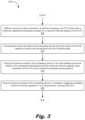
- FIG. 3is a flowchart depicting a method ( 300 ) of operating a central processing unit (CPU) according to an example of the principles described herein.
- the method ( 300 )may include setting ( 305 ) a maximum power provided to a central processing unit (CPU) lower than a maximum operational temperature based on a maximum thermal capacity of the CPU.
- the power provided to the CPUmay then be increased ( 310 ) when the maximum thermal capacity is below a set temperature and at a throttling state.
- the CPUmay be subjected to two distinct restrictions after receipt from a manufacturer: a power limiter (i.e., setting a maximum thermal capacity of the CPU) and a thermal control circuit offset (Tcc) (i.e., setting a throttling temperature).
- a power limiteri.e., setting a maximum thermal capacity of the CPU
- a thermal control circuit offsetTcc
- the method ( 300 )may also include placing ( 315 ) the power provided to the processing device to an intermediate power level relative to the operational temperature and the maximum thermal capacity when operations of the CPU are to exceed the operational temperature. This is done such that, when the power provided to the CPU is increased, a throttling maximum thermal capacity may be engaged ( 320 ) to, for a boost period, overclock the CPU.
- this boost periodmay be 100 milliseconds. In an example, this boost period may be between 50 and 150 milliseconds. Because, in this example, the Tcc is triggered based on temperature data, overclocking, in some circumstances, of the CPU may not necessarily result in the Tcc threshold being met.
- the boost periodis defined by an exponentially weighted moving average (EWMA) and may not be a fixed number across a number of different processing devices.
- the EWMAmay be associated with a chart specific to any given processing device.
- the EWMA chartmay show that a processing device of 70° C. over a period of 30 seconds may result in a 10 second boost.
- the EWMA chartmay show that a processing device shows that a temperature of the processing device is 95° C. has occurred in the past 30 seconds, such a situation may result to the 100 ms of boost period.
- the present specificationcontemplates that a EWMA be used with an accompanying chart, maintained on a data storage device, in order to determine the boost period descried herein.
- FIG. 4is a block diagram of a central processing unit (CPU) adaptive power controller ( 400 ) according to an example of the principles described herein.
- the CPU adaptive power controller ( 400 )may include a CPU ( 405 ) that includes a plurality of cores ( 410 - 1 , 410 - 2 , 410 - 3 , 410 -N).
- the actual number of cores ( 410 - 1 , 410 - 2 , 410 - 3 , 410 -N) within the CPU ( 405 )may vary and the present specification contemplates the use of any CPU ( 405 ) having any number of cores ( 410 - 1 , 410 - 2 , 410 - 3 , 410 -N) therein.
- the CPU ( 405 )may be may be any type of processing device that may receive any type of data from a data storage device as input and provide output.
- the processing devicemay include any combination of electronic circuits to facilitate the processing that data.
- the CPU ( 405 )may form part of a computing device such as a server, a desktop computer, a laptop computer, a personal digital assistant (PDA), a mobile device, a smartphone, a gaming system, and a tablet, among other types of computing devices as described herein.
- PDApersonal digital assistant
- the CPU adaptive power controller ( 400 )may further include a thermal capacity monitor ( 415 ).
- the thermal capacity monitor ( 415 )may be communicatively coupled to the CPU ( 405 ) itself in order to receive input and send data to the CPU ( 405 ) to facilitate the processes and methods described herein. Examples of data that may be exchanged between the thermal capacity monitor ( 415 ) and the CPU ( 405 ) may include temperature data regarding each of the cores ( 410 - 1 , 410 - 2 , 410 - 3 , 410 -N) either as a group or individually and instructions to set the power provided to the CPU ( 405 ) according to the methods ( 100 , 300 ) described herein.
- the thermal capacity monitor ( 415 )may be executed by the CPU ( 405 ) or other processing device to determine a maximum operational temperature of any number of the plurality of cores ( 410 - 1 , 410 - 2 , 410 - 3 , 410 -N) of the CPU ( 405 ) from a thermal control circuit of the CPU ( 405 ).
- the thermal capacity monitor ( 415 )may also increase the power provided to the CPU when the maximum thermal capacity is below a set temperature and at a throttling state. Still further, the thermal capacity monitor ( 415 ) may further place the power provided to the CPU to an intermediate power level relative to the operational temperature and the maximum thermal capacity when operations of the CPU are to exceed the operational temperature.
- the thermal capacity monitor ( 415 )may, when the power provided to the CPU is increased, engage a throttling maximum thermal capacity to, for a boost period, overclock the CPU.
- the boost periodmay be between 50 and 150 milliseconds or may be specific to an EWMA chart as described herein. In an example, the boost period may be 100 milliseconds.
- the maximum operational temperaturemay be between 90 and 110 degrees Celsius. In an example, the maximum operational temperature may be 97 degrees Celsius.
- the computer usable program codemay be provided to a processor of a general-purpose computer, special purpose computer, or other programmable data processing apparatus to produce a machine, such that the computer usable program code, when executed via, for example, the CPU ( 405 ) of a computing device or other programmable data processing apparatus, implement the functions or acts specified in the flowchart and/or block diagram block or blocks.
- the computer usable program codemay be embodied within a computer readable storage medium; the computer readable storage medium being part of the computer program product.
- the computer readable storage mediumis a non-transitory computer readable medium.
- the specification and figuresdescribe a method of stabilizing performance of a processing device and a CPU adaptive power controller to execute that method.
- the CPU adaptive power controllermay increase the overall performance of the processing device it operates such that reductions in clock speed are not realized. This allows for the computing device to operate at a speed not realized without the execution of the methods described herein.
Landscapes
- Engineering & Computer Science (AREA)
- Theoretical Computer Science (AREA)
- Physics & Mathematics (AREA)
- General Engineering & Computer Science (AREA)
- General Physics & Mathematics (AREA)
- Software Systems (AREA)
- Human Computer Interaction (AREA)
- Power Sources (AREA)
Abstract
Description
P=C*V2(a*f) Eq. 1
where “P” is the power provided to the processing device, “V” is the voltage of the energy provided to the processing device, “F” is the frequency (clock rate) measured in Hertz (Hz), “C” is a constant associated with the energy stored by a capacitor, and “a” is a constant.
Claims (20)
Applications Claiming Priority (1)
| Application Number | Priority Date | Filing Date | Title |
|---|---|---|---|
| PCT/US2019/012607WO2020145943A1 (en) | 2019-01-08 | 2019-01-08 | Stabilizing performance of processing devices |
Publications (2)
| Publication Number | Publication Date |
|---|---|
| US20210326188A1 US20210326188A1 (en) | 2021-10-21 |
| US12141624B2true US12141624B2 (en) | 2024-11-12 |
Family
ID=71520235
Family Applications (1)
| Application Number | Title | Priority Date | Filing Date |
|---|---|---|---|
| US17/059,579Active2040-07-12US12141624B2 (en) | 2019-01-08 | 2019-01-08 | Stabilizing performance of processing devices |
Country Status (4)
| Country | Link |
|---|---|
| US (1) | US12141624B2 (en) |
| EP (1) | EP3908903A4 (en) |
| CN (1) | CN113366409B (en) |
| WO (1) | WO2020145943A1 (en) |
Families Citing this family (2)
| Publication number | Priority date | Publication date | Assignee | Title |
|---|---|---|---|---|
| US20230213999A1 (en)* | 2022-01-06 | 2023-07-06 | Nvidia Corporation | Techniques for controlling computing performance for power-constrained multi-processor computing systems |
| US12314764B1 (en)* | 2024-05-31 | 2025-05-27 | Auradine Inc. | Differential control of aggregated cryptographic hardware assets |
Citations (47)
| Publication number | Priority date | Publication date | Assignee | Title |
|---|---|---|---|---|
| US20050060589A1 (en)* | 2001-11-16 | 2005-03-17 | Athas William C. | Method and apparatus for increasing the operating frequency of an electronic circuit |
| US20050071705A1 (en)* | 2003-09-29 | 2005-03-31 | Ati Technologies, Inc. | Adaptive temperature dependent feedback clock control system and method |
| US20050210905A1 (en)* | 2004-03-24 | 2005-09-29 | Burns James S | Separate thermal and electrical throttling limits in processors |
| US20060004538A1 (en)* | 2004-06-30 | 2006-01-05 | Cancel Ramon C | Method for adaptive performance margining with thermal feedback |
| CN101171564A (en) | 2005-05-11 | 2008-04-30 | 英特尔公司 | Seamless transition of operating environments in mobile systems for power optimization |
| US20090235108A1 (en)* | 2008-03-11 | 2009-09-17 | Gold Spencer M | Automatic processor overclocking |
| US20100064162A1 (en)* | 2008-09-05 | 2010-03-11 | Efraim Rotem | Techniques to manage operational parameters for a processor |
| US8006108B2 (en) | 2007-11-08 | 2011-08-23 | International Business Machines Corporation | Dynamic selection of group and device power limits |
| US8086884B2 (en) | 2002-12-16 | 2011-12-27 | Hewlett-Packard Development Company, L.P. | System and method for implementing an integrated circuit having dynamically variable power limit |
| US20120066535A1 (en)* | 2010-09-14 | 2012-03-15 | Naffziger Samuel D | Mechanism for controlling power consumption in a processing node |
| US20120102348A1 (en) | 2010-10-21 | 2012-04-26 | Muralidhar Rajeev D | Fine grained power management in virtualized mobile platforms |
| US20120110352A1 (en)* | 2010-10-29 | 2012-05-03 | Alexander Branover | Method and apparatus for thermal control of processing nodes |
| US20130117590A1 (en)* | 2011-11-03 | 2013-05-09 | International Business Machines Corporation | Minimizing Aggregate Cooling and Leakage Power with Fast Convergence |
| US20130159741A1 (en) | 2011-12-15 | 2013-06-20 | Travis T. Schluessler | Method, Apparatus, and System for Energy Efficiency and Energy Conservation Including Power and Performance Balancing Between Multiple Processing Elements and/or a Communication Bus |
| US20130332753A1 (en)* | 2012-03-29 | 2013-12-12 | Ankush Varma | Dynamic power limit sharing in a platform |
| US20130328890A1 (en) | 2012-06-07 | 2013-12-12 | Gokhan Avkarogullari | GPU with Dynamic Performance Adjustment |
| US20140086053A1 (en)* | 2012-09-21 | 2014-03-27 | Fujitsu Limited | Method for controlling information processing apparatus and information processing apparatus |
| US8788859B2 (en) | 2000-12-28 | 2014-07-22 | Intel Corporation | Thermal sensitivity based clock frequency adjustment for dynamic power control of a processor |
| US8786449B1 (en)* | 2009-12-16 | 2014-07-22 | Applied Micro Circuits Corporation | System-on-chip with thermal management core |
| WO2014197731A1 (en) | 2013-06-07 | 2014-12-11 | Apple Inc. | Computer thermal system |
| US9063785B2 (en)* | 2004-11-03 | 2015-06-23 | Intel Corporation | Temperature-based thread scheduling |
| US20150331433A1 (en)* | 2014-05-14 | 2015-11-19 | Advanced Micro Devices, Inc. | Hybrid system and method for determining performance levels based on thermal conditions within a processor |
| US20160034009A1 (en)* | 2014-08-01 | 2016-02-04 | Mediatek Inc. | Thermal protection method for referring to thermal headroom to control selection of computing power setting of processor-based system and related machine readable medium |
| US20160070627A1 (en) | 2014-09-08 | 2016-03-10 | Quanta Computer Inc. | Backup management control in a server system |
| US20160147280A1 (en)* | 2014-11-26 | 2016-05-26 | Tessil Thomas | Controlling average power limits of a processor |
| US20160266628A1 (en)* | 2015-03-09 | 2016-09-15 | Advanced Micro Devices, Inc. | Power management to change power limits based on device skin temperature |
| US20160274629A1 (en)* | 2015-03-20 | 2016-09-22 | Dominick Adam Lovicott | Systems And Methods Of Adaptive Thermal Control For Information Handling Systems |
| US9524012B2 (en) | 2012-10-05 | 2016-12-20 | Dell Products L.P. | Power system utilizing processor core performance state control |
| GB2540804A (en) | 2015-07-29 | 2017-02-01 | Samsung Electronics Co Ltd | Hardware Power Management Apparatus and Methods |
| US20170131754A1 (en)* | 2015-11-10 | 2017-05-11 | Intel Corporation | Dynamically Optimizing Power Management Operational Parameters Of A Processor |
| US9652019B2 (en) | 2014-06-02 | 2017-05-16 | Advanced Micro Devices, Inc. | System and method for adjusting processor performance based on platform and ambient thermal conditions |
| US20170264493A1 (en) | 2015-03-09 | 2017-09-14 | Vapor IO Inc. | Autonomous distributed workload and infrastructure scheduling |
| US20170285700A1 (en) | 2016-03-31 | 2017-10-05 | Intel Corporation | Systems, methods and devices for using thermal margin of a core in a processor |
| US20180199424A1 (en)* | 2017-01-10 | 2018-07-12 | Samsung Electronics Co., Ltd. | Method of dynamic thermal management |
| US20180210522A1 (en)* | 2017-01-20 | 2018-07-26 | Qualcomm Incorporated | System and method for context-aware thermal management and workload scheduling in a portable computing device |
| US20180324979A1 (en)* | 2017-05-03 | 2018-11-08 | Dell Products L.P. | Apparatus and methods for characterizing a heat pipe and for controlling an operating parameter of at least one heat generating component coupled to the heat pipe |
| US20190004575A1 (en)* | 2017-06-30 | 2019-01-03 | Dell Products L.P. | Systems and methods for thermal throttling via processor core count reduction and thermal load line shift |
| US20190129498A1 (en)* | 2018-12-27 | 2019-05-02 | Patrick Kam-shing Leung | Classification prediction of workload thermal behavior |
| US10509449B2 (en)* | 2017-07-07 | 2019-12-17 | Hewlett Packard Enterprise Development Lp | Processor power adjustment |
| US20200104573A1 (en)* | 2017-09-06 | 2020-04-02 | Shanghai Cambricon Information Technology Co., Ltd. | Data processing apparatus and method |
| US20200225724A1 (en)* | 2019-03-28 | 2020-07-16 | Intel Corporation | Platform slicing of central processing unit (cpu) resources |
| US10817039B2 (en)* | 2018-08-31 | 2020-10-27 | Hewlett Packard Enterprise Development Lp | Adjusting a power limit in response to a temperature difference |
| US10911634B2 (en)* | 2018-12-26 | 2021-02-02 | Canon Kabushiki Kaisha | Image forming apparatus |
| US11188379B2 (en)* | 2018-09-21 | 2021-11-30 | International Business Machines Corporation | Thermal capacity optimization for maximized single core performance |
| US11262832B2 (en)* | 2018-03-19 | 2022-03-01 | Hewlett-Packard Development Company, L.P. | Power consumption control of computing devices |
| US11709627B2 (en)* | 2020-03-05 | 2023-07-25 | Canon Kabushiki Kaisha | Recording control apparatus for accessing a plurality of recording media and method for controlling said recording control apparatus |
| US11709529B2 (en)* | 2021-10-12 | 2023-07-25 | Hewlett Packard Enterprise Development Lp | Variable enhanced processor performance |
Family Cites Families (1)
| Publication number | Priority date | Publication date | Assignee | Title |
|---|---|---|---|---|
| US9292293B2 (en)* | 2013-08-08 | 2016-03-22 | Qualcomm Incorporated | Intelligent multicore control for optimal performance per watt |
- 2019
- 2019-01-08EPEP19909367.5Apatent/EP3908903A4/enactivePending
- 2019-01-08USUS17/059,579patent/US12141624B2/enactiveActive
- 2019-01-08CNCN201980091435.2Apatent/CN113366409B/enactiveActive
- 2019-01-08WOPCT/US2019/012607patent/WO2020145943A1/ennot_activeCeased
Patent Citations (55)
| Publication number | Priority date | Publication date | Assignee | Title |
|---|---|---|---|---|
| US8788859B2 (en) | 2000-12-28 | 2014-07-22 | Intel Corporation | Thermal sensitivity based clock frequency adjustment for dynamic power control of a processor |
| US20050060589A1 (en)* | 2001-11-16 | 2005-03-17 | Athas William C. | Method and apparatus for increasing the operating frequency of an electronic circuit |
| US8086884B2 (en) | 2002-12-16 | 2011-12-27 | Hewlett-Packard Development Company, L.P. | System and method for implementing an integrated circuit having dynamically variable power limit |
| US20050071705A1 (en)* | 2003-09-29 | 2005-03-31 | Ati Technologies, Inc. | Adaptive temperature dependent feedback clock control system and method |
| US20050210905A1 (en)* | 2004-03-24 | 2005-09-29 | Burns James S | Separate thermal and electrical throttling limits in processors |
| US20060004538A1 (en)* | 2004-06-30 | 2006-01-05 | Cancel Ramon C | Method for adaptive performance margining with thermal feedback |
| US9063785B2 (en)* | 2004-11-03 | 2015-06-23 | Intel Corporation | Temperature-based thread scheduling |
| CN101171564A (en) | 2005-05-11 | 2008-04-30 | 英特尔公司 | Seamless transition of operating environments in mobile systems for power optimization |
| US20090172450A1 (en) | 2005-05-11 | 2009-07-02 | Wong Hong W | Mobile systems with seamless transition by activating second subsystem to continue operation of application executed by first subsystem as it enters sleep mode |
| US8006108B2 (en) | 2007-11-08 | 2011-08-23 | International Business Machines Corporation | Dynamic selection of group and device power limits |
| US20090235108A1 (en)* | 2008-03-11 | 2009-09-17 | Gold Spencer M | Automatic processor overclocking |
| US20100064162A1 (en)* | 2008-09-05 | 2010-03-11 | Efraim Rotem | Techniques to manage operational parameters for a processor |
| US9032223B2 (en) | 2008-09-05 | 2015-05-12 | Intel Corporation | Techniques to manage operational parameters for a processor |
| US8786449B1 (en)* | 2009-12-16 | 2014-07-22 | Applied Micro Circuits Corporation | System-on-chip with thermal management core |
| US20120066535A1 (en)* | 2010-09-14 | 2012-03-15 | Naffziger Samuel D | Mechanism for controlling power consumption in a processing node |
| US20120102348A1 (en) | 2010-10-21 | 2012-04-26 | Muralidhar Rajeev D | Fine grained power management in virtualized mobile platforms |
| CN107145211A (en) | 2010-10-21 | 2017-09-08 | 英特尔公司 | Virtualize the fine-grained power management in mobile platform |
| US20120110352A1 (en)* | 2010-10-29 | 2012-05-03 | Alexander Branover | Method and apparatus for thermal control of processing nodes |
| US8793512B2 (en)* | 2010-10-29 | 2014-07-29 | Advanced Micro Devices, Inc. | Method and apparatus for thermal control of processing nodes |
| US20130117590A1 (en)* | 2011-11-03 | 2013-05-09 | International Business Machines Corporation | Minimizing Aggregate Cooling and Leakage Power with Fast Convergence |
| CN104115093A (en) | 2011-12-15 | 2014-10-22 | 英特尔公司 | Methods, apparatus and systems for energy efficiency and conservation including power and performance balancing among multiple processing elements |
| US20130159741A1 (en) | 2011-12-15 | 2013-06-20 | Travis T. Schluessler | Method, Apparatus, and System for Energy Efficiency and Energy Conservation Including Power and Performance Balancing Between Multiple Processing Elements and/or a Communication Bus |
| US20130332753A1 (en)* | 2012-03-29 | 2013-12-12 | Ankush Varma | Dynamic power limit sharing in a platform |
| US20130328890A1 (en) | 2012-06-07 | 2013-12-12 | Gokhan Avkarogullari | GPU with Dynamic Performance Adjustment |
| US20140086053A1 (en)* | 2012-09-21 | 2014-03-27 | Fujitsu Limited | Method for controlling information processing apparatus and information processing apparatus |
| US9524012B2 (en) | 2012-10-05 | 2016-12-20 | Dell Products L.P. | Power system utilizing processor core performance state control |
| WO2014197731A1 (en) | 2013-06-07 | 2014-12-11 | Apple Inc. | Computer thermal system |
| CN204189111U (en) | 2013-06-07 | 2015-03-04 | 苹果公司 | Heat management system, cooling system, compact computing system, desk-top computing system |
| US20150331433A1 (en)* | 2014-05-14 | 2015-11-19 | Advanced Micro Devices, Inc. | Hybrid system and method for determining performance levels based on thermal conditions within a processor |
| US9652019B2 (en) | 2014-06-02 | 2017-05-16 | Advanced Micro Devices, Inc. | System and method for adjusting processor performance based on platform and ambient thermal conditions |
| US20160034009A1 (en)* | 2014-08-01 | 2016-02-04 | Mediatek Inc. | Thermal protection method for referring to thermal headroom to control selection of computing power setting of processor-based system and related machine readable medium |
| CN105404366A (en) | 2014-09-08 | 2016-03-16 | 广达电脑股份有限公司 | Method for backup management control in server rack system and server rack |
| US20160070627A1 (en) | 2014-09-08 | 2016-03-10 | Quanta Computer Inc. | Backup management control in a server system |
| US20160147280A1 (en)* | 2014-11-26 | 2016-05-26 | Tessil Thomas | Controlling average power limits of a processor |
| US20160266628A1 (en)* | 2015-03-09 | 2016-09-15 | Advanced Micro Devices, Inc. | Power management to change power limits based on device skin temperature |
| US20170264493A1 (en) | 2015-03-09 | 2017-09-14 | Vapor IO Inc. | Autonomous distributed workload and infrastructure scheduling |
| US20160274629A1 (en)* | 2015-03-20 | 2016-09-22 | Dominick Adam Lovicott | Systems And Methods Of Adaptive Thermal Control For Information Handling Systems |
| GB2540804A (en) | 2015-07-29 | 2017-02-01 | Samsung Electronics Co Ltd | Hardware Power Management Apparatus and Methods |
| US20170131754A1 (en)* | 2015-11-10 | 2017-05-11 | Intel Corporation | Dynamically Optimizing Power Management Operational Parameters Of A Processor |
| US20170285700A1 (en) | 2016-03-31 | 2017-10-05 | Intel Corporation | Systems, methods and devices for using thermal margin of a core in a processor |
| CN108780342A (en) | 2016-03-31 | 2018-11-09 | 英特尔公司 | Systems, methods and apparatus for utilizing thermal margin of cores in a processor |
| US20180199424A1 (en)* | 2017-01-10 | 2018-07-12 | Samsung Electronics Co., Ltd. | Method of dynamic thermal management |
| US20180210522A1 (en)* | 2017-01-20 | 2018-07-26 | Qualcomm Incorporated | System and method for context-aware thermal management and workload scheduling in a portable computing device |
| US20180324979A1 (en)* | 2017-05-03 | 2018-11-08 | Dell Products L.P. | Apparatus and methods for characterizing a heat pipe and for controlling an operating parameter of at least one heat generating component coupled to the heat pipe |
| US20190004575A1 (en)* | 2017-06-30 | 2019-01-03 | Dell Products L.P. | Systems and methods for thermal throttling via processor core count reduction and thermal load line shift |
| US10509449B2 (en)* | 2017-07-07 | 2019-12-17 | Hewlett Packard Enterprise Development Lp | Processor power adjustment |
| US20200104573A1 (en)* | 2017-09-06 | 2020-04-02 | Shanghai Cambricon Information Technology Co., Ltd. | Data processing apparatus and method |
| US11262832B2 (en)* | 2018-03-19 | 2022-03-01 | Hewlett-Packard Development Company, L.P. | Power consumption control of computing devices |
| US10817039B2 (en)* | 2018-08-31 | 2020-10-27 | Hewlett Packard Enterprise Development Lp | Adjusting a power limit in response to a temperature difference |
| US11188379B2 (en)* | 2018-09-21 | 2021-11-30 | International Business Machines Corporation | Thermal capacity optimization for maximized single core performance |
| US10911634B2 (en)* | 2018-12-26 | 2021-02-02 | Canon Kabushiki Kaisha | Image forming apparatus |
| US20190129498A1 (en)* | 2018-12-27 | 2019-05-02 | Patrick Kam-shing Leung | Classification prediction of workload thermal behavior |
| US20200225724A1 (en)* | 2019-03-28 | 2020-07-16 | Intel Corporation | Platform slicing of central processing unit (cpu) resources |
| US11709627B2 (en)* | 2020-03-05 | 2023-07-25 | Canon Kabushiki Kaisha | Recording control apparatus for accessing a plurality of recording media and method for controlling said recording control apparatus |
| US11709529B2 (en)* | 2021-10-12 | 2023-07-25 | Hewlett Packard Enterprise Development Lp | Variable enhanced processor performance |
Non-Patent Citations (2)
| Title |
|---|
| Brooks et al.; "Dynamic Thermal Management for High-Performance Microprocessors"; IEEE 2001; (Brooks_2001.pdf; pp. 171-182) (Year: 2001).* |
| Camponogara et al., "A Model Considering QoS for Real-Time Systems with Energy and Temperature Constraints", Brazilian Symposium on Computing Systems Engineering, Nov. 2014, 6 pgs. |
Also Published As
| Publication number | Publication date |
|---|---|
| CN113366409B (en) | 2024-07-23 |
| WO2020145943A1 (en) | 2020-07-16 |
| EP3908903A1 (en) | 2021-11-17 |
| EP3908903A4 (en) | 2022-08-17 |
| CN113366409A (en) | 2021-09-07 |
| US20210326188A1 (en) | 2021-10-21 |
Similar Documents
| Publication | Publication Date | Title |
|---|---|---|
| CN107690626B (en) | Method and apparatus for thermal throttling of electronic devices | |
| US10331185B2 (en) | Temperature trend controlled cooling system | |
| US10156987B1 (en) | Temperature management in a data storage system | |
| US9304565B2 (en) | Information handling system power supply automated de-rating for power output and thermal constraints | |
| US9274805B2 (en) | System and method for thermally aware device booting | |
| KR102151628B1 (en) | Ssd driven system level thermal management | |
| CN113826082B (en) | Method and equipment for controlling heat dissipation device | |
| US9852714B2 (en) | Energy conservation in a controller using dynamic frequency selection | |
| US11579672B1 (en) | Thermal mass aware thermal management | |
| US12141624B2 (en) | Stabilizing performance of processing devices | |
| US20060174146A1 (en) | Microprocessor performance mode control utilizing sensed temperature as an indication of microprocessor utilization | |
| US10514848B2 (en) | Data storage method for selectively storing data in a buffer preset in a memory of an electronic device or an inherent buffer in an SSD | |
| US11836028B2 (en) | System and method for closed-loop memory power capping | |
| US11500436B2 (en) | System and method for predictive fan speed control and management | |
| US20240411637A1 (en) | Electronic device providing warning message through communication interface, and method of operating the same | |
| HK40051555A (en) | Stabilizing performance of processing devices | |
| US11614786B2 (en) | Power limit alterations of component types | |
| US20250103026A1 (en) | Power management of edge devices to maintain minimum temperature compliance | |
| US20240353494A1 (en) | Intelligent risk prevention mode for abnormal battery temperature prediction | |
| US11435796B2 (en) | Power backup device charging system | |
| US20250311144A1 (en) | Proactive temperature and fan speed based utility qos triggering | |
| CN120604191A (en) | Energy-efficient Vmin architecture for shared power rails | |
| KR20170076306A (en) | The apparatus and method for managing heat of mobile device |
Legal Events
| Date | Code | Title | Description |
|---|---|---|---|
| AS | Assignment | Owner name:HEWLETT-PACKARD DEVELOPMENT COMPANY, L.P., TEXAS Free format text:ASSIGNMENT OF ASSIGNORS INTEREST;ASSIGNORS:HSU, CHUN JUNG;HSU, HSIH SUNG;REEL/FRAME:054487/0970 Effective date:20190109 | |
| FEPP | Fee payment procedure | Free format text:ENTITY STATUS SET TO UNDISCOUNTED (ORIGINAL EVENT CODE: BIG.); ENTITY STATUS OF PATENT OWNER: LARGE ENTITY | |
| STPP | Information on status: patent application and granting procedure in general | Free format text:DOCKETED NEW CASE - READY FOR EXAMINATION | |
| STPP | Information on status: patent application and granting procedure in general | Free format text:NON FINAL ACTION MAILED | |
| STPP | Information on status: patent application and granting procedure in general | Free format text:RESPONSE TO NON-FINAL OFFICE ACTION ENTERED AND FORWARDED TO EXAMINER | |
| STPP | Information on status: patent application and granting procedure in general | Free format text:FINAL REJECTION MAILED | |
| STPP | Information on status: patent application and granting procedure in general | Free format text:RESPONSE AFTER FINAL ACTION FORWARDED TO EXAMINER | |
| STPP | Information on status: patent application and granting procedure in general | Free format text:ADVISORY ACTION MAILED | |
| STPP | Information on status: patent application and granting procedure in general | Free format text:DOCKETED NEW CASE - READY FOR EXAMINATION | |
| STPP | Information on status: patent application and granting procedure in general | Free format text:NOTICE OF ALLOWANCE MAILED -- APPLICATION RECEIVED IN OFFICE OF PUBLICATIONS | |
| ZAAB | Notice of allowance mailed | Free format text:ORIGINAL CODE: MN/=. | |
| STPP | Information on status: patent application and granting procedure in general | Free format text:PUBLICATIONS -- ISSUE FEE PAYMENT VERIFIED | |
| STCF | Information on status: patent grant | Free format text:PATENTED CASE |