US12140404B2 - Scope turret - Google Patents
Scope turretDownload PDFInfo
- Publication number
- US12140404B2 US12140404B2US16/923,644US202016923644AUS12140404B2US 12140404 B2US12140404 B2US 12140404B2US 202016923644 AUS202016923644 AUS 202016923644AUS 12140404 B2US12140404 B2US 12140404B2
- Authority
- US
- United States
- Prior art keywords
- turret
- screw
- elevation
- guide surface
- windage
- Prior art date
- Legal status (The legal status is an assumption and is not a legal conclusion. Google has not performed a legal analysis and makes no representation as to the accuracy of the status listed.)
- Active
Links
Images


Classifications
- F—MECHANICAL ENGINEERING; LIGHTING; HEATING; WEAPONS; BLASTING
- F41—WEAPONS
- F41G—WEAPON SIGHTS; AIMING
- F41G1/00—Sighting devices
- F41G1/38—Telescopic sights specially adapted for smallarms or ordnance; Supports or mountings therefor
- G—PHYSICS
- G02—OPTICS
- G02B—OPTICAL ELEMENTS, SYSTEMS OR APPARATUS
- G02B23/00—Telescopes, e.g. binoculars; Periscopes; Instruments for viewing the inside of hollow bodies; Viewfinders; Optical aiming or sighting devices
- G02B23/14—Viewfinders
- G—PHYSICS
- G02—OPTICS
- G02B—OPTICAL ELEMENTS, SYSTEMS OR APPARATUS
- G02B23/00—Telescopes, e.g. binoculars; Periscopes; Instruments for viewing the inside of hollow bodies; Viewfinders; Optical aiming or sighting devices
- G02B23/16—Housings; Caps; Mountings; Supports, e.g. with counterweight
- G—PHYSICS
- G02—OPTICS
- G02B—OPTICAL ELEMENTS, SYSTEMS OR APPARATUS
- G02B7/00—Mountings, adjusting means, or light-tight connections, for optical elements
- G02B7/02—Mountings, adjusting means, or light-tight connections, for optical elements for lenses
- G02B7/023—Mountings, adjusting means, or light-tight connections, for optical elements for lenses permitting adjustment
Definitions
- the present inventionrelates generally to the field of optic sighting devices. More particularly, the present invention relates to devices and methods for conveniently adjusting such optics.
- a turretis one of two controls on the outside center part of a rifle scope body. Turrets are marked in increments and are used to adjust elevation and windage for points of impact change. Conventional turrets have markings on them that indicate how many clicks of adjustment have been dialed in on the turret, or an angular deviation, or a distance compensation for a given cartridge. A click is one tactile adjustment increment on the windage or elevation turret of a scope.
- the downward acceleration on the projectile imparted by gravityis of significance.
- the effect of gravity on a projectile in flightis often referred to as bullet drop because it causes the bullet to drop from the shooter's line of sight.
- the sighting components of a gunmust compensate for the effect of bullet drop.
- An adjustment to the angular position of the rifle scope relative to the rifle barrelis made using the elevation turret to compensate for bullet drop.
- any horizontal forces imparted on the projectileis of significance.
- the effect of wind on a projectile in flightis often referred to as drift because it causes the bullet to drift right or left from the shooter's line of sight.
- driftFor accuracy at longer distances, the sighting components of a gun must compensate for the effect of drift.
- An adjustment to the angular position of the rifle scope relative to the axis of the rifle barrelis made using the windage turret to compensate for drift.
- Conventional turretsallow for multiple rotations in order to enable the scope to compensate for longer-range targets or environmental conditions such as wind.
- conventional turretstypically omit at least one of the following functions: adjustment stops that prevent adjustment of the elevation and windage turrets beyond preset amounts, rotation indicator/counter, or turret locking.
- adjustment stopsthat prevent adjustment of the elevation and windage turrets beyond preset amounts
- rotation indicator/counteror turret locking.
- users of conventional turretsmay lose track of how many rotations are dialed in if they do not carefully count the number of rotations both while dialing away from the zero point and when dialing towards the zero point even when the turret's markings are visible.
- turretscan be easily bumped, and in dark conditions where it may be difficult to see the turret markings, the user may not realize the turrets have been inadvertently adjusted if the turret lacks a locking mechanism.
- Another difficulty with existing rifle scopesis that certain operating conditions require the user to remember both how many clicks and the direction of rotation needed to return the elevation turret to its zero point from a different setting.
- light conditionsare poor, such as at twilight, night, or in darkened rooms of buildings, or if it is difficult for the user to hear or feel the clicks, it is very easy for the user to lose track of what adjustment is needed to return to the zero point.
- the markingsmay not be sufficiently visible and the absence of a tactile rotation indicator is keenly felt. This is particularly significant for police and military users of firearms, who in the course of their duties may very likely be confronted with a threat under poor lighting conditions.
- huntersmay hunt at twilight or in deep shade.
- markingsare necessarily small, making them difficult to read under borderline conditions. While this may be a concern when making fine adjustments, it is of greater concern when a user must make large changes involving several revolutions of a knob, which may lead to an error in the number of revolutions made.
- the spiral cam mechanism according to the present inventionsubstantially departs from the conventional concepts and designs of the prior art, and in doing so provides an apparatus primarily developed for the purpose of preventing adjustment of a turret beyond a preset amount, giving the user an indication of how many rotations have been dialed on the turret, and giving the user the ability to lock the turret.
- One embodiment of the present inventionprovides an improved rifle scope with adjustment stops, rotation indicator, and locking mechanism, and overcomes the above-mentioned disadvantages and drawbacks of the prior art.
- one embodiment of the present inventionessentially comprises a scope body, a movable optical element defining an optical axis enclosed by the scope body, and a turret having a screw operably connected to the optical element for adjusting the optical axis in response to rotation of the screw.
- the turrethas a spiral cam mechanism engaged thereto.
- the turretdefines first and second stop surfaces positioned for engagement by the spiral cam to limit rotation of the turret.
- the first stop surfacedefines a zero position of the screw and the movable optical element.
- the second stop surfacedefines a maximum point of displacement of the screw and the moveable optical element.
- the stop surfacesmay be defined by a spiral cam groove in the indexing portion of the turret.
- the spiral cam groovemay overlap itself at least partially.
- the turretmay be an elevation turret or a windage turret.
- FIG. 1is a side view of an embodiment of the rifle scope with adjustment stops.
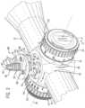
- FIG. 2is a top perspective exploded view of an elevation turret screw subassembly.
- FIG. 3is a top perspective exploded view of the elevation turret screw subassembly and turret housing.
- FIG. 4is a top perspective view of an elevation turret chassis and elevation indicator.
- FIG. 5 Ais a top perspective view of an elevation cam disc.
- FIG. 5 Bis a bottom perspective view of the elevation cam disc.
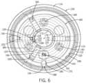
- FIG. 6is a top view of the elevation cam disc inserted into the elevation turret chassis with the elevation cam disc rendered partially transparent.
- FIG. 7 Ais a top perspective exploded view of the elevation turret chassis subassembly.
- FIG. 7 Bis a side sectional view of the elevation turret chassis subassembly of FIG. 8 A taken along the line 7 B- 7 B.
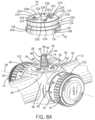
- FIG. 8 Ais a top perspective exploded view of the elevation turret chassis subassembly, elevation turret screw subassembly, and turret housing.
- FIG. 8 Bis a side sectional view of the elevation turret chassis subassembly, elevation turret screw subassembly, and turret housing.
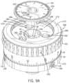
- FIG. 9 Ais a top perspective exploded view of an elevation micro adjuster and elevation outer knob.
- FIG. 9 Bis a side sectional view of the elevation micro adjuster, elevation outer knob, elevation turret chassis subassembly, and elevation turret screw subassembly of FIG. 1 taken along the line 9 B- 9 B.
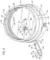
- FIG. 10is a top perspective view of a windage turret chassis.
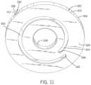
- FIG. 11is a bottom perspective view of the windage cam disc of FIG. 10 .
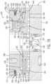
- FIG. 12is a side sectional view of the windage turret of FIG. 3 taken along the line 12 - 12 .
- FIG. 13is a side sectional view of the rifle scope with adjustment stops of FIG. 1 taken along the line 13 - 13 .
- FIG. 14 Ais a rear view of the rifle scope with adjustment stops of FIG. 1 with the elevation turret in the locked position.
- FIG. 14 Bis a rear view of the rifle scope with adjustment stops of FIG. 1 with the elevation turret in the unlocked position.
- FIG. 15 Ais a rear view of the rifle scope with adjustment stops of FIG. 1 with the elevation turret having made one rotation.
- FIG. 15 Bis a rear view of the rifle scope with adjustment stops of FIG. 1 with the elevation turret having made two rotations.
- An embodiment of the rifle scope with spiral cam mechanismis shown and generally designated by the reference numeral 10 .
- FIG. 1illustrates one embodiment of an improved sighting device, such as a rifle scope with spiral cam mechanism 10 .
- the rifle scope or a sighting device 10has a body 12 , in the embodiment shown, a scope body, that encloses a movable optical element 248 (shown in FIG. 13 ), which is an erector tube.
- the scope bodyis an elongate tube having a larger opening at its front 14 and a smaller opening at its rear 16 .
- An eyepiece 18is attached to the rear of the scope body, and an objective lens 20 is attached to the front of the scope body.
- the center axis of the movable optical elementdefines the optical axis 506 of the rifle scope.
- An elevation turret 22 and a windage turret 24are two dials on the outside center part of the scope body 12 . They are marked in increments by indicia 34 on their perimeters 30 and 32 and are used to adjust the elevation and windage of the movable optical element 248 for points of impact change. These turrets protrude from the turret housing 36 . The turrets are arranged so that the elevation turret rotation axis 26 is perpendicular to the windage turret rotation axis 28 . Indicia typically include tick marks, each corresponding to a click, and larger tick marks at selected intervals, as well as numerals indicating angle of adjustment or distance for bullet drop compensation.
- the movable optical element 248is adjusted by rotating the turrets one or more clicks.
- a clickis one tactile adjustment increment on the windage or elevation turret of the rifle scope, each of which corresponds to one of the indicia 34 .
- one clickchanges the scope's point of impact by 0.1 mrad.
- FIG. 2illustrates the improved turret screw subassembly 88 .
- the turret screw subassemblyconsists of a turret screw 38 , a turret screw base 60 , a friction pad 86 , and various fasteners.
- the turret screwis a cylindrical body made of brass in one embodiment.
- the top 40 of the turret screwdefines a slot 48 , and two opposing cam slots 46 run from the top part way down the side 44 .
- Two 0 -ring grooves 50 and 52are on the side located below the cam slots.
- the bottom 42 of the turret screwhas a reduced radius portion 56 that defines a ring slot 54 .
- the ring slot 54receives a retaining ring 84 , and a bore 304 in the bottom 42 receives the shaft 306 of the friction pad 86 .
- the side of the turret screw immediately below the 0-ring groove 52 and above the ring slot 54is a threaded portion 58 .
- the slot 48is shaped to receive a straight blade screwdriver, but could be shaped to receive a hex key or any other suitable type of driver.
- the turret screw base 60is a disc-shaped body made of brass in one embodiment.
- a cylindrical collar 66rises from the center of the top 62 of the turret screw base.
- the collarhas a turret screw bore 68 with threads 70 .
- the exterior of the collardefines a set screw V-groove 78 above the top of the turret screw base, an 0-ring groove 76 above the set screw V-groove, an 0-ring groove 74 above the 0-ring groove 76 , and a ring slot 72 above the 0-ring groove 74 .
- the turret screw basehas three mount holes 82 with smooth sides and a shoulder that receive screws 80 .
- FIG. 3illustrates the improved turret screw subassembly 88 and turret housing 36 . More particularly, the turret screw subassembly 88 is shown assembled and in the process of being mounted on the turret housing 36 .
- the top 92 of the turret housingdefines a recess 94 .
- Three mount holes 96 with threads 98 and a smooth central bore 508are defined in the top of the turret housing within the recess.
- the threads 70 of the turret screw bore 68are fine such that the turret screw bore may receive the threads 58 on the turret screw 38 .
- the retaining ring 84limits upward travel of the turret screw so that the turret screw cannot be inadvertently removed from the turret screw bore.
- the turret screw subassembly 88When the turret screw subassembly 88 is mounted on the turret housing 36 , screws 80 are inserted into the mount holes 82 and protrude from the bottom 64 of the turret screw base 60 . The screws are then screwed into the mount holes 96 in the turret housing to mount the turret screw base to the turret housing. Subsequently, the turret screw base remains in a fixed position with respect to the scope body 12 when the elevation turret 22 is rotated. This essentially makes the turret screw base functionally unitary with the scope body, and the turret screw base is not intended to be removed or adjusted by the user.
- the smooth central bore 508 in the top of the turret housingpermits passage of the friction pad 86 and the bottom 42 of the turret screw into the scope body.
- FIG. 4illustrates the improved elevation turret chassis 100 .
- the top 110 of the elevation turret chassishas an interior perimeter 102 with a relief cut 240 adjacent to the floor 264 , a toothed surface 108 above the relief cut, a lower click groove 106 above the toothed surface, and an upper click groove 104 above the lower click groove.
- the relief cutis for the tool that cuts the toothed surface.
- the floordefines a smooth central bore 120 and a slot 122 .
- the smooth central borepermits passage of the friction pad 86 and the bottom 42 of the turret screw through the turret chassis.
- the exterior perimeter 112 of the turret chassis 100defines an 0-ring groove 244 . Near the bottom 116 of the turret chassis, the exterior perimeter widens to define a shoulder 114 . Three holes 118 with threads 158 communicate from the exterior perimeter through the turret chassis to the smooth bore 120 .
- the turret chassisis made of steel.
- the slot 122 in the floor 264 of the turret chassis 100communicates with a hole 124 in the exterior perimeter 112 of the turret chassis.
- the hole 124receives a rotation indicator, which in this embodiment is an elevation indicator 136 .
- the rear 140 of the elevation indicatordefines a cam pin hole 154 .
- the front 138 of the elevation indicatorhas two stripes 148 and 150 and an 0-ring groove 152 .
- the stripe 148divides a first position 142 from a second position 144 .
- the stripe 150divides a second position 144 from a third position 146 .
- the elevation indicatoris made of painted black steel, and the stripes are white lines that do not glow, but which could be luminous in an alternative embodiment.
- the cam pin hole 154receives the bottom 134 of a cam pin 126 .
- the cam pinis a cylindrical body made of steel.
- the top 128 of the cam pinhas a reduced radius portion 130 that defines a shoulder 132 .
- the reduced radius portion of the cam pinprotrudes upward through the slot 122 above the floor 264 of the turret chassis 100 .
- FIGS. 5 A and 5 Billustrate an improved elevation cam disc 160 .
- the elevation cam discis made of steel with a top face 162 and a bottom face 164 .
- the tophas a reduced radius portion 166 that defines a shoulder 168 around the exterior perimeter 170 of the elevation cam disc.
- the topalso defines three mount holes 180 with threads 182 .
- a reduced radius central portion 176defines a shoulder 172 and a smooth central bore 178 .
- the smooth central borepermits passage of the turret screw subassembly through the elevation cam disc.
- a radial clicker channel 186 in the top 162 of the exterior perimeter 170receives a clicker 188 that reciprocates in the channel, and is biased radially outward.
- the front, free end 190 of the clickerprotrudes from the exterior perimeter.
- the clickerhas a wedge shape with a vertical vertex parallel to the axis of rotation of the turret and is made of steel.
- the bottom 164 of the elevation cam disc 160is a planar surface perpendicular to the elevation turret rotation axis 26 that defines a recessed spiral channel 184 .
- the spiral channelterminates in a zero stop surface 198 when traveled in a clockwise direction and terminates in an end of travel stop surface 200 when traveled in a counterclockwise direction.
- the spiral channeldefines a first transition 194 and a second transition 196 when the spiral channel begins to overlap itself for the first time and second time, respectively.
- the spiral channelis adapted to receive the reduced radius portion 130 of the cam pin 126 .
- the spiral channel and the stop surfacesare integral to the elevation cam disc and are not adjustable.
- FIG. 6illustrates an improved elevation cam disc 160 and improved turret chassis 100 . More particularly, the elevation cam disc is shown installed in the turret chassis.
- the spiral channel 184receives the reduced radius portion 130 of the cam pin 126 .
- the clicker 188protrudes from the clicker channel 186 in the exterior perimeter 170 of the elevation cam disc.
- a spring 202 at the rear 192 of the clickeroutwardly biases the clicker such that the clicker is biased to engage with the toothed surface 108 on the interior perimeter 102 of the turret chassis.
- the clickertravels over the toothed surface, thereby providing a rotational, resistant force and making a characteristic clicking sound.
- the toothed surface 108has 100 teeth, which enables 100 clicks per rotation of the elevation turret 22 .
- the spiral channel 184is formed of a several arcs of constant radius that are centered on the disc center, and extend nearly to a full circle, and whose ends are joined by transition portions of the channel, so that one end of the inner arc is connected to the end of the next arc, and so on to effectively form a stepped spiral. This provides for the indicator to remain in one position for most of the rotation, and to transition only in a limited portion of turret rotation when a full turret rotation has been substantially completed.
- the spiralmay be a true spiral with the channel increasing in its radial position in proportion to its rotational position.
- the channelhas its ends at different radial positions, with the channel extending more than 360 degrees, the ends being radially separated by material, and allowing a full 360 degree circle of rotation with the stop provided at each channel end.
- the elevation turret 22is positioned at the indicium 34 corresponding to 0° of adjustment when the cam pin 126 is flush with the zero stop surface 198 .
- the spiral channel 184holds the cam pin 126 in a circular arc segment at a constant distance from the rotation axis 26 until the elevation turret has rotated 9 mrad (324°).
- the first transition 194occurs as the elevation turret rotates counterclockwise from 9 mrad (324°) to 10 mrad (360′′). During the first transition, the spiral channel shifts the cam pin 126 towards the exterior perimeter 170 so the spiral channel can begin overlapping itself.
- the spiral channelholds the cam pin 126 in a circular arc segment at a constant further distance from the rotation axis 26 until the elevation turret has rotated 19 mrad (684°).
- the second transition 196occurs as the elevation turret rotates counterclockwise from 19 mrad (684°) to 20 mrad (7200°).
- the spiral channelshifts the cam pin 126 even further towards the exterior perimeter 170 so the spiral channel can overlap itself a second time.
- the spiral channelholds the cam pin 126 in a circular arc segment at a constant even further distance from the central bore 178 until the elevation turret has rotated 28.5 mrad (1026°). At that time, the cam pin is flush with the end of travel stop surface 200 , and further counterclockwise rotation of the elevation turret and elevation adjustment are prevented.
- the first and second transitionsare angled at about 36° (10% of the rotation) to enable adequate wall thickness between the concentric circular arc segments about the rotation axis 26 of the spiral channel.
- the cam pin diameterdetermines the overall diameter of the turret.
- a cam pin diameter of 1.5 mmprovides adequate strength while remaining small enough to keep the overall diameter of the turret from becoming too large.
- FIGS. 7 A and 7 Billustrate an elevation turret chassis subassembly 230 . More particularly, the turret chassis subassembly is assembled by inserting a locking gear 206 into the turret chassis 100 on top of the elevation cam disc 160 . The elevation turret chassis subassembly is shown in the locked position in FIG. 7 B .
- the locking gear 206has a top 208 and a bottom 210 .
- the top 208defines three mount holes 216 with threads 218 .
- the locking gearalso defines three smooth mount holes 220 and a central smooth bore 222 .
- the bottom 210 of the locking geardefines a toothed surface 214 .
- the toothed surface 214extends downward below the bottom 210 of the locking gear to encircle the reduced radius portion 166 of the top 162 of the elevation cam disc 160 when the turret chassis subassembly is assembled.
- the toothed surface 214has 100 teeth to mesh precisely with the 100 teeth of the toothed surface 108 on the interior perimeter 102 of the turret chassis 100 when the elevation turret 22 is locked.
- ball bearings 226protrude outwards from bores 232 in the exterior perimeter 212 located between the toothed surface and the top.
- Springs 400 behind the ball bearingsoutwardly bias the ball bearings such that the ball bearings are biased to engage with the upper click groove 104 and lower click groove 106 on the interior perimeter 102 of the turret chassis 100 .
- the ball bearingstravel between the lower and upper click grooves, thereby providing a vertical, resistant force and making a characteristic clicking sound.
- screws 224are inserted into the mount holes 220 and protrude from the bottom 210 of the locking gear 206 .
- the screwsare then screwed into the mount holes 180 in the top 162 of the elevation cam disc 160 to mount the locking gear to the elevation cam disc.
- the locking gear 206remains in a fixed rotational position with respect to the elevation cam disc when the elevation turret 22 is unlocked and rotated.
- the heads 234 of the screws 224are much thinner than the depth of the mount holes 220 from the top 208 of the locking gear to the shoulders 236 .
- the screws 224have shoulders 228 that contact the top 162 of the elevation cam disc 160 when the screws are secured.
- the locking gear 206is free to be raised until the heads of the screws contact the shoulders 236 and to be lowered until the bottom of the locking gear contacts the top of the elevation cam disc.
- This vertical movementis sufficient for the toothed surface 214 of the locking gear to be raised above the toothed surface 108 of the turret chassis 100 , thereby enabling the elevation turret to be unlocked and free to rotate.
- FIGS. 8 A and 8 Billustrate an elevation turret chassis subassembly 230 , turret screw subassembly 88 , and turret housing 36 . More particularly, the turret chassis subassembly is shown assembled and in the process of being mounted on the turret screw subassembly in FIG. 8 A and mounted on the turret screw subassembly in FIG. 8 B .
- the elevation turret chassis subassembly 230When the elevation turret chassis subassembly 230 is mounted on the turret screw subassembly 88 , the top 40 of the turret screw 38 and the collar 66 of the turret screw base 60 pass upwards through the smooth central bore 120 of the turret chassis 100 , the smooth central bore 178 of the elevation cam disc 160 , and the central smooth bore 222 of the locking gear 206 .
- a retaining ring 246is received by the ring slot 72 in the collar to prevent the elevation turret chassis subassembly from being lifted off of the turret screw subassembly.
- Three recesses 245 in the bottom 116 of the turret chassisreceive the heads of the screws 80 that protrude from the top 62 of the turret screw base 60 so the bottom 116 of the turret chassis can sit flush against the top 92 of the turret housing 36 .
- FIGS. 9 A and 9 Billustrate an improved elevation turret 22 with the top cap 308 removed. More particularly, the outer knob 268 is inserted over the top 110 of the turret chassis 100 so that the bottom 272 of the outer knob rests against the shoulder 114 of the turret chassis.
- the top 270 of the outer knobdefines a recess 274 with threads 276 .
- the top of the outer knobalso defines three mount holes 280 and a smooth central bore 284 . Each of the mount holes 280 receives a screw 282 .
- the screws 282are screwed into mount holes 216 in the top 208 of the locking gear 206 .
- the perimeter 30 of the outer knobhas three holes 300 in the knurled portion 310 . The holes 300 communicate with the central bore 284 .
- the recess 274 of the outer knob 268receives an elevation micro adjuster 266 when the elevation turret 22 is assembled.
- the micro adjusteris a disc with a smooth central bore 292 and a downward facing central shaft 286 .
- the shaftdefines an 0-ring groove 296 immediately below the disc-shaped portion of the micro adjuster.
- the shaftdefines a V-groove 294 immediately below the 0-ring groove, and two cam pin holes 288 immediately below the V-groove. Each of the cam pin holes receives a cam pin 290 .
- the micro adjuster 266is used to provide infinite adjustability of the point of aim instead of limiting the point of aim to coincide with turret click positions.
- the micro adjusterrotates such that the indicia 291 indicate how much adjustment is being made.
- a flat blade screwdriveris inserted into the slot 48 on the top 40 of the turret screw 38 to make the adjustment once the outer knob is disengaged from the V-groove 294 in the micro adjuster.
- 0-rings 298 , 256 , 252 , 260 , 262 , 258 , and 254seal the elevation turret 22 to protect its components from the elements.
- FIG. 10illustrates an improved windage turret chassis 338 .
- the top 344 of the windage turret chassishas an interior perimeter 340 with a relief cut 362 adjacent to the floor 364 , a toothed surface 342 above the relief cut, a lower click groove 360 above the toothed surface, and an upper click groove 358 above the lower click groove.
- the floordefines a smooth central bore 366 and a slot 368 .
- the smooth central borepermits passage of the friction pad 478 and the bottom 468 of the turret screw 446 through the turret chassis.
- the exterior perimeter 346 of the turret chassis 338defines 0-ring groove 352 . Near the bottom 350 of the turret chassis, the exterior perimeter widens to define a shoulder 348 . Three holes 354 with threads 356 communicate from the exterior perimeter through the turret chassis to the smooth bore 366 .
- the turret chassisis made of steel.
- the slot 368 in the floor 364 of the turret chassis 338receives the bottom 372 of a cam pin 370 .
- the cam pinis a cylindrical body made of steel.
- the top 376 of the cam pinhas a reduced radius portion 378 that defines a shoulder 374 .
- the reduced radius portion of the cam pinprotrudes upward through the slot 368 above the floor 364 of the turret chassis 338 .
- FIG. 11illustrates an improved windage cam disc 322 .
- the windage cam discis made of steel with a top 510 and a bottom 326 .
- the tophas a reduced radius portion 514 that defines a shoulder 516 around the exterior perimeter 518 of the windage cam disc.
- the topalso defines three mount holes 522 with threads 524 .
- a reduced radius central portion 502defines a shoulder 526 and a smooth central bore 328 .
- the smooth central borepermits passage of the friction pad 478 and the bottom 468 of the turret screw 446 through the windage cam disc.
- a clicker channel 512 in the top 510 of the exterior perimeter 518receives a clicker 334 .
- the front 336 of the clickerprotrudes from the exterior perimeter.
- the clickeris made of steel.
- the bottom 326 of the windage cam disc 322is a planar surface perpendicular to the windage turret rotation axis 28 that defines a recessed spiral channel 324 .
- the spiral channelterminates in an end of travel stop surface 330 when traveled in a clockwise direction and terminates in an end of travel stop surface 332 when traveled in a counterclockwise direction. When traveled in a counterclockwise direction, the spiral channel gradually moves outwards from the bore 328 so the spiral channel can slightly overlap itself.
- the spiral channelis adapted to receive the reduced radius portion 130 of the cam pin 126 .
- the spiral channel and the stop surfacesare integral to the windage cam disc and are not adjustable.
- the center points of the semi-circular ends of the channelare at the same rotational position on the disc, at different radial distances from the center of the disc. More than 360° of rotation could also be provided as described with respect to the elevation cam disc 160 above.
- the spiral channel 324receives the reduced radius portion 378 of the cam pin 370 .
- the clicker 334protrudes from the clicker channel 512 in the exterior perimeter 518 of the windage cam disc.
- a spring 412 at the rear 410 of the clickeroutwardly biases the clicker such that the clicker is biased to engage with the toothed surface 342 on the interior perimeter 340 of the turret chassis.
- the toothed surface 342has 100 teeth, which enables 100 clicks per rotation of the windage turret 24 .
- the windage turret 24is positioned at the indicium 90 corresponding to 0° of adjustment when the cam pin 370 is located at the midpoint 320 of the spiral channel 324 .
- the spiral channelholds the cam pin 126 in an arc segment at a constantly increasing distance from the rotation axis 28 .
- the spiral channel 324permits one-half of a revolution either clockwise or counterclockwise from the zero point 320 , which is 5 mrad in one embodiment. At that time, the cam pin is flush with an end of travel stop surface, and further rotation of the windage turret and windage adjustment are prevented.
- the spiral channel 324could be reconfigured to allow various other mrads of travel from the zero point 320 .
- FIG. 12illustrates an improved windage turret 24 . More particularly, the windage turret 24 is substantially identical in construction to the elevation turret 22 except for changes to the spiral cam disc and elimination of the elevation indicator. Although the windage turret could similarly include a windage indicator and spiral cam disc with more than one revolution, in practice, one revolution of the turret has been sufficient to adjust for lateral sighting adjustments.
- the turret screw subassembly 528consists of a turret screw 446 , a turret screw base 490 , a friction pad 478 , and various fasteners.
- the turret screwis a cylindrical body made of brass in one embodiment.
- the top 442 of the turret screwdefines a slot 444 , and two opposing cam slots run from the top part way down the side 530 .
- Two 0-ring grooves 464 and 494are on the side located below the cam slots.
- the bottom 468 of the turret screwhas a reduced radius portion 470 that defines a ring slot 472 .
- the ring slot 472receives a retaining ring 476
- the bottom 468receives the shaft 480 of the friction pad 478 in a bore 474 .
- the side of the turret screw immediately below the 0-ring groove 494 and above the ring slot 472is a threaded portion 492 .
- the slot 444is shaped to receive a straight blade screwdriver.
- the turret screw base 490is a disc-shaped body made of steel in one embodiment.
- a cylindrical collar 498rises from the center of the top 532 of the turret screw base.
- the collarhas a turret screw bore 533 with threads 534 .
- the exterior of the collardefines a set screw V-groove 458 above the top of the turret screw base, an 0-ring groove 456 above the set screw V-groove, an 0-ring groove 454 above the 0-ring groove 456 , and a ring slot 452 above the 0-ring groove 456 .
- the turret screw basehas three mount holes 536 with smooth sides and a shoulder that receive screws 486 .
- the threads 534 of the turret screw bore 533are fine such that the turret screw bore may receive the threads 492 on the turret screw 446 .
- the retaining ring 476limits upward travel of the turret screw so that the turret screw cannot be inadvertently removed from the turret screw bore.
- a locking gear 548is inserted into the turret chassis 338 on top of the windage cam disc 322 .
- the windage turret 24is shown in the locked position in FIG. 12 .
- the locking gearhas a top 402 and a bottom 326 .
- the top 402defines three mount holes 538 with threads 540 .
- the locking gearalso defines three smooth mount holes 426 and a central smooth bore 500 .
- the bottom 326 of the locking geardefines a toothed surface 542 .
- the toothed surface 542extends downward below the bottom 326 of the locking gear to encircle the reduced radius portion 514 of the top 510 of the windage cam disc 322 when the turret chassis subassembly 544 is assembled.
- the toothed surface 542has 100 teeth to mesh precisely with the 100 teeth of the toothed surface 342 on the interior perimeter 340 of the turret chassis 338 when the windage turret 24 is locked.
- ball bearings 404protrude outward from bores 408 in the exterior perimeter 546 located between the toothed surface and the top.
- Springs 406 behind the ball bearingsoutwardly bias the ball bearings such that the ball bearings are biased to engage with the upper click groove 358 and lower click groove 360 on the interior perimeter 340 of the turret chassis 338 .
- the ball bearingstravel between the lower and upper click grooves, thereby providing a perpendicular, resistant force with respect to the optical axis 256 and making a characteristic clicking sound.
- screws 422are inserted into the mount holes 426 and protrude from the bottom 326 of the locking gear 548 .
- the screwsare then screwed into the mount holes 522 in the top 510 of the windage cam disc 322 to mount the locking gear to the windage cam disc.
- the locking gearremains in a fixed rotational position with respect to the windage cam disc when the windage turret 24 is unlocked and rotated.
- the heads 424 of the screws 422are much thinner than the depth of the mount holes 426 from the top 402 of the locking gear to the shoulders 550 .
- the screws 422have shoulders 428 that contact the top 510 of the windage cam disc 322 when the screws are secured.
- the locking gearis free to be raised until the heads of the screws contact the shoulders 550 and to be lowered until the bottom of the locking gear contacts the top of the windage cam disc.
- This vertical movementis sufficient for the toothed surface 542 of the locking gear to be raised above the toothed surface 342 of the turret chassis 338 , thereby enabling the windage turret to be unlocked and free to rotate.
- Three recesses 552 in the bottom 414 of the turret chassisreceive the heads of the screws 486 that protrude from the top 532 of the turret screw base 490 so the bottom 414 of the turret chassis can sit flush against the top of the turret housing 36 .
- 0-rings 488seal the screws 486 within mount holes 536 .
- An 0-ring groove 482 in the bottom 554 of the turret screw basereceives an 0-ring 484 to seal the bottom of the turret screw base against the top of the turret housing 36 .
- the outer knob 380is inserted over the top 344 of the turret chassis 338 so that the bottom 556 of the outer knob rests against the shoulder 348 of the turret chassis.
- the top 392 of the outer knobdefines a recess 558 with threads 382 .
- the top of the outer knobalso defines three mount holes 560 and a smooth central bore 562 . Each of the mount holes 560 receives a screw 398 .
- the screws 398are screwed into mount holes 538 in the top 402 of the locking gear 548 .
- the perimeter 32 of the outer knobhas three holes 384 in the knurled portion 312 .
- the holes 384communicate with the central bore 562 .
- the recess 558 of the outer knob 380receives an windage micro adjuster 388 when the windage turret 24 is assembled.
- the micro adjusteris a disc with a smooth central bore 390 and a downward facing central shaft 448 .
- the shaftdefines an 0-ring groove 394 immediately below the disc-shaped portion of the micro adjuster.
- the shaftdefines a V-groove 592 immediately below the 0-ring groove, and two cam pin holes, similar to the pin hole 288 seen in FIG. 9 B , immediately below the V-groove.
- Each of the cam pin holesreceives a cam pin, similar to the cam pin 290 seen in FIG. 9 B .
- the micro adjuster 388is used to provide infinite adjustability of the point of aim instead of limiting the point of aim to coincide with turret click positions. Indicia on the micro adjuster rotate to indicate how much adjustment is being made. A flat blade screwdriver is inserted into the slot 444 on the top 442 of the turret screw 446 to make the adjustment once the outer knob is disengaged from the V-groove 592 in the micro adjuster.
- 0-rings 440 , 396 , 460 , 462 , 466 , 436 , 484 and 488seal the windage turret 24 to protect its components from the elements.
- FIGS. 13 - 15 Billustrate an improved rifle scope turret with spiral cam mechanism 10 . More particularly, the rifle scope 10 is shown in use.
- FIGS. 14 A and 14 Bshow the elevation turret 22 in the locked and unlocked positions, respectively.
- the elevation turretis unlocked by raising it parallel to the rotation axis 26 . This upward motion disengages the toothed surface 214 of the locking gear 206 from the toothed surface 108 of the turret chassis 100 .
- the elevation turretis then free to rotate to the extent permitted by the spiral channel 184 in the elevation cam disc 160 . Lowering the elevation turret engages the toothed surface of the locking gear 206 with the toothed surface 108 of the turret chassis. This downward motion returns the elevation turret to the locked position.
- Zero on the outer knobis the distance the rifle scope 10 is sighted in at when no clicks have been dialed in on the elevation turret and references the flight of the projectile. If the rifle scope is sighted in at 200 yards, it is said to have a 200 yard zero.
- the userrotates the elevation turret counterclockwise for longer range shots than the sight-in distance of the rifle scope 10 .
- Rotation of the turretadjusts the amount of the turret screw 38 that extends from the bottom of the turret.
- the turretapplies a downward force in the form of elevation pressure to the moveable optical element 248 via the friction pad 86 .
- the windage turret 24applies a sideways force in the form of windage pressure to the movable optical element via the friction pad 478 .
- the elevation indicator 136pops out from hole 124 in the exterior perimeter 112 of the turret chassis 100 .
- the position of the elevation indicator after one revolutionis shown in FIG. 15 A , in which the first position 142 , stripe 148 , and second position 144 are visible.
- the elevation indicatorextends further outwards radially as shown in FIG. 15 B , in which the stripe 150 and a portion of the third position 146 are newly visible.
- the indicatorretracts back into the turret chassis.
- the indicatorprovides both visual and tactile indication to the user of which of the nearly three revolutions the elevation turret is on.
- the windage turretfunctions substantially identically to the elevation turret except for lacking an elevation indicator.
- the windage turretcould similarly include a windage indicator, in practice, one revolution of the turret has been sufficient to adjust for lateral sighting adjustments.
Landscapes
- Physics & Mathematics (AREA)
- Optics & Photonics (AREA)
- General Physics & Mathematics (AREA)
- Astronomy & Astrophysics (AREA)
- Engineering & Computer Science (AREA)
- General Engineering & Computer Science (AREA)
- Aiming, Guidance, Guns With A Light Source, Armor, Camouflage, And Targets (AREA)
Abstract
Description
Claims (4)
Priority Applications (2)
| Application Number | Priority Date | Filing Date | Title |
|---|---|---|---|
| US16/923,644US12140404B2 (en) | 2012-04-18 | 2020-07-08 | Scope turret |
| US18/943,285US20250067539A1 (en) | 2012-04-18 | 2024-11-11 | Scope turret |
Applications Claiming Priority (4)
| Application Number | Priority Date | Filing Date | Title |
|---|---|---|---|
| US13/450,005US8919026B2 (en) | 2012-04-18 | 2012-04-18 | Rifle scope turret with spiral cam mechanism |
| US14/537,506US9435609B2 (en) | 2012-04-18 | 2014-11-10 | Scope turret |
| US15/254,463US10724828B2 (en) | 2012-04-18 | 2016-09-01 | Scope turret |
| US16/923,644US12140404B2 (en) | 2012-04-18 | 2020-07-08 | Scope turret |
Related Parent Applications (1)
| Application Number | Title | Priority Date | Filing Date |
|---|---|---|---|
| US15/254,463ContinuationUS10724828B2 (en) | 2012-04-18 | 2016-09-01 | Scope turret |
Related Child Applications (1)
| Application Number | Title | Priority Date | Filing Date |
|---|---|---|---|
| US18/943,285ContinuationUS20250067539A1 (en) | 2012-04-18 | 2024-11-11 | Scope turret |
Publications (2)
| Publication Number | Publication Date |
|---|---|
| US20200340782A1 US20200340782A1 (en) | 2020-10-29 |
| US12140404B2true US12140404B2 (en) | 2024-11-12 |
Family
ID=49378791
Family Applications (8)
| Application Number | Title | Priority Date | Filing Date |
|---|---|---|---|
| US13/450,005ActiveUS8919026B2 (en) | 2012-04-18 | 2012-04-18 | Rifle scope turret with spiral cam mechanism |
| US14/537,506ActiveUS9435609B2 (en) | 2012-04-18 | 2014-11-10 | Scope turret |
| US15/254,463ActiveUS10724828B2 (en) | 2012-04-18 | 2016-09-01 | Scope turret |
| US15/820,866ActiveUS10962328B2 (en) | 2012-04-18 | 2017-11-22 | Scope turret |
| US16/923,644ActiveUS12140404B2 (en) | 2012-04-18 | 2020-07-08 | Scope turret |
| US17/215,439ActiveUS11940243B2 (en) | 2012-04-18 | 2021-03-29 | Scope turret |
| US18/615,629PendingUS20250297832A1 (en) | 2012-04-18 | 2024-03-25 | Scope turret |
| US18/943,285PendingUS20250067539A1 (en) | 2012-04-18 | 2024-11-11 | Scope turret |
Family Applications Before (4)
| Application Number | Title | Priority Date | Filing Date |
|---|---|---|---|
| US13/450,005ActiveUS8919026B2 (en) | 2012-04-18 | 2012-04-18 | Rifle scope turret with spiral cam mechanism |
| US14/537,506ActiveUS9435609B2 (en) | 2012-04-18 | 2014-11-10 | Scope turret |
| US15/254,463ActiveUS10724828B2 (en) | 2012-04-18 | 2016-09-01 | Scope turret |
| US15/820,866ActiveUS10962328B2 (en) | 2012-04-18 | 2017-11-22 | Scope turret |
Family Applications After (3)
| Application Number | Title | Priority Date | Filing Date |
|---|---|---|---|
| US17/215,439ActiveUS11940243B2 (en) | 2012-04-18 | 2021-03-29 | Scope turret |
| US18/615,629PendingUS20250297832A1 (en) | 2012-04-18 | 2024-03-25 | Scope turret |
| US18/943,285PendingUS20250067539A1 (en) | 2012-04-18 | 2024-11-11 | Scope turret |
Country Status (4)
| Country | Link |
|---|---|
| US (8) | US8919026B2 (en) |
| EP (3) | EP2839234B1 (en) |
| CA (1) | CA2864737C (en) |
| WO (2) | WO2013158500A1 (en) |
Families Citing this family (57)
| Publication number | Priority date | Publication date | Assignee | Title |
|---|---|---|---|---|
| US9170068B2 (en) | 2012-01-04 | 2015-10-27 | Leupold & Stevens, Inc. | Locking adjustment device |
| US9091507B2 (en) | 2012-02-04 | 2015-07-28 | Burris Company | Optical device having projected aiming point |
| US9677848B2 (en)* | 2012-04-18 | 2017-06-13 | Sheltered Wings, Inc. | Multiple knob turret |
| US8919026B2 (en) | 2012-04-18 | 2014-12-30 | Sheltered Wings, Inc. | Rifle scope turret with spiral cam mechanism |
| KR101237738B1 (en)* | 2012-09-27 | 2013-02-26 | 김범수 | Electronic locking apparatus keycylinder |
| US9335506B2 (en)* | 2013-03-05 | 2016-05-10 | Exelis, Inc. | Translational optic alignment locking device |
| US9885541B2 (en) | 2013-03-15 | 2018-02-06 | Vista Outdoor Operations Llc | Riflescope aiming system |
| US9366502B2 (en) | 2013-03-15 | 2016-06-14 | Huskemaw Optics, Llc | Interlocking turret system |
| AT514600B1 (en)* | 2013-09-11 | 2015-02-15 | Swarovski Optik Kg | Verstellturm |
| GB201320436D0 (en) | 2013-11-19 | 2014-01-01 | Deben Group Ind Ltd | Rifle scope handwheel kit |
| USD728060S1 (en)* | 2013-12-12 | 2015-04-28 | Carl Zeiss Sports Optics Gmbh | Scope |
| USD728061S1 (en)* | 2013-12-12 | 2015-04-28 | Carl Zeiss Sports Optics Gmbh | Scope |
| US10241318B2 (en) | 2014-05-12 | 2019-03-26 | Sightron, Inc. | Telescoping sight with interoperating dual course and fine controls for focus, and methods of assembly and operation thereof |
| EP3186581A4 (en)* | 2014-08-08 | 2018-02-21 | Revic, LLC | Rifle scope elevation turret mechanism |
| WO2016061061A2 (en)* | 2014-10-13 | 2016-04-21 | Wilcox Industries Corp. | Combined refelex and laser sight with elevation macro-adjustment mechanism |
| US9423215B2 (en)* | 2014-11-26 | 2016-08-23 | Burris Corporation | Multi-turn elevation knob for optical device |
| US10415934B2 (en) | 2015-02-27 | 2019-09-17 | Burris Company, Inc. | Self-aligning optical sight mount |
| US9753483B1 (en)* | 2015-06-19 | 2017-09-05 | Kruger Optical, Inc. | Click knob assembly |
| USD813338S1 (en) | 2015-09-17 | 2018-03-20 | Vista Outdoor Operations Llc | Riflescope turret |
| US10323832B2 (en) | 2015-12-15 | 2019-06-18 | Wangs Alliance Corporation | LED lighting methods and apparatus |
| US11686459B2 (en) | 2015-12-15 | 2023-06-27 | Wangs Alliance Corporation | LED lighting methods and apparatus |
| US10302394B2 (en)* | 2016-01-13 | 2019-05-28 | Leapers, Inc. | Turret locking mechanism for optical device |
| US10443979B2 (en)* | 2016-01-15 | 2019-10-15 | Sig Sauer, Inc. | Turret assembly |
| US11105587B2 (en) | 2016-01-27 | 2021-08-31 | Sheltered Wings, Inc. | Turret with a zero stop |
| GB2547935B (en)* | 2016-03-03 | 2019-05-29 | Mtc Optics Ltd | Elevation adjustment turret for weapon sight |
| US10190848B2 (en) | 2016-05-13 | 2019-01-29 | Vista Outdoor Operations Llc | Adjustable zero-stop turret |
| USD807983S1 (en)* | 2016-08-12 | 2018-01-16 | All Pro Sporting Goods Inc. | Scope |
| US10054398B2 (en)* | 2016-11-02 | 2018-08-21 | Burris Company, Inc. | Optical device knob having variable resistance to rotation |
| US10197360B2 (en)* | 2016-11-02 | 2019-02-05 | Burris Company, Inc. | Optical device knob having variable resistance rotation |
| USD844092S1 (en)* | 2016-12-20 | 2019-03-26 | Leapers, Inc. | Adjusting knob for a scope |
| USD819163S1 (en)* | 2016-12-22 | 2018-05-29 | Nikon Vision Co., Ltd. | Rifle scope |
| USD824480S1 (en) | 2016-12-22 | 2018-07-31 | Nikon Vision Co., Ltd. | Targeting display for a rangefinder, riflescope, or other aimed optical device |
| USD832971S1 (en)* | 2016-12-22 | 2018-11-06 | Nikon Vision Co., Ltd. | Rifle scope |
| US10337831B2 (en)* | 2016-12-28 | 2019-07-02 | Sintai Optical (Shenzhen) Co., Ltd. | Sight and compensating mechanism thereof |
| CN108345345B (en)* | 2017-01-23 | 2020-02-14 | 信泰光学(深圳)有限公司 | Knob adjusting mechanism |
| USD923739S1 (en)* | 2017-03-03 | 2021-06-29 | Eotech, Llc | Rifle scope |
| US10900747B2 (en) | 2017-08-25 | 2021-01-26 | Michael Ali Kilic | Turret for rifle scopes |
| DE102018133064A1 (en) | 2017-12-20 | 2019-07-04 | Sig Sauer Inc. | Ballistic target system with digital adjustment wheel |
| WO2019213469A1 (en)* | 2018-05-03 | 2019-11-07 | Osprey Global, Llc | Adjustable rifle laser sight |
| WO2019237112A1 (en) | 2018-06-08 | 2019-12-12 | Sheltered Wings, Inc. D/B/A Vortex Optics | Self-centering guide rod system for a rifle scope turret |
| CA3126257A1 (en)* | 2019-01-08 | 2020-07-16 | Sheltered Wings, Inc. D/B/A Vortex Optics | Rifle scope turret with tool-free zeroing |
| GB201900665D0 (en) | 2019-01-17 | 2019-03-06 | Deben Group Industries Ltd | 06557607002 |
| US11530899B2 (en) | 2019-01-18 | 2022-12-20 | Primary Arms, Llc | Locking adjustment assembly and method for an optical aiming device |
| US12429306B2 (en) | 2019-02-27 | 2025-09-30 | Leupold & Stevens, Inc. | Engagement lock for tool-less re-zero adjustment knob |
| US11906268B2 (en) | 2019-02-27 | 2024-02-20 | Leupold & Stevens, Inc. | Tool-less re-zero adjustment knob for aiming devices, and methods of zeroing an aiming device |
| US12281783B2 (en) | 2019-12-31 | 2025-04-22 | Lumien Enterprise, Inc. | Electronic module group |
| CN110985903B (en) | 2019-12-31 | 2020-08-14 | 江苏舒适照明有限公司 | Lamp module |
| US11598517B2 (en) | 2019-12-31 | 2023-03-07 | Lumien Enterprise, Inc. | Electronic module group |
| CN111503556B (en) | 2020-04-23 | 2020-11-27 | 江苏舒适照明有限公司 | a spotlight structure |
| CN116235019A (en) | 2020-06-16 | 2023-06-06 | 夏尔特银斯公司D.B.A.涡流光学 | Turntable with zero-reset locking |
| CN111964530B (en)* | 2020-08-28 | 2025-04-18 | 武汉高明兰光电科技有限公司 | An adjusting hand wheel assembly and sighting scope with zero position limit function |
| CN114745069A (en) | 2020-12-01 | 2022-07-12 | 华为技术有限公司 | Communication method and device |
| US12230950B2 (en) | 2021-07-29 | 2025-02-18 | Lumien Enterprise, Inc. | Junction box |
| EP4569292A1 (en)* | 2022-08-12 | 2025-06-18 | Raytheon Canada Limited | Auto locking turret |
| US12235076B2 (en) | 2023-04-28 | 2025-02-25 | Leupold & Stevens, Inc. | Locking adjustment device |
| USD1091750S1 (en)* | 2023-09-27 | 2025-09-02 | Leupold & Stevens, Inc. | Riflescope |
| US12001007B1 (en) | 2023-11-13 | 2024-06-04 | Leapers, Inc. | Optical scope zero stop |
Citations (73)
| Publication number | Priority date | Publication date | Assignee | Title |
|---|---|---|---|---|
| US1425321A (en) | 1921-01-29 | 1922-08-08 | Etherington Harry Re Leycester | Rear sight for rifles and like small arms |
| US2608000A (en) | 1945-07-07 | 1952-08-26 | Wheel Aligning Necessities Inc | Wheel gauge |
| US2699141A (en) | 1950-11-24 | 1955-01-11 | Bendix Aviat Corp | Illuminated knob |
| US2811894A (en) | 1954-12-31 | 1957-11-05 | Benjamin V B Braker | Telescopic sight for direct fire gunnery |
| US3037287A (en) | 1960-07-12 | 1962-06-05 | Joseph L Glatz | Dual boresight knob mechanism |
| US3095750A (en) | 1959-12-12 | 1963-07-02 | Optische Werke Jos Schneider & | Control mechanism for the axial displacement of components of photographic or cinematographic objectives and the like |
| US3270418A (en) | 1964-04-21 | 1966-09-06 | Robert A Simeone | Rifle sight |
| US3904279A (en) | 1973-05-07 | 1975-09-09 | Canon Kk | Interchangeable lens for a camera |
| US3930720A (en) | 1974-02-18 | 1976-01-06 | Minolta Camera Kabushiki Kaisha | Control device for a zoom lens system |
| US3990155A (en) | 1975-12-29 | 1976-11-09 | Bausch & Lomb Incorporated | Riflescope elevation adjustment assembly |
| US4020203A (en) | 1973-06-15 | 1977-04-26 | Oscar Thuler | Luminous marking in an indentation of an object |
| US4247161A (en) | 1979-05-09 | 1981-01-27 | Unertl Jr John | Rifle telescope |
| US4285137A (en) | 1980-01-15 | 1981-08-25 | Jennie Fred L | Trajectory compensating device |
| US4286388A (en) | 1976-10-29 | 1981-09-01 | W. R. Weaver Company | Sight with reduced friction line of sight adjustment |
| US4373269A (en) | 1980-11-03 | 1983-02-15 | Litton Systems Inc. | Adjustment mechanism |
| US4554745A (en) | 1983-03-10 | 1985-11-26 | Carl Walther Gmbh | Device for aligning an adjustable sight element in a sight system for rifles |
| US4806007A (en) | 1987-11-06 | 1989-02-21 | Armson, Inc. | Optical gun sight |
| US4822994A (en) | 1987-09-23 | 1989-04-18 | Itt Electro Optical Products A Division Of Itt Corporation | Small arms sight for use during daylight and nighttime conditions |
| US5044304A (en) | 1988-06-08 | 1991-09-03 | Kanto Seiki Co., Ltd. | Illuminated indicator gauge |
| US5113261A (en) | 1989-07-11 | 1992-05-12 | Asahi Kogaku Kogyo Kabushiki Kaisha | Lens driving apparatus using cam plate |
| USRE34059E (en) | 1987-07-13 | 1992-09-08 | Olympus Optical Company, Ltd. | Zooming mechanism for zoom lens |
| US5291241A (en) | 1990-10-16 | 1994-03-01 | Asahi Kogaku Kogyo Kabushiki Kaisha | Optical device |
| US5372087A (en) | 1992-08-24 | 1994-12-13 | Nippondenso Co., Ltd. | Analog indicator with self-luminescent pointer |
| US5414595A (en) | 1992-11-19 | 1995-05-09 | Yazaki Corporation | Display apparatus for vehicle |
| US5752759A (en) | 1997-03-07 | 1998-05-19 | Illinois Tool Works Inc. | Illuminated knob assembly |
| US6279259B1 (en) | 1997-10-22 | 2001-08-28 | Leupold & Stevens, Inc. | Rifle scope adjustment mechanism |
| US6351907B1 (en)* | 1999-01-29 | 2002-03-05 | Leupold & Stevens, Inc. | Spiral cam mechanism for rifle sight adjustment |
| US6499191B1 (en) | 2000-06-29 | 2002-12-31 | The Grigoleit Company | Knob with a composite light pipe having a colored face and a light pipe |
| US6508026B1 (en) | 1999-11-02 | 2003-01-21 | Simmons Outdoor Corporation | Rifle scope with side indicia |
| US20030131516A1 (en) | 2002-01-14 | 2003-07-17 | Blomdahl Edward Albert | Windage and elevation adjustment emblem |
| US6608272B2 (en) | 2001-01-30 | 2003-08-19 | Cole Instrument Corporation | Illuminating rotary switch |
| US20030192224A1 (en) | 2002-04-10 | 2003-10-16 | Kirk J. Robert Van | Apparatuses and methods for mounting an optical device to an object |
| US6640481B1 (en) | 2002-08-05 | 2003-11-04 | John B. Williams, Jr. | Externally adjustable rifle telescope |
| US6643970B2 (en) | 2002-01-31 | 2003-11-11 | Jeffrey Huber | Zero stop adjustable rifle scope |
| US6691447B1 (en) | 2002-09-17 | 2004-02-17 | Leupold & Stevens, Inc. | Non-telescoping riflescope adjustment mechanism |
| US20040088898A1 (en) | 2002-07-17 | 2004-05-13 | Barrett Ronnie G. | Digital elevation knob |
| US20040144013A1 (en) | 2003-01-25 | 2004-07-29 | Leatherwood James Milner | Rifle scope adjustment invention |
| US20040148841A1 (en) | 2002-08-03 | 2004-08-05 | Timo Burzel | Cant indicator for firearms |
| US6860224B2 (en) | 2002-02-08 | 2005-03-01 | Delphi Technologies, Inc. | Indicator knob with overmolded applique |
| US20050201076A1 (en) | 2004-03-11 | 2005-09-15 | Master Lock Company | Illuminating Mechanism For A Lock |
| US20050252065A1 (en) | 2004-05-13 | 2005-11-17 | S.A.T. Swiss Arms Technology Ag | Sighting device for a firearm |
| US20060171136A1 (en) | 2005-02-03 | 2006-08-03 | Horoho David R | Illuminated knob |
| US7203998B2 (en) | 2004-03-24 | 2007-04-17 | The Grigoleit Company | Composite knob with light pipe leakage barrier |
| US20070103884A1 (en) | 2005-11-09 | 2007-05-10 | Popowich David J | Illuminated dial |
| US20070137089A1 (en) | 2005-12-21 | 2007-06-21 | U.S. Optics Inc. | Rifle scope with adjustment knob having multiple detent forces |
| US20070175080A1 (en) | 2006-01-30 | 2007-08-02 | Sammut Dennis J | Angle slope level indicator and uses thereof |
| US20070195513A1 (en) | 2006-02-17 | 2007-08-23 | Alps Electric Co., Ltd. | Illumination-type rotational control device |
| US20080023309A1 (en) | 2006-07-31 | 2008-01-31 | Montalvo Juan J | Rotary knob with a display |
| US20080066364A1 (en) | 2004-08-18 | 2008-03-20 | Christian Klepp | Operating Element for a Telescopic Sight |
| US7440185B1 (en) | 2005-12-15 | 2008-10-21 | Raytheon Company | Method and apparatus for internally zeroing a sight |
| US20090205461A1 (en) | 2004-11-30 | 2009-08-20 | Leupold & Stevens, Inc. | Locking Turret Knob |
| US20090241399A1 (en) | 2008-03-26 | 2009-10-01 | Sheltered Wings, Inc. | Rifle scope with friction reducing element |
| US7612952B2 (en) | 2006-04-07 | 2009-11-03 | Schmidt & Bender Gmbh & Co. Kg | Adjustment mechanism |
| US7640830B2 (en) | 2007-08-19 | 2010-01-05 | Bonis James G | Locking adjustment turret |
| WO2010077691A2 (en) | 2008-12-08 | 2010-07-08 | Windauer Bernard T | Multi-function turret knob |
| US20100175298A1 (en)* | 2009-01-14 | 2010-07-15 | Premier Reticles, Ltd | Lockable adjustment mechanism |
| US7793456B1 (en) | 2007-10-31 | 2010-09-14 | Nikon Inc. | Gun sight reticle having adjustable sighting marks for bullet drop compensation |
| US20100229451A1 (en) | 2009-03-11 | 2010-09-16 | Sheltered Wings, Inc. | Rifle scope with a low-light visible element |
| US7827725B1 (en) | 2007-04-02 | 2010-11-09 | Lloyd Hagler | Scope assembly |
| US20110061285A1 (en)* | 2009-09-14 | 2011-03-17 | Sheltered Wings, Inc. | Rifle scope with adjustment stop |
| US7934335B2 (en) | 2006-10-20 | 2011-05-03 | Leupold & Stevens, Inc. | Pop-up adjustment cap system for sighting device |
| US20110100152A1 (en) | 2009-11-04 | 2011-05-05 | Leupold & Stevens, Inc. | Auto-locking adjustment device |
| US20110102918A1 (en) | 2008-06-22 | 2011-05-05 | Windauer Bernard T | Operator-selectable-stop turret knob |
| US7997163B2 (en) | 2005-06-13 | 2011-08-16 | Gamo Outdoor Usa, Inc. | Adjustable locking windage and elevation knob |
| US20120186131A1 (en) | 2011-01-16 | 2012-07-26 | Windauer Bernard T | Operator-Programmable-Trajectory Turret Knob |
| US20130167425A1 (en) | 2012-01-04 | 2013-07-04 | Quint Crispin | Locking adjustment device |
| US8490317B2 (en) | 2010-12-30 | 2013-07-23 | Trijicon, Inc. | Locking turret |
| US20130276345A1 (en) | 2012-04-18 | 2013-10-24 | Samuel J. Hamilton | Rifle scope turret with spiral cam mechanism |
| US8928878B2 (en) | 2011-03-10 | 2015-01-06 | Steiner-Optik Gmbh | Adjusting device for adjusting the reticle unit of a telescopic sight |
| US20150153138A1 (en) | 2013-12-04 | 2015-06-04 | Trijicon, Inc. | Locking adjuster |
| US20150276348A1 (en) | 2014-03-28 | 2015-10-01 | Trijicon, Inc. | Relay assembly for optical sight |
| US20160025456A1 (en) | 2012-10-25 | 2016-01-28 | Harold M. Hamm | Sight |
| US9677848B2 (en) | 2012-04-18 | 2017-06-13 | Sheltered Wings, Inc. | Multiple knob turret |
Family Cites Families (1)
| Publication number | Priority date | Publication date | Assignee | Title |
|---|---|---|---|---|
| US2583042A (en)* | 1946-02-06 | 1952-01-22 | Theodore S Dayton | Combination gun sight and range finder |
- 2012
- 2012-04-18USUS13/450,005patent/US8919026B2/enactiveActive
- 2013
- 2013-04-12EPEP13778568.9Apatent/EP2839234B1/enactiveActive
- 2013-04-12EPEP20160806.4Apatent/EP3739286B1/enactiveActive
- 2013-04-12WOPCT/US2013/036427patent/WO2013158500A1/enactiveApplication Filing
- 2013-04-12WOPCT/US2013/036386patent/WO2013158493A1/enactiveApplication Filing
- 2013-04-12EPEP17205556.8Apatent/EP3358290B1/enactiveActive
- 2013-04-12CACA2864737Apatent/CA2864737C/enactiveActive
- 2014
- 2014-11-10USUS14/537,506patent/US9435609B2/enactiveActive
- 2016
- 2016-09-01USUS15/254,463patent/US10724828B2/enactiveActive
- 2017
- 2017-11-22USUS15/820,866patent/US10962328B2/enactiveActive
- 2020
- 2020-07-08USUS16/923,644patent/US12140404B2/enactiveActive
- 2021
- 2021-03-29USUS17/215,439patent/US11940243B2/enactiveActive
- 2024
- 2024-03-25USUS18/615,629patent/US20250297832A1/enactivePending
- 2024-11-11USUS18/943,285patent/US20250067539A1/enactivePending
Patent Citations (87)
| Publication number | Priority date | Publication date | Assignee | Title |
|---|---|---|---|---|
| US1425321A (en) | 1921-01-29 | 1922-08-08 | Etherington Harry Re Leycester | Rear sight for rifles and like small arms |
| US2608000A (en) | 1945-07-07 | 1952-08-26 | Wheel Aligning Necessities Inc | Wheel gauge |
| US2699141A (en) | 1950-11-24 | 1955-01-11 | Bendix Aviat Corp | Illuminated knob |
| US2811894A (en) | 1954-12-31 | 1957-11-05 | Benjamin V B Braker | Telescopic sight for direct fire gunnery |
| US3095750A (en) | 1959-12-12 | 1963-07-02 | Optische Werke Jos Schneider & | Control mechanism for the axial displacement of components of photographic or cinematographic objectives and the like |
| US3037287A (en) | 1960-07-12 | 1962-06-05 | Joseph L Glatz | Dual boresight knob mechanism |
| US3270418A (en) | 1964-04-21 | 1966-09-06 | Robert A Simeone | Rifle sight |
| US3904279A (en) | 1973-05-07 | 1975-09-09 | Canon Kk | Interchangeable lens for a camera |
| US4020203A (en) | 1973-06-15 | 1977-04-26 | Oscar Thuler | Luminous marking in an indentation of an object |
| US3930720A (en) | 1974-02-18 | 1976-01-06 | Minolta Camera Kabushiki Kaisha | Control device for a zoom lens system |
| US3990155A (en) | 1975-12-29 | 1976-11-09 | Bausch & Lomb Incorporated | Riflescope elevation adjustment assembly |
| US4286388A (en) | 1976-10-29 | 1981-09-01 | W. R. Weaver Company | Sight with reduced friction line of sight adjustment |
| US4247161A (en) | 1979-05-09 | 1981-01-27 | Unertl Jr John | Rifle telescope |
| US4285137A (en) | 1980-01-15 | 1981-08-25 | Jennie Fred L | Trajectory compensating device |
| US4373269A (en) | 1980-11-03 | 1983-02-15 | Litton Systems Inc. | Adjustment mechanism |
| US4554745A (en) | 1983-03-10 | 1985-11-26 | Carl Walther Gmbh | Device for aligning an adjustable sight element in a sight system for rifles |
| USRE34059E (en) | 1987-07-13 | 1992-09-08 | Olympus Optical Company, Ltd. | Zooming mechanism for zoom lens |
| US4822994A (en) | 1987-09-23 | 1989-04-18 | Itt Electro Optical Products A Division Of Itt Corporation | Small arms sight for use during daylight and nighttime conditions |
| US4806007A (en) | 1987-11-06 | 1989-02-21 | Armson, Inc. | Optical gun sight |
| US5044304A (en) | 1988-06-08 | 1991-09-03 | Kanto Seiki Co., Ltd. | Illuminated indicator gauge |
| US5113261A (en) | 1989-07-11 | 1992-05-12 | Asahi Kogaku Kogyo Kabushiki Kaisha | Lens driving apparatus using cam plate |
| US5291241A (en) | 1990-10-16 | 1994-03-01 | Asahi Kogaku Kogyo Kabushiki Kaisha | Optical device |
| US5372087A (en) | 1992-08-24 | 1994-12-13 | Nippondenso Co., Ltd. | Analog indicator with self-luminescent pointer |
| US5414595A (en) | 1992-11-19 | 1995-05-09 | Yazaki Corporation | Display apparatus for vehicle |
| US5752759A (en) | 1997-03-07 | 1998-05-19 | Illinois Tool Works Inc. | Illuminated knob assembly |
| US6279259B1 (en) | 1997-10-22 | 2001-08-28 | Leupold & Stevens, Inc. | Rifle scope adjustment mechanism |
| US6351907B1 (en)* | 1999-01-29 | 2002-03-05 | Leupold & Stevens, Inc. | Spiral cam mechanism for rifle sight adjustment |
| US6508026B1 (en) | 1999-11-02 | 2003-01-21 | Simmons Outdoor Corporation | Rifle scope with side indicia |
| US6499191B1 (en) | 2000-06-29 | 2002-12-31 | The Grigoleit Company | Knob with a composite light pipe having a colored face and a light pipe |
| US6608272B2 (en) | 2001-01-30 | 2003-08-19 | Cole Instrument Corporation | Illuminating rotary switch |
| US20030131516A1 (en) | 2002-01-14 | 2003-07-17 | Blomdahl Edward Albert | Windage and elevation adjustment emblem |
| US6643970B2 (en) | 2002-01-31 | 2003-11-11 | Jeffrey Huber | Zero stop adjustable rifle scope |
| US6860224B2 (en) | 2002-02-08 | 2005-03-01 | Delphi Technologies, Inc. | Indicator knob with overmolded applique |
| US20030192224A1 (en) | 2002-04-10 | 2003-10-16 | Kirk J. Robert Van | Apparatuses and methods for mounting an optical device to an object |
| US20040088898A1 (en) | 2002-07-17 | 2004-05-13 | Barrett Ronnie G. | Digital elevation knob |
| US6862832B2 (en) | 2002-07-17 | 2005-03-08 | Ronnie G. Barrett | Digital elevation knob |
| US20040148841A1 (en) | 2002-08-03 | 2004-08-05 | Timo Burzel | Cant indicator for firearms |
| US6640481B1 (en) | 2002-08-05 | 2003-11-04 | John B. Williams, Jr. | Externally adjustable rifle telescope |
| US6691447B1 (en) | 2002-09-17 | 2004-02-17 | Leupold & Stevens, Inc. | Non-telescoping riflescope adjustment mechanism |
| US20040144013A1 (en) | 2003-01-25 | 2004-07-29 | Leatherwood James Milner | Rifle scope adjustment invention |
| US6772550B1 (en) | 2003-01-25 | 2004-08-10 | James Milner Leatherwood | Rifle scope adjustment invention |
| US20050201076A1 (en) | 2004-03-11 | 2005-09-15 | Master Lock Company | Illuminating Mechanism For A Lock |
| US7203998B2 (en) | 2004-03-24 | 2007-04-17 | The Grigoleit Company | Composite knob with light pipe leakage barrier |
| US20050252065A1 (en) | 2004-05-13 | 2005-11-17 | S.A.T. Swiss Arms Technology Ag | Sighting device for a firearm |
| US20080066364A1 (en) | 2004-08-18 | 2008-03-20 | Christian Klepp | Operating Element for a Telescopic Sight |
| US7578091B2 (en) | 2004-08-18 | 2009-08-25 | Kahles Ges, M.B.H. | Operating element for a telescopic sight |
| US20090205461A1 (en) | 2004-11-30 | 2009-08-20 | Leupold & Stevens, Inc. | Locking Turret Knob |
| US8006429B2 (en) | 2004-11-30 | 2011-08-30 | Leupold & Stevens, Inc. | Locking turret knob |
| US20060171136A1 (en) | 2005-02-03 | 2006-08-03 | Horoho David R | Illuminated knob |
| US7997163B2 (en) | 2005-06-13 | 2011-08-16 | Gamo Outdoor Usa, Inc. | Adjustable locking windage and elevation knob |
| US20070103884A1 (en) | 2005-11-09 | 2007-05-10 | Popowich David J | Illuminated dial |
| US7440185B1 (en) | 2005-12-15 | 2008-10-21 | Raytheon Company | Method and apparatus for internally zeroing a sight |
| US20070137089A1 (en) | 2005-12-21 | 2007-06-21 | U.S. Optics Inc. | Rifle scope with adjustment knob having multiple detent forces |
| US7415791B2 (en) | 2005-12-21 | 2008-08-26 | U.S. Optics, Inc. | Rifle scope with adjustment knob having multiple detent forces |
| US20070175080A1 (en) | 2006-01-30 | 2007-08-02 | Sammut Dennis J | Angle slope level indicator and uses thereof |
| US20070195513A1 (en) | 2006-02-17 | 2007-08-23 | Alps Electric Co., Ltd. | Illumination-type rotational control device |
| US7612952B2 (en) | 2006-04-07 | 2009-11-03 | Schmidt & Bender Gmbh & Co. Kg | Adjustment mechanism |
| US20080023309A1 (en) | 2006-07-31 | 2008-01-31 | Montalvo Juan J | Rotary knob with a display |
| US7934335B2 (en) | 2006-10-20 | 2011-05-03 | Leupold & Stevens, Inc. | Pop-up adjustment cap system for sighting device |
| US7827725B1 (en) | 2007-04-02 | 2010-11-09 | Lloyd Hagler | Scope assembly |
| US7640830B2 (en) | 2007-08-19 | 2010-01-05 | Bonis James G | Locking adjustment turret |
| US7793456B1 (en) | 2007-10-31 | 2010-09-14 | Nikon Inc. | Gun sight reticle having adjustable sighting marks for bullet drop compensation |
| US20090241399A1 (en) | 2008-03-26 | 2009-10-01 | Sheltered Wings, Inc. | Rifle scope with friction reducing element |
| US7958665B2 (en) | 2008-03-26 | 2011-06-14 | Sheltered Wings, Inc. | Rifle scope with friction reducing element |
| US20110102918A1 (en) | 2008-06-22 | 2011-05-05 | Windauer Bernard T | Operator-selectable-stop turret knob |
| WO2010077691A2 (en) | 2008-12-08 | 2010-07-08 | Windauer Bernard T | Multi-function turret knob |
| US20110242650A1 (en) | 2008-12-08 | 2011-10-06 | Windauer Bernard T | Multi-function turret knob |
| US8670179B2 (en) | 2008-12-08 | 2014-03-11 | Bernard T. Windauer | Multi-function turret knob |
| US8984796B2 (en) | 2009-01-14 | 2015-03-24 | Tangent Theta Inc. | Lockable adjustment mechanism |
| US20100175298A1 (en)* | 2009-01-14 | 2010-07-15 | Premier Reticles, Ltd | Lockable adjustment mechanism |
| US7937879B2 (en) | 2009-03-11 | 2011-05-10 | Sheltered Wings, Inc. | Rifle scope with a low-light visible element |
| US20100229451A1 (en) | 2009-03-11 | 2010-09-16 | Sheltered Wings, Inc. | Rifle scope with a low-light visible element |
| US8166696B2 (en) | 2009-09-14 | 2012-05-01 | Sheltered Wings, Inc. | Rifle scope with adjustment stop |
| US20110061285A1 (en)* | 2009-09-14 | 2011-03-17 | Sheltered Wings, Inc. | Rifle scope with adjustment stop |
| US20110100152A1 (en) | 2009-11-04 | 2011-05-05 | Leupold & Stevens, Inc. | Auto-locking adjustment device |
| US8490317B2 (en) | 2010-12-30 | 2013-07-23 | Trijicon, Inc. | Locking turret |
| US20120186131A1 (en) | 2011-01-16 | 2012-07-26 | Windauer Bernard T | Operator-Programmable-Trajectory Turret Knob |
| US8928878B2 (en) | 2011-03-10 | 2015-01-06 | Steiner-Optik Gmbh | Adjusting device for adjusting the reticle unit of a telescopic sight |
| EP2684005B1 (en) | 2011-03-10 | 2015-05-06 | Steiner-Optik GmbH | Adjusting device for adjusting the reticle unit of a telescopic sight |
| US20130167425A1 (en) | 2012-01-04 | 2013-07-04 | Quint Crispin | Locking adjustment device |
| WO2013158500A1 (en) | 2012-04-18 | 2013-10-24 | Sheltered Wings, Inc. | Rifle scope turret with spiral cam mechanism |
| US20130276345A1 (en) | 2012-04-18 | 2013-10-24 | Samuel J. Hamilton | Rifle scope turret with spiral cam mechanism |
| US8919026B2 (en) | 2012-04-18 | 2014-12-30 | Sheltered Wings, Inc. | Rifle scope turret with spiral cam mechanism |
| US9677848B2 (en) | 2012-04-18 | 2017-06-13 | Sheltered Wings, Inc. | Multiple knob turret |
| US20160025456A1 (en) | 2012-10-25 | 2016-01-28 | Harold M. Hamm | Sight |
| US20150153138A1 (en) | 2013-12-04 | 2015-06-04 | Trijicon, Inc. | Locking adjuster |
| US20150276348A1 (en) | 2014-03-28 | 2015-10-01 | Trijicon, Inc. | Relay assembly for optical sight |
Non-Patent Citations (8)
| Title |
|---|
| Extended European search report for EP 17205556.8 dated Jun. 15, 2018, 9 pages. |
| International Search Report and Written Opinion for International Appln. No. PCT/US2017/015041, mailed Apr. 13, 2017, 13 pages. |
| International Search Report mailed Jul. 22, 2013 for PCT/US2013/036427. |
| Product Kahles Multizero System; website screenshot from http//www.youtube.com/watch?v=LXwMPIwiSFQ; obtained Dec. 3, 2014. |
| Product Meopta Ballistic Hunting Turret; website screenshot from http://www.meoptasportsoptics.com/en/ballistic-hunting-turret-installation-1404043008.html; obtained Dec. 3, 2014. |
| Product Nightforce B.E.A.S.T.; website screenshot from www.nighttorceoptics.com/beast; obtained Dec. 3, 2014. |
| Schmidt & Bender 2011 catalog. |
| Stoney Point Target Know, http://www.survivalmonkey.com/threads/stoney-points-target-knob-for-leupold.4380/., Oct. 17, 2006. |
Also Published As
| Publication number | Publication date |
|---|---|
| US11940243B2 (en) | 2024-03-26 |
| US20150068099A1 (en) | 2015-03-12 |
| US9435609B2 (en) | 2016-09-06 |
| US20180292171A1 (en) | 2018-10-11 |
| EP3358290A1 (en) | 2018-08-08 |
| US20250067539A1 (en) | 2025-02-27 |
| US20160370146A1 (en) | 2016-12-22 |
| US20200340782A1 (en) | 2020-10-29 |
| WO2013158500A1 (en) | 2013-10-24 |
| EP2839234B1 (en) | 2017-12-06 |
| EP3358290B1 (en) | 2020-03-04 |
| EP3739286A1 (en) | 2020-11-18 |
| US8919026B2 (en) | 2014-12-30 |
| WO2013158493A1 (en) | 2013-10-24 |
| US20210239427A1 (en) | 2021-08-05 |
| EP2839234A4 (en) | 2015-12-02 |
| US20170363388A9 (en) | 2017-12-21 |
| EP2839234A1 (en) | 2015-02-25 |
| CA2864737C (en) | 2017-03-21 |
| US10962328B2 (en) | 2021-03-30 |
| US20130276345A1 (en) | 2013-10-24 |
| US10724828B2 (en) | 2020-07-28 |
| CA2864737A1 (en) | 2013-10-24 |
| EP3739286B1 (en) | 2023-08-09 |
| US20250297832A1 (en) | 2025-09-25 |
Similar Documents
| Publication | Publication Date | Title |
|---|---|---|
| US12140404B2 (en) | Scope turret | |
| US10690445B2 (en) | Multiple knob turret | |
| US11971241B2 (en) | Self-centering guide rod system for a rifle scope turret | |
| CN113966480B (en) | Tool-free zero adjustment for rifle scopes | |
| US8166696B2 (en) | Rifle scope with adjustment stop | |
| KR102517667B1 (en) | Adjustable reflex sight | |
| US20230099212A1 (en) | Scope turret |
Legal Events
| Date | Code | Title | Description |
|---|---|---|---|
| FEPP | Fee payment procedure | Free format text:ENTITY STATUS SET TO UNDISCOUNTED (ORIGINAL EVENT CODE: BIG.); ENTITY STATUS OF PATENT OWNER: SMALL ENTITY | |
| FEPP | Fee payment procedure | Free format text:ENTITY STATUS SET TO SMALL (ORIGINAL EVENT CODE: SMAL); ENTITY STATUS OF PATENT OWNER: SMALL ENTITY | |
| STPP | Information on status: patent application and granting procedure in general | Free format text:RESPONSE TO NON-FINAL OFFICE ACTION ENTERED AND FORWARDED TO EXAMINER | |
| STPP | Information on status: patent application and granting procedure in general | Free format text:FINAL REJECTION MAILED | |
| STPP | Information on status: patent application and granting procedure in general | Free format text:FINAL REJECTION MAILED | |
| AS | Assignment | Owner name:SHELTERED WINGS, INC., WISCONSIN Free format text:ASSIGNMENT OF ASSIGNORS INTEREST;ASSIGNOR:HAMILTON, SAMUEL J.;REEL/FRAME:059152/0854 Effective date:20131030 Owner name:SHELTERED WINGS, INC. D/B/A VORTEX OPTICS, WISCONSIN Free format text:ASSIGNMENT OF ASSIGNORS INTEREST;ASSIGNOR:SHELTERED WINGS, INC.;REEL/FRAME:059149/0028 Effective date:20191220 | |
| AS | Assignment | Owner name:PNC BANK, NATIONAL ASSOCIATION, PENNSYLVANIA Free format text:SECURITY INTEREST;ASSIGNOR:SHELTERED WINGS, INC., D/B/A VORTEX OPTICS, A WISCONSIN CORPORATION;REEL/FRAME:059364/0670 Effective date:20220311 | |
| STCV | Information on status: appeal procedure | Free format text:NOTICE OF APPEAL FILED | |
| STPP | Information on status: patent application and granting procedure in general | Free format text:DOCKETED NEW CASE - READY FOR EXAMINATION | |
| STPP | Information on status: patent application and granting procedure in general | Free format text:NON FINAL ACTION MAILED | |
| STPP | Information on status: patent application and granting procedure in general | Free format text:FINAL REJECTION MAILED | |
| STPP | Information on status: patent application and granting procedure in general | Free format text:NON FINAL ACTION MAILED | |
| STPP | Information on status: patent application and granting procedure in general | Free format text:NOTICE OF ALLOWANCE MAILED -- APPLICATION RECEIVED IN OFFICE OF PUBLICATIONS | |
| ZAAB | Notice of allowance mailed | Free format text:ORIGINAL CODE: MN/=. | |
| STPP | Information on status: patent application and granting procedure in general | Free format text:PUBLICATIONS -- ISSUE FEE PAYMENT VERIFIED | |
| STCF | Information on status: patent grant | Free format text:PATENTED CASE |