US12139904B2 - Modular building units, and methods of constructing and transporting same - Google Patents
Modular building units, and methods of constructing and transporting sameDownload PDFInfo
- Publication number
- US12139904B2 US12139904B2US17/971,330US202217971330AUS12139904B2US 12139904 B2US12139904 B2US 12139904B2US 202217971330 AUS202217971330 AUS 202217971330AUS 12139904 B2US12139904 B2US 12139904B2
- Authority
- US
- United States
- Prior art keywords
- connector
- modules
- lower connector
- module frame
- module
- Prior art date
- Legal status (The legal status is an assumption and is not a legal conclusion. Google has not performed a legal analysis and makes no representation as to the accuracy of the status listed.)
- Active
Links
Images


Classifications
- E—FIXED CONSTRUCTIONS
- E04—BUILDING
- E04B—GENERAL BUILDING CONSTRUCTIONS; WALLS, e.g. PARTITIONS; ROOFS; FLOORS; CEILINGS; INSULATION OR OTHER PROTECTION OF BUILDINGS
- E04B1/00—Constructions in general; Structures which are not restricted either to walls, e.g. partitions, or floors or ceilings or roofs
- E04B1/18—Structures comprising elongated load-supporting parts, e.g. columns, girders, skeletons
- E04B1/19—Three-dimensional framework structures
- E04B1/1903—Connecting nodes specially adapted therefor
- B—PERFORMING OPERATIONS; TRANSPORTING
- B66—HOISTING; LIFTING; HAULING
- B66C—CRANES; LOAD-ENGAGING ELEMENTS OR DEVICES FOR CRANES, CAPSTANS, WINCHES, OR TACKLES
- B66C1/00—Load-engaging elements or devices attached to lifting or lowering gear of cranes or adapted for connection therewith for transmitting lifting forces to articles or groups of articles
- B66C1/10—Load-engaging elements or devices attached to lifting or lowering gear of cranes or adapted for connection therewith for transmitting lifting forces to articles or groups of articles by mechanical means
- B66C1/12—Slings comprising chains, wires, ropes, or bands; Nets
- B66C1/16—Slings with load-engaging platforms or frameworks
- B—PERFORMING OPERATIONS; TRANSPORTING
- B66—HOISTING; LIFTING; HAULING
- B66C—CRANES; LOAD-ENGAGING ELEMENTS OR DEVICES FOR CRANES, CAPSTANS, WINCHES, OR TACKLES
- B66C1/00—Load-engaging elements or devices attached to lifting or lowering gear of cranes or adapted for connection therewith for transmitting lifting forces to articles or groups of articles
- B66C1/10—Load-engaging elements or devices attached to lifting or lowering gear of cranes or adapted for connection therewith for transmitting lifting forces to articles or groups of articles by mechanical means
- B66C1/62—Load-engaging elements or devices attached to lifting or lowering gear of cranes or adapted for connection therewith for transmitting lifting forces to articles or groups of articles by mechanical means comprising article-engaging members of a shape complementary to that of the articles to be handled
- B66C1/66—Load-engaging elements or devices attached to lifting or lowering gear of cranes or adapted for connection therewith for transmitting lifting forces to articles or groups of articles by mechanical means comprising article-engaging members of a shape complementary to that of the articles to be handled for engaging holes, recesses, or abutments on articles specially provided for facilitating handling thereof
- E—FIXED CONSTRUCTIONS
- E04—BUILDING
- E04B—GENERAL BUILDING CONSTRUCTIONS; WALLS, e.g. PARTITIONS; ROOFS; FLOORS; CEILINGS; INSULATION OR OTHER PROTECTION OF BUILDINGS
- E04B1/00—Constructions in general; Structures which are not restricted either to walls, e.g. partitions, or floors or ceilings or roofs
- E04B1/18—Structures comprising elongated load-supporting parts, e.g. columns, girders, skeletons
- E04B1/24—Structures comprising elongated load-supporting parts, e.g. columns, girders, skeletons the supporting parts consisting of metal
- E04B1/2403—Connection details of the elongated load-supporting parts
- E—FIXED CONSTRUCTIONS
- E04—BUILDING
- E04B—GENERAL BUILDING CONSTRUCTIONS; WALLS, e.g. PARTITIONS; ROOFS; FLOORS; CEILINGS; INSULATION OR OTHER PROTECTION OF BUILDINGS
- E04B1/00—Constructions in general; Structures which are not restricted either to walls, e.g. partitions, or floors or ceilings or roofs
- E04B1/348—Structures composed of units comprising at least considerable parts of two sides of a room, e.g. box-like or cell-like units closed or in skeleton form
- E04B1/34815—Elements not integrated in a skeleton
- E04B1/3483—Elements not integrated in a skeleton the supporting structure consisting of metal
- E—FIXED CONSTRUCTIONS
- E04—BUILDING
- E04B—GENERAL BUILDING CONSTRUCTIONS; WALLS, e.g. PARTITIONS; ROOFS; FLOORS; CEILINGS; INSULATION OR OTHER PROTECTION OF BUILDINGS
- E04B1/00—Constructions in general; Structures which are not restricted either to walls, e.g. partitions, or floors or ceilings or roofs
- E04B1/38—Connections for building structures in general
- E04B1/388—Separate connecting elements
- E—FIXED CONSTRUCTIONS
- E04—BUILDING
- E04G—SCAFFOLDING; FORMS; SHUTTERING; BUILDING IMPLEMENTS OR AIDS, OR THEIR USE; HANDLING BUILDING MATERIALS ON THE SITE; REPAIRING, BREAKING-UP OR OTHER WORK ON EXISTING BUILDINGS
- E04G21/00—Preparing, conveying, or working-up building materials or building elements in situ; Other devices or measures for constructional work
- E04G21/14—Conveying or assembling building elements
- E04G21/142—Means in or on the elements for connecting same to handling apparatus
- F—MECHANICAL ENGINEERING; LIGHTING; HEATING; WEAPONS; BLASTING
- F16—ENGINEERING ELEMENTS AND UNITS; GENERAL MEASURES FOR PRODUCING AND MAINTAINING EFFECTIVE FUNCTIONING OF MACHINES OR INSTALLATIONS; THERMAL INSULATION IN GENERAL
- F16B—DEVICES FOR FASTENING OR SECURING CONSTRUCTIONAL ELEMENTS OR MACHINE PARTS TOGETHER, e.g. NAILS, BOLTS, CIRCLIPS, CLAMPS, CLIPS OR WEDGES; JOINTS OR JOINTING
- F16B7/00—Connections of rods or tubes, e.g. of non-circular section, mutually, including resilient connections
- F16B7/04—Clamping or clipping connections
- F16B7/044—Clamping or clipping connections for rods or tubes being in angled relationship
- F16B7/048—Clamping or clipping connections for rods or tubes being in angled relationship for rods or for tubes without using the innerside thereof
- F16B7/0486—Clamping or clipping connections for rods or tubes being in angled relationship for rods or for tubes without using the innerside thereof forming an abutting connection of at least one tube
- E—FIXED CONSTRUCTIONS
- E04—BUILDING
- E04B—GENERAL BUILDING CONSTRUCTIONS; WALLS, e.g. PARTITIONS; ROOFS; FLOORS; CEILINGS; INSULATION OR OTHER PROTECTION OF BUILDINGS
- E04B1/00—Constructions in general; Structures which are not restricted either to walls, e.g. partitions, or floors or ceilings or roofs
- E04B1/18—Structures comprising elongated load-supporting parts, e.g. columns, girders, skeletons
- E04B1/19—Three-dimensional framework structures
- E04B2001/1957—Details of connections between nodes and struts
- E—FIXED CONSTRUCTIONS
- E04—BUILDING
- E04B—GENERAL BUILDING CONSTRUCTIONS; WALLS, e.g. PARTITIONS; ROOFS; FLOORS; CEILINGS; INSULATION OR OTHER PROTECTION OF BUILDINGS
- E04B1/00—Constructions in general; Structures which are not restricted either to walls, e.g. partitions, or floors or ceilings or roofs
- E04B1/18—Structures comprising elongated load-supporting parts, e.g. columns, girders, skeletons
- E04B1/19—Three-dimensional framework structures
- E04B2001/1978—Frameworks assembled from preformed subframes, e.g. pyramids
- E—FIXED CONSTRUCTIONS
- E04—BUILDING
- E04B—GENERAL BUILDING CONSTRUCTIONS; WALLS, e.g. PARTITIONS; ROOFS; FLOORS; CEILINGS; INSULATION OR OTHER PROTECTION OF BUILDINGS
- E04B1/00—Constructions in general; Structures which are not restricted either to walls, e.g. partitions, or floors or ceilings or roofs
- E04B1/18—Structures comprising elongated load-supporting parts, e.g. columns, girders, skeletons
- E04B1/24—Structures comprising elongated load-supporting parts, e.g. columns, girders, skeletons the supporting parts consisting of metal
- E04B1/2403—Connection details of the elongated load-supporting parts
- E04B2001/2406—Connection nodes
- E—FIXED CONSTRUCTIONS
- E04—BUILDING
- E04B—GENERAL BUILDING CONSTRUCTIONS; WALLS, e.g. PARTITIONS; ROOFS; FLOORS; CEILINGS; INSULATION OR OTHER PROTECTION OF BUILDINGS
- E04B1/00—Constructions in general; Structures which are not restricted either to walls, e.g. partitions, or floors or ceilings or roofs
- E04B1/18—Structures comprising elongated load-supporting parts, e.g. columns, girders, skeletons
- E04B1/24—Structures comprising elongated load-supporting parts, e.g. columns, girders, skeletons the supporting parts consisting of metal
- E04B1/2403—Connection details of the elongated load-supporting parts
- E04B2001/2418—Details of bolting
- E—FIXED CONSTRUCTIONS
- E04—BUILDING
- E04B—GENERAL BUILDING CONSTRUCTIONS; WALLS, e.g. PARTITIONS; ROOFS; FLOORS; CEILINGS; INSULATION OR OTHER PROTECTION OF BUILDINGS
- E04B1/00—Constructions in general; Structures which are not restricted either to walls, e.g. partitions, or floors or ceilings or roofs
- E04B1/18—Structures comprising elongated load-supporting parts, e.g. columns, girders, skeletons
- E04B1/24—Structures comprising elongated load-supporting parts, e.g. columns, girders, skeletons the supporting parts consisting of metal
- E04B1/2403—Connection details of the elongated load-supporting parts
- E04B2001/2421—Socket type connectors
- E—FIXED CONSTRUCTIONS
- E04—BUILDING
- E04B—GENERAL BUILDING CONSTRUCTIONS; WALLS, e.g. PARTITIONS; ROOFS; FLOORS; CEILINGS; INSULATION OR OTHER PROTECTION OF BUILDINGS
- E04B1/00—Constructions in general; Structures which are not restricted either to walls, e.g. partitions, or floors or ceilings or roofs
- E04B1/18—Structures comprising elongated load-supporting parts, e.g. columns, girders, skeletons
- E04B1/24—Structures comprising elongated load-supporting parts, e.g. columns, girders, skeletons the supporting parts consisting of metal
- E04B1/2403—Connection details of the elongated load-supporting parts
- E04B2001/2451—Connections between closed section profiles
- E—FIXED CONSTRUCTIONS
- E04—BUILDING
- E04B—GENERAL BUILDING CONSTRUCTIONS; WALLS, e.g. PARTITIONS; ROOFS; FLOORS; CEILINGS; INSULATION OR OTHER PROTECTION OF BUILDINGS
- E04B1/00—Constructions in general; Structures which are not restricted either to walls, e.g. partitions, or floors or ceilings or roofs
- E04B1/18—Structures comprising elongated load-supporting parts, e.g. columns, girders, skeletons
- E04B1/24—Structures comprising elongated load-supporting parts, e.g. columns, girders, skeletons the supporting parts consisting of metal
- E04B2001/2466—Details of the elongated load-supporting parts
- E04B2001/2472—Elongated load-supporting part formed from a number of parallel profiles
- E—FIXED CONSTRUCTIONS
- E04—BUILDING
- E04B—GENERAL BUILDING CONSTRUCTIONS; WALLS, e.g. PARTITIONS; ROOFS; FLOORS; CEILINGS; INSULATION OR OTHER PROTECTION OF BUILDINGS
- E04B1/00—Constructions in general; Structures which are not restricted either to walls, e.g. partitions, or floors or ceilings or roofs
- E04B1/18—Structures comprising elongated load-supporting parts, e.g. columns, girders, skeletons
- E04B1/24—Structures comprising elongated load-supporting parts, e.g. columns, girders, skeletons the supporting parts consisting of metal
- E04B2001/2496—Shear bracing therefor
- E—FIXED CONSTRUCTIONS
- E04—BUILDING
- E04B—GENERAL BUILDING CONSTRUCTIONS; WALLS, e.g. PARTITIONS; ROOFS; FLOORS; CEILINGS; INSULATION OR OTHER PROTECTION OF BUILDINGS
- E04B1/00—Constructions in general; Structures which are not restricted either to walls, e.g. partitions, or floors or ceilings or roofs
- E04B1/348—Structures composed of units comprising at least considerable parts of two sides of a room, e.g. box-like or cell-like units closed or in skeleton form
- E04B2001/34892—Means allowing access to the units, e.g. stairs or cantilevered gangways
- F—MECHANICAL ENGINEERING; LIGHTING; HEATING; WEAPONS; BLASTING
- F16—ENGINEERING ELEMENTS AND UNITS; GENERAL MEASURES FOR PRODUCING AND MAINTAINING EFFECTIVE FUNCTIONING OF MACHINES OR INSTALLATIONS; THERMAL INSULATION IN GENERAL
- F16B—DEVICES FOR FASTENING OR SECURING CONSTRUCTIONAL ELEMENTS OR MACHINE PARTS TOGETHER, e.g. NAILS, BOLTS, CIRCLIPS, CLAMPS, CLIPS OR WEDGES; JOINTS OR JOINTING
- F16B2200/00—Constructional details of connections not covered for in other groups of this subclass
- F16B2200/67—Rigid angle couplings
- F—MECHANICAL ENGINEERING; LIGHTING; HEATING; WEAPONS; BLASTING
- F16—ENGINEERING ELEMENTS AND UNITS; GENERAL MEASURES FOR PRODUCING AND MAINTAINING EFFECTIVE FUNCTIONING OF MACHINES OR INSTALLATIONS; THERMAL INSULATION IN GENERAL
- F16B—DEVICES FOR FASTENING OR SECURING CONSTRUCTIONAL ELEMENTS OR MACHINE PARTS TOGETHER, e.g. NAILS, BOLTS, CIRCLIPS, CLAMPS, CLIPS OR WEDGES; JOINTS OR JOINTING
- F16B7/00—Connections of rods or tubes, e.g. of non-circular section, mutually, including resilient connections
- F16B7/18—Connections of rods or tubes, e.g. of non-circular section, mutually, including resilient connections using screw-thread elements
- F16B7/185—Connections of rods or tubes, e.g. of non-circular section, mutually, including resilient connections using screw-thread elements with a node element
- Y—GENERAL TAGGING OF NEW TECHNOLOGICAL DEVELOPMENTS; GENERAL TAGGING OF CROSS-SECTIONAL TECHNOLOGIES SPANNING OVER SEVERAL SECTIONS OF THE IPC; TECHNICAL SUBJECTS COVERED BY FORMER USPC CROSS-REFERENCE ART COLLECTIONS [XRACs] AND DIGESTS
- Y10—TECHNICAL SUBJECTS COVERED BY FORMER USPC
- Y10T—TECHNICAL SUBJECTS COVERED BY FORMER US CLASSIFICATION
- Y10T403/00—Joints and connections
- Y10T403/55—Member ends joined by inserted section
- Y10T403/555—Angle section
- Y—GENERAL TAGGING OF NEW TECHNOLOGICAL DEVELOPMENTS; GENERAL TAGGING OF CROSS-SECTIONAL TECHNOLOGIES SPANNING OVER SEVERAL SECTIONS OF THE IPC; TECHNICAL SUBJECTS COVERED BY FORMER USPC CROSS-REFERENCE ART COLLECTIONS [XRACs] AND DIGESTS
- Y10—TECHNICAL SUBJECTS COVERED BY FORMER USPC
- Y10T—TECHNICAL SUBJECTS COVERED BY FORMER US CLASSIFICATION
- Y10T403/00—Joints and connections
- Y10T403/75—Joints and connections having a joining piece extending through aligned openings in plural members
Definitions
- the inventionrelates to a connector assembly, a hoistable connector assembly using the connector assembly, a lifting frame assembly, a coupling system for modular frame units, a jig for forming a modular frame unit having the connector assembly, a method for coupling modular frame units having the connector assembly, a method of assembling a modular unit having the connector assembly and a building having the connector assembly.
- a limitation to the construction of slender or tall buildings using factory-built modulesis the inability of economically constructed modules to resist and transmit the large moments resulting from wind and seismic forces and the large compression loads resulting from the effect of gravity on the building and occupants. Further, all of these force types are exaggerated by narrowness in one or both axes of the building. These effects are greatest in the lower floors and rise in proportion to increasing height and slenderness, so forces are also largest at the lower floors. It is a characteristic of many modular construction systems that the pinned nature of the connections between adjacent modules and the lack of diagonal bracing beyond that necessary for integrity in shipping limits the effectiveness of force transmission through a larger assembly of conventional module types.
- the members comprising a networked structuremust be of nearly identical length, creating the numerous features required to accurately assemble modules by welding or other means, the subsequent location and connection of the subassemblies of which a module is made, the rigging and hoisting of the completed modules and the fastening of the modules to form structurally sound groupings which provide redundant and adequate load paths as currently practiced, requires a number of precision cutting and assembly operations which increase cost.
- moment-connected module frame or building framereduces the need for diagonal reinforcing elements which otherwise obstruct the view of the occupants and hinder the installation and maintenance of building services.
- moment connections which require expansive splice plates as a means of connectionrequire clear access to one or more faces of the module, thus increasing the amount of enclosing and finishing work which must be completed at the site.
- Some embodiments of a modular buildingwhich best suit the site conditions, the needs of the occupants and the aesthetic tastes of the architect or owner may be composed of module forms having non-orthogonal shapes, including tapering, curving, polygonal etc. however existing systems for the construction of structural modules suited to tall building construction are by nature not suited to non-orthogonal shapes.
- Varying shapes of modules and the varying location of walls, fixtures and other componentscauses the centre of gravity of modules used to construct a building or to furnish a single floor of said building, to vary.
- To facilitate placement while reducing the clearances to a minimumit is desirable to have the side walls of the modules oriented as closely to perpendicular as possible during hoisting. It has been the case that lengthy delays and repeated trial lifts are required to effect adjustments of the rigging so as to achieve this desirable condition.
- the time required to make the required changesin turn increases the total duration of the hoisting operation, thus increasing costs for both labour and equipment such as cranes as well as delaying the completion of the building.
- a module and the positional disposition of the members within itdefines the position and size of the outer wall facings, of the mechanical services, of the abutting and adjoining modules and of the support structures beneath the building and a such there is an interdependent relationship between all the elements of which a modular building is composed.
- the present inventioncan help to address the need for a compact, accurate, load-bearing, moment-connected, versatile and complete system of interrelated components for the orientation and assembly of module frames, which can facilitate quick and dependable rigging and hoisting of the completed modules and can provide for the connection of the modules to each other and to other necessary components of the building without the need for excessive unfinished areas so as to take full advantage of the structural properties of the modules and which defines and reduces the number of parts, provides features without the need for the fabrication of complex connections in the joining areas, excessive precision in the cutting of the required materials, the execution of difficult welds in difficult positions and a multiplicity of precision setups.
- the present inventionconsists of a system of components for the fabrication and assembly of building modules and to interconnect the modules to form buildings composed of those modules, together with a method for the definition of the number, selection and articulation of those components to be used in creating a modules suited to a specific configuration.
- the present inventioncan also help to address the need for a system of components and work methods which allow a fabricator to economically and safely construct buildings of a wide range of types, from single family dwellings to towers of over 20 stories in a plurality of forms, including but not limited to orthogonal, tapering, radiating and curving shapes.
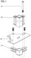
- FIG. 1is an exploded isometric view of a typical corner connection block
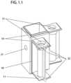
- FIG. 1 . 1is a perspective view of a lower corner block
- FIG. 1 . 2is a side view of a lower corner block showing the tapered locating coring
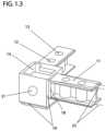
- FIG. 1 . 3is a perspective view of an upper corner block
- FIG. 2is a perspective view of a gusset plate
- FIG. 2 . 1is a perspective view of a gusset plate joining 4 columns;
- FIG. 2 . 2is a perspective view of a gusset plate joining 2 columns;
- FIG. 3is a partial exploded perspective view of a module corner
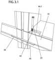
- FIG. 3 . 1is a partial perspective view of the connection between two adjacent stacks of modules
- FIG. 3 . 2is a vertical section through arms, gusset plate and HSS at a connection;
- FIG. 3 . 3is an isometric view of the connection between two modules in a single stack
- FIG. 3 . 4is a partial front view of the connection between two adjacent stacks of modules
- FIG. 3 . 5is a partial side view of the connection between two modules in a single stack
- FIG. 4is an exploded isometric view of a module
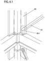
- FIG. 4 . 1is a partial isometric view of the inside of a module corner showing the vertical stiffeners and diagonal bracing;
- FIG. 4 . 2 aillustrates top section views showing progressive alternate embodiments of a reinforced column
- FIG. 4 . 2 billustrates top section views showing progressive alternate embodiments of a reinforced column
- FIG. 5is is an isometric view of a group of 18 modules joined to form a building with central hallways on all floors;
- FIG. 6is a side view of a group of modules joined to form a building
- FIG. 6 . 1is a front view of a group of modules joined to form a building
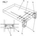
- FIG. 7is a transparent perspective view of a hallway slab and an end view of the slab installed in a building;
- FIG. 8is a partial exploded isometric view of the connection between two stacks of modules and the hallway floor at the point of connection between two consecutive hallway slabs;
- FIG. 9is a side section view through an extra tall module composed of two joined modules.
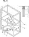
- FIG. 10is an isometric view of two stacked stair tower modules with a front view of the mateline in adjacent columns;
- FIG. 11is a partial perspective view of the blind connection of the stair at the mateline
- FIG. 12is a top view of the pin layout of the floor/ceiling layout and fabricating fixture
- FIG. 12 . 1is a partial top view and a partial side view of the floor/ceiling layout and fabricating fixture
- FIG. 12 . 2is a group of views showing the workpiece location pins (left) and two embodiments of the elevation blocks;
- FIG. 12 . 3is a partial top view of the location of the welds between typical members (centre) and a view of a single pin with clearances (bottom left);
- FIG. 13is a side section view of the hoisting fitting and the body of the upper block
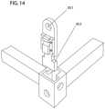
- FIG. 14is an isometric view of the hoisting fitting and upper block
- FIG. 15is an isometric view of the hoisting rig engaged to a module
- FIG. 15 . 1is an isometric view of a typical sliding hoist point
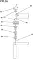
- FIG. 16is a partial end view of the hoisting frame shown engaged to a typical module
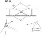
- FIG. 17(upper) is a top view showing the effect on the lateral centre of gravity of moving the hoist points on the hoist frame (Bottom left) the combined hoisting point (bottom right) an end view of the shift in CG from centre to one side;
- FIG. 17 . 1is a partial perspective view of one corner of the hoisting frame
- FIG. 18is a side view of one of a pair of the rotating module assembly fixtures required to assemble a module
- FIG. 19is an isometric view of the platen of the device in FIG. 18 ;
- FIG. 20is a partial isometric view of the locating stop rack which is part of FIG. 19 ;
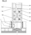
- FIG. 21is a section view through a split column
- FIG. 22is a section through an extendable mateline gasket
- FIG. 23is an exploded view of the façade system
- FIG. 24is a partially exploded view of the connection between an upper floor module built with reinforced columns and a lower floor module built with built-up mega columns;
- FIG. 25is a horizontal section of a panelized structure constructed with panels framed by built-up mega columns;
- FIG. 26is an exploded vertical view of a stack of modules showing the use of gusset plates of varying thickness and number to maintain the correct total height and alignment of a stack of modules;
- FIG. 27is an exploded horizontal section of a row of modules showing the use of shims of varying thickness and number to maintain the correct total width and alignment of a row of modules;
- the current inventionprovides upper and lower load-bearing connector or blocks which in one embodiment are corner blocks.
- the blocksare substantially quadrilateral and in other embodiments have polygonal or asymmetrical shapes.
- These blockscan be mass-produced with features that provide a multiplicity of functions so as to concentrate the precision operations in a small number and size of objects and reduce the amount and complexity of work that must be performed on other members.
- the upper and lower blocksare of distinct forms and located on the upper and lower ends of the vertical corner members (columns) of generally angular, tubular or built-up form, which perform the function of multi-story columns when modules so constructed are joined using the features on the blocks to form a larger or taller structure.
- the blockshave tapering arms projecting at a plurality of angles including but not limited to perpendicular to the faces of the blocks providing for the location and welding of adjoining members at a plurality of angles.
- the present inventionthus facilitates the fabrication and erection of modules including but not limited to orthogonal, tapering, radiating and curving shapes.
- the threaded and unthreaded holes in the armsachieve the positioning of threaded fasteners and the vertical walls of the arms provide an increase in the load-bearing capacity and transmission of the compression and tension forces created by the forces acting on the building and by the action of the fasteners.
- the blockshave holes in both the body and the arms for the passage and receiving of bolts with nuts or are threaded to receive bolts, so as to provide continuity of vertical tension through the columns and a moment resisting interconnection between adjacent modules or other building structures.
- the tension resistance resulting from the connection of the columns in the vertical planeenables the structure to resist uplift where it occurs and produces friction on the gusset plate so as to convey forces to the lateral members in the horizontal plane with a high level of fixity.
- the surfaces of the arms which are closest to the interior surface of the HSS which bears against the gusset plateis made tight, with all tolerance being on the opposite end, such that the tension imparted by the action of the bolt to the arms compresses the connecting surfaces and does not crush the HSS.
- the boltsare accessible within the wall cavity or other such places and can be arranged flush or below the surface such that a removable patch can be easily configured to cover the location of the bolt and ensure continuity of the fireproofing materials surrounding the load-bearing structures.
- the blockshave projecting features on the exterior and interior faces of the block located to provide backing for the assembly welding, reducing the structural impact of a weld to a connecting member that is cut to short or with an out-of square end or other imperfection reducing the probability of a worker executing a non-conforming welded connection between the corner blocks and the members which are welded to the block and a beveled feature so located on the outside of the block located so as to reduce the likelihood that a weld will project beyond the surface and conflict with an adjoining module.
- the holes in the corner blocksprovide a means of connection to tie-downs and hoisting devices.
- the upper face of the blockis prepared with an opening in to which a quick-release connector can be inserted so as to provide a means of quickly and dependably connecting and disconnecting the module to a lifting device.
- Another componentis a plate which is interposed between the blocks at the top and bottom ends of columns or groups of columns, which has upward-facing tapered locating pins for engaging and directing a descending module by sliding contact with a corresponding locating recess on the underside of a the corner block thus locating the module in the correct position for fastening.
- the platealso provides through holes for use in connecting adjacent modules with bolts to provide structural continuity in the horizontal plane both during construction and in the completed building and by virtue of its ductility, for accommodating slight variations in column length so as to ensure a continuous load path which bears equally on all members of the column group thus formed.
- the platecan be shaped to fit between a single vertical column or between two or more columns arranged in an orthogonal or other disposition.
- shims of a similar dimension and prepared with appropriate holesare placed in one or both sides of the connection to accommodate for variations in the finished dimensions of the modules thus maintaining the correct geometry of the modules stack.
- the system of the present inventionallows for the fabrication of modules within which are installed stairs or elevating devices and which separate at the mateline between two modules without a significant visual or functional disruption.
- the system of the present inventionallows for the fabrication of modules which comprise the upper and lower halves of habitable volumes which are taller than shipping restrictions will normally allow and which are joined at the mateline between two or more stacked modules without a significant visual or functional disruption.
- a structural hallway floorthat is made from a suitable material such as reinforced concrete, sandwich plate, wood or formed metal together with supporting pedestals.
- the slabis composed of reinforced concrete with reinforcement bars placed so that features on the support pedestals engage them so as to resist bending of the pedestals, thus creating a moment connection between stacks of adjacent modules thus connected.
- the pedestalsare provided with holes that align with corresponding holes in the upper and lower corner blocks and serve to connect two parallel stacks of modules as well as connecting the adjacent columns within a stack on one side so as to create a combined load path.
- the pedestals and floor slabsmay also be connected to the sides or ends of a stack of modules on one side of the slab and a balcony support frame on the outside to form a building with balconies or breezeways.
- the floor slab and pedestal assembliescan also be used as convenient carriers for building services such as ducts, pipes and wiring to facilitate the fabrication of these components off site in the factory environment.
- the present inventionalso comprises a pre-determined grid upon which the dimensioning of the interconnected elements of subject building are based together with a system of fixtures which ensure the grid is maintained throughout all fabricated assemblies in all axes which ensures an accurate and interdependent relationship extending from corner blocks, to members, to subassemblies, to modules and to whole buildings in all axes.
- the dimensioning systemthus serves to reduce fractional element and module sizing, to increase the number of common parts and to reduce the difficulty of coordination with foundation and podium contractors and which facilitates the work of all internal or external suppliers of components to be integrated in the modules so fabricated.
- the systemis based on increments of no more or no less than two inches in three axes with a centre-to-centre accuracy between holes used for fastening of plus or minus 1/32′′ and an outside to outside dimensional accuracy of all mating surfaces of plus 0′′ minus 1/16′′.
- the present inventionincludes a system for the assembly of the module frames which ensures that modules conform to the grid established above, and that no part of a module projects beyond the outermost ideal dimension, which increases the achievable speed of assembly and accuracy of the structure and, eliminates the possibility of additive dimensional drift, resulting in a reduction in the difficulty of erection, the difficulty of fireproofing, the possibility of interconnecting modules with a greater degree of fixity and a reduction in wall thickness and wasted space.
- a component of the system of the present inventionis an adjustable fixture consisting of a flat table or a flat table mounted on trunions to allow pivoting, which is of sufficient thickness and prepared with a grid of holes to receive vertical pins so located as to orient the components of a module ceiling or floor frame for assembly welding, thus creating module subassemblies such as floors, ceilings and walls.
- the locating holesare laid out so as to ensure that modules conform to the grid established above, which is coordinated with other building elements to ensure that the modules thus produced are easily assembled in to form a complete module and the complete module can be assembled to form a building.
- the pinsare equipped with a system of spacers used in ensuring the correct elevation of the components of the assembly so as to produce flush conditions as required for the application of floor or ceiling surfaces.
- the fixtureis thus configured to ensure that welding is executed in a position ideal for the structural welding and so as to ensure that the completed parts do not exceed the tolerance envelope resulting in accumulating tolerance conditions.
- Another component of the present inventionis an adjustable and rotatable fixture which orients a ceiling frame, a floor frame, the corner columns, the intermediate columns, the column reinforcements and the diagonal bracing, all of a plurality of dimensions; relative to each other for assembly welding so as to ensure that modules conform to the grid established above ensuring ease in the interconnection of modules and so as to ensure that the completed parts do not exceed the tolerance envelope and to ensure the parts can be oriented in a position ideal for the execution of the structural welds.
- Another component of the present inventionis a releasable and compact quick-connector which is employed in the attachment of the hoisting apparatus to the module, which is installed in a specially prepared opening in the corner blocks, from above, without tools, which is resistant to being accidentally released and which can be removed without tools.
- the connectoris structurally ideal in that the upward-facing bearing surface of the toggle and the corresponding downward-facing bearing surface of the receiving block and the tension-loaded part of the toggle shaft which conveys the load from the bearing surface to the hoisting apparatus are in ideal proportion so as to maximize the load-bearing capacity of the combined elements within the most compact space and while maintaining the dimensional limits of the assembly within the top face of the corner block.
- Another component of the present inventionis a hoisting apparatus which is arranged so as to suspend the load in an ideal posture for placement in the building, which in a particular embodiment is horizontal and which provides for the rapid adjustment of the position of all of the connection points from which lines pass to the crane hook so as to compensate for differences in the centre of gravity which occur in the length of a module.
- the device describedalso allows for altering the spread between pairs of cables on one side of the frame effecting a change in the dependant angle from vertical of the pair of lines which pass to the crane hook on one side of the module so as to move the centre of crane attachment to one side of the long axis of the frame so as to compensate for changes in the centre of gravity of loads which occur in the width of the module suspended from it.
- the inventioncomprise a system of standardized reinforcing members which connect with each other and with the columns, lateral framing, diagonal bracing and corner blocks described herein, eliminating the need for case-by-case design and fabrication or customization of reinforcement components.
- the present inventioncomprises a work method for systematically analysing the forces acting on a building composed of modules, defining the optimum location for the application of the standardized reinforcing systems, selecting from a list of standardized reinforcements with progressive buckling and uplift resistance and thereby incorporating only such reinforcements as are minimally necessary to strengthen the areas under additional stress, without adding unnecessary structural material to more locations than required, without significantly disrupting the application of fireproofing materials and without requiring additional thickness of the walls of the module.
- the present inventioncomprises a method for the fabrication and connection of the outer columns so they form groupings with greater resistance to the compressive and tensile forces resulting from the loads encountered in the construction of tall and/or slender buildings.
- the present inventioncomprises a gasket which extends to meet another opposed gasket after the module is placed by the action so as to prevent damage to the gasket surface during the hoisting and placement operation
- the system of components and work methods of the present inventionby means of involving the whole of the modular building units thus created and connected, can serve to increase the height of a building which can be built without the requirement for a secondary external or internal bracing frame, and to increase its useable floor area due to involving a larger portion of the members in the structural function and the enhanced fixity of the connections, the creation and assurance of multiple and redundant load paths, the integration of the brace frame in to the module walls and the resulting efficient transfer of the external, internal and self-loads imposed on the completed building through the adjacent modules and thence to the ground.
- this inventionBy reducing the amount of steel required in upper floors and thus its total weight, this invention also serves to increases the height of a building which is built with the use of a secondary external or internal bracing frame of a given size.
- the inventionBy analyzing the loads applied and more efficiently involving more of the required members in the structural function the invention also reduces the size of members required and limits the number, size and locations where unique reinforcement details and the related complexity of the fireproofing is required, thereby reducing the cost of such buildings.
- the present inventionreduces the precision of the parts which must be made by workers in the modular production facility, which reduces the cost of the fabrication.
- the present inventionconcentrates many of the complex features required to join members, hoist modules and join modules in a single mass-produced component, reducing both the complexity and the requirement for skilled work necessary to construct a module.
- the systemallows the building of taller modules composed of two stacked frames one of which has openings in the ceiling and the other of which has openings in the floor, longer modules due to the performance of the bracing and wider modules due to the improved behavior of the apertures in the ends, thus providing greater flexibility to designers of buildings so constructed.
- the present inventionreduces the wall thickness required to accommodate structure and services.
- the present inventioncan reduce both the number and the extent of the leave-out areas which must be subsequently patched.
- the present inventiondecreases the possibility of damage to the gasket and the attendant reduction in the performance of the building envelope.
- FIG. 1Connector Assembly 1 Having Upper Connector 10 and Lower Connector 20 Shown with Gusset Plate 30
- FIG. 1discloses an embodiment of a connector assembly 1 that is made up of an upper connector 10 , a lower connector 20 and a gusset plate 30 sandwiched between the upper connector 10 and lower connector 20 .
- the terms “upper” and “lower”are relative and can be interchanged.
- upper connector 10refers to connector that would typically be positioned at an upper corner or upper end of a modular frame that can be lifted and positioned on a second (or lower) modular frame.
- lower connectors 20refer to connectors positioned on the lower corner or lower end of a modular frame, and that would be closer to ground or floor (than the upper connector).
- the upper corner connector 10 and lower corner connector 20can be made from hollow castings of steel.
- the upper connector 10has an opening at one end (first end 2 ) that is formed for receiving a column, post or other structural unit of a modular frame, so that the upper connector can be coupled to an end of the of the first modular frame. While the second end 3 of the upper connector 10 is designed to allow coupling of the upper connector 10 to the gusset plate 30 .
- the lower connector 20can also be provided with an opening on both the first end 4 and the second end 5 ; with the first end 4 adapted for coupling to the gusset plate 30 , while the second end 5 allows coupling to an end or corner of the second modular frame.
- the connectorscan have mechanical properties such as tensile strength and ductility equal to or greater than mild steel and metallurgical properties such that the connector can be welded to mild steel with standard practices such as structural metal inert gas (MIG) welding.
- MIGstructural metal inert gas
- the upper and lower connectors ( 10 , 20 )each have a hollow body ( 2 , 4 ), respectively.
- the upper connector hollow body 2 and the lower connector hollow body 4can have a variety of shapes depending upon the design and application requirements. However, in the figures, the upper and lower connectors ( 10 , 20 ) have a hollow body ( 2 , 4 ) that has a shape having a square cross-section.
- bosses 6Provided on the outer surface of the hollow body 2 of the upper connector 10 are bosses 6 . Similar bosses 18 are also provided on the outer surface of the hollow body ( 4 ) of the lower connector 20 .
- the upper connector 10is provided by at least a pair of arms 11 that extend from the bosses 18 .
- the lower connector 20is also provided with at least a pair of arms 11 that extend from the bosses 18 .
- the arms 11extend normally from the surface of the bosses 18 .
- the arms 11are positioned to be perpendicular to each other, i.e., one arm extends at nearly 90° to the second arm.
- the position of the arms 11can be varied depending upon the design and application requirements, and the arms 11 can be present at angles less than or greater than 90°.
- the arms 11 on the upper connector 10can be provided with apertures 12 that can be used for coupling of the upper or lower connector to the connector assembly 1 .
- the central hollow bodies ( 2 , 4 )are 4′′ square to accept a 4′′ ⁇ 4′′ Hollow Structural Section (HSS). In another embodiment, the central hollow bodies ( 2 , 4 ) are 6′′ square to accept a 6′′ ⁇ 6′′ HSS.
- Connectors 10 and 20have adequate thickness for the intended function and details such as draft angles and uniformity of sections which facilitate casting.
- the castingare drilled and surfaces milled to an accuracy of +0-0.010 inches as measured between centres of the apertures 12 and the locating surfaces of the arms 11 , or other tolerances as may be convenient.
- the connectoris made by assembling one or more of rolled sections, flat or brake-formed plate by welding or mechanical means.
- the partis made by casting non-ferrous, plastic, cementitious or any other suitable material.
- the portions of the blocks to which the columns and arms will be connectedcan have features to locate the HSS and facilitate welding.
- the connector assembly 1can be formed by sandwiching the gusset plate 30 between the upper connector 10 and lower connector 20 .
- the gusset plate 30 shownhas two faces, where the first face can be in contact with lower connector 20 and the second face can be contact with the upper connector 10 .
- the gusset plate 30is provided with through holes 31 , which align with apertures 12 on the upper connector 10 and lower connector 20 , allowing fastening of the connectors ( 10 , 20 ) using fastening means.
- the fastening meansis not particularly limited, and can include nut and bolts, screws.
- FIG. 1Lower Connector 20
- the lower corner connectorhas bosses 18 which provide location to the longitudinal and transverse members of the module frame and backing for the assembly welds.
- the edges of the hollow body of the upper and lower connectorshave beveled edges.
- Bevels 19provide a location for the exterior surface of the weld bead which allows the weld to lie flush and eliminates the need to bevel the connected member.
- the outer faces of lower connector 20can have a plurality of holes (or bores) 21 which are threaded or unthreaded as required by circumstances for use in the connection of column groups, hallway slabs, fixtures, hoisting means or other useful features through the use of bolts, pins, clips, joining plates or other fastening means.
- the connector 20is taller and additional holes are provided for the use of additional fasteners or the addition of additional bracing or other features.
- the connector 20is more or less than 4-sided and not quadrilateral, but rather has trapezoidal, parallelogram or other shapes so as to facilitate the production of round, curving, tapering, star-shaped or other building forms.
- the lower connector 20has arms 11 with holes (or apertures) 12 for the passage of tension bolts 25 which pass through gusset plate 30 to secure the module vertically and provide a continuous tension and moment connection which passes loads through the connection between the stacked columns and the horizontal beams.
- these armsproject perpendicular to the surface, in another embodiment they have tapered sides 22 so as to permit the connection of members at an angle and in another embodiment the whole of the arms projects at an angle.
- FIG. 12 Lower Connector 20
- the connector 20has dimensions as shown in FIG. 1 . 2 .
- the bottom facehas an opening the sides of which are perpendicular or tapered in relation to the bottom face 23 .
- a plurality of these openings on a module having a radial relationship to the module centrereceive corresponding tapering locating pin 33 in the gusset plates 30 below, thus locating the module on top of the module below and in the correct position for connection.
- FIG. 13 Upper Connector 10
- the upper corner connector 10has bosses 18 which provide location to the longitudinal and transverse members of the module frame and backing for the assembly welds. Similar to the lower connector 20 , in the embodiment shown, the edges of the hollow body of the upper and lower connectors have beveled edges. Bevels 19 provide a location for the exterior weld bead which allows the weld to lie flush and eliminates the need to bevel the connected member.
- the outer faces of block 10have a plurality of holes (or bores) 21 which are threaded or unthreaded as required by circumstances for use in the connection of column groups, hallway slabs, or other useful features through the use of bolts, pins, clips, joining plates or other fastening means.
- the blockis taller and additional holes are provided for the use of additional fasteners or the addition of additional bracing or other features.
- the blockis more or less than 4-sided and not quadrilateral, but rather has trapezoidal, parallelogram or other shapes so as to facilitate the production of round, curving, tapering, star-shaped or other building forms.
- these armsproject perpendicular to the surface, in another embodiment they have tapered sides 22 so as to permit the connection of members at an angle and in another embodiment the whole of the arms projects at an angle.
- the upper connector 10has arms 11 with threaded holes (or second aperture) 12 closest to the body of the block for the receipt of tension bolts 25 and threaded holes (or first aperture) 13 most distant from the block for the receipt of gusset plate screws 34 .
- these armsproject perpendicular to the surface, in another embodiment they have tapered sides 22 so as to permit the connection of members at an angle and in another embodiment the whole of the arms projects at an angle.
- the top face of the blockhas T-shaped hole 14 , which engages with steel lifting fitting 15 shown in FIGS. 13 and 14 , and as described herein.
- FIG. 2Gusset Plate 30
- the gusset plate 30is cut from steel plate or other material having adequate thickness and mechanical properties for the intended function. In a further embodiment, it is 3 ⁇ 8′′ thick.
- the gusset platehas through holes 31 , countersunk holes 32 and locating pins 33 .
- Flathead screws 34passed through holes 32 and threaded in to holes 13 in upper connector 10 accurately unite adjacent columns and thus whole modules.
- the ductility of plate 30 in the vertical planeensures that the column groups are acting together to sustain large loads.
- the precision of the location of holes 32 for the flathead screws and the corresponding holes in the connectorsensures module-to-module tolerances are maintained and controlled.
- the gusset plate 30can be sized to fit on top of 1, 2, 3, 4 or more columns providing equivalent vertical separation in all locations and forming groups of 2, 3, 4 or more modules.
- FIG. 2 . 1which discloses an embodiment of a gusset plate joining 4 modules
- FIG. 2 . 2discloses a gusset plate 30 joining 2 modules.
- the plateis provided with a projecting edge for support of an adjacent component, as disclosed further herein.
- FIG. 3Assembly of a Module
- longitudinal floor beam 41 and lateral floor beam 42are cut to length and provided with holes 43 which generally correspond with but do not interfere with the locations of the holes in arms 11 on the connector 10 .
- these beamsare 3′′ ⁇ 8′′ HSS for the perimeter and 3′′ ⁇ 6′′ HSS for the infill members. Because the locating and welding fixture ( FIG. 12 ), described herein, positions the pre-machined connecting blocks and defines the hole locations and their locations relative to each other, provides the exterior dimensions of the assembly, the fixture ensures that modules made using the fixture conform to the established grid previously described. In addition, the features on the blocks ensure that the beams do not require beveling on the edges of the ends and the cutting to length operation is not critical in either length or squareness. The beams are slipped over the corresponding arms 11 on the lower corner connector 20 and welded in the manner previously described.
- a suitable material 44such as fibre-cement board, or steel sheet deck and concrete toping, or steel-composite sheet decking is applied to the top face of the floor beams of the module floor thus built, and fastened appropriately, or concrete or other material is filled between the framing so as to support occupant loads and provide the necessary diaphragm action to the module and in turn to a building composed of modules.
- materialsuch as drywall or fire-proof board and insulation of a variety of types depending on conditions is applied to the surfaces of the framing and boards and in voids in walls and ceilings to provide a variety of functions such as privacy to the occupants, to provide fireproofing to the structure and to limit the transmission of sound.
- FIG. 3 . 1 , 3 . 3 , 3 . 4 , 3 . 5Vertical Connection of Modules to Form a Moment-Resistant Structure
- lower connector tube 41has an oversize holes 43 which communicates with the hole in arms 22 through which pass tension bolts 25 which thread in to the threaded hole in the top face of arm 11 on upper block 10 inside upper wall framing tube 45 , trapping and clamping gusset plate 30 and transferring vertical tension loads through the connection.
- tension bolts 25are threaded to the correct torque value in to the female threads in hole 12 of the of arm 11 on upper connector 20 of the module below, the tension created pulls the upper and lower frame tubes and the gusset plate together so as to establish the continuous moment action ( 25 . 1 ) which passes from column to column through the connection thus formed and is prevented from rotating in the vertical plane by the adjacent frame tubes, especially the deeper members which comprise the floor frame.
- the racking actionwhich is a feature of all buildings subjected to wind, earthquake and other loads is thus reduced.
- bolts 25are composed of high-strength steel such as Grade 8 such that the combination of the tensile strength and the number of bolts is sufficient to resist the wind or seismic-induced uplift on the structure thus connected.
- FIG. 4Exploded View of Typical Frame
- Floor frame 40is connected to ceiling frame 47 by corner columns 50 and intermediate columns 51 which in a particular embodiment are substantially perpendicular to the floor and ceiling frames and welded in place.
- connections between the upper and lower horizontal members and the intermediate vertical columns 48is constructed with an intermediate connector 49 similar in form to the connectors described in FIGS. 1 . 1 and 1 . 3 . but having opposed arms.
- the columnsare of various lengths and mitred to fit against each other or against the blocks such that a plurality of angular relationships between the ceiling and floor is realized.
- FIG. 41 View of Sidewall Bracing
- the diagonal reinforcing systemconsists of vertical reinforcing bars 60 , which in a particular embodiment are of the form and installed in the location shown in FIG. 4 . 1 or of the forms and locations of other particular embodiments as shown in FIG. 4 . 2 a or 4 . 2 b .
- Diagonal bars 61are welded or bolted to these members or in the case of lighter structures having smaller loads they are welded directly to the vertical or horizontal frame members or both.
- the barsare diagonally opposed, 3 ⁇ 4′′ in section and function in tension. In another they are diagonally opposed, of 1′′ ⁇ 3′′ in section and function in tension. In another they are single, of 3′′ ⁇ 4′′ HSS or other dimension and function in both tension and compression as suited to the loads they are to resist.
- FIGS. 4 . 2 a and 4 . 2 bVertical Stiffeners
- FIGS. 4 . 2 a and 4 . 2 bare sequentially arranged figures showing progressive means of reinforcing columns against buckling and uplift starting with the weakest at the top and ending with the strongest at the bottom.
- FIG. 4 . 2 a and FIG. 4 . 2 bvertical stiffening and increasing of the cross section of the columns so as to increase load-bearing capacity and resistance to buckling and bending without increasing the thickness of the wall or introducing a separate brace frame is achieved by any of the means shown and applied in a progressive manner as warranted by loads and cost: Increasing wall thickness, filling the columns with grout, adding fins to the corners, grouping sections, using larger sections and grouping those sections.
- the particular embodimentis the approach which adds least to the thickness of the walls, especially where columns are grouped or are located in the centres of walls or where useful space would be obstructed.
- FIG. 5View of a Small Building
- Modules fabricated as described in FIG. 3are typically connected to form larger structures as shown.
- a central hallway 90is present and can provide access to the module ends for fastening, for completing the interconnection of mechanical services and for the use of the occupants in accessing their units.
- FIG. 6Side View of a Small Building
- a side view of a typical structure with a centrally-located hallway 76is shown, together with the diagonal bracing 60 described in FIG. 4 . 1 .
- FIG. 61 Front View of a Small Building
- a front view of a typical structureis shown.
- FIG. 7View of Hallway Floor System
- a section of flooris shown consisting of concrete slab 70 , with reinforcing bars 71 and supported by pedestals 72 which are prevented from rotating by being bolted to connector blocks 10 and 20 by means of holes 74 creating a moment connection; and prevented from pulling out of the concrete by shear studs 73 which engage the concrete and the reinforcing bars.
- the pedestalsspan vertically over upper and lower corner connectors and are bolted to them adding to the fixity of the vertical connection between columns.
- the slabis long enough that the pedestals span over two or more adjacent modules, adding to the fixity of the horizontal diaphragm action.
- the hallway slabis composed of formed plate, or any other suitable material such as wood or steel-urethane sandwich plate or composites.
- the hallwayis used as a convenient support and carrier for common services such as electrical or liquid supply lines 75 which are typically found in buildings and thus provides a means to pre-fabricate these elements, transport them to the building site and hoist them in to place without additional handling.
- common servicessuch as electrical or liquid supply lines 75 which are typically found in buildings and thus provides a means to pre-fabricate these elements, transport them to the building site and hoist them in to place without additional handling.
- the pedestal 72are in contact and positioned on the gusset plate 30 .
- the gusset plate 30 usedextends beyond the module frame to provide a surface for placing the pedestals 72 for supporting the slab.
- FIG. 8Exploded Isometric View of Connections to Hallway Floor System
- the structure thus formedWhen installed as described for use as the floor of a hallway between two stacks of modules separated by a suitable space, the structure thus formed unites the adjacent stacks with a moment resistant connection, such that the hallway floor structure increases the resistance of the entire building to lateral loads, thereby reducing both the number and size of diagonal reinforcement required.
- the hallway slab structureis connected to the outer face of a stack of modules and supported by a column grid or diagonal tension braces or diagonal struts to provide a breezeway or balcony.
- the pedestals 72 of the hallway 70are each provided with a pair of holes 74 .
- the first set of holes 74 in the pedestal that are positioned closer to the floor 70can be coupled to the lower connector 20 in the upper modular frame.
- the second set of holes 74 in the pedestal that are positioned away from the floor 70can be coupled to the upper connector 10 in a lower modular frame. Consequently, in the embodiment shown in FIG. 8 , the pedestals are not positioned on the gusset plate 30 , which lack the extension shown in FIG. 7 .
- FIG. 9Double Height Modules
- FIG. 9shows an open-topped module 80 joined to an open-bottomed module 81 using bolts 83 .
- Diagonal bracing 82is configured to provide the continuous diagonal bracing action required.
- FIG. 10Stair Tower Showing Mateline
- Stairs and stair stringers 150 and doors 151are shown factory installed in consecutive module frames 152 and 153 which are prepared for connection on site with the system of gusset plates and corner connectors previously described.
- FIG. 11Invisible Splice in Stair Stringers
- the riseris split horizontally on the same plane as the module within which it is installed. So as to minimize the visual impact of the horizontal mateline between modules, the stairs are joined by hidden plates 154 on the inside faces of the stringers 155 under and behind the treads 156 and risers 157 .
- FIG. 12Floor, Ceiling and Wall Assembly Fixture
- Floors, ceilings, infill walls and other structures as requiredare built in fixture 100 so as to ensure vertical alignment and regularity of features.
- the use of the fixtureensures that modules conform to the established grid previously described.
- FIG. 12 . 1Fixture, Jig Pins and Jig Pin Locations
- perimeter beams 40 and 41are passed over the arms of connector 20 as the assembly is placed in fixture 100 which locates the block in locator 105 in contact with buttons 102 which contact the centres of the two outer vertical faces and lower face of the connector and thus maintains perpendicularity of the connector and can help to establish the outside dimensions of the module so as to prevent accumulation of error, or maintain any other geometric relationship as may be desirable.
- the outer face of the perimeter beamsare located by means of contact with the sides of pins 101 which are not stepped and the inside faces are located by contact with stepped pins 101 . 1 which are stepped so as to allow for the small variations which occur in the production of sections and ensure that no part of the assembly exceeds the tolerance envelope.
- the intermediate floor beams 42are placed in accordance with the pre-defined grid established by contact with stepped pins 101 . 1 which can in this instance be used on both sides of the member so located.
- a floor assemblyis complete by welding the perimeter beams and intermediate beams to the corner connectors and to each other.
- FIG. 122 Elevating Blocks
- variable-height spacers 103sized and selected as required to orient the top faces correctly.
- the spacersare cut from HSS in the form shown in 104 and placed loosely over the pins.
- FIG. 123 Jig Clearances
- the beamsare welded in place exploiting the clearances provided by the position of the pins, positioned horizontally by the sides of the pins and elevated by the spacers.
- FIGS. 13 and 14Hoistable Connector Assembly
- FIG. 13discloses an embodiment of a hoistable connector assembly that can be used for connection and hoisting of a modular frame that has an upper connector 10 , as described herein.
- the top face of the upper corner connector 10can have a T-shaped hole (or opening) 14 , which engages with a “T”-shaped engaging means on the body 15 of the lifting device.
- the body of the lifting devicehas a T-shaped end that can be inserted into the T-shaped opening in the connector 10 .
- the lifting deviceis provided with a block 16 , which is coupled to the body of the lifting device.
- the block 16can move from a first disengaged position to a second engaged position.
- the first disengaged position(as shown in FIG. 13 ) allows the T-shaped end to be inserted or removed from the T-shaped opening in the connector 10 .
- the block 16slides into the T-shaped opening (see arrow in FIG. 13 that shows the sliding direction of the block 16 ), and prevents removal of the T-shaped end from the connector 10 and locking the connection in place.
- block 16is raised to clear the lifting feature on body 15 and the feature introduced in to the slot then moved sideways (see arrow present inside connector in FIG. 13 ). Once engaged in hole 14 , the fitting is locked in place by the action of gravity which causes block 16 to slide downward between guides 17 so as to occupy the wider entry portion of the slot, thus preventing backward movement and accidental releases of the lifting fitting.
- Block 16is held to the face of the body 15 by a retainer 15 . 1 running freely in recess 18 which is fastened to stand off 19 which moves vertically in slot 19 . 1 .
- the relatively delicate features of the block retainerare thus flush with the surface so as to prevent damage by inadvertent contact during handling.
- block 16is manipulated using a finger inserted in depression 20 in the surface of block.
- the blockis pressed in to the entry slot independently of the effect of gravity by a supplementary spring interposed between the top surface of the standoff 18 and the underside of the slot 19 .
- a sensoris positioned so as to detect the proper position of the locking block in the lifting slot. A signal thus generated is transmitted to the controls of the equipment or to the operator so as to prevent lifting of the load if the lifting device is not fully and properly engaged.
- the distal end(distal from the T-shaped end) can be provided with a hole, which can be used for coupling and lifting the hoistable connector assembly.
- FIGS. 15 and 171 Liftable Frame Assembly
- a lifting frameis provided for the reduction of the compression loads on the module frame members attributable to the pyramidal displacement of the lifting lines, and to provide a means to accurately level the modules during all phases of the lift and irrespective of the length of line passing upward to the crane, so as to facilitate placement of the modules without inadvertent contact which can damage frames, seals, insulation and finishes.
- Beams 80are joined by struts 81 through flanges 82 using bolts. Eight sliding hoist points 83 are provided which slide on beams 80 and are prevented from moving when locked in place using locking pins 84 in rows of holes 85 . Load-bearing cables 86 pass upwards and converge on master hoisting fitting 87 shown in FIG. 17 .
- the beam 80can be an I-beam that has an upper end and a lower end.
- a first set of four hoist blocks 83are provided on the upper end of the beam 80 and a second set of hoist blocks 83 are provided on the lower end of the beam 80 .
- the hoist blocks 83are coupled to the beam and can move (for instance by sliding the hoist block) from a first position to a second position, as may be required for lifting a frame.
- the I-beamcan also be provided with a plurality of holes near the first and second ends, which allows affixing of the hoist blocks 83 in place on the I-beam by use of fasteners, such as bolts and nuts.
- the first set of hoist blocks 83 present on the upper end (or first end) of the I-beamare attached to load bearing cables 86 , which are attached to a master hoisting fitting 87 shown in FIG. 17 .
- the lifting frame structurebe balanced to reduce load on any particular portion of the modular frame by moving the hoist blocks 83 on the I-beam 80 , and fastening the hoist blocks 83 in a different position.
- FIG. 16Hoisting Rigging
- FIG. 16shows a side view of a portion of the liftable frame assembly of FIG. 15 .
- the hoistable connector assembly 15is connected by shackle 88 to chain or wire rope 89 which is connected by another shackle to the lower portion of a typical sliding hoist point 83 located on the lower end of a lifting frame 80 .
- Locking pin or pins 84prevent movement of the sliding blocks.
- FIG. 17Hoisting Geometry
- the centre of gravity of the moduleis determined by the use of a computer program capable of calculating the centre of gravity based on the recorded weights and positions of the masses which comprise the module as represented in a computer model, or iteratively by one or more trial lifts.
- the data thus gatheredis recorded and provided with the module.
- a tableis prepared using a computer program or trigonometry which specifies the hole locations to be used to adjust the combined centre of gravity of the module and hoisting frame system to level the module to be hoisted. Prior to connecting the hoisting frame to the module, the table is consulted and the sliding blocks are located and locked in place in the stated positions.
- hoist points 83are moved as a group towards the centre of gravity of the load, maintaining an equidistant (quadrilateral) arrangement.
- the hoist points 83 on one side only of the beams 80are brought together or spread apart so as to increase or decrease the angle between them thus changing the angular relationship between the hoisting lines passing upwards to common hoisting point 87 .
- the hoist pointsare moved independently to achieve other desirable objectives, such as equalizing the load on the slings or to tilt the load intentionally.
- the frameis composed of a single beam, in another embodiment the frame is not quadrilateral but triangular, polygonal or any other shape as may be convenient for the purpose of best supporting and balancing the load.
- FIG. 151 View of a Single Sliding Block with Fabrication Details
- FIG. 15 . 1discloses an embodiment of a hoist block in accordance with the invention.
- the hoist blockcan be made of a block having a T-shaped channel extending from one face to another face of the block, and having an opening on an upper end of the block. The opening on the upper end extends to the T-shaped opening in the block.
- the blockalso has a first flange extending upwardly from the upper face of the block and a second flange extending from the lower end of the block. Each flange is provided with an opening for coupling the block.
- the blockis machined from solid steel or cast or fabricated from another suitable material.
- the blockis welded from plate as shown.
- FIG. 18Module Assembly Fixture
- Tower 121moves on rollers 122 which are equipped with flanges so as to locate accurately and squarely on track 122 . 1 .
- a pin through a bracket on the base of tower 121engages a row of holes adjacent to track 122 . 1 so as to ensure consistency with the defined dimensional grid previously described.
- Slewing bearing 124supports platen 125 and allows the platen to rotate so as to position the work in the ideal posture for assembly and welding.
- An identical structureis located on the same track and opposes the structure shown and supports the opposite end of the frame.
- Platen 125has two or more movable stop racks 126 mounted to its vertical face, to which are mounted side work supports 127 and top/bottom work supports 128 ( FIG. 20 ) which locate to the outer and lower and outer and upper faces of the corresponding corner connectors in the same orientation as the fixture in which it was built.
- the holes in the work supportsmatch the holes in the corresponding connectors thus ensuring that modules built in the fixture will interconnnect with the corresponding components built in this and other fixtures.
- the fixtureis equipped with a plurality of frame width defining holes 131 and frame height defining holes 132 so as to facilitate accurate and rapid adjustment of the jig for the production of modules of varying shapes and in logical increments and which ensure that the parts thus constructed coordinate with other components constructed in accordance with the scheme of the present invention.
- FIG. 21is a Section View Through a Split Column
- FIG. 21discloses a particular embodiment of a shared structural column.
- a built-up “C” section 152 spanning the height of the moduleis bolted in multiple locations with bolts 153 to a similar section 151 forming a column which is twice as wide thus providing greater resistance to buckling forces.
- Baseplate 156which occurs at both the top and bottom forms a transition to lighter columns 154 or heavier columns as appropriate depending on the loads.
- Diagonal braces 150 as requiredare connected to the extended web of column 151 .
- a removeable section of fire-proof wall board 155is provided for access to the bolts during erection of the structure.
- FIG. 22is a Section Through an Extendable Mateline Gasket
- a particular embodiment of an extendable mateline gasketis shown.
- Molded or extruded elastic material 168 with multiple sealing featuresis fastened to channel 166 , which slides in gasket 167 which is fastened to the inner surface of channel 169 and is extended by captive screw 164 travelling in threaded socket 165 and actuated by rotating head 163 .
- the assemblyis mounted to support channel 160 which can be of any convenient depth to which is fastened acoustic and fire-resistant material 170 .
- Access to operate the gasket advancing screwis through cover 161 which can, in a particular embodiment, be decorative and fastened in a removable manner.
- the modular unitsare each provided with a channel 166 .
- a gasket 167is present in the channel 160 , along with a toothed connector 168 .
- the toothed connectorhas a profile that is complementary to the toothed profile in the channel in the second modular unit.
- the gasket 167allows movement of the toothed connector 168 in one direction only, which is away from the modular frame. This can be achieved by, for instance, providing angled tabs that extend from a surface of the toothed connector and corresponding receptacles in the gasket 167 for receiving the tabs. Once the tabs are inserted into the receptacles, the gasket is locked in place and can prevent the toothed connector from moving back into the channel 160 .
- the two modular unitsare brought in contact with each other and the channels aligned.
- the toothed connector in the second modular framecan be present in an extended position, where it extends beyond the mateline of the two modular frames and also beyond the cavity of the channel 160 .
- the toothed connector in the first channelcan be extended from a disengaged position, where the toothed connector is positioned within the cavity of the channel to an engaged position, where it extends outside the cavity of the channel and the teeth of the toothed connector in the first modular frame engage and align with the complementary teeth of the toothed connector in the second modular frame.
- FIG. 23is an Exploded View of the FaçAde System
- a particular embodiment of a façade system for modular constructionis shown together with the associated structural frame.
- the structural frame 171 with moment blocks 181is fireproofed with insulating board layer 172 and decked with flooring board 182 and is shown supported by one half of progressively reinforced split column 179 connected to the adjacent column (not shown) using bolts inserted in holes 183 .
- Spacer frame 173is acoustically and fire insulated with board layer 178 and is provided with holes 177 to access gasket extension screws 164 ( FIG. 22 ).
- Façade infill and gasket mounting frame 175is equipped with gasket assembly 176 and faced with exterior wall panel 174 . The transition to a built up structural column 179 with slip-critical bolting 183 is shown.
- FIG. 24is an Exploded View of the Vertical Transition at a Shared Structural Column
- FIG. 23A particular embodiment of both halves of a shared structural column at the point of transition to a lighter column is shown.
- “C” sections 152are bolted to one another to form an “I” section.
- the members of structural frame 171are welded to the “C” channels in lieu of the moment blocks in the frames where the “C” sections are used.
- Moment block 181rests on combined shiming and gusset plate 30 (greater detail can be found in FIG. 2 ) which is in turn fastened to the top end of columns 152 .
- Façade framing 173is fastened to the face of the assembly in a manner similar to FIG. 23 .
- FIG. 25is a Horizontal Section of a Structural Panelized Façade System
- a particular embodiment of a structural façade system for a modular buildingis shown. Built up sections 152 are joined in the manner previously described by headers top and bottom to form assemblies with window units 190 , but unlike the volumetric modules previously described, the façade units are shipped and erected separate from the floors and interior walls. Beams 191 support floor slabs 178 . Fireproof covering 178 insulates the steel structure. Façade panel 50 provides insulation and appearance. As someone skilled in the art will appreciate, 45 degree split corner column 192 performs a similar function at a 90 degree outside corner. In another particular embodiment the angle of the split corner column is greater than or less than 45 degrees so as to facilitate the construction of structures with variable geometry.
- FIG. 26is a Simplified Exploded View of a Vertical Stack of Modules
- gusset plate 30is provided in a variety of thicknesses which can be selected during assembly of the building and interposed in the connection as required to compensate for variations in the dimensions of the modules, such that the total dimension of the stack of modules conforms to the correct value as measured at 195 .
- a partial plate 192is provided with the corresponding hole pattern and in a variety of thicknesses to compensate for differences in the dimensions of adjacent modules.
- FIG. 27is a Simplified Exploded View of a Horizontal Row of Modules
- shim 178is provided in a variety of thicknesses and with pre-cut holes for the passage of connecting bolts. During assembly of the building the appropriate shim can be selected and interposed in the connection as required to compensate for variations in the accumulated horizontal dimension of the modules as measured at 196 .
Landscapes
- Engineering & Computer Science (AREA)
- Architecture (AREA)
- Civil Engineering (AREA)
- Structural Engineering (AREA)
- Mechanical Engineering (AREA)
- Physics & Mathematics (AREA)
- Electromagnetism (AREA)
- General Engineering & Computer Science (AREA)
- Joining Of Building Structures In Genera (AREA)
- Conveying And Assembling Of Building Elements In Situ (AREA)
Abstract
Description
Claims (7)
Priority Applications (2)
| Application Number | Priority Date | Filing Date | Title |
|---|---|---|---|
| US17/971,330US12139904B2 (en) | 2013-02-22 | 2022-10-21 | Modular building units, and methods of constructing and transporting same |
| US18/941,977US20250067041A1 (en) | 2013-02-22 | 2024-11-08 | Modular building units, and methods of constructing and transporting same |
Applications Claiming Priority (7)
| Application Number | Priority Date | Filing Date | Title |
|---|---|---|---|
| US201361768328P | 2013-02-22 | 2013-02-22 | |
| US201361837451P | 2013-06-20 | 2013-06-20 | |
| US201461935992P | 2014-02-05 | 2014-02-05 | |
| PCT/CA2014/050110WO2014127472A1 (en) | 2013-02-22 | 2014-02-18 | Modular building units, and methods of constructing and transporting same |
| US201514770012A | 2015-08-24 | 2015-08-24 | |
| US15/229,880US11479961B2 (en) | 2013-02-22 | 2016-08-05 | Modular building units, and methods of constructing and transporting same |
| US17/971,330US12139904B2 (en) | 2013-02-22 | 2022-10-21 | Modular building units, and methods of constructing and transporting same |
Related Parent Applications (1)
| Application Number | Title | Priority Date | Filing Date |
|---|---|---|---|
| US15/229,880ContinuationUS11479961B2 (en) | 2013-02-22 | 2016-08-05 | Modular building units, and methods of constructing and transporting same |
Related Child Applications (1)
| Application Number | Title | Priority Date | Filing Date |
|---|---|---|---|
| US18/941,977ContinuationUS20250067041A1 (en) | 2013-02-22 | 2024-11-08 | Modular building units, and methods of constructing and transporting same |
Publications (2)
| Publication Number | Publication Date |
|---|---|
| US20230043888A1 US20230043888A1 (en) | 2023-02-09 |
| US12139904B2true US12139904B2 (en) | 2024-11-12 |
Family
ID=51390443
Family Applications (4)
| Application Number | Title | Priority Date | Filing Date |
|---|---|---|---|
| US14/770,012ActiveUS9458619B2 (en) | 2013-02-22 | 2014-02-18 | Modular building units, and methods of constructing and transporting same |
| US15/229,880ActiveUS11479961B2 (en) | 2013-02-22 | 2016-08-05 | Modular building units, and methods of constructing and transporting same |
| US17/971,330ActiveUS12139904B2 (en) | 2013-02-22 | 2022-10-21 | Modular building units, and methods of constructing and transporting same |
| US18/941,977PendingUS20250067041A1 (en) | 2013-02-22 | 2024-11-08 | Modular building units, and methods of constructing and transporting same |
Family Applications Before (2)
| Application Number | Title | Priority Date | Filing Date |
|---|---|---|---|
| US14/770,012ActiveUS9458619B2 (en) | 2013-02-22 | 2014-02-18 | Modular building units, and methods of constructing and transporting same |
| US15/229,880ActiveUS11479961B2 (en) | 2013-02-22 | 2016-08-05 | Modular building units, and methods of constructing and transporting same |
Family Applications After (1)
| Application Number | Title | Priority Date | Filing Date |
|---|---|---|---|
| US18/941,977PendingUS20250067041A1 (en) | 2013-02-22 | 2024-11-08 | Modular building units, and methods of constructing and transporting same |
Country Status (13)
| Country | Link |
|---|---|
| US (4) | US9458619B2 (en) |
| EP (2) | EP2959067B1 (en) |
| JP (2) | JP6441240B2 (en) |
| KR (3) | KR102384385B1 (en) |
| CN (2) | CN108360683B (en) |
| AU (3) | AU2014221181B2 (en) |
| BR (1) | BR112015020099B1 (en) |
| CA (2) | CA2901755C (en) |
| MX (2) | MX376591B (en) |
| MY (1) | MY201509A (en) |
| PL (1) | PL2959067T3 (en) |
| SG (2) | SG11201506504WA (en) |
| WO (1) | WO2014127472A1 (en) |
Cited By (1)
| Publication number | Priority date | Publication date | Assignee | Title |
|---|---|---|---|---|
| US20230203803A1 (en)* | 2021-12-24 | 2023-06-29 | China Construction Science &Technology Group Co., Ltd | Multi-story modular house and connection assembly thereof |
Families Citing this family (83)
| Publication number | Priority date | Publication date | Assignee | Title |
|---|---|---|---|---|
| AU2014221181B2 (en) | 2013-02-22 | 2018-03-15 | Z-Modular Holding, Inc. | Modular building units, and methods of constructing and transporting same |
| US20160319534A1 (en)* | 2013-12-16 | 2016-11-03 | Marcio BERNARDO | Reversible module co-ordination system for buildings |
| CN110725411B (en) | 2014-04-30 | 2021-08-27 | Z-模块控股公司 | Structure modular building connector |
| US9441359B1 (en)* | 2015-01-13 | 2016-09-13 | Tommy Hsieh | Structurally independent frame for component based multi-unit buildings |
| JP7051236B2 (en) | 2015-04-15 | 2022-04-11 | ゼット-モジュラー ホールディング,インコーポレイテッド | Connector for modular building structures |
| LT6370B (en)* | 2015-06-10 | 2017-03-10 | Uab Aldrea | Beam component for use in technical construction, construction kit and method of connecting beam components |
| JP7022688B2 (en)* | 2015-08-14 | 2022-02-18 | ジー-モジュラー ホールディング,インコーポレイテッド | Modular building connector |
| DE102015216133A1 (en)* | 2015-08-24 | 2017-03-02 | Kramer Gmbh | WohnModul |
| CN105369898B (en)* | 2015-08-25 | 2017-10-13 | 河南奥斯派克科技有限公司 | Thin-wall channel assembled house based on BIM |
| CA167636S (en) | 2016-03-18 | 2017-05-31 | Vectorbloc Corp | Structural modular building connector |
| CN105805123B (en)* | 2016-04-25 | 2017-10-20 | 中车青岛四方车辆研究所有限公司 | The module frame structure of tapered cup nut connection |
| US20180058060A1 (en)* | 2016-08-29 | 2018-03-01 | Solar Turbines Incorporated | Modular compression plant |
| WO2018057792A1 (en) | 2016-09-21 | 2018-03-29 | Skyrise Global, Llc | Structure and method of making the same |
| CN106759864A (en)* | 2016-11-23 | 2017-05-31 | 广州电力机车有限公司 | A kind of modularization steel house |
| CN106759863A (en)* | 2016-11-23 | 2017-05-31 | 广州电力机车有限公司 | A kind of modularization steel house frame structure |
| SG10201610522WA (en)* | 2016-12-15 | 2018-07-30 | Cs Corp Pte Ltd | Modular Building Unit, Modular Building And Method Of Assembling Thereof |
| KR102498929B1 (en)* | 2017-01-19 | 2023-02-10 | 지-모듈러 홀딩, 인크. | modular building connectors |
| JP6387428B2 (en)* | 2017-02-02 | 2018-09-05 | 日新製鋼株式会社 | Fastening structure and fastening method |
| EP3366853B1 (en)* | 2017-02-24 | 2020-04-22 | New World China Land Limited | Prefabricated structural system and assembling method thereof |
| GB2564084A (en)* | 2017-05-05 | 2019-01-09 | Mhi Modern Homes Ireland Ltd | A prefabricated house |
| CN107034991B (en)* | 2017-05-19 | 2022-09-09 | 易筑集合(北京)科技有限公司 | Tenon ear sleeve floor inserting connecting structure |
| CA3006818C (en) | 2017-05-31 | 2021-02-16 | Meadow Burke, Llc | Connector for precast concrete structures |
| EP3635187B1 (en) | 2017-06-09 | 2021-12-01 | Spanminx Limited | A structural module and a tie for the structural module |
| US10941561B2 (en) | 2017-07-27 | 2021-03-09 | Rad Urban, Llc | Prefabricated modular buildings |
| CN114607050A (en) | 2017-08-18 | 2022-06-10 | 可耐福石膏两合公司 | Frames, basic frames, modules, profiles, sets of structural elements for modular construction and modular buildings |
| KR101970404B1 (en)* | 2017-09-25 | 2019-08-13 | 노태길 | Module assembly type prefabricated house |
| US20190136504A1 (en)* | 2017-11-08 | 2019-05-09 | Modular Steel Solutions, LLC | Apparatus and systems related to modular construction |
| US11788565B1 (en)* | 2017-12-15 | 2023-10-17 | Cyrco, Inc. | Apparatus for assembling tubing structures |
| CN107893481B (en)* | 2017-12-21 | 2019-03-15 | 青岛理工大学 | Full-assembly steel frame structure system with recovery function |
| EP3743569A4 (en) | 2018-01-23 | 2021-10-20 | Qube Building Systems Inc. | SELF-SEALING BUILDING MODULE WITH A SELF-ALIGNING CONNECTOR |
| US20190284795A1 (en)* | 2018-03-14 | 2019-09-19 | Andy Vanaman | Modular Egress System |
| CN108316470B (en)* | 2018-04-11 | 2023-05-09 | 蔡瑶生 | Building frame construction method and building frame |
| CH714909A1 (en)* | 2018-04-17 | 2019-10-31 | Ustinov Igor | Building system of a module of a building. |
| CN108560753B (en)* | 2018-04-20 | 2019-11-01 | 青岛理工大学 | Prefabricated intelligent node with energy consumption of particle damping chamber and its installation method |
| WO2019227174A1 (en)* | 2018-06-01 | 2019-12-05 | Csr Building Products Limited | Connection system |
| US10640968B2 (en) | 2018-06-21 | 2020-05-05 | Thomas Joseph Teffenhart, JR. | System and method having an improved beam and beam coupling system |
| USD919420S1 (en) | 2018-06-21 | 2021-05-18 | Thomas Joseph Teffenhart, JR. | Corner coupler |
| KR102181525B1 (en)* | 2018-07-04 | 2020-11-20 | 김진우 | Multi floor tower type fusion Hanok framework made of steel beam |
| US11732459B2 (en) | 2018-07-12 | 2023-08-22 | Z-Modular Holding, Inc. | Locating pin assembly for a modular frame |
| CN108867877A (en)* | 2018-08-23 | 2018-11-23 | 上海迅铸建筑科技有限公司 | Modular architectural connecting joint structure |
| CN109537721B (en)* | 2018-12-07 | 2025-07-25 | 福建省德牧卫浴科技有限公司 | Connection structure and frame |
| US11236505B2 (en)* | 2019-05-15 | 2022-02-01 | Cover Technologies, Inc. | Panelized structural building system |
| GB2586007B (en) | 2019-07-09 | 2023-12-20 | Moonshine Investment Holdings Ltd | Multi-functional connector |
| CN113120729B (en)* | 2019-12-30 | 2024-05-31 | 苏州江南嘉捷电梯有限公司 | Use method of quick installation positioning device of modular elevator framework |
| US12129645B2 (en) | 2020-02-07 | 2024-10-29 | Assembly OSM, Inc. | Connection node for modular building structures |
| US10907342B1 (en)* | 2020-02-07 | 2021-02-02 | Assembly OSM, Inc. | Connection node for modular building structures |
| KR102286493B1 (en)* | 2020-02-21 | 2021-08-05 | 김승일 | Beam Assembly |
| US11492797B2 (en)* | 2020-03-05 | 2022-11-08 | Meadow Burke, Llc | Connector for precast concrete structures |
| MX2022012226A (en)* | 2020-04-08 | 2022-10-27 | Welkin Modular Inc | Systems and methods for a modular building. |
| US12110678B2 (en) | 2020-07-09 | 2024-10-08 | Meadow Burke, Llc | Reinforcement for a connector in a precast concrete panel |
| US11692341B2 (en)* | 2020-07-22 | 2023-07-04 | Nano And Advanced Materials Institute Limited | Lightweight concrete modular integrated construction (MIC) system |
| CN111927854A (en)* | 2020-07-29 | 2020-11-13 | 江苏新盈装配建筑科技有限公司 | Connecting component for building |
| CN112095786B (en)* | 2020-08-10 | 2022-08-05 | 中建集成建筑有限公司 | Tubular grouting shear-resistant connection node structure between modules and construction method thereof |
| CN112095784B (en)* | 2020-08-10 | 2022-08-05 | 中建集成建筑有限公司 | Bar type grouting shear-resistant connection node structure between modules and construction method thereof |
| CN112012355A (en)* | 2020-08-24 | 2020-12-01 | 信隆工程有限公司 | Node connection structure and modular building |
| CN112095810A (en)* | 2020-09-11 | 2020-12-18 | 浙江普天集成房屋有限公司 | Prefabricated house connecting piece system |
| US12416162B2 (en)* | 2020-09-21 | 2025-09-16 | Vinylast, Inc. | Wood post bracket |
| CN112112271A (en)* | 2020-10-13 | 2020-12-22 | 喜牌科技(泉州)有限公司 | An innovative modular house frame |
| CN112112272A (en)* | 2020-10-21 | 2020-12-22 | 西南科技大学 | Full-assembly type square steel pipe beam column connecting node and construction method |
| CN112302174B (en)* | 2020-10-28 | 2022-07-22 | 武汉品珈网络科技有限公司 | Building, frame structure thereof and building method |
| CN112554338B (en)* | 2020-12-03 | 2024-10-22 | 集术装备科技有限公司 | Beam column connection series node of cluster module |
| CN112482560B (en)* | 2020-12-03 | 2024-11-01 | 集术装备科技有限公司 | Modular building architecture |
| AU2021414233A1 (en) | 2020-12-31 | 2023-07-20 | Mitek Holdings, Inc. | Rapid assembly construction modules and methods for use |
| CA3107029A1 (en)* | 2021-01-26 | 2022-07-26 | Emerge Modular Ltd | Precast steel concrete module |
| KR20220118828A (en) | 2021-02-19 | 2022-08-26 | 주식회사 엘지에너지솔루션 | Apparatus and method for battery state |
| AU2021106516A4 (en) | 2021-04-21 | 2021-11-04 | Rhino Rack Australia Pty Limited | Means of forming T-joint between extruded elements |
| CN113233309B (en)* | 2021-07-14 | 2021-09-17 | 新乡职业技术学院 | Hoisting equipment for assembly type building construction |
| CN113666242B (en)* | 2021-08-08 | 2024-05-24 | 中国飞机强度研究所 | Modularized hoisting method for spray rack in climate environment test |
| GB2610429A (en)* | 2021-09-06 | 2023-03-08 | Stelling Modular Ltd | Metal-construction-beam connector system, construction module using said system, and a method of construction |
| US11702835B1 (en)* | 2022-01-17 | 2023-07-18 | Mehmet Baris Batukan | Self-aligning modular connector |
| GB2615106B (en)* | 2022-01-28 | 2024-09-11 | De Haan Ian | A building framework and method of constructing the building framework |
| CN114482270B (en)* | 2022-02-09 | 2024-10-29 | 国住人居工程顾问有限公司 | Steel beam column module building structure system and construction method thereof |
| GB2616910B (en)* | 2022-03-25 | 2024-04-17 | Ocado Innovation Ltd | Inventory handling station assembly |
| JP2023151597A (en)* | 2022-03-31 | 2023-10-16 | 株式会社ホリウチ | Unit structure, and construction method of unit structure |
| GB202208827D0 (en)* | 2022-06-15 | 2022-07-27 | City Univ Of London | Connector |
| CN115506490A (en)* | 2022-07-07 | 2022-12-23 | 杭州中普建筑科技有限公司 | Low multilayer assembled steel structure column connection foundry goods |
| CN117027188A (en)* | 2022-08-11 | 2023-11-10 | 三能集成房屋股份有限公司 | Modularized building |
| US20240049679A1 (en)* | 2022-08-12 | 2024-02-15 | EZwhelp, Inc. | Rail connectors and spacers for animal whelping containers |
| USD1090132S1 (en)* | 2023-11-29 | 2025-08-26 | L&F Plastics, Co., Ltd. | Board of tier shelf |
| CN118241878A (en)* | 2024-05-07 | 2024-06-25 | 联合利华(广州)有限公司 | Modularized installation method for steel structure pipe gallery |
| USD1083560S1 (en)* | 2024-06-04 | 2025-07-15 | Shanghai Shifu Industrial Development Co., Ltd | Corner piece for shipping container |
| CN119221613B (en)* | 2024-11-08 | 2025-09-26 | 广州大学 | A connection node between two modules of an assembled building |
| CN119981255A (en)* | 2025-03-17 | 2025-05-13 | 哈尔滨工业大学(深圳)(哈尔滨工业大学深圳科技创新研究院) | A detachable staggered stacked steel structure module system and construction method thereof |
Citations (133)
| Publication number | Priority date | Publication date | Assignee | Title |
|---|---|---|---|---|
| DE249688C (en) | ||||
| US946423A (en)* | 1909-03-01 | 1910-01-11 | Charles P Mcdougall | Furniture-clamp. |
| US2037736A (en) | 1934-12-14 | 1936-04-21 | Crane Packing Co | Jointed structure |
| US3205611A (en) | 1964-02-06 | 1965-09-14 | Richard A Onanian | Hollow blocks and tubular connecting means therefor |
| US3357727A (en)* | 1965-11-19 | 1967-12-12 | Gen Electric | Joint assembly for framework structures |
| US3416270A (en) | 1967-05-29 | 1968-12-17 | Mcvee Ind Inc | Portable structural support base |
| US3752511A (en)* | 1971-06-04 | 1973-08-14 | Line Fast Corp | Container coupler |
| US3824750A (en) | 1971-12-01 | 1974-07-23 | A Antoniou | Column connector system |
| US3858989A (en) | 1973-09-10 | 1975-01-07 | Frank P Field | Joint for connecting members |
| US3973855A (en)* | 1975-04-30 | 1976-08-10 | Edwin Florence, Limited | Connecting device for panels and tubes |
| US4003144A (en) | 1975-07-11 | 1977-01-18 | Damon Corporation | Educational block with replaceable chip |
| US4021127A (en)* | 1975-02-13 | 1977-05-03 | Luigi Gasparro | Jointing element for a compoundable unit structure, and a structure using said jointing element |
| JPS5294009U (en) | 1976-01-11 | 1977-07-14 | ||
| USD248447S (en) | 1976-12-13 | 1978-07-11 | Hornung Helmut J F | Framing component |
| USD258194S (en) | 1978-09-15 | 1981-02-10 | Stanley William J | Connector for structural supports |
| US4620404A (en) | 1983-06-14 | 1986-11-04 | Polyfab S.A.R.L. | Building panel |
| JPS6231604U (en) | 1985-08-08 | 1987-02-25 | ||
| US4726701A (en) | 1986-06-19 | 1988-02-23 | Thomas Olivier A | Modular shelf assembly |
| US4758111A (en) | 1986-11-21 | 1988-07-19 | Michael Vitta | Protective enclosures |
| JPS63179306U (en) | 1987-05-12 | 1988-11-21 | ||
| US4844648A (en)* | 1988-01-28 | 1989-07-04 | Fentiman Arthur E | Connector system |
| US4925330A (en) | 1988-09-26 | 1990-05-15 | S.G.B. Holdings Limited | Six-way connector |
| JPH0366303U (en) | 1989-10-30 | 1991-06-27 | ||
| JPH03224926A (en) | 1989-12-20 | 1991-10-03 | Misawa Homes Co Ltd | Jointing member between column and beam in housing unit |
| JPH03233042A (en) | 1990-02-07 | 1991-10-17 | Misawa Homes Co Ltd | Connecting plate for residential equipment |
| US5066161A (en) | 1989-05-08 | 1991-11-19 | Pinney Richard C | Framework for cabinet structure |
| JPH03267431A (en) | 1990-03-14 | 1991-11-28 | Misawa Homes Co Ltd | Installation of residential unit |
| US5127759A (en) | 1989-04-20 | 1992-07-07 | Orbom Eric W | Continuous connector |
| JPH0498904U (en) | 1991-02-01 | 1992-08-26 | ||
| JPH04261733A (en) | 1991-02-16 | 1992-09-17 | Misawa Homes Co Ltd | Manufacture of panel |
| JPH05195584A (en) | 1992-01-20 | 1993-08-03 | Sekisui Chem Co Ltd | Face member mounting method of unit building |
| US5259685A (en) | 1992-03-20 | 1993-11-09 | Simpson Strong-Tie Company, Inc. | Rigid intersection connection |
| JPH0642060A (en) | 1992-06-11 | 1994-02-15 | Misawa Homes Co Ltd | Structure for joining upper and lower floor of unit type building |
| USD357544S (en) | 1992-03-02 | 1995-04-18 | Daw Technologies, Inc. | Intersectional casting for ceiling grid support system |
| US5414918A (en) | 1992-08-17 | 1995-05-16 | High Tech Housing Systems, Inc. | Portable framing jig |
| JPH07180228A (en) | 1993-12-21 | 1995-07-18 | Misawa Homes Co Ltd | Building unit connecting tool |
| JPH07180221A (en) | 1993-12-24 | 1995-07-18 | Misawa Homes Co Ltd | Construction method for unit building |
| US5440544A (en) | 1993-12-27 | 1995-08-08 | General Electric Company | Integrated data link concept for air traffic control applications |
| JP3014203U (en) | 1995-02-01 | 1995-08-08 | ミサワホーム株式会社 | Building unit connection structure |
| JPH07243239A (en) | 1994-03-08 | 1995-09-19 | Misawa Homes Co Ltd | Building unit frame |
| US5451115A (en) | 1993-10-20 | 1995-09-19 | Sayres; David W. | Prefabricated corner joint for a framework comprising tubular members |
| JPH07300901A (en) | 1994-05-10 | 1995-11-14 | Sekisui Chem Co Ltd | Connection structure for column |
| US5516225A (en)* | 1994-05-04 | 1996-05-14 | Kvols; Kevin | Corner connector and molding therefor |
| US5556218A (en) | 1995-04-14 | 1996-09-17 | Homer; John L. | Tubing connector |
| GB2300432A (en) | 1995-05-01 | 1996-11-06 | Rovacabin Limited | Lifting or connecting portable units,e.g. cabins |
| DE19517785A1 (en) | 1995-05-15 | 1996-11-21 | Ea Metallbau Gmbh | Mobile building comprising modules of wall, floor and roof members |
| TW294752B (en) | 1995-08-31 | 1997-01-01 | Nisso Sangyo Kk | Joint fitting for unit building |
| US5590974A (en)* | 1995-05-30 | 1997-01-07 | Yang; Tian-Show | Assembling connector structure |
| US5605410A (en)* | 1994-12-23 | 1997-02-25 | Pantev; George | Connecting mechanism for tubular frame members |
| JPH09194179A (en) | 1996-01-16 | 1997-07-29 | Asahi Chem Ind Co Ltd | Unit hoisting device |
| JPH09278352A (en) | 1996-04-15 | 1997-10-28 | Masayuki Takeuchi | Suspending jig |
| US5727358A (en) | 1993-08-25 | 1998-03-17 | Hayashi; Yuuichirou | Method of constructing a building |
| WO1998036134A1 (en) | 1997-02-13 | 1998-08-20 | Tanaka Steel Workshop | Joint for steel structure, and combining structure using the same joints for steel structure |
| JPH10245929A (en) | 1997-03-07 | 1998-09-14 | Sekisui Chem Co Ltd | Wall panel, building unit and building unit suspending method |
| US5820289A (en)* | 1995-08-09 | 1998-10-13 | Schroff Gmbh | Corner joint element |
| JPH10331267A (en) | 1997-05-29 | 1998-12-15 | Sekisui Chem Co Ltd | Unit building |
| US5904437A (en)* | 1997-07-10 | 1999-05-18 | Allen; Stuart Vernon | Connector for square or rectangular structural tubing |
| US5921049A (en) | 1996-11-20 | 1999-07-13 | West Company Limited | Device for forming framework of wooden building |
| US6062761A (en)* | 1998-05-01 | 2000-05-16 | Allen; Stuart Vernon | Connector for square or rectangular structural tubing |
| CN2381869Y (en) | 1999-07-15 | 2000-06-07 | 陈宗民 | Gaggled coupler for connection of pumped well pipes |
| US6092849A (en) | 1996-09-30 | 2000-07-25 | Zambelli; Sergio | Device for lifting prefabricated components, particularly made of concrete, or the like |
| US6247869B1 (en)* | 1997-11-05 | 2001-06-19 | Ultra Lite Products, Inc. | Tubing connector |
| JP2001214530A (en) | 2000-02-04 | 2001-08-10 | Misawa Homes Co Ltd | Unit type building and method of structural calculation therefor |
| US6332657B1 (en)* | 1997-07-07 | 2001-12-25 | Lukas Fischer Chamaeleon Design | Set of construction elements for furniture |
| US20020007614A1 (en) | 2000-07-18 | 2002-01-24 | Satosi Katayama | Joint structure for joining composite beam and column |
| JP2002081140A (en) | 2000-09-11 | 2002-03-22 | Misawa Homes Co Ltd | Unit-type building |
| US6390719B1 (en)* | 2000-02-29 | 2002-05-21 | Chun Jin Co., Ltd. | Joint of a supporting frame |
| WO2003069083A1 (en) | 2002-02-18 | 2003-08-21 | Timberfix Limited | Construction system |
| JP2003293458A (en) | 2002-03-29 | 2003-10-15 | Sumitomo Forestry Co Ltd | Hanging fixture structure for housing unit |
| WO2004035952A1 (en) | 2002-10-16 | 2004-04-29 | Timberfix Limited | Construction system |
| JP2004270438A (en) | 2003-02-17 | 2004-09-30 | Sekisui Chem Co Ltd | Hoisting fixture and lifting method using the same |
| US20050034390A1 (en)* | 2003-08-14 | 2005-02-17 | York International Corporation | Raceway construction for an air handling unit |
| JP2005139623A (en) | 2003-11-04 | 2005-06-02 | Misawa Homes Co Ltd | Reinforcing beam and unit building with the reinforcing beam |
| US6974276B2 (en)* | 2000-09-13 | 2005-12-13 | Halfen Gmbh & Co. Kg | Connecting part for mounting rails |
| JP2006063787A (en) | 2004-07-26 | 2006-03-09 | Sotofumi Oshima | Column-beam joining structure |
| EP1683923A2 (en) | 2005-01-19 | 2006-07-26 | P Mantorp AB | Modular building |
| WO2006096997A1 (en) | 2005-03-18 | 2006-09-21 | 3088-7418 Quebec Inc. | Modular building structure |
| WO2006122372A1 (en) | 2005-05-19 | 2006-11-23 | Makulbek Pty Ltd | Modular building frame |
| WO2007144913A1 (en) | 2006-06-16 | 2007-12-21 | Smitt Carpenteria S.R.L. | Shelter structure, in particular for electrical equipments |
| JP2009024419A (en) | 2007-07-20 | 2009-02-05 | Nippon Container Assort Kk | Box unit |
| US7503623B2 (en)* | 2003-12-19 | 2009-03-17 | Ferrari S.P.A. | Metal frame made up of the union of a plurality of extruded elements, and method for its fabrication |
| US20090087255A1 (en) | 2007-09-28 | 2009-04-02 | Minnis & Samson Pty. Ltd | Connector |
| KR100923637B1 (en) | 2009-07-13 | 2009-10-23 | 금강공업 주식회사 | Building modular unit with reinforced connection |
| CN101575876A (en) | 2009-06-01 | 2009-11-11 | 徐泽樟 | Novel connecting element |
| US20090307994A1 (en) | 2008-06-13 | 2009-12-17 | Veristeel, Inc. | Module with moment frame and composite panels for a building structure |
| CN101680227A (en) | 2007-05-30 | 2010-03-24 | 康克斯科技公司 | Halo/spider, full-moment, column/beam connection in a building frame |
| WO2010035816A1 (en) | 2008-09-29 | 2010-04-01 | 積水化学工業株式会社 | Building unit with temporary reinforcement member, unit building, and method of constructing unit building |
| JP2010112008A (en) | 2008-11-04 | 2010-05-20 | Hiroyasu Minayoshi | Tool for fixing guide rod |
| CN101769008A (en) | 2010-01-11 | 2010-07-07 | 郑州大学 | Method for constructing quake-proof masonry house by utilizing prefabricated constructional column ring beams |
| JP2010168889A (en) | 2008-12-25 | 2010-08-05 | Ntec:Kk | Method for reinforcing hollow columnar article |
| USD622865S1 (en) | 2009-09-16 | 2010-08-31 | D & T Catering Removals Ltd. | Prefabricated building part |
| US7882388B2 (en) | 2008-08-21 | 2011-02-01 | Sierra Wireless America, Inc. | Dual independent non volatile memory systems |
| KR20110053101A (en) | 2009-11-13 | 2011-05-19 | 문근환 | Steel frame coupling structure of prefabricated building using guide pin |
| US20110286121A1 (en)* | 2008-08-29 | 2011-11-24 | Werner Extrusion Solutions LLC | Node, apparatus, system and method regarding a frame support for solar mirrors |
| CA2744074A1 (en) | 2010-06-21 | 2011-12-21 | Arnold Feeleus | Connectors for forming joints between pieces of finished lumber and methods relating to same |
| WO2012083391A1 (en) | 2010-12-21 | 2012-06-28 | Nikolay Vaskov Ivanov | Grid modules and method for interlocking grids |
| WO2012129601A1 (en) | 2011-03-30 | 2012-10-04 | Blue Arc International Pty Ltd | Building system |
| WO2012129701A1 (en) | 2011-04-01 | 2012-10-04 | Dynetek Industries Ltd. | Multilayer liner for a high-pressure gas cylinder |
| CN202559534U (en) | 2012-03-30 | 2012-11-28 | 浙江致远钢结构工程有限公司 | Novel steel structure clamping device |
| CN202672346U (en) | 2012-04-25 | 2013-01-16 | 广东长盈重工有限公司 | Box structure with top side beams dismountable |
| KR101233559B1 (en) | 2012-09-20 | 2013-02-14 | 현대엠코 주식회사 | Connection structure of modular unit |
| US20130045042A1 (en)* | 2011-08-19 | 2013-02-21 | Stuart A. Ohlson | Multi-Directional Structural Joint |
| JP2013167131A (en) | 2012-02-17 | 2013-08-29 | Sekisui Chem Co Ltd | Column material connection method, building unit, column material connection structure, and joint pin setting |
| US20130306808A1 (en)* | 2012-05-21 | 2013-11-21 | Tsung-Chieh Huang | Supporting frame |
| JP2013245501A (en) | 2012-05-28 | 2013-12-09 | Nippon Container Assort Kk | Connection structure of unit structure |
| EP2759648A1 (en) | 2013-01-24 | 2014-07-30 | Marcel Muri | Trussed structure, and connecting element and support for a trussed structure |
| WO2014127472A1 (en) | 2013-02-22 | 2014-08-28 | Julian Bowron | Modular building units, and methods of constructing and transporting same |
| CN203834666U (en) | 2014-03-11 | 2014-09-17 | 沈阳瑞福工业住宅有限公司 | Modular building system and connection assembly for modular building |
| US20140286695A1 (en)* | 2011-10-27 | 2014-09-25 | C E S Control Enclosure Systems Gmbh | Corner reinforcement insert |
| US20140294500A1 (en)* | 2011-02-25 | 2014-10-02 | C E S Control Enclosure Systems Gmbh | Corner connector for hollow profiles |
| EP2818429A1 (en) | 2013-06-28 | 2014-12-31 | Neobeit | Clamping device for containers |
| CN104612250A (en) | 2014-12-15 | 2015-05-13 | 广东新会中集特种运输设备有限公司 | Connecting structure and building modules with the same |
| US20150184369A1 (en)* | 2012-07-04 | 2015-07-02 | New Building System Pty Ltd | Building system and panel for a building system |
| US9121433B1 (en)* | 2013-04-14 | 2015-09-01 | Hilton Raymond Bacon | Joining elements for channelled structural members |
| WO2015164975A1 (en) | 2014-04-30 | 2015-11-05 | Julian Bowron | Structural modular building connector |
| US9334642B1 (en) | 2015-04-14 | 2016-05-10 | Senqcia Corporation | Connection structure of column and beam, and reinforcing member |
| USD756202S1 (en) | 2015-01-28 | 2016-05-17 | Roger Leduc | Tower frame bracket |
| WO2016165022A1 (en) | 2015-04-15 | 2016-10-20 | Vectorbloc Corp. | Connector for modular building structure |
| KR101676411B1 (en) | 2015-06-19 | 2016-11-15 | 현대건설 주식회사 | Junction structure of pillars and beams for the modular unit structure |
| WO2017027965A1 (en) | 2015-08-14 | 2017-02-23 | Vectorbloc Corp. | Connector for a modular building |
| US9579589B1 (en)* | 2015-08-04 | 2017-02-28 | Sangkil Lee | Block assembly |
| US20170089059A1 (en) | 2014-06-05 | 2017-03-30 | Carlos Farre Berga | System for creating junctions for tubular structures |
| US9932734B1 (en) | 2016-10-03 | 2018-04-03 | Roger Winter | Deck component with post sleeve and flanges |
| GB2554967A (en) | 2017-06-12 | 2018-04-18 | Eqrbs Ltd | A joint |
| WO2018132921A1 (en) | 2017-01-19 | 2018-07-26 | Vectorbloc Corp. | Modular building connector |
| US10036156B1 (en) | 2017-01-31 | 2018-07-31 | Exterior Wall Systems Limited | Method of forming a three-dimensional structure having rigid wall panels |
| WO2019016617A1 (en) | 2017-07-17 | 2019-01-24 | Kahatapitiya Lalith | A method of assembling a modular metal structure for multipurpose enclosures |
| US20190044753A1 (en) | 2017-08-02 | 2019-02-07 | Doubleday Acquisitions Llc | Active container with data bridging |
| US20190136504A1 (en) | 2017-11-08 | 2019-05-09 | Modular Steel Solutions, LLC | Apparatus and systems related to modular construction |
| WO2019162712A1 (en) | 2018-02-26 | 2019-08-29 | Stuckle Rolf | Bearing building structure effectuated by space grate of mutually joined metal tubes |
| USD867108S1 (en) | 2016-03-18 | 2019-11-19 | Vector Bloc, Corp. | Connector assembly |
| US20200035495A1 (en) | 2018-07-25 | 2020-01-30 | Globalfoundries Inc. | Chemical-mechanical polishing with variable-pressure polishing pads |
| US10907342B1 (en)* | 2020-02-07 | 2021-02-02 | Assembly OSM, Inc. | Connection node for modular building structures |
Family Cites Families (11)
| Publication number | Priority date | Publication date | Assignee | Title |
|---|---|---|---|---|
| JPS5143286B2 (en)* | 1972-09-08 | 1976-11-20 | ||
| DD249688A1 (en) | 1986-06-05 | 1987-09-16 | Polygraph Leipzig | LAST SUPPORT FACILITY |
| CN86105512A (en)* | 1986-07-29 | 1988-02-10 | 基尔格伦有限公司 | Assembly parts |
| US4910932A (en)* | 1987-01-05 | 1990-03-27 | Honigman Michael L | Modular building system |
| KR100260626B1 (en) | 1991-01-09 | 2000-07-01 | 미사와 치요지 | Connector for building unit and the making method thereof |
| CN2355017Y (en)* | 1998-05-01 | 1999-12-22 | 苑新堂 | Detachable multipurpose barracks |
| US7032354B2 (en)* | 2001-12-19 | 2006-04-25 | Universal Form Clamp Co., Inc. | Sandwich erection lift anchor with welding plate assembly |
| CN202690600U (en)* | 2012-06-14 | 2013-01-23 | 昆山维金五金制品有限公司 | Lower connecting member |
| CN202730957U (en)* | 2012-06-14 | 2013-02-13 | 苏州天地彩钢制造有限公司 | Combinable box type house |
| CN203361354U (en)* | 2013-07-08 | 2013-12-25 | 山东中通钢构建筑股份有限公司 | Beam column pitch point connecting device |
| CN203403534U (en)* | 2013-07-12 | 2014-01-22 | 宁波华星钢构股份有限公司 | Novel steel structural beam column connecting piece |
- 2014
- 2014-02-18AUAU2014221181Apatent/AU2014221181B2/enactiveActive
- 2014-02-18PLPL14754894.5Tpatent/PL2959067T3/enunknown
- 2014-02-18KRKR1020217005101Apatent/KR102384385B1/enactiveActive
- 2014-02-18MYMYPI2019005538Apatent/MY201509A/enunknown
- 2014-02-18SGSG11201506504WApatent/SG11201506504WA/enunknown
- 2014-02-18KRKR1020227011193Apatent/KR102526136B1/enactiveActive
- 2014-02-18CACA2901755Apatent/CA2901755C/enactiveActive
- 2014-02-18SGSG10201610543QApatent/SG10201610543QA/enunknown
- 2014-02-18WOPCT/CA2014/050110patent/WO2014127472A1/enactiveApplication Filing
- 2014-02-18CACA3201165Apatent/CA3201165A1/enactivePending
- 2014-02-18JPJP2015558313Apatent/JP6441240B2/enactiveActive
- 2014-02-18MXMX2015010800Apatent/MX376591B/enactiveIP Right Grant
- 2014-02-18EPEP14754894.5Apatent/EP2959067B1/enactiveActive
- 2014-02-18KRKR1020157026049Apatent/KR102220483B1/enactiveActive
- 2014-02-18EPEP22190507.8Apatent/EP4194630A1/enactivePending
- 2014-02-18CNCN201810153991.5Apatent/CN108360683B/enactiveActive
- 2014-02-18USUS14/770,012patent/US9458619B2/enactiveActive
- 2014-02-18CNCN201480022662.7Apatent/CN105283609B/enactiveActive
- 2014-02-18BRBR112015020099-0Apatent/BR112015020099B1/ennot_activeIP Right Cessation
- 2015
- 2015-08-20MXMX2020001799Apatent/MX2020001799A/enunknown
- 2016
- 2016-08-05USUS15/229,880patent/US11479961B2/enactiveActive
- 2018
- 2018-06-13AUAU2018204197Apatent/AU2018204197B2/enactiveActive
- 2018-11-21JPJP2018218118Apatent/JP6728309B2/enactiveActive
- 2020
- 2020-10-30AUAU2020260531Apatent/AU2020260531B2/enactiveActive
- 2022
- 2022-10-21USUS17/971,330patent/US12139904B2/enactiveActive
- 2024
- 2024-11-08USUS18/941,977patent/US20250067041A1/enactivePending
Patent Citations (168)
| Publication number | Priority date | Publication date | Assignee | Title |
|---|---|---|---|---|
| DE249688C (en) | ||||
| US946423A (en)* | 1909-03-01 | 1910-01-11 | Charles P Mcdougall | Furniture-clamp. |
| US2037736A (en) | 1934-12-14 | 1936-04-21 | Crane Packing Co | Jointed structure |
| US3205611A (en) | 1964-02-06 | 1965-09-14 | Richard A Onanian | Hollow blocks and tubular connecting means therefor |
| US3357727A (en)* | 1965-11-19 | 1967-12-12 | Gen Electric | Joint assembly for framework structures |
| US3416270A (en) | 1967-05-29 | 1968-12-17 | Mcvee Ind Inc | Portable structural support base |
| US3752511A (en)* | 1971-06-04 | 1973-08-14 | Line Fast Corp | Container coupler |
| US3824750A (en) | 1971-12-01 | 1974-07-23 | A Antoniou | Column connector system |
| US3858989A (en) | 1973-09-10 | 1975-01-07 | Frank P Field | Joint for connecting members |
| US4021127A (en)* | 1975-02-13 | 1977-05-03 | Luigi Gasparro | Jointing element for a compoundable unit structure, and a structure using said jointing element |
| US3973855A (en)* | 1975-04-30 | 1976-08-10 | Edwin Florence, Limited | Connecting device for panels and tubes |
| US4003144A (en) | 1975-07-11 | 1977-01-18 | Damon Corporation | Educational block with replaceable chip |
| JPS5294009U (en) | 1976-01-11 | 1977-07-14 | ||
| USD248447S (en) | 1976-12-13 | 1978-07-11 | Hornung Helmut J F | Framing component |
| USD258194S (en) | 1978-09-15 | 1981-02-10 | Stanley William J | Connector for structural supports |
| US4620404A (en) | 1983-06-14 | 1986-11-04 | Polyfab S.A.R.L. | Building panel |
| JPS6231604U (en) | 1985-08-08 | 1987-02-25 | ||
| US4726701A (en) | 1986-06-19 | 1988-02-23 | Thomas Olivier A | Modular shelf assembly |
| US4758111A (en) | 1986-11-21 | 1988-07-19 | Michael Vitta | Protective enclosures |
| JPS63179306U (en) | 1987-05-12 | 1988-11-21 | ||
| US4844648A (en)* | 1988-01-28 | 1989-07-04 | Fentiman Arthur E | Connector system |
| US4925330A (en) | 1988-09-26 | 1990-05-15 | S.G.B. Holdings Limited | Six-way connector |
| US5127759A (en) | 1989-04-20 | 1992-07-07 | Orbom Eric W | Continuous connector |
| US5066161A (en) | 1989-05-08 | 1991-11-19 | Pinney Richard C | Framework for cabinet structure |
| JPH0366303U (en) | 1989-10-30 | 1991-06-27 | ||
| JPH03224926A (en) | 1989-12-20 | 1991-10-03 | Misawa Homes Co Ltd | Jointing member between column and beam in housing unit |
| JPH03233042A (en) | 1990-02-07 | 1991-10-17 | Misawa Homes Co Ltd | Connecting plate for residential equipment |
| JPH03267431A (en) | 1990-03-14 | 1991-11-28 | Misawa Homes Co Ltd | Installation of residential unit |
| JPH0498904U (en) | 1991-02-01 | 1992-08-26 | ||
| JPH04261733A (en) | 1991-02-16 | 1992-09-17 | Misawa Homes Co Ltd | Manufacture of panel |
| JPH05195584A (en) | 1992-01-20 | 1993-08-03 | Sekisui Chem Co Ltd | Face member mounting method of unit building |
| USD357544S (en) | 1992-03-02 | 1995-04-18 | Daw Technologies, Inc. | Intersectional casting for ceiling grid support system |
| US5259685A (en) | 1992-03-20 | 1993-11-09 | Simpson Strong-Tie Company, Inc. | Rigid intersection connection |
| JPH0642060A (en) | 1992-06-11 | 1994-02-15 | Misawa Homes Co Ltd | Structure for joining upper and lower floor of unit type building |
| US5414918A (en) | 1992-08-17 | 1995-05-16 | High Tech Housing Systems, Inc. | Portable framing jig |
| US5727358A (en) | 1993-08-25 | 1998-03-17 | Hayashi; Yuuichirou | Method of constructing a building |
| US5451115A (en) | 1993-10-20 | 1995-09-19 | Sayres; David W. | Prefabricated corner joint for a framework comprising tubular members |
| JPH07180228A (en) | 1993-12-21 | 1995-07-18 | Misawa Homes Co Ltd | Building unit connecting tool |
| JPH07180221A (en) | 1993-12-24 | 1995-07-18 | Misawa Homes Co Ltd | Construction method for unit building |
| US5440544A (en) | 1993-12-27 | 1995-08-08 | General Electric Company | Integrated data link concept for air traffic control applications |
| JPH07243239A (en) | 1994-03-08 | 1995-09-19 | Misawa Homes Co Ltd | Building unit frame |
| US5516225A (en)* | 1994-05-04 | 1996-05-14 | Kvols; Kevin | Corner connector and molding therefor |
| JPH07300901A (en) | 1994-05-10 | 1995-11-14 | Sekisui Chem Co Ltd | Connection structure for column |
| US5605410A (en)* | 1994-12-23 | 1997-02-25 | Pantev; George | Connecting mechanism for tubular frame members |
| JP3014203U (en) | 1995-02-01 | 1995-08-08 | ミサワホーム株式会社 | Building unit connection structure |
| US5556218A (en) | 1995-04-14 | 1996-09-17 | Homer; John L. | Tubing connector |
| GB2300432A (en) | 1995-05-01 | 1996-11-06 | Rovacabin Limited | Lifting or connecting portable units,e.g. cabins |
| DE19517785A1 (en) | 1995-05-15 | 1996-11-21 | Ea Metallbau Gmbh | Mobile building comprising modules of wall, floor and roof members |
| US5590974A (en)* | 1995-05-30 | 1997-01-07 | Yang; Tian-Show | Assembling connector structure |
| US5820289A (en)* | 1995-08-09 | 1998-10-13 | Schroff Gmbh | Corner joint element |
| CN1149651A (en) | 1995-08-31 | 1997-05-14 | 日综产业株式会社 | Joint fitting for unit building |
| EP0761895A1 (en) | 1995-08-31 | 1997-03-12 | Nisso Sangyo Co Ltd | Joint fitting for unit building |
| JPH0967869A (en) | 1995-08-31 | 1997-03-11 | Nisso Ind Co Ltd | Joint metal fitting of unit building |
| US5816011A (en) | 1995-08-31 | 1998-10-06 | Nisso Sangyo Co., Ltd. | Joint fitting for unit building |
| TW294752B (en) | 1995-08-31 | 1997-01-01 | Nisso Sangyo Kk | Joint fitting for unit building |
| JPH09194179A (en) | 1996-01-16 | 1997-07-29 | Asahi Chem Ind Co Ltd | Unit hoisting device |
| JPH09278352A (en) | 1996-04-15 | 1997-10-28 | Masayuki Takeuchi | Suspending jig |
| DE69704916T2 (en) | 1996-09-30 | 2001-11-08 | Benito Zambelli | Device for lifting prefabricated components, in particular made of concrete or the like |
| US6334286B1 (en) | 1996-09-30 | 2002-01-01 | Sergio Zambelli | Device for lifting prefabricated components, particularly made of concrete, or the like |
| US6092849A (en) | 1996-09-30 | 2000-07-25 | Zambelli; Sergio | Device for lifting prefabricated components, particularly made of concrete, or the like |
| US5921049A (en) | 1996-11-20 | 1999-07-13 | West Company Limited | Device for forming framework of wooden building |
| WO1998036134A1 (en) | 1997-02-13 | 1998-08-20 | Tanaka Steel Workshop | Joint for steel structure, and combining structure using the same joints for steel structure |
| JPH10245929A (en) | 1997-03-07 | 1998-09-14 | Sekisui Chem Co Ltd | Wall panel, building unit and building unit suspending method |
| JPH10331267A (en) | 1997-05-29 | 1998-12-15 | Sekisui Chem Co Ltd | Unit building |
| US6332657B1 (en)* | 1997-07-07 | 2001-12-25 | Lukas Fischer Chamaeleon Design | Set of construction elements for furniture |
| US5904437A (en)* | 1997-07-10 | 1999-05-18 | Allen; Stuart Vernon | Connector for square or rectangular structural tubing |
| US6247869B1 (en)* | 1997-11-05 | 2001-06-19 | Ultra Lite Products, Inc. | Tubing connector |
| US6062761A (en)* | 1998-05-01 | 2000-05-16 | Allen; Stuart Vernon | Connector for square or rectangular structural tubing |
| CN2381869Y (en) | 1999-07-15 | 2000-06-07 | 陈宗民 | Gaggled coupler for connection of pumped well pipes |
| JP2001214530A (en) | 2000-02-04 | 2001-08-10 | Misawa Homes Co Ltd | Unit type building and method of structural calculation therefor |
| US6390719B1 (en)* | 2000-02-29 | 2002-05-21 | Chun Jin Co., Ltd. | Joint of a supporting frame |
| US20020007614A1 (en) | 2000-07-18 | 2002-01-24 | Satosi Katayama | Joint structure for joining composite beam and column |
| JP2002081140A (en) | 2000-09-11 | 2002-03-22 | Misawa Homes Co Ltd | Unit-type building |
| US6974276B2 (en)* | 2000-09-13 | 2005-12-13 | Halfen Gmbh & Co. Kg | Connecting part for mounting rails |
| US20060112657A1 (en)* | 2002-02-18 | 2006-06-01 | Abbot-Wilcox Philippe A | Construction system |
| WO2003069083A1 (en) | 2002-02-18 | 2003-08-21 | Timberfix Limited | Construction system |
| JP2003293458A (en) | 2002-03-29 | 2003-10-15 | Sumitomo Forestry Co Ltd | Hanging fixture structure for housing unit |
| WO2004035952A1 (en) | 2002-10-16 | 2004-04-29 | Timberfix Limited | Construction system |
| JP2004270438A (en) | 2003-02-17 | 2004-09-30 | Sekisui Chem Co Ltd | Hoisting fixture and lifting method using the same |
| US20050034390A1 (en)* | 2003-08-14 | 2005-02-17 | York International Corporation | Raceway construction for an air handling unit |
| US7334377B2 (en) | 2003-08-14 | 2008-02-26 | Johnson Controls Technology Company | Raceway construction for an air handing unit |
| JP2005139623A (en) | 2003-11-04 | 2005-06-02 | Misawa Homes Co Ltd | Reinforcing beam and unit building with the reinforcing beam |
| US7503623B2 (en)* | 2003-12-19 | 2009-03-17 | Ferrari S.P.A. | Metal frame made up of the union of a plurality of extruded elements, and method for its fabrication |
| JP2006063787A (en) | 2004-07-26 | 2006-03-09 | Sotofumi Oshima | Column-beam joining structure |
| EP1683923A2 (en) | 2005-01-19 | 2006-07-26 | P Mantorp AB | Modular building |
| WO2006096997A1 (en) | 2005-03-18 | 2006-09-21 | 3088-7418 Quebec Inc. | Modular building structure |
| WO2006122372A1 (en) | 2005-05-19 | 2006-11-23 | Makulbek Pty Ltd | Modular building frame |
| WO2007144913A1 (en) | 2006-06-16 | 2007-12-21 | Smitt Carpenteria S.R.L. | Shelter structure, in particular for electrical equipments |
| US20090205276A1 (en) | 2006-06-16 | 2009-08-20 | Smitt Carpenteria S.R.L. | Shelter Structure, in Particular for Electrical Equipments |
| US8176703B2 (en) | 2006-06-16 | 2012-05-15 | Smitt Carpenteria S.R.L. | Shelter structure, in particular for electrical equipments |
| CN101680227A (en) | 2007-05-30 | 2010-03-24 | 康克斯科技公司 | Halo/spider, full-moment, column/beam connection in a building frame |
| US7941985B2 (en) | 2007-05-30 | 2011-05-17 | Conxtech, Inc. | Halo/spider, full-moment, column/beam connection in a building frame |
| JP2009024419A (en) | 2007-07-20 | 2009-02-05 | Nippon Container Assort Kk | Box unit |
| US20090087255A1 (en) | 2007-09-28 | 2009-04-02 | Minnis & Samson Pty. Ltd | Connector |
| US7883288B2 (en)* | 2007-09-28 | 2011-02-08 | Minnis & Samson Pty, Ltd. | Connector |
| US20090307994A1 (en) | 2008-06-13 | 2009-12-17 | Veristeel, Inc. | Module with moment frame and composite panels for a building structure |
| US7882388B2 (en) | 2008-08-21 | 2011-02-01 | Sierra Wireless America, Inc. | Dual independent non volatile memory systems |
| US20110286121A1 (en)* | 2008-08-29 | 2011-11-24 | Werner Extrusion Solutions LLC | Node, apparatus, system and method regarding a frame support for solar mirrors |
| US20140102993A1 (en)* | 2008-08-29 | 2014-04-17 | Werner Extrusion Solutions, Llc | Node, Apparatus, System and Method Regarding a Frame Support for Solar Mirrors |
| WO2010035816A1 (en) | 2008-09-29 | 2010-04-01 | 積水化学工業株式会社 | Building unit with temporary reinforcement member, unit building, and method of constructing unit building |
| US20110219708A1 (en) | 2008-09-29 | 2011-09-15 | Katsunori Ohnishi | Building unit with temporary reinforcing members, unit building, and method for constructing unit building |
| JP2010112008A (en) | 2008-11-04 | 2010-05-20 | Hiroyasu Minayoshi | Tool for fixing guide rod |
| JP2010168889A (en) | 2008-12-25 | 2010-08-05 | Ntec:Kk | Method for reinforcing hollow columnar article |
| CN101575876A (en) | 2009-06-01 | 2009-11-11 | 徐泽樟 | Novel connecting element |
| KR100923637B1 (en) | 2009-07-13 | 2009-10-23 | 금강공업 주식회사 | Building modular unit with reinforced connection |
| USD622865S1 (en) | 2009-09-16 | 2010-08-31 | D & T Catering Removals Ltd. | Prefabricated building part |
| KR20110053101A (en) | 2009-11-13 | 2011-05-19 | 문근환 | Steel frame coupling structure of prefabricated building using guide pin |
| CN101769008A (en) | 2010-01-11 | 2010-07-07 | 郑州大学 | Method for constructing quake-proof masonry house by utilizing prefabricated constructional column ring beams |
| CA2744074A1 (en) | 2010-06-21 | 2011-12-21 | Arnold Feeleus | Connectors for forming joints between pieces of finished lumber and methods relating to same |
| US20110308063A1 (en) | 2010-06-21 | 2011-12-22 | Arnold Feeleus | Connectors for Forming Joints Between Pieces of Finished Lumber and Methods Relating to Same |
| WO2012083391A1 (en) | 2010-12-21 | 2012-06-28 | Nikolay Vaskov Ivanov | Grid modules and method for interlocking grids |
| US20140294500A1 (en)* | 2011-02-25 | 2014-10-02 | C E S Control Enclosure Systems Gmbh | Corner connector for hollow profiles |
| WO2012129601A1 (en) | 2011-03-30 | 2012-10-04 | Blue Arc International Pty Ltd | Building system |
| WO2012129701A1 (en) | 2011-04-01 | 2012-10-04 | Dynetek Industries Ltd. | Multilayer liner for a high-pressure gas cylinder |
| US20130045042A1 (en)* | 2011-08-19 | 2013-02-21 | Stuart A. Ohlson | Multi-Directional Structural Joint |
| US20140286695A1 (en)* | 2011-10-27 | 2014-09-25 | C E S Control Enclosure Systems Gmbh | Corner reinforcement insert |
| JP2013167131A (en) | 2012-02-17 | 2013-08-29 | Sekisui Chem Co Ltd | Column material connection method, building unit, column material connection structure, and joint pin setting |
| CN202559534U (en) | 2012-03-30 | 2012-11-28 | 浙江致远钢结构工程有限公司 | Novel steel structure clamping device |
| CN202672346U (en) | 2012-04-25 | 2013-01-16 | 广东长盈重工有限公司 | Box structure with top side beams dismountable |
| US8671644B2 (en)* | 2012-05-21 | 2014-03-18 | Tsung-Chieh Huang | Supporting frame |
| US20130306808A1 (en)* | 2012-05-21 | 2013-11-21 | Tsung-Chieh Huang | Supporting frame |
| JP2013245501A (en) | 2012-05-28 | 2013-12-09 | Nippon Container Assort Kk | Connection structure of unit structure |
| US20150184369A1 (en)* | 2012-07-04 | 2015-07-02 | New Building System Pty Ltd | Building system and panel for a building system |
| KR101233559B1 (en) | 2012-09-20 | 2013-02-14 | 현대엠코 주식회사 | Connection structure of modular unit |
| EP2759648A1 (en) | 2013-01-24 | 2014-07-30 | Marcel Muri | Trussed structure, and connecting element and support for a trussed structure |
| US9458619B2 (en) | 2013-02-22 | 2016-10-04 | Vectorbloc Corporation | Modular building units, and methods of constructing and transporting same |
| AU2018204197A1 (en) | 2013-02-22 | 2018-07-05 | Z-Modular Holding, Inc. | Modular building units, and methods of constructing and transporting same |
| AU2014221181B2 (en) | 2013-02-22 | 2018-03-15 | Z-Modular Holding, Inc. | Modular building units, and methods of constructing and transporting same |
| WO2014127472A1 (en) | 2013-02-22 | 2014-08-28 | Julian Bowron | Modular building units, and methods of constructing and transporting same |
| EP2959067A4 (en) | 2013-02-22 | 2017-02-22 | Vectorbloc Corp | Modular building units, and methods of constructing and transporting same |
| EP2959067A1 (en) | 2013-02-22 | 2015-12-30 | Vectorbloc Corp | Modular building units, and methods of constructing and transporting same |
| US20160002909A1 (en) | 2013-02-22 | 2016-01-07 | Julian Bowron | Modular Building Units, And Methods Of Constructing And Transporting Same |
| US20170002559A1 (en) | 2013-02-22 | 2017-01-05 | Vectorbloc Corporation | Modular Building Units, And Methods Of Constructing And Transporting Same |
| JP2016513192A (en) | 2013-02-22 | 2016-05-12 | ベクターブロック・コープ | MODULAR BUILDING UNIT AND METHOD FOR CONSTRUCTION AND CONVEYING THE SAME |
| US9121433B1 (en)* | 2013-04-14 | 2015-09-01 | Hilton Raymond Bacon | Joining elements for channelled structural members |
| EP2818429A1 (en) | 2013-06-28 | 2014-12-31 | Neobeit | Clamping device for containers |
| CN203834666U (en) | 2014-03-11 | 2014-09-17 | 沈阳瑞福工业住宅有限公司 | Modular building system and connection assembly for modular building |
| WO2015164975A1 (en) | 2014-04-30 | 2015-11-05 | Julian Bowron | Structural modular building connector |
| US9845595B2 (en) | 2014-04-30 | 2017-12-19 | Julian Bowron | Structural modular building connector |
| KR20160148659A (en) | 2014-04-30 | 2016-12-26 | 줄리안 보우런 | Structural modular building connector |
| JP2017515027A (en) | 2014-04-30 | 2017-06-08 | ボーロン、ジュリアン | Structural modular building connectors |
| US20170044753A1 (en) | 2014-04-30 | 2017-02-16 | Julian Bowron | Structural modular building connector |
| US20180127967A1 (en) | 2014-04-30 | 2018-05-10 | Julian Bowron | Structural modular building connector |
| US10450737B2 (en) | 2014-04-30 | 2019-10-22 | Vectorbloc Corp. | Structural modular building connector |
| US20170089059A1 (en) | 2014-06-05 | 2017-03-30 | Carlos Farre Berga | System for creating junctions for tubular structures |
| CN104612250A (en) | 2014-12-15 | 2015-05-13 | 广东新会中集特种运输设备有限公司 | Connecting structure and building modules with the same |
| USD756202S1 (en) | 2015-01-28 | 2016-05-17 | Roger Leduc | Tower frame bracket |
| US9334642B1 (en) | 2015-04-14 | 2016-05-10 | Senqcia Corporation | Connection structure of column and beam, and reinforcing member |
| WO2016165022A1 (en) | 2015-04-15 | 2016-10-20 | Vectorbloc Corp. | Connector for modular building structure |
| US20180135295A1 (en) | 2015-04-15 | 2018-05-17 | Vectorbloc Corp. | Modular building structure |
| KR101676411B1 (en) | 2015-06-19 | 2016-11-15 | 현대건설 주식회사 | Junction structure of pillars and beams for the modular unit structure |
| US9579589B1 (en)* | 2015-08-04 | 2017-02-28 | Sangkil Lee | Block assembly |
| JP2018529913A (en) | 2015-08-14 | 2018-10-11 | ベクターブロック コーポレイションVectorbloc Corp. | Modular building connector |
| WO2017027965A1 (en) | 2015-08-14 | 2017-02-23 | Vectorbloc Corp. | Connector for a modular building |
| US20190078321A1 (en) | 2015-08-14 | 2019-03-14 | Vectorbloc Corp. | Connector for a modular building |
| USD867108S1 (en) | 2016-03-18 | 2019-11-19 | Vector Bloc, Corp. | Connector assembly |
| US9932734B1 (en) | 2016-10-03 | 2018-04-03 | Roger Winter | Deck component with post sleeve and flanges |
| US20190330838A1 (en) | 2017-01-19 | 2019-10-31 | Vectorbloc Corp. | Modular building connector |
| WO2018132921A1 (en) | 2017-01-19 | 2018-07-26 | Vectorbloc Corp. | Modular building connector |
| US20180216336A1 (en) | 2017-01-31 | 2018-08-02 | Exterior Wall Systems Limited (d/b/a Ontario Panelization) | Method of forming a three-dimensional structure having rigid wall panels |
| US10036156B1 (en) | 2017-01-31 | 2018-07-31 | Exterior Wall Systems Limited | Method of forming a three-dimensional structure having rigid wall panels |
| GB2554967A (en) | 2017-06-12 | 2018-04-18 | Eqrbs Ltd | A joint |
| WO2019016617A1 (en) | 2017-07-17 | 2019-01-24 | Kahatapitiya Lalith | A method of assembling a modular metal structure for multipurpose enclosures |
| US20190044753A1 (en) | 2017-08-02 | 2019-02-07 | Doubleday Acquisitions Llc | Active container with data bridging |
| US20190136504A1 (en) | 2017-11-08 | 2019-05-09 | Modular Steel Solutions, LLC | Apparatus and systems related to modular construction |
| WO2019162712A1 (en) | 2018-02-26 | 2019-08-29 | Stuckle Rolf | Bearing building structure effectuated by space grate of mutually joined metal tubes |
| US20200035495A1 (en) | 2018-07-25 | 2020-01-30 | Globalfoundries Inc. | Chemical-mechanical polishing with variable-pressure polishing pads |
| US10907342B1 (en)* | 2020-02-07 | 2021-02-02 | Assembly OSM, Inc. | Connection node for modular building structures |
Non-Patent Citations (107)
| Title |
|---|
| Brazilian Patent Office, Application No. BR112015020099-0; Office Action dated Oct. 6, 2021. (in Portuguese with English translation). |
| Certificate of Grant issued by IPOS for Singaporean Patent Application No. 11201801190R dated Oct. 14, 2020, in English (3 pages). |
| Certificate of Grant issued for corresponding Australian Patent Application No. 2018204197 dated Nov. 12, 2020 in English (1 page). |
| Certificate of Grant issued for corresponding Malaysian Patent Application No. 2016001907 dated Oct. 27, 2020 in English (5 pages). |
| Certificate of Patent issued for corresponding Japanese Patent Application No. 2018-218118 with English translation (10 pages). |
| Chinese Office Action dated Jun. 19, 2018. |
| CNIPA, Application No. 201880013277.4; Office Action dated Jan. 21, 2022. (in Chinese with English translation). |
| Communication dated Feb. 25, 2022, in European Application No. 19833475.7, 6 pages. |
| Communication dated Mar. 25, 2022, in European Application No. 16836312.5, 4 pages. |
| Communication under Rule 71(3) EPC issued for corresponding European Patent Application No. 15 785 510.7 dated Aug. 3, 2020 in English (6 pages). |
| English translation of First Office Action issued against corresponding Japanese patent application 20 17-50871 7, dated Dec. 24, 2019. |
| English translation of Office Action issued against corresponding Japanese patent application 2018-218118, dated Dec. 17, 2019. |
| EPO; Application No. 18741568.2; Intention to Grant dated Oct. 18, 2021. |
| European Search Report dated Jul. 8, 2022, for European Application No. 22165259.7 (12 pages). |
| Examination Report dated Jul. 28, 2022, for Indian App. No. 202147003273 (6 pages). |
| Examination Report dated Mar. 16, 2022, in Brazilian Application No. BR112015020099-0, 6 pages. |
| Examination Report dated May 17, 2022, in Brazilian Application No. BR112018002870-3, 9 pages. |
| Examination Report issued against corresponding United Arab Emirates Application No. P6000048/ 2021; mailed Sep. 5, 2023; In English (7 pages). |
| Examination Report issued by Intellectual Property India against corresponding Indian patent application 201617036767, dated Feb. 21, 2020. |
| Extended European Search Report for corresponding application No. PCT/CA2014050110 dated Jan. 20, 2017. |
| Extended European Search Report issued against corresponding EP Patent Application No. 21152108.3 dated May 4, 2021 in English (7 pages). |
| Extended European Search Report issued against corresponding International Application PCT/CA2015050369 dated Nov. 20, 2017.Information on Search Strategy. |
| Extended European Search Report issued against International Application No. PCT/CA2014050110 dated Jan. 20, 2017. |
| Extended European Search Report issued against International Application No. PCT/CA2016050954 dated Feb. 14, 2019. |
| First Examination Report issued against corresponding Australian Patent Application No. 2016247454 dated May 20, 2020 in English (8 pages). |
| First Office Action and Search Report for corresponding Chinese Patent Application No. 201680027827 .9 dated Apr. 15, 2019. |
| Form 2906 issued by EPO against corresponding EPO patent application 14 754 894 .5, dated Nov. 25, 2019 (in English). |
| IMPI; Application No. MX/a/2018/001821 ; Office Action dated Mar. 11, 2022. {Related case; Machine translation). |
| International Preliminary Report on Patentability issued for corresponding International Application No. PCT/CA2019/050960 dated Jan. 12, 2021 (4 pages). |
| International Search Report for International Application No. PCT/CA2016/050434 dated Jun. 23, 2016. |
| International Search Report for International Application No. PCT/CA2016/050954 dated Oct. 14, 2016, 5 pages. |
| International Search Report for International Application No. PCT/CA2018/050065 dated Apr. 16, 2018, 4 pages. |
| IPOS Written Opinion issued against corresponding Singaporean Patent Application No. 11201906602S dated Sep. 4, 2020 in English (7 pages). |
| JPO; Application No. 2019-540006; Office Action dated Oct. 5, 2021. |
| KIPO; Application No. 10-2019-7024117; Office Action dated Feb. 24, 2022. (Related case; Machine translation). |
| Notice of Allowance issued for corresponding Mexican Patent Application No. MX/a/2015/010800 dated Jul. 27, 2020 with English translation (2 pages). |
| Notice of Allowance issued for corresponding South Korean Patent Application No. 10-2015-7026049 dated Nov. 20, 2020 with English translation (7 pages). |
| Notice of Grant of Patent issued for corresponding Chinese Patent Application No. 201810153991.5 dated Mar. 30, 2021 with English translation ( 4 pages). |
| Office Action dated Aug. 1, 2022, in Chinese Application No. 201980054125.3, together with English language translation thereof (36 pages). |
| Office Action dated Feb. 2, 2023, in U.S. Appl. No. 17/680,954 (15 pages). |
| Office Action dated Jun. 20, 2022, in Korean Application No. 10-2022-7011193 , with English language machine translation (7 pages). |
| Office Action dated Jun. 21, 2022, in Japanese Patent Application No. JP 2021-108974, with English language machine translation (7 pages). |
| Office Action issued against AU Patent Application No. 2019283912; dated Sep. 27, 2021 (4 pages). |
| Office Action issued against AU Patent Application No. 2020260531; dated Aug. 19, 2021 (4 pages). |
| Office Action issued against corresponding Australian Patent Application No. 2016308775 dated Feb. 25, 2021 in English (2 pages). |
| Office Action issued against corresponding BR Patent Application No. BR112021000532-3 dated Jun. 28, 2023 (8 pages). |
| Office Action issued against corresponding Brazilian Patent Application No. BR112015020099 dated Jun. 2, 2020 in Portuguese (4 pages). |
| Office Action issued against corresponding Brazilian Patent Application No. BR112018002870-3 dated Aug. 5, 2020 in Portuguese (4 pages). |
| Office Action issued against corresponding CA Patent Application No. 2,901,755; dated Sep. 7, 2021 (3 pages). |
| Office Action issued against corresponding Canadian Application No. 3,050,018; mailed May 30, 2024; In English (5 pages). |
| Office Action issued against corresponding Canadian Patent Application No. 2,901,755 dated Oct. 30, 2020 in English (4 pages). |
| Office Action issued against corresponding Chinese Application No. 201480022662.7 dated Jul. 18, 2017. |
| Office Action issued against corresponding Chinese Patent Application No. 201680052645.7 dated Feb. 2, 2021 with English translation (5 pages). |
| Office Action issued against corresponding Chinese Patent Application No. 2016800526457 dated Jun. 9, 2020 in Chinese and English (8 pages). |
| Office Action issued against corresponding Chinese Patent Application No. 201810153991.5 dated Aug. 31, 2020 with English translation (6 pages). |
| Office Action issued against corresponding Chinese Patent Application No. 201880013 277.4 dated Oct. 27, 2020 in Chinese (13 pages). |
| Office Action issued against corresponding Chinese Patent Application No. 201880013277.4 dated Oct. 27, 2020 with English translation ( 42 pages). |
| Office Action issued against corresponding CN Patent Application No. 201880013277.4 dated May 27, 2021 with English translation (26 pages). |
| Office Action issued against corresponding EP Patent Application No. 14 754 894.5 dated Apr. 16, 2021 in English (5 pages). |
| Office Action issued against corresponding EP Patent Application No. 16836312.5 dated Aug. 27, 2021 (5 pages). |
| Office Action issued against corresponding EP Patent Application No. 21152108.3 dated Sep. 12, 2023 (5 pages). |
| Office Action issued against corresponding IN Patent Application No. 201917030094 dated May 19, 2021 with English translation (7 pages). |
| Office Action issued against corresponding Indian Patent Application No. 201817005845 dated Sep. 14, 2020 with English translation (6 pages). |
| Office Action issued against corresponding Indian Patent Application No. 8541/DELNP/2015 dated Nov. 18, 2020 with English translation (6 pages). |
| Office Action issued against corresponding Indonesian Patent Application No. P00201607453 dated Apr. 30, 2020 with English machine translation (4 pages). |
| Office Action issued against corresponding Indonesian Patent Application No. P00201607453 dated Aug. 24, 2020 with English machine translation (4 pages). |
| Office Action issued against corresponding Indonesian Patent Application No. P00201904813 dated Sep. 14, 2020; English translation submitted herewith (4 pages). |
| Office Action issued against corresponding Japanese Application 2017-508717 dated Feb. 26, 2019. |
| Office Action issued against corresponding Japanese Patent Application No. 2017-508717 dated Nov. 24, 2020 with English machine translation (9 pages). |
| Office Action issued against corresponding Japanese Patent Application No. 2018-505507 dated Nov. 17, 2020 with English translation (6 pages). |
| Office Action issued against corresponding Japanese Patent Application No. 2018-526978 dated Aug. 21, 2020 in Japanese and English (14 pages). |
| Office Action issued against corresponding Japanese Patent Application No. 2021-500562 dated Aug. 2, 2023 English Translation (6 pages). |
| Office Action issued against corresponding Japanese Patent Application No. 2022-016873 dated Sep. 28, 2023 English Translation (4 pages). |
| Office Action issued against corresponding Japanese Patent Application No. JP2015-558313 dated Mar. 6, 2018. |
| Office Action issued against corresponding JP Patent Application 2018-505507 dated Jun. 14, 2021 with English translation (6 pages). |
| Office Action issued against corresponding JP Patent Application No. 2018-526978 dated Apr. 22, 2021 with English translation (6 pages). |
| Office Action issued against corresponding Korean Application No. 10-2021-7004068; mailed Dec. 18, 2023 In Korean with English Machine Translation ( 24 pages). |
| Office Action issued against corresponding Korean Patent Application No. 10-2018-7006810 dated Aug. 30, 2023 English Translation (16 pages). |
| Office Action issued against corresponding Mexican Patent Application No. MX/a/2016/014274 dated Aug. 26, 2020 with English machine translation (6 pages). |
| Office Action Issued against corresponding Mexican Patent Application No. MX/a/2019/008532 (Spanish with English Translation) dated Oct. 19, 2022. |
| Office Action issued against corresponding MX Patent Application No. MX/a/2017/013296 dated May 17, 2021 with English translation (10 pages). |
| Office Action issued against corresponding South Korean Patent Application No. 10-2016-7033280 dated Apr. 26, 2021 in English and Korean (23 pages). |
| Office Action issued against corresponding South Korean Patent Application No. 10-2021-7005101 dated Apr. 28, 2021 with English translation (7 pages). |
| Office Action issued against corresponding United Arab Emirates Patent Application No. P6000248/2018 dated Sep. 19, 2023 English Translation (5 pages). |
| Office Action Issued on basis of Art 35 in corresponding Brazilian Patent Application BR112019014771-3 (Portuguese with English translation) dated Nov. 1, 2022. |
| Partial acceptance issued against corresponding United Arab Emirates Application No. P6000048/ 2021; mailed Dec. 18, 2023; In Arabic with English Translation (2 pages). |
| PCT International Search Report for International Application No. PCT/CA2014/050110 dated May 5, 2014, 4 pages. |
| Search and Examination Reports dated Apr. 28, 2022, in United Arab Emirates Application No. P6000248/2018, 12 pages. |
| Search Report dated Nov. 30, 2022, in Singapore Application No. 10201900884S (2 pages). |
| Search Report issued against corresponding Brazilian Patent Application No. BR112016025375-2 dated Jul. 12, 2020 with English machine translation ( 11 pages). |
| Search Report issued against corresponding Chinese Patent Application No. 2019104842745 dated Oct. 27, 2020 with English translation ( 11 pages). |
| Search Report issued against corresponding European Patent Application No. 23 179 873.7 dated Oct. 20, 2023 in English (5 pages). |
| Search Report issued against corresponding United Arab Emirates Application No. P6000048/ 2021; mailed Sep. 5, 2023; In English (2 pages). |
| Second Examination Report issued against corresponding Australian Patent Application No. 2016247454 dated Jun. 23, 2020 in English (9 pages). |
| Substantive Examination Clear Report issued against corresponding Malaysian Patent Application No. PI 2015002061 dated Nov. 12, 2020 in English ( 1 page). |
| Substantive Examination Report issued by the Intellectual PropertyCorporation of Malaysia against corresponding Malaysian patent application PI 2016001907, dated Jan. 16, 2020. |
| Supplementary European Search Report for corresponding application No. PCT/CA2014050110 dated Feb. 17, 2017. |
| Technical Examination report issued against corresponding Brazilian Application No. BR112021000532-3; mailed Dec. 20, 2023 In Portuguese with English Machine Translation ( 8 pages). |
| Written Opinion and Search Report issued against corresponding Singaporean Patent Application No. 10201610543Q dated Sep. 8, 2020 in English (10 pages). |
| Written Opinion dated Dec. 1, 2022, in Singapore Application No. 10201900884S (6pages). |
| Written Opinion dated May 2, 2022, in Singaporean Application No. 11202100236X, 6 pages. |
| Written Opinion issued by the Canadian Intellectual Property Office for International Application No. PCT/2016/050954 dated Oct. 14, 2016, 8 pages. |
| Written Opinion issued by the Intellectual Property Office of Singapore for International Application No. PCT/CA2014/050110 dated May 2, 2016, 5 pages. |
| Written Opinion of the International Searching Authority for International Application No. PCT/CA2014/050110 dated May 5, 2014. |
| Written Opinion of the International Searching Authority for PCT/CA2015050369 dated Jul. 14, 2015. |
| Written Opinion of the International Searching Authority for PCT/CA2016050434 dated Jun. 23, 2016. |
| Written Opinion of the International Searching Authority for PCT/CA2018/050065 dated Apr. 16, 2018, 5 pages. |
Cited By (1)
| Publication number | Priority date | Publication date | Assignee | Title |
|---|---|---|---|---|
| US20230203803A1 (en)* | 2021-12-24 | 2023-06-29 | China Construction Science &Technology Group Co., Ltd | Multi-story modular house and connection assembly thereof |
Also Published As
Similar Documents
| Publication | Publication Date | Title |
|---|---|---|
| US12139904B2 (en) | Modular building units, and methods of constructing and transporting same | |
| US11946245B2 (en) | Connector for a modular building | |
| US20230392366A1 (en) | Structural modular building connector |
Legal Events
| Date | Code | Title | Description |
|---|---|---|---|
| FEPP | Fee payment procedure | Free format text:ENTITY STATUS SET TO UNDISCOUNTED (ORIGINAL EVENT CODE: BIG.); ENTITY STATUS OF PATENT OWNER: LARGE ENTITY | |
| FEPP | Fee payment procedure | Free format text:ENTITY STATUS SET TO SMALL (ORIGINAL EVENT CODE: SMAL); ENTITY STATUS OF PATENT OWNER: LARGE ENTITY | |
| STPP | Information on status: patent application and granting procedure in general | Free format text:DOCKETED NEW CASE - READY FOR EXAMINATION | |
| FEPP | Fee payment procedure | Free format text:ENTITY STATUS SET TO UNDISCOUNTED (ORIGINAL EVENT CODE: BIG.); ENTITY STATUS OF PATENT OWNER: LARGE ENTITY | |
| STPP | Information on status: patent application and granting procedure in general | Free format text:NON FINAL ACTION MAILED | |
| AS | Assignment | Owner name:Z-MODULAR HOLDING, INC., ILLINOIS Free format text:ASSIGNMENT OF ASSIGNORS INTEREST;ASSIGNOR:VECTORBLOC CORP.;REEL/FRAME:064912/0433 Effective date:20180929 Owner name:VECTORBLOC CORPORATION, CANADA Free format text:ASSIGNMENT OF ASSIGNORS INTEREST;ASSIGNORS:BOWRON, JULIAN;GULLIFORD, JOHN;CHURCHILL, ERIK;AND OTHERS;SIGNING DATES FROM 20151001 TO 20151006;REEL/FRAME:064905/0741 | |
| STPP | Information on status: patent application and granting procedure in general | Free format text:RESPONSE TO NON-FINAL OFFICE ACTION ENTERED AND FORWARDED TO EXAMINER | |
| STPP | Information on status: patent application and granting procedure in general | Free format text:FINAL REJECTION MAILED | |
| STPP | Information on status: patent application and granting procedure in general | Free format text:RESPONSE AFTER FINAL ACTION FORWARDED TO EXAMINER | |
| STPP | Information on status: patent application and granting procedure in general | Free format text:DOCKETED NEW CASE - READY FOR EXAMINATION | |
| STPP | Information on status: patent application and granting procedure in general | Free format text:NOTICE OF ALLOWANCE MAILED -- APPLICATION RECEIVED IN OFFICE OF PUBLICATIONS | |
| ZAAB | Notice of allowance mailed | Free format text:ORIGINAL CODE: MN/=. | |
| STPP | Information on status: patent application and granting procedure in general | Free format text:AWAITING TC RESP., ISSUE FEE NOT PAID | |
| STPP | Information on status: patent application and granting procedure in general | Free format text:NOTICE OF ALLOWANCE MAILED -- APPLICATION RECEIVED IN OFFICE OF PUBLICATIONS | |
| STPP | Information on status: patent application and granting procedure in general | Free format text:PUBLICATIONS -- ISSUE FEE PAYMENT VERIFIED | |
| STCF | Information on status: patent grant | Free format text:PATENTED CASE |